IP COM NETWORKS AP375 Wireless Access Point User Manual
SHENZHEN IP-COM NETWORKS CO.,LTD. Wireless Access Point
User Manual

1
1
User Guide
=OXKRKYY'IIKYY6UOTZ
'6

Copyright Statement
©2016 IP
-COM Networks Co., Ltd. All rights reserved.
is the registered trademark of IP-
COM Networks Co., Ltd. Other brand and product
names mentioned herein are trademarks or registered trademarks of their respective holders. Copyright
of the whole product as integration, including its accessories and software, belongs to IP
-
COM Networks
Co., Ltd. No part of this publication can be reproduced, transmitted, transcribed, stored in a retrieval
system, or translated into any language
in any form or by any means without the prior written permission
of IP
-COM Networks Co., Ltd.
Disclaimer
Pictures, images and product specifications herein are for references only. To improve internal design,
operational function, and/or reliability, IP
-C
OM reserves the right to make changes to the products
described in this document without obligation to notify any person or organization of such revisions or
changes. IP
-
COM does not assume any liability that may occur due to the use or application of the
product or circuit layout(s) described herein. Every effort has been made in the preparation of this
document to ensure accuracy of the contents, but all statements, information and recommendations in
this document do not constitute the warranty of any kind, express or implied.
Preface
Thank you for choosing IP-COM! Please read this user guide before you start with AP255.
Conventions
The typographical elements that may be found in this document are defined as follows.
Item
Presentation
Example
Cascading m
enus
>
System
> Live Users
Parameter and value
Bold
Set
User Name to Tom.
Variable
Italic
Format:
XX:XX:XX:XX:XX:XX
UI control
Bold
On the
Policy page, click the OK button.
The symbols that may be found in this document are defined as follows.
Symbol
Meaning
This format is used to highlight information of importance or special interest. Ignoring this
type of note may result in ineffective configurations, loss of data or damage to device.
This format is used to highlight a procedure that will save
time or resources.
Acronyms and Abbreviations
Acronym or Abbreviation
Full Spelling
AP
Access Point
DDNS
Dynamic Domain Name System
DHCP
Dynamic Host Configuration Protocol
DLNA
Digital Living Network Alliance
DMZ
Demilitarized Zone
DNS
Domai
n Name System
IPTV
Internet Protocol Television
ISP
Internet Service Provider
L2TP
Layer 2 Tunneling Protocol
MPPE
Microsoft Point
-to-Point Encryption
PPP
Point To Point Protocol
PPPoE
Point
-to-Point Protocol over Ethernet
PPTP
Point to Point Tun
neling Protocol
SSID
Service Set Identifier
4UZK
:O
V
Acronym or Abbreviation
Full Spelling
STB
Set Top Box
URL
Uniform Resource Locator
VLAN
Virtual Local Area Network
VPN
Virtual Private Network
WISP
Wireless Internet Service Provider
WPS
WiFi Protected Setup
Additional Information
For more information, search this product model on our website at http://www.ip-com.com.cn.
Technical Support
If you need more help, contact us by any of the following means. We will be glad to assist you as
soon as possible.
+86-755-27653089 info@ip-com.com.cn http://www.ip-com.com.cn
Contents
Product Overview .................................................................................................................................... 1
Introduction ...................................................................................................................................... 1
Features ........................................................................................................................................... 1
Appearance ...................................................................................................................................... 1
LED Indicators ....................................................................................................................... 2
Ports and Button .................................................................................................................... 3
Label ...................................................................................................................................... 3
Managing the AP ...................................................................................................................................... 5
Login.......................................................................................................................................................... 6
Logging in to the Web UI of the AP ................................................................................................. 6
Logging Out of the Web UI of the AP .............................................................................................. 8
Web UI Layout ................................................................................................................................. 8
Common Buttons ............................................................................................................................. 9
Quick Setup ............................................................................................................................................ 10
Overview ........................................................................................................................................ 10
Quick Setup ................................................................................................................................... 11
AP Mode .............................................................................................................................. 11
AP+Client Mode ................................................................................................................... 12
Status ...................................................................................................................................................... 14
System Status ................................................................................................................................ 14
Wireless Status .............................................................................................................................. 15
Traffic Statistics .............................................................................................................................. 16
Wireless Clients ............................................................................................................................. 16
Network Settings.................................................................................................................................... 18
LAN Setup ...................................................................................................................................... 18
Overview .............................................................................................................................. 18
Changing the LAN Settings ................................................................................................. 19
DHCP Server ................................................................................................................................. 21
Overview .............................................................................................................................. 21
Configuring the DHCP Server ............................................................................................. 21
Viewing the DHCP Client List .............................................................................................. 22
Wireless Settings ................................................................................................................................... 24
SSID Setup .................................................................................................................................... 24
Overview .............................................................................................................................. 24
Changing SSID Settings ...................................................................................................... 26
SSID Setup Example ........................................................................................................... 30
Radio .............................................................................................................................................. 47
Overview .............................................................................................................................. 47
Changing the RF Settings ................................................................................................... 48
Radio Optimizing............................................................................................................................ 51
Overview .............................................................................................................................. 51
Optimizing RF Bands........................................................................................................... 53
Frequency Analysis ........................................................................................................................ 56
Overview .............................................................................................................................. 56
Analyzing Frequencies ........................................................................................................ 56
WMM Setup ................................................................................................................................... 58
Overview .............................................................................................................................. 58
Changing the WMM Settings ............................................................................................... 59
Access Control ............................................................................................................................... 61
Overview .............................................................................................................................. 61
Example of Configuring Access Control .............................................................................. 62
Advanced ....................................................................................................................................... 63
Overview .............................................................................................................................. 63
Configuring the Client Type Filter ........................................................................................ 63
Configuring the Broadcast Data Filter ................................................................................. 64
QVLAN ........................................................................................................................................... 65
Overview .............................................................................................................................. 65
Configuring the QVLAN Function ........................................................................................ 65
Example of Configuring QVLAN Settings............................................................................ 67
Firewall.................................................................................................................................................... 70
URL Filter ....................................................................................................................................... 70
Overview .............................................................................................................................. 70
Configuring the URL Filter ................................................................................................... 70
App Filter ........................................................................................................................................ 71
Overview .............................................................................................................................. 71
Configuring the App Filter .................................................................................................... 71
Traffic Control ................................................................................................................................. 72
Overview .............................................................................................................................. 72
Configuring Traffic Control ................................................................................................... 72
Example of Configuring Traffic Control ............................................................................... 74
SNMP ....................................................................................................................................................... 77
Overview ........................................................................................................................................ 77
SNMP Management Framework ......................................................................................... 77
Basic SNMP Operations ...................................................................................................... 77
SNMP Protocol Version ....................................................................................................... 78
MIB Introduction .................................................................................................................. 78
Configuring the SNMP Function .................................................................................................... 78
Example of Configuring the SNMP Function ................................................................................. 79
Networking Requirement ..................................................................................................... 79
Configuration Procedure ..................................................................................................... 80
Verification ........................................................................................................................... 80
Deployment .......................................................................................................................................... 81
Overview ...................................................................................................................................... 81
Configuring the Deployment Mode .............................................................................................. 82
Exmaple of Configuring the Deployment Mode........................................................................... 83
Example of Configuring the Local Deployment Mode....................................................... 83
Example of Configuring the Cloud Deployment Mode ...................................................... 85
Tools...................................................................................................................................................... 89
Firmware Upgrade ....................................................................................................................... 89
Time & Date ................................................................................................................................. 90
System Time ...................................................................................................................... 90
Login Timeout .................................................................................................................... 91
Logs ............................................................................................................................................. 92
View Logs .......................................................................................................................... 92
Log Setup .......................................................................................................................... 93
Configuration ............................................................................................................................... 95
Backup and Restore .......................................................................................................... 95
Restore to Factory Default ................................................................................................ 96
Username and Password ............................................................................................................ 97
Diagnostics .................................................................................................................................. 97
Reboot ......................................................................................................................................... 98
Reboot ............................................................................................................................... 99
Time Reboot ...................................................................................................................... 99
LED ............................................................................................................................................ 101
Uplink Detection ......................................................................................................................... 101
Overview .......................................................................................................................... 101
Configuring Uplink Detection ........................................................................................... 102
Appendixes .............................................................................................................................................. 103
Safety and Emission Statement ......................................................................................................... 108
1
Product Overview
Introduction
AP375 provides three radio frequency (RF) bands, including one 2.4 GHz band, one 5 GHz band,
and one band that be changed between 2.4 GHz and 5 GHz. These bands together offer a total
wireless data rate of up to 2100 Mbps.
AP375 also supports IEEE 802.3at PoE power supplies and can be managed using its own web UI
or an IP-COM AP controller. It can be mounted onto ceiling, making it perfect for wireless coverage
in crowded areas such as meeting rooms, classrooms, exhibition centers.
Features
Radio 1: 2.4 GHz 300 Mbps
Radio 2: 5 GHz 867 Mbps
Radio 3: 2.4 GHz 300 Mbps or 5 GHz 867 Mbps
Maximum number of users: 384; recommended number of users: 120
Ceiling-mounted or wall-mounted
Support PoE 802.3at power supply
Gigabit LAN ports x 2
Manageable with IP-COM AP controller AC1000/AC2000/AC3000
Appearance
This section describes the button, LED indicators, ports, and label of the AP.
2
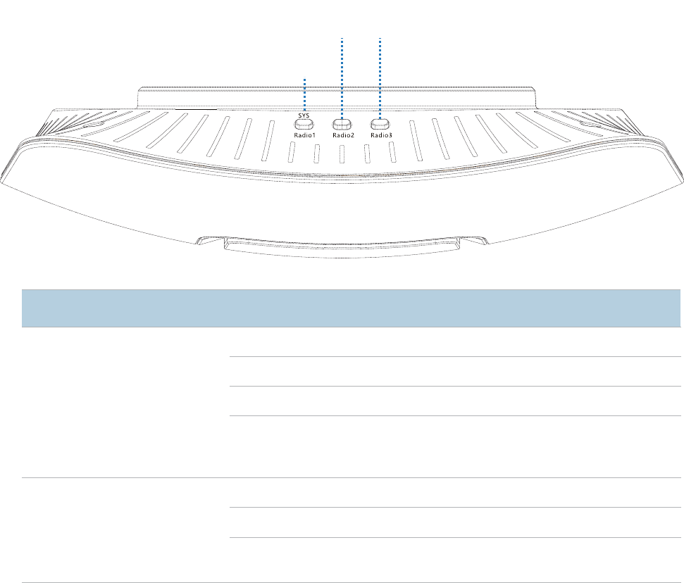
LED Indicators
The following describes the LED indicator states of the AP that has been powered on.
Print
LED Indicator
Description
SYS
Radio1
System/RF band 1
LED indicator
Solid on in orange
The system is booting.
Solid on in green
RF band 1 is enabled.
Blinking in green
RF ban
d 1 is transmitting or receiving data.
Off
The power supply is faulty, RF band 1 is disabled,
the LED indicator has been turned off, or the AP is
faulty.
Radio2
an
d
Radio3
RF band 2 LED
indicator
RF band 3 LED
indicator
Solid on in green
RF band 2/3 is
enabled.
Blinking in green
RF band 2/3 is transmitting of receiving data.
Off
RF band 2/3 is disabled, or the LED indictor has
been turned off.
8,HGTJ3
8,
HG
T
J
3
8,HGTJ2
System/RF band 1
3
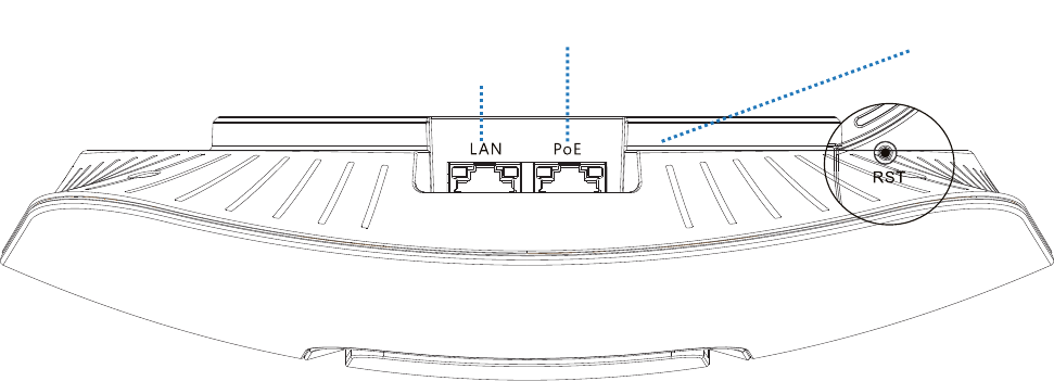
Ports and Button
PoE port
This 10/100/1000 Mbps auto-negotiation port is used to connect to a PoE power supply and
exchange data. To supply power to the AP, use an Ethernet cable to connect the AP to an injector or
a PoE switch compliant with the IEEE 802.3at standard.
LAN port
This 10/100/1000 Mbps auto-negotiation port is used to connect to switches, computers and other
devices.
Reset button
After the AP is powered on, you can hold down this button for 7 seconds to restore the factory
settings.
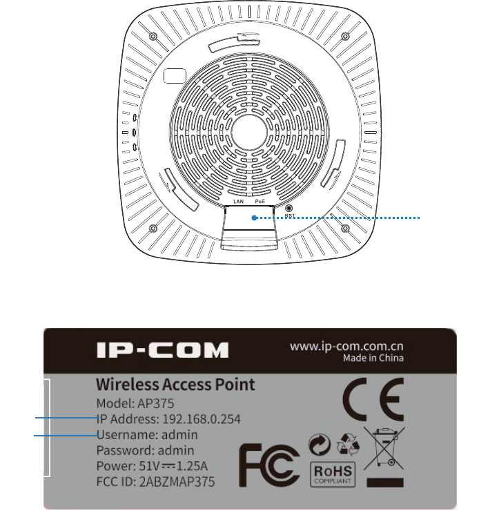
Label
It is attached to the rear panel of the AP. The following figure shows its position.
8KYKZH[ZZUT
PoEVUXZ
LAN port
4
The label is described as follows:
(1): Default IP address of the AP. You can use this IP address to log in to the web UI of the AP.
(2): Default user name and password of the web UI of the AP.
Label
5
Managing the AP
The AP can be managed using the web UI of the AP or an IP-COM AP controller
(AC1000/AC2000/AC3000).
Managing the AP using an AP controller
Refer to Section 10 "Deployment Mode." For details about how to manage the AP using an AP
controller, refer to the user guide for the AP controller available at www.ip-com.com.cn.
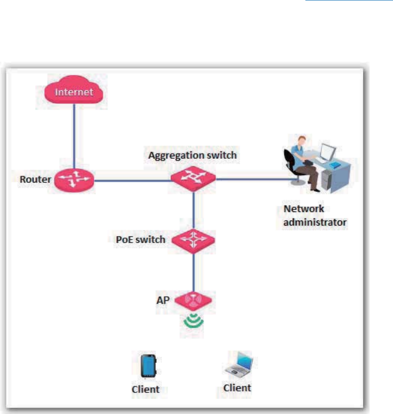
Managing the AP using the web UI of the AP
If you need to install only a small number of APs, connect the APs using the following topology and
log in to the web UI of each AP to manage the APs.
The following sections describe how to manage the AP using the web UI of the AP.
6
Login
Logging in to the Web UI of the AP
You can log in to the web UI of the AP using a web browser. The procedure is as follows:
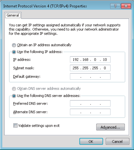
1. Use an Ethernet cable to connect the management computer to the AP or the switch connected
to the AP.
2. Set IP address of your local area connection to 192.168.0.X (X: 2 - 253) and Subnet mask to
255.255.255.0.
3. Start a web browser on the computer, enter the management IP address of the AP (default:
192.168.0.254) in the address bar, and press Enter.
4. Enter the user name and password of the AP (default user name and password: admin) and
click Login.
7
---End
4UZK
If this page is not displayed, refer to Q1 in FAQ.
You can now start configuring the AP.
8
Logging Out of the Web UI of the AP
If you log in to the web UI of the AP and perform no operation within the login timeout interval, the
AP logs you out. When you close the web browser, the system logs you out as well.
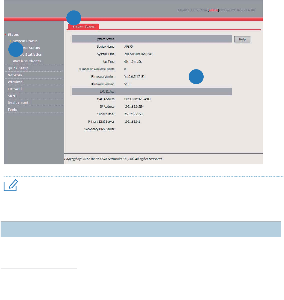
Web UI Layout
The web UI of the AP is composed of three parts, including the 2-level navigation tree, tab page area,
and configuration area. See the following figure.
4UZK
The functions and parameters dimmed on the web UI indicates that they are not supported by the AP or cannot be
changed in the current configuration.
No.
Name
Description
ᬚ
Level
-1 and
level
-2
navigation
bar
The
navigation bar displays the function menu of the AP. When you select a
function in the
navigation bar, the configuration of the function appears in the
configuration area.
ᬛ
Tab page area
ᬜ
Configuration area
It
enables you to view and modify configuration.
2
1
3

9
Common Buttons
The following table describes the common buttons available on the web UI of the AP.
Button
Description
Refresh
It is used to update the content of the current page.
Save
It is used to save the
configuration on the current page and enable the configuration to take
effect.
Restore
It is used to change the current configuration on the current page back to the original
configuration.
Help
It is used to view help information corresponding to the s
ettings on the current page.
10
Quick Setup
Overview
This module enables you to quickly configure the AP so that wireless devices such as smart phones
and pads can access the internet through the wireless network of the AP.
This AP can work in AP or AP+Client mode.
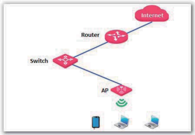
AP mode
By default, the AP works in this mode. In this mode, the AP connects to the internet using an
Ethernet cable and converts wired signals into wireless signals to provide wireless network
coverage. See the following topology.
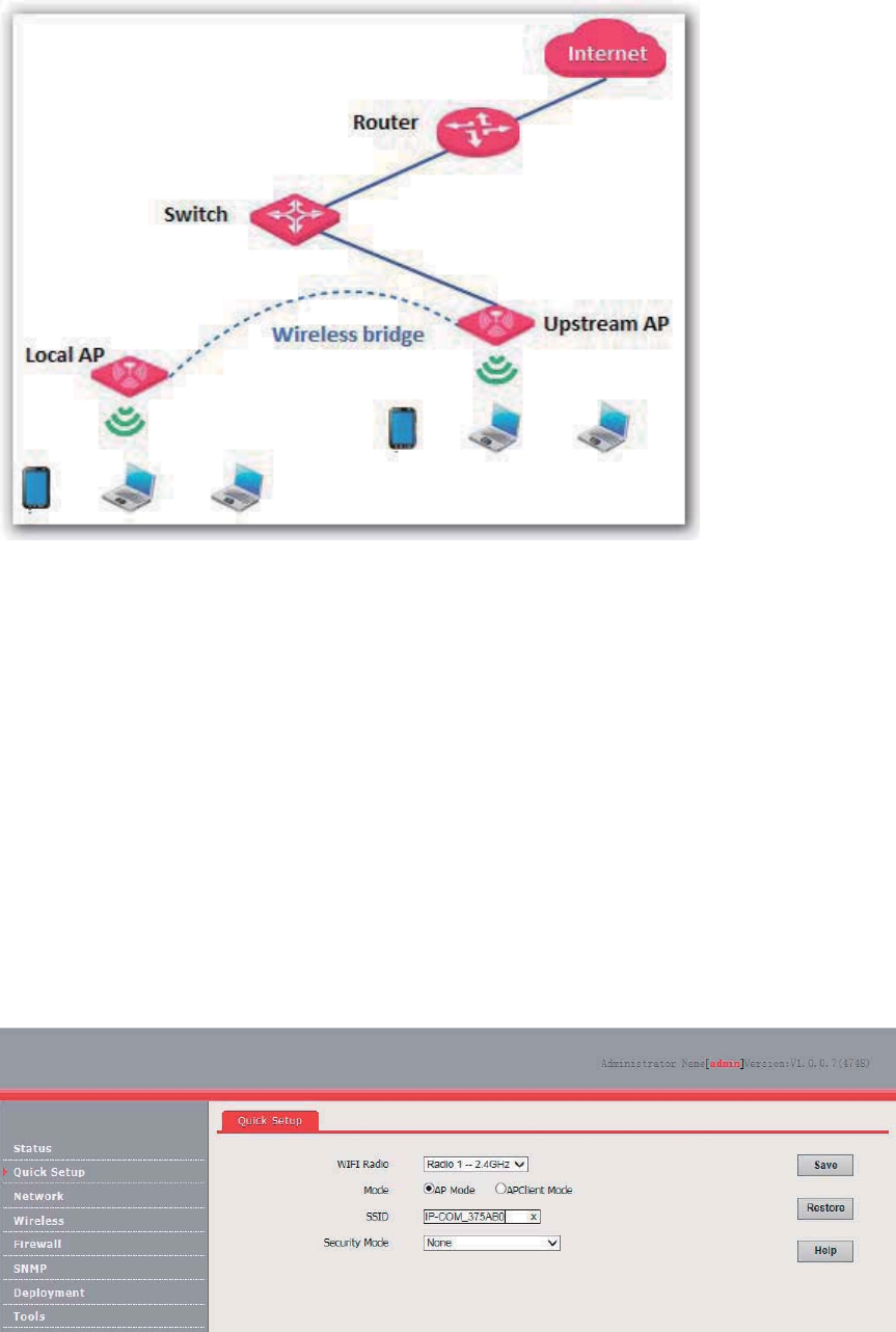
AP+Client mode
In this mode, the AP is wirelessly bridged to an upstream device (such as a wireless router or AP) to
extend the wireless network coverage of the upstream device.
See the following topology.
11
Quick Setup
AP Mode
1. Choose Quick Setup.
2. Set WIFI Radio to the RF band you want to set, such as Radio 1 –2.4 GHz.
3. Set Mode to AP Mode.
4. Change the primary SSID of the selected RF band in the SSID text box.
5. Select a security mode from the Security Mode drop-down list box and set the corresponding
parameters.
6. Click Save.
---End
Parameter description
12
Parameter
Description
WIFI Radio
It specifies the RF band to be configured.
This AP provide three RF
bands. RF
band 1 is a 2.4GHz band, RF band 2 is a 5 GHz band,
whereas RF band 3 is a 2.4 GHz or 5 GHz band.
Mode
It sp
ecifies the working mode of the AP, including the AP mode and AP+Client mode.
SSID
It enables you to change the primary SSID of the selected RF band.
Security Mode
It specifies the security mode corresponding to the
SSID. The
options include: None, WEP,
WPA
-PSK, WPA2-PSK, Mixed WPA/WPA2-PSK, WPA, and WPA2.
The option None allows any wireless clients to connect to the AP. This option is not
recommended because it affects network security.
After the configuration, you can select the SSID on your wireless devices such as smart phones and
enter your wireless network password to connect to the wireless network of the AP and access the
internet through the AP.
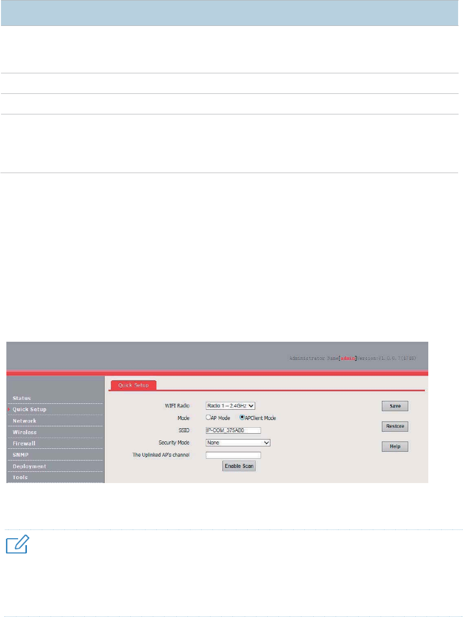
AP+Client Mode
1. Choose Quick Setup.
2. Set WIFI Radio to the RF band you want to set, such as Radio 1 –2.4 GHz.
3. Set Mode to APClient Mode.
4. Click Enable Scan.
5. Select the wireless network to be extended from the wireless network list that appears.
4UZK
− If no wireless network is found, ensure that the selected RF band is enabled, and try scanning wireless networks
again.
− After a wireless network to be extended is selected, the AP identifies the SSID, security mode, and channel of
the wireless network and enters them on the page. The other parameters including Security Key, RADIUS
Server, RADIUS Port, and RADIUS Password must be entered manually.
6. Click Disable Scan.
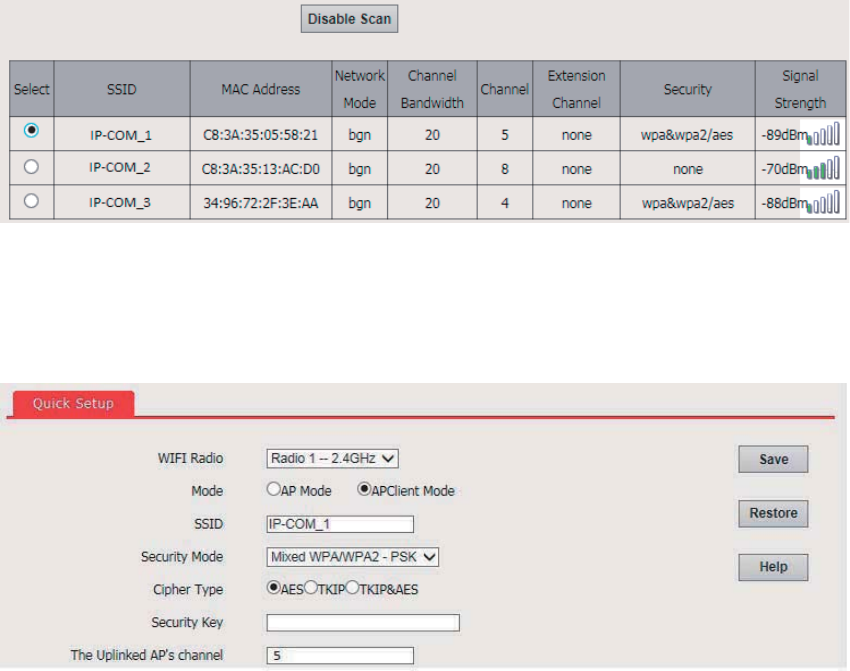
13
7. If the wireless network of the upstream device is encrypted, set Security Key to the wireless
network password of the device or set RADIUS Server, RADIUS Port, and RADIUS Password
to the IP address, port number, and password of the RADIUS server.
8. Click Save.
---End
After the configuration, you can select the SSID on your wireless devices such as smart phones and
enter your wireless network password to connect to the wireless network of the AP and access the
internet through the AP. If you do not know the SSID of the AP, go to the Wireless > SSID Setup
page.
14
Status
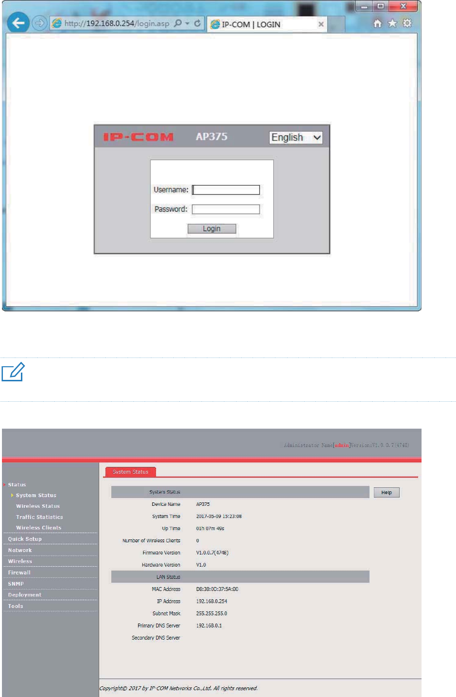
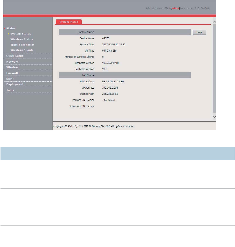
System Status
The access the page, choose Status > System Status.
The page displays the system and LAN port status of the AP.
Parameter description
Parameter
Description
Device Name
It specifies the name of the AP.
You can change the AP name on the
Network > LAN Setup page or on the SNMP
page.
System Time
It specifies the current system time of the AP.
Up Time
It specifies the time that
has elapsed since the AP was started last time.
Number of Wireless
Clients
It specifies the number of wireless clients currently connected to the AP.
Firmware Version
It specifies the firmware version number of the AP.
Hardware Version
It specifies the
hardware version number of the AP.
MAC Address
It specifies the physical address of the LAN port of the AP.
15
Parameter
Description
IP Address
It specifies the IP address of the AP. The web UI of the AP is accessible at this IP address.
Subnet Mask
It specifies the subnet mask
of the IP address of the AP.
Primary DNS
Server
It specifies the primary DNS server of the
AP. If
it is blank, the AP does not have a primary
DNS server.
Secondary DNS
Server
It specifies the secondary DNS server of the it is blank, the AP does not have
a secondary
DNS server.
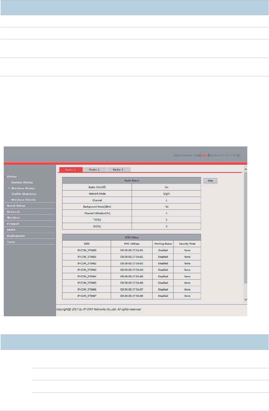
Wireless Status
The access the page, choose Status > Wireless Status.
This page displays general RF status and SSID status of the AP. By default, the page displays the
RF status of RF band 1. To view the RF status of RF bands 2 and 3, click the corresponding tabs.
Parameter description
Parameter
Description
Radio
Status
Radio (On/Off)
It specifies whether the wireless network corresponding to the RF band is
enabled.
Network Mode
It specifies the network mode of the wireless ne
twork.
Channel
It specifies the current working channel of the wireless network.
Background Noise
(dBm)
It specifies the strength of nearby interference radio signals on the current
working channel.
16
Parameter
Description
Channel Utilization
(%)
It specifies the air interf
ace usage of the current working channel.
TX
(%)
It specifies the proportion of AP
-transmitted packets in the current working
channel usage.
RX
(%)
It specifies the proportion of AP
-received packets in the current working
channel usage.
SSID
Status
SS
ID
It specifies all the SSIDs corresponding to the RF band.
MAC Address
It specifies the physical addresses corresponding to the SSIDs.
Working Status
It specifies whether an SSID is enabled.
Security Mode
It specifies the security modes correspondin
g to SSIDs.
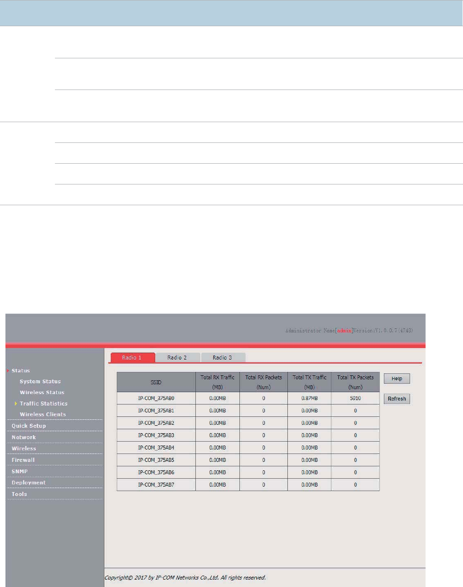
Traffic Statistics
The access the page, choose Status > Traffic Statistics.
This page displays the statistics about historical packets of the AP by RF band.
By default, the page displays the traffic statistics for RF band 1. To view the traffic statistics for RF
bands 2 and 3, click the corresponding tabs. To view the latest statistics, click Refresh.
Wireless Clients
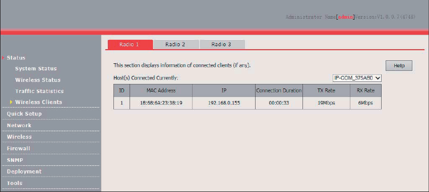
The access the page, choose Status > Wireless Clients.
17
This page displays information about the wireless clients connected to the wireless networks of the
AP by RF band.
By default, the page displays information about the wireless clients connected to the wireless
network corresponding to the primary SSID of RF band 1 of the AP. To view the wireless client
connection information of an SSID of an RF band, perform the following procedure:
1. Choose Status > Wireless Clients.
2. Select the RF band corresponding to the wireless client connection information to be viewed.
3. Select the SSID corresponding to the wireless client connection information to be viewed from
the drop-down list box in the upper-right corner.
---End
18
Network Settings
LAN Setup
Overview
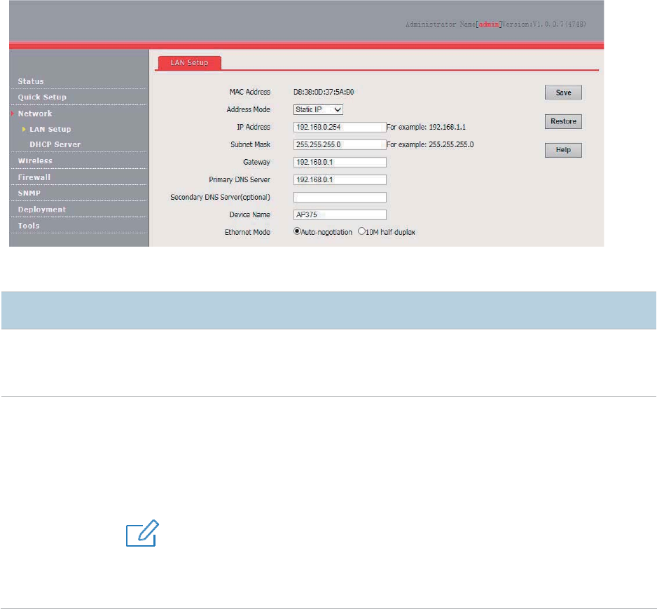
To access the page, choose Network > LAN Setup.
This page enables you to view the MAC address of the LAN port of the AP and set the name,
Ethernet mode, IP obtaining method, and other related parameters of the AP.
Parameter description
Parameter
Description
MAC Address
It specifies the MAC address of the LAN port of the AP.
The default primary SSID of RF band 1 of the AP is IP
-COM_XXXXXX, where XXXXXX
indicates the last 6 characters of this MAC address.
Address Mode
It specifies the IP address obtaining mode of the AP. The default option is
Static IP.
− Static IP: It indicates that the IP address, subnet mask, gateway, and DNS server
information of the AP is set manually.
− Dynamic IP
: It indicates that the IP address, subnet mask, gateway, and DNS server
information of the AP is obtained from a DHCP server on your LAN.
4UZK
If
Address Mode is set to Dynamic IP, you can log in to the web UI of
the AP only with the IP
address assigned to the AP by the DHCP server. The IP address is specified on the client list
of the DHCP server.

19
Parameter
Description
IP Address
It specifies the IP address of the AP. The web UI of the AP is accessible at this IP address.
The
default IP address is 192.168.0.254.
Generally, ensure that this IP address is in the same network segment as the LAN IP address
of your LAN router connected to the internet, so that the AP can access the internet.
Subnet Mask
It specifies the subnet mask of the
IP address of the AP. The default subnet mask is
255.255.255.0.
Gateway
It specifies the gateway IP address of the AP.
Generally, set the gateway IP address to the LAN IP address of your LAN router connected to
the internet, so that the AP can access the
internet.
Primary DNS
Server
It specifies the primary DNS server of the AP.
If your LAN router connected to the internet provides the DNS proxy function, this IP address
can be the LAN IP address of the
router. Otherwise, enter a correct DNS server IP add
ress.
Secondary DNS
Server (optional)
It specifies the IP address of the secondary DNS server of the AP. This parameter is optional.
If a DNS server IP address in addition to the IP address of the primary DNS server is available,
enter the additional IP a
ddress in this field.
Device Name
It specifies the name of the AP. The default name is AP375.
You are recommended to change the device name so that you can quickly locate the AP when
managing the AP remotely.
Ethernet Mode
It specifies the Ethernet mode
of the LAN port of the AP.
− Auto-negotiation
: This mode features a high transmission rate but short transmission
distance. Generally, this mode is recommended.
− 10M half-duplex
: This mode features a long transmission distance but relatively low
transmission rate (usually 10 Mbps).
This mode is recommended only if the Ethernet cable that connects the LAN port of the AP to
a peer device exceeds 100
meters. In
this case, the connected LAN port of the peer device
must work in auto
-negotiation mode. Otherwise, th
e LAN port of the AP may not be able to
properly transmit or receive data.
Changing the LAN Settings
Manually Setting the IP Address
This mode enables you to manually set the IP address, subnet mask, gateway IP address, primary
DNS server, and secondary DNS server of the AP. It is usually used in a scenario with only one or a
few APs.
Procedure:
1. Choose Network > LAN Setup.
2. Set Address Mode to Static IP.
3. Set an IP address, a subnet mask, a gateway address, a primary DNS server, and a secondary
DNS server.
4. Click Save.
20
---End
If you change the IP address of the LAN port, change the IP address of your management computer
as well so that the two IP addresses belong to the same network segment. Then, you can use the
new IP address of the LAN port to log in to the web UI of the AP.
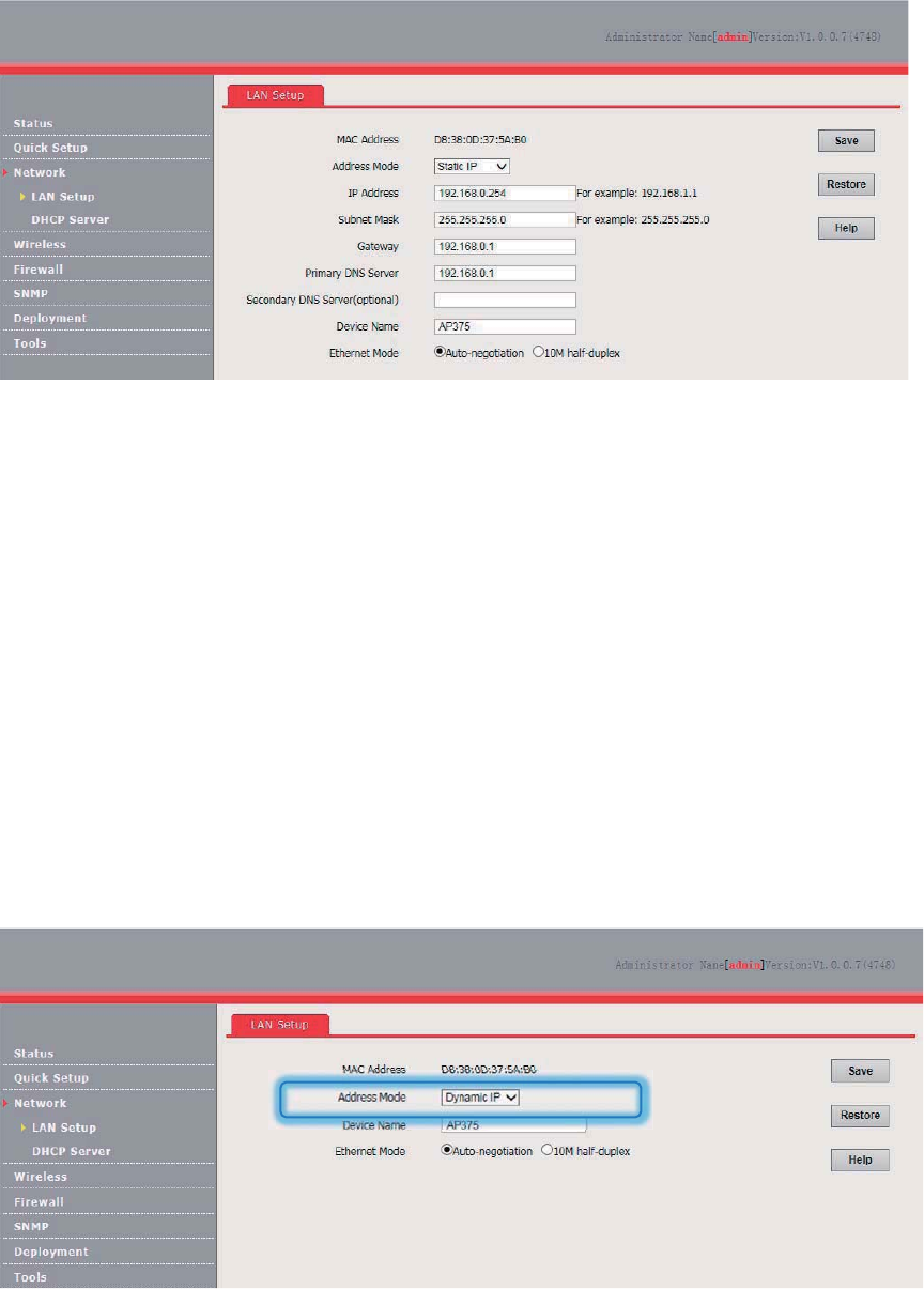
Automatically Obtaining an IP Address
This mode enables the AP to automatically obtain an IP address, subnet mask, gateway IP address,
primary DNS server IP address, and secondary DNS server IP address from a DHCP server in the
network. If a large number of APs are deployed, you can adopt this mode to prevent IP address
conflicts and effectively reduce your workload.
Procedure:
1. Choose Network > LAN Setup.
2. Set Address Mode to Dynamic IP.
3. Click Save.
---End
After the configuration takes effect, you can log in to the web UI of the AP only with the IP address
assigned to the AP by the DHCP server. The IP address is specified on the client list of the DHCP
server.
21
DHCP Server
Overview
The AP provides a DHCP server function to assign IP addresses to clients on the LAN. By default,
the DHCP server function is disabled.
4UZK
If the new and original IP addresses of the LAN port belong to different network segment, the system changes the IP
address pool of the DHCP server function of the AP so that the IP address pool and the new IP address of the LAN
port belong to the same network segment.
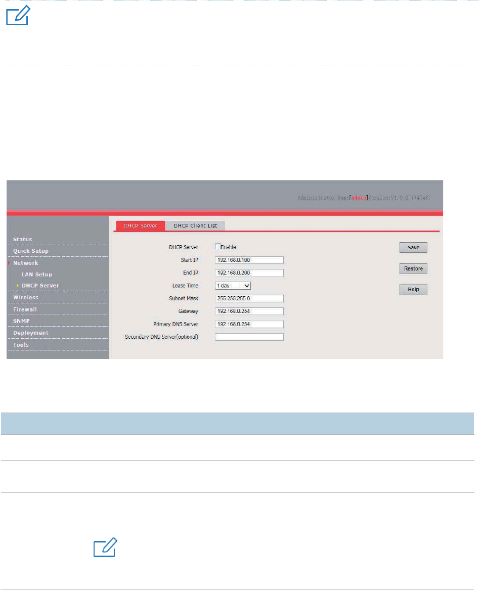
Configuring the DHCP Server
1. Choose Network > DHCP Server.
2. Set the parameters.
3. Click Save.
---End
Parameter description
Parameter
Description
DHCP Server
It sp
ecifies whether to enable the DHCP server function of the default, it is disabled.
Start IP
It specifies the start IP address of the IP address pool of the DHCP server. The default value
is
192.168.0.100.
End IP
It specifies the end IP address of the IP address pool of the DHCP server. The default value is
192.168.0.200
.
4UZK
The start and end IP addresses must belong to the same network segment as the IP address
of the LAN port of the AP.

22
Parameter
Description
Lease Time
It specifies the validity period of an IP address assigned
by the DHCP server to a client.
When
the lease time expires:
−
If the client is still connected to the AP, the client automatically extends the lease time
and continues to use this IP address.
− If the client has been shut down, the Ethernet cable between the
client and the AP has
been removed, or the wireless connection between the client and the AP is released,
the AP recycles the IP address. The
AP can then assign this IP address to any client
requesting an IP address.
It is recommended that you retain the
default value 1 day.
Subnet Mask
It specifies the subnet mask assigned by the DHCP server to clients. The default value is
255.255.255.0
.
Gateway
It specifies the gateway IP address assigned by the DHCP server to clients. The default value
is
192.168.0.254.
4UZK
When a client accesses a server or host located outside the network segment where the client
resides, the data from and to the client must be forwarded by a gateway. Generally, the IP
address of the gateway is the LAN IP address of the router in your
LAN.
Primary DNS
Server
It specifies the primary DNS server IP address assigned by the DHCP server to clients. The
default value is
192.168.0.254.
4UZK
To enable clients to access the internet, set this parameter to a correct DNS server IP address
or DNS prox
y IP address.
Secondary DNS
Server (optional)
It specifies the secondary DNS server IP address assigned by the DHCP server to clients.
This parameter is optional.
4UZK
If another DHCP server is available on your LAN, ensure that the IP address pool of the AP does not overlap the IP
address pool of that DHCP server. Otherwise, IP address conflicts may occur.
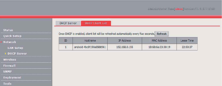
Viewing the DHCP Client List
If the AP functions as a DHCP server, you can view the DHCP client list to understand the details
about the clients that obtain IP addresses from the DHCP server. The details include host names, IP
addresses, MAC addresses, and lease times.
To access the page, choose Network > DHCP Server and click DHCP Client List tab.
23
You can click Refresh to view the latest client information.

24
Wireless Settings
SSID Setup
Overview
This module enables you to set SSID-related parameters of the AP.
Broadcast SSID
When the AP broadcasts an SSID, nearby wireless clients can detect the SSID. When this
parameter is set to Disable, the AP does not broadcast the SSID and nearby wireless clients cannot
detect the SSID. In this case, you need to enter the SSID manually on your wireless client if you
want to connect to the wireless network corresponding to the SSID. This to some extent enhances
the security of the wireless network.
4UZK
After Broadcast SSID is set to Disable, a hacker can still connect to the corresponding wireless network if he/she
manages to obtain the SSID by other means. Therefore, disabling this function only ensures low network security.
Client Isolation
This parameter implements a function similar to the VLAN function for wired networks. It isolates the
wireless clients connected to the same wireless network corresponding to an SSID, so that the
wireless clients can access only the wired network connected to the AP. Applying this function to
hotspot setup at public places such as hotels and airports helps increase network security.
WMF
The number of wireless clients keeps increasing currently, but wired and wireless bandwidth
resources are limited. Therefore, the multicast technology, which enables single-point data
transmission and multi-point data reception, has been widely used in networks to effectively reduce
bandwidth requirements and prevent network congestion.
Nevertheless, if a large number of clients are connected to a wireless interface of a wireless network
and multicast data is intended for only one of the clients, the data is still sent to all the clients, which
unnecessarily increases wireless resource usage and may lead to wireless channel congestion. In
addition, multicast stream forwarding over an 802.11 network is not secure.
25
The WMF function of the AP converts multicast traffic into unicast traffic and forwards the traffic to
the multicast traffic destination in the wireless network. This helps save wireless resources, ensure
reliable transmission, and reduce delays.
Maximum Clients
This parameter specifies the maximum number of clients that can connect to the wireless network
corresponding to an SSID. If the number is reached, the wireless network rejects new connection
requests from clients. This limit helps balance load among the SSIDs of the AP.
Security Mode
A wireless network uses radio, which is open to the public, as its data transmission medium. If the
wireless network is not protected by necessary measures, any client can connect to the network to
use the resources of the network or access unprotected data over the network. To ensure
communication security, transmission links of wireless networks must be encrypted for protection.
The AP supports various security modes for network encryption, including None, WEP, WPA-PSK,
WPA2-PSK, Mixed WPA/WPA2-PSK, WPA, and WPA2.
None
It indicates that any wireless client can connect to the wireless network. This option is not
recommended because it affects network security.
WEP
Wired Equivalent Privacy (WEP) uses a static key to encrypt all exchanged data, and ensures that a
wireless LAN has the same level of security as a wired LAN. Data encrypted based on WEP can be
easily cracked. In addition, WEP supports a maximum wireless network throughput of only 54 Mbps.
Therefore, this security mode is not recommended.
WPA-PSK, WPA2-PSK, and Mixed WPA/WPA2-PSK
Mixed WPA/WPA2-PSK indicates that wireless clients can connect to a wireless network using
either WPA-PSK or WPA2-PSK.
In these security modes, an AP adopts a preshared key for authentication, and generates another
key for data encryption. This prevents the vulnerability caused by static WEP keys, and makes the
security modes suitable for ensuring security of home wireless networks. Nevertheless, because the
initial pre-shared key for authentication is manually set and all clients use the same key to connect
to the same AP, the key may be disclosed unexpectedly. This makes the security modes not suitable
for scenarios where high security is required.
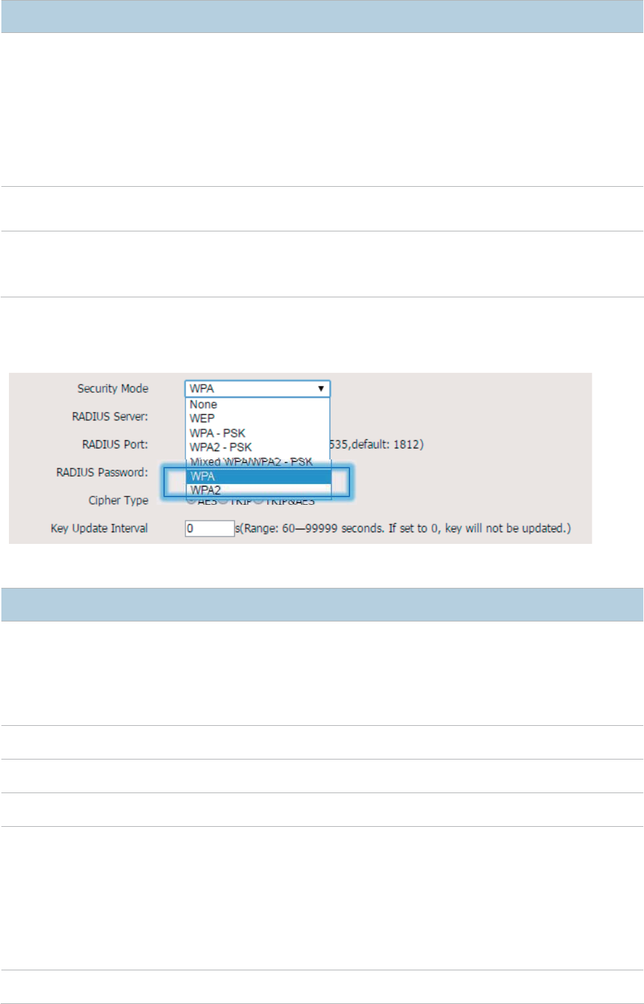
WPA and WPA2
To address the key management weakness of WPA-PSK and WPA2-PSK, the WiFi Alliance puts
forward WPA and WPA2, which use 802.1x to authenticate clients and generate data encryption–
oriented root keys. WPA and WPA2 use the root keys to replace the preshared keys that set
manually, but adopt the same encryption process as WPA-PSK and WPA2-PSK.
WPA and WPA2 uses 802.1x to authenticate clients and the login information of a client is managed
by the client. This effectively reduce the probability of information leakage. In addition, each time a
client connects to the AP that adopts the WPA or WPA2 security mode, the RADIUS server
generates a data encryption key and assigns it to the client. This makes it difficult for attackers to
obtain the key. These features of WPA and WPA2 help significantly increase network security,
making WPA and WPA2 the preferred security modes of wireless networks that require high security.
26
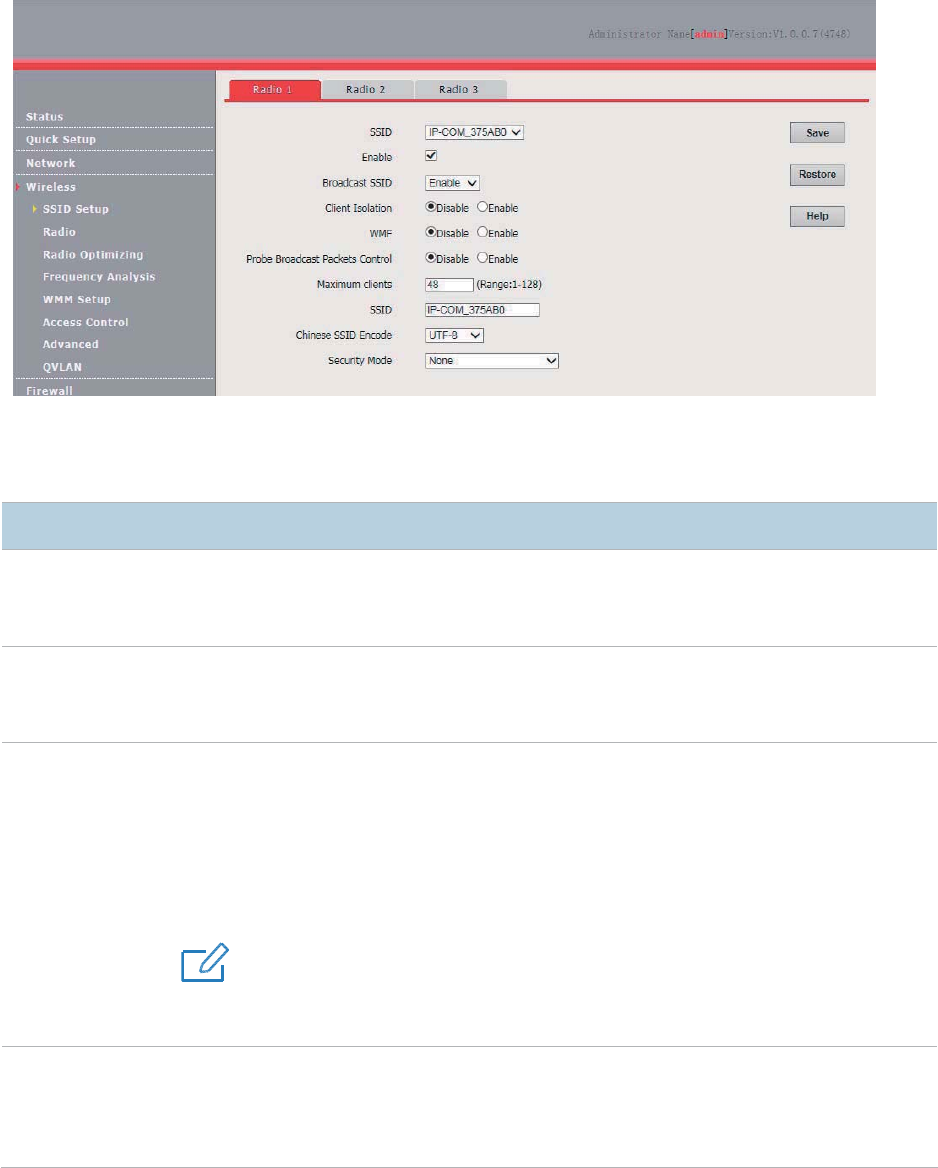
Changing SSID Settings
To change the basic settings of an SSID for an RF band, perform the following procedure:
1. Choose Wireless > SSID Setup.
2. Select the RF band corresponding to the SSID.
3. Select the SSID from the SSID drop-down list box.
4. Change the parameters as required. Generally, you only need to change the Enable, SSID, and
Security Mode settings.
5. Click Save.
---End
Parameter description
Parameter
Description
SSID
It specifies the SSID to be configured.
RF bands 1 and 3 support 8 SSIDs each, whereas RF band 2 support
s only 4 SSIDs. The
first
SSID of each RF band is the primary SSID.
Enable
It specifies whether to enable the selected SSID.
By default, the primary SSID is enabled, while the other SSIDs are disabled. You can enable
them if needed.
Broadcast SSID
It spe
cifies whether to broadcast the selected SSID.
− Enable
: It indicates that the AP broadcasts the selected SSID. In this case, nearby
wireless clients can detect the SSID.
− Disable
: It indicates that the AP does not broadcast the selected SSID. In this case, if
you want to connect a wireless client to the wireless network corresponding to the
SSID, you must manually enter the SSID on the client.
4UZK
This AP can automatically hide its
SSID. When
the number of clients connected to the AP with
an SSID of the AP reach
es the upper limit, the AP stops broadcasting the SSID.
Client Isolation
It specifies whether clients
connected with the same SSID can communicate with each other.
− Enable: It indicates that the wireless clients connected to the AP with the selected
SSID c
annot communicate with each other. This improves wireless network security.
− Disable: It indicates that the wireless clients connected to the AP with the selected
27
Parameter
Description
SSID can communicate with each other.
WMF
It specifies whether to enable the WMF function.
Probe Broadcast
Packets Control
By default, all wireless clients are detecting and scanning the nearby wireless networks using
the Probe Request frame (including SSID field).
After receiving the packets, the device
decides whether to join the network and re
sponds to the Probe Response (including all
parameters of Beacon frame), consuming massive wireless resources.
This function saves wireless resources by enabling the AP not to respond to the probe
requests without SSIDs.
Maximum Clients
It specifies the maximum number of clients that can be concurrently connected to the wireless
network corresponding to an SSID.
After this upper limit is reached, the AP rejects new requests from clients for connecting to the
wireless network.
SSID
It enables you to change
the selected SSID.
Chinese characters are allowed in an SSID.
Chinese SSID
Encode
It specifies the encoding format of Chinese characters in an SSID. This parameter takes effect
only if the SSID contains Chinese
characters. The default value is UTF8.
If 2
or more SSIDs of the AP are enabled, you are recommended to set this parameter to
UTF
-8 for some SSIDs and to GB2312
for the other SSIDs, so that any wireless client can
identify one or both SSIDs that contain Chinese characters.
Security Mode
It specifi
es the security mode of the selected SSID. The options include: None, WEP, WPA-
PSK,
WPA2
-PSK, Mixed WPA/WPA2-PSK, WPA, and WPA2.
Clicking a hyperlink navigates you to the
elaborated description of the corresponding security mode.
The option
None allows any wireless clients to connect to the AP. This option is not
recommended because it affects netwo
rk security.
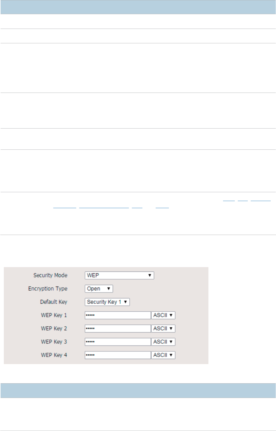
WEP
Parameter description
Parameter
Description
Encryption Type
It specifies the authentication type for the WEP security mode. The options include
Open,
Shared
, and 802.1x. The options share the same encryption process.
− Open: It specifies
that authentication is not required and data exchanged is encrypted
using WEP. In this case, a wireless client can connect to the wireless network
28
Parameter
Description
corresponding to the selected SSID without being authenticated, and the data
exchanged between the client and the network is encrypted in WEP security mode.
− Shared
: It specifies that a shared key is used for authentication and data exchanged is
encrypted using WEP. In this case, a wireless client must use a preset WEP key to
connect to the wireless network corresponding to an SSID of the AP. The wireless
client can be connected to the AP only if the WEP key is the same as that of the AP.
− 802.1x specifies that 802.1x authentication is required and data exchanged is
encrypted using WEP. In this case, ports are enabled when authenticated clients
connect to the AP, and disabled when non-authenticated users connect to the AP.
Default Key
It specifies the WEP key for the Open or Shared encryption type.
For
example, if Default Key is set to Security Key 2, a wireless client can connect to the
wireless network corresponding to the selected SSID only with the password specified by
WEP
Key 2.
ASCII
It is required if the
Open or Shared option is selected.
It allows 5 or 13 ASCII characters in a WEP key.
Hex
It is required
if the Open or Shared option is selected.
It allows 10 or 26
hexadecimal characters in a WEP key.
RADIUS Server
These parameters are dedicated to the 802.1x authentication type.
It specifies the IP address/port number/shared key of the RADIUS server for authentication.
RADIUS Port
RADIUS
Password
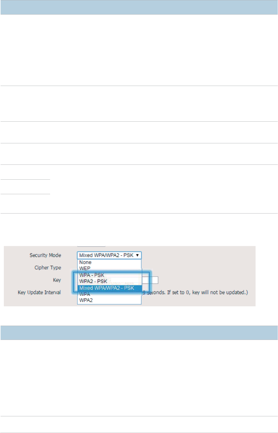
WPA-PSK, WPA2-PSK, and Mixed WPA/WPA2-PSK
Parameter description
Parameter
Description
Security Mode
The
WPA-PSK, WPA2-PSK, and Mixed WPA/WPA2-PSK options are available for
network protection with a presha
red key.
− WPA-PSK: It indicates that wireless clients can connect to the wireless network
corresponding to the selected SSID using WPA-PSK.
− WPA2-PSK
: It indicates that wireless clients can connect to the wireless network
corresponding to the selected SSID using WPA2-PSK.
− Mixed WPA/WPA2-PSK: It indicates that wireless clients can connect to the
wireless network corresponding to the selected SSID using either WPA-PSK or
WPA2-PSK.
Cipher Type
It specifies the encryption algorithm corresponding to the selected
security mode. If
Security Mode is set to WPA-PSK, this parameter has the AES and TKIP values. If
29
Parameter
Description
Security Mode is set to WPA2-PSK or Mixed WPA/WPA2-PSK, this parameter has the
AES
, TKIP, and TKIP&AES values.
− AES: It indicates the Advanced Encryption Standard.
− TKIP: It indicates the Temporal Key Integrity Protocol. If
this encryption algorithm is
used, the AP can reach a maximum wireless transmission rate of 54 Mbps.
− TKIP&AES: It indicates that both TKIP and AES encryption algorithms are
supported. Wireles
s clients can connect to the wireless network corresponding to
the selected SSID using TKIP or AES.
Key
It specifies a preshared WPA
key. A
WPA key can contain 8 to 63 ASCII characters or 8 to
64 hexadecimal characters.
Key Update Interval
It specifies t
he automatic update interval of a WPA key for data encryption. A shorter
interval results in higher data security.
The value
0 indicates that a WAP key is not updated.
WPA and WPA2
Parameter description
Parameter
Description
Security Mode
The
WPA and WPA2
options are available for network protection with a RADIUS server.
− WPA: It indicates that wireless clients can connect to the wireless network
corresponding to the selected SSID using WPA.
− WPA2: It indicates that wireless clients can connect to the wireless network
corresponding to the selected SSID using WPA2.
RADIUS Server
It specifies the IP address of the RADIUS server for authentication.
RADIUS Port
It specifies the port number of the RADIUS server for client authentication.
RADIUS Password
It
specifies the shared password of the RADIUS server.
Cipher Type
It specifies the encryption algorithm corresponding to the selected security mode. The
available options include
AES, TKIP, and TKIP&AES.
− AES: It indicates the Advanced Encryption Standard.
− TKIP: It indicates the Temporal Key Integrity Protocol.
− TKIP&AES: It indicates that both TKIP and AES encryption algorithms are
supported. Wireless clients can connect to the wireless network corresponding to
the selected SSID using TKIP or AES.
Key Update
Interval
It specifies the automatic update interval of a WPA key for data encryption. A shorter
30
Parameter
Description
interval results in higher data security.
The value
0 indicates that a WAP key is not updated.
SSID Setup Example
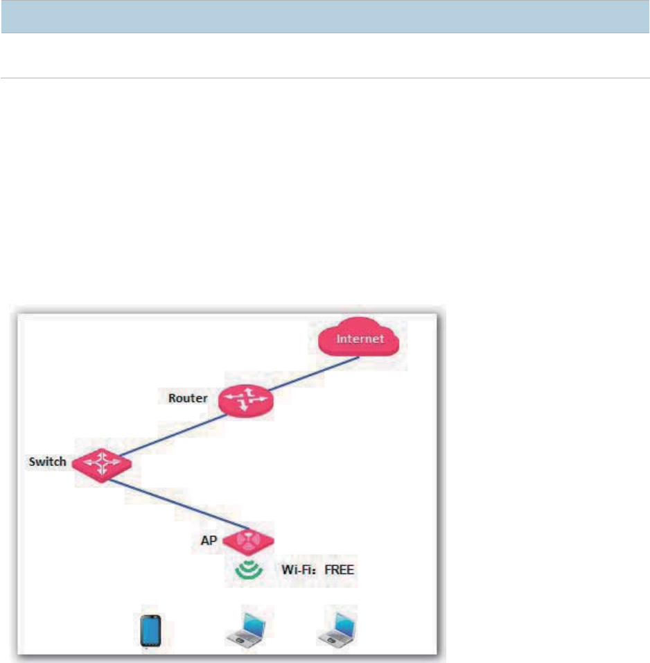
Setting up a Non-encrypted Wireless Network
Networking requirement
In a hotel lounge, guests can connect to the wireless network without a password and access the
internet through the wireless network.
Configuration procedure
Assume that the second SSID of RF band 1 of the AP is used.
1. Choose Wireless > SSID Setup.
2. Select the second SSID from the SSID drop-down list box.
3. Select the Enable check box.
4. Change the value of the SSID text box to FREE.
5. Set Security Mode to None.
6. Click Save.
31
---End
Verification
Verify that wireless devices can connect to the FREE wireless network without a password.
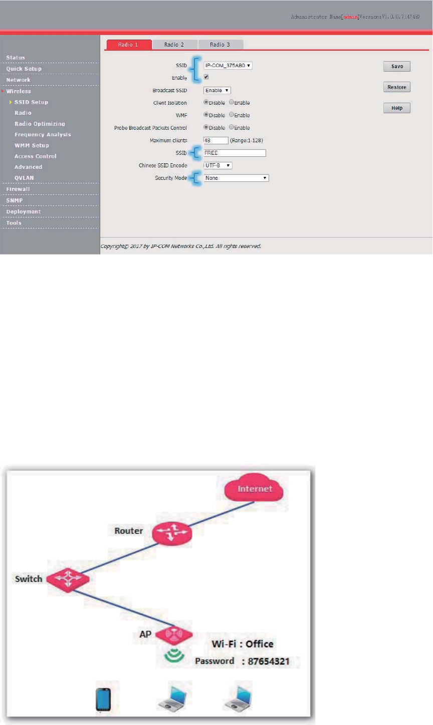
Setting Up a Wireless Network Encrypted Using WPA-PSK,
WPA2-PSK, or Mixed WPA/WPA2-PSK
Networking requirement
An enterprise wireless network with a certain level of security must be set up through a simply
procedure. In this case, WPA-PSK, WPA2-PSK, or Mixed WPA/WPA2-PSK is recommended. See
the following figure.
32
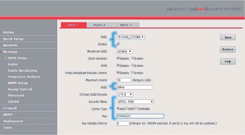
Configuration procedure
Assume that the second SSID of RF band 1 of the AP is used.
1. Choose Wireless > SSID Setup.
2. Select the second SSID from the SSID drop-down list box.
3. Select the Enable check box.
4. Change the value of the SSID text box to Office.
5. Set Security Mode to WPA2-PSK and Cipher Type to AES.
6. Set Key to 87654321.
7. Click Save.
---End
Verification
Verify that wireless devices can connect to the Office wireless network with the password
87654321.
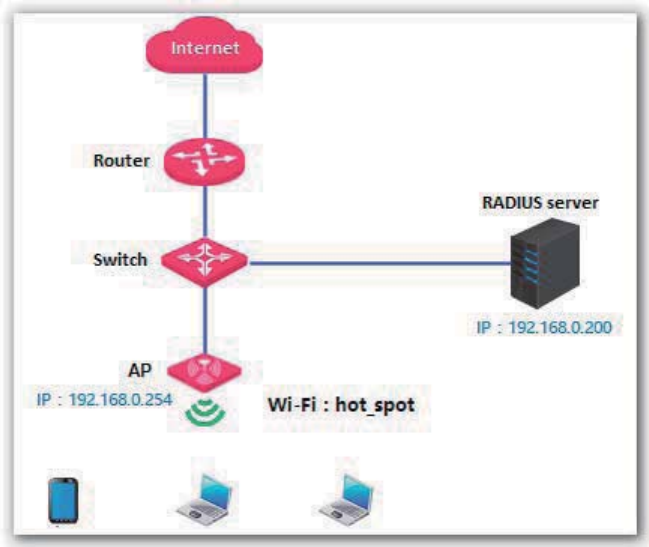
Setting up a Wireless Network Encrypted Using WPA or WPA2
Networking requirement
A highly secure wireless network is required and a RADIUS server is available. In this case, WPA or
WPA2 pre-shared key mode is recommended. See the following figure.
33
Configuration procedure
1. Configure the AP.
− Assume that the IP address of the RADIUS server is 192.168.0.200, the Key is 12345678,
and the port number for authentication is 1812.
− Assume that the second SSID of RF band 1 of the AP is used.
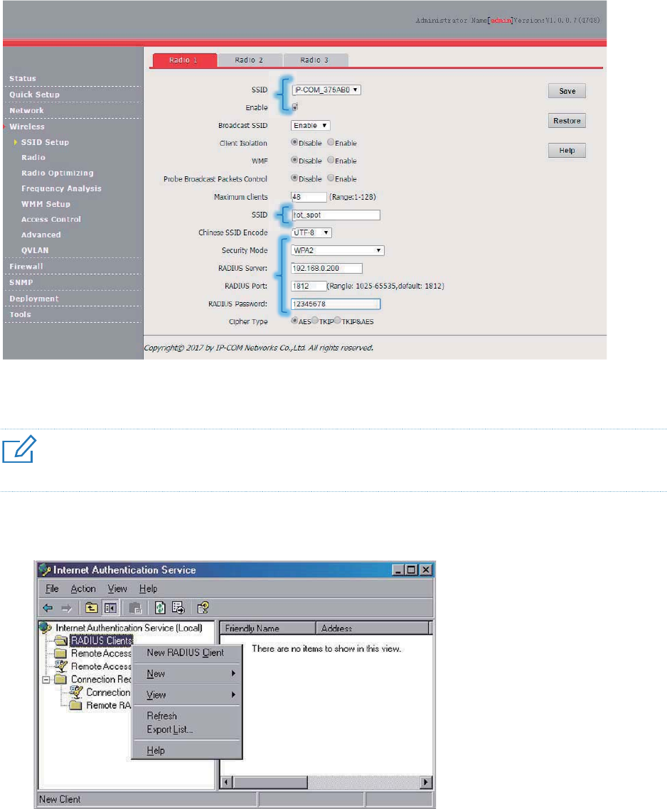
(1) Choose Wireless > SSID Setup.
(2) Select the second SSID from the SSID drop-down list box.
(3) Select the Enable check box.
(4) Change the value of the SSID text box to hot_spot.
(5) Set Security Mode to WPA2-PSK.
(6) Set RADIUS Server, RADIUS Port, and RADIUS Password to 192.168.0.200, 1812, and
12345678 respectively.
(7) Set Cipher Type to AES.
(8) Click Save.
34
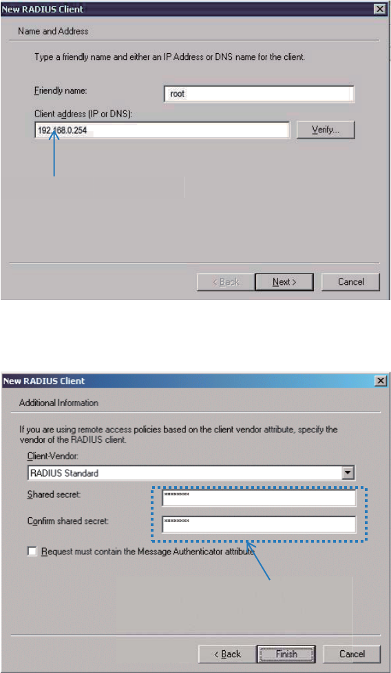
2. Configure the RADIUS server.
4UZK
Windows 2003 is used as an example to describe how to configure the RADIUS server.
(1) Configure a RADIUS client.
In the Computer Management dialog box, double-click Internet Authentication Service,
right-click RADIUS Clients, and choose New RADIUS Client.
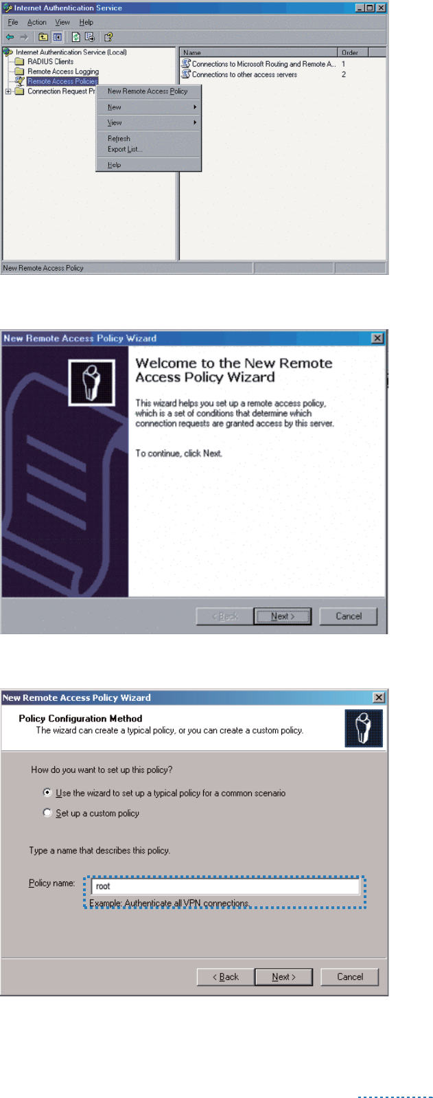
Enter a RADIUS client name (which can be the name of the AP) and the IP address of the AP,
and click Next.
35
Enter 12345678 in the Shared secret and Confirm shared secret text boxes, and click
Finish.
(2) Configure a remote access policy.
Right-click Remote Access Policies and choose New Remote Access Policy.
IP address of the AP
Password same as that specified
by RADIUS Password on the AP
36
In the New Remote Access Policy Wizard dialog box that appears, click Next.
Enter a policy name and click Next.
37
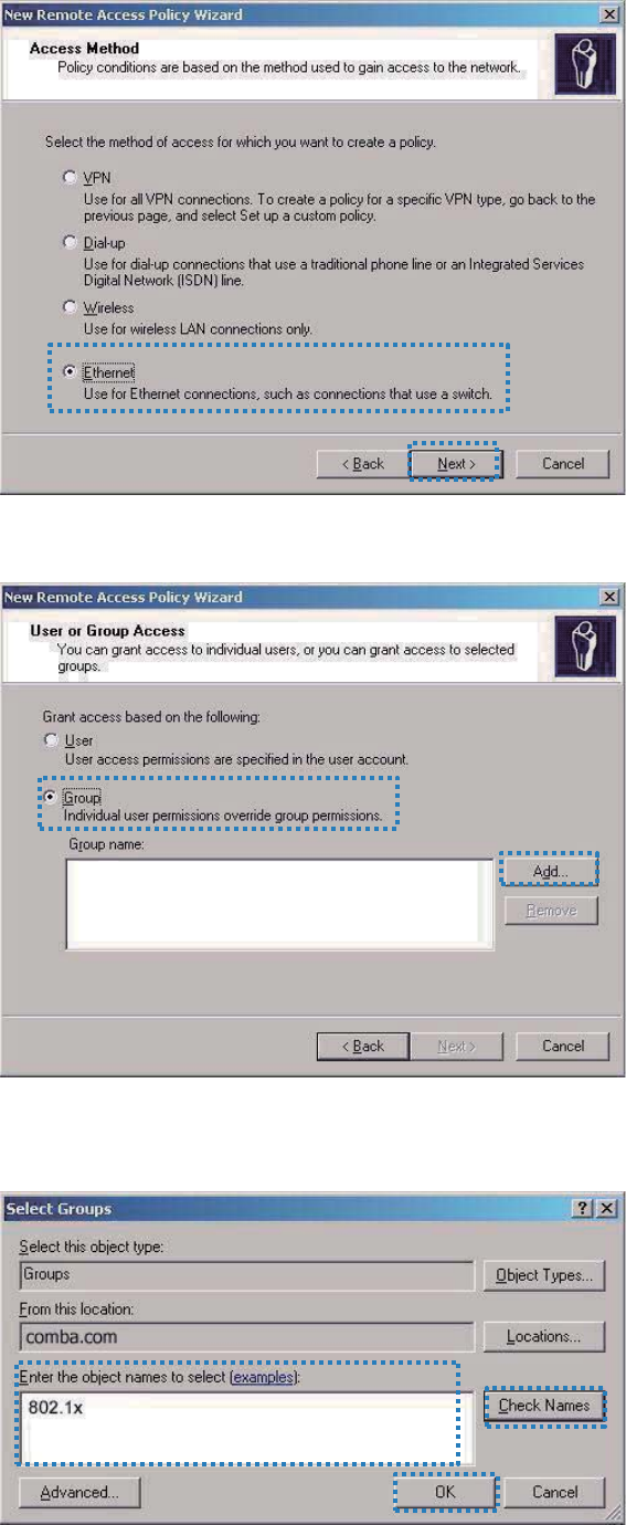
Select Ethernet and click Next.
Select Group and click Add.
Enter 802.1x in the Enter the object names to select text box, click Check Names, and click
OK.
38
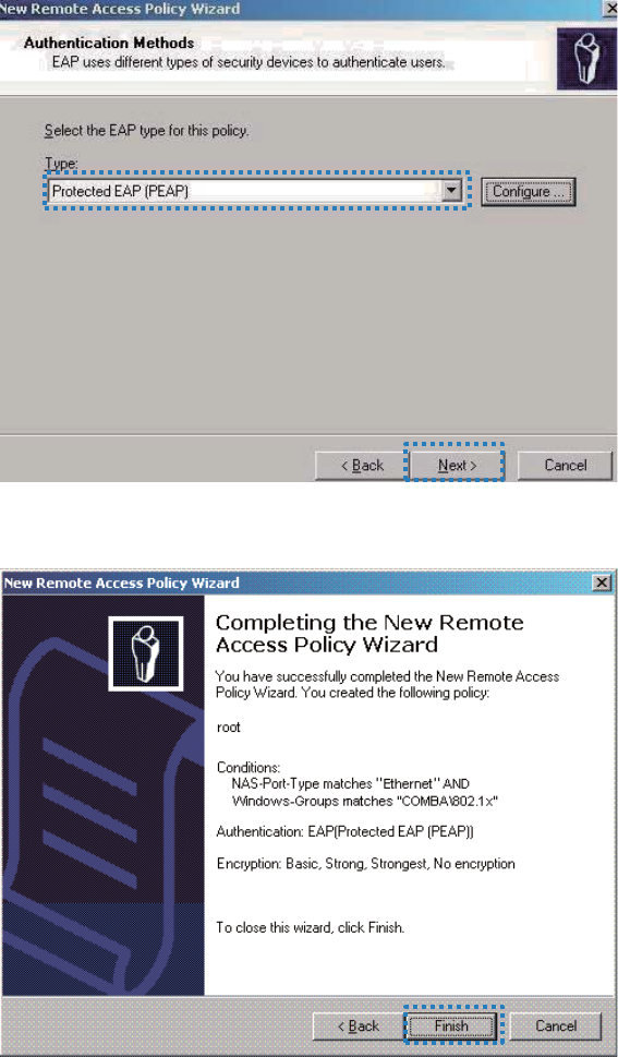
Select Protected EAP (PEAP) and click Next.
Click Finish. The remote access policy is created.
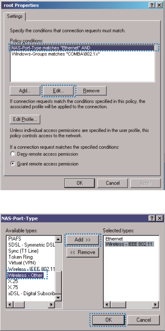
Right-click root and choose Properties. Select Grant remote access permission, select
NAS-Port-Type matches "Ethernet" AND, and click Edit.
39
Select Wireless –Other, click Add, and click OK.
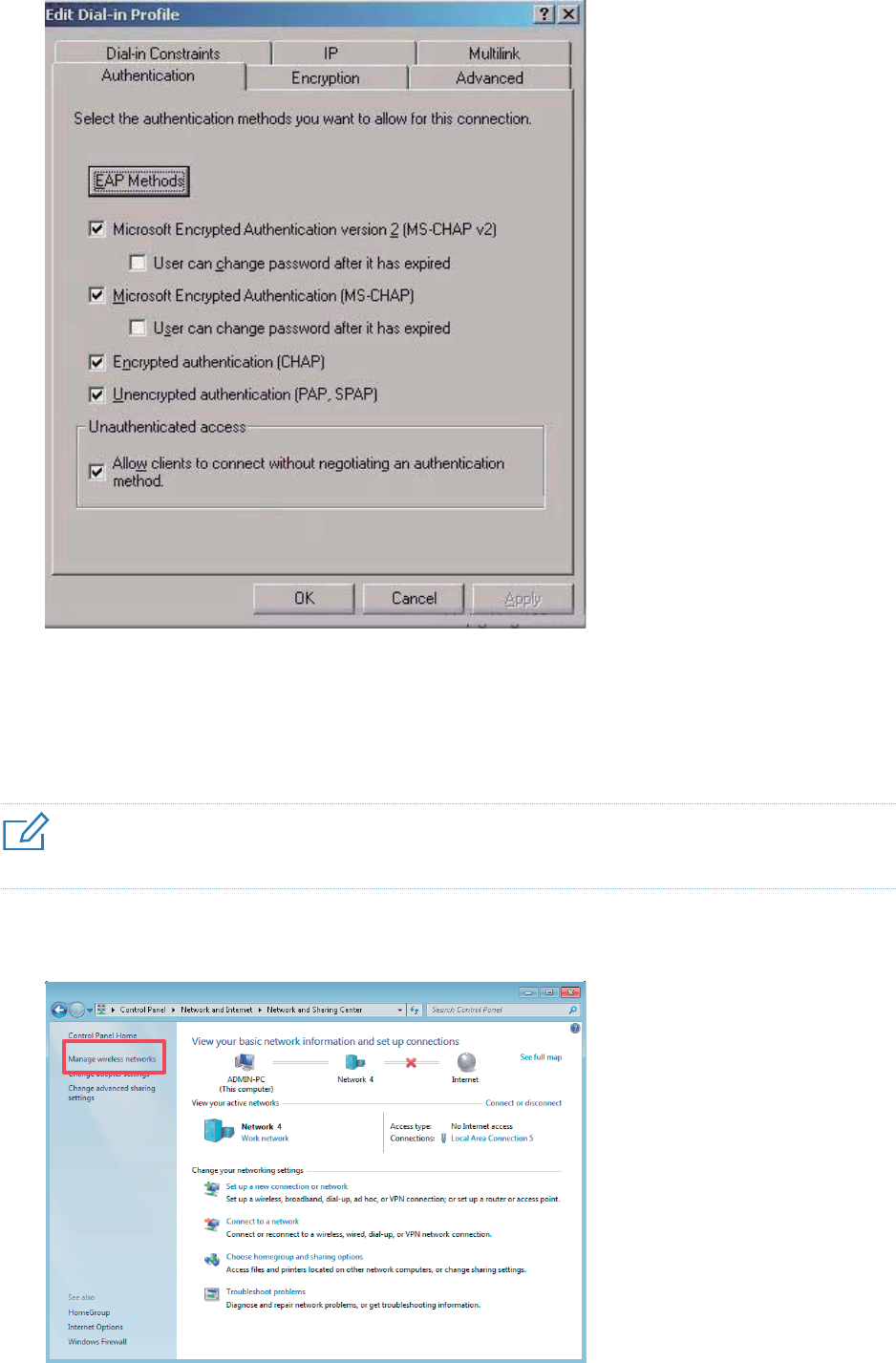
Click Edit Profile, click the Authentication tab, configure settings as shown in the following
figure, and click OK.
40
When a message appears, click No.
(3) Configure user information.
Create a user and add the user to group 802.1x.
3. Configure your wireless device.
4UZK
Windows 7 is taken as an example to describe the procedure.
(1) Choose Start > Control Panel, click Network and Internet, click Network and Sharing
Center, and click Manage wireless networks.
41
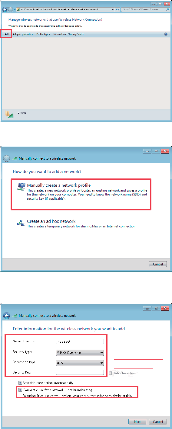
(2) Click Add.
(3) Click Manually create a network profile.
(4) Enter wireless network information, select Connect even if the network is not
broadcasting, and click Next.
9GSK GY ZNK
YKI[XOZ_ SUJK
UL ZNK 99/*
UL
ZNK'6
42
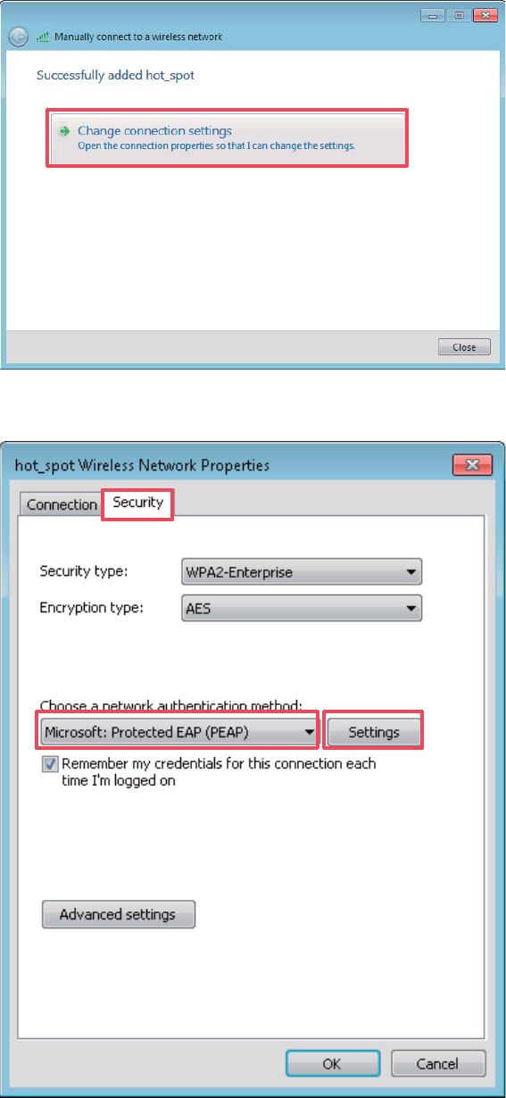
(5) Click Change connection settings.
(6) Click the Security tab, select Microsoft: Protected EAP (PEAP), and click Settings.
(7) Deselect Validate server certificate and click Configure.

43
(8) Deselect Automatically use my Windows logon name and password (and domain if
any) and click OK.
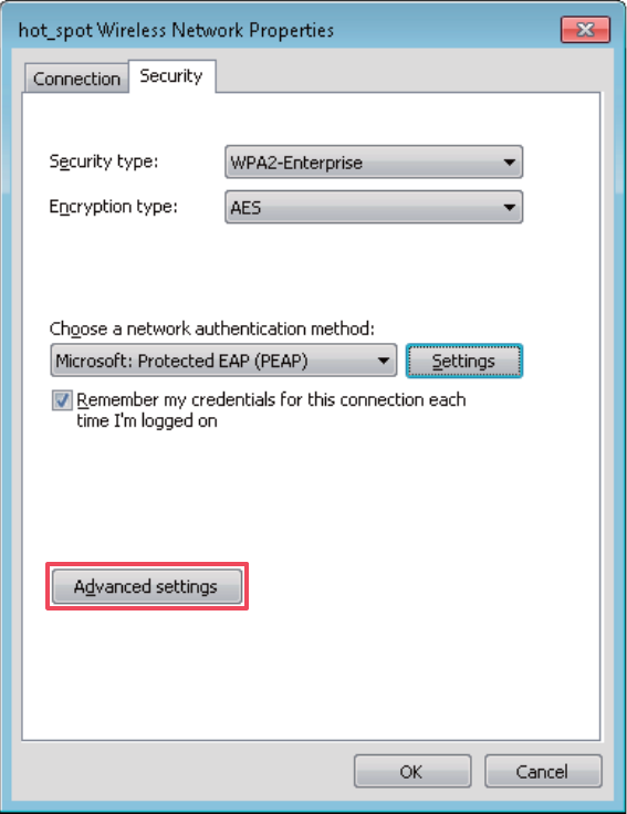
(9) Return to the Security tab page and click Advanced settings.
44
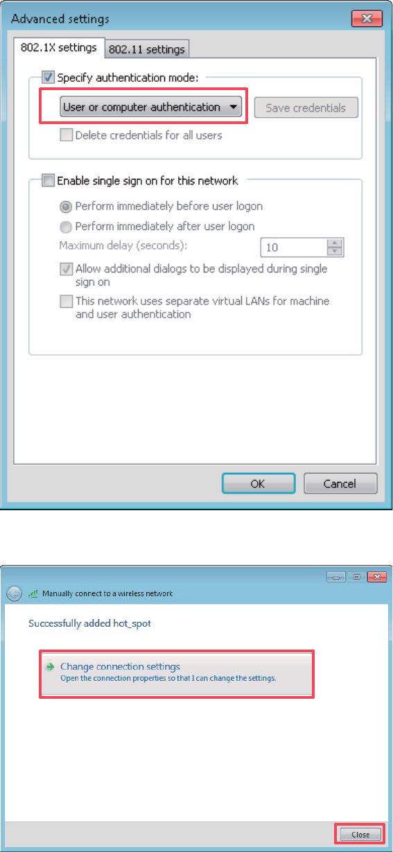
(10) Select User or computer authentication and click OK.
45
(11) Click Close.
46
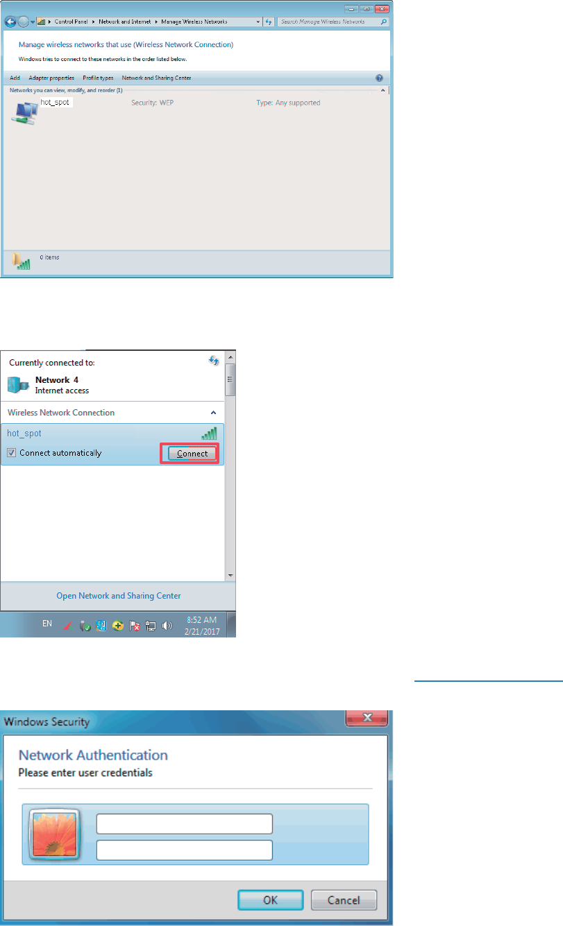
(12) Click the network icon in the lower-right corner of the desktop and choose the wireless
network of the AP, such as hot_spot in this example.
(13) In the Windows Security dialog box that appears, enter the user name and password set on
the RADIUS server and click OK.
---End
Verification
47
Wireless devices can connect to the wireless network hot_spot.
Radio
Overview
The Radio module is used to set RF parameters of the AP. This section describes some functions of
the module.
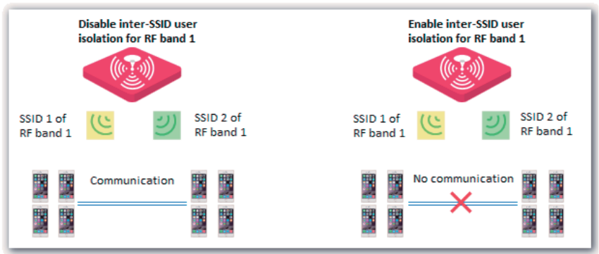
Inter-SSID User Isolation
This function isolates the wireless clients connected to different wireless networks corresponding to
the same RF band. For example, if user 1 connects to the wireless network corresponding to SSID1
of RF band 1, whereas user 2 connects to the wireless network corresponding to SSID2 of RF band
1, the two users cannot communicate with each other after inter-SSID user isolation is implemented
for RF band 1.
Client Load Balancing
If an AP uses two or more identical RF bands, wireless clients may not be evenly connected to the
RF bands, resulting in traffic imbalance between the RF bands. Client load balancing appropriately
achieve balance between the RF bands to effectively optimize network resource usage.
When the number of users connected to an RF band of the AP reaches the threshold specified by
Client Load Balancing Threshold, client load balancing is performed.
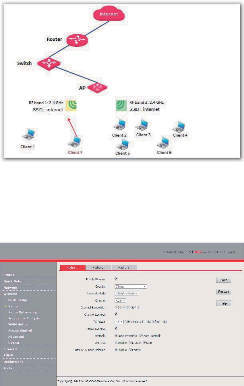
The following figure provides an example. RF band 1 and 3 of the AP are 2.4 GHz bands. Client 1
connects to RF band 1, whereas clients 2 to 6 connect to RF band 2. If client load balancing is
enabled, the client load balancing threshold is 5, and the client load balancing offset is 4, when client
7 sends a connection request to RF band 2, client 7 is connected to RF band 1 because the
threshold and offset of RF band 2 has been reached.
48
Changing the RF Settings
1. Choose Wireless > Radio.
2. Select the RF band to be configured.
3. Change the parameters as required. Generally, you only need to change the Enable Wireless,
Channel, and TX Power settings.
4. Click Save.
---End
Parameter description
Note:
Client load balancing is applicable only
when the AP has multiple identical RF
bands that have the same SSID and
security mode
settings (including the
security mode, cipher type, and key
settings).

49
Parameter
Description
Enable Wireless
It specifies whether to enable the wireless function corresponding to the selected RF band
of the AP.
C
ountry
It specifies the country or region where the AP is used. This parameter helps comply with
channel regulations of the country or region.
Network Mode
It specifies the wireless network mode of the
AP. The
available options for a 2.4 GHz RF
band inclu
de 11b, 11g, 11b/g, and 11b/g/n
. The available options for a 5 GHz RF band
include
11a, 11ac, and 11a/n.
− 11b
: The RF band works in 802.11b mode and only wireless devices compliant with
802.11b can connect to the wireless network corresponding to the RF ban
d of the
AP.
− 11g
: The RF band works in 802.11g mode and only wireless devices compliant with
802.11g can connect to the wireless networks corresponding to the RF band of the
AP.
− 11b/g
: The RF band works in 802.11b/g mode and only wireless devices compliant
with 802.11b or 802.11g can connect to the wireless network corresponding to the
RF band of the AP.
− 11b/g/n: The RF band works in 802.11b/g/n mode and only wireless devices
compliant with 802.11b, 802.11g, or 802.11n can connect to the wireless network
corresponding to the RF band of the AP.
− 11a
: The RF band works in 802.11a mode and only wireless devices compliant with
802.11a can connect to the wireless networks corresponding to the RF band of the
AP.
− 11ac: The RF band works in 802.11ac mode and only wir
eless devices compliant
with 802.11ac can connect to the wireless networks corresponding to the RF band
of the AP.
− 11a/n
: The RF band works in 802.11a/n mode and only wireless devices working at
5 GHz and compliant with 802.11a or 802.11n can connect to th
e wireless networks
corresponding to the RF band of the AP.
Channel
It specifies the operating channel of the selected RF band.
Auto: It indicates that the AP automatically adjusts its operating channel according to the
ambient environment.
Channel Bandwidth
It specifies the channel bandwidth of the selected RF band.
− 20MHz: It indicates that the only 20MHz channel bandwidth is available.
− 40MHz
: It indicates that the 40MHz channel bandwidth is used first, and changes to
20HMz channel bandwidth if severe channel competition occurs in the ambient
environment.
− 20/40MHz: It indicates that the AP automatically adjusts
its channel bandwidth to 20
MHz or 40 MHz according to the ambient environment.
− 80MHz: It indicates that the AP automatically adjusts its channel
bandwidth to 20
MHz, 40 MHz, or 80 MHz according to the ambient environment.
Extension Channel
It specifies an additional channel used to increase the channel bandwidth if the channel
bandwidth is 40 MHz or 20/40 MHz.
Channel Lockout
It is used to lock t
he channel settings of the selected RF band. After
a channel is locked,
parameters of the channel cannot be changed, including
Country, Network Mode,
Channel
, Channel Bandwidth, and Expansion Channel.
TX Power
It specifies the transmit power of the select
ed RF band.
A greater transmit power offers broader network
coverage. You can slightly reduce the
transmit power to improve the wireless network performance and security.

50
Parameter
Description
Power Lockout
It specifies whether the current transmit power settings of the selected RF band can be
changed. If it is selected, the settings cannot be changed.
Preamble
It specifies whether to use long preamble or short preamble. A preamble is a group of bits
located at the beginning of a packet to enable a receiver of the packet to p
erform
synchronization and prepare for receiving data.
By default, the
Long Preamble option is selected for compatibility with old network
adapters installed on wireless
clients. To
achieve better synchronization performance of
networks, you can select the
Short Preamble option.
Short GI
It indicates the short guard interval for preventing data block interference. Propagation
delays may occur on the receiver side due to factors such as multipath wireless signal
transmission. If a data block is transmitted at an overly high speed, it may interfere with the
previous data block. The short GI helps prevent such
interference. Enabling
the short GI
can yield a 10% improvement in data throughput.
− Disable: The short GI function is disabled.
− Enable: The short GI function is enabled.
− Auto: The short GI function is enabled or disabled depending on the actual
environment.
Inter
-SSID User
Isolation
It specifies whether to isolate the wireless clients connected to the selected RF band of the
AP with different SSIDs.
− Disable: It indicates that the wireless clients connected to the AP with different
SSIDs can communicate with each other.
− Enable
: It indicates that the wireless clients connected to the AP with different SSID
cannot communicate with each other. This improves wireless network security.
Client Load
Balancing
If RF band 3 is 2.4 GHz, the 2.4 GHz RF bands (RF bands 1 and 3) of the AP support this
function. If RF band 3 is 5 GHz, the 5 GHz RF bands (RF bands 2 and 3) of the AP support
this function.
− Enable: User-based client load balancing is enabled.
− Disable: User-based client load balancing is disabled.
4UZK
Client load balancing requires multiple identical RF bands with identical SSIDs.
Client Load
Balancing Threshold
It is required only after
Client Load Balancing is set to Enable.
It specifies a threshold for triggering client load balancing. When the number of users
connected to the identical RF bands reaches this threshold, client load balancing is
performed.
Client Load
Balancing Offset
It is required only aft
er Client Load Balancing is set to Enable. It
specifies an offset for the
following:
− If RF band 3 is 2.4 GHz, when the number of users connected to RF band 3 is
greater than the number of users connected to RF band 1 by this offset, new users
are connected to RF band 1 with priority.
−
If RF band 3 is 5 GHz, when the number of users connected to RF band 3 is greater
than the number of users connected to RF band 2 by this offset, new users are
connected to RF band 2 with priority.
51
Radio Optimizing
Overview
Wireless Network Application Scenario
Generally, wireless networks application scenarios include those with a common user density and
those with a high user density..
Application scenario with a common user density
In an office, public building, school, warehouse, or hospital, the wireless network must provide
coverage to many users in a large area.
Application scenario with a high AP density
In a large crowded area with many wireless clients, many APs are deployed to provide coverage
(AP/225~500 M2). The common application scenarios with a high AP density include:
− Conference hall, theatre, exhibition hall, and dining hall
− Indoor/outdoor stadium
− College classroom
− Airport and railway station
Performance Optimization Parameters
To cater to different requirements for wireless connection in different application scenarios and help
customers set up optimum wireless services, IP-COM provides a series of performance optimization
parameters.
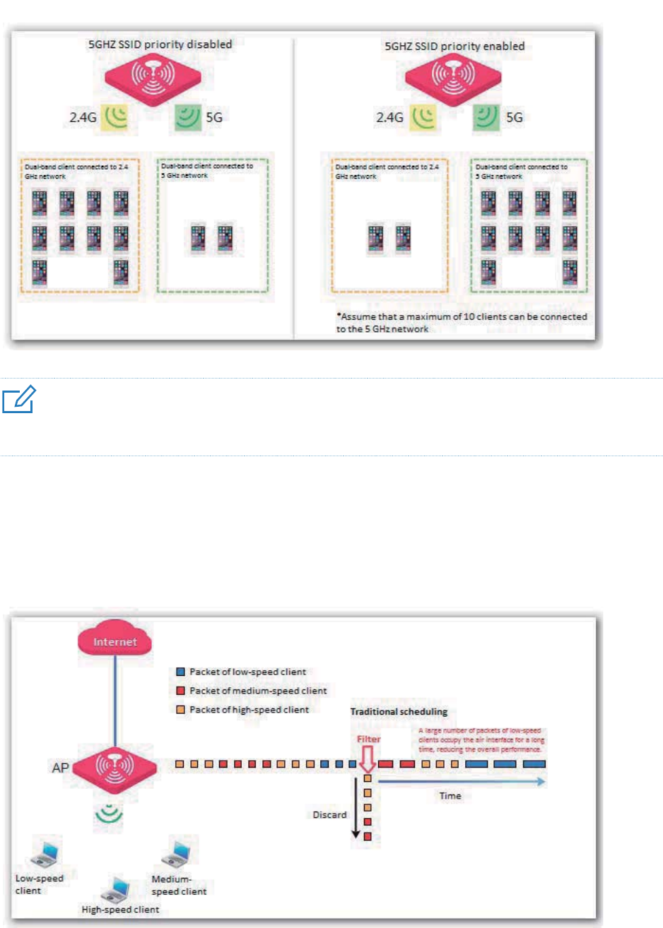
5GHZ SSID priority
The 2.4 GHz band is more widely used for wireless coverage than the 5 GHz band. However, the
2.4 GHz band offers only 3 non-overlapping channels. Therefore, the channels are busy, resulting in
great wireless signal interference. Actually, the 5 GHz band can offer more non-overlapping
channels. In China, it offers 9 channels. In Some other countries, it offers more than 20 channels.
An increasing number of users are using wireless clients that work at the 2.4 GHz and 5 GHz bands
at the same time as wireless network development continues. However, a dual-band client often
connects to the 2.4 GHz network by default, increasing the imbalance between the 2.4 GHz network
and 5 GHz network.
The 5GHZ SSID priority feature makes a dual-band client to connect to the 5 GHz network first to
reduce the workload and interference at the 2.4 GHz band for better user experience.
52
4UZK
The 5GHZ SSID priority feature is applicable only after both the 2.4 GHz and 5 GHz bands of the AP are enabled and
assigned the same SSID, security mode, and password.
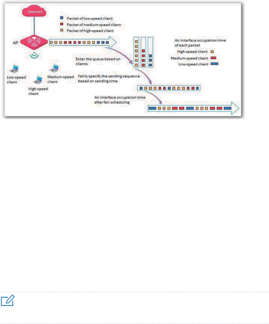
Airtime Scheduling
Traditional packet distribution is performed in FIFO mode. In an environment that involves various
wireless data rates, high-speed clients has high transmission capability and high frequency use
efficiency but has less time to access the air interface. On the contrary, low-speed clients has low
transmission capability and low frequency use efficiency but has more time to access the air
interface. This reduces the overall throughput of each AP, resulting in lower system efficiency.
Air interface scheduling assigns the same length of time for high-speed clients and low-speed
clients to access the air interface, enabling the high-speed clients to transmit more data. This
increases the overall throughput and number of connected users of an AP.
53
Signal Transmission
In a scenario with a common AP density, an AP must cover a large area. Therefore, the major WLAN
constraint is transmission loss. In a scenario with a high AP density, many users and clients gather
in a large area. Many APs must be deployed and they are within the visual distance of most users. In
this scenario, the major WLAN constraint is inter-AP interference.
The signal transmission capability can be adjusted together with the transmit power based on
scenarios to effectively ease the WLAN constraints. Select Coverage-oriented for a scenario with a
common AP density, and select Capacity-oriented for a scenario with a high AP density.
Signal Reception
In a scenario with a common AP density, a small number of APs are deployed and successful AP
connection by clients must be ensured. In a scenario with a high AP density, a large number of APs
are deployed and connection by clients to AP with stronger signals must be ensured.
You can configure signal reception based on the application scenario to adjust the receive signal
strength range acceptable to the AP.
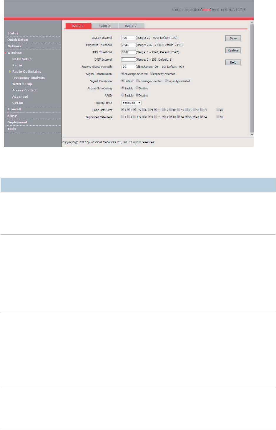
Optimizing RF Bands
4UZK
It is recommended that you change the settings only under the instruction of professional personnel, so as to prevent
decreasing the wireless performance of the router.
1. Choose Wireless > Radio Optimizing.
2. Select the RF band to be configured.
3. Change the parameter settings as required.
4. Click Save.
54
---End
Parameter description
Parameter
Description
Beacon Interval
It specifies the interval for transmitting the Beacon frame. The value range is 20 to 999. The unit
is millisecond.
The Beacon frame is transmitted at the specified interval to announce the presence of a wireless
network. Generally
, a smaller interval enables wireless clients to connect to the AP more
quickly, while a larger interval ensures
higher data transmission efficiency.
Fragment
Threshold
It specifies the threshold of a
fragment. The value range is 256 to 2346. The unit is byte.
Fragmenting is a process that divides a frame into several fragments, which are transmitted and
acknowledg
ed separately. If
the size of a frame exceeds this threshold, the frame is fragmented.
In case of a high error rate, you can reduce the threshold to enable the AP to resend only the
fragments that have not been sent successfully, so as to increase the fram
e throughput.
In an environment without interference, you can increase the threshold to reduce the number of
acknowledgement times, so as to increase the frame throughput.
RTS Threshold
It specifies the frame length threshold for triggering the RTS/CTS me
chanism.
If a frame exceeds this threshold, the RTS/CTS mechanism is triggered to reduce
conflicts.
The
value range is 1 to 2347. The unit is byte.
Set the RTS threshold based on the actual situation. An excessively small value increases the
RTS frame tran
smission frequency and bandwidth requirement. A higher RTS frame
transmission frequency enables a wireless network to recover from conflicts
quicker. For a
wireless network with high user density, you can reduce this threshold for reducing conflicts.
The RTS mechanism requires some network bandwidth. Therefore, it is triggered only when
frames exceed this threshold.
DTIM Interval
It specifies the interval for transmitting the Delivery Traffic Indication Message (DTIM) frame.
The value range is 1 to 255. T
he unit is Beacon.
A countdown starts from this value. The AP transmits broadcast and multicast frames in its
cache only when the countdown reaches zero.
For example, if DTIM Interval is set to 1, the AP transmits all cached frames at the Beacon

55
Parameter
Description
interval.
Receive Signal
Strength
It specifies the minimum strength of received signals acceptable to the AP. If the strength of the
signals transmitted by a wireless device is weaker than this threshold, the wireless device
cannot connect to the AP.
If there are multiple APs, an appropriate value of this parameter ensures that wireless clients
connect to the APs with strong signals.
5GHZ SSID
Priority
It specifies whether the AP makes a dual
-band client to connect to the 5 GHz network first.
− Enable: The AP makes a dual-band client to connect to the 5 GHz network first.
− Disable: The AP allows a dual-
band client to randomly connect to the 2.4 GHz or 5 GHz
network.
Signal
Transmission
It specifies the signal transmission mode for a specific scenario.
− Coverage-oriented
: This mode enables the AP to provide broader coverage when the
AP is deployed in an area with low AP density, such as an office, a warehouse, or a
hospital.
− Capacity-oriented: This mode reduces inter-
AP interference when the AP is deployed in
an area with high AP density, such as a venue, an exhibition hall, a banquet hall, a
stadium, a college classroom, or a departure lounge.
4UZK
This feature is available only to the 2.4 GHz band.
Signal
Reception
It specifies the signal reception mode for a specific sce
nario.
− Coverage-oriented
: This mode enables more wireless devices to connect to the AP in
an area with low AP density.
− Capacity-oriented
: This mode ensures that each wireless device in an area with high
AP density connects to the AP with the strongest signal.
− Default
: This mode enables the AP to achieve a balance between the other two modes.
4UZK
This feature is available only to the 2.4 GHz band.
Airtime
Scheduling
It specifies whether to enable the air interface scheduling function of the AP.
After it is ena
bled, clients with different data rates are assigned the same length of time to
access the air interface. This offers better user
experience to high-speed clients.
APSD
It specifies whether to enable the Automatic Power Save Delivery (APSD)
function. It helps
reduce power consumption of the
default, it is disabled.
Aging Time
It specifies the wireless client disconnection interval of the AP. The AP disconnects from a
wireless client if no traffic is transmitted or received by the wireless client within the interval. If
the wireless client starts transmitting or receiving traffic within the interval, the countdown is
reset.
Basic Rate Sets
It specifies the data rates that a wireless client must support if the wireless client must be
connected to the AP.
Supported Rate
Sets
It specifies the data rates that the AP supports and are optional to wireless clients.
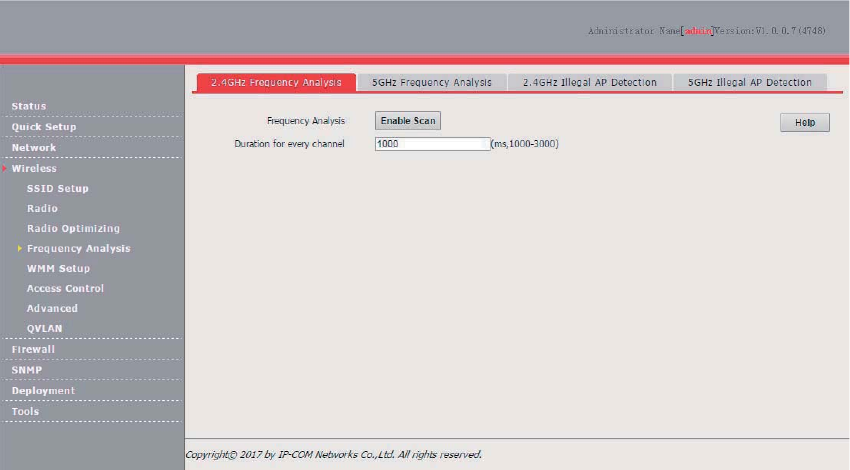
56
Frequency Analysis
Overview
The Frequency Analysis module provides the frequency analysis and rogue AP detection functions.
Frequency Analysis
This function enables you to view the noise and usage of each channel, so that you can select a
rarely used channel as the operating channel of the AP for better wireless transmission efficiency.
Rogue AP detection
This function enables you to detect the wireless signals near the AP, including information about
SSID, MAC address, channel, and signal strength.
Analyzing Frequencies
1. Choose Wireless > Frequency Analysis.
2. Click the 2.4GHz Frequency Analysis or 5GHz Frequency Analysis tab.
3. Click Enable Scan.
---End
The following figure shows a result example.
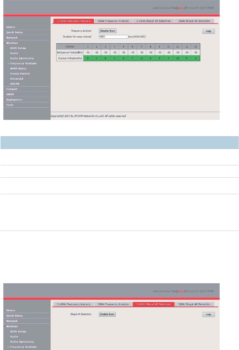
57
Parameter description
Parameter
Description
Duration for
every channel
It specifies the duration for scanning each
channel. The default duration is 1000 ms.
Channel
It specifies all the channels correspondin
g to the selected RF band.
Background
Noise
(dBm)
It specifies the background noise of a specific channel. The unit is dBm.
Channel
Utilization (%)
It specifies the use rate of a specific channel.
A channel use rate from 0%~50% is displayed in green, which indicates that the channel is idle.
A channel use rate from 50%~80% is displayed in yellow, which indicates that the channel is
busy. A channel use rate from 80%~100% is displayed in red, which indicates that the channel
is very busy.
Detecting Rogue APs
1. Choose Wireless > Frequency Analysis.
2. Click the 2.4GHz Illegal AP Detection or 5GHz Illegal AP Detection tab.
3. Click Enable Scan.
---End
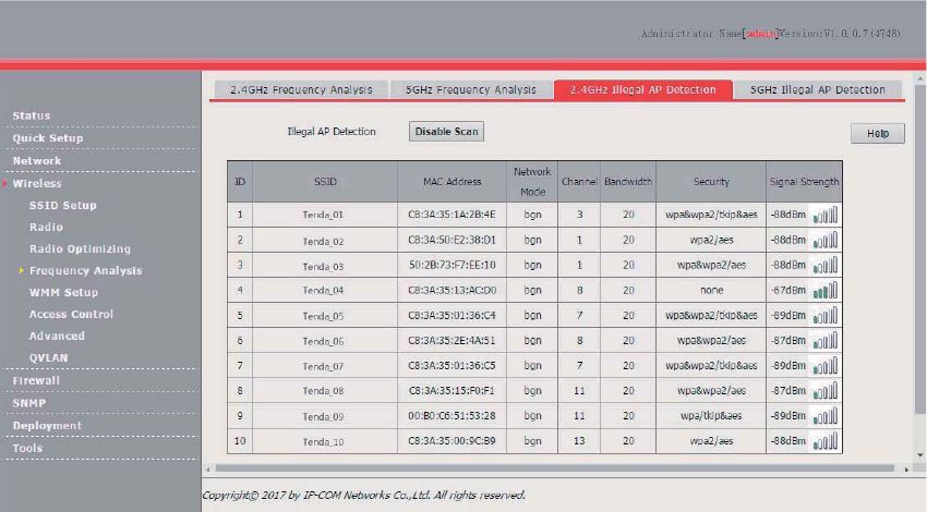
58
The following figure shows a result example.
WMM Setup
Overview
802.11 networks offer wireless access services based on the Carrier Sense Multiple Access with
Collision Avoidance (CSMA/CA) channel competition mechanism, which allows all wireless clients to
fairly compete for channels. All the services implemented over wireless networks share the same
channel competition parameters. Nevertheless, different services usually have different
requirements for bandwidth, delay, and jitter. This requires wireless networks to offer accessibility
based on the services implemented over the networks.
WMM is a wireless QoS protocol used to ensure that packets with high priorities are transmitted first.
This ensures better voice and video service experience over wireless networks.
WMM involves the following terms:
Enhanced Distributed Channel Access (EDCA): It is a channel competition mechanism to ensure
that packets with higher priorities are assigned more bandwidth and transmitted earlier.
Access Category (AC): AC: The WMM mechanism divides WLAN traffic by priority in descending
order into the AC-VO (voice stream), AC-VI (video stream), AC-BE (best effort), and AC-BK
(background) access categories. The access categories use queues with different priorities to
send packets. The WMM mechanism ensures that packets in queues with higher priorities have
more opportunities to access channels.
According to the 802.11 protocol family, all devices listen on a channel before using the channel to
send data. If the channel stays idle for or longer than a specified period, the devices wait a random
backoff period within the contention window. The device whose backoff period expires first can use
the channel. The 802.11 protocol family applies the same backoff period and contention window to
all devices across a network to ensure that the devices have the same channel contention
opportunity.
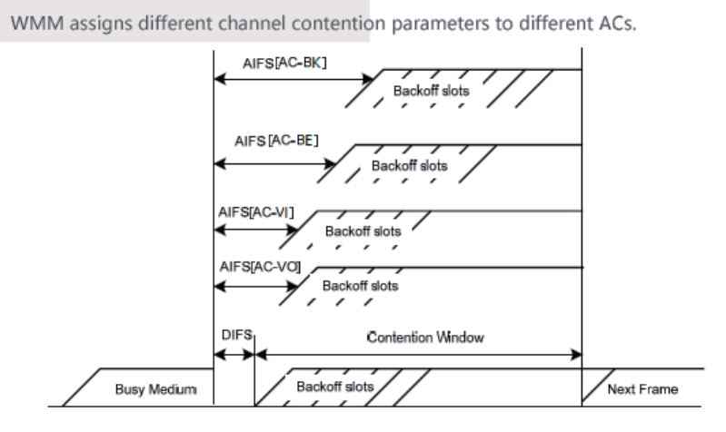
59
EDCA Parameters
WMM changes the contention mechanism of 802.11 networks by dividing packets into four ACs,
among which the ACs with higher priorities have more opportunities to access channels. The ACs
help achieve different service levels.
WMM assigns each AC a set of EDCA parameters for channel contention, including:
Arbitration Inter Frame Spacing Number (AIFSN): Different from the fixed distributed inter-frame
spacing (DIFS) specified in the 802.11 protocol family, AIFSN varies across ACs. A greater
AIFSN indicates a longer backoff period. See AIFS in the following figure.
Contention window minimum (CWmin) and contention window maximum (CWmax) specify the
average backoff period. The period increases along with these two values. See the backoff slots
in the following figure.
Transmission Opportunity (TXOP): It specifies the maximum channel use duration after
successful channel contention. The duration increases along with this value. The value 0
indicates that a device can send only one packet through a channel after winning contention for
the channel.
ACK Policies
WMM specifies the Normal ACK and No ACK policies.
According to the No ACK policy, no ACK packet is used during wireless packet transmission to
acknowledge packet reception. This policy is applicable to scenarios where interference is mild
and can effectively improve transmission efficiency. In case of strong interference, lost packets
are not sent again if this policy is adopted. This leads a higher packet loss rate and reduces the
overall performance.
According to the Normal ACK policy, each time a receiver receives a packet, it sends back an
ACK packet to acknowledge packet reception.
Changing the WMM Settings
By default, the WMM function is disabled. To enable the function, perform the following procedure:
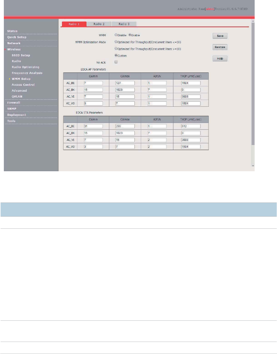
60
1. Choose Wireless > WMM Setup.
2. Select the RF band for which WMM is to be configured.
3. Set WMM to Enable.
4. Select the required WMM optimization mode.
5. If you select Custom, set the WMM parameters as required.
6. Click Save.
---End
Parameter description
Pa
rameter
Description
WMM
It specifies whether to enable the WMM function.
WMM Optimization
Mode
It allows you to select a WMM optimization mode or set WMM parameters.
AP375 provide
the WMM optimization modes. You can select a mode according to the
number
of users concurrently connected to the AP.
− Optimized For Throughput(Concurrent Users <=10): If 10 or less clients are
connected to the AP, you are recommended to select this mode to increase client
throughput.
− Optimized For Throughput(Concurrent Users >=10)
: If more than 10 clients are
connected to the AP, you are recommended to select this mode to ensure client
connectivity.
− Custom: This mode enables you to set the WMM EDCA parameters for manual
optimization.
No ACK
− If the check box is selected, the No ACK policy is adopted.
− If the check box is deselected, the Normal ACK policy is adopted.
EDCA Parameters
For details, refer to section 5.1.
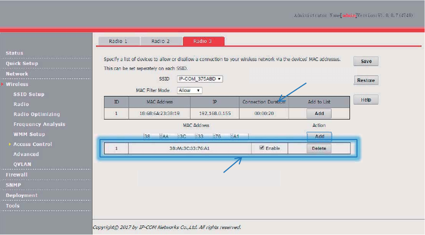
61
Access Control
Overview
It specifies, based on MAC address filter rules, the wireless devices that can or cannot access the
wireless networks of the AP. Devices that have been controlled cannot connect to the corresponding
wireless network.
The AP supports the following MAC address filter rules:
Disable: It indicates that access control is disabled. In this case, all wireless devices can access
the wireless networks of the AP.
Allow: It indicates that only the wireless devices with the specified MAC addresses can access
the wireless networks of the AP.
Deny: It indicates that only the wireless devices with the specified MAC addresses cannot
access the wireless networks of the AP.
Configuring Access Control
1. Choose Wireless > Access Control.
2. Click the tab of the RF band on which access control must be implemented.
3. From the SSID drop-down list box, select the SSID of the RF band on which access control must
be implemented.
4. Select an access control mode from the MAC Filter Mode drop-down list box.
5. If you select Allow or Deny, enter the MAC addresses to control in the control list and click Add.
6. If a wireless device to be controlled has been connected to the AP, you can click Add
corresponding to the device in the wireless client list to directly add it to the control list.
7. Click Save.
---End
Parameter description
=OXKRKYYIROKTZROYZ
=OXKRKYYGIIKYYIUTZXURROYZ
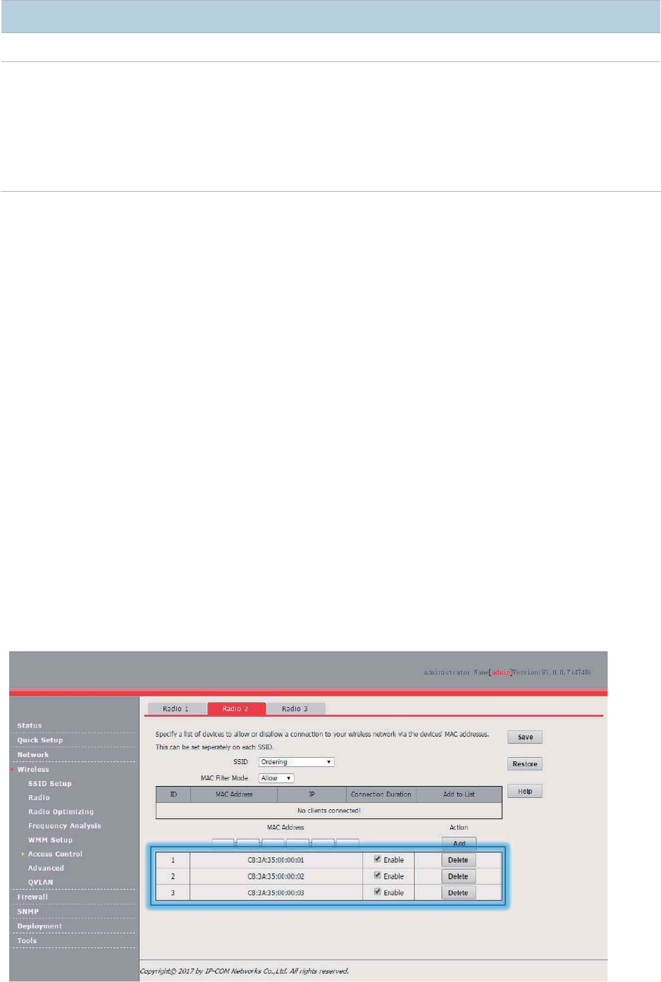
62
Parameter
Description
SSID
It specifies the SSID that re
quires wireless client access control.
MAC Filter Mode
It specifies the mode for filtering MAC addresses.
− Disable: It indicates that access control is disabled.
− Allow
: It indicates that only the wireless clients on the access control list can connect
to the AP with the selected SSID.
− Deny: It indicates that only the wireless clients on the access control list cannot
connect to the AP with the selected SSID.
Example of Configuring Access Control
Networking requirement
A hotel has set up wireless networks and designated the SSID Ordering corresponding to RF band
2 for placing orders. The AP must be configured to allow only ordering devices to connect to the
wireless network corresponding to the SSID.
You can use the access control function of the AP to address this requirement. Assume that there
are three ordering devices whose MAC addresses are C8:3A:35:00:00:01, C8:3A:35:00:00:02, and
C8:3A:35:00:00:03.
Configuration procedure
1. Choose Wireless > Access Control and click the Radio 2 tab.
2. Select Ordering from the SSID drop-down list box.
3. Select Allow from the MAC Filter Mode drop-down list box.
4. Enter C8:3A:35:00:00:01 in the MAC Address text box and click Add. Repeat this step to add
C8:3A:35:00:00:02 and C8:3A:35:00:00:03 as well.
5. Click Save.
---End
The following figure shows the configuration.
Verification
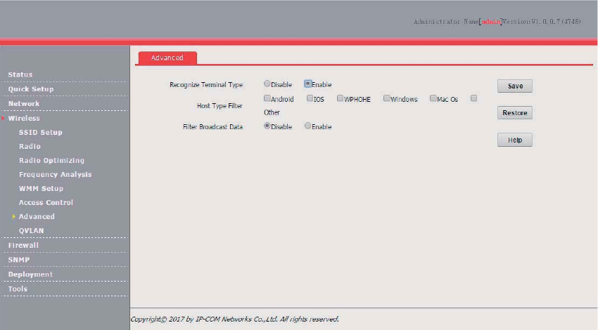
63
Verify that only the ordering devices can connect to the Ordering wireless network.
Advanced
Overview
This module enables you to identify and filter client types and to filter broadcast data.
Recognize Terminal Type
This function is used to identify the operating system types of wireless clients for efficient wireless
network management. The wireless client types that can be identified by the AP include: Android,
iOS, WPhone, Windows, MAC, and other.
Host Type Filter
This function enables you to filter wireless clients by type. A filtered client can connect to the
wireless network of the AP but cannot access the internet.
Filter Broadcast Data
By default, the AP forwards many invalid broadcast packets of the wired network, which may affect
forwarding of valid service data. This function enables you to filter broadcast packets to be
forwarded, so as to reduce air interface resource usage and ensure bandwidth for valid service data.
Configuring the Client Type Filter
1. Choose Wireless > Advanced.
2. Set Recognize Terminal Type to Enable.
3. Select the types of wireless clients not allowed to access the internet.
4. Click Save.
---End
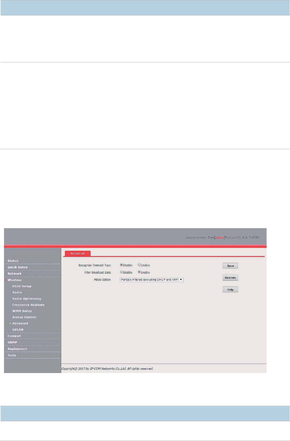
64
Parameter description
Parameter
Description
Recognize
Terminal Type
It specifies w
hether to identify client types.
− Enable: It indicates that client types are identified. After
enabling the function, you can go
to the Status > Wireless Clients
page to view the operating system types of the wireless
clients connected to the AP.
− Disable: It indicates that client types are not identified.
Host Type Filter
It specifies the types of wireless clients not allowed to access the internet.
− Android: It indicates the wireless clients running an Android operating system.
− IOS: It indicates the wireles
s clients running an iOS operation system, such as iPhone,
and iPad.
− WPHONE: It indicates the wireless clients running a WPhone operating system.
− Windows: It indicates the wireless clients running a Windows operating system.
− Mac Os: It indicates the wireless clients running a MAC operating system.
− Other: It indicates the wireless clients running an operating system other than the
preceding operating systems.
Configuring the Broadcast Data Filter
1. Choose Wireless > Advanced.
2. Set Filter Broadcast Data to Enable.
3. Select a broadcast data filter mode from the Mode Option drop-down list box.
4. Click Save.
---End
Parameter description
Parameter
Description
Filter Broadcast
Data
It specifies whether to filter broadcast data.
− Enable: It indicates that broadcast data is filtered to be forwarded, so as to reduce air
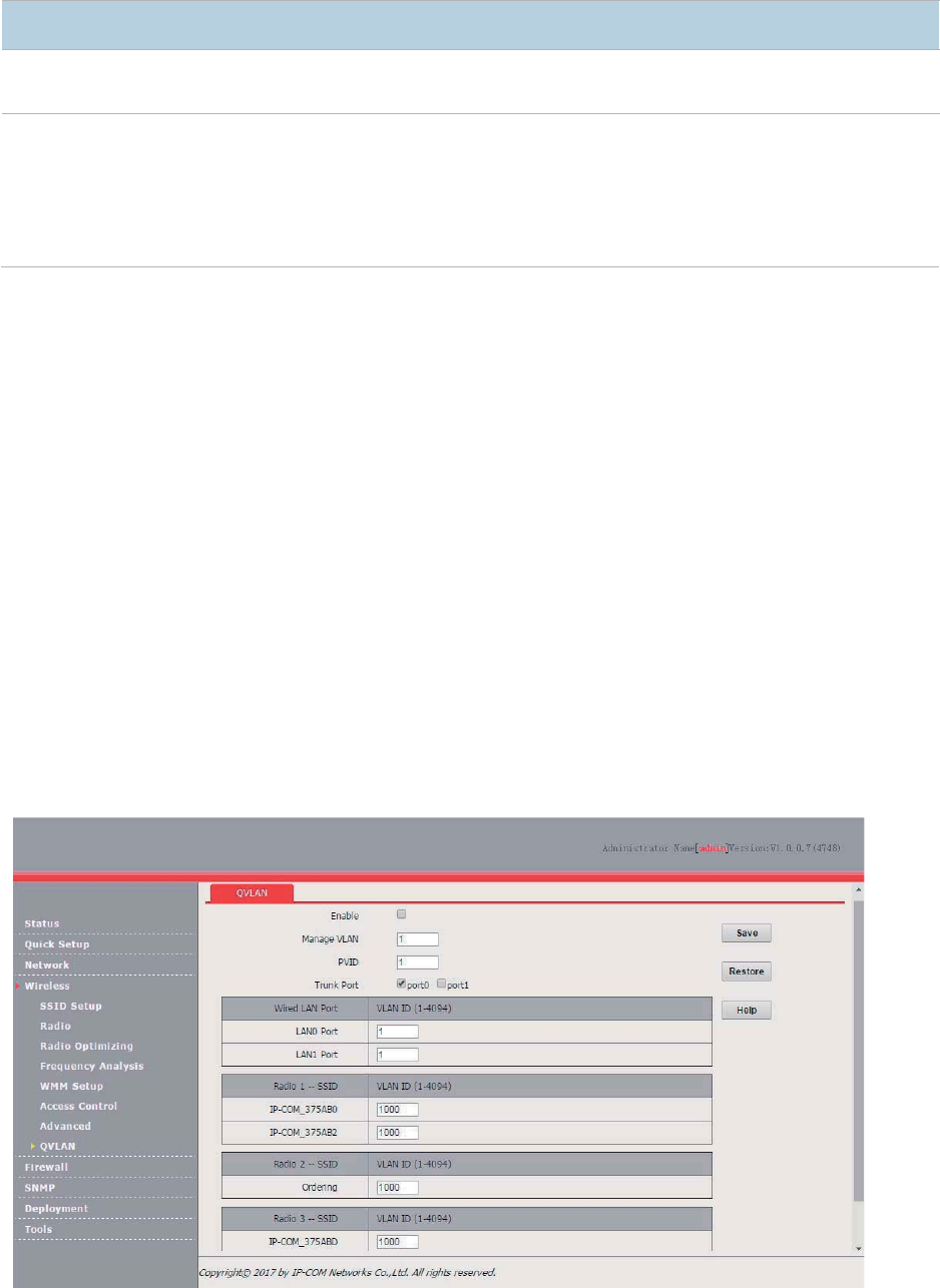
65
Parameter
Description
interface resource usage and ensure bandwidth for valid service data.
− Disable: It indicates that broadcast data is not filtered.
Option Mode
It is required if
Filter Broadcast Data is set to Enable.
− Partially Filtered (excluding DHCP and ARP): It indicates that all broadcast or
multicast data other than DHCP and ARP broadcast data is filtered.
− Partially Filtered (excluding ARP)
: It indicates that all broadcast or multicast data other
than ARP broadcast data is filtered.
QVLAN
Overview
The AP supports 802.1Q VLANs and is applicable in a network environment where 802.1Q VLANs
have been defined. By default, the QVLAN function is disabled.
Configuring the QVLAN Function
1. Choose Wireless > QVLAN.
2. Change the parameters as required. Generally, you only need to change the Enable option, the
VLAN IDs of wired LAN ports, and the SSID VLAN IDs of RF bands.
3. Click Save.
---End
Parameter description

66
Parameter
Description
Enable
It specifies whether to enable the QVLAN f
unction of the AP. By default, it is disabled.
Manage VLAN
It specifies the ID of the AP management VLAN. The default value is
1.
After changing the management VLAN, you can manage the AP only after connecting your
computer to the new management VLAN.
PV
ID
It specifies the ID of the default native VLAN of the trunk port of the AP. The default value is 1.
Trunk Port
It specifies the LAN port used as a trunk port of the AP. The default value is
port0.
Traffic of all
VLANs can pass through a trunk port.
4UZK
If
the QVLAN function is enabled, set at least one LAN port as a trunk port.
port0
corresponds to the LAN0 port and non-PoE port of the AP and port1
corresponds to the
LAN1 port and PoE port of the AP.
Wired LAN Port
It specifies the LAN ports of the AP, in
cluding LAN0 and LAN1.
4UZK
LAN0 Port
corresponds to the non-PoE port of the AP and LAN1
corresponds to the PoE port of
the AP.
VLAN ID
It specifies the VLAN ID corresponding to a wired LAN port used as an access port.
Radio 1 SSID
Radio 2 SSID
Radio 3 SSID
It specifies the currently enabled SSIDs corresponding to the RF bands of the AP.
VLAN ID
It specifies VLAN IDs corresponding to SSIDs. The default value is
1000
. The value range is 1 to
4094.
After the QVLAN function is enabled, the wireless ports corresponding to SSIDs functions as
access ports. The PVID and VLAN ID of an access port are the same.
If the QVLAN function is enabled, tagged data received by a port of the AP is forwarded to the port
corresponding to the VLAN ID in the data, whereas untagged data received by a port of the AP is
forwarded to the port corresponding to the PVID of the port that receives the data.
The following table describes how ports of different link types process transmitted and received
data.
Port
Method to Process Received
Data
Method to Process Transmitted Data
Tagged Data
Untagged Data
Access
Forward the data to other
ports of the VLAN
corresponding to the VID
in the data.
Forward the data to the
other ports of the VLAN
corresponding to the
PVID of the port that
recei
ves the data
Transmit data after removing tags from
the data.
Trunk
If the VLAN ID and PVID of a port are the
same, transmit data after removing tags
from the data.
If the VID and PVID of a port are
different, transmit data without removing
tags from th
e data.
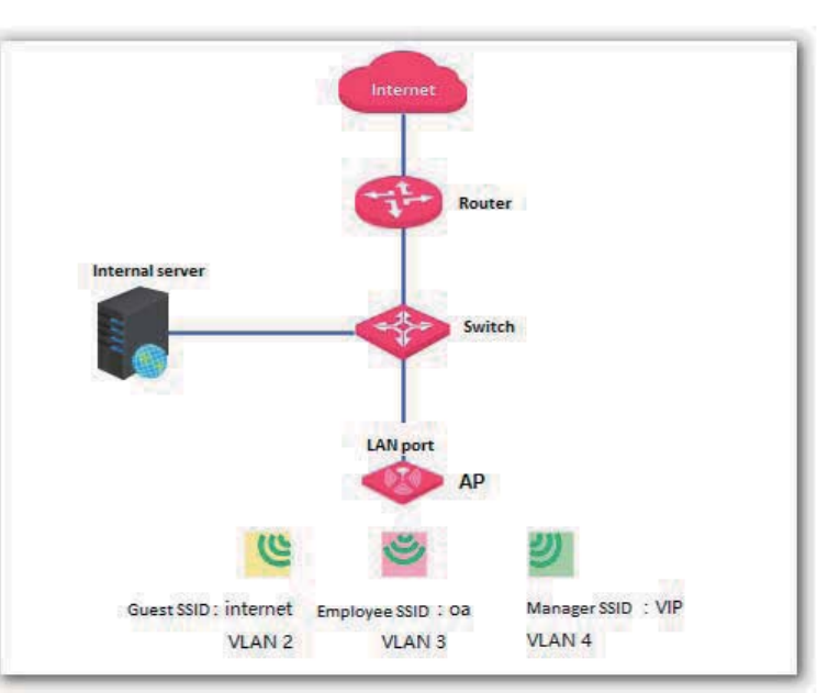
67
Example of Configuring QVLAN Settings
Networking Requirement
A hotel has the following wireless network coverage requirements:
Guests are connected to VLAN 2 and can access only the internet.
Employees are connected to VLAN 3 and can access only the LAN.
Hotel managers are connected to VLAN 4 and can access both the internet and LAN.
Assumption
Assume that RF band 1 is used, the SSID of the wireless network for guests is internet. the SSID of
the wireless network for employees is oa, and the SSID of the wireless network for managers is VIP.
Network Topology
Configuration Procedure
1. Configure the AP.
(1) Log in to the web UI of the AP and choose Wireless > QVLAN.
(2) Select the Enable check box.
(3) In the RF band 1 settings, change the VLAN ID of the SSID internet to 2, the VLAN ID of
the SSID oa to 3, and the VLAN ID of the SSID VIP to 4.
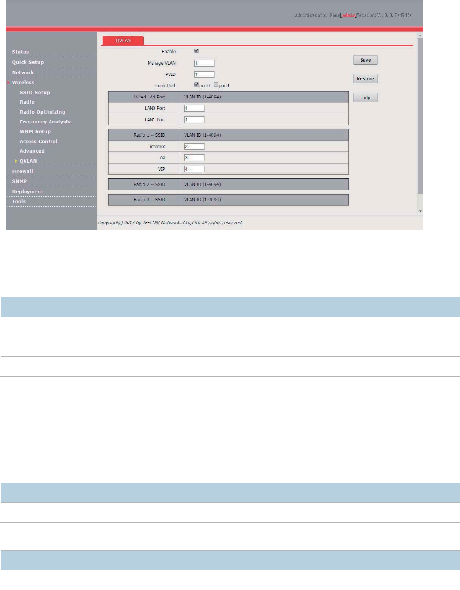
68
(4) Click Save.
Wait for the AP to reboot.
2. Configure the switch.
Create IEEE 802.1Q VLANs described in the following table on the switch.
Port Connected To
Accessible VLAN ID
P
ort Type
PVID
AP
1,
2, 3, and 4
Trunk
1
LAN server
3
and 4
Trunk
1
Router
2
and 4
Trunk
1
Retain the default settings of other ports. For details, refer to the user guide for the switch.
3. Configure the router and internal server.
To ensure that wireless clients connected to the AP can access the internet, the router and internal
server must support the QVLAN function and configured with QVLAN settings. The following
provides configuration details.
Router
Port Connected To
Accessible VLAN ID
Port Type
PVI
D
Switch
2
and 4
Trunk
1
Internal server
Port Connected To
Accessible VLAN ID
Port Type
PVID
Switch
3
and 4
Trunk
1
For details about how to configure a required device, refer to the user guide for the device.
Verification
Verify that wireless clients connected to the wireless network internet can access only the internet,
wireless clients connected to the wireless network oa can access only the LAN, and wireless clients
69
connected to the wireless network VIP can access both the internet and LAN.
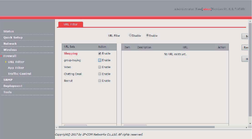
70
Firewall
URL Filter
Overview
This function enables you to disallow wireless users to access specified websites. By default, the AP
provides five website categories. You can define categories as required.
By default, URL filter function is disabled.
Configuring the URL Filter
1. Choose Firewall > URL Filter.
2. Set URL Filter to Enable.
3. Select the category of websites disallowed to be accessed.
4. Click Save.
---End
Parameter description
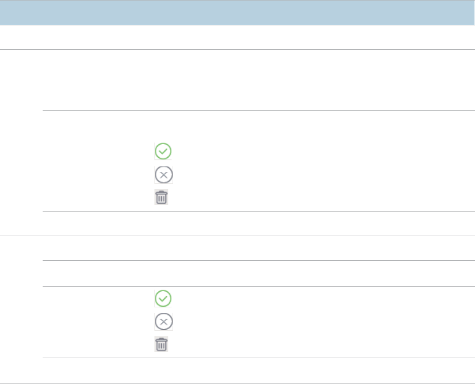
71
Parameter
Description
URL Filter
It specifies whether to enable the URL filter func
tion of the default, it is disabled.
URL
Sets
URL Sets
It specifies website
categories. When
you click a category, the URLs in the category
appear on the right.
By default, the Shopping, Group
-Buying, Video, Chatting Email, and Recruit
categories are prov
ided.
Action
Enable
indicates that wireless client cannot access the corresponding websites.
Disable
indicates that wireless client can access the corresponding websites.
− : It is used to save a new website category.
− : It is used to cancel creation of a website category.
− : It is used to delete a user-defined website category.
New URL Sets
It is used to create a website category.
Item
Description
It specifies the name of a website.
URL
It specifies the address of a website.
Action
− : It is used to save a new website entry.
− : It is used to cancel creation of a website entry.
− : It is used to delete a website entry.
New URL
It is used to create a website entry.
App Filter
Overview
The AP can filter mainstream apps.
After the app filter is enabled, wireless clients connected to the AP cannot use the services provided
by the filtered apps.
Configuring the App Filter
1. Choose Firewall > App Filter.
2. Set App Filter to Enable.
3. Select the apps disallowed to be used.
4. Click Save.
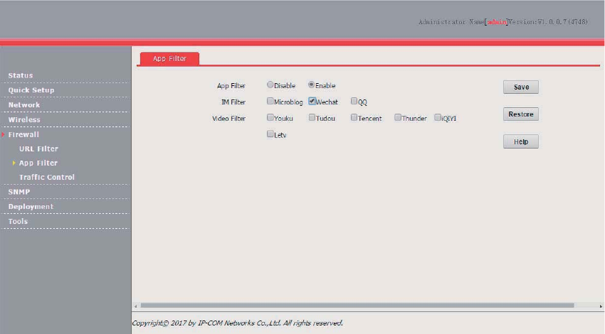
72
---End
Traffic Control
Overview
Bandwidth control mode enables the network administrator to control the users’ traffic so as to make
sure that the limited bandwidth resources can be distributed appropriately, improving the internet
utilization.
The AP can perform traffic control in the following modes:
Manual traffic control
You can manually set the maximum upload and download speeds by SSID and client to limit the
total bandwidth for SSIDs and evenly allocate bandwidth to clients. After multiple SSIDs are enabled,
this function prevents a low-priority network (such as the guest network) or user from using
excessive bandwidth, which significantly reduces the bandwidth available to other networks and
clients.
Automatic traffic control
You only need to specified the total AP bandwidth provided by your ISP and set the maximum
upload and download speeds by SSID. With the settings, the AP dynamically and evenly allocate
the total bandwidth to all the clients connected to the AP, and allocate the SSID-specific bandwidth
to all the clients connected with the SSID.
Configuring Traffic Control
By default, the traffic control function is disabled. To use the function, refer to the following
configuration procedures:
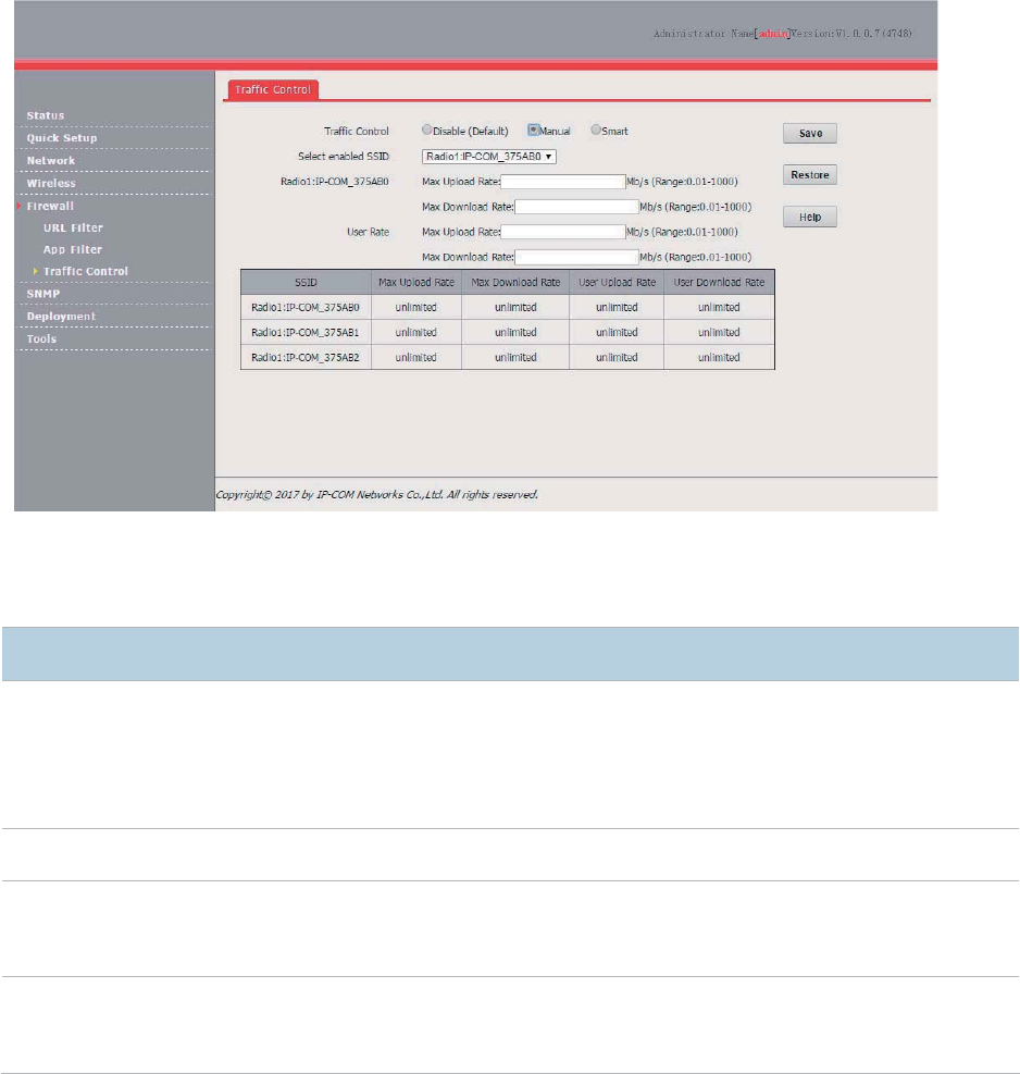
73
Configuring Manual Traffic Control
1. Choose Firewall > Traffic Control.
2. Set Traffic Control to Manual.
3. Select an enabled SSID from the Select enabled SSID drop-down list box for traffic control.
4. Set the SSID-specific maximum upload and download speeds in the Radio X:Selected SSID
text boxes.
5. Set the maximum upload and download speeds per user in the User Rate text boxes for the
SSID.
6. Click Save.
---End
Parameter description
Parameter
Description
Traffic Control
It specifies whether to enable traffic control.
− Disable (Default): It indicates that the traffic control function is disabled.
− Manual: It indicates that manual traffic control is implemented.
− Smart: It indicates that automatic traffic control is implemented.
Select enabled SSID
It specifies an enabled SSID
for which traffic control must be implemented.
Radio
x:SSID
It specifies the maximum upload and download speeds corresponding to the selected
SSID.
The
blank values indicate that the maximum upload and download speeds are
not limited.
User Rate
It specifies the maximum per
-
user upload and download speeds corresponding to the
selected
SSID. The blank values indicate that the maximum per-user upload and
download speeds are not limited.
Configuring Automatic Traffic Control
1. Choose Firewall > Traffic Control.
2. Set Traffic Control to Smart.
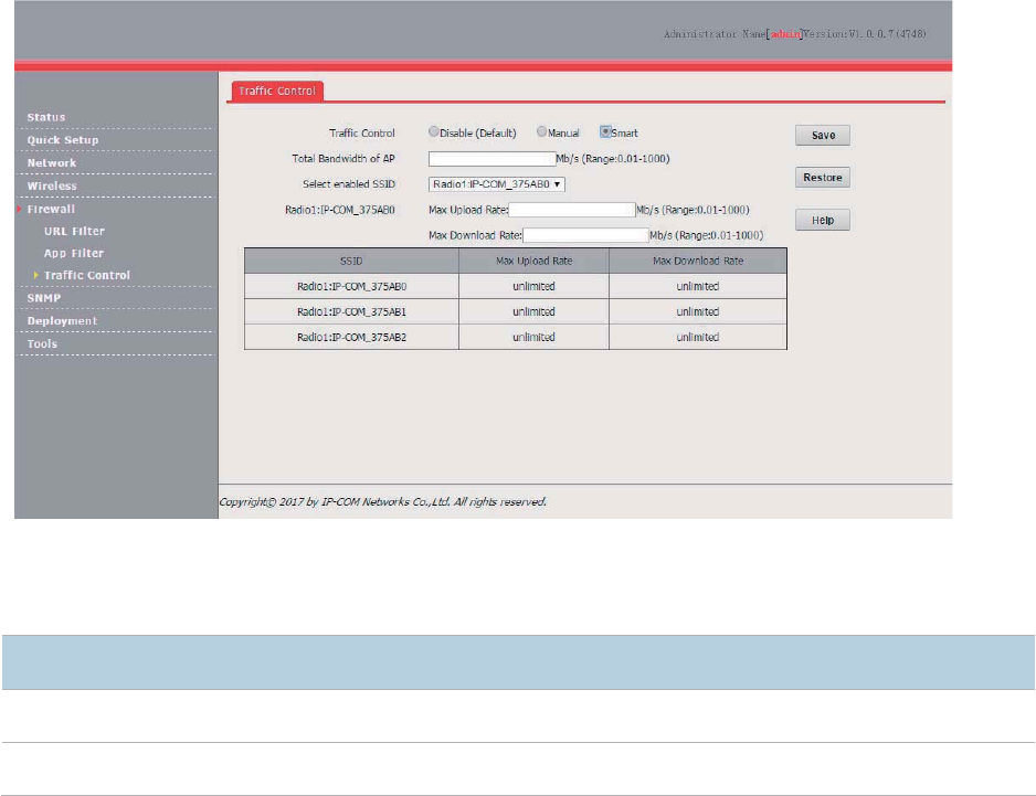
74
3. Set Total Bandwidth of AP to the total bandwidth provided by your ISP.
4. Select an enabled SSID from the Select enabled SSID drop-down list box for traffic control.
5. Set the SSID-specific maximum upload and download speeds in the Radio X:Selected SSID
text boxes.
6. Click Save.
---End
Parameter description
Parameter
Description
Total Bandwidth of AP
It specifies the total uplink bandwidth and downlink bandwidth provided by your ISP.
For details about the other parameters, refer to the preceding table.
Example of Configuring Traffic Control
Networking Requirement
A mall has a 100 Mbps optical internet connection. It requires 10 APs for wireless coverage. Each
AP is configured with 2 SSIDs. One of the SSID is used for the owner network and named VIP, and
the other SSID is used for the guest network and named Mall.
Each AP has a bandwidth of 10 Mbps. The other requirements are as follows:
For each AP, the bandwidth for the owner SSID is limited to 6 Mbps and the bandwidth for the
guest SSID is limited to 4 Mbps.
If some owners use excessive bandwidth to download resources or watch online videos, the
internet experience of the other owners will be affected. To prevent this problem, the per-client
bandwidth of the owner network is limited to 1 Mbps.
If some guests use excessive bandwidth to download resources or watch online videos, the
internet experience of the other guests will be affected. To prevent this problem, the per-client
bandwidth of the guest network is limited to 1 Mbps.
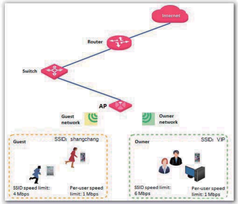
75
Assume that the VIP and Mall networks are set up using RF band 1 of the AP.
Configuration Procedure
1. Choose Firewall > Traffic Control.
2. Set the traffic control rule parameters of the VIP network as follows and click Save:
(1) Set Traffic Control to Manual.
(2) Set Select enabled SSID to Radio1:VIP.
(3) Set Max Upload Rate and Max Download Rate of Radio 1:VIP to 6 Mb/s.
(4) Set Max Upload Rate and Max Download Rate of User Rate to 1 Mb/s.
3. Set the traffic control rule parameters of the guest network as follows and click Save:
(1) Set Traffic Control to Manual.
(2) Set Select enabled SSID to Radio1:Mall.
(3) Set Max Upload Rate and Max Download Rate of Radio 1:Mall to 4 Mb/s.
(4) Set Max Upload Rate and Max Download Rate of User Rate to 1 Mb/s.
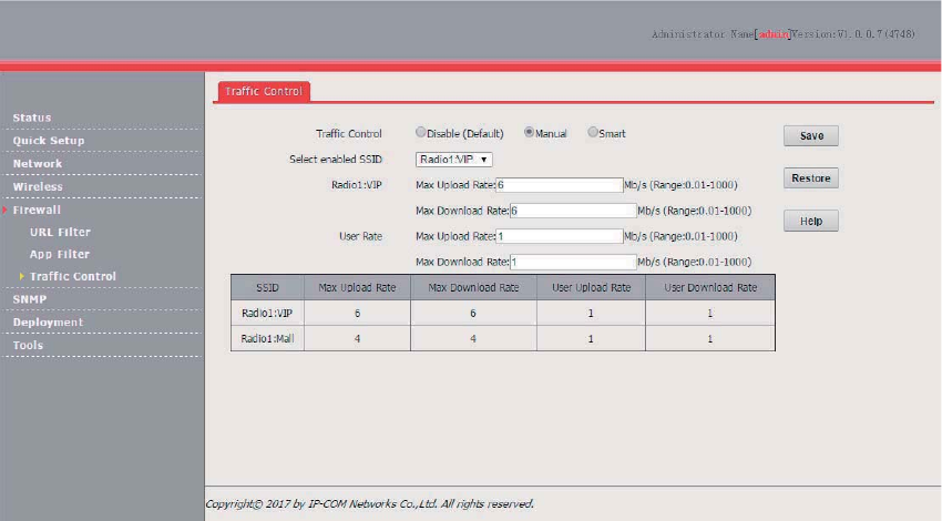
76
---End
77
SNMP
Overview
The Simple Network Management Protocol (SNMP) is the most widely used network management
protocol in TCP/IP networks. SNMP enables you to remotely manage all your network devices
compliant with this protocol, such as monitoring the network status, changing network device
settings, and receive network event alarms.
SNMP allows automatic management of devices from various vendors regardless of physical
differences among the devices.
SNMP Management Framework
The SNMP management framework consists of SNMP manager, SNMP agent, and Management
Information Base (MIB).
SNMP manager: It is a system that controls and monitors network nodes using the SNMP
protocol. The SNMP manager most widely used in network environments is Network
Management System (NMS). An NMS can be a dedicated network management server, or an
application that implements management functions in a network device.
SNMP agent: It is a software module in a managed device. The module is used to manage data
about the device and report the management data to an SNMP manager.
MIB: It is a collection of managed objects. It defines a series of attributes of managed objects,
including names, access permissions, and data types of objects. Each SNMP agent has its MIB.
An SNMP manager can read and/or write objects in the MIB based on the permissions assigned
to the SNMP manager.
An SNMP manager manages SNMP agents in an SNMP network. The SNMP manager exchanges
management information with the SNMP agents using the SNMP protocol.
Basic SNMP Operations
The AP allows the following basic SNMP operations:
Get: An SNMP manager performs this operation to query the SNMP agent of the AP for values of
one or more objects.
Set: An SNMP manager performs this operation to set values of one or more objects in the MIB
of the SNMP agent of the AP .
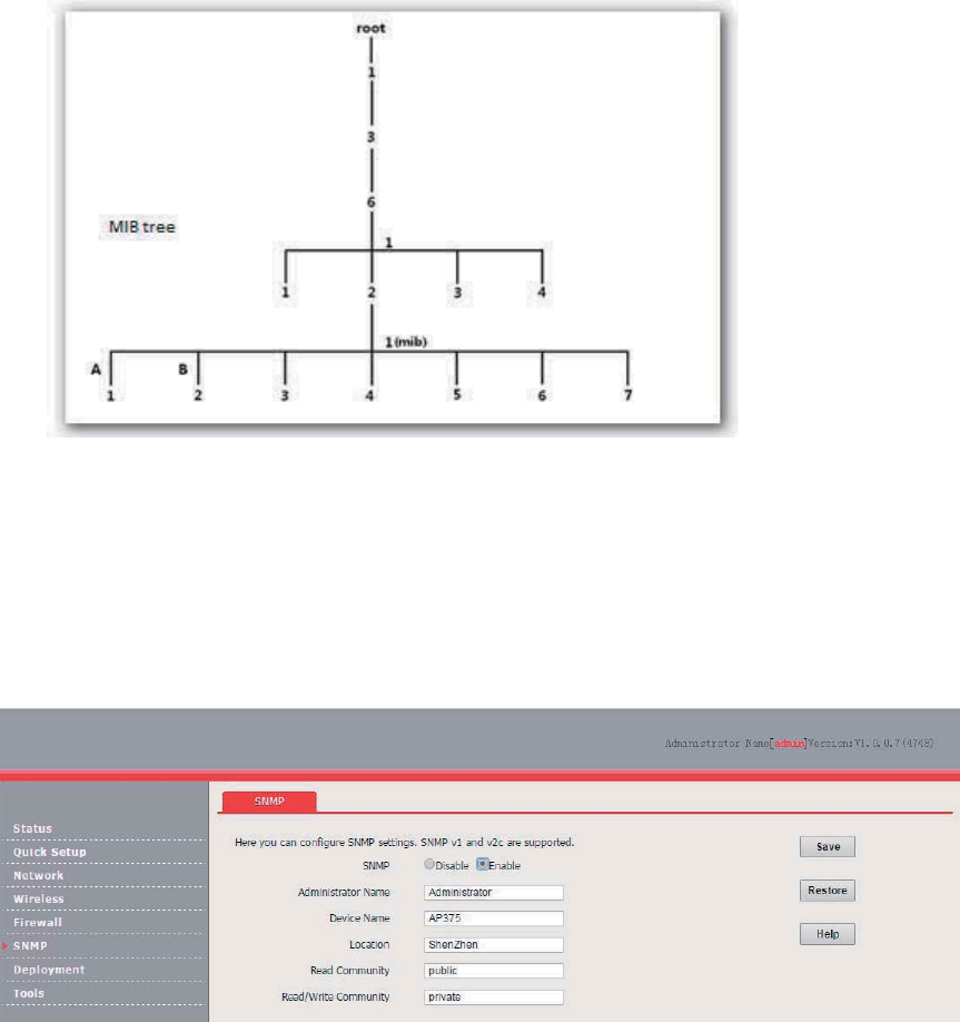
78
SNMP Protocol Version
The AP is compatible with SNMP V1 and SNMP V2C and adopts the community authentication
mechanism. Community name is used to define the relationship between an SNMP agent and an
SNMP manager. If the community name contained in an SNMP packet is rejected by a device, the
packet is discarded. A community name functions as a password to control SNMP agent access
attempts of SNMP managers.
SNMP V2C is compatible with SNMP V1 and provides more functions than SNMP V1. Compared
with SNMP V1, SNMP V2C supports more operations (GetBulk and InformRequest) and data types
(such as Counter64), and provides more error codes for better distinguishing errors.
MIB Introduction
An MIB adopts a tree structure. The nodes of the tree indicate managed objects. A path consisting of
digits and starting from the root can be used to uniquely identify a node. This path is call an object
identifier (OID). The following figure shows the structure of an MIB. In the figure, the OID of A is
1.3.6.1.2.1.1, whereas the OID of B is 1.3.6.1.2.1.2.
Configuring the SNMP Function
1. Choose SNMP and set SNMP to Enable.
2. Set related SNMP parameters.
3. Click Save.
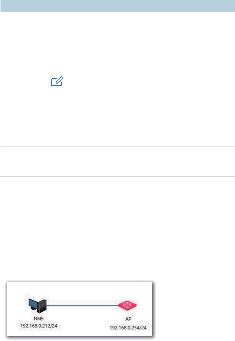
79
---End
Parameter description
Parameter
Description
SNMP
It specifies whether to enable the SNMP agent function of the
default, it is disabled.
The SNMP manager and SNMP agent can communicate with each other only if their SNMP
versions are the
same. Currently
, the SNMP agent function of the AP supports SNMP V1
and SNMP V2C.
Administrator Name
It specifies the name of the administrator of the AP. The default name is Administrator.
Device Name
It
specifies the device name of the AP. The default device name is the model of the AP.
For
example, the device name of AP375 is AP375.
4UZK
It is recommended that you change the AP name so that you can easily identify the AP
when managing the AP using SNMP.
Lo
cation
It specifies the location where the AP is used.
Read Community
It specifies the read password shared between SNMP managers and this SNMP agent.
The default password is
public.
The SNMP agent function of the AP allows an SNMP manager to use the password to read
variables in the MIB of the AP.
Read/Write
Community
It specifies the read/write password shared between SNMP managers and this SNMP
agent. The default password is
private.
The SNMP agent function of the AP allows an SNMP manager to use the p
assword to
read/write variables in the MIB of the AP.
Example of Configuring the SNMP
Function
Networking Requirement
The AP connects to an NMS over an LAN. This IP address of the AP is 192.168.0.254/24 and
the IP address of the NMS is 192.168.0.212/24.
The NMS use SNMP V1 or SNMP V2C to monitor and manage the AP.
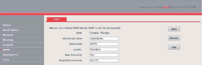
80
Configuration Procedure
1. Configure the AP.
Assume that the read community is Tom and read/write community is Tom123.
(1) Log in to the web UI of the AP and choose SNMP.
(2) Set SNMP to Enable.
(3) Set the SNMP parameters.
(4) Click Save.
2. Configure the NMS.
On an NMS that uses SNMP V1 or SNMP V2C, set the read community to Tom and read/write
community to Tom123. For details about how to configure the NMS, refer to the configuration guide
for the NMS.
---End
Verification
After the configuration, the NMS can connect to the SNMP agent of the AP and can query and set
some parameters on the SNMP agent through the MIB.
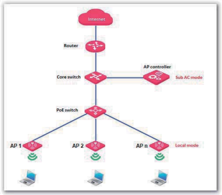
81
Deployment
Overview
If a large number of APs are deployed, you are recommended to adopt an IP-COM AP controller
(AC1000/2000/3000; AC2000 is used as an example) to manage the APs in a centralized manner.
In this case, Local and Cloud deployment modes are supported.
Local deployment
If you need to deploy many APs in a small area, you are recommended to select the local
deployment mode, which uses a local AC (in Sub AC mode) to manage the APs in a centralized
manner. The following figure shows the topology for the local deployment mode.
Cloud deployment
If you need to deploy many APs distributed across a large area, you are recommended to select the
cloud deployment mode, which uses an AC (in Cloud AC mode) over the internet to manage the APs
in a centralized manner. The following figure shows the topology for the cloud deployment mode.
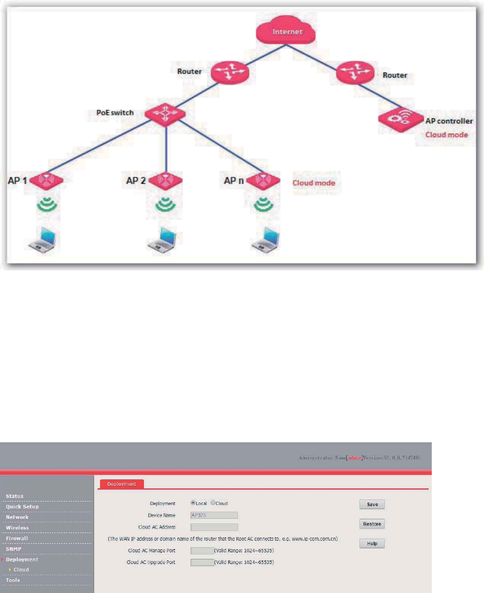
82
Configuring the Deployment Mode
By default, the deployment mode of the AP is Local.
Configuring Local Deployment Mode
1. Choose Deployment, and select Local.
2. Click Save.
---End
Configuring Cloud Deployment Mode
1. Choose Deployment, and select Cloud.
2. Set related parameters, including Device Name, Cloud AC Address, Cloud AC Manage Port,
and Cloud AC Upgrade Port.
3. Click Save.
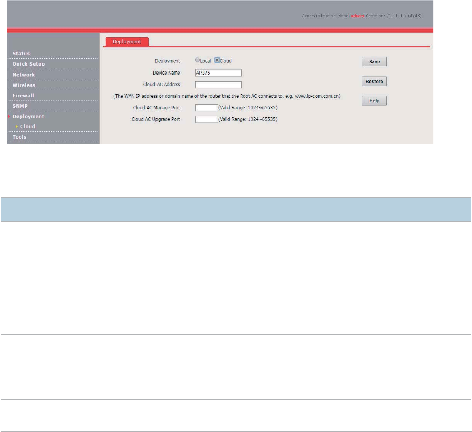
83
---End
Parameter description
Parameter
Description
Deployment
It specifies the deployment mode of the AP. The default option is
Local.
− Local: In this mode, the AP can be managed only by a local AC.
− Cloud: In this mode, the AP can be managed only by a cloud AC. To
use the cloud
deployment mode, set the following parameters as well.
Device Name
It specifies the device name of the AP. The default device n
ame is the model of the AP.
You are recommended to change the device name so that you can quickly locate the AP
when managing the AP remotely.
Cloud AC Address
It specifies the WAN IP address of the router to which the cloud AC connects, or the
domain nam
e to which the WAN IP address is bound.
Cloud AC Manage
Port
It specifies the port of the router to which the cloud AC connects for managing APs.
Cloud AC Upgrade
Port
It specifies the port of the router to which the cloud AC connects for managing APs.
Exmaple of Configuring the Deployment
Mode
Example of Configuring the Local Deployment
Mode
Networking Requirement
The meeting room of a hotel is deployed with multiple AP375s for wireless coverage and deployed
with AC2000 to manage the APs in a centralized manner.
Assume the that hotel does not set up VLANs. The following figure shows the topology.
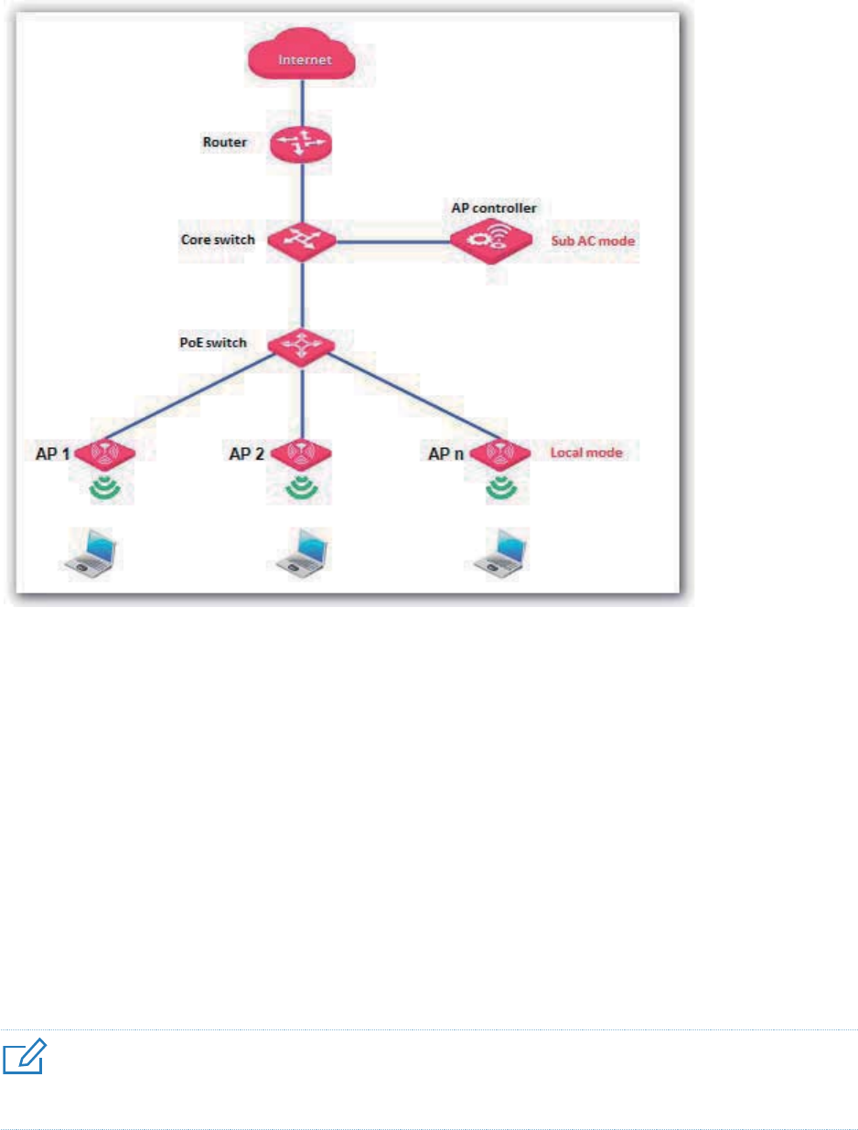
84
Configuration Procedure
1. Configure the AP.
By default, the deployment mode of the AP is Local. Use the default configuration.
2. Configuring the AP controller.
By default, AC2000 works in Sub AC mode. Use the default configuration of the AP controller.
---End
Verification
Log in to the web UI of AC2000 and access the Manage AP page to verify that all APs are online.
You can use AC2000 to manage the APs in a centralized manner.
4UZK
After the AP controller takes control over the APs, it changes the IP addresses of the APs. To log in to the web UI of an
AP, log in to the web UI of the AP controller and click the IP address of the AP.
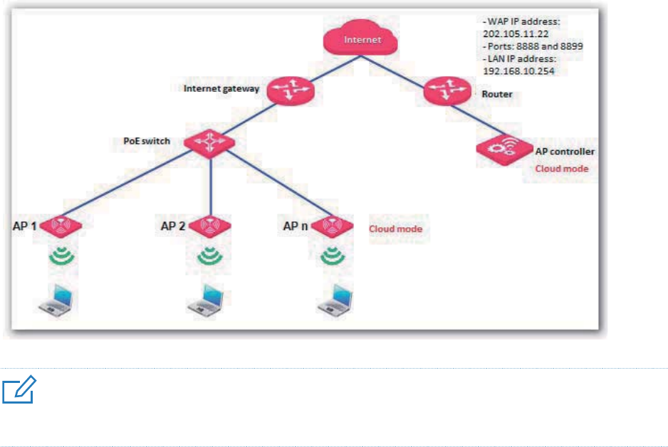
85
Example of Configuring the Cloud Deployment
Mode
Networking Requirement
A chain restaurant operator requires that:
Guests can access internet in the restaurants through WiFi networks.
The network administrator at the HQ can understand the AP operation conditions of the
restaurants any time and deliver configurations to the APs in a centralized manner for remote
control and troubleshooting.
Solution
IP-COM AC2000 and AP375 are used to address the requirement as follows:
The HQ is deployed with one AC2000 working in Cloud AC mode to manage all the APs at the
restaurants in a centralized manner.
The router connected to AC2000 at the HQ provides two ports for managing and upgrade the
APs.
One or more APs working in Cloud mode are deployed at each restaurant and the Cloud AC
Address is set to the WAN IP address of the router connected to AC2000.
4UZK
You are recommended to connect only one AP to a POE switch and configure the AP at a time, so as to prevent IP
address conflicts.
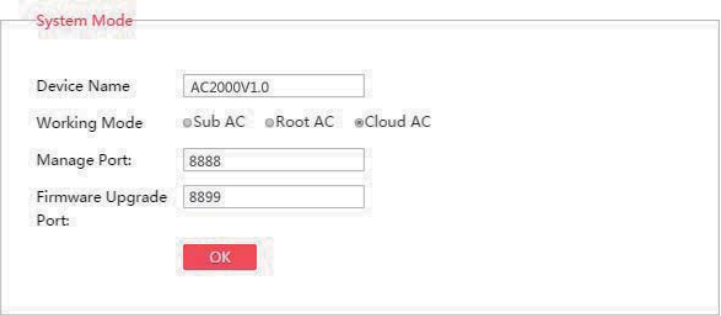
86
Assumption
The internet gateway has a DHCP server that assigns IP address to the APs so that the APs can
access the internet.
The router supports the DNS proxy function.
Configuration Procedure
1. Configure the router.
Map TCP port 8888 and UDP port 8899 of the router connected to AC2000 onto AC2000. For details,
refer to the user guide for the router.
2. Configure AC2000.
Log in to the web UI of AC2000 and perform the following procedure:
(1) Set Working Mode to Cloud AC.
(a) Choose System Tools > Maintain and locate the System Mode module.
(b) Set Working Mode to Cloud AC.
(c) Set Manage Port to the TCP port provided by the router, which is 8888 in this example.
(d) Set Firmware Upgrade Port to the UDP port provided by the router, which is 8899 in this
example.
(e) Click OK.
(f) Wait for AC2000 to reboot.
(2) Configure IP address information for the AP controller to access the internet.
(a) Choose System Tools > Network Setting and locate the LAN Settings module.
(b) Set IP Address to an IP address belonging to the same network segment as the IP
address of the LAN port of the router. Retain the default IP address 192.168.10.1 in this
example.
(c) Set Gateway to the IP address of the LAN port of the router. Retain the default IP address
192.168.10.254 in this example
(d) Set Preferred DNS to 192.168.10.254 because the router supports the DNS proxy
function.
(e) Click OK.
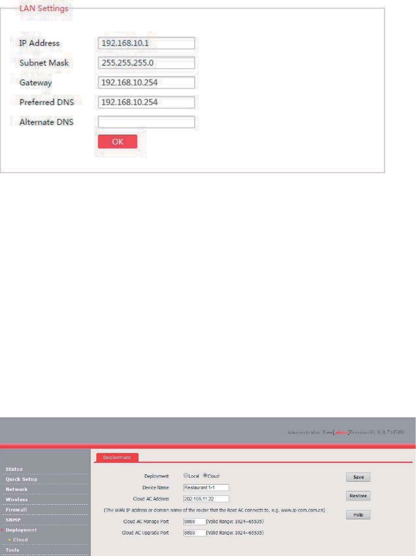
87
3. Configure the APs.
Log in to the web UI of each AP and perform the following procedure:
(1) Set Deployment of the AP to Cloud.
(a) Choose Deployment.
(b) Set Deployment to Cloud.
(c) Set Device Name to the location of the corresponding restaurant to help identify the AP.
(d) Set Cloud AC Address to the WAN IP address of the router connected to AC2000, which
is 202.105.11.22 in this example.
(e) Set Cloud AC Manage Port to the port number specified by Manage Port of AC2000,
which is 8888 in this example.
(f) Set Cloud AC Upgrade Port to the port number specified by Firmware Upgrade Port of
AC2000, which is 8899 in this example.
(g) Click Save.
(2) Configure IP address information to enable the AP to access the internet.
(a) Choose Network > LAN Setup.
(b) Set Address Mode to Dynamic IP.
(c) Click Save.
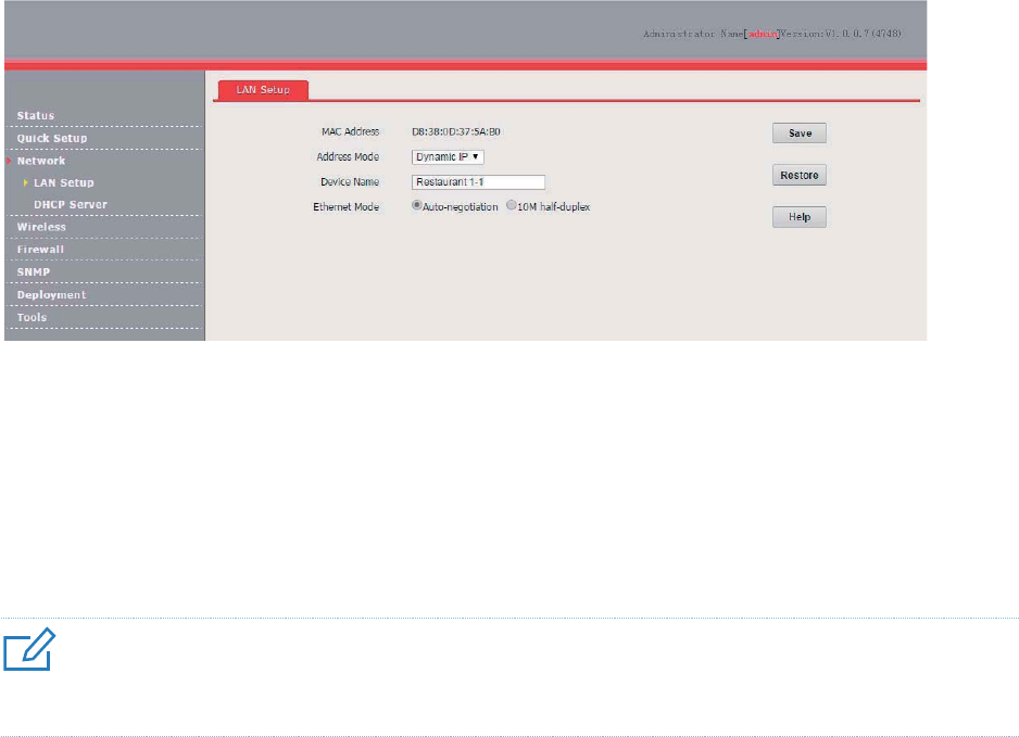
88
---End
Verification
Log in to the web UI of AC2000 and access the Manage AP page to verify that all APs are online.
You can use AC2000 to manage the APs in a centralized manner.
4UZK
After the AP controller takes control over the APs, it changes the IP addresses of the APs. To log in to the web UI of an
AP, log in to the web UI of the AP controller and click the IP address of the AP.
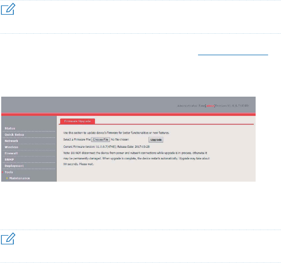
89
Tools
Firmware Upgrade
This function upgrades the firmware of the AP for more functions and higher stability.
4UZK
To prevent damaging the AP, verify that the new firmware version is applicable to the AP before upgrading the
firmware and keep the power supply of the AP connected during an upgrade.
Procedure:
1. Download the package of a later firmware version for the AP from http://www.ip-com.com.cn to
your local computer, and decompress the package.
2. Log in to the web UI of the AP and choose Tools >Maintenance.
3. Click Browse and choose the AP upgrade file.
4. Click Upgrade.
---End
Wait until the progress bar is complete. Log in to the web UI of the AP again. Choose Status >
System Status and check whether the upgrade is successful based on Firmware Version.
4UZK
After the firmware is upgraded, you are recommended to restore the factory settings of the AP and configure the AP
again, so as to ensure stability of the AP and proper operation of new functions.
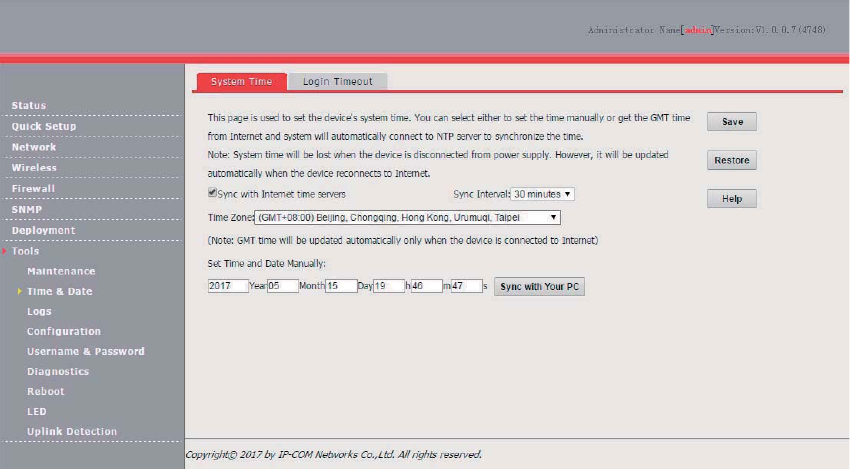
90
Time & Date
System Time
Ensure that the system time of the AP is correct, so that logs can be recorded correctly and the
reboot schedule can be executed correctly.
To access the page, choose Tools > Time & Date.
The AP allows you to set the system time by synchronizing the time with the internet or manually
setting the time. By default, it is configured to synchronize the system time with the internet.
Synchronizing the System Time with the Internet
The AP automatically synchronizes its system time with a time server of the internet. This enables
the AP to automatically correct its system time after being connected to the internet.
To connect the AP to the internet, choose Network > LAN Setup and set the IP address, subnet
mask, gateway, and DNS server of the AP.
Procedure for configuring the AP to synchronize its system time with the internet:
1. Choose Tools > Time & Date and click the System Time tab.
2. Select Sync with Internet time servers.
3. Set Sync Interval to the interval at which the AP synchronizes its system time with a time server
of the internet. The default value 30 minutes is recommended.
4. Set Time Zone to your time zone.
5. Click Save.
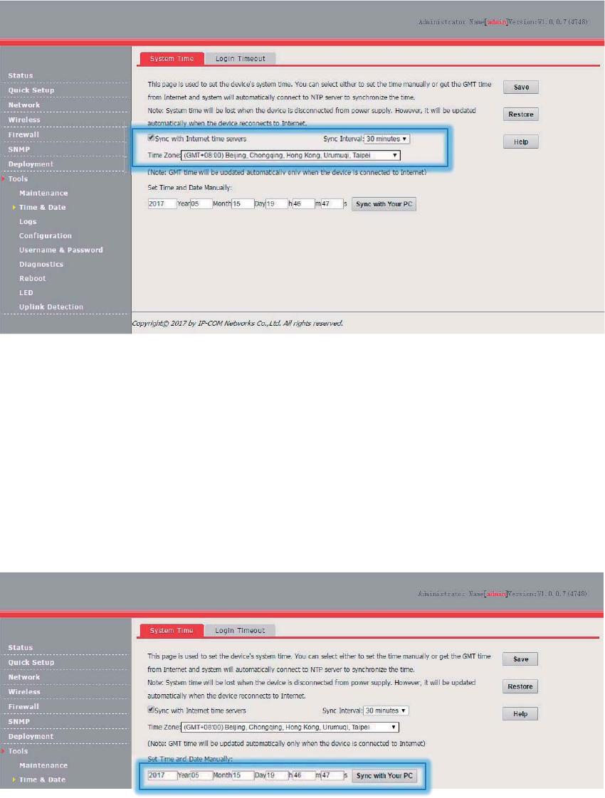
91
Manually Setting the System Time
You can manually set the system time of the you choose this option, you need to set the system time
each time after the AP reboots.
Procedure:
1. Choose Tools > Time & Date and click the System Time tab.
2. Enter a correct date and time, or click Sync with Your PC to synchronize the system time of the
AP with the system time (ensure that it is correct) of the computer being used to manage the AP.
3. Click Save.
---End
Login Timeout
If you log in to the web UI of the AP and perform no operation within the login timeout interval, the
AP logs you out for network security. The default login timeout interval is 5 minutes.
Procedure for setting the login timeout interval:
1. Choose Tools > Time & Date and click the Login Timeout tab.
2. Change the login timeout interval as required.

92
3. Click Save.
---End
Logs
View Logs
The logs of the AP record various events that occur and the operations that users perform after the
AP starts. In case of a system fault, you can refer to the logs during troubleshooting.
To access the page, choose Tools > Logs.
To ensure that the logs are recorded correctly, verify the system time of the AP. You can correct the
system time of the AP by choosing Tools > Time & Date > System Time.
To view the latest logs of the AP, click Refresh. To clear the existing logs of the AP, click Clear.
4UZK
− When the AP reboots, the previous logs are lost.
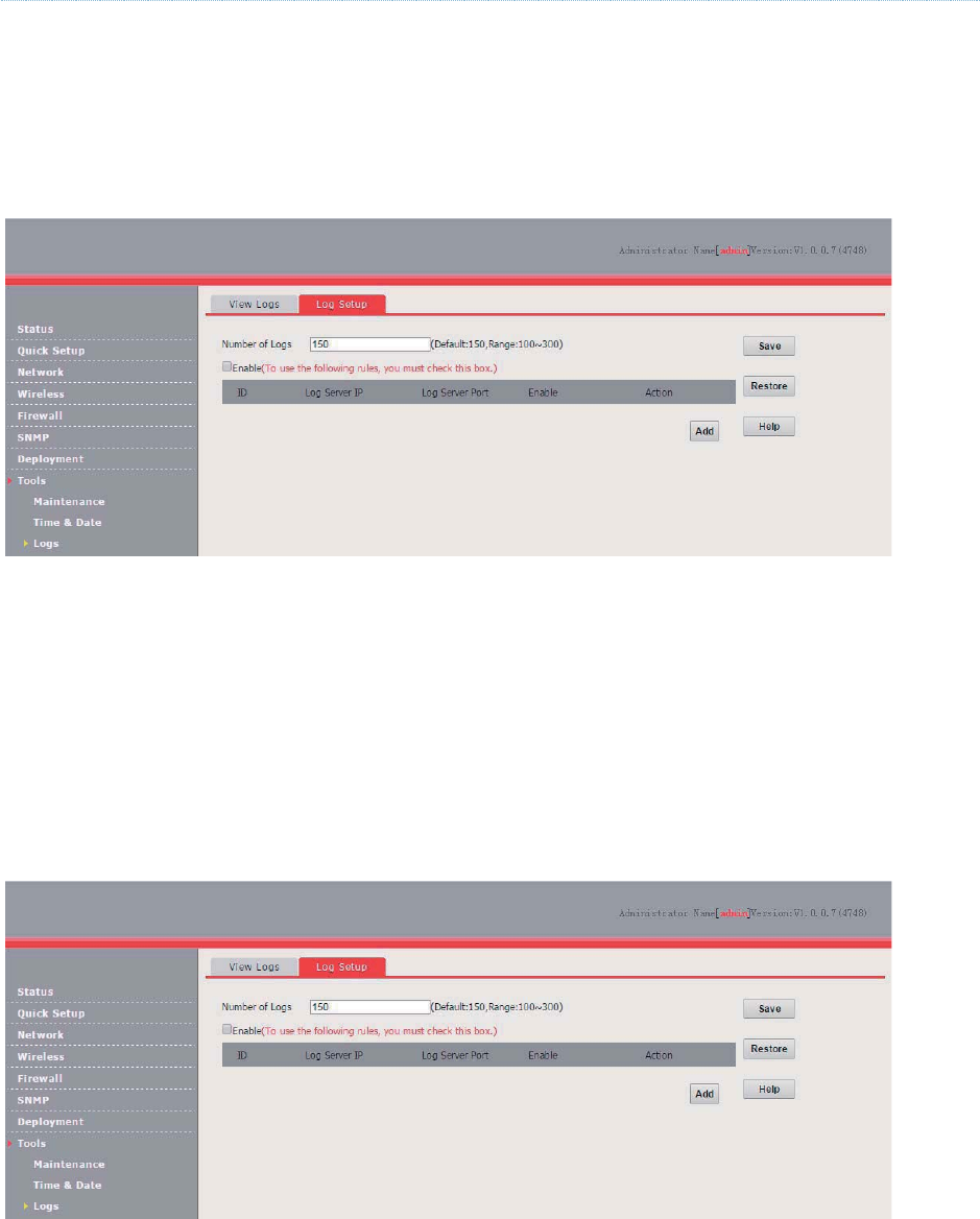
93
− The AP reboots when the AP is powered on after a power failure, the QVLAN function is configured, the firmware
is upgraded, an AP configuration is backed up or restored, or the factory settings are restored.
Log Setup
To access the page, choose Tools > Logs and click the Log Setup tab.
On this page, you can set the number of logs to be displayed and configure log servers.
Setting the Number of Logs to Be Displayed
By default, the AP can display a maximum of 150 logs on the View Logs page. You can change the
number as required.
Procedure:
1. Choose Tools > Logs and click Log Setup.
2. Change the number of logs as required within the range of 100 to 300.
3. Click Save.
---End
Configuring Log Server Settings
After you specify a log server, the AP sends its logs to the log server. You can view all the historical
logs of the AP on the log server.
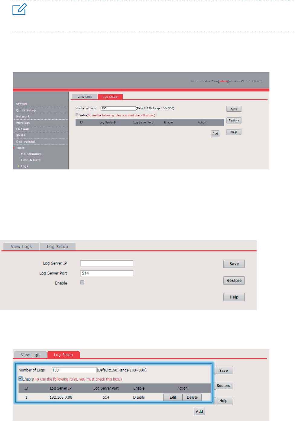
94
4UZK
To ensure that system logs can be sent to a log server, choose Network > LAN Setup and set the IP address, subnet
mask, and gateway of the AP for communicating with the log server.
Procedure for adding a log server
1. Choose Tools > Logs and click Log Setup.
2. Click Add.
3. Set parameters as follows:
(1) Set Log Server IP to the IP address of the log server.
(2) Set Log Server Port to the UDP port number used to send and receive system logs. The
default port number 514 is recommended.
(3) Select Enable to enable the log server function.
4. Click Save.
5. Select Enable (To use the following rules, you must check this box.).
6. Click Save.
The following figure shows an example of log server settings.
---End
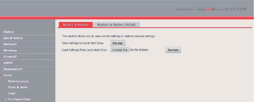
95
Procedure for changing log server settings
1. To access the page, choose Tools > Logs and click Log Setup.
2. Click Edit corresponding to the log server settings to be change.
---End
Procedure for deleting log server settings
1. To access the page, choose Tools > Logs and click Log Setup.
2. Click Delete corresponding to the log server settings to be deleted.
---End
Configuration
Backup and Restore
The backup function enables you to back up the current configuration of the AP to a local computer.
The restoration function enables you to restore the AP to a previous configuration.
If the AP enters the optimum condition after you greatly change the configuration of the AP, you are
recommended to back up the new configuration, so that you can restore it after upgrading or
resetting the AP.
Backing Up the Current Configuration
1. Choose Tools > Configuration.
2. Click Backup and follow the on-screen instructions to perform operations.
---End
Restoring a Configuration
1. Choose Tools > Configuration.
2. Click Browse and select the file of the configuration to be restored.
3. Click Restore and follow the on-screen instructions to perform operations.
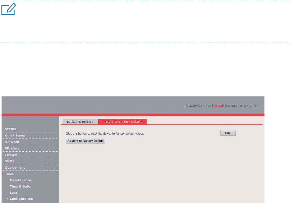
96
---End
Restore to Factory Default
If an computer connected to the AP cannot access the internet for unknown reasons, or you forget
the login password, you are recommended to restore the router to factory settings and reconfigure
the AP can be reset using software or hardware.
After the factory settings are restored, the login IP address of the AP is changed to 192.168.0.254,
and the user name and password of the AP are changed to admin.
4UZK
− When the factory settings are restored, your configuration is lost. Therefore, you need to reconfigure the AP to
connect to the internet. Restore the factory settings of the AP only when necessary.
− To prevent AP damages, ensure that the power supply of the AP is normal when the AP is reset.
Restoring the Factory Settings Using Software
1. Choose Tools > Configuration and click the Restore to Factory Default tab.
2. Click the Restore to Factory Default button.
---End
Restoring the Factory Settings Using Hardware
This method enables you to restore the factory settings without logging in to the web UI of the AP.
Procedure:
1. After the AP is powered on, use a pin to hold down the RST button for 8 seconds.
2. Wait about 45 seconds.
---End
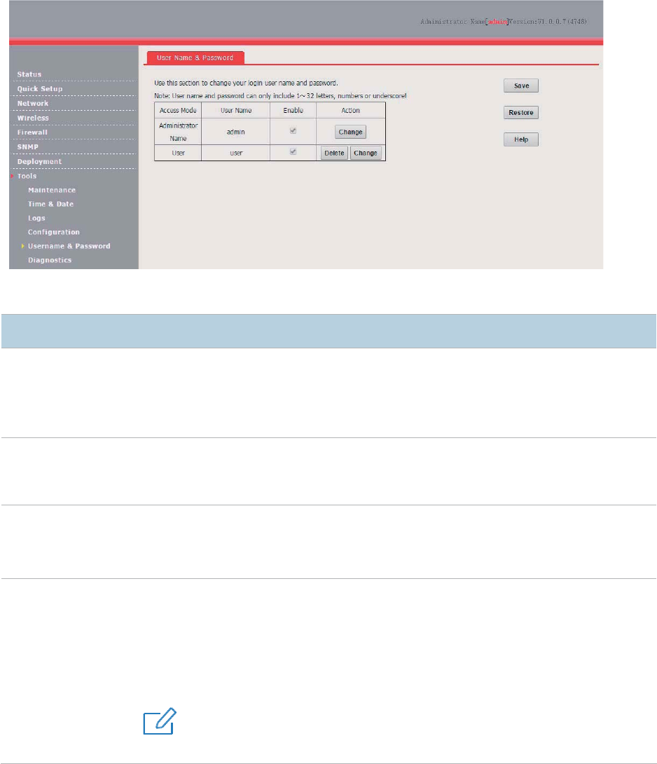
97
Username and Password
To access the page, choose Tools > Username & Password.
On this page, you can change the login account information of the AP to prevent unauthorized login.
Parameter description
Parameter
Description
Access Mode
It specifies the type of an account.
− Administrator Name: An account of this type enables you to view and modify
settings of the AP.
− User: An account of this type enables you to view settings of the AP.
User Name
It specifies the user name of an account.
By default, both the user name and password of the administrator account are
admin
. Both
the user name and password of the user account are
user.
Enable
It specifies
whether an account is enabled.
− The administrator account is always enabled.
− The user account is enabled by default and can be disabled.
Action
It specifies the operations that can be performed on a specific account.
− Change: This button is used to change
the user name and password of the account
corresponding to the button.
− Delete: This button is used to delete the user account.
− Add: This button is used to add the user account after the account is deleted.
4UZK
After changing, deleting, or adding an account, c
lick Save.
Diagnostics
If the network connection fails, you can use the diagnostics tool included with the AP to locate the
faulty node.
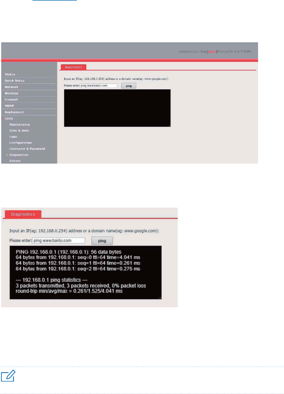
98
The link to www.baidu.com is used as an example. Perform the following procedure:
1. Choose Tools > Diagnostics.
2. Enter the IP address or domain name to be pinged in the text box. In this example, enter ping
www.baidu.com.
3. Click Ping.
---End
The diagnosis result will be displayed in a few seconds in the black text box below the Please enter
text box. See the following figure.
Reboot
This module enables you to manually reboot the AP or configure the AP to automatically reboot.
4UZK
When the AP reboots, all wireless connections are released. You are recommended to reboot the AP at an idle hour.
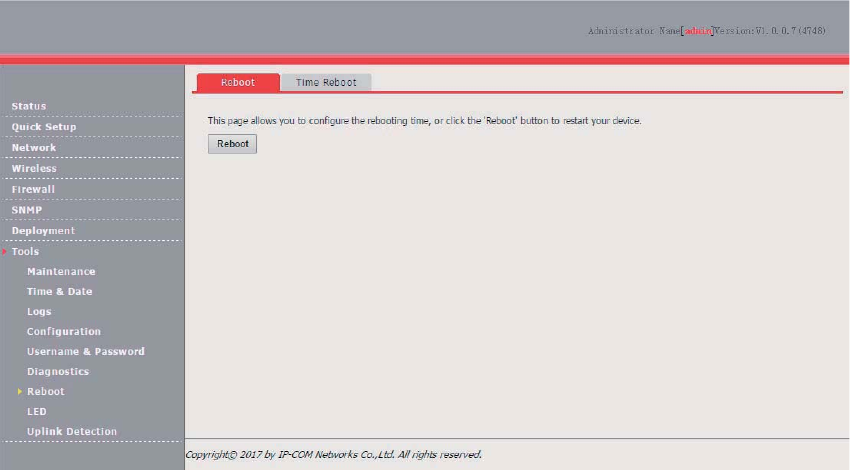
99
Reboot
If a setting does not take effect, you can try rebooting the AP to resolve the problem.
Perform the following procedure:
1. Choose Tools > Reboot.
2. Click Reboot.
---End
Time Reboot
This function enables the AP to automatically reboot as scheduled. You can use this function to
prevent wireless performance degradation or network instability that occurs after a long AP uptime.
The AP can reboot:
As intervals: In this mode, the AP reboots at the interval that you specify. The interval can be less
than 24 hours.
As Scheduled: In this mode, the AP reboots regularly at the time that you specify. The interval
must be 24 hours or a period that can be completely divided by 24 hours.
Configuring the AP to Reboot at an Interval
1. Choose Tools > Reboot and click the Time Reboot tab.
2. Select the Enable Auto Reboot check box.
3. Set AUTO Reboot Type to As Interval.
4. Set Interval to a value in minutes, such as 1440.
5. Click Save.
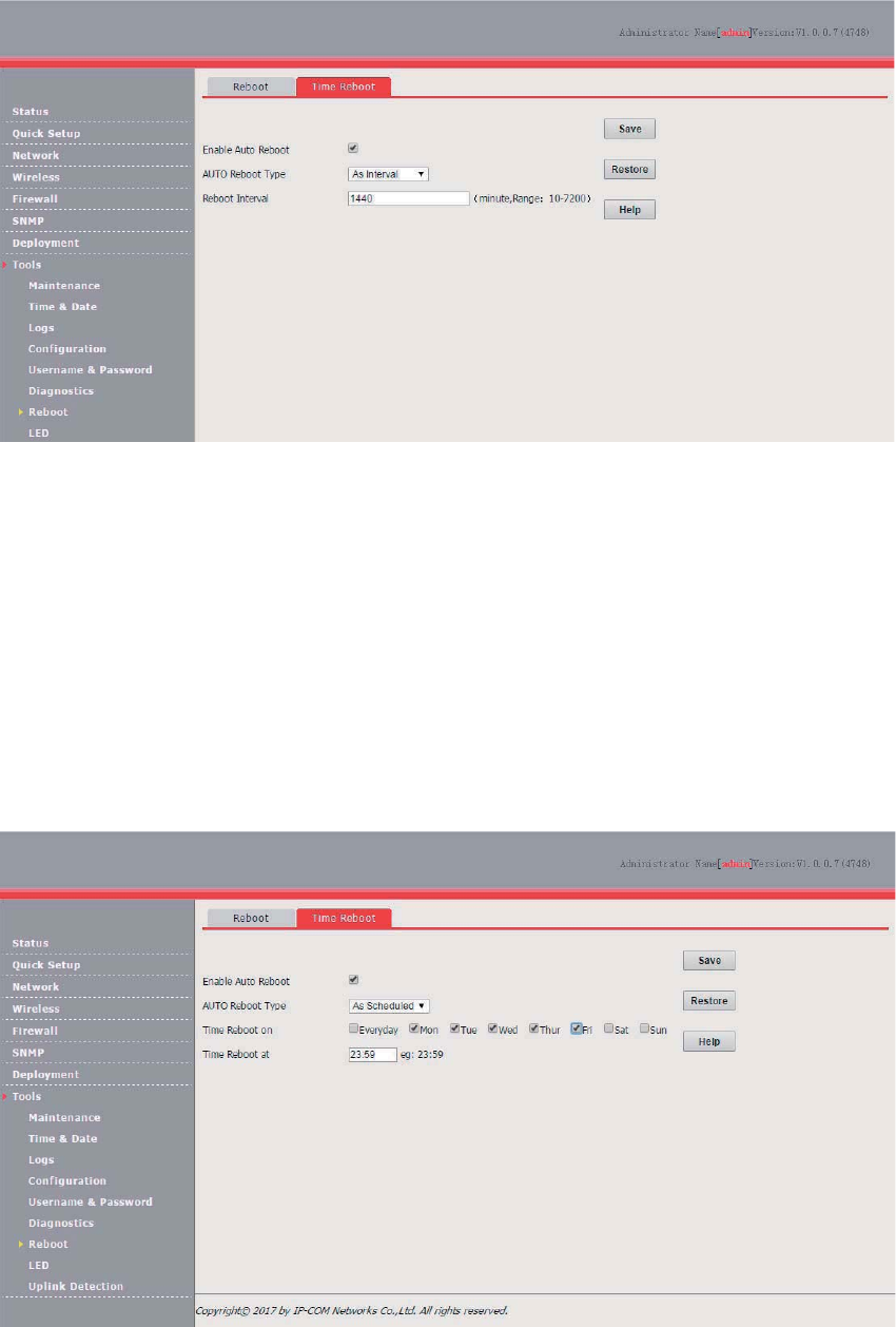
100
---End
Configuring the AP to Reboot as Scheduled
1. Choose Tools > Reboot and click the Time Reboot tab.
2. Select the Enable Auto Reboot check box.
3. Set AUTO Reboot Type to As Scheduled.
4. Select the day or days when the AP reboots.
5. Set the time when the AP reboots, such as 23:59.
6. Click Save.
---End
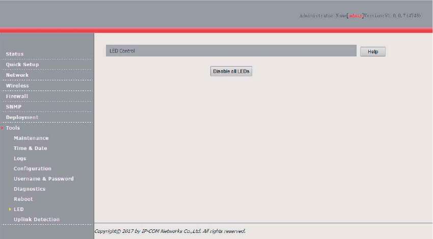
101
LED
This function enables you to turn on/off the LED indicator of the default, the LED indicator is turned
on.
Procedure for turning off the LED indicator:
1. Choose Tools > LED.
2. Click Disable all LEDs.
---End
Procedure for turning on the LED indicator:
1. Choose Tools > LED.
2. Click Enable all LEDs.
---End
Uplink Detection
Overview
In AP mode, the AP connects to its upstream network using the LAN0 port. If a critical node between
the LAN0 port and the upstream network fails, the AP as well as the wireless clients connected to
the AP cannot access the upstream network. If uplink detection is enabled, the AP regularly pings
specified hosts through the LAN0 port. If all the hosts are not reachable, the AP stops its wireless
service and wireless clients cannot find the SSIDs of the AP. The client can reconnect to the AP only
after the connection between the AP and the upstream networks is recovered.
If the uplink of the AP with uplink detection enabled is faulty, wireless clients can connect to the
upstream network through another nearby AP that works properly.
The following figure shows the upstream network of the AP.
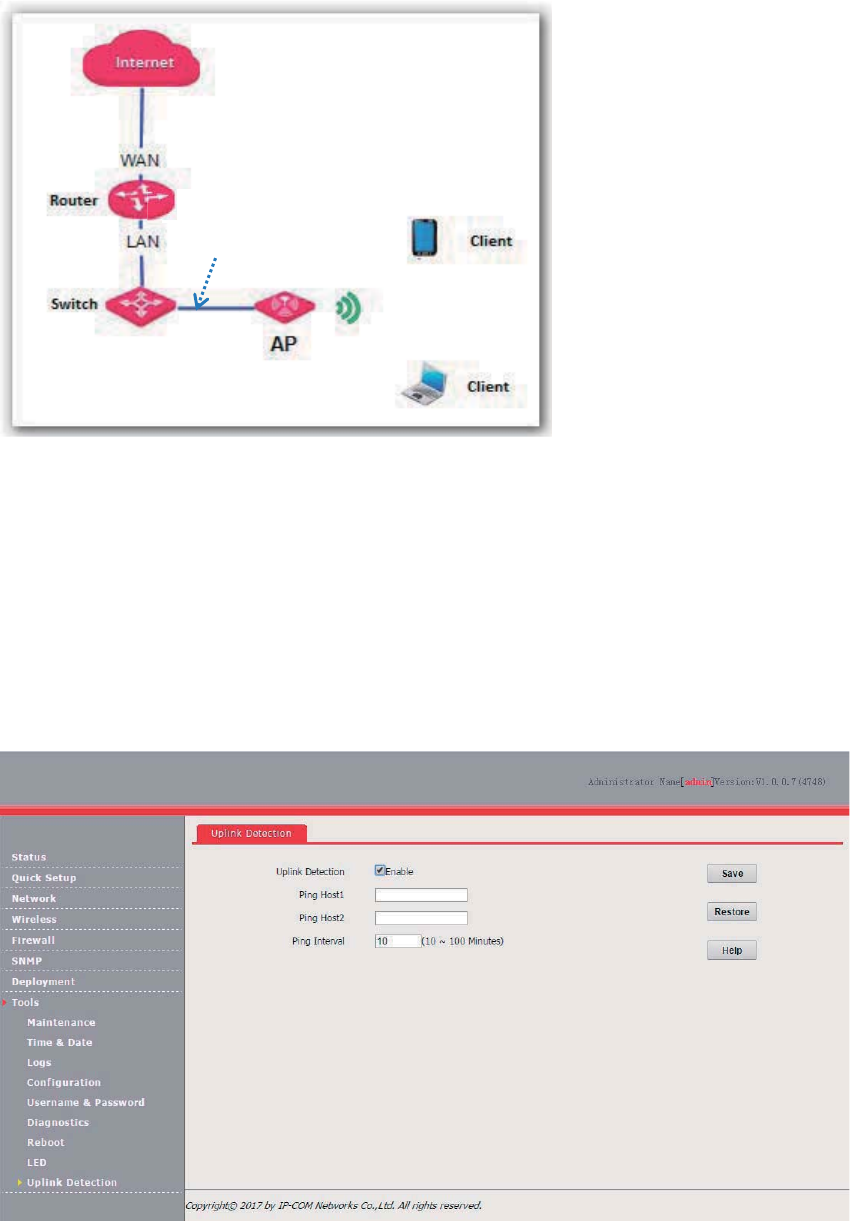
102
Configuring Uplink Detection
1. Choose Tools > Uplink Detection.
2. Select the Enable check box of Uplink Detection.
3. Set Ping Host1 or Ping Host2 to the IP address of the host to be pinged through the AP, such
as the IP address of the switch or router directly connected to the AP.
4. Set Ping Interval to the interval at which the AP detects its uplink.
5. Click Save.
---End
LAN port
103
Appendixes
A. FAQ
Q1. I cannot access the web UI of the AP after entering 192.168.0.254. What should I do?
A1. Check the following items:
Verify that the IP address of your computer is 192.168.0.X (X: 2~253).
Clear the cache of your web browser or replace the web browser, and try login again.
Disable the firewall of your computer or replace the computer, and try login again.
If two or more APs are connected to your network without an AP controller, connect one of the
APs to your PoE switch and change the IP address of the AP. Repeat this procedure to change
the IP addresses of the other APs.
The AP may be being managed by an AP controller and therefore its IP address is no longer
192.168.0.254. In that case, log in to the web UI of the AP controller to view the new IP address
of the AP, and log in to the AP using the new IP address.
If you have manually changed the IP address of the AP, change the IP address of your computer
to another IP address that belongs to the same network segment as the new IP address of the
AP and log in again using the new IP address of the AP.
If the problem persists, restore the factory settings of the AP and try login again.
Q2. My wireless AP controller cannot find the AP. What should I do?
A2. Check the following items:
Verify that the devices are connected properly and the AP has started.
If VLANs have been defined on your network, verify that the corresponding VLAN has been
added to your AP controller.
Restart the AP or restore the factory settings of the AP, and try scanning the AP again.
Q3. I forget the login user name and password of the AP. What should I do to log in to the web UI
of the AP?
A3. Try login with the default IP address 192.168.0.254 and default user name and password admin. If
login fails, restore the factory settings and use the default login information to try login again.
Q4. I cannot access the web UI of the AP. What should I do to restore the factory settings?

104
A4. After the AP is powered on, use a pin to hold down the RST button for 8 seconds and then wait about
1 second. After the factory settings are restored, configure the AP again.
Q5. What should I do if a computer connected to the AP displays an IP address conflict
message?
A5. Check the following items:
Verify that the IP address of the computer is not used by another device on your LAN. The
default IP address of the AP is 192.168.0.254.
Verify that the static IP addresses assigned to computers on your LAN are not used by other
devices.
For more technical assistance, visit our website at http://www.ip-com.com.cn or send your question to
info@ip-com.com.cn, or call +86-755-27653089. We will help you resolve your problem as soon as
possible.

105
B. Default Parameter Settings
The following table lists the default parameter values of the AP.
Parameter
Default Value
Login
Management I
P address
192.168.0.254
User
Name/Password
Administrator
A
dmin/admin
User
user
/user
Quick Setup
Mode
AP Mode
Mode of Radio 3
2.4
GHz
LAN Setup
Address Mode
Static IP
IP Address
192.168.
0.254
Subnet Mask
255.255.255.0
Gateway
192.168.0.1
Pr
imary DNS Server
192.168.0.1
Secondary DNS Server
None
Device Name
AP375
DHCP Server
Disabled
SSID Setup
SSID
Radio
1
The AP allows 8 SSIDs.
The SSID is Tenda_
XXXXXX, where XXXXXX
indicates the
last 6 characters of the MAC address of the LAN ports of
the
AP or the last 6 characters plus 1 to 7.
By default, the first SSID is enabled, and the other SSIDs are
disabled.
Radio
2
The AP allows 4 SSIDs.
The SSID is Tenda_
XXXXXX, where XXXXXX
indicates the
last 6 characters of the MAC address of the LAN ports of the
AP plus 9 to 12.
By default, the first SSID is enabled, and the other SSIDs are
disabled.
Radio
3
The AP allows 8 SSIDs.
The SSID of the AP is Tenda_
XXXXXX, where XXXXXX
indicates the last 6 characters of the MAC address of the LAN
ports of t
he AP plus 13 to 20.
By default, the first SSID is enabled, and the other SSIDs are
disabled.
Broadcast SSID
Enable
Client Isolation
Disable
WMF
Disable
Probe Broadcast Packets Control
Disable
Maximum Clients
48
Chinese SSID Encode
UTF
-8

106
Parameter
Default Value
Secu
rity Mode None
Radio
Enable Wireless
Selected
Country
China
Network
Mode
Radio 1
11b/g/n mixed
Radio 2
11ac
Radio 3
11b/g/n mixed
Channel
Auto
Channel
Bandwidth
Radio 1
20MHz
Radio
2
80MHz
Radio
3
20MHz
Channel Lockout
Selected
Power Lockout
Selected
Preamble
Long Preamble
Short GI
Auto
Inter
-SSID User Isolation Disable
Client Load Balancing
Enable (
Client Load Balancing Threshold: 5; Client Load
Balancing Offset: 5
)
*Available only for RF band 3
Radio
Optimizing
Beacon Interval
100ms
Fragment Threshold
2346
RTS Threshold
2347
DTIM Interval
1
Receive Signal Strength
-90dBm
Signal Transmission
coverage
-oriented
*Available only for RF bands 1 and 3
Signal R
eception
Default
*Available only for RF bands 1 and 3
Airtime Scheduling
Enable
APSD
Disable
Ageing Time
5
minutes
Basic Rate
Sets
Radio
1
1
, 2, 5.5, and 11
Radio
2
6
, 12, and 24
Radio
3
1
, 2, 5.5, and 11

107
Parameter
Default Value
Supported
Rate Sets
Radio 1 6, 9, 12, 18, 24, 36, 48, and 54
Radio
2
9
, 18, 36, 48, and 54
Radio
3
6
, 9, 12, 18, 24, 36, 48, and 54
WMM
Enable
Optimized For Throughput(Concurrent Users >=10)
Access Control
Disable
Advanced
Recognize Terminal Type
Disable
Filter Broadcast Data
Dis
able
QVLAN
Enable
Deselected
Manage VLAN
1
PVID
1
Trunk Port
port 0
VLAN ID
of Wired LAN Port 1
VLAN ID
of SSID 1000
Firewall
URL Filter
Disable
App Filter
Disable
Traffic Control
Disable
SNMP
Disable
Deployment
Local
Tools
Time & Date
S
ystem Time
Sync with Internet time servers
Time zone: (
GMT+08:00
) Beijing, Chongqing, Hong Kong,
Urumqi, Taipei
Login Timeout
5
minutes
Number of Logs
150
Log Server
None
Enable Auto Reboot
Deselected
LED Control
Enable all
LEDs
Uplink Detect
ion
Deselected

108
Safety and Emission Statement
CE Mark Warning
This is a Class B product. In a domestic environment, this product may cause radio interference, in which
case the user may be required to take adequate measures.
Operations in the 5.15-5.25GHz band are restricted to indoor use only.
This equipment should be installed and operated with minimum distance 20cm between the radiator &
your body.
NOTE: (1) The manufacturer is not responsible for any radio or TV interference caused by unauthorized
modifications to this equipment. (2) To avoid unnecessary radiation interference, it is recommended to
use a shielded RJ45 cable.
Declaration of Conformity
Hereby, IP-COM Networks Co., Ltd. declares that the radio equipment type AP375 is in compliance with
Directive 2014/53/EU.
The full text of the EU declaration of conformity is available at the following internet address:
http://www.ip-com.com.cn/en/ce.html
Software Version: 1.0.0.10
FCC Statement
This equipment has been tested and found to comply with the limits for a Class B digital device, pursuant
to Part 15 of the FCC Rules. These limits are designed to provide reasonable protection against harmful
interference in a residential installation. This equipment generates, uses and can radiate radio frequency
109
energy and, if not installed and used in accordance with the instructions, may cause harmful interference
to radio communications. However, there is no guarantee that interference will not occur in a particular
installation. If this equipment does cause harmful interference to radio or television reception, which can
be determined by turning the equipment off and on, the user is encouraged to try to correct the
interference by one or more of the following measures:
ȍ Reorient or relocate the receiving antenna.
ȍ Increase the separation between the equipment and receiver.
ȍ Connect the equipment into an outlet on a circuit different from that to which the receiver is
connected.
ȍ Consult the dealer or an experienced radio/TV technician for help.
This device is restricted to be used in the indoor.
This device complies with Part 15 of the FCC Rules. Operation is subject to the following two
conditions: (1) this device may not cause harmful interference, and (2) this device must accept any
interference received, including interference that may cause undesired operation.
Radiation Exposure Statement
This device complies with FCC radiation exposure limits set forth for an uncontrolled environment and it
also complies with Part 15 of the FCC RF Rules.
This equipment should be installed and operated with minimum distance 20cm between the radiator &
your body.
Caution:
Any changes or modifications not expressly approved by the party responsible for compliance could void
the user's authority to operate this equipment.
This transmitter must not be co-located or operating in conjunction with any other antenna or transmitter.
NOTE: (1) The manufacturer is not responsible for any radio or TV interference caused by unauthorized
modifications to this equipment. (2) To avoid unnecessary radiation interference, it is recommended to
use a shielded RJ45 cable.

110
RECYCLING
This product bears the selective sorting symbol for Waste electrical and electronic equipment (WEEE).
This means that this product must be handled pursuant to European directive 2012/19/EU in order to be
recycled or dismantled to minimize its impact on the environment.
User has the choice to give his product to a competent recycling organization or to the retailer when he
buys new electrical or electronic equipment.