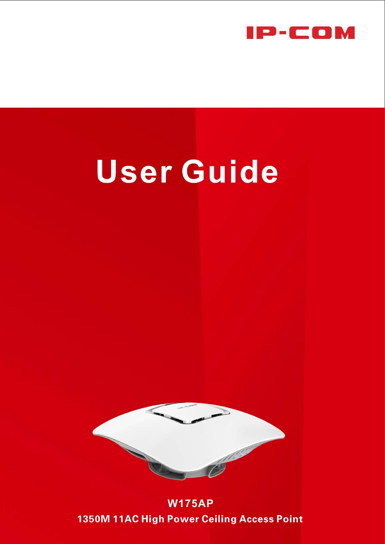
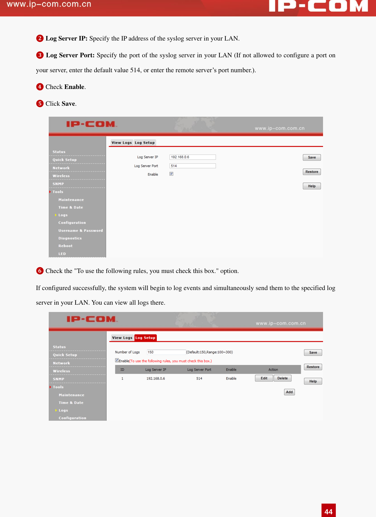
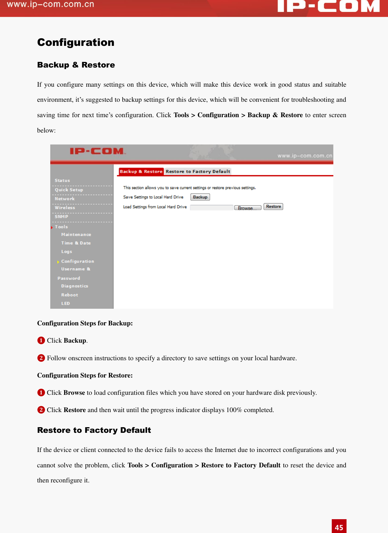
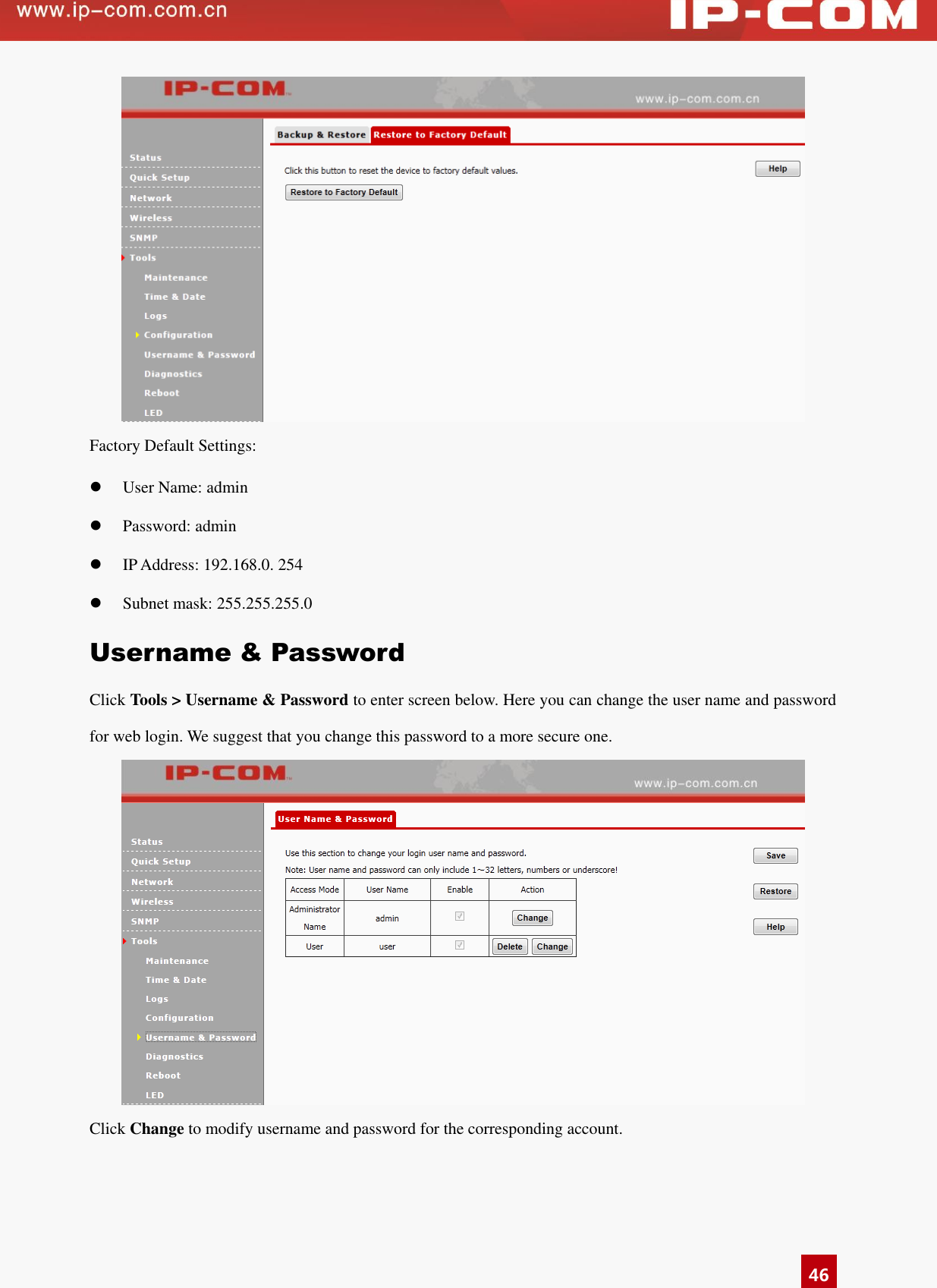
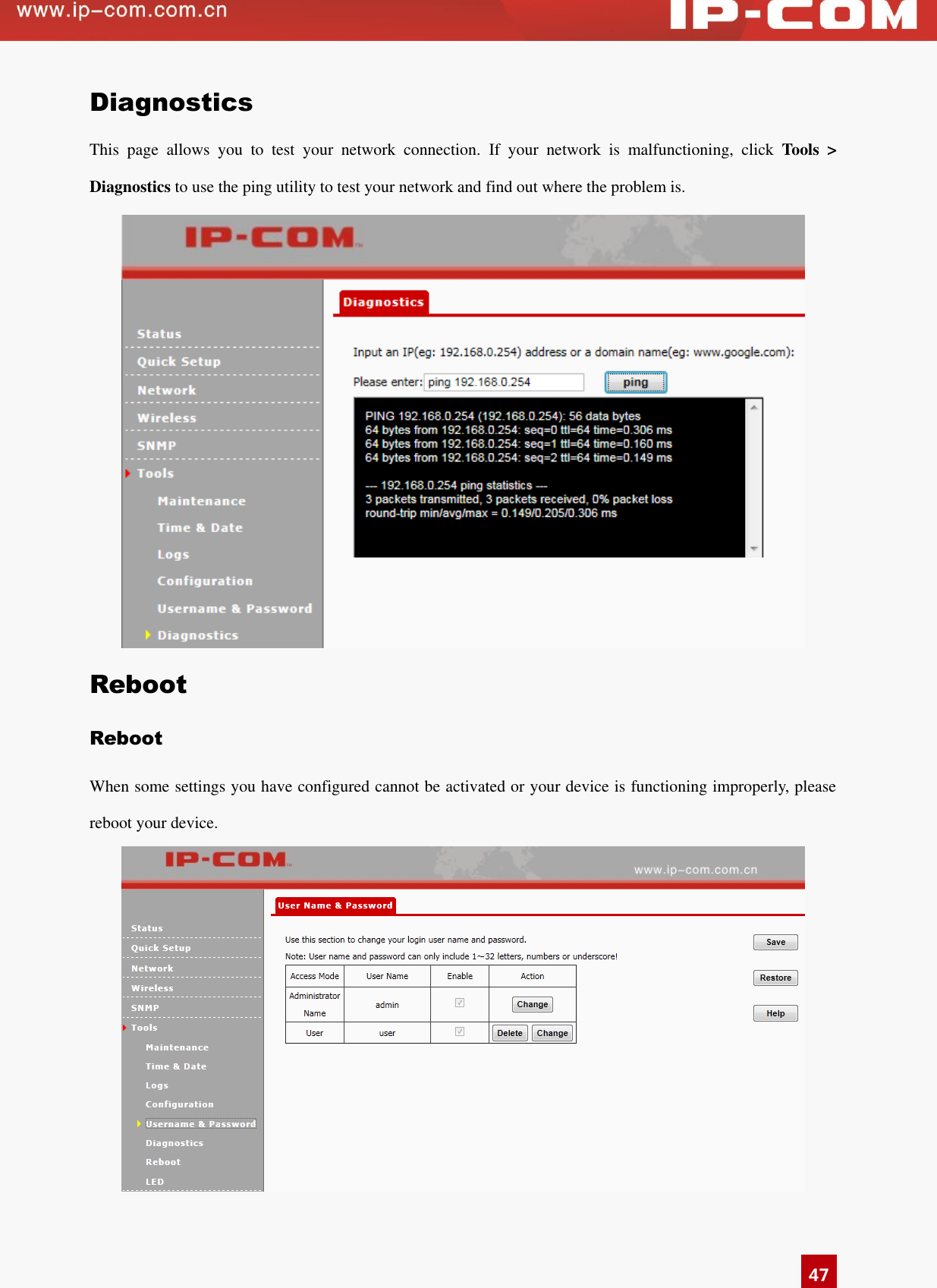
IP COM NETWORKS W175AP 1350M 11AC High Power Ceiling Access Point User Manual

SHENZHEN IP-COM NETWORKS CO.,LTD. 1350M 11AC High Power Ceiling Access Point

Users Manual

  i Copyright Statement ©2015 IP-COM Networks Co., Ltd. All rights reserved. IP-COM is the registered trademark of IP-COM Networks Co., Ltd. Other brand and product names mentioned herein are trademarks or registered trademarks of their respective holders. Copyright of the whole product as integration,  including  its  accessories  and  software,  belongs  to  IP-COM  Networks  Co.,  Ltd.  No  part  of  this publication  can  be  reproduced,  transmitted,  transcribed,  stored  in  a  retrieval  system,  or  translated  into  any language in any form or by any means without the prior written permission of IP-COM Networks Co., Ltd.   Disclaimer Pictures,  images  and  product  specifications  herein  are  for  references  only.  To  improve  internal  design, operational function, and/or reliability, IP-COM reserves the right to make changes to the products described in this document without obligation to notify any person or organization of such revisions or changes. IP-COM does not assume any liability that may occur due to the use or application of the product or circuit layout(s) described herein.  Every effort has been  made in the  preparation of  this document to  ensure accuracy of  the contents, but all statements, information and recommendations in this document do not constitute the warranty of any kind, express or implied.
  ii Preface   Thank you for purchasing this IP-COM product! Reading this User Guide will be helpful for you to configure, manage and maintain this product.   Intended Readers This  User  Guide  is  intended  for  technicians  who  have  basic  knowledge  related  to  Internet  and  network terminology.   Conventions   If  not  specifically  indicated,  “AP”,  “this  device”  or  “this  product”  mentioned  in  this  User  Guide  stands  for W175AP. Typographical conventions in this User Guide:   Item   Presentation   Example Button   Bold “Click  the  Save  button”  can  be  simplified  as “Click Save”. Menu   Bold   “The menu Basic” can be simplified as Basic.   Continuous Menus > Click Wireless > Basic   Symbols in this User Guide:   Item   Meaning   Note This format is used to highlight information of importance or special interest.  Ignoring  this  type  of  note  may  result  in  ineffective configurations, loss of data or damage to device. Tip This  format  is  used  to  highlight  a  procedure  that  will  save  time  or resources.
  iii Overview of this User Guide Contents of all chapters in this User Guide are arranged as shown below:   Chapter Content   1 Product Overview General  introduction  of  product  features  and  its  physical appearance 2 Device Installation Introduction of device installation 3 Web Manager Introduction Introduction of web manager of this device 4 Advanced Functions Introduction of advanced settings about this device 5 Appendix Introduction of troubleshootings, TCP/IP settings and safety & emission statement.
  iv Contents   1 Product Overview ................................................................................................................................................. 2 Overview ............................................................................................................................................................... 2 Features .................................................................................................................................................................. 2 Package Contents ................................................................................................................................................... 3 Product Appearance ............................................................................................................................................... 3 Interface & Button ............................................................................................................................................. 3 Label .................................................................................................................................................................. 4 2 Device Installation ................................................................................................................................................ 5 Preparations ........................................................................................................................................................... 5 Installation Considerations ................................................................................................................................ 5 Environmental Requirements ............................................................................................................................ 5 Tools You Need to Prepare ................................................................................................................................ 6 Hardware Installation ............................................................................................................................................ 6 Device Checking .................................................................................................................................................... 9 3 Web Manager Introduction ................................................................................................................................ 11 Web Login ............................................................................................................................................................11 Layout of Web Manager .......................................................................................................................................11 Configuration Requirements ................................................................................................................................ 12 4 Advanced Functions ........................................................................................................................................... 13 Status ................................................................................................................................................................... 13 System Status ................................................................................................................................................... 13 Wireless Status ................................................................................................................................................. 13 Traffic Statistics ............................................................................................................................................... 14 Wireless Clients ............................................................................................................................................... 15 Quick Setup ......................................................................................................................................................... 17 AP Mode .......................................................................................................................................................... 17 WDS Mode ...................................................................................................................................................... 18 APClient Mode ................................................................................................................................................ 22 Network ............................................................................................................................................................... 24 LAN Setup ....................................................................................................................................................... 24 DHCP Server ................................................................................................................................................... 25 Wireless ............................................................................................................................................................... 26
  v Basic ................................................................................................................................................................ 26 Radio ................................................................................................................................................................ 31 Channel Scan ................................................................................................................................................... 33 Advanced ......................................................................................................................................................... 34 Access Control ................................................................................................................................................. 36 QVLAN ........................................................................................................................................................... 37 SNMP .................................................................................................................................................................. 39 Tools .................................................................................................................................................................... 40 Maintenance ..................................................................................................................................................... 40 Time & Date .................................................................................................................................................... 41 Logs ................................................................................................................................................................. 42 Configuration ................................................................................................................................................... 45 Username & Password ..................................................................................................................................... 46 Diagnostics ...................................................................................................................................................... 47 Reboot .............................................................................................................................................................. 47 LED ................................................................................................................................................................. 49 5 Appendix .............................................................................................................................................................. 50 Troubleshooting ................................................................................................................................................... 50 Technical Support ................................................................................................................................................ 50 Configure PC ....................................................................................................................................................... 51 Windows 8 ....................................................................................................................................................... 51 Windows 7 ....................................................................................................................................................... 53 Windows XP .................................................................................................................................................... 55 Safety and Emission Statement ........................................................................................................................... 57
  2 1 Product Overview Overview This Wi-Fi access point is mainly designed for hotels, especially for star-rated hotels and commercial hotels for wireless extension. With its ceiling design and existing construction, it saves a lot of time and costs for wireless networking. Meanwhile, it is an ideal choice for WiFi extension.   Features  Support 2.4GHz: IEEE 802.11n/g/b  Support 5GHz: IEEE 802.11ac/n/a  2.4GHz wireless transmission rate: Up to 450Mbps; 5GHz wireless transmission rate: Up to 900Mbps  Support multiple SSIDs: 2.4GHz: 8 SSIDs; 5GHz: 4 SSIDs  Support QVLAN, which can isolate traffic flow among different SSIDs    Support DHCP server, which can automatically assign IP addresses to clients    Compliant with IEEE 802.3at PoE PDs, thus it can connect to the rated standard PoE injector or an IEEE 802.3at-compliant PoE_PSE switch for power supply    One 10/100/1000Mbps auto-negotiation, IEEE 802.3ab, IEEE 802.3u, IEEE 802.3-compliant PoE port for data transmission and power supply  Support multiple cipher types, including  WEP, WPA-PSK, WPA2-PSK, Mixed  WPA/WPA2-PSK, WPA and WPA2 to block unknown access    Support automatic channel selection    Support transmission power adjustment    Support 3 working modes: AP mode, WDS mode and AP Client mode  Support the diagnostic tool: ping    Support SNMP v1/v2c  Support LED ON/OFF
  3 Package Contents Unpack the package carefully and verify that the following items are included:  Wireless Access Point *1  Power Cord*1  Power Adapter *1  PoE Injector *1  Ethernet Cable *2  PA3 Screw *8  KA3 Screw *3  Magnet *4  Bracket A *1  Bracket B *1  Plastic Bolt *8  Install Guide *1  Position Paster *1  If any item is incorrect, missing, or damaged, please contact your dealer for immediate replacement.   Product Appearance Interface & Button  1. RST: Pressing it for 7 seconds restores this device to factory default settings. 2. ON / OFF: LED hardware switch for turning on/off LED lights
  4 3. PoE: PoE port for connecting to the PoE injector or a PoE switch for power supply 4. LAN: 10/100/1000Mbps auto-negotiation RJ45 port for connecting  to a PC, switch or any other Ethernet device   Label  1. Default login IP address for web login of this device   2. Default login user name and password 3. Power specification of this device
  5 2 Device Installation Preparations Before installing this device, please peruse this part carefully. Installation Considerations  Do not remove the housing of this device.    Put this device in a dry and flat place to avoid dampness and a fall.    Please keep the device clean. Environmental Requirements As this device must be used indoors, when it is mounted onto the ceiling, the following requirements should be met:  Try to choose a location that minimizes obstacles between this device and its connected wireless devices. Open corridors and other spacious locations will typically provide better conditions for performance than a crowded room.    Try to position your device away from electrical devices that are potential sources of interference, such as ceiling fans, home security systems, microwaves, PCs, refrigerators, etc.    Install this device in a position as hidden as possible to avoid affecting your daily life and work.  To ensure normal operation, the following environmental requirements should also be met:       Item   Requirement   Temperature   0℃~ 45℃ Humidity   10% ~ 90% RH (non-condensing)
  6 Tools You Need to Prepare While installing this device, prepare the following tools by yourself.    Hardware Installation   Step 1: Install the bracket   Method One: Ceiling/Wall Installation ❶ Paste the position paster onto the wall or ceiling, wear anti-static gloves and use the hammer drill to drill three holes with a diameter of 5mm on the wall or ceiling according to holes on the position paster.   ❷ Use the rubber hammer to knock the three plastic bolts onto  the  wall or  ceiling  where you’ve  drilled  the holes.   ❸ Maneuver the bracket until it fits in the plastic bolts on the wall or ceiling and then fix the bracket onto the wall or ceiling with the screwdriver and included screws.                    (Bracket A)                                                                (Bracket B)
  7 Method Two: Magnet Installation (Bracket B)   ❶ Place three magnets on corresponding concave surfaces of Bracket B, fix magnets onto the Bracket B with screws.  ❷ Then attach the bracket (installed with magnets) vertically onto the ironwork surface.  Step 2: Install the device   ❶ Connect one end of the Ethernet cable (Cat5 or higher is recommended) to the PoE port of this device.
  8 ❷ Maneuver the device until it fits in the bracket, and then refer to the following figure to rotate the device until the device is fixed tightly onto the bracket.  Step 3: Connect to power supply   Method One: Connect to a PoE device   Connect the other end of the Ethernet cable from the PoE port of this device to the PoE port of a PoE switch.    Method Two: Connect to the included PoE injector   ❶ Connect the other end of the Ethernet cable from the PoE port of this device to the AP port of the PoE injector.  ❷ Connect the switch port of the PoE injector to a switch with an Ethernet cable.   ❸ Connect the power cord to a socket.
  9 Device Checking When  this  device  is  powered  on,  you  can  know  whether  it  works  normally  or  not  according  to  LED designations.     LED Light Status   Description   Power Solid   Proper connection to power supply   Blinking   The device is functioning normally. Off   The following three circumstances may occur:  Improper connection to power supply  Malfunction occurs.  The LED is turned off manually. 2.4GHz Solid   2.4G WiFi is enabled.   Blinking Data is being transmitted (2.4GHz).   Off   The following three circumstances may occur:  Improper connection to power supply  2.4G WiFi is disabled.  The LED is turned off manually.
  10 11AC Solid 5G WiFi is enabled. Blinking   Data is being transmitted at the 5G radio. Off   The following three circumstances may occur:  Improper connection to power supply  5G WiFi is disabled   The LED is turned off manually.
  11 3 Web Manager Introduction Web Login Step 1: Connect your PC to the switch which has been connected to this AP or to the LAN port of this AP directly.   Step 2: Set your PC to a static IP address within the following range: 192.168.0.X (1~253). Note that the IP address of your PC should be a different one but on the same network segment as the LAN IP address of this device. For more details, see Configure PC. Step 3: Launch a web browser, input the LAN IP address of your AP (The default one is 192.168.0.254.) in the address bar and then press Enter or Return on your keyboard. Step 4: Enter the default username and password (admin for both) on the pop-out page and click Login.  Then you can log in to this device’s web page to configure settings for your device.   Layout of Web Manager The Web page can be divided into two parts: navigation bar and the configuration section.
  12    ❶ Navigation Bar: The navigation bar presents web administration functions to you in the form of navigation tree. This section allows you to select function menus.   ❷ Configuration Section: This section allows you to configure and view settings.    Note: Only web administration features that this device supports will be displayed on navigation bars. Specifically, please refer to the actual software of your device.  Configuration Requirements  Operation System: Windows XP / 2000 / Vista / 7 / 8, Windows Server 2003 enterprise edition, Windows Server 2003 standard edition, Linux, MAC OS, etc.    Web  Browser:  Microsoft  Internet  Explorer  8.0  SP2  or  higher,  Mozilla  Firefox  3.0  or  higher,  Google Chrome 2.0.174.0 or higher, Opera 9.64 or higher, Safari 3.1.1 or higher, etc.  The firewall of your PC should be disabled.    When the firmware version of your device is upgraded, it is advisable to clear your web browser cache first.
  13 4 Advanced Functions Status This section gives you an overview of device status and basic information. The following 4 parts are included:   System Status: Display the AP’s current system status and LAN information Wireless Status: Display connected devices’ radio status and SSID status information Traffic Statistics: Display traffic statistics of all SSIDs   Wireless Clients: Display information of connected devices   System Status This page displays system status information and LAN information of this AP, including device name, system time, up time, number of wireless clients, firmware version, hardware version, MAC address, IP address, etc.      Wireless Status This page displays 2.4GHz or 5 GHz radio status, SSID status and WDS status of this device. As for the 5GHz radio,  your  wireless  clients  must  be  compatible  with  5GHz.  Click  Status  >  Wireless  Status  to  enter  page below:
  14   Traffic Statistics This  page displays  traffic statistics  of  corresponding  SSIDs.  Click  Status >  Traffic Statistics  to enter  page below:
  15    SSID: WiFi name.  Total RX Traffic: Total traffic which the corresponding SSID has received.  Total RX Packets: Total packets which the corresponding SSID has received.  Total TX Traffic: Total traffic which the corresponding SSID has transmitted.  Total TX Packets: Total packets the corresponding SSID has transmitted.  Wireless Clients This page displays information, like MAC address, IP, connection duration and link speed of connected clients. Click Status > Wireless Clients to enter page below:
  16   MAC Address: MAC address of the connected device  IP: IP address that the connected device has obtained  Connection Duration: Display connection duration which the SSID has connected to.  Send Speed: Transmission speed of the wireless client  Receive Speed: Receiving speed of the wireless client
  17 Quick Setup There are three working modes on this device: AP mode, WDS mode and AP Client mode. Click Quick Setup to enter page below:  AP  Mode:  In  this  mode,  the  AP  connects  to  the  remote  device  via  an  Ethernet  cable  and  then  clients  can connect to the AP wirelessly, thus achieving the conversion between wired networking and wireless networking.   WDS Mode: In the WDS mode, the AP and the remote device should support WDS feature. By scanning each other and keeping their SSIDs, channels, security modes and keys the same, they can bridge successfully. Then clients can connect to the AP wirelessly for Internet access. AP  Client  Mode:  In  this  mode,  what  you  need  to  do  is  to  scan  the  remote  device’s  signal  and  bridge  it successfully without any configuration on the remote device. Then clients can connect to the AP wirelessly for Internet access. AP Mode In this mode, this device works as an access point and you can configure the SSID and its encryption mode.
  18 Configuration Steps: ❶ Mode: Select AP Mode.   ❷ SSID: Modify the SSID (optional). The SSID is the WiFi name you need to connect to for Internet access. ❸ Security Mode: WPA-PSK is recommended. ❹ Cipher Type: AES is recommended. ❺ Security Key: Configure a WiFi password as you like. When your device is connecting to the WiFi, the WiFi password (security key) will be needed. ❻ Click Save to apply your settings.   WDS Mode   SSID:  Display  SSID  of  this  device.  When  multiple  SSIDs  are  selected,  the  first  SSID  among  remote devices will be displayed here.  Security Mode: Display security  mode of the remote device.  In the WDS mode, all  devices’  encryption modes and security keys should be kept the same.    MAC Address: Display the remote device’s MAC address. 4 remote devices are supported in this mode.    The Uplink AP’S Channel: Display channel of the first remote device. In the WDS mode, channels for all devices should be kept the same.
  19  Enable Scan: Click it to scan SSIDs.  Application Scenario: There’s already an AP (Hereinafter referred as the remote AP) installed on the second floor of a hotel. Due to limited  WiFi  coverage  or  other  objects’  intereference, some  rooms  of  the  hotel  on  the  second  floor  may  be unable to enjoy WiFi smoothly. Then you can install one more AP or multiple APs (≤ 4) in those rooms where WiFi signal is not strong enough for WiFi extension. In this mode, both this AP and the remote AP need to scan each other for WDS settings.  Before configuring WDS settings, verify the  following information of the remote SSID: SSID (WiFi name), channel and encryption information.   Assuming information of the remote device (AP 2) is as below:   SSID: IP-COM_130518 Channel: 6 IP Address: 192.168.0.254 Security Mode: Mixed WPA/WPA2-PSK Cipher Type: AES Security Key: 12345678 Note: 1. In the WDS mode, both the AP and the remote device should support WDS feature. 2. As for IP addresses, they should not be the same but on the same network segment. 3. This AP’s and the remote device’s SSID, channel, security mode and security key should be kept the same.   4. Up to 4 APs can be bridged at the same time.
  20 Configuration Steps: ❶ Click Network > LAN Setup to set the LAN IP address of AP 1 to one that is different from AP 2 but on the same network segment. Here we change it to 192.168.0.253.  ❷ Select WDS Mode and click Enable Scan.  ❸ Select the remote SSID (WiFi name), type in encryption information (including security mode, cipher type and security key) of the remote device and then click Save. Then SSID of AP 1 will be the same as that of the remote device (AP 2).
  21  ❹ Refer to Steps 2~3 to configure similar settings on the remote device (AP 2). ❺ After  completing  all  settings  mentioned  above,  refresh  the  page.  When  the  corresponding  MAC  address’ status displays Connected, WDS settings are activated successfully.
  22   APClient Mode In this mode, the AP negotiates with the remote device firstly and then it can provide access to clients. What you need  to  do  is  to  scan  the  remote  device’s  signal  and  bridge  it  successfully  without  any  configuration  on  the remote device. To some extent, this is the biggest difference between the WDS mode and AP Client mode. Then clients can connect to the AP wirelessly for Internet access.
  23 Application Scenario: There’s already an AP (Hereinafter referred as the remote AP) installed on the second floor of a hotel. Due to limited  WiFi  coverage  or  other  objects’  intereference, some rooms of  the  hotel on the  second floor  may be unable to enjoy WiFi smoothly. Then you can install one more AP in the room where WiFi signal is not strong enough for WiFi extension. In this mode, you have no need to configure any WDS settings on the remote AP.  Before configuring AP Client settings, verify the following information of the remote SSID: SSID (WiFi name), channel and encryption information.   Assuming information of the remote device is as below:   SSID: IP-COM_130518 Channel: 6 Security Mode: Mixed WPA/WPA2-PSK Cipher Type: AES Security Key: 12345678  Configuration Steps: ❶ Select APClient Mode and click Enable Scan.
  24 ❷ Select the remote SSID “IP-COM_130518” and click Save.    Note: Verify that the DHCP server on the remote AP (AP 2) is disabled.   Network LAN Setup Click Network > LAN Setup to configure LAN parameters.     MAC Address: LAN MAC address of the device.   Address Mode: Static IP: The default address mode of your device. You can modify the LAN IP address       manually. Once the LAN IP address of the device is changed, you need to use the new IP address to re-log in to its web page. Dynamic IP: Your device obtains IP address information automatically.  IP Address: The default LAN IP address of the device is 192.168.0.254. You can modify it here.
  25  Subnet Mask: Subnet mask of the device. The default one is 255.255.255.0.  Gateway: Gateway of the device. Usually, it is advisable to enter the LAN IP address of the remote device.   Device Name: Modify the device name. DHCP Server DHCP Server If you enable the built-in DHCP server on the device, it will automatically configure the TCP/IP settings for all your  LAN  computers  (including  IP  address,  subnet  mask,  gateway  and  DNS  etc.),  eliminating  the  need  of manual intervention. Just be sure to set all computers on your LAN to be DHCP clients by selecting Obtain an IP Address Automatically  respectively on  each  PC.  When  turned on,  these  PCs  will  automatically load  IP information from the DHCP server. By default, the DHCP server on this device is disabled. The first time you connected to the AP, you need to set your PC to Use the following IP address. For more details, see Configure PC. Click Network > DHCP Server to enter page below:     DHCP Server: Check/Uncheck it to enable/disable the DHCP server.  Start IP: The start IP address that the DHCP server has automatically assigned.   End IP: The end IP address that the DHCP server has automatically assigned.   Lease Time: How long the IP address can be used by the client device.   Primary DNS Server: Primary DNS server address.  Secondary DNS Server: Secondary DNS server address.
  26 DHCP Client List Click Network > DHCP Server > DHCP Client List to view DHCP clients information.    Wireless Basic Click Wireless to configure basic wireless settings. It is advisable to configure the SSID, security mode and security key, and leave other settings unchanged.
  27   SSID: Up to 8 SSIDs at the 2.4G radio and 4 SSIDs at the 5G radio can be supported on this device.    Enable: When you check it, Wi-Fi will be allowed for the selected SSID.      Hide SSID automatically: When the maximum number of clients is exceeded, the SSID will be hidden automatically.  Broadcast SSID:  When  it  is  enabled,  wireless  clients  are  able  to  scan  the  SSID;  when  it  is  disabled, wireless clients are unable to scan the SSID. At this time, if you want to connect to it wirelessly, you have to type in the SSID and select the encryption mode manually.    AP  Isolation: When  this  function  is  enabled,  wireless  clients  connected  to  the  SSID  won’t  be  able  to communicate with each other, which can enhance wireless network security.    Maximum Clients: The maximum number of wireless clients which can connect to the SSID.    SSID: WiFi name. Different SSIDs can have different configurations.  Chinese SSID Encode: Select Chinese SSID encodes to match wireless clients with different code formats in a better way.  Security Mode: Display wireless encryption information of the current SSID. Available security modes are: None, WEP, WPA-PSK, WPA2-PSK, Mixed WPA/WPA2-PSK, WPA, and WPA2.   Configuration Steps: ❶ SSID: Select the SSID (WiFi name) you wish to configure.   ❷ Enable: Check it to enable the selected SSID. ❸ Maximum Clients: Configure the number of wireless clients
  28 ❹ SSID: Modify your SSID. ❺ Security  Mode,  Cipher  Type,  Key:  Choose  WPA-PSK  as  priority  and  configure  wireless  encryption information for your SSID.   ❻ Click Save. WEP WEP (Wired Equivalent Privacy): WEP is a security mode for data which is delivered between two devices to protect  wireless  network  from  illegal  users.  WEP  is  the  RSA  data  encryption  technology  based  on  RC4. Compared with WEP, WPA-PSK and WPA2-PSK are more secure.   Default Key: Four Security Keys are available. You can choose one from them.    Open: Uses "no authentication" + WEP Encryption. Wireless clients can associate with the device without going through authentication. Only data in transmission is encrypted with WEP encryption.  Shared: Uses shared key authentication + WEP Encryption. A WEP key that is mutually agreed in advance is required from both sides while wireless clients try to associate with the device. Association is established only if the two sides provide the same WEP key.  Default Key: Specify a WEP key from the preset keys for current use. For example, if you select Key 2, wireless clients must join your wireless network using this Key 2.  WEP  Keys:  ASCII  and  Hex  are  provided  for  you  to  configure.  When  you  configure  ASCII,  you  can
  29 choose 5 or 13 ASCII codes (only “0~9, a~z, A~Z, @, *, -, _”can be allowed). When you configure Hex, you can  choose  10 or 26 hexadecimal  numbers.  One  English letter or  an  Arabic numeral  takes up  one ASCII code. WPA-PSK   Wi-Fi Protected Access (WPA) and Wi-Fi Protected Access II (WPA2) are two security protocols and security certification programs developed by the Wi-Fi Alliance to secure wireless computer networks. Only authorized network users can access the wireless network. WPA-PSK adopts enhanced encryption algorithm over WEP.     Cipher  Type:  AES  (Advanced  Encryption  Standard),  TKIP  (Temporal  Key  Integrity  Protocol)  and TKIP&AES are available. The default is AES.  Key: Specify the security key you wish to configure (8~63 ASCII characters). Only “0~9, a~z, A~Z, @, *, - , _” can be included. And one English letter or an Arabic numeral takes up one ASCII code.   WPA2-PSK   WPA2  (Wi-Fi Protected  Access version 2)-PSK is more  secure than  WEP (Wireless Equivalent  Privacy)  or WPA (Wi-Fi Protected Access). Apart from TKIP, AES is also available.
  30   Cipher  Type:  AES  (Advanced  Encryption  Standard),  TKIP  (Temporal  Key  Integrity  Protocol)  and AES&TKIP are available. The default is AES.    Key: Specify the security key you wish to configure (8~63 ASCII characters). Only “0~9, a~z, A~Z, @, *, - , _” can be included. And one English letter or an Arabic numeral takes up one ASCII code.   Mixed WPA/WPA2-PSK     Cipher  Type:  AES  (Advanced  Encryption  Standard),  TKIP  (Temporal  Key  Integrity  Protocol)  and AES&TKIP are available. The default is AES.    Key: Specify the security key you wish to configure (8~63 ASCII characters). Only “0~9, a~z, A~Z, @, *, - , _” can be included. And one English letter or an Arabic numeral takes up one ASCII code.
  31 WPA/WPA2 Adopt 802.1X and RADIUS authentication for data encryption.     RADIUS Server: IP address of the RADIUS server.  RADIUS Port: Port for RADIUS authentication.  RADIUS Password: Password for accessing the RADIUS server.    Cipher  Type:  AES  (Advanced  Encryption  Standard),  TKIP  (Temporal  Key  Integrity  Protocol)  and AES&TKIP are available. The default is AES.   Radio Click Wireless > Radio to configure radio settings. If you are new to networking and have never configured these settings before, we recommend you to leave the default settings unchanged.
  32    Enable Wireless: Check it to enable WiFi function.    Country: Select the country where your device works,  Network Mode: Select a proper network mode for your device. In 2.4G radio, the default mode is 11b/g/n mixed. In 5G radio, the default mode is 11ac.  Channel: Select a proper channel for your wireless network.    Channel  Bandwidth:  Select  a  proper  channel  bandwidth  to  enhance  wireless  performance.  When  the network mode is not 802.11n mode, only 20M can be selected. When the network mode is 802.11n mode, it is advisable to select 20/40M for better wireless performance.    Extension Channel: This is used to ensure radio frequency for 802.11n devices on the network.    Channel Lockout: Once this option is enabled, you can’t modify the channel manually.    WMM Capable: WMM is QoS for your wireless network. Enabling this option may ensure better online stream wireless multimedia data such as video or audio (recommended).
  33  APSD Capable: Automatic power save delivery. It is disabled by default. Channel Scan Click  Wireless >  Channel  Scan  to  get  an  overview  of  wireless  signals  nearby.  And  then  you  can  select  a channel  which  is  the  least  used  by  neighboring  networks  (i.e.  the  channel  with  least  interference)  for  your device for better network performance.     Click Enable Scan to view channels of wireless signals nearby.
  34  Advanced Click Wireless > Advanced to configure advanced wireless settings. If you are not familiar with these settings, keep the default settings unchanged.      Beacon Interval: This is a time interval between any two consecutive Beacon packets sent by an Access
  35 Point to synchronize a wireless network. Specify a valid value between 20 and 999. The default setting is 100. It is advisable to leave the default value unchanged.    Fragment Threshold: Specify a valid Fragment Threshold value between 256 and 2346. The default is 2346.  Any  wireless  packet  exceeding  the  preset  value  will  be  divided  into  several  fragments  before transmission.   RTS Threshold: Specify a valid value between 1 and 2347. The default is 2347. If a packet exceeds the preset value, RTS/CTS scheme will be used to reduce collisions. Set it to a smaller value provided that there  are  distant  clients  and  interference.  For  SOHO  users,  it  is  suggested  to  keep  the  default  value unchanged.    DTIM Interval: A DTIM (Delivery Traffic Indication Message) Interval is a countdown informing clients of the next window for listening to  broadcast and multicast messages. When such packets arrive in  the router's buffer, the router will send DTIM (delivery traffic indication message) and DTIM interval to alert clients of the receiving packets. Specify a valid value between 1 and 255. The default is 1.    Receive  Signal  Strength:  Configure  signal  strength  for  connected  clients.  When  the  wireless  client’s signal strength is lower than the setting value, the wireless client will not be allowed to connect to the AP.  Interference Mitigation: Mainly used for reducing wireless or some non-wireless interference to enhance transmission rate of your device.   Interference mitigation: interference mitigation mode, range: 0-4. The default is 2. (1) Mode 0: All interference mitigation is disabled. (2) Mode 1: Non-wireless LAN Interference mitigation is enabled. (3) Mode 2: Wireless LAN Interference mitigation is enabled. (4) Mode 3: Auto Wireless LAN Interference mitigation is enabled and active. (5) Mode 4: Auto Wireless LAN Interference mitigation is enabled and noise reduction is enabled.  TX Power: Used for configuring wireless transmission power. You can change the value according to your actual network environment.  Power Lockout: Once this option is enabled, you can’t modify power manually.    Preamble: Mainly used for preamble synchronization. It is advisable to keep the default value unchanged.
  36 Access Control Click Wireless > Access Control to enter page below. This page allows you to specify a list of devices to allow or disallow a connection to your wireless network via the device's MAC addresses. To deactivate this feature, select "Disable"; to activate it, select "Allow" or "Deny".    SSID: Select the SSID you wish to configure access control setting.    MAC Filter Mode: Select Disable to disable Access Control function. Allow: Only MAC addresses in the access control list are allowed to connect to the SSID. Deny: MAC addresses in the access control list are not allowed to connect to the SSID.
  37 Configuration Steps: ❶ Select the SSID you wish to configure from the drop-down list. ❷ Select the MAC Filter mode. ❸ Enter the MAC address of the wireless client. ❹ Click Add. ❺ Click Save.  QVLAN When QVLAN is enabled, you can tag different SSIDs to different VLANs. Used with the managed switch, you can establish different VLANs and different Internet Access rights.  SSID: WiFi name. Up to 32 characters can be supported.    VLAN ID: Specify a value between 2 and 4094.
  38 For instance: People in a hotel are generally classified into three kinds: hotel executives, hotel stuffs and customers. They all access the internal network via this device.   1. Hotel executives can access both the Internet and internal network in the hotel. 2. Hotel stuffs can only have the access to internal network in the hotel, 3. Customers can only access the Internet. The network diagram is shown below:    After the above-mentioned physical installation, follow below steps: ❶ Enable 3 SSIDs on the device and name these SSIDs differently. As shown in the diagram, SSID used by internal members is hidden (Once QVLAN is enabled, we can only configure security key for one SSID. Hiding SSID secures the internal network in the hotel). ❷ Enable QVLAN and bind the three different SSIDs as shown below.   ❸ Configure the switch: A. Configure the port on the switch connected to the AP as the Trunk port, PVID=1 and all VLANs allowed; B. Configure the port on the switch connected to the server in the hotel to be VLAN1 tagged, VLAN10 tagged and VLAN20 tagged; C. Configure the port on the switch connected to the router as the Trunk port, VLAN1, VLAN10 and VLAN30 allowed;
  39 D. Configure the port on the switch connected to hotel executives to be VLAN10 tagged, the port connected to hotel stuffs to be VLAN20 tagged and the port connected to customers to be VLAN30 tagged.    SNMP The  Simple  Network  Management  Protocol  (SNMP)  is  widely  used  in  local  area  networks  (LANs)  for collecting information, managing, and monitoring network  devices, such as servers, printers, hubs, switches, and routers. Specialized software in each SNMP capable device, known as an Agent, continuously monitors the status of the device and reports the results to the SNMP Manager software, which can then act on the report. Click SNMP to enter screen below:   SNMP: Disable or Enable the SNMP function.    Read  Community:  Indicates  the  community  string  for  read  access  to  permit  reading  this  AP’s  SNMP information. The default is Public.    Write/Read  Community:  Indicates  the  community  string  for  write/read  access  to  permit  reading  and re-writing this AP’s SNMP information. The default is Private.
  40 Tools This section will instruct you how to maintain your device.   The following eight parts are included: Maintenance, Time & Date, Logs, Configuration, Username & Password, Diagnostics, Reboot and LED.   Maintenance If your device is in normal operation, it is not advisable to upgrade your device. If you want to acquire the latest software  version  or  better  value-added  functions  for  your  device,  you  can  access  our  official  website www.ip-com.com.cn to download the latest software for upgrading. Click Tools > Maintenance > Firmware Upgrade to enter screen below:    Configuration Steps for Firmware Upgrade: ❶ Launch a web browser and go to http://www.ip-com.com.cn to download the latest firmware.   ❷ Unzip the compressed upgrade file in the corresponding directory.   ❸ Click Browse to locate and select the upgrade file in the corresponding directory on your hard disk.   ❹ Click Upgrade to upgrade device firmware.   Note: 1.  While upgrading, please verify that your PC is connected to the device with an Ethernet cable and power is delivered on this device. And the upgrading process will take several minutes, please be patient. 2.  When the upgrading is completed, your device will be restored to factory default settings automatically and you need to reconfigure your device.
  41 Time & Date System Time Click Tools > Time & Date > System Time to  enter the System Time  screen. This page is used to set the device’s system time. System time can be configured using the following 2 methods:  Sync with Internet time servers: If enabled, system automatically connects to NTP server on the Internet to synchronize the time.  Set  Time  and  Date  Manually:  Specify  the  time  and  date  manually  or  click  Sync  with  Your  PC  to automatically copy your current PC's time to the device.    Configuration Steps for Setting Time and Date Manually: ❶ Uncheck Sync with Internet time servers.   ❷ Click Sync with your PC or enter the correct date and time in the input fields.   ❸ Click Save.   And then you can go to the Status screen to make sure the system time is correctly updated. Note:                                                                                 Once power is not delivered on this device, the time settings will be lost. By default, Sync with Internet time servers is enabled. When the device is able  to access the  Internet, it will automatically connect to  the NTP server on the Internet to synchronize the time.
  42 Login Timeout Click  Tools  >  Time  &  Date  >  Login  Timeout  and  here  you  can  configure  the  web  login  timeout  (1~60 minutes). The default is 5 minutes. Device returns to login window automatically depending on the specified login timeout and user name/password will be required.  Logs View Logs Click Tools > Logs > View Logs to enter screen below. Here you can view the history of the device’s actions. Three types of logs are supported on this device: All, System and LAN. You can select any one of them from the drop-down list. Click Refresh to update current log info or click Clear to clear all logs.
  43  Log Setup Click Tools > Logs > Log Setup to configure system logs. Here you can set up the number of logs and rules of log settings. Up to 300 entries can be logged. The default is 150.   Configuration Steps: ❶ Click Add.
  44 ❷ Log Server IP: Specify the IP address of the syslog server in your LAN. ❸ Log Server Port: Specify the port of the syslog server in your LAN (If not allowed to configure a port on your server, enter the default value 514, or enter the remote server’s port number.).   ❹ Check Enable.   ❺ Click Save.  ❻ Check the "To use the following rules, you must check this box." option. If configured successfully, the system will begin to log events and simultaneously send them to the specified log server in your LAN. You can view all logs there.
  45 Configuration Backup & Restore If you configure many settings on this device, which will make this device work in good status and suitable environment, it’s suggested to backup settings for this device, which will be convenient for troubleshooting and saving time for next time’s configuration. Click  Tools > Configuration > Backup & Restore to enter screen below:      Configuration Steps for Backup: ❶ Click Backup. ❷ Follow onscreen instructions to specify a directory to save settings on your local hardware. Configuration Steps for Restore: ❶ Click Browse to load configuration files which you have stored on your hardware disk previously. ❷ Click Restore and then wait until the progress indicator displays 100% completed. Restore to Factory Default If the device or client connected to the device fails to access the Internet due to incorrect configurations and you cannot solve the problem, click Tools > Configuration > Restore to Factory Default to reset the device and then reconfigure it.
  46  Factory Default Settings:  User Name: admin  Password: admin  IP Address: 192.168.0. 254  Subnet mask: 255.255.255.0 Username & Password Click Tools > Username & Password to enter screen below. Here you can change the user name and password for web login. We suggest that you change this password to a more secure one.  Click Change to modify username and password for the corresponding account.
  47 Diagnostics This  page  allows  you  to  test  your  network  connection.  If  your  network  is  malfunctioning,  click  Tools  > Diagnostics to use the ping utility to test your network and find out where the problem is.  Reboot Reboot   When some settings you have configured cannot be activated or your device is functioning improperly, please reboot your device.
  48 Time Reboot Click Tools > Time Reboot to enter page below. Here you can reboot your device regularly. Once this function is enabled, please make sure that your device is synchronized with the Internet time server.   Two methods for time reboot are available: As Interval and As Scheduled.    As Interval: The device will reboot automatically at intervals according to the interval you’ve configured.  As Scheduled: The device will reboot regularly according to the time you’ve configured.  Configuration Steps for As Interval: ❶ Check Enable Auto Reboot.   ❷ Select As Interval from the AUTO Reboot Type drop-down list.   ❸ Specify the reboot interval. ❹ Click Save.
  49  Configuration Steps for AS Scheduled: ❶ Check Enable Auto Reboot.   ❷ Select As Scheduled from the AUTO Reboot Type drop-down list.   ❸ Check corresponding dates from Monday to Sunday to specify the reboot date. ❹ Specify the reboot time. ❺ Click Save. LED Click Tools > LED to enter screen below. Here you can turn on/off all LEDs.
     50 5 Appendix  Troubleshooting Q1: Power LED troubleshooting You can know whether the power system of this AP is functioning normally or not in terms of its power LED status. If the system is functioning normally, the Power LED should be lighted or blinking; if the Power LED is off, please verify that:   1.   Power cord is correctly connected and the Power ON/OFF switch is on.   2.    The power supply accords with the rated power input. 3.    The AP is connected to its PoE injector correctly. Q2: I  enter  the  device’s  LAN  IP  address in  the  web  browser  but  cannot  access  this  device’s  web  page. What should I do? 1.  Check the TCP/IP settings on your PC and verify that IP address is 192.168.0.X (2-253); 2.  Clear the browser cache or try another web browser; 3.  Ensure the wireless NIC is functioning properly. If you are still unable to login, please restore the device to factory default settings and follow this user guide to configure your settings again.    Technical Support Website: http://www.ip-com.com.cn   Tel: (86 755) 2765 3089 Email: info@ip-com.com.cn Skype: IP-COM.Support
     51 Configure PC Windows 8 Step 1: Right click the icon    or    on the bottom right corner of your desktop.  Tips: If you cannot find the icon      or    on the bottom right corner of your desktop, follow steps below: Move your cursor to the top right corner of your desktop, select Settings > Control Panel > Network and Internet > Network and Sharing Center.  Step 2: Click Open Network and Sharing Center.  Step 3: Click Ethernet > Properties.
     52 Step 4: Find and double click Internet Protocol Version 4(TCP/IPv4).  Step  5:  Select  Use  the  following  IP  address,  type  in  the  IP  address:  192.168.0.x  (2~253);  subnet  mask: 255.255.255.0 and click OK.  Step 6: Click OK on the Ethernet Properties window (see Step 4 for the screenshot).
     53 Windows 7 Step 1: Click the icon    on the bottom right corner of your desktop. Step 2: Click Open Network and Sharing Center.   Tip: If you cannot find the icon    on the bottom right corner of your desktop, follow steps below: Click Start > Control Panel > Network and Internet > Network and Sharing Center.  Step 3: Click Local Area Connection > Properties.  Step 4: Find and double click Internet Protocol Version 4(TCP/IPv4).
     54  Step  5:  Select  Use  the  following  IP  address,  type  in  the  IP  address:  192.168.0.x  (2~253);  subnet  mask: 255.255.255.0 and click OK.  Step 6: Click OK on the Local Area Connection Properties window (see Step 4 for the screenshot).
     55 Windows XP Step 1: Right click My Network Places on your desktop and select Properties.  Step 2: Right click Local Area Connection and select Properties.  Step 3: Scroll down to find and double click Internet Protocol (TCP/IP).
     56 Step  4:  Select  Use  the  following  IP  address,  type  in  the  IP  address:  192.168.0.x  (2~253);  subnet  mask: 255.255.255.0 and click OK.  Step 5: Click OK on the Local Area Connection Properties window (see Step 3 for the screenshot).
     57 Safety and Emission Statement   CE Mark Warning Operations in the 5.15-5.25GHz band are restricted to indoor usage only. This is a Class B product. In a domestic environment, this product may cause radio interference, in which case the user may be required to take adequate measures. NOTE:  (1)  The  manufacturer  is  not  responsible  for  any  radio  or  TV  interference  caused  by  unauthorized modifications to this equipment. (2) To avoid unnecessary radiation interference, it is recommended to use a shielded RJ45 cable.   FCC Statement This device is restricted to be used in the indoor. This device complies with Part 15 of the FCC Rules. Operation is subject to the following two conditions: (1) This  device  may  not  cause  harmful  interference,  and  (2)  this  device  must  accept  any  interference  received, including interference that may cause undesired operation. This equipment has been tested and found to comply with the limits for a Class B digital device, pursuant to Part  15  of  the  FCC  Rules.  These  limits  are  designed  to  provide  reasonable  protection  against  harmful interference in a residential installation. This equipment generates uses and can radiate radio frequency energy and,  if  not  installed  and  used  in  accordance  with  the  instructions,  may  cause  harmful  interference  to  radio communications. However, there is no guarantee that interference will not occur in a particular installation. If this equipment does cause harmful interference to radio or television reception, which can be determined by turning  the  equipment  off  and  on,  the  user  is  encouraged  to  try  to  correct  the  interference  by  one  of  the following measures: —  Reorient or relocate the receiving antenna. —  Increase the separation between the equipment and receiver.
     58 —  Connect the equipment into an outlet on a circuit different from that to which the receiver is connected. —  Consult the dealer or an experienced radio/TV technician for help. FCC Caution: Any changes or modifications not expressly approved by the party responsible for compliance could void the user's authority to operate this equipment. This transmitter must not be co-located or operating in conjunction with any other antenna or transmitter.   Radiation Exposure Statement This equipment complies with FCC radiation exposure limits set forth for an uncontrolled environment. This equipment should be installed and operated with minimum distance 20cm between the radiator & your body. NOTE:  (1)  The  manufacturer  is  not  responsible  for  any  radio  or  TV  interference  caused  by  unauthorized modifications to this equipment. (2) To avoid unnecessary radiation interference, it is recommended to use a shielded RJ45 cable.

Navigation menu