IP COM NETWORKS W75AP Wireless N900 High Power Dual Band Access Point User Manual
SHENZHEN IP-COM NETWORKS CO.,LTD. Wireless N900 High Power Dual Band Access Point
UserManual.wiki
>
IP COM NETWORKS
>
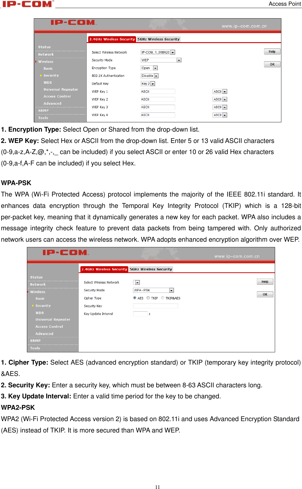
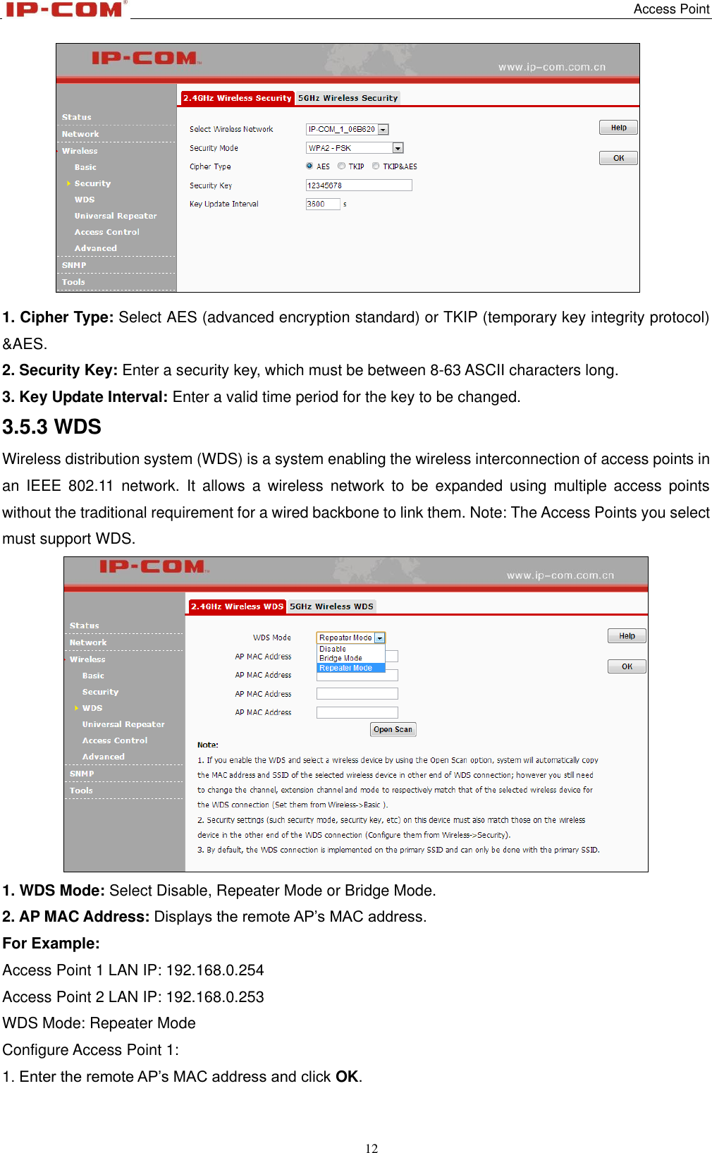
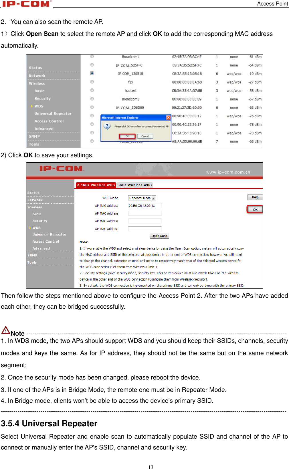
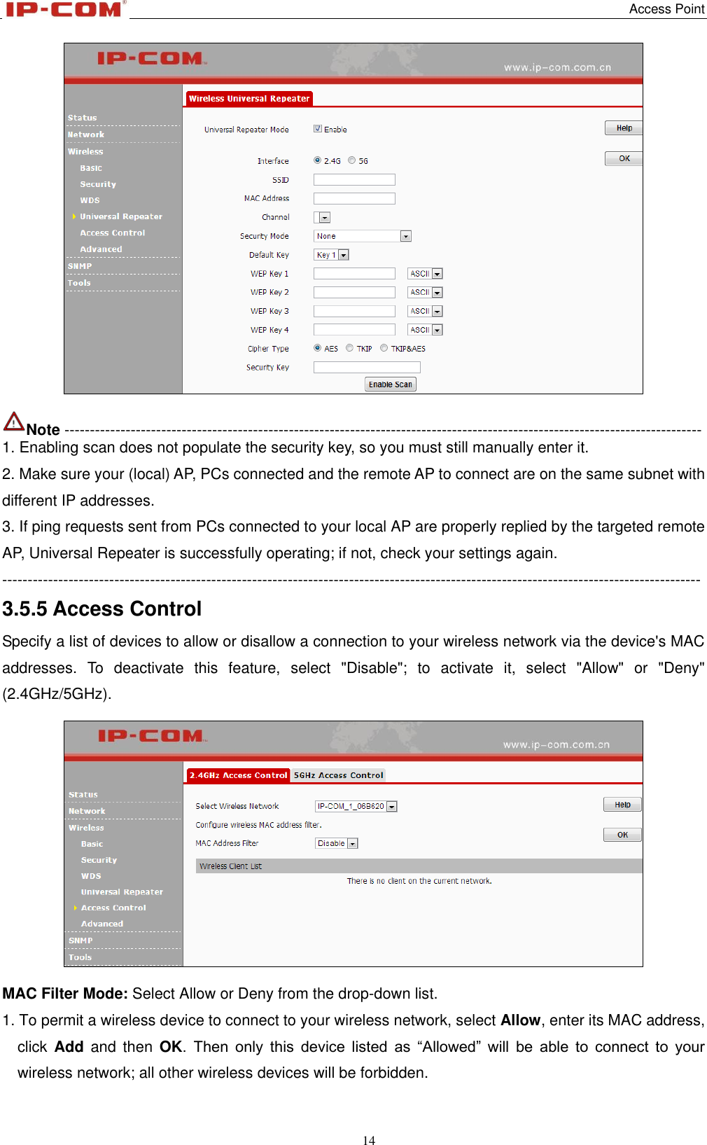
W75AP User Manual
User Manual
Navigation menu
Upload a User Manual
Namespaces
Wiki Guide
HTML
PDF
Info
Views
User Manual
Discussion / Help
Navigation