IP Mobilenet ECSHPA45TX User Manual hpa4
IP Mobilenet, LLC hpa4
Users Manual
ElectroCom
Product Support Manual
Model HPA4
UHF High Power
Amplifier
Document Number 516-80075 revision X1
TABLE OF CONTENTS
1. Introduction ................................................................................................... 3
1.1 Document Scope....................................................................................... 3
1.2 Reference Material ..................................................................................... 4
1.2.1 ElectroCom Documents (Attached)...................................................... 4
1.3 Product Description .................................................................................... 5
1.4 Product Features:....................................................................................... 5
2. Interface Description ........................................................................................ 6
3. Installation..................................................................................................... 7
3.1 Unpacking ................................................................................................. 7
3.2 Installation ................................................................................................. 7
3.1.1. Typical Rack Installation ..................................................................... 8
3.1.2 Installation Instructions....................................................................... 10
4. Theory of Operation.................................................................................... 11
4.1 Thermal Equilibration System.................................................................. 11
4.2 RF Amplifier Section................................................................................ 11
5. Maintenance ............................................................................................... 12
6. Specifications................................................................................................. 13
7. Warranty and Service..................................................................................... 14
7. 1 Warranty................................................................................................. 14
7.2 Warranty Service ...................................................................................... 15
1. Introduction
1.1 Document Scope
This document describes the hardware of the model HPA4 UHF High Power
Amplifier.
Section 1: non-technical overview of the product and its features
Section 2: identifies product interfaces (i.e. connectors, power sources, etc.)
Section 3: contains installation information
Section 4: provides functional description of circuit operation
Section 5: maintenance
Section 6: identifies the specifications the product is designed to meet
Section 7: contains warranty and service information
Section 8: contains internal interconnections, schematic diagrams, parts lists,
and component location drawings
Throughout this document, SMALL CAPITAL LETTERS are used to indicate signal
names used on schematics and Italics are used when describing circuitry,
methods, or devices which affect regulatory compliance.

1.2 Reference Material
1.2.1 ElectroCom Documents (Attached)
NUMBER DOCUMENT NUMBER DESCRIPTION
1 502-8800958 Schematic - High Power Amplifier HPA4
2 PL502-80059 Parts List Hi PWR AMP UHF
3 502-80185 Interface Locator Drawing
4 502-80073 Interconnection Diagram HPA4
1.3 Product Description
ElectroCom's Model HPA4 UHF Amplifier is designed to amplify the RF output of
ElectroCom's DR4B Base Station up to 100 Watts. The HPA4 uses a dual
amplifier design to ensure graceful degradation of output power under fault
conditions and enhanced reliability. The HPA4 features a three-stage thermal
equilibration system, and over-voltage protection prolonging the life of the
amplifier.
1.4 Product Features:
Model HPA4 High Power Amplifier Features:
• Dual Amplifier Design
• 3-Stage Thermal Equilibration
• Over-Voltage Protection
• 12 VDC operation
• Compact size, rugged construction
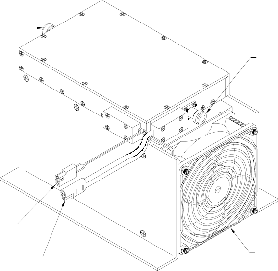
2. Interface Description
The HPA4 has 2 external RF ports; both are type "N" female coaxial connectors:
J1 is the RF input port
J2 is the RF output port
DC power connection to the HPA4 is accomplished via J3, a 2-conductor, quick-
disconnect connector. J4 is a control / alarm cable which carries the amplifier's key
signal and high-temp alarm signal.
DC POWER
INTERFACE
J3
J4
RF OUT
J2
COOLING
J1
RF IN
CONTROL
FAN
3. Installation
3.1 Unpacking
Carefully inspect the amplifier for any signs of shipping damage. If damage is
suspected, file a claim immediately with the carrier and contact your dealer. If
possible, keep the original shipping container for shipping the unit back for repair
or for verification of damage during shipment.
3.2 Installation
Standard considerations such as air flow clearance in the vicinity of the
amplifier's mounting location, and ensuring adequate space exists for the routing
of RF, DC power, and control cables are of primary importance.
RF coaxial, power, and control cables should be neatly routed with service loops
to provide for convenient removal for functional testing and / or maintenance
purposes.
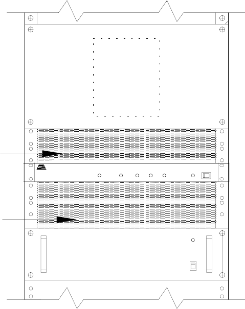
3.1.1. Typical Rack Installation
POWER SUPPLY
POWER AMPLIFIE
R
BASE STATION
DIVERSITY RECEPTION SYSTEM
ADJUSTMENT
SPACE FOR
ACCESS
FRONT VIEW
DC OUTPUT
12VDC
UHF (400-512MHz) BASE STATION
COOLING
SPACE FOR
Communication Systems
ElectroCom
TX RX1CD RX2 RX3 POWER
HPA4
IO
OPTIONAL
POWER