IP Mobilenet IPB1317 Mobile Radio Base Station User Manual 516 80499 UM IPBS
IP Mobilenet, LLC Mobile Radio Base Station 516 80499 UM IPBS
UserManual.wiki
>
IP Mobilenet
>
IPB1317 User Manual
Revised users manual
Navigation menu
Upload a User Manual
Namespaces
Wiki Guide
HTML
PDF
Info
Views
User Manual
Discussion / Help
Navigation
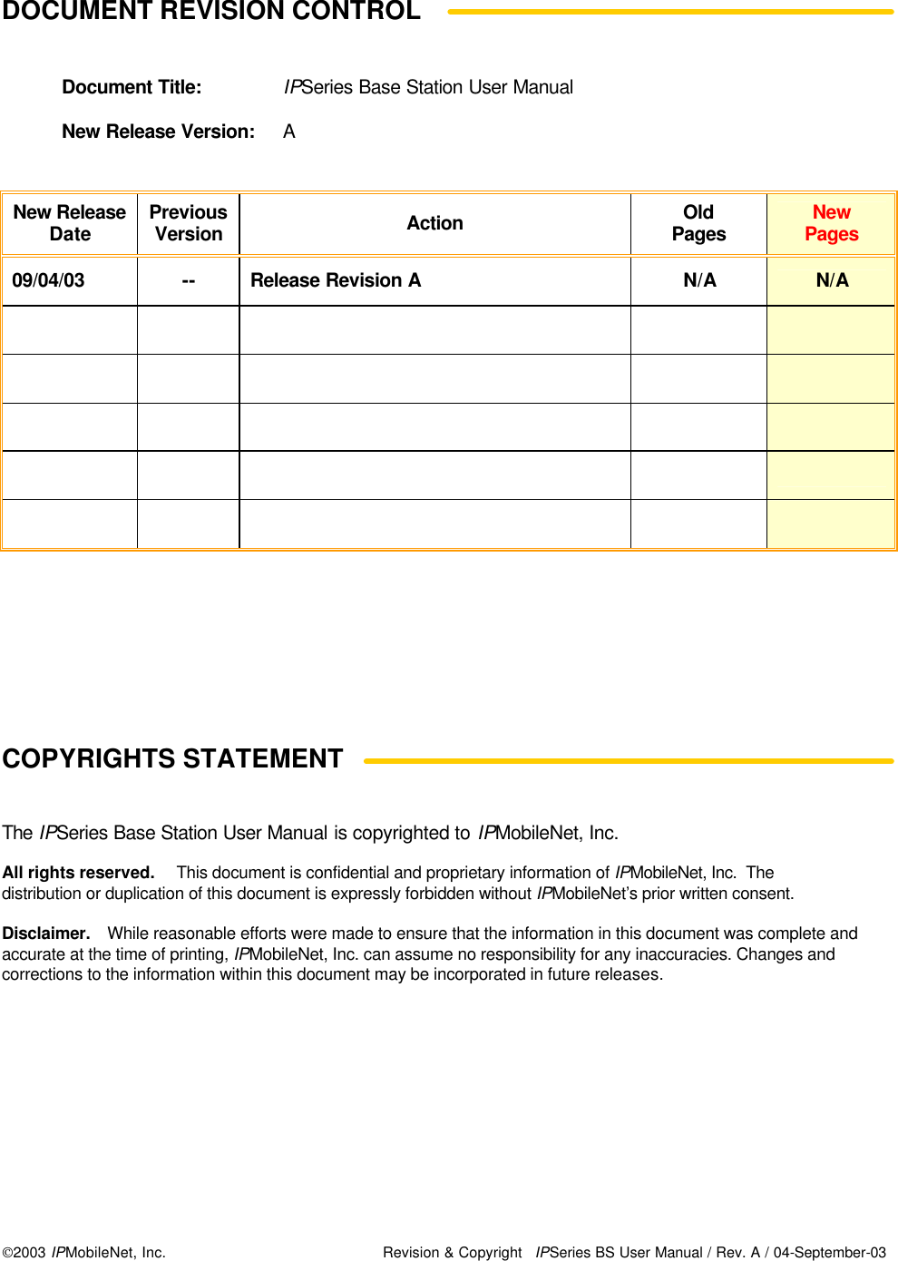
![CHAPTER 3: PRODUCT SETUP AND PRELIMINARY TESTING 2003 IPMobileNet, Inc. 16 IPSeries MR User Manual / Rev. A / 04-September-03 Preliminary Test Procedure Perform the following initial setup to prepare the base station for preliminary test: Step 1 Connect the base station to the 13.8 VDC power supply. Step 2 Power on the base station and verify that the LED’s illuminate and the power LED on the front panel remains illuminated. Step 3 Verify that the base station DC-supply current is <1.2 amps. Step 4 For the ideal serial or Ethernet setup please refer to the IPTurboConverter Quick Reference Guide (IPMN p/n: 516.80496.QR) available on the Product Documentation CD enclosed with this product. Step 5 Connect the antennas to the mobile radio. Step 6 Power on the mobile radio. Step 7 Connect the antenna to the base station’s TX port. Step 8 Recycle the base station power. Step 9 Connect the antennas to the base station’s RX1. Step 10 Verify that the RX1 and CD LED’s is illuminated when the mobile is attempting to connect. Repeat Steps 9 and 10 with RX2 and RX3. Step 11 From the Mobile PC, open the DOS prompt, then ping the IPNC with the following command: ping 172.16.23.200 (or replace with appropriate IPNC IP address). Press [ENTER] and verify that the IPNC responds to the ping request. Also verify that the base station carrier detect (CD) LED is lit followed by the TX LED.](https://usermanual.wiki/IP-Mobilenet/IPB1317/User-Guide-377613-Page-16.png)
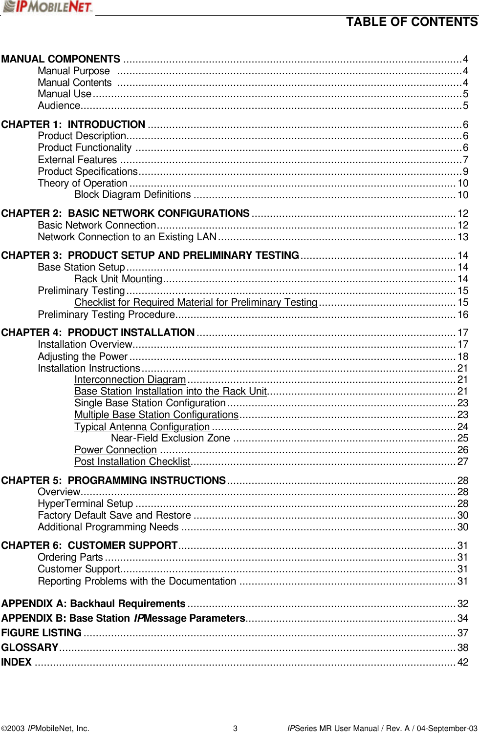
![CHAPTER 5: PROGRAMMING INSTRUCTIONS 2003 IPMobileNet, Inc. 29 IPSeries MR User Manual / Rev. A / 04-September-03 Step 8 Click on the OK button. Step 9 Open HyperTerminal. Step 10 Recycle the base power and HyperTerminal displays the base’s Firmware revision. Step 11 Type in a ? in the HyperTerminal screen and press [ENTER]. This will list the Base Station parameters. If the cursor is not responsive, check the cables for proper connection. ! See Appendix A for Base Station Parameter definitions and default settings. Ensure that the calibrated base station and the mobile radio antennas are separated by at least 10 feet. If the antennas are too close, the mobile radio receivers may overload by the transmitters resulting in intermittent communication and high data errors. Host serial = 115200,N,8,1, timeout=200 IPNC = 207.88.179.158, 207.88.179.157, 207.88.179.156, 207.88.179.152, 207.88.179.140 RF IP Address = 172.16.23.14 Tunnel Address = 8.4.2.14, Netmask = 255.255.255.240 Host interface = SLIP, no split frames, with status messages tunnel = 1 Injection = LOW SIDE, 45MHz pll type = MC145193 channel spacing = 12500 Reference frequency = 10.000 mHz Channel Tx freq Rx freq Inj freq Frequency=1 , 866.000000, 821.000000, 776.000000 Channel = 1 Serial number: 1234 TX quiet time = 5 Symbol sync time = 12 milliseconds, 0 extra inter-split-frame count TX tail time = 5 Radio data rate = 19200 Max data tx time = 60 seconds Carrier detect delay time = 8 milliseconds Station ID = abcd Station ID time = 0 minutes Polarity = TX-, RX+ allow crc errors = 0 Allow base to base = 0 RSSI step = 25 (=18dBm) default gateway = 0.0.0.0 Ethernet address = 00:00:00:00:00:00 Base station number = 14 SNTP interval = 16 seconds num timeslots = 16 timeslot period = 992ms timeslots per voice packet = 4 noise = -108dBm DHCP Relay Agent = enable -120dBm = (0) -110dBm = (0) -100dBm = (0) -90dBm = (0) -80dBm = (0) -70dBm = (0) -60dBm = (0) -50dBm = (0) -40dBm = (0) -30dBm = (0) Modem FEC = on RX in progress message = 1 MTU = 1480 Signal Strength = DBM IPNC query period = 10 secs](https://usermanual.wiki/IP-Mobilenet/IPB1317/User-Guide-377613-Page-29.png)