IP Mobilenet IPM4748 IPM4 Mobile Radio User Manual 516 80495 UM IPM MR
IP Mobilenet, LLC IPM4 Mobile Radio 516 80495 UM IPM MR
Contents
- 1. User Manual
- 2. Installation manual
Installation manual

I
IP
PS
Se
er
ri
ie
es
s
M
Mo
ob
bi
il
le
e
R
Ra
ad
di
io
o
U
Us
se
er
r
M
Ma
an
nu
ua
al
l
Released: April 8, 2003
IPMN p/n: 516.80495.UM
Revision: A
16842 Von Karman Avenue, Suite 200 Irvine, CA 92606
Voice: (949) 417-4590 Fax: (949) 417-4591
www.ipmobilenetinc.com

2003 IPMobileNet, Inc. Revision & Copyright IPSeries MR User Manual / Rev. A / 08-Apr-03
DOCUMENT REVISION CONTROL
Document Title: IPSeries Mobile Radio User Manual
New Release Version: A
New Release
Date
Previous
Version Action Old
Pages
New
Pages
04/08/03 X6 Release document N/A N/A
COPYRIGHTS STATEMENT
The IPSeries Mobile Radio User Manual is copyrighted to IPMobileNet, Inc.
All rights reserved. This document is confidential and proprietary information of IPMobileNet, Inc. The
distribution or duplication of this document is expressly forbidden without IPMobileNet’s prior written consent.
Disclaimer. While reasonable efforts were made to ensure that the information in this document was complete and
accurate at the time of printing, IPMobileNet, Inc. can assume no responsibility for any inaccuracies. Changes and
corrections to the information within this document may be incorporated in future releases.

TABLE OF CONTENTS
2003 IPMobileNet, Inc. 3 IPSeries MR User Manual / Rev. A / 08-Apr-03
MANUAL COMPONENTS.........................................................................................................................5
Manual Purpose ...........................................................................................................................5
Manual Contents ...........................................................................................................................5
Manual Use ...................................................................................................................................6
Audience .......................................................................................................................................6
CHAPTER 1: INTRODUCTION................................................................................................................7
Product Description.......................................................................................................................7
Product Functionality.....................................................................................................................7
External Features..........................................................................................................................8
Product Specifications...................................................................................................................9
Theory of Operation ....................................................................................................................10
Block Diagram Definitions..............................................................................................10
CHAPTER 2: BASIC NETWORK CONFIGURATIONS.........................................................................12
Basic Network Connection..........................................................................................................12
Network Connection to an Existing LAN .....................................................................................13
Wireless High Speed Digital IP Voice and Data (over the Internet) ...........................................14
CHAPTER 3: SETUP AND CONFIGURATION SCENARIOS...............................................................15
Mobile Radio Setup Scenarios....................................................................................................15
Mobile Radio-to-Mobile Computer Setup.......................................................................15
Mobile Radio-to-VIU-to-Mobile Computer Setup ...........................................................16
CHAPTER 4: PRODUCT INSTALLATION ............................................................................................17
Installation Overview ...................................................................................................................17
Installation Requirements ..............................................................................................17
Installation Instructions................................................................................................................20
Pre-Installation Guidelines .............................................................................................20
Mounting the Mobile Radio ............................................................................................21
Serial Cable Connection and Routing............................................................................22
Ethernet Setup ...............................................................................................................22
Delay Time Installation...................................................................................................22
Carling Switch Installation..............................................................................................24
Mobile Radio Power Supply Installation.........................................................................25
Antenna Configuration ...................................................................................................26
Measuring Return Loss.....................................................................................27
Measuring Voltage Standing Wave Ratio .........................................................28
Measuring Insertion Loss..................................................................................27
Voice Interface Unit Connections...................................................................................28
Post Installation Checklist .............................................................................................. 30
Mobile Installation Layout Diagrams ...........................................................................................31
Vehicle Unit Wiring Interconnection Layout ...................................................................31
Mobile Antenna Distance Matrix ....................................................................................31
Diversity Antenna Mobile Installation Detail (Typical Installation) .................................32
Vehicle Unit Wiring Interconnection Layout (with Voice Interface Unit).........................32
Preliminary Testing and Troubleshooting ...................................................................................33
Checklist of Required Materials .....................................................................................33
Base Station Setup for Testing ......................................................................................34
Preliminary Test Procedure and Troubleshooting .........................................................35

TABLE OF CONTENTS
2003 IPMobileNet, Inc. 4 IPSeries MR User Manual / Rev. A / 08-Apr-03
CHAPTER 5: PROGRAMMING INSTRUCTIONS .................................................................................38
Enabling Ethernet for Static IP Address Update in the Mobile Radio.........................................38
Viewing Mobile Radio’s Configuration Data................................................................................40
Changing the Mobile Radio’s IP Address ...................................................................................40
Changing the Mobile Radio’s Parameters .................................................................................. 40
Factory Default Save and Restore..............................................................................................43
CHAPTER 6: CUSTOMER SUPPORT ..................................................................................................44
APPENDIX A: Mobile Radio IPMessage Parameters ..........................................................................45
FIGURE LISTING ....................................................................................................................................48
GLOSSARY .............................................................................................................................................49
INDEX ......................................................................................................................................................53

MANUAL COMPONENTS
2003 IPMobileNet, Inc. 5 IPSeries MR User Manual / Rev. A / 08-Apr-03
Manual Purpose
The purpose of the IPSeries IPM Mobile Radio User Manual is to provide IPMobileNet dealers and
customers with the necessary information required to install, operate, and troubleshoot problems with the
mobile radio.
Manual Contents
This user manual contains the following sections:
Chapter 1: Introduction
The Introduction provides a description of the mobile radio as well as a general overview of its
functionality, how it operates, product interfaces, package contents at shipment, and theory of
operation with a block diagram and block definitions.
Chapter 2: Basic Network Configurations
Basic Network Configurations provides a series of network diagrams depicting possible network
configurations.
Chapter 3: Setup and Configuration Scenarios
Setup and Configuration Scenarios provide the diagrams and information required for the two (2)
possible setup methods for the mobile radio.
Chapter 4: Product Installation
Product Installation provides installation diagrams and instructions for installing the mobile radio and
other required components.
Chapter 5: Programming Instructions
Programming Instructions provides programming and setup instructions for setting up the mobile
radio and its interfaces.
Chapter 5: Customer Support
Customer Support provides instructions for ordering parts, documentation support, and reporting
problems.
Appendix A: Mobile Radio IPMessage Parameters
Figure Listing
Glossary
Index

MANUAL COMPONENTS
2003 IPMobileNet, Inc. 6 IPSeries MR User Manual / Rev. A / 08-Apr-03
Manual Use
Special icons appear throughout this manual to emphasize important information related to the chapter in
which the icons are found. The definitions for these icons are listed below.
1 It is imperative that the user read this section carefully prior to continuing to the next chapter of
this user manual.
TABLE 1: ICON HELPS
ICON INDICATES DEFINITION
NOTE This icon indicates that a note follows
highlighting or stressing a special point.
% PROCEDURE This icon indicates that the section that
follows contains a procedure.
1 CAUTION
This icon indicates that a precautionary
message follows. Carefully read the
message following this icon and proceed with
caution.
# TROUBLESHOOTING This icon indicates that a troubleshooting
strategy follows.
Audience
This user manual is intended for specific use by IPMobileNet, Inc. staff, dealers, and customers. This
user manual is not to be reproduced without expressed written consent of IPMobileNet Management.
CHAPTER 1: INTRODUCTION
2003 IPMobileNet, Inc. 7 IPSeries MR User Manual / Rev. A / 08-Apr-03
Product Description
The content of this manual applies to all frequency ranges of the IPSeries Mobile Radio, unless
otherwise specified. This manual will note key differences when appropriate.
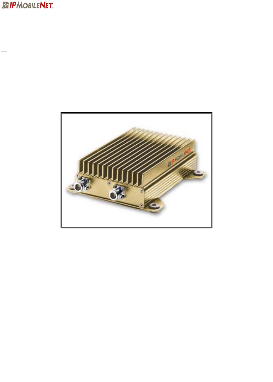
The IPSeries Mobile Radios are intelligent devices designed for the challenging requirements of mobile
data and voice applications. Mounted in vehicles, other intelligent devices may connect to the serial or
Ethernet ports for connectivity back to the Internet Protocol Network Controller (IPNC) and other such
servers. The IPSeries Mobile Radio provides the mobile link to land-based wired networks. The mobile
radio circuit boards are built using surface mount technology (SMT) and through-hole components.
Figure 1: IPSeries Mobile Radio (Front View)
Product Functionality
The mobile radio utilizes a high-performance, 4-level Frequency-Shift Keying (FSK) wireless data modem;
a multi-layered approach to signal reliability, including patented multi-receiver Intelligent Diversity
Reception; data scrambling; data interleaving; Forward Error Correction (FEC); and Viterbi soft-decision
algorithms, providing up to 20 dB improvement in Signal-to-Noise Ratio (SNR) in low signal-to-noise
environments. This assures a very high message success rate even while transferring large blocks of
data at high vehicle speeds. The mobile radio features a low-power consumption, high performance
integrated GPS receiver. Embedding this technology in the mobile radio lowers the cost of acquiring GPS
data from vehicles and ensures optimal performance.
The IPSeries Mobile Radio technology includes IPMobileNet’s Diversity Reception (DR) capability. DR
reduces the effects of fades in multi-path environment. With the use of two (2) antennas mounted at a
calculated distance on the roof of the vehicle (refer to the section in Chapter 4 titled Antenna
Configuration) the Diversity Reception System (DRS) minimizes the effects of fading by intelligently
selecting the receiver with a better signal.
Diversity is most effective when the vehicle is in motion.
CHAPTER 1: INTRODUCTION
2003 IPMobileNet, Inc. 8 IPSeries MR User Manual / Rev. A / 08-Apr-03
External Features
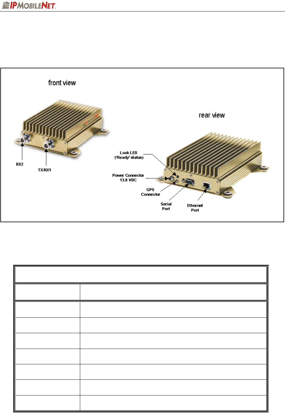
As seen in Figure 2 below, the IPSeries Mobile Radio technology is enclosed in a compact and sturdy
aluminum case.
Figure 2: IPSeries Mobile Radio (External Features)
The mobile radio external features consist of the following components:
TABLE 2: EXTERNAL FEATURES
FEATURE DESCRIPTION
TX/RX1 Transmitter / Receiver 1 antenna connection
RX2 Receiver 2 antenna connection
Power Connector 13.8 VDC mobile radio power connector
Lock LED Unit ‘Ready’ Status Indicator LED (light emitting diode)
GPS GPS antenna (3V) connector
Serial Port RS232 Serial Line Internet Protocol (SLIP) interface port
Ethernet Port 10 Base T Ethernet interface port

CHAPTER 1: INTRODUCTION
2003 IPMobileNet, Inc. 9 IPSeries MR User Manual / Rev. A / 08-Apr-03
Product Specifications
TABLE 3: PRODUCT SPECIFICATIONS
GENERAL SPECIFICATIONS
PARAMETER Model IPM1 Model IPM4 Model IPM8
Frequency range 135 to 175 MHz 400 to 512 MHz 806 to 869 MHz
channel spacing / speed 12.5 kHz / 9600 bps
25.0 kHz / 19200 bps
12.5 kHz / 9600 bps
25.0 kHz / 19200 bps
12.5 kHz / 9600 bps
25.0 kHz / 19200 bps
mode of operation half-duplex, diversity reception half-duplex, diversity reception half-duplex, diversity reception
operating temperature range -30C to +60C (-22F to +140F) -30C to +60C (-22F to +140F) -30C to +60C (-22F to +140F)
power supply voltage 13.8 VDC +/-20% 13.8 VDC +/-20% 13.8 VDC +/-20%
power supply <0.2 amps receive <0.2 amps receive <0.2 amps receive
current consumption 16 amps transmit 13 amps transmit 8 amps transmit
number of channels 256 256 256
intelligent diversity reception dual receiver, diversity reception dual receiver, diversity reception dual receiver, diversity reception
antenna connections Two (2) type “N” jacks
(tx/rx1, rx2)
two (2) type “N” jacks
(tx/rx1, rx2)
two (2) type “N” jacks
(tx/rx1, rx2)
interface connection RS232 serial port connector or
RJ45 Ethernet 10 Base T
RS232 serial port connector or
RJ45 Ethernet 10 Base T
RS232 serial port connector or
RJ45 Ethernet 10 Base T
dimensions (HxWxD / lbs) 2” X 4.5” X 8” / 2.5 lbs 2” X 4.5” X 8” / 2.5 lbs 2” X 4.5” X 8” / 2.5 lbs
Regulatory FCC Part 90 and Part 15 FCC Part 90 and Part 15 FCC Part 90 and Part 15
IPSERIES MOBILE RADIO TRANSMITTER SPECIFICATIONS
PARAMETER Model IPM1 Model IPM4 Model IPM8
frequency stability +/- 1.5 ppm @ operating temp +/- 1.5 ppm @ operating temp +/- 1.0 ppm @ operating temp
emission designator 20K0F1D 20K0F1D 20K0F1D
spurious and harmonic -61 dBc max -59 dBc max -56 dBc max
transmit power 60 watts 40 watts 20 watts
transmit attack time less than 5 ms less than 5 ms less than 5 ms
IPSERIES MOBILE RADIO RECEIVER SPECIFICATIONS
PARAMETER Model IPM1 Model IPM4 Model IPM8
sensitivity (voice) 12.0 dB SINAD@
-119 dB max level
12.0 dB SINAD@
-118 dB max level
12.0 dB SINAD@
-118 dB max level
distortion less than 3% @ 1.0 kHz less than 3% @ 1.0 kHz less than 3% @ 1.0 kHz
spurious response 85 dBm minimum 85 dBm minimum 85 dBm minimum
intermodulation distortion 75 dB minimum 75 dB minimum 75 dB minimum
GPS RECEIVER SPECIFICATIONS
general L1 frequency, C/A code (SPS), 8-channel continuous tracking receiver, 32 correlators
protocols TSIP, TAIP, and NMEA 0183
CHAPTER 1: INTRODUCTION
2003 IPMobileNet, Inc. 10 IPSeries MR User Manual / Rev. A / 08-Apr-03
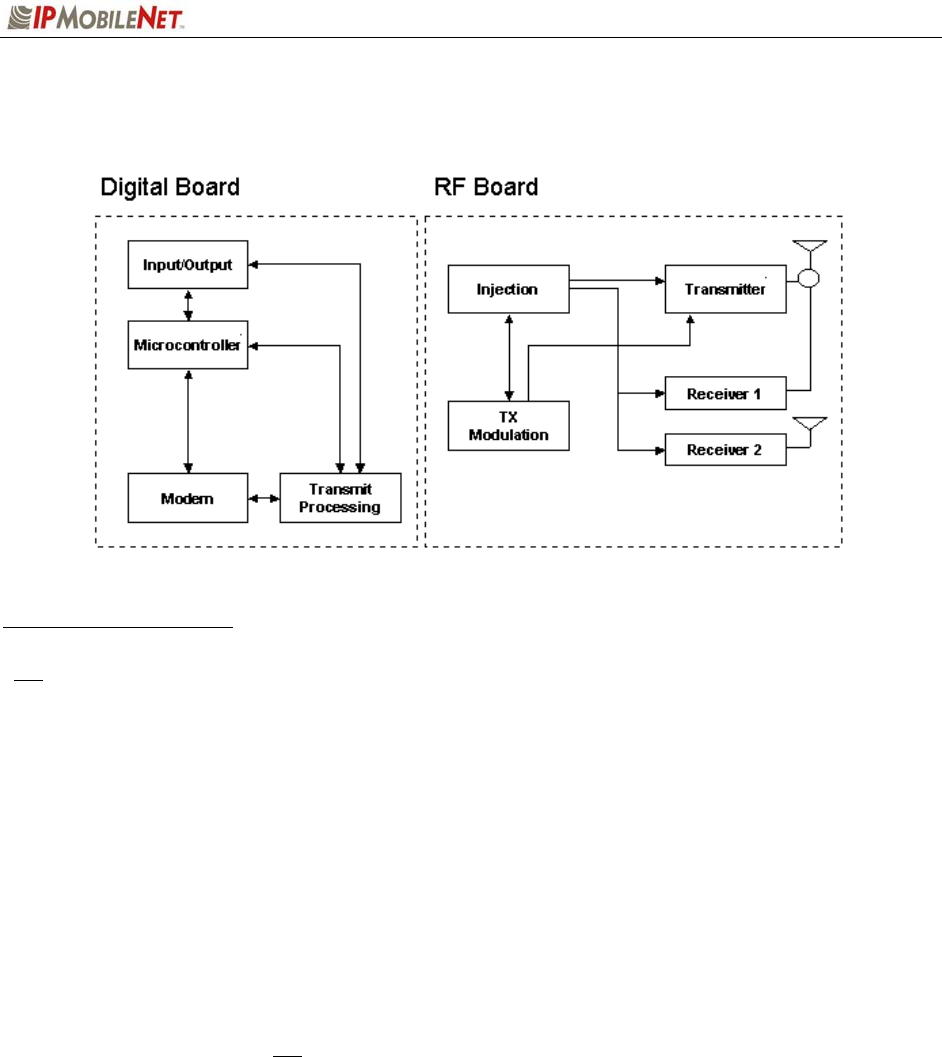
Theory of Operation
Figure 3: General Block Diagram
Block Diagram Definitions
For increased data security, the modem supports the Federal Government developed Digital
Encryption Standard (DES) data encryption and decryption protocols. This capability requires
installation of third party, Internet Protocol (IP) compliant DES encryption and decryption
software on the system.
The IPSeries Mobile Radio is comprised of two (2) sections, the digital section and the RF (radio
frequency) section.
The digital circuit board contains the following sections:
Input/Output Circuitry associated with the following data connectors:
RS232 Serial Port DB9 Data Connector
RJ45 Ethernet 10 Base T Interface Connection
For further details on the Ethernet Controller refer to the Crystal
LAN Ethernet Controller Product Bulletin (CS8900A-
EthernetCtrlr.pdf) available on the Product Documentation CD.
Microcontroller Manages the operation of the mobile radio, the modem, and determines
which receiver provides a better signal from a given transmission. Also
provides transmit time-out protection in the event a fault causes the mobile
radio to halt in the transmit mode.
Modem Converts serial data into an analog audio waveform for transmission and
analog audio from the receiver to serial data. Within a single chip it
provides forward error detection and correction, bit interleaving for more
robust data communications, and third generation collision detection and
correction capabilities.

CHAPTER 1: INTRODUCTION
2003 IPMobileNet, Inc. 11 IPSeries MR User Manual / Rev. A / 08-Apr-03
Power Supply The power supply creates the various voltages required by the digital
portion of the mobile radio.
The RF circuit board contains the following sections:
Transmit Processing Circuitry that amplifies the analog audio signal from the modem and uses it
to modulate the voltage-controlled oscillator (VCO) and reference oscillator
in the injection synthesizer section. Modulating the VCO and reference
oscillator simultaneously results in a higher quality FM signal.
Injection Synthesizer Provides programmable, ultra stable signals for the mobile radio.
Synthesizer incorporates phase lock loop technology used for both
receiving and transmitting.
Injection In the receive mode, the synthesizer provides a local oscillator signal of 45
MHz above or below the selected receive channel frequency.
Transmitter Consists of an exciter and power amplifier module. The transmitter covers
the various frequency bands in segments. A different power amplifier
module is required for each segment. The transmitter circuitry includes a
T/R switch switching the antenna between transmitter and receiver 1
(TX/RX1).
Receiver 1/Receiver 2 Required to support the mobile DRS; two (2) discrete receivers are tuned
to the same channel and use two (2) antennas.
The receivers are double-conversion superheterodyne with a first
Intermediate Frequency (IF) of 45 MHz and a second IF frequency of 455
KHz. Each receiver consists of bandpass filters, an RF amplifier, a MMIC
mixer, crystal filters, and a one-chip IF system. The injection synthesizer
provides the first local oscillator signal. Outputs from each receiver include
RSSI and analog audio for the baseband routing circuitry and modem.
For further details on the integrated GPS unit, refer to the Lassen GPS Unit Specification
(Lassen-GPSUnitSpec.pdf) available on the Product Documentation CD.
CHAPTER 2: BASIC NETWORK CONFIGURATIONS
2003 IPMobileNet, Inc. 12 IPSeries MR User Manual / Rev. A / 08-Apr-03
Basic Network Configurations
This section provides basic network connection samples to help the user better understand some of the
possibilities in setting up their respective systems.
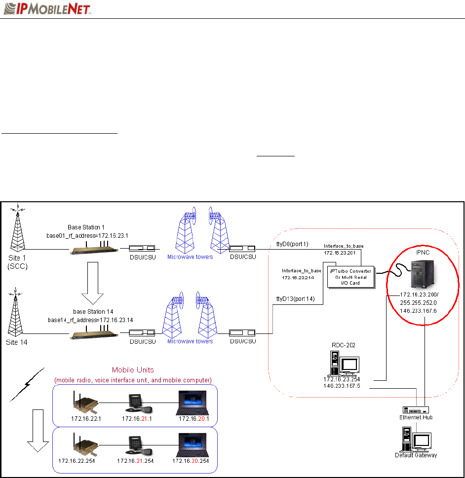
Basic Network Connection
Figure 4 depicts a basic network connection for a network inclusive of one (1) Internet Protocol Network
Controller (IPNC) and a range of base stations, mobile radios, VIUs (voice interface units), mobile
computers, and additional components that can interface with the system.
Figure 4: Basic Network Connection
CHAPTER 2: BASIC NETWORK CONFIGURATIONS
2003 IPMobileNet, Inc. 13 IPSeries MR User Manual / Rev. A / 08-Apr-03
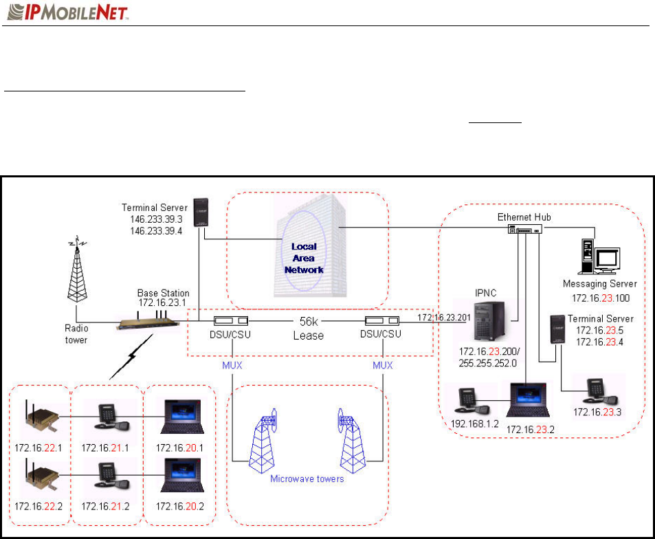
Network Connection to an Existing LAN
Figure 5 depicts network connection to an existing LAN (local area network) inclusive of one (1) IPNC,
one (1) base station, and a range of mobile radios, VIUs, mobile computers, and additional components
that can interface with the system. This diagram also shows a LAN VIU as well as Terminal Server VIU.
Figure 5: Network Connection to an Existing LAN
CHAPTER 2: BASIC NETWORK CONFIGURATIONS
2003 IPMobileNet, Inc. 14 IPSeries MR User Manual / Rev. A / 08-Apr-03
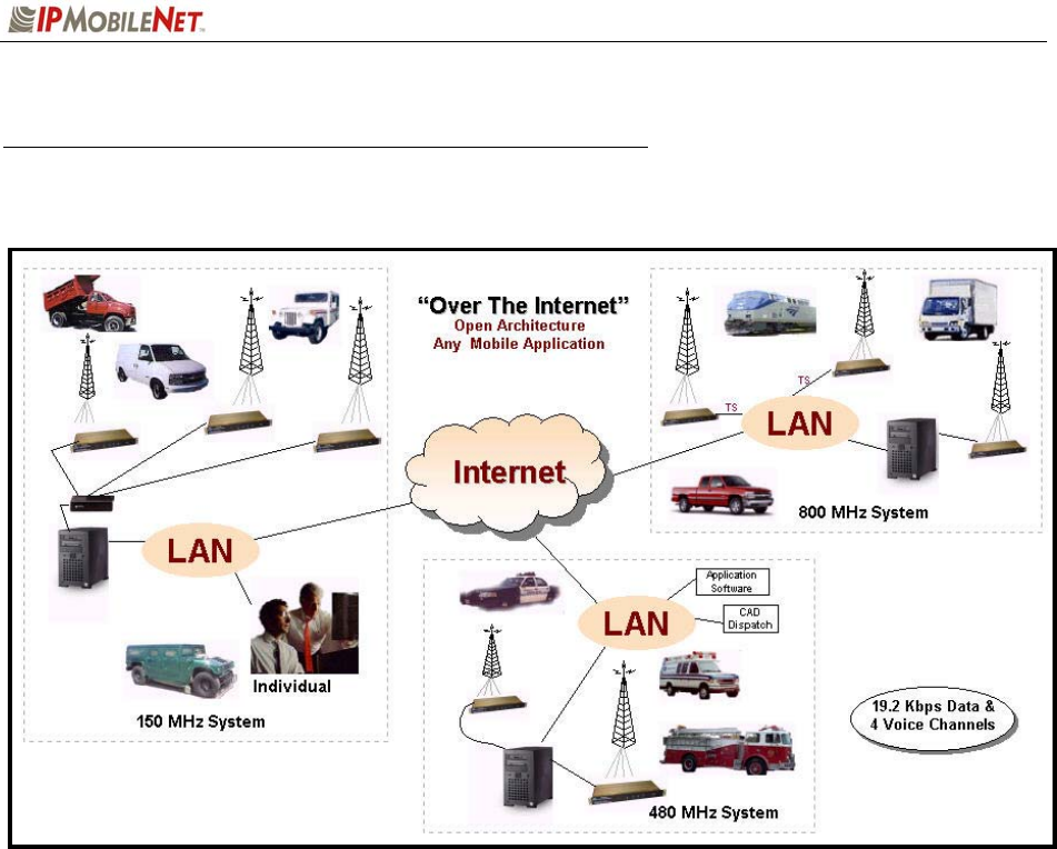
Wireless High Speed Digital IP Voice and Data (over the Internet)
Figure 6 depicts a variety of wireless data and voice networks on different frequencies.
Figure 6: Wireless High Speed Digital IP Voice & Data (over the Internet)
CHAPTER 3: SETUP AND CONFIGURATION SCENARIOS
2003 IPMobileNet, Inc. 15 IPSeries MR User Manual / Rev. A / 08-Apr-03
Mobile Radio Setup Scenarios
The following describes the two (2) methods of setting up a mobile radio in a vehicle:
Mobile Radio-to-Mobile Computer
Mobile Radio-to-VIU-to-Mobile Computer
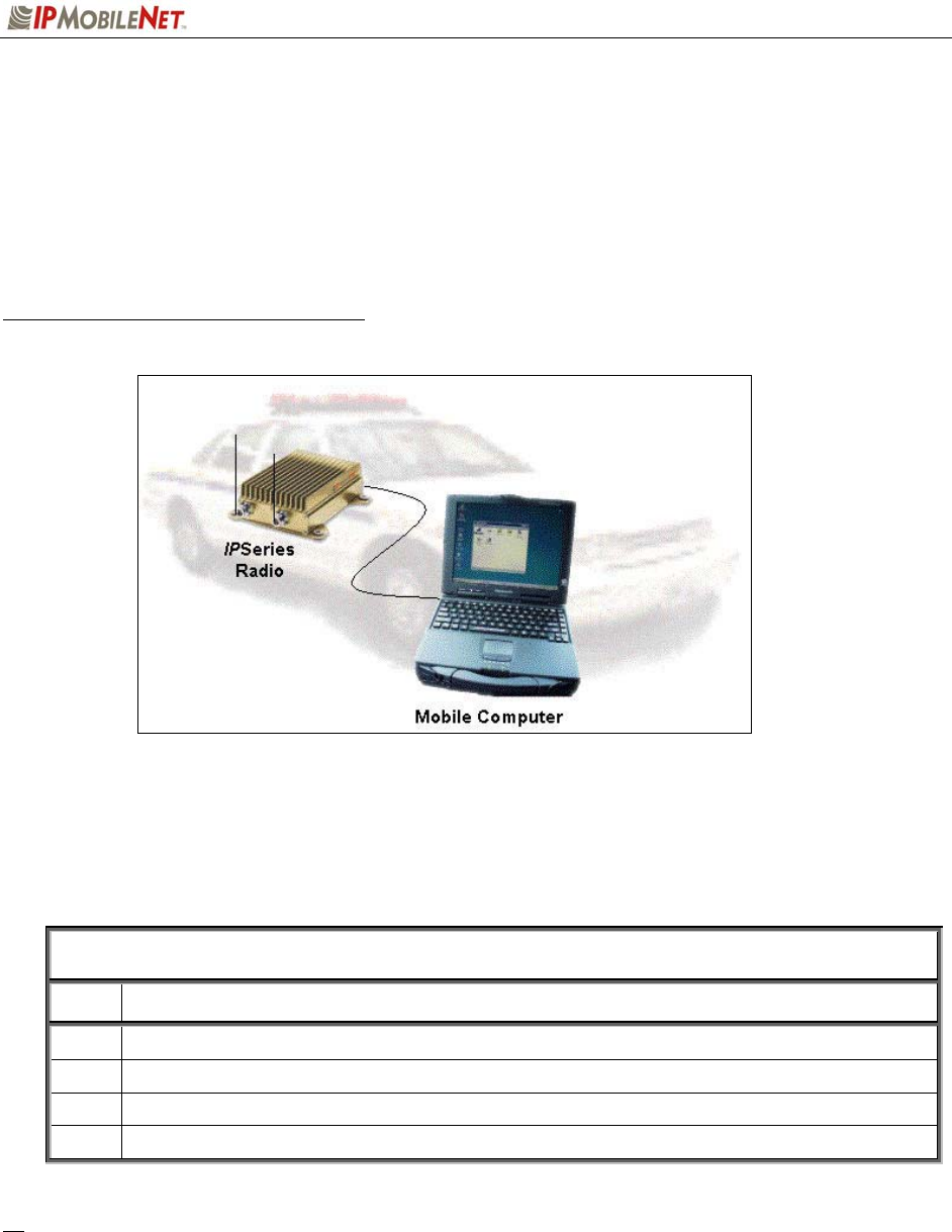
Mobile Radio-to-Mobile Computer Setup
Figure 7: Mobile Radio-to-Mobile Computer Setup
To setup a mobile radio-to-mobile computer configuration, additional components are required, as listed
in Table 4:
TABLE 4: MOBILE RADIO-TO-MOBLE COMPUTER COMPONENTS REQUIRED FOR
INSTALLATION
QTY DESCRIPTION
1 IPM Mobile Radio
1 Mobile Computer
1 20-foot serial cable (DB9F – DB9M)
1 Mobile Radio SLIP Port Driver Installation Diskette
If using the mobile radio’s Ethernet feature an Ethernet crossover cable is required to replace 20-
foot serial cable.
To configure the mobile radio and computer for this type of setup, follow the instructions on pages
2 through 17 in the Mobile Computer Setup for Communication with the Mobile Radio
Installation Guide (IPMN p/n: 516.80310.IG) available on the Product Documentation CD.
CHAPTER 3: SETUP AND CONFIGURATION SCENARIOS
2003 IPMobileNet, Inc. 16 IPSeries MR User Manual / Rev. A / 08-Apr-03
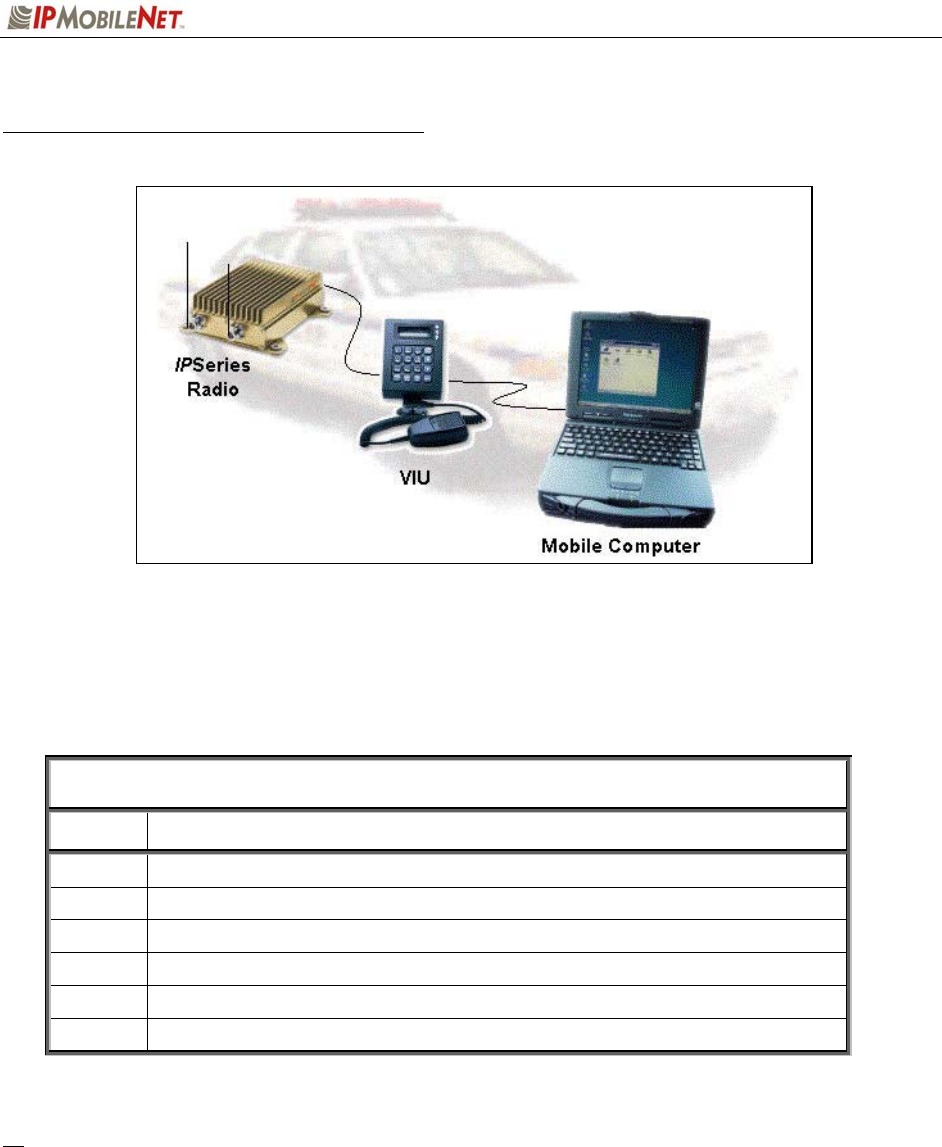
Mobile Radio-to-VIU-to-Mobile Computer Setup
Figure 8: Mobile Radio-to-VIU-to-Mobile Computer Setup
To setup a mobile radio-to-VIU-to-mobile computer configuration, additional components are required, as
listed in Table 5:
TABLE 5: MOBILE RADIO-TO-VIU-TO-MOBLE COMPUTER COMPONENTS
REQUIRED FOR INSTALLATION
QTY DESCRIPTION
1 IPM Mobile Radio
1 Mobile Computer
1 Voice Interface Unit (VIU)
1 20-foot serial cable (DB9F – DB9M)
1 10-foot serial cable (DB9F – DB9M)
1 Mobile Radio SLIP Port Driver Installation Diskette
To configure the mobile radio, the voice interface unit, and the mobile computer for this type of
setup, follow the instructions on pages 18 and 19 in the Mobile Computer Setup for
Communication with the Mobile Radio Installation Guide (IPMN p/n: 516.80310.IG) available on
the Product Documentation CD.

CHAPTER 4: PRODUCT INSTALLATION
2003 IPMobileNet, Inc. 17 IPSeries MR User Manual / Rev. A / 08-Apr-03
Installation Overview
This chapter provides the basic steps involved in the installation process of an IPSeries Mobile Radio.
This chapter includes wire routing and connections between the mobile radio, other components, and the
vehicle’s power.
1 To prevent personal injury and vehicle damage, exercise extreme caution throughout the
installation process and follow the reminders listed below.
Follow safety precautions for handling wiring, tools, and a vehicle’s engine.
Handle the vehicle’s battery with extreme caution to avoid burns.
Do not alter the components listed in the Installation Requirements section below, unless
substitutions are noted within this chapter.
Once the antennas are installed, as directed within this user manual, all persons must
maintain a distance of no less than 39 inches from the antennas.
Installation Requirements
Table 6 lists the documents required to successfully install the mobile radio and connect to the various
components within the vehicle:
TABLE 6: DOCUMENTS REQUIRED FOR MOBILE RADIO INSTALLATION
DESCRIPTION PART NUMBER
The following documents are available on the Product Documentation CD
enclosed in the shipment with the mobile radio: 480.0001.001
IPSeries Mobile Radio User Manual 516.80495.UM
Installation Guide for Mobile Computer Setup for Communication with
the Mobile Radio 516.80310.IG
Confirming Mobile Radio Receiver Sensitivity TN01-0027

CHAPTER 4: PRODUCT INSTALLATION
2003 IPMobileNet, Inc. 18 IPSeries MR User Manual / Rev. A / 08-Apr-03
Table 7 lists the components required to perform a successful mobile radio installation and are available
for purchase through IPMobileNet, Inc.
TABLE 7: MOBILE INSTALLATION ACCESSORIES KIT
QTY DESCRIPTION PART NUMBER
4 Screws, Self Tapping #10 X 5/8 37040010-10
1 EMI Filter 127-0020-002
1 Timer, 2 hours 150-0127-004
1 Relay 128-0117-001
1 Relay Socket 128-0116-001
2 Butt Connectors #8 AWG 120-0256-001
1 Terminal, Ring #8 AWG, #10 Screw Insulated 120-0127-001
4 Terminal, Ring #18-22 AWG, #10 Screws Insulated 120-0250-004
4 Terminal, Ring #10-12 AWG, #10 Screws Insulated 120-0250-005
4 Terminal, Disconnect #14-16 F 120-0244-002
18 Terminal, Disconnect #10-12 F 120-0244-003
2 Disconnect Tab, Quad Male 200-1377-001
1 Wire, 12 AWG Black, order 5 ft. 156-0242-001
1 Wire, 12 AWG Red, order 44 ft. 156-0242-003
1 Fuse, 15 AMPS ATO 122-0042-003
2 Fuse, 30 AMPS ATO 122-0042-001
3 Fuse Holder, 12 AWG 120-0253-001
1 Switch, Toggle DPST 144-0136-001
1 Diagram, Mobile Installation without VIU (see page 31) 502-80259
1 Diagram, Mobile Installation with VIU (see page 32) 502-80260

CHAPTER 4: PRODUCT INSTALLATION
2003 IPMobileNet, Inc. 19 IPSeries MR User Manual / Rev. A / 08-Apr-03
Table 8 lists the auxiliary equipment required to complete the installation process.
TABLE 8: AUXILIARY EQUIPMENT
QTY DESCRIPTION PART NUMBER
1 Serial Cable (DB9MF), 20 ft. 156-0245-020
1 Wire, 8 (133/29) AWG VW-1 Red, by foot, order 19.5 ft. 156-0243-003
1 Wire, 8 (133/29) AWG VW-1 Black, by foot, order 19.5 ft. 156-0243-001
2 RG58U Cable and Mount, VHF, 17 ft. (incl ¾” Brass Mount and N Male Crimp) 102-0200-001
2 RG8X Cable and Mount, UHF & 800 MHz, 17 ft. (incl ¾“ Brass Mount & N Male Crimp) 102-0200-002
2 Antenna, ¼ Wave, 136-144 MHz 102-0204-001
2 Antenna, ¼ Wave, 144-152 MHz 102-0204-002
2 Antenna, ¼ Wave, 152-162 MHz 102-0204-003
2 Antenna, ¼ Wave, 162-174 MHz 102-0204-004
2 Antenna, Radome Type, 410-430 MHz, 3dB Gain (requires 1 MB8XN for ea antenna) 102-0206-001
2 Antenna, Radome Type, 430-450 MHz, 3dB Gain (requires 1 MB8XN for ea antenna) 102-0206-002
2 Antenna, Radome Type, 450-470 MHz, 3dB Gain (requires 1 MB8XN for ea antenna) 102-0206-003
2 Antenna, Radome Type, 470-490 MHz, 3dB Gain (requires 1 MB8XN for ea antenna) 102-0206-004
2 Antenna, Radome type, 806-866 MHz, 3dB Gain (requires 1 MB8XN for ea antenna) 102-0207-001
2 Antenna, Radome Type 821-896 MHz, 3dB Gain (requires 1 MB8XN for ea antenna) 102-0207-002
2 Antenna, 5/8 Wave, 406-430 MHz, 3dB Gain (requires 1 MB8XN for ea antenna) 102-0199-003
2 Antenna, 5/8 Wave, 430-450 MHz, 3dB Gain (requires 1 MB8XN for ea antenna) 102-0199-004
2 Antenna, 5/8 Wave, 450-470 MHz, 3dB Gain (requires 1 MB8XN for ea antenna) 102-0199-005
2 Antenna, 5/8 Wave, 470-490 MHz, 3dB Gain (requires 1 MB8XN for ea antenna) 102-0199-002
2 Antenna, 5/8 Wave 490-512 MHz, 3dB Gain (requires 1 MB8XN for ea antenna) 102-0199-006
2 Antenna, 5/8 Wave, 806-866 MHz, 3dB Gain (requires 1 MB8XN for ea antenna) 102-0199-001
2 Antenna, ¼ Wave, 406-430 MHz, Unity Gain (requires 1 MB8XN for ea antenna) 102-0204-005
2 Antenna, ¼ Wave, 430-450 MHz, Unity Gain (requires 1 MB8XN for ea antenna) 102-0204-006
2 Antenna, ¼ Wave, 450-470 MHz, Unity Gain (requires 1 MB8XN for ea antenna) 102-0204-007
2 Antenna ¼ Wave, 470-490 MHz, Unity Gain (requires 1 MB8XN for ea antenna) 102-0204-008
2 Antenna, ¼ Wave, 490-512 MHz, Unity Gain (requires 1 MB8XN for ea antenna) 102-0204-009
2 Antenna, ¼ Wave, 806-896 MHz, Unity Gain (requires 1 MB8XN for ea antenna) 102-0204-010
CHAPTER 4: PRODUCT INSTALLATION
2003 IPMobileNet, Inc. 20 IPSeries MR User Manual / Rev. A / 08-Apr-03
Installation Instructions
Pre-Installation Guidelines
Prior to installing new equipment, perform the following steps:
1 1. Remove existing equipment and all related components to include stock clips on radio
wiring harness and antenna.
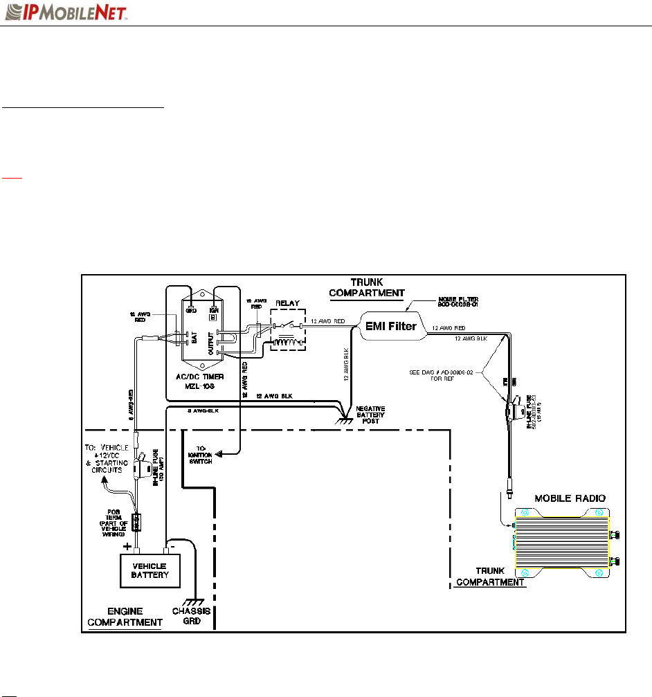
2. As shown in Figure 9 below, mounting of the mobile radio, delay timer, relay, and EMI
filter will take place in the trunk compartment, unless installing in a vehicle without a trunk
(refer to page 31 for the full drawing).
Figure 9: Trunk Compartment Installation
Removal of seats, rubber mats, and other obstructions, from inside the driver compartment, may
be necessary to facilitate routing of wires to the engine and trunk compartments.
3. To ensure appropriate cable and wire routing, exercise the following precautions:
Route cables away from sharp edges that can penetrate cable insulation and damage
wires.
Protect wires with silicone rubber grommets when routing through the engine
compartment firewall or through other holes with sharp edges.
Use high-quality electrical tape when covering exposed wires in the engine
compartment.
Avoid routing cables through areas exposed to extreme heat, such as the exhaust
system.
CHAPTER 4: PRODUCT INSTALLATION
2003 IPMobileNet, Inc. 21 IPSeries MR User Manual / Rev. A / 08-Apr-03
Keep wires routed through the engine compartment away from hot and/or moving
parts.
4. Prior to drilling holes in the engine compartment firewall, inspect both sides to avoid
obstructions.
5. For grounding point, use the engine block or the negative (-) terminal of the vehicle battery.
Ground connection surfaces must be free of paint, rust, and other corrosion to maximize
performance and avoid damage. Do not tie to the vehicle chassis.
6. To simplify troubleshooting problems, label all connecting points and wires.
Mounting the Mobile Radio
To mount the mobile radio, perform the following steps:
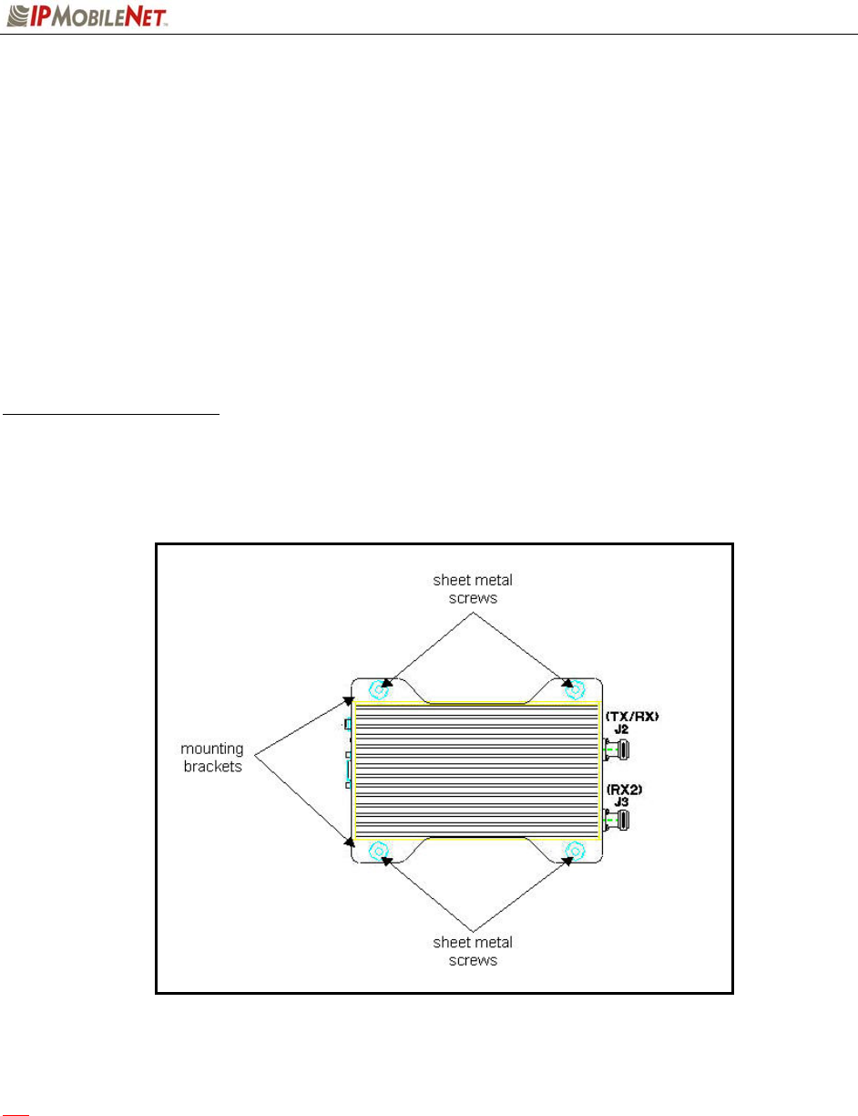
Step 1 As shown in Figure 10, secure the mobile radio into the trunk compartment. Insert
four (4) sheet metal screws in the mobile radio brackets.
Figure 10: Mobile Radio Mounting
1 If less than four (4) screws are used, the mobile radio can become loose in the trunk
compartment. This may cause the mobile radio not to function properly.
When inserting screws, be careful not to disturb the vehicle’s gas tank.

CHAPTER 4: PRODUCT INSTALLATION
2003 IPMobileNet, Inc. 22 IPSeries MR User Manual / Rev. A / 08-Apr-03
Serial Cable Connection and Routing
The serial cable connects the mobile radio to the mobile computer located in the driver compartment.
To connect the serial cable, perform the following steps:
Step 1 Attach the 20-foot serial cable male connector (DB9M – see Figure 11)
to the mobile radio.
Step 2 Route the female connector (DB9F – see Figure 12) to the driver
compartment and connect to the serial port located on the rear of the
mobile computer.
Route the serial cable to minimize foot pressure and other potential stresses. Use split
loom tubing and nylon cable ties for cable protection.
If connecting a Voice Interface Unit, see page 28 for instructions.
Ethernet Setup
The user also has the option to connect the mobile radio and the mobile computer via Ethernet.
To connect the Ethernet crossover cable, perform the following steps:
Step 1 Attach the Ethernet crossover cable (minimum 20 feet) to the Ethernet port on the rear
of the mobile radio, as shown previously in Figure 2.
Step 2 Route the other end of the Ethernet crossover cable to the driver compartment and
connect to the Ethernet port located on the rear of the mobile computer.
Route the cable to minimize foot pressure and other potential stresses. Use split loom
tubing and nylon cable ties for cable protection.
Note that if installing a Voice Interface Unit (VIU), the Ethernet setup cannot be
used, as the VIU is a serial-only device.
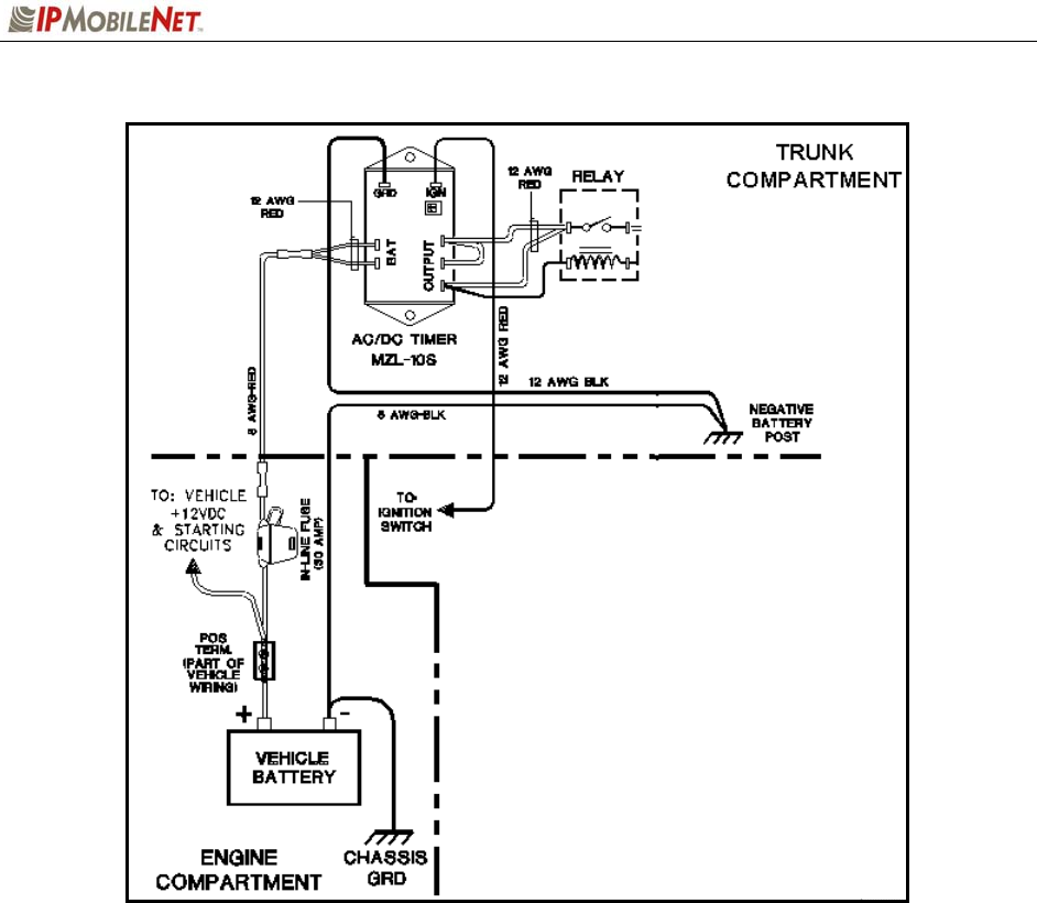
Delay Timer Installation
To install the Delay Timer, perform the following steps:
Step 1 Secure Delay Timer to the trunk compartment of the vehicle inserting screws in the
appropriate locations using care not to puncture the vehicle’s gas tank.
Step 2 Route the black wire (#12 AWG) from ground connection on the Delay Timer to the
vehicle chassis (see Figure 13).
Step 3 Route and wire red wire (#8 AWG) from the positive (+) terminal connection on the
vehicle battery connection via the in-line fuse toward the battery connection on the
Delay Timer.
Connect the red wire (#8 AWG) to the two red wires (#12 AWG). Route and wire the
red (#12 AWG) wires to the two (2) battery connections on the Delay Timer.
Figure 11
Figure 12
CHAPTER 4: PRODUCT INSTALLATION
2003 IPMobileNet, Inc. 23 IPSeries MR User Manual / Rev. A / 08-Apr-03
Figure 13: Delay Timer Installation
Step 4 Route a red wire (#12 AWG) from the ignition connection on the Delay Timer to the
ignition switch in the driver compartment (see Figure 13). The ignition wire should
be fused with 2A fuse.
Step 5 Route a red wire (#12 AWG) from the first and last output connections on the Delay
Timer to the Automotive Power Relay.
Step 6 Route and wire a red (#12 AWG) wire from the second output connection on the
Delay Timer to the last output connection on the Delay Timer.
Step 7 Route and wire a red (#12 AWG) wire from the last output connection on the Delay
Timer to the Automotive Power Relay coil at the position shown in Figure 13.
Step 8 Route and wire a black (#8 AWG) wire from the junction (negative battery post
group) in the trunk compartment to the negative (-) terminal on the vehicle battery.
Step 9 Wire the red (#12 AWG) wire to the battery input on the Delay Timer and route the
black (#8 AWG) portion of the wire to the positive terminal on the battery via an in-
line fuse (30 AMP).
CHAPTER 4: PRODUCT INSTALLATION
2003 IPMobileNet, Inc. 24 IPSeries MR User Manual / Rev. A / 08-Apr-03
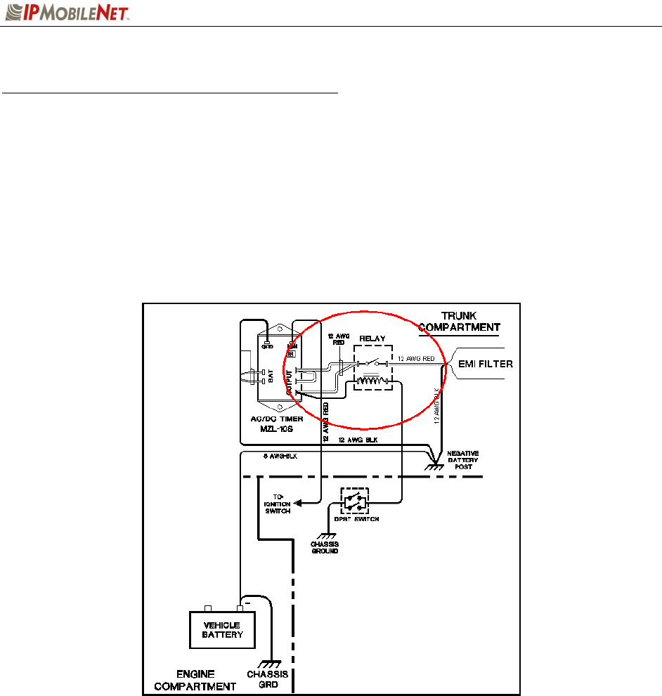
Carling Switch Installation (DPST Heavy Duty Toggle)
To install the switch, perform the following steps:
Step 1 Mount the switch in the selected location.
Step 2 Route and wire a red wire (#12 AWG) from the switch to the Automotive Power Relay
(see Figure 14).
Step 3 Ground the switch by routing and wiring a black wire from the switch to the negative
battery post.
Figure 14: Carling Switch Installation
CHAPTER 4: PRODUCT INSTALLATION
2003 IPMobileNet, Inc. 25 IPSeries MR User Manual / Rev. A / 08-Apr-03
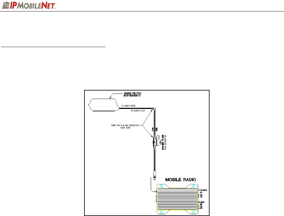
Mobile Radio Power Supply Installation
To install the mobile radio power connection, perform the following steps:
Step 1 Route and connect the power cable to the EMI filter, as shown in the figure below.
Figure 15: Power Supply Installation
Step 2 Route and connect the other end of the power cable to the rear of the mobile radio
to the power connector (13.8 VDC) connection, as shown previously in Figure 2.
EMI Filter
CHAPTER 4: PRODUCT INSTALLATION
2003 IPMobileNet, Inc. 26 IPSeries MR User Manual / Rev. A / 08-Apr-03
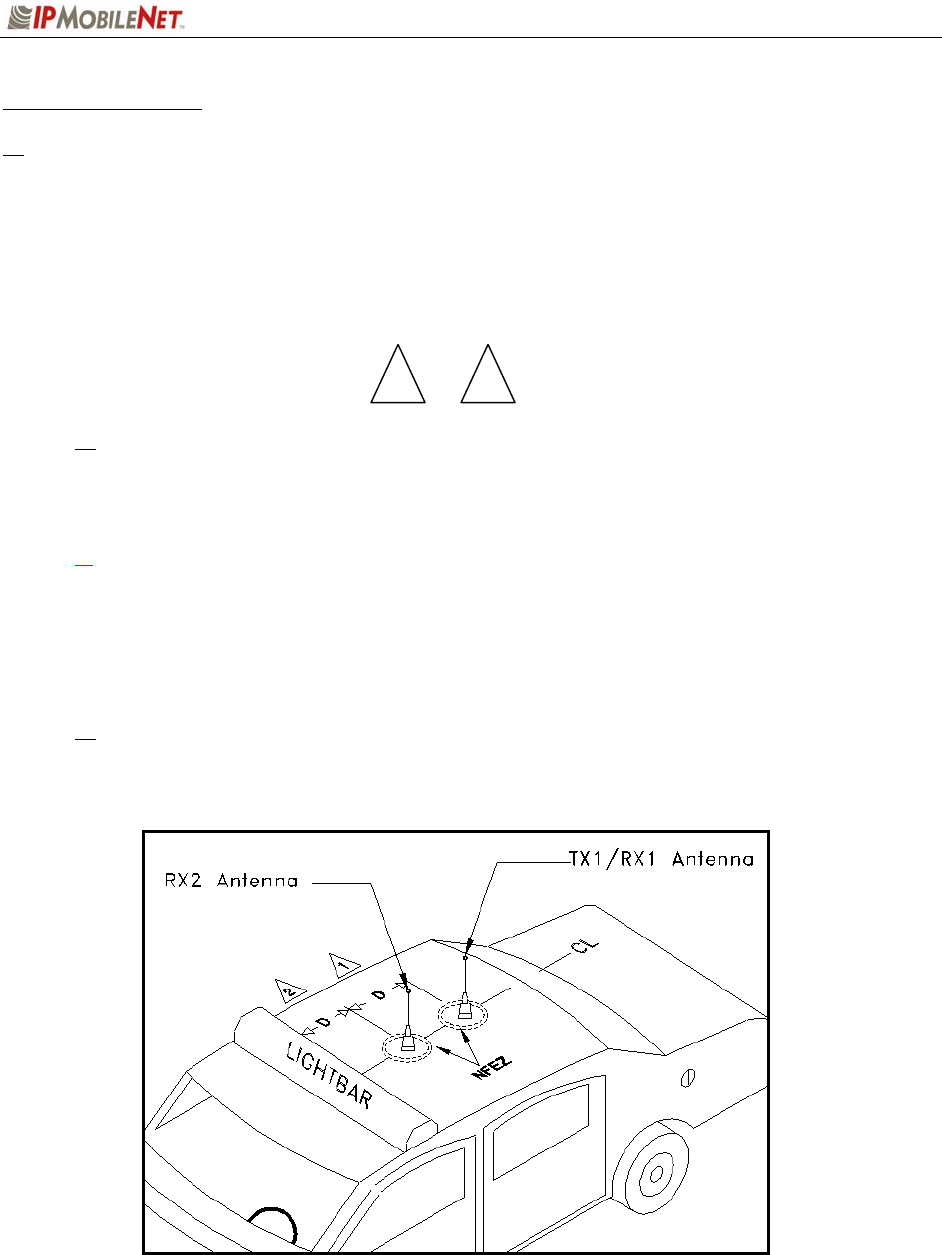
Antenna Configuration
Two (2) antennas are mounted and installed on the roof of the vehicle using specific
measurements for distance.
To mount and install the antennas, perform the following steps:
Step 1 Install antennas (see Figure 16).
Observe correct separation between antennas (refer to Table 10: Mobile Antenna
Distance Matrix). This table provides midpoint distance calculations and minimum and
Near-Field Exclusion Zone (NFEZ) for proper diversity reception.
1 The NFEZ distance is an absolute minimum. The greater the distance between the
antennas to any other surfaces will result in improved performance.
Step 2 Cut a mounting hole in the roof of the vehicle using an electric drill or hole saw.
The antenna-mounting hole provides ground connection to the antenna. Ensure that a
metal-to-metal connection between the antenna shields exists.
Figure 16: Antenna Distance Configuration
1 2

CHAPTER 4: PRODUCT INSTALLATION
2003 IPMobileNet, Inc. 27 IPSeries MR User Manual / Rev. A / 08-Apr-03
Figure 16 represents the recommended front-to-rear antenna installation. The receiver
antenna (RX2) should be the antenna nearest to the light bar.
Step 3 All antenna mounts must be environmentally tight. Install or use O-rings to seal the
antenna base to the rooftop of the vehicle.
Step 4 Route the coaxial cables to the mobile radio through one of the hollow spaces in the
roof supports into the trunk compartment where the mobile radio is mounted.
Both antennas should be checked and tested to ensure they are functioning properly.
If these installation guidelines are followed, it is safe for persons to stand at a distance no
less than 39 inches from the antennas.
Measuring Return Loss
The following test is performed without any power, thus can be performed immediately after the
installation of the coax and antenna, following the installation of the N-type connector on the coax.
To measure Return Loss, perform the following steps:
Step 1 Select the appropriate Antenna Analysts to perform the test.
Step 2 Connect the antenna to be tested to the Antenna Analyst.
Step 3 Turn on the Antenna Analyst and the Return Loss (RETL) is displayed in dB to the
left of the Voltage Standing Wave Ratio (VSWR) curve.
The Return Loss Specification is –14 dBm or greater (with good antennas the typical
range will be between –14 and –28).
Measuring Voltage Standing Wave Ratio
To measure the Voltage Standing Wave Ratio (VSWR) Reflected Power, perform the following
steps:
Step 1 After selecting the appropriate Analyst and connecting the antenna to be tested,
press F1 to access the Analyst Menu.
Step 2 Press F1 again to access the Display (DSPLY) menu, which lists the modes.
Step 3 Press F2 to select the VSWR display mode. Plotting will resume and the VSWR
value is highlighted.
The VSWR Reflected Power Specification should be at a ratio of approximately 1.6 to 1.

CHAPTER 4: PRODUCT INSTALLATION
2003 IPMobileNet, Inc. 28 IPSeries MR User Manual / Rev. A / 08-Apr-03
Measuring Insertion Loss
To measure Insertion Loss of an unterminated length of coax, perform the following steps:
Step 1 Connect the antenna to be tested to the appropriate Antenna Analyst.
Step 2 Turn on the Antenna Analyst and the Return Loss is displayed in dB to the left of the
VSWR curve.
To switch from the RETL mode to VSWR mode, refer back to the previous set of
instructions.
Step 3 Divide the result by two (2).
Voice Interface Unit Connections
If connecting a VIU, an additional 10-ft serial cable is required (IPMN p/n: 156-0245-010 included with
VIU).
To connect the serial cables, perform the following steps:
Step 1 Attach 20-ft serial cable male connector (DB9M) to the mobile radio.
Step 2 Route the female connector (DB9F) to the driver compartment and connect to the
serial port located on the rear of the VIU near the microphone hang up clip.
Step 3 Attach the 10-foot serial cable male connector (DB9M) to the other serial port
located on the rear of the VIU.
Step 4 Route the female connector (DB9F) serial cable to the serial port located on the rear
of the mobile computer.
CHAPTER 4: PRODUCT INSTALLATION
2003 IPMobileNet, Inc. 29 IPSeries MR User Manual / Rev. A / 08-Apr-03
Figure 17: VIU Connections
To connect the VIU power supply, perform the following steps:
Step 1 Route the VIU’s power supply cable from the driver compartment to the trunk
compartment.
Step 2 Connect the red (#12 AWG) wire via an in-line fuse from the VIU power cable to
the relay as shown in Figure 17 above.
Step 3 Attach the black (#12 AWG) wire of the VIU power cable to the ground connection
on the vehicle chassis.

CHAPTER 4: PRODUCT INSTALLATION
2003 IPMobileNet, Inc. 30 IPSeries MR User Manual / Rev. A / 08-Apr-03
Post Installation Checklist
Table 9 lists the tasks that should be performed upon completing installation.
TABLE 9: POST INSTALLATION CHECKLIST
NO. CHECKLIST ITEM
1 Scope out the entire vehicle setup to locate any obvious problem areas.
2 Check wiring for safety concerns.
3 Use tie wraps to ensure that all wires routed in parallel are bundled together.
4 Check to see if any wires are exposed.
5
If any wires are exposed, use electrical tape to cover.
When covering wires in the engine compartment, use high-quality
electrical tape.
6 Perform appropriate testing as described in this guide to ensure mobile radio
works properly.
Once installation is completed, remove all debris and restore dismantled parts and rubber mats to
appropriate locations.
CHAPTER 4: PRODUCT INSTALLATION
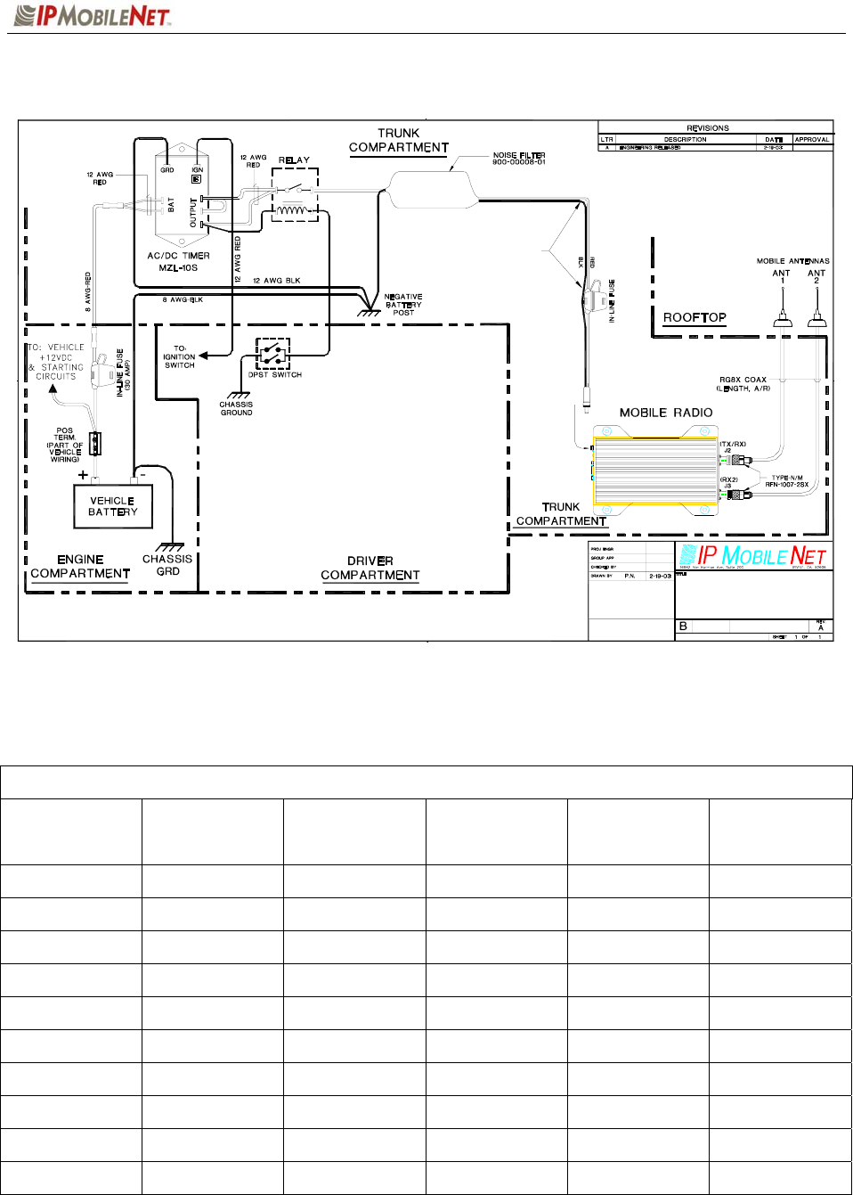
2003 IPMobileNet, Inc. 31 IPSeries MR User Manual / Rev. A / 08-Apr-03
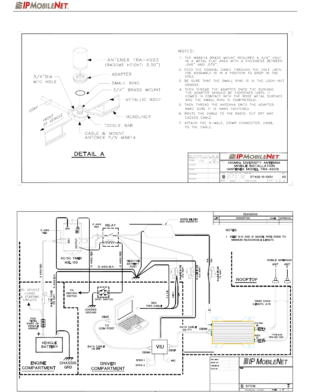
Mobile Installation Layout Diagrams
Figure 18: Vehicle Unit Wiring Interconnection Layout
Table 10 lists the mobile radio antenna distances by frequency band.
Table 10: Mobile Antenna Distance Matrix
Frequency Band
in MHz
Center Frequency
in MHz
Antenna Spacing
for
¼ Wave Ant
(inches)
Wavelength
(inches)
Near-Field
Exclusion Zone*
(inches)
¼ Wave Length
(inches)
130-140 135 65.4 87.3 10.9 21.8
140-150 145 61.2 81.4 10.2 20.4
150-160 155 57.0 76.2 9.5 19.0
160-174 167 53.1 70.7 8.9 17.7
400-430 415 21.3 28.5 3.5 7.1
430-450 440 20.1 26.8 3.4 6.7
450-470 460 19.2 25.7 3.2 6.4
470-490 480 18.6 24.6 3.1 6.2
490-512 501 17.7 23.6 2.9 5.9
806-821 814 10.8 14.5 1.8 3.6
*NFEZ = Minimum Near-Field Exclusion Zone **Round antenna spacing to the nearest ⅛”
12 AWG BLK
2 . FOR PARTS LIST SEE DWG # 502-80208-52 (M2M).
(15 AMP)
(without VIU - GENERIC)
MINIMUM REASONABLE LENGTH.
1. KEEP 8,10 AND 12 GAUGE WIRE RUNS TO
NOTES: Unless Otherwise Specified
SEE DWG # AD-00008-02
FOR REF
12 AWG BLK
502-80383-53
12 AWG RED
12 AWG RED
12 AWG RED
57219 502-80259-52
ACAD=502-80259-52.DWG
MOBILE UNIT
INSTALLATION LAYOUT
CHAPTER 4: PRODUCT INSTALLATION
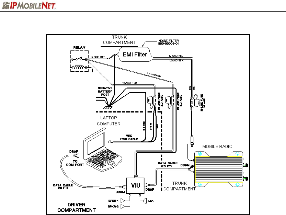
2003 IPMobileNet, Inc. 32 IPSeries MR User Manual / Rev. A / 08-Apr-03
Figure 19: Diversity Antenna Mobile Installation Detail (Typical Installation)
Figure 20: Vehicle Unit Wiring Interconnection Layout (with Voice Interface Unit)
COMPUTER
COMPARTMENT
TRUNK
LAPTOP
TRUNK
COMPARTMENT INITIAL ENGINEERING RELEASEDA
12 AWG RED
MOBILE RADIO
P. NGUYEN
502-80260
3-10-03
MOBILE UNIT/LAPTOP MDC
INSTALLATION LAYOUT
12 AWG RED
REVISED AND REDRAWNB 2-28-03
(WITH VIU - GENERIC)
12 AWG RED
12 AWG RED
12 AWG BLK

CHAPTER 4: PRODUCT INSTALLATION
2003 IPMobileNet, Inc. 33 IPSeries MR User Manual / Rev. A / 08-Apr-03
Preliminary Testing and Troubleshooting
This section provides a functional preliminary test for the mobile radio once installed. It is used to
determine the condition of new mobile radios before being placed into service. If the mobile radio is
found to be non-functional after completing this test and the related trobuleshooting scenarios, refer to
Chapter 6: Customer Support for appropriate action.
This section applies to all mobile radio frequency ranges.
Checklist of Required Material
Table 11 provides a checklist of the tools and equipment required to perform the preliminary test
procedure:
TABLE 11: CHECKLIST OF REQUIRED MATERIAL TO PERFORM PRELIMINARY TESTING
NO. REQUIRED TOOLS/EQUIPMENT
1 IPM mobile radio installed in the vehicle as previously described in this chapter.
2 A laptop with an available serial communication port and Microsoft Windows 98 or
greater installed.
3 IPMobileNet Dial-Up Networking and IPMessage software loaded onto the laptop
(IPMN_INVADR.exe).
4 DC power supply with ammeter, 13.8V, 12 amps or more (Astron VS12M or
equivalent).
5 Corresponding calibrated IPB base station
6 Internet Protocol Network Controller (IPNC)
7 Two antennas (generic mag mounts) tuned to frequency of transceiver.
8 Serial cable DB9M – DB9F connectors (IPMN p/n: 156-0245-020).
9 RF Attenuator 10-20 dB with appropriate wattage rating for transceiver.

CHAPTER 4: PRODUCT INSTALLATION
2003 IPMobileNet, Inc. 34 IPSeries MR User Manual / Rev. A / 08-Apr-03
Base Station Setup for Testing
The system must be programmed with the customer’s parameters before any tests are made on
the mobile radio.
To prepare the base station to be used in the mobile radio test, perform the following steps:
Step 1 On the laptop at the Windows desktop, click on the Start button and select
Accessories, Communications, and HyperTerminal.
Step 2 Power up the base station.
First-time users must enter the customer’s operating parameters into the base station
with HyperTerminal (refer to the IPB Base Station System Manual for instructions,
and the client’s system documentation for parameters).
1 Ensure that the calibrated base station and the mobile radio antennas are separated
by at least 10 feet. If the antennas are too close, the mobile radio receivers may
overload by the transmitters resulting in intermittent communications and high data
errors.
CHAPTER 4: PRODUCT INSTALLATION
2003 IPMobileNet, Inc. 35 IPSeries MR User Manual / Rev. A / 08-Apr-03
Preliminary Test Procedure and Troubleshooting
Prior to performing this procedure, the IP address of the IPNC must be obtained. Note taking
during preliminary testing is crucial to ensure necessary information is gathered to use for
additional testing or if the mobile radio needs to be submitted for repair.
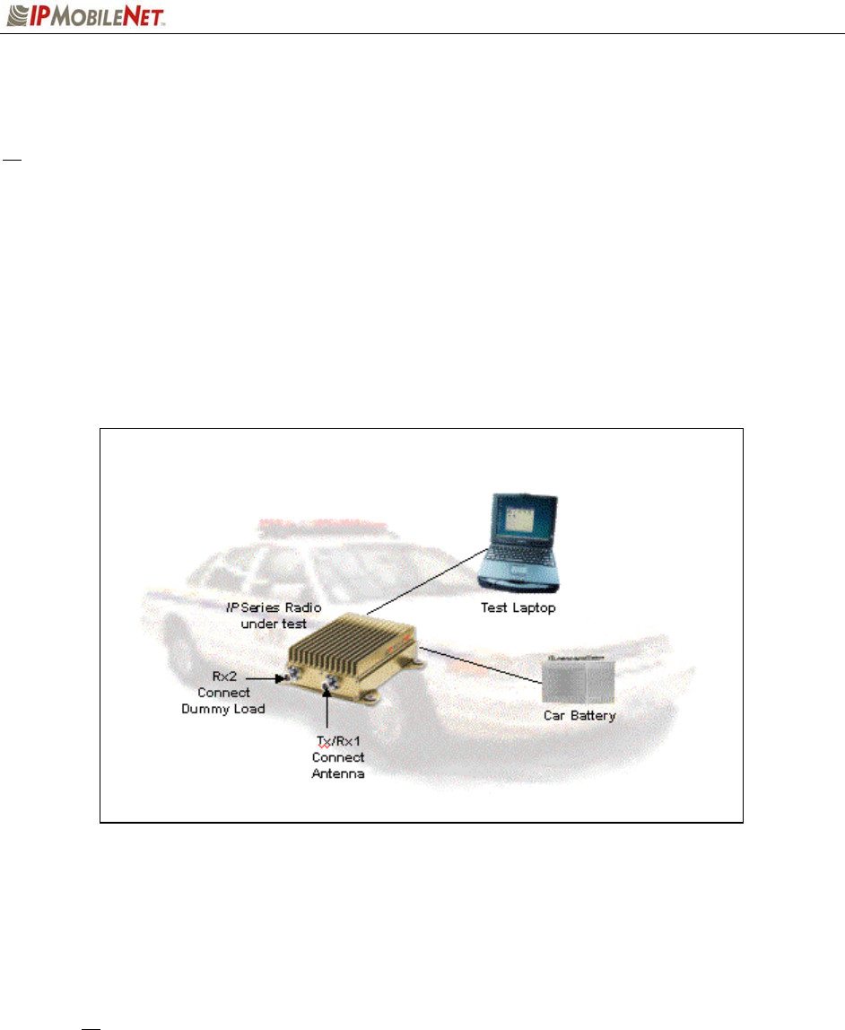
To test mobile radio functionality, perform the following steps:
Step 1 Perform a visual inspection of the mobile radio and its connections. Validate that
all connectors and power cables are in good condition and all chassis screws are
in place.
Step 2 Connect the mobile radio as shown below in Figure 21.
Figure 21: Mobile Radio Connection for Testing
Step 3 Power on the mobile radio and the test laptop. The power supply ammeter must
read 1.0 amp or less with a 13.8 VDC output.
Step 4 At the desktop, run the dial-up connection setup to use Serial Line Internet
Protocol (SLIP) by double clicking on the IPMN_INVADR shortcut.
The IPMN_INVADR dial-up network shortcut displays as an icon on the laptop’s desktop.
If the IPMN_INVADR shortcut is not available on the desktop, consult the Mobile Data
Computer for Communication with the Mobile Radio Installation Guide (IPMN p/n: 516-
80310) for instructions on how to set up the connection.
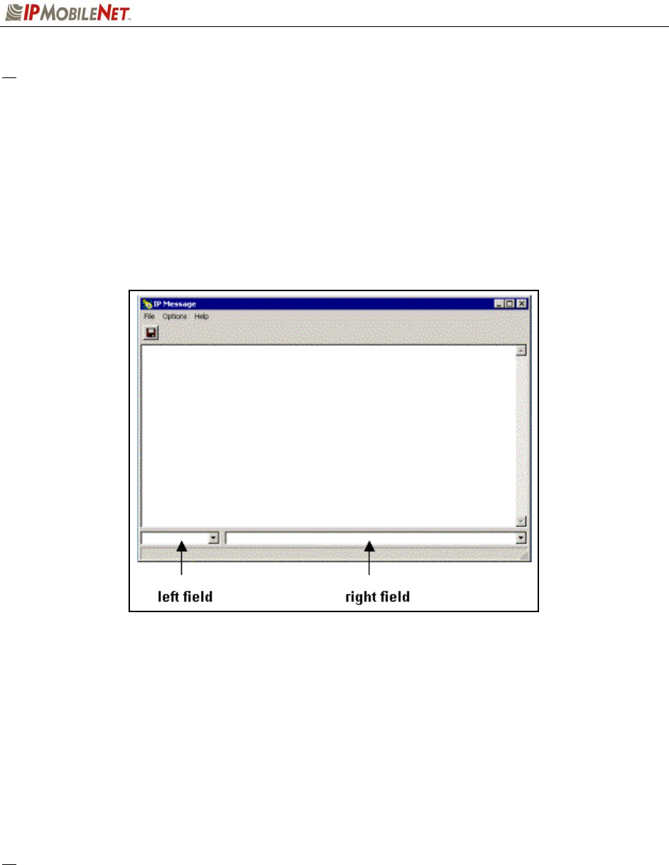
Step 5 At the desktop, run the IPMessage Utility by double clicking on the IPMsg
shortcut. The IPMessage window displays.
CHAPTER 4: PRODUCT INSTALLATION
2003 IPMobileNet, Inc. 36 IPSeries MR User Manual / Rev. A / 08-Apr-03
# If a message window appears indicating the connection was unsuccessful, perform the following
troubleshooting steps:
1. Ensure the serial and power cables are properly connected.
2. Verify that the mobile radio lock LED (light emitting diode) is on, indicating the mobile radio
has power (see Figure 2).
3. Ensure that the IPMN_INVADR dial-up connection is running.
4. If problem persists after retrying, replace the serial cable with one that is known to be
working properly.
Figure 22: IPMessage Window
Step 6 In the IPMessage window in the left field, enter the mobile radio’s IP address and
press the TAB button. If the mobile IP address is not known, enter
255.255.255.255 in the left field.
Step 7 In the right field type a ? and click the ENTER button. A list of mobile radio
configuration parameters appears in the upper message window. This verifies
that the IP address is correct, the mobile radio’s serial interface is live, and that
the mobile radio’s microcontroller section is active.
# If the upper message window only displays “To [IP address] ?”, communication has not been
established. Validate the IP address.
(
Address
)
(
Commands
)

CHAPTER 4: PRODUCT INSTALLATION
2003 IPMobileNet, Inc. 37 IPSeries MR User Manual / Rev. A / 08-Apr-03
Step 8 At the desktop, click on the Start button and select Programs and MS-DOS
Prompt. The MS-DOS window displays.
Step 9 Ping the IPNC commanding the transmitter to send 25 messages of 500
characters each to the IPNC as well as a response through Receiver 1 back to
the laptop or desktop PC by typing in the following command at the MS-DOS
prompt replacing NNN.NNN.NNN.NNN with the IPNC IP address:
Ping NNN.NNN.NNN.NNN –n 25 –l 500 –w 4000
After entering the command, press [ENTER] to continue.
When entering a command, pay special attention to the spaces and the
characters being typed.
# If the calibrated base station does not respond, check the syntax of the Ping command and verify
the IP address is correct.
If the ping command runs but high packet loss figures are shown, perform the following:
1. Verify that the calibrated base station and mobile radio antennas are separated by at least
10 feet. If the antennas are too close, the mobile radio receivers overload by the
transmitters resulting in intermittent communication and high data errors.
2. Verify the calibrated base station parameters are correct for the mobile radio. Such
parameters include IP addresses and complementary RX/TX frequencies.
3. Check to ensure the data and power cables are connected correctly.
4. If the Ping command continues to fail, test using a mobile radio that is known to be working
properly.
Step 10 Check the test laptop and verify that the Packets Lost Percentage is zero to 1%
packet loss. Greater losses may indicate a problem with the transmitter/receiver
1, or modem circuitry.
Step 11 Change the antenna on the mobile radio to the RX2 antenna input.
Step 12 Connect the RF attenuator to the mobile radio’s TX/RX1 antenna input.
Step 13 Connect the second antenna to the RF attenuator. In the IPMessage window,
enter receiver=2. This will allow the mobile radio to only receive via Receiver 2.
Step 14 Type the following command at the MS-DOS prompt replacing
NNN.NNN.NNN.NNN with the IPNC IP address:
Ping NNN.NNN.NNN.NNN –n 25 –l 500 –w 4000
After entering the command, press [ENTER] to continue.
Step 15 Check the test laptop and verify that the Packets Lost Percentage is zero to 1%
packet loss. Greater losses may indicate a problem with the transmitter/receiver
1, or modem circuitry.
CHAPTER 5: PROGRAMMING INSTRUCTIONS
2003 IPMobileNet, Inc. 38 IPSeries MR User Manual / Rev. A / 08-Apr-03
Enabling Ethernet for Static IP Address Update in the Mobile Radio
The following provides instruction on how to enable the Ethernet port on the mobile radio.
Requirements
This process is performed using Windows 98, 2000, or XP.
The default is the Ethernet port. If Ethernet is original connection it will remain connected there. If
disconnected, the connection will default back to the SLIP port connection. If the SLIP port is
connected and programming is attempted, it immediately switches to the Ethernet connection.
Enabling the Ethernet Port
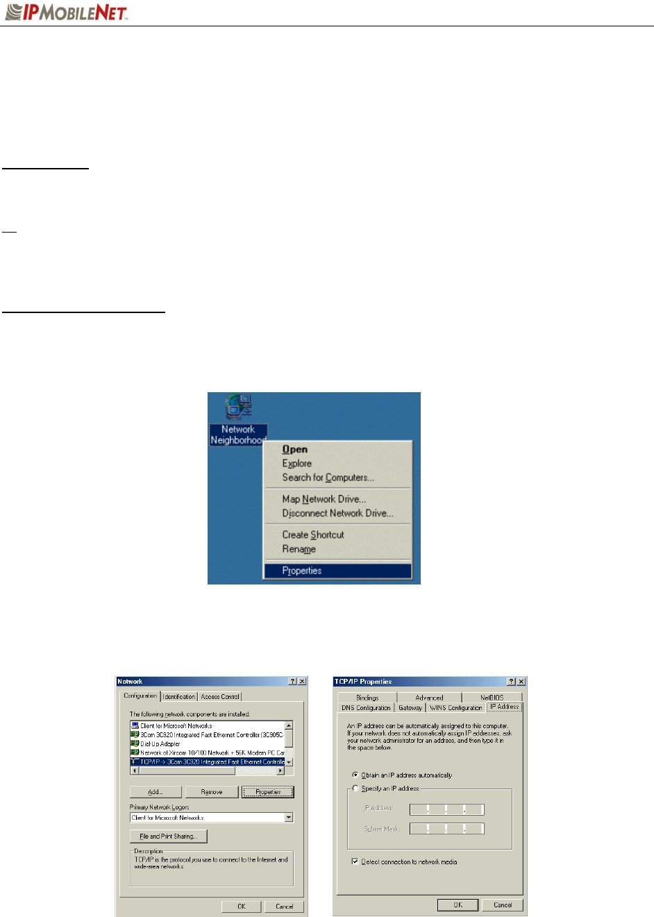
To enable the Ethernet port, perform the following steps:
Step 1 Press the right mouse button on the Network Neighborhood icon and select Properties.
Figure 23: Properties Selection
Step 2 Select TCP/IP Ethernet Controller click on the Properties button and at the TCP/IP
Properties window click on the IP Address tab.
Figure 24: TCP/IP and Ethernet Controller Properties
CHAPTER 5: PROGRAMMING INSTRUCTIONS
2003 IPMobileNet, Inc. 39 IPSeries MR User Manual / Rev. A / 08-Apr-03
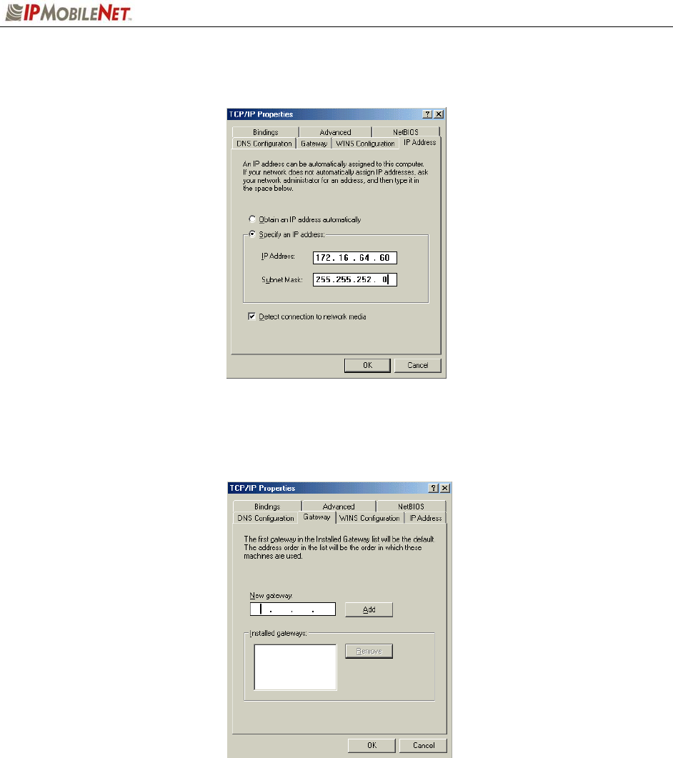
Step 3 Select ‘Specify an IP Address’ and enter the IP address as needed and the Subnet Mask as
needed.
Figure 25: TCP/IP Properties
Step 4 Select the Gateway tab and enter the gateway (the radio’s) IP address and click on ADD.
Figure 26: Gateway Entry
Step 5 Click on OK, then on OK again.
Step 6 For Windows 98, set Windows to find the CAB and System files, which can typically be
accessed via the following path:
C:\WINDOWS\OPTIONS\CABS; C:\WINDOWS\SYSTEM32
Step 7 Set Windows not to install older files.
Step 8 Reboot.

CHAPTER 5: PROGRAMMING INSTRUCTIONS
2003 IPMobileNet, Inc. 40 IPSeries MR User Manual / Rev. A / 08-Apr-03
Viewing the Mobile Radio’s Configuration Data
To view the mobile radio’s parameters, perform the following steps:
Step 1 At the desktop, run the IPMN_INVADR by double clicking on the dial-up network
connection shortcut.
Step 2 At the desktop, run the IPMessage Utility by double clicking on the IPMsg shortcut.
The IPMessage window displays.
Step 3 In the left field type the mobile radio’s IP address and press ENTER.
Step 4 In the lower message area type a ? and press ENTER. A list of mobile radio
configuration parameters appears in the upper message window.
Changing the Mobile Radio’s IP Address
To change the mobile radio’s IP address, perform the following steps:
Step 1 At the desktop, run the IPMN_INVADR by double clicking on the dial-up network
connection shortcut, as shown above.
Step 2 At the desktop, run the IPMessage Utility by double clicking on the IPMsg shortcut,
as shown above. The IPMessage window displays.
Step 3 In the left field type the mobile radio’s IP address and press ENTER.
Step 4 In the right field type a ? and press ENTER. A list of mobile radio configuration
parameters appears in the upper message window.
Step 5 In the right field type unlock=password (entering the appropriate password) and
press ENTER. This command unlocks the mobile radio’s Firmware and grants the
user the authority to change the IP address.
The password is case sensitive.
Step 6 In the right field type ipaddress=NNN.NNN.NNN.NNN replacing the N’s with the
mobile radio’s new IP address.
A line of text containing the mobile radio’s new IP address will appear in the
message window. If there is no response, repeat Steps 5 and 6.
Step 7 Write the new IP address on a label and attach the label to the mobile radio.
Communication with the mobile radio will cease due to the IP address change.
To resume communication with the mobile radio, type the new IP address in
the left field and press ENTER.

CHAPTER 5: PROGRAMMING INSTRUCTIONS
2003 IPMobileNet, Inc. 41 IPSeries MR User Manual / Rev. A / 08-Apr-03
Changing Mobile Radio Parameters
Perform the following steps to make changes to mobile radio parameters:
Step 1 At the desktop, run the IPMN_INVADR by double clicking on the dial-up network
connection shortcut, as shown on the previous page.
Step 2 At the desktop, run the IPMessage Utility by double clicking on the IPMsg shortcut,
as shown on the previous page. The IPMessage window displays.
Step 3 In the left field type the mobile radio’s IP address and press ENTER.
Step 4 In the right field type a ? and press ENTER. A list of mobile radio configuration
parameters appears in the upper message window.
Step 5 In the lower message window type unlock=password (entering the appropriate
password) and press ENTER. This command unlocks the mobile radio’s Firmware
and grants the user authority to change mobile radio parameters.
1 WARNING! Do not change mobile radio parameters unless familiar with this
process. Changing a parameter to the wrong value may seriously affect the
mobile radio’s performance. Parameter changes should be limited to the IP
address, power output, channel number, and RX/TX frequencies.
Step 6 Enter appropriate commands in the lower window with parameter changes (see
examples to follow).
In the following examples, the frequencies are representative of the IPM4.
Replace with the appropriate frequencies if dealing with an IPM1 or IPM8
EXAMPLE 1 SCENARIO
The transmit power output is too high. The client was authorized 25 Watts. The mobile radio configuration list
shows TX Power=200 (this does not mean 200 W).
Parameter Change Command:
In the lower message window, type the following command, then press ENTER.
TX POWER=150
Send test messages, measure the RF power output, and reenter the command with increased or decreased
values until 25 watts is achieved. The mobile radio is designed for full power use. Please consult IPMN Customer
service if your needs are going to be at a lower power output. TX power is not guaranteed to produce any user
selectable power level.
EXAMPLE 2 SCENARIO
The mobile radio was set for the wrong RX frequency. The client was assigned 471.5500 (RX), and 474.5500
(TX). The mobile radio configuration list shows TX Freq=474.5500, and RX Freq=471.0000.
Parameter Change Command:
In the lower message window, type the following command, then press ENTER.
FREQUENCY=0,474.550000,471.550000
NOTE: This programs channel 0. The trailing zeros (0) are not required.

CHAPTER 5: PROGRAMMING INSTRUCTIONS
2003 IPMobileNet, Inc. 42 IPSeries MR User Manual / Rev. A / 08-Apr-03
EXAMPLE 3 SCENARIO
The mobile radio was set for the wrong RX and TX frequencies. The client was assigned 471.6500 (RX), and
474.6500 (TX). The mobile radio configuration list shows TX Freq=474.5500, and RX Freq=471.5500.
NOTE: This programs channel 0.
Parameter Change Command:
In the lower message window, type the following command, then press ENTER.
FREQUENCY=0,474.650000,471.650000
EXAMPLE 4 SCENARIO
Add another channel. The client was assigned a second channel of 474.6500 (RX) and 477.6500 (TX). The
mobile radio configuration list shows Channel=0, TX Freq=474.6500, RX Freq=471.6500. There is no second
channel.
Parameter Change Command:
In the lower message window, type the following command, then press ENTER.
FREQUENCY=1,477.650000,474.650000
Notes on frequency changes:
• The syntax is FREQUENCY=CHANNEL NO.,TX FREQ,RX FREQ
• The channel number and both frequencies must be entered even if only changing one frequency.
• If new RX/TX frequencies are greatly different, the mobile radio may operate outside the bandpass
of the receiver filters and power amplifier module deteriorating performance. The mobile radio must
be replaced with one operating in the selected frequency range.
• Additional frequencies that are not active may be detrimental to the mobile radio’s performance.
Step 7 If necessary, repeat Steps 5 and 6 to change the parameters.
Step 8 Verify that all parameter changes were accepted by the mobile radio. To do this, type
a ? in the right field and press ENTER. Compare the desired parameter changes with
those appearing in the upper message window.
Step 9 Disconnect the mobile radio and return it to service.

CHAPTER 5: PROGRAMMING INSTRUCTIONS
2003 IPMobileNet, Inc. 43 IPSeries MR User Manual / Rev. A / 08-Apr-03
Factory Default Save and Restore
For instructions on Factory Default Save and Restore Commands, please contact the Customer Service
number provided in Chapter 6 of this document.

CHAPTER 6: CUSTOMER SUPPORT
2003 IPMobileNet, Inc. 44 IPSeries MR User Manual / Rev. A / 08-Apr-03
Ordering Parts
Replacement parts may be ordered from the following address:
Attn: Small Parts Sales
IPMobileNet, Inc.
16842 Von Karman Avenue, Suite 200
Irvine, CA 92606
Voice: (949) 417-4590
Fax: (949) 417-4591
Customer Support
To obtain assistance to troubleshoot problems with a product, please contact IPMobileNet’s Customer
Service Staff at (800) 348-1477.
Reporting Problems with the Documentation
To report problems or question concerning the documentation included in your shipment, please send an
email to mlopez@ipmobilenetinc.com explaining the problem and the Publications Department will
respond as soon as possible.
Please ensure to include the following information with your email message:
Your company name
Your name or other contact name
Return email address
Manual name
Manual part number
Page number(s)
Description of the problem

APPENDIX A: MOBILE RADIO IPMESSAGE PARAMETERS
2003 IPMobileNet, Inc. 45 IPSeries MR User Manual / Rev. A / 08-Apr-03
Data Field Description
hostframing=Ethernet
Sets up Host Interface in Ethernet Mode.
A new parameter, “Ethernet”, has been added to the existing “Host Framing” command.
Before typing in the command, the radio must be unlocked. The command is effective
immediately. When host framing is set to Ethernet, the radio will try to use the Ethernet
interface first. If the Ethernet link status is bad, the radio will switch back to the SLIP
interface. The radio does not support both SLIP and Ethernet interfaces concurrently.
Therefore, if both the serial and Ethernet interfaces are physically connected to the host, it
is very important that the SLIP2IPMN dial-up is disabled. The TCP/IP property for the
Ethernet interface of the PC must be configured with an IP address different from the
SLIP2IPMN’s IP address. The default gateway address must be set to be the same as the
mobile radio’s IP address. If the PC is configured to obtain the IP address dynamically, the
mobile radio’s DHCP Server feature must be enabled first (see DHCP Server command
below).
Default Value = Ethernet, nostatus
dhcpclient=enable or
dhcpclient=disable
Enables/Disables DHCP Client.
Use this command to enable or disable DHCP. Before typing in the command, the radio
must be unlocked. Once the command has been entered, the radio should be reset with
the “reboot” command.
When DHCP Client is enabled, upon resetting, the mobile radio will obtain the IP addresses
and netmasks of the mobile radio itself, the PC and the VIU over-the-air from the IPNC.
The base station where the mobile radio is connected must be configured with
“dchprelayagent” enabled. Also, the IPNC DHCP server must be set-up and activated.
When DHCP Client is disabled, the mobile radio’s IP address and netmask must be
configured manually using the “ipaddress” command.
Default Value = disable
dhcpserver=enable or
dhcpserver=disable
Enables/Disables the DHCP Server.
Use this command to enable or disable the DHCP server capability of the mobile radio.
Before typing in the command, the radio must be unlocked. Once the command has been
entered, the radio should be reset with the “reboot” command. When DHCP Server is
enabled in the mobile radio, the PC connected to the radio’s Ethernet port can be set-up for
dynamic IP address configuration. DHCP Server can be enabled/disabled independent of
the state of DHCP Client. If DHCP Server is enabled but DHCP Client is not, the radio will
generate the IP addresses for the PC and VIU according to rules of the IPNC subnet
addressing described in the IPNC Installation Manual.
Examples:
1. Mobile Netmask:255.255.255.0, mobile:172.16.22.10, pc:172.16.20.10,
viu:172.16.21.10
2. Mobile Netmask:255.255.254.0, mobile:172.16.44.10, pc:172.16.40.10,
viu:172.16.42.10
Default Value = disable
suspendtx=n
Enable/Disable Unlicensed Frequency Restriction.
Where “n” is a decimal number range from 0 to 32767. Use this command to enable or
disable the feature of prohibiting transmission on unlicensed frequency channels. Before
typing in the command, the radio must be unlocked. The command is effective
immediately. When the “suspendtx” parameter is set to zero, the feature is disabled. In this
case, the radio is not prohibited to transmit even if it has not received anything from a base
station. On the other hand, if the parameter is not zero, the radio will NOT send until it has
received from a base station. Once the radio has received from the base, it will begin
sending but will stop further transmissions if it has failed to receive from a base station after
the period, in seconds, specified in the parameter. When “testmode” is set to 1 in the
radio, “suspendtx” should be set to zero.
Default Value = 0

APPENDIX A: MOBILE RADIO IPMESSAGE PARAMETERS
2003 IPMobileNet, Inc. 46 IPSeries MR User Manual / Rev. A / 08-Apr-03
Data Field Description
txdelay=x
Setting Transmission Delay.
Where “x” is number of slots, from 0 to 15, to be delayed. Use this command to delay
back-to-back radio transmissions to reduce the chances of colliding with the base station
downlink transmission. Before typing in the command, the radio must be unlocked. The
command is effective immediately. When setting the delay to a non-zero value, the
“rxinprogressmessage” in the base must be set to 1.
Default Value = 2
mtu=n
Setting MTU.
Where “n” is the desired MTU in decimal value, 1500 maximum. Use this command to
change the MTU. Before typing in the command, the radio must be unlocked. The
command is effective immediately. When the radio receives a packet with size greater
than the MTU, it will return an ICMP packet (type=3, code=4) to the source. The original
received packet will be discarded.
Default Value = 1500
internalgpsinput=1 (input protocol =
TSIP)
internalgpsoutput=1 (output protocol
= TSIP)
internalgpsinput=2 (input protocol =
TAIP)
internalgpsoutput=2 (output protocol
= TAIP)
internalgpsoutput=3 (output protocol
= NMEA)
Setting Internal GPS Input/Output Default Protocol.
Use this command to configure the default protocol for the internal GPS. Before typing in
the command, the radio must be unlocked. Once the command has been entered, the
radio should be reset with the “reboot” command.
Default Value = internalgpsinput=2, internalgpsoutput=2
tftpoptions=s,t
Setting TFTP Packet Size and Delay between Packets.
Where “s” is the packet size in number of bytes (e.g. 512), and “t” is the delay between
packet transfers in seconds (e.g. 3).
Use this command to change the default over-the-air TFTP protocol options (256 bytes for
packet size and 3 seconds for packet delays). These options do not apply to TFTP packets
that are not sent over-the-air, which are fixed at 512 bytes and no delay. Before typing in
the command, the radio must be unlocked. The command is effective on the next file
transfer.
Default Value = 256, 3
diversityprocessor=0
Disable Diversity Processor.
Use this command to disable the diversity processor. The mobile Firmware automatically
detects whether the diversity processor is present and enables it if it is detected. When the
diversity processor is enabled, the diversity processor will handle diversity. If the diversity
processor is present but is disabled with the command by the user, the main processor will
handle diversity. Before typing in the command, the radio must be unlocked. The
command is effective immediately. To re-enable the diversity processor, the user must
reboot the radio using the ‘reboot’ command.
Default Value = 1 if found, 0 if not found (auto-detect)

APPENDIX A: MOBILE RADIO IPMESSAGE PARAMETERS
2003 IPMobileNet, Inc. 47 IPSeries MR User Manual / Rev. A / 08-Apr-03
Data Field Description
updatefirmware=filename
Update Mobile Radio Firmware/EEPROM.
Where “filename” is the file name of the Firmware or EEPROM binary file. Use this
command to update the radio Firmware or EEPROM content. The filename cannot contain
the path. The file must reside in the current file path of IPMSG. Before typing in the
command, the radio must be unlocked. When update is finished, the firmware will reboot
the radio automatically. Alternatively, the Firmware/EEPROM can be updated using the
“File | Update Firmware” pull-down menu in IPMSG. This is the preferred method, since
the path (drive and directory) can be specified.
Default Value = none

FIGURE LISTING
2003 IPMobileNet, Inc. 48 IPSeries MR User Manual / Rev. A / 08-Apr-03
No. Description Page No.
1 IPSeries Mobile Radio (Front View) 7
2 IPSeries Mobile Radio (External Features) 8
3 General Block Diagram 10
4 Basic Network Connection 12
5 Network Connection to an Existing LAN 13
6 Wireless high Speed Digital IP Voice & Data (over the Internet) 14
7 Mobile Radio-to-Mobile Computer Setup 15
8 Mobile Radio-to-VIU-to-Mobile Computer Setup 16
9 Trunk Compartment Installation 20
10 Mobile Radio Mounting 21
11 DB9M Serial Male Connector 22
12 DB9F Serial Female Connector 22
13 Delay Timer Installation 23
14 Carling Switch Installation 24
15 Power Supply Installation
16 Antenna Distance Configuration 27
17 VIU Connections 29
18 Vehicle Unit Wiring Interconnection Layout 31
19 Diversity Antenna Mobile Installation Detail (Typical Installation) 32
20 Vehicle Unit Wiring Interconnection Layout (with VIU) 32
21 Mobile Radio Connection for Testing 35
22 IPMessage Window 36
23 Properties Selection 38
24 TCP/IP and Ethernet Controller Properties 38
25 TCP/IP Properties 39
26 Gateway Entry 39

GLOSSARY
2003 IPMobileNet, Inc. 49 IPSeries MR User Manual / Rev. A / 08-Apr-03
4-Level FSK A form of digital modulation in which four (4) discrete levels
of carrier frequency displacement are employed to convey
information.
Analog A classification of signal in which the amplitude of the signal
may take on an infinite number of values.
Bessel Filter A filter with a linear phase response.
Broadband A term, which implies that the equipment can be operated
over a wide (broad) band of frequencies.
bps bits per second
CMOS Complementary Metal Oxide Semiconductor – A type of
integrated circuit with low power consumption.
Collision Tolerant Modem A specially designed modem, which can tolerate
transmissions that overlap in time.
Continuous Duty Indicates that the equipment can be operated 100% of the
time.
CRC Cyclic Redundancy Checksum – An error detection scheme
in which a known algorithm is used to operate on a message
both prior to transmission and after reception. The output of
the operation (the checksum) is compared on both sides of
the link to validate the integrity of the received message.
Data Interleaving A technique in which the order of the individual data bits
within the data to be transmitted is shifted and interleaved so
as to disassociate adjacent data bits in a message. This
scheme is complementary to forward error correction (FEC)
algorithms.
Data Scrambling A technique used to ensure no repeating patterns exist in the
transmitted data stream, a method of ensuring the data is
reasonable random in nature.
Digital A classification of signal in which the amplitude of the signal
may take a discrete number of values.
Diversity Reception A reception system using multiple antennas and/or multiple
receivers to combat multi-path fading.
Dynamic Range The range of amplitudes over which a receiver or amplifier
will operate within specifications.

GLOSSARY
2003 IPMobileNet, Inc. 50 IPSeries MR User Manual / Rev. A / 08-Apr-03
EIA Electronic Industries Association
EMI Electromagnetic Interference
Ethernet A local area network (LAN) architecture, which uses a bus or
star topology and supports data transfer rates of 10 Mbps.
Exciter An exciter is that part of a radio, which creates the transmit
RF carrier and performs the process of modulation.
FEC Forward Error Correction – A methodology used to correct
errors, which may occur in wireless transmission systems.
With FEC, additional data is added to each message prior to
transmission, at the receiving end, this additional information
can be used to correct errors in the received message.
FM Frequency Modulation – A form of modulation where the
carrier is shifted an amount proportional to the modulating
signal’s amplitude at a rate proportional to the modulating
signal’s frequency.
Frequency Stability A measure of the stability of a frequency with respect to
temperature, usually expressed in ppm (parts per million)
over a specified temperature range.
FSK Frequency Shift Keying – Digital modulation (a form of FM)
where the carrier frequency is shifted above and below the
operating frequency (in discreet steps) in response to a
digital data input.
Full Duplex A dual frequency mode of operation in which transmission
and reception occur simultaneously.
GFSK Gaussian Filtered Frequency Shift Keying – A form of digital
modulation in which the baseband modulation signal is
filtered by a low-pass filter with a Guassian response prior to
modulating the carrier signal.
GPS Global Positioning System
Image Frequency An unwanted frequency, which will produce an on-frequency
IF (Intermediate Frequency) signal.
Injection An injection signal is a signal used in frequency conversion
circuits, it is normally mixed with another signal to produce a
third signal (which is a sum or difference or the original
signal and the injection signal).

GLOSSARY
2003 IPMobileNet, Inc. 51 IPSeries MR User Manual / Rev. A / 08-Apr-03
Half Duplex A dual frequency mode of operation, which inhibits
simultaneous transmission and reception.
LO Local Oscillator – An on-board oscillator used in frequency
conversion circuits.
Modular Design A design in which the major functional components are
separated into distinct modules.
Multipath A radio propagation situation in which multiple RF (radio
frequency) signals paths exists between a transmitter and
receiver. These multiple paths or multi-path situations can
create significant distortion in the received signal.
NFEZ Near-Field Exclusion Zone
Noise Figure The “Figure of Merit” of an amplifier. Specifically, noise
figure is a measure of the degradation in SNR (signal-to-
noise ratio) between the input and output ports of a network.
PCB Printed Circuit Board
Phase Linearity Implies a linear relationship between the phase of a signal
and the frequency of that signal. A linear phase response
ensures constant input to output delays regardless of
frequency, import for wireless communication systems.
Phase Noise A measure of the purity of a discreet frequency (expressed
in –dBc/Hz at some offset frequency).
PLL Phase Locked Loop - A circuit configuration used to lock the
frequency of a VCO (voltage controlled oscillator) to a high
stability reference oscillator.
ppm Parts Per Million
RF Radio Frequency
RFI Radio Frequency Interference
SINAD The ratio of Signal + Noise + Distortion to Noise
+ Distortion.
Sensitivity The measure of a receiver’s ability to capture and faithfully
reproduce weak signals.

GLOSSARY
2003 IPMobileNet, Inc. 52 IPSeries MR User Manual / Rev. A / 08-Apr-03
SMT Surface Mount Technology – electronic components, which
make electrical contact on the surface layer of a PCB (as
opposed to thru-hole components). SMT devices provide
reduced size and increase performance.
SNR Signal-to-Noise Ratio
TCVCXO Temperature Compensated Volated Controlled Crystal
Oscillator
TIA Telecommunications Industry Association
Transmit Attack Time The elapsed time from transmit key assertion to 90% rated
RF power is achieved.
VCO Voltage Controlled Oscillator – An oscillator whose
frequency can be adjusted by a DC control voltage.

INDEX
2003 IPMobileNet, Inc. 53 IPSeries MR User Manual / Rev. A / 08-Apr-03
A
antenna · 7, 8, 9, 11, 19, 20, 26, 27, 28, 31, 37
C
Carling Switch · 3, 22, 24, 48
D
Delay Timer · 25, 26, 48
Diversity · 3, 7, 32, 46, 48, 49
E
EMI Filter · 3, 18, 22, 23, 48
Ethernet · 4, 7, 8, 9, 10, 38, 45, 50
F
Features · 3, 8, 48
G
GPS · 7, 9, 11, 46, 50
I
IPMessage · 4, 5, 33, 35, 36, 40, 41
IPMN_INVADR · 15, 16, 33, 35, 36, 40, 41
M
mobile radio · 5, 7, 8, 10, 11, 15, 16, 17, 18, 20,
21, 22, 23, 27, 28, 30, 31, 33, 34, 35, 36, 37,
38, 40, 41, 42, 45
P
Parameters · 4, 5, 41
Programming · 4
R
receiver · 7, 9, 10, 11, 27, 37, 42, 49, 51
S
Serial Cable · 3, 19, 22
Specifications · 3, 9
T
Testing · 3, 33, 34, 35, 36, 48
trunk · 20, 21, 22, 25, 26, 27, 29
V
Vehicle Unit Wiring · 3, 31, 32, 48
VIU · 3, 13, 15, 16, 18, 28, 29, 45, 48