IP Mobilenet IPMNIP8 IP8HPV Data Transceiver User Manual IP8HPV FCCRpt
IP Mobilenet, LLC IP8HPV Data Transceiver IP8HPV FCCRpt
UserManual.wiki
>
IP Mobilenet
>
IPMNIP8 User Manual
>
Manual
Contents
1.
Manual
2.
installation guide
3.
Revised manual
Manual
Navigation menu
Upload a User Manual
Namespaces
Wiki Guide
HTML
PDF
Info
Views
User Manual
Discussion / Help
Navigation
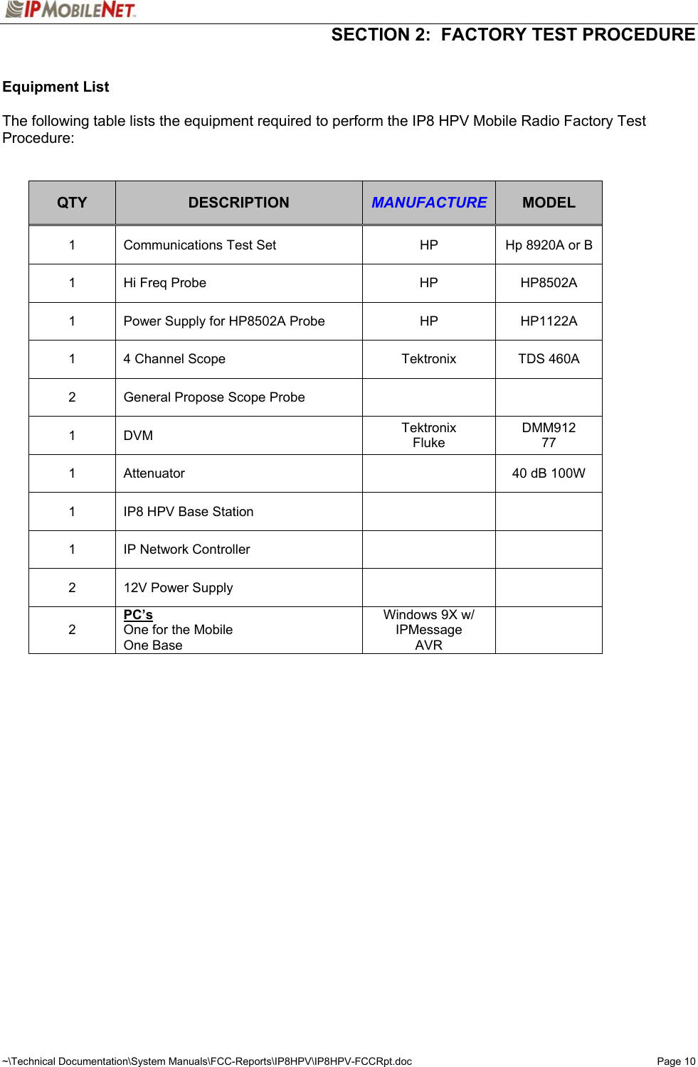
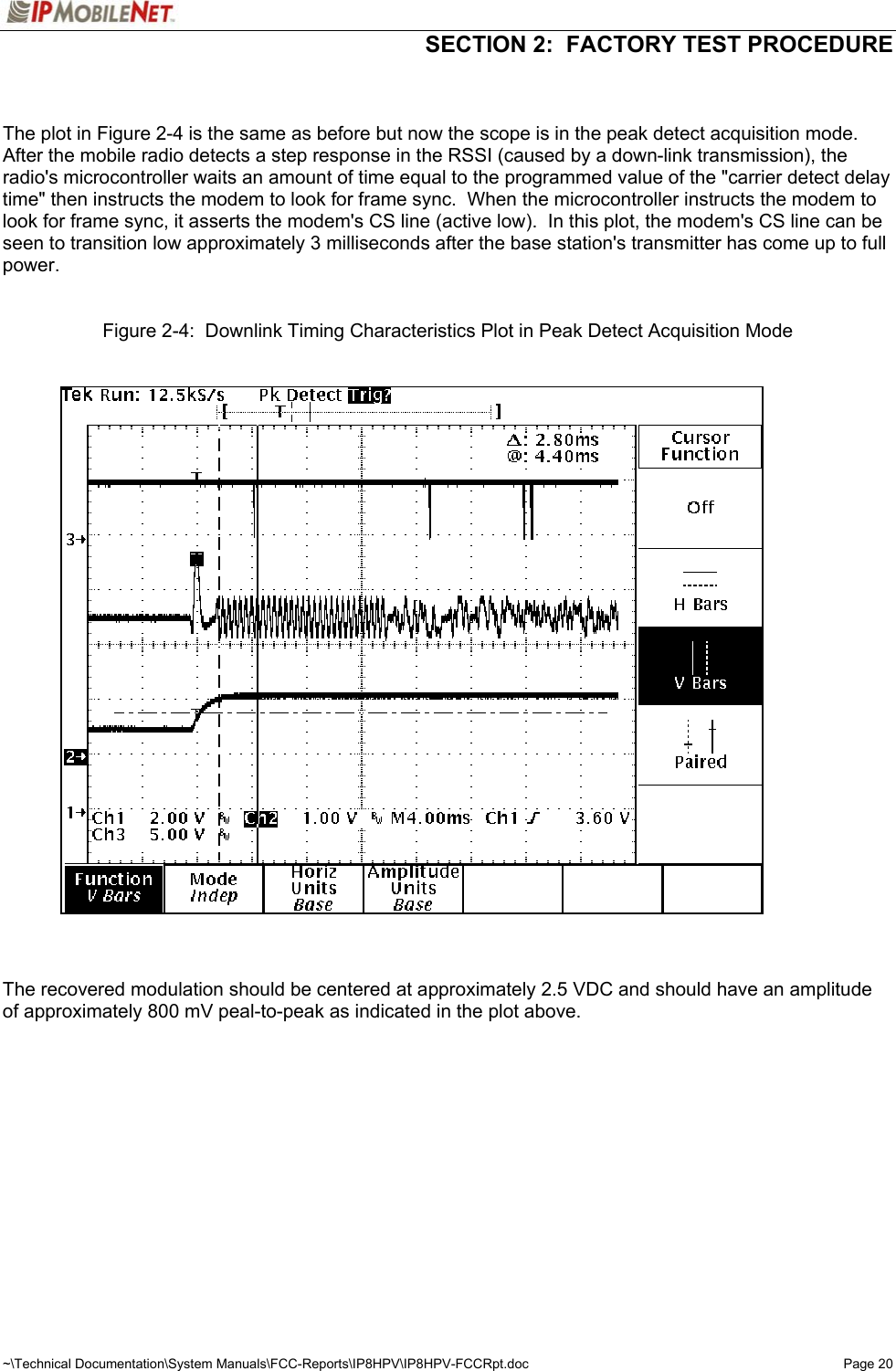
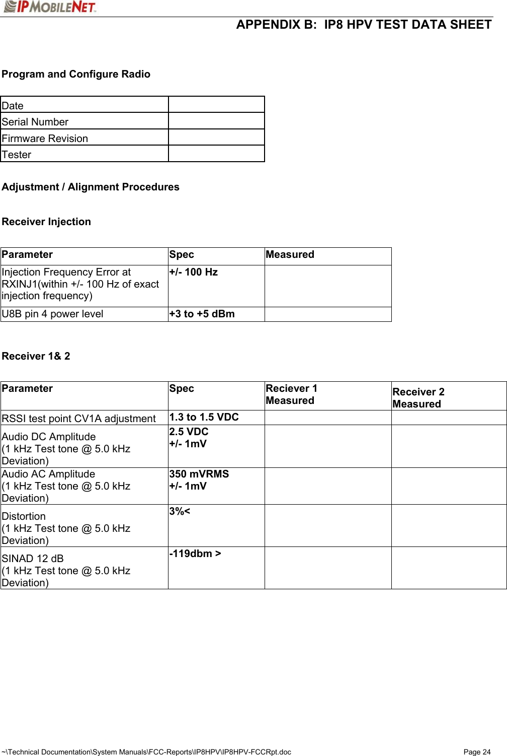
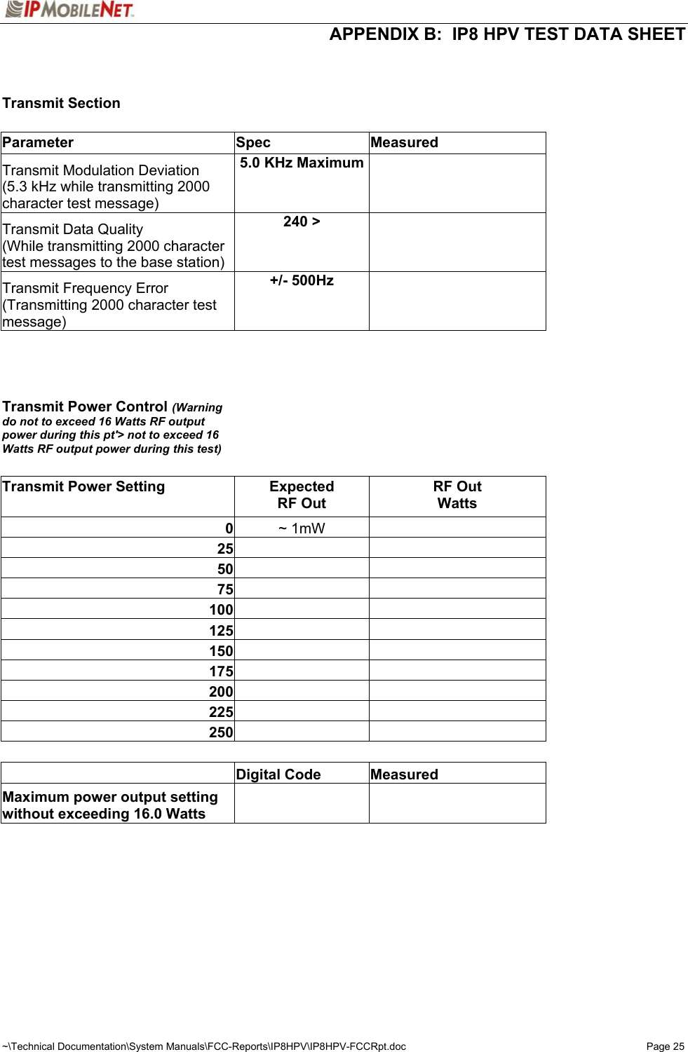
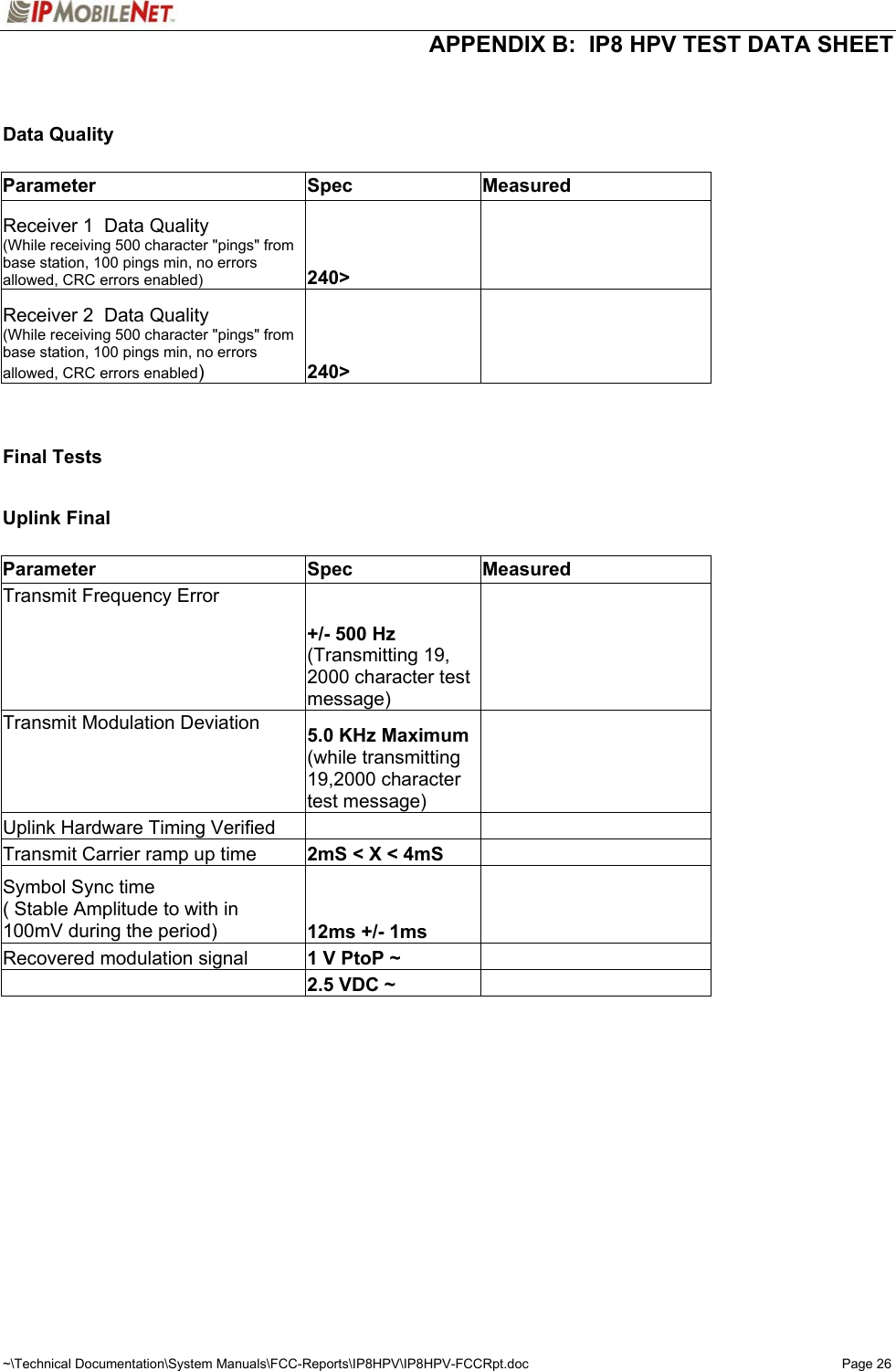
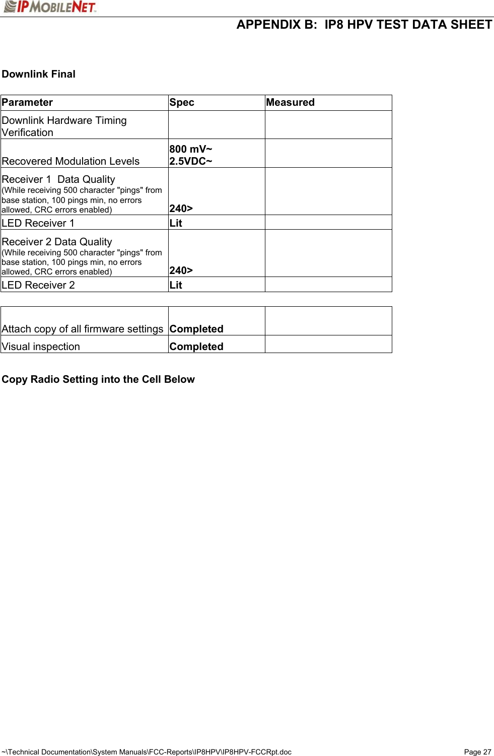
![SECTION 2: FACTORY TEST PROCEDURE ~\Technical Documentation\System Manuals\FCC-Reports\IP8HPV\IP8HPV-FCCRpt.doc Page 11 Programming and Configuring Mobile Radio Once the appropriate equipment for performing the factory test are gathered, perform the following steps to program and configure an IP8 HPV Mobile Radio: Step 1 Enter the following information on the Mobile Radio Performance Test Data Sheet: Radio Serial number Date test being performed Tester's Name Step 2 Program the radio to the current Firmware revision using the AVR programming utility. Step 3 Connect a PC to the radio using IPMessage program. In the IPMessage window, type in the following command: factory default Press the [ENTER] key and the radio will load default configuration values into the IPMessage window. Step 4 Enter the appropriate values for the radio's frequency band. Example: The following values were used for a 806 to 869 MHz radio: [To: Radio] ? [From: 192.168.3.10] Host serial = 19200,N,8,1, timeout=200 [From: 192.168.3.10] Host framing = [From: 192.168.3.10] SLIP no status messages [From: 192.168.3.10] Injection = LOW SIDE, 45MHz [From: 192.168.3.10] channel spacing = 25000 [From: 192.168.3.10] Channel = 0 [From: 192.168.3.10] TX Power = 0 [From: 192.168.3.10] Car to car TX power = 0 [From: 192.168.3.10] Channel Tx freq Rx freq Inj freq [From: 192.168.3.10] Frequency= 0, 815.10000, 860.10000, 815.100000 [From: 192.168.3.10] Serial number: undefined [From: 192.168.3.10] TX quiet time = 5 [From: 192.168.3.10] TX sync time = 12 milliseconds, 0 extra inter-split-frame count [From: 192.168.3.10] TX tail time = 5 [From: 192.168.3.10] Radio data rate = 19200 [From: 192.168.3.10] Max data tx time = 60 seconds [From: 192.168.3.10] PLL load to txkey delay = 2 milliseconds [From: 192.168.3.10] Carrier detect delay time = 3 milliseconds [From: 192.168.3.10] Polarity = TX-, RX+ [From: 192.168.3.10] allow crc errors = 0 [From: 192.168.3.10] Duplicate time = 10 milliseconds [From: 192.168.3.10] RSSI step = 12 (=234mV) [From: 192.168.3.10] noise = -62dBm, -131dBm [From: 192.168.3.10] Fixed TX Delay = 0 milliseconds [From: 192.168.3.10] Scale TX Delay = 0 microseconds [From: 192.168.3.10] IP Address = 192.168.3.10 (VIU = 172.16.19.1, PC = 172.16.18.1) [From: 192.168.3.10] netmask = 255.255.255.0 [From: 192.168.3.10] num timeslots = 16 [From: 192.168.3.10] timeslot period = 992ms [From: 192.168.3.10] timeslots per voice packet = 4 [From: 192.168.3.10] 15Sep2000 04:54:46 (PST), calibration=511 [From: 192.168.3.10] diversity speed = 5 [From: 192.168.3.10] receiver = auto](https://usermanual.wiki/IP-Mobilenet/IPMNIP8.Manual/User-Guide-176810-Page-11.png)