IP Mobilenet M1617-12 Mobile Station Data Radio Transceiver User Manual 395044
IP Mobilenet, LLC Mobile Station Data Radio Transceiver 395044
Contents
- 1. Users Manual
- 2. Installation Manual
- 3. RF Exposure Training
Installation Manual
~\Technical Documentation\Install_Guides\MR-Guide\6-Feb-04 Page 1 of 16
INSTALLATION GUIDE
IP SERIES MOBILE RADIO SYSTEM
INSTALLATION GUIDE CONTENTS:
Section Title Page
IP Series Mobile Radio Illustration....................................... 2
Installation Overview and Safety Reminder......................... 2
Installation Requirements .................................................... 3
Pre-Installation Guidelines ................................................... 5
Mounting the Mobile Radio .................................................. 5
Serial Cable Connection and Routing.................................. 5
EMI Filter Installation ........................................................... 6
Power Supply Installations................................................... 6
Switch Installation ................................................................ 7
Delay Timer Installation ....................................................... 7
Antenna Installation ............................................................. 8
VIU (Vehicle Interface Unit) Connections ............................ 9
Testing and Installation Checklist ...................................... 10
Vehicle Unit Wiring Interconnection Layout ....................... 11
Diversity Antenna Vehicle Installation Detail Diagram....... 12
Mobile Antenna Distance Matrix ........................................ 13
Vehicle Unit Wiring Interconnection Layout with VIU
(Voice Interface Unit).......................................................... 14
Vehicle Unit Wiring Interconnection Layout with
Data911 and VIU (Voice Interface Unit)............................. 15
Vehicle Unit Wiring Interconnection Layout with Litton
Computer and RF Filters.................................................... 16
IPMN p/n: 516-80307
Document Control #: DC-10
Version: C-3
11909 East Telegraph Road, Santa Fe Springs, CA 90670-3785
Voice: (562) 946-9493 Fax: (562) 949-0223
Copyright 2001-2002 IPMobileNet, Inc.
Notice:
While reasonable efforts were made to ensure that the information in this document was complete and accurate at the time
of printing, IPMobileNet, Inc. can assume no responsibility for any inaccuracies. Changes and corrections to the
inforrmation within this document may be incorporated into future releases.
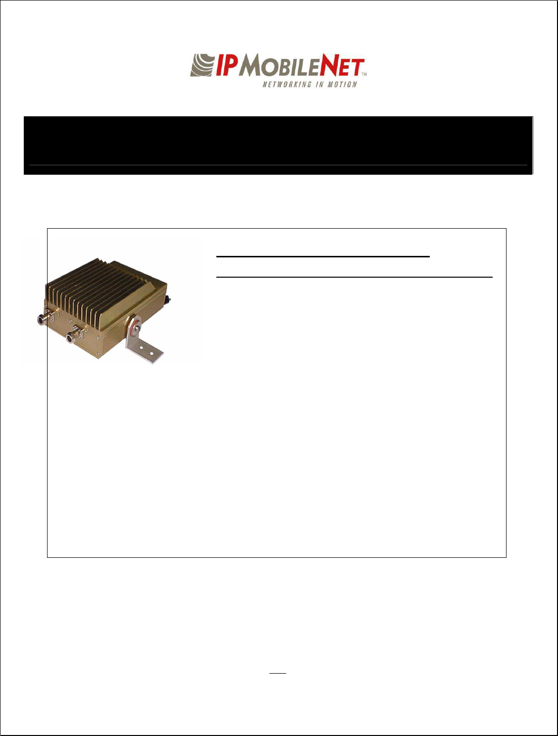
IP Series Mobile Radio
~\Technical Documentation\Install_Guides\MR-Guide\6-Feb-04 Page 2 of 16
IP Series Mobile Radio Illustration
Installation Overview
This guide will provide standard steps involved in the installation process of an IP Series Mobile Radio. This
guide includes wire routing and connections between the radio, other components, and the vehicle’s power.
Safety Reminder
1. To prevent personal injury and vehicle damage, exercise extreme caution throughout
this installation process.
Follow safety precautions for handling wiring, tools, and a vehicle’s engine.
Handle the vehicle’s battery with extreme caution to avoid burns.
Do not alter the components listed in the Installation Requirements on page 3
unless substitutions are noted within this document.
Once the antennas are installed, as directed within this guide on page 8 of 15, all
persons must maintain a distance of no less than 39 inches from the antennas.
Black
Red
TX/RX1 RX2
Serial Cable
DB9
Power Cable
Mounting
Bracket
TX FCC ID M17-EC8DT450TX
xxxxxxxx xxx
xxxxwweddd
xxxxxxxx
xxxxwweddd

~\Technical Documentation\Install_Guides\MR-Guide\6-Feb-04 Page 3 of 16
INSTALLATION REQUIREMENTS
PL502-82019-51 - MOBILE ACCESSORY KIT -- A Mobile Radio includes the following components (part
of mobile top assembly):
Qty Description IPMN Part Number
1 Cable, Power Extension 502-82020-53
2 ‘L’ Brackets 50026749
2 Screws Skt Cap Button Head 10-32 X 5/8 37081032-10
6 Washers Split Lock #10 271-0062-010
2 Washers Fender 1” O.D. X .28 I.D. X .05 THK 271-0059-001
4 Washers Rubber 1” O.D. X .65 I.D. X .12 THK 36040001
2 Hoses, Rubber Black .380 O.D. X .191 I.D. X .3 34010295
4 Screws Self-Tapping #10 X 5/8 37040010-10
0 Installation Manual 516-80307
0 Technical Manual 516-82025
PL502-80208-51 - INSTALLATION KIT – The following components are required for a Mobile Radio
Installation and are available for purchase through IPMobileNet, Inc.
Qty Description IPMN Part Number
1 EMI Filter 127-0020-001
1 Timer, 2 hours 150-0127-001
1 Relay 128-0117-001
1 Relay Socket 128-0116-001
2 Butt Connectors #8 AWG 120-0256-001
1 Terminal, Ring #8 AWG, #10 Screw Insulated 120-0127-001
4 Terminal, Ring #18-22 AWG, #10 Screws Insulated 120-0250-004
4 Terminal, Ring #10-12 AWG, #10 Screws Insulated 120-0250-005
4 Terminal, Disconnect #14-16 F 120-0244-002
18 Terminal, Disconnect #10-12 F 120-0244-003
2 Disconnect Tab, Quad Male 200-1377-001
1 Wire, 12 AWG Black, order 5 ft. 156-0242-001
1 Wire, 12 AWG Red, order 44 ft. 156-0242-003
1 Fuse, 30 AMPS ATO 122-0042-001
1 Fuse Holder, 30 AMPS 120-0253-001
1 Switch, Toggle DPST 144-0136-001
1 Diagram, Mobile Installation without VIU 502-80259
1 Diagram, Mobile Installation with VIU 502-80260
1 Diagram, Mobile Installation with Data 911 and VIU 502-80306
1 Diagram, Litton Interconnection with RF Filters VEH-01-0503

~\Technical Documentation\Install_Guides\MR-Guide\6-Feb-04 Page 4 of 16
OPTIONAL INSTALLATION SUPPLIES – Order each item individually:
Qty Description IPMN Part Number
1 Serial Cable (DB9MF), 20 ft. 156-0245-020
1 Wire, 8 (133/29) AWG VW-1 Red, by foot, order 19.5 ft. 156-0243-003
1 Wire, 8 (133/29) AWG VW-1 Black, by foot, order 19.5 ft. 156-0243-001
2 RG58U Cable and Mount, VHF, 17 ft. (incl ¾” Brass Mount and N Male Crimp) 102-0200-001
2 RG8X Cable and Mount, UHF & 800 MHz, 17 ft. (incl ¾“ Brass Mount & N Male Crimp) 102-0200-002
2 Antenna, Radome Type, 142-164 MHz, Unity Gain (requires 1 MB8UN for ea antenna) 102-0205-001
2 Antenna, Radome Type, 150-174 MHz, Unity Gain (requires 1 MB8UN for ea antenna) 102-0205-002
2 Antenna, Radome Type, 410-430 MHz, 3dB Gain (requires 1 MB8XN for ea antenna) 102-0206-001
2 Antenna, Radome Type, 430-450 MHz, 3dB Gain (requires 1 MB8XN for ea antenna) 102-0206-002
2 Antenna, Radome Type, 450-470 MHz, 3dB Gain (requires 1 MB8XN for ea antenna) 102-0206-003
2 Antenna, Radome Type, 470-490 MHz, 3dB Gain (requires 1 MB8XN for ea antenna) 102-0206-004
2 Antenna, Radome type, 806-866 MHz, 3dB Gain (requires 1 MB8XN for ea antenna) 102-0207-001
2 Antenna, Radome Type 821-896 MHz, 3dB Gain (requires 1 MB8XN for ea antenna) 102-0207-002
2 Antenna, 5/8 Wave, 406-430 MHz, 3dB Gain (requires 1 MB8XN for ea antenna) 102-0199-003
2 Antenna, 5/8 Wave, 430-450 MHz, 3dB Gain (requires 1 MB8XN for ea antenna) 102-0199-004
2 Antenna, 5/8 Wave, 450-470 MHz, 3dB Gain (requires 1 MB8XN for ea antenna) 102-0199-005
2 Antenna, 5/8 Wave, 470-490 MHz, 3dB Gain (requires 1 MB8XN for ea antenna) 102-0199-002
2 Antenna, 5/8 Wave 490-512 MHz, 3dB Gain (requires 1 MB8XN for ea antenna) 102-0199-006
2 Antenna, 5/8 Wave, 806-866 MHz, 3dB Gain (requires 1 MB8XN for ea antenna) 102-0199-001
2 Antenna, ¼ Wave, 136-144 MHz, Unity Gain (requires 1 MB8UN for ea antenna) 102-0204-001
2 Antenna, ¼ Wave, 144-152 MHz, Unity Gain (requires 1 MB8UN for ea antenna) 102-0204-002
2 Antenna, ¼ Wave, 152-162 MHz, Unity Gain (requires 1 MB8UN for ea antenna) 102-0204-003
2 Antenna, ¼ Wave, 162-174 MHz, Unity Gain (requires 1 MB8UN for ea antenna) 102-0204-004
2 Antenna, ¼ Wave, 406-430 MHz, Unity Gain (requires 1 MB8XN for ea antenna) 102-0204-005
2 Antenna, ¼ Wave, 430-450 MHz, Unity Gain (requires 1 MB8XN for ea antenna) 102-0204-006
2 Antenna, ¼ Wave, 450-470 MHz, Unity Gain (requires 1 MB8XN for ea antenna) 102-0204-007
2 Antenna ¼ Wave, 470-490 MHz, Unity Gain (requires 1 MB8XN for ea antenna) 102-0204-008
2 Antenna, ¼ Wave, 490-512 MHz, Unity Gain (requires 1 MB8XN for ea antenna) 102-0204-009
2 Antenna, ¼ Wave, 806-896 MHz, Unity Gain (requires 1 MB8XN for ea antenna) 102-0204-010
~\Technical Documentation\Install_Guides\MR-Guide\6-Feb-04 Page 5 of 16
2 sheet
metal screws
Mounting
Bracket
TX/RX1 RX2
Mounting
Bracket
TX FCC ID M17-EC8DT450TX
xxxxxx
xxxxxx
2 sheet
metal screws
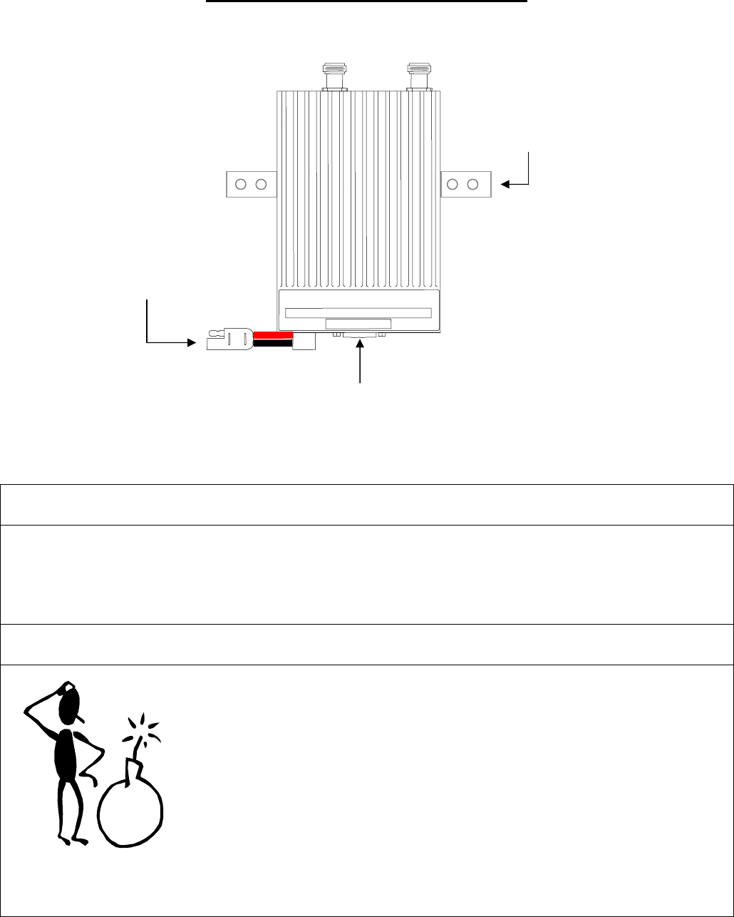
Figure 2
INSTALLATION INSTRUCTIONS
Pre-Installation Guidelines Mounting the Mobile Radio
To mount the radio, perform the following steps:
Step 1 Secure the radio into the trunk compartment. Insert four
(4) sheet metal screws in the radio brackets; two (2)
screws on either side of the radio (see Fig. 2).
CAUTION
:
If less than four (4) screws are used, the radio
can become loose in the trunk compartment.
This may cause the radio not to function
properly.
When inserting screws, be careful not to
disturb the vehicle gas tank.
Serial Cable Connection and Routing
(IPMN p/n: 156-0245-020)
1. Prior to installing new equipment, remove existing equipment
and all related components to include stock clips on radio
wiring harness and antenna.
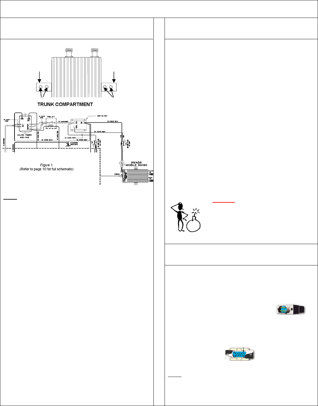
2. Mounting of the radio, delay timer, relay, and filter will take
place in the trunk compartment (see Fig. 1) unless installing
in a vehicle without a trunk.
NOTE: Removal of seats, rubber mats, and other obstructions,
from inside the driver compartment, may be necessary
to facilitate routing of wires to the engine and trunk
compartments.
3. To ensure appropriate cable and wire routing, exercise the
following precautions:
Route cables away from sharp edges that can penetrate
cable insulation and damage wires.
Protect wires with silicone rubber grommets when
routing through the engine compartment firewall or
through other holes with sharp edges.
Use high-quality electrical tape when covering exposed
wires in the engine compartment.
Avoid routing cables through areas exposed to extreme
heat, such as the exhaust system.
Keep wires routed through the engine compartment
away from hot and/or moving parts.
4. Prior to drilling holes in the engine compartment firewall,
inspect both sides to avoid obstructions.
5. For grounding point, use the engine block or the negative (-)
terminal of the vehicle battery. Ground connection surfaces
must be free of paint, rust, and other corrosion to maximize
performance and avoid damage.
6. To simplify troubleshooting problems, label all connecting
points and wires.
The serial cable connects the radio to the Mobile Data Computer
(MDC) located in the driver compartment.
To connect the serial cable, perform the following steps:
Step 1 Attach the 20-foot serial cable male
connector
(DB9M – see Fig. 3) to the
radio.
Step 2 Route the female connector (DB9F – see Fig. 4) to the
driver compartment and connect to the serial port located
on the rear of the MDC.
NOTE: Route the serial cable to minimize foot pressure and
other potential stresses. Use split loom tubing and nylon
cable ties for cable protection.
(If connecting a Voice Interface Unit, see page 9 for instructions).
Figure 3
Figure 4
~\Technical Documentation\Install_Guides\MR-Guide\6-Feb-04 Page 6 of 16
DRIVER
COMPARTMENT
TRUNK COMPARTMENT
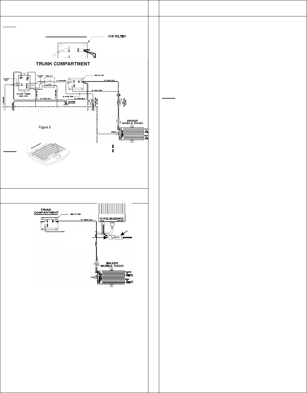
EMI Filter Installation
(IPMN p/n: 127-0020-001)
MDC Power Supply Installation
NOTE: The EMI Filter protects the radio and filters out noise.
To install the filter, perform the following steps:
Step 1 Secure the EMI Filter in the trunk compartment of the
vehicle (see Fig. 5) near radio mounting location.
NOTE: For proper wire connections, perform the steps for the
following components:
Radio Power Supply Installation, page 6
MDC Power Supply Installation, page 6
Carling Switch Installation, page 7
Delay Time Installation, page 7
Radio Power Supply Installation
To install the radio power connection, perform the following steps:
Step 1 Connect the radio power
cable to the power cable
extension (see Fig. 6).
Step 2 Route and wire the power cable extension red wire (#12
AWG), via the 15 AMP in-line fuse, to the radio (+)
terminal connection on the EMI Filter (see Fig. 7).
Step 3 Route and wire the power cable extension black wire
(#12 AWG) to the EMI Filter’s negative (-) terminal.
Figure 7
To install the MDC power connection, perform the following steps:
Step 1 Connect the MDC power cable to the MDC.
Step 2 Route and wire the red and clear MDC power wires via a
3 AMP in-line fuse, routing the red wire (#12 AWG) to the
battery (+) terminal connection on the EMI Filter (see
Fig. 8).
Step 3 Route and wire the black MDC power wire to the
negative (-) terminal on the EMI Filter (see Fig. 8).
NOTE: A black wire (#12 AWG) is grounded from the negative (-)
terminal connection on the EMI Filter to the vehicle
chassis.
Figure 8
radio’s power
cable
power
cable
extension
Figure 6
~\Technical Documentation\Install_Guides\MR-Guide\6-Feb-04 Page 7 of 16
TRUNK
COMPARTMENT
TRUNK COMPARTMENT
DRIVER COMPARTMENT
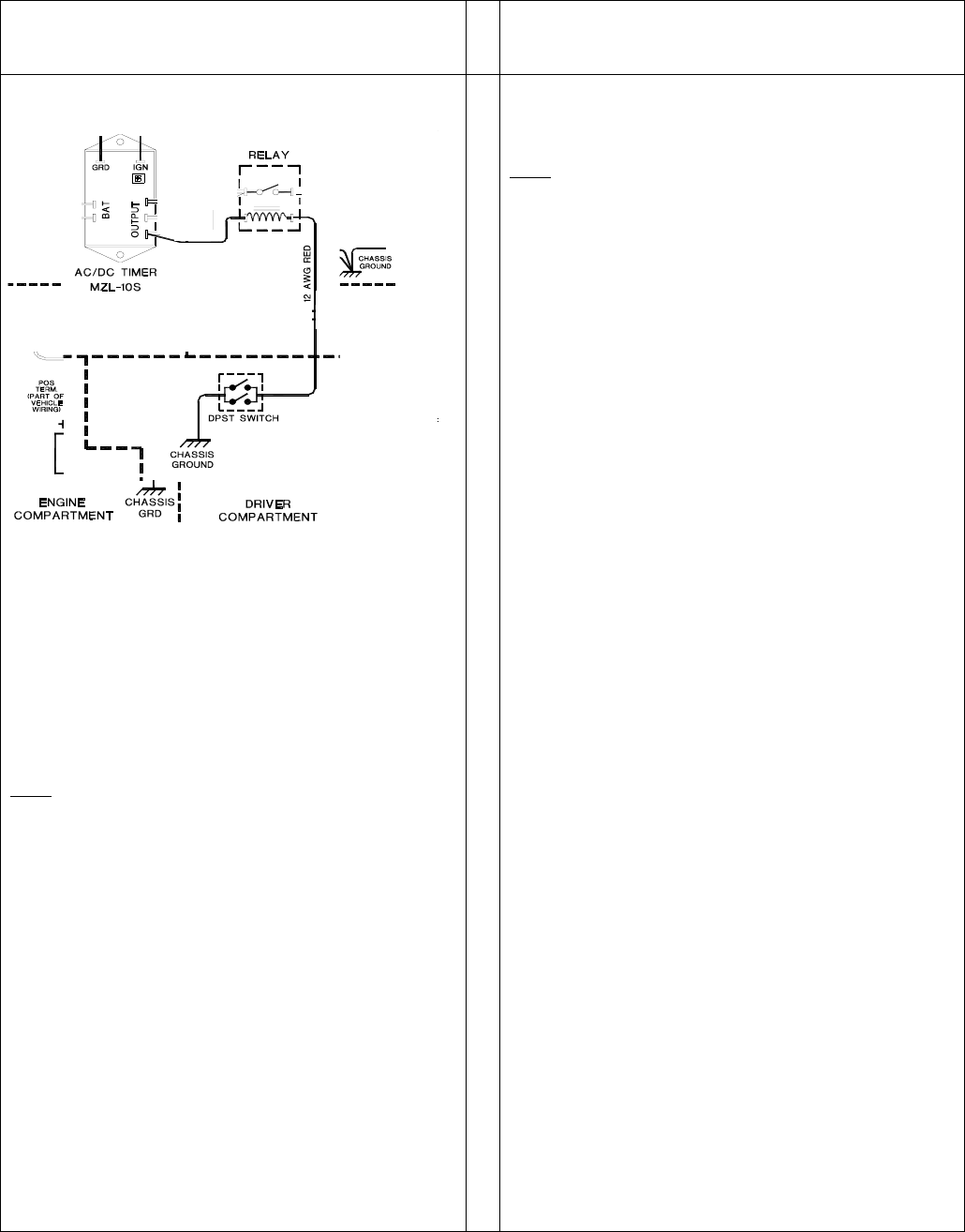
Carling Switch Installation
(DPST Heavy Duty Toggle)
(IPMN p/n: 144-0136-001)
Delay Timer Installation
(IPMN p/n: 150-0127-001)
To install the switch, perform the following steps:
Step 1 Mount the switch in the selected location.
Step 2 Route and wire a red wire (#12 AWG) from of the switch
to the Automotive Power Relay (see Fig. 9).
Step 3 Ground the switch by routing and wiring a black wire
from the switch to the vehicle chassis.
Figure 9
NOTE: Install switch in a location convenient to the driver
ensuring that the switch cannot be inadvertently moved
to the Off position.
To install the Delay Timer, perform the following steps:
Step 1 Secure Delay Timer to the trunk compartment of the
vehicle.
NOTE: When inserting screws be careful not to puncture the
vehicle gas tank.
Step 2 Route the black wire (#12 AWG) from ground connection
on the Delay Timer to the vehicle chassis (see Fig. 10).
Step 3 Route and wire red wire (#8 AWG) from the positive (+)
terminal connection on the vehicle battery connection via
a 30 AMP in-line fuse toward the battery connection on
the Delay Timer.
Connect the red wire (#8 AWG) to the two red wires (#12
AWG). Route and wire the red (#12 AWG) wires to the two
(2) battery connections on the Delay Timer.
Figure 10
Step 4 Route a red wire (#12 AWG) from the ignition connection
on the Delay Timer to the ignition switch in the driver
compartment (see Fig. 10).
Step 5 Route a red wire (#12 AWG) from the first and last output
connections on the Delay Timer to the Automotive
Power Relay.
Step 6 Route and wire a red (#12 AWG) wire from the second
output connection on the Delay Timer to the last output
connection on the Delay Timer.
Step 7 Route and wire a red (#12 AWG) wire from the last output
connection on the Delay Timer to the Automotive Power
Relay coil at the position shown in Figure 10.
Step 8 Route and wire a black (#8 AWG) wire from the vehicle
chassis in the trunk compartment to the negative (-)
terminal on the vehicle battery.
~\Technical Documentation\Install_Guides\MR-Guide\6-Feb-04 Page 8 of 16
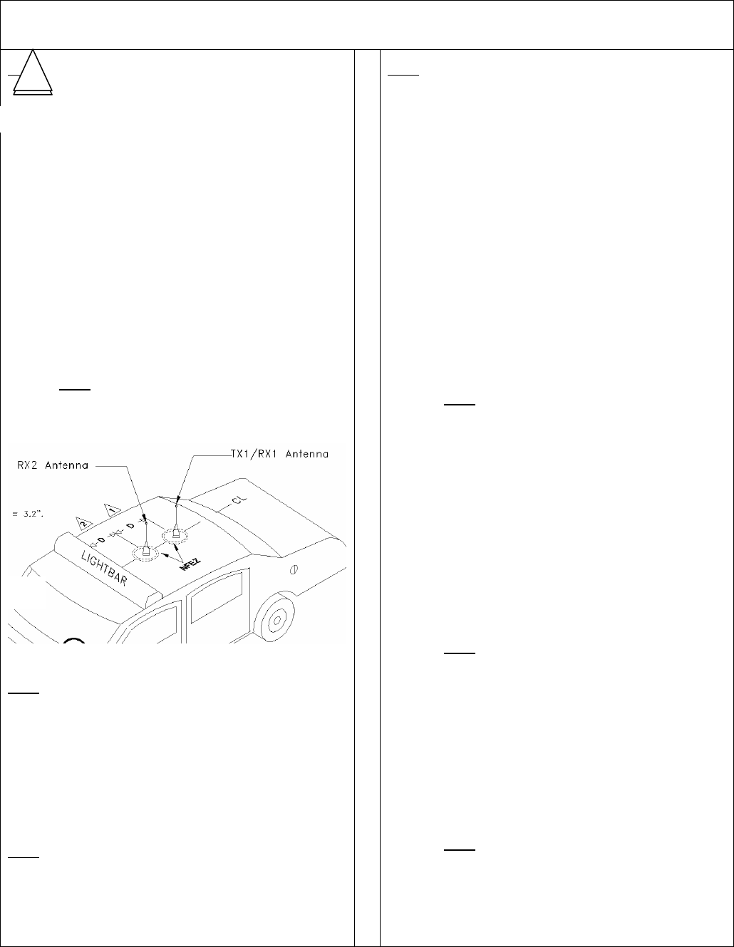
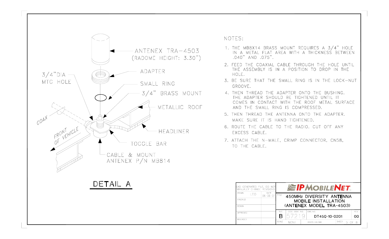
Antenna Installation
NOTE: Two (2) antennas are mounted and installed on the roof
of the vehicle using specific measurements for distance.
To mount and install the antennas, perform the following steps:
Step 1 Install antennas (see sample drawing DT450-10-0201
and Fig. 11 below).
The separation distance between the two (2) antennas
is 19”. The preferred is 31.25”.
The minimum distance of the RX2 antenna from the light
bar is 3.2”.
Observe correct separation between antennas (refer to
the Mobile Antenna Distance Matrix for midpoint
distance calculations on page 12) and minimum Near
Field Exclusion Zone (NFEZ) for proper diversity
reception operation.
Step 2 Cut a mounting hole in the roof of the vehicle using an
electric drill or hole saw.
NOTE: The antenna-mounting hole provides ground
connection to the antenna. Ensure that a
metal-to-metal connection between the
antenna shields exists.
Figure 11
NOTE: Figure 11 represents the recommended front-to-rear
antenna installation. The receiver antenna (RX2) should
be the antenna nearest to the light bar.
Step 3 All antenna mounts must be environmentally tight.
Install or use O-rings to seal the antenna base to the
rooftop of the vehicle.
Step 4 Route the coaxial cables to the radio through one of the
hollow spaces in the roof supports into the trunk
compartment where the radio is mounted.
NOTE: Both antennas should be checked and tested to ensure
they are functioning properly.
If these installation guidelines are followed, it is safe for
persons to stand at a distance no less than 39 inches
from the antennas.
NOTE: The following test is performed without any power, thus
can be performed immediately after the installation of the
coax and antenna, following the installation of the N-type
connector on the coax.
To measure Return Loss, perform the following steps:
Step 1 Select one of the following Antenna Analysts to perform
the test:
• 450 to 508 MHz installations, use the 140-525
Analyst
• 806 to 960MHz installations, use the CellMate
Analyst
Step 2 Connect the antenna to be tested to the Antenna
Analyst.
Step 3 Turn on the Antenna Analyst and the Return Loss
(RETL) is displayed in dB to the left of the Voltage
Standing Wave Ratio (VSWR) curve.
NOTE: The Return Loss Specification is –14 dBm or
greater (with good antennas the typical range
will be between –14 and –28).
To measure the Voltage Standing Wave Ratio (VSWR) Reflected
Power, perform the following steps:
Step 1 After selecting the appropriate Analyst and connecting
the antenna to be tested, press F1 to access the
Analyst Menu.
Step 2 Press F1 again to access the Display (DSPLY) menu,
which lists the modes.
Step 3 Press F2 to select the VSWR display mode. Plotting
will resume and the VSWR value is highlighted.
NOTE: The VSWR Reflected Power Specification is
1.6 watts or less.
To measure Insertion Loss of an unterminated length of coax,
perform the following steps:
Step 1 Connect the antenna to be tested to the appropriate
Antenna Analyst.
Step 2 Turn on the Antenna Analyst and the Return Loss is
displayed in dB to the left of the VSWR curve.
NOTE: To switch from the RETL mode to VSWR
mode, refer back to the previous set of
instructions.
Step 3 Divide the result by two (2).
1
2
~\Technical Documentation\Install_Guides\MR-Guide\6-Feb-04 Page 9 of 16
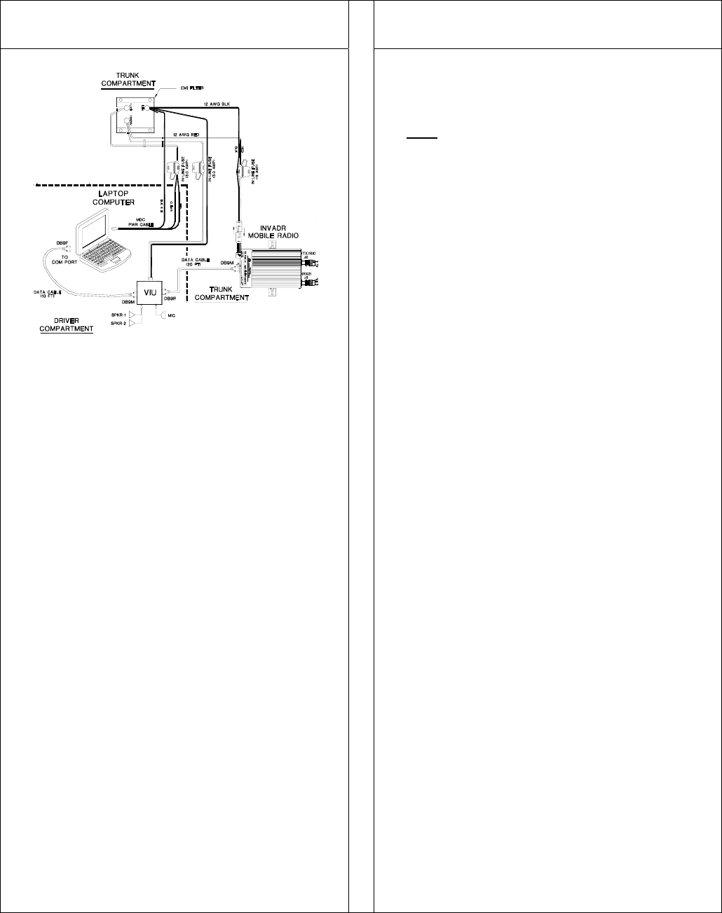
VIU Connections Mobile Radio Testing
If connecting a VIU, an additional serial cable is required.
10-ft serial cable (IPMN p/n: 156-0245-010) included with VIU
To connect the serial cables, perform the following steps:
Step 1 Attach 20-ft serial cable male connector (DB9M) to the
radio.
Step 2 Route the female connector (DB9F) to the driver
compartment and connect to the serial port located on
the rear of the VIU near the microphone hang up clip.
Step 3 Attach the 10-foot serial cable male connector (DB9M) to
the other serial port located on the rear of the VIU.
Step 4 Route the female connector (DB9F) serial cable to the
serial port located on the rear of the MDC.
Figure 12
To connect the VIU power supply, perform the following steps:
Step 1 Route the VIU’s power supply cable from the driver
compartment to the trunk compartment.
Step 2 Connect the black (#18 AWG) wire from the VIU power
cable to the negative (-) terminal on the EMI Noise Filter.
Step 3 Attach the red (#18 AWG) wire of the VIU power cable via
the 3 AMP in-line fuse to the radio connection on the EMI
Noise Filter.
Figure 13
1. To verify that the Mobile Radio setup works properly, use a
wattmeter and a service monitor.
NOTE: If a wattmeter and a service monitor are not
available, begin test from Step 3 through 6 and 10
through 12.
2. Connect the wattmeter between the radio and the coax
connector.
3. Connect the radio to a computer with the IPMobileNet IP
Message Utility program loaded. See the following
documents for further details:
Mobile Data Computer for Communication with the IP
Series Mobile Radio – IPMN p/n: 516-80310
4. Double click on the SLIP2IPMN icon to start the dial-up
connection.
5. Double click on the IP Message shortcut.
6. In the To: field, enter the radio’s IP address and click on the
Send button and the radio’s configuration will list in the upper
message screen.
7. Tune the service monitor to the assigned transmitter
frequency.
8. On the computer, in the lower message screen of the IP
Message Utility, type unlock=password (entering the
appropriate password to unlock the radio).
9. In the lower message screen, type x=2000, 19 and click on
the Send button to key the transmitter and measure the
forward power and reflected power.
10. Measure the transmitted frequency and the modulation level.
11. At the computer, using the IP Message Utility program, in the
lower message window, type V and click on the Send button
to enable verbose.
12. Ping the IPNC via MS-Dos using the following command:
Ping (IPNC IP address) –n 20 –l 500
Performance statistics showing TX data, RX data quality (DQ)
and signal levels (RSSI) will display on the IP Message
window.

~\Technical Documentation\Install_Guides\MR-Guide\6-Feb-04 Page 10 of 16
Installation Checklist
Throughout the installation process and once the
installation is complete, make sure to perform the
following tasks:
Thoroughly scope out the vehicle to find any obvious problem
areas.
Check wiring for safety concerns.
Use tie wraps to ensure that all wires routed in parallel are
bundled together.
Check to see if any wires are exposed.
If any wires are exposed, use electrical tape to cover.
REMINDER: When covering wires in the engine compartment,
use high-quality electrical tape.
Perform appropriate testing as described in this guide to
ensure radio works properly.
Once installation is completed, remove all debris and restore
dismantled parts and rubber mats to appropriate locations.
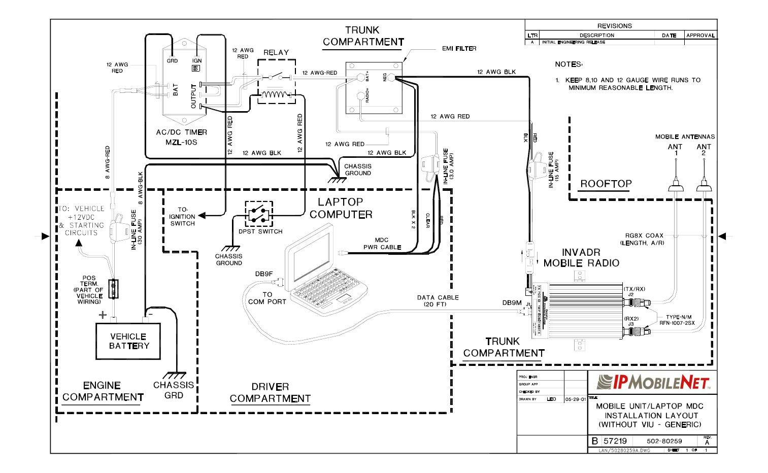
~\Technical Documentation\Install_Guides\MR-Guide\6-Feb-04 Page 11 of 16
VEHICLE UNIT WIRING INTERCONNECTION LAYOUT

~\Technical Documentation\Install_Guides\MR-Guide\6-Feb-04 Page 12 of 16
MOBILE ANTENNA DISTANCE MATRIX
Frequency
Band in MHz
Center
Frequency in
MHz
Antenna
Spacing** @
¼ Wavelength
Antenna
Spacing** @
¾ Wavelength
NFEZ* in
inches for
Radome
Antenna
NFEZ* in
inches for
¼ Wavelength
Whip
NFEZ* in
inches for “⅝”
Wavelength
Whip
Wavelength in
Inches
130-140 135.000 21.87 N/A 0.25 10.94 N/A 87.49
140-150 145.000 20.36 N/A 0.27 10.18 N/A 81.46
150-160 155.000 19.05 N/A 0.29 9.53 N/A 76.20
160-174 162.000 18.23 N/A 0.30 9.11 N/A 72.91
400-430 415.000 N/A 21.35 0.77 3.56 11.88 28.46
430-450 440.000 N/A 20.13 0.81 3.36 10.37 26.84
450-470 460.000 N/A 19.26 0.85 3.21 9.43 25.68
470-490 480.000 N/A 18.45 0.89 3.08 9.31 24.61
490-512 501.000 N/A 17.68 0.92 2.95 9.35 23.57
806-866 836.000 N/A 10.60 1.54 1.77 3.36 14.13
*NFEZ = Minimum Near Field Exclusion Zone **Round antenna spacing to the nearest ⅛”
~\Technical Documentation\Install_Guides\MR-Guide\6-Feb-04 Page 13 of 16
DIVERSITY ANTENNA MOBILE INSTALLATION DETAIL
(Typical installation)
~\Technical Documentation\Install_Guides\MR-Guide\6-Feb-04 Page 14 of 16
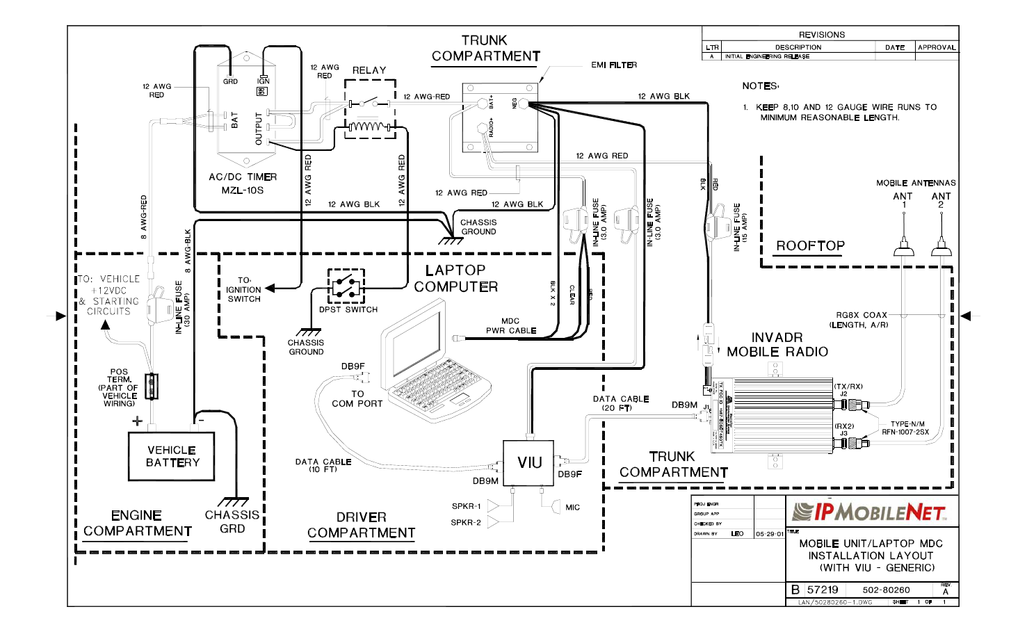
VEHICLE UNIT WIRING INTERCONNECTION LAYOUT
(with Voice Interface Unit – VIU)
~\Technical Documentation\Install_Guides\MR-Guide\6-Feb-04 Page 15 of 16
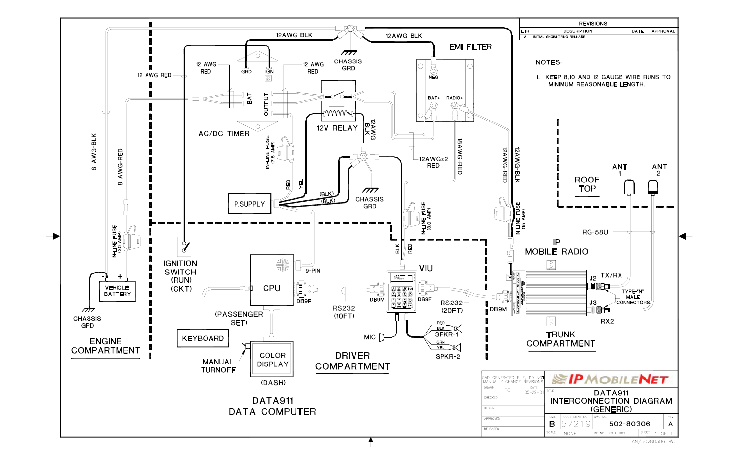
VEHICLE UNIT WIRING INTERCONNECTION LAYOUT
(Data 911 with Voice Interface Unit – VIU)
~\Technical Documentation\Install_Guides\MR-Guide\6-Feb-04 Page 16 of 16
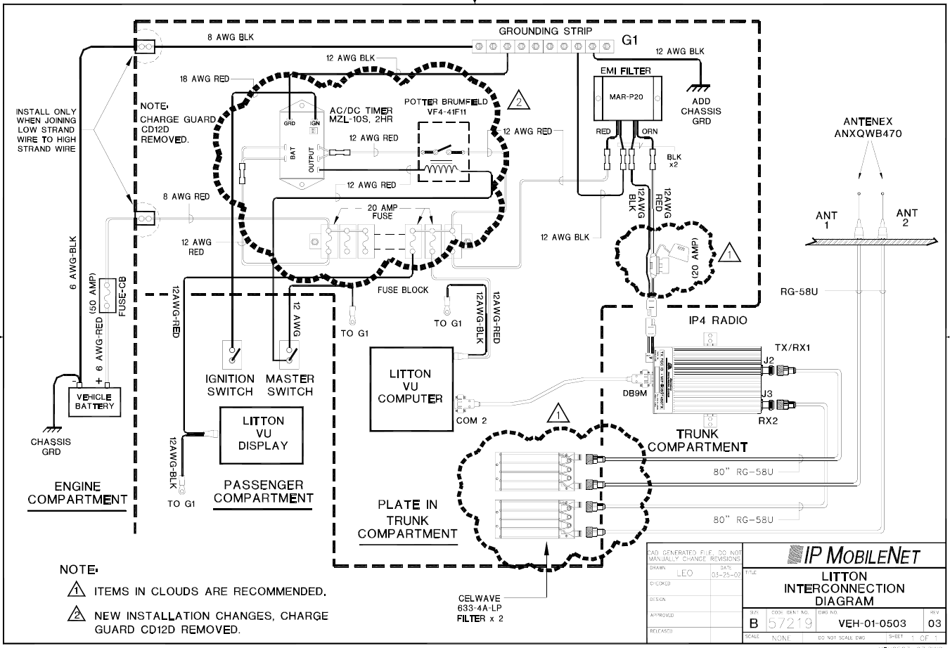
VEHICLE UNIT WIRING INTERCONNECTION LAYOUT
(with Litton Computer)