IP Mobilenet M64450G25 High Speed Mobile Radio User Manual 638402
IP Mobilenet, LLC High Speed Mobile Radio 638402
Contents
- 1. Users Manual 1
- 2. Users Manual 2
- 3. Users Manual 3
- 4. Users Manual 4
- 5. Users Manual 5
Users Manual 2

I
IP
PS
Se
er
ri
ie
es
s
M
M6
64
44
45
50
0G
G2
25
5
H
Hi
ig
gh
h
S
Sp
pe
ee
ed
d
M
Mo
ob
bi
il
le
e
R
Ra
ad
di
io
o
P
Pr
ro
od
du
uc
ct
t
O
Ow
wn
ne
er
r’
’s
s
M
Ma
an
nu
ua
al
l
Date Released: March 20, 2006
Document #: 516.80539.POM
Revision: A
Copyright 2005 IPMobileNet, Inc.
16842 Von Karman Avenue, Suite 200 Irvine, CA 92606
Voice: (949) 417-4590 Fax: (949) 417-4591
M64450G25-FCCRpt.doc Page ii
The term “IC”: before the radio certification number only signifies that Industry of Canada
technical specifications were met.
Operation is subject to the following two (2) conditions: (1) this devise may not cause
interference, and (2) this device must accept any interference, including interference that may
cause undesired operation of this device.
The following U.S. Patents apply to this product:
U.S. Patent numbers 5,640,695,6,018,647,6,243,393
Information contained in this document is subject to change without notice.
All rights reserved. Reproductions, adaptations, or translation without prior written permission is
prohibited, except as allowed under copyright laws.

TABLE OF CONTENTS
M64450G25-FCCRpt.doc Page 2
SECTION 1: OVERVIEW..........................................................................................................................3
Product Description....................................................................................................................3
SECTION 2: SETUP AND CONFIGURATION METHODS .....................................................................5
High Speed Mobile Radio Setup and Configuration Method..................................................5
Mobile Radio-to-Mobile Computer Setup......................................................................... 5
SECTION 3: INSTALLATION INSTRUCTIONS ......................................................................................6
Installation Overview ..................................................................................................................6
Installation Instructions..............................................................................................................8
Pre-Installation Guidelines ............................................................................................... 8
Mounting the High Speed Mobile Radio ..........................................................................9
Serial Cable Connection and Routing............................................................................10
Ethernet Setup ...............................................................................................................10
Delay Timer Installation .................................................................................................10
Switch Installation (DPST Heavy Duty Toggle) .............................................................12
Mobile Radio Power Supply Installation.........................................................................13
Antenna Configuration ...................................................................................................14
Post Installation Checklist ..............................................................................................16
Mobile Installation Layout Diagrams ......................................................................................17
Preliminary Testing and Troubleshooting..............................................................................19
Checklist of Requirement Materials ...............................................................................19
Base Station Setup for Testing ......................................................................................20
Preliminary Test Procedure and Troubleshooting ................................................................21
Confirming High Speed Mobile Radio Receiver Sensitivity ...........................................24
SECTION 4: FACTORY TEST PROCEDURE .......................................................................................25
Equipment List .........................................................................................................................25
Programming and Configuring Mobile Radio ........................................................................26
Test Connections......................................................................................................................27
Test Equipment..............................................................................................................27
Mobile Radio Connections .............................................................................................27
Receiver Alignments and Tests...............................................................................................28
TCXO Operation ............................................................................................................28
Receiver Injection...........................................................................................................28
45 MHz Filters – Waveform ...........................................................................................28
Receiver 12 dB SINAD ..................................................................................................29
Receivers Minimum Distortion .......................................................................................30
Data Quality and Message Success Rate .....................................................................31
Audio AC and DC Voltages and Balances..................................................................... 32
Receiver Calibration.......................................................................................................33
Transmitter Alignment Tests ...................................................................................................35
Transmitter Output .........................................................................................................35
Transmitter Modulation ..................................................................................................35
Transmitter Power..........................................................................................................36
Transmitter Data Quality and Message Success Rate..................................................36
Hardware Timing Troubleshooting.................................................................................37
Message Success Rate Testing and Burn-In .........................................................................40
Sequence Tests .............................................................................................................40
Final Inspection ......................................................................................................................... 41
SECTION 5: FCC LABEL.......................................................................................................................42
APPENDIX A: M64450G25 CIRCUIT BOARD DIAGRAMS .................................................................43
APPENDIX B: M64450G25 TEST DATA SHEET..................................................................................44
SECTION 1: OVERVIEW
M64450G25-FCCRpt.doc Page 3
Product Description
The M64450G25 Mobile Radio works within a frequency range of 450-506 MHz and requires a 1/4-wavelength
antenna.
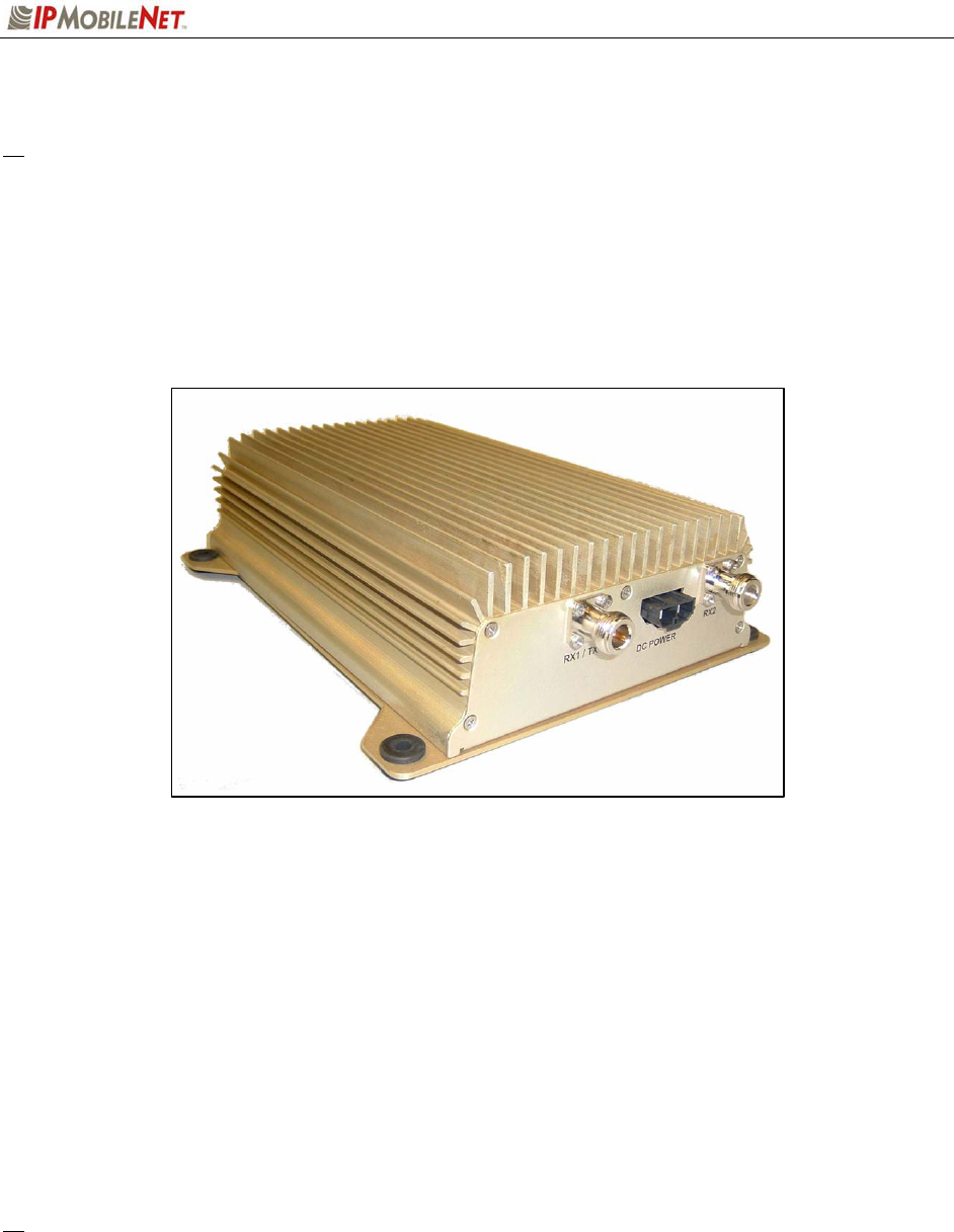
The IPSeries High Speed Mobile Radios are intelligent devices designed for the challenging requirements
of mobile data applications. Mounted in vehicles, other intelligent devices may connect to the serial or
Ethernet ports for connectivity back to the Internet Protocol Network Controller (IPNC) and other such
servers. It provides the mobile link to land-based wired networks.
Figure 1: IPSeries High Speed Mobile Radio (Front View)
Product Functionality
The IPSeries High Speed Mobile Radio utilizes a high-performance, 4-level Frequency-Shift Keying (FSK)
wireless data modem for 32 kbps operation, 16-level FSK for 64 kbps in 25 kHz channels; a multi-layered
approach to signal reliability. It features low power consumption, high performance integrated GPS
receiver. Embedding this technology in the mobile radio lowers the cost of acquiring GPS data from
vehicles and ensures optimal performance.
The mobile radio technology includes Diversity Reception (DR) capability. DR reduces the effects of
fades in a multi-path environment. With the use of two (2) antennae mounted at a calculated distance on
the roof of the vehicle the Diversity Reception System (DRS) minimizes the effects of fading by
intelligently selecting the receiver with a better signal.
Diversity is most effective when the vehicle is in motion.
SECTION 1: OVERVIEW
M64450G25-FCCRpt.doc Page 4
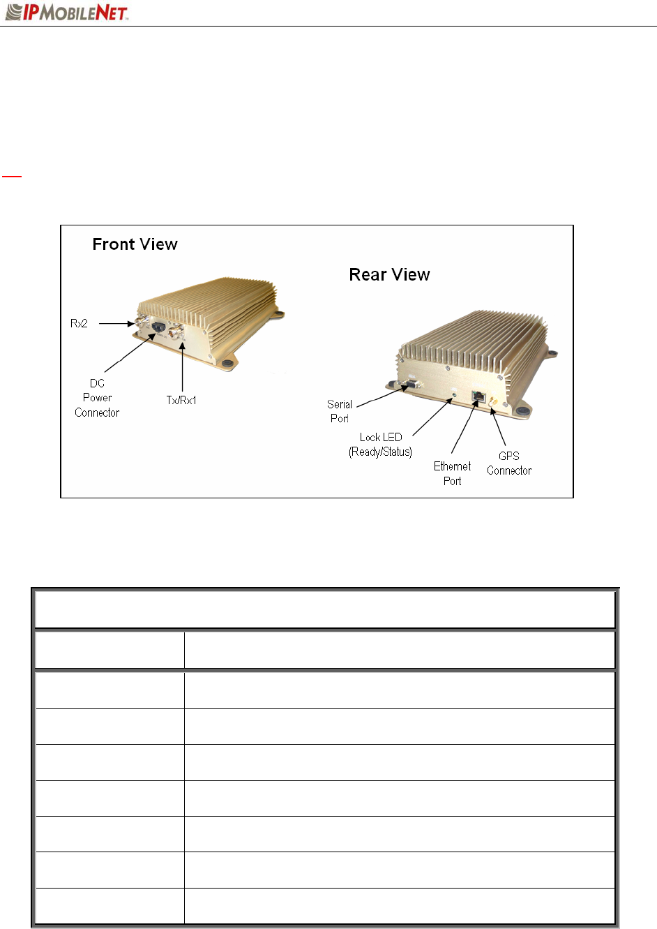
External Features
As seen in the figure below, the mobile radio technology is enclosed in a compact and sturdy aluminum
case. The external features consist of a series of connectors and ports as described in this section.
a The product warranty becomes immediately void if an uncertified or unauthorized individual
removes the mobile radio cover.
Figure 2: IPSeries High Speed Mobile Radio (External Features)
The mobile radio external features consist of the following connectors and ports:
TABLE 1: EXTERNAL FEATURES
FEATURE DESCRIPTION
TX/RX1 Transmitter / Receiver 1 antenna connection
RX2 Receiver 2 antenna connection
Power Connector 13.8 VDC mobile radio power connector
Lock LED Unit ‘Ready’ Status Indicator LED (light emitting diode)
GPS GPS antenna (SMA) connector
Serial Port RS232 Serial Line Internet Protocol (SLIP) interface port
Ethernet Port 10 Base T Ethernet interface port
SECTION 2: SETUP AND CONFIGURATION METHOD
M64450G25-FCCRpt.doc Page 5
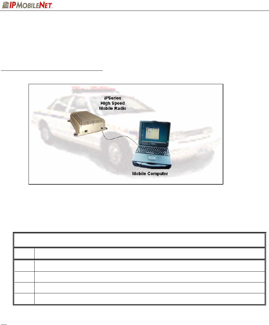
Mobile Radio-to-Mobile Computer Setup and Configuration
The following section describes the setup and configuration method for the mobile radio in a vehicle.
Mobile Radio-to-Mobile Computer Setup
Figure 3: High Speed Mobile Radio-to-Mobile Computer Setup
Additional components are required to setup a mobile radio-to-mobile computer configuration, and are
listed in the following table:
TABLE 2: HIGH SPEED MOBILE RADIO-TO-MOBLE COMPUTER COMPONENTS
REQUIRED FOR INSTALLATION
QTY DESCRIPTION
1 IPSeries High Speed Mobile Radio
1 Mobile Computer
1 20-foot serial cable (DB9F – DB9M)
1 IPMobileNet SLIP Port Driver Installation file (SLIP2IPMN.exe)
If using the mobile radio’s Ethernet feature an Ethernet crossover cable is required to replace the
20-foot serial cable.
To configure the mobile radio and computer for this type of setup, follow the instructions on pages
2 through 17 in the Mobile Computer Setup for Communication with the Mobile Radio
Installation Guide (IPMN p/n: 516.80310.IG) available on the Product Documentation CD.
SECTION 3: INSTALLATION INSTRUCTIONS
M64450G25-FCCRpt.doc Page 6
Installation Overview
This chapter provides the basic steps involved in the installation process of an IPSeries High Speed
Mobile Radio into a vehicle. This chapter includes wire routing and connections between the mobile
radio, other components, and the vehicle’s power.
a To prevent personal injury and vehicle damage, exercise extreme caution throughout the
installation process and follow the reminders listed below.
Follow safety precautions for handling wiring, tools, and a vehicle’s engine.
Handle the vehicle’s battery with extreme caution to avoid burns.
Do not alter the components listed in the ‘Installation Requirements’ section below, unless
substitutions are noted within this section.
Once the antennae are installed, as directed within this user manual, all persons must
maintain a distance of no less than 39 inches from the antennae while the mobile radio is in
the transmit mode.
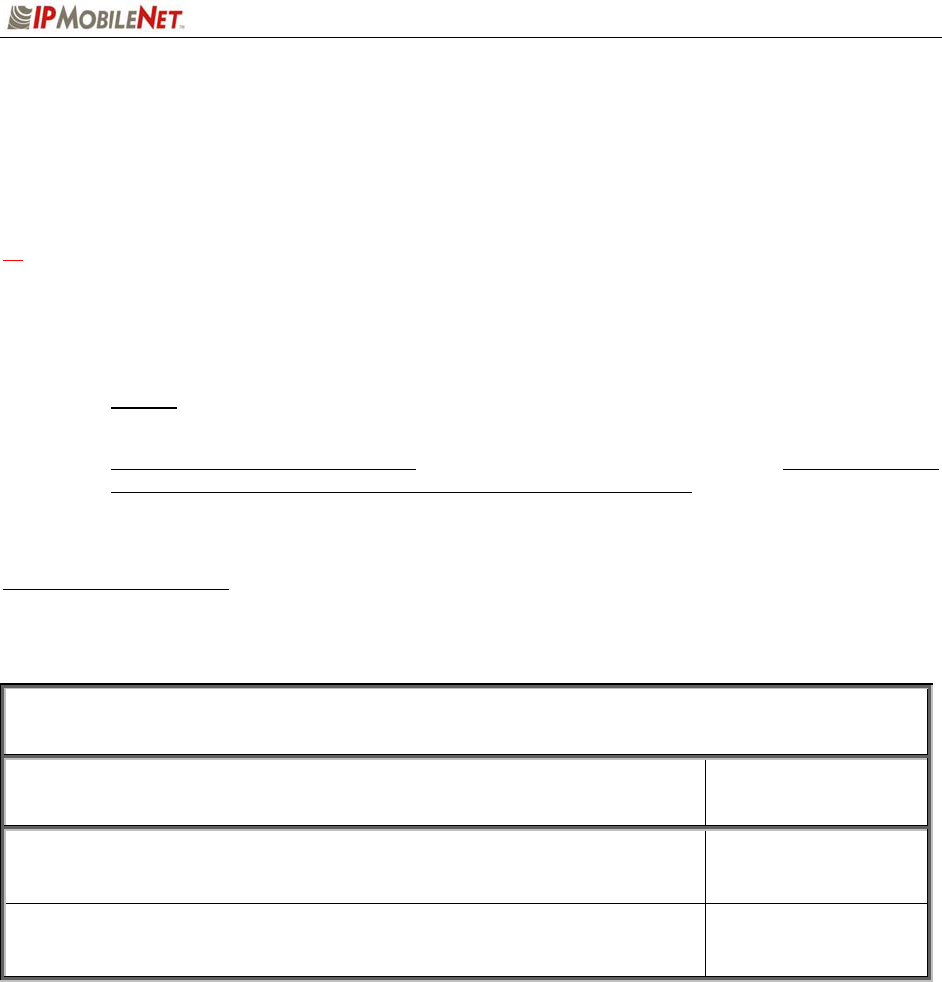
Installation Requirements
The table below lists the documents required to successfully install the mobile radio and connect to the
various components within the vehicle:
TABLE 3: DOCUMENTS REQUIRED FOR HIGH SPEED MOBILE RADIO INSTALLATION
DESCRIPTION PART NUMBER
M64450G25 High Speed Mobile Radio Product Owner’s Manual 516.80528.POM
Installation Guide for Mobile Computer Setup for Communication with
the Mobile Radio (available on the Product Documentation CD, IPMN
p/n: 480.0001.001).
516.80310.IG
SECTION 3: INSTALLATION INSTRUCTIONS
M64450G25-FCCRpt.doc Page 7
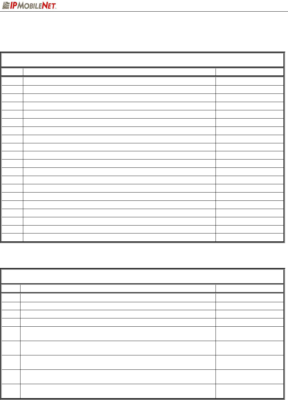
The table below lists components that are available for purchase through IPMobileNet, Inc.
TABLE 4: MOBILE INSTALLATION ACCESSORIES
QTY DESCRIPTION IPMN PART NUMBER
4 Screws, Self Tapping #10 X 5/8 37040010-10
1 EMI Filter 127.0020.002
1 Timer, 2 hours 150.0127.004
1 Relay 128.0117.001
1 Relay Socket 128.0116.001
2 Butt Connectors #8 AWG 120.0256.001
1 Terminal, Ring #8 AWG, #10 Screw Insulated 120.0127.001
4 Terminal, Ring #18-22 AWG, #10 Screws Insulated 120.0250.004
4 Terminal, Ring #10-12 AWG, #10 Screws Insulated 120.0250.005
4 Terminal, Disconnect #14-16 F 120.0244.002
18 Terminal, Disconnect #10-12 F 120.0244.003
2 Disconnect Tab, Quad Male 200.1377.001
1 Wire, 12 AWG Black, order 5 ft. 156.0242.001
1 Wire, 12 AWG Red, order 44 ft. 156.0242.003
1 Fuse, 15 AMPS ATO 122.0042.003
2 Fuse, 30 AMPS ATO 122.0042.001
3 Fuse Holder, 12 AWG 120.0253.001
1 Switch, Toggle DPST 144.0136.001
1 Diagram, Mobile Installation (included in this manual) 502.80259.52
1 Diagram, Diversity Antenna Mobile Installation Detail (Typical Install) DT450-10-0201
The table below lists the auxiliary equipment required to complete the installation process.
TABLE 5: AUXILIARY EQUIPMENT
QTY DESCRIPTION IPMN PART NUMBER
1 Serial Cable (DB9MF), 20 ft. 156.0245.020
1 Wire, 8 (133/29) AWG VW-1 Red, by foot, order 19.5 ft. 156.0243.003
1 Wire, 8 (133/29) AWG VW-1 Black, by foot, order 19.5 ft. 156.0243.001
2 Mounting Kit, Permanent Hole (MB8UN) 124.0601.001
2 Antenna, Radome Type, 410-430 MHz, 3dB Gain (requires 1MB8XN
for each antenna) 102.0206.001
2 Antenna, Radome Type, 430-450 MHz, 3dB Gain (requires 1MB8XN
for each antenna) 102.0206.002
2 Antenna, Radome Type, 458-470 MHz, 3dB Gain (requires 1MB8XN
for each antenna) 102.0206.003
2 Antenna, Radome Type, 470-490 MHz, 3dB Gain (requires 1MB8XN
for each antenna) 102.0206.004
2 Antenna, 5/8 Wave, 490-512 MHz, 3dB Gain (requires 1MB8XN for
each antenna) 102.0199.006
SECTION 3: INSTALLATION INSTRUCTIONS
M64450G25-FCCRpt.doc Page 8
Installation Instructions
Pre-Installation Guidelines
Prior to installing new equipment, perform the following steps:
a 1. Remove existing equipment and all related components to include stock clips on radio
wiring harness and antenna.
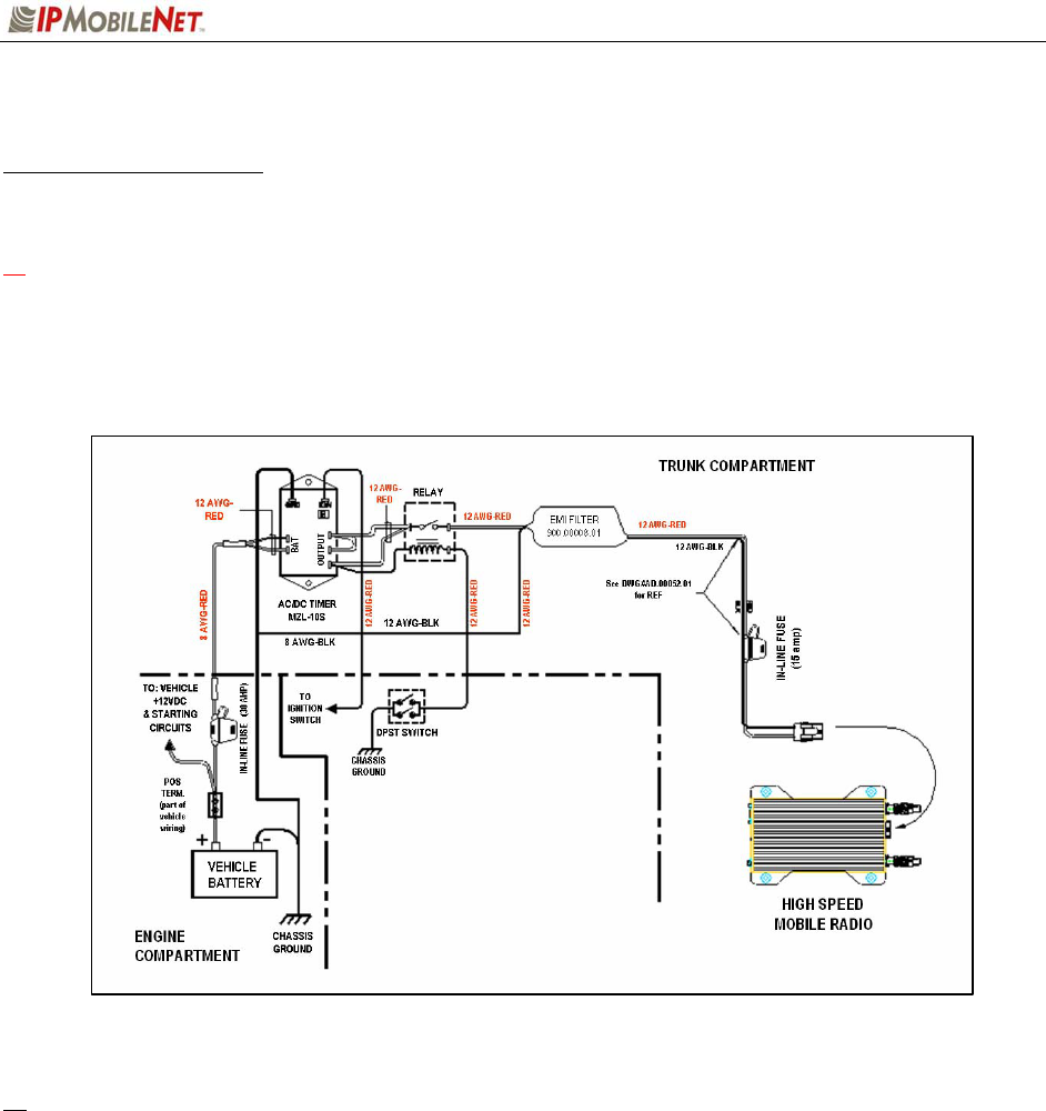
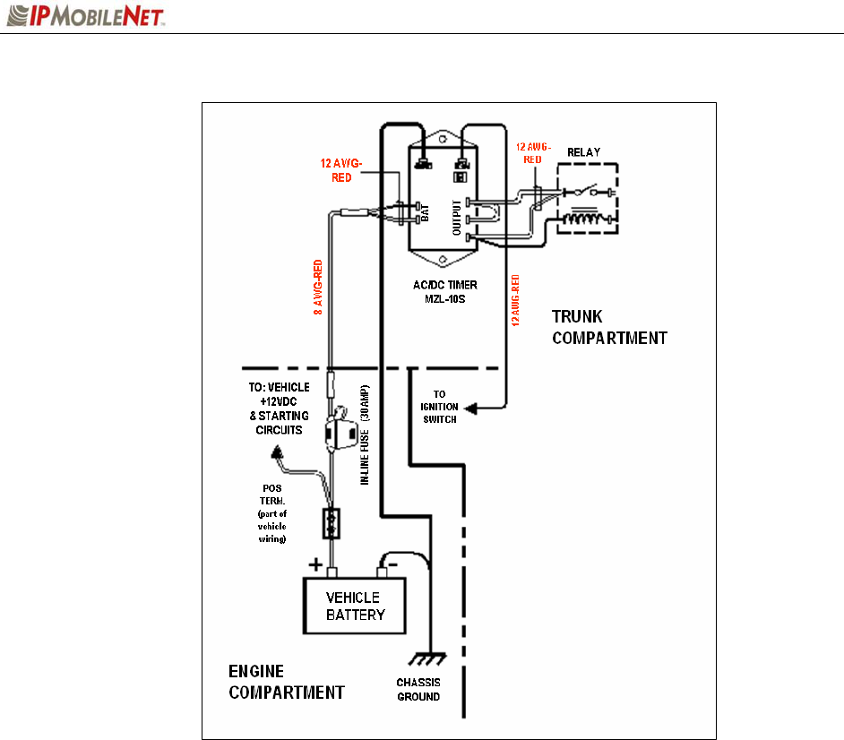
2. As shown in the figure below, mounting of the mobile radio, delay timer, relay, and EMI
filter (noise filter) will take place in the trunk compartment, unless installing in a vehicle
without a trunk.
Figure 4: Trunk Compartment Installation
Removal of seats, rubber mats, and other obstructions from inside the driver compartment may
be necessary to facilitate routing of wires to the engine and trunk compartments.
3. To ensure appropriate cable and wire routing, exercise the following precautions:
Route cables away from sharp edges that can penetrate cable insulation and damage
wires.
Protect wires with silicone rubber grommets when routing through the engine
compartment firewall or through other holes with sharp edges.
Use high-quality electrical tape when covering exposed wires in the engine
compartment.
Avoid routing cables through areas exposed to extreme heat, such as the exhaust.
Keep wires routed through the engine compartment away from hot and/or moving
parts.
SECTION 3: INSTALLATION INSTRUCTIONS
M64450G25-FCCRpt.doc Page 9
4. Prior to drilling holes in the engine compartment firewall, inspect both sides to avoid
obstructions.
5. For grounding point, use the engine block or the negative (-) terminal of the vehicle battery.
Ground connection surfaces must be free of paint, rust, and other corrosion to maximize
performance and avoid damage. Do not tie to the vehicle chassis.
6. To simplify troubleshooting problems, label all connecting points and wires.
Mounting the High Speed Mobile Radio
To mount the mobile radio, perform the following steps:
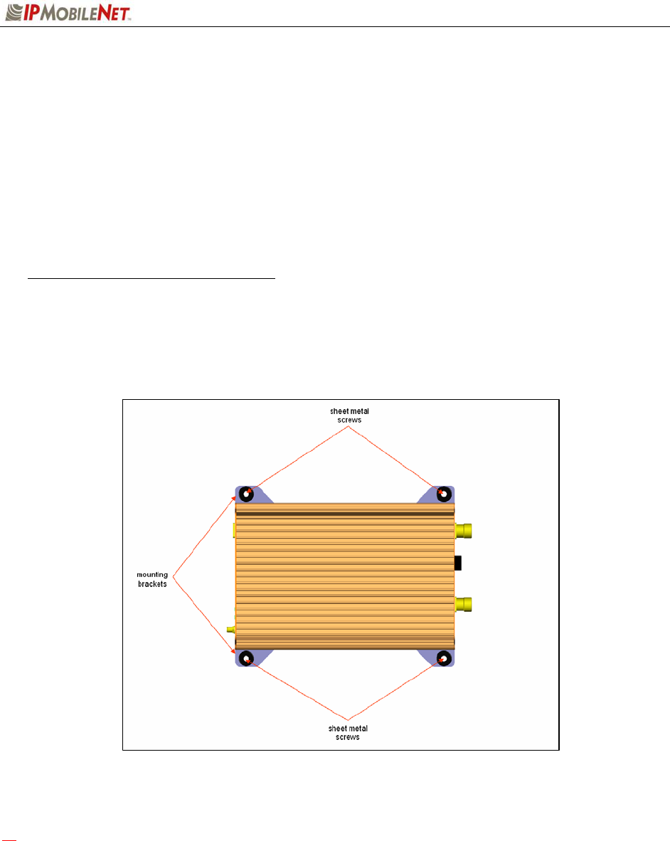
Step 1 As shown in the figure below, secure the mobile radio into the trunk compartment.
Insert four (4) sheet metal screws in the mobile radio brackets.
Figure 5: High Speed Mobile Radio Mounting
a If less than four (4) screws are used, the mobile radio can become loose in the trunk
compartment. This may cause the mobile radio not to function properly.
When inserting screws, be careful not to disturb the vehicle’s gas tank.
SECTION 3: INSTALLATION INSTRUCTIONS
M64450G25-FCCRpt.doc Page 10
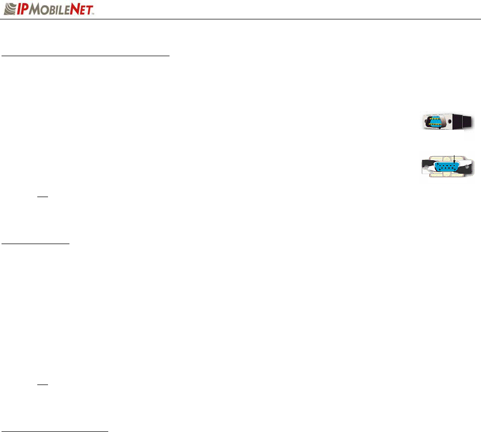
Serial Cable Connection and Routing
The serial cable connects the mobile radio to the mobile computer located in the driver compartment.
To connect the serial cable, perform the following steps:
Step 1 Attach the 20-foot serial cable male connector (DB9M) to the mobile
radio.
Step 2 Route the female connector (DB9F) to the driver compartment and
connect to the serial port located on the rear of the mobile computer.
Route the serial cable to minimize foot pressure and other potential
stresses. Use split loom tubing and nylon cable ties for cable protection.
Ethernet Setup
The user also has the option to connect the mobile radio and the mobile computer via Ethernet.
To connect the Ethernet cable, perform the following steps:
Step 1 Attach the Ethernet cable (minimum 20 feet) to the Ethernet port on the rear of the
mobile radio.
Step 2 Route the other end of the Ethernet cable to the driver compartment and connect to
the Ethernet port located on the rear of the mobile computer.
Route the cable to minimize foot pressure and other potential stresses. Use split loom
tubing and nylon cable ties for cable protection.
Delay Timer Installation
To install the Delay Timer, perform the following steps:
Step 1 Secure Delay Timer to the trunk compartment of the vehicle inserting screws in the
appropriate locations using care not to puncture the vehicle’s gas tank.
Step 2 Route the black wire (#12 AWG) from ground connection on the Delay Timer to the
vehicle chassis (see Figure 8).
Step 3 Route and wire the red wire (#8 AWG) from the positive (+) terminal connection on
the vehicle battery connection via the in-line fuse toward the battery connection on
the Delay Timer.
Connect the red wire (#8 AWG) to the two red wires (#12 AWG). Route and wire
the red (#12 AWG) wires to the two (2) battery connections on the Delay Timer.
Figure 6
Figure 7
SECTION 3: INSTALLATION INSTRUCTIONS
M64450G25-FCCRpt.doc Page 11
Figure 8: Delay Timer Installation
Step 4 Route a red wire (#12 AWG) from the ignition connection on the Delay Timer to the
ignition switch in the driver compartment (see the figure above). The ignition wire
should be fused with 2A fuse.
Step 5 Route a red wire (#12 AWG) from the first and last output connections on the Delay
Timer to the Automotive Power Relay.
Step 6 Route and wire a red (#12 AWG) wire from the second output connection on the
Delay Timer to the last output connection on the Delay Timer.
Step 7 Route and wire a red (#12 AWG) wire from the last output connection on the Delay
Timer to the Automotive Power Relay coil at the position shown in the figure above.
Step 8 Route and wire a black (#8 AWG) wire from the junction (negative battery post
group) in the trunk compartment to the negative (-) terminal on the vehicle battery.
Step 9 Wire the red (#12 AWG) wire to the battery input on the Delay Timer and route the
black (#8 AWG) portion of the wire to the positive terminal on the battery via an in-
line fuse (30 AMP).
SECTION 3: INSTALLATION INSTRUCTIONS
M64450G25-FCCRpt.doc Page 12
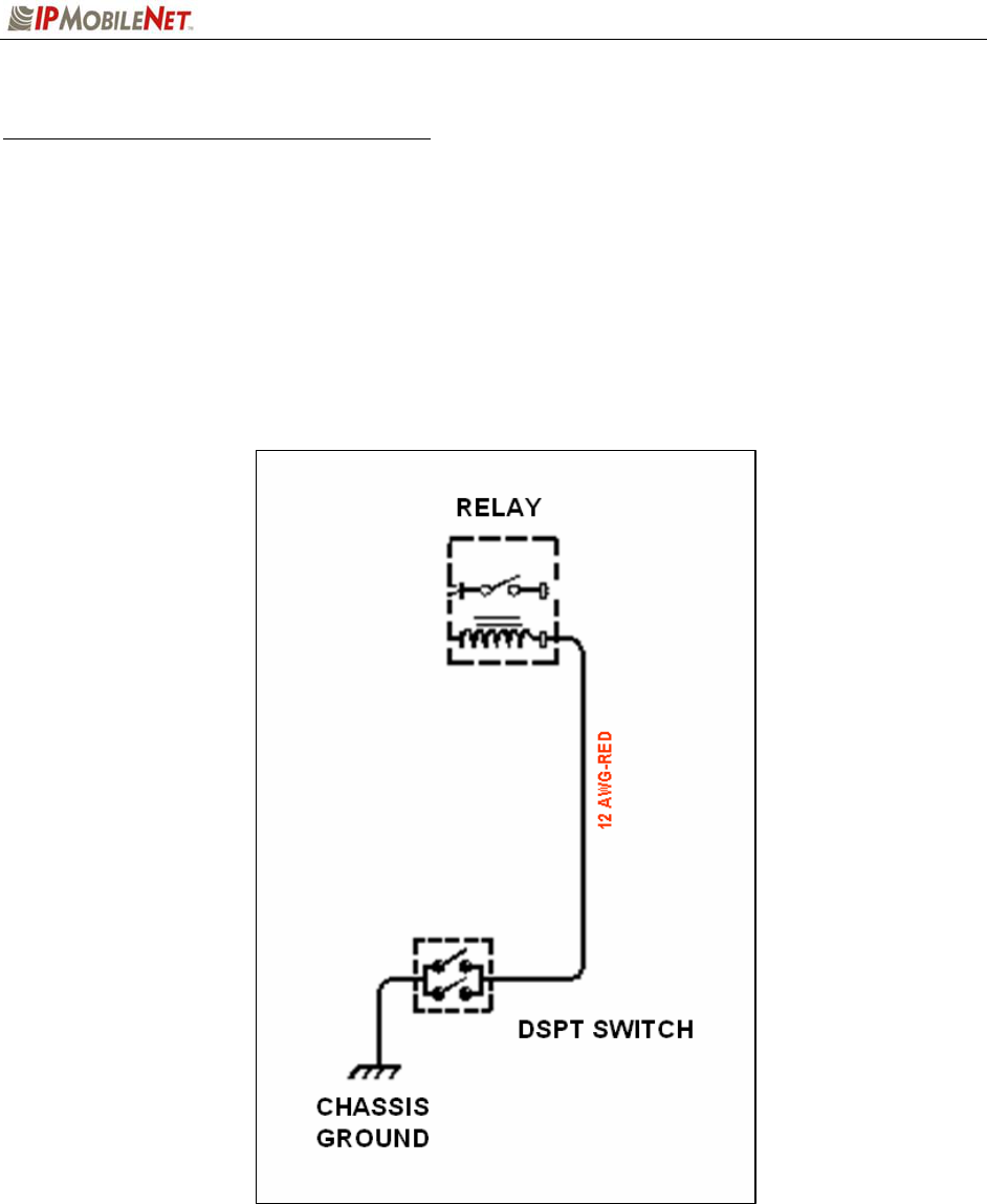
Switch Installation (DPST Heavy Duty Toggle)
To install the switch, perform the following steps:
Step 1 Mount the switch in the selected location.
Step 2 Route and wire a red wire (#12 AWG) from the switch to the Automotive Power Relay
(see the figure below).
Step 3 Ground the switch by routing and wiring a black wire from the switch to the chassis
ground.
Figure 9: Carling Switch Installation
SECTION 3: INSTALLATION INSTRUCTIONS
M64450G25-FCCRpt.doc Page 13
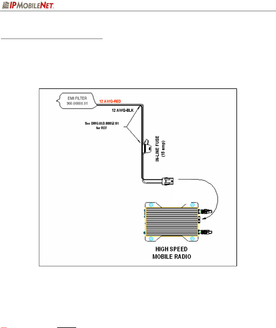
Mobile Radio Power Supply Installation
To install the mobile radio power connection, perform the following steps:
Step 1 Route and connect the power cable to the EMI filter, as shown in the figure below.
Figure 10: Power Supply Installation
Step 2 Route and connect the other end of the power cable to the rear of the mobile radio
to the power connector (13.8 VDC) connection.
a WARNING! Do not connect power before installing and connecting proper antenna or dummy
load on the TX/RX1 port. The mobile radio must never be allowed to transmit without a suitable
output load.
Step 3 Install the GPS antenna. The GPS antenna is required for the mobile radios and
the base stations.
SECTION 3: INSTALLATION INSTRUCTIONS
M64450G25-FCCRpt.doc Page 14
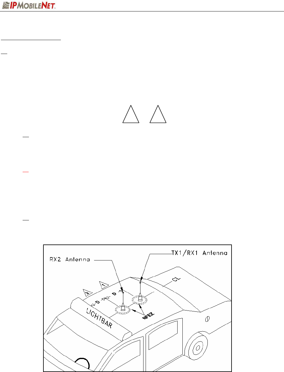
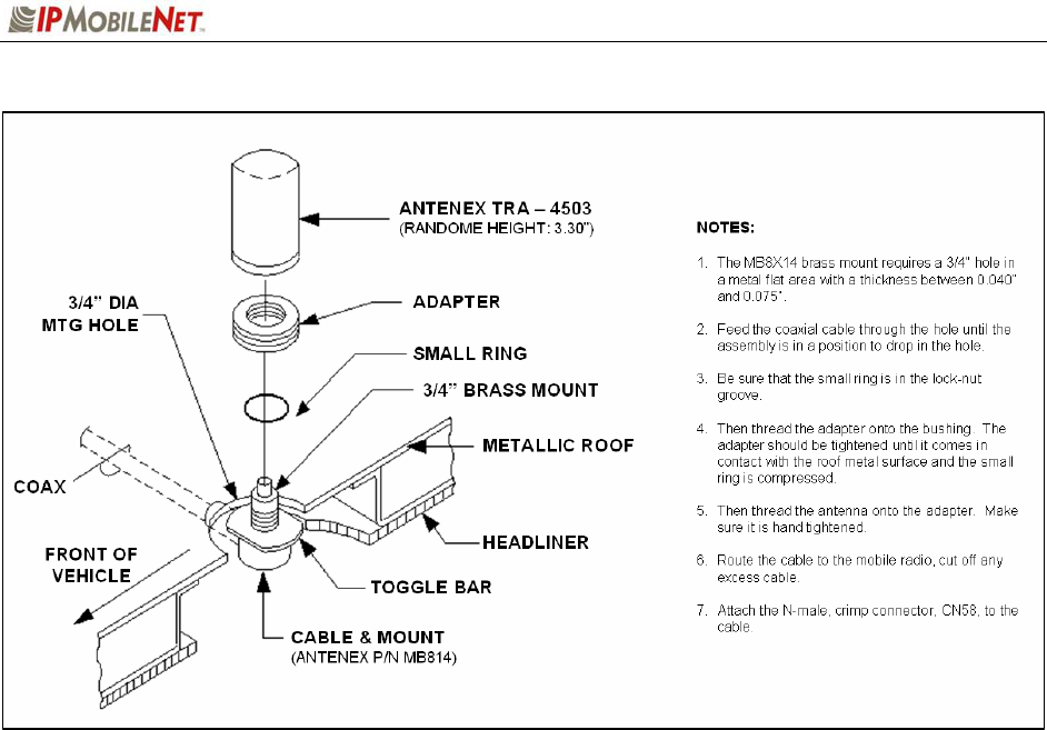
Antenna Configuration
Two (2) antennae are mounted and installed on the roof of the vehicle using specific
measurements for distance.
To mount and install the antennae, perform the following steps:
Step 1 Install antennae (see the figure below).
Observe correct separation between antennae (refer to Table 7: Mobile Antenna
Distance Matrix). This table provides midpoint distance calculations and minimum and
Near-Field Exclusion Zone (NFEZ) for proper diversity reception.
a The NFEZ distance is an absolute minimum. The greater the distance between the
antennae to any other surfaces will result in improved performance.
Step 2 Cut a mounting hole in the roof of the vehicle using an electric drill or hole saw.
The antenna-mounting hole provides ground connection to the antenna. Ensure that a
metal-to-metal connection between the antenna shields exists.
Figure 11: Antenna Distance Configuration
1 2

SECTION 3: INSTALLATION INSTRUCTIONS
M64450G25-FCCRpt.doc Page 15
The previous figure represents the recommended front-to-rear antenna installation. The
receiver antenna (RX2) should be the antenna nearest to the light bar.
Step 3 All antenna mounts must be environmentally tight. Install or use O-rings to seal the
antenna base to the rooftop of the vehicle.
Step 4 Route the coaxial cables to the mobile radio through one of the hollow spaces in the
roof supports into the trunk compartment where the mobile radio is mounted.
Both antennae should be checked and tested to ensure they are functioning properly.
a If these installation guidelines are followed, it will be safe for persons to stand at a
distance no less than 39 inches from the antennae while the mobile radio is in
transmit mode.
Measuring Return Loss
The following test is performed without any power, thus can be performed immediately after the
installation of the coax and antenna, following the installation of the N-type connector on the coax.
To measure Return Loss, perform the following steps:
Step 1 Select the appropriate Antenna Analysts to perform the test.
Step 2 Connect the antenna to be tested to the Antenna Analyst.
Step 3 Turn on the Antenna Analyst and the Return Loss (RETL) is displayed in dB to the
left of the Voltage Standing Wave Ratio (VSWR) curve.
The Return Loss Specification is –14 dBm or greater (with good antennae the typical
range will be between –14 dBm and –28 dBm).
Measuring Voltage Standing Wave Ratio
To measure the Voltage Standing Wave Ratio (VSWR) Reflected Power, perform the following
steps:
Step 1 After selecting the appropriate Analyst and connecting the antenna to be tested,
press F1 to access the Analyst Menu.
Step 2 Press F1 again to access the Display (DSPLY) menu, which lists the modes.
Step 3 Press F2 to select the VSWR display mode. Plotting will resume and the VSWR
value is highlighted.
The VSWR Reflected Power Specification should be at a ratio of approximately 1.6 to 1.
SECTION 3: INSTALLATION INSTRUCTIONS
M64450G25-FCCRpt.doc Page 16
Measuring Insertion Loss
To measure Insertion Loss of an unterminated length of coax, perform the following steps:
Step 1 Connect the antenna to be tested to the appropriate Antenna Analyst.
Step 2 Turn on the Antenna Analyst and the Return Loss is displayed in dB to the left of the
VSWR curve.
To switch from the RETL mode to VSWR mode, refer back to the previous set of
instructions.
Step 3 Divide the result by two (2).
Post Installation Checklist
Table 6 lists the tasks that should be performed upon completing installation.
TABLE 6: POST INSTALLATION CHECKLIST
NO. CHECKLIST ITEM ;
1 Scope out the entire vehicle setup to locate any obvious problem areas.
2 Check wiring for safety concerns.
3 Use tie wraps to ensure that all wires routed in parallel are bundled together.
4 Check to see if any wires are exposed.
5
If any wires are exposed, use electrical tape to cover.
When covering wires in the engine compartment, use high-quality
electrical tape.
6 Perform appropriate testing as described in this manual to ensure mobile radio
works properly.
Once installation is completed, remove all debris and restore dismantled parts and rubber mats to
appropriate locations.
SECTION 3: INSTALLATION INSTRUCTIONS
M64450G25-FCCRpt.doc Page 17
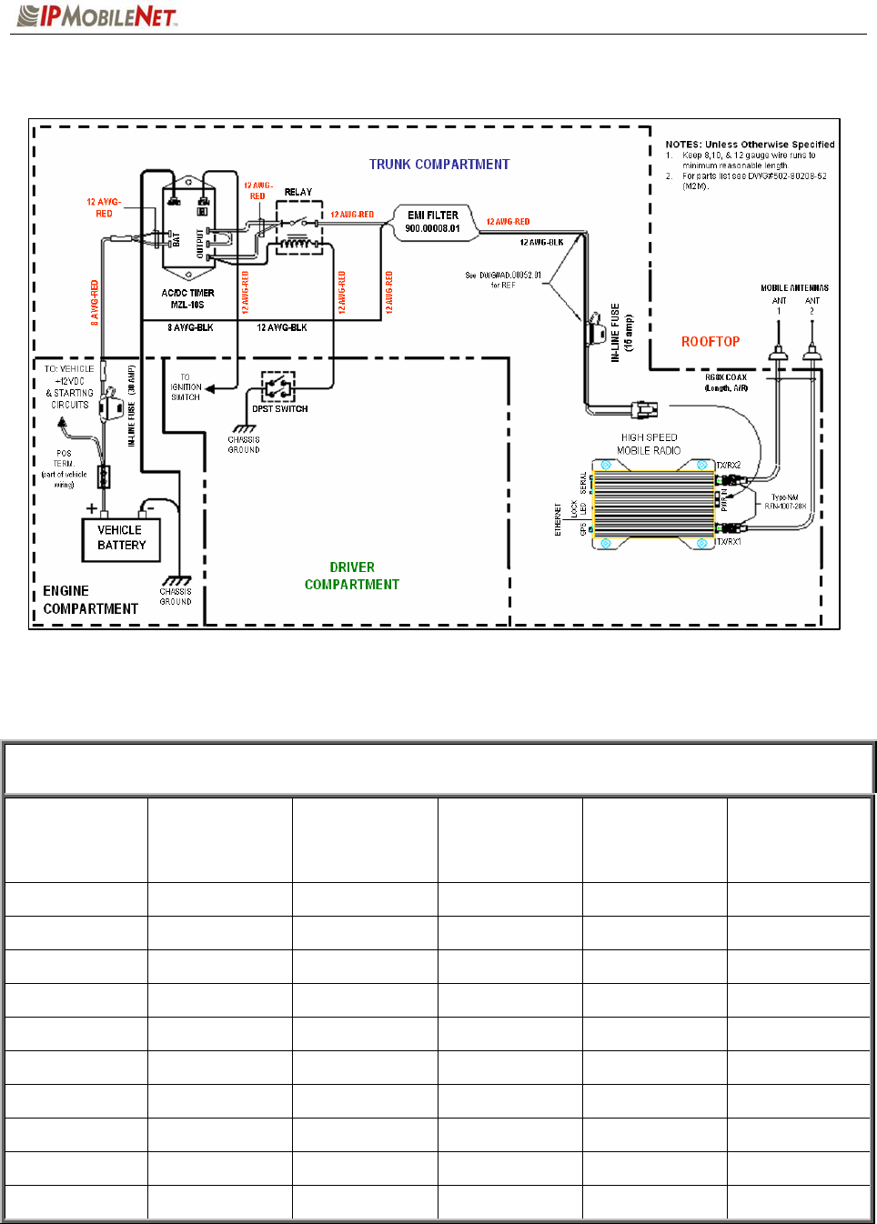
Mobile Installation Layout Diagrams
Figure 12 Vehicle Unit Wiring Interconnection Layout
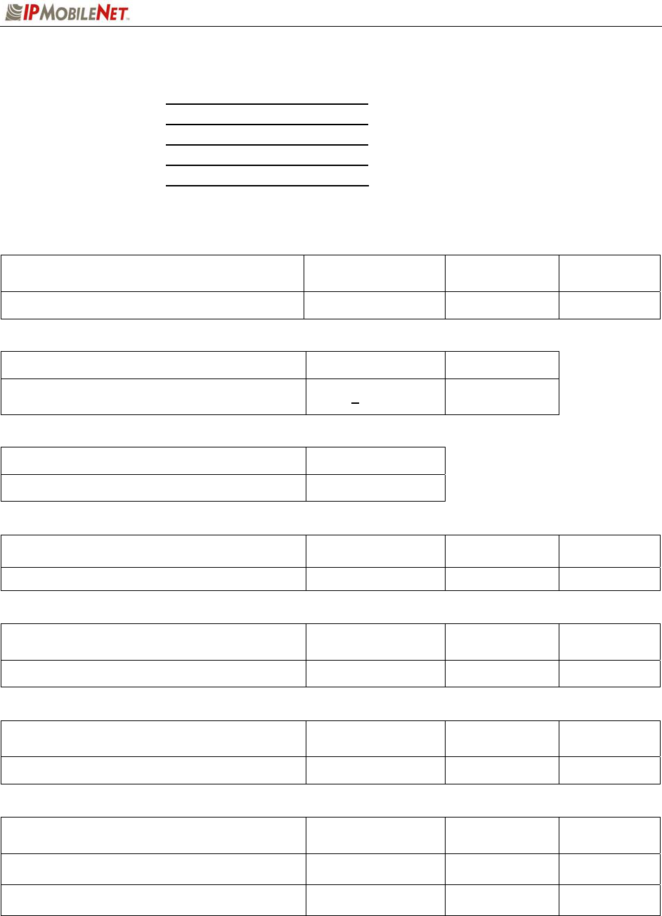
Table 7 lists the mobile radio antenna distances by frequency band.
TABLE 7: MOBILE ANTENNA DISTANCE MATRIX
Frequency
Band in MHz
Center
Frequency in
MHz
Antenna
Spacing for
¼ Wave Ant
(inches)
Wavelength
(inches)
Near-Field
Exclusion
Zone*
(inches)
¼ Wave
Length
(inches)
130-140 135 65.4 87.3 10.9 21.8
140-150 145 61.2 81.4 10.2 20.4
150-160 155 57.0 76.2 9.5 19.0
160-174 167 53.1 70.7 8.9 17.7
450-470 460 19.2 25.7 3.2 6.4
470-490 480 18.6 24.6 3.1 6.2
490-512 501 17.7 23.6 2.9 5.9
764-784 774 11.4 15.26 1.91 3.81
784-804 794 11.2 14.88 1.86 3.72
806-821 814 10.8 14.5 1.8 3.6
*NFEZ = Minimum Near-Field Exclusion Zone **Round antenna spacing to the nearest ⅛”
SECTION 3: INSTALLATION INSTRUCTIONS
M64450G25-FCCRpt.doc Page 18
Figure 13 Diversity Antenna Mobile Installation Detail (Typical Installation)
SECTION 3: INSTALLATION INSTRUCTIONS
M64450G25-FCCRpt.doc Page 19
Preliminary Testing and Troubleshooting
This section provides a functional preliminary test for the mobile radio once installed. It is used to
determine the condition of new mobile radios before being placed into service.
Checklist of Required Material
The table below provides a checklist of the tools and equipment required to perform the preliminary test
procedure.
TABLE 8: CHECKLIST OF REQUIRED MATERIAL TO PERFORM PRELIMINARY TESTING
NO. REQUIRED TOOLS/EQUIPMENT ;
1 IPSeries High Speed Mobile Radio installed in the vehicle as previously described
in this section
2 A laptop with an available serial communication port and Microsoft Windows 98 or
greater installed
3 IPMobileNet Dial-Up Networking and IPMessage software loaded onto the laptop
(SLIP2IPMN.exe)
4 DC power supply with ammeter, 13.8V, 12 amps or more (Astron VS12M or
equivalent)
5 Corresponding calibrated IPSeries Base Station
6 Internet Protocol Network Controller (IPNC)
7 Two antennae (generic mag mounts) tuned to frequency of transceiver
8 Serial cable DB9M – DB9F connectors (IPMN p/n: 156.0245.020)
9 RF Attenuator 10-20 dB with appropriate wattage rating for transceiver

SECTION 3: INSTALLATION INSTRUCTIONS
M64450G25-FCCRpt.doc Page 20
Base Station Setup for Testing
The system must be programmed with the customer’s parameters before any tests are made on
the mobile radio.
To prepare the base station to be used in the mobile radio test, perform the following steps:
Step 1 On the laptop at the Windows desktop, click on the Start button and select
Accessories, Communications, and HyperTerminal.
Step 2 Power up the base station.
First-time users must enter the customer’s operating parameters into the base station
with HyperTerminal (refer to the IPSeries High Speed Base Station System Manual
for instructions and the client’s system documentation for parameters).
a Ensure that the calibrated base station and the mobile radio antennae are separated
by at least 10 feet. If the antennae are too close, the mobile radio receivers may be
overloaded by the transmitters resulting in intermittent communications and high data
errors.
SECTION 3: INSTALLATION INSTRUCTIONS
M64450G25-FCCRpt.doc Page 21
Preliminary Test Procedure and Troubleshooting
Prior to performing this procedure, the IPNC IP address must be known. Note taking during
preliminary testing is crucial to ensure necessary information is gathered to use for additional
testing or if the mobile radio needs to be submitted for repair.
To test mobile radio functionality, perform the following steps:
Step 1 Perform a visual inspection of the mobile radio and its connections. Validate that
all connectors and power cables are in good condition and all chassis screws are
in place.
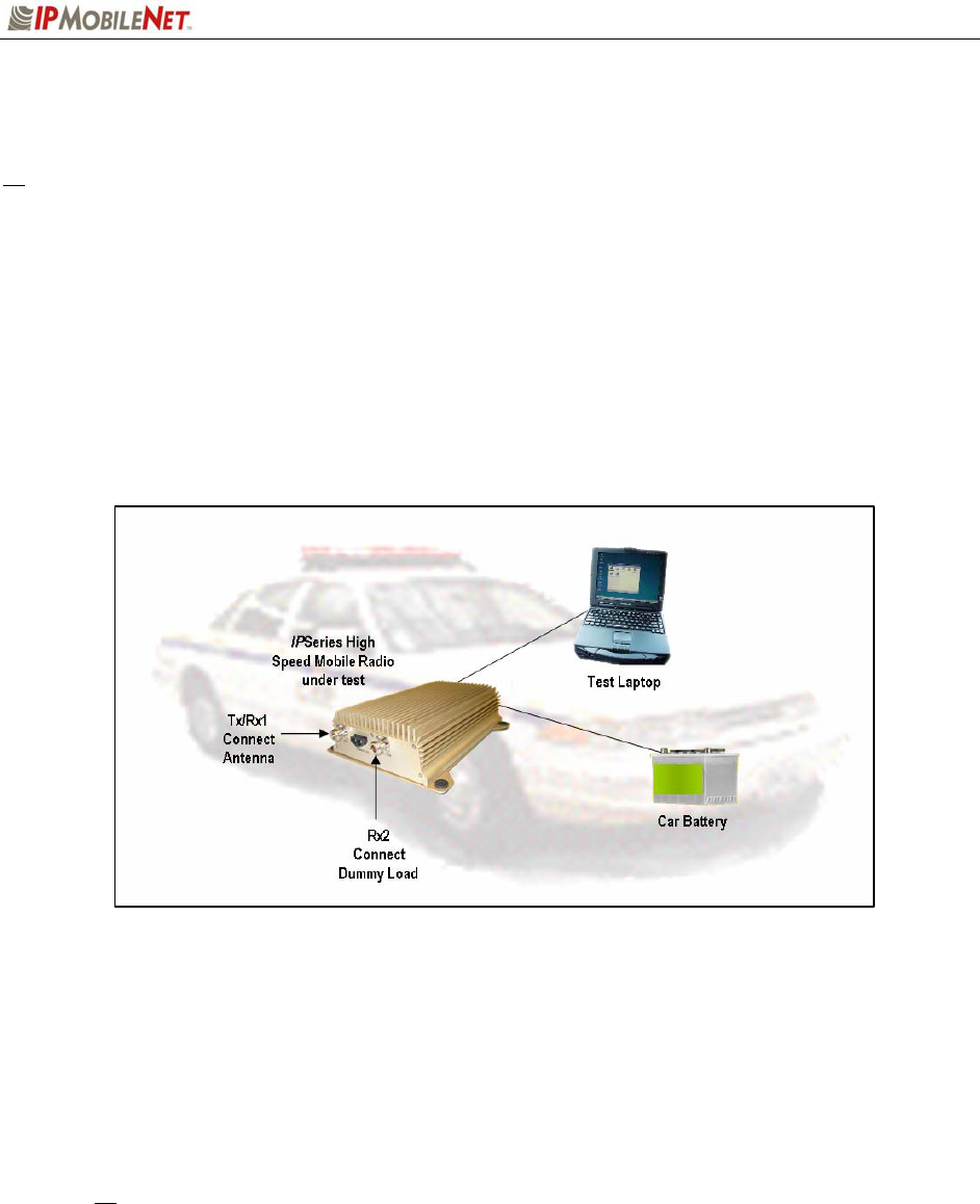
Step 2 Connect the mobile radio as shown in the figure below.
Figure 14 High Speed Mobile Radio Connection for Testing
Step 3 Power on the mobile radio and the test laptop. The power supply ammeter must
read 1.0 amp or less with a 13.8 VDC output.
Step 4 At the desktop, run the dial-up connection setup to use Serial Line Internet
Protocol (SLIP) by double clicking on the SLIP2IPMN shortcut.
The SLIP2IPMN dial-up network shortcut displays as an icon on the laptop’s desktop. If
the SLIP2IPMN shortcut is not available on the desktop, consult the Mobile Data
Computer for Communication with the Mobile Radio Installation Guide (IPMN p/n:
516-80310.IG) for instructions on how to set up the connection.
Step 5 At the desktop, run the IPMessage Utility by double clicking on the IPMsg
shortcut. The IPMessage window displays.
SECTION 3: INSTALLATION INSTRUCTIONS
M64450G25-FCCRpt.doc Page 22
# If a message window appears indicating the connection was unsuccessful, perform the following
troubleshooting steps:
1. Ensure the serial and power cables are properly connected.
2. Verify that the mobile radio lock LED (light emitting diode) is on, indicating the mobile radio
has power.
3. Ensure that the SLIP2IPMN dial-up connection is running.
4. If problem persists after retrying, replace the serial cable with one that is known to be
working properly.
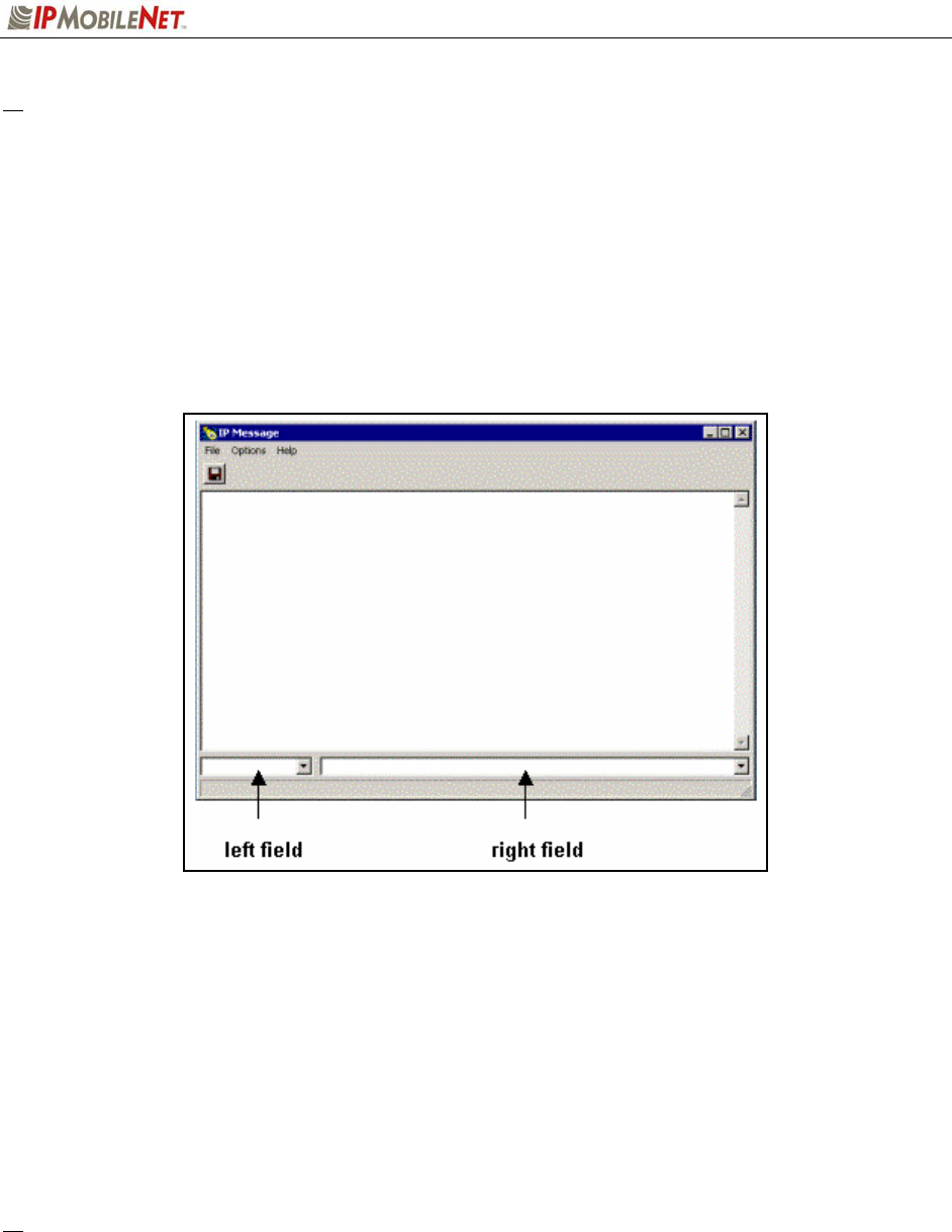
Figure 15IPMessage Window
Step 6 In the IPMessage window in the left field, enter the mobile radio’s IP address and
press the [TAB] button. If the mobile radio IP address is not known, enter
255.255.255.255 in the left field.
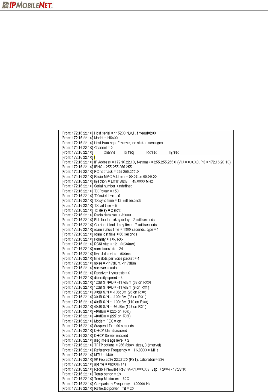
Step 7 In the right field type a ? and click the [ENTER] button. A list of mobile radio
configuration parameters appears in the upper message window. This verifies
that the IP address is correct, the mobile radio’s serial interface is live, and that
the mobile radio’s microcontroller section is active.
# If the upper message window only displays “To [IP address] ?”, communication has not been
established. Validate the IP address.
(
Address
)
(
Commands
)

SECTION 3: INSTALLATION INSTRUCTIONS
M64450G25-FCCRpt.doc Page 23
Step 8 At the desktop, click on the Start button and select Programs and MS-DOS
Prompt. The MS-DOS window displays.
Step 9 Ping the IPNC commanding the transmitter to send 25 messages of 500
characters each to the IPNC as well as a response through Receiver 1 back to
the laptop or desktop PC by typing in the following command at the MS-DOS
prompt replacing NNN.NNN.NNN.NNN with the IPNC IP address:
Ping NNN.NNN.NNN.NNN –n 25 –l 500 –w 4000
After entering the command, press [ENTER] to continue.
When entering a command, pay special attention to the spaces and the
characters being typed.
# If the calibrated base station does not respond, check the syntax of the Ping command and verify
the IP address is correct.
If the ping command runs but high packet loss figures are shown, perform the following:
1. Verify that the calibrated base station and mobile radio antennae are separated by at least
10 feet. If the antennae are too close, the mobile radio receivers can be overloaded by the
transmitters resulting in intermittent communication and high data errors.
2. Verify the calibrated base station parameters are correct for the mobile radio. Such
parameters include IP addresses and complementary RX/TX frequencies.
3. Check to ensure the data and power cables are connected correctly.
4. If the Ping command continues to fail, test using a mobile radio that is known to be working
properly.
Step 10 Check the test laptop and verify that the Packets Lost Percentage is zero to 1%
packet loss. Greater losses may indicate a problem with the transmitter/receiver
1, or modem circuitry.
Step 11 Change the antenna on the mobile radio to the RX2 antenna input.
Step 12 Connect the RF attenuator to the mobile radio’s TX/RX1 antenna input.
Step 13 Connect the second antenna to the RF attenuator. In the IPMessage window,
enter receiver=2. This will allow the mobile radio to only receive via Receiver 2.
Step 14 Type the following command at the MS-DOS prompt replacing
NNN.NNN.NNN.NNN with the IPNC IP address:
Ping NNN.NNN.NNN.NNN –n 25 –l 500 –w 4000
After entering the command, press [ENTER] to continue.
Step 15 Check the test laptop and verify that the Packets Lost Percentage is zero to 1%
packet loss. Greater losses may indicate a problem with the receiver 2, or
modem circuitry.

SECTION 3: INSTALLATION INSTRUCTIONS
M64450G25-FCCRpt.doc Page 24
Confirming High Speed Mobile Radio Receiver Sensitivity
This set of instructions provides the user with a list of required equipment and steps needed to confirm
mobile radio Receiver sensitivity.
Requirements
IPSeries High Speed Mobile Radio
DC power supply, 13.8V, 12 amps or more (Astron VS 12M or equivalent)
Desktop or laptop computer with IPMessage installed
Agilent HP 8920A or B Service Monitor
Serial cable DB9M – DB9F connectors (generic)
To confirm mobile radio receiver sensitivity, perform the following steps:
Step 1 Connect the mobile radio to the recommended power supply, the desktop or laptop
computer, and the service monitor.
Step 2 Turn on the mobile radio.
Step 3 Connect the serial cable or Ethernet interface to the mobile radio and the desktop or
laptop computer.
Step 4 Start the connection to the mobile radio.
Step 5 Start the IPMessage utility.
Step 6 At the IPMessage window, enter the mobile radio IP address and press [ENTER].
Step 7 At the IPMessage window, enter unlock=password (entering the assigned
password) and press [ENTER].
Step 8 Send the following test mode command at the IPMessage window, by entering
testmode=1 and press [ENTER] to continue.
Step 9 Generate an on frequency, modulated (1000 Hz @ 5 kHz dev) signal to Receiver 1 at
–100 dBm.
Step 10 At the IPMessage window, type noise and press [ENTER] to continue.
Step 11 Confirm that the noise level for Receiver 1 is +/- 2dB of the –100 dBm level.
Repeat the same steps for Receiver 2.
SECTION 4: FACTORY TEST PROCEDURE
M64450G25-FCCRpt.doc Page 25
Equipment List
The following table lists the equipment required to perform the M64450G25 Mobile Radio Factory Test
Procedure:
TABLE 9: EQUIPMENT REQUIRED TO PEREFORM FACTORY TEST PROCEDURE
QTY DESCRIPTION MANUFACTURER MODEL
2
PC’s
One for Mobile
One for Base
Windows 9X w/
IPMessage
AVR
1 Service Monitor – Communication Test Set HP HP8920B or
equivalent
1 Digital multimeter Tektronix
Fluke 77 or equivalent
1 DC power supply w/ ammeter, 13.8V, 20 Amps or
more Astron RM35A
1 4-Channel Scope Tektronix TDS 460A
1 IPSeries High Speed Mobile Radio M64450G25
1 Calibrated IPSeries High Speed Base Station B64450G25
1 Internet Protocol Network Controller (IPNC)
1 100 watt dummy load/attenuator Pasternack PE7021-40 or
equivalent
2 UHF Antennae (generic mag mount)
1 Serial cable DB9M-DB9F connectors IPMN p/n:
156-0245-020
1 IP power cable IPMN p/n:
502-82017-52
1 3-foot RF jumper cable with type N connectors
(generic)
1 High Frequency Probe
1 Ceramic tuning tool IPMN p/n:
44010006
1 ea #0, #1, and #2 Phillips screwdrivers (generic)
SECTION 4: FACTORY TEST PROCEDURE
M64450G25-FCCRpt.doc Page 26
Programming and Configuring Mobile Radio
Once the appropriate equipment for performing the factory test are gathered, perform the following steps
to program and configure an M64450G25 Mobile Radio:
Step 1 Enter the mobile radio serial number, date test being performed, and tester’s name on the
Test Data Sheet (see Appendix B).
Step 2 Program the radio to the current Firmware revision using the AVR programming utility.
Step 3 Connect a PC to the radio and launch the IPMessage program. In the IPMessage window,
type factory default, press [ENTER], and the radio displays the radio’s default values.
Step 4 Enter the appropriate values for the radio's frequency band. The following values were used
for a 450-506 MHz mobile radio:
Frequency= 0, 450.000000, 463.000000, 418.000000
SECTION 4: FACTORY TEST PROCEDURE
M64450G25-FCCRpt.doc Page 27
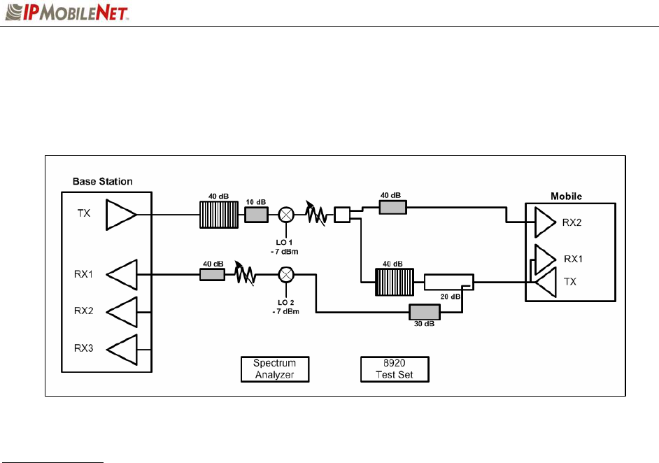
Test Connections
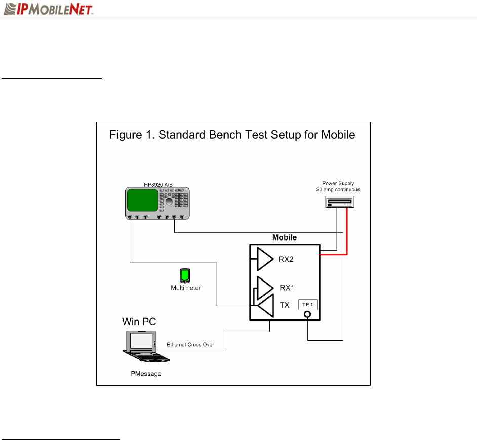
Test Equipment Setup
The test equipment should be configured as shown in the figure below:
Mobile Radio Connections
Perform the following steps to connect the mobile radio properly:
Step 1 Connect the GPS antenna.
Step 2 Connect a serial cable and launch IPMessage.
Step 3 Connect a load to the transmitter antenna port.
Step 4 Connect the power cable to a voltage source of 13.8 VDC able to deliver 25 amps of
continuous current.
Step 5 Apply power to the mobile radio.
Step 6 Verify the IPMessage connection by entering the “?” in the IPMessage command
field and pressing [ENTER].

SECTION 4: FACTORY TEST PROCEDURE
M64450G25-FCCRpt.doc Page 28
Receiver Alignments and Tests
TCXO Operation
Perform the following steps to check the operation of the TCXO:
Step 1 In IPMessage, type “status = pps, cal” in the command field and press [ENTER].
Step 2 Read the reported error values for the TCXOs.
Step 3 Continue using the “status = pps, cal” command, until GPS is acquired.
Step 4 Repeat the command observing the error values.
Step 5 Observe that the TCXO “error ppb” continues to adjust until it settles at +/-200.
Step 6 Enter the “error ppb” data onto the Tune and Align Data Sheet.
Receiver Injection
Perform the following steps to make sure the receiver injection is locked on frequency:
Step 1 Connect a coaxial cable from the Service Monitor “RF Input” port to the “RX2” port on
the mobile radio.
Step 2 Place the Service Monitor in the “Tx” mode.
Step 3 Set the Service Monitor to the base station’s Receiver Injection frequency.
Step 4 Adjust the squelch on the Service Monitor until the frequency error is displayed.
Step 5 When the injection frequency stabilizes record the frequency error on the Tune and
Align Data Sheet.
At this time the Operator is able to proceed with the other adjustments and
alignments.
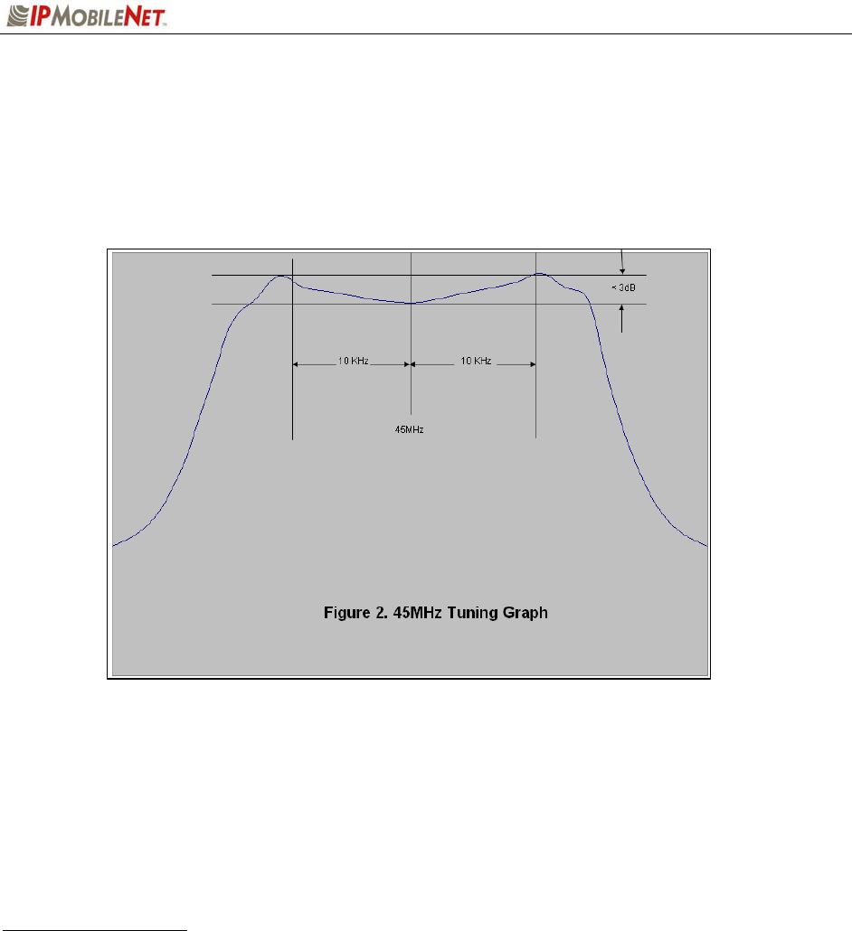
45 MHz Filters Waveform
Perform the following steps to set the Waveform for the 45 MHz filters:
Step 1 Set the Service Monitor with the following selections:
- Select the spectrum analyzer function
- Set the center frequency for 45 MHz
- Set the amplitude to -20 dBm
- Set the Span to 100 kHz
- Choose “Controls…RF Gen”
- Set to “Track” to enable the tracking generator
- Set the “RF Gen Freq” to equal the radio receive frequency minus 45 MHz
- Set “Amplitude” to -30 dBm
- Set the “Output Port” to “DUPL” to select the duplex out port
Step 2 Connect a High Frequency Probe to “Ant In” port on the Service Monitor.
SECTION 4: FACTORY TEST PROCEDURE
M64450G25-FCCRpt.doc Page 29
Step 3 Adjust Receiver 1 filters.
- Connect an RF cable from the “Duplex Out” port to Receiver 1
- Probe U64 pin 1 with the High Frequency Probe
- Adjust CV12, CV5, and CV8 for the correct waveform as shown in the figure
below
Step 4 Adjust Receiver 2 filters.
- Connect an RF cable from the “Duplex Out” port to Receiver 2
- Probe U48 pin 1 with the High Frequency Probe
- Adjust CV9, CV2, and CV7 for the correct waveform as shown in the figure
above
Reciever 12 dB SINAD
Perform the following steps to adjust Receiver 12 dB SINAD:
Step 1 Set the Service Monitor, as follows:
- Select the “RX” function
- Set “RF Gen Freq” to the receive frequency of the mobile radio under test
- Set the Service Monitor to display SINAD readings
- Set other values as follows:

SECTION 4: FACTORY TEST PROCEDURE
M64450G25-FCCRpt.doc Page 30
Amplitude: Varies AFGen1 Freq: 1.000 kHz AFGen2 Freq: 1.000 kHz
Atten Hold: Off AFGen to: FM 5 KHz AFGen2 to: Off
Output Port: RF Out Ext Load R: 600 ohm
Filter 1: 300 Hz HPF
Filter 2: 3 kHz LPF
Step 2 Test Receiver 1, as follows:
- Connect an RF cable from the Service Monitor’s “RF Out” port to the antenna
port of Receiver 1
- At the Service Monitor, reduce the “Amplitude” until the SINAD meter indicates
12 dB SINAD
The amplitude must be -115 dBm or less. If necessary, adjust CV12 slightly
to improve 12 dB SINAD reading.
Step 3 Test Receiver 2, as follows:
- Connect an RF cable from the Service Monitor’s “RF Out” port to the antenna
port of Receiver 2
- At the Service Monitor, reduce the “amplitude” until the SINAD meter indicates 12
dB SINAD
The amplitude must be -115 dBm or less. If necessary, adjust CV9 slightly to
improve 12 dB SINAD reading.
Receivers Minimum Distortion
Perform the following steps to adjust the receivers for minimum distortion:
Step 1 Set the Service Monitor, as follows:
- Select the “RX” function
- Set the “RF Gen Freq” to the receive frequency of the mobile radio under test
- Set the Service Monitor to display distortion readings
- Set other values as follows:
Amplitude: -80 dBm AFGen1 Freq: 1.000 kHz AFGen2 Freq: 1.000 kHz
Atten Hold: Off AFGen to: FM 5 KHz AFGen2 to: Off
Output Port: RF Out Ext Load R: 600 ohm
Filter 1: 300 Hz HPF
Filter 2: 3 kHz LPF
Step 2 Adjust Receiver 1, as follows:
- Connect an RF cable from the Service Monitor’s “RF Out” port to the antenna
port of Receiver 1
- Observe the Service Monitor while adjusting CV4 for minimum distortion –
Distortion must read 3.0% or less
- Record the distortion on the Tune and Align Data Sheet

SECTION 4: FACTORY TEST PROCEDURE
M64450G25-FCCRpt.doc Page 31
Step 3 Adjust Receiver 2, as follows:
- Connect an RF cable from the Service Monitor’s “RF Out” port to the antenna
port of Receiver 2
- Observe the Service Monitor while adjusting CV1 for minimum distortion –
Distortion must read 3.0% or less
- Record the distortion on the Tune and Align Data Sheet
Data Quality and Message Success Rate
Perform the following steps to adjust receiver data quality and Message Success Rate (MSR):
Step 1 Connect the base station to an IPNC via SLIP cable (an Ethernet connection will be
used during Message Success Rate Testing).
Step 2 Connect a mobile radio with known good transmitter data quality in the test set up.
Allow the mobile radio to connect to the base station.
Step 3 Run IPLinkView or ping the mobile radio from the IPNC.
Step 4 Set the uplink RSSI at -93 +/- 3dBm.
Step 5 Connect the mobile test setup receive cable to each of the two (2) receivers in turn.
Step 6 On each receiver, run a minimum of 50 packets in IPLinkView or 50 pings.
The Data Quality of each receiver must average at least 220 over 50
contiguous samples.
Step 7 For Receiver 1, if necessary adjust CV8 slightly to improve Data Quality.
Step 8 For Receiver 2, if necessary adjust CV7 slightly to improve Data Quality.
Step 9 Calculate the Message Success Rate (MSR) over the 50 consecutive packets on
each of the receivers.
The MSR shall be greater than 94%. If MSR does not meet 94% proceed
with Hardware Time Verification for trouble shooting.
Step 10 Record the Data Quality and the MSR on the Tune and Align Data Sheet.

SECTION 4: FACTORY TEST PROCEDURE
M64450G25-FCCRpt.doc Page 32
Audio AC and DC Voltages and Balances
Perform the following steps to adjust the Receiver Audio AC and DC voltages and balance:
Step 1 Set the Service Monitor, as follows:
- Select the "RX" function
- Set "RF Gen Freq" to the receive frequency of the mobile radio under test
- Set the Service Monitor to display DC volts and AC Volts
- Connect an oscilloscope 1x probe from TP1 on the base station control board to
the “audio in” connector on the Service Monitor
- Set other values as follows:
Amplitude: -80 dBm AFGen1 Freq: 1.000 kHz AFGen2 Freq: 1.000 kHz
Atten Hold: Off AFGen to: FM 5 KHz AFGen2 to: Off
Output Port: RF Out Ext Load R: 600 ohm
Filter 1: 300 Hz HPF
Filter 2: 3 kHz LPF
Step 2 Adjust Receiver 1, as follows:
- Connect an RF cable from the Service Monitor's RF Out port to the antenna
port of Receiver 1
- In IPMessage, type the command “receiver = 1” and observe that Receiver 1
is selected
- At TP1, measure AC and DC volts
- Adjust RV5 for an AC reading of 400 mVAC +/- 1mVAC
- Adjust RV6 for a DC reading of 2.500 mVDC +/- 1mVDC
- Record AC and DC levels on the Tune and Align Data Sheet
Step 3 Adjust Receiver 2, as follows:
- Connect an RF cable from the Service Monitor's RF Out port to the antenna
port of Receiver 2
- In IPMessage, type the command “receiver = 2” and observe that Receiver 2
is selected
- At TP1, measure AC and DC volts
- Adjust RV3 for an AC reading of 400 mVAC +/- 1mVAC
- Adjust RV4 for a DC reading of 2.500 mVDC +/- 1mVDC
- Record AC and DC levels on the Tune and Align Data Sheet

SECTION 4: FACTORY TEST PROCEDURE
M64450G25-FCCRpt.doc Page 33
Receiver Calibration
Each receiver must be calibrated at four (4) points to ensure the proper operation of Intelligent Diversity
Reception and to provide the IPNC with correct information about the signal strength of received mobile
data.
Step 1 Connect a coaxial cable from the Service Monitor “RF Input” port to a receiver
port on the base station
Step 2 Set the Service Monitor
Step 3 Select the "RX" function
Step 4 Set the "RF Gen Freq" to the receive frequency of the mobile radio under test
Step 5 Connect an oscilloscope 1x probe from TP1 on the base station control board to
the “audio in” connector on the Service Monitor
Step 6 Set other values as follows:
Amplitude: varies AFGen1 Freq: 1.000 kHz AFGen2 Freq: 1.000 kHz
Atten Hold: Off AFGen to: FM 5 KHz AFGen2 to: Off
Output Port: RF Out Ext Load R: 600 ohm
Filter 1: 300 Hz HPF
Filter 2: 3 kHz LPF
Step 7 Calibrate Receiver 1, as follows:
- Connect an RF cable from the Service Monitor's RF Out port to the
antenna port of Receiver 1
- In IPMessage, type the command “receiver = 1” and observe that
Receiver 1 is selected
- Set the Service Monitor to measure 12db SINAD
- Reduce signal amplitude on the Service Monitor until 12dB SINAD is
reached. Record this value
- In IPMessage, type the command “12DB SINAD = “ and the recorded
value
- Set the Service Monitor to measure SNR
- Increase signal amplitude until reaching a level of 30dB SNR
- Record the amplitude
- In IPMessage, type the command “30DB S/N = “ and the recorded value
- Increase signal amplitude until reaching 40dB SNR
- Record the amplitude
- In IPMessage, type the command “40DB S/N = “ and the recorded value
- Set the signal amplitude to -40dBm
- In IPMessage, type the command “-40DBM = -40“

SECTION 4: FACTORY TEST PROCEDURE
M64450G25-FCCRpt.doc Page 34
Step 8 Calibrate Receiver 2, as follows:
- Connect an RF cable from the Service Monitor's RF Out port to the antenna
port of Receiver 2
- In IPMessage, type the command “receiver = 2” and observe that Receiver 2
is selected
- Set the Service Monitor to measure 12db SINAD
- Reduce signal amplitude on the Service Monitor until 12dB SINAD is reached
- Record the value
- In IPMessage, type the command “12DB SINAD = “ and the recorded value
- Set the Service Monitor to measure SNR
- Increase signal amplitude until reaching a level of 30dB SNR.
- Record the amplitude
- In IPMessage, type the command “30DB S/N = “ and the recorded value
- Increase signal amplitude until reaching 40dB SNR
- Record the amplitude
- In IPMessage, type the command “40DB S/N = “ and the recorded value
- Set the signal amplitude to -40dBm
- In IPMessage, type the command “-40DBM = -40“
Step 9 Test Receiver Calibration, as follows:
- Inject a signal with an amplitude of -95dBm into the Receiver 1 antenna port
- In IPMessage, type the command “noise”. The result must -95 dBM +/- 2.
- Next, inject -105dBM into the receiver and type “noise”. The result must be
-95 dBM +/- 2.
Result must be within 2dBm. If the noise figure is not within 2dBm of
the injected signal level, return to receiver calibration and recalibrate
the receivers.
- Repeat the tests for the other Receiver
- Record the noise readings on the Tune and Align Data Sheet

SECTION 4: FACTORY TEST PROCEDURE
M64450G25-FCCRpt.doc Page 35
Transmitter Alignment Tests
Transmitter Output
Step 1 Set the Service Monitor to measure the transmitter frequency of the base station.
Step 2 Set the Service Monitor filters to “<20 Hz HPF” and “15 kHz HPF”.
Ensure the Service Monitor can handle the full power transmission of the
base station otherwise attach an attenuator to the output of the base
station transmitter antenna port before transmitting into the Service
Monitor.
Step 3 Connect a coaxial cable from the output of the base station (or connected
attenuator) to the Service Monitor’s RF In port.
Step 4 In IPMessage, type the command “symbol sync time = 5000”.
This will provide a steady modulated tone from which frequency error can
be measured.
Step 5 When ready to transmit, in IPMessage, type the command “X = 1” - The
transmitter frequency will be modulated with a 3.9 kHz tone.
Step 6 On the Service Monitor read the frequency error.
Step 7 Record the transmit frequency error on the Tune and Align Data Sheet -
Transmitter frequency error is controlled by the processor and cannot be
adjusted manually.
Transmitter Modulation
Step 1 Set the Service Monitor to measure the transmitter frequency of the base station.
Step 2 Set the Service Monitor filters to “<20 Hz HPF” and “15 kHz HPF”
Ensure the Service Monitor can handle the full power transmission of the
base station otherwise attach an attenuator to the output of the base
station transmitter antenna port before transmitting into the Service
Monitor.
Step 3 Connect a coaxial cable from the output of the base station (or connected
attenuator) to the Service Monitor’s RF In port.
Step 4 In IPMessage, type the command “symbol sync time = 5000”. This will provide a
steady modulated tone from which frequency error can be measured.
Step 5 When ready to transmit, in IPMessage, type the command “X = 1”. The
transmitter frequency will be modulated with a 3.9 kHz tone.
Step 6 On the Service Monitor read the deviation. Use RV2 to set the deviation between
4.7 and 4.9 kHz.
Step 7 Record the Transmit Deviation on the Tune and Align Data Sheet.

SECTION 4: FACTORY TEST PROCEDURE
M64450G25-FCCRpt.doc Page 36
Transmitter Power
Step 1 Set the Service Monitor to measure the transmitter frequency of the base station.
Step 2 Set the Service Monitor filters to “<20 Hz HPF” and “15 kHz HPF”.
Ensure the Service Monitor can handle the full power transmission of the
base station otherwise attach an attenuator to the output of the base station
transmitter antenna port before transmitting into the Service Monitor.
Step 3 Connect a coaxial cable from the output of the base station (or connected
attenuator) to the Service Monitor’s RF In port.
Step 4 In IPMessage, type the command “X = 1400,20”. The base station will transmit
20 packets of 1400 bytes each. This continuous transmission will last
approximately 10 seconds.
Step 5 On the Service Monitor note the transmitter power at the beginning of the
transmission and observe whether the transmitter power drops over the course of
the transmission.
Step 6 Transmitter Power Output must begin at a level between 20 and 35 watts and
must not drop by more then 5 watts over the course of the “X = 1400,20”
command.
Step 7 To change the transmitter output power use “TXpower” command in IPMessage.
Step 8 Record the Transmit Power on the Tune and Align Data Sheet.
Transmitter Data Quality and Message Success Rate
Step 1 Connect a base station to an IPNC via SLIP cable or Ethernet.
Step 2 Connect the mobile radio under test in the test set up.
Step 3 Allow the mobile radio to connect to the base station.
Step 4 Run IPLinkView or ping the mobile from the IPNC.
Step 5 Set the downlink and uplink RSSI to -90 +/- 2dBm.
Step 6 Observe the data quality reported by the base station on the uplink.
Step 7 Adjust RV1 in the mobile for the maximum data quality on the uplink.
Step 8 Data Quality must average 220 or better over the course of 50 consecutive
packets or pings.
Step 9 Calculate the Message Success Rate over the 50 Consecutive packets. The
MSR shall be greater that 94%.
Step 10 Record the Data Quality and the MSR on the Tune and Align Data Sheet. If
MSR does not meet 94% proceed with Hardware Time Verification for trouble
shooting.
SECTION 4: FACTORY TEST PROCEDURE
M64450G25-FCCRpt.doc Page 37
Step 11 After completion of Data Quality and MSR tuning, record Firmware Settings. File
the Tune and Align Data Sheet with the Firmware setting in the IPMN Network.
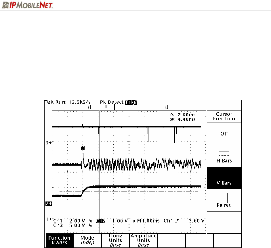
Hardware Timing Troubleshooting
For trouble shooting data quality and MSR failures hardware timing can be verified as follows. The figure
below is an oscilloscope plot of a down-link data message from the base station to the mobile. Channel 1
is connected to the mobile's RSSI test point, Channel 2 is connected to the mobile's recovered
modulation (TP1), and Channel 3 is connected to the mobile’s modem chip select line. The scope’s
acquisition mode is high-resolution.
As can be seen from this plot, the base station's transmit carrier has ramped up to full power (Channel 1)
in just a few milliseconds. The recovered modulation (Channel 2) is stable by this time. There follows a
few milliseconds of quiet time followed by 12 milliseconds of symbol sync time.
The recovered modulation from a base station should look similar to this plot. The recovered modulation
signal should be approximately 1.0 Volts peak-to-peak and should be centered at approximately 2.5 VDC
as is indicated in the figure above.
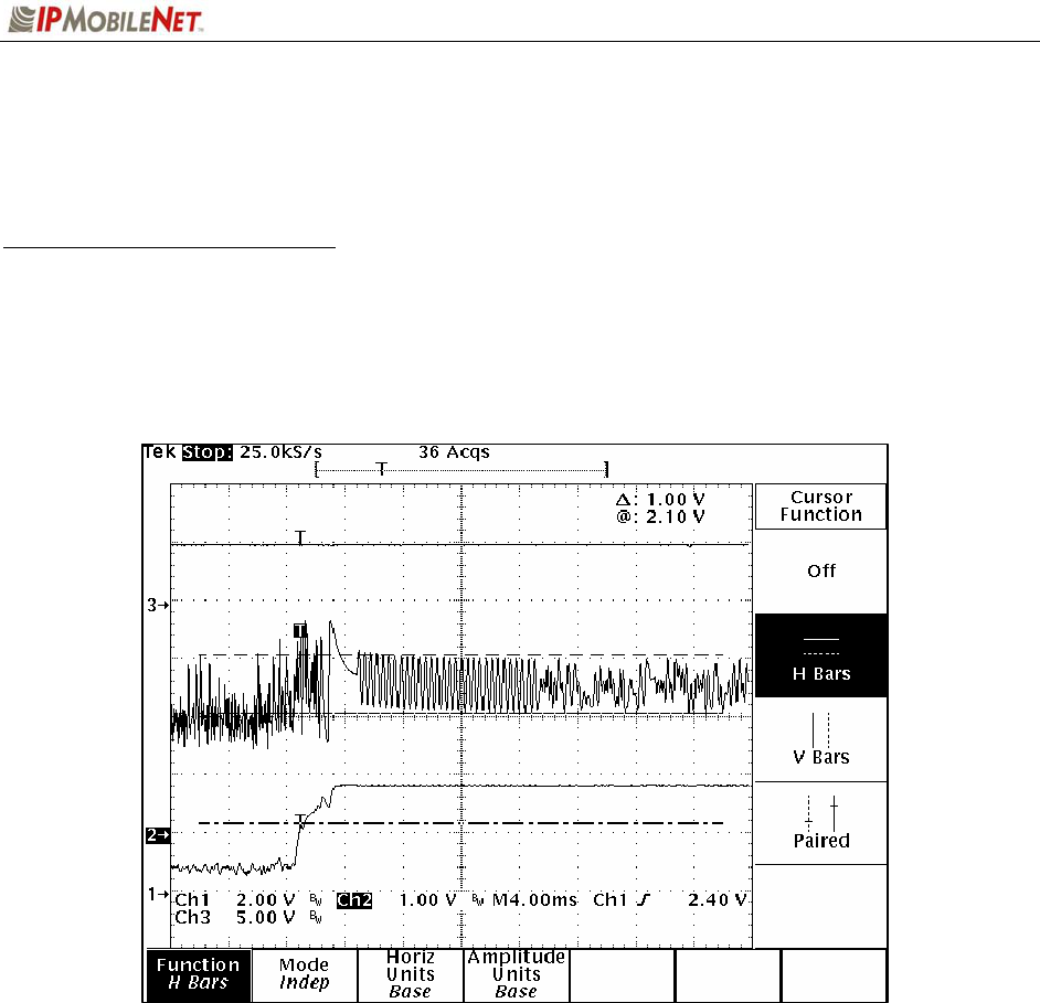
Below is another oscilloscope plot of an up-link data message from the mobile radio to the base station.
As in the last plot, Channel 1 is connected to the mobile's RSSI test point, Channel 2 is connected to the
mobile's recovered modulation test point (TP1), and Channel 3 is connected to the mobile's modem chip
select line. The scope's acquisition mode is now in the peak detect mode. This enables the mobile’s
modem CS (Chip Select) line to be viewed.
SECTION 4: FACTORY TEST PROCEDURE
M64450G25-FCCRpt.doc Page 38
The mobile radio’s microcontroller, upon detecting a step response in the RSSI (caused by the base
station's transmitter coming up to power), waits a period of time equal to the programmed value of the
mobile's carrier detect delay time. The microcontroller then instructs the modem to search for the modem
synchronization preamble. When the base station instructs the modem to look for sync tones the
modem's CS line transitions low. This can be seen in the above plot. Approximately 10 milliseconds after
the base station's transmitter causes a step increase in the mobile's RSSI, the CS signal goes low
momentarily. As can be seen, the sync tones are stable by this time and the modem quickly establishes
synchronization.
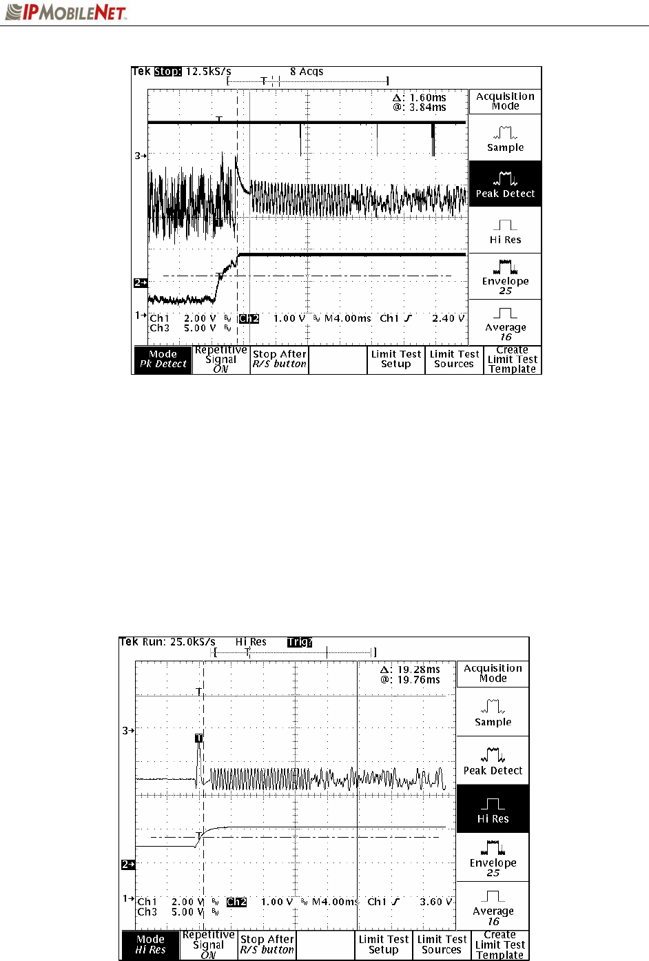
The figure below is a plot of the down-link timing characteristics. Channel 1 is connected to RSSI,
Channel 2 is connected to recovered audio, and Channel 3 is connected to the modem CS pin. The
scope is in the high resolution acquisition mode. Note there is a very short period of quiet time (no
modulation) followed by approximately 12 milliseconds of modem synchronization time (sync time).
SECTION 4: FACTORY TEST PROCEDURE
M64450G25-FCCRpt.doc Page 39
The next plot is the same as before but now the scope is in the peak detect acquisition mode. After the
mobile radio detects a step response in the RSSI (caused by a down-link transmission), the mobile radio's
microcontroller waits an amount of time equal to the programmed value of the "carrier detect delay time"
then instructs the modem to look for frame sync. When the microcontroller instructs the modem to look for
frame sync, it asserts the modem's CS line (active low). In this plot, the modem's CS line can be seen to
transition low approximately 3 milliseconds after the base station's transmitter has come up to full power.
The recovered modulation should be centered at approximately 2.5 VDC and should have the amplitude
of approximately 800 mV peal-to-peak as indicated in the plot above.
SECTION 4: FACTORY TEST PROCEDURE
M64450G25-FCCRpt.doc Page 40
Message Success Rate Testing and Burn-In
After completion of the alignment and testing, the base station shall undergo Burn In and Final Testing.
Install the mobile radio in the MSR screen room as shown in the figure below.
Sequence Tests
Step 1 In IPMessage, verify latest version of the mobile radio firmware by entering the
‘version’ command.
Step 2 Verify the serial number and MAC I.D. – match the label on the unit by typing
‘serial number’ and ‘radio mac address’.
Step 3 Modify firmware settings as needed and run IPLinkView on the mobile radio on
the highest and lowest frequencies programmed in the mobile radio.
Step 4 Run IPLinkView until a GPS connection is established.
Step 5 Run ‘firmware check’ for the specific Customer.

SECTION 4: FACTORY TEST PROCEDURE
M64450G25-FCCRpt.doc Page 41
Final Inspection
The final inspection of the mobile radio is a critical step that translates directly into confidence in the
product. Several areas must be checked on every base station before it can be shipped:
Screws- every screw hole must have the proper screw tightened the proper amount. The screws must
be new and cannot have rounded shoulders. Screw heads must be flush to the case.
Connectors- all screws must be tight and the internal portions of each connector must not be
damaged.
Covers and panels must not be dented or unduly scratched.
Initial traveler after completion of Final Inspection.
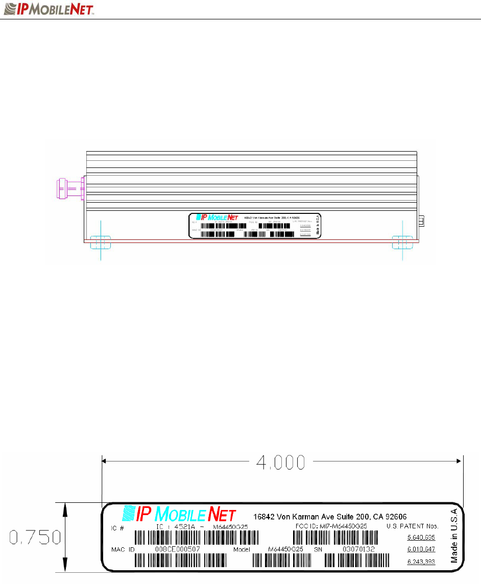
SECTION 5: FCC LABEL
M64450G25-FCCRpt.doc Page 42
M64450G25 Data Transceiver FCC Label Placement
M64450G25 Data Transceiver FCC Label
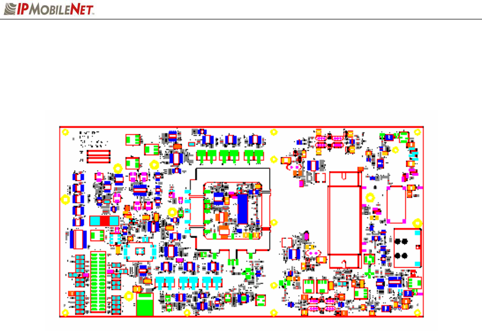
APPENDIX A: CIRCUIT BOARD DIAGRAMS
M64450G25-FCCRpt.doc Page 43
M64450G25 IPSeries High Speed Mobile Radio Circuit Board
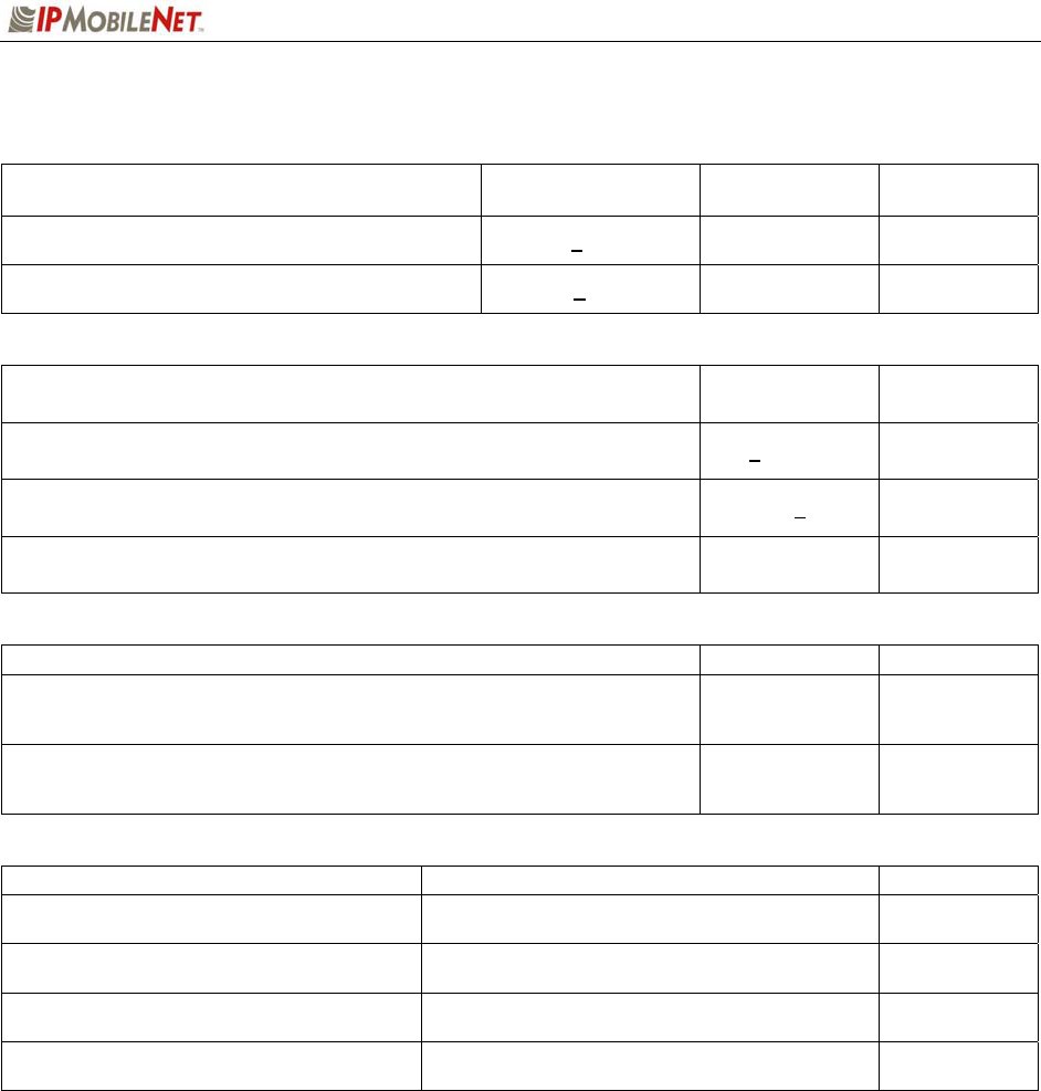
APPENDIX B: M64450G25 TEST DATA SHEET
M64450G25-FCCRpt.doc Page 44
Date:
Serial Number:
Firmware Revision:
End User:
Tester:
Adjustment / Alignment Procedures
TCXO Frequency Error
Parameter Specification
Using GPS as
freq ref Cal Value
TCXO freq error ppb ≤1 PPM
Receiver Injection
Parameter Specification Measured
Injection Frequency Error at RX Antenna Port +400 Hz
Set 45MHz Filter Waveform
Parameter Initial
Waveform set
Receiver SINAD
Parameter Specification
Receiver 1
Measured
Receiver 2
Measured
12dB SINAD at TP1 ≤ -116dBm
Receiver Distortion
Parameter Specification
Receiver 1
Measured
Receiver 2
Measured
Distortion ≤3.0%
Receiver Data Quality
Parameter Specification
Receiver 1
Measured
Receiver 2
Measured
Data Quality ≥ 220
Audio Voltages and balance
Parameter Specification
Receiver 1
Measured
Receiver 2
Measured
Audio AC voltage at TP1 400 mVAC +/- 1mV
Audio DC voltage at TP1 2.500 vDC +/- 1mV
APPENDIX B: M64450G25 TEST DATA SHEET
M64450G25-FCCRpt.doc Page 45
Receiver Calibration
Parameter Specification
Receiver 1
Measured
Receiver 2
Measured
"Noise" value reported with -95dBm signal injected -95 +2 dBm
"Noise" value reported with -105dBm signal
injected -105 + 2 dBm
Transmitter Output
Parameter Specification Measured
Transmitter Frequency Error (Frequency controlled by software; record
measured value) + 400 Hz
Transmitter Modulation (Deviation) 4.8 kHz +75 Hz
Output Power at 13.8 vDC 40 watts
Transmitter Data Quality
Parameter Specification Measured
Data Quality
≥ 220 for 50
contiguous
plots
Message Success Rate
≥ 94% for 50
contiguous
plots
Final Inspection
Item to check Check for Initials
Receiver selection function Correct Rx LED lights when receiving on its port
Visual inspection Screws, connectors, jack screws, switches,
overlay, no rattle
LED Lock light illuminates when power is applied
Attach copy of all firmware settings Completed