IPICO Australia IP3490A DUAL FREQUENCY PROXIMITY RFID READER User Manual DF RFID Proximity RW Reader v1 05
IPICO Australia DUAL FREQUENCY PROXIMITY RFID READER DF RFID Proximity RW Reader v1 05
USERS MANUAL
DF RFID PROXIMITY RW READER USER MANUAL V1_05.DOC
PAGE 1 OF 23
Version 1.0
5
26 February 2008
Doc. Number: IP7160
IP-X DF Proximity RW/TTO Reader
(USB or RS422 for Registration and Process control)
IP-X DF Proximity RO Reader
(26-bit Wiegand™ for Access Control)
IP66 Housings optional
User Manual
FCC ID: VHY
-
IP3490A

DF RFID PROXIMITY RW READER USER MANUAL V1_05.DOC
PAGE 2 OF 23
Please read instructions before operating this devise. This device may cause
interference to other electronic equipment that is sensitive to magnetic radiation.
Only use an approved linear power supply.
Only an authorised technician may open and work on this unit.
Warranty is void if you open or tamper with this device.
Explosive atmospheres
User shall switch off this unit and obey all safety requirements in these areas. This unit may only be operated if the area is
declared safe by a safety official. Hazardous areas typically include fuelling areas, below decks on boats, fuel or chemical
transfer/storage points, blasting locations and areas where air contains chemicals or particles, such as grain, dust or metal
powders.
FCC ID: VHY-IP3490A
FCC DECLARATION (USA)
FCC Section 15.19
This device complies with Part 15 of the FCC rules. Operation is subject to the following two conditions:
1. This device may not cause harmful interference.
2. This device must accept any interference received, including interference that may cause undesired operation.
Information to User (FCC section 15.21)
The user is cautioned that any changes or modifications not expressly approved by IPICO or authorized representative could void the user’s authority to operate the
equipment.
NOTICE
All rights reserved. No part of this document may be reproduced or transmitted in any form or by any means without written permission
from IPICO Inc.
IPICO Inc shall not be liable for any errors or for incidental or consequential damages in connection with the furnishing, performance or
use of this document, hardware and/or software.
All information in this document including the design and specification are subject to change without notice for the purpose of product
improvement.
For further information contact +27 12 345 9520.
IMPORTANT
SAFETY
This is a low power RF device. Avoid any extended human exposure directly in front of the reader, up to a distance of 2 cm, when unit is
switched on.
In most aircraft and hospitals the use of RF devices are prohibited. Please consult the local authorities and safety official when operating
this device.
Only qualified personnel may open the unit.
APPROVALS
FCC Part 15: Subpart C, Class B
EN 300-220-1, 300-220-3, ETS 300-683 and EN 6100-3-2& 3 (CE) : Pending
IEC 60950 (CE): Pending
UL 60950/CAN/CSA22.2 No. 60950 :
Pending

DF RFID PROXIMITY RW READER USER MANUAL V1_05.DOC
PAGE 3 OF 23
Table of Contents
Figures ........................................................................................................................................................4
Tables .........................................................................................................................................................4
History.........................................................................................................................................................4
Glossary .....................................................................................................................................................5
1. Know your reader ...........................................................................................................................6
2. Functional overview........................................................................................................................8
3. Quick start (Reader connected to PC via USB – Full R/W capability) ..........................................9
4. Quick start (Reader connected to Host via RS 422 - Full R/W capability)....................................9
5. Quick start (Reader connected to Host via Wiegand™ - R/O capability) ..................................9
6. Operations overview.....................................................................................................................11
7. Application notes..........................................................................................................................11
8. Troubleshooting............................................................................................................................12
9. Maintenance.................................................................................................................................12
10. Technical specification.................................................................................................................13
11. Support...........................................................................................................................................14
12. Technical Assistance ....................................................................................................................14
13. Appendix A: Mechanical layout of preliminary housing............................................................15
14. Appendix B: Mechanical layout of IP66 Housing........................................................................16
15. Appendix C: Wiring Schedule for reader.....................................................................................17
16. Appendix D: Read/Write SW interface overview.........................................................................18

DF RFID PROXIMITY RW READER USER MANUAL V1_05.DOC
PAGE 4 OF 23
FIGURES
Figure 1 Reader overview............................................................................................................6
Figure 2 Industrial IP66 Reader overview ....................................................................................7
Figure 3 Functional overview of Proximity reader ......................................................................8
Figure 4 Mechanical layout of Preliminary enclosure..............................................................15
Figure 5. FFBD of RW functionality .............................................................................................18
Figure 6. WRITE DATA - Transition Mode diagram (single page at a time) ............................19
Figure 7. READ DATA - Transition Mode diagram (single page at a time).............................20
TABLES
Table 1 Troubleshooting guide ..................................................................................................12
Table 2 Technical Specifications...............................................................................................13
Table 3 Wiring Schedule.............................................................................................................17
HISTORY
Version Date Person Reason
1.00 2008-01-01 MVD Created. Release for internal use.
1.01 2008-01-07 MVD Correct table 2. 34 bit to 26 Bit Wiegand, Add Buzzer to Fig 2
1.02 2008-01-07 MVD Add order codes and release for review
1.03 2008-01-27 MVD Add basic SW interface specification
1.04 2008-02-06 MVD Update naming conventions
1.05 2008-02-26 MVD Add Industrial IP66 Housing detail

DF RFID PROXIMITY RW READER USER MANUAL V1_05.DOC
PAGE 5 OF 23
GLOSSARY
BT
Bluetooth™
CW Continuous Wave
dB Decibels
DF Dual Frequency
HMI Human Machine Interface
PC Personal computer
RFID Radio Frequency Identification
RFU Radio Frequency Unit
R/O Read-Only. This is the mode in which the reader gets the UID from the
tag and happens in the presence of non-modulating readers.
RS422 Differential transceiver interface for RS232
R/W Read / Write. This functionality can only happen in the presence of
modulating readers.
RX Receive
SW Software
TX Transmit
TTO mode Mode in which tag can present USER DATA in the presence of a non-
modulating Read-Only reader.
USB Universal Serial Bus
Wiegand™ Electrical and Data interface specifically for security industry
DF RFID PROXIMITY RW READER USER MANUAL V1_05.DOC
PAGE 6 OF 23
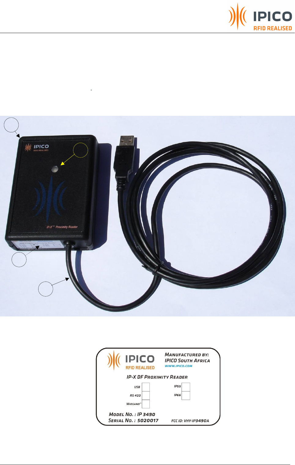
1. Know your reader
1. ABS Reader housing with integrated antenna
2. Status indicator (may not be available on all preliminary housings)
3. FCC and Product data label
4. Power/Communication link
(Communications are USB, RS422 or Wiegand™ (26-bit)
Figure 1 Reader overview
4
1
2
3
DF RFID PROXIMITY RW READER USER MANUAL V1_05.DOC
PAGE 7 OF 23
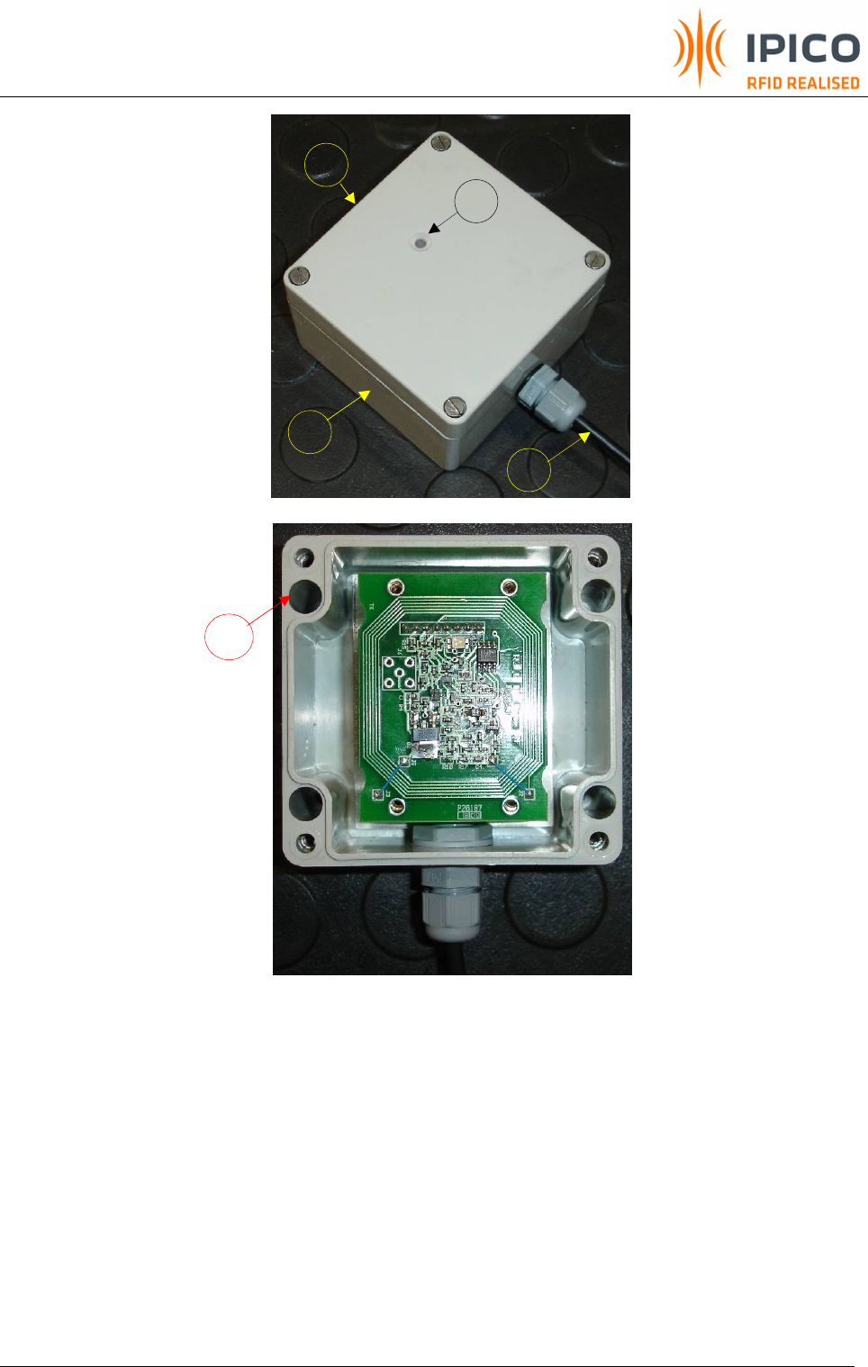
1. Reader in grey, glass reinforced polyester housing with integrated antenna
2. Status indicator
3. FCC and Product data label
4. Power/Communication link
(Communications are USB, RS422 or Wiegand™ (26-bit)
5. 4x Mounting holes
Figure 2 Industrial IP66 Reader overview
2
3
1
4
5
DF RFID PROXIMITY RW READER USER MANUAL V1_05.DOC
PAGE 8 OF 23
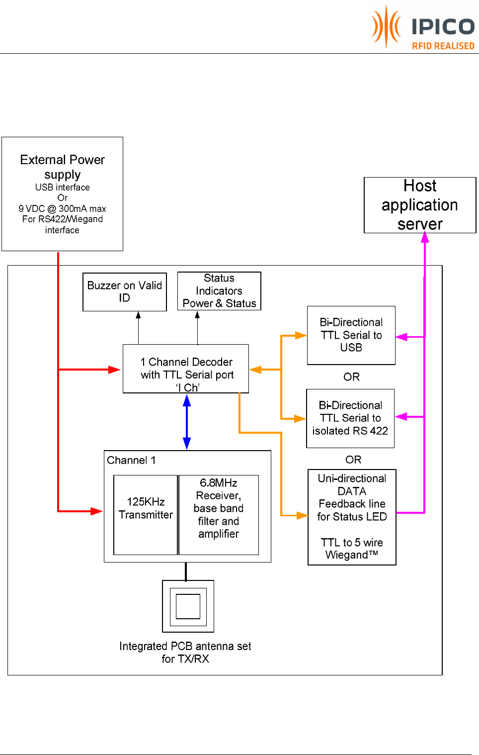
2. Functional overview
Figure 3 Functional overview of Proximity reader

DF RFID PROXIMITY RW READER USER MANUAL V1_05.DOC
PAGE 9 OF 23
3. Quick start (Reader connected to PC via USB – Full R/W capability)
1. Connect the reader to the host via the USB cable, and switch the reader ON.
2. Windows will detect a new device. Install the “CP210x USB Composite Device”. This driver
can be downloaded from the manufacturer at Silicon Laboratories. Windows will detect
readers above serial number 5020016 as IPICO Proximity readers.
3. Data format: Refer to IPICO’s serial protocol document.
4. Quick start (Reader connected to Host via RS 422 - Full R/W capability)
1. Connect the reader to the host via the RS 422 cable, and switch the reader ON. The Host
can be a PC or any other field device like a PLC. If the host does not support RS422
interface, the user can use any commercial RS422/RS232 converter to connect reader to
the host.
2. Once connected the user can use HyperTerminal, Showtags or any other client application
that can communicate to the reader.
3. Data format: Refer to IPICO’s serial protocol document.
5. Quick start (Reader connected to Host via Wiegand™ - R/O capability)
1. Connect the reader to the host via the Wiegand cable, and switch the reader ON. Reader
will operate in Read Only mode.
2. The Wiegand settings will be hard coded during manufacturing as follows:
a. 26-Bit code. For a 24 bit ID, bits 16 to 39 of the IPICO Tag ID are used (least significant
24 bits excluding the CRC + 2 parity bits).
b. Tpw = 50us, Tpi = 1.8ms and a code retransmit rate of 100ms.
c. D0 and D1 are open-collector outputs. User need to supply external pull-up resistors
to VCC at the host device.
d. LED input can be driven by +5V signal from the host device.

DF RFID PROXIMITY RW READER USER MANUAL V1_05.DOC
PAGE 10 OF 23
3. Data format
The 26 bits of transmission from the reader to the panel consists of two parity bits and 24
code bits. The bits are transmitted in the order described. The first bit transmitted is the first
parity bit, P1, it is even parity calculated over the first 12 code bits. The last bit transmitted is
the second parity bit, P2, it is odd parity calculated over the last 12 code bits:
CODE FORMAT
1 1 1 1 1 1 1 1 1 1 2 2 2 2 2 2 2
1 2 3 4 5 6 7 8 9 0 1 2 3 4 5 6 7 8 9 0 1 2 3 4 5 6
P1 C C C C C C C C C C C C C C C C C C C C C C C C P2
PARITY FORMAT
1 1 1 1 1 1 1 1 1 1 2 2 2 2 2 2 2
1 2 3 4 5 6 7 8 9 0 1 2 3 4 5 6 7 8 9 0 1 2 3 4 5 6
P1 E E E E E E E E E E E E
O O O O O O O O O O O O P2
P1: First, or even parity bit.
C: Code bits.
P2: Second, or odd parity bit.
E: Bits for calculation of even parity.
O: Bits for calculation of odd parity.
NOTE: Data format within the 24 code bits which include the partitioning of the bit, the
designation of the Most Significant Bit (MSB) or the Least Significant Bit (LSB) shall be subject
to definition by the panel and reader manufacturers and may remain proprietary.

DF RFID PROXIMITY RW READER USER MANUAL V1_05.DOC
PAGE 11 OF 23
6. Operations overview
The reader transmits CW carriers, which causes the tags in the RF beam to power up and start
backscattering their ID codes back to the reader. The RF unit receives the modulated backscatter
and decodes the tag ID’s. A time stamp is typically added by the reader for each tag read event
(Wiegand mode is 26-Bit ID only). The data from the reader is transmitted immediately
communication port to the host. No buffering takes place on the reader. When using the USB or RS
422 interface, additional data fields can be added. If more ID’s are received from the same tag
before its packet had been transmitted, a hit counter is increased. These hit counts are included in
the transmitted packet as “I” counts. The length of the tag ID data packet that is sent to the host
can be altered. The USB and RS422 readers can be used to WRITE USER DATA into EM4522 tags and
also setup these tags to operate in TTO mode. (TTO is a special operational mode of the tag in
which the tag will send its USER DATA pages in the presence of a RO or Non-modulating reader)
Refer to the instruction set in the serial protocol document or Showtags document – www.ipico.com.
7. Application notes
a. Read distances depends on the relationships between Tag size and Antenna
characteristics.
b. Electrical noise sources in close proximity to the reader may influence read performance. The
magnetic field produced by the unit may also cause slight interference with other sensitive
electronic equipment.
c. The USB interface allows the reader to be powered from the host as well as for bi-directional
communication between the host and the reader. An alternative isolated RS422 interface is
also available for integration into industrial point-to-point control applications. The reader is
typically used as a desktop registration reader, validation reader, printer programming head
or production line programming head, depending on how it integrates into the host
application.

DF RFID PROXIMITY RW READER USER MANUAL V1_05.DOC
PAGE 12 OF 23
8. Troubleshooting
Visual indicator guide
· GREEN Random flashing indicates valid tag ID’s are decoded.
· GREEN 1HZ flashing indicates Heartbeat (Shows Decoder is running).
· RED Steady indicates Power ON.
NOTE : in Wiegand mode the Greed LED will be under Host control
Table 1 Troubleshooting guide
9. Maintenance
This is a low maintenance device. The user must make sure that the reader is kept clean and dry
where possible. Do not use solvents to clean this unit. This unit will encase in a waterproof enclosure.
Do not use any switch mode power supplies unless approved by IPICO.
Symptom Possible causes
Reader switched OFF
Power source faulty
Red LED Off
Reader faulty
Transmitter not switched ON.
Faulty Tag or incorrect Tag baud rate selection.
Tag not orientated correctly.
Faulty Reader front end
Cannot read a tag although Host
communicates with the reader.
High levels of ambient RF noise operating in the
same frequency spectrum as reader.

DF RFID PROXIMITY RW READER USER MANUAL V1_05.DOC
PAGE 13 OF 23
10. Technical specification
Power supply
requirement
USB type = 5V from PC @ 300mA
RS422 and Wiegand type = 9VDC @ 300mA (less than 5mV ripple)
Transmitter power
-10dBuA/m with 50% duty cycle (10ms ON/OFF)
(Antenna power will always be set to be less or equal to the max allowed according to
ETSI or FCC, typically 64.8dBuA/m at 10m)
Operating frequency CH1 TX = 125 KHz
CH1 RX = 6.8 MHz
Antenna type Integrated PCB type (50x44mm, 12windings)
(Electrical/Physical configuration to comply with ETSI and FCC)
Read range
Depends on the tag type.
Typical read ranges with a laminated ISO credit card = 40mm
Can be mounted on metal.
Communication
Reader/Host:
USB – bidirectional – Full R/W
RS422 – bi-directional – Full R/W
26-bit Wiegand™ - uni-directional – R/O, LED feedback signal from host possible
Reader/Tag: iP-X Read Only, Read/Write enabled. EM4322, EM4522
Data storage No buffer storage on reader. Configuration data storage only.
Electrical interface
USB/Power – via USB type A connector on 600mm fly lead
Isolated RS 422/Power = 3pair cable (600mm fly lead)
Wiegand/Power = 5 Wire standard (600mm fly lead)
Environmental
Operating temperature range: -10 to +60 Deg C
Storage temperature range: -20 to +85 Deg C
Humidity: 5 to 95 % non-condensing
IP rating: IP54 and IP66 available in proto type housing (production housing will be IP66)
Physical
Approx dimension: 93(L) x 67(W) x 28(D) mm
Desktop or wall mount (bracket excluded)
Weight: Approx. <50g unpacked
Accessories Security Enhanced Decoder (application specific-not for general use)
Table 2 Technical Specifications

DF RFID PROXIMITY RW READER USER MANUAL V1_05.DOC
PAGE 14 OF 23
11. Support
Ordering information
Product Name Product
Code Description
DF Proximity Reader USB, RWTTO IP3490 - A IP-X DFRDR-PROX-USB-RWTTO
DF Proximity Reader RS422, RWTTO B IP-X DFRDR-PROX-RS422-RWTTO
DF Proximity Reader Wiegand 26 Bit, RO C IP-X DFRDR-PROX-WIEGAND 26Bit-RO
DF Proximity Reader USB, RWTTO (IP66 housing) D IP-X DFRDR-PROX-INDUST-USB-RWTTO
DF Proximity Reader RS422, RWTTO (IP66 housing) E IP-X DFRDR-PROX-INDUST-WIEGAND 26Bit-RO
DF Proximity Reader Wiegand 26 Bit, RO (IP66 housing) F IP-X DFRDR-PROX-INDUST-RS422-RWTTO
Please consult your local dealer for more information regarding the accessories and system design
12. Technical Assistance
Support support@ipico.co.za
IPICO online http://www.ipico.com

DF RFID PROXIMITY RW READER USER MANUAL V1_05.DOC
PAGE 15 OF 23
13. Appendix A: Mechanical layout of preliminary housing
Figure 4 Mechanical layout of Preliminary enclosure
DF RFID PROXIMITY RW READER USER MANUAL V1_05.DOC
PAGE 16 OF 23
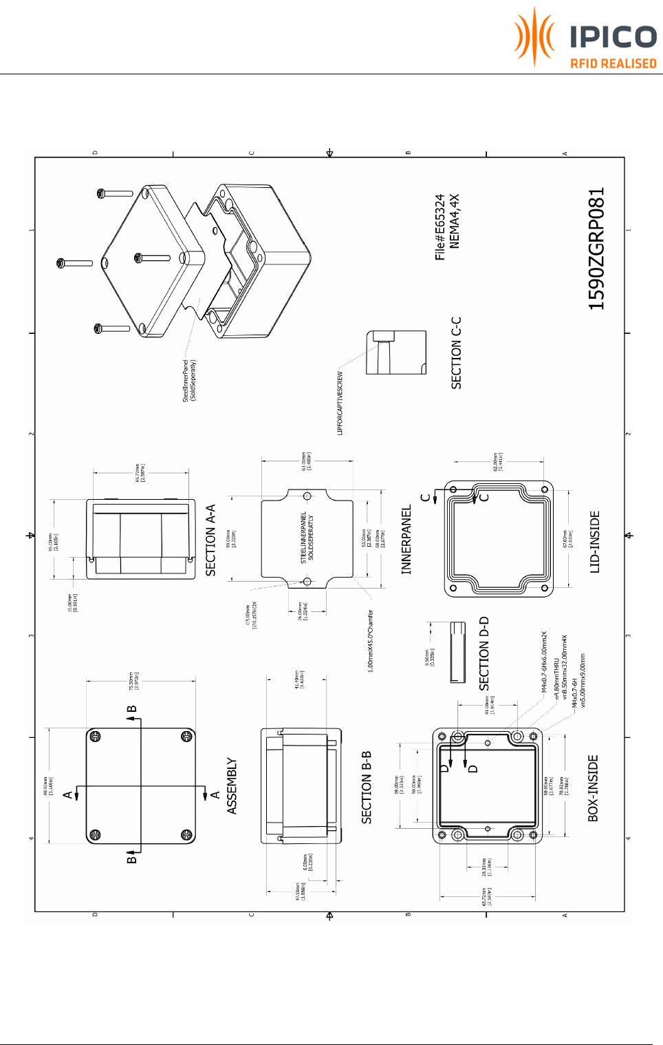
14. Appendix B: Mechanical layout of IP66 Housing
DF RFID PROXIMITY RW READER USER MANUAL V1_05.DOC
PAGE 17 OF 23
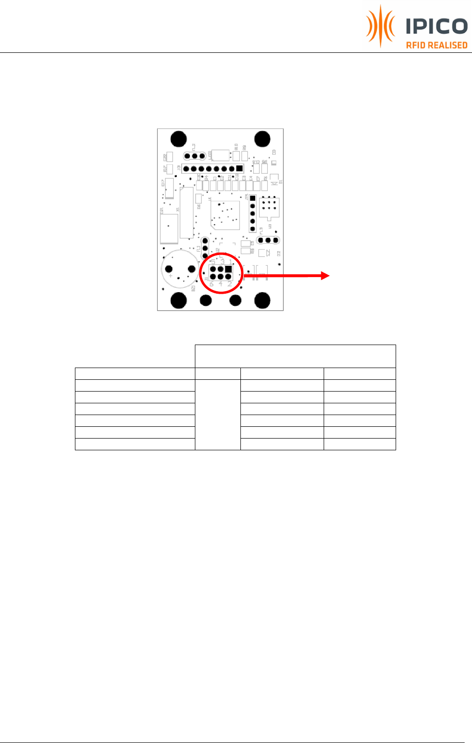
15. Appendix C: Wiring Schedule for reader
Power/Communication
Interface
PCB Pin Designation USB RS 422 Wiegand™
1 +V (White) +V (Red)
2 GND (Black) GND (Black)
3 RX- (Red) D1 (White)
4 RX+ (Blue) D0 (Green)
5 TX- (Yellow) LED (Brown)
6
Terminated
on USB type
A connector
TX+(Green) NC
Table 3 Wiring Schedule
NOTE:
1. All readers are supplied with an approximately 600mm fly lead that needs to be terminated to a
host system.
2. Wiegand interface
a. D0 and D1 on Wiegand interface are open-collector outputs. Two external pull-up resistors
between D0 and 12V and D1 and 12V (typical 10Kohm) need to be connected to host
controller’s input side.
b. LED input can be driven by 5V, 12V levels
See Table 3 for
connection schedule
DF RFID PROXIMITY RW READER USER MANUAL V1_05.DOC
PAGE 18 OF 23
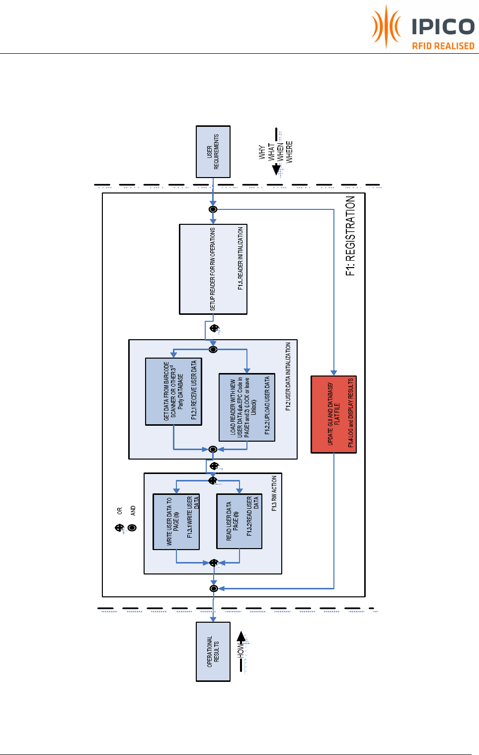
16. Appendix D: Read/Write SW interface overview
Reader will typically connect to one host i.e. PLC or PC.
Figure 5. FFBD of RW functionality
DF RFID PROXIMITY RW READER USER MANUAL V1_05.DOC
PAGE 19 OF 23
Main Application SW sends
INITIALIZATION
parameters down
to the reader
N=1
F1.1
Reader is to automatically
Write (N, N=1-14) Memory
page(s) of X5 tag
F1
IS it a RO or
RW tag?
READER is now ready and waiting for a tag to come in to
the beam. As soon as a tag enters the beam the READER
shall first determine if it is a RO or a RW tag by applying the
"Mask" to the start of the ID see init() i.e
058xxxxxxxxxyyyy=RO
and
478xxxxxxxxxyyyy = RW
NOTE: the following events is per tag that enters the beam
RW
RO
Reader keeps on
sending
"aa"+tagID's
replies to the SW
app while tag is in
the beam
Reader sends
"aa"+tagID's
replies to the SW
app while tag is in
the beam
Reader starts to
modulate the
"WRITE page (N)
data" command to
the tag
Reader will
automatically "Retry" to
execute the "WRITE"
command 5 times.
see init()
Reader decide if
"WRITE" event is
successful ?
No
Yes
Is "Retry"
counter = 5
No
Yes
Reader sends
"ad" + tagID's
+ page (N) data
replies to the SW
app while tag is in
the beam
NOTE: The RW event will be more secure if
the DATA in the MEM Pages i.e. Page 1 has
a CCITT CRC included => 48bits Data
+16bit CCITT CRC (CRC seed = 0xFFFF)
else the SW application may get an "ad"
reply, that must now be tested by evaluating
the accumulative I (or Q for the larger
decoders) counts >= 2 to accept the "ad"
reply as valid.
Reader now wait for the
remainder of the "Redo"
time to elaps
..Get USER DATA and
preload the reader with
DATA for Page (N)
One page at a time
F1.2
No
Yes
N=1
Wait for New tag
to be presented
N=N+1
F1.3.1
IS N > W?
(W = 1-14) and is User
Application specific
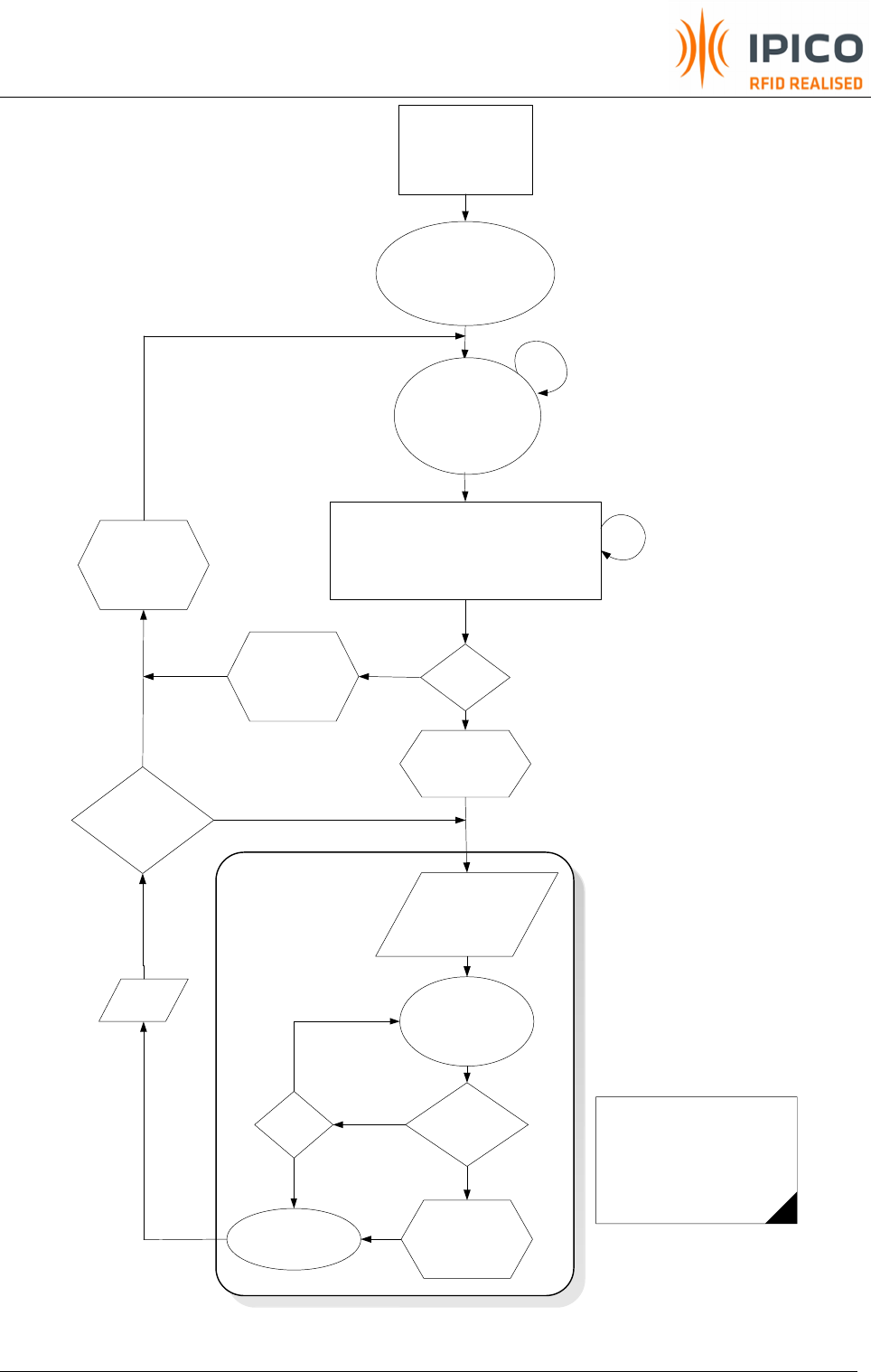
Figure 6. WRITE DATA - Transition Mode diagram (single page at a time)
DF RFID PROXIMITY RW READER USER MANUAL V1_05.DOC
PAGE 20 OF 23
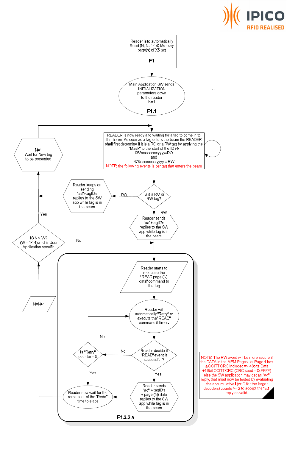
Figure 7. READ DATA - Transition Mode diagram (single page at a time)

DF RFID PROXIMITY RW READER USER MANUAL V1_05.DOC
PAGE 21 OF 23
F1.1 Reader initialization
Step Description String From Host to Reader Return
String
1.1.1 Set Message Format in a semi reduced
format i.e.
Rd ID, I count, All 8 UID bytes and LRC
ab00091143ff6161aa000d0a00d3\r\n
ab00001122
1.1.2 Set Message Mode i.e.
Normal
ab00030900ff07bf\r\n
ab00000929
1.1.3 Stop any RW actions ab00002325\r\n ab00002325
1.1.4 Resume all tags ab000125e0bd\r\n ab00002527
1.1.5 Set RW transmit rate for DF reader at 4kbps ab000117cdf0\r\n ab00001728
1.1.6 Set timeouts
Data=220, Redo=1, Retry=5, Rd Retry =3
ab00062400dc016d050316\r\n
ab00002426
1.1.7 Set Tag Baud Rate
128kbps (HH option using Showtags) ab0001120286\r\n ab00001223
1.1.8 Set Match Mask ab0008224ff00000000000009c\r\n ab00002224
F1.2 Preload Reader with USER DATA
Step
Description String From Host to Reader Return
String
1.2.1 Get USER DATA from Database or 3rd party device
i.e Barcode scanner. Now send USER DATA to
reader. USER DATA to be configured with or without
CRC and must be 8 bytes per Page i.e.
“ IPICO ” written Hex format
Without CRC
· Page 1 = 495049434f000000
With CRC16 seeded with FFFFh
· Page 1 = 495049434f003231
With CRC CCITT seeded with FFFFh
· Page 1 = 495049434f00FD34
NOTE: Only ONE Page can be loaded at a time and
WRITE to the tag.
ab000821495049434f0000008b\r\n ab00002123

DF RFID PROXIMITY RW READER USER MANUAL V1_05.DOC
PAGE 22 OF 23
F1.3.1 WRITE DATA Command and Automatic VERIFY (Data is known) Action
Step Description String From Host
to Reader
Return String
1.3.1.1 Issue WRITE Command i.e.
Page 1, Target = Addressed ab0003200011624f\r\n ab00002022
Reader will now perform the WRITE function according to the preloaded Retry count value and Redo timer value
1.3.1.2 Upon Successful WRITE an
“ad” string with the UID and
DATA page info will return to
the host.
ad004699000010deca65f109495049434f000000b5
Decoding of the return string is as follows
Header Reader
ID UID including CRC
Page 1
Page 2 = 02 etc
x= 0 hex to f hex incrementing
for each WRITE command
issued until x=f hex. Then x=0
again.
Sequence
number USER DATA in Page 1
LRC for
complete
string
ad 00 4699000010deca65 x1 09 495049434f000000 b5
For more information refer to Table 10 in the IPICO Reader Serial Protocol 100 20071120.pdf

DF RFID PROXIMITY RW READER USER MANUAL V1_05.DOC
PAGE 23 OF 23
F1.3.2.a READ DATA Command Action (single page)
Step Description String From Host
to Reader
Return String
1.3.2.a.1 Issue READ Command i.e.
Start Page = 1, number of
pages =1, Target =
Addressed (Byte 5 =
incrementing Seq number
51h (00h-ffh) for each
attempt)
ab00032051218258\r\n ab00002022
Reader will now perform the READ function according to the preloaded Retry count value and Redo timer value
1.3.2.a.2 Upon Successful READ an
“ad” string with the UID and
DATA page info will return
to the host.
ad004699000010df4a60810a495049434f0000007c
Data page as per function in 1.2.1
Decoding of the return string is as follows
Header Reader
ID UID including CRC
Page 1
Page 2 = 02 etc
x= 0 hex to f hex incrementing
for each READ command
issued until x=f hex. Then x=0
again.
USER DATA in Page 1
LRC for
complete
string
ad 00 4699000010df4a60 x1 01 495049434f000000 b5
ad004699000010df4a608101495049434f0000004c