IPICO Australia IP3960A LOW FREQUENCY SPORTS TIMING SYSTEM User Manual USERS MANUAL
IPICO Australia LOW FREQUENCY SPORTS TIMING SYSTEM USERS MANUAL
USERS MANUAL

IPICO Spider (3960) reader
User Manual
Compiled by Hubert PEYRE
Version 1.0 draft
November 22, 2007

IPICO Spider User Manual V1.0 draft 20071123 RWD .doc 12/12/2007 Page 1
IMPORTANT
FCC ID; VHY-IP3960A
This device complies with Part 15 of the FCC rules
Operation is subject to the following two conditions:
1. This device may not cause harmful interference, and
2. This device must accept any interference received, including interference that
may cause undesired operation.
NOTE: THE MANUFACTURER IS NOT RESPONSIBLE FOR ANY RADIO OR TV INTERFERENCE
CAUSED BY UNAUTHORIZED MODIFICATIONS TO THIS QUIPMENT.
SUCH MODIFICATIONS COULD VOID THE USER'S AUTHORITY TO OPERATE THE EQUIPMENT.

IPICO Spider User Manual V1.0 draft 20071123 RWD .doc 12/12/2007 Page 2
HISTORY:
Version Date Person Reason
Draft 1.0 22/11/2007 Hubert Create
Draft 1.1
Draft 1.2
Issued version 1.00 Dd/mm/yyyy Name Reason
Issued Version 2.00 Dd/mm/yyyy Name Issued
GLOSSARY:
DF Dual Frequency
TX Transmit antenna
RX Receive antenna
PSU Power Supply

IPICO Spider User Manual V1.0 draft 20071123 RWD .doc 12/12/2007 Page 3
Table of Contents
1 INTRODUCTION...........................................................................................................5
2 SUMMARY OF FACILITIES .........................................................................................5
3 READER .......................................................................................................................6
3.1 Front panel ................................................................................................................................7
3.1.1 Transmitter unit..................................................................................................................8
3.1.2 Receiver unit......................................................................................................................9
3.2 Back plane...............................................................................................................................10
4 POWER SUPPLY .......................................................................................................12
4.1 Power input side .....................................................................................................................13
4.2 Power output side...................................................................................................................13
5 COMMUNICATION WITH THE READER...................................................................15
5.1 Ethernet version......................................................................................................................15
5.2 USB version.............................................................................................................................15
5.3 WIFI version.............................................................................................................................16
5.4 Change the IP address (Ethernet or WIFI)............................................................................16
5.5 Reader data protocol..............................................................................................................16
5.6 Date/Time stamp data.............................................................................................................17
6 INSTALLATION OF THE SYSTEM ............................................................................18
6.1 Precautions of use!.................................................................................................................18
6.2 Installation of the reader ........................................................................................................18
6.3 Testing of tag reading distance.............................................................................................18
7 SPECIFICATIONS ......................................................................................................19
7.1 Reader......................................................................................................................................19
7.2 Power supply...........................................................................................................................19
7.2.1 Mains version...................................................................................................................19
7.2.2 DC version .......................................................................................................................19
APPENDIX A – STANDARD ANTENNAS........................................................................20
APPENDIX B – OPTIONAL ACCESSORIES ...................................................................21

IPICO Spider User Manual V1.0 draft 20071123 RWD .doc 12/12/2007 Page 4
Table of Figures
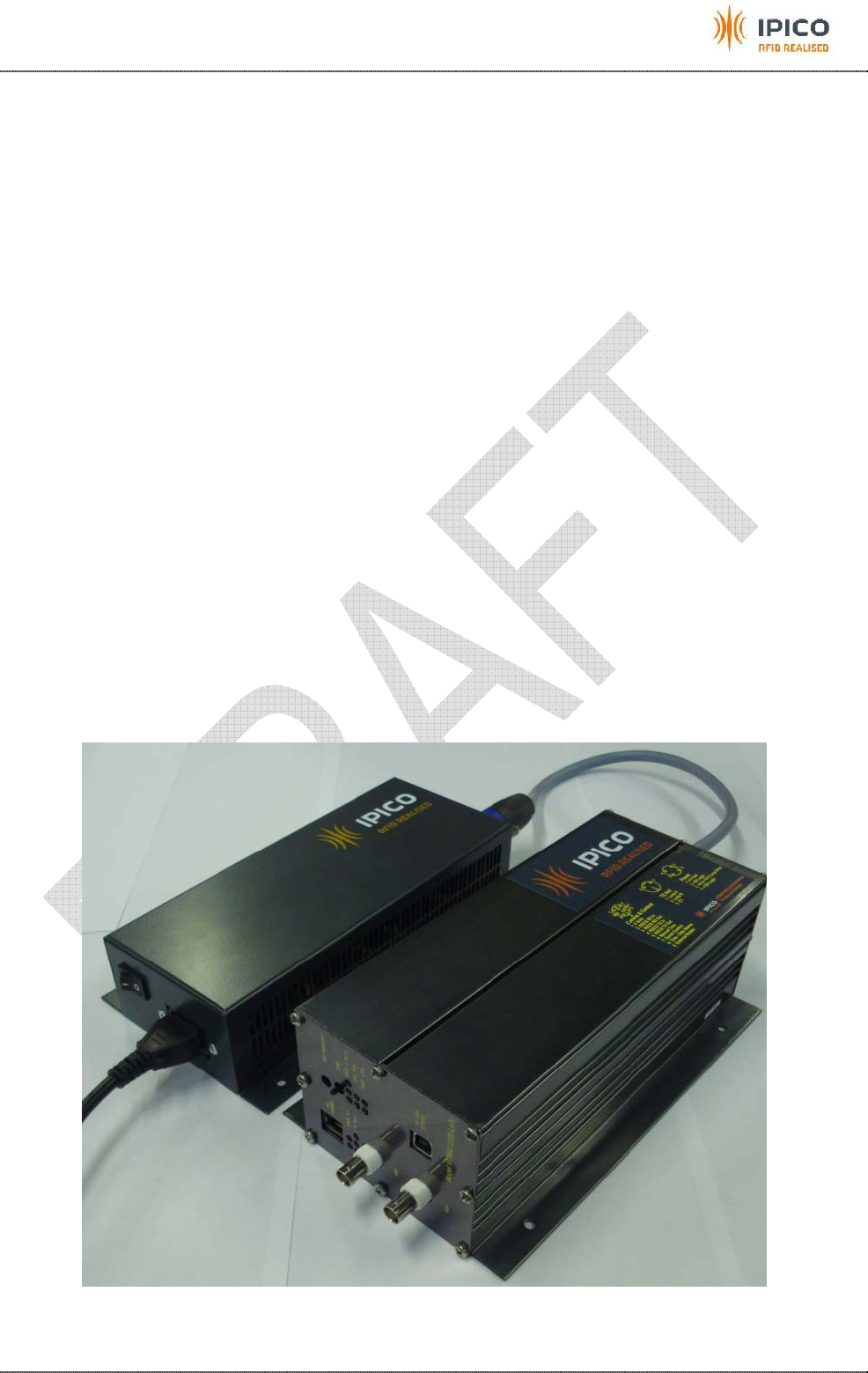
Figure 1: Reader + Power Supply .......................................................................................................5
Figure 2: Spider reader.......................................................................................................................6
Figure 3: Front panel layout of USB/Ethernet version and WIFI version.............................................7
Figure 4: Transmitter unit.................................................................................................................... 8
Figure 5: Receiver unit of USB or Ethernet version, receiver unit of WIFI version.............................9
Figure 6: Backplane layout and picture .............................................................................................10
Figure 7: Power connector pins.........................................................................................................11
Figure 8: TX connector pins...............................................................................................................11
Figure 9: Communications & controls connector pins .......................................................................12
Figure 10: Mains power supply..........................................................................................................12
Figure 11: Mains input & switch.........................................................................................................13
Figure 12: DC voltage outputs...........................................................................................................13
Figure 13: Adjustable voltage dipswitches location ...........................................................................14
Figure 14: Adjustable voltage settings...............................................................................................14
Figure 15: Battery assisted tag..........................................................................................................21
Figure 16: Field strength meter..........................................................................................................21
IPICO Spider User Manual V1.0 draft 20071123 RWD .doc 12/12/2007 Page 5
1 INTRODUCTION
This manual is intended to make a description of the Spider reader and to explain the procedure to setup and
use the reader. It must be understood that setup environment can influence the performance of the system.
This manual will help you to setup the reader to have an optimum tag read performance under most
conditions.
2 SUMMARY OF FACILITIES
• Capability to drive 2 TX antennas and 2 RX antennas.
• Ethernet port (RJ45) or USB or WIFI to communicate between a computer and the reader (must be
specified when ordering).
• Specific power supply to ensure good filtering in the tag band: 10V->58VDC or 110-220VAC 50-60Hz
(must be specified when ordering)
• External input for date/time stamp
• External output for buzzer
• Only one On/Off switch for the whole system
• RS232 connection on the back plane for RX data and TX management
• Leds and buzzer for tag detection.
• DSP(s) for better detection of tags in electromagnetic noisy environment
• Automatic tuning of the system
• Aluminium anodized enclosure
Figure 1: Reader + Power Supply
IPICO Spider User Manual V1.0 draft 20071123 RWD .doc 12/12/2007 Page 6
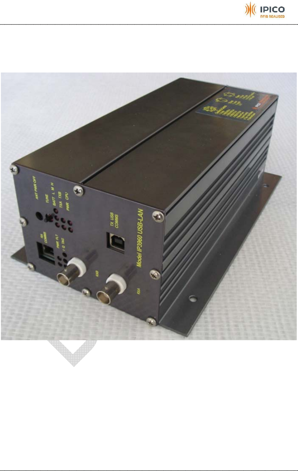
3 READER
Figure 2: Spider reader
IPICO Spider User Manual V1.0 draft 20071123 RWD .doc 12/12/2007 Page 7
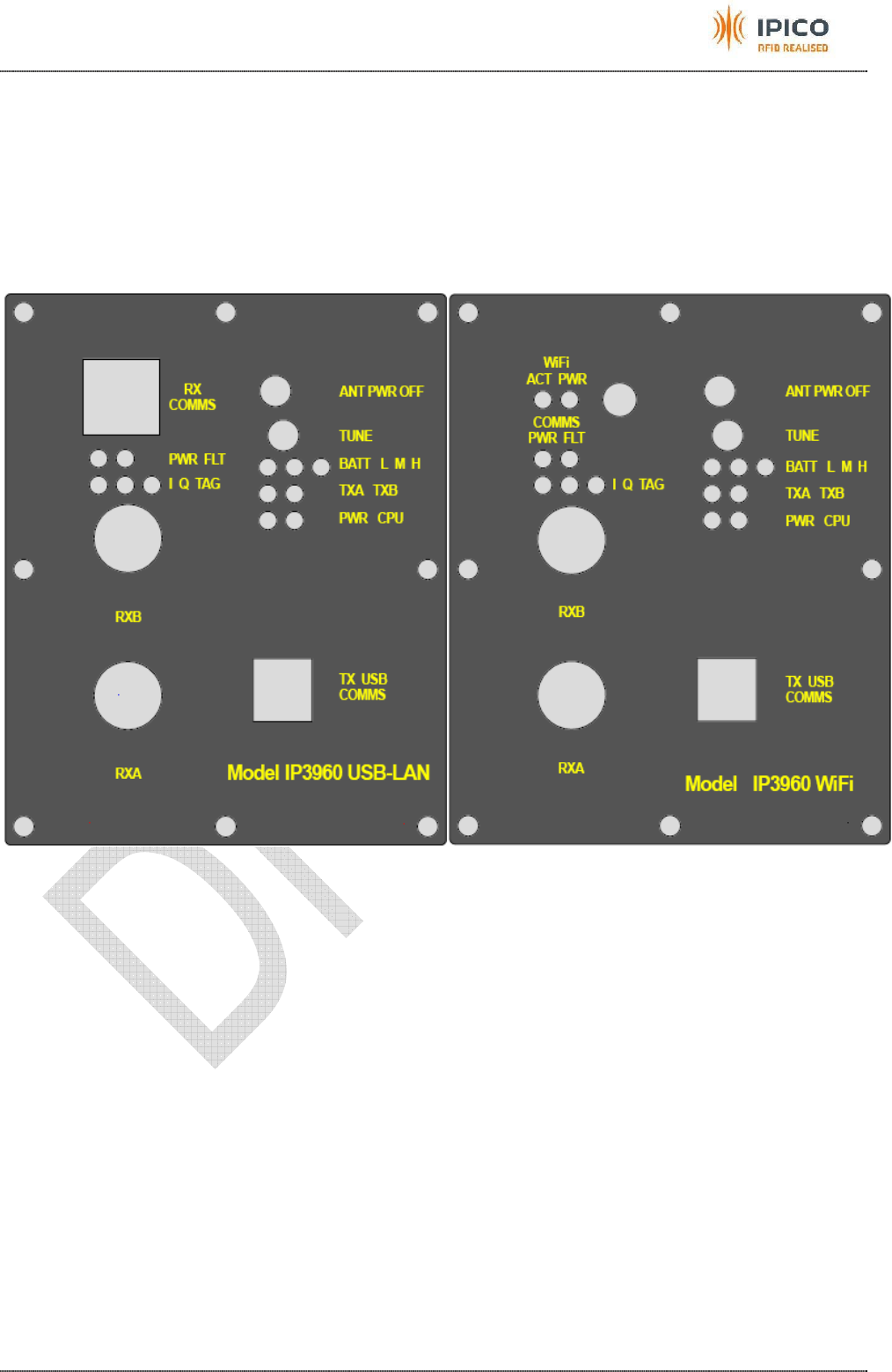
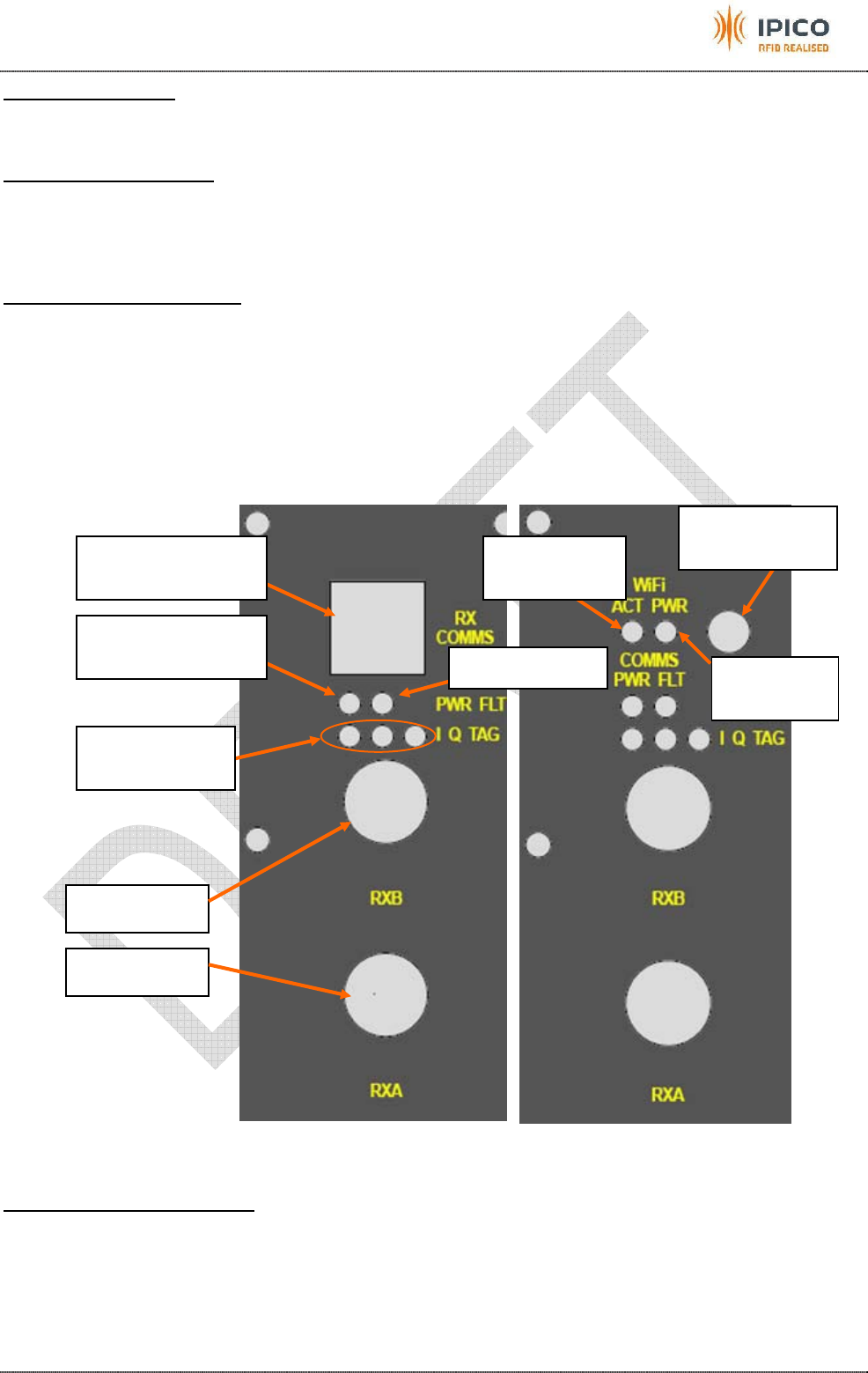
3.1 Front panel
There are 2 different front panels. One corresponding to the USB version or Ethernet version and the other
one corresponding to the WIFI version
All the visual indicators are on the front panel. A description of each part of the front panel is done in the
followings chapters. The front panel is aluminium anodized.
The figure below shows the front panel layout for the USB or Ethernet version, and for the WIFI version.
Figure 3: Front panel layout of USB/Ethernet version and WIFI version
IPICO Spider User Manual V1.0 draft 20071123 RWD .doc 12/12/2007 Page 8
3.1.1 Transmitter unit
This unit manages the TX loops to provide energy to tags.
Figure 4: Transmitter unit
Battery level indicator:
Three indicators show Low (L), Medium (M) and High (H) voltage levels. As the power supply is
managed by the Power Supply unit, the light should always show H or M.
Transmitter unit powered indicator:
This indicator should be lit when the reader is switched on to show that the transmitter unit is
powered.
Manual tuning button:
This button is used to start a manual tuning of the antennas. When the reader is switched on, the
reader will automatically tune the loops. The result of this tuning will be displayed on the TX tuning levels
indicators. This manual tuning must not be done when tags are detected. If so, tags can be missed. The aim
of the manual tuning is to tune the antennas if something changed in the antennas environment (metallic
part…). In most of the cases, the automatic tuning done when the reader is switched on is sufficient.
TXA Tuning Level indicator:
When the indicator is lit, the tuning is correct. When it is flashing and a beep is sounding, something
is not correct. Turn the power off, check that your antennas are installed correctly and restart the system.
TXB Tuning Level indicator:
When the indicator is lit, the tuning is correct. When it is flashing and a beep is sounding, something
is not correct. Turn the power off, check that your antennas are installed correctly and restart the system.
USB port for
transmitter setup
Manual tuning
button
Battery level
indicator
TXA tuning
level indicator TXB tuning
level indicator
Transmitter unit
powered indicator CPU activity indicator
Antennas power
off button
IPICO Spider User Manual V1.0 draft 20071123 RWD .doc 12/12/2007 Page 9
CPU activity indicator:
This indicator shows that the microprocessor is operating. When operating correctly the CPU
indicator will flash at approximately half second intervals.
Antennas power off button:
When you push this button, the TX unit will stop driving the TX antennas, you will hear a repetition of
beeps and the tuning level indicator will flash. In that case you will not read tags. If you push the button again,
the TX unit will start again to drive the TX antennas, the beeps will stops, and the tuning level indicator will
stop flashing.
USB port for transmitter setup:
This USB port must not be used by the user. It is only used by Ipico qualified staff to setup and
diagnose the transmitter unit at the manufacturing level.
3.1.2 Receiver unit
It is a dual channel receiver. It collects tag data from the RX loops.
The figure bellows shows the USB or Ethernet version receiver unit on the left. On the right it is the receiver
unit of the WIFI version.
Figure 5: Receiver unit of USB or Ethernet version, receiver unit of WIFI version
Receiver unit powered indicator:
This indicator should be lit when the reader is switched on to show that the receiver unit is powered.
Tag detection
indicators
Receiver unit
powered indicator Fault indicator
RXB socket
RXA socket
USB or Ethernet
port
WIFI antenna
connector
WIFI power
indicator
WIFI activity
indicator
IPICO Spider User Manual V1.0 draft 20071123 RWD .doc 12/12/2007 Page 10
Tag detection indicators:
The receiver has 3 data activity indicators. These are labelled I, Q and TAG. The I and Q indicator
show which section of the receiver RXA or RXB is detecting a tag. I correspond to RXA and B corresponds to
RXB. If a tag is detected the indicator is lit or flashes. The TAG indicator shows that the decoder in the
receiver is sending data to the Delta unit. A buzzer can also be setup to emit sound when a tag is detected.
Fault indicator:
This indicator will be lit if there is a communication problem in the receiver.
RXA & RXB sockets:
BNC sockets for receiver antennas.
USB or Ethernet port:
On the USB version it will be a USB port sending tags data. On the Ethernet version it will be an RJ45 port
sending tags data.
WIFI antenna connector:
It is a SMA connector to connect a standard WIFI antenna.
WIFI power indicator:
This indicator will be lit when the unit is powered.
WIFI activity indicator:
This indicator will flash whenever there is a data activity through the WIFI.
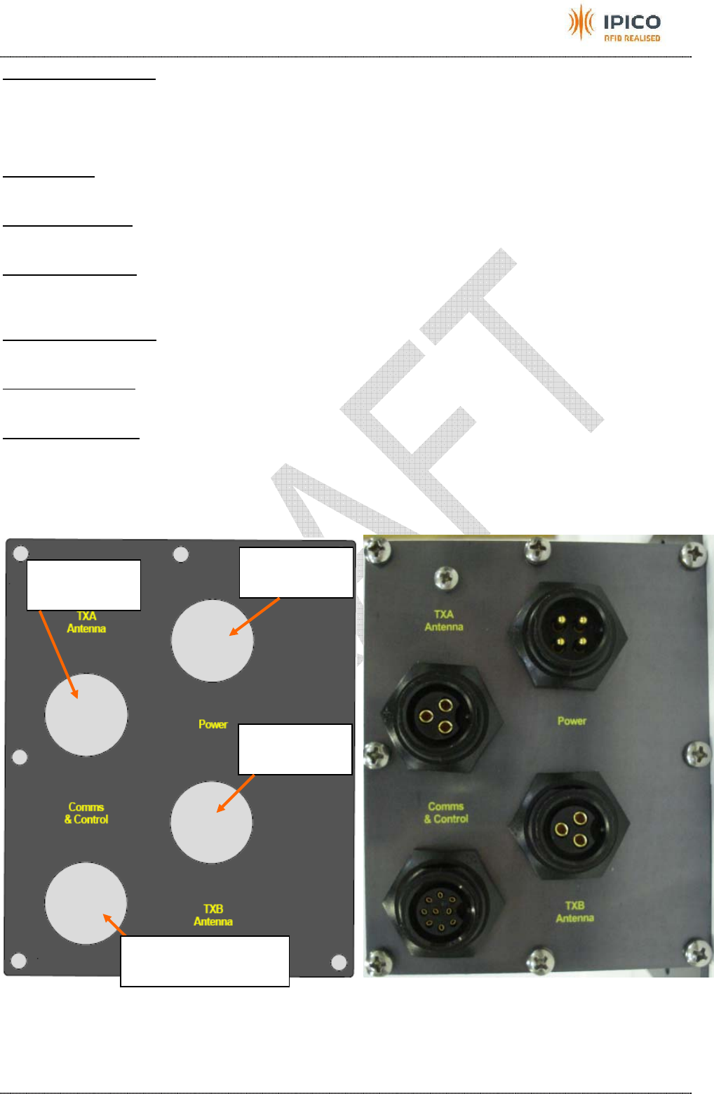
3.2 Back plane
The backplane is the same for the different versions of the spider. It is aluminium anodized.
Figure 6: Backplane layout and picture
TXA antenna
connector
Power
connector
TXB antenna
connector
Communications &
controls connector
IPICO Spider User Manual V1.0 draft 20071123 RWD .doc 12/12/2007 Page 11
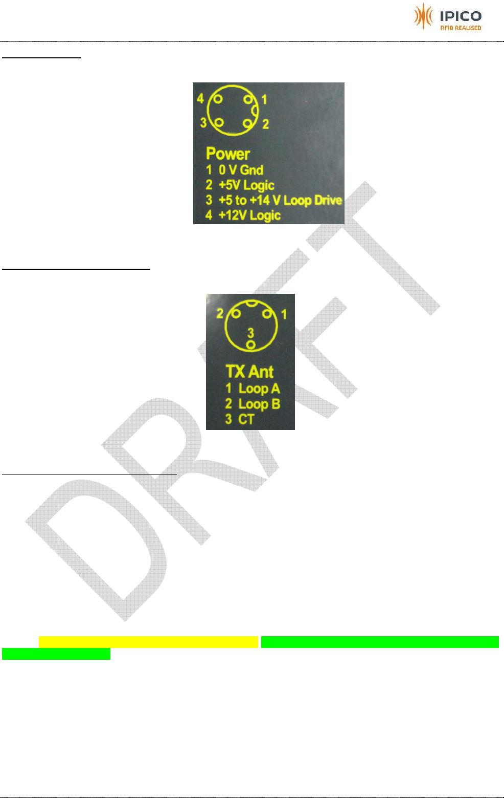
Power connector:
Connect the cable from the power supply to this connector.
Figure 7: Power connector pins
TXA & TXB antenna connectors:
Connect the TX antennas to these connectors.
Figure 8: TX connector pins
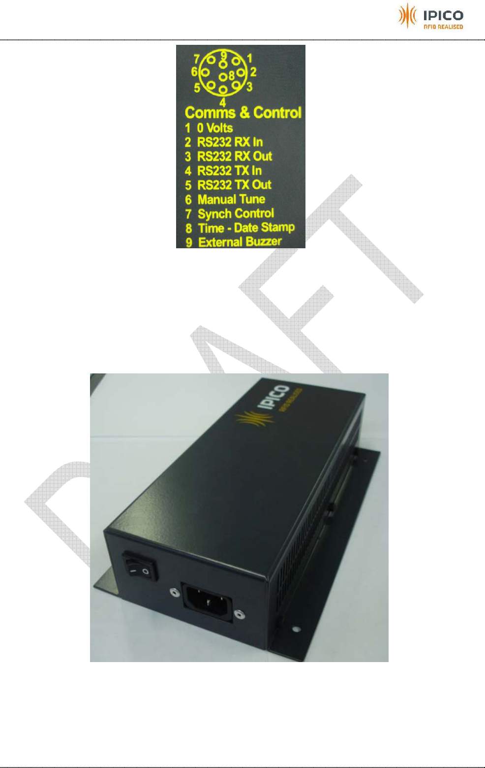
Communications & controls connector:
Pin 1 is the ground.
Pins 2 & 3 correspond to communication with the RX unit. Pin 3 may be used to get data each time a
tag is read.
Pins 4 & 5 correspond to communication with the TX unit. This is usually used for diagnostics by ipico
staff.
Pin 6 is a manual tuning input. It is a clear contact input. It has the same effect than the button on the
front plate.
Pin 7 is reserved for future use.
Pin 8 is a Date/Time stamp input. It is also a clear input contact. Its action is described in the
“Communications with the reader” chapter, in the “Date/time stamp data” section.
Pin 9 is an output to connect an external buzzer. The buzzer must be self oscillating and is connected
between pin 9 and pin 1
IPICO Spider User Manual V1.0 draft 20071123 RWD .doc 12/12/2007 Page 12
Figure 9: Communications & controls connector pins
4 POWER SUPPLY
This unit manages the power supply (PSU) of the whole reader. The PSU is specially designed to filter the
conducted noise from the mains that can be situated in the tag reply band. This PSU is also designed to
radiate as less as possible noise in the tag reply band.
The PSU has mounting holes in the chassis to be fixed on a wall or inside a box.
Figure 10: Mains power supply
IPICO Spider User Manual V1.0 draft 20071123 RWD .doc 12/12/2007 Page 13
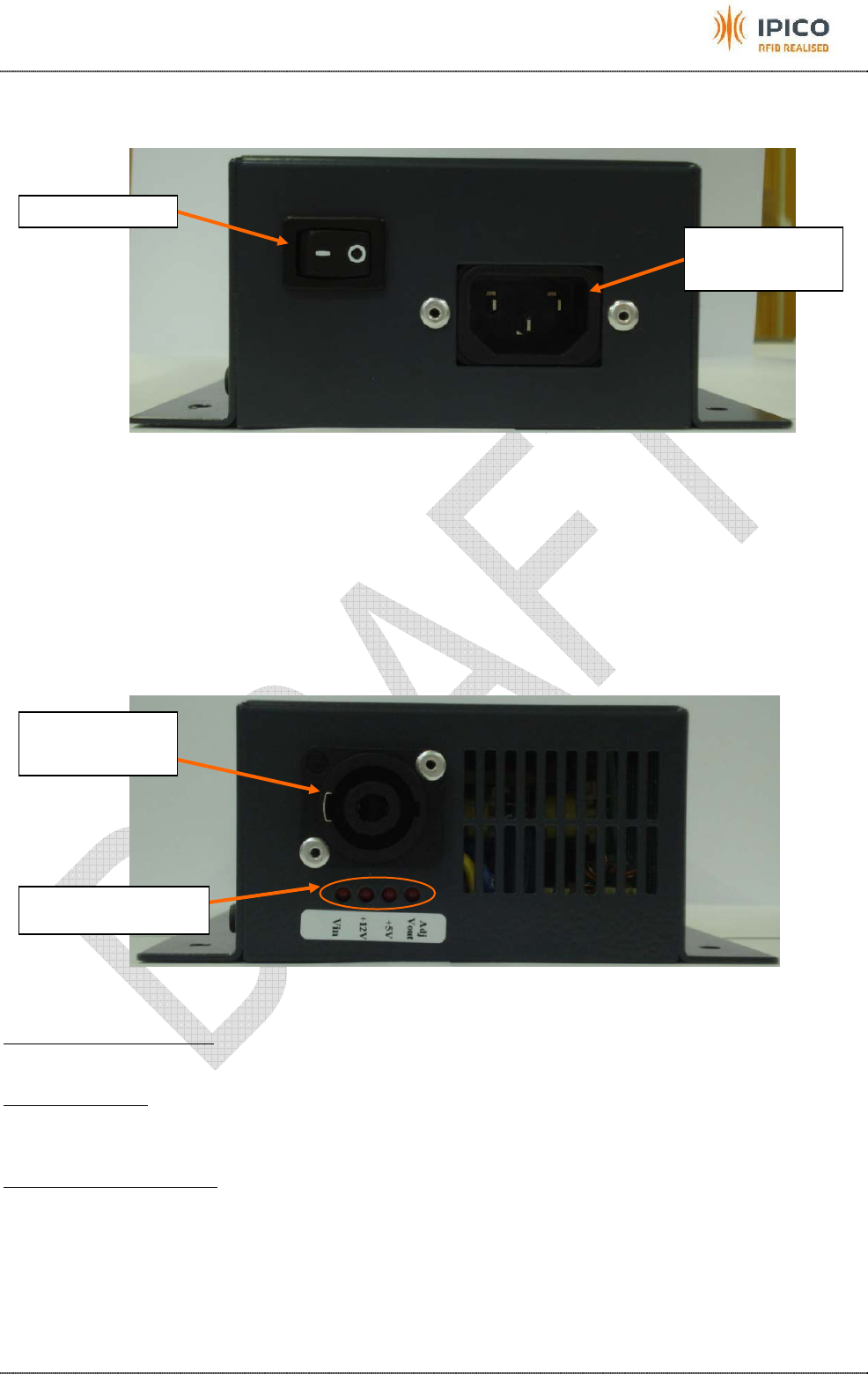
4.1 Power input side
The PSU can cope with alternative voltage from 87Vac to 264Vac, 50-60Hz.
Figure 11: Mains input & switch
4.2 Power output side
The PSU provides 3 different voltages:
• +5V @1A
• +12V @1A
• Adjustable voltage for TX drive: +6V, +8V, +10V, +12V or +13.8V (+12V by default) @ 10A
The figure below shows the DC outputs side of the PSU.
Figure 12: DC voltage outputs
Output voltages connector:
The connector is a Neutrik NL4FX.
Voltage indicators:
These indicators correspond to each voltages used in the reader. When the reader is turned on, all
should be lit.
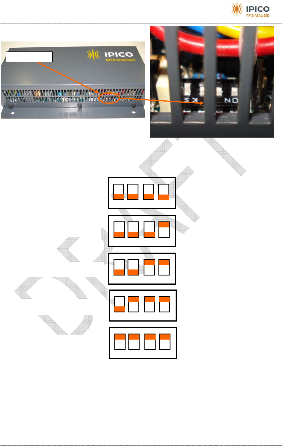
Adjustable voltage settings:
The TX drive voltage is adjustable by dipswitches. The picture below shows the location of the dipswitches.
On/Off switch
Mains input
connector
Output
voltages
t
Voltage indicators
IPICO Spider User Manual V1.0 draft 20071123 RWD .doc 12/12/2007 Page 14
Figure 13: Adjustable voltage dipswitches location
The figure below shows the different voltage settings of the TX drive voltage.
The usual TX drive voltage is 12V.
Figure 14: Adjustable voltage settings
Caution As this is a small closed volume unit the only cooling of the internal electronics is by
radiation from the case. Accordingly the following rules must be adhered to to ensure that the unit will
operate correctly.
100% Duty Cycle Loop Drive Voltage 8 Volts
80% duty cycle Loop Drive Voltage 10 Volts and
50% duty cycle Loop Drive voltage 12 Volts
Dipswitches
1 2 3 4
ON
1 2 3 4
ON
1 2 3 4
ON
1 2 3 4
ON
1 2 3 4
ON
Adjustable voltage output: 6V
Adjustable voltage output: 8V
Adjustable voltage output: 10V
Adjustable voltage output: 12V
Adjustable voltage output: 13.8V
IPICO Spider User Manual V1.0 draft 20071123 RWD .doc 12/12/2007 Page 15
5 COMMUNICATION WITH THE READER
5.1 Ethernet version
If you want to connect a PC directly to the reader, use an Ethernet crossover cable.
The default IP address of the reader is 10.19.1.101
Then connect to the TCP port 10000. Whenever a tag will be read, data will be sent by the reader to the port
10000.
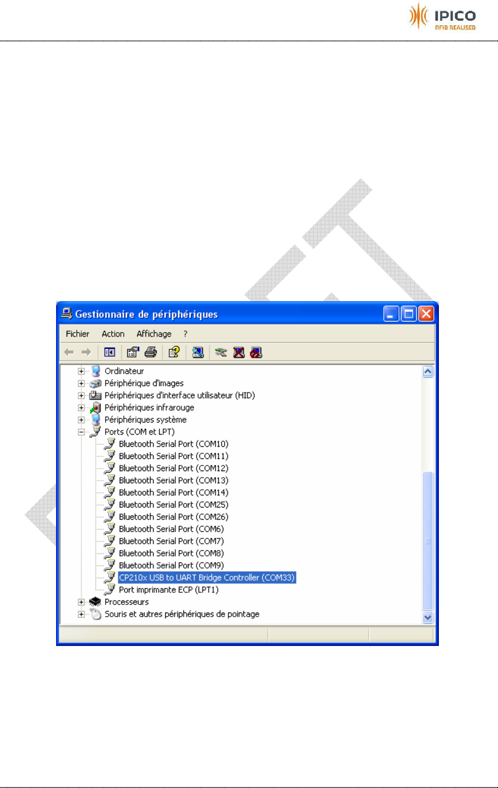
5.2 USB version
The first time you connect the reader to your computer, your computer needs to be connected to internet to
be able to download automatically the driver. When Windows® will detect the new device, you have to select
the option: ”Download automatically the driver from internet”.
After the successful installation of the driver, when you connect the reader to your computer, it will create a
virtual COM port. To know which COM port number it created, you go to “Windows Control Panel”, then
“Systems”, then “Hardware”, then “Peripherals manager”. You will see the windows on the figure below:
On your application side, the parameters for the connection to the COM port need to be:
Baud rate (Bits per seconds): 9600
Data bits: 8
Parity: None
Stop bits: 1
Flow control: None
IPICO Spider User Manual V1.0 draft 20071123 RWD .doc 12/12/2007 Page 16
After you setup correctly the connection, whenever a tag will be read, data will be sent by the reader to the
COM port.
5.3 WIFI version
5.4 Change the IP address (Ethernet or WIFI)
If you want to change the IP address, type in your internet browser address bar the current IP address of the
reader. A username and password will be asked.
• username: admin
• password: Don’t fill anything in the password field
Then a web page will open. You can type the new IP address and click on the “Save” button.
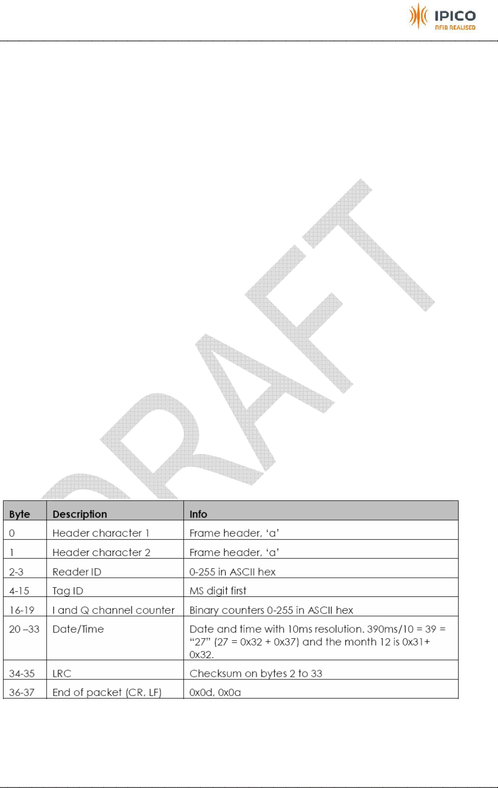
5.5 Reader data protocol
The following lines correspond to 2 tags that have been detected. The first tag detected has the ID
058000ab8684 and the second tag detected has the ID 058000abb494. The first tag has been read 6 times,
and the second tag has been read 4 times. There is one line outputted from the reader each time the tag is
read.
aa01058000ab8684000107060411580861bb
aa01058000ab8684000107060411580917bd
aa01058000ab8684000107060411580922b9
aa01058000ab868400010706041158094cec
aa01058000ab8684000107060411580958c2
aa01058000ab8684000107060411580963be
aa01058000abb49400010706041158131b0c
aa01058000abb494000107060411581320db
aa01058000abb49400010706041158132a0c
aa01058000abb494000107060411581353e1
The following table explains the different parts of each line:
Example:
Tag with an ID = 470011223344 is read at 14:05:20.39 on 2006-12-30 the data packet received from the
reader would be aa00470011223344090006123014052027xx\r\n where xx is the calculated LRC.

IPICO Spider User Manual V1.0 draft 20071123 RWD .doc 12/12/2007 Page 17
How to know from which antenna the tag was read:
Record
ID Receiver
ID Tag ID I-Count Q-Count
Date
(YYMMDD) Time
(HHMMSS) 100ths
(in Hex) LRC
aa 00 058000add0fa 01 00 070202 115001 12 aa
aa 00 058000abc5a3 01 00 070202 115001 13 e1
aa 00 058000abd035 01 00 070202 115002 00 17
aa 00 058000abbaa6 01 00 070202 115002 01 41
aa 00 058000add984 00 01 070202 115002 01 5d
aa 00
058000abbe87 00 01 070202 115002 02 86
aa 00 058000abf4aa 01 00 070202 115002 02 19
The receiver ID is always 00 for a spider reader. However if desired this can be changed.
The I and Q counts are used to determine which antenna that tag was seen on.
I-Count: If > 0 the Tag is seen on channel 1 of the receiver (top plug)
Q-Count: If > 0 the Tag is seen on channel 2 of the receiver (bottom plug)
Example: The highlighted tag ID “058000abbe87” was read on the Q-channel. This corresponds to the
antenna connected on the bottom plug of the receiver.
On the application software, all the lines that are not starting with “aa” must be ignored. They correspond to
maintenance data.
Further details can be obtained from the iPico Reader Serial Protocol document.
5.6 Date/Time stamp data
When you connect an external switch on the Time stamp input on “Comms & control” connector on the back
plane, the action on the switch will add the following line on the raw data port and in the data files:
ab000a2c070301041413513bd102d0
red is yymmdd (year month day) – i.e. 070301 (1st of March 2007)
green is dow e.g. 04 is Thursday
blue is hhmmss (hour minute second) i.e.141351 (14h13mins51s)
pink is 100ths in hex i.e. 3b (in hex) = 59ths (in decimal)

IPICO Spider User Manual V1.0 draft 20071123 RWD .doc 12/12/2007 Page 18
6 INSTALLATION OF THE SYSTEM
6.1 Precautions of use!
• Antennas should be placed at least 0.5m from any large metal / conducting objects such as fences,
barb wire... to get the best performances.
• The spider reader and antennas should be placed as far as possible from other electromagnetic field
generating equipment such as fan motors, audio equipment etc.
• AC power lines including extension cords should be placed at least at a distance of 20cm from
antennas leading cables, and as far as possible from the antennas.
• Switch mode power supply must be as far as possible from the reader and antennas.
• The system must always be switched on with the TX antennas connected.
6.2 Installation of the reader
1. Install your antennas
2. Install the spider + power supply (don’t connect the mains cable yet)
3. Plug the TX antennas
4. Plug the RX antennas
5. Connect the mains cable to the power supply
6. Switch on the reader
7. 2 seconds after switching on the reader, beeps will be emitted. When they stops, the reader is ready.
6.3 Testing of tag reading distance
A test of reading with a tag should be done on each antenna to check the performances.
After that your system is ready!

IPICO Spider User Manual V1.0 draft 20071123 RWD .doc 12/12/2007 Page 19
7 SPECIFICATIONS
7.1 Reader
• Consumption:
o 1 Amp for the +12V voltage
o 1Amp for the +5V voltage
o TX loop drive 3.5 Amps @ 12 V typical maximum for 2 antennas
o Weight: 1.6Kg
• Dimensions: 85mm H x 145mm W x 245mm L.
• Temperature rates: 0°C to 50°C
• IP protection: IP54
• Warranty 1 year
7.2 Power supply
7.2.1 Mains version
• Input: 87Vac->264Vac, 50-60Hz
• Output:
o +5V @1A
o +12V @1A
o Adjustable voltage (by dip-switches) for TX drive: +6V, +8V, +10V, +12V or +13.8V (+12V by
default) @ 10A
• Weight: 1Kg
• Dimensions: 57mm H x 140mm W x 240mm L.
• Temperature rates: 0°C to 50°C
• IP protection: IP54
• Warranty 1 year
7.2.2 DC version
• Input: +10Vdc->+58Vdc
• Output:
o +5V @1A
o +12V @1A
o Adjustable voltage (by dip-switches) for TX drive: +6V, +8V, +10V, +12V or +13.8V (+12V by
default) @ 10A
• Weight: 1Kg
• Dimensions: 57mm H x 145mm W x 245mm L.
• Temperature rates: 0°C to 50°C
• IP protection: IP54
• Warranty 1 year

IPICO Spider User Manual V1.0 draft 20071123 RWD .doc 12/12/2007 Page 20
APPENDIX A – STANDARD ANTENNAS
The following standard antenna panels are available for use with the Spider reader.
IP 2965 Dual Panel Antenna 600 x 400 mm
IP 2961 Dual Panel Antenna 800 x 600 mm
IP 2962 Dual Panel Antenna 800 x 1200 mm
Incorporates 3D tag read capability
IP 2974 Single Tube Antenna 500 x 100mm diameter
This antenna has a directed field and has been designed to
operate in a constricted under a Fork Hoist truck.
IPICO Spider User Manual V1.0 draft 20071123 RWD .doc 12/12/2007 Page 21
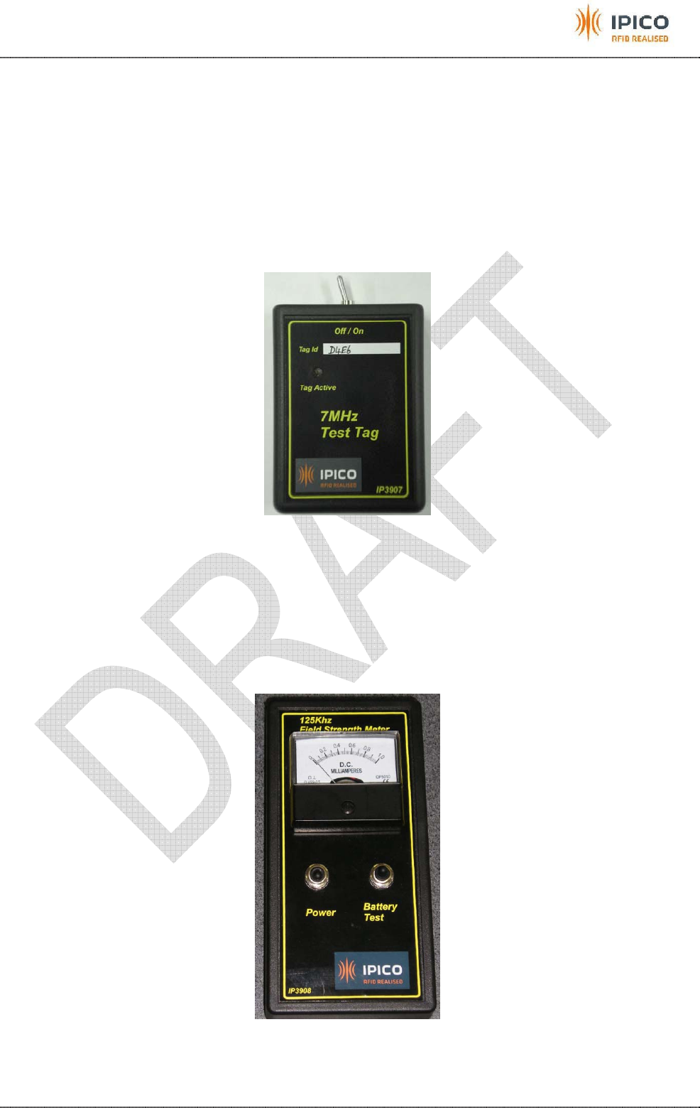
APPENDIX B – OPTIONAL ACCESSORIES
The 2 following tools are really useful for maintenance of the system on site.
Battery assisted tag
It is an active tag that take the necessary energy from an inside battery instead of from the 125 KHz
TX field. This tool is used to determine the read range of the system (RX part of reader + antennas).
Ordering number: IP3907
Figure 15: Battery assisted tag
125 KHz Field strength meter
It is a tool that measures the 125 KHz field. It is used to determine the power-up range of the system
(TX part of reader + antennas).
Ordering number: IP3908
Figure 16: Field strength meter