Contents
- 1. Manual DP 250
- 2. Manual DP 550
- 3. Manual DP 550P
Manual DP 250
DUOGUARD
PIR + Microwave Motion Detector
DP-250 Installation Instructions
R
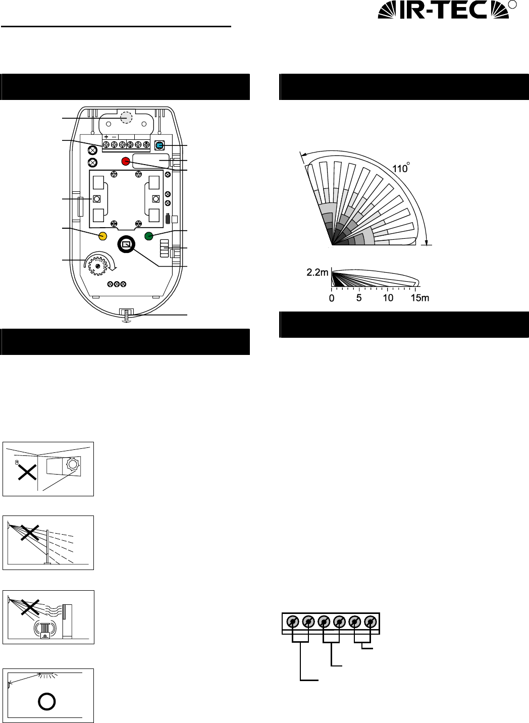
INTERNAL VIEW
ALARM TAMPER SW4
C17
C28
BY1
C31
C4
C33
C32
LED2
LED3 LED1
1/3
MAX.
2/3
MW.RANGE
C10 C12 C8
ALM
MW
PIR
SWB
SWA
CT35
Terminals
Microwave sensor
PIR LED
(Yellow)
Microwave range
adjustment
Tamper switch
Relay
Alarm LED
(Red)
Infrared sensor
(Don't touch!)
Microwave LEC
(Green)
Jumper switch
Locking bolt
Cable access
INSTALLATION HINTS
The DUOGUARD may be either wall or corner
mounted by applying different knockouts. The MB-95
or MB-99 mounting bracket can be applied for ceiling
or wall mount. Corner mount is generally
recommended for optimum detection.
Do not install where the detector
is in or facing direct/reflected
sunlight, windows onto main
roads (car head lights) or strong
draughts / heaters.
Ensure that there are not any
obstructions (plants, screens,
furniture etc.) in the field of view
which may cause incorrect cover/
operation of the detector.
Avoid locating the detector in
areas which contain equipment
that may change the environment
temperature rapidly.
Locate the detector at least 1
meter away from any illumination
to avoid possible interference to
microwave sensor.
)
Avoid running alarm wiring close to mains cables !!!
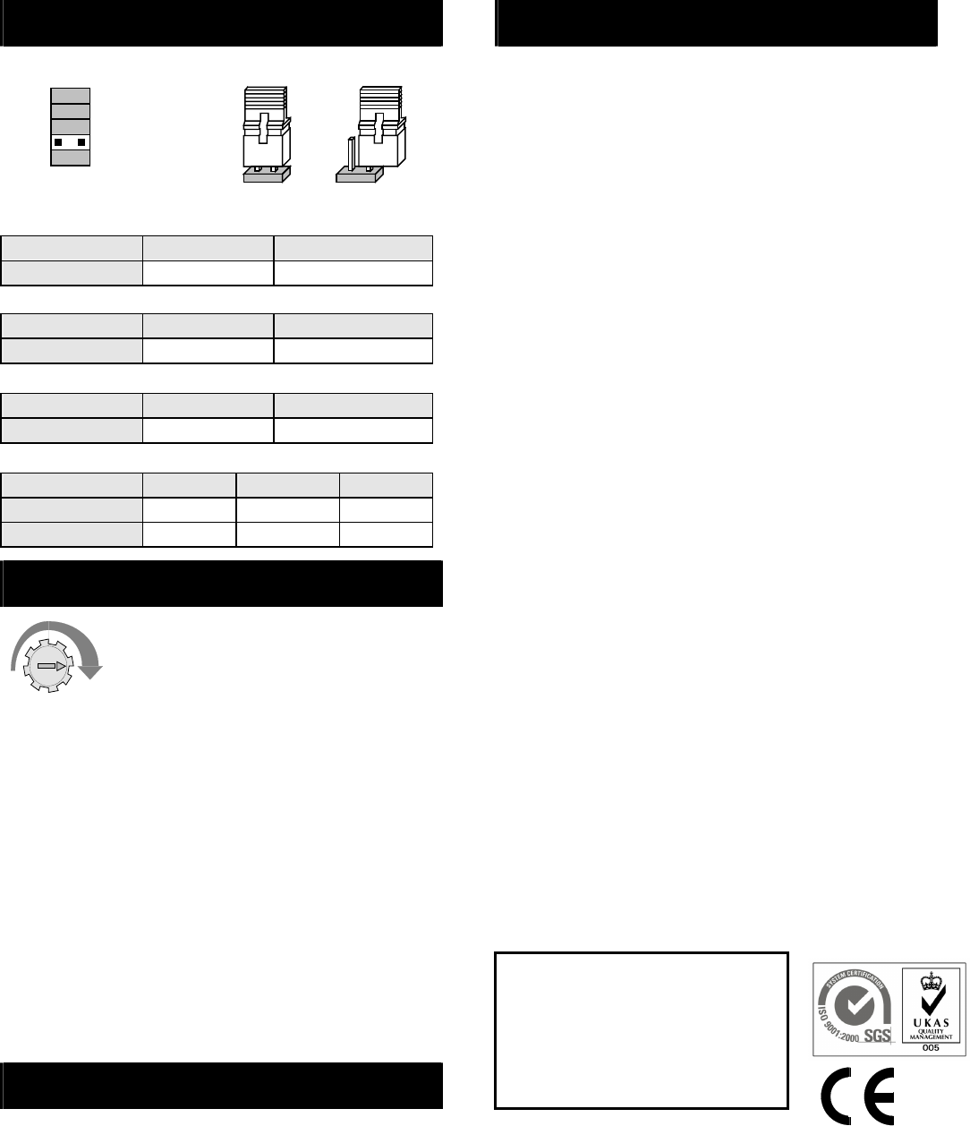
DETECTION PATTERN
Model: DP-250
110°, 15 x 15m at 25°C Top View
Side View
INSTALLATION & WIRING
Installation
1. Open the front cover by loosening the locking
bolt at the bottom of the case.
2. Remove the printed circuit board from the base of
the unit, by bending the P.C.B clips gently
upwards (handle printed circuit board with care).
3. Punch out the required knockouts and mount the
unit base to the wall, corner or bracket.
4. Lead the cable through the access hole and then
refit the printed circuit board.
5. Connect the wires to the respective terminals
according to the wiring instructions.
6. Replace the front cover after completing the
wiring and carry out a through walk test.
Wiring
+ALARM TAMPER
-
Tamper output (N.C loop)
Alarm output (N.C loop)
Power input (9 ~ 16 VDC)
Min. 1m
Light
) TAMPER terminals should be connected to the 24
hours N.C supervised loop of control panel.
JUMPER SWITCH SETTING
MW
ALM
PIR
SWB
SWA
ON OFF
(Factory set)
ALM - Alarm LED Indication
ALM jumper ON OFF
Red LED ON OFF
MW - Microwave LED Indication
MW. jumper ON OFF
Green LED ON OFF
PIR - PIR LED Indication
PIR jumper ON OFF
Yellow LED ON OFF
SWA, SWB - Pulse count selection
Pulse Count 1 2 3
SWA jumper ON OFF OFF
SWB jumper OFF ON OFF
WALK TEST & ADJUSTMENT
It is necessary to carry out a thorough
walk test of the detector to ensure that
the correct coverage is being achieved
and no over spill of the microwave is
occurring. Also to ensure that both PIR & microwave
are working to the same detection area.
The PIR range sensitivity is not adjustable. Accurate
setting of the microwave is achieved by careful
adjustment of the microwave range controller on the
front of the PCB, next to the PIR detector, the range is
increased by turning the pre-set in clockwise direction.
When you are satisfied with your setting, all of the
LEDs may be disable from jumper switch (please
retain for future walk testing).
)Regular walk testing must be carried out, as part of
your routine maintenance visits or at least once a
year.)
MOTION SIGNAL DISCRETION
The MSD (Motion Signal Discretion) circuit recognizes
the difference between motion and non-motion signals.
Alarm output is only generated when motion is
detected by infrared & microwave sensor and
analyzed by the MSD circuit. MSD circuit ensures
supreme reliability even when environmental
conditions are severe.
SPECIFICATIONS
Detection range ........15 x15 m at 25°C
Infrared sensor………Low noise, dual element
Microwave sensor.....DRO w/m micro strip antenna
MW Frequency .........10.525 GHz
MW output power .....6 mW E.I.R.P. peak
Power supply............9 ~ 16 VDC (12 VDC nominal)
Current drain.............30mA at 12 VDC
Alarm period .............2 ± 0.5 sec.
Alarm output .............N.C 30 VDC, 0.2A max.
Alarm output LED .....Red, can be disabled
MW sensor LED........Green, can be disabled
PIR sensor LED.........Yellow, can be disabled
Pulse count...............1, 2, 3 selectable
Tamper protection ....N.C cover open activates
RFI immunity.............Ave. 20V/m (10~1000 MHz)
Mounting height........2.0~ 2.4m (wall/corner mounted)
2.4~ 3.6m (with bracket)
Mounting bracket......MB-95 or MB-99 (Optional)
Temperature .............-10°C ~ 55°C (14°F ~ 131°F)
1/3
MAX
MW RANGE
2/3
Humidity....................95% RH max.
Dimensions...............132 x 72 x 57mm
Unit weight ...............110 grams
To continue improving produc qualityt, IR-TEC reserves the
right to change specifications without prior notice.
Warning: Changes or modifications this nit not expressly
approved by the party responsible for compliance could void
the user’s authority to operate the eqipment.
This device complies with Part 15 of the FCC Rules.
Operation is subject to the following two conditions:
(1) This device may not cause harmful interference, and
(2) This device must accept any interference received,
Including interference that may cause undesired
operation.