IR TEC HS1X0900 TRANS-HFD User Manual 058 50907 002 IM EN LMD 509
IR-TEC International Ltd. TRANS-HFD 058 50907 002 IM EN LMD 509
IR TEC >
Contents
- 1. User Manual (LMD-109).pdf
- 2. User Manual (LMD-509).pdf
- 3. User Manual (LMS-109).pdf
User Manual (LMD-509).pdf
P/N: 058-50907-002 Printed in Taiwanwww.irtec.com
This product may be covered by one or more U.S. patents or patent applications.
Please visit www.irtec.com for more information.
Line Voltage Bi-Level Occupancy Sensor
LMD-509 series
INSTALLATION INSTRUCTIONS
Risque de choc électrique - Débranchez l'alimentation avant
l'entretien.
Ouvrir Type commutateurs optoélectroniques.
Risk of Electric Shock - Disconnect power supply before
servicing.
Open Type Photoelectric Switches.
CAUTION
PRUDENCE
OVERVIEW
The LMD-509 series member of the TRANS family is a line voltage
occupancy sensor with 0-10V output for bi-level dimming control.
This occupancy sensor employs an advanced High Frequency
Doppler (HFD) sensing technology to provide superior sensing
performance of minor motion, such as typing, writing, or reading.
The HFD technology is operating with high frequency radio waves
which are capable of detecting the occupant's presence and
movements without requiring unobstructed line-of-sight like a PIR
sensor. Thus, the HFD sensor can detect through non-metallic
material, such as plastic, glass, plywood or plaster board.
The Accu-Set digitalized potentiometers make the sensor setting
easier, faster and more accurate than the conventional analog
ones. Four levels of sensitivity and control modes can be selected
via DIP switch setting. An exclusive Hybrid Switching technology
makes the LMD-509 series perfect to control lighting with
exceptionally high inrush current (HIC) during switching, such as
multiple LED lightings connected in parallel. The sensor comes
with an ambient light sensor (ALS) to inhibit switching on the light
if the ambient light level is higher than the threshold set. Like all
sensors in the TRANS family, the LMD-509 series is also available
in various mounting options.
APPLICATION NOTES
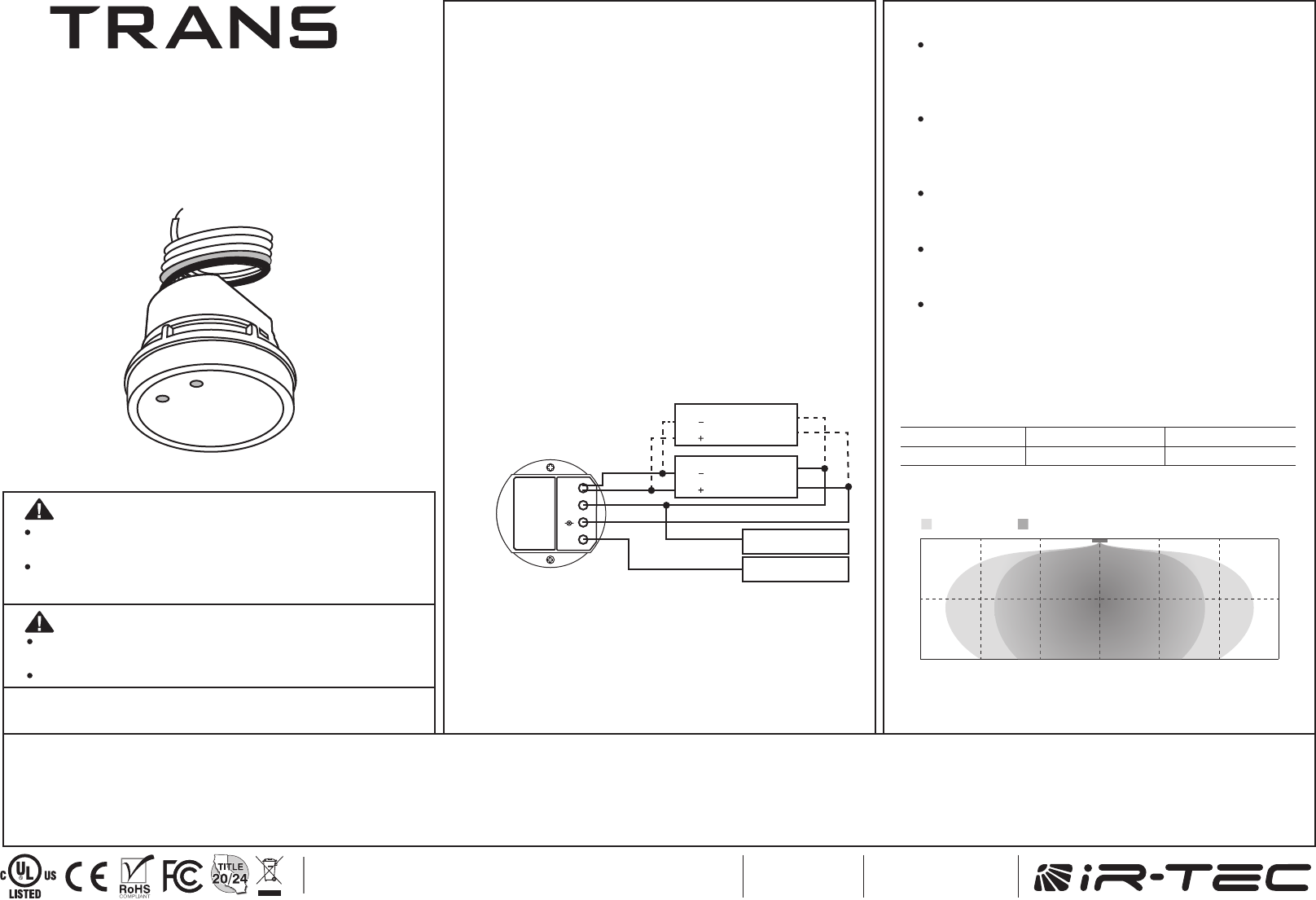
DETECTION PATTERN
Avoid placing the sensor in an area surrounded with
metallic wall which may block or absorb the radio
wave. If possible, place the sensor to the opening
as close as possible.
Fluorescent light may cause interference to the HFD
sensor operation, and result in lighting permanent
on. If possible, avoid placing the HFD sensor within
3 ft. of fluorescent light.
Avoid sensor placement facing doors, corridors or
exits as HFD sensor may detect the traffics at
adjacent area.
HFD sensors are best for use in areas with partitions
and high dividers, or high level of minor motion
activities.
The HFD sensor is more sensitive to the movements
“toward” than “across” the sensor, so ensure to
place the sensor at the position “toward” the
movements of occupant.
20 302030 10 30
6 969 3 30
0
3
6
0
10
20
(ft)
(ft)
(m)
(m) Minor motionMajor motion
Mounting Height
Coverage*
3 m (10 ft)
180 m2 (2,000 ft2)
6 m (20 ft)
100 m2 (1,200 ft2)
*Sensitivity 100%
WIRING DIAGRAM
LMD-509
DIM
L N
Neutral
Line
DIM
DIM
N
L
Gray
Violet
Red
White
Black
BALLAST
LED DRIVER
DIM
DIM
N
L
BALLAST
LED DRIVER
1
2
NOTE:
1. The driver/ballast MUST be 0-10V dimmable to achieve
dimming control.
2. Ensure connection of LINE and NEUTRAL are not reversed
to avoid damaging the sensor.
3. Ensure TOTAL isolation between DIM+/DIM- and GROUND
to avoid damaging the sensor.
4. Conduct test with GROUND connected.
This device complies with Part 15 of the FCC Rules. Operation is subject to the following two conditions: (1) This
device may not cause harmful interference, and (2) this device must accept any interference received, including
interference that may cause undesired operation.
This equipment has been tested and found to comply with the limits for a Class B digital device, pursuant to Part
15 of the FCC Rules. These limits are designed to provide reasonable protection against harmful interference in
a residential installation. This equipment generates, uses and can radiate radio frequency energy and, if not
installed and used in accordance with the instructions, may cause harmful interference to radio communications.
However, there is no guarantee that interference will not occur in a particular installation. If this equipment does
cause harmful interference to radio or television reception, which can be determined by turning the equipment off
and on, the user is encouraged to try to correct the interference by one of the following measures:
Radiation Exposure Statement:
This equipment complies with ISED radiation
exposure limits set forth for an uncontrolled
environment. This equipment should be installed and
operated with minimum distance 20cm between the
radiator & your body.
Déclaration d'exposition aux radiations:Cet
équipement est conforme aux limites d'exposition aux
rayonnements ISED établies pour un environnement
non contrôlé. Cet équipement doit être installé et
utilisé avec un minimum de 20 cm de distance entre la
source de rayonnement et votre corps.
-Reorient or relocate the receiving antenna.
-Increase the separation between the equipment and receiver.
-Connect the equipment into an outlet on a circuit different from that to which the receiver is
connected.
-Consult the dealer or an experienced radio/TV technician for help.
FCC Caution: Any changes or modifications not expressly approved by the party responsible for
compliance could void the user's authority to operate this equipment.
This transmitter must not be co-located or operating in conjunction with any other antenna or transmitter.
Radiation Exposure Statement: This equipment complies with FCC radiation exposure limits set forth
for an uncontrolled environment. This equipment should be installed and operated with minimum
distance 20cm between the radiator & your body.
Federal Communication Commission Interference Statement Industry Canada statement:
IC ID:22993-X09HS1AC602
This device complies with ISED’s licence-exempt RSSs. Operation is subject
to the following two conditions: (1) This device may not cause harmful
interference, and (2) this device must accept any interference received,
including interference that may cause undesired operation.
Le présent appareil est conforme aux CNR d’ ISED applicables aux appareils
radio exempts de licence. L’exploitation est autorisée aux deux conditions
suivantes : (1) le dispositif ne doit pas produire de brouillage préjudiciable,
et (2) ce dispositif doit accepter tout brouillage reçu, y compris un brouillage
susceptible de provoquer un fonctionnement indésirable.
FCC ID:NRIHS1X0900
IR-TEC hereby declares that the LMD-509 complies with Directive 2014/53/EU issued by the Commission of the
European Community. The complete declaration of conformity is available on our website: www.irtec.com
The frequency and maximum transmitted power in EU are listed as 5800 MHz: -11.28dBm.
Install the sensor at least 1ft. away from any occupant.
IR-TEC International Ltd.
6 Rong An Road
Luzhu Taoyuan 338
TAIWAN
IR-TEC America, Inc.
590 W. Central Avenue Suite C
Brea, CA 92821
USA
IC: 22993-X09HS1AC602
INSTALLATION
The potentiometer T sets the period of delay time that sensor
will turn off the connected lights after the area is vacated.
The LMD-509 series can be mounted with a junction box
into the ceiling, internally integrated or externally attached to
a fixture to control the lighting with specific mounting
bracket. Please refer to the mounting instructions separately
attached for details of mounting options available.
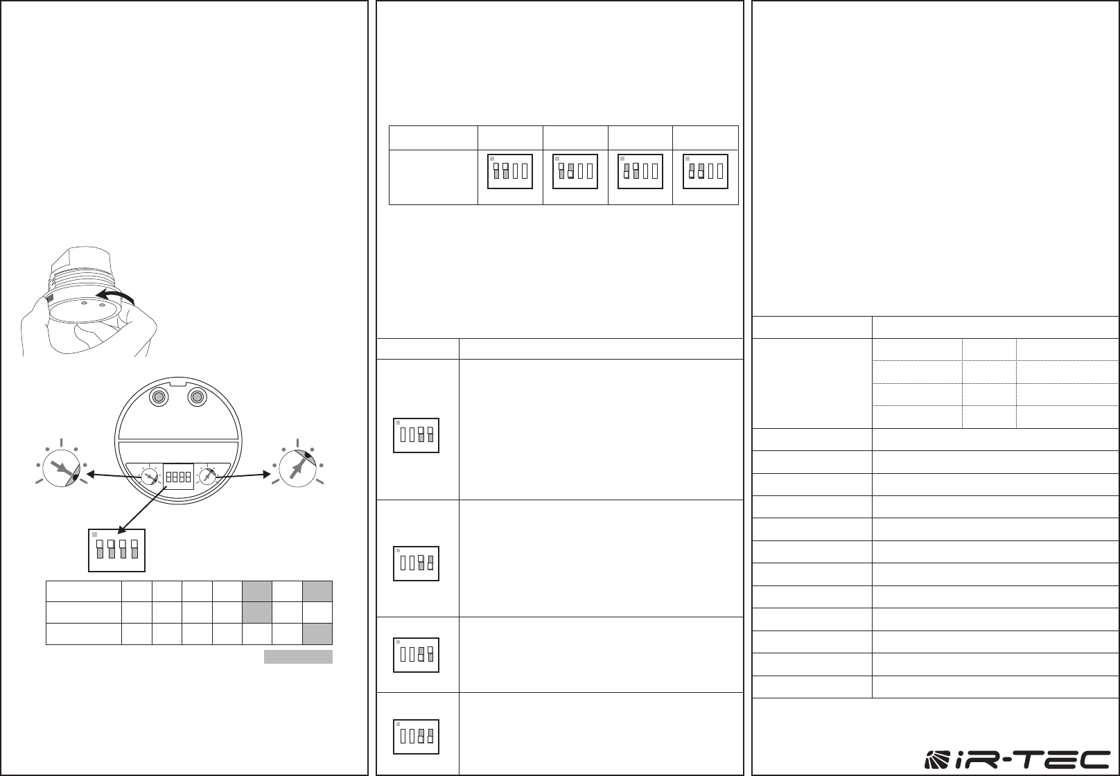
T - Delay Time
The potentiometer L sets the ambient light level that the
sensor will activate occupancy sensing control.
L - Ambient Light Level
The sensitivity and detection pattern of HFD sensor may vary
with the furniture placement, partition layout, wall material,
and shape of the space. For example, the detection pattern
will become long rectangular if sensor is placed in a long
corridor. 4 levels of sensitivity can be set via combinations of
DIP switch #1 and #2.
Sensitivity - SW1 & 2
The combination of DIP switch #3 and #4 determines the
sensing control mode.
Control Mode - SW3 & 4
The LMD-509 series features 4 different control modes
selectable via combination DIP switch #3 and #4, and 4
levels of sensitivity set via combination DIP switch #1 and
#2. The LMD-509 series also provides 7 different light-Off
delay time and daylight threshold settings via 2 Accu-Set
digital potentiometers marked T and L respectively.
To change the sensor setting,
rotate the front cover
counter-clockwise to remove.
Replace the front cover after
the setting complete.
SENSOR SETTINGS
24H
T 1’ 3’ 5’ 10’ 20’ 30’
T (min.)
L (lux)
1 2
3
4567
Position
15 20
510
25 60
Factory Set
TL
TL
(Factory set)
(10 minutes)(ALS disabled)
SW1 & 2 (100% Sensitivity)
SW3 & 4 (OSLATO Mode)
ON
1 2 3 4
1
2
345
6
7 1
2
345
6
7
Click!
DIP switch
setting
Sensitivity 100%
ON-ON ON-OFF OFF-ON OFF-OFF
75% 50% 25%
ON
1 2 3 4
ON
1 2 3 4
ON
1 2 3 4
ON
1 2 3 4
SPECIFICATIONS
Power supply
HFD sensitivity
Load switching
HIC protection
Dim control
Detection range
Mounting height
Ambient light level
Delay time setting
TIME OFF delay
Op. humidity
Op. temperature
Dimensions
120/240/277VAC, 50/60 Hz
25/50/75/100% selectable via DIP switch setting
Zero-cross Hybrid-Switching
Max. 80A for 16.7msec.
0-10V, ±5%, non-isolated, max. 25 mA
Up to 180 sq. m. @ 3 m (2,000 sq. ft @ 10 ft)
2.4 ~ 6 m (8 ~ 20 ft)
7 level Accu-Set digital potentiometer
T/1'/3'/5'/10'/20'/30' , T=10 sec. for testing
10 min., OSLATO mode only
Max. 95% RH
-40°C~70°C (-40°F~158°F)
Ø60 x H42 mm (Ø2.36"x H1.65")
*Max load for operating temperature at 55°C~70°C (131°F~158°F)
120VAC
800/*500W(VA)
800/*500W(VA)
540/*500VA
5A
5A
5A
240VAC
1200/*750W(VA)
1200/*750W(VA)
1200/*750VA
277VAC
Maximum load
-Incandescent/Halogen
-Fluorescent Ballast/CFL
-Ballast Electronic (LED)
OSLATO
OSLA
OSO
ON/OFF
: Occupancy Sensing at Low Ambient with Time-Off
: Occupancy Sensing at Low Ambient
: Occupancy Sensing Only
: ON-OFF Switching
Mode Control (LMD-509Sx)
ON/OFF 1.
2.
3.
OSO 1.
2.
3.
4.
OSLATO
1.
2.
3.
4.
5.
ON-ON
ON
1 2 3 4
OFF-ON
ON
1 2 3 4
OFF-OFF
ON
1 2 3 4
While ambient lux is higher than the level set, light
stays OFF.
While ambient lux is lower than the level set, and
occupancy detected, switch the light ON.
Dim the light to 30% after occupant leave and delay
time elapses.
Turn OFF the lights when 10 minutes TIME OFF
delay elapses.
When occupancy detected during TIME OFF,
switch the light ON.
OSLA
1.
2.
3.
4.
ON-OFF
ON
1 2 3 4
While ambient lux is higher than the level set, light
stays OFF.
While ambient lux is lower than the level set, dim
the light to 30% under vacancy.
While ambient lux is lower than the level set, and
occupancy detected, switch the light ON.
Dim the light to 30% after occupant leave and delay
time elapses.
Ambient light is disabled with this mode.
Dim the light to 30% at all time under vacancy.
Switch the light to ON under occupancy.
Dim the light to 30% after occupant leave and delay
time elapses.
While ambient lux is higher than the level set, light
stays OFF.
While ambient lux is lower than the level set, and
occupancy detected, switch the light ON.
Turn OFF the light after occupant leave and delay
time elapses.
To verify sensor control function normal, please proceed
with the instructions as below to conduct test;
TESTING
Set the arrow of T (DELAY TIME) potentiometer pointing
at position "1" (TEST) and other setting to the desired
threshold.
Walk within the expected range at normal speed. The
sensor will switch ON the light for 10 seconds whenever
sensor detects the movement, and then switch OFF or
DIM to 30% for 10 seconds as per the selected mode.
The LED of sensor will also blink to indicate every
motion detected.
After testing complete ensure to set the T potentiometer
to the position of desired time. NOTE: The sensor will
automatically control the light as per the selected mode
with factory set time delay (10 minutes) if the T
potentiometer has NOT been set to other position.
1.
2.
3.
www.irtec.com