IRay Technology 02112031 Wireless Digital Flat Panel Detector User Manual
iRay Technology (Shanghai) Ltd. Wireless Digital Flat Panel Detector
User manual
Tocustomers
1
ServiceOffice:
Tel:+862150720560
E‐mail:service@iraychina.com
Mars1417V serial
Wireless Digital Flat Panel Detector
User Manual
iRay Technology (Shanghai) Ltd.
ADDRESS:2F,Building7,No.590,RuiqingRoad,
ZhangjiangEast,PudongNewArea,
Shanghai201201,China
TEL:+86‐21‐50720560
FAX:+86‐21‐50720561
DATE:2013‐08‐09

Tocustomers
2
ServiceOffice:
Tel:+862150720560
E‐mail:service@iraychina.com
To customers
Thank you for purchasing iRay’s Mars1417V serial Medical X-ray
Radiography Flat Panel Detector. This User’s Manual explains the general
usage of the detector and peripheral equipment. Before using this product,
please read this manual thoroughly. Our company will not be responsible for
any abnormalities, malfunction and body harms caused by violations of the
user’s manual.
Important information on usage and management of
equipment
1. Only a physician or a legally certified operator is allowed to use this product.
2. The equipment should be maintained in a safe and operable condition by
maintenance personnel.
3. Use only computers and image display monitors complying with IEC 60601-1 or
IEC 60950-1. For details, consult our sales representative or local iRay dealer.
4. Use only the dedicated cables. Do not use any cables other than those supplied with
this product.
5. Opening the detector by the unauthorized personnel of our company is forbidden.
6. Prevent the liquid or electrical conductive substance entering into the detector.
7. The detector should not be used in circumstance with flammable gas or corrosive
gas.
8. The detector’s radiation protection complies with IEC 60601-1-3.
9. Prevent the detectors from sharp/hard things, or the cover will be broken. If the
painting or the cover is broken, do not contact with surface directly.
10. To pull out the plug is the only way to cut down the main power supply.
11. For product available in the USA/Canada market, only channel 1~11 can be
operated. Selection of other channels is not possible.

Tocustomers
3
ServiceOffice:
Tel:+862150720560
E‐mail:service@iraychina.com
Disclaimer
1. In no event shall iRay be liable for any damage or loss arising from fire, earthquake,
any action or accident by a third party, any intentional or negligent action by user,
any trial usage, or other usage under abnormal conditions.
2. Roentgenography, image processing, image reading, and image data storage must
be performed in accordance with the laws of the country or region in which the
product is being used. The user is responsible for maintaining the privacy of image
data.
3. In no event shall iRay be liable for personal physical harm or property damage that
is sustained when the instructions are not followed or the product is misused.
4. It is the responsibility of the attending physicians to provide medical care services.
iRay will not be liable for faulty diagnoses.
5. In no event shall iRay be liable for direct or indirect consequential damages arising
from the use or unavailability of this product. iRay shall not be liable for loss of
image for any reason.
6. In no event shall iRay be liable for any damage arising from moving, alteration,
inspection or repair by a person other than authorized service engineers.
7. Specifications, composition, and appearance of this product may change without
prior notice.
About CE
MARS1417V SERIAL is compliant with the standard of
IEC 60601-1,General requirements for basic safety and essential performance
and IEC 60601-1-2, Electromagnetic Compatibility –Medical Electrical
Instrument.
The detector can connect to public power supply as defined in CISPR 11 (the class
defines GROUP1 Class B).
Please refer to chapter V: Regulatory information for CE testing standard.
For more information, please contact with iRay.
About FCC
FCC Compliance
This device complies with Part 15 of the FCC Rules. Operation is subject to the

Tocustomers
4
ServiceOffice:
Tel:+862150720560
E‐mail:service@iraychina.com
following tow conditions:
1. This device may not cause harmful interference.
2. This device must accept any interference received, including interference that may
cause undesired operation.
Caution: Any changes or modifications not expressly approved by the party
responsible for compliance could void the user's authority to operate this equipment.
NOTE: This equipment has been tested and found to comply with the limits for a
Class B digital device, pursuant to part 15 of the FCC Rules. These limits are
designed to provide reasonable protection against harmful interference in a residential
installation. This equipment generates, uses, and can radiate radio frequency energy
and, if not installed and used in accordance with the instruction, may cause harmful
interference to radio communications. However, there is no guarantee that
interference will not occur in a particular installation. If this equipment dose cause
harmful interference to radio or television reception, which can be determined by
turning the equipment off and on, the user is encourage to try to correct the
interference by one or more of the following measures;
- Reorient or relocate the receiving antenna.
- Increase the separation between the equipment and receiver.
- Connect the equipment into an outlet on a circuit different from that to which the
receiver is connected.
- Consult the dealer or an experienced radio/TV technician for help.
- FCC requires this product to be used indoors for the frequency range 5.15 to 5.25
GHz to reduce the potential for harmful interference to co-channel Mobile Satellite
systems.
Federal Communication Commission (FCC) Radiation Exposure Statement.
This EUT is compliance with SAR for general population/uncontrolled exposure limits
in ANSI/IEEE C95.1-1999 and had been tested in accordance with the measurement
methods and procedures specified in OET Bulletin 65 Supplement C. This equipment
should be installed and operated contact with the radiator & your body.
Note on installation
Please request your sales representative or local iRay dealer to install this product.
Note on disposal of this product
Disposal of this product in an unlawful manner may have a negative impact on
health and environment. Be absolutely sure to follow the procedure which is in
conformity with the laws and regulations applicable in your area when disposing

Tocustomers
5
ServiceOffice:
Tel:+862150720560
E‐mail:service@iraychina.com
of this product.
European Union (and EEA) only.
This symbol indicates that this product can not be disposed of with
your household waste, according to the WEEE Directive (2002/96/EC)
and your national law. This product should be handed over to a
designated collection point, e.g., on an authorized one-for-one basis
when you buy a new similar product or an authorized collection site
for recycling waste electrical and electronic equipment (EEE).
Improper handling of this type of waste could have a possible
negative impact on the environment and human health due to
potentially hazardous substances that are generally associated with
EEE. At the same time, your cooperation in the correct disposal of
this product will contribute to fully utilizing natural resources. For
more information about where you can drop off your waste equipment
for recycling, please contact your local city office, waste authority,
approved WEEE scheme or your household waste disposal service.
For more information about return and recycling of WEEE products,
please contact iRay.
About Service Information
Please refer to iRay or iRay’s authorized service personnel only.
iRay or iRay’s authorized agents provide telephone service and site services if it is
determined necessary.
Expense of service and component may be charged to the customer according to
the warranty.
Any unauthorized attempt to repair instrument under warranty voids that warranty.
Client shall provide product’s serial number to obtain service.
Replaced component becomes the manufacturer’s property.
Customers shall be responsible for the instruments damage because of
transportation from customer to iRay or authorized agency.
Tocustomers
6
ServiceOffice:
Tel:+862150720560
E‐mail:service@iraychina.com
Symbols
The list of the symbols used in this instrument is as follows:
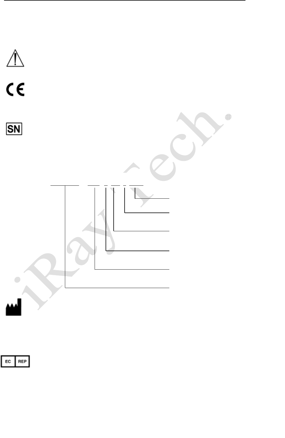
Symbol for “caution, consult accompanying documents”
For an instrument which has passed the CE test, the CE mark shall be placed on
the instrument’s label followed by the CE number
a. This symbol shall be accompanied by the manufacturer’s serial number. The
serial number shall be after, below or adjacent to the symbol.
b. The relative size of the symbol and the serial number are not specified.
c. So far our product serial number is made of thirteen digits:
a. The symbol shall be accompanied by the name and address of the
manufacturer,adjacent to the symbol. The address is not required with the
symbol on an immediate container as specified in EN375 AND EN376,
except the immediate container is also the outer container.
b. The relative size of the symbol ,the name and address is not specified.
a. The symbol shall be accompanied by the name and address of the
authorized representative in the European Community, adjacent to the
symbol. The address is not required with the symbol on an immediate
container as specified in EN375 AND EN376, except the immediate
container is also the outer container.
b. The relative size of the symbol, the name and address is not specified.
Numerical Order
Year
Date
Month
Ver si on
Product Code
A1A2A3A4 C
1C2 M DD Y XXX
Tocustomers
7
ServiceOffice:
Tel:+862150720560
E‐mail:service@iraychina.com
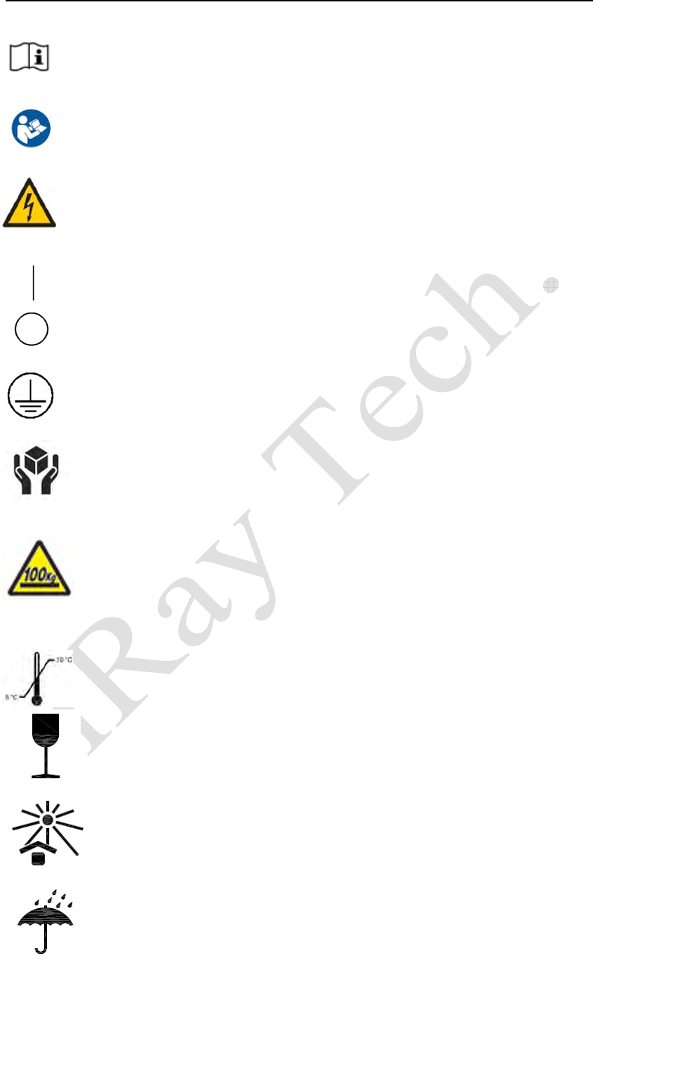
Symbol for “consult instructions for use”, “consult operation instructions”.
Safety Signs: Symbol for “refer to instruction manual”
Safety Signs:Symbol for “Dangerous Voltage”
“ON” ( power )
“OFF” ( power )
Protective Earth Conductor(ground)
This Mark indicates that this equipment must be handled with care
Do not jolt or apply excessive load to the equipment
The equipment shall be operated during the upper and lower limitsof
temperature
Fragile, the package should be handledwith care, package symbol
Keep awayfrom sunlight, package symbol
Keep dry, package symbol
Tocustomers
8
ServiceOffice:
Tel:+862150720560
E‐mail:service@iraychina.com
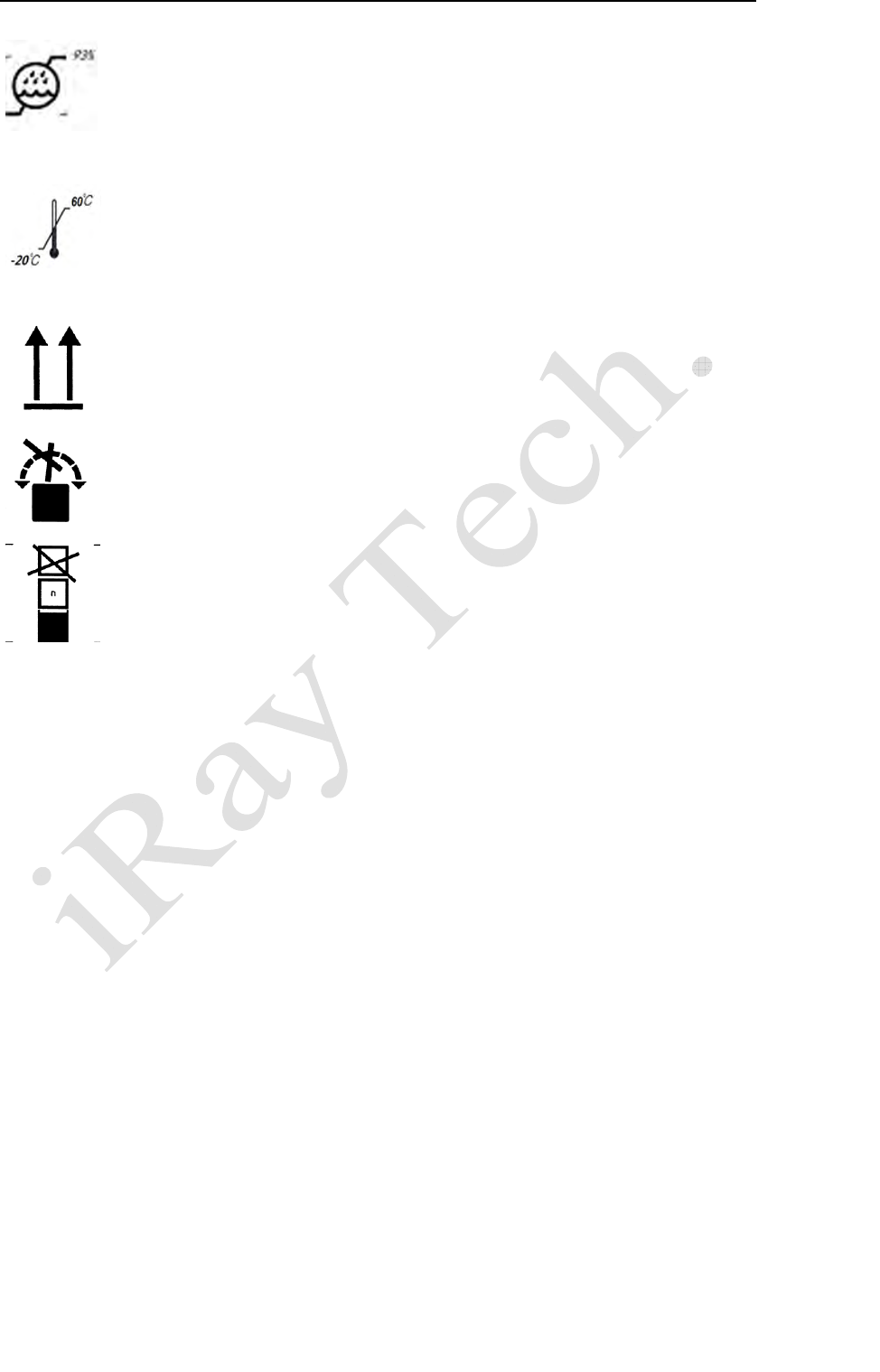
The humidity limitationshall be indicated adjacentto the upper horizontal
lines, package symbol
The storage temperatureshall be indicated adjacentto the upper horizontal
lines, package symbol
Indicates correctupright position ofthe transportpackage, package symbol
Transport packageshall not be rolled, package symbol
Stacking limit by number,package symbol
Trademarks
The iRay name and iRay logo are registered trademarks of Shanghai iRay
Technology Ltd.
Copyright
All rights reserved.
Under copyright laws, this manual may not be reproduced, in whole or in part,
without the written permission of iRay.

Contents
9
ServiceOffice:
Tel:+862150720560
E‐mail:service@iraychina.com
Contents
CONTENTS.......................................................................................................................................9
SAFETYNOTICES............................................................................................................................11
1.CHAPTERISAFETYINFORMATION...........................................................................................12
1.1
S
AFETYPRECAUTIONS
.........................................................................................................................12
1.2
N
OTESFORUSINGTHEEQUIPMENT
.......................................................................................................16
2.CHAPTERIIGENERALDESCRIPTION.........................................................................................20
2.1S
COPE
..............................................................................................................................................20
2.2M
ODEL
............................................................................................................................................21
2.3C
HARACTERISTIC
................................................................................................................................21
2.4I
NTENDEDUSE
...................................................................................................................................22
2.5S
TANDARDCONFIGURATION
..................................................................................................................22
2.6
S
TANDARD
P
ACKAGE
L
IST
....................................................................................................................23
2.7
M
AIN
S
PECIFICATIONS
........................................................................................................................25
2.8
D
ESCRIPTIONOF
I
NDICATORS
...............................................................................................................28
2.9
I
MAGE
D
IRECTION
.............................................................................................................................30
3.CHAPTERIIIINSTALLATIONANDOPERATION..............................................................................31
3.1Q
UICK
S
TART
.....................................................................................................................................31
3.2F
IRST
I
MAGE
A
CQUISITION
...................................................................................................................32
3.3
O
PERATION
N
OTES
............................................................................................................................32
4.CHAPTERIVCONTROLBOXINTERFACE.......................................................................................35
4.1AC
I
NPUT
.........................................................................................................................................36
4.2
S
ERIAL
P
ORT
.....................................................................................................................................36
4.3G
IGABIT
E
THERNET
P
ORT
.....................................................................................................................36
4.4HVG
I
NTERFACE
.................................................................................................................................37
4.5
I
NNER
T
RIGGER
M
ODULE
.....................................................................................................................38
4.6
X‐
RAY
I
MAGE
A
CQUISITION
..................................................................................................................38
5.CHAPTERVREGULATORYINFORMATION....................................................................................45
5.1
M
EDICALEQUIPMENTSAFETYSTANDARDS
..............................................................................................45
5.2
G
UIDANCEANDMANUFACTURE
’
SDECLARATIONFOR
EMC........................................................................46
6.CHAPTERVIIMAGINGSOFTWARESDK.........................................................................................51
7.CHAPTERVIISERVICEINFORMATION.........................................................................................52
PRODUCT LIFETIME...............................................................................................................52
REGULAR INSPECTION AND MAINTENANCE.....................................................................52
REPAIR.......................................................................................................................................52

Contents
10
ServiceOffice:
Tel:+862150720560
E‐mail:service@iraychina.com
REPLACEMENT PARTS SUPPORT..........................................................................................52
APPENDIXAINSTALLATIONOFSDK................................................................................................54
APPENDIXBDESCRIPTIONOFDIFFERENTCABLESERIES.................................................................57
APPENDIXCDIFFERENTVERSIONOFCONTROLBOX......................................................................58
APPENDIXDRECOMMENDEDCOMPUTERPLATFORM....................................................................60
APPENDIXEFIRMWAREUPDATE....................................................................................................62
APPENDIXFDUMMYLINES...........................................................................................................68
APPENDIXGDEFINITIONOFDEFECTS.............................................................................................70
APPENDIXHINFORMATIONOFSERVICEOFFICE.............................................................................71
APPENDIXIINFORMATIONOFMANUFACTURES............................................................................72
Safetynotices
11
ServiceOffice:
Tel:+862150720560
E‐mail:service@iraychina.com
Safety notices
The following safety notices are used to emphasize certain safety instructions. This
manual uses the caution symbol along with a caution message.
This notice is used to identify conditions under which improper
use of the product may cause death or serious personal injury.
This notice is used to identify conditions under which improper
use of the product may cause minor personal injury.
This notice is used to identify conditions under which improper
use of the product may cause property damage.
This is used to indicate a prohibited operation.
This is used to indicate an action that must be performed.
This is used to indicate important operations and restrictions. Be
sure to read this notice to prevent property damage or malfunction.
This is used to indicate operations for reference and
complementary information. Users are recommended to read this
notice.
Chapter I Safety Information
12
ServiceOffice:
Tel:+862150720560
E‐mail:service@iraychina.com
1. Chapter I Safety Information
1.1Safetyprecautions
Follow these safeguards and properly use the equipment to prevent injury and damage to any
equipment/data.
WARNING
Installation and environment of use
Do not use or store the equipment near flammable chemicals such as alcohol, thinner, benzene, etc.
If chemicals are spilled or evaporate, it may result in fire or electric shock through contact with electric
parts inside the equipment. Also, some disinfectants are flammable. Be sure to take care when using them.
Do not connect the equipment with anything other than specified.
Doing so may result in fire or electric shock.
Power supply
Do not operate the equipment using any type of power supply other than the one indicated on the
rating label.
Otherwise, it may result in fire or electric shock.
Do not handle the equipment with wet hands.
You may experience electric shock that could result in death or serious injury.
Do not place heavy object such as medical equipment on cables and cords. Do not pull, bend, bundle,
or step on them to prevent their sheath from being damaged, and do not alter them neither.
Doing so may damage the cords which could result in fire or electric shock.
Do not supply power to more than one piece of equipment using the same AC outlet.
Doing so may result in fire or electric shock.
Do not turn ON the system power when condensation has formed on the equipment.
Doing so may result in fire or electric shock.
Do not connect a multiple portable socket-outlet or extension cord to the system.
Doing so may result in fire or electric shock.
To avoid the risk of electric shock, this equipment must only be connected to power supply with
protective earth.
Not doing so may result in fire or electric shock.

Chapter I Safety Information
13
ServiceOffice:
Tel:+862150720560
E‐mail:service@iraychina.com
Securely plug the power cord into the AC outlet.
If contact failure occurs, or if metal objects come into contact with the exposed metal prongs of the plug,
fire or electric shock may result.
Be sure to turn OFF the power to each piece of equipment before connecting or disconnecting the
cords.
Otherwise, you may get an electric shock that could result in death or serious injury.
Be sure to hold the plug or connector to disconnect the cord.
If you pull the cord, the core wire may be damaged, resulting in fire or electric shock.
If the detector is intended to assemble mobile DR system, the sensor cable and Detector cable must be
ordered no longer than4m, and the cable must be collected in the fixed position, not doing this may cause
the DR system be toppled.
Chapter I Safety Information
14
ServiceOffice:
Tel:+862150720560
E‐mail:service@iraychina.com
WARNING
Handling
Never disassemble or modify the equipment. No modification of this equipment is allowed
Doing so may result in fire or electric shock. Also, since the equipment incorporates parts that may cause
electric shock as well as other hazardous parts, touching them may cause death or serious injury.
Do not place anything on top of the equipment.
The object may fall and cause an injury. Also, if metal objects such as needles or clips fall into the
equipment, or if liquid is spilled, it may result in fire or electric shock.
Do not hit or drop the equipment.
The equipment may be damaged if it receives a strong jolt, which may result in fire or electric shock if
the equipment is used without being repaired.
Do not put the equipment and pointed objects together.
The equipment may be damaged. If so, the equipment should be used in bucky.
Have the patient take a fixed posture and do not let the patient touch parts unnecessarily.
If the patient touches connectors or switches, it may result in electric shock or malfunction of the
equipment.
When a problem occurs
Should any of the following occurs, immediately turn OFF the power to each piece of equipment,
unplug the power cord from the AC outlet, and contact your sales representative or local iRay
dealer:
When there is smoke, an odd smell or abnormal sound
When liquid has been spilled into the equipment or a metal object has entered through an opening
When the equipment has been dropped and damaged
Maintenance and inspection
Please turn OFF the power of the equipment and unplug the power cord from the AC outlet before
cleaning.
NEVER use alcohol, ether and other flammable cleaning agent for safety. NEVER use methanol,
benzene, acid and base because they will erode the equipment.
DON’T dip the equipment into the liquid.
Please make sure that the equipment’s surface & plugs are dry before turning ON.
Otherwise, it may result in fire or electric shock.
Clean the plug of the power cord periodically by unplugging it from the AC outlet and removing
dust or dirt from the plug, its periphery and AC outlet with a dry cloth.
If the cord is kept plugged in for a long time in a dusty, humid or sooty place, dust around the plug
will attract moisture; this could cause insulation failure that may result in a fire.
For safety reasons, be sure to turn OFF the power to each piece of equipment when the performing
inspections indicated in this manual.
Otherwise, electric shocks may occur.
Chapter I Safety Information
15
ServiceOffice:
Tel:+862150720560
E‐mail:service@iraychina.com
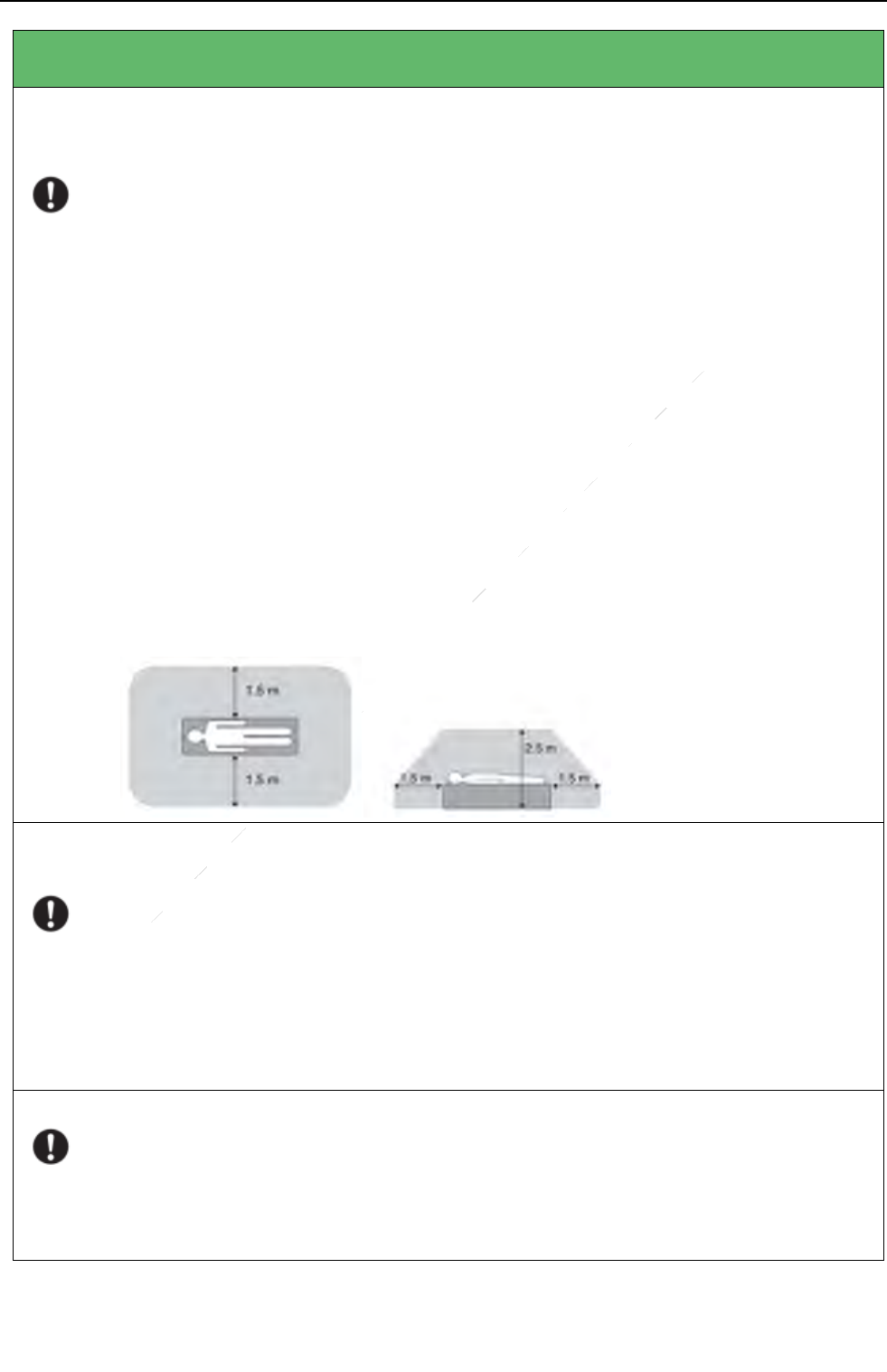
CAUTION
Installation and environment of use
Do not install the equipment in any of the locations listed below. Doing so may result in failure,
malfunction, equipment falling, fire or injury.
Close to facilities where water is used
Where it will be exposed to direct sunlight
Close to the air outlet of an air-conditioner or ventilation equipment
Close to heat source such as a heater
Where the power supply is unstable
In a dusty environment
In a saline or sulfurous environment
Where temperature or humidity is high
Where there is freezing or condensation
In areas prone to vibration
On an incline or in an unstable area
Because the equipment cable is long, take care that cables do not become tangled during use. Also,
be careful not to get your feet caught in the cable.
Otherwise, it may cause a malfunction of the equipment or the injury of the user due to tripping over
the cable.
Non-medical equipment such as the battery charger, access point and IR data communication unit
cannot be used in patient’s vicinity.
Power supply
Always connect the three-core power cord plug to a grounded AC power outlet.
To make it easy to disconnect the plug at any time, avoid putting any obstacles near the outlet.
Otherwise, it may not be possible to disconnect the plug in an emergency.
Be sure to ground the equipment to an indoor grounded connector. Also, be sure to connect all the
grounds for the system to a common ground.
Do not use any power source other than the one provided with this equipment.
Otherwise, fire or electric shock may be caused due to leakage.
Handling
Do not spill liquid or chemicals onto the equipment. In case the patient is injured, it is not allowed
to contact with blood or other body fluids.
Doing so may result in fire or electric shock.
In such a situation, protect the equipment with a disposable cover as necessary.
Turn OFF the power and pull out the plug to each piece of equipment for safety when not used.
Chapter I Safety Information
16
ServiceOffice:
Tel:+862150720560
E‐mail:service@iraychina.com
CAUTION
Handling
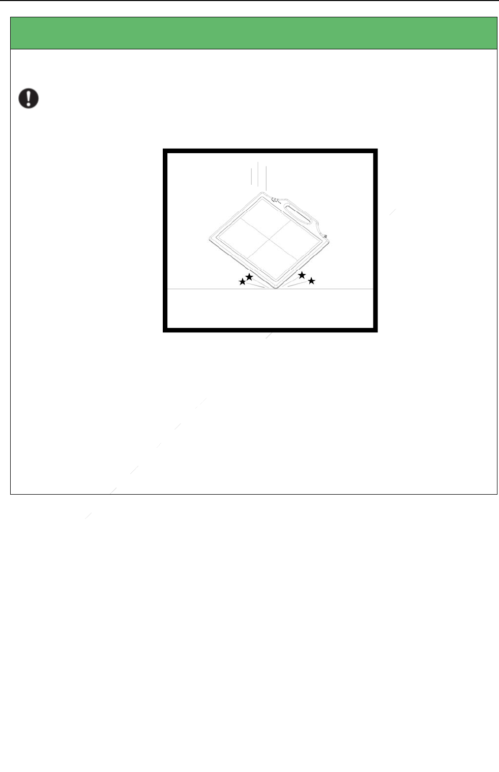
Handle the equipment carefully.
Do not submerge the equipment in water.
The internal image sensor may be damaged if something hits against it, or if it is dropped. If the
equipment is dropped, the drop sensor will turn red and the equipment will not be warranted by
iRay.
Do not place excessive weight on the detector.
Otherwise, the internal image sensor may be damaged and image may be incorrect.
Be sure to use the detector on a flat surface so it will not bend. Otherwise, the internal image sensor
may be damaged. Be sure to securely hold the detector while using it in upright positions.
Otherwise, the detector may fall over, resulting in injury to the user or patient, or may flip over,
resulting in damage to the inner device.
The detector should be used in the bucky or holder to keep the same load (same pressure) on the
detector when acquiring the image. Or the image will be incorrect.
1.2Notesforusingtheequipment
When using the equipment, take the following precautions. Otherwise, problems may occur and the
equipment may not function correctly.
Before exposure
Be sure to check the equipment daily and confirm that it works properly.
Check the cable MPN No. & control box version.
Sudden heating of the room in cold areas will cause condensation to form on the equipment.
In this case, wait until the condensation evaporates before performing an exposure. If the

Chapter I Safety Information
17
ServiceOffice:
Tel:+862150720560
E‐mail:service@iraychina.com
equipment is used while condensation is formed on it, problems may occur in the quality of
captured images. When an air-conditioner is used, be sure to raise/lower the temperature
gradually so that a difference of temperature in the room and equipment does not occur, to
prevent condensation.
The detector should warm up for 25 minutes before exposure or updating the gain map or
defect map.
During exposure
Do not move the power or Ethernet Cables during exposure, or it may cause image noise or
artifacts, even incorrect images.
Do not use the devices near the equipment generating a strong magnetic field. Otherwise, it
may cause image noise, artifacts or even incorrect images.
Disinfection and Cleaning
After every examination, wipe the patient contact surfaces of the detector using disinfectants
such as ethanol, to prevent the risk of infection. For details on how to sterilize, consult a
specialist.
Do not spray the detector directly with disinfectants or detergents.
Wipe it with a cloth slightly damped with a neutral detergent. Do not use solvents such as
alcohol, thinner, benzene, acid and base. Doing so may damage the surface of the equipment.
It’s recommended to use a waterproof non-woven cover as the isolated layer between detector
and the blooding patient.

Chapter I Safety Information
18
ServiceOffice:
Tel:+862150720560
E‐mail:service@iraychina.com
Replace Cables
Turn OFF the power of the equipment and unplug the power cord from the AC outlet before
operation. Unplug the detector cable from the float outlet, or it may result in fire or electric
shock.
Eliminate the static before replacing cable, including operating platform, tools and operator,
or ESD may damage the detector.
Operating/storage environment
Be sure to use and store this equipment under the conditions described below:
TemperatureTem pe rature
changeHumidityAtmospheric
PressurePressureChange
Operating5~30℃<1k/min
10~70%RH700~1000hPa1
0~70%RH
<10kp/min
(1kp=1.0197E‐5Pa)
Storage‐20~60℃≤93%RH
Do not expose this equipment to high temperatures and/or high humidity. Malfunctions may
occur.
Keep air flow around the equipment, especially when the environment temperature is above
30℃.
When the environment temperature is above 33℃ or running for a long time, the equipment
should be used in a holder or a bucky. The surface temperature may be above 41℃.
When not in use, keep the detector and grid in a designated and safe location.
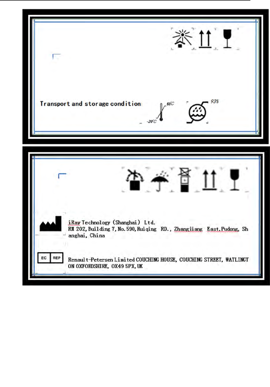
The labeling for Packaging marked with special handling instructions for transport and
storage:
The product should be storage or transport under the temperature from -20~60℃, the
humidity under 93% RH.
Chapter I Safety Information
19
ServiceOffice:
Tel:+862150720560
E‐mail:service@iraychina.com
Chapter II General Description
20
ServiceOffice:
Tel:+862150720560
E‐mail:service@iraychina.com
2. Chapter II General Description
The Mars1417V-PSI is the cassette-size (digital radiographic) X-ray flat panel detector based on
amorphous silicon thin-film transistor technologies. It is designed to provide the highest quality of
radiographic image, which contains an active matrix of2304×2800 pixels with 150μmpitch.Users can
select the type of scintillator such as Standard GOS(Gadolinium Sulfoxylate), DRZ Plus, or CsI
(Cesium Iodide).The data interface is Gigabit Ethernet which can afford high data transfer rates. In
addition, Mars1417V-PSI is equipped with iRay’s unique sync-shot function to make the hardware
connection between the equipment and HVG (High Voltage Generator)unnecessary.
Along with the equipment, iRay also provides a Microsoft Visual Studio (2008) library
IrayAcquireLib.lib, and a demo program iDemo® with source code to assist users’ integration of the
equipment into their existing DR system. The library IrayAcquireLib.lib contains functions for image
acquisition and equipment configuration. iDemo® demonstrates the usage of IrayAcquireLib.lib and
provides a simple user interface to acquire and preview X-ray images.
2.1Scope
This manual contains information about the iRay Mars1417V. All operators must read and understand
this manual before using the equipment. All information in this manual, including the illustrations, is
based on equipment prototype. If configuration of your equipment does not have any of these items,
information about these items in the manual does not apply to your equipment.
Chapter II General Description
21
ServiceOffice:
Tel:+862150720560
E‐mail:service@iraychina.com
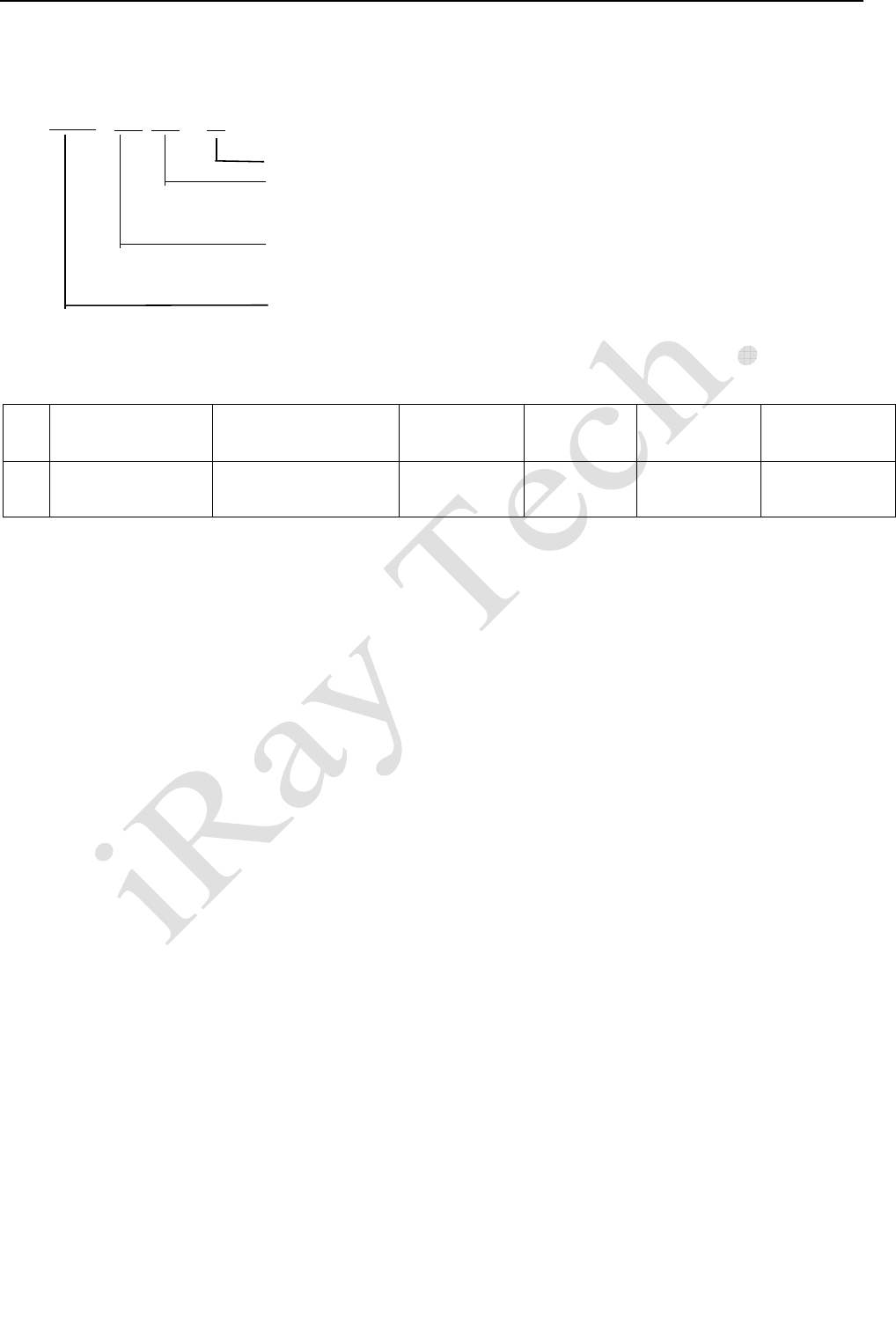
2.2Model
Mars□ □ - □
Scintillatortype:PSI,GadoliniumSulfoxylate
productuse:V,cassetteandportabledetector
productdimension:1417,14inch×17inch
productmodel:wirelessdigitalflatpaneldetector
Specification of Mars1417V serial Flat Panel Detector:
No. Model Brand Name Type of Use Active
area(cm2) Pixel matrix Pixel Pitch(μm)
1 Mars1417V-PSI Mars1417V-PSI Cassette and
portable 34.3×41.6 2304×2800 150
2.3Characteristic
Fixed static Flat Panel Detector used for general radiography.
Sync-Shot exposure trigger
Gigabit Ethernet
DRZ Plus or CsI scintillation screen.
Easy to change the cable and upgrade firmware.

Chapter II General Description
22
ServiceOffice:
Tel:+862150720560
E‐mail:service@iraychina.com
2.4Intendeduse
This equipment provides digital X-ray imaging for diagnosis of disease, injury, or any applicable health
problem. The image is obtained as the result of X-ray passing through the human body and detected
by the equipment. This device is intended to be used in the holder or bucky which is well insulated to
the detector. Or the holder or the bucky is well grounded. This device is not intended for directly
touching the person.
iRay will provide equipment and software support for integration of system. The total length of
Detector cable and Extension cable cannot exceed 9 m, or the impedance of protective earth
connections may exceed the safety threshold.
This device is not intended for mammography or dental applications,and prohibited for pregnant
women and children
2.5Standardconfiguration
The Mars1417Vcomes with a power supply which connects to 100-240 AC outlets and generates DC
voltages needed by the equipment.
Mars1417V sub types ending with suffix -I are equipped with internal X-ray sensors which
automatically detect the X-ray and synchronize image acquisition with the X-ray exposure, therefore,
they do not need to be connected to high voltage generator of the user’s DR system. Mars1417V
subtypes ending with the suffix -M are not equipped with any internal X-ray sensor and need to be
connected to the user’s high voltage generator through a supplied cable for synchronization between
image acquisition and X-ray exposure.
The equipment shall be connected to a computer through the Ethernet cable for data transfer. There is
also a serial cable connecting the detector to the computer for configuration and image acquisition
commands.
Chapter II General Description
23
ServiceOffice:
Tel:+862150720560
E‐mail:service@iraychina.com
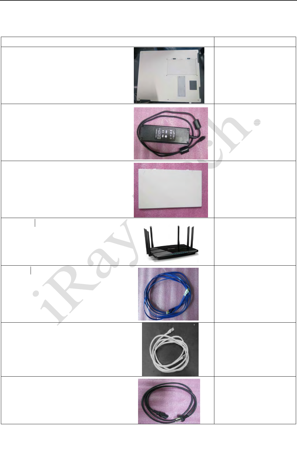
2.6StandardPackageList
ItemQty
Detector:
Mars1417V
(withdetectorcable)
1
MedicalAdaptor:
(ControlboxisspecifiedasapartofME
Equipment)
2
Battery:
3
WirelessAP
2
LANCable
1
EthernetCable
1
PowerCable
2

Chapter II General Description
24
ServiceOffice:
Tel:+862150720560
E‐mail:service@iraychina.com
Powerconvertcable
1
Chapter II General Description
25
ServiceOffice:
Tel:+862150720560
E‐mail:service@iraychina.com
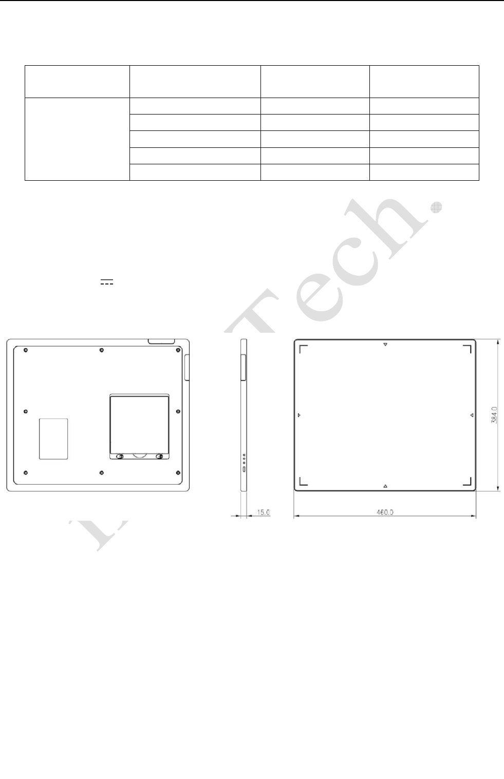
2.7MainSpecifications
2.7.1 Useful entrance field size
All the iRay’s detectors should meet the following requirements; the useful entrance field size should
be more than 95% nominal entrance field size.
Table 2.7.1 Entrance field size
Model Nominal entrance field size(cm) Useful entrance field size(cm)
Mars1417V serial 35 × 43 34.3×41.6
2.7.2 Minimumdetectabledoseshouldbelessthan100nGy.
2.7.3Maximumlinearitydoseshouldbemorethan60μGy,andthecorrelationcoefficient(r²)
shouldbenotlessthan0.99.
2.7.4Limitingspatialresolutionshouldbenotlessthan2.8Lp/mm(StandardGOS)/3.1Lp/mm(DRZ
PlusorCsI).
2.7.5Low‐contrastresolutionshouldbemorethan0.0055(withtheairkermashouldbe50μGy

Chapter II General Description
26
ServiceOffice:
Tel:+862150720560
E‐mail:service@iraychina.com
inthetestprocess).
2.7.6Defects
DefectsMaxNumberAllowed
FullClass013500
FullClass11500
FullClass21050
FullClass3300
FullClass4150
FullClass5120
FullClass60
FullClass70
FullClass80
Meta7+8Class10
Meta7+8Class20
Meta7+8Class30
Meta7+8Class40
Meta7+8Class50
Meta7+8Class60
Meta7+8Class70
Meta7+8Class80
SingleHorizontalDefectLines5
SingleVerticalDefectLines5
DoubleHorizontalDefectLines0
DoubleVerticalDefectLines2
DoubleVerticalDefectLinesinCentralArea0
TripleVerticalorHorizontalLines0
MinGapbetweenVerticalDefectLines/LinePairs10
MinGapbetweenHorizontalDefectLines/LinePairs10
2.7.7Flatuniformityshouldbenotexceed2.2%
2.7.8Modulationtransferfunction[MTF(u,v)]
TheMTFshouldmeetthefollowingtable
Standardradiation
qualityNo.RQA/μGySpatialfrequency(lp/mm) MTF(DRZ‐Plus)MTF(CSI)
5/2.5
0.5≥0.65≥0.77
1.0≥0.35≥0.58
1.5≥0.20≥0.39
2.0≥0.10≥0.25
2.5≥0.05≥0.15
3.3≥0.01≥0.10
Chapter II General Description
27
ServiceOffice:
Tel:+862150720560
E‐mail:service@iraychina.com
2.7.9Detectivequantumefficiency(DQE)
TheDQEshouldmeetthefollowingtable
Standardradiation
qualityNo.RQA/μGySpatialfrequency(lp/mm) DQE(DRZ‐Plus)DQE(CSI)
5/2.5
0≥0.20≥0.58
0.5≥0.15≥0.50
1.0≥0.10≥0.40
2.0≥0.02≥0.21
2.5≥0.01≥0.14
2.7.10Lageffectshouldbelessthan3%.
2.7.11 adaptor (ControlBoxisspecifiedasapartofMEequipment)
Power: Input: 110-240V~ 50-60Hz
Output: 12V 1A
Rated Input: 110VA
Chapter II General Description
28
ServiceOffice:
Tel:+862150720560
E‐mail:service@iraychina.com
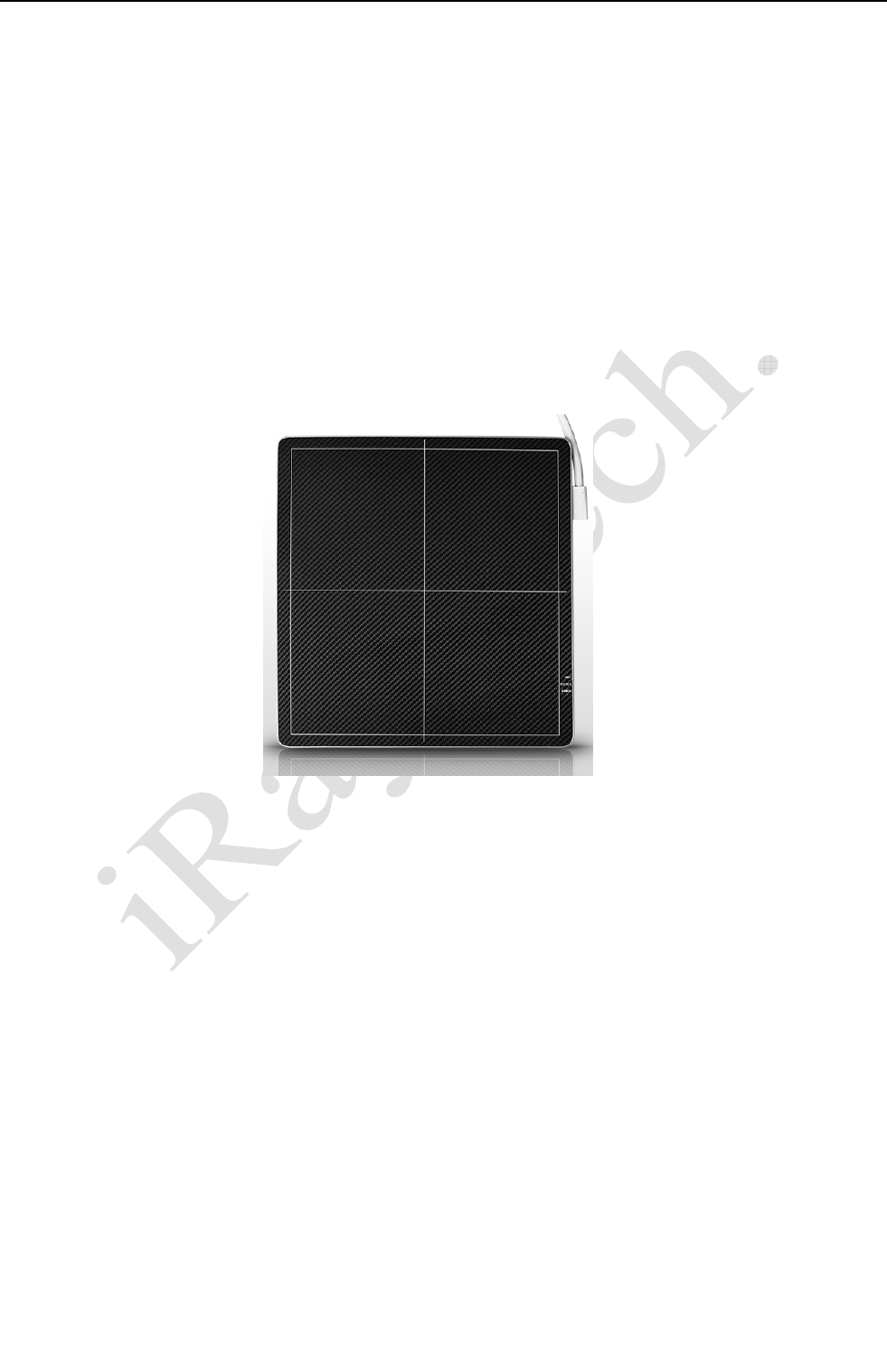
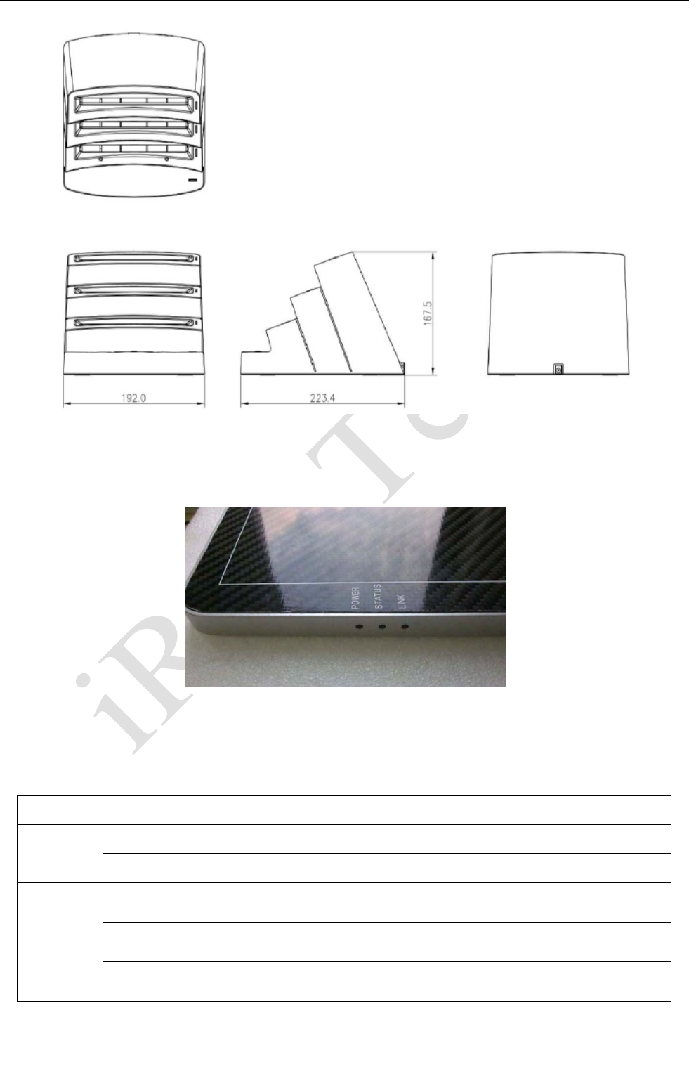
2.8DescriptionofIndicators
Fig.2.8.1DetectorIndicators
Table 2.8.1 Description of Detector Indicators
Items Color Descriptions
Power OFF Power OFF
Green(steady) Power supply is normal
Status
OFF Power OFF or Idle
Yellow(steady) Power up, load firmware or there exists error
Green(blinking) Data transmission between equipment and workstation

Chapter II General Description
29
ServiceOffice:
Tel:+862150720560
E‐mail:service@iraychina.com
Link OFF Power OFF
Green(steady) Gigabit Ethernet link is normal
Chapter II General Description
30
ServiceOffice:
Tel:+862150720560
E‐mail:service@iraychina.com
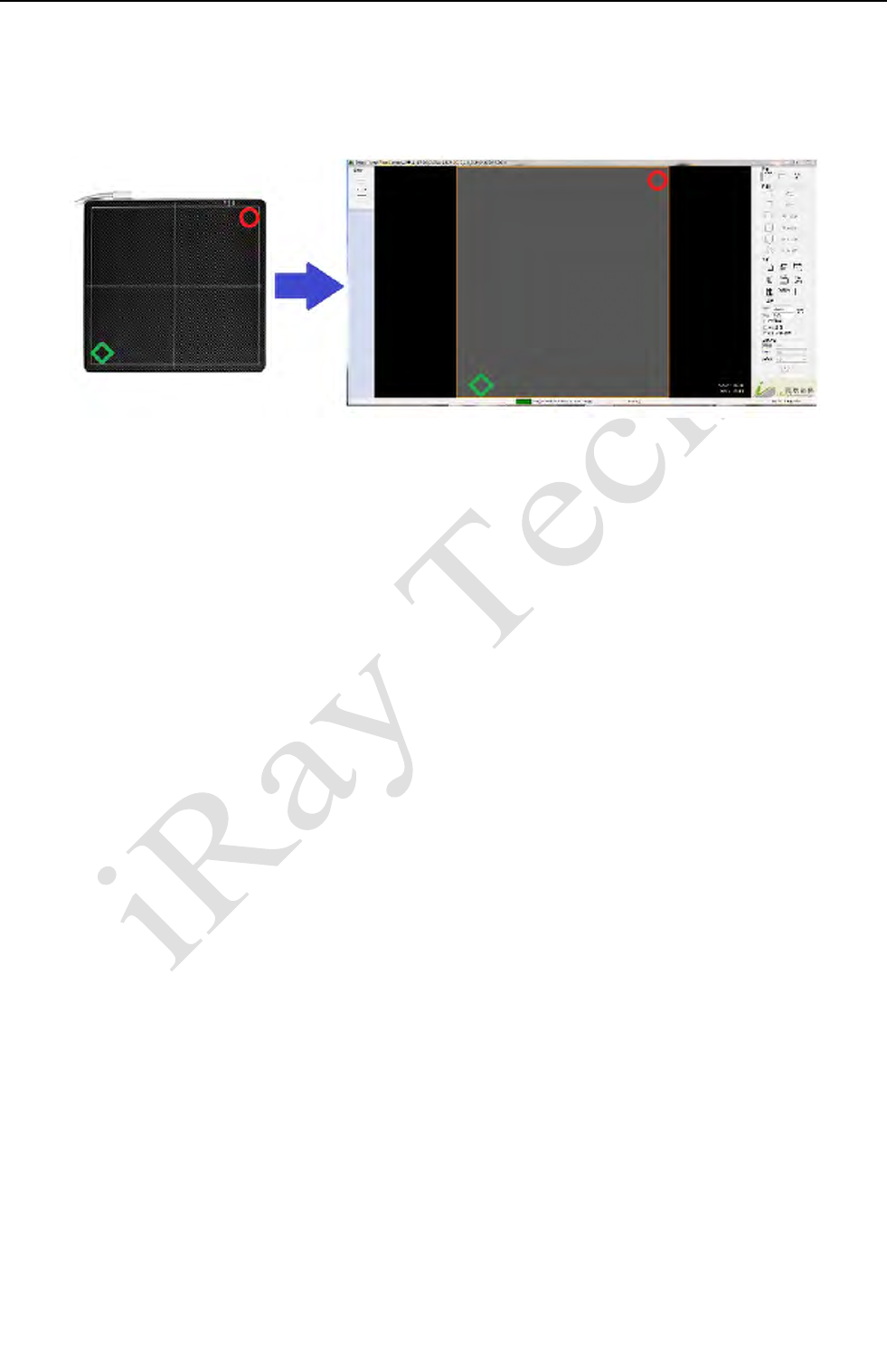
2.9ImageDirection
Please notice that the image direction is defined as follows:

Chapter III Installation and Operation
31
ServiceOffice:
Tel:+862150720560
E‐mail:service@iraychina.com
3. Chapter III Installation and Operation
The following is a general installation guide. The interface & operation may be different
between different firmware and software editions. Please contact iRay service office for the
details.
Before installation, please check the MPN (Manufactory Product Number) of the equipment
cable and the version of the control box. Please see Appendix B and Appendix C.
Do not place the detector/control box/cable near the AC-DC adapter, the electromagnet or the
RF equipment. Please find details from chapter 5.2.
iDemo 1.0.6.1(SDK 1.0.6.1) or above supports Software Auto-Clear Mode, when the mode is
enabled, please note the status message. Commands should be sent only when it is “Exposure
Enabled” or “Ready”, if it is “Exposure Prohibit (Auto-Clearing), the commands will be
ignored if they are sent. Please find details from SDK Manual and iRayDR User Guide.
The operator should have the experience of computer operation and X-ray diagnostic system
operation. Before using the product, the operation should be trained by iRay’s FAE or iRay’s
authorized engineers.
The equipment should be used with the specified power supply.
1. Turn on the computer.
2. Install a Gigabit Ethernet card in the computer if not installed.
3. Install WinPcap 4.1.2 for the Gigabit Ethernet interface.
4. Connect the power supply to a 110-240V AC outlet.
5. Connect the extension cable to the equipment.
6. Connect control box to PC and high voltage generator with interface cable(serial cable and
Ethernet cable).
7. Turn on power supply and the green indicator of the detector shall be lit up.
8. Run one image acquisition software such as iDemo.
3.1QuickStart
Before using the equipment, the user shall read the appendix A for details of SDK installation.

Chapter III Installation and Operation
32
ServiceOffice:
Tel:+862150720560
E‐mail:service@iraychina.com
Then the user can use the Quick Start software iDemo® for image acquisition.
3.2FirstImageAcquisition
iRay provides a Microsoft Visual Studio (2008) library IrayAcquireLib.lib and a demo program
iDemo® with source code to assist the users’ integration of the equipment into their existing DR system.
The library IrayAcquireLib.lib contains functions of image acquisition and detector configuration.
iDemo demonstrates the usage of IrayAcquireLib.lib and provides a simple user interface to acquire
and preview X-ray images.
The user can start the iDemo by double clicking on the executable file iDemo.exe included in the
CD ROM. iDemo loads the acquisition driver and sends commands through Gigabit Ethernet port. The
image data acquired by Mars1417V serial will be sent through the Gigabit Ethernet cable to the
computer. iDemo can perform offset, gain and defect correction on the image and then display the
image on screen.
After setting up the FPD and running iDemo, Please find the details from the SDK Manual or
contact with iRay Service Office.
3.3OperationNotes
The following notes should be noticed before using the detector.
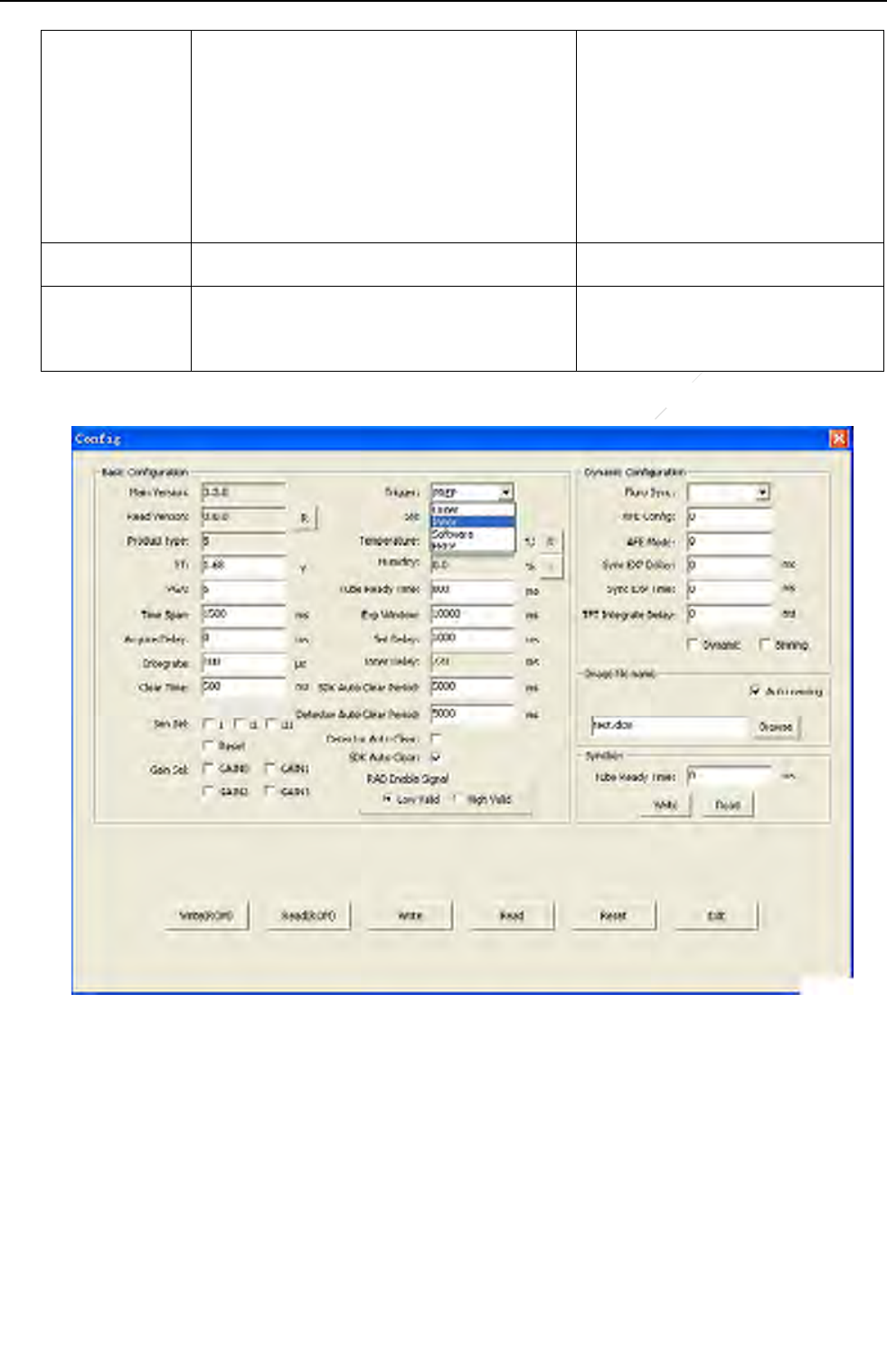
Basic Configuration Setting
There are some basic parameters on the “Config” Dialog when click the “Config” button on the
main window of the iDemo. The parameters should be set and checked as following, or the
image will be incorrect or no images will be gotten.
Parameters Description Comment
Set Delay The time between the end of Clear
process and the beginning of the Acquire
process of the “PREP Acquire”
Command.
Range from 0 to 9500
and should be less than
Exp Window-200
Chapter IV Control Box Interface
33
ServiceOffice:
Tel:+862150720560
E‐mail:service@iraychina.com
Acquire Delay The time between the end of the trigger
signal and the beginning of the Acquire
process of the “Acquire” command.
Range from 0 to 9500
and should be less than
Exp Window-200
It’s recommended to keep the
default value.
Exp Window The exposure window. Range from 100 to 10000
Trigger To set the mode of the trigger Should be checked before
installation
Please keep the other parameters as the default. Or contact with the service office of iRay.
Acquisition and post-offset calibration
Post-offset calibration needs the interval from the end of “Clear” and the beginning of the
“Acquire”. So with post-offset calibration, be sure to send “Clear” command before “Acquire” or
it’ll take long time to get the image or no images will be gotten.
Chapter IV Control Box Interface
34
ServiceOffice:
Tel:+862150720560
E‐mail:service@iraychina.com
Gigabit Ethernet Connection
The detector can set stable connection with the Ethernet Card from Intel or Broadcom. The
computer should meet the minimum requirements of the hardware and software. Please find the
details from Appendix D If there is a connection problem, please check the hardware settings,
including connector, cable or the computer. Re-plugging the Ethernet cable may be helpful to
set the connection.
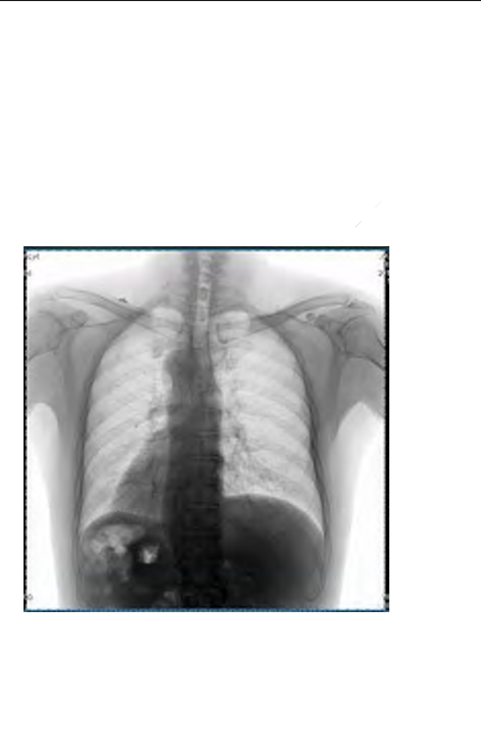
To acquire a normal clinical diagnostic image
The clinical diagnostic image does not contain the defect pixel, defect data line and any other
image defect. Human tissue should be fit for the requirements of clinical diagnosis, the image
should be clearly and identifiable.

ChapterIVControlBoxInterface
35
ServiceOffice:
Tel:+862150720560
E‐mail:service@iraychina.com
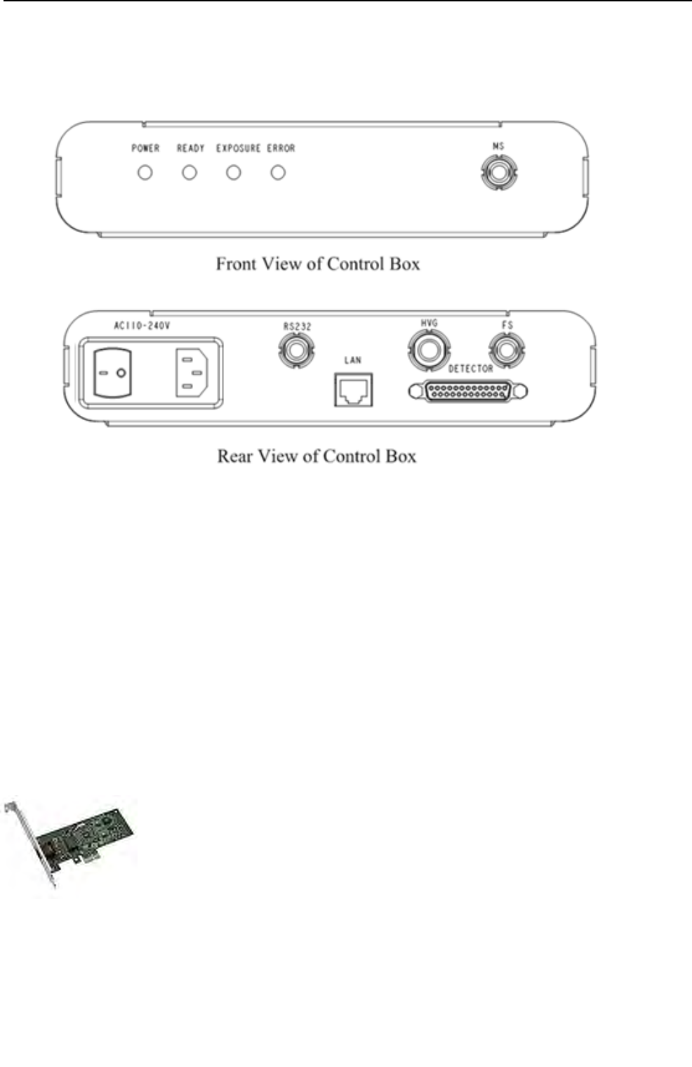
4. Chapter IV Control Box Interface
Control box is the relay device between computer and equipment. It is specified as a part of ME
equipment. As shown in the figure, there are 1 connection ports & 4 LEDs at the front panel and 6
connection ports at the back panel of the control box. Some of these interfaces may not provide the
function in some versions, please contact iRay service office. All the plug and connector should be
placed in a portable position. To avoid the connection error, all the plug and connector are designed to
insert error hardly.
AC Input: Three-phase (electric) outlet for AC110-240V power input.
LAN: Gigabit Ethernet port connected to PC.
RS232: Reserved.
HVG: Control interface connected to high voltage generator.
FS : Foot Switch interface
DETECTOR: Integrated interface with power and data connected to Equipment.
MS: Hand Switch (Manual Switch) interface.
Status indicators:
POWER: indicate power status
READY: indicate equipment is ready for X-ray exposure
EXPOSURE: indicate there is X-ray shot
ERROR: indicate power up or there exists error
Please find the details from §2.8 Description of Indicators
ChapterIVControlBoxInterface
36
ServiceOffice:
Tel:+862150720560
E‐mail:service@iraychina.com
4.1ACInput
AC input shall be connected to AC 100-240V three-phase power supply. Be careful that the AC socket
must have right earth connection terminals. The control box shall conform to IEC 60601-1.
4.2SerialPort
The serial port is reserved for firmware updating.
4.3GigabitEthernetPort
The GBE port shall be connected with an Ethernet cable to a Gigabit Ethernet
Port of the user’s computer. The GBE port transmits image data through Gigabit
Ethernet protocol. For NIC (Network Interface Card), Intel Pro EXP9301CT
PRO Gigabit Network Adapter with PCIe interface is recommended. If the user
prefers any other Gigabit Network Adapter, only those with PCIe interface
should be considered.

ChapterIVControlBoxInterface
37
ServiceOffice:
Tel:+862150720560
E‐mail:service@iraychina.com
4.4HVGInterface
The HVG interface with 16 pins is to synchronize HVG with the equipment.
The descriptions of HVG interface & HVG Cable
Pin
No. Wire Color Name I/O Signal Description
1 Shield NC / Not Connected
2 White Syn_OUT_N O
Reserved for dynamic mode, the negative
part of trigger signal provided by the
equipment.
3 Red/white Xray_On_N/
Syn_IN_N I Reserved for dynamic mode, the negative
part of trigger signal provided by the HVG.
4 Black SYN_OUT_P O
Reserved for dynamic mode, the positive
part of trigger signal provided by the
equipment.
5 Green Reserved O Please left float
6 Gray Expose_OK_N O
Negative part of ready signal for high
voltage generator. When the signal is
active, it indicates that the equipment is
ready for exposure.
7 Brown Reserved / Please left float
8 Brown/
white Expose_Ok_P O
Positive part of ready signal for high
voltage generator. When the signal is
active, it indicates that the equipment is
ready for exposure.
9 Blue Frame_Request_P I
Positive part of request provided by the
HVG. Ask for preparation of the
equipment.
10 Yellow EXT_VOUT O +5V power supply
11 Black/
white Frame_Request_N O
Negative part of request provided by the
HVG. Ask for preparation of the detector.
12 Pink EXT_GND / Ground of EXT_VOUT
13 Red Xray_ON_P
/Syn_IN_P I Reserved for dynamic mode, positive part
of trigger signal provided by the HVG.
14 Cyan G_SW_XON O
Reserved for hand switch or foot switch,
relay pin for X-ray exposure
15 Purple G_SW_EN O
Reserved for hand switch or foots witch,
relay pin for X-ray preparation
16 Orange G_SW_COM O
Reserved for hand switch or foot switch,
relay common pin
ChapterIVControlBoxInterface
38
ServiceOffice:
Tel:+862150720560
E‐mail:service@iraychina.com
Table 4.4.1 DC characteristic of HVG interface
I
typ
(mA)I
max
(mA)U
min
(V)U
typ
(V)U
max
(V)U
rev_max
(V)
Input(P‐N)‐16‐25456.55
Output(P‐N)‐1‐10456.55
PowerOutput/10004.555.5/
4.5InnerTriggerModule
The detector has anembedded well-proved Inner Trigger module consisting of X-ray sensor and
inner trigger board. It can simplify the connection with the HVG.The energy range is from 50kV to
150kV.
4.6X‐rayImageAcquisition
Mars1417V serial provides carefully designed functions and commands for the terminal users to
acquire X-ray images under various environments. The users need to select one of three acquisition
trigger modes: Prep-trigger mode, Inner-trigger mode and Soft-trigger mode.
The trigger mode must be set correct before image acquisition; otherwise the FPDs
may not work properly.
The voltage and current of tube should be set properly to get sufficient dose rate.
Otherwise, no images will be gotten after the exposure and another “Acquire” command should be
sent to get the image back.
ChapterIVControlBoxInterface
39
ServiceOffice:
Tel:+862150720560
E‐mail:service@iraychina.com
4.6.1 Prep-trigger mode
In the Prep-trigger mode, HVG (High Voltage Generator) needs to be connected to the control box.
The whole acquisition process (including prepare, exposure, acquisition and transmission) is trigged
by the request from HVG. If the process is started, the images will be acquired and transmitted to the
Ethernet port, no matter X-ray is fired or not.
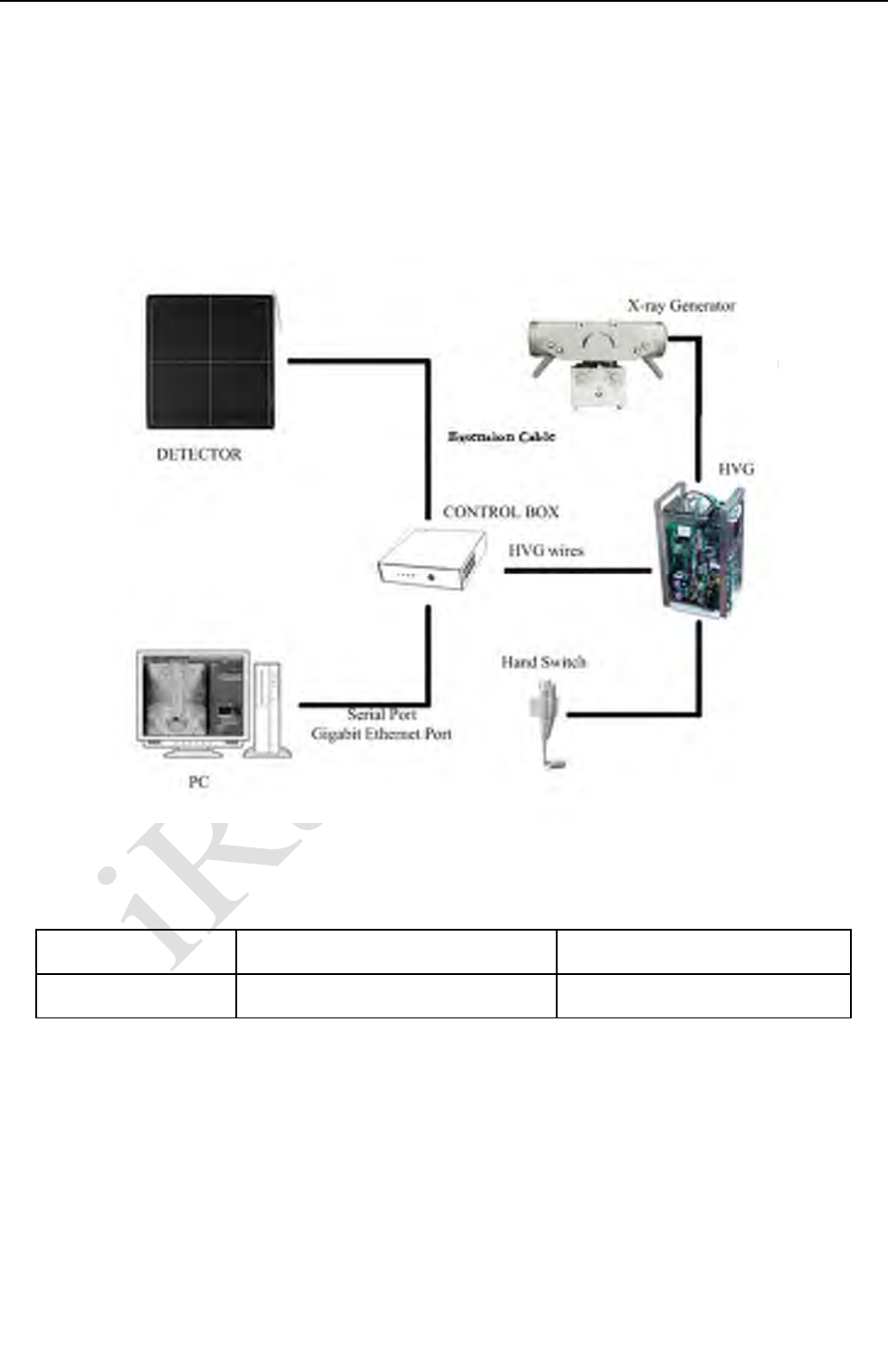
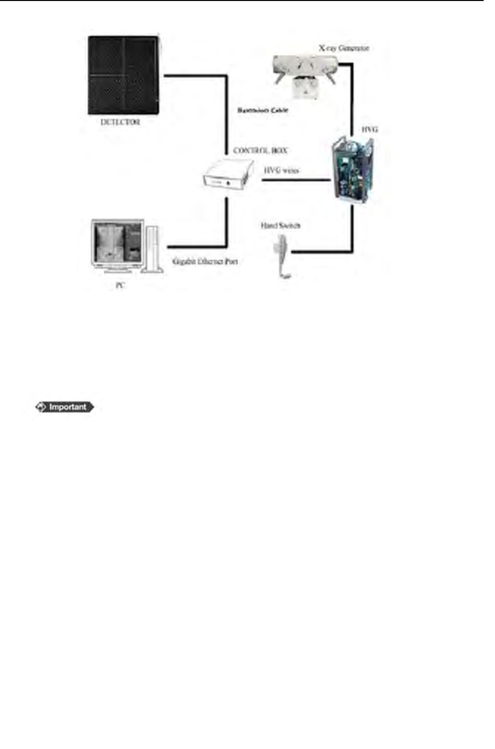
System installation
Control box provides 2pairs of signals and 1 pair of power (Fig. 4.6.2).
Fig 4.6.1 Basic Connection
Before connecting to the HVG (High Voltage Generator), please check the
control box version. The HVG connection is different between two versions, but both of them
can support Prep-Trigger mode .Please see Appendix C or find the details from iRay service
office. The Following is for V1.
ChapterIVControlBoxInterface
40
ServiceOffice:
Tel:+862150720560
E‐mail:service@iraychina.com
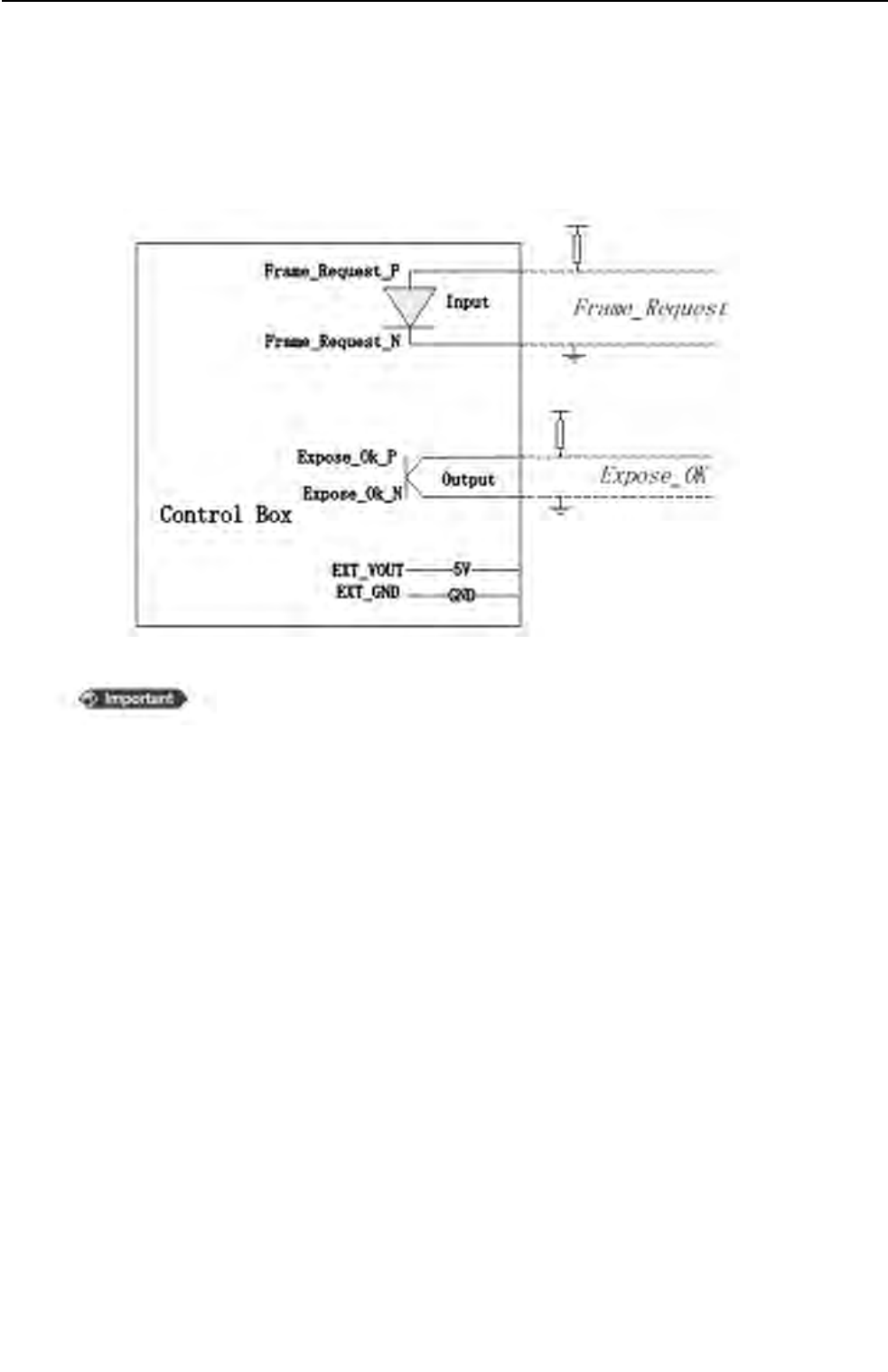
For Prep-trigger mode, only Frame_Request,Expose_OK are needed. To work properly some
pull-up/pull-down circuits may be necessary for different HVG, please find details from your HVG
manual. The control box also has output power supply for pull-up/pull down circuits.
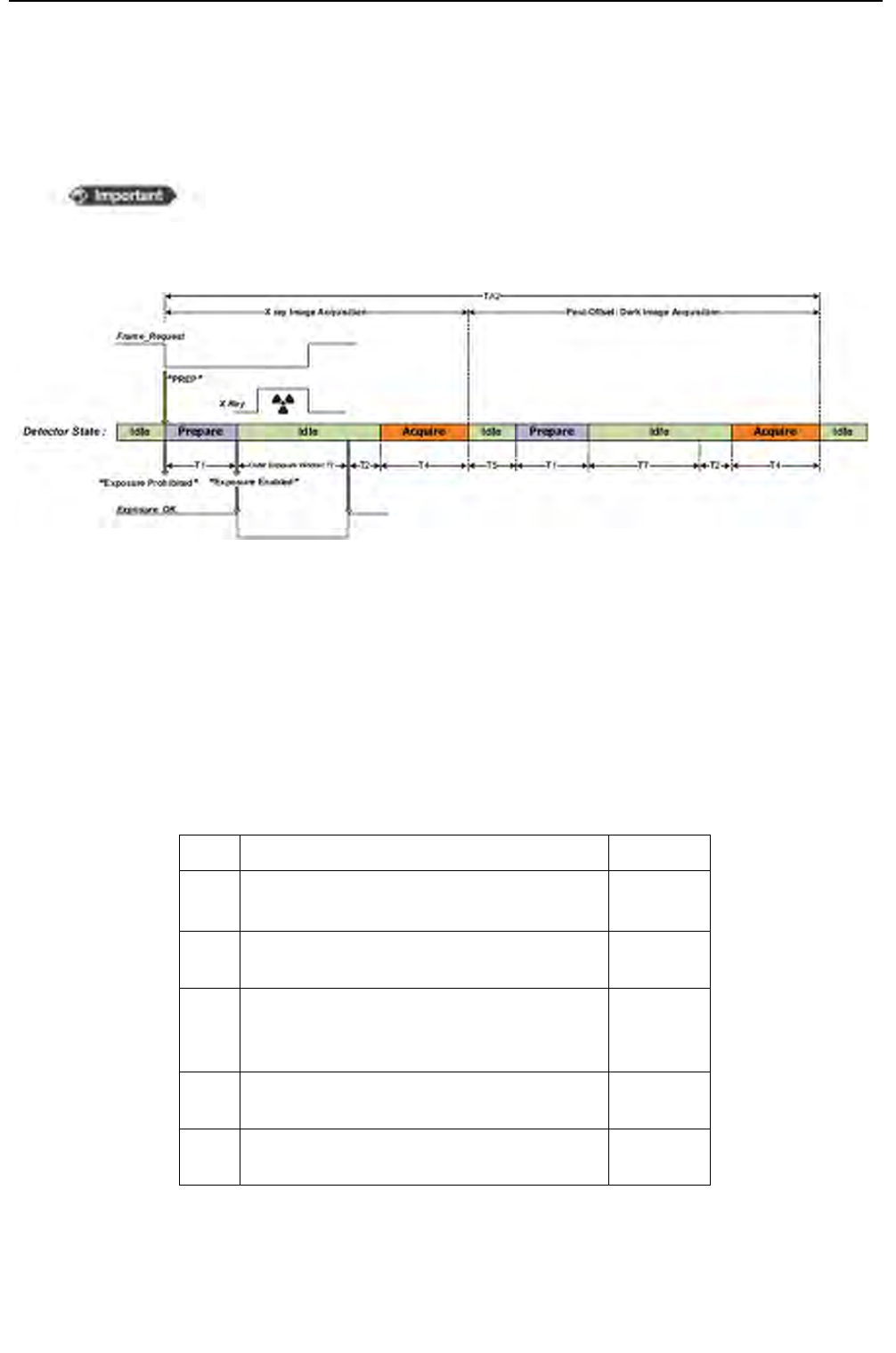
X-ray image acquisition timing
In Prep-trigger mode, the acquisition process is triggered by the Frame_Request from the HVG
when there is no “Exposure Prohibited (auto clear)” shown in software status box. And
equipment will start preparing for exposure and sending the message “Exposure Prohibited” to the
workstation to indicate that the X-ray should not be fired before the equipment is ready.
After the equipment is ready, it sends the message “Exposure Enabled” to the workstation to
indicate that the detector is ready for exposure,and the signal “Exposure_OK” is given to HVG
at the same time.
Fig.4.6.2HVGPortofControlBox
The Frame_request is low level valid.
ChapterIVControlBoxInterface
41
ServiceOffice:
Tel:+862150720560
E‐mail:service@iraychina.com
When the detector is ready, it starts the “prep trigger window”. X-ray should be fired in the “prep
trigger window” to get the proper images. After “preptrigger window”, an image will be acquired
no matter the X-ray is fired or not.
If the “post-offset” is enabled, the dark image acquisition will start automatically after the light
image acquisition. The dark image provides the offset calibration information to workstation.
The calibrated image will be shown when workstation receives light image and dark image, or
there may be no image shown.
Table4.6.2TypicalValueofMars1417Vserialinprep‐trigger
mode(unit:sec)
T1Preparetimeofequipment.0.5
T2Intervalbetweenendofprep‐triggerwindow
andbeginningofacquisitionprocess./
T4Dataacquireandtransmissiontimeof
detector0.7
T5
Intervalbetweentheendoflightimage
acquisitionandthebeginningofdarkimage
acquisition.
0.3
T7PreptriggerwindowSetDelay
Time
TA2Cycletimeoftheimageacquisitionwhen
“post‐offset”isenabled/
Fig.4.6.3Prep‐TriggerTiming
If the “post-offset” is enabled, DO NOT trigger another exposure or
acquisition before the previous image is on screen.
ChapterIVControlBoxInterface
42
ServiceOffice:
Tel:+862150720560
E‐mail:service@iraychina.com
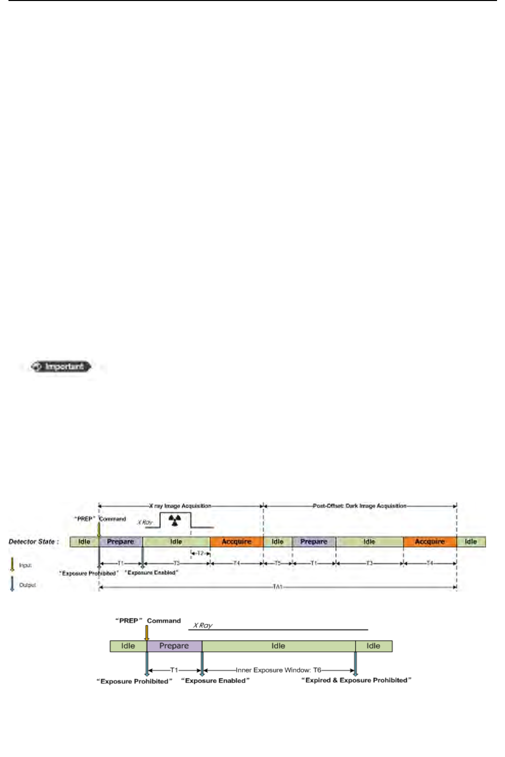
4.6.2 Inner-trigger mode,
System installation
In Inner-trigger mode, the acquisition is triggered by sync-shot module in the equipment. The
connection between HVG and control box is unnecessary.
X-ray image acquisition timing
The acquisition is triggered by the “Prep” (“Prepare”) command provided by the workstation
when there is no “Exposure Prohibited (auto clear)” shown in software status box. Then the
equipment will start preparing and feedbacking the message “Exposure Prohibited” to the
workstation to indicate that X-ray should not be fired before the equipment is ready.
When the equipment is ready, it starts “inner trigger window” and feedbacks the message
“Exposure Enabled” to the workstation to indicate that the equipment is ready for exposure.
To get proper image, X-ray should be fired in the “inner triggerwindow” (see fig.4.6.4),or
equipment gives the message“Expired & Exposure Prohibited” to indicate that no image is
acquired and the equipment is not ready for X-ray.(see fig. 4.6.5).
If the “post-offset” is enabled, the dark image acquisition will start automatically after the light
image received. The dark image provides the offset calibration information to workstation. The
calibrated image will be shown when workstation receives light image and dark image, or there
may be no image shown.
Fig.4.6.4TimingofInnerTriggerMode:NormalOperation
Fig.4.6.5TimingofInnerTriggerMode:NoExposure
If the “post-offset” is enabled, DO NOT trigger another exposure or
acquisition before the previous image is on screen.

ChapterIVControlBoxInterface
43
ServiceOffice:
Tel:+862150720560
E‐mail:service@iraychina.com
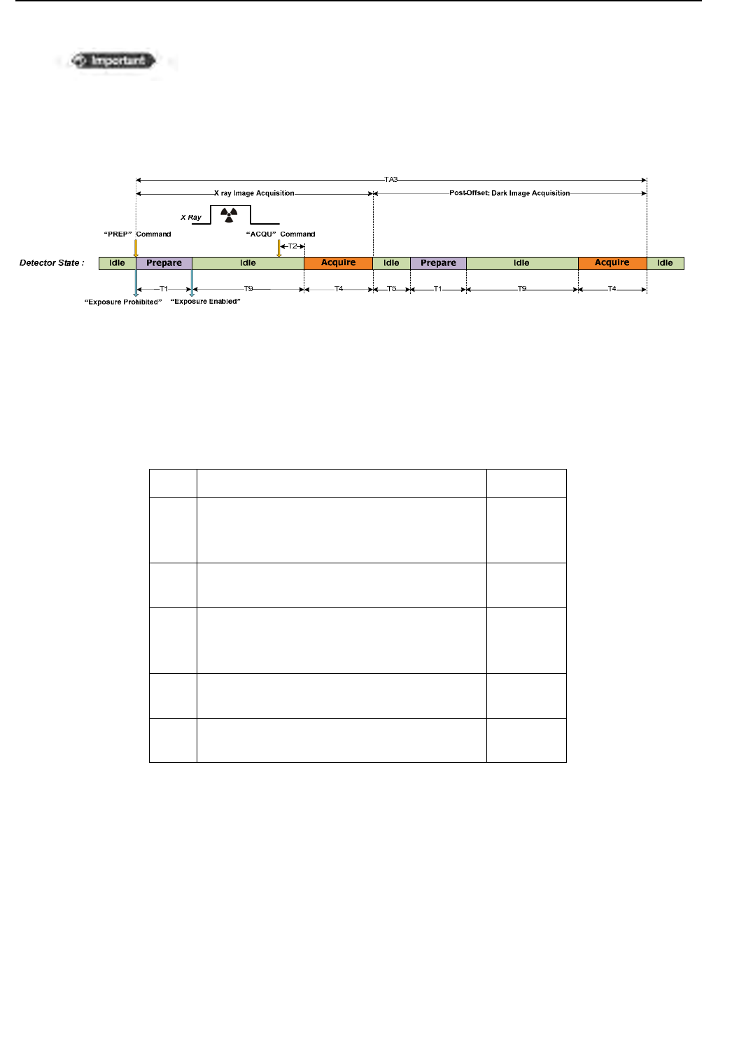
4.6.3 Soft-trigger mode
System installation
In soft-trigger mode, the acquisition is triggered by the “PREP Acquire” command provided by
workstation when there is no “Exposure Prohibited (auto clear)” shown in software status
box. The connection between HVG and equipment is unnecessary.
X-ray image acquisition timing
In soft-trigger mode, equipment starts preparation when receiving “PREP Acquire” command
provided by workstation. And the message “Exposure Prohibited” will be sent to the workstation
to indicate that X-ray should not be fired before the equipment is ready.
After the equipment is ready, it sends the message “Exposure Enabled” to indicate that equipment
is ready for exposure. To acquire X-ray image (light image), X-ray should be fired(see
fig.4.6.6).Please note that the image acquisition is just triggered by the “PREP Acquire” command,
so an image will be acquired if the detector gets the “PREP Acquire” command no matter X-ray
is fired or not.
If “post-offset” is enabled, the dark image acquisition starts automatically after the light image
acquisition is successful. The dark image provides the offset calibration information to
workstation. The calibrated image will be on screen when workstation receives light image and
dark image, otherwise there may be no image shown.
Table4.6.3TypicalValueofMars1417Vserialininner‐trigger
mode(unit:sec)
T1Preparetimeofequipment.0.5
T2Intervalbetweenendofprep‐triggerwindow
andbeginningofacquisitionprocess./
T3Inner‐triggerwindow<10
T4Dataacquireandtransmissiontimeof
detector0.7
T5
Intervalbetweenoftheendoflightimage
acquisitionandthebeginningofdarkimage
acquisition.
0.3
TA1Cycletimeoftheimageacquisitionwhen
“post‐offset”isenabled2.7+2T3
ChapterIVControlBoxInterface
44
ServiceOffice:
Tel:+862150720560
E‐mail:service@iraychina.com
Table4.6.4TypicalValueofMars1417Vserialinsoft‐triggermode
(unit:sec)
T1Preparetimeofequipment.0.5
T2
Intervalbetweenreceivingimageacquisition
commandandbeginningofacquisiton
process.
/
T4Dataacquireandtransmissiontimeof
equipment0.7
T5
Intervalbetweentheendoflightimage
acquisitionandthebeginningofdarkimage
acquisition.
0.3
T9Intervalbetweentheequipmentisreadyand
thebeginningoftheimageacquisition<T6
TA3Cycletimeoftheimageacquisitionwhen
“post‐offset”isenabled2.7+2T9
Fig.4.6.6TimingofSoftwareTriggerMode:NormalOperation
If the “post-offset” is enabled, DO NOT triggers another exposure or
acquisition
before the previous image is shown.

Chapter V Regulatory Information
45
ServiceOffice:
Tel:+862150720560
E‐mail:service@iraychina.com
5. Chapter V Regulatory Information
The product safety standards that apply to Mars1417V serial, which include the main units: detector
and adaptor.
5.1Medicalequipmentsafetystandards
Medical equipment classification
Type of protection against electrical shock external electrical power source equipment
Class I Equipment, with wiring unit
Degree of protection against electrical shock B type Applied Parts
Degree of protection against ingress of water IP21
Mode of operation Continuous operation
Flammable anesthetics Not suitable for use in the presence of a flammable
anesthetic mixture with air or with, oxygen or nitrous oxide
Not suitable for use in the oxygen rich environment
Product safety standards
EN 60601-1:2006+AC:2010 Medical electrical equipment -- Part 1: General requirements for basic
safety and essential performance
EN 60601-1-2:2007+AC:2010 Medical electrical equipment – Part 1-2: Collateral standard:
Electromagnetic compatibility – Requirements and tests
EN 60601-1-3:2008 Medical electrical equipment – Part 1-3: Collateral standard: General
requirements for radiation protection in diagnostic X-ray equipment
EN 60601-2-54:2009 Medical electrical equipment -- Part 2-54: Particular requirements for the
basic safety and essential performance of X-ray equipment for
radiography and radioscopy
EN 62220-1:2004
Medical electrical equipment - Characteristics of digital X-ray imaging
devices -- Part 1: Determination of the detective quantum efficiency
EN 300 328 V1.8.1 Electromagnetic compatibility and Radio spectrum Matters (ERM);
Wideband transmission systems; Data transmission equipment operating
in the 2,4 GHz ISM band and using wide band modulation techniques
EN 301 893 Broadband Radio Access Networks (BRAN);5 GHz high performance

Chapter V Regulatory Information
46
ServiceOffice:
Tel:+862150720560
E‐mail:service@iraychina.com
RLAN; Harmonized EN covering essential requirements of article 3.2 of
the R&TTE Directive V1.2.3
EN 301 489-1/-17
EN 62311:2008 Assessment of electronic and electrical equipment related to human
exposure restrictions for electromagnetic fields (0 Hz - 300 GHz)
FCC Part 15 Subpart B Class B and
Part 15 Subpart C
5.2Guidanceandmanufacture’sdeclarationforEMC
Electromagnetic emissions
Mars1417V serial is intended for use in the electromagnetic environment specified below. The
customer or the user of Mars1417V serial should assure that it is used in such an environment.
Emission Test Compliance Electromagnetic Environment - Guidance
RF emissions CISPR 11 GROUP1
Mars1417V serial uses RF energy only for its internal function.
Therefore, its RF emissions are very low and are not likely to
cause any interference in nearby electronic equipment.
RF emissions CISPR 11 Class B
Mars1417V serial is suitable for use in all establishments,
including domestic establishments and those directly connected to
the public low-voltage power supply network that supplies
buildings used for domestic purposes.
Harmonic emissions
IEC 61000-3-2 Class B
Voltage fluctuations/ flicker
emissions
IEC 61000-3-3
Pass
Electromagnetic immunity
Mars1417V serialis intended for use in the electromagnetic environment specified below.
Thecustomer or the user of Mars1417V serial should assure that it is used in such an environment.
Immunity Test IEC 60601 Test Level Compliance Level Electromagnetic Environment - Guidance
Electrostatic discharge
(ESD)
IEC 61000-4-2
±6 kV contact
±8)kV air
±6)kV contact
±8kV air
Floors should be wood, concrete or ceramic tile. If
floors are covered with synthetic material, the
relative humidity should be at least 30%.
Electrical fast transient/
burst
±2 kV for power supply
lines
±2 kV for power supply
lines
Mains power quality should be that of a typical
commercial or hospital environment.

Chapter V Regulatory Information
47
ServiceOffice:
Tel:+862150720560
E‐mail:service@iraychina.com
IEC 61000-4-4 ±1 kV for input/ output
lines
±1 kV for input/ output
lines
Surge
IEC 61000-4-5
±1 kV differential mode
±2 kV common mode
±1 kV differential mode
±2 kV common mode
Mains power quality should be that of a typical
commercial or hospital environment.
Voltage dips, short
interruptions and
voltage variations on
power supply input
lines
IEC 61000-4-11
<5% UT (>95% dip in
UT) for 0.5 cycle.
40% UT (60% dip in
UT) for 5 cycle.
70% UT (30% dip in
UT) for 25 cycle.
<5% UT (>95% dip in
UT) for 5 sec.
<5% UT (>95% dip in
UT) for 0.5 cycle.
40% UT (60% dip in
UT) for 5 cycle.
70% UT (30% dip in
UT) for 25 cycle.
<5% UT (>95% dip in
UT) for 5 sec.
Mains power quality should be that of a typical
commercial or hospital environment. If the user of
that requires continued operation during power
mains interruptions, it is recommended that (?) be
powered from an uninterruptible power supply.
Power frequency
(50/60Hz) magnetic
field
IEC 61000-4-8
3 A/m 3 A/m
Power frequency magnetic fields should be at
levels characteristic of a typical location in a
typical commercial or hospital environment.
UT is the a.c. mains voltage prior to application of the test level.
Guidance and manufacturer’s declaration----electromagnetic immunity
Mars1417V serial is intended for use in the electromagnetic environment specified below.
Thecustomer or the user of Mars1417V serial should assure that it is used in such an environment.
Immunity Test IEC 60601 Test
Level Compliance Level Electromagnetic Environment - Guidance
Conducted RF
IEC 61000-4-6
3 Vrms
150kHz to 80MHz
3 Vrms
Portable and mobile RF communications
equipmentshould be used no closer to any part of the
ModelMars1417V serial, including cables, than the
recommendedseparation distance calculated from the
equationapplicable to the frequency of the transmitter.
Recommended separation distance
d = 1,2 p
d = 1,2 p 80 MHz to 800 MHz
d = 2,3 p 800 MHz to 2,5 GHz
Where P is the maximum output power rating of
thetransmitter in watts (W) according to the
transmittermanufacturer and d is the recommended
separationdistance in meters (m).
Radiated RF
IEC 61000-4-3
3 V/m
80MHz to 2.5GHz
3 V/m
Chapter V Regulatory Information
48
ServiceOffice:
Tel:+862150720560
E‐mail:service@iraychina.com
Field strengths from fixed RF transmitters, as
determinedby an electromagnetic site survey, shouldbe
less than the compliance level in each frequency range.
Interference may occur in the vicinity of
equipmentmarked with the following symbol:
NOTE: UT is the a.c. mains voltage prior to application of the test level.
NOTE1 At 80 MHz and 800 MHz, the higher frequency range applies.
NOTE2 These guidelines may not apply in all situations. Electromagnetic propagation is affected
by absorption and reflection from structures, objects and people.
a Field strengths from fixed transmitters, such as base stations for radio (cellular/cordless)
telephones and land mobile radios, amateur radio, AM and FM radio broadcast and TV broadcast
cannot be predicted theoretically with accuracy. To assess the electromagnetic environment due
to fixed RF transmitters, an electromagnetic site survey should be considered. If the measured
field strength in the location in which Mars1417V serialis used exceeds the applicable RF
compliance level above, Mars1417V serialshould be observed to verify normal operation. If
abnormal performance is observed, additional measures may be necessary, such as re-orienting
or relocating Mars1417V serial.
b Over the frequency range 150 kHz to 80 MHz, field strengths should be less than [V1] V/m.
Recommended separation distances between portable and mobile RF communications
equipment and Mars1417V serial
Mars1417V serial is intended for use in an electromagnetic environment in which radiated RF
disturbances are controlled. The customer or the user of Mars1417V serial can help prevent
electromagnetic interference by maintaining a minimum distance between portable and mobile RF
communications equipment (transmitters) and Mars1417V serial as recommended below,
according to the maximum output power of the communications equipment.
Rated maximum output
power of transmitter /W
Separation distance according to frequency of transmitter /m
150kHz~80 MHz
d = 1.2 p
80 MHz~800 MHz
d = 1.2 p
800 MHz ~2.5GHz
d = 2.3 p
0.01 0.12 0.12 0.23
0.1 0.38 0.38 0.73
1 1.2 1.2 2.3
10 3.8 3.8 7.3
100 12 12 23

Chapter V Regulatory Information
49
ServiceOffice:
Tel:+862150720560
E‐mail:service@iraychina.com
For transmitters rated at a maximum output power not listed above, the recommended separation
distance d inmeters (m) can be estimated using the equation applicable to the frequency of the
transmitter, where P is the maximum output power rating of the transmitter in watts (W) according
to the transmitter manufacturer.
NOTE 1 At 80 MHz and 800 MHz, the separation distance for the higher frequency range applies.
NOTE 2 These guidelines may not apply in all situations. Electromagnetic propagation is affected
by absorption and reflection from structures, objects and people.
Below cables information are provided for EMC reference.
Cable Recommended
cable length Shielded or Unshielded Number Cable classification
Adaptor Power Cable 3m Unshielded 1 Set AC Power
LAN port Cable >3m Shielded 1 pcs Signal
Data Cable >3m Shielded 1 pcs Signal
Important information regarding Electro Magnetic Compatibility (EMC)
Mars1417V serialneeds special precautions regarding EMC and needs to be installed only by
iRay or authorization engineer and put into service according to the EMC information provided in
the user manual; Mars1417V serial in use may be susceptible to electromagnetic interference from
portable and mobile RF communications such as mobile (cellular) telephones. Electromagnetic
interference may result in incorrect operation of the system and create a potentially unsafe situation.
Mars1417V serial conforms to this EN60601-1-2:2007 standard for both immunity and
emissions.
Nevertheless, special precautions need to be observed:
The use of accessories, transmitters and cables other than those specified by this User Manual,
with the exception of accessories and cables sold by iRay of Mars1417V serial as replacement parts
for internal components, may result in increased EMISSIONS or decreased IMMUNITY of
Mars1417V serial.
Mars1417V serial should not be used adjacent to or stacked with other equipment. In case
adjacent or stacked use is necessary, Mars1417V serial should be observed to verify normal

Chapter V Regulatory Information
50
ServiceOffice:
Tel:+862150720560
E‐mail:service@iraychina.com
operation in configuration.

Chapter VI Imaging Software SDK
51
ServiceOffice:
Tel:+862150720560
E‐mail:service@iraychina.com
6. Chapter VI ImagingSoftwareSDK
Please find the details from iRaySDKManualortheupdated versions. Please contact iRay service office.

Chapter VII Service Information
52
ServiceOffice:
Tel:+862150720560
E‐mail:service@iraychina.com
7. Chapter VII Service Information
Product lifetime
The estimated product lifetime is up to 8 years under appropriate regular inspection and maintenance.
Regular inspection and maintenance
In order to ensure the safety of patients, operator and third parties, and maintain the performance and
reliability of the equipment, be sure to perform regular inspection at least once a year. If necessary,
clean up the equipment, make adjustments, or replace consumables. There may be cases where
overhaul is recommended depending on conditions. Contact your sales representative or local iRay
dealer for regular inspection or maintenance.
Repair
If a problem cannot be solved even taking the measures indicated in troubleshooting, contact your
sales representative or local iRay dealer for repairs. Please refer to the name label and provide the
following information:
Product Name: Venu-
Serial Number:
Description of Problem: In details as clear as possible.
Replacement parts support
Performance parts (parts required to maintain the functioning of the product) of this product will be
stocked for 5 years after discontinuance of production, to allow for repair.
Trouble Shooting
When you encounter problems or error message in using MARS1417V SERIAL detector, search the
table below for the problem or error message and try the solutions. If the problem persists, turn off the
detector and consult your sales representative or local dealer. Please refer to the detail of the problem
or error message.

Chapter VII Service Information
53
ServiceOffice:
Tel:+862150720560
E‐mail:service@iraychina.com
symptom Causer / Error messages
in control system.
Remedy
Failed to turn on Damage of control box Check the power supply connector and
power plug, plug the power cord
again.
Check the fuses holder.
Consult iRay’s or iRay’s authorized
Filed Application Engineer.
Link lamp does not light
up
The communication
circuit is not secured.
Check the LAN cable whether loose,
plug the LAN cable again.
Consult iRay’s or iRay’s authorized
Filed Application Engineer.
Power lamp does not
light up
The power circuit is not
secured.
Check the power supply connector and
power plug, plug the power cord
again.
Check the fuses holder.
Consult iRay’s or iRay’s authorized
Filed Application Engineer.
Detector’s parameter
does not read out.
The control interface is
not secured.
Consult iRay’s or iRay’s authorized
Filed Application Engineer.
When send acquisition
command to detector,
no image can acquire.
The control interface is
not secured.
Consult iRay’s or iRay’s authorized
Filed Application Engineer.
ServiceOffice
Tel:+862150720560‐8059
Fax:+862150720561
E‐mail:service@iraychina.com
Location:2F,Building7,No.590,RuiqingRd,Pudong,Shanghai,ChinaPC:201201
Appendix A Installation of SDK
54
ServiceOffice:
Tel:+862150720560
E‐mail:service@iraychina.com
Appendix A Installation of SDK
The equipment provides two interfaces for image acquisition. For using, user must
install the related software correctly.
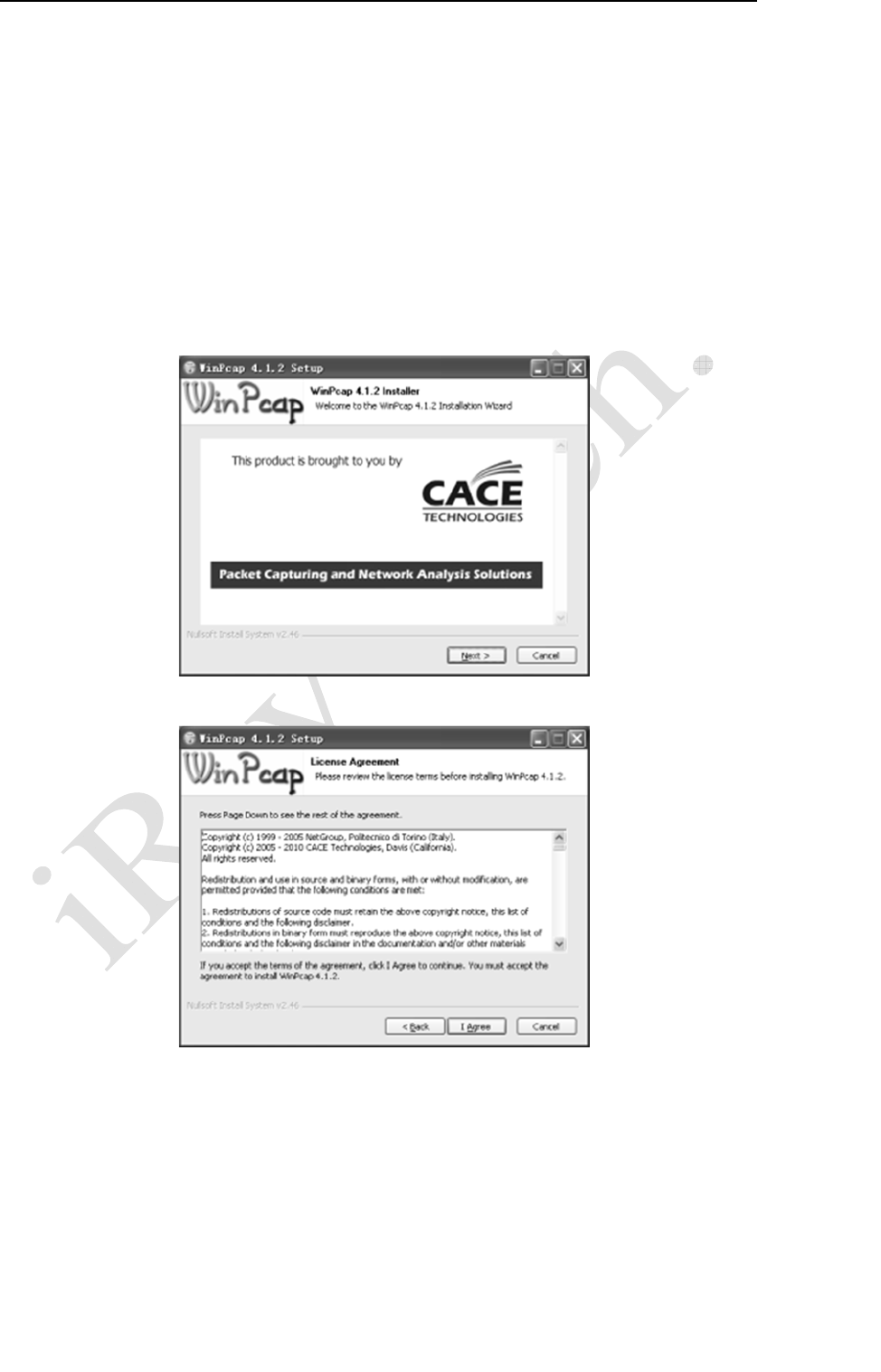
A.1Installation of Gigabit Ethernet Driver
In order to use the Gigabit Ethernet interface for data transfer, the uses needs to
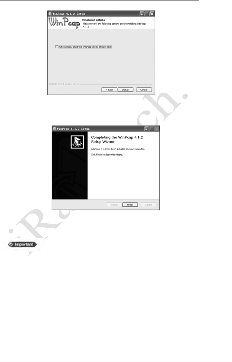
install the driver WinPcap4.1.2, which has been included in the CD-ROM.
Click “next” button to start installation.
Click the “I Agree” button to confirm with the license agreement.
Appendix A Installation of SDK
55
ServiceOffice:
Tel:+862150720560
E‐mail:service@iraychina.com
Do not select the “Automatically start the WinPcap driver at boot time” item. The
function will be loaded bytheimage acquisition software.
Then installation completed
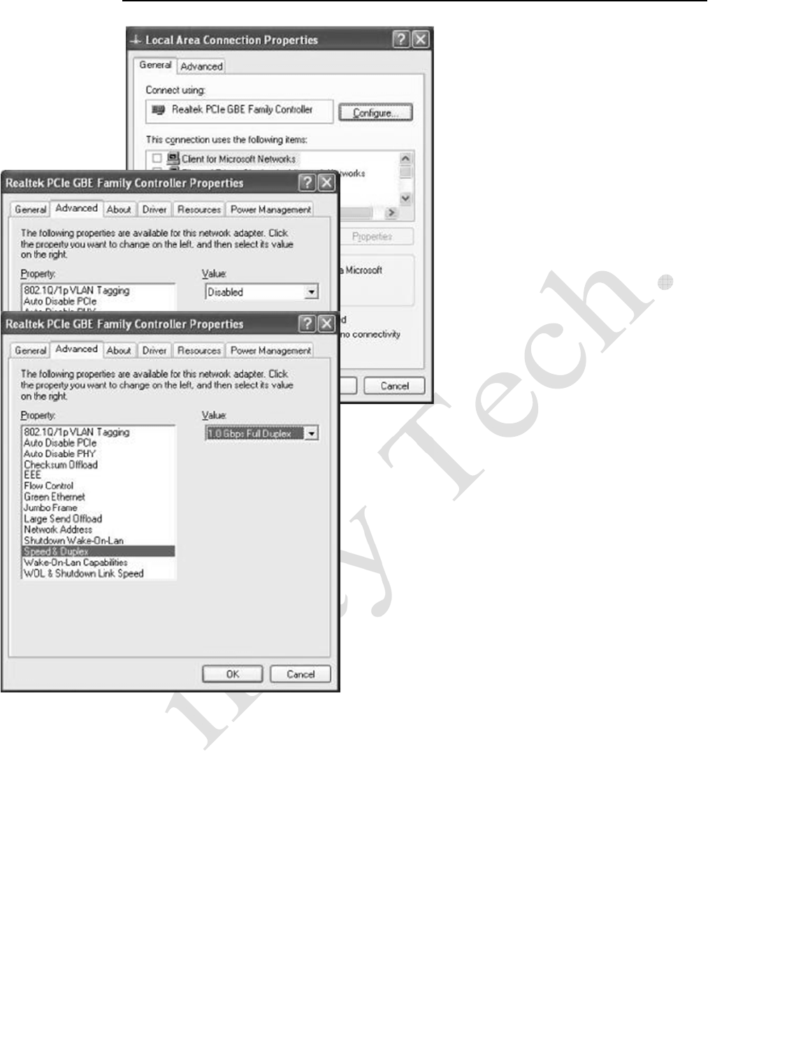
When using a new computer, the user shall configure the settings
of network card.
As shown below, click “Configure” button of Local Area Connection Properties, set
the value of Large Send Offload as Disabled, and the value of Speed & Duplex as 1.0
Gbps Full Duplex. Error settings may consult in abnormal network connection.
Appendix A Installation of SDK
56
ServiceOffice:
Tel:+862150720560
E‐mail:service@iraychina.com
Appendix BDescription of Different Cable Series
57
ServiceOffice:
Tel:+862150720560
E‐mail:service@iraychina.com
Appendix B Description of Different Cable Series
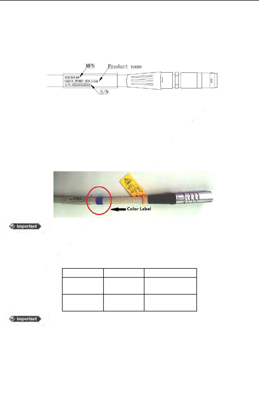
A. Check the MPN of the Extension cables and the Detector cables of the equipment.
MPNLabeloftheDetectorCable
There is a printed label near the float plug/socket on the cable. The first line is the MPN. IF there is no label or
different label on the cable, please find the details from iRay service office.
B. Check the color label of the cable
There are color labels on the Detector cable and Extension cable. If the label color is same that means the
definition of the Detector cable can match the Extension cable. For Mars1417V serial, ONLY series B is available
whose color label is BLUE.
The same color means the pin definitions of the cables are same or matching.
But before installation, please check the cable length. The total length of the
Detector cable and Extension cable should be less than 9m.
C. Compatibility of different cable series
Cable Series Detector Cable Extension Cable
A 02040002
02040003 (long)
02040023 (short)
B 02030144
02040013 (long)
02040019 (short)
Cables can ONLY be used with the same series. Mixed use of cables in series
A and B may result in damage of the equipment or Control Box circuit.
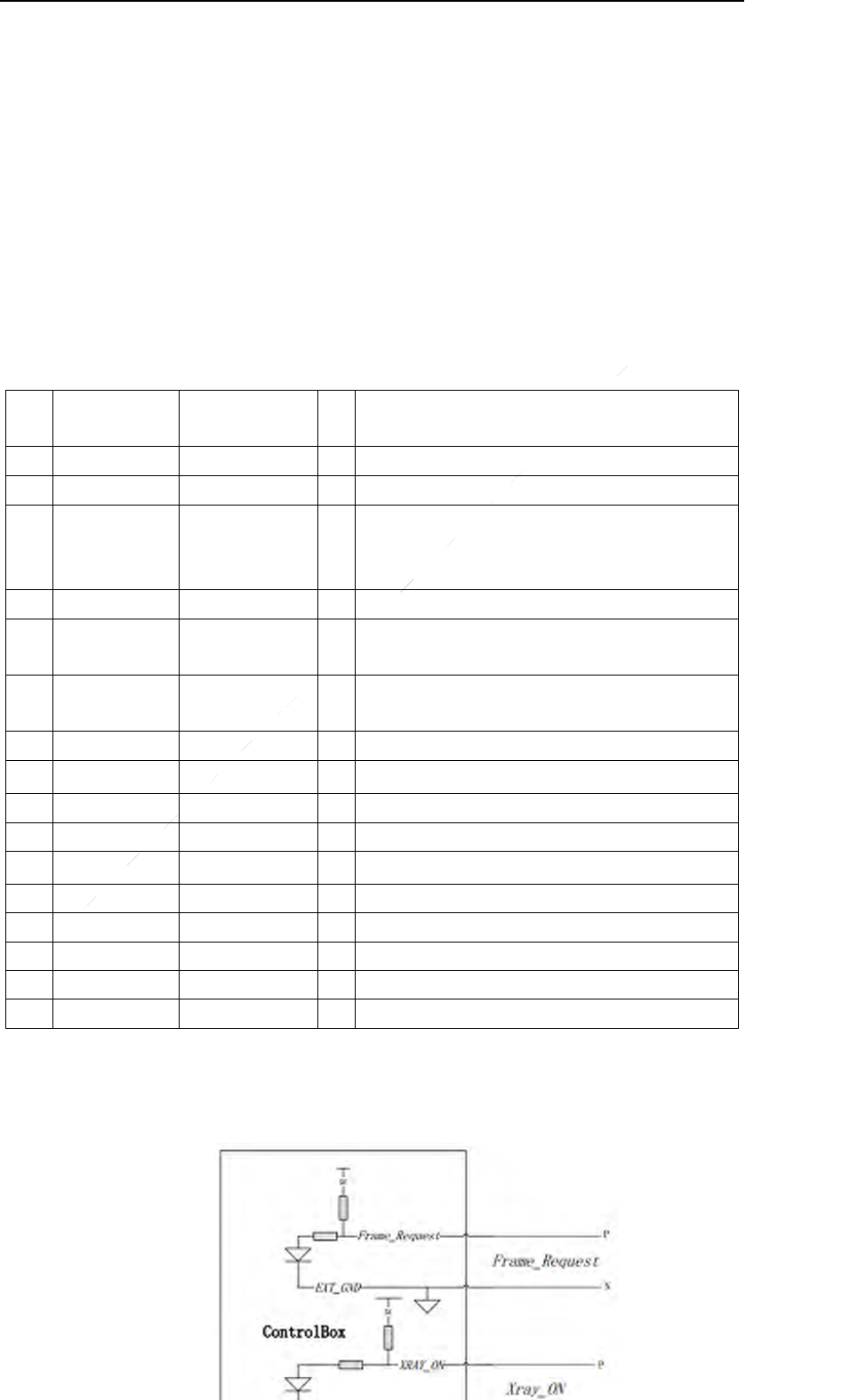
Appendix CDifferent Version of Control Box
58
ServiceOffice:
Tel:+862150720560
E‐mail:service@iraychina.com
Appendix C Different Version of Control Box
There are two versions of control box. They can be told by the label on the bottom of the control
box. The V0 used the label only in English or Chinese (Fig. C1). The V1’s label has both English
and Chinese descriptions (Fig. C2)
Both versions share the same circuit architecture and have the same performance. But the definition
of the HVG port is different.
The descriptions of HVG interface & HVG Cable ofV0
Pin
No. Wire Color Name I/
OSignal Description
1 Shield NC / No Connection
2 White Reserved / No Connection
3 Red/white Xray_On I
The synchronizing signal to the X-ray given by the
HVG. Detector will start data acquire after the
signal shift from the low level to the high level
4 Black Reserved / No Connection
5 Green Frame_Request IRequest given by the HVG, it’s a prepare signal of
the detector.
6 Gray Expose_OK OWhen the signal is low , it indicates that the
detector is ready for the exposure
7 Brown Reserved / No Connection
8 Brown/white EXT_GND / GND
9 Blue Reserved / No Connection
10 Yellow EXT_VOUT O+12V(Imax=450mA) power supply
11 Black/white Reserved O No Connection
12 Pink Reserved O No Connection
13 Red Reserved O No Connection
14 Cyan Reserved I No Connection
15 Purple Reserved / No Connection
16 Orange Reserved O No Connection
The V0 control box also supports the prep-trigger mode. There are pull-up/pull-down circuits
inside the control box, so the external pull-up/pull-down circuits are unnecessary. (Fig.C3)

Appendix CDifferent Version of Control Box
59
ServiceOffice:
Tel:+862150720560
E‐mail:service@iraychina.com
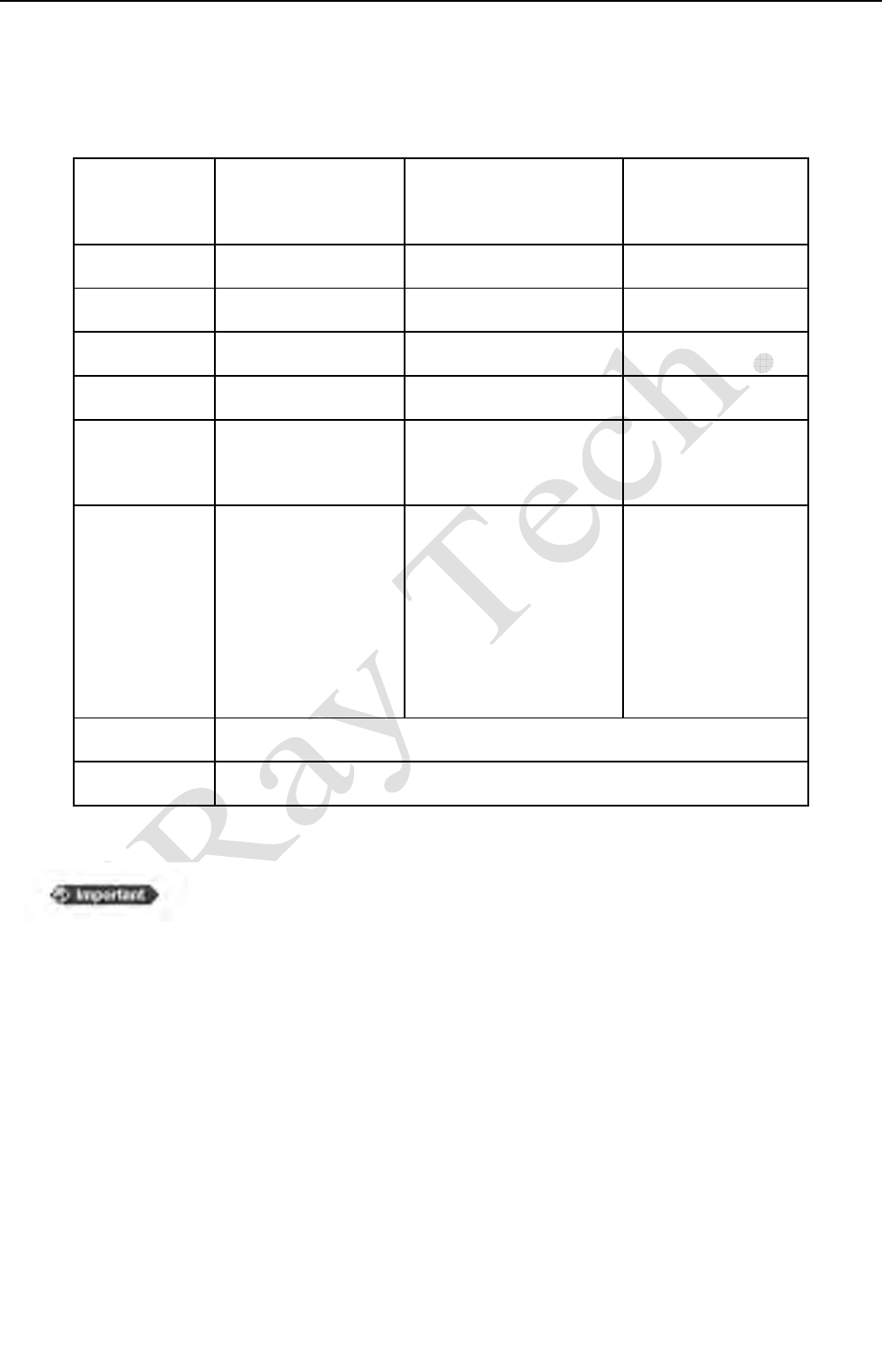
Appendix D Recommended Computer Platform
60
ServiceOffice:
Tel:+862150720560
E‐mail:service@iraychina.com
Appendix DRecommended Computer Platform
Minimum
Recommended
Desktop
Recommended
Laptop
CPU Intel Core i3 2.8G Intel Core i73.6G Intel Core i73.6G
Memory 2G DDR3 4G DDR3 4G DDR3
Hard Disk 160 G 640 G 320 G
Monitor 1280×1024 1680 x 1050 1600×900
Memory of
Display
Adapter
512Mbits 1Gbits 1Gbits
Ethernet Card
Gigabit Network
Adapter with PCIe
interface of Intel or
Broadcom
Intel Pro EXP9301CT
PRO
Gigabit Network
Adapter with PCIe
interface
Intel(R) 82579LM
Gigabit Network
Connection
Others USB2.0
OS Windows XP 32bit
Please set the computer to “high performance” and set “power
saving” disabled, when the SDK or detector is running. It’s also
recommended to set “screen saver” disabled.

Appendix D Recommended Computer Platform
61
ServiceOffice:
Tel:+862150720560
E‐mail:service@iraychina.com
Function List of Different Hardware/Firmware
Versions
Detector Control
Box Cable Firmware Function
V0 V0
Series A
Or
Series B
Detector: 2.2.x
Control Box: 1.2.x 1. RS232 command interface
2. Static image acquisition
3. Default mode:inner-triggermode
V0 V1 Detector: 2.2.x
Control Box: 1.2.x
V1 V1 SeriesB
Detector: 3.3.x
Control Box:1.3.x
1. Static image acquisition
2. Gigabit Ethernet command
interface
3. Default mode: inner-trigger
mode, but can be configured by
customers
4. Temperature feedback
5. Detector SN. Feedback
6. Replaceable sensor cable
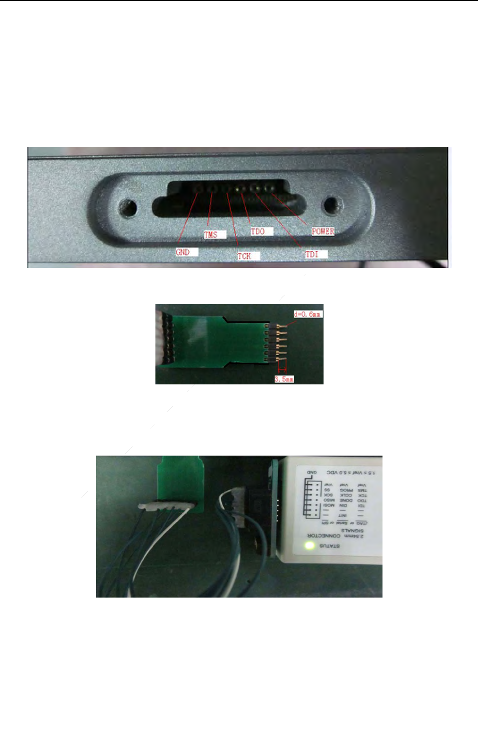
Appendix E Firmware Update
62
ServiceOffice:
Tel:+862150720560
E‐mail:service@iraychina.com
Appendix EFirmware Update
Mars1417V serial allows user upgrade firmware without removing cover of the equipment.
Please do as follows:
a)Turn off the power
b)Open the cover of the JTAG port on it. You will see the port as FigE1.
Fig.E1 JTAG Port
c)Insert the FPD JTAGBoard into the port.
Fig.E2JTAGBoard
d)Connect the Xilinx JTAG Adapter to the JTAGBoard and Computer. Then turn on the power.
The LED on the Adapter will turn on, Fig A/E3.
FigE3. Xilinx JTAG Adapter
a) Open the Xilinx iMPACT® software;
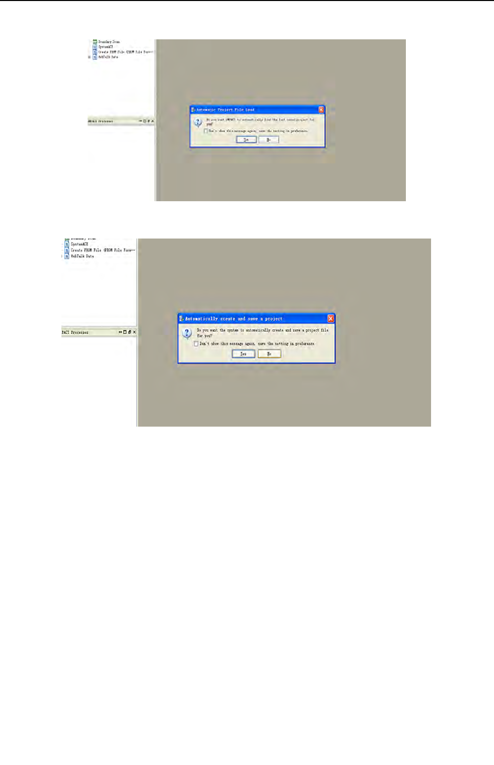
Appendix E Firmware Update
63
ServiceOffice:
Tel:+862150720560
E‐mail:service@iraychina.com
Select “No”
Select “No”
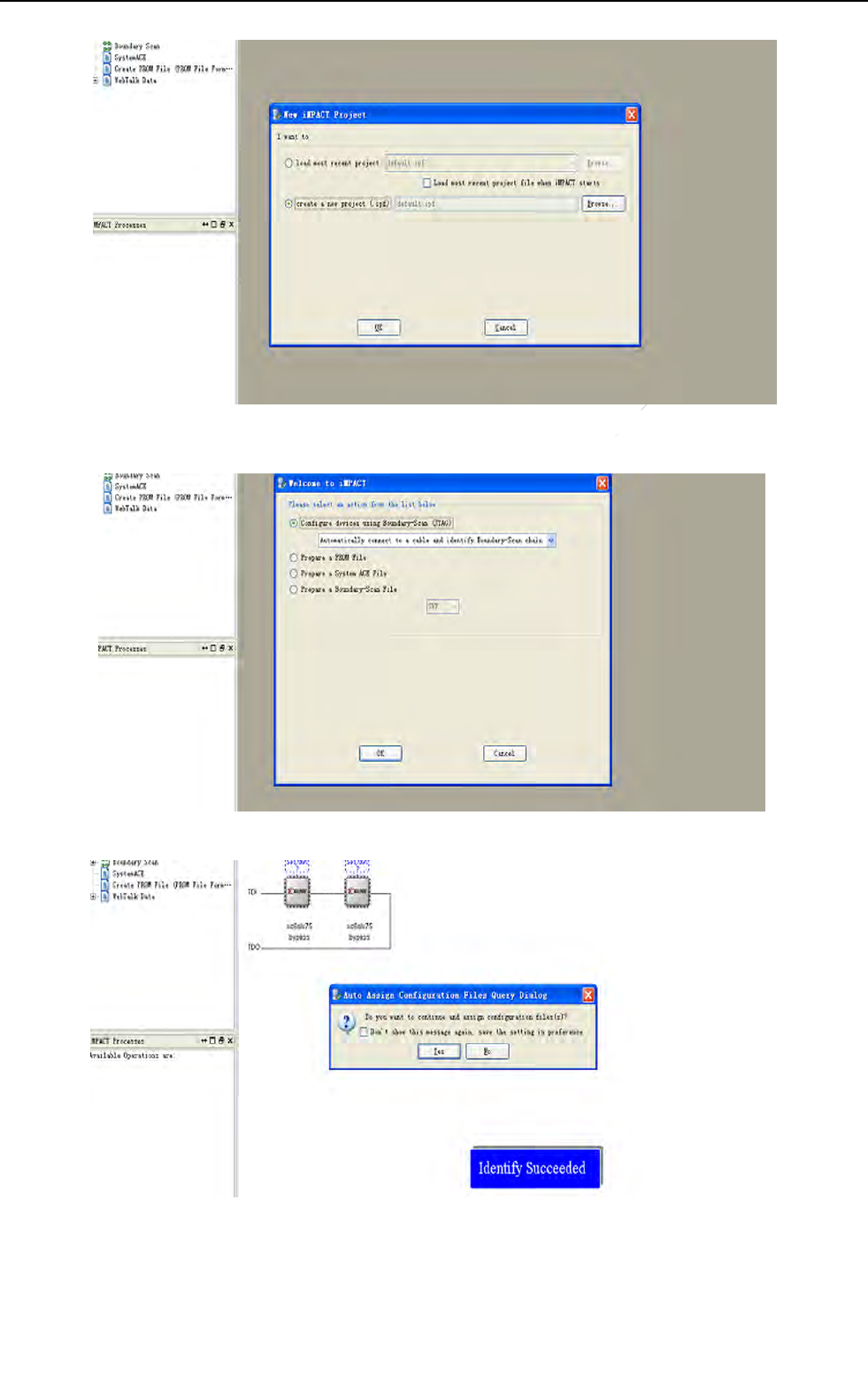
Appendix E Firmware Update
64
ServiceOffice:
Tel:+862150720560
E‐mail:service@iraychina.com
Select“Create a new project”
Select“Configure devices using Boundary-Scan(JTAG)”, then“OK”
Select“NO”
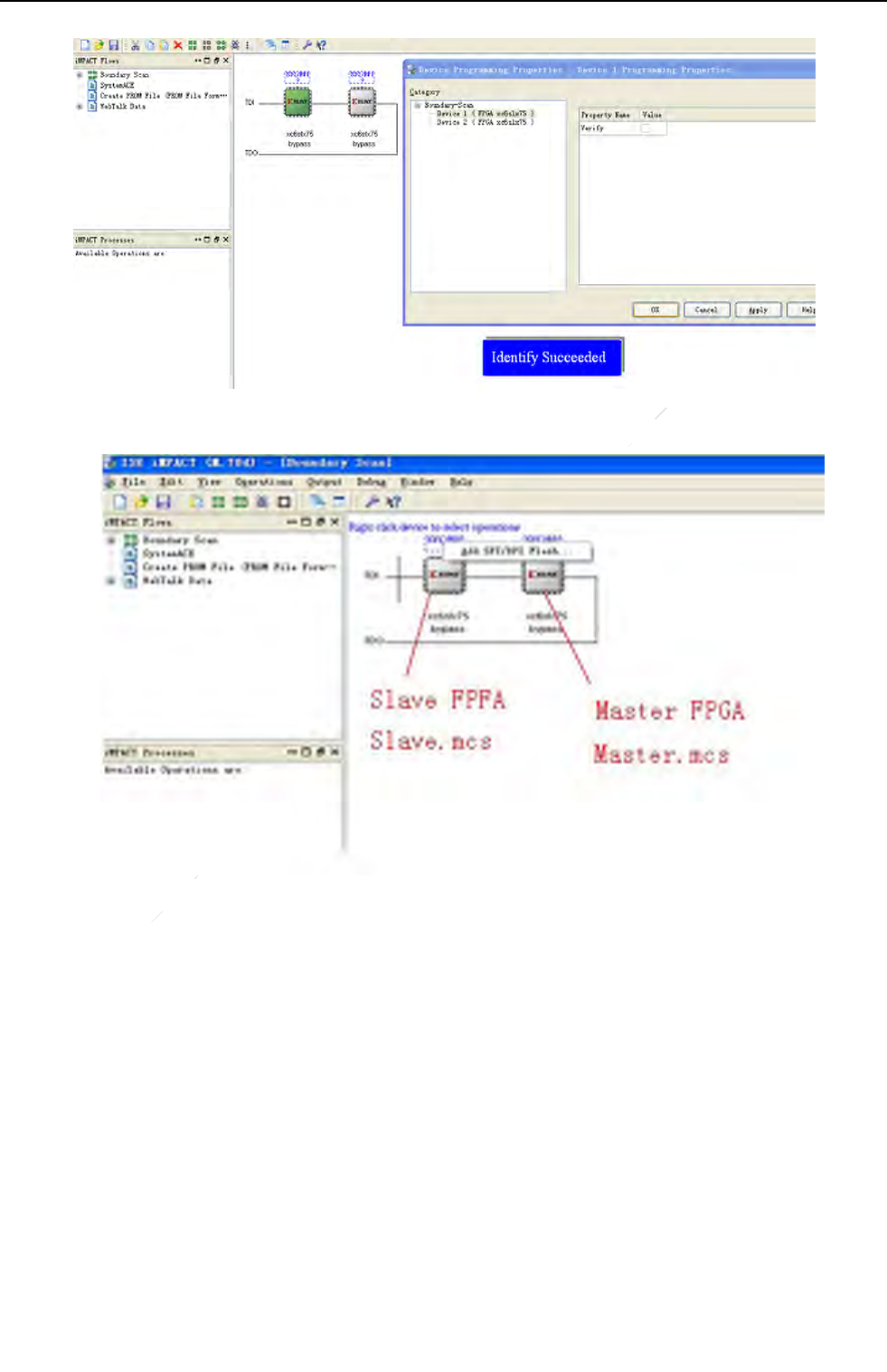
Appendix E Firmware Update
65
ServiceOffice:
Tel:+862150720560
E‐mail:service@iraychina.com
Select“Cancel”
f)Program the FPGA
Select the first FPGA,right click and select“Add SPI/BPI Flash”
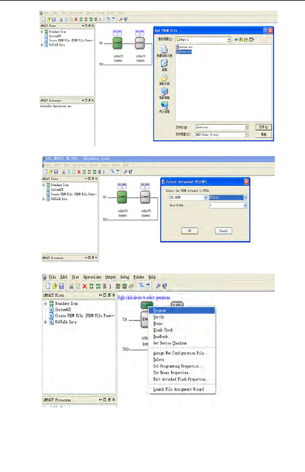
Appendix E Firmware Update
66
ServiceOffice:
Tel:+862150720560
E‐mail:service@iraychina.com
Select“slave.mcs”
Select Flash type“N25Q128”,then“OK”
Right click and select“Program”
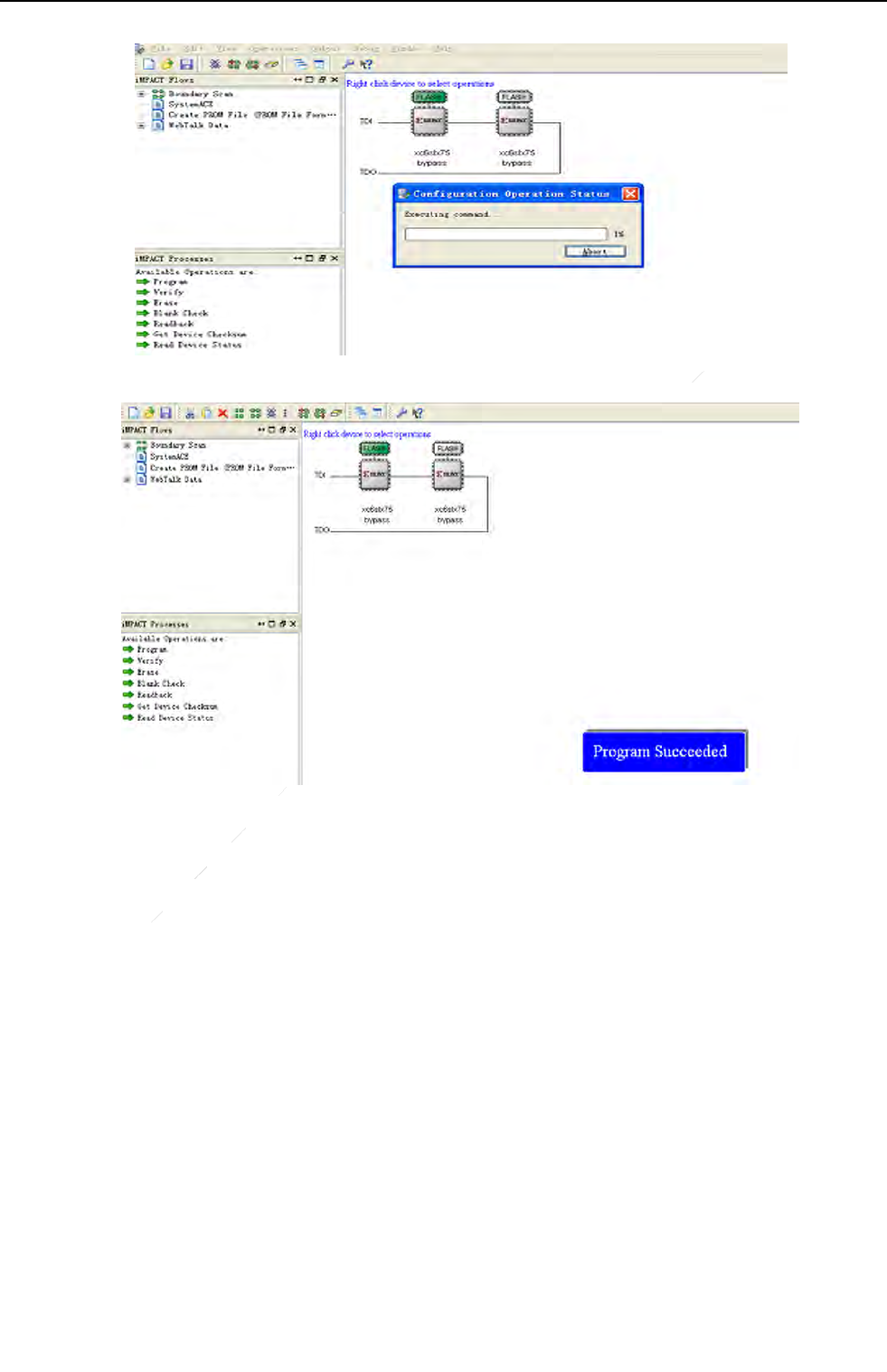
Appendix E Firmware Update
67
ServiceOffice:
Tel:+862150720560
E‐mail:service@iraychina.com
Ittakes several minutes to finish updating
b) As the same steps, upgrade the master FPGA’s firmware
c) Reboot the Flat Panel Detector;

Appendix F Dummy Lines
68
ServiceOffice:
Tel:+862150720560
E‐mail:service@iraychina.com
Appendix F Dummy Lines
Thereare8dummylinesontheeachlongedgeoftheimage.
Fig D1
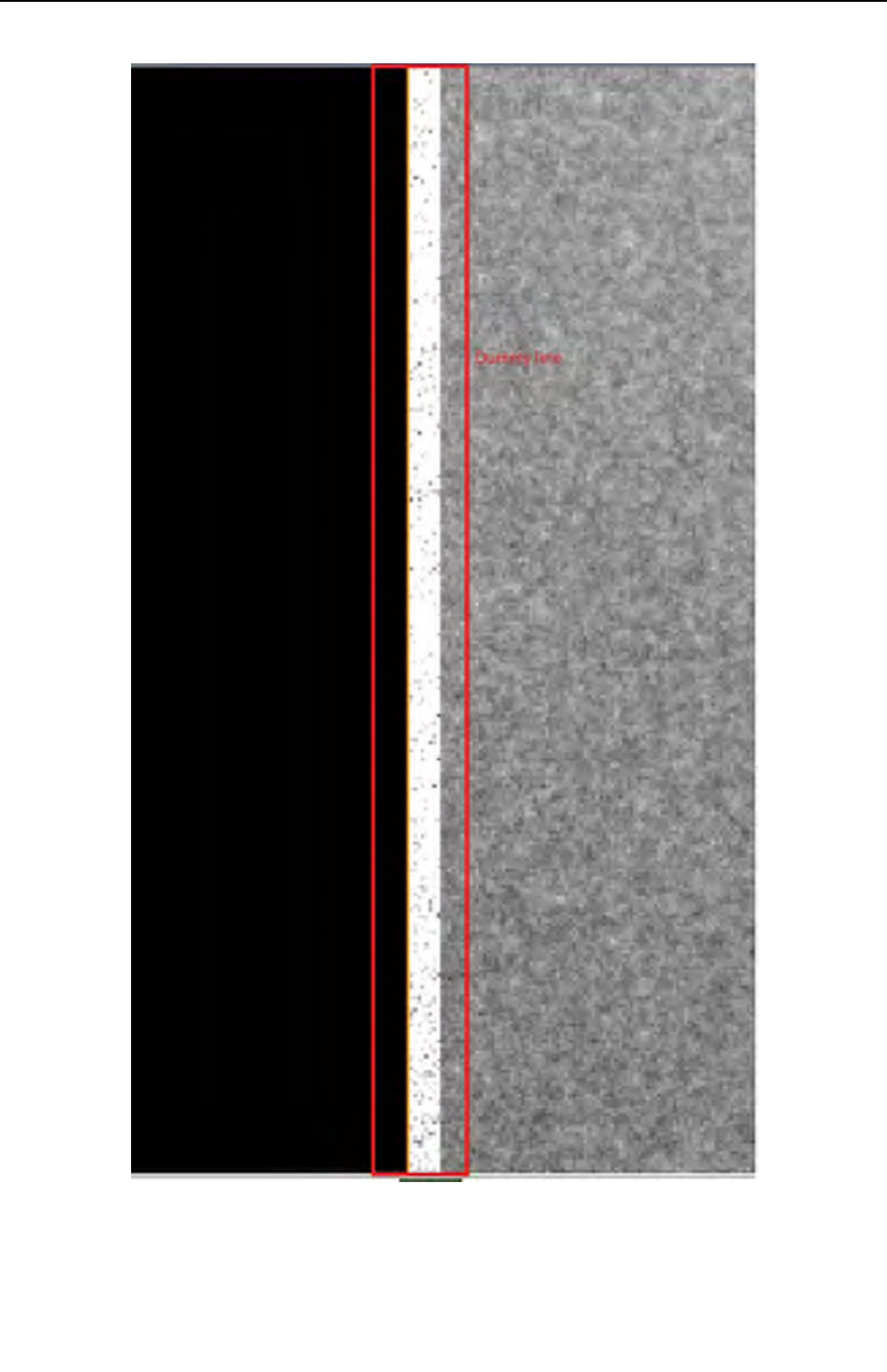
Appendix F Dummy Lines
69
ServiceOffice:
Tel:+862150720560
E‐mail:service@iraychina.com
In details
Fig D2

Appendix G Definition of Defects
70
ServiceOffice:
Tel:+862150720560
E‐mail:service@iraychina.com
Appendix GDefinition of Defects
Defect Pixel:
A defect pixel is defined as a pixel whose value is deviated from the median of its neighboring
32x32 pixels by more than 6 times of the standard deviation of this regionafter gain-offset
correctionunder any X-ray condition. In addition, if there is defect which is not included in the defect
map the supplier defined, then new defect should be added to the defect map. If the final statistics is
above the quality control limit, then the detector should be returned.
Defect Line:
The horizontal or verticallinesof which more than 5% of the pixels are determined as defect pixels.
Full Class 0-8:
"Class N" defect is a defective pixel with N adjacent defect(s). "Full" means that all defective
pixels (even included in a defective line or column) are individually counted.
Meta 7+8 Class1-8:
"Meta 7+8" means that on the original defect map, isolate the defective pixels corresponding to
Class 7 and Class 8: this gives a new defect map where each Class 7 or Class 8 cluster is replaced by
one single defective pixel. On this new defect map, re-calculate the distribution of defect Class N, this
gives the "Meta 7+8 Class N" defect.
Central Area:
The area in which both the x-coordinates and y-coordinates of the pixels are between 1/6 to 5/6 width
and height of the panel respectively. For example, for a 2304x2800 panel, the central area is defined
as the area where 384≤x≤1920 and 467≤y≤2333.

Appendix H Information of Service Office
71
ServiceOffice:
Tel:+862150720560
E‐mail:service@iraychina.com
Appendix H Information of Service Office
Tel: +86 21 50720560 - 8059
Fax: +86 21 50720561
E-mail: service@iraychina.com
Address: 2F, Building 7, No.590, Ruiqing Rd, Pudong, Shanghai, China PC: 20120

Appendix I Information of Manufactures
72
ServiceOffice:
Tel:+862150720560
E‐mail:service@iraychina.com
Appendix I Information of Manufactures
COMPANY: iRayTechnology(Shanghai) Ltd.
ADDRESS: Rm202, Building 7, No. 590, Ruiqing Rd, Zhangjiang East, Pudong New
Area, Shanghai, China
ZIPCODE: 201201
TELEPHONE: +86-21-50720560
FAX: +86-21-50720561
HOMEPAGE: WWW.IRAY-TECH.COM
SERVICE: SERVICE DEPARTMENT of iRay
SERVICE TEL: +86-21-50720560
MARKET TEL: +86-21-50720560