ISA Intelligent Sensing Anywhere ISMTI-V1 Multi purpose autonomous remote management system User Manual

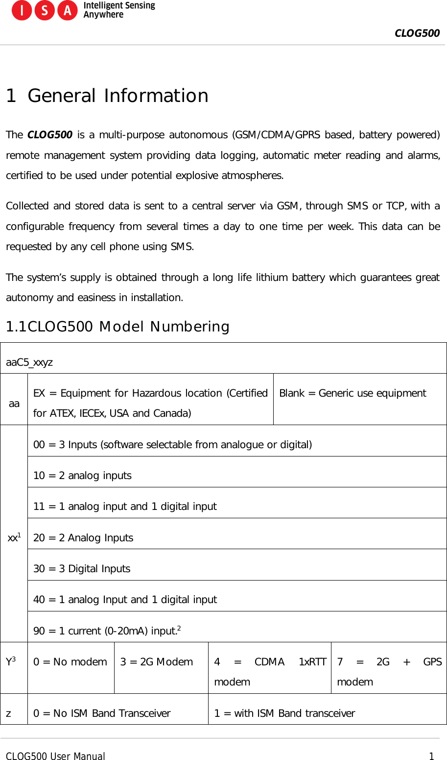
ISA - Intelligent Sensing Anywhere Multi purpose autonomous remote management system

User Manual

   CLOG500 User Manual  ISA – Intelligent Sensing Anywhere Rua Pedro Nunes, Edifício D 3030-199 Coimbra, Portugal Phone: +351 239 791 090 Fax: +351 239 791 099 Email: info@isasensing.com http://www.isasensing.com
 CLOG500      CLOG500 User Manual     i     Data  Versão  Descrição  Autor 16/07/2014  V0.01  First release of document.  Artur Vieira 03/09/2014  V0.02 Added  option  for  variant  EXC5_20XY possibilitie to have possibilitie to have 2 sensors. Artur Vieira 18/09/2014  V1.0  Revision  Ester Soares 27/01/2015  V1.01  Changes for FCC certification  Artur Vieira 02/03/2015  V2.00  Revision  Ester Soares
 CLOG500      CLOG500 User Manual     ii  Índice 1 General Information................................................................................................................................................. 1 1.1 CLOG500 Model Numbering ..................................................................................................................... 1 2 FCC PART 15 compliance ...................................................................................................................................... 2 2.1 RF Exposure Information ............................................................................................................................. 3 3 Warnings ....................................................................................................................................................................... 3 4 Maintenance ................................................................................................................................................................ 4 5 Typical Installation procedure ............................................................................................................................. 4 6 Sensor connection .................................................................................................................................................... 5 6.1 CLOG500 supplied with external cable ................................................................................................ 6 7 Placing the CLOG500 ............................................................................................................................................. 6 7.1 Attaching the CLOG500 .............................................................................................................................. 6 7.1.1 Using glue to attach......................................................................................................................... 7 7.1.2 Using cable ties to attach .............................................................................................................. 9 7.2 Possible scenarios ........................................................................................................................................ 10 8 Equipment activation ........................................................................................................................................... 11 8.1 Passing the magnet to activate ............................................................................................................ 11 8.2 Visual Indicators ........................................................................................................................................... 11 8.3 Equipment information ............................................................................................................................. 13 9 CLOG500 configuration ...................................................................................................................................... 13 9.1 Sensor types and input numbers ......................................................................................................... 13 9.1.1 Sensors connect through radio device................................................................................. 14 10 Tips and Tricks ........................................................................................................................................................ 14
 CLOG500      CLOG500 User Manual     1  1 General Information The CLOG500 is a multi-purpose autonomous (GSM/CDMA/GPRS based, battery powered) remote management system providing data logging, automatic meter reading and alarms, certified to be used under potential explosive atmospheres.  Collected and stored data is sent to a central server via GSM, through SMS or TCP, with a configurable frequency from several times a day to one time per week. This data can be requested by any cell phone using SMS.  The system’s supply is obtained through a long life lithium battery which guarantees great autonomy and easiness in installation. 1.1 CLOG500 Model Numbering aaC5_xxyz aa  EX = Equipment for Hazardous location (Certified for ATEX, IECEx, USA and Canada) Blank = Generic use equipment xx1 00 = 3 Inputs (software selectable from analogue or digital) 10 = 2 analog inputs 11 = 1 analog input and 1 digital input 20 = 2 Analog Inputs 30 = 3 Digital Inputs 40 = 1 analog Input and 1 digital input 90 = 1 current (0-20mA) input.2 Y3  0 = No modem  3 = 2G Modem  4  =  CDMA  1xRTT modem 7  =  2G  +  GPS modem z  0 = No ISM Band Transceiver  1 = with ISM Band transceiver
 CLOG500      CLOG500 User Manual     2  1 Check the safety manual for input parameters. 2 This model does not have hazardous location. 2 FCC PART 15 compliance This device complies with part 15 of the FCC Rules. Operation is subject to the following two conditions: (1) This device may not cause harmful interference, and (2) this device must accept any interference received, including interference that may cause undesired operation. These limits are designed to provide reasonable protection against harmful interference in a residential installation.   This equipment has been tested and found to comply with the limits for a Class B digital device,  pursuant  to  part  15  of  the  FCC  Rules.  These  limits  are  designed  to  provide reasonable  protection  against  harmful  interference  in  a  residential  installation.  This equipment generates uses and can radiate radio frequency energy and, if not installed and used  in  accordance  with  the  instructions,  may  cause  harmful  interference  to  radio communications.  However,  there  is  no  guarantee  that  interference  will  not  occur  in  a particular installation. If this equipment does cause harmful interference to radio or television reception, which can be determined  by  turning  the  equipment  off  and  on, the  user  is  encouraged to  try  to correct the interference by one or more of the following measures:  Reorient or relocate the receiving antenna.  Increase the separation between the equipment and  the receiver.  Connect the equipment into an outlet on a circuit different from that to which the receiver is connected.  Consult the dealer or an experienced radio/TV technician for help. You may also find helpful the following booklet, prepared by the FCC: "How to Identify and Resolve  Radio-TV  Interference  Problems."    This  booklet  is  available  from  the  U.S. Government Printing Office, Washington D.C. 20402.
 CLOG500      CLOG500 User Manual     3  WARNING:  Changes  and  Modifications  not  expressly  approved  by  the  manufacturer  or registrant  of  this  equipment  can  void  your  authority  to  operate  this  equipment  under Federal Communications Commission’s rules. 2.1 RF Exposure Information This device meets government’s requirements for exposure to radio waves. This device is designed and manufactured not to exceed the emission limits for exposure to radio  frequency  (RF)  energy  set  by  the  Federal  Communications  Commission  of  U.S. Government. The device complies with FCC radiation limits set forth for an uncontrolled environment. In order to avoid the possibility of exceeding the FCC radio frequency exposures limits, human proximity to the antenna shall not be less than 20cm (8 inches) during normal operation. 3 Warnings PLEASE READ CAREFULLY BEFORE ANY MANIPULATION OF THE EQUIPMENT.  Reading of this manual and safety manual is mandatory prior to any manipulation of the equipment. Failure to comply with presented safety instructions may lead to severe damage or injury and loss of liability by the manufacturer.  These instructions must be kept and followed throughout the life of the equipment.  Never open the equipment when a potential explosive atmosphere may be present.  POTENTIAL ELECTROSTATIC CHARGING HAZARD. CLEAN ONLY WITH DAMP CLOTHS.  Only use approved batteries. Check other warnings in this manual (always marked with  ).
 CLOG500      CLOG500 User Manual     4  4 Maintenance  The equipment will have no maintenance inside the safety zone. The maintenance possible  to  perform  on  the  field  is  just  the  batteries  exchange  and  SIM  Card replacement.  For  others  problems  the  equipment  must  be  returned  to manufacturer.  5 Typical Installation procedure This procedure is valid for versions that contain a GSM or CDMA modem. For version that  only contains the ISM  Band transceiver the only  necessary steps are the sensor connection, equipment placement and activation. 1) Connect the sensor to the CLOG500 (see section 6). Some models may already have this connection. 2) Position the equipment next to the target (gas tank gauge, pulse meter, etc) and attach it using the base of the equipment (see section 7). 3) Attach the sensor to the target. 4) Prepare the SMS to send to the equipment (see section Error! Reference source not found.). 5) Activate the CLOG500, passing the magnet in order to prepare it to receive the SMS configuration (see section 8.1). In some models it may be possible that you need to operate the ON/OFF switch in order to activate the CLOG500 (see section 8). a) Check if a red LED starts to flash inside the CLOG500. b) After 2 minutes a green LED should turn ON and, after 30 seconds, start to flash. This means that the modem is already registered on the GSM network (ready for the SMS). 6) Send the SMS to the CLOG500 (see section Error! Reference source not found.). 7) Wait for the response from the CLOG500 (see section Error! Reference source not found.).
 CLOG500      CLOG500 User Manual     5  8) Check if the values for the ‘SQ:’ and ‘MEM:’ are correct (see section Error! Reference source not found.). 9) Check if the value for the cabled channel is identical to the one shown by the respective sensor. A 4%~ 6% errors is admissible. 10) Take note of the installation data on a sheet (see section Error! Reference source not found.). 11) Take all the waste with you. 12) Congratulations, the installation is complete. 6 Sensor connection The only external component connected to the equipment may be a Rochester6320S level sensor (max length= 3 m), or any sensor / digital switch which are compatible with the equipment. The sensor must already have the correct plug to  connect to the CLOG500. The sensor connector is illustrated in the following picture:  Figure 1 - Sensor connector location. Attention: The sensor connector has a correct position for the cable insertion.
 CLOG500      CLOG500 User Manual     6   Figure 2 – CLOG500 with sensor connected. 6.1 CLOG500 supplied with external cable The equipment may be supplied with external cable for sensor connection. The connection between the equipment and the sensor should be made using a junction box. Check Installation and safety manual for cable color code and safety parameters. 7 Placing the CLOG500 7.1 Attaching the CLOG500 The equipment should be attached to a solid surface (1m to 2m from the ground) with a vertical orientation (if possible) optimized for radio transmission and communication. To attach the equipment, it is recommended to use glue to fix the enclosure to the tank or use cable ties. The next Figure shows an example of how to correctly attach the CLOG500 to a gas tank hook with cable ties or glue.
 CLOG500      CLOG500 User Manual     7    Figure 3 – Example of correct attaching on a gas tank hook with cable ties or glue. Some provided or recommended accessories:      Figure 4 - Cable ties. Figure 5 - Wurth MS Instant (Ref: 0893226100) Figure 6 –C leaner product - Wurth Brake Cleaner (Ref: 08901087)  7.1.1 Using glue to attach 1. In case of fixation by glue, the user should clean the tank surface to remove dirt and degrease from the area where is going to apply glue:
 CLOG500      CLOG500 User Manual     8    Figure 7 - Cleaning the tank surface before applying glue. 2. Next, apply glue to the base that is going to be fixed in the tank and attach to the tank. Apply sufficient glue to provide a good fixation.   Figure 8 - Base fixation. 3. Remove any glue excess. 4. Wait some minutes to allow the glue to fix. 5. Hook the CLOG500 in the base.
 CLOG500      CLOG500 User Manual     9   Figure 9 – CLOG500 in the final position. 7.1.2 Using cable ties to attach 1. Attach the base to a pipe or some other acceptable place using cable ties.  Figure 10 - Fixation of the base. 2. Hook the CLOG500 in the base.
 CLOG500      CLOG500 User Manual    10   Figure 11 - Final position of CLOG500. The CLOG500 should be installed as indicated in the previous figure, vertical position and the sensor cable at the lowest side. 7.2 Possible scenarios The installation attaching option should be based on tank type. Equipment should always be placed in a vertical position when possible. The CLOG500 must be conveniently placed on a solid area (not in places that can move or have  mechanical  shock,  for  example  covers,  doors  or  fences),  safe  from  flooding  and particular attention should be paid to installation in totally metallic boxes, due to the effect of the Faraday cage.
 CLOG500      CLOG500 User Manual    11  8 Equipment activation 8.1 Passing the magnet to activate In order to activate the CLOG500 the user must have a magnet. The location to wave the magnet over is illustrated in the following picture. In the CLOG500 the magnet is on the opposite side from the sensor connection.    Figure 12 - Location to pass the magnet on the CLOG500. 8.2 Visual Indicators The CLOG500 has two LED lights that can be seen from the outside, visible on the bottom, if looking through the semi-transparent enclosure.
 CLOG500      CLOG500 User Manual    12    Figure 13 - Location of the red and green LED on the CLOG500. Equipment that only have the ISM Transceiver will only have the RED LED. Visual indicator  Status  Observations Green (modem LED) OFF  Modem OFF Always ON  Modem ON, waiting for GSM Network registration Flashing  Modem ON and registered on GSM Network, waiting for SMS Red (system LED) OFF  System on stand-by mode Flashing  System in Installation phase, accepts installation SMS Always ON  Error state Table 1 - Visual Indicators description for equipment’s with GSM / CDMA modem. Visual indicator  Status  Observations Red (system LED) OFF  System on stand-by mode Flashing (Fast)  Equipment in installation phase, can respond to radio messages. On (Duration 2s) Equipment transmitting a Radio message. Always ON  Error state
 CLOG500      CLOG500 User Manual    13  Table 2 - Visual Indicators description for equipment with only ISM Band Transceiver. The CLOG500 only accepts the installation SMS if both red and green LEDs are flashing. If the equipment receives an installation SMS when the red LED is OFF, the equipment will respond with an SMS error. It is advisable to only send messages to the equipment after the green LED is flashing; otherwise  the  SMS  can  take  longer  to  be  delivered  to  the  equipment,  delaying  the installation procedure. 8.3 Equipment information Equipment information, such as SIMCard phone number, IMEI, serial number, Radio ID and product reference can be found in metallic labels at the bottom of the equipment. The equipment has a bar code (QR Code) that can be read with most mobile phones with all such information. 9 CLOG500 configuration The CLOG500 has physical inputs and wireless inputs (in some models) available to connect several sensor types. The sensor readings are associated with logic inputs (channels). The data associated to each channel is saved and sent later to a remote server, by SMS.  The configuration consists of associating each sensor (connected to a particular input) with a  channel. This configuration is assured by  sending  a  message (SMS installation) to  the CLOG500, which sends back another SMS. This means that the installer cell phone number must be part of the SMS installation. 9.1 Sensor types and input numbers Note that not all the inputs are available for all sensor types. There are differences between CLOG500 models. The next table shows the possible combinations depending on the sensor type and on the CLOG500 model.   Sensor Type / Possible inputs (input number)*   R  D  E  M  N CLOG500 Model Voltage Data: 0~100% Digital-Voltage Data: 0~1023 Voltage 0-5V Data: 0~1023 Digital - Impulses Data: 0 ~2^32 Digital – Input Data: 0 or 1
 CLOG500      CLOG500 User Manual    14  EXC5_00XY SIG1 (1)  SIG1 (1) / SIG2(2)  SIG1 (1)  SIG1(1) / SIG2(2) / SIG(3) SIG1(1) / SIG2(2) / SIG(3) EXC5_10XY  SIG1 (1)  SIG1 (1) / SIG2(2)  --  --  -- EXC5_11XY  SIG1 (1)  SIG1 (1)  --  SIG2(2)  SIG2(2) EXC5_20XY  SIG1 (1) / SIG (2)  SIG1 (1)  / SIG (2)  SIG1 (1)  / SIG (2)  --  -- EXC5_30XY  --  --  --  SIG1(1) / SIG2(2) / SIG(3) SIG1(1) / SIG2(2) / SIG(3) EXC5_40XY  SIG1 (1)  SIG1 (1)  --  --  -- (*) input number is the number to be used in the SMS installation (example for the input 2: CLOGI C1:2RC TEL:+351912345678). Table 3 – Possible sensor types on each CLOG500. Note:  In  order  to  use  input  3  “SIG(3)”  in  variant EXC5_00XY  as  Digital  Input  or  Digital Impulses is necessary to place the Jumper S2 in the Open Position. 9.1.1 Sensors connect through radio device For sensors connect via a radio device (RTU), the input number to put in the installation message is the “Radio ID:” field presented in the technical label of the radio device. This number can have any value from 10 to 65530. 10 Tips and Tricks Here are some useful tips and tricks for CLOG500 installer:  For level sensors use channel 1 to 2 because the CLOG500 sends instant data to these channels. Instant data is very useful for level sensors.  Always  configure cabled  sensor  on  channel  1  and  wireless  sensor  on  channel  2 (wireless sensors are available only on some CLOG500 models).  When passing the magnet to activate equipment, rub it 3 or 4 times.   The PIN code of the SIMCard should be deactivated or changed to the PIN code provided by ISA.
 CLOG500      CLOG500 User Manual    15   Enable your SMS report on the installer cell phone in order to get feedback from the SMS (delivery report).  The CLOG500 has a limit to the number of SMS (for each type of SMS) it can send each day. In case the limit is reached, the installer can reset the counter in order to receive  an  SMS  from  the  CLOG500.  To  reset  the  daily  SMS  counter,  send  the following SMS: CLOGM01000000PP0000000  To uninstall a sensor from a channel, send an installation SMS with one dash instead of input number and another dash instead the sensor type. For instance: CLOGI C1:-- TEL:+351912345678 Troubleshooting   Problem  Diagnostic/Solution If you receive a SMS starting with ????Mxx, an error has occurred on the configuration SMS. The error code is indicated by xx: 01 – Unknown message 02 – Error on the control code 03 – Message length error 04 – Invalid arguments 05 – Message not processed 06 – Installation message out of installation period 01 – Verify the installation message and try sending the SMS again.  02 – The control code is incorrect. Verify the control code and try sending the SMS again. 03 – Installation SMS is incorrect; verify the arguments and try sending the SMS again. 04 – Correct the arguments in the installation SMS and try sending the SMS again. 05 – Installation SMS is incorrect; verify the arguments and try sending the SMS again. 06 – The configuration time exceeded. Repeat the installation procedure. You don’t receive an SMS back  Check if green LED is blinking, if yes:
 CLOG500      CLOG500 User Manual    16  and you don’t receive the delivery report.  Erroneous  telephone number: Verify the phone number on the equipment and compare it with the number used to send the  installation  message.  If  the  number  is  incorrect,  please repeat the installation procedure.   Damaged equipment: If the phone number is correct, please change the equipment and repeat the installation procedure.   GSM  Signal  is  too  weak: Change  the  location  of  the equipment and try again. If the problem persists again, don’t install equipment in that location.   You don’t receive an SMS back but you receive the delivery report.  Erroneous  telephone number: Verify the phone number on the equipment and compare it with the number used to send the installation SMS. If the number is incorrect, please repeat the installation procedure.  Damaged equipment: If the phone number is correct, please change the equipment and repeat the installation procedure.  GSM  Signal  is  too  weak: Change  the  location  of  the equipment and try again. If the problem persists again, don’t install equipment in that location.  Daily SMS counter by type of SMS reached the limit (10 by default). Send an CLOGM type SMS to reset the counter (see tips section 10). A channel was incorrectly configured – I’d like to uninstall it.  Send  an  installation  SMS  with  one  dash  instead  of  input number and one dash instead the sensor type. For instance: CLOGI C1:1RC C2:-- TEL:+351912345678 Table 4 – Troubleshooting.

Navigation menu