ISONAS orporated RC-03 RFID Security access controller (LF) User Manual
ISONAS Incorporated RFID Security access controller (LF)
UserManual.wiki
>
ISONAS orporated
>
RC 03 User Manual
User manual
Navigation menu
Upload a User Manual
Namespaces
Wiki Guide
HTML
PDF
Info
Views
User Manual
Discussion / Help
Navigation

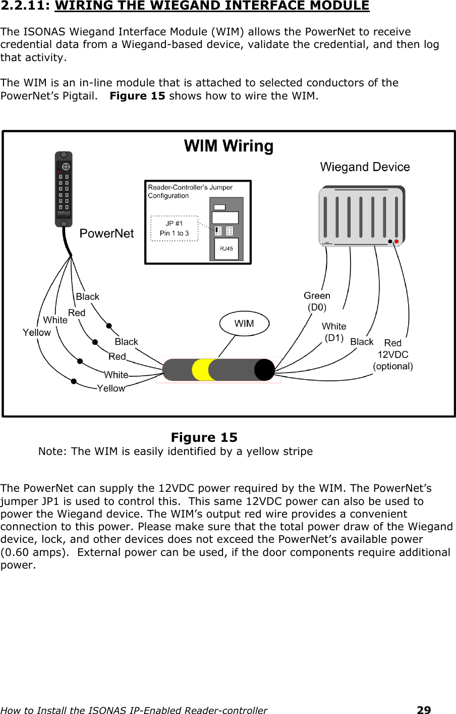
![How to Install the ISONAS IP-Enabled Reader-controller 5 1: BEFORE YOU BEGIN To install an ISONAS Reader-controller unit, you must complete three key wiring tasks: 1.Supply power to the Reader-controller unit. This may be accomplished with a power feed on the Ethernet Data cable (Power over Ethernet [PoE]) or through an external DC power source (12VDC or 24VDC) 2.Wire the unit to the door’s locks and other components for physical access control. 3.Connect the unit to the data network for communication with the server/workstation host PC. This guide discusses each wiring process separately. Understanding all of these processes makes a project much simpler and guarantees success. 1.1: GENERAL REQUIREMENTS: If PoE is not being used, then use only UL-listed, access control, power-limited power supplies with an ‘AC on’ indicator light clearly visible on the enclosure. Power supplies should provide at least four hours of standby power. Never connect power supplies to a switch-controlled receptacle. Install the ISONAS system in accordance with the National Electrical Code NFPA 70. (Local authority has jurisdiction.) Use only wire or UL-listed cabling recognized suitable for ISONAS power supply and data communications, in accordance with the National Electrical Code. Where possible, separate ISONAS equipment and cabling from sources of electromagnetic interference (EMI). Where this is not possible, take other steps to reduce the effect of EMI on cabling or equipment. Protect input and output terminals adequately from transient signals. Also, connect these terminals to power-limited circuitry.](https://usermanual.wiki/ISONAS-orporated/RC-03/User-Guide-1895859-Page-5.png)

![How to Install the ISONAS IP-Enabled Reader-controller 28 2.2.9: USING THE TTL LEADS The TTL1 and TTL2 leads are logical output leads. In their “normal” state, there is a 5VDC potential on the leads. When the leads “activate”, this voltage potential is removed (0 VDC. These leads are typically used to connect to an alarm system. Certain abnormal conditions of the reader-controller can be configured to activate these leads. An example would be having TTL2 activate when the door is held open too long. See the Crystal Access Software manual for more information on the usage of these leads. 2.2.10: USING THE POWERNET’S RS-232 INPUT The pigtail’s RS-232 signal leads (Yellow & White) can be connected to an external device that will pass a credential ID to the PowerNet. The most common usage is: To pass in a 2 to 9 character long ASCII data string. Only Numeric ASCII values are allowed in the string (“0” to “9”). Delimiter characters are typically used at the beginning and/or end of the message. The serial connection’s default configuration is: 9600 Baud (Adjustable w/ PlugNPlay [9600, 19200, 38400, 57600]) 8 Data Bits N Parity (Adjustable w/ PlugNPlay [N, E, O]) 1 Stop Bit N Hardware flow control](https://usermanual.wiki/ISONAS-orporated/RC-03/User-Guide-1895859-Page-28.png)