ISONAS orporated RC-03M RFID Security access controller (LF 122kHz or HF 13.56MHz) User Manual 1
ISONAS Incorporated RFID Security access controller (LF 122kHz or HF 13.56MHz) 1
User manual 1

How to Install an
ISONAS PowerNet™
Reader-Controller
Copyright © 2006-2012, ISONAS Security Systems
All rights reserved

ISONAS Inc.
FCC ID: 0CZRC-03
IC: 8431A-RC03
This device complies with Part 15 of the FCC Rules and RSS-210 of Industry Canada.
Operation is subject to the following two conditions:
(1) This device may not cause harmful interference, and
(2) This device must accept any interference received, including interference that
may cause undesired operation.
Changes or modifications not expressly approved by the party responsible for
compliance could void the user’s authority to operate the equipment.
This equipment has been tested and found to comply with the limits for a Class B
digital device, pursuant to part 15 of the FCC Rules. These limits are designed to
provide reasonable protection against harmful interference in a residential
installation. This equipment generates, uses, and can radiate radio frequency
energy and, if not installed and used in accordance with the instructions, may
cause harmful interference to radio communications. However, there is no
guarantee that interference will not occur in a particular installation. If this
equipment does cause harmful interference to radio or television reception, which
can be determined by turning the equipment off and on, the user is encouraged to
try to correct the interference by one or more of the following measures:
– Reorient or relocate the receiving antenna. – Increase the separation between
the equipment and receiver. – Connect the equipment to an outlet on a circuit
different from that to which the receiver is connected. – Consult the dealer or an
experienced radio/TV technician for help.
For RF Safety and per FCC and Industry Canada regulations, the product should
never be installed within 8-inches (20cm) of typical people locations.
Table of Contents
1: BEFORE YOU BEGIN ............................................................................................................................ 5
1.1: GENERAL REQUIREMENTS: ...................................................................................................... 5
1.2: POWERNET READER-CONTROLLER SPECIFICATIONS: .................................................. 6
1.3: INSTALLATION LOCATION GUIDELINES .............................................................................. 7
2: WIRING AT THE DOOR AND READER-CONTROLLER ............................................................ 11
2.1: POWERING THE READER-CONTROLLERS ......................................................................... 11
2.1.1: POWER OVER ETHERNET (PoE) OPTION .......................................................................... 11
2.1.2: ADDITIONAL POWER OPTIONS ........................................................................................... 13
2.2: WIRING THE DOORS .................................................................................................................. 16
2.2.1: READER-CONTROLLER CONTROL-LEADS DESCRIPTION ......................................... 17
2.2.2: LOCK WIRING -- BASIC .......................................................................................................... 19
2.2.3: WIRING THE REX BUTTON ................................................................................................... 22
2.2.4: WIRING THE AUX INPUT ....................................................................................................... 22
2.2.5: WIRING THE DOOR SENSE .................................................................................................... 23
2.2.6: LOCK WIRING -- LOW-VOLTAGE 12VDC POWER OPTION ......................................... 24
2.2.7: LOCK WIRING -- EXTERIOR DOOR KIT ............................................................................ 25
2.2.8: LOCK WIRING -- 2 READERS TO 1 LOCK .......................................................................... 27
2.2.9: USING THE TTL LEADS .......................................................................................................... 28
2.2.10: USING THE POWERNET’S RS-232 INPUT ......................................................................... 28
2.2.11: WIRING THE WIEGAND INTERFACE MODULE ............................................................ 29
2.2.12: WIRING THE DUAL-SRM ...................................................................................................... 31
2.2.13: WIRING THE QUAD-SRM...................................................................................................... 33
2.2.11: MANAGING INDUCTIVE LOAD CHALLANGES .............................................................. 35
2.2.12: MANAGING IN-RUSH CURRENT LOADS .......................................................................... 36
2.3: CONFIGUATION EXAMPLES ........................................................................................................ 37
2.3.1: PoE --- ELECTRIC STRIKE ...................................................................................................... 37
2.3.2: PoE --- EXTERNAL PWR FOR ELECTRIC STRIKE ........................................................... 38
2.3.3: 12VDC – ELECTRIC STRIKE .................................................................................................. 39
2.3.4: PoE --- MAGNETIC LOCK ........................................................................................................ 40
2.3.5: PoE --- MAGNETIC LOCK & PIR ........................................................................................... 41
2.3.6: PoE --- MAGNETIC LOCK, EDK & PIR ................................................................................. 42
2.3.7: DUAL POWER SOURCES ......................................................................................................... 43
3: CONFIGURING THE READER-CONTROLLER’S COMMUNICATIONS ................................ 44
3.1: ETHERNET-BASED TCP/IP READER-CONTROLLERS ...................................................... 44
3.2: SECURING MESSAGES ON YOUR NETWORK ..................................................................... 47

Document Version
Date of Revision
Revision
Author
Description
6/29/2007
2.0
Roger Matsumoto
Updated to include installation information
for PowerNet reader-controllers
7/10/2007
2.1
Shirl Jones
Updated to cover the Exterior Door Kit
8/11/2007
2.2
Shirl Jones
Clarified differences between ClearNet and
PowerNet configurations
10/14/2007
2.3
Shirl Jones
Improved External Door Kit instructions
4/15/2008
2.4
Shirl Jones
Typical lock wiring diagram for PowerNet
w/PoE added
4/24/2008
2.5
Shirl Jones
Clarified jumper configuration for lock relay
6/20/2008
2.6
Shirl Jones
Added In-Rush Current Suppressor section
5/12/2009
2.7
Shirl Jones
Removed 12V Terminal Block references.
Power supplied by the PowerNet is now
routed thru Pigtail
6/16/2009
2.8
Michael Radicella
Added the FCC compliance ID and notice
8/3/2009
2.9
Shirl Jones
Added Typical Configuration diagrams
9//4/2009
2.10
Shirl Jones
Expanded the PoE budgeting guidelines.
Revised the description of the Reset button/s
LED display
9/24/2009
2.11
Shirl Jones
Updated the rated PoE output.
12/2/2009
2.12
Shirl Jones
Added Serial Port and default setting
5/03/2010
2.13
Shirl Jones
Added Dual Power Source Configuration
Removed References to Clearnets
5/13/2010
2.14
Shirl Jones
Added a couple additional configuration
examples.
6/12/2010
2.15
Shirl Jones
Added Mag Lock w/EDK configuration
diagram.
9/14/2012
2.16
Shirl Jones
Updated for the RC03 model. Added
descriptions of alternate power options
9/17/2012
2.17
Shirl Jones
Minor edits
10/7/2012
2.18
Shirl Jones
Added WIM and SRM sections.
11/27/2012
2.19
Shirl Jones
Updated FCC statements

How to Install the ISONAS IP-Enabled Reader-controller 5
1: BEFORE YOU BEGIN
To install an ISONAS Reader-controller unit, you must complete three key wiring
tasks:
1.Supply power to the Reader-controller unit. This may be accomplished with a
power feed on the Ethernet Data cable (Power over Ethernet [PoE]) or through
an external DC power source (12VDC or 24VDC)
2.Wire the unit to the door’s locks and other components for physical access
control.
3.Connect the unit to the data network for communication with the
server/workstation host PC.
This guide discusses each wiring process separately. Understanding all of these
processes makes a project much simpler and guarantees success.
1.1: GENERAL REQUIREMENTS:
If PoE is not being used, then use only UL-listed, access control, power-
limited power supplies with an ‘AC on’ indicator light clearly visible on the
enclosure. Power supplies should provide at least four hours of standby power.
Never connect power supplies to a switch-controlled receptacle.
Install the ISONAS system in accordance with the National Electrical Code
NFPA 70. (Local authority has jurisdiction.)
Use only wire or UL-listed cabling recognized suitable for ISONAS power
supply and data communications, in accordance with the National Electrical
Code.
Where possible, separate ISONAS equipment and cabling from sources of
electromagnetic interference (EMI). Where this is not possible, take other steps
to reduce the effect of EMI on cabling or equipment.
Protect input and output terminals adequately from transient signals. Also,
connect these terminals to power-limited circuitry.

How to Install the ISONAS IP-Enabled Reader-controller 6
1.2: POWERNET READER-CONTROLLER SPECIFICATIONS:
Input Voltage
12V DC, 24V DC, or
PoE per IEEE 802.3af
Current Draw
0.20 AMPS
Supplied Power for External Devices
(when PoE power is being used)
0.60 AMPS @ 12VDC
Read Range
3 TO 5 inches typically
Read Speed
<250msec (Prox)
Exciter Field Frequency
Proximity -- 125khz
Multi-Tech - 13.56 MHz
Modulation Schemes
Proximity -- FSK/ASK
Multi-Tech --ISO 14443 type A and type B
Communication Interface
TCP/IP Over Ethernet
10 Mbps, ½ duplex
Inputs/Outputs
3 Inputs/2 TTL Outputs/1 Tamper Input
Relay
2.0 amp @ 30V DC (Resistive load)
Standalone Memory Capacity
64000 Cards/ 5000 Events/ 32 Time zones
Visual Indicators
2 LEDs for Normal Operations
Operating Temperatures
-40° To 122° Fahrenheit
-40° To 50° Celsius
Weight
Mullion Approximately 8 Ounces
Size
Mullion 6 ¾”H BY 1 5/8”W

How to Install the ISONAS IP-Enabled Reader-controller 7
1.3: INSTALLATION LOCATION GUIDELINES
When selecting the location where you are going to mount the ISONAS reader-
controller, a few guidelines should be observed.
1) The reader-controller should be kept at least 2 feet from another ISONAS
reader-controller, and 6 feet from any other RF emitting device.
2) Assure that the window on the back of the reader-controller’s is mounted
against a reflective surface. A self-adhesive reflective sticker is provided with
each reader-controller, in case the wall’s mounting surface is non-reflective.
Please note that this reflective surface is required for successful operation of
the ISONAS reader-controller
3) In an exterior location, the reader-controller’s mounting should be sealed to
prevent water from running down between the mounting surface and the back
of the reader-controller.
4) For the PowerNet reader, a dielectric insulating compound (Dow Corning DC-4
or equivalent) can be used to obtain extra water protection of the reader-
controller’s cable connections.
5) The reader-controller should be protected from extreme heat and sunlight. It
is rated for conditions up to 120 F. A direct southern exposure, in the
Southwest area of the United States may exceed these ratings.
6) For a few installations, mounting the reader against a large metal object may
reduce the read range of the reader. Steel, iron, and copper will have more of
an effect on the read range than aluminum. If the PowerNet will be mounted
on a steel surface we recommend being prepared to mount a pad ( “1 to 3”
inches in depth) between the reader and the metal frame. Then during the
installation phase and before final mounting of reader test the reader’s read
range to make sure it is acceptable. If not, then insert the pad between the
reader and the steel surface to improve the read range.
7) The cables extending from the back of the PowerNet’s Pigtail cable comes in a
standard 4 ft length. 10 ft and 25 ft lengths Pigtails are optionally available.
Plan for terminating the door wiring within that distance of the reader-
controller.
8) The wall mounting features required for the reader-controller are shown in
the next figure. Electronic versions of this figure can be found on the ISONAS
website, and can be printed out, for use as life-size drill templates.
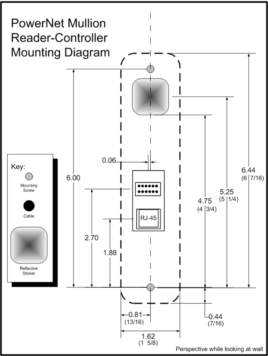
How to Install the ISONAS IP-Enabled Reader-controller 8
Figure 1 (PowerNet Mullion Mounting Diagram)
How to Install the ISONAS IP-Enabled Reader-controller 9
1.4 POWERNET CONFIGURATION
The PowerNet reader-controller has a set of
jumper pins that configure both its input
power source, and its lock control circuit.
The PowerNet reader-controller can be
configured for power to be supplied to the
reader-controller through the 12 conductor
pigtail (either 12VDC or 24VDC) or through
the RJ45 connector (Power Over Ethernet).
If POE is used, the reader-controller can
supply 12VDC thru its pigtail, which may be
used to power the lock or other devices at the
door location.
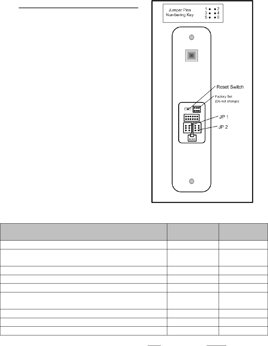
Note: The RC03 has an additional set of
jumpers. These are set at the factory, based on
the hardware inside the reader, and are not
intended to be changed in the field.
Figure 2 shows the components on the back
of the ISONAS PowerNet Reader-controller.
Figure 2
Feature
JP 1
Jumpers
JP 2
Jumpers
Input Power – 12VDC, thru Pigtail
1 to 3
Input Power -- 24VDC, thru Pigtail
3 to 5 &
4 to 6
Input Power – PoE, thru RJ45 connector
None
Input Power – PoE, thru RJ45 connector (See Note 1)
1 to 3
Input Power – No affect, place-holder for extra jumper
2 to 4
Lock’s power/signal is externally supplied on
the pigtail’s pink wire
None
Supply internal 12VDC to relay common (See Note 2)
1 to 3
ISONAS External Door Kit being used.
4 to 3
Connect GROUND to relay’s common contact.
5 to 3
Note 1. Special case: The unit is PoE powered AND you want 12v output power
supplied on the pigtail’s red conductor.
Note 2. Used when powering an external lock device. This option only available if
JP 1 configured for PoE.

How to Install the ISONAS IP-Enabled Reader-controller 10
1.5 POWERNET READER-CONTROLLER RESET BUTTON
The PowerNet reader-controller has a Reset Button located on the back.
It can be used for two different types of resets.
It is helpful if the PowerNet’s Ethernet cable is connected, and functioning (the
amber LED is lit). Monitoring the amber LAN status LED allows you to determine the
status of the reset operation.
Reset CPU: Press, hold (approx. 2 seconds) and release the Reset button.
Once the Reset Button is released, the Amber LAN Status LED should turn off
(approx. 6 seconds), and then turn back on. If the Amber LED does not turn off,
then the reset did not occur.
Reset Configuration: Press and hold the Reset button (approx. 10 seconds),
until the Amber LAN LED turns off. Selected reader-controller configuration is
reset to factory defaults. Setting that are changed include:
IP Address (Default value: 192.168.1.27)
IP Port (Default value: 10001)
Subnet Mask (Default value: 255.255.0.0)
Gateway (Default value: 0.0.0.0)
DHCP Setting (Default value: Off)
ACS Server (Default value: SrvrAcs)
ACS Server IP (Default value: 0.0.0.0)
Serial Port (Default values: 9600, 8, N 1)
Clear AES Encryption Configuration
Reset PowerNet’s Passwords
How to Install the ISONAS IP-Enabled Reader-controller 11
2: WIRING AT THE DOOR AND READER-CONTROLLER
2.1: POWERING THE READER-CONTROLLERS
All ISONAS Reader-controller models require a direct connection to a power source.
The PowerNet reader-controllers can be powered with 12 volts DC, 24 volts DC, or
PoE (IEEE 802.3af) power and the supply must be regulated. Many brands of
power sources work well with ISONAS equipment. For the PowerNet reader-
controller, the desired input power selection is made thru the use of the jumper pins.
See previous section (1.4) for the description of the usage of these jumper pins.
2.1.1: POWER OVER ETHERNET (PoE) OPTION
If you are installing ISONAS PowerNet readers, then you can use the Power Over
Ethernet (PoE) option. PoE allows
one cable to supply data and power
to both the Reader-controller and an
Electronic lock. The obvious savings
here is that you only need to run a
single CAT5 cable to the door which
will provide enough power to run
both the ISONAS Reader-controller
and an electronic lock. If you are
not familiar with PoE, please take a
moment to read the PoE document
located on the ISONAS web site.
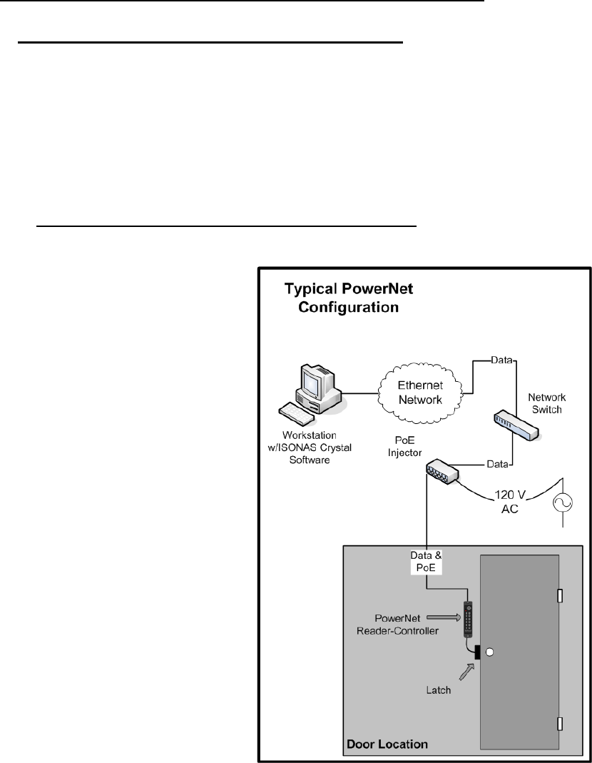
If your network switch is equipped
to provide PoE power, then the
separate PoE Injector is not
required.
If used, the PoE Injector is normally
located right next to your existing
network hub/switch, and the
Injector itself is plugged directly into
a standard AC outlet, or for extra
security, a UPS battery backup.
Figure 3 is an overview of how to
use PoE to power both the ISONAS
PowerNet Reader-controller and an
electronic locking mechanism.
Figure 3
How to Install the ISONAS IP-Enabled Reader-controller 12
A standard CAT5 cable is then run between the PoE source (Injector or switch) and
the PowerNet Reader-Controller which will be located right next to the door. The
CAT5 cable can be up to 100 Meters (328 feet) long.
With one cable, you provided the required network connection and all the power that
will be needed at the door site.
PowerNet Supplying 12 VDC to Door Components
When using PoE, the PowerNet reader can supply 0.6 amps@12 Volts of power for
the external door components. This power can be routed to the lock control circuit
using the jumper pins. The supplied 12V power can also be accessed thru the
reader-controller’s Pigtail, when the reader’s jumper-pins are properly configured (on
Jumper block JP1, jumper pin 1 to pin 3). The power will be continuously available
on the Pigtail’s Red and Black conductors. You might use this 12VDC source to power
a Motion Detector located at the door location.

How to Install the ISONAS IP-Enabled Reader-controller 13
PoE Power Budget Calculations
When planning an installation using PoE, you need to assure that the PoE source
(PoE Injector or PoE equipped Network Switch) supplying the PoE power is sized
properly for the power draw of all the doors. To do this, you total up the power draw
(in watts) of the PoE connections, and compare that total power draw to the rated
capacity of the PoE source.
Below is a chart of expected PoE power draws of the ISONAS Reader-controllers.
Door Location Configuration
PoE Power Requirement **
(Watts)
PowerNet Reader-Controller
3.0 Watts
PowerNet Reader-Controller with
Electronic Lock (0.6 amp @ 12V)
11.0 Watts
*** Ethernet cabling power losses not included. Losses range from being negligible
for short Cat5 cables up to about 16% for 100 meter Cat5 cables.
To meet the PowerNet’s variable PoE power requirements, the PowerNet will classify
itself with the PoE source as a “Class 0” PoE device. The power usage of a Class 0
device can range between 0.4 to 13.0 watts at the device (up to 15.4 watts from the
PoE source).
Some network PoE equipment will budget and allocate it’s distribution of PoE power
based upon the maximum power usage of the each attached device’s classification.
If your network equipment uses this power provisioning technique, then you should
budget 15.4 watts for each PowerNet. Such network PoE Equipment may allow you
to manually configure the amount of power that should be allocated to each device.
Configuring the PoE equipment for an allocation of 3.0 watts or 11.0 watts per
connection would be appropriate.
2.1.2: ADDITIONAL POWER OPTIONS
Most installations will use PoE for the PowerNet and door locks.
That is a clean way to control a door using a single, standard network cable.
There are many additional options available, that can be used, if the door location
requires more power than a standard PoE-powered PowerNet can provide.
The different options require different configurations of the supporting equipment
and /or building wiring. The following chart and Figure 4 describes some of these
power options.

How to Install the ISONAS IP-Enabled Reader-controller 14
Power Source
Switchable
Power
(Max)
Equipment at
the Door
Limiting Factor
Topology
Diagram
PoE (802.3af)
0.60 amps
(12VDC)
PowerNet
PowerNet’s available
PoE Output
A
PoE (802.3af)
0.55 amps
(12VDC)
PowerNet
EDK
PowerNet’s available
PoE Output
{minus}
the power required by
the EDK
B
DC Power Supply
12 or 24 VDC
1.0 amps
(As supplied)
PowerNet
Rating of PowerNet’s
lock relay
C
DC Power Supply
12 VDC
3.0 amps
(12VDC)
PowerNet
EDK
Rating of EDK’s lock
relay
(12VDC required by EDK’s
internal circuitry)
D
High-Powered PoE
(802.3at)
1.0 amps
(12VDC)
PowerNet
PoE Splitter
Example PoE Splitter
PowerDsine
PD-AS-701/12
Rating of PowerNet’s
lock relay
E
High-Powered PoE
(802.3at)
1.8 amps
(Approx)
(12VDC)
PowerNet
EDK
PoE Splitter
Example PoE Splitter
PowerDsine
PD-AS-701/12
Rating of PoE Splitter
{minus}
power required to
operate PowerNet &
EDK
F
High-Powered PoE
(non-standard)
Example PoE Injector
PowerDsine PD-9501G
3.00 amps
(12VDC)
PowerNet
EDK
PoE Splitter
Example PoE Splitter
PowerDsine
PD-AS-951/12-24
Rating of EDK’s lock
relay
G
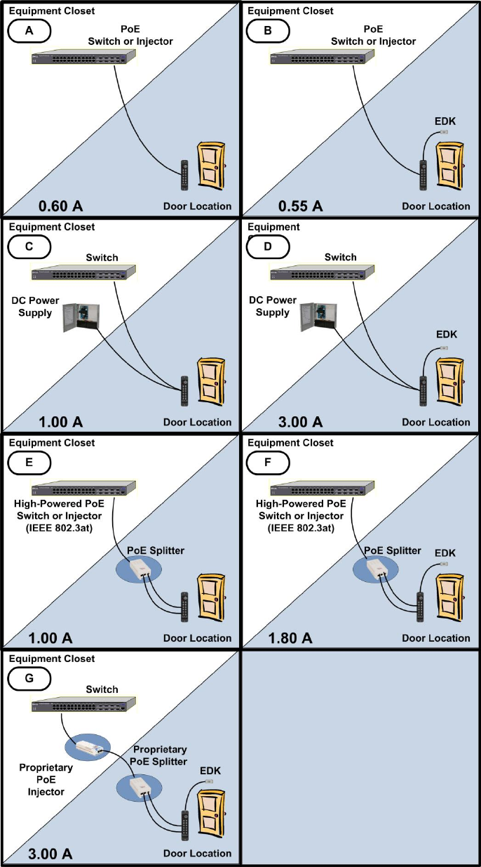
How to Install the ISONAS IP-Enabled Reader-controller 15
Power Options
Figure 4
How to Install the ISONAS IP-Enabled Reader-controller 16
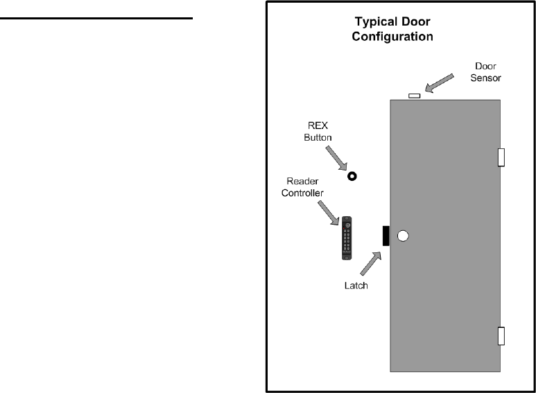
2.2: WIRING THE DOORS
After you connect power to every
Reader-controller, the next step is to
connect the wiring at each door.
Wiring a door may involve connecting:
An electronic door latch
A request to exit (REX) like:
REX Button
Motion Detector
An auxiliary (AUX) button
Door sensors
TTL lines (TTL1 and TTL2)
Figure 5 shows the typical configuration
of equipment at the door.
Figure 5
How to Install the ISONAS IP-Enabled Reader-controller 17
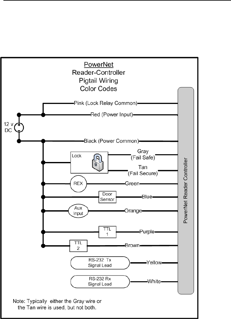
2.2.1: READER-CONTROLLER CONTROL-LEADS DESCRIPTION
The reader-controller has a cable extending from its back plate that is referred to as
“the pigtail”. The pigtail consists of 12 wire leads (22 awg) which are used to
connect to the various components at the door location. Most installations do not
require the use of all the leads. The typical usage of each available lead is shown in
Figure 6.
Figure 6
One of the wires is for a door sense switch. Another is for a REX (Request for Exit)
signal coming from a switch, infrared sensor or other REX device. A third input
signal, called AUX (auxiliary), can be programmed to act in a variety of ways.
How to Install the ISONAS IP-Enabled Reader-controller 18
The controllers have a lock-control circuit. This circuit consists of a form-C relay, with
its “normally open”, “normally closed” and “common” contacts connected to three
leads of the pigtail. These pigtail leads can be directly connected to the electronic
lock to unlock the door when a valid credential is presented.
There are two additional output signals called TTL1 and TTL2 that can be
programmed to behave in a variety of ways.
The usage of each lead will be detailed in the next few pages.

How to Install the ISONAS IP-Enabled Reader-controller 19
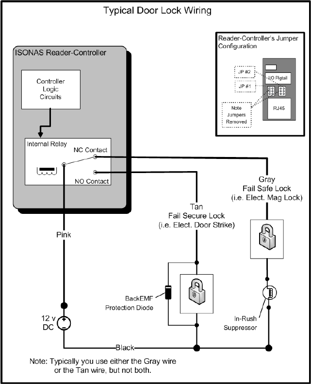
2.2.2: LOCK WIRING -- BASIC
Electronic door lock Overview:
If the door does not already have an electronic lock, first install the electronic door
lock according to the manufacturer's instructions. Examine the lock to determine
whether applying power will lock or unlock the
door.
Fail Safe: If applying power locks the door
(usually magnetic locks), use the gray wire
labeled (NC).
Fail Secure: If applying power unlocks the
door (usually electric strike locks), use the
tan wire labeled (NO).
Most locking mechanisms have two leads for the
power coil. On an electric strike, the leads power
a solenoid. On a Mag Lock, the leads power an
electromagnet.
The door lock control relay inside the ISONAS Reader-Controller has a set of Form
“C” contacts that are rated at 1.0 amp @ 30V DC. This means it can handle most
locking mechanisms. If your application requires more voltage or amperage than
this, an external relay that is controlled by the reader/controller can be used.
Installation Tip
For non-PoE installations:
Before you start wiring an
electronic door lock, check that
its power source is separate
from the power source for the
Reader-controller at that door.
Voltage fluctuations caused by
using the same power source
for both devices may cause the
Reader to malfunction.
How to Install the ISONAS IP-Enabled Reader-controller 20
Generic Wiring, using External Power for the Lock: See Figure 7
1. The PowerNet itself is being powered by PoE.
2. Connect the positive side of the power supply to the pink (common) wire on
the ISONAS Reader.
3. For a Fail Safe lock, connect the gray (Normally Closed (NC)) wire on the
ISONAS Reader-controller to one lead of the electric lock. For a Fail Secure
lock use the Reader's tan (Normally Open (NO)) wire instead.
4. Wire the other lead of the lock to the Black wire on the power supply.
Figure 7
How to Install the ISONAS IP-Enabled Reader-controller 21
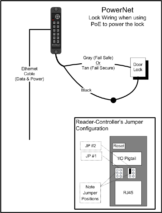
Generic Wiring, using PoE: See Figure 8
The PowerNet supports a
simplified configuration when
PoE is being used to supply the
lock’s power.
1. Assure that the jumpers
are configured as
shown:
JP1: Pins 2 to 4
Or
No jumper
JP2: Pins 1 to 3.
2. For a Fail Safe lock,
connect the gray
(Normally Closed
(NC)) wire on the
ISONAS Reader-
controller to one lead of
the electric lock. See
In-Rush suppressor
section for more info.
3. For a Fail Secure lock
use the Reader's tan
(Normally Open (NO))
wire instead. See
BackEMF diode section
for more info.
Figure 8
4. Connect the other lead of the lock to the black wire on the ISONAS reader-
controller.
Additional Lock Circuit wiring Notes:
There are many additional ways that the lock-control circuit can be used. Examples
include: Gate Controllers, Intelligent locking mechanisms, and Fuel pumps.
The general guidelines for using the Lock-Control Circuit are:
1. Always keep the voltage under 30 volts, and the current under 1 amp.
2. Use the Tan lead, if electrical current flow will unlock the door.
3. Use the Gray lead, if electrical current flow will lock the door.
4. Use the Pink Lead, if external power is being used to power the lock.
a. Otherwise you may supply 12VDC power to the lock relay by using
the jumper pins as shown in Figure 8.
How to Install the ISONAS IP-Enabled Reader-controller 22
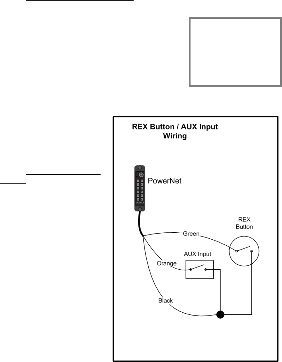
2.2.3: WIRING THE REX BUTTON
The REX (Request for Exit) signal expected by ISONAS
Reader-controllers is a momentary closure. You can
generate this signal with a pushbutton, infrared motion
detector, or other simple device. Typically the REX is placed
adjacent to the door so that people can press the button
and let themselves out the door without setting off the
alarm. When pressed, this button tells the ISONAS Reader-
controller that that someone wishes to pass through the
door, and the latch releases. In the ISONAS Crystal
software you can configure how the door responds to the
REX button.
You must wire this switch through the ISONAS Reader-controller. (See Figure 9)
First, connect one terminal of the
momentary switch to the Reader's
green wire. Then, connect the
switch's other terminal to the
Reader's common ground wire
(black).
2.2.4: WIRING THE AUX
INPUT
In host mode, the AUX Input is
another momentary switch which
functions exactly like the REX
button. (See Figure 9) The AUX
Input might be controlled by a
relay on an intercom at the door.
This would allow the receptionist
to unlock the door using the
intercom system’s functionality.
In the ISONAS Crystal software
you can configure how the door
responds to the AUX button.
In local mode, the door will stay
unlocked while the AUX switch is
closed.
Wiring for the AUX button is
similar to that of the REX button.
First, connect one terminal of the
momentary switch to the Reader's
orange wire. Then, connect the
switch's other terminal to the
Reader's common ground wire (black). Figure 9
About REX and AUX
REX and AUX are
both normally open
inputs. No action is
taken until the input
is closed.
How to Install the ISONAS IP-Enabled Reader-controller 23
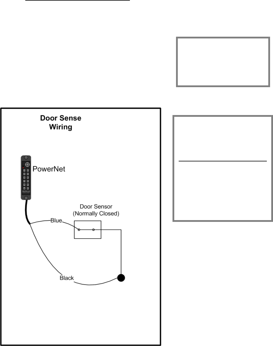
2.2.5: WIRING THE DOOR SENSE
Connecting the ISONAS Reader-controller to a door sensor allows our Crystal
software to determine whether that door is physically open. Then the Crystal
software can create alarms based on the door’s state.
This wiring task is similar to wiring the REX or AUX
buttons.
First, connect one terminal of the door sensor to the
Reader's blue wire. Then connect the door sensor's
other terminal to the Reader's common ground wire
(black).
Figure 10 shows how to wire the door sensor.
Figure 10
About the Door Sense
The door sense is a
normally closed input. No
action is taken until the
input is opened.
IMPORTANT: If There's No
Door Sense Switch
If you choose NOT to install a
door sense switch, then you
must permanently ground
the door sense input (blue
wire) to the reader’s Black
wire, so the system will not
see the door as "open."
How to Install the ISONAS IP-Enabled Reader-controller 24
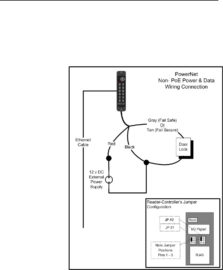
2.2.6: LOCK WIRING -- LOW-VOLTAGE 12VDC POWER OPTION
Powering the reader-controller using low-voltage DC:
Wiring DC power to a Reader-controller: Simply run the positive and negative
wires from the power source to the positive and negative wires on each Reader. The
example below shows the typical power connection for a reader-controller and a lock.
1. Connect the positive power from the power supply to the positive power
connection (red lead) of the reader-controller. Install the Jumper pins as
shown, which provides
12VDC to the lock
circuit.
2. Connect one side of
the electric lock to
EITHER the Tan (Fail
Secure) or Gray (Fail
Safe) connection on
the reader-controller.
See BackEMF diode or
In-Rush suppressor
sections for more info.
3. Connect the negative
power from the power
supply to the negative
power connection
(black lead) of the
reader-controller and
the remaining side of
the electric lock.
Figure 11 shows how to
take the power from the
External Power supply and
drive both the PowerNet
Reader-Controller and an
Electronic lock.
Figure 11
How to Install the ISONAS IP-Enabled Reader-controller 25
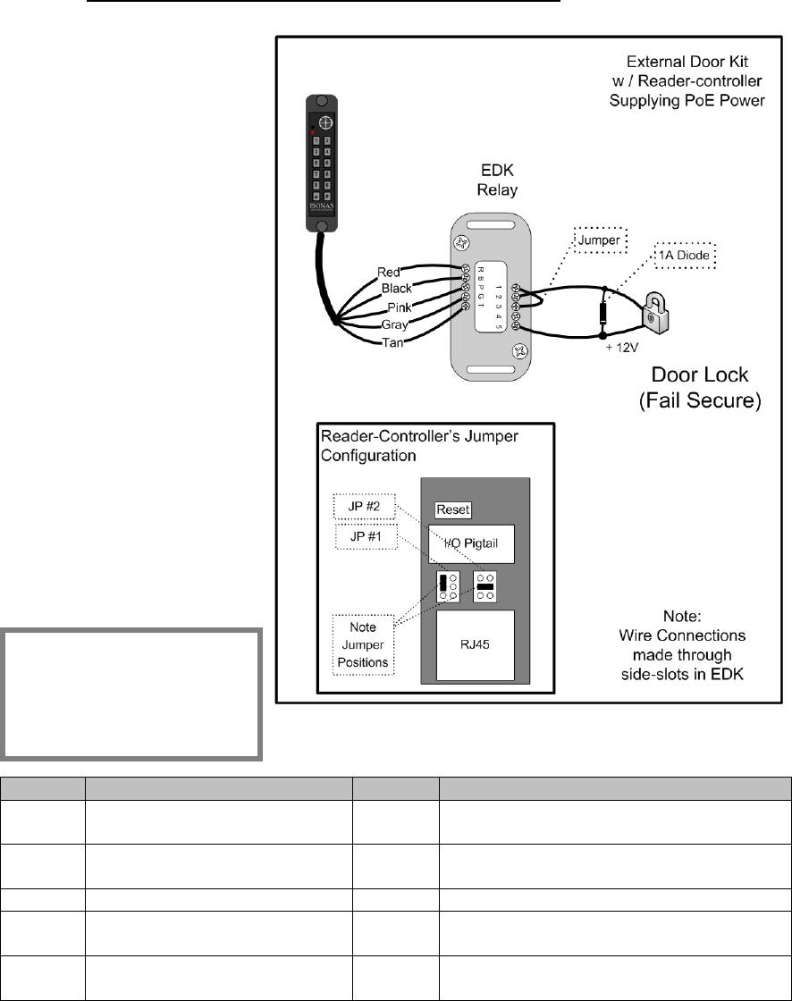
2.2.7: LOCK WIRING -- EXTERIOR DOOR KIT
The PowerNet reader-
controller has an optional
Exterior Door Kit (EDK),
which allows you to isolate
the door’s lock control
circuitry on the secure side
of the building. Also, since
the EDK is rated for 3
amps of current @ 12
Volts, it can be used in
cases where the locking
mechanism requires more
current than the reader-
controller’s control circuit
is rated for.
Two methods of
connecting the EDK are
shown
The 1st example shows
powering both the lock and
the EDK with the Reader-
controller’s PoE power
See Figure 12
Figure 12
Label
Reader Side Connection
Label
Lock Side Connection
R
Pigtail’s Red wire
(12 V Input Power)
1
12V Output Power
B
Pigtail’s Black wire
(Ground)
2
Power Ground
P
Pigtail’s Pink wire
3
EDK Relay’s Common Contact
G
Pigtail’s Gray wire
4
EDK Relay’s Normally Closed (NC)
contact (Fail-Safe Lock)
T
Pigtail’s Tan wire
5
EDK Relay’s Normally Open (NO)
contact (Fail-Secure Lock)
Installation Tip:
Jumper Block #1 and #2
should be configured as
shown.
How to Install the ISONAS IP-Enabled Reader-controller 26
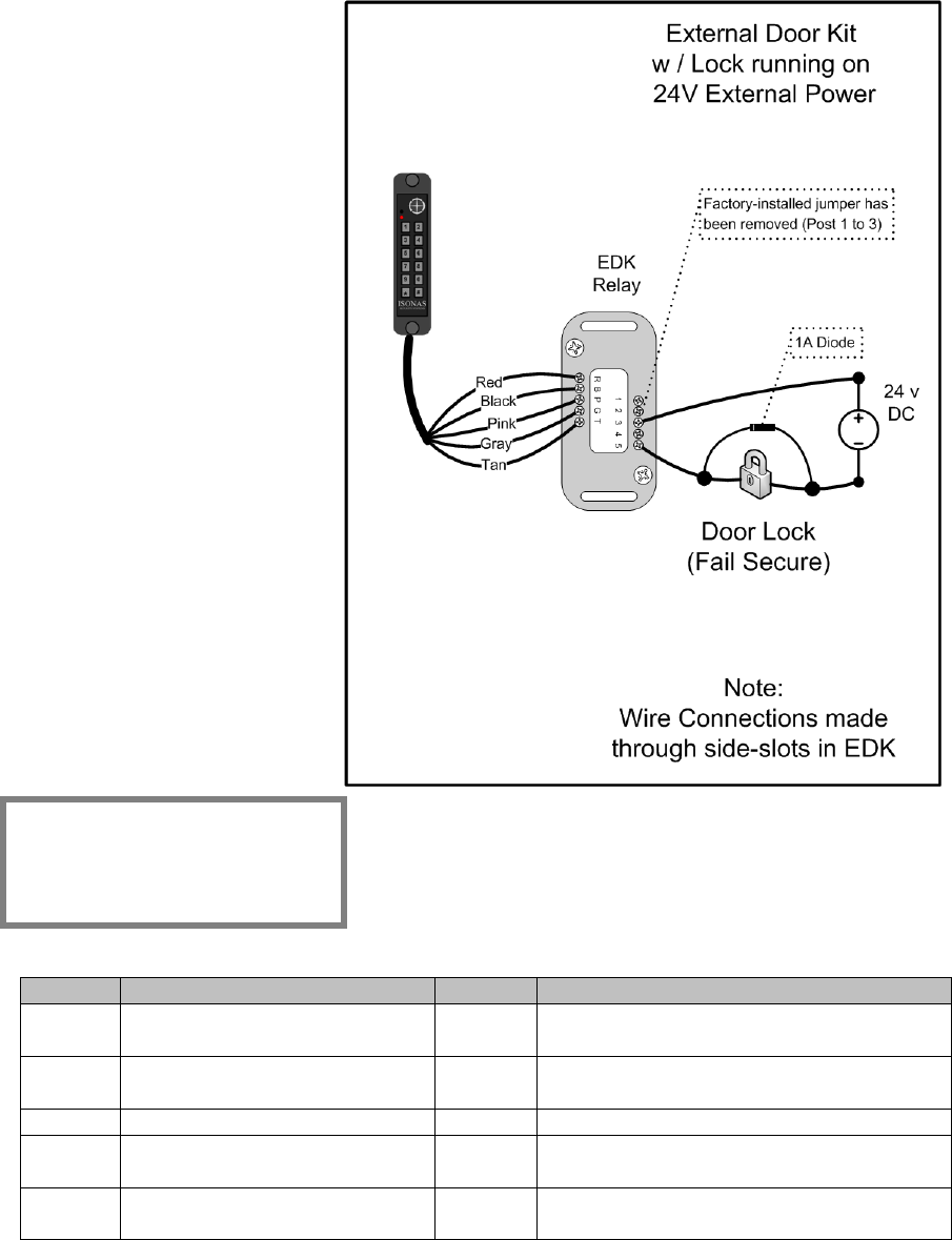
The 2nd example shows powering the EDK with the Reader-controller’s PoE power
output, and the lock with an external 24 volt power supply. See Figure 13
Understanding the
EDK’s LEDs:
When the EDK Power LED
is lit, it indicates that
power is available to the
EDK (Red LED).
The EDK communication’s
LED has four states:
Off: No signal received
from the reader-controller.
Green: Signal received
from the reader-controller,
and valid encryption key is
available.
Red: Signal received from
the reader-controller, but
no encryption key is
available.
Amber: Communications
problem. May relate to
Pink/Gray/Tan wire
connections or be a
BackEMF issue.
Figure 13
Label
Reader Side Connection
Label
Lock Side Connection
R
Pigtail’s Red wire
(12 V Input Power)
1
Not Used
B
Pigtail’s Black wire
(Ground)
2
Not Used
P
Pigtail’s Pink wire
3
EDK Relay’s Common Contact
G
Pigtail’s Gray wire
4
EDK Relay’s Normally Closed (NC)
contact (Fail-Safe Lock)
T
Pigtail’s Tan wire
5
EDK Relay’s Normally Open (NO)
contact (Fail-Secure Lock)
Installation Tip:
Configure the Jumper Blocks
as shown in previous
example
How to Install the ISONAS IP-Enabled Reader-controller 27
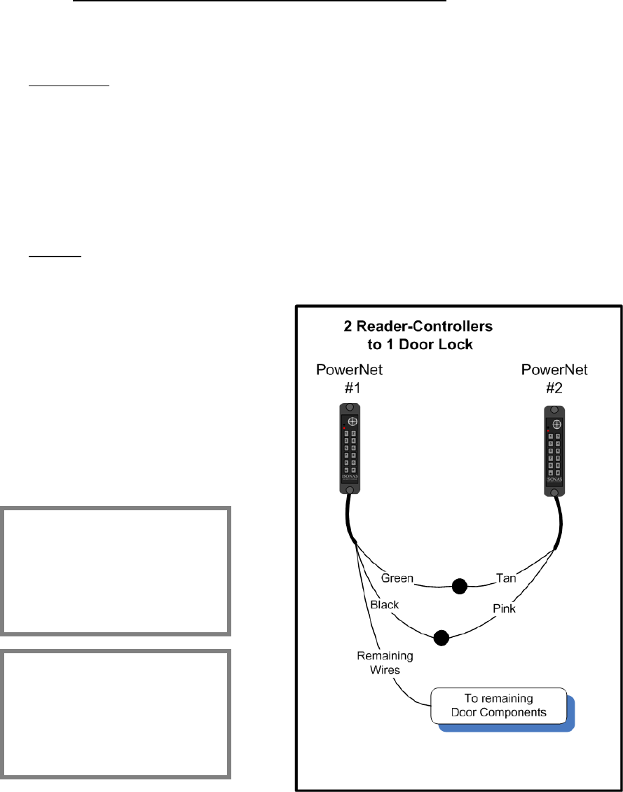
2.2.8: LOCK WIRING -- 2 READERS TO 1 LOCK
If you are wiring both sides of the door to control IN and OUT access, then you will
have the special condition of wiring 2 Reader-Controllers to a single locking
mechanism.
If there is not a door sensor switch connected to the door, then typically you connect
both reader-controllers to the door’s lock circuit.
For Fail-Secure locks, wire the two reader-controller’s lock circuits in-parallel
(Lock is connected to both reader-controller’s Tan leads)
For Fail-Safe locks, wire the two reader-controller’s lock-circuits in-series
(Gray lead of Reader #1 connects to Pink lead of Reader #2, Gray lead of
Reader #2 connects to lock).
If there is a door sensor switch connected to the door, then Reader #1 controls the
door, and is wired to the door’s Door-sense switch. Use the following steps to cause
Reader #2 to activate the REX button on Reader #1.
Two Readers & One Lock Wiring
Steps: See Figure 14
1. Wire reader #1 normally
2. Connect the tan (NO) lead
from reader #2 to the Green
(REX) lead on reader #1.
3. Connect the pink (common)
lead from reader #2 to the
black (ground) lead on reader
#1.
Figure 14
Programming
Reader #1 must be
programmed to accepted
REX inputs
Installation Tip:
For Figure 11 -- Verify that
there are no jumpers
installed on Controller #2 ‘s
JP 2 jumper block.

How to Install the ISONAS IP-Enabled Reader-controller 28
2.2.9: USING THE TTL LEADS
The TTL1 and TTL2 leads are logical output leads. In their “normal” state, there is a
5VDC potential on the leads. When the leads “activate”, this voltage potential is
removed (0 VDC.
These leads are typically used to connect to an alarm system. Certain abnormal
conditions of the reader-controller can be configured to activate these leads. An
example would be having TTL2 activate when the door is held open too long.
See the Crystal Access Software manual for more information on the usage of these
leads.
2.2.10: USING THE POWERNET’S RS-232 INPUT
The pigtail’s RS-232 signal leads (Yellow & White) can be connected to an external
device that will pass a credential ID to the PowerNet.
The most common usage is:
To pass in a 2 to 9 character long ASCII data string.
Only Numeric ASCII values are allowed in the string (“0” to “9”).
Delimiter characters are typically used at the beginning and/or end of the
message.
The serial connection’s default configuration is:
9600 Baud (Adjustable w/ PlugNPlay [9600, 19200, 38400, 57600])
8 Data Bits
N Parity (Adjustable w/ PlugNPlay [N, E, O])
1 Stop Bit
N Hardware flow control
How to Install the ISONAS IP-Enabled Reader-controller 29
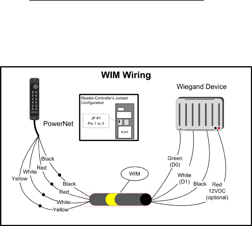
2.2.11: WIRING THE WIEGAND INTERFACE MODULE
The ISONAS Wiegand Interface Module (WIM) allows the PowerNet to receive
credential data from a Wiegand-based device, validate the credential, and then log
that activity.
The WIM is an in-line module that is attached to selected conductors of the
PowerNet’s Pigtail. Figure 15 shows how to wire the WIM.
Figure 15
Note: The WIM is easily identified by a yellow stripe
The PowerNet can supply the 12VDC power required by the WIM. The PowerNet’s
jumper JP1 is used to control this. This same 12VDC power can also be used to
power the Wiegand device. The WIM’s output red wire provides a convenient
connection to this power. Please make sure that the total power draw of the Wiegand
device, lock, and other devices does not exceed the PowerNet’s available power
(0.60 amps). External power can be used, if the door components require additional
power.

How to Install the ISONAS IP-Enabled Reader-controller 30
WIM’s wiring color code
Color
Function
Red
(PowerNet-side)
12 VDC Power
Black
(PowerNet-side)
Ground
(Power & Signal)
White
(PowerNet-side)
RS-232 Transmit to PowerNet
Yellow
(PowerNet-side)
RS-232
(Future use)
Red
(Wiegand-Side)
12VDC connection
(power from PowerNet)
Black
(Wiegand-Side)
Ground connection
(Power & Signal)
Green
(Wiegand-Side)
DO signal from Wiegand Reader
White
(Wiegand-Side)
D1 signal from Wiegand Reader
How to Install the ISONAS IP-Enabled Reader-controller 31
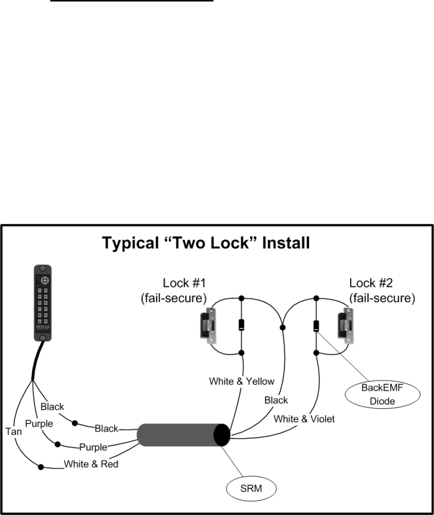
2.2.12: WIRING THE DUAL-SRM
The dual Secondary Relay Module (SRM) is available to enhance the PowerNet’s
ability to control devices located at the door.
The SRM provides a set of form-C relay contacts, which are controlled by one of the
PowerNet’s TTL outputs. There a multiple options available within the Crystal Matrix
software to control the TTL outputs.
The SRM is commonly used to selectivity control two locks, or to control a device
located at the door, in addition to the door’s lock.
Two example SRM usages are shown below.
Figure 16 shows a PowerNet controlling two locks. Note Tan wire’s power supply
can be configured by JP2. See section 2.2.2 of this manual for more details.
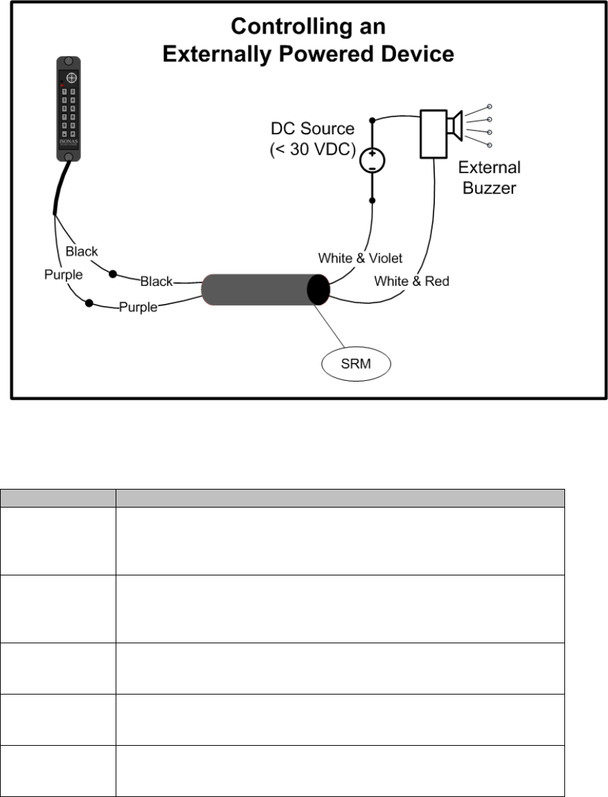
Figure 17 shows the PowerNet controlling an external device, in addition to the
potentially controlling the door’s lock.
Figure 16
How to Install the ISONAS IP-Enabled Reader-controller 32
Figure 17
SRM’s wiring color code
Color
Function
Purple
TTL input to SRM.
Connected to the PowerNet pigtail’s Purple or Brown
conductor.
Black
Power Ground from PowerNet.
Connects to Pigtail’s Black conductor and other grounded
connections
White / Red
SRM Relay
Common contact
White / Violet
SRM Relay
Open contact (when TTL is inactive)
White / Yellow
SRM Relay
Closed contact (when TTL is inactive)
How to Install the ISONAS IP-Enabled Reader-controller 33
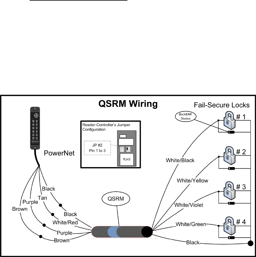
2.2.13: WIRING THE QUAD-SRM
The Quad Secondary Relay Module (QSRM) is available to allow a single PowerNet to
control up to 4 locks.
The QSRM is an electronically controlled 4-way switch, that directs an input electrical
signal to one-of-four outputs connections.
The QRM is commonly used to control multiple doors on storage cabinets or
computer racks.
Figure 18 shows a PowerNet and QSRM controlling four fail-secure locks.
Figure 18
Note: The QSRM is easily identified by a blue stripe

How to Install the ISONAS IP-Enabled Reader-controller 34
QSRM’s wiring color code
Color
Function
Purple
TTL input to SRM.
Connected to the PowerNet pigtail’s Purple conductor.
Brown
TTL input to SRM.
Connected to the PowerNet pigtail’s Brown conductor.
Red
(PowerNet-side)
12 VDC Power
Black
(PowerNet-side)
Ground
(Power & Signal)
Black (x4)
(Lock side)
Ground connection
Connects to Pigtail’s Black conductor and other grounded
connections
White / Red
Electrical Signal Input
Common contact
White / Black
Connection’s Output
TTL1 = Active
TTL2 = Inactive
White / Yellow
Connection’s Output
TTL1 = Inactive
TTL2 = Active
White / Violet
Connection’s Output
TTL1 = Active
TTL2 = Active
White / Green
Connection’s Output
TTL1 = Inactive
TTL2 = Inactive
Example usages of the QSRM are shown in the Knowledge-base Article
KBA0015CabinetControl.PDF
How to Install the ISONAS IP-Enabled Reader-controller 35
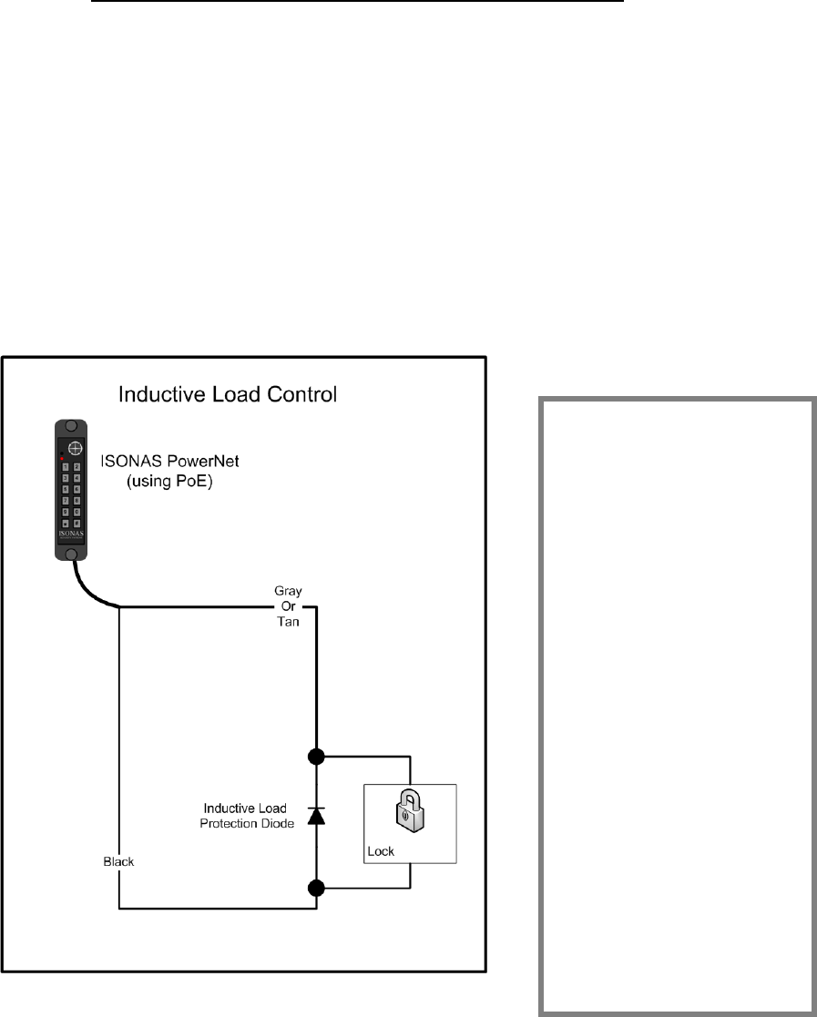
2.2.11: MANAGING INDUCTIVE LOAD CHALLANGES
Most door latches use a relay coil that powers up and down to open and close the
door. When this happens, electricity enters the connected circuit. This problem,
known as back EMF, produces network interference that usually becomes more
pronounced when the device is switched off.
Switching off a typical 12 VDC relay coil can produce a back EMF of 300 volts or
more. If this relay is switched via an output, that voltage appears across the
terminals of the output. The problem gets worse as switching voltage/current rises.
Figure 19 shows a solution. You can virtually eliminate back EMF by installing a
transient suppression device (diode). Always check that the diode is correctly
rated for the circuit voltage. For optimum performance, the diode should be installed
at the lock or close to the lock. Standard diodes have a stripe-band marking on one
side. That side of the diode should be connected to the “+” wire of the lock circuit.
Figure 19
Protect the Digital
Output
Which type of transient
suppressor should you
install? This depends
mainly on the type of
inductive load being
switched. Some locks
have Back EMF protection
built into the lock itself.
For Back EMF in low-
voltage DC applications, a
1N4007 diode will suffice.
However, for protection
against other transient
voltages (i.e. lightening),
we recommend using a
fast-switching transient
voltage suppressor, such
as a bipolar TranZorb.
How to Install the ISONAS IP-Enabled Reader-controller 36
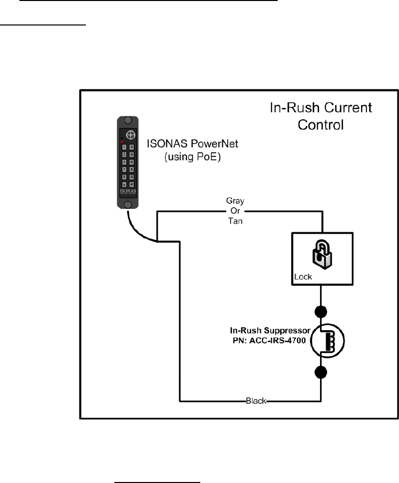
2.2.12: MANAGING IN-RUSH CURRENT LOADS
Some Magnetic Locks with advanced quick-release circuitry will generate an initial
surge of current when the lock is turned on. This surge of current can be 20 times
greater than the lock’s steady state current requirements. The lock control relay is
rated for 1 amp of current. This in-rush current can greatly exceed that rating, and
shorten the useful life of the reader-controller.
Figure 20 shows
the solution to this.
Installing an in-
rush suppressor in
the lock circuit will
prevent any
detrimental affects
on the reader-
controller.
F
Figure 20
Any installation that is using Magnetic Locks that are equipped with a “quick-
release feature” should have this in-rush protection installed.
Other devices who also create this in-rush current include incandescent light bulbs
and “capacitive loads”. A light bulb’s cold resistance is close to 0 ohms, and a
discharged capacitor is also a short-circuit when power is initially applied. Any
installation which is controlling these types of devices should have the in-rush
suppressor installed.
How to Install the ISONAS IP-Enabled Reader-controller 37
2.3: CONFIGUATION EXAMPLES
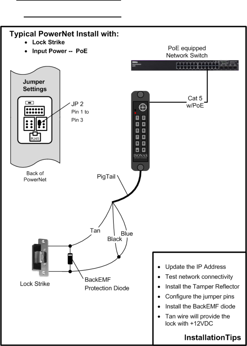
2.3.1: PoE --- ELECTRIC STRIKE
Figure 21
How to Install the ISONAS IP-Enabled Reader-controller 38
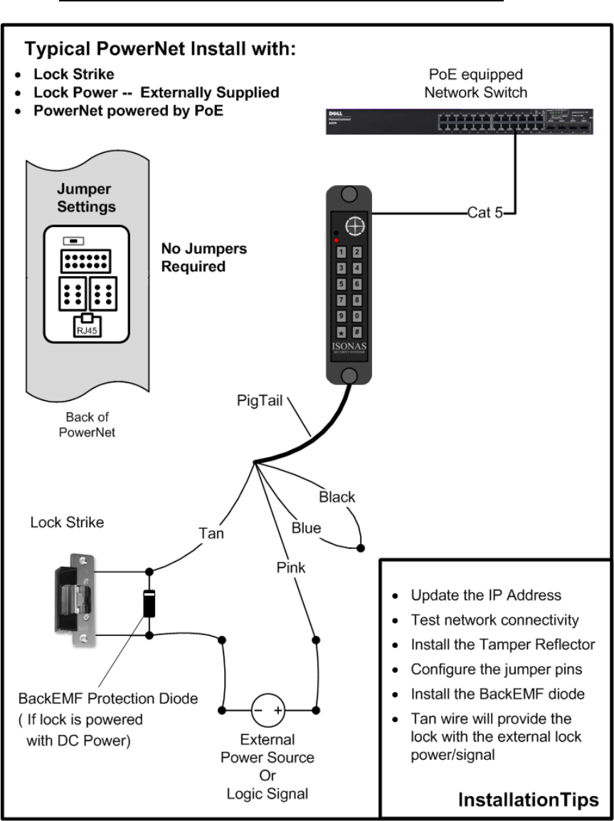
2.3.2: PoE --- EXTERNAL PWR FOR ELECTRIC STRIKE
Figure 22
How to Install the ISONAS IP-Enabled Reader-controller 39
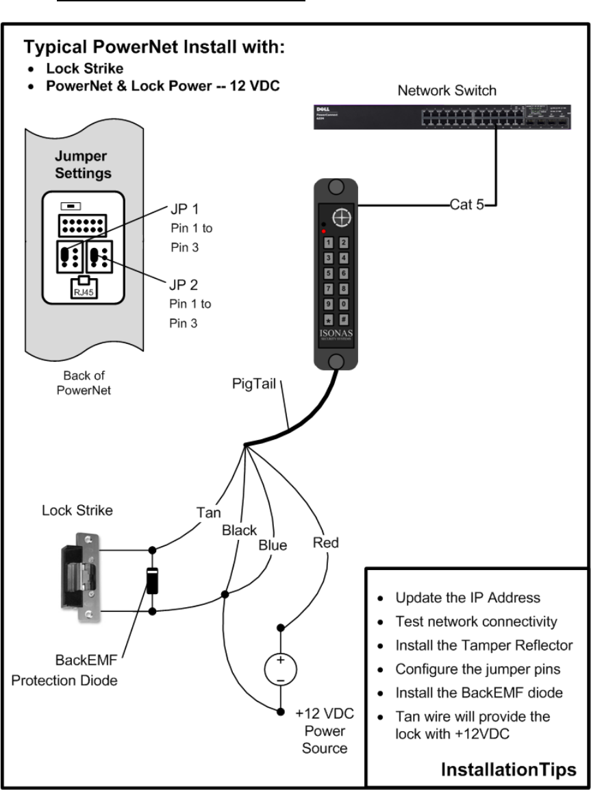
2.3.3: 12VDC – ELECTRIC STRIKE
Figure 23
How to Install the ISONAS IP-Enabled Reader-controller 40
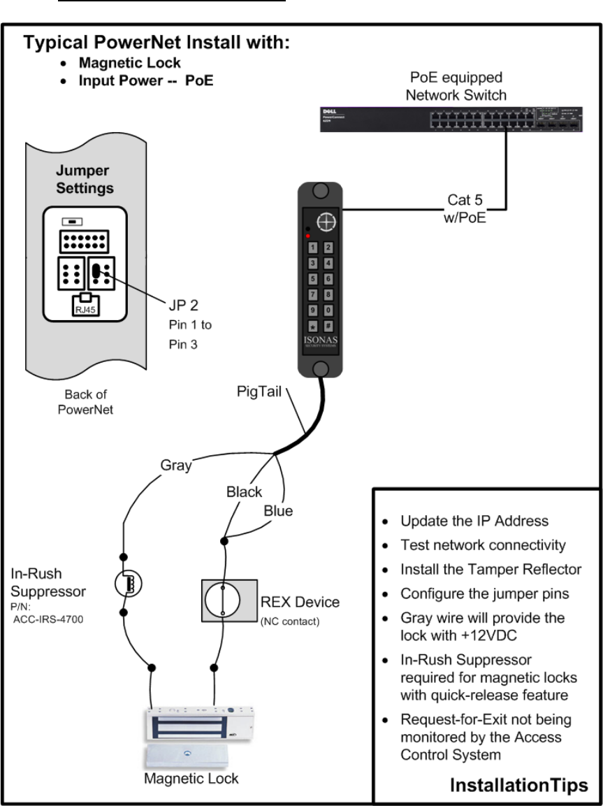
2.3.4: PoE --- MAGNETIC LOCK
Figure 24
How to Install the ISONAS IP-Enabled Reader-controller 41
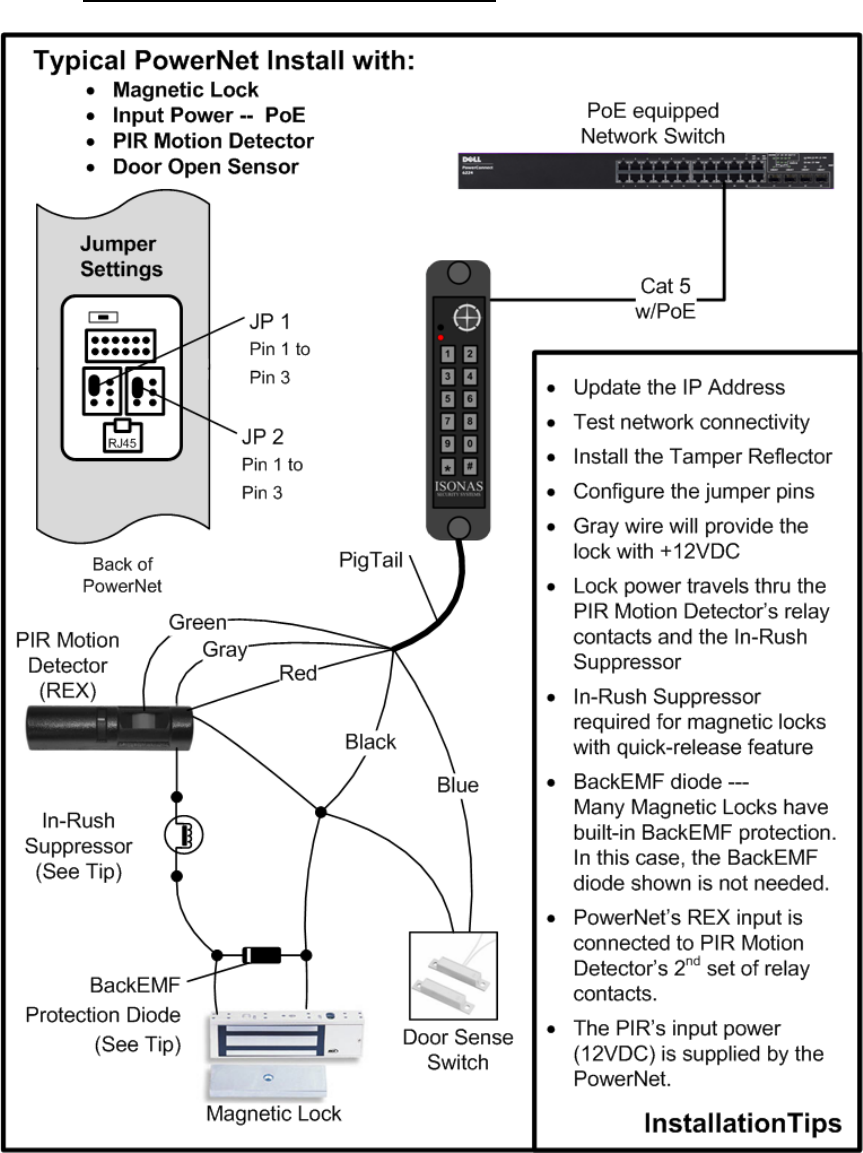
2.3.5: PoE --- MAGNETIC LOCK & PIR
Figure 25
How to Install the ISONAS IP-Enabled Reader-controller 42
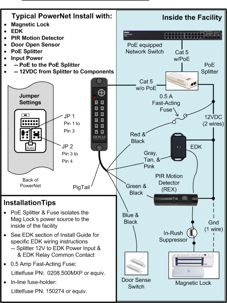
2.3.6: PoE --- MAGNETIC LOCK, EDK & PIR
Figure 26
How to Install the ISONAS IP-Enabled Reader-controller 43
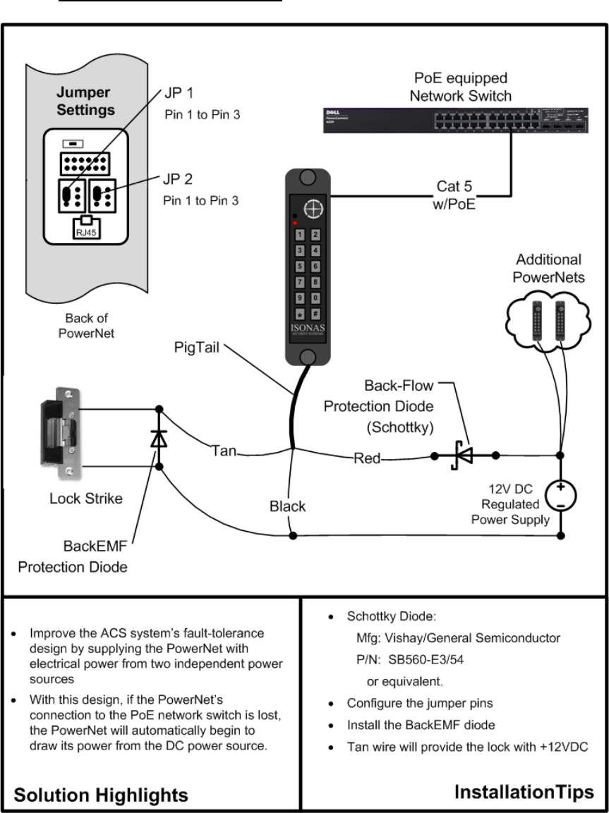
2.3.7: DUAL POWER SOURCES
Figure 27

How to Install the ISONAS IP-Enabled Reader-controller 44
3: CONFIGURING THE READER-CONTROLLER’S
COMMUNICATIONS
ISONAS Crystal software communicates to the Reader-controller units over the
organization's data network.
3.1: ETHERNET-BASED TCP/IP READER-CONTROLLERS
There are many Ethernet network topology permutations, too many topologies to
cover in this guide. Here are two common Ethernet configurations used by ISONAS
customers:
Direct Crystal-Software to Readers: This is the simplest type of network
connection. ISONAS Crystal software runs on a server/workstation that is
connected to an Ethernet network. All the Reader-controllers are also directly
connected to this network.
Addressing: Each reader’s assigned IP address is reachable from the
server/workstation. For example, assume that you are installing three Reader-
controllers. Two are located in your own Austin Texas office, and 1 is located in
the company’s Singapore office. Your networking staff gives you three IP
addresses to use. 205.155.45.130 and 205.155.45.131 for the Readers that
are located in your office. 205.172.37.130 for the reader located in the
Singapore office. As long as the network is configured so your workstation
can reach all three reader-controllers, there is no difference in configuring or
using the three readers.
Here are a couple guidelines to follow to assure that your network’s
configuration will support the ISONAS access system.
1. The ISONAS reader-controller is a standard “network appliance”.
Standard TCP/IP rules apply.
2. For many installations, each reader-controller is assigned a static IP
address. Typically, the network administrator will define what IP
address to use.
3. The reader-controller’s IP Address should be a valid IP address for the
network-subnet that the reader-controller is physically connected to.
4. If the reader-controller’s IP Address must be changed, then the
ISONAS tool “Plug and Play” can be used to reset the IP Address. See
the Crystal Matrix Software Users Guide for more details on using this
tool. Note: Plug and Play requires that the workstation running the
Plug and Play application and the reader-controller be physically
connected to the same network subnet.
5. The host’s IP Address should be a valid IP address for the network-
subnet that the host is physically connected to.
6. If the host and reader-controller are on different subnets, then
network routers must be in-place to enable TCP/IP communications
between the two subnets.
7. One definition of a “Network subnet” is:
The set of network connections that can communicate with
each other without having to go thru a network router.
How to Install the ISONAS IP-Enabled Reader-controller 45
Using Port Forwarding to reach the Readers. This is common on
networks where the available number of IP addresses is limited. It can also
be used when the ISONAS software must communicate with Reader-
controllers on another site that is behind a network firewall.
As in the first topology, ISONAS Crystal software runs on a
server/workstation that is connected to a Ethernet network. The readers are
connected to a network, but because of the design of the network, the
readers can not be directly reached from the workstation/server. A router is
between the server/workstation and the readers. The router is configured to
implement Port Forwarding. The router will intercept and redirect the IP
communications to enable the server/workstation to communicate with the
Readers. This configuration allows you to connect many Readers without
consuming the primary network's IP address allotment.
Addressing: Each Reader-
controller unit is assigned an
IP address compatible with its
local network (not the
server/workstation network).
For example, assume the
reader’s local network uses IP
addresses in the range of
192.168.10.2 thru
192.168.10.254. In this
example, assume that the
Server/workstation has an IP
address of 84.117.31.158.
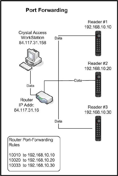
Port Addressing: (please refer
to Figure 28) Port forwarding
is a function of Routers, when
using this configuration the
ISONAS software does not
need the IP address of each
reader-controller, it just needs
the Port number associated
with each reader; however,
the software does need the IP
address of the Router.
Figure 28
Configuring the ISONAS software is easy, you simply define an ‘IP address’
with the address of the Router (in this example it is 84.117.31.16), then each
reader is given a unique Port number assignment under that server.
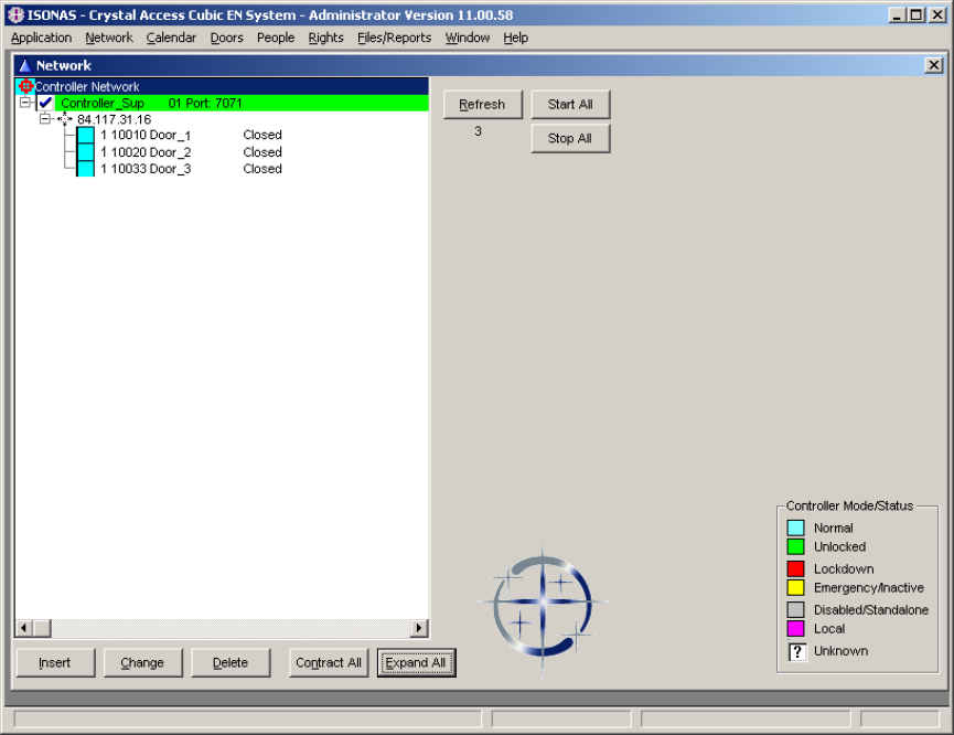
How to Install the ISONAS IP-Enabled Reader-controller 46
Here is an example of the ISONAS Network screen for the above configuration:
Port Forwarding requires steps outside of the ISONAS software; you must
configure your Router to “forward” each port number to exactly one reader.
This configuration is specific to the Router that you purchase and will be
defined in the vendor’s documentation. Typically the configuration is labeled
“port forwarding”; however it is sometimes referred to as “gaming options.”
When using Port Addressing, it will also be necessary to configure each of the
Reader-controllers to have the proper IP address and to use the correct Port
number. Changing the IP addresses and port number for the reader-controller
is easily accomplished using the ISONAS Plug and Play application
Note:
Port Forwarding requires configuration of the network router. Please
reference the router’s manual for instructions on configuring the router
to support this feature.

How to Install the ISONAS IP-Enabled Reader-controller 47
3.2: SECURING MESSAGES ON YOUR NETWORK
You can configure ISONAS Readers and software to secure each and every message
to and from the Reader using Advanced Encryption Standard (AES).
When you enable AES in both an ISONAS Reader-controller and the Crystal software,
every message to and from that Reader-controller is encrypted. Therefore, anyone
who manages to hack into your data network would still face a daunting task to
decrypt the actual messages to the Reader-controllers. This is a significant ISONAS
advantage in protecting Reader-controllers from hackers.
How to Install the ISONAS IP-Enabled Reader-controller 48
For more information:
Web: www.isonas.com E-mail: sales@isonas.com
Tel: 800-581-0083 (toll-free) or 303-567-6516 (CO)
Fax: 303-567-6991
ISONAS Headquarters:
4720 Walnut Street, Suite 200, Boulder, Colorado 80301 USA