ISONAS orporated RC-04SK Product is a POE powered LF and HF RFID reader controller used to allow access to access controlled areas User Manual
ISONAS Incorporated Product is a POE powered LF and HF RFID reader controller used to allow access to access controlled areas Users Manual
Contents
- 1. Users Manual
- 2. Users manual
Users Manual

How to Install an
ISONAS PureIP™
Reader-Controller
Copyright © 2016, ISONAS, Inc.
All rights reserved

ISONAS Inc.
FCC ID: OCZRC-04M, OCZRC-04S, OCZRC-04SK
IC: 8431A-RC04M, 8431A-RC04S, 8431A-RC04SK,
This device complies with Part 15 of the FCC Rules.
Operation is subject to the following two conditions:
(1) This device may not cause harmful interference, and
(2) This device must accept any interference received, including interference that may cause
undesired operation.
Changes or modifications not expressly approved by the party responsible for compliance could void the
user’s authority to operate the equipment.
This equipment has been tested and found to comply with the limits for a Class B digital device, pursuant
to part 15 of the FCC Rules. These limits are designed to provide reasonable protection against harmful
interference in a residential installation. This equipment generates, uses, and can radiate radio frequency
energy and, if not installed and used in accordance with the instructions, may cause harmful interference to
radio communications. However, there is no guarantee that interference will not occur in a particular
installation. If this equipment does cause harmful interference to radio or television reception, which can be
determined by turning the equipment off and on, the user is encouraged to try to correct the interference by
one or more of the following measures: 1) Reorient or relocate the receiving antenna. 2) Increase the
separation between the equipment and receiver. 3) Connect the equipment to an outlet on a circuit different
from that to which the receiver is connected. 4) Consult the dealer or an experienced radio/TV technician
for help.
This device complies with RSS-210 of Industry Canada.
Operation is subject to the following two conditions:
(1) This device may not cause harmful interference, and
(2) This device must accept any interference received, including interference that
may cause undesired operation.
Le présent appareil est conforme aux CNR d’Industrie Canada applicables aux appareils
radio exempts de licence.L’exploitation est autorisée aux deux conditions suivantes:
1. l’appareil ne doit pas produire de brouillage, et
2. l’utilisateur de l’appareil doit accepter tout brouillage radioélectrique subi, même si le
brouillage est susceptible d’en compromettre le fonctionnement.
This Class B digital apparatus complies with Canadian ICES-003.
Cet appareil numérique de la classe B est conforme à la norme NMB-003 du Canada.
For RF Safety and per FCC and Industry Canada regulations, the product should never be
installed within 8-inches (20cm) of typical people locations.
Table of Contents
1: BEFORE YOU BEGIN ...................................................................................................................... 5
1.1: GENERAL REQUIREMENTS: .................................................................................................. 5
1.2: PureIP RC (PureIP RC) SPECIFICATIONS: ........................................................................... 6
1.3: INSTALLATION LOCATION GUIDELINES .......................................................................... 7
1.4: INSTALLER TOOLKIT COMPONENTS ................................................................................. 9
2: WIRING AT THE DOOR AND READER-CONTROLLER ......................................................... 11
2.1: POWERING THE READER-CONTROLLERS ...................................................................... 11
2.1.1: POWER OVER ETHERNET (PoE) OPTION....................................................................... 11
2.1.2: ADDITIONAL POWER OPTIONS ....................................................................................... 13
2.2: WIRING THE DOORS ............................................................................................................. 16
2.2.1: READER-CONTROLLER CONTROL-LEADS DESCRIPTION ....................................... 17
2.2.2: LOCK WIRING -- BASIC ...................................................................................................... 18
2.2.3: WIRING THE REX/AUX INPUT .......................................................................................... 20
2.2.5: WIRING THE DOOR SENSE................................................................................................ 21
2.2.7: LOCK WIRING -- EXTERIOR DOOR KIT ......................................................................... 22
2.2.8: EDK LED STATUS INDEX ................................................................................................... 24
2.2.9: LOCK WIRING -- 2 READERS TO 1 LOCK ....................................................................... 25
2.2.15: MANAGING INDUCTIVE LOAD CHALLANGES ........................................................... 26
2.3: CONFIGUATION EXAMPLES ................................................................................................... 27
2.3.1: PoE --- ELECTRIC STRIKE ................................................................................................. 27
2.3.2: PoE --- MAGNETIC LOCK, EDK & PIR ............................................................................. 28
2.3.3: DUAL POWER SOURCES .................................................................................................... 29
3: CONFIGURING THE READER-CONTROLLER’S COMMUNICATIONS ............................... 30
3.1: ETHERNET-BASED TCP/IP READER-CONTROLLERS .................................................... 30
3.2: SECURING MESSAGES ON YOUR NETWORK .................................................................. 31

Document Version
Date of
Revision
Revision
Author
Description
11/03/2016
1.00
Shirl Jones
Initial Release

How to Install the ISONAS PureIP Reader-controller 5
1: BEFORE YOU BEGIN
To install an ISONAS Reader-controller unit, you must complete three key wiring tasks:
1.1. Mount the PureIP reader in the appropriate location. Recommended locations and wiring
methods shall be in accordance with the National Electrical Code, ANSI/NFPA 70.
1.2. Supply power to the PureIP reader. This may be accomplished with power being provided
on the Ethernet data cable (Power over Ethernet [POE / POE+) or through an external DC
power source (12VD). When powering from POE or POE+, in order for the system to be
UL294 V6 compliant, the Power Sourcing Equipment (PSE) injector or end point must be
compliant to UL294 or UL294B standards.
1.3. Wire the unit to the door’s locks and other components for physical access control.
1.4. Connect the unit to the data network for communication with the server/workstation host
PC.
1.5. The PureIP reader complies with UL 294 V6 and is rated for the following performance
levels:
1.5.1. Standby power = Level I.
1.5.2. Endurance = Level IV.
1.5.3. Line Security = Level IV.
1.5.4. Destructive Attack = Level TBD.
This guide discusses each wiring process separately. Understanding all of these processes
makes a project much simpler and helps guarantee success.
1.1: GENERAL REQUIREMENTS:
If PoE is not being used, then use only UL-listed, access control, power-limited power
supplies with an ‘AC on’ indicator light clearly visible on the enclosure. Power supplies should
provide at least four hours of standby power.
Never connect power supplies to a switch-controlled receptacle.
Install the ISONAS system in accordance with the National Electrical Code NFPA 70. (Local
authority has jurisdiction.)
Use only UL-listed wire or cabling recognized suitable for ISONAS power supply and data
communications, in accordance with the National Electrical Code.
Where possible, separate ISONAS equipment and cabling from sources of electromagnetic
interference (EMI). Where this is not possible, take other steps to reduce the effect of EMI on
cabling or equipment.
Protect input and output terminals adequately from transient signals. Also, connect these
terminals to power-limited circuitry.

How to Install the ISONAS PureIP Reader-controller 6
1.2: PureIP RC (PureIP RC) SPECIFICATIONS:
Input Voltage
12 VDC
(8.0V absolute minimum to 14.5V absolute maximum)
PoE per IEEE 802.3af
Input Current Draw
(Without external loads)
PoE: 2.3 watts
12VDC: 150 mA
Supplied Power for External Devices
(when PoE power is being used)
0.60 AMPS @ 12VDC
Read Range
2 TO 5 inches typically
Read Speed
<250msec (Prox)
Exciter Field Frequency
Proximity -- 125khz
Multi-Tech - 13.56 MHz
Modulation Schemes
Proximity – FSK
Multi-Tech --ISO 14443 type A and type B
Communication Interface
TCP/IP Over Ethernet
10 Mbps
Auto Negotiate
Half-duplex / Full-duplex
Inputs
1 Door Sensor / 1 REX/AUX
Outputs
1 Lock Power Output / 1 EDK control output
Standalone Memory Capacity
64000 Cards/ 5000 Events/ 32 Time zones
Visual Indicators
LED for Normal Operations
Operating Temperatures
-40° To 135° Fahrenheit
-40° To 57° Celsius
Weight
Mullion 6.5 Oz
WallMount 8.0 Oz
WallMount w/Keypad 9.5 Oz
Size
Mullion 5.10 x 1.70 x 0.71
WallMount 5.10 x 3.25 x 0.71
WallMount w/Keypad 5.10 x 3.25 x 0.75

How to Install the ISONAS PureIP Reader-controller 7
1.3: INSTALLATION LOCATION GUIDELINES
When selecting the location where you are going to mount the ISONAS reader-controller, a few
guidelines should be observed.
1) The reader-controller should be kept at least 2 feet from another ISONAS reader-controller,
and 6 feet from any other RF emitting device.
2) In an exterior location, the reader-controller’s mounting should be sealed to prevent water
from running down between the mounting surface and the back of the reader-controller.
3) For the PureIP RC, a dielectric insulating compound (Dow Corning DC-4 or equivalent) can
be used to obtain extra water protection of the reader-controller’s cable connections.
4) In humid environments, it is recommended that a drip-loop be formed in the PureIP’s
cables, before the cables enter the reader-controller.
5) The reader-controller should be protected from extreme heat and sunlight. It is rated for
conditions up to 135 F. A direct southern exposure, in the Southwest area of the United
States may exceed these ratings.
6) The cables extending from the back of the PureIP’s Pigtail cable is available in a two
standard lengths (10 foot or 25 foot). Plan for the termination of the door wiring within that
distance of the reader-controller.
7) The wall mounting features required for the reader-controller are shown in the next figure.
It is recommended to use the RC04’s detachable metal bracket as a drill template for
locating the mounting screws.
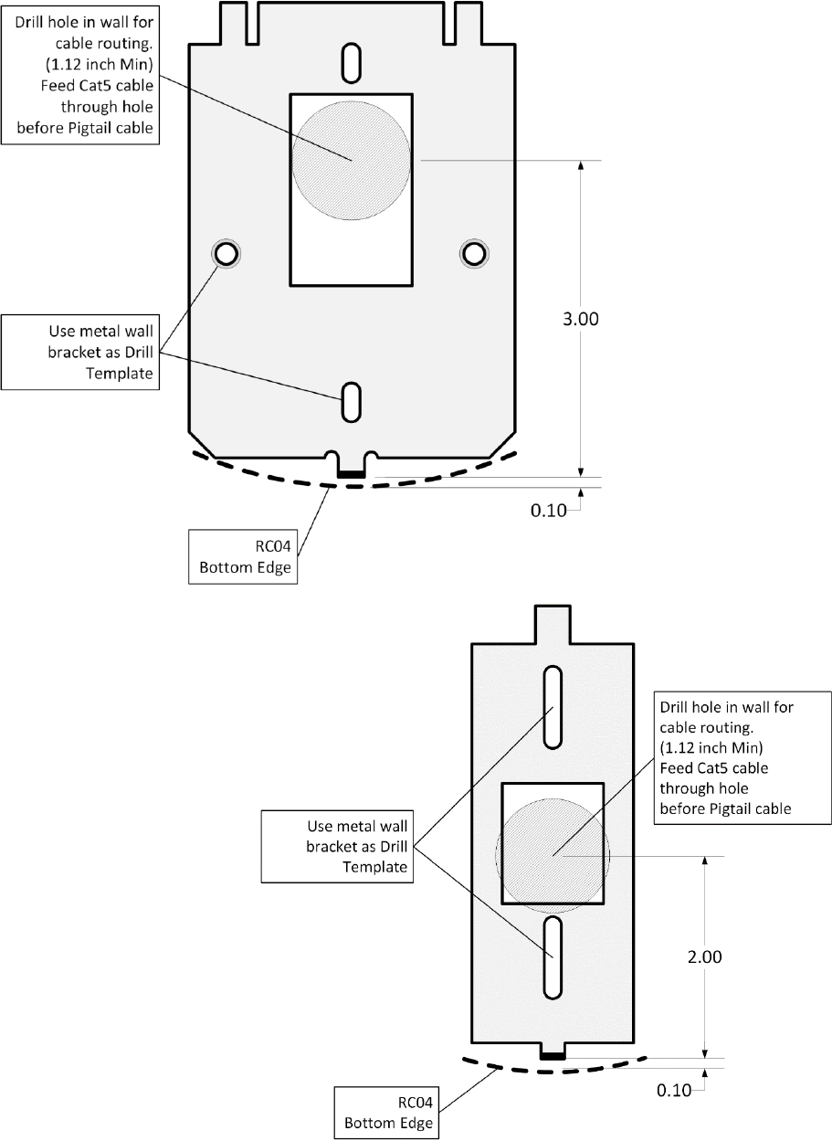
How to Install the ISONAS PureIP Reader-controller 8
Figure 1
PureIP Wallplate
Mounting Diagram
Figure 2
PureIP Mullion
Mounting Diagram

How to Install the ISONAS PureIP Reader-controller 9
1.4: INSTALLER TOOLKIT COMPONENTS
Before an installer goes to a customer site, they need to put together their supplies and tool-kit.
The ISONAS solution is simpler to install than other Access Control Systems, but materials are still
needed. And some of those materials may be different than what you are use to carrying. The list
below identifies some important items that you should make sure to bring with you, to the
customer’s site.
A prepared installer will have:
Installer completed the on-line reseller training program.
An installer’s Tool Kit should include the following:
1. The copy of the PureIP RC Installation and Wiring Guide
2. A Volt-Ohm Meter
3. Pin-in-Torx Screwdriver
o T-8 (Tamper Resistant)
4. 1 1/8 inch hole-saw (If mounting is done without a J-box)
5. A PoE Injector
6. A Cross-over Cat5/Cat6 cable
7. A straight-thru Cat5/Cat6 patch cable.
8. Basic Ethernet network cable tester (Tests for: Opens, Shorts, Split Pairs,
Mis-wires & Reversals)
9. A spare PureIP RC
10. An extra PureIP RC Pigtail
11. Silicon Caulking for sealing the PureIP to exterior walls
12. Dielectric Silicon Grease (Dow DC-4) for protecting cable connections.
13. The ISONAS PureIP As-Built forms, which is used to record the details of the
door's installation.
14. Credentials that match the customer system’s technology
o ISONAS Proximity
o HID Proximity
o DESFire EV2 Smart Cards

How to Install the ISONAS PureIP Reader-controller 10
1.6: PUREIP RC RESET BUTTON
The PureIP RC has a Reset Button located on the back.
It can be used for two different types of resets.
It is helpful if the PureIP’s Ethernet cable is connected, and functioning (the network status LED is
lit). Monitoring the RC04’s main status LED allows you to determine the status of the reset
operation.
Reset CPU: Press, hold (approx. 2 seconds) and release the Reset button. Once the Reset
Button is released, the Amber LAN Status LED should turn off (approx. 6 seconds), and then
turn back on. If the Amber LED does not turn off, then the reset did not occur.
Reset Configuration: Press and hold the Reset button (approx. 10 seconds), until the
RC04’s Main Status LED turns AMBER. Selected reader-controller configuration settings are
reset to factory defaults. Setting that are changed include:
DHCP (Default value: On)
IP Address (Default value: 192.168.1.119)
IP Port (Default value: 10001)
Subnet Mask (Default value: 255.255.0.0)
Gateway (Default value: 0.0.0.0)
ACS Alias (Default value: {blank})
ACS Server IP (Default value: 0.0.0.0)
Communication Type (Default value: Server)
Remote Host Name (Default value: {blank})
Remote Host IP (Default value: 0.0.0.0)
Remote Host IP Port (Default value: 55533)
Remote Host DNS (Default value: 0.0.0.0)
Clear AES Encryption Configuration
Reset PureIP’s Passwords
How to Install the ISONAS PureIP Reader-controller 11
2: WIRING AT THE DOOR AND READER-CONTROLLER
2.1: POWERING THE READER-CONTROLLERS
All ISONAS Reader-controller models require a direct connection to a power source.
The PureIP RCs can be powered with 12 volts DC or PoE (IEEE 802.3af) power and the supply
must be regulated. Many brands of power sources work well with ISONAS equipment.
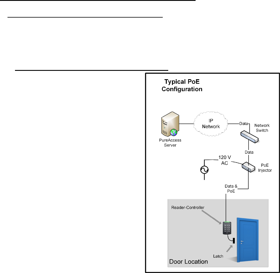
2.1.1: POWER OVER ETHERNET (PoE) OPTION
If you are installing ISONAS PureIP RCs, then you
can use the Power Over Ethernet (PoE) option. PoE
allows one cable to supply data and power to both
the Reader-controller and an Electronic lock. The
obvious savings here is that you only need to run a
single CAT5 cable to the door which will provide
enough power to run both the ISONAS Reader-
controller and an electronic lock.
If your network switch is equipped to provide PoE
power, then the separate PoE Injector is not
required.
If used, the PoE Injector is normally located close
to your existing network hub/switch, and the PoE
Injector itself is plugged directly into a standard AC
outlet, or for extra reliability, a UPS with battery
backup.
Figure 3 is an overview of how to use PoE to
power both the ISONAS PureIP RC and an
electronic locking mechanism.
Figure 3
How to Install the ISONAS PureIP Reader-controller 12
A standard CAT5 cable is then run between the PoE source (Injector or switch) and the PureIP RC
which will be located right next to the door. The CAT5 cable can be up to 100 Meters (328 feet)
long.
Supplying 12 VDC to Door Components from the PoE powered PureIP RC
When the PureIP RC is powered by PoE, the reader can supply 0.6 amps @12 VDC power for
external components. This DC power is available via two pigtail wires.
The Red pigtail wire is typically used to control the door’s lock. The Red wire’s 12VDC output will be
activated /deactivated when the reader is operating the door’s lock. This connection has a built-in
current limiting feature, to prevent the lock from consuming too much electrical power.
The Orange pigtail wire provides a source of continuously-available 12 VDC power. You might use
this 12VDC source to power a PIR Motion Detector located at the door location.

How to Install the ISONAS PureIP Reader-controller 13
PoE Power Budget Calculations
When planning an installation using PoE, you need to assure that the PoE source (PoE Injector or
PoE equipped Network Switch) supplying the PoE power is sized properly for the power draw of all
the doors. To do this, you total up the power draw (in watts) of the PoE connections, and compare
that total power draw to the rated capacity of the PoE source.
Below is a chart of expected PoE power draws of the ISONAS Reader-controllers.
Door Location Configuration
PoE Power Requirement **
(Watts)
PureIP RC
2.3 Watts
PureIP RC with
Electronic Lock (300 mA @ 12V)
6.2 Watts
PureIP RC with
Electronic Lock (600 mA @ 12V)
10.4 Watts
*** Ethernet cabling power losses not included. Losses range from being negligible for short Cat5
cables up to about 16% for 100 meter Cat5 cables.
To meet the PureIP’s variable PoE power requirements, the PureIP will classify itself with the PoE
source as a “Class 0” PoE device. The power usage of a Class 0 device can range between 0.4 to
13.0 watts at the device (up to 15.4 watts from the PoE source).
Some network PoE equipment will budget and allocate it’s distribution of PoE power based upon the
maximum power usage of the each attached device’s classification. If your network equipment
uses this power provisioning technique, then you should budget 15.4 watts for each PureIP. Such
network PoE Equipment may allow you to manually configure the amount of power that should be
allocated to each device. Configuring the PoE equipment for an allocation of 3.0 watts or 11.0 watts
per connection would be appropriate. When powering from POE or POE+, in order for the system
to be UL294 V6 compliant, the Power Sourcing Equipment (PSE) injector or end point must be
compliant to UL294 or UL294B standards.
2.1.2: ADDITIONAL POWER OPTIONS
Most installations will use PoE for the PureIP and door locks.
That is a clean way to control a door using a single, standard network cable.
There are many additional options available, that can be used, if the door location requires more
power than a standard PoE-powered PureIP can provide.

How to Install the ISONAS PureIP Reader-controller 14
The different options require different configurations of the supporting equipment and /or building
wiring. The following chart and Figure 4 describes some of these power options.
Power Source
Switchable
Power
(Max)
Equipment at
the Door
Limiting Factor
Topology
Diagram
PoE (802.3af)
0.60 amps
(12VDC)
PureIP
PureIP’s available PoE
Output
A
PoE (802.3af)
0.55 amps
(12VDC)
PureIP
EDK
PureIP’s available PoE
Output
{minus}
the power required by
the EDK
B
DC Power Supply
12 VDC
3.0 amps
(12VDC)
PureIP
EDK
Rating of EDK’s lock
relay
(12VDC required by EDK’s
internal circuitry)
C
High-Powered PoE
(802.3at)
1.8 amps
(Approx)
(12VDC)
PureIP
EDK
PoE Splitter
Example PoE Splitter
PowerDsine
PD-AS-701/12
Rating of PoE Splitter
{minus}
power required to
operate PureIP & EDK
D
High-Powered PoE
(non-standard)
Example PoE Injector
PowerDsine PD-9501G
3.00 amps
(12VDC)
PureIP
EDK
PoE Splitter
Example PoE Splitter
PowerDsine
PD-AS-951/12-24
Rating of EDK’s lock
relay
E
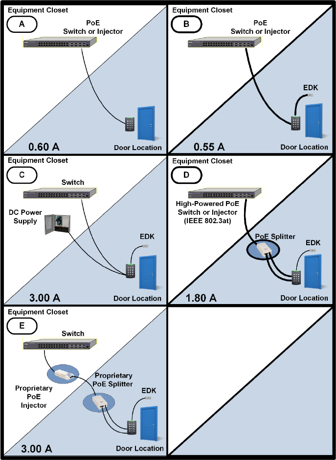
How to Install the ISONAS PureIP Reader-controller 15
Power Options
Figure 4

How to Install the ISONAS PureIP Reader-controller 16
2.2: WIRING THE DOORS
After you connect power to every Reader-controller, the
next step is to connect the wiring at each door.
Wiring a door may involve connecting:
An electronic door latch
A request to exit (REX) like:
REX Button
Motion Detector
Door sensors
Figure 5 shows the typical configuration of equipment at
the door.
Figure 5
How to Install the ISONAS PureIP Reader-controller 17
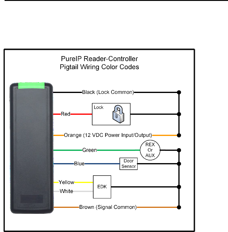
2.2.1: READER-CONTROLLER CONTROL-LEADS DESCRIPTION
The reader-controller has a cable extending from its back plate that is referred to as “the pigtail”.
The pigtail consists of 8 wire leads (22 awg) which are used to connect to the various components
at the door location. Most installations do not require the use of all the leads. The typical usage
of each available lead is shown in Figure 6.
Figure 6
One of the wires is for a door sense switch. Another is for a REX (Request for Exit) signal coming
from a switch, infrared sensor or other REX device.
The controllers have a lock-control circuit. This circuit provides conditioned 12VDC power and can
be directly connected to the electronic lock to unlock the door when a valid credential is presented.
The usage of each lead will be detailed in the next few pages.

How to Install the ISONAS PureIP Reader-controller 18
2.2.2: LOCK WIRING -- BASIC
Electronic door lock Overview:
If the door does not already have an electronic lock, first install the lock hardware according to the
manufacturer's instructions. Examine the lock to determine whether applying power will lock or
unlock the door.
Fail Safe: Applying power locks the door
(usually magnetic locks).
Fail Secure: Applying power unlocks the
door (usually electric strike locks).
Most locking mechanisms have two leads for
the power coil. On an electric strike, the leads
power a solenoid. On a Mag Lock, the leads power
an electromagnet.
The PureIP’s lock control circuit can control either
a fail-safe or fail-secure lock. This selection is
typically configured within the host computer’s
door settings.
Installation Tip
For non-PoE installations:
Before you start wiring an
electronic door lock, verify that
the lock’s power source is
separate from the power source
for the Reader-controller.
Otherwise, supply voltage
fluctuations induced by the
lock’s operation may cause the
reader to malfunction.
How to Install the ISONAS PureIP Reader-controller 19
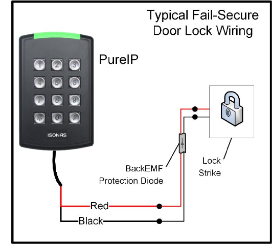
Lock Wiring, using PoE:
The PureIP supports a simplified configuration when PoE is being used to supply the lock’s power.
1. Connect the Red wire on the ISONAS Reader-controller to one lead of the electric lock.
See Figure 7
2. Connect the other lead of the lock to the black wire on the ISONAS reader-controller.
3. See this manual’s BackEMF diode section for more info regarding the use of the BackEMF
diode.
Figure 7
How to Install the ISONAS PureIP Reader-controller 20
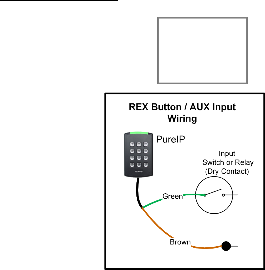
2.2.3: WIRING THE REX/AUX INPUT
The PureIP RC ’s REX / AUX input expects a momentary
closure. You can generate this signal with a pushbutton,
infrared motion detector, or other simple device.
The host computer configures the reader to know if the
input’s action is treated as a REX event or an AUX event.
Typically the REX is placed adjacent to the door so that
people can press the button and let themselves out the
door without setting off the alarm. When pressed, this
button tells the ISONAS Reader-controller
that that someone wishes to pass
through the door, and the latch releases.
The reader could be configured to create
an AUX event. An example usage of the
AUX input is being connected to a panic
button under a cashier’s desk. The AUX
event could then generate a system alert
message.
You must wire the switch through the
ISONAS Reader-controller.
(See Figure 8) First, connect one
terminal of the momentary switch to the
Reader's green wire. Then, connect the
switch's other terminal to the Reader's
common ground wire (brown).
Figure 8
About REX / AUX
REX / AUX is a
normally open input.
No action is taken
until the input is
closed.
How to Install the ISONAS PureIP Reader-controller 21
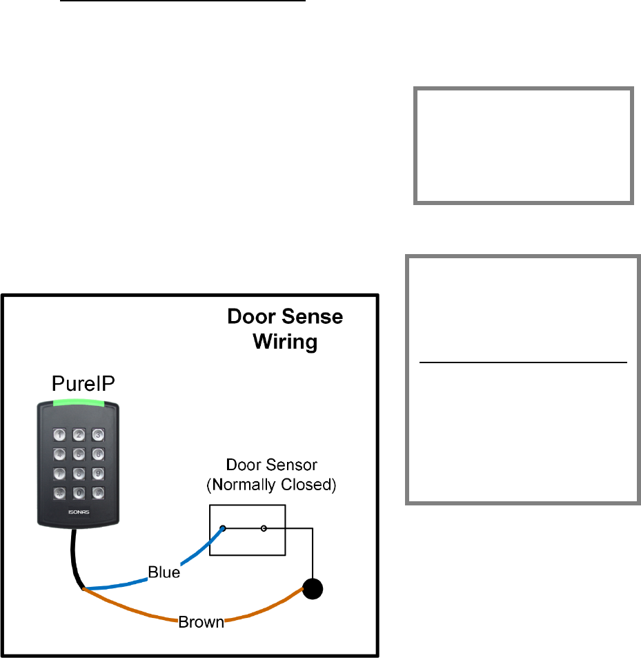
2.2.5: WIRING THE DOOR SENSE
Connecting the ISONAS Reader-controller to a door sensor allows the host software to determine
whether that door is physically open. Then the host system can create alarms based on the door’s
state. This wiring task is similar to wiring the REX / AUX
input.
First, connect one terminal of the door sensor to the
Reader's blue wire. Then connect the door sensor's
other terminal to the Reader's common ground wire
(brown).
Figure 9 shows how to wire the door sensor.
Figure 9
About the Door Sense
The door sense is a
normally closed input. No
action is taken until the
input is opened.
IMPORTANT: If There's No
Door Sense Switch
If you choose NOT to install a
door sense switch, then you
must permanently ground
the door sense input (blue
wire) to the reader’s Brown
wire, so the system will not
see the door as "open."
How to Install the ISONAS PureIP Reader-controller 22
2.2.7: LOCK WIRING -- EXTERIOR DOOR KIT
The PureIP RC has an optional Exterior Door Kit (EDK), which allows you to isolate the door’s lock
control circuitry on the secure side of the building.
The EDK contains a form-C relay with dry-
contracts that are rated for 3 amps of current @
30 Volts. It can also be used in cases where the
reader-controller is switching an externally
supplied voltage or an external control signal.
Examples of such usages include operating a
24VDC lock, or switching a logic signal for a
garage door opener.
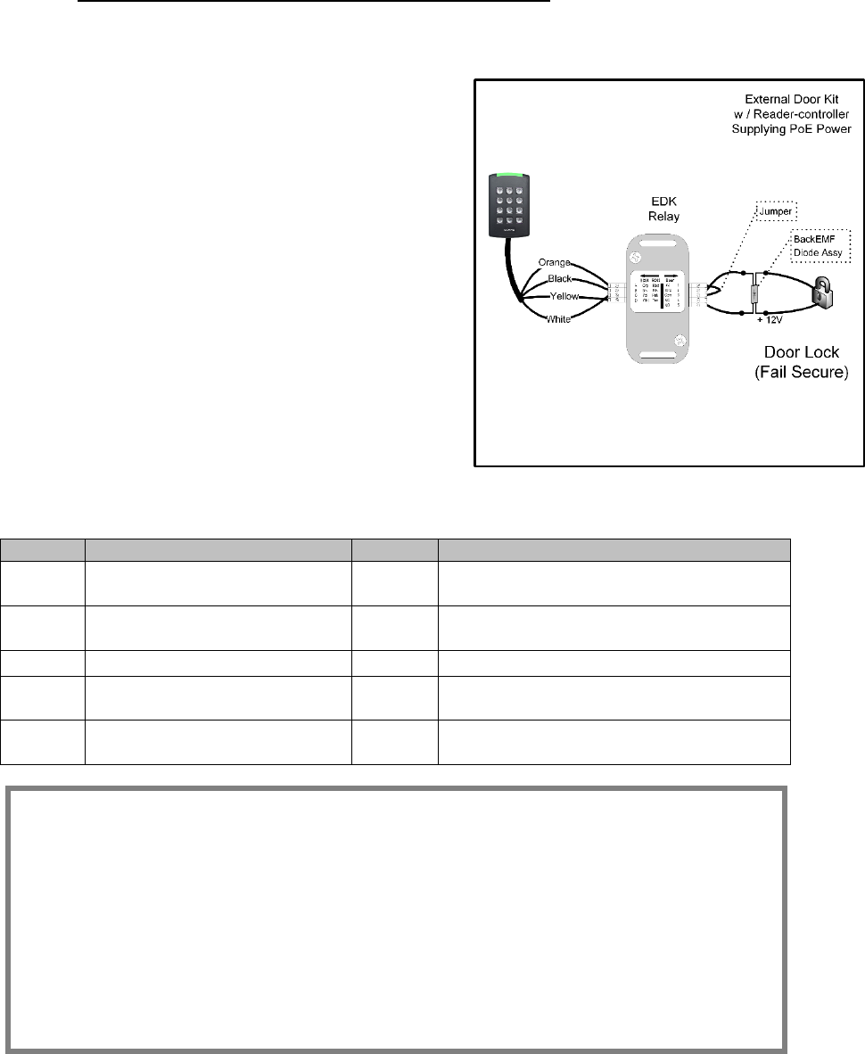
Two methods of connecting the EDK are shown
The 1st example shows powering both the lock and
the EDK with the Reader-controller’s PoE power
See Figure 10
Figure 10
Label
Reader Side Connection
Label
Lock Side Connection
A
Pigtail’s Orange wire
(12 V Input Power)
1
12V Output Power
B
Pigtail’s Black wire
(Ground)
2
Power Ground
C
Pigtail’s Yellow wire
3
EDK Relay’s Common Contact
D
Pigtail’s White wire
4
EDK Relay’s Normally Closed (NC)
contact (Fail-Safe Lock)
5
EDK Relay’s Normally Open (NO)
contact (Fail-Secure Lock)
EDK Wire Conductor Preparation:
Strip back the wire insulation: .25 to .275 (1/4 to 9/32) inches
Acceptable single conductor sizes: 26 gauge to 15 gauge
Acceptable two conductors sizes: 26 gauge to 15 gauge
Note for multi-stranded conductors:
Avoid allowing any stray wire strands from contacting
the adjacent terminal block connection.
Twist the multi-strands together prior to insertion.
Lightly solder-tinning the exposed wire can help prevent stray strands.
How to Install the ISONAS PureIP Reader-controller 23
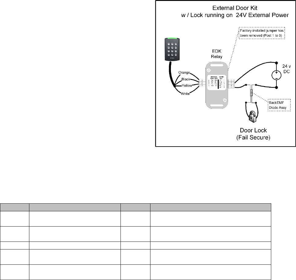
The 2nd example shows powering the EDK with
the Reader-controller’s PoE power output, and
the lock with an external 24 volt power supply.
See Figure 11
Figure 11
Label
Reader Side Connection
Label
Lock Side Connection
A
Pigtail’s Orange wire
(12 V Input Power)
1
Not Used
B
Pigtail’s Black wire
(Ground)
2
Not Used
C
Pigtail’s Yellow wire
3
EDK Relay’s Common Contact
D
Pigtail’s White wire
4
EDK Relay’s Normally Closed (NC)
contact (Fail-Safe Lock)
Not Used
5
EDK Relay’s Normally Open (NO)
contact (Fail-Secure Lock)

How to Install the ISONAS PureIP Reader-controller 24
2.2.8: EDK LED STATUS INDEX
The EDK has two status LEDs
Power LED:
Located on the side towards the PureIP’s pigtail.
A Red LED indicates 12VDC power is being supplied to the EDK.
Communication Status LED:
Located on the side towards the Lock wiring.
LED status meaning are described in the table below.
PureIP
Locked
PureIP
Unlocked
Lock State when
PureIP is
unlocked
Description or Item to Check
Off
Green
Normal Operation
Flash
Amber
Flash
Amber
No Operation
Yellow wire may be disconnected
Off
Flash
Amber
No Operation
White wire may be disconnected
Off
Flash
Amber
No Operation
Invalid encryption key received from PureIP
Off
Off
No Operation
If PowerCycle of PureIP allows for one or
more lock operations,and then the lock stops
operating, then the BackEMF diode may not
be installed correctly.
How to Install the ISONAS PureIP Reader-controller 25
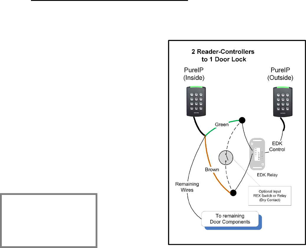
2.2.9: LOCK WIRING -- 2 READERS TO 1 LOCK
If you are wiring both sides of the door to control IN and OUT access, then you will have the special
condition of wiring 2 Reader-Controllers to a single locking mechanism.
The “Inside” Reader controls the door, and is wired
to the door’s components, such as the lock and
Door-sense switch. Use the following steps to cause
the “outside” Reader to activate the REX input on
the “Inside” Reader.
Two Readers & One Lock Wiring Steps: See
Figure 12
1. Wire the “Inside” reader normally
2. Connect an EDK to the “Outside” reader
3. Connect the “Inside” reader’s REX input to
the “NO” terminal of the EDK.
4. Connect the “Inside” reader’s Brown wire to
the Common terminal of the EDK.
5. If the door also has a REX device, wire the
REX device “in parallel” to the EDK.
Figure 12
Programming
“Inside” Reader must be
programmed to activate the
lock upon a REX input
event.
How to Install the ISONAS PureIP Reader-controller 26
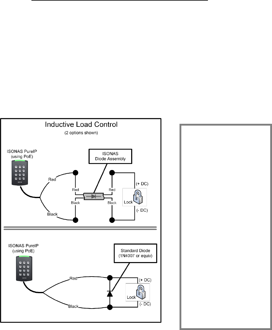
2.2.15: MANAGING INDUCTIVE LOAD CHALLANGES
Most door latches use a relay coil that powers up and down, when the door is unlocked and
locked. When this happens, a pulse of electrical energy is produced by the lock’s coil. This pulse is
called back EMF, and can interfere with the reader’s operation.
Switching off a typical 12 VDC relay coil can produce a back EMF pulse of 300 volts or more. If this
voltage pulse is allowed to flows back into the reader, it can cause the reader to “brown out” and
the reader will reboot.
Figure 13 shows a solution. You can virtually eliminate back EMF by installing a transient
suppression device (diode). Each PureIP RC is supplied with a diode assembly, which simplifies
the installation process. A standard diode, from any electronic supply store, can also be used.
Always check that the diode is correctly rated for the circuit voltage. For optimum performance, the
diode should be installed at the lock or close to the lock. Standard diodes have a stripe-band
marking on one side. That side of the diode should be connected to the “+” wire of the lock circuit.
Figure 13
Protect the Digital
Output
Which type of transient
suppressor should you
install? This depends
mainly on the type of
inductive load being
switched. Some locks
have Back EMF protection
built into the lock itself.
For Back EMF in low-
voltage DC applications, a
1N4007 diode will suffice.
However, for protection
against other transient
voltages (i.e. lightening),
we recommend using a
fast-switching transient
voltage suppressor, such
as a bipolar TranZorb.
How to Install the ISONAS PureIP Reader-controller 27
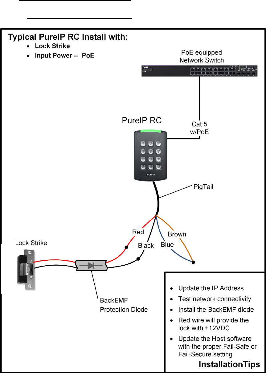
2.3: CONFIGUATION EXAMPLES
2.3.1: PoE --- ELECTRIC STRIKE
Figure 14
How to Install the ISONAS PureIP Reader-controller 28
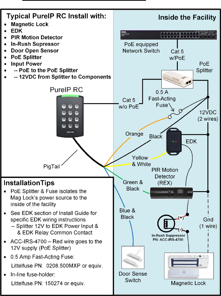
2.3.2: PoE --- MAGNETIC LOCK, EDK & PIR
Figure 15
How to Install the ISONAS PureIP Reader-controller 29
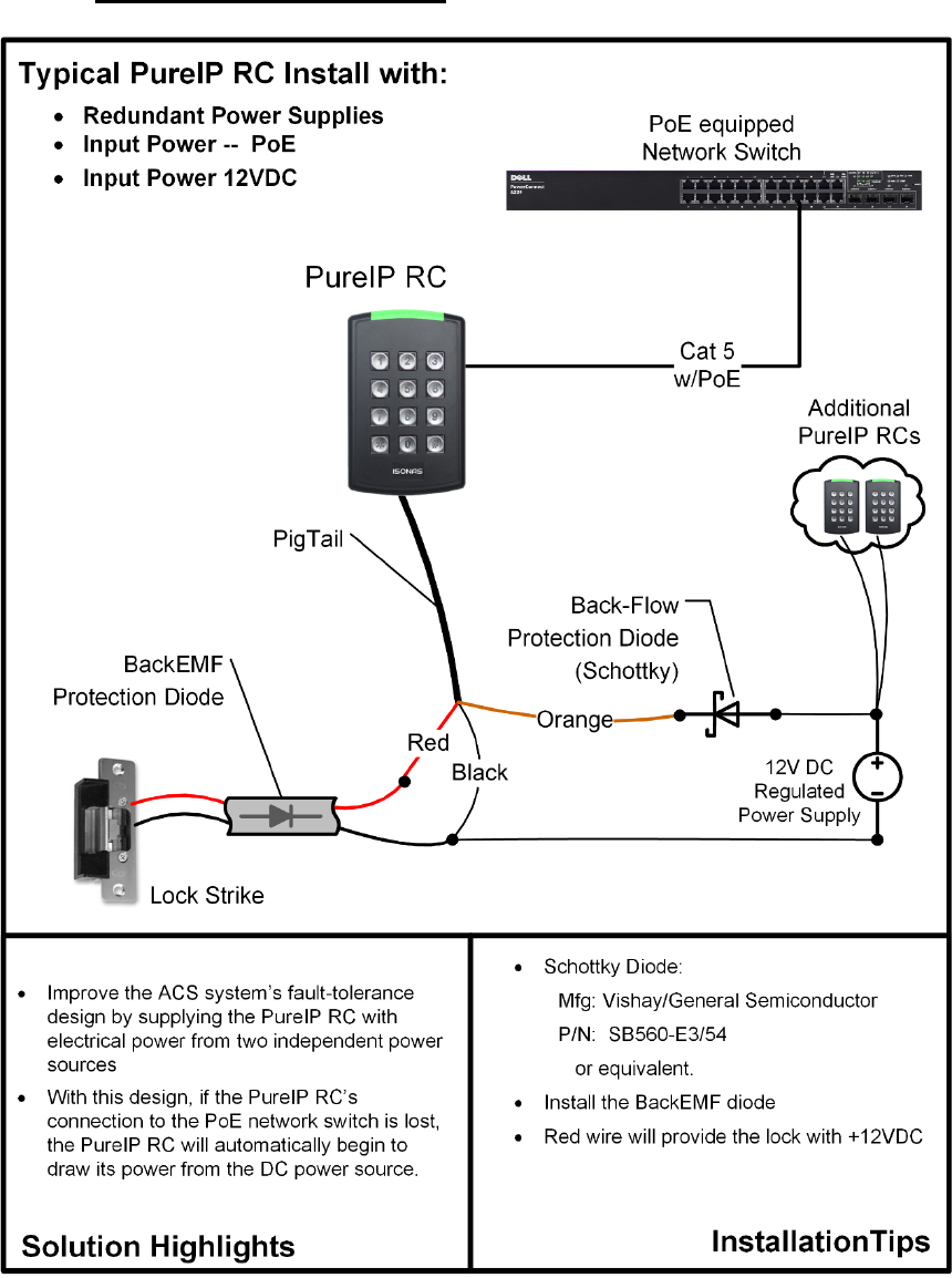
2.3.3: DUAL POWER SOURCES
Figure 16

How to Install the ISONAS PureIP Reader-controller 30
3: CONFIGURING THE READER-CONTROLLER’S COMMUNICATIONS
The Reader-controllers communicates with the ISONAS PureAccess software over the
organization's data network.
3.1: ETHERNET-BASED TCP/IP READER-CONTROLLERS
There are many Ethernet network topology permutations, too many topologies to cover in this
guide. Here are two common Ethernet configurations used by ISONAS customers:
PureIP RCs to PureAccess-Cloud Software:
This is the simplest type of network connection. ISONAS provides a cloud instance of the
PureAccess software. The readers are configured to automatically connect to hosted
PureAccess software.
Addressing:
The recommended best-practices is to let the local network’s DHCP service assign the IP
Address to each reader.
As an alternate, you can manually assign the reader’s IP Address. To allow the reader to
successfully reach the host software, the following setting are typically required:
Static IP Address that is valid on the local subnetwork
Proper Subnet Mask
IP Address of the local subnetwork’s gateway.
Here are a couple guidelines to follow to assure that your network’s configuration will support
the ISONAS access system.
The ISONAS reader-controller is a standard “network appliance”. Standard TCP/IP
networking rules apply.
ISONAS can provide a simple utility, that will redirect any currently installed reader-
controllers to the cloud instance of PureAccess
PureIP RCs to PureAccess-Manager Software:
Some locations may have a version of PureAccess installed on a local server. The software
package that is designed for such on-site installation is named: PureAccess-Manager.
These installations will require that the reader-controller’s configuration be modified to
direct the reader to connect to the local server’s location.
ISONAS can provide a simple utility, that can be used to redirect the reader-controllers to
the local instance of PureAccess-Manager.
Addressing:
The recommended best-practices is to let the local network’s DHCP service assign the IP
Address to each reader.
As an alternate, you can manually assign the reader’s IP Address. To allow the reader to
successfully reach the host software, the following setting are typically required:
Static IP Address that is valid on the local subnetwork
Proper Subnet Mask
IP Address of the local subnetwork’s gateway.

How to Install the ISONAS PureIP Reader-controller 31
3.2: SECURING MESSAGES ON YOUR NETWORK
You can configure ISONAS Readers and software to secure each and every message to and from
the Reader using Advanced Encryption Standard (AES).
When you enable AES in both an ISONAS Reader-controller and the PureAccess software, every
message to and from that Reader-controller is encrypted. Therefore, anyone who manages to hack
into your data network would still face a daunting task to decrypt the actual messages to the
reader-controllers. This is a significant strength of the ISONAS solution in protecting the customer’s
reader-controllers from hackers.
How to Install the ISONAS PureIP Reader-controller 32
For more information:
Web: www.isonas.com E-mail: sales@isonas.com
Tel: 800-581-0083 (toll-free) or 303-567-6516 (CO)
Fax: 303-567-6991
ISONAS Headquarters:
4750 Walnut Street, Suite 110, Boulder, Colorado 80301 USA