ISV WPM-2400R DIGITAL WIRELESS MICROPHONE SYSTEM User Manual wpm 2400 Generic Manual
ISV Co., Ltd. DIGITAL WIRELESS MICROPHONE SYSTEM wpm 2400 Generic Manual
ISV >
Users Manual
2.4GHZ Digital Wireless
Microphone System
USER GUIDE
TABLE OF CONTENTS
1.
Description
of the units
.......................................
........
................
3
1. Quick Set Up and Operation .........................
..............................
4
2. Installation....................................................................................
5
3. Guidelines For Best Performance.................
...............................
6
4. Troubleshooting Guide............
......................
...............................
7
5. Technical Specifications...............................................................
8
6.
Factory
Service
.......................
............
.........................................
9
7.
Warrant
y.......................
.........
..........
.............
...............................
9
8
.
Accessories
and Parts
......................
......... .........
................
..........
9
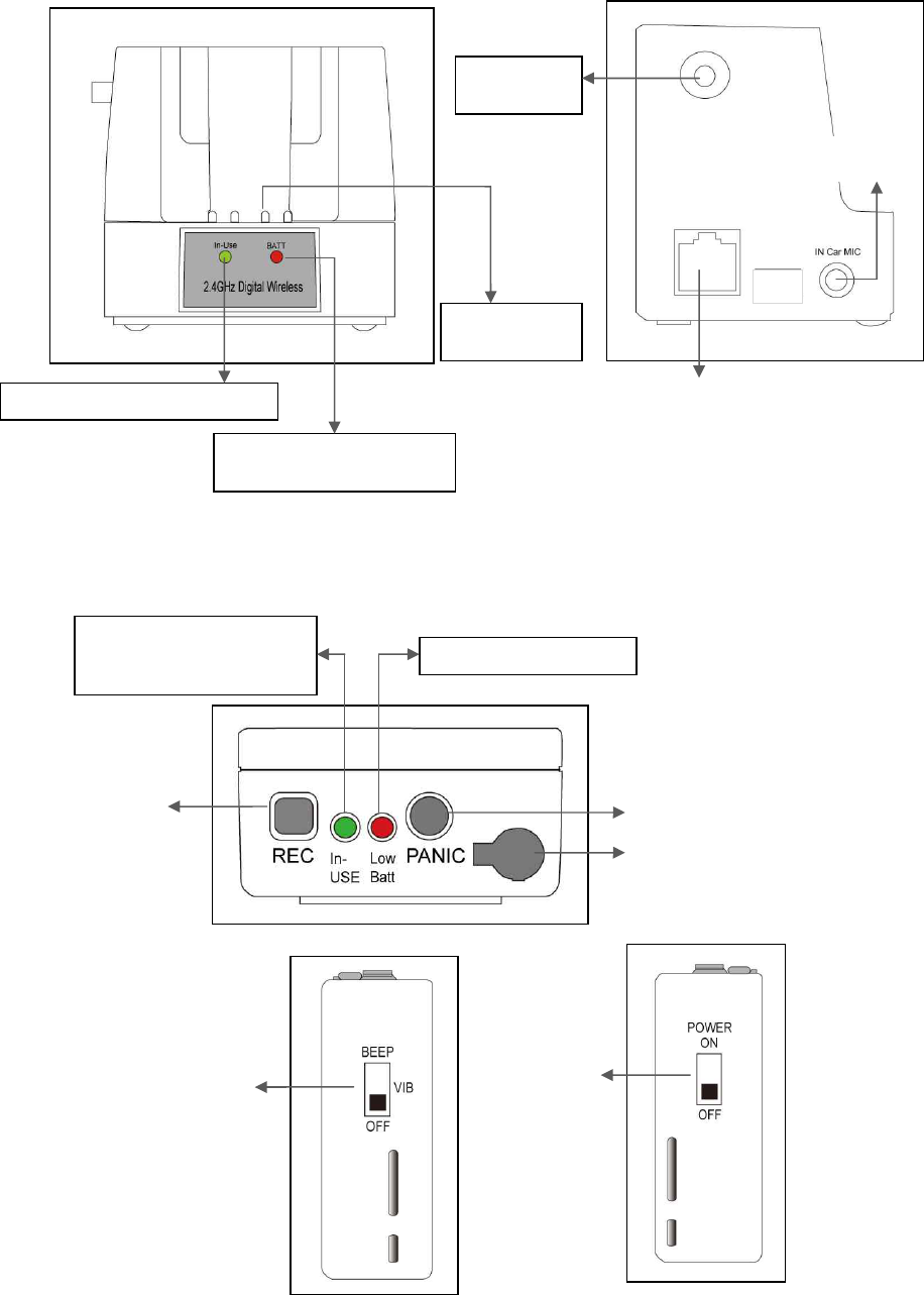
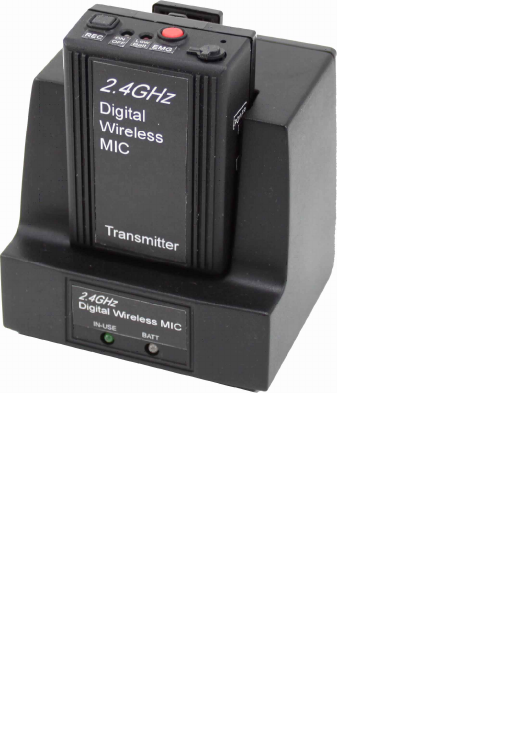
DESCRIPTION
Receiver
Transmitter
Green LED: In
-
use, Record
RED LED: Charging
Green LED: Full charge
Terminal
For charging
Antenna
Connection
Modular Jack
Audio Jack Input
Re
cord Button
Lapel Mic. Cover
Emergency Button
Green: In
-
use (Light On)
Record (Flashing)
RED
LED:
Out of Range
RED LED: Low Battery
Audible and Vibration
Selectable Switch
Power On/Off
Switch

1.
QUI
C
K
SET
UP
A
N
D
O
P
ERATI
O
N
Synching
Up
t
he
Tra
n
smitter
and
B
a
se
The synch operation only needs to be performed the first time a system is used, or a new b
odypack is used
with a base previously synched to another bodypack.
Do not perform the synch operation multiple times;
it only needs to be done one time when a new bodypack is used with a new base.
1) Turn the transmitter power switch to ON and place th
e transmitter in the recharge cradle of the base.
The transmitter goes in the base with the belt clip facing out.
2) The recharge LED will light (Green if fully charged, Red if charging). Leave the transmitter in the cradle
for 4 hours for a full charge.
3) Press the
REC
button on the transmitter and hold until the In
-
Use LED on the transmitter and base start
to flash, then release the button.
4) After a few seconds the light will stop flashing, and a beep will sound (If the beep is enabled).
5) The
transmitter and base are now synched and will continue to be until another transmitter is linked to
that base.
Normal O
p
eration
1)
With the transmitter synched up, remove it from the cradle, plug in the lapel microphone (if used)
and place the transmitter o
n your belt.
2)
When you remove Transmitter from the cradle, The TR and Base
’
s In
-
USE LED will light a constant
Green and you will hear short beep.
To start the recording, press the
REC
button and the In
-
Use
LED will
blink in green.
3)
To end recording, press t
he
REC
button and the In
-
Use LED will
light a constant green.
4)
At the end of your shift turn the transmitter off and replace it in the charging cradle.
Out of Ran
g
e
1) T
he transmitter will alert you with Audible warning beeps (two tone) and the In
-
Use LED
will blink in
red.
2) Move closer to the receiver base and the link will be re
-
established once you return to normal
range. The In
-
Use LED will light constant green when link is back to normal operation.
3) If the link is not re
-
established within 30
seconds, the transmitter and receiver will return to standby
mode.
4) If you went out of range in Standby mode, or the unit reverted to standby mode, re
-
enter normal range
and press the In
-
Use button. Operation will return to normal.
5) If you will be
out of range for a long period of time, turn the bodypack off.
Low
Battery
W
a
rning
1) If the transmitter Low BATT indicator (red) starts flashing or you hear warning beeps, return the
transmitter to its cradle on the receiver to fully charge the transm
itter.
2) The Charge LED indicator will light constant green when the unit is fully charged.
EMG
Panic
B
utton
(if
wir
e
d
for
use
in
y
o
ur
vehic
l
e)
1) The EMG or Panic Button can be programmed to do many things but may not be connected in your
vehicle. C
heck with your technical department to understand what this button will control before you use
it.
2) In Record mode: Press the EMG button on the transmitter, a beep will sound and the relay will be
triggered at the receiver.
3) In Standby mode: Press
the EMG button on the transmitter, a beep will sound, the green In
-
Use
indicator will blink and the relay will be triggered at the receiver.
Disabling the Beep Sound On the Transmitter
1)
All of the audible beep signals on the transmitter can be disabled
by setting the BEEP switch to the
off position.
Record Trigger
(if video recording equipment supports)
1) The
Record trigger
feature is used to turn on
recording
whenever the video recorder is turned on.
Some video record units can be triggered by oth
er events (lights and siren being turned on etc.) and
ensures the microphone starts recording at the same time.
The transmitter must be turned on and in
standby mode.
2) A +
12
V signal on the line means the microphone is
Record off
.
3) 0V or ground on
the line turns on the microphone is Record on.
2.
INSTALLATION
PIN DESCRIPTION OF THE BASE OUTPUT PORT
Connector wire (RJ45)
Pin #1 :
Transmitter Audio out
Pin #2 :
In Car Mic. Audio out
Pin #3 :
12V DC_IN
Pin #4 :
Ground
Pin #5 :
Rec
ord Trigger OUT
Pin #6 :
Record Trigger IN
Pin #7 :
Panic Trigger Out
Pin #8 :
In Car Mic. Trigger IN
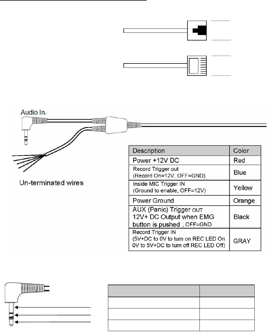
Terminated Connector
( Optional )
Type A
1)
Wire the un
-
terminated signal wires to the control unit according to the signal chart. 5 Amp
fast
blow fuse is recommend in the 12VDC power supply line to protect the equipment.
2)
Plug the 3.5mm stereo plug into the audio input jack of the recording device.
3)
If it is to be used, plug in the in
-
car microphone into the In
-
Car Mic jack in the side of the receiver
base.
4)
Turn on the transmitter and place it in the charging cradle with the beltclip facing out. The Charge
LED will light if
there is power. If the LEDs do not come on, check the connections and repeat.
Description
Position
Audio Ground
Sleeve
Transmitter Audio
Ring
Inside Car
Mic. Audio
Tip
8
1
8
1
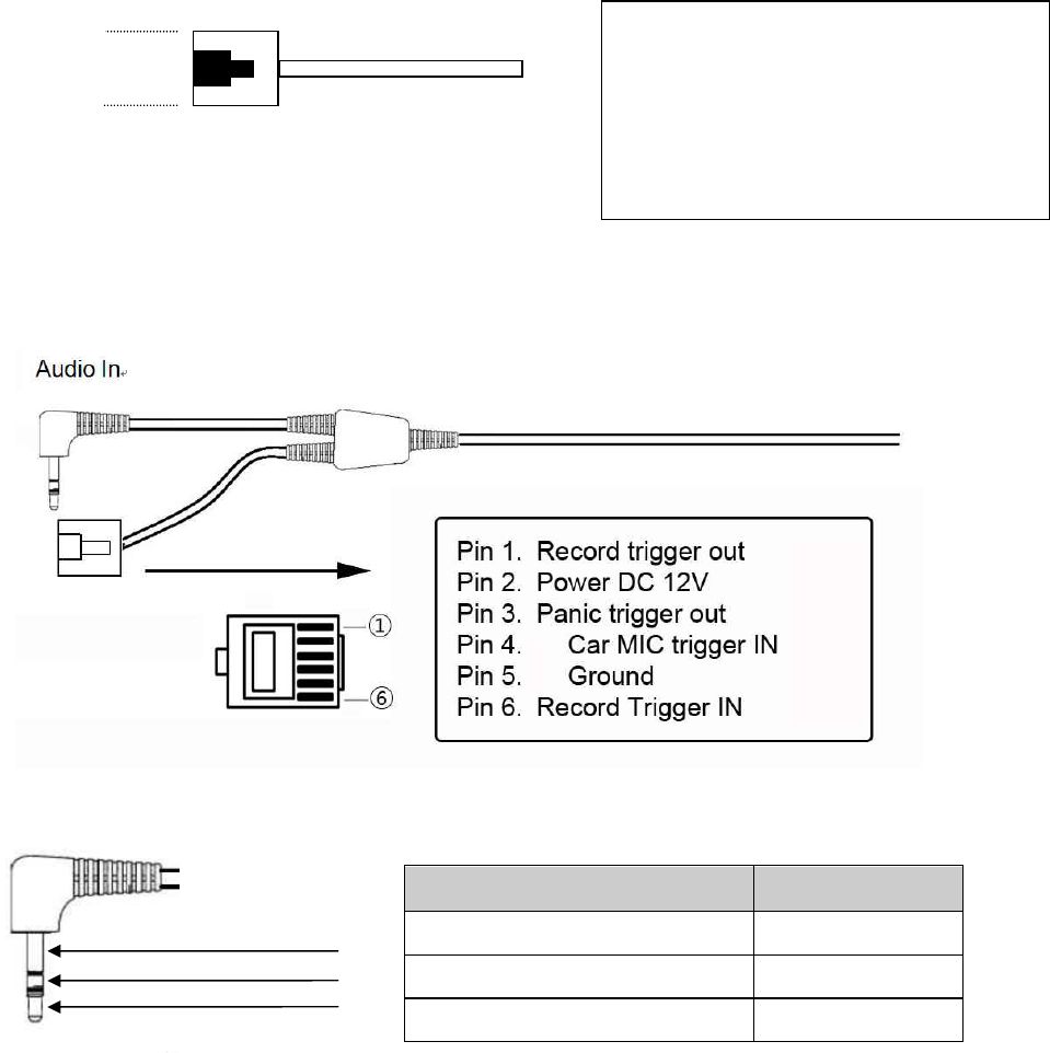
Type B
Wire the un
-
terminated signal wires to the control unit according to the signal chart. A 5 Amp fast blow fuse is
recommend in the 12VDC power supply line to protect th
e equipment.
Type C
Wire the un
-
terminated signal wires to the control unit according to the signal chart. A 5 Amp fast blow fuse is
recommend in the 12VDC power supply line to protect the equipment.
1)
Plug the 3.5mm
stereo plug into the audio input jack of the recording device.
2)
If it is to be used, plug in the in
-
car microphone into the In
-
Car Mic jack in the s
ide of the receiver
base.
3)
Turn on the transmitter and place it in the charging cradle with the beltclip facing out. The Charge
LED will light if there is power. If the LEDs do not come on, check the connections and repeat.
Installation is complete. Refer t
o Operation Section for more information.
3.
GUIDELINES AND RECOMMENDATIONS FOR BEST PERFORMANCE
Compatibility
The transmitter and receiver must synchronize to work together (see Synch process on page 3). The synch
operation only needs to be performed
the first time a system is used, or when a new bodypack is used with a
base previously synched to another bodypack.
Do not synch multiple times, just once until a new
bodypack is used.
Any Base can be synchronized with any Transmitter.
Description
Position
Audio Ground
Sleeve
Transmitter Audio
Ring
Inside Car Mic. Audio
Tip
Pin
#1 : Transmitter Audio out
Pin #2 : In Car Mic. Audio out
Pin #3 : 12V DC_IN
Pin #4 : Ground
Pin #
5 : Record Trigger Out
Pin #6 : Record Trigger IN
Pin #7 : Panic Trigger Out
Pin #8 : In Car Mic. Trigger IN
8
1

Using Multiple Wire
less Systems
The
PW
2
4
s
y
stem
h
a
s
95
possib
l
e
“ch
a
nne
l
s”
that are really different frequ
e
nc
y
hoppi
n
g
schem
e
s.
Each
sy
n
c
h
ron
i
zed
b
a
se
a
n
d
tra
n
smitter wil
l
automaticall
y
find
a
clear
chan
n
el
so
u
p to
40
syste
m
s
c
a
n
w
o
rk
t
o
gether
in
o
ne
locati
o
n
de
pe
nding
o
n
oth
e
r
interf
e
re
n
c
e
probl
e
m
s
Potential Sources of Interference
There are many potential sources of interference for your wireless system. Any electronic product that
contains digital circuitry including digital signal processors (reverb/multi
-
effects unit
s), electronic keyboards,
digital lighting controllers, CD and DVD players, and computers, all emit RF energy that can adversely affect
the performance of your wireless system. It is always best to place the receiver as far away as possible from
these devi
ces to minimize potential problems.
The PW24 operates in the 2.4MHz ISM band and other devices in that band may interfere. The spread
spectrum technique used in the PW24 is very robust and should operate even in the presence of other
2.4MHz devices such a
s walkie
-
talkies, LANs, cordless phones, etc. in the area.
Battery Recommendations
The Lithium
-
Ion battery built into the PW24 transmitter will work at full capacity for over 500 charge cycles. If
you notice lower than usual battery life over time, it m
ay be time to replace the cell
Warnings
Do not use this product in or near water, i.e. near a bathtub, sink, or swimming pool.
Do not use this product in the vicinity of a gas leak or to report a gas leak.
4. TROUBLE SHOOTING GUIDE
Problem
Possible Cau
ses
Solutions
No audio and no In
-
Use LED
light
on the receiver when
T
ransmitter is on and In
-
use
Receiver is not powered
Make sure that the power
supply
is properly connected
Transmitter and receiver not
synchronized
Turn on transmitter and place
I
n rec
harge cradle. Press the
In
-
use button
until
the In
-
Use
LEDs flash 3 and the fair will
be synched
No(or low) Audio with all in
-
Use
LEDs solid green
Lapel Microphone not connected
or positioned properly
C
heck the mic. connection and
P
lacement of the microph
one
Receiver audio output cable is
D
amaged or disconnected
Connect, repair
or replace
cable
Interference
Another 2.4GHz device in the
A
rea causing interference
Push the In
-
Use button and
the
PWW24 will automatically
select
a clear channel. If the
interf
erence is too strong,
this may not completely
eliminate it.
Shot range or drop
-
outs
RF reflective metal obstacles
between the transmitter and
receiver
Move the obstacles, or
reposition the receiver if
possible
In
-
Use LED on
bodypack
flashes
red and two t
one
beep sounds
Transmitter is out of range
Move closer to the receiver
Variable sync times or failure
to synch
Synch process run more than
one time with same pair
Power cycle the base
station
and Synch one time.
5.
TECHNICAL SPECIFICATIONS
RECEIVER
BASE STATION
Controls
Video Trigger Active +12/GND
Indicators
INUSE LED:
GREEN
CHARGE
LE
D
:
CHARGING
-
>
RED
FULL CHARGED
-
> GREEN
RECORD LED GREEN FLASHING
Co
n
necti
o
ns
In
Car
Mi
c
.
2.5mm
Mono
P
lug
Un
-
terminated Cord
RED +12V DC Powe
r
BLUE
Record Trigger out
(
Record on =DC12V, OFF= GND
)
YELLOW Inside MIC Trigger IN (Ground to enable, OFF=12V)
ORANGE POWER GROUND
BLACK
AUX (Panic) Trigger
out
(+12V when EMG is pushed
, OFF=GND
)
GRAY
RECORD TRIGGER IN
(
GND= RECORD LED ON, +5V DC REC LED OFF
)
Audio Connector
Tip Inside Car Mic
Ring Transmitter Audio
Sleeve Audio Ground
R
F
Specificat
io
ns
Fr
equ
e
n
c
y
R
a
nge
:
2.4GHz
Num
b
er
of
Ch
a
nn
e
ls
:
95
pos
s
ib
l
e Diversi
t
y
:
Internal
antenna Recei
v
er
T
y
pe
:
FHSS
RF
Sensitivi
t
y
:
-
102
+/
-
3
dB
m F
CC
t
y
p
e
acc
e
ptance
:
Appro
v
ed
Part
15
Aud
i
o
Spe
c
ifications
Fr
equ
e
n
cy
Re
s
pon
s
e
:
200
~ 400
0H
z
+/
-
3
dB Aud
i
o
Output
L
evel
:
3.6Vp
-
p
Distorti
o
n
:
Less
tha
n
2% Sig
n
a
l
to
Noi
se
Ratio
:
>
40
dB
D
y
namic
R
a
ng
e
:
>
50
dB
Gener
a
l
Speci
f
icati
o
ns
Ra
n
g
e
1000feet
typical
P
o
w
er
Suppl
y
:
E
x
te
r
nal
12
VDC Current
D
ra
w
:
190mA
T
y
pi
c
al
Size
:
2.75
i
n
x
2
.
99
i
n
x
3.
1
5in
(70mm
x
76m
m
x
80mm)
W
eigh
t
23
3
g
Transmitter
Contr
o
ls
On/Of
f
S
w
itch
Beep On/Off Switch
In
Use
Button Emerg
e
n
c
y
Bu
tton
Indicators
Red
L
ED
l
o
w
b
atte
r
y
i
nd
i
cator/Emerg
enc
y
i
n
di
c
ator
Yello
w
LED
In Use
Batte
ry
Internal
L
i
-
i
o
n
3.7V/1
3
0
0mA
h
cell
Batte
r
y
L
if
e
15
hours
In
Us
e
w
i
t
h
full
c
h
arge
14
da
y
s
St
an
dby
Batte
r
y
R
echa
r
ge
T
im
e
3.5
hours
fro
m
full
dis
c
har
g
e
Anten
na
Internal
2.5mm
Mic
C
o
nnecto
r
T
i
p
Sig
n
al, Slee
ve
Ground
Seco
n
da
r
y
Mi
cr
op
h
on
e
Internal
R
F
Outpu
t
30
~
40
m
W
(typical)
Siz
e
2.5
in.
x
1.8
i
n.
x
0.
9
4
in.
64
mm
x
46
mm
x
24
mm
W
eigh
t
7
4
g

6.
FACTORY SERVICE ( NORTH AMERICA )
If factory service is required, ship the unit prepaid in its original carton to:
Wonwoousa Service
c/o Wonwoousa 2580 E. Philadelphia St. Suite A, Ontario, CA 91761 U.S.A.
Tel:909/930
-
2320 or 888
-
4
-
966
-
966
Fax: 909/930
-
2321
Enclose a note describing the problem along with any other pertinent information and how to contact you
7.
WARRANTY( Limited )
Wonwoousa products are gua
ranteed against malfunction due to defects in materials or workmanship for a specified
period, as noted in the individual product
-
line statement(s) below, or in the individual product data sheet or owner's
manual, beginning with the date of original purcha
se. If such malfunction occurs during the specified period, the product
will be repaired or replaced (at our option) without charge. The product will be returned to the customer prepaid via UPS
Ground.
Exclusions and Limitations:
The Limited Warranty does
not apply to: (a) exterior finish or appearance; (b)
certain specific described in the individual product
-
line statement(s) below, or in the individual product data sheet or
owner's manual; (c) malfunction resulting from use or operation of the product oth
er than as specified in the product data
sheet or owner's manual; (d) malfunction resulting from misuse or abuse of the product; or (e) malfunction occurring at
any time after repairs have been made to the product by anyone other than Electro
-
Voice or any
of its authorized service
representatives.
Obtaining Warranty Service:
To obtain warranty service, the customer must deliver the product,
prepaid, to Wonwoousa together with proof of purchase of the product in the form of a bill of sale or receipted invoic
e.
Incidental and Consequential Damages Excluded:
Product repair or replacement and return to the customer are the
only remedies provided to the customer. Wonwoousa shall not be liable for any incidental or consequential damages
including, without limitati
on, injury to persons or property or loss of use.
Other Rights (United States Only):
This
warranty gives you specific legal rights and you may also have other rights, which vary from state to state.
Wonwoousa
2.4GHz Wireless Systems
are guaranteed against
malfunction due to defects in materials or workmanship for a period
of one (1) year from the date of original purchase. The Limited Warranty does not extend to cables or cable connectors.
Additional details are included in the Uniform Limited Warranty Stat
ement. Technical Assistance: 888
-
4
-
966
-
966(U.S. and
Canada only)
FCC NOTICE
This
device complies with part 15 of the FCC rules
.
O
peration is subject
to the following two conditions :
(1) T
his device may not cause harmful interference, and
(2) T
his devic
e must accept any interference received, including interference that may
cause undesired operation
.
This equipment has been tested and found to comply with the limits for a Class B digital device, pursuant to part 15 of
the FCC Rules. These limits are de
signed to provide reasonable protection against harmful interference in a residential
installation. This equipment generates
,
uses and can radiate radio frequency energy and, if not installed and used in
accordance with the instructions, my cause harmful i
nterference to radio communication. However, there is no guarantee
that interference will not occur in a particular installation. If this equipment does cause harmful interference to radio or
television reception, which can be determined by turning the equ
ipment off and on, the user is encouraged to try to
correct the interference by one or more of the following measures:
l
Reorient or relocate the receiving antenna.
l
Increase the separation between the equipment and receiver.
l
Connect the equipment into an ou
tlet on a circuit difference from that to which the receiver is connected.
l
Consult the dealer of an experienced radio/TV technician for help.
NOTE
: The manufacturer is not responsible for any radio or TV interference caused by unauthorized modifications
to
this equipment. Such modifications could void the user’s authority to operate the equipment.

FCC RF R
ADIATION
E
XPOSURE
S
TATEMENT
Your transmitter contains a low power transmitter. When the Push
-
to Talk button is pushed it sends out radio
frequency
(RF) signals. This device is authorized to operate at a duty factor not to exceed 50% in MARCH 2008
the Federal Communications Commission (FCC) adopted RF exposure guidelines with safety levels for hand
-
held wireless devices.
CAUTION:
To maintain complia
nce with the FCC’s RF exposure guidelines, hold the transmitter and antenna at least 1.0
inches (2.5 centimeters) from your face, with the antenna pointed up and away from the face, if you wear the handset on
your body while using the headset accessory, us
e only the manufacturers supplied belt clip for this product and ensure
that the antenna is at least 1.0 inch (2,5 centimeters) from your body when transmitting.
This device and its antenna(s) must not be co
-
located or operating in conjunction with any ot
her antenna or transmitter.
Use only the supplied antenna. Unauthorized antennas, modifications, or attachments could damage the transmitter and
may violate FCC regulations.
This device has an output power of max 13mW, which no warning statements required
. Now this device designed to be
hold transmitter and antenna at least 1.0 inch (2.5cm) from your face. Therefore this device satisfies RF exposure
compliance.
IMPORTANT SAFETY INSTRUCTIONS
When using your equipment, basis safety precautions should alw
ays be followed to reduce the risk of life
electric shock, and injury to persons, including the following.
l
Do not place near TV, speakers, or other electronic devices
l
Before installation, check power supply and voltage to avoid
hazards
l
Do not apply force
or shock to the unit
l
D
o not disassemble the unit
l
Unplug this product from the outlet before cleaning. Do not use liquid cleaners or aerosol
cleaners. Use a damp
cloth for cleaning.
l
Do not use this product near water, for example, near a bathtub, washbowl
, kitchen sink,
o
r
l
aundry tub in a wet
basement or near a swimming pool.
l
Do not place this product on an unstable cart, stand, or table. The product may fall, causing
serious damage to the
product.
l
This product should be operated only from the type of pow
er source indicated on the manual
.
l
To reduce the risk of electric shock, do not disassemble this product, but take it to a qualified
service contractor when
some service or removing covers may expose you to dangerous
voltages or other risks. Incorrect reas
sembly can
cause electric shock when the appliance is
subsequently used.

Li
-
ion Battery safety precautions
l
Use only the following type and the size battery :
13
00mAh, 3.6V (Li
-
ion
/3.6V, or equivalent)
l
Do not dispose of the battery in a fire. T
he cell may explode. Check with local codes for possible special disposal
instructions.
l
Do not connect the positive terminal and the negative terminal of the battery to each other with any metal object (such
as wire).
l
Do not carry or store the batteries to
gether with necklaces, hairpins, or other metal objects.
l
Do not penetrate the battery with nails, strike the battery with a hammer, step on the battery, or otherwise subject it to
strong impacts or shocks.
l
Do not expose the battery to water or salt water,
or allow the battery to get wet.
l
Do not disassemble or modify the battery. The battery contains safety and protection devices which, if damaged, may
cause the battery to generate heat, explode or ignite.
l
Do not place the battery on or near fires, stoves, o
r other high temperature locations.
l
Do not place the battery in direct sunshine, or use or store the battery inside cars in hot weather. Doing so may cause
the battery to generate heat, explode, or ignite. Using the battery in this manner may also result i
n a loss of
performance and a shortened life expectancy.
l
Do not insert the battery into equipment designed to be hermetically sealed. In some cases hydrogen or oxygen may
be discharge d from the cell which may result in rupture, fire or explosion.
l
Do not c
ontinue charging the battery if it does not recharge within the specified charging time. Doing so may cause the
battery to become hot, explode, or ignite.
l
The temperature range over which the battery can be charged is 10°C to 45°C. Charging the battery at
temperatures
outside of this range may cause the battery to become hot or to break. Charging the battery outside of this
temperature range may also harm the performance of the battery or reduce the battery’s expectancy.
l
The temperature range over which the
battery can be discharged is
-
10°C to 60°C. Use of the battery outside of this
temperature range may damage the performance of the battery or may reduce its life expectancy.
8.
ACCESSORIES AND PARTS
Police Wireles
s P
W
24
T/R
Model
DESCRIPTION
P
W
24
T
P
W
24
R
EXA24
-
10
PWC
-
24
PLM
-
24
P
W
24
-
I
M
T
ransmitter with internal microphone, battery, belt clip
Receiver and recharge station,
RJ45
cable
External ANT
–
10Feet
Optional TX Charger Base for P
W
24
T
Lapel Microphone
P
W
24
R
In Car Microphone