ITEAD Intelligent Systems PSF-B85 Wireless medule User Manual
ITEAD Intelligent Systems Co., Ltd Wireless medule
User Manual

Overview
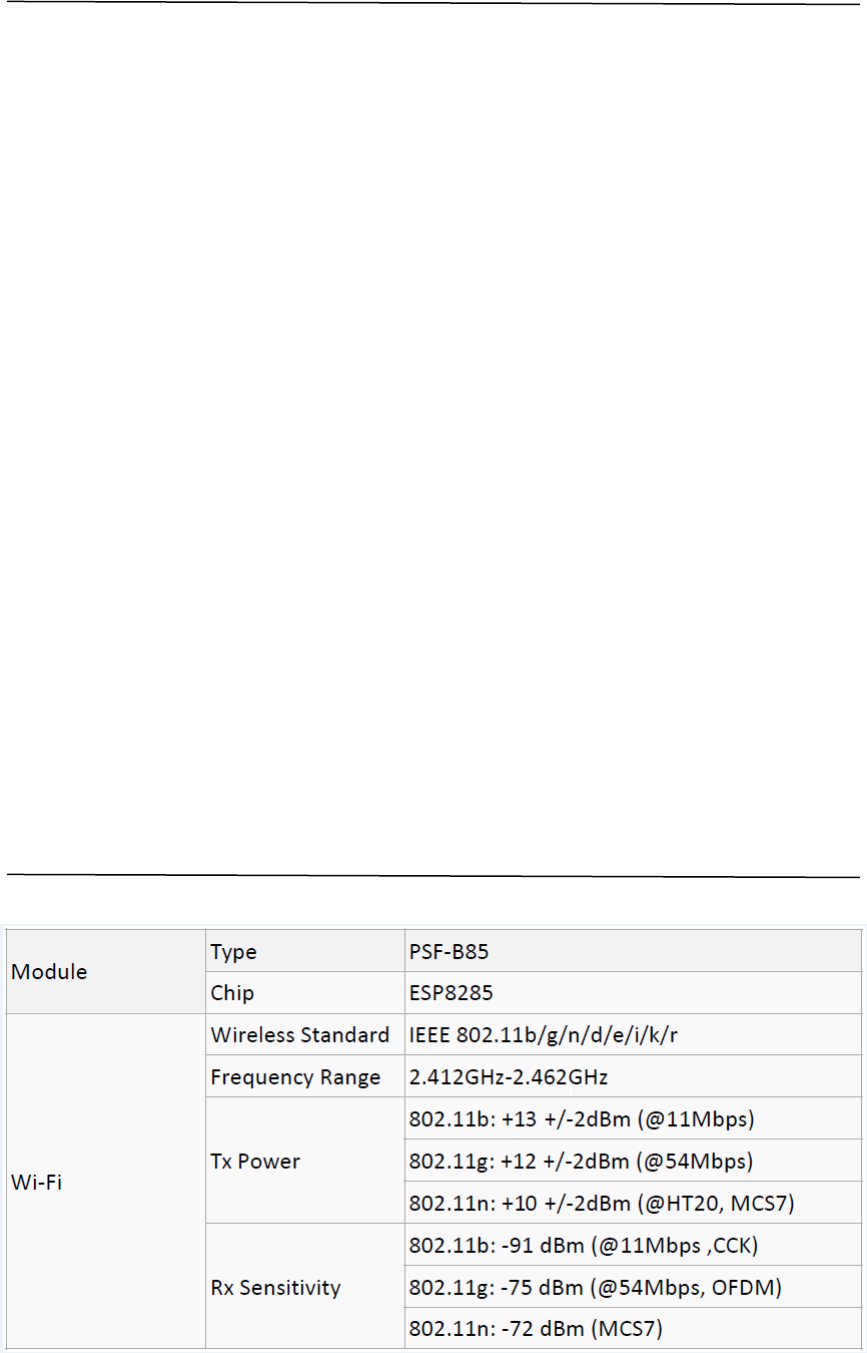
PSF-B85 is an ultra low-power Wi-Fi module designed by ITEAD. The module
adopts the highly integrated Wi-Fi chip ESP8285. It features industry's highly
competitive compact packaging size and ultra-low power technology. Specially
designed for mobile devices and the Internet of Things application, it connects
physical devices to Wi-Fi wireless network to make Internet or LAN communications.
PSF-B85 has completed self-contained wireless network, with built-in 32-bit kernel
processor, on-chip SRAM, it can be used as the main control chip, but also as a WiFi
adapter. Simply apply it to other microcontroller-based designs by SPI/SDIO or
I2C/UART interface communication.
PSF-B85 supports multiple packaging form. Supports antenna of IPEX connector
and stamp hole interface.
PSF-B85 is widely applied to smart power grid, smart transportation, smart home,
handheld devices, industrial control, etc.
Features
802.11 b/g/n/d/e/i/k/r
Support STA/AP/STA+AP mode
WPA/WPA2 PSK and WP
Built-in TCP/IP protocol stack, support multi-way TCP Client connection
Support rich Socket AT commands
Support UART/GPIO data communication interface
Built-in 32 bit MCU, also work as application processor
3.3V single supply
Wi-Fi Direct (P2P) support
Support MIMO 1x1 and 2x1, STBC, A- MPDU and A-MSDU aggregation and 0.4μs
guard interval
WMM power save U-APSD
Multiple queue management to fully utilize traffic prioritization defined by 802.11e
standard.
Adaptive rate fallback algorithm sets the optimum transmission rate and Tx power
based on actual SNR and packet loss information.
Functions
Main functions
The main function of PSF-B85 includes serial transparent transmission, PWM control,
GPIO control.
Serial transparent transmission good transmission performance, the maximum
transmission rate is 460800bps.
PWM control adjust lighting, adjust led color, adjust motor speed and much more.
GPIO control control switch, relay and more.
Operating Mode
PSF-B85 supports three operating mode:STA/AP/STA+AP.
STA mode: the module connects to Internet via a router, thus mobile phone or
computer can remote control devices via Internet.
AP mode: PSF-B85 module worked as a hotspot, which realizes directly
communication between the module and phone/ computer, enables wireless LAN
control.
STA+AP mode: this is coexistence mode, which can realize seamlessly switch via the
Internet control, easy operation.
Applications
Serial to Wi-Fi;
Industrial transparent transmission DTU;
Wi-Fi remote monitoring/control;
Intelligent Toy;
Color LED control;
Firefighting and security integrated intelligence management;
Intelligent card terminals, wireless POS machines, Wi-Fi cameras, hand-held devices,
etc.
Main Technical Specifications

Connector External:stamp hole interface
External:I-PEX connector
Hardware
Peripheral
Interface UART,IIC,PWM,GPIO,ADC
Operating Voltage 3.3V
GPIO Drive
capability Max:12mA
Operating Current
Continue sending=>Average value:~70mA,
Peak value: 200mA
Normal mode=> Average value: ~12mA, Peak
value: 200mA Standby:<200uA
Operating
Temperature
Range
-40℃~125℃
Storage
Temperature
Range
Temp.:<40℃, Relative humidity:<90%R.H.
Size 13.5mm*13.7mm*1mm;
Serial transparent
transmission
Transmission rate 110-921600bps
TCP Client 5
Software
Wireless network
types STA/AP/STA+AP
Security WEP/WPA-PSK/WPA2-PSK
Encryption WEP64/WEP128/TKIP/AES
Firmware Upgrade UART Download / OTA (via network)
Network Protocols IPv4, TCP/UDP/FTP/HTTP
Hardware
We can offer PSF-A85 module PCB package, please contact customer service if you
need;
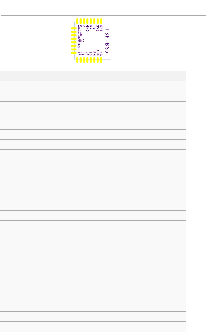
Pin Definitions
PIN Function Description
1 ANT WiFi Antenna
2 ADC ADC, input range: 0V-1V;
3 EN Chip enable terminal. Active high: chip works normally;
Active low: chip close, very small current.
4 GPIO16 GPIO16
5 GPIO14 GPIO14; HSPI_CLK
6 GPIO12 GPIO12; HSPI_MISO
7 GPIO13 GPIO13; HSPI_MOSI; UART0_CTS
8 GPIO15 GPIO15; HSPI_CS; UART0_RTS
9 GPIO2 Also used as a programming flash UART1_TX;GPIO2
10 GPIO0 GPIO0; SPI_CS2
11 GPIO4 GPIO4
12 GND GND
13 GPIO9 PIHD;HSPIHD;GPIO9
14 GPIO10 SPIWP;HSPIWP;GPIO10
15 GPIO11 SPI_CS0;GPIO11
16 GPIO6 SPI_CLK;GPIO6
17 GPIO7 SPI_MSIO;GPIO7
18 GPIO8 SPI_MOSI;GPIO8
19 GPIO5 GPIO5
20 GND GND
21 RX Also used as a programming flash UART Rx;GPIO3
22 TX Also used as a programming flash UART Tx ;GPIO1;SPI_CS1
23 3V3 Power supply
24 RESET External reset(low active)
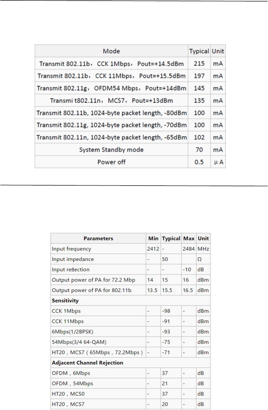
Power Consumption
The following data are conducted at 25°temperature with 3.3V power supply.
1. All measurements were performed at the antenna interface.
2. All transmitted data are conducted based on a 90% duty cycle, continuous
transmission mode.
Wi-Fi Radio Characteristics
The following data are from tests conducted at room temperature with 3.3V power
supply.Note:
1. 72.2Mbps is measured under 802.11n mode, MCS = 7, GI = 200uS;
2. Maximum output power can be + 16.5dBm in 802.11b mode;
WiFi Antenna
PSF-B85 has onboard ceramic antenna, users can directly use, no need to design
again. Please do not rub copper or connect wire below the antenna.
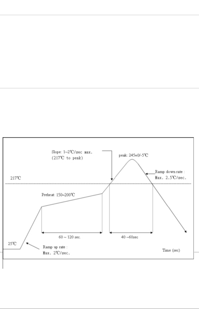
Recommended Temperature Graph
Refer to IPCJEDEC standard; Peak Temperature 250°C; Number of Times ≤2 times;

Related Terminologies
Abbreviation Description
WiFi Wireless Fidelity
UART Universal Asynchronous Receiver & Transmitter
DTIM Delivery Traffic Indication Message
SOC System On a Chip
P2P Point to Point
TCP Transmission Control Protocol
IP Internet Protocol
STBC Space-Time Block Coding
MIMO Multiple Input Multiple Output
MPDU MAC Protocol Data Unit
MSDU MAC Server Data Unit
IEEE Institute Of Electrical And Electronics Engineers
bps Bits Per Second
CCK Corporate Control Key
DQPSK Differential Quadrature Phase Shift Keying
DBPSK Differential Binary Phase Shift Keying
QAM Quadrature Amplitude Modulation
OFDM Orthogonal Frequency Division Multiplexing
WPA Wi-Fi Protected Access
WPS Wi-Fi Protected Setup
TKIP Temporal Key Integrity Protocol
WAPI Wlan Authentication And Privacy Infrastructure
WEP Wired Equivalent Privacy
CRC Cyclic Redundancy Check
FCC Caution: Any changes or modifications not expressly
approved by the party responsible for compliance could void the user's
authority to operate this equipment.
This device complies with Part 15 of the FCC Rules.
Operation is subject to the following two conditions: (1) This device may not
cause harmful interference, and (2) this device must accept any interference
received, including interference that may cause undesired operation.
This device and its antenna(s) must not be co-located or operating in conjunction
with any other antenna or transmitter.
15.105 Information to the user.
(b) For a Class B digital device or peripheral, the instructions furnished the
user shall include the following or similar statement, placed in a prominent
location in the text of the manual:
Note: This equipment has been tested and found to comply
with the limits for a Class B digital device, pursuant to part 15 of the FCC Rules.
These limits are designed to provide reasonable protection against harmful
interference in a residential installation. This equipment generates, uses and
can radiate radio frequency energy and, if not installed and used in
accordance with the instructions, may cause harmful interference to radio
communications. However, there is no guarantee that interference will not
occur in a particular installation. If this equipment does cause harmful
interference to radio or television reception, which can be determined by
turning the equipment off and on, the user is encouraged to try to correct the
interference by one or more of the following measures:
—Reorient or relocate the receiving antenna.
—Increase the separation between the equipment and receiver.
—Connect the equipment into an outlet on a circuit different from that to which
the receiver is connected.
—Consult the dealer or an experienced radio/TV technician for help.
This equipment complies with FCC radiation exposure limits set forth for an uncont
rolled environment. This equipment should be installed and operated with minimum
distance 20cm between the radiator and your body.
Radiation Exposure Statement:
This equipment complies with FCC radiation exposure limits set forth for an
uncontrolled environment.
This transmitter must not be co-located or operating in conjunction with any other
antenna or transmitter.
The availability of some specific channels and/or operational frequency bands
are country dependent and are firmware programmed at the factory to match
the intended destination.
The firmware setting is not accessible by the end user.
The final end product must be labelled in a visible area with the following:
“Contains Transmitter Module ESP8266”