ITERIS CAM-RZ4W Vantage Wireless Color Camera User Manual Vantage Wireless Camera Installation Guide
ITERIS Vantage Wireless Color Camera Vantage Wireless Camera Installation Guide
ITERIS >
Users Manual

Iteris Vantage Wireless System
Installation Guide
4931005
Version 2.0
This device complies with part 15 of the FCC Rules: Operation is subject to the following conditions: (1)
This device may not cause harmful interference, and (2) this device must accept any interference that may
cause undesired operation.
4931005, Version 2.0, June 2000, Made in USA.
©Copyright 2000, ITERIS. All rights reserved.
Your right to copy this manual is limited by copyright law. Making copies or adaptations without prior
written authorization of ITERIS. is prohibited by law and constitutes a punishable violation of the law.
ITERIS provides this publication “as is” without warranty of any kind, either express or implied, including
but not limited to the implied warranties of merchantability or fitness for a particular purpose. ITERIS may
revise this publication from time to time without notice.
ITERIS, Vantage, Vantage Edge are trademarks of ITERIS. All other company/product names are
trademarks/registered trademarks of their respective holders.
FCC STATEMENT
This equipment has been tested and found to comply with the limits for a class B digital device,
pursuant to part 15 of the FCC Rules. These limits are designed to provide reasonable protection
against harmful interference in a residential installation. This equipment generates, uses and can
radiate radio frequency energy and if not installed and used in accordance with the instructions,
may cause harmful interference to radio communications. However, there is no guarantee that
interference will not occur in a particular installation. If this equipment does cause harmful
interference to radio or television reception, which can be determined by turning the equipment
off and on, the user is encouraged to try to correct the interference by one or more of the
following measures:
* Reorient or relocate the receiving antenna.
* Increase the separation between the equipment and receiver.
* Connect the equipment into an outlet on a circuit different from that to which the receiver is
connected.
* Consult the dealer or an experienced radio/TV technician for help.
This equipment has been verified to comply with the limits for a class B computing device,
pursuant to FCC Rules. Operation with non-approved equipment is likely to result in interference
to radio and TV reception.
The user is cautioned that changes and modifications made to the equipment without the approval
of manufacturer could void the user's authority to operate this equipment.
INDUSTRY CANADA STATEMENT
This device has been designed to operate with an antenna having a maximum gain of 2.15dBi.
Antenna having a higher gain is strictly prohibited per regulations of Industry Canada. The
required antenna impedance is 50 ohms.
To reduce potential radio interference to other users, the antenna type and its gain should be so
chosen that the equivalent isotropically radiated power (EIRP) is not more than the required for
successful communication.
Operation is subject to the following two conditions:
(1) This device may not cause harmful interference, and
(2) This device must accept any interference received, including interference that may cause
undesired operation.
Document 4931005, Version 2.0 iii
Contents
Introduction . . .......................... 1
PurposeofThisGuide.........................1
IfYouNeedAssistance ........................1
OverviewofWirelessVideoImageDetection.......... 2
BenefitsofStandardandWirelessVIDS...............2
2.4GHzFMVideoTransmission...................3
BenefitsofUsingFM-BasedVideoTransmission .........3
CameraPower .............................4
ReceiverAntennaTypeandLocation ................5
OtherApplications...........................5
Single-Channelvs.Multi-ChannelReceivers............6
Tools, Equipment, and Supplies Required for Installation . . . 8
RequiredToolsandEquipment ...................8
RequiredSupplies ...........................8
InstallingtheCameraandReceiverUnit ............10
BasicInstallationSteps ....................... 10
Mounting the Wireless Camera/Transmitter Unit . . . . . . . . 10
Connecting Power to the Wireless Camera/Transmitter Unit . 11
MountingtheAntenna ....................... 14
ConnectingtheAntennaPre-Amp................. 15
InstallingtheReceiverCoaxCable................. 17
CableTypes ......................... 17
InstallingCoaxConnectors................. 17
MakingConnectionsInsidetheCabinet.............. 21
Installing the Bias-T and Surge Protection Device . . . . 21
iv Vantage Wireless System Installation Guide
ReceiverUnitConnections .................24
InstallingaSignalSplitter..................25
DeterminingtheCameraTransmitterFrequency.........26
SettingtheReceiverFrequency ...................27
Setting the Frequency for Single-Channel Receivers . . . 27
Setting the Frequency for Multi-Channel Receivers . . . 28
TuningtheReceivingAntenna ...................29
AdjustingtheCameraFocusandFieldofView..........32
Troubleshooting..........................33
Specifications...........................34
VantageWirelessCameraSpecifications..............34
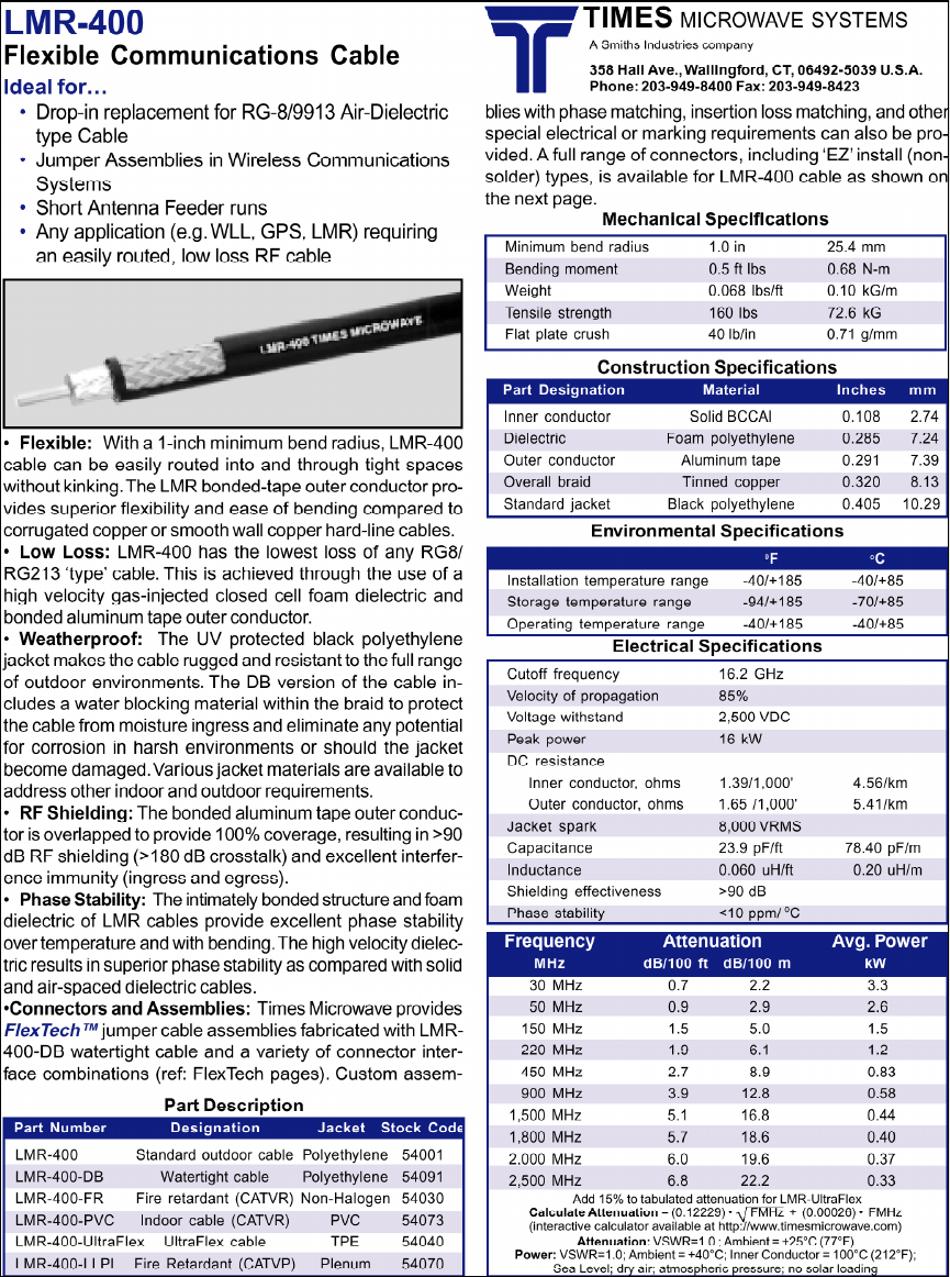
LMR-400CoaxCableSpecifications ................35
SurgeSuppressorSpecifications ..................36
SignalSplitterSpecifications.....................38
2 Overview of Wireless Video Image Detection Vantage Wireless System Installation Guide
Overview of Wireless Video Image Detection
Any major city that relies on vehicle detection for its signal control
system eventually experiences damage to traditional inductive
loops due to roadway construction or pavement failure. Damage
to inductive loops from road widening or re-surfacing projects can
compromise the reliability of vehicle detection. Maintaining
optimum traffic flow during construction can be difficult due to
temporary striping and lane closures.
Adverse weather conditions also impede repair of inductive loops
and at times may delay repair activities for several months. During
such times, intersections that rely on a failed inductive loop may
go into max-recall for the duration.
The use of wireless video transmission facilitates rapid
deployment for permanent and temporary applications while
maintaining superb vehicle detection where inductive loops or
other vehicle detection methods cannot be deployed or repaired.
Benefits of Standard and Wireless VIDS
Although wireless video communications technology is not new,
its application in vehicle detection provides enormous benefits.
Video image detection systems (VIDS) in general provide
flexibility in the placement of vehicle detection zones. Temporary
lane closures and lane markings can be easily accommodated by
moving the detection zones of the video image processor.
At intersections with a high volume of heavy vehicles, the constant
abuse of the roadway surface from heavy vehicles requires
inductiveloopstobereplacedeveryyear.Forthesetypesof
locations, VIDS is an excellent alternative detection method.
Utilizing wireless video transmission between the VIDS camera
and video image processor provides additional flexibility where
quick and low cost deployment is required. At many locations,
running high-quality coaxial cable may be difficult or impossible
because existing conduits are filled to capacity, blocked with
debris, or even frozen. Wireless video technology provides cable-
free live video from the VIDS camera to the controller cabinet,
where the video image processor is housed.
Document 4931005, Version 2.0 Overview of Wireless Video Image Detection 3
2.4 GHz FM Video Transmission
The ITERIS Wireless Vantage System utilizes the license-free 2.4
GHzbandtotransmitlivevideofromtheVIDScameratothe
controller cabinet. A wireless transmitter is integrated into the
camera and has no external components other than a 3-inch
“rubber ducky” antenna. The video transmitter is FCC compliant
and does not require the end user to have an operator license from
the FCC.
The wireless transmission system uses frequency modulation (FM)
techniques to transmit the video. This modulation scheme, unlike
spread spectrum transmission where data is digitized prior to
transmission, uses analog methods to modulate the video signal.
Digital transmission typically requires higher bandwidths than
FM-based systems.
There are several reasons why the 2.4 GHz band was selected.
Video transmissions in the 902-928 MHz unlicensed band require
too much bandwidth, and the 5.8 GHz unlicensed band encounters
signal reflections common to higher frequency devices at locations
where several obstructions and radio wave reflectors exists. Since
wireless video transmission devices are mounted at lower
elevations, signal poles, mast arms, signal heads, and even vehicles
may cause havoc with multipaths and reflections, resulting in
image ghosting, image shifting, and possibly even image
cancellation. The 2.4 GHz band avoids these problems.
Benefits of Using FM-Based Video Transmission
The question arises: How can multiple intersections use wireless
VIDS if they use the same frequency? This is possible because of
thenatureofFMcommunications.
Frequency modulation receivers detect and use the strongest
signal they receive. Wireless Vantage video transmitters are low-
power devices. Signal strengths of adjacent intersection video
transmitters are significantly lower than local transmitters and do
not cause interference, provided that adjacent intersections are at
least 250 feet away.
Other benefits of FM-based video transmission:
•Proven video transmission technology.
•Ease of deployment.
•Lower maintenance costs (does not require expensive
digital test equipment).
4 Overview of Wireless Video Image Detection Vantage Wireless System Installation Guide
Camera Power
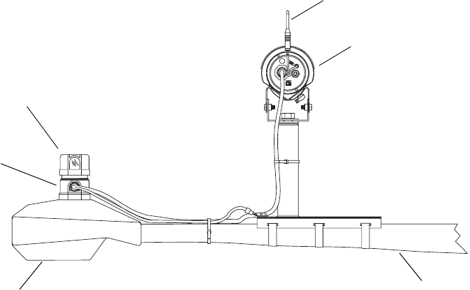
The portability of the Wireless Vantage VIDS hinges upon how
power is provided to the camera. Since the recommended
mounting location of the Vantage wireless camera is on the safety
light arm above the signal head, the luminaire circuit supplies the
camera power. The only requirement is that the luminaire head be
controlled by its own photocell.
In this manner, power for the camera can be tapped prior to the
photocell by hardwiring in the power cable or by using a photocell
power adapter or power take-off (PTO) placed between the
photocellanditsreceptacle(seeFigure1).Thephotocellcanstill
provide nighttime switching capabilities while providing
continuous 24-hour power to the camera.
Figure 1. Vantage Camera Power
Transmitter antenna
Vantage wireless camera/
Luminaire (safety light) arm
Luminaire
Power
adapter
Photocell
transmitter unit
Document 4931005, Version 2.0 Overview of Wireless Video Image Detection 5
Receiver Antenna Type and Location
The wireless video receiver is located in the controller cabinet, and
its baseband video output provides full-motion video to the
Vantage VIDS. Getting clean, optimum radio waves to the video
receiver takes careful planning prior to system installation. As
with any wireless transmission, radio wave reflections, multipaths,
and obstructions can degrade signal quality.
For optimum radio wave signal reception, the receiver antenna
should be placed as high as possible to eliminate reflections from
ground level objects, such as pedestrian signal heads and moving
objects (high-profile vehicles, for example). The receiver antenna
height also dictates the amount of signal degradation induced
from pedestrians. A minimum height of 20 feet is recommended
for most applications. Some sites may require additional receiver
antenna height if direct line-of-sight between the transmitting
antennas and receiver antenna cannot be achieved.
A linear-polarized directional patch antenna for receivers provides
the best results in most applications. This type of antenna typically
has a 60–90 degree angle of reception and is designed for vertical
or horizontal polarization. A linear-polarized antenna rejects
reflected radio waves since polarization of reflected signals is
typically shifted in some manner. In addition, a patch-type
directional antenna provides rejection of reflected radio waves by
rejecting signals coming from behind the patch antenna.
Other Applications
Other applications for wireless VIDS are construction management
activities during road widening, intersection improvements, or
temporary lane closures. Locations where road surfaces are
continually damaged by heavy vehicles or severe weather can also
benefit from the use of wireless VIDS. At these locations,
permanent installations of the wireless system significantly
reduces recurring maintenance costs and headaches.
Mid-block vehicle detection can benefit from the use of wireless
VIDS by eliminating the need to install conduit and cabling from
the mid-block detection location to the intersection controller
cabinet. A higher-gain Yagi receiver antenna can be used to extend
reception distance to more than a mile.
The use of wireless technology in VIDS applications expands the
flexibility for deployment. Coaxial cable and other hard wiring are
no longer limiting factors. ITERIS has integrated their proven
Vantage VIDS with wireless video transmission to provide a more
flexibleVIDSproductthataccommodatesalmostanyintersection
and mid-block configuration.
6 Overview of Wireless Video Image Detection Vantage Wireless System Installation Guide
Single-Channel vs. Multi-Channel Receivers
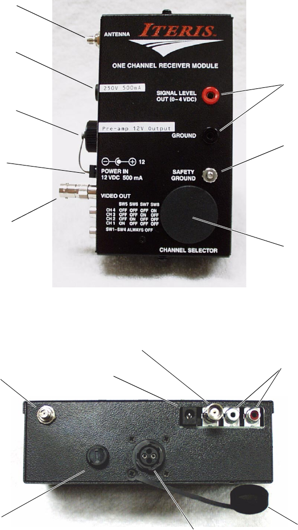
The single-channel receiver is designed for applications requiring a
single camera. The single-channel receiver is shown in Figures 2
and 3.
Figure 2. Single-Channel Receiver (Front View)
Figure 3. Single-Channel Receiver (Side View)
Signal strength
measurement points
(0-4 VDC)
Chassis grounding
point
Frequency selection
access cover
Antenna input
Video output with
RCA-to-BNC adapter
Wall transformer
power supply
receptacle
Bias-T power
receptacle and cover
Pre-amp power 15 VDC
250v/500mA fuse
Fuse holder
Antenna input
Wall transformer
power receptacle
Video output
Not used
Receptacle
cover
Bias-T power
receptacle
Document 4931005, Version 2.0 Overview of Wireless Video Image Detection 7
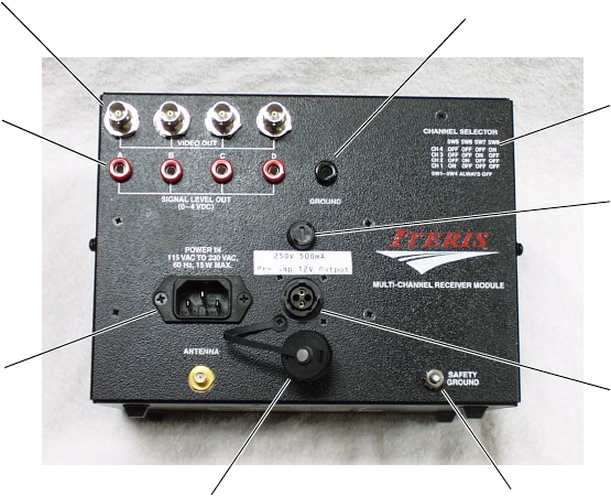
The multi-channel receiver is composed of two or four individual
receivers combined into one unit. The external power supply and
the signal splitter are not required when using a multi-channel
receivers because they are already built into the unit.
A four-channel receiver is shown in Figure 4. The two-channel
version has only two video outputs.
Figure 4. Multi-Channel Receiver
Chassis ground connection
Bias-T power plug
Receiver frequency
table
DC ground reference jack
(meter lead DC-)
Receiver signal
strength jacks
(meter leads DC+)
Video outputs
120 VAC power
plug
Bias-T power plug cover
Pre-amp power
15 VDC
250v/500mA fuse
8 Tools, Equipment, and Supplies Required for Installation Vantage Wireless System Installation Guide
Tools, Equipment, and Supplies Required for
Installation
Required Tools and Equipment
1Buckettruck
2 Monitor
3 Lens Adjustment Module (LAM)
4 Volt/Ohmmeter (VOM)
5 Utility knife or coaxial stripper
6 Banding tool
7Hammer
8 Screwdriver
9Adjustablewrench
10 9⁄16"and1
1⁄8"wrench
11 Needlenose pliers
12 Wire cutters
13 Wire strippers
14 Two-way communication equipment
15 High heat soldering iron and solder (100 Watt)
16 Meter probe adapters to male banana plug
Required Supplies
1 ½" or ¾" banding material or lag bolts (for pole bracket
installations)
2 Camera bracket(s)
3 Antenna coaxial cable (use type LMR-400; see page 35 for
specifications)
4 Antenna coaxial cable connectors, type N male (provided;
RF Connectors distributor part no. RFN-1001-S type N male
clamp and solder plug, Van Gorden manufacturer part no.
N13STGP)
5 Photocell power adapter(s); also called power take-off
(PTO)
Document 4931005, Version 2.0 Tools, Equipment, and Supplies Required for Installation 9
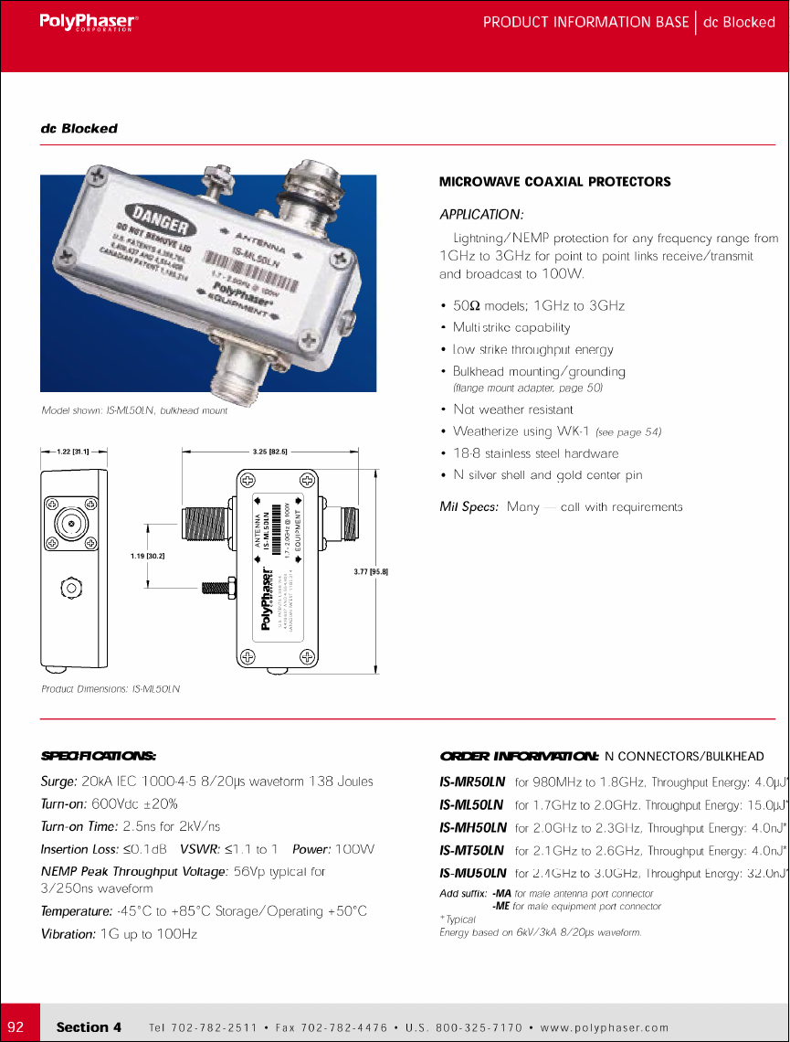
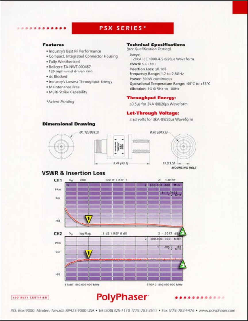
6 Surge suppressor (provided; use PolyPhaser PSX,
IS-MT50LN, or equivalent; see pages 36-37 for
specifications)
7 N-to-SMA cable (type N on one end, type SMA on other
end; provided)
8 Type N male-to-male barrel adapter (provided)
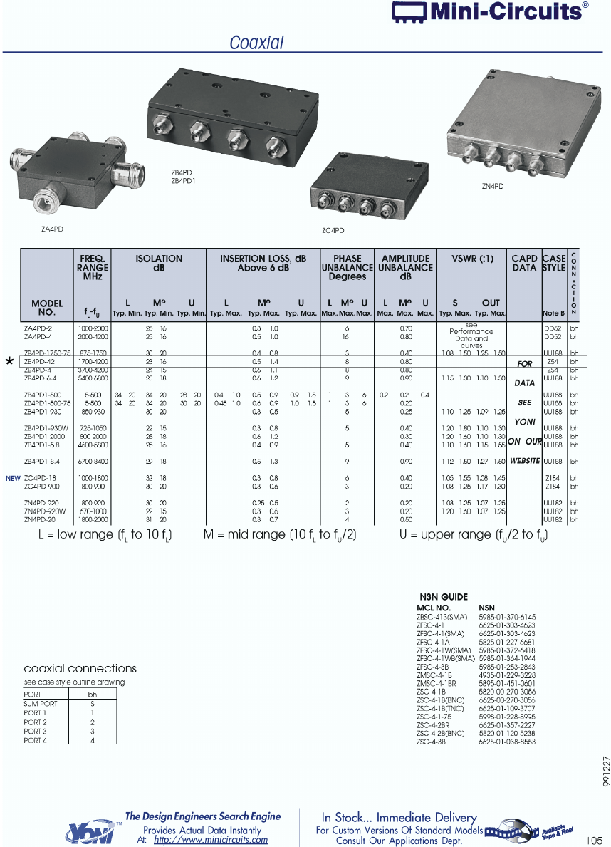
9 Signal splitter (required for installations using more than
one single-channel receiver; use Mini-Circuits ZB4PD-42 or
equivalent; see page 38 for specifications)
Note The signal splitter is not required for installations using a
multi-channel receiver.
10 10 AWG green grounding wire
11 3'–6' BNC-to-BNC 75-Ohm coaxial jumper cables
12 Rubber tape, electrical tape, and ScotchKote
13 Tie wraps or hose clamps for the antenna pre-amp
mounting
10 Installing the Camera and Receiver Unit Vantage Wireless System Installation Guide
Installing the Camera and Receiver Unit
Basic Installation Steps
Installing the Vantage wireless camera and receiver unit requires
the following steps:
1 Mounting the wireless camera/transmitter unit.
2 Connecting power to the wireless camera/transmitter unit.
3 Mounting the receiving antenna.
4 Connecting the receiving antenna pre-amp.
5 Installing the antenna coax cable.
6 Installing the antenna coax cable connectors.
7 Installing the bias-T and surge protection device.
8 Wireless receiver unit connections.
9 Determining wireless camera frequency.
10 Setting wireless receiver frequency.
11 Adjusting the antenna to obtain maximum RF signal
strength.
12 Adjusting the wireless camera focus and field of view.
Mounting the Wireless Camera/Transmitter Unit
To mount the wireless camera/transmitter unit, follow the
instructions for mounting a standard camera as described in your
Vantage Installation and User Guide. The connections required for
the wireless camera/transmitter unit are described in the next
section of this guide.

Document 4931005, Version 2.0 Installing the Camera and Receiver Unit 11
Connecting Power to the Wireless Camera/Transmitter
Unit
The RZ-3 wireless camera/transmitter unit can be powered using
either 120 or 220 VAC. The photocell power adapter (or power
take-off unit) can be used to provide 120 VAC to the
camera/transmitter unit (see Figure 5.
The new photocell power adapter can be used for either 120 or 220
VAC applications as a convenient power source for the
camera/transmitter unit. To use the photocell power adapter:
1 Remove the existing photocell.
2 Plug in the photocell power adapter in its place.
3 Install the original photocell into the top of the adapter.
4 Rotate the photocell as needed to orient it in the correct
direction (pointing north).
In some cases, luminaires have shorting plugs installed in the
photocell sockets. In this situation, the actual switching is probably
occurring at the service or cabinet utilizing a single photocell and
contactor relay. You can sometimes install a shorting cap at this
point, remove the shorting caps on the luminaires, and install the
Vantage photocell adapters along with individual photocells to
avoid having to use another power source.
If you cannot use the photocell power adapter, you need to
provide the camera with another source of 120 or 220 VAC. Use a
three-conductor, Neoprene, type SJOW, 16-AWG power cord.
Figure 5. Photocell Power Adapter / Power Take-Off Unit (PTO)
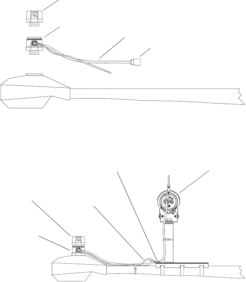
The photocell power adapter comes with an attached Deutsch
connector that plugs into the back of the camera/transmitter unit
to provide power (see Figures 6 and 7).
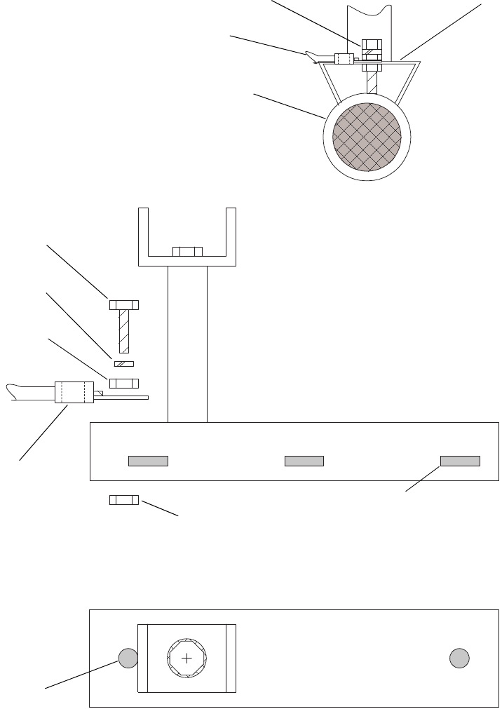
The 10 AWG green wire needs to be attached to the camera
mounting bracket and grounded to the signal pole arm (see
Figure 8). When attaching the ground wire:
12 Installing the Camera and Receiver Unit Vantage Wireless System Installation Guide
•Secure the ground bolt assembly to the camera bracket.
•Tighten the bottom of the bolt so that it digs into the pole
and provides good electrical contact with the pole arm.
Figure 6. Power Connections Using Photocell Adapter (Exploded View)
Figure 7. Power Connections Using Photocell Adapter
Photocell
Photocell power adapter/
power take-off (PTO) Camera power
Deutsch connector
cable
Camera
Photocell
Grounding bolt
assembly
10 AWG ground
wire from photocell
power adapter
transmitter
unit
Photocell power
adapter/power
take-off (PTO)
Document 4931005, Version 2.0 Installing the Camera and Receiver Unit 13
Figure 8. Grounding the Photocell Power Adapter
SIDE VIEW
SIDE
VIEW
TOP
VIEW
Camera bracket
Camera bracket
Banding slot
Nut
Hole
Crimp ring terminal
on ground wire from
photocell power
adapter
Nut
Lock washer
Grounding bolt
Camera
bracket
G
roun
db
o
l
t
assembly
Ground wire from
photocell power
adapter
Pole arm
14 Installing the Camera and Receiver Unit Vantage Wireless System Installation Guide
Mounting the Antenna
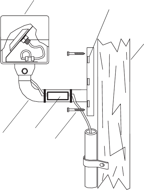
Mount the antenna using the antenna bracket as shown in Figure 9.
Thebracketcanbemountedtothesideofapoleusing½"or¾"
banding material. For a wooden pole, lag bolts can be used to
secure the antenna mounting bracket to the pole instead of
banding material.
Figure 9. Antenna Mounting Location
Mounting
bracket
Antenna
assembly
Wooden or
metal pole
Bracket slots for alternative
metal banding installation
2" lag bolt
Pre-amp
on steel signal poles
Document 4931005, Version 2.0 Installing the Camera and Receiver Unit 15
Connecting the Antenna Pre-Amp
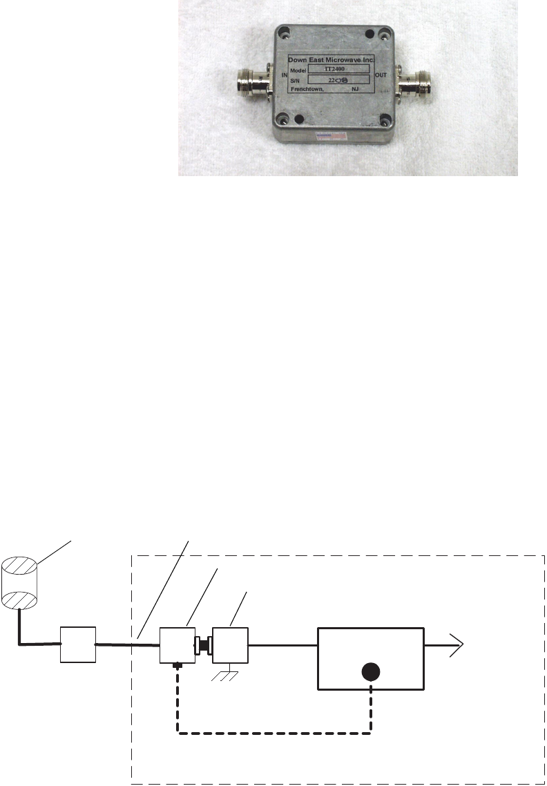
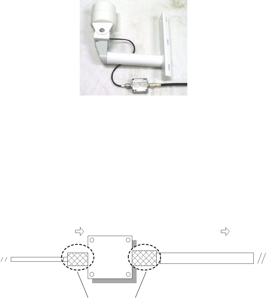
The antenna pre-amp is connected between the LMR-400 coaxial
cable run to the cabinet and the receiver antenna.
Figure 10. Antenna Pre-Amp
The pre-amp should be connected as shown in Figure 11. When
connecting the pre-amp:
•Do not mount the pre-amp in the cabinet.
•Thepre-ampshouldbemountedasclosetotheantennaas
possible.
•Make sure the bias-T and pre-amp are correctly oriented.
•For optimal performance, the total LMR-400 coax cable run
from the antenna to the receiver should not exceed 150 feet.
To connect the pre-amp:
1 Connect the end of the antenna coax cable to the IN side of
the pre-amp. See Figure 12.
2 Connect LMR-400 coax cable to the OUT side of the pre-
amp and run the cable back to the cabinet.
In Out
Antenna
side Cabinet
side
Inside cabinet
Belden 8281
coax cable
to Vantage
Antenna
Pre-amp
OutIn
LMR-400 coax cable (150' max)
Bias-T
Surge suppressor
Receiver
Bias-T power cable
Processor
Figure 11. Pre-Amp Installation
16 Installing the Camera and Receiver Unit Vantage Wireless System Installation Guide
Figure 12. Antenna and Pre-Amp
3 Connect the cabinet end of the LMR-400 cable to the RF DC
side of the bias-T.
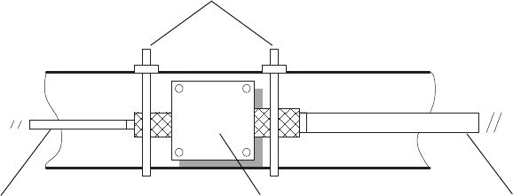
4 Properly weatherproof both pre-amp connections and any
other external coax cable connections as shown in
Figure 13.
To weatherproof coax cable connections:
a Wrap the connection with a layer of rubber tape.
b Wrap the connection with another layer of electrical
tape.
c Cover the connection with a generous coating of 3M
ScotchKote™.
Figure 13. Weatherproofing Coax Cable Connections
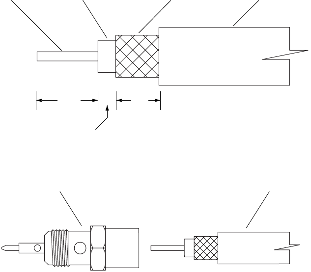
5 Secure the pre-amp to the antenna mounting bracket arm
using tie-wraps or stainless steel hose clamps (see
Figure 14).
RG-22/ Pre-Amp
Pre-Amp LMR 400 Coaxial Cable
From Antenna Assembly To Cabinet and Receiver nit
"N" Connector
"N" Connector
Coax cable connections
requiring weatherproofing
Document 4931005, Version 2.0 Installing the Camera and Receiver Unit 17
Figure 14. Securing the Pre-Amp
Installing the Receiver Coax Cable
CABLE TYPES
Although it depends on your installation configuration, coax cable
must be pulled from the receiving antenna to the traffic control
cabinet.UsetypeLMR-400coaxcabletoconnectfromthe
receiving antenna to the cabinet. Coax cable specifications are on
page 35. The coax cable run should not exceed 150 feet.
Coax cable connections inside the cabinet are described in Making
Connections Inside the Cabinet on page 21.
If you are not using the photocell power adapter, the power cable
for the camera should be an SJOW-type, three-conductor, 16-gauge
cable.
INSTALLING COAX CONNECTORS
Coax cable specifications are listed on page 35.
To install a coax connector, follow these steps:
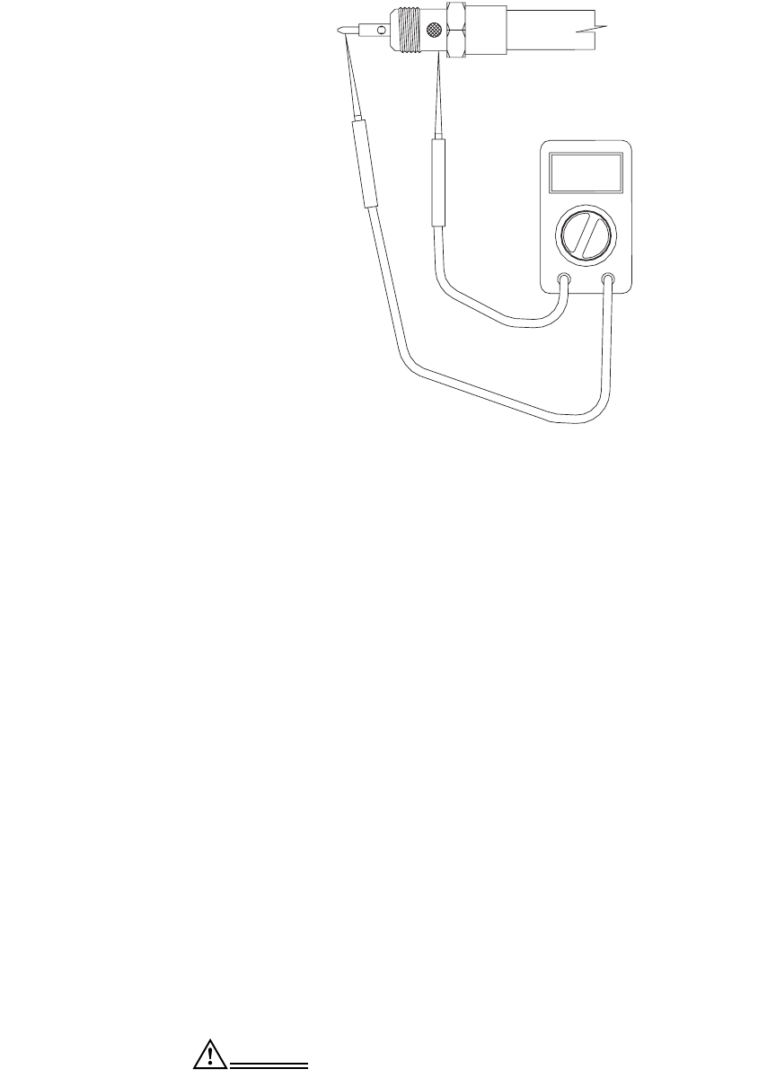
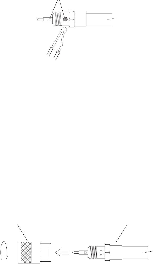
1 Use a sharp utility knife to strip the end of the coax cable as
showninFigure15.Becarefulnottoscoreornickthe
shield, dialectric, or center conductor.
2 Insert the end of the coax cable into the connector body as
shown in Figure 16. Thread the connector body onto the
outer sheath of the cable.
Note If there is foil on the dielectric, make sure the foil does not
make contact with the center conductor.
Pre-Amp
LMR 400
coax cable
Pre-ampRG-22/
Tie-wraps or hose clamps
18 Installing the Camera and Receiver Unit Vantage Wireless System Installation Guide
Figure 15. Stripping the Coax Cable
Figure 16. Attaching the Coax Connector Body
3 Check the connector for shorts as shown in Figure 17.
a Set your multimeter to the continuity or resistance
setting (ohms).
b Place one meter test lead so it touches the connector
center pin. Place the other test lead so it makes
contact with the connector body. With both ends of
the coaxial cable disconnected from any equipment,
you should have infinite resistance between these
points (no continuity).
If you do have a low resistance (continuity), there is
a short somewhere in the coax cable or connector. It
is most often at the connector due to improper
assembly. Examine the coax for cuts or tears. If
there is no visible damage, remove and re-install the
connector.
Measure the connector again after it is removed
from the cable. If the short disappears, the problem
is in the connector. If there is still a short, the
problem is with the cable.
Fix any problems before proceeding.
1/4"
/16"
7/16"
Coax cableBraided
shield outer sheath
Teflon foam
dialectric
Center
conductor
Coax cableConnector body
Document 4931005, Version 2.0 Installing the Camera and Receiver Unit 19
Figure 17. Checking the Coax Connector for a Short
4 Solder the cable to the connector body at the points
indicated in Figure 18.
a Makesurethesolderingguntipiscleanandwell
tinned.
b Makesureyoucanvisiblyseethebraidedshield
and the copper center conductor through the holes
in the connector body.
c Heat the connector body with the soldering gun
until solder flows into the holes for the center
conductor and the braided shield. Repeat this
process for the holes on both sides of the connector.
Establish a good electrical connection between the
coax braided shield and connector body, and
between the center pin and coax center conductor.
The solder connections should be bright and shiny,
not dull and pitted (which results from cold solder).
A low power soldering iron will not have the
wattage to adequately heat up the connector to
allow the solder to flow properly. Make sure you
areusingahighheatsolderinggunwitharatingof
at least 100/140 watts.
CAUTION Do not overheat the connector. Overheating can
cause the dielectric to melt and allow it to create a
short between the center conductor and the shield.
20 Installing the Camera and Receiver Unit Vantage Wireless System Installation Guide
Figure 18. Soldering the Coax Cable and Connector Body
5 After soldering the center conductor in place, check the
connector again for shorts as described in step 3.
6 Perform an additional test for continuity. To perform this
test, take a jumper clip lead and short the center pin on one
of the connectors to the connector body. Go to the other
non-jumpered connector and measure from the center pin
to the connector body. You should measure a low
resistance (continuity).
If the resistance is over 10 ohms (no continuity), there is a
problem. It could be a broken center conductor in the coax
cable or (most likely) a poor or improper connection at the
coaxial connectors. Isolate the problem as described in
step 3b.
Note Poor connections on the receiver coax cable can result in poor
signal strength. Make sure these critical connections are done
correctly. If you are not familiar with proper soldering
techniques, consult another reference on the topic.
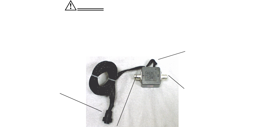
7 After verifying that there are no shorts, screw the connector
body and connector shell together as shown in Figure 19.
Use two adjustable wrenches (one to hold the connector,
the other to tighten it).
Figure 19. Assembling the Connector Body and Shell
Solder holes
Connector shell Coax cable
Document 4931005, Version 2.0 Installing the Camera and Receiver Unit 21
Making Connections Inside the Cabinet
INSTALLING THE BIAS-T AND SURGE PROTECTION
DEVICE
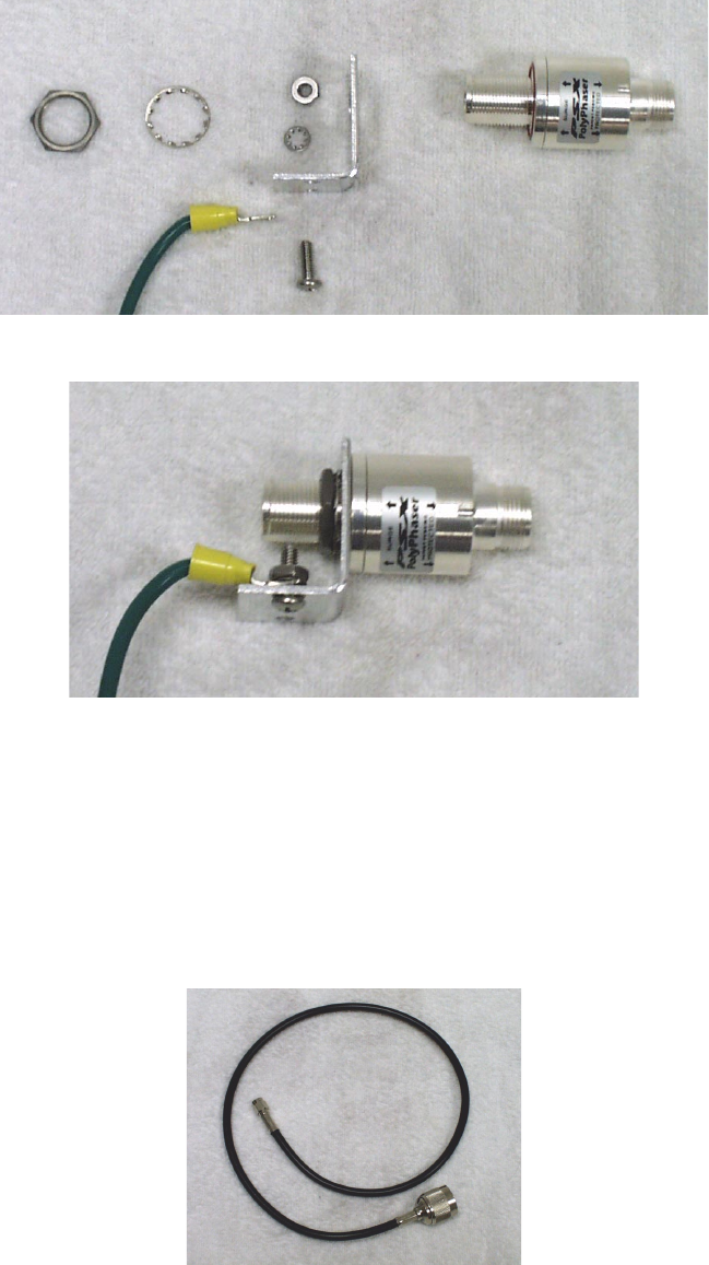
1 Attach the bias-T to the LMR-400 coax cable that you pulled
into the cabinet from the antenna and pre-amp. Orient the
bias-T so that the RF-DC side goes to the antenna and the
RF side goes to the surge protector and receiver unit. See
Figure 20.
CAUTION The bias-T must be oriented correctly and located
between the pre-amp and surge protection device.
Improper installation will result in poor operation
and may also blow the receiver power supply fuse
and damage the pre-amp, bias-T, and receiver unit.
Figure 20. Bias-T
2 Plug the power cord from the bias-T into the 15 VDC
receptacle on the receiver unit.
In addition to providing power to the bias-T, power is
supplied to the pre-amp from the bias-T through the coax
cable without interference to the video signal and without
requiring additional wiring.
3 Install the male-to-male barrel adapter to the RF side of the
bias-T, and connect the SURGE side of the surge protection
device to the other end of the barrel adapter.
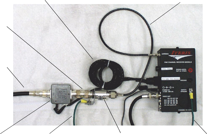
4 Assemble the surge protection device as shown in Figures
21 and 22. (Use a PolyPhaser IS-MT50LN, PSX, or suitable
equivalent. See page 36 for specifications.)
•Be sure to install the orange “O” ring into the
groove on the suppressor body.
•Properly ground the bracket using 10 AWG green
wire.
15 VDC in
RF DC
(pre-amp/antenna side)
RF (surge protection side)
Bias-T power
plug
22 Installing the Camera and Receiver Unit Vantage Wireless System Installation Guide
Figure 21. Surge Protection Device (Exploded View)
Figure 22. Surge Protection Device (Assembled)
5 Use the N-to-SMA adapter cable (see Figure 23) to connect
the surge protection device to the receiver unit. The N
connector side of the cable connects to the PROTECTED
side of the surge protector, and the SMA side of the cable
connects to the ANTENNA input connector on the receiver.
Figure 24 shows the bias-T, surge protection device, and
receiver properly connected.
Figure 23. N-to-SMA Adapter Cable
Document 4931005, Version 2.0 Installing the Camera and Receiver Unit 23
Figure 24. Bias-T, Surge Protection Device, and Receiver Correctly Connected
N-to-SMA adapter
10 AWG
ground wire
Surge protection
device
10 AWG
ground wire
Bias-T 10 AWG
ground wire
LMR-400
coax cable
Barrel
adapter
Bias-T power cord cable
24 Installing the Camera and Receiver Unit Vantage Wireless System Installation Guide
RECEIVER UNIT CONNECTIONS
Receiver units require several connections:
•The receiver unit requires a power source. Single-channel
receivers have a plug-in wall transformer power supply
that runs off 120 VAC. Multi-channel receivers have a
detachable power cord that needs to be plugged into a 120
VAC outlet.
•As described previously, the bias-T power cord must be
plugged into the 15 VDC receptacle on the receiver unit in
order for the pre-amp to operate properly.
•TheSMAsideoftheN-to-SMAadaptercablemustbe
connected to the SMA antenna input on the receiver.
•A short BNC-to-BNC jumper cable of Belden 8281F must be
attached from the video output to the Vantage unit video
input. Single-channel receivers require an RCA-to-BNC
adapter to adapt the RCA-type video output to a BNC-type
output connector.
•The receiver chassis must be grounded by attaching a green
10 AWG wire to the chassis grounding lug and running the
wire back to the cabinet grounding buss.
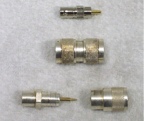
Figure 25 shows some of connectors and adapters that may be
needed when making these connections.
Figure 25. Connectors and Adapters
RCA-to-BNC adapter
Male-to-male barrel connector
N-type connector for
LMR-400 coax cable

Document 4931005, Version 2.0 Installing the Camera and Receiver Unit 25
INSTALLING A SIGNAL SPLITTER
If you have multiple cameras and single-channel receivers, you
also need to install a signal splitter. Specifications for the signal
splitter are on page 38.
Note A separate signal splitter is not necessary with a multi-
channel receiver, which has a signal splitter inside the unit.
In this configuration, connect a jumper cable between the surge
protector and the input on the signal splitter, and then connect a
jumper cable between an output on the signal splitter and each
receiver unit. See Figure 26.
Figure 26. Signal Splitter Connections
Antenna
Pre-amp
Bias-T
Surge
protection
Input
Splitter
Outputs
421
Single
channel
receiver
Single
channel
receiver
Single
channel
receiver
Single
channel
receiver
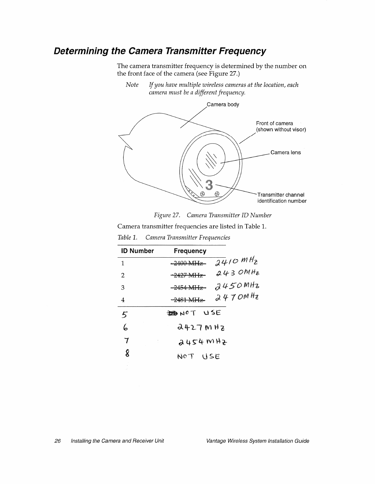
Document 4931005, Version 2.0 Installing the Camera and Receiver Unit 27
Setting the Receiver Frequency
SETTING THE FREQUENCY FOR SINGLE-CHANNEL
RECEIVERS
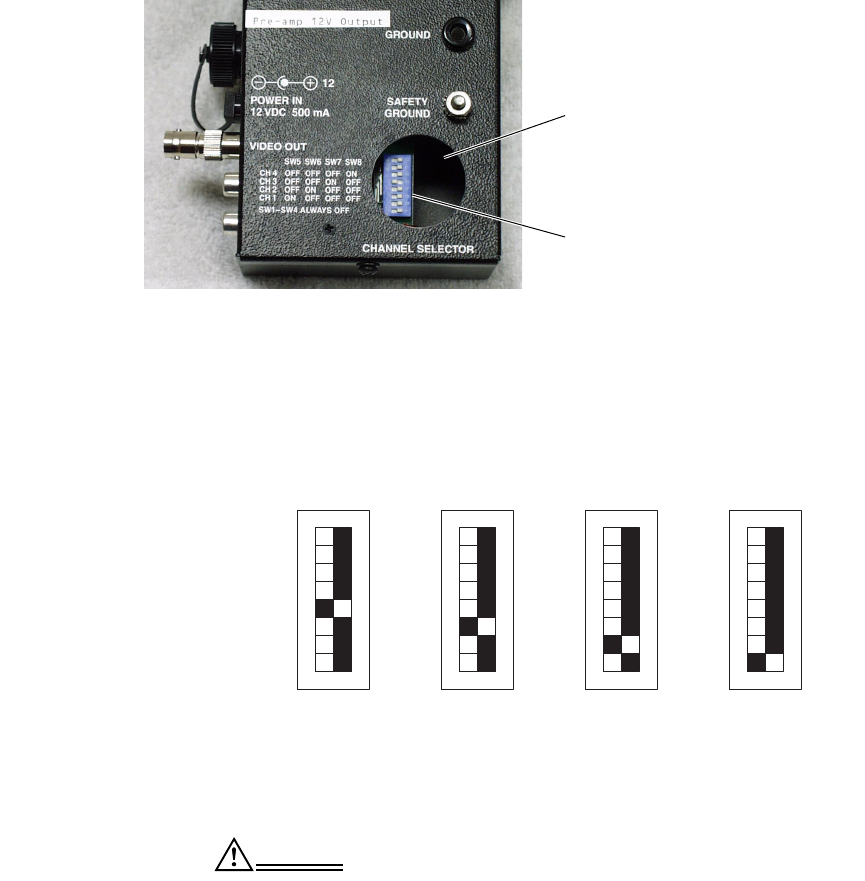
The frequency on the single-channel receiver is set using DIP
switches. The location of the DIP switches is shown in Figure 28.
Figure 28. Single-Channel Receiver DIP Switches
To set the frequency for a receiver, carefully remove the circular
access cover on the receiver unit to access the DIP switches, then
set the DIP switches to the appropriate frequency as listed in
Table 2 and shown in Figure 29.
Figure 29. Receiver Frequency DIP Switch Settings
CAUTION Turn on the DIP switch for one frequency only, and
leave all other DIP switches off. If you turn on the
DIP switch for more than one frequency, you may
damage the receiver.
Frequency selection access
cover removed
DIP switches
1
8
OFF ON OFF OFFON ON
11
88
ONOFF
1
8
Channel 1
2400 MHz Channel 2
2427 MHz Channel
2454 MHz Channel 4
2481 MHz
(switch 5 on) (switch 6 on) (switch 7 on) (switch 8 on)
30 Installing the Camera and Receiver Unit Vantage Wireless System Installation Guide
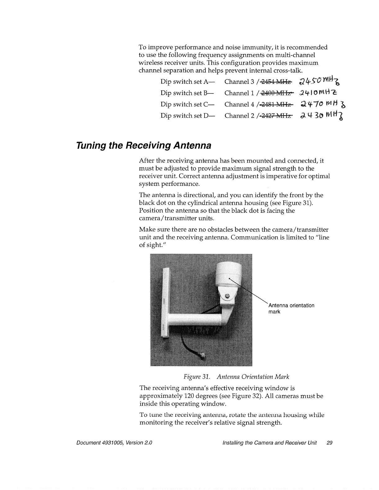
Figure 32. Tuning the Receiving Antenna
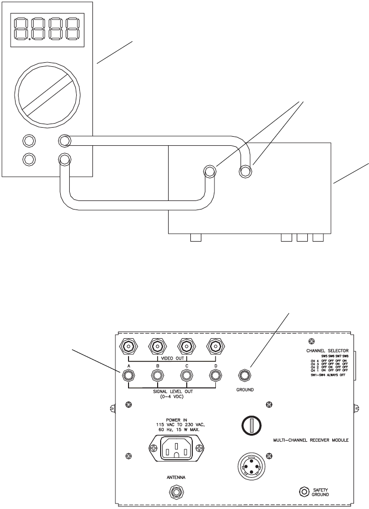
Measure the receiver signal strength using the DC measurement
scale on a standard multimeter. Using banana-type jack adapters,
insert the meter probes into the color-coded test points on the
receiver unit to measure the DC signal strength. (For single-
channel receivers, see Figure 2 on page 6 and Figure 33. For multi-
channel receivers, see Figure 4 on page 7 and Figure 34.)
The signal strength should be 1–4 VDC. For optimal performance,
the signal strength should exceed 1.5 VDC.
Rotate the receiving antenna until you obtain the maximum
average signal strength. When you find the best position, tighten
the antenna permanently into place. Make sure the coaxial cable
has a drip loop, and tie-wrap it for added strain relief.
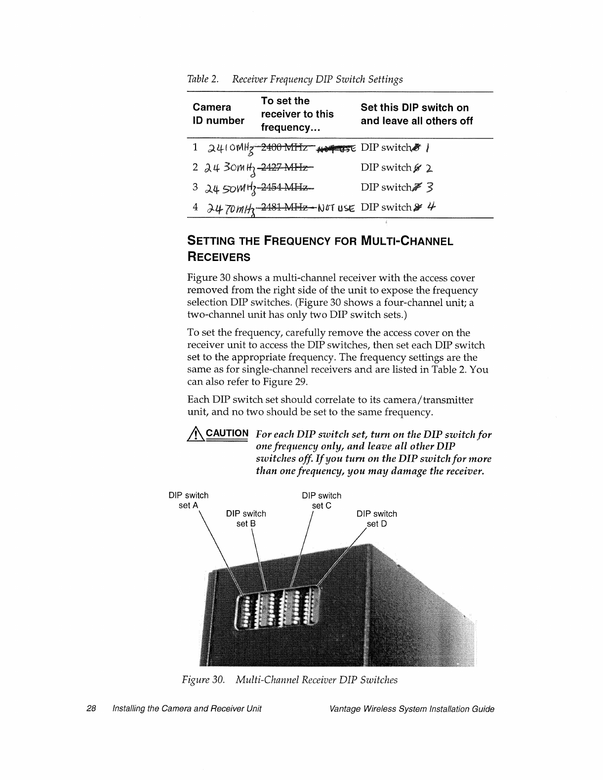
If you have multiple single-channel receivers or a multi-channel
receiver, you need to obtain the highest average signal strength for
each receiver or channel. Realize that adjusting the antenna to
obtain a higher reading for one may degrade the signal strength of
another. Adjust the receiving antenna to find a happy medium.
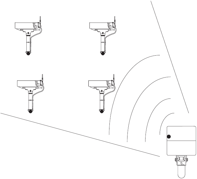
Camera 1 Camera 2
Camera Camera 4
120 degrees
Receiving
antenna
Document 4931005, Version 2.0 Installing the Camera and Receiver Unit 31
Figure 33. Measuring the Receiver Signal Strength (Single-Channel Receiver)
Figure 34. Measuring the Receiver Signal Strength (Multi-Channel Receiver
Receiver
DC voltage test points
Multimeter
Fuse 250v/.5 amp
15VDC Preamp
Power Out
Ground reference
negative lead (black)
DC voltage test points
positive lead (red)
32 Installing the Camera and Receiver Unit Vantage Wireless System Installation Guide
Adjusting the Camera Focus and Field of View
The field of view and focusing adjustment is the same for the
wireless camera as for the normal Vantage video camera. Refer to
your Vantage product user and installation guide for a description
of how to adjust the camera focus and field of view.
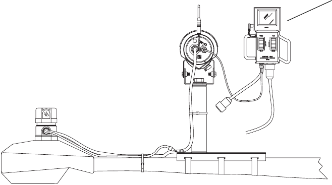
To adjust the camera focus and field of view, you need to connect a
Lens Adjustment Module (LAM) to the BNC connector on the back
ofthecameraasshowninFigure35.
Figure 35. Connecting a LAM to the Camera
Lens adjustment
module (LAM)

Document 4931005, Version 2.0 Troubleshooting 33
Troubleshooting
If you have no video, poor video, or low signal strength, check the
following table
Table 3. Troubleshooting
Potential Problem See Page
Are all camera/transmitter units within the 120 degree operating
window of the receiving antenna?
29
Is the antenna adjusted to provide a signal strength of 1.5 VDC or
greater to all camera/transmitter units?
29
Are their any obstructions blocking the receiving antennas “line of
sight” path to any of the camera/transmitter units?
29
Are the pre-amp, bias-T, and surge protector connected in the correct
order and orientation?
•Make sure that the bias-T is in front of the surge protector (between
the surge protector and the antenna pre-amp).
•Make sure that the RF DC side of the bias-T is connected to the
pre-amp and that the RF side of the bias-T is connected to the surge
protector.
•Make sure the IN side of the pre-amp goes to the antenna and the
OUTsideofthepre-ampgoestotheRFDCsideofthebias-T.
21
Make sure that the pre-amp is mounted with the receiving antenna. 15
Make sure that the pre-amp connections are correctly weatherproofed. 16
Make sure that the bias-T’s power cord is plugged into the receiver unit. 21
Check the 15 VDC fuse in the fuse holder above the bias-T power plug
to make sure it is still good. Fuse is 250V 500mA.
6, 7
Check the coax cable from the cabinet to the receiving antenna:
•Makesurethecablerunislessthan150feet.
•Make sure that LMR-400 cable is used.
•Make sure that the connectors are installed correctly.
15
Make sure the camera/transmitter rubber duck antenna is in a vertical
(NOT horizontal) position.
4

34 Specifications Vantage Wireless System Installation Guide
Specifications
Vantage Wireless Camera Specifications
Table 4. Vantage Wireless Camera Specifications
North America International
Signal format NTSC PAL
Input Composite video 1.0Vp-p,
75 ohms
Composite video 1.0Vp-p,
75 ohms
Output Composite video 1.0Vp-p,
75 ohms
Composite video 1.0Vp-p,
75 ohms
Power source 89V-240V AC, 60Hz 215V-265V AC, 50Hz
Power consumption 17W (max) 17W (max)
Operating temperature -31°F to 140°F-35°Cto60°C
Operating humidity 0% to 100% 0% to 100%
Transmitter range Up to 500 feet with clear line
of sight
Up to 150 m with clear line of
sight
Dimensions 5 in. (width)
5.5 in. (height)
14 in. (length)
127 mm (width)
140 mm (height)
355.6 mm (length)
Weight 5.5lb. 2.5kg
Document 4931005, Version 2.0 Specifications 35
LMR-400 Coax Cable Specifications
36 Specifications Vantage Wireless System Installation Guide
Surge Suppressor Specifications
Document 4931005, Version 2.0 Specifications 37
38 Specifications Vantage Wireless System Installation Guide
Signal Splitter Specifications
* Model no. ZB4PD-42.

ITERIS 1515 S. Manchester Avenue, Anaheim, CA 92802-2907 (714) 780-7255
ITERIS
Vantage Customer Satisfaction
Survey
Dear Valued Customer:
We are providing this form to give you an opportunity to tell us how satisfied you are
with our Vantage products and our product support. We appreciate any comments or
suggestions that you might have that would help us to improve our Vantage products
and product support efforts.
Thank you for taking the time to complete the form. Our mailing address, fax number,
and phone number are listed at the bottom of the form.
Your Vantage Dealer:
Your Dealer Representative:
Agency:
Name:
Title:
Phone number:
E-mail address:
Mailing address:
1 How satisfied are you with the performance of your Vantage products?
!Very satisfied !Adequate / could improve !Very dissatisfied
Comments:
2 How satisfied are you with the service and support provided by your Vantage Dealer?
!Very satisfied !Adequate / could improve !Very dissatisfied
Comments:

ITERIS 1515 S. Manchester Avenue, Anaheim, CA 92802-2907 (714) 780-7255
ITERIS
Vantage Customer Satisfaction
Survey
Mail to: ITERIS
Customer Support Dept.
1515 S. Manchester Avenue
Anaheim, CA 92802-2907
or
Fax to: (714) 780-7246 Attn: Customer Support
3 How easy was the installation and setup of your Vantage product?
!Very easy !Adequate !Difficult
Comments:
4 How thorough was the Vantage User Guide?
!Very thorough !Adequate !Needs improvement
Comments:
5 What improvements or enhancements would you most like to see in the Vantage products?
6 Do you plan to continue purchasing Vantage products in the future?
!Yes !No
Comments:
7 Would you like to be contacted by an ITERIS Customer Support / Sales Representative?
!Yes !No
Comments: