ITERIS CAM-VC2W Wireless Module Assembly User Manual
ITERIS Wireless Module Assembly Users Manual
ITERIS >
Users Manual

InstallationandUserManual
493486201RevB
December2009
I
FCCStatement
ThisequipmenthasbeentestedandfoundtocomplywiththelimitsforaclassBdigitaldevice,pursuant
topart15oftheFCCRules.Theselimitsaredesignedtoprovidereasonableprotectionagainstharmful
interferenceinaresidentialinstallation.Thisequipmentgenerates,usesandcanradiateradiofrequency
energyandifnotinstalledandusedinaccordancewiththeinstructions,maycauseharmfulinterference
toradiocommunications.However,thereisnoguaranteethatinterferencewillnotoccurinaparticular
installation.Ifthisequipmentdoescauseharmfulinterferencetoradioortelevisionreception,which
canbedeterminedbyturningtheequipmentoffandon,theuserisencouragedtotrytocorrectthe
interferencebyoneormoreofthefollowingmeasures:
• Reorientorrelocatethereceivingantenna.
• Increasetheseparationbetweentheequipmentandthereceiver.
• Connecttheequipmentintoanoutletonacircuitdifferentfromthattowhichthereceiveris
connected.
• Consultthedealeroranexperiencedradio/TVtechnicianforhelp.
Theuseriscautionedthatchangesandmodificationsmadetotheequipmentwithouttheapprovalof
manufacturercouldvoidtheuser’sauthoritytooperatethisequipment.
FCCRFExposureStatement
CAUTION:TocomplywithFCCRFexposurecompliancerequirements,aseparationdistanceofatleast
20cmmustbemaintainedbetweentheantennaofthisdeviceandallpersons.
II
TableofContents
1Introduction..........................................................................................................................................1
1.1VersiCamWirelessSystemOverview............................................................................................2
1.2FeaturesandBenefits...................................................................................................................4
2SystemInstallationInformation............................................................................................................5
2.1SystemRequirements...................................................................................................................5
2.2ToolsandEquipment....................................................................................................................5
3SystemInstallation................................................................................................................................7
3.1TheCameraProcessorUnit...........................................................................................................7
3.1.1CameraProcessorUnitMounting................................................................................................8
3.1.2CameraProcessorPowerRequirements...................................................................................16
3.1.3CameraProcessorUnitWireTerminations...............................................................................16
3.2TheBaseStationUnit..................................................................................................................20
3.2.1BaseStationUnitMounting.......................................................................................................20
3.2.2BaseStationUnitWireTerminations.........................................................................................21
3.3TheICC‐2WModule....................................................................................................................24
3.3.1ICC‐2WModuleConfigurationSwitches....................................................................................26
3.3.2ICC‐2WModuleWireTerminations...........................................................................................27
3.3.3ICC‐2WModuleACPowerRequirements..................................................................................30
3.3.4ICC‐2WModuleInstallation.......................................................................................................31
4.0SystemSetup.......................................................................................................................................32
4.1Installingthesoftware..................................................................................................................33
4.2VersiCamWirelessConsole...............................................................................................................39
4.3NetworkSetupTool..........................................................................................................................40
4.4VersiLAM‐CameraSetupTool.........................................................................................................42
4.5SystemSetupandOperation(VRAS)................................................................................................45
4.6VersiCamWirelessSoftwareUpgradeTool......................................................................................48
5VersiCamOptions...............................................................................................................................49
5.1OutputConfiguration........................................................................................................................49
6FirmwareReleaseNotes.....................................................................................................................50
7Maintenance.......................................................................................................................................51
8VantageEquipmentRepair.................................................................................................................52
9TechnicalInformation.........................................................................................................................53
9.1SamplePowerCable...................................................................................................................53
9.2IterisVantageCameraBracket...................................................................................................54
9.3EDCOSurgeProtection...............................................................................................................55
9.4VersiCamWirelessTechnicalInformation..................................................................................56
10 IfYouNeedAssistance........................................................................................................................57
1
1 Introduction
VersiCamWireless™isbasedonIteris’alreadypopularVersiCamplatform,anintegratedmachinevision
processorandcamerasolutionwiththesamehighperformanceVantagevideodetectionalgorithmsina
low‐costpackage.
VersiCamWirelessisaversatile,high‐resolutionvideotrafficcameraspeciallyoptimizedformachine
visionprocessingtechnology.Thecameraoffersremotezoomandfocusfunctionstosimplifysetupand
includesahighsensitivitycolorimager(CCD)toensureaccuratevehicledetectioninalllighting
conditions.SetupandinstallationiseasyusingIteris’VRASsoftwareandwithVersiCamWireless’new
side‐firecapability,userswithnon‐traditionalordifficultcameramountingsituationscannowtake
advantageofthebenefitsofvideodetection.
VersiCamWirelesshasuptoa1000footrange(withclearlineofsight)using2.4GHzdigitalwireless
communication–deliveringsignificantsavingsbyeliminatingexpensivecableruns.VersiCamWirelessis
perfectforconstructionorspecialevents,mid‐blockdetectionforarterials,orforotherremote
applicationswhereonlypowerisavailable.
VersiCamWirelessincludestheInterfaceCommunicationController(ICC‐2W)thatresidesinthe
roadsidecabinet.TheICC‐2Winstallsintoastandard170inputfileorNEMATS‐1/TS‐2detectorrackand
hasabuilt‐inpowersupplytopowerthecamera.AnadditionalfeatureisthatasingleICC‐2Wmodule
canaccommodatetwowirelesscamerasensors,thusreducingdetectorrackspacerequirements.
VersiCamWirelesscomplimentstheexistingVantagerangeofEdge2videodetectionproductsby
combiningpresencedetection,withthefreedomofwirelessconnectivity‐allatacostefficientprice.
VersicamWirelessisarobustvehicledetectionsolutionbuilttoworkintheharshestoutdoor
environmentsandhasbeensuccessfullytestedtoFCCandNEMAstandards.
1.1 VersiCam Wireless System Overview
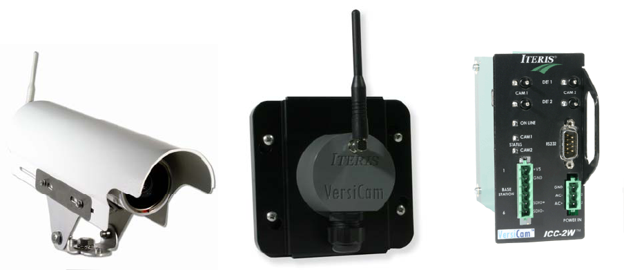
Figure1.1(a)MajorcomponentsoftheVersiCamWirelessSystem(Camera,BaseStationandICC‐2W)
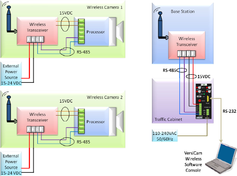
TheVersiCamsystemiscomposedoftheICC‐2Wmodule,theBaseStationandtheoneortwoCamera
Processorunits.UnliketheVantageEdge2,theprocessorisintegratedintothecameraassembly.The
ICC‐2Wmoduleisrackmountableorcanbeshelfmountedusinganavailableenclosurejustlikean
Edge2processormodule,however,itonlyprocessescommunications,providescontactclosureoutputs
andprovidespowertotheBaseStation.TheICC‐2WmodulehastwooutputchannelsperCamera
Processorunitthatcanbeassignedtoanyoftheeightdetectionzones.Communicationandpowerare
interfacedfromtheICC‐2WmoduletotheBaseStationbyanIMSA39‐2or40‐2,2pairstranded,
19AWGmulticonductorcable.CommunicationsfromtheICC‐2W/BaseStationtotheCameraProcessor
unitsisachievedbywirelessradiointhe2.4GHzbandwidth.PowerfortheCameraProcessorunitis
providedlocallyatthepole.TheCameraProcessorunitrequires24VDC.Iterisprovidesanumberof
powersuppliesthatcanconverthighvoltage(115‐240v50/60Hz)orsolarchargedbatterypower
(12VDC)tothe24VDCrequired.
AnotherinnovationistheintegrationofthecameraZoomandFocusoperationsintotheCamera
Processorunit,thuseliminatingtheneedforatraditionallensadjustmentmodule(LAM).Thisallowsthe
cameraZoomandFocusoperationstobeperformedfromthecabinetusingaPCrunningtheVersiCam
WirelessSoftwareConsole.Theinstallerwillnolongerneedtomakeuseofthedarkfocusingfilm(filter)
orweldersglasstoopenthecamerairisduringthefocusingprocedure.VersiCamWirelessopenstheiris
electronicallyandautomaticallyduringthecamerafocusingprocess.Thesefunctionsandprocedures
willbedescribedindetailinthefollowingsectionsofthismanual.
2
TheinterfacetotheCameraProcessorunitisutilizestheVersiCamWirelessSoftwareConsole.Thissuite
ofapplicationsprovidesetupandconfigurationofthesystemfromaPC.TheConsolecontainsfour
applications:
• NetworkSetupTool
• CameraSetupTool
• VRAS(VantageRemoteAccessSystem)
• WiVersiCamSoftwareUpgradeTool
Figure1.1(b)SystemBlockDiagram
3

4
1.2 Features and Benefits
Features
• CameraHousing
o StateoftheartCCDcamerawithfull10Xopticalzoom,auto‐iris,auto‐focusandauto
exposure
o SealedhousingtoIP67specification
o Integratedadjustablesunshield
o Internalheaterwithproportionalpowercontrol
o Integratedmountingbracket
• Cameraprocessor
o Storesthreedetectorconfigurations
o Setupprogramandmenu
o Vantagevideodetectionalgorithms
o Eightvirtualdetectionzones
• ThewirelessICCmodule
o Cansupporttwocamerassimultaneously
o Twodetectionoutputseachforatotaloffouroutputs(TS‐1)
• Upto1000feetrangewithclearlineofsiteusing2.4GHzdigitalwirelesscommunication
• Onlypowerconnectionneededforcamera(2wires)
Benefits
• Veryeasytouseandinstall
• Wirelessvideoconnectivity—nomorepullingco‐axialcablestoeachcamera
• Wideanglelensenableslowermountingheightsatornearthestopbar
• Focusandzoomcanbeadjustedfromtheground
• Supportslowcontrastzonesforhandlingoffoggyorlowcontrastconditions
• Builtupontimeandfield‐testedvehicledetectionalgorithmsoftheEdgefamilyofproducts

5
2 System Installation Information
2.1 System Requirements
TheVersiCamWirelesssystemusesasuiteofsoftwareapplications,TheVersiCamWirelessConsole,for
setupandconfigurationofthesystem.TheseapplicationsrunonaWindowsPC.
PC Minimum Requirements
• PentiumIII1GHzIntelprocessor
• 512MBRAM
• AGPvideocardwith64MBofmemory
• 100MBminimum,250MBrecommendedfreehard‐drivespace
• CD‐ROMreader
• MouseandKeyboard
• 15”monitorwithatleast(800x600)resolutionand16bitcolor
• RS‐232SerialPort
Operating System and Software
• WindowsXPwithServicePack3(minimum)
• WindowsVistawithServicePack1
• Windows2000withServicePack4
• VersiCamWirelessConsoleversion1.0(fromIteris)
o NetworkSetupTool
o CameraSetupTool
o VRAS(VantageRemoteAccessSystem)
o WiVersiCamSoftwareUpgradeTool
2.2 Tools and Equipment
Tools
• ASmallSlottedScrewdriver
o ForterminatingthewirestoconnectorsontheICC‐2WmoduleandbackoftheCamera
Processorunit.
• ARegularSlottedScrewdriver
o ForadjustingthescrewsontheCameraProcessorunitsunshield.Foradjustingthe
clampstorotatetheCameraProcessorunithousingbody.
• WireStrippersfor19AWGWire
• Forstrippingtheinsulationonthemulticonductor19gaugestrandedwire.
• WireCutters
o Forcuttingmulticonductorcableandmulticonductorwire.
• AdjustableWrenchandNutDrivers
o Foradjustingthecamerabracketbolts9/16"and3/4".Foradjustingthesunshield
screws5/16"orslottedscrewdriver.
• BandingTool
o ForsecuringthebandingmaterialwhenmountingtheCameraProcessorunitbracketto
themastarmorsignalpole.
• FishTape(Non‐Conductive)
o Forpullingmulticonductorcable.
• HoleSaw
o Fordrillingthepolearmwherethemulticonductorcableexitsthepole.Alwaysusea
cablestrainrelieftoavoidcuttingthecableandtoprovidethenecessarysupportforthe
cablewhereitexitsthepole.
Equipment
• IMSA39‐2/40‐2,3PairStranded,19AWG(Example:Belden581718)
o ForconnectionsbetweenICCmoduleinthecabinetandCameraProcessorunitinthe
field.Seethecablespecificationsheetinthebackofthemanualformoreinformation.
UsingincorrectcablingmayseverelyjeopardizeVersiCamsystemperformance.Seethe
detailedcablespecificationformoredetails.
• StainlessSteelBandingMaterial(Nothoseclamps)
o FormountingtheVersiCamCameraProcessorbrackettothemastarmorsignalpole.
• CableStrainReliefSuitableforIMSA39‐2/40‐2strainrelief.
• MiscellaneousSupplies:ElectricalTape,TieWraps
6
3 System Installation
TheVersiCamWirelesssystemiscomposedofthreedistinctcomponents,theCameraProcessorunit,
theICC‐2WmodulewhichislocatedinthetrafficcontrolcabinetandaBaseStationwhichislocatedon
thesignalpolenearestthetrafficcontrolcabinet.TheBaseStationandtheICC‐2Wmodule
communicateovertwistedpaircable.ThecabletransmitsdataandprovidespowerfromtheICC‐2W
moduletotheCameraProcessorunit.APCisrequiredtoinstallandconfigurethesystem.Asuiteof
applicationsisprovidedtosetupthenetwork,settheFieldofViewandconfiguretheCameraProcessor
unit.
3.1 The Camera Processor Unit
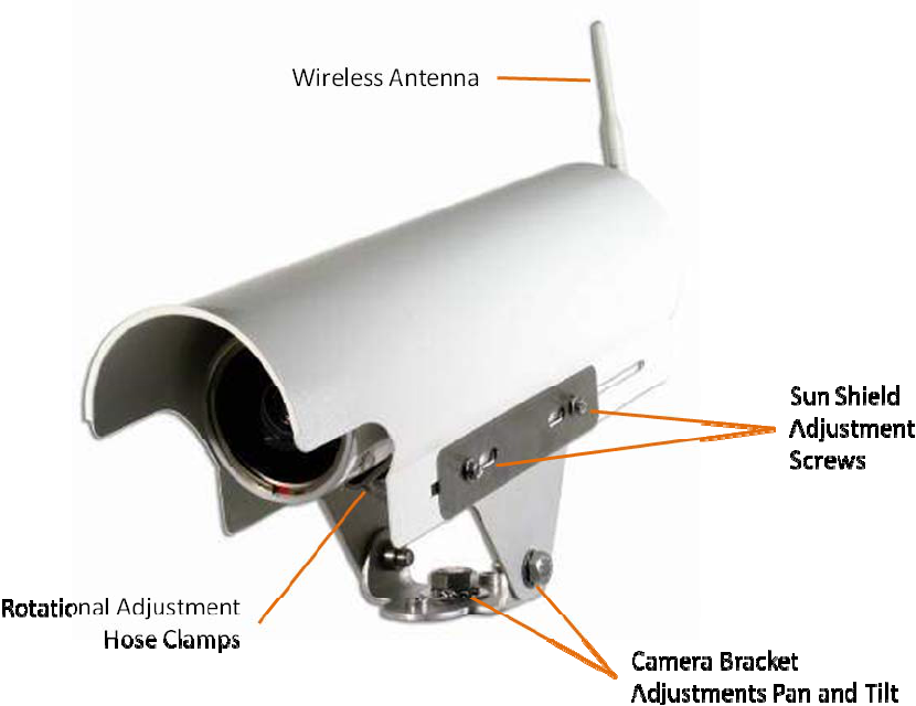
Figure3.1(a)CameraProcessorUnit
TheCameraProcessorunitintegratesthecameraandvideoprocessorintoone.Communicationsdata
aresentbacktotheICC‐2Wviathewirelessmodulemountedinsidethebackcap.
7
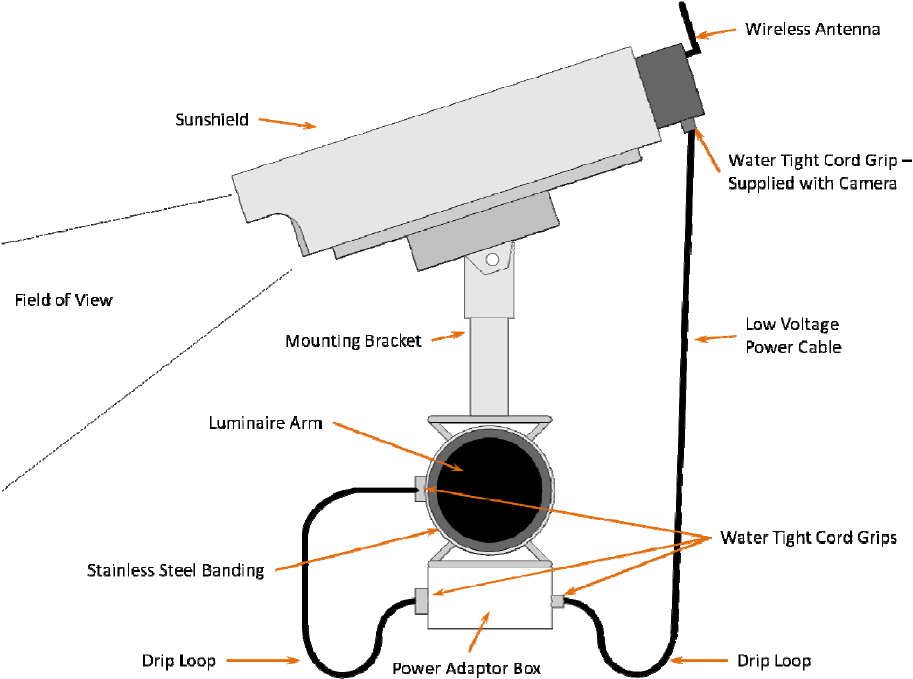
3.1.1 Camera Processor Unit Mounting
Thephysicalcameramountingisdoneusingacamerabracketthatisbandedtotheluminairearmor
canbemountedonthemastarmusingasuitableextensionbracket.
Figure3.1.1(a)
Onepossiblecameramountinglocationisupontheluminairearmcenteredoverthefieldofview,
however,itisnotalwayspossibletousethismounting.Cameramountingiscriticaltoprovidingthe
properfieldofview.
Note:Duringtheinstallationofthecamerasitisimportanttonotetheserialnumberofthecamerafor
eachapproach.Theserialnumberwillbeusedastheinitialidentifierfornetworksetup.
Mountthecamerabrackettothepolearmusingstainlesssteelbandingmaterial.Donotusehose
clamps,theytendtoloosenovertimeandmayresultinthecameramovingandslippingonthepole.
Theluminarearmorsignalmastarmaretypicalmountinglocations.Ifyouareunsureofthebest
mountinglocationcontactyourlocalIterisdealerorcallIterisProductSupportforrecommendationson
optimalcameramountingforyourapplication.
8
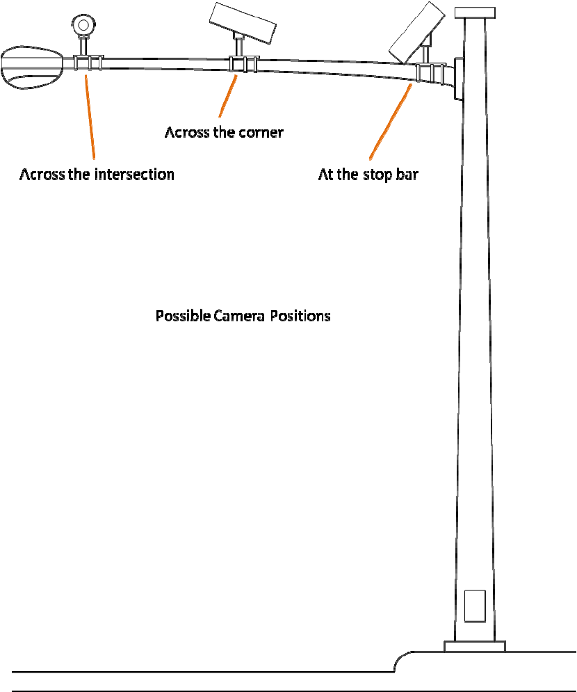
Figure3.1.1(b)LuminaireArmMountingPositions
9
10
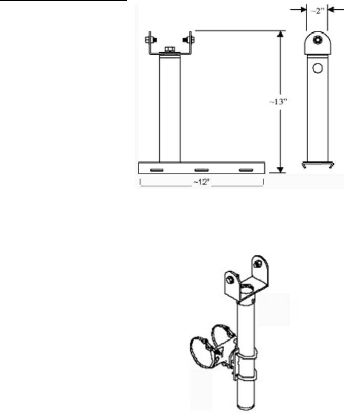
CameraMountingBrackets
IterisUniversalCameraMountingBracket,seeFigure3.1.1(d),CAMBRKT4
ac"74inchCameraExtensionBracket,seeFiguree3.1.1(e),AB‐0175‐5‐96‐ALO(Mast
orwithoutserviceoutlet.
ontact your local PELCO dealer for more information on these brackets.
Figure3.1.1(d)
Figure3.1.1(e)
PELCO"AstroBr
ArmMounting)
PELCOhasseveralmodelsdependingonbandorcablemountingandwith
C
GeneralFieldofView(FOV)Considerations
TheVersiCamWirelesssystemdoesnotprovidelivevideotothecabinet.Allvideodetectionprocessing
isperformedintheCameraProcessorunit.DetectiondataissendtotheICC‐2Wtoactivatethe
appropriateoutputs.ThesystemprovidessnapshotsoftheFOVtofacilitatethesetupofthecamera,
pleaserefertoSection4.4formoredetailonFOVsetup.
fromdirectlyhittingthecameralens,especiallyon
ithtwolanedetectioncapability
• Enoughmountingheighttoavoidcrosstrafficocclusion
ional‘acrosstheintersection’locationsaswellason
olesnearthestopbarorattheadjacentcorner.
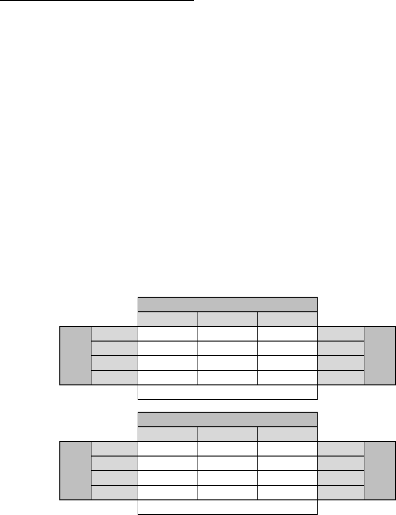
owingtablesdetailsmountingheightrequirementsforinstallationat
twoandthreelaneapproaches.
• NohorizonintheFOV
• Enoughcameraangletopreventsunlight
eastandwestfacingapproaches
• PreferredwidthofatleastthreelanesintheFOV,w
• Cameraviewcenteredovertheroadwayapproach
TheVersiCamWirelessCameraisequippedwithalensprovidingahorizontalfieldofview(HFOV)of85o.
Thispermitsthecameratobemountedintradit
p
Toprovideanacceptablefieldofviewthecloserthecameraistothestopbarthehigherthecamera
needstobepositioned.Thefoll
10' 13' 15'
19.5' 16.7' 14.5' 12.5' 12'
18' 15.0' 12.4' 9.9' 11'
16.5' 13.1' 10.2' 6.9' 10'
15' 11.2' 7.5' 0' 9'
LaneWidth
Camerato
StopBar
MountingHeights‐3LaneApproach
RequiredCameraSetbacks
10' 13' 15'
13' 8.3' 1.0' 0' 12'
12' 6.6' 0' 0' 11'
11' 4.6' 0' 0' 10'
10' 1.0' 0' 0' 9'
Camerato
StopBar
LaneWidth
RequiredCameraSetbacks
MountingHeights‐2LaneApproach
Note:
Thevaluesinthetablesaboverepresentthe‘minimum’camerasetbackforvariousmountingheights
andrequiredFOVwidths.Othervariationsarepossible.Thekeyistorememberthatforaccurate
detectionwheretheattainedcameraFOVcomplimentsthevehiclesizewherethealgorithmswill
performthebest,aminimumof3laneswidthsshouldbevisiblewhentakingasnapshotimageofthe
intersection.
11
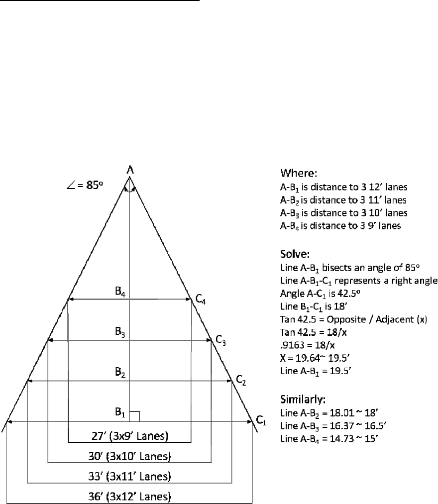
VersiCamCameraFieldofViewCalculations
Itispossibletocalculatethemountingheightnecessaryforanyinstallationusingthefollowingmath.
mof2of3trafficlanes.
.
5. MountingheightfordeterminingtheminimumcameratoROIdistanceis0’(worsecase).
dthenusingPythagoreantheoremwiththedesiredmountingheightsolvesforthecamera
etback.
Assumptions:
1. CameraHFOVisatmaximumWAadjustmentof85o.
2. MinimumHFOVimageshouldincludeaminimu
3. Typicaltrafficlanesare9’,10’,11’or12’wide
4. Cameramountingheightrangeis10’to15’.
Thisexampleisforthreetrafficlanes.
ObtainingtheCameradistancetotheRegionOfInterest(ROI)forvariousmountingheightssimplyuses
theFOV(0’MH)distancecalculatedpreviouslyandusesitasthehypotenuseofatriangleasdescribed
belowan
s
12
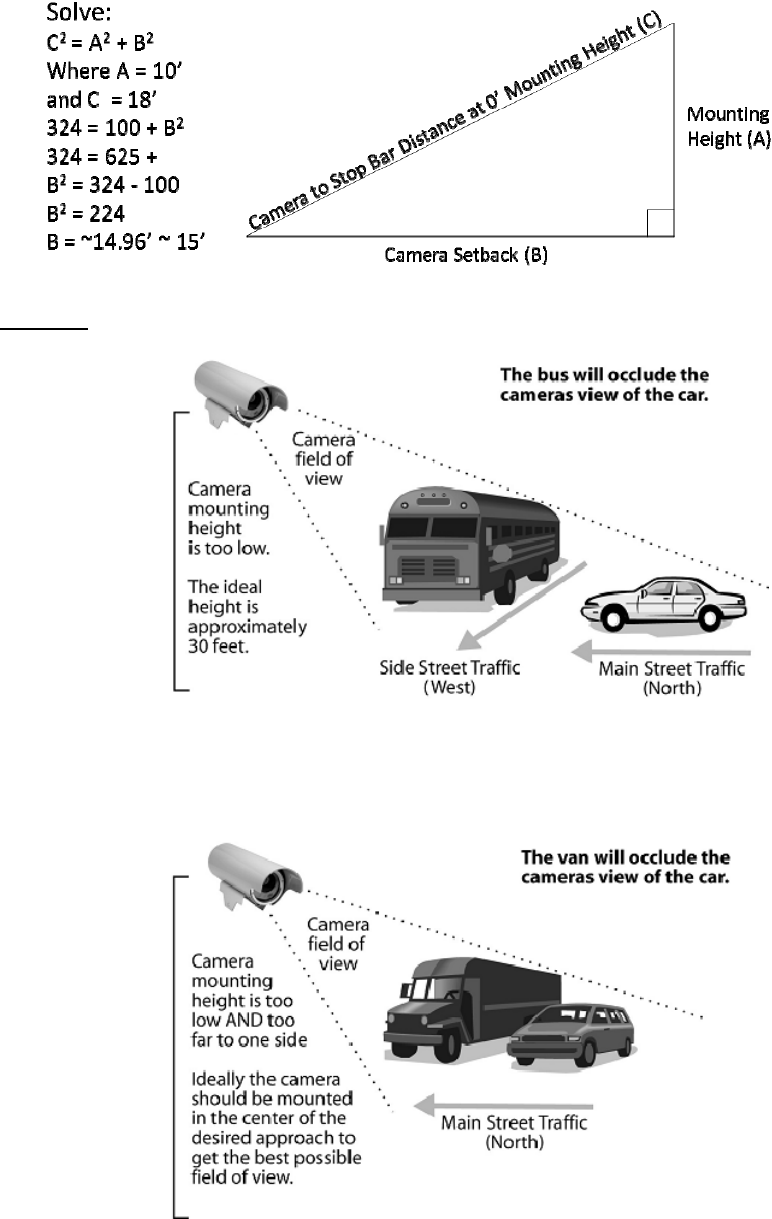
Occlusion
igure3.1.1(g)Examplesofocclusionproblems
Figure3.1.1(f)
F
13
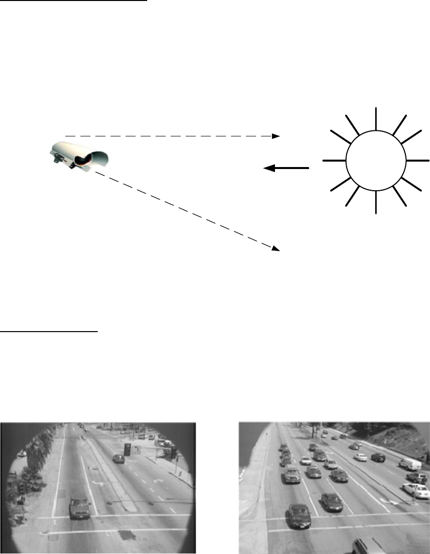
MaintainaProperCameraAngle
Thephysicalcameraadjustmentsaredonebyadjustingthecamerabracketmountingboltstosetthe
mechanicalcamerapanandtiltafterthecamerabrackethasbeenmountedtothearmorpole.The
camerashouldalwaysbetiltedslightlydownwardandshouldneverbeflatorbeyondhorizontal.When
couldacamerabeindangerofbeingbeyondhorizontal?Whenthecameraisaiminguphillonasteep
grade.Thedistancethecameracanlookoutissignificantlyreducedonapproacheswithasteepuphill
grade.
SUN
Bad
Good
The sun must never be
allowed to shine directly
into the camera.
This is especially
important on east and
west approaches.
The camera visor
should be pulled
forward as far as
possible without
being allowed to
obstruct the camera
field of view.
The camera should never be
flat or level. It should always
be angled downward.
Figure3.1.1(h)
Pullthevisorforward
Youshouldhavethecamerasunshield(visor)farenoughforwardtogivethecameramaximum
protectionfromthesun.Bylooseningthetwohoseclampsetscrews,thecamerabodycanbemoved
backwardintheclamps,effectivelylengtheningthesunshieldvisor.Movethecamerabodybackallthe
wayoruntiltheedgesofthesunshieldvisorarejustbarelyvisibleinthetopleftandrightcornersofthe
fieldofview.Seethefollowingexamples.
Figure3.1.1(i)Figure3.1.1(j)
untof
ToomuchcameravisorintheFOV Maximumacceptableamo
14
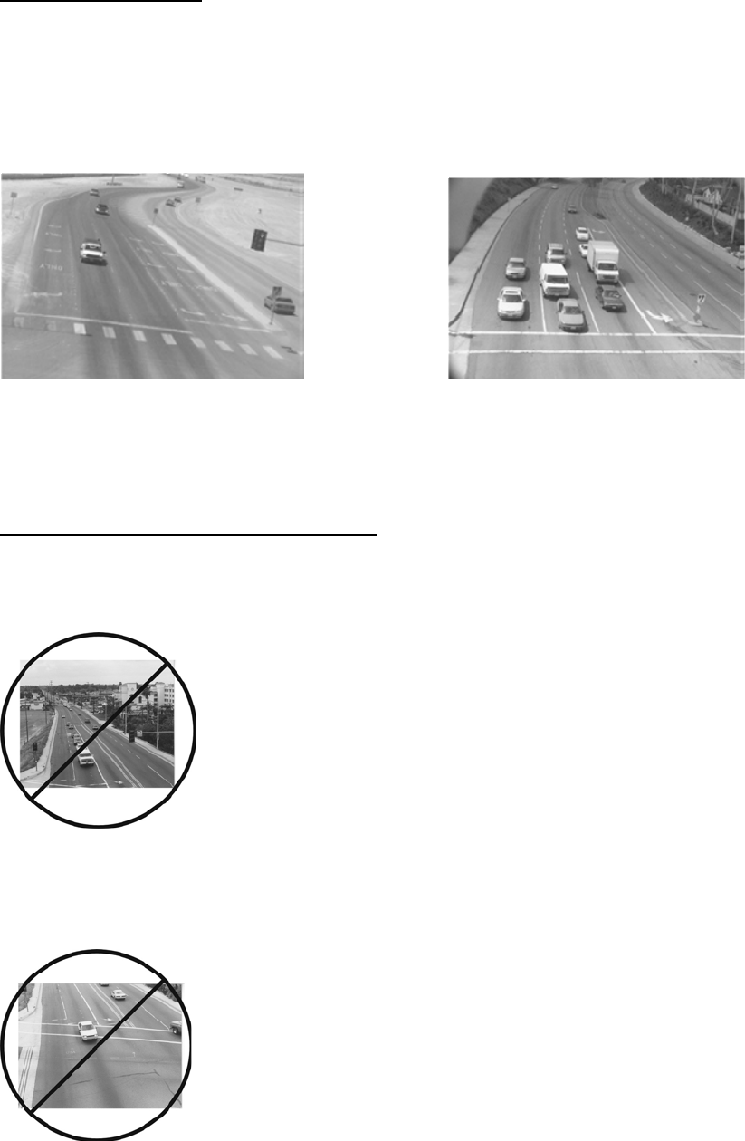
15
visorintheFOV
RotatetheCameraBody
seningthetwohoseclampsetscrews,thecamerabodycanrotatetobettersquare
uptheFOVimage.
Thecarbumpersshouldalsoendupbeingparallelwiththebottomofthescreen.
le
tohelpsquareupthestopbararea FOVandstopbarareaalignment.
Ideally,formostintersectionapplications,vehiclesshouldflowfromthetopofthescreentothebottom
ofthescreen.Byloo
Figure3.1.1(k)Figure3.1.1(l)
ThecamerabodycouldberotatedTheabovepictureshowsanacceptab
OtherImportantFieldofViewConsiderations
1)MakesurethatthereisnohorizonintheFOV.ThiscanresultinseriousoperationalproblemsforEast
orWestapproaches.Why?Becauseofthesun!Duringsunriseorsunsetthesuncancompletelyblind
adjustment,andcameratiltcanpreventthispotentialproblem.
PoorSetup‐HorizonIsIncludedAsPartofTheFieldofView(FOV)
xamplephotoshowsthestopbararealocatedinthemiddleof
theFOV,whichisnottheideallocation.
PoorSetup‐StopbarAreaIsInTheMiddleofTheFieldofView(FOV)
Figure3.1.1(n)
visorthecamera.ProperFOV,
Figure3.1.1(m)
2)MakesurethestopbarareaislocatedtowardthebottomoftheFOV.Thiswillalsoleaveroomfor
advancezonedetection.Thefollowinge
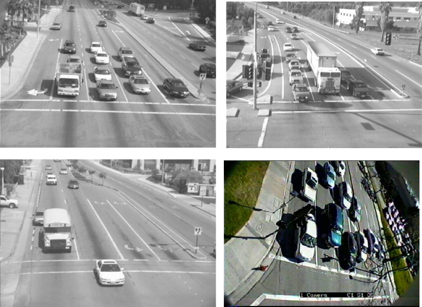
Figure3.1.1(o),ExamplesofGoodFieldsofView
3.1.2 Camera Processor Power Requirements
TheCameraProcessorrequiresaDCvoltageofbetween15vdcand24vdcforcorrectoperation.This
powersourceisprovidedlocallyatthecamera.IterisofferstwoPowerAdaptorModules;onewhich
canconverthighacvoltage(110‐240v)downto24vdc,theothercanconvertlowdcvoltage(12v)to
24vdc.Bothmodulesareprovidedwithapolemountingbracket.
3.1.3 Camera Processor Unit Wire Terminations
Whenconnectingthecameratoasuitablepowersourceuseafieldapprovedcable.IMSA39‐2/40‐2or
similarissuitableforusewiththeVersiCamWirelesssystem.Ifusingamulti‐corecableonlytwo
conductorsareneededforpowerconnection.Carefullystripthecableouterjackbackapproximately
fiveinches(125mm),seeFigure3.1.3(a),withoutnickingordamagingtheinsulationonthewirepairs
inside.Scoringtheouterjacketlightlywithasharpknifeandbendingtheouterjacketsheathbackand
forthuntilitpartsisthesafestmethod.Ifthecableisshieldedremovetheshieldandtheplasticcore
wrapflushwiththeouterjacketbeingcarefulnottodamagethewires.Separatethewiresandstrip
eachofthewire’sinsulationbackapproximately¼”(6mm).Ifyouareusingacablewithmorethantwo
pairscuttheunusedpairsshorttoavoidthepossibilityofshortingoutinsidethecap.
16
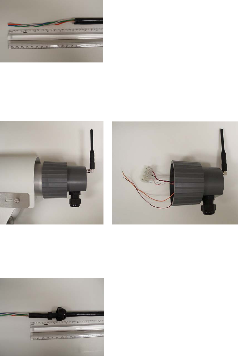
Figure3.1.3(a)
ToseparateandremovethebackcapassemblyformthebackoftheCameraProcessorunit,loosenthe
cameravisorscrewsandmovethesunshieldtoitsextremeforwardposition.Graspthebackcap
assemblyfirmlyandtwistitapproximatelyonequarterturncounterclockwisetofreethethreeposts
fromtheirdetentpositionintheslotsandallowthecapassemblytobepulledfreefromthebackofthe
CameraProcessorunithousing,seeFigures3.1.3(b)and(c).
Figure3.1.3(b) Figure3.1.3(c)
Removethecablecordgripcapandgrommetfromtheassemblybyunscrewingit.Installthegrommet
andcaponthecableandpushthepreparedcablethroughthecordgripbodyapproximately1½inches,
seeFigure3.1.3(d).
Figure3.1.3(d)
17
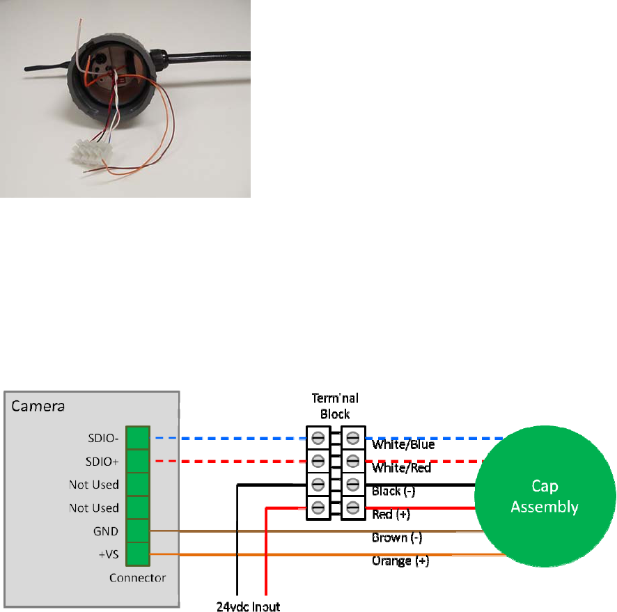
Re‐assemblethecordgrip.Afterthecordgripissecurelyinstalledbackonthecapassemblytightenthe
nutdownuntiltheinnergrommetfirmlygripsthecablebody,seeFigure3.1.3(e).Handtightisusually
sufficient.
Figure3.1.3(e)
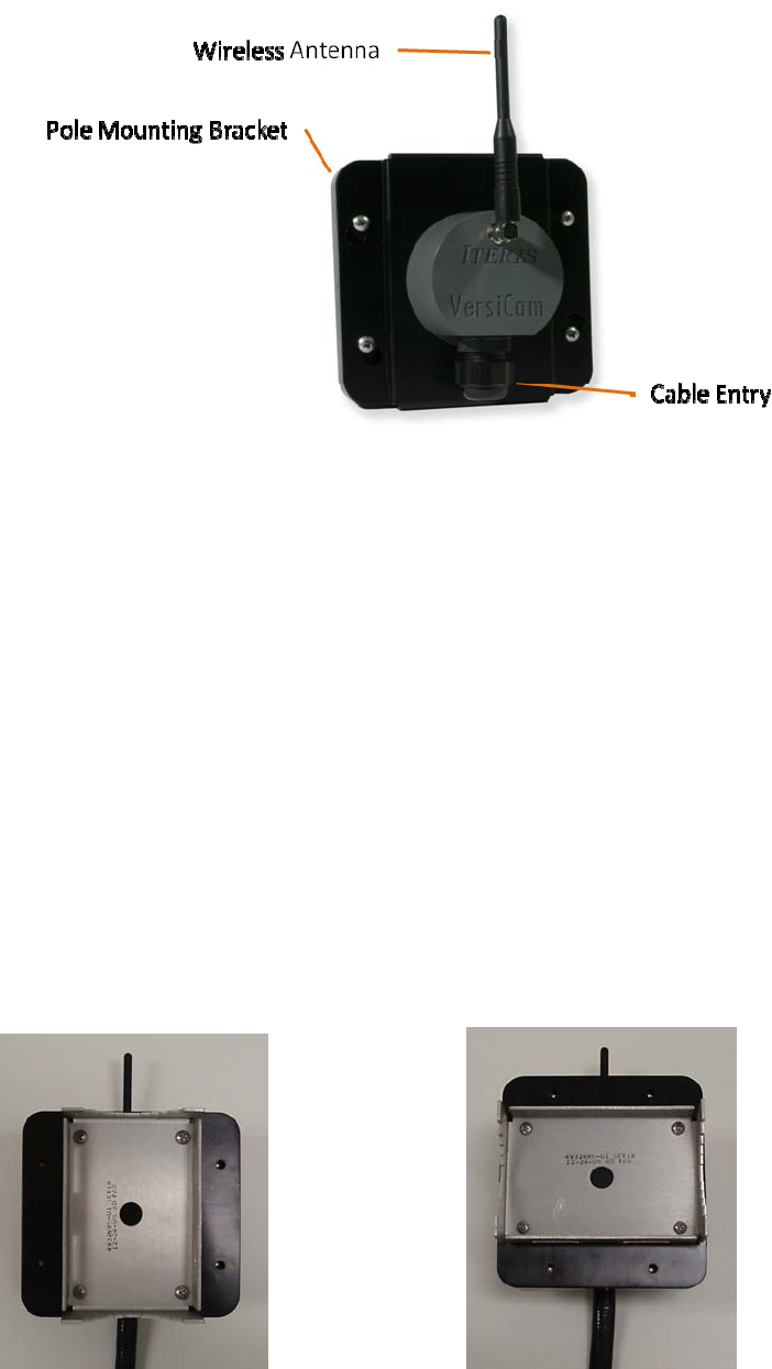
TherearetwoplacestoconnecttoontheCameraProcessorunit,awhitefourwayterminalblockanda
sixwayconnector,seeFigure3.1.3(f).Connectthetwoincomingwiresfromthepowersource(24vdc)
totheredandblackconnectionsontheterminalblock.Ensurethecorrectpolarity,redispositiveand
blackisnegative.ConnecttheorangeandbrownwiresfrominsidethecapassemblytotheGNDand
+VSconnectionsontheconnector.Ensurethecorrectpolarity,orangeispositiveandbrownisnegative.
Usingjumperwire,connectSDIO‐(white/bluewire)tothecorrectpinontheconnectorandtheSDIO+
(white/red)tothecorrectpinontheconnector,seeFigure3.1.3(g).
Figure3.1.3(f)
18

Figure3.1.3(g)
PlugtheconnectorintothesocketonthebackoftheCameraProcessorunit,seeFigure3.1.3(h),the
connectoriskeyedandcanonlypluginoneway.
Figure3.1.3(h)
19
Aligntheslotsinthebackcapassemblywiththethreepostson
theCameraProcessorunit.Gripthecapassemblyfirmlyandpush
itintoplace.Whenthethreepostsarefullyseatedgivethecapa
quarterturnclockwisetofullysecureittotheCameraProcessor
unit.Ensurethatthewiresarenot‘pinched’betweenthecapand
theCamerabody.Turnthebackofthecapassemblysothatthe
antennaispointedstraightup,seeFigure3.1.3(i).
Theantennaissuppliedintheshipkit.Itismountedbyscrewing
totherightanglebracketonthecapassembly.
Pullthecamerasunshieldbackandsnugdownthecamera
bracketsetscrews.Finaladjustmentofthesunshieldwillbedone
laterduringtheFieldOfView(FOV)setupprocedure.
Figure3.1.3(i)
3.2 The Base Station Unit
TheBaseStationisthewirelessinterfacebetweentheICC‐2WandtheCameraProcessorUnit.Itis
mountedonthepoleormastarmnearesttheTrafficControlCabinet.Itshouldbesitedsuchthatthere
isclearlineofsightbetweentheBaseStationandeachoftheCameras.
3.2.1 Base Station Unit Mounting
ThephysicalBaseStationmountingisdoneusingthemountingbracketprovided.TheBaseStation
shouldbebandedtotheluminairearmorcanbemountedonthemastarmusingasuitablebracket.
TheBaseStationshouldbemountedtothepoleclosesttotheTrafficControlCabinet.Itshouldbesited
suchthatthereisaclearlineofsightbetweentheBaseStationandeachoftheCameras.
Note:Thereshouldbeaminimumdistanceof3’(1meter)betweentheBaseStationandeitherofthe
Cameras.ThisisnecessaryinsituationswheretheBaseStationandCameraarebothmountedonthe
poleclosesttotheTrafficControlCabinet
TheBaseStationcanbemountedeitherhorizontallyorvertically,seeFigures3.2.1(a)and(b).Oncethe
BaseStationismountedandwiringcompletedthecapassemblyshouldbeturnedsotheantennais
pointingdirectlyup.
Figure3.2.1(a) Figure3.2.1(b)
20
3.2.2 Base Station Unit Wire Terminations
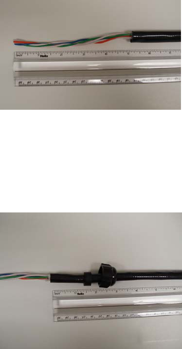
TwotwistedpairsrequiredforconnectionbetweentheBaseStationandtheICC‐2W.TheseareDC
powerandcommunications.Usingtheappropriatecable(anIMSA39‐2shieldedcableis
recommended),carefullystripthemulticableouterjackbackapproximatelyfiveinches(125mm),see
Figure3.2.2(a),withoutnickingordamagingtheinsulationonthewirepairsinside.Scoringtheouter
jacketlightlywithasharpknifeandbendingtheouterjacketsheathbackandforthuntilitpartsisthe
safestmethod.Cutthecorrugatedcoppershieldandtheplasticcorewrapflushwiththeouterjacket
beingcarefulnottodamagethewirepairs.Separatethewirepairsandstripeachofthewire’s
insulationbackapproximately¼”(6mm).Ifyouareusingacablewithmorethantwopairscutthe
unusedpairsshorttoavoidthepossibilityofshortingoutinsidethecap.
Note:Ifwirepairsarenotuniquelycolorcodedormarkedbesuretolabelornumberthepairsaheadof
timesotheycaneasilybeidentifiedattheotherend.Useofmismatchedpairsandwirescanleadto
installationissuesandpossibledamagetotheVersiCamequipment.Alsomakeanoteofwhichwire
pairsarebeingusedforwhatpurposei.e.,power,communication.
Figure3.2.2(a)
TheBaseStationassemblyisprovidedfromthefactorypartlyassembled.Removethecapassembly
fromthebaseassemblybyturningthecapassemblysothescrewheadsinthebasealignwiththe
keyhole.Removethecordgripcapandgrommetfromtheassemblybyunscrewingit.Installthe
grommetandcaponthecableandpushthepreparedcablethroughthecordgripbodyapproximately1
½inches,seeFigure3.2.2(b).
Figure3.2.2(b)
21
Re‐assemblethecordgrip.Afterthecordgripissecurelyinstalledbackonthecapassemblythightenthe
nutdownuntiltheinnergrommetfirmlygripsthecablebody,seeFigure3.2.2(c).Handtightisusually
sufficient.
Figure3.2.2(c)
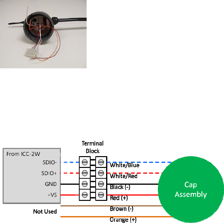
Nextconnecttheincomingwiretothefourwayterminalblockonthecapassembly.Connecttwowires
fromthepowersource(24vdc)totheredandblackconnectionsontheterminalblock.Ensurethe
correctpolarity,redispositiveandblackisnegative.Connecttwowiresfromthecommunications
(SDIO‐and+).Ensurethecorrectpolarity,white/redisSDIO+andwhite/blueisSDIO‐.Cuttheunused
orangeandbrownwirestoensuretheydonotshortoutinsidethecapassembly.SeeFigures3.2.2(d)
and(e).
Figure3.2.2(d)
22
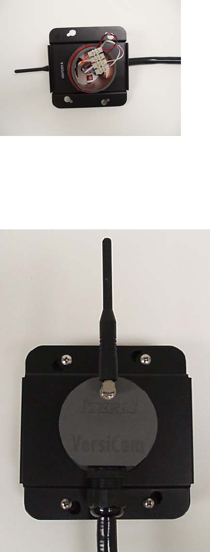
Figure3.2.2(e)
Re‐assemblethecapontothebasebutaligningthescrewheadswiththekeyholesandturningthecap
assembly.Tightenthefourscrewstoensuretheassemblyisproperlysealedfromtheelements.Turn
thecapassemblyuntiltheantennaispointedstraightup,seeFigure3.2.2(f).
Figure3.2.2(f)
Theantennaissuppliedintheshipkit.Itismountedbyscrewingtotherightanglebracketonthecap
assembly.
23
3.3 The ICC-2W Module
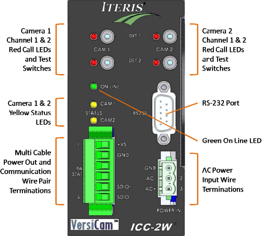
Figure3.3(a),TheICC‐2WModule
TheICC‐2WModuleisthecabinetinterfacetotheCameraProcessorUnit.ItprovidespowertotheBase
Stationandreceivesdata.Itplacesthedetectioncallsinthedetectorrackorinputfile.Thefollowing
sectiondefinessomeofthefeaturesofthemodule.
GreenOnLineLED–thisindicationshouldalwaysbeilluminatedwhentheICC‐2Wmoduleisoperating.
FailureoftheOnLineLEDtoilluminatewhenappropriatepowerisappliedindicatesaproblemwiththe
ICC‐2Wmodule.
24

25
YellowStatusLEDs–thisindicationhasfourmodestoshowcurrentoperatingstatusofthesystem.
SeeFigure3.3(b)foradescriptionofthedifferentstates.
StateDescription
OffNocameraisassignedtothischannel
OnCameraandcommunicationsaregood
SlowBlinkNocommunicationwithcamera
FastBlinkCommunicationwithcamera,novideoforsystemtoprocess.
Figure3.3(b)
BaseStationConnection–this6wayconnectorisforconnectionoftheICC‐2WModuletotheBase
Station.Forfieldinstallationonly4pinsareused;VS,GND,SDIO+andSDIO‐.Thetwocenterpinsare
notused.
ACPowerConnection–theICC‐2WModulerequires120vacor240vac.Ifpowerisnotavailableonthe
detectorrackbackplaneoronly240vacisavailablethenpowershouldbeconnectedhere.
Channel1&2CallLEDs–theseindicators,twoforeachcamera,shouldilluminatewhencallsarebeing
placedtotheoutputsoftheICC‐2WModule.Theyrepresentopencollectoroutputstriggeredbythe
detectionzonethatthechannelitisassociatedwith.
Channel1&2TestSwitches–thesetoggleswitcheshavethreepositions.Thedefaultpositionisinthe
centerandisthepositiontheyshouldbekeptinduringnormaloperation.Theswitchcanbepushedup
toplaceamomentarycall(contactclosure)ontheoutputchannelorcanbepusheddowntoplacea
constantcallontheoutputchannelfortestingortroubleshootingpurposes.Whentestingiscomplete
besuretorestoretheswitchtothecenterpositionfornormaloperation.
RS‐232Port–thisserialportisusedtocommunicatewiththesystem.ItisconnectedtoaPCforuse
withtheVersiCamWirelessSoftwareConsole.
3.3.1 ICC-2W Module Configuration Switches
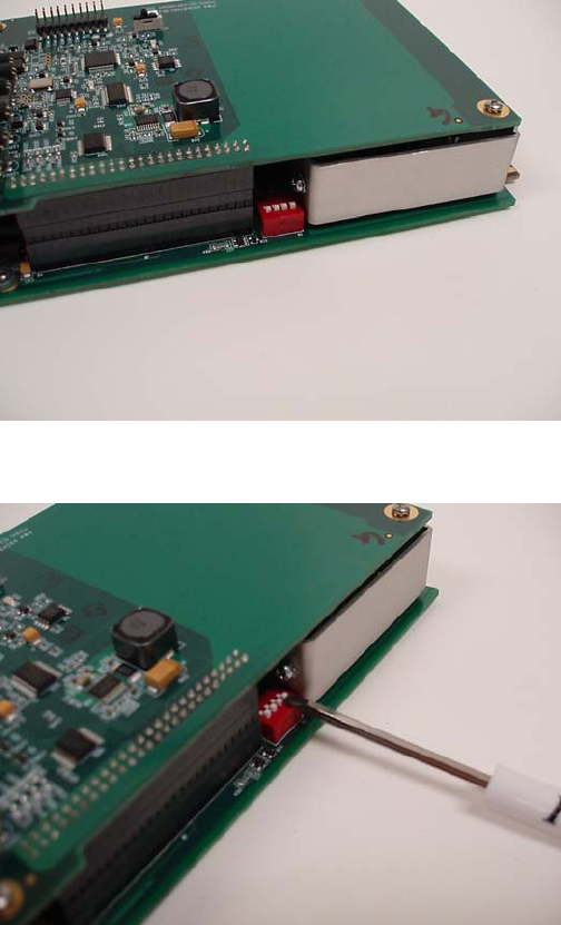
ThereisasetofconfigurationDIPswitcheslocatedonthetopedgeofthelowerboardoftheICC‐2W
Module,seeFigure3.3.1(a).TheseswitchesareusedtoconfiguretheICCmoduleforuseinaNEMATS‐
2typedetectorrack.Allswitchesshouldbeinthe“ON”position(towardsthecardedge)foruseinaTS‐
2typedetectorrack,seeFigure3.3.1(b).ForotherracktypestheDIPswitchesshouldremaininthe
“OFF”position(awayfromthecardedge).Thepositionoftheseswitchesforoperationinracksother
thanaNEMATS‐2isnotcritical.
Figure3.3.1(a)
Figure3.3.1(b)
26
3.3.2 ICC-2W Module Wire Terminations
Theotherendofthemulti‐corecableusedtoconnecttotheBaseStationconnectstotheICC‐2W.
Carefullystripthemulticableouterjackbackapproximately2½inches(65mm),withoutnickingor
damagingtheinsulationonthewirepairsinside.Scoringtheouterjacketlightlywithasharpknifeand
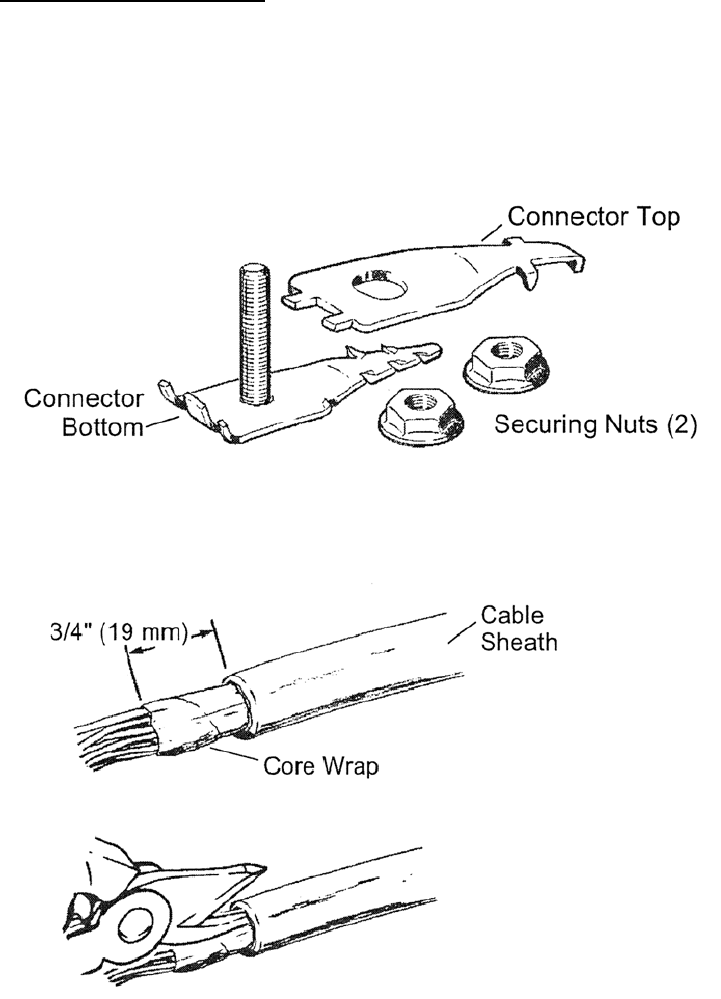
bendingtheouterjacketsheathbackandforthuntilitpartsisthesafestmethod.Installthegroundlug
usingthemethoddescribedbelow.
InstallationofGroundingLug
TheScotchlokTM4460‐DShieldConnectorisdesignedtomakeastableandlowresistanceelectrical
connectionbetweencommunicationcablesof.80"diameterorless(100pair,24ga.andunder)anda
conductorsuchasastrap,wireorbraid.Thefollowingsectioncoversinstallingthegroundinglugonthe
cabinetsideofthemulti‐conductorcable.A3/8”TerminalWrenchandTabbingShearsarerequiredfor
installation.
27
Figure3.3.2(a)ConnectorComponents
Figure3.3.2(b)CablePreparation.
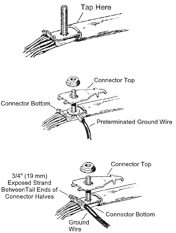
Note:Allcablesmustbetabbedwitha1”(25mm)slitonthesideofthesheathoppositetheconnector,
toeaseinsertionandtoavoidconductordamage.
Insertconnectorbasebetweenshieldandcorewrap,seeFigure3.3.2(c),untiltheconnectorstopsmeet
outersheath.Tapsheathaboveconnectorbasetosetconnectorteeth.
28
Figure3.3.2(c)
Figure3.3.2(d)PreterminatedGroundWire
Figure3.3.2(e)ExposedStrand
Note:Besurethattheinsulationofthegroundwireisnotpinchedbetweentheconnectorhalves.
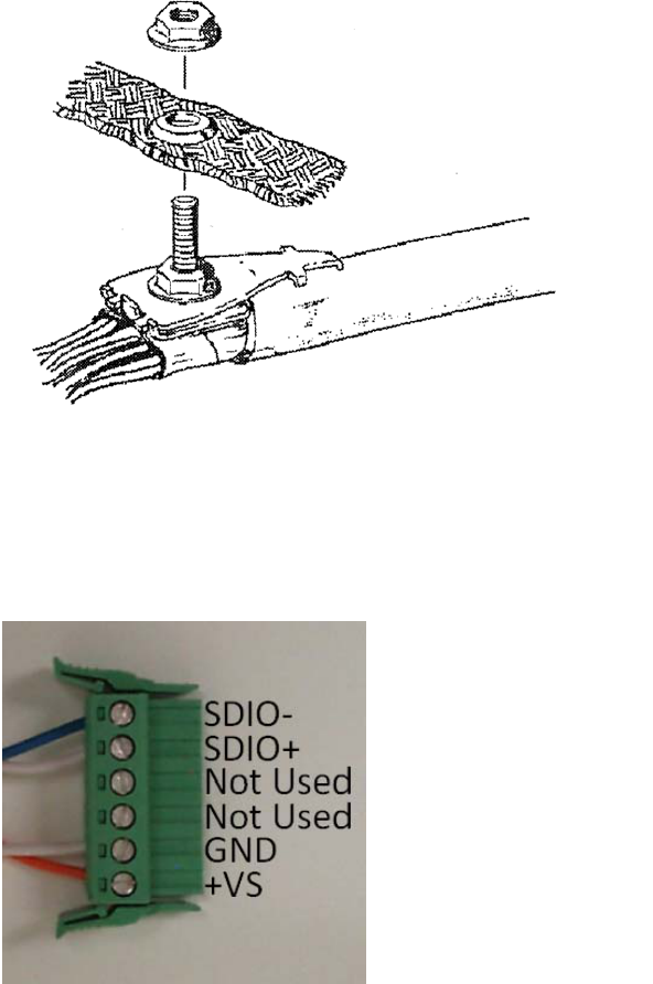
Ifbondbraidoradditionalgroundingorbondinghardwareisused,installitabovethefirstnutand
secureitwiththeadditionalnut,seeFigure3.3.2(f).
29
Figure3.3.2(f)AdditionalGrounding
Afterinstallingthegroundinglug,separatethewirepairsandstripeachofthewire’sinsulationback
approximately¼”(6mm).Ifyouareusingacablewithmorethantwopairscuttheunusedpairsshort
toavoidthepossibilityofshortingout.Installthewiresonthe6wayconnector,seeFigure3.3.2(g).
Figure3.3.2(g)
3.3.3 ICC-2W Module AC Power Requirements
TheICC‐2WModulerequiresACpower(100‐240vac50/60Hz)whichcanbesuppliedbytheconnector
onthefrontpanelorcanbesuppliedfromthebackplaneontherack.Powertothebackplaneis
suppliedonpinsL,MandN,seeFigure3.3.3(a).
BackPlanePins120VAC
LChassisGround
MAC–Neutral
NAC+Hot
Figure3.3.3(a)
Note:thebackplaneconnectionisonlysuitablefor120vmaximum.
Ifyouhavea240vsourceusethepowerconnectoronthefrontpanel.IfACpowerisavailablefromthe
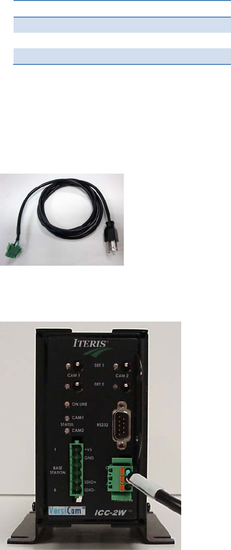
rackthefrontpanelconnectorisdisabled.IftherackdoesnotprovideACpowerusethepre‐wiredAC
powercord,seeFigure3.3.3(b).
Figure3.3.3(b)
Plugthegreen3pinconnectorintothesocketonthefrontofthemodule,seeFigure3.3.3(c).Plugthe
cordintoasuitable120vor240vsource.
Figure3.3.3(c)
30

31
3.3.4 ICC-2W Module Installation
TheICC‐2WmoduleisdesignedtobeinstalledinastandardNEMATS‐1orTS‐2detectorrackorina
standard332cabinettypedetectorinputfile.Totherack,theICC‐2Wmodulelookslikeafourchannel
detectorloopamplifier.ThoughtheICC‐2Wmodulefootprinttakesuptworackspaceslikeafour
channelloopamplifier,theoutputboardedgeconnectoronlyplugsintooneofthedetectorrackslots–
theslotontheright.Thisslotiswherethefourlogiclevelcontactclosureoutputswillbeplacedandwill
callthephaseorphasesassociatedwiththatdetectorslot.WhereyouplugtheICC‐2Wmoduleinthe
detectorrackwilldeterminewhatphasesitwillcallwhenthedetectionzoneassociatedwiththat
channelisactivated.
TheICC‐2Wmoduleoperateson120‐240VAC,realizethatthemodulealsorequires12or24VDCfrom
thedetectorrackoroutputfiletooperateifyouarebringingACintothefrontofthemodule.Having
correctlyterminatedthepowerandcommunicationwiresfromtheBaseStationasdescribedinthe
previoussection,plugtheICC‐2Wmoduleintothedetectorrackoryoucaninstallthemoduleintoa
VantageVRack1forstandaloneoperation.MakesuretheICC‐2WmodulehasACpower(andDCpower
ifACpowerisbeingbroughtinthroughthefront).Makesurethecorrectpolarityhasbeenobservedon
DCandcommunicationswirepairs.TheICC‐2WmoduleshouldpowerupandthegreenONLINELED
shouldcomeonsolid.IfthegreenONLINELEDfailstoilluminatechecktheACpowerandpower
connections.IfthegreenONLINELEDstillfailstoilluminatecallIterisProductSupport.
ExternalSurgeProtection
Anexternalsurgeprotectiondeviceisavailableandisrecommendedforallinstallations.Seesection9.3
formoredetails.

4.0 System Setup
SystemsetupisachievedusingtheVersiCamWirelessConsole,seeFigure4.0(a).Thisprovidesaccessto
thethreeapplicationsnecessarytoinstallandsetupthesystemandafourthapplicationforfuture
softwareupgrades.
Theprocessforsettingupthesystemis:
EstablishtheWirelessNetwork–UsingtheNetworkSetupTool
AdjusttheCameraFieldofView–UsingtheCameraSetupTool
SettheSystemConfiguration–UsingVRAS
Figure4.0(a)
32
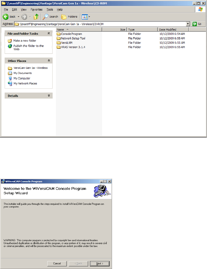
4.1 Installing the software on the PC
AllthesoftwarenecessarytosetupthesystemisprovidedonaCD‐ROM.InserttheCDintheoptical
drive.Therearefourfolders,seeFigure4.1(a),eachcontaininganapplication.Followthestepsbelowto
completetheinstallation.
Figure4.1(a)
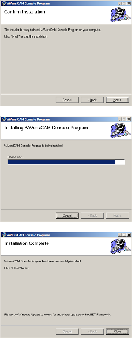
1. Openthe“ConsoleProgram”folderanddoubleclickonthe“setup.exe”file.Thesoftwarewill
begintoload.Followtheinstructionsonthescreen,seeFigures4.1(b),(c),(d)and(e).
Figure4.1(b)
33
34
Figure4.1(c)
Figure4.1(d)
Figure4.1(e)
2. Openthe“NetworkSetupTool”folderanddoubleclickonthe
“SetupForNetworkSetupTool.msi”file.Thesoftwarewillbegintoload.Followtheinstructions
onthescreen,seeFigures4.1(f),(g),(h)and(i).
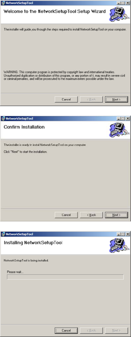
Figure4.1(f)
Figure4.1(g)
Figure4.1(h)
35
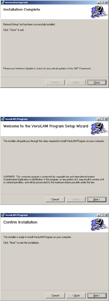
Figure4.1(i)
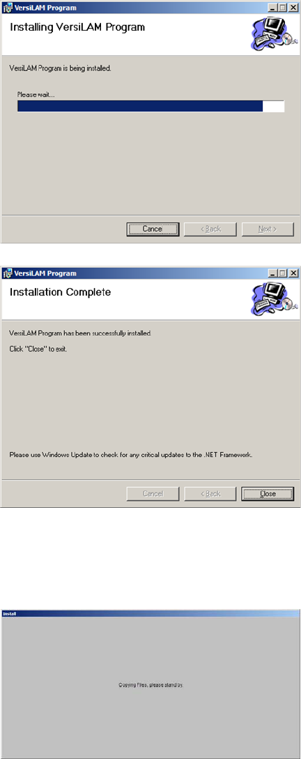
3. Openthe“VersiLAM”folderanddoubleclickonthe“setup.exe”file.Thesoftwarewillbeginto
load.Followtheinstructionsonthescreen,seeFigures4.1(j),(k),(l)and(m).
Figure4.1(j)
Figure4.1(k)
36
37
Figure4.1(l)
Figure4.1(m)
4. Openthe“VRASVersion3.1.4”folderanddoubleclickonthe“setup.exe”file.Thesoftwarewill
begintoload.Followtheinstructionsonthescreen,seeFigures4.1(n),(o),(p),(q),(r),(s)and
(t).
Figure4.1(n)
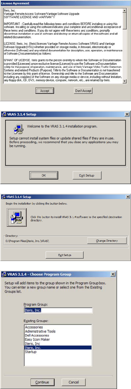
Figure4.1(o)
Figure4.1(p)
Figure4.1(q)
Figure4.1(r)
38
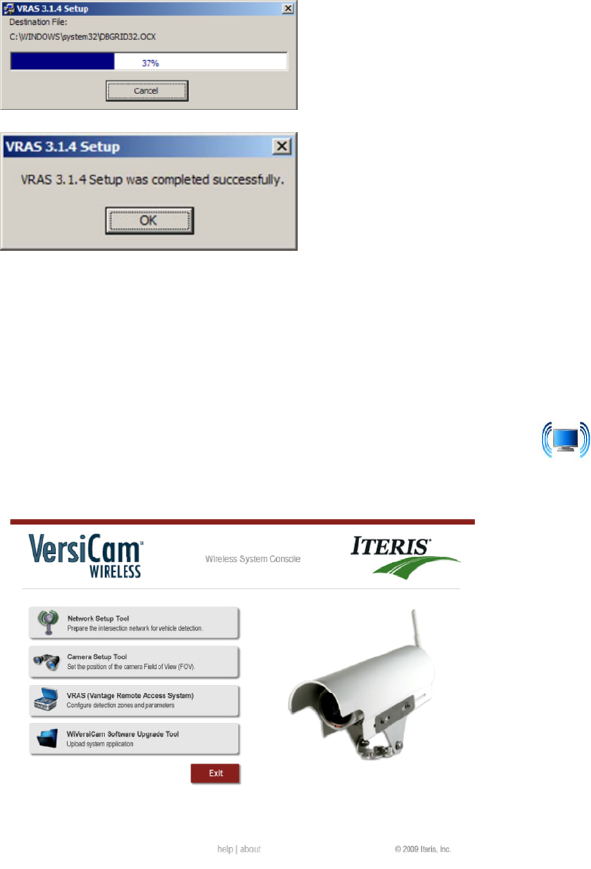
39
Figure4.1(s)
Figure4.1(t)
5. Theinstallationofthesoftwareisnowcomplete.
Note:ThereisafourthapplicationontheConsole“SoftwareUpgradeTool”.Thiswillbeusedforfuture
softwareupgrades.
4.2 VersiCam Wireless Console
ConnectaRS‐232cablefromtheserialportofthePCandtheRS‐232portonthefrontoftheICC‐2W.A
nullmodemcableissuppliedwiththesystem.ClickontheWiVersiCAMConsoleicon installed
onyourdesktop.TheConsoleprogramwillstart,seeFigure4.2(a).
Figure4.2(a)
4.3 Network Setup Tool
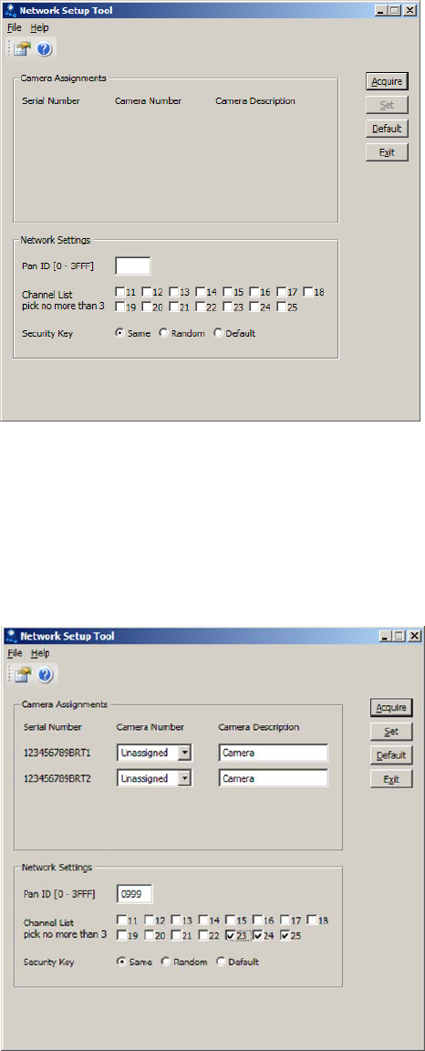
ClickontheiconfortheNetworkSetupTool.ThescreenisFigure4.3(a)willbedisplayed.
Figure4.3(a)
EnsuretheBaseStationandCamerashavepowerandclickonthe“Acquire”button.Thesystemwill
searchforVersiCamWirelessCamerasinthevicinityandreportthembacktothesystem.Theavailable
cameraswillbedisplayedinthecenterofthescreen,seeFigure4.3(b).
Note:Duringtheinstallationofthecamerasitisimportanttonotetheserialnumberofthecamerafor
eachapproach.Theserialnumberwillbeusedastheinitialidentifierfornetworksetup.
Figure4.3(b)
40
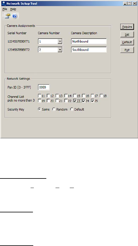
Foreachcameraselectacameranumberfromthedropdownboxnexttotheserialnumber.Acamera
descriptioncanbeaddedintheboxtotherightofthecameranumber,seeFigure4.3(c).
Figure4.3(c)
Tofurtherensurethatthenetworkisuniqueandimmunefromotherwirelesssystemcrosstalkthree
NetworkSettingsareprovidedatthebottomofthescreen.
PANID(0–3FFF)
ThisisthePersonalAreaNetworkidentifierandcanbesettoanyhexadecimalnumberbetween0000
and3FFF.
ChannelList
Thereare15wirelesschannelsthatthesystemhasaccessto.EachVersiCamnetworkisrestrictedto
threeofthese.Choosethethreebycheckinganduncheckingtheboxes.
SecurityKey
ThecommunicationsintheVersiCamnetworkisencryptedforsecurity.Thesecuritykeyshouldnotbe
changedunlessinstructedtodosobyaqualifiedIterisProductSupportspecialist.
Onceallthesettingshavebeenmadeclickonthe“Set”button.ThesettingswillbesenttotheBase
StationandCameras.Thenetworkisnoestablished.Clickonthe“Exit”buttontoclosetheapplication
andreturntotheConsole.
41
4.4 VersiLAM - Camera Setup Tool
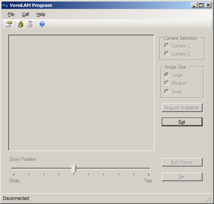
ClickontheiconfortheCameraSetupTool(VersiLAM).ThescreenisFigure4.4(a)willbedisplayed.
Figure4.4(a)
Clickontheconnecticonatthetopofthescreen.Thesystemwillidentifywhichcamerashavebeen
assignedtothenetwork.SelecteitherCamera1or2tostartthesetup.Thesystemwillinterrogatethe
selectedcameratodeterminethecurrentzoomposition.Thecurrentpositionwillbeshownbythe
positionofthepointeronthesliderbaratthebottomofthescreen.Thereare10stepsbetweenthe
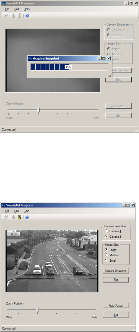
fullywideandthetele‐focusedpositions.Clickonanimagesizeandclickonthe“AcquireSnapshot”
button.Thesystemwillbegintodownloadanimagefromtheselectedcamera.Aprogressbarwillbe
displayed,seeFigure4.3(b).
Note:Wheneverthesystemisbusyalltheselectionoptionsandbuttonswillbe“greyedout”.
42
43
Figure4.3(b)
Oncetheimagehasbeendownloadeditwillbedisplayedonthescreen,seeFigure4.3(c).Followingthe
guidelinessetoutinSection3.1.1,adjusttherotationoftheimageasnecessaryatthecamera.Ifthe
FOVistooclosemovetheslidertowardthe“Wide”setting,iftheimageistoofarmovetheslider
towardthe“Tele”setting.Everytimeanadjustmentismadethesystemwillgreyoutwhilethechanges
aresenttothecameraandtheadjustmentmade.Aftereachadjustmentclickonthe“Acquire
Snapshot”buttontoreceivethelatestFOVimage.
Figure4.3(c)

Note:Therearethreeimagesizesavailable,Small,MediumandLarge,seeFigures4.3(d),(e),(f).Each
hasadifferentresolutionandeachtakeadifferentamountoftimetodownloadfromthecamera.Itis
suggestedthatyoustarttheFOVsetupwiththeSmallimageforgeneralplacementandmovetoeither
theMediumorLargeimageto“finetune”theFOVsetting.FormoredetailsongoodFOVsettingsee
Section3.1.1.
Figure4.3(d)–LargeSnapshotImage
Figure4.3(e)–MediumSnapshotImage
Figure4.3(f)–SmallSnapshotImage
44
OnceyouaresatisfiedwiththeFOVclickonthe“AutoFocus”button.Thiswillcommandthecamera
moduletoadjustitsimageforthesharpestsetting.Failuretoperformthisstepmaycausethesystemto
notperformatitsoptimallevelbymissingvehicledetectionsorbyplacingfalsecalls.
Finallyclickonthe“Set”button.ThiswillcommandthecameramoduletostoretheFOVandFocus
settings.IfapowercycleweretooccurthecameramodulewillautomaticallyreturntothestoredFOV
andfocus.Failuretoperformthisstepmaycausethesystemtolosetheabilitytodetectvehiclesinthe
eventofapowercycleduetolossofzone/approachalignment.
Havingcompletedthesetupforonecamerarepeattheprocessforothercamerasinthenetwork.
Onceallthecamerashavebeensetupclickonthe“Exit”buttontoclosetheapplicationandreturnto
theconsole.
4.5 System Setup and Operation (VRAS)
Systemsetupandconfiguration,zoneplacement,zonetypes,outputassignments,etc.areachieved
usingVRAS.
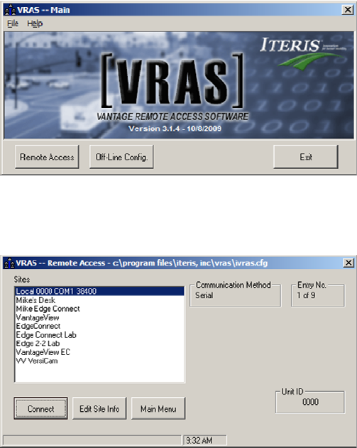
ClickontheiconforVRAS(VantageRemoteAccessSystem).The“VRAS–Main”screen,seeFigure
4.5(a),willbedisplayed.
Figure4.5(a)–VRASMainScreen
ItisnecessaryonfirstusetosetuptheVersiCamWirelessCamerasinthesystem.Clickonthe“Remote
Access”button,the“VRAS‐RemoteAccess”screen,seeFigure4.5(b),willbedisplayed.
Figure4.5(b)–VRAS–RemoteAccessScreen
45
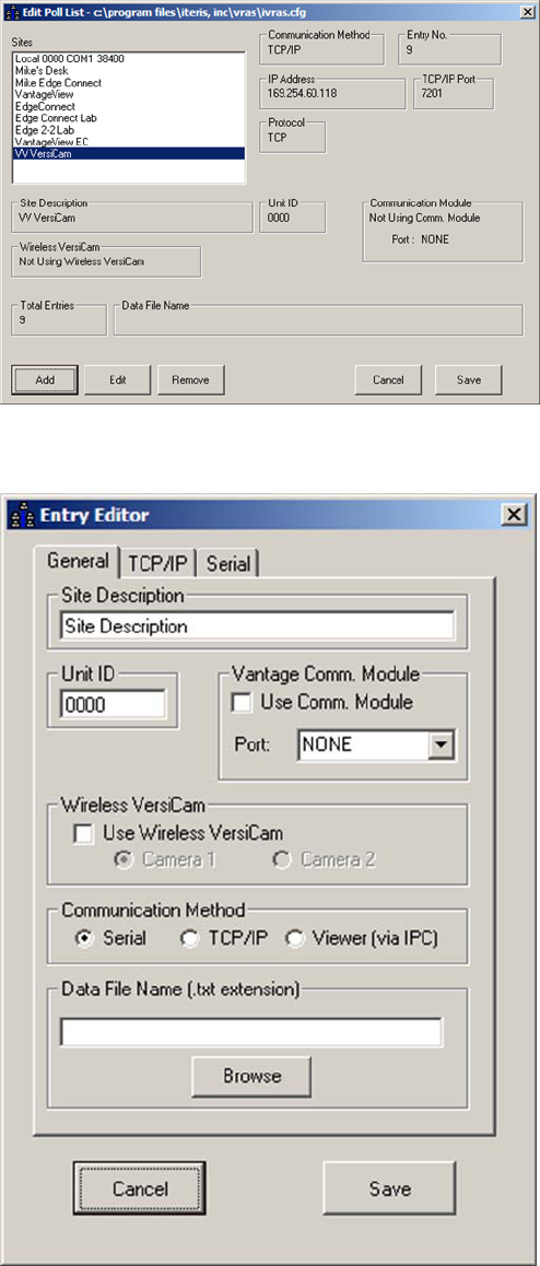
Clickonthe“EditSiteInfo”button.The“EditPollList”screen,seeFigure4.5(c),willbedisplayed.
Figure4.5(c)–EditPollListScreen
Clickonthe“Add”button.The“EntryEditor”screen,seeFigure4.5(d),willbedisplayed.
Figure4.5(d)–EntryEditorScreen
46
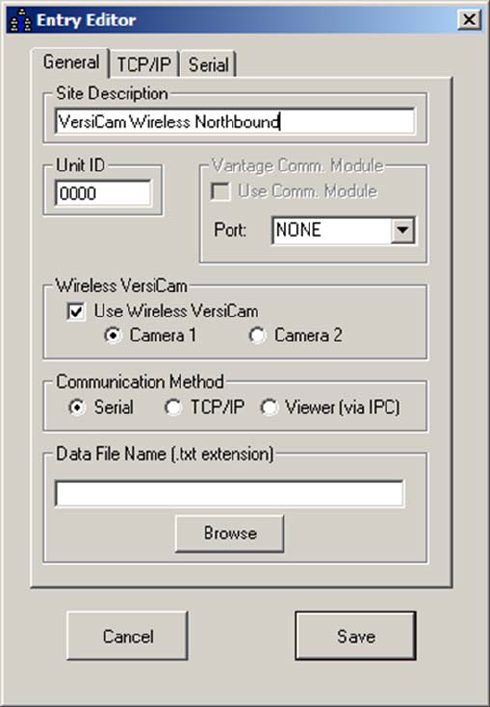
EnteraSiteDescription,clickinthe“UseWirelessVersiCam”checkboxandselecteitherCamera1or
Camera2.SeeFigure4.5(e)
Figure4.5(e)
Clickonthe“Save”button.The“EditPollList”screenwillbedisplayed.Repeattheprocessforanyother
camerasinthesystem.
Afterallcamerashavebeensetupclickonthe“Save”buttononthe“EditPollList”.The“VRAS‐Remote
Access”screenwillbedisplayed.
TheVRASsoftwareisnowreadytocommunicatewiththeVersiCamWirelessCameras.Fromthe“VRAS
–RemoteAccess”screenselectacameraandclickonthe“Connect”button.The“GeneralStatus”
screen,seeFigure4.5(f),willbedisplayed.
47
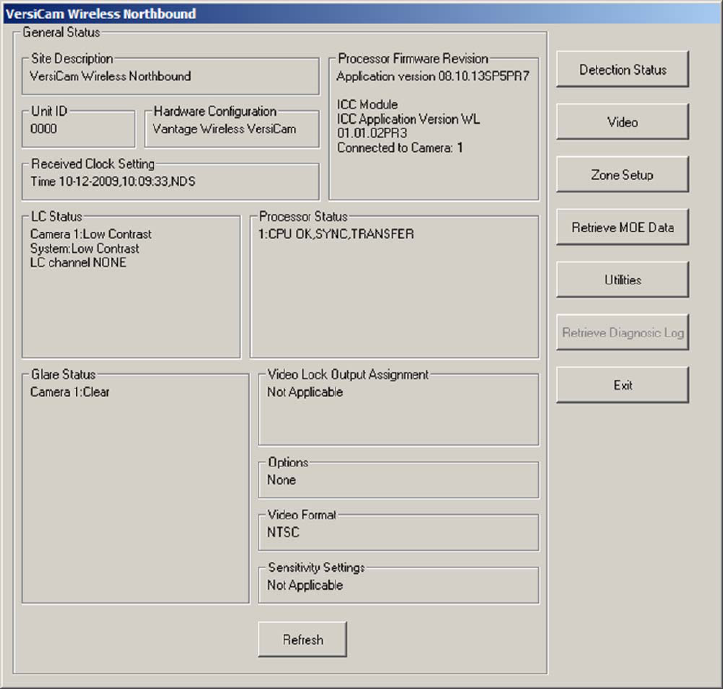
Figure4.5(f)
Youcannowretrieveasnapshotfromthecamera,setupzonesandoutputandstoretheconfiguration
inthecamera.RefertotheVRASdocumentationforfurtherinformationontheoperationofthe
software.
4.6 VersiCam Wireless Software Upgrade Tool
TheVersiCamWirelessConsoleisequippedwithatoolforuploadingnewapplicationcode.Thiswillbe
usedforfuturesoftwareupgrades.
48
5 VersiCam Options
TheVersiCamcanbeinstalledinmoststandardNEMAdetectorracksand332cabinettypeinputfiles.
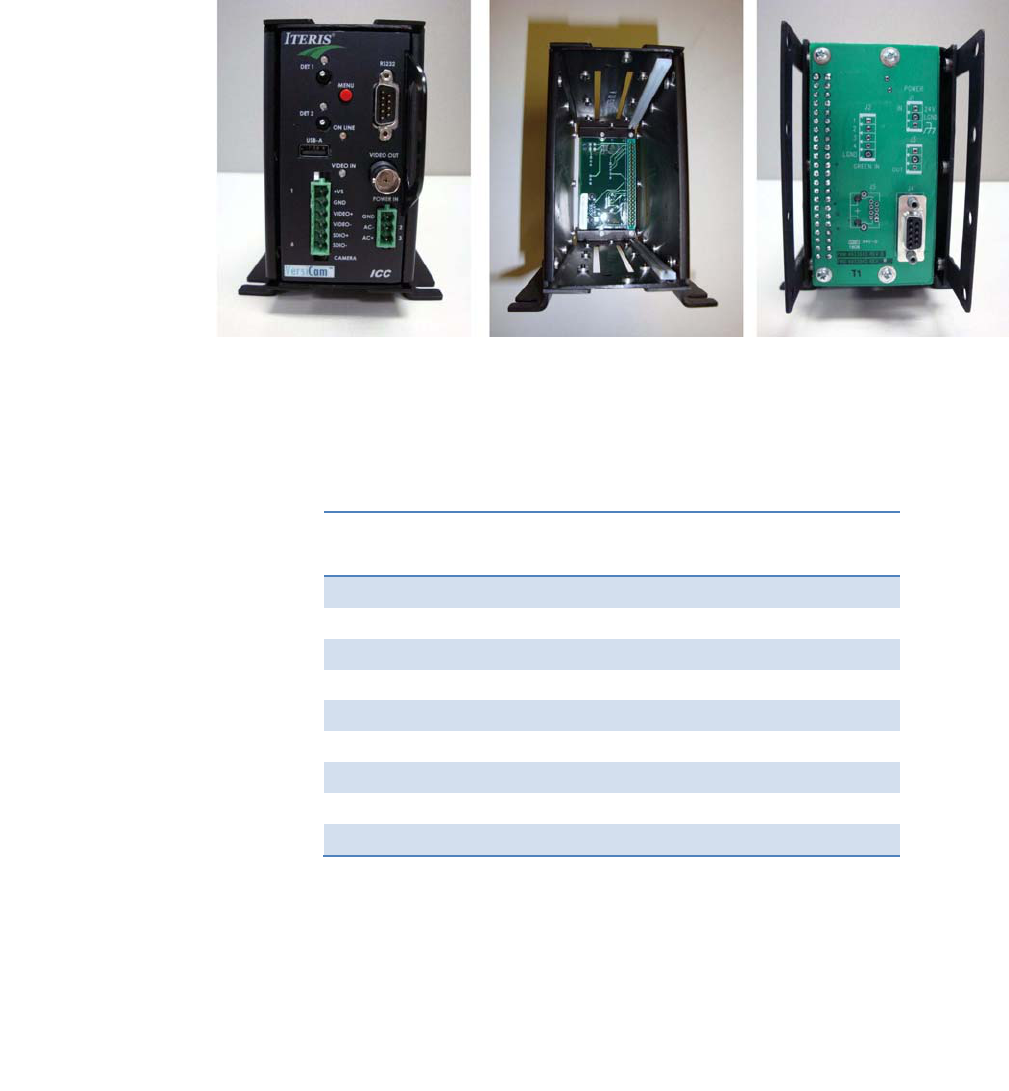
ThereisalsoanoptionalstandaloneVCRack(VersiCamRack),seeFigure4(a),thatcanbeusedfor
applicationswhereadetectorrackorinputfilearenotavailableorarenotpractical.
Figure4(a)
5.1 Output Configuration
ThebackplaneoftherackhasaDB9connectortointerfacewiththeinputfile.UsethesuppliedCCable
toconnectfromtheracktotheinputfile.SeeFigure5.1(a)forpinconfiguration.
Pin
NumberPinFunctionCameraAssignment
1Output1Camera1Output1
2Output2Camera1Output2
3Output3Camera2Output1
4Output4Camera2Output2
5NotUsedNotUsed
6NotUsedNotUsed
7NotUsedNotUsed
8NotUsedNotUsed
9LogicGroundN/A
Figure5.1(a)
49

50
6 Firmware Release Notes
Itisimportanttorecognizethatperiodically,Vantagefirmwareupdatesaremadeavailableforthe
Vantagevideodetectionproducts.ReleasenotesareincludedaspartoftheVantageSoftwareUpgrade
(VSU)package.Thougheveryeffortismadetokeeptheproductmanualsuptodate,thecustomer
shouldalwaysrefertothelatestfirmwarereleasenotesforthemostrecentinformationontheir
Vantageproductfirmware.Newfeaturesandenhancementsarecontinuouslybeingofferedandthese
newfeaturesmaynotbefullyrepresentedintheproductmanual.
Vantagereleasenotesarelocatedinthefolder:.../ProgramFiles/IterisInc./VantageSoftware
Upgrade/……ReleaseNotes.rtf
FirmwareVersionNumberingSystem
XXHardwarePlatform:
08=VersiCam
05=Edge2‐4
04=Edge2‐1and2‐2(secondgeneration)
03=Edge2(firstgeneration)
02=Plus,One,ClassicEdge
YYFirmwareApplication
01=Intersection
02=Express
05=Ramp
ZZVersionRevisionIncrement
Forexample:04.01.13=Edge2.Intersection.Revision13
YoucanalsocontactyourlocalVantageDealerortheVantageProductSupportTeamtoseeifthereare
newaddendum'sornewerproductmanualrevisionsavailableforyourVantageproducts.
NewVantagefirmwarereleasesarenormallydistributedbyyourlocalVantageDealerortheycanbe
obtainedbycontactingtheVantageProductSupportTeamdirectly.SeetheProductSupportsectionfor
moreinformation.
51
7 Maintenance
TheVersiCamWirelessVideoDetectionSystem,oncecorrectlyinstalled,requiresaminimalamountof
maintenance.
CameraCleaning
BecauseVersiCamWirelessvideodetectionisamachinevisionbasedsystem,oneofthebigoperational
concernsiskeepingthefrontcameraglassreasonablyclean.Aregularmaintenanceprogramshouldbe
implementedtoensurethefrontcameraglassiskeptfreefromdirtanddebris.Thecamerahousing
glassshouldbecleanedatleastonceayear,ormorefrequentlyifrequired,especiallyundersevere
environmentalconditions.Dirtycameraglassisoneoftheleadingcontributorstodecreasedsystem
performance.
Theuseofasoftcottoncloth(non‐abrasive)andwateristherecommendedmethodforcameraglass
cleaning.Avoidleavingstreaksontheglass.Avoidanythingthatmightscratchtheglass,cloudtheglass,
orleaveanundesirableresidue.
ConnectorandCableInspection
Periodically,itiswisetocheckalltheconnections.Lookforconnectorcorrosionormoisturedamage.
Replacedefectiveconnectors.Makesurescrewterminalconnectionsaretightandallwiresaremaking
agoodelectricalconnection.Checkcablingandwiringfordamageandrepairorreplaceitasneeded.

52
8 Vantage Equipment Repair
ThelatestVantageequipmentcomeswithastandardthreeyearfactorywarranty.Thiswarrantyis
basedontheequipment’sdateofshipmenttotheVantageDealer.Thiswarrantydoesnotcover
lightningdamageoranyotherdamageresultingfromtheimproperuseorinstallationoftheIteris
Vantageequipment.Theuseofimpropermaterials,otherthanthosespecifiedbyIteris,willalsovoid
themanufacturer’swarranty.
ToreturnVantageequipmentforrepair,contactyourlocalVantageDealerorcontacttheIterisProduct
SupportTeamtoobtainaReturnMaterialAuthorization(RMA).Equipmentsentinforrepairmusthave
avalidRMAnumberassignedinadvance.ThisRMAnumbershouldbeclearlydisplayedontheoutside
ofthebox.
WhenyoucallforanRMAnumber,bepreparedtoprovidethefollowinginformation:
‐ TypeofVantageproductandtheproduct’sserialnumber.Usedtodeterminetheproducts
warrantystatus.
‐ Veryspecificinformationonthesymptomsandtypeoffailure.
‐ Whattroubleshootingstepshavebeentaken,howlonghastheequipmentbeenrunning.
Byprovidinguswiththisbasicinformation,wheneverpossible,itwillallowustobetterserveyouand
willhelpustobemoreefficient.Customersatisfactionisextremelyimportanttous.
RMAReturnEquipmentShippingAddress:
Iteris,Inc.
RMAReturns
1700CarnegieAvenue,Suite100
SantaAna,CA92705‐5551
Note:BesuretoincludetheRMA#inaclearlyvisibleareaontheoutsideofthebox.
9 Technical Information
ThefollowingsectioncontainsdetailedtechnicalinformationontheVersiCamWirelessSystemandit’s
associatedcomponents.
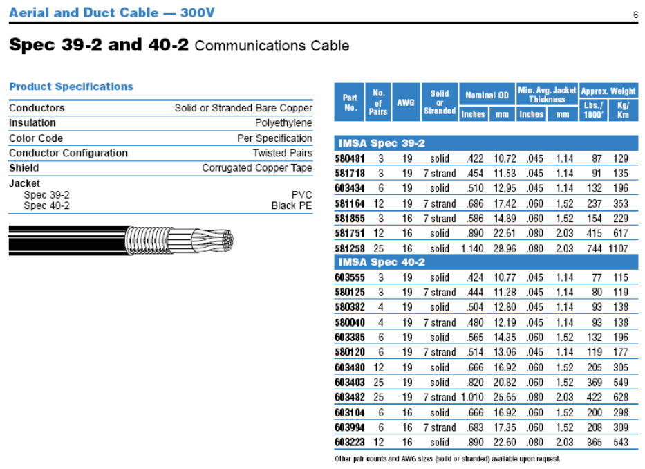
• IMSA39‐2Cable
• CameraBracket
• EDCOSurgeProtection
9.1 Sample Power Cable
53
9.2 Iteris Vantage Camera Bracket
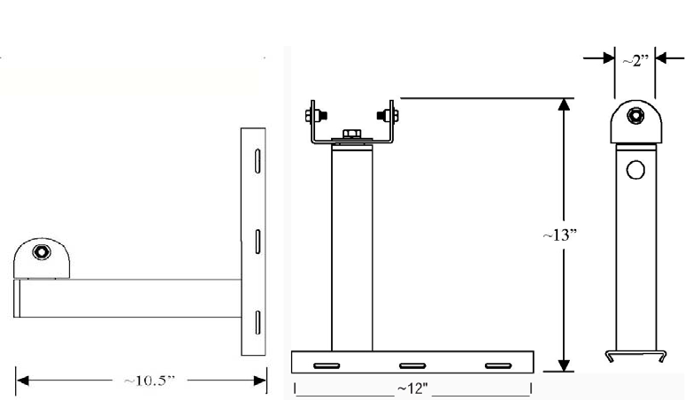
TheUniversalCameraBracketisdesignedtoaccommodatebothhorizontalandverticalstructure
mounting.ThemountingbracketmatesperfectlywithIteris'swiredandwirelesscamerasandis
constructedusinghighstrength6061aluminum.Foraddedprotection,theassemblyisgraypowder
coated.
FEATURES&BENEFITS
• UniversalCameraMounting
• Horizontalforluminairearmmounting
• Verticalforstandardpolemounting
• Highstrength,lightweightaluminumconstruction
• Easypan/tiltangleadjustment
• Threebandingslotsforstainlesssteelbandingofupto¾inch
VerticalMountHorizontalMount
IterisUniversalCameraBracket
IterisPart:CAMBRKT4
54

9.3 EDCO Surge Protection
55

56
9.4 VersiCam Wireless Technical Information
CameraICC‐2WModule ICC‐2WShelfMountBaseStation
FeaturesColorimager170inputfile
compatible
Compactenclosure
768x494effective
pixels
TS1compatible
470TVlinesTS2compatible
Automaticwhite
balance
>50dBS/Nratio
0.1luxcapable
LensFocallengthandfocus
adjustablefor
horizontalFOVranging
from5.4oteleto85o
wide
ConnectionsTerminal
–
4wayTerminal
–
6wayfor
BaseStation
Terminal
–
6wayfor
BaseStation
TerminalStrip
–
4way
2xDCPower2xDCPower 2xDCPower 2xDCPower
2xDifferentialControl2xDifferentialControl 2xDifferentialControl2xDifferentialControl
2xUnused(for
productionuseonly)
2xUnused(for
productionuseonly)
Terminal
–
3wayfor
PowerInput
Terminal
–
3wayfor
PowerInput
RS‐232port RS‐232port
Mechanical
Dimensions
13.5”(L)x4”(D)7”(L)x4.5”(H)x
2.3”(W)
8.3”(L)x5”(H)x
2.8”(W)
34.3cmx10.2cm17.78cmx11.43cmx
5.85cm
17.78cmx11.43cmx
5.85cm
Withoutbracket
Weight1.05lbs/0.48kgs 2.4lbs/1.09kgs
Environmental
Temperature‐31oFto+140oF ‐35oFto+165oF‐35oFto+165oF‐31oFto+140oF
‐35oCto+60oC‐37oCto+74oC‐37oCto+74oC‐35oCto+60oC
Humidity0‐100%relative0‐ 95%relative 0‐ 95%relative 0‐100%relative
Non‐condensingNon‐condensing Non‐condensingNon‐condensing
Vibration0.5G,3axes,5‐30Hz0.5G,3axes,5‐30Hz 0.5G,3axes,5‐30Hz0.5G,3axes,5‐30Hz
Shock10G,3axes10G,3axes 10G,3axes 10G,3axes
PowerInput15VDC,output23W
typical
100‐240VAC50/60Hz
0.7A
100‐240VAC50/60Hz
0.7A
15VDC,output1W
typical
OutputRS‐485Serial15VDC 15VDC RS‐485Serial
2.4GHzradio27Wtypical 27Wtypical 2.4GHzradio

57
10 If You Need Assistance
TheIterisVantageProductSupportTeamconsistsofagroupofhighlyskilledindividualsthatare
knowledgeableandreadilyavailabletoansweryourquestionsorassistyouwithanyofourVantage
products.Pleasedonothesitatetocontactusat:
(888)254‐5487
FormoreinformationonIterisandtheproductsandservicesthatweprovide,visitourwebsiteat
www.iteris.com.