IWT FS5 Face Sentry User Manual
IWT Limited. Face Sentry
UserManual.wiki
>
IWT
>
FS5 User Manual
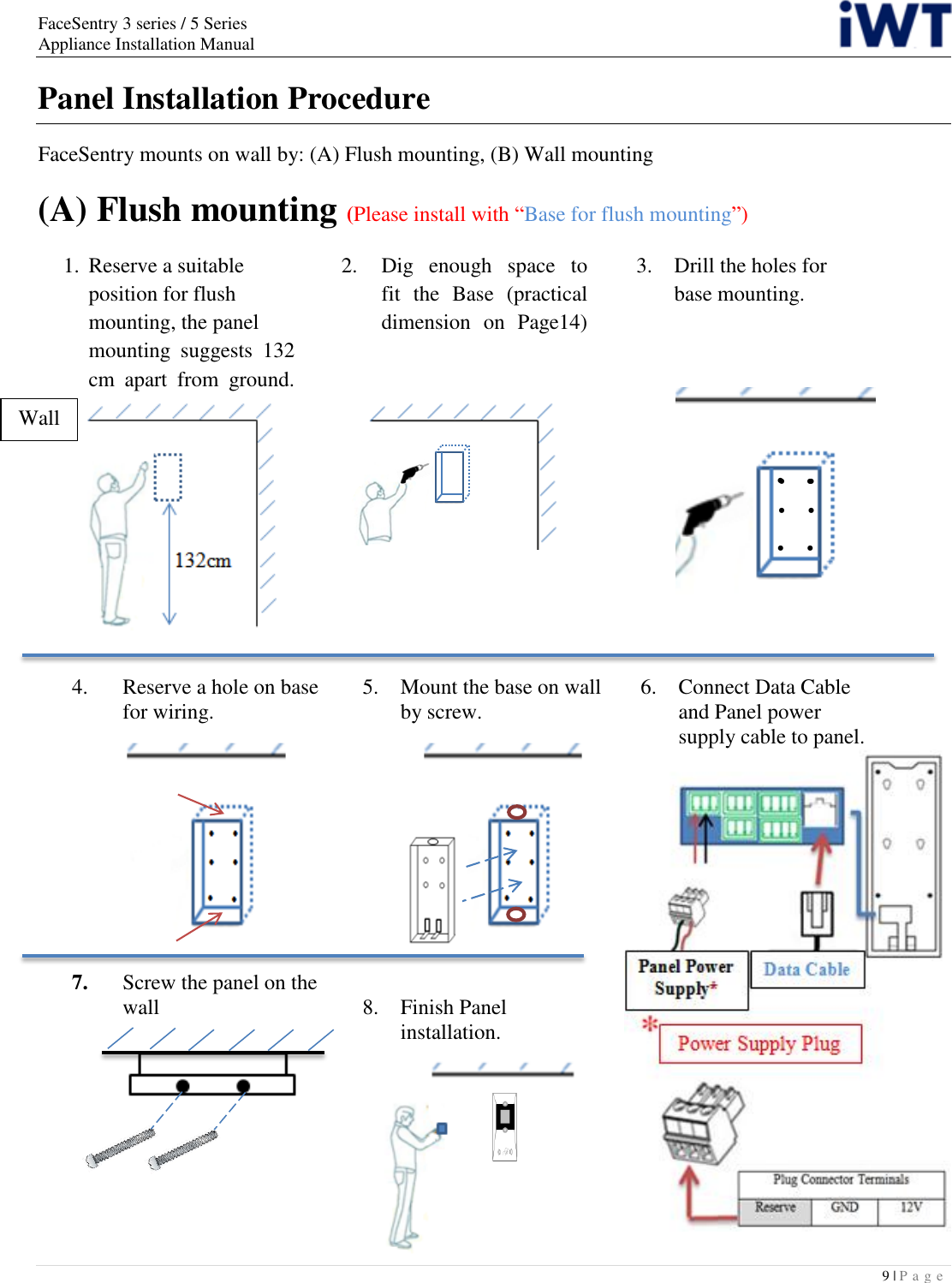
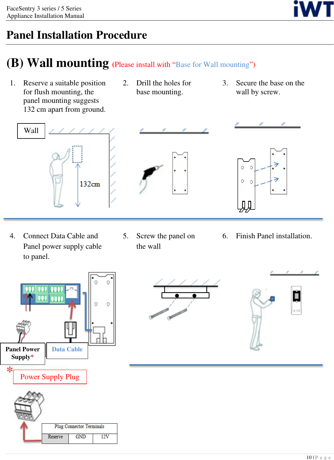
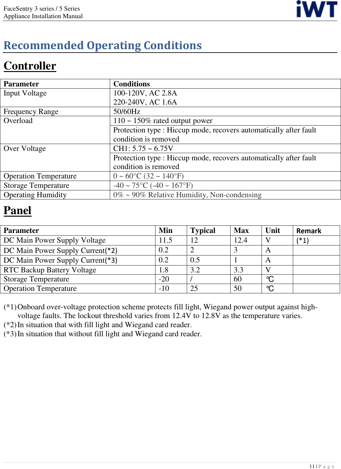
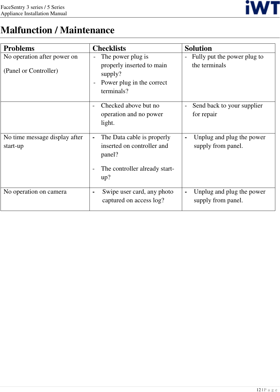
User Manual
Navigation menu
Upload a User Manual
Namespaces
Wiki Guide
HTML
PDF
Info
Views
User Manual
Discussion / Help
Navigation