Ibis Networks 200 RF Module User Manual DataSheetSinglex
Ibis Networks Inc. RF Module DataSheetSinglex
Contents
- 1. User Manual - IS-201
- 2. User Manual - IS-204
User Manual - IS-201
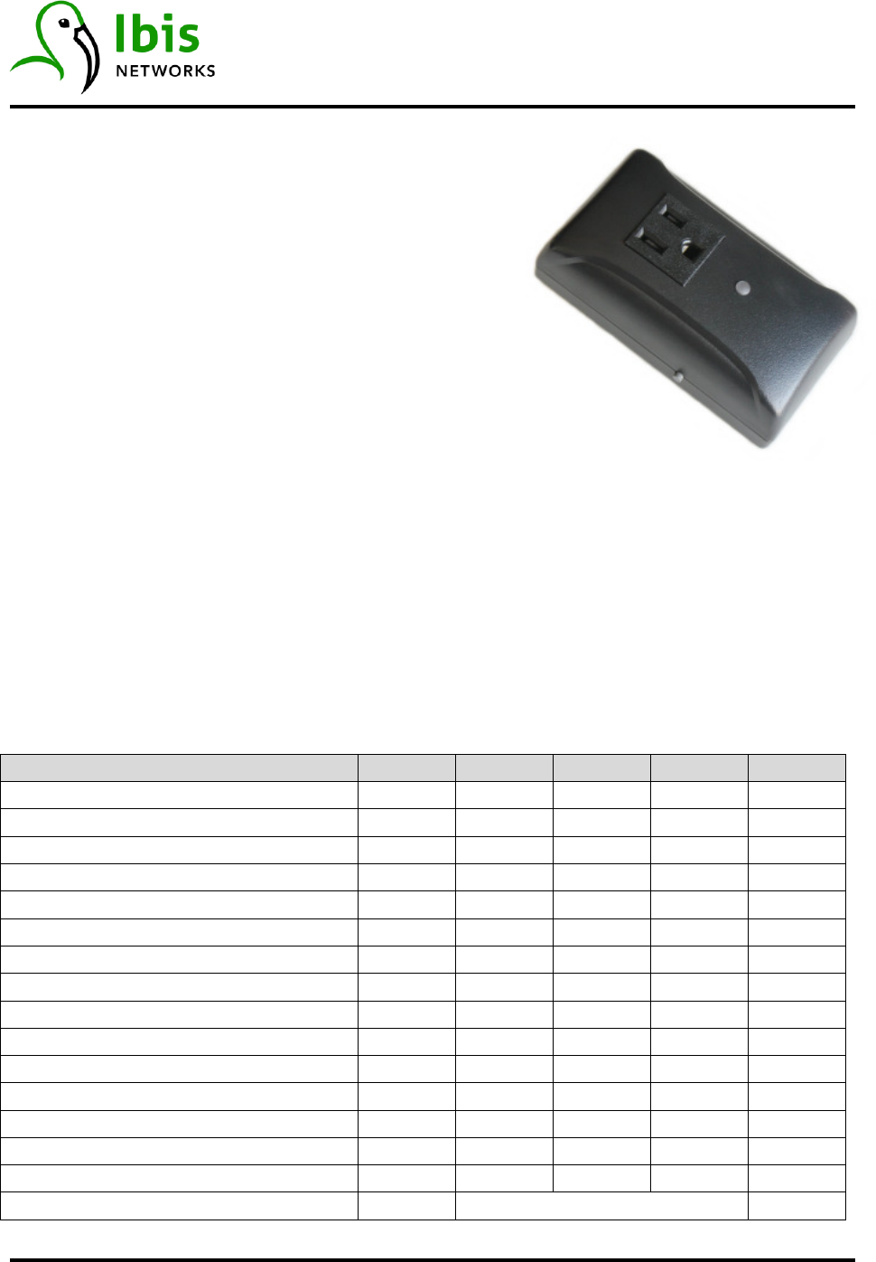
IS-201
InteliSocket
™
Ibis Networks
·
828 Fort Street Mall Suite 600
·
Honolulu, HI 96813
·
www.ibisnetworks.com 1
05/28/15
FEATURES
• 120V 15A
• UL Certification
• ZigBee Pro
• 128 bit AES Security
• 20dBm RF Power
• Surge Protected
•
0C to 40C
DESCRIPTION
The IS-201 is a smart socket which meters plug load energy usage and provides device on/off
capability. It works with other InteliSockets
TM
to form a secure wireless mesh network for
control and reporting of data. Each network has an InteliGateway
TM
base station providing
connectivity to the Ibis InteliNetwork
TM
, a cloud-based data collection and analysis application.
InteliSockets can be configured to operate on any of the 15 ZigBee channels. In addition, the
hive (PANID) has over 4000 possible settings, preventing nearby systems from interfering with
each other.
PERFORMANCE
Parameter Symbol Min Typ Max Units
Input Voltage (RMS) V
IN
108 120 132 V
Input Frequency 60 Hz
Output Current (RMS) I
OUT
15 A
Output Power P
OUT
1800 W
Power Consumption 1 W
Reporting Interval 1 15 255 s
Accuracy (Energy) 0.5 %
Accuracy (Voltage) 2 %
Accuracy (Interval) 1 ms
Resolution 1 W-s
RF Range 50 m
RF Transmit Power 0 20 dBm
Sockets per Network 120
ZigBee Channels 11 25
ZigBee Hive 0x3000 0x3FFF
Size 4.1 x 2.2 x 1.7 inches
IS-201
InteliSocket
™
Ibis Networks
·
828 Fort Street Mall Suite 600
·
Honolulu, HI 96813
·
www.ibisnetworks.com 2
05/28/15
COMPLIANCE
Agency File
UL916 – Energy Management Equipment E470522
ZigBee Profile (Ibis Automation) 0x114B
FCC 2AECN200
ENVIRONMENTAL
Parameter Symbol Min Typ Max Units
Operating Temperature T
O
0 25 40 C
Storage Temperature T
S
-40 100 C
Relative Humidity RH 0 95 %
InteliSockets are for indoor use only.
PROTOCOL
InteliSockets use the Ibis custom ZigBee profile for commands, acknowledgements, and
reporting of data. Refer to the V2 Protocol documentation for details.
DATA
InteliSockets report data typically every 15 seconds. Each report packet is comprised of socket
type, ZigBee channel, ZigBee hive (PANID), interval (seconds), voltage (RMS), frequency (Hz),
energy (watt-seconds), and power factor (fraction). From these data we can calculate
instantaneous power (watts) and current (amps).
·
The InteliGateway appends additional information (IP, timestamp, location, etc.) before
uploading to the InteliNetwork. This allows any socket in the world to be located and
addressed individually.

IS-201
InteliSocket
™
Ibis Networks
·
828 Fort Street Mall Suite 600
·
Honolulu, HI 96813
·
www.ibisnetworks.com 3
05/28/15
PUSHBUTTON
The small pushbutton on the side provides addition control features. First and foremost, it is a
manual override for turning the outlet on and off (toggle). If pressed for at least two seconds, it
causes a reboot of the socket. Finally, if the pushbutton is pressed while plugging in the socket,
a factory reset is performed causing the socket to revert back to factory default settings. This is
a useful feature for maintenance purposes.
LED
The LED on the front indicates the state of the socket. When red the outlet is off; green is
outlet is on. If LED is blinking, the socket has not yet associated with a mesh network. During a
reboot, the LED will flash yellow for a second.
FCC
This equipment has been tested and found to comply with the limits for a class B digital device,
pursuant to part 15 of the FCC rules. These limits are designed to provide reasonable
protection against harmful interference in a residential installation. This equipment generates,
uses, and can radiate radio frequency energy and if not installed and used in accordance with
the instructions, may cause harmful interference to radio communications. However, there is
no guarantee that interference will not occur in a particular installation. If this equipment does
cause harmful interference to radio or television reception, which can be determined by
turning the equipment off and on, the user is encouraged to try to correct the interference by
one or more of the following measures:
• Reorient or relocate the receiving antenna.
• Increase the separation between the equipment and receiver.
• Connect the equipment into an outlet on a circuit different from that to which the
receiver is connected.
• Consult the dealer or an experienced radio/TV technician for help.
The user is cautioned that changes and modifications made to the equipment without the
approval of manufacturer could void the user’s authority to operate this equipment.
To satisfy RF exposure requirements, this device and its antenna must operate with a
separation distance of at least 20 cm from all persons and must not be co-located or operating
in conjunction with any other antenna or transmitter.