Ibm 131 Users Manual Self Checkout 4845
BW3 to the manual f2ab79c6-82b2-4bbc-ae50-f52df08b288c
2015-03-11
: Ibm Ibm-131-Users-Manual-431801 ibm-131-users-manual-431801 ibm pdf
Open the PDF directly: View PDF ![]() .
.
Page Count: 156 [warning: Documents this large are best viewed by clicking the View PDF Link!]
- Contents
- Preface
- Chapter 1. Core Module
- Assembly 1: Core Module
- Assembly 2: Bill Dispenser
- Assembly 3: Bill Dispenser Main Unit Illustration 1 of 3
- Assembly 4: Bill Dispenser Main Unit Illustration 2 of 3
- Assembly 5: Bill Dispenser Main Unit Illustration 3 of 3
- Assembly 6: Bill Dispenser Lower Unit
- Assembly 7: Bill Dispenser Cassette
- Assembly 8: Bill Dispenser Communications and Power
- Assembly 9: Coin Dispensers
- Assembly 10: Coin Acceptor
- Assembly 11: Bill Acceptor
- Assembly 12: Printers TIx and TGx
- Assembly 13: Printers TF6 and TM6
- Assembly 14: Printers Fiscal
- Assembly 15: Printers Epson
- Assembly 16: Magnetic stripe reader and pin pad mount
- Assembly 17: Hand held scanner
- Assembly 18: Countertop
- Assembly 19: Signature Capture and Coupon Acceptor
- Assembly 20: Lane light and transaction light
- Assembly 21: Lane PC, Mouse, and Keyboard
- Chapter 2. Load Cells, Platens, Plates, and Retaining Fences
- Chapter 3. Security Conveyor
- Chapter 4. Transport Conveyor
- Chapter 5. Bagging and Carousel Bagging
- Chapter 6. Wire Bag Rack
- Chapter 7. BOSS
- Chapter 8. Integrated Paystation
- Chapter 9. EPO (Red) Button
- Chapter 10. Cables
- Chapter 11. Locks and Keys
- Chapter 12. Field Kits and Tools
- Appendix A. Cabinet Parts and Sensors
- Assembly 36: Core Module Cabinet FRUs
- Assembly 37: Security Conveyor and Transport Conveyor Cabinet
- Assembly 38: Models 152, 602, and 612 Bagging Cabinet
- Assembly 39: Models 153, 603, and 613 Bagging Cabinet
- Assembly 40: Model N54 Bagging Cabinet
- Assembly 41: Models 171, 800, and 810 Bagging Cabinet
- Assembly 42: Models 171, 800, and 810 Bumpers, Order Separators, Soft Goods Shelf
- Assembly 43: Sensors, Emitters, and Detectors
- Appendix B. Notices
- Electronic emission notices
- Federal Communications Commission (FCC) statement
- European Union EMC Directive conformance statement
- Industry Canada Class A Emission Compliance statement
- Avis de conformité aux normes d'Industrie Canada
- Germany
- Australia and New Zealand
- Japanese power line harmonics compliance statement
- Japanese Voluntary Control Council for Interference (VCCI) statement
- Cable ferrite requirement
- Electrostatic Discharge (ESD)
- Product Recycling and disposal
- Battery return program
- Flat panel displays
- Monitors
- Trademarks
- Electronic emission notices
- Index
- Part number index
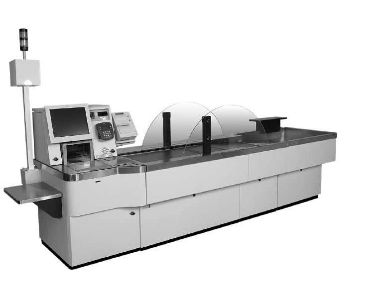
Self Checkout 4845
Parts Manual
Models 131, 15x, 171, 6xx, 8xx, and BW3
S131-0106-02Updated October 16, 2007
Self Checkout 4845
Parts Manual
Models 131, 15x, 171, 6xx, 8xx, and BW3
S131-0106-02Updated October 16, 2007

Note
Before using this information and the product it supports, be sure to read the “Safety ” on page vii and the general
information under Appendix B, “Notices,” on page 125.
October 2007
This edition applies to IBM Self Checkout Solution, machine type 4845, Models 131, 151, 152, 153, and 171 and
IBM Self Checkout Systems, machine type 4845, Models 602, 603, 606, 612, 613, 616, 800, 810, and BW3.
Current versions of Retail Store Solutions documentation are available on the IBM Retail Store Solutions Web site at:
www.ibm.com/solutions/retail/store/support. Click Publications.
A form for reader’s comments is also provided at the back of this publication. If the form has been removed, address
your comments to:
IBM Corporation
Retail Store Solutions Information Development
Department ZBDA
PO Box 12195
Research Triangle Park, North Carolina, 27709 USA
When you send information to IBM, you grant IBM a nonexclusive right to use or distribute whatever information you
supply in any way it believes appropriate without incurring any obligation to you.
© Copyright International Business Machines Corporation 2006, 2007. All rights reserved.
US Government Users Restricted Rights – Use, duplication or disclosure restricted by GSA ADP Schedule Contract
with IBM Corp.
Updated October 16, 2007
|
|

Contents
Preface . . . . . . . . . . . . . . . . . . . . . . . . . . . .v
How to Use This Parts Manual . . . . . . . . . . . . . . . . . . .v
Identifying a Right Hand or Left Hand Model . . . . . . . . . . . . .v
Related Publications . . . . . . . . . . . . . . . . . . . . . . .vi
Where to Find More Information . . . . . . . . . . . . . . . . . . vii
Safety . . . . . . . . . . . . . . . . . . . . . . . . . . . . vii
Publications Accessibility . . . . . . . . . . . . . . . . . . . . . vii
Providing Feedback . . . . . . . . . . . . . . . . . . . . . . . viii
Uninterruptible Power Supply Option . . . . . . . . . . . . . . . . . viii
Taiwanese Battery Recycling Statement . . . . . . . . . . . . . . . . viii
End of life disposal . . . . . . . . . . . . . . . . . . . . . . . viii
Chapter 1. Core Module . . . . . . . . . . . . . . . . . . . . .1
Assembly 1: Core Module . . . . . . . . . . . . . . . . . . . . .2
Assembly 2: Bill Dispenser . . . . . . . . . . . . . . . . . . . . .6
Assembly 3: Bill Dispenser Main Unit Illustration 1 of 3 . . . . . . . . . . .8
Assembly 4: Bill Dispenser Main Unit Illustration 2 of 3 . . . . . . . . . .10
Assembly 5: Bill Dispenser Main Unit Illustration 3 of 3 . . . . . . . . . .12
Assembly 6: Bill Dispenser Lower Unit . . . . . . . . . . . . . . . .14
Assembly 7: Bill Dispenser Cassette . . . . . . . . . . . . . . . . .16
Assembly 8: Bill Dispenser Communications and Power . . . . . . . . . .18
Assembly 9: Coin Dispensers . . . . . . . . . . . . . . . . . . .20
Assembly 10: Coin Acceptor . . . . . . . . . . . . . . . . . . . .24
Assembly 11: Bill Acceptor . . . . . . . . . . . . . . . . . . . . .26
Assembly 12: Printers TIx and TGx . . . . . . . . . . . . . . . . .28
Assembly 13: Printers TF6 and TM6 . . . . . . . . . . . . . . . . .32
Assembly 14: Printers Fiscal . . . . . . . . . . . . . . . . . . . .36
Assembly 15: Printers Epson . . . . . . . . . . . . . . . . . . . .38
Assembly 16: Magnetic stripe reader and pin pad mount . . . . . . . . .40
Assembly 17: Hand held scanner . . . . . . . . . . . . . . . . . .42
Assembly 18: Countertop . . . . . . . . . . . . . . . . . . . . .44
Assembly 19: Signature Capture and Coupon Acceptor . . . . . . . . . .46
Assembly 20: Lane light and transaction light . . . . . . . . . . . . . .48
Assembly 21: Lane PC, Mouse, and Keyboard . . . . . . . . . . . . .50
Chapter 2. Load Cells, Platens, Plates, and Retaining Fences . . . . . .53
Assembly 22: Load Cell . . . . . . . . . . . . . . . . . . . . . .54
Assembly 23: Platens and Retaining Fences . . . . . . . . . . . . . .56
Chapter 3. Security Conveyor . . . . . . . . . . . . . . . . . . .59
Assembly 24: Security Conveyor . . . . . . . . . . . . . . . . . .60
Chapter 4. Transport Conveyor . . . . . . . . . . . . . . . . . .63
Assembly 25: Transport Conveyor . . . . . . . . . . . . . . . . . .64
Chapter 5. Bagging and Carousel Bagging . . . . . . . . . . . . .67
Assembly 26: Carousel parts . . . . . . . . . . . . . . . . . . . .70
Chapter 6. Wire Bag Rack . . . . . . . . . . . . . . . . . . . .73
Assembly 27: Wire Bag Rack . . . . . . . . . . . . . . . . . . .74
Chapter 7. BOSS . . . . . . . . . . . . . . . . . . . . . . . .77
Assembly 28: BOSS FRUs . . . . . . . . . . . . . . . . . . . .78
Updated October 16, 2007
© Copyright IBM Corp. 2006, 2007 iii
Chapter 8. Integrated Paystation . . . . . . . . . . . . . . . . .81
Assembly 29: Paystation . . . . . . . . . . . . . . . . . . . . .82
Chapter 9. EPO (Red) Button . . . . . . . . . . . . . . . . . . .85
Assembly 30: EPO (Red) Button . . . . . . . . . . . . . . . . . .86
Chapter 10. Cables . . . . . . . . . . . . . . . . . . . . . . .89
Assembly 31: Cables . . . . . . . . . . . . . . . . . . . . . . .90
Assembly 32: Power Cords . . . . . . . . . . . . . . . . . . . .92
Chapter 11. Locks and Keys . . . . . . . . . . . . . . . . . . .95
Assembly 33: Currency Lock with Key . . . . . . . . . . . . . . . .96
Assembly 34: Cabinet Lock with Key . . . . . . . . . . . . . . . . .98
Chapter 12. Field Kits and Tools . . . . . . . . . . . . . . . . . 101
Assembly 35: Field Kits and Tools . . . . . . . . . . . . . . . . . 102
Appendix A. Cabinet Parts and Sensors . . . . . . . . . . . . . . 105
Assembly 36: Core Module Cabinet FRUs . . . . . . . . . . . . . . 106
Assembly 37: Security Conveyor and Transport Conveyor Cabinet . . . . .110
Assembly 38: Models 152, 602, and 612 Bagging Cabinet . . . . . . . .112
Assembly 39: Models 153, 603, and 613 Bagging Cabinet . . . . . . . .114
Assembly 40: Model N54 Bagging Cabinet . . . . . . . . . . . . . .116
Assembly 41: Models 171, 800, and 810 Bagging Cabinet . . . . . . . .118
Assembly 42: Models 171, 800, and 810 Bumpers, Order Separators, Soft
Goods Shelf . . . . . . . . . . . . . . . . . . . . . . . . 120
Assembly 43: Sensors, Emitters, and Detectors . . . . . . . . . . . . 122
Appendix B. Notices . . . . . . . . . . . . . . . . . . . . . . 125
Electronic emission notices . . . . . . . . . . . . . . . . . . . . 127
Federal Communications Commission (FCC) statement . . . . . . . . 127
European Union EMC Directive conformance statement . . . . . . . . 127
Industry Canada Class A Emission Compliance statement . . . . . . . 128
Avis de conformité aux normes d’Industrie Canada . . . . . . . . . . 128
Germany . . . . . . . . . . . . . . . . . . . . . . . . . 128
Australia and New Zealand . . . . . . . . . . . . . . . . . . . 128
Japanese power line harmonics compliance statement . . . . . . . . . 128
Japanese Voluntary Control Council for Interference (VCCI) statement 129
Cable ferrite requirement . . . . . . . . . . . . . . . . . . . . . 129
Electrostatic Discharge (ESD) . . . . . . . . . . . . . . . . . . . 129
Product Recycling and disposal . . . . . . . . . . . . . . . . . . 129
Battery return program . . . . . . . . . . . . . . . . . . . . . 130
For Taiwan: . . . . . . . . . . . . . . . . . . . . . . . . . 131
For the European Union: . . . . . . . . . . . . . . . . . . . . 131
For California: . . . . . . . . . . . . . . . . . . . . . . . . 131
Flat panel displays . . . . . . . . . . . . . . . . . . . . . . . 132
Monitors . . . . . . . . . . . . . . . . . . . . . . . . . . . 132
Trademarks . . . . . . . . . . . . . . . . . . . . . . . . . . 132
Index . . . . . . . . . . . . . . . . . . . . . . . . . . . . 133
Part number index . . . . . . . . . . . . . . . . . . . . . . . 135
Updated October 16, 2007
iv Self Checkout 4845: Parts Manual Models 131, 15x, 171, 6xx, 8xx, and BW3
||

Preface
This parts manual lists the field replaceable units (FRUs) for the IBM Self Checkout
Solution Models 131, 151, 152, 153, and 171 and the IBM Self Checkout Systems
Models 602, 603, 606, 612, 613, 616, 800, 810, and BW3.
How to Use This Parts Manual
This manual is divided into the following components:
v Core module. See Chapter 1, “Core Module,” on page 1.
v Load cell. See Chapter 2, “Load Cells, Platens, Plates, and Retaining Fences,”
on page 53.
v Security conveyor. See Chapter 3, “Security Conveyor,” on page 59.
v Transport conveyor. See Chapter 4, “Transport Conveyor,” on page 63.
v Bagging module. See Chapter 5, “Bagging and Carousel Bagging,” on page 67.
v Wire Bag Rack. See Chapter 6, “Wire Bag Rack,” on page 73.
v BOSS. See Chapter 7, “BOSS,” on page 77.
v Paystation. See Chapter 8, “Integrated Paystation ,” on page 81.
v EPO. See Chapter 9, “EPO (Red) Button,” on page 85.
v Cables. See Chapter 10, “Cables,” on page 89.
v Locks and keys. See Chapter 11, “Locks and Keys,” on page 95.
v Field kits. See Chapter 12, “Field Kits and Tools,” on page 101.
v Cabinet parts. See Appendix A, “Cabinet Parts and Sensors,” on page 105.
Fasteners, screws, bolts, nuts, grommets and other miscellaneous parts are located
in Chapter 12, “Field Kits and Tools,” on page 101.
Pictures in this manual are for reference only. The actual part might look different.
When ordering, be sure to order the correct part using the machine type and model
number.
Parts without index numbers or FRU numbers are shown for reference only. Some
parts listed by FRU number are not pictured.
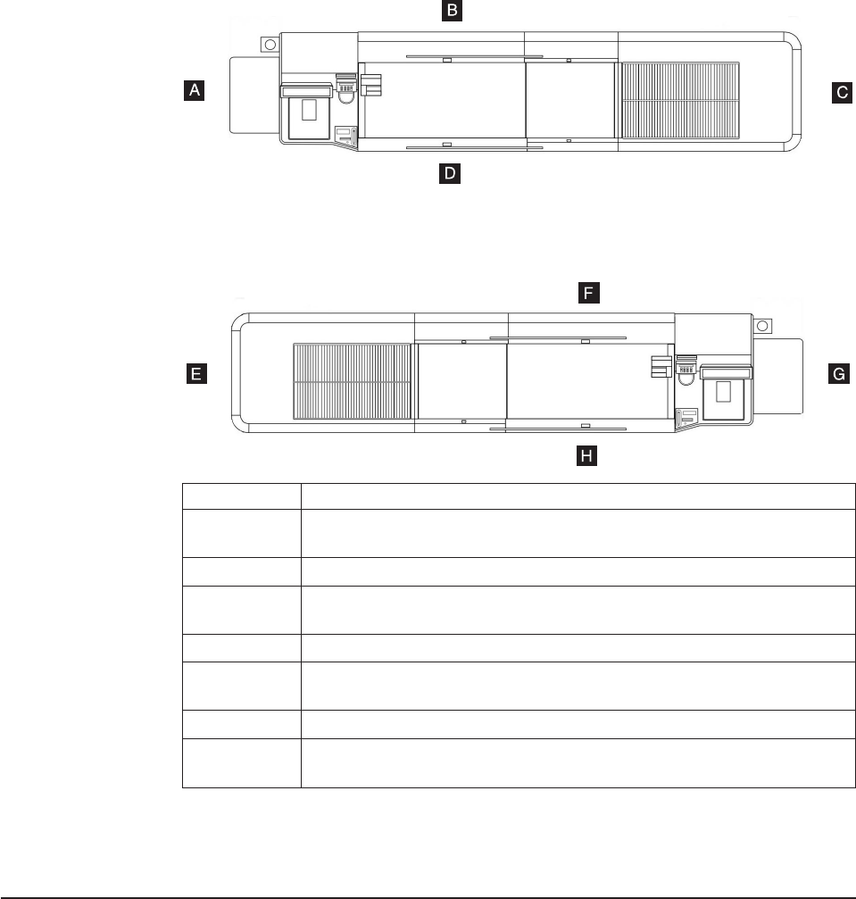
Identifying a Right Hand or Left Hand Model
Figure 1 on page vi shows a right-hand lane and a left-hand lane and gives the
naming conventions used in this manual for referring to the sides of the lanes.
Updated October 16, 2007
© Copyright IBM Corp. 2006, 2007 v
Related Publications
v IBM Self Checkout 4845 Overview Models 131, 15x, 171, 6xx, 8xx and BW3,
GC30-9732
v IBM Self Checkout 4845 Hardware Planning and Installation Guide Models 131,
15x, 171, 6xx, 8xx, and BW3, GC30-9733
v IBM Self Checkout Solution 4845 Operations Guide Models 131, 151, 152, 153,
and 171, GA27-4341 (for software releases prior to Version 5 Release 2)
v IBM Self Checkout Solution 4845 Operations Guide Models 131, 151, 152, 153,
and 171, with Version 5 Release 2 Software, GC30-9734
v IBM Self Checkout 4845 Operations Guide Models 6xx, 8xx, and BW3 with IBM
Checkout Environment for Consumer-Service Version 6, GC30-9729
A Start of right-hand lane.
B Rear side (or left side relative to the transaction flow) of right-hand lane.
The emitters are on the left side of the conveyor.
C End of right-hand lane.
D Front (customer side or right side relative to the transaction flow) of
right-hand lane. The detectors are on the right side of the conveyor.
E End of left-hand lane.
F Rear side (or right side relative to the transaction flow) of left-hand lane.
The detectors are on the right side of the conveyor.
G Start of left-hand lane.
H Front (customer side or left side relative to the transaction flow) of left-hand
lane. The emitters are on the left side of the conveyor.
Figure 1. Right-Hand and Left-Hand Lanes
Updated October 16, 2007
vi Self Checkout 4845: Parts Manual Models 131, 15x, 171, 6xx, 8xx, and BW3
|
|
|
|
|
|

v IBM Self Checkout 4845 Hardware Service Guide Models 131, 15x, 171, 6xx,
8xx, and BW3, GY27-0442
v IBM Checkout Environment for Consumer-Service Software Planning, Installation,
and Maintenance Guide for Version 6, SC30-4156
v IBM Checkout Environment for Consumer-Service Software Programming Guide
for Version 6, SC30-4157
v IBM 4610 SureMark Printers Hardware Service Manual, GY27-0355
v IBM 4610 SureMark Printers User Guide, GA27-4151
v IBM 4820 SurePoint Solution Planning, Installation and Service Guide,
GA27-4231
v IBM 4800 SurePOS 720, 740, and 780 Hardware Service Guide, SA27-4329
v IBM 4800 SurePOS 720, 740, and 780 Planning, Installation and Operation
Guide, GA27-4328
v IBM 4694 Point-of-Sale Terminal Hardware Service Manual, SY27-0364
v IBM Safety and Regulatory Information - Read This First, GA27-4004
Where to Find More Information
Current versions of Retail Store Solutions documentation are available on the IBM
Retail Store Solutions Web site at www.ibm.com/solutions/retail/store. Select
Support; then select Publications.
For information about publications not contained on the Web site, contact your IBM
representative or your place of purchase.
Safety
Before you begin to install or service this product, read the safety information in the
IBM Safety and Regulatory Information - Read This First, GA27-4004. This book
describes the safe procedures for installing and servicing IBM products. In addition,
read the following safety information.
DANGER
Electrical power must be removed before performing any maintenance or
service on the self checkout product. See IBM Self Checkout 4845 Hardware
Service Guide Models 131, 15x, 171, 6xx, 8xx, and BW3, GY27-0442 for
information about removing power.
DANGER
If the self checkout product is equipped with an uninterruptible power
supply some devices are still energized after the removal of ac power. The
uninterruptible power supply must be disconnected to ensure that all
power is removed from the self checkout product.
Publications Accessibility
The soft-copy version of this guide and other related publications are
accessibility-enabled.
Updated October 16, 2007
Preface vii
|
|
|
|
|
|
|
|
|
|
|
|
|
|
|
Providing Feedback
Your feedback is important in helping IBM provide accurate and high-quality
information.
You can use either of these ways to provide feedback:
v Go to http://www.ibm.com/solutions/retail/store. Click Support, then click
Publications. Click the publication comments within the introductory text.
Provide the requested information and your comments. Be sure to include the
name and form number of the document in the [Publication ID] field.
v Print and complete the form at the end of this document. Return the form to IBM
by mail or by giving it to an IBM representative.
If applicable, include a reference to the specific location of the text (for example, the
page or table number) on which you are commenting.
Between major revisions of this document, there might be minor technical updates.
The latest version of this document is available on the Retail Store Solutions Web
site at http://www.ibm.com/solutions/retail/store/support/publications/.
Uninterruptible Power Supply Option
This product contains a sealed lead acid battery. The battery must be recycled or
disposed of properly.
In the United States, IBM has established a collection process for reuse, recycling,
or proper disposal of used IBM sealed acid batteries. For information about proper
disposal of these batteries, please contact IBM at 1-800-426-4333. Please have the
IBM part number listed on the battery available prior to your call.
For information about disposal of sealed acid batteries outside the United States, go
to the following URL or contact your local waste disposal facility.
http://www.ibm.com/ibm/environment/products/batteryrecycle.shtml
Taiwanese Battery Recycling Statement
Waste batteries, please recycle.
End of life disposal
This unit must be recycled or discarded according to applicable local and national
regulations. IBM encourages owners of information technology (IT) equipment to
responsibly recycle their equipment when it is no longer needed. IBM offers a
variety of product return programs and services in several countries to assist
equipment owners in recycling their IT products. Information on IBM product
recycling offerings can be found on IBM’s Internet site at http://www.ibm.com/ibm/
environment/products/prp.shtml.
Updated October 16, 2007
viii Self Checkout 4845: Parts Manual Models 131, 15x, 171, 6xx, 8xx, and BW3

Notice: This mark applies only to countries within the European Union (EU) and
Norway.
Appliances are labeled in accordance with European Directive 2002/96/EC
concerning waste electrical and electronic equipment (WEEE). The Directive
determines the framework for the return and recycling of used appliances as
applicable throughout the European Union. This label is applied to various products
to indicate that the product is not to be thrown away, but rather reclaimed upon end
of life per this Directive.
In accordance with the European WEEE Directive, electrical and electronic
equipment (EEE) is to be collected separately and to be reused, recycled, or
recovered at end of life. Users of EEE with the WEEE marking per Annex IV of the
WEEE Directive, as shown above, must not dispose of end of life EEE as unsorted
municipal waste, but use the collection framework available to customers for the
return, recycling, and recovery of WEEE. Customer participation is important to
minimize any potential effects of EEE on the environment and human health due to
the potential presence of hazardous substances in EEE. For proper collection and
treatment, contact your local IBM representative.
Disposal of IT products should be in accordance with local ordinances and
regulations.
Updated October 16, 2007
Preface ix
Updated October 16, 2007
x Self Checkout 4845: Parts Manual Models 131, 15x, 171, 6xx, 8xx, and BW3
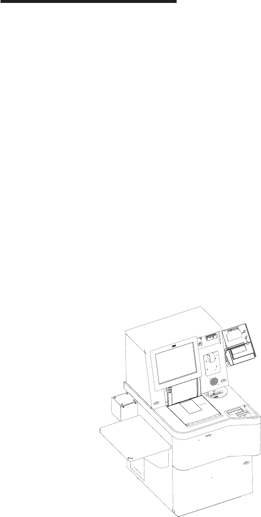
Chapter 1. Core Module
Assembly 1: Core Module . . . . . . . . . . . . . . . . . . . . .2
Assembly 2: Bill Dispenser . . . . . . . . . . . . . . . . . . . . .6
Assembly 3: Bill Dispenser Main Unit Illustration 1 of 3 . . . . . . . . . . .8
Assembly 4: Bill Dispenser Main Unit Illustration 2 of 3 . . . . . . . . . .10
Assembly 5: Bill Dispenser Main Unit Illustration 3 of 3 . . . . . . . . . .12
Assembly 6: Bill Dispenser Lower Unit . . . . . . . . . . . . . . . .14
Assembly 7: Bill Dispenser Cassette . . . . . . . . . . . . . . . . .16
Assembly 8: Bill Dispenser Communications and Power . . . . . . . . . .18
Assembly 9: Coin Dispensers . . . . . . . . . . . . . . . . . . .20
Assembly 10: Coin Acceptor . . . . . . . . . . . . . . . . . . . .24
Assembly 11: Bill Acceptor . . . . . . . . . . . . . . . . . . . . .26
Assembly 12: Printers TIx and TGx . . . . . . . . . . . . . . . . .28
Assembly 13: Printers TF6 and TM6 . . . . . . . . . . . . . . . . .32
Assembly 14: Printers Fiscal . . . . . . . . . . . . . . . . . . . .36
Assembly 15: Printers Epson . . . . . . . . . . . . . . . . . . . .38
Assembly 16: Magnetic stripe reader and pin pad mount . . . . . . . . .40
Assembly 17: Hand held scanner . . . . . . . . . . . . . . . . . .42
Assembly 18: Countertop . . . . . . . . . . . . . . . . . . . . .44
Assembly 19: Signature Capture and Coupon Acceptor . . . . . . . . . .46
Assembly 20: Lane light and transaction light . . . . . . . . . . . . . .48
Assembly 21: Lane PC, Mouse, and Keyboard . . . . . . . . . . . . .50
Updated October 16, 2007
© Copyright IBM Corp. 2006, 2007 1
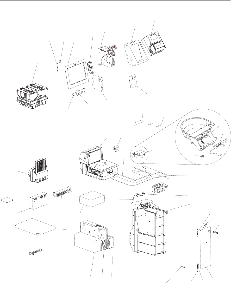
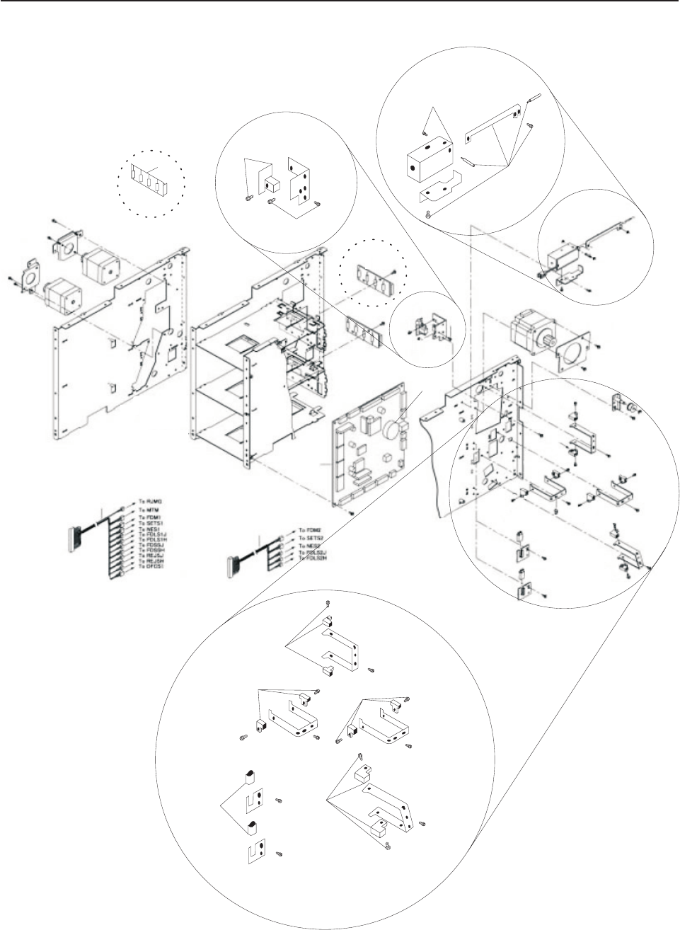
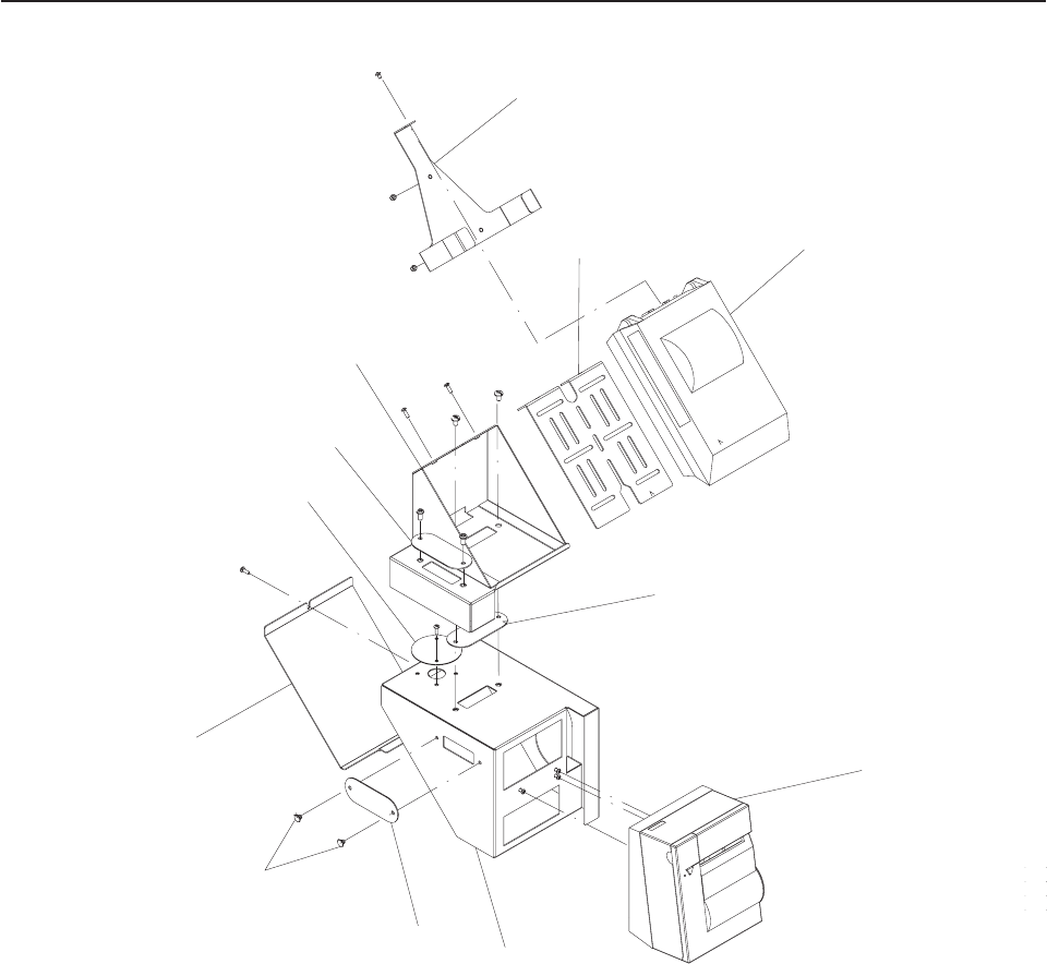
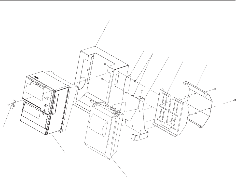
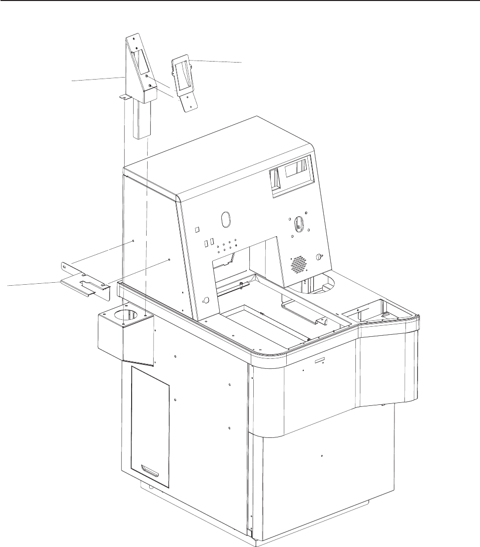
Assembly 1: Core Module
34
5
7
8
9
10
11
13 14
15
20
27
28
29
31
3233
34
36
35
37
38
39
40
26
16
17
1
2
24
25
21
22
23
6
12
30
18c
18b
19
18
41
Updated October 16, 2007
2 Self Checkout 4845: Parts Manual Models 131, 15x, 171, 6xx, 8xx, and BW3

Asm–
Index
Part
Number Units Description
1– See “How to Use This Parts Manual” on page v for general parts manual
information, including finding and ordering parts. See “Identifying a Right
Hand or Left Hand Model” on page v for how to identify left hand and right
hand models.
–1 1 Hopper coin dispenser. See “Assembly 9: Coin Dispensers” on page 20 for a
complete listing of coin dispenser parts.
–2 40M9470 1 Cable, Reset Button
–3 40M9469 1 Button Assembly, Reset (on upper door behind monitor)
–4 41J9296 1 Monitor, IBM SurePoint Model 4820 - 5WN (USB with I/O support), pearl white
(BOSS) (machines built after July 31, 2006)
–4 40M9366 1 Monitor, IBM SurePoint Model 4820 - 5WN (USB with I/O support), pearl white
(BOSS)
–4 41J9298 1 Monitor, IBM SurePoint Model 4820 - 5WN (USB without I/O support), pearl white
(lane)
–4 41J9295 1 Monitor, IBM SurePoint Model 4820 - 5GN (USB with I/O support), iron gray
(RAP/BOSS)
–4 41J9297 1 Monitor, IBM SurePoint Model 4820 - 5GN (USB without I/O support), iron gray
(lane) (machines built after July 31, 2006)
–4 28R5455 1 Monitor, IBM SurePoint Model 4820 - 5GN (USB without I/O support), iron gray
(lane)
–4 44M1846 1 Monitor, IBM SurePoint Model 4820 - 5GN (RS232 touch I/O), iron gray (EMEA)
–4 44D1157 1 Monitor, flat, T115 TFT, Model 4942 - 15X, black
– 14J1054 1 3.8 cable, Analog video Monitor, IBM SurePoint Model 4820.
– 42M5667 1 3.8 cable, Analog video Monitor, IBM SurePoint Model 4820 (machines built after
July 31, 2006).
– 01L1637 1 3.8 cable, USB Touchscreen Monitor, IBM SurePoint Model 4820.
– 42M5632 1 3.8 cable, USB Touchscreen Monitor, IBM SurePoint Model 4820 (machines built
after July 31, 2006).
–5 40N6220 1 Magnetic stripe reader, pearl white (attaches to the 4820 display)
–5 40N6224 1 Magnetic stripe reader, iron gray (attaches to the 4820 display)
–6 1 Bill acceptor assembly. See “Assembly 11: Bill Acceptor” on page 26 for a complete
listing of bill acceptors and parts.
–7 See “Assembly 12: Printers TIx and TGx” on page 28.
–8 See “Assembly 12: Printers TIx and TGx” on page 28.
–9 41E1851 1 Cover plate if there is no pinpad (not shown)
–9 Magnetic strip reader mount and pin pad mounting. See “Assembly 16: Magnetic
stripe reader and pin pad mount” on page 40).
–10 1 Coin acceptor. See “Assembly 10: Coin Acceptor” on page 24 for a complete listing
of coin acceptors and parts.
–11 41E1849 1 SurePoint display hinge
–12 41E1850 1 Display mounting kit (includes 4 - shoulder washers, 8 - screws, 4 - M4 top inserts,
1 - spacer plate, 1 - limiter (right hand), and 1 - limiter (left hand).
–13 1 Scanner/scale (shown for reference only)
– 41D7211 1 Scanner Adapter plate, Fujitsu (customer furnished scanner)
–14 28R3786 1 Speaker
–14 41D7083 1 Speaker (machines built after July 31, 2006)
– 41K6370 1 Speaker Audio cable (not shown)
–15 1 Scanner/scale contrast label (shown for reference only)
–16 42K0356 1 Label, Cash Out, right hand
–16 42K0360 1 Label, Cash Out, left hand
–17 42K0358 1 Label, Coupon
–18 41J9839 1 Cash cup assembly, right hand
–18 41J9841 1 Cash cup assembly, left hand
Assembly 1: (continued)
Updated October 16, 2007
Chapter 1. Core Module 3

Asm–
Index
Part
Number Units Description
–18 41K6356 1 Cash cup, left hand
–18 41K6355 1 Cash cup, right hand
–18B 41D7080 1 Detector, cash cup
–18C 41D7082 1 Emitter, cash cup
–19 41J9838 1 Sensor card, cash cup
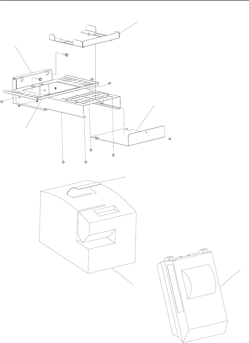
–20 1 Countertop. See “Assembly 18: Countertop” on page 44 for a complete listing of
available countertops.
–21 1 Signature capture device. See “Assembly 19: Signature Capture and Coupon
Acceptor” on page 46 for a complete listing of signature capture parts.
–22 41J9916 1 Proximity sensor
–23 40M9472 1 Proximity sensor cable
–24 1 Bill dispenser assembly. See “Assembly 2: Bill Dispenser” on page 6.
–25 41D9329 1 Hinge, upper hinge for right hand door (lower hinge for the left hand door)
–26 41K6087 1 Safe door cam lock
–27 41K6120 1 Safe door lock, currency lock with key. See Chapter 11, “Locks and Keys,” on page
95.
–28 41K6089 1 Safe door, right hand
–28 41K6090 1 Safe door, left hand
–29 41D9330 1 Hinge, lower hinge for the right hand door (upper hinge for the left hand door)
–30 41K6166 1 Bushing, hinge
–31 1 Keylock, cabinet lock with key. See Chapter 11, “Locks and Keys,” on page 95.
–32 41J9135 1 Security controller
–33 1 Lane PC. See “Assembly 21: Lane PC, Mouse, and Keyboard” on page 50.
–34 41D9359 1 Uninterruptible power supply, 230V/400W (BK650EI) (machines built after July 31,
2006)
–34 41D7068 1 Uninterruptible power supply, 115V (replaces 28R3582) (SU620)
– 44D0872 1 APC RBC4 Uninterruptible power supply replacement battery (for SU620)
– 44D0874 1 APC RBC5 Uninterruptible power supply replacement battery (for SU700INET)
– 44D1125 1 APC RBC17 Uninterruptible power supply replacement battery (for BK650EI)
(machines built after July 31, 2006)
–35 41K6161 1 Customer or basket shelf
–36 1 Sensormatic Scan Max Pro controller (shown for reference only)
–37 28R3587 1 Power strip, 5 Outlet, IEC320 (International, not US and Canada)
– 28R3595 1 Power strip, 115V, US, Canada, 8 outlet (not shown)
– 41D7775 1 Power strip IEC320 C-14 to 5 EU1-16R, French
– 44D0448 1 Power strip, IEC 60320 C-14 to 5 UK-13R
–38 41J9542 1 Filter/power box
–39 41E1865 1 Cover plate, lane light
–40 1 Cassette Coin dispenser. See “Assembly 9: Coin Dispensers” on page 20 for a
complete listing of coin dispenser parts.
–41 41J9891 1 Bracket for vacuum florescent (VF) display (for some fiscal printers)
– 40N4716 1 3.8m Printer USB cable (not shown)
– 41K6369 1 PC Audio cable (not shown)
– 41D7073 1 Cable, 6 foot, DB9, male/female, used for uninterruptible power supply data (not
shown)
– 41E1832 1 Power strip mounting plate (not shown)
– 28R3559 1 Power jumper cord, IEC 60320 C-14 to NEMA 5-15R (not shown)
– 39M5376 1 Power jumper cord, IEC320, 2-0M
– 41K6368 1 Power supply, Security controller (not shown)
–See Appendix A, “Cabinet Parts and Sensors,” on page 105 for available
cabinet FRUs.
–See Chapter 10, “Cables,” on page 89 for additional cable FRUs.
Assembly 1: (continued) Updated October 16, 2007
4 Self Checkout 4845: Parts Manual Models 131, 15x, 171, 6xx, 8xx, and BW3
Updated October 16, 2007
Chapter 1. Core Module 5
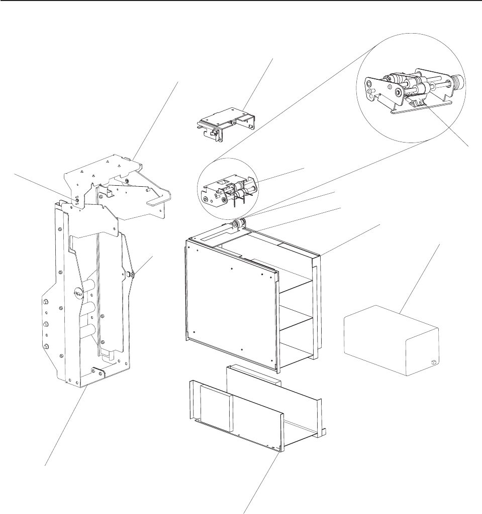
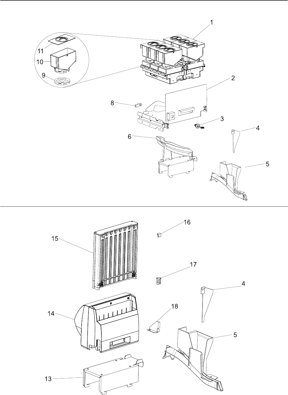
Assembly 2: Bill Dispenser
8
7
6
3
2
1
4
5
10
9
11
3a
Updated October 16, 2007
6 Self Checkout 4845: Parts Manual Models 131, 15x, 171, 6xx, 8xx, and BW3

Asm–
Index
Part
Number Units Description
2– See “How to Use This Parts Manual” on page v for general parts manual
information, including ordering parts. See “Identifying a Right Hand or Left Hand
Model” on page v for how to identify left hand and right hand models.
–1 41E1866 1 Bracket assembly, bill dispenser presenter mounting
–2 41K6318 1 Mount, bill dispenser (remains in cabinet)
–3 41K6319 1 Presenter, bill dispenser
–3A 41D7135 1 Sensor prism, presenter
–4 41D7137 1 Gear train, presenter gears
–5 41D7139 1 Presenter sensor plate
–6 41D7213 1 Bill dispenser, universal, 2 bin
–7 41D7053 1 Cartridge, universal, bill dispenser (includes configuration instructions and labels for
each currency). See “Assembly 7: Bill Dispenser Cassette” on page 16 for
additional component details.
–8 41D7215 1 Additional denomination module
–9 41K6398 1 Slide assembly, bill dispenser (with counter weight)
–10 41K6399 1 Mount parts, bill dispenser (pivot, screws, latch spring)
–11 41D8199 1 Set screw, bill dispenser presenter mount
– 41D7123 1 Presenter unit cable assembly (not shown)
– 41D7127 1 Presenter unit exit sensor (not shown)
Assembly 2: (continued)
Updated October 16, 2007
Chapter 1. Core Module 7
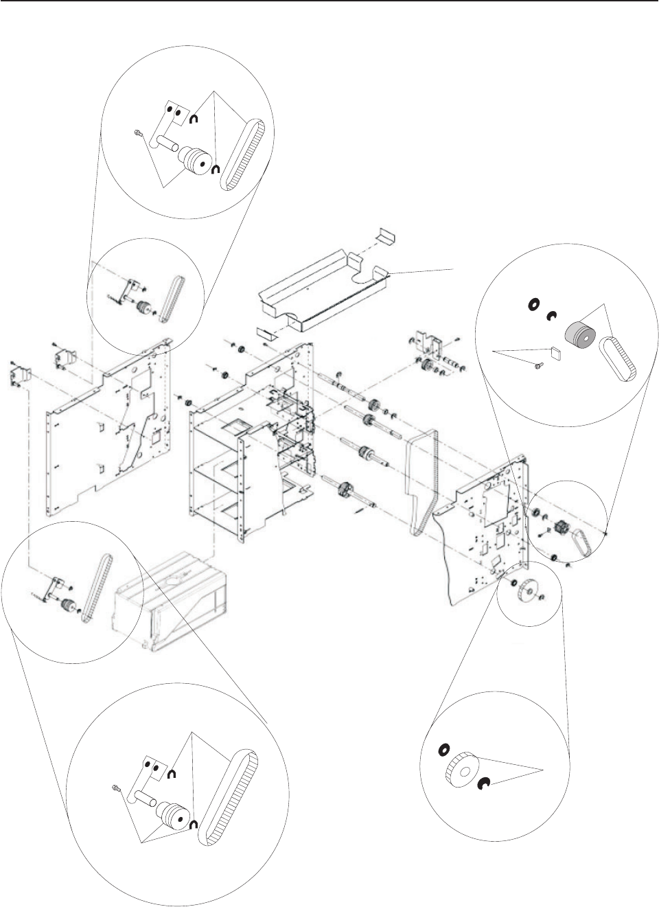
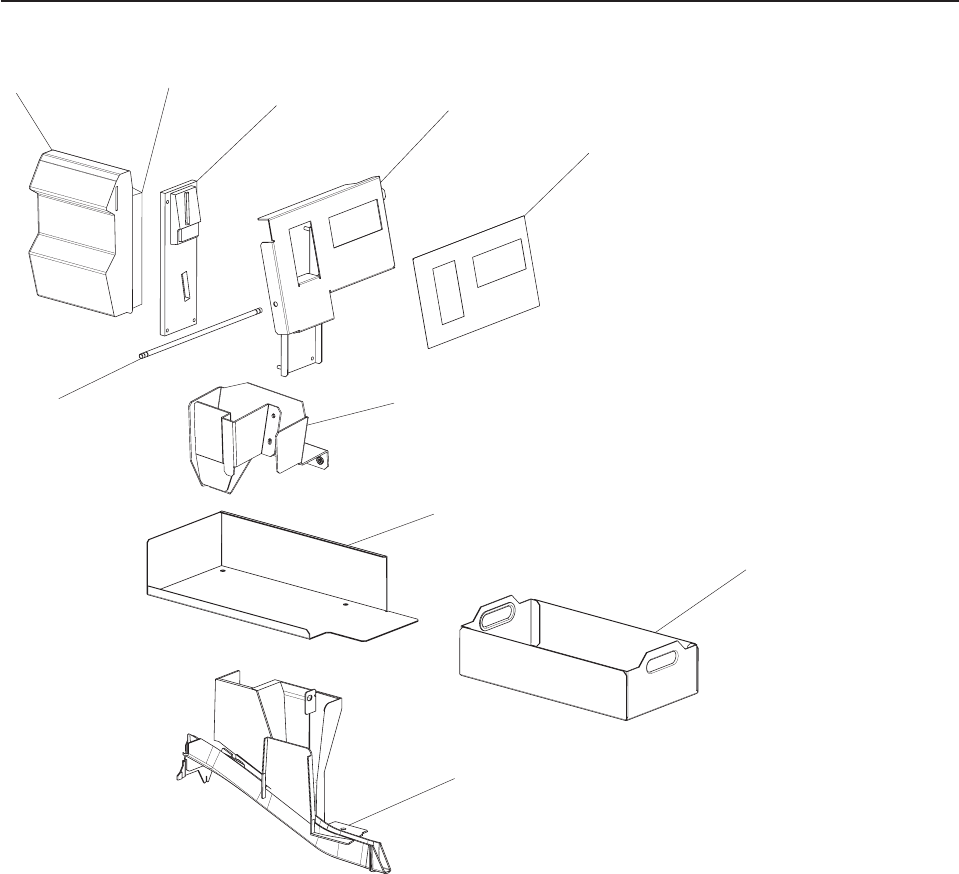
Assembly 3: Bill Dispenser Main Unit Illustration 1 of 3
5
1
1
4
4
2
3
2
Updated October 16, 2007
8 Self Checkout 4845: Parts Manual Models 131, 15x, 171, 6xx, 8xx, and BW3

Asm–
Index
Part
Number Units Description
3– See “How to Use This Parts Manual” on page v for general parts manual
information, including ordering parts. See “Identifying a Right Hand or Left Hand
Model” on page v for how to identify left hand and right hand models.
–1 41K6289 1 Timing kit, main unit channel 1 (includes 1 gear pulley, 2 retaining rings, 1 spring, 1
timing belt)
–2 41D7119 1 Timing kit, intermodule (includes 1 timing belt, 1 washer, 1 screw, 1 pulley)
–3 41K6303 1 Main/lower unit interconnect (includes 1 gear, 1 pin, 1 retainer E ring)
–4 41K6290 1 Timing kit, main unit channel 2 (includes 1 gear pulley, 2 retaining rings, 1 spring, 1
timing belt)
–5 41D7133 1 Reject bin
Assembly 3: (continued)
Updated October 16, 2007
Chapter 1. Core Module 9
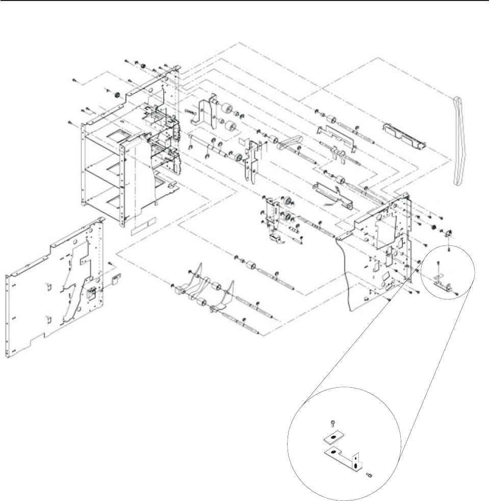
Assembly 4: Bill Dispenser Main Unit Illustration 2 of 3
1
1
1
Updated October 16, 2007
10 Self Checkout 4845: Parts Manual Models 131, 15x, 171, 6xx, 8xx, and BW3

Asm–
Index
Part
Number Units Description
4– See “How to Use This Parts Manual” on page v for general parts manual
information, including ordering parts. See “Identifying a Right Hand or Left Hand
Model” on page v for how to identify left hand and right hand models.
–1 41D7105 1 Scraper kit (includes 1 large and 1 small scraper, 2 screws (1 for each scraper)
Assembly 4: (continued)
Updated October 16, 2007
Chapter 1. Core Module 11
Assembly 5: Bill Dispenser Main Unit Illustration 3 of 3
1
6
7
8
3
2
54
4
44
3
2
9
Updated October 16, 2007
12 Self Checkout 4845: Parts Manual Models 131, 15x, 171, 6xx, 8xx, and BW3

Asm–
Index
Part
Number Units Description
5– See “How to Use This Parts Manual” on page v for general parts manual
information, including ordering parts. See “Identifying a Right Hand or Left Hand
Model” on page v for how to identify left hand and right hand models.
–1 1 Printed circuit board (reed switch type, sometimes referred to as a PCB) - not
serviceable (replace the bill dispenser assembly)
–2 41D7103 1 Thickness sensor (includes 1 sensor, 2 screws, 1 shaft, 1 retaining ring)
–3 41D7107 1 Solenoid kit (includes 1 solenoid, 3 screws, 3 retaining rings, 1 spring, 1 shaft, 1
MG arm)
–4 41D7563 1 Bill dispenser sensor kit (includes 2 sensors, 2 screws)
–5 41D7125 1 Cassette sensor, bill dispenser
–6 41D7113 1 Cable, CAU 2 Main unit controlled access unit
–7 41D7111 1 Cable, CAU 1 Main unit
–8 41D7109 1 Printed circuit board (main unit, sometimes referred to as a PCB)
–9 04G5389 1 Battery, Lithium
–9 41D7610 1 Battery, Lithium bill dispenser (machines built after July 31, 2006)
Assembly 5: (continued)
Updated October 16, 2007
Chapter 1. Core Module 13
Assembly 6: Bill Dispenser Lower Unit
1
9
9
8
9
3
5
6
4
7
2
Updated October 16, 2007
14 Self Checkout 4845: Parts Manual Models 131, 15x, 171, 6xx, 8xx, and BW3

Asm–
Index
Part
Number Units Description
6– See “How to Use This Parts Manual” on page v for general parts manual
information, including ordering parts. See “Identifying a Right Hand or Left Hand
Model” on page v for how to identify left hand and right hand models.
–1 41K6308 1 Lower unit timing belt
–2 41K6306 1 Lower unit gear 20 kit (includes 1 pin, 1 gear, 2 retaining E rings)
–3 41D7217 1 Lower unit gear 34 kit (includes 1 pin, 1 gear, 1 retaining E ring)
–4 41K6307 1 Lower unit gear 54 kit (includes 1 gear, 1 retaining ring)
–5 41D7121 1 Lower unit gear 44 kit (includes 1 pin, 1 gear, 1 retaining ring)
–6 41D7563 1 Bill dispenser sensor kit. See 5–4 on page 13.
–7 41D7125 1 Cassette sensor, bill dispenser
–8 41K6309 1 Cable assembly, lower unit
–9 41K6291 1 Timing kit, lower unit (includes 1 gear pulley, 2 retaining rings, 1 spring, 1 timing
belt)
Assembly 6: (continued)
Updated October 16, 2007
Chapter 1. Core Module 15
Assembly 7: Bill Dispenser Cassette
1
11
1
1
11
11
1
1
1
1
1
1
1
1
1
1
1
4
5
5
3
2
2
3
3
3
3
3
6
7
8
9
Updated October 16, 2007
16 Self Checkout 4845: Parts Manual Models 131, 15x, 171, 6xx, 8xx, and BW3

Asm–
Index
Part
Number Units Description
7– See “How to Use This Parts Manual” on page v for general parts manual
information, including ordering parts. See “Identifying a Right Hand or Left Hand
Model” on page v for how to identify left hand and right hand models.
– 41D7053 1 Cassette, universal bill dispenser
–1 41D7115 1 Pick roller kit (includes 1 passway, 1 spacer, 2 shaft assemblies, 2 pulleys, 2
one-way rollers, 3 gears, 2 rollers, 2 bearings, 1 timing belt, 2 screws, 2 nuts)
–2 41K6298 1 Cassette pressure plate kit (includes 1 pressure plate, 1 spring, 1 rubber sheet)
–3 41D7117 1 Cassette currency rails kit (includes 2 adjuster S, 4 leaf springs, 1 adjuster R, 4
screws, 1 rear pressure, 1 spring, 1 rubber sheet)
–4 41K6300 1 Cassette handle
–5 41K6301 1 Cassette magnets (package of 2)
–6 41D7131 1 Cassette prism
–7 42K0061 1 Cassette label "1" (not shown)
–7 42K0062 1 Cassette label "5" (not shown)
–7 42K0063 1 Cassette label "10" (not shown)
–7 42K0064 1 Cassette label "20" (not shown)
–8 41K6322 1 Cassette latching hook
–9 44M1840 1 Cassette latch
– 41D7129 1 Low note sensor
Assembly 7: (continued)
Updated October 16, 2007
Chapter 1. Core Module 17
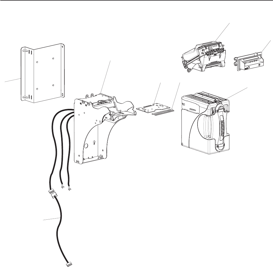
Assembly 8: Bill Dispenser Communications and Power
1 2 3
Updated October 16, 2007
18 Self Checkout 4845: Parts Manual Models 131, 15x, 171, 6xx, 8xx, and BW3

Asm–
Index
Part
Number Units Description
8– See “How to Use This Parts Manual” on page v for general parts manual
information, including ordering parts. See “Identifying a Right Hand or Left Hand
Model” on page v for how to identify left hand and right hand models.
–1 39M5374 1 1.0m power jumper cord (Uninterruptible power supply to Controller Uninterruptible
power supply In)
–2 40M9400 1 Cable, bill dispenser data
–3 41K6080 1 Power dongle, 24V
– 40N5606 1 Power adapter (power supply), 24V (not shown) (machines built after July 31, 2006)
Assembly 8: (continued)
Updated October 16, 2007
Chapter 1. Core Module 19
Assembly 9: Coin Dispensers
Updated October 16, 2007
20 Self Checkout 4845: Parts Manual Models 131, 15x, 171, 6xx, 8xx, and BW3

Asm–
Index
Part
Number Units Description
9– See “How to Use This Parts Manual” on page v for general parts manual
information, including ordering parts. See “Identifying a Right Hand or Left Hand
Model” on page v for how to identify left hand and right hand models.
– 41D7047 1 Hopper coin dispenser, UK (includes assembly index # 1 ,9, 10, 11 and the base)
– 44D1294 1 Hopper coin dispenser, Euro (includes assembly index # 1 ,9, 10, 11 and the base)
– 41D7043 1 Hopper coin dispenser, US (includes assembly index # 1 ,9, 10, 11 and the base)
– 41D7045 1 Hopper coin dispenser, Canada (includes assembly index # 1 ,9, 10, 11 and the
base)
– 41D7051 1 Hopper coin dispenser, Australia (includes assembly index # 1 ,9, 10, 11 and the
base)
–1 41J7615 1 Hopper, coin dispenser, US/Canada .01
–1 41J7616 1 Hopper, coin dispenser, US/Canada .05
–1 41J7617 1 Hopper, coin dispenser, US/Canada .10
–1 41J7618 1 Hopper, coin dispenser, US/Canada .25
–1 41J7619 1 Hopper, coin dispenser, US/Canada 1.00
–1 41J7620 1 Hopper, coin dispenser, Canada 2.00
–1 41J7621 1 Hopper, coin dispenser, UK .01
–1 41J7622 1 Hopper, coin dispenser, UK .02
–1 41J7623 1 Hopper, coin dispenser, UK .05
–1 41J7624 1 Hopper, coin dispenser, UK .10
–1 41J7625 1 Hopper, coin dispenser, UK .20
–1 41J7626 1 Hopper, coin dispenser, UK 1.00
–1 41J7627 1 Hopper, coin dispenser, Euro .01
–1 41J7628 1 Hopper, coin dispenser, Euro .02
–1 41J7629 1 Hopper, coin dispenser, Euro .05
–1 41J7630 1 Hopper, coin dispenser, Euro .10
–1 41J7631 1 Hopper, coin dispenser, Euro .20
–1 41J7632 1 Hopper, coin dispenser, Euro .50
–1 41J7633 1 Hopper, coin dispenser, Euro 1.00
–1 41J7634 1 Hopper, coin dispenser, Euro 2.00
–2 41K6082 1 Hopper mount assembly, right hand (includes slide rails)
–2 41K6086 1 Hopper mount assembly, left hand (includes slide rails)
–3 1 Keylock. See Chapter 11, “Locks and Keys,” on page 95.
–4 41D7076 1 Reject plate, coin, right hand
–4 41D7078 1 Reject plate, coin, left hand
–5 41K6363 1 Chute, coin, right hand, for both hopper and cassette coin dispensers
–5 41K6364 1 Chute, coin, left hand, for both hopper and cassette coin dispensers
–6 41D7813 1 Upper coin chute assembly, right hand
–6 41D7815 1 Upper coin chute assembly, left hand
–8 41K6088 1 Lock, cam
–9 41J7638 1 Hopper coin dispenser rotor, US/Canada .01
–9 41J7639 1 Hopper coin dispenser rotor, US/Canada .05
–9 41J7640 1 Hopper coin dispenser rotor, US/Canada .10
–9 41J7641 1 Hopper coin dispenser rotor, US .25, UK .10
–9 41J7642 1 Hopper coin dispenser rotor, US/Canada 1.00
–9 41J7643 1 Hopper coin dispenser rotor, Canada 2.00
–9 41J7644 1 Hopper coin dispenser rotor, UK .01
–9 41J7645 1 Hopper coin dispenser rotor, UK .02
–9 41J7646 1 Hopper coin dispenser rotor, UK .05
–9 41J7648 1 Hopper coin dispenser rotor, UK .20 Euro .05
–9 41J7649 1 Hopper coin dispenser rotor, UK 1.00
–9 44D1296 1 Hopper coin dispenser rotor, Euro .01
–9 41J7651 1 Hopper coin dispenser rotor, Euro .02/.10
Assembly 9: (continued)
Updated October 16, 2007
Chapter 1. Core Module 21

Asm–
Index
Part
Number Units Description
–9 41J7654 1 Hopper coin dispenser rotor, Euro .20/1.00
–9 41J7655 1 Hopper coin dispenser rotor, Euro .50/2.00
–10 41J7658 1 Hopper coin dispenser bin, clear
–11 41J7659 1 Hopper coin dispenser bin cover kit (includes cover body, label set for US, UK,
Euro
–13 41K6353 1 Coin dispenser stand
–14 41K6077 1 Coin dispenser with cable and power supply (does not include cartridge/cassette)
(unconfigured)
–14 41K7207 1 Coin dispenser with cable and power supply (does not include cartridge/cassette),
US
–14 41K7208 1 Coin dispenser with cable and power supply (does not include cartridge/cassette),
Canada
–14 41K7209 1 Coin dispenser with cable and power supply (does not include cartridge/cassette),
Euro
–14 41K7210 1 Coin dispenser with cable and power supply (does not include cartridge/cassette),
Australia
–14 41K7211 1 Coin dispenser with cable and power supply (does not include cartridge/cassette),
UK
–15 28R3678 1 Cassette, coin, Canada
–15 28R3679 1 Cassette, coin, Euro
–15 28R3680 1 Cassette, coin, Australia
–15 28R5399 1 Cassette, coin, UK
–15 28R5466 1 Cassette, coin, US
–16 41D8231 1 Corner plug, coin dispenser (used to block loading of coins in one or more stacks)
–17 41D8229 1 Wing clip, coin dispenser cassette (used to block dispensing of coins from one or
more stacks)
–18 41D8060 1 Coin cassette deflector, right hand
–18 41D8062 1 Coin cassette deflector, left hand
– 41D7403 1 Power supply, cassette coin dispenser, 32 VDC (not shown)
– 41D7404 1 Power supply, hopper coin dispenser, 24 VDC (not shown)
– 41K6352 1 Coin dispenser signal cable for both hopper and cassette dispensers (not shown)
– 39M5377 1 Power jumper cord, UK, EURO, Australia (not shown)
– 39M5081 1 Power jumper cord , US, Canada (not shown)
– 41J7635 1 Cable harness, position 1,2, and 3, hopper coin dispenser (not shown)
– 41J7636 1 Cable harness, position 4,5, and 6 hopper coin dispenser (not shown)
– 41J7637 1 Card assembly, hopper coin dispenser (not shown)
Assembly 9: (continued) Updated October 16, 2007
22 Self Checkout 4845: Parts Manual Models 131, 15x, 171, 6xx, 8xx, and BW3
Updated October 16, 2007
Chapter 1. Core Module 23
Assembly 10: Coin Acceptor
1234
5
67
8
9
10
Updated October 16, 2007
24 Self Checkout 4845: Parts Manual Models 131, 15x, 171, 6xx, 8xx, and BW3

Asm–
Index
Part
Number Units Description
10– See “How to Use This Parts Manual” on page v for general parts manual
information, including ordering parts. See “Identifying a Right Hand or Left Hand
Model” on page v for how to identify left hand and right hand models.
–1 41D9345 1 Coin Acceptor, MEI CF9520, US, with side reject plate (part 10–2) (machines built
after July 31, 2006)
–1 41D8051 1 Coin Acceptor MEI, CF9520, US, rejects $0.01, with side reject plate (part 10–2)
(machines built after July 31, 2006)
–1 41J6735 1 Coin Acceptor MEI, CF9520, US, with side reject plate (part 10–2)
–1 41D9347 1 Coin Acceptor, MEI CF9520, UK, with side reject plate (part 10–2) (machines built
after July 31, 2006)
–1 41J6736 1 Coin Acceptor MEI, CF9520, UK, with side reject plate (part 10–2)
–1 41D9346 1 Coin Acceptor, MEI CF9520, Canada, with side reject plate (part 10–2) (machines
built after July 31, 2006)
–1 41J6737 1 Coin Acceptor, Canada, with side reject plate (part 10–2)
–1 41D9348 1 Coin Acceptor, MEI CF9520, Euro, with side reject plate (part 10–2) (machines built
after July 31, 2006)
–1 41J6738 1 Coin Acceptor, Euro, with side reject plate (part 10–2)
–1 41D9349 1 Coin Acceptor, MEI CF9520, Australian, with side reject plate (part 10–2) (machines
built after July 31, 2006)
–1 41J6739 1 Coin Acceptor, MEI CF9520, Australian, with side reject plate (part 10–2)
–2 41J8231 1 Coin acceptor side reject plate
–3 28R3292 1 Coin acceptor mounting plate
–4 42K0052 1 Cash acceptance bezel, right hand
–4 42K0053 1 Cash acceptance bezel, left hand
–5 42K0355 1 Label, cash in, right hand
–5 42K0359 1 Label, cash in, left hand
–6 41K6593 1 Shaft, cash acceptance bezel
–7 41J8076 1 Coin deflector, right hand
–7 42K0058 1 Coin deflector, left hand
–8 44D0245 1 Coin tray guide, right hand
–8 44D0246 1 Coin tray guide, left hand
–9 41K6160 1 Coin tray
–10 41K6363 1 Chute, coin RH
–10 41K6364 1 Chute, coin LH
– 28R5566 1 Ferrite core (installed on signal cable)
– 41K6354 1 Coin acceptor cable, US/Canada (not shown)
– 41K6359 1 Coin acceptor cable, EMEA/Australia (not shown)
Assembly 10: (continued)
Updated October 16, 2007
Chapter 1. Core Module 25
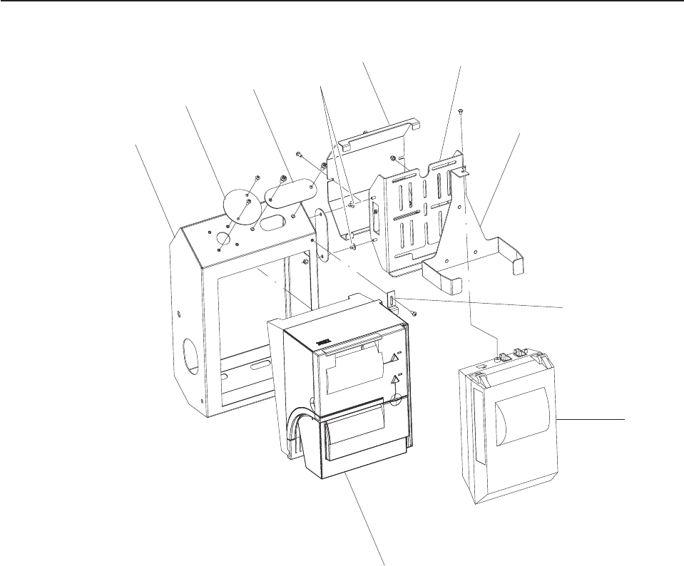
Assembly 11: Bill Acceptor
64
3
2
1
5
78
Updated October 16, 2007
26 Self Checkout 4845: Parts Manual Models 131, 15x, 171, 6xx, 8xx, and BW3

Asm–
Index
Part
Number Units Description
11– See “How to Use This Parts Manual” on page v for general parts manual
information, including ordering parts. See “Identifying a Right Hand or Left Hand
Model” on page v for how to identify left hand and right hand models.
– 41J9330 1 Mars SC6607R bill acceptor, US
– 41D7250 Mars SC6607R bill acceptor, US (machines built after July 31, 2006)
– 40M9343 1 Mars SC6607R bill acceptor, Australian firmware
– 41D7254 1 Mars SC8307R bill acceptor, Euro, UK
– 41E1449 1 Mars SC8307R bill acceptor, Canadian firmware
– 40M9341 1 Mars SC8307R bill acceptor, UK firmware
– 40M9342 1 Mars SC8307R bill acceptor, Euro firmware
–1 44D0258 1 Chassis with connector cables, Mars SC bill acceptor (does not include 11–6 or
11–7)
–2 41D7249 1 Head, Mars SC6607R bill acceptor, US, Australia (replaces 41J9486)
–2 41D7252 1 Head, Mars SC8307R bill acceptor, UK, Euro, Canada
–2 41D9700 1 Head, Mars SC8307R bill acceptor, Canadian firmware
–2 41D9701 1 Head, Mars SC8307R bill acceptor, UK firmware
–2 41D9702 1 Head, Mars SC8307R bill acceptor, Euro firmware
–2 41D9703 1 Head, Mars SC6607R bill acceptor, Australian firmware
–3 41D7251 1 Universal bezel with gap filler, Mars SC6607R bill acceptor, US, Australia (replaces
28R3477)
–3 41D7253 1 Universal bezel with gap filler, Mars SC8307R bill acceptor, UK, Euro, Canada
(replaces 28R5028)
–4 41D7248 1 Cash Box, Mars SC bill acceptors (replaces 28R3492)
–5 28R3684 1 Mars SC bill acceptor data cable
–6 41K6109 1 Bill acceptor mounting bracket
–7 44D0260 1 Interface card, MEI SC series bill acceptor
–8 44D0262 1 Edge connector, MEI SC series bill acceptor
Assembly 11: (continued)
Updated October 16, 2007
Chapter 1. Core Module 27
Assembly 12: Printers TIx and TGx
1
234
56
7
8
10
9
Updated October 16, 2007
28 Self Checkout 4845: Parts Manual Models 131, 15x, 171, 6xx, 8xx, and BW3

Asm–
Index
Part
Number Units Description
12– Printer, left hand iron gray
–1 41J9442 1 Printer shelf, TI and TG, left hand, iron gray
–2 41J9770 1 Hole cover, round, iron gray
–3 41J9457 1 Hole cover, oval, iron gray
–4 41J8809 1 Rivet, black push in
–5 41J9447 1 Printer, Catalina, back cover, iron gray
–6 41J9438 1 Printer, Catalina, left hand auxiliary mounting bracket iron gray (used with 41J9442)
–7 41J9452 1 Printer, Catalina, mounting bracket, iron gray (used with 41J9438)
–8 41J9416 1 Locking bracket, iron gray
–9 1 Catalina Printer (customer furnished)
–10 1 TI/TG Printer. See IBM 4610 SureMark Printers Hardware Service Manual,
GY27-0355.
– 41D9648 1 Printer, Catalina, support bracket, left hand, iron gray
–Printer, left hand pearl white
–1 41J9444 1 Printer shelf, TI and TG, left hand, pearl white
–2 41J9772 1 Hole cover, round, pearl white
–3 41J9459 1 Hole cover, oval, pearl white
–4 41J8807 1 Rivet, off white push in
–5 41J9449 1 Printer, Catalina, back cover, pearl white
–6 41J9440 1 Printer, Catalina, left hand auxiliary mounting bracket pearl white (used with
41J9444)
–7 41J9454 1 Printer, Catalina, mounting bracket pearl white (used with 41J9440)
–8 41J9418 1 Locking bracket, pearl white
–9 1 Catalina Printer (customer furnished)
–10 1 TI/TG Printer. See IBM 4610 SureMark Printers Hardware Service Manual,
GY27-0355.
– 41D9650 1 Printer, Catalina, support bracket, left hand, pearl white
–Printer, right hand iron gray
–1 41J9465 1 Printer shelf, TI and TG, right hand, iron gray
–2 41J9770 1 Hole cover, round, iron gray
–3 41J9457 1 Hole cover, oval, iron gray
–4 41J8809 1 Rivet, black push in
–5 41J9447 1 Printer, Catalina, back cover, iron gray
–6 41J9461 1 Printer, Catalina, right hand auxiliary mounting bracket iron gray (used with
41J9465)
–7 41J9452 1 Printer, Catalina, mounting bracket, iron gray (used with 41J9461)
–8 41J9416 1 Locking bracket, iron gray
–9 1 Catalina Printer (customer furnished)
–10 1 TI/TG Printer. See IBM 4610 SureMark Printers Hardware Service Manual,
GY27-0355.
– 41D9642 1 Printer, Catalina, support bracket, right hand, iron gray
–Printer, right hand pearl white
–1 41J9467 1 Printer shelf, TI and TG, right hand, pearl white
–2 41J9772 1 Hole cover, round, pearl white
–3 41J9459 1 Hole cover, oval, pearl white
–4 41J8807 1 Rivet, off white push in
–5 41J9449 1 Printer, Catalina, back cover, pearl white
–6 41J9463 1 Printer, Catalina, right hand auxiliary mounting bracket pearl white (used with
41J9467)
–7 41J9454 1 Printer, Catalina, mounting bracket pearl white (used with 41J9467)
Assembly 12: (continued)
Updated October 16, 2007
Chapter 1. Core Module 29

Asm–
Index
Part
Number Units Description
–8 41J9418 1 Locking bracket, pearl white
–9 1 Catalina Printer (customer furnished)
–10 1 TI/TG Printer. See IBM 4610 SureMark Printers Hardware Service Manual,
GY27-0355.
– 41D9644 1 Printer, Catalina, support bracket, right hand, pearl white
Assembly 12: (continued) Updated October 16, 2007
30 Self Checkout 4845: Parts Manual Models 131, 15x, 171, 6xx, 8xx, and BW3
Updated October 16, 2007
Chapter 1. Core Module 31
Assembly 13: Printers TF6 and TM6
1
23
4
5
6
4
7
8
9
4
10
Updated October 16, 2007
32 Self Checkout 4845: Parts Manual Models 131, 15x, 171, 6xx, 8xx, and BW3

Asm–
Index
Part
Number Units Description
13– Printer, right hand iron gray
–1 41J9452 1 Bracket, mounting Catalina printer, iron gray
–2 41J9533 1 Mounting bracket Catalina printer, right hand, iron gray (used with 41J9523)
–3 1 Catalina printer (customer furnished)
–4 41J9457 1 Hole cover, oval, iron gray
–5 1 Printer, TF6 and TM6. See IBM 4610 SureMark Printers Hardware Service Manual,
GY27-0355.
–6 41J9513 1 Printer shelf, 4610-TF6/TM6, right hand, iron gray
–7 41J8809 1 Rivet, black push in
–8 41J9538 1 Back cover, Catalina printer, iron gray (used with 41J9513)
–9 41J9770 1 Hole cover, round, iron gray
–10 41J9523 1 Auxiliary mount bracket Catalina printer, right hand, iron gray (used with 41J9513)
– 41D9653 1 Support bracket Catalina printer, iron gray
–Printer, right hand pearl white
–1 41J9454 1 Bracket, mounting Catalina printer, pearl white
–2 41J9535 1 Mounting bracket Catalina printer, right hand, pearl white (used with 41J9525)
–3 1 Catalina printer (customer furnished)
–4 41J9459 1 Hole cover, oval, pearl white
–5 1 Printer, TF6 and TM6. See IBM 4610 SureMark Printers Hardware Service Manual,
GY27-0355.
–6 41J9515 1 Printer shelf, 4610-TF6/TM6, right hand pearl white
–7 41J8807 1 Rivet, off white push in
–8 41J9540 1 Back cover, Catalina printer, pearl white (used with 41J9515)
–9 41J9772 1 Hole cover, round, pearl white
–10 41J9525 1 Auxiliary mount bracket Catalina printer, right hand, pearl white (used with 41J9515)
– 41D9655 1 Support bracket, Catalina printer, pearl white
–Printer, left hand iron gray
–1 41J9452 1 Bracket, mounting Catalina printer, iron gray
–2 41J9533 1 Mounting bracket Catalina printer, left hand, iron gray (used with 41J9528)
–3 1 Catalina printer (customer furnished)
–4 41J9457 1 Hole cover, oval, iron gray
–5 1 Printer, TF6 and TM6. See IBM 4610 SureMark Printers Hardware Service Manual,
GY27-0355.
–6 41J9518 1 Printer shelf, 4610-TF6/TM6, left hand iron gray
–7 41J8809 1 Rivet, black push in
–8 41J9538 1 Back cover, Catalina printer, iron gray (used with 41J9518)
–9 41J9770 1 Hole cover, round, iron gray
–10 41J9528 1 Auxiliary mount bracket Catalina printer, left hand, iron gray (used with 41J9518)
– 41D9653 1 Support bracket Catalina printer, iron gray
–Printer, left hand pearl white
–1 41J9454 1 Bracket, mounting Catalina printer, pearl white
–2 41J9535 1 Mounting bracket Catalina printer, left hand, pearl white (used with 41J9530)
–3 1 Catalina printer (customer furnished)
–4 41J9459 1 Hole cover, oval, pearl white
–5 1 Printers, TF6 and TM6. See IBM 4610 SureMark Printers Hardware Service
Manual, GY27-0355.
–6 41J9520 1 Printer shelf, 4610-TF6/TM6, left hand pearl white
–7 41J8807 1 Rivet, off white push in
–8 41J9540 1 Back cover, Catalina printer, pearl white (used with 41J9520)
–9 41J9772 1 Hole cover, round, pearl white
Assembly 13: (continued)
Updated October 16, 2007
Chapter 1. Core Module 33

Asm–
Index
Part
Number Units Description
–10 41J9530 1 Auxiliary mount bracket Catalina printer, left hand, pearl white (used with 41J9520)
– 41D9655 1 Support bracket, Catalina printer, pearl white
Assembly 13: (continued) Updated October 16, 2007
34 Self Checkout 4845: Parts Manual Models 131, 15x, 171, 6xx, 8xx, and BW3
Updated October 16, 2007
Chapter 1. Core Module 35
Assembly 14: Printers Fiscal
9
8
7
6
5
4
3
2
1
Updated October 16, 2007
36 Self Checkout 4845: Parts Manual Models 131, 15x, 171, 6xx, 8xx, and BW3

Asm–
Index
Part
Number Units Description
14– Printer, right hand pearl white
–1 41J9666 1 Printer shelf, Fiscal, right hand pearl white (Models 152, 602, and 612)
–2 41J9459 1 Hole cover, oval, pearl white
–3 41J8807 1 Rivet, off white push in nylon
–4 41J9454 1 Bracket, mounting Catalina printer, pearl white (used with 41J9463)
–5 41J9463 1 Auxiliary mount bracket Catalina printer, right hand, pearl white (used with 41J9666)
–6 41J9449 1 Printer, Catalina, back cover, pearl white
–7 1 Catalina printer (customer furnished)
–8 1 Fiscal printer. See IBM 4610 SureMark Printers Hardware Service Manual,
GY27-0355.
–9 41J9418 1 Locking bracket, pearl white
–Printer, left hand pearl white
–1 41J9670 1 Printer shelf, Fiscal, left hand pearl white (Models 152, 602, and 612)
–2 41J9459 1 Hole cover, oval, pearl white
–3 41J8807 1 Rivet, off white push in nylon
–4 41J9454 1 Bracket, mounting Catalina printer, pearl white (used with 41J9440)
–5 41J9440 1 Auxiliary mount bracket Catalina printer, left hand, pearl white (used with 41J9670)
–6 41J9449 1 Printer, Catalina, back cover, pearl white
–7 1 Catalina printer (customer furnished)
–8 1 Fiscal printer. See IBM 4610 SureMark Printers Hardware Service Manual,
GY27-0355.
–9 41J9418 1 Locking bracket, pearl white
Assembly 14: (continued)
Updated October 16, 2007
Chapter 1. Core Module 37
||||
||||
Assembly 15: Printers Epson
7
2
3
1
4
5
6
Updated October 16, 2007
38 Self Checkout 4845: Parts Manual Models 131, 15x, 171, 6xx, 8xx, and BW3

Asm–
Index
Part
Number Units Description
15– Printer, iron gray
–1 44D0252 1 Printer support bracket, iron gray
–2 44D0361 1 Support bracket for Catalina printer, iron gray
–3 44D0256 1 Cable cover for Catalina printer, iron gray
–4 44D0254 1 Auxiliary support bracket Catalina printer, iron gray
–5 44D0381 1 Paper diverter, Epson printer
– 44D0922 1 Mount adapter plate, Epson printer, iron gray
–6 1 Epson printer (customer furnished)
–7 1 Catalina printer (customer furnished)
–Printer, pearl white
–1 41D8573 1 Printer support bracket, pearl white
–2 44D0359 1 Support bracket for Catalina printer, pearl white
–3 41D8579 1 Cable cover for Catalina printer, pearl white
–4 41D8576 1 Auxiliary support bracket Catalina printer, pearl white
–5 44D0381 1 Paper diverter, Epson printer
– 44D0920 1 Mount adapter plate, Epson printer, pearl white
–6 1 Epson printer (customer furnished)
–7 1 Catalina printer (customer furnished)
Assembly 15: (continued)
Updated October 16, 2007
Chapter 1. Core Module 39
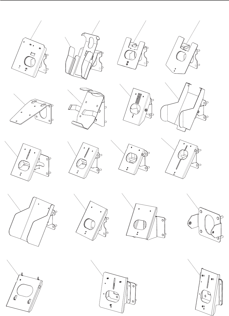
Assembly 16: Magnetic stripe reader and pin pad mount
1 3 4 5
2
14
10 11 12 13
9
8
7
6
15 16 17
18 19 20
Updated October 16, 2007
40 Self Checkout 4845: Parts Manual Models 131, 15x, 171, 6xx, 8xx, and BW3

Asm–
Index
Part
Number Units Description
16–1 41J8883 1 Magnetic stripe reader bracket, Verifone Omni 7000
–2 41J9662 1 Magnetic stripe reader shield, Ingenico 3500
–3 41J9660 1 Magnetic stripe reader bracket, Ingenico 3500
–4 41D7155 1 Bracket, Ingenico 6550 pin pad mounting
–5 41D7156 1 Bracket, Ingenico 6770 pin pad mounting
–6 41J7193 1 Magnetic stripe reader bracket, Banksys C-Zam Smash
–7 41D7246 1 Magnetic stripe reader bracket, Ingenico 3300
–8 41D7586 1 Mount, Checkmate 2001 pin pad
–9 41D7680 1 Mount, Wymix pin pad
–10 41D8391 1 Mount, Verifone OMNI 7000 pin pad (left hand)
–11 41D7767 1 Mount,
Verifone OMNI 490
Hypercom L4100
Verifone TT8800
–12 41J9157 1 Magnetic stripe reader mount bracket w/tilt assembly, Ingenico 6550
–13 41J9154 1 Magnetic stripe reader mount bracket assembly, Ingenico Entouch 1000
–14 41D8143 1 Magnetic stripe reader mounting bracket assembly Moneyline L3000
– 41J9765 1 Magnetic stripe reader washer, Ingenico 3500 (not shown) (Models 152, 602, and
612)
–15 41D7142 1 Mounting bracket, Verifone Everest Plus (right hand)
–16 41D7144 1 Mounting bracket, Verifone Everest Plus (left hand)
–17 41D7061 1 Support bracket, Verifone MX870 pin pad
–18 41D7634 1 Support bracket, Hypercom 5500
–19 41D9876 1 Mount, Verifone Omni 7000MPD pin pad (right hand)
–20 44D0347 1 Mount, Verifone Omni 7000MPD pin pad (left hand)
– 41D7595 1 Cable cover, Verifone and Checkmate mount (not shown)
– 41D7588 1 Mount bracket Checkmate 2001 pin pad (not shown)
– 41D7169 1 Bracket, locking for Wymix pin pad (not shown)
Assembly 16: (continued)
Updated October 16, 2007
Chapter 1. Core Module 41
||||
|
Assembly 17: Hand held scanner
1A
2
1B
Updated October 16, 2007
42 Self Checkout 4845: Parts Manual Models 131, 15x, 171, 6xx, 8xx, and BW3

Asm–
Index
Part
Number Units Description
17– 41D7242 1 Bracket for hand held scanner, pearl white (mounts to lane light bustle - Models
153, 603, and 613 only)
– 41D9435 1 Bracket for hand held scanner, iron gray (mounts to lane light bustle - Models 153,
603, and 613 only)
–1A 44D0241 1 Bracket, hand held scanner
–1B 44D0243 1 Bracket, hand held scanner
–2 41J9812 1 Bracket, hand held scanner, right hand, silver
–2 41J9817 1 Bracket, hand held scanner, left hand, silver
–2 41D8445 1 Bracket, hand held scanner, right hand, Formica white
–2 41D8448 1 Bracket, hand held scanner, left hand, Formica white
–2 41D1011 1 Bracket, hand held scanner, right hand, iron gray
–2 41D1015 1 Bracket, hand held scanner, left hand, iron gray
–2 41D1013 1 Bracket, hand held scanner, right hand, pearl white
–2 41D1017 1 Bracket, hand held scanner, left hand, pearl white
– 41D8449 1 Hole plate with strain relief for hand held scanner cable (not shown)
Assembly 17: (continued)
Updated October 16, 2007
Chapter 1. Core Module 43
||||
|
||||
|

Assembly 18: Countertop
1
2
3
4
6
7
8
9
5
12
13
10
11
15
16
17
18
14
Updated October 16, 2007
44 Self Checkout 4845: Parts Manual Models 131, 15x, 171, 6xx, 8xx, and BW3

Asm–
Index
Part
Number Units Description
18–1 41E1858 1 Countertop with signature capture, right hand
–2 41J6747 1 Countertop, with signature capture, right hand
–3 41E1861 1 Countertop, no signature capture, right hand
–4 41J6746 1 Countertop, no signature capture, right hand
–5 41D8628 1 Countertop, no signature capture, no coupon, right hand
–6 41D7161 1 Countertop, cashless with signature capture, right hand
–7 41D9626 1 Countertop, cashless with signature capture, right hand
–8 41J7533 1 Countertop, cashless with no signature capture, right hand
–9 41J6745 1 Countertop, cashless with no signature capture, right hand
–10 41J6749 1 Countertop, with signature capture, left hand
–11 41E1859 1 Countertop, with signature capture, left hand
–12 41J6750 1 Countertop, no signature capture, left hand
–13 41E1862 1 Countertop, no signature capture, left hand
–14 41D8630 1 Countertop, no signature capture, no coupon, left hand
–15 41D9628 1 Countertop, cashless with signature capture, left hand
–16 41D7163 1 Countertop, cashless with signature capture, left hand
–17 41J6748 1 Countertop, cashless with no signature capture, left hand
–18 41J7536 1 Countertop, cashless with no signature capture, left hand
Assembly 18: (continued)
Updated October 16, 2007
Chapter 1. Core Module 45
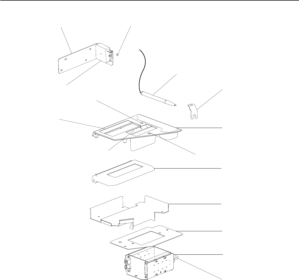
Assembly 19: Signature Capture and Coupon Acceptor
1
2
3
4
5
6
7
8
13
14 15
10 9
11
12
Updated October 16, 2007
46 Self Checkout 4845: Parts Manual Models 131, 15x, 171, 6xx, 8xx, and BW3

Asm–
Index
Part
Number Units Description
19– See “How to Use This Parts Manual” on page v for general parts manual
information, including ordering parts. See “Identifying a Right Hand or Left Hand
Model” on page v for how to identify left hand and right hand models.
– 44D1022 1 Signature capture assembly (right hand) with non-active stylus (also includes
bracket, retainer, hex L key)
– 44D1023 1 Signature capture assembly (left hand) with non-active stylus (also includes
bracket, retainer, hex L key)
– 44D1130 1 Signature capture assembly (left hand) with active stylus (also includes bracket,
retainer, hex L key)
– 44D1131 1 Signature capture assembly (right hand) with active stylus (also includes bracket,
retainer, hex L key)
–1 41D9560 1 Active stylus (includes stylus collar 19–15, O ring 19–, split ring 19–, and hex L key
19–)
–1 44D0750 1 Non active stylus (includes stylus collar 19–15)
–1 44D0987 1 Non active stylus (includes stylus collar 19–15, O ring 19–, split ring 19–, and hex L
key 19–)
– 44D0989 1 #60 O ring (not shown)
– 44D0991 1 #7 fine split ring (not shown)
– 44D1161 1 M0.9 hex L key (not shown)
–2 41K6576 1 Clip, signature capture
–3 44M1901 1 Signature capture bezel, right hand
–3 44M1902 1 Signature capture bezel, left hand
–4 41D8114 1 Signature capture device
–5 41E1854 1 Signature capture bracket, right hand
–5 41E1855 1 Signature capture bracket, left hand
– 41E1863 1 Filler plate, no signature capture bracket, right hand (not shown)
– 41E1864 1 Filler plate, no signature capture bracket, left hand (not shown)
–6 41E1829 1 Coupon mounting plate
–7 41J7798 1 Coupon emitter/detector assembly
–8 41J9289 1 6 in. RJ11 coupon patch cable
–9 41K6367 1 Coupon indicator assembly
–10 42K0358 1 Label, coupon
–11 42K0357 1 Label, signature
–12 44D1337 1 3/8 in. black nylon hole plug
–13 41J7094 1 Signature capture stylus retractor and collar
–14 41J7093 1 Signature capture stylus retractor bracket
–15 41D9561 1 Stylus collar
– 41E1830 1 Coupon indicator cable from coupon box to the LED (not shown)
– 41E1831 1 Coupon cable from the coupon box to the security controller (not shown)
– 41D1337 1 3/8 in. black nylon hole plug
Assembly 19: (continued)
Updated October 16, 2007
Chapter 1. Core Module 47
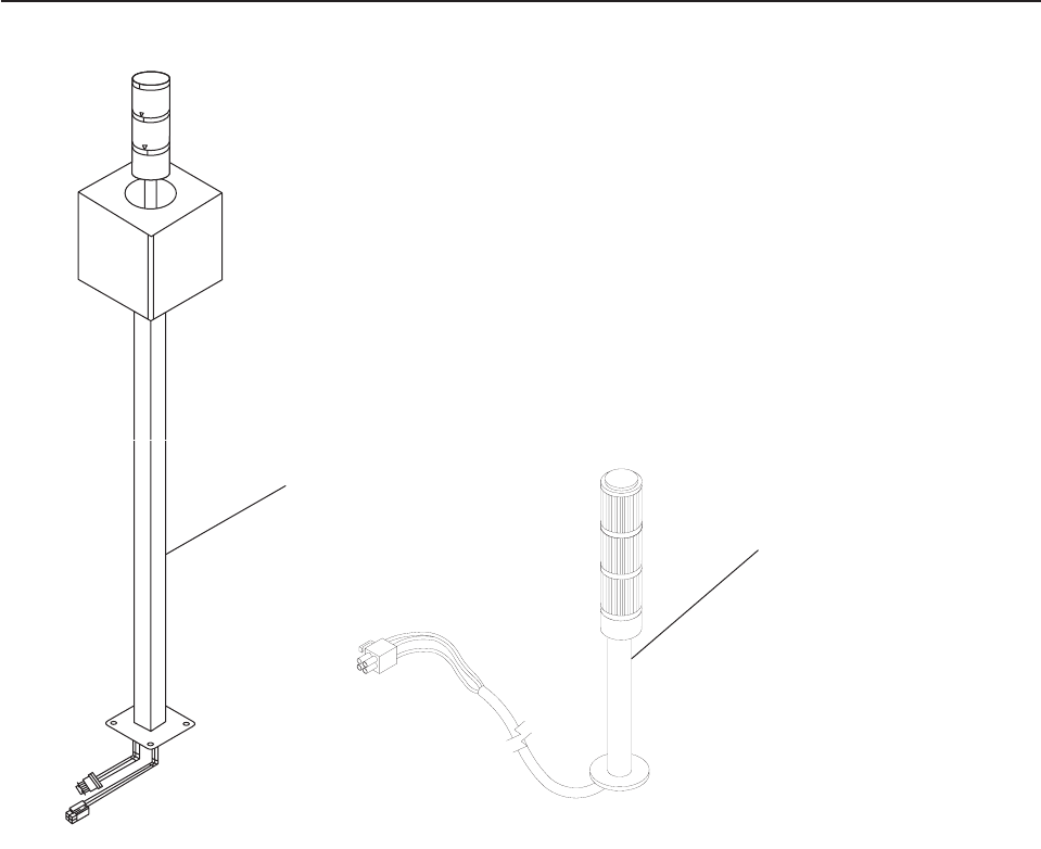
Assembly 20: Lane light and transaction light
1
2
Updated October 16, 2007
48 Self Checkout 4845: Parts Manual Models 131, 15x, 171, 6xx, 8xx, and BW3

Asm–
Index
Part
Number Units Description
20– See “How to Use This Parts Manual” on page v for general parts manual
information, including ordering parts. See “Identifying a Right Hand or Left Hand
Model” on page v for how to identify left hand and right hand models.
–1 41K6371 1 Lane light, with transaction light (English)
– 41D7426 1 Lane light, with transaction light (No text on globe)
– 41D7424 1 Lane light with transaction light (French, Dutch) Carrefour
– 41D7428 1 Lane light (Haggen ″Self Scan″) (top food banner)
– 41D7430 1 Lane light (Haggen ″Self Scan/ 12 items or less″) (top food banner)
– 41D8557 1 Lane light assembly, Haggen (Haggen Banner only) ″Self Scan / 12 Item or Less″
Models 153, 603, and 613
– 41D8555 1 Lane light assembly, Haggen (Haggen Banner) ″Self Scan″
– 41J8193 1 Lane light with transaction awareness light assembly, Carrefour, Belgium (French
only)
– 41J8194 1 Lane light with transaction awareness light assembly, Carrefour, Belgium (Dutch
only)
– 41J8195 1 Lane light with transaction awareness light assembly, Carrefour, Belgium
(German/French)
– 44D1232 1 Lane light with 2-tier transaction awareness light assembly and 400mm pole
– 41D8054 1 Cable, lane light power adapter
– 41D7557 1 Lens, red transaction light
– 41E1865 1 Cover plate, lane light (used when no lane light is present)
– 41D7656 1 Bulb 12 Vdc, transaction light
–2 41D7704 1 Transaction awareness light, 2-tier
–2 41D7706 1 Transaction awareness light, 3-tier
–2 41D7977 1 Transaction awareness light, 3-tier, Carrefour France (green, red, amber)
–2 44D0421 1 Transaction awareness light, 3-tier, Costco
– 41D8056 1 Cable, transaction awareness light
– 44M1884 1 Lane light mounting clamp (not shown, used when lane light is mounted on Models
152, 602, and 612 bagging module)
– 44M1886 1 Lane light mounting strap (not shown, used when lane light is mounted on Models
152, 602, and 612 bagging module)
Assembly 20: (continued)
Updated October 16, 2007
Chapter 1. Core Module 49
||||
|
||||
|
||||
|
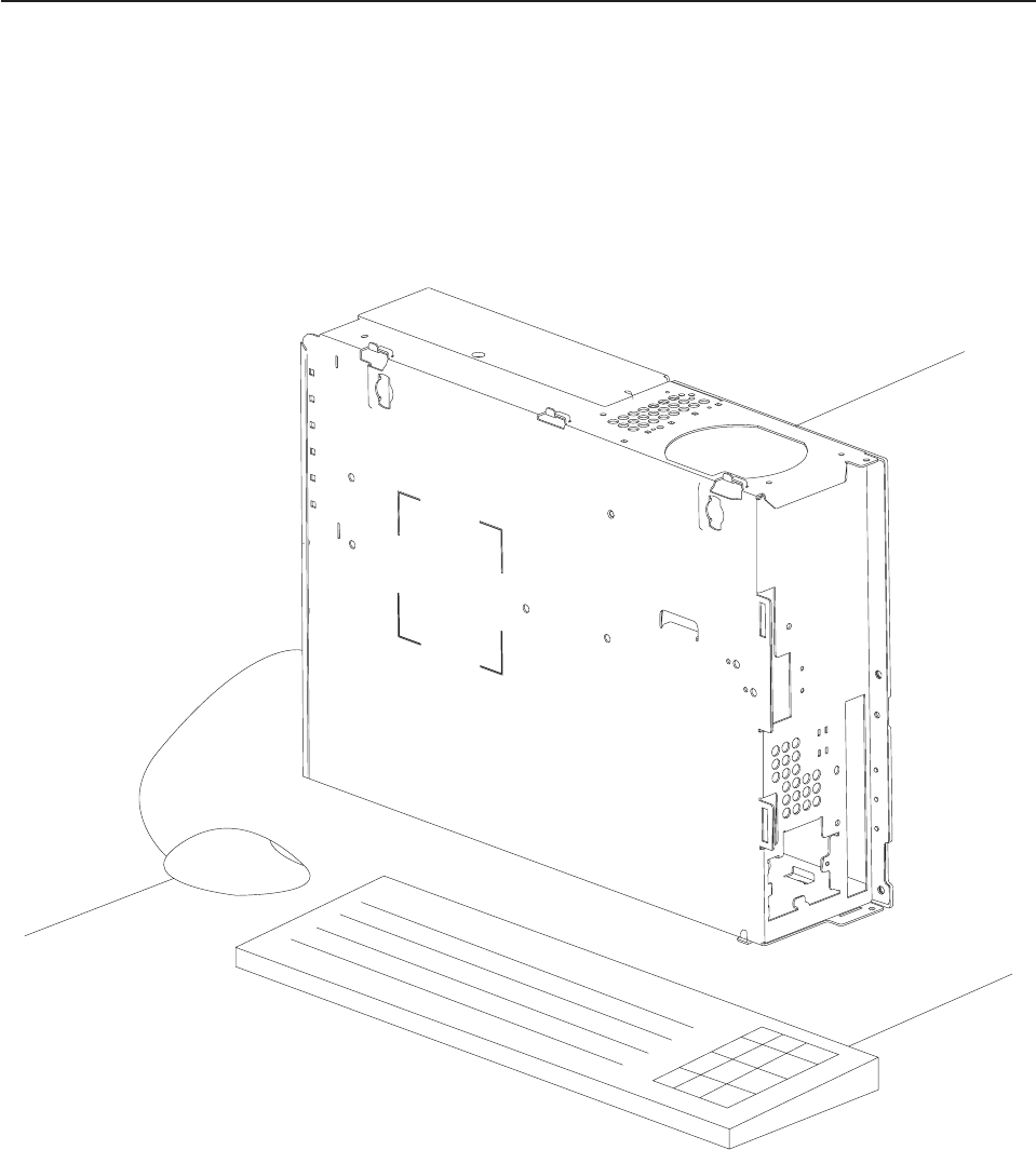
Assembly 21: Lane PC, Mouse, and Keyboard
1
2
3
Updated October 16, 2007
50 Self Checkout 4845: Parts Manual Models 131, 15x, 171, 6xx, 8xx, and BW3

Asm–
Index
Part
Number Units Description
21– See “How to Use This Parts Manual” on page v for general parts manual
information, including ordering parts. See “Identifying a Right Hand or Left Hand
Model” on page v for how to identify left hand and right hand models.
–1 1 Lane PC, IBM 4800-742 MFI. Refer to IBM 4800 SurePOS 720, 740, and 780
Hardware Service Guide, SA27-4329 for lane PC information.
–2 32N1205 1 Keyboard, Black, US English USB, #103P, PS/2 key layout, 3m cable
–2 32N1206 1 Keyboard, Black, French USB, #189, PS/2 key layout, 3m cable
–2 32N1207 1 Keyboard, Black, Italian USB, #142, PS/2 key layout, 3m cable
–2 32N1208 1 Keyboard, Black, German/Austrian USB, #129, PS/2 key layout, 3m cable
–2 32N1209 1 Keyboard, Black, UK English USB, #166, PS/2 key layout, 3m cable
–2 32N1210 1 Keyboard, Black, Spanish USB, #172, PS/2 key layout, 3m cable
–2 32N1216 1 Keyboard, Black, French Canadian USB, #445, PS/2 key layout, 3m cable
–2 32N1218 1 Keyboard, Black, Belgian/UK, #120, USB, PS/2 key layout, 3m cable
–2 32N1220 1 Keyboard, Black, Danish USB, #159, PS/2 key layout, 3m cable
–2 32N1224 1 Keyboard, Black, Dutch USB, #143, PS/2 key layout, 3m cable
–2 32N1236 1 Keyboard, Black, Slovenian USB, #234, PS/2 key layout, 3m cable
–2 10N9421 1 Keyboard, Black, Brazilian Portuguese USB, #275, PS/2 key layout, 3m cable
–2 10N9422 1 Keyboard, Black, Hungarian USB, #208, PS/2 key layout, 3m cable
–2 10N9428 1 Keyboard, Black, Swedish/Finnish USB, #153, PS/2 key layout, 3m cable
–2 10N9431 1 Keyboard, Black, Swiss, French/German USB, #150F/G, PS/2 key layout, 3m cable
–2 10N9432 1 Keyboard, Black, Norwegian USB, #155, PS/2 key layout, 3m cable
–2 10N9434 1 Keyboard, Black, Portuguese USB, #163, PS/2 key layout, 3m cable
–2 10N9435 1 Keyboard, Black, Greek USB, #319, PS/2 key layout, 3m cable
–2 10N9437 1 Keyboard, Black, Polish USB, #214, PS/2 key layout, 3m cable
–2 10N9439 1 Keyboard, Black, Czech USB, #243, PS/2 key layout, 3m cable
–2 10N9440 1 Keyboard, Black, Turkish USB, #179, PS/2 key layout, 3m cable
–2 10N9441 1 Keyboard, Black, LA Spanish USB, #171, PS/2 key layout, 3m cable
–3 03N6669 1 USB 3-Button mouse
– 41D7596 1 HASP ISS-45 POS software key
Assembly 21: (continued)
Updated October 16, 2007
Chapter 1. Core Module 51
||||
||||
||||
||||
||||
||||
||||
||||
||||
||||
||||
||||
||||
||||
||||
||||
||||
||||
||||
||||
||||
||||
Assembly 21: (continued) Updated October 16, 2007
52 Self Checkout 4845: Parts Manual Models 131, 15x, 171, 6xx, 8xx, and BW3

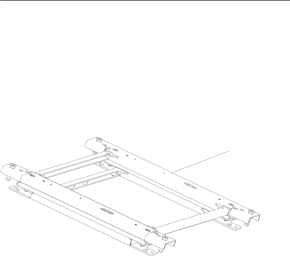
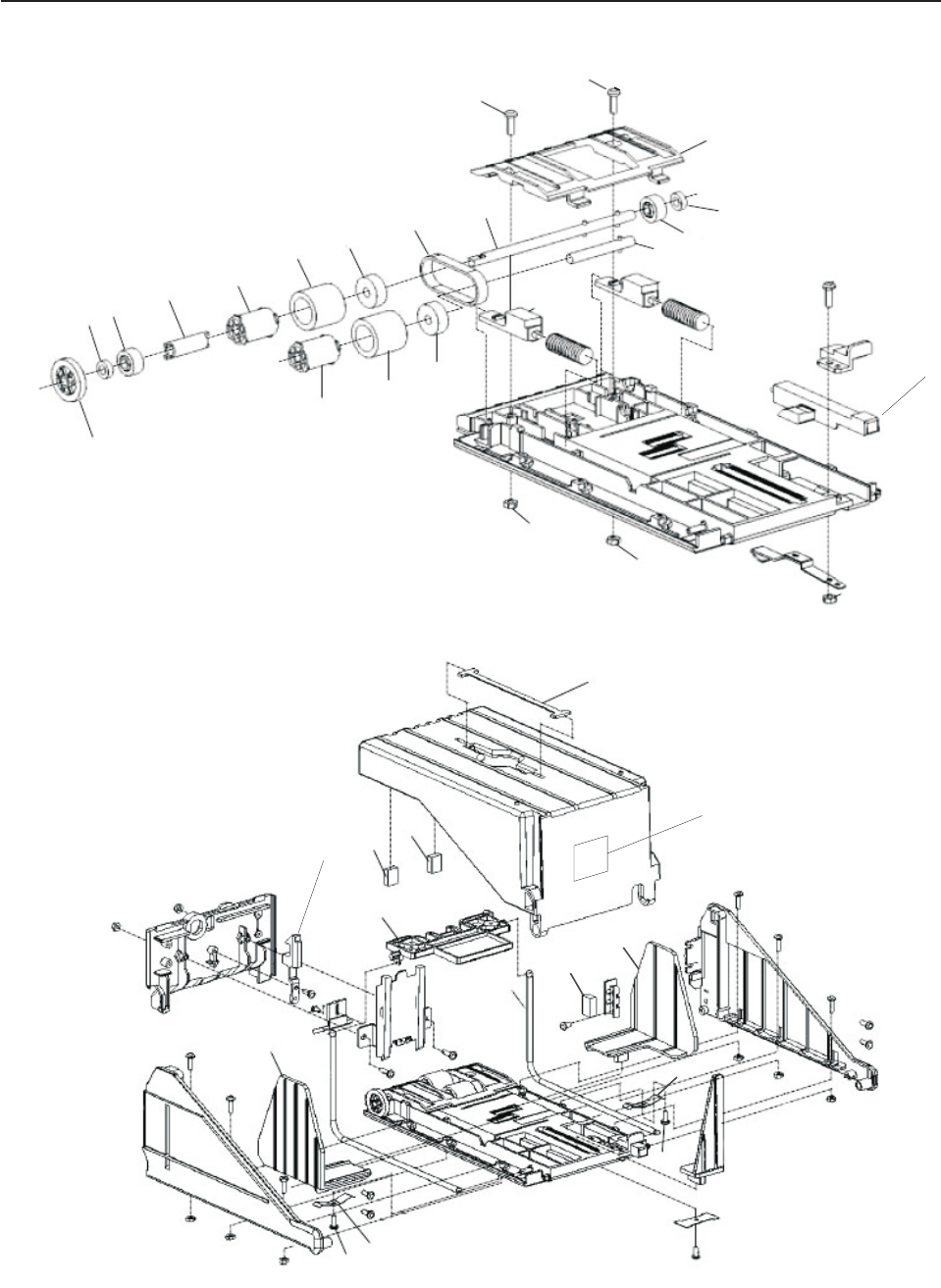
Assembly 22: Load Cell
1
Updated October 16, 2007
54 Self Checkout 4845: Parts Manual Models 131, 15x, 171, 6xx, 8xx, and BW3

Asm–
Index
Part
Number Units Description
22– See “How to Use This Parts Manual” on page v for general parts manual
information, including ordering parts. See “Identifying a Right Hand or Left Hand
Model” on page v for how to identify left hand and right hand models.
–1 41D7448 1 Load cell, 1 bag position (Model N54)
–1 41D7451 1 Load cell, Models 152, 153, 171, 602, 612, 603, 613, 800, 810 (replaces 41J8098)
–1 41D7453 1 Load cell, 100 KG, Models 171, 800, and 810 (for wide lane with 25 inch belt)
–1 41D8188 1 Load cell, Models 151, 606, and 616 Carousel
–1 41D7622 1 Load cell, Models 151, 606, and 616 secondary shelf
– 41D7621 1 Digital carousel weighting assembly with load cells, frame, platen, cables, control
box, Models 151, 606, and 616
– 41D8291 4 Screw, M6 X 55 (attaches load cell to conveyor) Models 171, 800, and 810
– 41J6930 2 Adapter bar, (attaches load cell to conveyor, for wide lane with 25 inch belt)
– 41J6934 2 Guide, load cell plastic, Models 171, 800, and 810 (for standard lane with 19 inch
belt)
– 41J7417 2 Guide, load cell plastic, Models 171, 800, and 810 (for wide lane with 25 inch belt)
– 41D7073 2 Cable, 6 foot, DB9, male/female, used for load cell extension
Assembly 22: (continued)
Updated October 16, 2007
Chapter 2. Load Cells, Platens, Plates, and Retaining Fences 55
||||
||||
||||
||||
||||
|
||||
||||
|
||||
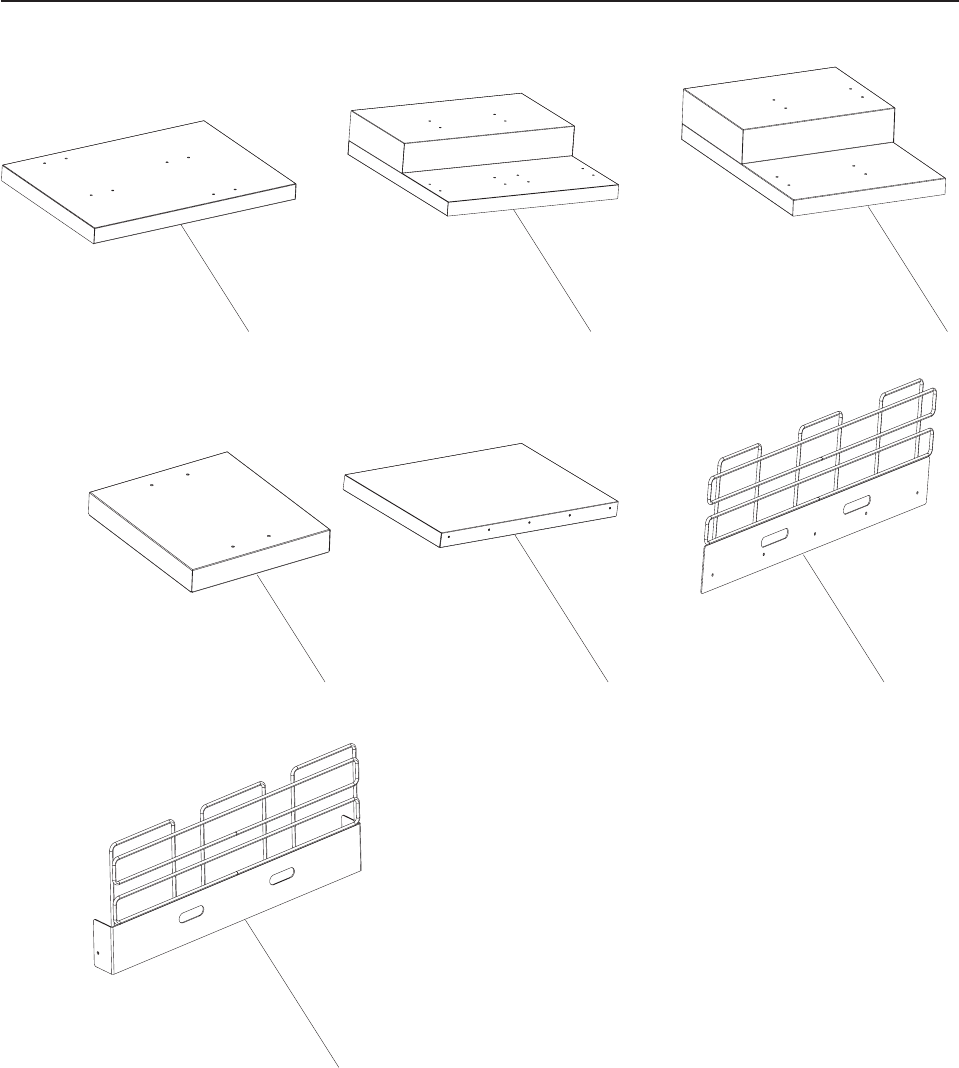
Assembly 23: Platens and Retaining Fences
1 2 3
4 5 6
7
Updated October 16, 2007
56 Self Checkout 4845: Parts Manual Models 131, 15x, 171, 6xx, 8xx, and BW3

Asm–
Index
Part
Number Units Description
23– See “How to Use This Parts Manual” on page v for general parts manual
information, including ordering parts. See “Identifying a Right Hand or Left Hand
Model” on page v for how to identify left hand and right hand models.
–1 41D7323 1 Flat platen with 2 bag hole pattern, right hand, Models 152, 602, and 612
– 41D7324 1 Flat platen with 2 bag hole pattern, left hand, Models 152, 602, and 612
–2 41D7636 1 Platen for Models 153, 603, and 613, tiered, 3 bag hole pattern, right hand/left
hand
– 41D8184 1 Platen, for Models 151, 606, and 616 Carousel (round platen)
–3 41D7635 1 Platen for Model Models 152, 602, and 612, tiered, 2 bag hole pattern, right hand
– 41D9327 1 Platen for Models 152, 602, and 612, tiered, 2 bag hole pattern, left hand
–4 41J9748 1 Platen, flat, 1 bag hole pattern, right hand/left hand, Model N54
– Platen tower See 26–4 on page 71.
– 41D8196 1 Platen assembly Models 151, 606, and 616 Carousel side shelf
–5 41D7667 1 Platen, flat, Models 152, 602, and 612
–6 41D7669 1 Fence, long retaining, Models 152, 602, and 612 (for use with Models 152, 602,
and 612 flat platen)
–7 41D7671 1 Fence, short retaining, Models 152, 602, and 612 (for use with Models 152, 602,
and 612 flat platen)
Assembly 23: (continued)
Updated October 16, 2007
Chapter 2. Load Cells, Platens, Plates, and Retaining Fences 57
||||
||||
|
||||
||||
||||
||||
||||
||||
|
||||
|
Assembly 23: (continued) Updated October 16, 2007
58 Self Checkout 4845: Parts Manual Models 131, 15x, 171, 6xx, 8xx, and BW3

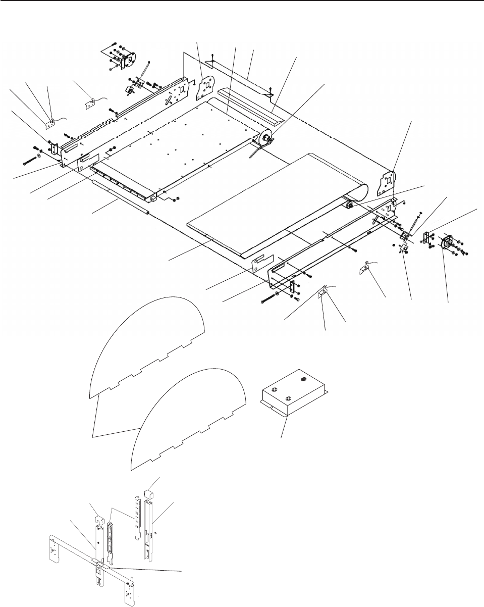
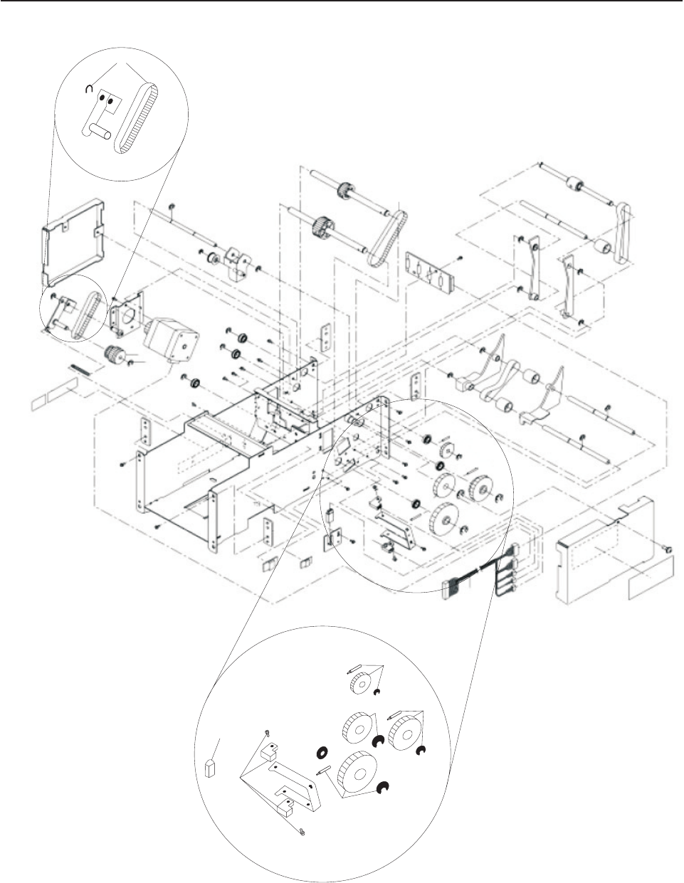
Assembly 24: Security Conveyor
123
4
5
6
8
9
10
11
15
16
17
18
20
21
27
28 29
26
25
12
7
22
31
33
30
31 32
13
14
23 24
19
34
Updated October 16, 2007
60 Self Checkout 4845: Parts Manual Models 131, 15x, 171, 6xx, 8xx, and BW3

Asm–
Index
Part
Number Units Description
24– See “How to Use This Parts Manual” on page v for general parts manual
information, including ordering parts. See “Identifying a Right Hand or Left Hand
Model” on page v for how to identify left hand and right hand models.
– 41J7432 1 Security conveyor assembly, 19 in., 115V
– 41J7436 1 Security conveyor assembly, 19 in., 230V
– 41J7440 1 Security conveyor assembly, 25 in., 115V
– 41J7444 1 Security conveyor assembly, 25 in., 230V
–1 41J8791 1 Skid plate (for standard lane with 19 inch belt)
–1 41J8896 1 Skid plate (for wide lane with 25 inch belt)
–2 41J9127 1 Plate, front transition, with sensors (for standard lane with 19 inch belt)
–2 41J8340 1 Plate, front transition, with sensors (for wide lane with 25 inch belt)
–2 41J8848 1 Plate, front transition (for wide lane with 25 inch belt) (includes support bracket)
–3 41D9782 1 Card stop bracket (mounted under the transition plate) (for standard lane with 19
inch belt)
–3 41J8867 1 Card stop bracket (mounted under the transition plate) (for wide lane with 25 inch
belt)
–4 41J9312 1 Motorized pulley, 19" security conveyor 115V-60hz, balanced
–4 41D9816 1 Motorized pulley, 19" security conveyor 230V-50hz, balanced
–4 41J9320 1 Motorized pulley, 25" security conveyor 115V-60hz, balanced
–4 41D9822 1 Motorized pulley, 25" security conveyor 230V-50hz, balanced
–5 28R3196 1 Guide, tracking, nose end (order with 28R3195). Adhesive plastic sticker. Reduces
friction between belt and metal sides.
–6 28R3298 1 Roller, idler (for standard lane with 19 inch belt)
–6 28R3275 1 Roller, idler (for wide lane with 25 inch belt)
–7 28R3284 2 Angle adjuster (one on each side)
–8 28R3285 2 Drive roller retaining angle (one on each side)
–9 41J7666 2 Bracket, drive isolation. Large black coupling. Use to adjust and isolate motor. (one
on each side)
–10 28R3283 2 Block, idler roller (one on each side)
–11 41J9845 1 Emitter, flat pack sensor assembly, replaces 40M9507, (Flat pack sensor
assemblies for the emitter and detector should be replaced as a set. Order
41J9849 detector.)
–12 41J9845 1 Exit sensor emitter (for standard lane with 19 inch belt)
–12 41J8344 1 Exit sensor emitter (for wide lane with 25 inch belt)
– 41J8854 1 Sensor cable, transition plate (not shown)
–13 41J8850 1 2nd emitter mounting bracket
–14 41D9783 1 Exit sensor mounting bracket
–15 28R3191 1 Plate, conveyer, left side (for standard lane with 19 inch belt)
–15 28R3277 1 Plate, conveyer, left side (for wide lane with 25 inch belt)
–16 28R3194 1 Guide, tracking, motor end (order with 28R3197). Adhesive plastic sticker. Reduces
friction between belt and metal sides.
–17 28R3192 1 Belt, security conveyor, with roller (for standard lane with 19 inch belt)
–17 28R3278 1 Belt, security conveyor, with roller (for wide lane with 25 inch belt)
–18 41J8338 1 Crossbar, conveyor frame (for standard lane with 19 inch belt) Aluminum bar.
(Replaces 28R3180)
–18 28R3279 1 Crossbar, conveyor frame (for wide lane with 25 inch belt)
–19 41J7448 1 Nose bar assembly (for standard lane with 19 inch belt)
–19 41J7450 1 Nose bar assembly (for wide lane with 25 inch belt)
–20 28R3195 1 Guide, tracking, motor end (order with 28R3196). Adhesive plastic sticker. Reduces
friction between belt and metal sides.
–21 28R3190 1 Plate, conveyer, right side (for standard lane with 19 inch belt)
–21 28R3276 1 Plate, conveyer, right side (for wide lane with 25 inch belt)
–22 28R3172 1 Nose bar angle adjuster
Assembly 24: (continued)
Updated October 16, 2007
Chapter 3. Security Conveyor 61

Asm–
Index
Part
Number Units Description
–23 41J8869 1 2nd detector mounting bracket
–24 41D9783 1 Exit sensor mounting bracket
–25 41J9849 1 Exit sensor detector (for standard lane with 19 inch belt)
–25 41J8342 1 Exit sensor detector (for wide lane with 25 inch belt)
–26 41J9849 1 Detector, flat pack sensor assembly, replaces 40M9508, (Flat pack sensor
assemblies for the emitter and detector should be replaced as a set. Order
41J9845 emitter.)
–27 28R3197 1 Guide, tracking, motor end (order with 28R3194). Adhesive plastic sticker. Reduces
friction between belt and metal sides.
– 41J7676 M6 x 19 Black screw for security shield (not shown)
–28 41J7678 2 Security shield
–29 41J9544 1 Capacitor box, 230V
–29 41J9546 1 Capacitor box, 115V
– 40M9423 1 Capacitor box cable (provides power to the conveyor motors) (not shown)
–30 41D9785 1 Curtain support, RH (for standard lane with 19 inch belt)
–30 41D9786 1 Curtain support, RH (for wide lane with 25 inch belt)
–30 41D9803 1 Curtain support, LH (for standard lane with 19 inch belt)
–30 41D9804 1 Curtain support, LH (for wide lane with 25 inch belt)
–32 41D9784 1 Cap, tower (one on each side)
–32 44M2189 1 Curtain detector/emitter sensor assembly (matched set) (located in the curtain
tower)
–33 41D9787 1 Tower, rear curtain support (for standard lane with 19 inch belt)
–33 41D9788 1 Tower, rear curtain support (for wide lane with 25 inch belt)
–34 44M2232 1 Curtain guard, customer side (for wide lane with 25 inch belt)
– 41J8414 4 Cable, curtain sensor fanout dongle (not shown)
– 41J8336 1 Wire cord clips (bag of 10)
– 42H1161 1 Cable tie (not shown)
–NOTE: Hardware items such as screws, bolts, nuts, and washers removed during
the disassembly of parts should be retained for use during re-assembly of those
parts. Screws, bolts, nuts, and washers can not be ordered separately, they are
available as part of a field kit. See Chapter 12, “Field Kits and Tools,” on page 101
for a listing of screws, bolts, nuts, and washers contained in each field kit.
– 41E1748 4 Transition plate extension cable
– 41E1749 2 Sensor extension cable
Assembly 24: (continued) Updated October 16, 2007
62 Self Checkout 4845: Parts Manual Models 131, 15x, 171, 6xx, 8xx, and BW3

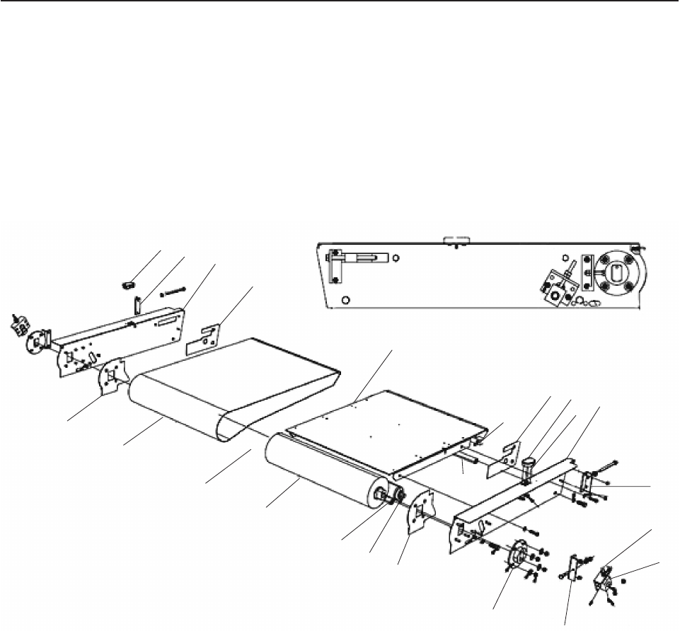
Assembly 25: Transport Conveyor
21
20
19
18
17
16 15 13
12
11
10
9
8
7
6
5
4
2
1
4
14
3
14
Updated October 16, 2007
64 Self Checkout 4845: Parts Manual Models 131, 15x, 171, 6xx, 8xx, and BW3

Asm–
Index
Part
Number Units Description
25– See “How to Use This Parts Manual” on page v for general parts manual
information, including ordering parts. See “Identifying a Right Hand or Left Hand
Model” on page v for how to identify left hand and right hand models.
– 41J7434 1 Transport conveyor assembly, 19 in., 115V
– 44M1899 1 Transport conveyor assembly with Sensormatic, 19 in., 115V, right hand
– 44M1900 1 Transport conveyor assembly with Sensormatic, 19 in., 115V, left hand
– 41J7438 1 Transport conveyor assembly, 19 in., 230V
– 41J7442 1 Transport conveyor assembly, 25 in., 115V
– 44D0405 1 Transport conveyor assembly with Sensormatic, 25 in., 115V, right hand
– 44D0407 1 Transport conveyor assembly with Sensormatic, 25 in., 115V, left hand
– 41J7446 1 Transport conveyor assembly, 25 in., 230V
–1 28R3196 1 Guide, tracking, motor end (order with 28R3195). Adhesive plastic sticker.
–2 28R3189 1 Belt, transport conveyor (for standard lane with 19 inch belt)
–2 28R3274 1 Belt, transport conveyor (for wide lane with 25 inch belt)
–3 41D9769 1 LED light visor mount (not shown, located on motor cable)
–4 41J9310 1 Motorized pulley, 19" conveyor 115-60hz, unbalanced (transport only)
–4 41D9818 1 Motorized pulley, 19" transport conveyor 230V
–4 41J9318 1 Motorized pulley, 25" conveyor 115-60hz, unbalanced (transport only)
–4 41D9820 1 Motorized pulley, 25" transport conveyor 230V
–5 41J8438 1 Crossbar, conveyor frame (for standard lane with 19 inch belt)
–5 28R3279 1 Crossbar, conveyor frame (for wide lane with 25 inch belt)
–6 28R3298 1 Roller (for standard lane with 19 inch belt)
–6 28R3275 1 Roller (for wide lane with 25 inch belt)
–7 28R3197 1 Guide, tracking, motor end (order with 28R3194). Adhesive plastic sticker.
–8 41J7666 2 Bracket, drive isolation. Large black coupling. Use to adjust and isolate motor. (one
on each side)
–9 28R3285 2 Drive roller retaining angle (one on each side)
–10 28R3283 2 Block, idler roller (one on each side)
–11 28R3284 2 Bracket, tensioner (one on each side)
–12 28R3172 1 Nosebar adjusting angle
–13 41J7426 1 Plate, side, transport conveyor, left side
–14 41J6928 1 Emitter/detector bracket, bagging area full sensor
–15 41D7146 1 Emitter, bagging area full sensor (for standard lane with 19 inch belt)
–15 41J8450 1 Emitter, bagging area full sensor (for wide lane with 25 inch belt)
–16 28R3195 1 Guide, tracking, motor end (order with 28R3196). Adhesive plastic sticker.
–17 41J7448 1 Assembly, nosebar, (for standard lane with 19 inch belt) (Replaces 28R7098)
–17 41J7450 1 Assembly, nosebar, (for wide lane with 25 inch belt) (Replaces 28R7084)
–18 41J8332 1 Skid plate, (for standard lane with 19 inch belt), no Sensormatic
–18 44M1913 1 Skid plate with Sensormatic opening, (for standard lane with 19 inch belt), right
hand
–18 44M1914 1 Skid plate with Sensormatic opening, (for standard lane with 19 inch belt), left hand
–18 41J8334 1 Skid plate, (for wide lane with 25 inch belt), no Sensormatic
–19 28R3194 1 Guide, tracking, motor end (order with 28R3197). Adhesive plastic sticker.
–20 41J7425 1 Plate, side, transport conveyor, right side plate
–21 41D7150 1 Detector, bagging area full sensor (for standard lane with 19 inch belt)
–21 41J8452 1 Detector, bagging area full sensor (for wide lane with 25 inch belt)
– 41J7126 1 25 inch order separator (not shown). See 42–1 on page 121.
– 41J7127 1 19 inch order separator (not shown). See 42–1 on page 121.
– 41J8854 1 Sensor cable, transition plate (not shown)
– 41J8855 1 Transition plate emitter (not shown)
– 41J8856 1 Transition plate detector (not shown)
– 42H1161 1 Cable tie (not shown)
– 41J8336 1 Wire cord clips (bag of 10)
Assembly 25: (continued)
Updated October 16, 2007
Chapter 4. Transport Conveyor 65

Asm–
Index
Part
Number Units Description
–NOTE: Hardware items such as screws, bolts, nuts, and washers removed during
the disassembly of parts should be retained for use during re-assembly of those
parts. Screws, bolts, nuts, and washers can not be ordered separately, they are
available as part of a field kit. See Chapter 12, “Field Kits and Tools,” on page 101
for a listing of screws, bolts, nuts, and washers contained in each field kit.
Assembly 25: (continued) Updated October 16, 2007
66 Self Checkout 4845: Parts Manual Models 131, 15x, 171, 6xx, 8xx, and BW3

Chapter 5. Bagging and Carousel Bagging
Updated October 16, 2007
© Copyright IBM Corp. 2006, 2007 67
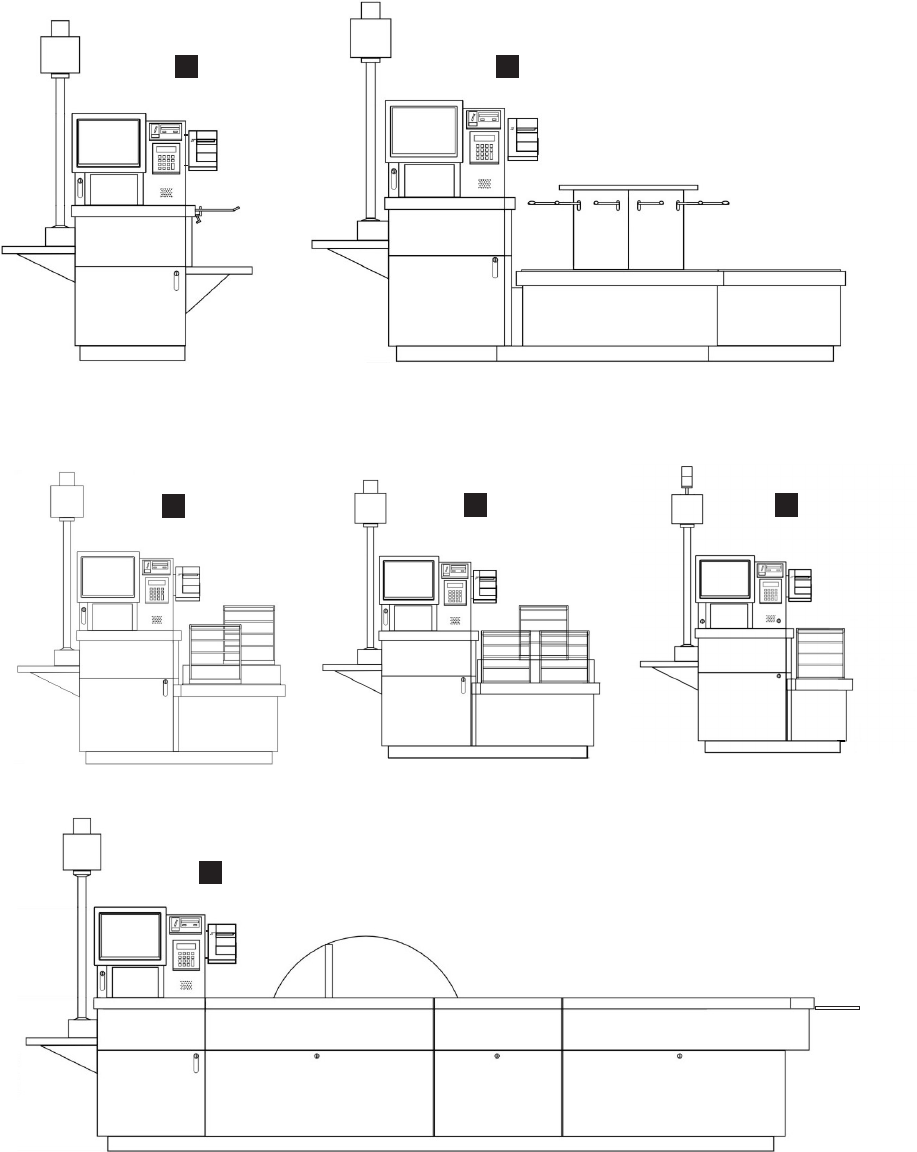

Contact your IBM parts center for bagging parts. Be sure to have the correct model
name and store name when ordering parts. See “How to Use This Parts Manual” on
page v for general parts manual information, including ordering parts. See
“Identifying a Right Hand or Left Hand Model” on page v for how to identify left
hand and right hand models.
The bagging options are:
Table 1.
Key Description
A Model 131, bagging rack attached to the core module
B Models 151, 606, and 616, 6 bagging stations on a carousel
C Models 152, 602, and 612, 2 bagging stations
D Models 153, 603, and 613, 3 bagging stations
E Model N54 Express-Plus, 1 bagging station
F Models 171, 800, and 810 Full Lane, a transport conveyor that delivers items
to a bagging area
Updated October 16, 2007
Chapter 5. Bagging and Carousel Bagging 69
||
||
|
||
||
|
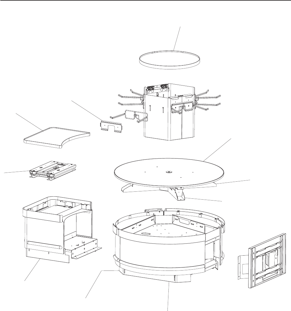
Assembly 26: Carousel parts
1
2
4
5
6
7
3
8
9
10
Updated October 16, 2007
70 Self Checkout 4845: Parts Manual Models 131, 15x, 171, 6xx, 8xx, and BW3

Asm–
Index
Part
Number Units Description
26–1 1 Load cell. See 22–1 on page 55.
–2 Platen, carousel side shelf. See assembly 23– on page 57.
–3 41D9744 1 Carousel bag pack clamping plate
–4 41D8195 1 Lid tower, Models 151, 606, and 616 Carousel, round small
– 41D7621 1 Carousel assembly contains:
–5 v Platen, carousel round. See 23– on page 57.
–6 v Load cell, carousel. See 22–1 on page 55.
–7 41D8194 1 v Wheel assembly Models 151, 606, and 616 carousel, plastic
–8 44M1975 1 Kickplate, front/rear, for Models 151, 606, and 616 carousel
–9 44M1976 1 Kickplate, side, for Models 151, 606, and 616 carousel
–10 44M1977 1 Kickplate, shelf, for Models 151, 606, and 616 carousel
– 41D8185 1 Lower bushing kit, Models 151, 606, and 616 carousel (not shown)
– 41D8187 1 Carousel parts kit, contains - 4 M8x10 hex socket screws, 4 rubber buffers
30x25xM8, 1 grounding spring, 4 shims frolic 1026D, 4 Phil pan head screws NC
6x1", 8 M6x35 hex socket screws, 1 bearing, 8 socket head shoulder screws (M8),
1 upper bushing, 1 nylon locking nut, 1 plastic plug transparent
– 41D8190 1 Electrical interface box for Models 151, 606, and 616 carousel (not shown)
– 41D8192 1 Cable, Models 151, 606, and 616 carousel data communication (not shown)
– 41D8193 1 Power supply Models 151, 606, and 616 carousel, 120/9V external (not shown)
Assembly 26: (continued)
Updated October 16, 2007
Chapter 5. Bagging and Carousel Bagging 71
||||
||||
||||
||||
||||
||||
||||
||||
||||
Assembly 26: (continued) Updated October 16, 2007
72 Self Checkout 4845: Parts Manual Models 131, 15x, 171, 6xx, 8xx, and BW3

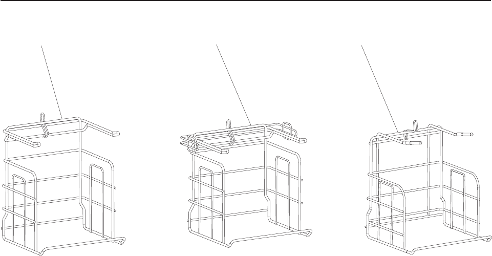
Assembly 27: Wire Bag Rack
12
3
Updated October 16, 2007
74 Self Checkout 4845: Parts Manual Models 131, 15x, 171, 6xx, 8xx, and BW3

Asm–
Index
Part
Number Units Description
27–1 28R3173 (28R3167) Tall rack
–2 28R5540 (28R5697) Short rack
–3 41K7093 (41K7092) European rack
– 41D8560 (41D8559) Rack clamp (not shown)
Assembly 27: (continued)
Updated October 16, 2007
Chapter 6. Wire Bag Rack 75
Assembly 27: (continued) Updated October 16, 2007
76 Self Checkout 4845: Parts Manual Models 131, 15x, 171, 6xx, 8xx, and BW3


Assembly 28: BOSS FRUs
Updated October 16, 2007
78 Self Checkout 4845: Parts Manual Models 131, 15x, 171, 6xx, 8xx, and BW3

Asm–
Index
Part
Number Units Description
28– 23K8035 1 Cover, I/O blank
– 41A3391 1 Riser card, 2 PCI slots
– Lane PC. See “Assembly 21: Lane PC, Mouse, and Keyboard” on page 50.
Monitor/display. See 1–4 on page 3.
Magnetic stripe reader. See 1–5 on page 3.
Power strip. See 1–37 on page 4.
Power supply. See 1–34 on page 4.
Printer. See “Assembly 12: Printers TIx and TGx” on page 28.
Assembly 28: (continued)
Updated October 16, 2007
Chapter 7. BOSS 79
Assembly 28: (continued) Updated October 16, 2007
80 Self Checkout 4845: Parts Manual Models 131, 15x, 171, 6xx, 8xx, and BW3

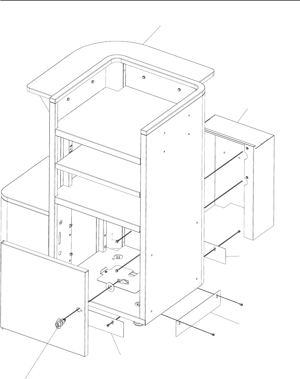
Assembly 29: Paystation
5
2
4
3
2
1
Updated October 16, 2007
82 Self Checkout 4845: Parts Manual Models 131, 15x, 171, 6xx, 8xx, and BW3

Asm–
Index
Part
Number Units Description
29– 41D8116 1 Stabilizer, paystation front/rear (not shown)
– 41D8118 1 Stabilizer, paystation side (not shown)
–1 41D7391 1 Paystation shelf
–2 41D7320 1 Integrated Paystation interface plate/cable cover
–3 44D0861 1 Integrated Paystation front/rear kickplate
–4 44D0862 1 Integrated Paystation left/right side kickplate
–5 1 Keylock, cabinet lock with key. See Chapter 11, “Locks and Keys,” on page 95.
Assembly 29: (continued)
Updated October 16, 2007
Chapter 8. Integrated Paystation 83
Assembly 29: (continued) Updated October 16, 2007
84 Self Checkout 4845: Parts Manual Models 131, 15x, 171, 6xx, 8xx, and BW3

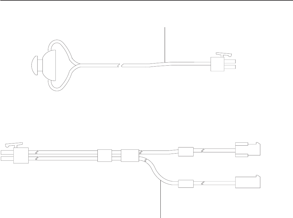
Assembly 30: EPO (Red) Button
1
2
Updated October 16, 2007
86 Self Checkout 4845: Parts Manual Models 131, 15x, 171, 6xx, 8xx, and BW3

Asm–
Index
Part
Number Units Description
30–1 41K7082 1 EPO button (red) button cable assembly (EPO button mounted on top of upper core
module door for certain customers)
–2 41K7080 1 Reset (green) and EPO (red) buttons Y cable (used with 41K7082 instead of
40M9470 1–2 on page 3)
Assembly 30: (continued)
Updated October 16, 2007
Chapter 9. EPO (Red) Button 87
Assembly 30: (continued) Updated October 16, 2007
88 Self Checkout 4845: Parts Manual Models 131, 15x, 171, 6xx, 8xx, and BW3

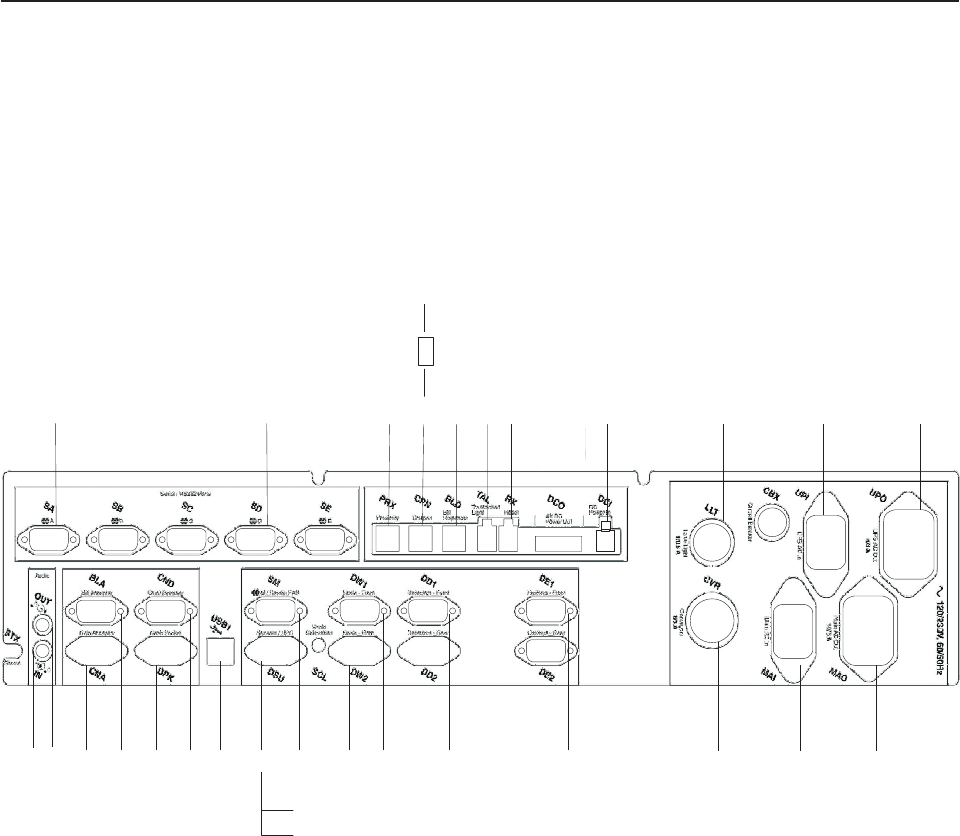
Assembly 31: Cables
234678 910
1
5
11
13
12
1415
161720 1921
22
23 1824252627
28
29
Updated October 16, 2007
90 Self Checkout 4845: Parts Manual Models 131, 15x, 171, 6xx, 8xx, and BW3

Asm–
Index
Part
Number Units Description
31– The illustration shown here is for reference only. There is a tag on each cable that
contains the part number for that cable. When ordering replacement cables
reference the part number on the tag of the failing or broken cable.
– See “How to Use This Parts Manual” on page v for general parts manual
information, including ordering parts. See “Identifying a Right Hand or Left Hand
Model” on page v for how to identify left hand and right hand models.
–1 NA 1 Scanner/scale (optional) (SA) (Supplied by the scanner/scale manufacturer)
–2 41D7073 1 RS-232 Security scale (SD) Cable, 6 foot, DB9, male/female
–3 40M9472 1 Proximity sensor to security controller (PRX)
–4 41E1831 1 Coupon detector to security controller (CPN)
–5 41E1830 1 Coupon detector to coupon indicator LED
–6 40M9400 1 Bill dispenser RS232 cable (BLD)
–7 NA 1 Transaction awareness light (TAL) (comes as part of the light assembly)
–8 40M9470 1 Reset button (RX)
–9 41K6368 1 Security controller DC power (DCI) with power supply
–10 NA 1 Lane light (optional) (LLT) (comes as part of the light assembly)
–11 28R3565 1 Power input from uninterruptible power supply cable (UPI)
–12 28R3559 1 Uninterruptible power supply power output to device power strip (UPO) IEC60320
to C14 Adapter
–13 28R3559 1 Main power output (MAO)
–14 28R3589 1 Main power input from power filter box (MAI)
–15 40M9423 1 Capacitor box (CVB)
–16 41D7073 1 To curtain emitter (DE1) Cable, 6 foot, DB9, male/female
–17 41D7073 1 To curtain detector (DD1) Cable, 6 foot, DB9, male/female
–18 41D7073 1 Security scale front load cell (DW1) Cable, 6 foot, DB9, male/female
–19 41D7073 1 Security scale rear load cell (DW2) Cable, 6 foot, DB9, male/female)
–20 44D1165 1 Sensormatic control cable
–21 41E1619 1 Splitter cable to uninterruptible power supply and sensors (DSU)
–22 41D7073 1 Cable to uninterruptible power supply from splitter cable
–22 41D9361 1 240V Cable to uninterruptible power supply from splitter cable
–23 41J7731 1 USB to lane PC (USB1)
–24 41K6352 1 Coin dispenser data cable (DB9 on one end, RJ45 on other)
–25 41K6365 1 Cash cup (DPK)
– 44M1643 1 Cash cup detector cable (not shown)
– 41J9835 1 Cash cup emitter cable (not shown)
–26 28R3684 1 Bill acceptor (BLA)
–27 41K6354 1 Coin acceptor cable, US/Canada
–27 41K6359 1 Coin acceptor cable, EMEA/Australia
–28 41K6370 1 Audio out to speaker (OUT)
–29 41K6369 1 Audio to lane PC (IN)
– 41D7072 1 10' Ethernet CAT5 cable
– 41D7075 1 5' Ethernet CAT5 cable
– 41D7073 1 ELO touchscreen Cable, 6 foot, DB9, male/female
– 41J7452 1 Cable harness loop style
Assembly 31: (continued)
Updated October 16, 2007
Chapter 10. Cables 91
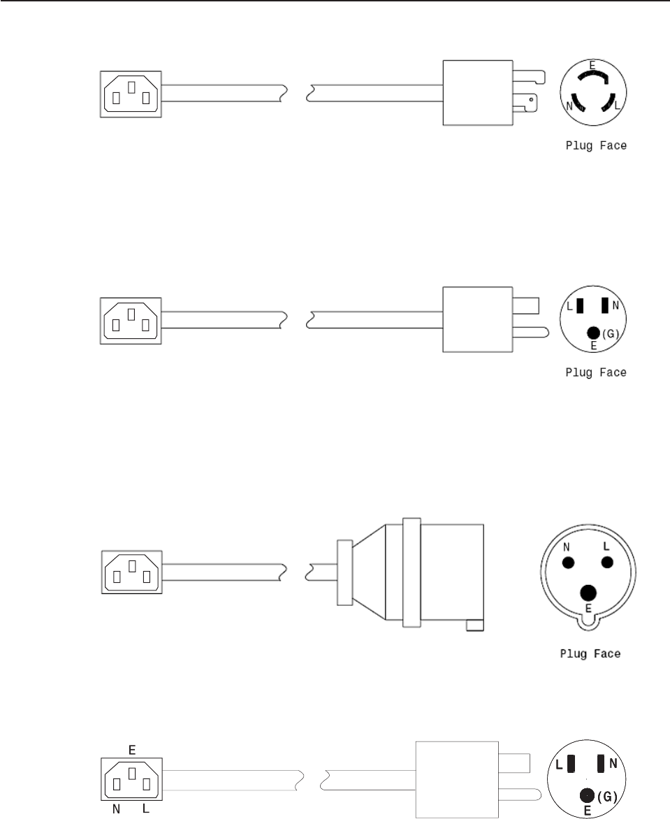
Assembly 32: Power Cords
E
NL
Coupler Face
E
NL
Coupler Face
E
NL
Coupler Face
1
3
2
Plug Face
4
Coupler Face
Updated October 16, 2007
92 Self Checkout 4845: Parts Manual Models 131, 15x, 171, 6xx, 8xx, and BW3

Asm–
Index
Part
Number Units Description
32–1 39M5107 1 4.3m, Right angle power cord, NEMA L5–15P
–2 39M5073 1 4.3m, Nonlock right angle power cord, NEMA 5–15P
–3 39M5177 1 4.3m, Right angle power cord, IEC 309 16A/250V 2P+G
–4 41J8393 1 1.8m, Inline coupler power cord, IEC 320 10A/125V
Assembly 32: (continued)
Updated October 16, 2007
Chapter 10. Cables 93
Assembly 32: (continued) Updated October 16, 2007
94 Self Checkout 4845: Parts Manual Models 131, 15x, 171, 6xx, 8xx, and BW3


Assembly 33: Currency Lock with Key
12
3
4
5
Updated October 16, 2007
96 Self Checkout 4845: Parts Manual Models 131, 15x, 171, 6xx, 8xx, and BW3

Asm–
Index
Part
Number Units Description
33–1 41K6088 1 Coin lock cam
–2 41K6087 1 Safe lock cam
–3 44D0244 1 Safe door pull
–4 41K6120 1 Currency lock with key, combo #1, Emka key 306
–4 41K6121 1 Currency lock with key, combo #2, Emka key 314
–4 41K6122 1 Currency lock with key, combo #3, Emka key 321
–4 41K6123 1 Currency lock with key, combo #4, Emka key 343
–4 41K6124 1 Currency lock with key, combo #5, Emka key 351
–4 41K6125 1 Currency lock with key, combo #6, Emka key 382
–4 41K6126 1 Currency lock with key, combo #7, Emka key 420
–4 41K6127 1 Currency lock with key, combo #8, Emka key 437
–4 41K6128 1 Currency lock with key, combo #9, Emka key 463
–4 41K6129 1 Currency lock with key, combo #10, Emka key 520
–5 41K6130 1 Currency key, combo #1, Emka key 306
–5 41K6131 1 Currency key, combo #2, Emka key 314
–5 41K6132 1 Currency key, combo #3, Emka key 321
–5 41K6133 1 Currency key, combo #4, Emka key 343
–5 41K6134 1 Currency key, combo #5, Emka key 351
–5 41K6135 1 Currency key, combo #6, Emka key 382
–5 41K6136 1 Currency key, combo #7, Emka key 420
–5 41K6137 1 Currency key, combo #8, Emka key 437
–5 41K6138 1 Currency key, combo #9, Emka key 463
–5 41K6139 1 Currency key, combo #10, Emka key 520
Assembly 33: (continued)
Updated October 16, 2007
Chapter 11. Locks and Keys 97
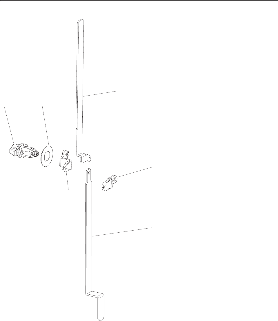
Assembly 34: Cabinet Lock with Key
12
3
4
5
6
Updated October 16, 2007
98 Self Checkout 4845: Parts Manual Models 131, 15x, 171, 6xx, 8xx, and BW3

Asm–
Index
Part
Number Units Description
34–1 42K0080 1 Cabinet lock with key, combo #1, Emka key 305
–1 42K0081 1 Cabinet lock with key, combo #2, Emka key 436
–1 42K0082 1 Cabinet lock with key, combo #3, Emka key 448
–1 42K0083 1 Cabinet lock with key, combo #4, Emka key 449
–1 42K0084 1 Cabinet lock with key, combo #5, Emka key 450
–1 42K0085 1 Cabinet lock with key, combo #6, Emka key 471
–1 42K0086 1 Cabinet lock with key, combo #7, Emka key 478
–1 42K0087 1 Cabinet lock with key, combo #8, Emka key 487
–1 42K0088 1 Cabinet lock with key, combo #9, Emka key 502
–1 42K0089 1 Cabinet lock with key, combo #10, Emka key 608
– 42K0090 1 Cabinet key, combo #1, Emka key 305
– 42K0091 1 Cabinet key, combo #2, Emka key 436
– 42K0092 1 Cabinet key, combo #3, Emka key 448
– 42K0093 1 Cabinet key, combo #4, Emka key 449
– 42K0094 1 Cabinet key, combo #5, Emka key 450
– 42K0095 1 Cabinet key, combo #6, Emka key 471
– 42K0096 1 Cabinet key, combo #7, Emka key 478
– 42K0097 1 Cabinet key, combo #8, Emka key 487
– 42K0098 1 Cabinet key, combo #9, Emka key 502
– 42K0099 1 Cabinet key, combo #10, Emka key 608
–2 41K6585 1 Lock indicator
–3 41K6094 1 Lock cam, lower door
–4 41K6105 1 Latch bar, upper RH, lower door
–4 41K6597 1 Latch bar, upper LH, lower door
–5 41K6087 1 Lock cam, upper door
–6 41K6104 1 Latch bar, lower, lower door
– 41K6098 1 Vertical crossbar lock bar, upper door (for doors with a single lock)
– 41K6099 1 Horizontal crossbar lock bar, upper door (for doors with a single lock)
– 41K6100 1 Latching bar, upper door, right hand (for doors with a single lock)
Assembly 34: (continued)
Updated October 16, 2007
Chapter 11. Locks and Keys 99
Assembly 34: (continued) Updated October 16, 2007
100 Self Checkout 4845: Parts Manual Models 131, 15x, 171, 6xx, 8xx, and BW3

Chapter 12. Field Kits and Tools
Assembly 35: Field Kits and Tools . . . . . . . . . . . . . . . . . 102
Field kits contain an assortment of screws, washers, nuts, and bolts.
Hardware items such as screws, bolts, nuts, and washers, removed during the
disassembly of parts should be retained for use during re-assembly of those parts.
Screws, bolts, nuts, and washers can not be ordered separately, they are available
as part of a field kit.
Updated October 16, 2007
© Copyright IBM Corp. 2006, 2007 101

Assembly 35: Field Kits and Tools
Field Kits and Tools Updated October 16, 2007
102 Self Checkout 4845: Parts Manual Models 131, 15x, 171, 6xx, 8xx, and BW3

Asm–
Index
Part
Number Units Description
35– 41D7009 1 4845 Fastener kit This kit contains:
–2 – #4-40 Hex nuts
–2 – #6-32 Lock nuts
–2 – 1/4"-20 Hex nut
–2 – #6-32 Hex nut
–2 – #8-32 Nylon lock nuts
–2 – #10-32 Nylon nuts
–2 – 1/4"-20 Hex nuts
–8 – 1/4"-20 Nylon nuts
–4 – 5/16"-18 Hex nuts
–2 – 1/4"-20 x 1/2" Phillips head pan screws
–2 – #10-32 x 3" Phillips head pan screws
–2 – M3 x 8mm Slotted flat head screws
–2 – #6–32 x 3/8" Phillips pan screws
–2 – #10-32 x 5/8" Phillips pan head screws
–2 – #6-32 x 1/4" Phillips pan head screws
–2 – #10-32 x 5/8" Phillips pan head screws
–2 – #6-32 x 1/4" Phillips pan head screws
–2 – #10-32 x 1/2" Phillips pan head screws
–2 – #10-32 x 1/4" Cup point set screws
–2 – #10-32 x 1/2" Phillips sheet metal screws
–2 – #5/16"-18 x 4" bolts
–2 – #10-32 x 1/2" Cup point set screws
–2 – #6-32 x 3/8" Phillips flat head machine screws
–2 – #8-32 x 1/2" Black Phillips washer head screws
–2 – #6-32 x 1/4" Flat head screws
–2 – #8–32 x 5/8" Phillips sheet metal flange head
–2 – #8-32 x 1/2" Phillips pan head sheet metal screws
–2 – #8-32 x 3/4" Phillips sheet metal screws
–2 – #10-32 x 5/8" Phillips pan head screws
–4 – #10-32 x 1/2" Button head machine screws
–2 – #10-32 x 1/2" Phillips Pan head screws
–2 – #10-32 x 3/4" Phillips pan head machine screws
–2 – 1/4"-28 x 1-1/2" Hex cap screws
–2 – 1/4"-20 x 3/4" Hex cap screws
–2 – 1/4"-20 x 5/8" Hex cap screws
–2 – 1/4"-20 x 1" Phillips flat head screws
–4 – 1/4"-20 x 1" Hex cap screws
–2 – 1/4"-20 x 2-1/4" Hex cap screws
–2 – 1/4"-20 X 1-1/4" Hex cap screws
–2 – Fully threaded rod
–2 – 3/8"-16 x 1" Hex cap screw
–2 – 3/8" Lock nuts
–2 – #4-40 x 5/8" Phillips pan head screws
–4 – Hinged black screw cover
–4 – 1/4"-20 x 3/4" Phillips pan head screws
–4 – #10-32 x 1/4" Phillips pan head machine screws
–2 – #10-24 x 1/4" Pan head machine screws
–2 – M4 x 8mm screws
–2 – M5 x 6mm Phillips pan head machine screws
–2 – #6-32 x 1/2" Self-tapping screws
–2 – #6 External star washers
–2 – #6 Split lock washers
Assembly 35: (continued)
Updated October 16, 2007
Chapter 12. Field Kits and Tools 103

Asm–
Index
Part
Number Units Description
–2 – #4 Split lock washers
–2 – 1/4" x 1/2" Hex cap screws
–4 – 5/16" Flat washers
–2 – #10 Flat washers
–4 – 1/4" Flat washers
–4 – 1/4" Split lock washers
–2 – 1/4" External star washers
–2 – 3/8" Split lock washers
–4 – 1/4” Flat washers
–2 – 1/4"-20 x 2-1/2" Hex screws
–4 – #10-24 Nylon lock nuts
– 44D0412 1 Washer/clip kit
– 44D0533 1 UNC screw kit
– 44D0534 1 Metric screw kit
– 44M2154 1 Cash module lower door field adjustment kit, right hand
– 44M2155 1 Cash module lower door field adjustment kit, left hand
– 44D1606 1 Sensormatic field installation kit
– 41D9631 1 Velcro tape
– 44D1776 1 Version 3.00 Ghost software kit
– 41D9350 1 US coin acceptor programming module
– 41D9351 1 Canadian coin acceptor programming module
– 41D9352 1 UK coin acceptor programming module
– 41D9353 1 Euro coin acceptor programming module
– 41D9354 1 Australian coin acceptor programming module
– 41D9355 1 US penniless coin acceptor programming module
– 41D7101 1 Bill dispenser fastener kit (fasteners, screws, and retainers)
– 41K6284 1 Bill dispenser screwdriver kit
Assembly 35: (continued) Updated October 16, 2007
104 Self Checkout 4845: Parts Manual Models 131, 15x, 171, 6xx, 8xx, and BW3

Appendix A. Cabinet Parts and Sensors
Assembly 36: Core Module Cabinet FRUs . . . . . . . . . . . . . . 106
Assembly 37: Security Conveyor and Transport Conveyor Cabinet . . . . .110
Assembly 38: Models 152, 602, and 612 Bagging Cabinet . . . . . . . .112
Assembly 39: Models 153, 603, and 613 Bagging Cabinet . . . . . . . .114
Assembly 40: Model N54 Bagging Cabinet . . . . . . . . . . . . . .116
Assembly 41: Models 171, 800, and 810 Bagging Cabinet . . . . . . . .118
Assembly 42: Models 171, 800, and 810 Bumpers, Order Separators, Soft
Goods Shelf . . . . . . . . . . . . . . . . . . . . . . . . 120
Assembly 43: Sensors, Emitters, and Detectors . . . . . . . . . . . . 122
This appendix contains the locations and descriptions of the cabinet parts. Cabinet
parts can be ordered by description from the IBM Self Checkout Solution service
center. You must have the IBM Self Checkout Solution model number, cabinet part
description, customer name, color, and whether the machine is a left hand or right
hand model.
Updated October 16, 2007
© Copyright IBM Corp. 2006, 2007 105
||
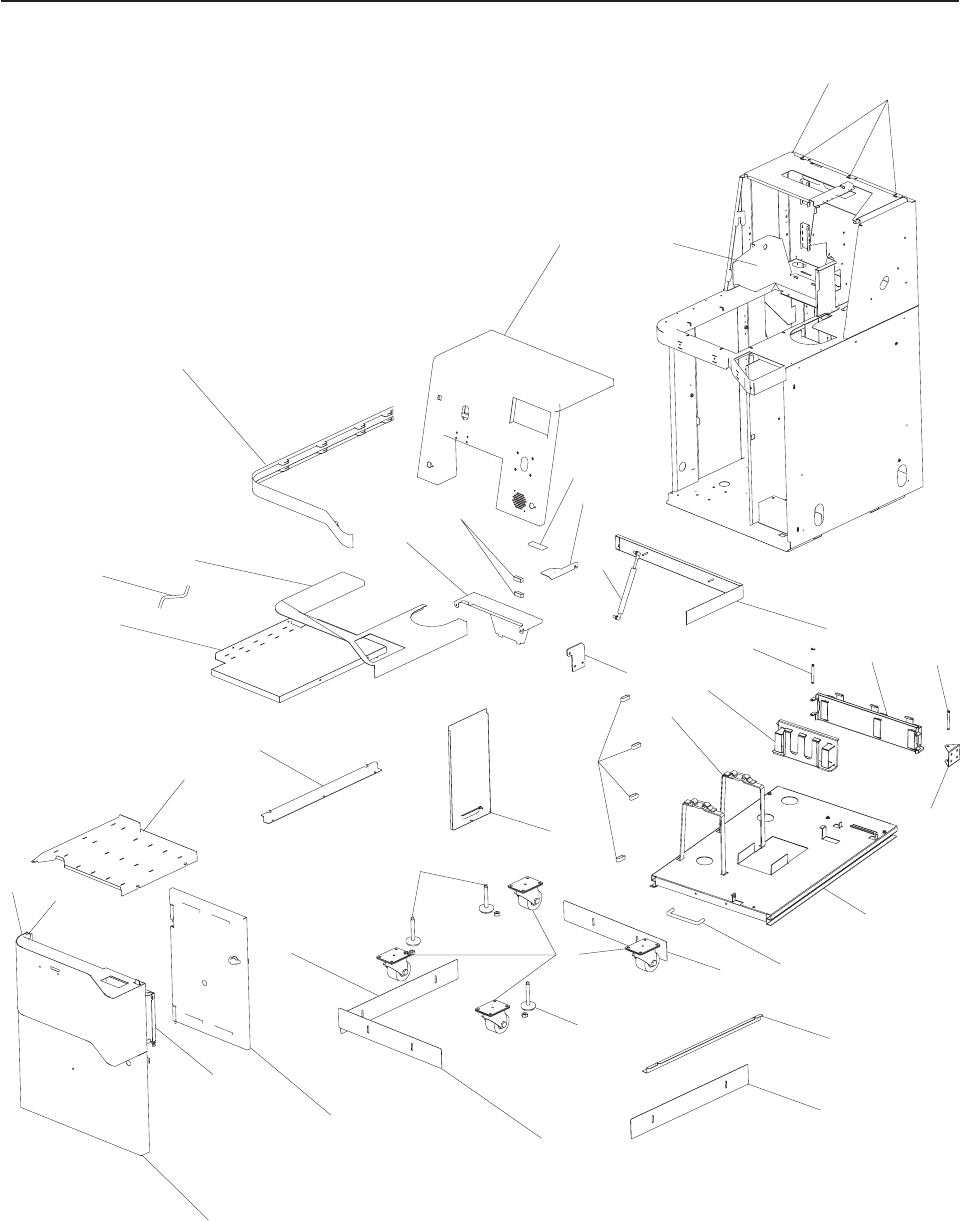
Assembly 36: Core Module Cabinet FRUs
1
2
3
5
9
10
25
15
17
15
19
22
20
19
17
23
24
25
26
32
27
29
930
31
2a
40
41
30a
11
44
45
43
42
13
12
46
12
47 48
Updated October 16, 2007
106 Self Checkout 4845: Parts Manual Models 131, 15x, 171, 6xx, 8xx, and BW3

Asm–
Index
Part
Number Units Description
36– Be sure to specify whether you are ordering replacement parts for a left hand or a
right hand model. See “How to Use This Parts Manual” on page v for general parts
manual information, including ordering parts. See “Identifying a Right Hand or Left
Hand Model” on page v for how to identify left hand and right hand models.
–1 Upper door assembly (No part number assigned, custom color part)
–2 Cabinet Weldment (No part number assigned, custom color part)
–3 42K0056 1 Rear bumper
–5 42K0068 1 Gas spring stiffener plate
–9 41K6103 1 Cable retainer, hook and loop
–10 Exterior access panel (No part number assigned, custom color part)
– 41K6165 1 Access panel thumbscrew/retainer (not shown)
–11 41K6164 1 Drip pan tubing
–12 41K6600 1 Cable, basket shaft
–13 41K6148 1 Cable basket bracket
–15 41K6150 1 Front/rear kick plate
–17 41K6149 1 Left/right kick plate
–19 41D7344 1 Leveler (replaces 39Y0601)
–20 12R9478 1 Caster, swivel
–22 41K6167 1 PC access door assembly, right hand
–22 41K6168 1 PC access door assembly, left hand
–23 Lower door assembly, cash module (No part number assigned, custom color part)
–24 41K6154 1 Accessory shelf, right hand
–24 41K6155 1 Accessory shelf, left hand
–25 41K6156 1 PC/Uninterruptible power supply shelf bracket
–26 41K6162 1 Drip pan, right hand
–26 41K6163 1 Drip pan, left hand
–27 Upper countertop assembly (see “Assembly 18: Countertop” on page 44 for a
complete listing of available countertops)
–29 42K0057 1 Scanner hood
–30 41K6151 1 Upper door cover stop, right hand
–30 41K6152 1 Upper door stop cover, left hand
–30A 41K6153 1 Upper door cover stop nut
–31 42K0051 1 Gas spring
–32 41K6157 1 Bumper, front
– 41K6159 1 Bumper gasket (not shown)
–40 41K6102 1 Upper door hinge (includes fasteners)
–41 41K6106 1 Lower door, coupon box assembly
– 41K6108 1 Lower door keyboard retaining bracket (not shown)
–42 41K6140 1 PC/uninterruptible power supply shelf, right hand
–42 41K6141 1 PC/uninterruptible power supply shelf, left hand
–43 41K6083 1 Drawer pull
–44 41K6142 1 Velcro strap for uninterruptible power supply
–45 41K6144 1 Cable basket, short, right hand
–45 41K6146 1 Cable basket, short, left hand
–46 41K6143 1 Cable basket, long, right hand
–46 41K6145 1 Cable basket, long, left hand
–47 44M1961 Lower door welded hinge pin, right hand
–47 44M1959 Lower door welded hinge pin, left hand
–48 41J6659 1 Lower door hinge spacer plate (not shown)
– 41K6595 1 Door stop, lower (not shown)
– 41D8382 1 Adjuster, lower door, RH (not shown)
– 41D8383 1 Adjuster, lower door, LH (not shown)
– 41K6572 1 Upper door cable cover (not shown)
Assembly 36: (continued)
Updated October 16, 2007
Appendix A. Cabinet Parts and Sensors 107

Asm–
Index
Part
Number Units Description
– 42K0050 1 Spacer for scanner leveler (not shown)
– 41K6147 1 Velcro strap for cable basket (not shown)
– 1 Filler plate, lane light mount opening (used if lane light mount is not used, not
shown) (no part number given, custom color part)
Assembly 36: (continued) Updated October 16, 2007
108 Self Checkout 4845: Parts Manual Models 131, 15x, 171, 6xx, 8xx, and BW3
Updated October 16, 2007
Appendix A. Cabinet Parts and Sensors 109
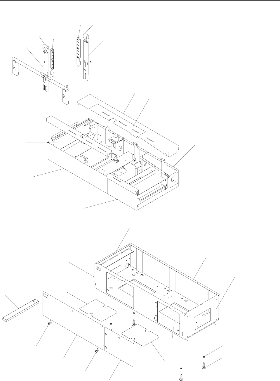
Assembly 37: Security Conveyor and Transport Conveyor Cabinet
45
6
910
11
12
13
14
16
15
18
19
20
22
23 24
25
26
27
28
29
17
21
1
23
Updated October 16, 2007
110 Self Checkout 4845: Parts Manual Models 131, 15x, 171, 6xx, 8xx, and BW3

Asm–
Index
Part
Number Units Description
37– Be sure to specify whether you are ordering replacement parts for a left hand or a
right hand model. See “How to Use This Parts Manual” on page v for general parts
manual information, including ordering parts. See “Identifying a Right Hand or Left
Hand Model” on page v for how to identify left hand and right hand models.
–1 Tower (a single welded assembly, the front curtain support). See 24–30 on page
62.
–2 Tower cap. See 24–32 on page 62.
–3 Curtain detector assembly. See 24–32 on page 62 for detector/emitter FRU
number.
–4 Curtain emitter assembly. See 24–32 on page 62 for detector/emitter FRU number.
–5 Tower cap. See 24–32 on page 62.
–6 Tower, rear curtain support. See 24–33 on page 62.
–7 Channel support
–8 Support bracket
–9 Access door assembly
–10 Wide rail
–11 Upper cabinet console
–12 Front bulkhead
–13 Lower panel
–14 Rear bulkhead
–15 Leveler lock nut
–16 Leveler
–17 Lower cabinet
–18 Cover plate
–19 Transport section door (no FRU number given, custom color part)
–20 41K6382 1 Hex key cam lock
–21 Security module lower access door (no FRU number given, custom color part)
–22 41K6382 Hex key cam lock
–23 Trash tray
–24 Cover plate
–25 Lower door panel
–26 Transport conveyor access panel (no FRU number given, custom color part)
–27 Security conveyor access panel (no FRU number given, custom color part)
–28 Bulkhead assembly
–29 Narrow rail (shopper side)
Assembly 37: (continued)
Updated October 16, 2007
Appendix A. Cabinet Parts and Sensors 111
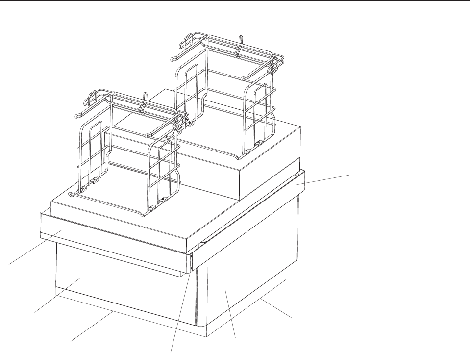
Assembly 38: Models 152, 602, and 612 Bagging Cabinet
7
5
2
1
4
3
6
Updated October 16, 2007
112 Self Checkout 4845: Parts Manual Models 131, 15x, 171, 6xx, 8xx, and BW3

Asm–
Index
Part
Number Units Description
38– Be sure to specify whether you are ordering replacement parts for a left hand or a
right hand model. See “How to Use This Parts Manual” on page v for general parts
manual information, including ordering parts. See “Identifying a Right Hand or Left
Hand Model” on page v for how to identify left hand and right hand models.
–1 44D1363 1 Side bumper assembly
–2 Side kickplate
–3 1 Side access cover (no FRU number given, custom color part)
–4 44D1151 2 Corner bumper connector bracket (one on each side)
–5 44D0859 2 Front/rear kickplate
–6 2 Front/back cover (no FRU number given, custom color part)
–7 44D1365 1 Front bumper assembly
– 44D1366 1 Rear bumper assembly (not shown)
– 41K6382 1 Hex key cam lock
– 1 Lane light mounting clamp (not shown, used when lane light assembly is mounted
to the Models 152, 602, and 612 bagging module). See 20– on page 49 for FRU
number.
– 1 Lane light mounting strap (not shown, used when lane light assembly is mounted to
the Models 152, 602, and 612 bagging module). See 20– on page 49 for FRU
number.
Assembly 38: (continued)
Updated October 16, 2007
Appendix A. Cabinet Parts and Sensors 113
||||
|
|
||||
|
|
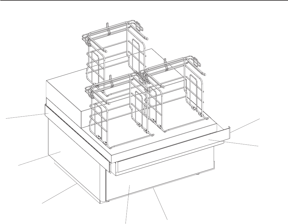
Assembly 39: Models 153, 603, and 613 Bagging Cabinet
7
3
2
5
6
4
1
Updated October 16, 2007
114 Self Checkout 4845: Parts Manual Models 131, 15x, 171, 6xx, 8xx, and BW3
|
|
|

Asm–
Index
Part
Number Units Description
39– Be sure to specify whether you are ordering replacement parts for a left hand or a
right hand model. See “How to Use This Parts Manual” on page v for general parts
manual information, including ordering parts. See “Identifying a Right Hand or Left
Hand Model” on page v for how to identify left hand and right hand models.
–1 44D1151 2 Corner bumper connector bracket (one on each side)
–2 44D1364 2 Front/rear bumper assembly
–3 44D0860 2 Front/rear kickplate
–4 1 Front access cover (no FRU number given, custom color part)
–5 1 Side kickplate
–6 2 Side/back cover (no FRU number given, custom color part)
–7 44D1363 1 Side bumper assembly
Assembly 39: (continued)
Updated October 16, 2007
Appendix A. Cabinet Parts and Sensors 115
|
|
|
|
|||
||||
|
|
|
||||
||||
||||
||||
||||
||||
||||
|

Assembly 40: Model N54 Bagging Cabinet
Updated October 16, 2007
116 Self Checkout 4845: Parts Manual Models 131, 15x, 171, 6xx, 8xx, and BW3

Asm–
Index
Part
Number Units Description
40– Be sure to specify whether you are ordering replacement parts for a left hand or a
right hand model. See “How to Use This Parts Manual” on page v for general parts
manual information, including ordering parts. See “Identifying a Right Hand or Left
Hand Model” on page v for how to identify left hand and right hand models.
– Front/rear bumper assembly
– 41J9751 1 Front/rear kickplate
– 41J9752 1 Side kickplate
– 41J9750 1 Side bumper assembly
Assembly 40: (continued)
Updated October 16, 2007
Appendix A. Cabinet Parts and Sensors 117
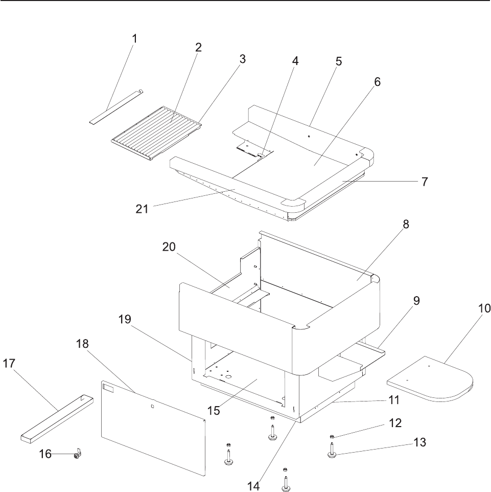
Assembly 41: Models 171, 800, and 810 Bagging Cabinet
Updated October 16, 2007
118 Self Checkout 4845: Parts Manual Models 131, 15x, 171, 6xx, 8xx, and BW3

Asm–
Index
Part
Number Units Description
41– Be sure to specify whether you are ordering replacement parts for a left hand or a
right hand model. See “How to Use This Parts Manual” on page v for general parts
manual information, including ordering parts. See “Identifying a Right Hand or Left
Hand Model” on page v for how to identify left hand and right hand models.
–1 44D0264 1 Rear (bagging) transition plate, for right hand, standard lane with 19 inch belt
– 44D0266 1 Rear (bagging) transition plate, for right hand, wide lane with 25 inch belt
– 44D0265 1 Rear (bagging) transition plate, for left hand, standard lane with 19 inch belt
– 41K6387 1 Roller assembly for right hand, standard lane with 19 inch belt (includes rollers,
frame, bracket, rear transition plate, cover plate, screw, wing nut)
– 44D0274 1 Roller assembly for left hand, standard lane with 19 inch belt (includes rollers,
frame, bracket, rear transition plate, cover plate, screw, wing nut)
–2 41K6388 1 Bagger roller for standard lane with 19 inch belt
– 44M1749 1 Bagger roller for wide lane with 25 inch belt
– 44M2123 1 M5 nylon wing nut (not shown)
–3 44M1995 1 Roller frame bracket
– 44M1992 1 Roller frame cover plate (not shown, located under the rollers)
–4 41K6391 1 Hinge bracket
–5 Side rail assembly
–6 Desk pan
–7 Desk pan holder
–8 Cabinet upper console
–9 41K6386 1 Bagging shelf support
–10 41K6385 1 Bagging shelf
– 41D8119 1 Bagging shelf (for 90 degree angled bag rack, right hand or left hand)
–11 41K6384 1 End kickplate for 19, 28, 48, and 66 inch bagging cabinets
–12 Nut leveler adjusting lock nut
–13 Leveler
–14 44D0854 1 Side kickplate for 19 inch bagging cabinet
– 44D0855 1 Side kickplate for 28 inch bagging cabinet
– 44D0856 1 Side kickplate for 48 inch bagging cabinet
– 44D0857 1 Side kickplate for 66 inch bagging cabinet
–15 Frame, Weldment
–16 Hex key cam lock
–17 Trash tray
–18 Cabinet door
–19 Panel, lower door
–20 Bulkhead assembly
–21 Side rail
Assembly 41: (continued)
Updated October 16, 2007
Appendix A. Cabinet Parts and Sensors 119
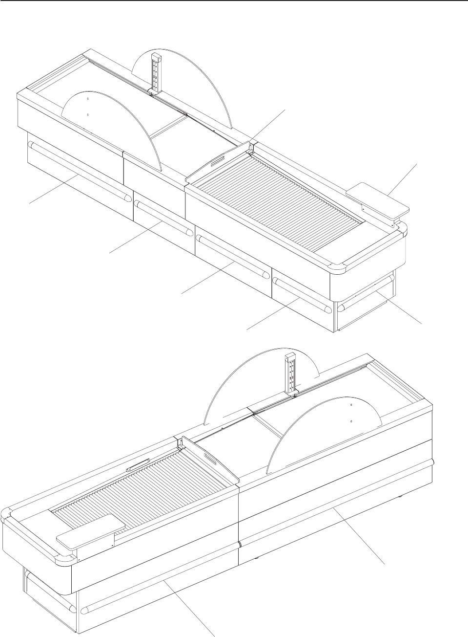
Assembly 42: Models 171, 800, and 810 Bumpers, Order Separators,
Soft Goods Shelf
7
8
6
4
4
5
3
1
2
Updated October 16, 2007
120 Self Checkout 4845: Parts Manual Models 131, 15x, 171, 6xx, 8xx, and BW3

Asm–
Index
Part
Number Units Description
42– Be sure to specify whether you are ordering replacement parts for a left hand or a
right hand model. See “How to Use This Parts Manual” on page v for general parts
manual information, including ordering parts. See “Identifying a Right Hand or Left
Hand Model” on page v for how to identify left hand and right hand models.
–1 41J7126 1 25 inch order separator
–1 41J7127 1 19 inch order separator
–2 41K6379 1 Bagger soft good shelf
– 41D8764 1 Bumper, stock gray, 140mm (not shown, used on core module)
– 41D8766 1 Bumper, stock gray, 150mm (not shown, used on bagging module)
– 41D8768 1 Bumper, stock gray, 280mm (not shown, used on core module)
– 41D8770 1 Bumper, stock gray, 470mm (not shown, used on core module)
–3 41D8772 1 Bumper, stock gray, 540mm
–4 41D8772 1 Bumper, stock gray, 540mm
–5 41D8774 1 Bumper, stock gray, 700mm
–6 41D8776 1 Bumper, stock gray, 1030mm
–7 41D8778 1 Bumper, stock gray, 1450mm
–8 41D8780 1 Bumper, stock gray, 1840mm
– 44D0852 1 Side kickplate, 19 in. security module
– 44D0853 1 Side kickplate, 25 in. security module
Assembly 42: (continued)
Updated October 16, 2007
Appendix A. Cabinet Parts and Sensors 121
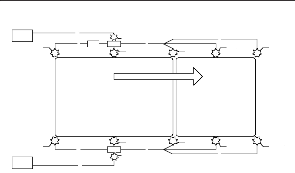
Assembly 43: Sensors, Emitters, and Detectors
To Core
Module
9
7
Curtain Emitter
8
2FP Emitter 2RC Emitter 3
BAF Emitter
7
1
Transition Plate
Emitter
Security Conveyor Transport Conveyor
Shopper Flow
4
Transition Plate
Detector
6
BAF Detector
7
5RC Detctor
8
5FP Detector
Curtain Detector
7
9
4
Transition Plate
Detector
To Core
Module
Transmission Plate
Emitter 1
10
11
10
Updated October 16, 2007
122 Self Checkout 4845: Parts Manual Models 131, 15x, 171, 6xx, 8xx, and BW3

Asm–
Index
Part
Number Units Description
43– Be sure to specify whether you are ordering replacement parts for a left hand or a
right hand model. See “How to Use This Parts Manual” on page v for general parts
manual information, including ordering parts. See “Identifying a Right Hand or Left
Hand Model” on page v for how to identify left hand and right hand models.
–1 Transition plate emitter. See 25– on page 65 for FRU number.
–2 Flat pack sensor emitter and also exit sensor emitter. See 24–11 on page 61 and
24–12 on page 61 for FRU number.
–3 Bagging area full emitter sensor assembly. See 25–15 on page 65 for FRU number.
–4 Transition plate detector. See 25– on page 65 for FRU number.
–5 Flat pack sensor emitter and also exit sensor emitter. See 24–26 on page 62 and
24–12 on page 61 for FRU number.
–6 Bagging area full detector sensor. See 25–21 on page 65 for FRU number.
–7 Transition plate extension cable. See 24– on page 62 for FRU number.
–8 Sensor extension cable. See 24– on page 62 for FRU number.
–9 DB9 cable curtain emitter/detector extension cable. See 31–16 on page 91 for FRU
number.
–10 Curtain detector/emitter sensor assembly. See 24–32 on page 62 for FRU number.
–11 44M1624 1 Ferrite core (on transition plate extension cable)
Assembly 43: (continued)
Updated October 16, 2007
Appendix A. Cabinet Parts and Sensors 123
Assembly 43: (continued) Updated October 16, 2007
124 Self Checkout 4845: Parts Manual Models 131, 15x, 171, 6xx, 8xx, and BW3

Appendix B. Notices
This information was developed for products and services offered in the U.S.A.
IBM may not offer the products, services, or features discussed in this document in
other countries. Consult your local IBM representative for information on the
products and services currently available in your area. Any reference to an IBM
product, program, or service is not intended to state or imply that only that IBM
product, program, or service may be used. Any functionally equivalent product,
program, or service that does not infringe any IBM intellectual property right may be
used instead. However, it is the user’s responsibility to evaluate and verify the
operation of any non-IBM product, program, or service.
IBM may have patents or pending patent applications covering the subject matter in
this document. The furnishing of this document does not give you any license to
these patents. You can send license inquiries, in writing, to:
IBM Director of Licensing
IBM Corporation
North Castle Drive
Armonk, NY 10504-1785
U.S.A.
For license inquiries regarding double-byte character set (DBCS) information,
contact the IBM Intellectual Property Department in your country or send inquiries,
in writing, to:
IBM World Trade Asia Corporation
Licensing
2-31 Roppongi 3-chome, Minato-ku
Tokyo 106, Japan
The following paragraph does not apply to the United Kingdom or any other country
where such provisions are inconsistent with local law: INTERNATIONAL BUSINESS
MACHINES CORPORATION PROVIDES THIS PUBLICATION "AS IS" WITHOUT
WARRANTY OF ANY KIND, EITHER EXPRESS OR IMPLIED, INCLUDING, BUT
NOT LIMITED TO, THE IMPLIED WARRANTIES OF NON-INFRINGEMENT,
MERCHANTABILITY, OR FITNESS FOR A PARTICULAR PURPOSE. Some states
do not allow disclaimer of express or implied warranties in certain transactions,
therefore, this statement may not apply to you.
This information could include technical inaccuracies or typographical errors.
Changes are periodically made to the information herein; these changes will be
incorporated in new editions of the publication. IBM may make improvements and/or
changes in the product(s) and/or program(s) described in this publication at any
time without notice.
IBM may use or distribute any of the information you supply in any way it believes
appropriate without incurring any obligation to you.
Any references in this information to non-IBM Web sites are provided for
convenience only and do not in any manner serve as an endorsement of those
Web sites. The materials at those Web sites are not part of the materials for this
IBM product and use of those Web sites is at your own risk.
Updated October 16, 2007
© Copyright IBM Corp. 2006, 2007 125
Information concerning non-IBM products was obtained from the suppliers of those
products, their published announcements or other publicly available sources. IBM
has not tested those products and cannot confirm the accuracy of performance,
compatibility or any other claims related to non-IBM products. Questions on the
capabilities of non-IBM products should be addressed to the suppliers of those
products.
This information is for planning purposes only. The information herein is subject to
change before the products described become available.
Updated October 16, 2007
126 Self Checkout 4845: Parts Manual Models 131, 15x, 171, 6xx, 8xx, and BW3

Electronic emission notices
Federal Communications Commission (FCC) statement
This equipment has been tested and found to comply with the limits for a Class A
digital device, pursuant to Part 15 of the FCC Rules. These limits are designed to
provide reasonable protection against harmful interference when the equipment is
operated in a commercial environment. This equipment generates, uses, and can
radiate radio frequency energy and, if not installed and used in accordance with the
instruction manual, may cause harmful interference to radio communications.
Operation of this equipment in a residential area is likely to cause harmful
interference, in which case the user will be required to correct the interference at
his own expense.
Properly shielded and grounded cables and connectors must be used in order to
meet FCC emission limits. IBM is not responsible for any radio or television
interference caused by using other than recommended cables and connectors or by
unauthorized changes or modifications to this equipment. Unauthorized changes or
modifications could void the user’s authority to operate the equipment.
This device complies with part 15 of the FCC Rules. Operation is subject to the
following two conditions:
1. This device may not cause harmful interference, and
2. This device must accept any interference received, including interference that
may cause undesired operation.
European Union EMC Directive conformance statement
This product is in conformity with the protection requirements of EU Council
Directive 2004/108/EC on the approximation of the laws of the Member States
relating to electromagnetic compatibility. IBM cannot accept responsibility for any
failure to satisfy the protection requirements resulting from a non-recommended
modification of the product, including the fitting of non-IBM option cards.
This product has been tested and found to comply with the limits for Class A
Information Technology Equipment according to CISPR 22/European Standard EN
55022. The limits for Class A equipment were derived for commercial and industrial
environments to provide reasonable protection against interference with licensed
communication equipment.
Attention: This is a Class A product. In a domestic environment this product may
cause radio interference in which case the user may be required to take adequate
measures.
European Community contact:
IBM Technical Regulations
Pascalstr. 100, Stuttgart, Germany 70569
Telephone: 0049 (0)711 785 1176
Fax: 0049 785 1283
E-mail: tjahn@de.ibm.com
Updated October 16, 2007
Appendix B. Notices 127
Industry Canada Class A Emission Compliance statement
This Class A digital apparatus complies with Canadian ICES-003.
Avis de conformité aux normes d’Industrie Canada
Cet appareil numérique de la classe A est conforme à la norme NMB-003 du
Canada.
Germany
Zulassungsbescheinigung laut dem Deutschen Gesetz über die
elektromagnetische Verträglichkeit von Geräten (EMVG) vom 30. August 1995
(bzw. der EMC EG Richlinie 89/336).
Dieses Gerät ist berechtigt in Übereinstimmung mit dem Deutschen EMVG das
EG-Konformitätszeichen - CE - zu führen.
Verantwortlich für die Konformitätserklärung nach Paragraph 5 des EMVG ist die
IBM Deutschland Informationssysteme GmbH, 70548 Stuttgart
Informationen in Hinsicht EMVG Paragraph 3 Abs. (2) 2:
Das Gerät erfüllt die Schutzanforderungen nach EN 50082–1 und EN 55022 Klasse A.
EN 55022 Klasse A Geräte müssen mit folgendem Warnhinweis versehen werden:
″Warnung: dies ist eine Einrichtung der Klasse A. Diese Einrichtung kann im
Wohnbereich Funkstörungen verursachen; in diesem Fall kann vom Betreiber
verlangt werden, angemessene Maβnahmen durchzuführen und dafür
aufzukommen.″
EN 50082–1 Hinweis:
″Wird dieses Gerät in einer industriellen Umgebung betrieben (wie in EN 50082–2
festgelegt), dann kann es dabei eventuell gestört werden. In solch einem Fall ist der
Abstand bzw. die Abschirmung zu der industriellen Störquelle zu vergröβern.″
Anmerkung:
Um die Einhaltung des EMVG sicherzustellen sind die Geräte, wie in den IBM
Handbüchern angegeben, zu installieren und zu betreiben.
Australia and New Zealand
Attention: This is a Class A product. In a domestic environment this product may
cause radio interference, in which case the user may be required to take adequate
measures.
Japanese power line harmonics compliance statement
Updated October 16, 2007
128 Self Checkout 4845: Parts Manual Models 131, 15x, 171, 6xx, 8xx, and BW3
Japanese Voluntary Control Council for Interference (VCCI) statement
Attention: This product is a Class A Information Technology Equipment and
conforms to the standards set by the Voluntary Control Council for Interference by
Technology Equipment (VCCI). In a domestic environment this product may cause
radio interference in which case the user may be required to take adequate
measures.
Cable ferrite requirement
All cable ferrites are required to suppress radiated EMI emissions and must not be
removed.
Electrostatic Discharge (ESD)
Attention: ESD damage can occur when there is a difference in charge between
the part, the product, and the service person. No damage will occur if the service
person and the part being installed are at the same charge level.
ESD Damage Prevention
Anytime a service action involves physical contact with logic cards, modules,
back-panel pins, or other ESD sensitive (ESDS) parts, the service person must be
connected to an ESD common ground point on the product through the ESD wrist
strap and cord.
The ESD ground clip can be attached to any frame ground, ground braid, green
wire ground, or the round ground prong on the AC power plug. Coax or connector
outside shells can also be used.
Handling Removed Cards
Logic cards removed from a product should be placed in ESD protective containers.
No other object should be allowed inside the ESD container with the logic card.
Attach tags or reports that must accompany the card to the outside of the container.
Product Recycling and disposal
This unit must be recycled or discarded according to applicable local and national
regulations. IBM encourages owners of information technology (IT) equipment to
responsibly recycle their equipment when it is no longer needed. IBM offers a
variety of product return programs and services in several countries to assist
equipment owners in recycling their IT products. Information on IBM product
recycling offerings can be found on IBM’s Internet site at http://www.ibm.com/ibm/
environment/products/prp.shtml.
Español:
Esta unidad debe reciclarse o desecharse de acuerdo con lo establecido en la
normativa nacional o local aplicable. IBM recomienda a los propietarios de equipos
de tecnología de la información (TI) que reciclen responsablemente sus equipos
cuando éstos ya no les sean útiles. IBM dispone de una serie de programas y
servicios de devolución de productos en varios países, a fín de ayudar a los
Updated October 16, 2007
Appendix B. Notices 129

propietarios de equipos a reciclar sus productos de TI. Se puede encontrar
información sobre las ofertas de reciclado de productos de IBM en el sitio web de
IBM http://www.ibm.com/ibm/environment/products/prp.shtml.
Notice: This mark applies only to countries within the European Union (EU) and
Norway.
Appliances are labeled in accordance with European Directive 2002/96/EC
concerning waste electrical and electronic equipment (WEEE). The Directive
determines the framework for the return and recycling of used appliances as
applicable throughout the European Union. This label is applied to various products
to indicate that the product is not to be thrown away, but rather reclaimed upon end
of life per this Directive.
In accordance with the European WEEE Directive, electrical and electronic
equipment (EEE) is to be collected separately and to be reused, recycled, or
recovered at end of life. Users of EEE with the WEEE marking per Annex IV of the
WEEE Directive, as shown above, must not dispose of end of life EEE as unsorted
municipal waste, but use the collection framework available to customers for the
return, recycling, and recovery of WEEE. Customer participation is important to
minimize any potential effects of EEE on the environment and human health due to
the potential presence of hazardous substances in EEE. For proper collection and
treatment, contact your local IBM representative.
Disposal of IT products should be in accordance with local ordinances and
regulations.
Battery return program
This product may contain sealed lead acid, nickel cadmium, nickel metal hydride,
lithium, or lithium ion battery. Consult your user manual or service manual for
specific battery information. The battery must be recycled or disposed of properly.
Recycling facilities may not be available in your area. For information on disposal of
batteries outside the United States, go to http://www.ibm.com/ibm/environment/
products/batteryrecycle.shtml or contact your local waste disposal facility.
In the United States, IBM has established a return process for reuse, recycling, or
proper disposal of used IBM sealed lead acid, nickel cadmium, nickel metal hydride,
and other battery packs from IBM equipment. For information on proper disposal of
these batteries, contact IBM at 1-800-426-4333. Please have the IBM part number
listed on the battery available prior to your call.
Updated October 16, 2007
130 Self Checkout 4845: Parts Manual Models 131, 15x, 171, 6xx, 8xx, and BW3
For Taiwan:
Please recycle batteries.
For the European Union:
Notice: This mark applies only to countries within the European Union (EU)
Batteries or packaging for batteries are labeled in accordance with European
Directive 2006/66/EC concerning batteries and accumulators and waste batteries
and accumulators. The Directive determines the framework for the return and
recycling of used batteries and accumulators as applicable throughout the European
Union. This label is applied to various batteries to indicate that the battery is not to
be thrown away, but rather reclaimed upon end of life per this Directive.
In accordance with the European Directive 2006/66/EC, batteries and accumulators
are labeled to indicate that they are to be collected separately and recycled at end
of life. The label on the battery may also include a chemical symbol for the metal
concerned in the battery (Pb for lead, Hg for mercury and Cd for cadmium). Users
of batteries and accumulators must not dispose of batteries and accumulators as
unsorted municipal waste, but use the collection framework available to customers
for the return, recycling and treatment of batteries and accumulators. Customer
participation is important to minimize any potential effects of batteries and
accumulators on the environment and human health due to the potential presence
of hazardous substances. For proper collection and treatment, contact your local
IBM representative.
For California:
Perchlorate material – special handling may apply
Refer to http://www.dtsc.ca.gov/hazardouswaste/perchlorate.
The foregoing notice is provided in accordance with California Code of Regulations
Title 22, Division 4.5, Chapter 33: Best Management Practices for Perchlorate
Materials. This product/part includes a lithium manganese dioxide battery which
contains a perchlorate substance.
Updated October 16, 2007
Appendix B. Notices 131

Flat panel displays
The fluorescent lamp in the liquid crystal display contains mercury. Dispose of it as
required by local ordinances and regulations.
Monitors
Connecticut - Please see the web site of the Department of Environmental
Protection at http://www.ct.gov/dep for information about recycling covered
electronic devices in the State of Connecticut, or telephone the Connecticut
Department of Environmental Protection at 1-860-424-3000.
Washington - Please see the web site of the Department of Ecology at
http://1800recycle.wa.gov/ for information about recycling covered electronic devices
in the State of Washington, or telephone the Washington Department of Ecology at
1-800Recycle.
Trademarks
The following are trademarks of International Business Machines Corporation in the
United States or other countries, or both:
AnyPlace Kiosk(tm)
AnyPlace POS Hub(tm)
DB2
DB2 Universal Database
IBM and the IBM logo
PS/2
SureMark
SurePoint
SurePOS
Wake on LAN
WebSphere
Microsoft, Windows, Windows NT, and the Windows logo are trademarks of
Microsoft Corporation in the United States, other countries, or both.
Celeron and Intel are trademarks of Intel corporation in the United States, or other
countries.
Java and all Java-based trademarks and logos are trademarks or registered
trademarks of Sun Microsystems, Inc. in the United States, or other countries, or
both.
Other company, product, or service names may be trademarks or service marks of
others.
Updated October 16, 2007
132 Self Checkout 4845: Parts Manual Models 131, 15x, 171, 6xx, 8xx, and BW3

Index
A
acceptor, bill 26
acceptor, coin 24
accessibility of publications vii
B
bag rack 73
bagging 68
bagging cabinet, Models 152, 602, and 612 112
bagging cabinet, Models 153, 603, and 613 114
bagging cabinet, Models 171, 800, and 810 118
bagging cabinet, N54 116
battery
sealed lead acid, recycling viii
battery return program 130
battery, European Union 131
bill acceptor 26
bill dispenser 6
bill dispenser cassette 16
bill dispenser communications 18
bill dispenser lower unit 14
bill dispenser main unit 9
bill dispenser power 18
BOSS 77
bumpers, Models 171, 800, and 810 120
C
cabinet parts 105
cabinet, core module 106
cabinet, Models 152, 602, and 612 bagging 112
cabinet, Models 153, 603, and 613 bagging 114
cabinet, Models 171, 800, and 810 bagging
cabinet 118
cabinet, N54 bagging cabinet 116
cabinet, security conveyor 110
cabinet, transport conveyor 110
cable ferrite requirement 129
cables 89, 90
capture, signature 46
cassette, bill dispenser 16
CD-ROM vii
cell, load 53
Class A compliance statement
Australia and New Zealand 128
European Union 127
FCC (USA) 127
Germany 128
Industry Canada 128
Japan 128
coin acceptor 24
coin dispenser 20
conveyor, security 59, 60
conveyor, transport 64
core module 1
core module cabinet 106
countertop 44
coupon acceptor 46
D
damage from electrostatic discharge 129
detectors, Models 171, 800, and 810 122
dispenser communications, bill 18
dispenser power, bill 18
dispenser, bill 6
dispenser, cassette bill 16
dispenser, coin 20
dispenser, lower unit bill 14
dispenser, main unit bill 9
disposal of equipment viii, 129
E
electronic emissions notices 127
Australia and New Zealand 128
European Union 127
FCC (USA) 127
Germany 128
Industry Canada 128
Japan 128
electrostatic discharge (ESD) 129
emitters, Models 171, 800, and 810 122
end of life disposal viii, 129
EPO button 85
equipment disposal viii, 129
F
ferrite requirement 129
field kits 101
flat panel displays 132
H
how to use this manual v
J
Japanese power line harmonics compliance
statement 128
Japanese Voluntary Control Council for Interference
statement 129
K
keys 95
kits, field 101
Updated October 16, 2007
© Copyright IBM Corp. 2006, 2007 133
L
lane light 48
lane PC 50
light, lane 48
load cell 53
locks 95
lower unit, bill dispenser 14
M
main unit, bill dispenser 9
mercury-added statement 132
module, core 1
N
notices 125
battery recycling 130
cable ferrites 129
electronic emissions 127
electrostatic discharge (ESD) 129
end of life disposal 129
IBM 125
O
order separators, Models 171, 800, and 810 120
P
Paystation, integrated 81
PC, lane 50
perchlorate 131
power cords 92
publications, related vi
R
recycling
sealed lead acid battery viii
Red (EPO) button 85
related publications vi
S
safety vii
safety information vii
security conveyor 59, 60
security conveyor cabinet 110
sensors, Models 171, 800, and 810 122
signature capture 46
soft goods shelf, Models 171, 800, and 810 120
T
Taiwanese battery recycling statement 130
trademarks 132
transport conveyor 64
transport conveyor cabinet 110
U
using this manual v
W
Web site vii
wire bag rack 73
Updated October 16, 2007
134 Self Checkout 4845: Parts Manual Models 131, 15x, 171, 6xx, 8xx, and BW3

Part number index
Part
Number
Asm–
Index Page
01L1637 1– 3
03N6669 21–3 51
04G5389 5–9 13
10N9421 21–2 51
10N9422 21–2 51
10N9428 21–2 51
10N9431 21–2 51
10N9432 21–2 51
10N9434 21–2 51
10N9435 21–2 51
10N9437 21–2 51
10N9439 21–2 51
10N9440 21–2 51
10N9441 21–2 51
12R9478 36–20 107
14J1054 1– 3
23K8035 28– 79
28R3172 24–22 61
28R3172 25–12 65
28R3173 27–1 75
28R3189 25–2 65
28R3190 24–21 61
28R3191 24–15 61
28R3192 24–17 61
28R3194 24–16 61
28R3194 25–19 65
28R3195 24–20 61
28R3195 25–16 65
28R3196 24–5 61
28R3196 25–1 65
28R3197 24–27 62
28R3197 25–7 65
28R3274 25–2 65
28R3275 24–6 61
28R3275 25–6 65
28R3276 24–21 61
28R3277 24–15 61
28R3278 24–17 61
28R3279 24–18 61
28R3279 25–5 65
28R3283 24–10 61
28R3283 25–10 65
28R3284 24–7 61
28R3284 25–11 65
28R3285 24–8 61
28R3285 25–9 65
28R3292 10–3 25
28R3298 24–6 61
28R3298 25–6 65
28R3559 1– 4
Part
Number
Asm–
Index Page
28R3559 31–12 91
28R3559 31–13 91
28R3565 31–11 91
28R3587 1–37 4
28R3589 31–14 91
28R3595 1– 4
28R3678 9–15 22
28R3679 9–15 22
28R3680 9–15 22
28R3684 11–5 27
28R3684 31–26 91
28R3786 1–14 3
28R5399 9–15 22
28R5455 1–4 3
28R5466 9–15 22
28R5540 27–2 75
28R5566 10– 25
32N1205 21–2 51
32N1206 21–2 51
32N1207 21–2 51
32N1208 21–2 51
32N1209 21–2 51
32N1210 21–2 51
32N1216 21–2 51
32N1218 21–2 51
32N1220 21–2 51
32N1224 21–2 51
32N1236 21–2 51
39M5073 32–2 93
39M5081 9– 22
39M5107 32–1 93
39M5177 32–3 93
39M5374 8–1 19
39M5376 1– 4
39M5377 9– 22
40M9341 11– 27
40M9342 11– 27
40M9343 11– 27
40M9366 1–4 3
40M9400 31–6 91
40M9400 8–2 19
40M9423 24– 62
40M9423 31–15 91
40M9469 1–3 3
40M9470 1–2 3
40M9470 31–8 91
40M9472 1–23 4
40M9472 31–3 91
40N4716 1– 4
40N5606 8– 19
Updated October 16, 2007
© Copyright IBM Corp. 2006, 2007 135

Part
Number
Asm–
Index Page
40N6220 1–5 3
40N6224 1–5 3
41A3391 28– 79
41D1011 17–2 43
41D1013 17–2 43
41D1015 17–2 43
41D1017 17–2 43
41D1337 19– 47
41D7009 35– 103
41D7043 9– 21
41D7045 9– 21
41D7047 9– 21
41D7051 9– 21
41D7053 2–7 7
41D7053 7– 17
41D7061 16–17 41
41D7068 1–34 4
41D7072 31– 91
41D7073 1– 4
41D7073 22– 55
41D7073 31– 91
41D7073 31–16 91
41D7073 31–17 91
41D7073 31–18 91
41D7073 31–19 91
41D7073 31–2 91
41D7073 31–22 91
41D7075 31– 91
41D7076 9–4 21
41D7078 9–4 21
41D7080 1–18B 4
41D7082 1–18C 4
41D7083 1–14 3
41D7101 35– 104
41D7103 5–2 13
41D7105 4–1 11
41D7107 5–3 13
41D7109 5–8 13
41D7111 5–7 13
41D7113 5–6 13
41D7115 7–1 17
41D7117 7–3 17
41D7119 3–2 9
41D7121 6–5 15
41D7123 2– 7
41D7125 5–5 13
41D7125 6–7 15
41D7127 2– 7
41D7129 7– 17
41D7131 7–6 17
41D7133 3–5 9
41D7135 2–3A 7
41D7137 2–4 7
Part
Number
Asm–
Index Page
41D7139 2–5 7
41D7142 16–15 41
41D7144 16–16 41
41D7146 25–15 65
41D7150 25–21 65
41D7155 16–4 41
41D7156 16–5 41
41D7161 18–6 45
41D7163 18–16 45
41D7169 16– 41
41D7211 1– 3
41D7213 2–6 7
41D7215 2–8 7
41D7217 6–3 15
41D7242 17– 43
41D7246 16–7 41
41D7248 11–4 27
41D7249 11–2 27
41D7250 11– 27
41D7251 11–3 27
41D7252 11–2 27
41D7253 11–3 27
41D7254 11– 27
41D7320 29–2 83
41D7323 23–1 57
41D7324 23– 57
41D7344 36–19 107
41D7391 29–1 83
41D7403 9– 22
41D7404 9– 22
41D7424 20– 49
41D7426 20– 49
41D7428 20– 49
41D7430 20– 49
41D7448 22–1 55
41D7451 22–1 55
41D7453 22–1 55
41D7557 20– 49
41D7563 5–4 13
41D7563 6–6 15
41D7586 16–8 41
41D7588 16– 41
41D7595 16– 41
41D7596 21– 51
41D7610 5–9 13
41D7621 22– 55
41D7621 26– 71
41D7622 22–1 55
41D7634 16–18 41
41D7635 23–3 57
41D7636 23–2 57
41D7656 20– 49
41D7667 23–5 57
Updated October 16, 2007
136 Self Checkout 4845: Parts Manual Models 131, 15x, 171, 6xx, 8xx, and BW3

Part
Number
Asm–
Index Page
41D7669 23–6 57
41D7671 23–7 57
41D7680 16–9 41
41D7704 20–2 49
41D7706 20–2 49
41D7767 16–11 41
41D7775 1– 4
41D7813 9–6 21
41D7815 9–6 21
41D7977 20–2 49
41D8051 10–1 25
41D8054 20– 49
41D8056 20– 49
41D8060 9–18 22
41D8062 9–18 22
41D8114 19–4 47
41D8116 29– 83
41D8118 29– 83
41D8119 41– 119
41D8143 16–14 41
41D8184 23– 57
41D8185 26– 71
41D8187 26– 71
41D8188 22–1 55
41D8190 26– 71
41D8192 26– 71
41D8193 26– 71
41D8194 26–7 71
41D8195 26–4 71
41D8196 23– 57
41D8199 2–11 7
41D8229 9–17 22
41D8231 9–16 22
41D8291 22– 55
41D8382 36– 107
41D8383 36– 107
41D8391 16–10 41
41D8445 17–2 43
41D8448 17–2 43
41D8449 17– 43
41D8555 20– 49
41D8557 20– 49
41D8560 27– 75
41D8573 15–1 39
41D8576 15–4 39
41D8579 15–3 39
41D8628 18–5 45
41D8630 18–14 45
41D8764 42– 121
41D8766 42– 121
41D8768 42– 121
41D8770 42– 121
41D8772 42–3 121
Part
Number
Asm–
Index Page
41D8772 42–4 121
41D8774 42–5 121
41D8776 42–6 121
41D8778 42–7 121
41D8780 42–8 121
41D9327 23– 57
41D9329 1–25 4
41D9330 1–29 4
41D9345 10–1 25
41D9346 10–1 25
41D9347 10–1 25
41D9348 10–1 25
41D9349 10–1 25
41D9350 35– 104
41D9351 35– 104
41D9352 35– 104
41D9353 35– 104
41D9354 35– 104
41D9355 35– 104
41D9359 1–34 4
41D9361 31–22 91
41D9435 17– 43
41D9560 19–1 47
41D9561 19–15 47
41D9626 18–7 45
41D9628 18–15 45
41D9631 35– 104
41D9642 12– 29
41D9644 12– 30
41D9648 12– 29
41D9650 12– 29
41D9653 13– 33
41D9653 13– 33
41D9655 13– 33
41D9655 13– 34
41D9700 11–2 27
41D9701 11–2 27
41D9702 11–2 27
41D9703 11–2 27
41D9744 26–3 71
41D9769 25–3 65
41D9782 24–3 61
41D9783 24–14 61
41D9783 24–24 62
41D9784 24–32 62
41D9785 24–30 62
41D9786 24–30 62
41D9787 24–33 62
41D9788 24–33 62
41D9803 24–30 62
41D9804 24–30 62
41D9816 24–4 61
41D9818 25–4 65
Updated October 16, 2007
Part number index 137

Part
Number
Asm–
Index Page
41D9820 25–4 65
41D9822 24–4 61
41D9876 16–19 41
41E1449 11– 27
41E1619 31–21 91
41E1748 24– 62
41E1749 24– 62
41E1829 19–6 47
41E1830 19– 47
41E1830 31–5 91
41E1831 19– 47
41E1831 31–4 91
41E1832 1– 4
41E1849 1–11 3
41E1850 1–12 3
41E1851 1–9 3
41E1854 19–5 47
41E1855 19–5 47
41E1858 18–1 45
41E1859 18–11 45
41E1861 18–3 45
41E1862 18–13 45
41E1863 19– 47
41E1864 19– 47
41E1865 1–39 4
41E1865 20– 49
41E1866 2–1 7
41J6659 36–48 107
41J6735 10–1 25
41J6736 10–1 25
41J6737 10–1 25
41J6738 10–1 25
41J6739 10–1 25
41J6745 18–9 45
41J6746 18–4 45
41J6747 18–2 45
41J6748 18–17 45
41J6749 18–10 45
41J6750 18–12 45
41J6928 25–14 65
41J6930 22– 55
41J6934 22– 55
41J7093 19–14 47
41J7094 19–13 47
41J7126 25– 65
41J7126 42–1 121
41J7127 25– 65
41J7127 42–1 121
41J7193 16–6 41
41J7417 22– 55
41J7425 25–20 65
41J7426 25–13 65
41J7432 24– 61
Part
Number
Asm–
Index Page
41J7434 25– 65
41J7436 24– 61
41J7438 25– 65
41J7440 24– 61
41J7442 25– 65
41J7444 24– 61
41J7446 25– 65
41J7448 24–19 61
41J7448 25–17 65
41J7450 24–19 61
41J7450 25–17 65
41J7452 31– 91
41J7533 18–8 45
41J7536 18–18 45
41J7615 9–1 21
41J7616 9–1 21
41J7617 9–1 21
41J7618 9–1 21
41J7619 9–1 21
41J7620 9–1 21
41J7621 9–1 21
41J7622 9–1 21
41J7623 9–1 21
41J7624 9–1 21
41J7625 9–1 21
41J7626 9–1 21
41J7627 9–1 21
41J7628 9–1 21
41J7629 9–1 21
41J7630 9–1 21
41J7631 9–1 21
41J7632 9–1 21
41J7633 9–1 21
41J7634 9–1 21
41J7635 9– 22
41J7636 9– 22
41J7637 9– 22
41J7638 9–9 21
41J7639 9–9 21
41J7640 9–9 21
41J7641 9–9 21
41J7642 9–9 21
41J7643 9–9 21
41J7644 9–9 21
41J7645 9–9 21
41J7646 9–9 21
41J7648 9–9 21
41J7649 9–9 21
41J7651 9–9 21
41J7654 9–9 22
41J7655 9–9 22
41J7658 9–10 22
41J7659 9–11 22
Updated October 16, 2007
138 Self Checkout 4845: Parts Manual Models 131, 15x, 171, 6xx, 8xx, and BW3

Part
Number
Asm–
Index Page
41J7666 24–9 61
41J7666 25–8 65
41J7676 24– 62
41J7678 24–28 62
41J7731 31–23 91
41J7798 19–7 47
41J8076 10–7 25
41J8193 20– 49
41J8194 20– 49
41J8195 20– 49
41J8231 10–2 25
41J8332 25–18 65
41J8334 25–18 65
41J8336 24– 62
41J8336 25– 65
41J8338 24–18 61
41J8340 24–2 61
41J8342 24–25 62
41J8344 24–12 61
41J8393 32–4 93
41J8414 24– 62
41J8438 25–5 65
41J8450 25–15 65
41J8452 25–21 65
41J8791 24–1 61
41J8807 12–4 29
41J8807 12–4 29
41J8807 13–7 33
41J8807 13–7 33
41J8807 14–3 37
41J8807 14–3 37
41J8809 12–4 29
41J8809 12–4 29
41J8809 13–7 33
41J8809 13–7 33
41J8848 24–2 61
41J8850 24–13 61
41J8854 24– 61
41J8854 25– 65
41J8855 25– 65
41J8856 25– 65
41J8867 24–3 61
41J8869 24–23 62
41J8883 16–1 41
41J8896 24–1 61
41J9127 24–2 61
41J9135 1–32 4
41J9154 16–13 41
41J9157 16–12 41
41J9289 19–8 47
41J9295 1–4 3
41J9296 1–4 3
41J9297 1–4 3
Part
Number
Asm–
Index Page
41J9298 1–4 3
41J9310 25–4 65
41J9312 24–4 61
41J9318 25–4 65
41J9320 24–4 61
41J9330 11– 27
41J9416 12–8 29
41J9416 12–8 29
41J9418 12–8 29
41J9418 12–8 30
41J9418 14–9 37
41J9418 14–9 37
41J9438 12–6 29
41J9440 12–6 29
41J9440 14–5 37
41J9442 12–1 29
41J9444 12–1 29
41J9447 12–5 29
41J9447 12–5 29
41J9449 12–5 29
41J9449 12–5 29
41J9449 14–6 37
41J9449 14–6 37
41J9452 12–7 29
41J9452 12–7 29
41J9452 13–1 33
41J9452 13–1 33
41J9454 12–7 29
41J9454 12–7 29
41J9454 13–1 33
41J9454 13–1 33
41J9454 14–4 37
41J9454 14–4 37
41J9457 12–3 29
41J9457 12–3 29
41J9457 13–4 33
41J9457 13–4 33
41J9459 12–3 29
41J9459 12–3 29
41J9459 13–4 33
41J9459 13–4 33
41J9459 14–2 37
41J9459 14–2 37
41J9461 12–6 29
41J9463 12–6 29
41J9463 14–5 37
41J9465 12–1 29
41J9467 12–1 29
41J9513 13–6 33
41J9515 13–6 33
41J9518 13–6 33
41J9520 13–6 33
41J9523 13–10 33
Updated October 16, 2007
Part number index 139

Part
Number
Asm–
Index Page
41J9525 13–10 33
41J9528 13–10 33
41J9530 13–10 34
41J9533 13–2 33
41J9533 13–2 33
41J9535 13–2 33
41J9535 13–2 33
41J9538 13–8 33
41J9538 13–8 33
41J9540 13–8 33
41J9540 13–8 33
41J9542 1–38 4
41J9544 24–29 62
41J9546 24–29 62
41J9660 16–3 41
41J9662 16–2 41
41J9666 14–1 37
41J9670 14–1 37
41J9748 23–4 57
41J9750 40– 117
41J9751 40– 117
41J9752 40– 117
41J9765 16– 41
41J9770 12–2 29
41J9770 12–2 29
41J9770 13–9 33
41J9770 13–9 33
41J9772 12–2 29
41J9772 12–2 29
41J9772 13–9 33
41J9772 13–9 33
41J9812 17–2 43
41J9817 17–2 43
41J9835 31– 91
41J9838 1–19 4
41J9839 1–18 3
41J9841 1–18 3
41J9845 24–11 61
41J9845 24–12 61
41J9849 24–25 62
41J9849 24–26 62
41J9891 1–41 4
41J9916 1–22 4
41K6077 9–14 22
41K6080 8–3 19
41K6082 9–2 21
41K6083 36–43 107
41K6086 9–2 21
41K6087 1–26 4
41K6087 33–2 97
41K6087 34–5 99
41K6088 33–1 97
41K6088 9–8 21
Part
Number
Asm–
Index Page
41K6089 1–28 4
41K6090 1–28 4
41K6094 34–3 99
41K6098 34– 99
41K6099 34– 99
41K6100 34– 99
41K6102 36–40 107
41K6103 36–9 107
41K6104 34–6 99
41K6105 34–4 99
41K6106 36–41 107
41K6108 36– 107
41K6109 11–6 27
41K6120 1–27 4
41K6120 33–4 97
41K6121 33–4 97
41K6122 33–4 97
41K6123 33–4 97
41K6124 33–4 97
41K6125 33–4 97
41K6126 33–4 97
41K6127 33–4 97
41K6128 33–4 97
41K6129 33–4 97
41K6130 33–5 97
41K6131 33–5 97
41K6132 33–5 97
41K6133 33–5 97
41K6134 33–5 97
41K6135 33–5 97
41K6136 33–5 97
41K6137 33–5 97
41K6138 33–5 97
41K6139 33–5 97
41K6140 36–42 107
41K6141 36–42 107
41K6142 36–44 107
41K6143 36–46 107
41K6144 36–45 107
41K6145 36–46 107
41K6146 36–45 107
41K6147 36– 108
41K6148 36–13 107
41K6149 36–17 107
41K6150 36–15 107
41K6151 36–30 107
41K6152 36–30 107
41K6153 36–30A 107
41K6154 36–24 107
41K6155 36–24 107
41K6156 36–25 107
41K6157 36–32 107
41K6159 36– 107
Updated October 16, 2007
140 Self Checkout 4845: Parts Manual Models 131, 15x, 171, 6xx, 8xx, and BW3

Part
Number
Asm–
Index Page
41K6160 10–9 25
41K6161 1–35 4
41K6162 36–26 107
41K6163 36–26 107
41K6164 36–11 107
41K6165 36– 107
41K6166 1–30 4
41K6167 36–22 107
41K6168 36–22 107
41K6284 35– 104
41K6289 3–1 9
41K6290 3–4 9
41K6291 6–9 15
41K6298 7–2 17
41K6300 7–4 17
41K6301 7–5 17
41K6303 3–3 9
41K6306 6–2 15
41K6307 6–4 15
41K6308 6–1 15
41K6309 6–8 15
41K6318 2–2 7
41K6319 2–3 7
41K6322 7–8 17
41K6352 31–24 91
41K6352 9– 22
41K6353 9–13 22
41K6354 10– 25
41K6354 31–27 91
41K6355 1–18 4
41K6356 1–18 4
41K6359 10– 25
41K6359 31–27 91
41K6363 10–10 25
41K6363 9–5 21
41K6364 10–10 25
41K6364 9–5 21
41K6365 31–25 91
41K6367 19–9 47
41K6368 1– 4
41K6368 31–9 91
41K6369 1– 4
41K6369 31–29 91
41K6370 1– 3
41K6370 31–28 91
41K6371 20–1 49
41K6379 42–2 121
41K6382 37–20 111
41K6382 37–22 111
41K6382 38– 113
41K6384 41–11 119
41K6385 41–10 119
41K6386 41–9 119
Part
Number
Asm–
Index Page
41K6387 41– 119
41K6388 41–2 119
41K6391 41–4 119
41K6398 2–9 7
41K6399 2–10 7
41K6572 36– 107
41K6576 19–2 47
41K6585 34–2 99
41K6593 10–6 25
41K6595 36– 107
41K6597 34–4 99
41K6600 36–12 107
41K7080 30–2 87
41K7082 30–1 87
41K7093 27–3 75
41K7207 9–14 22
41K7208 9–14 22
41K7209 9–14 22
41K7210 9–14 22
41K7211 9–14 22
42H1161 24– 62
42H1161 25– 65
42K0050 36– 108
42K0051 36–31 107
42K0052 10–4 25
42K0053 10–4 25
42K0056 36–3 107
42K0057 36–29 107
42K0058 10–7 25
42K0061 7–7 17
42K0062 7–7 17
42K0063 7–7 17
42K0064 7–7 17
42K0068 36–5 107
42K0080 34–1 99
42K0081 34–1 99
42K0082 34–1 99
42K0083 34–1 99
42K0084 34–1 99
42K0085 34–1 99
42K0086 34–1 99
42K0087 34–1 99
42K0088 34–1 99
42K0089 34–1 99
42K0090 34– 99
42K0091 34– 99
42K0092 34– 99
42K0093 34– 99
42K0094 34– 99
42K0095 34– 99
42K0096 34– 99
42K0097 34– 99
42K0098 34– 99
Updated October 16, 2007
Part number index 141

Part
Number
Asm–
Index Page
42K0099 34– 99
42K0355 10–5 25
42K0356 1–16 3
42K0357 19–11 47
42K0358 1–17 3
42K0358 19–10 47
42K0359 10–5 25
42K0360 1–16 3
42M5632 1– 3
42M5667 1– 3
44D0241 17–1A 43
44D0243 17–1B 43
44D0244 33–3 97
44D0245 10–8 25
44D0246 10–8 25
44D0252 15–1 39
44D0254 15–4 39
44D0256 15–3 39
44D0258 11–1 27
44D0260 11–7 27
44D0262 11–8 27
44D0264 41–1 119
44D0265 41– 119
44D0266 41– 119
44D0274 41– 119
44D0347 16–20 41
44D0359 15–2 39
44D0361 15–2 39
44D0381 15–5 39
44D0381 15–5 39
44D0405 25– 65
44D0407 25– 65
44D0412 35– 104
44D0421 20–2 49
44D0448 1– 4
44D0533 35– 104
44D0534 35– 104
44D0750 19–1 47
44D0852 42– 121
44D0853 42– 121
44D0854 41–14 119
44D0855 41– 119
44D0856 41– 119
44D0857 41– 119
44D0859 38–5 113
44D0860 39–3 115
44D0861 29–3 83
44D0862 29–4 83
44D0872 1– 4
44D0874 1– 4
44D0920 15– 39
44D0922 15– 39
Part
Number
Asm–
Index Page
44D0987 19–1 47
44D0989 19– 47
44D0991 19– 47
44D1022 19– 47
44D1023 19– 47
44D1125 1– 4
44D1130 19– 47
44D1131 19– 47
44D1151 38–4 113
44D1151 39–1 115
44D1157 1–4 3
44D1161 19– 47
44D1165 31–20 91
44D1232 20– 49
44D1294 9– 21
44D1296 9–9 21
44D1337 19–12 47
44D1363 38–1 113
44D1363 39–7 115
44D1364 39–2 115
44D1365 38–7 113
44D1366 38– 113
44D1606 35– 104
44D1776 35– 104
44M1624 43–11 123
44M1643 31– 91
44M1749 41– 119
44M1840 7–9 17
44M1846 1–4 3
44M1884 20– 49
44M1886 20– 49
44M1899 25– 65
44M1900 25– 65
44M1901 19–3 47
44M1902 19–3 47
44M1913 25–18 65
44M1914 25–18 65
44M1959 36–47 107
44M1961 36–47 107
44M1975 26–8 71
44M1976 26–9 71
44M1977 26–10 71
44M1992 41– 119
44M1995 41–3 119
44M2123 41– 119
44M2154 35– 104
44M2155 35– 104
44M2189 24–32 62
44M2232 24–34 62
NA 31–1 91
NA 31–10 91
NA 31–7 91
Updated October 16, 2007
142 Self Checkout 4845: Parts Manual Models 131, 15x, 171, 6xx, 8xx, and BW3
|||
| | |
| | |
| | |

Updated October 16, 2007
S131-0106-02
