Ibm 2274 Users Manual Windsor3 Ch1
2274 to the manual 029e4f7d-dc74-4eb1-af8e-1cc23c07824d
2015-02-02
: Ibm Ibm-2274-Users-Manual-431625 ibm-2274-users-manual-431625 ibm pdf
Open the PDF directly: View PDF ![]() .
.
Page Count: 183 [warning: Documents this large are best viewed by clicking the View PDF Link!]
- Hardware Maintenance Service for Service Level A
- Contents
- Notices
- General Information
- Check Procedures
- Diagnostic Aids
- Repair Information
- Parts/Test Point Locations
- Safety Inspection Guide
- Parts Catalog
- Appendix A. FRU Number List
- Appendix B. Online Support
- Index

Hardware Maintenance Service
for Service Level A
Machine Type 2274
First Edition (May, 2000)
The following paragraph does not apply to any state
or country where such provisions are inconsistent
with local law: INTERNATIONAL BUSINESS
MACHINES CORPORATION PROVIDES THIS
PUBLICATION “AS IS” WITHOUT WARRANTY OF
ANY KIND, EITHER EXPRESSED OR IMPLIED,
INCLUDING, BUT NOT LIMITED TO, THE IMPLIED
WARRANTIES OF MERCHANTABILITY OR
FITNESS FOR A PARTICULAR PURPOSE.
References to IBM products, programs, or services
do not imply that IBM intends to make them available
outside the United States. This publication could
include technical inaccuracies or typographical
errors. Changes are periodically made to the
information herein; these changes will be made in
later editions. IBM may make improvements and/or
changes in the product(s) and/or the program(s) at
any time. Address comments about this publication to
IBM Corporation, Dept. E23/962-2, 455 Park Place,
Lexington, KY 40511-1856, USA. Information you
supply may be used by IBM without obligation. For
copies of publications related to this product, call toll
free 1-800-IBM-7282 in the Continental U.S.A. In
Canada, call toll free 1-800-465-7999.
© Copyright International Business Machines
Corporation 2000.
All rights reserved.
Note to U.S. Government Users - Documentation
related to restricted rights - Use, duplication or
disclosure is subject to restrictions set forth in GSA
ADP Schedule Contract with IBM Corp.

iii
Contents
Contents ..............................................................iii
Notices ................................................................vii
Safety Information ................................................viii
Laser Compliance Statement..............................xxxi
Trademarks .......................................................xxxii
Preface .............................................................xxxiii
General Information .............................................1
Introduction ............................................................2
Product Overview ...................................................3
Processor ........................................................3
Memory ...........................................................3
External Ports ..................................................4
Diskette Drive ..................................................4
Hard Disk Drive ...............................................4
DVD-ROM Drive ..............................................5
Multimedia .......................................................5
Power Management ........................................5
Power Supply ..................................................6
Internal Cabling ...............................................6
Monitor (Not included with some models) .......6
Keyboard .........................................................7
Mouse .............................................................7
Hardware Interfaces ...............................................8
CMOS Reset ........................................................10
Power-On Password ............................................11
Flash (BIOS) Update Procedure ..........................12
BIOS-contained Model Number and
Serial Number ......................................................13
BIOS Configuration/Setup Utility ..........................14
Working with the Setup Menus .....................14
Viewing System Information, and
Product Data .................................................17
Devices and I/O ports ....................................17
Startup Options .............................................20
Date and Time ...............................................21
Advanced Setup ............................................23
Power Management Setup ............................24
Specifications .......................................................28
Dimension (width x depth x height) ...............28
Weight ...........................................................28
Environment ..................................................28
Power consumption .......................................28
iv
Electrical input ...............................................28
Operating Requirements ......................................29
Check Procedures .............................................31
Introduction ..........................................................32
Start .....................................................................33
Index of Symptoms, Messages, Error Codes,
or Beeps ...............................................................38
Troubleshooting ...................................................54
Factory-Installed Storage Devices ................54
Factory-Installed Modem Card .............................58
Audio (Not Supported by Diagnostics Program) .. 60
CD/DVD-ROM Drive ............................................63
Memory ................................................................65
Keyboard ..............................................................66
Mouse ..................................................................67
Power Supply .......................................................69
Monitor .................................................................72
Undetermined Problems ......................................74
Diagnostic Aids ..................................................77
Introduction ..........................................................78
Power-On Self Test ..............................................79
Diagnostic Diskette ..............................................81
Using the Diagnostic Diskette .......................81
Using Diagnostic Program from
Recovery CD .................................................82
Diagnostics Program Features ......................83
Repair Information .............................................85
Removals and Replacements ..............................86
Handling ESD-Sensitive Parts .............................87
Cover .............................................................90
Bay Panels .................................................... 92
Bay 1- 5.25-In. Bay
(Internal or External Access) .........................93
Bay 3 - 3.5-In. Bay
(Internal or External Access) .........................94
Bay 4 - 3.5-In. Bay
(External Access for Diskette Drive) .............94
Front Panel ....................................................96
Power Supply ................................................97
Adapter Cards ...............................................98
Memory(DIMM) .............................................99
AMD K7 Duron Processor ...........................100
System Backup Battery ...............................102
v
Indicator LED and Cable .............................103
System Board ..............................................104
Parts/Test Point Locations ..............................107
Introduction ........................................................108
System Board Jumpers and Connectors ...........109
Power Supply Connectors and Voltages ...........111
Network Cards ...................................................113
Factory-Installed Modem Card Layout ...............114
Video Cards .......................................................115
Nvidia M64 w/ TV Out, 32MB ......................115
Nvidia NV10 w/ TV Out, 32MB ....................115
3.5-In. Hard Disk Drive Jumper Settings ............117
CD-ROM Drive ...................................................119
CD-ROM Drive Rear Panel Connectors
and Jumpers ...............................................121
CD-ROM R/W Drive ...........................................122
CD-ROM R/W Drive Rear Panel
Connectors and Jumpers ............................123
DVD-ROM Drive ..........................................124
DVD-ROM Drive Rear Panel Connectors
and Jumpers ...............................................125
DIMM Configurations .........................................126
System Board Connector Pin Signals ................127
Monitor Port Signals ....................................127
Serial Port Signals .......................................127
Parallel Port Signals ....................................128
Mouse Port Signals .....................................128
Keyboard Port Signals ................................128
Diskette Drive Cable Connector Signals .....129
IDE Cable Connector Signals .....................130
Safety Inspection Guide ..................................131
General Guidelines ............................................132
Parts Catalog ....................................................133
Abbreviations .....................................................134
System Assembly ..............................................135
Assembly 1: System Unit ............................135
Assembly 2: Diskette, Hard Drive
and Zip Drive ...............................................137
Assembly 3: CD/DVD-ROM Drive ............... 138
Assembly 4: Power Cord .............................139
Assembly 5: Keyboard and Mouse .............140

Notices vii
Notices
References in this publication to IBM products,
programs, or services do not imply that IBM intends
to make these available in all countries in which IB
operates. Any reference to an IBM product, program,
or service is not intended to state or imply that only
IBM's product, program, or service may be used. Any
functionally equivalent product, program, or service
that does not infringe any of IBM's intellectual
property rights, or other legally protectable rights,
may be used instead of the IBM product, program, or
service. References in this publication to IBM
products, programs, or services are purely hardware-
related and do not cover circumstances of software
problems. Evaluation and verification of operation in
conjunction with other products, program, or services,
except those expressly designated by IBM are the
user's responsibility.
IBM may have patents or pending patent applications
covering subject matter in this document. The
featuring of these patents, pending or otherwise, in
this document does not give you any license to these
patents. You can send license inquires, in writing, to
the IBM director of Commercial Relations, IBM
Corporation, Purchase, NY10577.
Voltage Supply Switch Settings
Your IBM Personal Computer might have voltage
switches, which must be set correctly for your voltage
supply. If your monitor or system unit has a voltage
switch, complete these steps to make sure each
switch is set correctly:
1. Determine the correct voltage switch setting for
your area:
2. Locate the voltage switch on the back of your
monitor or system unit. If the setting shown on the
switch is:
•Correct: start setting up your IBM computer.
•Incorrect: change the voltage switch setting.
Voltage Supply Range Voltage Switch Setting
100-127 V 115 V
200-240 V 230 V

viii
Safety Information
DANGER
To avoid a shock hazard, do not connect or
disconnect any cables or perform installation,
maintenance, or reconfiguration of this product during
an electrical storm.
To avoid shock hazard:
•The power cord must be connected to a properly
wired and earthed receptacle.
•Any equipment to which this product will be
attached must also be connected to properly wired
receptacles.
When possible, use one hand to connect or
disconnect signal cables to prevent a possible shock
from touching two surfaces with different electrical
potentials.
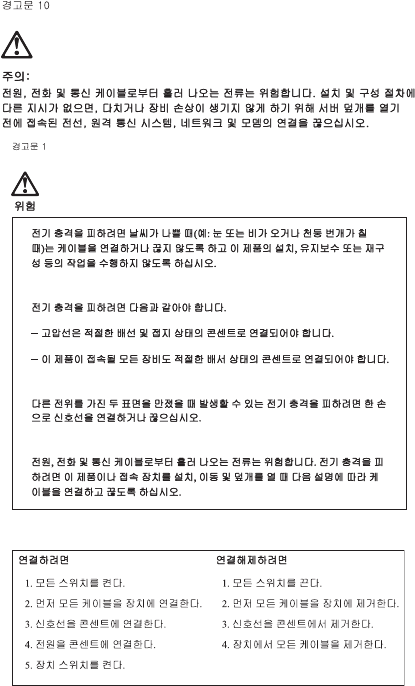
Electrical current from power, telephone, and
communications cables is hazardous. To avoid shock
hazard, connect and disconnect cables as described
following when installing, moving, or opening covers
of this product or attached devices.
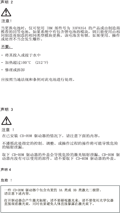
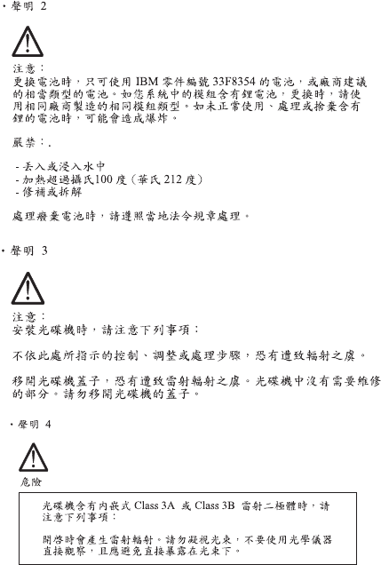
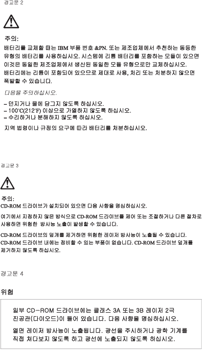
IMPORTANT:
When replacing the battery, use only IBM Part
Number 33F8354 or an equivalent type battery
recommended by the manufacturer. If your
system has a module containing a lithium
battery, replace it only with the same module
type made by the same manufacturer. The
To Connect
1. Turn Everything OFF.
2. First, attach all cables to
devices.
3. Attach signal cables to
receptacles.
4. Attach power cord(s) to
outlet.
5. Turn device ON
To Disconnect
1. Turn Everything OFF.
2. First, remove power
cord(s) from outlet.
3. Remove signal cables
from receptacles.
4. Remove all cables from
devices.

Notices ix
battery contains lithium and can explode if not
properly used, handled, or disposed of.
Do not:
•Throw or immerse into water
•Heat to more than 100°C (212°F)
•Repair or disassemble
Dispose the battery as required by local ordinances
or regulations.
IMPORTANT:
When a CD-ROM drive is installed, note the following.
Use of controls or adjustments or performance of
procedures other than those specified herein might
result in hazardous radiation exposure.
Removing the covers of the CD-ROM drive could
result in exposure to hazardous laser radiation. There
are no serviceable parts inside the CD-ROM drive.
Do not remove the CD-ROM drive covers.
DANGER
Some CD-ROM drives contain an embedded Class
3A or Class 3B laser diode. Note the following.
Laser radiation when open. Do not stare into the
beam, do not view directly with optical instruments,
and avoid direct exposure to the beam.
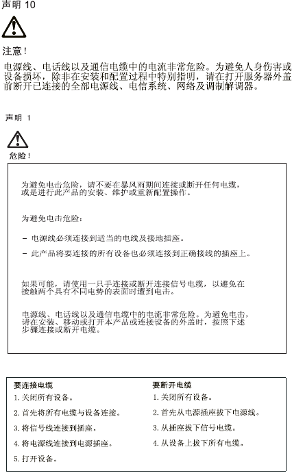
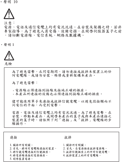
IMPORTANT:
Electrical current from power, telephone, and
communication cables can be hazardous. To avoid
personal injury or equipment damage, disconnect the
attached power cords, telecommunications systems,
networks, and modems before you open the server
covers, unless instructed otherwise in the installation
and configuration procedures.

x
PERIGO:
Para evitar choques elétricos, não conecte ou
desconecte nenhum cabo, nem efetue instalação,
manutenção ou reconfiguração deste produto
durante uma tempestade com raios.
Para evitar choques elétricos:
•O cabo de alimentação deve ser conectado a um
receptáculo corretamente instalado e aterrado.
•Todos os equipamentos aos quais este produto
será conectado devem também ser conectados a
receptáculos corretamente instalados.
Quando possível, utilize uma das mãos para
conectar ou desconectar cabos de sinal, para evitar
um possível choque ao tocar duas superfícies com
potenciais elétricos diferentes.
A corrente elétrica proveniente de cabos de
alimentação, de telefone e de comunicação é
perigosa. Para evitar choques elétricos, conecte e
desconecte os cabos conforme descrito a seguir, ao
instalar, movimentar ou abrir tampas deste produto
ou de dispositivos conectados.
Para Conectar
1.DESLIGUE tudo.
2.Conecte primeiro todos
oscabos nosdispositivos.
3.Conecte os cabos de sinal
nos receptáculos.
4.Conecte o(s) cabo(s) de
alimentação nas
tomadas.
5.LIGUE o dispositivo
Para Desconectar
1.DESLIGUE tudo.
2.Remova primeiro o(s)
cabo(s) de alimentação
das tomadas.
3.Remova os cabos de sinal
dos receptáculos.
4.Remova todos os cabos
dos dispositivos

Notices xi
CUIDADO:
Ao substituir a bateria, utilize apenas o Número de
Peça IBM 33F8354 ou um tipo de bateria equivalente
recomendado pelo fabricante. Se seu sistema
possuir um módulo com uma bateria de lítio,
substitua-o apenas pelo mesmo tipo de módulo,
produzido pelo mesmo fabricante. A bateria contém
lítio e pode explodir se não for utilizada, manuseada
e descartada de forma adequada.
Não:
•Jogue ou coloque na água
•Aqueça a mais de 100°C (212°F)
•Conserte nem desmonte.
Descarte a bateria conforme requerido pelas
disposições e regulamentações locais.
CUIDADO:
Quando uma unidade de CD-ROM estiver instalada,
observe o seguinte.
A utilização de controles ou ajustes ou a execução de
procedimentos diferentes daqueles especificados
nesta publicação pode resultar em exposição
perigosa à radiação.
A remoção das tampas da unidade de CD-ROM pode
resultar em exposição a radiação perigosa de laser.
Não existem peças que possam ser consertadas no
interior da unidade de CD-ROM. Não remova as
tampas da unidade de CD-ROM.
PERIGO:
Algumas unidades de CD-ROM contém um diodo de
laser da Classe 3A ou da Classe 3B. Observe o
seguinte.
Radiação de laser quando aberto. Não olhe
diretamente para o feixe de laser, não olhe

xii
diretamente com instrumentos óticos, e evite
exposição direta ao raio.
CUIDADO:
A corrente elétrica proveniente de cabos de
alimentação, de telefone e de comunicação é
perigosa. Para evitar ferimentos pessoais ou danos
aos equipamentos, desconecte os cabos de
alimentação, sistemas de telecomunicação, redes e
modems antes de abrir as tampas do servidor, a
menos que receba outras instruções nos
procedimentos de instalação e configuração.
Notices xiii
xiv
Notices xv
xvi

Notices xvii
PERIGO:
Pour éviter tout risque de choc électrique, ne
manipulez aucun câble et n'effectuez aucune
opération d'installation, d'entretien ou de
reconfiguration de ce produit au cours d'un orage.
Pour éviter tout risque de choc électrique :
• Les cordons d'alimentation du présent produit et
de tous les appareils qui lui sont connectés doivent
être branchés sur des socles de prise de courant
correctement câblés et mis à la terre.
Afin d'éviter tout risque de choc électrique provenant
d'une différence de potentiel de terre, n'utilisez
qu'une main, lorsque cela est possible, pour
connecter ou déconnecter les cordons d'interface.
Le courant électrique passant dans les câbles de
communication, ou les cordons téléphoniques et
d'alimentation peut être dangereux. Pour éviter tout
risque de choc électrique, lorsque vous installez ou
que vous déplacez le présent produit ou des
périphériques qui lui sont raccordés, reportez-vous
aux instructions ci-dessous pour connecter et
déconnecter les différents cordons.
Connexion
1. Mettez les unités hors
tension.
2. Commencez par
brancher tous les
cordons sur les unités.
3. Branchez les câbles
d'interface sur les prises.
4. Branchez les cordons
d'alimentation sur un
socle de prise de
courant.
5. Mettez les unités sous
tension.
Déconnexion
1. Mettez les unités hors
tension.
2. Commencez pas
débrancher les cordons
alimentation des socles
de prise de courant.
3. Débranchez les câbles
d'interface des prises.
4. Débranchez tous les
câbles des unités.

xviii
ATTENTION:
Remplacez la pile usagée par une pile de référence
identique exclusivement - voir la référence IBM - ou
par une pile équivalente recommandée par le
fabricant. Si votre système est doté d'un module
contenant une pile au lithium, vous devez le
remplacer uniquement par un module identique,
produit par le même fabricant. La pile contient du
lithium et présente donc un risque d'explosion en cas
de mauvaise manipulation ou utilisation.
•Ne la jetez pas à l'eau.
•Ne l'exposez pas à une température supérieure à
100°C.
•Ne cherchez pas à la réparer ou à la démonter.
Pour la mise au rebut, reportez-vous à la
réglementation en vigueur.
ATTENTION:
Si une unité de CD-ROM est installée, prenez
connaissance des informations suivantes :
Pour éviter tout risque d'exposition au rayon laser,
respectez les consignes de réglage et d'utilisation
des commandes, ainsi que les procédures décrites
dans le présent document.
Pour éviter une exposition directe au rayon laser,
n'ouvrez pas l'unité de CD-ROM. Vous ne pouvez
effectuer aucune opération de maintenance à
l'intérieur.
PERIGO:
Certaines unités de CD-ROM contiennent une diode
laser de classe 3A ou 3B. Prenez connaissance des
informations suivantes :
Rayonnement laser lorsque le carter est ouvert.
Évitez de regarder fixement le faisceau ou de

Notices xix
l'observer à l'aide d'instruments optiques. Évitez une
exposition directe au rayon.
ATTENTION:
Le courant électrique circulant dans les câbles de
communication et les cordons téléphoniques et
d'alimentation peut être dangereux. Pour votre
sécurité et celle de l'équipement, avant de retirer les
carters du serveur, mettez celui-ci hors tension et
déconnectez ses cordons d'alimentation, ainsi que
les câbles qui le relient aux réseaux, aux systèmes
de télécommunication et aux modems (sauf
instruction contraire mentionnée dans les procédures
d'installation et de configuration)
.

xx
VORSICHT:
Aus Sicherheitsgründen bei Gewitter an diese
Gerät keine Kabel anschließen oder lösen. Ferner
keine Installations-, Wartungs- oder
Rekonfigurationsarbeiten durchführen.
Aus Sicherheitsgründen:
•Gerät nur an eine Schutzkontaktsteckdose mit
ordnungsgemäß geerdetem Schutzkontakt
anschließen.
•Alle angeschlossenen Geräte ebenfalls an
Schutzkontaktsteckdosen mit ordnungsgemäß
geerdetem Schutzkontakt anschließen.
Signalkabel möglichst einhändig anschließen oder
lösen, um einen Stromschlag durch Berühren von
Oberflächen mit unterschiedlichem elektrischem
Potential zu vermeiden.
Elektrische Spannungen von Netz-, Telefon- und
Datenübertragungsleitungen sind gefährlich. Um
einen Stromschlag zu vermeiden, nur nach den
Anweisungen arbeiten, die für Installation, Transport
oder Öffnen von Gehäusen dieses Produkts oder
angeschlossenen Einheiten gelten.
Kabel anschließen
1.Alle Geräte ausschalten
und Netzstecker ziehen.
2.Zuerst alle Kabel an
Einheiten anschließen.
3.Signalkabel an
Anschlußbuchsen
anschließen.
4.Netzstecker an Steckdose
anschließen.
5.Gerät einschalten.
Kabel lösen
1.Alle Geräte ausschalten.
2.Zuerst Netzstecker von
Steckdose lösen.
3.Signalkabel von
Anschlußbuchsen lösen.
4.Alle Kabel von Einheiten
lösen.

Notices xxi
ACHTUNG:
Eine verbrauchte Batterie nur durch eine Batterie mit
der IBM Teilenummer 33F8354 oder durch eine vo
Hersteller empfohlene Batterie ersetzen. Wenn Ihr
System ein Modul mit einer Lithium-Batterie enthält,
ersetzen Sie es immer mit dem selben Modultyp vom
selben Hersteller. Die Batterie enthält Lithium und
kann bei unsachgemäßer Verwendung, Handhabung
oder Entsorgung explodieren.
Die Batterie nicht
•mit Wasser in Berührung bringen.
•über 100 C erhitzen.
•reparieren oder zerlegen.
Die örtlichen Bestimmungen für die Entsorgung von
Sondermüll beachten.
ACHTUNG:
Wenn ein CD-ROM-Laufwerk installiert ist, beachten
Sie folgendes. Steuer- und Einstellelemente sowie
Verfahren nur entsprechend den Anweisungen im
vorliegenden Handbuch einsetzen. Andernfalls kann
gefährliche Laserstrahlung auftreten.
Das Entfernen der Abdeckungen des CD-ROM-
Laufwerks kann zu gefährlicher Laserstrahlung
führen. Es befinden sich keine Teile innerhalb des
CD-ROM-Laufwerks, die vom Benutzer gewartet
werden müssen. Die Verkleidung des CD-ROM-
Laufwerks nicht öffnen.
VORSICHT:
Manche CD-ROM-Laufwerke enthalten eine
eingebaute Laserdiode der Klasse 3A oder 3B. Die
nachfolgend aufgeführten Punkte beachten.
Laserstrahlung bei geöffneter Tür. Niemals direkt in
den Laserstrahl sehen, nicht direkt mit optischen

xxii
Instrumenten betrachten und den Strahlungsbereich
meiden.
ACHTUNG:
An Netz-, Telefon- und Datenleitungen können
gefährliche elektrische Spannungen anliegen. Um
eine Gefährdung des Benutzers oder Beschädigung
des Geräts zu vermeiden, ist der Server
auszuschalten. Die Verbindung zu den
angeschlossenen Netzkabeln,
Telekommunikationssystemen, Netzwerken und
Modems ist vor dem Öffnen des Servergehäuses zu
unterbrechen (sofern in Installations- und
Konfigurationsanweisungen nicht anders angegeben)

Notices xxiii
PERICOLO:
Per evitare il pericolo di scosse elettriche durante i
temporali, non collegare o scollegare cavi, non
effettuare l'installazione, la manutenzione o la
riconfigurazione di questo prodotto.
Per evitare il pericolo di scosse elettriche:
•collegare il cavo di alimentazione ad una presa
elettrica correttamente cablata e munita di terra di
sicurezza;
•collegare qualsiasi apparecchiatura collegata a
questo prodotto ad una presa elettrica
correttamente cablata e munita di terra di
sicurezza.
Quando possibile, collegare o scollegare i cavi di
segnale con una sola mano per evitare il rischio di
scosse derivanti dal contatto con due superfici a
diverso potenziale elettrico.
La corrente elettrica circolante nei cavi di
alimentazione, del telefono e di segnale è pericolosa.
Per evitare scosse elettriche, collegare e scollegare
icavi come descritto quando si effettuano
l'installazione, la rimozione o l'apertura dei coperchi
di questo prodotto o durante il collegamento delle
unità.
Per collegare
1.SPEGNERE tutti i
dispositivi.
2.Collegare prima tutti I cavi
alle unità.
3.Collegare i cavi di segnale
alle prese.
4.Collegare il(i) cavo(i) di
alimentazione alla presa
elettrica.
5.ACCENDERE le unità.
Per scollegare
1.SPEGNERE tutti i
dispositivi.
2.Rimuovere prima il(i)
cavo(i) di alimentazione
dalla presa elettrica.
3.Rimuovere i cavi di
segnale dalle prese.
4.Rimuovere tutti i cavi dalle
unità.

xxiv
ATTENZIONE:
Quando si sostituisce la batteria, utilizzare solo una
batteria IBM o batterie dello stesso tipo o di tipo
equivalente consigliate dal produttore. Se il sistema
di cui si dispone è provvisto di un modulo contenente
una batteria al litio, sostituire tale batteria solo con un
tipo di modulo uguale a quello fornito dal produttore.
La batteria contiene litio e può esplodere se utilizzata,
maneggiata o smaltita impropriamente.
Evitare di:
•Gettarla o immergerla in acqua
•Riscaldarla ad una temperatura superiore ai 100°C
•Cercare di ripararla o smaltirla
Smaltire secondo la normativa in vigore (D.Lgs 22 del
5/2/97) e successive disposizioni nazionali e locali.

Notices xxv
ATTENZIONE:
Quando è installata un'unità CD-ROM, notare quanto
segue:
L'utilizzo di controlli, regolazioni o l'esecuzione di
procedure non descritti nel presente manuale
possono provocare l'esposizione a radiazioni
pericolose.
L'apertura di un'unità CD-ROM può determinare
l'esposizione a radiazioni laser pericolose. All'interno
dell'unità CD-ROM non vi sono parti su cui effettuare
l'assistenza tecnica. Non rimuovere i coperchi
dell'unità CD-ROM.
PERICOLO:
Alcune unità CD-ROM contengono all'interno un
diodo laser di Classe 3A o Classe 3B. Prestare
attenzione a quanto segue:
Aprendo l'unità vengono emesse radiazioni laser.
Non fissare il fascio, non guardarlo direttamente con
strumenti ottici ed evitare l'esposizione diretta al
fascio.
ATTENZIONE:
La corrente circolante nei cavi di alimentazione, del
telefono e di segnale è pericolosa. Per evitare
situazioni pericolose per le persone o
danneggiamenti all'apparecchiatura, scollegare i cavi
di alimentazione, i sistemi di telecomunicazioni, le reti
e ed i modem prima di aprire i coperchi del servente
se non diversamente indicato nelle procedure di
installazione e configurazione.
xxvi
Notices xxvii

xxviii
PELIGRO:
Para evitar una posible descarga eléctrica, no
conecte ni desconecte los cables ni lleve a cabo
ninguna operación de instalación, de mantenimiento
o de reconfiguración de este producto durante una
tormenta eléctrica.
Para evitar una posible descarga:
•El cable de alimentación debe conectarse a un
receptáculo con una instalación eléctrica correcta
y con toma de tierra.
•Los aparatos a los que se conecte este producto
también deben estar conectados a receptáculos
con la debida instalación eléctrica.
Cuando sea posible, utilice una sola mano para
conectar o desconectar los cables de señal a fin de
evitar una posible descarga al tocar dos superficies
con distinto potencial eléctrico.
La corriente eléctrica de los cables de
comunicaciones, teléfono y alimentación puede
resultar peligrosa. Para evitar una posible descarga,
siga las indicaciones de conexión y desconexión de
los cables siempre que tenga que instalar, mover o
abrir las cubiertas de este producto o de los
dispositivos acoplados.
Instrucciones de
conexión
1.Apague todos los
componentes (OFF).
2.En primer lugar, conecte
todos los cables a los
dispositivos.
3.Conecte los cables de
señal a los receptáculos.
4.Conecte los cables de
alimentación a las tomas.
5.Encienda el dispositivo
(ON).
Instrucciones de
desconexión
1.Encienda todos los
componentes (ON).
2.En primer lugar, retire los
cables de alimentación de
las tomas.
3.Retire los cables de señal
de los receptáculos.
4.Retire todos los cables de
los dispositivos.

Notices xxix
IMPORTANT:
Al cambiar la batería, utilice únicamente la batería
IBM Número de pieza 33F8354 o un tipo de batería
equivalente recomendado por el fabricante. Si el
sistema tiene un módulo que contiene una batería de
litio, sustitúyalo únicamente por el mismo tipo de
módulo del mismo fabricante. La batería contiene litio
y puede explotar si no se utiliza, manipula o desecha
correctamente.
Lo que no debe hacer
•Tirar o sumergir el producto en agua.
•Exponer el producto a una temperatura superior a
100°C.
•Reparar o desmontar el producto.
Cuando quiera desechar la batería, siga las
disposiciones y reglamentaciones locales.
IMPORTANT:
Cuando instale una unidad de CD-ROM, tenga en
cuenta la siguiente información.
Si se llevan a cabo controles o ajustes o se utilizan
métodos que no se atengan a lo aquí especificado,
se puede producir una exposición peligrosa a las
radiaciones.
Si se retiran las cubiertas de la unidad de CD-ROM,
se puede producir una peligrosa exposición a
radiaciones de láser. Dentro de la unidad de CD-
ROM no existen piezas reparables. No retire las
cubiertas de la unidad de CD-ROM.
PELIGRO:
Algunas unidades de CD-ROM tienen incorporado un
diodo de láser de Clase 3A o de Clase 3B Tenga en
cuenta la siguiente información.

xxx
Cuando la unidad está abierta se generan emisiones
de rayos láser. No dirija la mirada al haz, no lo
observe directamente con instrumentos ópticos y
evite la exposición directa.
IMPORTANT:
La corriente eléctrica de los cables de
comunicaciones, de teléfono y de alimentación puede
resultar peligrosa. Para evitar posibles lesiones o
daños del aparato, desconecte los cables de
alimentación, los sistemas de telecomunicaciones,
las redes y los módems antes de abrir las cubiertas
del servidor, salvo que se indique lo contrario en las
instrucciones de las operaciones de instalación y
configuración.

Notices xxxi
Laser Compliance Statement
The CD-ROM drive in the computer is a laser
product. The CD-ROM drive's classification label
(sample shown below) is located on the drive.
The CD-ROM drive is certified in the U.S. to conform
to the requirements of the Department of Health and
Human Services 21 Code of Federal Regulations
(DHHS 21 CFR) Subchapter J for Class 1 laser
products.
In other countries, the drive is certified to conform to
the requirements of EN60825.
Class 1 laser products are not considered to be
hazardous. The CD-ROM drive has an internal Class
1, 0.5-milliwatt, aluminum gallium-arsenide laser that
operates at a wavelength of 760 to 810 manometers.
The design of the laser system and the CD-ROM
drive ensures that there is no exposure to laser
radiation above a Class 1 level during normal
operation, user maintenance, or servicing conditions.
CLASS 1 LASER PRODUCT
APPAREIL A LASER CLASSE 1
LASER KLASSE 1
LUOKAN 1 LASERLAITE
PRODUIT LASE
CATEGORIE 1

xxxii
Trademarks
The following are trademarks of the IBM Corporation
in the United States or other countries or both:
AT
HelpCenter
IBM
Operating System/2
OS/2
Personal System/2
PS/1
PS/2
Intel, Pentium, MMX, EtherExpress, and LANDesk
are trademarks or registered trademarks of Intel
Corporation.
Microsoft, MS-DOS, Windows, and Windows NT are
trademarks or registered trademarks of Microsoft
Corporation.
Other company, product, and service names may be
trademarks or service marks of others.

Notices xxxiii
Preface
This manual contains service information for the 2274
Service Level A (SL-A) model of the IBM Personal
Computer, worldwide. This manual is intended to be
used as a stand-alone document to service machine
type 2274 products. It is divided into the following
chapters:
Notices contains important safety information and
notices required to service this computer.
General Information contains a brief description of
this manual.
Check Procedures provides step-by-step
instructions that aid in locating the failing Field
Replaceable Unit (FRU).
Diagnostic Aids explains how to use the diagnostics
tools for isolating failures.
Repairing Information contains illustrations and
descriptions to disassemble and reassemble the
computer.
Parts/Test Point Locations contains illustrations and
descriptions of the locations of the major parts,
jumpers, and connectors.
Safety Inspection Guide contains information about
inspecting a machine for safety problems before
putting the machine under a Maintenance
Agreement.
Parts Catalog contains descriptions, illustrations,
and part numbers for individual FRUs.
Appendix A, FRU Number Index contains part
numbers listed in numerical order.
xxxiv

General Information 1
General Information
Introduction ............................................................2
Product Overview ...................................................3
Processor ........................................................3
Memory ...........................................................3
External Ports ..................................................4
Diskette Drive ..................................................4
Hard Disk Drive ...............................................4
DVD-ROM Drive ..............................................5
Multimedia .......................................................5
Power Management ........................................5
Power Supply ..................................................6
Internal Cabling ...............................................6
Monitor (Not included with some models) .......6
Keyboard .........................................................7
Mouse .............................................................7
Hardware Interfaces ...............................................8
CMOS Reset ........................................................10
Power-On Password ............................................11
Flash (BIOS) Update Procedure ..........................12
BIOS-contained Model Number and
Serial Number ......................................................13
BIOS Configuration/Setup Utility ..........................14
Working with the Configuration/Setup
Utility Menus ..................................................14
Viewing System Information, and
Product Data .................................................17
Devices and I/O ports ....................................17
Startup Options .............................................20
Date and Time ...............................................21
Advanced Setup ............................................23
Power Management Setup ............................24
Specifications .......................................................28
Dimension (width x depth x height) ...............28
Weight ...........................................................28
Environment ..................................................28
Power consumption .......................................28
Electrical input ...............................................28
Operating Requirements ......................................29


General Information 3
Product Overview
Personal Computer Type 2274 has three PCI slots
and supports the AMD K7 Duron processor family
with Socket A processor package type.
The Personal Computer Type 2274 supports
Accelerated Graphics Port (AGP) 2X / 4X, which
allows installed system memory to be used as texture
memory, yielding a huge texture footprint to enhance
3D graphical display performance.
Listed below are 2274 system features:
Processor
•Socket A connector.
•Detachable CPU fan sink.
•128 KB of on-chip level one (L1) cache
•64 KB level two (L2) cache support for Duron
•AMD K7 processor; 200MHz front side bus, 600/
700MHz, 0.18 Microns, with 3DNow!™ technology
•Multiple parallel x86 instruction decoders
Memory
•168-pin Synchronous Dynamic Random Access
Memory (SDRAM), Dual in-line Memory Module
(DIMM) sockets.
- 3 memory sockets.
- 8MB, 16MB, 32MB, 64MB, 128MB and 256MB
DIMM.
- PC-100/133 (8-128 M-bit, ECC, 133MHz,
3.3volt) DIMMs with gold contacts
- Maximum memory is 768MB
4 IBM Desktop System HMM
External Port
•2x/4x AGP video card (15-pin VGA connector)
•Multi-Mode Parallel port (25-pin D-type connector)
•Serial port (9-pin D-sub connector). 2274 has one
serial ports, serial port 1
•Keyboard and mouse port
•Four USB ports (2 on port bracket, the other 2 on
the front panel)
•Game/MIDI port (15-pin D-sub connector)
•Microphone-in jack
•Speaker-out jack
•Line-in jack
•Telephone line-out connector (modem adapter
card available)
•Telephone line-in connector (modem adapter card
available)
•RJ-45 connector (adapter card available)
Diskette Drive
•3.5 “ drive for 2.88MB, 1.44MB or 720KB diskette
•5.25” drive for 1.2MB or 360KB diskette
•Support 3-mode drive
Hard Disk Drive
•3.5-in., 1-in. height IDE drive. (3.5-in may be in
acoustic mounting bracket), and 7200rpm.
•128 KB “look-ahead” cache memory inside the
hard disk drive.
•Average and minimum 12 ms seek time, access
time varies for the hard disk drive and the hard
disk drive manufacturer.
General Information 5
DVD-ROM Drive
•5.25-in. high-performance, 8X/40X DVD-ROM
IDE/AT drive.
•Read data and audio play from standard, mini
DVD-ROM and audio compact discs (audio CDs).
DVD media supported on DVD models.
Multimedia
•A pair of external active speakers with a power
adapter or a pair of passive speakers.
•Noise canceling microphone available.
Power Management
•Support both ACPI (Advanced Configuration and
Power Interface) and legacy (APM) power
management.
•ACPI v1.0 and APM v1.2 compliant
•CPU clock throttling and clock stop control for
complete ACPI S1 and S5 state support
•PCI bus clock run, Power Management enable
(PME) control, PCI/CPU color generator stop
control.
•Power-on Switch must support Soft-Off and
Full-Off.
- Touch for 1 second or less to put system on
Suspend state.
- Touch and hold for 4 seconds to put system on
Full-Off state (Power Supply standby remains).
•System enters standby mode if any of following
conditions are met:
- Execute standby from Windows 98 Start menu
- Press system power button if it sets to act as
standby function
- System is idle and the standby timer set in the
Windows 98 Power Management Property
elapses
•8 bytes of BIOS scratch register
6 IBM Desktop System HMM
Power Supply
•PC-98 compatible 145W ATX power supply
•Switchable high/low voltage selection
Internal Cabling
•Two 40-pin ribbon cables for hard disk drives and
CD/DVD-ROM drive.
•One 34-pin ribbon cable for AT diskette drive.
•One 4-pin (2-wire) cable for hard disk drive
light-emitting diode (LED).
•One 3-pin (3-wire) cable for power light-emitting
diode (LED).
•One 2-pin (2-wire) cable for power switch.
Monitor (Not included with some models)
•Super Video Graphics Array (SVGA) monitor.
•VESA power saving mode compliant.
•Connector for a detachable grounded 3-wire
power cord
•1.8-m (5.8-ft.) signal cable attached
•Auto-sensing power input for 100 Vac to 240 Vac
•15" (13.7" viewable image size) monitor
- 0.28-mm dot pitch
- Automatic scanning horizontal frequencies from
30 KHz to 54 KHz or 30 KHz to 69 KHz
(for Japan)
- Vertical frequencies between 50 Hz and 120 Hz.
- DDC2A/B or DDC1/2B+ support (for Japan)
- OSD (On-Screen Display) menu (for Japan)
•17" (15.7" viewable image size) monitor
- 0.28-mm or 0.27-mm dot pitch (for Japan)
- Automatic scanning horizontal frequencies from
30 KHz to 69 KHz or 30 KHz to 72 KHz
(for Japan)
- Vertical frequencies between 50 Hz and 120 Hz.
- DDC1/2B+ support and OSD (On-Screen
Display) menu
General Information 7
Keyboard
•104-key, rubber dome Rapid Access™II keyboard
with 1.8-m (5.8-ft.) cable
Mouse
•4 Button PS/2 Sleek or ScrollPoint™II mouse with
1.8-m (5.8-ft.) cable

8 IBM Desktop System HMM
Hardware Interfaces
The following peripheral interfaces for adapters,
options, and drives are supported in the system unit.
Item Interface
Expansion slot for
I/O adapter cards
Three PCI (Peripheral Component
Interconnect) v2.2 compatible
expansion slots that operates at 33
MHz bus speed.
Hard disk drives Four PCI local bus Enhanced IDE
v1.0 compatible hard disk drive
interfaces that support:
- PIO mode up to 6 mode
- DMA 32-bit access
- Ultra 33/66 Synchronous DMA (33/
66M bytes/sec).
DVD-ROM drive 5.25-in. high-performance, 8X/40X
DVD-ROM IDE/AT drive.
Support Bootable CD-ROM Format
specification version 1.0.
Compliant to Audio-CD, Video-CD,
CD-ROM/XA, Karaoke-CD, and
Photo-CD (both single and multi
session) format.
Diskette drive AT diskette interface
Video Physical interface is compatible with
the IBM Personal System/2 (PS/2)
VGA interface.
Support Accelerated Graphics Port
(AGP)
Modem One 56.6 Kbps PCI modem adapter
card with data/fax/voice or non-voice
features.
Audio Compatible to AC99
Pointing device IBM PS/2-compatible mouse
Keyboard device IBM PS/2-compatible keyboard
Serial port Support one high speed NS 16C550
compatible UARTs with send/receive
16 bytes FIFOs
RS232D electrical interface
compliant

General Information 9
Parallel port Supports SPP (IBM PC/XT, PC/AT,
PS/2) compatible, EPP (IEEE 1284
compliance), ECP (IEEE 1284
compliance) interface.
IEEE 1284 compliant
Game port Game port interface for joystick. It
also supports MIDI.
USB Supports Universal UHCI
Specification for USB 1.1
Item Interface


General Information 11
Power-On Password
A power-on password denies access to the system by
an unauthorized user when the system is powered
on. When a power-on password is active, the
password prompt appears on the screen each time
the system is powered on. The system starts after the
proper password is entered. See “Power-On
password” on page 21 for more information about
how to change, remove and set password in
Configuration/Setup Utility.
In some cases, you might be required to service a
system with an active and unknown power-on
password. To clear a password from the system,
follow these steps.
1. Turn off system unit.
2. Unplug power cable from the electrical outlet.
IMPORTANT: Do not attempt these steps with the
power cord plugged into the electrical outlet.
The power supply maintains +5 Vdc of standby
power when the power cord is plugged.
System damage might result if the power cord
is not unplugged during jumper setting.
3. Set JP14 to 2-3 position to clear BIOS setting as
original manufacture setting. See “System Board
Jumpers and Connectors” on page 109.
4. Set JP7 back to the 1-2 position to enable
password check process. See “System Board
Jumpers and Connectors” on page 109.
IMPORTANT: To reinstall the password, the user
must enter a password in the Configuration/Setup
Utility. If Enhanced Security is enabled and the
password is forgotten, the system board must be
replaced.

12 IBM Desktop System HMM
Flash (BIOS) Update Procedure
NOTE: The flash update procedure does not change
the model number and serial number
information in BIOS.
1. Prepare a bootable DOS diskette with
AWDFLASH.EXE, and one XXXXXXX.BIN files
NOTE: The AWDFLASH.EXE are flash utility
programs. The one VXXYYZZ.RN file has the
BIOS checksum information. The
XXXXXXX.BIN is BIOS source code binary file.
2. Insert the diskette and boot from drive A.
WARNING: Do not boot with any memory related
driver such as HIMEM.SYS, EMS.SYS....
3. At the DOS prompt, type A:> AWDAFLASH
XXXXXXX.BIN /PY/SN/CD/CP then press Enter.
4. The program updates the BIOS automatically.
IMPORTANT: Verify the BIOS checksum value shown
on screen is the same as the one in
VXXYYZZ.RN file.
WARNING: Do not turn off the system power while the
BIOS is programming, or the flash ROM will be
destroyed.
5. Power off system after the BIOS is completely
updated.

General Information 13
BIOS-contained Model Number and
Serial Number
The model number and serial number information is
stored in BIOS ROM and displayed in the “Product
Data” of Configuration/Setup Utility main menu. If a
service repair is completed by replacing a new
system board or a new BIOS ROM, then you are
required to input the original system's model number
and serial number into the new BIOS ROM.
Follow these steps to input the model number and
serial number to BIOS:
1. Prepare a diskette with DMICFG.EXE file.
2. At the DOS prompt, type A:>DMICFG.exe.
3. When update system product name, at the DOS
prompt type A:>DMICFG.EXE/ type 01 05
[String].
For example:
[String] : Type 2274
type A:>DMICFG.EXE/ type 01 05 “Type
2174”.
NOTE: You can type a maximum of 32 characters. If
you have a string with spaces, type “ “ to quote
the string.
4. When update system serial number, at the DOS
prompt type A:>DMICFG.EXE/ type 01 07 [String].
NOTE: Enter the serial number and press Enter to
continue. You can type a maximum of 32
characters (without spaces).
5. Enter BIOS setting to display and verify your input
product number and serial number information.

14 IBM Desktop System HMM
BIOS Configuration/Setup Utility
The Configuration/Setup Utility lets you review and
change important information about the computer and
its hardware.
Working with the Configuration/Setup
Utility Menu
Starting the Configuration/Setup Utility
Follow these steps to enter Setup when the computer
is off:
1. Turn on your monitor.
2. Press and hold F1.
3. Turn on the system unit.
If you have previously set a password, you are
prompted to type in the password after you press the
F1 key. Refer to the Configuration/Setup Utility Main
Menu below.
Configuration/Setup Utility
Select Options:
• System Summary
• Product Data
• Devices and I/O Ports
• Start Options
• Date and Time
• System Security
• Advanced Setup
• Power Management Setup
Save & Exit Setup
Load Default Settings
Exit Without Saving
↓
↓↓
↓↑
↑↑
↑Move Enter:Select F1:Help
F10:Save ESC:Exit
General Information 15
The following table lists specific keys on the keyboard
that will help you move through the Configuration/
Setup Utility Menus:
Changing Parameter Settings
In the Configuration/Setup Utility Menus, the
configuration information that you can change is
enclosed in brackets like these: [ ]. You cannot
change any information that is not enclosed in
brackets. Use the up- or down- arrow keys to
highlight options then press Enter to display a menu.
When changing the setting of a particular parameter,
highlight the setting then use the left- or right- arrow
key to change the setting. Refer to the Configuration/
Setup Utility help for details on the configurable
parameters in each menu.
Keys Function
Down- or up-
arrow key
Use these arrow keys to highlight
an option on the menu. (Press the
Enter key to choose the option.)
Left- or right-
arrow key
Use these arrow keys to make a
selection and change an option's
setting. On some menus, you can
use these keys to move from one
field to another.
F1 Press this key if you want help for a
selected menu option.
Esc After viewing or making changes to
the settings on a menu, press this
key to exit the menu.
Enter Press this key to choose a
highlighted option from a menu
F10 Press this key if you want to save
the current settings for a line
F7 Press this key if you want to load
the factory default settings from the
selected brackets.
F5 Press this key if you want to restore
item previous setting
16 IBM Desktop System HMM
Save & Exit Settings
After changing any parameter in the Setup
Configuration setting, return to Configuration/Setup
Utility main menu and select Save & Exit Setup to
save all the settings you have changed. Then, exit the
Configuration/Setup Utility menu.
Loading Default Settings
The computer is already configured for use. The
original configuration settings, also called factory or
default settings, are stored in the CMOS. Setup
includes an option Load Default Settings that lets you
reload the original configuration at any time.
To load the default settings, follow these steps:
1. Use down-arrow key to select load default settings.
A dialog box appears confirming if you want to
load the default settings.
2. Use the left-arrow key to select Yes, then press
Enter.
3. Press Esc to exit Setup.
A dialog box appears confirming if you want to
save the settings (in this case, the default settings
that you reloaded).
4. Use the left-arrow key to select Yes, then press
Enter to save the changes in Configuration/Setup
Utility.
You must load the Setup default settings in the
following instances:
•When you replace the system battery.
•When you customize the system configuration
settings and some resource assignments conflict
causing the computer to stop responding.
General Information 17
Exiting Without Saving
Press Esc to return to the Main Menu when you have
finished viewing settings and making changes. Fro
this location, you can exit Setup but without saving
your changes.
Viewing System Information, and
Product Data
To view general hardware information about your
computer, select the System Summary option fro
the Configuration/Setup Utility main menu. The items
displayed in the System Summary menu are not
configurable.
Setup automatically updates this menu when you do
either of the following:
•Add or change hardware on your computer
•Make changes to other menus in Setup and save
those changes
To view the computer information such as the
machine type/model, flash EEPROM revision level,
system serial number, BIOS version, BIOS date, and
BIOS mode, select the Product Data option from the
Configuration/Setup Utility main menu. Like in the
System Summary menu, the items displayed are not
configurable.
Devices and I/O ports
If you install USB devices, video, IDE drives, audio, or
network drive, BIOS auto-detects the presence of
these devices. Enter Configuration/Setup Utility to
identify or verify the type of drive installed in the
computer.
Diskette Drive A
This option displays the size and storage capacity of
the currently installed diskette drive. The default is
1.44 MB, 3.5 in..
Diskette Drive B
This option displays the size and storage capacity of
the currently installed diskette drive. Empty drive
bays are indicated with a “None” default setting.
18 IBM Desktop System HMM
Serial Port Setup
Onboard Serial Port 1
It comes with one 9-pin serial ports. This parameter
will be allowed to set Auto, Disabled, or the base
address such as 3F8/IRQ4, 2F8/IRQ3, 3E8/IRQ4, or
2E8/IRQ3 for serial port. The default is set to Auto.
Parallel Port Setup
Onboard Parallel Port
Your computer comes with one parallel port. This
parameter shows the base address to activate the
parallel port. The default base address is 378h and
the default IRQ is 7.
Onboard Parallel Mode
There are four selection for this parameter Normal,
EPP, ECP, ECP/EPP. The default setting is Normal.
ECP Mode Use DMA
When Onboard parallel Mode is set to ECP or ECP/
EPP, this parameter becomes configurable.
Otherwise, it will be unchangeable and the default
setting is 3.
Parallel Port EPP Type
When Onboard parallel Mode is set to EPP or ECP/
EPP, this parameter becomes configurable.
Otherwise, it will be unchangeable and the default
setting is EPP1.9.
USB Setup
Onboard USB
The item Universal Serial Bus (USB) parameter is
allowed to set as Enabled and Disabled . The default
setting is Enabled.
USB Keyboard Support
The default setting is set to Disabled while the
parameter Onboard USB is Enabled. If Onboard
USB is set to Disabled, this item is not configuable.
General Information 19
USB Mouse Support
This parameter enables or disables the use of a USB
keyboard outside of Windows. The default is
Disabled. It is not configurable if Onboard USB is set
to Disabled.
IDE Drives Setup
IDE Prefetch Mode
The default setting is Enabled. IDE prefetch mode
can improve performance of your system for fast
drive accesses. If install a primary and/or secondary
add-in IDE interface, set this field to Disabled if the
interface does not support prefetch.
Audio Setup
Onboard Sound
This parameter enables or disables the onboard
audio controller chipset. This item does not appear in
the menu if there is no physical audio chipset on the
system board. The default setting is Enabled.
Onboard Legacy Audio
This parameter enables or disables the onboard
audio controller chipset to function in DOS
environment. The default is Enabled.
IMPORTANT: When onboard legacy audio is set to
Enabled, the below six parameters can be
configurabled as I/O base address and IRQ
assignment and so on.
Sound Blaster
The default is Disabled.
SB I/O Base Address
The default is set to 220H.
SB IRQ Select
The default is IRQ5.
MPU-401 --Enabled
The default is Enabled.
20 IBM Desktop System HMM
MPU-401 I/Q Address
NOTE: The default is 330-333H
Game Port (200-207H)
NOTE: The default is Enabled.
Startup Options
From the Configuration/Setup Utility main menu,
select Start Options to view or change start-up
configuration settings.
Startup Sequence
The startup sequence is used when the system is
powered on by the power switch. The startup device
will include Floppy, LS120, HDD-0, SCSI, CDROM,
HDD-1, HDD-2, HDD-3, ZIP100, LAN and Disabled.
First Boot Device
The default is set to Floppy.
Second Boot Device
The default setting is HDD-0.
Third Boot Device
The default is CD-ROM.
Boot Other Device
The default value is Enabled.
Keyboard NumLock Status
This parameter displays when the NumLock function
on the keyboard turns on automatically each time you
turn your computer on. You can set this to On or Off.
The default is On.
Disketteless Operation
When enabled, the BIOS issues the seek command
to the diskette drive during POST to move diskette
drive head forward and backward. The default is
enabled.
General Information 21
Keyboardless Operation
When enabled, the BIOS issues the seek command
to the keyboard to move faster during POST. The
default is enabled.
Power On Self Test
When set to Enabled, which is the default, this
parameter allows the system to boot faster by
skipping some power-on self-test (POST) routines.
Date and Time
From the Configuration/Setup Utility main menu,
select the Date and Time option to view or change the
system clock from the Date and Time menu. If you
want to change the system date, enter the date in the
format shown on the screen.
If you change the time, enter the time in 24-hour
format (hours, minutes, seconds). For example:
- 12 midnight is 00:00:00
- 12 noon is 12:00:00
- 1 p.m. is 13:00:00
When setting date and time, press the up- or down-
arrow key to highlight a field. The date and time are
saved as you type it.
Power-On password
Select this parameter and press the down arrow key
to display the Power-on Password window. In this
window, you can set up a password to restrict the use
of your computer. You can also change or remove the
password.
If you set up a power-on password, you must type this
password each time you turn on your computer. If you
do not key in the correct password, you cannot use
your computer. You must also type this password if
you want to enter Setup.
Setting a Power-On Password
1. Press F1 to enter Configuration/Setup Utility.
2. From the Configuration/Setup Utility main menu,
select System Security and then [Power-On
Password].
3. Highlight the [Power-On Password] parameter and
press the Enter key to display the Power-On
22 IBM Desktop System HMM
Password window.
4. Type a password consisting of up to eight
characters, then press Enter.
5. Retype the password then press Enter.
6. Press Enter again to confirm the setting of the
password. Pressing Esc aborts the password
setting.
After pressing Enter, the Power-On Password
window disappears. The [Power-On Password]
parameter automatically is set completely.
7. Press Esc to return to Configuration/Setup Utility
main menu.
8. Press Esc to exit Setup and reboot the system.
Answer Yes when prompted to save settings.
The next time you turn on the system, and If you
press F1 during POST to enter Configuration/Setup
Utility, you must key in the password.
If you were not able to set a password after
performing the above procedure, or should you
encounter any error message when setting a
password, refer to “Power-On Password” on page 11
about how to set the hardware jumper to clear
password check.
Changing the Power-On Password
1. Enter Configuration/Setup Utility.
2. Key in your current password when prompted.
3. From the Configuration/Setup Utility main menu,
select System Security, then [Power-On
Password] Options.
4. Type in a new password then press Enter.
5. Retype the new password then press Enter.
6. Press Esc twice to return to the Configuration/
Setup Utility main menu.
7. Press Save Settings to save the password and
press Exit to exit Configuration/Setup Utility menu,
and then reboot the system.
Delete Power-On Password
1. Enter Configuration/Setup Utility and select
System Security Options, then [Power-On
password] Options.
2. Leave empty on Power-on password windows,
General Information 23
and then press Enter. The message appears on
the screen as below:
“PASSWORD DISABLED!!!“
Press any key to continue ........
3. Return to Configuration/Setup Utility main menu.
4. Select Save and Exit Setup to save and exit
Setup and reboot the system.
Administrator Password
IMPORTANT: When both Power-On password and
Administrator password are setup with
password, you must enter Power-On password
to get in the Configuration/Setup Utility. All the
setting in the BIOS will not be configurable.
Otherwise, after typing in administator
password and enter the Configuration/Setup
Utility menu, you can change all the Setup
settings.
For the basic administrator password setting, follow
the same rule with Power-On Password to set up,
change, or delete a password.
Advanced Setup
IMPORTANT: Items on the following menus control
advanced hardware features. If they are
configured incorrectly, the system might
malfunction.
Cache Control
CPU Internal Cache
This parameter enables or disables the first-level or
internal memory, that is, the memory integrated into
the CPU. The default setting is Enabled.
External Cache
This parameter enables or disable the external cache
is incorporated in the CPU module.
ROM Shadowing
Video BIOS Shadow
The default is Enabled. Video BIOS Shadow means
to copy video display card BIOS into the DRAM area.
This enhances system performance because DRA
access time is faster than ROM.
24 IBM Desktop System HMM
IMPORTANT: These six items are for shadowing
ROM code on other expansion cards. Before
you set these parameters, you need to know
the specific addresses of that ROM code. If you
do not know this information, enable all the
ROM shadow settings.
C8000-CBFFF Shadow
The default is Disabled.
CC000-CFFFF Shadow
The default is set to Disabled.
D0000-D3FFF Shadow
The default is Disabled.
D4000-D7FFF Shadow
The default is Disabled.
D8000-DBFFF Shadow
The default is Disabled.
DC000-DFFFF Shadow
The default is set to Disabled.
Power Management Setup
ACPI function
The ACPI (Advanced Configuration and Power
Interface) feature enables the operating system to
monitor and control the amount of power supplied to
each device attached to the system. When enabled,
ACPI uses the OS (operating system) to turn off the
peripheral devices (such as a CD-ROM) that are not
in use. The default setting is Enabled.
APM
Power Management
This parameter allows you to select the type (or
degree) of power saving such as User Define, Min.
Saving, and Max. Saving as well as is directly
effected on the following modes HDD Power Down,
Doze Mode and Suspend Mode.
General Information 25
The default of Power Management is set to User
Define, so it allows you to set each mode individually.
HDD Power Down
Whatever Power Management is set, the ranges are
from 1 min. to 15 min. and Disabled. The default is
Disabled.
Doze Mode
While Power Management is set to User Define, this
ranges are from 1 min. to 1 hour. and Disabled. The
default is Disabled.
While Power Management is set to Min Saving, this
parameter will be 1 min.
While Power Management is set to Max Saving, this
parameter will be 1 hour.
Suspend Mode
While Power Management is set to User Define, this
ranges are from 1 min. to 1 hour. and Disabled. The
default is Disabled.
While Power Management is set to Min Saving, this
parameter will be 1 min.
While Power Management is set to Max Saving, this
parameter will be 1 hour.
PM Control by APM
When set to Yes, an Advanced Power Management
device will be activated to enhance the Max. Power
Saving mode and stop the CPU internal clock.
When set to No, the Max. Power Saving is not
enabled.
Video Off Option
Based on an inactivity time-out, the system will enter
power saving management modes. There are three
modes, Always On, Suspend -> Off, and All Modes ->
Off, to determine whether turn off the monitor. The
default is Suspend -> Off.
26 IBM Desktop System HMM
Video Off Method
This determines the manner in which the monitor is
blanked. The default is set to V/H SYNC+Blank.
When V/H SYNC+Blank is chosen, this selection will
cause the system to turn off the vertical and
horizontal synchronization ports and write blanks to
the video buffer.
The parameter is set to DPMS Support, it will initial
display power management signaling.
When set to Blank Screen, this option only writes
blanks to the video buffer.
Activity Monitor
VGA The default is OFF. When set to On, you can
set the LAN to awaken the system.
LPT & COM When LPT/COM is selected, any
activity from one of the listed system peripheral
devices or IRQs wakes up the system. LPT/COM is
selected as the default.
HDD & FDD When the HDD & FDD is set to On, any
activity from one of the listed system peripheral
devices wakes up the system. The default is On.
PCI Master When PCI Master is set to On, any
activity from one of the list system peripheral devices
wakes up the system. The default is Off.
Primary INTR
This item is used to enable or disable the detection of
IRQ3-15 or NMI interrupt events for power down state
transition. Normally, this is applied to the network
card. The default is On.
IMPORTANT: The following are used to enable or
disable the IRQ resources which assign each
system interrupt a type, depending on the type
of device using the interrupt.
IRQ3 (COM2) The default is Enabled.
IRQ4 (COM1) The default is Enabled.
IRQ5 (LPT2) The default is Enabled.
IRQ6 (Floppy Disk) The default is Enabled.
IRQ7 (LPT 1) The default is Enabled.
General Information 27
IRQ8 (RTC Alarm) The default is Enabled.
IRQ9 (IRQ2 Redir) The default is Disabled.
IRQ10 (Reserved) The default is Disabled.
IRQ11 (Reserved) The default is Disabled.
IRQ12 (PS/2 Mouse) The default is Enabled.
IRQ13 (Coprocessor) The default is Enabled.
Automatic Power On
Power On by PCI Card
This option allows the user to boot from the PCI
device after the system is turned on. The default is
Disabled.
Modem Ring Resume
This parameter enables or disables an input signal on
the serial Ring Indicator (RI) line (an incoming call on
the modem) to awaken the system from a soft off
state. The default is Disabled.
RTC Alarm Resume.
When Enabled, you can set the date and time at
which the RTC (real-time clock) alarm wakes the
system from suspend mode. The default is Disabled.
Date (Month)
When RTC Alarm Resume is set to Disabled, it is not
configurable.
Resume Time (hh:mm:ss)
When RTC Alarm Resume is set to Disabled, it is not
configurable.
Soft-Off by PWRBTW
When the power button is pressed for more than 4
seconds, it forces the system to enter the Soft-Off
state when the system has “hung“. The default is set
to Instant-Off.
ACPI Suspend Type
When ACPI mode is set to S1(POS), all the
components are working normally, only the processor
28 IBM Desktop System HMM
is in suspend state. When it is set to S3(STR), only
the system memory is working, the rest of the
components are in suspend state. The default is
S3(STR).

General Information 29
Specifications
Dimension (width x depth x height)
•System unit: 190mm x 370 mm x 384 mm
Weight
•System unit: 12.7kg ( 28lb)
Environmen
•Temperature for system unit:
- Operating: 10° to 35°C (50° to 95°F)
- Non-operating: -10° to 60°C (14° to 140°F)
: -20° to 60°C (-4° to 140°F)
(Storage package)
•Humidity for system unit:
- Operating: 20% to 80% RH
- Non-operating: 20% to 80% RH, unpacked
:20% to 80% RH, Storage package
•Vibration
- Operating : 5~16.2 Hz ; 0.38mm (peak to peak)
16.2~250 Hz ; 0.2 G
- Non-operating : 5~27.1 Hz; 0.6G
27.1~50 Hz; 0.4mm(peak to peak)
50~500 Hz; 2.0 G
Power consumption
- System unit: Maximum 95 Watts
Electrical input
•Input voltage for system unit (Sine-wave input is
required)
•Low Range: 100 to 120 Vrms
•High Range: 200 to 240 Vrms

30 IBM Desktop System HMM
Operating Requirements
All machines require two power inputs: one for the
system unit and one for the monitor display.
The system unit comes with a voltage selector switch,
allowing selection of voltage of either 115 Vac or 230
Vac. This switch must be in the 230 Vac position
when the machine is plugged into a 230 Vac electrical
outlet.
The required power input for the monitor (Not
included with some models) shipped with the system
unit is auto-sensing type and does not require any
voltage switch adjustment.

Check Procedures 31
Check Procedures
Introduction ..........................................................32
Start .....................................................................33
Index of Symptoms, Messages, Error Codes,
or Beeps ...............................................................38
Troubleshooting ...................................................54
Factory-Installed Storage Devices ................54
Factory-Installed Modem Card .............................58
Audio (Not Supported by Diagnostics Program) .. 60
CD/DVD-ROM Drive ............................................63
Memory ................................................................65
Keyboard ..............................................................66
Mouse ..................................................................67
Power Supply .......................................................69
Monitor .................................................................72
Undetermined Problems ......................................74

32 IBM Desktop System HMM
Introduction
This chapter contains the check procedures used to
diagnose the causes of product failures. The
diagnostic information consists of:
Start: This is the starting point for any diagnostic
action. Based on high-level symptoms, the check
procedure directs you to more detailed procedures to
help resolve machine failures.
Index of Symptoms, Messages, Error Codes, or
Beeps: The tables for BIOS Error Messages, Codes,
Beeps, and Error Symptoms list symptoms along with
their probable causes, and direct you to the
applicable check procedures to help resolve machine
failures. These tables also list the field replaceable
units (FRUs) most likely to cause a particular
problem.
Check Procedures: When the Start check
procedure or the Index of Symptoms, Messages,
Error Codes, or Beeps tables point you to a specific
check procedure, proceed to that section. If there are
any notes or instructions at the top of the page, read
them before you begin with the procedure. Carefully
read each step of the check procedure and perform
the steps as instructed. If you do not remember the
location of a specific part or test point, or an
adjustment or removal procedure, see the chapter
that contains that information. Always return to the
check procedure after you do this. In some cases,
you are referred to other check procedures to detect
the cause of the failure.

Check Procedures 33
Start
This is the entry point for all check procedures. The
check procedures use failure symptoms, Power-On
Self Test (POST) error codes, or beeps to help
determine the defective field replaceable unit (FRU).
Follow the suggested check procedures or use the
diagnostics diskette to determine the problem FRU.
IMPORTANT: Replace FRUs ONLY when it is
determined that the error is not a result of
software, loose contacts, or dirty component
surfaces. Any FRU change should be verified
by running a complete test (“Diagnostics - All
Tests” in PC-Doctor diagnostics program).
This book comes with a diagnostic program diskette.
This diskette should be used ONLY with 2274
Service Level A (SL-A) IBM Personal Computers.
Do not use this diskette on other models.
POST error codes and error messages are displayed
on the screen after the IBM logo. Meanwhile, error
beeps could be issued to help diagnose syste
problem. Please refer to “Index of Symptoms,
Messages, Error Codes, or Beeps” on page 38 for
additional help.
All voltages in the check procedures are positive
unless otherwise indicated. Use frame ground for all
voltage checks unless otherwise specified.
IMPORTANT: There is a Power Override switch
located at the back of the machine, just above
the connector for the power cable. If the
system does not power on after pressing the
power button situated on the front of the
machine, please check the power cable and
the Power Override switch. If the Power
Override switch is switched on, no power is
supplied to the system.
NOTE: If the check procedures instruct you to replace
a FRU and the error message persists, an
option adapter card might be causing the
failure. Remove all option adapter cards, one
at a time, until the error changes or the
problem is no longer apparent. Replace the
last option adapter card removed.

34 IBM Desktop System HMM
The hard disk drive contains pre-loaded software. Be
sure to reload the software on the primary hard disk
drive (Drive C) when replacing it.
IMPORTANT: The drives in the system you are
servicing may have been rearranged, or the
drive startup sequence has changed. Be
extremely careful during write operations, such
as copying, saving, or formatting. Data or
programs can be overwritten if you select an
incorrect drive. Ask the customer to back up
any additional software from the hard disk
drive before you reload the software.
How to Diagnose Combined FRUs: If an adapter or
device consists of more than one FRU, any of the
FRUs might cause an error code. Before replacing
the device or adapter, remove the FRUs one by one
to see if the symptoms change.
If a newly replaced FRU does not correct the
problem: If you have reached this point of the check
procedures and were instructed to replace a FRU but
doing so did not correct the problem, reinstall the
original FRU and go through “Start” again.
If you want to print a copy of a Configuration/Setup
Utility screen to an attached printer, press Print
Screen key while the following screen is displayed.
READ THE FOLLOWING:
Human Error is a cause for concern when applied
to check procedures. It exists in every first time
set of analysis procedures. It is therefore
essential for effective and time-efficient servicing
that each stage of every procedure be verified.
(For example: When a symptom is found, or when
a symptom appears to have been cured; the
preceding steps should be repeated for accuracy
of analysis.)
001 - START
•To begin, note the following:
•Disable the setting of “Fast POST Mode” in
Configuration/Setup Utility.
•To disable or reset the power-on password, see
“Power-On Password” on page 11.
•Disconnect all external cables and devices
Check Procedures 35
including speakers and microphone from the
system unit, except for the keyboard, mouse, and
monitor.
•Power off the system unit (unplug the power cord)
before moving it or when replacing FRUs.
•Remove all adapter cards, except for the factory-
installed modem adapter card and any other IB
Personal Computer factory-installed adapter
cards.
•Disconnect all drives except:
- 3.5-in. diskette drive
- Hard disk drive
- IBM Personal Computer factory-installed devices
(such as a CD-ROM drive)
•Ensure that all power cords and cables are
connected properly.
•Ensure that the monitor brightness and contrast
controls are not turned down.
•Power on the system unit.
NOTE: Some monitors have a detachable system I/O
signal cable between the monitor and the
system unit. In this case, check this signal
cable before replacing the unit. See “Monitor
Port Signals” on page 127 for pin identification.
•Ensure correct monitor refresh rate.
•Note any symptoms, messages, error codes, or
beeps.
•Make sure that there are no diskette or CD in the
drives.
002 - DOES AN IBM LOGO SCREEN APPEAR?
(YES, READ AHEAD. NO, GO TO STEP 004.)
•Insert diagnostics diskette in the diskette drive.
003 - DOES SYSTEM LOAD THE DIAGNOSTICS
PROGRAM FROM THE DISKETTE DRIVE? (YES,
READ AHEAD. NO, GO TO STEP 004.)
•Follow the instructions on the screen and select
Utility from the diagnostics program menu.
•Select Tech Support Form from the menu, press
F5 to execute, then generate a system
configuration report.
36 IBM Desktop System HMM
•Compare the system configuration list with the
actual devices installed in system.
NOTE: If necessary, remove the machine cover and
visually compare the devices installed in
system to those shown in the system
configuration report.
•Go to step 006.
004 - DO ANY MESSAGES, ERROR CODES, OR
SYMPTOMS APPEAR? (YES, READ AHEAD. NO,
GO TO STEP 005)
•Go to “Index of Symptoms, Messages, Error
Codes, or Beeps” on page 38.
•End.
005 -
•If the keyboard responds incorrectly, go to
“Keyboard” on page 66.
•If monitor problems appear, such as jittering,
shifting, or being out of focus, go to “Monitor” on
page 72.
006 - DOES THE SYSTEM CONFIGURATION
REPORT CORRECTLY IDENTIFY THE DEVICES
INSTALLED IN SYSTEM? (YES, READ AHEAD.
NO, GO TO STEP 007.)
•Select Diagnostics from the diagnostics program
menu.
•Select and execute All Tests.
- Go to step 008.
007 -
•The system configuration report shows only those
devices supported by the diagnostics diskette.
•If a device is missing from the list and is not factory
installed, refer to the service manual provided for
that device.
008 - DO THE DIAGNOSTICS FINISH WITHOUT
ANY ERRORS? (YES, READ AHEAD. NO, GO TO
STEP 009.)
•If the Diagnostics \ All Tests did not detect a failure
but the system still indicates a failure:
Check Procedures 37
- Check all adapter card jumper settings.
- Check all adapter card switch settings.
- Check all adapter card cables and connectors.
Make sure that all of the above are set correctly
and show the correct voltages and continuity. Re-
place any defective cables or adapter cards. See
“Parts/Test Point Locations” on page 107.
- Run the Diagnostics \ All Tests again.
- If an error or other symptom is displayed, go to
“Index of Symptoms, Messages, Error Codes, or
Beeps” on page 38.
- If no error can be detected or the symptom is in-
termittent, go to “Undetermined Problems” on
page 74.
• End
009 -
•If the last test stops and you cannot continue, first
make sure all switches, power connectors, cables,
and jumpers are set correctly and show the correct
voltages and continuity.
•Take note of any messages, error codes, beeps, or
new symptoms. Go to “Index of Symptoms,
Messages, Error Codes, or Beeps” on page 38.
•If there is no error symptom or the error symptom
is intermittent, go to “Undetermined Problems” on
page 74.

38 IBM Desktop System HMM
Index of Symptoms, Messages, Error
Codes, or Beeps
How to Use Error Messages: Use the messages,
error codes, and beeps combinations that occur to
diagnose failures. If more than one failure occurs,
begin the diagnosis from the first failure that
appeared. The cause of the first failure can result in
false messages, error codes, or beeps. If you did not
receive any messages, error codes, or beeps, see if
the symptom is listed in “Table 2-3 Error Symptoms
List” on page 45.
CAUTION: When you have deemed it necessary to
replace a FRU, and have done so, you must
run a total system check to ensure that no
other activity has been affected by the change.
This system check can be done through the
diagnostics program (Select Diagnostics, then
select and execute All Tests from PC-Doctor).
POST: Some diagnostic aids are resident in the
machine, such as the Power-On Self Test (POST).
The machine performs the POST each time it is
powered on. Use this information throughout the
diagnostic procedures. The POST is a series of
system checks and initializations that verify the
correct operation of the base system.
After a successful POST, the system attempts to load
operating system. The system can be customized for
different startup (boot) methods by the Configuration/
Setup Utility. “Startup Options” on page 20.
The system's default startup sequence automatically
looks for the operating system files in the hard disk if
these files are not found in the diskette.
WARNING: Remember that POST does not test all
areas, but only those that allow the system to
operate well enough to run the diagnostics
program.
Table 2-1 lists BIOS error codes, messages, and their
possible causes. Table 2-2 lists BIOS beeps and their
possible causes. Table 2-3 lists error symptoms and
their possible causes. The most likely cause is listed
first. Make sure you complete all items in the cause or
“Action/FRU” column. When servicing a system,
always begin with “Start” on page 33.
Check Procedures 39
If you are unable to correct the problem using these
two index tables, go to “Undetermined Problems” on
page 74.
NOTE:
1. If an error message and incorrect audio response
occur, diagnose the error message first.
2. If you cannot run the diagnostics program tests but
did receive a POST error code and message, use
“Table 2-1 POST Error Codes and Messages List”
on page 40 to diagnose system problems.
3. If you cannot run the diagnostics program tests but
did receive a POST error beeps, use See “Table 2-
2 BIOS Error Beeps List” on page 44 to diagnose
system problems.
4. If you did not receive any error message, look for a
description of your error symptoms in “Table 2-3
Error Symptoms List” on page 45.
IMPORTANT: Check all power supply voltages,
switch, and jumper settings before you replace
the system board. Also check the power supply
voltages if you have a “system no-power”
condition.
5. If you are unable to correct the problem by using
the “BIOS Error Codes, Messages, And Beeps
List” table and “Error Symptoms List” table, go to
“Undetermined Problems” on page 74.

40 IBM Desktop System HMM
Table 2-1 POST Error Codes and Messages List
NOTE: To diagnose a problem, first find the BIOS error
messages or codes in left column. If directed to a
check procedure, replace the FRU indicated in the
check procedure. If no check procedure is indicated,
the first Action/FRU listed in right column is the most
likely cause.
BIOS Error Codes,
Messages Action/FRU
Real Time Clock Error
CMOS Battery Has Failed
CMOS Checksum Error
1. Enter Configuration/
Setup Utility and load the
default settings.
2. CMOS battery.
3. System board.
Disk Boot Failure, Insert
System Disk And Press
Enter
1. Insert a bootable floppy
disk into floppy drive.
2. Check if floppy drive fails.
3. Check if system board
fails.
Diskette Drives Or Types
Mismatch Error-Run Setup
1. Enter Configuration/
Setup Utility to
reconfigure the drive type
correctly.
Display Switch Is Set
Incorrectly
1. Enter Configuration/
Setup Utility to
reconfigure Video
Setting.
Display Type Has Changed
Since Last Boot
1. Enter Configuration/
Setup Utility to configure
new display type.
2. Adapter Card
EISA Configuration
Checksum Error
Please Run EISA
Configuration Utility
1. No ESIA slot available.
EISA Configuration Is Not
Complete
Please Run EISA
Configuration Utility
1. No ESIA slot available.

Check Procedures 41
Error Encountered
Initializing Hard Drive
1. Enter Configuration/
Setup Utility to load the
default setting
2. IDE hard disk drive power
3. IDE hard disk drive cable/
connection
4. IDE hard disk drive
Error Initializing Hard Disk
Controller
1. Enter Configuration/
Setup Utility to load the
default setting
2. Check IDE drive jumper
See “3.5-In. Hard Disk
Drive Jumper Settings”
on page 117.
3. IDE hard disk drive power
4. IDE hard disk drive cable/
connection
5. IDE hard disk drive
6. System board
Floppy Disk CNTRLR Error
Or No CNTRLR Present
1. Enter Configuration/
Setup Utility to load the
default setting
2. Diskette drive cable/
connection
3. Diskette drive
4. System board
Invalid EISA Configuration
Please Run EISA
Configuration Utility
1. No ESIA slot available
Keyboard Error or No
Keyboard Present
1. Re-connect keyboard
2. Enter Configuration/
Setup Utility and load the
default settings
3. keyboard
4. System board
Table 2-1 POST Error Codes and Messages List
NOTE: To diagnose a problem, first find the BIOS error
messages or codes in left column. If directed to a
check procedure, replace the FRU indicated in the
check procedure. If no check procedure is indicated,
the first Action/FRU listed in right column is the most
likely cause.
BIOS Error Codes,
Messages Action/FRU

42 IBM Desktop System HMM
Memory Address Error at
.......
Memory Parity Error
at.............
Memory Size Has Changed
Since Last Boot
Memory Verify Error
at............
RAM Parity Error-Checking
For Segment..
1. Insert the memory
modules in the DIMM
sockets properly, then
reboot the system
2. Memory module. See
“005 -” on page 65 to
replace memory module
3. System board
Offending Address Not
Found
Offending Segment
1. Enter Configuration/
Setup Utility and load the
default settings.
2. Remove all adapter cards
that are NOT factory-
installed, then reboot the
system.
3. System board
Press A Key To Reboot 1. Message Only
Should Be Empty But EISA
Board Found
Please Run EISA
Configuration Utility
1. No ESIA slot available
Should Have EISA Board
But Not Found
Please Run EISA
Configuration Utility
1. No ESIA slot available
Slot Not Empty 1. No ESIA slot available
System Halted, (CTRL-ALT-
DEL) To Reboot.....
1. Message Only
Wrong Board in Slot
Please Run EISA
Configuration Utility
1. No ESIA slot available
Table 2-1 POST Error Codes and Messages List
NOTE: To diagnose a problem, first find the BIOS error
messages or codes in left column. If directed to a
check procedure, replace the FRU indicated in the
check procedure. If no check procedure is indicated,
the first Action/FRU listed in right column is the most
likely cause.
BIOS Error Codes,
Messages Action/FRU

Check Procedures 43
Floppy Disk(s) Fail (80) 1. Re-connect floppy disk
drive
2. Enter Configuration/
Setup Utility and load the
default settings.
3. Floppy disk drive
4. System board
Floppy Disk(s) Fail (40) 1. Re-connect floppy disk
drive
2. Enter Configuration/
Setup Utility and load the
default settings.
3. Floppy disk drive
Hard Disk(s) Fail (80)
Hard Disk(s) Fail (40)
1. Enter Configuration/
Setup Utility and load the
default setting
2. Check IDE drive jumper.
See “3.5-In. Hard Disk
Drive Jumper Settings”
on page 117.
3. IDE hard disk drive
power.
4. IDE hard disk drive cable/
connection.
5. IDE hard disk drive.
6. System board
Hard Disk(s) Fail (20)
Hard Disk(s) Fail (10)
1. Enter Configuration/
Setup Utility and load the
default setting
2. IDE hard disk drive
power.
3. IDE hard disk drive cable/
connection.
4. IDE hard disk drive.
Hard Disk(s) Fail (08) 1. Hard disk drive
Table 2-1 POST Error Codes and Messages List
NOTE: To diagnose a problem, first find the BIOS error
messages or codes in left column. If directed to a
check procedure, replace the FRU indicated in the
check procedure. If no check procedure is indicated,
the first Action/FRU listed in right column is the most
likely cause.
BIOS Error Codes,
Messages Action/FRU

44 IBM Desktop System HMM
Table 2-2 BIOS Error Beeps List
NOTE: To diagnose a problem, first find the BIOS error
beeps in left column. If directed to a check
procedure, replace the FRU indicated in the check
procedure. If no check procedure is indicated, the
first Action/FRU listed in right column is the most
likely cause.
Keyboard Is Lock Out-
Unlock The Key
1. Enter Configuration/
Setup Utility and load the
default settings.
2. Keyboard
3. System board
Manufacturing POST loop 1. Message only
BIOS ROM Checksum
error-System Halted
1. Clear CMOS and reboot
again.
2. BIOS ROM
3. System board
Memory Test Fail 1. Enter Configuration/
Setup Utility and load the
default settings.
2. Memory
3. System board.
BIOS Error Beeps
(L:long beep, S:short beep) Action/FRU
L-L.... (Repeatedly)
System DRAM has error
1. Insert the memory
modules in the DIMM
sockets properly, then
reboot the system.
2. Memory module. See
“005 -” on page 65 to
replace memory module.
3. System boar
L-S-S
Video has error
1. Video adapter card
2. System boar
Table 2-1 POST Error Codes and Messages List
NOTE: To diagnose a problem, first find the BIOS error
messages or codes in left column. If directed to a
check procedure, replace the FRU indicated in the
check procedure. If no check procedure is indicated,
the first Action/FRU listed in right column is the most
likely cause.
BIOS Error Codes,
Messages Action/FRU

Check Procedures 45
Table 2-3 Error Symptoms List
NOTE: To diagnose a problem, first find the error symptom
in the left column. If directed to a check procedure,
replace the FRU indicated in the check procedure. If
no check procedure is indicated, the first Action/
FRU listed in right column is the most likely cause.
Error Symptoms Action/FRU
Processor / Processor Fan
NOTE: Normally, the processor fan should be operative,
and the processor clock setting should be exactly
set to match its speed requirement before
diagnosing any processor problems.
Processor fan does not run
but power supply fan runs.
1. Ensure that the system is
not in power saving mode
and the “Stop CPU clock
in sleep state” is not set
to Yes. See “Power
Management” on page 5.
2. With the system power
on, measure the voltage
of processor fan
connector FN2. Its
reading should be
+12Vdc. See “System
Board Jumpers and
Connectors” on page
109.
3. Processor fan.
4. System board.
Processor test failed. 1. Processor.
2. System board.
System Board and Memory
NOTE: Ensure that the memory modules are installed
properly and the contact leads are clean before
diagnosing any system problems.
Memory test failed. 1. See “Memory” on page
65.
2. System board

46 IBM Desktop System HMM
Incorrect memory size
shown or repeated during
POST.
1. Insert the memory
modules in the DIMM
sockets properly, then
reboot the system.
2. Memory module. See
“005 -” on page 65 to
replace memory module.
3. System board.
System works but fails to
enter power saving mode
when the Power
Management Mode is set to
[Enabled], and power
saving timer set in BIOS has
elapsed.
1. Enter Configuration/
Setup Utility and load
default settings.
2. In Windows 98, check
settings in Power
Management Property of
Control Panel.
3. Reload software from
Recovery CD.
System hangs before
system boot.
1. See “Index of Symptoms,
Messages, Error Codes,
or Beeps” on page 38.
2. See “Undetermined
Problems” on page 74
System hangs after system
boot.
1. Execute a system test
(“Diagnostics / All Tests”
in PC-Doctor diagnostics
program) and set it to
stop at “Halt on Error” to
see the potential cause of
the problem.
2. “Undetermined
Problems” on page 74.
Blinking cursor only; system
does not work.
1. See “Start” on page 33.
2. Diskette/IDE drive
connection/cables
3. Diskette/IDE disk drives
4. See “Undetermined
Problems” on page 74
5. System board
Diskette Drive
NOTE: Ensure that the diskette drive is configured
correctly in Configuration/Setup Utility and its read/
write head is clean before diagnosing any diskette
drive problems.
Error Symptoms Action/FRU

Check Procedures 47
Media and drive are
mismatched.
1. Ensure that the diskette
drive is configured
correctly in the Disk
Drives of Configuration/
Setup Utility. See “Hard
Disk Drive” on page 4.
2. Ensure that the diskette
drive is correctly
formatted.
3. Diskette drive
connection/cable
4. Diskette drive
5. System board
Diskette drive does not
work.
1. Ensure that the diskette
drive is not set to [None]
in the Disk Drives of
Configuration/Setup
Utility. See “Hard Disk
Drive” on page 4.
2. Diskette drive power
3. Diskette drive
connection/cable
4. Diskette drive
5. System board
Diskette drive read/write
error.
1. Diskette.
2. Ensure that the diskette
drive is not set to [Write
protect] in the Security
Options of Configuration/
Setup Utility.
3. Diskette drive cable.
4. Diskette drive.
5. System board.
Diskette drive LED comes
on for more than 2 minutes
when reading data.
1. Diskette
2. Diskette drive
connection/cable
3. Diskette drive
4. System board
Diskette drive LED fails to
light, and the drive is unable
to access for more than 2
minutes.
1. Diskette
2. Diskette drive power
3. Diskette drive
connection/cable
4. Diskette drive
5. System board
Error Symptoms Action/FRU

48 IBM Desktop System HMM
Diskette drive test failed. 1. Diskette
2. Diskette drive
3. Diskette drive cable
4. System board
Hard Disk Drive
NOTE: Ensure hard disk drive is configured correctly in
Configuration/Setup Utility, cable/jumper are set
correctly before diagnosing any hard disk drive
problems.
Hard disk drive test failed. 1. Enter Configuration/
Setup Utility and Load
default settings.
2. Hard disk drive cable.
3. Hard disk drive.
4. System board.
Hard disk drive format error. 1. Enter Configuration/
Setup Utility and Load
default settings.
2. Hard disk drive cable.
3. Hard disk drive.
4. System board.
Hard disk drive write error. 1. Enter Configuration/
Setup Utility and Load
default settings.
2. Hard disk drive.
Hard disk drive LED fails to
light, but system operates
normally.
1. With the system power
on, measure the voltage
of hard disk LED
connector CN6. The
reading should be:
CN6 HDD Idle /Active
pin-1 pin-1 +5Vdc/ -
pin-2 pin-2 +5Vdc/0Vdc
pin-3 pin-3 +5Vdc/0Vdc
pin-4 pin-4 +5Vdc/ -
2. See “System Board
Jumpers and
Connectors” on page
109.
3. Hard drive LED cable.
Error Symptoms Action/FRU

Check Procedures 49
CD/DVD-ROM Drive
NOTE: Ensure CD/DVD-ROM drive is configured correctly
in Configuration/Setup Utility, cable/jumper are set
correctly and its laser beam is clean before
diagnosing any CD/DVD-ROM drive problems.
CD/DVD-ROM drive LED
flashes for more than 30
seconds before LED
shutting off.
Software asks to reinstall
disc.
Software displays a reading
CD/DVD error.
1. CD/DVD may have dirt or
foreign material on it.
Check with a known good
disc.
2. CD/DVD is not inserted
properly.
3. CD/DVD is damaged.
CD/DVD-ROM drive LED
doesn't come on but works
normally.
1. CD/DVD-ROM drive
CD/DVD-ROM drive cannot
load or eject when the
system is turned on and its
eject button is pressed and
held.
1. See “CD-ROM
Emergency-exit <option
1>” on page 120 and
“CD-ROM Emergency-
exit <option 2>” on page
120.
2. Disconnect all cables
from CD/DVD-ROM drive
except power cable, then
press eject button to try
to unload the disk.
3. CD/DVD-ROM drive
power.
4. CD/DVD-ROM drive
CD/DVD-ROM drive does
not read and there are no
error codes or messages
are displayed.
1. CD may have dirt or
foreign material on it.
Check with a known good
disc.
2. Ensure that the CD/DVD-
ROM driver is installed
properly. See “CD/DVD-
ROM Drive” on page 63.
3. CD/DVD-ROM drive.
Error Symptoms Action/FRU

50 IBM Desktop System HMM
CD/DVD-ROM drive can
play audio CD but no sound
output.
1. Ensure that the
headphone jack of the
CD/DVD-ROM has an
output, then check if the
audio cable from CD/
DVD-ROM drive to
system board CN20 is
connected properly. See
“System Board Jumpers
and Connectors” on page
109.
2. Turn up the sound
volume.
3. Speaker power/
connection/cable.
4. CD/DVD-ROM drive.
Real-Time Clock
Real-time clock is
inaccurate.
1. Ensure that the
information in the Date
and Time of
Configuration/Setup
Utility is set correctly. See
“Date and Time” on page
21.
2. Load default settings.
3. CMOS battery.
4. System board
Audio
Audio software program
invokes but no sound
comes from speakers.
1. Speaker power/
connection/cable.
Modem
Data/fax modem software
program invokes but cannot
receive/send data/fax
1. See “Factory-Installed
Modem Card” on page
58.
Fax modem software
program invokes but has no
sound output. (Data files are
received normally; voice
from modem cannot be
produced, but system sound
feature works normally.)
1. Ensure that the modem
voice-in cable from
modem adapter card to
system board CN21is
connected properly. See
“System Board Jumpers
and Connectors” on page
109.
2. “Factory-Installed Modem
Card” on page 58.
Error Symptoms Action/FRU

Check Procedures 51
Modem ring cannot wake up
system from suspend mode.
1. Ensure the “Modem
Wake-Up on Ring” in
Configuration/Setup
Utility is set to [Enabled].
“Power Management” on
page 5.
2. If PCI modem card is
used, reinsert the modem
card to PCI slot firmly or
replace modem card.
3. If ISA modem card is
used, ensure the modem
ring-in cable from the
modem card to system
board CN16 is connected
properly. See “System
Board Jumpers and
Connectors” on page
109.
4. In Win 98 ensure that
telephone application is
configured correctly for
your modem and set to
receive messages and/or
fax.
Video and Monitor
Video memory test failed.
Video adapter failed.
1. Remove all non factory-
installed cards.
2. Load default settings (if
screen is readable).
3. System board
Display problem:
- Incorrect colors
- No high intensity
- Missing, broken, or
incorrect characters
- Blank monitor(dark)
- Blank monitor(bright)
- Distorted image
- Unreadable monitor
- Other monitor problems
1. Monitor signal
connection/cable.
2. Monitor
3. Video adapter card
4. System board
Display changing colors. 1. Monitor signal
connection/cable
2. Monitor
3. System board
Error Symptoms Action/FRU

52 IBM Desktop System HMM
Display problem not listed
above (including blank or
illegible monitor).
1. “Monitor” on page 72.
2. Load default settings
(if screen is readable).
3. System board
Parallel/Serial Ports
NOTE: Execute “Load BIOS Default Settings” in
Configuration/Setup Utility to confirm ports' presence
before diagnosing any parallel/serial ports problems.
Serial or parallel port loop-
back test failed.
1. Make sure that the LPT#
or COM# you test is the
same as is set in
Configuration/Setup
Utility
2. Loop-back.
3. System board.
Printing failed. 1. Ensure that the printer
driver is properly
installed.
2. Refer to the service
manual for the printer.
3. Printer
4. Printer cable.
5. System board.
Printer problems. 1. Refer to the service
manual for the printer.
Joystick
Game port does not
respond or does not work.
1. Connect a joystick to the
game port, then execute
“Interactive Test/Joystick”
test in PC-Doctor
diagnostics program.
2. System board.
Diagnostic Program
Diagnostics programs
cannot be executed.
1. Reboot the system from
the diagnostics diskette.
2. Load default settings.
3. Diagnostics diskette.
4. Memory module.
5. System board.
Missing diagnostics file(s). 1. Diagnostics diskette.
Keyboard
Some or all keys on
keyboard do not work.
1. “Keyboard” on page 66.
Error Symptoms Action/FRU

Check Procedures 53
Power Supply
Pressing power switch does
not turn off system. (Only
unplug power cord from
electrical outlet can turn off
system.)
1. Power switch cable
assembly
2. “Power Supply” on page
69
Pressing power switch does
not turn on system.
1. Ensure the power
override switch (situated
at the back of the
machine, just above the
connector for the power
cable) is not set to off.
2. Power switch cable
assembly
Executing software
shutdown from Windows98
Start menu does not turn off
system. (Only pressing
power switch can turn off
the system).
1. Load default settings.
2. Reload software from
Recovery CD.
No system power, or power
supply fan is not running.
1. “Power Supply” on page
69
2. System board.
Other Problems
Any other problems. 1. See “Undetermined
Problems” on page 74
Error Symptoms Action/FRU

54 IBM Desktop System HMM
Troubleshooting
Failing Parts or Assemblies: The check procedures
generally help you trace a problem to one part or
assembly. The last step of the specific check
procedure you are using indicates that a part or
assembly is failing. You should inspect the part or
assembly before you decide to replace it. It might be
loose, dirty, or in need of a small repair. The check
procedures might lead you to two, or even three,
possible failing parts or assemblies. The parts that
might be failing are listed in order of the most
probable failure. Also, the FRU parts are defined as
replaced units and are not repaired in the field.
Measuring Voltages: Some check procedure steps
instruct you to measure voltages on cable plugs and
electronic board connectors. If you are asked to
measure voltage at several places on a plug or
connector, a chart next to or near the instruction
indicates the number of the plug or connector, the pin
numbers you should measure, the signal name, and
the correct voltage for the condition you are
measuring. Measure the voltage only at the pins
listed in the chart. Remember to set the meter on the
correct scale and to put the meter leads in the correct
position for the voltage you are asked to measure.
NOTE: Use frame ground as the ground reference.
Attach the black (ground) lead of meter to
frame ground, except where specified
otherwise.
Factory-Installed Storage Devices
Use this check procedure to test any factory-installed
drives, including Zip drives.
ATTENTION: The customer may have customized
settings in the Configuration/Setup Utility (other
than default settings) on the computer you are
servicing. Running the Configuration/Setup
Utility might alter those settings. Take note of
the current settings and verify that the
customer settings are in place when service is
complete.
Check Procedures 55
NOTE: If you cannot access the hard disk drive or
load a diskette from Drive A or load a CD from
the CD-ROM drive, make sure that the
Configuration/Setup Utility has the startup
sequence set with diskette, CD ROM, and hard
disk drives.
001 - START
• Insert the diagnostics diskette into the diskette
drive.
• Power-off then power-on the system unit.
002 - DO ANY POST MESSAGES, ERROR
CODES, BEEPS, OR SYMPTOMS OCCUR? (YES,
READ AHEAD. NO, GO TO STEP 003)
• Go to “Index of Symptoms, Messages, Error
Codes, or Beeps” on page 38.
• End.
003 -
•Select Utility from the menu.
•Select and execute Tech Support Form from the
menu to generate a system configuration report.
•Compare the system configuration list with the
actual devices installed in system.
NOTE: If necessary, remove the cover and visually
compare the devices installed in the system
unit to those shown in the Tech Support Form.
004 - IF THE NUMBER OF DISKETTE, HARD
DISK, OR CD-ROM DRIVE IS NOT CORRECT,
READ AHEAD; OR GO TO STEP 005.
•Check the cable installation of all disk drives.(See
“System Board Jumpers and Connectors” on page
109)
- Diskette drive should be connected to the system
board connector CN14.
- IDE Primary Channel Master and Slave Drives in
Configuration/Setup Utility should be connected
to the system board connector CN13.
- IDE Secondary Channel Master and Slave
Drives in Configuration/Setup Utility should be
connected to the system board connector CN12.
56 IBM Desktop System HMM
NOTE: The CD-ROM drive that comes with syste
unit should be configured as IDE Secondary
Channel Master device.
•Check all power supply voltages, switch, and
jumper settings before you replace the system
board. (See “System Board Jumpers and
Connectors” on page 109)
•Check the power supply voltages if you have a
“system no-power” condition. See “Power Supply
Connectors and Voltages” on page 111.
•Check the hard disk and CD-ROM drives jumper
settings. See “3.5-In. Hard Disk Drive Jumper
Settings” on page 117. Check the voltages of all
disk drive power connectors. See “Power Supply
Connectors and Voltages” on page 111.
•Correct the parameter settings under Disk Drives
in the Configuration/Setup Utility. See “Hard Disk
Drive” on page 4.
- In the Configuration/Setup Utility, check that the
correct drive size is set for the flagged drive
shown in the System Information. See “Viewing
System Information, and Product Data” on page
17.
•Enter Configuration/Setup Utility and load default
settings.
If the problem remains, check the continuity on the
drive and the cable and replace it if necessary. If
that does not fix the problem, replace the syste
board.
•End.
005 -
•Select Diagnostics from the PC-Doctor diagnostics
program main menu. Select and execute Floppy
Disk Test if you want to test diskette drive. Select
and execute Hard Disk Test if you want to test hard
disk drive.
•Select Interactive Tests from the PC-Doctor
diagnostics program main menu, then select and
execute CD-ROM/DVD Test if you want to test CD-
ROM drive.
Check Procedures 57
•If the diagnostics program did not detect a failure,
but the system still displays a failure:
- If an error or other symptom appears, go to “In-
dex of Symptoms, Messages, Error Codes, or
Beeps” on page 38.
- If no error can be detected or the symptom is in-
termittent, go to “Undetermined Problems” on
page 74.
•End.

58 IBM Desktop System HMM
Factory-Installed Modem Card
NOTE: The factory-installed modem is a 56.6 Kbps
modem with a cable of microphone-in and
speaker-out from system board.
001 - START
•In Windows 98 Device Manager, ensure that the
modem is not configured with a conflicting COM
port and IRQ setting.
•Ensure that the communication software is
configured with the correct COM and IRQ settings
(same COM port and IRQ as the modem).
•Ensure that all communication parameters (baud
rate, data, stop and parity bits) are properly
configured and are identical on both sides.
•Connect the phone line to the LINE port of the
modem card.
•Power off the system unit.
NOTE: Check the outside phone line by connecting a
working telephone to the telephone wall jack.
Listen for a dial tone to ensure that the phone
line is good.
002 -
•Insert the diagnostics diskette into the diskette
drive.
•Power on the system unit.
•Select Diagnostics menu.
•Select All Tests, then execute Modem test.
003 - DOES THE MODEM PASS THE TEST? (YES,
READ AHEAD. NO, GO TO STEP 004.)
•Power off the system unit.
•Remove all adapter cards.
•Connect a hard disk drive with pre-loaded
Windows 98.
•Power on the system unit.
•Perform the following steps under Windows 98.
NOTE: If an operating system other than Microsoft
Windows 98 is installed, the program screens
and icons may differ from these instructions.
Check Procedures 59
1. Start Microsoft Windows 98.
2. Select the Start icon.
3. Select Program, then select Accessories, Hyper
Terminal.
4. Select an on-line service station, dial and connect
to it.
004 - CAN THE MODEM DIAL OUT AND
CONNECT TO ANY BBS SUCCESSFULLY? (YES,
READ AHEAD. NO, GO TO STEP 005.)
•The modem adapter functions normally.
•End.
005 -
•Ensure that Windows 98 is properly installed, then
power off the system unit.
•Plug the modem adapter card into a different PCI
expansion slot.
•Go to step 002.
•If the error symptom still remains, replace the
modem adapter card.
•End.

60 IBM Desktop System HMM
Audio (Not Supported by Diagnostics
Program)
IMPORTANT: Audio tests for the sound card cannot
be carried out in the PC-Doctor DOS
diagnostics program. It is, however, possible to
carry out a dial tone test for the modem.
While performing this check, you may need to
enter and exit Microsoft Windows 98 several
times. When instructed to select an icon or
button, double click on the item with the
mouse.
NOTE: For more information about using Microsoft
Windows 98, see the user’s guide that came
with the computer.
If an operating system other than Microsoft
Windows 98 is installed, the program screens
and icons may differ from these instructions.
001 - START
•Power off the system unit.
•Remove all adapter cards.
•Connect a hard disk drive with pre-loaded
Windows 98.
•Power on the system unit.
•Load default settings in setup (audio may be
disabled).
002 - DO ANY POST MESSAGES, ERROR
CODES, BEEPS, OR SYMPTOMS APPEAR? (YES,
READ AHEAD. NO, GO TO STEP 003)
•Go to “Index of Symptoms, Messages, Error
Codes, or Beeps” on page 38.
•End.
003 - DO ANY MESSAGES OR ERROR CODES
DISPLAY AFTER POST COMPLETES BUT
BEFORE MICROSOFT WINDOWS 98 STARTS?
(YES, READ AHEAD. NO, GO TO STEP 004)
NOTE: If POST does not complete, answer this
question “No.”
•Ensure that Windows 98 is properly installed.
•End.
Check Procedures 61
004 -
• Perform the following under Windows 98.
NOTE: If an operating system other than Microsoft
Windows 98 is installed, the program screens
and icons may differ from these instructions.
1. Start Microsoft Windows 98.
2. Select the Start icon.
3. Select Settings, then select Control Panel.
4. Select the Sound icon.
5. In the Sound window, select chimes from the
Names field. (To test other adapter card software,
select an action from a menu in that software.)
005 - IS THE PREVIEW BUTTON, OR ACTION IN
OTHER SOFTWARE, SELECTABLE ON THE
SCREEN (SHOWN IN BLACK AND NOT GRAY)?
(YES, GO TO STEP 006. NO, READ AHEAD.)
• Ensure that Windows 98 is properly installed.
• Go to step 001.
006 -
•Select the Preview button from the Sound window.
007 - DO YOU HEAR ANY SOUND FROM THE
SPEAKER? (YES, READ AHEAD. NO, GO TO
STEP 008.)
•The audio feature is functioning normally. Click
Cancel to close the dialog box. Exit Microsoft
Windows 98.
•If the symptom remains or has changed, go to
“Index of Symptoms, Messages, Error Codes, or
Beeps” on page 38.
•End.
008 -
•Make sure that the volume control is not turned
low.
•Make sure that the speaker and its adapter are not
damaged.
•Make sure that the speaker is plugged in speak-
out jack. See “System Board Jumpers and
Connectors” on page 109.
62 IBM Desktop System HMM
•If the error cannot be resolved, replace the system
board.
•End.

Check Procedures 63
CD/DVD-ROM Drive
001 - START
•Insert the diagnostics diskette into the diskette
drive and ensure that there is no CD/DVD in the
CD/DVD-ROM drive.
•Select Interactive Tests menu, then select and
execute CD/DVD-ROM Test.
002 - DO YOU SEE A MESSAGE “NO CD/DVD-
ROM DRIVE OR MSCDEX DEVICE DRIVER
INSTALLED.”? (YES, READ AHEAD. NO, GO TO
003.)
•Exit the diagnostics program and power off the
system
•Check and ensure that the CD/DVD-ROM drive
power cable and audio and data cables are not
damaged and are connected properly.
•Check and ensure that the CD/DVD-ROM drive
driver is loaded correctly.
•Load default settings.
003 - DO THE TESTS OF OPEN/CLOSE TRAY BY
DIAGNOSTICS PROGRAM AND BY DEPRESSING
CD/DVD-ROM DRIVE BUTTON WORK? (YES,
READ AHEAD. NO, GO TO STEP 006.)
•Load a known good data CD/DVD into the CD/
DVD-ROM drive and try to read its content by
typing DIR at DOS prompt.
004 - CAN A CD/DVD BE READ FROM THE CD/
DVD-ROM DRIVE? (YES, THEN THE CD/DVD-ROM
DRIVE FUNCTIONS NORMALLY. NO, READ
AHEAD.)
• Try reading the CD/DVD with a known good CD/
DVD-ROM drive.
64 IBM Desktop System HMM
005 - IS THE CD/DVD STILL NOT READABLE?
(YES, READ AHEAD. NO, GO TO STEP 006.)
• Replace system board.
• End.
006 -
• Replace CD/DVD-ROM drive.
• End.

Check Procedures 65
Memory
001 - START
• Power off the system unit.
• Insert the diagnostics diskette into the diskette
drive.
• Ensure that all DIMMs are installed correctly.
• Power on the system unit.
• Take note of any messages, error codes, or
symptoms.
002 - DO YOU RECEIVE POST MEMORY ERROR
MESSAGE? (YES, READ AHEAD. NO, GO TO
STEP003)
• Enter Configuration/Setup Utility then reboot the
system. Take note of any messages, error codes,
or symptoms. If the error message remains, go to
step 005.
003 -
• Follow the screen instructions to run the Memory
test.
004 - DOES THE MEMORY TEST COMPLETE
WITHOUT AN ERROR? (YES, READ AHEAD. NO,
GO TO STEP005)
• The system memory is now functioning correctly.
If you suspect an intermittent problem, run the
Memory test again.
• End.
005 -
• Replace each DIMM, one at a time, with a known
working DIMM of the same size and type.
• If the problem does not appear, it means that the
last DIMM replaced is defective. If all DIMMs on
the system board, have been replaced and the
problem remains, replace system board.
• Go to step 001.
NOTE: If system board has no memory installed, you
will hear L-L-S-S-S. (L: long beep, S: short
beep) beeps during POST.

66 IBM Desktop System HMM
Keyboard
001 - START
•Power off system unit and ensure the keyboard
plug is connected properly.
002 -
•Insert the diagnostics diskette into the diskette
drive and power on the system unit.
•Select Interactive Tests menu, then execute
Keyboard test.
003 - DOES THE KEYBOARD FUNCTION
CORRECTLY? (YES, READ AHEAD. NO, GO TO
STEP 004.)
•Keyboard is functioning normally.
•End.
004 - ARE THERE ANY STUCK KEYS OR ANY
GRIME IN THE GAP OF KEYCAPS? (YES, READ
AHEAD. NO, GO TO STEP 005.)
•Power off the system unit. Carefully remove the
grime and solve the stuck keys problem.
•Go to step 001.
005 - ARE THERE ANY BROKEN PINS IN THE
KEYBOARD PLUG? (YES, GO TO STEP 007. NO,
READ AHEAD.)
•Try with a known good keyboard.
006 - DOES THE ERROR SYMPTOM STILL
REMAIN? (YES, READ AHEAD. NO, GO TO STEP
007.)
•Replace the system board.
•End.
007 -
•Replace the keyboard.
•End.

Check Procedures 67
Mouse
NOTE: A sticking key button can cause the mouse to
operate incorrectly. If you suspect this, go to
“Keyboard” on page 66.
001 - START
•Make sure that the mouse ball turns freely.
•Make sure that the mouse plug connects properly.
002 -
•Power off the system unit.
•Insert the diagnostics diskette into the diskette
drive.
•Power on the system unit.
•Select Interactive Tests menu, then execute
Mouse test.
003 - DO YOU SEE THE MOUSE CURSOR IN THE
DIAGNOSTICS PROGRAM? (YES, READ AHEAD.
NO, GO TO STEP 011)
•Test right (left) button and check if right (left) button
works.
004 - DOES THE MOUSE BUTTON WORK? (YES,
READ AHEAD. NO, GO TO STEP 007)
•Test mouse cursor movement.
005 - DOES THE MOUSE MOVE SMOOTHLY AND
KEEP X AND Y COORDINATES CHANGED? (YES,
READ AHEAD. NO, GO TO STEP 006)
•Mouse is functioned normally.
•End.
006 -
•Power off the system unit.
•Open mouse bottom cover and clean track ball.
•Go to step 002.
007
•Power off the system unit.
•Check the mouse plug.
68 IBM Desktop System HMM
008 - ARE THERE ANY BROKEN PINS IN THE
MOUSE PLUG? (YES, GO TO STEP 010. NO,
READ AHEAD.)
•Try with a known good mouse.
009 - DO THE ERROR SYMPTOMS STILL
REMAIN? (YES, READ AHEAD. NO, GO TO STEP
010.)
•Replace the system board.
•End.
010 -
•Replace the mouse.
•End.
011 -
•Exit diagnostics program.
• Ensure that the mouse driver is properly installed.
• Go to step 002.

Check Procedures 69
Power Supply
001 - START
ATTENTION: Check the Power Override switch,
situated at the back of the machine, just above
the connector for the power cable. If this switch
is activated (switched to on), no power will be
supplied to the system.
• Power off (unplug) the system unit. Check the
power cord for continuity. Replace if necessary.
•Check for the correct line voltage from the power
outlet, and verify that the voltage selector switch (if
present) is set to the correct voltage.
•Power on the system unit.
002 - DOES THE POWER SUPPLY FAN RUN?
(YES, GO TO STEP 003. NO, GO TO STEP 004.)
003 - DOES THE SYSTEM FAIL TO SHUT OFF
WHEN THE ON/OFF SWITCH IS PRESSED? (YES,
READ AHEAD. NO, GO TO STEP 005.)
•You might have a damaged on/off switch cable
assembly
•Disconnect the on/off switch cable assembly
connector from the power supply connector and
take an ohm reading.
•Go to step 007.
004 -
•Disconnect the power cord from the back of the
system unit.
•Disconnect all power and switch cable connectors
from the system board and the power supply.
•Disconnect the power connectors to all drives.
•Connect any one of the power connector to system
board or drive as power load for driving up power
supply.
•Reconnect the power cord and turn on the power
supply.
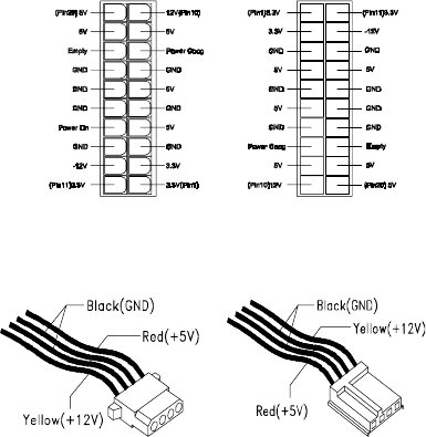
70 IBM Desktop System HMM
005 - DOES THE POWER SUPPLY FAN RUN?
(YES, READ AHEAD. NO, GO TO STEP 009)
•With the system powered on and the power supply
fan running, check the voltages of the power
supply connectors for the system board and all
drive connectors, as shown in the following figures.
006 - ARE THE VOLTAGES CORRECT AND DOES
THE FAN RUN? (YES, READ AHEAD. NO, GO TO
STEP 009.)
•The power supply is working normally.
•If you suspect the on/off switch cable assembly,
see Step 003.
•If the fan continues to run when all connectors are
plugged back in, go to See “Undetermined
Problems” on page 74.
• If the fan stops running when a drive connector is
plugged back in, go to “Start” on page 33.
Pin-hole side view Cable side view
Check Procedures 71
007 - DO YOU HAVE AN OHM READING WHEN
THE SWITCH IS PRESSED AND AN OPEN
READING WHEN THE SWITCH IS RELEASED?
(YES, READ AHEAD. NO, GO TO STEP 008.)
• Replace the on/off switch cable assembly.
008 -
• Replace the system board.
• End.
009 -
• Replace the power supply.
• End.

72 IBM Desktop System HMM
Monitor
First, set the system to VGA mode. To do this in
Windows 98, depress the F8 function key during
startup. Safe mode (VGA) will be set for Windows 98.
Use the operating system's video setup to change the
monitor resolution.
The monitors that come with the system are DDC2A/
B or DDC1/2B+ (Display Data Channel) compliant.
While starting Windows 98, the DDC2 monitor passes
resolution and frequency information to the system.
The system interprets the data and sets up the proper
refresh rate.
If the monitor type is set to the power saving mode,
the screen remains black and the LED lights or
flashes in amber color. When the monitor is turned on
alone, or is turned on and connected to a powered-off
system unit, the monitor LED blinks in amber color.
Under the normal operating conditions, the LED lights
in green color.
NOTE: Some monitors have a detachable system I/O
signal cable between the monitor and the
system unit. Check the line voltage, power
cord, and continuity for the system I/O signal
cable before replacing the monitor. See
“Monitor Port Signals” on page 127 for pin
identification.
001 - START
• Power off the system unit and monitor.
• Remove all adapter cards.
• Make sure that the monitor I/O signal cable is
properly connected to the system unit and monitor.
• Make sure that the power cords are properly
connected to the system unit and monitor, and that
the line voltage is correct.
• Make sure that the monitor contrast and
brightness controls are not turned too low.
• Make sure that the diagnostics diskette is in the
diskette drive.
• Power on the monitor, and wait 20 seconds.
• Power on the system unit.
Check Procedures 73
NOTE: If the monitor was not sold together with the
system unit, you may need to refer to the
service information provided with the monitor.
002 - IS THE SCREEN READABLE? (YES, READ
AHEAD. NO, GO TO STEP 004)
NOTE: If the screen shows a blinking cursor with no
memory count running, answer this question
“No.”
•Select Interactive Tests from the Main Menu.
•Select and execute Video test from the menu.
•Follow the prompts and perform the video test.
•Go to“Index of Symptoms, Messages, Error
Codes, or Beeps” on page 38.
•You might have to adjust the monitor controls to
obtain the best image.
003 - DOES THE MONITOR SUCCESSFULLY
PASS ALL TESTS? (YES, READ AHEAD. NO, G
TO STEP 004)
•You have successfully completed the video
diagnostics tests. If the problem remains, go to
“Index of Symptoms, Messages, Error Codes, or
Beeps” on page 38
•End.
004 -
• Power off the system unit.
• Remove the hard disk drive system cable.
• Power on the system unit.
005 - IS THE SCREEN STILL NOT READABLE?
• Replace the monitor. If the symptom remains,
replace the system board.
• End.

74 IBM Desktop System HMM
Undetermined Problems
If an error code, error message or error beeps is
present, go to “Index of Symptoms, Messages, Error
Codes, or Beeps” on page 38. If you did not receive
any messages, error codes, or beeps, see if the
symptom is listed in “Table 2-3 Error Symptoms List”
on page 45. If you still cannot solve the problem,
continue with this check:
1. Check the power supply voltages (See “Power
Supply Connectors and Voltages” on page 111). If
the voltages are correct, return here and continue
with the following steps:
2. Power off the system unit.
3. Perform the following checks, one by one, until you
have isolated the problem FRU (refer to “Parts/
Test Point Locations” on page 107 for locations):
- Load default settings in setup.
- Check all system board jumper positions and
switch settings.
- Check all adapter card jumper positions.
- Check all device jumper positions.
- Check all cables and connectors for proper in-
stallation.
4. If the jumpers, switch, and voltage settings are
correct, continue with the following steps:
•Remove or disconnect the following, one at a time:
- Non-IBM devices
- External devices
- Any adapter card (modem card or video card, if
installed)
-CD-ROM drive
- Diskette drive
- Hard disk drive
-DIMM
-Processor
- System board
5. Power on the system unit.
6. Repeat steps 2 through 5 until you find the failing
device or adapter.
7. If software related, reload software from Recovery
CD.
76 IBM Desktop System HMM

Diagnostic Aids 77
Diagnostic Aids
Introduction ..........................................................78
Power-On Self Test ..............................................79
Diagnostic Diskette ..............................................81
Using the Diagnostic Diskette .......................81
Using Diagnostic Program from
Recovery CD .................................................82
Diagnostics Program Features ......................83


Diagnostic Aids 79
Power-On Self Test
Each time you power-on the system, the power-on
self test (POST) is initiated. Several items are tested
during POST, but is for the most part transparent to
the user.
POST checks the following:
To start POST, turn on the monitor and then the
system unit. The following will happen:
1. The IBM Personal Computer logo will appear on
the screen.
2. At this time one of two hot-keys may be used. The
F1 key will cause the system Configuration/Setup
Utility menu to appear. The F9 key will switch the
graphical IBM logo screen to the traditional text-
based system startup screen, which displays BIOS
version and system memory tested. For Personal
Computer Type 2274, the F9 key will only work
after exiting Configuration/Setup Utility.
3. If an error is detected during POST, the IBM logo
screen will automatically switch to the text-based
screen and display the error message or code with
a beep. Depending on the criticality of the POST
error, the system may halt and/or display the
message “Press <F1> to enter to the Setup or
<Enter> to continue...”
If this message appears, pressing the Enter key
will allow the system to attempt to proceed despite
the reported error; pressing F1 will cause the
system Configuration/Setup Utility menu to appear.
• System Board • Mouse
• Memory • Parallel Port(s)
• SVGA Controller • Serial Port(s)
• Hard Disk Drive(s) • CD/DVD-ROM Drive(s)
• Floppy Diskette
Drive(s)
• Sound Controller*
• Keyboard
80 IBM Desktop System HMM
4. If no keyboard keys are pressed, and if POST is
completed without errors, the system will then
proceed with the loading of Windows98 or other
operating system from a hard disk drive or diskette
drive A or CD-ROM drive, depending on the Start
options selected in the Configuration/Setup Utility.
If any errors are detected by POST, there will be
an error message accompanied with an error code
shown on display screen and a beep. See “Index
of Symptoms, Messages, Error Codes, or Beeps”
on page 38 to find the most likely cause and
countermeasure.

Diagnostic Aids 81
Diagnostic Diskette
WARNING: This manual is intended to test the IBM
Personal Computer Type 2274 machine type
only. Testing devices which are not included
with the original product package, including
other IBM products, prototype cards, or
modifying hardware settings may give false
errors and invalid system responses. The
diagnostics not specifically made for this model
may also report incorrect errors and
information.
The diagnostics program comes on a diskette along
with this book. This version of PC-Doctor diagnostics
program, developed by Watergate for IBM, is the
primary method of testing the computer. You can use
it to test the IBM components of the system and some
external devices. The amount of time required to test
components depends on the number of components
installed and selected. The more devices you have
attached to your system and selected in PC-Doctor,
the longer the testing will take.
Using the Diagnostic Diskette
1. Power-off the system unit.
2. Insert diagnostic diskette in drive A.
3. Power-on the system unit.
NOTE: Do not press F1 during POST. If any POST
errors appear after POST, make a note of the
errors.
4. DOS should load. During boot, verify that each
driver loads successfully. For drivers that do not
load successfully, verify that the device driver is
associated with it and is installed properly.
5. Diagnostics program (PC-Doctor) will load, then
follow the screen instructions to operate.
82 IBM Desktop System HMM
Using Diagnostic Program from
Recovery CD
1. Insert the Personal Computer recovery CD into the
CD-ROM drive then restart computer.
2. Depress F1 while POST to enter Configuration/
Setup Utility menu. Select and enter “Startup
Options”, set the first priority of boot sequence to
CD-ROM. Save and exit from Configuration/Setup
Utility.
3. When screen displays IBM Recovery Program
menu, choose “Run Diagnostics” to execute
diagnostic program.
4. Follow the instructions on the screen to operate
the diagnostics program.

Diagnostic Aids 83
Diagnostics Program Features
Diagnostics program (PC-Doctor) includes the
following features:
Table 3- 1 Diagnostic Program Main Menu
Selections
Main Menu Selections Submenu Selections
Diagnostics • Run Normal Test
• Run Quick Test
• CPU/Coprocessor
• System board
• Video Adapter
• Serial Ports
• Parallel Ports
• Fixed Disks
• Diskette Drive
• Other Devices
• Zip Drive
• HiFD Drive
• LS-120 Drive
• CD-ROM/DVD Drive
• Memory Test-Full
• Memory Test-Quick
• Intel PNA Test
Interactive Tests • Keyboard
• Video
• Internal Speaker
• Mouse
• Joystick Test
• Diskette
• Printer Test
• CD-ROM/DVD Test
• Stereo Speaker
• Accton Test
Hardware Info • System Configuration
• Memory Contents
• IRQ and DMA Use
• Device Drivers
• COM and LPT Ports
• Physical Disk Drives
• Logical Disk Drives

84 IBM Desktop System HMM
Hardware Info • VGA Information
• Software Interrupts
• SCSI Devices
• I/O Use
• IDE Drive Info
• PCI Information
• PNPISA Information
• SMBIOS Information
• DIMM/RIMM Info
Utility • Run External Test
• Surface Scan Hard Disk
• Benchmark System
• DOS Shell
• Tech. Support Form
• Select Languages
• View Test Log
• Print Log
• Save Log
• View Stored Results
Quit • Exit Diagnostics
• Park HD
• Reboot
• About
Table 3- 1 Diagnostic Program Main Menu Selections
(Continued)
Main Menu Selections Submenu Selections

General Information 85
Repair Information
Removals and Replacements ..............................86
Handling ESD-Sensitive Parts .............................87
Cover .............................................................90
Bay Panels .................................................... 92
Bay 1- 5.25-In. Bay
(Internal or External Access) .........................93
Bay 3 - 3.5-In. Bay
(Internal or External Access) .........................94
Bay 4 - 3.5-In. Bay
(External Access for Diskette Drive) .............94
Front Panel ....................................................96
Power Supply ................................................97
Adapter Cards ...............................................98
Memory(DIMM) .............................................99
AMD K7 Duron Processor ...........................100
System Backup Battery ...............................102
Indicator LED and Cable .............................103
System Board ..............................................104

86 IBM Desktop System HMM
Removals and Replacements
BEFORE REMOVING ANY FRU, POWER-OFF THE
COMPUTER, UNPLUG ALL POWER CORDS FROM
ELECTRICAL OUTLETS, THEN DISCONNECT ANY
INTERCONNECTING CABLES.
ATTENTION: The system board, processors, adapter
cards, DIMMs, and upgrade processors can be
damaged by electrostatic discharge. Use an
electrostatic discharge (ESD) strap to establish
personal grounding. If you don't have an ESD
strap, establish personal grounding by
touching a ground point with one hand before
touching the static-sensitive FRUs.
The arrows in the removals and replacements
procedures show the direction of movement to
remove a field-replaceable unit (FRU), to turn a
screw, or the direction to press a tab to release the
FRU.
Begin all removals by removing the cover (and rear
cover, if applicable).
When other FRUs must be removed prior to removing
the failing FRU, they are listed at the top of the page.
Go to the removal procedure for each FRU listed,
remove the FRU, and then continue with the removal
of the failing FRU.
To replace a FRU, reverse the removal procedure
and follow any notes that pertain to replacement.
Before disconnecting any cables, note their location
and orientation. Reinstall any new FRUs with cabling
in their original location.

General Information 87
Handling ESD-Sensitive Parts
Many electronic parts are sensitive to electrostatic
discharge (ESD). To prevent damage when working
with ESD-sensitive parts, observe the following
instructions. Do these in addition to taking all the
usual precautions, such as switching off the power
and unplugging the power cord.
•Keep the ESD-sensitive part in its original shipping
container (or special ESD bag) until you are ready
to install the part.
•Make the fewest possible movements with your
body to prevent an increase of static electricity
from clothing fibers, carpets, and furniture.
•Put the ESD wrist strap on your wrist. Ensure the
machine is turned off. Connect the wrist strap to
the serial bracket mounting screw. This discharges
any static electricity in your body to the machine
frame.
•Hold the ESD-sensitive part by its edge connector
shroud (cover). Do not touch its pins. If you are
removing a plug-able module, use the correct
tools.
•Do not place the ESD-sensitive part on the
machine cover or on a metal table. If you need to
put down the ESD-sensitive part for any reason,
put it into it's original container.
•Machine covers and metal tables are electrical
grounds. They increase the risk of damage
because they make a discharge path from your
body through the ESD-sensitive part. (Large metal
objects can be discharge paths without being
grounded.)
•Prevent ESD-sensitive parts from being
accidentally touched by other persons. Reinstall
machine covers when you are not working on the
machine.
•If possible, keep all ESD-sensitive parts in a
grounded metal cabinet.
•Be extra careful when working with ESD-sensitive
parts while cold-weather heating is being used.
Low humidity increases static electricity.
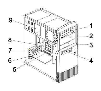
88 IBM Desktop System HMM
Identifying the Parts of the System Unit
This computer system has four bays that can hold
5.25-inch and 3.5-inch drives. Additional devices
can be installed in the empty bays.
Diskette drives in this unit use the standard diskette
advanced technology (AT) interface. Hard disk drives
in this unit use an integrated drive electronics (IDE)
AT interface. This computer supports the American
National Standards Institute (ANSI) standard for AT
attachment disk drives.
It also has interface slots for installation of additional
cards devices. Industry Standard Architecture (ISA)
and Peripheral Component Interconnect (PCI)
adapter cards are both supported.
1. Bay 1.
This drive bay can hold a 5.25-inch half high drive
or a 5.25-inch slim drive. A 3.5-inch drive can be
accommodated with additional brackets. This bay
can hold a CD-ROM, DVD-ROM, diskette, hard
disk, tape, or Zip drive.
2. Bay 2.
This drive bay can hold a 5.25-inch half high drive
or a 5.25-inch slim drive. A 3.5-inch drive can be
accommodated with additional brackets. This bay
can hold a CD-ROM, DVD-ROM, diskette, hard
General Information 89
disk, tape, or Zip drive.
3. Bay 3.
This drive bay can hold a 3.5-inch slim drive, such
as a diskette, hard disk, tape, or Zip drive.
4. Bay 4.
This drive bay is designed for a 3.5-inch diskette
drive.
5. Adapter card connectors.
Adapter card connectors are sockets on the
system board into which adapter cards are
installed. Your system board has four adapter card
connectors. One of these connectors is for an ISA
card and three are for PCI cards. Since two of
these connectors are shared (one ISA and one
PCI next to it), only three cards (excluding the AGP
video card) can be installed at any time.
6. Adapter cards.
Adapter cards add to your computer's capabilities.
7. Adapter card slots.
Adapter card slots are the holes in the back of the
tower that permit external access to adapter cards.
8. System board.
The system board is the main circuit board in your
computer. It contains the processor, also known as
the central processing unit (CPU), and the system
battery. It also contains sockets for memory
modules, connectors for adapter cards, and
connectors for the cables that carry data to and
from drives.
9. Power supply.
The power supply provides the electricity that is
used by the other hardware components in your
computer. This model may come with a 95
power supply.
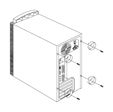
90 IBM Desktop System HMM
Cover
•Disconnect the system unit power cord.
•Remove the 4 screws at the back of the tower.
•Insert a screwdriver under one of the tabs on the
back of the cover and gently pry the tower cover so
that it separates from the tower.
•Slide the cover back about half inch (or 1.25
centimeters).
•Lift the cover up by the top front and back edges,
pulling the sides out and away from the tower.
NOTE: To prevent the tower from tipping over, you
may want to lay the tower on its side on a work
surface, such as a table.
•Touch the bare metal frame of the system to
dissipate any static electricity from your body (do
not touch any of the components inside the frame
until you have done this). Do not touch any
component(s) with a voltage warning label.
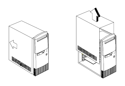
General Information 91
NOTE: Replacing the Cover
•To replace the tower cover, lower the cover down
over the tower, pressing in on the sides so the
hooks inside the cover fit over the bottom ledge of
the tower. Slide the cover forward into place.
Secure the tower cover by replacing the screws
you removed.
CAUTION: When you replace the cover, there are
hooks inside the cover that help fit it to the
tower.
1
2
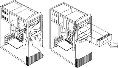
92 IBM Desktop System HMM
Bay Panels
If you remove a drive from a bay and you do not
intend to install a new drive immediately, reinstall the
bay panel on the empty exposed drive bay.
Follow these steps to remove the plastic bay panel
from the front of the system unit cover.
•Hold a bay panel and press either side to unlatch it
from the front of the system unit cover.
•Pull the bay panel and EMI bay cover out
NOTE: Replace the EMI Bay Panel
•Replace the EMI bay cover.
•Insert a bay panel into the opening at the front of
the system cover, aligning the panel latches with
the sides of the unit.
•Push the panel back until you hear the latches
click into place.
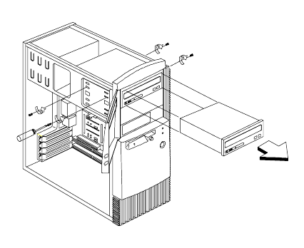
General Information 93
Bay 1- 5.25-In. Bay (Internal or External
Access)
•Disconnect any cable on the drive (note location
and orientation of cables).
•Remove the screws.
•Pull out the drive.
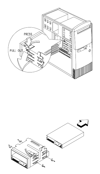
94 IBM Desktop System HMM
Bay 3 - 3.5-In. Bay (Internal or External
Access)
Bay 4 - 3.5-In. Bay (External Access for
Diskette Drive)
•Disconnect the cables (note location of cables).
•Press the lever and rotate outward.
•Pull carefully and slowly as soon as the warning
arrow appears.
•The drive frame becomes free after the line behind
the arrow appears. Remove the frame from the
chassis
•Remove the screws located on both sides of the
drive and slide the drive out.
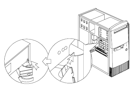
General Information 95
NOTE: Reinstall the 3.5-in Drive Frame
•Before reinstalling the drive frame into the main
unit, make sure the upper and lower drive frames
are properly reattached.
•Align the front notch of the drive frame with the
system chassis
•Align the top rail of the drive frame with the system
chassis and swing inward until it “clicks” to lock.
•Re-attach the power and signal cables to the
drives.
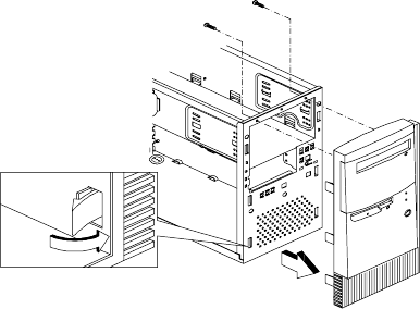
96 IBM Desktop System HMM
Front Panel
•Remove the 2 screws and release the 6 latches
that holds the front panel.
•Gently remove the front panel from the tower.
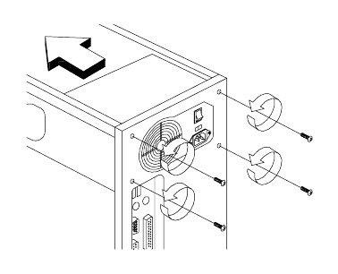
General Information 97
Power Supply
•Disconnect all cables necessary before removal
(note location of cables).
•Remove the four screws from the chassis.
•Push the power supply forward towards the CD/
DVD-ROM drive.
•Once it is sufficiently forward, place your hand
underneath the power supply and push upwards to
detach it from the chassis.
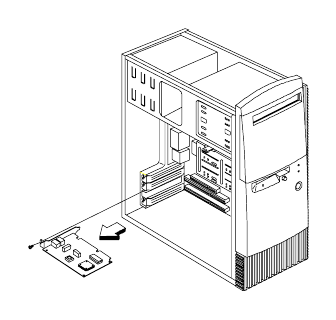
98 IBM Desktop System HMM
Adapter Cards
NOTE:
1. Before removing an adapter card, note the
location of the adapter card and any cables.
When removing an adapter card, install the
replacement card in the same slot as the one
you removed.
2. If necessary, remove cards from the
adjacent slots of the failed card.
•Position the system unit such that the card is
accessible to you.
•If the adapter card has cables, disconnect them.
Be sure to take note where those cables are
connected and how they are oriented. You will
need to reconnect those cables when you reinstall
the card.
•Remove the adapter card screw.
•Carefully pull the adapter card straight out of the
slot so that the card does not bend.
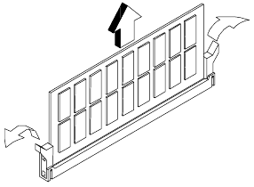
General Information 99
Memory(DIMM
CAUTION: Memory modules are sensitive to static
discharge.
•Press the levers on both sides of the socket down
and outwards.
•Lift the DIMM to remove.
ATTENTION: Place your forefingers on the top of the
DIMM before you press the holding clips to
gently disengage the DIMM from the socket.
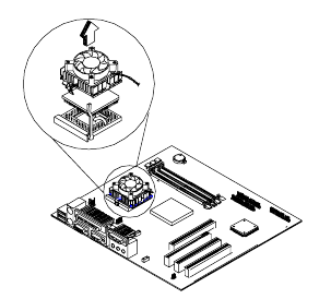
100 IBM Desktop System HMM
AMD K7 Duron Processor
NOTE: Determine the type of processor you are
installing and make sure the jumpers are set
correctly. Run the Configuration/Setup Utility
after correctly installing a processor.
CAUTION: Processors are sensitive to static
discharge.
•Remove adapter cards if applicable.
•Detach the heat sink cable from the fan connector.
•Remove the fan sink by pressing the release tab
(rectangular end) and lifting it up from the
Processor.
•Pull up the ZIF socket release lever.
•Lift the processor out of the socket.
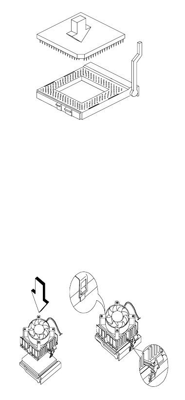
General Information 101
NOTE: Installing the processor
•Place the ZIF socket release lever to the release
(up) position.
•Insert the new processor, matching the notched
corner of the processor with the pin 1 indicator on
the socket.
•Push down the lever to lock the processor to the
socket.
•Place the processor heat sink fan over the
processor
•Insert one side of fan brace onto the ZIF socket.
•Secure by latching the other side to the ZIF socket.
•Reconnect the processor fan sink cable to the
connector FN1 on the system board.
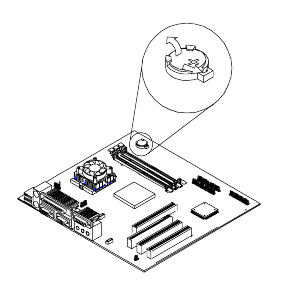
102 IBM Desktop System HMM
System Backup Battery
CAUTION: All BIOS configuration settings will be lost
when the backup battery is removed!
ATTENTION: Be careful when removing the backup
battery. If the metal lever is damaged or
broken, the system board must be replaced.
•Gently pull the metal lever away from the backup
battery.
•Lift the backup battery out.
IMPORTANT: Make sure to insert the battery with the
positive side facing up. A plus(+) sign indicates
the positive side.
•If you replace the system battery, you need to
reset the system date and time. You can perform
this task from the Window 98 desktop or from the
Configuration/Setup Utility. To reset the syste
date and time in the Configuration/Setup Utility,
select the Date and Time option from the Main
Menu.
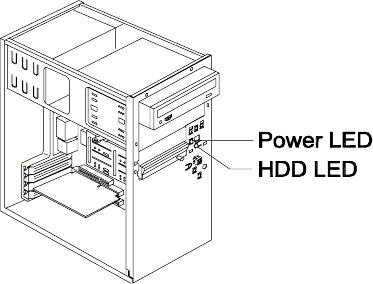
General Information 103
Indicator LED and Cable
•Push in on the indicator LED and remove from the
rear.
•Disconnect the LED and cable from the syste
board.
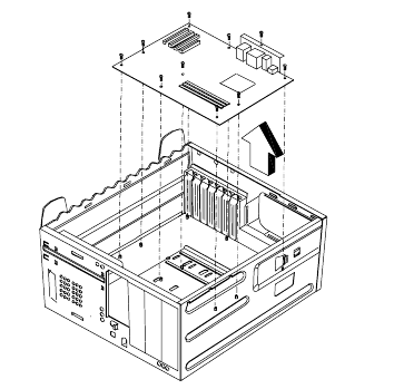
104 IBM Desktop System HMM
System Board
•Remove all adapter cards.
•Disconnect all cables connected to the system
board. Note the location and orientation of all
cables.
•Remove the screws securing the system board to
the chassis.
•Lift the system board to remove from chassis.
•Remove memory (DIMM) if applicable.
•Remove processor if necessary.
NOTE: System Board Installation
•Before reinstallation, position the housing on its
side. When installing a new system board, push
the board to the rear and align it with the front
locating pin. Visually verify that the board is
aligned properly, then press the board down.
•Be sure to reinstall the processor, DIMMs, I/O port
bracket onto the new system board if applicable.
•After installing the system board, secure with
original screws.
•Change all jumper settings to match those of the
original board.
•Reinstall other components into the machine i.e.
drives, power supply, cables, etc.
General Information 105
•Upgrade the BIOS version on the new system
board using the BIOS upgrade utility.
•Change the Machine Type and Serial Number in
the BIOS to match the original planar BIOS
settings.
•Reboot the system and run the Configuration/
Setup Utility.
106 IBM Desktop System HMM

Parts/Test Point Locations 107
Parts/Test Point Locations
Introduction ........................................................108
System Board Jumpers and Connectors ...........109
Power Supply Connectors and Voltages ...........111
Network Cards ...................................................113
Factory-Installed Modem Card Layout ...............114
Video Cards .......................................................115
Nvidia M64 w/ TV Out, 32MB ......................115
Nvidia NV10 w/ TV Out, 32MB ....................115
3.5-In. Hard Disk Drive Jumper Settings ............117
CD-ROM Drive ...................................................119
CD-ROM Drive Rear Panel Connectors
and Jumpers ...............................................121
CD-ROM R/W Drive ...........................................122
CD-ROM R/W Drive Rear Panel
Connectors and Jumpers ............................123
DVD-ROM Drive ..........................................124
DVD-ROM Drive Rear Panel Connectors
and Jumpers ...............................................125
DIMM Configurations .........................................126
System Board Connector Pin Signals ................127
Monitor Port Signals ....................................127
Serial Port Signals .......................................127
Parallel Port Signals ....................................128
Mouse Port Signals .....................................128
Keyboard Port Signals ................................128
Diskette Drive Cable Connector Signals .....129
IDE Cable Connector Signals .....................130

108 IBM Desktop System HMM
Introduction
This chapter contains system board layouts and
jumper settings. It is useful when you are asked to
measure voltages. Use this information to help you
locate parts such as electronic boards, connectors,
pin numbers, and test points. This chapter also
contains jumper settings for the hard disk drive,
CD-ROM, and the connector information for modem
adapter card.
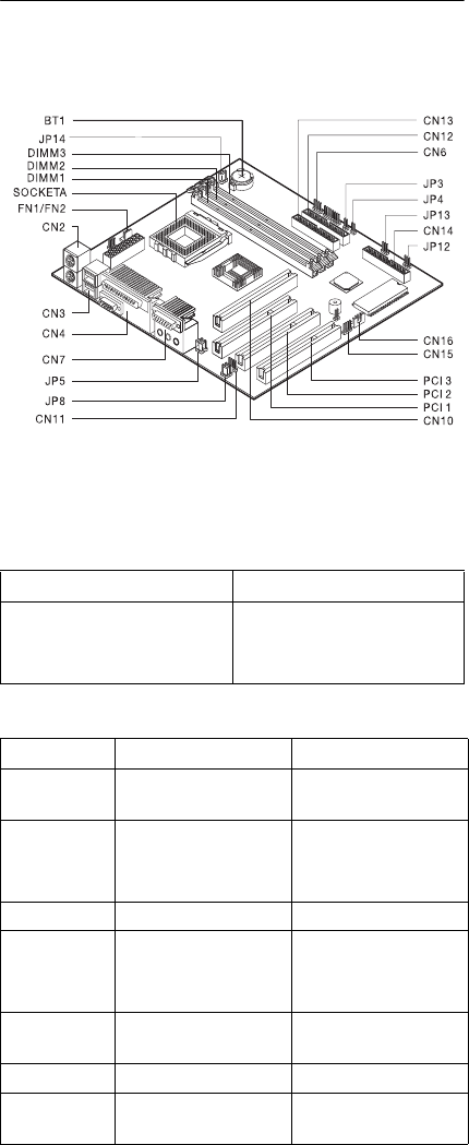
Parts/Test Point Locations 109
System Board Jumpers and
Connectors
NOTE: The blackened pin of a jumper represents
pin 1.
System Board Connector Functions
System Board Jumper Setting
Jumper/Settings Function
JP14
1-2
2-3
CMOS Setup
*Normal
Clear CMOS
Connector Function Connect to...
BT1 System battery
connector
System battery
DIMM 1
DIMM 2
DIMM 3
System memory
module connectors
Memory
FN1/FN2 Fan connector Processor fan
PCI 1
PCI 2
PCI 3
PCI slots Adapter cards
CN2 PS/2 keyboard and
mouse connectors
Keyboard and
mouse
CN3 USB connectors USB device
CN4 Parallel and serial
connectors
Printer, parallel and
serial devices

110 IBM Desktop System HMM
NOTE: The white corner of the jumper block
represents pin 1.
CN6 HDD LED connector HDD LED
CN7 Audio connector
CN10 AGP video card
connector
VGA card
CN11 CD-in connector CD-ROM
CN12 Secondary IDE
connector
CD-ROM
CN13 Primary IDE
connector
Hard Disk Drive
CN14 Diskette drive
connector
Diskette Drive
CN15 Front panel USB
connector
USB device
CN16 Wake on LAN
(WOL) connector
LAN card
JP3 Power Switch
connector
Power switch
JP4 Reset switch
connector
Reset switch
JP5
JP8
Headphone and line
out jumpers
JP12 Power LED
connector
Power LED
JP14 CMOS setup
Socket A Processor connector Processor
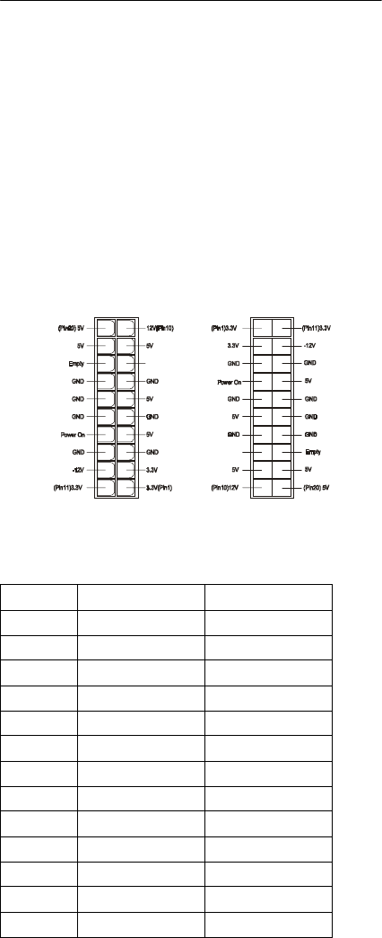
Parts/Test Point Locations 111
Power Supply Connectors and
Voltages
Refer to the following figures when checking for
voltages on power supply cable connectors.
When checking voltages, the power supply fan must
be running. To power-on the power supply without
using the on/off switch, use a screwdriver or other tool
to short the connector JP3 (with the switch cable
disconnected from the connector on the syste
board), or use a connection (jumper) to short the
black and green wires of the 20-pin connector on
power supply.
20-pin Power Connector
Pin-hole side view Cable side view
Power Supply Output Pin Assignment
Pin Voltage Cable Color
1 +3.3Vdc Orange
2 +3.3Vdc Orange
3Ground Black
4 Power-on Red
5Ground Black
6+5Vdc Red
7Ground Black
8 Power Good Gray
9+5Vdc Purple
10 +12Vdc Yellow
11 +3.3Vdc Orange
12 -12Vdc Blue
13 Ground Black
Power Good
Power Good
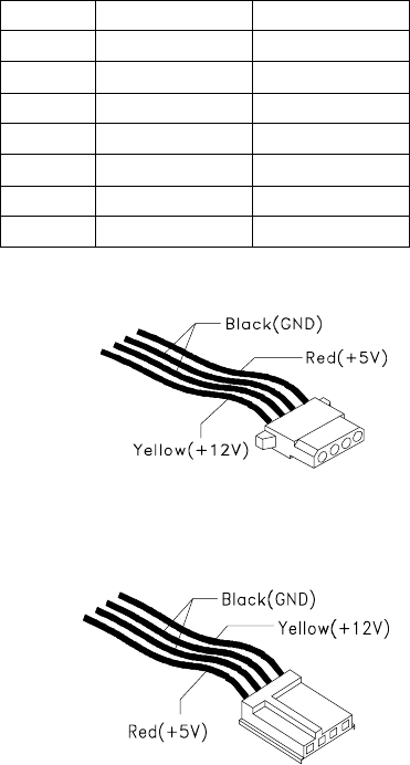
112 IBM Desktop System HMM
14 +5Vdc Green
15 Ground Black
16 Ground Black
17 Ground Black
18 no connect no connect
19 +5Vdc Red
20 +5Vdc Red
Power Supply Output Pin Assignment (Continued)
Pin Voltage Cable Color
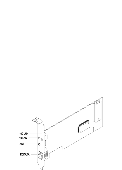
Parts/Test Point Locations 113
Network Cards
NOTE: While transferring the data,”Act” LED emits
light to indicate a ready state and the link
indicators “10 Link” or “100 Link” specifies the
current line transmission speed. Depending on
the 10Base-T/100Base-T connections to
unshielded twisted-pair(10Base-T, UTP) or
unshielded twisted-pair(100Base-T, Category
5), the transmission speed will be auto-
detected.
The RJ-45 connector is used.
Accton
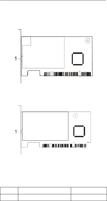
114 IBM Desktop System HMM
Factory-Installed Modem Card
Layout
GVC
Askey
GVC Factory-Installed Modem Card Connector
Functions
Item Function Connect to...
1 RJ11 connector Telephone line
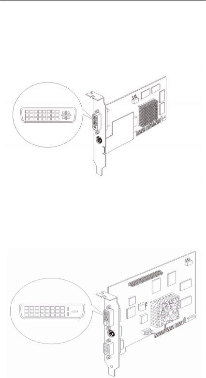
Parts/Test Point Locations 115
Video Cards
Nvidia M64 w/ TV Out, 32MB
Nvidia NV10 w/ TV Out, 32MB

116 IBM Desktop System HMM
1Optional output from monitor.
2Note: The IEEE-1394 internal cable bundle
needs an outer shield to minimize internal
crosstalk within the cable construction. The outer
EMI containment shield for the IEEE-1394 func-
tion will be provided by the overall P&D cable
shield. If the internal bundle shield for IEEE-1394
is required, this may be terminated to pin #18. It
is recommended that this implementation be
evaluated in the case where both Charge Power
return and the IEEE-1394 internal cable bundle
shield will be commoned to pin #18.
P&D-D Signal Pin Assignments
Pin Signal Pin Signal
1 TMDS Data2 + 16 USB data +
2 TMDS Data2 - 17 USB data -
3 TMDS Data2 return 18 1394 outer shield
(optional) & Charge
Power return2
4 Unused 19 1394 Vg
5 Unused 20 1394 Vp
6Unused 21TMDS Data0 +
7 TMDS Clock return 22 TMDS Data0 -
8Charge power1 + 23 TMDS Data0 return
9 1394 pair A, data - 24 Unused
10 1394 pair A, data + 25 DDC return
11 TMDS Data1 + 26 DDC data (SDA)
12 TMDS Data1 - 27 DDC clock (SCL)
13 TMDS Data1 return 28 +5 VDC
14 TMDS Clock + 29 1394 pair B, Clock +
15 TMDS Clock - 30 1394 pair B, Clock -
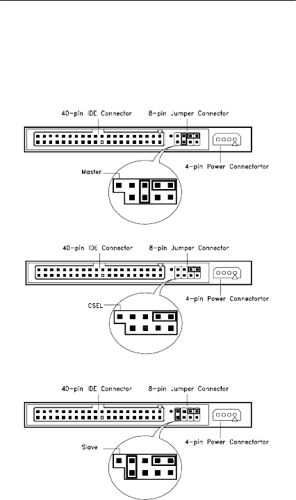
Parts/Test Point Locations 117
3.5-In. Hard Disk Drive Jumper
Settings
The configuration of the following jumpers control the
drive's mode of operation:
•Master
•Slave
•CSEL - Cable Select
3.5-In IBM Hard Disk
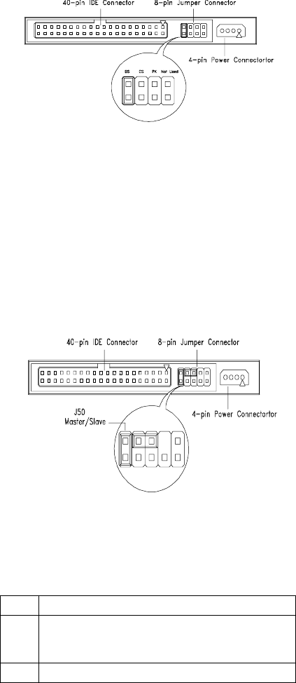
118 IBM Desktop System HMM
The configuration of the following jumpers control the
drive's mode of operation:
•DS - Drive Select (For Master only)
•CS - Cable Select
•PK - Park, used as a place to store a jumper
3.5-In Quantum Fireball Series Hard Disk
3.5-In Maxtor Hard Disk
3.5-In Maxtor Hard Disk Drive Jumper Settings
J50 Description
On Drive configured as Master or
Drive configured as Master, with an attached
Slave
Off Drive configured as Slave.
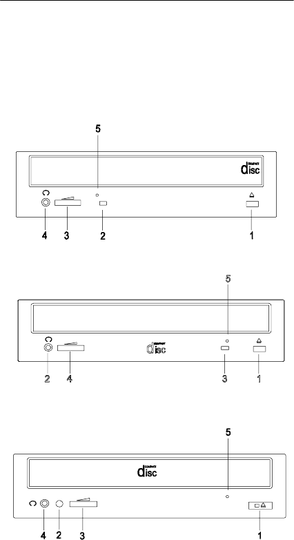
Parts/Test Point Locations 119
CD-ROM Drive
ATTENTION: Either <option 1> or <option 2>
CD-ROM drive may come with your machine.
Their front panel buttons, indicators and
emergency eject method may be different.
Lite-on
LG
BTC
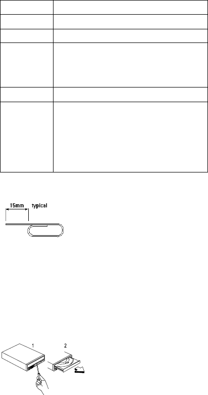
120 IBM Desktop System HMM
ATTENTION: Make sure to turn off the power before
manual disc eject operation.
CD-ROM Front Panel Introduction
Item Description
1 Load / eject button
2 Headphone jack
3 Power-on / busy indicator, lights up in
green color while disc is set in ready
state; lights up and flashes in amber color
during data read or seek operation.
4 Headphone volume control
5 Emergency eject hole.
See CD-ROM Emergency-exit <option 1>
below.
Disc tray and emergency eject
See CD-ROM Emergency-exit <option 2>
below.
CD-ROM Emergency-exit <option 1>
If for any reason the tray does not
eject automatically, insert and press
an eject-bar inside the emergency
eject hole to manually eject the tray. A
straightened paper clip with a diameter
of 1.2 mm (typical) can be used as an
eject-bar.
CD-ROM Emergency-exit <option 2>
Locate the bottom edge of the
disc tray. Gently pry the disk tray
open with a screwdriver. When
the disc tray opens, simply
remove the disc from the CD-
ROM drive.
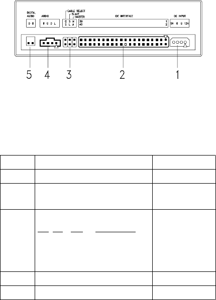
Parts/Test Point Locations 121
CD-ROM Drive Rear Panel Connectors
and Jumpers
NOTE: CD-ROM drives may come with item no. 5
(digital audio output) connectors.
CD-ROM Drive Rear Panel Connectors and Jumpers
Item Function Connect to...
1 Power supply connector Power supply
2 Interface connector System board
CN12: IDE 2
3 Configuration jumper.
CS SL MA Description
-- -- On Master
-- On -- Slave.
On -- -- Cable select
--
4 Audio line out connector System board
5 Digital audio output --
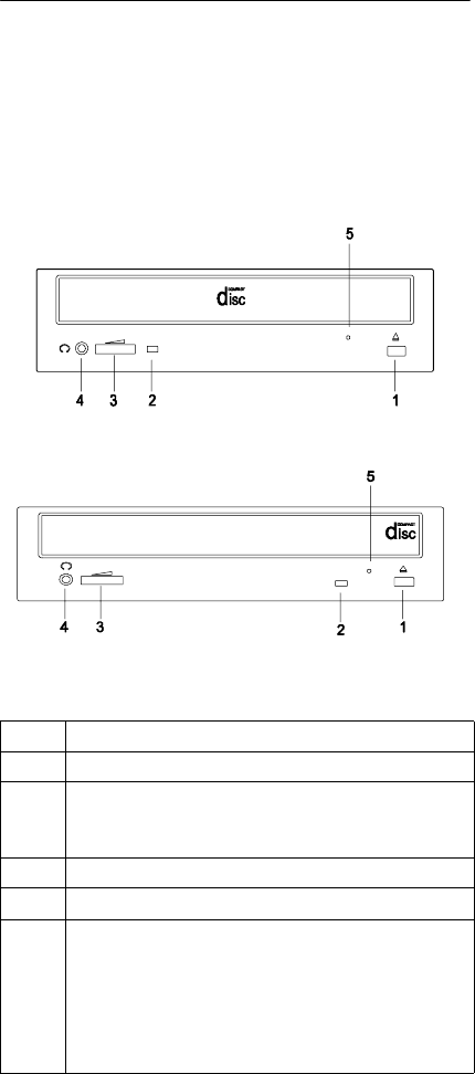
122 IBM Desktop System HMM
CD-ROM R/W Drive
ATTENTION: Either <option 1> or <option 2>
CD-ROM R/W drive may come with your
Personal Computer. Their front panel buttons,
indicators and emergency eject methods may
be different.
TEAC
LG
CD-ROM R/W Front Panel Introduction
Item Description
1 Load / eject button
2 Power-on / busy indicator, lights up in green color
while disc is in ready state; lights up and flashes in
amber color during data read or seek operation.
3 Headphone volume control
4 Headphone jack
5 Emergency eject hole.
See “CD-ROM Emergency-exit <option 1>” on
page 120
Disc tray and emergency eject
See “CD-ROM Emergency-exit <option 2>” on
page 120
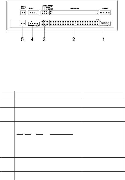
Parts/Test Point Locations 123
CD-ROM R/W Drive Rear Panel
Connectors and Jumpers
NOTE: CD-ROM R/W drives may come with item no.
5 (digital audio output and testing jumper)
connectors.
CD-ROM R/W Drive Rear Panel Connectors and
Jumpers
Item Function Connect to...
1 Power supply connector Power supply
2 Interface connector System board
CN12: IDE 2
3 Configuration jumper.
CS SL MA Description
-- -- On Master
-- On -- Slave.
On -- -- Cable select
--
4 Audio line out connector Depended on
sound card
5 Digital audio output --
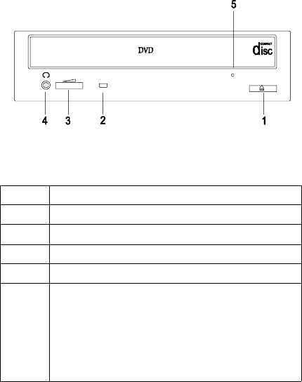
124 IBM Desktop System HMM
DVD-ROM Drive
Front Panel and Emergency-Exit
DVD-ROM Front Panel Introduction
Item Description
1 Open/Close Button
2 Disc Indicator
3 Headphone Volume Control
4 Headphone Jack
5 Emergency eject hole.
See “CD-ROM Emergency-exit <option 1>” on
page 120.
Disc tray and emergency eject
See “CD-ROM Emergency-exit <option 2>” on
page 120
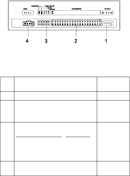
Parts/Test Point Locations 125
DVD-ROM Drive Rear Panel Connectors
and Jumpers
DVD-ROM Drive Rear Panel Connectors and
Jumpers
Item Function Connect
to...
1 Power connector Power supply
2 IDE Interface connector System
board
CN12
3 Configuration jumper.
RDaRD CS SL MA Description
-- -- -- -- On Master
-- -- -- On -- Slave.
-- -- On -- -- Cable select
a. RD -- Configuration jumper (RD indicates
Reserved)
--
4 Audio Out Depended on
sound card

126 IBM Desktop System HMM
DIMM Configurations
The 2274 system board has three DIMM sockets. A
maximum of 384MB memory may be installed. You
can install 8MB, 16MB, 64MB or 128MB PC-100/
PC-133 DIMM in any sockets and with any
combinations.
NOTE: Some system boards require that DIMM
socket number one be occupied. If after
installing memory the system does not boot
successfully and both DIMM sockets are not
occupied, switch the DIMM to the unoccupied
socket and reboot the system.

Parts/Test Point Locations 127
System Board Connector Pin Signals
Monitor Port Signals
Serial Port Signals
Pin Signal
Name I/O Pin Signal
Name I/O
1 Red Video O 9 +5 V dc
2 Green Video O 10 Synch
Ground
3 Blue Video O 11 Monitor ID Bit
0
4 Monitor ID Bit
2
I 12 SDA I
5Synch
Ground
13 Horizontal
Synch
O
6 Red Ground 14 Vertical
Synch
O
7Green
Ground
15 SCL I
8 Blue Ground
Pin Signal
Name I/O Pin Signal
Name I/O
1 Data Carrier
Detect
I 6 Data Set
Ready
I
2 Receive
Data
I 7 Request T
Send
O
3Transmit
Data
O 8 Clear T
Send
I
4Data
Te r mi n al
Ready
O 9 Ring
Indicator
I
5Signal
Ground

128 IBM Desktop System HMM
Parallel Port Signals
Mouse Port Signals
Keyboard Port Signals
Pin Signal
Name I/O Pin Signal
Name I/O
1 Strobe O 14 Auto Feed N/A
2 Data Bit 0 I/O 15 Error I
3 Data Bit 1 I/O 16 Initialize O
4 Data Bit 2 I/O 17 Select (In) O
5 Data Bit 3 I/O 18 Ground P
6 Data Bit 4 I/O 19 Ground Power
7 Data Bit 5 I/O 20 Ground Power
8 Data Bit 6 I/O 21 Ground Power
9 Data Bit 7 I/O 22 Ground Power
10 Acknowledge I 23 Ground Power
11 Busy I 24 Ground Power
12 Paper Empty I 25 Ground Power
13 Select 0 -- -- --
Pin Signal
Name I/O Pin Signal
Name I/O
1Mouse
Data
I/O 4 +5 V dc Power
2No
Connection
-- 5 Mouse
Clock
I/O
3 Ground Power 6 No
Connection
--
Pin Signal
Name I/O Pin Signal
Name I/O
1 Data I/O 4 +5 V dc Power
2 No
Connection
5 Clock I/O
3 Ground Power 6 No
Connection
--

Parts/Test Point Locations 129
Diskette Drive Cable Connector Signals
Pin Signal
Name I/O Pin Signal
Name I/O
1 Ground 18 Direction 0
2 Density
Select
O19Ground
3No
Connection
20 Step O
4 No
Connection
21 Ground
5Ground 22Write DataO
6No
Connection
23 Ground
7 Ground 24 Write Enable O
8 Index I 25 Ground
9 Ground 26 Track 0I I
10 Motor Enable
0
O27Ground
11 Ground 28 Write Protect I
12 Drive Select
1
O29Ground
13 Ground 30 Read Data I
14 Drive Select
0
O31Ground
15 Ground 32 Select Head
1
O
16 Motor Enable
1
O33Ground
17 Ground 34 Diskette
Change
I

130 IBM Desktop System HMM
IDE Cable Connector Signals
Pin Signal
Name I/O Pin Signal
Name I/O
1 Host Reset O 21 No
Connection
2 Ground 22 Ground
3 Host Data 7 I/O 23 Host IOW O
4 Host Data 8 I/O 24 Ground Power
5 Host Data 6 I/O 25 Host IOR O
6 Host Data 9 I/O 26 Ground Power
7 Host Data 5 I/O 27 I/O Channel
Ready
I
8Host Data
10
I/O 28 No
Connection
9 Host Data 4 I/O 29 No
Connection
10 Host Data
11
I/O 30 Ground Power
11 Host Data 3 I/O 31 Host IRQ I
12 Host Data
12
I/O 32 No
Connection
13 Host Data 2 I/O 33 Host A1 O
14 Host Data
13
I/O 34 No
Connection
15 Host Data 1 I/O 35 Host A0 O
16 Host Data
14
I/O 36 Host A2 O
17 Host Data 0 I/O 37 Host CS0 O
18 Host Data
15
I/O 38 Host CS1 O
19 Ground Power 39 ACTIVE ba I
20 No
Connection
40 Ground Power


132 IBM Desktop System HMM
General Guidelines
The purpose of this Safety Inspection Guide is to help
you identify possible unsafe conditions on machines
that are being inspected for a Maintenance
Agreement. Each machine has necessary functions
items installed to provide the operators and service
personnel with an acceptable level of safety. This
guide lists only these items. Good judgment should
be used to identify possible safety conditions not
covered by this Safety Inspection Guide.
If any unsafe conditions are present, you must find
out how serious the hazard is and if you can continue
before you correct the hazard.
All current IBM Personal Computer service
supplements outlining feature/model changes, along
with the machine history, should be reviewed.
Check the following items:
•Damaged, missing, or changed parts, especially in
the area of the On/Off switch and the power
supply.
•Damaged, missing, or changed covers.
•Possible safety exposure from any non-IBM
attachments.

Parts Catalog 133
Parts Catalog
Abbreviations .....................................................134
System Assembly ..............................................135
Assembly 1: System Unit ............................135
Assembly 2: Diskette, Hard Drive
and Zip Drive ...............................................137
Assembly 3: CD/DVD-ROM Drive ............... 138
Assembly 4: Power Cord .............................139
Assembly 5: Keyboard and Mouse .............140

134 IBM Desktop System HMM
Abbreviations
In this chapter, the following abbreviations are used to
identify country and language version:
Country Language Version
AT Austria
AU Australia
BD Belgium - Dutch
BF Belgium - French
CA Canada
CE Canada - English
CF Canada - French
CN China
DK Denmark - Danish
FI Finland - Finish
FR France
GE Germany
HK Hong Kong
IT Italy
JP Japan
LS LA-Spanish
ND Netherlands - Dutch
NL Netherlands - Dutch
NO Norway - Norwegian
SF Swiss - French
SG Swiss - German
SP Spain
SW Sweden - Swedish
TW Taiwan
UK United Kingdom
US United States
SZ Switzerland
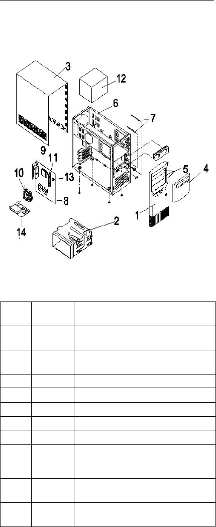
Parts Catalog 135
System Assembly
Assembly 1: System Uni
Asm-
Index FRU
Number Description
1-1 22P2259 Main Bezel (w/ Front USB), White,
Aptiva
1-1 22P2270 Main Bezel (w/ Front USB), White,
Netvista
1-2 20L2197 3.5" FDD/HDD (Holder) Bracket
1-3 20L2193 Top Cover, White
1-4 22P2270 Main Bezel Door, White (India only)
1-4 20L2194 Main Bezel Door, White
1-5 20L2195 Drive Bay Panel, White
1-6 22P2261 Chassis Assembly, Lower Case
(without SPS) w/power supply frame,
drive frame, bracket port, w/Front USB
1-7 20L2190 Power Switch/HDD-Pwr Led Cable
Asm
1-8 19K3648 S21M - Micro ATX, Socket A, W/VIA
KZ133

136 IBM Desktop System HMM
1-9 19K3649 Socket K7 Duron 64K/200 600MHz
1-9 19K3650 Socket K7 Duron 64K/200 700MHz
1-10 19K3653 Fansink (Duron Processors)
1-11 09N3351 64MB DIMM (PC133)
1-11 09N3352 128MB DIMM (PC133)
1-12 22P2275 145W Power Supply (For Duron)
1-13 01K4278 CMOS Backup Battery (CR2032)
1-NS 01K4200 Port Bracket
1-NS 01N1940 Screw Pack
1-NS 19K4309 Accton 10/100 Ethernet PCI Adapter
Card
1-NS 22P2262 Planar I/O Port EMC Shield
1-NS 22P2264 USB Cable
1-NS 36L9138 HDD Tray (Mounts 3.5" HDD into 5.25"
Bay)
Asm-
Index FRU
Number Description
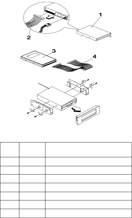
Parts Catalog 137
Assembly 2: Diskette, Hard Drive and Zip
Drive
Asm-
Index FRU
Number Description
2-1 02K2299 3.5", 3 mode MKE (JU256A276P)
2-2 02K2603 FDD Cable
2-3 19K1545 7.5GB HDD, 3.5" 5400 RPM
2-3 19K1476 10GB HDD, 3.5" 5400 RPM
2-3 19K1575 15GB HDD, 3.5" 5400 RPM
2-3 19K1560 20GB HDD, 3.5" 5400 RPM
2-4 09N5385 HDD Cable Supports ATA 66/100
5
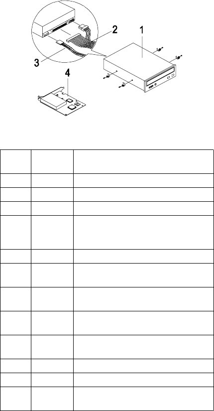
138 IBM Desktop System HMM
Assembly 3: CD/DVD-ROM Drive
Asm-
Index FRU
Number Description
3-1 00N8328 40X CD-ROM, White
3-1 01N1952 4X4X32X CD-RW (Read/Write), White
3-1 22P2280 DVD-ROM 8X/40X, White
3-3 22P2276 Y' - CD-ROM/DVD-ROM Audio Cable -
For use w/ mdls that have both
CD-RW and DVD-ROM Drives
3-3 22P2277 Audio Cable, CD-ROM
3-4 19K3631 GVC, F-1156IV/R9C, NA/LA/SA/
Japan/China/TW/HK
3-4 19K3632 GVC WT, F-1156IV+/R9C, EMEA/
ANZ/Singapore/India
3-4 19K3633 Askey, 1456VQH87, NA/LA/SA/Japan/
China/TW/HK
3-4 19K3634 Askey INT, 1456VQH87 (INT), EMEA/
ANZ/Singapore/India
3-NS 10K2940 Video Graphics Card, Diamond S3
3-NS 00K8183 7FT Phone Cord
3-NS 19K3658 Zylux Non Branded Tier 3, Passive
(White/Blue Grill)

Parts Catalog 139
Assembly 4: Power Cord
Asm-
Index FRU
Number Description
4-NS 02K0545 Power Cord - China
4-NS 13F9939 Power Cord - ANZ
4-NS 14F0032 Power Cord - UK/HK/Singapore/
United Arab Emirate (Dubai)
4-NS 6952301 Power Cord - US, LA (Lo Volt),
Canada, Mexico, Peru, Colombia,
Ecuador, Venezuela, Bolivia, Panama,
El Salvador, Honduras, Nicaragua,
Dominican Republic, Guatemala,
Taiwan, Saudi Arabia, Thailand
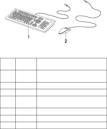
140 IBM Desktop System HMM
Assembly 5: Keyboard and Mouse
Asm-
Index FRU
Number Description
5-1 37L2514 104 Palm Rest US ENG
103P, US/China/ANZ/Singapore/India
5-1 37L2590 104 US ENGLISH 103P, US/CE
5-1 37L2592 105 FR CANADIAN 445
5-1 37L2609 104 US ENGLISH-EMEA 103P, ANZ/
China
5-1 37L2611 104 CHINESE/US 467, HK/TW
5-2 10L6145 Logitech Badger (2 Button), White
5-2 28L1865 Scrollpoint II Mouse, White

FRU Number List 141
Appendix A. FRU Number List
FRU Number Asm-Index Page
00K8183 3-NS 138
00N8328 3-1 138
01K4200 1-NS 136
01K4278 1-13 136
01N1940 1-NS 136
01N1952 3-1 138
02K0545 4-NS 139
02K2299 2-1 137
02K2603 2-2 137
09N3351 1-11 136
09N3352 1-11 136
09N5385 2-4 137
10K2940 3-NS 138
10L6145 5-2 140
13F9939 4-NS 139
14F0032 4-NS 139
19K1476 2-3 137
19K1545 2-3 137
19K1560 2-3 137
19K1575 2-3 137
19K3631 3-4 138
19K3632 3-4 138
19K3633 3-4 138
19K3634 3-4 138
19K3648 1-8 135
19K3649 1-9 136
19K3650 1-9 136
19K3653 1-10 136
19K3658 3-NS 138
19K4309 1-NS 136
20L2190 1-7 135
20L2193 1-3 135
20L2194 1-4 135
20L2195 1-5 135

142 IBM Desktop System HMM
20L2197 1-2 135
22P2259 1-1 135
22P2261 1-6 135
22P2262 1-NS 136
22P2264 1-NS 136
22P2270 1-4 135
22P2270 1-1 135
22P2275 1-12 136
22P2276 3-3 138
22P2277 3-3 138
22P2280 3-1 138
28L1865 5-2 140
36L9138 1-NS 136
37L2514 5-1 140
37L2590 5-1 140
37L2592 5-1 140
37L2609 5-1 140
37L2611 5-1 140
6952301 4-NS 139
FRU Number Asm-Index Page

Online Support 143
Appendix B. Online Support
Information
This section describes online technical support
services available to help repair the Personal
Computer.
This section covers:
• IBM PC Company Fax-Back Service (US and
Canada only)
• IBM Online HelpCenter on America Online
• IBM useful sites on the World Wide Web (WWW)
Online technical support offers convenient and
valuable information when you need it. IBM offers
support areas on several online services where you
can work with IBM technicians for solutions to your
questions, download key files, and access database
information for the personal computer.
The IBM PC Company offers online resources
including several Internet World Wide Web sites, the
IBM Online HelpCenter support areas, and a Fax-
Back service.
The IBM PC Company Automated Fax-Back System
offers a variety of IBM computer-related articles. To
access this service, call 800-IBM-3395.
Technical support is offered through the IBM Online
Help Centers on the America Online.
IBM online support areas on all of the services can
assist with your technical questions. These areas
offer message boards monitored by IBM technicians,
databases of computer-related solutions, and file
libraries.
You can reach the IBM Online Help Center on
America Online using keyword: IBM Connection. For
information about America Online, please call (800)
827-6364 (U.S. and Canada only). America Online
have limited international availability.
To access the IBM PC Company Internet sites, you
will need to acquire Internet access. Please check
with your local Internet provider for more information.
(Members of AOL can reach these sites through the
Internet capabilities of the services.)

144 IBM Desktop System HMM
Here are some useful IBM Internet addresses for
Personal Computer information:
http://www.ibm.com/pc
PC Company Home Page
http://www.ibm.com/pc/us/netvista
Netvista Home Page
hhttp://www.ibm.com/support
IBM Support Site

Index 145
Index
A
AGP 3
Audio
Check Procedure, 60
B
BIOS
Flash Update Procedure, 12
Model Number and Serial Number, 13
BIOS Setup Utility 14
Disk Drives, 17
Main Menu, 14
System Information, 17
C
CD/DVD-ROM Drive
Check Procedure, 63
CD-ROM Drive
Connectors and Jumpers, 121
Emergency-exit , 120
Emergency-exit , 120
Front Panel , 120, 122
Check Procedures, 32
CMOS Reset, 10
D
Dimension, 28
Diskette Drive 4
Cable Connector Signals, 129
DVD-ROM Drive
Front Panel, 124
DVD-ROM Drive, 5
E
Electrical input, 28
Environment, 28
Error Beeps List, 44
Error Beeps, 32, 38
Error Codes and Messages List, 40
Error Codes, 32, 38
Error Messages, 38
Error Symptoms List 45
Error Symptoms, 38
146 IBM Desktop System HMM
ESD 87
External Ports 4
H
Hard Disk Drive
Cable Connector Signals, 130
Hard Disk Drive, 4
Hardware Interfaces, 8
I
IDE Cable Connector Signals 130
Internal Cabling, 6
K
Keyboard 7
Check Procedure, 66
Port Signals, 128
M
Memory 3
Check Procedure, 65
DIMM Configurations, 126
Mode
Factory-Installed Modem Card Connector Func-
tions, 114
Factory-Installed Modem Card Layout 114
Monitor
Check Procedure, 72
Port Signals, 127
Mouse
Check Procedure, 67
Port Signals, 128
Mouse, 7
Multimedia 5
O
Online Support Information, 143
Operating Requirements 29
P
Parallel Port
Port Signals, 128
Password
Changing, 22
Password, 11
Index 147
Port Signals
Keyboard, 128
Monitor 127
Mouse, 128
Parallel Port, 128
POST, 38, 79
Power consumption, 28
Power Management 5
Power Supply
Check Procedure, 69
Connector Pin Assignment 111
Connectors and Voltages, 111
Power Supply, 6
Processors 3
R
Removals and Replacements 86
Adapter Card, 98
Bay 1, 5.25-In. Bay 93
Bay 3, 3.5-In. Bay 94
Bay 4, 3.5-In. Bay 94
Bay Panels 92
Cover 90
ESD-Sensitive Parts, 87
LED and Cable, 103
Memory(DIMM), 99
Power Supply 97
System Board 104
S
Safety Information viii
Startup Options 20
System Backup Battery 102
System Board
Connectors, 109
Jumper Settings, 109
System Unit 135
T
Troubleshooting, 54
U
Undetermined Problems
Check Procedure, 74
USB 18

Printed in U.S.A.
International Business Machines Corporation
Old Orchard Road,
Armonk, New York 10504
Part Number:
