Ibm 42E Users Manual
9TS to the manual f7bf3be7-fa5a-4892-bbc1-4a1472eaa84c
2015-03-11
: Ibm Ibm-42E-Users-Manual-431646 ibm-42e-users-manual-431646 ibm pdf
Open the PDF directly: View PDF ![]() .
.
Page Count: 208 [warning: Documents this large are best viewed by clicking the View PDF Link!]
- About this supplement
- IBM PC Server/Enterprise rack enclosures
- Type 9306 Models 4QS, 4QX, 9QS, 9QX, 9TS, 9TX
- Type 9306 Model 200
- Features
- Locations
- Side panel
- Selector switch locations
- Power Distribution Unit
- Blank bezel
- Fixed shelf
- Keyboard tray
- Installing a flat panel monitor rack mount kit
- Removing the existing flat panel monitor stand
- Installing the new monitor stand
- Starting the system
- Configuring the selector switch
- Switching among servers
- Advanced selector switch functions
- Resetting the selector switch
- Making connections under power
- Parts Listing (Type 9306 Model 200)
- Type 9306 Model 900/910
- Features
- Locations
- Side Panel
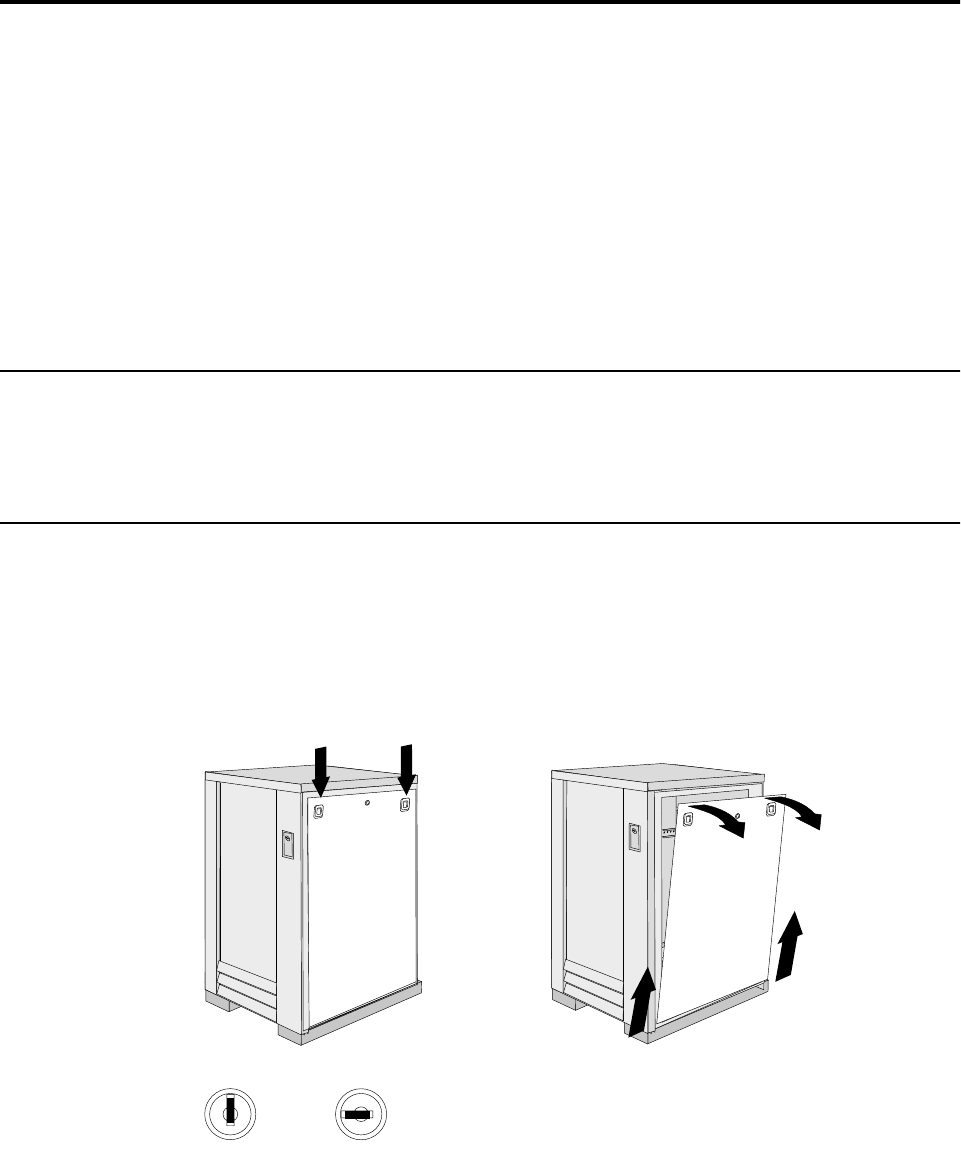
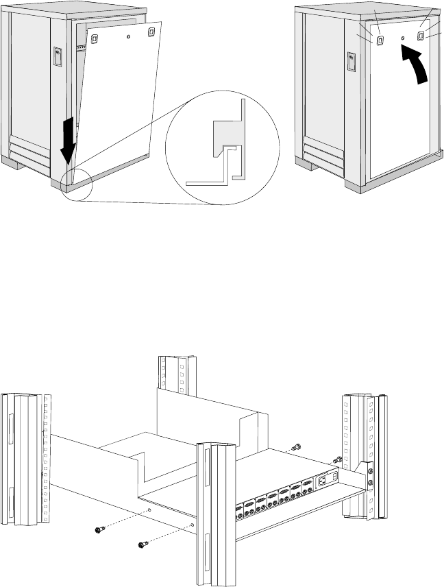
- Perforated Doors (model 910)
- Installing the new door on a model 900 rack cabinet
- Selector switch locations
- Power Distribution Unit
- Blank bezel
- Fixed shelf
- Keyboard tray
- Installing a flat panel monitor rack mount kit
- Removing the existing flat panel monitor stand
- Installing the new monitor stand
- Starting the system
- Configuring the selector switch
- Switching among servers
- Advanced selector switch functions
- Resetting the selector switch
- Making connections under power
- Locations
- Parts listing (Type 9306 Model 900/910)
- Features
- NetBAY 42 Enterprise Rack (Type 9308 Models 42P, 42X, 4SA, 4SB, 42S, 42E)
- Features
- Locations
- Removing and installing panels
- Doors
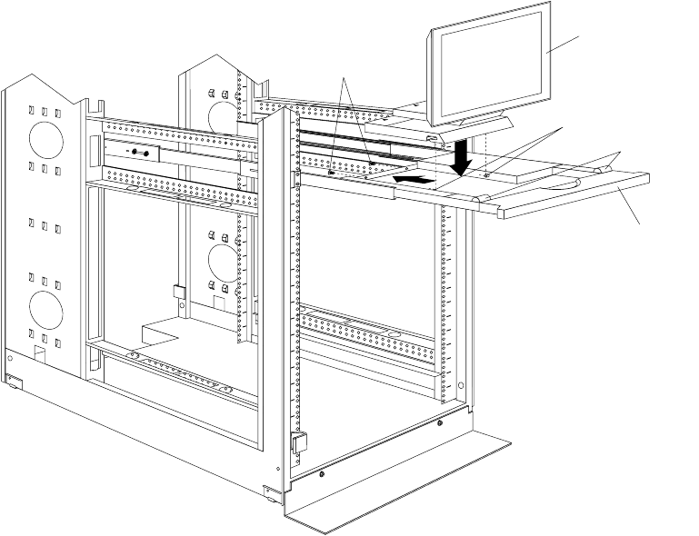
- Removing and installing the top 6U portion of the rack
- Installing the stabilizer bracket
- Attaching rack cabinets in a suite
- Installing L-channel support rails to rack mounting brackets
- Installing a server
- Fixed shelf
- Keyboard tray
- Monitor shelf
- Installing a flat panel monitor rack mount kit
- Removing the existing flat panel monitor stand
- Installing the new monitor stand
- Blank filler panel
- Parts listing (Type 9308 Model 42P, 42X)
- NetBAY3 enclosure
- NetBAY3E enclosure
- IBM NetBAY console switch
- NetBAY Power Distribution Units
- Related service information

IBM
Hardware Maintenance Manual
IBM PC Server/Enterprise Racks
IBM
Hardware Maintenance Manual
IBM PC Server/Enterprise Racks

Note:
Before using this information and the product it supports, be sure to read the general
information under “Notices” on page 195.
Sixth Edition (November 1999) Updated April 2001
The following paragraph does not apply to the United Kingdom or any country where such provisions are
inconsistent with local law:
INTERNATIONAL BUSINESS MACHINES CORPORATION PROVIDES THIS PUBLICATION "AS IS" WITHOUT
WARRANTY OF ANY KIND, EITHER EXPRESS OR IMPLIED, INCLUDING, BUT NOT LIMITED TO, THE IMPLIED
WARRANTIES OF MERCHANTABILITY OR FITNESS FOR A PARTICULAR PURPOSE. Some states do not allow
disclaimer of express or implied warranties in certain transactions, therefore, this statement may not apply to you.
This publication could include technical inaccuracies or typographical errors. Changes are periodically made to the
information herein; these changes will be incorporated in new editions of the publication. IBM may make improvements
and/or changes in the product(s) and/or the program(s) described in this publication at any time.
This publication was developed for products and services offered in the United States of America. IBM may not offer the
products, services, or features discussed in this document in other countries, and the information is subject to change
without notice. Consult your local IBM representative for information on the products, services, and features available in
your area.
Requests for technical information about IBM products should be made to your IBM reseller or IBM marketing
representative.
© Copyright International Business Machines Corporation 2001. All rights reserved.
US Government Users Restricted Rights – Use, duplication or disclosure restricted by GSA ADP Schedule Contract with
IBM Corp.

© Copyright IBM Corp. 2001 iii
About this supplement
This supplement contains diagnostic and service information for the IBM PC Server
Rack Enclosure and the IBM Rack enclosures:
IBM PC Server Rack Enclosure models:
•Type 9306 19-inch and 24-inch Models:
—4QS, 4QX, 9QS
—9QX, 9TS, 9TX
•IBM Rack enclosure models:
—Type 9306 Models 200, 900
—Type 9308 Models 42P, 42X, 42S, 42E, 4SA, 4SB (NetBAY42 Enterprise)
•IBM NetBAY3 enclosure
•IBM NetBAY3E enclosure
This supplement should be used with the related service information in the IBM PC
Servers Hardware Maintenance Manual (part number 70H0751, form number S30H-
2501-01).
Important: This manual is intended for trained servicers who are familiar with IBM
PC Server and IBM Server products.
Before servicing an IBM product, be sure to review “Safety information”
on page 183.
Related publications
The following publications are available for IBM products. For more information,
contact IBM or an IBM Authorized Dealer.

iv Hardware Maintenance Manual: IBM PC Server/Enterprise Racks
For information about See publication
PC Servers IBM PC Servers Hardware Maintenance Manual
(S30H-2501)
PS/2 Computers IBM Personal System/2 Hardware Maintenance
Manual (S52G-9971)
PS/ValuePoint Computers IBM PS/ValuePoint Hardware Maintenance Service
and Reference (S61G-1423)
Laptop, Notebook, Portable, and
ThinkPad Computers (L40, CL57, N45,
N51, P70/P75, ThinkPad 300, 350, 500,
510, 710T, Expansion Unit, Dock I,
Dock II)
IBM Mobile Systems Hardware Maintenance
Manual Volume 1 (S82G-1501)
ThinkPad Computers (ThinkPad 340,
355, 360, 370, 700, 701, 720, 750, 755) IBM Mobile Systems Hardware Maintenance
Manual Volume 2 (S82G-1502)
ThinkPad Computers (ThinkPad 365,
760) IBM Mobile Systems Hardware Maintenance
Manual Volume 3 (S82G-1503)
Monitors (Displays) (February 1993) IBM PS/2 Display HMM Volume 1 (SA38-0053)
Monitors (December 1993) IBM Color Monitor HMM Volume 2 (S71G-4197)
IBM Monitors (P Series) (February
1996) IBM Monitor HMM Volume 3 (S52H-3679)
IBM 2248 Monitor (February 1996) IBM Monitor HMM Volume 4 (S52H-3739)
Disk Array technology overview and
using the IBM RAID Configuration
Program
Configuring Your Disk Array booklet (S82G-1506)
Installation Planning for Personal
System/2 computers Personal System/2 Installation Planning and
Beyond (G41G-2927)
Installation Planning for Advanced
Personal System/2 Servers Advanced PS/2 Servers Planning and Selection
Guide (GG24-3927)

© Copyright IBM Corp. 2001 v
Contents
About this supplement . . . . . . . . . . . . . . . iii
Related publications . . . . . . . . . . . . . . . . . . . . . . . . . . . . . . iii
IBM PC Server/Enterprise rack enclosures1
General checkout. . . . . . . . . . . . . . . . . . . . . . . . . . . . . . . . . 1
Power checkout . . . . . . . . . . . . . . . . . . . . . . . . . . . . . . . . . . 2
Powering off the rack . . . . . . . . . . . . . . . . . . . . . . . . . . . . . 3
Type 9306 Models 4QS, 4QX, 9QS, 9QX,
9TS, 9TX . . . . . . . . . . . . . . . . . . . . . . . . . . . 5
Features. . . . . . . . . . . . . . . . . . . . . . . . . . . . . . . . . . . . . . . . . 5
IBM PC Server expansion rack models. . . . . . . . . . . . 5
Locations. . . . . . . . . . . . . . . . . . . . . . . . . . . . . . . . . . . . . . . . 5
Server selector console . . . . . . . . . . . . . . . . . . . . . . . . . 6
Server selector unit . . . . . . . . . . . . . . . . . . . . . . . . . . . . 6
Connections . . . . . . . . . . . . . . . . . . . . . . . . . . . . . . . . . . 7
Power distribution unit. . . . . . . . . . . . . . . . . . . . . . . . . 7
Cooling fan . . . . . . . . . . . . . . . . . . . . . . . . . . . . . . . . . . . 8
Sliding trays . . . . . . . . . . . . . . . . . . . . . . . . . . . . . . . . . . 9
Sliding rails . . . . . . . . . . . . . . . . . . . . . . . . . . . . . . . . . . 10
Keyboard tray. . . . . . . . . . . . . . . . . . . . . . . . . . . . . . . . 11
Parts listing (Type 9306 – 19-inch) Models 9QS, 9TS and
9QX, 9TX. . . . . . . . . . . . . . . . . . . . . . . . . . . . . . . . . . . . . . . 12
Parts listing (Type 9306 – 24-inch) Models 4QS, 4QX . 17
Type 9306 Model 200 . . . . . . . . . . . . . . . . . 21
Features. . . . . . . . . . . . . . . . . . . . . . . . . . . . . . . . . . . . . . . . 21
Locations. . . . . . . . . . . . . . . . . . . . . . . . . . . . . . . . . . . . . . . 21
Side panel . . . . . . . . . . . . . . . . . . . . . . . . . . . . . . . . . . . 21
Selector switch locations. . . . . . . . . . . . . . . . . . . . . . . 22
Power Distribution Unit . . . . . . . . . . . . . . . . . . . . . . . 26
Blank bezel . . . . . . . . . . . . . . . . . . . . . . . . . . . . . . . . . . 27
Fixed shelf. . . . . . . . . . . . . . . . . . . . . . . . . . . . . . . . . . . 27
Keyboard tray. . . . . . . . . . . . . . . . . . . . . . . . . . . . . . . . 28
Installing a flat panel monitor rack mount kit. . . . . 29
Removing the existing flat panel monitor stand. . . 29
Installing the new monitor stand. . . . . . . . . . . . . . . . 31
Starting the system. . . . . . . . . . . . . . . . . . . . . . . . . . . . 35
Configuring the selector switch. . . . . . . . . . . . . . . . . 35
Switching among servers . . . . . . . . . . . . . . . . . . . . . . 36
Advanced selector switch functions . . . . . . . . . . . . . 37
Resetting the selector switch . . . . . . . . . . . . . . . . . . . 45
Making connections under power. . . . . . . . . . . . . . . 46
Parts Listing (Type 9306 Model 200). . . . . . . . . . . . . . . . 47
Type 9306 Model 900/910 . . . . . . . . . . . . . 51
Features. . . . . . . . . . . . . . . . . . . . . . . . . . . . . . . . . . . . . . . . 51
Locations . . . . . . . . . . . . . . . . . . . . . . . . . . . . . . . . . . . . 51
Parts listing (Type 9306 Model 900/910) . . . . . . . . . . . . 77
NetBAY 42 Enterprise Rack (Type 9308
Models 42P, 42X, 4SA, 4SB, 42S, 42E) . . 81
Features. . . . . . . . . . . . . . . . . . . . . . . . . . . . . . . . . . . . . . . . 81
Locations. . . . . . . . . . . . . . . . . . . . . . . . . . . . . . . . . . . . . . . 85
Removing and installing panels . . . . . . . . . . . . . . . . 85
Doors . . . . . . . . . . . . . . . . . . . . . . . . . . . . . . . . . . . . . . . 87
Removing and installing the top 6U portion of the rack
91 Installing the stabilizer bracket . . . . . . . . . . . . . . . . . 92
Attaching rack cabinets in a suite . . . . . . . . . . . . . . . 92
Installing L-channel support rails to rack mounting
brackets . . . . . . . . . . . . . . . . . . . . . . . . . . . . . . . . . . . . . . . . 94
Installing a server . . . . . . . . . . . . . . . . . . . . . . . . . . . . 97
Fixed shelf . . . . . . . . . . . . . . . . . . . . . . . . . . . . . . . . . . 100
Keyboard tray . . . . . . . . . . . . . . . . . . . . . . . . . . . . . . . 101
Monitor shelf. . . . . . . . . . . . . . . . . . . . . . . . . . . . . . . . 102
Installing a flat panel monitor rack mount kit. . . . 103
Removing the existing flat panel monitor stand . . 103
Installing the new monitor stand. . . . . . . . . . . . . . . 105
Blank filler panel . . . . . . . . . . . . . . . . . . . . . . . . . . . . 109
Parts listing (Type 9308 Model 42P, 42X) . . . . . . . . . . . 111
NetBAY3 enclosure . . . . . . . . . . . . . . . . . 115
Features. . . . . . . . . . . . . . . . . . . . . . . . . . . . . . . . . . . . . . . 115
Locations. . . . . . . . . . . . . . . . . . . . . . . . . . . . . . . . . . . . . . 115
Casters . . . . . . . . . . . . . . . . . . . . . . . . . . . . . . . . . . . . . 116
Foot pads . . . . . . . . . . . . . . . . . . . . . . . . . . . . . . . . . . . 116
Front cover . . . . . . . . . . . . . . . . . . . . . . . . . . . . . . . . . 117
Rear panel . . . . . . . . . . . . . . . . . . . . . . . . . . . . . . . . . . 117
Device side rails . . . . . . . . . . . . . . . . . . . . . . . . . . . . . 118
Stacking NetBAY3 enclosures. . . . . . . . . . . . . . . . . . 118
Parts Listing (NetBAY3) . . . . . . . . . . . . . . . . . . . . . . . . . 121
NetBAY3E enclosure . . . . . . . . . . . . . . . . 123
Features. . . . . . . . . . . . . . . . . . . . . . . . . . . . . . . . . . . . . . . 123
Locations. . . . . . . . . . . . . . . . . . . . . . . . . . . . . . . . . . . . . . 123
Casters . . . . . . . . . . . . . . . . . . . . . . . . . . . . . . . . . . . . . 124
Front cover . . . . . . . . . . . . . . . . . . . . . . . . . . . . . . . . . 124
Rear panel . . . . . . . . . . . . . . . . . . . . . . . . . . . . . . . . . . 125
Device side rails . . . . . . . . . . . . . . . . . . . . . . . . . . . . . 126
Stacking NetBAY3E enclosures . . . . . . . . . . . . . . . . 126
Parts listing (NetBAY3E). . . . . . . . . . . . . . . . . . . . . . . . . 127
IBM NetBAY console switch . . . . . . . . . . 129
Features. . . . . . . . . . . . . . . . . . . . . . . . . . . . . . . . . . . . . . . 130
Tool requirements . . . . . . . . . . . . . . . . . . . . . . . . . . . . . . 131
Specifications . . . . . . . . . . . . . . . . . . . . . . . . . . . . . . . . . . 132
Installation overview . . . . . . . . . . . . . . . . . . . . . . . . . . . 132
Installing a console switch in a monitor shelf . . . . 132
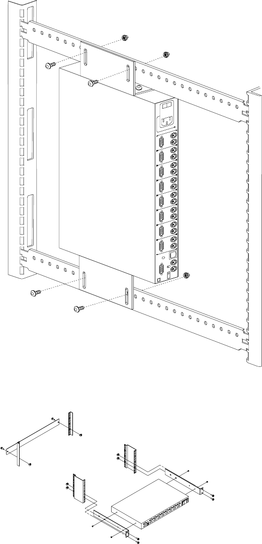
Installing a console switch vertically in a rack. . . . 134
Installing a console switch horizontally in a rack . 137
Parts listing (NetBAY Console Switch). . . . . . . . . . . . . 139
NetBAY Power Distribution Units . . . . . . 141
NetBAY rack Power Distribution Unit introduction . 141
Tool requirements. . . . . . . . . . . . . . . . . . . . . . . . . . . . 142
Installation overview . . . . . . . . . . . . . . . . . . . . . . . . . 142
Installing devices vertically . . . . . . . . . . . . . . . . . . . 142
Installing a single device horizontally . . . . . . . . . . 144
Installing two devices horizontally . . . . . . . . . . . . . 146
Cabling your PDUs . . . . . . . . . . . . . . . . . . . . . . . . . . 148
NetBAY front-end Power Distribution Unit introduction.
156Tool requirements. . . . . . . . . . . . . . . . . . . . . . . . . . . . 157
Installation overview . . . . . . . . . . . . . . . . . . . . . . . . . 157
Installing a single device vertically . . . . . . . . . . . . . 157
Installing two devices vertically . . . . . . . . . . . . . . . 160
Rack PDU specifications . . . . . . . . . . . . . . . . . . . . . . 164
vi Hardware Maintenance Manual: IBM PC Server/Enterprise Racks
Line cords . . . . . . . . . . . . . . . . . . . . . . . . . . . . . . . . . . 165
Power cables . . . . . . . . . . . . . . . . . . . . . . . . . . . . . . . . 165
NetBAY server dual-cord Power Distribution Unit
introduction . . . . . . . . . . . . . . . . . . . . . . . . . . . . . . . . . . . 166
Tool requirements . . . . . . . . . . . . . . . . . . . . . . . . . . . 167
Installation overview. . . . . . . . . . . . . . . . . . . . . . . . . 167
Installing devices vertically . . . . . . . . . . . . . . . . . . . 167
Installing a single device horizontally . . . . . . . . . . 169
Installing two devices horizontally. . . . . . . . . . . . . 171
Cabling your PDUs . . . . . . . . . . . . . . . . . . . . . . . . . . 173
Power cables . . . . . . . . . . . . . . . . . . . . . . . . . . . . . . . . 180
Line cords . . . . . . . . . . . . . . . . . . . . . . . . . . . . . . . . . . 181
Parts listing (Power Distribution Units) . . . . . . . . . . . 181
Related service information . . . . . . . . . . 183
Safety information. . . . . . . . . . . . . . . . . . . . . . . . . . . . . . 183
Safety notice (multi-lingual translations) . . . . . . . . 191
Safety inspection guide . . . . . . . . . . . . . . . . . . . . . . . 192
Handling electrostatic discharge-sensitive devices 193
Grounding requirements. . . . . . . . . . . . . . . . . . . . . . 194
Problem determination tips . . . . . . . . . . . . . . . . . . . . . . 194
Notices. . . . . . . . . . . . . . . . . . . . . . . . . . . . . . . . . . . . . . . . 195
Send us your comments! . . . . . . . . . . . . . . . . . . . . . . . . 196
Trademarks. . . . . . . . . . . . . . . . . . . . . . . . . . . . . . . . . . . . 197

© Copyright IBM Corp. 2001 1
IBM PC Server/Enterprise rack enclosures
General checkout. . . . . . . . . . . . . . . . . . . . . . . . . . . . . 1
Power checkout . . . . . . . . . . . . . . . . . . . . . . . . . . . . . . 2 Powering off the rack. . . . . . . . . . . . . . . . . . . . . . . . . 3
General checkout
Use the following procedure for diagnosing keyboard, mouse, and video problems for
the IBM PC Server Rack Enclosure and the IBM Rack enclosures (Type 9306 and Type
9308).
For power problems, see “Power checkout” on page 2.
Attention:
•For Models 4QS, 4QX, 9QS, 9QX, 9TS, 9TX only:
Ensure that the voltage selector switch on each server installed in the server rack
is set to 230 V ac.
•For Models 200, 900 only:
Ensure that the voltage selector switch on each server installed in the server rack
is set to the proper voltage as supplied by the Power Distribution Unit, PDU.
1. Check the following:
•Ensure the external power cord is in good condition and properly connected
to a known-good power source.
•Ensure the internal power cables are in good condition and properly
connected. (The internal power cables connect between the power
distribution unit and the servers installed in the server rack.)
•Ensure the following devices are powered on.
a. Power distribution unit
b. Server selector unit
c. All system units
d. Display
2. If the items/conditions specified in step 1. are not okay, correct the problem and
verify that the server rack is operating correctly.
3. If the items/conditions specified in step 1. are okay, then, using the server selector
keypad buttons, check the operation of the failing device for all of the servers that
are installed in the rack.
4. Did the failure occur on more than one server?
•NO: Go to the Hardware Maintenance manual for the server that was
selected when the failure occurred. Disconnect the keyboard and mouse from
the server selector unit and connect them directly to the failing server. Then,
run the server diagnostic programs on the failing server.
If the problem still remains, disconnect the keyboard and mouse from the
failing server and reconnect them to the server selector unit. Then, replace the
server rack components in the following order until the problem goes away.
a. Device cable (connects between the server selector unit and the server
that was selected when the failure occurred).

2 Hardware Maintenance Manual: IBM PC Server/Enterprise Racks
b. Server selector cable (connects between the server selector keypad and
the server selector unit).
c. Server selector keypad.
d. Server selector unit.
•YES: Power-off the server rack and replace the server rack components in the
following order until the problem goes away. See “Powering off the rack” on
page 3.
a. Device extender cable (connects between the device and the server
selector unit)
b. Failing device
c. Server selector cable (connects between the server selector keypad and
the server selector unit)
d. Server selector keypad
e. Server selector unit
Power checkout
Use the following procedure for diagnosing power problems for the IBM PC Server
Rack Enclosure and IBM Rack enclosure (Type 9306).
Attention:
•For Models 4QS, 4QX, 9QS, 9QX, 9TS, 9TX only:
Ensure that the voltage selector switch on each server installed in the server rack
is set to 230 V ac.
•For Models 200, 900 only:
Ensure that the voltage selector switch on each server installed in the server rack
is set to the proper voltage as supplied by the Power Distribution Unit, PDU.
1. Check the following:
•Ensure the external power cord is in good condition and properly connected
to a known-good power source.
•Ensure the internal power cables are in good condition and properly
connected. (The internal power cables connect between the power
distribution unit and the servers installed in the server rack.)
•Ensure the following devices are powered on.
a. Power distribution unit
b. Server selector unit
c. All system units
d. Display
2. If the items/conditions in step 1. are not okay, correct the problem and verify
correct operation of the server rack.
3. If the items/conditions specified in step 1. are okay, then, using the server selector
keypad buttons, check for correct operation of all the servers installed in the rack.
4. Did the failure occur on more than one server?
•No: Go to the Hardware Maintenance manual for the server that was selected
when the failure occurred and run the server diagnostic programs. If the
problem still remains, replace the power distribution unit.

IBM PC Server/Enterprise rack enclosures 3
•Yes: Power-off the server rack and replace the server rack components in the
following order until the problem goes away. See “Powering off the rack” on
page 3.
a. Power distribution unit fuse.
b. Power distribution unit.
Powering off the rack
Before performing service on the rack, follow this procedure to prevent personal
injury and to avoid damaging the rack and the installed servers.
To power-off the IBM PC Server Rack:
1. Shut down and power-off all installed servers.
2. Power-off the server selector unit.
3. If a UPS system is installed in the rack, power-off the UPS system.
4. Disconnect power from the IBM PC Server Rack.
•If the rack is plugged into a wall-mounted power supply, disconnect the
power cord plug from the wall socket.
•If the power cord is wired directly into the installed location's power supply,
open the rear door of the rack cabinet and disconnect the power plug from the
base of the power distribution unit.
4 Hardware Maintenance Manual: IBM PC Server/Enterprise Racks

© Copyright IBM Corp. 2001 5
Type 9306 Models 4QS, 4QX, 9QS, 9QX, 9TS, 9TX
Features. . . . . . . . . . . . . . . . . . . . . . . . . . . . . . . . . . . . . 5
IBM PC Server expansion rack models . . . . . . . . . . 5
Locations. . . . . . . . . . . . . . . . . . . . . . . . . . . . . . . . . . . . 5
Server selector console . . . . . . . . . . . . . . . . . . . . . . . . 6
Server selector unit . . . . . . . . . . . . . . . . . . . . . . . . . . . 6
Connections . . . . . . . . . . . . . . . . . . . . . . . . . . . . . . . . . 7
Power distribution unit . . . . . . . . . . . . . . . . . . . . . . . 7
Cooling fan. . . . . . . . . . . . . . . . . . . . . . . . . . . . . . . . . . 8
Sliding trays . . . . . . . . . . . . . . . . . . . . . . . . . . . . . . . . . 9
Single latch rail tray . . . . . . . . . . . . . . . . . . . . . . . . . . 9
Dual latch rail tray . . . . . . . . . . . . . . . . . . . . . . . . . . 10
Sliding rails . . . . . . . . . . . . . . . . . . . . . . . . . . . . . . . . 10
Keyboard tray . . . . . . . . . . . . . . . . . . . . . . . . . . . . . . .11
Parts listing (Type 9306 – 19-inch) Models 9QS, 9TS
and 9QX, 9TX . . . . . . . . . . . . . . . . . . . . . . . . . . . . . . 12
Parts listing (Type 9306 – 24-inch) Models 4QS, 4QX
17
Features
The 9306 IBM PC Server Rack Enclosure, models 4QS, 9QS, 9TS come in three primary
models.
•19-inch Quad Primary Server Rack, Model 9QS
•19-inch Tri Primary Server Rack, Model 9TS
•24-inch Quad Primary Server Rack, Model 4QS
A Quad Primary Server Rack can house up to four IBM PC Servers. The Tri Primary
Server Rack can house up to three IBM PC Servers.
Both Quad and Tri Primary Server Racks provide a built in server selector which
connects to one set of console devices (monitor, keyboard, and mouse.) The server
selector works independently from the server's operating systems, enabling the
connected servers to run different operating systems.
These IBM 9306 PC Server Rack Enclosure models are shipped preassembled and pre-
cabled.
IBM PC Server expansion rack models
Three optional IBM PC Server Rack Expansion models are available to expand the
capacity of the IBM PC Server Rack Primary Enclosure. The optional IBM PC Server
Rack Expansion models are:
•19-inch Quad Expansion Rack, Model 9QX
•19-inch Tri Expansion Rack, Model 9TX
•24-inch Quad Expansion Rack, Model 4QX
The IBM PC Server Rack Expansion models allow the installation of up to four more
servers using the Primary IBM PC Server Rack monitor, keyboard, and mouse.
Locations
The following sections contain information on specific equipment locations.
Note: For instructions on how to power-off the rack, see “Powering off the rack” on
page 3.
6 Hardware Maintenance Manual: IBM PC Server/Enterprise Racks
Server selector console
To remove the Server Selector Console:
1. Power-off the rack.
2. Use an 1/8-inch allen wrench to remove screws.
3. Disconnect the server selector cable from the back of the server selector console.
4. Remove the server selector console from the cabinet.
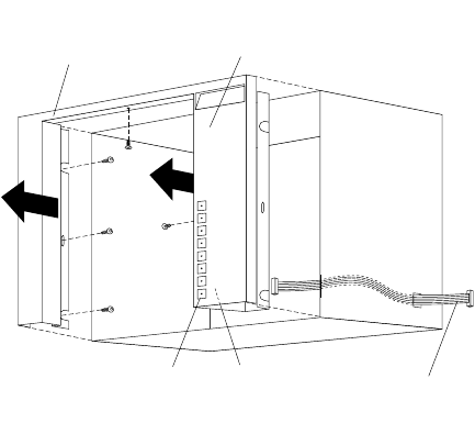
Server selector unit
The server selector unit is located in the upper rear of the rack cabinet. The server
selector unit can only be accessed or removed from the rear of the IBM Rack cabinet.
CAUTION:
The server selector unit is heavy. You will need two people to safely remove the
server selector unit. See “Safety notice (multi-lingual translations)” on page 191.
To remove the server selector unit:
1. Power-off the rack.
2. Unplug the keyboard, mouse, video cables, and the power cord.
3. Remove the server selector console.
4. With one person bracing the server selector unit from below, have the second
person use a 5/16-inch wrench to remove the four nuts that secure the server
selector unit to the rack cabinet.
5. Remove the server selector unit from the cabinet.
Note: When replacing the server selector unit, be sure that the Server Selector cable is
fed through the indentation along the left side of the server selector unit.
Server
Selector
Console
Monitor
Bezel
Server
Selector
Cable
Server
Selector
Electronics
Server
Selector
Keypad
Type 9306 Models 4QS, 4QX, 9QS, 9QX, 9TS, 9TX 7
Connections
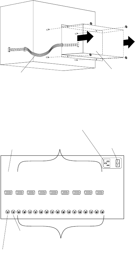
Power distribution unit
Note: For information and installation instructions for the IBM NetBAY Rack Power
Distribution Units, see “NetBAY Power Distribution Units” on page 141".
Note: To remove the power distribution unit, you might need to remove the right
side cabinet panel, the server installed in sliding tray 2 (in the primary IBM PC
Server Rack), or sliding tray 5 (in the IBM PC Server Expansion Rack).
To remove the power distribution unit:
1. Power-off the rack.
2. Disconnect all power plugs from the power distribution unit.
3. Using a Phillips screwdriver, remove the four screws from the front of the power
distribution unit.
Server
Selector
Cable
Server
Selector
Unit
M
O
N
O
V
G
A
1
K
B
O
V
G
A
2
V
G
A
3
V
G
A
4
V
G
A
5
V
G
A
7
V
G
A
6
V
G
A
8
M
O
UK
1M
1K
2M
2K
3M
3K
4M
4K
5M
5K
6M
6K
7M
7K
8M
8
Server
Monitor
Connections
AC Power
Input
Server Selector
Unit On-Off
Switch
Server Rack
Mouse
Connection
Server Rack
Keyboard
Connection
Server Rack
Monitor
Connection
Server Keyboard
and Mouse
Connections
8 Hardware Maintenance Manual: IBM PC Server/Enterprise Racks
Note: These screws are held in place by nuts and washers. Hold the nut while
you are unscrewing the screw to prevent the nut and washer from falling
into the bottom of the cabinet.
4. Remove the power distribution unit from the cabinet.
Cooling fan
To remove the cooling fan:
1. Power-off the rack.
2. Open the rear door of the rack cabinet.
3. Disconnect the power plug from the rear of the cooling fan.
4. Use a 5/16-inch wrench to remove the eight nuts that secure the cooling fan to the
top of the rack cabinet.
5. Remove the cooling fan from the cabinet.
Note: When installing the fan, make sure that the green and yellow ground wire is
attached to one of the top fan mounting screws and that the strain-relieving
clamp is attached to another. The power cable should be secured by the strain-
relieving clamp.
Circuit
Breaker
AC Fuse
115V AC
Power-On
Indicator
230V AC
Power-On
Indicator
Voltage
Selection
Switch
AC Power
Output
AC Power
Input
Type 9306 Models 4QS, 4QX, 9QS, 9QX, 9TS, 9TX 9
Sliding trays
Models 4QS and 4QX come with either single latch slide rails or dual latch slide rails.
Single latch slide rails have a front latch release on the right rail only. Dual latch slide
rails have a front latch release on both rails. The slide rail FRU number for the 24-inch
rack replaces the single latch slide rail with the dual latch slide rail.
Note: If a server is installed on a tray being removed, first remove the server.
Single latch rail tray
To remove a sliding tray with single latch rails:
1. Power-off the rack.
2. Open the rear door of the rack cabinet and remove the pin 1 that secures the
sliding tray to the cable management arm
3. Loosen the thumbscrews 2 on the sliding tray and fully extend the sliding tray.
4. Use a 3/32-inch allen wrench to remove the five screws 3 from the left side of the
sliding tray.
5. Lift the rear locking tab 4 and push the sliding tray approximately two inches into
the cabinet.
6. Release the forward locking tab 5. Then, while holding the sliding tray in place,
use your other hand to grasp the outside sliding rail 6 and push it into the rack
cabinet until it disconnects from the sliding tray.
Ground
Wire
Power
Plug
10 Hardware Maintenance Manual: IBM PC Server/Enterprise Racks
Dual latch rail tray
To remove a sliding tray with dual latch rails:
1. Power-off the rack.
2. Open the rear door of the rack cabinet and remove the pin 1 that secures the
sliding tray to the cable management arm.
3. Loosen the thumbscrews 2 on the sliding tray and fully extend the sliding tray.
4. Push in on the spring of the right rear locking tab 3 and push the sliding tray
approximately two inches into the cabinet.
5. Release both left and right forward locking tabs 4. Then, while holding the
sliding tray in place, push both left and right outside sliding rails 5 into the rack
cabinet until it disconnects from the sliding tray.
Note: Left side view for 4 and 5 are not shown.
Sliding rails
This procedure is for single latch sliding rails and dual latch sliding rails.
For single latch sliding rails, the right rail is the one that has the front latch. The left
rail does not have a front latch.
For dual latch sliding rails, the right rail is the one that has the rear latch. The left rail
does not have a rear latch.
To remove the sliding rails:
1. Power-off the rack.
2. Remove the sliding tray that is attached to the sliding rails that you want to
remove. See “Sliding trays” on page 9.
3. Use a 3/32-inch allen wrench to remove the four screws that secure each of the
sliding rails to the rack cabinet.
Type 9306 Models 4QS, 4QX, 9QS, 9QX, 9TS, 9TX 11
Note: You will need to adjust the position of the sliding rail in order to line up the
access holes over the locations of the screws.
Keyboard tray
To remove the keyboard tray:
1. Power-off the rack.
2. Disconnect the keyboard and mouse cables from the keyboard and mouse
extension cables.
3. Remove the keyboard and mouse from the keyboard tray.
4. Pull the keyboard tray straight out of the rack cabinet.
12 Hardware Maintenance Manual: IBM PC Server/Enterprise Racks
Parts listing (Type 9306 – 19-inch) Models 9QS, 9TS and 9QX, 9TX
This parts listing is for Models 9QS, 9TS and 9QX, 9TX
1
56789
10
11
12
13
14
15
16
17
18
19
20
22 21
23
24
2
3
4
28 29
30
25
26
27
Type 9306 Models 4QS, 4QX, 9QS, 9QX, 9TS, 9TX 13
Index 19-Inch Rack Enclosure (Type 9306) FRU
1 Adapter Plate Options:
PS/2 Server 85/95 76H3733
Model 300 76H3734
Model 500, 700 76H3734
2Monitor Stand 07H0061
3 Server Selector Cable 07H0036
4 Blank Bezel (9QX, 9TX Expansion units only) 76H0379
5 Monitor Bezel with button label 76H0378
6 Server Selector Keypad 07H0097
7 Monitor Housing (19-inch) 76H0377
8 Server Selector Unit Electronics
See “Safety inspection guide” on page 192. 07H0034
9 Internal Cables
See Cable Kit Shelf Server 06P6007
10 Cable Management Arm 76H0386
11 Cable Management Arm Single Server Tray 76H0387
12 Pin, Cable Management Arm 07H0089
13 Fan 220 V ac with Power Cord 07H0063
14 Latch, Rear Door 76H0376
15 Rear Door (19-Inch) 76H0373
15 Hinge Set for Rear Door 76H0389
16 External Power Cord:
Australia 14F1559
Europe 14F1554
Israel 14F1561
Italy 14F1560
New Zealand 14F1558
South America, India 14F1557
U.K./Denmark 14F1555
USA 14F1553
External Power Cord Option - 6 Ft. 07H0094
17 Left/Right Side Panel 76H0374
18 Caster 76H3626
19 NetBAY Rack Power Distribution Unit 09N9668
19 NetBAY Front-end Power Distribution Unit 09N9670
3-phase NEMA L21-30P line cord (200-250 Vac) for NetBAY Front-end PDU 00N7720
3-phase IEC 309-3P+N+Gnd line cord (380-415 Vac) for NetBAY Front-end PDU 00N7721
14 Hardware Maintenance Manual: IBM PC Server/Enterprise Racks
1-phase NEMA L5-30P line cord (100-127 Vac) for NetBAY Front-end PDU 00N7722
1-phase NEMA L6-30P line cord (200-240 Vac) for NetBAY Front-end PDU 00N7723
1-phase IEC 309-2P+Gnd line cord (200-240 Vac) for NetBAY Front-end PDU 00N7724
19 NetBAY Server Dual-cord Power Distribution Unit 09N9669
Hardware Kit for NetBAY Power Distribution Units 09N9671
Power Distribution Unit 07H0424
19 250 V Slow Blow Fuse 0303549
20 Keyboard Slides, (one pair) 07H0038
21 Leveling Foot (Qty. 1) 76H0390
22 Stabilizing Bar 76H0375
23 Keyboard Tray, 19-Inch 76H0381
24 Slide Rails, Server Tray (one pair) 07H0083
24 Slide Rails, Dual Tray (one pair) 76H0383
25 19-inch Front Compartment Door (19-Inch by 26-Inch) Includes Hinge Set and Screws 76H0371
26 Door Hinge Set 76H0372
27 Door Valance (9QX, 9TX, Expansion units only) 76H0380
28 Mouse Table 07H0079
29 Dual Server Tray 76H0382
29 Dual Server Shelf 76H0385
30 Single Server Tray 76H0384
19-Inch Single Slide Shelf for an Industry Standard 19-Inch Rack. 76H3628
Cable, SVGA-Video (15 Feet) Option 76H3736
Monitor Power Cable (connects from monitor to Power Distribution Unit) 07H0075
Rack Keyboard Cable (connects from Keyboard Drawer to Server Selector Unit) 07H0067
Rack Mouse Cable (connects from Keyboard Drawer to Server Selector Unit) 07H0069
Index 19-Inch Rack Enclosure (Type 9306) FRU
Type 9306 Models 4QS, 4QX, 9QS, 9QX, 9TS, 9TX 15
Rack Enclosure Kits (Type 9306) FRU
Bolt-Together Kit (19-Inch to 24-Inch, 24-Inch to 19-Inch)
•19-Inch Attachment Bracket (2 each)
•Screw 1/4-20 x 1/2 Button Head Socket Cap Allen (8 each)
•Screw 1/4-20 x 1-1/4 Socket Cap (4 each)
•Flanged Nut 1/4-20 (12 each)
•24-Inch Attachment Bracket (4 each)
76G3627
Cable Kit Shelf Server (12- foot cables)
•Monitor Cable
•Keyboard Cable
•Mouse Cable
•Internal Power Cable
06P6007
Cable Kit Top Shelf Server (7-foot cables)
•Monitor Cable
•Keyboard Cable
•Mouse Cable
•Internal Power Cable
06P6006
16 Hardware Maintenance Manual: IBM PC Server/Enterprise Racks
Miscellaneous Parts Kit
•Rack Nut/Holder 10-32 (8 each)
•Keeper Nut 8-32 Zinc (8 each)
•Keeper Nut 10-32 (6 each)
•Screw 6-32 x 5/16 (2 each)
•Screw 6-32 x 1/4 Button Head Socket Cap Allen (8 each)
•Screw 10-32 x 3/8 Button Head Socket Cap (8 each)
•Screw 6-32 x 3/8 Button Head Socket Cap (2 each)
•Screw 1/4-20 x 1/2 Button Head Socket Cap (2 each)
•Screw 8-32 x 1/4 Button Head Socket Cap Allen (4 each)
•Screw 10-32 x 1/4 Button Head Socket Cap (2 each)
•Screw 8-32 x 1/4 Button Head Socket Cap (8 each)
•Pull-ring, 3-Inch (2 each)
•Shoulder Screw 8-32 x 3/8 (2 each)
•Standoff,.25 Hex, 6-32 FF,.5-Inch (2 each)
•Screw 8-32 x 3/8 Button Head Socket cap (2 each)
•Screw 10-24 x 1/4 Button Head Socket Allen (2 each)
•Screw 10-24 x 5/16 Button head Socket Allen (2 each)
•Keeper Nut 8-32 (2 each)
•Nut 8-32 (2 each)
•Captive Weld Nut (2 each)
•Whiz-Lock Flange Nut 1/4-20 (2 each)
•Keeper Nut 10-32 (2 each)
•Bumpers (2 each)
•Cable Ties (8 each)
07H0057
Server Tray Interlock Kit
•Cam (1 each)
•Spring (1 each)
07H0091
Rack Enclosure Kits (Type 9306) FRU
Type 9306 Models 4QS, 4QX, 9QS, 9QX, 9TS, 9TX 17
Parts listing (Type 9306 – 24-inch) Models 4QS, 4QX
This parts listing is for Models 4QS and 4QX.
1
5678910 11 12
18
19
20
21
22
23
13
14
15
16
17
23
4
28
29
30
26
27
24
25
18 Hardware Maintenance Manual: IBM PC Server/Enterprise Racks
Index 24-Inch Rack Enclosure (Type 9306) FRU
1 Adapter Plate Options:
PS/2 Server 85/95 76H3733
Model 300 76H3734
Model 500, 700 76H3735
2 Monitor Stand 07H0061
3Server Selector Cable 07H0036
4 Blank Bezel (4QX Only) 07H0066
5 Monitor Housing (24-Inch) 07H0065
6 Server Selector Keypad 07H0097
7 Rack Frame N/A
8 Spacer (see Spacer Kit, right side at end of this FRU list) 07H0059
9 Server Selector Unit Electronics See "Safety Notice (Multi-lingual Translations) See “Safety
notice (multi-lingual translations)” on page 191. 07H0034
10 Internal Cables (see Cable Kit Top Shelf Server and Cable Kit Bottom Shelf Server)
11 Cable Management Arm 07H0087
12 Pin, Cable Management Arm 07H0089
13 Fan 220 V ac with Power Cord 07H0063
14 Rear Door Latch/Lock with Key and Bracket 07H0055
15 Rear Door (24-Inch) 07H0047
16 External Power Cord:
Australia 14F1559
Europe 14F1554
Israel 14F1561
Italy 14F1560
New Zealand 14F1558
South America, India 14F1557
U.K./Denmark 14F1555
USA 14F1553
External Power Cord Option - 6 Ft. 07H0094
17 Left/Right Side Panel 07H0049
18 NetBAY Rack Power Distribution Unit 09N9668
18 NetBAY Front-end Power Distribution Unit 09N9670
18 NetBAY Server Dual-cord Power Distribution Unit 09N9669
Hardware Kit for NetBAY Power Distribution Units 09N9671
18 Power Distribution Unit 07H0424
250 V Slow Blow Fuse 0303549
19 Keyboard Slides, 24-Inch (one pair) 07H0038
Type 9306 Models 4QS, 4QX, 9QS, 9QX, 9TS, 9TX 19
20 Leveling Feet (Qty. 4) 07H0053
21 Stabilizing Leg 07H0051
22 Keyboard Drawer, 24-Inch (with Slides and Brackets) 07H0077
23 Slide Rails, Server Tray (one pair) 07H0083
24 24-Inch Front Compartment Door (24-Inch by 26-Inch) 07H0058
25 Door Hinge Set 07H0045
26 Door Valance (4QX Only) 07H0068
27 Handle, Server/Keyboard Tray 07H0085
28 Server Tray 07H0081
29 Mouse Table 07H0079
30 Shelf, Server Tray, 24-Inch 07H0093
Cable, SVGA-Video (15 Feet) 76H3736
Monitor Power Cable (connects from monitor to Power Distribution Unit) 07H0075
Rack Keyboard Cable (connects from Keyboard Drawer to Server Selector Unit) 07H0067
Rack Mouse Cable (connects from Keyboard Drawer to Server Selector Unit) 07H0069
Rack Enclosure Kits 24-inch (Type 9306) FRU
Bolt-Together Kit (19-Inch to 24-Inch, 24-Inch to 19-Inch) – includes: 19-Inch Attachment
Bracket (2 each); Screw 1/4-20 x 1/2 Button Head Socket Cap; Allen (8 each); Screw 1/4-20
x 1-1/4 Socket Cap (4 each); Flanged Nut 1/4-20 (12 each); 24-Inch Attachment Bracket (4
each)
76G3627
Cable Kit Shelf Server (12 foot cables) – includes: Monitor Cable; Keyboard Cable; Mouse
Cable; Internal Power Cable 07H0073
Cable Kit Top Shelf Server (7 foot cables) – includes: Monitor Cable; Keyboard Cable;
Mouse Cable; Internal Power Cable 07H0071
Miscellaneous Parts Kit – includes: Rack Nut/Holder 10-32 (8 each); Keeper Nut 8-32 Zinc
(8 each); Keeper Nut 10-32 (6 each); Screw 6-32 x 5/16 (2 each); Screw 6-32 x 1/4 Button
Head Socket Cap; Allen (8 each); Screw 10-32 x 3/8 Button Head Socket Cap; (8 each);
Screw 6-32 x 3/8 Button Head Socket Cap; (2 each); Screw 1/4-20 x 1/2 Button Head
Socket Cap; (2 each); Screw 8-32 x 1/4 Button Head Socket Cap; Allen (4 each); Screw 10-
32 x 1/4 Button Head Socket Cap; (2 each); Screw 8-32 x 1/4 Button Head Socket Cap; (8
each); Pull-ring, 3-Inch (2 each); Shoulder Screw 8-32 x 3/8 (2 each); Standoff, .25 Hex, 6-32
FF, .5-Inch (2 each); Screw 8-32 x 3/8 Button Head Socket cap; (2 each); Screw 10-24 x 1/4
Button Head Socket Allen; (2 each); Screw 10-24 x 5/16 Button head Socket Allen; (2 each);
Keeper Nut 8-32 (2 each); Nut 8-32 (2 each); Captive Weld Nut (2 each); Whiz-Lock Flange
Nut 1/4-20 (2 each); Keeper Nut 10-32 (2 each); Bumpers (2 each); Cable Ties (8 each)
07H0057
Server Tray Interlock Kit – includes: Cam (1 each); Spring (1 each) 07H0091
Spacer Kit, Right Side – includes: Rack Joiner (8 each); Spacer, Top and Bottom, 34-Inch (1
each); Spacer, Body 70-Inch (2 each); Screw 10-32 x 3/8 Button Head Socket cap; (8 each);
Screw 1/4-20 x 1/2 Button Head Socket cap; (8 each); Whiz-Lock Flange Nut 1/4-20 (8
each); Screw 6-32 x 3/8 Button Head Socket Cap; (6 each)
07H0059
Index 24-Inch Rack Enclosure (Type 9306) FRU
20 Hardware Maintenance Manual: IBM PC Server/Enterprise Racks
© Copyright IBM Corp. 2001 21
Type 9306 Model 200
Features. . . . . . . . . . . . . . . . . . . . . . . . . . . . . . . . . . . . 21
Locations. . . . . . . . . . . . . . . . . . . . . . . . . . . . . . . . . . . 21
Side panel . . . . . . . . . . . . . . . . . . . . . . . . . . . . . . . . . . 21
Selector switch locations . . . . . . . . . . . . . . . . . . . . . 22
Power Distribution Unit. . . . . . . . . . . . . . . . . . . . . . 26
Blank bezel . . . . . . . . . . . . . . . . . . . . . . . . . . . . . . . . . 27
Fixed shelf . . . . . . . . . . . . . . . . . . . . . . . . . . . . . . . . . 27
Keyboard tray . . . . . . . . . . . . . . . . . . . . . . . . . . . . . . 28
Installing a flat panel monitor rack mount kit . . . 29
Removing the existing flat panel monitor stand . 29
Installing the new monitor stand. . . . . . . . . . . . . . 31
Starting the system. . . . . . . . . . . . . . . . . . . . . . . . . . 35
Configuring the selector switch . . . . . . . . . . . . . . . 35
Switching among servers . . . . . . . . . . . . . . . . . . . . 36
Advanced selector switch functions . . . . . . . . . . . 37
Resetting the selector switch. . . . . . . . . . . . . . . . . . 45
Making connections under power. . . . . . . . . . . . . 46
Parts Listing (Type 9306 Model 200) . . . . . . . . . . . 47
Features
The IBM NetBAY22, Type 9306, Model 200 Rack enclosure is a 22-U high (38.5-inch)
industry-standard, 19-inch rack that houses and controls multiple IBM PC
Servers/IBM Servers and related equipment.
Locations
The following sections contain information on specific equipment locations.
Note: For instructions on how to power-off the rack, see “Powering off the rack” on
page 3.
Side panel
Locked Unlocked
22 Hardware Maintenance Manual: IBM PC Server/Enterprise Racks
Selector switch locations
Note: For information about the IBM NetBAY Console Switch, see “IBM NetBAY
console switch” on page 129.
Figure 1. Selector switch in monitor compartment
One
KM
Three
KM
KM
Two
Aux.
Reset
Important
Information
1
0
Three
KM
KM
TwoThree
KM
Three
KM
KM
Two
Type 9306 Model 200 23
Figure 2. Selector switch between side panels
Figure 3. Selector switch rear of rack with blank panel front of rack
FRONT
REAR
One
KM
Three
KM
KM
Two
Aux.
Reset
Important
Information
1
0
Three
KM
KM
Two Three
KM
Three
KM
KM
Two
24 Hardware Maintenance Manual: IBM PC Server/Enterprise Racks
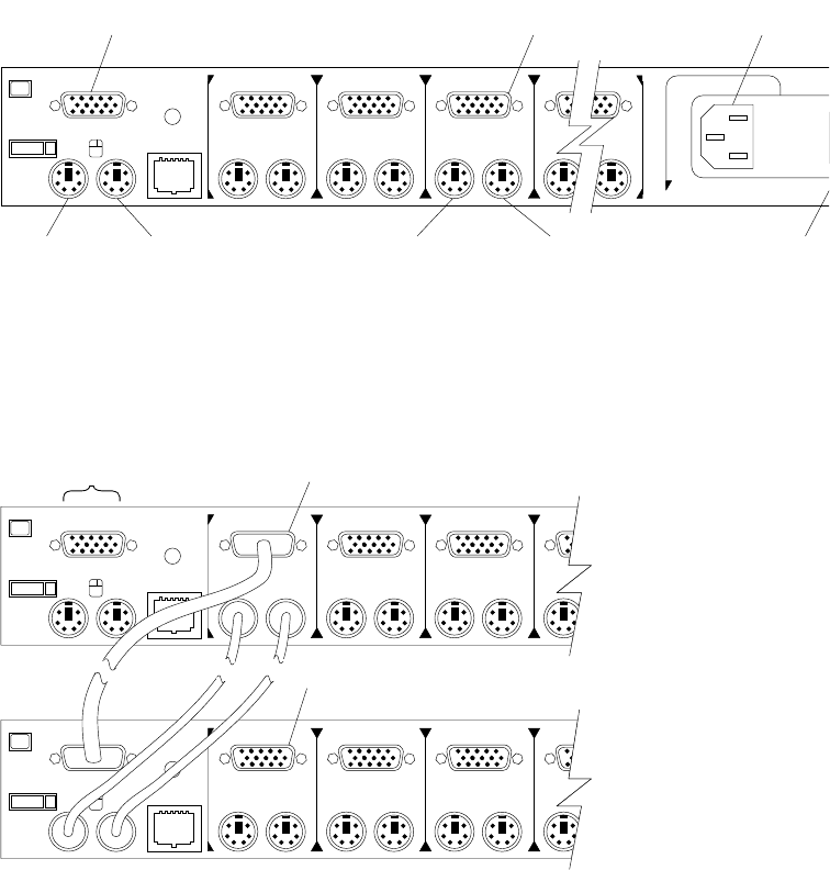
Selector switch cable connections
Tiered switch configuration
One eight-port primary selector switch can accommodate up to eight secondary
selector switches which can then support up to 64 servers.
Note: There are two types of selector switches available:
•4 port
•8 port
One
KM
Three
KM KMKM
Two
Aux.
Reset
Important
Information
Power C
o
Connect
o
Power
Switch
Computer 3
Mouse
Computer 3
Keyboard
Computer 3
Monitor
Mouse
Keyboard
Monitor
One
KM
Three
KM KKM
Two
Aux.
Reset
Monitor
Keyboard
Mouse
Connectors
One
KM
Three
KM KKM
Two
Aux.
Reset
System 1 to 8
System 1-1 to 1-8
Type 9306 Model 200 25
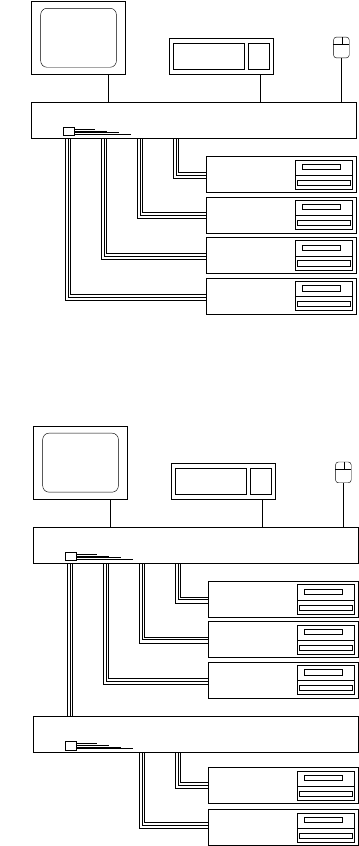
Selector switch environment
Figure 4. Single selector switch
Figure 5. Multiple selector switch
Monitor Keyboard Mouse
Selector Switch
Server 1
Server 2
Server 3
Server 4
Console
Cable
Set
Monitor Keyboard Mouse
Server 1
Server 2
Server 3
Server 4
Secondary Selector Switch
Console
Cable
Set
Primary Selector Switch
Server 5

26 Hardware Maintenance Manual: IBM PC Server/Enterprise Racks
Power Distribution Unit
Note: For information and installation instructions for the IBM NetBAY Rack Power
Distribution Units, see “NetBAY Power Distribution Units” on page 141.
Figure 6. Power Distribution vertical installation
Figure 7. Power distribution horizontal installation
REAR
FRONT

Type 9306 Model 200 27
Note: There are two types of Power distribution units available:
•High voltage
•Low voltage
Blank bezel
Fixed shelf

28 Hardware Maintenance Manual: IBM PC Server/Enterprise Racks
Keyboard tray
To remove the tray from the side rails, pull up on the left rail tab and push down on
the right rail tab.
Type 9306 Model 200 29
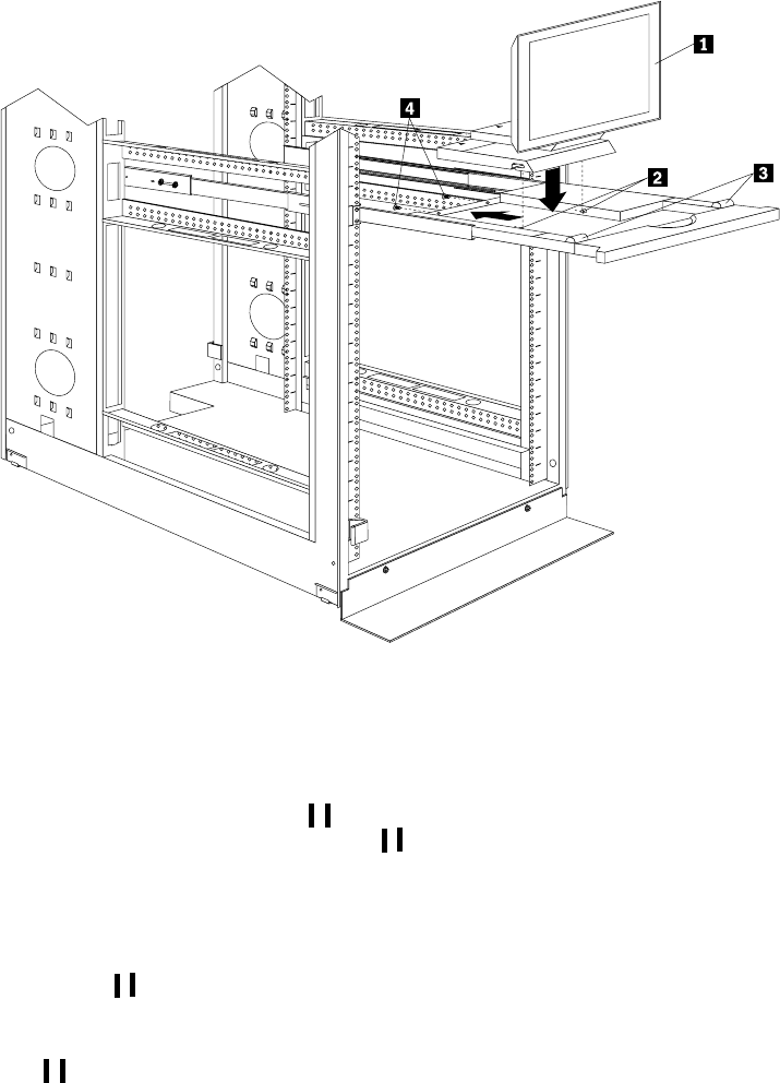
Installing a flat panel monitor rack mount kit
You can store a T54 or T55 Flat Panel Monitor in a keyboard tray with the flat panel
monitor rack mount kit. This kit requires an additional 2U of space above an installed
keyboard tray in your rack cabinet. See the documentation that comes with the flat
panel monitor rack mount kit for detailed installation instructions. Use the following
general procedure to install a flat panel monitor in your rack cabinet:
Figure 8. Installing a flat panel monitor rack mount kit
1. Ensure that a keyboard tray is properly installed in your rack cabinet (see
“Keyboard tray” on page 28) with at least 2U of clearance above the keyboard
tray.
2. Install the flat panel monitor base on the flat panel monitor. See the
documentation that comes with your flat panel monitor rack mount kit for
detailed installation instructions.
3. Install the mounting studs and bumpers on the keyboard tray.
4. Attach the monitor base to the inside of the keyboard tray using the screws that
come with the rack mount kit.
5. Fold the monitor all the way down against the bumpers; then, slide the keyboard
tray into the rack cabinet to ensure that there is proper clearance.
6. See the documentation that comes with your flat panel monitor for information
on how to connect power and how to connect the monitor to a server or console
switch.
Removing the existing flat panel monitor stand
Use the following steps to remove the existing flat panel monitor stand from your
monitor:
Keyboard tray
Rear screws
Flat panel monitor
Mounting studs
Bumpers

30 Hardware Maintenance Manual: IBM PC Server/Enterprise Racks
1. Unplug the flat panel monitor and disconnect the power cord from the flat panel
monitor power supply.
2. Carefully use a flat-blade screwdriver to pry the bottom of the cable cover 1 up
and remove it. Save the cable cover for later reinstallation.
Figure 9. Removing the cable cover, hinge cover, and stand cover
3. Squeeze the sides of the hinge cover 2 and remove it.
Note: Even though this hinge cover is not used with the Flat Panel Monitor Rack
Mount Kit, do not discard it. Store it with the other monitor stand parts
you remove for possible future use.
4. Gently push the stand cover 3 and slide it backwards until it is completely off
the stand.
5. Disconnect the signal cable and power cord from the flat panel monitor. Carefully
remove and save the plastic cable clamp to free the power cord.
Note: The plastic cable clamp is reusable and is needed to secure the power cord
after installing the Flat Panel Monitor Rack Mount Kit on the flat panel
monitor.
Figure 10. Removing the plastic cable clamp
6. Lay the monitor facedown on a cushioned surface and remove the six screws that
secure the hinges to the flat panel monitor.
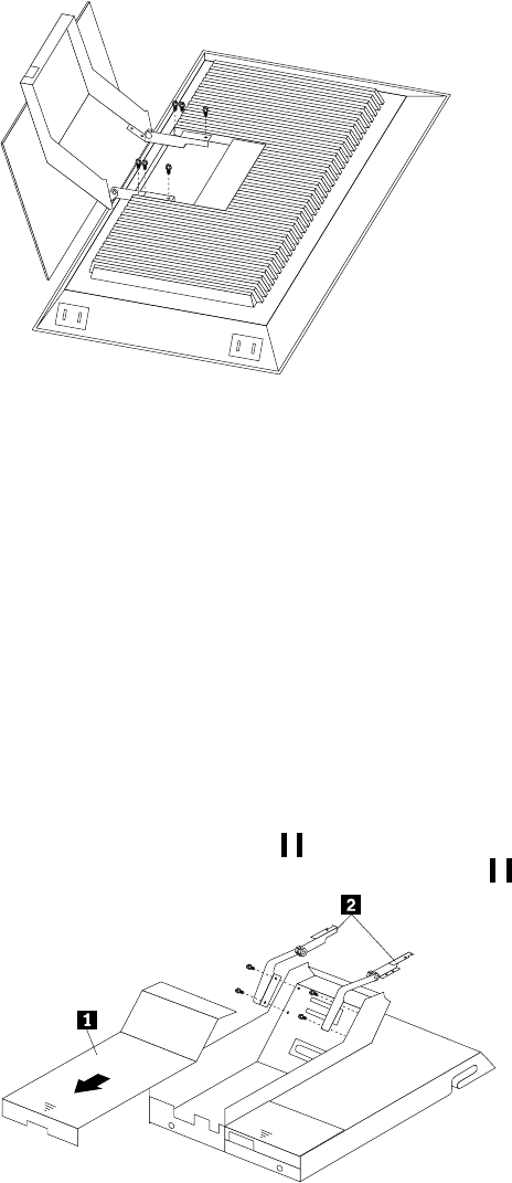
Type 9306 Model 200 31
Figure 11. Removing the existing monitor stand from the monitor
7. Lift off the hinge and monitor stand assembly. Store this assembly in a safe place
for possible future use.
Installing the new monitor stand
Refer to “Removing the existing flat panel monitor stand” on page 29 for instructions
on how to remove the existing stand from the flat panel monitor. Before installing the
new stand, install the keyboard tray in the rack according to the instructions that
come with the rack or the keyboard tray option.
Note: The Flat Panel Monitor Rack Mount Kit and keyboard tray require 3U of rack
mounting space. If the keyboard tray does not have at least 2U of clearance
above it, relocate the keyboard tray within the rack.
Use the following steps to install the Flat Panel Monitor Rack Mount Kit:
1. Remove the cable cover 1 from the new monitor stand; then, remove the four
screws (two per hinge) that secure the hinges 2 to the stand.
Figure 12. Removing the hinges from the new monitor stand
2. Install the hinges on the flat panel monitor, using the six screws that you removed
from the old monitor stand.
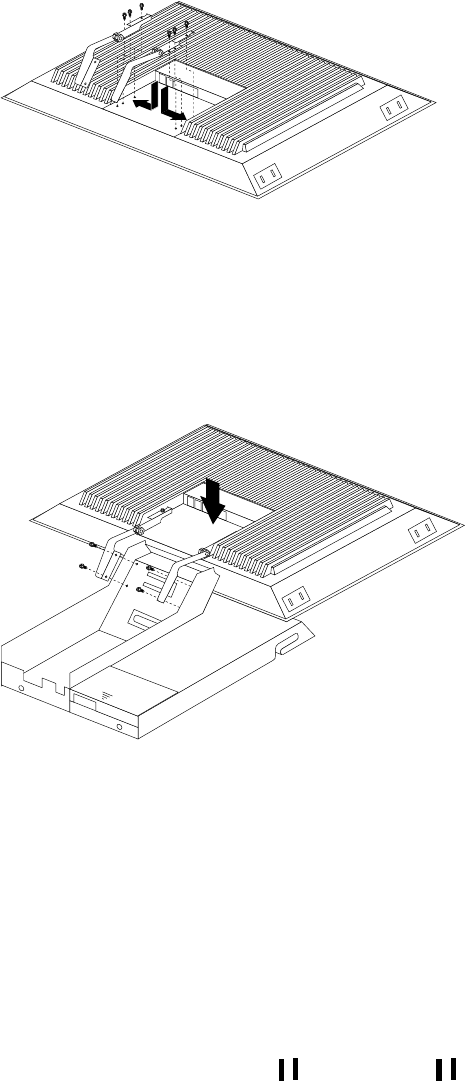
32 Hardware Maintenance Manual: IBM PC Server/Enterprise Racks
Figure 13. Installing the hinges on the flat panel monitor
Note: Be sure to slide each hinge into place on the back of the monitor and align
the holes in the hinges with holes on the monitor.
3. Lower the flat panel monitor onto the new monitor stand, making sure that you
align the holes in the stand with holes in the hinges; then, secure the flat panel
monitor to the monitor stand with the four screws that you removed earlier.
Figure 14. Installing the monitor on the new monitor stand
You have now finished attaching the flat panel monitor to its stand. The rest of
the installation process involves preparing the keyboard tray for storage and
routing cables.
Notes:
a. You must remove any keyboard or mouse that is already in the keyboard tray
before continuing.
b. You will not be able to store a mouse in the keyboard tray after installing the
Flat Panel Monitor Rack Mount Kit.
c. You can only store a space-saver keyboard in the keyboard tray.
4. Install the mounting studs 2 and bumpers 3 that come in the monitor
mounting hardware package.
Type 9306 Model 200 33
Figure 15. Installing the flat panel monitor in the keyboard tray
Note: Clean the installation area on the keyboard tray with a suitable cleaning
agent, such as alcohol, before installing the rubber bumpers on the front of
the keyboard tray.
5. Open the flat panel monitor 1 to its full upright position and align the grooves in
the stand with the mounting studs 2 in the keyboard tray. When the monitor
stand is sitting inside the keyboard tray, slide it towards the back until it stops.
Note: Install or remove the flat panel monitor only when the display is in its
upright position.
6. Secure the monitor stand in the back of the keyboard tray with the two provided
screws 4.
7. Place the flat panel monitor power supply, which came with your flat panel
monitor, inside the monitor stand. If necessary, insert the power supply spacer
3 behind the power supply and over the cable to keep the power supply in
place.
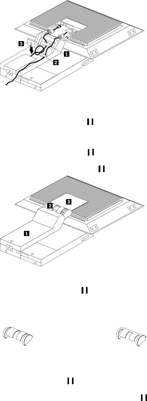
34 Hardware Maintenance Manual: IBM PC Server/Enterprise Racks
Figure 16. Storing the power supply and routing cables
8. Connect the power supply to the monitor and route the cable under the tab near
the top of the monitor stand 1; then, secure the power cable with the cable
clamp you removed from the original stand and coil excess cable inside the
monitor stand.
9. Connect the monitor signal cable to the monitor and route it under the tab in the
bottom of the monitor stand 2 and out the back of the stand through the hole
provided.
10. Replace the monitor stand cover 1.
Figure 17. Installing the cable cover, hinge cover, and stand cover
11. Snap the new hinge cover 2 into place over the hinge assembly.
Note: Be sure to use the new hinge cover that comes with the Flat Panel Monitor
Rack Mount Kit because it has deeper grooves to accommodate the new
hinge assembly.
12. Snap the cable cover 3 into place on the back of the flat panel monitor.
13. Fold the flat panel monitor down until it rests on the rubber bumpers; then, gently
push back and remove the small cable exit cover 1 on the monitor stand.
New hinge cover Old hinge cover
Type 9306 Model 200 35
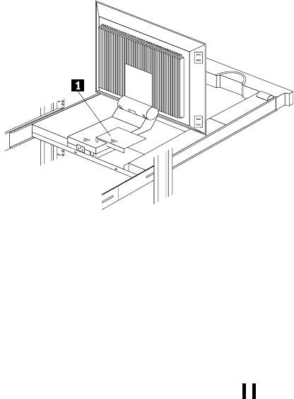
Figure 18. Routing the keyboard cable
14. Route the space-saver keyboard cable through the hole in the front of the base and
out the opening in the back where you removed the small cover; then, place the
keyboard (with its adjustable feet fully down) inside the keyboard tray.
Note: You must open the flat panel monitor to its full upright position so that
you can install the keyboard and route its cable.
15. Fold the flat panel monitor down again until it rests on the rubber bumpers; then,
reinstall the small cable exit cover 1.
16. Slide the keyboard tray into the rack; then, neatly route and secure all cables in the
rack using the provided cable straps.
You can now connect the power cord to the flat panel monitor and connect the
display to a server.
Starting the system
Start the system by:
1. Power-on the selector switch(s).
2. Power-on the monitor.
3. Power-on the servers.
Note: The selector switch must be powered on first, then the servers. This is to
assure that the device drivers for the servers send device settings to the
selector switch.
When the selector switch is powered on, it:
•Identifies the mouse and keyboard and puts them into default status.
•Switches to port 1 by default, and displays the number '1' in the status flag field
on the monitor.
Configuring the selector switch
Note: For information about the IBM NetBAY Console Switch, see “IBM NetBAY
console switch” on page 129.
Note: Some selector switch units have different functions and displays. Refer to the
Apex PC Solutions® Outlook™ Concentrator User Guide. This guide is
shipped with the Selector Switch Unit.
No configuration is necessary for normal switch operation.

36 Hardware Maintenance Manual: IBM PC Server/Enterprise Racks
Switch configuration can be performed to:
•Assign unique names to servers.
•Display servers by their assigned port names and port numbers.
Switching among servers
To switch among servers:
•Press the Print Screen key.
•Type the port number of the server to be switched.
•Press Enter.
Note: One depression of the Print Screen key starts the switching process. To
print a screen, depress the Print Screen key twice.
Port Name
1 Magic +
2 CentralOfc +
3 Sales-C +
4 Sales-B
5 Sales-A +
6 Downtown
7 Foreign +
8
F1 Help F2 Advanced
Port Name
1 Magic +
2 CentralOfc +
3 Sales-C +
4 Sales-B
5 Sales-A +
6 Downtown
7 Foreign +
8
F1 Help F2 Advanced
Port Name
1 Magic +
2 CentralOfc +
3 Sales-C +
4 Sales-B
5 Sales-A +
6 Downtown
7 Foreign +
8
F1 Help F2 Advanced
Port Name
1 Magic +
2 CentralOfc +
3 Sales-C +
4 Sales-B
5 Sales-A +
6 Downtown
7 Foreign +
8
F1 Help F2 Advanced
Port Name
1 Magic +
2 CentralOfc +
3 Sales-C +
4 Sales-B
5 Sales-A +
6 Downtown
7 Foreign +
8
F1 Help F2 Advanced
Port Name
1 Magic +
2 CentralOfc +
3 Sales-C +
4 Sales-B
5 Sales-A +
6 Downtown
7 Foreign +
8
F1 Help F2 Advanced
Port Name
1 Magic +
2 CentralOfc +
3 Sales-C +
4 Sales-B
5 Sales-A +
6 Downtown
7 Foreign +
8
F1 Help F2 Advanced
Port Name
1 Magic +
2 CentralOfc +
3 Sales-C +
4 Sales-B
5 Sales-A +
6 Downtown
7 Foreign +
8
F1 Help F2 Advanced
Port Name
1 Magic +
2 CentralOfc +
3 Sales-C +
4 Sales-B
5 Sales-A +
6 Downtown
7 Foreign +
8
F1 Help F2 Advanced
Port Name
1 Magic +
2 CentralOfc +
3 Sales-C +
4 Sales-B
5 Sales-A +
6 Downtown
7 Foreign +
8
F1 Help F2 Advanced
Port Name
1 Magic +
2 CentralOfc +
3 Sales-C +
4 Sales-B
5 Sales-A +
6 Downtown
7 Foreign +
8
F1 Help F2 Advanced
Port Name
1 Magic +
2 CentralOfc +
3 Sales-C +
4 Sales-B
5 Sales-A +
6 Downtown
7 Foreign +
8
F1 Help F2 Advanced
Port Name
1 Magic +
2 CentralOfc +
3 Sales-C +
4 Sales-B
5 Sales-A +
6 Downtown
7 Foreign +
8
F1 Help F2 Advanced
Port Name
1 Magic +
2 CentralOfc +
3 Sales-C +
4 Sales-B
5 Sales-A +
6 Downtown
7 Foreign +
8
F1 Help F2 Advanced
Port Name
1 Magic +
2 CentralOfc +
3 Sales-C +
4 Sales-B
5 Sales-A +
6 Downtown
7 Foreign +
8
F1 Help F2 Advanced
Port Name
1 Magic +
2 CentralOfc +
3 Sales-C +
4 Sales-B
5 Sales-A +
6 Downtown
7 Foreign +
8
F1 Help F2 Advanced
Port Name
1 Magic +
2 CentralOfc +
3 Sales-C +
4 Sales-B
5 Sales-A +
6 Downtown
7 Foreign +
8
F1 Help F2 Advanced
Port Name
1 Magic +
2 CentralOfc +
3 Sales-C +
4 Sales-B
5 Sales-A +
6 Downtown
7 Foreign +
8
F1 Help F2 Advanced
Port Name
1 Magic +
2 CentralOfc +
3 Sales-C +
4 Sales-B
5 Sales-A +
6 Downtown
7 Foreign +
8
F1 Help F2 Advanced
Port Name
1 Magic +
2 CentralOfc +
3 Sales-C +
4 Sales-B
5 Sales-A +
6 Downtown
7 Foreign +
8
F1 Help F2 Advanced
Port Name
1 Magic +
2 CentralOfc +
3 Sales-C +
4 Sales-B
5 Sales-A +
6 Downtown
7 Foreign +
8
F1 Help F2 Advanced
Port Name
1 Magic +
2 CentralOfc +
3 Sales-C +
4 Sales-B
5 Sales-A +
6 Downtown
7 Foreign +
8
F1 Help F2 Advanced
Port Name
1 Magic +
2 CentralOfc +
3 Sales-C +
4 Sales-B
5 Sales-A +
6 Downtown
7 Foreign +
8
F1 Help F2 Advanced
Port Name
1 Magic +
2 CentralOfc +
3 Sales-C +
4 Sales-B
5 Sales-A +
6 Downtown
7 Foreign +
8
F1 Help F2 Advanced
Port Name
1 Magic +
2 CentralOfc +
3 Sales-C +
4 Sales-B
5 Sales-A +
6 Downtown
7 Foreign +
8
F1 Help F2 Advanced
Port Name
1 Magic +
2 CentralOfc +
3 Sales-C +
4 Sales-B
5 Sales-A +
6 Downtown
7 Foreign +
8
F1 Help F2 Advanced
Port Name
1 Magic +
2 CentralOfc +
3 Sales-C +
4 Sales-B
5 Sales-A +
6 Downtown
7 Foreign +
8
F1 Help F2 Advanced
Port Name
1 Magic +
2 CentralOfc +
3 Sales-C +
4 Sales-B
5 Sales-A +
6 Downtown
7 Foreign +
8
F1 Help F2 Advanced
Port Name
1 Magic +
2 CentralOfc +
3 Sales-C +
4 Sales-B
5 Sales-A +
6 Downtown
7 Foreign +
8
F1 Help F2 Advanced
Port Name
1 Magic +
2 CentralOfc +
3 Sales-C +
4 Sales-B
5 Sales-A +
6 Downtown
7 Foreign +
8
F1 Help F2 Advanced
Type 9306 Model 200 37
•Using the Up Arrow ( and Down Arrow ( ), select the server you want to
switch to, or press the numeric key that corresponds to the server’s port number
and then press Enter.
The symbols after the Port or Name columns on the menu show the status of the port
as follows:
Advanced selector switch functions
System configuration is performed through the keyboard and menus to include these
Advanced selector switch functions:
•Scanning the servers
•Displaying server BIOS versions and settings
•Saving the Hardware Configuration
•Resetting the mouse and keyboard
•Setting a scan pattern
•Assigning unique names to the servers
•Listing servers by name or port number (Changing Menu Attributes)
•Changing the position and color of the operation menus and windows (Changing
Flag Attributes)
•Assigning a specific monitor type to a certain port (server)
Type of Symbol Symbol Meaning
Plus + Server connected and running
Asterisk * Secondary selector switch connected and running
Port Name
CentralOfc 2 +
Downtown 6
Foreign 7 +
Magic 1 +
Sales-A 5 +
Sales-B 4
Sales-C 3 +
8
F1 Help F2 Advanced
Port Name
CentralOfc 2 +
Downtown 6
Foreign 7 +
Magic 1 +
Sales-A 5 +
Sales-B 4
Sales-C 3 +
8
F1 Help F2 Advanced
Port Name
CentralOfc 2 +
Downtown 6
Foreign 7 +
Magic 1 +
Sales-A 5 +
Sales-B 4
Sales-C 3 +
8
F1 Help F2 Advanced
Port Name
CentralOfc 2 +
Downtown 6
Foreign 7 +
Magic 1 +
Sales-A 5 +
Sales-B 4
Sales-C 3 +
8
F1 Help F2 Advanced
Port Name
CentralOfc 2 +
Downtown 6
Foreign 7 +
Magic 1 +
Sales-A 5 +
Sales-B 4
Sales-C 3 +
8
F1 Help F2 Advanced
Port Name
CentralOfc 2 +
Downtown 6
Foreign 7 +
Magic 1 +
Sales-A 5 +
Sales-B 4
Sales-C 3 +
8
F1 Help F2 Advanced
Port Name
CentralOfc 2 +
Downtown 6
Foreign 7 +
Magic 1 +
Sales-A 5 +
Sales-B 4
Sales-C 3 +
8
F1 Help F2 Advanced
Port Name
CentralOfc 2 +
Downtown 6
Foreign 7 +
Magic 1 +
Sales-A 5 +
Sales-B 4
Sales-C 3 +
8
F1 Help F2 Advanced
Port Name
CentralOfc 2 +
Downtown 6
Foreign 7 +
Magic 1 +
Sales-A 5 +
Sales-B 4
Sales-C 3 +
8
F1 Help F2 Advanced
Port Name
CentralOfc 2 +
Downtown 6
Foreign 7 +
Magic 1 +
Sales-A 5 +
Sales-B 4
Sales-C 3 +
8
F1 Help F2 Advanced
Port Name
CentralOfc 2 +
Downtown 6
Foreign 7 +
Magic 1 +
Sales-A 5 +
Sales-B 4
Sales-C 3 +
8
F1 Help F2 Advanced
Port Name
CentralOfc 2 +
Downtown 6
Foreign 7 +
Magic 1 +
Sales-A 5 +
Sales-B 4
Sales-C 3 +
8
F1 Help F2 Advanced
Port Name
CentralOfc 2 +
Downtown 6
Foreign 7 +
Magic 1 +
Sales-A 5 +
Sales-B 4
Sales-C 3 +
8
F1 Help F2 Advanced
Port Name
CentralOfc 2 +
Downtown 6
Foreign 7 +
Magic 1 +
Sales-A 5 +
Sales-B 4
Sales-C 3 +
8
F1 Help F2 Advanced
Port Name
CentralOfc 2 +
Downtown 6
Foreign 7 +
Magic 1 +
Sales-A 5 +
Sales-B 4
Sales-C 3 +
8
F1 Help F2 Advanced
Port Name
CentralOfc 2 +
Downtown 6
Foreign 7 +
Magic 1 +
Sales-A 5 +
Sales-B 4
Sales-C 3 +
8
F1 Help F2 Advanced
Port Name
CentralOfc 2 +
Downtown 6
Foreign 7 +
Magic 1 +
Sales-A 5 +
Sales-B 4
Sales-C 3 +
8
F1 Help F2 Advanced
Port Name
CentralOfc 2 +
Downtown 6
Foreign 7 +
Magic 1 +
Sales-A 5 +
Sales-B 4
Sales-C 3 +
8
F1 Help F2 Advanced
Port Name
CentralOfc 2 +
Downtown 6
Foreign 7 +
Magic 1 +
Sales-A 5 +
Sales-B 4
Sales-C 3 +
8
F1 Help F2 Advanced
Port Name
CentralOfc 2 +
Downtown 6
Foreign 7 +
Magic 1 +
Sales-A 5 +
Sales-B 4
Sales-C 3 +
8
F1 Help F2 Advanced
Port Name
CentralOfc 2 +
Downtown 6
Foreign 7 +
Magic 1 +
Sales-A 5 +
Sales-B 4
Sales-C 3 +
8
F1 Help F2 Advanced
Port Name
CentralOfc 2 +
Downtown 6
Foreign 7 +
Magic 1 +
Sales-A 5 +
Sales-B 4
Sales-C 3 +
8
F1 Help F2 Advanced
Port Name
CentralOfc 2 +
Downtown 6
Foreign 7 +
Magic 1 +
Sales-A 5 +
Sales-B 4
Sales-C 3 +
8
F1 Help F2 Advanced
Port Name
CentralOfc 2 +
Downtown 6
Foreign 7 +
Magic 1 +
Sales-A 5 +
Sales-B 4
Sales-C 3 +
8
F1 Help F2 Advanced
Port Name
CentralOfc 2 +
Downtown 6
Foreign 7 +
Magic 1 +
Sales-A 5 +
Sales-B 4
Sales-C 3 +
8
F1 Help F2 Advanced
Port Name
CentralOfc 2 +
Downtown 6
Foreign 7 +
Magic 1 +
Sales-A 5 +
Sales-B 4
Sales-C 3 +
8
F1 Help F2 Advanced
Port Name
CentralOfc 2 +
Downtown 6
Foreign 7 +
Magic 1 +
Sales-A 5 +
Sales-B 4
Sales-C 3 +
8
F1 Help F2 Advanced
Port Name
CentralOfc 2 +
Downtown 6
Foreign 7 +
Magic 1 +
Sales-A 5 +
Sales-B 4
Sales-C 3 +
8
F1 Help F2 Advanced
Port Name
CentralOfc 2 +
Downtown 6
Foreign 7 +
Magic 1 +
Sales-A 5 +
Sales-B 4
Sales-C 3 +
8
F1 Help F2 Advanced
Port Name
CentralOfc 2 +
Downtown 6
Foreign 7 +
Magic 1 +
Sales-A 5 +
Sales-B 4
Sales-C 3 +
8
F1 Help F2 Advanced

38 Hardware Maintenance Manual: IBM PC Server/Enterprise Racks
Scanning the servers
To place the selector switch in scan mode:
•Press the Print Screen key
•Press the F2 key to display the Advanced Menu screen.
•Using the Up Arrow ( ) and Down Arrow ( ) keys, move the highlighting to
Scan and press Enter. The selector switch enters the scan mode and the display
returns to the status flag. To cancel the operation, press Esc any time before you
press Enter.
•To cancel the scan mode, press any key or move the mouse. The scan stops at the
currently connected server.
Displaying version information and device
settings
The selector switch BIOS version number along with keyboard and mouse
information can be displayed for the currently selected server.
•Press the Print Screen key.
•Press the F2 key to display the Advanced Menu screen.
•Using the Up Arrow ( ) and Down Arrow ( ) keys, move the highlighting to
Version and press Enter.
•Keyboard information includes:
—Enabled or disabled
—Typematic rate
—LED settings
—Port mode
—Keyboard type.
•Mouse information includes:
Version
BIOS X.XX
Hardware X X
Port 1 Magic 1
Keyboard Mouse
Enabled Enabled
Rate 2C Rate 100
LEDs 2 Res 2
Mode 2
Type 101 Type Gen
Version
BIOS X.XX
Hardware X X
Port 1 Magic 1
Keyboard Mouse
Enabled Enabled
Rate 2C Rate 100
LEDs 2 Res 2
Mode 2
Type 101 Type Gen
Version
BIOS X.XX
Hardware X X
Port 1 Magic 1
Keyboard Mouse
Enabled Enabled
Rate 2C Rate 100
LEDs 2 Res 2
Mode 2
Type 101 Type Gen
Version
BIOS X.XX
Hardware X X
Port 1 Magic 1
Keyboard Mouse
Enabled Enabled
Rate 2C Rate 100
LEDs 2 Res 2
Mode 2
Type 101 Type Gen
Version
BIOS X.XX
Hardware X X
Port 1 Magic 1
Keyboard Mouse
Enabled Enabled
Rate 2C Rate 100
LEDs 2 Res 2
Mode 2
Type 101 Type Gen
Version
BIOS X.XX
Hardware X X
Port 1 Magic 1
Keyboard Mouse
Enabled Enabled
Rate 2C Rate 100
LEDs 2 Res 2
Mode 2
Type 101 Type Gen
Version
BIOS X.XX
Hardware X X
Port 1 Magic 1
Keyboard Mouse
Enabled Enabled
Rate 2C Rate 100
LEDs 2 Res 2
Mode 2
Type 101 Type Gen
Version
BIOS X.XX
Hardware X X
Port 1 Magic 1
Keyboard Mouse
Enabled Enabled
Rate 2C Rate 100
LEDs 2 Res 2
Mode 2
Type 101 Type Gen
Version
BIOS X.XX
Hardware X X
Port 1 Magic 1
Keyboard Mouse
Enabled Enabled
Rate 2C Rate 100
LEDs 2 Res 2
Mode 2
Type 101 Type Gen
Version
BIOS X.XX
Hardware X X
Port 1 Magic 1
Keyboard Mouse
Enabled Enabled
Rate 2C Rate 100
LEDs 2 Res 2
Mode 2
Type 101 Type Gen
Version
BIOS X.XX
Hardware X X
Port 1 Magic 1
Keyboard Mouse
Enabled Enabled
Rate 2C Rate 100
LEDs 2 Res 2
Mode 2
Type 101 Type Gen
Version
BIOS X.XX
Hardware X X
Port 1 Magic 1
Keyboard Mouse
Enabled Enabled
Rate 2C Rate 100
LEDs 2 Res 2
Mode 2
Type 101 Type Gen
Version
BIOS X.XX
Hardware X X
Port 1 Magic 1
Keyboard Mouse
Enabled Enabled
Rate 2C Rate 100
LEDs 2 Res 2
Mode 2
Type 101 Type Gen
Version
BIOS X.XX
Hardware X X
Port 1 Magic 1
Keyboard Mouse
Enabled Enabled
Rate 2C Rate 100
LEDs 2 Res 2
Mode 2
Type 101 Type Gen
Version
BIOS X.XX
Hardware X X
Port 1 Magic 1
Keyboard Mouse
Enabled Enabled
Rate 2C Rate 100
LEDs 2 Res 2
Mode 2
Type 101 Type Gen
Version
BIOS X.XX
Hardware X X
Port 1 Magic 1
Keyboard Mouse
Enabled Enabled
Rate 2C Rate 100
LEDs 2 Res 2
Mode 2
Type 101 Type Gen
Version
BIOS X.XX
Hardware X X
Port 1 Magic 1
Keyboard Mouse
Enabled Enabled
Rate 2C Rate 100
LEDs 2 Res 2
Mode 2
Type 101 Type Gen
Version
BIOS X.XX
Hardware X X
Port 1 Magic 1
Keyboard Mouse
Enabled Enabled
Rate 2C Rate 100
LEDs 2 Res 2
Mode 2
Type 101 Type Gen
Version
BIOS X.XX
Hardware X X
Port 1 Magic 1
Keyboard Mouse
Enabled Enabled
Rate 2C Rate 100
LEDs 2 Res 2
Mode 2
Type 101 Type Gen
Version
BIOS X.XX
Hardware X X
Port 1 Magic 1
Keyboard Mouse
Enabled Enabled
Rate 2C Rate 100
LEDs 2 Res 2
Mode 2
Type 101 Type Gen
Version
BIOS X.XX
Hardware X X
Port 1 Magic 1
Keyboard Mouse
Enabled Enabled
Rate 2C Rate 100
LEDs 2 Res 2
Mode 2
Type 101 Type Gen
Version
BIOS X.XX
Hardware X X
Port 1 Magic 1
Keyboard Mouse
Enabled Enabled
Rate 2C Rate 100
LEDs 2 Res 2
Mode 2
Type 101 Type Gen
Version
BIOS X.XX
Hardware X X
Port 1 Magic 1
Keyboard Mouse
Enabled Enabled
Rate 2C Rate 100
LEDs 2 Res 2
Mode 2
Type 101 Type Gen
Version
BIOS X.XX
Hardware X X
Port 1 Magic 1
Keyboard Mouse
Enabled Enabled
Rate 2C Rate 100
LEDs 2 Res 2
Mode 2
Type 101 Type Gen
Version
BIOS X.XX
Hardware X X
Port 1 Magic 1
Keyboard Mouse
Enabled Enabled
Rate 2C Rate 100
LEDs 2 Res 2
Mode 2
Type 101 Type Gen
Version
BIOS X.XX
Hardware X X
Port 1 Magic 1
Keyboard Mouse
Enabled Enabled
Rate 2C Rate 100
LEDs 2 Res 2
Mode 2
Type 101 Type Gen
Version
BIOS X.XX
Hardware X X
Port 1 Magic 1
Keyboard Mouse
Enabled Enabled
Rate 2C Rate 100
LEDs 2 Res 2
Mode 2
Type 101 Type Gen
Version
BIOS X.XX
Hardware X X
Port 1 Magic 1
Keyboard Mouse
Enabled Enabled
Rate 2C Rate 100
LEDs 2 Res 2
Mode 2
Type 101 Type Gen
Version
BIOS X.XX
Hardware X X
Port 1 Magic 1
Keyboard Mouse
Enabled Enabled
Rate 2C Rate 100
LEDs 2 Res 2
Mode 2
Type 101 Type Gen
Version
BIOS X.XX
Hardware X X
Port 1 Magic 1
Keyboard Mouse
Enabled Enabled
Rate 2C Rate 100
LEDs 2 Res 2
Mode 2
Type 101 Type Gen

Type 9306 Model 200 39
—Enabled or disabled
—Sample rate
—Resolution
—Mouse type
•Press Esc to remove the Version menu.
Saving Hardware Configuration
Whenever servers are added to or removed from the configuration, or whenever there
is a change in the mouse or monitor, save the hardware configuration setting by:
1. Press the Print Screen key.
2. Press the F2 key to display the Advanced Menu screen.
3. Using the Up Arrow ( ) and Down Arrow ( ) keys, move the highlighting to
Snapshot and press the Enter key. The hardware settings are saved to memory.
Important: If the settings are not saved and the selector switch power is lost, it might
be necessary to restart each server in the configuration to reestablish
keyboard and mouse communications.
Resetting the mouse and keyboard
Resetting the mouse and keyboard restores the default setting for the selected server.
•Press the Print Screen key.
•Press the F2 key to display the Advanced Menu screen.
•Using the Up Arrow ( ) and Down Arrow ( ) keys, move the highlighting to
Reset and press the Enter key. The mouse and keyboard are now reset.
Setting a scan pattern
The selector switch has a standard scan routine for sequentially connecting each
server to the monitor, keyboard, and mouse. The scan routine can be configured to
scan all or any of the servers in a particular pattern. To create a scan pattern, do the
following.
1. Press the Print Screen key.
2. Press the F2 key to display the Advanced Menu screen. Press the Right Arrow
() key to move the highlight to the Setup Menu.
3. Using the Up Arrow ( ) and Down Arrow ( ) keys, move the highlighting to
Scan and press the Enter key. The Scan Pattern Setup menu appears with the first
port position or server name highlighted. The following example screen displays
when the port order mode is selected.

40 Hardware Maintenance Manual: IBM PC Server/Enterprise Racks
If Name order was selected, the Port and Name columns will be reversed.
4. Using the keyboard keys, select the port number of the first server to be included
in the scan. Note that the server name, if any is assigned, appears in the far right
column on the menu.
5. Press the Tab key or Right Arrow ( ) key to move the highlighting to the Sec
column. Then, use the keyboard keys to enter a time value, in seconds, for the
length of time you want this server to be connected to the monitor and keyboard,
before switching to the next server in the scan.
6. Press the Down Arrow ( ) key to move the highlighting to the next port in the
Port column and repeat step 5. To delete unwanted ports from the scan list in the
Scan Pattern Setup window, place the highlighting on the top-most port to be
removed and press the Delete key (not the Del key on the numeric keypad).
7. When you have finished setting the scan pattern, press the Enter key. Press Esc at
any time before pressing Enter to retain the previous scan pattern.
Note: Pressing the F2 key will return all Port and Sec values to the factory
defaults.
8. To exit, press Esc.
Assigning Unique Names to Servers
Unique names can be given to servers and secondary selector switches. To assign
names:
1. Press the Print Screen key
2. Press the F2 key to display the Advanced Menu screen.
Press the Right Arrow ( ) key to move the highlight to the Setup Menu.
3. Using the Up Arrow ( ) and Down Arrow ( ) keys, move the highlighting to
Names and press the Enter key. The Port Naming menu appears, as shown
below.
Scan Pattern Setup
Port/Sec Name
6/20 Downtown
5/20 Sales-A
4/10 Sales-B
1/10 Match
F2 for defaults
Scan Pattern Setup
Port/Sec Name
6/20 Downtown
5/20 Sales-A
4/10 Sales-B
1/10 Match
F2 for defaults
Scan Pattern Setup
Port/Sec Name
6/20 Downtown
5/20 Sales-A
4/10 Sales-B
1/10 Match
F2 for defaults
Scan Pattern Setup
Port/Sec Name
6/20 Downtown
5/20 Sales-A
4/10 Sales-B
1/10 Match
F2 for defaults
Scan Pattern Setup
Port/Sec Name
6/20 Downtown
5/20 Sales-A
4/10 Sales-B
1/10 Match
F2 for defaults
Scan Pattern Setup
Port/Sec Name
6/20 Downtown
5/20 Sales-A
4/10 Sales-B
1/10 Match
F2 for defaults
Scan Pattern Setup
Port/Sec Name
6/20 Downtown
5/20 Sales-A
4/10 Sales-B
1/10 Match
F2 for defaults
Scan Pattern Setup
Port/Sec Name
6/20 Downtown
5/20 Sales-A
4/10 Sales-B
1/10 Match
F2 for defaults
Scan Pattern Setup
Port/Sec Name
6/20 Downtown
5/20 Sales-A
4/10 Sales-B
1/10 Match
F2 for defaults
Scan Pattern Setup
Port/Sec Name
6/20 Downtown
5/20 Sales-A
4/10 Sales-B
1/10 Match
F2 for defaults
Scan Pattern Setup
Port/Sec Name
6/20 Downtown
5/20 Sales-A
4/10 Sales-B
1/10 Match
F2 for defaults
Scan Pattern Setup
Port/Sec Name
6/20 Downtown
5/20 Sales-A
4/10 Sales-B
1/10 Match
F2 for defaults
Scan Pattern Setup
Port/Sec Name
6/20 Downtown
5/20 Sales-A
4/10 Sales-B
1/10 Match
F2 for defaults
Scan Pattern Setup
Port/Sec Name
6/20 Downtown
5/20 Sales-A
4/10 Sales-B
1/10 Match
F2 for defaults
Scan Pattern Setup
Port/Sec Name
6/20 Downtown
5/20 Sales-A
4/10 Sales-B
1/10 Match
F2 for defaults
Scan Pattern Setup
Port/Sec Name
6/20 Downtown
5/20 Sales-A
4/10 Sales-B
1/10 Match
F2 for defaults
Scan Pattern Setup
Port/Sec Name
6/20 Downtown
5/20 Sales-A
4/10 Sales-B
1/10 Match
F2 for defaults
Scan Pattern Setup
Port/Sec Name
6/20 Downtown
5/20 Sales-A
4/10 Sales-B
1/10 Match
F2 for defaults
Scan Pattern Setup
Port/Sec Name
6/20 Downtown
5/20 Sales-A
4/10 Sales-B
1/10 Match
F2 for defaults
Scan Pattern Setup
Port/Sec Name
6/20 Downtown
5/20 Sales-A
4/10 Sales-B
1/10 Match
F2 for defaults
Scan Pattern Setup
Port/Sec Name
6/20 Downtown
5/20 Sales-A
4/10 Sales-B
1/10 Match
F2 for defaults
Scan Pattern Setup
Port/Sec Name
6/20 Downtown
5/20 Sales-A
4/10 Sales-B
1/10 Match
F2 for defaults
Scan Pattern Setup
Port/Sec Name
6/20 Downtown
5/20 Sales-A
4/10 Sales-B
1/10 Match
F2 for defaults
Scan Pattern Setup
Port/Sec Name
6/20 Downtown
5/20 Sales-A
4/10 Sales-B
1/10 Match
F2 for defaults
Scan Pattern Setup
Port/Sec Name
6/20 Downtown
5/20 Sales-A
4/10 Sales-B
1/10 Match
F2 for defaults
Scan Pattern Setup
Port/Sec Name
6/20 Downtown
5/20 Sales-A
4/10 Sales-B
1/10 Match
F2 for defaults
Scan Pattern Setup
Port/Sec Name
6/20 Downtown
5/20 Sales-A
4/10 Sales-B
1/10 Match
F2 for defaults
Scan Pattern Setup
Port/Sec Name
6/20 Downtown
5/20 Sales-A
4/10 Sales-B
1/10 Match
F2 for defaults
Scan Pattern Setup
Port/Sec Name
6/20 Downtown
5/20 Sales-A
4/10 Sales-B
1/10 Match
F2 for defaults
Scan Pattern Setup
Port/Sec Name
6/20 Downtown
5/20 Sales-A
4/10 Sales-B
1/10 Match
F2 for defaults

Type 9306 Model 200 41
4. Move the highlighting to the Port entry for which the server name is to be entered
or changed. Type in the name of the server using up to 12 alphanumeric
characters.
Note: Legal characters are A-Z, 0-9, and the dash character. Lowercase letters are
converted to uppercase. Press the Backspace key to delete an incorrect
entry.
5. If necessary, repeat step 4 for each of the servers that are to be named.
6. Press the Enter key to save the server names in nonvolatile RAM. Press Esc at any
time before pressing Enter to cancel the operation.
7. To exit, press Esc.
Changing menu attributes
The menus displayed on the monitor can be altered in visual appearance to suit the
particular use of the system. You can:
•Position the menu in a convenient location on the display.
•List servers by port or by name, whichever is desired, in the appropriate menus.
• Adjust character height.
• Change colors.
•Display the selection menu for a certain period.
To change the menu attributes, do the following:
•Press the Print Screen key.
•Press the F2 key to display the Advanced Menu screen. Press the Right Arrow
() key to move the highlighting to the Setup list.
•Using the Up Arrow ( ) and Down Arrow ( ) keys, move the highlighting to
OSCAR™. (On Screen Configuration and Activity Reporting) and press the
Enter key. The following Attribute menu appears.
Port Naming
Port Name
1 MAGIC
2 CENTRALOFC
3 SALES-C
4 SALES-B
5 SALES-A
6 DOWNTOWN
7 FOREIGN
8
Port Naming
Port Name
1 MAGIC
2 CENTRALOFC
3 SALES-C
4 SALES-B
5 SALES-A
6 DOWNTOWN
7 FOREIGN
8
Port Naming
Port Name
1 MAGIC
2 CENTRALOFC
3 SALES-C
4 SALES-B
5 SALES-A
6 DOWNTOWN
7 FOREIGN
8
Port Naming
Port Name
1 MAGIC
2 CENTRALOFC
3 SALES-C
4 SALES-B
5 SALES-A
6 DOWNTOWN
7 FOREIGN
8
Port Naming
Port Name
1 MAGIC
2 CENTRALOFC
3 SALES-C
4 SALES-B
5 SALES-A
6 DOWNTOWN
7 FOREIGN
8
Port Naming
Port Name
1 MAGIC
2 CENTRALOFC
3 SALES-C
4 SALES-B
5 SALES-A
6 DOWNTOWN
7 FOREIGN
8
Port Naming
Port Name
1 MAGIC
2 CENTRALOFC
3 SALES-C
4 SALES-B
5 SALES-A
6 DOWNTOWN
7 FOREIGN
8
Port Naming
Port Name
1 MAGIC
2 CENTRALOFC
3 SALES-C
4 SALES-B
5 SALES-A
6 DOWNTOWN
7 FOREIGN
8
Port Naming
Port Name
1 MAGIC
2 CENTRALOFC
3 SALES-C
4 SALES-B
5 SALES-A
6 DOWNTOWN
7 FOREIGN
8
Port Naming
Port Name
1 MAGIC
2 CENTRALOFC
3 SALES-C
4 SALES-B
5 SALES-A
6 DOWNTOWN
7 FOREIGN
8
Port Naming
Port Name
1 MAGIC
2 CENTRALOFC
3 SALES-C
4 SALES-B
5 SALES-A
6 DOWNTOWN
7 FOREIGN
8
Port Naming
Port Name
1 MAGIC
2 CENTRALOFC
3 SALES-C
4 SALES-B
5 SALES-A
6 DOWNTOWN
7 FOREIGN
8
Port Naming
Port Name
1 MAGIC
2 CENTRALOFC
3 SALES-C
4 SALES-B
5 SALES-A
6 DOWNTOWN
7 FOREIGN
8
Port Naming
Port Name
1 MAGIC
2 CENTRALOFC
3 SALES-C
4 SALES-B
5 SALES-A
6 DOWNTOWN
7 FOREIGN
8
Port Naming
Port Name
1 MAGIC
2 CENTRALOFC
3 SALES-C
4 SALES-B
5 SALES-A
6 DOWNTOWN
7 FOREIGN
8
Port Naming
Port Name
1 MAGIC
2 CENTRALOFC
3 SALES-C
4 SALES-B
5 SALES-A
6 DOWNTOWN
7 FOREIGN
8
Port Naming
Port Name
1 MAGIC
2 CENTRALOFC
3 SALES-C
4 SALES-B
5 SALES-A
6 DOWNTOWN
7 FOREIGN
8
Port Naming
Port Name
1 MAGIC
2 CENTRALOFC
3 SALES-C
4 SALES-B
5 SALES-A
6 DOWNTOWN
7 FOREIGN
8
Port Naming
Port Name
1 MAGIC
2 CENTRALOFC
3 SALES-C
4 SALES-B
5 SALES-A
6 DOWNTOWN
7 FOREIGN
8
Port Naming
Port Name
1 MAGIC
2 CENTRALOFC
3 SALES-C
4 SALES-B
5 SALES-A
6 DOWNTOWN
7 FOREIGN
8
Port Naming
Port Name
1 MAGIC
2 CENTRALOFC
3 SALES-C
4 SALES-B
5 SALES-A
6 DOWNTOWN
7 FOREIGN
8
Port Naming
Port Name
1 MAGIC
2 CENTRALOFC
3 SALES-C
4 SALES-B
5 SALES-A
6 DOWNTOWN
7 FOREIGN
8
Port Naming
Port Name
1 MAGIC
2 CENTRALOFC
3 SALES-C
4 SALES-B
5 SALES-A
6 DOWNTOWN
7 FOREIGN
8
Port Naming
Port Name
1 MAGIC
2 CENTRALOFC
3 SALES-C
4 SALES-B
5 SALES-A
6 DOWNTOWN
7 FOREIGN
8
Port Naming
Port Name
1 MAGIC
2 CENTRALOFC
3 SALES-C
4 SALES-B
5 SALES-A
6 DOWNTOWN
7 FOREIGN
8
Port Naming
Port Name
1 MAGIC
2 CENTRALOFC
3 SALES-C
4 SALES-B
5 SALES-A
6 DOWNTOWN
7 FOREIGN
8
Port Naming
Port Name
1 MAGIC
2 CENTRALOFC
3 SALES-C
4 SALES-B
5 SALES-A
6 DOWNTOWN
7 FOREIGN
8
Port Naming
Port Name
1 MAGIC
2 CENTRALOFC
3 SALES-C
4 SALES-B
5 SALES-A
6 DOWNTOWN
7 FOREIGN
8
Port Naming
Port Name
1 MAGIC
2 CENTRALOFC
3 SALES-C
4 SALES-B
5 SALES-A
6 DOWNTOWN
7 FOREIGN
8
Port Naming
Port Name
1 MAGIC
2 CENTRALOFC
3 SALES-C
4 SALES-B
5 SALES-A
6 DOWNTOWN
7 FOREIGN
8

42 Hardware Maintenance Manual: IBM PC Server/Enterprise Racks
•Highlight the settings you want to change and use the + or - keys to change the
values. As you select different values, the effect of the changes is reflected
immediately on the display.
•When all changes are completed, press the Enter key to save the changes to
nonvolatile RAM. Press Esc at any time before pressing Enter to cancel the
operation and retain the previous settings.
Note: It is possible, while changing the attributes, to garble the menu and
windows, making it difficult to correct. If this occurs, reset the selector
switch to its default values by pressing the following keys in this order:
1. Esc
2. Esc
3. Print Screen
4. F10
5. Y
6. Enter
Available menu attributes:
OSCAR Attributes
Resolution 640
Height 16
Horizontal 12
Vertical 7
Background 1
Highlight 4
Text 7
Delay Time 0
Order Port
OSCAR Attributes
Resolution 640
Height 16
Horizontal 12
Vertical 7
Background 1
Highlight 4
Text 7
Delay Time 0
Order Port
OSCAR Attributes
Resolution 640
Height 16
Horizontal 12
Vertical 7
Background 1
Highlight 4
Text 7
Delay Time 0
Order Port
OSCAR Attributes
Resolution 640
Height 16
Horizontal 12
Vertical 7
Background 1
Highlight 4
Text 7
Delay Time 0
Order Port
OSCAR Attributes
Resolution 640
Height 16
Horizontal 12
Vertical 7
Background 1
Highlight 4
Text 7
Delay Time 0
Order Port
OSCAR Attributes
Resolution 640
Height 16
Horizontal 12
Vertical 7
Background 1
Highlight 4
Text 7
Delay Time 0
Order Port
OSCAR Attributes
Resolution 640
Height 16
Horizontal 12
Vertical 7
Background 1
Highlight 4
Text 7
Delay Time 0
Order Port
OSCAR Attributes
Resolution 640
Height 16
Horizontal 12
Vertical 7
Background 1
Highlight 4
Text 7
Delay Time 0
Order Port
OSCAR Attributes
Resolution 640
Height 16
Horizontal 12
Vertical 7
Background 1
Highlight 4
Text 7
Delay Time 0
Order Port
OSCAR Attributes
Resolution 640
Height 16
Horizontal 12
Vertical 7
Background 1
Highlight 4
Text 7
Delay Time 0
Order Port
OSCAR Attributes
Resolution 640
Height 16
Horizontal 12
Vertical 7
Background 1
Highlight 4
Text 7
Delay Time 0
Order Port
OSCAR Attributes
Resolution 640
Height 16
Horizontal 12
Vertical 7
Background 1
Highlight 4
Text 7
Delay Time 0
Order Port
OSCAR Attributes
Resolution 640
Height 16
Horizontal 12
Vertical 7
Background 1
Highlight 4
Text 7
Delay Time 0
Order Port
OSCAR Attributes
Resolution 640
Height 16
Horizontal 12
Vertical 7
Background 1
Highlight 4
Text 7
Delay Time 0
Order Port
OSCAR Attributes
Resolution 640
Height 16
Horizontal 12
Vertical 7
Background 1
Highlight 4
Text 7
Delay Time 0
Order Port
OSCAR Attributes
Resolution 640
Height 16
Horizontal 12
Vertical 7
Background 1
Highlight 4
Text 7
Delay Time 0
Order Port
OSCAR Attributes
Resolution 640
Height 16
Horizontal 12
Vertical 7
Background 1
Highlight 4
Text 7
Delay Time 0
Order Port
OSCAR Attributes
Resolution 640
Height 16
Horizontal 12
Vertical 7
Background 1
Highlight 4
Text 7
Delay Time 0
Order Port
OSCAR Attributes
Resolution 640
Height 16
Horizontal 12
Vertical 7
Background 1
Highlight 4
Text 7
Delay Time 0
Order Port
OSCAR Attributes
Resolution 640
Height 16
Horizontal 12
Vertical 7
Background 1
Highlight 4
Text 7
Delay Time 0
Order Port
OSCAR Attributes
Resolution 640
Height 16
Horizontal 12
Vertical 7
Background 1
Highlight 4
Text 7
Delay Time 0
Order Port
OSCAR Attributes
Resolution 640
Height 16
Horizontal 12
Vertical 7
Background 1
Highlight 4
Text 7
Delay Time 0
Order Port
OSCAR Attributes
Resolution 640
Height 16
Horizontal 12
Vertical 7
Background 1
Highlight 4
Text 7
Delay Time 0
Order Port
OSCAR Attributes
Resolution 640
Height 16
Horizontal 12
Vertical 7
Background 1
Highlight 4
Text 7
Delay Time 0
Order Port
OSCAR Attributes
Resolution 640
Height 16
Horizontal 12
Vertical 7
Background 1
Highlight 4
Text 7
Delay Time 0
Order Port
OSCAR Attributes
Resolution 640
Height 16
Horizontal 12
Vertical 7
Background 1
Highlight 4
Text 7
Delay Time 0
Order Port
OSCAR Attributes
Resolution 640
Height 16
Horizontal 12
Vertical 7
Background 1
Highlight 4
Text 7
Delay Time 0
Order Port
OSCAR Attributes
Resolution 640
Height 16
Horizontal 12
Vertical 7
Background 1
Highlight 4
Text 7
Delay Time 0
Order Port
OSCAR Attributes
Resolution 640
Height 16
Horizontal 12
Vertical 7
Background 1
Highlight 4
Text 7
Delay Time 0
Order Port
OSCAR Attributes
Resolution 640
Height 16
Horizontal 12
Vertical 7
Background 1
Highlight 4
Text 7
Delay Time 0
Order Port
Type 9306 Model 200 43
Changing the status flag attributes
The status flag shows the currently connected server and can be set to appear on the
screen whenever the system is operating. You can alter how and where the flag
appears on the screen by changing one or more of the following attributes:
•Appearance on the screen: none, timed, or constant
•Position on the screen
•Color and opaqueness
To change the flag attributes, do the following:
1. Press the Print Screen key.
2. Press theF2 key to display the Advanced Menu screen. Press the Right Arrow ( )
key to move the highlighting to the Setup menu.
3. Using the Up Arrow ( ) and Down Arrow ( ) keys, move the highlight to Flag
and press the Enter key.
Setting Effect on Menu or Window Appearance
Resolution Affects the size of the menu and windows as they appear on the
display. Choose from values of 320, 480, and 640. The lower the value,
the larger the size.
Height Affects the size of the text in the menu and windows. The larger the
value, the larger the text.
Horizontal/Vertical Determines the position of the menu or window on the screen.
Background Determines the menu or window background color.
Highlight Determines the menu or window highlight bar color.
Text Determines the menu or window text color.
Delay Time Sets the time in seconds that the OSCAR selection window is delayed
before appearing after the Print Screen key is pressed. This delay may
be increased so that the menu is not a distraction when performing
simple server switching operations at the keyboard.
Order Determines the order which the servers are listed, numerically by port
or alphabetically by assigned name.
Flag Attributes
Enabled Names on
Row 14
Column 1
Color 2
Text 0
Mode Transparent
Flag Attributes
Enabled Names on
Row 14
Column 1
Color 2
Text 0
Mode Transparent
Flag Attributes
Enabled Names on
Row 14
Column 1
Color 2
Text 0
Mode Transparent
Flag Attributes
Enabled Names on
Row 14
Column 1
Color 2
Text 0
Mode Transparent
Flag Attributes
Enabled Names on
Row 14
Column 1
Color 2
Text 0
Mode Transparent
Flag Attributes
Enabled Names on
Row 14
Column 1
Color 2
Text 0
Mode Transparent
Flag Attributes
Enabled Names on
Row 14
Column 1
Color 2
Text 0
Mode Transparent
Flag Attributes
Enabled Names on
Row 14
Column 1
Color 2
Text 0
Mode Transparent
Flag Attributes
Enabled Names on
Row 14
Column 1
Color 2
Text 0
Mode Transparent
Flag Attributes
Enabled Names on
Row 14
Column 1
Color 2
Text 0
Mode Transparent
Flag Attributes
Enabled Names on
Row 14
Column 1
Color 2
Text 0
Mode Transparent
Flag Attributes
Enabled Names on
Row 14
Column 1
Color 2
Text 0
Mode Transparent
Flag Attributes
Enabled Names on
Row 14
Column 1
Color 2
Text 0
Mode Transparent
Flag Attributes
Enabled Names on
Row 14
Column 1
Color 2
Text 0
Mode Transparent
Flag Attributes
Enabled Names on
Row 14
Column 1
Color 2
Text 0
Mode Transparent
Flag Attributes
Enabled Names on
Row 14
Column 1
Color 2
Text 0
Mode Transparent
Flag Attributes
Enabled Names on
Row 14
Column 1
Color 2
Text 0
Mode Transparent
Flag Attributes
Enabled Names on
Row 14
Column 1
Color 2
Text 0
Mode Transparent
Flag Attributes
Enabled Names on
Row 14
Column 1
Color 2
Text 0
Mode Transparent
Flag Attributes
Enabled Names on
Row 14
Column 1
Color 2
Text 0
Mode Transparent
Flag Attributes
Enabled Names on
Row 14
Column 1
Color 2
Text 0
Mode Transparent
Flag Attributes
Enabled Names on
Row 14
Column 1
Color 2
Text 0
Mode Transparent
Flag Attributes
Enabled Names on
Row 14
Column 1
Color 2
Text 0
Mode Transparent
Flag Attributes
Enabled Names on
Row 14
Column 1
Color 2
Text 0
Mode Transparent
Flag Attributes
Enabled Names on
Row 14
Column 1
Color 2
Text 0
Mode Transparent
Flag Attributes
Enabled Names on
Row 14
Column 1
Color 2
Text 0
Mode Transparent
Flag Attributes
Enabled Names on
Row 14
Column 1
Color 2
Text 0
Mode Transparent
Flag Attributes
Enabled Names on
Row 14
Column 1
Color 2
Text 0
Mode Transparent
Flag Attributes
Enabled Names on
Row 14
Column 1
Color 2
Text 0
Mode Transparent
Flag Attributes
Enabled Names on
Row 14
Column 1
Color 2
Text 0
Mode Transparent

44 Hardware Maintenance Manual: IBM PC Server/Enterprise Racks
4. Highlight the setting to be changed and use the + and - keys to adjust the values.
The following table describes each of the available menu attributes:
5. Press the Enter key to save the settings. Press Esc at anytime before pressing
Enter to cancel the operation and save the previous settings.
6. Press Esc to exit.
Assigning specific device types
In situations where one or more servers need a special type of monitor device, it might
be necessary to assign that device type to the port number associated with the server.
Note: When tiering, you must make the primary selector switch aware of the
secondaries through the assignment.
Assign a device type as follows:
1. Press the Print Screen key.
2. Press the F2 key to display the Advanced Menu screen. Press the Right Arrow
() key to move the highlighting to the Setup menu.
3. Using the Up Arrow ( ) and Down Arrow ( ) keys, move the highlighting to
Devices and press the Enter key. The following menu appears:
Setting Values and Effect on Flag Appearance
Enabled Flags Off = Flag does not appear
Ports On = Flag shows the connected port number
Names On = Flag shows the connected server by name
Ports Timed = Port number displays for five seconds after connection
Names Timed = Name displays for five seconds after connection
Row Select values from 0–14 to position the flag vertically on the screen
Column Select values from 0–25 to position the flag horizontally on the screen
Color Select values from 0–7 for the flag color.
Text Select values from 0–7 for the flag text color
Mode Choose between Opaque and Transparent

Type 9306 Model 200 45
4. To assign a monitor type, highlight the port you want and use the + or - keys to
select the value that corresponds to the particular monitor.
To assign a secondary selector switch to a port, highlight the port and use the + or
- keys to obtain the appropriate port value.
5. Press the Enter key to save the settings. Press Esc at any time before pressing
Enter to cancel the operation.
6. Press Esc to remove the Advanced Menu from the screen.
Resetting the selector switch
The selector switch can be reset by depressing the Reset button on the back panel of
the selector switch.
Note: Pressing the reset button might recover the device settings without having to
power-off, then power-on all the servers.
Device Settings
Port Monitor
1 SVGA
2 SVGA
3 8515
4 SVGA
5 Default
6 Default
7 Default
8 8port
Device Settings
Port Monitor
1 SVGA
2 SVGA
3 8515
4 SVGA
5 Default
6 Default
7 Default
8 8port
Device Settings
Port Monitor
1 SVGA
2 SVGA
3 8515
4 SVGA
5 Default
6 Default
7 Default
8 8port
Device Settings
Port Monitor
1 SVGA
2 SVGA
3 8515
4 SVGA
5 Default
6 Default
7 Default
8 8port
Device Settings
Port Monitor
1 SVGA
2 SVGA
3 8515
4 SVGA
5 Default
6 Default
7 Default
8 8port
Device Settings
Port Monitor
1 SVGA
2 SVGA
3 8515
4 SVGA
5 Default
6 Default
7 Default
8 8port
Device Settings
Port Monitor
1 SVGA
2 SVGA
3 8515
4 SVGA
5 Default
6 Default
7 Default
8 8port
Device Settings
Port Monitor
1 SVGA
2 SVGA
3 8515
4 SVGA
5 Default
6 Default
7 Default
8 8port
Device Settings
Port Monitor
1 SVGA
2 SVGA
3 8515
4 SVGA
5 Default
6 Default
7 Default
8 8port
Device Settings
Port Monitor
1 SVGA
2 SVGA
3 8515
4 SVGA
5 Default
6 Default
7 Default
8 8port
Device Settings
Port Monitor
1 SVGA
2 SVGA
3 8515
4 SVGA
5 Default
6 Default
7 Default
8 8port
Device Settings
Port Monitor
1 SVGA
2 SVGA
3 8515
4 SVGA
5 Default
6 Default
7 Default
8 8port
Device Settings
Port Monitor
1 SVGA
2 SVGA
3 8515
4 SVGA
5 Default
6 Default
7 Default
8 8port
Device Settings
Port Monitor
1 SVGA
2 SVGA
3 8515
4 SVGA
5 Default
6 Default
7 Default
8 8port
Device Settings
Port Monitor
1 SVGA
2 SVGA
3 8515
4 SVGA
5 Default
6 Default
7 Default
8 8port
Device Settings
Port Monitor
1 SVGA
2 SVGA
3 8515
4 SVGA
5 Default
6 Default
7 Default
8 8port
Device Settings
Port Monitor
1 SVGA
2 SVGA
3 8515
4 SVGA
5 Default
6 Default
7 Default
8 8port
Device Settings
Port Monitor
1 SVGA
2 SVGA
3 8515
4 SVGA
5 Default
6 Default
7 Default
8 8port
Device Settings
Port Monitor
1 SVGA
2 SVGA
3 8515
4 SVGA
5 Default
6 Default
7 Default
8 8port
Device Settings
Port Monitor
1 SVGA
2 SVGA
3 8515
4 SVGA
5 Default
6 Default
7 Default
8 8port
Device Settings
Port Monitor
1 SVGA
2 SVGA
3 8515
4 SVGA
5 Default
6 Default
7 Default
8 8port
Device Settings
Port Monitor
1 SVGA
2 SVGA
3 8515
4 SVGA
5 Default
6 Default
7 Default
8 8port
Device Settings
Port Monitor
1 SVGA
2 SVGA
3 8515
4 SVGA
5 Default
6 Default
7 Default
8 8port
Device Settings
Port Monitor
1 SVGA
2 SVGA
3 8515
4 SVGA
5 Default
6 Default
7 Default
8 8port
Device Settings
Port Monitor
1 SVGA
2 SVGA
3 8515
4 SVGA
5 Default
6 Default
7 Default
8 8port
Device Settings
Port Monitor
1 SVGA
2 SVGA
3 8515
4 SVGA
5 Default
6 Default
7 Default
8 8port
Device Settings
Port Monitor
1 SVGA
2 SVGA
3 8515
4 SVGA
5 Default
6 Default
7 Default
8 8port
Device Settings
Port Monitor
1 SVGA
2 SVGA
3 8515
4 SVGA
5 Default
6 Default
7 Default
8 8port
Device Settings
Port Monitor
1 SVGA
2 SVGA
3 8515
4 SVGA
5 Default
6 Default
7 Default
8 8port
Device Settings
Port Monitor
1 SVGA
2 SVGA
3 8515
4 SVGA
5 Default
6 Default
7 Default
8 8port
46 Hardware Maintenance Manual: IBM PC Server/Enterprise Racks
Making connections under power
Additional servers, can be connected to the selector switch while the selector switch is
running.
Failed devices such as a keyboard or mouse can be connected to a running selector
switch.
Note: When new devices are connected, the selector switch recognizes it and
configures it to the settings of the currently selected server.
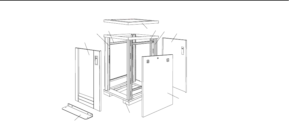
Type 9306 Model 200 47
Parts Listing (Type 9306 Model 200)
123
5
6
7
8
94
10
48 Hardware Maintenance Manual: IBM PC Server/Enterprise Racks
Index Rack Enclosure (Type 9306 Model 200) FRU
1 Top Cover including cover standoffs and screws 28L0548
2 Rear EIA Rail (1) includes mounting hardware 28L0547
3 Rack Frame 28L0550
Caster (1) 12J4466
Leveler (1) 76H4960
4 Rear Door Assembly including latch and lock 28L0545
5 Side Panel Assembly with Latches and Lock 28L0549
Side Panel Latches 12J4468
Side Panel Lock with Keys 76H4965
6 Caster Extension Plinth (1) 12J4482
7 Stabilizer 12J4485
8 Front Door Assembly including latch and lock 28L0544
9 Front EIA Rail (1) includes mounting hardware 28L0546
10 Side Brace (1) 12J4477
Front/Rear Door Hinge with Pin (1) 76H4966
Front/Rear Door Latch with Lock and Keys (1) 76H4967
Front/Rear Door Striker Plate (1) includes mounting hardware 12J4465
Front/Rear Door Hinge Pin (1) 12J4469
Grommet, Cable Exit 28L0553
Label, EIA Unit Numbers 28L0551
Miscellaneous Parts Kit - Includes: M6X25 Pan Head Screw (1), M6 Caged Nut (6), M6X16
Combination Head Screw (6), 10-32 Flat Washer (6), M6X12 Button Socket Head Cap Screw
(5), 12mm Open End Wrench (1), M6 Tinnerman Clip (2), M6 Threaded Hex Spacer (1), M6
Dome Nut (2), M6 Flange Nut (5), Soft Tie Wraps (10)
76H4950
Rack Enclosure (Type 9306 Model 200) Options FRU
Monitor Housing 76H4947
Filler Panels: 1U, 3U, and 5U - with hardware 12J4473
Keyboard Tray 76H4958
Keyboard Tray II 28L0562
Keyboard Tray II filler block 28L0567
Keyboard Slides (set) with Hardware 76H4961
Fixed Shelf with Hardware 76H4963
C13 - C14 Power Cable 07H0075
C19 - C14 Power Cable 76H4964
C13 - NEMA 5-15P Power Cable 76H4962
C19 - NEMA 5-15P Power Cable 12J4479
Video, Mouse, Keyboard Cable (7 feet) 06P6006
Type 9306 Model 200 49
Video, Mouse, Keyboard Cable (12 feet) 06P6007
Video, Mouse, Keyboard Power Cable (25 feet) 12J4484
Mouse Extension Cable 07H0069
Keyboard Extension Cable 07H0067
Concentrator (4 port) with Hardware 28L0543
Concentrator (8 port) with Hardware 76H4948
1x4 switch 06P6003
2x8 switch 06P6004
NetBAY Rack Power Distribution Unit 09N9668
NetBAY Front-end Power Distribution Unit 09N9670
3-phase NEMA L21-30P line cord (200-250 Vac) for NetBAY Front-end PDU 24P6844
3-phase IEC 309-3P+N+Gnd line cord (380-415 Vac) for NetBAY Front-end PDU 24P6845
1-phase NEMA L5-30P line cord (100-127 Vac) for NetBAY Front-end PDU 24P6846
1-phase NEMA L6-30P line cord (200-240 Vac) for NetBAY Front-end PDU 24P6847
1-phase IEC 309-2P+Gnd line cord (200-240 Vac) for NetBAY Front-end PDU 24P6848
NetBAY Server Dual-cord Power Distribution Unit 09N9669
Hardware Kit for NetBAY Power Distribution Units 09N9671
Flat Panel Monitor Rack Mount Kit (T54A, models AG1, AW1; T55) 37L6888
Flat Panel Adapter Hinge - R.H. & L.H. (T54A, T55) 09N9678
Flat Panel Adapter Misc. Hardware Kit – Includes: Hinge Cover (1), Power Supply Cover (1),
Mounting Stud (1), Bumper (2), Cable Access Cover (1), M4 X 12 Screw (4), M4 X 8 Screw
(2), 14 inch Soft Tie Wrap (1), T54A power supply spacer (1)
00N8693
Flat Panel Adapter Display Housing – Includes: Power Supply Cover (1), Base Housing (1),
Cable Access Cover (1), Bottom Stand 00N8694
Rack Enclosure (Type 9306 Model 200) Options FRU
50 Hardware Maintenance Manual: IBM PC Server/Enterprise Racks
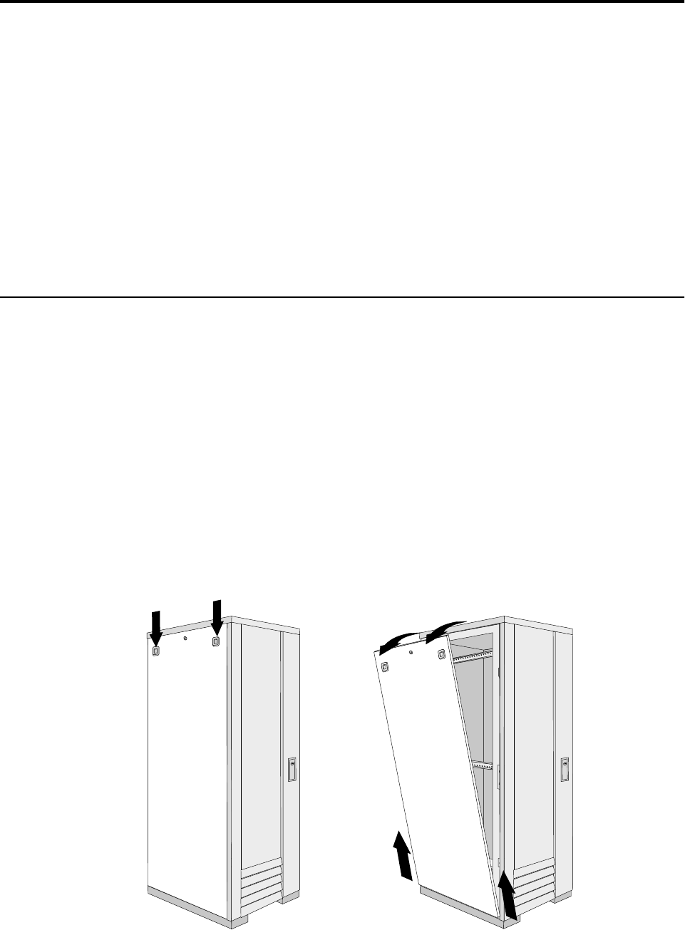
© Copyright IBM Corp. 2001 51
Type 9306 Model 900/910
Features. . . . . . . . . . . . . . . . . . . . . . . . . . . . . . . . . . . . 51
Locations. . . . . . . . . . . . . . . . . . . . . . . . . . . . . . . . . . . 51
Side Panel . . . . . . . . . . . . . . . . . . . . . . . . . . . . . . . . . . 51
Perforated Doors (model 910). . . . . . . . . . . . . . . . . 52
Installing the new door on a model 900 rack cabinet
53
Selector switch locations . . . . . . . . . . . . . . . . . . . . . 54
Power Distribution Unit. . . . . . . . . . . . . . . . . . . . . . 57
Blank bezel . . . . . . . . . . . . . . . . . . . . . . . . . . . . . . . . . 59
Fixed shelf . . . . . . . . . . . . . . . . . . . . . . . . . . . . . . . . . 59
Keyboard tray . . . . . . . . . . . . . . . . . . . . . . . . . . . . . . 60
Installing a flat panel monitor rack mount kit. . . 61
Removing the existing flat panel monitor stand . 61
Installing the new monitor stand. . . . . . . . . . . . . . 63
Starting the system. . . . . . . . . . . . . . . . . . . . . . . . . . 67
Configuring the selector switch . . . . . . . . . . . . . . . 67
Switching among servers . . . . . . . . . . . . . . . . . . . . 68
Advanced selector switch functions . . . . . . . . . . . 69
Resetting the selector switch. . . . . . . . . . . . . . . . . . 76
Making connections under power. . . . . . . . . . . . . 76
Parts listing (Type 9306 Model 900/910). . . . . . . . 77
Features
The IBM Server 9306-900/910 Rack enclosure is an industry-standard, 19-inch rack
that houses and controls multiple IBM PC Servers/IBM Servers and related
equipment.
•Model 900 has optional side panels, solid front door, and perforated rear door.
•Model 910 has side panels and perforated front and rear doors.
Locations
The following sections contain information on specific equipment locations.
Note: For instructions on how to power-off the rack, see “Powering off the rack” on
page 3.
Side Panel
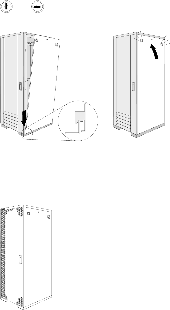
52 Hardware Maintenance Manual: IBM PC Server/Enterprise Racks
Perforated Doors (model 910)
The Type 9306 Model 910 Rack comes with front and rear perforated doors that
provide enhanced cooling and airflow for components you install in your rack
cabinet. The 9306 Model 910 Rack also comes with side panels already installed.
Locked Unlocked
®
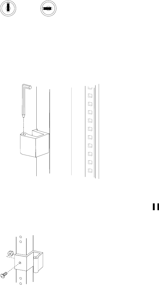
Type 9306 Model 900/910 53
Refer to installation instructions in this document if you have a 9306 Model 900 Rack
and are installing a new perforated front door.
Note: The illustrations in this documentation might be slightly different from your
hardware.
Installing the new door on a model 900 rack
cabinet
Use the following steps to remove your existing front door and install the new
perforated door:
1. Refer to the rack documentation for information on removing side panels; then,
remove the left side panel on the rack and set it aside.
2. If the front door is locked, unlock it; then, open the front door.
3. While supporting the door, remove all four hinge pins that hold the front door in
place; then, store the door in a safe place for possible future use.
Note: Save three of the hinge pins for later installation.
s
4. Remove the screw and nut that holds the hinge bracket 1 in place; then, move
the hinge bracket three mounting spaces downward and reinstall it at the new
center location.
Locked Unlocked
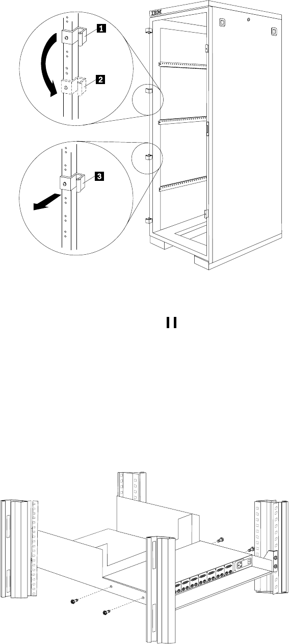
54 Hardware Maintenance Manual: IBM PC Server/Enterprise Racks
Note: Insert the screw through the bracket and into the lower of the two holes in
the new center location.
5. Remove the other hinge bracket 3 and store it with the old door that you
removed earlier.
6. While supporting the new door, use three of the hinge pins that you removed
from the old door to attach the new door to your rack cabinet. Store the fourth
hinge pin with the old door and hinge bracket.
7. Reinstall the left side panel that you removed earlier.
Selector switch locations
Note: For information about the IBM NetBAY Console Switch, see “IBM NetBAY
console switch” on page 129.
Figure 19. Selector switch in monitor compartment
®
One
KM
Three
KM
KM
Two
Aux.
Reset
Important
Information
1
0
Three
KM
KM
TwoThree
KM
Three
KM
KM
Two
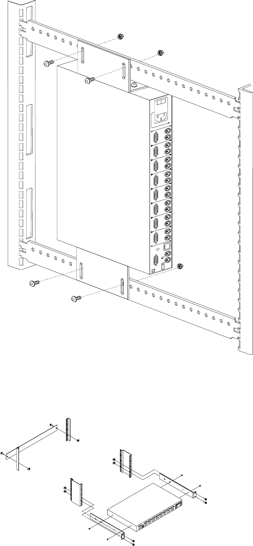
Type 9306 Model 900/910 55
Figure 20. Selector switch between side panels
Figure 21. Selector switch rear of rack with blank panel front of rack
FRONT
REAR
One
KM
Three
KM
KM
Two
Aux.
Reset
Important
Information
1
0
Three
KM
KM
Two Three
KM
Three
KM
KM
Two
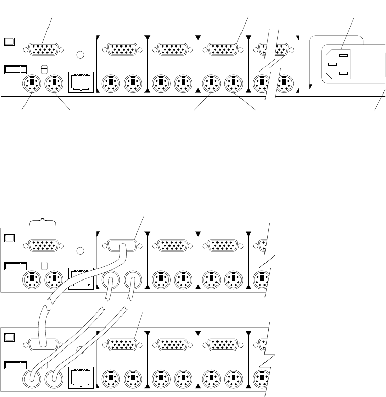
56 Hardware Maintenance Manual: IBM PC Server/Enterprise Racks
Selector switch cable connections:
Tiered switch configuration:
One eight-port primary selector switch can accommodate up to eight secondary
selector switches which can then support up to 64 servers.
Note: There are two types of selector switches available:
•4 port
•8 port
One
KM
Three
KM KMKM
Two
Aux.
Reset
Important
Information
Power C
o
Connect
o
Power
Switch
Computer 3
Mouse
Computer 3
Keyboard
Computer 3
Monitor
Mouse
Keyboard
Monitor
One
KM
Three
KM KKM
Two
Aux.
Reset
Monitor
Keyboard
Mouse
Connectors
One
KM
Three
KM KKM
Two
Aux.
Reset
System 1 to 8
System 1-1 to 1-8
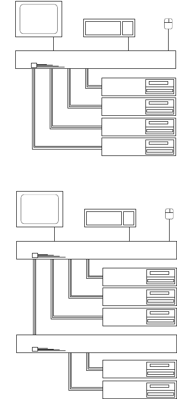
Type 9306 Model 900/910 57
Selector switch environment:
Figure 22. Single selector switch
Figure 23. Multiple selector switch
Power Distribution Unit
Note: For information and installation instructions for the IBM NetBAY Rack Power
Distribution Units, see “NetBAY Power Distribution Units” on page 141.
Monitor Keyboard Mouse
Selector Switch
Server 1
Server 2
Server 3
Server 4
Console
Cable
Set
Monitor Keyboard Mouse
Server 1
Server 2
Server 3
Server 4
Secondary Selector Switch
Console
Cable
Set
Primary Selector Switch
Server 5
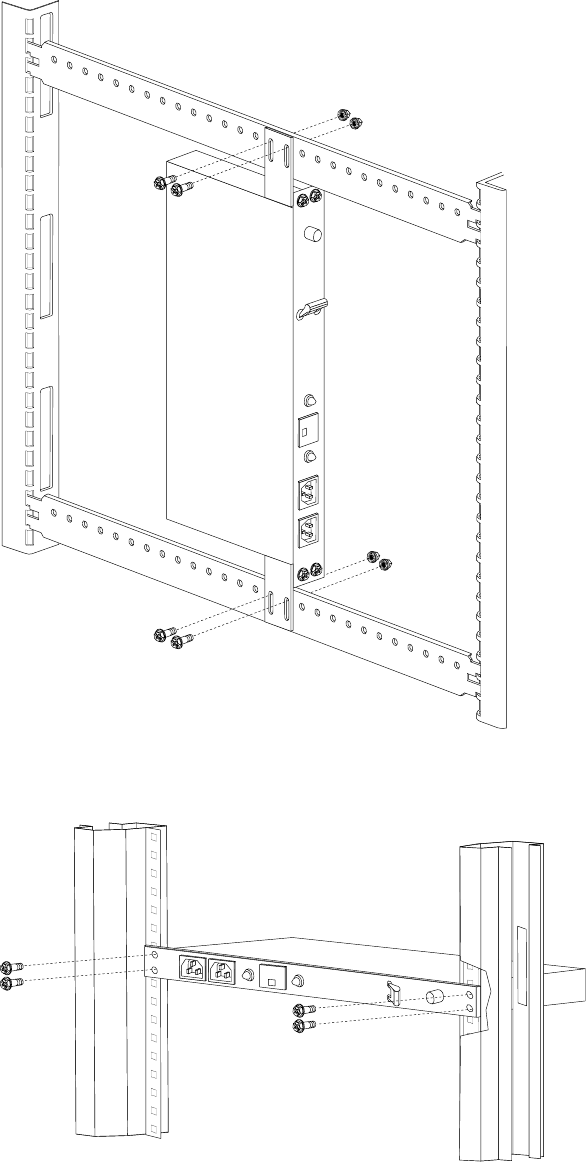
58 Hardware Maintenance Manual: IBM PC Server/Enterprise Racks
Figure 24. Power Distribution installation
Figure 25. Power Distribution horizontal installation
Note: There are two types of Power distribution units available:
•High voltage
•Low voltage
REAR
FRONT
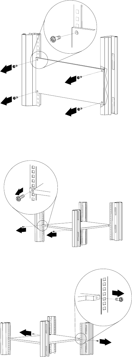
Type 9306 Model 900/910 59
Blank bezel
Fixed shelf
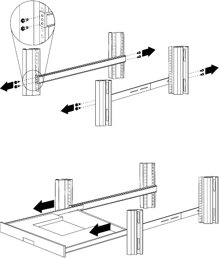
60 Hardware Maintenance Manual: IBM PC Server/Enterprise Racks
Keyboard tray
To remove the tray from the side rails, pull up on the left rail tab and push down on
the right rail tab.

Type 9306 Model 900/910 61
Installing a flat panel monitor rack mount kit
You can store a T54 or T55 Flat Panel Monitor in a keyboard tray with the flat panel
monitor rack mount kit. This kit requires an additional 2U of space above an installed
keyboard tray in your rack cabinet. See the documentation that comes with the flat
panel monitor rack mount kit for detailed installation instructions. Use the following
general procedure to install a flat panel monitor in your rack cabinet:
Figure 26. Installing a flat panel monitor rack mount kit
1. Ensure that a keyboard tray is properly installed in your rack cabinet (see
“Keyboard tray” on page 60) with at least 2U of clearance above the keyboard
tray.
2. Install the flat panel monitor base on the flat panel monitor. See the
documentation that comes with your flat panel monitor rack mount kit for
detailed installation instructions.
3. Install the mounting studs and bumpers on the keyboard tray.
4. Attach the monitor base to the inside of the keyboard tray using the screws that
come with the rack mount kit.
5. Fold the monitor all the way down against the bumpers; then, slide the keyboard
tray into the rack cabinet to ensure that there is proper clearance.
6. See the documentation that comes with your flat panel monitor for information
on how to connect power and how to connect the monitor to a server or console
switch.
Removing the existing flat panel monitor stand
Use the following steps to remove the existing flat panel monitor stand from your
monitor:
Keyboard tray
Rear screws
Flat panel monitor
Mounting studs
Bumpers

62 Hardware Maintenance Manual: IBM PC Server/Enterprise Racks
1. Unplug the flat panel monitor and disconnect the power cord from the flat panel
monitor power supply.
2. Carefully use a flat-blade screwdriver to pry the bottom of the cable cover 1 up
and remove it. Save the cable cover for later reinstallation.
Figure 27. Removing the cable cover, hinge cover, and stand cover
3. Squeeze the sides of the hinge cover 2 and remove it.
Note: Even though this hinge cover is not used with the Flat Panel Monitor Rack
Mount Kit, do not discard it. Store it with the other monitor stand parts
you remove for possible future use.
4. Gently push the stand cover 3 and slide it backwards until it is completely off
the stand.
5. Disconnect the signal cable and power cord from the flat panel monitor. Carefully
remove and save the plastic cable clamp to free the power cord.
Note: The plastic cable clamp is reusable and is needed to secure the power cord
after installing the Flat Panel Monitor Rack Mount Kit on the flat panel
monitor.
Figure 28. Removing the plastic cable clamp
6. Lay the monitor facedown on a cushioned surface and remove the six screws that
secure the hinges to the flat panel monitor.

Type 9306 Model 900/910 63
Figure 29. Removing the existing monitor stand from the monitor
7. Lift off the hinge and monitor stand assembly. Store this assembly in a safe place
for possible future use.
Installing the new monitor stand
Refer to “Removing the existing flat panel monitor stand” on page 61 for instructions
on how to remove the existing stand from the flat panel monitor. Before installing the
new stand, install the keyboard tray in the rack according to the instructions that
come with the rack or the keyboard tray option.
Note: The Flat Panel Monitor Rack Mount Kit and keyboard tray require 3U of rack
mounting space. If the keyboard tray does not have at least 2U of clearance
above it, relocate the keyboard tray within the rack.
Use the following steps to install the Flat Panel Monitor Rack Mount Kit:
1. Remove the cable cover 1 from the new monitor stand; then, remove the four
screws (two per hinge) that secure the hinges 2 to the stand.
Figure 30. Removing the hinges from the new monitor stand
2. Install the hinges on the flat panel monitor, using the six screws that you removed
from the old monitor stand.
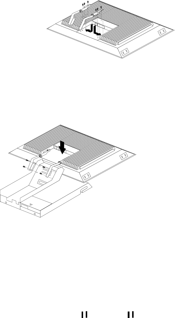
64 Hardware Maintenance Manual: IBM PC Server/Enterprise Racks
Figure 31. Installing the hinges on the flat panel monitor
Note: Be sure to slide each hinge into place on the back of the monitor and align
the holes in the hinges with holes on the monitor.
3. Lower the flat panel monitor onto the new monitor stand, making sure that you
align the holes in the stand with holes in the hinges; then, secure the flat panel
monitor to the monitor stand with the four screws that you removed earlier.
Figure 32. Installing the monitor on the new monitor stand
You have now finished attaching the flat panel monitor to its stand. The rest of
the installation process involves preparing the keyboard tray for storage and
routing cables.
Notes:
a. You must remove any keyboard or mouse that is already in the keyboard tray
before continuing.
b. You will not be able to store a mouse in the keyboard tray after installing the
Flat Panel Monitor Rack Mount Kit.
c. You can only store a space-saver keyboard in the keyboard tray.
4. Install the mounting studs 2 and bumpers 3 that come in the monitor
mounting hardware package.

Type 9306 Model 900/910 65
Figure 33. Installing the flat panel monitor in the keyboard tray
Note: Clean the installation area on the keyboard tray with a suitable cleaning
agent, such as alcohol, before installing the rubber bumpers on the front of
the keyboard tray.
5. Open the flat panel monitor 1 to its full upright position and align the grooves in
the stand with the mounting studs 2 in the keyboard tray. When the monitor
stand is sitting inside the keyboard tray, slide it towards the back until it stops.
Note: Install or remove the flat panel monitor only when the display is in its
upright position.
6. Secure the monitor stand in the back of the keyboard tray with the two provided
screws 4.
7. Place the flat panel monitor power supply, which came with your flat panel
monitor, inside the monitor stand. If necessary, insert the power supply spacer
3 behind the power supply and over the cable to keep the power supply in
place.

66 Hardware Maintenance Manual: IBM PC Server/Enterprise Racks
Figure 34. Storing the power supply and routing cables
8. Connect the power supply to the monitor and route the cable under the tab near
the top of the monitor stand 1; then, secure the power cable with the cable
clamp you removed from the original stand and coil excess cable inside the
monitor stand.
9. Connect the monitor signal cable to the monitor and route it under the tab in the
bottom of the monitor stand 2 and out the back of the stand through the hole
provided.
10. Replace the monitor stand cover 1.
Figure 35. Installing the cable cover, hinge cover, and stand cover
11. Snap the new hinge cover 2 into place over the hinge assembly.
Note: Be sure to use the new hinge cover that comes with the Flat Panel Monitor
Rack Mount Kit because it has deeper grooves to accommodate the new
hinge assembly.
12. Snap the cable cover 3 into place on the back of the flat panel monitor.
13. Fold the flat panel monitor down until it rests on the rubber bumpers; then, gently
push back and remove the small cable exit cover 1 on the monitor stand.
New hinge cover Old hinge cover

Type 9306 Model 900/910 67
Figure 36. Routing the keyboard cable
14. Route the space-saver keyboard cable through the hole in the front of the base and
out the opening in the back where you removed the small cover; then, place the
keyboard (with its adjustable feet fully down) inside the keyboard tray.
Note: You must open the flat panel monitor to its full upright position so that
you can install the keyboard and route its cable.
15. Fold the flat panel monitor down again until it rests on the rubber bumpers; then,
reinstall the small cable exit cover 1.
16. Slide the keyboard tray into the rack; then, neatly route and secure all cables in the
rack using the provided cable straps.
You can now connect the power cord to the flat panel monitor and connect the
display to a server.
Starting the system
Start the system by:
1. Power-on the selector switch(s).
2. Power-on the monitor.
3. Power-on the servers.
Note: The selector switch must be powered on first, then the servers. This is to
assure that the device drivers for the servers send device settings to the
selector switch.
When the selector switch is powered on, it:
•Identifies the mouse and keyboard and puts them into default status.
•Switches to port 1 by default, and displays the number '1' in the status flag field
on the monitor.
Configuring the selector switch
Note: For information about the IBM NetBAY Console Switch, see “IBM NetBAY
console switch” on page 129.
Note: Some selector switch units have different functions and displays. Refer to the
Apex PC Solutions® Outlook™ Concentrator User Guide. This guide is
shipped with the selector switch unit.
No configuration is necessary for normal switch operation.

68 Hardware Maintenance Manual: IBM PC Server/Enterprise Racks
Switch configuration can be performed to:
•Assign unique names to servers.
•Display servers by their assigned port names and port numbers.
Switching among servers
To switch among servers:
•Press the Print Screen key.
•Type the port number of the server to be switched.
•Press Enter.
Note: One depression of the Print Screen key starts the switching process. To
print a screen, depress the Print Screen key twice.
Port Name
1 Magic +
2 CentralOfc +
3 Sales-C +
4 Sales-B
5 Sales-A +
6 Downtown
7 Foreign +
8
F1 Help F2 Advanced
Port Name
1 Magic +
2 CentralOfc +
3 Sales-C +
4 Sales-B
5 Sales-A +
6 Downtown
7 Foreign +
8
F1 Help F2 Advanced
Port Name
1 Magic +
2 CentralOfc +
3 Sales-C +
4 Sales-B
5 Sales-A +
6 Downtown
7 Foreign +
8
F1 Help F2 Advanced
Port Name
1 Magic +
2 CentralOfc +
3 Sales-C +
4 Sales-B
5 Sales-A +
6 Downtown
7 Foreign +
8
F1 Help F2 Advanced
Port Name
1 Magic +
2 CentralOfc +
3 Sales-C +
4 Sales-B
5 Sales-A +
6 Downtown
7 Foreign +
8
F1 Help F2 Advanced
Port Name
1 Magic +
2 CentralOfc +
3 Sales-C +
4 Sales-B
5 Sales-A +
6 Downtown
7 Foreign +
8
F1 Help F2 Advanced
Port Name
1 Magic +
2 CentralOfc +
3 Sales-C +
4 Sales-B
5 Sales-A +
6 Downtown
7 Foreign +
8
F1 Help F2 Advanced
Port Name
1 Magic +
2 CentralOfc +
3 Sales-C +
4 Sales-B
5 Sales-A +
6 Downtown
7 Foreign +
8
F1 Help F2 Advanced
Port Name
1 Magic +
2 CentralOfc +
3 Sales-C +
4 Sales-B
5 Sales-A +
6 Downtown
7 Foreign +
8
F1 Help F2 Advanced
Port Name
1 Magic +
2 CentralOfc +
3 Sales-C +
4 Sales-B
5 Sales-A +
6 Downtown
7 Foreign +
8
F1 Help F2 Advanced
Port Name
1 Magic +
2 CentralOfc +
3 Sales-C +
4 Sales-B
5 Sales-A +
6 Downtown
7 Foreign +
8
F1 Help F2 Advanced
Port Name
1 Magic +
2 CentralOfc +
3 Sales-C +
4 Sales-B
5 Sales-A +
6 Downtown
7 Foreign +
8
F1 Help F2 Advanced
Port Name
1 Magic +
2 CentralOfc +
3 Sales-C +
4 Sales-B
5 Sales-A +
6 Downtown
7 Foreign +
8
F1 Help F2 Advanced
Port Name
1 Magic +
2 CentralOfc +
3 Sales-C +
4 Sales-B
5 Sales-A +
6 Downtown
7 Foreign +
8
F1 Help F2 Advanced
Port Name
1 Magic +
2 CentralOfc +
3 Sales-C +
4 Sales-B
5 Sales-A +
6 Downtown
7 Foreign +
8
F1 Help F2 Advanced
Port Name
1 Magic +
2 CentralOfc +
3 Sales-C +
4 Sales-B
5 Sales-A +
6 Downtown
7 Foreign +
8
F1 Help F2 Advanced
Port Name
1 Magic +
2 CentralOfc +
3 Sales-C +
4 Sales-B
5 Sales-A +
6 Downtown
7 Foreign +
8
F1 Help F2 Advanced
Port Name
1 Magic +
2 CentralOfc +
3 Sales-C +
4 Sales-B
5 Sales-A +
6 Downtown
7 Foreign +
8
F1 Help F2 Advanced
Port Name
1 Magic +
2 CentralOfc +
3 Sales-C +
4 Sales-B
5 Sales-A +
6 Downtown
7 Foreign +
8
F1 Help F2 Advanced
Port Name
1 Magic +
2 CentralOfc +
3 Sales-C +
4 Sales-B
5 Sales-A +
6 Downtown
7 Foreign +
8
F1 Help F2 Advanced
Port Name
1 Magic +
2 CentralOfc +
3 Sales-C +
4 Sales-B
5 Sales-A +
6 Downtown
7 Foreign +
8
F1 Help F2 Advanced
Port Name
1 Magic +
2 CentralOfc +
3 Sales-C +
4 Sales-B
5 Sales-A +
6 Downtown
7 Foreign +
8
F1 Help F2 Advanced
Port Name
1 Magic +
2 CentralOfc +
3 Sales-C +
4 Sales-B
5 Sales-A +
6 Downtown
7 Foreign +
8
F1 Help F2 Advanced
Port Name
1 Magic +
2 CentralOfc +
3 Sales-C +
4 Sales-B
5 Sales-A +
6 Downtown
7 Foreign +
8
F1 Help F2 Advanced
Port Name
1 Magic +
2 CentralOfc +
3 Sales-C +
4 Sales-B
5 Sales-A +
6 Downtown
7 Foreign +
8
F1 Help F2 Advanced
Port Name
1 Magic +
2 CentralOfc +
3 Sales-C +
4 Sales-B
5 Sales-A +
6 Downtown
7 Foreign +
8
F1 Help F2 Advanced
Port Name
1 Magic +
2 CentralOfc +
3 Sales-C +
4 Sales-B
5 Sales-A +
6 Downtown
7 Foreign +
8
F1 Help F2 Advanced
Port Name
1 Magic +
2 CentralOfc +
3 Sales-C +
4 Sales-B
5 Sales-A +
6 Downtown
7 Foreign +
8
F1 Help F2 Advanced
Port Name
1 Magic +
2 CentralOfc +
3 Sales-C +
4 Sales-B
5 Sales-A +
6 Downtown
7 Foreign +
8
F1 Help F2 Advanced
Port Name
1 Magic +
2 CentralOfc +
3 Sales-C +
4 Sales-B
5 Sales-A +
6 Downtown
7 Foreign +
8
F1 Help F2 Advanced
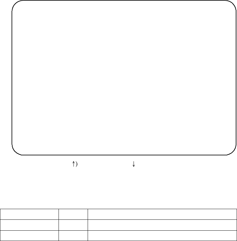
Type 9306 Model 900/910 69
•Using the Up Arrow ( and Down Arrow ( ), select the server you want to
switch to, or press the numeric key that corresponds to the server’s port number
and then press Enter.
The symbols after the Port or Name columns on the menu show the status of the port
as follows:
Advanced selector switch functions
System configuration is performed through the keyboard and menus to include these
advanced selector switch functions:
•Scanning the servers
•Displaying server BIOS versions and settings
•Saving the hardware configuration
•Resetting the mouse and keyboard
•Setting a scan pattern
•Assigning unique names to the servers
•Listing servers by name or port number (Changing Menu Attributes)
•Changing the position and color of the operation menus and windows (Changing
Flag Attributes)
•Assigning a specific monitor type to a certain port (server)
Scanning the servers: To place the selector switch in scan mode:
•Press the Print Screen key.
Type of Symbol Symbol Meaning
Plus + Server connected and running
Asterisk * Secondary selector switch connected and running
Port Name
CentralOfc 2 +
Downtown 6
Foreign 7 +
Magic 1 +
Sales-A 5 +
Sales-B 4
Sales-C 3 +
8
F1 Help F2 Advanced
Port Name
CentralOfc 2 +
Downtown 6
Foreign 7 +
Magic 1 +
Sales-A 5 +
Sales-B 4
Sales-C 3 +
8
F1 Help F2 Advanced
Port Name
CentralOfc 2 +
Downtown 6
Foreign 7 +
Magic 1 +
Sales-A 5 +
Sales-B 4
Sales-C 3 +
8
F1 Help F2 Advanced
Port Name
CentralOfc 2 +
Downtown 6
Foreign 7 +
Magic 1 +
Sales-A 5 +
Sales-B 4
Sales-C 3 +
8
F1 Help F2 Advanced
Port Name
CentralOfc 2 +
Downtown 6
Foreign 7 +
Magic 1 +
Sales-A 5 +
Sales-B 4
Sales-C 3 +
8
F1 Help F2 Advanced
Port Name
CentralOfc 2 +
Downtown 6
Foreign 7 +
Magic 1 +
Sales-A 5 +
Sales-B 4
Sales-C 3 +
8
F1 Help F2 Advanced
Port Name
CentralOfc 2 +
Downtown 6
Foreign 7 +
Magic 1 +
Sales-A 5 +
Sales-B 4
Sales-C 3 +
8
F1 Help F2 Advanced
Port Name
CentralOfc 2 +
Downtown 6
Foreign 7 +
Magic 1 +
Sales-A 5 +
Sales-B 4
Sales-C 3 +
8
F1 Help F2 Advanced
Port Name
CentralOfc 2 +
Downtown 6
Foreign 7 +
Magic 1 +
Sales-A 5 +
Sales-B 4
Sales-C 3 +
8
F1 Help F2 Advanced
Port Name
CentralOfc 2 +
Downtown 6
Foreign 7 +
Magic 1 +
Sales-A 5 +
Sales-B 4
Sales-C 3 +
8
F1 Help F2 Advanced
Port Name
CentralOfc 2 +
Downtown 6
Foreign 7 +
Magic 1 +
Sales-A 5 +
Sales-B 4
Sales-C 3 +
8
F1 Help F2 Advanced
Port Name
CentralOfc 2 +
Downtown 6
Foreign 7 +
Magic 1 +
Sales-A 5 +
Sales-B 4
Sales-C 3 +
8
F1 Help F2 Advanced
Port Name
CentralOfc 2 +
Downtown 6
Foreign 7 +
Magic 1 +
Sales-A 5 +
Sales-B 4
Sales-C 3 +
8
F1 Help F2 Advanced
Port Name
CentralOfc 2 +
Downtown 6
Foreign 7 +
Magic 1 +
Sales-A 5 +
Sales-B 4
Sales-C 3 +
8
F1 Help F2 Advanced
Port Name
CentralOfc 2 +
Downtown 6
Foreign 7 +
Magic 1 +
Sales-A 5 +
Sales-B 4
Sales-C 3 +
8
F1 Help F2 Advanced
Port Name
CentralOfc 2 +
Downtown 6
Foreign 7 +
Magic 1 +
Sales-A 5 +
Sales-B 4
Sales-C 3 +
8
F1 Help F2 Advanced
Port Name
CentralOfc 2 +
Downtown 6
Foreign 7 +
Magic 1 +
Sales-A 5 +
Sales-B 4
Sales-C 3 +
8
F1 Help F2 Advanced
Port Name
CentralOfc 2 +
Downtown 6
Foreign 7 +
Magic 1 +
Sales-A 5 +
Sales-B 4
Sales-C 3 +
8
F1 Help F2 Advanced
Port Name
CentralOfc 2 +
Downtown 6
Foreign 7 +
Magic 1 +
Sales-A 5 +
Sales-B 4
Sales-C 3 +
8
F1 Help F2 Advanced
Port Name
CentralOfc 2 +
Downtown 6
Foreign 7 +
Magic 1 +
Sales-A 5 +
Sales-B 4
Sales-C 3 +
8
F1 Help F2 Advanced
Port Name
CentralOfc 2 +
Downtown 6
Foreign 7 +
Magic 1 +
Sales-A 5 +
Sales-B 4
Sales-C 3 +
8
F1 Help F2 Advanced
Port Name
CentralOfc 2 +
Downtown 6
Foreign 7 +
Magic 1 +
Sales-A 5 +
Sales-B 4
Sales-C 3 +
8
F1 Help F2 Advanced
Port Name
CentralOfc 2 +
Downtown 6
Foreign 7 +
Magic 1 +
Sales-A 5 +
Sales-B 4
Sales-C 3 +
8
F1 Help F2 Advanced
Port Name
CentralOfc 2 +
Downtown 6
Foreign 7 +
Magic 1 +
Sales-A 5 +
Sales-B 4
Sales-C 3 +
8
F1 Help F2 Advanced
Port Name
CentralOfc 2 +
Downtown 6
Foreign 7 +
Magic 1 +
Sales-A 5 +
Sales-B 4
Sales-C 3 +
8
F1 Help F2 Advanced
Port Name
CentralOfc 2 +
Downtown 6
Foreign 7 +
Magic 1 +
Sales-A 5 +
Sales-B 4
Sales-C 3 +
8
F1 Help F2 Advanced
Port Name
CentralOfc 2 +
Downtown 6
Foreign 7 +
Magic 1 +
Sales-A 5 +
Sales-B 4
Sales-C 3 +
8
F1 Help F2 Advanced
Port Name
CentralOfc 2 +
Downtown 6
Foreign 7 +
Magic 1 +
Sales-A 5 +
Sales-B 4
Sales-C 3 +
8
F1 Help F2 Advanced
Port Name
CentralOfc 2 +
Downtown 6
Foreign 7 +
Magic 1 +
Sales-A 5 +
Sales-B 4
Sales-C 3 +
8
F1 Help F2 Advanced
Port Name
CentralOfc 2 +
Downtown 6
Foreign 7 +
Magic 1 +
Sales-A 5 +
Sales-B 4
Sales-C 3 +
8
F1 Help F2 Advanced
70 Hardware Maintenance Manual: IBM PC Server/Enterprise Racks
•Press the F2 key to display the Advanced Menu screen.
•Using the Up Arrow ( ) and Down Arrow ( ) keys, move the highlighting to
Scan and press Enter. The selector switch enters the scan mode and the display
returns to the status flag. To cancel the operation, press Esc any time before you
press Enter.
•To cancel the scan mode, press any key or move the mouse. The scan stops at the
currently connected server.
Displaying version information and device settings: The selector switch BIOS
version number along with keyboard and mouse information can be displayed for the
currently selected server.
•Press the Print Screen key.
•Press the F2 key to display the Advanced Menu screen.
•Using the Up Arrow ( ) and Down Arrow ( ) keys, move the highlighting to
Version and press Enter.
Keyboard information includes:
—Enabled or disabled
—Typematic rate
—LED settings
—Port mode
—Keyboard type.
Mouse information includes:
—Enabled or disabled
—Sample rate
—Resolution
—Mouse type
•Press Esc to remove the Version menu.
Version
BIOS X.XX
Hardware X X
Port 1 Magic 1
Keyboard Mouse
Enabled Enabled
Rate 2C Rate 100
LEDs 2 Res 2
Mode 2
Type 101 Type Gen
Version
BIOS X.XX
Hardware X X
Port 1 Magic 1
Keyboard Mouse
Enabled Enabled
Rate 2C Rate 100
LEDs 2 Res 2
Mode 2
Type 101 Type Gen
Version
BIOS X.XX
Hardware X X
Port 1 Magic 1
Keyboard Mouse
Enabled Enabled
Rate 2C Rate 100
LEDs 2 Res 2
Mode 2
Type 101 Type Gen
Version
BIOS X.XX
Hardware X X
Port 1 Magic 1
Keyboard Mouse
Enabled Enabled
Rate 2C Rate 100
LEDs 2 Res 2
Mode 2
Type 101 Type Gen
Version
BIOS X.XX
Hardware X X
Port 1 Magic 1
Keyboard Mouse
Enabled Enabled
Rate 2C Rate 100
LEDs 2 Res 2
Mode 2
Type 101 Type Gen
Version
BIOS X.XX
Hardware X X
Port 1 Magic 1
Keyboard Mouse
Enabled Enabled
Rate 2C Rate 100
LEDs 2 Res 2
Mode 2
Type 101 Type Gen
Version
BIOS X.XX
Hardware X X
Port 1 Magic 1
Keyboard Mouse
Enabled Enabled
Rate 2C Rate 100
LEDs 2 Res 2
Mode 2
Type 101 Type Gen
Version
BIOS X.XX
Hardware X X
Port 1 Magic 1
Keyboard Mouse
Enabled Enabled
Rate 2C Rate 100
LEDs 2 Res 2
Mode 2
Type 101 Type Gen
Version
BIOS X.XX
Hardware X X
Port 1 Magic 1
Keyboard Mouse
Enabled Enabled
Rate 2C Rate 100
LEDs 2 Res 2
Mode 2
Type 101 Type Gen
Version
BIOS X.XX
Hardware X X
Port 1 Magic 1
Keyboard Mouse
Enabled Enabled
Rate 2C Rate 100
LEDs 2 Res 2
Mode 2
Type 101 Type Gen
Version
BIOS X.XX
Hardware X X
Port 1 Magic 1
Keyboard Mouse
Enabled Enabled
Rate 2C Rate 100
LEDs 2 Res 2
Mode 2
Type 101 Type Gen
Version
BIOS X.XX
Hardware X X
Port 1 Magic 1
Keyboard Mouse
Enabled Enabled
Rate 2C Rate 100
LEDs 2 Res 2
Mode 2
Type 101 Type Gen
Version
BIOS X.XX
Hardware X X
Port 1 Magic 1
Keyboard Mouse
Enabled Enabled
Rate 2C Rate 100
LEDs 2 Res 2
Mode 2
Type 101 Type Gen
Version
BIOS X.XX
Hardware X X
Port 1 Magic 1
Keyboard Mouse
Enabled Enabled
Rate 2C Rate 100
LEDs 2 Res 2
Mode 2
Type 101 Type Gen
Version
BIOS X.XX
Hardware X X
Port 1 Magic 1
Keyboard Mouse
Enabled Enabled
Rate 2C Rate 100
LEDs 2 Res 2
Mode 2
Type 101 Type Gen
Version
BIOS X.XX
Hardware X X
Port 1 Magic 1
Keyboard Mouse
Enabled Enabled
Rate 2C Rate 100
LEDs 2 Res 2
Mode 2
Type 101 Type Gen
Version
BIOS X.XX
Hardware X X
Port 1 Magic 1
Keyboard Mouse
Enabled Enabled
Rate 2C Rate 100
LEDs 2 Res 2
Mode 2
Type 101 Type Gen
Version
BIOS X.XX
Hardware X X
Port 1 Magic 1
Keyboard Mouse
Enabled Enabled
Rate 2C Rate 100
LEDs 2 Res 2
Mode 2
Type 101 Type Gen
Version
BIOS X.XX
Hardware X X
Port 1 Magic 1
Keyboard Mouse
Enabled Enabled
Rate 2C Rate 100
LEDs 2 Res 2
Mode 2
Type 101 Type Gen
Version
BIOS X.XX
Hardware X X
Port 1 Magic 1
Keyboard Mouse
Enabled Enabled
Rate 2C Rate 100
LEDs 2 Res 2
Mode 2
Type 101 Type Gen
Version
BIOS X.XX
Hardware X X
Port 1 Magic 1
Keyboard Mouse
Enabled Enabled
Rate 2C Rate 100
LEDs 2 Res 2
Mode 2
Type 101 Type Gen
Version
BIOS X.XX
Hardware X X
Port 1 Magic 1
Keyboard Mouse
Enabled Enabled
Rate 2C Rate 100
LEDs 2 Res 2
Mode 2
Type 101 Type Gen
Version
BIOS X.XX
Hardware X X
Port 1 Magic 1
Keyboard Mouse
Enabled Enabled
Rate 2C Rate 100
LEDs 2 Res 2
Mode 2
Type 101 Type Gen
Version
BIOS X.XX
Hardware X X
Port 1 Magic 1
Keyboard Mouse
Enabled Enabled
Rate 2C Rate 100
LEDs 2 Res 2
Mode 2
Type 101 Type Gen
Version
BIOS X.XX
Hardware X X
Port 1 Magic 1
Keyboard Mouse
Enabled Enabled
Rate 2C Rate 100
LEDs 2 Res 2
Mode 2
Type 101 Type Gen
Version
BIOS X.XX
Hardware X X
Port 1 Magic 1
Keyboard Mouse
Enabled Enabled
Rate 2C Rate 100
LEDs 2 Res 2
Mode 2
Type 101 Type Gen
Version
BIOS X.XX
Hardware X X
Port 1 Magic 1
Keyboard Mouse
Enabled Enabled
Rate 2C Rate 100
LEDs 2 Res 2
Mode 2
Type 101 Type Gen
Version
BIOS X.XX
Hardware X X
Port 1 Magic 1
Keyboard Mouse
Enabled Enabled
Rate 2C Rate 100
LEDs 2 Res 2
Mode 2
Type 101 Type Gen
Version
BIOS X.XX
Hardware X X
Port 1 Magic 1
Keyboard Mouse
Enabled Enabled
Rate 2C Rate 100
LEDs 2 Res 2
Mode 2
Type 101 Type Gen
Version
BIOS X.XX
Hardware X X
Port 1 Magic 1
Keyboard Mouse
Enabled Enabled
Rate 2C Rate 100
LEDs 2 Res 2
Mode 2
Type 101 Type Gen

Type 9306 Model 900/910 71
Saving hardware configuration: Whenever servers are added to or removed from
the configuration, or whenever there is a change in the mouse or monitor, save the
hardware configuration setting by:
1. Press the Print Screen key.
2. Press the F2 key to display the Advanced Menu screen.
3. Using the Up Arrow ( ) and Down Arrow ( ) keys, move the highlighting to
Snapshot and press the Enter key. The hardware settings are saved to memory.
Important: If the settings are not saved and the selector switch power is lost, it might
be necessary to restart each server in the configuration to reestablish
keyboard and mouse communications.
Resetting the mouse and keyboard: Resetting the mouse and keyboard restores the
default setting for the selected server.
•Press the Print Screen key.
•Press the F2 key to display the Advanced Menu screen.
•Using the Up Arrow ( ) and Down Arrow ( ) keys, move the highlighting to
Reset and press the Enter key. The mouse and keyboard are now reset.
Setting a scan pattern: The selector switch has a standard scan routine for
sequentially connecting each server to the monitor, keyboard, and mouse. The scan
routine can be configured to scan all or any of the servers in a particular pattern. To
create a scan pattern, do the following.
1. Press the Print Screen key.
2. Press the F2 key to display the Advanced Menu screen. Press the Right Arrow
() key to move the highlight to the Setup Menu.
3. Using the Up Arrow ( ) and Down Arrow ( ) keys, move the highlighting to
Scan and press the Enter key. The Scan Pattern Setup menu appears with the
first port position or server name highlighted. The following example screen
displays when the port order mode is selected.
If Name order was selected, the Port and Name columns will be reversed.
4. Using the keyboard keys, select the port number of the first server to be included
in the scan. Note that the server name, if any is assigned, appears in the far right
column on the menu.
5. Press the Tab key or Right Arrow ( ) key to move the highlighting to the Sec
column. Then, use the keyboard keys to enter a time value, in seconds, for the
Scan Pattern Setup
Port/Sec Name
6/20 Downtown
5/20 Sales-A
4/10 Sales-B
1/10 Match
F2 for defaults
Scan Pattern Setup
Port/Sec Name
6/20 Downtown
5/20 Sales-A
4/10 Sales-B
1/10 Match
F2 for defaults
Scan Pattern Setup
Port/Sec Name
6/20 Downtown
5/20 Sales-A
4/10 Sales-B
1/10 Match
F2 for defaults
Scan Pattern Setup
Port/Sec Name
6/20 Downtown
5/20 Sales-A
4/10 Sales-B
1/10 Match
F2 for defaults
Scan Pattern Setup
Port/Sec Name
6/20 Downtown
5/20 Sales-A
4/10 Sales-B
1/10 Match
F2 for defaults
Scan Pattern Setup
Port/Sec Name
6/20 Downtown
5/20 Sales-A
4/10 Sales-B
1/10 Match
F2 for defaults
Scan Pattern Setup
Port/Sec Name
6/20 Downtown
5/20 Sales-A
4/10 Sales-B
1/10 Match
F2 for defaults
Scan Pattern Setup
Port/Sec Name
6/20 Downtown
5/20 Sales-A
4/10 Sales-B
1/10 Match
F2 for defaults
Scan Pattern Setup
Port/Sec Name
6/20 Downtown
5/20 Sales-A
4/10 Sales-B
1/10 Match
F2 for defaults
Scan Pattern Setup
Port/Sec Name
6/20 Downtown
5/20 Sales-A
4/10 Sales-B
1/10 Match
F2 for defaults
Scan Pattern Setup
Port/Sec Name
6/20 Downtown
5/20 Sales-A
4/10 Sales-B
1/10 Match
F2 for defaults
Scan Pattern Setup
Port/Sec Name
6/20 Downtown
5/20 Sales-A
4/10 Sales-B
1/10 Match
F2 for defaults
Scan Pattern Setup
Port/Sec Name
6/20 Downtown
5/20 Sales-A
4/10 Sales-B
1/10 Match
F2 for defaults
Scan Pattern Setup
Port/Sec Name
6/20 Downtown
5/20 Sales-A
4/10 Sales-B
1/10 Match
F2 for defaults
Scan Pattern Setup
Port/Sec Name
6/20 Downtown
5/20 Sales-A
4/10 Sales-B
1/10 Match
F2 for defaults
Scan Pattern Setup
Port/Sec Name
6/20 Downtown
5/20 Sales-A
4/10 Sales-B
1/10 Match
F2 for defaults
Scan Pattern Setup
Port/Sec Name
6/20 Downtown
5/20 Sales-A
4/10 Sales-B
1/10 Match
F2 for defaults
Scan Pattern Setup
Port/Sec Name
6/20 Downtown
5/20 Sales-A
4/10 Sales-B
1/10 Match
F2 for defaults
Scan Pattern Setup
Port/Sec Name
6/20 Downtown
5/20 Sales-A
4/10 Sales-B
1/10 Match
F2 for defaults
Scan Pattern Setup
Port/Sec Name
6/20 Downtown
5/20 Sales-A
4/10 Sales-B
1/10 Match
F2 for defaults
Scan Pattern Setup
Port/Sec Name
6/20 Downtown
5/20 Sales-A
4/10 Sales-B
1/10 Match
F2 for defaults
Scan Pattern Setup
Port/Sec Name
6/20 Downtown
5/20 Sales-A
4/10 Sales-B
1/10 Match
F2 for defaults
Scan Pattern Setup
Port/Sec Name
6/20 Downtown
5/20 Sales-A
4/10 Sales-B
1/10 Match
F2 for defaults
Scan Pattern Setup
Port/Sec Name
6/20 Downtown
5/20 Sales-A
4/10 Sales-B
1/10 Match
F2 for defaults
Scan Pattern Setup
Port/Sec Name
6/20 Downtown
5/20 Sales-A
4/10 Sales-B
1/10 Match
F2 for defaults
Scan Pattern Setup
Port/Sec Name
6/20 Downtown
5/20 Sales-A
4/10 Sales-B
1/10 Match
F2 for defaults
Scan Pattern Setup
Port/Sec Name
6/20 Downtown
5/20 Sales-A
4/10 Sales-B
1/10 Match
F2 for defaults
Scan Pattern Setup
Port/Sec Name
6/20 Downtown
5/20 Sales-A
4/10 Sales-B
1/10 Match
F2 for defaults
Scan Pattern Setup
Port/Sec Name
6/20 Downtown
5/20 Sales-A
4/10 Sales-B
1/10 Match
F2 for defaults
Scan Pattern Setup
Port/Sec Name
6/20 Downtown
5/20 Sales-A
4/10 Sales-B
1/10 Match
F2 for defaults

72 Hardware Maintenance Manual: IBM PC Server/Enterprise Racks
length of time you want this server to be connected to the monitor and keyboard,
before switching to the next server in the scan.
6. Press the Down Arrow ( ) key to move the highlighting to the next port in the
Port column and repeat step 5.
To delete unwanted ports from the scan list in the Scan Pattern Setup window,
place the highlighting on the top-most port to be removed and press the Delete
key (not the Del key on the numeric keypad).
7. When you have finished setting the scan pattern, press the Enter key. Press Esc at
any time before pressing Enter to retain the previous scan pattern.
Note: Pressing the F2 key will return all Port and Sec values to the factory
defaults.
8. To exit, press Esc.
Assigning unique names to servers: Unique names can be given to servers and
secondary selector switches. To assign names:
1. Press the Print Screen key.
2. Press the F2 key to display the Advanced Menu screen.
Press the Right Arrow ( ) key to move the highlight to the Setup Menu.
3. Using the Up Arrow ( ) and Down Arrow ( ) keys, move the highlighting to
Names and press the Enter key. The Port Naming menu appears, as shown
below.
4. Move the highlighting to the Port entry for which the server name is to be entered
or changed. Type in the name of the server using up to 12 alphanumeric
characters.
Note: Legal characters are A-Z, 0-9, and the dash character. Lowercase letters
are converted to uppercase. Press the Backspace key to delete an incorrect
entry.
5. If necessary, repeat step 4 for each of the servers that are to be named.
6. Press the Enter key to save the server names in nonvolatile RAM. Press Esc at any
time before pressing Enter to cancel the operation.
7. To exit, press Esc.
Port Naming
Port Name
1 MAGIC
2 CENTRALOFC
3 SALES-C
4 SALES-B
5 SALES-A
6 DOWNTOWN
7 FOREIGN
8
Port Naming
Port Name
1 MAGIC
2 CENTRALOFC
3 SALES-C
4 SALES-B
5 SALES-A
6 DOWNTOWN
7 FOREIGN
8
Port Naming
Port Name
1 MAGIC
2 CENTRALOFC
3 SALES-C
4 SALES-B
5 SALES-A
6 DOWNTOWN
7 FOREIGN
8
Port Naming
Port Name
1 MAGIC
2 CENTRALOFC
3 SALES-C
4 SALES-B
5 SALES-A
6 DOWNTOWN
7 FOREIGN
8
Port Naming
Port Name
1 MAGIC
2 CENTRALOFC
3 SALES-C
4 SALES-B
5 SALES-A
6 DOWNTOWN
7 FOREIGN
8
Port Naming
Port Name
1 MAGIC
2 CENTRALOFC
3 SALES-C
4 SALES-B
5 SALES-A
6 DOWNTOWN
7 FOREIGN
8
Port Naming
Port Name
1 MAGIC
2 CENTRALOFC
3 SALES-C
4 SALES-B
5 SALES-A
6 DOWNTOWN
7 FOREIGN
8
Port Naming
Port Name
1 MAGIC
2 CENTRALOFC
3 SALES-C
4 SALES-B
5 SALES-A
6 DOWNTOWN
7 FOREIGN
8
Port Naming
Port Name
1 MAGIC
2 CENTRALOFC
3 SALES-C
4 SALES-B
5 SALES-A
6 DOWNTOWN
7 FOREIGN
8
Port Naming
Port Name
1 MAGIC
2 CENTRALOFC
3 SALES-C
4 SALES-B
5 SALES-A
6 DOWNTOWN
7 FOREIGN
8
Port Naming
Port Name
1 MAGIC
2 CENTRALOFC
3 SALES-C
4 SALES-B
5 SALES-A
6 DOWNTOWN
7 FOREIGN
8
Port Naming
Port Name
1 MAGIC
2 CENTRALOFC
3 SALES-C
4 SALES-B
5 SALES-A
6 DOWNTOWN
7 FOREIGN
8
Port Naming
Port Name
1 MAGIC
2 CENTRALOFC
3 SALES-C
4 SALES-B
5 SALES-A
6 DOWNTOWN
7 FOREIGN
8
Port Naming
Port Name
1 MAGIC
2 CENTRALOFC
3 SALES-C
4 SALES-B
5 SALES-A
6 DOWNTOWN
7 FOREIGN
8
Port Naming
Port Name
1 MAGIC
2 CENTRALOFC
3 SALES-C
4 SALES-B
5 SALES-A
6 DOWNTOWN
7 FOREIGN
8
Port Naming
Port Name
1 MAGIC
2 CENTRALOFC
3 SALES-C
4 SALES-B
5 SALES-A
6 DOWNTOWN
7 FOREIGN
8
Port Naming
Port Name
1 MAGIC
2 CENTRALOFC
3 SALES-C
4 SALES-B
5 SALES-A
6 DOWNTOWN
7 FOREIGN
8
Port Naming
Port Name
1 MAGIC
2 CENTRALOFC
3 SALES-C
4 SALES-B
5 SALES-A
6 DOWNTOWN
7 FOREIGN
8
Port Naming
Port Name
1 MAGIC
2 CENTRALOFC
3 SALES-C
4 SALES-B
5 SALES-A
6 DOWNTOWN
7 FOREIGN
8
Port Naming
Port Name
1 MAGIC
2 CENTRALOFC
3 SALES-C
4 SALES-B
5 SALES-A
6 DOWNTOWN
7 FOREIGN
8
Port Naming
Port Name
1 MAGIC
2 CENTRALOFC
3 SALES-C
4 SALES-B
5 SALES-A
6 DOWNTOWN
7 FOREIGN
8
Port Naming
Port Name
1 MAGIC
2 CENTRALOFC
3 SALES-C
4 SALES-B
5 SALES-A
6 DOWNTOWN
7 FOREIGN
8
Port Naming
Port Name
1 MAGIC
2 CENTRALOFC
3 SALES-C
4 SALES-B
5 SALES-A
6 DOWNTOWN
7 FOREIGN
8
Port Naming
Port Name
1 MAGIC
2 CENTRALOFC
3 SALES-C
4 SALES-B
5 SALES-A
6 DOWNTOWN
7 FOREIGN
8
Port Naming
Port Name
1 MAGIC
2 CENTRALOFC
3 SALES-C
4 SALES-B
5 SALES-A
6 DOWNTOWN
7 FOREIGN
8
Port Naming
Port Name
1 MAGIC
2 CENTRALOFC
3 SALES-C
4 SALES-B
5 SALES-A
6 DOWNTOWN
7 FOREIGN
8
Port Naming
Port Name
1 MAGIC
2 CENTRALOFC
3 SALES-C
4 SALES-B
5 SALES-A
6 DOWNTOWN
7 FOREIGN
8
Port Naming
Port Name
1 MAGIC
2 CENTRALOFC
3 SALES-C
4 SALES-B
5 SALES-A
6 DOWNTOWN
7 FOREIGN
8
Port Naming
Port Name
1 MAGIC
2 CENTRALOFC
3 SALES-C
4 SALES-B
5 SALES-A
6 DOWNTOWN
7 FOREIGN
8
Port Naming
Port Name
1 MAGIC
2 CENTRALOFC
3 SALES-C
4 SALES-B
5 SALES-A
6 DOWNTOWN
7 FOREIGN
8

Type 9306 Model 900/910 73
Changing menu attributes: The menus displayed on the monitor can be altered in
visual appearance to suit the particular use of the system. You can:
•Position the menu in a convenient location on the display.
•List servers by port or by name, whichever is desired, in the appropriate menus.
• Adjust character height.
• Change colors.
•Display the selection menu for a certain period.
To change the menu attributes, do the following:
•Press the Print Screen key.
•Press the F2 key to display the Advanced Menu screen. Press the Right Arrow
() key to move the highlighting to the Setup list.
•Using the Up Arrow ( ) and Down Arrow ( ) keys, move the highlighting to
OSCAR™. (On Screen Configuration and Activity Reporting) and press the
Enter key. The following Attribute menu appears.
•Highlight the settings you want to change and use the + or - keys to change the
values. As you select different values, the effect of the changes is reflected
immediately on the display.
•When all changes are completed, press the Enter key to save the changes to
nonvolatile RAM. Press Esc at any time before pressing Enter to cancel the
operation and retain the previous settings.
Note: It is possible, while changing the attributes, to garble the menu and
windows, making it difficult to correct. If this occurs, reset the selector
switch to its default values by pressing the following keys in this order:
1. Esc
2. Esc
3. Print Screen
OSCAR Attributes
Resolution 640
Height 16
Horizontal 12
Vertical 7
Background 1
Highlight 4
Text 7
Delay Time 0
Order Port
OSCAR Attributes
Resolution 640
Height 16
Horizontal 12
Vertical 7
Background 1
Highlight 4
Text 7
Delay Time 0
Order Port
OSCAR Attributes
Resolution 640
Height 16
Horizontal 12
Vertical 7
Background 1
Highlight 4
Text 7
Delay Time 0
Order Port
OSCAR Attributes
Resolution 640
Height 16
Horizontal 12
Vertical 7
Background 1
Highlight 4
Text 7
Delay Time 0
Order Port
OSCAR Attributes
Resolution 640
Height 16
Horizontal 12
Vertical 7
Background 1
Highlight 4
Text 7
Delay Time 0
Order Port
OSCAR Attributes
Resolution 640
Height 16
Horizontal 12
Vertical 7
Background 1
Highlight 4
Text 7
Delay Time 0
Order Port
OSCAR Attributes
Resolution 640
Height 16
Horizontal 12
Vertical 7
Background 1
Highlight 4
Text 7
Delay Time 0
Order Port
OSCAR Attributes
Resolution 640
Height 16
Horizontal 12
Vertical 7
Background 1
Highlight 4
Text 7
Delay Time 0
Order Port
OSCAR Attributes
Resolution 640
Height 16
Horizontal 12
Vertical 7
Background 1
Highlight 4
Text 7
Delay Time 0
Order Port
OSCAR Attributes
Resolution 640
Height 16
Horizontal 12
Vertical 7
Background 1
Highlight 4
Text 7
Delay Time 0
Order Port
OSCAR Attributes
Resolution 640
Height 16
Horizontal 12
Vertical 7
Background 1
Highlight 4
Text 7
Delay Time 0
Order Port
OSCAR Attributes
Resolution 640
Height 16
Horizontal 12
Vertical 7
Background 1
Highlight 4
Text 7
Delay Time 0
Order Port
OSCAR Attributes
Resolution 640
Height 16
Horizontal 12
Vertical 7
Background 1
Highlight 4
Text 7
Delay Time 0
Order Port
OSCAR Attributes
Resolution 640
Height 16
Horizontal 12
Vertical 7
Background 1
Highlight 4
Text 7
Delay Time 0
Order Port
OSCAR Attributes
Resolution 640
Height 16
Horizontal 12
Vertical 7
Background 1
Highlight 4
Text 7
Delay Time 0
Order Port
OSCAR Attributes
Resolution 640
Height 16
Horizontal 12
Vertical 7
Background 1
Highlight 4
Text 7
Delay Time 0
Order Port
OSCAR Attributes
Resolution 640
Height 16
Horizontal 12
Vertical 7
Background 1
Highlight 4
Text 7
Delay Time 0
Order Port
OSCAR Attributes
Resolution 640
Height 16
Horizontal 12
Vertical 7
Background 1
Highlight 4
Text 7
Delay Time 0
Order Port
OSCAR Attributes
Resolution 640
Height 16
Horizontal 12
Vertical 7
Background 1
Highlight 4
Text 7
Delay Time 0
Order Port
OSCAR Attributes
Resolution 640
Height 16
Horizontal 12
Vertical 7
Background 1
Highlight 4
Text 7
Delay Time 0
Order Port
OSCAR Attributes
Resolution 640
Height 16
Horizontal 12
Vertical 7
Background 1
Highlight 4
Text 7
Delay Time 0
Order Port
OSCAR Attributes
Resolution 640
Height 16
Horizontal 12
Vertical 7
Background 1
Highlight 4
Text 7
Delay Time 0
Order Port
OSCAR Attributes
Resolution 640
Height 16
Horizontal 12
Vertical 7
Background 1
Highlight 4
Text 7
Delay Time 0
Order Port
OSCAR Attributes
Resolution 640
Height 16
Horizontal 12
Vertical 7
Background 1
Highlight 4
Text 7
Delay Time 0
Order Port
OSCAR Attributes
Resolution 640
Height 16
Horizontal 12
Vertical 7
Background 1
Highlight 4
Text 7
Delay Time 0
Order Port
OSCAR Attributes
Resolution 640
Height 16
Horizontal 12
Vertical 7
Background 1
Highlight 4
Text 7
Delay Time 0
Order Port
OSCAR Attributes
Resolution 640
Height 16
Horizontal 12
Vertical 7
Background 1
Highlight 4
Text 7
Delay Time 0
Order Port
OSCAR Attributes
Resolution 640
Height 16
Horizontal 12
Vertical 7
Background 1
Highlight 4
Text 7
Delay Time 0
Order Port
OSCAR Attributes
Resolution 640
Height 16
Horizontal 12
Vertical 7
Background 1
Highlight 4
Text 7
Delay Time 0
Order Port
OSCAR Attributes
Resolution 640
Height 16
Horizontal 12
Vertical 7
Background 1
Highlight 4
Text 7
Delay Time 0
Order Port

74 Hardware Maintenance Manual: IBM PC Server/Enterprise Racks
4. F10
5. Y
6. Enter
Available menu attributes:
Changing the status flag attributes: The status flag shows the currently connected
server and can be set to appear on the screen whenever the system is operating. You
can alter how and where the flag appears on the screen by changing one or more of
the following attributes:
•Appearance on the screen: none, timed, or constant
•Position on the screen
•Color and opaqueness
To change the flag attributes, do the following:
1. Press the Print Screen key.
2. Press theF2 key to display the Advanced Menu screen. Press the Right Arrow ( )
key to move the highlighting to the Setup menu.
3. Using the Up Arrow ( ) and Down Arrow ( ) keys, move the highlight to Flag
and press the Enter key.
Setting Effect on Menu or Window Appearance
Resolution Affects the size of the menu and windows as they appear on the
display. Choose from values of 320, 480, and 640. The lower the value,
the larger the size.
Height Affects the size of the text in the menu and windows. The larger the
value, the larger the text.
Horizontal/Vertical Determines the position of the menu or window on the screen.
Background Determines the menu or window background color.
Highlight Determines the menu or window highlight bar color.
Text Determines the menu or window text color.
Delay Time Sets the time in seconds that the OSCAR selection window is delayed
before appearing after the Print Screen key is pressed. This delay may
be increased so that the menu is not a distraction when performing
simple server switching operations at the keyboard.
Order Determines the order which the servers are listed, numerically by port
or alphabetically by assigned name.

Type 9306 Model 900/910 75
4. Highlight the setting to be changed and use the + and - keys to adjust the values.
The following table describes each of the available menu attributes:
5. Press the Enter key to save the settings. Press Esc at anytime before pressing
Enter to cancel the operation and save the previous settings.
6. Press Esc to exit.
Assigning specific device types: In situations where one or more servers need a
special type of monitor device, it might be necessary to assign that device type to the
port number associated with the server.
Note: When tiering, you must make the primary selector switch aware of the
secondaries through the assignment.
Assign a device type as follows:
1. Press the Print Screen key.
2. Press the F2 key to display the Advanced Menu screen. Press the Right Arrow
() key to move the highlighting to the Setup menu.
3. Using the Up Arrow ( ) and Down Arrow ( ) keys, move the highlighting to
Devices and press the Enter key. The following menu appears:
Setting Values and Effect on Flag Appearance
Enabled Flags Off = Flag does not appear
Ports On = Flag shows the connected port number
Names On = Flag shows the connected server by name
Ports Timed = Port number displays for five seconds after connection
Names Timed = Name displays for five seconds after connection
Row Select values from 0–14 to position the flag vertically on the screen
Column Select values from 0–25 to position the flag horizontally on the screen
Color Select values from 0–7 for the flag color.
Text Select values from 0–7 for the flag text color
Mode Choose between Opaque and Transparent
Flag Attributes
Enabled Names on
Row 14
Column 1
Color 2
Text 0
Mode Transparent
Flag Attributes
Enabled Names on
Row 14
Column 1
Color 2
Text 0
Mode Transparent
Flag Attributes
Enabled Names on
Row 14
Column 1
Color 2
Text 0
Mode Transparent
Flag Attributes
Enabled Names on
Row 14
Column 1
Color 2
Text 0
Mode Transparent
Flag Attributes
Enabled Names on
Row 14
Column 1
Color 2
Text 0
Mode Transparent
Flag Attributes
Enabled Names on
Row 14
Column 1
Color 2
Text 0
Mode Transparent
Flag Attributes
Enabled Names on
Row 14
Column 1
Color 2
Text 0
Mode Transparent
Flag Attributes
Enabled Names on
Row 14
Column 1
Color 2
Text 0
Mode Transparent
Flag Attributes
Enabled Names on
Row 14
Column 1
Color 2
Text 0
Mode Transparent
Flag Attributes
Enabled Names on
Row 14
Column 1
Color 2
Text 0
Mode Transparent
Flag Attributes
Enabled Names on
Row 14
Column 1
Color 2
Text 0
Mode Transparent
Flag Attributes
Enabled Names on
Row 14
Column 1
Color 2
Text 0
Mode Transparent
Flag Attributes
Enabled Names on
Row 14
Column 1
Color 2
Text 0
Mode Transparent
Flag Attributes
Enabled Names on
Row 14
Column 1
Color 2
Text 0
Mode Transparent
Flag Attributes
Enabled Names on
Row 14
Column 1
Color 2
Text 0
Mode Transparent
Flag Attributes
Enabled Names on
Row 14
Column 1
Color 2
Text 0
Mode Transparent
Flag Attributes
Enabled Names on
Row 14
Column 1
Color 2
Text 0
Mode Transparent
Flag Attributes
Enabled Names on
Row 14
Column 1
Color 2
Text 0
Mode Transparent
Flag Attributes
Enabled Names on
Row 14
Column 1
Color 2
Text 0
Mode Transparent
Flag Attributes
Enabled Names on
Row 14
Column 1
Color 2
Text 0
Mode Transparent
Flag Attributes
Enabled Names on
Row 14
Column 1
Color 2
Text 0
Mode Transparent
Flag Attributes
Enabled Names on
Row 14
Column 1
Color 2
Text 0
Mode Transparent
Flag Attributes
Enabled Names on
Row 14
Column 1
Color 2
Text 0
Mode Transparent
Flag Attributes
Enabled Names on
Row 14
Column 1
Color 2
Text 0
Mode Transparent
Flag Attributes
Enabled Names on
Row 14
Column 1
Color 2
Text 0
Mode Transparent
Flag Attributes
Enabled Names on
Row 14
Column 1
Color 2
Text 0
Mode Transparent
Flag Attributes
Enabled Names on
Row 14
Column 1
Color 2
Text 0
Mode Transparent
Flag Attributes
Enabled Names on
Row 14
Column 1
Color 2
Text 0
Mode Transparent
Flag Attributes
Enabled Names on
Row 14
Column 1
Color 2
Text 0
Mode Transparent
Flag Attributes
Enabled Names on
Row 14
Column 1
Color 2
Text 0
Mode Transparent

76 Hardware Maintenance Manual: IBM PC Server/Enterprise Racks
4. To assign a monitor type, highlight the port you want and use the + or - keys to
select the value that corresponds to the particular monitor.
To assign a secondary selector switch to a port, highlight the port and use the + or
- keys to obtain the appropriate 8port value.
5. Press the Enter key to save the settings. Press Esc at any time before pressing
Enter to cancel the operation.
6. Press Esc to remove the Advanced Menu from the screen.
Resetting the selector switch
The selector switch can be reset by depressing the Reset button on the back panel of
the selector switch.
Note: Pressing the reset button might recover the device settings without having to
power-off, then power-on all the servers.
Making connections under power
Additional servers, can be connected to the selector switch while the selector switch is
running.
Failed devices such as a keyboard or mouse can be connected to a running selector
switch.
Note: When new devices are connected, the selector switch recognizes it and
configures it to the settings of the currently selected server.
Device Settings
Port Monitor
1 SVGA
2 SVGA
3 8515
4 SVGA
5 Default
6 Default
7 Default
8 8port
Device Settings
Port Monitor
1 SVGA
2 SVGA
3 8515
4 SVGA
5 Default
6 Default
7 Default
8 8port
Device Settings
Port Monitor
1 SVGA
2 SVGA
3 8515
4 SVGA
5 Default
6 Default
7 Default
8 8port
Device Settings
Port Monitor
1 SVGA
2 SVGA
3 8515
4 SVGA
5 Default
6 Default
7 Default
8 8port
Device Settings
Port Monitor
1 SVGA
2 SVGA
3 8515
4 SVGA
5 Default
6 Default
7 Default
8 8port
Device Settings
Port Monitor
1 SVGA
2 SVGA
3 8515
4 SVGA
5 Default
6 Default
7 Default
8 8port
Device Settings
Port Monitor
1 SVGA
2 SVGA
3 8515
4 SVGA
5 Default
6 Default
7 Default
8 8port
Device Settings
Port Monitor
1 SVGA
2 SVGA
3 8515
4 SVGA
5 Default
6 Default
7 Default
8 8port
Device Settings
Port Monitor
1 SVGA
2 SVGA
3 8515
4 SVGA
5 Default
6 Default
7 Default
8 8port
Device Settings
Port Monitor
1 SVGA
2 SVGA
3 8515
4 SVGA
5 Default
6 Default
7 Default
8 8port
Device Settings
Port Monitor
1 SVGA
2 SVGA
3 8515
4 SVGA
5 Default
6 Default
7 Default
8 8port
Device Settings
Port Monitor
1 SVGA
2 SVGA
3 8515
4 SVGA
5 Default
6 Default
7 Default
8 8port
Device Settings
Port Monitor
1 SVGA
2 SVGA
3 8515
4 SVGA
5 Default
6 Default
7 Default
8 8port
Device Settings
Port Monitor
1 SVGA
2 SVGA
3 8515
4 SVGA
5 Default
6 Default
7 Default
8 8port
Device Settings
Port Monitor
1 SVGA
2 SVGA
3 8515
4 SVGA
5 Default
6 Default
7 Default
8 8port
Device Settings
Port Monitor
1 SVGA
2 SVGA
3 8515
4 SVGA
5 Default
6 Default
7 Default
8 8port
Device Settings
Port Monitor
1 SVGA
2 SVGA
3 8515
4 SVGA
5 Default
6 Default
7 Default
8 8port
Device Settings
Port Monitor
1 SVGA
2 SVGA
3 8515
4 SVGA
5 Default
6 Default
7 Default
8 8port
Device Settings
Port Monitor
1 SVGA
2 SVGA
3 8515
4 SVGA
5 Default
6 Default
7 Default
8 8port
Device Settings
Port Monitor
1 SVGA
2 SVGA
3 8515
4 SVGA
5 Default
6 Default
7 Default
8 8port
Device Settings
Port Monitor
1 SVGA
2 SVGA
3 8515
4 SVGA
5 Default
6 Default
7 Default
8 8port
Device Settings
Port Monitor
1 SVGA
2 SVGA
3 8515
4 SVGA
5 Default
6 Default
7 Default
8 8port
Device Settings
Port Monitor
1 SVGA
2 SVGA
3 8515
4 SVGA
5 Default
6 Default
7 Default
8 8port
Device Settings
Port Monitor
1 SVGA
2 SVGA
3 8515
4 SVGA
5 Default
6 Default
7 Default
8 8port
Device Settings
Port Monitor
1 SVGA
2 SVGA
3 8515
4 SVGA
5 Default
6 Default
7 Default
8 8port
Device Settings
Port Monitor
1 SVGA
2 SVGA
3 8515
4 SVGA
5 Default
6 Default
7 Default
8 8port
Device Settings
Port Monitor
1 SVGA
2 SVGA
3 8515
4 SVGA
5 Default
6 Default
7 Default
8 8port
Device Settings
Port Monitor
1 SVGA
2 SVGA
3 8515
4 SVGA
5 Default
6 Default
7 Default
8 8port
Device Settings
Port Monitor
1 SVGA
2 SVGA
3 8515
4 SVGA
5 Default
6 Default
7 Default
8 8port
Device Settings
Port Monitor
1 SVGA
2 SVGA
3 8515
4 SVGA
5 Default
6 Default
7 Default
8 8port
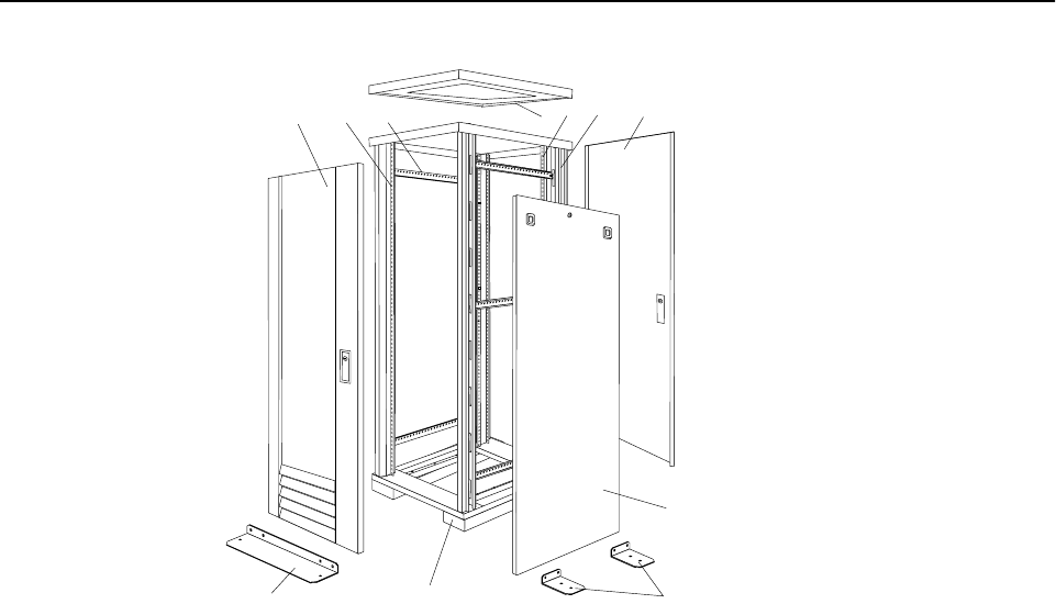
Type 9306 Model 900/910 77
Parts listing (Type 9306 Model 900/910)
1
10 11 2 34
5
6
7
8
9
78 Hardware Maintenance Manual: IBM PC Server/Enterprise Racks
Index Rack Enclosure (Type 9306 Model 900/910) FRU
1 Top Cover including cover standoffs and screws 12J4481
2 Rear EIA Rail (1) includes mounting hardware 76H4956
3 Rack Frame 76H4959
Caster (1) 12J4466
Leveler (1) 76H4960
4 Rear Door Assembly including latch and lock 12J4478
5 Side Panel Assembly (option for model 900, standard for model 910) including latches
and lock 76H4949
6 Stabilizer Bar (1) 12J4467
7 Caster Extension Plinth (1) 12J4482
8 Front Stabilizer (1) 12J4485
9 Front Door Assembly (model 900 only) including latch and lock 76H4942
9 Front Door Assembly (model 910 only) including latch and lock 12J4478
10 Front EIA Rail (1) includes mounting hardware 76H4951
11 Side Brace (1) 12J4477
Front/Rear Door Hinge with Pin (1) 76H4966
Front/Rear Door Latch with Lock and Keys 76H4967
Front/Rear Door Striker Plate (1) includes mounting hardware 12J4465
Front/Rear Door Hinge Pin (1) 12J4469
Label, EIA Unit Numbers 12J4471
Miscellaneous Parts Kit - Includes: 76H4950
M6X25 Pan Head Screw (1)
M6 Caged Nut (6)
M6X16 Combination Head Screw (6)
10-32 Flat Washer (6)
M6X12 Button Socket Head Cap Screw (5)
12mm Open End Wrench (1)
M6 Tinnerman Clip (2)
M6 Threaded Hex Spacer (1)
M6 Dome Nut (2)
M6 Flange Nut (5)
Soft Tie Wraps (10)
Rack Enclosure (Type 9306 Model 900/910) Options FRU
Monitor Housing 76H4947
Side Panel Lock with Keys 76H4965
Side Panel Latch 12J4468
Type 9306 Model 900/910 79
Filler Panels: 1U, 3U, and 5U - with Hardware 12J4473
Keyboard Tray 76H4958
Keyboard Tray II 28L0562
Keyboard Tray II filler block 28L0567
Keyboard Slides (set) with Hardware 76H4961
Fixed Shelf with Hardware 76H4963
Rack to Rack Mounting Kit - Includes: Horizontal Trim (1); Vertical Trim (2); M6x16
Screws (12); M6 Cage Nuts (4); M6 Whiz nuts (10); Brackets, Rack Mounting (4) 12J4476
C13 - C14 Power Cable 07H0075
C19 - C14 Power Cable 76H4964
C13 - NEMA 5-15P Power Cable 76H4962
C19 - NEMA 5-15P Power CablE 12J4479
Video, Mouse, Keyboard Cable (7 feet) 06P6006
Video, Mouse, Keyboard Cable (12 feet) 06P6007
Video, Mouse, Keyboard Power Cable (25 feet) 12J4484
Mouse Extension Cable 07H0069
Keyboard Extension Cable 07H0067
Concentrator with Hardware (8 port) 76H4948
Concentrator with Hardware (4 port) 28L0543
1x4 switch 06P6003
2x8 switch 06P6004
NetBAY Rack Power Distribution Unit 09N9668
NetBAY Front-end Power Distribution Unit 09N9670
3-phase NEMA L21-30P line cord (200-250 Vac) for NetBAY Front-end PDU 24P6844
3-phase IEC 309-3P+N+Gnd line cord (380-415 Vac) for NetBAY Front-end PDU 24P6845
1-phase NEMA L5-30P line cord (100-127 Vac) for NetBAY Front-end PDU 24P6846
1-phase NEMA L6-30P line cord (200-240 Vac) for NetBAY Front-end PDU 24P6847
1-phase IEC 309-2P+Gnd line cord (200-240 Vac) for NetBAY Front-end PDU 24P6848
NetBAY Server Dual-cord Power Distribution Unit 09N9669
Hardware Kit for NetBAY Power Distribution Units 09N9671
Flat Panel Monitor Rack Mount Kit (T54A, models AG1, AW1; T55) 37L6888
Flat Panel Adapter Hinge - R.H. & L.H. (T54A, T55) 09N9678
Flat Panel Adapter Misc. Hardware Kit – Includes: Hinge Cover (1); Power Supply
Cover (1); Mounting Stud (1); Bumper (2); Cable Access Cover (1); M4 X 12 Screw (4);
M4 X 8 Screw (2); 14 inch Soft Tie Wrap (1); T54A power supply spacer (1)
00N8693
Flat Panel Adapter Display Housing – Includes: Power Supply Cover (1); Base Housing
(1); Cable Access Cover (1); Bottom Stand 00N8694
Rack Enclosure (Type 9306 Model 900/910) Options FRU
80 Hardware Maintenance Manual: IBM PC Server/Enterprise Racks

© Copyright IBM Corp. 2001 81
NetBAY 42 Enterprise Rack (Type 9308 Models 42P, 42X, 4SA,
4SB, 42S, 42E)
Features. . . . . . . . . . . . . . . . . . . . . . . . . . . . . . . . . . . . 81
Locations. . . . . . . . . . . . . . . . . . . . . . . . . . . . . . . . . . . 85
Removing and installing panels . . . . . . . . . . . . . . . 85
Doors. . . . . . . . . . . . . . . . . . . . . . . . . . . . . . . . . . . . . . 87
Removing and installing the top 6U portion of the
rack . . . . . . . . . . . . . . . . . . . . . . . . . . . . . . . . . . . . . . . 91
Installing the stabilizer bracket . . . . . . . . . . . . . . . . 92
Attaching rack cabinets in a suite. . . . . . . . . . . . . . 92
Installing L-channel support rails to rack mounting
brackets. . . . . . . . . . . . . . . . . . . . . . . . . . . . . . . . . . . . 94
Installing a server. . . . . . . . . . . . . . . . . . . . . . . . . . . 97
Fixed shelf . . . . . . . . . . . . . . . . . . . . . . . . . . . . . . . . 100
Keyboard tray . . . . . . . . . . . . . . . . . . . . . . . . . . . . . 101
Monitor shelf. . . . . . . . . . . . . . . . . . . . . . . . . . . . . . 102
Installing a flat panel monitor rack mount kit. . 103
Removing the existing flat panel monitor stand 103
Installing the new monitor stand. . . . . . . . . . . . . 105
Blank filler panel. . . . . . . . . . . . . . . . . . . . . . . . . . . 109
Parts listing (Type 9308 Model 42P, 42X) . . . . . . .111
Features
The IBM NetBAY 42 Enterprise Rack (Type 9308 – Models 42P, 42X, 4SA, 4SB, 42S,
42E) enclosure is an industry-standard, 19-inch rack cabinet that houses multiple IBM
servers and related equipment.
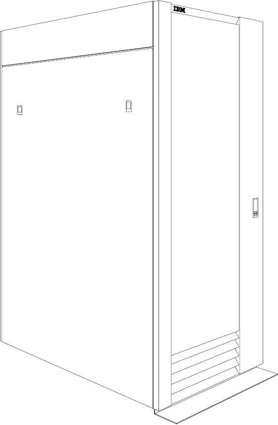
82 Hardware Maintenance Manual: IBM PC Server/Enterprise Racks
Primary Rack (Model 42P)
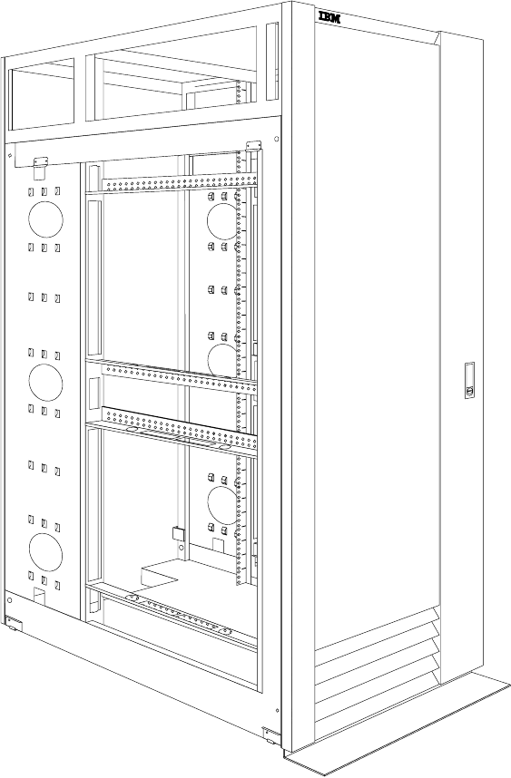
NetBAY 42 Enterprise Rack (Type 9308 Models 42P, 42X, 4SA, 4SB, 42S, 42E) 83
Extension Rack (Model 42X)
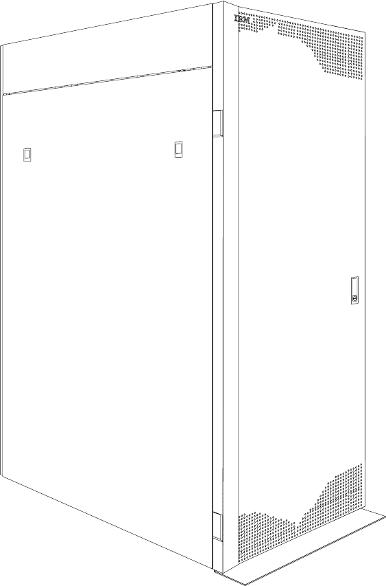
84 Hardware Maintenance Manual: IBM PC Server/Enterprise Racks
Primary Rack (42S)
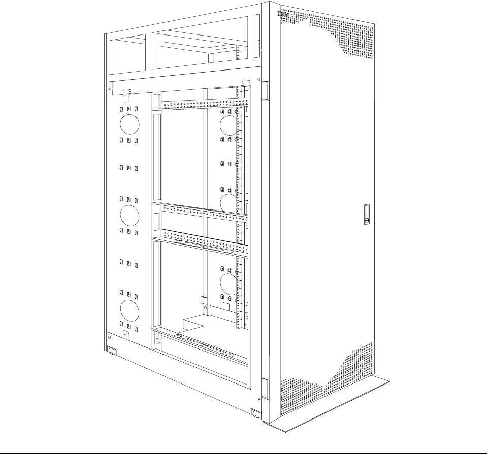
NetBAY 42 Enterprise Rack (Type 9308 Models 42P, 42X, 4SA, 4SB, 42S, 42E) 85
Expansion Rack (42E)
Locations
The following sections contain information on specific equipment locations.
Removing and installing panels
The primary rack cabinet comes with side panels installed. Remove the side panels
from a primary rack cabinet, or the outermost rack cabinets in a suite, before you
install or remove optional devices.
Note: You do not need to remove the top 6U side panels unless you are removing the
top 6U portion of the rack cabinet.
Removing and installing the side panels
Use the following procedure to remove the rack side panels:
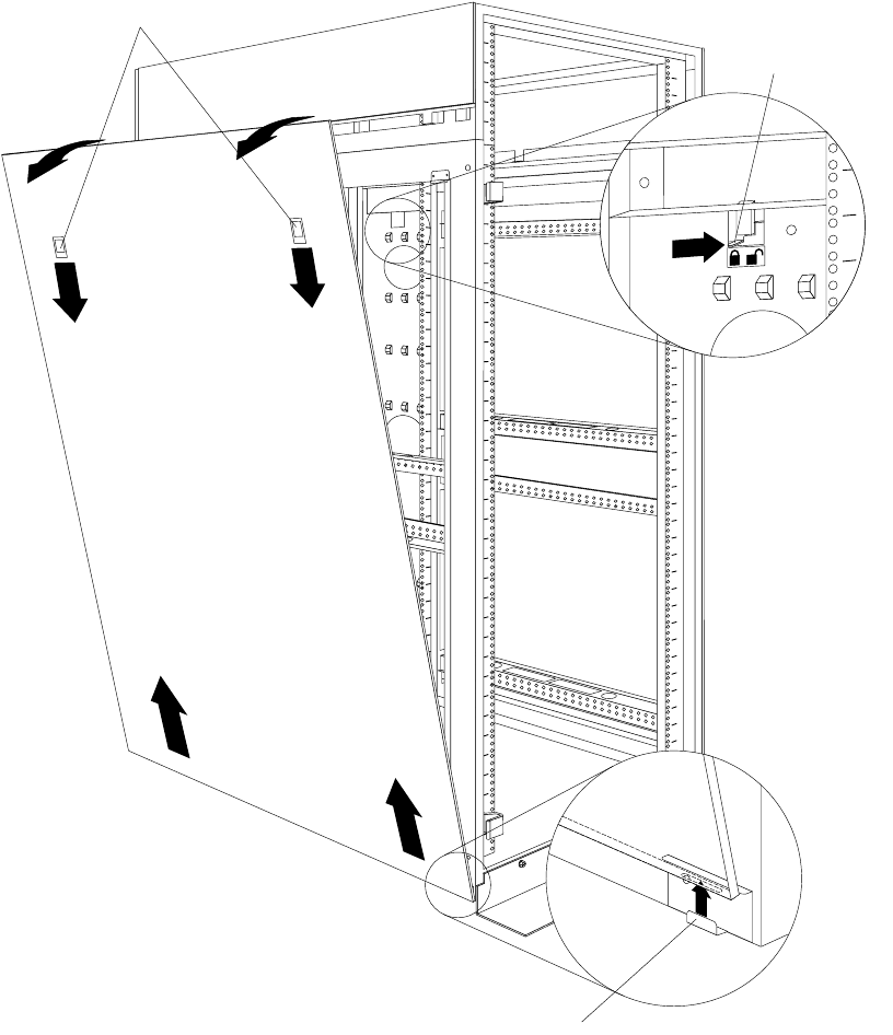
86 Hardware Maintenance Manual: IBM PC Server/Enterprise Racks
Figure 37. Removing the rack side panels
1. From the inside of the rear of the rack cabinet, slide the side panel locking bar
toward the unlocked position.
2. Push down the release latches and tilt the side panel slightly toward you; then, lift
the side panel away from the tabs on the bottom of the rack cabinet.
3. Repeat this procedure to remove both side panels.
Reverse this procedure to install the rack side panels. Slide the locking bar to the
locked position to secure the side panel to the rack cabinet.
Removing and installing the top 6U side panels
Use the following procedure to remove the top 6U side panels from the rack cabinet:
Tabs
Side panel locking bar
Release latches
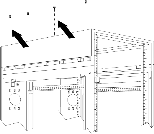
NetBAY 42 Enterprise Rack (Type 9308 Models 42P, 42X, 4SA, 4SB, 42S, 42E) 87
Figure 38. Removing the top 6U side panels from the rack cabinet
1. On the top of the rack cabinet, loosen the four screws that hold each side panel in
place.
2. Tilt the side panel slightly toward you; then, remove it from the rack cabinet.
3. Repeat this procedure to remove both side panels.
Reverse this procedure to install the top 6U side panels on the rack cabinet.
Doors
The following instructions describe how to remove and install front and rear doors on
the NetBAY42 Enterprise Rack (Type 9308 Models 42P, 42X, 4SA, 4SB, 42S, 42E):
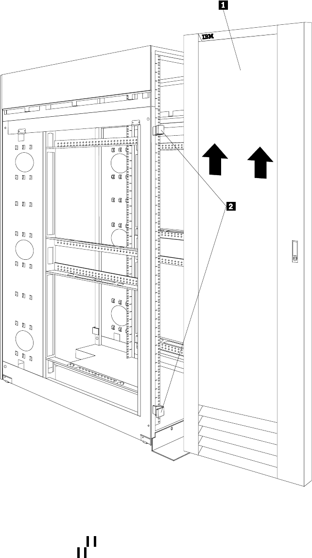
88 Hardware Maintenance Manual: IBM PC Server/Enterprise Racks
Front and rear doors – Models 42P, 42X, 4SA,
4SB
To remove a door:
1. Unlock the door and open it fully.
2. Grasp the door 1 firmly with both hands and lift it upwards until it is fully off
of the hinges 2.
Notes:
1. Reverse this procedure to reinstall front and rear doors.
2. The top hinge pin is longer than the bottom; engage it first when you reinstall
doors.
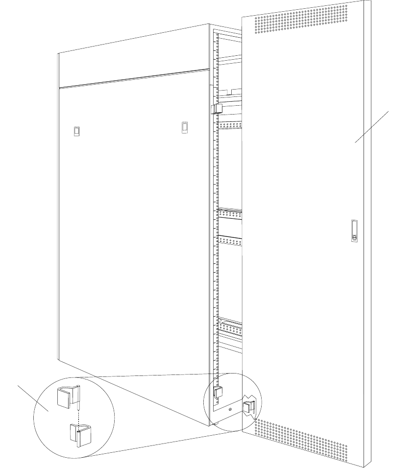
NetBAY 42 Enterprise Rack (Type 9308 Models 42P, 42X, 4SA, 4SB, 42S, 42E) 89
Rear door – Models 42S, 42E
Use the following procedure to remove a rear door from the rack cabinet:
Figure 39. Removing a rear door from the rack cabinet
1. Unlock and open the rear door.
2. Grasp the door firmly with both hands and lift it upward and away from the
hinges; then, set the door aside.
Reverse this procedure to install the rear door on the rack cabinet.
Attention: The bottom hinge pin on the rear door is longer than the top hinge pin.
Ensure that you engage the bottom hinge pin first when you install a rear door on
your rack cabinet.
Bottom
hinge pin
Rear door
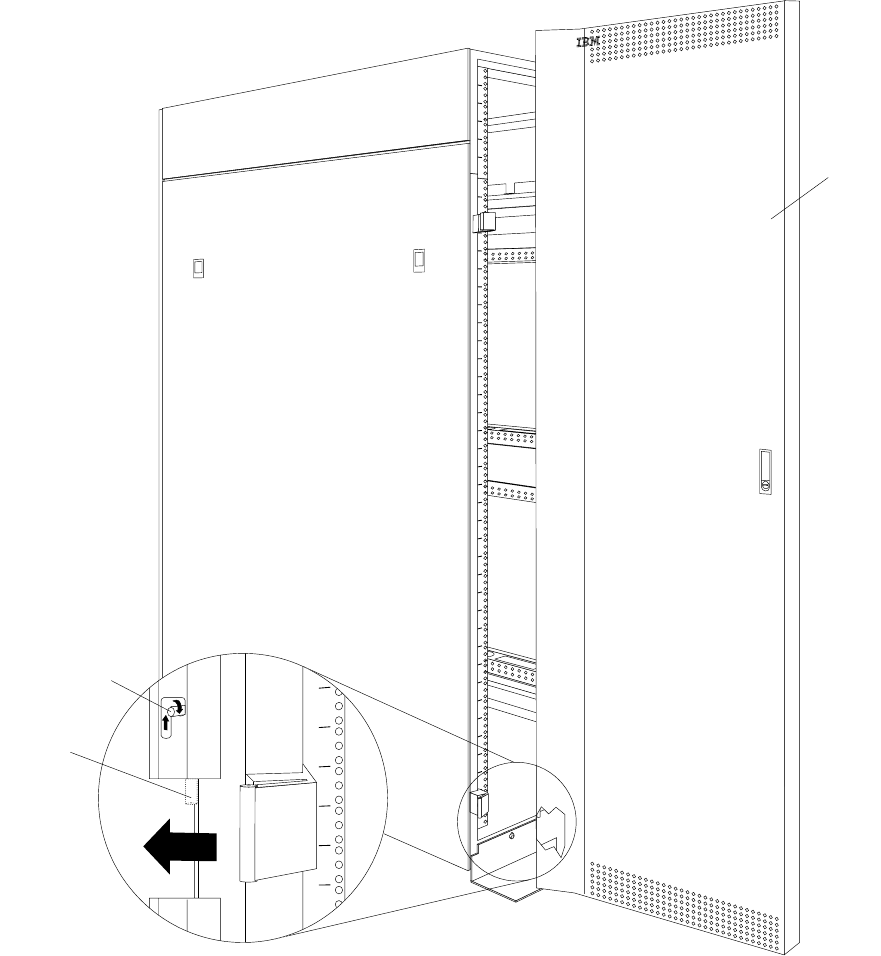
90 Hardware Maintenance Manual: IBM PC Server/Enterprise Racks
Front door – Models 42S, 42E
Use the following procedure to remove a front door from the rack cabinet:
Figure 40. Removing a front door from the rack cabinet
Hinge pin
Hinge pin
latch
Front doo
r
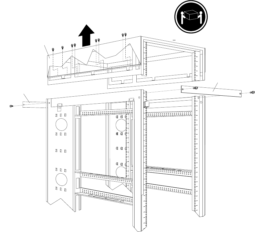
NetBAY 42 Enterprise Rack (Type 9308 Models 42P, 42X, 4SA, 4SB, 42S, 42E) 91
1. Unlock and open the front door.
2. While supporting the door, lift the bottom hinge-pin latch and move it clockwise
to unlock the bottom hinge pin; then, unlock the top hinge pin.
3. Pull the door away from the rack cabinet; then, set the door aside.
Reverse this procedure to install the front door on the rack cabinet.
Attention: When you install the front door, ensure that you align the hinge pins with
the hinges on the rack cabinet before you lock the hinge pins into place.
Removing and installing the top 6U portion of the rack
You can temporarily remove the top 6U portion (including the top cover) of the rack
cabinet while you move the rack cabinet through some nonstandard doorways. You
must first remove both doors according to “Doors” on page 87.
You will need two people to remove and install the top 6U portion of the rack cabinet
according to the following procedure:
Figure 41. Removing the top 6U portion of the rack cabinet
1. Install support bars on the front and rear of the rack cabinet, using two screws per
support bar.
Front support bar
> 18 kg ( 39.7 lb)
Rear support bar
Top 6U
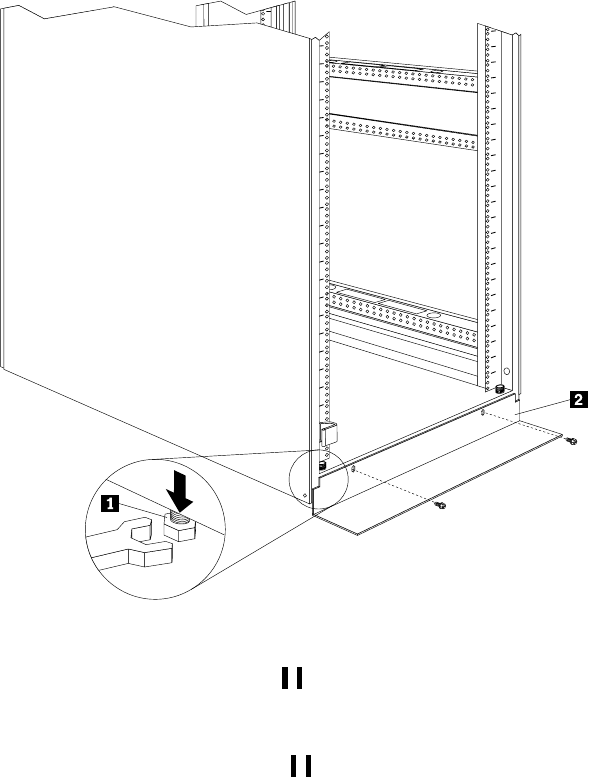
92 Hardware Maintenance Manual: IBM PC Server/Enterprise Racks
2. Remove the 16 screws (eight per side) that hold the top 6U portion of the rack
cabinet in place.
3. Relocate your rack cabinet; then, install the top 6U portion of the rack cabinet
using all 16 of the screws that you removed.
4. Remove both support bars from the rack cabinet.
Installing the stabilizer bracket
To lower the leveling feet and install the stabilizer bracket:
1. Lower each of the four feet 1 just enough so that they touch the floor.
Note: The rack casters will support the weight of the 9308 rack. The feet prevent
the rack from rolling.
2. Secure the stabilizer bracket 2 to the front of the rack with the screws that come
with the rack.
Attaching rack cabinets in a suite
Expansion rack cabinets come with all the hardware required for you to attach rack
cabinets together and form a suite. Use the following procedure to attach rack
cabinets together in a suite:
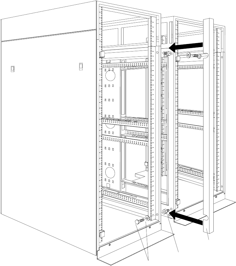
NetBAY 42 Enterprise Rack (Type 9308 Models 42P, 42X, 4SA, 4SB, 42S, 42E) 93
Figure 42. Attaching two adjacent rack cabinets to each other to form a suite
1. Remove both side panels (see “Removing and installing the side panels” on page
85) from the side of a primary rack cabinet that is adjacent to an expansion rack in
a suite.
2. Remove the front and rear doors (see “Doors” on page 87) from all rack cabinets.
3. On the outside of two adjacent rack cabinets, install the four threaded standoffs
that come with the expansion rack cabinet:
a. Install two threaded standoffs on the rack cabinet to the left, one on the top-
front and one on the bottom-rear.
b. Install the other two threaded standoffs on the rack cabinet to the right, one
on the bottom-front and one on the top-rear.
4. Attach the rack cabinets together, using four bolts and washers that come with the
expansion rack cabinet.
Note: You must install the top-front and bottom-rear bolts from right-to-left;
then, install the bottom-front and top-rear bolts from left-to-right.
Bolt and washer
Threaded standoff
Trim piece
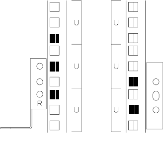
94 Hardware Maintenance Manual: IBM PC Server/Enterprise Racks
5. Snap the trim pieces into place between the adjacent rack cabinets. Install one
trim piece in the front and one in the rear.
6. Repeat step 3 through step 5 for all other adjacent rack cabinets in the suite.
7. On the outside of the outermost expansion rack cabinets in the suite, install the
side panels that you removed in step 1.
8. Install the front and rear doors on all rack cabinets.
Installing L-channel support rails to rack mounting
brackets
1. Use the following illustration of the front and rear rack mounting flanges to
determine the appropriate rack-mounting holes for installing cage nuts or clip
nuts to secure the rails. From left to right, the illustration shows the front and rear
flanges respectively.
Front Rear
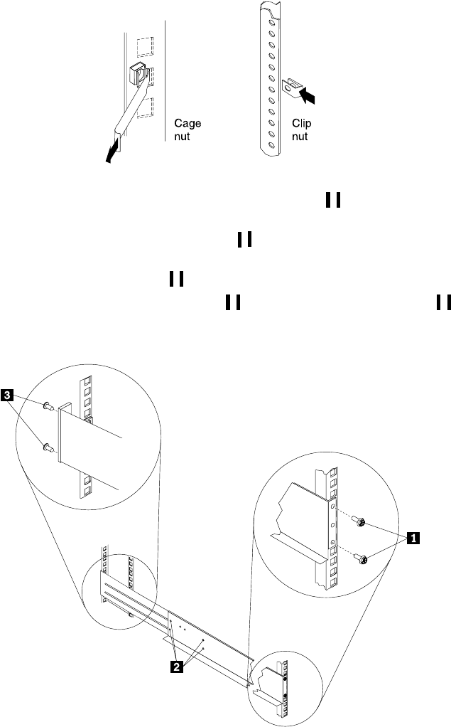
NetBAY 42 Enterprise Rack (Type 9308 Models 42P, 42X, 4SA, 4SB, 42S, 42E) 95
Note: Use clip nuts if your rack has holes. If your rack has square holes, you can
use the rack-insertion tool or a flat-blade screwdriver to install cage nuts.
2. On the rail marked R, loosen the four screws 2.
3. Hold the rail against the outside of the right rack-mounting flange, and loosely
insert the two front M6 screws 1.
4. Extend the rail outside of the rear rack-mounting flange; then, install and tighten
two rear M6 screws 3.
5. Tighten the two front screws 1; then, tighten the four screws 2.
Repeat step 2 through step 5 to install the rail marked L on the left side of the rack.
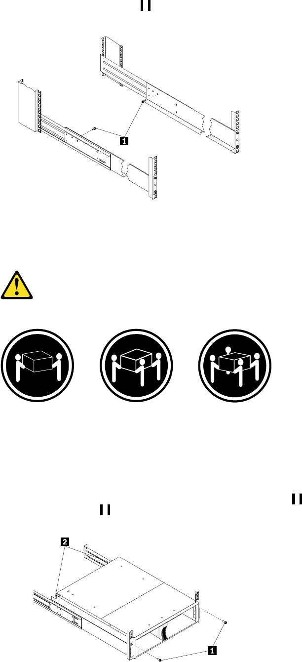
96 Hardware Maintenance Manual: IBM PC Server/Enterprise Racks
6. Loosely insert one M5 screw 1 into each rail.
7. Slide the expansion unit into the rack, and insert the M6 screws 1. Do not
overtighten the M6 1 screws.
Statement 4
≥18 kg (37 lbs) ≥32 kg (70.5 lbs) ≥55 kg (121.2 lbs)
CAUTION:
Use safe practices when lifting.

NetBAY 42 Enterprise Rack (Type 9308 Models 42P, 42X, 4SA, 4SB, 42S, 42E) 97
8. Tighten the rear screws 2.
Installing a server
A small server can occupy from 1U to 5U of rack mounting space. A large server can
occupy 8U or more of rack mounting space. Most servers also come with cable-
management arms so that you can neatly route any cables that you attach to your
server. See the documentation that comes with your server for detailed installation
instructions.
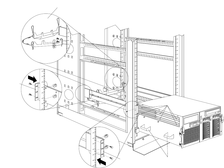
98 Hardware Maintenance Manual: IBM PC Server/Enterprise Racks
Installing a large server
Use the following general procedure to install a large server in your rack cabinet:
Figure 43. Installing a large server
1. See the server documentation for detailed installation and configuration
information.
2. Use the template and rack mounting instructions that come with your server to
determine where to install clip nuts.
3. Install the slide rails and cable-management arm that come with your server,
using the provided screws and clip nuts.
Note: If required, adjust the length of the slide rails to fit the depth of your rack
cabinet.
4. Install the server handles; then, lift the server and place it on the extended slide
rails.
5. Attach the server to the slide rails with the provided screws; then, remove the
server handles and slide the server into the rack cabinet.
6. See your server documentation for information on how to connect power and
other device cables.
Cable-management arm
Rear of rail
Front of rail
Server rail screws
Server handles
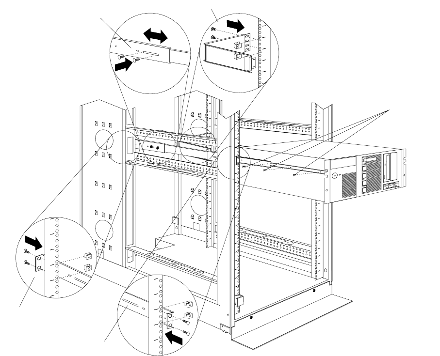
NetBAY 42 Enterprise Rack (Type 9308 Models 42P, 42X, 4SA, 4SB, 42S, 42E) 99
Installing a small server
Use the following general procedure to install a small server in your rack cabinet:
Figure 44. Installing a small server
1. See the server documentation for detailed installation and configuration
information.
2. Use the template and rack mounting instructions that come with your server to
determine where to install clip nuts.
3. Install the slide rails and cable-management arm that come with your server,
using the provided screws and clip nuts.
Note: If required, adjust the length of the slide rails to fit the depth of your rack
cabinet.
4. Lift the server and place it on the extended slide rails; then, attach the server to
the slide rails with the provided screws.
5. See your server documentation for information on how to connect power and
other device cables.
Server screws
Rear of rail
Front of rail
Rail adjustment Cable-management arm
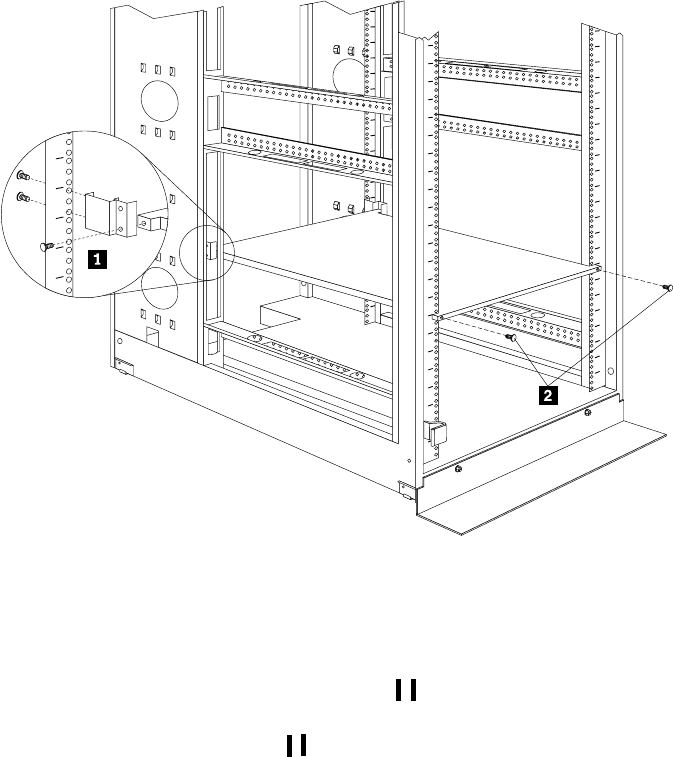
100 Hardware Maintenance Manual: IBM PC Server/Enterprise Racks
Fixed shelf
Note: A fixed shelf can support a device or option weighing up to 45kg (100 lbs).
To install a fixed shelf:
1. Determine the location for the fixed shelf within the rack.
2. Secure the threaded mounting brackets 1 to the rear of the shelf; then, secure
the brackets to the rack with two screws and clip nuts per bracket.
3. Secure the front of the shelf 2 with two screws and clip nuts.
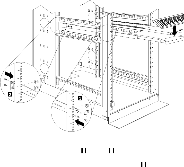
NetBAY 42 Enterprise Rack (Type 9308 Models 42P, 42X, 4SA, 4SB, 42S, 42E) 101
Keyboard tray
To install a keyboard tray:
1. Secure the slide rails to the front 1 and rear 2 of the rack, adjusting them as
needed.
2. Slide the keyboard tray onto the rails and store the keyboard 3 in the area
provided.
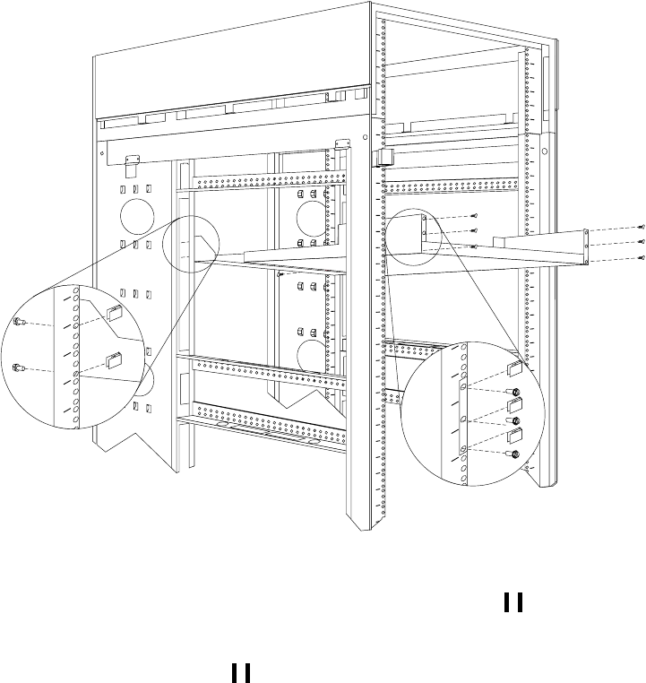
102 Hardware Maintenance Manual: IBM PC Server/Enterprise Racks
Monitor shelf
To install a monitor shelf:
1. Secure the rear monitor shelf bracket in the rear of the rack 1 with two screws
per side.
2. Place the monitor shelf inside of the rack, resting on the rear bracket; then, secure
it to the front of the rack 2 with three screws and clip nuts per side.

NetBAY 42 Enterprise Rack (Type 9308 Models 42P, 42X, 4SA, 4SB, 42S, 42E) 103
Installing a flat panel monitor rack mount kit
You can store a T54 or T55 Flat Panel Monitor in a keyboard tray with the flat panel
monitor rack mount kit. This kit requires an additional 2U of space above an installed
keyboard tray in your rack cabinet. See the documentation that comes with the flat
panel monitor rack mount kit for detailed installation instructions. Use the following
general procedure to install a flat panel monitor in your rack cabinet:
Figure 45. Installing a flat panel monitor rack mount kit
1. Ensure that a keyboard tray is properly installed in your rack cabinet (see
“Keyboard tray” on page 101) with at least 2U of clearance above the keyboard
tray.
2. Install the flat panel monitor base on the flat panel monitor. See the
documentation that comes with your flat panel monitor rack mount kit for
detailed installation instructions.
3. Install the mounting studs and bumpers on the keyboard tray.
4. Attach the monitor base to the inside of the keyboard tray using the screws that
come with the rack mount kit.
5. Fold the monitor all the way down against the bumpers; then, slide the keyboard
tray into the rack cabinet to ensure that there is proper clearance.
6. See the documentation that comes with your flat panel monitor for information
on how to connect power and how to connect the monitor to a server or console
switch.
Removing the existing flat panel monitor stand
Use the following steps to remove the existing flat panel monitor stand from your
monitor:
Keyboard tray
Rear screws
Flat panel monitor
Mounting studs
Bumpers
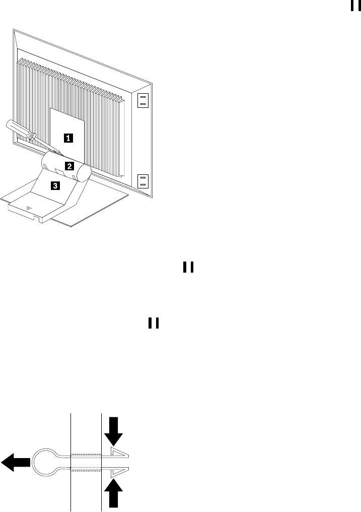
104 Hardware Maintenance Manual: IBM PC Server/Enterprise Racks
1. Unplug the flat panel monitor and disconnect the power cord from the flat panel
monitor power supply.
2. Carefully use a flat-blade screwdriver to pry the bottom of the cable cover 1 up
and remove it. Save the cable cover for later reinstallation.
Figure 46. Removing the cable cover, hinge cover, and stand cover
3. Squeeze the sides of the hinge cover 2 and remove it.
Note: Even though this hinge cover is not used with the Flat Panel Monitor Rack
Mount Kit, do not discard it. Store it with the other monitor stand parts
you remove for possible future use.
4. Gently push the stand cover 3 and slide it backwards until it is completely off
the stand.
5. Disconnect the signal cable and power cord from the flat panel monitor. Carefully
remove and save the plastic cable clamp to free the power cord.
Note: The plastic cable clamp is reusable and is needed to secure the power cord
after installing the Flat Panel Monitor Rack Mount Kit on the flat panel
monitor.
Figure 47. Removing the plastic cable clamp
6. Lay the monitor facedown on a cushioned surface and remove the six screws that
secure the hinges to the flat panel monitor.

NetBAY 42 Enterprise Rack (Type 9308 Models 42P, 42X, 4SA, 4SB, 42S, 42E) 105
Figure 48. Removing the existing monitor stand from the monitor
7. Lift off the hinge and monitor stand assembly. Store this assembly in a safe place
for possible future use.
Installing the new monitor stand
Refer to “Removing the existing flat panel monitor stand” on page 103 for instructions
on how to remove the existing stand from the flat panel monitor. Before installing the
new stand, install the keyboard tray in the rack according to the instructions that
come with the rack or the keyboard tray option.
Note: The Flat Panel Monitor Rack Mount Kit and keyboard tray require 3U of rack
mounting space. If the keyboard tray does not have at least 2U of clearance
above it, relocate the keyboard tray within the rack.
Use the following steps to install the Flat Panel Monitor Rack Mount Kit:
1. Remove the cable cover 1 from the new monitor stand; then, remove the four
screws (two per hinge) that secure the hinges 2 to the stand.
Figure 49. Removing the hinges from the new monitor stand
2. Install the hinges on the flat panel monitor, using the six screws that you removed
from the old monitor stand.
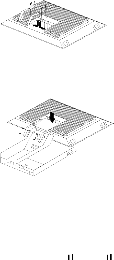
106 Hardware Maintenance Manual: IBM PC Server/Enterprise Racks
Figure 50. Installing the hinges on the flat panel monitor
Note: Be sure to slide each hinge into place on the back of the monitor and align
the holes in the hinges with holes on the monitor.
3. Lower the flat panel monitor onto the new monitor stand, making sure that you
align the holes in the stand with holes in the hinges; then, secure the flat panel
monitor to the monitor stand with the four screws that you removed earlier.
Figure 51. Installing the monitor on the new monitor stand
You have now finished attaching the flat panel monitor to its stand. The rest of
the installation process involves preparing the keyboard tray for storage and
routing cables.
Notes:
a. You must remove any keyboard or mouse that is already in the keyboard tray
before continuing.
b. You will not be able to store a mouse in the keyboard tray after installing the
Flat Panel Monitor Rack Mount Kit.
c. You can only store a space-saver keyboard in the keyboard tray.
4. Install the mounting studs 2 and bumpers 3 that come in the monitor
mounting hardware package.

NetBAY 42 Enterprise Rack (Type 9308 Models 42P, 42X, 4SA, 4SB, 42S, 42E) 107
Figure 52. Installing the flat panel monitor in the keyboard tray
Note: Clean the installation area on the keyboard tray with a suitable cleaning
agent, such as alcohol, before installing the rubber bumpers on the front of
the keyboard tray.
5. Open the flat panel monitor 1 to its full upright position and align the grooves in
the stand with the mounting studs 2 in the keyboard tray. When the monitor
stand is sitting inside the keyboard tray, slide it towards the back until it stops.
Note: Install or remove the flat panel monitor only when the display is in its
upright position.
6. Secure the monitor stand in the back of the keyboard tray with the two provided
screws 4.
7. Place the flat panel monitor power supply, which came with your flat panel
monitor, inside the monitor stand. If necessary, insert the power supply spacer
3 behind the power supply and over the cable to keep the power supply in
place.

108 Hardware Maintenance Manual: IBM PC Server/Enterprise Racks
Figure 53. Storing the power supply and routing cables
8. Connect the power supply to the monitor and route the cable under the tab near
the top of the monitor stand 1; then, secure the power cable with the cable
clamp you removed from the original stand and coil excess cable inside the
monitor stand.
9. Connect the monitor signal cable to the monitor and route it under the tab in the
bottom of the monitor stand 2 and out the back of the stand through the hole
provided.
10. Replace the monitor stand cover 1.
Figure 54. Installing the cable cover, hinge cover, and stand cover
11. Snap the new hinge cover 2 into place over the hinge assembly.
Note: Be sure to use the new hinge cover that comes with the Flat Panel Monitor
Rack Mount Kit because it has deeper grooves to accommodate the new
hinge assembly.
12. Snap the cable cover 3 into place on the back of the flat panel monitor.
13. Fold the flat panel monitor down until it rests on the rubber bumpers; then, gently
push back and remove the small cable exit cover 1 on the monitor stand.
New hinge cover Old hinge cover
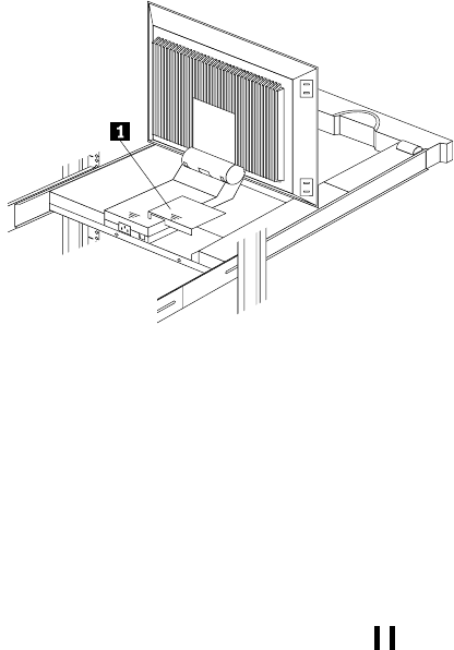
NetBAY 42 Enterprise Rack (Type 9308 Models 42P, 42X, 4SA, 4SB, 42S, 42E) 109
Figure 55. Routing the keyboard cable
14. Route the space-saver keyboard cable through the hole in the front of the base and
out the opening in the back where you removed the small cover; then, place the
keyboard (with its adjustable feet fully down) inside the keyboard tray.
Note: You must open the flat panel monitor to its full upright position so that
you can install the keyboard and route its cable.
15. Fold the flat panel monitor down again until it rests on the rubber bumpers; then,
reinstall the small cable exit cover 1.
16. Slide the keyboard tray into the rack; then, neatly route and secure all cables in the
rack using the provided cable straps.
You can now connect the power cord to the flat panel monitor and connect the
display to a server.
Blank filler panel
Blank filler panels can occupy 1U, 3U, or 5U of space on a rack.
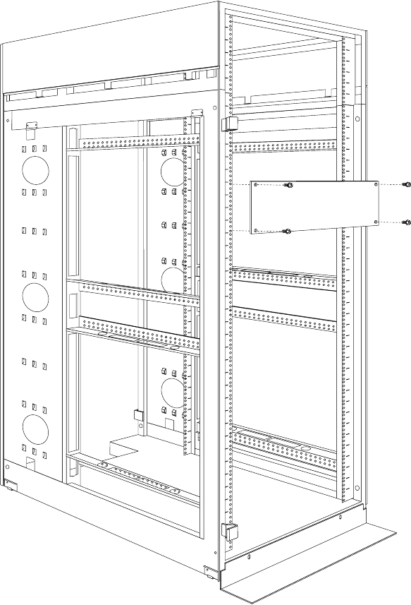
110 Hardware Maintenance Manual: IBM PC Server/Enterprise Racks
To install a blank filler panel:
1. Determine the size (1U, 3U, or 5U) panel you need.
2. Secure the blank filler panel in place with four screws and clip nuts.
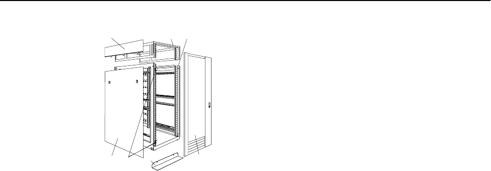
NetBAY 42 Enterprise Rack (Type 9308 Models 42P, 42X, 4SA, 4SB, 42S, 42E) 111
Parts listing (Type 9308 Model 42P, 42X)
Index Rack Enclosure (Type 9308 Model 42P, 42X, 4SA, 4SB, 42S, 42E) FRU
1 Top Cover Assembly including cover standoffs and screws (All models) 05N4896
2 Cabinet Frame (All models) 05N4895
3 Front Door w/Lock (Models 42P, 42X) 05N4897
Rear Door w/Lock (Models 42P, 42X) 05N4899
Front Door w/Lock (Models 42S, 42E) 09N9694
Rear Door w/Lock (Models 42S, 42E) 06P6047
Front Door (Models 4SA, 4SB) 05N4899
Rear Door (Models 4SA, 4SB) 05N4899
4 Stabilizer Foot, Black (All models) 05N4920
5 Door Hinges (50mm) (Models 42P, 42X) 05N4901
Front Door Hinge (Models 42S, 42E) 09N9695
Rear Door Hinges (20mm) (All models) 05N4902
Door Hinge (Models 4SA, 4SB) 05N4902
6 Lower Side Cover (Models 42P, 4SA, 42S) 05N4905
7 Upper Side Cover (Models 42P, 4SA, 42S) 05N4906
Caster, Fixed (1) w/mounting hardware (All models) 05N4915
Caster, Swivel (1) w/mounting hardware (All models) 05N4916
Door Latch w/Lock (All models) 05N4903
Front Door Striker (2) w/mounting screws (Models 42P, 42X, 42S, 42E) 05N4904
EIA Mounting Flange Label,1-42U, Decorative (All models) 05N4917
EIA Mounting Flange Label, 1-36U, Plain (All models) 05N4918
EIA Mounting Flange Label, 37-42U, Plain (All models) 05N4919
Leveler Foot (4) w/jam nut (All models) 05N4914
Miscellaneous Hardware Kit - Includes: clip nut (25); screw, M6 Hex Head (25); tie - soft (15)
(All models) 05N4922
Rack to Rack Mounting Kit, Black (Models 42X, 4SB, 42E) 05N4908
12
3
4
5
6
7
112 Hardware Maintenance Manual: IBM PC Server/Enterprise Racks
Leveling foot wrench (All models) 05N4927
Rack Enclosure (Type 9308 Model 42P, 42X, 4SA, 4SB, 42S, 42E) Options FRU
Monitor Housing 76H4947
Side Panel Latch 12J4468
Filler Panels: 1U, 3U, and 5U - with Hardware 12J4473
Keyboard Tray 76H4958
Keyboard Tray II 28L0562
Keyboard Tray II filler block 28L0567
Keyboard Slides (set) with Hardware 76H4961
Fixed Shelf with Hardware 76H4963
C13 - C14 Power Cable 07H0075
C19 - C14 Power Cable 76H4964
C13 - NEMA 5-15P Power Cable 76H4962
C19 - NEMA 5-15P Power Cable 12J4479
Video, Mouse, Keyboard Cable (7 feet) 06P6006
Video, Mouse, Keyboard Cable (12 feet) 06P6007
Video, Mouse, Keyboard Power Cable (25 feet) 12J4484
Mouse Extension Cable 07H0069
Keyboard Extension Cable 07H0067
Concentrator with Hardware (8 port) 76H4948
Concentrator with Hardware (4 port) 28L0543
1x4 switch 06P6003
2x8 switch 06P6004
NetBAY Rack Power Distribution Unit 09N9668
NetBAY Front-end Power Distribution Unit 09N9670
3-phase NEMA L21-30P line cord (200-250 Vac) for NetBAY Front-end PDU 24P6844
3-phase IEC 309-3P+N+Gnd line cord (380-415 Vac) for NetBAY Front-end PDU 24P6845
1-phase NEMA L5-30P line cord (100-127 Vac) for NetBAY Front-end PDU 24P6846
1-phase NEMA L6-30P line cord (200-240 Vac) for NetBAY Front-end PDU 24P6847
1-phase IEC 309-2P+Gnd line cord (200-240 Vac) for NetBAY Front-end PDU 24P6848
NetBAY Server Dual-cord Power Distribution Unit 09N9669
Hardware Kit for NetBAY Power Distribution Units 09N9671
Flat Panel Monitor Rack Mount Kit Option (T54A, T55) 37L6888
Flat Panel Adapter Hinge - R.H. & L.H. (T54A, models AG1, AW1; T55) 09N9678
Flat Panel Adapter Misc. Hardware Kit – Includes: Hinge Cover (1); Power Supply Cover (1);
Mounting Stud (1); Bumper (2); Cable Access Cover (1); M4 X 12 Screw (4); M4 X 8 Screw (2);
14 inch Soft Tie Wrap (1); T54A power supply spacer (1)
00N8693
Index Rack Enclosure (Type 9308 Model 42P, 42X, 4SA, 4SB, 42S, 42E) FRU
NetBAY 42 Enterprise Rack (Type 9308 Models 42P, 42X, 4SA, 4SB, 42S, 42E) 113
Flat Panel Adapter Display Housing – Includes: Power Supply Cover (1); Base Housing (1);
Cable Access Cover (1); Bottom Stand 00N8694
Rack Enclosure (Type 9308 Model 42P, 42X, 4SA, 4SB, 42S, 42E) Options FRU
114 Hardware Maintenance Manual: IBM PC Server/Enterprise Racks

© Copyright IBM Corp. 2001 115
NetBAY3 enclosure
Features. . . . . . . . . . . . . . . . . . . . . . . . . . . . . . . . . . . 115
Locations. . . . . . . . . . . . . . . . . . . . . . . . . . . . . . . . . . 115
Casters. . . . . . . . . . . . . . . . . . . . . . . . . . . . . . . . . . . . 116
Foot pads . . . . . . . . . . . . . . . . . . . . . . . . . . . . . . . . . 116
Front cover . . . . . . . . . . . . . . . . . . . . . . . . . . . . . . . . 117
Rear panel . . . . . . . . . . . . . . . . . . . . . . . . . . . . . . . . .117
Device side rails . . . . . . . . . . . . . . . . . . . . . . . . . . . .118
Stacking NetBAY3 enclosures. . . . . . . . . . . . . . . . .118
Parts Listing (NetBAY3). . . . . . . . . . . . . . . . . . . . . 121
Features
The IBM NetBAY3 enclosure provides a convenient 3-U high by 24-inch deep storage
cabinet for the installation of computer devices.
Note: Vertical measurements are given in rack units (U). One U is equal to 4.45 cm
(1.75-inches).
Up to three NetBAY3 enclosures can be stacked under certain IBM servers. Devices
such as the IBM EXP10, an uninterruptable power supply (UPS), or various
telecommunications equipment can also be installed in a NetBAY3 enclosure.
Locations
The following sections contain information on specific equipment locations.
Important:
•The maximum server weight is 77 kg (170 lb.).
•Refer to the latest IBM Server Hardware Maintenance Manual when
servicing the server.
•Assure all power and signal cables are routed properly and are not
pinched.
•Make sure NetBAY3 enclosures in a stack are securely fastened
together.
•Servers are lifted onto and off of the NetBAY3 enclosure. Make sure
you have help when lifting.
•Servers are lifted onto and off of the NetBAY3 enclosure. Make sure
you have help when lifting.
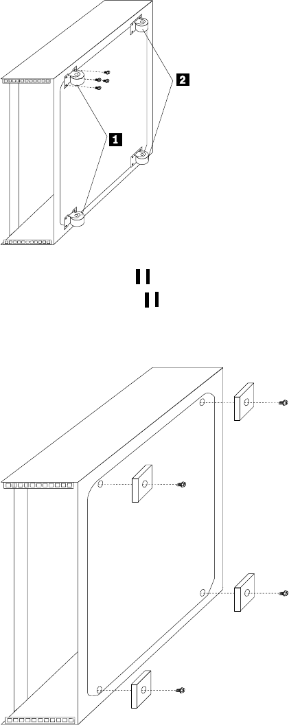
116 Hardware Maintenance Manual: IBM PC Server/Enterprise Racks
Casters
•Two fixed casters 1 at the front of the NetBAY3 enclosure.
•Two swivel casters 2 at the rear of the NetBAY3 enclosure.
Foot pads
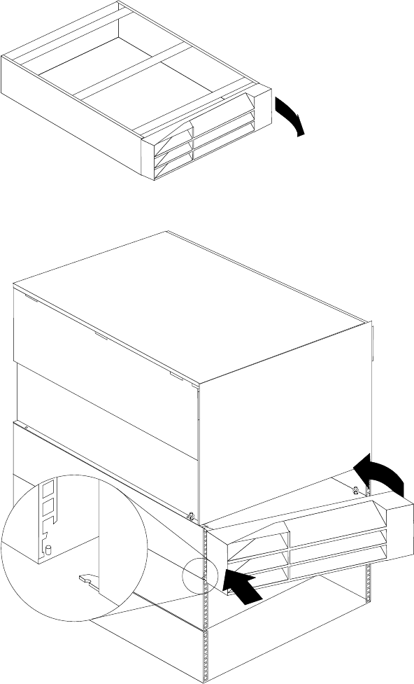
NetBAY3 enclosure 117
Front cover
Rear panel
Note: Make sure empty NetBAY3 enclosures (no devices installed) have the rear
cover securely attached.
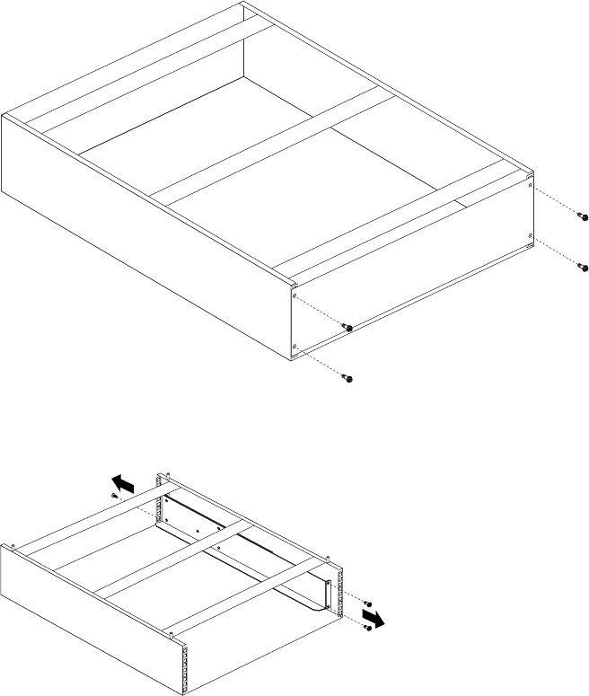
118 Hardware Maintenance Manual: IBM PC Server/Enterprise Racks
Device side rails
Stacking NetBAY3 enclosures
Note: Make sure NetBAY3 enclosures in a stack are securely fastened together.
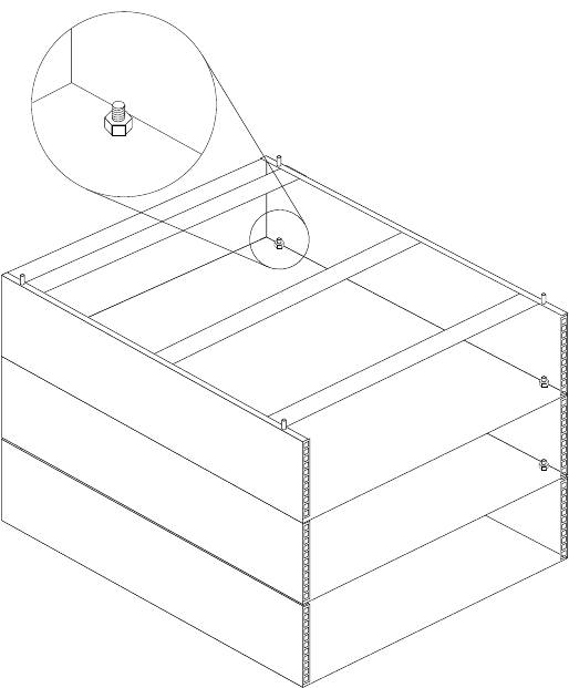
NetBAY3 enclosure 119
Note: The maximum server weight is 77 kg (170 lb.).
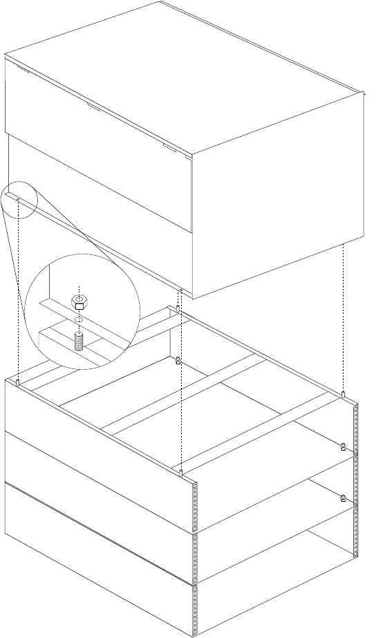
120 Hardware Maintenance Manual: IBM PC Server/Enterprise Racks
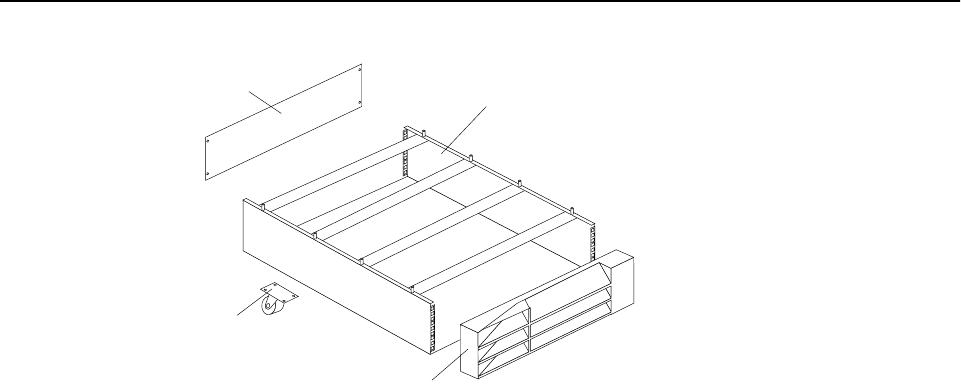
NetBAY3 enclosure 121
Parts Listing (NetBAY3)
Index NetBAY3 Enclosure (NetBAY3) FRU
1 3-U Enclosure Frame 03K8797
2 Front Bezel Assembly with Lock and Keys 03K8798
3Foot Pads Qty. 4 03K8800
4 Casters Fixed, Front, Qty. 2 12J3279
4 Casters Swivel, Rear, Qty. 2 12J3283
53-U Blank Panel 03K8799
Miscellaneous Parts Kit - Includes:
•M6 Caged Nuts (2)
• M6X16 Combination Head Screw (2)
•M6X14 Flanged Hex Head Screw (2)
•M5 Flange Nut (2)
03K9056
1
2
3
4
122 Hardware Maintenance Manual: IBM PC Server/Enterprise Racks

© Copyright IBM Corp. 2001 123
NetBAY3E enclosure
Features. . . . . . . . . . . . . . . . . . . . . . . . . . . . . . . . . . . 123
Locations. . . . . . . . . . . . . . . . . . . . . . . . . . . . . . . . . . 123
Casters. . . . . . . . . . . . . . . . . . . . . . . . . . . . . . . . . . . . 124
Front cover . . . . . . . . . . . . . . . . . . . . . . . . . . . . . . . . 124
Rear panel . . . . . . . . . . . . . . . . . . . . . . . . . . . . . . . . 125
Device side rails . . . . . . . . . . . . . . . . . . . . . . . . . . . 126
Stacking NetBAY3E enclosures . . . . . . . . . . . . . . 126
Parts listing (NetBAY3E) . . . . . . . . . . . . . . . . . . . . 127
Features
The IBM NetBAY3E enclosure provides a convenient 3-U high by 28-inch deep storage
cabinet for the installation of computer devices.
Note: Vertical measurements are given in rack units (U). One U is equal to 4.45 cm
(1.75-inches).
Up to three NetBAY3E enclosures can be stacked under certain IBM servers. Devices
such as the IBM EXP10, an uninterruptable power supply (UPS), or various
telecommunications equipment can also be installed in a NetBAY3E enclosure.
Important:
•The maximum server weight is 77 kg (170 lb.).
•Refer to the latest IBM Server Hardware Maintenance Manual when
servicing the server.
•Assure all power and signal cables are routed properly and are not
pinched.
•Make sure NetBAY3E enclosures in a stack are securely fastened
together.
•Make sure empty NetBAY3E enclosures (no devices installed) have
the rear cover securely attached.
•Servers are lifted onto and off of the NetBAY3E enclosure. Make sure
you have help when lifting.
Locations
The following sections contain information on specific equipment locations.
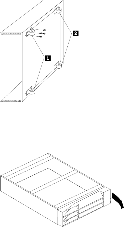
124 Hardware Maintenance Manual: IBM PC Server/Enterprise Racks
Casters
•Two fixed casters 1 at the front of the NetBAY3E enclosure.
•Two swivel casters 2 at the rear of the NetBAY3E enclosure.
Front cover
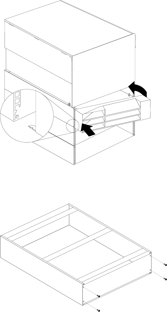
NetBAY3E enclosure 125
Rear panel
Note: Make sure empty NetBAY3E enclosures (no devices installed) have the rear
cover securely attached.
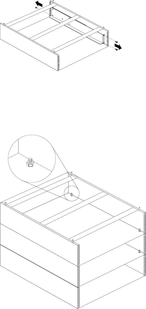
126 Hardware Maintenance Manual: IBM PC Server/Enterprise Racks
Device side rails
Stacking NetBAY3E enclosures
Notes:
1. Make sure NetBAY3E enclosures in a stack are securely fastened together.
2. When stacking an enclosure on top of another, you must attach them together
before you install any device in the upper enclosure.
Important:
•Always lock the casters with the caster stabilizer bar before removing
or installing any devices in or on the enclosure.
•Always use the caster stabilizer when multiple NetBAY3E enclosures
are stacked under a server.

NetBAY3E enclosure 127
Notes:
1. The maximum server weight is 77 kg (170 lb.).
2. Always install a server on the top enclosure in a stack.
Carefully lift the server by its handles and align its mounting holes 1 with the
NetBAY3E enclosure mounting studs 2.
Parts listing (NetBAY3E)
Index NetBAY3E Enclosure (NetBAY3E) FRU
13-U Enclosure Frame 28L0571
2 Front Bezel Assembly with Lock and Keys 03K8798
3 Casters Fixed, Front, Qty. 2 12J3279
3 Casters Swivel, Rear, Qty. 2 12J3283
43-U Blank Panel 03K8799
Caster Stabilizer 09N7417
Miscellaneous Parts Kit - Includes:
•Hotswap Planar Clamp (1)
• M6 Caged Nut (2)
•M6X16 Combination Head Screw (2)
•M4X6 Slotted Pan Head Screw (2)
•M6X10 Flanged Hex Head Screw (2)
•Cage Nut Insertion Tool (1)
•M5 Flange Nut (1)
•M3.5X7 Flanged Hex Head Screw (1)
28L0574
1
2
3
4
128 Hardware Maintenance Manual: IBM PC Server/Enterprise Racks
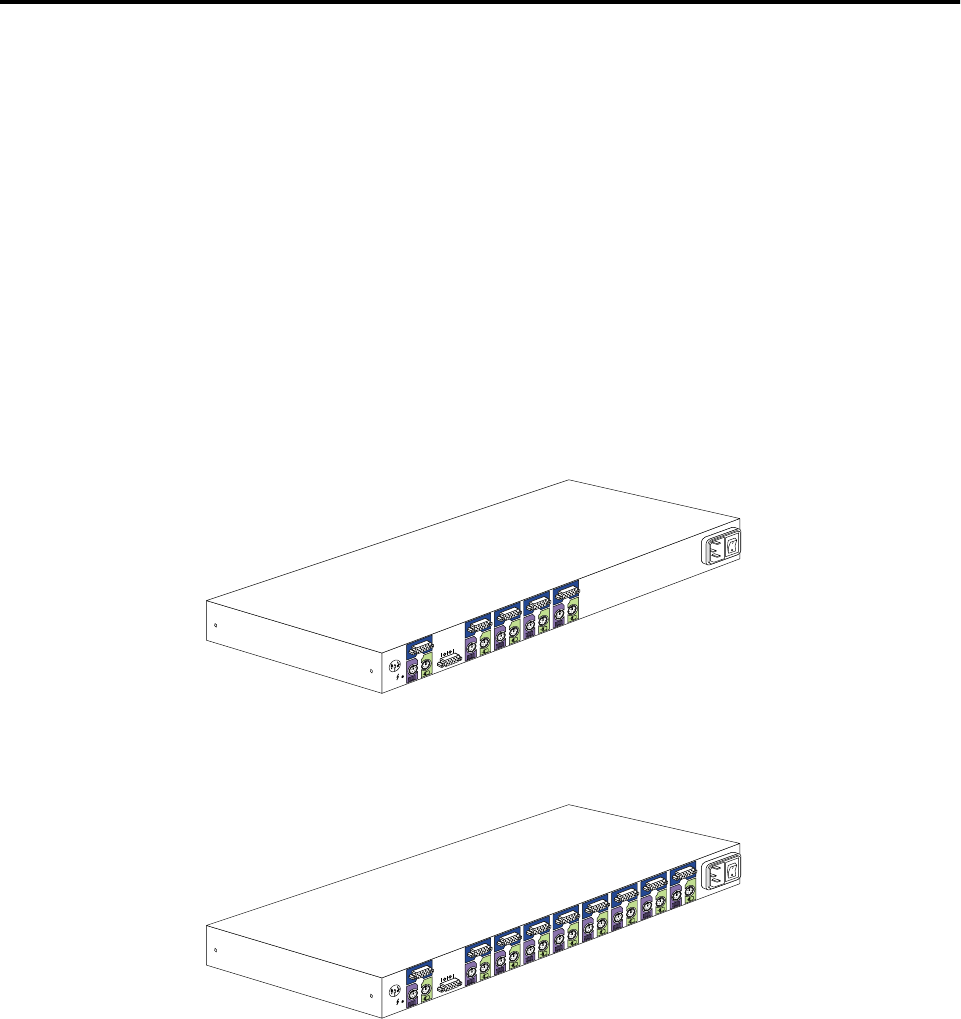
© Copyright IBM Corp. 2001 129
IBM NetBAY console switch
Features. . . . . . . . . . . . . . . . . . . . . . . . . . . . . . . . . . . 130
Tool requirements . . . . . . . . . . . . . . . . . . . . . . . . . . 131
Specifications . . . . . . . . . . . . . . . . . . . . . . . . . . . . . . 132
Installation overview . . . . . . . . . . . . . . . . . . . . . . . 132
Installing a console switch in a monitor shelf. . . 132
Installing a console switch vertically in a rack. . 134
Installing a console switch horizontally in a rack . .
137
Parts listing (NetBAY Console Switch) . . . . . . . . 139
The IBM NetBAY 1x4 Console Switch allows you to connect up to four servers to a
single monitor, mouse, and keyboard.
The IBM NetBAY 2x8 Console Switch allows you to connect up to eight servers to a
primary and secondary monitor, mouse, and keyboard.
You can also connect multiple console switches to each other in a tiered configuration.
The Apex User Guide CD contains configuration information about your console
switch.
Figure 56. 1x4 console switch
Figure 57. 2x8 console switch
You can install a console switch inside the rear storage compartment NetBAY monitor
shelf, vertically in the side of your rack cabinet, or horizontally within 1U of EIA
mounting space in your rack cabinet.
Note: If you install a 2x8 Console Switch inside the monitor shelf, you will not be
able to use the B port on the console switch to connect a second monitor,
keyboard, and mouse.
The following parts come with the console switch:
1
A
2
3
4
8
1
A
2
3
4
5
6
7
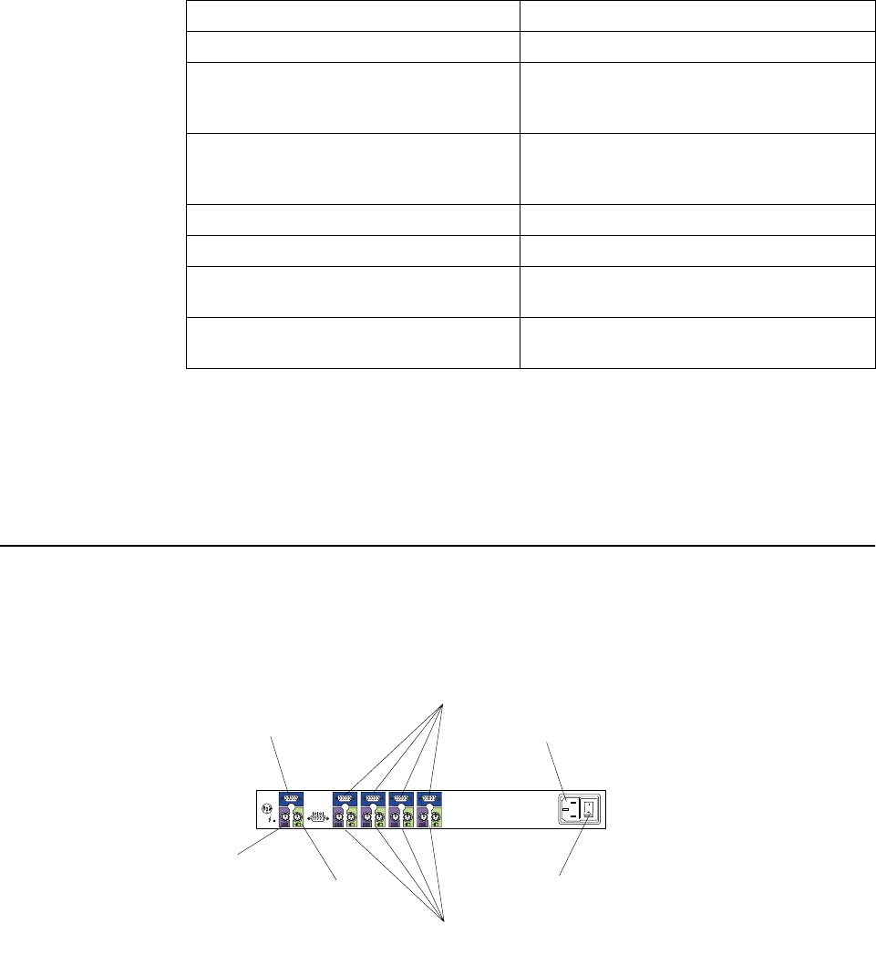
130 Hardware Maintenance Manual: IBM PC Server/Enterprise Racks
Note: A NetBAY Console Cable Set is required for each server that you will connect
to a console switch, or for each console switch you will connect to another
console switch in a tiered configuration. Console cable sets are available in
different lengths, and are color-coded the same as the ports on the console
switch.
Features
The 1x4 Console Switch allows you to connect up to four servers to a single monitor,
keyboard, and mouse. Port A is located on the rear of the console switch and is where
you connect the monitor, mouse, and keyboard. Ports 1 through 4 are where you
connect each of your servers.
The 2x8 Console Switch allows you to connect up to eight servers to a primary and
secondary monitor, mouse, and keyboard. Port A is located on the rear of the console
switch and is where you connect your primary monitor, mouse, and keyboard. Port B
is located on the front of the console switch and is where you connect your secondary
monitor, mouse, and keyboard. Ports 1 through 8 are where you connect each of your
servers.
1x4 Console Switch 2x8 Console Switch
Two vertical mounting brackets Two vertical mounting brackets
Miscellaneous hardware kit (for attaching
brackets and installing the console switch in
a rack cabinet)
Two horizontal mounting brackets, marked ’L’
and ’R’ (Left and Right)
One 1.8 m (6 ft) power cord Miscellaneous hardware kit (for attaching
brackets and installing the console switch in a
rack cabinet)
One 1.5 m (4.9 ft) IEC connector power cable One 1.8 m (6 ft) power cord
Apex User Guide CD One 1.5 m (4.9 ft) IEC connector power cable
IBM NetBAY Console Switch Installation
Instructions Manual Apex User Guide CD
IBM NetBAY Console Switch Installation
Instructions Manual
A1234
Server monitor ports 1-4
Server keyboard
and mouse ports 1-4
Primary monitor
Primary keyboard
Primary mouse
Power connector
Power switch
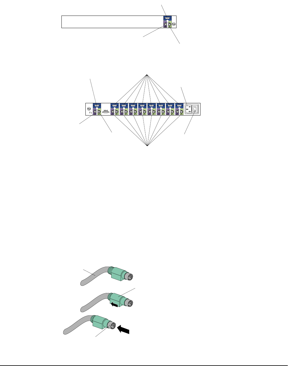
IBM NetBAY console switch 131
You can connect multiple console switches to each other in a tiered configuration. If
you use a 1x4 Console Switch as the primary switch, you can connect up to four
additional console switches and 32 servers. If you use a 2x8 Console Switch as the
primary switch, you can connect up to eight console switches and 64 servers. The
user interface of the primary switch will control all of the console switches in the tier.
The NetBAY Console Cable Set is available separately to connect servers to your
console switch. The console cables are available in different lengths, and are color-
coded in the same manner as the ports on the console switch.
The locking keyboard and mouse connectors automatically lock when you connect
them to prevent accidental disconnection. To disconnect one of these cables, grasp the
color-coded housing on the connector; then, pull the housing away from the console
switch to unlock the connector and disconnect the cable.
Tool requirements
You will need the following tools to install the console switch:
Secondary monitor
Secondary keyboard
Secondary mouse
B
A12345678
Server monitor ports 1-8
Server keyboard
and mouse ports 1-8
Primary monitor
Primary keyboard
Primary mouse
Power connector
Power switch
Cable
Locking
housing
Connector

132 Hardware Maintenance Manual: IBM PC Server/Enterprise Racks
•A Phillips screwdriver
•A 10mm nut driver or 10mm open-end or box wrench
Specifications
The following table contains the product specifications for the 1x4 Console Switch and
the 2x8 Console Switch:
Installation overview
Use the following general steps to install your console switch:
1. Install the console switch in your rack cabinet:
•Install a console switch inside the rear storage compartment of a NetBAY
monitor shelf according to Chapter 2, Installing a console switch in a monitor
shelf, on page 5 OR
•Install a console switch vertically in the side of your rack cabinet according to
Chapter 3, Installing a console switch vertically in a rack, on page 9, OR
•Install a console switch horizontally in 1U of EIA rack mounting space in
your rack cabinet according to Chapter 4, Installing a console switch
horizontally in a rack, on page 13.
2. If you have more than one console switch to install in your rack cabinet repeat
step 1 for each console switch.
3. Refer to the Apex User Guide CD for operation and configuration information.
Installing a console switch in a monitor shelf
Use the following procedure to install the console switch in the rear compartment of a
NetBAY monitor shelf:
1. Refer to the documentation that comes with your rack cabinet for additional
information.
1x4 Console Switch 2x8 Console Switch
Height 4.3 cm (1.7 in.) 4.3 cm (1.7 in.)
Depth 20.3 cm (8.0 in.) 20.3 cm (8.0 in.)
Width 43.2 cm (17 in.) 43.2 cm (17 in.)
Weight 2.38 kg (5.25 lbs) 2.59 kg (5.7 lbs)
Rated voltage 100 240 V ac 100 240 V ac
Rated frequency 50 60 Hz 50 60 Hz
Rated input current 1.0 A maximum 1.0 A maximum
Operating temperature at 0914 m
(03000 ft) 10° 35°C (50° 95°F) 10° 35°C (50° 95°F)
Operating temperature at 914-
2133 m (3000-7000 ft) 10° 32°C (50° 90°F) 10° 32°C (50° 90°F)
Operating humidity (non-
condensing) 8% 80% 8% 80%
Video modes supported VGA, SVGA, XGA VGA, SVGA, XGA
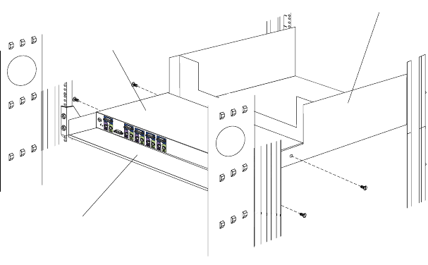
IBM NetBAY console switch 133
Note: Removing the rack doors and side panels might make your console switch
installation easier.
2. If the monitor shelf is not already installed, install the monitor shelf according to
its documentation.
3. Place the console switch in the rear compartment of the monitor shelf; then, install
and tighten the four M3x5 screws.
Notes:
a. Make sure that the rear of the console switch is facing the back of your rack
cabinet.
b. If you install a 2x8 Console Switch inside the monitor shelf, you will not be
able to use the B port on the console switch to connect a second monitor,
keyboard, and mouse.
Continue with the rest of the procedure to cable your console switch.
Note: Refer to the Apex User Guide CD for additional information if you are
configuring a tiered installation.
4. Verify that the power switch on the rear of the console switch is in the Off
position before connecting any cables.
5. Route your mouse cable neatly toward the rear of the console switch; then,
connect it to the appropriate mouse connector on Port A of the console switch.
AAAAA
Console switch
Monitor shelf
Rear compartment
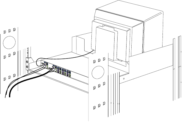
134 Hardware Maintenance Manual: IBM PC Server/Enterprise Racks
6. Connect the monitor signal cable from your monitor to the blue monitor
connector on Port A of the console switch; then, tighten the screws on the monitor
signal cable.
7. Route your keyboard cable neatly toward the rear of the console switch; then,
connect it to the appropriate keyboard connector on Port A of the console switch.
8. Connect one end of a console cable set to one of the numbered ports on the rear of
the console switch.
9. Route the console cable set toward the rear of your rack cabinet, and up or down
toward your server. Use the cable straps that come with this option to secure the
console cable set along the way.
10. Connect the other end of the console cable set to the appropriate monitor, mouse,
and keyboard connectors on your server.
11. Repeat step 8. to step 10. for all servers that you need to connect to your console
switch.
12. Connect the power cord that comes with the console switch to the power
connector on the rear of the console switch.
13. Route the power cord toward the rear of your rack cabinet, and either up or down
toward a properly wired and grounded power source such as an uninterruptable
power supply (UPS), a power distribution unit (PDU), or an electrical outlet. Use
the cable straps that come with this option to secure the power cord along the
way, and use the openings in your rack cabinet if you must exit the rack to
connect to your power source.
14. Refer to the Apex User Guide CD for configuration and operation information
about your console switch.
Installing a console switch vertically in a rack
Use the following procedure to install the console switch vertically in the side of your
rack cabinet:
Note: The mounting holes on upper and lower side braces in a rack side
compartment must be between 50.8 cm (20.0 in.) and 57.3 cm (22.6 in.) apart. If
your rack cabinet has movable side braces, refer to your rack documentation
for information about relocating your side braces if they are not already spaced
for this installation.
A1234
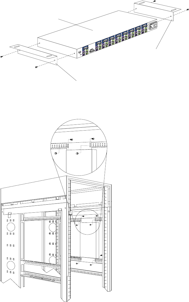
IBM NetBAY console switch 135
1. Refer to the documentation that comes with your rack cabinet for additional
information.
Note: Removing the rack doors and side panels might make your console switch
installation easier.
2. Attach one vertical mounting bracket to each side of the console switch using two
8-32 screws per bracket.
3. Hold the console switch against the side braces, with the rear of the console
switch facing the back of your rack cabinet; then, use four M6 screws and nuts to
attach the console switch to the side braces.
Continue with the rest of the procedure to cable your console switch.
Note: Refer to the Apex User Guide CD for additional information if you are
configuring a tiered installation.
8
1
A
2
3
4
5
6
7
Vertical mounting bracket
Vertical mounting bracket
Console switch
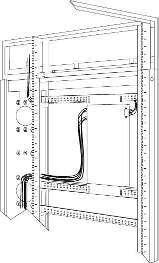
136 Hardware Maintenance Manual: IBM PC Server/Enterprise Racks
4. Verify that the power switch on the rear of the console switch is in the Off
position before connecting any cables.
5. Route your mouse cable neatly toward the rear of the console switch; then,
connect it to the appropriate mouse connector on Port A of the console switch.
6. Connect the monitor signal cable from your monitor to the blue monitor
connector on Port A of the console switch; then, tighten the screws on the monitor
signal cable.
7. Route your keyboard cable neatly toward the rear of the console switch; then,
connect it to the appropriate keyboard connector on Port A of the console switch.
8. If you have a 2x8 Console Switch, repeat step 5. to step 7. and connect a second
monitor, mouse, and keyboard to Port B on the front of your console switch.
9. Connect one end of a console cable set to one of the numbered ports on the rear of
the console switch.
10. Route the console cable set toward the rear of your rack cabinet, and up or down
toward your server. Use the cable straps that come with this option to secure the
console cable set along the way.
11. Connect the other end of the console cable set to the appropriate monitor, mouse,
and keyboard connectors on your server.
12. Repeat step 9. to step 11. for all servers that you need to connect to your console
switch.
13. Connect the power cord that comes with the console switch to the power
connector on the rear of the console switch.
14. Route the power cord toward the rear of your rack cabinet, and either up or down
toward a properly wired and grounded power source such as an uninterruptable
power supply (UPS), a power distribution unit (PDU), or an electrical outlet. Use
the cable straps that come with this option to secure the power cord along the
way, and use the openings in your rack cabinet if you must exit the rack to
connect to your power source.
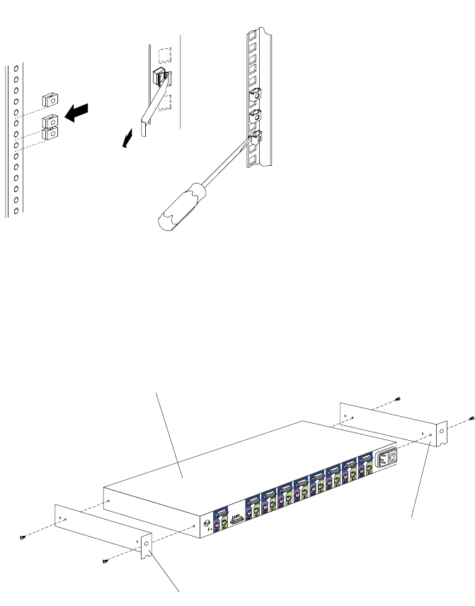
IBM NetBAY console switch 137
15. Refer to the Apex User Guide CD for configuration and operation information
about your console switch.
Installing a console switch horizontally in a rack
Use the following procedure to install the console switch horizontally in 1U of EIA
rack mounting space in your rack cabinet:
1. Refer to the documentation that comes with your rack cabinet for additional
information.
Notes:
a. Removing the rack doors and side panels might make your console switch
installation easier.
b. Use cage nuts for rack cabinets with square holes, or clip nuts for rack
cabinets with round holes.
2. Attach one horizontal mounting bracket to each side of the console switch using
two 8-32 screws per bracket. Make sure that the notched hole on the bracket is
toward the bottom of the console switch.
Note: There are two sets of mounting holes on the brackets. You can install the
console switch even with the EIA mounting flanges of the rack cabinet or
recessed, depending on how you install the brackets.
3. Determine the appropriate U level within the EIA mounting space; then, install
the console switch in the rear of your rack cabinet using four M6 screws and
either cage nuts or clip nuts.
Cage
nuts
Cage
nuts
Clip
nuts
8
1
A
2
3
4
5
6
7
Console switch
Horizontal mounting bracket
Horizontal mounting bracket
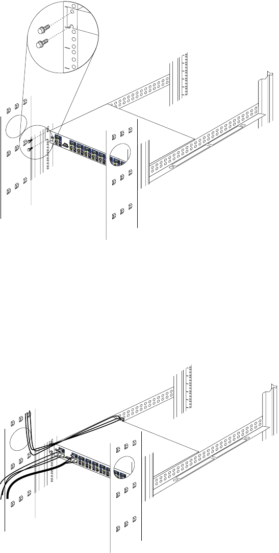
138 Hardware Maintenance Manual: IBM PC Server/Enterprise Racks
Continue with the rest of the procedure to cable your console switch.
Note: Refer to the Apex User Guide CD for additional information if you are
configuring a tiered installation.
4. Verify that the power switch on the rear of the console switch is in the Off
position before connecting any cables.
5. Route your mouse cable neatly toward the rear of the console switch; then,
connect it to the appropriate mouse connector on Port A of the console switch.
6. Connect the monitor signal cable from your monitor to the blue monitor
connector on Port A of the console switch; then, tighten the screws on the monitor
signal cable.
7. Route your keyboard cable neatly toward the rear of the console switch; then,
connect it to the appropriate keyboard connector on Port A of the console switch.
8. If you have a 2x8 Console Switch, repeat step 5. to step 7. and connect a second
monitor, mouse, and keyboard to Port B on the front of your console switch.
Important
Information
Important
Information
1
0
1
0
1
5
A
26
37
44
A15
26
33
44
1
0
1
0

IBM NetBAY console switch 139
9. Connect one end of a console cable set to one of the numbered ports on the rear of
the console switch.
10. Route the console cable set toward the rear of your rack cabinet, and up or down
toward your server. Use the cable straps that come with this option to secure the
console cable set along the way.
11. Connect the other end of the console cable set to the appropriate monitor, mouse,
and keyboard connectors on your server.
12. Repeat step 9. to step 11. for all servers that you need to connect to your console
switch.
13. Connect the power cord that comes with the console switch to the power
connector on the rear of the console switch.
14. Route the power cord toward the rear of your rack cabinet, and either up or down
toward a properly wired and grounded power source such as an uninterruptable
power supply (UPS), a power distribution unit (PDU), or an electrical outlet. Use
the cable straps that come with this option to secure the power cord along the
way, and use the openings in your rack cabinet if you must exit the rack to
connect to your power source.
15. Refer to the Apex User Guide CD for configuration and operation information
about your console switch.
Parts listing (NetBAY Console Switch)
NetBAY (Console Switch) FRU
1x4 switch 06P6003
2x8 switch 06P6004
7-foot locking console cable 06P6006
12-foot locking console cable 06P6007
140 Hardware Maintenance Manual: IBM PC Server/Enterprise Racks
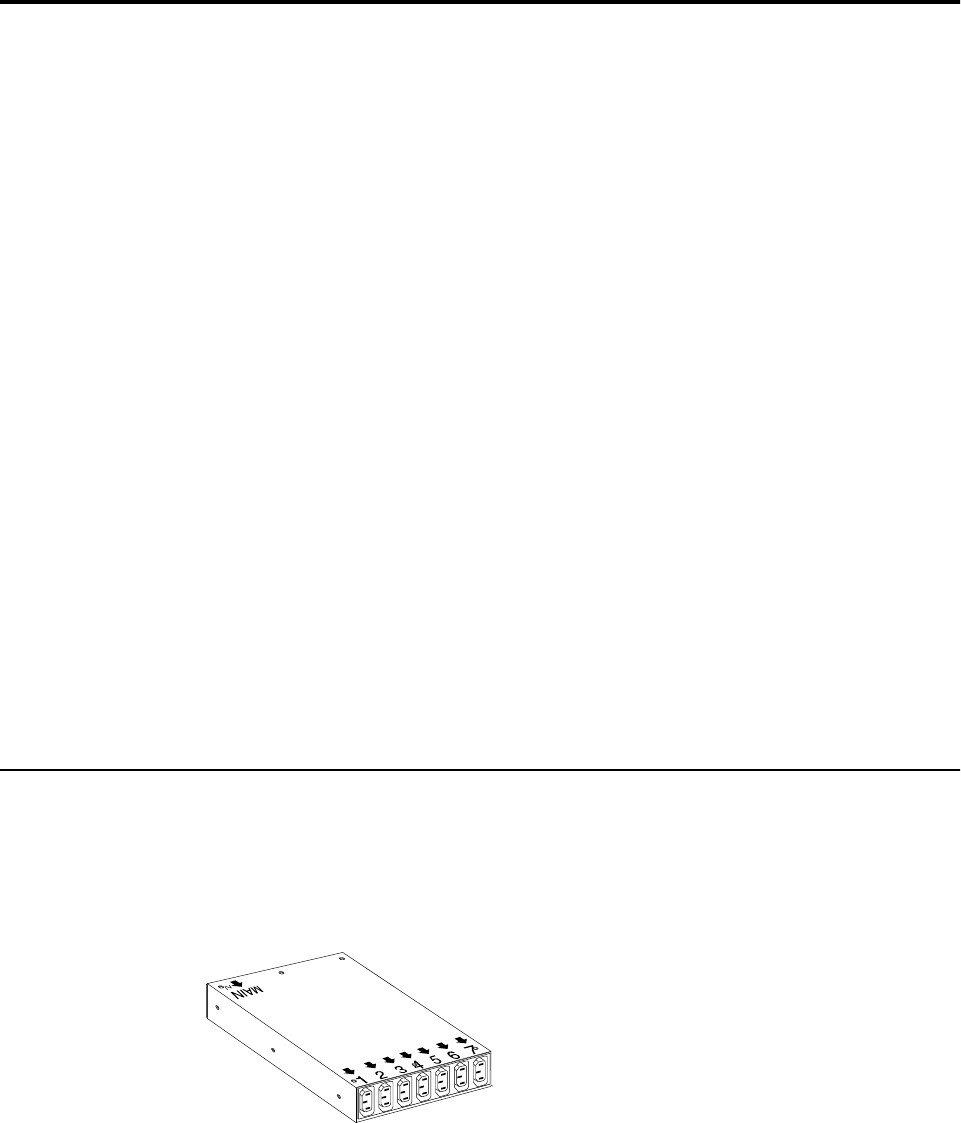
© Copyright IBM Corp. 2001 141
NetBAY Power Distribution Units
NetBAY rack Power Distribution Unit introduction
141
Tool requirements . . . . . . . . . . . . . . . . . . . . . . . . . . 142
Installation overview . . . . . . . . . . . . . . . . . . . . . . . 142
Installing devices vertically . . . . . . . . . . . . . . . . . . 142
Installing a single device horizontally . . . . . . . . . 144
Installing two devices horizontally . . . . . . . . . . . 146
Cabling your PDUs. . . . . . . . . . . . . . . . . . . . . . . . . 148
NetBAY front-end Power Distribution Unit
introduction . . . . . . . . . . . . . . . . . . . . . . . . . . . . . . . 156
Tool requirements . . . . . . . . . . . . . . . . . . . . . . . . . . 157
Installation overview . . . . . . . . . . . . . . . . . . . . . . . 157
Installing a single device vertically . . . . . . . . . . . 157
Installing two devices vertically . . . . . . . . . . . . . . 160
Rack PDU specifications . . . . . . . . . . . . . . . . . . . . 164
Line cords . . . . . . . . . . . . . . . . . . . . . . . . . . . . . . . . 165
Power cables . . . . . . . . . . . . . . . . . . . . . . . . . . . . . . 165
NetBAY server dual-cord Power Distribution Unit
introduction. . . . . . . . . . . . . . . . . . . . . . . . . . . . . . . 166
Tool requirements. . . . . . . . . . . . . . . . . . . . . . . . . . 167
Installation overview. . . . . . . . . . . . . . . . . . . . . . . 167
Installing devices vertically . . . . . . . . . . . . . . . . . 167
Installing a single device horizontally. . . . . . . . . 169
Installing two devices horizontally . . . . . . . . . . . 171
Cabling your PDUs . . . . . . . . . . . . . . . . . . . . . . . . 173
Power cables . . . . . . . . . . . . . . . . . . . . . . . . . . . . . . 180
Line cords . . . . . . . . . . . . . . . . . . . . . . . . . . . . . . . . 181
Parts listing (Power Distribution Units) . . . . . . . 181
The IBM NetBAY Rack Power Distribution Units are part of the Rack Modular Power
Distribution Unit (M/PDU) family.
These Rack PDUs are used in all models of the IBM 9306 and 9308 racks.
The Rack PDUs come in three types:
•NetBAY Rack Power Distribution Unit
•NetBAY Front-end Power Distribution Unit
•NetBAY Server Dual-cord Power Distribution Unit
NetBAY rack Power Distribution Unit introduction
The IBM NetBAY Rack Power Distribution Unit is part of the Rack Modular Power
Distribution Unit (M/PDU) family and enables you to connect up to seven devices to
a single dedicated power source, such as an electrical outlet or an uninterruptable
power supply (UPS). The Rack PDU has one power inlet and seven IEC standard
power outlets.
Notes:
1. Power cables for devices that you will connect to the Rack PDU do not come with
the Rack PDU.
2. You will have some unused parts depending upon how you install the Rack PDU.
3. When you install two Rack PDUs you will need some parts from both devices.
142 Hardware Maintenance Manual: IBM PC Server/Enterprise Racks
4. You can install other M/PDU family devices next to your Rack PDU using
mounting hardware from both devices.
You can install the Rack PDU vertically in the side of your rack cabinet, or
horizontally within 1U of EIA mounting space in your rack cabinet. The mounting
hardware that comes with this option enables you to install one Rack PDU next to
another in the same mounting space within your rack cabinet.
The following parts come with the Rack PDU:
•One Rack PDU
•One line cord (Some models include both a high voltage and a low voltage line
cord)
•One vertical mounting plate
•One vertical-mounting cable-management bracket
•One horizontal mounting bracket
•One single-device attachment bracket (for horizontal-mount installations)
•One dual-device attachment bracket (for horizontal-mount installations)
•One 1U blank filler panel (for horizontal-mount installations)
•Miscellaneous hardware kit (for attaching brackets and installing the device in a
rack cabinet)
•Cable straps
•Installation documentation
Note: The illustrations in this documentation might be slightly different from your
hardware.
Tool requirements
You will need the following tools to install the Rack PDU:
•A Phillips screwdriver
•A 10-mm nut driver or 10-mm open-end or box wrench
Installation overview
Use the following general steps to install your Rack PDU:
1. Install one or two devices in your rack cabinet
•Install devices vertically in the side of your rack cabinet according
to“Installing devices vertically”, OR
•Install a single device horizontally in your rack cabinet in 1U of available EIA
mounting space according to “Installing a single device horizontally” on page
144, OR
•Install two devices horizontally in your rack cabinet in 1U of available EIA
mounting space according to “Installing two devices horizontally” on page
171.
2. Connect line cords and cables according to “Cabling your PDUs” on page 148.
Installing devices vertically
Use the following procedure to mount the Rack PDU in the side of your rack cabinet:
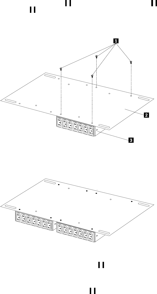
NetBAY Power Distribution Units 143
Note: The mounting holes on the upper and lower side braces in a rack side
compartment must be between 48.6 cm (19.1 in.) and 56.9 cm (22.4 in.) apart. If
your rack cabinet has movable side braces, refer to your rack documentation
for information about relocating your side braces if they are not already spaced
for this installation.
1. Refer to the documentation that comes with your rack cabinet for additional
information.
Note: Removing the rack doors and side panels might make your Rack PDU
installation easier.
2. Verify that the circuit breaker switch is in the Off position before installing your
Rack PDU.
3. Install the Rack PDU 3 to the vertical mounting plate 2 with four M3x5
screws 1 that come with this option. Make sure that the countersink holes in
the vertical mounting plate are facing away from the device.
Note: Align the Rack PDU to one end or the other of the vertical mounting plate
to leave room for a second device.
Figure 58. Installing the Rack PDU on the vertical mounting plate
4. If you have a second M/PDU device to install, install it on the vertical mounting
plate with four M3x5 screws that come with the second device.
Figure 59. Installing a second Rack PDU
5. Install the vertical mounting plate 2 in the side of your rack cabinet with four
M6 screws and nuts that come with this option. Make sure that the seven-
connector side of the Rack PDU is facing the rear of your rack cabinet, and leave
room between the vertical mounting plate and the rear EIA mounting flanges for
the cable-management bracket 1.
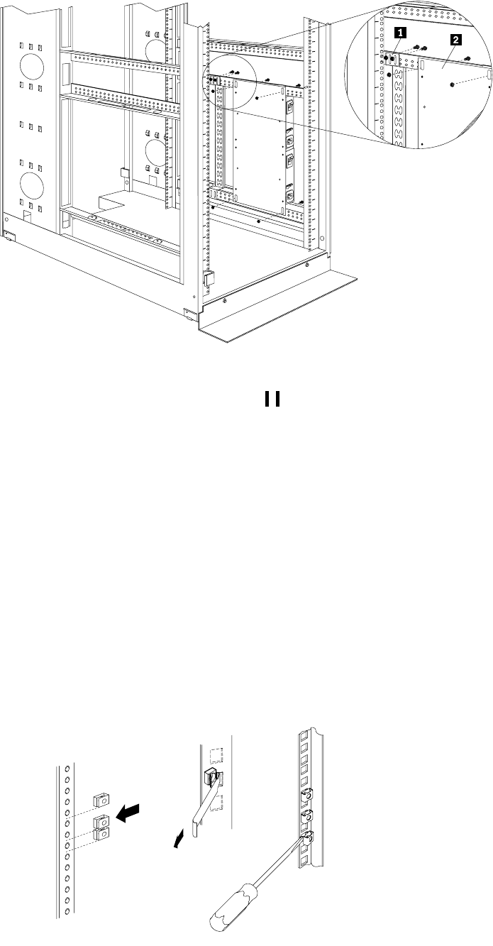
144 Hardware Maintenance Manual: IBM PC Server/Enterprise Racks
Figure 60. Installing the vertical mounting plate and cable-management bracket
6. Install the cable-management bracket 1 beside the vertical mounting plate with
four M6 screws and nuts that come with this option.
Proceed to“Cabling your PDUs” on page 148 for instructions on how to cable
your Rack PDU.
Installing a single device horizontally
Use the following procedure to mount a single Rack PDU horizontally in your rack
cabinet:
1. Refer to the documentation that comes with your rack cabinet for additional
information.
Notes:
a. Removing the rack doors and side panels might make your Rack PDU
installation easier.
b. Use clip nuts for rack cabinets with round holes; use cage nuts for rack
cabinets with square holes.
Cage
nuts
Cage
nuts
Clip
nuts
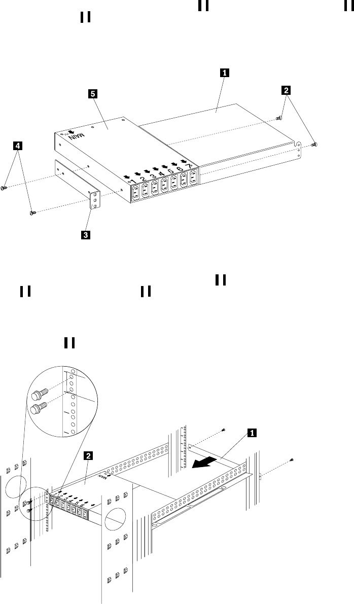
NetBAY Power Distribution Units 145
2. Verify that the circuit breaker switch is in the Off position before installing
your Rack PDU.
3. Install the horizontal mounting bracket 3on one side of the Rack PDU 5 with
M3x5 screws 4.
Note: There are two sets of mounting holes on the bracket. You can align the
Rack PDU to be even with the back of the rack cabinet or recessed inside,
depending on how you install the bracket.
Figure 61. Installing the mounting brackets for a single device
4. Install the single-device attachment bracket 1 on the other side of the Rack PDU
5 with two M3x5 screws 2. Make sure that you use the same set of mounting
holes on this bracket as you used on the bracket in the previous step.
5. Determine the U level within your rack cabinet where you are going to install the
Rack PDU; then, install the Flat Panel Monitor Rack Mount Kit and bracket
assembly 2 in the rear of the rack cabinet with four M6 screws and clip nuts or
cage nuts (two screws and nuts per bracket).
Figure 62. Installing the Rack PDU and the blank filler panel
7
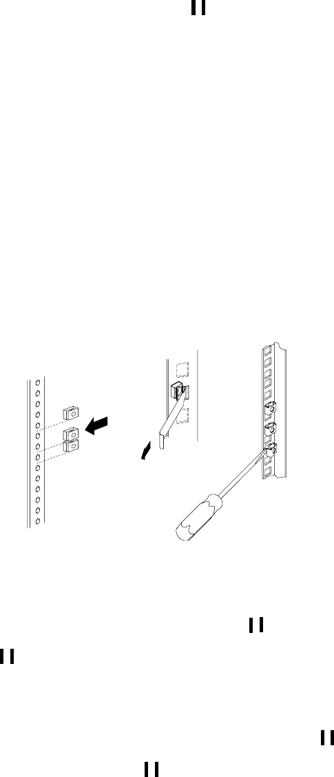
146 Hardware Maintenance Manual: IBM PC Server/Enterprise Racks
6. Install the 1U blank filler panel 1 on the front of the rack cabinet at the same U
level as the Rack PDU. Use two M6 screws that come with this option.
Proceed to “Cabling your PDUs” on page 148 for instructions on how to cable
your Rack PDU.
Installing two devices horizontally
Use the following procedure to mount two Rack PDUs horizontally in your rack
cabinet:
1. Refer to the documentation that comes with your rack cabinet for additional
information.
Notes:
a. Removing the rack doors and side panels might make your Rack PDU
installation easier.
b. Use clip nuts for rack cabinets with round holes; use cage nuts for rack
cabinets with square holes.
2. Verify that the circuit breaker switch is in the Off position before installing your
Rack PDU.
3. Attach a dual-device attachment bracket 6 to the right side of one of the Rack
PDUs with two M3x5 screws; then, attach another dual-device attachment bracket
5 to the left side of the other Rack PDU with two M3x5 screws.
Notes:
a. When you install two Rack PDUs next to each other, you will need some parts
from both options.
b. Turn the second dual-device attachment bracket 5 so that the threaded
holes are on the opposite side of the device as the holes on the other
attachment bracket 6.
Cage
nuts
Cage
nuts
Clip
nuts
NetBAY Power Distribution Units 147
Figure 63. Installing the mounting brackets for two devices
4. Push the two Rack PDUs together, aligning the holes on the dual-device
attachment brackets; then, use four M6 screws to secure the front 1 and rear 2
of the brackets to each other.
5. Install a horizontal mounting bracket 4 on the Rack PDU on the right with two
M3x5 screws 3; then, install the other horizontal mounting bracket 7 on the
Rack PDU on the left with two M3x5 screws 8.
Note: There are two sets of mounting holes on the brackets. You can align the
Rack PDU to be even with the back of the rack cabinet or recessed inside,
depending on how you install the brackets.
6. Determine the U level within your rack cabinet where you are going to install the
Rack PDUs; then, install both Flat Panel Monitor Rack Mount Kits 2 in the rear
of the rack cabinet with four M6 screws and clip nuts or cage nuts (two screws
and nuts per bracket).
148 Hardware Maintenance Manual: IBM PC Server/Enterprise Racks
Figure 64. Installing two Rack PDUs and the blank filler panel
7. Install the 1U blank filler panel 1on the front of the rack cabinet at the same U
level as the Rack PDU. Use two M6 screws that come with this option.
Proceed to “Cabling your PDUs” on page 173 for instructions on how to cable
your Rack PDU.
Cabling your PDUs
Cable routing differs between horizontal and vertical Rack PDU installations. Refer to
“Cabling instructions for vertical-mount PDUs” on page 150 or “Cabling instructions
for horizontal-mount PDUs” on page 151 as appropriate for your installation.
77
NetBAY Power Distribution Units 149
Statement 1
DANGER
Statement 13
To connect:
1. Turn everything OFF.
2. First, attach all cables to devices.
3. Attach signal cables to connectors.
4. Attach power cords to outlet.
5. Turn device ON.
To disconnect:
1. Turn everything OFF.
2. First, remove power cords from outlet.
3. Remove signal cables from connectors.
4. Remove all cables from devices.
Electrical current from power, telephone, and communication cables is
hazardous. To avoid a shock hazard:
•Do not connect or disconnect any cables or perform installation,
maintenance, or reconfiguration of this product during an electrical
storm.
•Connect all power cords to a properly wired and grounded electrical
outlet.
•Connect to properly wired outlets any equipment that will be attached to
this product.
•When possible, use one hand only to connect or disconnect signal cables.
•Never turn on any equipment when there is evidence of fire, water, or
structural damage.
•Disconnect the attached power cords, telecommunications systems,
networks, and modems before you open the device covers, unless
instructed otherwise in the installation and configuration procedures.
150 Hardware Maintenance Manual: IBM PC Server/Enterprise Racks
DANGER
Cabling instructions for vertical-mount PDUs
If your Rack PDU came with more than one line cord, select either the high-voltage
cord or the low-voltage cord for your installation. Use the following procedure to
connect and route cables for Rack PDUs that you mounted vertically in the side of
your rack cabinet:
1. Connect the line cord that comes with this option to the inlet on the Rack PDU;
then, remove the screw on the cable clamp 1 and route the line cord through the
clamp.
Figure 65. Connecting and routing the line cord
Overloading a branch circuit is potentially a fire hazard and a shock hazard
under certain conditions. To avoid these hazards, ensure that your system
electrical requirements do not exceed branch circuit protection requirements.
Refer to the information that is provided with your IBM device for electrical
specifiacations. Also adhere to the following statements:
1. If you are connecting to a 120-127 V ac power source, connect each power
cord to a separate branch circuit.
2. If you are connecting to a 200-240 V ac power source and the branch
circuit rating is:
a. 13 amps or less, connect each power cord to a separate branch circuit.
b. 14 amps to 19 amps, do not connect more than two power cords to the
same branch circuit.
c. 20 amps or greater, you may connect up to three power cords to the
same branch circuit.
MAIN MAIN
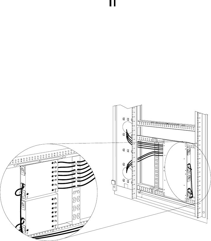
NetBAY Power Distribution Units 151
2. Reinstall the screw on the cable clamp 1 and repeat step 1 for the other device if
you installed two devices.
3. Route the line cords down and toward the rack side braces; then, route the line
cords along the side brace towards the back of the rack cabinet and secure them
with the cable straps that come with this option.
4. Route the line cords toward a dedicated power source, such as a UPS or electrical
outlet. Use the provided cable straps to secure the line cords along the way. Use
the openings in your rack cabinet, if you must exit the rack cabinet to connect to
your power source.
5. After you connect the line cords to properly wired and grounded dedicated
power sources, you can turn on the circuit breaker; then, connect other devices in
your rack cabinet to the seven power outlets on the Rack PDU. Route all other
power cables neatly, and use the cable-management bracket to secure the cables
that you plug into the outlets on the Rack PDU.
Figure 66. Connecting and routing other power cables to the outlets
Cabling instructions for horizontal-mount PDUs
If your Rack PDU came with more than one line cord, select either the high-voltage
cord or the low-voltage cord for your installation. Use the following procedure to
connect and route cables for Rack PDUs that you mounted in the horizontal EIA space
of your rack cabinet:
1. Connect the line cord that comes with this option to the inlet on a Rack PDU; then,
remove the screw on the cable clamp and route the line cord through the clamp.
MAIN MAIN
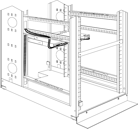
152 Hardware Maintenance Manual: IBM PC Server/Enterprise Racks
Figure 67. Connecting and routing the line cord
Reinstall the screw on the cable clamp and repeat this step for the other device, if
you installed two devices.
2. Route the line cords left or right, toward the side of the rack cabinet; then, route
the line cords along the side brace towards the back of the rack cabinet and secure
them with the cable straps that come with this option.
3. Route the line cords toward a dedicated power source, such as a UPS or electrical
outlet. Use the provided cable straps to secure the line cords along the way. Use
the openings in your rack cabinet, if you must exit the rack cabinet to connect to
your power source.
4. After you connect the line cords to properly wired and grounded dedicated
power sources, you can turn on the circuit breaker; then, connect other devices in
your rack cabinet to the seven power outlets on the Rack PDU. Route all other
power cables neatly, and use cable straps to secure the cables that you plug into
the outlets on the Rack PDU.
MAIN
45667
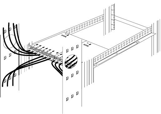
NetBAY Power Distribution Units 153
Figure 68. Connecting and routing other power cables to the outlets
77

154 Hardware Maintenance Manual: IBM PC Server/Enterprise Racks
Rack PDU specifications
When connected to a dedicated power source, the Rack PDU conforms to UL950, CSA
22.0-950, EN-60950, and IEC-950 standards. The following table contains the product
specifications for the Rack PDU:
Height 43 mm (1.7 in.)
Width 192 mm (7.5 in.)
Depth 221 mm (8.7 in.)
Weight 1.5 kg (3.2 lbs)
Operating temperatures 10°C–35°C (50°F–95°F) at 0–914 m (0–3000 ft)
10°C–32 °C (50°F–90°F°) at 914–2133 m (3000–7000 ft)
Operating humidity 8–80% (non-condensing)
Rated voltage 100–240 V ac, 15 A, single-phase
Rated frequency 50–60 Hz
Maximum power rating 3600 VA
Circuit breaker Two-pole, 15 A with time-delay protection for up to 600 A
input current without nuisance tripping.
Power inlet IEC 320-C20 inlet rated at 16 A (VDE) / 20 A (UL/CSA)
Power outlets Seven IEC 320-C13 outlets rated at 10 A (VDE) / 15 A
(UL/CSA)

NetBAY Power Distribution Units 155
Power cables
Power cables that you use to connect a system, storage expansion unit, and other
devices to the Rack PDU usually come with those devices. The following table
contains a list of power cables that you can use with the Rack PDU:
Power cables that you use to connect your Rack PDU to a UPS or Front-end PDU
come with those devices as indicated in the following table:
Length Cable rating Plug type Cable part #
2.8 m (9.2 ft) 250 V, 10 A IEC 320-C13 to IEC 320-C14 36L8886
4.3 m (14 ft) 250 V, 10 A IEC 320-C13 to IEC 320-C14 94G7448
Length Cable
rating Plug type Cable
part # Comes with:
2 m (6.6 ft) 250 V, 16 A IEC 320-C19 to IEC 320-C20 00N7700 APC SU-5000 RMB UPS
(2 cables)
1 m (3.3 ft) 250 V, 16 A IEC 320-C19 to IEC 320-C20 00N7698 Front-end PDU
(3 cables)
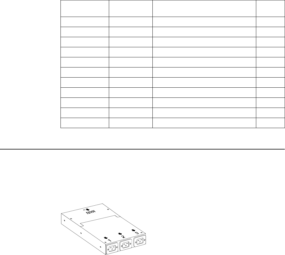
156 Hardware Maintenance Manual: IBM PC Server/Enterprise Racks
Line cords
A 4.3 m (14 ft) country-specific line cord that you use to connect your Rack PDU to a
properly wired, grounded, and dedicated power source comes with the Rack PDU.
The following table contains a list of line cords that you can use with the Rack PDU:
NetBAY front-end Power Distribution Unit introduction
The IBM NetBAY Single-phase and Three-phase Front-end Power Distribution Units
are part of the Rack Modular Power Distribution Unit (M/PDU) family and enable
you to connect a single-phase or three-phase dedicated power source to three different
single-phase PDUs in the M/PDU family. The Rack PDU has one power source inlet
and three IEC standard power outlets.
Notes:
1. You will have some unused parts depending upon how you install the Rack PDU.
2. You can install other M/PDU family devices next to your Rack PDU using
mounting hardware from both devices.
You must install the Rack PDU vertically in the side of your rack cabinet with the
provided mounting hardware. The following parts come with the Rack PDU:
The following parts come with the Rack PDU:
•One 1P Rack PDU with a fixed line cord or one 3P Flat Panel Monitor Rack Mount
Kit with a fixed line cord
•Three power cables (for connecting other M/PDU family devices)
Power Source Line cord rating Plug type Line cord
part #
100–127 V ac, 20 A 127 V ac, 18 A IEC 320-C19 to NEMA L5-20P 12J5117
200–240 V ac, 20 A 250 V ac, 18 A IEC 320-C19 to NEMA L6-20P 14F1553
220–240 V ac, 16 A 250 V ac, 16 A IEC 320-C19 to CEE7-VII 14F1554
220–240 V ac, 16 A 250 V ac, 16 A IEC 320-C19 to IEC 309-2P + Gnd 36L8823
220–240 V ac, 16 A 250 V ac, 16 A IEC 320-C19 to SII 32 14F1561
220–240 V ac, 16 A 250 V ac, 16 A IEC 320-C19 to CEI 23-16 14F1560
220–240 V ac, 16 A 250 V ac, 16 A IEC 320-C19 to SABS 164 14F1557
220–240 V ac, 13 A 250 V ac, 13 A IEC 320-C19 to BS 1363/A 12J5988
220–240 V ac, 15 A 250 V ac, 15 A IEC 320-C19 to AS/NZ 3112 14F1559
220–240 V ac, 15 A 250 V ac, 15 A IEC 320-C19 to GB 2099.1 01K9852
220–240 V ac, 15 A 250 V ac, 15 A IEC 320-C19 to IRAM 2063 36L8885
NetBAY Power Distribution Units 157
•One vertical mounting plate
•One vertical-mounting cable-management bracket
•Miscellaneous hardware kit (for attaching brackets and installing the device in a
rack cabinet)
•Cable straps
•Installation documentation
Note: The illustrations in this documentation might be slightly different from your
hardware.
Tool requirements
You will need the following tools to install the Rack PDU:
•A Phillips screwdriver
•A 10-mm nut driver or 10-mm open-end or box wrench
Installation overview
Use the following general steps to install your Rack PDU:
1. Install one or two devices in your rack cabinet:
•Install a single device vertically in the side of your rack cabinet according to
“Installing a single device vertically”, OR
•Install two devices vertically in the side of your rack cabinet according to
“Installing two devices vertically” on page 160.
2. Connect line cords and cables as appropriate for your installation.
Installing a single device vertically
Use the following procedure to mount a single Rack PDU in the side of your rack
cabinet:
Note: The mounting holes on the upper and lower side braces in a rack side
compartment must be between 48.6 cm (19.1 in.) and 56.9 cm (22.4 in.) apart. If
your rack cabinet has movable side braces, refer to your rack documentation
for information about relocating your side braces if they are not already spaced
for this installation.
158 Hardware Maintenance Manual: IBM PC Server/Enterprise Racks
Statement 1
DANGER
1. Refer to the documentation that comes with your rack cabinet for additional
information.
Note: Removing the rack doors and side panels might make your Rack PDU
installation easier.
2. Install the Rack PDU on the center of the vertical mounting plate 2 with four
M3x5 screws 1 that come with this option. Make sure that the countersink holes
in the vertical mounting plate are facing away from the device.
To connect:
1. Turn everything OFF.
2. First, attach all cables to devices.
3. Attach signal cables to connectors.
4. Attach power cords to outlet.
5. Turn device ON.
To disconnect:
1. Turn everything OFF.
2. First, remove power cords from outlet.
3. Remove signal cables from connectors.
4. Remove all cables from devices.
Electrical current from power, telephone, and communication cables is
hazardous. To avoid a shock hazard:
•Do not connect or disconnect any cables or perform installation,
maintenance, or reconfiguration of this product during an electrical
storm.
•Connect all power cords to a properly wired and grounded electrical
outlet.
•Connect to properly wired outlets any equipment that will be attached to
this product.
•When possible, use one hand only to connect or disconnect signal cables.
•Never turn on any equipment when there is evidence of fire, water, or
structural damage.
•Disconnect the attached power cords, telecommunications systems,
networks, and modems before you open the device covers, unless
instructed otherwise in the installation and configuration procedures.
•Connect and disconnect cables as described in the following table when
installing, moving, or opening covers on this product or attached devices.
NetBAY Power Distribution Units 159
Figure 69. Installing the Rack PDU on the vertical mounting plate
3. Install the vertical mounting plate in the side of your rack cabinet with four M6
screws and nuts that come with this option. Make sure that the three-connector
side of the Rack PDU is facing up.
Figure 70. Installing the vertical mounting plate
4. Route the fixed line cord down, towards the rack side braces; then, route the line
cord along the side brace towards the back of the rack cabinet and secure it with
the cable straps that come with this option.
160 Hardware Maintenance Manual: IBM PC Server/Enterprise Racks
Figure 71. Routing the fixed line cord and power cables
5. Route the line cord towards a dedicated power source. Use the provided cable
straps to secure the line cord along the way. Use the openings in your rack
cabinet, if you must exit the rack cabinet to connect to your power source.
6. After you connect the line cord to a properly wired and grounded dedicated
power source, you can connect up to three other M/PDU family devices to the
three power outlets on the Rack PDU. Route all other power cables neatly, and
use the provided cable straps to secure the cables that you plug into the outlets on
the Rack PDU.
Installing two devices vertically
Use the following procedure to mount two Rack PDUs in the side of your rack
cabinet:
Note: The mounting holes on the upper and lower side braces in a rack side
compartment must be between 48.6 cm (19.1 in.) and 56.9 cm (22.4 in.) apart. If
your rack cabinet has movable side braces, refer to your rack documentation
for information about relocating your side braces if they are not already spaced
for this installation.
1
23
MAIN
NetBAY Power Distribution Units 161
Statement 1
DANGER
1. Refer to the documentation that comes with your rack cabinet for additional
information.
Note: Removing the rack doors and side panels might make your Rack PDU
installation easier.
2. Install the Rack PDU 3 on the vertical mounting plate 2 with four M3x5
screws 1 that come with this option. Make sure that the countersink holes in
the vertical mounting plate are facing away from the device.
Note: Align the Rack PDU to one end or the other of the vertical mounting plate
to leave room for a second device.
To connect:
1. Turn everything OFF.
2. First, attach all cables to devices.
3. Attach signal cables to connectors.
4. Attach power cords to outlet.
5. Turn device ON.
To disconnect:
1. Turn everything OFF.
2. First, remove power cords from outlet.
3. Remove signal cables from connectors.
4. Remove all cables from devices.
Electrical current from power, telephone, and communication cables is
hazardous. To avoid a shock hazard:
•Do not connect or disconnect any cables or perform installation,
maintenance, or reconfiguration of this product during an electrical
storm.
•Connect all power cords to a properly wired and grounded electrical
outlet.
•Connect to properly wired outlets any equipment that will be attached to
this product.
•When possible, use one hand only to connect or disconnect signal cables.
•Never turn on any equipment when there is evidence of fire, water, or
structural damage.
•Disconnect the attached power cords, telecommunications systems,
networks, and modems before you open the device covers, unless
instructed otherwise in the installation and configuration procedures.
•Connect and disconnect cables as described in the following table when
installing, moving, or opening covers on this product or attached devices.
162 Hardware Maintenance Manual: IBM PC Server/Enterprise Racks
Figure 72. Installing the Rack PDU on the vertical mounting plate
3. If you have a second M/PDU device to install, install it on the vertical mounting
plate with four M3x5 screws that come with the second device.
Figure 73. Installing a second Rack PDU
4. Install the vertical mounting plate 2 in the side of your rack cabinet with four
M6 screws and nuts that come with this option. Make sure that the three-
connector side of the Rack PDU is facing the rear of your rack cabinet, and leave
room between the vertical mounting plate and the rear EIA mounting flanges for
the cable-management bracket 1.
NetBAY Power Distribution Units 163
Figure 74. Installing the vertical mounting plate and cable-management bracket
5. Install the cable-management bracket 1 beside the vertical mounting plate with
four M6 screws and nuts that come with this option.
6. Route the fixed line cords down, towards the rack side braces; then, route the line
cords along the side brace towards the back of the rack cabinet and secure them
with the cable straps that come with this option.
Figure 75. Routing the fixed line cords
1
1
2
23
3
MAIN MAIN
164 Hardware Maintenance Manual: IBM PC Server/Enterprise Racks
7. Route each line cord towards a dedicated power source. Use the provided cable
straps to secure the line cords along the way. Use the openings in your rack
cabinet, if you must exit the rack cabinet to connect to your power source.
8. After you connect both line cords to properly wired and grounded dedicated
power sources, you can connect up to three other M/PDU family devices to the
three power outlets on each Rack PDU. Route all other power cables neatly, and
use the cable-management bracket to secure the cables that you plug into the
outlets on the Rack PDU.
Figure 76. Connecting and routing other power cables to the outlets
Rack PDU specifications
When connected to a properly wired, grounded, and dedicated power source, the
Rack PDU conforms to UL950, CSA 22.0-950, EN-60950, and IEC-950 standards. The
following table contains the product specifications for the Rack PDU:
1
1
2
23
3
MAIN
MAIN

NetBAY Power Distribution Units 165
Line cords
The 2.5 m (8.2 ft) fixed line cord on the Rack PDU determines the connectivity of the
Rack PDU. The following table contains a list of the line cords that you can use with
the Rack PDU:
Power cables
The Rack PDU comes with three power cables, that you use to connect to other
M/PDU family devices, as listed in the following table:
Height 43 mm (1.7 in.)
Width 192 mm (7.5 in.)
Depth 221 mm (8.7 in.)
Weight 1.6 kg (3.5 lbs)
Operating temperatures 10°C–35°C (50°F–95°F) at 0–914 m (0–3000 ft)
10°C–32 °C (50°F–90°F°) at 914–2133 m (3000–7000 ft)
Operating humidity 8–80% (non-condensing)
Rated voltage 100–120 V ac, 30 A, single-phase
200–240 V ac, 30 A, single-phase
200–240 V ac, 32 A, single-phase
200–240 V ac, 30 A, single-phase
380–415 V ac, 32 A, single-phase
Rated frequency 50–60 Hz
Maximum power rating 4800-6000 VA
Power inlet One fixed line cord
Power outlets Three IEC 320-C19 outlets rated at 16 A (VDE) / 20 A
(UL/CSA)
Power Source Line cord rating Plug type Line cord
part #
100-127 V ac, 30 A, single-phase 127 V, 30 A NEMA L5-30P 24P6846
200-240 V ac, 30 A, single-phase 250 V, 30 A NEMA L6-30P 24P6847
200-240 V ac, 32 A, single-phase 250 V, 32 A IEC 309-2P + Gnd 24P6848
200-240 V ac, 30 A, three-phase 250 V, 30 A NEMA L21-30P 24P6844
380-415 V ac, 32 A, three-phase 415 V, 32 A IEC 309-3P + N + Gnd 24P6845
166 Hardware Maintenance Manual: IBM PC Server/Enterprise Racks
NetBAY server dual-cord Power Distribution Unit introduction
The IBM NetBAY Server Dual-cord Power Distribution Unit is part of the Rack
Modular Power Distribution Unit (M/PDU) family and enables you to connect one
server to two dedicated, independent, and redundant power sources, such as an
electrical outlet and an uninterruptable power supply (UPS). The Rack PDU has two
power inlets, for Main and Backup power connections, and four IEC standard power
outlets.
Notes:
1. You will have some unused parts depending upon how you install the Rack PDU.
2. When you install two Rack PDUs you will need some parts from both options.
3. You can install other M/PDU family devices next to your Rack PDU using
mounting hardware from both devices.
You can install the Rack PDU vertically in the side of your rack cabinet, or
horizontally within 1U of EIA mounting space in your rack cabinet. The mounting
hardware that comes with this option enables you to install one Rack PDU next to
another in the same mounting space within your rack cabinet.
The following parts come with the Rack PDU:
•One Rack PDU
•Two line cord (some models come with two high voltage and two low voltage line
cords)
•One vertical mounting plate
•One vertical-mounting cable-management bracket
•One horizontal mounting bracket
•One single-device attachment bracket (for horizontal-mount installations)
•One dual-device attachment bracket (for horizontal-mount installations)
•One 1U blank filler panel (for horizontal-mount installations)
•Miscellaneous hardware kit (for attaching brackets and installing the device in a
rack cabinet)
•Cable straps
•Installation documentation
Length Cable rating Plug type Cable part #
1 m (3.3 ft) 250 V, 16 A IEC 320-C19 to IEC 320-C20 00N7698

NetBAY Power Distribution Units 167
Note: The illustrations in this documentation might be slightly different from your
hardware.
Tool requirements
You will need the following tools to install the Rack PDU:
•A Phillips screwdriver
•A 10-mm nut driver or 10-mm open-end or box wrench
Installation overview
Use the following general steps to install your Rack PDU:
1. Install one or two devices in your rack cabinet:
•Install devices vertically in your rack cabinet according to “Installing a single
device vertically” on page 157, OR
•Install a single device horizontally in your rack cabinet in 1U of available EIA
mounting space according to “Installing a single device horizontally” on page
169, OR
•Install two devices horizontally in your rack cabinet in 1U of available EIA
mounting space according to “Installing two devices horizontally” on page
171.
2. Connect line cords and cables according to “Cabling your PDUs” on page 173.
Installing devices vertically
Use the following procedure to mount the Rack PDU in the side of your rack cabinet:
Note: The mounting holes on the upper and lower side braces in a rack side
compartment must be between 48.6 cm (19.1 in.) and 56.9 cm (22.4 in.) apart. If
your rack cabinet has movable side braces, refer to your rack documentation
for information about relocating your side braces if they are not already spaced
for this installation.
1. Refer to the documentation that comes with your rack cabinet for additional
information.
Note: Removing the rack doors and side panels might make your Rack PDU
installation easier.
2. Install the Rack PDU 3 on the vertical mounting plate 2 with four M3x5
screws 1 that come with this option. Make sure that the countersink holes in
the mounting plate are facing away from the device.
Note: Align the Rack PDU to one end or the other of the vertical mounting plate
to leave room for a second device.
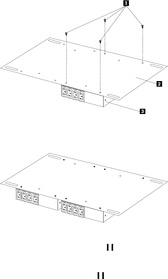
168 Hardware Maintenance Manual: IBM PC Server/Enterprise Racks
Figure 77. Installing the Rack PDU on the vertical mounting plate
3. If you have a second M/PDU device to install, install it on the vertical mounting
plate with four M3x5 screws that come with the second device.
Figure 78. Installing a second Rack PDU
4. Install the vertical mounting plate 2 in the side of your rack cabinet with four
M6 screws and nuts that come with this option. Make sure that the four-
connector side of the Rack PDU is facing the rear of your rack cabinet, and leave
room between the vertical mounting plate and the rear EIA mounting flanges for
the cable-management bracket 1.
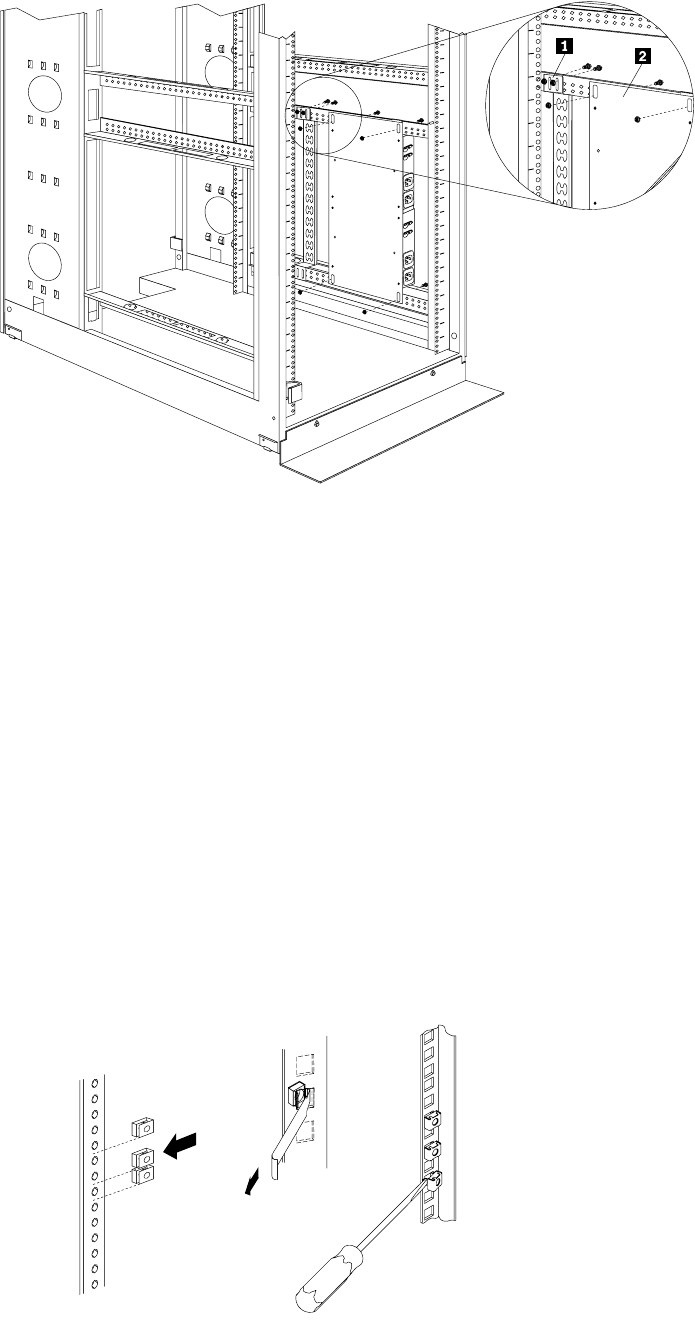
NetBAY Power Distribution Units 169
Figure 79. Installing the vertical mounting plate and cable-management bracket
5. Install the cable-management bracket 1 beside the vertical mounting plate with
four M6 screws and nuts that come with this option.
Proceed to “Cabling your PDUs” on page 173 for instructions on how to cable
your Rack PDU.
Installing a single device horizontally
Use the following procedure to mount a single Rack PDU horizontally in your rack
cabinet:
1. Refer to the documentation that comes with your rack cabinet for additional
information.
Notes:
a. Removing the rack doors and side panels might make your Rack PDU
installation easier.
b. Use clip nuts for rack cabinets with round holes; use cage nuts for rack
cabinets with square holes.
Cage
nuts
Cage
nuts
Clip
nuts
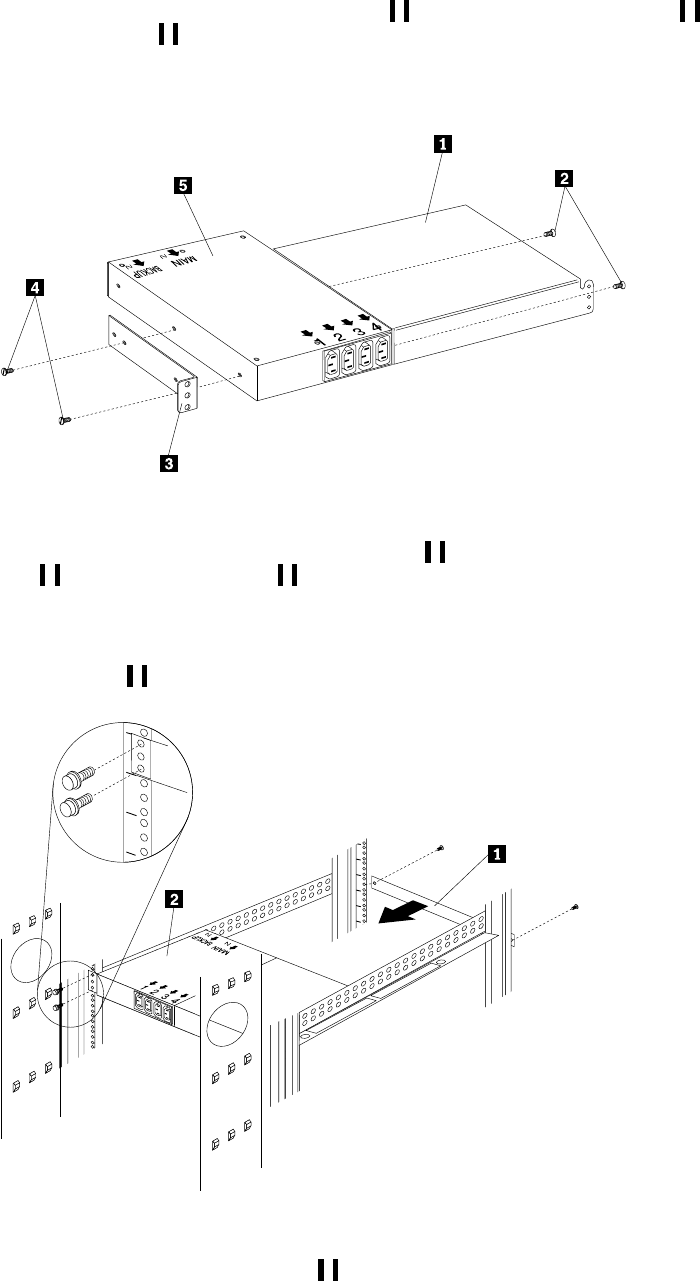
170 Hardware Maintenance Manual: IBM PC Server/Enterprise Racks
2. Install the horizontal mounting bracket 3 on one side of the Rack PDU 5 with
M3x5 screws 4.
Note: There are two sets of mounting holes on the bracket. You can align the
Rack PDU to be even with the back of the rack cabinet or recessed inside,
depending on how you install the bracket.
Figure 80. Installing the mounting brackets for a single device
3. Install the single-device attachment bracket 1 on the other side of the Rack PDU
5 with two M3x5 screws 2. Make sure that you use the same set of mounting
holes on this bracket as you used on the bracket in the previous step.
4. Determine the U level within your rack cabinet where you are going to install the
Rack PDU; then, install the Flat Panel Monitor Rack Mount Kit and bracket
assembly 2 in the rear of the rack cabinet with four M6 screws and clip nuts or
cage nuts (two screws and nuts per bracket).
Figure 81. Installing the Rack PDU and blank filler panel
5. Install the 1U blank filler panel 1 on the front of the rack cabinet at the same U
level as the Rack PDU. Use two M6 screws that come with this option.
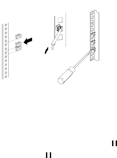
NetBAY Power Distribution Units 171
Installing two devices horizontally
Use the following procedure to mount two Rack PDUs horizontally in your rack
cabinet:
1. Refer to the documentation that comes with your rack cabinet for additional
information.
Notes:
a. Removing the rack doors and side panels might make your Rack PDU
installation easier.
b. Use clip nuts for rack cabinets with round holes; use cage nuts for rack
cabinets with square holes.
2. Attach a dual-device attachment bracket 6 to the right side of one of the Rack
PDUs with two M3x5 screws; then, attach another dual-device attachment bracket
5 to the left side of the other Rack PDU with two M3x5 screws.
Notes:
a. When you install two Rack PDUs next to each other, you will need some parts
from both options.
b. Turn the second dual-device attachment bracket 5 so that the threaded
holes are on the opposite side of the device as the holes on the other
attachment bracket 6.
Cage
nuts
Cage
nuts
Clip
nuts
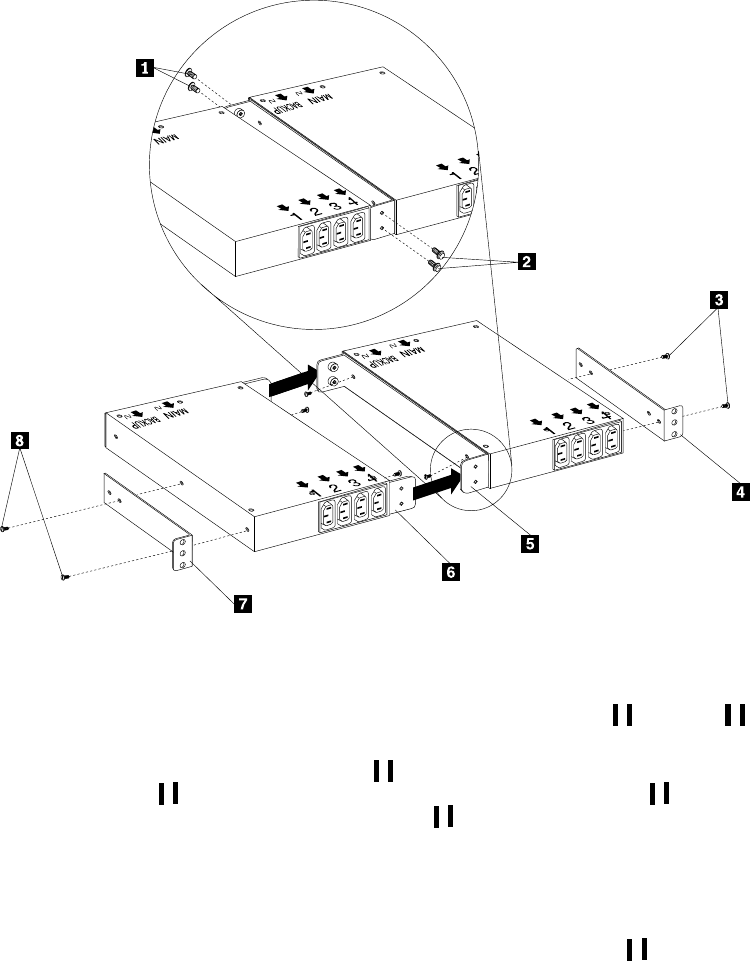
172 Hardware Maintenance Manual: IBM PC Server/Enterprise Racks
Figure 82. Installing the mounting brackets for two devices
3. Push the two Rack PDUs together, aligning the holes on the dual-device
attachment brackets; then, use four M6 screws to secure the front 1 and rear 2
of the brackets to each other.
4. Install a horizontal mounting bracket 4 on the Rack PDU on the right with two
M3x5 screws 3; then, install the other horizontal mounting bracket 7 on the
Rack PDU on the left with two M3x5 screws 8.
Note: There are two sets of mounting holes on the brackets. You can align the
Rack PDU to be even with the back of the rack cabinet or recessed inside,
depending on how you install the brackets.
5. Determine the U level within your rack cabinet where you are going to install the
Rack PDUs; then, install both Flat Panel Monitor Rack Mount Kits 2 in the rear
of the rack cabinet with four M6 screws and clip nuts or cage nuts (two screws
and nuts per bracket).
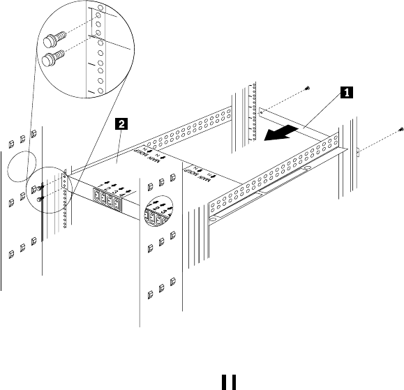
NetBAY Power Distribution Units 173
Figure 83. Installing the Rack PDUs and the blank filler panel
6. Install the 1U blank filler panel 1 on the front of the rack cabinet at the same U
level as the Rack PDU. Use two M6 screws that come with this option.
Cabling your PDUs
Cable routing differs between horizontal and vertical Rack PDU installations. Refer to
“Cabling instructions for vertical-mount PDUs” on page 175 or “Cabling instructions
for horizontal-mount PDUs” on page 176 as appropriate for your installation.

174 Hardware Maintenance Manual: IBM PC Server/Enterprise Racks
Statement 1
DANGER
Statement 5
CAUTION:
The power control button on the device and the power switch on the power supply
do not turn off the electrical current supplied to the device. The device also might
To connect:
1. Turn everything OFF.
2. First, attach all cables to devices.
3. Attach signal cables to connectors.
4. Attach power cords to outlet.
5. Turn device ON.
To disconnect:
1. Turn everything OFF.
2. First, remove power cords from outlet.
3. Remove signal cables from connectors.
4. Remove all cables from devices.
Electrical current from power, telephone, and communication cables is
hazardous. To avoid a shock hazard:
•Do not connect or disconnect any cables or perform installation,
maintenance, or reconfiguration of this product during an electrical
storm.
•Connect all power cords to a properly wired and grounded electrical
outlet.
•Connect to properly wired outlets any equipment that will be attached to
this product.
•When possible, use one hand only to connect or disconnect signal cables.
•Never turn on any equipment when there is evidence of fire, water, or
structural damage.
•Disconnect the attached power cords, telecommunications systems,
networks, and modems before you open the device covers, unless
instructed otherwise in the installation and configuration procedures.
•Connect and disconnect cables as described in the following table when
installing, moving, or opening covers on this product or attached devices.
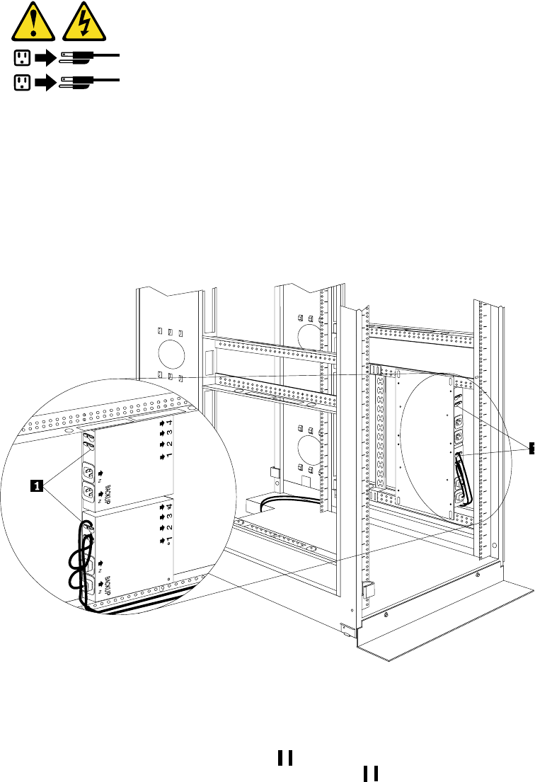
NetBAY Power Distribution Units 175
have more than one power cord. To remove all electrical current from the device,
ensure that all power cords are disconnected from the power source.
Cabling instructions for vertical-mount PDUs
If your Rack PDU came with more than two line cords, select either the high-voltage
cords or the low-voltage cords for your installation. Use the following procedure to
connect and route cables for Rack PDUs that you mounted vertically in the side of
your rack cabinet:
1. Connect one of the line cords to the main inlet on the Rack PDU. Use the line cord
that you will connect to your primary power source.
Figure 84. Connecting and routing the line cords
2. Connect the other line cord to the Backup inlet on the Rack PDU. Use the line
cord that you will connect to your backup power source.
3. Remove the screws on the cable clamps 1 and route the line cords through the
clamps; then, reinstall the screws on the cable clamps 1 and repeat step 1. and
step 2. for the other device if you installed two devices.
4. Route the line cords down and toward the rack side braces; then, route the line
cords along the side brace towards the back of the rack cabinet and secure them
with the cable straps that come with this option.
5. Route each line cord towards a dedicated independent power source, such as a
UPS or electrical outlet. Use the provided cable straps to secure the line cords
1
2
MAIN
MAIN
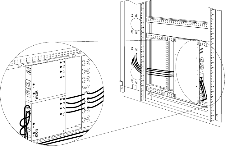
176 Hardware Maintenance Manual: IBM PC Server/Enterprise Racks
along the way. Use the openings in your rack cabinet, if you must exit the rack
cabinet to connect to your power source.
6. After you connect both line cords to properly wired and grounded dedicated
independent power sources, you can connect one server (having up to four line
cords) to the four power outlets on the Rack PDU. Route all other power cables
neatly, and use the cable-management bracket to secure the cables that you plug
into the outlets on the Rack PDU.
Figure 85. Connecting and routing other power cables to the outlets
Cabling instructions for horizontal-mount PDUs
If your Rack PDU came with more than two line cords, select either the high-voltage
cords or the low-voltage cords for your installation. Use the following procedure to
connect and route cables for Rack PDUs that you mounted in the horizontal EIA space
of your rack cabinet:
1. Connect one of the line cords to the Main inlet on the Rack PDU. Use the line cord
that you will connect to your primary power source.
MAIN
MAIN
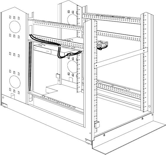
NetBAY Power Distribution Units 177
Figure 86. Connecting and routing the line cords
2. Connect the other line cord to the Backup inlet on the Rack PDU. Use the line
cord that you will connect to your backup power source.
3. Remove the screws on the cable clamps and route the line cords through the
clamps; then, reinstall the screws on the cable clamps and repeat step 1 and step 2
for the other device, if you installed two devices.
4. Route the line cords left or right, toward the side of the rack cabinet; then, route
the line cords along the side brace towards the back of the rack cabinet and secure
them with the cable straps that come with this option.
5. Route each line cord toward a dedicated independent power source, such as a
UPS or electrical outlet. Use the provided cable straps to secure the line cords
along the way. Use the openings in your rack cabinet, if you must exit the rack
cabinet to connect to your power source.
6. After you connect both line cords to properly wired and grounded dedicated
independent power sources, you can connect one server (having up to four line
cords) to the four power outlets on the Rack PDU. Route all other power cables
neatly, and use cable straps to secure the cables that you plug into the outlets on
the Rack PDU.
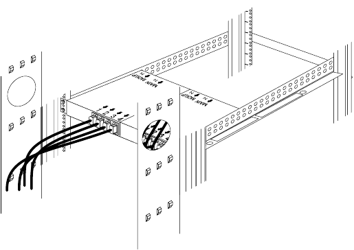
178 Hardware Maintenance Manual: IBM PC Server/Enterprise Racks
Figure 87. Connecting and routing other power cables to the outlets

NetBAY Power Distribution Units 179
Rack PDU specifications
When connected to a dedicated power source, the Rack PDU conforms to UL950, CSA
22.0-950, EN-60950, and IEC-950 standards. The following table contains the product
specifications for the Rack PDU:
Height 43 mm (1.7 in.)
Width 192 mm (7.5 in.)
Depth 221 mm (8.7 in.)
Weight 2.4 kg (5.4 lbs)
Operating temperatures 10°C–35°C (50°F–95°F) at 0–914 m (0–3000 ft)
10°C–32 °C (50°F–90°F°) at 914–2133 m (3000–7000 ft)
Operating humidity 8–80% (non-condensing)
Rated voltage 100–127 V ac, 15 A, single-phase
200-240 V ac, 10 A, single-phase
Rated frequency 50–60 Hz
Maximum power rating 2400 VA
Power inlet Two IEC 320-C20 inlets rated at 16 A (VDE) / 20 A (UL/CSA)
Transfer time <35 ms from main to backup power
Power outlets Four IEC 320-C13 outlets rated at 10 A (VDE) / 15 A
(UL/CSA)

180 Hardware Maintenance Manual: IBM PC Server/Enterprise Racks
Power cables
Power cables that you use to connect a server (with more than one power supply) to
the Rack PDU usually come with the server. The following table contains a list of
power cables that you can use with the Rack PDU:
Power cables that you use to connect your Rack PDU to a UPS or Front-end PDU
come with those devices as indicated in the following table:
Length Cable rating Plug type Cable part #
2.8 m (9.2 ft) 250 V, 10 A IEC 320-C13 to IEC 320-C14 36L8886
4.3 m (14 ft) 250 V, 10 A IEC 320-C13 to IEC 320-C14 94G7448
Length Cable
rating Plug type Cable
part # Comes with:
2 m (6.6 ft) 250 V, 16 A IEC 320-C19 to IEC 320-C20 00N7700 APC SU-5000 RMB UPS
(2 cables)
1 m (3.3 ft) 250 V, 16 A IEC 320-C19 to IEC 320-C20 00N7698 Front-end PDU
(3 cables)

NetBAY Power Distribution Units 181
Line cords
Two 4.3 m (14 ft) country-specific line cords that you use to connect your Rack PDU to
properly wired, grounded, and dedicated power sources come with the Rack PDU.
One line cord is for the Main inlet (primary power source), and the other line cord is
for the Backup inlet (backup power source). The following table contains a list of line
cords that you can use with the Rack PDU:
Parts listing (Power Distribution Units)
Power Source Line cord rating Plug type Line cord
part #
100–127 V ac, 20 A 127 V ac, 18 A IEC 320-C19 to NEMA L5-20P 12J5117
200–240 V ac, 20 A 250 V ac, 18 A IEC 320-C19 to NEMA L6-20P 14F1553
220–240 V ac, 16 A 250 V ac, 16 A IEC 320-C19 to CEE7-VII 14F1554
220–240 V ac, 16 A 250 V ac, 16 A IEC 320-C19 to IEC 309-2P + Gnd 36L8823
220–240 V ac, 16 A 250 V ac, 16 A IEC 320-C19 to SII 32 14F1561
220–240 V ac, 16 A 250 V ac, 16 A IEC 320-C19 to CEI 23-16 14F1560
220–240 V ac, 16 A 250 V ac, 16 A IEC 320-C19 to SABS 164 14F1557
220–240 V ac, 13 A 250 V ac, 13 A IEC 320-C19 to BS 1363/A 12J5988
220–240 V ac, 15 A 250 V ac, 15 A IEC 320-C19 to AS/NZ 3112 14F1559
220–240 V ac, 15 A 250 V ac, 15 A IEC 320-C19 to GB 2099.1 01K9852
220–240 V ac, 15 A 250 V ac, 15 A IEC 320-C19 to IRAM 2063 36L8885
Power Distribution Unit FRU
Rack PDU 09N9668
Server PDU 09N9669
Front End PDU 09N9670
Common Mounting Hardware Kit 09N9671
3-Phase NEMA L21-30P Line Cord (200-250 V ac) 24P6844
3-Phase IEC 309-3P+N+Gnd Line Cord (380-415 V ac) 24P6845
1-Phase NEMA L5-30P Line Cord (100-127 V ac) 24P6846
1-Phase NEMA L6-30P Line Cord (200-240 V ac) 24P6847
1-Phase IEC 309-2P+Gnd Line Cord (200-240 V ac) 24P6848
182 Hardware Maintenance Manual: IBM PC Server/Enterprise Racks
© Copyright IBM Corp. 2001 183
Related service information
These procedures are written with the assumption that you have model-specific
training on all computers, or that are familiar with the computers, functions,
terminology, and service information provided in this manual.
Safety information
The following section contains the safety information that you need to know before
servicing an IBM server or IBM supporting equipment such as the Type 9306 IBM PC
Server Rack Enclosure and Type 9306 IBM Rack.
1.
DANGER
•The maximum allowable weight for devices mounted on slides is 80 Kg
(176 lbs). Do not install sliding devices exceeding this weight.
•The center of gravity for an extended unit cannot exceed 362 mm (14.25 in.)
from the face of the rack. If an extended device exceeds this distance, the
configured rack might be unstable.
2.
DANGER
•Always install servers and power devices in the rack from the bottom to the
top.
•Always install the heaviest equipment in the bottom of the rack.
•Always install the UPS (uninterruptible power supply) in the bottom of the
rack.
•Always install the stabilizer bracket.
•Do not extend more than one sliding device at a time.
3.
DANGER
Plug rack power cords into electrical outlets that are located near the rack and
are easily accessible.
4.
DANGER
Connect all devices installed in a rack to power
devices installed in the same rack. Do not plug
the power cord from a device installed in one rack
into a power device installed in a different rack.
184 Hardware Maintenance Manual: IBM PC Server/Enterprise Racks
1.
PERIGO
•O peso máximo permitido para dispositivos montados em trilhos é de 80 kg
(176 lbs). Não instale dispositivos em trilhos que excedam este peso.
•O centro de gravidade para uma unidade estendida não pode exceder 362
mm (14.25 in.) da frente do rack. Se um dispositivo estendido exceder esta
distância, o rack configurado pode se tornar instñÚ Ýável.
2.
PERIGO
•Instale sempre os servidores e dispositivos de alimentação no rack de baixo
para cima.
•Sempre instale o equipamento mais pesado na parte inferior do rack.
•Sempre instale a fonte de alimentação contínua (UPS) na parte inferior do
rack.
•Sempre instale o suporte do estabilizador.
•Não estenda mais de um dispositivo com trilho de uma vez.
3.
PERIGO
Conecte os cabos de alimentação do rack em saídas elétricas localizadas perto
do rack e de fácil acesso.
4.
.
PERIGO
Conecte todos os dispositivos de um rack aos dispositivos de energia instalados
no mesmo rack. Não conecte um cabo de alimentação de um dispositivo
instalado em um rack a um dispositivo de energia instalado em um rack
diferente.
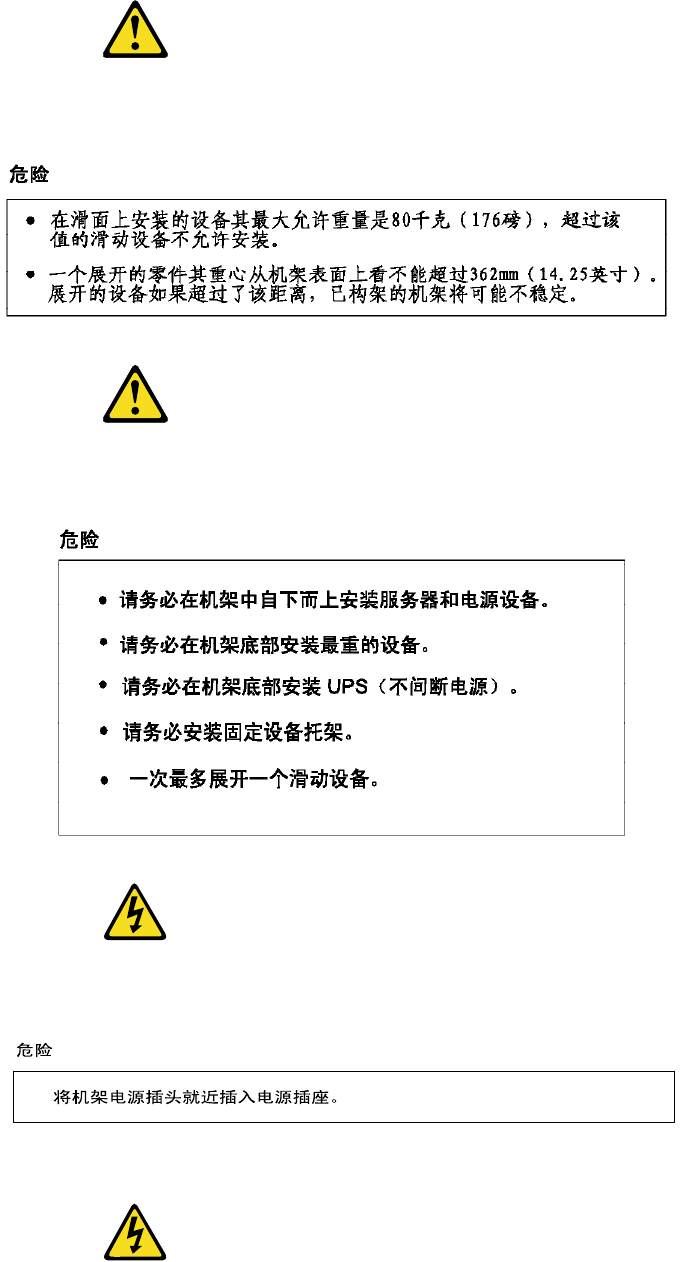
Related service information 185
1.
DANGER
2.
DANGER
3.
DANGER
4.
DANGER
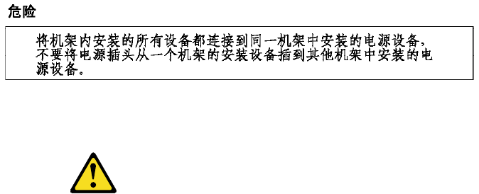
186 Hardware Maintenance Manual: IBM PC Server/Enterprise Racks
1.
DANGER
•Le poids maximal d'une unité montée sur glissières est de 80 kg ; n'installez
pas d'unités dont le poids est supérieur.
•Le centre de gravité d'une unité tirée hors de son logement ne doit pas être
éloigné de plus de 362 mm de la face avant de l'armoire. Sinon, l'armoire
configurée risque de ne pas être stable.

Related service information 187
2.
DANGER
•Commencez toujours par installer les serveurs et les blocs d’alimentation
dans la partie inférieure de l'armoire.
•Installez toujours les composants les plus lourds dans la partie inférieure
de l'armoire.
•Installez toujours les blocs d'alimentation (UPS) dans la partie inférieure
de l'armoire.
•Installez toujours les stabilisateurs.
•Certaines unités sont installées sur des tiroirs coulissants. N'ouvrez pas
plusieurs de ces tiroirs à la fois.
3.
DANGER
Branchez les cordons d'alimentation sur des socles de prises de courant proches
de l'armoire et facilement accessibles.
4.
DANGER
Toutes les unités installées dans une armoire doivent être reliées à des unités
d'alimentation situées dans la même armoire. Ne branchez jamais le cordon
d'alimentation d'une unité installée dans une armoire sur une unité
d'alimentation installée dans une autre armoire.

188 Hardware Maintenance Manual: IBM PC Server/Enterprise Racks
1.
VORSICHT
•Das zulässige Höchstgewicht für auf Schienen montierte Einheiten beträgt
80 kg. Keine Einheiten mit höheren Gewicht einbauen.
•Der Schwerpunkt einer ausgefahrenen Einheit darf nicht mehr als 362 mm
von der Frontseite des Gehäuse entfernt liegen. Liegt der Schwerpunkt
weiter entfernt, kann das konfigurierte Gehäuse instabil werden.
2.
VORSICHT
•Server und Netzeinheiten immer von unten nach oben im Gehäuse
installieren.
•Die schwersten Einheiten unten installieren.
•Die USV (Unterbrechungsfreie Stromversorgung) immer unten
installieren.
•Immer die Kippsicherung anbringen.
•Nie mehr als jeweils eine Einschubeinheit herausziehen.
3.
VORSICHT
Die Netzkabel des Gehäuses an Steckdosen anschlieβen, die sich in der Nähe
des Gehäuses befinden und gut zugänglich sind.
4.
VORSICHT
Alle in einem Gehäuse installierten Einheiten an Netzeinheiten in einem
Gehäuse anschlieβen. Nicht das Netzkabel einer in einem Gehäuse
befindlichen Einheit an eine Netzeinheit in einem anderen Gehäuse
anschlieβen.

Related service information 189
1.
PERICOLO
•Il peso massimo consentito per i dispositivi montati su slitte è di 80 kg.
Non installare dispositivi scorrevoli che hanno un peso superiore a quello
sopra citato.
•Il centro di gravità di un'unità estratta non puòsuperare i 362 mm dalla
superficie del rack. In caso contrario, il rack configurato potrebbe essere
instabile.
2.
PERICOLO
•Installare sempre i serventi e gli alimentatori nel rack dal basso verso l’alto.
•Installare sempre il componente più pesante nella parte inferiore del rack.
•Installare sempre l’UPS (uninterruptible power supply) nella parte
inferiore del rack.
•Installare sempre il supporto stabilizzatore.
•Non aprire più di un'unità scorrevole alla volta.
3.
PERICOLO
Inserire i cavi di alimentazione del rack in prese elettriche situate vicino al rack
e di facile accesso.
4.
PERICOLO
Collegare tutte le unità installate nel rack ai dispositivi di alimentazione
installati nello stesso rack. Non collegare il cavo di alimentazione di un'unità
installata in un rack al dispositivo di alimentazione di un differente rack.
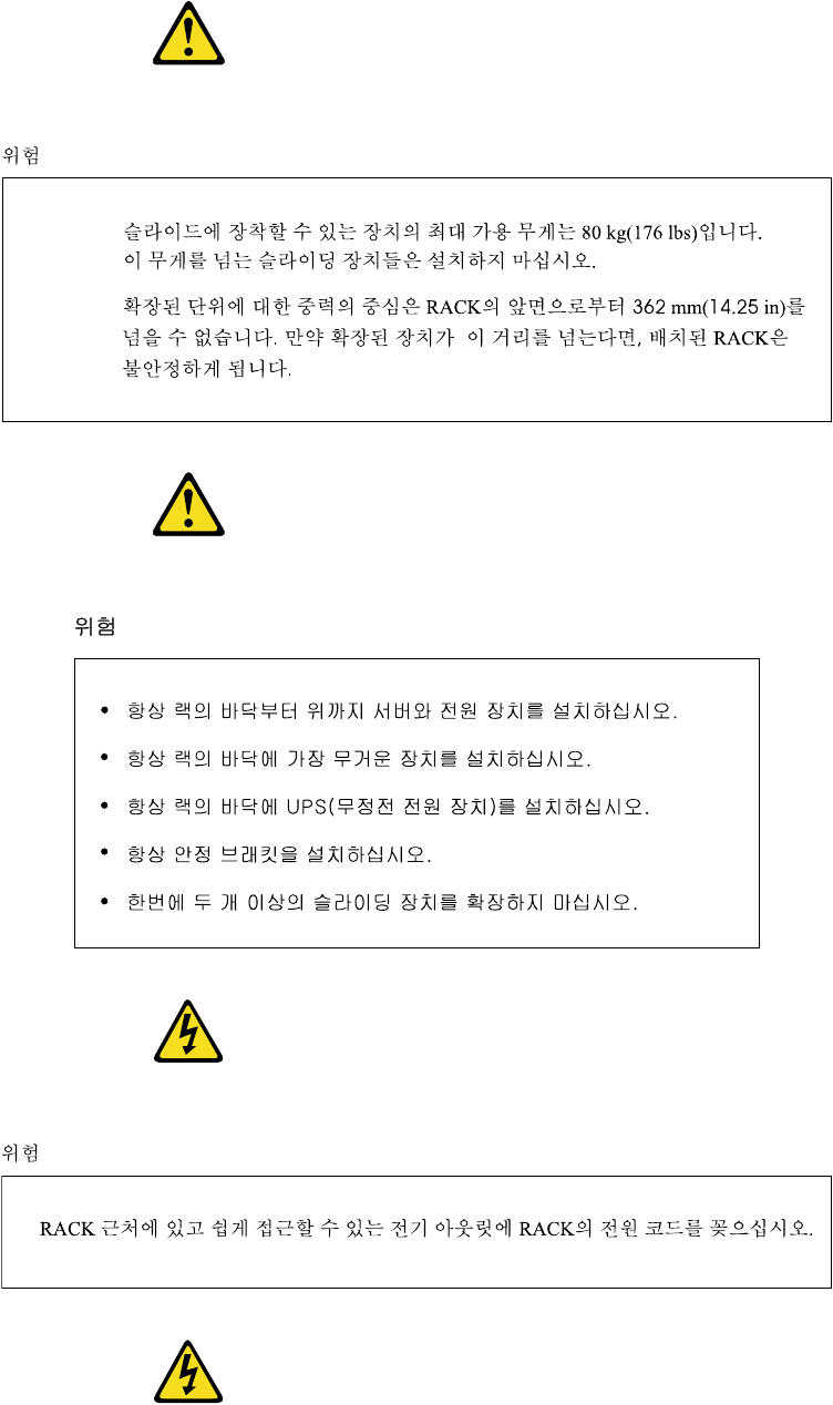
190 Hardware Maintenance Manual: IBM PC Server/Enterprise Racks
1.
2.
3.
4.
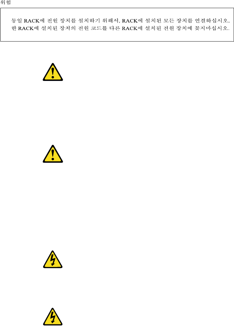
Related service information 191
1.
PELIGRO
•El peso máximo permitido para los dispositivos montados en correderas es de
80 Kg (176 lbs). No instale dispositivos deslizantes que excedan este peso.
•El centro de gravedad de una unidad extendida no puede exceder los 362 mm
(14,25 pgda.) desde la parte frontal del bastidor. Si un dispositivo extendido
excede esta distancia, el bastidor que lo contuviese podría ser poco estable.
2.
PELIGRO
•Instale siempre los servidores y dispositivos de alimentación en el bastidor de
abajo a arriba.
•Instale siempre el equipo más pesado en la parte baja del bastidor.
•Instale siempre los UPS (fuentes de alimentación ininterrumpible) en la parte
baja del bastidor.
•Instale siempre la pestaña estabilizadora.
•No extienda más de un dispositivo deslizante a la vez.
3.
PELIGRO
•Enchufe los cables de alimentación del bastidor en tomas eléctricas que
estén situadas cerca de éste y a las que se pueda acceder fácilmente.
4.
PELIGRO
Conecte todos los dispositivos instalados en un bastidor a los dispositivos de
alimentación instalados en dicho bastidor. No enchufe el cable de
alimentación de un dispositivo instalado en un bastidor en un dispositivo de
alimentación instalado en un bastidor diferente.
Safety notice (multi-lingual translations)
This safety notice for (Type 9306 models 4QS, 4QX, 9QS, 9QX, 9TS, and 9TX) is
provided in the following languages:

192 Hardware Maintenance Manual: IBM PC Server/Enterprise Racks
•English
•Brazilian/Portuguese
•Chinese
•French
•German
•Italian
•Spanish
CAUTION:
The server selector unit is heavy. You will need two people to safely remove the
server selector unit.
A unidade seletora do servidor é pesada. Você irá precisar de duas pess oas para
remover com segurança esta unidade.
Le bloc sélecteur est lourd. Faites-vous aider pour le retirer en toute.
Die Server Selektor Einheit ist schwer. Um sie zu transportieren, sind mindestens
zwei Personen erforderlich.
L'unità per la selezione dei serventi è pesante ed occorrono due persone per
rimuoverla in maniera sicura.
La unidad de selector del servidor es pesada. Se necesitan dos personas para
extraer la unidad de selector del servidor sin peligro.
Safety inspection guide
The intent of this inspection guide is to assist you in identifying potentially unsafe
conditions on these products. Each machine, as it was designed and built, had
required safety items installed to protect users and service personnel from injury. This
guide addresses only those items. However, good judgment should be used to
identify potential safety hazards due to attachment of non-IBM features or options not
covered by this inspection guide.
If any unsafe conditions are present, you must determine how serious the apparent
hazard could be and whether you can continue without first correcting the problem.
Consider these conditions and the safety hazards they present:
•Electrical hazards, especially primary power (primary voltage on the frame can
cause serious or fatal electrical shock).
•Explosive hazards, such as a damaged CRT face or bulging capacitor
•Mechanical hazards, such as loose or missing hardware
The guide consists of a series of steps presented in a checklist. Begin the checks with
the power off, and the power cord disconnected.
Related service information 193
Checklist:
1. Check exterior covers for damage (loose, broken, or sharp edges).
2. Power-off the computer. Disconnect the power cord.
3. Check the power cord for:
a. A third-wire ground connector in good condition. Use a meter to measure
third-wire ground continuity for 0.1 ohm or less between the external ground
pin and frame ground.
b. The power cord should be the appropriate type as specified in the parts
listings.
c. Insulation must not be frayed or worn.
4. Remove the cover.
5. Check for any obvious non-IBM alterations. Use good judgment as to the safety
of any non-IBM alterations.
6. Check inside the unit for any obvious unsafe conditions, such as metal filings,
contamination, water or other liquids, or signs of fire or smoke damage.
7. Check for worn, frayed, or pinched cables.
8. Check that the power-supply cover fasteners (screws or rivets) have not been
removed or tampered with.
Handling electrostatic discharge-sensitive devices
Any computer part containing transistors or integrated circuits (ICs) should be
considered sensitive to electrostatic discharge (ESD). ESD damage can occur when
there is a difference in charge between objects. Protect against ESD damage by
equalizing the charge so that the machine, the part, the work mat, and the person
handling the part are all at the same charge.
Notes:
1. Use product-specific ESD procedures when they exceed the requirements noted
here.
2. Make sure that the ESD protective devices you use have been certified (ISO 9000)
as fully effective.
When handling ESD-sensitive parts:
•Keep the parts in protective packages until they are inserted into the product.
•Avoid contact with other people.
•Wear a grounded wrist strap against your skin to eliminate static on your body.
•Prevent the part from touching your clothing. Most clothing is insulative and
retains a charge even when you are wearing a wrist strap.
•Use the black side of a grounded work mat to provide a static-free work surface.
The mat is especially useful when handling ESD-sensitive devices.
•Select a grounding system, such as those listed below, to provide protection that
meets the specific service requirement.
Note: The use of a grounding system is desirable but not required to protect
against ESD damage.
—Attach the ESD ground clip to any frame ground, ground braid, or green-wire
ground.
—Use an ESD common ground or reference point when working on a double-
insulated or battery-operated system. You can use coax or connector-outside
shells on these systems.

194 Hardware Maintenance Manual: IBM PC Server/Enterprise Racks
—Use the round ground-prong of the ac plug on ac-operated computers.
Grounding requirements
Electrical grounding of the PC Server Rack and computers is required for operator
safety and correct system function. Proper grounding of the electrical outlet can be
verified by a certified electrician.
Problem determination tips
Due to the variety of hardware and software combinations that can be encountered,
use the following information to assist you in problem determination. If possible,
have this information available when requesting assistance from Service Support and
Engineering functions.
•Machine type and model
•Processor or hard disk upgrades
•Failure symptom
—Do diagnostics fail?
—What, when, where, single, or multiple systems?
—Is the failure repeatable?
—Has this configuration ever worked?
—If it has been working, what changes were made prior to it failing?
—Is this the original reported failure?
•Reference/Diagnostics diskette version
—Type and version level
•Hardware configuration
—Print (print screen) configuration currently in use
—BIOS level
•Operating system software
—Type and version level
CAUTION:
Important:
To eliminate confusion, identical systems are considered identical only if they:
1. Are the exact machine type and model
2. Have the same BIOS level
3. Have the same adapters/attachments in the same locations
4. Have the same address jumpers/terminators/cabling
5. Have the same software versions and levels
6. Have the same Reference/Diagnostics Diskette (version)
7. Have the same configuration options set in the system
8. Have the same setup for the operation system control files
Comparing the configuration and software set-up between "working and non-
working" systems will often lead to problem resolution.

Related service information 195
Notices
References in this publication to IBM products, programs, or services do not imply
that IBM intends to make these available in all countries in which IBM operates. Any
reference to an IBM product, program, or service is not intended to state or imply that
only that IBM product, program, or service may be used. Subject to IBM’s valid
intellectual property or other legally protectable rights, any functionally equivalent
product, program, or service may be used instead of the IBM product, program, or
service. The evaluation and verification of operation in conjunction with other
products, except those expressly designated by IBM, are the responsibility of the user.
IBM makes no representations or warranties regarding non-IBM products. For non-
IBM software, third-party software licenses may apply.
GHz, MHz only measures microprocessor internal clock speed, not application
performance. Many factors affect application performance.
When referring to hard disk drive capacity, GB equals one billion bytes. Total user-
accessible capacity may vary depending on operating environments.
IBM makes no warranties, express or implied, regarding non-IBM products and
services that are ServerProven, including but not limited to the implied warranties of
merchantability and fitness for particular purpose. These products are offered and
warranted solely by third parties.

196 Hardware Maintenance Manual: IBM PC Server/Enterprise Racks
Send us your comments!
We want to know your opinion about this manual (part number 10K2658). Your input
will help us to improve our publications.
Please photocopy this survey, complete it, and then fax it to IBM HMM Survey at
919-543-8167 (USA).
Name: _________________________________________
Phone number: __________________________________
Thank you for your response!
1. Do you like this manual?
❑ Yes ❑ No
________________________________________________________________
________________________________________________________________
2. What would you like to see added, changed, or deleted in this manual?
________________________________________________________________
________________________________________________________________
3. What is your service experience level?
❑ Less than five years
❑ More than five years
4. Which servers do you service most?
________________________________________________________________
________________________________________________________________
________________________________________________________________
________________________________________________________________

Related service information 197
Trademarks
The following items are trademarks of the IBM Corporation in the United States or
other countries or both:
Apex PC Solutions, OutLook, OutLook4, and OSCAR are trademarks of Apex PC
Solutions, Inc.
The following terms are trademarks of other companies:
Lotus and Lotus Notes are trademarks of Lotus Development Corporation.
Intel, Pentium, MMX and Xeon are trademarks of Intel Corporation.
UNIX is a trademark of The Open Group in the United States and other countries.
Microsoft, Windows and Windows NT are trademarks of Microsoft Corporation.
Other company, product, and service names used in this publication may be
trademarks or service marks of others.
IBM SystemXtra
NetBAY
ServeRAID ThinkPad
ServerGuide ServerProven
Light Path Diagnostics Predictive Failure Analysis
Wake on LAN Alert on LAN
xSeries TechConnect
Active PCI EduQuest
HelpCenter HelpClub
NetBAY2 NetBAY3
NetBAY3E Netfinity
OS/2 Personal System/2
PS/1 PS/2
PS/ValuePoint Skill Dynamics
NetBAY42
198 Hardware Maintenance Manual: IBM PC Server/Enterprise Racks

IBM@
Part Number: 10K2658
File Number:
Printed in the United States of America
on recycled paper containing 10%
recovered post-consumer fiber.
10K2658
0410K2658
