Ibm 6058 Users Manual Hardware Maintenance
6568 to the manual c8052fb2-aa70-4402-8a35-638706898cda
2015-03-11
: Ibm Ibm-6058-Users-Manual-431629 ibm-6058-users-manual-431629 ibm pdf
Open the PDF directly: View PDF ![]() .
.
Page Count: 248 [warning: Documents this large are best viewed by clicking the View PDF Link!]
- About this manual
- Related Publications
- Contents
- Chapter 1. IBM PC Enhanced Diagnostics error codes
- Chapter 2. Types 6568/6569/6648/6649
- Product description
- General checkout
- Diagnostics, test and recovery information
- Power-On Self-Test (POST)
- POST beep codes
- Error code format
- Product Recovery Program menu
- IBM PC Enhanced Diagnostics
- Enhanced Diagnostics download or diskette
- Navigating through the diagnostics programs
- Running diagnostics tests
- Test selection
- IBM PC Enhanced Memory Diagnostics
- Alert-On LAN™ test
- Asset ID™ test
- Test results
- Hard file Smart test
- IBM Fixed Disk Optimized Test
- Quick and Full erase - hard drive
- Iomega Zip drive test
- Asset EEPROM backup
- Viewing the test log
- SIMM/DIMM/RIMM memory errors
- Setup Utility program
- Hard disk drive boot error
- When to use the Low-Level Format program
- Preparing the hard disk drive for use
- Additional service information
- Computer exploded view - Types 6568/6569/6648/6649
- A40 and A40P system board layout
- Symptom-to-FRU index
- Undetermined problems
- Model tables - Country/Region/Language
- Parts - Types 6568/6569/6648/6649
- Chapter 3. Types 6058/6059/6269/6578/6579
- Product description
- General checkout
- Diagnostics, test and recovery information
- Power-On Self-Test (POST)
- POST beep codes
- Error code format
- Product Recovery Program menu
- IBM PC Enhanced Diagnostics
- Enhanced Diagnostics download or diskette
- Navigating through the diagnostics programs
- Running diagnostics tests
- Test selection
- IBM PC Enhanced Memory Diagnostics
- Alert-On LAN test
- Asset ID test
- Test results
- Hard file Smart test
- IBM Fixed Disk Optimized Test
- Quick and Full erase - hard drive
- Iomega Zip drive test
- Asset EEPROM backup
- Viewing the test log
- SIMM/DIMM/RIMM memory errors
- Setup Utility program
- Hard disk drive boot error
- When to use the Low-Level Format program
- Preparing the hard disk drive for use
- Additional service information
- Computer exploded view - Types 6058/6059/6269/6578/6579
- A20 system board layout (Type 6269)
- A40/A40P system board layout (Types 6058/6059/6578/6579)
- Symptom-to-FRU index
- Undetermined problems
- Model tables - Country/Region/Language
- Parts - Types 6058/6059/6269/6578/6579
- Chapter 4. Related Service Information
Hardware Maintenance Manual
IBM NetVista Computer Types 6058,
6059, 6269, 6568, 6569,
6578, 6579, 6648, 6649
Hardware Maintenance Manual
IBM NetVista Computer Types 6058,
6059, 6269, 6568, 6569,
6578, 6579, 6648, 6649

Note:
Before using this information and the product it supports, be sure to read the general information
under “Notices” on page 228.
Second Edition (November 2000)
The following paragraph does not apply to the United Kingdom or any country where such provisions are
inconsistent with local law:
INTERNATIONAL BUSINESS MACHINES CORPORATION PROVIDES THIS PUBLICATION ″AS IS″WITHOUT
ANY WARRANTY OF ANY KIND, EITHER EXPRESS OR IMPLIED, INCLUDING, BUT NOT LIMITED TO, THE
LIMITED WARRANTIES OF MERCHANTABILITY OR FITNESS FOR A PARTICULAR PURPOSE. Some states do not
allow disclaimers or express or implied warranties in certain transactions; therefore, this statement may not apply to
you.
This publication could include technical inaccuracies or typographical errors. Changes are periodically made to the
information herein; these changes will be incorporated in new editions of the publication. IBM may make
improvements or changes in the products or the programs described in this publication at any time.
Requests for technical information about IBM products should be made to your IBM Authorized Dealer or your IBM
Marketing Representative.
© Copyright International Business Machines Corporation 2000. All rights reserved.
US Government Users Restricted Rights – Use, duplication or disclosure restricted by GSA ADP Schedule Contract
with IBM Corp.

About this manual
This manual contains service and reference information for the IBM
®
NetVista
TM
Series computer types 6058, 6059, 6269, 6568, 6569, 6578, 6579,
6648, 6649.
This manual is divided into product service sections (by machine chassis) and
a related service section, as follows:
vThe product service sections include procedures for isolating problems to a
FRU, a Symptom-to-FRU Index, additional service information and an
illustrated parts catalog.
vThe related service section includes safety notices and safety information,
and problem determination tips.
Note: This manual is intended for trained servicers who are familiar with
IBM Personal Computer products. Use this manual along with
advanced diagnostic tests to troubleshoot problems effectively.
Before servicing an IBM product, be sure to review the “Safety notices
(multi-lingual translations)”on page 189 and “Safety information”on
page 185.
© Copyright IBM Corp. 2000 iii

Important Safety Information
Be sure to read all caution and danger statements in this book before
performing any of the instructions.
Prenez connaissance de toutes les consignes de type Attention et Danger
avant de procéder aux opérations décrites par les instructions.
Lesen Sie alle Sicherheitshinweise, bevor Sie eine Anweisung ausführen.
Accertarsi di leggere tutti gli avvisi di attenzione e di pericolo prima di
effettuare qualsiasi operazione.
Leia todas as instruções de cuidado e perigo antes de executar qualquer
operação.
Lea atentamente todas las declaraciones de precaución y peligro ante de llevar
a cabo cualquier operación.
iv Hardware Maintenance Manual: IBM NetVista Computer Types 6058, 6059, 6269, 6568, 6569, 6578, 6579, 6648,
6649
About this manual v
vi Hardware Maintenance Manual: IBM NetVista Computer Types 6058, 6059, 6269, 6568, 6569, 6578, 6579, 6648,
6649

Related Publications
The following publications are available for IBM products. For more
information, contact IBM or an IBM Authorized Dealer.
For Information About: See Publication:
PC300/700®and IntelliStation®computers -
Volume 1 Hardware Maintenance Manual
IBM Personal Computer HMM Volume 1
(S83G-7789)
PC300®and IntelliStation computers (Including
Aptiva®2173) - Volume 2 Hardware Maintenance
Manual
IBM Personal Computer HMM Volume 2
(S00N-4019)
PC300 and IntelliStation computers - Volume 3
Hardware Maintenance Manual
IBM Personal Computer HMM Volume 3
(S09N-8603)
PS/2®Computers IBM Personal System/2 HMM (S52G-9971)
PS/ValuePoint®Computers IBM PS/ValuePoint Hardware Maintenance
Service and Reference (S61G-1423)
Laptop, Notebook, Portable, and ThinkPad®
Computers (L40, CL57, N45, N51, P70/P75,
ThinkPad 300, 350, 500, 510, 710T, Expansion Unit,
Dock I, Dock II)
IBM Mobile Systems HMM Volume 1 (S82G-1501)
ThinkPad Computers (340, 355, 360, 370, 700, 701,
720, 750, 755)
IBM Mobile Systems HMM Volume 2 (S82G-1502)
ThinkPad Computers (365, 560, 760, SelectaDock) IBM Mobile Systems HMM Volume 3 (S82G-1503)
Monitors (Displays) (February 1993) IBM PS/2 Display HMM Volume 1 (SA38-0053)
Monitors (December 1993) IBM Color Monitor HMM Volume 2 (S71G-4197)
IBM Monitors (P/G Series) (June 1996) IBM Monitor HMM Volume 3 (S52H-3679)
IBM 2248 Monitor (February 1996) IBM Monitor HMM Volume 4 (S52H-3739)
Disk Array technology overview and using the
IBM RAID Configuration Program
Configuring Your Disk Array booklet (S82G-1506)
Installation Planning for Personal System/2
computers
Personal System/2 Installation Planning and
Beyond (G41G-2927)
Installation Planning for Advanced Personal
System/2 Servers
Advanced PS/2 Servers Planning and Selection
Guide (GG24-3927)
© Copyright IBM Corp. 2000 vii
viii Hardware Maintenance Manual: IBM NetVista Computer Types 6058, 6059, 6269, 6568, 6569, 6578, 6579, 6648,
6649

Contents
About this manual .........iii
Important Safety Information ......iv
RelatedPublications ........vii
Chapter 1. IBM PC Enhanced Diagnostics
error codes ............1
Chapter 2. Types 6568/6569/6648/6649 . . 21
Product description .........23
Specifications Information (ISO/ANSI) . . 24
Specifications - Types
6568/6569/6648/6649 ........24
General checkout ..........26
Module test menu and hardware
configurationreport........28
Keyboard ............29
Printer.............29
Power supply ..........30
20-pin main power supply connection . . 31
Display ............32
Diagnostics, test and recovery information . . 33
Power-On Self-Test (POST) ......33
POST beep codes .........33
Errorcodeformat.........34
Product Recovery Program menu ....34
IBM PC Enhanced Diagnostics .....35
Enhanced Diagnostics download or
diskette ...........35
Navigating through the diagnostics
programs...........36
Running diagnostics tests .....36
Test selection..........36
IBM PC Enhanced Memory Diagnostics 36
Alert-On LAN
™
test .......37
Asset ID
™
test .........37
Testresults..........37
Hard file Smart test .......38
IBM Fixed Disk Optimized Test . . . 38
Quick and Full erase - hard drive . . . 39
Iomega Zip drive test .......40
Asset EEPROM backup ......40
Viewing the test log .......40
SIMM/DIMM/RIMM memory errors 40
Setup Utility program........41
Hard disk drive boot error ......42
When to use the Low-Level Format
program............42
Preparing the hard disk drive for use . . 43
Additional service information ......44
Replacing a processor ........45
Replacing a system board ......45
Security features .........46
Passwords ..........46
Vital product data ........47
Management Information Format (MIF) 47
Alert on LAN .........48
Hard disk drive jumper settings ....48
CD-ROM drive jumper settings ....49
BIOSlevels...........49
Flash (BIOS/VPD) update procedure. . . 50
Flash recovery boot block jumper ....50
Power management ........51
Automatic configuration and power
interface (ACPI) BIOS .......51
Advanced Power Management....51
Automatic Hardware Power
Management features .......52
Setting Automatic Hardware Power
Management features .......52
AutomaticPower-Onfeatures....53
Network settings .........53
Flash over LAN (update POST/BIOS
overnetwork).........54
WakeonLAN.........54
System board memory .......55
Supported memory configuration . . . 55
Computer exploded view -
Types 6568/6569/6648/6649 ......55
Input/Output connectors ......56
Cover removal ..........57
Replacingthecover........57
EMC shield (CD-ROM drive bay) ....58
EMC shield (system board) ......58
Installing adapters .........59
Adapter slots .........59
CD-ROM drive removal and replacement 60
Internal drive removal .......63
3.5″drive removal ........63
Hard drive removal .......64
© Copyright IBM Corp. 2000 ix
Fan/speaker bracket removal .....64
Power supply removal .......65
Components of the riser card .....65
A40 and A40P system board layout ....67
System board locations .......67
A40/A40P System board jumper settings 67
A40/A40P Clear CMOS/Flash Boot
BlockRecovery.........67
A40/ A40P Processor Speed Settings . . 68
A40/A40P Diskette Write Access . . . 68
Symptom-to-FRUindex........69
Beepsymptoms..........70
No-beepsymptoms ........72
POST error codes .........72
Miscellaneous error messages .....87
Undetermined problems ........90
Model tables - Country/Region/Language . . 91
Parts - Types 6568/6569/6648/6649 ....92
Parts listing ...........93
Keyboards - 6568/6569
(PCNext Lite Pearl White) .....95
Keyboards - 6648/6649
(PCNextLiteBlack).......96
ComputerPowerCords......98
Display and Monitor Information . . . 98
Special tools ...........98
Chapter 3. Types 6058/6059/6269/6578/6579 99
Product description .........101
Specifications Information (ISO/ANSI) 102
Specifications -
Types 6058/60596269/6578/6579 ....102
General checkout ..........104
Module test menu and hardware
configurationreport........106
Keyboard ...........107
Printer............107
Power supply ..........108
20-pin main power supply connection 109
Display............110
Diagnostics, test and recovery information 111
Power-On Self-Test (POST) ......111
POST beep codes .........112
Errorcodeformat.........112
Product Recovery Program menu . . . 112
IBM PC Enhanced Diagnostics ....113
Enhanced Diagnostics download or
diskette ...........113
Navigating through the diagnostics
programs ..........114
Running diagnostics tests .....114
Test selection .........114
IBM PC Enhanced Memory
Diagnostics ..........115
Alert-On LAN test .......115
Asset ID test .........115
Testresults..........115
Hard file Smart test .......117
IBM Fixed Disk Optimized Test . . . 117
Quick and Full erase - hard drive . . 119
Iomega Zip drive test ......119
Asset EEPROM backup ......120
Viewing the test log .......120
SIMM/DIMM/RIMM memory errors 121
Setup Utility program .......122
Hard disk drive boot error ......123
When to use the Low-Level Format
program............123
Preparing the hard disk drive for use . . 123
Additional service information .....124
Replacing a processor .......125
Replacing a system board ......125
Security features .........125
Passwords..........126
Vital product data........127
Management Information Format
(MIF)............127
Alert on LAN .........128
Hard disk drive jumper settings ....128
CD-ROM drive jumper settings ....129
BIOSlevels...........129
Flash (BIOS/VPD) update procedure . . 130
Flash recovery boot block jumper . . . 131
Power management ........131
Automatic configuration and power
interface (ACPI) BIOS ......131
Advanced Power Management . . . 131
Automatic Hardware Power
Management features ......132
Setting Automatic Hardware Power
Management features ......132
AutomaticPower-Onfeatures....133
Network settings .........133
Flash over LAN (update POST/BIOS
overnetwork).........134
WakeonLAN.........135
System board memory .......135
Supported memory configuration . . 135
Computer exploded view -
Types 6058/6059/6269/6578/6579 ....136
xHardware Maintenance Manual: IBM NetVista Computer Types 6058, 6059, 6269, 6568, 6569, 6578, 6579, 6648,
6649
Input/Output connectors - Type 6269 . . 137
Input/Output connectors - Types
6058/6059/6578/6579 .......138
Cover removal ..........139
Replacingthecover.......139
EMC shield (front) ........140
EMC shield (system board) .....140
Installing adapters ........140
Adapter slots .........140
Air duct (Types 6058/6059/6278/6279) 141
CD-ROM drive removal.......142
Fan/speaker bracket removal .....142
Hard drive removal ........143
Power supply removal .......144
A20 system board layout (Type 6269) . . . 146
System board locations .......146
A20 System board jumper settings . . . 146
A20 Clear CMOS/Flash Boot Block
Recovery...........146
A20 Processor Speed Settings ....147
A20 Diskette Write Access .....147
A40/A40P system board layout
(Types 6058/6059/6578/6579) ......148
System board locations .......148
A40/A40P System board jumper settings 148
A40/A40P Clear CMOS/Flash Boot
BlockRecovery ........149
A40/A40P Processor Speed Settings 149
A40/A40P Diskette Write Access. . . 149
Symptom-to-FRUindex........150
Beepsymptoms.........150
No-beepsymptoms........152
POST error codes .........153
Miscellaneous error messages .....167
Undetermined problems .......171
Model tables - Country/Region/Language 172
Parts - Types 6058/6059/6269/6578/6579 173
Parts listing ...........174
Keyboards - PCNext Lite Pearl White 180
ComputerPowerCords......181
RecoveryCDs.........182
Display and Monitor Information . . 182
Special tools .........183
Chapter 4. Related Service Information 185
Safety information .........185
General safety ..........185
Electrical safety .........186
Safety inspection guide .......188
Handling electrostatic discharge-sensitive
devices ............189
Grounding requirements ......189
Safety notices (multi-lingual translations) 189
Send us your comments! .......227
Problem determination tips ......227
Notices .............228
Trademarks............229
Miscellaneous Information .......229
Acronyms, Abbreviations, and Terms . . 229
Contents xi
xii Hardware Maintenance Manual: IBM NetVista Computer Types 6058, 6059, 6269, 6568, 6569, 6578, 6579, 6648,
6649

Chapter 1. IBM PC Enhanced Diagnostics error codes
Refer to the following Diagnostic Error Codes when using the IBM PC
Enhanced Diagnostics test. See the ″Diagnostic and test information″section
for the specific model for information about the IBM PC Enhanced
Diagnostics program.
In the following index, Xcan represent any number.
Diagnostic Error Code FRU/Action
000-000-XXX BIOS Test Passed 1. No action
000-002-XXXBIOS Timeout 1. Flash the system
2. System board
000-024-XXXBIOS Addressing test failure 1. Flash the system
2. System board
000-025-XXXBIOS Checksum Value error 1. Flash the system
2. Boot block
3. System board
000-026-XXXFLASH data error 1. Flash the system
2. Boot block
3. System board
000-027-XXXBIOS Configuration/Setup error 1. Run Setup
2. Flash the system
3. Boot block
4. System board
000-034-XXXBIOS Buffer Allocation failure 1. Reboot the system
2. Flash the system
3. Run memory test
4. System board
000-035-XXXBIOS Reset Condition detected 1. Flash the system
2. System board
000-036-XXXBIOS Register error 1. Flash the system
2. Boot block
3. System board
© Copyright IBM Corp. 2000 1

Diagnostic Error Code FRU/Action
000-038-XXXBIOS Extension failure 1. Flash the system
2. Adapter card
3. System board
000-039-XXXBIOS DMI data error 1. Flash the system
2. System board
000-195-XXXBIOS Test aborted by user 1. Information
2. Re-start the test, if necessary
000-196-XXXBIOS test halt, error threshold
exceeded 1. Press F3 to review the log file
2. Re-start the test to reset the log file
000-197-XXXBIOS test warning 1. Make sure the component that is called out is
connected and/or enabled
2. Re-run test
3. Component that is called out in warning statement
4. Component under test
000-198-XXXBIOS test aborted 1. If a component is called out, make sure it is
connected and/or enabled
2. Flash the system and re-test
3. Go to the ″Undetermined problems″section
000-199-XXXBIOS test failed, cause unknown 1. Go to the ″Undetermined problems″section
2. Flash the system and re-test
3. Replace component under function test
000-250-XXXBIOS APM failure 1. Flash the system
2. System board
000-270-XXXBIOS ACPI failure 1. Flash the system
2. System board
001-000-XXXSystem Test Passed 1. No action
001-00X-XXXSystem Error 1. System board
001-01X-XXXSystem Error 1. System board
001-024-XXXSystem Addressing test failure 1. System board
001-025-XXXSystem Checksum Value error 1. Flash the system
2. System board
001-026-XXXSystem FLASH data error 1. Flash the system
2. System board
2Hardware Maintenance Manual: IBM NetVista Computer Types 6058, 6059, 6269, 6568, 6569, 6578, 6579, 6648,
6649

Diagnostic Error Code FRU/Action
001-027-XXXSystem Configuration/Setup error 1. Run Setup
2. Flash the system
3. System board
001-032-XXXSystem Device Controller failure 1. System board
001-034-XXXSystem Device Buffer Allocation
failure 1. Reboot the system
2. Flash the system
3. Run memory test
4. System board
001-035-XXXSystem Device Reset condition
detected 1. System board
001-036-XXXSystem Register error 1. System board
001-038-XXXSystem Extension failure 1. Adapter card
2. System board
001-039-XXXSystem DMI data structure error 1. Flash the system
2. System board
001-040-XXXSystem IRQ failure 1. Power-off/on system and re-test
2. System board
001-041-XXXSystem DMA failure 1. Power-off/on system and re-test
2. System board
001-195-XXXSystem Test aborted by user 1. Information
2. Re-start the test, if necessary
001-196-XXXSystem test halt, error threshold
exceeded 1. Press F3 to review the log file
2. Re-start the test to reset the log file
001-197-XXXSystem test warning 1. Make sure the component that is called out is
connected and/or enabled
2. Re-run test
3. Component that is called out in warning statement
4. Component under test
001-198-XXXSystem test aborted 1. If a component is called out, make sure it is
connected and/or enabled
2. Flash the system and re-test
3. Go to the ″Undetermined problems″section
Chapter 1. IBM PC Enhanced Diagnostics error codes 3

Diagnostic Error Code FRU/Action
001-199-XXXSystem test failed, cause unknown 1. Go to the ″Undetermined problems″section
2. Flash the system and re-test
3. Replace component under function test
001-250-XXXSystem ECC error 1. System board
001-254-XXX
001-255-XXX
001-256-XXX
001-257-XXXSystem DMA error
1. System board
001-260-XXX
001-264-XXXSystem IRQ error 1. System board
001-268-XXXSystem IRQ1 failure 1. Device on IRQ1
2. System board
001-269-XXXSystem IRQ2 failure 1. Device on IRQ2
2. System board
001-270-XXXSystem IRQ3 failure 1. Device on IRQ3
2. System board
001-271-XXXSystem IRQ4 failure 1. Device on IRQ4
2. System board
001-272-XXXSystem IRQ5 failure 1. Device on IRQ5
2. System board
001-273-XXXSystem IRQ6(diskette drive)
failure 1. Diskette Cable
2. Diskette drive
3. System board
001-274-XXXSystem IRQ7 failure 1. Device on IRQ7
2. System board
001-275-XXXSystem IRQ8 failure 1. Device on IRQ8
2. System board
001-276-XXXSystem IRQ9 failure 1. Device on IRQ9
2. System board
001-277-XXXSystem IRQ10 failure 1. Device on IRQ10
2. System board
001-278-XXXSystem IRQ11 failure 1. Device on IRQ11
2. System board
4Hardware Maintenance Manual: IBM NetVista Computer Types 6058, 6059, 6269, 6568, 6569, 6578, 6579, 6648,
6649

Diagnostic Error Code FRU/Action
001-279-XXXSystem IRQ12 failure 1. Device on IRQ12
2. System board
001-280-XXXSystem IRQ13 failure 1. Device on IRQ13
2. System board
001-281-XXXSystem IRQ14(hard disk drive)
failure 1. Hard disk drive cable
2. Hard disk drive
3. System board
001-282-XXXSystem IRQ15 failure 1. Device on IRQ15
2. System board
001-286-XXX
001-287-XXX
001-288-XXXSystem Timer failure
1. System board
001-292-XXXSystem CMOS RAM error 1. Run Setup and re-test
2. System board
001-293-XXXSystem CMOS Battery 1. Battery
2. System board
001-298-XXXSystem RTC date/time update
failure 1. Flash the system
2. System board
001-299-XXXSystem RTC periodic interrupt
failure 1. System board
001-300-XXXSystem RTC Alarm failure 1. System board
001-301-XXXSystem RTC Century byte error 1. Flash the system
2. System board
005-000-XXXVideo Test Passed 1. No action
005-00X-XXXVideo error 1. Video card, if installed
2. System board
005-010-XXX
005-011-XXX
005-012-XXX
005-013-XXXVideo Signal failure
1. Video card, if installed
2. System board
005-016-XXXVideo Simple Pattern test failure 1. Video Ram
2. Video card, if installed
3. System board
Chapter 1. IBM PC Enhanced Diagnostics error codes 5

Diagnostic Error Code FRU/Action
005-024-XXXVideo Addressing test failure 1. Video card, if installed
2. System board
005-025-XXXVideo Checksum Value error 1. Video card, if installed
2. System board
005-027-XXXVideo Configuration/Setup error 1. Run Setup
2. Video drivers update
3. Video card, if installed
4. System board
005-031-XXXVideo Device Cable failure 1. Video cable
2. Monitor
3. Video card, if installed
4. System board
005-032-XXXVideo Device Controller failure 1. Video card, if installed
2. System board
005-036-XXXVideo Register error 1. Video card, if installed
2. System board
005-038-XXXSystem BIOS extension failure 1. Video card, if installed
2. System board
005-040-XXXVideo IRQ failure 1. Video card, if installed
2. System board
005-195-XXXVideo Test aborted by user 1. Information
2. Re-start the test, if necessary
005-196-XXXVideo test halt, error threshold
exceeded 1. Press F3 to review the log file
2. Re-start the test to reset the log file
005-197-XXXVideo test warning 1. Make sure the component that is called out is
connected and/or enabled
2. Re-run test
3. Component that is called out in warning statement
4. Component under test
005-198-XXXVideo test aborted 1. If a component is called out, make sure it is
connected and/or enabled
2. Flash the system and re-test
3. Go to the ″Undetermined problems″section
6Hardware Maintenance Manual: IBM NetVista Computer Types 6058, 6059, 6269, 6568, 6569, 6578, 6579, 6648,
6649

Diagnostic Error Code FRU/Action
005-199-XXXVideo test failed, cause unknown 1. Go to the ″Undetermined problems″section
2. Flash the system and re-test
3. Replace component under function test
005-2XX-XXX
005-3XX-XXXVideo subsystem error 1. Video card, if installed
2. System board
006-000-XXXDiskette interface Test Passed 1. No action
006-0XX-XXXDiskette interface error 1. Diskette drive Cable
2. Diskette drive
3. System board
006-195-XXXDiskette interface Test aborted by
user 1. Information
2. Re-start the test, if necessary
006-196-XXXDiskette interface test halt, error
threshold exceeded 1. Press F3 to review the log file
2. Re-start the test to reset the log file
006-197-XXXDiskette interface test warning 1. If a component is called out, make sure it is
connected and/or enabled
2. Re-run test
3. Component that is called out in warning statement
4. Component under test
006-198-XXXDiskette interface test aborted 1. If a component is called out, make sure it is
connected and/or enabled
2. Flash the system and re-test
3. Go to the ″Undetermined problems″section
006-199-XXXDiskette interface test failed, cause
unknown 1. Go to the ″Undetermined problems″section
2. Flash the system and re-test
3. Replace component under function test
006-25X-XXXDiskette interface Error 1. Diskette drive cable
2. Diskette drive
3. System board
011-000-XXXSerial port Interface Test Passed 1. No action
011-001-XXXSerial port Presence 1. Remove external serial device, if present
2. Run setup, enable port
3. System board
011-002-XXX
011-003-XXXSerial port Timeout/Parity error 1. System board
Chapter 1. IBM PC Enhanced Diagnostics error codes 7

Diagnostic Error Code FRU/Action
011-013-XXX
011-014-XXXSerial port Control
Signal/Loopback test failure
1. System board
011-015-XXXSerial port External Loopback
failure 1. Wrap plug
2. System board
011-027-XXXSerial port Configuration/Setup
error 1. Run Setup, enable port
2. Flash the system
3. System board
011-03X-XXX
011-04X-XXXSerial port failure 1. System board
011-195-XXXSerial port Test aborted by user 1. Information
2. Re-start the test, if necessary
011-196-XXXSerial port test halt, error
threshold exceeded 1. Press F3 to review the log file
2. Re-start the test to reset the log file
011-197-XXXSerial port test warning 1. Make sure the component that is called out is
connected and/or enabled
2. Re-run test
3. Component that is called out in warning statement
4. Component under test
011-198-XXXSerial port test aborted 1. If a component is called out, make sure it is
connected and/or enabled
2. Flash the system and re-test
3. Go to the ″Undetermined problems″section
011-199-XXXSerial port test failed, cause
unknown 1. Go to the ″Undetermined problems″section
2. Flash the system and re-test
3. Replace component under function test
011-2XX-XXXSerial port signal failure 1. External serial device
2. System board
014-000-XXXParallel port Interface Test Passed 1. No action
014-001-XXXParallel port Presence 1. Remove external parallel device, if present
2. Run setup, enable port
3. System board
014-002-XXX
014-003-XXXParallel port Timeout/Parity error 1. System board
8Hardware Maintenance Manual: IBM NetVista Computer Types 6058, 6059, 6269, 6568, 6569, 6578, 6579, 6648,
6649

Diagnostic Error Code FRU/Action
014-013-XXX
014-014-XXXParallel port Control
Signal/Loopback test failure
1. System board
014-015-XXXParallel port External Loopback
failure 1. Wrap plug
2. System board
014-027-XXXParallel port Configuration/Setup
error 1. Run Setup, enable port
2. Flash the system
3. System board
014-03X-XXX
014-04X-XXXParallel port failure 1. System board
014-195-XXXParallel port Test aborted by user 1. Information
2. Re-start the test, if necessary
014-196-XXXParallel port test halt, error
threshold exceeded 1. Press F3 to review the log file
2. Re-start the test to reset the log file
014-197-XXXParallel port test warning 1. Make sure the component that is called out is
connected and/or enabled
2. Re-run test
3. Component that is called out in warning statement
4. Component under test
014-198-XXXParallel port test aborted 1. If a component is called out, make sure it is
connected and/or enabled
2. Flash the system and re-test
3. Go to the ″Undetermined problems″section
014-199-XXXParallel port test failed, cause
unknown 1. Go to the ″Undetermined problems″section
2. Flash the system and re-test
3. Replace component under function test
014-2XX-XXX
014-3XX-XXXParallel port failure 1. External parallel device
2. System board
015-000-XXXUSB port Interface Test Passed 1. No action
015-001-XXXUSB port Presence 1. Remove USB device(s) and re-test
2. System board
015-002-XXXUSB port Timeout 1. Remove USB device(s) and re-test
2. System board
Chapter 1. IBM PC Enhanced Diagnostics error codes 9

Diagnostic Error Code FRU/Action
015-015-XXXUSB port External Loopback
failure 1. Remove USB device(s) and re-test
2. System board
015-027-XXXUSB port Configuration/Setup
error 1. Flash the system
2. System board
015-032-XXXUSB port Device Controller failure 1. System board
015-034-XXXUSB port bufferallocation failure 1. Reboot the system
2. Flash the system
3. Run memory test
4. System board
015-035-XXXUSB port Reset condition detected 1. Remove USB device(s) and re-test
2. System board
015-036-XXXUSB port Register error 1. System board
015-040-XXXUSB port IRQ failure 1. Run setup and check for conflicts
2. Flash the system
3. System board
015-195-XXXUSB port Test aborted by user 1. Information
2. Re-start the test, if necessary
015-196-XXXUSB port test halt, error threshold
exceeded 1. Press F3 to review the log file
2. Re-start the test to reset the log file
015-197-XXXUSB port test warning 1. Make sure the component that is called out is
connected and/or enabled
2. Re-run test
3. Component that is called out in warning statement
4. Component under test
015-198-XXXUSB port test aborted 1. If a component is called out, make sure it is
connected and/or enabled
2. Flash the system and re-test
3. Go to the ″Undetermined problems″section
015-199-XXXUSB port test failed, cause
unknown 1. Go to the ″Undetermined problems″section
2. Flash the system and re-test
3. Replace component under function test
018-000-XXXPCI Card Test Passed 1. No action
10 Hardware Maintenance Manual: IBM NetVista Computer Types 6058, 6059, 6269, 6568, 6569, 6578, 6579, 6648,
6649

Diagnostic Error Code FRU/Action
018-0XX-XXXPCI Card Failure 1. Riser card, if installed
2. System board
018-195-XXXPCI Card Test aborted by user 1. PCI card
2. Information
3. Re-start the test, if necessary
018-196-XXXPCI Card test halt, error threshold
exceeded 1. Press F3 to review the log file
2. Re-start the test to reset the log file
018-197-XXXPCI Card test warning 1. Make sure the component that is called out is
connected and/or enabled
2. Re-run test
3. Component that is called out in warning statement
4. Component under test
018-198-XXXPCI Card test aborted 1. Make sure the component that is called out is
connected and/or enabled
2. Flash the system and re-test
3. Go to the ″Undetermined problems″section
018-199-XXXPCI Card test failed, cause
unknown 1. Go to the ″Undetermined problems″section
2. Flash the system and re-test
3. Replace component under function test
018-250-XXXPCI Card Services error 1. PCI card
2. Riser card, if installed
3. System board
020-000-XXXPCI Interface Test Passed 1. No action
020-0XX-XXXPCI Interface error 1. PCI card
2. Riser card, if installed
3. System board
020-195-XXXPCI Test aborted by user 1. Information
2. Re-start the test, if necessary
020-196-XXXPCI test halt, error threshold
exceeded 1. Press F3 to review the log file
2. Re-start the test to reset the log file
Chapter 1. IBM PC Enhanced Diagnostics error codes 11

Diagnostic Error Code FRU/Action
020-197-XXXPCI test warning 1. Make sure the component that is called out is
connected and/or enabled
2. Re-run test
3. Component that is called out in warning statement
4. Component under test
020-198-XXXPCI test aborted 1. If a component is called out, make sure it is
connected and/or enabled
2. Flash the system and re-test
3. Go to the ″Undetermined problems″section
020-199-XXXPCI test failed, cause unknown 1. Go to the ″Undetermined problems″section
2. Flash the system and re-test
3. Replace component under function test
020-262-XXX
PCI system error 1. PCI card
2. Riser card, if installed
3. System board
025-000-XXX
IDE interface Test Passed 1. No action
025-00X-XXX
025-01X-XXXIDE interface failure 1. IDE signal cable
2. Check power supply
3. IDE device
4. System board
025-027-XXXIDE interface Configuration/Setup
error 1. IDE signal cable
2. Flash the system
3. IDE device
4. System board
025-02X-XXX
025-03X-XXX
025-04X-XXXIDE Interface failure
1. IDE signal cable
2. Check power supply
3. IDE device
4. System board
025-195-XXXIDE interface Test aborted by user 1. Information
2. Re-start the test, if necessary
025-196-XXXIDE interface test halt, error
threshold exceeded 1. Press F3 to review the log file
2. Re-start the test to reset the log file
12 Hardware Maintenance Manual: IBM NetVista Computer Types 6058, 6059, 6269, 6568, 6569, 6578, 6579, 6648,
6649

Diagnostic Error Code FRU/Action
025-197-XXXIDE interface test warning 1. Make sure the component that is called out is
connected and/or enabled
2. Re-run test
3. Component that is called out in warning statement
4. Component under test
025-198-XXXIDE interface test aborted 1. If a component is called out, make sure it is
connected and/or enabled
2. Flash the system and re-test
3. Go to the ″Undetermined problems″section
025-199-XXXIDE interface test failed, cause
unknown 1. Go to the ″Undetermined problems″section
2. Flash the system and re-test
3. Replace component under function test
030-000-XXXSCSI interface Test Passed 1. No action
030-00X-XXX
030-01X-XXXSCSI interface failure 1. SCSI signal cable
2. Check power supply
3. SCSI device
4. SCSI adapter card, if installed
5. System board
030-027-XXXSCSI interface
Configuration/Setup error 1. SCSI signal cable
2. Flash the system
3. SCSI device
4. SCSI adapter card, if installed
5. System board
030-03X-XXX
030-04X-XXXSCSI interface error 1. SCSI signal cable
2. Check power supply
3. SCSI device
4. SCSI adapter card, if installed
5. installed System board
030-195-XXXSCSI interface Test aborted by
user 1. Information
2. Re-start the test, if necessary
030-196-XXXSCSI interface test halt, error
threshold exceeded 1. Press F3 to review the log file
2. Re-start the test to reset the log file
Chapter 1. IBM PC Enhanced Diagnostics error codes 13

Diagnostic Error Code FRU/Action
030-197-XXXSCSI interface test warning 1. Make sure the component that is called out is
connected and/or enabled
2. Re-run test
3. Component that is called out in warning statement
4. Component under test
030-198-XXXSCSI interface test aborted 1. If a component is called out, make sure it is
connected and/or enabled
2. Flash the system and re-test
3. Go to the ″Undetermined problems″section
030-199-XXXSCSI interface test failed, cause
unknown 1. Go to the ″Undetermined problems″section
2. Flash the system and re-test
3. Replace component under function test
035-000-XXXRAID interface Test Passed 1. No action
035-0XX-XXXRAID interface Failure 1. RAID signal cable
2. RAID device
3. RAID adapter card, if installed
4. System board
035-195-XXXRAID interface Test aborted by
user 1. Information
2. Re-start the test, if necessary
035-196-XXXRAID interface test halt, error
threshold exceeded 1. Press F3 to review the log file
2. Re-start the test to reset the log file
035-197-XXXRAID interface test warning 1. Make sure the component that is called out is
connected and/or enabled
2. Re-run test
3. Component that is called out in warning statement
4. Component under test
035-198-XXXRAID interface test aborted 1. If a component is called out, make sure it is
connected and/or enabled
2. Flash the system and re-test
3. Go to the ″Undetermined problems″section
035-199-XXXRAID interface test failed, cause
unknown 1. Go to the ″Undetermined problems″section
2. Flash the system and re-test
3. Replace component under function test
071-000-XXXAudio port Interface Test Passed 1. No action
14 Hardware Maintenance Manual: IBM NetVista Computer Types 6058, 6059, 6269, 6568, 6569, 6578, 6579, 6648,
6649

Diagnostic Error Code FRU/Action
071-00X-XXX
071-01X-XXX
071-02X-XXX
Audio port error
1. Run Setup
2. Flash the system
3. System board
071-03X-XXXAudio port failure 1. Speakers
2. Microphone
3. Audio card, if installed
4. System board
071-04X-XXXAudio port failure 1. Run Setup
2. Audio card, if installed
3. System board
071-195-XXXAudio port Test aborted by user 1. Information
2. Re-start the test, if necessary
071-196-XXXAudio port test halt, error
threshold exceeded 1. Press F3 to review the log file
2. Re-start the test to reset the log file
071-197-XXXAudio port test warning 1. Make sure the component that is called out is
connected and/or enabled
2. Re-run test
3. Component that is called out in warning statement
4. Component under test
071-198-XXXAudio port test aborted 1. If a component is called out, make sure it is
connected and/or enabled
2. Flash the system and re-test
3. Go to the ″Undetermined problems″section
071-199-XXXAudio port test failed, cause
unknown 1. Go to the ″Undetermined problems″section
2. Flash the system and re-test
3. Replace component under function test
071-25X-XXXAudio port failure 1. Speakers
2. Audio card, if installed
3. System board
080-000-XXXGame Port interface Test Passed 1. No action
080-XXX-XXXGame Port interface Error 1. Remove the game port device and re-test the
system
080-195-XXXGame Port interface Test aborted
by user 1. Information
2. Re-start the test, if necessary
Chapter 1. IBM PC Enhanced Diagnostics error codes 15

Diagnostic Error Code FRU/Action
080-196-XXXGame Port interface test halt,
error threshold exceeded 1. Press F3 to review the log file
2. Re-start the test to reset the log file
080-197-XXXGame Port interface test warning 1. Make sure the component that is called out is
connected and/or enabled
2. Re-run test
3. Component that is called out in warning statement
4. Component under test
080-198-XXXGame Port interface test aborted 1. If a component is called out, make sure it is
connected and/or enabled
2. Flash the system and re-test
3. Go to the ″Undetermined problems″section
080-199-XXXGame Port interface test failed,
cause unknown 1. Go to the ″Undetermined problems″section
2. Flash the system and re-test
3. Replace component under function test
086-000-XXXMouse Port interface Test Passed 1. No action
086-001-XXXMouse Port interface Presence 1. Mouse
2. System board
086-032-XXXMouse Port interface Device
controller failure 1. Mouse
2. System board
086-035-XXXMouse Port interface Reset 1. Mouse
2. System board
086-040-XXXMouse Port interface IRQ failure 1. Run Setup
2. Mouse
3. System board
086-195-XXXMouse Port interface Test aborted
by user 1. Information
2. Re-start the test, if necessary
086-196-XXXMouse Port interface test halt,
error threshold exceeded 1. Press F3 to review the log file
2. Re-start the test to reset the log file
086-197-XXXMouse Port interface test warning 1. Make sure the component that is called out is
connected and/or enabled
2. Re-run test
3. Component that is called out in warning statement
4. Component under test
16 Hardware Maintenance Manual: IBM NetVista Computer Types 6058, 6059, 6269, 6568, 6569, 6578, 6579, 6648,
6649

Diagnostic Error Code FRU/Action
086-198-XXXMouse Port interface test aborted 1. If a component is called out, make sure it is
connected and/or enabled
2. Flash the system and re-test
3. Go to the ″Undetermined problems″section
086-199-XXXMouse Port interface test failed,
cause unknown 1. Go to the ″Undetermined problems″section
2. Flash the system and re-test
3. Replace component under function test
089-000-XXXMicroprocessor Test Passed 1. No action
089-XXX-XXXMicroprocessor failure 1. Microprocessor(s)
2. System board
089-195-XXXMicroprocessor Test aborted by
user 1. Information
2. Re-start the test, if necessary
089-196-XXXMicroprocessor test halt, error
threshold exceeded 1. Press F3 to review the log file
2. Re-start the test to reset the log file
089-197-XXXMicroprocessor test warning 1. Make sure the component that is called out is
connected and/or enabled
2. Re-run test
3. Component that is called out in warning statement
4. Component under test
089-198-XXXMicroprocessor test aborted 1. Flash the system and re-test
2. Go to the ″Undetermined problems″section
089-199-XXXMicroprocessor test failed, cause
unknown 1. If a component is called out, make sure it is
connected and/or enabled
2. Go to the ″Undetermined problems″section
3. Flash the system and re-test
4. Replace component under function test
170-000-XXXVoltage Sensor(s) Test Passed 1. No action
170-0XX-XXXVoltage Sensor(s) failure 1. Flash system
2. System board
170-195-XXXVoltage Sensor(s) Test aborted by
user 1. Information
2. Re-start the test, if necessary
170-196-XXXVoltage Sensor(s) test halt, error
threshold exceeded 1. Press F3 to review the log file
2. Re-start the test to reset the log file
Chapter 1. IBM PC Enhanced Diagnostics error codes 17

Diagnostic Error Code FRU/Action
170-197-XXXVoltage Sensor(s) test warning 1. Make sure the component that is called out is
connected and/or enabled
2. Re-run test
3. Component that is called out in warning statement
4. Component under test
170-198-XXXVoltage Sensor(s) test aborted 1. If a component is called out, make sure it is
connected and/or enabled
2. Flash the system and re-test
3. Go to the ″Undetermined problems″section
170-199-XXXVoltage Sensor(s) test failed, cause
unknown 1. Go to the ″Undetermined problems″section
2. Flash the system and re-test
3. Replace component under function test
170-250-XXX
170-251-XXXVoltage Sensor(s) Voltage limit
error
1. Power supply
2. System board
170-254-XXXVoltage Sensor(s) Voltage
Regulator Module error 1. Voltage Regulator Module (VRM)
2. Microprocessor
3. System board
175-000-XXXThermal Sensor(s) Test Passed 1. No action
175-0XX-XXXThermal Sensor(s) failure 1. Flash system
2. System board
175-195-XXXThermal Sensor(s) Test aborted by
user 1. Information
2. Re-start the test, if necessary
175-196-XXXThermal Sensor(s) test halt, error
threshold exceeded 1. Press F3 to review the log file
2. Re-start the test to reset the log file
175-197-XXXThermal Sensor(s) test warning 1. Make sure the component that is called out is
connected and/or enabled
2. Re-run test
3. Component that is called out in warning statement
4. Component under test
175-198-XXXThermal Sensor(s) test aborted 1. If a component is called out, make sure it is
connected and/or enabled
2. Flash the system and re-test
3. Go to ″Undetermined problems″section
18 Hardware Maintenance Manual: IBM NetVista Computer Types 6058, 6059, 6269, 6568, 6569, 6578, 6579, 6648,
6649

Diagnostic Error Code FRU/Action
175-199-XXXThermal Sensor(s) test failed,
cause unknown 1. Go to the ″Undetermined problems″section
2. Flash the system and re-test
3. Replace component under function test
175-250-XXX
175-251-XXXThermal Sensor(s) limit error 1. Check fans
2. Check Power supply
3. Microprocessor
4. System board
185-000-XXXAsset Security Test Passed 1. No action
185-XXX-XXXAsset Security failure 1. Flash system
2. System board
185-278-XXXAsset Security Chassis Intrusion 1. Assure Asset Security Enabled
2. C2 Cover Switch
3. System board
201-000-XXXSystem Memory Test Passed 1. No action
201-XXX-XXXSystem Memory error 1. Replace the memory module called out by the
test
2. System board
202-000-XXXSystem Cache Test Passed 1. No action
202-XXX-XXXSystem Cache error 1. Cache, if removable
2. System board
3. Microprocessor
206-000-XXXDiskette Drive Test Passed 1. No action
206-XXX-XXXDiskette Drive error 1. Diskette Drive Cable
2. Check power supply voltages
3. Diskette drive
4. System board
215-000-XXXCD-ROM Drive Test Passed 1. No action
215-XXX-XXXCD-ROM Drive error 1. CD-ROM Drive Cable
2. Check power supply voltages
3. CD-ROM drive
4. System board
217-000-XXXHard Disk Drive Test Passed 1. No action
Chapter 1. IBM PC Enhanced Diagnostics error codes 19

Diagnostic Error Code FRU/Action
217-25X-XXX
217-26X-XXXHard Disk Drive (IDE) error 1. Hard Disk Drive Cable
2. Check power supply voltages
3. Hard Disk drive (IDE)
4. System board
217-28X-XXX
217-29X-XXXHard Disk Drive (SCSI) error 1. Hard Disk Drive Cable
2. Check power supply voltages
3. Hard Disk drive (SCSI)
4. SCSI adapter card
5. System board
220-000-XXXHi-Capacity Cartridge Drive Test
Passed 1. No action
220-XXX-XXXHi-Capacity Cartridge Drive
error 1. Remove the Hi-Capacity Cartridge Drive and
re-test the system
301-XXX-XXXKeyboard error 1. Keyboard
2. Check and test mouse
3. System board
301-000-XXXKeyboard Test Passed 1. No action
302-000-XXXMouse Test Passed 1. No action
302-XXX-XXXMouse error 1. Mouse
2. Check and test Keyboard
3. System board
303-000-XXXJoystick Test Passed 1. No action
303-XXX-XXXJoystick error 1. Remove the Joystick and re-test the system
305-000-XXXMonitor DDC Test Passed 1. No action
305-250-XXXMonitor DDC self test failure 1. Run Setup to enable DDC
2. Cable
3. Monitor
4. Video card
5. System board
415-000-XXX
Modem Test Passed 1. No action
415-XXX-XXXModem error 1. Remove the Modem and re-test the system
20 Hardware Maintenance Manual: IBM NetVista Computer Types 6058, 6059, 6269, 6568, 6569, 6578, 6579, 6648,
6649

Chapter 2. Types 6568/6569/6648/6649
Product description .........23
Specifications Information (ISO/ANSI) . . 24
Specifications - Types
6568/6569/6648/6649 ........24
General checkout ..........26
Module test menu and hardware
configurationreport........28
Keyboard ............29
Printer.............29
Power supply ..........30
20-pin main power supply connection . . 31
Display ............32
Diagnostics, test and recovery information . . 33
Power-On Self-Test (POST) ......33
POST beep codes .........33
Errorcodeformat.........34
Product Recovery Program menu ....34
IBM PC Enhanced Diagnostics .....35
Enhanced Diagnostics download or
diskette ...........35
Navigating through the diagnostics
programs...........36
Running diagnostics tests .....36
Test selection..........36
IBM PC Enhanced Memory Diagnostics 36
Alert-On LAN
™
test .......37
Asset ID
™
test .........37
Testresults..........37
Hard file Smart test .......38
IBM Fixed Disk Optimized Test . . . 38
Quick and Full erase - hard drive . . . 39
Iomega Zip drive test .......40
Asset EEPROM backup ......40
Viewing the test log .......40
SIMM/DIMM/RIMM memory errors 40
Setup Utility program........41
Hard disk drive boot error ......42
When to use the Low-Level Format
program............42
Preparing the hard disk drive for use . . 43
Additional service information ......44
Replacing a processor ........45
Replacing a system board ......45
Security features .........46
Passwords ..........46
Power-onpassword......46
Removing a power-on password . . 46
Administrator password .....47
Administrator password control . . 47
Operating system password....47
Vital product data ........47
Management Information Format (MIF) 47
Alert on LAN .........48
Hard disk drive jumper settings ....48
CD-ROM drive jumper settings ....49
BIOSlevels...........49
Flash (BIOS/VPD) update procedure. . . 50
Flash recovery boot block jumper ....50
Power management ........51
Automatic configuration and power
interface (ACPI) BIOS .......51
Advanced Power Management....51
Automatic Hardware Power
Management features .......52
Setting Automatic Hardware Power
Management features .......52
AutomaticPower-Onfeatures....53
Network settings .........53
Flash over LAN (update POST/BIOS
overnetwork).........54
WakeonLAN.........54
System board memory .......55
Supported memory configuration . . . 55
Computer exploded view -
Types 6568/6569/6648/6649 ......55
Input/Output connectors ......56
Cover removal ..........57
Replacingthecover........57
EMC shield (CD-ROM drive bay) ....58
EMC shield (system board) ......58
Installing adapters .........59
Adapter slots .........59
CD-ROM drive removal and replacement 60
Internal drive removal .......63
3.5″drive removal ........63
Hard drive removal .......64
Fan/speaker bracket removal .....64
Power supply removal .......65
Components of the riser card .....65
A40 and A40P system board layout ....67
© Copyright IBM Corp. 2000 21
System board locations .......67
A40/A40P System board jumper settings 67
A40/A40P Clear CMOS/Flash Boot
BlockRecovery.........67
A40/ A40P Processor Speed Settings . . 68
A40/A40P Diskette Write Access . . . 68
Symptom-to-FRUindex........69
Beepsymptoms..........70
No-beepsymptoms ........72
POST error codes .........72
Miscellaneous error messages .....87
Undetermined problems ........90
Model tables - Country/Region/Language . . 91
Parts - Types 6568/6569/6648/6649 ....92
Parts listing ...........93
Keyboards - 6568/6569
(PCNext Lite Pearl White) .....95
Keyboards - 6648/6649
(PCNextLiteBlack).......96
ComputerPowerCords......98
Display and Monitor Information . . . 98
Special tools ...........98
22 Hardware Maintenance Manual: IBM NetVista Computer Types 6058, 6059, 6269, 6568, 6569, 6578, 6579, 6648,
6649

Product description
The NetVista type 6568/6569/6648/6649 computers are available in2x3(two
I/O adapter slots plus Ethernet, and three drive bays).
vType 6568 and 6569 are the white desktop types with the A40 and A40P
system boards, respectively.
vType 6648 and 6649 are the black desktop types with the A40 and A40P
system boards, respectively.
vSecurity
–Administrator password
–Cover lock
–Power-on password
–Operating system password
–U-bolt and cable (optional for some models)
vCMOS backup battery (lithium)
vCommon parts
–Diskette drive
–Hard disk drive
–Keyboard
–Power supply
–Mouse
Chapter 2. Types 6568/6569/6648/6649 23

Specifications Information (ISO/ANSI)
The machine type specifications information on the following pages was
determined in controlled acoustical environments according to procedures
specified by the American National Standards Institute (ANSI) S12.10 and ISO
7779, and are reported in accordance with ISO 9296. Actual sound pressure
levels in your location might differ from the average values stated because of
room reflections and other nearby noise sources. The declared sound power
levels indicate an upper limit, below which a large proportion of machines
will operate.
Specifications - Types 6568/6569/6648/6649
Feature Description
Size Depth: 360 mm (14.2 inches)
Height: 87 mm (3.43 inches)
Width: 345 mm (13.6 inches)
Weight Minimum configuration as shipped:
8.2kg(18lb)
Maximum configuration as shipped:
8.6kg(19lb)
Environment Air temperature:
vSystem on: 10 to 35 C
(50to95F)
vSystem off: 10 to 43 C
(50to110F)
Humidity:
vSystem on: 8% to 80%
vSystem off: 8% to 80%
Maximum altitude: 2134 m (7000 ft.)
Heat Output Approximate heat output in BTUs per hour:
vMinimum:
205 BTU/hr. (60 watts)
vMaximum:
375 BTU/hr. (110 watts)
24 Hardware Maintenance Manual: IBM NetVista Computer Types 6058, 6059, 6269, 6568, 6569, 6578, 6579, 6648,
6649

Feature Description
Electrical Input Sine-wave input (47 to 63 Hz) required
Input voltage range:
vMinimum: 90 V AC
vMaximum: 265 V AC
Input kVA (approximately):.
vMinimum: 0.08 kVA
vMaximum: 0.16 kVA (as shipped)
Airflow Approximately 0.25 cubic meters/minute (9 cubic feet/minute)
Acoustical Noise Emission
Values
Average sound pressure levels:
At operator position:
v43 dB operating
v38 dB idle
At bystander position (1 meter):
v37 dB operating
v33 dB idle
Declared (upper limit) sound power levels:
v5.1 bels operating
v4.8 bels idle
For additional information, see the ISO Supplier’s Declaration, which is
available from IBM.
Chapter 2. Types 6568/6569/6648/6649 25

General checkout
This general checkout procedure is for type 6568/6569/6648/6649 computers.
Attention:
The drives in the computer you are servicing might have been
rearranged or the drive startup sequence changed. Be extremely
careful during write operations such as copying, saving or
formatting. Data or programs can be overwritten if you select an
incorrect drive.
Diagnostic error messages appear when a test program finds a problem with a
hardware option. For the test programs to properly determine if a test Passed,
Failed or Aborted, the test programs check the error-return code at test
completion. See “IBM PC Enhanced Diagnostics”on page 35.
General error messages appear if a problem or conflict is found by an
application program, the operating system, or both. For an explanation of
these messages, refer to the information supplied with that software package.
Notes:
1.
Type 6568/6569/6648/6649 computers default to come up quiet (no beep
and no memory count and checkpoint code display) when no errors are
detected by POST.
To enable beep and memory count and checkpoint code display when a
successful POST occurs, do the following:
a. Select Start Options in the Configuration/Setup Utility program (see
“Setup Utility program”on page 41).
b. Set Power-On Self-Test to Enhanced.
2. Before replacing any FRUs, ensure that the latest level of BIOS is installed
on the system. A down-level BIOS might cause false errors and
unnecessary replacement of the system board. For more information on
how to determine and obtain the latest level BIOS, see “BIOS levels”on
page 49.
3. If multiple error codes are displayed, diagnose the first error code
displayed.
4. If the computer hangs with a POST error, go to “Symptom-to-FRU index”
on page 69.
5. If the computer hangs and no error is displayed, go to “Undetermined
problems”on page 90.
6. If an installed device is not recognized by the diagnostics program, that
device might be defective.
26 Hardware Maintenance Manual: IBM NetVista Computer Types 6058, 6059, 6269, 6568, 6569, 6578, 6579, 6648,
6649
001
1. Power-off the computer and all external devices.
2. Check all cables and power cords.
3. Make sure the system board is seated properly.
4. Set all display controls to the middle position.
5. Power-on all external devices.
6. Power-on all external devices.
7. Power-on the computer.
8. Check for the following response:
vReadable instructions or the Main Menu.
DID YOU RECEIVE THE CORRECT RESPONSE?
If NO, continue to 002.
If YES, proceed to 003.
002
If the Power Management feature is enabled, do the following:
1. Start the Configuration/Setup Utility program (see “Setup Utility
program”on page 41)
2. Select Power Management from the Configuration/Setup Utility program
menu.
3. Select APM.
4. Be sure APM BIOS Mode is set to Disabled. If it is not, press Left Arrow
(}) or Right Arrow (Æ) to change the setting.
5. Select Automatic Hardware Power Management.
6. Set Automatic Hardware Power Management to Disabled.
-or-
Go to “IBM PC Enhanced Diagnostics”on page 35.
003
Run the IBM PC Enhanced Diagnostics test. If necessary, refer to “Diagnostics,
test and recovery information”on page 33.
vIf you receive an error, replace the part that the diagnostic program calls
out or go to “IBM PC Enhanced Diagnostics”on page 35.
vIf the test stops and you cannot continue, replace the last device tested.
Chapter 2. Types 6568/6569/6648/6649 27
vIf the computer has incorrect keyboard responses, go to “Keyboard”on
page 29.
vIf the printer has incorrect responses, go to “Printer”on page 29.
vIf the display has problems such as jittering, rolling, shifting, or being out
of focus, go to “Display”on page 32.
Module test menu and hardware configuration report
Depending on the diagnostics version level you are using, the installed
devices in the computer are verified in one of two ways.
1. At the start of the diagnostic tests, the Module Test Menu is displayed.
Normally, all installed devices in the computer are highlighted on the
menu.
2. At the start of the diagnostic tests, the main menu appears. From this
menu, select System Info, then select Hardware Configuration from the
next menu. Normally, all installed devices in the computer are highlighted
on this report.
If an installed device is not recognized by the diagnostics program, then
review the following:
vThe diagnostic code for the device is not in the Enhanced Diagnostics
utility. Run the diagnostics provided with that device.
vThe missing device is defective or it requires an additional diskette or
service manual.
vAn unrecognizable device is installed.
vA defective device is causing another device not to be recognized.
vThe SCSI controller failed (on the system board or SCSI adapter).
vUse the procedure in “Undetermined problems”on page 90 to find the
problem.
If a device is missing from the list, replace it. If this does not correct the
problem, use the procedure in “Undetermined problems”on page 90.
28 Hardware Maintenance Manual: IBM NetVista Computer Types 6058, 6059, 6269, 6568, 6569, 6578, 6579, 6648,
6649
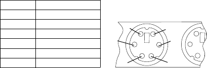
Keyboard
Note: If a mouse or other pointing device is attached, remove it to see if the
error symptom goes away. If the symptom goes away, the mouse or
pointing device is defective.
001
- Power-off the computer.
Disconnect the keyboard cable from the system unit.
Power-on the computer and check the keyboard cable connector on the
system unit for the voltages shown.
All voltages are 5%.
Pin
1
2
3
4
5
6
Voltage (Vdc)
+5.0
Reserved
Ground
+5.0
+5.0
Reserved
1
6
2
3
4
5
ARE THE VOLTAGES CORRECT?
If NO, continue with 002.
If YES, proceed to 003.
002
Replace the system board.
003
On keyboards with a detachable cable, replace the cable. If the problem
remains or if the cable is permanently attached to the keyboard, replace the
keyboard. If the problem remains, replace the system board.
Printer
1. Make sure the printer is properly connected and powered on.
2. Run the printer self-test.
If the printer self-test does not run correctly, the problem is in the printer.
Refer to the printer service manual.
Chapter 2. Types 6568/6569/6648/6649 29

If the printer self-test runs correctly, install a wrap plug in the parallel port
and run the diagnostic tests to determine which FRU failed.
If the diagnostic tests (with the wrap plug installed) do not detect a failure,
replace the printer cable. If that does not correct the problem, replace the
system board or adapter connected to the printer cable.
Power supply
If the power-on indicator is not on, the power supply fan is not running, or
the computer will not power-off, use the following procedures.
Check/Verify FRU/Action
Check the following for proper installation.
vPower Cord
vOn/Off Switch connector
vOn/Off Switch Power Supply connector
vSystem Board Power Supply connectors
vMicroprocessor(s) connection
Reseat
Check the power-on switch for continuity. Power Cord
Check the power-on switch for continuity. Power-on Switch
If the above are correct, check the following voltages.
30 Hardware Maintenance Manual: IBM NetVista Computer Types 6058, 6059, 6269, 6568, 6569, 6578, 6579, 6648,
6649
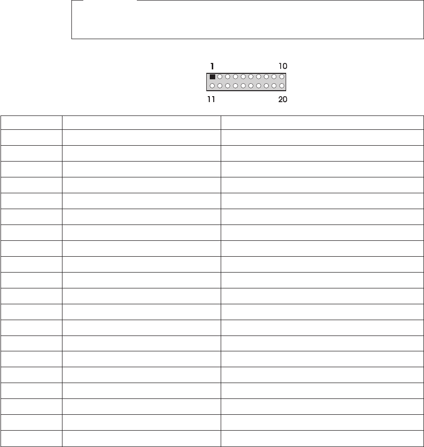
20-pin main power supply connection
See “A40 and A40P system board layout”on page 67 for connector locations.
Attention
These voltages must be checked with the power supply cables connected
to the system board.
Pin Signal Function
1 3.3 V +3.3 V dc
2 3.3 V +3.3 V dc
3 COM Ground
4 5V +5Vdc
5 COM Ground
6 5V +5Vdc
7 COM Ground
8 POK Power Good
9 5VSB Standby Voltage
10 12 V +12 V dc
11 3.3 V +3.3 V dc
12 -12V -12Vdc
13 COM Ground
14 PS-ON DC Remote Enable
15 COM Ground
16 COM Ground
17 COM Ground
18 No voltage Not used
19 5V +5Vdc
20 5V +5Vdc
If the voltages are not correct, and the power cord is good, replace the power
supply.
Chapter 2. Types 6568/6569/6648/6649 31
Display
If the screen is rolling, replace the display assembly. If that does not correct
the problem, replace the video adapter (if installed) or replace the system
board.
If the screen is not rolling, use the following procedure to run the display
self-test.
1. Power-off the computer and display.
2. Disconnect the display signal cable.
3. Power-on the display.
4. Turn the brightness and contrast controls clockwise to their maximum
setting.
5. Check for the following conditions.
vYou should be able to vary the screen intensity by adjusting the contrast
and brightness controls.
vThe screen should be white or light gray, with a black margin (test
margin) on the screen.
Note: The location of the test margin varies with the type of display. The
test margin might be on the top, bottom, or one or both sides.
If you do not see any test margin on the screen, replace the display. If
there is a test margin on the screen, replace the video adapter (if installed)
or replace the system board.
Note: During the first two or three seconds after the display is powered
on, the following might occur while the display synchronizes with
the computer.
vUnusual patterns or characters
vStatic, crackling, or clicking sounds
vA“power-on”hum on larger displays
A noticeable odor might occur on new displays or displays recently
removed from storage.
These sounds, display patterns, and odors are normal. Do not
replace any parts.
If you are unable to correct the problem, go to “Undetermined problems”on
page 90.
32 Hardware Maintenance Manual: IBM NetVista Computer Types 6058, 6059, 6269, 6568, 6569, 6578, 6579, 6648,
6649

Diagnostics, test and recovery information
The following tools are available to help identify and resolve hardware-related
problems.
vPower-On Self-Test (POST)
–POST Beep Codes
–Error Code Format
vIBM PC Enhanced Diagnostics
vRecovery utility
–Full recovery
–Partial recovery
vRepair utility
Power-On Self-Test (POST)
Each time you power-on the system, it performs a series of tests that check
the operation of the system and some options. This series of tests is called the
Power-On Self-Test,orPOST. POST does the following operations.
vChecks some basic system-board operations
vChecks the memory operation
vStarts the video operation
vVerifies that the diskette drive is working
vVerifies that the hard disk drive is working
If the POST finishes without detecting any problems, a single beep sounds
and the first screen of the operating system or application program appears.
Note: Type 6568/6569/6648/6649 computers default to come up quiet (no
beep and no memory count and checkpoint code display) when no
errors are detected by POST. To enable beep and memory count and
checkpoint code display when a successful POST occurs, do the
following:
1. Select Start Options in the Configuration/Setup Utility program
(see “Setup Utility program”on page 41).
2. Set Power-On Self-Test to Enhanced.
If the POST detects a problem, an error message appears on the screen. A
single problem can cause several error messages to appear. When you correct
the cause of the first error message, the other error messages probably will not
appear on the screen the next time you turn on the system.
POST beep codes
The Power-On Self-Test generates a beeping sound to indicate successful
completion of POST or to indicate that the tests detect an error.
Chapter 2. Types 6568/6569/6648/6649 33

One beep and the appearance of text on the display indicates successful
completion of the POST. More than one beep indicates that the POST detects
an error.
Error code format
This section provides an explanation of the encoded non-SCSI and SCSI POST
error codes.
Error messages are displayed on the screen as three, four, five, eight, twelve,
or thirteen digits. An Xin an error message can be any number or letter. The
shorter POST errors are highlighted in the Symptom-to-FRU Index. Some
digits will represent different information for SCSI errors versus non-SCSI
errors.
The following figure shows which digits display the shorter POST errors. The
figure also defines additional SCSI information.
RDDDPLSCB QEET
T
E
Q
B
C
S
L
P
D
R
est state
rror code Extension
ualifier
us (0=internal 1=external)
apacity of the device
lot number of the device
UN (usually 0)
UN (SCSI ID #)
evice Number
eserved Digit (usually 0)
Notes:
1. Non-IBM device error codes and documentation supersede this list.
2. Duplicate SCSI ID settings will cause misleading error symptoms or
messages.
Product Recovery Program menu
Type 6568/6569/6648/6649 machines have recovery and diagnostics programs
on a separate hard drive partition. The recovery CD and Enhanced
Diagnostics diskette are not shipped with the machine or the HMM. To
download diagnostics tests or to order a recovery CD, see “Enhanced
Diagnostics download or diskette”on page 35.
At startup, after the machine tests the DIMM memory (if Power-on Self Test is
set to Enhanced), the machine displays the following:
To start the Product Recovery Program, press F11
After depressing F11, you are given the following options.
vFull recovery
34 Hardware Maintenance Manual: IBM NetVista Computer Types 6058, 6059, 6269, 6568, 6569, 6578, 6579, 6648,
6649
This utility reformats the hard drive and restores all original files.
vPartial recovery
This utility reformats the hard drive and restores the Windows operating
system and all device drivers
vRepair
This is the emergency repair utility, and should not be used to install
Windows components.
vSystem utilities
1. Run diagnostics
This selection accesses the IBM PC Enhanced Diagnostics.
2. System info
3. Create recovery/ repair diskette
IBM PC Enhanced Diagnostics
The IBM PC Enhanced Diagnostics programs use a full range of diagnostic
utilities to determine the operating condition of the computer’s hardware
components.
The diagnostic program includes the following:
vPC-Doctor’s Diagnostic Software
This interface serves as the control program for running both the IBM PC
Enhanced Memory Diagnostics and the suite of diagnostic tests provided by
PC-Doctor.
vIBM PC Enhanced Memory Diagnostics
The memory diagnostic tests determine which memory module (SIMM or
DIMM) is defective and report the socket where the failing module is
located. The Memory diagnostics can run a quick and full test of the
system. Diagnostics can also be run on a single SIMM or DIMM.
Note: See “Chapter 1. IBM PC Enhanced Diagnostics error codes”on page 1
for the specific error codes.
Enhanced Diagnostics download or diskette
The IBM PC Enhanced Diagnostics are available on-line at
http://www.ibm.com/
vSelect Support.
vSelect Desktop computing from the ″Search by Category″pull-down menu.
vSelect NetVista from the ″Product Family″list.
vSearch for the machine type in the ″Quick Path″box on the left.
vSelect Diagnostics from the ″Downloadable files by Category″menu or
select the link to PC Enhanced Diagnostics from the ″Downloadable files
by date″list.
Chapter 2. Types 6568/6569/6648/6649 35
Navigating through the diagnostics programs
Use the cursor movement keys to navigate within the menus.
vThe Enter key is used to select a menu item.
vThe Esc key is used to back up to the previous menu.
vFor online help select F1.
Running diagnostics tests
There are four ways to run the diagnostic tests.
1. Using the cursor movement keys, highlight Run Normal Test or Run
Quick Test from the Diagnostics Menu and then press Enter.
This will automatically run a pre-defined group of tests from each test
category. Run Normal Test runs a more extensive set of tests than does
Run Quick Test and takes longer to execute.
2. Press F5 to automatically run all selected tests in all categories. See ″Test
Selection″.
3. From within a test category, press Ctrl-Enter to automatically run only the
selected tests in that category. See ″Test Selection″.
4. Using the cursor movement keys, highlight a single test within a test
category, then press Enter. This will run only that test.
Press Esc at any time to stop the testing process.
Test results, (N/A, PASSED, FAILED, ABORTED), are displayed in the field
beside the test description and in the test log. See “Viewing the test log”on
page 40.
Test selection
To select one or more tests, use the following procedure.
1. Open the corresponding test category.
2. Using the cursor movement keys, highlight the desired test.
3. Press the space bar.
A selected test is marked by >>. Pressing the space bar again de-selects a
test and removes the chevron.
4. Repeat steps 2 and 3 above to select all desired tests.
IBM PC Enhanced Memory Diagnostics
The IBM PC Enhanced Memory Diagnostics provide the capability to identify
a particular memory module (SIMM or DIMM) which fails during testing. Use
the System Board Layout section to reference the memory sockets, or select F1
twice to load the Online Manual and select Chapter 11, ″SIMM/DIMM/RIMM
Locator″.
36 Hardware Maintenance Manual: IBM NetVista Computer Types 6058, 6059, 6269, 6568, 6569, 6578, 6579, 6648,
6649

Follow the steps below to locate the IBM PC Enhanced Memory Diagnostics
test options.
1. Select the DIAGNOSTICS option on the toolbar and press Enter.
2. Highlight either the Memory Test-Full or Memory Test-Quick option and
press Enter.
3. Memory Test-Full
The full memory test will take about 80 seconds per MB of memory and
will detect marginal, intermittent, and solid (stuck) memory failures.
4. Memory Test-Quick
The quick memory test will take about 20 seconds per MB of memory and
will detect solid (stuck) memory failures only.
Notes
Either level of memory testing can be performed on all memory or a
single SIMM or DIMM socket.
Only sockets containing a SIMM or DIMM can be selected for testing.
Unpopulated sockets are noted by ........ beside the test description.
Alert-On LAN
™
test
The Alert On LAN test does the following:
vDetermines if Alert On LAN is supported on the system.
vChecks the revision ID register.
vVerifies the EEPROM checksum.
vValidates that a software alert can be sent.
Asset ID
™
test
The Asset ID test does the following:
vDetermines if Asset ID is supported on the system.
vVerifies the EEPROM areas.
vPerforms an antenna detection test.
Test results
IBM PC Enhanced Diagnostic test results will produce the following error
code format:
Function Code Failure Type DeviceID Date ChkDigits Text
vFunction Code:
Represents the feature or function within the PC.
vFailure Type:
Chapter 2. Types 6568/6569/6648/6649 37

Represents the type of error encountered.
vDeviceID:
Contains the component’s unit-ID which corresponds to either a fixed disk
drive, removable media drive, serial or parallel port, processor, specific
SIMM or DIMM, or a device on the PCI bus.
vDate:
Contains the date on which the diagnostic test was run. The date is
retrieved from CMOS and displayed using the YYYYMMDD format.
vChkDigits:
Contains a 2-digit check-digit value to ensure the following:
–Diagnostics were run on the specified date.
–Diagnostics were run on the specified IBM computer.
–The diagnostic error code is recorded correctly.
vText:
Description of the error.
Note
See “Chapter 1. IBM PC Enhanced Diagnostics error codes”on page 1 for
error code listings.
Hard file Smart test
Use the Hard File Smart Test when the system management tool has detected
a hard file SMART alert.
The Smart test does the following:
vInterrogates IDE devices for support of the SMART instruction set.
vIssues a ENABLE SMART command to make sure SMART functionality is
active.
vChecks the SMART RETURN STATUS command to determine if any
thresholds have been exceeded.
If thresholds have been exceeded, an error message is shown, and the test
fails. If no SMART is supported by the drive, the test returns with ″N/A″.
IBM Fixed Disk Optimized Test
You can use the IBM Fixed Disk Optimized Test to identify a particular area
of a hard disk that fails during testing. You can also use this test to correct
types of errors.
To run the Fixed Disk Optimized Test, do the following:
1. From the toolbar, select Diagnostics.
38 Hardware Maintenance Manual: IBM NetVista Computer Types 6058, 6059, 6269, 6568, 6569, 6578, 6579, 6648,
6649

2. Select Fixed Disk Optimized Test.
3. Select one of the tests:
vHard Disk Test - Full performs a complete test of the hard disk drive.
vHard Disk Test - Quick performs a subset of the full hard disk tests.
vStart SMART Hard Disk Test initiates an IDE extended offline self-test.
vSMART Hard Disk Test Results runs the IDE extended offline self-test
and displays the results.
You can run the Start SMART Hard Disk Test and then continue with other
diagnostics tests before running the Hard Drive Self-Test Results.
Quick and Full erase - hard drive
The IBM PC Enhanced Diagnostics Program offers two hard drive format
utilities:
vQuick Erase Hard Drive
vFull Erase Hard Drive
The Quick Erase Hard Drive provides a DOS utility that performs the
following steps.
vDestroys the Master Boot Record (MBR) on the hard drive.
vDestroys all copies of the FAT Table on all partitions (both the master and
backup).
vDestroys the partition table.
vProvides messages that warn the user that this is a non-recoverable process.
The Full Erase Hard Drive provides a DOS utility that performs the following
steps.
vPerforms all the steps in Quick Erase.
vProvides a DOS utility that writes random data to all sectors of the hard
drive.
vProvide an estimate of time to completion along with a visual
representation of completion status.
vProvides messages that warn the user about non-recoverable process.
Important
Make sure that the customer backs up all data before using the Quick or
Full Erase function.
To select the Quick Erase or Full Erase Hard Drive utility, use the following
procedure.
Chapter 2. Types 6568/6569/6648/6649 39

1. Select the UTILITY option on the toolbar and press Enter.
2. Select either the QUICK ERASE or FULL ERASE HARD DISK option and
follow the instructions.
Iomega Zip drive test
Use the Iomega Zip Drive Test to test the Zip drive and the drive interface.
The test takes about 20 seconds to run.
The default tests the following:
vController
vMax Seek (50 times)
vRandom Seek (300 sectors)
Asset EEPROM backup
When replacing a system board, this utility allows the backup of all Asset
information from the EEPROM to diskette. This utility also restores data to
the EEPROM from diskette after replacement of the system board.
To run this utility, use the following procedure.
vSelect Utility
vSelect Asset EEPROM Backup
vFollow instructions on screen.
Viewing the test log
Errors reported by the diagnostic test will be displayed by the program as a
failed test.
To view details of a failure or to view a list of test results, use the following
procedure from any test category screen.
vPress F3 to activate the log file.
vPress F3 again to save the file to diskette or F2 to print the file.
SIMM/DIMM/RIMM memory errors
SIMM/DIMM/RIMM error messages issued by the IBM PC Enhanced
Diagnostics.
Message Failure Found Recommended Actions
2xx-1y A memory error was detected in
SIMM socket Y.
Replace the SIMM in the socket
identified by the last digit of the
error code.
Re-run the test.
If the same error code occurs
again, replace the system board.
40 Hardware Maintenance Manual: IBM NetVista Computer Types 6058, 6059, 6269, 6568, 6569, 6578, 6579, 6648,
6649

Message Failure Found Recommended Actions
2xx-2y A memory error was detected in
DIMM/RIMM socket Y
Replace the DIMM/RIMM in the
socket identified by the last digit
of the error code.
Re-run the test.
If the same error code occurs
again, replace the system board
or where memory is on the
processor card, replace the
processor card.
Corrupt BIOS Information in BIOS is not as
expected.
Not able to find expected DMI
information from BIOS.
Memory controller chipset
vendor ID does not match
expected value.
Reflash the BIOS.
Perform boot block recovery.
Replace the system board.
Test aborted by user User stopped test. Restart test.
Note: Yis the SIMM/DIMM/RIMM socket number. Use the System Board
Layout section in the latest Hardware Maintenance Manual (HMM) to
reference the memory sockets.
Setup Utility program
Attention
A customized setup configuration (other than default settings) might
exist on the computer you are servicing. Running the Setup Utility
program might alter those settings. Note the current configuration
settings and verify that the settings are in place when service is
complete.
The Setup Utility (configuration) program is stored in the permanent memory
of the computer. This program includes settings for the following:
vSystem Summary
vProduct Data
vDevices and I/O Ports
vStart Options
vDate and Time
vSystem Security
Chapter 2. Types 6568/6569/6648/6649 41

vAdvanced Setup
vPower Management
To run the Setup Utility program, use the following procedure.
1. Power-off the computer and wait for a few seconds until all in-use lights
go off.
2. Power-on the computer.
3. When the Setup Utility prompt appears on the screen during start-up,
press F1. The Setup Utility menu will appear.
4. Follow the instructions on the screen.
5. When finished, select System Summary to verify that any configuration
changes have been accepted.
Hard disk drive boot error
A hard disk drive boot error (error codes 1962 and I999030X) can have the
following causes.
Cause Action
The start-up drive is not in the boot sequence in
configuration.
Check the configuration and ensure the start-up
drive is in the boot sequence.
No operating system installed on the boot drive. Install an operating system on the boot drive.
The boot sector on the start-up drive is corrupted. The drive must be formatted, do the following:
1. Attempt to access and recover (back-up) the
failing hard disk drive.
2. Using the operating systems programs, format
the hard disk drive.
3. Go to “Preparing the hard disk drive for use”
on page 43.
The drive is defective. Replace the hard disk drive.
When to use the Low-Level Format program
Notes
1. The low-level format is not available on all diagnostic diskettes.
2. Before formatting the hard disk drive, make a back-up copy of the
files on the drive to be formatted.
Use the Low-Level Format program in the following situations:
vWhen you are installing software that requires a low-level format.
vWhen you get recurring messages from the test programs directing you to
run the Low-Level Format program on the hard disk.
42 Hardware Maintenance Manual: IBM NetVista Computer Types 6058, 6059, 6269, 6568, 6569, 6578, 6579, 6648,
6649
vAs a last resort before replacing a hard disk drive.
Preparing the hard disk drive for use
When the Low-Level Format program is finished, restore to the hard disk all
the files that you previously backed up.
1. Partition the remainder of the hard disk for the operating system. (The
commands vary with the operating system. Refer to the operating system
manual for instructions.)
2. Format the hard disk using the operating system. (The commands vary
with the operating system. Refer to the operating system manual for
instructions.)
3. Install the operating system.
You are now ready to restore the files.
Chapter 2. Types 6568/6569/6648/6649 43

Additional service information
The following additional service information supports types
6568/6569/6648/6649.
v“Replacing a processor”on page 45
v“Replacing a system board”on page 45
v“Security features”on page 46
v“Passwords”on page 46
v“Vital product data”on page 47
v“Management Information Format (MIF)”on page 47
v“Alert on LAN”on page 48
v“Hard disk drive jumper settings”on page 48
v“CD-ROM drive jumper settings”on page 49
v“BIOS levels”on page 49
v“Flash (BIOS/VPD) update procedure”on page 50
v“Flash recovery boot block jumper”on page 50
v“Power management”on page 51
v“Network settings”on page 53
v“Flash over LAN (update POST/BIOS over network)”on page 54
v“Wake on LAN”on page 54
v“System board memory”on page 55
44 Hardware Maintenance Manual: IBM NetVista Computer Types 6058, 6059, 6269, 6568, 6569, 6578, 6579, 6648,
6649

Replacing a processor
Make sure the processor is fully seated in its socket and that the goal post
latches are engaged.
Important
vMake sure the air baffle is installed to prevent processor overheating.
vIf the processor is not installed correctly, the system board and the
processor can be damaged.
Replacing a system board
Important
Before replacing a system board, back up Asset information with
PC-Doctor by using the “Asset EEPROM backup”on page 40.
Notes
1. The BIOS and Vital Product Data (VPD) for the computer you are
servicing must be installed on the new system board (FRU) after it is
installed in the computer. To do this, you must run the Flash Update
program using the Flash Update diskette. See “BIOS levels”on
page 49, “Vital product data”on page 47, and “Flash (BIOS/VPD)
update procedure”on page 50.
2. Always ensure the latest level of BIOS is installed on the computer. A
down level BIOS may cause false errors and unnecessary replacement
of the system board.
3. The processor is a separate FRU from the system board and is not
included with the system board FRU. If you are instructed to replace
the system board, use the following procedure.
a. Remove the processor from the old system board and install it on
the new system board.
b. Remove any of the following installed options on the old system
board, and install them on the new system board.
vMemory modules
c. Ensure that the new system board jumper settings match the old
system board jumper settings.
d. If the new system board does not correct the problem, reinstall
the options on the old system board, reinstall the old system
board, then replace the processor.
Chapter 2. Types 6568/6569/6648/6649 45

Security features
Security features in this section include the following:
vPasswords
vVital Product Data
vManagement Information Format (MIF)
vAlert on LAN
Passwords
The following section provides information about computer hardware and
software-related passwords.
vPower-on Password
vAdministrator Password
vOperating System Password
Power-on and Administrator passwords are set in the Setup Utility program.
See “Setup Utility program”on page 41 for information about running the
Setup Utility.
Power-on password: A power-on password denies access to the computer by
an unauthorized user when the computer is powered on. When a power-on
password is active, the password prompt appears on the screen each time the
computer is powered on. The computer starts after the proper password is
entered.
Removing a power-on password: To service a computer with an active and
unknown power-on password, power-off the computer and use the following
procedure.
Note
On some models, this procedure will also remove the administrator
password.
1. Unplug the power cord and remove the top cover.
2. Refer to “A40 and A40P system board layout”on page 67 to find the
recovery jumper.
3. Move the recovery jumper from normal to clear.
4. Power-on the computer. The system senses the change in the position and
erases the password. It is necessary to move the jumper back to the previous
position.
5. Remind the user to enter a new password when service is complete.
46 Hardware Maintenance Manual: IBM NetVista Computer Types 6058, 6059, 6269, 6568, 6569, 6578, 6579, 6648,
6649

Administrator password: The administrator password is used to restrict
access to the Configuration/Setup Utility program. If the administrator
password is activated, and you do not enter the administrator password, the
configuration can be viewed but not changed.
Note
Type 6568/6569/6648/6649 has Enhanced Security Mode. If Enhanced
Security mode is enabled and there is no password given, the computer
will act as if Enhanced Security is disabled.
If Enhanced Security is Enabled and an administrator password is given,
the administrator password must be entered to use the computer. If the
administrator password is lost or forgotten, the system board in the
computer must be replaced in order to regain access to the
Configuration/Setup Utility program.
Administrator password control: The Administrator password is set in the
Setup Configuration. Refer to “Setup Utility program”on page 41.
Operating system password: An operating system password is very similar
to a power-on password and denies access to the computer by an
unauthorized user when the password is activated. The computer is unusable
until the password is entered and recognized by the computer.
Vital product data
Each computer has a unique Vital Product Data (VPD) code stored in the
nonvolatile memory on the system board. After you replace the system board,
the VPD must be updated. To update the VPD, see “Flash (BIOS/VPD)
update procedure”on page 50.
Management Information Format (MIF)
Management Information Format (MIF) is a file used to maintain a list of the
system unit serial number along with all serialized components (for example,
system board, riser card, memory, and processor).
At the time of computer manufacture, the EPROM will be loaded with the
serial numbers of the system and all major components. The customer will
have access to the MIF file via the DMI MIF Browser that is installed with the
preload and is also available on the SSCD that is provided with the system.
A company called Retain-a-Group is a central data warehouse offering serial
number data management. Retain-a-Group acts as a focal point to law
enforcement. The customer has the option to purchase serial number
Chapter 2. Types 6568/6569/6648/6649 47

information and services from Retain-a-Group. It is the customer’s
responsibility to maintain the MIF file and to inform Retain-a-Group of any
changes to the file.
Some customers may request their servicers to assist them in maintaining the
MIF file when serialized components are replaced during hardware service.
This assistance is between the customer and the servicer. The servicer can use
the DMI MIF Browser to update the MIF information in the EPROM. It is
anticipated that some servicers might charge for this service.
To update the EPROM using the DMI MIF Browser, use the following
procedure.
1. Click Start from the desktop, then Programs.
2. Select IBM SystemView Agent
3. Select the Serial Number Information icon
4. Click the plus sign to expand.
5. Select the component you want to view or edit.
6. Double click on the component you want to change.
7. Enter new data in the Value field, then click Apply.
Alert on LAN
Alert on LAN provides notification of changes in the computer, even when
the computer power is turned off. Working with DMI and Wake on LAN
®
technologies, Alert on LAN helps to manage and monitor the hardware and
software features of the computer. Alert on LAN generates notifications to the
server of these occurrences:
vComputer disconnected from the network
vComputer unplugged from the power outlet
vAll POST errors
vOperating system or POST hang condition
Alert on LAN events are configured to be Enabled or Disabled from the LAN
server only, and not from the computer. See the LAN administrator for
configuration status information.
Hard disk drive jumper settings
IDE hard disk drives for the NetVista series computers use jumpers to set the
drives as primary (master) or secondary (slave).
Note
For drives not shown below, refer to the label on the hard disk drive for
the hard disk drive settings.
48 Hardware Maintenance Manual: IBM NetVista Computer Types 6058, 6059, 6269, 6568, 6569, 6578, 6579, 6648,
6649
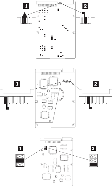
1Primary (Master) Hard Disk Drive
2Secondary (Slave) Hard Disk Drive
CD-ROM drive jumper settings
Type 6568/6569/6648/6649 machines support only the 24X slim CD-ROM
drive. Thus there are no primary versus secondary jumper settings.
BIOS levels
An incorrect level of BIOS can cause false error and unnecessary FRU
replacement. Use the following information to determine the current level of
BIOS installed in the computer, the latest BIOS available for the computer, and
where to obtain the latest level of BIOS.
vCurrent Level BIOS information
–Run the Configuration Utility to determine the level of BIOS installed.
vSources for determining the latest level BIOS available
1.
IBM PC Company Home Page
http://www.ibm.com/pc/us/
Chapter 2. Types 6568/6569/6648/6649 49

2. PC PartnerInfo-Technical Database (CTSTIPS.NSF)
3. HelpCenter
®
4. Levels 1 and 2 Support
5. RETAIN
®
vSources for obtaining the latest level BIOS available
1.
IBM PC Company Home Page
http://www.ibm.com/pc/us/
2. PC PartnerInfo-Technical Database (CTSTIPS.NSF)
3. HelpCenter
4. Levels 1 and 2 Support
To update (flash) the BIOS, see “Flash (BIOS/VPD) update procedure”on
page 50.
Flash (BIOS/VPD) update procedure
Attention
Refer to the information label located inside the system unit cover for
any model-specific information.
1. Power-off the computer.
2. Insert the flash update diskette into drive A.
3. Power-on the computer.
4. When the Update Utility appears; select the country/keyboard, then press
Enter.
5. If the computer serial number was previously recorded, the number is
displayed with an option to update it. Press Yto update the serial number.
6. Type the 7-digit serial number of the computer you are servicing, then
press Enter.
7. Follow the instructions on the screen to complete the flash (BIOS/VPD)
update procedure.
Flash recovery boot block jumper
Attention
If an interruption occurs during a Flash/BIOS upgrade, the BIOS might
be left in an unusable state. The Boot Block jumper enables you to restart
the system and recover the BIOS.
To perform a Flash/BIOS recovery using the recovery jumper, use the
following procedure.
50 Hardware Maintenance Manual: IBM NetVista Computer Types 6058, 6059, 6269, 6568, 6569, 6578, 6579, 6648,
6649

1. Power-off the computer and remove the cover.
2. Move the system board recovery jumper to the clear position. Refer to
“A40 and A40P system board layout”on page 67 or the label inside the
computer for more information.
3. Insert the upgrade diskette into the diskette drive.
4. Power-on the computer. The IBM Logo will appear.
5. When the Flash Update Utility appears, select the country/keyboard, then
press Enter.
6. If the computer serial number was previously recorded, the number is
displayed with an option to update it. Press Yto update the serial number.
7. Type the 7-digit serial number of the computer you are servicing, then
press Enter.
8. Follow the instructions on the screen to complete the flash (BIOS/VPD)
update procedure.
9. When you are instructed to reboot the computer, power-off the computer
and move the recovery jumper to the normal position. Then replace the
cover and power-on the computer.
Power management
Power management reduces the power consumption of certain components of
the computer such as the system power supply, processor, hard disk drives,
and some monitors. Advanced Power Management and Rapid Resume
™
Manager are features of some personal computers.
Automatic configuration and power interface (ACPI) BIOS
Being an ACPI BIOS system, the operating system is allowed to control the
power management features of the computer and the setting for Advanced
Power Management (APM) BIOS mode are ignored. Not all operating systems
support ACPI BIOS mode.
Advanced Power Management
Energy-saving settings can be viewed and changed by using the Advanced
Power Management menu in the Configuration/Setup Utility program.
Attention
If a device, such as a monitor, does not have power-management
capabilities, it can be damaged when exposed to a reduced-power state.
Before making energy-saving selections for the monitor, check the
documentation supplied with the monitor to see if it supports Display
Power Management Signaling (DPMS).
Chapter 2. Types 6568/6569/6648/6649 51
Automatic Hardware Power Management features
Automatic Hardware Power Management can reduce the power states of the
computer, processor, and monitor (if the monitor supports DPMS) if they are
inactive for a predetermined length of time.
There are three levels of specified time that the computer must be inactive
before the power management options that are selected take effect. Select the
amount of time that is offered within each level.
Level 1 Set time from 5 minutes to 4 hours.
Level 2 Set time from 10 minutes to 5 hours.
Level 3 Set time from 15 minutes to 6 hours.
At each level, you can define the amount of energy savings by specifying
values for the following options.
v
System Power
–Select On for the computer to remain on.
–Select Off for the computer to shut down.
v
Processor Speed
Set the microprocessor to be disabled,ortorunat1,10,25,or50 percent of
its internal clock speed.
v
Display
Set display to be disabled or to be reduced at these power states:
–Standby: Screen is blank, but can be restored immediately when any
activity is detected.
–Suspend: Monitor uses less power than in Standby mode. Screen image
is restored after a few seconds when any activity is detected.
–Off: Monitor power is off. Press Monitor power button to restore power.
On some monitors, you might have to depress the power button twice.
Setting Automatic Hardware Power Management features
1. Start the Configuration/Setup Utility program (see “Setup Utility
program”on page 41).
2. Select Advanced Power Management from the Configuration/Setup
Utility program menu.
3. Select the APM BIOS Mode and be sure it is set to Enabled. If it is not,
press Left Arrow (}) or Right Arrow (Æ) to change the setting.
4. Select Automatic Hardware Power Management.
52 Hardware Maintenance Manual: IBM NetVista Computer Types 6058, 6059, 6269, 6568, 6569, 6578, 6579, 6648,
6649
5. Set Automatic Hardware Power Management to Enabled.
6. Select values for the three categories of power management (system
power, processor speed, and display), as necessary.
7. Set Hard Disk to Enabled or Disabled.
Note: This does not apply to SCSI drives.
8. Press Esc twice to return to the Configuration/Setup Utility program
menu.
9. Before you exit from the program, select Save Settings from the
Configuration/Setup Utility program menu.
10. To exit from the Configuration/Setup Utility program, press Esc and
follow the instructions on the screen.
Automatic Power-On features
The Automatic Power-On features within the Power Management menu allow
you to enable and disable features that turn on the computer automatically.
vSerial Port A Ring Detect: With this feature set to Enabled and an external
modem connected to serial port (COM1), the computer will turn on
automatically when a ring is detected on the modem.
vPCI Modem Ring Detect: With this feature set to Enabled , the computer
will turn on automatically when a ring is detected on the internal modem.
vPCI Wake Up: This feature allow PCI cards that support this capability to
wake the system.
vWake Up on Alarm: You can specify a date and time at which the
computer will be turned on automatically. This can be either a single event
or a daily event.
vWake on LAN: If the computer has a properly configured token-ring or
Ethernet LAN adapter card that is Wake on LAN-enabled and there is
remote network management software, you can use the IBM-developed
Wake on LAN feature. When you set Wake on LAN to Enabled, the
computer will turn on when it receives a specific signal from another
computer on the local area network (LAN). For further information, see
“Wake on LAN”on page 54.
Network settings
This section applies only to computers that are linked to a network.
The Configuration/Setup Utility program includes settings that can be
enabled and disabled to configure the network interface in the computer.
These settings are the following:
vFlash over LAN (Update POST/BIOS over Network)
vWake on LAN
Chapter 2. Types 6568/6569/6648/6649 53
Flash over LAN (update POST/BIOS over network)
Note: For local Flash (BIOS/VPD) update, see “Flash (BIOS/VPD) update
procedure”on page 50.
This setting is used to enable or disable the Flash over LAN feature. When the
feature is enabled, the system programs, in the computer, can be updated
remotely from a network server. If the administrator password is set in the
computer, it does not have to be entered by the server.
To access the Flash over LAN setting, use the following procedure.
1. Start the Configuration/Setup Utility program. See “Setup Utility
program”on page 41.
2. Select System Security.
3. Select POST/BIOS Update from the Configuration/Setup Utility program
menu.
4. To enable Flash over LAN, select Enabled. To disable Flash over LAN,
select Disabled.
5. Press Esc twice to return to the Configuration/Setup Utility program
menu.
6. Before you exit from the program, select Save Settings from the
Configuration/Setup Utility program menu.
7. To exit from the Configuration/Setup Utility program, press Esc and
follow the instructions on the screen.
Wake on LAN
This setting is used to enable or disable the IBM-developed Wake on LAN
feature. This feature makes it possible for the computer to be turned on
remotely by a network server. Remote network management software must be
used in conjunction with this feature.
To access the Wake on LAN setting, use the following procedure.
1. Start the Configuration/Setup Utility program. See “Setup Utility
program”on page 41.
2. Select Advanced Power Management.
3. Select Automatic Power On from the program menu.
4. Select Wake on LAN from the Automatic Power On menu.
5. To enable Wake on LAN, select Enabled. To disable Wake on LAN, select
Disabled.
6. Press Esc until you return to the Configuration/Setup Utility program
menu.
7. Before you exit from the program, select Save Settings from the
Configuration/Setup Utility program menu.
54 Hardware Maintenance Manual: IBM NetVista Computer Types 6058, 6059, 6269, 6568, 6569, 6578, 6579, 6648,
6649
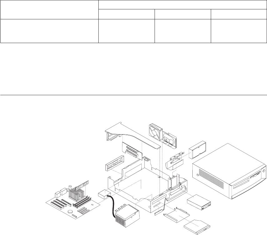
8. To exit from the Configuration/Setup Utility program, press Esc and
follow the instructions on the screen.
System board memory
The following matrix cross-references the name of the computer (printed on
the logo) and the size, speed, and type of memory modules supported in the
computer.
Computers Memory Module
Size Speed Type
Types6568/6569/6648/6649 64 MB128 MB256
MB
133 MHz SDRAMNon-
ParityIndustry
Standard
Supported memory configuration
DIMM sizes of 64 MB, 128 MB and 256 MB are acceptable. Start filling DIMM
socket 0, then 1. Use 3.3 V unbuffered 133 MHz SDRAM non-parity DIMMs
only.
Computer exploded view -
Types 6568/6569/6648/6649
Chapter 2. Types 6568/6569/6648/6649 55
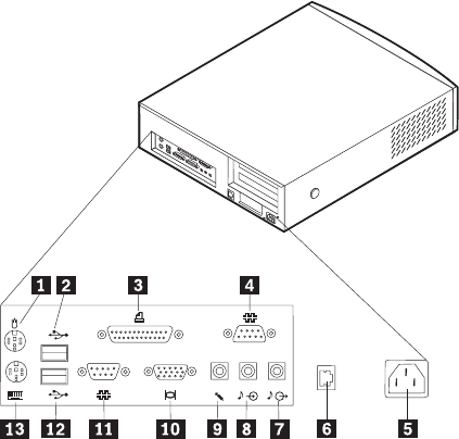
Input/Output connectors
1
2
1Mouse 8Audio input connector
2USB connector 2 9Microphone connector
3Parallel connector 10Monitor connector
4Serial connector 2 (joystick/MIDI connector in
some models)
11Serial connector 1
5Power connector 12USB connector 1
6Ethernet connector 13Keyboard connector
7Audio output connector
56 Hardware Maintenance Manual: IBM NetVista Computer Types 6058, 6059, 6269, 6568, 6569, 6578, 6579, 6648,
6649
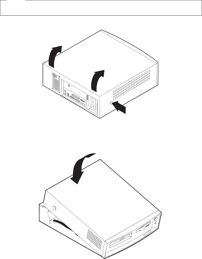
Cover removal
Firmly press the cover latch buttons on both sides. Pull up the back end of
cover, and swing the cover toward the front of the computer.
Note
The front panel is integrated with the top cover.
Replacing the cover
Position the cover over the chassis and pivot the cover down over the
computer until the cover snaps into place.
Chapter 2. Types 6568/6569/6648/6649 57

EMC shield (CD-ROM drive bay)
To remove the EMC shield:
1. Remove the front cover.
2. Remove the single screw that holds the EMC shield in place.
EMC shield (system board)
To remove the EMC shield from the system board:
1. Remove the eight I/O screws that hold the EMC shield in place.
58 Hardware Maintenance Manual: IBM NetVista Computer Types 6058, 6059, 6269, 6568, 6569, 6578, 6579, 6648,
6649
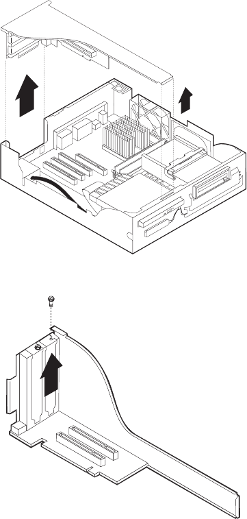
Installing adapters
Adapter slots
To install an adapter in a PCI expansion slot:
1. Remove the riser card housing and place the housing on its side with the
adapter slots facing up.
2. Remove the adapter from its static-protective package.
3. Remove the screw and adapter slot cover for the adapter slot into which
you installing the adapter.
4. Install the adapter and insert the retaining screw.
Note: If you are installing a Wake on LAN supported network adapter,
attach the Wake on LAN cable that came with the adapter to the
Chapter 2. Types 6568/6569/6648/6649 59
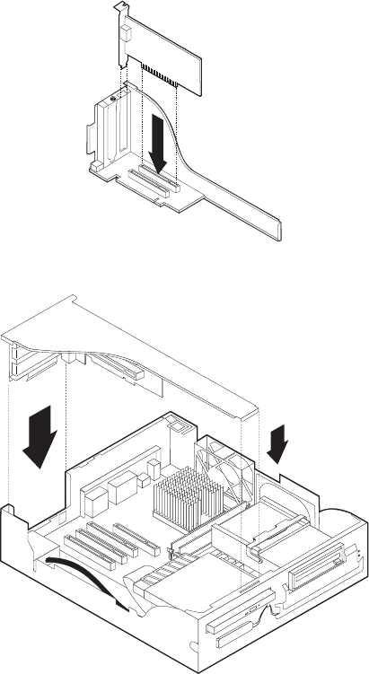
Wake on LAN connector on the system board. If you also want to
take advantage of the Alert on LAN feature of the computer, you
must install the network adapter in PCI slot 1. For the location of
PCI slot 1 and the Wake on LAN connector, see the diagram of the
system board on the inside of the computer.
5. Replace the riser card housing.
6. Replace the cover.
CD-ROM drive removal and replacement
1. Remove the riser card housing (see “Installing adapters”on page 59).
2. Remove the retaining lever and cable from the rear of the drive.
60 Hardware Maintenance Manual: IBM NetVista Computer Types 6058, 6059, 6269, 6568, 6569, 6578, 6579, 6648,
6649
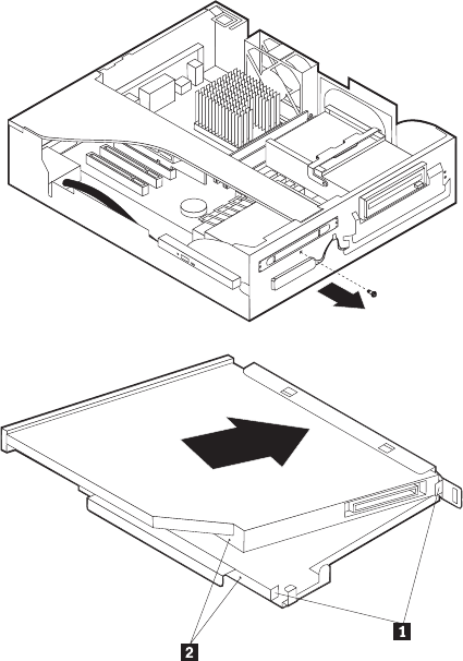
3. Remove the CD-ROM drive bracket retaining screw from the front of the
chassis and remove the CD-ROM drive bracket from the drive bay.
4. Install the slimline CD-ROM drive into the drive bay bracket, aligning the
tabs on the bay bracket 1 with the rear of the slimline CD-ROM drive
2and the tiny holes in the drive with the retaining pins in the drive bay
bracket.
5. Press the CD-ROM drive against the retaining spring in the bracket until
the drive is squarely oriented in the bracket and release the drive. You
should hear a slight click as the drive is secured into the bracket.
Chapter 2. Types 6568/6569/6648/6649 61
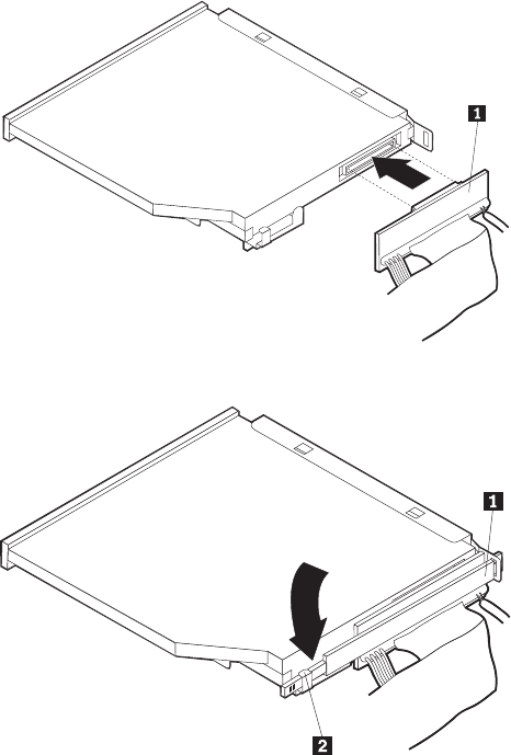
6. Insert the CD-ROM drive and the bracket into the drive bay and replace
the screw.
7. Install the cable and replace the retaining lever behind the CD-ROM.
62 Hardware Maintenance Manual: IBM NetVista Computer Types 6058, 6059, 6269, 6568, 6569, 6578, 6579, 6648,
6649
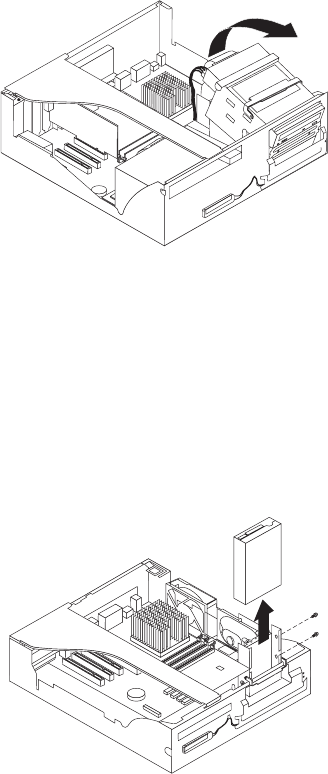
Internal drive removal
Note: The internal drive assembly is designed to latch firmly into place.
When pivoting the drive cage out, you will feel some initial resistance,
so you should pull firmly until the drive cage swings out. Inversely,
when you swing the cage back into the machine case, you should feel a
slight resistance until the cage snaps solidly back into place.
1. Pivot the drive bay cage up and toward the front of the computer.
2. Latch the handle to the front of the chassis, so that the drive cage stays
upright.
3.5″drive removal
1. Remove the two screws from the right side of the drive. Lift the drive out.
Note: Be sure to place the 3.5″drive cable under the single tab on the bottom
of the drive cage. Press the cable down so that the cable folds
underneath the drive cage, toward the front of the chassis, instead of
folding back toward the system board. This will ensure the 3.5″drive
cable is not pinched when the drive cage is firmly placed into its
horizontal operating position.
Chapter 2. Types 6568/6569/6648/6649 63
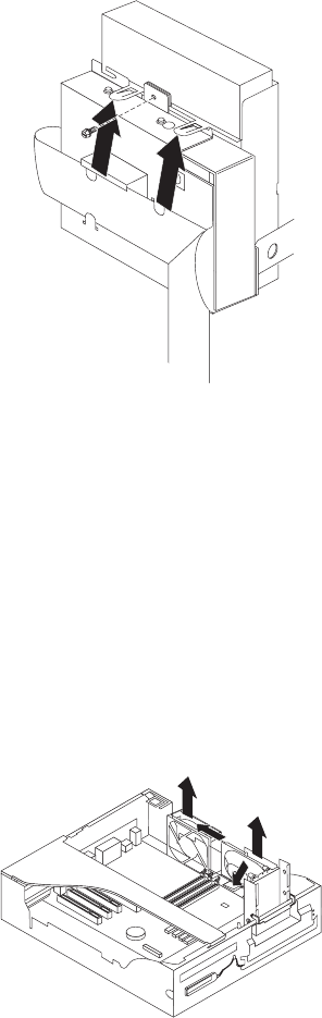
Hard drive removal
1. Latch the drive cage in the upright position.
2. Remove the 3.5″drive cable from the tab at the bottom of the drive cage.
3. Remove the screw that holds the HD bracket, and lift the tabs that hold
the bracket in place. Lift the drive back and up.
4. Remove the HD cable from the drive and from the bottom of the drive
cage. Note the placement of the cable under the three tabs.
5. Remove the four screws on the side and bottom, and take the HD out of
the bracket.
Note: When replacing the HD in the drive cage, place the cable under the
three tabs at the bottom of the drive cage. Be sure to fold the 3.5″drive
cable properly under the cage (see ″Note″in “3.5″drive removal”on
page 63).
Fan/speaker bracket removal
1. Locate the metal tab that secures the fan/speaker bracket to the chassis (on
the bottom of the bracket, just below the rear end of the speaker).
64 Hardware Maintenance Manual: IBM NetVista Computer Types 6058, 6059, 6269, 6568, 6569, 6578, 6579, 6648,
6649
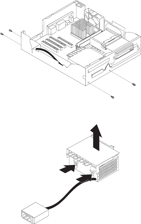
2. Press down on the tab, slide the bracket back and lift up.
Power supply removal
1. Remove the CD-ROM drive (see “CD-ROM drive removal and
replacement”on page 60).
2. Remove the two screws that secure the power supply to the front of the
chassis. Remove the two screws that secure the power cord plug to the
back of the chassis.
3. Locate the two tabs that secure the CD-ROM drive bracket to the back of
the power supply. Push in the two tabs and remove the bracket.
4. Lift out the power supply and plug.
Components of the riser card
The following illustration shows the location of PCI connectors on the riser
card. The Ethernet disable jumper pins (as seen in the diagram below) are
numbered as follows:
Chapter 2. Types 6568/6569/6648/6649 65
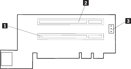
vPin 1 is at the top.
vPin 2 is in the middle.
vPin 3 is at the bottom.
To enable Ethernet, jumper pins 1-2. To disable Ethernet, jumper pins 2-3.
1 PCI slot 1 3 Ethernet disable jumper
2 PCI slot 2
66 Hardware Maintenance Manual: IBM NetVista Computer Types 6058, 6059, 6269, 6568, 6569, 6578, 6579, 6648,
6649
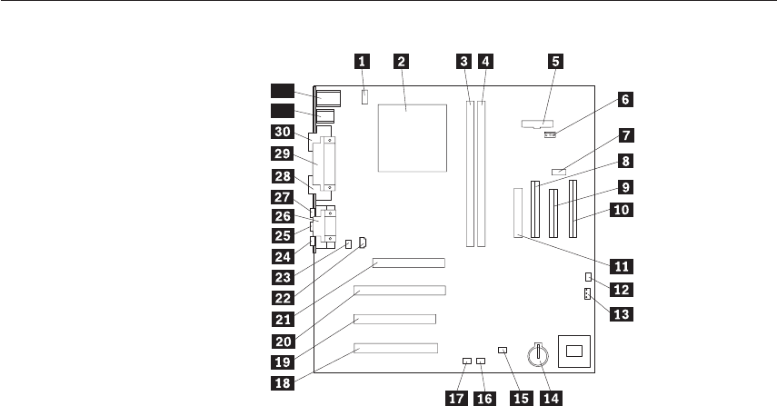
A40 and A40P system board layout
32
31
System board locations
1 #2 fan connector 17 Wake on LAN
2 Microprocessor 18 PCI slot 3
3 DIMM 0 19 PCI slot 2
4 DIMM 1 20 PCI slot 1
5 Power LED connector 21 AGP connector
6 RFID connector 22 CD-ROM audio
7 Front USB connector 23 Speaker connector
8 Secondary IDE connector 24 Audio output
9 Diskette connector 25 Audio input
10 Primary IDE connector 26 Serial port 2
11 Power connector 27 Microphone input
12 CMOS clear/recovery jumper 28 Monitor port
13 #1 fan connector 29 Parallel port
14 Battery 30 Serial port 1
15 SCSI adapter LED connector 31 USB connectors
16 Alert on LAN 32 Mouse and keyboard connectors
A40/A40P System board jumper settings
The following table contains the jumper setting information. (D) indicates the
default setting.
A40/A40P Clear CMOS/Flash Boot Block Recovery
Use the recovery jumper setting to Clear CMOS or to Flash Boot Block
Recover.
Chapter 2. Types 6568/6569/6648/6649 67

Note: The A40/A40P CMOS clear/recovery jumper pins are numbered as
follows:
vPin 1 is the farthest from the battery.
vPins 2 and 3 are below pin 1, as seen in the A40/A40P System Board
layout.
Jumper Setting Description
CMOS Reset 2-3 CMOS Reset/Flash Recovery Mode
1-2 (D) Normal Mode
A40/ A40P Processor Speed Settings
Processor speed for type 6568/6569/6648/6649 computers are fixed and are
determined by the processor. There are no settings required.
A40/A40P Diskette Write Access
Diskette Write Enable and Write Protect options are changed in the Setup
Configuration. See “Setup Utility program”on page 41.
68 Hardware Maintenance Manual: IBM NetVista Computer Types 6058, 6059, 6269, 6568, 6569, 6578, 6579, 6648,
6649

Symptom-to-FRU index
The Symptom-to-FRU index lists error symptoms and possible causes. The
most likely cause is listed first. Always begin with “General checkout”on
page 26. See “Chapter 1. IBM PC Enhanced Diagnostics error codes”on page 1
when running diagnostics. This index can also be used to help you decide
which FRUs to have available when servicing a computer. If you are unable to
correct the problem using this index, go to “Undetermined problems”on
page 90.
Notes
vIf you have both an error message and an incorrect audio response,
diagnose the error message first.
vIf you cannot run the diagnostic tests or you get a diagnostic error
code when running a test, but did receive a POST error message,
diagnose the POST error message first.
vIf you did not receive any error message, look for a description of
your error symptoms in the first part of this index.
vCheck all power supply voltages before you replace the system board.
(See “Power supply”on page 30.)
vCheck the hard disk drive jumper settings before you replace a hard
disk drive. (See “Hard disk drive jumper settings”on page 48.)
Important
1.
Some errors are indicated with a series of beep codes (see “Beep
symptoms”on page 70).
Type 6568/6569/6648/6649 computers default to come up quiet (no
beep and no memory count and checkpoint code display) when no
errors are detected by POST. To enable beep and memory count and
checkpoint code display when a successful POST occurs, do the
following:
a. Select Start Options in the Configuration/Setup Utility program
(see “Setup Utility program”on page 41).
b. Set Power-On Self-Test to Enhanced.
2. The processor is a separate FRU from the system board; the processor
is not included with the system board FRU.
Chapter 2. Types 6568/6569/6648/6649 69

Beep symptoms
Beep symptoms are short tones or a series of short tones separated by pauses
(intervals without sound). See the following examples.
Beeps Description
1-2-X vOne beep
vA pause (or break)
vTwo beeps
vA pause (or break)
vAny number of breaks
4Four continuous beeps
Use the following table to diagnose beep symptoms.
Beep Symptom FRU/Action
1-1-3CMOS read-write error 1. Run Setup
2. System Board
1-1-4ROM BIOS check error 1. System Board
1-2-XDMA error 1. System Board
1-3-X 1. Memory Module
2. System Board
1-4-4 1. Keyboard
2. System Board
1-4-XError detected in first 64 KB of RAM 1. Memory Module
2. System Board
2-1-1,2-1-2 1. Run Setup
2. System Board
2-1-XFirst 64 KB of RAM failed 1. Memory Module
2. System Board
2-2-2 1. Video Adapter (if installed)
2. System Board
2-2-XFirst 64 KB of RAM failed 1. Memory Module
2. System Board
2-3-X 1. Memory Module
2. System Board
70 Hardware Maintenance Manual: IBM NetVista Computer Types 6058, 6059, 6269, 6568, 6569, 6578, 6579, 6648,
6649

Beep Symptom FRU/Action
2-4-X 1. Run Setup
2. Memory Module
3. System Board
3-1-XDMA register failed 1. System Board
3-2-4Keyboard controller failed 1. System Board
2. Keyboard
3-3-4Screen initialization failed 1. Video Adapter (if installed)
2. System Board
Display
3-4-1Screen retrace test detected an error 1. Video Adapter (if installed)
2. System Board
3. Display
3-4-2POST is searching for video ROM 1. Video Adapter (if installed)
2. System Board
41. Video Adapter (if installed)
2. System Board
All other beep code sequences 1. System Board
One long and one short beep during POST.Base
640 KB memory error or shadow RAM error 1. Memory Module
2. System Board
One long beep and two or three short beeps
during POST.(Video error) 1. Video Adapter (if installed)
2. System Board
Three short beeps during POST 1. See “System board memory” on page 55
2. System Board
Continuous beep 1. System Board
Repeating short beeps 1. Keyboard stuck key?
2. Keyboard Cable
3. System Board
Chapter 2. Types 6568/6569/6648/6649 71
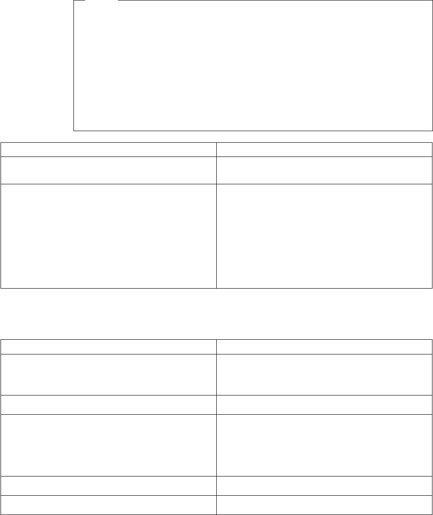
No-beep symptoms
Note
Type 6568/6569/6648/6649 computers default to come up quiet (no beep
and no memory count and checkpoint code display) when no errors are
detected by POST.
To enable beep and memory count and checkpoint code display when a
successful POST occurs, do the following:
1. Select Start Options in the Configuration/Setup Utility program (see
“Setup Utility program”on page 41).
2. Set Power-On Self Test to Enhanced.
Symptom/Error FRU/Action
No beep during POST but computer works
correctly. 1. System Board
No beep during POST. 1. See “Undetermined problems”on page 90
2. System Board
3. Memory Module
4. Any Adapter or Device
5. Riser Card
6. Power Cord
7. Power Supply
POST error codes
In the following index, Xcan represent any number.
POST Error Code FRU/Action
000SCSI Adapter not enabled 1. Verify adapter device and Bus Master fields
are enabled in PCI configuration program.
See documentation shipped with computer.
02X 1. SCSI Adapter
08XCheck SCSI terminator installation. 1. SCSI Cable
2. SCSI Terminator
3. SCSI Device
4. SCSI Adapter
101System board interrupt failure 1. System Board
102System board timer error 1. System Board
72 Hardware Maintenance Manual: IBM NetVista Computer Types 6058, 6059, 6269, 6568, 6569, 6578, 6579, 6648,
6649

POST Error Code FRU/Action
106 1. System Board
110System board memory parity error 1. Memory Module
2. System Board
111I/O channel parity error 1. Reseat adapters
2. Any adapter
3. Riser card
4. System Board
114Adapter ROM error 1. Adapter Memory
2. System Board
3. Riser card
129Internal cache test error 1. Processor
2. L2 Cache Memory
3. System Board
151Real-time clock failure 1. System Board
161Bad CMOS battery 1. Run Setup
2. CMOS Backup Battery (see “Safety
information”on page 185)
3. System Board
162Configuration mismatch 1. Run Setup and verify Configuration
2. Had a device been added, removed, changed
location? If not, suspect that device.
3. Power-on external devices first, then power-on
computer
4. CMOS Backup Battery (see “Safety
information”on page 185)
System Board
5. System Board
6. Riser card
162And unable to run diagnostics 1. Diskette Drive
2. System Board
3. Diskette Drive Cable
4. Riser card
163Clock not updating or invalid time set 1. Time and Date Set?
2. CMOS Backup Battery (see “Safety
information”on page 185)
3. System Board
Chapter 2. Types 6568/6569/6648/6649 73

POST Error Code FRU/Action
164POST detected a base memory or extended
memory size mismatch error or RIMM socket 3 is
populated with a RIMM memory module
1. Run Setup. Check System Summary menu for
memory size change. (See “Setup Utility
program”on page 41.)
2. Run the Extended Memory Diagnostic tests
166Boot Block Check Sum Error 1. Run Flash Recovery using Boot Block. See
“Flash recovery boot block jumper”on
page 50.
2. System Board
167Microprocessor installed that is not supported
by the current POST/BIOS 1. Run Setup. Check Stepping level for the
BIOS level needed, then perform the flash
update.
2. Processor
168Alert on LAN error 1. Run Setup. Check to see that Ethernet and
Alert on LAN are enabled.
2. System Board
3. Riser card
17X, 18X 1. C2 Security
175 1. Run Configuration. See “Setup Utility
program”on page 41.
2. System Board
176 1. Covers were removed from the computer
177Corrupted Administrator Password 1. System Board
178 1. System Board
183 1. Enter the administrator password
184No RFID Antenna 1. Make sure Asset Care and Asset ID are
enabled in Configuration/Setup
2. RFID Antenna
3. System Board
4. Riser card
185Corrupted boot sequence 1. Set configuration and reinstall the boot
sequence
186 1. System Board
187 1. Clear Administration password
2. System Board
74 Hardware Maintenance Manual: IBM NetVista Computer Types 6058, 6059, 6269, 6568, 6569, 6578, 6579, 6648,
6649

POST Error Code FRU/Action
189 1. More than three password attempts were
made to access the computer
190Chassis intrusion detector was cleared. This is
information only, no action required. If this code
does not clear:
1. System Board
1XXNot listed above 1. System Board
201, 20XMemory data error 1. Run Enhanced Diagnostics Memory Test
2. Memory Module
3. System Board
225 1. Unsupported Memory
229External cache test error 1. L2 Cache Memory
2. System Board
262POST detected a base memory or extended
memory type error 1. Run Setup. Check System Summary menu for
memory. (See “Setup Utility program”on
page 41.)
2. Run the Extended Memory Diagnostic tests.
301 1. Keyboard
2. Keyboard Cable
3. System Board
303With an 8603 error 1. Mouse
2. Keyboard
3. Keyboard Cable
4. System Board
303With no 8603 error 1. Keyboard
2. Keyboard Cable
3. System Board
3XXNot listed above 1. Keyboard
2. Keyboard Cable
3. System Board
5XX 1. Video Adapter (if installed)
2. System Board
601 1. Diskette Drive A
2. Diskette Drive Cable
3. System Board
4. Riser card
Chapter 2. Types 6568/6569/6648/6649 75

POST Error Code FRU/Action
602 1. Bad Diskette?
2. Verify Diskette and retry
604And able to run diagnostics 1. Run Setup and verify diskette configuration
settings
2. Diskette Drive A/B
3. Diskette Drive Cable
4. System Board
5. Riser card
605POST cannot unlock the diskette drive 1. Diskette Drive
2. Diskette Drive Cable
3. System Board
4. Riser card
662 1. Diskette drive configuration error or wrong
diskette drive type; run Setup Configuration
6XXNot listed above 1. Diskette Drive
2. System Board
3. Riser card
4. External Drive Adapter
5. Diskette Drive Cable
6. Power Supply
762Math coprocessor configuration error 1. Run Setup
2. Processor
3. System Board
7XX Not listed above 1. Processor
2. System Board
962 Parallel port configuration error 1. Run Configuration
2. Parallel Adapter (if installed)
3. System Board
9XX 1. Printer
2. System Board
1047 1. 16-Bit AT
™
Fast SCSI Adapter
76 Hardware Maintenance Manual: IBM NetVista Computer Types 6058, 6059, 6269, 6568, 6569, 6578, 6579, 6648,
6649

POST Error Code FRU/Action
107XCheck SCSI terminator installation 1. Check SCSI terminator installation
2. SCSI Cable
3. SCSI Terminator
4. SCSI Device
5. SCSI Adapter
1101Serial connector error, possible system board
failure 1. Run Enhanced Diagnostics
1101, 1102, 1106, 1108, 1109 1. System Board
2. Any Serial Device
1107 1. Communications Cable
2. System Board
1102Card selected feedback error 1. Run Enhanced Diagnostics
1103Port fails register check 1. Run Enhanced Diagnostics
2. System Board
1106Serial option cannot be turned off 1. Run Enhanced Diagnostics
2. System Board
1107 1. Serial Device Cable
2. System Board
1110Register test failed 1. Run Enhanced Diagnostics
2. System Board
1116Interrupt error 1. Run Enhanced Diagnostics
1117Failed baud rate test 1. Run Enhanced Diagnostics
1162 Serial port configuration error 1. Run Configuration
2. Serial Adapter
(if installed)
3. System Board
11XXNot listed above 1. System Board
1201 1. System Board
2. Any Serial Device
1202, 1206, 1208, 1209, 12XX 1. Dual Async Adapter/A
2. System Board
3. Any Serial Device
Chapter 2. Types 6568/6569/6648/6649 77

POST Error Code FRU/Action
1207 1. Communications Cable
2. Dual Async Adapter/A
13XX 1. Game Adapter
1402Printer not ready Information only
1403No paper error, or interrupt failure Information only
1404System board timeout failure 1. Run Enhanced Diagnostics
1405Parallel adapter error 1. Run Enhanced Diagnostics
1406Presence test error 1. Run Enhanced Diagnostics
14XXNot listed above. Check printer before
replacing system board 1. Printer
2. System Board
15XX 1. SDLC Adapter
1692Boot sequence error 1. Run FDISK to ensure at least one active
partition is set active
16XX 1. 36/38 Workstation Adapter
1762Hard disk drive configuration error 1. Run Configuration (See “Setup Utility
program”on page 41)
1780 (Disk Drive 0)1781 (Disk Drive 1)1782 (Disk
Drive 2)1783 (Disk Drive 3) 1. See “Power supply”on page 30
2. Hard Disk Drive
3. System Board
4. Riser card
5. Hard Disk Cable
6. Power Supply
180X, 188XPCI configuration or resource error 1. Run Setup and verify PCI/ISA configuration
settings.
2. If necessary, set ISA adapters to Not available to
allow PCI adapters to properly configure.
3. Remove any suspect ISA adapters.
4. Rerun diagnostics.
5. PCI Adapter
1962Boot sequence error 1. Possible hard disk drive problem; see “Hard
disk drive boot error”on page 42
209X 1. Diskette Drive
2. Diskette Cable
78 Hardware Maintenance Manual: IBM NetVista Computer Types 6058, 6059, 6269, 6568, 6569, 6578, 6579, 6648,
6649

POST Error Code FRU/Action
20XXNot listed above 1. BSC Adapter
21XX 1. SCSI Device
2. 16-bit AT Fast SCSU adapter
3. Alternate BSC adapter
2401, 2402If screen colors change 1. Display
2401, 2402If screen colors are OK 1. System Board
2. Display
2409 1. Display
2410 1. System Board
2. Display
2462Video memory configuration error 1. Check cable connections
2. Run Setup and verify video configuration
settings
3. Video Memory Modules
4. Video Adapter (if installed)
5. System Board
4611, 4630 1. Multiport/2 Interface Board
2. Multiport/2 Adapter
4612, 4613, 4640, 4641 1. Memory Module Package
2. Multiport/2 Adapter
4650 1. Multiport/2 Interface Cable
46XXNot listed above 1. Multiport/2 Adapter
2. Multiport/2 Interface
Board
3. Memory Module
5600 1. Financial System Controller Adapter
5962An IDE device (other than hard drive)
configuration error 1. Run Configuration
2. CD-ROM Drive
3. CD-ROM Adapter
4. Zip or other ATAPI device
5. System Board
6. Riser card
Chapter 2. Types 6568/6569/6648/6649 79

POST Error Code FRU/Action
62XX 1. 1st Store Loop Adapter
2. Adapter Cable
63XX 1. 2nd Store Loop Adapter
2. Adapter Cable
64XX 1. Network Adapter
71XX 1. Voice Adapter
74XX 1. Video Adapter
(if installed)
76XX 1. Page Printer Adapter
78XX 1. High Speed Adapter
79XX 1. 3117 Adapter
80XX 1. PCMCIA Adapter
84XX 1. Speech Adapter
2. Speech Control Assy.
8601, 8602 1. Pointing Device (Mouse)
2. System Board
8603, 8604 1. System Board
2. Pointing Device
(Mouse)
86XXNot listed above 1. Mouse
2. System Board
89XX 1. PC Music Adapter
2. MIDI Adapter Unit
91XX 1. Optical Drive
2. Adapter
96XX 1. SCSI Adapter
2. Any SCSI Device
3. System Board
4. Riser card
10101, 10102, 10104, 10105, 10106, 10107, 10108,
10109, 10111,
10112, 10113, 10114,
10115, 10116
1. Have customer verify correct operating system
device drivers are installed and operational.
2. Modem
80 Hardware Maintenance Manual: IBM NetVista Computer Types 6058, 6059, 6269, 6568, 6569, 6578, 6579, 6648,
6649

POST Error Code FRU/Action
10103, 10110, 101171 1. System Board
2. Data/Fax Modem
3. Riser card
10117Not listed above 1. Check system speaker
2. Check PSTN cable
3. External DAA
(if installed)
4. Modem
10118 1. Run Diagnostics and verify the correct
operation of the modem slot
2. Modem
10119 1. Diagnostics detected a non-IBM modem
2. Modem
10120 1. Check PSTN Cable
2. External DAA
(if installed)
3. Modem
10132, 10133, 10134,
10135, 10136, 10137,
10138, 10139, 10140,
10141, 10142, 10143,
10144, 10145, 10146,
10147, 10148, 10149,
10150, 10151, 10152
1. Modem
10153 1. Data/Fax Modem
2. System Board
3. Riser card
101XXNot listed above 1. Modem Adapter/A
2. Data/Fax Modem
3. System Board
4. Riser card
10450, 10451, 10490,
10491, 10492, 10499Read/write error 1. Run Enhanced Diagnostics
2. Hard Disk Drive
3. System Board
4. Riser card
10452Seek test error 1. Run Enhanced Diagnostics
Chapter 2. Types 6568/6569/6648/6649 81

POST Error Code FRU/Action
10453Wrong drive type? Information only
10454Sector buffer test error 1. Run Enhanced Diagnostics
10455, 10456Controller error 1. Run Enhanced Diagnostics
10459Drive diagnostic command error Information only
10461Drive format error 1. Run Enhanced Diagnostics
10462Controller seek error 1. Run Enhanced Diagnostics
10464Hard Drive read error 1. Run Enhanced Diagnostics
10467Drive non-fatal seek error 1. Run Enhanced Diagnostics
10468Drive fatal seek error 1. Run Enhanced Diagnostics
10469Drive soft error count exceeded 1. Run Enhanced Diagnostics
10470, 10471, 10472Controller wrap error 1. Run Enhanced Diagnostics
10473Corrupt data. Low level format might be
required
Information only
10480 1. Hard Disk Drive (ESDI)
2. Drive Cable
3. System Board
10481ESDI drive D seek error 1. Run Enhanced Diagnostics
10482Drive select acknowledgement bad 1. Run Enhanced Diagnostics
106X1 1. Check Configuration
2. Ethernet Adapter
10635 1. Power-off computer, wait ten seconds then
power-on the computer
2. Ethernet Adapter
10651, 10660 1. Check Cables
2. Ethernet Adapter
106XXNot listed above 1. Ethernet Adapter
107XX 1. 5.25-inch External
Diskette Drive
2. 5.25-inch Diskette
Drive Adapter/A
82 Hardware Maintenance Manual: IBM NetVista Computer Types 6058, 6059, 6269, 6568, 6569, 6578, 6579, 6648,
6649

POST Error Code FRU/Action
109XXCheck the adapter cables 1. ActionMedia
Adapter/A
2. System Board
3. Riser card
112XXThis adapter does not have cache 1. SCSI Adapter
2. Any SCSI Device
3. System Board
4. Riser card
119XX 1. 3119 Adapter
121XX 1. Modem Adapter
2. Any Serial Device
3. System Board
4. Riser card
136XX 1. ISDN Primary Rate Adapter
2. System Board
3. Riser card
137XX 1. System Board
141XX 1. Realtime Interface Coprocessor Portmaster
Adapter/A
143XX 1. Japanese Display Adapter
2. System Board
3. Riser card
14710, 14711 1. System Board Video Adapter
2. Adapter Video Memory
148XX 1. Video Adapter
14901, 14902,
1491X, 14922 1. Video Adapter
(if installed)
2. System Board
3. Riser card
4. Display (any type)
14932 1. External Display
2. Video Adapter
161XX 1. FaxConcentrator Adapter
Chapter 2. Types 6568/6569/6648/6649 83

POST Error Code FRU/Action
164XX 1. 120 MB Internal Tape Drive
2. Diskette Cable
3. System Board
4. Riser card
16500 1. 6157 Tape Attachment
2. Adapter
16520, 16540 1. 6157 Streaming Tape Drive
2. 6157 Tape Attachment Adapter
166XX, 167XX 1. Token Ring Adapter
2. System Board
3. Riser card
18001 to 18029 1. Wizard Adapter
2. Wizard Adapter Memory
18031 to 18039 1. Wizard Adapter Cable
185XXXX 1. DBCS Japanese Display Adapter/A
2. System Board
3. Riser card
20001 to 20003 1. Image Adapter/A
Image-I Adapter/A
2. Memory Module DRAM, VRAM
20004 1. Memory Module DRAM, VRAM
2. Image Adapter/A
Image-I Adapter/A
20005 to 20010 1. Image Adapter/A
Image-I Adapter/A
2. Memory Module DRAM, VRAM
200XXNot listed above 1. Image Adapter/A
2. Image-I Adapter/A
3. Memory Module DRAM, VRAM
4. System Board
5. Riser card
20101 to 20103 1. Printer/Scanner Option
2. Image Adapter/A
3. Memory Module DRAM, VRAM
84 Hardware Maintenance Manual: IBM NetVista Computer Types 6058, 6059, 6269, 6568, 6569, 6578, 6579, 6648,
6649

POST Error Code FRU/Action
20104 1. Memory Module DRAM, VRAM
2. Printer/Scanner Option
3. Image Adapter/A
20105 to 20110 1. Printer/Scanner Option
2. Image Adapter/A
3. Memory Module DRAM, VRAM
Image Adapter/A Memory Test failure indicated
by graphic of adapter 1. Replace memory module (shown in graphic)
206XX 1. SCSI-2 Adapter
2. Any SCSI Device
3. System Board
4. Riser card
208XXVerify there are no duplicate SCSI ID
settings on the same bus. 1. Any SCSI Device
210XXXXInternal bus, size
unknown210XXX1External bus, size unknown 1. SCSI Hard Disk Drive
2. SCSI Adapter or System Board
3. SCSI Cable
4. SCSI ID Switch (on some models)
Tape Drive amber LED remains on 1. Tape Drive
2. SCSI Cable (internal)
3. SCSI Adapter or System Board
Tape Drive green ″in use″LED fails to come on 1. Tape Drive
2. SCSI Adapter or System Board
3. SCSI Cable (internal)
4. SCSI Cable (external)
Tape automatically ejected from drive 1. Tape Cassette
Drive
SCSI ID on rotary switch does not match SCSI ID
set in configuration. Verify drive switches inside
cover are set to zero
1. Rotary Switch Circuit Board
2. Circuit Board Cable
3. Tape Drive
Tape sticks or breaks in drive. Verify that the tapes
used meet ANSI standard X3B5 1. Tape Cassette
212XX 1. SCSI Printer
2. Printer Cable
213XX 1. SCSI Processor
Chapter 2. Types 6568/6569/6648/6649 85

POST Error Code FRU/Action
214XX 1. WORM Drive
215XXXC, 215XXXD, 215XXXE, 215XXXUIf an
external device, and power-on LED is off, check
external voltages
1. CD-ROM Drive I
2. CD-ROM Drive II
Enhanced CD-ROM Drive II
Any CD-ROM Drive
3. SCSI Cable
4. SCSI Adapter or System Board
216XX 1. Scanner
217XXIf an external device, and power-on LED is
off, check external voltages 1. Rewritable Optical Drive
2. SCSI Adapter or System Board
3. SCSI Cable
218XXCheck for multi CD tray or jukebox 1. Changer
219XX 1. SCSI Communications Device
24201Y0, 24210Y0Be sure wrap plug is attached 1. ISDN/2 Adapter
2. ISDN/2 Wrap Plug
3. ISDN/2 Communications Cable
273XX 1. 1 Mbps Micro Channel
2. Infrared LAN Adapter
27501, 27503, 27506, 27507 1. ServerGuard Adapter
2. System Board
3. Riser card
27502, 27504, 27510, 27511, 27533, 27534, 27536,
27537 1. ServerGuard Adapter
27509 1. Remove redundant adapters, run Auto
Configuration program, then retest.
27512 1. WMSELF.DGS diagnostics file is missing
2. WMSELF.DGS diagnostics file is incorrect
27535 1. 3V Lithium Backup Battery
2. ServerGuard Adapter
27554 1. Internal Temperature out of range
2. ServerGuard Adapter
27555, 27556 1. ServerGuard Adapter
2. Power Supply
86 Hardware Maintenance Manual: IBM NetVista Computer Types 6058, 6059, 6269, 6568, 6569, 6578, 6579, 6648,
6649

POST Error Code FRU/Action
27557 1. 7.2V NiCad Main Battery Pack
2. ServerGuard Adapter
27558, 27559, 27560, 27561 1. PCMCIA Type II Modem
2. ServerGuard Adapter
27562 1. External Power Control not connected
2. External Power Control
3. ServerGuard Adapter
27563, 27564 1. External Power Control
2. ServerGuard Adapter
275XX 1. Update Diagnostic Software
27801 to 27879 1. Personal Dictation System
2. Adapter
3. System Board
27880 to 27889 1. External FRU
(Speaker, Microphone)
999030XHard disk reset failure 1. Possible hard disk drive problem; see “Hard
disk drive boot error”on page 42
Miscellaneous error messages
Message/Symptom FRU/Action
CMOS Backup Battery inaccurate 1. CMOS Backup Battery (see “Safety
information”on page 185)
2. System Board
Changing colors 1. Display
Computer will not power-off. See “Power supply”
on page 30. 1. Power Switch
2. System Board
3. Riser card
Computer will not RPL from server 1. Ensure that network is in startup sequence as
first device or first device after diskette
2. Ensure that network adapter is enabled for
RPL
3. Network adapter (Advise network
administrator of new MAC address)
Chapter 2. Types 6568/6569/6648/6649 87

Message/Symptom FRU/Action
Computer will not Wake On LAN (if applicable) 1. Check power supply and signal cable
connections to network adapter
2. Ensure that the operating system settings are
set to enable Wake on LAN
3. Ensure Wake On LAN feature is enabled in
Setup/Configuration (see “Setup Utility
program”on page 41)
4. Ensure network administrator is using correct
MAC address
5. Ensure no interrupt or I/O address conflicts
6. Network adapter (advise network
administrator of new MAC address)
Dead computer. See “Power supply”on page 30. 1. Power Supply
2. System Board
3. Riser card
Diskette drive in-use light remains on or does not
light when drive is active. 1. Diskette Drive
2. System Board
3. Diskette Drive Cable
4. Riser card
Flashing cursor with an otherwise blank display. 1. System Board
2. Primary Hard Disk Drive
3. Hard Disk Drive Cable
4. Riser card
Incorrect memory size during POST 1. Run the Memory tests
2. Memory Module
3. System Board
″Insert a Diskette″icon appears with a
known-good diagnostics diskette in the first
3.5-inch diskette drive.
1. System Board
2. Diskette Drive Cable
3. Riser card
4. Network Adapter
Intensity or color varies from left to right of
characters and color bars 1. Display
2. System Board
No power or fan not running 1. See “Power supply”on page 30
88 Hardware Maintenance Manual: IBM NetVista Computer Types 6058, 6059, 6269, 6568, 6569, 6578, 6579, 6648,
6649

Message/Symptom FRU/Action
Non-system disk or disk error-type message with
a known-good diagnostic diskette. 1. Diskette Drive
2. System Board
3. Diskette Drive Cable
4. Riser card
Drives not recognized by the Fixed Disk diagnostic
(e.g., you have six drives but the fixed disk test
only shows three)
1. Remove the first drive that does not show up
and rerun the Fixed Disk diagnostic. If the
remaining drives then show up, replace the
drive you removed.
Hang during Fixed Disk diagnostic 1. Remove the hard file being tested at the time
of the hang.
2. Rerun the diagnostic.
3. If successful, replace the drive you removed.
Other display symptoms not listed above
(including blank or illegible display) 1. See “Display”on page 32
2. System Board
3. Display
Power-on indicator or hard disk drive in-use light
not on, but computer works correctly 1. Power Supply
2. System Board
3. LED Cables
Printer problems 1. See “Printer”on page 29
Program loads from the hard disk with a
known-good diagnostics diskette in the first
3.5-inch diskette drive
1. Run Setup
2. Diskette Drive
3. Diskette Drive Cable
4. System Board
5. Riser card
6. Power Supply
RPL computer cannot access programs from its
own hard disk. 1. If network administrator is using LCCM
Hybrid RPL, check startup sequence:
a. First device - network
b. Second device - hard disk
2. Hard disk drive
RPL computer does not RPL from server 1. Check startup sequence
2. Check the network adapter LED status
Chapter 2. Types 6568/6569/6648/6649 89

Message/Symptom FRU/Action
Serial or parallel port device failure (system board
port) 1. External Device Self-Test OK?
2. External Device
3. Cable
4. System Board
Serial or parallel port device failure (adapter port) 1. External Device Self-Test OK?
2. External Device
3. Cable
4. Alternate Adapter
5. System Board
Some or all keys on the keyboard do not work 1. Keyboard
2. Keyboard Cable
3. System Board
Undetermined problems
Check the power supply voltages. See “Power supply”on page 30. If the
voltages are correct, return here and continue with the following steps.
1. Power-off the computer.
2. Remove or disconnect the following components (if installed) one at a
time.
a. Non-IBM devices
b. External devices (modem, printer, or mouse)
c. Any adapters
d. Riser card
e. Memory modules
Before removing or replacing memory modules, see “System board
memory”on page 55.
f. Extended video memory
g. External Cache
h. External Cache RAM
i. Hard disk drive
j. Diskette drive
3. Power-on the computer to re-test the system.
4. Repeat steps 1 through 3 until you find the failing device or adapter.
If all devices and adapters have been removed, and the problem continues,
replace the system board. See “Replacing a system board”on page 45.
90 Hardware Maintenance Manual: IBM NetVista Computer Types 6058, 6059, 6269, 6568, 6569, 6578, 6579, 6648,
6649
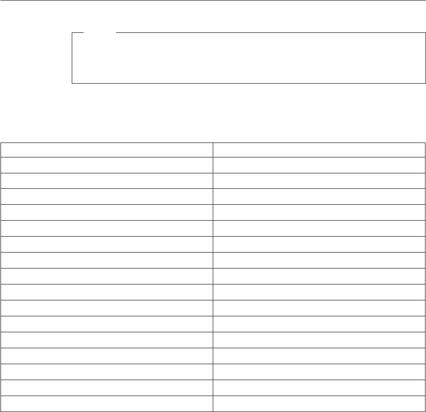
Model tables - Country/Region/Language
Note
For model information, please refer to IBM online at
http://www.ibm.com, then select support to find information for type
6568/6569/6648/6649 models.
Use this table to identify the country/region/language specific models. In
most cases, country/region or language designation will be identified by the
last digit of the model number.
EMEA Model
EMEA preload xxG
North America Model
U.S. English xxU
Canadian French xxF
Latin America Model
Portuguese (Brazil) xxP
L.A. Spanish xxS
Asia Pacific (AP) Model
A.P. English (Australia, New Zealand) xxA
Japan (Japanese) xxJ
Hong Kong (A.P. English) xxD
Hong Kong (Chinese) xxM
China (Chinese) xxC
China (A.P. English) xxD
Thailand (Thai) xxT
Taiwan (Chinese) xxV
Chapter 2. Types 6568/6569/6648/6649 91
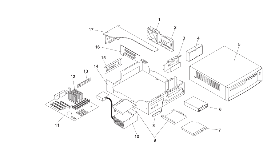
Parts - Types 6568/6569/6648/6649
92 Hardware Maintenance Manual: IBM NetVista Computer Types 6058, 6059, 6269, 6568, 6569, 6578, 6579, 6648,
6649
Parts listing
Each FRU is available for all types/models, unless specific types or models
are given.
Index System (Types 6568/6569/6648/6649) FRU No.
1FAN ASM 80MM with FAN/SPEAKER BRACKET (all types/models) 22P2473
2SPEAKER w/CABLE ASM (all types/models) 00N5151
3DASD MOUNTING BRACKET (all types/models) 10K0941
410.1GB HARDFILE EIDE 5400 RPM (6568 - GAx, GBx, LAx, LBx, NAx,
NBx) (6569/ 6649 - LAx, LBx)(6648 -
GAx,GBx,LAx,LBx,D2U,D3U,NAx,NBx)
36L8681
415.0GB HARDFILE EIDE 5400RPM (6568 - D3U) 09N0851
420.4GB HARDFILE EIDE 5400RPM (6568 - LCx, LDx, PAx, PBx, RAx,
RBx, TAx, TBx, RAA, RBA, RFG,VEG,VCM,VCV, VCD,VDV, KAV, KQV,
KTV, PBV)(6569 - NAx, NBx, PAx, PBx, RAx, RBx, TAx, TBx, RAA,
RBA, RCG, TCG)(6648 - PAx, PBx, RAx, RBx, TAx, TBx, TCU) (6649 -
NAx, NBx, TAx, PAx, PBx, RAx, RBx, TBx,TCU)
09N0705
20.4GB HARDFILE EIDE OPTIONAL (6568 - LCx, LDx, PAx, PBx, RAx,
RBx, TAx, TBx, RAA, RBA, RFG,VEG,VCM,VCV,VDV)
06P5240
5TOP COVER ASM with Front Bezel Asm (6568/6569 - all models) 10K0939
5TOP COVER ASM with Front Bezel Asm (6648/6649 only) 19K5571
63.5″1.44MB DISKETTE DRIVE (all types/models) 06P5229
7CD-ROM DRIVE - 24x SLIM(6568 - LCx, LDx, RAx, RBx, NAx, NBx,
TAx, TBx, RAA, RBA, RFG, VEG)(6569 - NAx, NBx, PAx, PBx, RAx,
RBx, TAx, TBx, RAA, RBA, RCG, TCG)(6648 - NAx, NBx, RAx, RBx,
TAx, TBx,TCU) (6649 - NAx, NBx, TAx, TBx, PAx, PBx, RAx, RBx, TCU)
19K1523
8RFID ANTENNA 03K9654
9CDROM BRACKET w/SPRING KIT (all) 10K0937
10 110W POWER SUPPLY (6568/6569/6648/6649 - all models) 00N7673
10 110W POWER SUPPLY - CHINA (6568 - GAC, GBC, KAV, KQV, KTV,
LAC, LBC, NAC, NBC, PAC, PBC, PBV, TAC, TBC)
00N7675
11 SYST BD W/O MEM/PROC/ MERLOT/ W/O POV CARD
(6568/6569/6648/6649)
09K9982
11 SYST BD MERLOT W/POV CARD (6569/6649 only) 10K1195
12 PIII COPPERMINE 600MHz (6648 - D2U,D3U) 06P7445
12 PIII COPPERMINE 667MHz (6568/6648 - GAx, GBx) 10K0863
12 PIII COPPERMINE 733MHz (6568 - LAx, LBx, LCx,
LDx)(6569/6648/6649 - LAx, LBx)
10K0864
12 PIII COPPERMINE 800MHz (OPTIONAL) (6568/6648/6569/6649 -
NAx, NBx)
10K1196
12 COPPERMINE 866MHz PROCESSOR (6568/6569/6648/6649 - PAx,
PBx)
19K7539
12 COPPERMINE 933MHz PROCESSOR (6568 - RAx, RBx,RAA,RBA,RFG)
(6569 - RAx, RBx,RAA,RBA,RCG) (6648/6649 - RAx, RBx)
19K7537
12 COPPERMINE 933MHz (6648/6649 - RAx, RBx) 25P0719
12 PIll 1GHz PROCESSOR (6568 - TAx, TBx, VEG, VCM, VCV, VCD, VDV,
KQV, KTV) (6569 - TAx, TBx,TCG)(6648/6649 -TAx,TBx,TCU)
24P9479
Chapter 2. Types 6568/6569/6648/6649 93
Index System (Types 6568/6569/6648/6649) FRU No.
13 MEMORY 64MB SDRAM (6568 - GAx, GBx, LAx, LBx, NAx,
NBx)(6569/6649 - LAx, LBx)(6648 - GAx, GBx, LAx, LBx, NAx, NBx)
33L3072
13 MEMORY 128MB SDRAM (6568 - LCx, LDx, PAx, PBx, RAx, RBx, TAx,
TBx, D3U, RAA, RBA, RFG, VEG,VCM, VCV, VCD, VDV, KAV, KQV,
KTV, PBV)(6569 - NAx, NBx, PAx, PBx, RAx, RBx, TAx,
TBx,RAA,RBA,RCG,TCG)(6648 - D2U, D3U, PAx, PBx, RAx, RBx, TAx,
TBx)(6649 - NAx, NBx, PAx, PBx, RAx, RBx, TAx, TBx)
33L3074
13 MEMORY 256MB SDRAM (6648, 6649 - TCU) 33L3076
14 Chassis ASM with FDD Cage (6568/6569 only, all models) 06P2950
14 Chassis ASM with FDD Cage (6648/6649 only, all models) 06P2951
15 EMC PLANAR SHIELD (all types/models) 09N5770
16 RISER CARD ENET (all types/models) 09N4515
17 I/O BRACKET ASM (all types/models) 10K0940
FOOT (5) and VERTICAL STAND (6568/6569 only, all models) 10K0934
FOOT (5) and VERTICAL STAND (6648/6649 only, all models) 19K5569
BEZEL KIT with NAMEPLATE (6568/6569 only, all models) 10K0935
BEZEL KIT with NAMEPLATE (6648/6649 only, all models) 19K5570
POWER/LED CABLE ASM (all types/models) 10K0942
KEYLOCK ASM (all types/models) 10K0944
C2 SWITCH ASM (all types/models) 09K9827
CABLE HARDFILE - ATA (all types/models) 10K0829
CABLE DISKETTE DRIVE (all types/models) 10K0828
MOUSE - 2 Button (6568/6648 - all) (6569 -PAG, PBG, RAx, RBx, TAx,
TBx, RAA, RBA, RCG, TCG) (6649 - TAx, TBx, TCU)
10L6145
MOUSE - Scrollpoint®(6569 - NAx, NBx, LAx ,LBx, PAA, PBA) 09N5535
MOUSE - 2 Button Black (6648 - all) (6649 - TAx, TBx,TCU) 76H5080
MOUSE - Scrollpoint Black (6649 only - LAx, LBx, NAx, NBx, PAx, PBx,
RAx, RBx)
28L1868
MOUSE - Scrollpoint Black (6649 - LAx, LBx, NAx, NBx, PAx, PBx,
RAx, RBx)
09N5537
MISC. HARDWARE KIT (all types/models) 10K0938
CDROM CABLE (all types/models) 09N0102
USB CABLE (all types/models) 09N4496
LITHIUM BATTERY (all types/models) 33F8354
PLANAR LOCATION LABEL (all types/models) 06P2735
CELERON 600MHz (6568 - D3U) 06P2442
COPPERMINE CELERON 800MHz (100 Bus/800MHz/128Kb L2 Cache)
″D0″STEP LEVEL FLIP CHIP WITH HEATSINK 09N4373 (NOTE:
PRIME P/N TO 10K1196) (6568/ 6569/ 6648/ 6649 - NAx, NBx)
25P2779
COPPERMINE 866MHz (133/866-256KL2Cache) ″D0″STEP LEVEL
WITH HEATSINK 09N4373 (PRIME TO 22P4385 AND 19K7539) (6568 -
PAx, PBx, KAV, PBV) (6648 - PAx,PBx)
25P2778
COPPERMINE 866MHz (133/866-256KL2Cache) ″C0″STEP LEVEL
WITH HEATSINK 09N4373 (OPTIONAL) (6568/6648 - PAx,PBx)
22P4385
94 Hardware Maintenance Manual: IBM NetVista Computer Types 6058, 6059, 6269, 6568, 6569, 6578, 6579, 6648,
6649
Index System (Types 6568/6569/6648/6649) FRU No.
HEATSINK NON-IHS 566-866 MHz (6568 - GAx, GBx, LAx, LBx, LCx,
LDx, NAx, NBx, PAx, PBx, KAV, PBV) (6569/6649 - LAx, LBx, NAx,
NBx, PAX, PBx) (6648 - GAx, GBx, LAx, LBx, D2U, D3U, NAx, NBx,
PAx, PBx)
09N4372
PROCESSOR HEATSINK (6568 - TAx, TBx, VEG, VCM, VCV, VCD,
VDV, KQT, KTV) (6569 - TAx, TBx, RAA, RBA, RCG, TCG)
22P2457
FAN SINK 900 MHz (6568 - RAx, RBx, RAA, RBA, RFG, TAx, TBx,
VEG, VCM, VCV, VCD, VDV, KQV, KTV) (6569 - RAx, RBx, RAA, RBA,
RCG, TAx, TBx, TCG) (6648/6649 - RAx, RBx, TAx, TBx, TCU)
06P2458
FANSINK IHS 866-1.10 GHz (6568 - RAx, RBx, RAA, RBA, RFG, TAx,
TBx, VEG, VCM, VCV, VCD, VDV, KQV, KTV) (6569 - RAx, RBx, RAA,
RBA, RCG, TAx, TBx, TCG) (6648/6649 - RAx, RBx, TAx, TBx, TCU)
22P4370
AIR BAFFLE DUCT (6568 - TAx,TBx,VEG,VCM,VCV, VCD,VDV, KQV,
KTV) (6569 - TAx,TBx,RAA,RBA,RCG,TCG) (6648/ 6649 -
TAx,TBx,TCU)
22P3624
Keyboards - 6568/6569
(PCNext Lite Pearl White)
US ENGLISH 37L2514
FRENCH CANADIAN 058 37L0912
FRENCH CANADIAN 044 37L2515
LA/SPANISH 37L2516
BRAZIL - PORTUGUESE 28L1826
ARABIC 37L2518
BELGIUM - FRENCH 37L2519
BELGIUM - ENGLISH 37L2520
BULGARIAN 37L2521
CZECH 37L2522
DANISH 37L2523
DUTCH 37L2524
FRENCH 37L2525
GERMAN 37L2526
GREEK 37L2527
HEBREW 37L2528
HUNGARIAN 37L2529
ITALIAN 37L2531
NORWEGIAN 37L2532
POLISH 37L2533
PORTUGUESE 37L2534
ROMANIAN 37L2535
RUSSIAN 37L2536
SERBIAN - CYR 37L2537
SLOVAK 37L2538
SPANISH 37L2539
Chapter 2. Types 6568/6569/6648/6649 95
SWEDISH/FINNISH 37L2540
SWISS - FRENCH/GERMAN 37L2541
TURKISH - ID 179 37L2542
TURKISH - ID 440 37L2543
UK ENGLISH 37L2544
YUGOSLAVIAN 37L2545
UK ENGLISH (ISO) 37L2546
JAPANESE 37L2547
CHINESE 37L2548
KOREAN 28L1860
THAI 37L2550
Keyboards - 6648/6649
(PCNext Lite Black)
US ENGLISH 37L2551
FRENCH CANADIAN 058 37L0913
FRENCH CANADIAN 044 37L2552
LA/SPANISH 37L2553
BRAZIL - PORTUGUESE 37L2554
ARABIC 37L2555
BELGIUM - FRENCH 37L2556
BELGIUM - ENGLISH 37L2557
BULGARIAN 37L2558
CZECH 37L2559
DANISH 37L2560
DUTCH 37L2561
FRENCH 37L2562
GERMAN 37L2563
GREEK 37L2564
HEBREW 37L2565
HUNGARIAN 37L2566
ICELAND 37L2567
ITALIAN 37L2568
NORWEGIAN 37L2569
POLISH 37L2570
PORTUGUESE 37L2571
ROMANIAN 37L2572
RUSSIAN 37L2573
SERBIAN - CYR 37L2574
SLOVAK 37L2575
SPANISH 37L2576
SWEDISH/FINNISH 37L2577
SWISS - FRENCH/GERMAN 37L2578
TURKISH - ID 179 37L2579
96 Hardware Maintenance Manual: IBM NetVista Computer Types 6058, 6059, 6269, 6568, 6569, 6578, 6579, 6648,
6649
TURKISH - ID 440 37L2580
UK ENGLISH 37L2581
YUGOSLAVIAN 37L2582
UK ENGLISH (ISO) 37L2583
JAPANESE 37L2584
CHINESE 37L2585
KOREAN 28L1905
THAI 37L2587
Chapter 2. Types 6568/6569/6648/6649 97
Computer Power Cords
ARABIC 14F0033
AUSTRALIAN 93F2365
BELGIAN 1339520
BULGARIAN 1339520
CANADIAN 93F2364
CZECH 1339520
DENMARK 13F9997
FINLAND 1339520
FRANCE 1339520
GERMAN 1339520
HUNGARIAN 1339520
ISRAEL 14F0087
ITALIAN 14F0069
LATIN AMERICAN 6952301
NETHERLANDS 1339520
NEW ZEALAND 93F2365
NORWEGIAN 1339520
POLISH 1339520
PORTUGUESE 1339520
SERBIAN 1339520
SLOVAKIAN 1339520
SOUTH AFRICAN 14F0015
SPANISH 1339520
SWISS 1339520
SWISS - FRENCH/GERMAN 14F0051
US ENGLISH 93F2364
UK - IRELAND 14F0033
YUGOSLAVIAN 1339520
CHILE 14F0069
ARGENTINA, PARAGUAY, & URUGUAY 36L8880
Display and Monitor Information
Display and monitor information is available separately and is listed under
“Related Publications”on page vii.
Special tools
The following tools are required to service the computer models/types listed
in this section of the service manual
vVolt-ohm meter, IBM P/N 73G5404
vWrap Plug, IBM P/N 72X8546
98 Hardware Maintenance Manual: IBM NetVista Computer Types 6058, 6059, 6269, 6568, 6569, 6578, 6579, 6648,
6649

Chapter 3. Types 6058/6059/6269/6578/6579
Product description .........101
Specifications Information (ISO/ANSI) 102
Specifications -
Types 6058/60596269/6578/6579 ....102
General checkout ..........104
Module test menu and hardware
configurationreport........106
Keyboard ...........107
Printer............107
Power supply ..........108
20-pin main power supply connection 109
Display............110
Diagnostics, test and recovery information 111
Power-On Self-Test (POST) ......111
POST beep codes .........112
Errorcodeformat.........112
Product Recovery Program menu . . . 112
IBM PC Enhanced Diagnostics ....113
Enhanced Diagnostics download or
diskette ...........113
Navigating through the diagnostics
programs ..........114
Running diagnostics tests .....114
Test selection .........114
IBM PC Enhanced Memory
Diagnostics ..........115
Alert-On LAN test .......115
Asset ID test .........115
Testresults..........115
Hard file Smart test .......117
IBM Fixed Disk Optimized Test . . . 117
Quick and Full erase - hard drive . . 119
Iomega Zip drive test ......119
Asset EEPROM backup ......120
Viewing the test log .......120
SIMM/DIMM/RIMM memory errors 121
Setup Utility program .......122
Hard disk drive boot error ......123
When to use the Low-Level Format
program............123
Preparing the hard disk drive for use . . 123
Additional service information .....124
Replacing a processor .......125
Replacing a system board ......125
Security features .........125
Passwords..........126
Power-onpassword......126
Removing a power-on password 126
Administrator password ....126
Administrator password control . . 127
Operating system password . . . 127
Vital product data........127
Management Information Format
(MIF)............127
Alert on LAN .........128
Hard disk drive jumper settings ....128
CD-ROM drive jumper settings ....129
BIOSlevels...........129
Flash (BIOS/VPD) update procedure . . 130
Flash recovery boot block jumper . . . 131
Power management ........131
Automatic configuration and power
interface (ACPI) BIOS ......131
Advanced Power Management . . . 131
Automatic Hardware Power
Management features ......132
Setting Automatic Hardware Power
Management features ......132
AutomaticPower-Onfeatures....133
Network settings .........133
Flash over LAN (update POST/BIOS
overnetwork).........134
WakeonLAN.........135
System board memory .......135
Supported memory configuration . . 135
Computer exploded view -
Types 6058/6059/6269/6578/6579 ....136
Input/Output connectors - Type 6269 . . 137
Input/Output connectors - Types
6058/6059/6578/6579 .......138
Cover removal ..........139
Replacingthecover.......139
EMC shield (front) ........140
EMC shield (system board) .....140
Installing adapters ........140
Adapter slots .........140
Air duct (Types 6058/6059/6278/6279) 141
CD-ROM drive removal.......142
Fan/speaker bracket removal .....142
Hard drive removal ........143
© Copyright IBM Corp. 2000 99
Power supply removal .......144
A20 system board layout (Type 6269) . . . 146
System board locations .......146
A20 System board jumper settings . . . 146
A20 Clear CMOS/Flash Boot Block
Recovery...........146
A20 Processor Speed Settings ....147
A20 Diskette Write Access .....147
A40/A40P system board layout
(Types 6058/6059/6578/6579) ......148
System board locations .......148
A40/A40P System board jumper settings 148
A40/A40P Clear CMOS/Flash Boot
BlockRecovery ........149
A40/A40P Processor Speed Settings 149
A40/A40P Diskette Write Access. . . 149
Symptom-to-FRUindex........150
Beepsymptoms.........150
No-beepsymptoms........152
POST error codes .........153
Miscellaneous error messages .....167
Undetermined problems .......171
Model tables - Country/Region/Language 172
Parts - Types 6058/6059/6269/6578/6579 173
Parts listing ...........174
Keyboards - PCNext Lite Pearl White 180
ComputerPowerCords......181
RecoveryCDs.........182
Display and Monitor Information . . 182
Special tools .........183
100 Hardware Maintenance Manual: IBM NetVista Computer Types 6058, 6059, 6269, 6568, 6569, 6578, 6579, 6648,
6649

Product description
The NetVista type 6058/60596269/6578/6579 computers are available in4x4
(four I/O adapter slots, four drive bays). Type 6269 has only has 3 usable I/O
slots.
vType 6269 is the white desktop type with the A20 system board.
vTypes 6578 and 6579 are the white desktop types with the A40 and A40P
system boards, respectively.
vTypes 6058 and 6059 are the Global machine types, white desktop, with the
A40 and A40P system boards, respectively.
vSecurity
–Administrator password
–Cover lock
(optional on 6269; not shipped with machine)
–Power-on password
–Operating system password
–U-bolt and cable (optional for some models)
vCMOS backup battery (lithium)
vCommon parts
–Diskette drive
–Hard disk drive
–Keyboard
–Power supply
–Mouse
Chapter 3. Types 6058/6059/6269/6578/6579 101

Specifications Information (ISO/ANSI)
The machine type specifications information on the following pages was
determined in controlled acoustical environments according to procedures
specified by the American National Standards Institute (ANSI) S12.10 and ISO
7779, and are reported in accordance with ISO 9296. Actual sound pressure
levels in your location might differ from the average values stated because of
room reflections and other nearby noise sources. The declared sound power
levels indicate an upper limit, below which a large proportion of machines
will operate.
Specifications -
Types 6058/60596269/6578/6579
Feature Description
Size Depth: 425 mm (16.7 inches)
Height: 140 mm (5.5 inches)
Width: 425 mm (16.7 inches)
Weight Minimum configuration as shipped:
9.4kg(20lb)
Maximum configuration as shipped: 11.3 kg (25 lb)
Environment Air temperature:
vSystem on: 10 to 35 C
(50to95F)
vSystem off: 10 to 43 C
(50to110F)
Humidity:
vSystem on: 8% to 80%
vSystem off: 8% to 80%
Maximum altitude: 2134 m (7000 ft.)
Heat Output Approximate heat output in BTUs per hour:
vMinimum:
240 BTU/hr. (75 watts)
vMaximum:
705 BTU/hr. (207 watts)
102 Hardware Maintenance Manual: IBM NetVista Computer Types 6058, 6059, 6269, 6568, 6569, 6578, 6579, 6648,
6649

Feature Description
Electrical Input Sine-wave input (47 to 63 Hz) required
Input voltage range:
vMinimum: 90 V AC
vMaximum: 265 V AC
Input kVA (approximately):
vMinimum: 0.08 kVA
vMaximum: 0.30 kVA (as shipped)
Airflow Approximately 0.5 cubic meters/minute (18 cubic feet/minute)
Acoustical Noise Emission
Values
Average sound pressure levels:
At operator position:
v43 dB operating
v38 dB idle
At bystander position (1 meter):
v37 dB operating
v33 dB idle
Declared (upper limit) sound pressure levels:
v5.1 bels operating
v4.8 bels idle
Chapter 3. Types 6058/6059/6269/6578/6579 103

General checkout
This general checkout procedure is for type 6058/6059/6269/6578/6579
computers.
Attention: The drives in the computer you are servicing might have been
rearranged or the drive startup sequence changed. Be extremely
careful during write operations such as copying, saving or
formatting. Data or programs can be overwritten if you select an
incorrect drive.
Diagnostic error messages appear when a test program finds a problem with a
hardware option. For the test programs to properly determine if a test Passed,
Failed or Aborted, the test programs check the error-return code at test
completion. See “IBM PC Enhanced Diagnostics”on page 113.
General error messages appear if a problem or conflict is found by an
application program, the operating system, or both. For an explanation of
these messages, refer to the information supplied with that software package.
Notes:
1.
Type 6058/6059/6269/6578/6579 computers default to come up quiet (no
beep and no memory count and checkpoint code display) when no errors
are detected by POST.
To enable beep and memory count and checkpoint code display when a
successful POST occurs, do the following:
a. Select Start Options in the Configuration/Setup Utility program (see
“Setup Utility program”on page 122).
b. Set Power-On Self-Test to Enhanced.
2. Before replacing any FRUs, ensure that the latest level of BIOS is installed
on the system. A down-level BIOS might cause false errors and
unnecessary replacement of the system board. For more information on
how to determine and obtain the latest level BIOS, see “BIOS levels”on
page 129.
3. If multiple error codes are displayed, diagnose the first error code
displayed.
4. If the computer hangs with a POST error, go to “Symptom-to-FRU index”
on page 150.
5. If the computer hangs and no error is displayed, go to “Undetermined
problems”on page 171.
6. If an installed device is not recognized by the diagnostics program, that
device might be defective.
104 Hardware Maintenance Manual: IBM NetVista Computer Types 6058, 6059, 6269, 6568, 6569, 6578, 6579, 6648,
6649
001
1. Power-off the computer and all external devices.
2. Check all cables and power cords.
3. Make sure the system board is seated properly.
4. Set all display controls to the middle position.
5. Power-on all external devices.
6. Power-on all external devices.
7. Power-on the computer.
8. Check for the following response:
vReadable instructions or the Main Menu.
DID YOU RECEIVE THE CORRECT RESPONSE?
If NO, continue to 002.
If YES, proceed to 003.
002
If the Power Management feature is enabled, do the following:
1. Start the Configuration/Setup Utility program (see “Setup Utility
program”on page 122)
2. Select Power Management from the Configuration/Setup Utility program
menu.
3. Select APM.
4. Be sure APM BIOS Mode is set to Disabled. If it is not, press Left Arrow
(}) or Right Arrow (Æ) to change the setting.
5. Select Automatic Hardware Power Management.
6. Set Automatic Hardware Power Management to Disabled.
-or-
Go to the “IBM PC Enhanced Diagnostics”on page 113.
003
Run the IBM PC Enhanced Diagnostics test. If necessary, refer to “Diagnostics,
test and recovery information”on page 111.
vIf you receive an error, replace the part that the diagnostic program calls
out or go to “IBM PC Enhanced Diagnostics”on page 113.
vIf the test stops and you cannot continue, replace the last device tested.
Chapter 3. Types 6058/6059/6269/6578/6579 105
vIf the computer has incorrect keyboard responses, go to “Keyboard”on
page 107.
vIf the printer has incorrect responses, go to “Printer”on page 107.
vIf the display has problems such as jittering, rolling, shifting, or being out
of focus, go to “Display”on page 110.
Module test menu and hardware configuration report
Depending on the diagnostics version level you are using, the installed
devices in the computer are verified in one of two ways.
1. At the start of the diagnostic tests, the Module Test Menu is displayed.
Normally, all installed devices in the computer are highlighted on the
menu.
2. At the start of the diagnostic tests, the main menu appears. From this
menu, select System Info, then select Hardware Configuration from the
next menu. Normally, all installed devices in the computer are highlighted
on this report.
If an installed device is not recognized by the diagnostics program, then
review the following:
vThe diagnostic code for the device is not in the Enhanced Diagnostics
utility. Run the diagnostics provided with that device.
vThe missing device is defective or it requires an additional diskette or
service manual.
vAn unrecognizable device is installed.
vA defective device is causing another device not to be recognized.
vThe SCSI controller failed (on the system board or SCSI adapter).
vUse the procedure in “Undetermined problems”on page 171 to find the
problem.
If a device is missing from the list, replace it. If this does not correct the
problem, use the procedure in “Undetermined problems”on page 171.
106 Hardware Maintenance Manual: IBM NetVista Computer Types 6058, 6059, 6269, 6568, 6569, 6578, 6579, 6648,
6649
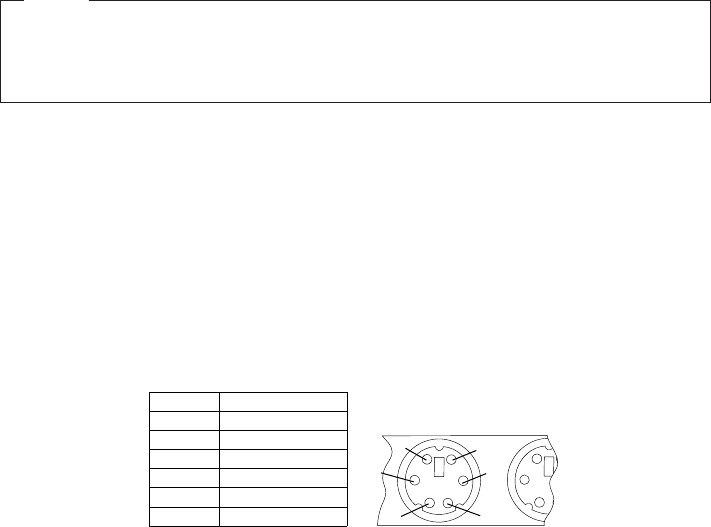
Keyboard
Note
If a mouse or other pointing device is attached, remove it to see if the
error symptom goes away. If the symptom goes away, the mouse or
pointing device is defective.
001
- Power-off the computer.
Disconnect the keyboard cable from the system unit.
Power-on the computer and check the keyboard cable connector on the
system unit for the voltages shown.
All voltages are 5%.
Pin
1
2
3
4
5
6
Voltage (Vdc)
+5.0
Reserved
Ground
+5.0
+5.0
Reserved
1
6
2
3
4
5
ARE THE VOLTAGES CORRECT?
If YES, proceed to 003.
If NO, continue with 002.
002
Replace the system board.
003
On keyboards with a detachable cable, replace the cable. If the problem
remains or if the cable is permanently attached to the keyboard, replace the
keyboard. If the problem remains, replace the system board.
Printer
1. Make sure the printer is properly connected and powered on.
2. Run the printer self-test.
Chapter 3. Types 6058/6059/6269/6578/6579 107

If the printer self-test does not run correctly, the problem is in the printer.
Refer to the printer service manual.
If the printer self-test runs correctly, install a wrap plug in the parallel port
and run the diagnostic tests to determine which FRU failed.
If the diagnostic tests (with the wrap plug installed) do not detect a failure,
replace the printer cable. If that does not correct the problem, replace the
system board or adapter connected to the printer cable.
Power supply
If the power-on indicator is not on, the power supply fan is not running, or
the computer will not power-off, use the following procedures.
Check/Verify FRU/Action
Verify that the voltage-selector switch is set for the
correct voltage.
Correct the voltage-selector switch setting
Check the following for proper installation.
vPower Cord
vOn/Off Switch connector
vOn/Off Switch Power Supply connector
vSystem Board Power Supply connectors
vMicroprocessor(s) connection
Reseat
Check the power-on switch for continuity. Power Cord
Check the power-on switch for continuity. Power-on Switch
If the above are correct, check the following voltages.
108 Hardware Maintenance Manual: IBM NetVista Computer Types 6058, 6059, 6269, 6568, 6569, 6578, 6579, 6648,
6649

20-pin main power supply connection
See “A20 system board layout (Type 6269)”on page 146 or “A40/A40P system
board layout
(Types 6058/6059/6578/6579)”on page 148 for connector locations.
Attention
These voltages must be checked with the power supply cables connected
to the system board.
Pin Signal Function
1 3.3 V +3.3 V dc
2 3.3 V +3.3 V dc
3 COM Ground
4 5V +5Vdc
5 COM Ground
6 5V +5Vdc
7 COM Ground
8 POK Power Good
9 5VSB Standby Voltage
10 12 V +12 V dc
11 3.3 V +3.3 V dc
12 -12V -12Vdc
13 COM Ground
14 PS-ON DC Remote Enable
15 COM Ground
16 COM Ground
17 COM Ground
18 No voltage Not used
19 5V +5Vdc
20 5V +5Vdc
Chapter 3. Types 6058/6059/6269/6578/6579 109
If the voltages are not correct, and the power cord is good, replace the power
supply.
Display
If the screen is rolling, replace the display assembly. If that does not correct
the problem, replace the video adapter (if installed) or replace the system
board.
If the screen is not rolling, use the following procedure to run the display
self-test.
1. Power-off the computer and display.
2. Disconnect the display signal cable.
3. Power-on the display.
4. Turn the brightness and contrast controls clockwise to their maximum
setting.
5. Check for the following conditions.
vYou should be able to vary the screen intensity by adjusting the contrast
and brightness controls.
vThe screen should be white or light gray, with a black margin (test
margin) on the screen.
Note: The location of the test margin varies with the type of display. The
test margin might be on the top, bottom, or one or both sides.
If you do not see any test margin on the screen, replace the display. If
there is a test margin on the screen, replace the video adapter (if installed)
or replace the system board.
Note: During the first two or three seconds after the display is powered
on, the following might occur while the display synchronizes with
the computer.
vUnusual patterns or characters
vStatic, crackling, or clicking sounds
vA“power-on”hum on larger displays
A noticeable odor might occur on new displays or displays recently
removed from storage.
These sounds, display patterns, and odors are normal. Do not
replace any parts.
If you are unable to correct the problem, go to “Undetermined problems”on
page 171.
110 Hardware Maintenance Manual: IBM NetVista Computer Types 6058, 6059, 6269, 6568, 6569, 6578, 6579, 6648,
6649

Diagnostics, test and recovery information
The following tools are available to help identify and resolve hardware-related
problems.
vPower-On Self-Test (POST)
–POST Beep Codes
–Error Code Format
vIBM PC Enhanced Diagnostics
vRecovery utility
–Full recovery
–Partial recovery
vRepair utility
Power-On Self-Test (POST)
Each time you power-on the system, it performs a series of tests that check
the operation of the system and some options. This series of tests is called the
Power-On Self-Test,orPOST. POST does the following operations.
vChecks some basic system-board operations
vChecks the memory operation
vStarts the video operation
vVerifies that the diskette drive is working
vVerifies that the hard disk drive is working
If the POST finishes without detecting any problems, a single beep sounds
and the first screen of the operating system or application program appears.
Note: Types 6058/6059/6269/6578/6579 computers default to come up quiet
(no beep and no memory count and checkpoint code display) when no
errors are detected by POST.
To enable beep and memory count and checkpoint code display when a
successful POST occurs, do the following:
1. Select Start Options in the Configuration/Setup Utility program
(see “Setup Utility program”on page 122).
2. Set Power-On Self-Test to Enhanced.
If the POST detects a problem, an error message appears on the screen. A
single problem can cause several error messages to appear. When you correct
the cause of the first error message, the other error messages probably will not
appear on the screen the next time you turn on the system.
Chapter 3. Types 6058/6059/6269/6578/6579 111

POST beep codes
The Power-On Self-Test generates a beeping sound to indicate successful
completion of POST or to indicate that the tests detect an error.
One beep and the appearance of text on the display indicates successful
completion of the POST. More than one beep indicates that the POST detects
an error.
Error code format
This section provides an explanation of the encoded non-SCSI and SCSI POST
error codes.
Error messages are displayed on the screen as three, four, five, eight, twelve,
or thirteen digits. An Xin an error message can be any number or letter. The
shorter POST errors are highlighted in the Symptom-to-FRU Index. Some
digits will represent different information for SCSI errors versus non-SCSI
errors.
The following figure shows which digits display the shorter POST errors. The
figure also defines additional SCSI information.
RDDDPLSCB QEET
T
E
Q
B
C
S
L
P
D
R
est state
rror code Extension
ualifier
us (0=internal 1=external)
apacity of the device
lot number of the device
UN (usually 0)
UN (SCSI ID #)
evice Number
eserved Digit (usually 0)
Notes:
1. Non-IBM device error codes and documentation supersede this list.
2. Duplicate SCSI ID settings will cause misleading error symptoms or
messages.
Product Recovery Program menu
Types 6058/6059/6269/6578/6579 machines have recovery and diagnostics
programs on a separate hard drive partition. The recovery CD and Enhanced
Diagnostics diskette are not shipped with the machine or the HMM. To
download diagnostics tests or to order a recovery CD, see “Enhanced
Diagnostics download or diskette”on page 113.
112 Hardware Maintenance Manual: IBM NetVista Computer Types 6058, 6059, 6269, 6568, 6569, 6578, 6579, 6648,
6649
At startup, after the machine tests the DIMM memory, the machine displays
the following:
To start the Product Recovery Program, press F11
After depressing F11, you are given the following options.
vFull recovery
This utility reformats the hard drive and restores all original files.
vPartial recovery
This utility reformats the hard drive and restores the Windows operating
system and all device drivers
vRepair
This is the emergency repair utility, and should not be used to install
Windows components.
vSystem utilities
1. Run diagnostics
This selection accesses the IBM PC Enhanced Diagnostics.
2. System info
3. Create recovery/ repair diskette
IBM PC Enhanced Diagnostics
The IBM PC Enhanced Diagnostics programs use a full range of diagnostic
utilities to determine the operating condition of the computer’s hardware
components.
The diagnostic program includes the following:
vPC-Doctor’s Diagnostic Software
This interface serves as the control program for running both the IBM PC
Enhanced Memory Diagnostics and the suite of diagnostic tests provided by
PC-Doctor.
vIBM PC Enhanced Memory Diagnostics
The memory diagnostic tests determine which memory module (SIMM or
DIMM) is defective and report the socket where the failing module is
located. The Memory diagnostics can run a quick and full test of the
system. Diagnostics can also be run on a single SIMM or DIMM.
Note: See “Chapter 1. IBM PC Enhanced Diagnostics error codes”on page 1
for the specific error codes.
Enhanced Diagnostics download or diskette
The IBM PC Enhanced Diagnostics are available on-line at
http://www.ibm.com/
vSelect Support.
Chapter 3. Types 6058/6059/6269/6578/6579 113
vSelect Desktop computing from the ″Search by Category″pull-down menu.
vSelect NetVista from the ″Product Family″list.
vSearch for the machine type in the ″Quick Path″box on the left.
vSelect Diagnostics from the ″Downloadable files by Category″menu or
select the link to PC Enhanced Diagnostics from the ″Downloadable files
by date″list.
Navigating through the diagnostics programs
Use the cursor movement keys to navigate within the menus.
vThe Enter key is used to select a menu item.
vThe Esc key is used to back up to the previous menu.
vFor online help select F1.
Running diagnostics tests
There are four ways to run the diagnostic tests.
1. Using the cursor movement keys, highlight Run Normal Test or Run
Quick Test from the Diagnostics Menu and then press Enter.
This will automatically run a pre-defined group of tests from each test
category. Run Normal Test runs a more extensive set of tests than does
Run Quick Test and takes longer to execute.
2. Press F5 to automatically run all selected tests in all categories. See ″Test
Selection″.
3. From within a test category, press Ctrl-Enter to automatically run only the
selected tests in that category. See ″Test Selection″.
4. Using the cursor movement keys, highlight a single test within a test
category, then press Enter. This will run only that test.
Press Esc at any time to stop the testing process.
Test results, (N/A, PASSED, FAILED, ABORTED), are displayed in the field
beside the test description and in the test log. See “Viewing the test log”on
page 120.
Test selection
To select one or more tests, use the following procedure.
1. Open the corresponding test category.
2. Using the cursor movement keys, highlight the desired test.
3. Press the space bar.
A selected test is marked by >>. Pressing the space bar again de-selects a
test and removes the chevron.
4. Repeat steps 2 and 3 above to select all desired tests.
114 Hardware Maintenance Manual: IBM NetVista Computer Types 6058, 6059, 6269, 6568, 6569, 6578, 6579, 6648,
6649

IBM PC Enhanced Memory Diagnostics
The IBM PC Enhanced Memory Diagnostics provide the capability to identify
a particular memory module (SIMM or DIMM) which fails during testing. Use
the System Board Layout section to reference the memory sockets, or select F1
twice to load the Online Manual and select Chapter 11, ″SIMM/DIMM/RIMM
Locator″.
Follow the steps below to locate the IBM PC Enhanced Memory Diagnostics
test options.
1. Select the DIAGNOSTICS option on the toolbar and press Enter.
2. Highlight either the Memory Test-Full or Memory Test-Quick option and
press Enter.
3. Memory Test-Full
The full memory test will take about 80 seconds per MB of memory and
will detect marginal, intermittent, and solid (stuck) memory failures.
4. Memory Test-Quick
The quick memory test will take about 20 seconds per MB of memory and
will detect solid (stuck) memory failures only.
Notes:
1. Either level of memory testing can be performed on all memory or a single
SIMM or DIMM socket.
2. Only sockets containing a SIMM or DIMM can be selected for testing.
Unpopulated sockets are noted by ........ beside the test description.
Alert-On LAN test
The Alert On LAN test does the following:
vDetermines if Alert On LAN is supported on the system.
vChecks the revision ID register.
vVerifies the EEPROM checksum.
vValidates that a software alert can be sent.
Asset ID test
The Asset ID test does the following:
vDetermines if Asset ID is supported on the system.
vVerifies the EEPROM areas.
vPerforms an antenna detection test.
Test results
IBM PC Enhanced Diagnostic test results will produce the following error
code format:
Function Code Failure Type DeviceID Date ChkDigits Text
Chapter 3. Types 6058/6059/6269/6578/6579 115
vFunction Code:
Represents the feature or function within the PC.
vFailure Type:
Represents the type of error encountered.
vDeviceID:
Contains the component’s unit-ID which corresponds to either a fixed disk
drive, removable media drive, serial or parallel port, processor, specific
SIMM or DIMM, or a device on the PCI bus.
vDate:
Contains the date on which the diagnostic test was run. The date is
retrieved from CMOS and displayed using the YYYYMMDD format.
116 Hardware Maintenance Manual: IBM NetVista Computer Types 6058, 6059, 6269, 6568, 6569, 6578, 6579, 6648,
6649
vChkDigits:
Contains a 2-digit check-digit value to ensure the following:
–Diagnostics were run on the specified date.
–Diagnostics were run on the specified IBM computer.
–The diagnostic error code is recorded correctly.
vText:
Description of the error.
Note:
See “Chapter 1. IBM PC Enhanced Diagnostics error codes”on page 1
for error code listings.
Hard file Smart test
Use the Hard File Smart Test when the system management tool has detected
a hard file SMART alert.
The Smart test does the following:
vInterrogates IDE devices for support of the SMART instruction set.
vIssues an ENABLE SMART command to make sure SMART functionality is
active.
vChecks the SMART RETURN STATUS command to determine if any
thresholds have been exceeded.
If thresholds have been exceeded, an error message is shown, and the test
fails. If no SMART is supported by the drive, the test returns with ″N/A″.
IBM Fixed Disk Optimized Test
You can use the IBM Fixed Disk Optimized Test to identify a particular area
of a hard disk that fails during testing. You can also use this test to correct
types of errors.
To run the Fixed Disk Optimized Test, do the following:
1. From the toolbar, select Diagnostics.
2. Select Fixed Disk Optimized Test.
3. Select one of the tests:
vHard Disk Test - Full performs a complete test of the hard disk drive.
vHard Disk Test - Quick performs a subset of the full hard disk tests.
vStart SMART Hard Disk Test initiates an IDE extended offline self-test.
vSMART Hard Disk Test Results runs the IDE extended offline self-test
and displays the results.
Chapter 3. Types 6058/6059/6269/6578/6579 117
You can run the Start SMART Hard Disk Test and then continue with other
diagnostics tests before running the Hard Drive Self-Test Results.
118 Hardware Maintenance Manual: IBM NetVista Computer Types 6058, 6059, 6269, 6568, 6569, 6578, 6579, 6648,
6649
Quick and Full erase - hard drive
The IBM PC Enhanced Diagnostics Program offers two hard drive format
utilities:
vQuick Erase Hard Drive
vFull Erase Hard Drive
The Quick Erase Hard Drive provides a DOS utility that performs the
following steps.
vDestroys the Master Boot Record (MBR) on the hard drive.
vDestroys all copies of the FAT Table on all partitions (both the master and
backup).
vDestroys the partition table.
vProvides messages that warn the user that this is a non-recoverable process.
The Full Erase Hard Drive provides a DOS utility that performs the following
steps.
vPerforms all the steps in Quick Erase.
vProvides a DOS utility that writes random data to all sectors of the hard
drive.
vProvide an estimate of time to completion along with a visual
representation of completion status.
vProvides messages that warn the user about non-recoverable process.
Important: Make sure that the customer backs up all data before using the
Quick or Full Erase function.
To select the Quick Erase or Full Erase Hard Drive utility, use the following
procedure.
1. Select the UTILITY option on the toolbar and press Enter.
2. Select either the QUICK ERASE or FULL ERASE HARD DISK option and
follow the instructions.
Iomega Zip drive test
Use the Iomega Zip Drive Test to test the Zip drive and the drive interface.
The test takes about 20 seconds to run.
The default tests the following:
vController
vMax Seek (50 times)
vRandom Seek (300 sectors)
Chapter 3. Types 6058/6059/6269/6578/6579 119
Asset EEPROM backup
When replacing a system board, this utility allows the backup of all Asset
information from the EEPROM to diskette. This utility also restores data to
the EEPROM from diskette after replacement of the system board.
To run this utility, use the following procedure.
vSelect Utility
vSelect Asset EEPROM Backup
vFollow instructions on screen.
Viewing the test log
Errors reported by the diagnostic test will be displayed by the program as a
failed test.
To view details of a failure or to view a list of test results, use the following
procedure from any test category screen.
vPress F3 to activate the log file.
vPress F3 again to save the file to diskette or F2 to print the file.
120 Hardware Maintenance Manual: IBM NetVista Computer Types 6058, 6059, 6269, 6568, 6569, 6578, 6579, 6648,
6649

SIMM/DIMM/RIMM memory errors
SIMM/DIMM/RIMM error messages issued by the IBM PC Enhanced
Diagnostics.
Message Failure Found Recommended Actions
2xx-1y A memory error was detected in
SIMM socket Y.
Replace the SIMM in the socket
identified by the last digit of the
error code.
Re-run the test.
If the same error code occurs
again, replace the system board.
2xx-2y A memory error was detected in
DIMM/RIMM socket Y
Replace the DIMM/RIMM in the
socket identified by the last digit
of the error code.
Re-run the test.
If the same error code occurs
again, replace the system board
or where memory is on the
processor card, replace the
processor card.
Corrupt BIOS Information in BIOS is not as
expected.
Not able to find expected DMI
information from BIOS.
Memory controller chipset
vendor ID does not match
expected value.
Reflash the BIOS.
Perform boot block recovery.
Replace the system board.
Test aborted by user User stopped test. Restart test.
Note: Yis the SIMM/DIMM/RIMM socket number. Use the System Board
Layout section in the latest Hardware Maintenance Manual (HMM) to
reference the memory sockets.
Chapter 3. Types 6058/6059/6269/6578/6579 121
Setup Utility program
Attention: A customized setup configuration (other than default settings)
might exist on the computer you are servicing. Running the Setup
Utility program might alter those settings. Note the current
configuration settings and verify that the settings are in place
when service is complete.
The Setup Utility (configuration) program is stored in the permanent memory
of the computer. This program includes settings for the following:
vSystem Summary
vProduct Data
vDevices and I/O Ports
vStart Options
vDate and Time
vSystem Security
vAdvanced Setup
vPower Management
To run the Setup Utility program, use the following procedure.
1. Power-off the computer and wait for a few seconds until all in-use lights
go off.
2. Power-on the computer.
3. When the Setup Utility prompt appears on the screen during start-up,
press F1. The Setup Utility menu will appear.
4. Follow the instructions on the screen.
5. When finished, select System Summary to verify that any configuration
changes have been accepted.
122 Hardware Maintenance Manual: IBM NetVista Computer Types 6058, 6059, 6269, 6568, 6569, 6578, 6579, 6648,
6649

Hard disk drive boot error
A hard disk drive boot error (error codes 1962 and I999030X) can have the
following causes.
Cause Action
The start-up drive is not in the boot sequence in
configuration.
Check the configuration and ensure the start-up
drive is in the boot sequence.
No operating system installed on the boot drive. Install an operating system on the boot drive.
The boot sector on the start-up drive is corrupted. The drive must be formatted, do the following:
1. Attempt to access and recover (back-up) the
failing hard disk drive.
2. Using the operating systems programs, format
the hard disk drive.
3. Go to “Preparing the hard disk drive for use”
on page 123.
The drive is defective. Replace the hard disk drive.
When to use the Low-Level Format program
Notes:
1. The low-level format is not available on all diagnostic diskettes.
2. Before formatting the hard disk drive, make a back-up copy of the files on
the drive to be formatted.
Use the Low-Level Format program in the following situations:
vWhen installing software that requires a low-level format.
vWhen you get recurring messages from the test programs directing you to
run the Low-Level Format program on the hard disk.
vAs a last resort before replacing a hard disk drive.
Preparing the hard disk drive for use
When the Low-Level Format program is finished, restore to the hard disk all
the files that you previously backed up.
1. Partition the remainder of the hard disk for the operating system. (The
commands vary with the operating system. Refer to the operating system
manual for instructions.)
2. Format the hard disk using the operating system. (The commands vary
with the operating system. Refer to the operating system manual for
instructions.)
3. Install the operating system.
You are now ready to restore the files.
Chapter 3. Types 6058/6059/6269/6578/6579 123

Additional service information
v“Replacing a processor”on page 125
v“Replacing a system board”on page 125
v“Security features”on page 125
v“Passwords”on page 126
v“Vital product data”on page 127
v“Management Information Format (MIF)”on page 127
v“Alert on LAN”on page 128
v“Hard disk drive jumper settings”on page 128
v“CD-ROM drive jumper settings”on page 129
v“BIOS levels”on page 129
v“Flash (BIOS/VPD) update procedure”on page 130
v“Flash recovery boot block jumper”on page 131
v“Power management”on page 131
v“Network settings”on page 133
v“Flash over LAN (update POST/BIOS over network)”on page 134
v“Wake on LAN”on page 135
v“System board memory”on page 135
The following additional service information supports Types
6058/6059/6269/6578/6579.
124 Hardware Maintenance Manual: IBM NetVista Computer Types 6058, 6059, 6269, 6568, 6569, 6578, 6579, 6648,
6649
Replacing a processor
Make sure the processor is fully seated in its socket and that the goal post
latches are engaged.
Important:
vMake sure the air baffle is installed to prevent processor
overheating.
vIf the processor is not installed correctly, the system board and
the processor can be damaged.
Replacing a system board
Important:
Before replacing a system board, back up Asset information with
PC-Doctor by using the “Asset EEPROM backup”on page 120.
Notes:
1. The BIOS and Vital Product Data (VPD) for the computer you are
servicing must be installed on the new system board (FRU) after it is
installed in the computer. To do this, you must run the Flash Update
program using the Flash Update diskette. See “BIOS levels”on page 129,
“Vital product data”on page 127, and “Flash (BIOS/VPD) update
procedure”on page 130.
2. Always ensure the latest level of BIOS is installed on the computer. A
down level BIOS may cause false errors and unnecessary replacement of
the system board.
3. The processor is a separate FRU from the system board and is not
included with the system board FRU. If you are instructed to replace the
system board, use the following procedure.
a. Remove the processor from the old system board and install it on the
new system board.
b. Remove any of the following installed options on the old system
board, and install them on the new system board.
vMemory modules
c. Ensure that the new system board jumper settings match the old
system board jumper settings.
d. If the new system board does not correct the problem, reinstall the
options on the old system board, reinstall the old system board, then
replace the processor.
Security features
Security features in this section include the following:
vPasswords
Chapter 3. Types 6058/6059/6269/6578/6579 125
vVital Product Data
vManagement Information Format (MIF)
vAlert on LAN
Passwords
The following section provides information about computer hardware and
software-related passwords.
vPower-on Password
vAdministrator Password
vOperating System Password
Power-on and Administrator passwords are set in the Setup Utility program.
See “Setup Utility program”on page 122 for information about running the
Setup Utility.
Power-on password: A power-on password denies access to the computer by
an unauthorized user when the computer is powered on. When a power-on
password is active, the password prompt appears on the screen each time the
computer is powered on. The computer starts after the proper password is
entered.
Removing a power-on password: To service a computer with an active and
unknown power-on password, power-off the computer and use the following
procedure.
Note: On some models, this procedure will also remove the administrator
password.
1. Unplug the power cord and remove the top cover.
2. Refer to “A20 system board layout (Type 6269)”on page 146 or
“A40/A40P system board layout
(Types 6058/6059/6578/6579)”on page 148 to find the recovery jumper.
3. Move the recovery jumper from normal to clear.
4. Power-on the computer. The system senses the change in the position and
erases the password. It is necessary to move the jumper back to the previous
position.
5. Remind the user to enter a new password when service is complete.
Administrator password: The administrator password is used to restrict
access to the Configuration/Setup Utility program. If the administrator
password is activated, and you do not enter the administrator password, the
configuration can be viewed but not changed.
126 Hardware Maintenance Manual: IBM NetVista Computer Types 6058, 6059, 6269, 6568, 6569, 6578, 6579, 6648,
6649
Note: Types 6058/6059/6269/6578/6579 has Enhanced Security Mode. If
Enhanced Security mode is enabled and there is no password given, the
computer will act as if Enhanced Security is disabled.
If Enhanced Security is Enabled and an administrator password is
given, the administrator password must be entered to use the
computer. If the administrator password is lost or forgotten, the system
board in the computer must be replaced in order to regain access to the
Configuration/Setup Utility program.
Administrator password control: The Administrator password is set in the
Setup Configuration. Refer to “Setup Utility program”on page 122.
Operating system password: An operating system password is very similar
to a power-on password and denies access to the computer by an
unauthorized user when the password is activated. The computer is unusable
until the password is entered and recognized by the computer.
Vital product data
Each computer has a unique Vital Product Data (VPD) code stored in the
nonvolatile memory on the system board. After you replace the system board,
the VPD must be updated. To update the VPD, see “Flash (BIOS/VPD)
update procedure”on page 130.
Management Information Format (MIF)
Management Information Format (MIF) is a file used to maintain a list of the
system unit serial number along with all serialized components (for example,
system board, riser card, memory, and processor).
At the time of computer manufacture, the EPROM will be loaded with the
serial numbers of the system and all major components. The customer will
have access to the MIF file via the DMI MIF Browser that is installed with the
preload and is also available on the SSCD that is provided with the system.
A company called Retain-a-Group is a central data warehouse offering serial
number data management. Retain-a-Group acts as a focal point to law
enforcement. The customer has the option to purchase serial number
information and services from Retain-a-Group. It is the customer’s
responsibility to maintain the MIF file and to inform Retain-a-Group of any
changes to the file.
Some customers may request their servicers to assist them in maintaining the
MIF file when serialized components are replaced during hardware service.
This assistance is between the customer and the servicer. The servicer can use
the DMI MIF Browser to update the MIF information in the EPROM. It is
anticipated that some servicers might charge for this service.
Chapter 3. Types 6058/6059/6269/6578/6579 127
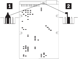
To update the EPROM using the DMI MIF Browser, use the following
procedure.
1. Click Start from the desktop, then Programs.
2. Select IBM SystemView Agent
3. Select the Serial Number Information icon
4. Click the plus sign to expand.
5. Select the component you want to view or edit.
6. Double click on the component you want to change.
7. Enter new data in the Value field, then click Apply.
Alert on LAN
Alert on LAN provides notification of changes in the computer, even when
the computer power is turned off. Working with DMI and Wake on LAN
technologies, Alert on LAN helps to manage and monitor the hardware and
software features of the computer. Alert on LAN generates notifications to the
server of these occurrences:
vComputer disconnected from the network
vComputer unplugged from the power outlet
vAll POST errors
vOperating system or POST hang condition
Alert on LAN events are configured to be Enabled or Disabled from the LAN
server only, and not from the computer. See the LAN administrator for
configuration status information.
Hard disk drive jumper settings
IDE hard disk drives for the NetVista series computers use jumpers to set the
drives as primary (master) or secondary (slave).
Note: For drives not shown below, refer to the label on the hard disk drive
for the hard disk drive settings.
1Primary (Master) Hard Disk Drive
2Secondary (Slave) Hard Disk Drive
128 Hardware Maintenance Manual: IBM NetVista Computer Types 6058, 6059, 6269, 6568, 6569, 6578, 6579, 6648,
6649
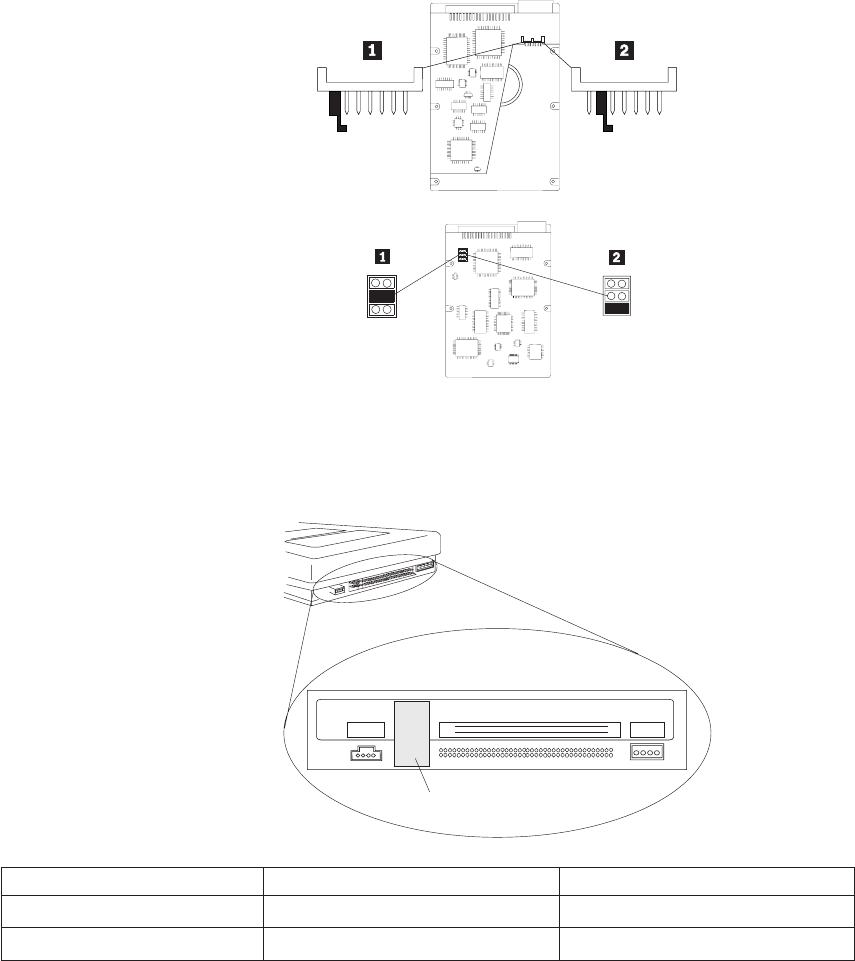
CD-ROM drive jumper settings
CD-ROM and PC/CD-ROM drives use jumpers or tabs to set the drives as
primary (master) or secondary (slave). Refer to the drive connector labels or
the figures below for the drive settings.
AUDIO
IDE INTERFACE
See Jumper
Settings Below
DC INPUT
RGGL
5V G G 12V
39
40
1
2
CD-ROM Primary (Master) Secondary (Slave)
40X :: : :
48X :: : :
BIOS levels
An incorrect level of BIOS can cause false error and unnecessary FRU
replacement. Use the following information to determine the current level of
Chapter 3. Types 6058/6059/6269/6578/6579 129
BIOS installed in the computer, the latest BIOS available for the computer, and
where to obtain the latest level of BIOS.
vCurrent Level BIOS information
–Run the Configuration Utility to determine the level of BIOS installed.
vSources for determining the latest level BIOS available
1.
IBM PC Company Home Page
http://www.ibm.com/pc/us/
2. PC PartnerInfo-Technical Database (CTSTIPS.NSF)
3. HelpCenter
4. Levels 1 and 2 Support
5. RETAIN
vSources for obtaining the latest level BIOS available
1.
IBM PC Company Home Page
http://www.ibm.com/pc/us/
2. PC PartnerInfo-Technical Database (CTSTIPS.NSF)
3. HelpCenter
4. Levels 1 and 2 Support
To update (flash) the BIOS, see “Flash (BIOS/VPD) update procedure”.
Flash (BIOS/VPD) update procedure
Attention: Refer to the information label located inside the system unit cover
for any model-specific information.
1. Power-off the computer.
2. Insert the flash update diskette into drive A.
3. Power-on the computer.
4. When the Update Utility appears; select the country/keyboard, then press
Enter.
5. If the computer serial number was previously recorded, the number is
displayed with an option to update it. Press Yto update the serial number.
6. Type the 7-digit serial number of the computer you are servicing, then
press Enter.
7. Follow the instructions on the screen to complete the flash (BIOS/VPD)
update procedure.
130 Hardware Maintenance Manual: IBM NetVista Computer Types 6058, 6059, 6269, 6568, 6569, 6578, 6579, 6648,
6649
Flash recovery boot block jumper
Attention: If an interruption occurs during a Flash/BIOS upgrade, the BIOS
might be left in an unusable state. The Boot Block jumper enables
you to restart the system and recover the BIOS.
To perform a Flash/BIOS recovery using the recovery jumper, use the
following procedure.
1. Power-off the computer and remove the cover.
2. Move the system board recovery jumper to the clear position. Refer to
“A20 system board layout (Type 6269)”on page 146, “A40/A40P system
board layout
(Types 6058/6059/6578/6579)”on page 148, or to the label inside the
computer for more information.
3. Insert the upgrade diskette into the diskette drive.
4. Power-on the computer. The IBM Logo will appear.
5. When the Flash Update Utility appears, select the country/keyboard, then
press Enter.
6. If the computer serial number was previously recorded, the number is
displayed with an option to update it. Press Yto update the serial number.
7. Type the 7-digit serial number of the computer you are servicing, then
press Enter.
8. Follow the instructions on the screen to complete the flash (BIOS/VPD)
update procedure.
9. When you are instructed to reboot the computer, power-off the computer
and move the recovery jumper to the normal position. Then replace the
cover and power-on the computer.
Power management
Power management reduces the power consumption of certain components of
the computer such as the system power supply, processor, hard disk drives,
and some monitors. Advanced Power Management and Rapid Resume
Manager are features of some personal computers.
Automatic configuration and power interface (ACPI) BIOS
Being an ACPI BIOS system, the operating system is allowed to control the
power management features of the computer and the setting for Advanced
Power Management (APM) BIOS mode are ignored. Not all operating systems
support ACPI BIOS mode.
Advanced Power Management
Energy-saving settings can be viewed and changed by using the Advanced
Power Management menu in the Configuration/Setup Utility program.
Chapter 3. Types 6058/6059/6269/6578/6579 131
Attention: If a device, such as a monitor, does not have power-management
capabilities, it can be damaged when exposed to a reduced-power
state. Before making energy-saving selections for the monitor,
check the documentation supplied with the monitor to see if it
supports Display Power Management Signaling (DPMS).
Automatic Hardware Power Management features
Automatic Hardware Power Management can reduce the power states of the
computer, processor, and monitor (if the monitor supports DPMS) if they are
inactive for a predetermined length of time.
There are three levels of specified time that the computer must be inactive
before the power management options that are selected take effect. Select the
amount of time that is offered within each level.
Level 1 Set time from 5 minutes to 4 hours.
Level 2 Set time from 10 minutes to 5 hours.
Level 3 Set time from 15 minutes to 6 hours.
At each level, you can define the amount of energy savings by specifying
values for the following options.
v
System Power
–Select On for the computer to remain on.
–Select Off for the computer to shut down.
v
Processor Speed
Set the microprocessor to be disabled,ortorunat1,10,25,or50 percent of
its internal clock speed.
v
Display
Set display to be disabled or to be reduced at these power states:
–Standby: Screen is blank, but can be restored immediately when any
activity is detected.
–Suspend: Monitor uses less power than in Standby mode. Screen image
is restored after a few seconds when any activity is detected.
–Off: Monitor power is off. Press Monitor power button to restore power.
On some monitors, you might have to depress the power button twice.
Setting Automatic Hardware Power Management features
1. Start the Configuration/Setup Utility program (see “Setup Utility
program”on page 122).
132 Hardware Maintenance Manual: IBM NetVista Computer Types 6058, 6059, 6269, 6568, 6569, 6578, 6579, 6648,
6649
2. Select Advanced Power Management from the Configuration/Setup
Utility program menu.
3. Select the APM BIOS Mode and be sure it is set to Enabled. If it is not,
press Left Arrow (}) or Right Arrow (Æ) to change the setting.
4. Select Automatic Hardware Power Management.
5. Set Automatic Hardware Power Management to Enabled.
6. Select values for the three categories of power management (system
power, processor speed, and display), as necessary.
7. Set Hard Disk to Enabled or Disabled.
Note: This does not apply to SCSI drives.
8. Press Esc twice to return to the Configuration/Setup Utility program
menu.
9. Before you exit from the program, select Save Settings from the
Configuration/Setup Utility program menu.
10. To exit from the Configuration/Setup Utility program, press Esc and
follow the instructions on the screen.
Automatic Power-On features
The Automatic Power-On features within the Power Management menu allow
you to enable and disable features that turn on the computer automatically.
vSerial Port A Ring Detect: With this feature set to Enabled and an external
modem connected to serial port (COM1), the computer will turn on
automatically when a ring is detected on the modem.
vPCI Modem Ring Detect: With this feature set to Enabled , the computer
will turn on automatically when a ring is detected on the internal modem.
vPCI Wake Up: This feature allow PCI cards that support this capability to
wake the system.
vWake Up on Alarm: You can specify a date and time at which the
computer will be turned on automatically. This can be either a single event
or a daily event.
vWake on LAN: If the computer has a properly configured token-ring or
Ethernet LAN adapter card that is Wake on LAN-enabled and there is
remote network management software, you can use the IBM-developed
Wake on LAN feature. When you set Wake on LAN to Enabled, the
computer will turn on when it receives a specific signal from another
computer on the local area network (LAN). For further information, see
“Wake on LAN”on page 135.
Network settings
This section applies only to computers that are linked to a network.
Chapter 3. Types 6058/6059/6269/6578/6579 133
The Configuration/Setup Utility program includes settings that can be
enabled and disabled to configure the network interface in the computer.
These settings are the following:
vFlash over LAN (Update POST/BIOS over Network)
vWake on LAN
Flash over LAN (update POST/BIOS over network)
Note: For local Flash (BIOS/VPD) update, see “Flash (BIOS/VPD) update
procedure”on page 130.
This setting is used to enable or disable the Flash over LAN feature. When the
feature is enabled, the system programs, in the computer, can be updated
remotely from a network server. If the administrator password is set in the
computer, it does not have to be entered by the server.
To access the Flash over LAN setting, use the following procedure.
1. Start the Configuration/Setup Utility program. See “Setup Utility
program”on page 122.
2. Select System Security.
3. Select POST/BIOS Update from the Configuration/Setup Utility program
menu.
4. To enable Flash over LAN, select Enabled. To disable Flash over LAN,
select Disabled.
5. Press Esc twice to return to the Configuration/Setup Utility program
menu.
6. Before you exit from the program, select Save Settings from the
Configuration/Setup Utility program menu.
7. To exit from the Configuration/Setup Utility program, press Esc and
follow the instructions on the screen.
134 Hardware Maintenance Manual: IBM NetVista Computer Types 6058, 6059, 6269, 6568, 6569, 6578, 6579, 6648,
6649

Wake on LAN
This setting is used to enable or disable the IBM-developed Wake on LAN
feature. This feature makes it possible for the computer to be turned on
remotely by a network server. Remote network management software must be
used in conjunction with this feature.
To access the Wake on LAN setting, use the following procedure.
1. Start the Configuration/Setup Utility program. See “Setup Utility
program”on page 122.
2. Select Advanced Power Management.
3. Select Automatic Power On from the program menu.
4. Select Wake on LAN from the Automatic Power On menu.
5. To enable Wake on LAN, select Enabled. To disable Wake on LAN, select
Disabled.
6. Press Esc until you return to the Configuration/Setup Utility program
menu.
7. Before you exit from the program, select Save Settings from the
Configuration/Setup Utility program menu.
8. To exit from the Configuration/Setup Utility program, press Esc and
follow the instructions on the screen.
System board memory
The following matrix cross-references the name of the computer (printed on
the logo) and the size, speed, and type of memory modules supported in the
computer.
Computers Memory Module
Size Speed Type
Types62696058/6059/6578/6579 64 MB128 MB256
MB
133 MHz SDRAMNon-
ParityIndustry
Standard
Supported memory configuration
DIMM sizes of 64 MB, 128 MB and 256 MB are acceptable. Start filling DIMM
socket 0, then 1. Use 3.3 V unbuffered 133 MHz SDRAM non-parity DIMMs
only.
Chapter 3. Types 6058/6059/6269/6578/6579 135
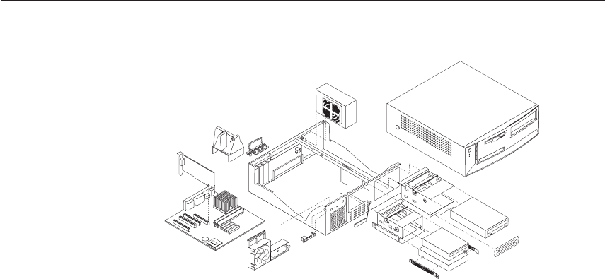
Computer exploded view -
Types 6058/6059/6269/6578/6579
136 Hardware Maintenance Manual: IBM NetVista Computer Types 6058, 6059, 6269, 6568, 6569, 6578, 6579, 6648,
6649
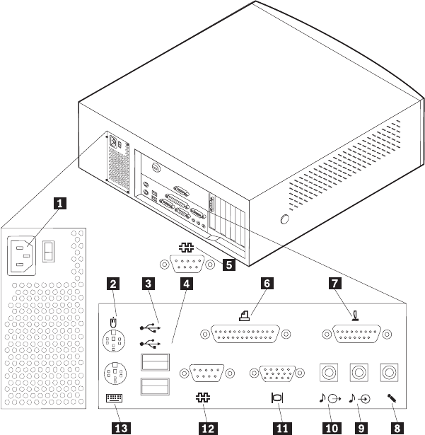
Input/Output connectors - Type 6269
1
1
2
1Power cord 8Microphone connector
2Mouse connector 9Audio input connector
3USB connector 2 10Audio output connector
4USB connector 1 11Monitor connector
5Serial connector 2 12 Serial connector 1
6Parallel connector 13 Keyboard connector
7Joystick / MIDI
Chapter 3. Types 6058/6059/6269/6578/6579 137
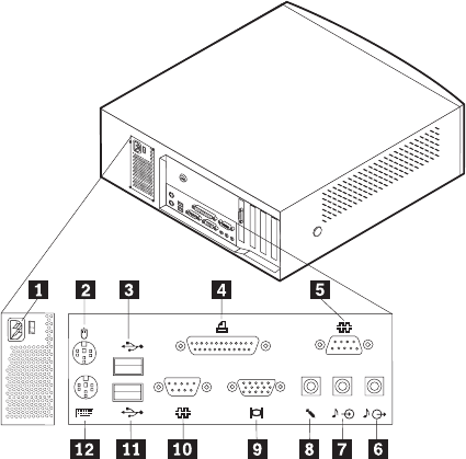
Input/Output connectors - Types 6058/6059/6578/6579
1
2
1Power connector 7Audio in connector
2Mouse 8Microphone connector
3USB connector 2 9Monitor connector
4Parallel connector 10Serial connector 1
5Serial connector 2 (joystick/MIDI connector in
some models)
11USB connector 1
6Audio out connector 12Keyboard connector
138 Hardware Maintenance Manual: IBM NetVista Computer Types 6058, 6059, 6269, 6568, 6569, 6578, 6579, 6648,
6649
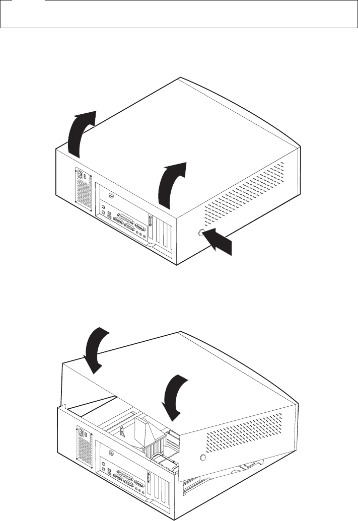
Cover removal
Note
The front panel is integrated with the top cover.
Firmly press the cover latch buttons on both sides. Pull up the back end of
cover, and swing the cover toward the front of the computer.
Replacing the cover
Pivot the cover from the front, and move it down over the computer until the
cover snaps into place.
Chapter 3. Types 6058/6059/6269/6578/6579 139
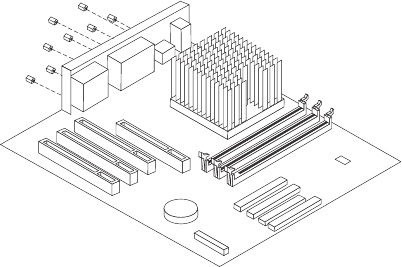
EMC shield (front)
Models that are not shipped with a CD-ROM drive have an EMC shield
covering the drive bay. To remove the EMC shield, remove the front cover.
Then, remove the single screw that holds the EMC shield in place.
EMC shield (system board)
Remove the eight screws that hold the EMC shield in place.
Installing adapters
This section provides information and instructions for installing and removing
adapters.
Adapter slots
Types 6058/6059/6269/6578/6579 have four expansion slots used to connect
adapters to the peripheral component interconnect (PCI) bus.
To install an adapter in a PCI or AGP expansion slot:
1. Remove the adapter from its static-protective package.
2. Remove the metal I/O bracket form the adapter slot.
140 Hardware Maintenance Manual: IBM NetVista Computer Types 6058, 6059, 6269, 6568, 6569, 6578, 6579, 6648,
6649
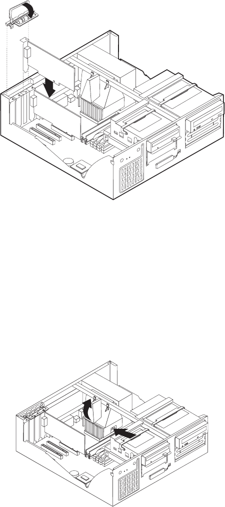
3. Install the adapter into the appropriate slot on the system board.
4. Install the adapter slot cover latch. Pivot the latch back to horizontal
Note: If you are installing a Wake on LAN supported network adapter,
attach the Wake on LAN cable that came with the adapter to the
Wake on LAN connector on the system board. If you also want to
take advantage of the Alert on LAN feature of the computer, you
must install the network adapter in PCI slot 1.
Air duct (Types 6058/6059/6278/6279)
1. The air duct in some machines may have a hole in the side. Press the
metal latch that is behind the hole, and swing out the duct to a 45-degree
angle and lift it up.
Chapter 3. Types 6058/6059/6269/6578/6579 141
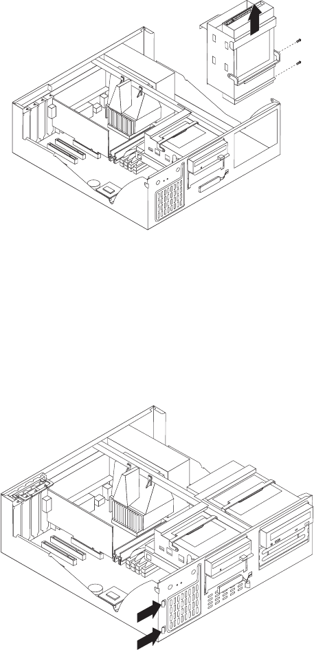
2. If the air duct does not have a hole, simply swing out the duct to a
45-degree angle and lift it up.
CD-ROM drive removal
1. Swing the 5.25″drive cage up and out.
2. Remove the two screws that hold the CD-ROM drive in place. Lift the
CD-ROM drive out of the cage.
3. When replacing the drive cage into its horizontal position, be sure place
the cage latch back to its regular horizontal position. This is necessary so
that the machine cover will fit properly.
Fan/speaker bracket removal
1. Detach the left side of the fan/speaker bracket by pushing the two left
tabs that latch the bracket to the chassis.
142 Hardware Maintenance Manual: IBM NetVista Computer Types 6058, 6059, 6269, 6568, 6569, 6578, 6579, 6648,
6649
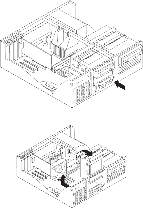
2. Locate the right tab that hinges the fan/speaker bracket to the chassis.
Push the tab to detach the bracket from the chassis.
3. Swing the 3.5″drive cage up and latch into vertical.
4. Lift the fan/speaker bracket back and out.
Hard drive removal
1. Swing the 3.5″drive cage up, and latch it to the vertical position.
Chapter 3. Types 6058/6059/6269/6578/6579 143
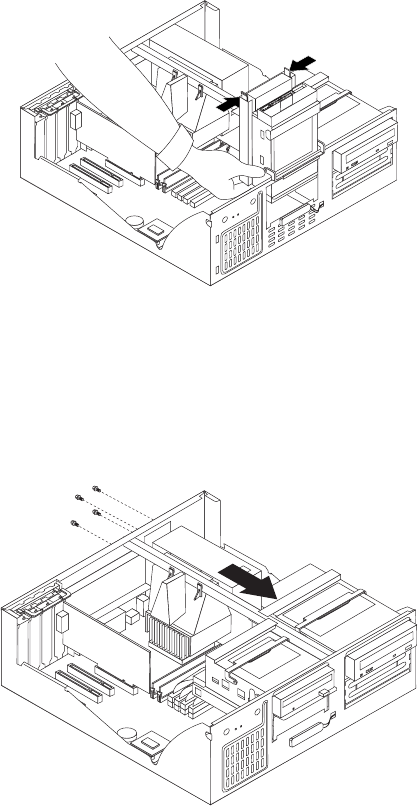
2. Press the two side rail tabs and push the HD from the bottom. Pull the
HD out.
3. When replacing the drive cage into its horizontal position, be sure place
the cage latch back to its regular horizontal position. This is necessary so
that the machine cover will fit properly.
Power supply removal
1. Remove the four screws that hold the power supply to the back of the
chassis.
2. The power supply is attached to the base of the chassis by a latch on the
front. Slide the power supply forward to dislatch if from the chassis.
144 Hardware Maintenance Manual: IBM NetVista Computer Types 6058, 6059, 6269, 6568, 6569, 6578, 6579, 6648,
6649
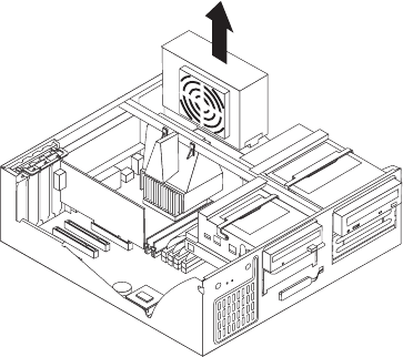
3. Lift out the power supply.
Chapter 3. Types 6058/6059/6269/6578/6579 145
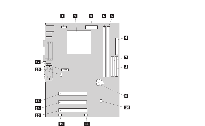
A20 system board layout (Type 6269)
System board locations
1 CPU fan connector 10 Clear CMOS/recovery jumper
2 Microprocessor 11 Front fan connector
3 Power connector 12 Wake on LAN connector
4 DIMM 1 13 PCI connector 3
5 DIMM 2 14 PCI connector 2
6 Diskette connector 15 PCI connector 1
7 Secondary IDE connector 16 CD-ROM audio connector
8 Primary IDE connector 17 Serial 2 connector
9 Battery
A20 System board jumper settings
The following table contains the jumper setting information. (D) indicates the
default setting.
A20 Clear CMOS/Flash Boot Block Recovery
Use the recovery jumper setting to Clear CMOS or to Flash Boot Block
Recover.
146 Hardware Maintenance Manual: IBM NetVista Computer Types 6058, 6059, 6269, 6568, 6569, 6578, 6579, 6648,
6649

Jumper Setting Description
CMOS Reset 2-3 CMOS Reset/Flash Recovery Mode
1-2 (D) Normal Mode
Note: The A20 CMOS clear/recovery jumper pins are numbered as follows:
vPin 1 is the nearest to the battery.
vPins 2 and 3 are below pin 1, as seen in the A20 System Board
layout.
A20 Processor Speed Settings
Processor speed for Type 6269 computers is fixed and are determined by the
processor. There are no settings required.
A20 Diskette Write Access
Diskette Write Enable and Write Protect options are changed in the Setup
Configuration. See “Setup Utility program”on page 122.
Chapter 3. Types 6058/6059/6269/6578/6579 147
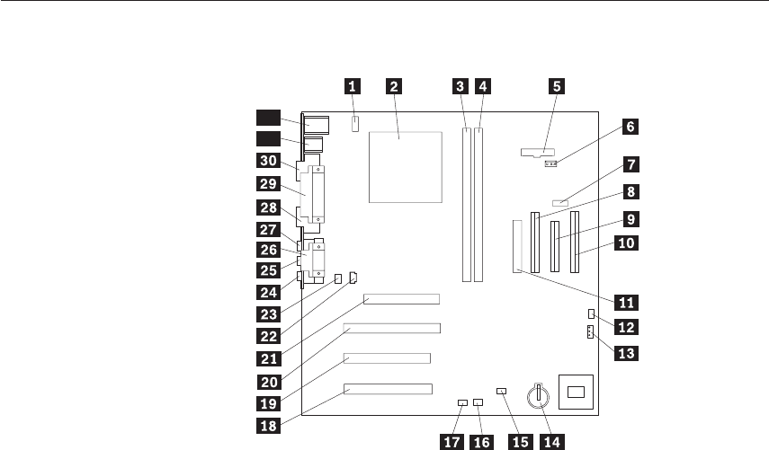
A40/A40P system board layout
(Types 6058/6059/6578/6579)
32
31
System board locations
1 #2 fan connector 17 Wake on LAN
2 Microprocessor 18 PCI slot 3
3 DIMM 0 19 PCI slot 2
4 DIMM 1 20 PCI slot 1
5 Power LED connector 21 AGP connector
6 RFID connector 22 CD-ROM audio
7 Front USB connector 23 Speaker connector
8 Secondary IDE connector 24 Audio output
9 Diskette connector 25 Audio input
10 Primary IDE connector 26 Serial port 2
11 Power connector 27 Microphone input
12 CMOS clear/recovery jumper 28 Monitor port
13 #1 fan connector 29 Parallel port
14 Battery 30 Serial port 1
15 SCSI adapter LED connector 31 USB connectors
16 Alert on LAN 32 Mouse and keyboard connectors
A40/A40P System board jumper settings
The following table contains the jumper setting information. (D) indicates the
default setting.
148 Hardware Maintenance Manual: IBM NetVista Computer Types 6058, 6059, 6269, 6568, 6569, 6578, 6579, 6648,
6649

A40/A40P Clear CMOS/Flash Boot Block Recovery
Use the recovery jumper setting to Clear CMOS or to Flash Boot Block
Recover.
Jumper Setting Description
CMOS Reset 2-3 CMOS Reset/Flash Recovery Mode
1-2 (D) Normal Mode
Note: The A40/A40P CMOS clear/recovery jumper pins are numbered as
follows:
vPin 1 is the farthest from the battery.
vPins 2 and 3 are below pin 1, as seen in the A40/A40P System Board
layout.
A40/A40P Processor Speed Settings
Processor speed for NetVista type 6058/6059/6578/6579 computers is fixed
and is determined by the processor. There are no settings required.
A40/A40P Diskette Write Access
Diskette Write Enable and Write Protect options are changed in the Setup
Configuration. See “Setup Utility program”on page 122.
Chapter 3. Types 6058/6059/6269/6578/6579 149

Symptom-to-FRU index
The Symptom-to-FRU index lists error symptoms and possible causes. The
most likely cause is listed first. Always begin with “General checkout”on
page 104. See “Chapter 1. IBM PC Enhanced Diagnostics error codes”on
page 1 when running diagnostics. This index can also be used to help you
decide which FRUs to have available when servicing a computer. If you are
unable to correct the problem using this index, go to “Undetermined
problems”on page 171.
Notes:
1. If you have both an error message and an incorrect audio response,
diagnose the error message first.
2. If you cannot run the diagnostic tests or you get a diagnostic error code
when running a test, but did receive a POST error message, diagnose the
POST error message first.
3. If you did not receive any error message, look for a description of your
error symptoms in the first part of this index.
4. Check all power supply voltages before you replace the system board. (See
“Power supply”on page 108.)
5. Check the hard disk drive jumper settings before you replace a hard disk
drive. (See “Hard disk drive jumper settings”on page 128.)
Important:
1.
Some errors are indicated with a series of beep codes (see
“Beep symptoms”).
Types 6058/6059/6269/6578/6579 computers default to come
up quiet (no beep and no memory count and checkpoint code
display) when no errors are detected by POST. To enable beep
and memory count and checkpoint code display when a
successful POST occurs, do the following:
a. Select Start Options in the Configuration/Setup Utility
program (see“Setup Utility program”on page 122).
b. Set Power-On Self-Test to Enhanced.
2. The processor is a separate FRU from the system board; the
processor is not included with the system board FRU.
Beep symptoms
Beep symptoms are short tones or a series of short tones separated by pauses
(intervals without sound). See the following examples.
150 Hardware Maintenance Manual: IBM NetVista Computer Types 6058, 6059, 6269, 6568, 6569, 6578, 6579, 6648,
6649

Beeps Description
1-2-X vOne beep
vA pause (or break)
vTwo beeps
vA pause (or break)
vAny number of breaks
4Four continuous beeps
Use the following table to diagnose beep symptoms.
Beep Symptom FRU/Action
1-1-3CMOS read-write error 1. Run Setup
2. System Board
1-1-4ROM BIOS check error 1. System Board
1-2-XDMA error 1. System Board
1-3-X 1. Memory Module
2. System Board
1-4-4 1. Keyboard
2. System Board
1-4-XError detected in first 64 KB of RAM 1. Memory Module
2. System Board
2-1-1,2-1-2 1. Run Setup
2. System Board
2-1-XFirst 64 KB of RAM failed 1. Memory Module
2. System Board
2-2-2 1. Video Adapter (if installed)
2. System Board
2-2-XFirst 64 KB of RAM failed 1. Memory Module
2. System Board
2-3-X 1. Memory Module
2. System Board
2-4-X 1. Run Setup
2. Memory Module
3. System Board
Chapter 3. Types 6058/6059/6269/6578/6579 151

Beep Symptom FRU/Action
3-1-XDMA register failed 1. System Board
3-2-4Keyboard controller failed 1. System Board
2. Keyboard
3-3-4Screen initialization failed 1. Video Adapter (if installed)
2. System Board
Display
3-4-1Screen retrace test detected an error 1. Video Adapter (if installed)
2. System Board
3. Display
3-4-2POST is searching for video ROM 1. Video Adapter (if installed)
2. System Board
41. Video Adapter (if installed)
2. System Board
All other beep code sequences 1. System Board
One long and one short beep during POST.Base
640 KB memory error or shadow RAM error 1. Memory Module
2. System Board
One long beep and two or three short beeps
during POST.(Video error) 1. Video Adapter (if installed)
2. System Board
Three short beeps during POST 1. See “System board memory”on page 135
2. System Board
Continuous beep 1. System Board
Repeating short beeps 1. Keyboard stuck key?
2. Keyboard Cable
3. System Board
No-beep symptoms
Note: Types 6058/6059/6269/6578/6579 computers default to come up quiet
(no beep and no memory count and checkpoint code display) when no
errors are detected by POST.
To enable beep and memory count and checkpoint code display when a
successful POST occurs, do the following:
1. Select Start Options in the Configuration/Setup Utility program
(see “Setup Utility program”on page 122).
152 Hardware Maintenance Manual: IBM NetVista Computer Types 6058, 6059, 6269, 6568, 6569, 6578, 6579, 6648,
6649

2. Set Power-On Self Test to Enhanced.
Symptom/Error FRU/Action
No beep during POST but computer works
correctly. 1. System Board
No beep during POST. 1. See “Undetermined problems”on page 171
2. System Board
3. Memory Module
4. Any Adapter or Device
5. Power Cord
6. Power Supply
POST error codes
In the following index, Xcan represent any number.
POST Error Code FRU/Action
000SCSI Adapter not enabled 1. Verify adapter device and Bus Master fields
are enabled in PCI configuration program.
See documentation shipped with computer.
02X 1. SCSI Adapter
08XCheck SCSI terminator installation. 1. SCSI Cable
2. SCSI Terminator
3. SCSI Device
4. SCSI Adapter
101System board interrupt failure 1. System Board
102System board timer error 1. System Board
106 1. System Board
110System board memory parity error 1. Memory Module
2. System Board
111I/O channel parity error 1. Reseat adapters
2. Any adapter
3. System Board
114Adapter ROM error 1. Adapter Memory
2. System Board
129Internal cache test error 1. Processor
2. L2 Cache Memory
3. System Board
Chapter 3. Types 6058/6059/6269/6578/6579 153

POST Error Code FRU/Action
151Real-time clock failure 1. System Board
161Bad CMOS battery 1. Run Setup
2. CMOS Backup Battery (see “Safety
information”on page 185)
3. System Board
162Configuration mismatch 1. Run Setup and verify Configuration
2. Had a device been added, removed, changed
location? If not, suspect that device.
3. Power-on external devices first, then power-on
computer
4. CMOS Backup Battery (see “Safety
information”on page 185)
System Board
5. System Board
162And unable to run diagnostics 1. Diskette Drive
2. System Board
3. Diskette Drive Cable
163Clock not updating or invalid time set 1. Time and Date Set?
2. CMOS Backup Battery (see “Safety
information”on page 185)
3. System Board
164POST detected a base memory or extended
memory size mismatch error or RIMM socket 3 is
populated with a RIMM memory module
1. Run Setup. Check System Summary menu for
memory size change. (See“Setup Utility
program”on page 122.)
2. Run the Extended Memory Diagnostic tests
166Boot Block Check Sum Error 1. Run Flash Recovery using Boot Block. See
“Flash recovery boot block jumper”on page
131.
2. System Board
167Microprocessor installed that is not supported
by the current POST/BIOS 1. Run Setup. Check Stepping level for the
BIOS level needed, then perform the flash
update.
2. Processor
168Alert on LAN error 1. Run Setup. Check to see that Ethernet and
Alert on LAN are enabled.
2. System Board
17X, 18X 1. C2 Security
154 Hardware Maintenance Manual: IBM NetVista Computer Types 6058, 6059, 6269, 6568, 6569, 6578, 6579, 6648,
6649

POST Error Code FRU/Action
175 1. Run Configuration. See “Setup Utility
program”on page 122.
2. System Board
176 1. Covers were removed from the computer
177Corrupted Administrator Password 1. System Board
178 1. System Board
183 1. Enter the administrator password
184No RFID Antenna 1. Make sure Asset Care and Asset ID are
enabled in Configuration/Setup
2. RFID Antenna
3. System Board
185Corrupted boot sequence 1. Set configuration and reinstall the boot
sequence
186 1. System Board
187 1. Clear Administration password
2. System Board
189 1. More than three password attempts were
made to access the computer
190Chassis intrusion detector was cleared. This is
information only, no action required. If this code
does not clear:
1. System Board
1XXNot listed above 1. System Board
201, 20XMemory data error 1. Run Enhanced Diagnostics Memory Test
2. Memory Module
3. System Board
225 1. Unsupported Memory
229External cache test error 1. L2 Cache Memory
2. System Board
262POST detected a base memory or extended
memory type error 1. Run Setup. Check System Summary menu for
memory. (See “Setup Utility program”on
page 122.)
2. Run the Extended Memory Diagnostic tests.
Chapter 3. Types 6058/6059/6269/6578/6579 155

POST Error Code FRU/Action
301 1. Keyboard
2. Keyboard Cable
3. System Board
303With an 8603 error 1. Mouse
2. Keyboard
3. Keyboard Cable
4. System Board
303With no 8603 error 1. Keyboard
2. Keyboard Cable
3. System Board
3XXNot listed above 1. Keyboard
2. Keyboard Cable
3. System Board
5XX 1. Video Adapter (if installed)
2. System Board
601 1. Diskette Drive A
2. Diskette Drive Cable
3. System Board
602 1. Bad Diskette?
2. Verify Diskette and retry
604And able to run diagnostics 1. Run Setup and verify diskette configuration
settings
2. Diskette Drive A/B
3. Diskette Drive Cable
4. System Board
605POST cannot unlock the diskette drive 1. Diskette Drive
2. Diskette Drive Cable
3. System Board
662 1. Diskette drive configuration error or wrong
diskette drive type; run Setup Configuration
156 Hardware Maintenance Manual: IBM NetVista Computer Types 6058, 6059, 6269, 6568, 6569, 6578, 6579, 6648,
6649

POST Error Code FRU/Action
6XXNot listed above 1. Diskette Drive
2. System Board
3. External Drive Adapter
4. Diskette Drive Cable
5. Power Supply
762Math coprocessor configuration error 1. Run Setup
2. Processor
3. System Board
7XX Not listed above 1. Processor
2. System Board
962 Parallel port configuration error 1. Run Configuration
2. Parallel Adapter (if installed)
3. System Board
9XX 1. Printer
2. System Board
1047 1. 16-Bit AT Fast SCSI Adapter
107XCheck SCSI terminator installation 1. Check SCSI terminator installation
2. SCSI Cable
3. SCSI Terminator
4. SCSI Device
5. SCSI Adapter
1101Serial connector error, possible system board
failure 1. Run Enhanced Diagnostics
1101, 1102, 1106, 1108, 1109 1. System Board
2. Any Serial Device
1107 1. Communications Cable
2. System Board
1102Card selected feedback error 1. Run Enhanced Diagnostics
1103Port fails register check 1. Run Enhanced Diagnostics
2. System Board
1106Serial option cannot be turned off 1. Run Enhanced Diagnostics
2. System Board
Chapter 3. Types 6058/6059/6269/6578/6579 157

POST Error Code FRU/Action
1107 1. Serial Device Cable
2. System Board
1110Register test failed 1. Run Enhanced Diagnostics
2. System Board
1116Interrupt error 1. Run Enhanced Diagnostics
1117Failed baud rate test 1. Run Enhanced Diagnostics
1162 Serial port configuration error 1. Run Configuration
2. Serial Adapter
(if installed)
3. System Board
11XXNot listed above 1. System Board
1201 1. System Board
2. Any Serial Device
1202, 1206, 1208, 1209, 12XX 1. Dual Async Adapter/A
2. System Board
3. Any Serial Device
1207 1. Communications Cable
2. Dual Async Adapter/A
13XX 1. Game Adapter
1402Printer not ready Information only
1403No paper error, or interrupt failure Information only
1404System board timeout failure 1. Run Enhanced Diagnostics
1405Parallel adapter error 1. Run Enhanced Diagnostics
1406Presence test error 1. Run Enhanced Diagnostics
14XXNot listed above. Check printer before
replacing system board 1. Printer
2. System Board
15XX 1. SDLC Adapter
1692Boot sequence error 1. Run FDISK to ensure at least one active
partition is set active
16XX 1. 36/38 Workstation Adapter
1762Hard disk drive configuration error 1. Run Configuration. (See “Setup Utility
program”on page 122.)
158 Hardware Maintenance Manual: IBM NetVista Computer Types 6058, 6059, 6269, 6568, 6569, 6578, 6579, 6648,
6649

POST Error Code FRU/Action
1780 (Disk Drive 0)1781 (Disk Drive 1)1782 (Disk
Drive 2)1783 (Disk Drive 3) 1. See “Power supply”on page 108
2. Hard Disk Drive
3. System Board
4. Hard Disk Cable
5. Power Supply
180X, 188XPCI configuration or resource error 1. Run Setup and verify PCI/ISA configuration
settings.
2. If necessary, set ISA adapters to Not available to
allow PCI adapters to properly configure.
3. Remove any suspect ISA adapters.
4. Rerun diagnostics.
5. PCI Adapter
1962Boot sequence error 1. Possible hard disk drive problem; see “Hard
disk drive boot error”on page 123.
209X 1. Diskette Drive
2. Diskette Cable
20XXNot listed above 1. BSC Adapter
21XX 1. SCSI Device
2. 16-bit AT Fast SCSU adapter
3. Alternate BSC adapter
2401, 2402If screen colors change 1. Display
2401, 2402If screen colors are OK 1. System Board
2. Display
2409 1. Display
2410 1. System Board
2. Display
2462Video memory configuration error 1. Check cable connections
2. Run Setup and verify video configuration
settings
3. Video Memory Modules
4. Video Adapter (if installed)
5. System Board
4611, 4630 1. Multiport/2 Interface Board
2. Multiport/2 Adapter
Chapter 3. Types 6058/6059/6269/6578/6579 159

POST Error Code FRU/Action
4612, 4613, 4640, 4641 1. Memory Module Package
2. Multiport/2 Adapter
4650 1. Multiport/2 Interface Cable
46XXNot listed above 1. Multiport/2 Adapter
2. Multiport/2 Interface
Board
3. Memory Module
5600 1. Financial System Controller Adapter
5962An IDE device (other than hard drive)
configuration error 1. Run Configuration
2. CD-ROM Drive
3. CD-ROM Adapter
4. Zip or other ATAPI device
5. System Board
62XX 1. 1st Store Loop Adapter
2. Adapter Cable
63XX 1. 2nd Store Loop Adapter
2. Adapter Cable
64XX 1. Network Adapter
71XX 1. Voice Adapter
74XX 1. Video Adapter
(if installed)
76XX 1. Page Printer Adapter
78XX 1. High Speed Adapter
79XX 1. 3117 Adapter
80XX 1. PCMCIA Adapter
84XX 1. Speech Adapter
2. Speech Control Assy.
8601, 8602 1. Pointing Device (Mouse)
2. System Board
8603, 8604 1. System Board
2. Pointing Device
(Mouse)
160 Hardware Maintenance Manual: IBM NetVista Computer Types 6058, 6059, 6269, 6568, 6569, 6578, 6579, 6648,
6649

POST Error Code FRU/Action
86XXNot listed above 1. Mouse
2. System Board
89XX 1. PC Music Adapter
2. MIDI Adapter Unit
91XX 1. Optical Drive
2. Adapter
96XX 1. SCSI Adapter
2. Any SCSI Device
3. System Board
10101, 10102, 10104, 10105, 10106, 10107, 10108,
10109, 10111,
10112, 10113, 10114,
10115, 10116
1. Have customer verify correct operating system
device drivers are installed and operational.
2. Modem
10103, 10110, 101171 1. System Board
2. Data/Fax Modem
10117Not listed above 1. Check system speaker
2. Check PSTN cable
3. External DAA
(if installed)
4. Modem
10118 1. Run Diagnostics and verify the correct
operation of the modem slot
2. Modem
10119 1. Diagnostics detected a non-IBM modem
2. Modem
10120 1. Check PSTN Cable
2. External DAA
(if installed)
3. Modem
10132, 10133, 10134,
10135, 10136, 10137,
10138, 10139, 10140,
10141, 10142, 10143,
10144, 10145, 10146,
10147, 10148, 10149,
10150, 10151, 10152
1. Modem
Chapter 3. Types 6058/6059/6269/6578/6579 161

POST Error Code FRU/Action
10153 1. Data/Fax Modem
2. System Board
101XXNot listed above 1. Modem Adapter/A
2. Data/Fax Modem
3. System Board
10450, 10451, 10490,
10491, 10492, 10499Read/write error 1. Run Enhanced Diagnostics
2. Hard Disk Drive
3. System Board
10452Seek test error 1. Run Enhanced Diagnostics
10453Wrong drive type? Information only
10454Sector buffer test error 1. Run Enhanced Diagnostics
10455, 10456Controller error 1. Run Enhanced Diagnostics
10459Drive diagnostic command error Information only
10461Drive format error 1. Run Enhanced Diagnostics
10462Controller seek error 1. Run Enhanced Diagnostics
10464Hard Drive read error 1. Run Enhanced Diagnostics
10467Drive non-fatal seek error 1. Run Enhanced Diagnostics
10468Drive fatal seek error 1. Run Enhanced Diagnostics
10469Drive soft error count exceeded 1. Run Enhanced Diagnostics
10470, 10471, 10472Controller wrap error 1. Run Enhanced Diagnostics
10473Corrupt data. Low level format might be
required
Information only
10480 1. Hard Disk Drive (ESDI)
2. Drive Cable
3. System Board
10481ESDI drive D seek error 1. Run Enhanced Diagnostics
10482Drive select acknowledgement bad 1. Run Enhanced Diagnostics
106X1 1. Check Configuration
2. Ethernet Adapter
162 Hardware Maintenance Manual: IBM NetVista Computer Types 6058, 6059, 6269, 6568, 6569, 6578, 6579, 6648,
6649

POST Error Code FRU/Action
10635 1. Power-off computer, wait ten seconds then
power-on the computer
2. Ethernet Adapter
10651, 10660 1. Check Cables
2. Ethernet Adapter
106XXNot listed above 1. Ethernet Adapter
107XX 1. 5.25-inch External
Diskette Drive
2. 5.25-inch Diskette
Drive Adapter/A
109XXCheck the adapter cables 1. ActionMedia
Adapter/A
2. System Board
112XXThis adapter does not have cache 1. SCSI Adapter
2. Any SCSI Device
3. System Board
119XX 1. 3119 Adapter
121XX 1. Modem Adapter
2. Any Serial Device
3. System Board
136XX 1. ISDN Primary Rate Adapter
2. System Board
137XX 1. System Board
141XX 1. Realtime Interface Coprocessor Portmaster
Adapter/A
143XX 1. Japanese Display Adapter
2. System Board
14710, 14711 1. System Board Video Adapter
2. Adapter Video Memory
148XX 1. Video Adapter
14901, 14902,
1491X, 14922 1. Video Adapter
(if installed)
2. System Board
3. Display (any type)
Chapter 3. Types 6058/6059/6269/6578/6579 163

POST Error Code FRU/Action
14932 1. External Display
2. Video Adapter
161XX 1. FaxConcentrator Adapter
164XX 1. 120 MB Internal Tape Drive
2. Diskette Cable
3. System Board
16500 1. 6157 Tape Attachment
2. Adapter
16520, 16540 1. 6157 Streaming Tape Drive
2. 6157 Tape Attachment Adapter
166XX, 167XX 1. Token Ring Adapter
2. System Board
18001 to 18029 1. Wizard Adapter
2. Wizard Adapter Memory
18031 to 18039 1. Wizard Adapter Cable
185XXXX 1. DBCS Japanese Display Adapter/A
2. System Board
20001 to 20003 1. Image Adapter/A
Image-I Adapter/A
2. Memory Module DRAM, VRAM
20004 1. Memory Module DRAM, VRAM
2. Image Adapter/A
Image-I Adapter/A
20005 to 20010 1. Image Adapter/A
Image-I Adapter/A
2. Memory Module DRAM, VRAM
200XXNot listed above 1. Image Adapter/A
2. Image-I Adapter/A
3. Memory Module DRAM, VRAM
4. System Board
20101 to 20103 1. Printer/Scanner Option
2. Image Adapter/A
3. Memory Module DRAM, VRAM
164 Hardware Maintenance Manual: IBM NetVista Computer Types 6058, 6059, 6269, 6568, 6569, 6578, 6579, 6648,
6649

POST Error Code FRU/Action
20104 1. Memory Module DRAM, VRAM
2. Printer/Scanner Option
3. Image Adapter/A
20105 to 20110 1. Printer/Scanner Option
2. Image Adapter/A
3. Memory Module DRAM, VRAM
Image Adapter/A Memory Test failure indicated
by graphic of adapter 1. Replace memory module (shown in graphic)
206XX 1. SCSI-2 Adapter
2. Any SCSI Device
3. System Board
208XXVerify there are no duplicate SCSI ID
settings on the same bus. 1. Any SCSI Device
210XXXXInternal bus, size
unknown210XXX1External bus, size unknown 1. SCSI Hard Disk Drive
2. SCSI Adapter or System Board
3. SCSI Cable
4. SCSI ID Switch (on some models)
Tape Drive amber LED remains on 1. Tape Drive
2. SCSI Cable (internal)
3. SCSI Adapter or System Board
Tape Drive green ″in use″LED fails to come on 1. Tape Drive
2. SCSI Adapter or System Board
3. SCSI Cable (internal)
4. SCSI Cable (external)
Tape automatically ejected from drive 1. Tape Cassette
Drive
SCSI ID on rotary switch does not match SCSI ID
set in configuration. Verify drive switches inside
cover are set to zero
1. Rotary Switch Circuit Board
2. Circuit Board Cable
3. Tape Drive
Tape sticks or breaks in drive. Verify that the tapes
used meet ANSI standard X3B5 1. Tape Cassette
212XX 1. SCSI Printer
2. Printer Cable
213XX 1. SCSI Processor
Chapter 3. Types 6058/6059/6269/6578/6579 165

POST Error Code FRU/Action
214XX 1. WORM Drive
215XXXC, 215XXXD, 215XXXE, 215XXXUIf an
external device, and power-on LED is off, check
external voltages
1. CD-ROM Drive I
2. CD-ROM Drive II
Enhanced CD-ROM Drive II
Any CD-ROM Drive
3. SCSI Cable
4. SCSI Adapter or System Board
216XX 1. Scanner
217XXIf an external device, and power-on LED is
off, check external voltages 1. Rewritable Optical Drive
2. SCSI Adapter or System Board
3. SCSI Cable
218XXCheck for multi CD tray or jukebox 1. Changer
219XX 1. SCSI Communications Device
24201Y0, 24210Y0Be sure wrap plug is attached 1. ISDN/2 Adapter
2. ISDN/2 Wrap Plug
3. ISDN/2 Communications Cable
273XX 1. 1 Mbps Micro Channel
2. Infrared LAN Adapter
27501, 27503, 27506, 27507 1. ServerGuard Adapter
2. System Board
27502, 27504, 27510, 27511, 27533, 27534, 27536,
27537 1. ServerGuard Adapter
27509 1. Remove redundant adapters, run Auto
Configuration program, then retest.
27512 1. WMSELF.DGS diagnostics file is missing
2. WMSELF.DGS diagnostics file is incorrect
27535 1. 3V Lithium Backup Battery
2. ServerGuard Adapter
27554 1. Internal Temperature out of range
2. ServerGuard Adapter
27555, 27556 1. ServerGuard Adapter
2. Power Supply
166 Hardware Maintenance Manual: IBM NetVista Computer Types 6058, 6059, 6269, 6568, 6569, 6578, 6579, 6648,
6649

POST Error Code FRU/Action
27557 1. 7.2V NiCad Main Battery Pack
2. ServerGuard Adapter
27558, 27559, 27560, 27561 1. PCMCIA Type II Modem
2. ServerGuard Adapter
27562 1. External Power Control not connected
2. External Power Control
3. ServerGuard Adapter
27563, 27564 1. External Power Control
2. ServerGuard Adapter
275XX 1. Update Diagnostic Software
27801 to 27879 1. Personal Dictation System
2. Adapter
3. System Board
27880 to 27889 1. External FRU
(Speaker, Microphone)
999030XHard disk reset failure 1. Possible hard disk drive problem; see “Hard
disk drive boot error”on page 123.
Miscellaneous error messages
Message/Symptom FRU/Action
CMOS Backup Battery inaccurate 1. CMOS Backup Battery (see “Safety
information”on page 185)
2. System Board
Changing colors 1. Display
Computer will not power-off. See “Power supply”
on page 108. 1. Power Switch
2. System Board
Computer will not RPL from server 1. Ensure that network is in startup sequence as
first device or first device after diskette
2. Ensure that network adapter is enabled for
RPL
3. Network adapter (Advise network
administrator of new MAC address)
Chapter 3. Types 6058/6059/6269/6578/6579 167

Message/Symptom FRU/Action
Computer will not Wake On LAN (if applicable) 1. Check power supply and signal cable
connections to network adapter
2. Ensure that the operating system settings are
set to enable Wake on LAN
3. Ensure Wake On LAN feature is enabled in
Setup/Configuration. (See “Setup Utility
program”on page 122.)
4. Ensure network administrator is using correct
MAC address
5. Ensure no interrupt or I/O address conflicts
6. Network adapter (advise network
administrator of new MAC address)
Dead computer. See “Power supply”on page 108. 1. Power Supply
2. System Board
Diskette drive in-use light remains on or does not
light when drive is active. 1. Diskette Drive
2. System Board
3. Diskette Drive Cable
Flashing cursor with an otherwise blank display. 1. System Board
2. Primary Hard Disk Drive
3. Hard Disk Drive Cable
Incorrect memory size during POST 1. Run the Memory tests
2. Memory Module
3. System Board
″Insert a Diskette″icon appears with a
known-good diagnostics diskette in the first
3.5-inch diskette drive.
1. System Board
2. Diskette Drive Cable
3. Network Adapter
Intensity or color varies from left to right of
characters and color bars 1. Display
2. System Board
No power or fan not running 1. See “Power supply”on page 108
Non-system disk or disk error-type message with
a known-good diagnostic diskette. 1. Diskette Drive
2. System Board
3. Diskette Drive Cable
Other display symptoms not listed above
(including blank or illegible display) 1. See “Display”on page 110
2. System Board
3. Display
168 Hardware Maintenance Manual: IBM NetVista Computer Types 6058, 6059, 6269, 6568, 6569, 6578, 6579, 6648,
6649

Message/Symptom FRU/Action
Power-on indicator or hard disk drive in-use light
not on, but computer works correctly 1. Power Supply
2. System Board
3. LED Cables
Printer problems 1. See “Printer”on page 107
Program loads from the hard disk with a
known-good diagnostics diskette in the first
3.5-inch diskette drive
1. Run Setup
2. Diskette Drive
3. Diskette Drive Cable
4. System Board
5. Power Supply
Drives not recognized by the Fixed Disk diagnostic
(e.g., you have six drives but the fixed disk test
only shows three)
1. Remove the first drive that does not show up
and rerun the Fixed Disk diagnostic. If the
remaining drives then show up, replace the
drive you removed.
Hang during Fixed Disk diagnostic 1. Remove the hard file being tested at the time
of the hang.
2. Rerun the diagnostic.
3. If successful, replace the drive you removed.
RPL computer cannot access programs from its
own hard disk. 1. If network administrator is using LCCM
Hybrid RPL, check startup sequence:
a. First device - network
b. Second device - hard disk
2. Hard disk drive
RPL computer does not RPL from server 1. Check startup sequence
2. Check the network adapter LED status
Serial or parallel port device failure (system board
port) 1. External Device Self-Test OK?
2. External Device
3. Cable
4. System Board
Serial or parallel port device failure (adapter port) 1. External Device Self-Test OK?
2. External Device
3. Cable
4. Alternate Adapter
5. System Board
Chapter 3. Types 6058/6059/6269/6578/6579 169

Message/Symptom FRU/Action
Some or all keys on the keyboard do not work 1. Keyboard
2. Keyboard Cable
3. System Board
170 Hardware Maintenance Manual: IBM NetVista Computer Types 6058, 6059, 6269, 6568, 6569, 6578, 6579, 6648,
6649

Undetermined problems
Check the power supply voltages. See “Power supply”on page 108. If the
voltages are correct, return here and continue with the following steps.
1. Power-off the computer.
2. Remove or disconnect the following components (if installed) one at a
time.
a. Non-IBM devices
b. External devices (modem, printer, or mouse)
c. Any adapters
d. Memory modules
Before removing or replacing memory modules, see “System board
memory”on page 135.
e. Extended video memory
f. External Cache
g. External Cache RAM
h. Hard disk drive
i. Diskette drive
3. Power-on the computer to re-test the system.
4. Repeat steps 1 through 3 until you find the failing device or adapter.
If all devices and adapters have been removed, and the problem continues,
replace the system board. See “Replacing a system board”on page 125.
Chapter 3. Types 6058/6059/6269/6578/6579 171

Model tables - Country/Region/Language
Note: For model information, please refer to IBM online at
http://www.ibm.com, then select support to find model information for
Types 6058/6059/6269/6578/6579 models.
Use this table to identify the country/region/language of specific models. In
most cases, country/region or language designation will be identified by the
last digit of the model number.
EMEA Model
EMEA preload xxG
North America Model
U.S. English xxU
Canadian French xxF
Latin America Model
Portuguese (Brazil) xxP
L.A. Spanish xxS
Asia Pacific (AP) Model
A.P. English (Australia, New Zealand) xxA
Japan (Japanese) xxJ
Hong Kong (A.P. English) xxD
Hong Kong (Chinese) xxM
China (Chinese) xxC
China (A.P. English) xxD
Thailand (Thai) xxT
Taiwan (Chinese) xxV
172 Hardware Maintenance Manual: IBM NetVista Computer Types 6058, 6059, 6269, 6568, 6569, 6578, 6579, 6648,
6649
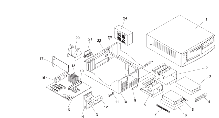
Parts - Types 6058/6059/6269/6578/6579
Chapter 3. Types 6058/6059/6269/6578/6579 173
Parts listing
Each FRU is available for all types/models, unless specific types or models
are given.
Index System (Types 6058/6059/6269/6578/6579) FRU No.
1TOP COVER ASM 06P2732
25.25 DASD BRACKET 09N5746
3CD-ROM DRIVE - 40x (6058 - PAx, PBx) (6578 - LAx, LBx, NCx, NDx,
PAx, RAx, RBx, E4L, EPS, KQG, KSG, RAA, RBA)
09N0879
3CD-ROM DRIVE - 48x (6058 - TAx, TBx, THU, THF, THS, THP, THA,
THT, THM, THV, HD, THG, THC, THJ) (6269 -C2x, D2x, E2x, M2x,
N2x, K2x, L2x, N7x, N8x, P9x, R1x,
R2x,P7x,P8x,F2x,G2x,P3x,H2x,H6x,HCx,J4x,A2x, A6x, R4x, R6x, RBx,
RAx, U3x, U6x,V1x,V3x,UAG,UBG, VAG, VBG, K7S, KDS, KES, UCG,
KCS, KAS, S1G, S2G, SAU, AFU, AGU, V4U, V5G) (6578 - PEx, PFx,
RFx, K7G, K8G, TAx, TBx, TCx, TDx, KAU, DWS, TGU, THU, THF,
THS, THP, THG, THA, THT, THC, THM, THV, THD, THJ, VDJ, VEJ,
VGG, VGC, VGV, TLG, TMG) (6579 - LDx, LEx, NAx, NBx, PCx, PDx,
RAx, RBx, TAx, TBx, TCx, TDx, TEx, TGx, RKx, RAA, RBA, RCG, TEG,
TKU, VHU, VDA, VEA, VFJ, VGJ)
19K1529
3CD-ROM DRIVE - 48x (PRIMARY)(6058 - TAx, TBx, THU, THF, THS,
THP, THA, THT, THM,THV,THD,THG,THC,THJ) (6059 - LDx, LEx,
NAx, NBx, PCx, PDx) (6579 - LDx, LEx, NAx, NBx, PCx, PDx, RAx,
RBx, TAx, TBx, TCx, TDx, TEx, TGx, RJx,
RKx,RAA,RBA,RCG,TEG,TKU,VHU,VDA,VEA,VFJ,VGJ)
09N0735
3CD-ROM DRIVE - 48x (OPTIONAL)(6578 - PEx, PFx, REx, RFx, K7G,
K8G, TAx, TBx, TCx,TDx,KAU, DWS, TGU, THU,D8V, TLG, TMG)
24P3603
4BEZEL KIT 09N5732
53.5″1.44MB DISKETTE DRIVE 75H9550
53.5″1.44MB DISKETTE DRIVE - JAPAN 75H9552
610.1GB EIDE HARDFILE (6269 - C1x, C2x, D1x, D2x, E1x, E2x, M1x,
M2x, N1x, N2x, K1x, K2x, L1x, L2x, D3A, D3T, D3G, D3C, D3D, D3M,
D3V, D4x, D6G, F1x, F3x, F4x, F6x, G1x, N3x, N4x, N5x, N7x, N8x, P2x,
P4x, P5x, P9x, R1x, R2x, P7x, PBx, F2x, G2x, P1x, P3x, J2S, G3x,
H1x,H2x,H4x,H5x,H6x,H9x,HCx, J4x, A2x, A3x, A5x, A6x, R4x, R6x,
RBx,R8x, RAx, U3x, U5x,U6x,V1x,V2x,V3x,FAG,HAG,HBG,AAG,ABG,
UAG, UBG,VAG,VBG, K7S, J5S, KDS, KES, HEG, ACG, UCG, KCS,
KAS, AGU, V4U) (6058 - LCx, LDx)(6578 - GAx, GBx, LCx, LDx, K7G,
K8G)(6059 - GAx, GBx, LAx, LBx) (6579 - GAx, GBx, LAx, LBx)
36L8681
620.4GB EIDE HARDFILE 5400 RPM(6269 - none)(6058 - NAx, NBx, PAx,
PBx, RAx, RBx, TAx, TBx, THU, THF, THS, THP, THA, THT, THM,
THV, THD, THG, THC, THJ) (6578 -LAx, LBx, NAx, NBx, NCx, NDx,
PAx, PBx, RAx, RBx, PCx, PDx, PEx, PFx, RCx, RDx, REx, RFx, RGx,
TAx, TBx, TCx, TDx, TEx, E4L, EPS, KAU, KQG, KSG, DWS, TGU,
THU, THF, THS, THP, PHG, THA, THT, THC, THM, THV, THD, THJ,
VFM,VFD, VGG, VGC,VGV, D8V, QYV, TLG, TMG, RAA, RBA) (6579 -
LDx, LEx, NCx, NDx, PAx, PBx,TCx, TDx, RJx, RKx, RCG, TEG, TEx,
TKU)
09N0705
174 Hardware Maintenance Manual: IBM NetVista Computer Types 6058, 6059, 6269, 6568, 6569, 6578, 6579, 6648,
6649
Index System (Types 6058/6059/6269/6578/6579) FRU No.
620.4GB EIDE HARDFILE (OPTIONAL)(6578 - LAx, LBx, NAx, NBx,
NCx, NDx, PAx, PBx, RAx, RBx, PCx, PDx, PEx, PFx, RCx, RDx, REx,
RFx, RGx, TAx, TBx, TCx, TDx, TEx, E4L, EPS, KAU, KQG, KSG, DWS,
TGU, TLG, TMG)
19K1557
630.0GB EIDE HARDFILE 7200RPM (6059 - NAx, NBx, PCx, PDx)(6579 -
NAx, NBx, PCx, PDx, RAx, RBx, TAx, TBx, TGx, RAA, RBA, VHU,
VDA, VEA,VFJ,VGJ)
09N0925
7DASD RAIL KIT 19K5331
83.5 DASD BRACKET 06P2734
9RFID ANTENNA 03K9654
10 CHASSIS ASM 06P2731
11 CONTROL PANEL ASM (all) 37L5092
12 SPEAKER with CABLE ASM 01K4909
13 92MM FAN ASM w/grommets 33L2594
14 FAN/SPEAKER BRACKET 09N5763
15 SYSTEM BD W/O MEM/PROC/POV/MERLOT 09K9982
15 SYST BD MERLOT W/POV CARD(6059/6579 only) 10K1195
15 SYSTEM BOARD(6269-All except Refresh 3 models) 19K5060
16 PLANAR EMC SHIELD KIT(6269 only) 10K1540
16 PLANAR EMC SHIELD KIT 09N5770
17 NVidia AGP4/16MB VIDEO ADAPTER(6059 - all) (6578 - TCx,
TDx)(6579 - LDx, LEx, NAx, NBx, PCx, PDx, TAx, TBx, TGx,VDA,VEA)
19K5340
18 CELERON 533MHz(6269 - C1x, C2x, 20U)(6058/6059/6578/6579 - none) 09N9307
18 CELERON 566MHz(6269 - D1x, D2x, 30U, D3A, D3T, D3G, D3C, D3D,
D3M, D3V, D4x, D6G)(6058/6059/6578/6579 - none)
06P3004
18 CELERON 600 MHz(6269 - E1x, E2x, 40U)(6058/6059/6578/6579 - none) 19K5067
18 CELERON 633 MHz(6269 - F1x, F3x, F4x, F6x, F2x, FAG, 42U, K3V, D3S,
D4S)(6058/6059/6578/6579 - none)
06P7163
18 CELERON 667 MHz(6269 - G1x, G2x, 44U, G3x, G4x, G5x, HAG,
HBG)(6058/6059/6578/6579 - none)
22P2476
18 CELERON 700 MHz(6269 - H1x, H2x, 46U, H4G, H3x, H5x, H6x, H7x,
H9x, HCx, HDU, HEG)(6058/6059/6578/6579 - none)
33L2754
18 CELERON 733 MHz(6269 - J1x, JAx, J4x)(6058/6059/6578/6579 - none) 24P5586
18 CELERON 766 MHz(6269 - A1x, A2x, A3x, A4x, A5x, A6x, AAG, ABG,
ADU, ACG, SAU, AHG)(6058/6059/6578/6579 - none)
24P5583
18 CELERON 800 MHz(100 BUS/800 MHz/128KB L2 CACHE) FLIP CHIP
WITH HEAT SINK (all)
24P5748
18 PiII COPPERMINE 650 MHz(6269 - K1x, K2x,
7OU)(6058/6059/6578/6579 - none)
19K5068
18 PiII COPPERMINE 667MHz(6269 - M1x, M2x, 50U, J2S, K7S, KDS, KES,
KCS)(6058/6059/6578/6579 - none)
37L1534
18 PIII COPPERMINE 667MHz (6578/6579 - GAx, GBx) 10K0863
18 PIII COPPERMINE 700MHz(6269 - L1x, L2x, 8OU ) 19K5077
18 PIII COPPERMINE 733MHz (6058 - LCx, LDx)(6059/6578 - LAx, LBx,
L1U, LCx, LDx) (6579 - LAx, LBx, LDx, LEx, L1U)
10K0864
Chapter 3. Types 6058/6059/6269/6578/6579 175
Index System (Types 6058/6059/6269/6578/6579) FRU No.
18 PIII COPPERMINE 733MHz(6269 - N1x, N2x, 60U, N3x, N4x, N5x, N7x,
N8x, J5S,KAS)(6058/6059/6578/6579 - none)
37L5338
18 PIII COPPERMINE 800MHz (6058 - NAx, NBx)(6059/6578 - NAx, NBx,
NCx, NDx, N1U, E4L) (6579 - NAx, NBx, N1U, NCx, NDx)
10K1196
18 PIII COPPERMINE 800MHz (OPTIONAL TO 25P4964)(6269 - P2x, P4x,
P5x, P9x, P7x, P8x, P1x, P3x, 9OU, D5S, D6S) (6579 - RAx, RBx, R1U,
RJx, RKx, RAA, RBA, RCG)
19K7535
18 PIII COPPERMINE 800MHz (PRIMARY) (6269 - P2x, P4x, P5x, P9x, P7x,
P8x, P1x, P3x, 9OU, D5S, D6S)
25P4964
18 PIII COPPERMINE 866MHz(6269 - R1x, R2x, R3x, R4x, R5x, R6x, RBx,
R7x, R8x, RAx, S1G, DFS)
19K7536
18 PIII COPPERMINE 866MHz (6058 - PAx, PBx)(6578 - PAx, PBx, P1U,
PCx, PDx, PEx, PFx, K7G,K8G, EPS, KAU, DWS) (6579 -
PAx,PBx,PCx,PDx,P1U)
19K7539
18 COPPERMINE 866MHz (6578 - PAx, PBx, P1U, PCx, PDx, PEx, PFx,
K7G, K8G, EPS, KAU, DWS) (6579 - PAx, PBx, PCx, PDx, P1U)
25P2778
18 COPPERMINE 866MHz (6578 -PAx, PBx, P1U, PCx, PDx, PEx, PFx,
K7G, K8G, EPS, KAU, DWS)(6579 - PAx,PBx,PCx,PDX,P1U)
22P4385
18 PIII (COPPERMINE) 933MHz(6058 - RAx,RBx) (6269 - U1x, U2x, U3x,
U4x, U5x, U6x, UAG, UBG, UDU, UCG, S2G)(6578 - RAx, RBx, RCx,
RDx, REx, RFx, R1U, RGx, KQG, KSG,QYV, RAA, RBA)(6579 - RAx,
RBx, R1U, RJx, RKx)(6579 - RAx, RBx,R1U,RJx,RKx,RAA,RBA,RCG)
19K7535
18 PIII (COPPERMINE) 933MHz (6058 - RAx, RBx) (6578 - RAx, RBx, RCx,
RDx, REx, RFx, R1U, RGx, KQG, KSG,QYV, RAA, RBA) (6579 - RAx,
RBx, R1U, RJx, RKx, RAA, RBA, RCG)
19K7537
18 PIII (COPPERMINE) 933MHz (6269 - U1x, U2x, U3x, U4x, U5x, U6x,
UAG, UBG, UDU, UCG, S2G) (6578 - RAx, RBx, RCx, RDx, REx, RFx,
R1U, RGx, KQG, KSG, QYV, RAA, RBA) (6579 -RAx, RBx, R1U, RJx,
RKx, RAA, RBA, RCG)
25P0719
18 COPPERMINE 1000MHz PROCESSOR(6058 - TAx, TBx, THU, THF,
THS, THP, THA, THT, THM, THV, THD, THG, THC, THJ)(6269 - V1x,
V2x, V3x, VAG, VBG, VDU, S4U, V4U, V5U)(6578-
TAx,TBx,TCx,TDx,TEx,T2U, TFU, TGU, THU, THF, THS, THP, THG,
THA, THT, THC, THM, THV, THD, THJ, VDJ, VEJ, VFM, VFD, VGG,
VGC, VGV ,D8V, TLG, TMG) (6579 - TAx, TBx, TCx, TDx, TEx, TGx,
T2U, TEG, TKU, VHU, VDA, VEA, VFJ, VGJ)
22P3415
18 PROCESSOR HEATSINK AND CLIP(6269 - P1x, P2x, P3x, P4x, P5x,
P7x, P8x, P9x, R1x, R2x, 9OU, A1x, A2x, A3x, A4x, A5x, A6x, R3x, R4x,
R5x, R6x, RBx, R7x, R8x, RAx, AAG, ABG, ADU, AJG, D5S, D6S, ACG,
S1G, SAU, A7G, A7S, A7P, A8S, A8P, A9P, A9S, AFU, AGU, AEU, AHG)
10K1689
18 PROCESSOR HEATSINK AND CLIP(6269 only - C1x, C2x, 20U) 06P2446
176 Hardware Maintenance Manual: IBM NetVista Computer Types 6058, 6059, 6269, 6568, 6569, 6578, 6579, 6648,
6649
Index System (Types 6058/6059/6269/6578/6579) FRU No.
18 PROCESSOR HEATSINK AND CLIP(6269 only-D1x, D2x, D3A, D3T,
D3G, D3C, D3D, D3M, D3V, D4x, D6G, E1x, E2x, F1x, F2x, F3x, F4x,
F6x, G1x, G2x, G3x, H1x, H2x, J2S, K1x, K2x, L1x, L2x, M1x, M2x, N1x,
N2x, N3x, N4x, N5x, N7x, N8x, 30U, 40U, 42U, 44U, 46U, 50U, 60U,
70U, 80U, H4G, H9G, K3V, H3x, H5x, H6x, H7x, H9x, HCx,
J1x,JAx,J4x,FAG,HAG,HBG,HDU,D3S,K7S,J5S,KDS,KES,HEG,D4S,KCS,KAS,
DFS)
06P2454
19 MEMORY 64MB SDRAM (6058 - LCx,LDx,NAx,NBx)(6269 - C1x, C2x,
D1x, D2x, E1x, E2x, M1x, M2x, N1x, N2x, K1x, K2x, L1x, L2x, D4x, F1x,
N3x, P2x, R1x, G1x, P7x, F2x, G2x,P1x,P3x,J2S,H1x,H2x,K3V,
G4x,G5x,H3x,H4x, H5x, H6x, H7x, J1x, JAx, A1x, A2x,A3x,A4x,R3x,R4x,
R5x, R6x, R7x, U1x, U2x, U3x, U4x, U5x, V1x, HAG, AAG, UAG, VAG,
HDU, ADU, D3S, D5S, D6S, K7S, J5S, KDS, KES, HEG, ACG,
UCG,D4S,KCS,KAS,S1G, S2G, A7G, A7S, A7P, A8S, A8P, A9S,A9P, AGU,
AEU, V4U, AHG, V5G)(6578 - GAx, GBx, LCx, LDx, NAx, NBx, PCx,
PDx, K7G, RGx, TEx, KQG, TLG)(6059/6579 - GAx, GBx, LAx, LBx,
NCx, NDx, PAx, PBx)
33L3072
19 MEMORY 128MB SDRAM (6058 -PAx,PBx, RAx, RBx, TAx,
TBx)(6059-all)(6269 - D3A, D3T, D3G, D3C, D3D, D3M, D3V, D6G, F3x,
F4x, F6x, N4x, N5x, N7x, N8x, P4x, P5x, P9x, R2x, P8x, G3x, H9x, HCx,
J4x, A5x, A6x, RBx, RAx, U6x, V2x, V3x, FAG, HBG, ABG, AJG, UBG,
VBG, UDU, VDU, S4U, SAU, DGS, AFU) (6578 -LAx, LBx, NCx, NDx,
PAx, PBx, RAx, RBx, PEx, PFx,RCx, RDx, REx, RFx, K8G,TAx, TBx, TCx,
TDx, T2U, E4L, EPS, KAU, KSG, DWS, TGU, VDJ, VEJ, VFM, VFD,
VGG, VGC, VGV, D8V, TMG, RAA, RBA) (6579 - LDx, LEx, NAx, NBx,
PCx, PDx, RAx, TAx, TBx, TCx, TDx, TEx, TGx, T2U, RJx,RKx,RAA,
RBA,RCG,TEG,VDA,VEA,VFJ,VGJ)
33L3074
20 AIR BAFFLE DUCT 06P2733
21 I/O CAM BRACKET 09N5734
22 KEYLOCK ASM 09K9829
23 C2 SWITCH ASM 09K9827
24 155W POWER SUPPLY 00N7685
24 155W POWER SUPPLY - JAPAN (6058 - LCJ, LDJ, NAJ, NBJ, PAJ, PBJ,
RAJ, RBJ, TAJ, TBJ, LCG, LDG, NAG, NBG, PAG, PBG, RAG, RBG,
TAG, TBG, THG, THJ)(6059 - NAJ, NBJ, PCJ, PDJ, NAG, NBG, PCG,
PDG) (6578 - LCJ, LDJ, NAJ, NBJ, PAJ, PBJ, RAJ, RBJ, PEJ, PFJ, RCJ,
RDJ, REJ, RFJ, TAJ, TBJ, LAG, LBG, LCG, LDG, NAG, NBG, NCG,
NDG, PAG, PBG, RAG, RBG, RCG, RDG, REG, RFG, K7G, K8G, TAG,
TBG, TCG, TDG, KQG, KSG, THG, THJ, VDJ, VEJ, VGG)(6579 - LDJ,
LEJ, NAJ, NBJ, PAJ, PBJ, PCJ, PDJ, TAJ, TEJ, TGJ, NAG, NBG, PDG,
RAG, RBG, TAG, TBG, RCG, TEG,VFJ,VGJ)
00N7687
24 155W POWER SUPPLY - CHINA(6058 - LCC, LDC, NAC, NBC, PAC,
PBC, RAC, RBC, TAC, TBC, THC)(6578 - GAC, GBC, LAC, LBC, LCC,
LDC, NAC, NBC, NCC, NDC, THC, VGC, D8V, QYV, PAC, PBC, RCC,
RDC, TAC, TBC, TEC)(6579 - LAC, LBC, LDC, LEC, NAC, NBC, NCC,
NDC, PAC, PBC, PCC, PDC, TAC, TEC)(6059 - NAC, NBC, PCC, PDC)
00N7689
5.25″DASD BRACKET HANDLE 09N5747
Chapter 3. Types 6058/6059/6269/6578/6579 177
Index System (Types 6058/6059/6269/6578/6579) FRU No.
3.5″DASD BRACKET HANDLE 09N5748
CABLE HARDFILE - ATA 37L4525
FOOT (4) 03K9655
BEZEL KIT 09N5732
CABLE DISKETTE DRIVE 33L2596
MOUSE - 2 Button(6058/6269/6578 - all)(6579 - TAx, TBx, TCx, TDx,
TEx, TGx, T2U,TEG,TKU,VHU,VDA,VEA,VFJ,VGJ)
10L6145
MOUSE - Scrollpoint(6059)(6579 - GAx, GBx, LAx, LBx, LDx, LEx, L1U,
NAx, NBx, NCx, NDx, N1U, PAx, PBx, PCx, PDx, P1U, RAx, RBx, R1U,
RJx, RKx, RAA, RBA, RCG)
28L1865
MISC. HARDWARE KIT (6269/6578/6579 - all) 09N5764
ATA-66 CABLE ASM (2 drop)(6269/6578/6579 - all) 37L5098
CDROM AUDIO CABLE (6269/6578/6579 - all) 75H9219
DUAL USB CABLE(6058/6059/6578/6579 only) 22P1188
LITHIUM BATTERY 33F8354
PLANAR LOCATION LABEL(6269 only) 10K1698
PLANAR INFO LABEL KIT 09N5715
EMC SHIELD FOR 5.25″BAY (6269 - all) 19K5548
EMC SHIELD FOR 5.25″BAY 20L3073
NAMEPLATE 09N5733
INTERPOSER CABLE ASM(6269 only) 06P2401
ACCTON ETHERNET CARD(6269 - C2x, D2x, E2x, M2x, N2x, K2x, L2x,
D3x, F4x, N3x, N5x, N8x, P2x, P5x, P9x, F2x, G2x, P3x, G3x, H2x, H4x,
H5x, H6x, H9x. HCx, J4x, A2x, A3x, A5x, A6x, R4x, R6x, RBx, R8x, RAx,
U3x, U5x, U6x, V1x, V2x, V3x, FAG, HAG, HBG, AAG, ABG,UAG,
UBG, VAG, VBG, K7S, KES, HEG, ACG, UCG, KAS, S1G, S2G, S4U,
SAU, A7S, A7P, A8S, A8P, A9S, A9P, AFU, AGU, AHG, V5G )
(6058/6059/6578/6579 - none)
19K4309
ROULETTE ETHERNET ADAPTER (6058 - PAx, PBx, TAx,
TBx,THU,THF,THS,THP,THA,THT,THM,THV,THD,THG,THC,THJ )(6578
-LAx,LBx,NCx,NDx,PAx,PBx,RAx,RBx,PEx,PFx,REx, THU, THF, THS,
THG, THA, THT, THC,THM, THV, THD, THJ, VDJ, VEJ, VFM, VFDM
VGG, VGC, TFU, THG, THU, RFX, ,K7G,K8G,TAx,TBx,TCx,
TDx,TEx,E4L,EPS,KAU,KQG,KSG,DWS,D8V, TLG, TMG, RAA,
RBA)(6059/6579 - all)
19K4885
VIDEO CARD 4xAGP DONGLE (6578 - PEx, PFx, REx, RFx,TCx,TDx)
(6059 - all)(6579 - LDx, LEx, NAx, NBx, PCx, PDx, RAx,RBx, TAx, TBx,
TGx, RAA, RBA, VDA, VEA)
37L5566
NVidia P09/32MB VIDEO ADAPTER (6578 - PEx, PFx, REx, RFx) (6579
- RAx, RBx,RAA,RBA,VDA,VEA)
09N5033
ENET ADAPTER FERRITE ( 6059 - NAJ, NBJ, PCJ, PDJ) (6579 - LDJ,
LEJ, NAJ, NBJ, PAJ, PBJ, PCJ, PDJ)
06P7059
178 Hardware Maintenance Manual: IBM NetVista Computer Types 6058, 6059, 6269, 6568, 6569, 6578, 6579, 6648,
6649
Index System (Types 6058/6059/6269/6578/6579) FRU No.
SYSTEM BOARD - GIGABYTE PLANAR (6269 - G4x, G5x, H3x, H4x,
H5x, H6x, H7x, H9x, HCx, J1x, JAx, J4x, A1x, A2x, A3x, A4x, A5x, A6x,
R3x, R4x, R5x, R6x, RBx,R7x, R8x, RAx, U1x, U2x, U3x, U4x, U5x, U6x,
V1x, V2x, V3x, FAG, HAG, HBG, AAG, ABG, UAG, UBA, VAG, VBG,
HDU, ADU, UDU, VDU, KDS, KES, HEG, ACG, UCG, D4S, KCS, KAS,
S1G, S2G, S4U, SAU, A7S, A7P, A8S, A8P, A9S, A9P, AFU, AGU, AEU,
V4U, AHG, V5G)
24P5565
MEMORY 256MB SDRAM (6058 -THU, THF, THS, THP, THA, THT,
THM, THV, THD, THG, THC, THJ) (6269 - all) (6578 - TFU, THU, THF,
THS, THP, THG, THA, THT, THC, THM,THV,THD,THJ,QYV) (6579 -
TKU,VHU)
33L3076
10GB HARDFILE EIDE 5400rpm (PRIMARY) (6269 -C1x, C2x, D1x, D2x,
E1x,E2x,M1x,M2x,N1x,N2x,K1x,
K2x,L1x,L2x,D3A,D3T,D3G,D3C,D3D,D3M,D3V,
D4x,D6G,F1x,F3x,F4x,F6x,G1x,N3x,N4x,N5x,N7x, N8x, P2x, P4x, P5x,
P9x, R1x,
R2x,P7x,P8x,F2x,G2x,P1x,P3x,J2S,G3x,H1x,H2x,H4x,H5x,H6x,H9x,HCx,J4x,A2x,A3x,A5x,A6x,R4x,R6x,RBx,R8x,RAx,U3x,U5x,U6x
AGU, V4U)
19K1476
20GB IDE 5400rpm HARDFILE (6269 - G4x, G5x, H3x, H7x, J1x, JAx,
A1x, A4x, R3x, R5x, R7x, U1x, U2x, U4x, D3S, D5S, D6S, D4S, S1G, S2G,
SAU, DFS, A7G, A7S, A7P, A8S, A8P, A9S, A9P, AFU, AHG, AJG, V5G)
19K1560
30.0GB ATA - 100, 7200RPM Hardfile (6269 - S4U)(6578-TFU,VDJ,VEJ)
(6578 - TFU, VDJ, VEJ)
19K1567
8x4x32x CDROM READ/WRITE (6269- S4U) 09N0891
LC 2.3 ETHERNET CARD (6269 - F3x, N4x, P4x) 34L1209
GVC MODEM (Domestic) (PRIMARY) (6269 - KDS, KES, KCS) 09N1677
MODEM (DOMESTIC) (6269 - SAU) 09N1678
MODEM (DOMESTIC) (6269 - SAU) 19K2965
2ND SERIAL PORT CABLE ASM (6269 - all) 24P9065
8X CD-RW, LG, WHITE, NO HD PH (6578-TFU) 06P5163
COPPERMINE CELERON 800MHz (100 BUS/800MHz/128Kb L2
CACHE) ″D0″STEP LEVEL FLIP CHIP WITH HEATSINK 09N4373
(NOTE: PRIME P/N TO 10K1196) (6058 - NAx,NBx) (6578 - NAx, NBx,
NCx, NDx, N1U, E4L) (6579 - NAx, NBx, N1U,NCx,NDx)
25P2779
COPPERMINE CELERON 800MHz (100 BUS/800MHz/128Kb L2
CACHE) ″C0″STEP LEVEL FLIP CHIP WITH HEATSINK (NOTE:
PRIME P/N TO 24P5784) (6269 - A7G, A7S, A7P, A8S, A8P, A9P, AFU,
AGU, AEU, AJG)
25P0834
COPPERMINE CELERON 800MHz (100 BUS/800MHz/128Kb L2
CACHE) ″D0″STEP LEVEL FLIP CHIP WITH HEATSINK (NOTE:
PRIME P/N TO 25P0834) (6269 - A7G, A7S, A7P, A8S, A8P, A9P, AFU,
AGU, AEU, AJG)
24P5784
Chapter 3. Types 6058/6059/6269/6578/6579 179
Index System (Types 6058/6059/6269/6578/6579) FRU No.
FANSINK NON-IHS 900 MHz (6058 - RAx, RBx, TAx, TBx, THA, THU,
THF, THS, THP, THT, THM, THV, THD, THG, THC, THJ) (6578 - RAx,
RBx, RCx, RDx, REx, RFx, R1U, RGx, KQG, KSG, QYV, RAA, RBA, TAx,
TBx, TCx, TDx, TEx, T2U, TFU, TGU, THU, THF, THS, THP THG, THA,
THT, THC, THM, THV, THD, THJ, VDJ, VEJ, VFM, VFD, VGG, VGC,
VGV, DBV, TLG, TMG) (6579 - RAx, RBx, R1U, RJx, RKx, RAA, RBA,
RCG, TAx, TBx, TCx, TDx, TEx, TGx, T2U, TEG, TKU, VHU, VDA,
VEA, VFJ, VGJ)
06P2458
FANSINK, IHS 866 - 1.10 GHz (6058 - PAx, PBx, RAx, RBx, TAx, TBx,
THU, THF, THS, THP, THA, THT, THM, THV, THD, THG, THC, THJ)
(6578 - RAx, RBx, RCx, RDx, REx, RFx, R1U, RGx, KQG, KSG, QYV,
RAA, RBA, TAx, TBx, TCx, TDx, TEx, T2U, TFU, TGU, THU, THF, THS,
THP THG, THA, THT, THC, THM, THV, THD, THJ, VDJ, VEJ, VFM,
VFD, VGG, VGC, VGV, D8V, TLG, TMG) (6579 - RAx, RBx, R1U, RJx,
RKx, RAA, RBA, RCG, TAx, TBx, TCx, TDx, TEx, TGx, T2U, TEG, TKU,
VHU, VDA, VEA, VFJ, VGJ)
22P4370
HEATSINK, NON-IHS 566 - 866 MHz (6058 - LCx, LDx, NAx, NBx,
PAx, PBx) (6578 - GAx, GBx, LAx, LBx, L1U LCx, LDx, NAx, NBx, NCx,
NDx, N1U, E4L, PAx, PBx, P1U, PCx, PDx, PEx, PFx, K7G, K8G, EPS,
KAU, DWS) (6579 - GAx, GBx, LAx, LBx, LDx, LEx, L1U NAx, NBx,
N1U, NCx, NDx, PAx, PBx, PCx, PDx, P1U)
09N4372
Keyboards - PCNext Lite Pearl White
US ENGLISH 37L2514
FRENCH CANADIAN 058 37L0912
FRENCH CANADIAN 044 37L2515
LA/SPANISH 37L2516
BRAZIL - PORTUGUESE 28L1826
ARABIC 37L2518
BELGIUM - FRENCH 37L2519
BELGIUM - ENGLISH 37L2520
BULGARIAN 37L2521
CZECH 37L2522
DANISH 37L2523
DUTCH 37L2524
FRENCH 37L2525
GERMAN 37L2526
GREEK 37L2527
HEBREW 37L2528
HUNGARIAN 37L2529
ITALIAN 37L2531
NORWEGIAN 37L2532
180 Hardware Maintenance Manual: IBM NetVista Computer Types 6058, 6059, 6269, 6568, 6569, 6578, 6579, 6648,
6649
POLISH 37L2533
PORTUGUESE 37L2534
ROMANIAN 37L2535
RUSSIAN 37L2536
SERBIAN - CYR 37L2537
SLOVAK 37L2538
SPANISH 37L2539
SWEDISH/FINNISH 37L2540
SWISS - FRENCH/GERMAN 37L2541
TURKISH - ID 179 37L2542
TURKISH - ID 440 37L2543
UK ENGLISH 37L2544
YUGOSLAVIAN 37L2545
UK ENGLISH (ISO) 37L2546
JAPANESE 37L2547
CHINESE 37L2548
KOREAN 28L1860
THAI 37L2550
Computer Power Cords
ARABIC 14F0033
AUSTRALIAN 93F2365
BELGIAN 1339520
BULGARIAN 1339520
CANADIAN 93F2364
CZECH 1339520
DENMARK 13F9997
FINLAND 1339520
FRANCE 1339520
GERMAN 1339520
HUNGARIAN 1339520
ISRAEL 14F0087
ITALIAN 14F0069
LATIN AMERICAN 6952301
NETHERLANDS 1339520
NEW ZEALAND 93F2365
NORWEGIAN 1339520
POLISH 1339520
PORTUGUESE 1339520
SERBIAN 1339520
SLOVAKIAN 1339520
SOUTH AFRICAN 14F0015
SPANISH 1339520
SWISS 1339520
Chapter 3. Types 6058/6059/6269/6578/6579 181
SWISS - FRENCH/GERMAN 14F0051
US ENGLISH 93F2364
UK - IRELAND 14F0033
YUGOSLAVIAN 1339520
CHILE 14F0069
ARGENTINA, PARAGUAY, & URUGUAY 36L8880
Recovery CDs
ARGENTINA, PARAGUAY, & URUGUAY 36L8880
Display and Monitor Information
Display and monitor information is available separately and is listed under
“Related Publications”on page vii.
182 Hardware Maintenance Manual: IBM NetVista Computer Types 6058, 6059, 6269, 6568, 6569, 6578, 6579, 6648,
6649
Special tools
The following tools are required to service the computer models/types listed
in this section of the service manual
vVolt-ohm meter, IBM P/N 73G5404
vWrap Plug, IBM P/N 72X8546
Chapter 3. Types 6058/6059/6269/6578/6579 183
184 Hardware Maintenance Manual: IBM NetVista Computer Types 6058, 6059, 6269, 6568, 6569, 6578, 6579, 6648,
6649

Chapter 4. Related Service Information
Note: The service procedures are designed to help you isolate problems. They
are written with the assumption that you have model-specific training
on all computers, or that you are familiar with the computers,
functions, terminology, and service information provided in this
manual.
Safety information
The following section contains the safety information that you need to be
familiar with before servicing an IBM mobile computer.
General safety
Follow these rules to ensure general safety:
vObserve good housekeeping in the area of the machines during and after
maintenance.
vWhen lifting any heavy object:
1. Ensure you can stand safely without slipping.
2. Distribute the weight of the object equally between your feet.
3. Use a slow lifting force. Never move suddenly or twist when you
attempt to lift.
4. Lift by standing or by pushing up with your leg muscles; this action
removes the strain from the muscles in your back. Do not attempt to lift
any objects that weigh more than 16 kg (35 lb) or objects that you think are too
heavy for you.
vDo not perform any action that causes hazards to the customer, or that
makes the equipment unsafe.
vBefore you start the machine, ensure that other service representatives and
the customer’s personnel are not in a hazardous position.
vPlace removed covers and other parts in a safe place, away from all
personnel, while you are servicing the machine.
vKeep your tool case away from walk areas so that other people will not trip
over it.
vDo not wear loose clothing that can be trapped in the moving parts of a
machine. Ensure that your sleeves are fastened or rolled up above your
elbows. If your hair is long, fasten it.
vInsert the ends of your necktie or scarf inside clothing or fasten it with a
nonconductive clip, approximately 8 centimeters (3 inches) from the end.
© Copyright IBM Corp. 2000 185

vDo not wear jewelry, chains, metal-frame eyeglasses, or metal fasteners for
your clothing.
Remember: Metal objects are good electrical conductors.
vWear safety glasses when you are: hammering, drilling soldering, cutting
wire, attaching springs, using solvents, or working in any other conditions
that might be hazardous to your eyes.
vAfter service, reinstall all safety shields, guards, labels, and ground wires.
Replace any safety device that is worn or defective.
vReinstall all covers correctly before returning the machine to the customer.
Electrical safety
CAUTION:
Electrical current from power, telephone, and communication cables can be
hazardous. To avoid personal injury or equipment damage, disconnect the
attached power cords, telecommunication systems, networks, and modems
before you open the server covers, unless instructed otherwise in the
installation and configuration procedures.
Observe the following rules when working on electrical equipment.
Important: Use only approved tools and test equipment. Some hand tools
have handles covered with a soft material that does not insulate
you when working with live electrical currents.
Many customers have, near their equipment, rubber floor mats
that contain small conductive fibers to decrease electrostatic
discharges. Do not use this type of mat to protect yourself from
electrical shock.
vFind the room emergency power-off (EPO) switch, disconnecting switch, or
electrical outlet. If an electrical accident occurs, you can then operate the
switch or unplug the power cord quickly.
vDo not work alone under hazardous conditions or near equipment that has
hazardous voltages.
vDisconnect all power before:
–Performing a mechanical inspection
–Working near power supplies
–Removing or installing main units
vBefore you start to work on the machine, unplug the power cord. If you
cannot unplug it, ask the customer to power-off the wall box that supplies
power to the machine and to lock the wall box in the off position.
186 Hardware Maintenance Manual: IBM NetVista Computer Types 6058, 6059, 6269, 6568, 6569, 6578, 6579, 6648,
6649
vIf you need to work on a machine that has exposed electrical circuits,
observe the following precautions:
–Ensure that another person, familiar with the power-off controls, is near
you.
Remember: Another person must be there to switch off the power, if
necessary.
–Use only one hand when working with powered-on electrical equipment;
keep the other hand in your pocket or behind your back.
Remember: There must be a complete circuit to cause electrical shock. By
observing the above rule, you may prevent a current from passing
through your body.
–When using testers, set the controls correctly and use the approved
probe leads and accessories for that tester.
–Stand on suitable rubber mats (obtained locally, if necessary) to insulate
you from grounds such as metal floor strips and machine frames.
Observe the special safety precautions when you work with very high
voltages; these instructions are in the safety sections of maintenance
information. Use extreme care when measuring high voltages.
vRegularly inspect and maintain your electrical hand tools for safe
operational condition.
vDo not use worn or broken tools and testers.
vNever assume that power has been disconnected from a circuit. First, check
that it has been powered-off.
vAlways look carefully for possible hazards in your work area. Examples of
these hazards are moist floors, nongrounded power extension cables, power
surges, and missing safety grounds.
vDo not touch live electrical circuits with the reflective surface of a plastic
dental mirror. The surface is conductive; such touching can cause personal
injury and machine damage.
vDo not service the following parts with the power on when they are
removed from their normal operating places in a machine:
–Power supply units
–Pumps
–Blowers and fans
–Motor generators
and similar units. (This practice ensures correct grounding of the units.)
vIf an electrical accident occurs:
–Use caution; do not become a victim yourself.
–Switch off power.
Chapter 4. Related Service Information 187
–Send another person to get medical aid.
Safety inspection guide
The intent of this inspection guide is to assist you in identifying potentially
unsafe conditions on these products. Each machine, as it was designed and
built, had required safety items installed to protect users and service
personnel from injury. This guide addresses only those items. However, good
judgment should be used to identify potential safety hazards due to
attachment of non-IBM features or options not covered by this inspection
guide.
If any unsafe conditions are present, you must determine how serious the
apparent hazard could be and whether you can continue without first
correcting the problem.
Consider these conditions and the safety hazards they present:
vElectrical hazards, especially primary power (primary voltage on the frame
can cause serious or fatal electrical shock).
vExplosive hazards, such as a damaged CRT face or bulging capacitor
vMechanical hazards, such as loose or missing hardware
The guide consists of a series of steps presented in a checklist. Begin the
checks with the power off, and the power cord disconnected.
Checklist:
1. Check exterior covers for damage (loose, broken, or sharp edges).
2. Power-off the computer. Disconnect the power cord.
3. Check the power cord for:
a. A third-wire ground connector in good condition. Use a meter to
measure third-wire ground continuity for 0.1 ohm or less between the
external ground pin and frame ground.
b. The power cord should be the appropriate type as specified in the
parts listings.
c. Insulation must not be frayed or worn.
4. Remove the cover.
5. Check for any obvious non-IBM alterations. Use good judgment as to the
safety of any non-IBM alterations.
6. Check inside the unit for any obvious unsafe conditions, such as metal
filings, contamination, water or other liquids, or signs of fire or smoke
damage.
7. Check for worn, frayed, or pinched cables.
8. Check that the power-supply cover fasteners (screws or rivets) have not
been removed or tampered with.
188 Hardware Maintenance Manual: IBM NetVista Computer Types 6058, 6059, 6269, 6568, 6569, 6578, 6579, 6648,
6649
Handling electrostatic discharge-sensitive devices
Any computer part containing transistors or integrated circuits (ICs) should be
considered sensitive to electrostatic discharge (ESD). ESD damage can occur
when there is a difference in charge between objects. Protect against ESD
damage by equalizing the charge so that the machine, the part, the work mat,
and the person handling the part are all at the same charge.
Notes:
1. Use product-specific ESD procedures when they exceed the requirements
noted here.
2. Make sure that the ESD protective devices you use have been certified
(ISO 9000) as fully effective.
When handling ESD-sensitive parts:
vKeep the parts in protective packages until they are inserted into the
product.
vAvoid contact with other people.
vWear a grounded wrist strap against your skin to eliminate static on your
body.
vPrevent the part from touching your clothing. Most clothing is insulative
and retains a charge even when you are wearing a wrist strap.
vUse the black side of a grounded work mat to provide a static-free work
surface. The mat is especially useful when handling ESD-sensitive devices.
vSelect a grounding system, such as those listed below, to provide protection
that meets the specific service requirement.
Note: The use of a grounding system is desirable but not required to
protect against ESD damage.
–Attach the ESD ground clip to any frame ground, ground braid, or
green-wire ground.
–Use an ESD common ground or reference point when working on a
double-insulated or battery-operated system. You can use coax or
connector-outside shells on these systems.
–Use the round ground-prong of the ac plug on ac-operated computers.
Grounding requirements
Electrical grounding of the computer is required for operator safety and
correct system function. Proper grounding of the electrical outlet can be
verified by a certified electrician.
Safety notices (multi-lingual translations)
The caution and danger safety notices in this section are provided in the
following languages:
vEnglish
Chapter 4. Related Service Information 189

vBrazilian/Portuguese
vChinese
vFrench
vGerman
vItalian
vKorean
vSpanish
Important: All caution and danger statements in this Netfinity Server Library
begin with a number. This number is used to cross reference an
English caution or danger statement with translated versions of
the caution or danger statement in this section.
For example, if a caution statement begins with a number 1,
translations for that caution statement appear in this section under
statement 1.
Be sure to read all caution and danger statements before
performing any of the instructions.
vStatement 1
DANGER
Electrical current from power, telephone and communication cables is
hazardous.
To avoid a shock hazard:
vDo not connect or disconnect any cables or perform installation,
maintenance, or reconfiguration of this product during an electrical
storm.
vConnect all power cords to a properly wired and grounded electrical
outlet.
vConnect to properly wired outlets any equipment that will be attached to
this product.
vWhen possible, use one hand only to connect or disconnect signal cables.
vNever turn on any equipment when there is evidence of fire, water, or
structural damage.
190 Hardware Maintenance Manual: IBM NetVista Computer Types 6058, 6059, 6269, 6568, 6569, 6578, 6579, 6648,
6649

vDisconnect the attached power cords, telecommunications systems,
networks, and modems before you open the device covers, unless
instructed otherwise in the installation and configuration procedures.
vConnect and disconnect cables as described in the following table when
installing, moving, or opening covers on this product or attached devices.
To Connect To Disconnect
1. Turn everything OFF.
2. First, attach all cables to devices.
3. Attach signal cables to connectors.
4. Attach power cords to outlet.
5. Turn device ON.
1. Turn everything OFF.
2. First, remove power cords from outlet.
3. Remove signal cables from connectors.
4. Remove all cables from devices.
vStatement 2
CAUTION:
When replacing the lithium battery, use only IBM Part Number 33F8354 or
an equivalent type battery recommended by the manufacturer. If your
system has a module containing a lithium battery, replace it only with the
same module type made by the same manufacturer. The battery contains
lithium and can explode if not properly used, handled, or disposed of.
Do not:
vThrow or immerse into water
vHeat to more than 100°C (212°F)
vRepair or disassemble
Dispose of the battery as required by local ordinances or regulations.
vStatement 3
Chapter 4. Related Service Information 191
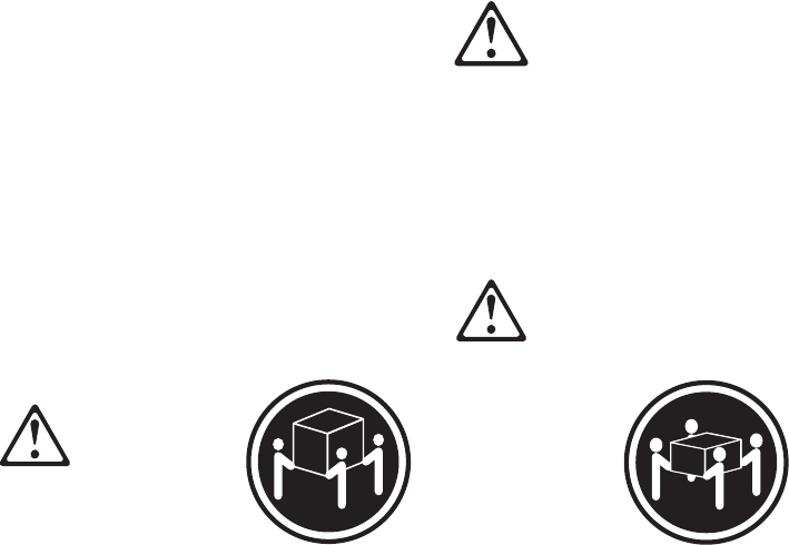
CAUTION:
When laser products (such as CD-ROMs, DVD-ROM drives, fiber optic
devices, or transmitters) are installed, note the following:
vDo not remove the covers. Removing the covers of the laser product
could result in exposure to hazardous laser radiation. There are no
serviceable parts inside the device.
vUse of controls or adjustments or performance of procedures other than
those specified herein might result in hazardous radiation exposure.
Some laser products contain an embedded Class 3A or Class 3B laser diode.
Note the following:
Laser radiation when open. Do not stare into the beam, do not view directly
with optical instruments, and avoid direct exposure to the beam.
vStatement 4
192 Hardware Maintenance Manual: IBM NetVista Computer Types 6058, 6059, 6269, 6568, 6569, 6578, 6579, 6648,
6649
≥32 kg (70.5 lbs) ≥55 kg (121.2 lbs)
CAUTION:
Use safe practices when lifting.
vStatement 5
CAUTION:
The power control button on the device and the power switch on the power
supply do not turn off the electrical current supplied to the device. The
device also might have more than one power cord. To remove all electrical
current from the device, ensure that all power cords are disconnected from
the power source.
1
2
vStatement 10
CAUTION:
Do not place any object weighing more than 82 kg (180 lbs.) on top of
rack-mounted devices.
Importante:
Chapter 4. Related Service Information 193

Todas as instruções de cuidado e perigo da :cit.Netfinity Server Library:ecit.
começam com um número. Este número éutilizado para fazer referência
cruzada de uma instrução de cuidado ou perigo no idioma inglês com as
versões traduzidas das instruções de cuidado ou perigo encontradas nesta
seção.
Por exemplo, se uma instrução de cuidado éiniciada com o número1,as
traduções para aquela instrução de cuidado aparecem nesta seção sob a
instrução1.
Certifique-se de ler todas as instruções de cuidado e perigo antes de executar
qualquer operação.
Instrução1
PERIGO
A corrente elétrica proveniente de cabos de alimentação, de telefone e de
comunicações éperigosa.
Para evitar risco de choque:
vNão conecte ou desconecte cabos e não realize instalação, manutençãoou
reconfiguração deste produto durante uma tempestade com raios.
vConecte todos os cabos de alimentação a tomadas elétricas corretamente
instaladas e aterradas.
vConecte todos os equipamentos ao qual esse produto seráconectado a
tomadas corretamente instaladas.
vSempre que possível, utilize apenas uma das mãos para conectar ou
desconectar cabos de sinal.
vNunca ligue qualquer equipamento quando existir evidência de danos por
fogo, água ou na estrutura.
vDesconecte cabos de alimentação, sistemas de telecomunicação, redes e
modems antes de abrir as tampas dos dispositivos, a menos que
especificado de maneira diferente nos procedimentos de instalaçãoe
configuração.
vConecte e desconecte cabos conforme descrito na seguinte tabela, ao instalar
ou movimentar este produto ou os dispositivos conectados, ou ao abrir suas
tampas.
194 Hardware Maintenance Manual: IBM NetVista Computer Types 6058, 6059, 6269, 6568, 6569, 6578, 6579, 6648,
6649
Para Conectar: Para Desconectar:
1. DESLIGUE Tudo.
2. Primeiramente, conecte todos os cabos aos
dispositivos.
3. Conecte os cabos de sinal aos conectores.
4. Conecte os cabos de alimentaçãoàs tomadas.
5. LIGUE os dispositivos.
1. DESLIGUE Tudo.
2. Primeiramente, remova os cabos de alimentação
das tomadas.
3. Remova os cabos de sinal dos conectores.
4. Remova todos os cabos dos dispositivos.
Instrução2
CUIDADO:
Ao substituir a bateria de lítio, utilize apenas uma bateria IBM, Número de
Peça 33F8354 ou uma bateria de tipo equivalente, recomendada pelo
fabricante. Se o seu sistema possui um móídulo com uma bateria de lítio,
substitua-o apenas pelo mesmo tipo de mídulo, do mesmo fabricante. A
bateria contémlítio e pode explodir se não for utilizada, manuseada e
descartada de maneira correta.
.Não:
vJogue ou coloque na água
vAqueça a mais de 100C (212F)
vConserte nem desmonte
Para descartar a bateria, entre em contato com a área de atendimento a
clientes IBM, pelo telefone (011) 889-8986, para obter informações sobre como
enviar a bateria pelo correio para a IBM.
Instrução3
PRECAUCIÓN:
Quando produtos a laser (unidades de CD-ROM, unidades de DVD,
dispositivos de fibra ítica, transmissores, etc.) estiverem instalados, observe o
seguinte:
Chapter 4. Related Service Information 195
vNão remova as tampas. A remoção das tampas de um produto a laser pode
resultar em exposição prejudicial àradiação de laser. Nenhuma peça
localizada no interior do dispositivo pode ser consertada.
vA utilização de controles ou ajustes ou a execução de procedimentos
diferentes dos especificados aqui pode resultar em exposição prejudicial à
radiação.
PERIGO
Alguns produtos a laser contêm um diodo laser da Classe 3A ou Classe 3B
embutido. Observe o seguinte:
Radiação de laser quando aberto. Não olhe diretamente para o raio a olho nu
ou com instrumentos íticos, e evite exposição direta ao raio.
Instrução4
196 Hardware Maintenance Manual: IBM NetVista Computer Types 6058, 6059, 6269, 6568, 6569, 6578, 6579, 6648,
6649
≥32 kg (70.5 lbs) ≥55 kg (121.2 lbs)
CUIDADO:
Ao levantar a máquina, faça-o com segurança.
Instrução5
CUIDADO:
Os botões Liga/Desliga localizados no dispositivo e na fonte de alimentação
não desligam a corrente elétrica fornecida ao dispositivo. O dispositivo
também pode ter mais de um cabo de alimentação. Para remover toda a
corrente elétrica do dispositivo, assegure que todos os cabos de alimentação
estejam desconectados da fonte de energia elétrica.
1
2
CUIDADO:
Instrução10
CUIDADO:
Chapter 4. Related Service Information 197
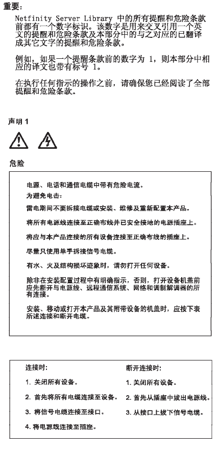
Não coloque nenhum objeto com peso superior a 82 kg (180 lbs.) sobre
dispositivos montados em rack.
198 Hardware Maintenance Manual: IBM NetVista Computer Types 6058, 6059, 6269, 6568, 6569, 6578, 6579, 6648,
6649
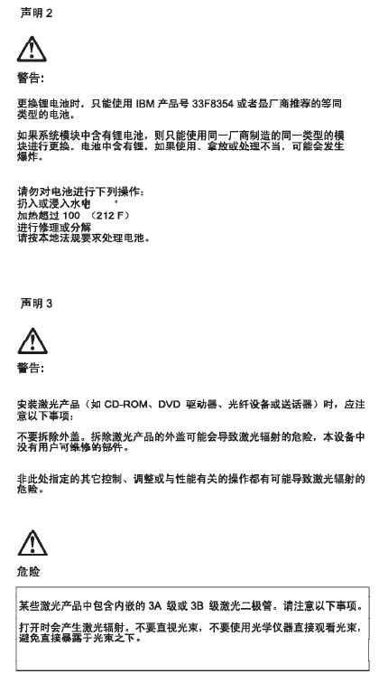
Chapter 4. Related Service Information 199
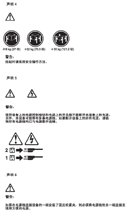
200 Hardware Maintenance Manual: IBM NetVista Computer Types 6058, 6059, 6269, 6568, 6569, 6578, 6579, 6648,
6649
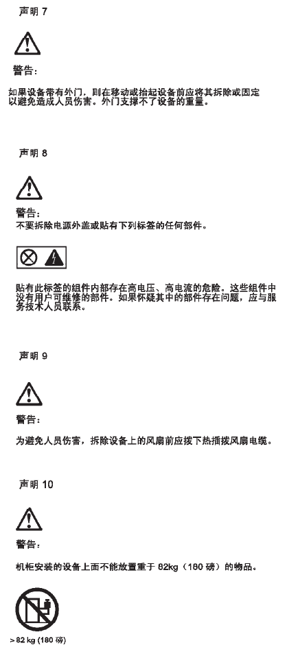
Chapter 4. Related Service Information 201
202 Hardware Maintenance Manual: IBM NetVista Computer Types 6058, 6059, 6269, 6568, 6569, 6578, 6579, 6648,
6649
Chapter 4. Related Service Information 203
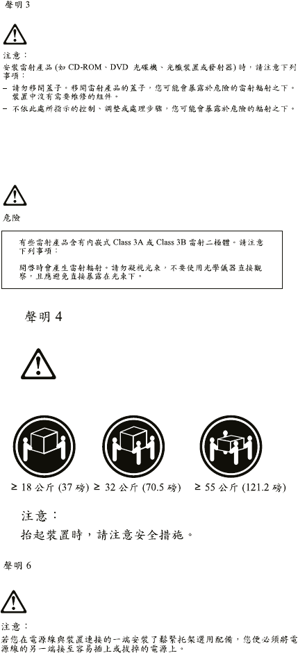
204 Hardware Maintenance Manual: IBM NetVista Computer Types 6058, 6059, 6269, 6568, 6569, 6578, 6579, 6648,
6649
Important:
Toutes les consignes Attention et Danger indiquées dans la bibliothèque
:cit.Netfinity Server:ecit. sont précédées d’un numéro. Ce dernier permet de
mettre en correspondance la consigne en anglais avec ses versions traduites
dans la présente section.
Par exemple, si une consigne de type Attention est précédée du chiffre 1, ses
traductions sont également précédées du chiffre 1 dans la présente section.
Prenez connaissance de toutes les consignes de type Attention et Danger
avant de procéder aux opérations décrites par les instructions.
Notice n1
DANGER
Le courant électrique passant dans les câbles de communication, ou les
cordons téléphoniques et d’alimentation peut être dangereux.
Pour éviter tout risque de choc électrique:
vNe manipulez aucun câble et n’effectuez aucune opération d’installation,
d’entretien ou de reconfiguration de ce produit au cours d’un orage.
vBranchez tous les cordons d’alimentation sur un socle de prise de courant
correctement câbléet mis àla terre.
vBranchez sur des socles de prise de courant correctement câblés tout
équipement connectéàce produit.
vLorsque cela est possible, n’utilisez qu’une seule main pour connecter ou
déconnecter les câbles d’interface.
Chapter 4. Related Service Information 205
vNe mettez jamais un équipement sous tension en cas d’incendie ou
d’inondation, ou en présence de dommages matériels.
vAvant de retirer les carters de l’unité, mettez celle-ci hors tension et
déconnectez ses cordons d’alimentation, ainsi que les câbles qui la relient
aux réseaux, aux systèmes de télécommunication et aux modems (sauf
instruction contraire mentionnée dans les procédures d’installation et de
configuration).
vLorsque vous installez ou que vous déplacez le présent produit ou des
périphériques qui lui sont raccordés, reportez-vous aux instructions
ci-dessous pour connecter et déconnecter les différents cordons.
Connexion Déconnexion
1. Mettez les unités hors tension.
2. Commencez par brancher tous les cordons sur
les unités.
3. Branchez les câbles d’interface sur des
connecteurs.
4. Branchez les cordons d’alimentation sur des
prises.
5. Mettez les unités sous tension.
1. Mettez les unités hors tension.
2. Débranchez les cordons d’alimentation des
prises.
3. Débranchez les câbles d’interface des
connecteurs.
4. Débranchez tous les câbles des unités.
Notice n2
ATTENTION:
Remplacez la pile au lithium usagée par une pile de référence identique
exclusivement - voir la référence IBM - ou par une pile équivalente
recommandée par le fabricant. Si votre système est dotéd’un module
contenant une pile au lithium, vous devez le remplacer uniquement par un
module identique, produit par le même fabricant. La pile contient du
lithium et présente donc un risque d’explosion en cas de mauvaise
manipulation ou utilisation.
vNe la jetez pas àl’eau.
vNe l’exposez pas àune température supérieure à100 °C.
vNe cherchez pas àla réparer ou àla démonter.
Pour la mise au rebut, reportez-vous àla réglementation en vigueur.
206 Hardware Maintenance Manual: IBM NetVista Computer Types 6058, 6059, 6269, 6568, 6569, 6578, 6579, 6648,
6649
Notice n3
ATTENTION:
Si des produits laser sont installés (tels que des unités de CD-ROM ou de
DVD, des périphériques contenant des fibres optiques ou des
émetteurs-récepteurs), prenez connaissance des informations suivantes:
vN’ouvrez pas ces produits pour éviter une exposition directe au rayon
laser. Vous ne pouvez effectuer aucune opération de maintenance à
l’intérieur.
vPour éviter tout risque d’exposition au rayon laser, respectez les
consignes de réglage et d’utilisation des commandes, ainsi que les
procédures décrites dans le présent document.
DANGER
Certains produits laser contiennent une diode laser de classe 3A ou 3B.
Prenez connaissance des informations suivantes:
Rayonnement laser lorsque le carter est ouvert. évitez de regarder fixement
le faisceau ou de l’observer àl’aide d’instruments optiques. évitez une
exposition directe au rayon.
Notice n4
Chapter 4. Related Service Information 207
≥32 kg (70.5 lbs) ≥55 kg (121.2 lbs)
ATTENTION:
Faites-vous aider pour soulever ce produit.
Notice n5
ATTENTION:
Le bouton de mise sous tension/hors tension de l’unitéet l’interrupteur
d’alimentation du bloc d’alimentation ne coupent pas l’arrivée de courant
électrique àl’intérieur de la machine. Il se peut que votre unitédispose de
plusieurs cordons d’alimentation. Pour isoler totalement l’unitédu réseau
électrique, débranchez tous les cordons d’alimentation des socles de prise
de courant.
1
2
Notice n10
ATTENTION:
Wichtig:
208 Hardware Maintenance Manual: IBM NetVista Computer Types 6058, 6059, 6269, 6568, 6569, 6578, 6579, 6648,
6649

Alle Sicherheitshinweise in dieser :cit.Netfinity Server-Bibliothek:ecit. beginnen
mit einer Nummer. Diese Nummer verweist auf einen englischen
Sicherheitshinweis mit den übersetzten Versionen dieses Hinweises in diesem
Abschnitt.
Wenn z. B. ein Sicherheitshinweis mit der Nummer 1 beginnt, so erscheint die
übersetzung für diesen Sicherheitshinweis in diesem Abschnitt unter dem
Hinweis 1.
Lesen Sie alle Sicherheitshinweise, bevor Sie eine Anweisung ausführen.
Hinweis 1
VORSICHT
Elektrische Spannungen von Netz-, Telefon- und Datenübertragungsleitungen
sind gefährlich.
Aus Sicherheitsgründen:
vBei Gewitter an diesem Gerät keine Kabel anschließen oder l÷sen. Ferner
keine Installations-, Wartungs- oder Rekonfigurationsarbeiten durchführen.
vGerät nur an eine Schutzkontaktsteckdose mit ordnungsgemäß geerdetem
Schutzkontakt anschließen.
vAlle angeschlossenen Geräte ebenfalls an Schutzkontaktsteckdosen mit
ordnungsgemäß geerdetem Schutzkontakt anschließen.
vSignalkabel m÷glichst einhändig anschließen oder l÷sen.
vKeine Geräte einschalten, wenn die Gefahr einer Beschädigung durch Feuer,
Wasser oder andere Einflüsse besteht.
vDie Verbindung zu den angeschlossenen Netzkabeln,
Telekommunikationssystemen, Netzwerken und Modems ist vor dem
÷ffnen des Gehäuses zu unterbrechen. Es sei denn, dies ist in den
zugeh÷rigen Installations- und Konfigurationsprozeduren anders
angegeben.
vNur nach den nachfolgend aufgeführten Anweisungen arbeiten, die für
Installation, Transport oder ÷ffnen von Gehäusen von Personal Computern
oder angeschlossenen Einheiten gelten.
Chapter 4. Related Service Information 209

Kabel anschlieβen: Kabel l÷sen:
1. Alle Geräte ausschalten und Netzstecker
ziehen.
2. Zuerst alle Kabel an Einheiten anschließen.
3. Signalkabel an Anschlußbuchsen anschließen.
4. Netzstecker an Steckdose anschließen.
5. Gerät einschalten.
1. Alle Geräte ausschalten.
2. Zuerst Netzstecker von Steckdose l÷sen.
3. Signalkabel von Anschlußbuchsen l÷sen.
4. Alle Kabel von Einheiten l÷sen.
Hinweis 2
ACHTUNG:
Eine verbrauchte Batterie nur durch eine Batterie mit der IBM Teilenummer
33F8354 oder durch eine vom Hersteller empfohlene Batterie ersetzen. Wenn
Ihr System ein Modul mit einer Lithium-Batterie enthält, ersetzen Sie es
immer mit dem selben Modultyp vom selben Hersteller. Die Batterie enthält
Lithium und kann bei unsachgemäßer Verwendung, Handhabung oder
Entsorgung explodieren.
Die Batterie nicht:
vmit Wasser in Berührung bringen.
vüber 100 C erhitzen.
vreparieren oder zerlegen.
Die ÷rtlichen Bestimmungen für die Entsorgung von Sondermüll beachten.
Hinweis 3
ACHTUNG:
Wenn ein Laserprodukt (z. B. CD-ROM-Laufwerke, DVD-Laufwerke,
Einheiten mit Glasfaserkabeln oder Transmitter) installiert ist, beachten Sie
folgendes.
vDas Entfernen der Abdeckungen des CD-ROM-Laufwerks kann zu
gefährlicher Laserstrahlung führen. Es befinden sich keine Teile innerhalb
des CD-ROM-Laufwerks, die vom Benutzer gewartet werden müssen. Die
Verkleidung des CD-ROM-Laufwerks nicht ÷ffnen.
210 Hardware Maintenance Manual: IBM NetVista Computer Types 6058, 6059, 6269, 6568, 6569, 6578, 6579, 6648,
6649
vSteuer- und Einstellelemente sowie Verfahren nur entsprechend den
Anweisungen im vorliegenden Handbuch einsetzen. Andernfalls kann
gefährliche Laserstrahlung auftreten.
VORSICHT
Manche CD-ROM-Laufwerke enthalten eine eingebaute Laserdiode der Klasse
3A oder 3B. Die nachfolgend aufgeführten Punkte beachten.
Laserstrahlung bei ge÷ffneter Tür. Niemals direkt in den Laserstrahl sehen,
nicht direkt mit optischen Instrumenten betrachten und den Strahlungsbereich
meiden.
Hinweis 4
Chapter 4. Related Service Information 211
≥32 kg (70.5 lbs) ≥55 kg (121.2 lbs)
ACHTUNG:
Beim Anheben der Maschine die vorgeschriebenen Sicherheitsbestimmungen
beachten.
Hinweis 5
ACHTUNG:
Mit dem Betriebsspannungsschalter an der Vorderseite des Servers und dem
Betriebsspannungsschalter am Netzteil wird die Stromversorgung für den
Server nicht unterbrochen. Der Server k÷nnte auch mehr als ein Netzkabel
aufweisen. Um die gesamte Stromversorgung des Servers auszuschalten, muß
sichergestellt werden, daßalle Netzkabel aus den Netzsteckdosen
herausgezogen wurden.
1
2
Hinweis 10
212 Hardware Maintenance Manual: IBM NetVista Computer Types 6058, 6059, 6269, 6568, 6569, 6578, 6579, 6648,
6649
ACHTUNG:
Keine Gegenstände, die mehr als 82 kg wiegen, auf Rack-Einheiten ablegen.
Importante:
Tutti gli avvisi di attenzione e di pericolo riportati nella pubblicazione
:cit.Netfinity Server Library:ecit. iniziano con un numero. Questo numero
viene utilizzato per confrontare avvisi di attenzione o di pericolo in inglese
con le versioni tradotte riportate in questa sezione.
Ad esempio, se un avviso di attenzione inizia con il numero 1, la relativa
versione tradotta èpresente in questa sezione con la stessa numerazione.
Prima di eseguire una qualsiasi istruzione, accertarsi di leggere tutti gli avvisi
di attenzione e di pericolo.
Avviso 1
PERICOLO
La corrente elettrica circolante nei cavi di alimentazione, del telefono e di
segnale èpericolosa.
Per evitare il pericolo di scosse elettriche:
vNon collegare o scollegare i cavi, non effettuare l’installazione, la
manutenzione o la riconfigurazione di questo prodotto durante i temporali.
vCollegare tutti i cavi di alimentazione ad una presa elettrica correttamente
cablata e munita di terra di sicurezza.
vCollegare qualsiasi apparecchiatura collegata a questo prodotto ad una
presa elettrica correttamente cablata e munita di terra di sicurezza.
Chapter 4. Related Service Information 213

vQuando possibile, collegare o scollegare i cavi di segnale con una sola
mano.
vNon accendere qualsiasi apparecchiatura in presenza di fuoco, acqua o se
sono presenti danni all’apparecchiatura stessa.
vScollegare i cavi di alimentazione, i sistemi di telecomunicazioni, le reti e i
modem prima di aprire i coperchi delle unità, se non diversamente indicato
nelle procedure di installazione e configurazione.
vCollegare e scollegare i cavi come descritto nella seguente tabella quando si
effettuano l’installazione, la rimozione o l’apertura dei coperchi di questo
prodotto o delle unitàcollegate.
Per collegare: Per scollegare:
1. SPEGNERE tutti i dispositivi.
2. Collegare prima tutti i cavi alle unità.
3. Collegare i cavi di segnale ai connettori.
4. Collegare i cavi di alimentazione alle prese
elettriche.
5. ACCENDERE le unità.
1. SPEGNERE tutti i dispositivi.
2. Rimuovere prima i cavi di alimentazione dalle
prese elettriche.
3. Rimuovere i cavi di segnale dai connettori.
4. Rimuovere tutti i cavi dalle unità.
Avviso 2
214 Hardware Maintenance Manual: IBM NetVista Computer Types 6058, 6059, 6269, 6568, 6569, 6578, 6579, 6648,
6649

ATTENZIONE:
Quando si sostituisce la batteria al litio, utilizzare solo una batteria IBM con
numero parte 33F8354 o batterie dello stesso tipo o :erev refid=a. di tipo
equivalente consigliate dal produttore. Se il sistema di cui si dispone è
provvisto di un modulo contenente una batteria al litio, sostituire tale batteria
solo con un tipo di modulo uguale a quello fornito dal produttore. La batteria
contiene litio e puòesplodere se utilizzata, maneggiata o smaltita
impropriamente.
Evitare di:
vGettarla o immergerla in acqua
vRiscaldarla ad una temperatura superiore ai 100C
vCercare di ripararla o smontarla
Smaltire secondo la normativa in vigore (D.Lgs 22 del 5/2/9) e successive
disposizioni nazionali e locali.
Avviso 3
Chapter 4. Related Service Information 215

ATTENZIONE:
Quando si installano prodotti laser come, ad esempio, le unitàDVD,
CD-ROM, a fibre ottiche o trasmettitori, prestare attenzione a quanto segue:
vNon rimuovere i coperchi. L’apertura dei coperchi di prodotti laser può
determinare l’esposizione a radiazioni laser pericolose. All’interno delle
unitànon vi sono parti su cui effettuare l’assistenza tecnica.
vL’utilizzo di controlli, regolazioni o l’esecuzione di procedure non descritti
nel presente manuale possono provocare l’esposizione a radiazioni
pericolose.
216 Hardware Maintenance Manual: IBM NetVista Computer Types 6058, 6059, 6269, 6568, 6569, 6578, 6579, 6648,
6649

PERICOLO
Alcuni prodotti laser contengono all’interno un diodo laser di Classe 3A o
Classe 3B. Prestare attenzione a quanto segue:
Aprendo l’unitàvengono emesse radiazioni laser. Non fissare il fascio, non
guardarlo direttamente con strumenti ottici ed evitare l’esposizione diretta al
fascio.
Avviso 4
Chapter 4. Related Service Information 217
ATTENZIONE:
Durante il sollevamento della macchina seguire delle norme di sicurezza.
Avviso 5
ATTENZIONE:
Il pulsante del controllo dell’alimentazione situato sull’unitàel’interruttore di
alimentazione posto sull’alimentatore :erev refid=a. non disattiva la corrente
elettrica fornita all’unità.L’unitàpotrebbe disporre di piùdi un cavo di
alimentazione. Per disattivare la corrente elettrica dall’unità, accertarsi che
tutti i cavi di alimentazione siano scollegati dalla sorgente di alimentazione.
1
2
Avviso 10
218 Hardware Maintenance Manual: IBM NetVista Computer Types 6058, 6059, 6269, 6568, 6569, 6578, 6579, 6648,
6649

ATTENZIONE:
Non poggiare oggetti che pesano piùdi 82 kg sulla parte superiore delle unità
montate in rack.
Chapter 4. Related Service Information 219
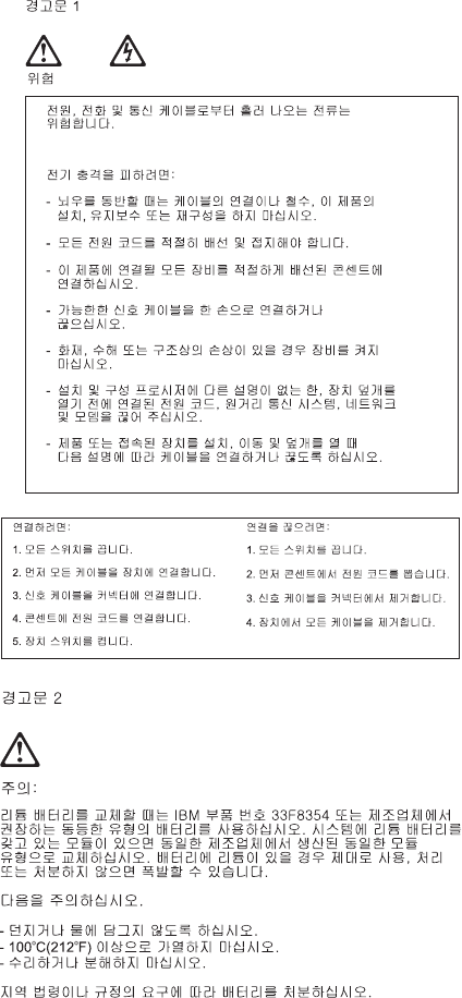
220 Hardware Maintenance Manual: IBM NetVista Computer Types 6058, 6059, 6269, 6568, 6569, 6578, 6579, 6648,
6649
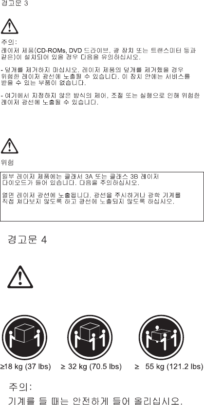
Chapter 4. Related Service Information 221
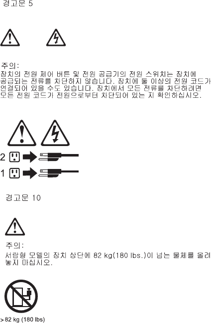
Importante:
Todas las declaraciones de precauciín de esta :cit.Biblioteca del servidor
Netfinity:ecit. empiezan con un número. Dicho número se emplea para
establecer una referencia cruzada de una declaraciín de precauciín o peligro
en inglés con las versiones traducidas que de dichas declaraciones pueden
encontrarse en esta secciín.
Por ejemplo, si una declaraciín de peligro empieza con el número 1, las
traducciones de esta declaraciín de precauciín aparecen en esta secciín bajo
Declaraciín1.
Lea atentamente todas las declaraciones de precauciín y peligro antes de
llevar a cabo cualquier operaciín.
Declaración1
222 Hardware Maintenance Manual: IBM NetVista Computer Types 6058, 6059, 6269, 6568, 6569, 6578, 6579, 6648,
6649
PELIGRO:
La corriente eléctrica de los cables telefínicos, de alimentaciínyde
comunicaciones es perjudicial.
Para evitar una descarga eléctrica:
vNo conecte ni desconecte ningún cable ni realice las operaciones de
instalaciín, mantenimiento o reconfiguraciín de este producto durante una
tormenta.
vConecte cada cable de alimentaciín a una toma de alimentaciíneléctrica con
conexiín a tierra y cableado correctos.
vConecte a tomas de alimentaciín con un cableado correcto cualquier equipo
que vaya a estar conectado a este producto.
vSi es posible, utilice una sola mano cuando conecte o desconecte los cables
de sent.al.
vNo encienda nunca un equipo cuando haya riesgos de incendio, de
inundaciínodedaños estructurales.
vDesconecte los cables de alimentaciín, sistemas de telecomunicaciones, redes
ymídems conectados antes de abrir las cubiertas del dispositivo a menos
que se indique lo contrario en los procedimientos de instalaciíny
configuraciín.
vConecte y desconecte los cables tal como se describe en la tabla siguiente
cuando desee realizar una operaciín de instalaciín, de traslado o de
apertura de las cubiertas para este producto o para los dispositivos
conectados.
Para la conexin Para la desconexiín
1. APÁGUELO todo.
2. En primer lugar, conecte los cables a los
dispositivos.
3. Conecte los cables de señal a los conectores.
4. Conecte cada cable de alimentaciínalatoma
de alimentaciín.
5. ENCIENDA el dispositivo.
1. APÁGUELO todo.
2. En primer lugar, retire cada cable de
alimentaciín de la toma de alimentaciín.
3. Retire los cables de señal de los conectores.
4. Retire los cables de los dispositivos.
Chapter 4. Related Service Information 223

Declaración2
PRECAUCIÓN:
Cuando desee sustituir la batería de litio, utilice únicamente el número de
pieza 33F8354 de IBM o cualquier tipo de batería equivalente que recomiende
el fabricante. Si el sistema tiene un mídulo que contiene una batería de litio,
sustitúyalo únicamente por el mismo tipo de mídulo, que ha de estar creado
por el mismo fabricante. La batería contiene litio y puede explotar si el
usuario no la utiliza ni la maneja de forma adecuada o si no se desprende de
la misma como corresponde.
No realice las acciones siguientes:
vArrojarla al agua o sumergirla
vCalentarla a una temperatura que supere los 100C (212F)
vRepararla o desmontarla
Despréndase de la batería siguiendo los requisitos que exija el reglamento o la
legislaciín local.
Declaración3
PRECAUCIÓN:
Cuando instale productos láser (como, por ejemplo, CD-ROM, unidades DVD,
dispositivos de fibra íptica o transmisores), tenga en cuenta las advertencias
siguientes:
vNo retire las cubiertas. Si retira las cubiertas del producto láser, puede
quedar expuesto a radiaciínláser perjudicial. Dentro del dispositivo no
existe ninguna pieza que requiera mantenimiento.
vEl uso de controles o ajustes o la realizaciín de procedimientos que no sean
los que se han especificado aquípueden dar como resultado una exposiciín
perjudicial a las radiaciones.
PELIGRO:
224 Hardware Maintenance Manual: IBM NetVista Computer Types 6058, 6059, 6269, 6568, 6569, 6578, 6579, 6648,
6649
Algunos productos láser contienen un diodo de láser incorporado de Clase 3A
o de Clase 3B. Tenga en cuenta la advertencia siguiente.
Cuando se abre, hay radiaciínláser. No mire fijamente el rayo ni lleve a cabo
ningún examen directamente con instrumentos ípticos; evite la exposiciín
directa al rayo.
Declaración4
≥32 kg (70.5 lbs) ≥55 kg (121.2 lbs)
PRECAUCIÓN:
Tome medidas de seguridad al levantar el producto.
Declaración5
PRECAUCIÓN:
El botín de control de alimentaciín del dispositivo y el interruptor de
alimentaciín de la fuente de alimentaciín no apagan :erev refid=a. la corriente
eléctrica suministrada al dispositivo. Es posible también que el dispositivo
tenga más de un cable de alimentaciín. Para eliminar la corriente eléctrica del
dispositivo, asegúrese de desconectar todos los cables de alimentaciíndela
Chapter 4. Related Service Information 225
fuente de alimentaciín.
1
2
Declaración10
PRECAUCIÓN:
No coloque ningún objeto que pese más de 82 kg (180 libras) encima de los
dispositivos montados en bastidor.
226 Hardware Maintenance Manual: IBM NetVista Computer Types 6058, 6059, 6269, 6568, 6569, 6578, 6579, 6648,
6649

Send us your comments!
We want to know your opinion about this manual (part number 06P1504).
Your input will help us to improve our publications.
Please photocopy this survey, complete it, and then fax it to IBM HMM
Survey at 919-543-8167 (USA).
Name: _________________________________________
Phone number: __________________________________
1. Do you like this manual?
hYes hNo
_________________________________________
_________________________________________
2. What would you like to see added, changed, or deleted in this manual?
_________________________________________
_________________________________________
3. What is your service experience level?
hLess than five years
hMore than five years
4. Which Servers do you service most?
_________________________________________
_________________________________________
_________________________________________
_________________________________________
Thank you for your response!
Problem determination tips
Due to the variety of hardware and software combinations that can be
encountered, use the following information to assist you in problem
determination. If possible, have this information available when requesting
assistance from Service Support and Engineering functions.
vMachine type and model
vProcessor or hard disk upgrades
Chapter 4. Related Service Information 227

vFailure symptom
–Do diagnostics fail?
–What, when, where, single, or multiple systems?
–Is the failure repeatable?
–Has this configuration ever worked?
–If it has been working, what changes were made prior to it failing?
–Is this the original reported failure?
vReference/Diagnostics version
–Type and version level
vHardware configuration
–Print (print screen) configuration currently in use
–BIOS level
vOperating system software
–Type and version level
Note: To eliminate confusion, identical systems are considered identical only
if they:
1. Are the exact machine type and models
2. Have the same BIOS level
3. Have the same adapters/attachments in the same locations
4. Have the same address jumpers/terminators/cabling
5. Have the same software versions and levels
6. Have the same Reference/Diagnostics Diskette (version)
7. Have the same configuration options set in the system
8. Have the same setup for the operation system control files
Comparing the configuration and software set-up between ″working
and non-working″systems will often lead to problem resolution.
Notices
References in this publication to IBM products, programs, or services do not
imply that IBM intends to make these available in all countries in which IBM
operates. Any reference to an IBM product, program, or service is not
intended to state or imply that only that IBM product, program, or service
may be used. Subject to IBM’s valid intellectual property or other legally
protectable rights, any functionally equivalent product, program, or service
may be used instead of the IBM product, program, or service. The evaluation
and verification of operation in conjunction with other products, except those
expressly designated by IBM, are the responsibility of the user.
228 Hardware Maintenance Manual: IBM NetVista Computer Types 6058, 6059, 6269, 6568, 6569, 6578, 6579, 6648,
6649

Trademarks
The following items are trademarks of the IBM Corporation in the United
States or other countries or both:
HelpCenter HelpFax
IBM OS/2
NetBAY3 Netfinity
Netfinity Manager ThinkPad
SystemXtra
The following terms are trademarks of other companies:
Notes Lotus Development Corporation
MMX and Pentium are trademarks or registered trademarks of Intel
Corporation.
UNIX is a trademark or registered trademark of The Open Group in the
United States and other countries.
Windows NT is a trademark or registered trademark of Microsoft
Corporation.
Miscellaneous Information
Acronyms, Abbreviations, and Terms
Term Information
ACPA/A Audio Capture and Playback Adapter
ADP Automatic Data Processing
AGP Advanced Graphics Port
Alt Alternate
ANSI American National Standards Institute
ARTIC A Real Time Interface Coprocessor
ASCII American National Standard Code for Interface Interchange
AT Advanced Technology (refer to AT Bus)
AVC Audio Video Connection
BIOS Basic Input/Output System
bps Bits Per Second
BPS Bytes Per Second
CCITT The International Telephone and Telegraph Consultative Committee
CCS Common Command Set
CCSB Common Complete Status Block
CCSB Configuration Control Sub Board
Chapter 4. Related Service Information 229
Term Information
CD Compact Disc
CDPD Cellular Digital Packet Data
CD-ROM CD Read-Only Memory
CGA Color Graphics Adapter (See EGA)
CRC Cyclic Redundancy Check
CRT Cathode Ray Tube
CSA Canadian Standards Association
CSD Corrective Service Diskette
DASD Direct Access Storage Device (hard disk)
DMA Direct Memory Access
DRAM Dynamic Random Access Memory
ECA Engineering Change Announcement
ECC Error Correction Code
EGA Enhanced Graphics Adapter
ESD Electrostatic Discharge
ESDI Enhanced Small Device Interface
EEPROM Electrically Erasable Programmable Read-Only Memory
EWS Energy Work Station
FRU Field Replaceable Unit (replaceable part)
GPIB General Purpose Interface Bus (IEEE 348)
GSA General Services Administration
Ht Height
IDE Integrated Drive Electronics
IC Integrated Circuit
IEEE Institute of Electrical and Electronics Engineers
IEC International Electrotechnical Commission
IML Initial Machine Load
IPL Initial Program Load
ISA Industry Standard Architecture
ISO International Organization for Standardization
ISDN Integrated-Services Digital Network
LAN Local Area Network
LBA Local Block Address
LTB Local Transfer Bus
LUN Logical Unit Number (refer to SCSI)
MAP Maintenance Analysis Procedure
MCGA Modified Color Graphics Adapter
MCA Micro Channel Architecture (bus structure)
MHz Mega Hertz (million cycles per second)
MIDI Musical Instrument Digital Interface
MM Multimedia
N/A Not Available or Not Applicable
NDD National Distribution Division
NDIS Network Driver Interface Specification
230 Hardware Maintenance Manual: IBM NetVista Computer Types 6058, 6059, 6269, 6568, 6569, 6578, 6579, 6648,
6649
Term Information
NMI Non-Maskable Interrupt
NSC National Support Center
NVRAM Non-Volatile Random Access Memory
OEM Original Equipment Manufacturer
PCI Peripheral Component Interconnect
PCMCIA Personal Computer Memory Card International Association
POS Programmable Option Select
PUN Physical Unit Number (refer to SCSI)
RAID Redundant Array of Independent Disks
RAM Random Access Memory (read/write)
RGB Red Green Blue (refer to monitors)
RIPL Remote Initial Program Load
ROM Read-Only Memory
SASD Sequential Access Storage Device (Tape)
SCB Subsystem Control Block
SCSI Small Computer Systems Interface
SCSI ID SCSI Identification Number
SPD Software Product Description
SR Service Representative
SRAM Static Random Access Memory
SVGA Super Video Graphics Array (800x600x16)
STN Super Twisted Nematic
T/A NDD Technical Advisor (see your Marketing Representative)
TDD Telecommunications Device for the Deaf
TFT Thin-Film Transistor
TPF ThinkPad File
TSR Terminate and Stay Resident
UL Underwriters Laboratory
VCA Video Capture Adapter
VESA Video Electronics Standards Association
VGA Video Graphics Array (640x480x16)
VPD Vital Product Data
VRAM Video Random Access Memory
WORM Write Once Read Many (storage medium)
XGA Extended Graphics Array
Y/C Luminance/Chrominance Signal (Video)
Chapter 4. Related Service Information 231
232 Hardware Maintenance Manual: IBM NetVista Computer Types 6058, 6059, 6269, 6568, 6569, 6578, 6579, 6648,
6649

Part Number: 06P1504
(1P) P/N: 06P1504
