Ibm Ds5020 Users Manual System Storage Subsystem
DS5020 to the manual d2f008f0-6ff4-41bd-95de-54d9c3c2903e
2015-02-02
: Ibm Ibm-Ds5020-Users-Manual-431712 ibm-ds5020-users-manual-431712 ibm pdf
Open the PDF directly: View PDF ![]() .
.
Page Count: 250 [warning: Documents this large are best viewed by clicking the View PDF Link!]
- Contents
- Figures
- Tables
- Safety
- About this document
- Chapter 1. Introduction
- Overview
- Inventory checklist
- Product updates and support notifications
- Best practices guidelines
- Storage subsystem components
- Software and hardware compatibility and upgrades
- Specifications
- Chapter 2. Installing the storage subsystem
- Chapter 3. Cabling the storage subsystem
- Enclosure ID settings
- Fibre Channel loop and ID settings
- Working with SFPs and fiber-optic cables
- Connecting storage expansion enclosures to the DS5020
- Redundant drive channel pair
- Overview of steps to connect storage expansion enclosures to a storage subsystem
- DS5020 storage subsystem drive cabling topologies
- One DS5020 and one storage expansion enclosure
- One DS5020 and two storage expansion enclosures
- One DS5020 and three storage expansion enclosures
- One DS5020 and four storage expansion enclosures
- One DS5020 and up to six storage expansion enclosures
- One DS5020 and two or more storage expansion enclosures in a mixed configuration
- DS5020 storage subsystem and supported storage expansion enclosure drive cabling schemes
- Storage expansion enclosure settings
- Connecting secondary interface cables
- Configuring the storage subsystem
- Installing the storage subsystem configuration
- Cabling the ac power supply
- Chapter 4. Operating the storage subsystem
- Chapter 5. Replacing components
- Chapter 6. Hardware maintenance
- Appendix A. Records
- Appendix B. Rack mounting templates
- Appendix C. Specifications for non-IBM rack installation
- Appendix D. Power cords
- Appendix E. Additional DS5020 documentation
- DS Storage Manager Version 10 library
- DS5020 storage subsystem library
- DS4800 storage subsystem library
- DS4700 storage subsystem library
- DS4500 storage subsystem library
- DS4400 storage subsystem library
- DS4300 storage subsystem library
- DS4200 Express storage subsystem library
- DS4100 Storage subsystem library
- DS5000 and DS4000 storage expansion enclosure documents
- Other DS5000 and DS4000-related documents
- Appendix F. Accessibility
- Notices
- Trademarks
- Important notes
- Particulate contamination
- Documentation format
- Electronic emission notices
- Federal Communications Commission (FCC) statement
- Industry Canada Class A emission compliance statement
- Avis de conformité à la réglementation d′Industrie Canada
- Australia and New Zealand Class A statement
- United Kingdom telecommunications safety requirement
- European Union EMC Directive conformance statement
- Taiwanese Class A warning statement
- Germany Electromagnetic Compatibility Directive
- People's Republic of China Class A warning statement
- Japanese Voluntary Control Council for Interference (VCCI) statement
- Korean Class A warning statement
- Glossary
- Index
IBM System Storage DS5020 Storage Subsystem
Installation, User’s, and Maintenance Guide
IBM System Storage DS5020 Storage Subsystem
Installation, User’s, and Maintenance Guide

Note:
Before using this information and the product it supports, be sure to read the general information in “Safety” on page xiii and
“Notices” on page 197.
First Edition (July 2009)
© Copyright International Business Machines Corporation 2009.
US Government Users Restricted Rights – Use, duplication or disclosure restricted by GSA ADP Schedule Contract
with IBM Corp.

Contents
Figures ............................ix
Tables ............................xi
Safety ............................xiii
About this document ......................xix
Who should read this document ..................xix
How this document is organized ..................xix
DS5020 and DS4000-family storage subsystem installation tasks - General
overview ..........................xx
Getting information, help, and service ................xxiv
Before you call .......................xxiv
Using the documentation....................xxiv
Finding DS5020 and DS4000-family readme files...........xxiv
Web sites .........................xxv
Software service and support ..................xxvi
Hardware service and support ..................xxvi
Fire suppression systems ...................xxvii
Chapter 1. Introduction ......................1
Overview ...........................1
Base DS5020 features .....................2
Operating system support ....................3
Fibre Channel defined......................3
SATA defined .........................3
iSCSI defined .........................3
Inventory checklist ........................3
Product updates and support notifications ...............5
Best practices guidelines......................5
Storage subsystem components ...................6
Enhanced Disk Drive Modules (E-DDMs)...............7
Controllers ..........................8
Connectors, switch, and enclosure ID ...............9
Setting up IP addresses for DS5020 storage controllers ........11
AC power supply and fan units ..................13
Battery units .........................14
SFP modules ........................16
Software and hardware compatibility and upgrades ...........17
Software and firmware support code upgrades ............18
Determining firmware levels ...................18
Specifications .........................19
Area requirements ......................19
Dimensions ........................19
Weight ..........................19
Shipping dimensions .....................20
Environmental requirements and specifications ............20
Temperature and humidity ...................20
Altitude..........................21
Airflow and heat dissipation ..................21
Shock and vibration requirements ................22
Acoustic noise .......................22
Electrical requirements .....................23
© Copyright IBM Corp. 2009 iii
Power and site wiring requirements ...............23
Heat output, airflow, and cooling .................24
Chapter 2. Installing the storage subsystem .............27
Installation overview .......................27
Handling static-sensitive devices ..................29
Preparing for installation .....................29
Tools and hardware required ...................31
Preparing the site .......................31
Preparing the rack cabinet....................32
Installing the support rails .....................32
Installing the DS5020 ......................36
Removing the CRUs ......................36
Removing a controller ....................37
Removing an ac power supply and fan unit ............38
Removing an E-DDM ....................39
Installing the DS5020 into a rack on the support rails ..........40
Replacing the components ...................42
Replacing a controller ....................42
Replacing an ac power supply and fan unit ............43
Replacing an E-DDM ....................44
Chapter 3. Cabling the storage subsystem..............45
Enclosure ID settings ......................45
Fibre Channel loop and ID settings .................46
Working with SFPs and fiber-optic cables ...............46
Handling fiber-optic cables ...................47
Installing SFP modules .....................48
Removing SFP modules ....................50
Using LC-LC Fibre Channel cables ................51
Connecting an LC-LC cable to an SFP module ...........52
Removing an LC-LC Fibre Channel cable .............54
Connecting storage expansion enclosures to the DS5020 .........54
Redundant drive channel pair ..................55
Overview of steps to connect storage expansion enclosures to a storage
subsystem.........................56
DS5020 storage subsystem drive cabling topologies ..........57
One DS5020 and one storage expansion enclosure .........59
One DS5020 and two storage expansion enclosures .........60
One DS5020 and three storage expansion enclosures ........62
One DS5020 and four storage expansion enclosures .........63
One DS5020 and up to six storage expansion enclosures .......64
One DS5020 and two or more storage expansion enclosures in a mixed
configuration .......................66
DS5020 storage subsystem and supported storage expansion enclosure drive
cabling schemes ......................67
DS5020 storage subsystem drive cabling rules ...........67
One DS5020 and one EXP520 storage expansion enclosure ......70
One DS5020 and two EXP520 storage expansion enclosures......71
One DS5020 and three or more EXP520 storage expansion enclosures 72
Storage expansion enclosure settings ...............78
Fibre Channel loop and ID settings ...............78
Storage expansion enclosure ID settings .............78
Connecting secondary interface cables ................78
Configuring the storage subsystem .................79
Storage subsystem management methods..............80
iv IBM System Storage DS5020 Storage Subsystem: Installation, User’s, and Maintenance Guide
Host-agent (in-band) management method.............80
Direct (out-of-band) management method .............81
Connecting hosts to the DS5020 using Fibre Channel host ports .....82
Fibre Channel and iSCSI connections ...............84
Fibre Channel host loop configurations ...............85
Redundant Fibre Channel host loops ...............85
iSCSI configurations ......................87
DS5020 host iSCSI configurations ................88
Installing the storage subsystem configuration .............91
Cabling the ac power supply ....................91
Chapter 4. Operating the storage subsystem .............93
Performing the DS5020 Health Check process .............93
Web pages .........................94
Hardware responsibilities ....................94
Powering on the storage subsystem .................95
Turning on the storage subsystem .................95
Installing the DS Storage Manager client ...............97
Monitoring status through software .................98
Finding controller, storage expansion enclosure, and drive information . . . 99
Firmware updates .......................99
Troubleshooting the storage subsystem ..............100
Checking the LEDs .......................101
AC power supply and fan unit LEDs ...............101
Front LEDs .........................102
Battery unit LEDs ......................103
Controller LEDs .......................104
Seven-segment numeric display LEDs ...............107
Powering off the storage subsystem.................109
Turning off the storage subsystem ................109
Performing an emergency shutdown ...............112
Restoring power after an unexpected shutdown ...........112
Recovering from an overheated power supply and fan unit ........114
Cache memory and cache battery .................116
Cache memory .......................116
Subsystem cache battery....................117
Chapter 5. Replacing components ................121
Handling static-sensitive devices ..................121
Service Action Allowed Status LED .................121
Replacing a controller ......................122
Working with hot-swap E-DDMs ..................126
Installing hot-swap E-DDMs...................128
Replacing hot-swap E-DDMs ..................130
Replacing multiple E-DDMs ...................131
Replacing all E-DDMs at the same time .............132
Replacing the E-DDMs one at a time ..............134
Verifying the link rate setting ...................136
Replacing an ac power supply and fan unit ..............139
Replacing a battery unit .....................144
Replacing an SFP module ....................146
Replacing a midplane ......................149
Chapter 6. Hardware maintenance ................153
General checkout .......................153
Solving problems .......................153
Contents v
Parts listing..........................160
Appendix A. Records .....................163
Identification numbers ......................163
Storage subsystem and controller information record ..........164
Sample information record ...................165
Installed device records .....................166
Appendix B. Rack mounting templates...............167
Appendix C. Specifications for non-IBM rack installation .......171
General safety requirements for IBM products installed in a non-IBM rack or
cabinet ..........................171
Rack specifications .......................173
Appendix D. Power cords ....................179
Appendix E. Additional DS5020 documentation ...........183
DS Storage Manager Version 10 library ...............183
DS5020 storage subsystem library .................184
DS4800 storage subsystem library .................185
DS4700 storage subsystem library .................186
DS4500 storage subsystem library .................187
DS4400 storage subsystem library .................188
DS4300 storage subsystem library .................189
DS4200 Express storage subsystem library ..............190
DS4100 Storage subsystem library .................191
DS5000 and DS4000 storage expansion enclosure documents.......192
Other DS5000 and DS4000-related documents ............193
Appendix F. Accessibility ....................195
Notices ...........................197
Trademarks..........................197
Important notes ........................198
Particulate contamination.....................199
Documentation format ......................199
Electronic emission notices ....................200
Federal Communications Commission (FCC) statement ........200
Industry Canada Class A emission compliance statement ........200
Avis de conformité à la réglementation d’Industrie Canada .......200
Australia and New Zealand Class A statement ............200
United Kingdom telecommunications safety requirement ........200
European Union EMC Directive conformance statement ........201
Taiwanese Class A warning statement ...............201
Germany Electromagnetic Compatibility Directive ...........201
Deutschland: Einhaltung des Gesetzes über die elektromagnetische
Verträglichkeit von Geräten .................202
Zulassungsbescheinigung laut dem Deutschen Gesetz über die
elektromagnetische Verträglichkeit von Geräten (EMVG) (bzw. der EMC
EG Richtlinie 2004/108/EG) für Geräte der Klasse A ........202
People's Republic of China Class A warning statement.........202
Japanese Voluntary Control Council for Interference (VCCI) statement 202
Korean Class A warning statement ................202
Glossary ..........................203
vi IBM System Storage DS5020 Storage Subsystem: Installation, User’s, and Maintenance Guide
viii IBM System Storage DS5020 Storage Subsystem: Installation, User’s, and Maintenance Guide

Figures
1. DS5020 hot-swap drive bays ...........................7
2. Back view; controllers with two standard Fibre Channel host expansion channels .......10
3. Back view; controllers with two standard and two optional Fibre Channel host expansion channels 10
4. Back view; controllers with two standard Fibre Channel host expansion channels and two optional
iSCSI host expansion channels .........................10
5. Power supply and fan unit components for the DS5020 ................13
6. Power supply and fan unit and airflow .......................14
7. Backup battery unit ..............................15
8. SFP module and fiber-optic cable.........................17
9. DS5020 dimensions..............................19
10. DS5020 airflow ...............................22
11. Example of cold aisle/hot aisle rack configuration ...................25
12. Example of DS5020 serial number, machine type, and model number location ........28
13. Front rack mounting template ..........................33
14. Rear rack mounting template ..........................34
15. Installing the support rails ...........................35
16. Removing and replacing a controller........................38
17. Removing a power supply and fan unit.......................39
18. Removing an E-DDM CRU ...........................39
19. Installing the DS5020 .............................41
20. Securing the DS5020 to the rack cabinet ......................41
21. Removing and replacing a controller........................42
22. Replacing a power supply and fan unit .......................43
23. Replacing an E-DDM .............................44
24. Storage subsystem seven-segment enclosure IDs ..................46
25. Bending and looping specifications for fiber-optic cables ................48
26. SFP module and protective cap .........................50
27. Installing an SFP module into the host port .....................50
28. Unlocking the SFP module latch - plastic variety ...................51
29. Unlocking the SFP module latch - wire variety ....................51
30. LC-LC Fibre Channel cable ...........................52
31. Removing fiber-optic cable protective caps .....................53
32. Inserting an LC-LC Fibre Channel cable into an SFP module ..............53
33. LC-LC Fibre Channel cable lever and latches ....................54
34. Removing the LC-LC Fibre Channel cable .....................54
35. Example of a redundant drive channel pair .....................56
36. DS5020 storage subsystem ports and controllers ...................58
37. Cabling for one DS5020 and one storage expansion enclosure ..............59
38. Cabling for one DS5020 and two storage expansion enclosures .............60
39. Incorrect cabling of one DS5020 and two storage expansion enclosures ..........61
40. Cabling for one DS5020 and three storage expansion enclosures .............62
41. Cabling for one DS5020 and four storage expansion enclosures .............63
42. Cabling for one DS5020 and up to six storage expansion enclosures ...........64
43. Cabling for one DS5020 and up to six storage expansion enclosures ...........66
44. Cabling for one DS5020 and two or more storage expansion enclosures in a mixed environment 67
45. DS5020 drive ports connected to EXP810 ESM ports labeled 1B .............69
46. Cabling for one DS5020 and one EXP520 storage expansion enclosure ..........70
47. One DS5020 and two EXP520 storage expansion enclosures behind a pair of DS5020 drive ports 71
48. One DS5020 and three EXP520 storage expansion enclosures behind a pair of DS5020 drive
ports ...................................72
49. One DS5020 and four EXP520 storage expansion enclosures behind a pair of DS5020 drive ports 74
50. One DS5020 and a maximum of six EXP520 storage expansion enclosures behind a pair of
DS5020 drive ports ..............................76
© Copyright IBM Corp. 2009 ix
51. Ethernet and serial port locations on DS5020 ....................79
52. Host-agent (in-band) managed storage subsystems ..................80
53. Direct (out-of-band) managed storage subsystems ..................82
54. Location of host cables on RAID controllers on the DS5020 ...............83
55. Cabling diagram for two redundant host connections..................84
56. Examples of redundant host direct attached Fibre Channel SAN configurations ........85
57. Example of a single SAN fabric configuration ....................86
58. Example of a dual SAN fabric configuration .....................86
59. Example of two storage subsystems in a dual SAN environment .............87
60. Example of a two-cluster configuration .......................87
61. Example of a single-host, multiple-port configuration ..................88
62. Example of a multiple-host, multiple-port configuration .................89
63. Example of iSCSI and Fibre Channel hosts, multiple-port configuration ...........89
64. Example of an incorrect configuration: Single-host, iSCSI and Fibre Channel.........90
65. Example of a multiple-host, multiple-port, multiple-switch configuration ...........91
66. Power supply and fan unit LEDs.........................102
67. Front LEDs and controls ...........................103
68. Battery unit LEDs ..............................104
69. LEDs, controls, and connectors of controllers with two standard Fibre Channel host expansion
channels .................................105
70. LEDs, controls, and connectors of controllers with two standard and two optional Fibre Channel
host expansion channels ...........................105
71. LEDs, controls, and connectors of controllers with two standard Fibre Channel host expansion
channels and two optional iSCSI host expansion channels ...............106
72. Numeric display LEDs ............................108
73. Cache Active LEDs .............................117
74. Battery unit LEDs ..............................119
75. Unlocking the SFP module latch - plastic variety ...................124
76. Unlocking the SFP module latch - wire variety ...................124
77. Removing a controller from the DS5020 ......................125
78. Installing a controller .............................125
79. Hot-swap E-DDM LEDs ............................129
80. E-DDM CRU handle .............................129
81. Link rate LEDs ...............................137
82. Link rate switch ...............................138
83. Replacing a power supply and fan unit ......................143
84. Removing and replacing a battery unit from the controller chassis ............145
85. Replacing an SFP module ...........................148
86. Front cage frame screw locations ........................150
87. Screws holding the top and bottom sides of the chassis to the cage frame .........151
88. DS5020 storage subsystem parts list .......................160
89. Front rack mounting template..........................168
90. Rear rack mounting template ..........................169
91. Top View of non-IBM Rack Specifications Dimensions.................174
92. Rack specifications dimensions, top front view ...................175
93. Rack specifications dimensions, bottom front view ..................175
xIBM System Storage DS5020 Storage Subsystem: Installation, User’s, and Maintenance Guide

Tables
1. Where to find DS5020 and DS4000-family installation and configuration procedures ......xx
2. DS5020 weights ...............................20
3. DS5020 component weights...........................20
4. DS5020 shipping carton dimensions........................20
5. Temperature and humidity requirements for storage subsystem when in storage or in transit 21
6. Temperature and humidity requirements for storage subsystem in a typical Information Technology
(IT) or office environment............................21
7. DS5020 altitude ranges ............................21
8. DS5020 power and heat dissipation ........................22
9. Random vibration power spectral density ......................22
10. DS5020 sound levels .............................22
11. DS5020 ac power requirements .........................23
12. Power supply and fan unit LEDs.........................102
13. Front LEDs and controls ...........................103
14. Battery unit LEDs ..............................104
15. Rear controller LEDs, controls, and connectors ...................106
16. Host and drive channel LED definitions ......................107
17. Numeric display diagnostic codes ........................108
18. Drive LED activity ..............................128
19. Data transfer rates for drive modules .......................137
20. Symptom-to-FRU index ............................154
21. Parts listing (DS5020 storage subsystem) .....................161
22. Storage subsystem and controller information record .................164
23. Sample information record ...........................165
24. Hard disk drive record ............................166
25. IBM power cords ..............................179
26. DS Storage Manager Version 10 titles by user tasks .................183
27. DS5020 storage subsystem document titles by user tasks ...............184
28. DS4800 storage subsystem document titles by user tasks ...............185
29. DS4700 storage subsystem document titles by user tasks ...............186
30. DS4500 storage subsystem document titles by user tasks ...............187
31. DS4400 storage subsystem document titles by user tasks ...............188
32. DS4300 storage subsystem document titles by user tasks ...............189
33. DS4200 Express storage subsystem document titles by user tasks ............190
34. DS4100 storage subsystem document titles by user tasks ...............191
35. DS5000 and DS4000 storage expansion enclosure document titles by user tasks ......192
36. DS5000 and DS4000-related document titles by user tasks...............193
37. DS Storage Manager alternate keyboard operations .................195
38. Limits for particulates and gases ........................199
© Copyright IBM Corp. 2009 xi
xii IBM System Storage DS5020 Storage Subsystem: Installation, User’s, and Maintenance Guide

Safety
The caution and danger statements that this document contains can be referenced
in the multilingual IBM®Safety Information document that is provided with your IBM
System Storage™DS5020 Storage Subsystem. Each caution and danger statement
is numbered for easy reference to the corresponding statements in the translated
document.
vDanger: These statements indicate situations that can be potentially lethal or
extremely hazardous to you. A danger statement is placed just before the
description of a potentially lethal or extremely hazardous procedure, step, or
situation.
vCaution: These statements indicate situations that can be potentially hazardous
to you. A caution statement is placed just before the description of a potentially
hazardous procedure step or situation.
vAttention: These notices indicate possible damage to programs, devices, or
data. An attention notice is placed just before the instruction or situation in which
damage could occur.
Before installing this product, read the following danger and caution notices.
© Copyright IBM Corp. 2009 xiii

Statement 1:
DANGER
Electrical current from power, telephone, and communication cables is
hazardous.
To avoid a shock hazard:
vDo not connect or disconnect any cables or perform installation,
maintenance, or reconfiguration of this product during an electrical
storm.
vConnect all power cords to a properly wired and grounded electrical
outlet.
vConnect to properly wired outlets any equipment that will be attached to
this product.
vWhen possible, use one hand only to connect or disconnect signal
cables.
vNever turn on any equipment when there is evidence of fire, water, or
structural damage.
vDisconnect the attached power cords, telecommunications systems,
networks, and modems before you open the device covers, unless
instructed otherwise in the installation and configuration procedures.
vConnect and disconnect cables as described in the following table when
installing, moving, or opening covers on this product or attached
devices.
To Connect: To Disconnect:
1. Turn everything OFF.
2. First, attach all cables to devices.
3. Attach signal cables to connectors.
4. Attach power cords to outlet.
5. Turn device ON.
1. Turn everything OFF.
2. First, remove power cords from outlet.
3. Remove signal cables from connectors.
4. Remove all cables from devices.
xiv IBM System Storage DS5020 Storage Subsystem: Installation, User’s, and Maintenance Guide
Statement 2:
CAUTION:
When replacing the lithium battery, use only an equivalent type battery
recommended by the manufacturer. If your system has a module containing a
lithium battery, replace it only with the same module type made by the same
manufacturer. The battery contains lithium and can explode if not properly
used, handled, or disposed of.
Do not:
vThrow or immerse into water
vHeat to more than 100° C (212° F)
vRepair or disassemble
Dispose of the battery as required by local ordinances or regulations.
Statement 3:
CAUTION:
When laser products (such as CD-ROMs, DVD drives, fiber-optic devices, or
transmitters) are installed, note the following:
vDo not remove the covers. Removing the covers of the laser product could
result in exposure to hazardous laser radiation. There are no serviceable
parts inside the device.
vUse of controls or adjustments or performance of procedures other than
those specified herein might result in hazardous radiation exposure.
DANGER
Some laser products contain an embedded Class 3A or Class 3B laser
diode. Note the following.
Laser radiation when open. Do not stare into the beam, do not view directly
with optical instruments, and avoid direct exposure to the beam.
a
Class 1 Laser statement
Safety xv
Class 1 Laser Product
Laser Klasse 1
Laser Klass 1
Luokan 1 Laserlaite
Apparell Laser de Calsse 1À
IEC 825-11993 CENELEC EN 60 825
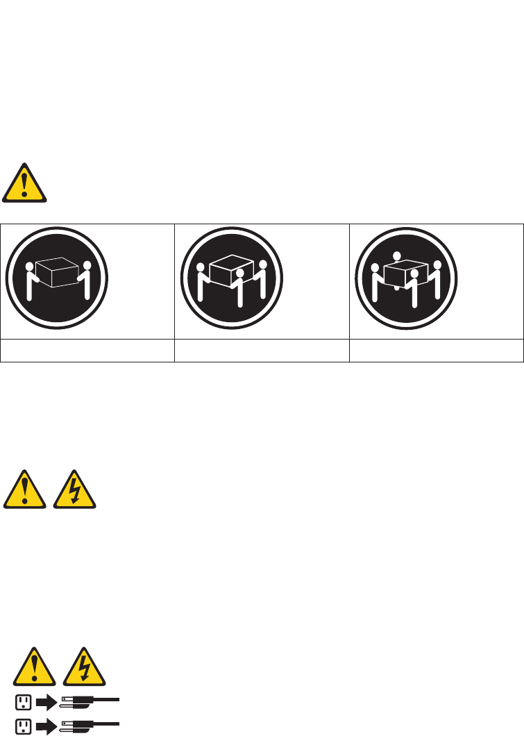
Statement 4:
≥18 kg (39.7 lb) ≥32 kg (70.5 lb) ≥55 kg (121.2 lb)
CAUTION:
Use safe practices when lifting.
Statement 5:
CAUTION:
The power control button on the device and the power switch on the power
supply do not turn off the electrical current supplied to the device. The device
also might have more than one power cord. To remove all electrical current
from the device, ensure that all power cords are disconnected from the power
source.
1
2
xvi IBM System Storage DS5020 Storage Subsystem: Installation, User’s, and Maintenance Guide
Statement 8:
CAUTION:
Never remove the cover on a power supply or any part that has the following
label attached.
Hazardous voltage, current, and energy levels are present inside any
component that has this label attached. There are no serviceable parts inside
these components. If you suspect a problem with one of these parts, contact
a service technician.
Statement 30:
CAUTION:
To reduce the risk of electric shock or energy hazards:
vThis equipment must be installed by trained service personnel in a
restricted-access location, as defined by the NEC and IEC 60950-1, First
Edition, The Standard for Safety of Information Technology Equipment.
vConnect the equipment to a reliably grounded safety extra low voltage
(SELV) source. An SELV source is a secondary circuit that is designed so
that normal and single fault conditions do not cause the voltages to exceed
a safe level (60 V direct current).
vThe branch circuit overcurrent protection must be rated 20 A.
vUse 12 American Wire Gauge (AWG) or 2.5 mm2 copper conductor only, not
exceeding 4.5 meters in length.
vIncorporate a readily available approved and rated disconnect device in the
field wiring.
CAUTION:
This unit has more than one power source. To remove all power from the unit,
all dc MAINS must be disconnected.
Safety xvii
Cable Warning:
WARNING: Handling the cord on this product or cords associated with accessories
sold with this product, will expose you to lead, a chemical known to the State of
California to cause cancer, and birth defects or other reproductive harm. Wash
hands after handling.
xviii IBM System Storage DS5020 Storage Subsystem: Installation, User’s, and Maintenance Guide

About this document
This document provides instructions for installing and customizing the configuration
of your IBM System Storage DS5020 storage subsystem. It also provides
maintenance procedures and troubleshooting information.
Who should read this document
This document is intended for system operators and service technicians who have
extensive knowledge of Fibre Channel and network technology.
How this document is organized
Chapter 1, “Introduction,” on page 1 describes the IBM System Storage DS5020
storage subsystem. This chapter includes an inventory checklist and an overview of
the storage subsystem features, operating specifications, and components.
Chapter 2, “Installing the storage subsystem,” on page 27 contains information
about how to install the DS5020 storage subsystem in a standard rack cabinet and
setting the interface options.
Chapter 3, “Cabling the storage subsystem,” on page 45 contains Fibre Channel
and power cabling information for the DS5020 storage subsystem.
Chapter 4, “Operating the storage subsystem,” on page 93 contains information
about how to turn the power to the DS5020 storage subsystem on and off, recover
from an overheated power supply and fan unit, troubleshoot, and interpret LEDs.
Chapter 5, “Replacing components,” on page 121 contains step-by-step instructions
about how to install or remove customer replaceable units (CRUs), such as
Enhanced Disk Drive Modules (E-DDMs), power supply and fan units, RAID
controllers, battery units, midplane, and Small Form-factor Pluggable transceiver
(SFP) modules.
Chapter 6, “Hardware maintenance,” on page 153 describes problems and
symptoms that are specific to the DS5020 storage subsystem. It also provides a
parts list for the DS5020 storage subsystem.
Appendix A, “Records,” on page 163 provides a table that you can use to record
and update important information about your DS5020 storage subsystem, including
serial number and device records.
Appendix B, “Rack mounting templates,” on page 167 provides the rack mounting
templates for installation of the DS5020 storage subsystem. If you want to tear out
the templates from the document for use during installation, use these copies of the
templates.
Appendix D, “Power cords,” on page 179 lists power cord information for the
DS5020 storage subsystem.
Appendix E, “Additional DS5020 documentation,” on page 183 lists additional
DS5020 documents.
Appendix F, “Accessibility,” on page 195 details accessibility information.
© Copyright IBM Corp. 2009 xix

DS5020 and DS4000-family storage subsystem installation tasks -
General overview
For educational information about the DS5020 and other IBM System Storage
products, go to http://ibmdsseriestraining.com/.
Table 1 provides a sequential list of many installation and configuration tasks that
are common to most DS5020 and DS4000-family configurations. When you install
and configure your storage subsystem, refer to this table to find the documentation
that explains how to complete each task.
Table 1. Where to find DS5020 and DS4000-family installation and configuration procedures
Installation task Where to find information or procedures
1Plan the installation vDS Storage Manager Version 10 Installation and Host
Support Guide
vDS4100 Storage Subsystem Installation, User’s, and
Maintenance Guide
vDS4200 Express Storage Subsystem Installation, User’s, and
Maintenance Guide
vDS4300 Storage Subsystem Installation, User's, and
Maintenance Guide
vDS4400 Fibre Channel Storage Server Installation and
Support Guide
vDS4500 Storage Subsystem Installation, User's, and
Maintenance Guide
vDS4700 Express Storage Subsystem Installation, User’s, and
Maintenance Guide
vIBM System Storage Quick Start Guide, Quick reference for
the DS4800
vDS4800 Storage Subsystem Installation, User’s, and
Maintenance Guide
vIBM System Storage Quick Start Guide, Quick reference for
the DS4700 and DS4200, Sections 2, 3, and 4 also for
installing the EXP810 and EXP420
vIBM System Storage DS5000 Quick Start Guide
vDS5000 Installation, User’s, and Maintenance Guide
vIBM System Storage DS5020 Quick Start Guide
vDS5020 Installation, User’s, and Maintenance Guide
xx IBM System Storage DS5020 Storage Subsystem: Installation, User’s, and Maintenance Guide

Table 1. Where to find DS5020 and DS4000-family installation and configuration
procedures (continued)
Installation task Where to find information or procedures
2Mount the DS5020
storage subsystem in
the rack
vDS4800 Storage Subsystem Installation, User’s, and
Maintenance Guide
vIBM System Storage Quick Start Guide, Quick reference for
the DS4800
vDS4700 Express Storage Subsystem Installation, User’s, and
Maintenance Guide
vIBM System Storage Quick Start Guide, Quick reference for
the DS4700 and DS4200, Sections 2, 3, and 4 also for
installing the EXP810 and EXP420
vDS4400 and DS4500 Rack Mounting Instructions
vDS4300 Rack Mounting Instructions
vDS4200 Express Storage Subsystem Installation, User’s, and
Maintenance Guide
vDS4100 Storage Subsystem Installation, User’s and
Maintenance Guide
vIBM System Storage DS5000 Installation, User’s, and
Maintenance Guide
vIBM System Storage DS5020 Installation, User’s, and
Maintenance Guide
3Mount the storage
expansion unit in the
rack
vDS4000 EXP100 Storage Expansion Unit Installation, User’s
and Maintenance Guide
vDS4000 EXP420 Storage Expansion Enclosures Installation,
User’s, and Maintenance Guide
vDS4000 EXP700 and EXP710 Storage Expansion Enclosures
Installation, User’s, and Maintenance Guide
vDS4000 EXP810 Storage Expansion Enclosures Installation,
User’s, and Maintenance Guide
vFAStT EXP500 Installation and User’s Guide
vIBM System Storage Quick Start Guide, Quick reference for
the DS4700 and DS4200, Sections 2, 3, and 4 also for
installing the EXP810 and EXP420
vDS5000 Installation, User’s, and Maintenance Guide
vDS5020 Installation, User’s, and Maintenance Guide
About this document xxi

Table 1. Where to find DS5020 and DS4000-family installation and configuration
procedures (continued)
Installation task Where to find information or procedures
4Route the storage
expansion unit Fibre
Channel cables
vDS4100 Storage Subsystem Installation, User’s, and
Maintenance Guide
vDS4200 Express Storage Subsystem Installation, User’s, and
Maintenance Guide
vDS4300 Storage Subsystem Installation, User’s, and
Maintenance Guide
vDS4400 Fibre Channel Cabling Instructions
vDS4500 Storage Subsystem Installation, User’s, and
Maintenance Guide
vDS4700 Express Storage Subsystem Installation, User’s, and
Maintenance Guide
vIBM System Storage Quick Start Guide, Quick reference for
the DS4700 and DS4200, Sections 2, 3, and 4 also for
installing the EXP810 and EXP420
vDS4800 Storage Subsystem Installation, User’s, and
Maintenance Guide
vIBM System Storage Quick Start Guide, Quick reference for
the DS4800
vDS5000 Installation, User’s, and Maintenance Guide
vDS5020 Installation, User’s, and Maintenance Guide
5Route the host
server Fibre Channel
cables
6Power up the
subsystem
7Configure DS5020
network settings
vDS Storage Manager Version 10 Installation and Host
Support Guide
vDS4100 Storage Subsystem Installation, User’s, and
Maintenance Guide
vDS4200 Express Storage Subsystem Installation, User’s, and
Maintenance Guide
vDS4300 Storage Subsystem Installation, User’s, and
Maintenance Guide
vDS4400 Fibre Channel Storage Server Installation and
Support Guide
vDS4500 Storage Subsystem Installation, User’s, and
Maintenance Guide
vDS4700 Express Storage Subsystem Installation, User’s, and
Maintenance Guide
vIBM System Storage Quick Start Guide, Quick reference for
the DS4700 and DS4200, Sections 2, 3, and 4 also for
installing the EXP810 and EXP420
vDS4800 Storage Subsystem Installation, User’s, and
Maintenance Guide
vIBM System Storage Quick Start Guide, Quick reference for
the DS4800
DS5000 Installation, User’s, and Maintenance Guide
DS5020 Installation, User’s, and Maintenance Guide
xxii IBM System Storage DS5020 Storage Subsystem: Installation, User’s, and Maintenance Guide

Table 1. Where to find DS5020 and DS4000-family installation and configuration
procedures (continued)
Installation task Where to find information or procedures
8Zone the fabric
switch (SAN-attached
only)
vDS Storage Manager Version 10 Installation and Host
Support Guide
vDS4000 Storage Manager Copy Services Guide (describes
switch zoning for the Remote Mirror Option)
vSee also the documentation provided by the switch
manufacturer.
9Install DS Storage
Manager software on
the management
station
vDS Storage Manager Version 10 Installation and Host
Support Guide
vDS Storage Manager online help (for post-installation tasks)
10 Install host software
(failover drivers) on
host server
11 Start DS Storage
Manager
12 Set the DS Storage
Manager clock
13 Set the DS Storage
Manager host default
type
14 Verify DS5020
subsystem health
vDS4100 Storage Subsystem Installation, User’s, and
Maintenance Guide
vDS4200 Express Storage Subsystem Installation, User’s, and
Maintenance Guide
vDS4300 Storage Subsystem Installation, User’s, and
Maintenance Guide
vDS4400 Fibre Channel Storage Server Installation and
Support Guide
vDS4500 Storage Subsystem Installation, User’s, and
Maintenance Guide
vDS4700 Express Storage Subsystem Installation, User’s, and
Maintenance Guide
vDS4800 Storage Subsystem Installation, User’s, and
Maintenance Guide
vIBM System Storage DS5020 Installation, User’s, and
Maintenance Guide
15 Enable DS Storage
Manager premium
feature keys
Copy Services premium features
DS4000 Storage Manager Copy Services Guide
FC/SATA Intermix premium feature
vDS4000 Fibre Channel and Serial ATA Intermix
Premium Feature Installation Overview
vFDE Best Practices Guide
Storage Partitioning (and general premium features
information)
DS Storage Manager Version 10 Installation and Host
Support Guide
About this document xxiii

Table 1. Where to find DS5020 and DS4000-family installation and configuration
procedures (continued)
Installation task Where to find information or procedures
16 Configure arrays and
logical drives
vDS Storage Manager Version 10 Installation and Host
Support Guide
vDS Storage Manager online help
17 Configure host
partitions
18 Verify host access to
DS5020 storage
19 Add storage capacity
or configure
migration of drives
IBM System Storage Migration Guide
Getting information, help, and service
If you need help, service, or technical assistance or just want more information
about IBM products, you will find a wide variety of sources available from IBM to
assist you. This section contains information about where to go for additional
information about IBM and IBM products, what to do if you experience a problem
with your system, and whom to call for service, if it is necessary.
Before you call
Before you call, take these steps to try to solve the problem yourself:
vCheck all cables to make sure that they are connected.
vCheck the power switches to make sure that the system is turned on.
vUse the troubleshooting information in your system documentation, and use the
diagnostic tools that come with your system.
vCheck for technical information, hints, tips, and new device drivers at the IBM
support Web site pages that are listed in this section.
vUse an IBM discussion forum on the IBM Web site to ask questions.
You can solve many problems without outside assistance by following the
troubleshooting procedures that IBM provides in the DS Storage Manager online
help or in the documents that are provided with your system and software. The
information that comes with your system also describes the diagnostic tests that
you can perform. Most subsystems, operating systems, and programs come with
information that contains troubleshooting procedures and explanations of error
messages and error codes. If you suspect a software problem, see the information
for the operating system or program.
Using the documentation
Information about your IBM system and preinstalled software, if any, is available in
the documents that come with your system. This includes printed books, online
documents, readme files, and help files. See the troubleshooting information in your
system documentation for instructions for using the diagnostic programs. The
troubleshooting information or the diagnostic programs might tell you that you need
additional or updated device drivers or other software.
Finding DS5020 and DS4000-family readme files
1. Go to the following Web site:
www.ibm.com/systems/support/storage/disk/
xxiv IBM System Storage DS5020 Storage Subsystem: Installation, User’s, and Maintenance Guide
2. Click the link for your storage subsystem (for example, DS5020).
3. When the subsystem support page opens, click the Download tab.
4. Under the Download tab, click Storage Manager, firmware, HBA, tools,
support & pubs (including readmes).
5. Click the applicable tab for the type of readme file that you are looking for:
vFirmware
vStorage Mgr
vHBA
vTools
A table displays as you click each tab.
6. In the table, click on the applicable link in the Current version and readmes
column.
7. Click the link for the readme file.
Web sites
The most current information about DS5020 storage subsystems and DS Storage
Manager, including documentation and the most recent software, firmware, and
NVSRAM downloads, can be found at the following Web sites.
DS4000 and DS5000 Midrange Disk Systems
Find the latest information about IBM System Storage disk storage systems,
including all of the DS4000 and DS5000 storage subsystems:
http://www.ibm.com/systems/support/storage/disk
IBM System Storage products
Find information about all IBM System Storage products:
http://www.ibm.com/systems/storage
Support for IBM System Storage disk storage systems
Find links to support pages for all IBM System Storage disk storage
systems, including DS4000 and DS5000 storage subsystems and
expansion units:
http://www.ibm.com/systems/support/storage/disk/
System Storage DS4000 and DS5000 interoperability matrix
Find the latest information about operating system and HBA support,
clustering support, storage area network (SAN) fabric support, and DS
Storage Manager feature support:
http://www.ibm.com/servers/storage/disk/ds4000/interop-matrix.html
Storage Area Network (SAN) support
Find information about using SAN switches, including links to user guides
and other documents:
http://www.ibm.com/systems/support/storage/san
DS4000 and DS5000 technical support
Find downloads, hints and tips, documentation, parts information, HBA and
Fibre Channel support:
http://www.ibm.com/systems/support/storage/disk/
Select your storage subsystem (for example, DS5020).
About this document xxv
Premium feature activation
Activate a DS5020 or DS4000 premium feature by using the online tool:
http://www-912.ibm.com/PremiumFeatures/jsp/keyInput.jsp
IBM publications center
Find IBM publications:
http://www.ibm.com/shop/publications/order/
Support for System p®servers
Find the latest information supporting System p AIX®and Linux®servers:
http://www.ibm.com/systems/support/supportsite.wss/
brandmain?brandind=5000025
Support for System x®servers
Find the latest information supporting System x Intel®- and AMD-based
servers:
http://www.ibm.com/systems/support/supportsite.wss/
brandmain?brandind=5000008
Fix delivery center for AIX and Linux on POWER®
Find the latest AIX and Linux on POWER information and downloads:
http://www-912.ibm.com/eserver/support/fixes/fcgui.jsp
In the Product family drop-down menu, select UNIX®servers. Then select
your product and fix type from the subsequent drop-down menus.
System p and AIX information center
Find everything you need to know about using AIX with System p and
POWER servers:
http://publib.boulder.ibm.com/infocenter/pseries/index.jsp?
Software service and support
Through the IBM Support Line, for a fee you can get telephone assistance with
usage, configuration, and software problems. For information about which products
are supported by Support Line in your country or region, go to the following Web
site:
http://www.ibm.com/services/sl/products
For more information about the IBM Support Line and other IBM services, go to the
following Web sites:
vhttp://www.ibm.com/services/
vhttp://www.ibm.com/planetwide/
Hardware service and support
You can receive hardware service through IBM Integrated Technology Services or
through your IBM reseller, if your reseller is authorized by IBM to provide warranty
service. Go to the following Web site for support telephone numbers:
http://www.ibm.com/planetwide/
In the U.S. and Canada, hardware service and support is available 24 hours a day,
7 days a week. In the U.K., these services are available Monday through Friday,
from 9 a.m. to 6 p.m.
xxvi IBM System Storage DS5020 Storage Subsystem: Installation, User’s, and Maintenance Guide
Fire suppression systems
A fire suppression system is the responsibility of the customer. The customer’s own
insurance underwriter, local fire marshal, or a local building inspector, or both,
should be consulted in selecting a fire suppression system that provides the correct
level of coverage and protection. IBM designs and manufactures equipment to
internal and external standards that require certain environments for reliable
operation. Because IBM does not test any equipment for compatibility with fire
suppression systems, IBM does not make compatibility claims of any kind nor does
IBM provide recommendations on fire suppression systems.
About this document xxvii
xxviii IBM System Storage DS5020 Storage Subsystem: Installation, User’s, and Maintenance Guide

Chapter 1. Introduction
This chapter describes the operating specifications, features, and components for
the IBM System Storage DS5020 Storage Subsystem (hereafter referred to as
DS5020 or storage subsystem).
This chapter also includes an inventory checklist and important information about
best practices guidelines and product updates for your DS5020.
Overview
The IBM System Storage DS5020 storage subsystem (Machine Type 1814-20A) is
designed to provide solutions to meet the needs of midrange/departmental storage
requirements, delivering high performance, advanced function, high availability,
modular and scalable storage capacity, with SAN-attached 8 Gbps Fibre Channel
(FC) and 1 Gbps iSCSI connectivity, and support for RAID levels 0, 1, 3, 5, and 6
up to over 49 terabytes (TB) when using 450 GB Fibre Channel hard drives and up
to 112 TB when using 1 TB Serial Advanced Technology Attachment (SATA)
Enhanced Disk Drive Modules (E-DDMs).
A 3U rack-mountable enclosure houses the DS5020 redundant, dual-active RAID
controllers with either four Fibre Channel ports, four Fibre Channel ports, or two
Fibre Channel and two iSCSI ports per controller. The DS5020 can be configured
for the attachment of host servers and EXP520 and EXP810 storage expansion
enclosures and up to 16 4 Gbps Fibre Channel or SATA E-DDMs. The base
DS5020 storage subsystem controllers each have four Fibre Channel ports.
The DS5020 supports the attachment of up to six EXP520 and EXP810 storage
expansion enclosures, resulting in the capability to connect up to 112 E-DDMs and
enabling storage configurations of over 49 TB using 450 GB Fibre Channel E-DDMs
or 112 TB using 1 TB SATA E-DDMs.
The base DS5020 storage subsystem supports up to 32 drives, which includes 16
drives in the DS5020 chassis and 16 more drives in an attached storage expansion
enclosure. To attach more than 32 drives, you much purchase the applicable
feature option.
To attach additional drives to the DS5020, you can use EXP520 or EXP810 storage
expansion enclosures. You can connect EXP520 storage expansion enclosures to
the DS5020 without purchasing feature options. To attach an EXP810 storage
expansion enclosure or enclosures to the DS5020, you must purchase the Attach
EXP810 to DS5020 Activation feature option. Contact your IBM marketing
representative or IBM reseller for more information.
To connect 33 - 64 drives in one DS5020 and three EXP520 storage expansion
enclosures, you must purchase the DS5020 Drive Attach 33 - 64 feature option. If
you need to connect 65 - 112 drives in a DS5020 configuration, you must purchase
the DS5020 Drive Attach 65- 112 feature option in addition to the DS5020 Drive
Attach 33 - 64 feature option. These two feature options enable you to attach the
additional drives in one DS5020 and six EXP520 storage expansion enclosures.
Contact your IBM marketing representative or IBM reseller for more information.
The DS5020 supports configurations of FC disks with or without Full Disk
Encryption (FDE), or SATA disks, or a mix of disk drives. To install FDE disks in a
DS5020, you must purchase the Full Disk Encryption option. Advanced DS5020
© Copyright IBM Corp. 2009 1
storage management, copy service options, and optional advanced disaster
recovery functions are available for the DS5020, including FlashCopy®,
VolumeCopy, and Enhanced Remote Mirroring.
The DS5020 supports up to four hosts in a redundant direct-attached Fibre Channel
configuration. When using Fibre Channel or Ethernet switches, you can redundantly
connect up to 512 hosts to the DS5020 FC and iSCSI host ports. You can order up
to 128 storage partitions for the DS5020.
The DS5020 storage subsystem has ac power and fan units.
The DS Storage Manager client is also available for the DS5020. This storage
management software is designed to help centralize storage management, help
simplify partitioning of the DS5020 storage subsystem, and strategically allocate
storage capacity to maximize storage space.
Base DS5020 features
The base DS5020 storage subsystem is a 3U rack-mount enclosure with the
following features.
Note: Depending on the configuration options that were purchased with your
DS5020, your hardware features might differ slightly from those in this list.
vDual RAID controllers, one of the configurations in the following list:
– Controllers with 1 GB memory, two standard 8 Gbps FC host ports, and two
standard 4 Gbps FC drive channel ports
– Controllers with 1 GB memory, two standard 8 Gbps FC host ports, one
optional 2-port 8 Gbps FC host card, and two standard 4 Gbps FC drive
channel ports
– Controllers with 1 GB memory, two standard 8 Gbps FC host ports, one
optional 2-port 1 GB iSCSI host card, and two standard 4 Gbps FC drive
channel ports
– Controllers with 2 GB memory, two standard 8 Gbps FC host ports, and two
standard 4 Gbps FC drive channel ports
– Controllers with 2 GB memory, two standard 8 Gbps FC host ports, one
optional 2-port 8 Gbps FC host card, and two standard 4 Gbps FC drive
channel ports
– Controllers with 2 GB memory, two standard 8 Gbps FC host ports, one
optional 2-port 1 GB iSCSI host card, and two standard 4 Gbps FC drive
channel ports
vFour or eight 8 Gbps FC Small Form-factor Pluggable transceivers (SFPs)
Note: These SFPs will be included only if the DS5020 controllers purchased
have the four additional Fibre Channel host ports
vFour 4 Gbps FC Small Form-factor Pluggable transceivers (SFPs)
vDual AC power and fan units
vTwo PDU power cords
vRack-mounting kit
vVersion 7.60 firmware (preinstalled on the controller)
vIBM Documentation CD
vAccess to educational information about the DS5020 at http://
ibmdsseriestraining.com/.
2IBM System Storage DS5020 Storage Subsystem: Installation, User’s, and Maintenance Guide

Contact your IBM sales representative or reseller for more information about the
various DS5020 and options.
Operating system support
For supported operating systems, see the latest DS Storage Manager host software
readme file and the IBM DS4000 and DS5000 series products interoperability matrix
at the following Web site for additional host operating system support:
http://www-1.ibm.com/servers/storage/disk/ds4000/interop-matrix.html
See “Finding DS5020 and DS4000-family readme files” on page xxiv to learn how
to access the DS5020 readme files on the Web.
Fibre Channel defined
Fibre Channel technology is outlined in the SCSI-3 Fibre Channel Protocol
(SCSI-FCP) standard. Fibre Channel is a high-speed data transport technology that
is used for mass storage and networking.
Using a Fibre Channel arbitrated loop (FC-AL), more than 100 Fibre Channel
devices can be supported, compared to 15 small computer system interface (SCSI)
devices. The Fibre Channel connection speed from the storage subsystem to
storage expansion enclosures is 4 Gbps, and enables data transfer rates up to 400
Mbps half-duplex and 800 Mbps full-duplex on optical interfaces.
SATA defined
The Serial Advanced Technology Attachment (SATA) interface offers increased data
rate performance over Parallel Advanced Technology Attachment (ATA), while
maintaining the benefits of ATA. SATA is designed to overcome the performance
barriers that have been forecasted for current parallel technologies while
maintaining the cost-efficiency of Parallel ATA. SATA specifications allow for thinner,
more flexible cables, and lower pin counts. It also enables easier, more flexible
cable routing management and the use of smaller connectors than is possible with
the existing Parallel ATA technology.
The Serial ATA Working Group introduced the first SATA specification, Serial ATA
1.0, in 2001 (http://www.serialata.org).
iSCSI defined
The Internet Small Computer System Interface (iSCSI) is an IP-based standard for
linking data storage devices over a network and transferring data by carrying SCSI
commands over IP networks.
Inventory checklist
After you unpack the DS5020, verify that you have the following items.
Note: Depending on your DS5020 order, your shipping box might contain additional
materials not listed in the following checklist. Review the inventory checklist
included in the DS5020 shipping box for any additional parts, and use that
checklist in combination with the following information.
vHardware
– E-DDMs or blank trays (16) (Your storage subsystem might come with up to
16 E-DDMs.)
Chapter 1. Introduction 3
– RAID controllers (2)
– AC power supply and fan units (2)
– Fiber-optic cables (2)
– Battery units (2)
– Power cables (2 rack jumper line cords)
– Diagnostic wrap plug/coupler (1)
– Serial cable adapter (1)
– Rack-mounting hardware kit (1), including:
- Rails (2) (right and left assembly)
- M5 black hex-head slotted screws (12)
- M4 screws (4)
- Washers (8)
– 8 Gbps SFPs (4 or 8)
Note: The number of 8 Gbps SFPs depends on the storage subsystem
configuration. The SFPs are preinstalled in the DS5020 ports.
– 4 Gbps SFPs (4)
Note: The SFPs are for the drive channel ports only, and are preinstalled in
the DS5020 drive channel ports.
Attention: The DS5020 does not ship with region-specific ac power cords. You
must obtain the IBM-approved power cords for your region. See Appendix D,
“Power cords,” on page 179 for the IBM-approved power cords for your region.
vSoftware and documentation
– Host software attachment kit
Depending on the DS5020 configuration that you order, your DS5020 includes
your choice of host software kits (Windows®, AIX, Linux, Netware, SUN
Solaris, HP-UX, Linux on POWER, or VMware). The host software kit grants
you permission to attach host servers using the applicable operating system
to the DS5020. The kit includes a DS Storage Manager Support DVD that has
the applicable IBM DS Storage Manager host software. The DVD also
includes firmware, online help, and publications in Adobe Acrobat Portable
Document Format (PDF). (For a list of available IBM DS4000 and DS5000
publications, see Appendix E, “Additional DS5020 documentation,” on page
183.)
If you order more than one host software kit, the additional kits might also be
shipped in the DS5020 shipping box.
Note: Depending on your DS5020 configuration, you might need to purchase
the applicable host software kit for your host server operating system.
Contact your IBM representative or reseller for more information.
– Activation kit, including a storage partition kit with the number of partitions you
ordered
–IBM System Storage DS5020 Storage Subsystem Installation, User’s, and
Maintenance Guide
–IBM System Storage Quick Start Guide for the DS5020
–IBM Safety Information
– IBM License Agreement
– Statement of Limited Warranty
4IBM System Storage DS5020 Storage Subsystem: Installation, User’s, and Maintenance Guide

– Box ID labels (used to label the enclosure IDs on the front of the DS5020)
Note: If you ordered additional premium features or entitlements, the premium
features activation or entitlement kits might also be shipped inside the
box.
If an item is missing or damaged, contact your IBM reseller or your IBM marketing
representative.
A rack mounting template and instructions for installing the support rails and the
storage subsystem are provided in “Installing the support rails” on page 32.
To connect your DS5020 to other devices, use the following options:
vIBM SFP module (preinstalled)
vIBM LC-LC Fibre Channel cable
Note: You must order these options separately.
Product updates and support notifications
Be sure to download the latest versions of the DS Storage Manager host software,
DS5020 storage subsystem controller firmware, storage expansion enclosure ESM
firmware, and drive firmware at the time of the initial installation and when product
updates become available.
Important: Keep your system up to date with the latest firmware and other product
updates by subscribing to receive support notifications.
For more information about support notifications or the My Support feature,
including instructions on how to register, see the following IBM Support Web page:
http://www.ibm.com/systems/support/storage/subscribe/moreinfo.html
You can also check the Stay Informed section of the IBM Disk Support Web site:
http://www.ibm.com/servers/storage/support/disk/index.html
Best practices guidelines
To achieve optimal system operation, always follow these best practices guidelines:
vMake sure that your system is in an optimal state before you shut it down. Never
turn the power off if any Needs Attention LED is lit; be sure to resolve any error
conditions before you shut down the system.
vBack up the data on your storage drives periodically.
vTo maintain power redundancy, plug the DS5020 right and left power supply and
fan units into two independent external power circuits through ac power
distribution units inside a rack cabinet or directly into external receptacles.
Similarly, make sure that the right and left power supplies of the storage
expansion enclosures attached to the DS5020 are plugged into the same two
independent external power circuits as the DS5020. This ensures that the
DS5020 and all its attached storage expansion enclosures will have power in the
event that only one power circuit is available. In addition, having all the right or
all the left power cables plug into the same power circuit enables the devices in
the configuration to power on simultaneously during an unattended restoration of
power.
Chapter 1. Introduction 5

Note: Do not overload the circuits that power your storage subsystem and
storage expansion enclosures. Use additional pairs of ac power
distribution units (PDUs) if necessary. Refer to for information about
storage subsystem power requirements. Contact your IBM service
representative for additional information if needed.
vBefore any planned system shutdown or after any system additions, removals, or
modifications (including firmware updates, logical drive creations, storage
partitioning definitions, hardware changes, and so on), complete the following
tasks:
1. Save the storage subsystem profile
2. Save the storage subsystem configuration
Make sure that you save the files in a location other than in the logical drives that
were created for the storage subsystem.
For more information about how to complete these tasks, check the DS Storage
Manager online help or the Storage Manager guide for your operating system.
vDuring any maintenance or attended power-up procedure, carefully follow the
power-up sequence listed in “Powering on the storage subsystem” on page 95.
Check that each component of the subsystem is powered-on in the proper order
during this entire power-up procedure so the controller will be able to optimally
access all of your storage subsystems.
vThe storage subsystem supports simultaneous power-up to the system
components, but always follow the power-up sequence listed in “Powering on the
storage subsystem” on page 95 during any attended power-up procedure.
vA storage system in an optimal state recovers automatically from an unexpected
shutdown and unattended simultaneous restoration of power to system
components. After power is restored, call IBM support if any of the following
conditions occur:
– The storage subsystem logical drives and subsystems are not displayed in the
DS Storage Manager graphical user interface (GUI).
– The storage subsystem logical drives and subsystems do not come online.
– The storage subsystem logical drives and subsystems seem to be degraded.
Storage subsystem components
The storage subsystem has the following removable components. These
components, called customer replaceable units (CRUs), are accessible from the
front or back of the storage subsystem.
vUp to sixteen 4 Gbps Fibre Channel or SATA Enhanced Disk Drive Modules
(E-DDMs)
vTwo RAID controllers
vTwo ac power supply and fan units
vTwo battery units
vSFP modules
The hot-swap features enable you to remove and replace 4 Gbps Fibre Channel or
SATA E-DDMs, power supply and fan units, and controllers without turning off the
storage subsystem. You can maintain the availability of your system while a
hot-swap device is removed, installed, or replaced.
6IBM System Storage DS5020 Storage Subsystem: Installation, User’s, and Maintenance Guide
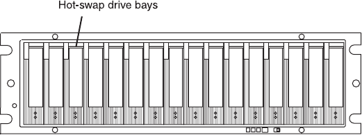
Enhanced Disk Drive Modules (E-DDMs)
The hot-swap drive bays that are accessible from the front of your storage
subsystem are shown in Figure 1.
The DS5020 supports both Fibre Channel (FC) and SATA E-DDMs intermixed in the
storage subsystem drive chassis. The DS5020 supports up to sixteen 4 Gbps FC or
3 Gbps SATA E-DDMs.
SATA E-DDMs have an ATA translator card that converts the Fibre Channel protocol
interface of the DS5020 drive channel or loop into the hard drive SATA protocol
interface. It also provides dual paths to the SATA drive for drive CRU path
redundancy. Each drive, ATA translator card (also referred to as interposer card),
and carrier assembly are called SATA E-DDM CRUs. The Fibre Channel E-DDMs
consist of the Fibre Channel and the carrier assembly (drive tray).
Install E-DDM CRUs in the 16 drive bays on the front of the storage subsystem
from the leftmost slot (slot 1) to the rightmost slot (slot 16). When an E-DDM is
installed, the drive and tray slot designation is set automatically. The hardware
addresses are based on the enclosure ID, which is set by the controller software,
and on the E-DDM physical location in the storage subsystem.
The DS5020 storage subsystem drive channel operates at a 4 Gbps Fibre Channel
interface speed. Make sure that the DS5020 enclosure speed switch is set correctly
for 4 Gbps Fibre Channel E-DDM CRUs. The DS5020 storage subsystem SATA
E-DDM CRUs have an ATA translator card that converts E-DDM 3 Gbps SATA drive
interface protocol to a 4 Gbps Fibre Channel interface protocol. Operate these
SATA E-DDMs at 4 Gbps Fibre Channel operating speed.
Note: Even though the DS5020 hasa2or4Gbps Fibre Channel Link Rate switch
that can be used to set the drive channel speed at 2 Gbps, the link rate
speed must be set to 4 Gbps. The DS5020 supports only 4 Gbps FC speed
in the drive channel. See “Verifying the link rate setting” on page 136for
more information.
The Link Rate switch on the DS5020 storage subsystem and the storage expansion
enclosures connected to it must have the same setting.
There are no serviceable parts in an E-DDM CRU. If it fails, it must be replaced in
its entirety (E-DDM, ATA translator card, bezel, and tray). The DS5020 drive tray is
not interchangeable with the drive tray of other DS4000 storage subsystems such
as DS4100 or DS4300 storage subsystems. The DS5020 E-DDM option CRUs are
not interchangeable with those of the DS4200 Express and EXP420. When
replacing an E-DDM CRU, be sure to order and install the correct E-DDM CRU.
Figure 1. DS5020 hot-swap drive bays
Chapter 1. Introduction 7
Using non-supported E-DDM options or FRUs will result in the E-DDM being locked
out by the DS5020 controller firmware and might also damage the drive connector
in the enclosure midplane.
Attention:
1. After you remove an E-DDM CRU, wait 70 seconds before replacing or
reseating the E-DDM CRU to allow it to properly spin down. Failure to do so
might cause undesired events.
2. Never hot-swap an E-DDM CRU when its associated green Activity LED is
flashing. Hot-swap an E-DDM CRU only when its associated amber Fault LED
lights is not flashing or when the E-DDM is inactive and its associated green
Activity LED lights is not flashing.
Note: If the E-DDM you want to remove is not in a failed or bypass state, always
use the Storage Manager client program either to place it in a failed state or
to place the array that is associated with the E-DDM (or E-DDMs) in an
offline state before you remove it from the enclosure.
Controllers
The DS5020 has two hot-swappable and redundant RAID controllers. The
controllers are located at the back of the storage subsystem. The left controller is
labeled controller A, and the right controller is labeled controller B. One controller
will continue to operate if the other controller fails.
The controllers contain the storage subsystem control logic, interface ports, and
LEDs. Depending on the DS5020 configuration you purchased, your controllers are
one of the following types:
vControllers with 1 GB memory, two standard 8 Gbps FC host ports, and two
standard 4 Gbps FC drive channel ports
vControllers with 1 GB memory, two standard 8 Gbps FC host ports, one optional
2-port 8 Gbps FC host card, and two standard 4 Gbps FC drive channel ports
vControllers with 1 GB memory, two standard 8 Gbps FC host ports, one optional
2-port 1 GB iSCSI host card, and two standard 4 Gbps FC drive channel ports
vControllers with 2 GB memory, two standard 8 Gbps FC host ports, and two
standard 4 Gbps FC drive channel ports
vControllers with 2 GB memory, two standard 8 Gbps FC host ports, one optional
2-port 8 Gbps FC host card, and two standard 4 Gbps FC drive channel ports
vControllers with 2 GB memory, two standard 8 Gbps FC host ports, one optional
2-port 1 GB iSCSI host card, and two standard 4 Gbps FC drive channel ports
Each controller for the DS5020 has Fibre Channel or iSCSI drive ports for
connecting to the storage expansion enclosures and two Ethernet ports for DS5020
subsystem management. See Figure 2 on page 10, Figure 3 on page 10, or
Figure 4 on page 10.
The iSCSI ports support both IPv4 and IPv6 TCP/IP addresses, CHAP, and iSNS.
Use either Cat5E or Cat6 Ethernet cable types for iSCSI port connections. A Cat6
Ethernet cable provides optimal performance.
Although both controllers (A and B) are identical, they are seated in the DS5020
chassis in opposite orientations. If the controller cannot fully be inserted in the
controller bay, flip it 180 degrees and reinsert it. Do not force fit because it might
cause damage to the controller unit.
8IBM System Storage DS5020 Storage Subsystem: Installation, User’s, and Maintenance Guide
Connectors, switch, and enclosure ID
The controllers support fiber-optic interfaces for both the host channel and drive
channel ports. The controllers also contain two Ethernet ports for storage
subsystem management purposes and a serial port that IBM Support uses to
perform problem recovery and troubleshooting procedures.
The default IP addresses for the Ethernet ports on controller A are 192.168.128.101
and 192.168.129.101. The default IP addresses for the Ethernet ports on controller
B are 192.168.128.102 and 192.168.129.102. The subnet mask for all cases are
255.255.255.0. See “Setting up IP addresses for DS5020 storage controllers” on
page 11 for more information.
The enclosure ID, comprised of two seven-segment numbers, is located on the
back of each controller next to the controller indicator lights. The two digits that
comprise the enclosure ID are referred to as x10 and x1 digits. The enclosure ID
provides a unique identifier for each enclosure in the storage subsystem. The
storage management software automatically sets the enclosure ID number. You can
only change the enclosure ID setting through the DS Storage Manager software.
There are no switches on the DS5020 chassis to manually set the enclosure ID.
Both controller enclosure ID numbers will be identical under normal operating
conditions. The default setting of the enclosure ID is a value of 85.
Storage expansion enclosures in a DS5020 storage subsystem must also have
unique enclosure IDs. In addition to having unique enclosure IDs for each storage
expansion enclosure (including the DS5020 storage subsystems with drives
installed) in the DS5020 storage subsystem configuration, make sure that the single
digit (x1) of the enclosure ID for every storage expansion enclosure in a redundant
drive channel/loop pair is unique.
If you do not set the single-digit value of the enclosure IDs to be unique among
storage expansion enclosures in a redundant drive channel/loop pair, it will be
difficult to troubleshoot the source of errors in the drive channels. For example, with
four enclosures attached to a DS4500 in a redundant drive loop pair, the correct
enclosure ID settings are x1, x2, x3, and x4 (where x can be any digits that can be
set). Examples of incorrect settings would be 11, 21, 31, 41; or 12, 22, 32 62.
These examples are incorrect because the x1 digits are the same in all enclosure
IDs (either 1 or 2).
If the enclosure IDs in your subsystem configuration are not currently set to have
unique single-digit (x1) values for the enclosures in the same redundant drive
channel/loop pair, make the changes to the enclosure IDs in the next maintenance
schedule. The EXP520 and EXP810 storage expansion enclosures do not require
you to reset the power to the configuration to activate new enclosure ID settings.
Figure 2 on page 10, Figure 3 on page 10, and Figure 4 on page 10 show the three
different DS5020 controller configurations that are available. Figure 2 on page 10
shows the base DS5020 storage subsystem, with two Fibre Channel host ports. For
more information about DS5020 controller options and other components, see the
“Parts listing” on page 160.
Chapter 1. Introduction 9
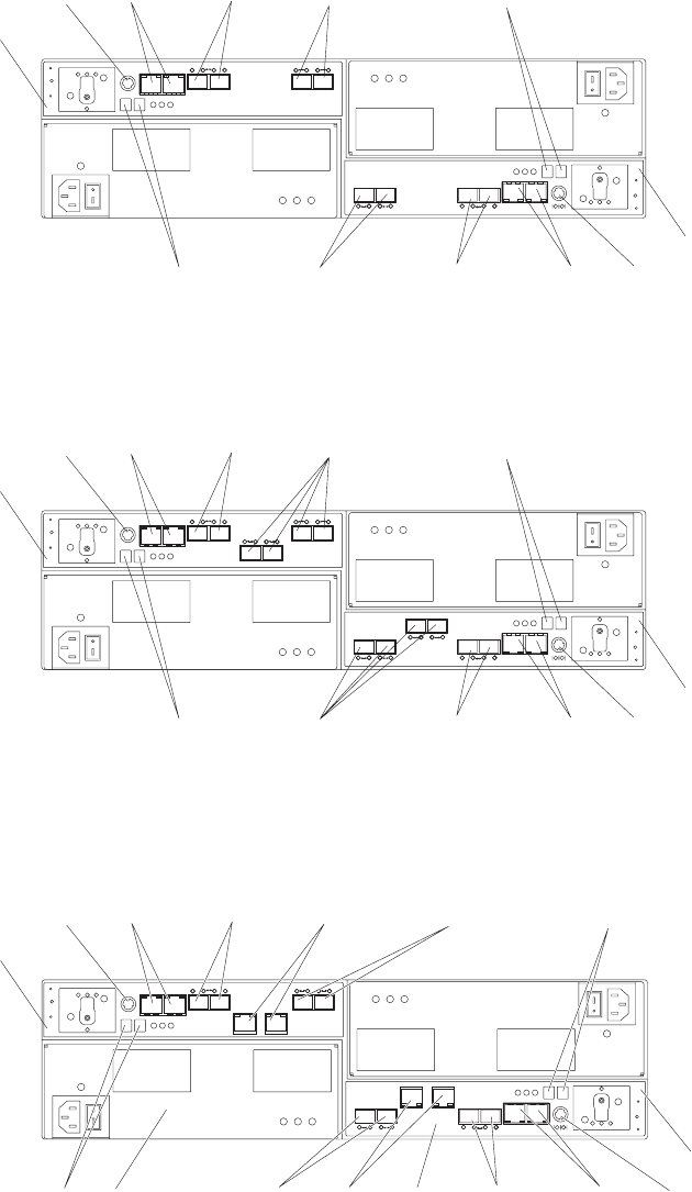
Controller B
Controller A
Fibre Channel
host channels
Ethernet
ports
Serial
port
Enclosure ID
Dual-ported
drive channel Enclosure ID
Ethernet
ports
Serial
port
Dual-ported
drive channel
Fibre Channel
host channels
Figure 2. Back view; controllers with two standard Fibre Channel host expansion channels
Controller B
Controller A
Fibre Channel
host channels
Ethernet
ports
Serial
port
Enclosure ID
Dual-ported
drive channel Enclosure ID
Ethernet
ports
Serial
port
Dual-ported
drive channel
Fibre Channel
host channels
Figure 3. Back view; controllers with two standard and two optional Fibre Channel host
expansion channels
Controller B
Controller A
Fibre Channel
host channels
Ethernet
ports
Serial
port
Enclosure ID
Dual-ported
drive channel Enclosure ID
Ethernet
ports
Serial
port
Dual-ported
drive
channel
iSCSI
host
channels
Power-fan
canister
Controller
canister
Fibre Channel
host channels
iSCSI
host
channels
Figure 4. Back view; controllers with two standard Fibre Channel host expansion channels
and two optional iSCSI host expansion channels
10 IBM System Storage DS5020 Storage Subsystem: Installation, User’s, and Maintenance Guide
Setting up IP addresses for DS5020 storage controllers
After you install DS Storage Manager (as described in the DS Storage Manager
Installation and Support Guide for your host operating system), complete one of the
following procedures to set up IP addresses:
v“Steps for setting up the DHCP/BOOTP server and network”
v“Steps for assigning static TCP/IP addresses to the DS5020 controllers”
Steps for setting up the DHCP/BOOTP server and network: To complete this
procedure, you must have the following components:
vA DHCP or BOOTP server
vA network management station (NMS) for Simple Network Management Protocol
(SNMP) traps
vA host that is connected to a storage subsystem through a Fibre Channel I/O
path
vA management station that is connected by an Ethernet cable to the storage
subsystem controllers
Note: You can avoid DHCP/BOOTP server and network tasks either by using the
default controller IP addresses, or by assigning static IP addresses to the
controller, as described in the next section.
Complete the following steps to set up the DHCP/BOOTP server and network:
1. Get the MAC address from each controller blade.
2. Complete whichever of the following steps is applicable for your server:
vOn a DHCP server, create a DHCP record for each of the MAC addresses.
Set the lease duration to the longest time possible.
vOn a BOOTP server, edit the bootptab file to add in the entries that associate
the MAC address tab with the TCP/IP address.
3. Connect the DS5020 storage subsystem Ethernet ports to the network.
4. Turn on the DS5020 storage subsystem.
The DHCP server automatically assigns new IP addresses to the controller Ethernet
port.
Steps for assigning static TCP/IP addresses to the DS5020 controllers: To
complete this procedure, you must have the following components:
vA host that is connected to a storage subsystem through a Fibre Channel I/O
path
vA management station that is connected by an Ethernet cable to the storage
subsystem controllers
For a host that is connected to a storage subsystem through a Fibre Channel I/O
path: Complete the following steps to assign static TCP/IP addresses to the
DS5020 storage subsystem controllers by way of the host that has Fibre Channel
connectivity to the DS5020 Fibre Channel host port.
Note: You cannot perform in-band management with a host that has iSCSI
connections to the DS5020 until it is configured. Use an out-of-band
management connection instead.
1. Install the DS Storage Manager client software in the host, and make sure that
the SMagent software is installed and running.
Chapter 1. Introduction 11
2. Start the DS Storage Manager client software. The Enterprise Management
window opens.
3. Add the DS5020 subsystem to the Enterprise Management domain using the IP
address of the host that has Fibre Channel connectivity to the DS5020.
4. In the Enterprise Management window, click on the name of the default storage
subsystem. The Subsystem Management window opens.
5. In the Subsystem Management window, right-click the Controller icon and
select Change > Network Configuration in the drop-down menu. The Change
Network Configuration window opens.
6. In the Change Network Configuration window, click on the Controller A and
Controller B tabs and type the new TCP/IP addresses in their applicable fields.
Click OK.
7. Close the Subsystem Management window, wait at least five minutes, then
delete the default DS5020 storage subsystem entry in the Enterprise
Management window.
8. If applicable, change the IP address of the Ethernet port in the management
station to a value that is on the same TCP/IP subnet as the controller Ethernet
port IP addresses that you just assigned. Exit DS Storage Manager, then
restart.
9. Make Ethernet cabling to the controller management ports. Add a new storage
subsystem entry in the Enterprise Management window, using the new assigned
IP addresses.
For a management station that is connected by an Ethernet cable to the storage
subsystem controllers: Complete the following steps to assign static TCP/IP
addresses to the DS5020 storage subsystem controllers, using default TCP/IP
addresses that are assigned to the DS5020 storage subsystem controllers during
manufacturing:
1. Make a direct management connection to the DS5020 storage subsystem, using
the default TCP/IP addresses:
vController A: 192.168.128.101
vController B: 192.168.128.102
vSubnet Mask: 255.255.255.0
Note: For a storage subsystem that has two Ethernet ports per controller, such
as the DS4200, DS4700 and DS4800, use the Ethernet port that is
labeled #1.
The default IP addresses of the second Ethernet port are:
vController A: 192.168.129.101
vController B: 192.168.129.102
vSubnet mask: 255.255.255.0
2. Start the DS Storage Manager client software. The Enterprise Management
window opens.
3. Add the DS5020 subsystem to the Enterprise Management domain using the
default IP addresses.
4. In the Enterprise Management window, click on the name of the default storage
subsystem. The Subsystem Management window opens.
5. In the Subsystem Management window, right-click the controller icon and select
Change > Network Configuration in the pull-down menu. The Change
Network Configuration window opens.
12 IBM System Storage DS5020 Storage Subsystem: Installation, User’s, and Maintenance Guide
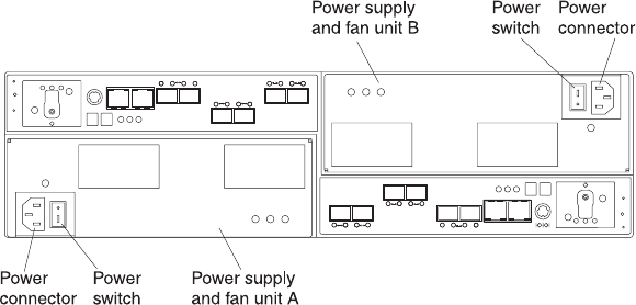
6. In the Change Network Configuration window, click on the Controller A and
Controller B tabs and type the new TCP/IP addresses in their applicable fields.
Click OK.
7. Close the Subsystem Management window, wait at least five minutes, then
delete the default DS5020 storage subsystem entry in the Enterprise
Management window.
8. If applicable, change the IP address of the Ethernet port in the management
station to a value that is on the same TCP/IP subnet as the controller Ethernet
port IP addresses that you just assigned. Exit DS Storage Manager, then
restart.
9. Add a new storage subsystem entry in the Enterprise Management window,
using the new assigned IP addresses.
Note: To manage storage subsystems through a firewall, configure the firewall to
open port 2463 to TCP data.
AC power supply and fan units
The DS5020 storage subsystem has two removable ac power supply and fan units.
Each power supply and fan unit contains one power supply and two fans. The four
fans pull air through the drive from front to back across the drives.
The fans provide redundant cooling, which means that if one of the fans in either
fan housing fails, the remaining fans continue to provide sufficient cooling to
operate the storage subsystem. The power supplies provide power to the internal
components by converting incoming ac voltage to dc voltage. If one power supply is
turned off or malfunctions, the other power supply maintains electrical power to the
storage subsystem. To preserve the optimal airflow, do not remove a failed power
supply and fan unit CRU from the DS5020 chassis until you are ready to replace it
with a new CRU.
Figure 5 shows power supply and fan unit components for the DS5020.
Notes:
1. Your DS5020 hardware might differ slightly from the following illustration.
2. Although both power supply and fan units (left and right) are identical, they are
seated in the DS5020 chassis in opposite orientations. If the power supply and
fan unit cannot fully be inserted in the power supply and fan unit bay, flip it 180
degree and reinsert it.
Figure 5. Power supply and fan unit components for the DS5020
Chapter 1. Introduction 13
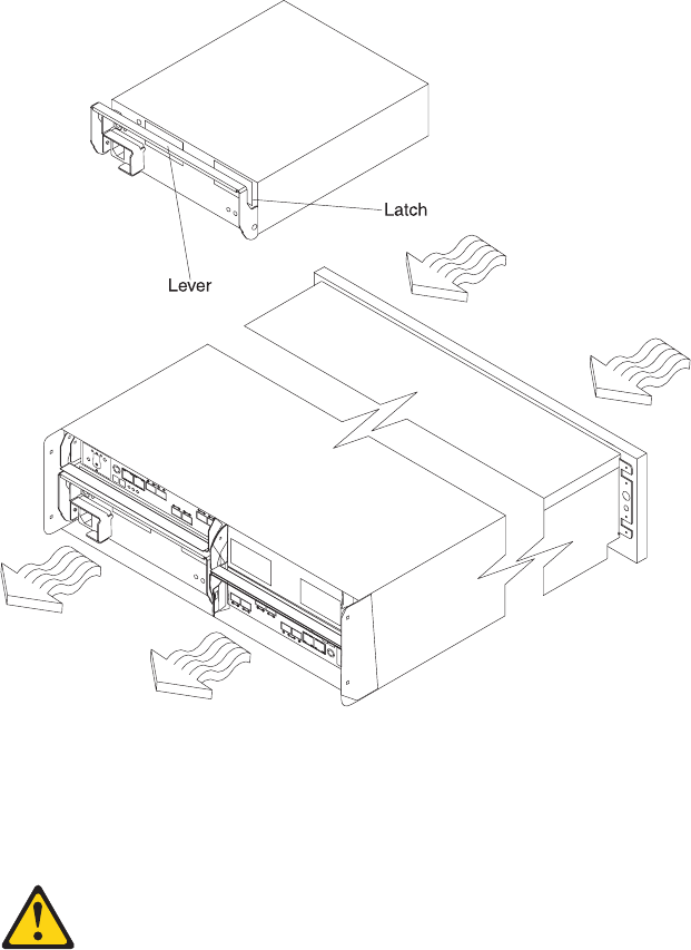
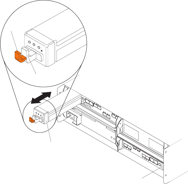
CAUTION:
When replacing the lithium battery, use only an equivalent type battery
recommended by the manufacturer. If your system has a module containing a
lithium battery, replace it only with the same module type made by the same
manufacturer. The battery contains lithium and can explode if not properly
used, handled, or disposed of.
Do not:
vThrow or immerse into water
vHeat to more than 100° C (212° F)
vRepair or disassemble
Dispose of the battery as required by local ordinances or regulations.
Each controller also contains a rechargeable battery unit that is used in the event of
a power failure.
Figure 7 shows how the battery unit slides into the battery backup slot in controller
A.
The backup battery unit provides power to back up the cache memory of each
controller onto flash drives in the event of a power failure. Each battery unit
contains a sealed, rechargeable SMART lithium ion battery. The battery unit
contains enough charge to back up the cached data in each controller to a flash
drive in the event of a power failure.
When the unit is powered on the first time or whenever the battery is replaced, the
battery chargers will charge the battery to the programmed level. Then, the
Pull handle
Latch
Controller A
backup battery unit
Controller B
backup battery unit
Figure 7. Backup battery unit
Chapter 1. Introduction 15
controller will start a battery learning cycle to determine whether the battery current
capacity is sufficient. Data caching starts after the battery is charged to the
programmed level. During the battery learn cycle, cache will be active if the battery
is in good condition. If the battery fails the learn cycle, it is marked as failed. The
battery learning cycle lasts up to three hours. After the first battery learn cycle, the
controller will perform a learn cycle every 8 weeks to re-calibrate the
battery-charging level.
The battery unit is hot-swappable. You can remove the battery unit for servicing and
then reinsert it while the DS5020 continues to perform I/O operations. However,
write I/O caching is disabled when the battery is in a failed state or removed from
the controller chassis. Replace the failed battery as soon as possible to minimize
the time that the write IO caching is disabled.
Information about the condition of the battery unit is conveyed by indicator LEDs on
the front of battery unit. (“Battery unit LEDs” on page 103 identifies the indicator
LEDs on the battery unit and explains the conditions that each LED indicates.)
SFP modules
Statement 3:
CAUTION:
When laser products (such as CD-ROMs, DVD drives, fiber-optic devices, or
transmitters) are installed, note the following:
vDo not remove the covers. Removing the covers of the laser product could
result in exposure to hazardous laser radiation. There are no serviceable
parts inside the device.
vUse of controls or adjustments or performance of procedures other than
those specified herein might result in hazardous radiation exposure.
DANGER
Some laser products contain an embedded Class 3A or Class 3B laser
diode. Note the following.
Laser radiation when open. Do not stare into the beam, do not view directly
with optical instruments, and avoid direct exposure to the beam.
Class 1 Laser statement
Class 1 Laser Product
Laser Klasse 1
Laser Klass 1
Luokan 1 Laserlaite
Apparell Laser de Calsse 1À
IEC 825-11993 CENELEC EN 60 825
16 IBM System Storage DS5020 Storage Subsystem: Installation, User’s, and Maintenance Guide
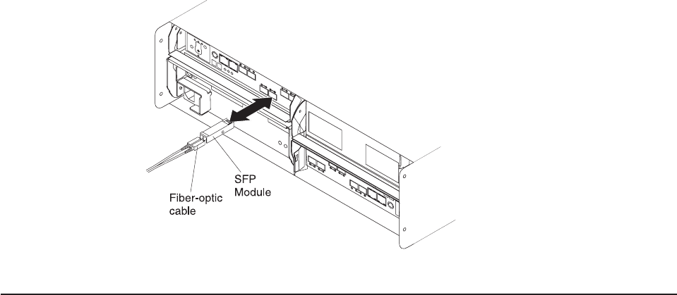
The storage subsystem supports a fiber-optic interface for host and storage
expansion enclosure connections. You must install a Small Form-factor Pluggable
(SFP) module in each interface connector on the controller where a fiber-optic cable
is to be installed. Do not install an SFP in any port that will not have a fiber-optic
cable attached. Remove any SFP from any port that does not have fiber-optic
cables attached.
The DS5020 storage subsystem host ports support 2, 4, and 8 Gbps Fibre Channel
speeds. The DS5020 storage subsystem drive ports support only 4 Gbps Fibre
Channel speeds.
Attention: The maximum operating speed of the Fibre Channel port is determined
by two factors: the speed of the SFP module that is installed and the speed of the
Fibre Channel connection. For example, a 4 Gbps SFP that is plugged into a 8
Gbps-capable port will limit the speed of that port to a maximum of 4 Gbps.
Conversely, an 8 Gbps SFP that is plugged into a 4 Gbps-capable port will limit the
speed of the port to a maximum of 4 Gbps. Carefully check the SFP IBM part
number, option number, and FRU part number to identify its speed. There are no
physical features that distinguish an 8 Gbps SFP from a 4 Gbps SFP.
Figure 8 shows an example of SFP module with fiber-optic cable.
Note: The SFP module and the fiber-optic cable shown are for illustrative purposes
only. The actual SFP module and the fiber-optic cable shape might look
different from the figure shown.
Software and hardware compatibility and upgrades
The latest DS5020 controller firmware and NVSRAM, the storage expansion
enclosure drive enclosure ESM firmware, and Fibre Channel and SATA drive CRUs
firmware must be installed to achieve optimal functionality, manageability, and
reliability.
Unless stated otherwise, you can find the latest DS5020 publications, firmware, and
host software at the IBM System Storage Support Web site:
http://www.ibm.com/systems/support/storage/disk
Figure 8. SFP module and fiber-optic cable
Chapter 1. Introduction 17
Software and firmware support code upgrades
To enable support for the DS5020, you must make sure that your system software
and firmware are the correct versions. To find the latest DS Storage Manager
software, storage subsystem controller firmware, ESM, and NVSRAM firmware,
check the firmware readme files. See “Finding DS5020 and DS4000-family readme
files” on page xxiv to learn how to access the readme files on the Web.
See the IBM System Storage DS Storage Manager Installation and Host Support
Guide for your operating system for instructions that describe how to install the
DS5020 controller firmware and Storage Manager host software.
Note: For the latest information about supported servers and operating systems,
refer to the interoperability matrix at this Web site:
http://www-1.ibm.com/servers/storage/disk/ds4000/interop-matrix.html
Determining firmware levels
There are two different methods to determine the DS5020 storage subsystem and
firmware versions. Each method uses the DS Storage Manager client that manages
the DS5020 storage subsystem.
Method One:
Go to the Subsystem Management window and select View > Storage Subsystem
Profile. When the Storage Subsystem Profile window opens, select the All tab and
scroll through the Profile For Storage Subsystem list to locate the following
information.
Note: The Profile For Storage Subsystem list contains all the profile information for
the entire subsystem. Therefore, it might be necessary to scroll through a
large amount of information to locate the firmware version numbers.
DS5020 Storage Server
vNVSRAM version
vAppware version
vBootware version
Drives
vFirmware version
vATA translator card firmware version (SATA E-DDMs only)
Note: The ATA translator card firmware and drive firmware are typically
packaged together as a single drive firmware upgrade file.
ESM
vESM card firmware version
Method Two:
Complete the applicable procedure to obtain the specified firmware version.
To obtain the controller firmware version:
Right-click the Controller icon in the Physical View pane of the Subsystem
Management window and select Properties. The Controller Enclosure
properties window opens and displays the properties for that controller.
18 IBM System Storage DS5020 Storage Subsystem: Installation, User’s, and Maintenance Guide
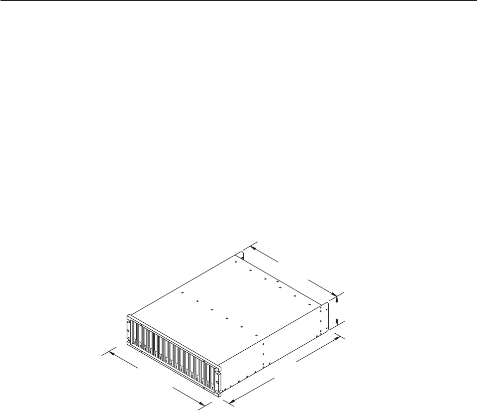
You must perform this step for each individual controller.
To obtain the drive firmware (and ATA translator card firmware) version:
Right-click the Drive icon in the Physical View pane of the Subsystem
Management window and select Properties. The Drive Properties window
opens and displays the properties for that drive.
You must perform this step for each individual drive.
To obtain the ESM and drive enclosure component firmware versions:
1. In the Physical View pane of the Subsystem Management window, click
the Drive Enclosure Component icon, which is the icon furthest to the
right. The Drive Enclosure Component Information window opens.
2. Click the ESM icon in the left pane. The ESM information displays in the
right pane of the Drive Enclosure Component Information window.
3. Locate the firmware version of each ESM in the drive enclosure.
Specifications
This section provides site specifications for the DS5020 storage subsystem. Before
installing, you must either verify that your planned installation site meets these
requirements, or prepare the site so that it does meet these requirements.
Preparations might involve meeting area requirements, environmental requirements,
and electrical requirements for DS5020 storage subsystem installation, service, and
operation.
Area requirements
The floor space at the installation site must provide enough strength to support the
weight of the storage subsystem and associated equipment; sufficient space to
install, operate, and service the storage subsystem; and sufficient ventilation to
provide a free flow of air to the unit.
Dimensions
Figure 9 shows the dimensions of the DS5020, which conforms to the 19-inch rack
standard.
Weight
The total weight of the storage subsystem depends on the number of components
installed. Table 2 on page 20 lists the maximum, empty, and shipping weights for
44.70 cm (17.60 in.)
12.95 cm (5.1 in.)
57.15 cm (22.5 in.)
48.26 cm (19.00 in.)
Figure 9. DS5020 dimensions
Chapter 1. Introduction 19

the storage subsystem in different configurations. Table 3 lists the weight of each
component.
Table 2. DS5020 weights
Unit
Weight
Maximum 1Empty 2Shipping
DS5020 40 kg (88 lb) 16.4 kg (36.1 lb) 52.2 kg (115.0 lb)
1Chassis with all CRUs and 16 drives.
2Chassis without CRUs and drives but with front cage frame and midplane.
Table 3. DS5020 component weights
Unit Weight
Drive 0.75 kg (1.65 lb)
Power supply and fan unit 3.60 kg (7.95 lb)
Controller (including cache battery backup
unit)
2.8 kg (6.1 lb)
Battery unit 0.9 kg (2 lb)
Shipping dimensions
Table 4 lists shipping carton dimensions. The height shown includes the height of
the pallet.
Table 4. DS5020 shipping carton dimensions
Height Width Depth
45.7 cm (18.0 in.) 62.6 cm (24.5 in.) 80.7 cm (31.75 in.)
Environmental requirements and specifications
This section describes the environmental requirements and specifications for the
DS5020 storage subsystem, including temperature and humidity, altitude, airflow
and heat dissipation, shock and vibration requirements, and acoustic noise levels.
Temperature and humidity
Table 5 on page 21 lists the acceptable temperature and humidity ranges for the
DS5020 storage subsystem when in storage or in transit. Table 6 on page 21 lists
temperature and humidity ranges for the storage subsystem in typical Information
Technology (IT) or office environments.
Note: Substantial deviations from the suggested operating range, in either
direction, if sustained for extended periods of time, will expose the unit to
greater risk of failure from external causes.
Important: The operating environment air temperature must be 22° C (72° F) or
lower.
20 IBM System Storage DS5020 Storage Subsystem: Installation, User’s, and Maintenance Guide
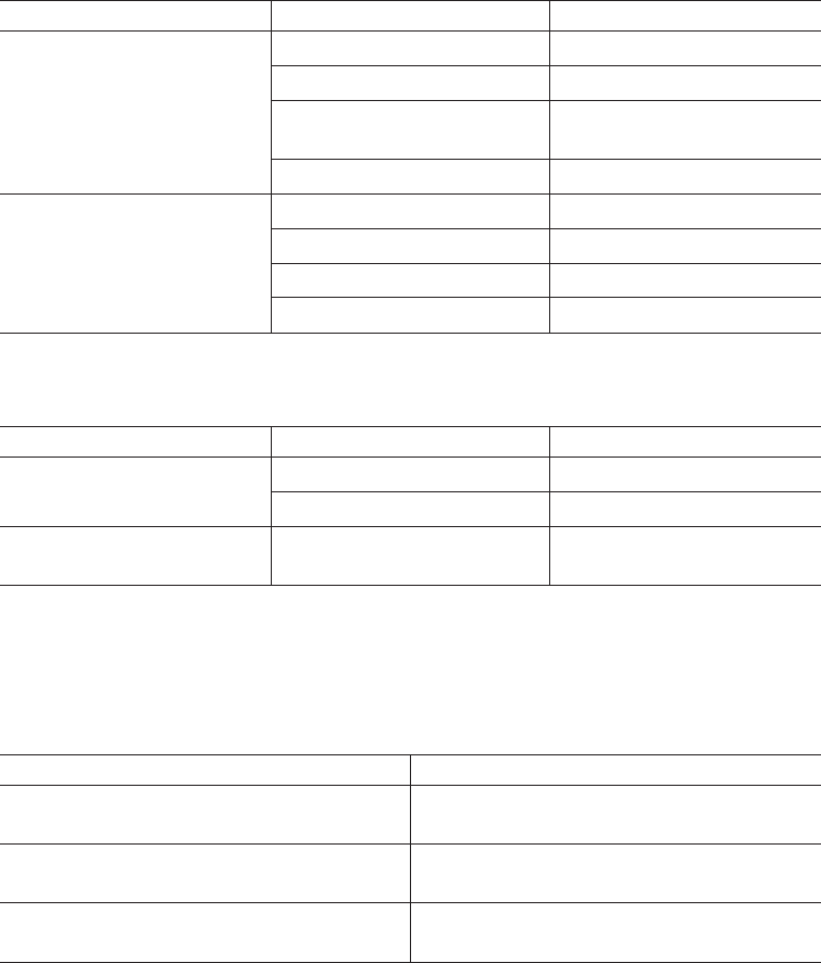
Table 5. Temperature and humidity requirements for storage subsystem when in storage or in
transit
Condition Parameter Requirement
Temperature Storage range -10° - 65° C (14° - 149° F)
Maximum rate of change 15° C (27° F) per hour
Transit range -40° C to 65° C (-40° F to
149° F)
Maximum rate of change 20° C (36° F) per hour
Relative humidity (no
condensation)
Storage range 8% to 90%
Transit range 5% to 95%
Maximum dew point 26° C (79° F)
Maximum gradient 10% per hour
Table 6. Temperature and humidity requirements for storage subsystem in a typical
Information Technology (IT) or office environment
Condition Parameter Requirement
Temperature Operating range 10° - 35° C (50° - 95° F)
Maximum rate of change 10° C (18° F) per hour
Relative humidity (no
condensation)
Operating range 8% to 80%
Altitude
Table 7 lists the acceptable altitudes for operating, storing, and shipping the
DS5020.
Table 7. DS5020 altitude ranges
Environment Altitude
Operating 30.5 m (100 ft.) below sea level to 3000 m
(9842 ft.) above sea level
Storage 30.5 m (100 ft.) below sea level to 3000 m
(9842 ft.) above sea level
Transit 30.5 m (100 ft.) below sea level to 12,000 m
(40,000 ft.) above sea level
Airflow and heat dissipation
Figure 10 on page 22 shows the intended airflow for the DS5020. Allow at least 30
inches in front of the storage subsystem and at least 24 inches behind the storage
subsystem for service clearance, proper ventilation, and heat dissipation.
Chapter 1. Introduction 21
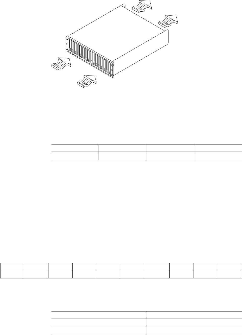
Table 8 lists the KVA, watts, and Btu calculations. These values assume the power
supplies have a 73 percent efficiency and a power factor of 0.99. These tabulated
power and heat dissipation values are typical for the storage subsystem. Maximum
configuration units are typically operated at higher data rates, have larger random
access memory (RAM) capacities, or have different host interface boards.
Table 8. DS5020 power and heat dissipation
Parameter KVA Watts (ac) Btu per hour
DS5020 0.496 447 1529
Shock and vibration requirements
Operational shock and operational vibration requirements are shown in this section.
Operational Shock: The DS5020 will be able to withstand the following shock.
Subjecting the equipment to a single shock pulse with the following characteristics
will simulate this level of shock:
vVelocity change = 20 inches per second
vWave®form = Triangular, 10g @3.75 ms
Operational Vibration (Random): While in its normal operating position, the
DS5020 will continue operating when subjected to a random vibration test using the
criteria shown in Table 9. This test uses the indicated spectral power density for 30
minutes in each of the three axes.
Table 9. Random vibration power spectral density
Hz 5 17 45 48 62 65 150 200 500
g2/Hz 2.0x10⁻⁷-7 2.2x10⁻⁵ 2.2x10⁻⁵ 2.2x10⁻⁵ 2.2x10⁻⁵ 2.2x10⁻⁵ 2.2x10⁻⁵ 2.2x10⁻⁵ 2.2x10⁻⁵
Acoustic noise
Table 10 lists the maximum sound levels emitted by the storage subsystem.
Table 10. DS5020 sound levels
Measurement Level
Sound power (normal operation) 6.4 bels
Sound pressure (normal operation) 68 dBA
Figure 10. DS5020 airflow
22 IBM System Storage DS5020 Storage Subsystem: Installation, User’s, and Maintenance Guide

These levels are measured in controlled acoustical environments according to ISO
7779 and are reported in accordance with ISO 9296. The declared sound power
levels indicate an upper limit, below which a large portion of machines operate.
Sound pressure levels in your location might exceed the average 1-meter values
stated because of room reflections and other nearby noise.
Electrical requirements
This section provides information regarding site power and wiring, storage
subsystem power requirements, and power cord routing instructions.
Consider the following information when preparing the installation site:
vProtective ground – Site wiring must include a protective ground connection to
the ac power source.
Note: Protective ground is also known as safety ground or chassis ground.
vCircuit overloading – Power circuits and associated circuit breakers must provide
sufficient power and overload protection. To prevent possible damage to the unit,
isolate its power source from large switching loads (such as air conditioning
motors, elevator motors, and factory loads).
vPower failures – If a total power failure occurs, the unit automatically performs a
power-up recovery sequence without operator intervention after power is
restored.
Table 11. DS5020 ac power requirements
Low Range High Range
Nominal Voltage 90 to 136 VAC 198 to 264 VAC
Frequency (Hertz) 50 to 60 Hz 50 to 60 Hz
Idle Current 3.53 Aa2.08 Ab
Maximum Operating Current 3.71 Aa2.04 Ab
Maximum Surge Current 5.04 Aa2.67 Ab
a. Typical voltage: 120 V ac, 60 Hz, assumes 72% power-supply efficiency and 0.99 power
factor
b. Typical voltage: 240 V ac, 60 Hz, assumes 72% power-supply efficiency and 0.99 power
factor
Power and site wiring requirements
The storage subsystem uses wide-ranging redundant power supplies that
automatically accommodate voltages to the ac power source. The ac power
supplies operate within the ranges specified in Table 11. The ac power supplies
meet standard voltage requirements for both domestic (inside USA) and
international (outside USA) operation. They use standard industrial wiring with
line-to-neutral or line-to-line power connections.
The agency ratings for the DS5020 storage subsystem are 6 amps at 100 VAC and
2.5 amps at 240 VAC. These are the overall maximum operating currents for the
DS5020 storage subsystem with ac power supply and fan unit CRUs.
AC power recovery: After a total ac power failure, after normal power is restored,
the storage subsystem performs power-up recovery procedures automatically
without operator intervention.
Chapter 1. Introduction 23
Power cords and receptacles: The storage subsystem ships with two jumper
cords used to connect to the rack PDU. You must purchase the power cords that
are appropriate for use in a typical outlet in the destination country. See
Appendix D, “Power cords,” on page 179 for more information.
Heat output, airflow, and cooling
See “Airflow and heat dissipation” on page 21 for heat output, airflow, and cooling
specifications.
Note: In general, disk subsystem reliability tends to decrease as the ambient
temperature of the environment in which it is being used increases. The
ambient temperature in the immediate area of the disk enclosure unit must
be kept near 22° C (72° F), or lower, to provide better reliability.
When racks that contain many storage subsystems are to be installed together, the
following requirements must be met to for the storage subsystems to be cooled
adequately:
vAir enters at the front of the rack and leaves at the back. To prevent the air that
is leaving the rack from entering the intake of another piece of equipment, you
must position the racks in alternate rows, back-to-back and front-to-front. This
arrangement is known as “cold aisle/hot aisle” and is shown in Figure 11 on page
25.
vWhere racks are in rows, each rack must touch the rack that is next to it to
reduce the amount of hot air that can flow around from the back of the rack into
the intakes of the storage expansion enclosures that are in that rack. Use Suite
Attach Kits to completely seal any gaps that remain between the racks. For
details about Suite Attach Kits, contact your marketing representative.
vWhere racks are in rows front-to-front or back-to-back, a gap of at least 1220 mm
(48 in.) must separate the rows across the cold aisle.
vFor proper airflow in each rack, the rack filler plates must be installed in unused
positions. Also, all the gaps in the front of the racks must be sealed, including the
gaps between the storage subsystems.
24 IBM System Storage DS5020 Storage Subsystem: Installation, User’s, and Maintenance Guide
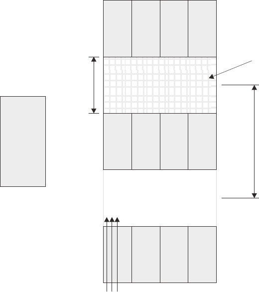
1220 mm cold
aisle width
2440 mm between
center lines of hot
and cold aisle
Perforated tiles
or gratings
back
back
T42 racks
T42 racks
T42 racks
Cold aisle
Hot aisle
Air
conditioner
back
front
front
front
Airflow
Figure 11. Example of cold aisle/hot aisle rack configuration
Chapter 1. Introduction 25
26 IBM System Storage DS5020 Storage Subsystem: Installation, User’s, and Maintenance Guide
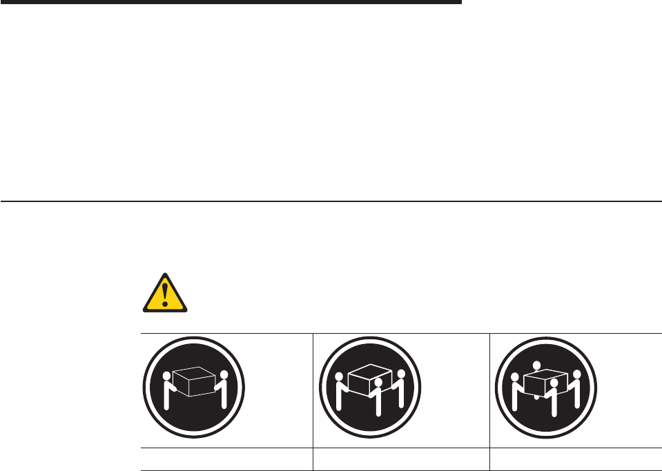
Chapter 2. Installing the storage subsystem
This chapter provides the information that you need to install the storage subsystem
into a rack cabinet.
Before you begin the installation, review the safety information in “Safety” on page
xiii.
“Installation overview” provides an overview of the entire storage subsystem
installation process. Read this overview before you begin the installation.
Installation overview
Statement 4:
≥18 kg (39.7 lb) ≥32 kg (70.5 lb) ≥55 kg (121.2 lb)
CAUTION:
Use safe practices when lifting.
Attention: A fully configured DS5020 weighs up to 40 kg (88 lb). At least two
other people should help you lift the DS5020 from the shipping box. If desired, open
the sides of the shipping box and remove the CRUs from the DS5020 before you lift
it from the shipping box in order to lighten the storage subsystem. See “Removing
the CRUs” on page 36.
The following steps summarize the DS5020 installation process. Each step below is
detailed in this chapter or next two chapters, Chapter 3, “Cabling the storage
subsystem,” on page 45 and Chapter 4, “Operating the storage subsystem,” on
page 93.
1. Review the preparation guidelines. See “Preparing for installation” on page 29.
2. Prepare the installation site. See “Preparing the site” on page 31.
3. Prepare the rack cabinet. See “Preparing the rack cabinet” on page 32.
4. Fold down and open the sides of the shipping box. Without removing the
DS5020 from box, you can remove the DS5020 rack mounting rails and
hardware from the box. The DS5020 rack mounting rails and hardware are
placed on the bottom of the shipping box (under the DS5020 storage
subsystem). Install the support rails in the rack cabinet. See “Installing the
support rails” on page 32.
© Copyright IBM Corp. 2009 27

5. Before removing the DS5020 from the shipping box, remove the components
from the DS5020 chassis to lighten the unit. See “Removing the CRUs” on
page 36.
6. Record the serial number, machine type and model number, and RAID
controller MAC addresses for your DS5020 storage subsystem in Appendix A,
“Records,” on page 163.
The serial number, machine type, and model number are located on the left
edge of the front unit as shown in Figure 12.
The MAC addresses are located near the Ethernet ports on each RAID
controller.
7. Install and secure the DS5020 chassis in the rack cabinet. See “Installing the
DS5020 into a rack on the support rails” on page 40.
8. If needed, replace the components in the installed DS5020 chassis. See
“Replacing the components” on page 42.
9. Install the storage expansion enclosure or enclosures you will cable to the
DS5020 in the rack cabinet. Follow the instructions in the Installation, User’s,
and Maintenance Guide for your storage expansion enclosure to set up and
mount the storage expansion enclosures.
10. Use SFP modules and Fibre Channel cables to cable the DS5020 to the
DS4000 storage expansion enclosure or enclosures. See “Connecting storage
expansion enclosures to the DS5020” on page 54.
11. Perform one of the following cabling tasks to enable management of the
DS5020 configuration:
vIf you are using out-of-band management, cable the DS5020 Ethernet ports
to either the management workstation or the host.
vIf you are using in-band management, cable the DS5020 host channels to
the Fibre Channel host bus adapters (HBAs) in either the hosts or the Fibre
Channel switch that connects to the host HBAs. See “Connecting hosts to
the DS5020 using Fibre Channel host ports” on page 82.
12. Connect the power cables for the DS5020. See “Cabling the ac power supply”
on page 91.
Attention:
Before you turn on the power to the DS5020 storage subsystem, it must be
populated with at least two E-DDMs.
If at least two E-DDMs are not installed in the DS5020, an insufficient load to
the enclosure power supplies might cause them to intermittently appear as
failed, falsely indicating the power supplies are bad. All of the E-DDMs in the
DS5020 storage subsystem and the connected storage expansion enclosure or
enclosures must contain no prior configuration data.
Ser i al n u m b er
Machine type
Model number
Figure 12. Example of DS5020 serial number, machine type, and model number location
28 IBM System Storage DS5020 Storage Subsystem: Installation, User’s, and Maintenance Guide

13. Turn on the power to the attached storage expansion enclosure and the
DS5020 storage subsystem using the procedure described in “Powering on the
storage subsystem” on page 95.
14. Install the DS Storage Manager host software on the management workstation
(for out-of-band management) or on the host (for in-band management). Refer
to the IBM System Storage DS Storage Manager Version 10 Installation and
Host Support Guide for the appropriate operating system for instructions on
how to install the DS Storage Manager host software.
15. Use the DS Storage Manager host software to verify the configuration.
16. Review and perform the procedures described in “Performing the DS5020
Health Check process” on page 93.
Handling static-sensitive devices
Attention: Static electricity can damage electronic devices and your system. To
avoid damage, keep static-sensitive devices in their static-protective packages until
you are ready to install them.
To reduce the possibility of electrostatic discharge (ESD), observe the following
precautions:
vLimit your movement. Movement can cause static electricity to build up around
you.
vHandle the device carefully, holding it by its edges or its frame.
vDo not touch solder joints, pins, or exposed printed circuitry.
vDo not leave the device where others can handle and possibly damage the
device.
vWhile the device is still in its static-protective package, touch it to an unpainted
metal part of the system unit for at least two seconds. This drains static electricity
from the package and from your body.
vRemove the device from its package and install it directly into your system unit
without setting it down. If it is necessary to set the device down, place it in its
static-protective package. Do not place the device on your system unit cover or
on a metal table.
vTake additional care when handling devices during cold weather because heating
reduces indoor humidity and increases static electricity.
Preparing for installation
Before installing the DS5020 storage subsystem, create a detailed plan of how this
unit will be used in your storage configuration. The plan might include determining
RAID levels, failover requirements, operating systems to be used, and total storage
capacity requirements.
The following illustration shows the items that you need to install the DS5020
storage subsystem in the rack cabinet. If any items are missing or damaged,
contact your place of purchase.
Note: The illustration might differ slightly from your DS5020 hardware. The
host-interface cables, Ethernet cables, Fibre Channel signal cables, and
iSCSI signal cables are not shown in the following illustration.
Chapter 2. Installing the storage subsystem 29
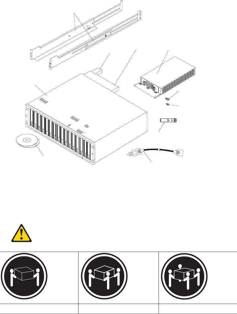
Support rails
DS5020
Storage
subsystem
Backup
battery unit Controller
AC power supply
and fan unit
M5 x 8 mm
screws (12)
M4 x 8 mm
screws (4)
Small Form-factor
Pluggable transceivers (pre-installed)
AC power cord (2)
Firmware and DS
Storage Manager DVDs
Complete the following steps to prepare the DS5020 storage subsystem for
installation into a rack cabinet:
1. Prepare the site to meet all area, environmental, power, and site requirements.
For more information, see “Specifications” on page 19.
Statement 4:
≥18 kg (39.7 lb) ≥32 kg (70.5 lb) ≥55 kg (121.2 lb)
CAUTION:
Use safe practices when lifting.
2. Move the shipping box that contains the DS5020 to the site.
3. Remove the mounting rails, mounting hardware, and line jumper cords from the
DS5020 shipping box. Do not remove the DS5020 from the shipping box at this
time.
30 IBM System Storage DS5020 Storage Subsystem: Installation, User’s, and Maintenance Guide
Attention: The mounting rails, mounting hardware, and line jumper cords
might be packed beneath the DS5020 in the shipping box. To remove these
items from the shipping box without first removing the DS5020, open the two
long sides of the shipping box. Then open and fold flat the two short sides of
the shipping box. This enables you to access the mounting rails, mounting
hardware, and line jumper cords without first removing the DS5020 from the
shipping box.
After you open the DS5020 shipping container and remove the mounting rails,
mounting hardware, and line jumper cords, check the remaining contents (see
“Inventory checklist” on page 3) without removing the DS5020 from the shipping
box. If any items are missing, contact your IBM reseller or representatives
before proceeding.
4. Verify that you have the applicable host software kit for your operating system.
Depending on the DS5020 configuration you order, your DS5020 will ship with
either the Microsoft®Windows host software attachment kit or with your choice
of host software kits (Windows, AIX, Linux, Netware, SUN Solaris, HP-UX, Linux
on POWER, or VMware). The host software kit grants you permission to attach
host servers using the applicable operating system to the DS5020.
The kit includes a DS Storage Manager DVD that has the applicable IBM DS
Storage Manager host software. If you order more than one host software kit,
the additional kits might also be shipped in the DS5020 shipping box.
The DVD also includes the DS5020 storage subsystem controller firmware. For
the latest controller firmware, check the IBM support Web site for IBM System
Storage products:
http://www.ibm.com/systems/support/storage/disk
5. Read the applicable readme files that are included in the Storage Manager host
software or DS5020 controller firmware packages for any updated information
about hardware, software, or firmware products. See “Finding DS5020 and
DS4000-family readme files” on page xxiv to learn how to access the DS5020
and DS4000-family readme files on the Web.
6. Continue with “Preparing the site.”
Tools and hardware required
Gather the tools and equipment you will need for installation. These might include:
vRegion-specific power cords required for the DS5020
v5/16 (8 mm) hex nut driver
vNo. 2 Phillips screwdriver
vAntistatic protection (such as a grounding wrist strap)
vFibre Channel (FC) and Ethernet interface cables and cable straps
vRack power jumper cords that are shipped with the DS5020
vSFP modules
vRack-mounting hardware that ships with the DS5020
Preparing the site
This section lists the floor space requirements and weight information for the
storage subsystem. For information about interface cables and connections, see
Chapter 3, “Cabling the storage subsystem,” on page 45.
Floor space: The floor area at the installation site must provide the following
conditions:
Chapter 2. Installing the storage subsystem 31

vSufficient space to install the storage subsystem
vEnough stability to support the weight of the fully configured storage subsystem
and associated systems. See “Weight” on page 19 for weight specifications.
Make sure that all requirements, such as floor space, air conditioning, and electrical
service, have been met. Other site preparation activities include the following tasks:
vTo make sure that there is enough room to move around the cabinet and install
modules, clear space at the installation area.
vInstall uninterruptible power supply (UPS) devices.
vIf applicable, install host servers with Fibre Channel host bus adapters (HBAs),
Fibre Channel switches, or other devices.
vRoute interface cables from the Fibre Channel HBA ports in the hosts or Fibre
Channel switches to the installation area.
vRoute main power cords to the installation area.
Continue with “Preparing the rack cabinet.”
Preparing the rack cabinet
Important: Before you install the storage subsystem in a rack cabinet, keep in mind
the following considerations:
vReview the documentation that comes with your rack enclosure for safety and
cabling considerations.
vInstall the storage subsystem in an environment with a temperature of 22° C (72°
F). See “Environmental requirements and specifications” on page 20 for details.
vFor proper airflow, do not block the air vents; allow for at least 15 cm (6 in.) of air
space.
vFor optimal rack stability, load the rack starting at the bottom.
vIf you install multiple components in the rack, do not overload the power outlets.
vAlways connect the storage subsystem to a properly grounded outlet.
vAlways connect the IBM-certified rack power distribution units (PDUs) to at least
two independent power circuits or sources.
Complete the following steps to prepare the rack cabinet before you install the
storage subsystem:
1. Move, unpack, and level the rack at the installation site (if needed).
2. Remove the external rack panels.
3. If necessary, stop all I/O activity to the devices in the rack.
4. If necessary, turn off all drive enclosure and rack power. Disconnect existing
power, network, and other external cables.
5. Install any additional interface cables and power cables.
After you have completed these steps, continue with “Installing the support rails.”
Installing the support rails
Important: Duplicate copies of the rack mounting templates are provided in
Appendix B, “Rack mounting templates,” on page 167. If you want to
tear out the templates from this document, use the copies in
Appendix B, “Rack mounting templates,” on page 167.
32 IBM System Storage DS5020 Storage Subsystem: Installation, User’s, and Maintenance Guide
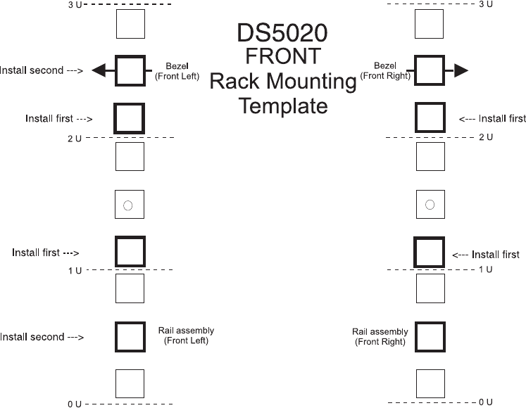
Use the following templates (Figure 13 and Figure 14 on page 34) to identify the
proper locations for inserting M5 screws when mounting the support rails and
DS5020 storage subsystem to a rack cabinet. The locations for the M5 screws are
highlighted in the templates.
Hold the applicable template up to each side of the rack cabinet at the 3U section
where you will install the DS5020. U boundaries are shown as horizontal dashed
lines in the rack mounting templates. The highlighted squares on each side of the
template mark the positions where you will thread the M5 screws that secure the
rails and the DS5020 to the front and rear of the cabinet.
Note: The mounting holes that are shown in the following templates are square.
The holes in your rack might be round, square, or threaded.
Figure 13. Front rack mounting template
Chapter 2. Installing the storage subsystem 33
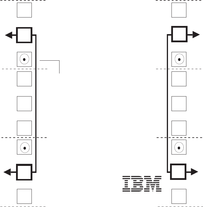
Before installing the DS5020 in a rack cabinet, you must install the rails and
rack-mounting hardware that come with your storage subsystem. The DS5020
requires an Electronic Industries Association (EIA) 310-D Type A 19-inch rack
cabinet. The distance between EIA rails, from the front to the rear of the rack, is
60.96 cm (24 in.) minimum and 81.28 cm (32 in.) maximum. This rack conforms to
the EIA standard. Where you place the support rails in the rack depends on where
you intend to position the storage subsystem.
Complete the following steps to install the support rails.
Note: Refer to Figure 15 on page 35 while performing these steps.
®
3U
3U
2U 2U
1U 1U
0U 0U
Rail assembly
(Rear Left) Rail assembly
(Rear right)
Printed in the U.S.A
REAR
Rack Mounting
Template
DS5020
Rail mounting guide
Figure 14. Rear rack mounting template
34 IBM System Storage DS5020 Storage Subsystem: Installation, User’s, and Maintenance Guide
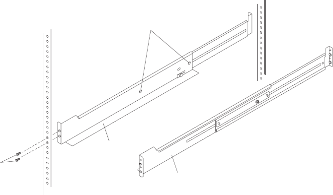
1. Make sure that the rack cabinet has already been installed.
2. Make sure that a stabilizer has been correctly attached to the bottom front of
the rack to prevent the rack from tipping forward while the DS5020 is being
installed.
Refer to the installation and service guide, or equivalent, for the rack as
required.
3. Locate the two support rails, eight of the twelve M5 screws, and eight washers
that are supplied with the DS5020.
Note: The M5 screws and washers might already be attached to the support
rails. If so, remove them from the support rails.
4. The rack-mounted unit is three EIA units high. Decide accordingly where you
are going to install the support rails.
Important: Duplicate copies of the rack mounting templates are provided in
Appendix B, “Rack mounting templates,” on page 167. If you want
to tear out the templates from this document, use the copies in
Appendix B, “Rack mounting templates,” on page 167. Use the
preceding templates (Figure 13 on page 33 and Figure 14 on page
34) to identify the proper locations for inserting M5 screws when
mounting the support rails and DS5020 storage subsystem to a
rack cabinet. The locations for the M5 screws are highlighted in
the templates.
Note the following considerations before you choose where to install the rails:
vIf you are installing the DS5020 into an empty rack, install it into the lowest
available position so that the rack does not become unstable.
vIf you are installing more than one DS5020 in the rack, start at the lowest
available position, and work upward.
vIf applicable, allow for possible later installation of other units.
vIf necessary, remove the rack power distribution unit before you install the
support rails.
vFor procedures and more information, refer to the installation and service
guide, or equivalent, for the rack.
Support rail
adjustment screws
Left
support
rail
Right
support
rail
M5
screws
Figure 15. Installing the support rails
Chapter 2. Installing the storage subsystem 35

vThe lip on the rail lines up with the bottom of the storage subsystem (the 0U
boundary in Figure 14 on page 34).
5. Using a No. 2 Phillips screwdriver, loosen the two screws on the left support
rail that hold the two parts of the rail together. The support rails are marked as
left or right.
6. Hold the back of the rail against the inside of the rack-mounting flange. Make
sure that the rail mounting guide pins are in the correct holes.
7. Using the 5/16 (8 mm) hex nut driver, securely tighten the two M5 screws.
Note: Make sure that you use a washer when installing an M5 screw through
asquare hole on the rack-mounting flange.
8. Extend the rail to the front of the rack until it makes contact with the front
rack-mounting flange.
9. Securely tighten the M5 screws.
Note: Be sure to install the screw labeled install first in Figure 13 on page 33.
10. Securely tighten the two screws on the left support rail that hold the two parts
of the rail together.
11. Repeat step 5 through step 10 for the right support rail.
Note: Because the mounting holes on the rack are not always the same size
as the mounting screws, the lip of each of the support rails might not
line up evenly. Make minor adjustments as needed to make sure that
the lip of the left and right support rails are lined up evenly on the racks.
Failure to do so will cause the storage subsystem to fit unevenly in the
rack.
12. Continue with “Removing the CRUs.”
Installing the DS5020
This section provides instructions on installing the DS5020. The installation process
includes:
v“Removing the CRUs”
v“Installing the DS5020 into a rack on the support rails” on page 40
v“Replacing the components” on page 42
Removing the CRUs
This section describes how to remove the CRUs to minimize the weight of the
DS5020 before you install it in the rack. However, if you have three or more people
available to lift and install the DS5020 in a rack, you might not find it necessary to
remove the CRUs before you install the DS5020. If this is the case, you can skip
the CRU removal instructions provided in this section. Instead, continue with
“Installing the DS5020 into a rack on the support rails” on page 40, and then skip
the CRU replacement instructions provided in “Replacing the components” on page
42.
Attention: Remove CRUs from the DS5020 chassis to lessen the weight to make
it easier to transfer the DS5020 storage subsystem from the shipping box to the
rack.
Use the following procedures to remove the CRUs from the DS5020 before
installation. Use these instructions after you have completed all applicable site,
rack, and preparations (as listed in “Preparing for installation” on page 29) and
36 IBM System Storage DS5020 Storage Subsystem: Installation, User’s, and Maintenance Guide
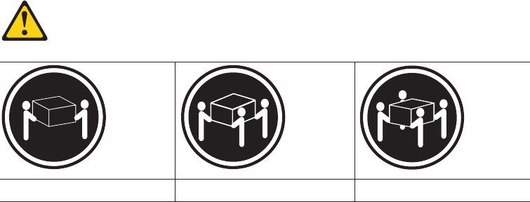
installed the support rails (as listed in “Installing the support rails” on page 32).
Alternately, you can use these instructions to lighten the DS5020 before removing it
from the shipping box. The shipping box opens to provide access to the storage
subsystem CRUs.
The DS5020 comes with a rack-mounting hardware kit for installing it in a rack. It is
easier to lift the DS5020 and install it in a rack cabinet if you remove all the CRUs
first. You will need an antistatic wrist strap and a cart or level surface (to hold the
CRUs). Observe the precautions listed in “Handling static-sensitive devices” on
page 29.
In the following procedure, you will remove the following CRUs from the storage
subsystem before you install it in the rack:
vControllers
vAC power supply and fan units
vHot-swap E-DDMs
You do not need to remove the blank trays.
Statement 4:
≥18 kg (39.7 lb) ≥32 kg (70.5 lb) ≥55 kg (121.2 lb)
CAUTION:
Use safe practices when lifting.
Attention: The storage subsystem comes with a bezel that is attached to the front
of the unit. The bezel protects the light pipes that are located above the drive trays.
Leave the protective bezel in place until you are instructed to remove it.
Removing a controller
Complete the following steps to remove a controller:
1. Squeeze the controller latch and pull the lever open 90° (so that the lever is
horizontal) to release the controller from the latch. The controller latch is a coral
colored tab on the lever.
Note: The lever rotates upward or downward 90°, depending on whether the
controller you are removing is the right or left controller CRU.
2. Slowly pull the lever away from the chassis to remove the controller from the
bay, as shown in Figure 16 on page 38.
Chapter 2. Installing the storage subsystem 37
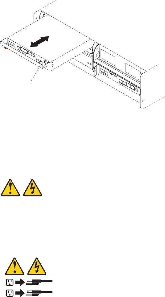
3. Place the controller on a level surface.
4. Repeat step 1 through step 3 for the second controller.
Removing an ac power supply and fan unit
Statement 5:
CAUTION:
The power control button on the device and the power switch on the power
supply do not turn off the electrical current supplied to the device. The device
also might have more than one power cord. To remove all electrical current
from the device, ensure that all power cords are disconnected from the power
source.
1
2
CAUTION:
Disconnect the power cord before removing the power supply and fan unit.
Complete the following steps to remove a power supply and fan unit:
1. Squeeze the latch and pull the lever open 90° (so that the lever is horizontal) to
release the power supply and fan unit from the latch. The latch is a coral
colored tab on the lever.
2. Slowly pull the lever away from the chassis to remove the power supply and fan
unit, as shown in Figure 17 on page 39.
Note: The lever rotates upward or downward 90°, depending on whether the
power supply and fan unit you are removing is in the left or right power
supply and fan unit bay.
Lever
Figure 16. Removing and replacing a controller
38 IBM System Storage DS5020 Storage Subsystem: Installation, User’s, and Maintenance Guide
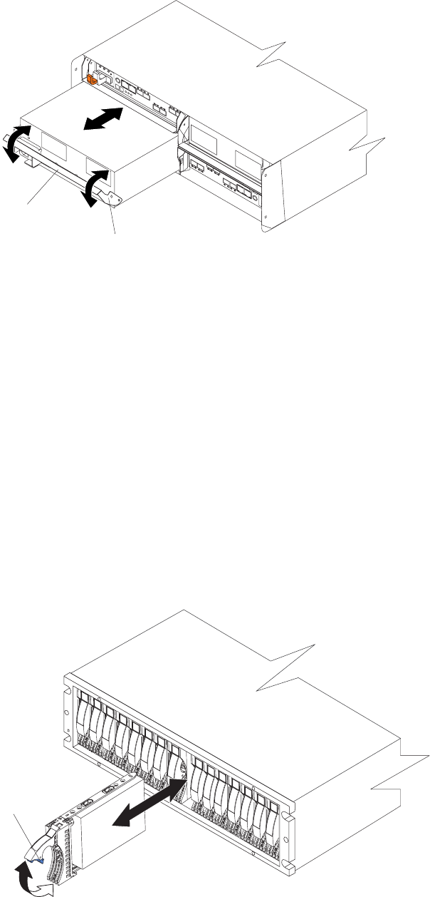
3. Place the power supply and fan unit on a level surface.
4. Repeat step 1 through step 3 for the second power supply and fan unit.
Removing an E-DDM
Complete the following steps to remove a hot-swap E-DDM:
Note: The E-DDM comes installed in a drive tray. Do not attempt to detach the
E-DDM from the tray.
1. Use Table 24 on page 166 to record the location and identify your E-DDMs. You
must record this information to be able to replace the E-DDMs in their original
order before they were removed.
2. Release the latch on the E-DDM CRU by pressing on the inside of the bottom
of the tray handle.
3. Lift the closed latch to its open position. (The latch is at a 90° angle to the front
of the E-DDM when open.)
4. Pull the E-DDM out of the bay, as shown in Figure 18.
Lever
Latch
Figure 17. Removing a power supply and fan unit
Latch
Figure 18. Removing an E-DDM CRU
Chapter 2. Installing the storage subsystem 39
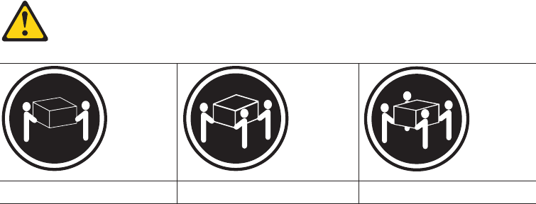
5. Place the E-DDM CRU horizontally on a level surface.
Attention: Do not stack E-DDM CRUs on top of one another. Protect the
E-DDM CRUs from vibrations or sudden shocks.
6. Repeat step 1 through step 4 on page 39 for additional E-DDM CRUs.
Installing the DS5020 into a rack on the support rails
Complete the following steps to install the DS5020 in the rack cabinet.
CAUTION:
Do not install modules or other equipment in the top half of a rack mount
cabinet while the bottom half is empty. Doing so can cause the cabinet to
become top-heavy and tip over. Always install hardware in the lowest
available position in the cabinet.
Statement 4:
≥18 kg (39.7 lb) ≥32 kg (70.5 lb) ≥55 kg (121.2 lb)
CAUTION:
Use safe practices when lifting.
1. Put the DS5020 on antistatic protection, and keep it on while you perform all of
the remaining procedures in this chapter.
2. Using a No. 2 Phillips screwdriver, remove the four M4 screws from the rails
(two screws in each rail). If you do not remove these screws, the storage
subsystem will not fit securely.
Note: If the screws are shipped in the hardware pack instead of already
installed in the rails, skip this step and go to step 3.
3. Place the storage subsystem in the rack.
Note: If you have removed the CRUs from the DS5020, you can lift the unit
into the cabinet with the help of one other person. If you have not
removed the CRUs before the installation, have at least two other people
available to help you lift the DS5020 into the rack.
a. Move the storage subsystem to the front of the rack mount cabinet.
b. With help from another person, place the back of the storage subsystem on
the support rails, and then slide the unit into the rack as shown in Figure 19
on page 41.
40 IBM System Storage DS5020 Storage Subsystem: Installation, User’s, and Maintenance Guide
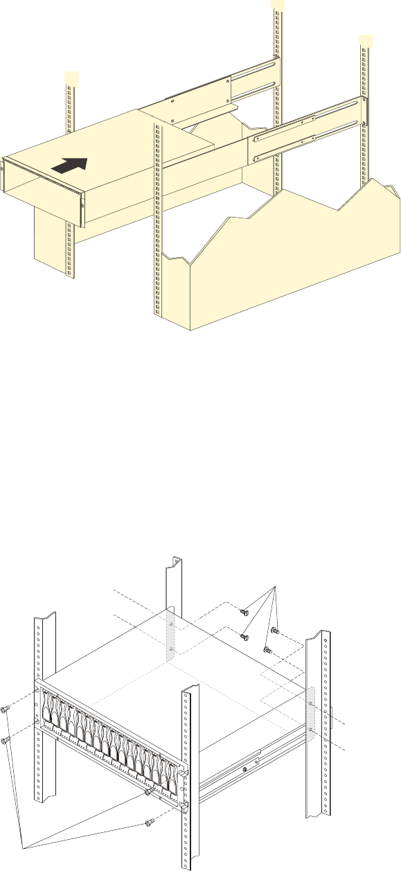
4. Secure the storage subsystem. Figure 20 shows how to secure the storage
subsystem to the rack.
a. Align the front mounting holes on each side of the storage subsystem with
the mounting holes on the front of the support rails.
b. Using the M4 screws that you removed in step 2 on page 40, secure the
sides in the back of the DS5020 to the rack rails.
c. Secure the front of the DS5020 using the four M5 screws as shown in
Figure 20.
Front of Rack
Figure 19. Installing the DS5020
M5 screws
M4 screws
Figure 20. Securing the DS5020 to the rack cabinet
Chapter 2. Installing the storage subsystem 41
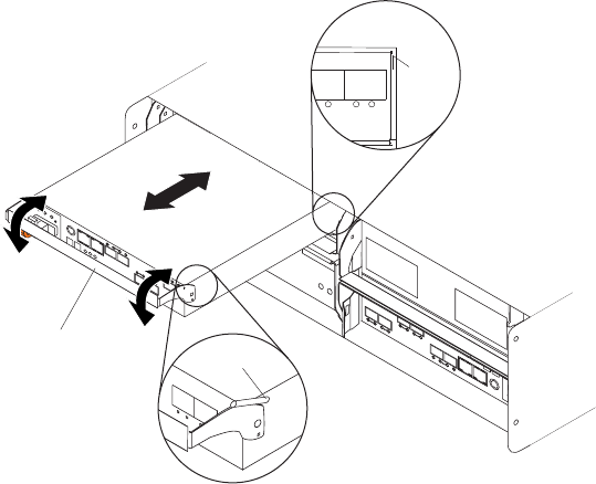
5. Continue with one of the following actions:
vIf you did remove the DS5020 CRUs before installation (as described in
“Removing the CRUs” on page 36), continue with “Replacing the
components.”
vIf you did not remove the DS5020 CRUs before installation, continue with
Chapter 3, “Cabling the storage subsystem,” on page 45.
Replacing the components
If you removed components from the DS5020 storage subsystem before you
installed it into a rack cabinet, use the following procedures to replace the
components in the DS5020 after it is installed successfully in a rack cabinet.
Replacing a controller
Complete the following steps to replace the controller that you removed before the
installation.
Attention: After you remove an controller, wait 70 seconds before reseating or
replacing the controller. Failure to do so might cause undesired events. The left and
right controllers are seated in the DS5020 chassis in opposite orientations. If you
cannot fully insert the controller into the controller bay, flip it 180° and reinsert it.
1. Slide one controller into the empty slot in the storage subsystem. Be sure that
the lever is pulled straight out as you slide the controller in, as shown in
Figure 21.
2. As you slide the controller into the empty slot, make sure the guide pins on the
side of the controller fit into the notches. After the guide pins fit into the notches
and the controller fits snugly into the bay, push the lever downward or upward
90°, depending on whether the controller is inserted in the A or B controller bay
to fully latch it into place. Do not force fit. The controller is designed to prevent it
from being inserted into the chassis incorrectly.
Attention: Make sure that the levers lock into place in the storage subsystem
chassis.
3. Repeat step 1 and step 2 to replace the second controller.
Lever
Guide pin
Notch
Figure 21. Removing and replacing a controller
42 IBM System Storage DS5020 Storage Subsystem: Installation, User’s, and Maintenance Guide
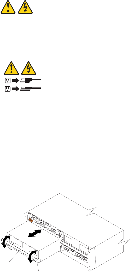
Replacing an ac power supply and fan unit
Statement 5:
CAUTION:
The power control button on the device and the power switch on the power
supply do not turn off the electrical current supplied to the device. The device
also might have more than one power cord. To remove all electrical current
from the device, ensure that all power cords are disconnected from the power
source.
1
2
CAUTION:
Disconnect the power cord before replacing the power supply and fan unit.
Complete the following steps to replace the power supply and fan units that you
removed before the installation:
1. Slide one power supply and fan unit into the storage subsystem. Be sure to
replace the power supply and fan units so that the lever on each power supply
and fan unit opens toward the interior of the storage subsystem, as shown in
Figure 22. Do not force fit. The power supply and fan unit is designed to prevent
it from being inserted into the chassis incorrectly.
Attention: Be sure that the lever is pulled straight out as you slide the power
supply and fan unit into the storage subsystem, as shown in Figure 22. The left
and right power supply and fan units are seated in the DS5020 chassis in
opposite orientations. If you cannot fully insert the power supply and fan unit
into the power supply and fan unit bay, flip it 180° and reinsert it.
2. As you slide the power supply and fan unit into the empty slot, make sure the
guide pins on the side of the power supply and fan unit fit into the notches
Lever
Latch
Figure 22. Replacing a power supply and fan unit
Chapter 2. Installing the storage subsystem 43
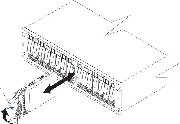
along the sides of the power supply and fan unit bay. After the guide pins fit into
the notches and power supply and fan unit fits snugly into the slot, push the
lever upward or downward 90° depending on whether the power supply fan is
inserted in the left or right bay to fully latch it into place. Push the front of the
power supply and fan unit in gently to make sure that it is fully seated.
3. Repeat step 1 on page 43 and step 2 on page 43 to replace the second power
supply and fan unit.
Replacing an E-DDM
Complete the following steps to replace the hot-swap E-DDMs that you removed
before the installation.
Attention: After you remove an E-DDM CRU, wait 70 seconds before replacing or
reseating the E-DDM CRU to allow the E-DDM to properly spin down. Failure to do
so might cause undesired events.
Note: Use Table 24 on page 166 to verify the proper replacement locations of your
E-DDMs.
1. Lift up on the handle and gently push the E-DDM CRU into the empty bay until
the hinge of the tray handle latches beneath the storage subsystem bezel, as
shown in Figure 23.
2. Push the tray handle down until the latch clicks into place.
3. Repeat step 1 and step 2 to replace additional E-DDMs.
Latch
Figure 23. Replacing an E-DDM
44 IBM System Storage DS5020 Storage Subsystem: Installation, User’s, and Maintenance Guide

Chapter 3. Cabling the storage subsystem
After the storage subsystem is installed in its permanent location, you must cable it
to hosts, drives, and other external devices, depending on your hardware
configuration.
This chapter addresses the following cabling and configuration topics:
v“Enclosure ID settings”
v“Fibre Channel loop and ID settings” on page 46
v“Working with SFPs and fiber-optic cables” on page 46
v“Connecting storage expansion enclosures to the DS5020” on page 54
v“Connecting hosts to the DS5020 using Fibre Channel host ports” on page 82
v“Connecting secondary interface cables” on page 78
v“Configuring the storage subsystem” on page 79
v“Installing the storage subsystem configuration” on page 91
v“Cabling the ac power supply” on page 91
Enclosure ID settings
The enclosure ID, comprised of two seven-segment numbers, is located on the
back of each controller next to the indicator lights. It provides a unique identifier for
each enclosure in the DS5020 storage subsystem configuration.
The controller automatically sets the enclosure ID number. You can change the
setting through the storage management software if necessary. Both controller
enclosure ID numbers are identical under normal operating conditions. Each
storage expansion enclosure (including the DS5020 storage subsystem) in the
DS5020 storage subsystem configuration must have a unique storage enclosure ID.
In addition, the single digits (x1) of the enclosure IDs of all storage expansion
enclosures and the DS5020 storage subsystem in the redundant drive channel/loop
pair must be unique.
Although the allowable ranges for enclosure ID settings are 0-99, do not set the
enclosure ID to 00 or any number less than 80. The DS5020 enclosure ID is usually
set to a value of 85 before it is shipped.
Figure 24 on page 46 shows the enclosure ID areas.
Note: Your DS5020 hardware might differ slightly from the following illustration.
© Copyright IBM Corp. 2009 45
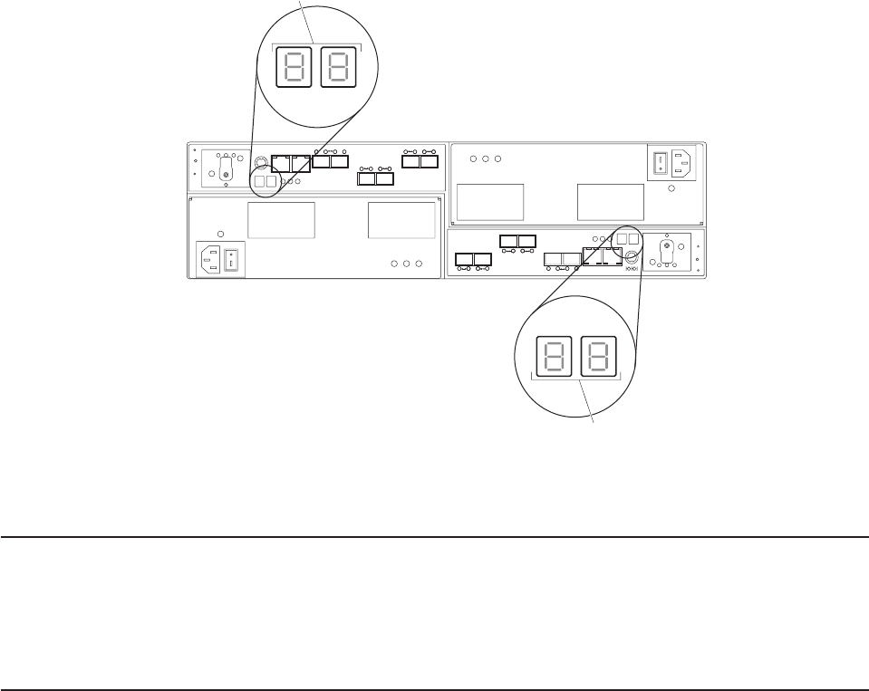
Fibre Channel loop and ID settings
When you install a hard disk drive in the storage subsystem, the drive tray plugs
into a printed circuit board called the midplane. The midplane sets the Fibre
Channel loop ID automatically, based on the enclosure ID switch setting and the
physical location (bay) of the hard disk drive.
Working with SFPs and fiber-optic cables
Each RAID controller has up to four single-ported host channel connections
(depending on the configuration you ordered) and two dual-ported drive channel
connections. A Small Form-factor Pluggable transceiver (SFP) connects each host
channel port and drive channel port to hosts and storage expansion enclosures.
Note: The SFPs are preinstalled in the DS5020.
The SFP is inserted into the port, and then a fiber-optic cable is inserted into the
SFP. The other end of the fiber-optic cable connects to an external device. SFPs
are laser products.
Enclosure ID
Enclosure ID
Figure 24. Storage subsystem seven-segment enclosure IDs
46 IBM System Storage DS5020 Storage Subsystem: Installation, User’s, and Maintenance Guide

Statement 3:
CAUTION:
When laser products (such as CD-ROMs, DVD drives, fiber-optic devices, or
transmitters) are installed, note the following:
vDo not remove the covers. Removing the covers of the laser product could
result in exposure to hazardous laser radiation. There are no serviceable
parts inside the device.
vUse of controls or adjustments or performance of procedures other than
those specified herein might result in hazardous radiation exposure.
DANGER
Some laser products contain an embedded Class 3A or Class 3B laser
diode. Note the following.
Laser radiation when open. Do not stare into the beam, do not view directly
with optical instruments, and avoid direct exposure to the beam.
Handling fiber-optic cables
Attention: To avoid damage to your fiber-optic cables, follow these guidelines:
vFor devices on slide rails, leave enough slack in the cables so they do not bend
to a diameter of less than 76 mm (3 in.), or a radius less than 38 mm (1.5 in.),
when extended or become pinched when retracted.
vDo not overtighten the cable straps or bend the cables to a diameter of less than
76 mm (3 in.), or a radius less than 38 mm (1.5 in.).
vWhen storing excess or unused fiber-optic cables, do not bend the cables to a
diameter of less than 76 mm (3 in.), or a radius less than 38 mm (1.5 in.) or wrap
them around themselves. See Figure 25 on page 48.
vMake sure you have a minimum loop diameter of 76 mm (3 in.) and a minimum
bend radius of 38 mm (1.5 in.) for fiber-optic cables. Loops or bends smaller than
these minimums might cause damage to your fiber-optic cables. Use loop
diameters and bend radii that are greater than these minimums.
vDo not route the cable along a folding cable-management arm.
vRoute the cable away from places where it can be damaged by other devices in
the rack cabinet.
vDo not put excess weight on the cable at the connection point. Be sure that the
cable is well supported.
vDo not use plastic cable ties in place of the provided cable straps.
vThe supported maximum lengths of OM2 category Fibre Channel cable are:
– 4 Gbps: 150 m (492 ft.) of 50/125 um fiber, 300 m (984 ft.) of 62.5/125 um
fiber
– 8 Gbps: 50 m (164 ft.) of 50/125 um fiber, 150 m (492 ft.) of 62.5/125 um fiber
Chapter 3. Cabling the storage subsystem 47
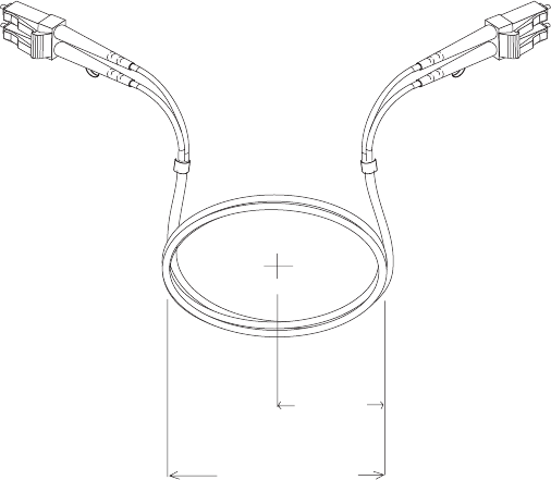
Installing SFP modules
The DS5020 requires SFP modules. SFP modules convert electrical signals to
optical signals that are required for Fibre Channel transmission to and from RAID
controllers.
Note: The SFPs are preinstalled in the DS5020.
If the SFPs are not preinstalled in your DS5020 hardware, or if you need to replace
them, use the information in this section to install the SFPs into the ports. After you
install the SFP modules, you can use fiber-optic cables to connect the DS5020 to
other Fibre Channel devices.
Before installing SFP modules and fiber-optic cables, read the following information:
vDo not mix long-wave SFPs and short-wave SFPs on a single storage
subsystem. Use only short-wave SFPs. You can use the DS Storage Manager
client to view the Storage Subsystem Profile to verify that you are not mixing
long-wave and short-wave SFPs.
Attention: Do not use long-wave SFPs or GBICs in any of the Fibre Channel
ports in the DS5020 controllers. (Long-wave SFPs and GBICs are not supported
for use in the DS5020 or any of the attached storage expansion enclosures.)
vThe SFP module housing has an integral guide key that is designed to prevent
you from inserting the SFP module improperly.
vUse minimal pressure when inserting an SFP module into an SFP port. Forcing
the SFP module into a port could cause damage to the SFP module or to the
port.
vYou can insert or remove the SFP module while the port is powered on.
vDo not install an SFP in any port that will not have a fiber-optic cable attached.
Remove any SFP from any port that does not have fiber-optic cables attached.
1.5 inch
(38 mm)
radius
3.0 inch
(76 mm)
diameter
Figure 25. Bending and looping specifications for fiber-optic cables
48 IBM System Storage DS5020 Storage Subsystem: Installation, User’s, and Maintenance Guide

vThe operational or redundant loop performance is not affected when you install
or remove an SFP module.
vYou must insert the SFP module into a port before you connect the fiber-optic
cable.
vYou must remove the fiber-optic cable from the SFP module before you remove
the SFP module from the port. Refer to “Removing SFP modules” on page 50 for
more information.
vThe maximum operating speed of the Fibre Channel port is determined by two
factors: the speed of the SFP module that is installed and the speed of the Fibre
Channel connection. For example, a 4 Gbps SFP that is plugged into an 8
Gbps-capable port will limit the speed of that port to a maximum of 4 Gbps.
Conversely, an 8 Gbps SFP that is plugged into a 4 Gbps-capable port will limit
the speed of the port to a maximum of 4 Gbps.
Attention: Carefully check the SFP IBM part number, option number, and FRU
part number to identify its speed. There are no physical features that distinguish
a 4 Gbps SFP from an 8 Gbps SFP.
Statement 3:
CAUTION:
When laser products (such as CD-ROMs, DVD drives, fiber-optic devices, or
transmitters) are installed, note the following:
vDo not remove the covers. Removing the covers of the laser product could
result in exposure to hazardous laser radiation. There are no serviceable
parts inside the device.
vUse of controls or adjustments or performance of procedures other than
those specified herein might result in hazardous radiation exposure.
DANGER
Some laser products contain an embedded Class 3A or Class 3B laser
diode. Note the following.
Laser radiation when open. Do not stare into the beam, do not view directly
with optical instruments, and avoid direct exposure to the beam.
Attention: When you handle static-sensitive devices, take precautions to avoid
damage from static electricity. For details about handling static-sensitive devices,
see “Handling static-sensitive devices” on page 29.
To install an SFP module, complete the following steps:
1. Remove the SFP module from its static-protective package.
2. Remove the protective cap from the SFP module, as shown in Figure 26 on
page 50. Save the protective cap for future use.
Chapter 3. Cabling the storage subsystem 49
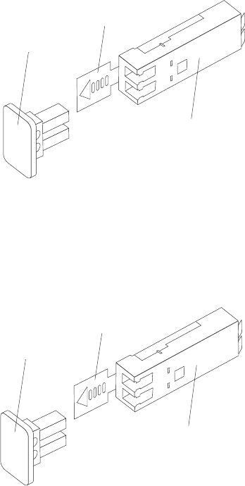
3. Remove the protective cap from the SFP port. Save the protective cap for future
use.
4. Insert the SFP module into the host port until it clicks into place. See Figure 27.
5. Connect an LC-LC Fibre Channel cable. For information about the LC-LC cable,
see “Using LC-LC Fibre Channel cables” on page 51.
Removing SFP modules
Complete the following steps to remove the SFP module from the host port:
Attention: To avoid damage to the cable or to the SFP module, make sure that
you unplug the LC-LC Fibre Channel cable before you remove the SFP module.
1. Remove the LC-LC Fibre Channel cable from the SFP module. For more
information, see “Removing an LC-LC Fibre Channel cable” on page 54.
2. Unlock the SFP module latch:
vFor SFP modules that contain plastic tabs, unlock the SFP module latch by
pulling the plastic tab outward 10°, as shown in Figure 28 on page 51.
Protective cap
Plastic tab
SFP module
Figure 26. SFP module and protective cap
Protective cap
Plastic tab
SFP module
Figure 27. Installing an SFP module into the host port
50 IBM System Storage DS5020 Storage Subsystem: Installation, User’s, and Maintenance Guide
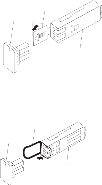
vFor SFP modules that contain wire tabs, unlock the SFP module latch by
pulling the wire latch outward 90°, as shown in Figure 29.
3. With the SFP latch in the unlocked position, extract the SFP module.
vFor SFP modules that contain plastic tabs, slide the SFP module out of the
port.
vFor SFP modules that contain wire tabs, grasp the wire latch and pull the
SFP module out of the mini-hub port.
4. Replace the protective cap on the SFP module.
5. Place the SFP module into a static-protective package.
6. Replace the protective cap on the host port.
Using LC-LC Fibre Channel cables
The LC-LC Fibre Channel cable is a fiber-optic cable that you use to connect
DS5020 Fibre Channel ports into one of the following devices:
vAn SFP module installed in a Fibre Channel switch port
vAn SFP module of the host bus adapter port
vAn SFP module installed in an IBM DS5000 or DS4000 storage expansion
enclosure
See Figure 30 on page 52 for an illustration of the LC-LC Fibre Channel cable.
For more information about cabling these devices, see the documentation that
comes with the LC-LC Fibre Channel cable.
10
o
SFP module
Protective cap
Plastic tab
Figure 28. Unlocking the SFP module latch - plastic variety
o
Protective
cap
Wire
tab
SFP
module
90
Figure 29. Unlocking the SFP module latch - wire variety
Chapter 3. Cabling the storage subsystem 51
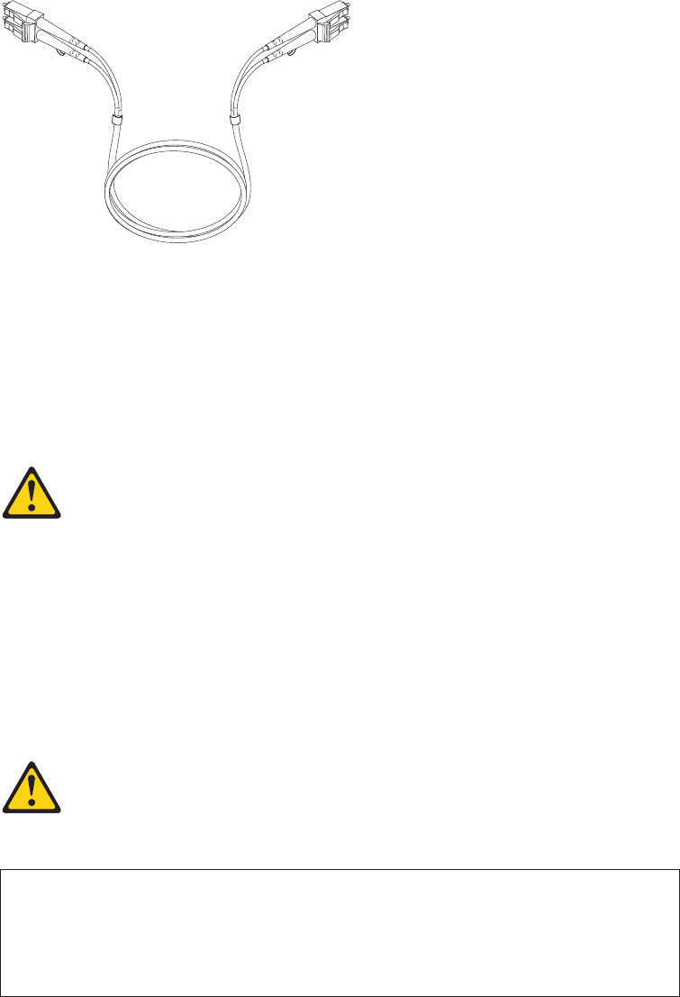
Connecting an LC-LC cable to an SFP module
Complete the following steps to connect an LC-LC Fibre Channel cable to an SFP
module:
Statement 3:
CAUTION:
When laser products (such as CD-ROMs, DVD drives, fiber-optic devices, or
transmitters) are installed, note the following:
vDo not remove the covers. Removing the covers of the laser product could
result in exposure to hazardous laser radiation. There are no serviceable
parts inside the device.
vUse of controls or adjustments or performance of procedures other than
those specified herein might result in hazardous radiation exposure.
DANGER
Some laser products contain an embedded Class 3A or Class 3B laser
diode. Note the following.
Laser radiation when open. Do not stare into the beam, do not view directly
with optical instruments, and avoid direct exposure to the beam.
1. Read the information in “Handling fiber-optic cables” on page 47.
2. If necessary, remove the protective cap from the SFP module, as shown in
Figure 26 on page 50. Save the protective cap for future use.
3. Remove the two protective caps from one end of the LC-LC cable, as shown in
Figure 31 on page 53. Save the protective caps for future use.
Figure 30. LC-LC Fibre Channel cable
52 IBM System Storage DS5020 Storage Subsystem: Installation, User’s, and Maintenance Guide
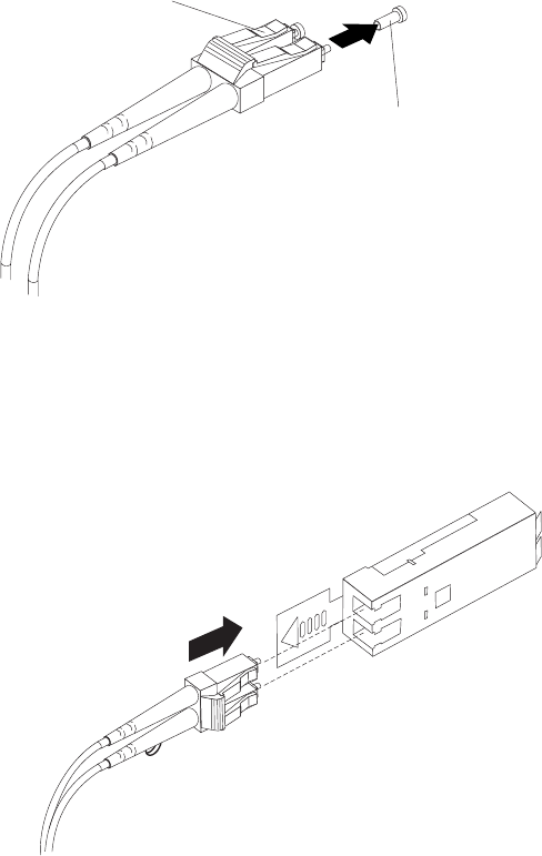
4. Carefully insert this end of the LC-LC cable into an SFP module that is installed
in the DS5020. The cable connector is keyed so it will be inserted into the SFP
module correctly. Holding the connector, push in the cable until it clicks into
place, as shown in Figure 32.
5. Remove the two protective caps from the other end of the LC-LC cable. Save
the protective caps for future use.
6. Connect this end of the LC-LC cable to one of the following devices:
vAn SFP module that is installed in a separate storage expansion enclosure
vAn SFP module that is installed in a Fibre Channel switch port
vA Fibre Channel host bus adapter port
Protective cap
Fibre-optic
cable
Figure 31. Removing fiber-optic cable protective caps
Figure 32. Inserting an LC-LC Fibre Channel cable into an SFP module
Chapter 3. Cabling the storage subsystem 53
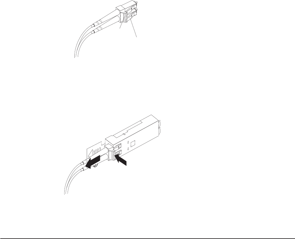
Removing an LC-LC Fibre Channel cable
Complete the following steps to remove an LC-LC Fibre Channel cable:
Attention: To avoid damaging the LC-LC cable or SFP module, make sure that
you observe the following precautions:
vPress and hold the lever to release the latches before you remove the cable from
the SFP module.
vMake sure that the levers are in the released position when you remove the
cable.
vDo not grasp the SFP module plastic tab when you remove the cable.
1. On the end of the LC-LC cable that connects into the SFP module or host bus
adapter, press down and hold the lever to release the latches, as shown in
Figure 33.
Lever
Latches
2. While pressing down the cable lever, carefully pull on the connector to remove
the cable from the SFP module, as shown in Figure 34.
3. Replace the protective caps on the cable ends.
4. Replace the protective cap on the SFP module.
Connecting storage expansion enclosures to the DS5020
Attention: Before you turn on the power to the DS5020 storage subsystem, it
must be populated with at least two E-DDMs. If at least two E-DDMs are not
installed in the DS5020, an insufficient load to the enclosure power supplies might
cause them to intermittently appear as failed, falsely indicating the power supplies
are bad. All of the E-DDMs in the DS5020 storage subsystem and the connected
storage expansion enclosure or enclosures must contain no prior configuration data.
Figure 33. LC-LC Fibre Channel cable lever and latches
Figure 34. Removing the LC-LC Fibre Channel cable
54 IBM System Storage DS5020 Storage Subsystem: Installation, User’s, and Maintenance Guide
In the initial installation of the DS5020, you can add only new storage expansion
enclosures to the DS5020 storage subsystem. This means there must be no
existing configuration information about the storage expansion enclosures that you
want to install.
The DS5020 supports the attachment of up to six EXP520 and EXP810 storage
expansion enclosures, resulting in the capability to connect up to 112 E-DDMs and
enabling storage configurations of over 49 TB using 450 GB Fibre Channel E-DDMs
or 112 TB using 1 TB SATA E-DDMs.
The base DS5020 storage subsystem supports up to 32 drives, which includes 16
drives in the DS5020 chassis and 16 more drives in an attached storage expansion
enclosure. To attach more than 32 drives, you much purchase the applicable
feature option.
To attach additional drives to the DS5020, you can use EXP520 or EXP810 storage
expansion enclosures. You can connect EXP520 storage expansion enclosures to
the DS5020 without purchasing feature options. To attach an EXP810 storage
expansion enclosure or enclosures to the DS5020, you must purchase the Attach
EXP810 to DS5020 Activation feature option. Contact your IBM marketing
representative or IBM reseller for more information.
To connect 33 - 64 drives in one DS5020 and three EXP520 storage expansion
enclosures, you must purchase the DS5020 Drive Attach 33 - 64 feature option. If
you need to connect 65 - 112 drives in a DS5020 configuration, you must purchase
the DS5020 Drive Attach 65- 112 feature option in addition to the DS5020 Drive
Attach 33 - 64 feature option. These two feature options enable you to attach the
additional drives in one DS5020 and six EXP520 storage expansion enclosures.
Contact your IBM marketing representative or IBM reseller for more information.
If the storage expansion enclosures that you want to install currently contain logical
drives or configured hot spares, and you want them to be a part of the DS5020
storage subsystem configuration, refer to the IBM System Storage DS4000 Hard
Drive and Storage Expansion Enclosure Installation and Migration Guide. Improper
drive migration might cause loss of configuration and other storage subsystem
problems. Contact your IBM technical support representative for additional
information.
Redundant drive channel pair
Each controller on the DS5020 has drive channel ports. The storage expansion
enclosures that are connected to these ports form a drive channel (also referred to
as drive loop). The maximum number of hard drives that can be installed in one
drive channel is 112. One drive channel from each controller combines to form a
redundant drive channel pair.
Figure 35 on page 56 shows an example of a redundant drive channel pair. If any
component of the drive channel fails, the RAID controllers can still access the
storage expansion enclosures in the redundant drive channel pair.
Note: In the following drive cabling figures, the DS5020 graphics are simplified to
show only the drive ports of each controller.
Chapter 3. Cabling the storage subsystem 55
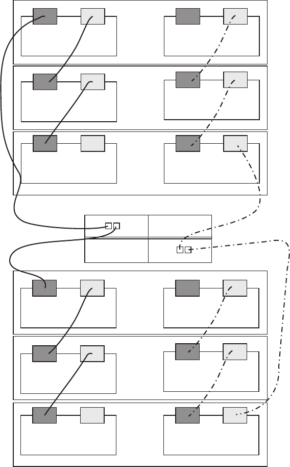
Overview of steps to connect storage expansion enclosures to a
storage subsystem
To connect storage expansion enclosures to the storage subsystem, perform the
following steps:
Note: The following procedures are for ″cold-case″procedures (in which the
DS5020 is powered down when storage expansion enclosures are
connected, as in the case of initial installation). For ″hot-case″procedures (in
which the DS5020 is powered on when storage expansion enclosures are
connected), refer to the IBM System Storage DS4000 Hard Drive and
Storage Expansion Enclosure Installation and Migration Guide.
Drive
Channel 2, port 1
Redundant
Drive Channel
pair
Left ESM
Left ESM
Left ESM
Right ESM
Right ESM
Right ESM
Drive Drive
Left ESM
Left ESM
Left ESM
Right ESM
Right ESM
Right ESM
DS5020
Channel 2, port 2Channel 1, port 1
Drive
Channel 1, port 2
Figure 35. Example of a redundant drive channel pair
56 IBM System Storage DS5020 Storage Subsystem: Installation, User’s, and Maintenance Guide
1. Follow the instructions in the Installation, User’s, and Maintenance Guide for
your DS5000 or DS4000 storage expansion enclosure to set up and mount the
storage expansion enclosures.
2. Select a cabling topology appropriate for the number of storage expansion
enclosures you will connect to the DS5020. If you are connecting external
storage expansion enclosures to the DS5020, make sure that the storage
expansion enclosures are populated with at least two drives before you turn on
the power. In addition, you must have at least two drives in the DS5020 storage
subsystem before you power it on.
“DS5020 storage subsystem drive cabling topologies” describes the schemes for
cabling different numbers of storage expansion enclosures to the DS5020 and
to each other (if you are connecting more than one storage expansion
enclosure).
3. After you select the cabling topology for your configuration, follow the cabling
diagram for your chosen topology and perform the steps identified in “DS5020
storage subsystem and supported storage expansion enclosure drive cabling
schemes” on page 67.
4. If required, set unique enclosure IDs for all storage expansion enclosures that
are cabled to the DS5020. See “Storage expansion enclosure ID settings” on
page 78, and then refer to your storage expansion enclosure installation manual
for details on setting the enclosure ID.
The DS5020 storage subsystem locates the drives in the storage expansion
enclosures after you turn on the power to the configuration. Always connect power
to the storage expansion enclosures first and then connect power to the DS5020.
After you have powered on the configuration, use the DS Storage Manager client to
check the status of the new drives, correct any errors found, and configure the new
drives.
Notes:
1. EXP810 and EXP520 storage expansion enclosures can be intermixed behind a
DS5020 drive channel.
2. To cable EXP810 storage expansion enclosures with a DS5020, you must
purchase the Attach EXP810 to DS5020 Activation feature option.
DS5020 storage subsystem drive cabling topologies
This section provides preferred cabling topologies for cabling storage expansion
enclosures to the DS5020 storage subsystem. The cabling topologies include the
following:
v“One DS5020 and one storage expansion enclosure” on page 59
v“One DS5020 and two storage expansion enclosures” on page 60
v“One DS5020 and three storage expansion enclosures” on page 62
v“One DS5020 and four storage expansion enclosures” on page 63
v“One DS5020 and up to six storage expansion enclosures” on page 64
v“One DS5020 and two or more storage expansion enclosures in a mixed
configuration” on page 66
Each example provides redundant paths to the drives. If one of these examples is
suitable for your hardware and application, complete the cabling connections as
described by the graphics. If you have hardware other than what is shown in these
examples to include in your topology, use these examples as a starting point for
creating your specific topology.
Chapter 3. Cabling the storage subsystem 57
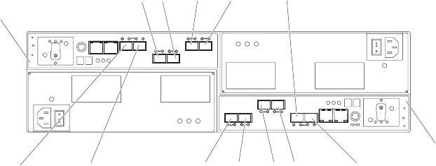
Important: The DS5020 supports the connection of a maximum of six storage
expansion enclosures per redundant drive channel pair. The DS5020
supports one redundant drive channel pair.
If you are using fiber-optic cables, install SFP modules into the ports that will
receive the cables before installing the cables.
Figure 36 and shows the locations of controllers A and B, the single-ported Fibre
Channel host channels, Ethernet ports, and dual-ported Fibre Channel drive
channels at the back of the DS5020 storage subsystem.
Note: Your DS5020 hardware might differ slightly from the following illustration.
Notes:
1. EXP810 and EXP520 storage expansion enclosures can be intermixed behind a
DS5020 drive channel.
2. To cable EXP810 storage expansion enclosures with a DS5020, you must
purchase the Attach EXP810 to DS5020 Activation feature option.
Controller B
Controller A
Host
port 4
Host
port 3
Host
port 2
Host
port 1
Host
port 1
Host
port 2
Host
port 3
Host
port 4
Drive Channel 1 -
Port 2 on Controller A
Drive Channel 1 -
Port 1 on Controller A
Drive Channel 2 -
Port 2 on Controller B
Drive Channel 2 -
Port 1 on Controller B
Figure 36. DS5020 storage subsystem ports and controllers
58 IBM System Storage DS5020 Storage Subsystem: Installation, User’s, and Maintenance Guide
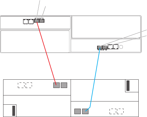
One DS5020 and one storage expansion enclosure
If you are cabling one DS5020 storage subsystem to one storage expansion
enclosure, Figure 37 shows the correct cabling topology.
Note: Figure 37 illustrates the drive channel connections between the DS5020 and
the storage expansion enclosures. Do not use Figure 37 as the cabling
diagram. Follow the instructions in “DS5020 storage subsystem and
supported storage expansion enclosure drive cabling schemes” on page 67
for specific cabling instructions.
DS5020
Port 2, drive channel 1
Port 1, drive channel 1
Port 1, drive channel 2
Port 2, drive channel 2
1A
1B
1A 1B
Figure 37. Cabling for one DS5020 and one storage expansion enclosure
Chapter 3. Cabling the storage subsystem 59
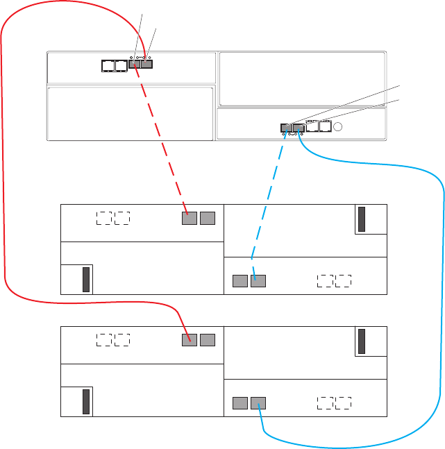
One DS5020 and two storage expansion enclosures
If you are cabling one DS5020 storage subsystem and two storage expansion
enclosures, connect one storage expansion enclosure per controller drive port as
shown in Figure 38. Figure 39 on page 61 shows that you can also connect two
expansion enclosures together behind a single controller drive port. Although this is
technically correct, use the topology as shown in Figure 38.
As Figure 38 shows, when you connect additional storage expansion enclosures,
you can connect them by using the additional port of the drive channel.
When you connect additional storage expansion enclosures, you can connect them
by continuing the connection from the existing redundant drive channel pair.
DS5020
Port 2, drive channel 1
Port 1, drive channel 1
Port 1, drive channel 2
Port 2, drive channel 2
1A
1B
1A 1B
1A
1B
1A 1B
Figure 38. Cabling for one DS5020 and two storage expansion enclosures
60 IBM System Storage DS5020 Storage Subsystem: Installation, User’s, and Maintenance Guide
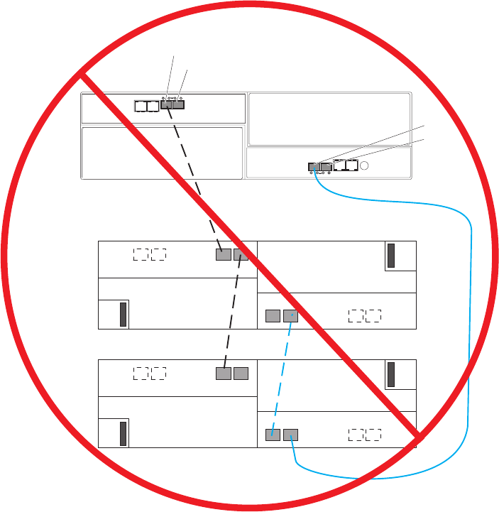
Important: Do not cable the DS5020 storage subsystem and two storage
expansion enclosures as shown in Figure 39. A storage array with the
incorrect storage topology might appear to be functional, but incorrect
cabling can potentially have unpredictable results.
DS5020
Port 2, drive channel 1
Port 1, drive channel 1
Port 1, drive channel 2
Port 2, drive channel 2
1A
1B
1A 1B
1A
1B
1A 1B
Figure 39. Incorrect cabling of one DS5020 and two storage expansion enclosures
Chapter 3. Cabling the storage subsystem 61
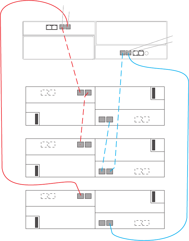
One DS5020 and three storage expansion enclosures
If you are cabling one DS5020 storage subsystem and three storage expansion
enclosures, Figure 40 shows the correct cabling topology.
1A
1B
DS5020
Port 2, drive channel 1
1A 1B
1A
1B
1A
1B
Port 1, drive channel 1
Port 1, drive channel 2
Port 2, drive channel 2
1A 1B
1A 1B
Figure 40. Cabling for one DS5020 and three storage expansion enclosures
62 IBM System Storage DS5020 Storage Subsystem: Installation, User’s, and Maintenance Guide
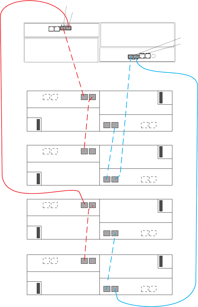
One DS5020 and four storage expansion enclosures
If you are cabling one DS5020 storage subsystem and four storage expansion
enclosures, Figure 41 shows the correct cabling topology.
1A
1B
DS5020
Port 2, drive channel 1
1A 1B
1A
1B
1A
1B
Port 1, drive channel 1
Port 1, drive channel 2
Port 2, drive channel 2
1A 1B
1A 1B
1A
1B
1B
1A
Figure 41. Cabling for one DS5020 and four storage expansion enclosures
Chapter 3. Cabling the storage subsystem 63
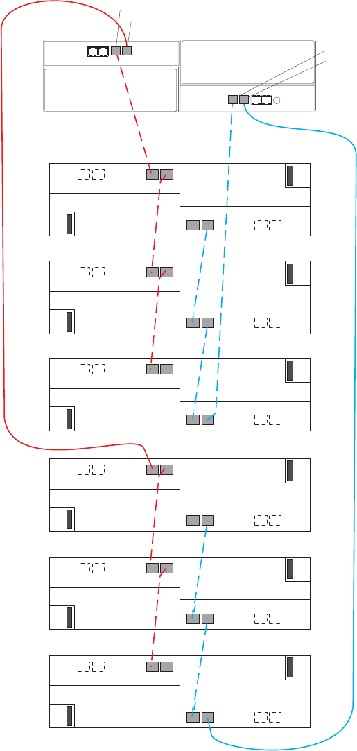
One DS5020 and up to six storage expansion enclosures
If you are cabling one DS5020 storage subsystem and up to six storage expansion
enclosures, Figure 42 shows the correct cabling topology.
1A
1B
DS5020
Port 2, drive channel 1
1A 1B
1A
1B
1A
1B
Port 1, drive channel 1
Port 1, drive channel 2
Port 2, drive channel 2
1A 1B
1B
1A
1B
1A 1B
1A
1B
1B
1A
1B
1B
1A
1A
1A
Figure 42. Cabling for one DS5020 and up to six storage expansion enclosures
64 IBM System Storage DS5020 Storage Subsystem: Installation, User’s, and Maintenance Guide
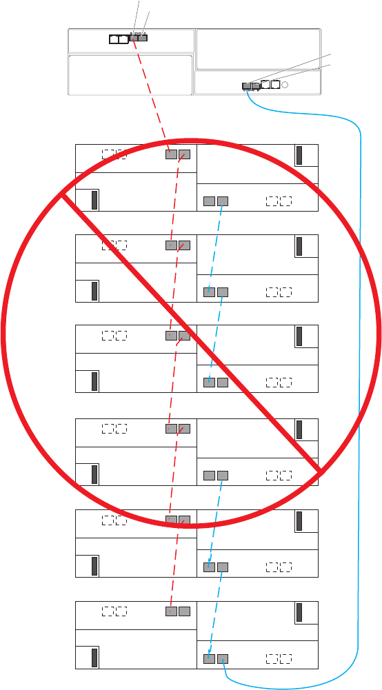
Important: Do not cable the storage subsystem and storage expansion enclosures
as shown in Figure 43. A storage array with the incorrect storage
topology might appear to be functional, but incorrect cabling can
potentially have unpredictable results.
One DS5020 and two or more storage expansion enclosures in a
mixed configuration
A mixed configuration is a configuration in which you have more than one type of
storage expansion enclosure. Figure 44 on page 67 shows the cabling topology if
you have three EXP520s and three EXP810s attached to the DS5020. (The
1A
1B
1A 1B
1A
1B
1A
1B
1A 1B
1B
1A
1B
1A 1B
1A
1B
1B
1A
1B
1B
1A
1A
1A
DS5020
Port 2, drive channel 1
Port 1, drive channel 1
Port 1, drive channel 2
Port 2, drive channel 2
Figure 43. Cabling for one DS5020 and up to six storage expansion enclosures
66 IBM System Storage DS5020 Storage Subsystem: Installation, User’s, and Maintenance Guide
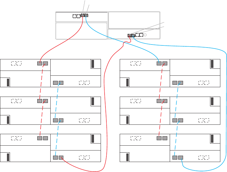
EXP520s are denoted in the graphic as 1 while the EXP810s are denoted as
2.)
DS5020 storage subsystem and supported storage expansion
enclosure drive cabling schemes
The DS5020 supports only EXP520 and EXP810 storage expansion enclosures. To
attach one or more EXP810 storage expansion enclosures to the DS5020 storage
subsystem, you must purchase the Attach EXP810 to DS5020 Activation feature
option. Contact your IBM marketing representative for more information about
purchasing feature options.
The cabling schemes for the EXP520 and EXP810 storage expansion enclosures
are the same. This section describes the instructions only for the EXP520; use the
same diagrams and procedures to cable the DS5020 to one or more EXP810
storage expansion enclosures.
The following sections show cabling schemes for supported storage expansion
enclosures and the DS5020 storage subsystem:
v“One DS5020 and one EXP520 storage expansion enclosure” on page 70
v“One DS5020 and two EXP520 storage expansion enclosures” on page 71
v“One DS5020 and three or more EXP520 storage expansion enclosures” on
page 72
DS5020 storage subsystem drive cabling rules
Refer to these general rules when you complete the cabling steps in the cabling
schemes described in this section.
1A
1B
DS5020
Port 2, drive channel 1
1A 1B
1A
1B
1A
1B
Port 1, drive channel 1
Port 1, drive channel 2
Port 2, drive channel 2
1A 1B
1A 1B
EXP520
EXP520
EXP520
1A
1B
1A 1B
1A
1B
1A
1B
1A 1B
1A 1B
EXP810
EXP810
EXP810
Figure 44. Cabling for one DS5020 and two or more storage expansion enclosures in a
mixed environment
Chapter 3. Cabling the storage subsystem 67
1. Do not connect a combination of more than six EXP520 or EXP810 storage
expansion enclosures to the two ports of a dual-ported drive channel. Failure
to observe this limitation might result in loss of data availability. In the DS5020
storage subsystem environment, no more than six EXP520 or EXP810 storage
expansion enclosures can be connected to the two ports of a dual-ported drive
channel because of the internal drive slots in the DS5020 storage subsystem.
2. Do not connect more than four EXP520 or EXP810 storage expansion
enclosures to each port of a dual-ported drive channel.
3. Add storage expansion enclosures to the storage subsystem drive ports in a
round-robin fashion. For example, if you have four drive expansion enclosures
to be cabled to the storage subsystem, instead of cabling all four drive
expansion enclosures to one drive port of a drive channel, distribute the
enclosures to all drive ports, which results in one enclosure per drive port of a
drive channel.
4. Do not connect more than the maximum number of enclosures per drive
channel, which is eight for EXP520s and EXP810s.
5. The DS5020 storage subsystem supports the connection of a maximum of six
storage expansion enclosures per redundant drive channel loop and supports
one redundant drive channel loop pair. Failure to observe this limitation might
result in loss of data availability.
6. The DS5020 currently supports a maximum of 112 drives in six 16-drive
storage expansion enclosures per drive channel in each controller. One drive
channel from each of controllers A and B must be connected to the same set
of storage expansion enclosures to provide drive channel redundancy. Do not
connect a combination of more than six storage expansion enclosures to the
two ports of a single drive channel.
7. When connecting six storage expansion enclosures to a DS5020, use all ports
in both drive channels. See Figure 42 on page 64 for the cabling topology.
8. Connect a maximum of four EXP520s or EXP810s per DS5020 controller drive
port.
9. When mixing different types of storage expansion enclosures in the same drive
channel pair, the link rate Setting must be the same for each storage
expansion enclosure. IBM does not support different enclosure speed settings
in the same drive channel.
10. The controller drive ports of the DS5020 storage subsystem controllers must
always be connected to ports labeled 1B in both the right and left ESMs of the
EXP810s in the redundant drive channel/loop pair that is connected to the
DS5020 storage subsystem. Figure 45 on page 69 shows the location of the
ports.
11. To attach EXP810 storage expansion enclosures to the DS5020, you must
purchase the Attach EXP810 to DS5020 Activation feature option. Contact your
IBM marketing representative for more information.
12. To attach 33 - 64 additional drives to the DS5020, you must purchase the
DS5020 Drive Attach 33 - 64 feature option. To attach 65 - 112 additional
drives to the DS5020. you must purchase the DS5020 Drive Attach 65- 112
feature option in addition to the DS5020 Drive Attach 33 - 64 feature option.
Contact your IBM marketing representative for more information.
68 IBM System Storage DS5020 Storage Subsystem: Installation, User’s, and Maintenance Guide
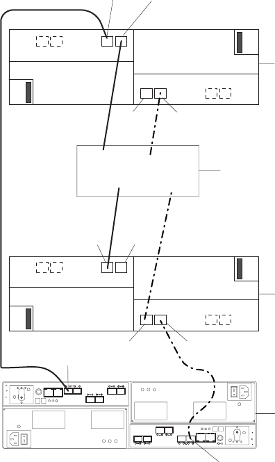
13. The DS5020 supports the intermix of SATA and Fibre Channel E-DDMs within
the same drive enclosure.
ESM B
ESM A
EXP810
ESM B
ESM A
EXP810
First EXP810
storage expansion
enclosure
Last EXP810
storage expansion
enclosure
DS5020
ESM
port 1A
ESM
port 1B
ESM
port 1A
ESM
port 1A
ESM
port 1B
ESM
port 1A
ESM
port 1A
ESM
port 1B
Drive channel
port
Other storage
expansion
enclosures
Drive channel
port
Figure 45. DS5020 drive ports connected to EXP810 ESM ports labeled 1B
Chapter 3. Cabling the storage subsystem 69
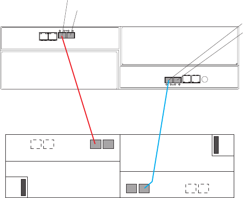
One DS5020 and one EXP520 storage expansion enclosure
Figure 46 shows the cabling scheme for one DS5020 storage subsystem and one
EXP520 storage expansion enclosure.
Perform the following steps to create the cabling scheme shown in Figure 46:
1. Connect either port 2 or port 1 of the dual-ported drive channel 1 in controller A
on the DS5020 to port 1B on the left ESM of the EXP520.
2. Connect either port 1 or port 2 of the dual-ported drive channel 2 in controller B
on the DS5020 to port 1B on the right ESM of the EXP520.
1A
1B
DS5020
Port 2, drive channel 1
1A 1B
Port 1, drive channel 1
Port 1, drive channel 2
Port 2, drive channel 2
EXP520
Figure 46. Cabling for one DS5020 and one EXP520 storage expansion enclosure
70 IBM System Storage DS5020 Storage Subsystem: Installation, User’s, and Maintenance Guide
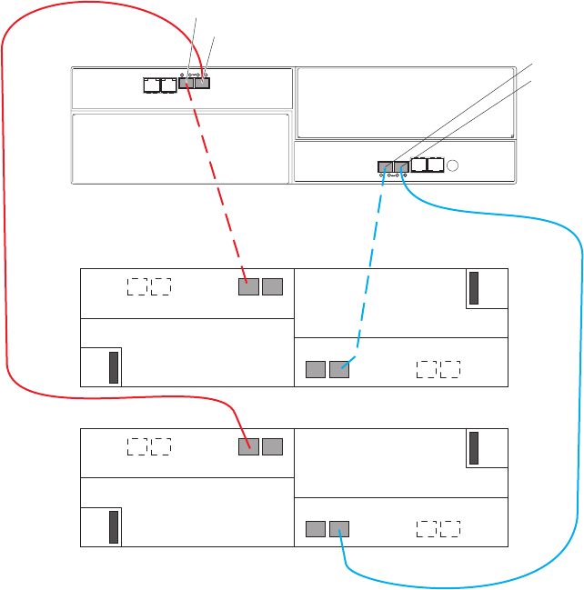
One DS5020 and two EXP520 storage expansion enclosures
Figure 47 shows the cabling scheme for one DS5020 storage subsystem and two
EXP520 storage expansion enclosures behind both ports of a dual-ported drive
channel.
Perform the following steps to create the cabling scheme shown in Figure 47:
1. Connect port 2 of drive channel 1 on the DS5020 to port 1B on the left ESM in
the EXP520 one.
2. Connect port 1B on the right ESM in EXP520 one to port 1 of drive channel 2
on the DS5020.
3. Connect port 1 of drive channel 1 on the DS5020 to port 1B on the left ESM in
EXP520 two.
4. Connect port 1B on the right ESM in EXP520 two to port 2 of drive channel 2
on the DS5020.
1A
1B
DS5020
Port 2, drive channel 1
1A 1B
1A
1B
Port 1, drive channel 1
Port 1, drive channel 2
Port 2, drive channel 2
1A 1B
EXP520 one
EXP520 two
Figure 47. One DS5020 and two EXP520 storage expansion enclosures behind a pair of
DS5020 drive ports
Chapter 3. Cabling the storage subsystem 71
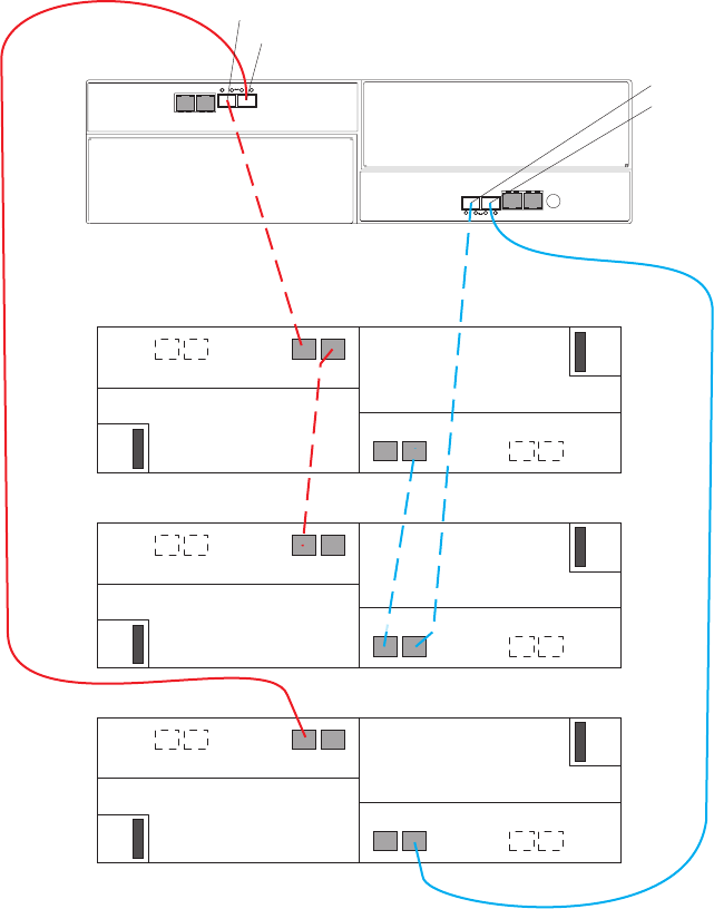
One DS5020 and three or more EXP520 storage expansion
enclosures
To connect three or more storage expansion enclosures to a DS5020 storage
subsystem, alternately connect a storage expansion enclosure to one of the drive
ports of the dual-ported drive channel then connect to the other port until all of the
storage expansion enclosures are attached. Figure 48 shows the cabling scheme
for one DS5020 storage subsystem and three EXP520 storage expansion
enclosures behind both ports of a dual-ported drive channel.
Perform the following steps to create the cabling scheme shown in Figure 48:
1. Connect port 1A on the left ESM in EXP520 one to port 1B on the left ESM in
EXP520 three.
2. Connect port 1A on the right ESM in EXP520 three to port 1B on the right ESM
in EXP520 one.
3. Connect port 1B on the left ESM in EXP520 one to port 2 of drive channel 1 on
the DS5020.
1A
1B
DS5020
Port 2, drive channel 1
1A 1B
1A
1B
1A
1B
Port 1, drive channel 1
Port 1, drive channel 2
Port 2, drive channel 2
1A 1B
1A 1B
EXP520 one
EXP520 two
EXP520 three
Figure 48. One DS5020 and three EXP520 storage expansion enclosures behind a pair of
DS5020 drive ports
72 IBM System Storage DS5020 Storage Subsystem: Installation, User’s, and Maintenance Guide
4. Connect port 1 of drive channel 2 on the DS5020 to port 1B on the right ESM in
EXP520 three.
5. Connect port 1B on the left ESM in EXP520 two to port 1 of drive channel 1 on
the DS5020.
6. Connect port 1B on the right ESM in EXP520 two to port 2 of drive channel 2
on the DS5020.
Figure 49 on page 74 shows the cabling scheme for one DS5020 storage
subsystem and four EXP520 storage expansion enclosures behind both ports of a
dual-ported drive channel.
Chapter 3. Cabling the storage subsystem 73
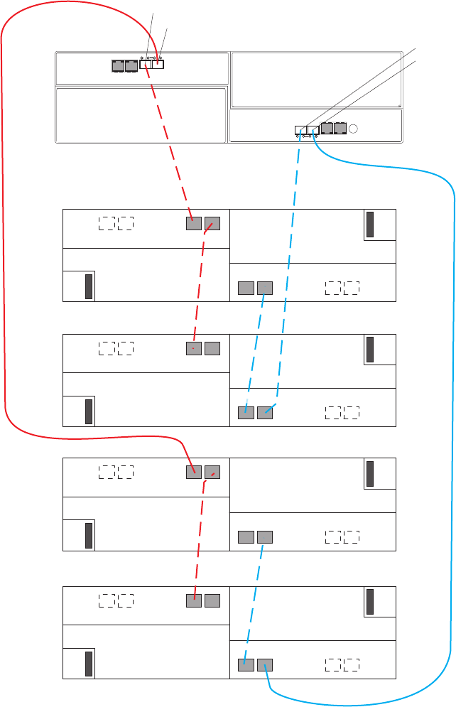
Perform the following steps to create the cabling scheme shown in Figure 49:
1. Connect port 1A on the left ESM in EXP520 one to port 1B on the left ESM in
EXP520 three.
2. Connect port 1A on the right ESM in EXP520 three to port 1B on the right ESM
in EXP520 one.
3. Connect port 1B on the left ESM in EXP520 one to port 2 of drive channel 1 on
the DS5020.
4. Connect port 1 of drive channel 2 on the DS5020 to port 1B on the right ESM in
EXP520 three.
1A
1B
DS5020
Port 2, drive channel 1
1A 1B
1A
1B
1A
1B
Port 1, drive channel 1
Port 1, drive channel 2
Port 2, drive channel 2
1A 1B
1A 1B
1A
1B
1A 1B
EXP520 one
EXP520 two
EXP520 three
EXP520 four
Figure 49. One DS5020 and four EXP520 storage expansion enclosures behind a pair of
DS5020 drive ports
74 IBM System Storage DS5020 Storage Subsystem: Installation, User’s, and Maintenance Guide
5. Connect port 1A on the left ESM in EXP520 two to port 1B on the left ESM in
EXP520 four.
6. Connect port 1A on the right ESM in the EXP520 four to port 1B on the right
ESM in EXP520 two.
7. Connect port 1B on the left ESM in EXP520 two to port 1 of drive channel 1 on
the DS5020.
8. Connect port 2 of drive channel 2 on the DS5020 to port 1B on the right ESM in
the EXP520 four.
Figure 50 on page 76 shows the cabling scheme for one DS5020 storage
subsystem and a maximum of six EXP520 storage expansion enclosures behind
both ports of a dual-ported drive channel.
Chapter 3. Cabling the storage subsystem 75
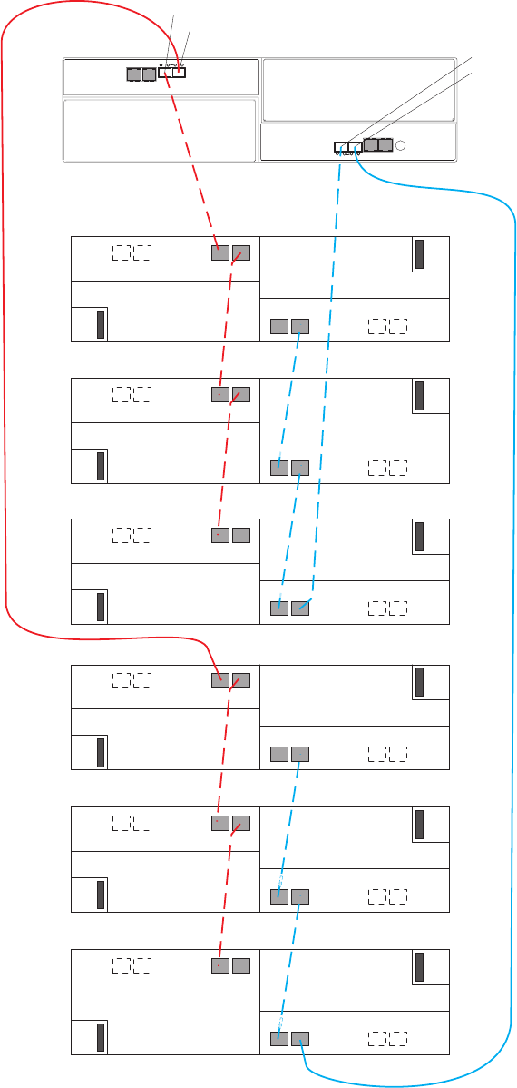
Perform the following steps to create the cabling scheme shown in Figure 50:
1A
1B
DS5020
Port 2, drive channel 1
1A 1B
1A
1B
1A
1B
Port 1, drive channel 1
Port 1, drive channel 2
Port 2, drive channel 2
1A 1B
1B
1A
1B
1A 1B
1A
1B
1B
1A
1B
1B
1A
1A
1A
EXP520 one
EXP520 two
EXP520 three
EXP520 four
EXP520 five
EXP520 six
Figure 50. One DS5020 and a maximum of six EXP520 storage expansion enclosures
behind a pair of DS5020 drive ports
76 IBM System Storage DS5020 Storage Subsystem: Installation, User’s, and Maintenance Guide
1. Connect port 1A on the left ESM in EXP520 one to port 1B on the left ESM in
EXP520 three.
2. Connect port 1A on the right ESM in EXP520 three to port 1B on the right
ESM in EXP520 one.
3. Connect port 1B on the left ESM in EXP520 one to port 2 of drive channel 1
on the DS5020.
4. Connect port 1A on the left ESM in EXP520 three to port 1B on the left ESM in
EXP520 five.
5. Connect port 1A on the right ESM in EXP520 five to port 1B on the right ESM
in EXP520 three.
6. Connect port 1 of drive channel 2 on the DS5020 to port 1B on the right ESM
in the EXP520 five.
7. Connect port 1A on the left ESM in EXP520 two to port 1B on the left ESM in
EXP520 four.
8. Connect port 1A on the right ESM in EXP520 four to port 1B on the right ESM
in EXP520 two.
9. Connect port 1B on the left ESM in EXP520 two to port 1 of drive channel 1
on the DS5020.
10. Connect port 1A on the left ESM in EXP520 four to port 1B on the left ESM in
EXP520 six.
11. Connect port 1A on the right ESM in EXP520 six to port 1B on the right ESM
in the EXP520 four.
12. Connect port 2 of drive channel 2 on the DS5020 to port 1B on the right ESM
in EXP520 six.
Chapter 3. Cabling the storage subsystem 77

Storage expansion enclosure settings
This section provides information about storage expansion enclosure settings. For
additional detail, refer to the Installation, User’s, and Maintenance Guide for your
storage expansion enclosure.
Fibre Channel loop and ID settings
When you install an E-DDM in the storage expansion enclosure, the E-DDM tray
plugs into a printed circuit board called the midplane. The midplane sets the Fibre
Channel loop ID automatically, based on the enclosure ID switch setting and the
physical location (bay) of the E-DDM.
Storage expansion enclosure ID settings
EXP520 and EXP810 storage expansion enclosures do not have enclosure ID
switches because the controllers automatically set the enclosure ID numbers.
Each storage expansion enclosure in a DS5020 storage subsystem drive loop must
have a unique enclosure ID. DS5020 controllers use a combination of the enclosure
ID and the number of the physical slot that a hard drive occupies to create a unique
Fibre Channel loop address or arbitrated loop physical address (AL_PA) for each
drive in a Fibre Channel drive loop. The enclosure ID consists of two digits, a tens
digit (x10) and ones digit (x1).
Attention: When connecting storage expansion enclosures, you must use the
tens digit (x10) enclosure ID setting to distinguish different redundant drive channel
pairs and use the ones digit (x1) enclosure ID setting to distinguish storage
expansion enclosures IDs within a redundant drive channel.
The DS5020 normally ships with an enclosure ID outside the range of 00–77.
However, if your DS5020 enclosure ID was set to a value within the range of
00–77, it might be in conflict with the enclosure ID of one of the drive expansion
enclosures that you are trying to attach to the DS5020. If this is the case, the
amber ID Conflict LED on the storage expansion enclosure will light after you turn
on the power to the storage subsystem.
Give each storage expansion enclosure in a redundant drive channel pair a unique
ones digit (x1) ID. This setting will enforce hard AL_PAs (unchangeable between
Fibre Channel Loop Initializations [LIPs]) for the drives and facilitate drive loop
problem troubleshooting in the event of an error. If the ones digits are not unique,
two or more devices will have the same hard AL_PA. In such a case, the DS5020
controller will use soft AL_PAs for the devices that have identical hard AL_PAs.
The problem with soft AL_PAs addressing is that addresses might change between
LIPs. This possibility increases the difficulty of troubleshooting drive channel
problems, since one cannot easily ascertain whether the same device with a
different address or different device might be causing a problem. Set the enclosure
IDs in a given drive channel/loop pair to enforce hard AL_PAs addressing.
Connecting secondary interface cables
This section is applicable to (direct) out-of-band management configurations only. If
your configuration uses host-agent (in-band) management, skip this section.
Use the Ethernet interface ports on the back of the storage subsystem to connect
the controllers for direct management of the storage subsystems (see “Direct
(out-of-band) management method” on page 81).
78 IBM System Storage DS5020 Storage Subsystem: Installation, User’s, and Maintenance Guide
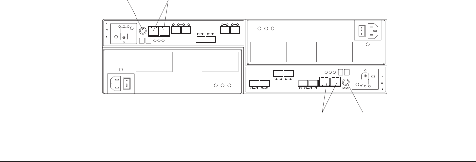
Important:
1. The serial interface ports are intended to be used by service technicians to
perform diagnostic operations on the storage subsystem. Incorrect use of the
serial port can result in loss of data access and, in some cases, in loss of data.
Do not make connections to the serial port unless you do so under the direct
supervision and guidance of IBM support personnel. The serial port connection
requires a special PS2 DIN to DB9 male converter. (IBM Service and support
personnel, see the Serial cable adapter (RoHS) in “Parts listing” on page 160
for the FRU P/N.)
2. To minimize security risks, do not connect the DS5020 in a public LAN or public
subnet. Use a local private network for the DS5020 and the management
station Ethernet ports.
3. For proper EMI shielding, always use quality braided and shielded serial cables.
Connect a pair of Ethernet cables from the storage-management station to the
Ethernet ports for controller A (located on the top) and controller B (located on the
bottom) on the back of the storage subsystem. Figure 51 shows the location of the
ports on the DS5020 storage subsystem. Only one Ethernet port connection from
each controller is required to establish a direct (out-of-band) management
connection to the DS5020 storage subsystem.
Notes:
1. The alignment of the Ethernet and serial ports on controller A are opposite those
of controller B. Before inserting an Ethernet or serial cable, verify that the cable
connection is rotated correctly to match the alignment of the port on the RAID
controller. Do not force-fit.
2. Your DS5020 hardware might differ slightly from the following illustration.
Configuring the storage subsystem
You must configure the storage subsystem configuration after you install the storage
subsystem in a rack cabinet. Use the information in the following sections to
configure your storage subsystem configuration.
Ethernet
ports
Serial
port
Ethernet
ports Serial
port
Figure 51. Ethernet and serial port locations on DS5020
Chapter 3. Cabling the storage subsystem 79
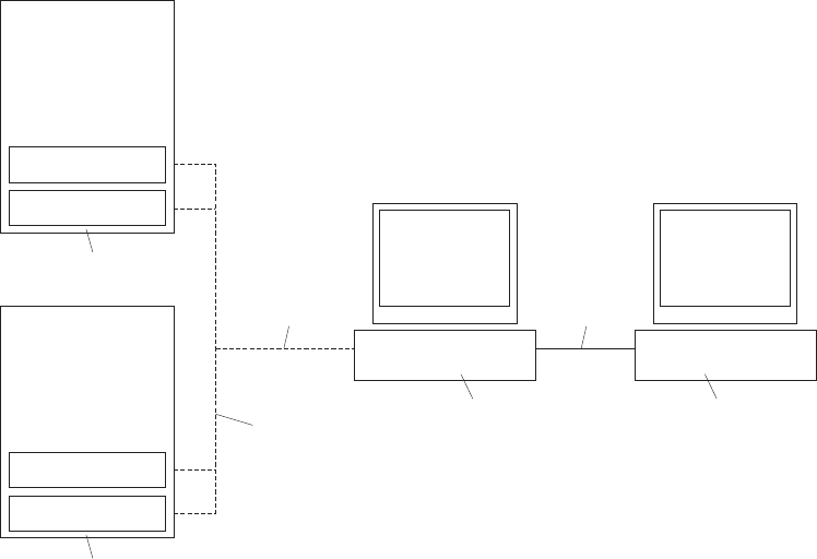
Storage subsystem management methods
Before you configure the storage subsystem, determine which method of storage
subsystem management you want to use. You can manage the storage subsystems
in either of two ways: host-agent (in-band) management or direct (out-of-band)
management.
For more information about setting up in-band or out-of-band management
connections, refer to the DS Storage Manager Installation and Host Support Guide
for the operating system of the host computer that will be used to manage the
storage subsystem.
Important: If the operating system of the host server that the storage subsystem
logical drives are mapped to is not Microsoft Windows 2000 or Server
2003, then you have to make a direct (out-of-band) management
connection to the storage subsystem to set the correct host type first.
Then, the server will be able to recognize the storage subsystem
correctly for host-agent (in-band) management.
Host-agent (in-band) management method
This method requires host-agent software that you install on the host server. The
host-agent software allows the DS Storage Manager client program to manage the
DS5020 storage subsystem using the same Fibre Channel connections between the
host server and the storage subsystem. You must install at least one management
station and a software agent host. The management station can be the host or a
workstation on the Ethernet network. A management station will have the client
software installed. Figure 52 shows the host-agent (in-band) management method.
5
4
Two storage
subsystems
Two storage
subsystems Ethernet
network
Ethernet
network
Host
server
Management
station
Fibre Channel
Figure 52. Host-agent (in-band) managed storage subsystems
80 IBM System Storage DS5020 Storage Subsystem: Installation, User’s, and Maintenance Guide
Direct (out-of-band) management method
This method uses Ethernet connections from a management station to each
controller. You must install at least one management station. The management
station can be the host or a workstation on the Ethernet network. A management
station will have the client software installed. Attach Ethernet cables to each
management station (one pair per storage subsystem). You will connect the cables
to each storage subsystem controller later when you install the storage subsystem.
Figure 53 on page 82 shows the direct (out-of-band) management method.
You can either use the default controller Ethernet IP addresses for out-of-band
connection or change the default controller Ethernet IP addresses by using
Dynamic Host Configuration Protocol (DHCP) or Storage Manager client. Refer to
the DS Storage Manager Installation, User's and Maintenance Guide for the
applicable operating system for more information about setting the management
connections and installing the DS5020 storage subsystem management software.
For a listing of default IP addresses, see “Connectors, switch, and enclosure ID” on
page 9.
Note: Do not connect the storage subsystem Ethernet ports to a public network or
public subnet. Create a private network between the storage subsystem and
the management station.
Chapter 3. Cabling the storage subsystem 81
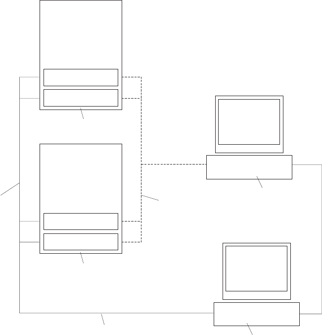
Connecting hosts to the DS5020 using Fibre Channel host ports
The DS5020 supports redundant direct attached connections to up to four hosts. To
Make sure that you have full protection against the loss of any one Fibre Channel
path from the host servers to the DS5020 storage subsystem, always use
redundant host connections by connecting each host to the applicable single-ported
host channels on both RAID controllers A and B. Using the Fibre Channel switches,
up to 512 hosts can be redundantly attached to the DS5020 storage subsystem in a
Fibre Channel SAN fabric.
To connect a Fibre Channel host adapter to the DS5020 RAID controllers, perform
the following steps:
1. Install SFP modules in host ports on RAID controllers A and B.
Note: The alignment of the single-ported host channels on controller A are
opposite those of controller B. Before inserting an SFP module into a
host port, verify that the SFP module is rotated correctly to match the
alignment of the host port on the RAID controller. Do not force-fit.
2. Connect the Fibre Channel cables from the SFP modules in the DS5020 RAID
controller host ports to either the SFP modules in the Fibre Channel switch or
5
Two storage
subsystems
Two storage
subsystems
Fibre Channel
Ethernet
network
Host
server
Management
station
Fibre Channel
Figure 53. Direct (out-of-band) managed storage subsystems
82 IBM System Storage DS5020 Storage Subsystem: Installation, User’s, and Maintenance Guide
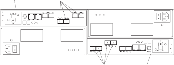
the SFP modules of the host bus adapters. Figure 54 shows the location on the
RAID controllers of the DS5020 storage subsystem where the host-system
cables connect.
Note: DS5020 controllers with four Fibre Channel host ports is shown in the
following illustration. The host channel configuration in your DS5020
hardware might differ slightly from the following illustration.
3. Repeat steps 1 on page 82 and 2 on page 82 for each additional redundant
host connection. You can create two redundant host connections for the
DS5020 storage subsystem, as shown in Figure 55 on page 84, or a maximum
of four redundant host connections (not shown). With four redundant host
connections, you can have a connection to a DS5020 Fibre Channel host bus
adapter or to Fibre Channel switch ports.
Host portsController A
Host ports Controller B
Figure 54. Location of host cables on RAID controllers on the DS5020
Chapter 3. Cabling the storage subsystem 83
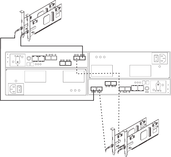
For other examples of redundant host configurations, see “Fibre Channel host loop
configurations” on page 85.
Fibre Channel and iSCSI connections
A DS5020 storage subsystem Fibre Channel connection consists of up to four host
Fibre Channel loops and a redundant drive Fibre Channel loop. The host Fibre
Channel loops provide the fibre path for host attachment. They can consist of Fibre
Channel cables, SFPs, host bus adapters, Fibre Channel switches, and RAID
controllers. The redundant drive Fibre Channel loop provides the fibre path from the
DS5020 storage subsystem to the hard disk drives (HDDs) in the storage expansion
enclosures. The redundant drive Fibre Channel loop consists of the DS5020
storage subsystem, the storage expansion enclosures, Fibre Channel cables, and
SFPs.
The DS5020 supports redundant drive channel loop configurations. You can build a
redundant drive channel loop by connecting one or more storage expansion
enclosures to the redundant RAID controllers. Then, use dual fiber-optic cables to
connect one storage expansion enclosure to another in a daisy-chain. For more
information, see “Connecting storage expansion enclosures to the DS5020” on page
54.
The DS5020 storage subsystem also supports 1 Gbps iSCSI connectivity. The host
iSCSI connections provide an iSCSI path for host attachment. The connections can
consist of Cat6 Ethernet cables, host bus adapters with iSCSI initiators, or an
Ethernet adapter with Gigabit Ethernet switches and RAID controllers. See “iSCSI
configurations” on page 87 for more information about iSCSI configurations.
Host 1, Host Adapter 1 and 2
Host 2, Host Adapter 1 and 2
Figure 55. Cabling diagram for two redundant host connections
84 IBM System Storage DS5020 Storage Subsystem: Installation, User’s, and Maintenance Guide
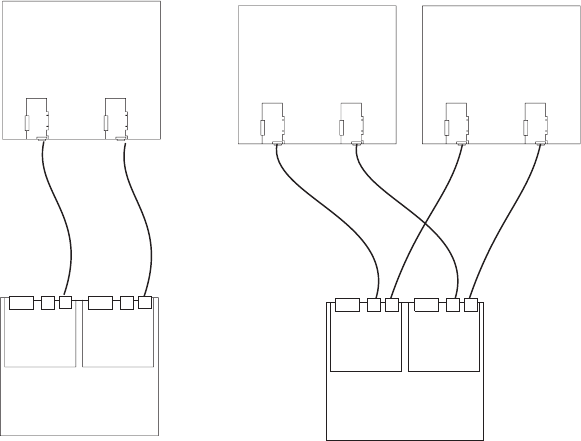
Fibre Channel host loop configurations
You must determine how the host systems will connect to the storage subsystem.
You can connect up to four host systems directly to the storage subsystem through
Fibre Channel host ports, or you can connect more than four hosts to the Fibre
Channel storage subsystem through switches. The illustrations in the following
sections show common host system configurations when you connect to the
DS5020 Fibre Channel host ports. See “iSCSI configurations” on page 87 for more
information about host connections through iSCSI.
Note: The DS5020 supports up to 128 partitions. Configuration upgrades are
available as upgrade options. Contact your IBM reseller or marketing
representative for more information.
Redundant Fibre Channel host loops
This section provides examples of DS5020 host Fibre Channel configurations.
DS5020 host Fibre Channel SAN configurations: This section provides the
following examples of DS5020 host Fibre Channel SAN configurations:
vRedundant host direct-attached configurations, as shown in Figure 56
vSingle SAN fabric configuration, as shown in Figure 57 on page 86
vDual SAN fabric configuration, as shown in Figure 58 on page 86
vTwo storage subsystems in a dual SAN fabric configuration, as shown in
Figure 59 on page 87
vTwo clusters, as shown in Figure 60 on page 87
Notes:
1. These configurations have host and drive path failover protection and provide
high availability.
2. The following illustrations do not accurately represent the controller locations or
port locations in the DS5020. The illustrations are for illustration purposes only.
Host system
with two host
adapters
DS5020
Host system
with two host
adapters
Host system
with two host
adapters
DS5020
Figure 56. Examples of redundant host direct attached Fibre Channel SAN configurations
Chapter 3. Cabling the storage subsystem 85
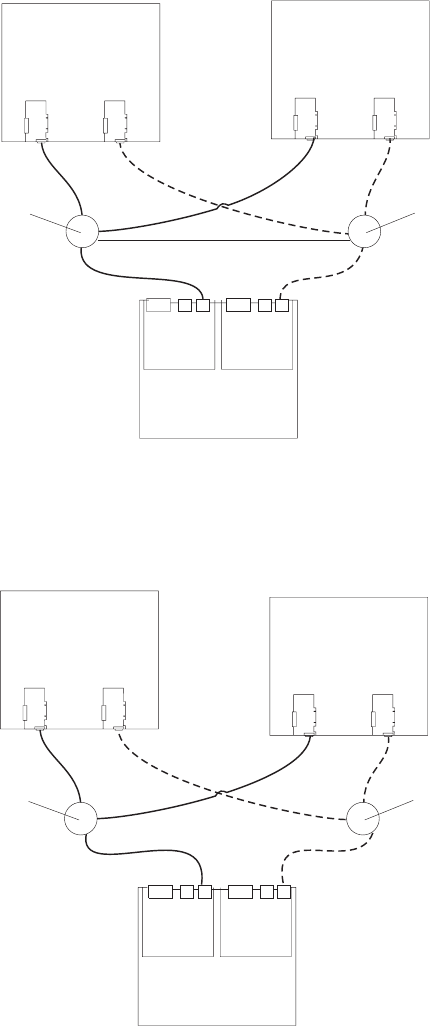
In Figure 57, the Fibre Channel switches are connected together via the inter-switch
link (ISL) to form a single SAN fabric.
In Figure 58, the Fibre Channel switches are connected together via the inter-switch
link (ISL) to form a dual SAN fabric.
In Figure 59 on page 87, the Fibre Channel switches are not connected together.
Each switch forms its own SAN fabric.
Host system
with two host
adapters
Host system
with two host
adapters
Switch Switch
Interswitch link
DS5020
Figure 57. Example of a single SAN fabric configuration
DS5020
Host system
with two host
adapters
Host system
with two host
adapters
Switch Switch
Figure 58. Example of a dual SAN fabric configuration
86 IBM System Storage DS5020 Storage Subsystem: Installation, User’s, and Maintenance Guide
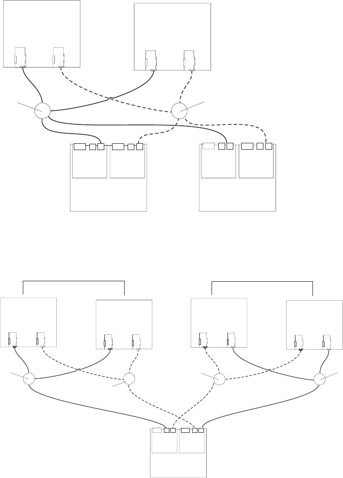
Figure 60 shows an example of a two-cluster configuration.
iSCSI configurations
The DS5020 storage subsystem supports 1 Gbps iSCSI connectivity. You must
determine how the host systems will connect to the storage subsystem. The
illustrations in the following sections show common iSCSI host system
configurations.
The iSCSI ports support IPv4 and IPv6 TCP/IP addresses, CHAP, and iSNS. Use
either Cat5E or Cat6 Ethernet cable types for iSCSI port connections. A Cat6
Ethernet cable provides optimal performance.
Host system
with two host
adapters
Host system
with two host
adapters
Switch Switch
DS5020
DS5020
Figure 59. Example of two storage subsystems in a dual SAN environment
DS5020
Host system
with two host
adapters
Host system
with two host
adapters
Switch Switch
Host system
with two host
adapters
Host system
with two host
adapters
Switch
Switch
Cluster 1 Cluster 2
Figure 60. Example of a two-cluster configuration
Chapter 3. Cabling the storage subsystem 87
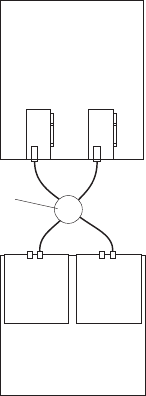
Note: The minimum DS5020 configuration is two partitions. The maximum is 128
partitions. Configuration upgrades are available as upgrade options. Contact
your IBM reseller or marketing representative for more information.
DS5020 host iSCSI configurations
This section provides the following examples of DS5020 host iSCSI configurations:
vSingle-host, multiple-port configuration, as shown in Figure 61
vMultiple-host, multiple-port configuration, as shown in Figure 62 on page 89
viSCSI and Fibre Channel hosts, multiple-port configuration, as shown in
Figure 63 on page 89
vExample of an incorrect configuration: Single-host, iSCSI and Fibre Channel, as
shown in Figure 64 on page 90
vMultiple-host, multiple-port, multiple-switch configuration, as shown in Figure 65
on page 91
Notes:
1. The DS5020 does not support direct connections from the host systems to the
iSCSI ports on the storage subsystem.
2. The DS5020 does not support connections to both iSCSI and Fibre Channel
ports from the same host system.
3. The following illustrations do not accurately represent the controller locations or
port locations in the DS5020. The illustrations are for illustration purposes only.
Figure 61 shows an example of a multiple port, single-host configuration. A system
that uses multiple iSCSI ports can provide enhanced performance compared to a
single-port iSCSI connection.
Figure 62 on page 89 shows a multiple-host, multiple-port configuration. For cluster
configurations, the following illustration is an example of a multiple-host,
multiple-port, and redundant path and controller configuration. You can replace the
two gigabit Ethernet switches in the illustration with one large gigabit Ethernet
switch that has the required number of ports. Virtual local area network (VLAN) can
also be used to isolate the two iSCSI networks, instead of a single switch.
Gigabit
Ethernet
switch
Host system
with two iSCSI
connectors
DS5020
Figure 61. Example of a single-host, multiple-port configuration
88 IBM System Storage DS5020 Storage Subsystem: Installation, User’s, and Maintenance Guide
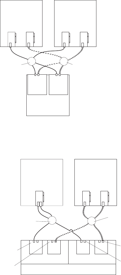
Figure 63 shows iSCSI and Fibre Channel hosts in a multiple-port configuration.
Gigabit
Ethernet
switch
Host system
with two iSCSI
connectors
DS5020
Host system
with two iSCSI
connectors
Ethernet
switch
Figure 62. Example of a multiple-host, multiple-port configuration
Gigabit
Ethernet
switch
Host 1 with a
dual-port Fibre
Channel HBA
DS5020
Fibre
Channel
switch
Controller A Controller B
Fibre
Channel
ports
iSCSI
ports
Fibre
Channel
ports
Host 2 with two
single-port
iSCSI HBAs
iSCSI
ports
Figure 63. Example of iSCSI and Fibre Channel hosts, multiple-port configuration
Chapter 3. Cabling the storage subsystem 89
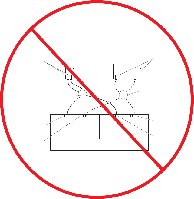
Figure 64 shows an incorrect configuration of a single host with both iSCSI and
Fibre Channel connections.
Important: Do not cable the storage subsystem and host systems as shown in
Figure 64. A storage subsystem with the incorrect storage topology
might appear to be functional, but incorrect cabling can potentially have
unpredictable results.
Figure 65 on page 91 shows an example of a multiple-host, multiple-port,
multiple-switch configuration.
Gigabit
Ethernet
switch
Host with two single-port iSCSI
HBAs and one dual-port Fibre
Channel HBA
DS5020
Fibre
Channel
switch
Controller A Controller B
Fibre
Channel
ports
iSCSI
ports
Fibre
Channel
ports
iSCSI
ports
Fibre
Channel
ports
iSCSI
ports
Figure 64. Example of an incorrect configuration: Single-host, iSCSI and Fibre Channel
90 IBM System Storage DS5020 Storage Subsystem: Installation, User’s, and Maintenance Guide
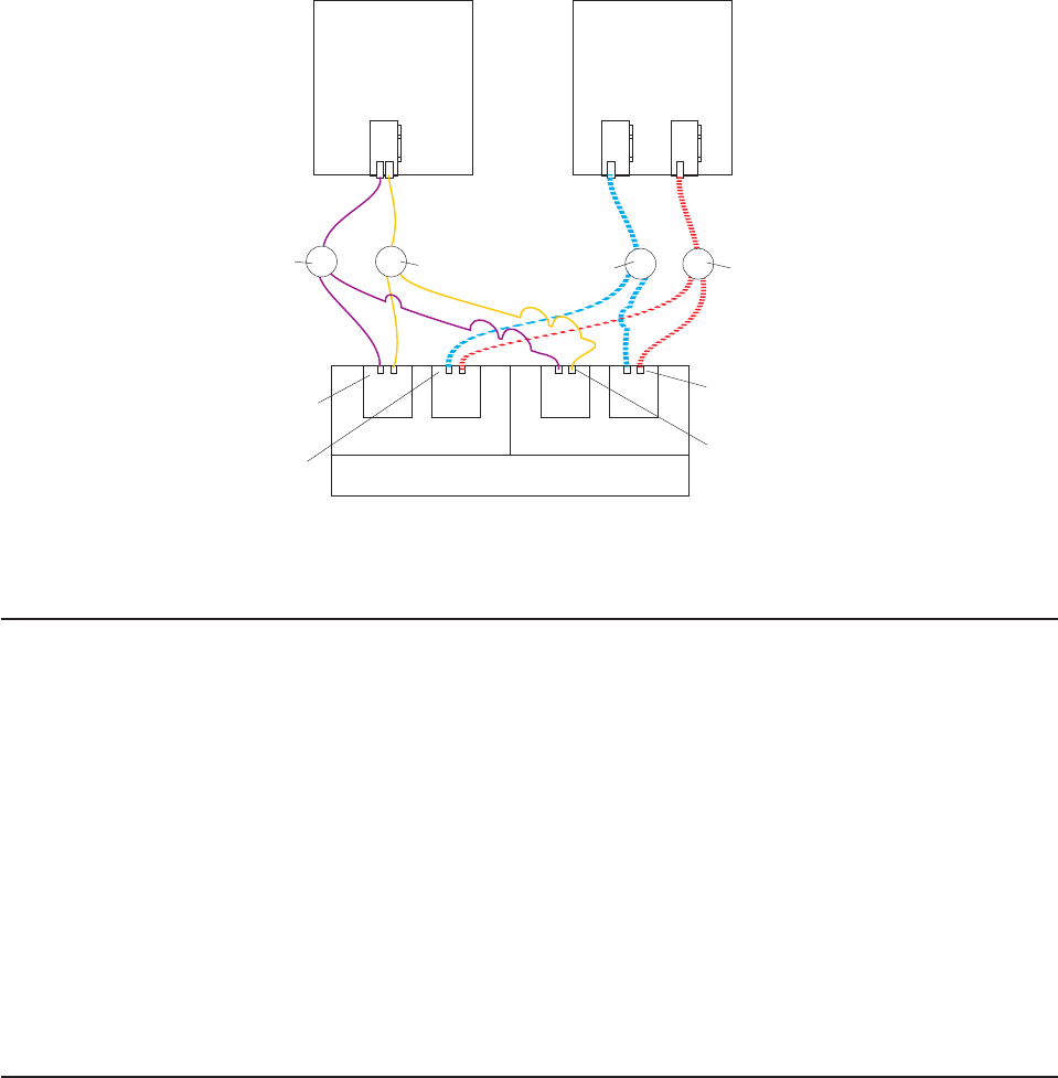
Installing the storage subsystem configuration
Using the information gathered in the previous sections, install the host systems
and host adapters.
Notes:
1. See the documentation provided with your host adapters for installation
requirements and procedures.
2. Use the correct host adapter driver. For the latest supported host adapters and
drivers, go to the following Web site:
http://www.ibm.com/systems/support/storage/disk
Attach fiber-optic interface cables to each host adapter. You will connect the other
end of the cables to the controller later in the installation process. For more
information about handling fiber-optic cables, see “Handling fiber-optic cables” on
page 47.
Cabling the ac power supply
Complete the following steps to connect the ac power supply cable:
1. Using the supplied strap, tie the power supply cord to the rail to provide strain
relief for the power cord.
2. Connect the power cable to the power supply.
3. Plug the supplied power cable into a properly grounded electrical outlet. For
maximum protection against power loss, connect each of the two power
supplies to a different power source.
4. Continue with “Powering on the storage subsystem” on page 95 for the initial
startup of the storage subsystem.
Gigabit
Ethernet
switch
Host 1 with a
dual-port Fibre
Channel HBA
DS5020
Fibre
Channel
switch
Controller A Controller B
Fibre
Channel
ports
iSCSI
ports
Fibre
Channel
ports
Host 2 with two
single-port
iSCSI HBAs
iSCSI
ports
Gigabit
Ethernet
switch
Fibre
Channel
switch
Figure 65. Example of a multiple-host, multiple-port, multiple-switch configuration
Chapter 3. Cabling the storage subsystem 91
92 IBM System Storage DS5020 Storage Subsystem: Installation, User’s, and Maintenance Guide

Chapter 4. Operating the storage subsystem
This chapter describes operating procedures for the DS5020.
For information about the optimal operation of your system, see “Best practices
guidelines” on page 5
Performing the DS5020 Health Check process
The DS5020 Health Check process is a sequence of suggested actions developed
by IBM to help users verify and maintain the optimal performance of their DS5020
storage configurations. The information that you collect in these steps also helps
provide IBM Service with important information needed for problem troubleshooting
during IBM Service calls.
Perform the following Health Check tasks after the initial configuration of your
DS5020 storage subsystem, and after all configuration sessions. Set a regular
schedule of periodic Health Check evaluations in order to keep your DS5020 code
current and to preserve optimal data access and performance.
1. Monitor the Recovery Guru in the DS Storage Manager client for any obvious
storage subsystem errors or problem conditions.
2. Gather and save the following DS5020 storage subsystem event logs for review
by IBM Service. Gather these event logs periodically for regular Health Check
monitoring regardless of the state of the Recovery Guru. (You can collect all
these logs at once and zip them into a single file by clicking Advanced
Troubleshooting Collect All Support Data in the DS Storage Manager
Subsystem Management window.)
vDS5020 storage subsystem management event log (MEL)
vStorage Subsystem Profile or DS5020 Profile
vRead-Link Status (RLS) data
In addition, collect event logs for the host servers that have mapped logical
drives from the storage subsystem.
Attention: Save these event log files to a server disk that will remain
accessible in the event of a DS5020 storage configuration failure. Do not save
these event log files only to a LUN in the DS5020 storage subsystem.
3. Use the Storage Subsystem Profile or DS5020 Profile to verify that the following
firmware levels are at the latest versions supported for your DS5020 storage
subsystem:
vController firmware
vESM firmware
vDrive firmware
If you discover your firmware is not up-to-date, upgrade the firmware and
software to the latest level applicable to your DS5020 storage configuration. See
“Web pages” on page 94 for information about where to find the latest firmware
and software.
Attention: You must resolve Recovery Guru errors or problems before
upgrading firmware.
Save the storage subsystem profile before performing any controller or ESM
firmware upgrades. Save the storage subsystem profile and all *.cfg files to a
server disk that will remain accessible in the event of a DS5020 storage
configuration failure.
© Copyright IBM Corp. 2009 93
Note: When you upgrade firmware, you must upgrade all client package
components to the same release level. For example, if you are upgrading
your controller firmware from version 6.x to version 7.x, you must also
upgrade your Storage Manager client to version 10.x or higher. If your
host system uses RDAC, upgrading controller firmware from version 6.x
to version 7.x might also require host software updates, such as RDAC
updates and HBA driver updates. Refer to the IBM System Storage Web
site for detailed instructions.
4. Use the Storage Subsystem Profile or DS5020 Profile to verify that the following
functions are enabled:
vFor the DS5020 and all DS4000 models, Media Scan is enabled both at the
controller level and at the LUN level.
vFor the DS5020 and all DS4000 models, the read/write cache is enabled. In
addition, use the Storage Subsystem Profile to verify that cache is matched
between the controllers.
Web pages
IBM maintains pages on the World Wide Web where you can get the latest
technical information and download device drivers and updates.
For DS5020 and DS4000 information, go to the following Web site:
http://www.ibm.com/systems/support/storage/disk
For the latest information about operating system and HBA support, clustering
support, SAN fabric support, and Storage Manager feature support, see the System
Storage DS5020 and DS4000 Interoperability Matrix at the following Web site:
http://www-1.ibm.com/servers/storage/disk/ds4000/interop-matrix.html
Hardware responsibilities
In addition to the Health Check steps described above, regular hardware inspection
and maintenance helps to support the optimal performance of your DS5020 storage
configuration. Periodically inspect the Fibre Channel components of your DS5020
storage configuration.
The following guidelines are suggested:
vMaintain an up-to-date storage subsystem profile for your DS5020 storage
configuration. Save the profile to a server disk that will remain accessible in case
of a DS5020 storage configuration failure. Do not save the profile only to a LUN
in the DS5020 storage subsystem.
vDevelop a Change Management plan. Include schedules for updating subsystem
firmware and server host software in the plan.
Note: Some updates might require storage subsystem downtime.
vUse IBM-approved Fibre Channel cables for all situations. Note in your
configuration documentation whether any cables are not IBM-approved.
vCreate and maintain a cabling diagram of the current SAN configuration. Keep
this diagram updated as you make configuration changes, and keep the cabling
diagram available for review.
vCreate and maintain a list of other components that are being used within the
cabling diagram (such as the host system, Fibre Channel switches, and other
SAN attachments).
94 IBM System Storage DS5020 Storage Subsystem: Installation, User’s, and Maintenance Guide

vMake sure that all ESMs are properly seated.
vMake sure that all drives are properly seated.
vMake sure that all SFP modules are properly seated.
vConfirm Fibre Channel cable loop size. (Although IBM specifications require at
least 3-inch cable loops, use 6-inch cable loops or longer.)
vMake sure that you have proper Fibre Channel cable management.
vMake sure there is proper air flow and temperature for all components in your
storage configuration.
Note: You can find details on many of these inspection and maintenance
responsibilities in the applicable sections of this document.
In addition to these inspection and maintenance responsibilities, DS5000 and
DS4000 training is available for staff who support DS5000 and DS4000 storage
configurations. Although training is not a part of the Health Check process, DS5000
and DS4000 training reduces the potential for configuration problems and
contributes to the overall health of the system.
Powering on the storage subsystem
This section contains instructions for turning the storage subsystem on under
normal and emergency situations. When you turn on and turn off the DS5020, be
sure to use the startup sequence in this section. If you are turning on the storage
subsystem after an emergency shutdown or power outage, see “Restoring power
after an unexpected shutdown” on page 112.
Turning on the storage subsystem
The following procedure covers two situations:
vThe entire storage subsystem has been shut down. (The main circuit breakers for
the cabinet are off.)
vSome storage expansion enclosures are being powered on while others remain
online. (The main circuit breakers for the cabinet are on.) You might encounter
this if you are adding an additional storage expansion enclosure to increase
storage capacity.
Attention:
1. Potential damage to E-DDMs - Repeatedly turning the power off and on
without waiting for the E-DDMs to spin down can damage them. Always wait
at least 70 seconds from when you turn off the power until you turn it on
again.
2. If you are connecting a power cord to a DS5020 storage subsystem or
storage expansion enclosure, turn off both of its power switches first. If the
main circuit breaker is off, be sure both power switches are off on each
storage expansion enclosure in the cabinet before turning on the main circuit
breakers.
1. Are the main circuit breakers turned on?
vYes - Turn off both power switches on each enclosure that you intend to
connect to the power.
vNo - Turn off both power switches on all enclosures in the storage
subsystem.
2. Make sure that all power cords are connected. See “Cabling the ac power
supply” on page 91 for details, depending on the DS5020 configuration you
purchased.
Chapter 4. Operating the storage subsystem 95
Note: If the power cords are not connected, turn off both power switches on all
modules in the configuration before connecting power cords or turning on
the main circuit breakers.
3. If the main circuit breakers are turned off, turn them on.
4. Verify that the link rate setting on the front of the storage expansion enclosure
matches the speed of the drives in the subsystem.
Attention: You must turn on power to each attached storage expansion
enclosure before turning on power to the DS5020 storage subsystem to make
sure that the controllers recognize all drives in the configuration during the
startup process.
5. Turn on both power switches on the back of each storage expansion enclosure
attached to the storage subsystem. While each storage expansion enclosure
powers up, the green and amber LEDs on the front and back of the storage
expansion enclosure turn on and off intermittently. Depending on your
configuration, it can take several minutes for each storage expansion enclosure
to power up.
Check the LEDs on the front and back of all the storage expansion enclosures.
Verify that no Needs Attention or enclosure ID LEDs light on any of the storage
expansion enclosures. To verify the Fibre Channel connections between the
drive expansion enclosures, make sure that no Port Bypass LEDs for
connections to other storage expansion enclosures are lit. Only the Port Bypass
LED of the ESM port that connects directly to the storage subsystem drive port
should be lit.
Note: The drive activity LEDs will flash slowly (once every 2 seconds) until the
drive is started by the DS5020 controller.
6. Turn on both power switches on the back of each controller in the storage
subsystem.
Depending on the number of storage expansion enclosures in the configuration,
the storage subsystem might take several minutes to power up. The battery
self-test might take an additional 15 minutes. The LEDs will blink intermittently
until the storage subsystem powers up and completes the battery self-test. The
green Battery Charging LED will flash slowly (once every 2 seconds) until the
battery is fully charged.
Before attempting any operations, wait at least five minutes for the storage
subsystem to completely power up. A storage subsystem can take up to 10
minutes to power on and up to 15 more minutes to complete its controller
battery self-test. During this time, the indicator lights on the front and back of
the module blink intermittently.
7. Determine the status of all storage subsystems and components in the
configuration by completing the following steps:
a. Check all LEDs on each component in the storage expansion enclosures.
Make sure that all the LEDs show normal status. For more information about
LED status for storage expansion enclosures, see “Checking the LEDs” on
page 101 or the Installation, User’s, and Maintenance Guide for your
storage expansion enclosure.
b. Check all LEDs on each component in the storage subsystem. Make sure
that all the LEDs show normal status. For information about LED status, see
“Solving problems” on page 153.
c. Open the DS Storage Manager Subsystem Management window, and
display the Physical View for the configuration.
The status for each component will be either Optimal or Needs Attention.
96 IBM System Storage DS5020 Storage Subsystem: Installation, User’s, and Maintenance Guide

d. Review the status of the configuration components shown in the Subsystem
Management window by selecting the applicable component button for each
storage subsystem.
8. Are the LEDs indicating normal operation, and is the status Optimal on all the
configuration components?
vYes — End of procedure.
vNo — Go to step 9.
9. Diagnose and correct the fault by completing the following steps.
a. Run the DS Storage Manager Recovery Guru by selecting the Recovery
Guru toolbar button in the Subsystem Management window.
b. Complete the recovery procedure.
If the Recovery Guru directs you to replace a failed component, use the
individual LEDs on the storage subsystem to locate the specific failed
component. For troubleshooting procedures, see Chapter 6, “Hardware
maintenance,” on page 153.
c. When the recovery procedure is completed, select Recheck in the Recovery
Guru. This action reruns the Recovery Guru to make sure that the problem
has been corrected.
d. If the problem persists, contact your IBM service representative.
Installing the DS Storage Manager client
See the IBM System Storage DS Storage Manager Installation and Host Support
Guide for the applicable operating system for instructions on how to install the DS
Storage Manager software. Use that document and the online help to configure the
logical drives, partitions, and so on for the RAID controllers. Use your operating
system documentation to make the new logical drives accessible to the operating
system. Do not proceed with the configuration setup until you have completed the
DS Storage Manager installation.
Assemble any additional items in preparation for software installation. These items
might include the following:
vHBA drivers
vController firmware version listed at the IBM System Storage Support Web site:
http://www.ibm.com/systems/support/storage/disk
vIP addresses for RAID controllers (for in-band management only)
vAdditional documentation for switches and HBAs, if needed
vApplicable host kit for your operating system, which includes the DS Storage
Manager DVD containing the applicable Storage Manager version and storage
subsystem controller firmware.
Depending on the DS5020 configuration you purchased, your DS5020 will ship
with either the Microsoft Windows host software attachment kit or with your
choice of host software kits (Windows, AIX, Linux, Netware, SUN Solaris, HP-UX,
Linux on POWER, or VMware). The host software kit grants you permission to
attach host servers using the applicable operating system to the DS5020. The kit
includes a DS Storage Manager Support DVD that has the applicable IBM DS
Storage Manager host software. The DVD also includes correct controller
firmware version.
For the latest controller firmware and the DS Storage Manager host software for
your operating systems, check the IBM support web site IBM System Storage
products.
Chapter 4. Operating the storage subsystem 97

http://www.ibm.com/systems/support/storage/disk
Before any planned system shutdown or after any system additions, removals, or
modifications (including firmware updates, logical drive creations, storage
partitioning definitions, hardware changes, and so on), save the storage subsystem
profile as explained in the DS Storage Manager guide for your operating system.
Save the profile in a location other than the logical drives created for the DS5020.
Always refer to the readme that is included with the DS5020 storage subsystem
firmware package (whether the firmware is accessed by the Web or DVD) for any
special requirements or restrictions that apply to that particular firmware version.
See “Finding DS5020 and DS4000-family readme files” on page xxiv to learn how
to access the readme files on the Web.
Note: Make sure that you install the DS Storage Manager event monitoring service
to enable continuous monitoring of the status of the storage subsystem. For
more information about the importance of this information, see “Monitoring
status through software.”
Monitoring status through software
Use the DS Storage Manager client to monitor the status of the storage subsystem.
Run the software constantly, and check it frequently.
Notes:
1. You can only monitor storage subsystems that are within the management
domain of the storage-management software.
2. If you have not installed the DS Storage Manager Event Monitor service as part
of the storage-management software installation, the DS Storage Manager
Enterprise Management window must remain open. (If you close the window,
you will not receive any alert notifications from the managed storage
subsystems.)
For more information, see the Enterprise Management online Help.
Important: Refer to the IBM System Storage DS Storage Manager Version 10
Installation and Host Support Guide for the applicable operating system
for instructions on how to install the DS Storage Manager host
software.
In addition, to download the latest version of the DS Storage Manager
host software, the DS5020 storage subsystem controller firmware and
NVSRAM, and the latest storage expansion enclosure ESM firmware,
go to the following Web site:
http://www.ibm.com/systems/support/storage/disk
The DS Storage Manager client provides the best way to diagnose and repair
storage-server failures. The software can help you do the following:
vDetermine the nature of the failure
vLocate the failed component
vDetermine the recovery procedures to repair the failure
Although the storage subsystem has Needs Attention LEDs, these LEDs do not
necessarily indicate which component has failed or needs to be replaced, or which
type of recovery procedure you must perform. In some cases (such as in the case
98 IBM System Storage DS5020 Storage Subsystem: Installation, User’s, and Maintenance Guide
of a hard disk drive exceeding its PFAs), the Needs Attention LED does not turn on.
Only the DS Storage Manager client can detect the failure.
For example, the recovery procedure for a Predictive Failure Analysis®(PFA) flag
(impending drive failure) on a drive varies depending on the drive status (hot spare,
unassigned, RAID level, current logical drive status, and so on). Depending on the
circumstances, a PFA flag on a drive can indicate a high risk of data loss (if the
drive is in a RAID 0 volume) or a minimal risk (if the drive is unassigned). Only the
DS Storage Manager client can identify the risk level and provide the necessary
recovery procedures.
Note: For PFA flags, the General-system-error LED and Drive Needs Attention
LEDs do not turn on, so checking the LEDs will not notify you of the failure,
even if the risk of data loss is high.
Recovering from a storage-server failure might require you to perform procedures
other than replacing the component (such as backing up the logical drive). The DS
Storage Manager client gives these procedures.
Attention: Not following the software-recovery procedures can result in data loss.
In addition, always replace a failing component as soon as possible to minimize
additional failures that might occur, causing loss of data access.
Finding controller, storage expansion enclosure, and drive information
You can view a Storage Subsystem Profile to find controller, enclosure, and drive
information for the storage subsystem and attached storage expansion enclosures.
To view a Storage System Profile, perform the following steps:
1. Open the Storage Subsystem Management window from the DS Storage
Manager Enterprise Management window.
2. Select Storage Subsystem →View →Profile.
A Storage Subsystem Profile window opens.
3. Select the Controllers tab.
4. Scroll through the list to find Board ID, Submodel ID, Product ID, and Product
revision for the storage subsystem.
5. Select the Enclosures tab.
6. Scroll through the list to find the Product ID for supported storage expansion
enclosures.
7. Select the Drives tab.
8. Scroll through the list to find the drive values such as Product ID.
Firmware updates
Attention: Save the storage subsystem profile before performing any controller or
ESM firmware upgrades. Save the DS5020 storage subsystem profile and all
configuration (*.cfg) files to a server disk that will remain accessible in the event of
a DS5020 storage configuration failure. Do not save these files only to a LUN in the
DS5020 storage subsystem.
For optimal operation of the DS5020 and its attached storage expansion
enclosures, the storage expansion enclosure ESM firmware, the DS5020 controller
firmware, the hard drive firmware, and the NVSRAM (for controllers only) must be
up to date. Go to the following Web site to get the latest updates.
Chapter 4. Operating the storage subsystem 99
http://www.ibm.com/systems/support/storage/disk
Always check the readme files that are included with the firmware packages for the
most up-to-date information about firmware prerequisites, firmware update
instructions, and host I/O restrictions, if any. Apply the necessary updates before
configuring the storage subsystem arrays and logical drives. Subscribe to My
Support for automatic notifications of firmware or Storage Manager software
updates or any important information about your storage subsystems (see “Product
updates and support notifications” on page 5).
Attention: Read the readme file that is included in each firmware or DS Storage
Manager software package for any limitations, subsystem firmware prerequisites, or
download-sequence information. For example, the controller firmware code might
require the storage expansion enclosure ESM firmware to be upgraded first to a
particular version, or the controller firmware download might require the halting of
I/Os to the DS5020 logical drives. Failure to observe the limitations, prerequisites,
and dependencies in the readme file might result in a loss of data access. See
“Finding DS5020 and DS4000-family readme files” on page xxiv to learn how to
access the DS5020 readme files on the Web.
Unless the readme file contains special requirements for the sequence in which you
upgrade firmware, perform firmware upgrades in the following sequence:
1. ESM firmware for the storage expansion enclosures
2. Controller firmware
3. Controller NVSRAM
4. Drive firmware
Troubleshooting the storage subsystem
The DS Storage Manager is the best way to monitor the storage subsystem,
diagnose a problem, and recover from a hardware failure. Run the DS Storage
Manager continuously, and frequently check the configuration status.
Use the following procedure to check the status of and identify a problem with the
storage subsystem. If a problem has occurred, use the DS Storage Manager client
software and the LEDs on the storage subsystem to help locate a failed component.
1. Open the Subsystem Management window.
2. Select the component button for each storage expansion enclosure in this
storage subsystem, and view the status of each of the components.
The status for each component is either Optimal or Needs Attention.
3. Does any component have a Needs Attention status?
vYes - Go to step 4.
vNo - All components are Optimal. Go to step 6 on page 101.
4. Select the Recovery Guru toolbar button. Perform the procedure in the
Recovery Guru to correct the problem. The Recovery Guru might direct you to
replace the failed component. If so, go to step 5.
Attention: If the fault requires you to power off an attached storage expansion
enclosure, you might need to reset the power to the DS5020 storage subsystem
and all remaining storage expansion enclosures in the storage subsystem.
Contact IBM Customer and Technical Support before powering off any attached
storage expansion enclosures.
5. If applicable, mute the alarm.
100 IBM System Storage DS5020 Storage Subsystem: Installation, User’s, and Maintenance Guide

6. Check the indicator LEDs on the front and the back of the storage expansion
enclosure.
A green LED denotes a normal status; an amber LED denotes a hardware fault.
7. Is an amber LED on?
vYes - Locate and troubleshoot the failed components. See “Checking the
LEDs.”
vNo - You are finished with this procedure. If you are still experiencing a
problem with this storage subsystem, create, save, and print a storage
subsystem profile. This information might be helpful when troubleshooting.
Contact IBM Customer and Technical Support for assistance. When the
recovery procedure is completed, select Recheck in the Recovery Guru to
rerun the Recovery Guru and to make sure that the problem has been
corrected.
Checking the LEDs
The LEDs display the status of the storage subsystem and components. The color
of the LED is important.
vGreen LEDs indicate a normal operating status
vAmber LEDs (Needs Attention) indicate a possible failure
vBlue LED on a CRU indicates that is safe to remove the component
The DS5020 storage subsystem also has a blue Global Locate LED that is lit when
the menu function is selected in the Subsystem Management window, causing the
LOCATE command to be sent to the DS5020.
It is important to check all the LEDs on the front and back of the storage subsystem
when you turn on the power. During power up, the indicator LEDs blink
intermittently as the storage subsystem and components complete the power-up
process. In addition to checking for faults, you can use the LEDs on the front of the
storage subsystem to determine if the drives are responding to I/O transmissions
from the host.
AC power supply and fan unit LEDs
This section describes the primary power supply and fan unit LEDs on the DS5020
storage subsystem.
Chapter 4. Operating the storage subsystem 101
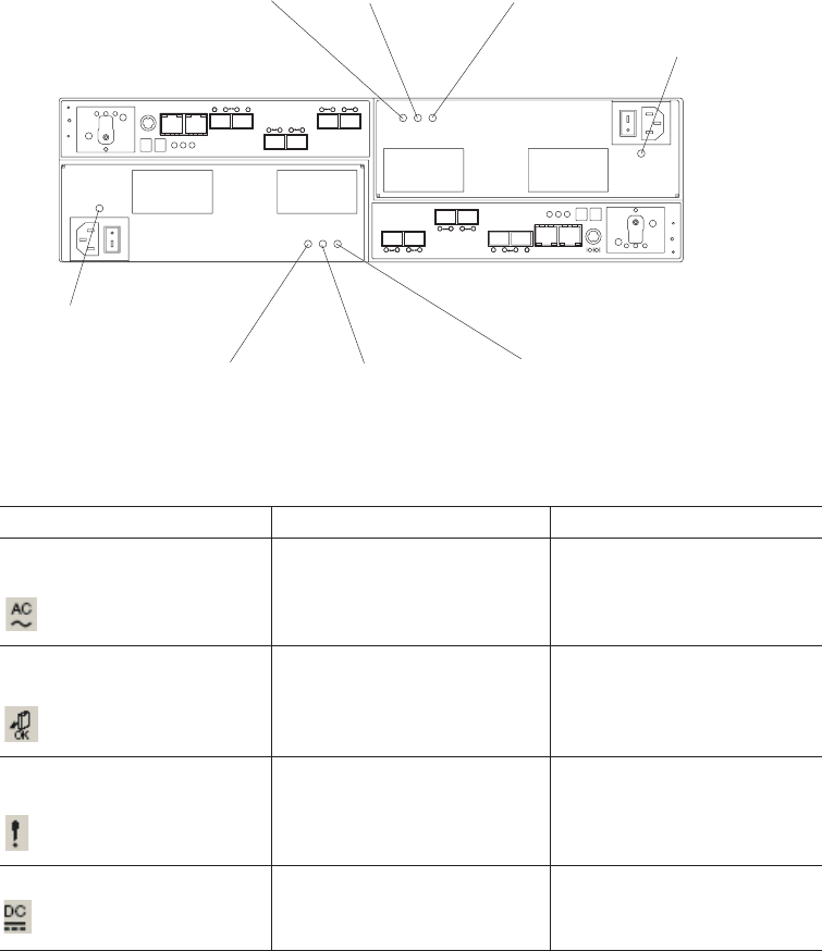
Table 12. Power supply and fan unit LEDs
LED Normal Status Problem Status
Power supply and fan unit
power
On Off
Service Action Allowed (OK to
Remove)
Off On
Service Action Required
(Fault)
Off On
Direct Current Enabled On Off
Front LEDs
This section describes the primary LEDs and controls on the front of the DS5020
storage subsystem.
Power supply and
fan unit power LED
Service action allowed
(ok to remove) LED
Service action required
(fault) LED
Direct current
enabled LED
Power supply and
fan unit power LED
Service action allowed
(ok to remove) LED
Service action required
(fault) LED
Direct current
enabled LED
Figure 66. Power supply and fan unit LEDs
102 IBM System Storage DS5020 Storage Subsystem: Installation, User’s, and Maintenance Guide
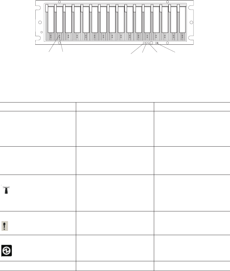
Table 13. Front LEDs and controls
LED Normal Status Problem Status
Drive Activity LED On (not blinking) - No data is
being processed
Blinking - Data is being
processed
Off
Drive Fault LED Off
Blinking - Drive, volume, or
storage array locate function
On (not blinking)
Global Locate On only when you activate
the locate function in the DS
Storage Manger Subsystem
Management window menu.
The normal state is off.
N/A
Global Summary Fault Off On
Global Power On Off
Link Rate Switch Set to the 4 Gbps position. N/A
Battery unit LEDs
This section describes the primary LEDs on the storage subsystem battery units.
Drive
activity
LED
Drive
fault
LED
Global
locate
LED
Global
summary
fault
LED
Global
power
LED
Link
rate
switch
Figure 67. Front LEDs and controls
Chapter 4. Operating the storage subsystem 103
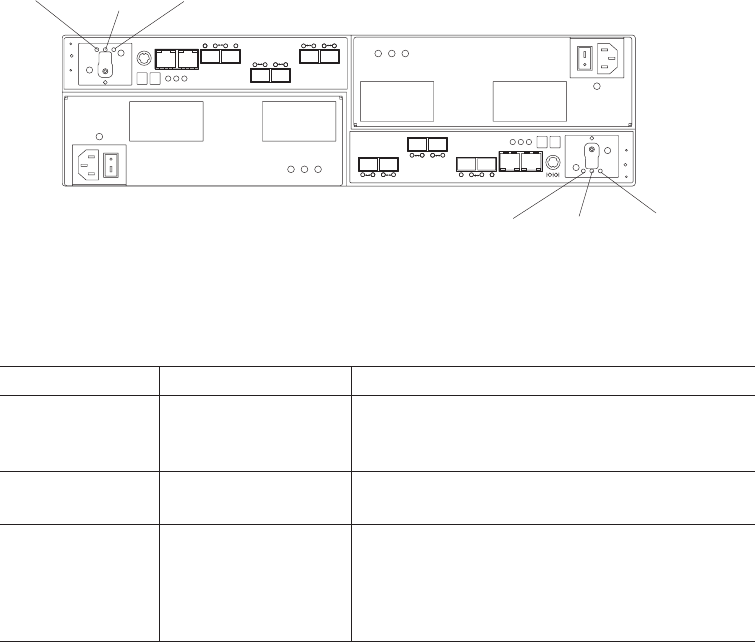
Table 14. Battery unit LEDs
LED Normal Status Problem Status
Service Action
Allowed (OK to
Remove)
Off On
Service Action
Required (Fault)
Off On
Battery Charging Green means on,
ready
Blinking green means
charging
Off
The Global Power, Global Summary Fault, and Global Locate LEDs are general
indicators for the entire DS5020 storage subsystem (or configuration, in the case of
the Global Summary Fault). The Global Summary Fault LED turns on if a fault
condition is detected in any component in the storage subsystem configuration,
including all attached storage expansion enclosures. The Global Power, Global
Summary Fault, and Global Locate LEDs shine through the front bezel.
Attention: If the Global Summary Fault LED lights, refer to the DS Storage
Manager client software to determine the problem with the storage subsystem. Also,
inspect the Needs Attention LEDs on the other components in the storage
subsystem to help isolate the fault to a specific component.
Controller LEDs
This section describes the primary LEDs, controls, and connectors on the rear of
the storage subsystem controller.
Figure 69 on page 105, Figure 70 on page 105, and Figure 71 on page 106 show
the three different DS5020 controller configurations that are available. Figure 69 on
page 105 shows the base DS5020 storage subsystem, with two Fibre Channel host
ports. For more information about DS5020 controller options and other components,
see the “Parts listing” on page 160.
Service action
allowed (ok to
remove) LED
Service action
required
(fault) LED
Battery
charging
LED
Service action
allowed (ok to
remove) LED
Service action
required
(fault) LED
Battery
charging
LED
Figure 68. Battery unit LEDs
104 IBM System Storage DS5020 Storage Subsystem: Installation, User’s, and Maintenance Guide
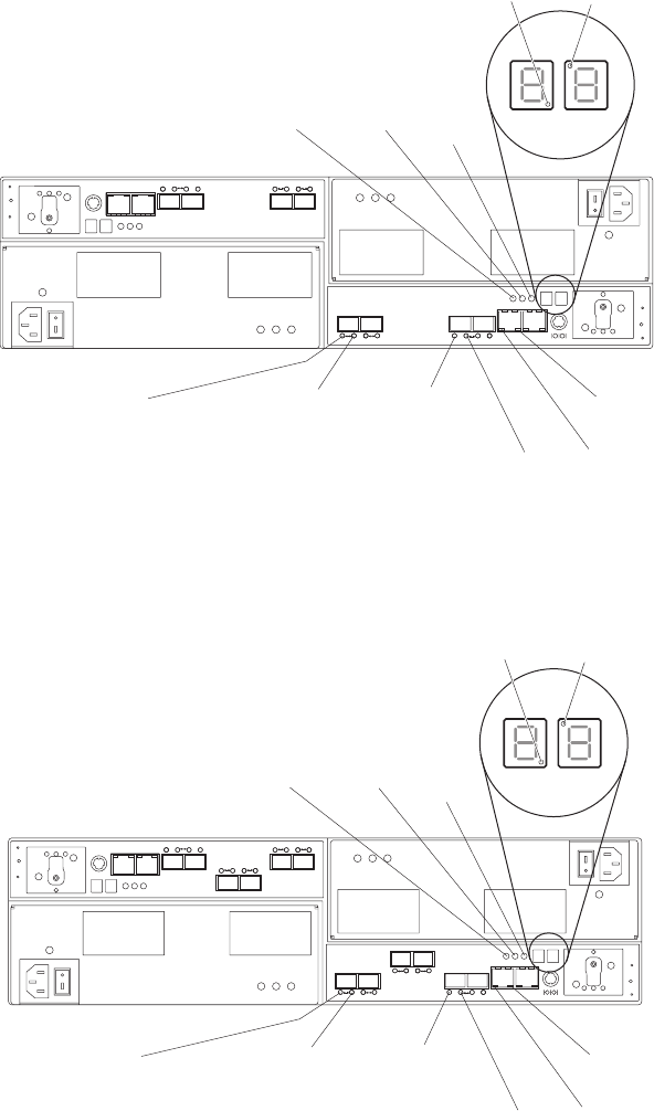
Heartbeat
LED
Diagnostic
LED
Cache
active
LED
Service
action
required
LED
Service
action
allowed
LED
Host channel
speed - L1 LED
Drive channel
port bypass LED
Drive channel
speed LED
Ethernet link
activity LED
Ethernet link
speed LED
Host channel
speed - L2 LED
Figure 69. LEDs, controls, and connectors of controllers with two standard Fibre Channel
host expansion channels
Heartbeat
LED
Diagnostic
LED
Cache
active
LED
Service
action
required
LED
Service
action
allowed
LED
Host channel
speed - L1 LED
Drive channel
port bypass LED
Drive channel
speed LED
Ethernet link
activity LED
Ethernet link
speed LED
Host channel
speed - L2 LED
Figure 70. LEDs, controls, and connectors of controllers with two standard and two optional
Fibre Channel host expansion channels
Chapter 4. Operating the storage subsystem 105
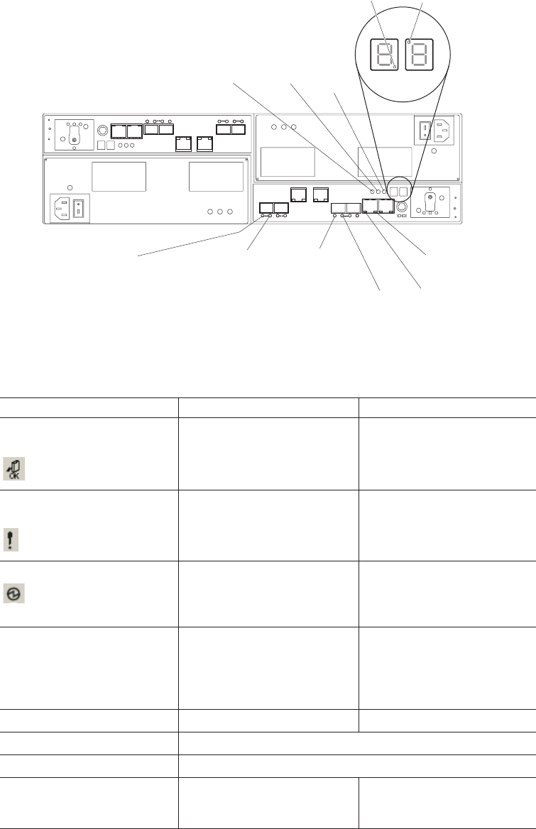
Table 15. Rear controller LEDs, controls, and connectors
LED Normal Status Problem Status
Service Action Allowed (OK to
Remove)
Off On
Service Action Required
(Fault)
Off On
Cache Active On - Data is in cache
Off - Caching is turned off. No
data in cache
Not applicable
Diagnostic On - Seven-segment LEDs
indicate diagnostic code
Off - Seven-segment LEDs
indicate enclosure ID
Not applicable
Heartbeat Blinking Off
Host Channel Speed - L1 See Table 16 on page 107.
Host Channel Speed - L2 See Table 16 on page 107.
Ethernet Link Speed On - 1 Gbps
Off - 100 Mbps
Not applicable
Note: The iSCSI ports have the same LEDs as the management Ethernet ports. As
with the Ethernet port LEDs, the iSCSI port LEDs represent link speed and
link activity.
Heartbeat
LED
Diagnostic
LED
Cache
active
LED
Service
action
required
LED
Service
action
allowed
LED
Host channel
speed - L1 LED
Drive channel
port bypass LED
Drive channel
speed LED
Ethernet link
activity LED
Ethernet link
speed LED
Host channel
speed - L2 LED
Figure 71. LEDs, controls, and connectors of controllers with two standard Fibre Channel
host expansion channels and two optional iSCSI host expansion channels
106 IBM System Storage DS5020 Storage Subsystem: Installation, User’s, and Maintenance Guide

Table 15. Rear controller LEDs, controls, and connectors (continued)
LED Normal Status Problem Status
Ethernet Link Activity On - link established
Off - no link established
Blinking - activity
Not applicable
Drive Channel Port Bypass
(One LED per port)
Note: The drive channel
consists of two FC ports. This
LED indicates the drive port
bypass status of one of the
two FC ports that comprise a
drive channel. The other drive
channel port has its own
Drive Channel Port Bypass
LED.
Off
(Also off if no SFP
connected)
On - No valid device detected
and port is bypassed
Drive Channel Speed - L1 See Table 16.
Drive Channel Speed - L2 See Table 16.
The L1 and L2 LEDs for each Fibre Channel host and drive channel combine to
indicate the status and the operating speed of each host and drive channel.
Table 16. Host and drive channel LED definitions
L1 L2 Definition
Off Off When both LEDs for a host or drive channel are off, this indicates one or more
of the following conditions:
vThe host or drive channel ports are bad or the SFPs are faulty.
vAn SFP module is inserted with no Fibre Channel cable attached.
Note: If the SFP is inserted in a drive port with no Fibre Channel attached,
the associated drive port bypassed LED will also be lit. In addition, the L1
and L2 LEDs will be unlit.
vNo SFP module is inserted in one or both of the host or drive ports in the
channel.
On Off The host is operating at 2 Gbps. The drive channel is operating at 1 Gbps.
Note: This pattern is not applicable in the drive port because the DS5020 does
not support 1 Gbps Fibre Channel speed.
Off On The host is operating at 4 Gbps. The drive channel is operating at 2 Gbps.
On On The host is operating at 8 Gbps. The drive channel is operating at 4 Gbps.
Seven-segment numeric display LEDs
The numeric display consists of two seven-segment LEDs that provide information
about enclosure identification and diagnostics. Figure 72 on page 108 shows the
numeric display and the diagnostic LED.
Chapter 4. Operating the storage subsystem 107
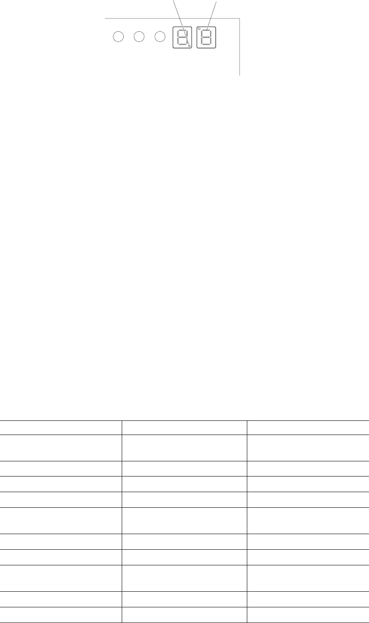
When you turn on the power to the storage subsystem, the seven-segment LEDs
show 88 before the boot firmware starts to run. After the boot code starts,--is
displayed.
When the storage subsystem is operating normally, the numeric display shows the
enclosure identification (enclosure ID) of the storage subsystem.
If an error has occurred and the Needs Attention LED is on, the numeric display
shows diagnostic information. The numeric display indicates the information is
diagnostic by illuminating an LED that appears as a decimal point between the
display numbers. The diagnostic LED tuns off when the numeric display shows the
storage subsystem enclosure ID. The numeric display shows various diagnostic
codes as the enclosures perform the startup process after each power cycle or
reset. After diagnostics are complete, the current storage subsystem enclosure ID is
displayed.
Diagnostic codes in the form of Lx or Hx, where x is a hexadecimal digit, indicate
storage subsystem state information. In general, these codes are displayed only
when the storage subsystem is in a non-operational state. The storage subsystem
might be non-operational due to a configuration problem (such as mismatched
types), or it might be non-operational due to hardware faults. If the storage
subsystem is non-operational due to system configuration, the storage subsystem
Needs Attention LED is off. If the storage subsystem is non-operational due to a
hardware fault, the storage subsystem Needs Attention LED is on. The definitions
for Lx diagnostic codes are listed in Table 17.
Table 17. Numeric display diagnostic codes
Value Controller State Description
L0 Suspended Mismatched controller board
ID
L1 Suspended Missing interconnect canister
L2 Suspended Persistent memory errors
L3 Suspended Persistent hardware errors
L4 Suspended Persistent data protection
errors
L5 Suspended ACS failure
L6 Suspended Unsupported host card
L7 Suspended Submodel identifier not set or
mismatched
L8 Suspended Memory configuration error
L9 Suspended Link speed mismatch
Seven-segment
display
Diagnostic
LED
Figure 72. Numeric display LEDs
108 IBM System Storage DS5020 Storage Subsystem: Installation, User’s, and Maintenance Guide

Table 17. Numeric display diagnostic codes (continued)
Value Controller State Description
LA Suspended Reserved
LB Suspended Host card configuration error
LC Suspended Persistent cache backup
configuration error
LD Suspended Mixed cache memory DIMMs
LE Suspended Uncertified cache memory
DIMM sizes
LF Suspended Lockdown with limited
SYMbol support
LH Suspended Controller firmware mismatch
Powering off the storage subsystem
The DS5020 is designed to run continuously. After you turn it on, do not turn it off.
Turn off the power only in the following situations:
vInstructions in a hardware or software procedure require that you turn off the
power.
vAn IBM technical support representative instructs you to turn off the power.
vA power outage or emergency situation occurs, see “Restoring power after an
unexpected shutdown” on page 112.
Turning off the storage subsystem
Use the following procedure to turn off the power for the DS5020.
Attention: Except in an emergency, never turn off the power if any Needs
Attention LEDs are on. Correct the fault before you turn off the power. Use the DS
Storage Manager client and the Needs Attention LEDs to check the overall status of
the DS5020. All LEDs should be green on the front of the storage subsystem. If
they are not, use the DS Storage Manager client to diagnose the problem. This
ensures that the DS5020 will power up correctly later.
The DS5020 is designed to run continuously. After you turn on the DS5020, do not
turn it off. Turn off the power only in the following situations:
vInstructions in a hardware or software procedure require that you turn off the
power.
vAn IBM technical support representative instructs you to turn off the power.
vA power outage or emergency situation occurs, see “Restoring power after an
unexpected shutdown” on page 112.
Chapter 4. Operating the storage subsystem 109
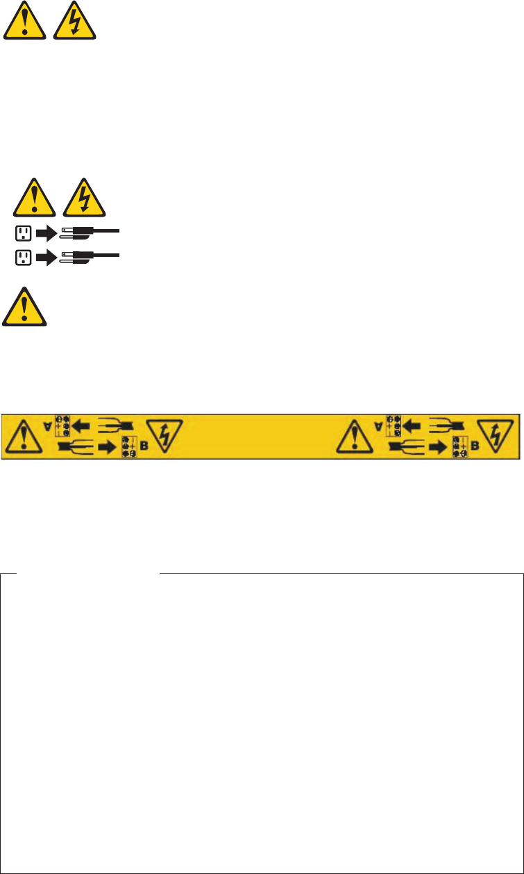
Statement 5:
CAUTION:
The power control button on the device and the power switch on the power
supply do not turn off the electrical current supplied to the device. The device
also might have more than one power cord. To remove all electrical current
from the device, ensure that all power cords are disconnected from the power
source.
1
2
CAUTION:
This unit has more than one power source. To remove all power from the unit,
all MAINS must be disconnected.
Attention: Turning off and turning on power without waiting for the storage
subsystem disk drives to spin down can damage the drives and might cause data
loss. Always let at least 70 seconds elapse from when you turn off the power until
you turn on the power again.
Power-off overview
Review the following information before you continue with the power-off
procedure below.
Turn off the power to each device based on the following shutdown sequence:
1. Turn off power to the host before the storage subsystem. If the host must
stay powered on to support an existing network, see the operating system
documentation for information about disconnecting the storage subsystem
logical drives from the host before the storage subsystem is powered off.
2. Turn off power to the storage subsystem before you turn off power to the
storage expansion enclosures. Turn off both power supply switches on the
back of the storage subsystem.
3. Turn off power to other supporting devices (for example, management
stations, Fibre Channel switches, or Ethernet switches).
Note: You do not need to perform this step if you are servicing only the
storage subsystem.
110 IBM System Storage DS5020 Storage Subsystem: Installation, User’s, and Maintenance Guide
Use the following procedure to turn off power to one or more storage subsystems
for a planned shutdown. To turn off power for an unplanned shutdown, see
“Restoring power after an unexpected shutdown” on page 112.
Before proceeding, use the Storage Manager client to determine the status of the
system components and special instructions. The operating system software might
require you to perform other procedures before you turn off the power.
1. Stop all I/O activity to each storage subsystem.
2. Remove the front cover from the storage subsystem, if applicable.
3. Determine the status of all storage subsystems and components in the
configuration by completing the following steps:
a. Check all LEDs on each component in the storage expansion enclosures.
Make sure that all the LEDs show normal status.
b. Check all LEDs on each component in the storage subsystem. Make sure
that all the LEDs show normal status.
c. Open the Subsystem Management window for the configuration and
display the Physical View for the configuration.
d. Review the status of the configuration components shown in the
Subsystem Management window by selecting the applicable component
button for each storage subsystem.
The status for each component will be either Optimal or Needs Attention.
4. Are the LEDs indicating normal operation, and is the status Optimal on all
configuration components?
vYes - Go to step 6.
vNo - Go to step 5.
5. To diagnose and correct the fault, complete the following steps:
a. Run the Recovery Guru by selecting the Recovery Guru toolbar button in
the Subsystem Management window.
b. Complete the recovery procedure.
If the Recovery Guru directs you to replace a failed component, use the
individual LEDs to locate the failed component.
c. When the recovery procedure is completed, select Recheck in the
Recovery Guru. This action reruns the Recovery Guru to make sure that
the problem has been fixed.
d. If the problem has not been fixed, contact your IBM service representative.
Do not turn off power until all problems are corrected.
6. Check the Cache Active LED, and verify that it is off.
If the Cache Active LED is on steady, the cache contains data. Wait for the
data to clear from cache memory before turning off the power.
7. Check the LEDs on the storage expansion enclosures to verify that all Drive
Active LEDs are on steady (not blinking).
If one or more LEDs are blinking, data is being written to or from the drives.
Wait for all Active LEDs to stop blinking.
8. Turn off the power switch on the back of each controller in the storage
subsystem.
Note: Until the power switch on each controller is turned off, power still
remains turned on for the both controllers; therefore, the seven-segment
display on each controller stays on until the power switch on each
controller is turned off.
Chapter 4. Operating the storage subsystem 111
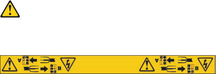
9. Turn off both power switches on the back of each storage expansion enclosure
in the configuration.
CAUTION:
The power switch on the power supply and fan unit does not turn off the
electrical current supplied to the device. The DS5020 storage subsystem
might also have more than one connection to ac power. To remove all
electrical current from the device, ensure that all ac power cords are
disconnected from the power supply and fan unit ac input connectors.
10. Remove (unplug) all of the power cords from the DS5020 power supply
connectors.
11. After you perform the necessary maintenance procedures, turn on the power
using the procedure in “Turning on the storage subsystem” on page 95.
Performing an emergency shutdown
Attention: Emergency situations might include fire, flood, extreme weather
conditions, or other hazardous circumstances. If a power outage or emergency
situation occurs, always turn off all power switches on all computing equipment.
This helps to safeguard your equipment from potential damage due to electrical
surges when power is restored. If the storage subsystem loses power unexpectedly,
it might be due to a hardware failure in the power system or in the midplane.
Complete the following steps to shut down the system during an emergency:
1. If you have time, stop all I/O activity to the storage subsystem by shutting down
the host or disconnecting the storage subsystem logical drives through the host.
2. Check the LEDs. Make note of any Needs Attention LEDs that are on so you
can correct the problem when you turn on the power again.
3. Turn off all power supply switches, starting with the DS5020 storage subsystem
first, and followed by the storage expansion enclosures. Then, unplug the power
cables from the storage subsystem.
CAUTION:
This unit has more than one power source. To remove all power from the
unit, all MAINS must be disconnected.
CAUTION:
The power switch on the power supply and fan unit does not turn off the
electrical current supplied to the device. The DS5020 storage subsystem
might also have more than one connection to ac power. To remove all
electrical current from the device, ensure that all power cords are
disconnected from the power supply and fan unit input connectors.
Restoring power after an unexpected shutdown
Use the following procedure to restore power to the storage subsystem in a
configuration after an unplanned shutdown.
112 IBM System Storage DS5020 Storage Subsystem: Installation, User’s, and Maintenance Guide
Risk of severe electrical shock – Never turn on the power to any equipment if
there is evidence of fire, water, or structural damage. Doing so might cause severe
electrical shock
1. After the emergency situation is over or power is restored, visually check the
storage subsystem for damage. Is there evidence of damage to any of the
storage subsystem components, cables, or equipment attached to the storage
subsystem?
vYes – Do not continue with this procedure. Contact your IBM service
representative for assistance. Depending on the current service agreements,
you might need to return the equipment to the factory or local service center
for repair.
vNo – Go to step 2.
Potential data loss – Before resetting circuit breakers in the cabinet, make
sure that the storage subsystem and storage expansion enclosures power
switches are turned off. Resetting circuit breakers after an emergency
situation while the storage subsystem and storage expansion enclosure
power switches are turned on can cause potential data loss because the
configuration components might not be powered on in the correct sequence.
2. After you check the storage subsystem for damage, make sure that the power
switches are in the off position; then plug in the DS5020 power cables, if
required.
3. Check the system documentation of the hardware devices that you want to turn
on and determine the proper startup sequence.
Note: Be sure to turn on all of the storage expansion enclosures and verify that
there are not any ESM or power supply and fan unit fault LEDs lit before
you turn on the DS5020.
In addition, consider the following items:
vThe storage subsystem supports simultaneous power-up of the system
components, but you must always follow the power-up sequence listed
in the “Best practices guidelines” on page 5 section during any
attended power-up procedure.
vA storage subsystem in an optimal state recovers automatically from
an unexpected shutdown and unattended simultaneous restoration of
power to system components. After power is restored, contact IBM
technical support if any of the following conditions occur:
– The storage subsystem logical drives and subsystems do not
display in the Storage Manager graphical user interface (GUI).
– The storage subsystem logical drives and subsystems do not come
online.
– The storage subsystem logical drives and subsystems seem to be
degraded.
4. Turn on the power to each device, based on the startup sequence.
5. Turn on any attached disconnect devices.
6. Turn on both of the power supply switches on the DS5020. The green LEDs on
the front and the back of the DS5020 remain lit. If other amber Fault LEDs light,
see “Solving problems” on page 153.
Chapter 4. Operating the storage subsystem 113

Recovering from an overheated power supply and fan unit
Each storage subsystem contains two power supply and fan units. Each power
supply and fan unit contains a built-in temperature sensor designed to prevent it
from overheating. Under normal operating conditions, with an ambient air
temperature range of 10° C to 35° C (50° F to 95° F), the fans in the power supply
and fan units maintain a proper operating temperature inside the module.
If the internal temperature reaches 65° C (149° F), the power supply shuts down
automatically. If both power supplies shut down because of overheating, the module
has no power, and all indicator lights are off.
The following factors can cause the power supplies to overheat:
vAn unusually high room temperature
vFan failures in the power supply and fan units
vDefective circuitry in the power supply
vBlocked air vents
vFailures in other devices in the configuration or cabinet
If a fan failure causes overheating or the operating environment becomes too hot
(greater than 55° C), the Global Fault LED on the storage expansion enclosure
turns on. The power supply and fan unit Fault and Service Action Allowed (SAA®)
LEDs on the back of the storage subsystem also turn on. “Controller LEDs” on page
104 shows the location of these LEDs.
Attention: Because the power supply and fan unit CRU Fault and SAA LEDs are
lit when the operating environment temperature is too hot (greater than 55° C), do
not assume the power supply and fan unit CRU is bad. Take action to cool down
the environment first. When the operating environment temperature is within the
specified operating environment range, the power supply and fan unit Fault and
SAA LEDs will be unlit if there are no problems with the power supply and fan unit
CRU.
If the module temperature exceeds 45° C (113° F), the storage management
software displays a Needs Attention icon in the Subsystem Management window. If
event monitoring is enabled, and event notification is configured, the software
issues the following two critical problem notifications:
vIf one power supply shuts down, the storage management software displays a
Needs Attention status in the Subsystem Management window.
vIf both power supplies shut down, the module shuts down, and the storage
management software displays a Not Responding status in the Array
Management window.
Use the following procedure to resume normal operation after a power supply
shutdown.
Attention: Risk of damage from overheating - The power supplies
automatically shut down when the air temperature inside the cabinet reaches 68°
C (154° F). If the power supplies shut down, immediately remove all cabinet
panels to help cool the cabinet air temperature and to prevent damage to the
DS5020 storage subsystem configuration components.
1. Remove the front cover.
2. If applicable, mute the alarm.
3. Did you use the procedure “Troubleshooting the storage subsystem ” on page
100 to identify an overheating problem?
114 IBM System Storage DS5020 Storage Subsystem: Installation, User’s, and Maintenance Guide

vYes - Go to step 4.
vNo - Perform the procedure “Troubleshooting the storage subsystem ” on
page 100 to verify that the power supplies have shut down because of an
overheating problem, and then go to step 4.
4. Stop I/O activity to the storage subsystem and all attached storage expansion
enclosures.
5. Take all or some of the following measures to alleviate the overheating
problem:
vRemoving all panels from the cabinet immediately
vUsing external fans to cool the area
vShutting down the power to the storage expansion enclosure, using the
procedure described in “Performing an emergency shutdown” on page 112
6. Wait for the air temperature in and around the storage subsystem to cool.
After the temperature inside the power supplies cools to below 65° C (149° F),
the storage subsystem is capable of power-up recovery without operator
intervention. After the air has cooled, the power supplies turn on automatically.
If the power supplies restart automatically, the controllers will reset and return
to normal operation.
7. Did the power supply and fan units restart automatically?
vYes - Go to step 9.
vNo - Go to step 8.
8. Turn off the power switch on each controller in the storage subsystem, power
off all connected storage expansion enclosures, and flip the disconnected
devices to the OFF position. Wait 1 minute and then turn on power to all
connected storage expansion enclosures and flip the disconnected devices to
the ON position.
CAUTION:
This unit has more than one power source. To remove all power from the
unit, all MAINS must be disconnected.
CAUTION:
The power switch on the power supply and fan unit does not turn off the
electrical current supplied to the device. The DS5020 storage subsystem
might also have more than one connection to power. To remove all
electrical current from the device, ensure that all power cords are
disconnected from the power supply and fan unit input connectors.
While the storage expansion enclosure powers up, the LEDs on the front and
the back of the module blink intermittently. Depending on your configuration,
the storage expansion enclosure can take between 20 seconds and several
minutes to power on.
9. Turn on both power switches on the back of the storage subsystem.
A storage subsystem can take 10 seconds to power on and up to 15 minutes
for the battery self-test to complete. During this time, the LEDs on the front
and the back of the modules blink intermittently.
Chapter 4. Operating the storage subsystem 115

10. Check the status LEDs on the front and back of the storage subsystem.
a. Note the status of the LEDs on the front and back of each module.
A green LED indicates a normal status; amber LEDs indicate a hardware
fault.
b. Open the Subsystem Management window for the storage array.
c. Select the applicable components button for each module in the Physical
View of the Subsystem Management window to view the status of its
components.
The status for each component is either Optimal or Needs Attention.
11. Does each module display green LEDs only, and is the status Optimal for each
module component?
vYes - Go to step 13.
vNo - Go to step 12.
12. Diagnose and correct the fault.
a. To run the Recovery Guru, select the Recovery Guru toolbar button in the
Subsystem Management window.
b. Complete the recovery procedure.
If the Recovery Guru directs you to replace a failed component, locate and
troubleshoot that component. See “Checking the LEDs” on page 101.
c. When the procedure is completed, rerun the Recovery Guru to make sure
that the problem has been corrected by selecting Recheck in the Recovery
Guru.
d. If the problem persists, contact IBM Customer and Technical Support.
13. Replace the bezel on the storage expansion enclosure, if applicable.
Cache memory and cache battery
Each RAID controller in the DS5020 storage subsystem contains either 1 GB or 2
GB of cache memory to store read and write operations. (Both RAID controllers in
the DS5020 must have the same amount of cache memory.) The battery unit
contains enough charge to back up the cached data in each controller to a flash
drive in the event of a DS5020 power failure.
Attention: There are different replacement FRU part numbers for the DS5020
controller with certain cache sizes. The DS5020 storage subsystem profile has the
information about the installed cache memory size in the DS5020 controllers. Refer
to the storage subsystem profile and see “Parts listing” on page 160 for the correct
FRU part number for the DS5020 controller.
Cache memory
Cache memory is memory on the RAID controller that is used for intermediate
storage of read and write data on the DS5020 RAID controllers. Using cache
memory can increase system performance. The data for a read operation from the
host might be in the cache memory from a previous operation (thus eliminating the
need to access the drive itself), and a write operation is completed when it is written
to the cache, rather than to the drives.
The RAID controller has a Cache Active LED that displays the current status of the
cache. The LED is on if there is data in the cache, and it is off if there is no data in
the cache.
116 IBM System Storage DS5020 Storage Subsystem: Installation, User’s, and Maintenance Guide
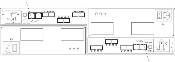
If caching is enabled and the Cache Active LED never comes on during I/O activity,
it indicates one of the following conditions:
vThe cache memory from either controller A or controller B has failed.
vThe cache sizes in controller A and controller B are not the same.
vThe battery has failed. (In this case, one or both of the green Battery LEDs will
be off and one or both amber Battery Needs Attention LEDs will be lit.)
Note: Always use the DS Storage Manager client to check your cache memory
settings before assuming a hardware failure.
Figure 73 shows the locations of the Cache Active LEDs on the front of the RAID
controllers.
Subsystem cache battery
The backup battery unit provides power to back up the cache memory of each
controller onto flash drives in the event of a power failure. Each battery unit
contains a sealed, rechargeable SMART lithium ion battery. The battery unit
contains enough charge to back up the cached data in each controller to a flash
drive in the event of a power failure.
Cache
active
LED
Cache
active
LED
Figure 73. Cache Active LEDs
Chapter 4. Operating the storage subsystem 117

Statement 2:
CAUTION:
When replacing the lithium battery, use only an equivalent type battery
recommended by the manufacturer. If your system has a module containing a
lithium battery, replace it only with the same module type made by the same
manufacturer. The battery contains lithium and can explode if not properly
used, handled, or disposed of.
Do not:
vThrow or immerse into water
vHeat to more than 100° C (212° F)
vRepair or disassemble
Dispose of the battery as required by local ordinances or regulations.
Replace the battery units in the DS5020 when they are identified as failing by the
DS Storage Manager Subsystem Management window, or when the Battery LEDs
or Battery Needs Attention LEDs light. These LEDs are located on the power supply
and fan units and on the battery unit respectively, as shown in Figure 74 on page
119.
Replace only the battery unit that is indicated as failed by the LEDs or in the DS
Storage Manager Subsystem Management window. You do not need to replace
both battery units when the Battery LEDs indicate that only one battery unit has
failed.
If the battery age expires, do not call IBM technical support to replace the battery.
Instead, reset the battery age using the procedure described in the Storage
Manager online help. Replace the battery only when it is in a failed state, as
indicated by the Storage Manager Recovery Guru.
Each power supply and fan unit has green Battery LEDs on the back that indicates
the battery status of each battery unit, as follows:
vThe LED is on and remains steady when the battery is fully charged.
vThe LED flashes when the battery is charging or performing a self-test.
vThe LED is off if the battery or the battery charger has failed.
The battery unit also has a battery failure indicator LED that is located on the
battery unit. This LED will light if the battery fails to hold a charge.
The battery performs a learn cycle the first time the storage subsystem is turned on,
and again every eight weeks thereafter, to assess the charge capacity of the
battery. If the battery fails the learn cycle or takes too much time to reach full
charge, the Battery LED turns off (indicating a battery fault) and the DS Storage
Manager identifies the battery as failed.
The learn cycle takes up to three hours. During this time, the cache will be active if
the battery is in optimal condition. If the learn cycle is interrupted, the current learn
cycle will be terminated and the battery will perform a new learn cycle at the next
scheduled interval (eight weeks from the current learn cycle). A learn cycle
118 IBM System Storage DS5020 Storage Subsystem: Installation, User’s, and Maintenance Guide
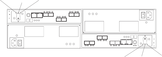
interruption is caused if you remove the battery from the controller chassis, reset
the power to the storage subsystem, or if a storage expansion enclosure or battery
overheats.
Data caching starts after the battery is charged to the programmed voltage level,
which occurs when the storage subsystem power is first turned on, when a new
battery is installed to replace a failed battery, or when the subsystem power is
turned on after months of inactivity.
Attention: Write caching is suspended while a battery pack is either charging or
self-testing.
Figure 74 shows the location of the Battery LEDs.
Service action
allowed (ok to
remove) LED
Service action
required
(fault) LED
Battery
charging
LED
Service action
allowed (ok to
remove) LED
Service action
required
(fault) LED
Battery
charging
LED
Figure 74. Battery unit LEDs
Chapter 4. Operating the storage subsystem 119
120 IBM System Storage DS5020 Storage Subsystem: Installation, User’s, and Maintenance Guide

Chapter 5. Replacing components
This chapter contains information about replacing a controller, E-DDM CRU, power
supply and fan unit CRU, battery unit, SFP module, and midplane.
Attention: Always replace a failed component as soon as possible. The Recovery
Guru menu function in the DS5020 storage subsystem identifies failed components.
Handling static-sensitive devices
Attention: Static electricity can damage electronic devices and your system. To
avoid damage, keep static-sensitive devices in their static-protective packages until
you are ready to install them.
To reduce the possibility of electrostatic discharge, observe the following
precautions:
vLimit your movement. Movement can cause static electricity to build up around
you.
vHandle the device carefully, holding it by its edges or its frame.
vDo not touch solder joints, pins, or exposed printed circuitry.
vDo not leave the device where others can handle and possibly damage the
device.
vWhile the device is still in its static-protective package, touch it to an unpainted
metal part of the storage subsystem for at least two seconds. This drains static
electricity from the package and from your body.
vRemove the device from its package and install it directly into your storage
subsystem without setting it down. If it is necessary to set the device down, place
it in its static-protective package. Do not place the device on your storage
subsystem cover or any metal surface.
vTake additional care when handling devices during cold weather because heating
reduces indoor humidity and increases static electricity.
Service Action Allowed Status LED
Each controller, power supply and fan unit, and battery unit has a blue Service
Action Allowed status LED. The purpose of the Service Action Allowed status LED
is to help make sure that a component is not removed before it is safe to do so. Do
not remove any storage subsystem component unless the Service Action Allowed
status LED for that component is lit.
Attention
Never remove a controller, power supply and fan unit, or battery unit unless
the Service Action Allowed status LED is turned on. Doing so can result in a
potential loss of data availability. If the Needs Attention LED is lit and the
associated Service Action Allowed status LED is not lit, then you must perform
additional diagnostics before you can remove the indicated component. Use
the Recovery Guru instructions in the DS Storage Manager Subsystem
Management window or refer to the applicable component replacement
instructions in this chapter for the additional diagnostics required in this case.
© Copyright IBM Corp. 2009 121

The Service Action Allowed status LED automatically turns on or off as conditions
change. Wait at least two minutes after you replace each component for the
controller to recognize the new component and update the LED status. In most
cases when a single component fails, the Service Action Allowed status LED turns
on steadily when the Needs Attention status LED is turned on for the component.
Replacing a controller
Attention: Before you replace a controller, verify the following:
vThe replacement controller part number matches the part number of the
controller to be replaced. To provide full functionality, the two controllers must
have the same cache memory capacity, same number of host ports, same types
of host ports (FC or iSCSI), and same FRU part number. Inserting a
non-compatible controller causes the controller to be placed in a lockout state by
the other controller in the DS5020 chassis.
Note: The DS5020 storage subsystem controller FRU is not compatible with the
DS4200 Express or DS4700 storage subsystem controller FRU. See the
“Parts listing” on page 160 for more information about compatible
controllers.
vBoth power supply and fan units must be connected and powered on with no
Needs Attention LEDs lit. Make sure that the Power LEDs on each of the power
supply and fan units are lit. If either of the power supply and fan units is not
optimal, replace that component before you proceed with the controller
replacement procedure.
vIf you are replacing an optimal controller, first make sure that the other controller
is optimal and that the Fibre Channel path from the hosts to the other controller
is also optimal.
Each controller has a unique hardware Ethernet address, which is printed on a label
on the front.
Use the following procedure to replace a controller in an DS5020 storage
subsystem:
1. Use the DS Storage Manager client software to print a storage subsystem
profile. Move logical drive ownership to the other controller. If the controller you
are replacing has failed but is still operating, move the failed controller to an
Offline state.
Attention: Never remove a controller unless the Service Action Allowed
status LED is turned on. Doing so can result in a potential loss of data.
2. Locate the failed controller by checking the Needs Attention status LEDs on
the controllers in the storage subsystem.
3. Is the Service Action Allowed status LED turned on?
vYes – Go to step 4.
vNo – Another component might require attention before you can remove the
controller. Use the Recovery Guru function in the DS5020 Subsystem
Management window to identify and correct any additional failures. If there
are none, proceed with step 4 to replace the controller.
Electrostatic discharge can damage sensitive components. Touching the
storage subsystem or its components without using a proper ground might
damage the equipment. To avoid damage, use proper antistatic protection
while handling any components.
4. Put on antistatic protection.
122 IBM System Storage DS5020 Storage Subsystem: Installation, User’s, and Maintenance Guide
5. Unpack the new controller. Save all packing materials in the event you need to
return the new controller.
6. Determine whether the replacement controller will serve as controller A or
controller B (controller A is inserted in the left controller bay; controller B is
inserted in the right controller bay), and then apply the controller labels for host
channels, drive channels, and numeric display to the replacement controller.
The controller labels and instructions are included with the replacement
controller. Make sure that the labels are aligned properly and do not cover any
ports or LEDs.
Statement 3:
CAUTION:
When laser products (such as CD-ROMs, DVD drives, fiber-optic devices,
or transmitters) are installed, note the following:
vDo not remove the covers. Removing the covers of the laser product
could result in exposure to hazardous laser radiation. There are no
serviceable parts inside the device.
vUse of controls or adjustments or performance of procedures other
than those specified herein might result in hazardous radiation
exposure.
DANGER
Some laser products contain an embedded Class 3A or Class 3B laser
diode. Note the following.
Laser radiation when open. Do not stare into the beam, do not view
directly with optical instruments, and avoid direct exposure to the
beam.
Class 1 Laser statement
Class 1 Laser Product
Laser Klasse 1
Laser Klass 1
Luokan 1 Laserlaite
Apparell Laser de Calsse 1À
IEC 825-11993 CENELEC EN 60 825
Attention: Handle and install fiber-optic cables properly to avoid degraded
performance or loss of communications with devices. For specific handling
guidelines, see “Handling fiber-optic cables” on page 47.
7. Disconnect all attached interface cables from the failed controller, including the
SFP modules. Make sure that you label each cable so that you can reconnect
them correctly to the new controller.
Use the following procedure to remove the SFPs from the RAID controller that
has failed:
Chapter 5. Replacing components 123
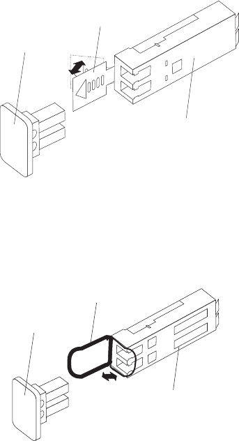
a. Remove the LC-LC Fibre Channel cable from the SFP module. For more
information, see “Handling fiber-optic cables” on page 47.
b. Unlock the SFP module latch:
vFor SFP modules that contain plastic tabs, unlock the SFP module latch
by pulling the plastic tab outward 10°, as shown in Figure 75.
vFor SFP modules that contain wire tabs, unlock the SFP module latch by
pulling the wire latch outward 90°, as shown in Figure 76.
c. With the SFP latch in the unlocked position, extract the SFP module.
vFor SFP modules that contain plastic tabs, slide the SFP module out of
the port.
vFor SFP modules that contain wire tabs, grasp the wire latch and pull
the SFP module out of the minihub port.
d. Replace the protective cap on the SFP module.
e. Place the SFP module into a static-protective package.
f. Replace the protective cap on the port.
8. Squeeze the controller latch and pull the lever open 90° (so that the lever is
horizontal) to release the controller from the latch. The controller latch is a
coral colored tab on the lever.
Note: The lever rotates upward or downward 90°, depending on whether the
controller you are removing is the right or left controller CRU.
9. Slowly pull the lever away from the chassis to remove the controller from the
bay. Use two hands when releasing the controller levers. Figure 77 on page
125
Pro t ect i ve cap
SFP m o d u l e
10
o
Plastic tab
Figure 75. Unlocking the SFP module latch - plastic variety
Prot ect iv e cap
SFP m o d ul
e
90
o
Wire t ab
Figure 76. Unlocking the SFP module latch - wire variety
124 IBM System Storage DS5020 Storage Subsystem: Installation, User’s, and Maintenance Guide
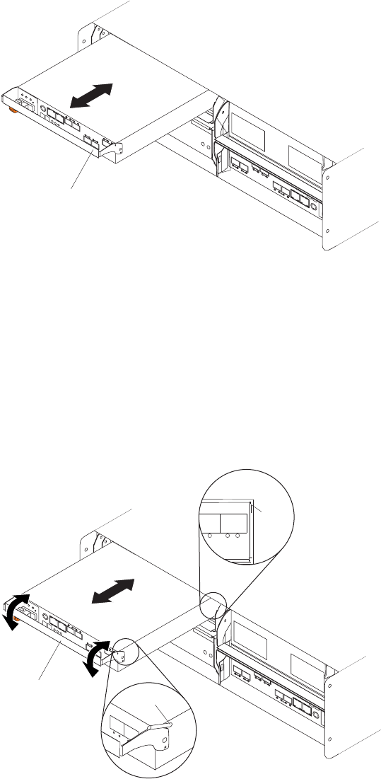
125 shows the controller sliding from the storage subsystem chassis.
10. If the new controller does not have the cache battery backup unit already
installed, follow the instructions in “Replacing a battery unit” on page 144 to
remove the cache backup battery from the existing controller unit and insert it
into the new controller CRU.
11. Install the new controller.
a. Slide one controller into the empty slot in the storage subsystem. Be sure
that the lever is pulled straight out as you slide the controller in, as shown
in Figure 78.
b. As you slide the controller into the empty slot, make sure the guide pins on
the side of the controller fit into the notches. After the guide pins fit into the
notches and the controller fits snugly into the bay, push the lever downward
or upward 90°, depending on whether the controller is inserted in the A or
Lever
Figure 77. Removing a controller from the DS5020
Lever
Guide pin
Notch
Figure 78. Installing a controller
Chapter 5. Replacing components 125

B controller bay to fully latch it into place. Do not force fit. The controller is
designed to prevent it from being inserted into the chassis incorrectly.
Attention: Make sure that the levers lock into place in the storage
subsystem chassis.
c. Repeat step 11a on page 125 and step 11b on page 125 to replace the
second controller.
12. Wait up to 5 minutes for the DS Storage Manager client software to recognize
the new controller.
13. Complete any remaining Recovery Guru procedures for controller replacement,
if needed.
14. Check the LEDs on the new controller to verify that the controller is fully
operational.
15. Remove the antistatic protection.
16. Use the DS Storage Manager client Subsystem Management window to check
the status of all components in the storage subsystem.
vIf the new controller is online and the DS Storage Manager client
Subsystem Management window indicates normal operation, go to step 19.
vIf the new controller is online and the DS Storage Manager client
Subsystem Management window indicates a problem status, go to
“Troubleshooting the storage subsystem ” on page 100.
vIf the new controller is offline, go to step 17.
17. If the newly inserted controller is in an offline state, see the DS Storage
Manager client online help for instructions on bringing the controller online.
If necessary, open the DS Storage Manager Subsystem Management window
and place the controller on-line; select the off-line controller and click
Advanced Recovery Place controller online.
18. Verify the state of the LEDs on the newly inserted controller. See “Controller
LEDs” on page 104. You can also use the DS Storage Manager client
Subsystem Management window to identify any new faults. Do any storage
subsystems have a fault (Needs Attention) status?
vYes – Select the Recovery Guru toolbar button in the Subsystem
Management window, and complete the recovery procedure. If the problem
persists, contact your IBM service representative.
vNo – Go to step 19.
19. Use the DS Storage Manager client software to print a new storage subsystem
profile.
Working with hot-swap E-DDMs
This section explains how you can increase the storage subsystem capacity by
adding more E-DDMs or by replacing existing E-DDMs with ones that have a larger
capacity.
Before you begin, complete the following tasks:
vRead the safety and handling guidelines in “Safety” on page xiii and in “Handling
static-sensitive devices” on page 29.
vMake sure that your current system configuration is working properly.
vBack up all important data before you make changes to data storage devices.
Before you install or remove E-DDM CRUs, review the following information:
126 IBM System Storage DS5020 Storage Subsystem: Installation, User’s, and Maintenance Guide
vBlank trays: A storage subsystem without a full set of E-DDMs (16) contains
blank trays in the unused drive bays. Before installing new E-DDMs, you must
remove these empty trays. Save the empty trays for future use. Each of the 16
bays must always contain either a blank tray or a hot-swap E-DDM.
For proper cooling and EMC protection, do not leave a drive slot open without
either a drive blank or an E-DDM CRU inserted.
vE-DDM CRUs:
– The DS5020 storage subsystem supports 4 Gbps Fibre Channel and SATA
E-DDMs. The link rate setting speed must be set accordingly. See “Verifying
the link rate setting” on page 136 for more information.
– When adding E-DDM CRUs, if you are not installing all 16 E-DDM CRUs into
the storage subsystem, install the E-DDM CRUs from left to right
consecutively.
– For optimum performance, never insert an E-DDM into a storage subsystem
without first confirming the drive firmware level. In the event of a drive
firmware mismatch, schedule down time as soon as possible to upgrade the
drive firmware to the same version. For information about supported drive
firmware versions, refer to the IBM Storage Systems support Web site:
http://www.ibm.com/systems/support/storage/disk
– Use of non-supported drives in the drive modules can cause the storage
subsystem to fail.
– In configurations with mixed storage expansion enclosures, all storage
expansion enclosures on a fibre loop must be operating at the same interface
speed.
– Make sure that the speed of the E-DDM CRU you are adding is supported in
the storage subsystem. For example, do not install a 2 Gbps E-DDM CRUs in
a storage subsystem that supports only 4 Gbps E-DDMs.
– E-DDM CRUs are not interchangeable between EXP520 and EXP810 storage
expansion enclosures.
– After you remove an E-DDM CRU, wait 70 seconds before replacing or
reseating it to allow it to properly spin down. Failure to do so might cause
undesired events.
Attention:
Before you turn on the power to the DS5020 storage subsystem, it must be
populated with at least two E-DDMs.
If at least two E-DDMs are not installed in the DS5020, an insufficient load to the
enclosure power supplies might cause them to intermittently appear as failed,
falsely indicating the power supplies are bad. All of the E-DDMs in the DS5020
storage subsystem and the connected storage expansion enclosure or
enclosures must contain no prior configuration data.
vE-DDM CRU labels: A label is provided on the front of each E-DDM. Use this
label to record the location information for each E-DDM before you remove it.
Make sure that you keep track of the E-DDMs and their corresponding bays.
Also, record the location information in Table 24 on page 166. If you install an
E-DDM in the wrong bay, you might lose data.
vE-DDM LEDs: Each E-DDM CRU tray has two associated LEDs, a green Activity
LED and an amber Fault LED. These LEDs indicate the status for that drive. See
Table 18 on page 128 for the E-DDM LED states and descriptions.
Chapter 5. Replacing components 127

vE-DDM CRUs are not interchangeable between the DS5020 and other DS4000
storage subsystems.
Table 18. Drive LED activity
LED LED state Descriptions
Activity LED Flashing green The green LED flashes to indicate Fibre Channel activity to
the drive.
Activity LED Steady green The green LED lights to indicate that the drive is properly
installed and is spun up by the DS5020 controller.
Fault LED Flashing
amber
The amber LED flashes to indicate that a drive has been
identified by the software.
Fault LED Steady amber The amber LED lights to indicate a drive failure due to bad
or uncertified drive. The green activity LED might flash
once every 2 seconds, remain steady green, or be unlit.
Activity and
Fault LEDs
All unlit Check for and resolve one of the following situations:
vDS5020 is turned off.
vDS5020 link rate speed is not set correctly.
Activity LED Flashing once
every 2
seconds
Check for and resolve one of the following situations:
vThe controller did not complete the boot process.
vStorage subsystem controller firmware is not correct.
Note: Drives are spun down because they are in a "not
compatible state″,″exported state″,or″locked state″due to
an invalid security key.
Activity and
Fault LEDs
Flashing
together in a
certain pattern
Drive failure due to the incorrect link rate speed setting or
internal drive hardware failures.
vFibre Channel loop IDs: When you install an E-DDM in the storage subsystem,
the drive tray connects into a printed circuit board called the midplane. The
midplane sets the Fibre Channel loop ID automatically, based on the setting of
the enclosure ID switch and the physical location (bay) of the drive CRU.
vHot-swap hardware: The DS5020 contains hardware that enables you to
replace a failed E-DDM without turning off the storage subsystem. You can
continue to operate your system while an E-DDM is removed or installed. These
E-DDMs are known as hot-swap E-DDMs.
Installing hot-swap E-DDMs
With the exception of the DS5020 storage subsystem initial power up, add E-DDMs
while the storage subsystem is turned on and running. Complete the following steps
to install hot-swap E-DDMs in the storage subsystem:
Attention:
vAfter you remove an E-DDM CRU, wait 70 seconds before replacing or reseating
it to allow it to properly spin down. Failure to do so might cause undesired
events.
vThe DS5020 and EXP810 E-DDMs and FRUs are not compatible with the
DS4200 Express and EXP420 EV-DDMs and FRUs.
1. Read the documentation that comes with the E-DDM.
2. Check for Fault LEDs shown in Figure 79 on page 129. If any amber LEDs are
lit, see “Solving problems” on page 153.
128 IBM System Storage DS5020 Storage Subsystem: Installation, User’s, and Maintenance Guide
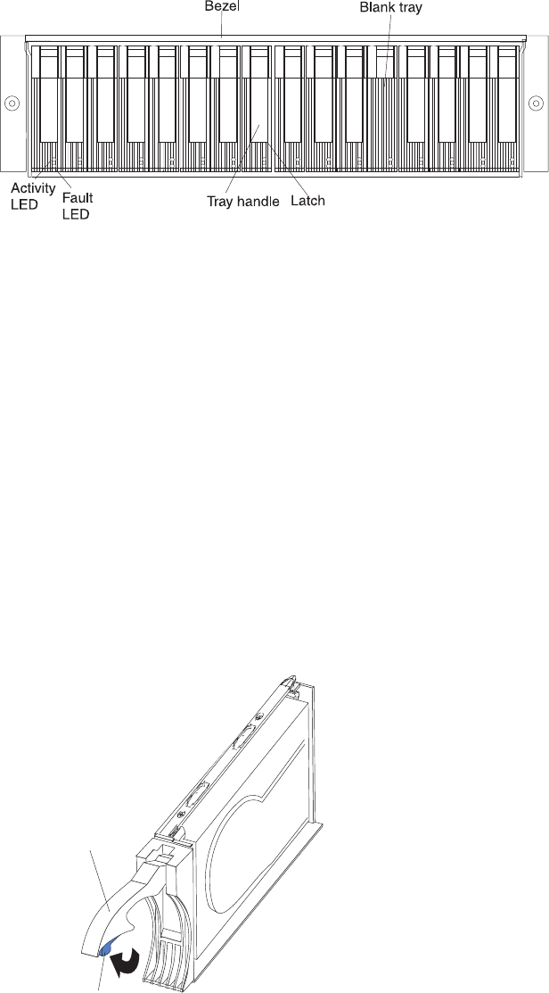
3. Determine the bay into which you want to install the E-DDM.
4. Remove the blank tray by doing the following:
a. Release the latch on the E-DDM CRU by pressing on the inside of the
bottom of the tray handle.
b. Lift the closed latch to its open position. (The latch is at a 90° angle to the
front of the E-DDM when open.)
c. Pull the blank tray out of the bay.
d. Save the blank tray for later use.
5. Install the E-DDM by doing the following:
Note: The hard disk drive comes installed in a drive tray. Do not attempt to
detach the drive from the tray.
a. Release the latch on the drive CRU by pressing on the inside of the bottom
of the tray handle.
b. Pull the handle on the tray out so that it is in the open position, as shown in
Figure 80.
Tr ay h a n d l e
Tr ay l a t c h
c. Slide the E-DDM CRU into the empty bay until the hinge of the tray handle
latches beneath the storage subsystem bezel or the adjacent E-DDM CRU
bezel.
Figure 79. Hot-swap E-DDM LEDs
Figure 80. E-DDM CRU handle
Chapter 5. Replacing components 129
Note: Make sure that the EMC gasket does not snag on the bezel.
d. Push the tray handle down until it latches into place.
Replacing hot-swap E-DDMs
E-DDM problems include any malfunctions that delay, interrupt, or prevent
successful I/O activity between the hosts and the E-DDMs in the storage
subsystem. This includes transmission problems between the host controllers and
the E-DDMs. This section explains how to replace a failed E-DDM.
Note: If you want to remove an E-DDM that is not in a failed or bypass state,
always use the Storage Manager client program either to place the E-DDM
in a failed state or to place the array that is associated with the E-DDM (or
E-DDMs) in an offline state before you remove it from the storage
subsystem.
Attention: Failure to replace the E-DDMs in their correct bays might result in loss
of data. If you are replacing an E-DDM that is part of a configured array and logical
drive, make sure that you install the replacement E-DDM in the correct bay. Check
the hardware and software documentation that is provided with your DS5020 to see
if there are restrictions regarding E-DDM configurations.
Complete the following steps to replace a hot-swap E-DDM:
1. Use the DS Storage Management client software to print a new storage system
profile.
2. Determine the location of the E-DDM that you want to remove.
Attention: Never hot-swap an E-DDM CRU when its associated green Activity
LED is flashing. Hot-swap an E-DDM CRU only when its associated amber
Fault LED is lit and not flashing.
3. Put on antistatic protection.
4. Remove the E-DDM CRU by doing the following:
a. Release the latch on the E-DDM CRU by pressing on the inside of the
bottom of the tray handle, as shown by the arrow in Figure 80 on page 129.
b. Pull the tray handle out into the open position.
c. Pull the E-DDM CRU about 1/2 inch out of the bay and wait 70 seconds to
allow the E-DDM to properly spin down and the storage subsystem
controller to properly recognize that an E-DDM is removed from the
configuration. .
d. Verify that there is proper identification (such as a label) on the E-DDM
CRU, and then slide it completely out of the storage subsystem.
5. Unpack the new E-DDM. Save all packing material in case you need to return it.
6. Install the new E-DDM CRU by doing the following:
a. Gently push the E-DDM CRU into the empty bay until the hinge of the tray
handle latches beneath the storage subsystem enclosure bezel.
b. Push the tray handle down into the closed (latched) position.
7. Check the E-DDM LEDs by doing the following:
vWhen an E-DDM is ready for use, the green Activity LED lights and the
amber Fault LED is off.
vIf the amber Fault LED lights and is not flashing, remove the E-DDM from the
unit and wait 70 seconds; then, install the E-DDM again.
130 IBM System Storage DS5020 Storage Subsystem: Installation, User’s, and Maintenance Guide
Attention: After you remove an E-DDM CRU, wait 70 seconds before
replacing or reseating the E-DDM CRU to allow it to properly spin down. Failure
to do so might cause undesired events.
8. Use the DS Storage Manager subsystem management window to verify that the
E-DDM is shown in the Storage Subsystem Management window.
Replacing multiple E-DDMs
This section provides guidelines for upgrading the E-DDMs in the storage
subsystem. Read the software documentation and this entire section to determine if
you should use this procedure, use a modified version of this procedure, or use a
different procedure that is provided by your operating system.
Note: Instructions that are provided with your software supersede anything stated
in this document.
Attention: After you remove an E-DDM CRU, wait 70 seconds before replacing or
reseating the E-DDM CRU to allow it to properly spin down. Failure to do so might
cause undesired events.
The following are methods for upgrading E-DDMs:
vReplacing all the E-DDMs at the same time
This method requires that you back up the data on the affected E-DDMs and
then turn off the DS5020 storage subsystem.
Attention: Turn off the DS5020 storage subsystem before you turn off the
attached storage expansion enclosures.
After replacing all the E-DDMs, you must reconfigure the new E-DDMs and
restore data from backup. See the procedure in “Replacing all E-DDMs at the
same time” on page 132.
This is the safest way to exchange E-DDMs without losing data. However, this
method might take a long time to complete because of the backup,
reconfiguration, and restoration processes. In addition, other users are not able
to use the storage subsystem (or any storage expansion enclosures attached to
the storage subsystem) until you finish the procedure. You must use this method
on RAID 0 logical drives.
vReplacing the E-DDMs one at a time
In this method, you manually fail each E-DDM, replace it, and wait for the system
to restore data to the new E-DDM before installing the next E-DDM. After you
install the new E-DDMs, you can configure them to make the additional drive
space available. See the procedure in “Replacing the E-DDMs one at a time” on
page 134.
Using this method, you can replace the E-DDMs while the storage expansion
enclosures and the DS5020 are running, eliminating the down time that is
required if you replace all the E-DDMs at once. However, this method is more
risky because you can lose data if the drive restoration or storage subsystem
reconfiguration process fails. In addition, the reconstruction process might take a
long time. This method works only on redundant logical drives (RAID 1, 3, or 5).
You cannot use this method with any drives containing RAID 0 logical drives.
Consider backing up your data if you use this method. This safeguards your data
if the restoration and reconfiguration process fails or the new drive malfunctions.
The method you use depends on the following considerations:
vWhich method most closely matches the drive upgrade procedure in the
operating-system or the storage-management software documentation.
Chapter 5. Replacing components 131
vWhich RAID level is used on the affected drives. (RAID 0 requires you to replace
all the E-DDMs at the same time.)
vHow much downtime is acceptable as you swap the E-DDMs.
vThe number of E-DDMs in an array. Replacing E-DDMs one at a time is better
suited for arrays consisting of 3 to 5 E-DDMs. If you have more than 10 E-DDMs
or arrays that are comprised of high capacity SATA E-DDMs, consider replacing
all E-DDMs at the same time.
vHow much risk of losing data is acceptable. Because the array will be in a
degraded state during the RAID array reconstruction and copyback process as
result of replacing a drive in the array, any new E-DDM failure will cause the
array to fail (causing a loss of data availability and even a loss of data). The
duration of the reconstruction and copyback process can be quite long,
depending on the size of the RAID array.
vHow extensive will the data be changed while the array is in a degraded state
during the RAID array reconstruction and copyback process as result of replacing
an E-DDM in the array. The more extensive the data changes, the more work
that will need to be performed to restore the data in the event that the array
failed because of an addition E-DDM failed while the array is in degraded state.
Replacing all E-DDMs at the same time
Use this procedure to replace all E-DDMs at the same time. You must use this
method if you are upgrading E-DDMs containing RAID 0 logical drives. All the data
currently on the E-DDMs is lost when you replace the E-DDMs; therefore, you must
back up all data that is currently on the E-DDMs. This procedure also requires you
to turn off the storage expansion enclosures and the DS5020, which makes the
storage subsystem (and any attached storage expansion enclosures) inaccessible
to other users.
Attention: After you remove an E-DDM CRU, wait 70 seconds before replacing or
reseating the E-DDM CRU to allow it to properly spin down. Failure to do so might
cause undesired events.
To replace all the E-DDMs at the same time, perform the following steps:
1. Read the following information:
vThe information in “Replacing multiple E-DDMs” on page 131, particularly
the paragraphs that discuss the differences between the two possible
upgrade procedures
vThe information in your software documentation regarding E-DDM upgrades
and installation
vThe documentation that comes with the new E-DDMs
Read all precautionary notes, kit instructions, and other information. Kit
instructions often contain the most current information regarding the
E-DDMs and their installation, plus upgrade or servicing procedures.
Compare the kit instructions with this procedure to determine if you need to
modify this procedure.
2. Use the DS Storage Manager software to check the status of the DS5020.
Correct any problems that are reported.
3. Perform a complete backup of the E-DDMs that you are replacing.
You need the backup to restore data on the E-DDMs later in this procedure.
Attention: When you handle static-sensitive devices, take precautions to
avoid damage from static electricity. For details about handling static-sensitive
devices, see “Handling static-sensitive devices” on page 29.
4. Unpack the new E-DDMs.
132 IBM System Storage DS5020 Storage Subsystem: Installation, User’s, and Maintenance Guide
Set the E-DDMs on a dry, level surface away from magnetic fields. Save the
packing material and documentation in case you need to return them.
5. Perform the following steps:
a. Stop all I/O activity to the storage subsystem and attached storage
expansion enclosures. Make sure of the following:
1) All of the green Drive activity LEDs on the front of the storage
subsystem (and on all attached storage expansion enclosures) are not
flashing.
2) The green Cache active LEDs are off.
b. If applicable, use the operating system software to disconnect the storage
subsystem logical drives from the host before you power off the storage
subsystem.
Attention: To turn off all power to the storage subsystem, you must turn off
both power supply and fan unit switches and disconnect both power cords.
Use the procedure in step 6 for the proper shutdown sequence.
6. Turn off the power to each device based on the following shutdown sequence:
a. Turn off power to the host before you turn off power to the storage
subsystem. If the host must stay powered on to support an existing
network, see the operating system documentation for information about
disconnecting the storage subsystem logical drives from the host before
the storage subsystem is powered off.
b. Turn off power to the storage subsystem before you turn off power to the
storage expansion enclosures. Turn off both power supply switches on the
back of the storage subsystem.
CAUTION:
This unit has more than one power source. To remove all power from
the unit, all MAINS must be disconnected.
CAUTION:
The power switch on the power supply and fan unit does not turn off
the electrical current supplied to the device. The DS5020 storage
subsystem might also have more than one connection to power. To
remove all electrical current from the device, ensure that all power
cords are disconnected from the power supply and fan unit input
connectors.
c. Turn off power to other supporting devices (for example, management
stations, Fibre Channel switches, or Ethernet switches).
7. Use the procedures in “Replacing hot-swap E-DDMs” on page 130 to remove
the E-DDMs that you want to replace. Use the procedures in “Installing
hot-swap E-DDMs” on page 128 to install the new E-DDMs into the storage
subsystem.
8. After you install all the new E-DDMs, check the system documentation for the
hardware devices that you intend to power up, and then determine the proper
startup sequence. Use the following power-on sequence, where applicable:
Chapter 5. Replacing components 133
a. Turn on the power to the supporting devices (for example, Ethernet
switches and management stations) before you turn off power to the
storage subsystem.
b. You must turn on the storage expansion enclosures before the storage
subsystem. The controllers might not recognize the correct configuration if
the E-DDMs are powered up after the storage subsystem. For instructions
on powering up the storage subsystem, see the storage subsystem
documentation.
c. Turn on the power to the storage subsystem; then restart or turn on the
power to the host.
9. Turn on the power to each device, based on the power-on sequence in step 8
on page 133. To turn on power to the storage subsystem and the storage
expansion enclosures, turn on the power supply and fan unit switches on the
back of the storage subsystem. You must turn on both power supply and fan
unit switches to take advantage of the redundant power supplies.
10. Check the green Drive activity LEDs and the amber Drive fault LEDs above
the new E-DDM CRUs.
Make sure that the Drive activity LEDs are on and the Drive fault LEDs are off.
Note: The Drive fault LEDs might flash intermittently while the E-DDMs spin
up.
vIf the Drive activity LED is off, the E-DDM CRU might not be installed
correctly. Remove the E-DDM CRU, wait 30 seconds, and then reinstall it.
vIf the Drive fault LED stays on or the Drive activity LED stays off, the new
E-DDM might be faulty. See the DS Storage Manager software for problem
determination.
11. Use the DS Storage Manager software to configure the new E-DDMs. See the
DS Storage Manager software online Help for detailed instructions.
12. Restore the data from backup to all the E-DDMs.
Replacing the E-DDMs one at a time
Use this procedure to replace all the E-DDMs one at a time. You cannot use this
procedure on RAID 0 logical drives (use the procedure in “Replacing all E-DDMs at
the same time” on page 132).
Note: If your storage subsystem has hot spares assigned, you might want to
unassign the hot spares while you perform this procedure. If you do not,
reconstruction might start on the hot spare before you insert the new
E-DDM. The data on the new E-DDM is still rebuilt, but the process takes
longer for each E-DDM. Remember to reassign the hot spares when you are
finished with this procedure.
Attention: After you remove an E-DDM CRU, wait 70 seconds before replacing or
reseating the E-DDM CRU to allow it to properly spin down. Failure to do so might
cause undesired events.
To replace the E-DDMs one at a time, perform the following steps:
1. Read the following information:
v“Replacing multiple E-DDMs” on page 131, particularly the paragraphs that
discuss the differences between the two possible upgrade procedures
vYour software documentation regarding E-DDM upgrades and installation
vThe documentation that comes with the new E-DDMs
134 IBM System Storage DS5020 Storage Subsystem: Installation, User’s, and Maintenance Guide
Read all precautionary notes, kit instructions, and other information. Kit
instructions often contain the most current information regarding the
E-DDMs and their installation, plus upgrade or servicing procedures.
Compare the kit instructions with this procedure to determine if you need to
modify this procedure.
2. Use the DS Storage Manager software to check the status of the unit. Correct
any problems that are reported.
3. Back up the data in the arrays and logical drives that are configured using the
E-DDMs that you are replacing.
Attention: When you handle static-sensitive devices, take precautions to
avoid damage from static electricity. For details about handling static-sensitive
devices, see “Handling static-sensitive devices” on page 29.
4. Unpack the new E-DDMs.
Set the E-DDMs on a dry, level surface away from magnetic fields. Save the
packing material and documentation in case you need to return the E-DDMs.
5. Use the DS Storage Manager software to make sure that the array that was
defined using these E-DDMs is in optimal (not degraded) state before manually
failing the first E-DDM you want to replace. If the array is in degraded state,
use the recovery procedures to bring the array into the optimal state.
Make sure of the following:
vYou fail only one E-DDM.
vThe software status display shows a failed status for the applicable E-DDM.
vThe amber Drive fault LED (on the front bezel below the E-DDM) is on.
Attention: Removing the wrong E-DDM can cause data loss. Make sure that
you remove only the failed E-DDM CRU. To identify the failed E-DDM CRU,
look for the lit Drive fault LED.
If you remove an active E-DDM accidentally, wait at least 30 seconds and then
reinstall it. Because you failed two E-DDMs in a RAID array, the array might be
marked failed by the controller. This array will not be available to the host for
I/O. See the DS Storage Manager software for further recovery instructions. Do
not attempt to replace any E-DDMs until the array is brought back to optimal
state.
6. Use the procedures in “Replacing hot-swap E-DDMs” on page 130 to remove
the failed E-DDM. Use the procedures in “Installing hot-swap E-DDMs” on
page 128 to install the new E-DDMs into the storage subsystem.
The new E-DDM automatically reconstructs the data after you install it in the
drive slot.
During data reconstruction, the amber Drive fault LED might come on for a few
minutes, then turn off when the green Drive activity LED begins flashing. A
flashing Drive activity LED indicates that data reconstruction is in progress.
Note: If your storage subsystem has active hot spares, data might not start
copying to the new E-DDM until the data is reconstructed on the hot
spare. This increases the time that is required to complete the
procedure.
7. Check the green Drive activity LED and the amber Drive fault LED above the
new E-DDM CRUs.
Make sure that the Drive activity LEDs are on and the Drive fault LEDs are off.
Chapter 5. Replacing components 135

Note: The Drive fault LEDs might flash intermittently while the E-DDMs spin
up.
vIf the Drive activity LED is off, the E-DDM CRU might not be installed
correctly. Remove the E-DDM CRU, wait 30 seconds, and then reinstall it.
vIf the Drive fault LED stays on or the Drive activity LED stays off, the new
E-DDM might be faulty or might be an uncertified drive. See the DS Storage
Manager software for problem determination. In the case of an uncertified
drive, verify that the drive options or drive FRU part number is correct for
your storage subsystem.
8. Use the DS Storage Manager software to monitor the status of the new
E-DDM and the progress of the data reconstruction. Wait for data
reconstruction to finish (the Drive activity LED stops flashing).
Note: The Drive activity LED will continue to flash after reconstruction is
finished if there is I/O activity to that E-DDM. In that case, use the host
software to determine if the data reconstruction is finished.
9. When reconstruction is finished on the new E-DDM, repeat step 5 on page 135
through step 8 for each additional E-DDM that you want to install.
10. Use the DS Storage Manager software to configure the additional space on the
new E-DDMs.
Verifying the link rate setting
Important: Make sure that the link rate for the DS5020 is always set to 4 Gbps.
The DS5020 supports only 4 Gbps FC drives.
If a link rate problem is indicated, use the following procedure to verify the link rate
setting.
A link rate switch is located on the front of the storage subsystem as shown in
Figure 82 on page 138. The link rate indicator LEDs are located on the back of the
storage subsystem. The link rate switch is only read when the storage subsystem is
powered up.
Note: Do not mix storage subsystems with different link rate speed settings in the
same drive loop.
The DS5020 storage subsystem drive channel operates at a 4 Gbps Fibre Channel
interface speed. The DS5020 storage subsystem SATA E-DDM CRUs have an ATA
translator card that converts E-DDM 3 Gbps SATA drive interface protocol a 4 Gbps
Fibre Channel interface protocol. Set the DS5020 enclosure speed to 4 Gbps when
these SATA E-DDM CRUs are installed and connected to storage expansion
enclosures running at 4 Gbps speed. The link rate setting speed must be set
accordingly. See “Verifying the link rate setting” for more information.
Do not mix 2 GB drives and 4 GB drives in the same storage subsystem. If drives
of mixed speeds reside in the storage subsystem, the data transfer rate changes
depending on the configuration. Table 19 on page 137 shows the data transfer rates
for drives of different configurations.
136 IBM System Storage DS5020 Storage Subsystem: Installation, User’s, and Maintenance Guide
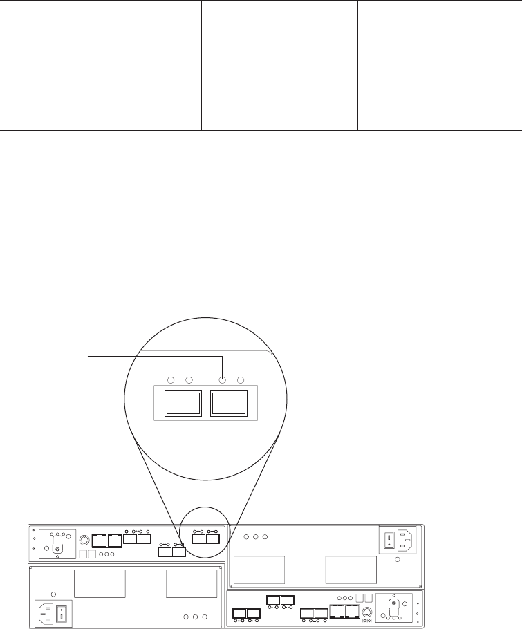
CAUTION:
Do not change the link rate setting while the storage subsystem is running.
Changing the link rate setting while the storage subsystem is running could
cause drives to fail. You must power down the storage subsystem and
storage expansion enclosures before changing the link rate setting.
Attention: All devices on the loop must have the same data transfer rate, which
means that you must set the link rate on the storage expansion enclosure to the
same rate as the storage subsystem to which it is connected. Information about
supported DS4000 storage subsystems can be obtained from the certified
Compatibility Matrix, which can be found at the following Internet location:
http://www-1.ibm.com/servers/storage/disk/ds4000/interop-matrix.html
Table 19. Data transfer rates for drive modules
Link rate
switch
setting
Storage subsystem
with 2 GB drives
Storage subsystem with
4 GB drives
Storage subsystem with
mixed drives
4 Gbps Drives do not come
online.
Drives work in 4 Gbps
mode.
2 GB drives do not come
online.
4 GB drives work in 4 Gbps
mode.
Use the following procedure to check the current setting of the data transfer rate
and change it, if necessary:
1. Complete the power-off sequence described in “Turning off the storage
subsystem” on page 109 ensuring that the DS5020 storage subsystem is
turned off before any attached storage expansion enclosures.
2. Locate the link rate indicator LEDs. Figure 81 shows the location of the link
rate indicator lights on the back of the storage subsystem.
Link
Rate
LEDs
Two on = 4 Gbps
One on = 2 Gbps
Figure 81. Link rate LEDs
Chapter 5. Replacing components 137
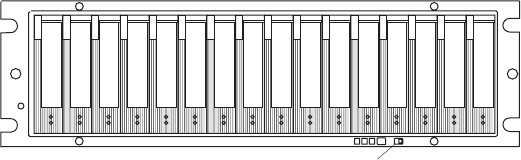
If both link rate indicator LEDs are on, the data transfer rate is set for 4 Gbps.
If one link rate indicator light is on, the data transfer rate is set for 2 Gbps.
Important: Make sure that the link rate for the DS5020 is always set to 4
Gbps. The DS5020 supports only 4 Gbps FC drives.
3. Is the data transfer rate set correctly?
Note: Make sure that the link rate for the DS5020 is always set to 4 Gbps.
vYes - Go to step 8.
vNo - Go to step 5 to change the setting.
Attention: When you handle static-sensitive devices, take precautions to
avoid damage from static electricity. For details about handling static-sensitive
devices, see “Handling static-sensitive devices” on page 29.
4. Locate the link rate switch. Figure 81 on page 137 shows the location of the
link rate indicator light on the front of the command module.
5. Change the link rate switch setting by doing the following:
a. Put on antistatic protection.
b. Use a small screwdriver or the tip of a ball point pen to slide the link rate
switch to the left or right to set the desired Fibre Channel operating speed.
Attention: Although the link rate LED indicates the correct speed setting,
the link rate speed does not change until after you cycle power to the
storage subsystem.
6. Repeat step 1 on page 137 through step 5 for all of the storage subsystems in
the configuration.
7. Perform the power-on sequence as described in “Turning on the storage
subsystem” on page 95.
8. Check the indicator lights on the front and back of all of the storage subsystem
and expansion drive modules. All the green indicator LEDs are lit, and the
amber indicator LEDs are off. (No LEDs are displayed on blank drives.)
9. Are only the green indicator LEDs on?
vYes - The drive is working correctly.
vNo - If an amber Fault indicator LED is on, go to 10.
10. Diagnose and correct the fault.
a. To run the Recovery Guru, select the Recovery Guru toolbar button in the
Subsystem Management window.
b. Complete the recovery procedure.
Link Rat e sw it ch
(2 Gbps or 4 Gbps)
Figure 82. Link rate switch
138 IBM System Storage DS5020 Storage Subsystem: Installation, User’s, and Maintenance Guide

c. When the procedure is completed, rerun the Recovery Guru to make sure
that the problem has been corrected by selecting Recheck in the Recovery
Guru.
11. If the problem persists, contact IBM Customer and Technical Support.
Replacing an ac power supply and fan unit
Statement 5:
CAUTION:
The power control button on the device and the power switch on the power
supply do not turn off the electrical current supplied to the device. The device
also might have more than one power cord. To remove all electrical current
from the device, ensure that all power cords are disconnected from the power
source.
1
2
CAUTION:
Disconnect the power cord before replacing the power supply and fan unit.
The power supply and fan unit is a component that includes both a 600-W power
supply unit and two fans. The power supply and fan units provide power and
cooling for the DS5020. The power supply and fan units are customer replaceable
units (CRUs) and do not require preventive maintenance. Use only the supported
power supply and fan units for your specific storage subsystem.
Each power supply and fan unit has a built-in sensor that detects the following
conditions:
vOver-voltage
vOver-current
vOverheated power supply
If any of these conditions occurs, one or both power supplies will shut down. If the
power remains off after the condition that causes it to go off, make sure that the
environment is optimal (no overheating has occurred, all electrical outlets are
working, and so on). For more information, see “Restoring power after an
unexpected shutdown” on page 112.
The storage subsystem cooling system consists of two fans in each of the two
power supply and fan unit CRUs. The power supply and fan units circulate air from
the front to the back of the unit.
If both power supply and fan units fail, or if the power supply and fan units cannot
maintain an internal temperature below 68° C (154° F), the power supply and fan
Chapter 5. Replacing components 139
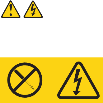
units in the unit will automatically shut down (an over-temperature condition). If this
occurs, you must cool the unit and restart it. See “Restoring power after an
unexpected shutdown” on page 112.
Attention: The fans in the power supply and fan units draw in fresh air and force
out hot air. The power supply and fan units are hot-swappable and redundant;
however, if the fans in one power supply and fan unit fail, you must replace the
entire failed power supply and fan unit within 72 hours to maintain redundancy and
optimum cooling. Do not remove the failed power supply and fan unit until you have
the replacement power supply and fan unit. When you do remove the failed power
supply and fan unit, be sure to install the second power supply and fan unit within
10 minutes to prevent any overheating due to the interruption to the air flow that
cools the storage subsystem.
Do not run the storage subsystem without adequate ventilation and cooling,
because it might cause damage to the internal components and circuitry.
Use the following procedure to replace an ac power supply and fan unit. Figure 83
on page 143 illustrates removing and inserting a unit.
Attention: Potential damage to a component - To prevent damage from
overheating, replace a failed power supply and fan unit CRU within 15 minutes of
removal. If replacing it will take longer than 15 minutes, stop all I/O activity to the
storage subsystem and turn off the power until you complete the replacement.
Statement 8:
CAUTION:
Never remove the cover on a power supply and fan unit or any part that has
the following label attached.
Hazardous voltage, current, and energy levels are present inside any
component that has this label attached. There are no serviceable parts inside
these components. If you suspect a problem with one of these parts, contact
a service technician.
1. If needed, use the DS Storage Manager client software to print a storage
system profile.
2. Did the Recovery Guru direct you to replace a failed power supply and fan
unit?
vYes - Go to step 3.
vNo - Run the Recovery Guru to identify the failed component, and then go
to step 3.
3. Put on antistatic protection.
140 IBM System Storage DS5020 Storage Subsystem: Installation, User’s, and Maintenance Guide

4. Unpack the new power supply and fan unit. Save all packing material in case
you need to return the failed power supply and fan unit CRU.
Note: The new power supply and fan unit CRU comes with an instruction
sheet and label sheet. The instruction sheet provides instructions on
placing the applicable labels on the power supply and fan unit CRU to
mark the LEDs correctly. The label sheet contains the peel-off labels
that you actually place on the power supply and fan unit CRU.
5. Using the information provided on the instruction sheet, place the labels on the
power supply and fan unit CRU to correctly mark the LEDs.
6. Turn off the power switch on the new unit.
7. Check the Fault LED to locate the failed power supply and fan unit. If a fault is
detected, the amber Fault LED is on.
8. Verify that the Service Action Allowed LED is on. Do not remove the power
supply and fan unit if the LED is off. For more information about the Service
Action Allowed LED, see “Service Action Allowed Status LED” on page 121.
Statement 1:
Chapter 5. Replacing components 141

DANGER
Electrical current from power, telephone, and communication cables is
hazardous.
To avoid a shock hazard:
vDo not connect or disconnect any cables or perform installation,
maintenance, or reconfiguration of this product during an electrical
storm.
vConnect all power cords to a properly wired and grounded electrical
outlet.
vConnect to properly wired outlets any equipment that will be
attached to this product.
vWhen possible, use one hand only to connect or disconnect signal
cables.
vNever turn on any equipment when there is evidence of fire, water,
or structural damage.
vDisconnect the attached power cords, telecommunications systems,
networks, and modems before you open the device covers, unless
instructed otherwise in the installation and configuration
procedures.
vConnect and disconnect cables as described in the following table
when installing, moving, or opening covers on this product or
attached devices.
To Connect: To Disconnect:
1. Turn everything OFF.
2. First, attach all cables to devices.
3. Attach signal cables to connectors.
4. Attach power cords to outlet.
5. Turn device ON.
1. Turn everything OFF.
2. First, remove power cords from outlet.
3. Remove signal cables from connectors.
4. Remove all cables from devices.
9. Turn off the power switch, and unplug the power cord from the failed power
supply and fan unit.
10. Squeeze the latch and pull the lever open 90° (so that the lever is horizontal)
to release the power supply and fan unit from the latch. The latch is a coral
colored tab on the lever.
11. Slowly pull the lever away from the chassis to remove the power supply and
fan unit, as shown in Figure 83 on page 143.
Note: The lever rotates upward or downward 90°, depending on whether the
power supply and fan unit you are removing is in the right or left power
supply and fan unit bay.
12. Slide the new unit into the empty slot. As you slide the power supply and fan
unit into the empty slot, make sure the guide pins on the side of the power
supply and fan unit fit into the notches. After the guide pins fit into the notches
and power supply and fan unit fits snugly into the slot, push the lever
downward or upward 90° to fully latch the power supply and fan unit into place,
depending on whether you are inserting the power supply and fan unit into the
right or left power supply and fan unit bay. Then gently push the front of the
power supply and fan unit to make sure that it is fully seated.
142 IBM System Storage DS5020 Storage Subsystem: Installation, User’s, and Maintenance Guide
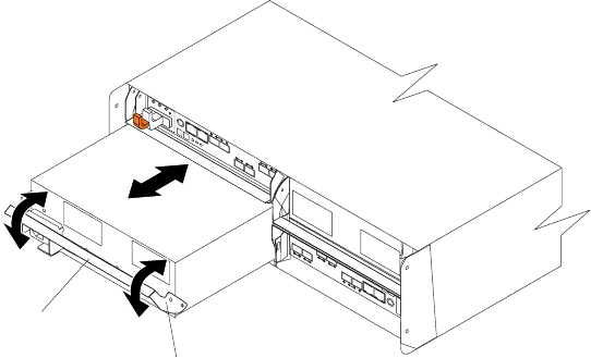
Attention: The left and right power supply and fan units are seated in the
DS5020 chassis in opposite orientations. If you cannot fully insert the power
supply and fan unit into the power supply and fan unit bay, flip it 180° and
reinsert it. Make sure that the levers lock into place in the storage subsystem
chassis. Do not force fit. The power supply and fan unit is designed to prevent
it from being inserted into the chassis incorrectly.
13. Plug in the power cord and turn on the power.
14. Check the Power and Fault LEDs on the new unit.
15. Based on the status of the Power and Fault LEDs, choose one of the following
steps:
vFault LED is on and ac and power LED are off - The new unit might be
installed incorrectly. The power supply and fan unit switch might not be
turned on. The power cord plug might not be fully inserted into the power
outlet or the power supply and fan unit ac socket. There is not any power to
the outlet that the power supply-unit is connected to. The power cord might
be faulty. Go to step 16.
vFault and ac power LED are on but the power LED is off - The power
supply and fan unit is faulty. Turn the power supply and fan unit power
switch to off and contact IBM Customer and Technical Support for another
power supply and fan unit.
vAC and Power LED is on and Fault LED is off - Go to step 17.
16. Perform the following task or task(s) to resolve the problem:
vMake sure that the power switch is turned to the on position.
vMake sure that there is power at the ac outlet and no circuit breaker has
tripped.
vMake sure that the power cord is working and fully seated into the electrical
outlet and the power supply and fan unit ac socket.
vReinstall the power supply and fan unit.
If the above tasks do not resolve the problem, contact IBM Customer and
Technical Support
17. Complete any remaining Recovery Guru procedures, if needed.
18. Check the status of each component in the storage subsystem.
19. Do any components have a Needs Attention LED?
Lever
Latch
Figure 83. Replacing a power supply and fan unit
Chapter 5. Replacing components 143

vYes - Select the Recovery Guru toolbar button in the Subsystem
Management window and complete the recovery procedure. If a problem is
still indicated, contact IBM Customer and Technical Support.
vNo - Go to step 20.
20. Create, save, and print a new storage subsystem profile.
Replacing a battery unit
Statement 2:
CAUTION:
When replacing the lithium battery, use only an equivalent type battery
recommended by the manufacturer. If your system has a module containing a
lithium battery, replace it only with the same module type made by the same
manufacturer. The battery contains lithium and can explode if not properly
used, handled, or disposed of.
Do not:
vThrow or immerse into water
vHeat to more than 100° C (212° F)
vRepair or disassemble
Dispose of the battery as required by local ordinances or regulations.
Each RAID controller in the DS5020 storage subsystem contains a rechargeable
battery unit that backs up data in cache to flash memory in the event of power
failure.
Use the following procedure if the DS Storage Manager client instructs you to
replace the battery unit because the current battery has failed. You can also use the
DS Storage Manager client to check the status of the battery. Because
write-caching is disabled when either one of the battery units fail, replace the failed
battery unit as soon as possible to minimize any impact due to the disabling of the
write-caching function.
Replace only the battery unit that is indicated as failed by the LEDs. You do not
need to replace both battery units when the Battery LEDs indicate that only one
battery unit has failed. If the battery is identified as failed by the DS Storage
Manager and the battery LEDs were are lit in a fault state, use the Service Action
Allowed menu function in the DS Storage Manager subsystem window to identify
the failed battery for replacement.
Important: Unlike the batteries for DS4000 storage subsystems, the DS5020
storage subsystem battery units do not have set expiration dates. Do
not replace these batteries after a certain usage period.
Attention: When you handle static-sensitive devices, take precautions to avoid
damage from static electricity. For details about handling static-sensitive devices,
see “Handling static-sensitive devices” on page 29.
Use the following procedure to replace a battery unit.
144 IBM System Storage DS5020 Storage Subsystem: Installation, User’s, and Maintenance Guide
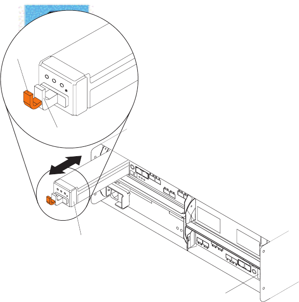
1. Use the DS Storage Manager client software to print a storage subsystem
profile.
2. Locate the RAID controller that contains the failed battery unit.
3. Check the LEDs on the battery units to determine which of the two battery units
has failed. (See “Battery unit LEDs” on page 103.) Replace only the battery unit
that is indicated as failed by the LEDs.
4. Put on antistatic protection.
5. To remove the failed battery unit from the RAID controller, press the orange
battery unit latch toward the black battery handle to unlatch the battery from the
DS5020 chassis and slowly pull the battery unit from the controller chassis
using the handle, as shown in Figure 84.
Pull handle
Latch
Controller A
backup battery unit
Controller B
backup battery unit
Figure 84. Removing and replacing a battery unit from the controller chassis
Chapter 5. Replacing components 145

Attention: This product contains a sealed Lithium Ion battery. Discharged
Lithium and Lithium Ion batteries are currently designated to be disposed of in
normal trash. However, users should contact their municipal waste disposal
facility prior to discarding any used battery in normal trash. Alternatively, you
can return Lithium, Lithium Ion and Lithium Ion battery packs to IBM for
recycling.
In the United States, IBM has established a collection process for reuse,
recycling, or proper disposal of used IBM Lithium, Lithium Ion and Lithium Ion
battery packs. For information on proper disposal of these batteries, please
contact IBM at 1-800-426-4333. Please have the IBM part number listed on the
battery available prior to your call.
For information on disposal of sealed Lithium Ion batteries outside the United
States, go to www.ibm.com/ibm/environment/products/batteryrecycle.shtml or
contact your local waste disposal facility.
6. Place the battery unit that you removed on a level surface.
7. Unpack the new battery unit. Set the new battery unit on a dry, level surface.
Save all packing materials in the event you need to return the new battery unit.
8. Insert the new battery unit into the controller chassis. Make sure the new battery
unit is inserted in the correct orientation in the battery unit bay. Press the battery
unit fully into the bay until it clicks into place. Do not force fit. The battery unit is
designed to prevent it from being inserted into the chassis incorrectly.
Note: The green Battery Charging LED flashes until the battery is fully charged.
9. Once the battery is charged to the optimal state from the reduced-charge
shipping state, the battery performs a learn cycle to access the discharge time
of the battery. Do not turn off the power to the storage subsystem for at least 24
hours to ensure that the battery finishes charging and completes the first learn
cycle.
Replacing an SFP module
Statement 3:
CAUTION:
When laser products (such as CD-ROMs, DVD drives, fiber-optic devices, or
transmitters) are installed, note the following:
vDo not remove the covers. Removing the covers of the laser product could
result in exposure to hazardous laser radiation. There are no serviceable
parts inside the device.
vUse of controls or adjustments or performance of procedures other than
those specified herein might result in hazardous radiation exposure.
146 IBM System Storage DS5020 Storage Subsystem: Installation, User’s, and Maintenance Guide

DANGER
Some laser products contain an embedded Class 3A or Class 3B laser
diode. Note the following.
Laser radiation when open. Do not stare into the beam, do not view directly
with optical instruments, and avoid direct exposure to the beam.
Class 1 Laser statement
Class 1 Laser Product
Laser Klasse 1
Laser Klass 1
Luokan 1 Laserlaite
Apparell Laser de Calsse 1À
IEC 825-11993 CENELEC EN 60 825
The speed of the SFP module determines the maximum operating speed of the
Fibre Channel port in which the SFP is installed. For example, a 4 Gbps SFP that is
plugged into a 8 Gbps-capable port will limit the speed of that port to a maximum of
4 Gbps.
Attention: Refer to the FRU option P/N on the SFP to identify the maximum
operating speed of the SFP and to request the correct FRU replacement.
Use the following procedure to replace a Small Form-factor Pluggable (SFP)
module on the storage subsystem. The SFP module shown in this procedure might
look different from those you are using, but the difference will not affect functionality.
Figure 85 on page 148 illustrates installing an SFP module.
Electrostatic discharge can damage sensitive components. To prevent electrostatic
discharge damage to the storage subsystem, use proper antistatic protection when
handling components.
To replace an SFP module, do the following:
1. Use the DS Storage Manager client software to print a new storage subsystem
profile.
2. Using the Recovery Guru, identify the failed component that needs to be
replaced.
3. Check the Fault LEDs to locate the failed SFP module. If a fault is detected,
the amber Fault LED is on.
Attention: Potential loss of data access - To prevent loss of access to
data, remove only the SFP module that has a failed status in the storage
management software and has Port Bypass LED lit.
4. Put on antistatic protection.
5. Unpack the new SFP module. Verify that it is the same type of module you are
replacing. If it is not, contact IBM Customer and Technical Support.
Note: The speed of the SFP module determines the maximum operating
speed of the Fibre Channel port in which the SFP is installed. For
example, a 4 Gbps SFP that is plugged into an 8 Gbps-capable port will
limit the speed of that port to a maximum of 4 Gbps.
Chapter 5. Replacing components 147
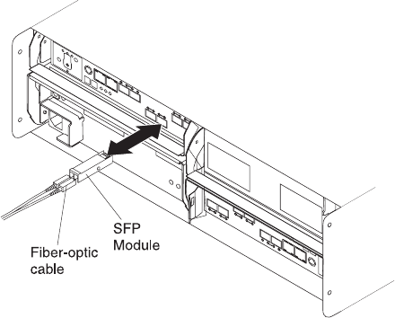
Attention: Handle and install fiber-optic cables properly to avoid degraded
performance or loss of communications with devices. For specific handling
guidelines, see “Handling fiber-optic cables” on page 47.
6. Disconnect the interface cables from the SFP module.
7. Remove the failed SFP module from the controller.
8. Install the new SFP module into the controller.
9. Reconnect the interface cable.
10. Check the Bypass and Fault LEDs for the new SFP module.
11. Based on the status of the Bypass and Fault LEDs, choose one of the
following steps:
vBypass LED or Fault LED is on - Reinstall the SFP module and cables,
and verify that the SFP module and cables are securely connected. Use the
Fibre Channel loopback and the LC-LC connector to perform path
diagnostics to make sure that the Fibre Channel cable is good and the SFP
on the other end of the Fibre Channel connection is working properly. When
finished, go to step 12.
vBypass LED and Fault LED are off - Go to step 12.
12. Is the problem corrected?
vYes - Go to step 13.
vNo-Contact IBM Support.
13. Complete any remaining Recovery Guru procedures, if needed.
14. Use the DS Storage Manager Subsystem Management window to check the
status the status of all components in the storage subsystem.
15. Remove the antistatic protection.
16. Does any component have a Needs Attention status?
vYes - Select the Recovery Guru toolbar button in the Subsystem
Management window, and complete the recovery procedure. If the problem
persists, contact IBM Support.
vNo - Go to step 17.
17. Use the DS Storage Manager client software to print a new storage subsystem
profile.
Figure 85. Replacing an SFP module
148 IBM System Storage DS5020 Storage Subsystem: Installation, User’s, and Maintenance Guide
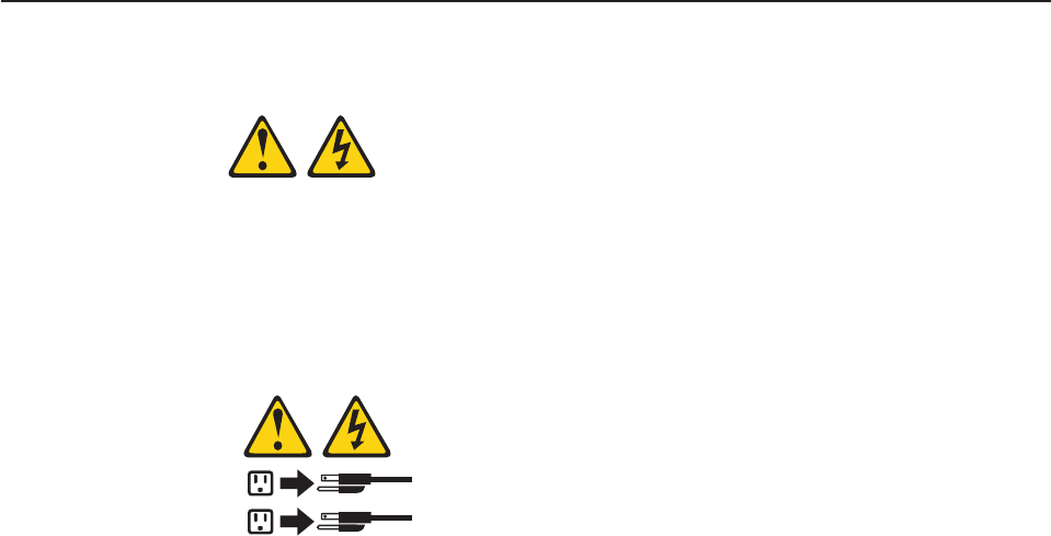
Replacing a midplane
Statement 5:
CAUTION:
The power control button on the device and the power switch on the power
supply do not turn off the electrical current supplied to the device. The device
also might have more than one power cord. To remove all electrical current
from the device, ensure that all power cords are disconnected from the power
source.
1
2
Attention: Observe handling static-sensitive device precautions stated in
“Handling static-sensitive devices” on page 29 when removing components.
Perform the following steps to replace a midplane:
1. Complete the power-off sequence described in “Turning off the storage
subsystem” on page 109 to make sure that the DS5020 storage subsystem is
turned off before any attached storage expansion enclosures.
Attention: The power switch on the power supply and fan unit does not turn
off the electrical current supplied to the device. The DS5020 storage
subsystem might also have more than one connection to power. To remove all
electrical current from the device, make sure that all power cords are
disconnected from the power supply and fan unit input connectors.
2. Label and remove the power cords from the power supply and fan units of the
DS5020 storage subsystem.
3. Label the Fibre Channel cables that are attached to the rear of the controllers.
Labeling the cables simplifies the re-cabling process.
4. Remove the Fibre Channel cables that are attached to the rear of the
controllers.
5. Remove both controllers. To remove them do the following:
a. Squeeze the controller latch and pull the lever open 90° (so that the lever
is horizontal) to release the controller from the latch. The controller latch is
a coral colored tab on the lever.
Note: The lever rotates upward or downward 90°, depending on whether
the controller you are removing is the right or left controller CRU.
b. Slowly pull the lever away from the storage subsystem chassis to remove
the controller from the controller bay, as shown in Figure 16 on page 38.
(Remove the controllers from the chassis and place it on electrostatic
discharge (ESD) protected surface.)
c. Repeat steps 5a and 5b for the other controller.
6. Remove both power supply and fan units. To remove them, do the following:
Chapter 5. Replacing components 149
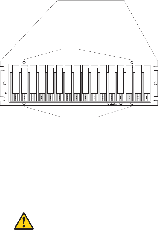
a. Squeeze the latch and pull the lever open 90° (so that the lever is
horizontal) to release the power supply and fan unit from the latch. The
latch is a coral colored tab on the lever.
b. Slowly pull the lever away from the chassis to remove the power supply
and fan unit, as shown in Figure 17 on page 39. (Remove the power
supply and fan unit from the chassis and place it on ESD protected
surface.)
Note: The lever rotates upward or downward 90°, depending on whether
the power supply and fan unit you are removing is in the right or left
power supply and fan unit bay.
c. Repeat steps 6a and 6b for the other power supply and fan unit.
7. Label the Enhanced Disk Drive Module (E-DDM) CRUs so you know their
physical location in the midplane.
8. Remove the E-DDM CRUs and any blank drive CRUs if the storage subsystem
has them. See “Removing an E-DDM” on page 39 for instructions. Place
E-DDMs on ESD protected surface.
Attention: Do not stack E-DDM CRUs on top of each other. Protect the
E-DDM CRUs from vibrations or sudden shocks.
9. Use a #1 Phillips screwdriver to loosen the four front cage frame screws on
the midplane, as shown in Figure 86.
10. On the back of the DS5020, remove the four Phillips screws (two screws on
each side) that hold the sides of the DS5020 chassis to the sides of the rails.
11. On the front of the DS5020, remove the four M5 screws (two screws on each
side) on the DS5020 chassis that hold the DS5020 to the rails.
Attention: The unit must be removed from the rack and placed on a level
ESD protected surface before servicing it.
12.
Statement 4:
810midpl
Front cage frame screws
Front cage frame screws
Figure 86. Front cage frame screw locations
150 IBM System Storage DS5020 Storage Subsystem: Installation, User’s, and Maintenance Guide
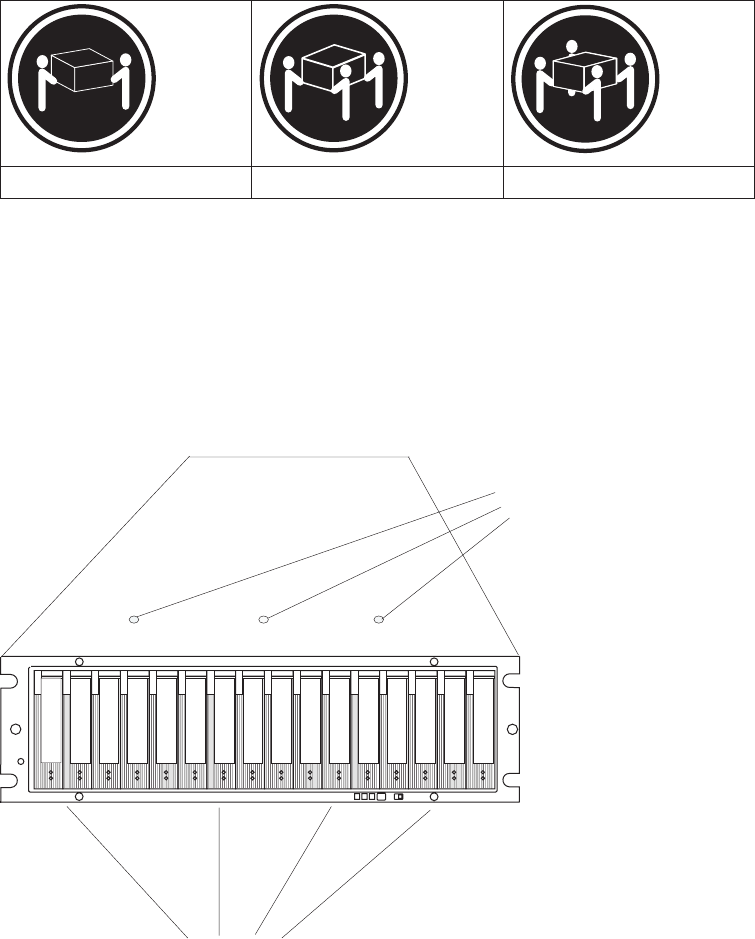
≥18 kg (39.7 lb) ≥32 kg (70.5 lb) ≥55 kg (121.2 lb)
CAUTION:
Use safe practices when lifting.
Pull the chassis outward from the front of the rack and remove from the rack.
Place it on a level surface. Look for a row of three Phillips screws on top of the
chassis and a row of four Phillips screws on the bottom of the chassis, as
shown in Figure 87. Remove the seven Phillips screws using the #1 Phillips
screwdriver. Save these screws.
13. Grasp the blue handle in the center of the front cage frame and pull it outward
to slide the front cage frame out approximately two inches. Grab the two sides
of the front cage frame and remove it from the chassis.
Note: The front cage frame might be tightly secured in the chassis. Mount the
DS5020 chassis back in the rack using the four M5 screws to hold the
DS5020 chassis in place while you pull on the blue handle to separate
the front cage frame from the chassis. Remove the DS5020 chassis
from the rack and place it on a level surface after you remove the failed
front cage frame for the next step.
14. Unpack the new front cage frame with the midplane. Save the packaging
materials in case you need to return it.
Scr e w
s
Scr e w s
Figure 87. Screws holding the top and bottom sides of the chassis to the cage frame
Chapter 5. Replacing components 151
15. Insert the new front cage plane/midplane by aligning it with the storage
subsystem front opening and slowly sliding it into the storage subsystem
chassis. Make sure that the front cage frame EMC gaskets do not snag
between the frame and chassis.
16. Tighten the four front cage frame screws. See Figure 86 on page 150.
17. Install the seven Phillips screws (three on top and four on bottom) that hold the
front cage frame to the EXP810 chassis that you removed in step 12 on page
150, as shown in Figure 87 on page 151.
18. Push the chassis all the way back into the rail and install the four M5 screws
along the side edges of the DS5020 chassis.
19. Install the four Phillips screws on the back along the sides of the DS5020
chassis that hold the DS5020 to the rails.
20. Insert the E-DDM CRUs. Be sure you insert them in the correct slots. Use the
labels you put on them before you removed them to guide you.
21. Re-insert the controllers and reconnect the Fibre Channel cables.
22. Re-insert the power supply and fan units and reconnect the power supply
cords.
23. Turn on the power to the attached storage expansion enclosures.
24. Wait at least 3 minutes and then turn on the power to the DS5020 storage
subsystem. Verify the status of the configuration using LEDs and the DS
Storage Manager client program.
25. After removing the faulty cage frame with midplane assembly, transpose the
DS5020 serial number, machine type, and model tag from the faulty cage
frame assembly to the Repair Identification (RID) tag on the new cage frame
assembly. The RID tag is important in transferring the serial number, machine
type, and model from the faulty cage frame assembly to the new cage frame
assembly. Make sure that the new RID tag is affixed to the new cage frame
assembly before you dispose of the faulty cage frame with midplane assembly.
This will so that the warranty coverage is not interrupted.
152 IBM System Storage DS5020 Storage Subsystem: Installation, User’s, and Maintenance Guide

Chapter 6. Hardware maintenance
This chapter contains information to help you solve some of the simpler problems
that you might have with your storage subsystem. It contains the problem indicators
and error messages along with suggested actions to take to resolve the problem.
For instructions on how to obtain service and technical assistance for your storage
subsystem and other IBM products, see “Getting information, help, and service” on
page xxiv.
General checkout
Use the indicator lights, the diagnostics and test information, the symptom-to-FRU
index, and the connected server Problem Determination and Service Guide to
diagnose problems.
The PD maps found in the IBM System Storage DS4000 Problem Determination
Guide provide you with additional diagnostic aids.
Solving problems
This section contains information to help you solve some of the problems you might
have with your storage subsystem. Table 20 on page 154 contains the problem
symptoms and error messages, along with suggested actions to take to resolve
problems.
Always use the DS Storage Manager client to diagnose storage subsystem
problems and component failures and find solutions to problems that have definite
symptoms.
You can use Table 20 on page 154, which contains the problem symptoms and
error messages, along with suggested actions as a guide for troubleshooting
problems in addition to the DS Storage Manager Recovery Guru in the Subsystem
Management window. Do not depend solely Table 20 on page 154 for a FRU
replacement decision.
See the problem determination maps in the DS4000 Problem Determination Guide
for more detailed procedures for problem isolation.
© Copyright IBM Corp. 2009 153

Table 20. Symptom-to-FRU index
Problem
indicator Component Possible cause Possible solutions
Amber LED is lit Drive CRU
(Drive Fault
LED)
Note: The
green Drive
Activity LED
might also be
lit.
Drive failure Replace the failed drive.
Note: The amber LED on the
drive is also lit if the drive slot
has a blank drive tray inserted.
Drive uncertified Verify the drive option and FRU
part number to verify that it is
supported by the DS5020 storage
subsystem. (For FRU part
numbers, see Table 21 on page
161.)
RAID controller
(Fault LED)
Note:
Controller
Service Action
Allowed LED
will also be lit.
RAID controller
failure
Replace the RAID controller. See
your controller documentation for
more information. See Chapter 5,
“Replacing components,” on page
121 for more information.
Controller was
placed offline by a
user or the other
controller.
Use the menu function in the
DS5020 Subsystem Management
window to place the controller
back online. If the controller
continues going to an offline state
after being placed online, replace
the RAID controller.
Unsupported
controller type. For
example, a DS4200
Express FRU is
inserted into a
DS5020 chassis.
Use the Storage Manager Client
Subsystem Management window
and Recovery Guru to verify that
the correct controller FRU is
used. Replace with the correct
DS5020 controller FRU.
RAID controller
(Port Bypass
LED)
No incoming signal
detected
Reconnect the SFP modules and
the Fibre Channel cables. Verify
the input and output SFP using
the path failure determination
instruction in the DS4000
Problem Determination Guide
and the Fibre Channel loopback
and female-female LC connector.
Replace either input or output
SFP modules or Fibre Channel
cables as necessary.
Incorrect enclosure
speed setting
When connecting storage
expansion enclosures to the
existing operating redundant
drive loop with a different speed
setting, the port goes into bypass
mode because mixing different
speed enclosures within the
same redundant drive
loop/channel is not supported.
RAID controller
failure
If the RAID controller Fault LED
is lit, also replace the RAID
controller.
154 IBM System Storage DS5020 Storage Subsystem: Installation, User’s, and Maintenance Guide

Table 20. Symptom-to-FRU index (continued)
Problem
indicator Component Possible cause Possible solutions
Amber LED is lit
(continued)
Front panel
(Global
Summary Fault
LED)
General machine
fault
A Fault LED is lit somewhere on
the storage subsystem (check for
Amber LEDs on CRUs).
General machine
fault (continued)
Open the DS5020 Storage
Subsystem Management window
and click on the Recovery Guru
to see problems in the DS5020
configuration.
Some errors will cause the
Global Summary Fault LED to be
lit but will not cause any
individual CRU Fault LEDs to be
lit. (Drive PFA exceeded or
nominal temperature exceeded
errors are a few examples.)
Follow the corrective actions in
the Recovery Guru window.
Fibre Channel
connection failure
Check that the CRUs are
properly installed. If none of the
amber LEDs are lit on any of the
CRUs, this indicates an SFP
module transmission fault in the
storage subsystem. Replace the
failed SFP module. See the DS
Storage Manager software
documentation for more
information.
Battery unit
fault
Battery unit failure Verify the failure using DS
Storage Manager Client and
replace the failing battery.
Amber LED is lit
and green LED is
off
Power supply
CRU
The power switch is
turned off or there is
an ac power failure.
Replace the failed power supply
or turn on all power supply
switches.
Amber and green
LEDs are lit
Power supply
CRU
(Fault and
Power LEDs lit;
SAA lit; Direct
Current Enable
LED is not lit)
Power supply failure Replace the failed power supply.
Operating
environment is too
hot
Cool down the environment.
Fan failure Replace the power supply and
fan unit CRU
All amber and
green LEDs are
slowly flashing
All drive CRUs The DS5020 controllers are going through start-of-day
process (booting up). Wait up to five minutes for the
controllers to complete the booting process. If the drive
Activity LEDs are not steady lit or momentarily flicker,
and the amber LEDs are unlit after waiting more than
six minutes, contact IBM support.
Chapter 6. Hardware maintenance 155

Table 20. Symptom-to-FRU index (continued)
Problem
indicator Component Possible cause Possible solutions
All green LEDs
are off
All CRUs Subsystem power is
off
Check that all storage subsystem
power cables are plugged in and
the power switches are on. If
applicable, check that the main
circuit breakers for the rack are
powered on.
AC power failure Check the main circuit breaker
and ac outlet.
Power supply failure Replace the power supply.
Operating
environment is too
hot
Cool down the environment.
Amber LED is
flashing
Drive CRUs
(Fault LED lit)
Drive identity is in
process
No corrective action needed.
RAID controller
port bypass
A Fibre Channel
loop initialization
process (LIP) is
being generated in
the drive loop due
to a faulty
component.
Use the Read Link Status
window in the Storage Manager
Client Subsystem Management
window and the storage
subsystem event logs to isolate
the faulty component.
Controller drive
port bypass
LED
The enclosure
speed was set to 4
Gbps but the SFP
inserted in the
controller drive SFP
port does not
operate at 4 Gbps.
Use the Recovery Guru menu
function in the Storage Manager
Client Subsystem Management
window to verify the problem and
replace the SFP with a 4 Gbps
SFP.
General Fault
LED (located
on the front of
the storage
subsystem)
An intermittent
failure in the
DS5020 storage
subsystem
configuration. The
problem could be
directly related to
the hardware in the
configuration (hard
drive or bad cable)
or indirectly related
to the DS5020
storage subsystem
configuration (such
as a Fibre Channel
host bus adapter
failure in the host
server or the Fibre
Channel switch in
the SAN causing
LUNs to be on a
non-preferred path.)
Use the Recovery Guru menu
function in the Storage Manager
Client Subsystem Management
window to diagnose the problem.
156 IBM System Storage DS5020 Storage Subsystem: Installation, User’s, and Maintenance Guide

Table 20. Symptom-to-FRU index (continued)
Problem
indicator Component Possible cause Possible solutions
One or more
green LEDs are
off
Power supply
CRUs
Power cable is
unplugged or
switches are turned
off.
Make sure that the power cable
is plugged in and that the
switches are turned on.
All drive CRUs Midplane failure Replace the midplane. Contact
an IBM technical support
representative.
Several CRUs Hardware failure Replace the affected CRUs. If
this does not correct the problem,
replace the RAID controllers,
followed by the midplane.
Contact an IBM technical support
representative.
Front panel Power supply
problem
Make sure that the power cables
are plugged in and that the
power supplies are turned on.
Hardware failure If any other LEDs are lit, replace
the midplane. Contact an IBM
technical support representative.
Chapter 6. Hardware maintenance 157

Table 20. Symptom-to-FRU index (continued)
Problem
indicator Component Possible cause Possible solutions
Intermittent or
sporadic power
loss to the storage
subsystem
Some or all
CRUs
Defective ac power
source or
improperly
connected power
cable
Check the ac power source.
Reseat all installed power cables
and power supplies. If applicable,
check the power components
(power units or universal power
supply). Replace defective power
cables.
Drives are part of
an exported array.
When the array is
exported, the power
to the drives in the
array is turned off
so that they can be
removed from the
enclosure.
Use the Subsystem Management
window in the DS Storage
Manager to verify that the drives
are indeed part of an exported
array. If they are, remove the
drives from the storage
subsystem as required.
Note: If the drives are removed,
the empty drive slots must be
filled with other drives or blank
drive trays to ensure optimal air
flow.
Drives are
incompatible. Power
to incompatible
drives is turned off
when they are
inserted into the
drive slots.
Use the Subsystem Management
window in the DS Storage
Manager to verify that the drives
are recognized as incompatible.
Replace the incompatible drives
with drive options that are
supported by the storage
subsystem controllers. See the
“Parts listing” on page 160 for a
list of compatible drives.
Drive failure Use the Subsystem Management
window in the DS Storage
Manager to verify that the drive
or drives are recognized as failed
by the storage subsystem.
Replace the failed drives. See
the “Parts listing” on page 160 for
a list of compatible drives.
Power supply failure Check the power supply Fault
LED on the power supply. If the
LED is lit, replace the failed CRU.
Midplane failure Have the midplane replaced.
Contact an IBM technical support
representative.
158 IBM System Storage DS5020 Storage Subsystem: Installation, User’s, and Maintenance Guide

Table 20. Symptom-to-FRU index (continued)
Problem
indicator Component Possible cause Possible solutions
Unable to access
drives
Drives and
Fibre Channel
loop
Incorrect storage
subsystem ID
settings
Make sure that the Fibre Channel
optical cables are undamaged
and properly connected. Check
the storage subsystem ID
settings.
Note: Change the switch
position only when your storage
subsystem is powered off.
RAID controller
failure
Replace one or both RAID
controllers. Contact an IBM
technical support representative.
Drive or drives
failed
Replace failed drive or drives.
Random errors Storage
subsystem
Midplane failure Have the midplane replaced.
Contact an IBM technical support
representative.
Hard disk drive is
not visible in RAID
management
software
Several CRUs Drive or drives
failed
Replace failed drive or drives.
Fibre Channel cable
failed
Replace Fibre Channel cable.
SFP failed Replace SFP.
RAID controller
failure
Replace RAID controller.
Midplane failure Have the midplane replaced.
Contact an IBM technical support
representative.
Drive CRU has
interface problem
with the ESM or
controller.
Replace the drive CRU.
Incorrect firmware
version
Verify that the DS5020 storage
subsystem has the correct
firmware version. Refer to
“Software and hardware
compatibility and upgrades” on
page 17.
A controller has
failed in addition to
the ESM failure in
the drive channel
that originates from
the functioning
controller.
Replace the failed controller and
ESM.
Chapter 6. Hardware maintenance 159
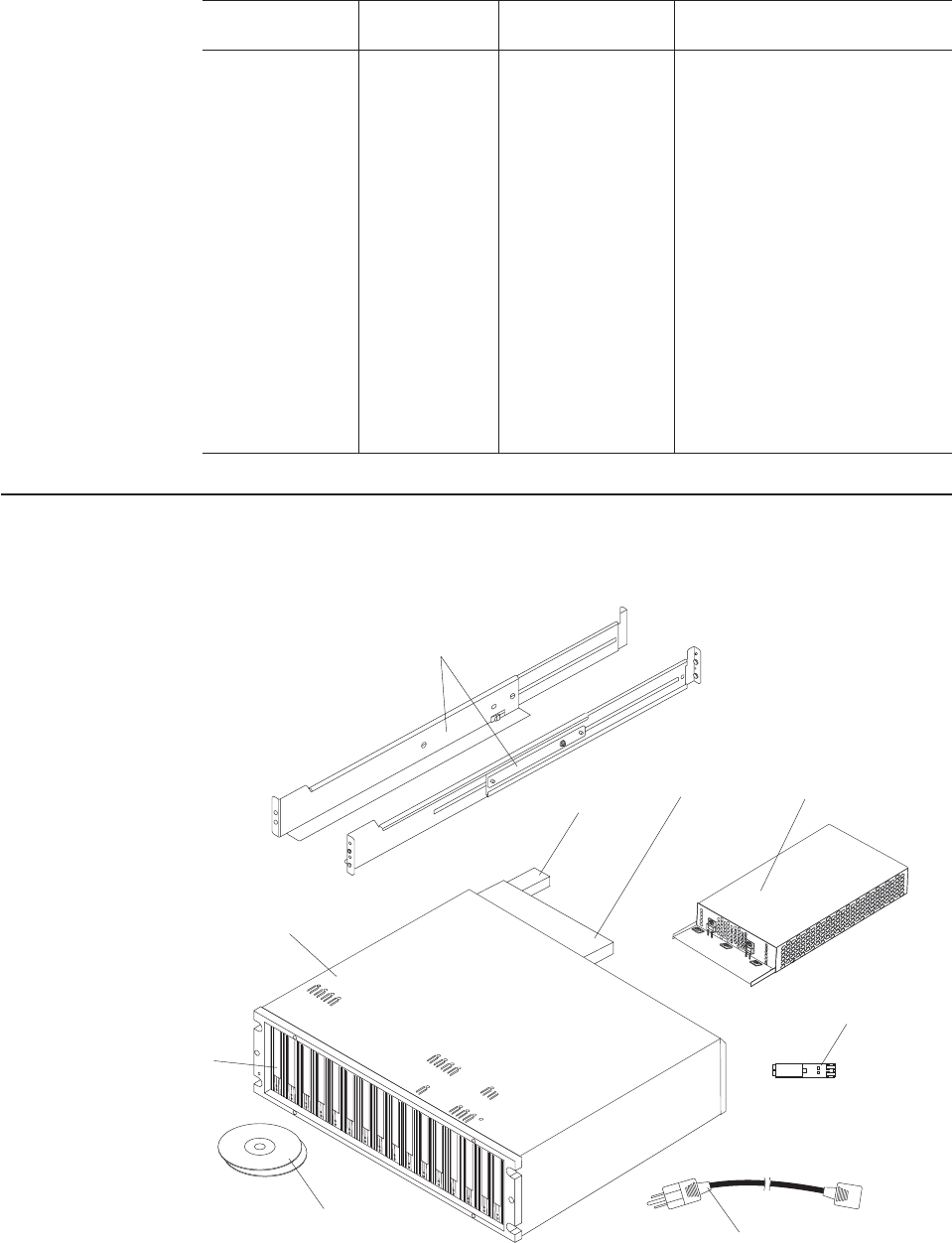
Table 20. Symptom-to-FRU index (continued)
Problem
indicator Component Possible cause Possible solutions
Storage expansion
enclosures are not
attached to the
storage
subsystem
Storage
subsystem
The DS5020 does
not have the
necessary feature
options to support
the storage
expansion
enclosures.
The base DS5020 storage
subsystem supports up to 32
drives, which includes 16 drives
in the DS5020 chassis and the
16 more drives if an EXP520
storage expansion enclosure is
attached. To attach more than 32
drives, you much purchase the
applicable feature option. For
example, to attach one or more
EXP810 storage expansion
enclosures to the EXP520
storage subsystem, you must
have the feature option for the
EXP810. Contact your IBM
marketing representative for more
information about purchasing
feature options.
Parts listing
Figure 88 and provides a parts listing for the DS5020.
1
8
234
5
6
7
9
Figure 88. DS5020 storage subsystem parts list
160 IBM System Storage DS5020 Storage Subsystem: Installation, User’s, and Maintenance Guide

Table 21. Parts listing (DS5020 storage subsystem)
Index DS5020 storage subsystem CRU P/N
1Rail kit 41Y5152
2Battery 59Y5151
3Controller, 1 GB memory, two standard 8
Gbps FC host ports, two standard 4 Gbps FC
drive channel ports
59Y5251
Controller, 1 GB memory, two standard 8
Gbps FC host ports, one optional 2-port 8
Gbps FC host card, two standard 4 Gbps FC
drive channel ports
59Y5252
Controller, 1 GB memory, two standard 8
Gbps FC host ports, one optional 2-port 1 GB
iSCSI host card, two standard 4 Gbps FC
drive channel ports
59Y5254
Controller, 2 GB memory, two standard 8
Gbps FC host ports, two standard 4 Gbps FC
drive channel ports
59Y5256
Controller, 2 GB memory, two standard 8
Gbps FC host ports, one optional 2-port 8
Gbps FC host card, two standard 4 Gbps FC
drive channel ports
59Y5258
Controller, 2 GB memory, two standard 8
Gbps FC host ports, one optional 2-port 1 GB
iSCSI host card, two standard 4 Gbps FC
drive channel ports
59Y5259
4AC power supply and fan unit, 600 W 42D3346
5Small Form-factor Pluggable transceiver, 8
Gbps
49Y4123
6AC power cord, 2.8 m 39M5081
7DVDs, Firmware and DS Storage Manager 42D3315
Chapter 6. Hardware maintenance 161

Table 21. Parts listing (DS5020 storage subsystem) (continued)
Index DS5020 storage subsystem CRU P/N
8E-DDM, 4 Gbps FC, 146.8 GB, 15,000 RPM
drive module
40K6823
E-DDM, 4 Gbps FC, 300 GB, 15,000 RPM
drive module
42D0417
E-DDM, 4 Gbps FC, 450 GB, 15,000 RPM
drive module
44X2451
E-DDM, 4 Gbps FC, 600 GB, 15,000 RPM
drive module
59Y5336
E-DDM, 4 Gbps FC, encryption-capable, 146.8
GB, 15,000 RPM drive module
44E5638
E-DDM, 4 Gbps FC, encryption-capable, 300
GB, 15,000 RPM drive module
44E5642
E-DDM, 4 Gbps FC, encryption-capable, 450
GB, 15,000 RPM drive module
44E5646
E-DDM, 4 Gbps FC, encryption-capable, 600
GB 15,000 RPM drive module
59Y5341
E-DDM, 3 Gbps SATA, 750 GB HS, 7,200
RPM drive module
43W9715
E-DDM, 3 Gbps SATA, 1 TB, 7,200 RPM drive
module
44X2459
9Cage assembly 59Y5249
Empty drive filler panel 42D3315
Cable, fiber-optic, 1 m 39M5699
Cable, fiber-optic, 5 m 39M5700
Cable, fiber-optic, 25 m 39M5701
LC wrap plug assembly 39M5914
SFP (shortwave), 4 Gbps 22R6443
OM3 fiber optic cable LC to LC 10 meter 45W2222
SFP, 8 Gbps 49Y4123
Serial cable adapter 39M5942
Line cord jumper, high-voltage 39M5377
162 IBM System Storage DS5020 Storage Subsystem: Installation, User’s, and Maintenance Guide

Appendix A. Records
Whenever you add options to your DS5020, be sure to update the information in
this appendix. Accurate, up-to-date records make it easier to add other options and
provide needed data whenever you contact your IBM technical support
representative.
Identification numbers
Record and retain the following information.
Product name: IBM System Storage DS5020 Storage Subsystem
Machine type: 1814
Model number: 20A
Serial number:
The serial number is located on the bottom inside surface at the rear and on the left
edge at the front of the DS5020.
© Copyright IBM Corp. 2009 163

Storage subsystem and controller information record
Table 22 provides a data sheet for recording storage subsystem names,
management types, Ethernet hardware addresses, and IP addresses. Make a copy
of this table and complete the information for your storage subsystems and
controllers. Use the information to set up the BOOTP table for the network server
and the host or Domain Name System (DNS) table. The information is also helpful
if you add storage subsystems after initial installation. Refer to your Storage
Manager documentation for detailed instructions about how to obtain the
information. For a sample information record, see Table 23 on page 165.
Table 22. Storage subsystem and controller information record
Storage
subsystem
name
Management
method
Controllers-Ethernet and IP
addresses, and host name
Host-IP address
and host name
164 IBM System Storage DS5020 Storage Subsystem: Installation, User’s, and Maintenance Guide

Sample information record
Table 23 shows a sample information record. This network contains storage
subsystems that are managed by using both the direct-management and
host-agent-management method.
Table 23. Sample information record
Storage
subsystem name
Management
method
Controllers-Ethernet and IP
addresses, and host name
Host-IP address
and host name
Controller A Controller B
Finance Direct Hardware
Ethernet address
= 00a0b8020420
Hardware
Ethernet address
= 00a0b80000d8
IP address =
192.168.128.101
IP address =
192.168.128.102
Host = Denver_a Host = Denver_b
Engineering Host-agent IP address =
192.168.2.22
Host = Atlanta
Appendix A. Records 165

Installed device records
Use the following table to record the number of the hard disk drives that you
replaced and the corresponding bay number.
Attention: If you replace a hard disk drive in the wrong drive bay it might cause a
loss of data.
Table 24. Hard disk drive record
Bay number Hard disk drive serial number
Replaced hard disk drive serial
number
166 IBM System Storage DS5020 Storage Subsystem: Installation, User’s, and Maintenance Guide

Appendix B. Rack mounting templates
This appendix provides duplicate copies of the rack mounting templates. If you want
to tear out the templates from this document, use these copies rather than those
provided in “Installing the support rails” on page 32.
Use the following templates (Figure 89 on page 168 and Figure 90 on page 169) to
identify the proper locations for inserting M5 screws when mounting the support
rails and DS5020 to a rack. The locations for the M5 screws are highlighted in the
templates.
The DS5020 is 3 U high. Align the template with the rack at a U boundary. U
boundaries are shown as horizontal dashed lines in the rack mounting templates.
Note: The mounting holes that are shown in the following templates are square.
The holes in your rack might be round or square.
© Copyright IBM Corp. 2009 167
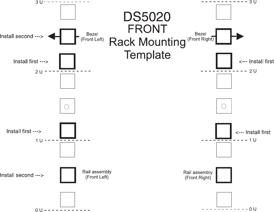
Figure 89. Front rack mounting template
168 IBM System Storage DS5020 Storage Subsystem: Installation, User’s, and Maintenance Guide
®
3U
3U
2U 2U
1U 1U
0U 0U
Rail assembly
(Rear Left) Rail assembly
(Rear right)
Printed in the U.S.A
REAR
Rack Mounting
Template
DS5020
Rail mounting guide
Figure 90. Rear rack mounting template
Appendix B. Rack mounting templates 169
170 IBM System Storage DS5020 Storage Subsystem: Installation, User’s, and Maintenance Guide

Appendix C. Specifications for non-IBM rack installation
The following instructions provide safety requirements and rack specifications for
installing DS5000 storage subsystems and DS5000 storage expansion enclosures
into non-IBM racks.
Note: The information in this section applies to 19–inch racks. It is your
responsibility, working with your rack manufacturer, to ensure that the
non-IBM rack chosen meets the safety requirements and specifications listed
in this section.
General safety requirements for IBM products installed in a non-IBM
rack or cabinet
The general safety requirements for IBM products installed in non-IBM racks are:
1. Any product or component that plugs into either an IBM power distribution unit
or mains power (via a power cord), or uses any voltage over 42 V ac or 60 V
dc (considered to be hazardous voltage) must be Safety Certified by a
Nationally Recognized Test Laboratory (NRTL) for the country in which it will
be installed.
Some of the items that require safety certification may include: the rack or
cabinet (if it contains electrical components integral to the rack or cabinet), fan
trays, power distribution unit, uninterruptible power supplies, multi-outlet strips,
or any other products installed in the rack or cabinet that connect to hazardous
voltage.
Examples of OSHA-approved NRTLs for the U.S.:
vUL
vETL
vCSA (with CSA NRTL or CSA US mark)
Examples of approved NRTLs for Canada:
a. UL (Ulc mark)
b. ETL (ETLc mark)
c. CSA
The European Union requires a CE mark and a Manufacturer’s Declaration of
Conformity (DOC).
Certified products should have the NRTL logos or marks somewhere on the
product or product label. However, proof of certification must be made
available to IBM upon request. Proof consists of such items as copies of the
NRTL license or certificate, a CB Certificate, a Letter of Authorization to apply
the NRTL mark, the first few pages of the NRTL certification report, Listing in
an NRTL publication, or a copy of the UL Yellow Card. Proof should contain
the manufacturer's name, product type and model, standard to which it was
certified, the NRTL name or logo, the NRTL file number or license number, and
a list of any Conditions of Acceptance or Deviations. A Manufacturer’s
Declaration is not proof of certification by an NRTL.
2. The rack or cabinet must meet all electrical and mechanical safety legal
requirements for the country in which it is installed.
The rack or cabinet must be free of exposed hazards (such as voltages over
60 V dc or 42 V ac, energy over 240 VA, sharp edges, mechanical pinch
points, or hot surfaces).
© Copyright IBM Corp. 2009 171
3. There must be an accessible and unambiguous disconnect device for each
product in the rack, including any power distribution unit.
A disconnect device might consist of either the plug on the power cord (if the
power cord is no longer than 1.8 m (6 ft.)), the appliance inlet receptacle (if the
power cord is of a detachable type), or a power on/off switch, or an
Emergency Power Off switch on the rack, provided all power is removed from
the rack or product by the disconnect device.
If the rack/or cabinet has electrical components (such as fan trays or lights),
the rack must have an accessible and unambiguous disconnect device.
4. The rack or cabinet, power distribution unit and multi-outlet strips, and products
installed in the rack or cabinet must all be properly grounded to the customer
facility ground.
There must be no more than 0.1 Ohms between the ground pin of the power
distribution unit or rack plug and any touchable metal or conductive surface on
the rack and on the products installed in the rack. Grounding method must
comply with applicable country’s electric code (such as NEC or CEC). Ground
continuity can be verified by your IBM service personnel, after the installation
is completed, and should be verified prior to the first service activity.
5. The voltage rating of the power distribution unit and multi-outlet strips must be
compatible with the products plugged into them.
The power distribution unit or multi-outlet strips current and power ratings are
rated at 80 percent of the building supply circuit (as required by the National
Electrical Code and the Canadian Electrical Code). The total load connected to
the power distribution unit must be less than the rating of the power distribution
unit. For example, a power distribution unit with a 30 A connection will be rated
for a total load of 24 A (30 A x 80 percent). Therefore, the sum of all
equipment connected to the power distribution unit in this example must be
lower than the 24 A rating.
If an uninterruptible power supply is installed, it must meet all the above
electrical safety requirements as described for a power distribution unit
(including certification by an NRTL).
6. The rack or cabinet, power distribution unit, uninterruptible power supply,
multi-outlet strips and all products in the rack or cabinet must be installed
according to the manufacturer's instructions, and in accordance with all
national, state or province, and local codes and laws.
The rack or cabinet, power distribution unit, uninterruptible power supply,
multi-outlet strips and all products in the rack or cabinet must be used as
intended by the manufacturer (per manufacturer's product documentation and
marketing literature).
7. All documentation for use and installation of the rack or cabinet, power
distribution unit, uninterruptible power supply, and all products in the rack or
cabinet, including safety information, must be available on-site.
8. If there is more than one source of power in the rack cabinet, there must be
clearly visible safety labels for ″Multiple Power Source″(in the languages
required for the country in which the product is installed).
9. If the rack or cabinet or any products installed in the cabinet had safety or
weight labels applied by the manufacturer, they must be intact and translated
into the languages required for the country in which the product is installed.
10. The rack or cabinet configuration must comply with all IBM requirements for
″safe to service″(contact your IBM Installation Planning Representative for
assistance in determining if the environment is safe).
172 IBM System Storage DS5020 Storage Subsystem: Installation, User’s, and Maintenance Guide

There must be no unique maintenance procedures or tools required for
service.
11. Elevated service installations, where the product(s) to be serviced are installed
between 1.5 m and 3.7 m (5 ft. and 12 ft.) above the floor, require the
availability of an OSHA- and CSA-approved nonconductive step ladder. If a
ladder is required for service, the customer must supply the OSHA- and CSA-
approved nonconductive step ladder (unless other arrangements have been
made with the local IBM Service Branch Office). Products installed over 2.9 m
(9 ft.) above the floor requires a Special Bid to be completed before they can
be serviced by IBM service personnel.
For products not intended for rack-mounting to be serviced by IBM, the
products and parts that will be replaced as part of that service must not weigh
over 11.4 kg (25 lb). (Contact your Installation Planning Representative if in
doubt).
12. There must not be any special education or training required for safe servicing
of any of the product(s) installed in the racks. (Contact your Installation
Planning Representative if in doubt).
Rack specifications
When installing a DS5000 storage subsystem or DS5000 storage expansion
enclosure into a non-IBM rack, follow the specifications below.
1. The rack or cabinet must meet the EIA Standard EIA-310-D for 19-inch racks
published August 24, 1992. The EIA-310-D standard specifies internal
dimensions, for example, the width of the rack opening (width of the chassis),
the width of the module mounting flanges, the mounting hole spacing, and the
depth of the mounting flanges. The EIA-310-D standard does not control the
overall external width of the rack. There are no restrictions on the location of
side walls and corner posts relative to the internal mounting space.
The front rack opening must be 451 mm wide + 0.75 mm (17.75 in. + 0.03 in.),
and the rail-mounting holes must be 465 mm + 0.8 mm (18.3 in. + 0.03 in.)
apart on center (horizontal width between vertical columns of holes on the two
front-mounting flanges and on the two rear-mounting flanges).
Appendix C. Specifications for non-IBM rack installation 173
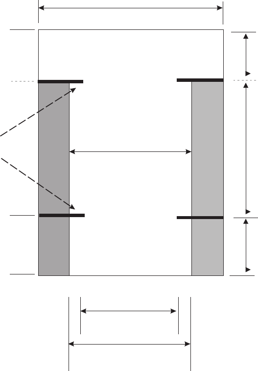
Top view of non-IBM rack specifications dimensions
The vertical distance between mounting holes must consist of sets of three
holes spaced (from bottom to top) 15.9 mm (0.625 in.), 15.9 mm (0.625 in.), and
12.67 mm (0.5 in.) on center (making each three hole set of vertical hole
spacing 44.45 mm (1.75 in.) apart on center). The front and rear mounting
flanges in the rack or cabinet must be 719 mm (28.3 in.) apart and the internal
width bounded by the mounting flanges at least 494 mm (19.45 in.), for the IBM
Storage System or eServer™rails to fit in your rack or cabinet (see Figure 91).
nonibm_topview
Back, No Door
571 mm (22.50 in.)
Drawer Rail
Mounting Flanges 494 mm (19.45 in.)
Front, No Door
451 mm (17.46 in.)
494 mm (19.45 in.)
203 mm (8.0 in.)
719 mm (28.31 in.)
51 mm (2.01 in)
Figure 91. Top View of non-IBM Rack Specifications Dimensions
174 IBM System Storage DS5020 Storage Subsystem: Installation, User’s, and Maintenance Guide
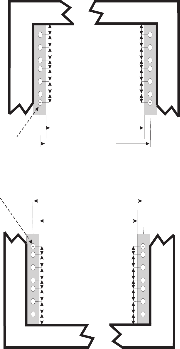
2. The rack or cabinet must be capable of supporting an average load of 15.9 kg
(35 lb.) of product weight per EIA unit.
Top Front of Rack
EIA Hole Spacing
6.75 mm min.
15.9 mm
15.9 mm
15.9 mm
15.9 mm
12.7 mm
12.7 mm
Hole Diameter =
7.1 +/- 0.1 mm
450 +/- 0.75 mm
Rack Front Opening
465 +/- 0.8 mm
Rack Mounting Holes Center-to-Center
6.75 mm min.
15.9 mm
15.9 mm
12.7 mm
15.9 mm
15.9 mm
12.7 mm
nonibm_topfront
Figure 92. Rack specifications dimensions, top front view
Bottom Front
of Rack
EIA Hole Spacing
6.75 mm min.
15.9 mm
15.9 mm
15.9 mm
15.9 mm
12.7 mm
12.7 mm
Hole Diameter =
7.1 +/- 0.1 mm
450 +/- 0.75 mm
Rack Front Opening
465 +/- 0.8 mm
Rack Mounting Holes Center-to-Center
6.75 mm min.
15.9 mm
15.9 mm
12.7 mm
15.9 mm
15.9 mm
12.7 mm
nonibm_botview
Figure 93. Rack specifications dimensions, bottom front view
Appendix C. Specifications for non-IBM rack installation 175
For example, a four EIA drawer will have a maximum drawer weight of 63.6 kg
(140 lb.).
3. AC or dc power drawers need to be support based on equipment purchased for
the rack or cabinet. It is strongly recommended that you use a power
distribution unit that meets the same specifications as each unit already installed
in the rack. Each power distribution unit needs a dedicated power line. Rack or
cabinet power distribution device(s) must meet the drawer power requirements,
as well as that of any additional products that will be connected to the same
power distribution device.
The rack or cabinet power receptacle (power distribution unit, uninterruptible
power supply, or multi-outlet strip) must have a compatible plug type for your
drawer or device. The customer is responsible for ensuring the power
distribution unit is compatible with the rack or cabinet and assumes
responsibility for any and all agency certifications required.
4. The rack or cabinet must be compatible with drawer mounting rails, including a
secure and snug fit of the rail-mounting pins and screws into the rack or cabinet
rail mounting holes. You must use the IBM mounting rails that are shipped with
the IBM product to install it in the rack. The mounting rails that ship with IBM
products have been designed and tested to safely support the product during
operation and service activities as well as to safely support the weight of your
drawer or device. The rails must facilitate service access by allowing the drawer
to be safely extended, if necessary, forwards, backwards, or both.
Note: If the rack or cabinet has square holes on the mounting flanges,
additional hardware might be required.
5. The rack or cabinet must have stabilization feet or brackets installed both in the
front and rear of the rack, or have another means of preventing the rack/cabinet
from tipping while the drawer or device is pulled into its extreme front or rear
service positions.
Examples of some acceptable alternatives: The rack or cabinet can be securely
bolted to the floor, ceiling or walls, or to adjacent racks or cabinets in a long and
heavy row of racks or cabinets.
6. There must be adequate front and rear service clearances (in and around the
rack or cabinet).
The rack or cabinet must have sufficient horizontal width clearance in the front
and rear to allow the drawer to be fully slid into the front and, if applicable, the
rear service access positions (typically this requires 914.4 mm (36 in.) clearance
in both the front and rear).
If present, front and rear doors must be able to open far enough to provide
unrestrained access for service or be easily removable. If doors must be
removed for service, it is the customer’s responsibility to remove them prior to
service.
7. The rack or cabinet must provide adequate clearance around the rack drawer.
There must be adequate clearance around the drawer bezel so that it can be
opened and closed, according to the product specifications.
Front or rear doors must also maintain a minimum of 51 mm (2 in.) front, 203
mm (8 in.) rear, door to mounting flange clearance, and 494 mm (19.4 in.) front,
571 mm (22.5 in.) rear, side-to-side clearance for drawer bezels and cables (see
Figure 91 on page 174).
8. The rack or cabinet must provide adequate front-to-back ventilation.
For optimum ventilation, it is recommended the rack or cabinet not have a front
door. If the rack or cabinet has doors, the doors must be fully perforated so that
there is proper front-to-back airflow to maintain the required drawer ambient
176 IBM System Storage DS5020 Storage Subsystem: Installation, User’s, and Maintenance Guide
inlet temperature as specified in the server specifications. The perforations
should yield at least 34 percent minimum open area per square inch.
Appendix C. Specifications for non-IBM rack installation 177
178 IBM System Storage DS5020 Storage Subsystem: Installation, User’s, and Maintenance Guide

Appendix D. Power cords
For your safety, IBM provides a power cord with a grounded attachment plug to use
with this IBM product. To avoid electrical shock, always use the power cord and
plug with a properly grounded outlet.
IBM power cords used in the United States and Canada are listed by Underwriter’s
Laboratories (UL) and certified by the Canadian Standards Association (CSA).
For units intended to be operated at 115 volts: Use a UL-listed and CSA-certified
cord set consisting of a minimum 18 AWG, Type SVT or SJT, three-conductor cord,
a maximum of 15 feet in length and a parallel blade, grounding-type attachment
plug rated 15 amperes, 125 volts.
For units intended to be operated at 230 volts (U.S. use): Use a UL-listed and
CSA-certified cord set consisting of a minimum 18 AWG, Type SVT or SJT,
three-conductor cord, a maximum of 15 feet in length and a tandem blade,
grounding-type attachment plug rated 15 amperes, 250 volts.
For units intended to be operated at 230 volts (outside the U.S.): Use a cord set
with a grounding-type attachment plug. The cord set should have the applicable
safety approvals for the country in which the equipment will be installed.
IBM power cords for a specific country or region are usually available only in that
country or region.
Table 25. IBM power cords
IBM power cord
part number
Feature
code Description
Used in these countries or
regions
39Y7931 9800 Power Cord (125v,
10A, 4.3m)
Antigua and Barbuda, Aruba,
Bahamas, Barbados, Belize,
Bermuda, Bolivia, Cayman Islands,
Costa Rica, Columbia, Cuba,
Dominican Republic, Ecuador, El
Salvador, Guam, Guatemala, Haiti,
Honduras, Jamaica, Mexico,
Micronesia (Federal States of),
Netherlands Antilles, Nicaragua,
Panama, Peru, Philippines, Saudi
Arabia, Thailand, Turks and Caicos
Islands, United States, Venezuela
© Copyright IBM Corp. 2009 179

Table 25. IBM power cords (continued)
IBM power cord
part number
Feature
code Description
Used in these countries or
regions
39Y7917 9820 Power Cord (250v,
10A, 2.8m)
Afghanistan, Albania, Algeria,
Andorra, Angola, Armenia, Austria,
Azerbaijan, Belarus, Belgium,
Benin, Bosnia and Herzegovina,
Bulgaria, Burkina Faso, Burundi,
Cambodia, Cameroon, Cape Verde,
Central African Republic, Chad,
Comoros, Congo (Democratic
Republic of), Congo (Republic of),
Cote D’Ivoire (Ivory Coast), Croatia
(Republic of), Czech Rep,
Dahomey, Djibouti, Egypt,
Equatorial Guinea, Eritrea, Estonia,
Ethiopia, Finland, France, French
Guyana, French Polynesia, Gabon,
Georgia, Germany, Greece,
Guadeloupe, Guinea, Guinea
Bissau, Hungary, Iceland,
Indonesia, Iran, Kazakhstan,
Kyrgyzstan, Laos (Peoples
Democratic Republic of), Latvia,
Lebanon, Lithuania, Luxembourg,
Macedonia (former Yugoslav
Republic of), Madagascar, Mali,
Martinique, Mauritania, Mauritius,
Mayotte, Moldova (Republic of),
Monaco, Mongolia, Morocco,
Mozambique, Netherlands, New
Caledonia, Niger, Norway, Poland,
Portugal, Reunion, Romania,
Russian Federation Rwanda, Sao
Tome and Principe, Saudi Arabia,
Senegal, Serbia, Slovakia, Slovenia
(Republic of), Somalia, Spain,
Suriname, Sweden, Syrian Arab
Republic, Tajikistan, Tahiti, Togo,
Tunisia, Turkey, Turkmenistan,
Ukraine, Upper Volta, Uzbekistan,
Vanuatu, Vietnam, Wallis and
Futuna, Yugoslavia (Federal
Republic of), Zaire
39Y7918 9821 Power Cord (250v,
10A, 2.8m)
Denmark
180 IBM System Storage DS5020 Storage Subsystem: Installation, User’s, and Maintenance Guide

Table 25. IBM power cords (continued)
IBM power cord
part number
Feature
code Description
Used in these countries or
regions
39Y7923 9825 Power Cord (250v,
10A, 2.8m)
Abu Dhabi, Bahrain, Botswana,
Brunei Darussalam, Channel
Islands, Cyprus, Dominica, Gambia,
Ghana, Grenada, Guyana, Hong
Kong, Iraq, Ireland, Jordan, Kenya,
Kuwait, Liberia, Malawi, Malaysia,
Malta, Myanmar (Burma), Nigeria,
Oman, Qatar, Saint Kitts & Nevis,
Saint Lucia, Saint Vincent and the
Grenadines, Seychelles, Sierra
Leone, Singapore, Sudan, Tanzania
(United Republic of), Trinidad &
Tobago, United Arab Emirates
(Dubai), United Kingdom, Yemen,
Zambia, Zimbabwe
39Y7920 9827 Power Cord (250v,
10A, 2.8m)
Israel
39Y7919 9828 Power Cord (250v,
10A, 2.8m)
Liechtenstein, Switzerland
39Y7922 9829 Power Cord (250v,
10A, 2.8m)
Bangladesh, Lesotho, Maceo,
Maldives, Namibia, Nepal, Pakistan,
Samoa, South Africa, Sri Lanka,
Swaziland, Uganda
39Y7925 9845 Power Cord (250v,
12A, 2.8m)
Korea (Democratic Peoples
Republic of)
39Y7921 9830 Power Cord (250v,
10A, 2.8m)
Chile, Italy, Libyan Arab Jamahiriya
39M7924 9831 Power Cord (250v,
10A, 2.8m)
Australia, Fiji, Kiribati, Nauru, New
Zealand, Papua New Guinea
39Y7930 9834 Power Cord (250v,
10A, 2.8m)
Argentina, Paraguay, Uruguay
39Y7928 9840 Power Cord (250v,
10A, 2.8m)
China
39M2830 9841 Power Cord 1.8m
long
Taiwan
39Y7929 9842 Power Cord (125v,
10A, 2.8m)
Brazil
39Y7927 9843 Power Cord (250v,
10A, 2.8m)
India
39Y7926 9844 Power Cord (125v,
10A, 4.3m)
Japan
N/A 9986 Power Cord (125v,
10A, 1.8m) -
US/Chicago
Appendix D. Power cords 181
182 IBM System Storage DS5020 Storage Subsystem: Installation, User’s, and Maintenance Guide

Appendix E. Additional DS5020 documentation
For educational information about the DS5020 and other IBM System Storage
products, go to http://ibmdsseriestraining.com/.
The following tables present an overview of the IBM System Storage DS Storage
Manager, storage subsystem, and storage expansion enclosure product libraries, as
well as other related documents. Each table lists documents that are included in the
libraries and what common tasks they address.
You can access the documents listed in these tables at both of the following Web
sites:
www.ibm.com/servers/storage/support/disk/
www.ibm.com/shop/publications/order/
DS Storage Manager Version 10 library
Table 26 associates each document in the DS Storage Manager Version 10 library
with its related common user tasks.
Table 26. DS Storage Manager Version 10 titles by user tasks
Title User tasks
Planning Hardware
installation
Software
installation
Configuration Operation and
administration
Diagnosis and
maintenance
IBM System
Storage DS5020
Quick Start Guide
UU U
IBM System
Storage DS Storage
Manager Installation
and Host Support
Guide for Windows
2000/Server
2003/2008,
NetWare, VMWare
ESX Server, and
Linux
UUU
IBM System
Storage DS Storage
Manager Installation
and Host Support
Guide for AIX,
UNIX, Solaris, and
Linux on POWER
UUU
IBM System
Storage DS Storage
Manager Copy
Services User’s
Guide
UUUU
© Copyright IBM Corp. 2009 183

Table 26. DS Storage Manager Version 10 titles by user tasks (continued)
Title User tasks
Planning Hardware
installation
Software
installation
Configuration Operation and
administration
Diagnosis and
maintenance
IBM System
Storage DS Storage
Manager Concepts
Guide
UU U U U U
IBM System
Storage DS4000
Fibre Channel and
Serial ATA Intermix
Premium Feature
Installation
Overview
UU U U
DS5020 storage subsystem library
Table 27 associates each document in the DS5020 storage subsystem library with
its related common user tasks.
Table 27. DS5020 storage subsystem document titles by user tasks
Title User Tasks
Planning Hardware
Installation
Software
Installation
Configuration Operation and
Administration
Diagnosis and
Maintenance
IBM System Storage
DS5020 Storage
Subsystem
Installation, User’s
and Maintenance
Guide
UU U U U
IBM System Storage
Quick start guide,
Quick reference for
the DS5020 and
DS4200, Sections 2,
3, and 4 also for
installing the
EXP810 and
EXP420
UU U
IBM System Storage
DS5020 Quick Start
Guide
UU U
IBM System Storage
DS5020 Installation,
User’s, and
Maintenance Guide
UU U U U U
184 IBM System Storage DS5020 Storage Subsystem: Installation, User’s, and Maintenance Guide

DS4800 storage subsystem library
Table 28 associates each document in the DS4800 storage subsystem library with
its related common user tasks.
Table 28. DS4800 storage subsystem document titles by user tasks
Title User Tasks
Planning Hardware
Installation
Software
Installation
Configuration Operation and
Administration
Diagnosis and
Maintenance
IBM System Storage
DS4800 Storage
Subsystem
Installation, User’s
and Maintenance
Guide
UU U U U
IBM System Storage
Quick start guide,
Quick reference for
the DS4800
UU U
IBM TotalStorage
DS4800 Controller
Cache Upgrade Kit
Instructions
UU U
Appendix E. Additional DS5020 documentation 185

DS4700 storage subsystem library
Table 29 associates each document in the DS4700 storage subsystem library with
its related common user tasks.
Table 29. DS4700 storage subsystem document titles by user tasks
Title User Tasks
Planning Hardware
Installation
Software
Installation
Configuration Operation and
Administration
Diagnosis and
Maintenance
IBM System Storage
DS4700 Storage
Subsystem
Installation, User’s
and Maintenance
Guide
UU U U U
IBM System Storage
Quick start guide,
Quick reference for
the DS4700 and
DS4200, Sections 2,
3, and 4 also for
installing the
EXP810 and
EXP420
UU U
IBM TotalStorage
DS4500 Storage
Subsystem
Installation, User’s,
and Maintenance
Guide
UU U
IBM TotalStorage
DS4500 Storage
Subsystem Cabling
Instructions
UU
IBM TotalStorage
DS4500 Rack
Mounting
Instructions
UU
186 IBM System Storage DS5020 Storage Subsystem: Installation, User’s, and Maintenance Guide

DS4500 storage subsystem library
Table 30 associates each document in the DS4500 (previously FAStT900) storage
subsystem library with its related common user tasks.
Table 30. DS4500 storage subsystem document titles by user tasks
Title User Tasks
Planning Hardware
Installation
Software
Installation
Configuration Operation and
Administration
Diagnosis and
Maintenance
IBM TotalStorage
DS4500 Storage
Subsystem
Installation, User's,
and Maintenance
Guide
UU U U U
IBM TotalStorage
DS4500 Storage
Subsystem Cabling
Instructions
UU
IBM TotalStorage
DS4500 Rack
Mounting
Instructions
UU
Appendix E. Additional DS5020 documentation 187

DS4400 storage subsystem library
Table 31 associates each document in the DS4400 (previously FAStT700) storage
subsystem library with its related common user tasks.
Table 31. DS4400 storage subsystem document titles by user tasks
Title User Tasks
Planning Hardware
Installation
Software
Installation
Configuration Operation and
Administration
Diagnosis and
Maintenance
IBM TotalStorage
DS4400 Fibre
Channel Storage
Server User’s Guide
UU U U U
IBM TotalStorage
DS4400 Fibre
Channel Storage
Server Installation
and Support Guide
UU U U
IBM TotalStorage
DS4400 Fibre
Channel Cabling
Instructions
UU
188 IBM System Storage DS5020 Storage Subsystem: Installation, User’s, and Maintenance Guide

DS4300 storage subsystem library
Table 32 associates each document in the DS4300 (previously FAStT600) storage
subsystem library with its related common user tasks.
Table 32. DS4300 storage subsystem document titles by user tasks
Title User Tasks
Planning Hardware
Installation
Software
Installation
Configuration Operation and
Administration
Diagnosis and
Maintenance
IBM TotalStorage
DS4300 Storage
Subsystem
Installation, User’s,
and Maintenance
Guide
UU U U U
IBM TotalStorage
DS4300 Rack
Mounting
Instructions
UU
IBM TotalStorage
DS4300 Storage
Subsystem Cabling
Instructions
UU
IBM TotalStorage
DS4300 SCU Base
Upgrade Kit
UU
IBM TotalStorage
DS4300 SCU Turbo
Upgrade Kit
UU
IBM TotalStorage
DS4300 Turbo
Models 6LU/6LX
Upgrade Kit
UU
Appendix E. Additional DS5020 documentation 189

DS4200 Express storage subsystem library
Table 33 associates each document in the DS4200 Express storage subsystem
library with its related common user tasks.
Table 33. DS4200 Express storage subsystem document titles by user tasks
Title User Tasks
Planning Hardware
Installation
Software
Installation
Configuration Operation and
Administration
Diagnosis and
Maintenance
IBM System Storage
DS4200 Express
Storage Subsystem
Installation, User’s
and Maintenance
Guide
UU U U U
IBM System Storage
Quick start guide,
Quick reference for
the DS4700 and
DS4200, Sections 2,
3, and 4 also for
installing the
EXP810 and
EXP420
UU U
190 IBM System Storage DS5020 Storage Subsystem: Installation, User’s, and Maintenance Guide

DS4100 Storage subsystem library
Table 34 associates each document in the DS4100 (previously FAStT100) storage
subsystem library with its related common user tasks.
Table 34. DS4100 storage subsystem document titles by user tasks
Title User Tasks
Planning Hardware
Installation
Software
Installation
Configuration Operation and
Administration
Diagnosis and
Maintenance
IBM TotalStorage
DS4100 Storage
Server Installation,
User’s and
Maintenance Guide
UU U U U
IBM TotalStorage
DS4100 Storage
Server Cabling
Guide
U
Appendix E. Additional DS5020 documentation 191

DS5000 and DS4000 storage expansion enclosure documents
Table 35 associates each of the following documents with its related common user
tasks.
Table 35. DS5000 and DS4000 storage expansion enclosure document titles by user tasks
Title User Tasks
Planning Hardware
Installation
Software
Installation
Configuration Operation and
Administration
Diagnosis and
Maintenance
IBM System Storage
EXP520 Expansion
Enclosure
Installation, User’s,
and Maintenance
Guide
UU U U U U
IBM System Storage
DS4000 EXP810
Storage Expansion
Enclosure
Installation, User’s,
and Maintenance
Guide
UU U U U
IBM System Storage
Quick start guide,
Quick reference for
the DS5020 and
DS4200, Sections 2,
3, and 4 also for
installing the
EXP810 and
EXP420
UU U
IBM TotalStorage
DS4000 EXP700
and EXP710
Storage Expansion
Enclosures
Installation, User’s,
and Maintenance
Guide
UU U U U
IBM DS4000
EXP500 Installation
and User’s Guide
UU U U U
IBM System Storage
DS4000 EXP420
Storage Expansion
Enclosure
Installation, User’s,
and Maintenance
Guide
UU U U U
IBM System Storage
DS4000 Hard Drive
and Storage
Expansion
Enclosures
Installation and
Migration Guide
UU
192 IBM System Storage DS5020 Storage Subsystem: Installation, User’s, and Maintenance Guide

Other DS5000 and DS4000-related documents
Table 36 associates each of the following documents with its related common user
tasks.
Table 36. DS5000 and DS4000-related document titles by user tasks
Title User Tasks
Planning Hardware
Installation
Software
Installation
Configuration Operation and
Administration
Diagnosis and
Maintenance
IBM Safety
Information U
IBM TotalStorage
DS4000 Hardware
Maintenance Manual
¹
U
IBM System Storage
DS4000 Problem
Determination Guide
U
IBM Fibre Channel
Planning and
Integration: User’s
Guide and Service
Information
UU U U
IBM TotalStorage
DS4000 FC2-133
Host Bus Adapter
Installation and
User’s Guide
UU
IBM TotalStorage
DS4000 FC2-133
Dual Port Host Bus
Adapter Installation
and User’s Guide
UU
IBM Netfinity®Fibre
Channel Cabling
Instructions
U
IBM Fibre Channel
SAN Configuration
Setup Guide
UUUU
Notes:
1. The IBM TotalStorage DS4000 Hardware Maintenance Manual does not contain maintenance information for the
IBM System Storage DS4100, DS4200, DS4300, DS4500, DS4700, or DS4800 storage subsystems. You can find
maintenance information for these products in the IBM System Storage DSx000 Storage Subsystem Installation,
User's, and Maintenance Guide for the particular subsystem.
Appendix E. Additional DS5020 documentation 193
194 IBM System Storage DS5020 Storage Subsystem: Installation, User’s, and Maintenance Guide

Appendix F. Accessibility
This section provides information about alternate keyboard navigation, which is a
DS Storage Manager accessibility feature. Accessibility features help a user who
has a physical disability, such as restricted mobility or limited vision, to use software
products successfully.
By using the alternate keyboard operations that are described in this section, you
can use keys or key combinations to perform Storage Manager tasks and initiate
many menu actions that can also be done with a mouse.
Note: In addition to the keyboard operations that are described in this section, the
DS Storage Manager version 9.14 - 10.10 (and later) software installation packages
for Windows include a screen reader software interface.
To enable the screen reader, select Custom Installation when using the installation
wizard to install Storage Manager 9.14 - 10.10 (or later) on a Windows
host/management station. Then, in the Select Product Features window, select Java
Access Bridge in addition to the other required host software components.
Table 37 defines the keyboard operations that enable you to navigate, select, or
activate user interface components. The following terms are used in the table:
vNavigate means to move the input focus from one user interface component to
another.
vSelect means to choose one or more components, typically for a subsequent
action.
vActivate means to carry out the action of a particular component.
Note: In general, navigation between components requires the following keys:
vTab - Moves keyboard focus to the next component or to the first member
of the next group of components
vShift-Tab - Moves keyboard focus to the previous component or to the
first component in the previous group of components
vArrow keys - Move keyboard focus within the individual components of a
group of components
Table 37. DS Storage Manager alternate keyboard operations
Short cut Action
F1 Open the Help.
F10 Move keyboard focus to main menu bar and post first
menu; use the arrow keys to navigate through the
available options.
Alt+F4 Close the management window.
Alt+F6 Move keyboard focus between dialogs (non-modal) and
between management windows.
© Copyright IBM Corp. 2009 195

Table 37. DS Storage Manager alternate keyboard operations (continued)
Short cut Action
Alt+ underlined letter Access menu items, buttons, and other interface
components by using the keys associated with the
underlined letters.
For the menu options, select the Alt + underlined letter
combination to access a main menu, and then select the
underlined letter to access the individual menu item.
For other interface components, use the Alt + underlined
letter combination.
Ctrl+F1 Display or conceal a tool tip when keyboard focus is on
the toolbar.
Spacebar Select an item or activate a hyperlink.
Ctrl+Spacebar
(Contiguous/Non-contiguous)
AMW Logical/Physical View
Select multiple drives in the Physical View.
To select multiple drives, select one drive by pressing
Spacebar, and then press Tab to switch focus to the next
drive you want to select; press Ctrl+Spacebar to select
the drive.
If you press Spacebar alone when multiple drives are
selected then all selections are removed.
Use the Ctrl+Spacebar combination to deselect a drive
when multiple drives are selected.
This behavior is the same for contiguous and
non-contiguous selection of drives.
End, Page Down Move keyboard focus to the last item in the list.
Esc Close the current dialog (does not require keyboard
focus).
Home, Page Up Move keyboard focus to the first item in the list.
Shift+Tab Move keyboard focus through components in the reverse
direction.
Ctrl+Tab Move keyboard focus from a table to the next user
interface component.
Tab Navigate keyboard focus between components or select
a hyperlink.
Down arrow Move keyboard focus down one item in the list.
Left arrow Move keyboard focus to the left.
Right arrow Move keyboard focus to the right.
Up arrow Move keyboard focus up one item in the list.
196 IBM System Storage DS5020 Storage Subsystem: Installation, User’s, and Maintenance Guide

Notices
This information was developed for products and services offered in the U.S.A.
IBM may not offer the products, services, or features discussed in this document in
other countries. Consult your local IBM representative for information on the
products and services currently available in your area. Any reference to an IBM
product, program, or service is not intended to state or imply that only that IBM
product, program, or service may be used. Any functionally equivalent product,
program, or service that does not infringe any IBM intellectual property right may be
used instead. However, it is the user’s responsibility to evaluate and verify the
operation of any non-IBM product, program, or service.
IBM may have patents or pending patent applications covering subject matter
described in this document. The furnishing of this document does not give you any
license to these patents. You can send license inquiries, in writing, to:
IBM Director of Licensing
IBM Corporation
North Castle Drive
Armonk, NY 10504-1785
U.S.A.
INTERNATIONAL BUSINESS MACHINES CORPORATION PROVIDES THIS
PUBLICATION “AS IS” WITHOUT WARRANTY OF ANY KIND, EITHER EXPRESS
OR IMPLIED, INCLUDING, BUT NOT LIMITED TO, THE IMPLIED WARRANTIES
OF NON-INFRINGEMENT, MERCHANTABILITY OR FITNESS FOR A
PARTICULAR PURPOSE. Some states do not allow disclaimer of express or
implied warranties in certain transactions, therefore, this statement may not apply to
you.
This information could include technical inaccuracies or typographical errors.
Changes are periodically made to the information herein; these changes will be
incorporated in new editions of the publication. IBM may make improvements and/or
changes in the product(s) and/or the program(s) described in this publication at any
time without notice.
Any references in this information to non-IBM Web sites are provided for
convenience only and do not in any manner serve as an endorsement of those
Web sites. The materials at those Web sites are not part of the materials for this
IBM product, and use of those Web sites is at your own risk.
IBM may use or distribute any of the information you supply in any way it believes
appropriate without incurring any obligation to you.
Trademarks
IBM, the IBM logo, and ibm.com are trademarks or registered trademarks of
International Business Machines Corporation in the United States, other countries,
or both. If these and other IBM trademarked terms are marked on their first
occurrence in this information with a trademark symbol (®or ™), these symbols
indicate U.S. registered or common law trademarks owned by IBM at the time this
information was published. Such trademarks may also be registered or common law
trademarks in other countries. A current list of IBM trademarks is available on the
Web at “Copyright and trademark information” at http://www.ibm.com/legal/
copytrade.shtml.
© Copyright IBM Corp. 2009 197

Adobe and PostScript are either registered trademarks or trademarks of Adobe
Systems Incorporated in the United States and/or other countries.
Cell Broadband Engine is a trademark of Sony Computer Entertainment, Inc., in the
United States, other countries, or both and is used under license therefrom.
Intel, Intel Xeon, Itanium, and Pentium are trademarks or registered trademarks of
Intel Corporation or its subsidiaries in the United States and other countries.
Java and all Java-based trademarks are trademarks of Sun Microsystems, Inc., in
the United States, other countries, or both.
Linux is a registered trademark of Linus Torvalds in the United States, other
countries, or both.
Microsoft, Windows, and Windows NT are trademarks of Microsoft Corporation in
the United States, other countries, or both.
UNIX is a registered trademark of The Open Group in the United States and other
countries.
Other company, product, or service names may be trademarks or service marks of
others.
Important notes
Processor speed indicates the internal clock speed of the microprocessor; other
factors also affect application performance.
CD or DVD drive speed is the variable read rate. Actual speeds vary and are often
less than the possible maximum.
When referring to processor storage, real and virtual storage, or channel volume,
KB stands for 1024 bytes, MB stands for 1 048 576 bytes, and GB stands for
1 073 741 824 bytes.
When referring to hard disk drive capacity or communications volume, MB stands
for 1 000 000 bytes, and GB stands for 1 000 000 000 bytes. Total user-accessible
capacity can vary depending on operating environments.
Maximum internal hard disk drive capacities assume the replacement of any
standard hard disk drives and population of all hard disk drive bays with the largest
currently supported drives that are available from IBM.
Maximum memory might require replacement of the standard memory with an
optional memory module.
IBM makes no representation or warranties regarding non-IBM products and
services that are ServerProven®, including but not limited to the implied warranties
of merchantability and fitness for a particular purpose. These products are offered
and warranted solely by third parties.
IBM makes no representations or warranties with respect to non-IBM products.
Support (if any) for the non-IBM products is provided by the third party, not IBM.
198 IBM System Storage DS5020 Storage Subsystem: Installation, User’s, and Maintenance Guide

Some software might differ from its retail version (if available) and might not include
user manuals or all program functionality.
Particulate contamination
Attention: Airborne particulates (including metal flakes or particles) and reactive
gases acting alone or in combination with other environmental factors such as
humidity or temperature might pose a risk to the storage subsystem that is
described in this document. Risks that are posed by the presence of excessive
particulate levels or concentrations of harmful gases include damage that might
cause the storage subsystem to malfunction or cease functioning altogether. This
specification sets forth limits for particulates and gases that are intended to avoid
such damage. The limits must not be viewed or used as definitive limits, because
numerous other factors, such as temperature or moisture content of the air, can
influence the impact of particulates or environmental corrosives and gaseous
contaminant transfer. In the absence of specific limits that are set forth in this
document, you must implement practices that maintain particulate and gas levels
that are consistent with the protection of human health and safety. If IBM
determines that the levels of particulates or gases in your environment have caused
damage to the storage subsystem, IBM may condition provision of repair or
replacement of storage subsystem or parts on implementation of appropriate
remedial measures to mitigate such environmental contamination. Implementation of
such remedial measures is a customer responsibility.
Table 38. Limits for particulates and gases
Contaminant Limits
Particulate vThe room air must be continuously filtered with 40% atmospheric dust
spot efficiency (MERV 9) according to ASHRAE Standard 52.21.
vAir that enters a data center must be filtered to 99.97% efficiency or
greater, using high-efficiency particulate air (HEPA) filters that meet
MIL-STD-282.
vThe deliquescent relative humidity of the particulate contamination
must be more than 60%2.
vThe room must be free of conductive contamination such as zinc
whiskers.
Gaseous vCopper: Class G1 as per ANSI/ISA 71.04-19853
vSilver: Corrosion rate of less than 300 Å in 30 days
1ASHRAE 52.2-2008 - Method of Testing General Ventilation Air-Cleaning Devices for
Removal Efficiency by Particle Size. Atlanta: American Society of Heating, Refrigerating and
Air-Conditioning Engineers, Inc.
2The deliquescent relative humidity of particulate contamination is the relative humidity at
which the dust absorbs enough water to become wet and promote ionic conduction.
3ANSI/ISA-71.04-1985. Environmental conditions for process measurement and control
systems: Airborne contaminants. Instrument Society of America, Research Triangle Park,
North Carolina, U.S.A.
Documentation format
The publications for this product are in Adobe Portable Document Format (PDF)
and should be compliant with accessibility standards. If you experience difficulties
when you use the PDF files and want to request a Web-based format or accessible
PDF document for a publication, direct your mail to the following address:
Information Development
IBM Corporation
Notices 199

205/A015
3039 E. Cornwallis Road
P.O. Box 12195
Research Triangle Park, North Carolina 27709-2195
U.S.A.
In the request, be sure to include the publication part number and title.
When you send information to IBM, you grant IBM a nonexclusive right to use or
distribute the information in any way it believes appropriate without incurring any
obligation to you.
Electronic emission notices
Federal Communications Commission (FCC) statement
Note: This equipment has been tested and found to comply with the limits for a
Class A digital device, pursuant to Part 15 of the FCC Rules. These limits are
designed to provide reasonable protection against harmful interference when the
equipment is operated in a commercial environment. This equipment generates,
uses, and can radiate radio frequency energy and, if not installed and used in
accordance with the instruction manual, may cause harmful interference to radio
communications. Operation of this equipment in a residential area is likely to cause
harmful interference, in which case the user will be required to correct the
interference at his own expense.
Properly shielded and grounded cables and connectors must be used in order to
meet FCC emission limits. IBM is not responsible for any radio or television
interference caused by using other than recommended cables and connectors or by
unauthorized changes or modifications to this equipment. Unauthorized changes or
modifications could void the user’s authority to operate the equipment.
This device complies with Part 15 of the FCC Rules. Operation is subject to the
following two conditions: (1) this device may not cause harmful interference, and (2)
this device must accept any interference received, including interference that may
cause undesired operation.
Industry Canada Class A emission compliance statement
This Class A digital apparatus complies with Canadian ICES-003.
Avis de conformité à la réglementation d’Industrie Canada
Cet appareil numérique de la classe A est conforme à la norme NMB-003 du
Canada.
Australia and New Zealand Class A statement
Attention: This is a Class A product. In a domestic environment this product may
cause radio interference in which case the user may be required to take adequate
measures.
United Kingdom telecommunications safety requirement
Notice to Customers
This apparatus is approved under approval number NS/G/1234/J/100003 for indirect
connection to public telecommunication systems in the United Kingdom.
200 IBM System Storage DS5020 Storage Subsystem: Installation, User’s, and Maintenance Guide

European Union EMC Directive conformance statement
This product is in conformity with the protection requirements of EU Council
Directive 2004/108/EC on the approximation of the laws of the Member States
relating to electromagnetic compatibility. IBM cannot accept responsibility for any
failure to satisfy the protection requirements resulting from a nonrecommended
modification of the product, including the fitting of non-IBM option cards.
This product has been tested and found to comply with the limits for Class A
Information Technology Equipment according to CISPR 22/European Standard EN
55022. The limits for Class A equipment were derived for commercial and industrial
environments to provide reasonable protection against interference with licensed
communication equipment.
Attention: This is a Class A product. In a domestic environment this product may
cause radio interference in which case the user may be required to take adequate
measures.
European Community contact:
IBM Technical Regulations
Pascalstr. 100, Stuttgart, Germany 70569
Telephone: 0049 (0)711 785 1176
Fax: 0049 (0)711 785 1283
E-mail: tjahn@de.ibm.com
Taiwanese Class A warning statement
Germany Electromagnetic Compatibility Directive
Deutschsprachiger EU Hinweis:
Hinweis für Geräte der Klasse A EU-Richtlinie zur Elektromagnetischen
Verträglichkeit
Dieses Produkt entspricht den Schutzanforderungen der EU-Richtlinie 2004/108/EG
zur Angleichung der Rechtsvorschriften über die elektromagnetische Verträglichkeit
in den EU-Mitgliedsstaaten und hält die Grenzwerte der EN 55022 Klasse A ein.
Um dieses sicherzustellen, sind die Geräte wie in den Handbüchern beschrieben zu
installieren und zu betreiben. Des Weiteren dürfen auch nur von der IBM
empfohlene Kabel angeschlossen werden. IBM übernimmt keine Verantwortung für
die Einhaltung der Schutzanforderungen, wenn das Produkt ohne Zustimmung der
Notices 201
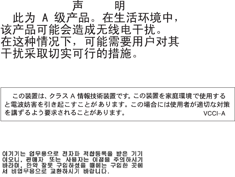
IBM verändert bzw. wenn Erweiterungskomponenten von Fremdherstellern ohne
Empfehlung der IBM gesteckt/eingebaut werden.
EN 55022 Klasse A Geräte müssen mit folgendem Warnhinweis versehen werden:
“Warnung: Dieses ist eine Einrichtung der Klasse A. Diese Einrichtung kann im
Wohnbereich Funk-Störungen verursachen; in diesem Fall kann vom Betreiber
verlangt werden, angemessene Maßnahmen zu ergreifen und dafür aufzukommen.”
Deutschland: Einhaltung des Gesetzes über die
elektromagnetische Verträglichkeit von Geräten
Dieses Produkt entspricht dem “Gesetz über die elektromagnetische Verträglichkeit
von Geräten (EMVG)”. Dies ist die Umsetzung der EU-Richtlinie 2004/108/EG in
der Bundesrepublik Deutschland.
Zulassungsbescheinigung laut dem Deutschen Gesetz über die
elektromagnetische Verträglichkeit von Geräten (EMVG) (bzw. der
EMC EG Richtlinie 2004/108/EG) für Geräte der Klasse A
Dieses Gerät ist berechtigt, in Übereinstimmung mit dem Deutschen EMVG das
EG-Konformitätszeichen - CE - zu führen. Verantwortlich für die
Konformitätserklärung des EMVG ist die IBM Deutschland GmbH, 70548 Stuttgart.
Generelle Informationen:
Das Gerät erfüllt die Schutzanforderungen nach EN 55024 und EN 55022
Klasse A.
People's Republic of China Class A warning statement
Japanese Voluntary Control Council for Interference (VCCI) statement
Korean Class A warning statement
202 IBM System Storage DS5020 Storage Subsystem: Installation, User’s, and Maintenance Guide

Glossary
This glossary provides definitions for the
terminology and abbreviations used in IBM
System Storage DS5000 and DS4000
publications.
If you do not find the term you are looking for, see
the IBM Glossary of Computing Terms located at
the following Web site:
www.ibm.com/ibm/terminology
This glossary also includes terms and definitions
from:
vInformation Technology Vocabulary by
Subcommittee 1, Joint Technical Committee 1,
of the International Organization for
Standardization and the International
Electrotechnical Commission (ISO/IEC
JTC1/SC1). Definitions are identified by the
symbol (I) after the definition; definitions taken
from draft international standards, committee
drafts, and working papers by ISO/IEC
JTC1/SC1 are identified by the symbol (T) after
the definition, indicating that final agreement
has not yet been reached among the
participating National Bodies of SC1.
vIBM Glossary of Computing Terms. New York:
McGraw-Hill, 1994.
The following cross-reference conventions are
used in this glossary:
See Refers you to (a) a term that is the
expanded form of an abbreviation or
acronym, or (b) a synonym or more
preferred term.
See also
Refers you to a related term.
Abstract Windowing Toolkit (AWT). A Java graphical
user interface (GUI).
accelerated graphics port (AGP). A bus specification
that gives low-cost 3D graphics cards faster access to
main memory on personal computers than the usual
peripheral component interconnect (PCI) bus. AGP
reduces the overall cost of creating high-end graphics
subsystems by using existing system memory.
access volume. A special logical drive that allows the
host-agent to communicate with the controllers in the
storage subsystem.
adapter. A printed circuit assembly that transmits user
data input/output (I/O) between the internal bus of the
host system and the external Fibre Channel link and
vice versa. Also called an I/O adapter, host adapter, or
Fibre Channel adapter.
advanced technology (AT) bus architecture. A bus
standard for IBM compatibles. It extends the XT bus
architecture to 16 bits and also allows for bus
mastering, although only the first 16 MB of main
memory are available for direct access.
agent. A server program that receives virtual
connections from the network manager (the client
program) in a Simple Network Management
Protocol-Transmission Control Protocol/Internet Protocol
(SNMP-TCP/IP) network-managing environment.
AGP. See accelerated graphics port.
AL_PA. See arbitrated loop physical address.
arbitrated loop. One of three existing fibre-channel
topologies, in which 2 - 126 ports are interconnected
serially in a single loop circuit. Access to the Fibre
Channel Arbitrated Loop (FC-AL) is controlled by an
arbitration scheme. The FC-AL topology supports all
classes of service and guarantees in-order delivery of
Fibre Channel frames when the originator and
responder are on the same FC-AL. The default topology
for the disk array is arbitrated loop. An arbitrated loop is
sometimes referred to as a Stealth Mode.
arbitrated loop physical address (AL_PA). An 8-bit
value that is used to uniquely identify an individual port
within a loop. A loop can have one or more AL_PAs.
array. A collection of fibre-channel or SATA hard drives
that are logically grouped together. All the drives in the
array are assigned the same RAID level. An array is
sometimes referred to as a ″RAID set.″See also
redundant array of independent disks (RAID),RAID
level.
asynchronous write mode. In remote mirroring, an
option that allows the primary controller to return a write
I/O request completion to the host server before data
has been successfully written by the secondary
controller. See also synchronous write mode,remote
mirroring,Global Copy,Global Mirroring.
AT. See advanced technology (AT) bus architecture.
ATA. See AT-attached.
AT-attached. Peripheral devices that are compatible
with the original IBM AT computer standard in which
signals on a 40-pin AT-attached (ATA) ribbon cable
followed the timings and constraints of the Industry
© Copyright IBM Corp. 2009 203
Standard Architecture (ISA) system bus on the IBM PC
AT computer. Equivalent to integrated drive electronics
(IDE).
auto-volume transfer/auto-disk transfer (AVT/ADT).
A function that provides automatic failover in case of
controller failure on a storage subsystem.
AVT/ADT. See auto-volume transfer/auto-disk transfer.
AWT. See Abstract Windowing Toolkit.
basic input/output system (BIOS). The personal
computer code that controls basic hardware operations,
such as interactions with diskette drives, hard disk
drives, and the keyboard.
BIOS. See basic input/output system.
BOOTP. See bootstrap protocol.
bootstrap protocol (BOOTP). In Transmission Control
Protocol/Internet Protocol (TCP/IP) networking, an
alternative protocol by which a diskless machine can
obtain its Internet Protocol (IP) address and such
configuration information as IP addresses of various
servers from a BOOTP server.
bridge. A storage area network (SAN) device that
provides physical and transport conversion, such as
Fibre Channel to small computer system interface
(SCSI) bridge.
bridge group. A bridge and the collection of devices
connected to it.
broadcast. The simultaneous transmission of data to
more than one destination.
cathode ray tube (CRT). A display device in which
controlled electron beams are used to display
alphanumeric or graphical data on an
electroluminescent screen.
client. A computer system or process that requests a
service of another computer system or process that is
typically referred to as a server. Multiple clients can
share access to a common server.
command. A statement used to initiate an action or
start a service. A command consists of the command
name abbreviation, and its parameters and flags if
applicable. A command can be issued by typing it on a
command line or selecting it from a menu.
community string. The name of a community
contained in each Simple Network Management
Protocol (SNMP) message.
concurrent download. A method of downloading and
installing firmware that does not require the user to stop
I/O to the controllers during the process.
CRC. See cyclic redundancy check.
CRT. See cathode ray tube.
CRU. See customer replaceable unit.
customer replaceable unit (CRU). An assembly or
part that a customer can replace in its entirety when any
of its components fail. Contrast with field replaceable
unit (FRU).
cyclic redundancy check (CRC). (1) A redundancy
check in which the check key is generated by a cyclic
algorithm. (2) An error detection technique performed at
both the sending and receiving stations.
dac. See disk array controller.
dar. See disk array router.
DASD. See direct access storage device.
data striping. See striping.
default host group. A logical collection of discovered
host ports, defined host computers, and defined host
groups in the storage-partition topology that fulfill the
following requirements:
vAre not involved in specific logical drive-to-LUN
mappings
vShare access to logical drives with default logical
drive-to-LUN mappings
device type. Identifier used to place devices in the
physical map, such as the switch, hub, or storage.
DHCP. See Dynamic Host Configuration Protocol.
direct access storage device (DASD). A device in
which access time is effectively independent of the
location of the data. Information is entered and retrieved
without reference to previously accessed data. (For
example, a disk drive is a DASD, in contrast with a tape
drive, which stores data as a linear sequence.) DASDs
include both fixed and removable storage devices.
direct memory access (DMA). The transfer of data
between memory and an input/output (I/O) device
without processor intervention.
disk array controller (dac). A disk array controller
device that represents the two controllers of an array.
See also disk array router.
disk array router (dar). A disk array router that
represents an entire array, including current and
deferred paths to all logical unit numbers (LUNs) (hdisks
on AIX). See also disk array controller.
DMA. See direct memory access.
domain. The most significant byte in the node port
(N_port) identifier for the fibre-channel (FC) device. It is
not used in the Fibre Channel-small computer system
204 IBM System Storage DS5020 Storage Subsystem: Installation, User’s, and Maintenance Guide
interface (FC-SCSI) hardware path ID. It is required to
be the same for all SCSI targets logically connected to
an Fibre Channel adapter.
drive channels. The DS4200, DS4700, and DS4800
subsystems use dual-port drive channels that, from the
physical point of view, are connected in the same way
as two drive loops. However, from the point of view of
the number of drives and enclosures, they are treated
as a single drive loop instead of two different drive
loops. A group of storage expansion enclosures are
connected to the DS5020 storage subsystems using a
drive channel from each controller. This pair of drive
channels is referred to as a redundant drive channel
pair.
drive loops. A drive loop consists of one channel from
each controller combined to form one pair of redundant
drive channels or a redundant drive loop. Each drive
loop is associated with two ports. (There are two drive
channels and four associated ports per controller.) For
the DS4800, drive loops are more commonly referred to
as drive channels. See drive channels.
DRAM. See dynamic random access memory.
Dynamic Host Configuration Protocol (DHCP). A
protocol defined by the Internet Engineering Task Force
that is used for dynamically assigning Internet Protocol
(IP) addresses to computers in a network.
dynamic random access memory (DRAM). A
storage in which the cells require repetitive application
of control signals to retain stored data.
ECC. See error correction coding.
EEPROM. See electrically erasable programmable
read-only memory.
EISA. See Extended Industry Standard Architecture.
electrically erasable programmable read-only
memory (EEPROM). A type of memory chip which can
retain its contents without consistent electrical power.
Unlike the PROM which can be programmed only once,
the EEPROM can be erased electrically. Because it can
only be reprogrammed a limited number of times before
it wears out, it is appropriate for storing small amounts
of data that are changed infrequently.
electrostatic discharge (ESD). The flow of current
that results when objects that have a static charge
come into close enough proximity to discharge.
environmental service module (ESM) canister. A
component in a storage expansion enclosure that
monitors the environmental condition of the components
in that enclosure. Not all storage subsystems have ESM
canisters.
E_port. See expansion port.
error correction coding (ECC). A method for
encoding data so that transmission errors can be
detected and corrected by examining the data on the
receiving end. Most ECCs are characterized by the
maximum number of errors they can detect and correct.
ESD. See electrostatic discharge.
ESM canister. See environmental service module
canister.
automatic ESM firmware synchronization. When
you install a new ESM into an existing storage
expansion enclosure in a storage subsystem that
supports automatic ESM firmware synchronization, the
firmware in the new ESM is automatically synchronized
with the firmware in the existing ESM.
EXP. See storage expansion enclosure.
expansion port (E_port). A port that connects the
switches for two fabrics.
Extended Industry Standard Architecture (EISA). A
bus standard for IBM compatibles that extends the
Industry Standard Architecture (ISA) bus architecture to
32 bits and allows more than one central processing
unit (CPU) to share the bus. See also Industry Standard
Architecture.
fabric. A Fibre Channel entity which interconnects and
facilitates logins of N_ports attached to it. The fabric is
responsible for routing frames between source and
destination N_ports using address information in the
frame header. A fabric can be as simple as a
point-to-point channel between two N-ports, or as
complex as a frame-routing switch that provides multiple
and redundant internal pathways within the fabric
between F_ports.
fabric port (F_port). In a fabric, an access point for
connecting a user’s N_port. An F_port facilitates N_port
logins to the fabric from nodes connected to the fabric.
An F_port is addressable by the N_port connected to it.
See also fabric.
FC. See Fibre Channel.
FC-AL. See arbitrated loop.
feature enable identifier. A unique identifier for the
storage subsystem, which is used in the process of
generating a premium feature key. See also premium
feature key.
Fibre Channel (FC). A set of standards for a serial
input/output (I/O) bus capable of transferring data
between two ports at up to 100 Mbps, with standards
proposals to go to higher speeds. FC supports
point-to-point, arbitrated loop, and switched topologies.
Fibre Channel Arbitrated Loop (FC-AL). See
arbitrated loop.
Glossary 205
Fibre Channel Protocol (FCP) for small computer
system interface (SCSI). A high-level fibre-channel
mapping layer (FC-4) that uses lower-level fibre-channel
(FC-PH) services to transmit SCSI commands, data,
and status information between a SCSI initiator and a
SCSI target across the FC link by using FC frame and
sequence formats.
field replaceable unit (FRU). An assembly that is
replaced in its entirety when any one of its components
fails. In some cases, a field replaceable unit might
contain other field replaceable units. Contrast with
customer replaceable unit (CRU).
FlashCopy. A premium feature for the DS5020 that
can make an instantaneous copy of the data in a
volume.
F_port. See fabric port.
FRU. See field replaceable unit.
GBIC. See gigabit interface converter
gigabit interface converter (GBIC). A transceiver that
performs serial, optical-to-electrical, and
electrical-to-optical signal conversions for high-speed
networking. A GBIC can be hot swapped. See also
small form-factor pluggable.
Global Copy. Refers to a remote logical drive mirror
pair that is set up using asynchronous write mode
without the write consistency group option. This is also
referred to as ″Asynchronous Mirroring without
Consistency Group.″Global Copy does not ensure that
write requests to multiple primary logical drives are
carried out in the same order on the secondary logical
drives as they are on the primary logical drives. If it is
critical that writes to the primary logical drives are
carried out in the same order in the applicable
secondary logical drives, Global Mirroring should be
used instead of Global Copy. See also asynchronous
write mode,Global Mirroring,remote mirroring,Metro
Mirroring.
Global Mirroring. Refers to a remote logical drive
mirror pair that is set up using asynchronous write mode
with the write consistency group option. This is also
referred to as ″Asynchronous Mirroring with Consistency
Group.″Global Mirroring ensures that write requests to
multiple primary logical drives are carried out in the
same order on the secondary logical drives as they are
on the primary logical drives, preventing data on the
secondary logical drives from becoming inconsistent
with the data on the primary logical drives. See also
asynchronous write mode,Global Copy,remote
mirroring,Metro Mirroring.
graphical user interface (GUI). A type of computer
interface that presents a visual metaphor of a real-world
scene, often of a desktop, by combining high-resolution
graphics, pointing devices, menu bars and other menus,
overlapping windows, icons, and the object-action
relationship.
GUI. See graphical user interface.
HBA. See host bus adapter.
hdisk. An AIX term representing a logical unit number
(LUN) on an array.
heterogeneous host environment. A host system in
which multiple host servers, which use different
operating systems with their own unique disk storage
subsystem settings, connect to the same DS5020
storage subsystem at the same time. See also host.
host. A system that is directly attached to the storage
subsystem through a fibre-channel input/output (I/O)
path. This system is used to serve data (typically in the
form of files) from the storage subsystem. A system can
be both a storage management station and a host
simultaneously.
host bus adapter (HBA). An interface between the
fibre-channel network and a workstation or server.
host computer. See host.
host group. An entity in the storage partition topology
that defines a logical collection of host computers that
require shared access to one or more logical drives.
host port. Ports that physically reside on the host
adapters and are automatically discovered by the DS
Storage Manager software. To give a host computer
access to a partition, its associated host ports must be
defined.
hot swap. To replace a hardware component without
turning off the system.
hub. In a network, a point at which circuits are either
connected or switched. For example, in a star network,
the hub is the central node; in a star/ring network, it is
the location of wiring concentrators.
IBMSAN driver. The device driver that is used in a
Novell NetWare environment to provide multipath
input/output (I/O) support to the storage controller.
IC. See integrated circuit.
IDE. See integrated drive electronics.
in-band. Transmission of management protocol over
the fibre-channel transport.
Industry Standard Architecture (ISA). Unofficial
name for the bus architecture of the IBM PC/XT
personal computer. This bus design included expansion
slots for plugging in various adapter boards. Early
versions had an 8-bit data path, later expanded to 16
bits. The ″Extended Industry Standard Architecture″
206 IBM System Storage DS5020 Storage Subsystem: Installation, User’s, and Maintenance Guide
(EISA) further expanded the data path to 32 bits. See
also Extended Industry Standard Architecture.
initial program load (IPL). The initialization procedure
that causes an operating system to commence
operation. Also referred to as a system restart, system
startup, and boot.
integrated circuit (IC). A microelectronic
semiconductor device that consists of many
interconnected transistors and other components. ICs
are constructed on a small rectangle cut from a silicon
crystal or other semiconductor material. The small size
of these circuits allows high speed, low power
dissipation, and reduced manufacturing cost compared
with board-level integration. Also known as a chip.
integrated drive electronics (IDE). A disk drive
interface based on the 16-bit IBM personal computer
Industry Standard Architecture (ISA) in which the
controller electronics reside on the drive itself,
eliminating the need for a separate adapter card. Also
known as an Advanced Technology Attachment
Interface (ATA).
Internet Protocol (IP). A protocol that routes data
through a network or interconnected networks. IP acts
as an intermediary between the higher protocol layers
and the physical network.
Internet Protocol (IP) address. The unique 32-bit
address that specifies the location of each device or
workstation on the Internet. For example, 9.67.97.103 is
an IP address.
interrupt request (IRQ). A type of input found on
many processors that causes the processor to suspend
normal processing temporarily and start running an
interrupt handler routine. Some processors have several
interrupt request inputs that allow different priority
interrupts.
IP. See Internet Protocol.
IPL. See initial program load.
IRQ. See interrupt request.
ISA. See Industry Standard Architecture.
Java Runtime Environment (JRE). A subset of the
Java Development Kit (JDK) for end users and
developers who want to redistribute the Java Runtime
Environment (JRE). The JRE consists of the Java virtual
machine, the Java Core Classes, and supporting files.
JRE. See Java Runtime Environment.
label. A discovered or user entered property value that
is displayed underneath each device in the Physical and
Data Path maps.
LAN. See local area network.
LBA. See logical block address.
local area network (LAN). A computer network
located on a user’s premises within a limited geographic
area.
logical block address (LBA). The address of a logical
block. Logical block addresses are typically used in
hosts’ I/O commands. The SCSI disk command
protocol, for example, uses logical block addresses.
logical partition (LPAR). (1) A subset of a single
system that contains resources (processors, memory,
and input/output devices). A logical partition operates as
an independent system. If hardware requirements are
met, multiple logical partitions can exist within a system.
(2) A fixed-size portion of a logical volume. A logical
partition is the same size as the physical partitions in its
volume group. Unless the logical volume of which it is a
part is mirrored, each logical partition corresponds to,
and its contents are stored on, a single physical
partition. (3) One to three physical partitions (copies).
The number of logical partitions within a logical volume
is variable.
logical unit number (LUN). An identifier used on a
small computer system interface (SCSI) bus to
distinguish among up to eight devices (logical units) with
the same SCSI ID.
loop address. The unique ID of a node in
fibre-channel loop topology sometimes referred to as a
loop ID.
loop group. A collection of storage area network
(SAN) devices that are interconnected serially in a
single loop circuit.
loop port. A node port (N_port) or fabric port (F_port)
that supports arbitrated loop functions associated with
an arbitrated loop topology.
LPAR. See logical partition.
LUN. See logical unit number.
MAC. See medium access control.
management information base (MIB). The
information that is on an agent. It is an abstraction of
configuration and status information.
man pages. In UNIX-based operating systems, online
documentation for operating system commands,
subroutines, system calls, file formats, special files,
stand-alone utilities, and miscellaneous facilities.
Invoked by the man command.
MCA. See micro channel architecture.
media scan. A media scan is a background process
that runs on all logical drives in the storage subsystem
for which it has been enabled, providing error detection
on the drive media. The media scan process scans all
Glossary 207
logical drive data to verify that it can be accessed, and
optionally scans the logical drive redundancy
information.
medium access control (MAC). In local area
networks (LANs), the sublayer of the data link control
layer that supports medium-dependent functions and
uses the services of the physical layer to provide
services to the logical link control sublayer. The MAC
sublayer includes the method of determining when a
device has access to the transmission medium.
Metro Mirroring. This term is used to refer to a
remote logical drive mirror pair which is set up with
synchronous write mode. See also remote mirroring,
Global Mirroring.
MIB. See management information base.
micro channel architecture (MCA). Hardware that is
used for PS/2 Model 50 computers and above to
provide better growth potential and performance
characteristics when compared with the original
personal computer design.
Microsoft Cluster Server (MSCS). MSCS, a feature
of Windows NT Server (Enterprise Edition), supports the
connection of two servers into a cluster for higher
availability and easier manageability. MSCS can
automatically detect and recover from server or
application failures. It can also be used to balance
server workload and provide for planned maintenance.
mini hub. An interface card or port device that
receives short-wave fiber channel GBICs or SFPs.
These devices enable redundant Fibre Channel
connections from the host computers, either directly or
through a Fibre Channel switch or managed hub, over
optical fiber cables to the DS5020 Storage Server
controllers. Each DS5020 controller is responsible for
two mini hubs. Each mini hub has two ports. Four host
ports (two on each controller) provide a cluster solution
without use of a switch. Two host-side mini hubs are
shipped as standard. See also host port, gigabit
interface converter (GBIC), small form-factor pluggable
(SFP).
mirroring. A fault-tolerance technique in which
information on a hard disk is duplicated on additional
hard disks. See also remote mirroring.
model. The model identification that is assigned to a
device by its manufacturer.
MSCS. See Microsoft Cluster Server.
network management station (NMS). In the Simple
Network Management Protocol (SNMP), a station that
runs management application programs that monitor
and control network elements.
NMI. See non-maskable interrupt.
NMS. See network management station.
non-maskable interrupt (NMI). A hardware interrupt
that another service request cannot overrule (mask). An
NMI bypasses and takes priority over interrupt requests
generated by software, the keyboard, and other such
devices and is issued to the microprocessor only in
disastrous circumstances, such as severe memory
errors or impending power failures.
node. A physical device that allows for the
transmission of data within a network.
node port (N_port). A fibre-channel defined hardware
entity that performs data communications over the
fibre-channel link. It is identifiable by a unique worldwide
name. It can act as an originator or a responder.
nonvolatile storage (NVS). A storage device whose
contents are not lost when power is cut off.
N_port. See node port.
NVS. See nonvolatile storage.
NVSRAM. Nonvolatile storage random access
memory. See nonvolatile storage.
Object Data Manager (ODM). An AIX proprietary
storage mechanism for ASCII stanza files that are
edited as part of configuring a drive into the kernel.
ODM. See Object Data Manager.
out-of-band. Transmission of management protocols
outside of the fibre-channel network, typically over
Ethernet.
partitioning. See storage partition.
parity check. (1) A test to determine whether the
number of ones (or zeros) in an array of binary digits is
odd or even. (2) A mathematical operation on the
numerical representation of the information
communicated between two pieces. For example, if
parity is odd, any character represented by an even
number has a bit added to it, making it odd, and an
information receiver checks that each unit of information
has an odd value.
PCI local bus. See peripheral component interconnect
local bus.
PDF. See portable document format.
performance events. Events related to thresholds set
on storage area network (SAN) performance.
peripheral component interconnect local bus (PCI
local bus). A local bus for PCs, from Intel, that
provides a high-speed data path between the CPU and
up to 10 peripherals (video, disk, network, and so on).
The PCI bus coexists in the PC with the Industry
Standard Architecture (ISA) or Extended Industry
208 IBM System Storage DS5020 Storage Subsystem: Installation, User’s, and Maintenance Guide
Standard Architecture (EISA) bus. ISA and EISA boards
plug into an IA or EISA slot, while high-speed PCI
controllers plug into a PCI slot. See also Industry
Standard Architecture,Extended Industry Standard
Architecture.
polling delay. The time in seconds between
successive discovery processes during which discovery
is inactive.
port. A part of the system unit or remote controller to
which cables for external devices (such as display
stations, terminals, printers, switches, or external
storage units) are attached. The port is an access point
for data entry or exit. A device can contain one or more
ports.
portable document format (PDF). A standard
specified by Adobe Systems, Incorporated, for the
electronic distribution of documents. PDF files are
compact; can be distributed globally by e-mail, the Web,
intranets, or CD-ROM; and can be viewed with the
Acrobat Reader, which is software from Adobe Systems
that can be downloaded at no cost from the Adobe
Systems home page.
premium feature key. A file that the storage
subsystem controller uses to enable an authorized
premium feature. The file contains the feature enable
identifier of the storage subsystem for which the
premium feature is authorized, and data about the
premium feature. See also feature enable identifier.
private loop. A freestanding arbitrated loop with no
fabric attachment. See also arbitrated loop.
program temporary fix (PTF). A temporary solution or
bypass of a problem diagnosed by IBM in a current
unaltered release of the program.
PTF. See program temporary fix.
RAID. See redundant array of independent disks
(RAID).
RAID level. An array RAID level is a number that
refers to the method used to achieve redundancy and
fault tolerance in the array. See also array, redundant
array of independent disks (RAID).
RAID set. See array.
RAM. See random-access memory.
random-access memory (RAM). A temporary storage
location in which the central processing unit (CPU)
stores and executes its processes. Contrast with DASD.
RDAC. See redundant disk array controller.
read-only memory (ROM). Memory in which stored
data cannot be changed by the user except under
special conditions.
recoverable virtual shared disk (RVSD). A virtual
shared disk on a server node configured to provide
continuous access to data and file systems in a cluster.
redundant array of independent disks (RAID). A
collection of disk drives (array) that appears as a single
volume to the server, which is fault tolerant through an
assigned method of data striping, mirroring, or parity
checking. Each array is assigned a RAID level, which is
a specific number that refers to the method used to
achieve redundancy and fault tolerance. See also array,
parity check, mirroring, RAID level, striping.
redundant disk array controller (RDAC). (1) In
hardware, a redundant set of controllers (either
active/passive or active/active). (2) In software, a layer
that manages the input/output (I/O) through the active
controller during normal operation and transparently
reroutes I/Os to the other controller in the redundant set
if a controller or I/O path fails.
remote mirroring. Online, real-time replication of data
between storage subsystems that are maintained on
separate media. The Enhanced Remote Mirror Option is
a DS5020 premium feature that provides support for
remote mirroring. See also Global Mirroring,Metro
Mirroring.
ROM. See read-only memory.
router. A computer that determines the path of
network traffic flow. The path selection is made from
several paths based on information obtained from
specific protocols, algorithms that attempt to identify the
shortest or best path, and other criteria such as metrics
or protocol-specific destination addresses.
RVSD. See recoverable virtual shared disk.
SAI. See Storage Array Identifier.
SA Identifier. See Storage Array Identifier.
SAN. See storage area network.
SATA. See serial ATA.
scope. Defines a group of controllers by their Internet
Protocol (IP) addresses. A scope must be created and
defined so that dynamic IP addresses can be assigned
to controllers on the network.
SCSI. See small computer system interface.
segmented loop port (SL_port). A port that allows
division of a fibre-channel private loop into multiple
segments. Each segment can pass frames around as
an independent loop and can connect through the fabric
to other segments of the same loop.
sense data. (1) Data sent with a negative response,
indicating the reason for the response. (2) Data
describing an I/O error. Sense data is presented to a
host system in response to a sense request command.
Glossary 209
serial ATA. The standard for a high-speed alternative
to small computer system interface (SCSI) hard drives.
The SATA-1 standard is equivalent in performance to a
10 000 RPM SCSI drive.
serial storage architecture (SSA). An interface
specification from IBM in which devices are arranged in
a ring topology. SSA, which is compatible with small
computer system interface (SCSI) devices, allows
full-duplex packet multiplexed serial data transfers at
rates of 20 Mbps in each direction.
server. A functional hardware and software unit that
delivers shared resources to workstation client units on
a computer network.
server/device events. Events that occur on the server
or a designated device that meet criteria that the user
sets.
SFP. See small form-factor pluggable.
Simple Network Management Protocol (SNMP). In
the Internet suite of protocols, a network management
protocol that is used to monitor routers and attached
networks. SNMP is an application layer protocol.
Information on devices managed is defined and stored
in the application’s Management Information Base
(MIB).
SL_port. See segmented loop port.
SMagent. The DS Storage Manager optional
Java-based host-agent software, which can be used on
Microsoft Windows, Novell NetWare, AIX, HP-UX,
Solaris, and Linux on POWER host systems to manage
storage subsystems through the host fibre-channel
connection.
SMclient. The DS Storage Manager client software,
which is a Java-based graphical user interface (GUI)
that is used to configure, manage, and troubleshoot
storage servers and storage expansion enclosures in a
DS5020 storage subsystem. SMclient can be used on a
host system or on a storage management station.
SMruntime. A Java compiler for the SMclient.
SMutil. The DS Storage Manager utility software that
is used on Microsoft Windows, AIX, HP-UX, Solaris, and
Linux on POWER host systems to register and map
new logical drives to the operating system. In Microsoft
Windows, it also contains a utility to flush the cached
data of the operating system for a particular drive before
creating a FlashCopy.
small computer system interface (SCSI). A standard
hardware interface that enables a variety of peripheral
devices to communicate with one another.
small form-factor pluggable (SFP). An optical
transceiver that is used to convert signals between
optical fiber cables and switches. An SFP is smaller
than a gigabit interface converter (GBIC). See also
gigabit interface converter.
SNMP. See Simple Network Management Protocol and
SNMPv1.
SNMP trap event. (1) (2) An event notification sent by
the SNMP agent that identifies conditions, such as
thresholds, that exceed a predetermined value. See
also Simple Network Management Protocol.
SNMPv1. The original standard for SNMP is now
referred to as SNMPv1, as opposed to SNMPv2, a
revision of SNMP. See also Simple Network
Management Protocol.
SRAM. See static random access memory.
SSA. See serial storage architecture.
static random access memory (SRAM). Random
access memory based on the logic circuit know as
flip-flop. It is called static because it retains a value as
long as power is supplied, unlike dynamic random
access memory (DRAM), which must be regularly
refreshed. It is however, still volatile, meaning that it can
lose its contents when the power is turned off.
storage area network (SAN). A dedicated storage
network tailored to a specific environment, combining
servers, storage products, networking products,
software, and services. See also fabric.
Storage Array Identifier (SAI or SA Identifier). The
Storage Array Identifier is the identification value used
by the DS Storage Manager host software (SMClient) to
uniquely identify each managed storage server. The DS
Storage Manager SMClient program maintains Storage
Array Identifier records of previously-discovered storage
servers in the host resident file, which allows it to retain
discovery information in a persistent fashion.
storage expansion enclosure (EXP). A feature that
can be connected to a system unit to provide additional
storage and processing capacity.
storage management station. A system that is used
to manage the storage subsystem. A storage
management station does not need to be attached to
the storage subsystem through the fibre-channel
input/output (I/O) path.
storage partition. Storage subsystem logical drives
that are visible to a host computer or are shared among
host computers that are part of a host group.
storage partition topology. In the DS Storage
Manager client, the Topology view of the Mappings
window displays the default host group, the defined host
group, the host computer, and host-port nodes. The
host port, host computer, and host group topological
210 IBM System Storage DS5020 Storage Subsystem: Installation, User’s, and Maintenance Guide
elements must be defined to grant access to host
computers and host groups using logical drive-to-LUN
mappings.
striping. Splitting data to be written into equal blocks
and writing blocks simultaneously to separate disk
drives. Striping maximizes performance to the disks.
Reading the data back is also scheduled in parallel, with
a block being read concurrently from each disk then
reassembled at the host.
subnet. An interconnected but independent segment
of a network that is identified by its Internet Protocol (IP)
address.
sweep method. A method of sending Simple Network
Management Protocol (SNMP) requests for information
to all the devices on a subnet by sending the request to
every device in the network.
switch. A fibre-channel device that provides full
bandwidth per port and high-speed routing of data by
using link-level addressing.
switch group. A switch and the collection of devices
connected to it that are not in other groups.
switch zoning. See zoning.
synchronous write mode. In remote mirroring, an
option that requires the primary controller to wait for the
acknowledgment of a write operation from the
secondary controller before returning a write I/O request
completion to the host. See also asynchronous write
mode,remote mirroring,Metro Mirroring.
system name. Device name assigned by the vendor’s
third-party software.
TCP. See Transmission Control Protocol.
TCP/IP. See Transmission Control Protocol/Internet
Protocol.
terminate and stay resident program (TSR
program). A program that installs part of itself as an
extension of DOS when it is executed.
topology. The physical or logical arrangement of
devices on a network. The three fibre-channel
topologies are fabric, arbitrated loop, and point-to-point.
The default topology for the disk array is arbitrated loop.
TL_port. See translated loop port.
transceiver. A device that is used to transmit and
receive data. Transceiver is an abbreviation of
transmitter-receiver.
translated loop port (TL_port). A port that connects
to a private loop and allows connectivity between the
private loop devices and off loop devices (devices not
connected to that particular TL_port).
Transmission Control Protocol (TCP). A
communication protocol used in the Internet and in any
network that follows the Internet Engineering Task Force
(IETF) standards for internetwork protocol. TCP
provides a reliable host-to-host protocol between hosts
in packed-switched communication networks and in
interconnected systems of such networks. It uses the
Internet Protocol (IP) as the underlying protocol.
Transmission Control Protocol/Internet Protocol
(TCP/IP). A set of communication protocols that
provide peer-to-peer connectivity functions for both local
and wide-area networks.
trap. In the Simple Network Management Protocol
(SNMP), a message sent by a managed node (agent
function) to a management station to report an
exception condition.
trap recipient. Receiver of a forwarded Simple
Network Management Protocol (SNMP) trap.
Specifically, a trap receiver is defined by an Internet
Protocol (IP) address and port to which traps are sent.
Presumably, the actual recipient is a software
application running at the IP address and listening to
the port.
TSR program. See terminate and stay resident
program.
uninterruptible power supply. A source of power
from a battery that is installed between a computer
system and its power source. The uninterruptible power
supply keeps the system running if a commercial power
failure occurs, until an orderly shutdown of the system
can be performed.
user action events. Actions that the user takes, such
as changes in the storage area network (SAN), changed
settings, and so on.
worldwide port name (WWPN). A unique identifier for
a switch on local and global networks.
worldwide name (WWN). A globally unique 64-bit
identifier assigned to each Fibre Channel port.
WORM. See write-once read-many.
write-once read many (WORM). Any type of storage
medium to which data can be written only a single time,
but can be read from any number of times. After the
data is recorded, it cannot be altered.
WWN. See worldwide name.
zoning. (1) In Fibre Channel environments, the
grouping of multiple ports to form a virtual, private,
storage network. Ports that are members of a zone can
communicate with each other, but are isolated from
ports in other zones. (2) A function that allows
segmentation of nodes by address, name, or physical
port and is provided by fabric switches or hubs.
Glossary 211
212 IBM System Storage DS5020 Storage Subsystem: Installation, User’s, and Maintenance Guide

Index
A
a hot-swap E-DDM
replacing 130
a hot-swap hard disk drive
replacing 130
about this document xix
ac power cords and receptacles 24
ac power recovery 23
ac power requirements 23
ac power supply
cabling 91
ac power supply and fan unit
replacing 43, 139
ac power supply and fan unit, removal 38
ac site wiring requirements 23
accessible documentation 199
acoustical noise emission values 22
airflow 13, 21, 24
altitude ranges 21
area requirements 19
audience xix
B
battery
LEDs 117
replacing 117
battery unit
LEDs 16, 103
overview 15
replacing 144
bays
hot-swap drive 7
best practices 5
blank trays 126
board ID 99
BOOTP server
sample network 11
C
cabling
ac power supply 91
cabling rules 67
cabling schemes
DS5020 and storage expansion enclosures 67
one DS5020 and one EXP520 storage expansion
enclosure 70
one DS5020 and three or more EXP520 storage
expansion enclosures 72
one DS5020 and two EXP520 storage expansion
enclosures 71
cabling the storage subsystem
connecting host to RAID controller 82
connecting secondary interface cables 78
connecting storage expansion enclosures 54
cabling topologies
one DS5020 and four storage expansion
enclosures 63
one DS5020 and one storage expansion
enclosure 59
one DS5020 and three storage expansion
enclosures 62
one DS5020 and two or more storage expansion
enclosures in a mixed configuration 66
one DS5020 and two storage expansion
enclosures 60
one DS5020 and up to six storage expansion
enclosures 64
storage expansion enclosures and storage
subsystem 57
cache battery
See battery 117
cache memory
cache active LED 116
size of 116
caution and danger notices xiii
checking the LEDs 101
Class A electronic emission notice 200
components
4 Gbps hard disk drives 6
battery unit 15
battery units 6
controllers 6
power supply and fan units 6
SFP modules 6
weights 19
Concepts Guide 183
configuration, installing the storage subsystem 91
contamination, particulate and gaseous 199
controller
information record 164
removal 37
replacing 42
controller information 99
controllers
description 8
LEDs 104
location 8
replacing 122
cooling 24
Copy Services Guide 183
customer replaceable units (CRUs) 6
removal 36
removing a ac power supply and fan unit 37
removing a controller 37
removing a hard disk drive 39
removing an ac power supply and fan unit 38
removing an E-DDM 39
removing E-DDMs 37
removing hard disk drives 37
replacing 42
replacing the battery unit 144
replacing the controllers 122
© Copyright IBM Corp. 2009 213
D
data sheet 164
devices, installing and replacing 121
DHCP server
sample network 11
diagnostic interface port 79
direct management method 81
document organization xix
documentation
DS Storage Manager 183
DS4000-related documents 193
DS4100 SATA storage subsystem 191
DS4200 Express storage subsystem 190
DS4300 Fibre Channel storage subsystem 189
DS4400 Fibre Channel storage subsystem 188
DS4500 storage subsystem 187
DS4800 storage subsystem 185, 186
DS5020 183
DS5020 documents 193
DS5020 storage subsystem 184
Web sites xxv
documentation format 199
documentation inventory 4
drive
2 Gbps 7
amber Fault LED 8
green Activity LED 8
trays 7
drive CRU labels 127
drive CRUs 127
drive information 99
drive LED activity 128
drive LEDs 127
drive, hard disk
replacing all at same time 131, 132
replacing one at a time 131, 134
DS Storage Manager
documentation 183
installing 97
related documents 193
using to monitor storage subsystem status 98
DS4000
Hardware Maintenance Manual 193
Problem Determination Guide 193
Storage expansion enclosure documentation 192
DS4000 storage expansion enclosures
enclosure ID settings 78
storage subsystem drive cabling topologies 57
DS4100
storage subsystem library 191
DS4200 Express
Storage subsystem library 190
DS4300
Storage subsystem library 189
DS4400
Storage subsystem library 188
DS4500
Storage subsystem library 187
DS4800
Storage subsystem library 185, 186
DS5020
dimensions 19
environmental requirements and specifications 20
general checkout 153
parts listing 160
Storage expansion enclosure documentation 192
Storage subsystem library 184
DS5020 documentation 183
E
E-DDM
replacing all at same time 131, 132
replacing one at a time 131, 134
E-DDM CRUs 127
E-DDM, removal 39
EIA 310-D Type A 19-inch rack cabinet 34
electrical requirements 23
electronic emission Class A notice 200
emergency shutdown 112
enclosure ID 45
enclosure ID settings 78
enclosure information 99
environmental requirements and specifications 20
Ethernet
connecting to RAID controller 78
F
FCC Class A notice 200
fiber-optic cable, handling 47
Fibre Channel
connections 84
loop configurations 85
Fibre Channel loop and ID
midplane 46
setting 45, 46
Fibre Channel loop ID
midplane 78
setting 78
Fibre Channel loop IDs 128
Fibre Channel, definition of 3
fire suppression xxvii
firmware levels, determining 18
firmware updates 99
G
gaseous contamination 199
glossary 203
guidelines, fiber-optic cables 47
H
hard disk drive
replacing all at same time 131, 132
replacing one at a time 131, 134
hard disk drive, removal 39
hardware fault indicator LEDs 101
hardware service and support xxvi
214 IBM System Storage DS5020 Storage Subsystem: Installation, User’s, and Maintenance Guide
Health Check process 93
heat dissipation 21
heat output 24
host adapter, connecting to RAID controller 82
host-agent management method 80
hot swap
drive bays 7
drive LED activity described 128
hardware 128
hot-swap E-DDMs
installing 128
replacing 44
hot-swap hard disk drives 126
installing 128
replacing 44
hub
See managed hub 82
I
IBM Safety Information 193
IBM System Storage DS5020
battery unit 15
battery unit LEDs 103
cache memory and cache battery 116
Health Check process 93
installing the configuration 91
identification numbers 163
in-band management method 80
indicator LEDs
during power up 101
indicator lights
power supply and fan unit Fault 13
power supply and fan unit Power 13
information record, storage subsystem and
controller 164
installation
into a rack 40
into a rack cabinet 27
preparation 29, 36
installed device records 166
installing and replacing devices
blank trays 126
hot-swap hard disk drives 121
interconnect-battery unit
battery packs 117
inventory checklist 3
iSCSI
loop configurations 87
iSCSI technology, definition of 3
L
LC-LC Fibre Channel cable 51
connecting to an SFP 52
removing 54
LEDs
battery unit 103
cache battery 117
controller 104
diagnostic 107
LEDs (continued)
front bezel 102
link rate setting, verifying 136
loop configurations
overview 85, 87
redundant 85
loop redundancy, described 55
M
managed hub
in Fibre Channel loop configurations 85
in iSCSI loop configurations 87, 88
using to connect host to RAID controller 82
memory, cache
cache active LED 116
size of 116
midplane
replacing 149
Migration Guide 183
mixed configuration
cabling topologies 66
multiple drives
replacing 131
multiple E-DDMs
replacing 131
My Support 5
N
non-IBM rack installation 171
notes, important 198
notices 197
electronic emission 200
FCC, Class A 200
safety and caution xiii
static-sensitive precautions 121
numbers, drive ID 9
numeric display 107
O
out-of-band management method 81
overheating, power supplies 114
overview of the product 1
P
part numbers, power cords 179
particulate contamination 199
planned shutdown, powering off 109
power cord use by country 179
power cords 179
power indicator light
power supply and fan unit 13
power outage
due to overheated power supplies 114
power supply and fan unit
described 13
Index 215
power supply and fan units (ac)
description 13
power-fan canister
recovering from shutdown 114
power, restoring after an emergency 112
powering off
for planned shutdown 109
powering on
after planned shutdown 95
after power supply shutdown 114
at initial startup 95
problem
determination 153
product ID 99
product overview 1
R
rack cabinet
EIA 310-D Type A 19 inch 34
preparatory procedures 32
rail installation 34
site preparation 30
rack mounting template for DS5020 167
RAID controller
cache battery 117
connecting Ethernet cable to 78
connecting host to 82
connecting RS-232 (serial) cable 79
RAID controllers) 6
rail installation 34
readme files
finding online xxiv
records
identification numbers 163
installed device 166
redundant drive channel pair, defined 55
redundant host and drive loops 85
removal of the CRUs 36
replacing components
battery unit 144
controller 122
handling static-sensitive devices 121
Service Action Allowed Status LED 121
replacing CRUs
ac power supply and fan unit 43
controller 42
hot-swap E-DDMs 44
hot-swap hard disk drives 44
replacing failed
ac power supply and fan unit 139
midplane 149
SFP module 146
resources
Web sites xxv
restoring power
after planned shutdown 95
after power supply shutdown 114
restoring power after an emergency 112
RS-232 serial port 79
S
safety information xiii
safety, static-sensitive devices 29
SATA technology, definition of 3
settings
Fibre Channel loop and ID 45, 46
storage expansion enclosure 78
SFP modules
described 16
replacing 146
shock and vibrations requirements 22
shutdown, emergency 112
Simple Network Management Protocol (SNMP)
traps 11
site preparation 31
small form-factor pluggable module (SFP)
connecting an LC-LC Fibre Channel cable 52
important information about 48
protective cap 49
removal 50
removing an LC-LC cable 54
static-protective package 49
Small-form Factor Pluggable modules
described 16
replacing 146
SNMP traps 11
specifications 19
specifications, fiber-optic cables 47
startup sequence 95
static-sensitive devices, handling 29, 121
steps
connecting storage expansion enclosures 56
storage area network (SAN)
technical support Web site xxv
storage expansion enclosure
settings 78
turning on before storage subsystem 134
storage expansion enclosures
cabling schemes 67
connecting to storage subsystem 54, 56
storage manager software and hardware
compatibility 17
storage subsystem
airflow 13
checking status 101
configuring 79
connecting storage expansion enclosures to 56
drive ID numbers 9
fans 13
fault indicator LEDs 101
identification numbers 163
information record 164
performing an emergency shutdown 112
power supply and fan unit 13
records 163
restoring power after an emergency 112
startup sequence 95
troubleshooting 100
turn on and turn off the 95
turning off 109
216 IBM System Storage DS5020 Storage Subsystem: Installation, User’s, and Maintenance Guide
storage subsystem configuration
saving 6
storage subsystem configuration, installing 91
storage subsystem profile
saving 6
submodel ID 99
support code upgrades
software and firmware 18
support notifications 5
switch
technical support Web site xxv
T
tasks by document title 183
tasks by documentation title 183
temperature and humidity 20
temperature, maximum 114
template, rack mounting 167
trademarks 197
troubleshooting 153
no power 114
overheating problem 114
procedure 100
turning off power
for planned shutdown 109
turning off the storage subsystem 109
turning on power
after power supply shutdown 114
at initial startup 95
U
United States electronic emission Class A notice 200
United States FCC Class A notice 200
updates (product updates) 5
upgrades, support code 18
user controls 8
W
Web sites
AIX fix delivery center xxvi
DS4000 and DS5000 interoperability matrix xxv
DS4000 and DS5000 storage subsystems xxv
DS4000 and DS5000 technical support xxv
IBM publications center xxvi
IBM System Storage products xxv
list xxv
premium feature activation xxv
readme files xxiv
SAN support xxv
switch support xxv
Index 217
218 IBM System Storage DS5020 Storage Subsystem: Installation, User’s, and Maintenance Guide

Part Number: 49Y0289
Printed in USA
(1P) P/N: 49Y0289
