Ibm Ds6000 Users Manual System Storage Series
2015-03-11
: Ibm Ibm-Ds6000-Users-Manual-576743 ibm-ds6000-users-manual-576743 ibm pdf
Open the PDF directly: View PDF ![]() .
.
Page Count: 578 [warning: Documents this large are best viewed by clicking the View PDF Link!]
- Front cover
- Contents
- Notices
- Preface
- Summary of changes
- Part 1 Overview
- Chapter 1. Introduction
- Chapter 2. Copy Services architecture
- Part 2 Interfaces
- Chapter 3. DS Storage Manager
- Chapter 4. DS Command-Line Interface
- Chapter 5. System z interfaces
- Part 3 FlashCopy
- Chapter 6. FlashCopy overview
- Chapter 7. FlashCopy options
- 7.1 Multiple relationship FlashCopy
- 7.2 Consistency Group FlashCopy
- 7.3 FlashCopy target as a Metro Mirror or Global Copy primary
- 7.4 Incremental FlashCopy - refresh target volume
- 7.5 Remote FlashCopy
- 7.6 Persistent FlashCopy
- 7.7 Data set FlashCopy
- 7.8 Reverse restore
- 7.9 Fast reverse restore
- 7.10 Options and interfaces
- Chapter 8. FlashCopy ordering and activation
- Chapter 9. FlashCopy interfaces
- Chapter 10. FlashCopy performance
- Chapter 11. FlashCopy examples
- Part 4 Metro Mirror
- Chapter 12. Metro Mirror overview
- Chapter 13. Metro Mirror options and configuration
- Chapter 14. Metro Mirror interfaces
- 14.1 Metro Mirror interfaces - overview
- 14.2 TSO commands for Metro Mirror management
- 14.3 ICKDSF
- 14.3.1 Metro Mirror management with ICKDSF
- 14.3.2 Display the Fibre Channel Connection Information Table
- 14.3.3 PPRCOPY DELPAIR
- 14.3.4 PPRCOPY DELPATH
- 14.3.5 PPRCOPY ESTPATH
- 14.3.6 PPRCOPY ESTPAIR
- 14.3.7 PPRCOPY FREEZE
- 14.3.8 PPRCOPY QUERY
- 14.3.9 PPRCOPY RECOVER
- 14.3.10 PPRCOPY SUSPEND
- 14.3.11 PPRCOPY RUN
- 14.3.12 Refreshing the VTOC
- 14.4 DS Command-Line Interface
- 14.5 DS CLI command- examples
- 14.6 DS Storage Manager GUI
- 14.7 ANTRQST API
- Chapter 15. Metro Mirror performance and scalability
- Chapter 16. Metro Mirror examples
- Part 5 Global Copy
- Chapter 17. Global Copy overview
- Chapter 18. Global Copy options and configuration
- Chapter 19. Global Copy performance and scalability
- Chapter 20. Global Copy interfaces
- Chapter 21. Global Copy examples
- Chapter 22. Global Mirror overview
- Part 6 Global Mirror
- Chapter 23. Global Mirror options and configuration
- 23.1 Terminology used in Global Mirror environments
- 23.2 Create a Global Mirror environment
- 23.3 Modify a Global Mirror session
- 23.4 Remove a Global Mirror environment
- 23.5 Global Mirror with multiple storage disk subsystems
- 23.6 Connectivity between local and remote site
- 23.7 Recovery scenario after primary site failure
- 23.7.1 Normal Global Mirror operation
- 23.7.2 Primary site failure
- 23.7.3 Failover B volumes
- 23.7.4 Check for valid Consistency Group state
- 23.7.5 Set consistent data on B volumes
- 23.7.6 Reestablish the FlashCopy relationship between B and C volumes
- 23.7.7 Restart the application at the remote site
- 23.7.8 Prepare to switch back to the local site
- 23.7.9 Return to local site
- 23.7.10 Conclusions
- Chapter 24. Global Mirror interfaces
- 24.1 Global Mirror interfaces - overview
- 24.2 Different interfaces for the same function
- 24.3 Global Mirror management using TSO commands
- 24.3.1 Establish a Global Mirror environment
- 24.3.2 Define paths
- 24.3.3 Establish Global Copy volume pairs
- 24.3.4 Establish FlashCopy relationships for Global Mirror
- 24.3.5 Define a Global Mirror session
- 24.3.6 Populate a Global Mirror session with volumes
- 24.3.7 Start a Global Mirror session
- 24.3.8 Query a Global Mirror session
- 24.4 DS CLI to manage Global Mirror volumes in z/OS
- 24.5 Global Mirror management using ICKDSF
- 24.5.1 Establish a Global Mirror environment
- 24.5.2 Define paths
- 24.5.3 Establish Global Copy pairs
- 24.5.4 Establish FlashCopy relationships
- 24.5.5 Define a Global Mirror session
- 24.5.6 Add volumes to a session
- 24.5.7 Start Global Mirror
- 24.5.8 Query an active Global Mirror session
- 24.5.9 Remove a Global Mirror environment
- 24.5.10 Stop the Global Mirror session
- 24.5.11 Remove volumes from Global Mirror
- 24.5.12 Un-define the Global Mirror session
- 24.5.13 Withdraw FlashCopy relationships
- 24.5.14 Delete Global Copy pairs
- 24.5.15 Remove all paths
- 24.6 ANTRQST macro
- 24.7 DS Storage Manager GUI
- Chapter 25. Global Mirror performance and scalability
- Chapter 26. Global Mirror examples
- 26.1 Global Mirror examples - configuration
- 26.2 Global Mirror query examples with TSO
- 26.3 Set up the Global Mirror environment using TSO
- 26.4 Primary site failure and recovery management with TSO
- 26.4.1 Primary site failure
- 26.4.2 Stop a Global Mirror session
- 26.4.3 Failover from B to A volumes
- 26.4.4 Check Global Mirror FlashCopy status between B and C volumes
- 26.4.5 Create a data consistent set of B volumes
- 26.4.6 Optionally create a data consistent set of D volumes
- 26.4.7 Create a data consistent set of C volumes
- 26.4.8 Prepare to return to the local site
- 26.4.9 Replicate the changes from B to A
- 26.4.10 Return to the local site and resume Global Mirror
- 26.5 Remove Global Mirror environment using TSO
- 26.6 Planned outage management using ICKDSF
- 26.7 Remove a Global Mirror environment using ICKDSF
- 26.8 Query device information with ICKDSF
- 26.9 Set up a Global Mirror environment using DS SM
- 26.10 Set up a Global Mirror environment using the DS CLI
- 26.11 Control and Query Global Mirror with the DS CLI
- 26.12 Site switch basic operations using the DS CLI
- 26.13 Remove the Global Mirror environment with the DS CLI
- Part 7 Interoperability
- Chapter 27. Combining Copy Service functions
- Chapter 28. Interoperability between DS6000 and DS8000
- 28.1 DS6000 and DS8000 Copy Services interoperability
- 28.2 Preparing the environment
- 28.2.1 Minimum microcode levels
- 28.2.2 Hardware and licensing requirements
- 28.2.3 Network connectivity
- 28.2.4 Creating matching user IDs and passwords
- 28.2.5 Updating the DS CLI profile
- 28.2.6 Adding the Storage Complex
- 28.2.7 Volume size considerations for Remote Mirror Copy
- 28.2.8 Determining DS6000 and DS8000 CKD volume size
- 28.3 RMC: Establishing paths between DS6000 and DS8000
- 28.4 Managing Metro Mirror or Global Copy pairs
- 28.5 Managing DS6000 to DS8000 Global Mirror
- 28.6 Managing DS6000 and DS8000 FlashCopy
- 28.7 z/OS Global Mirror
- Part 8 Solutions
- Chapter 29. Interoperability between DS6000 and ESS 800
- 29.1 DS6000 and ESS 800 Copy Services interoperability
- 29.2 Preparing the environment
- 29.2.1 Minimum microcode levels
- 29.2.2 Hardware and licensing requirements
- 29.2.3 Network connectivity
- 29.2.4 Creating matching user IDs and passwords
- 29.2.5 Updating the DS CLI profile
- 29.2.6 Adding the Copy Services domain
- 29.2.7 Volume size considerations for RMC (PPRC)
- 29.2.8 Volume address considerations on the ESS 800
- 29.3 RMC: Establishing paths between DS6000 and ESS 800
- 29.4 Managing Metro Mirror or Global Copy pairs
- 29.5 Managing ESS 800 Global Mirror
- 29.6 Managing ESS 800 FlashCopy
- Chapter 30. IIBM TotalStorage Rapid Data Recovery
- Chapter 31. IBM TotalStorage Productivity Center for Replication
- 31.1 IBM TotalStorage Productivity Center
- 31.2 Where we are coming from
- 31.3 What TPC for Replication provides
- 31.4 Copy Services terminology
- 31.5 TPC for Replication terminology
- 31.6 TPC for Replication session types
- 31.7 TPC for Replication session states
- 31.8 Volumes in a copy set
- 31.9 TPC for Replication and scalability
- 31.10 TPC for Replication system and connectivity overview
- 31.11 TPC for Replication monitoring and freeze capability
- 31.12 TPC for Replication heartbeat
- 31.13 Supported platforms
- 31.14 Hardware requirements for TPC for Replication servers
- 31.15 TPC for Replication GUI
- 31.16 Command Line Interface to TPC for Replication
- Chapter 32. GDPS overview
- Appendix A. Concurrent Copy
- Appendix B. SNMP notifications
- Appendix C. Licensing
- Appendix D. CLI migration
- Related publications
- Index
- Back cover

ibm.com/redbooks
Front cover
IBM System Storage DS6000
Series: Copy Services with
IBM System z
Plan, install and configure DS6000
Copy Services with System z
Learn how to use the management
interfaces: TSO, DS CLI, DS GUI
Learn about TPC for replication
support
Gustavo Castets
Bertrand Dufrasne
Stephen Baird
Werner Bauer
Denise Brown
Jana Jamsek
Wenzel Kalabza
Peter Klee
Markus Oscheka
Ying Thia
Robert Tondini

International Technical Support Organization
IBM System Storage DS6000 Series: Copy Services
with IBM System z
December 2006
SG24-6782-02

© Copyright International Business Machines Corporation 2005, 2006. All rights reserved.
Note to U.S. Government Users Restricted Rights -- Use, duplication or disclosure restricted by GSA ADP Schedule Contract with IBM
Corp.
Third Edition (December 2006)
This edition applies to features, microcode, GUI and DS CLI as announced for the DS6000 in August 2006.
Note: Before using this information and the product it supports, read the information in “Notices” on
page xv.
© Copyright IBM Corp. 2006. All rights reserved. iii
Contents
Notices . . . . . . . . . . . . . . . . . . . . . . . . . . . . . . . . . . . . . . . . . . . . . . . . . . . . . . . . . . . . . . . . .xv
Trademarks . . . . . . . . . . . . . . . . . . . . . . . . . . . . . . . . . . . . . . . . . . . . . . . . . . . . . . . . . . . . . xvi
Preface . . . . . . . . . . . . . . . . . . . . . . . . . . . . . . . . . . . . . . . . . . . . . . . . . . . . . . . . . . . . . . . . xvii
The team that wrote this redbook. . . . . . . . . . . . . . . . . . . . . . . . . . . . . . . . . . . . . . . . . . . . . xvii
Acknowledgements . . . . . . . . . . . . . . . . . . . . . . . . . . . . . . . . . . . . . . . . . . . . . . . . . . . . . . . xix
Become a published author . . . . . . . . . . . . . . . . . . . . . . . . . . . . . . . . . . . . . . . . . . . . . . . . . .xx
Comments welcome. . . . . . . . . . . . . . . . . . . . . . . . . . . . . . . . . . . . . . . . . . . . . . . . . . . . . . . .xx
Summary of changes. . . . . . . . . . . . . . . . . . . . . . . . . . . . . . . . . . . . . . . . . . . . . . . . . . . . . xxi
December 2006, Third Edition . . . . . . . . . . . . . . . . . . . . . . . . . . . . . . . . . . . . . . . . . . . . . . . xxi
Part 1. Overview . . . . . . . . . . . . . . . . . . . . . . . . . . . . . . . . . . . . . . . . . . . . . . . . . . . . . . . . . . . . . . . . . . . . . . 1
Chapter 1. Introduction. . . . . . . . . . . . . . . . . . . . . . . . . . . . . . . . . . . . . . . . . . . . . . . . . . . . 3
1.1 Introduction to Copy Services . . . . . . . . . . . . . . . . . . . . . . . . . . . . . . . . . . . . . . . . . . . . . 4
1.1.1 Point-in-Time Copy (FlashCopy). . . . . . . . . . . . . . . . . . . . . . . . . . . . . . . . . . . . . . . 4
1.1.2 Remote Mirror and Copy RMC (formerly Peer-to-Peer Remote Copy). . . . . . . . . . 5
1.1.3 Optional Copy Services function for z/OS. . . . . . . . . . . . . . . . . . . . . . . . . . . . . . . . 6
Chapter 2. Copy Services architecture . . . . . . . . . . . . . . . . . . . . . . . . . . . . . . . . . . . . . . . 7
2.1 Introduction to the Copy Services structure . . . . . . . . . . . . . . . . . . . . . . . . . . . . . . . . . . 8
2.1.1 What is a management console? . . . . . . . . . . . . . . . . . . . . . . . . . . . . . . . . . . . . . . 8
2.1.2 What is a Storage Unit? . . . . . . . . . . . . . . . . . . . . . . . . . . . . . . . . . . . . . . . . . . . . . 8
2.1.3 What is a Storage Facility Image (SFI)? . . . . . . . . . . . . . . . . . . . . . . . . . . . . . . . . . 8
2.1.4 What is a Storage Complex? . . . . . . . . . . . . . . . . . . . . . . . . . . . . . . . . . . . . . . . . 10
2.2 How the new structure of Copy Services works . . . . . . . . . . . . . . . . . . . . . . . . . . . . . . 11
2.2.1 Remote Mirror and Copy between Storage Complexes . . . . . . . . . . . . . . . . . . . . 12
2.2.2 Differences between the DS CLI and the DS GUI . . . . . . . . . . . . . . . . . . . . . . . . 12
2.3 System z communication path for Copy Services. . . . . . . . . . . . . . . . . . . . . . . . . . . . . 13
Part 2. Interfaces. . . . . . . . . . . . . . . . . . . . . . . . . . . . . . . . . . . . . . . . . . . . . . . . . . . . . . . . . . . . . . . . . . . . . 15
Chapter 3. DS Storage Manager . . . . . . . . . . . . . . . . . . . . . . . . . . . . . . . . . . . . . . . . . . . 17
3.1 System and hardware requirements . . . . . . . . . . . . . . . . . . . . . . . . . . . . . . . . . . . . . . . 18
3.1.1 Supported operating systems . . . . . . . . . . . . . . . . . . . . . . . . . . . . . . . . . . . . . . . . 18
3.2 Installation modes . . . . . . . . . . . . . . . . . . . . . . . . . . . . . . . . . . . . . . . . . . . . . . . . . . . . . 18
3.3 Connecting to your DS6000 SMC . . . . . . . . . . . . . . . . . . . . . . . . . . . . . . . . . . . . . . . . . 19
3.3.1 Real-time and simulated configuration . . . . . . . . . . . . . . . . . . . . . . . . . . . . . . . . . 20
3.3.2 Advantages of using the DS GUI over the DS CLI or TSO. . . . . . . . . . . . . . . . . . 20
3.3.3 Disadvantages of using the DS GUI over the DS CLI or TSO . . . . . . . . . . . . . . . 20
3.4 Accessing the Information Center . . . . . . . . . . . . . . . . . . . . . . . . . . . . . . . . . . . . . . . . . 21
3.5 Managing the Storage Complex . . . . . . . . . . . . . . . . . . . . . . . . . . . . . . . . . . . . . . . . . . 22
3.5.1 Procedure to add a Storage Complex. . . . . . . . . . . . . . . . . . . . . . . . . . . . . . . . . . 23
Chapter 4. DS Command-Line Interface . . . . . . . . . . . . . . . . . . . . . . . . . . . . . . . . . . . . . 25
4.1 Introduction and functionality . . . . . . . . . . . . . . . . . . . . . . . . . . . . . . . . . . . . . . . . . . . . 26
4.2 Supported operating systems for the DS CLI . . . . . . . . . . . . . . . . . . . . . . . . . . . . . . . . 26
4.3 User accounts . . . . . . . . . . . . . . . . . . . . . . . . . . . . . . . . . . . . . . . . . . . . . . . . . . . . . . . . 27
4.4 DS CLI profile . . . . . . . . . . . . . . . . . . . . . . . . . . . . . . . . . . . . . . . . . . . . . . . . . . . . . . . . 28
iv IBM System Storage DS6000 Series: Copy Services with IBM System z
4.5 Command structure. . . . . . . . . . . . . . . . . . . . . . . . . . . . . . . . . . . . . . . . . . . . . . . . . . . . 29
4.6 Copy Services commands . . . . . . . . . . . . . . . . . . . . . . . . . . . . . . . . . . . . . . . . . . . . . . 29
4.7 Using the DS CLI application . . . . . . . . . . . . . . . . . . . . . . . . . . . . . . . . . . . . . . . . . . . . 31
4.7.1 Single-shot mode . . . . . . . . . . . . . . . . . . . . . . . . . . . . . . . . . . . . . . . . . . . . . . . . . 31
4.7.2 Script command mode . . . . . . . . . . . . . . . . . . . . . . . . . . . . . . . . . . . . . . . . . . . . . 32
4.7.3 Interactive mode . . . . . . . . . . . . . . . . . . . . . . . . . . . . . . . . . . . . . . . . . . . . . . . . . . 32
4.8 Return codes. . . . . . . . . . . . . . . . . . . . . . . . . . . . . . . . . . . . . . . . . . . . . . . . . . . . . . . . . 33
4.9 User assistance. . . . . . . . . . . . . . . . . . . . . . . . . . . . . . . . . . . . . . . . . . . . . . . . . . . . . . . 34
4.10 Usage examples . . . . . . . . . . . . . . . . . . . . . . . . . . . . . . . . . . . . . . . . . . . . . . . . . . . . . 35
Chapter 5. System z interfaces . . . . . . . . . . . . . . . . . . . . . . . . . . . . . . . . . . . . . . . . . . . . 37
5.1 System z interfaces. . . . . . . . . . . . . . . . . . . . . . . . . . . . . . . . . . . . . . . . . . . . . . . . . . . . 38
5.1.1 Operating system alternatives. . . . . . . . . . . . . . . . . . . . . . . . . . . . . . . . . . . . . . . . 38
5.2 TSO. . . . . . . . . . . . . . . . . . . . . . . . . . . . . . . . . . . . . . . . . . . . . . . . . . . . . . . . . . . . . . . . 38
5.3 ICKDSF . . . . . . . . . . . . . . . . . . . . . . . . . . . . . . . . . . . . . . . . . . . . . . . . . . . . . . . . . . . . . 39
5.4 DFSMSdss . . . . . . . . . . . . . . . . . . . . . . . . . . . . . . . . . . . . . . . . . . . . . . . . . . . . . . . . . . 39
5.5 The ANTRQST macro. . . . . . . . . . . . . . . . . . . . . . . . . . . . . . . . . . . . . . . . . . . . . . . . . . 39
5.6 z/TPF commands . . . . . . . . . . . . . . . . . . . . . . . . . . . . . . . . . . . . . . . . . . . . . . . . . . . . . 39
Part 3. FlashCopy . . . . . . . . . . . . . . . . . . . . . . . . . . . . . . . . . . . . . . . . . . . . . . . . . . . . . . . . . . . . . . . . . . . . 41
Chapter 6. FlashCopy overview. . . . . . . . . . . . . . . . . . . . . . . . . . . . . . . . . . . . . . . . . . . . 43
6.1 Operational environments . . . . . . . . . . . . . . . . . . . . . . . . . . . . . . . . . . . . . . . . . . . . . . . 44
6.2 Terminology . . . . . . . . . . . . . . . . . . . . . . . . . . . . . . . . . . . . . . . . . . . . . . . . . . . . . . . . . 45
6.3 Basic concepts . . . . . . . . . . . . . . . . . . . . . . . . . . . . . . . . . . . . . . . . . . . . . . . . . . . . . . . 45
6.3.1 Full volume copy . . . . . . . . . . . . . . . . . . . . . . . . . . . . . . . . . . . . . . . . . . . . . . . . . . 48
6.3.2 Nocopy option . . . . . . . . . . . . . . . . . . . . . . . . . . . . . . . . . . . . . . . . . . . . . . . . . . . . 48
6.4 FlashCopy in combination with other Copy Services . . . . . . . . . . . . . . . . . . . . . . . . . . 49
6.4.1 FlashCopy and Metro Mirror . . . . . . . . . . . . . . . . . . . . . . . . . . . . . . . . . . . . . . . . . 49
6.4.2 FlashCopy and Global Copy . . . . . . . . . . . . . . . . . . . . . . . . . . . . . . . . . . . . . . . . . 50
6.4.3 FlashCopy and Global Mirror . . . . . . . . . . . . . . . . . . . . . . . . . . . . . . . . . . . . . . . . 51
6.5 FlashCopy for z/OS data sets . . . . . . . . . . . . . . . . . . . . . . . . . . . . . . . . . . . . . . . . . . . . 51
Chapter 7. FlashCopy options . . . . . . . . . . . . . . . . . . . . . . . . . . . . . . . . . . . . . . . . . . . . . 53
7.1 Multiple relationship FlashCopy . . . . . . . . . . . . . . . . . . . . . . . . . . . . . . . . . . . . . . . . . . 54
7.2 Consistency Group FlashCopy . . . . . . . . . . . . . . . . . . . . . . . . . . . . . . . . . . . . . . . . . . . 55
7.3 FlashCopy target as a Metro Mirror or Global Copy primary. . . . . . . . . . . . . . . . . . . . . 55
7.4 Incremental FlashCopy - refresh target volume . . . . . . . . . . . . . . . . . . . . . . . . . . . . . . 56
7.5 Remote FlashCopy . . . . . . . . . . . . . . . . . . . . . . . . . . . . . . . . . . . . . . . . . . . . . . . . . . . . 59
7.6 Persistent FlashCopy . . . . . . . . . . . . . . . . . . . . . . . . . . . . . . . . . . . . . . . . . . . . . . . . . . 59
7.7 Data set FlashCopy. . . . . . . . . . . . . . . . . . . . . . . . . . . . . . . . . . . . . . . . . . . . . . . . . . . . 59
7.8 Reverse restore. . . . . . . . . . . . . . . . . . . . . . . . . . . . . . . . . . . . . . . . . . . . . . . . . . . . . . . 60
7.9 Fast reverse restore . . . . . . . . . . . . . . . . . . . . . . . . . . . . . . . . . . . . . . . . . . . . . . . . . . . 60
7.10 Options and interfaces . . . . . . . . . . . . . . . . . . . . . . . . . . . . . . . . . . . . . . . . . . . . . . . . 60
Chapter 8. FlashCopy ordering and activation. . . . . . . . . . . . . . . . . . . . . . . . . . . . . . . . 63
8.1 Ordering FlashCopy . . . . . . . . . . . . . . . . . . . . . . . . . . . . . . . . . . . . . . . . . . . . . . . . . . . 64
8.2 Activating FlashCopy . . . . . . . . . . . . . . . . . . . . . . . . . . . . . . . . . . . . . . . . . . . . . . . . . . 65
8.2.1 Management . . . . . . . . . . . . . . . . . . . . . . . . . . . . . . . . . . . . . . . . . . . . . . . . . . . . . 65
8.2.2 Activation . . . . . . . . . . . . . . . . . . . . . . . . . . . . . . . . . . . . . . . . . . . . . . . . . . . . . . . 67
Chapter 9. FlashCopy interfaces . . . . . . . . . . . . . . . . . . . . . . . . . . . . . . . . . . . . . . . . . . . 69
9.1 FlashCopy interfaces - overview . . . . . . . . . . . . . . . . . . . . . . . . . . . . . . . . . . . . . . . . . . 70
9.2 DS CLI and DS SM - commands and options. . . . . . . . . . . . . . . . . . . . . . . . . . . . . . . . 71
Contents v
9.2.1 Local FlashCopy management . . . . . . . . . . . . . . . . . . . . . . . . . . . . . . . . . . . . . . . 71
9.2.2 Remote FlashCopy management . . . . . . . . . . . . . . . . . . . . . . . . . . . . . . . . . . . . . 72
9.3 z/OS-provided interfaces. . . . . . . . . . . . . . . . . . . . . . . . . . . . . . . . . . . . . . . . . . . . . . . . 72
9.4 Local FlashCopy using the DS CLI . . . . . . . . . . . . . . . . . . . . . . . . . . . . . . . . . . . . . . . . 73
9.4.1 Parameters used with local FlashCopy commands . . . . . . . . . . . . . . . . . . . . . . . 73
9.4.2 Local FlashCopy commands - examples . . . . . . . . . . . . . . . . . . . . . . . . . . . . . . . 75
9.4.3 FlashCopy Consistency Groups . . . . . . . . . . . . . . . . . . . . . . . . . . . . . . . . . . . . . . 84
9.5 Remote FlashCopy using the DS CLI . . . . . . . . . . . . . . . . . . . . . . . . . . . . . . . . . . . . . . 85
9.5.1 Remote FlashCopy commands. . . . . . . . . . . . . . . . . . . . . . . . . . . . . . . . . . . . . . . 85
9.5.2 Parameters used in remote FlashCopy commands . . . . . . . . . . . . . . . . . . . . . . . 86
9.6 FlashCopy management using the DS SM . . . . . . . . . . . . . . . . . . . . . . . . . . . . . . . . . . 87
9.6.1 Initiate FlashCopy using Create . . . . . . . . . . . . . . . . . . . . . . . . . . . . . . . . . . . . . . 87
9.6.2 Display properties of existing FlashCopy . . . . . . . . . . . . . . . . . . . . . . . . . . . . . . . 89
9.6.3 Reverse existing FlashCopy . . . . . . . . . . . . . . . . . . . . . . . . . . . . . . . . . . . . . . . . . 92
9.6.4 Initiate background copy for a persistent FlashCopy relationship. . . . . . . . . . . . . 93
9.6.5 Resynchronize target . . . . . . . . . . . . . . . . . . . . . . . . . . . . . . . . . . . . . . . . . . . . . . 94
9.6.6 Delete existing FlashCopy relationship. . . . . . . . . . . . . . . . . . . . . . . . . . . . . . . . . 96
9.7 z/OS interfaces for local FlashCopy . . . . . . . . . . . . . . . . . . . . . . . . . . . . . . . . . . . . . . . 97
9.7.1 Initiating FlashCopy using DFSMSdss . . . . . . . . . . . . . . . . . . . . . . . . . . . . . . . . . 97
9.7.2 FlashCopy using TSO commands . . . . . . . . . . . . . . . . . . . . . . . . . . . . . . . . . . . 103
Chapter 10. FlashCopy performance. . . . . . . . . . . . . . . . . . . . . . . . . . . . . . . . . . . . . . . 111
10.1 FlashCopy performance overview. . . . . . . . . . . . . . . . . . . . . . . . . . . . . . . . . . . . . . . 112
10.1.1 Distribution of the workload - Source and target volumes location . . . . . . . . . . 112
10.1.2 LSS/LCU versus rank considerations . . . . . . . . . . . . . . . . . . . . . . . . . . . . . . . . 113
10.1.3 Rank geometry . . . . . . . . . . . . . . . . . . . . . . . . . . . . . . . . . . . . . . . . . . . . . . . . . 113
10.1.4 Incremental FlashCopy . . . . . . . . . . . . . . . . . . . . . . . . . . . . . . . . . . . . . . . . . . . 113
10.2 FlashCopy establish phase performance . . . . . . . . . . . . . . . . . . . . . . . . . . . . . . . . . 114
10.3 Background copy performance . . . . . . . . . . . . . . . . . . . . . . . . . . . . . . . . . . . . . . . . . 114
10.4 FlashCopy impact on applications . . . . . . . . . . . . . . . . . . . . . . . . . . . . . . . . . . . . . . 115
10.5 FlashCopy options - considerations . . . . . . . . . . . . . . . . . . . . . . . . . . . . . . . . . . . . . 116
10.6 FlashCopy scenarios. . . . . . . . . . . . . . . . . . . . . . . . . . . . . . . . . . . . . . . . . . . . . . . . . 116
10.6.1 Scenario #1: Backup to disk . . . . . . . . . . . . . . . . . . . . . . . . . . . . . . . . . . . . . . . 116
10.6.2 Scenario #2: Backup to tape. . . . . . . . . . . . . . . . . . . . . . . . . . . . . . . . . . . . . . . 117
10.6.3 Scenario #3: FlashCopy during peak application activity . . . . . . . . . . . . . . . . . 117
10.6.4 Scenario #4: Ranks reserved for FlashCopy . . . . . . . . . . . . . . . . . . . . . . . . . . 119
Chapter 11. FlashCopy examples . . . . . . . . . . . . . . . . . . . . . . . . . . . . . . . . . . . . . . . . . 121
11.1 Create a test system or integration system. . . . . . . . . . . . . . . . . . . . . . . . . . . . . . . . 122
11.1.1 One-time test system . . . . . . . . . . . . . . . . . . . . . . . . . . . . . . . . . . . . . . . . . . . . 122
11.1.2 Multiple setup of a test system with same contents . . . . . . . . . . . . . . . . . . . . . 122
11.2 Create a backup . . . . . . . . . . . . . . . . . . . . . . . . . . . . . . . . . . . . . . . . . . . . . . . . . . . . 123
11.2.1 Create a FlashCopy for backup purposes without volume copy. . . . . . . . . . . . 123
11.2.2 Incremental FlashCopy for backup purposes . . . . . . . . . . . . . . . . . . . . . . . . . . 124
11.2.3 Using a target volume to restore its contents back to the source . . . . . . . . . . . 125
Part 4. Metro Mirror. . . . . . . . . . . . . . . . . . . . . . . . . . . . . . . . . . . . . . . . . . . . . . . . . . . . . . . . . . . . . . . . . . 127
Chapter 12. Metro Mirror overview . . . . . . . . . . . . . . . . . . . . . . . . . . . . . . . . . . . . . . . . 129
12.1 Metro Mirror overview . . . . . . . . . . . . . . . . . . . . . . . . . . . . . . . . . . . . . . . . . . . . . . . . 130
12.2 Metro Mirror volume state . . . . . . . . . . . . . . . . . . . . . . . . . . . . . . . . . . . . . . . . . . . . . 131
12.3 Data consistency. . . . . . . . . . . . . . . . . . . . . . . . . . . . . . . . . . . . . . . . . . . . . . . . . . . . 131
12.4 Rolling disaster . . . . . . . . . . . . . . . . . . . . . . . . . . . . . . . . . . . . . . . . . . . . . . . . . . . . . 132
12.5 Automation and management . . . . . . . . . . . . . . . . . . . . . . . . . . . . . . . . . . . . . . . . . . 132
vi IBM System Storage DS6000 Series: Copy Services with IBM System z
Chapter 13. Metro Mirror options and configuration . . . . . . . . . . . . . . . . . . . . . . . . . . 133
13.1 High availability solutions . . . . . . . . . . . . . . . . . . . . . . . . . . . . . . . . . . . . . . . . . . . . . 134
13.1.1 GDPS HyperSwap Manager . . . . . . . . . . . . . . . . . . . . . . . . . . . . . . . . . . . . . . . 134
13.1.2 Open systems - Clustering . . . . . . . . . . . . . . . . . . . . . . . . . . . . . . . . . . . . . . . . 134
13.2 Failover and failback . . . . . . . . . . . . . . . . . . . . . . . . . . . . . . . . . . . . . . . . . . . . . . . . . 134
13.3 Consistency Group function . . . . . . . . . . . . . . . . . . . . . . . . . . . . . . . . . . . . . . . . . . . 136
13.3.1 Data consistency and dependent writes . . . . . . . . . . . . . . . . . . . . . . . . . . . . . . 136
13.3.2 Consistency Group function - how it works. . . . . . . . . . . . . . . . . . . . . . . . . . . . 137
13.3.3 FREEZE and RUN parameters. . . . . . . . . . . . . . . . . . . . . . . . . . . . . . . . . . . . . 140
13.3.4 Critical attribute . . . . . . . . . . . . . . . . . . . . . . . . . . . . . . . . . . . . . . . . . . . . . . . . . 141
13.3.5 Consistency Group and critical mode combination. . . . . . . . . . . . . . . . . . . . . . 142
13.4 Metro Mirror paths and links . . . . . . . . . . . . . . . . . . . . . . . . . . . . . . . . . . . . . . . . . . . 142
13.4.1 Fibre Channel links . . . . . . . . . . . . . . . . . . . . . . . . . . . . . . . . . . . . . . . . . . . . . . 143
13.4.2 Logical paths. . . . . . . . . . . . . . . . . . . . . . . . . . . . . . . . . . . . . . . . . . . . . . . . . . . 144
13.5 Bandwidth . . . . . . . . . . . . . . . . . . . . . . . . . . . . . . . . . . . . . . . . . . . . . . . . . . . . . . . . . 145
13.6 LSS design . . . . . . . . . . . . . . . . . . . . . . . . . . . . . . . . . . . . . . . . . . . . . . . . . . . . . . . . 145
13.7 Distance . . . . . . . . . . . . . . . . . . . . . . . . . . . . . . . . . . . . . . . . . . . . . . . . . . . . . . . . . . 146
13.8 Symmetrical configuration. . . . . . . . . . . . . . . . . . . . . . . . . . . . . . . . . . . . . . . . . . . . . 146
13.9 Volumes . . . . . . . . . . . . . . . . . . . . . . . . . . . . . . . . . . . . . . . . . . . . . . . . . . . . . . . . . . 147
13.10 Hardware requirements. . . . . . . . . . . . . . . . . . . . . . . . . . . . . . . . . . . . . . . . . . . . . . 148
Chapter 14. Metro Mirror interfaces. . . . . . . . . . . . . . . . . . . . . . . . . . . . . . . . . . . . . . . . 149
14.1 Metro Mirror interfaces - overview. . . . . . . . . . . . . . . . . . . . . . . . . . . . . . . . . . . . . . . 150
14.2 TSO commands for Metro Mirror management. . . . . . . . . . . . . . . . . . . . . . . . . . . . . 151
14.2.1 Commands overview. . . . . . . . . . . . . . . . . . . . . . . . . . . . . . . . . . . . . . . . . . . . . 152
14.2.2 CESTPAIR . . . . . . . . . . . . . . . . . . . . . . . . . . . . . . . . . . . . . . . . . . . . . . . . . . . . 152
14.2.3 CESTPATH. . . . . . . . . . . . . . . . . . . . . . . . . . . . . . . . . . . . . . . . . . . . . . . . . . . . 153
14.2.4 CDELPAIR . . . . . . . . . . . . . . . . . . . . . . . . . . . . . . . . . . . . . . . . . . . . . . . . . . . . 154
14.2.5 CDELPATH. . . . . . . . . . . . . . . . . . . . . . . . . . . . . . . . . . . . . . . . . . . . . . . . . . . . 154
14.2.6 CGROUP . . . . . . . . . . . . . . . . . . . . . . . . . . . . . . . . . . . . . . . . . . . . . . . . . . . . . 154
14.2.7 CQUERY. . . . . . . . . . . . . . . . . . . . . . . . . . . . . . . . . . . . . . . . . . . . . . . . . . . . . . 155
14.2.8 CRECOVER . . . . . . . . . . . . . . . . . . . . . . . . . . . . . . . . . . . . . . . . . . . . . . . . . . . 156
14.2.9 CSUSPEND . . . . . . . . . . . . . . . . . . . . . . . . . . . . . . . . . . . . . . . . . . . . . . . . . . . 157
14.2.10 Batch execution of Metro Mirror TSO commands. . . . . . . . . . . . . . . . . . . . . . 157
14.3 ICKDSF . . . . . . . . . . . . . . . . . . . . . . . . . . . . . . . . . . . . . . . . . . . . . . . . . . . . . . . . . . . 157
14.3.1 Metro Mirror management with ICKDSF. . . . . . . . . . . . . . . . . . . . . . . . . . . . . . 158
14.3.2 Display the Fibre Channel Connection Information Table. . . . . . . . . . . . . . . . . 159
14.3.3 PPRCOPY DELPAIR . . . . . . . . . . . . . . . . . . . . . . . . . . . . . . . . . . . . . . . . . . . . 159
14.3.4 PPRCOPY DELPATH. . . . . . . . . . . . . . . . . . . . . . . . . . . . . . . . . . . . . . . . . . . . 160
14.3.5 PPRCOPY ESTPATH. . . . . . . . . . . . . . . . . . . . . . . . . . . . . . . . . . . . . . . . . . . . 160
14.3.6 PPRCOPY ESTPAIR . . . . . . . . . . . . . . . . . . . . . . . . . . . . . . . . . . . . . . . . . . . . 161
14.3.7 PPRCOPY FREEZE . . . . . . . . . . . . . . . . . . . . . . . . . . . . . . . . . . . . . . . . . . . . . 161
14.3.8 PPRCOPY QUERY. . . . . . . . . . . . . . . . . . . . . . . . . . . . . . . . . . . . . . . . . . . . . . 161
14.3.9 PPRCOPY RECOVER . . . . . . . . . . . . . . . . . . . . . . . . . . . . . . . . . . . . . . . . . . . 164
14.3.10 PPRCOPY SUSPEND . . . . . . . . . . . . . . . . . . . . . . . . . . . . . . . . . . . . . . . . . . 164
14.3.11 PPRCOPY RUN . . . . . . . . . . . . . . . . . . . . . . . . . . . . . . . . . . . . . . . . . . . . . . . 164
14.3.12 Refreshing the VTOC . . . . . . . . . . . . . . . . . . . . . . . . . . . . . . . . . . . . . . . . . . . 164
14.4 DS Command-Line Interface. . . . . . . . . . . . . . . . . . . . . . . . . . . . . . . . . . . . . . . . . . . 165
14.4.1 DS CLI supported environments. . . . . . . . . . . . . . . . . . . . . . . . . . . . . . . . . . . . 165
14.5 DS CLI command- examples . . . . . . . . . . . . . . . . . . . . . . . . . . . . . . . . . . . . . . . . . . 165
14.5.1 Set up a Metro Mirror environment . . . . . . . . . . . . . . . . . . . . . . . . . . . . . . . . . . 166
14.5.2 Remove a Metro Mirror environment . . . . . . . . . . . . . . . . . . . . . . . . . . . . . . . . 167
14.5.3 Manage a Metro Mirror environment. . . . . . . . . . . . . . . . . . . . . . . . . . . . . . . . . 168
Contents vii
14.6 DS Storage Manager GUI . . . . . . . . . . . . . . . . . . . . . . . . . . . . . . . . . . . . . . . . . . . . . 172
14.6.1 Define Metro Mirror paths . . . . . . . . . . . . . . . . . . . . . . . . . . . . . . . . . . . . . . . . . 172
14.6.2 Create Metro Mirror pairs . . . . . . . . . . . . . . . . . . . . . . . . . . . . . . . . . . . . . . . . . 175
14.6.3 Resume suspended pair . . . . . . . . . . . . . . . . . . . . . . . . . . . . . . . . . . . . . . . . . . 179
14.7 ANTRQST API . . . . . . . . . . . . . . . . . . . . . . . . . . . . . . . . . . . . . . . . . . . . . . . . . . . . . 179
Chapter 15. Metro Mirror performance and scalability . . . . . . . . . . . . . . . . . . . . . . . . 181
15.1 Performance . . . . . . . . . . . . . . . . . . . . . . . . . . . . . . . . . . . . . . . . . . . . . . . . . . . . . . . 182
15.1.1 Peak bandwidth requirements . . . . . . . . . . . . . . . . . . . . . . . . . . . . . . . . . . . . . 182
15.1.2 RMF . . . . . . . . . . . . . . . . . . . . . . . . . . . . . . . . . . . . . . . . . . . . . . . . . . . . . . . . . 182
15.1.3 Initial synchronization . . . . . . . . . . . . . . . . . . . . . . . . . . . . . . . . . . . . . . . . . . . . 182
15.2 Scalability . . . . . . . . . . . . . . . . . . . . . . . . . . . . . . . . . . . . . . . . . . . . . . . . . . . . . . . . . 183
Chapter 16. Metro Mirror examples . . . . . . . . . . . . . . . . . . . . . . . . . . . . . . . . . . . . . . . . 185
16.1 Resynchronization of suspended volume using TSO . . . . . . . . . . . . . . . . . . . . . . . . 186
16.2 Failover and failback using TSO . . . . . . . . . . . . . . . . . . . . . . . . . . . . . . . . . . . . . . . . 187
16.2.1 Failover process . . . . . . . . . . . . . . . . . . . . . . . . . . . . . . . . . . . . . . . . . . . . . . . . 187
16.2.2 Failback process . . . . . . . . . . . . . . . . . . . . . . . . . . . . . . . . . . . . . . . . . . . . . . . . 189
16.3 Open systems volumes with TSO commands. . . . . . . . . . . . . . . . . . . . . . . . . . . . . . 194
16.4 Define Metro Mirror path using ICKDSF . . . . . . . . . . . . . . . . . . . . . . . . . . . . . . . . . . 196
16.5 DS CLI freezepprc and unfreezepprc commands . . . . . . . . . . . . . . . . . . . . . . . . . . . 198
Part 5. Global Copy. . . . . . . . . . . . . . . . . . . . . . . . . . . . . . . . . . . . . . . . . . . . . . . . . . . . . . . . . . . . . . . . . . 199
Chapter 17. Global Copy overview . . . . . . . . . . . . . . . . . . . . . . . . . . . . . . . . . . . . . . . . 201
17.1 Global Copy overview . . . . . . . . . . . . . . . . . . . . . . . . . . . . . . . . . . . . . . . . . . . . . . . . 202
17.2 Volume states and change logic . . . . . . . . . . . . . . . . . . . . . . . . . . . . . . . . . . . . . . . . 203
17.3 Global Copy positioning . . . . . . . . . . . . . . . . . . . . . . . . . . . . . . . . . . . . . . . . . . . . . . 204
Chapter 18. Global Copy options and configuration . . . . . . . . . . . . . . . . . . . . . . . . . . 205
18.1 Global Copy basic options . . . . . . . . . . . . . . . . . . . . . . . . . . . . . . . . . . . . . . . . . . . . 206
18.1.1 Establish Global Copy pair . . . . . . . . . . . . . . . . . . . . . . . . . . . . . . . . . . . . . . . . 206
18.1.2 Suspend Global Copy pair . . . . . . . . . . . . . . . . . . . . . . . . . . . . . . . . . . . . . . . . 206
18.1.3 Resume Global Copy pair. . . . . . . . . . . . . . . . . . . . . . . . . . . . . . . . . . . . . . . . . 206
18.1.4 Terminate Global Copy pair . . . . . . . . . . . . . . . . . . . . . . . . . . . . . . . . . . . . . . . 207
18.1.5 Convert a Global Copy pair to Metro Mirror . . . . . . . . . . . . . . . . . . . . . . . . . . . 207
18.2 Catch-up transition . . . . . . . . . . . . . . . . . . . . . . . . . . . . . . . . . . . . . . . . . . . . . . . . . . 207
18.2.1 Go-to-sync using TSO . . . . . . . . . . . . . . . . . . . . . . . . . . . . . . . . . . . . . . . . . . . 207
18.2.2 Go-to-sync using ICKDSF. . . . . . . . . . . . . . . . . . . . . . . . . . . . . . . . . . . . . . . . . 208
18.2.3 Go-to-sync using the DS Storage Manager . . . . . . . . . . . . . . . . . . . . . . . . . . . 208
18.2.4 Go-to-sync using the DS CLI . . . . . . . . . . . . . . . . . . . . . . . . . . . . . . . . . . . . . . 209
18.2.5 Display out-of-sync tracks. . . . . . . . . . . . . . . . . . . . . . . . . . . . . . . . . . . . . . . . . 209
18.3 Create a consistent point-in-time copy . . . . . . . . . . . . . . . . . . . . . . . . . . . . . . . . . . . 209
18.4 Cascading for ESS migration . . . . . . . . . . . . . . . . . . . . . . . . . . . . . . . . . . . . . . . . . . 211
18.5 Hardware requirements. . . . . . . . . . . . . . . . . . . . . . . . . . . . . . . . . . . . . . . . . . . . . . . 213
18.6 DS6800 I/O ports . . . . . . . . . . . . . . . . . . . . . . . . . . . . . . . . . . . . . . . . . . . . . . . . . . . 214
18.7 Global Copy connectivity. . . . . . . . . . . . . . . . . . . . . . . . . . . . . . . . . . . . . . . . . . . . . . 215
18.7.1 Fibre Channel links . . . . . . . . . . . . . . . . . . . . . . . . . . . . . . . . . . . . . . . . . . . . . . 215
18.7.2 Logical paths. . . . . . . . . . . . . . . . . . . . . . . . . . . . . . . . . . . . . . . . . . . . . . . . . . . 216
18.8 Distance considerations . . . . . . . . . . . . . . . . . . . . . . . . . . . . . . . . . . . . . . . . . . . . . . 216
18.9 Other planning considerations . . . . . . . . . . . . . . . . . . . . . . . . . . . . . . . . . . . . . . . . . 217
Chapter 19. Global Copy performance and scalability . . . . . . . . . . . . . . . . . . . . . . . . 219
19.1 Performance . . . . . . . . . . . . . . . . . . . . . . . . . . . . . . . . . . . . . . . . . . . . . . . . . . . . . . . 220
viii IBM System Storage DS6000 Series: Copy Services with IBM System z
19.1.1 Peak bandwidth requirements . . . . . . . . . . . . . . . . . . . . . . . . . . . . . . . . . . . . . 220
19.2 Scalability . . . . . . . . . . . . . . . . . . . . . . . . . . . . . . . . . . . . . . . . . . . . . . . . . . . . . . . . . 220
19.2.1 Addition of capacity. . . . . . . . . . . . . . . . . . . . . . . . . . . . . . . . . . . . . . . . . . . . . . 220
Chapter 20. Global Copy interfaces. . . . . . . . . . . . . . . . . . . . . . . . . . . . . . . . . . . . . . . . 221
20.1 Global Copy interfaces - overview . . . . . . . . . . . . . . . . . . . . . . . . . . . . . . . . . . . . . . 222
20.2 TSO commands for Global Copy management . . . . . . . . . . . . . . . . . . . . . . . . . . . . 224
20.2.1 Commands summary and use . . . . . . . . . . . . . . . . . . . . . . . . . . . . . . . . . . . . . 224
20.2.2 CESTPAIR . . . . . . . . . . . . . . . . . . . . . . . . . . . . . . . . . . . . . . . . . . . . . . . . . . . . 224
20.2.3 CESTPATH. . . . . . . . . . . . . . . . . . . . . . . . . . . . . . . . . . . . . . . . . . . . . . . . . . . . 225
20.2.4 CDELPAIR . . . . . . . . . . . . . . . . . . . . . . . . . . . . . . . . . . . . . . . . . . . . . . . . . . . . 225
20.2.5 CDELPATH. . . . . . . . . . . . . . . . . . . . . . . . . . . . . . . . . . . . . . . . . . . . . . . . . . . . 225
20.2.6 CGROUP . . . . . . . . . . . . . . . . . . . . . . . . . . . . . . . . . . . . . . . . . . . . . . . . . . . . . 226
20.2.7 CQUERY. . . . . . . . . . . . . . . . . . . . . . . . . . . . . . . . . . . . . . . . . . . . . . . . . . . . . . 227
20.2.8 CRECOVER . . . . . . . . . . . . . . . . . . . . . . . . . . . . . . . . . . . . . . . . . . . . . . . . . . . 227
20.2.9 CSUSPEND . . . . . . . . . . . . . . . . . . . . . . . . . . . . . . . . . . . . . . . . . . . . . . . . . . . 228
20.2.10 Batch execution of Global Copy TSO commands. . . . . . . . . . . . . . . . . . . . . . 228
20.3 ICKDSF utility for Global Copy management . . . . . . . . . . . . . . . . . . . . . . . . . . . . . . 228
20.4 DS Command-Line Interface (DS CLI) . . . . . . . . . . . . . . . . . . . . . . . . . . . . . . . . . . . 229
20.4.1 Define Global Copy paths . . . . . . . . . . . . . . . . . . . . . . . . . . . . . . . . . . . . . . . . . 230
20.4.2 Manage Global Copy pairs . . . . . . . . . . . . . . . . . . . . . . . . . . . . . . . . . . . . . . . . 231
20.5 DS Storage Manager . . . . . . . . . . . . . . . . . . . . . . . . . . . . . . . . . . . . . . . . . . . . . . . . 233
20.5.1 Paths panel . . . . . . . . . . . . . . . . . . . . . . . . . . . . . . . . . . . . . . . . . . . . . . . . . . . . 233
20.5.2 Metro Mirror panel. . . . . . . . . . . . . . . . . . . . . . . . . . . . . . . . . . . . . . . . . . . . . . . 234
Chapter 21. Global Copy examples . . . . . . . . . . . . . . . . . . . . . . . . . . . . . . . . . . . . . . . . 237
21.1 Define and manage Global Copy pairs using TSO . . . . . . . . . . . . . . . . . . . . . . . . . . 238
21.2 Global Copy for migration using the DS CLI . . . . . . . . . . . . . . . . . . . . . . . . . . . . . . . 241
21.2.1 Migration procedure steps . . . . . . . . . . . . . . . . . . . . . . . . . . . . . . . . . . . . . . . . 241
21.2.2 Cascading alternative . . . . . . . . . . . . . . . . . . . . . . . . . . . . . . . . . . . . . . . . . . . . 244
Chapter 22. Global Mirror overview. . . . . . . . . . . . . . . . . . . . . . . . . . . . . . . . . . . . . . . . 245
22.1 Synchronous and non synchronous data replication . . . . . . . . . . . . . . . . . . . . . . . . 246
22.1.1 Synchronous data replication and dependent writes . . . . . . . . . . . . . . . . . . . . 246
22.1.2 Asynchronous data replication and dependent writes. . . . . . . . . . . . . . . . . . . . 250
22.2 Basic concepts of Global Mirror . . . . . . . . . . . . . . . . . . . . . . . . . . . . . . . . . . . . . . . . 253
22.3 Set up a Global Mirror session . . . . . . . . . . . . . . . . . . . . . . . . . . . . . . . . . . . . . . . . . 255
22.3.1 Simple configuration to start . . . . . . . . . . . . . . . . . . . . . . . . . . . . . . . . . . . . . . . 255
22.3.2 Establish connectivity to remote site. . . . . . . . . . . . . . . . . . . . . . . . . . . . . . . . . 255
22.3.3 Create Global Copy relationship between local and remote volume . . . . . . . . 256
22.3.4 Introduce FlashCopy. . . . . . . . . . . . . . . . . . . . . . . . . . . . . . . . . . . . . . . . . . . . . 257
22.3.5 Define Global Mirror session. . . . . . . . . . . . . . . . . . . . . . . . . . . . . . . . . . . . . . . 258
22.3.6 Populate Global Mirror session with volumes . . . . . . . . . . . . . . . . . . . . . . . . . . 259
22.3.7 Start Global Mirror session . . . . . . . . . . . . . . . . . . . . . . . . . . . . . . . . . . . . . . . . 259
22.4 Consistency Groups . . . . . . . . . . . . . . . . . . . . . . . . . . . . . . . . . . . . . . . . . . . . . . . . . 260
22.4.1 Consistency Group formation . . . . . . . . . . . . . . . . . . . . . . . . . . . . . . . . . . . . . . 260
22.4.2 Consistency Group parameters . . . . . . . . . . . . . . . . . . . . . . . . . . . . . . . . . . . . 262
Part 6. Global Mirror . . . . . . . . . . . . . . . . . . . . . . . . . . . . . . . . . . . . . . . . . . . . . . . . . . . . . . . . . . . . . . . . . 265
Chapter 23. Global Mirror options and configuration . . . . . . . . . . . . . . . . . . . . . . . . . 267
23.1 Terminology used in Global Mirror environments . . . . . . . . . . . . . . . . . . . . . . . . . . . 268
23.2 Create a Global Mirror environment . . . . . . . . . . . . . . . . . . . . . . . . . . . . . . . . . . . . . 269
23.3 Modify a Global Mirror session . . . . . . . . . . . . . . . . . . . . . . . . . . . . . . . . . . . . . . . . . 271
Contents ix
23.3.1 Add or remove volumes to a Global Mirror session . . . . . . . . . . . . . . . . . . . . . 271
23.3.2 Add or remove storage disk subsystems or LSSs . . . . . . . . . . . . . . . . . . . . . . 272
23.3.3 Modify Global Mirror session parameters . . . . . . . . . . . . . . . . . . . . . . . . . . . . . 272
23.3.4 Global Mirror environment topology changes . . . . . . . . . . . . . . . . . . . . . . . . . . 273
23.3.5 Remove a FlashCopy relationship . . . . . . . . . . . . . . . . . . . . . . . . . . . . . . . . . . 274
23.4 Remove a Global Mirror environment . . . . . . . . . . . . . . . . . . . . . . . . . . . . . . . . . . . . 275
23.5 Global Mirror with multiple storage disk subsystems . . . . . . . . . . . . . . . . . . . . . . . . 275
23.6 Connectivity between local and remote site . . . . . . . . . . . . . . . . . . . . . . . . . . . . . . . 279
23.6.1 Multi-site host connectivity . . . . . . . . . . . . . . . . . . . . . . . . . . . . . . . . . . . . . . . . 279
23.6.2 Single site host connectivity . . . . . . . . . . . . . . . . . . . . . . . . . . . . . . . . . . . . . . . 281
23.7 Recovery scenario after primary site failure . . . . . . . . . . . . . . . . . . . . . . . . . . . . . . . 282
23.7.1 Normal Global Mirror operation. . . . . . . . . . . . . . . . . . . . . . . . . . . . . . . . . . . . . 282
23.7.2 Primary site failure . . . . . . . . . . . . . . . . . . . . . . . . . . . . . . . . . . . . . . . . . . . . . . 282
23.7.3 Failover B volumes . . . . . . . . . . . . . . . . . . . . . . . . . . . . . . . . . . . . . . . . . . . . . . 283
23.7.4 Check for valid Consistency Group state . . . . . . . . . . . . . . . . . . . . . . . . . . . . . 285
23.7.5 Set consistent data on B volumes. . . . . . . . . . . . . . . . . . . . . . . . . . . . . . . . . . . 289
23.7.6 Reestablish the FlashCopy relationship between B and C volumes. . . . . . . . . 290
23.7.7 Restart the application at the remote site . . . . . . . . . . . . . . . . . . . . . . . . . . . . . 292
23.7.8 Prepare to switch back to the local site. . . . . . . . . . . . . . . . . . . . . . . . . . . . . . . 292
23.7.9 Return to local site . . . . . . . . . . . . . . . . . . . . . . . . . . . . . . . . . . . . . . . . . . . . . . 293
23.7.10 Conclusions . . . . . . . . . . . . . . . . . . . . . . . . . . . . . . . . . . . . . . . . . . . . . . . . . . 296
Chapter 24. Global Mirror interfaces . . . . . . . . . . . . . . . . . . . . . . . . . . . . . . . . . . . . . . . 297
24.1 Global Mirror interfaces - overview . . . . . . . . . . . . . . . . . . . . . . . . . . . . . . . . . . . . . . 298
24.2 Different interfaces for the same function . . . . . . . . . . . . . . . . . . . . . . . . . . . . . . . . . 298
24.2.1 Establish FlashCopy using TSO . . . . . . . . . . . . . . . . . . . . . . . . . . . . . . . . . . . . 299
24.2.2 Establish FlashCopy using DS CLI . . . . . . . . . . . . . . . . . . . . . . . . . . . . . . . . . . 300
24.2.3 Establish FlashCopy using ICKDSF . . . . . . . . . . . . . . . . . . . . . . . . . . . . . . . . . 301
24.2.4 Which interface to choose. . . . . . . . . . . . . . . . . . . . . . . . . . . . . . . . . . . . . . . . . 301
24.3 Global Mirror management using TSO commands. . . . . . . . . . . . . . . . . . . . . . . . . . 302
24.3.1 Establish a Global Mirror environment . . . . . . . . . . . . . . . . . . . . . . . . . . . . . . . 303
24.3.2 Define paths . . . . . . . . . . . . . . . . . . . . . . . . . . . . . . . . . . . . . . . . . . . . . . . . . . . 303
24.3.3 Establish Global Copy volume pairs . . . . . . . . . . . . . . . . . . . . . . . . . . . . . . . . . 305
24.3.4 Establish FlashCopy relationships for Global Mirror . . . . . . . . . . . . . . . . . . . . . 307
24.3.5 Define a Global Mirror session . . . . . . . . . . . . . . . . . . . . . . . . . . . . . . . . . . . . . 308
24.3.6 Populate a Global Mirror session with volumes . . . . . . . . . . . . . . . . . . . . . . . . 309
24.3.7 Start a Global Mirror session. . . . . . . . . . . . . . . . . . . . . . . . . . . . . . . . . . . . . . . 310
24.3.8 Query a Global Mirror session . . . . . . . . . . . . . . . . . . . . . . . . . . . . . . . . . . . . . 310
24.4 DS CLI to manage Global Mirror volumes in z/OS . . . . . . . . . . . . . . . . . . . . . . . . . . 313
24.5 Global Mirror management using ICKDSF . . . . . . . . . . . . . . . . . . . . . . . . . . . . . . . . 313
24.5.1 Establish a Global Mirror environment . . . . . . . . . . . . . . . . . . . . . . . . . . . . . . . 313
24.5.2 Define paths . . . . . . . . . . . . . . . . . . . . . . . . . . . . . . . . . . . . . . . . . . . . . . . . . . . 314
24.5.3 Establish Global Copy pairs . . . . . . . . . . . . . . . . . . . . . . . . . . . . . . . . . . . . . . . 316
24.5.4 Establish FlashCopy relationships . . . . . . . . . . . . . . . . . . . . . . . . . . . . . . . . . . 317
24.5.5 Define a Global Mirror session . . . . . . . . . . . . . . . . . . . . . . . . . . . . . . . . . . . . . 318
24.5.6 Add volumes to a session . . . . . . . . . . . . . . . . . . . . . . . . . . . . . . . . . . . . . . . . . 319
24.5.7 Start Global Mirror . . . . . . . . . . . . . . . . . . . . . . . . . . . . . . . . . . . . . . . . . . . . . . 321
24.5.8 Query an active Global Mirror session . . . . . . . . . . . . . . . . . . . . . . . . . . . . . . . 322
24.5.9 Remove a Global Mirror environment . . . . . . . . . . . . . . . . . . . . . . . . . . . . . . . . 324
24.5.10 Stop the Global Mirror session . . . . . . . . . . . . . . . . . . . . . . . . . . . . . . . . . . . . 324
24.5.11 Remove volumes from Global Mirror . . . . . . . . . . . . . . . . . . . . . . . . . . . . . . . 325
24.5.12 Un-define the Global Mirror session . . . . . . . . . . . . . . . . . . . . . . . . . . . . . . . . 325
24.5.13 Withdraw FlashCopy relationships . . . . . . . . . . . . . . . . . . . . . . . . . . . . . . . . . 326
x IBM System Storage DS6000 Series: Copy Services with IBM System z
24.5.14 Delete Global Copy pairs . . . . . . . . . . . . . . . . . . . . . . . . . . . . . . . . . . . . . . . . 327
24.5.15 Remove all paths . . . . . . . . . . . . . . . . . . . . . . . . . . . . . . . . . . . . . . . . . . . . . . 327
24.6 ANTRQST macro . . . . . . . . . . . . . . . . . . . . . . . . . . . . . . . . . . . . . . . . . . . . . . . . . . . 327
24.7 DS Storage Manager GUI . . . . . . . . . . . . . . . . . . . . . . . . . . . . . . . . . . . . . . . . . . . . . 328
24.7.1 View Global Mirror volumes in session . . . . . . . . . . . . . . . . . . . . . . . . . . . . . . . 329
24.7.2 Pause and resume Global Mirror . . . . . . . . . . . . . . . . . . . . . . . . . . . . . . . . . . . 330
Chapter 25. Global Mirror performance and scalability. . . . . . . . . . . . . . . . . . . . . . . . 335
25.1 Performance aspects for Global Mirror . . . . . . . . . . . . . . . . . . . . . . . . . . . . . . . . . . . 336
25.2 Performance considerations at coordination time . . . . . . . . . . . . . . . . . . . . . . . . . . . 337
25.3 Consistency Group transmission . . . . . . . . . . . . . . . . . . . . . . . . . . . . . . . . . . . . . . . 338
25.4 Remote storage disk subsystem configuration . . . . . . . . . . . . . . . . . . . . . . . . . . . . . 338
25.5 Growth within Global Mirror configurations . . . . . . . . . . . . . . . . . . . . . . . . . . . . . . . . 340
Chapter 26. Global Mirror examples . . . . . . . . . . . . . . . . . . . . . . . . . . . . . . . . . . . . . . . 341
26.1 Global Mirror examples - configuration . . . . . . . . . . . . . . . . . . . . . . . . . . . . . . . . . . . 342
26.2 Global Mirror query examples with TSO . . . . . . . . . . . . . . . . . . . . . . . . . . . . . . . . . . 342
26.2.1 Query a Global Mirror session . . . . . . . . . . . . . . . . . . . . . . . . . . . . . . . . . . . . . 342
26.2.2 Query Global Mirror volume status - DVCSTAT option. . . . . . . . . . . . . . . . . . . 343
26.2.3 Query Global Mirror session summary - GMLSTAT option. . . . . . . . . . . . . . . . 343
26.2.4 Global Mirror session status for each LSS - GMPSTAT option . . . . . . . . . . . . 344
26.2.5 Timing information . . . . . . . . . . . . . . . . . . . . . . . . . . . . . . . . . . . . . . . . . . . . . . 345
26.3 Set up the Global Mirror environment using TSO . . . . . . . . . . . . . . . . . . . . . . . . . . . 345
26.3.1 Define paths . . . . . . . . . . . . . . . . . . . . . . . . . . . . . . . . . . . . . . . . . . . . . . . . . . . 346
26.3.2 Establish Global Copy volume pairs . . . . . . . . . . . . . . . . . . . . . . . . . . . . . . . . . 348
26.3.3 Establish FlashCopy relationships . . . . . . . . . . . . . . . . . . . . . . . . . . . . . . . . . . 349
26.3.4 Define Global Mirror session. . . . . . . . . . . . . . . . . . . . . . . . . . . . . . . . . . . . . . . 350
26.3.5 Populate the session with Global Copy primary volumes . . . . . . . . . . . . . . . . . 351
26.3.6 Start Global Mirror session . . . . . . . . . . . . . . . . . . . . . . . . . . . . . . . . . . . . . . . . 352
26.4 Primary site failure and recovery management with TSO. . . . . . . . . . . . . . . . . . . . . 352
26.4.1 Primary site failure . . . . . . . . . . . . . . . . . . . . . . . . . . . . . . . . . . . . . . . . . . . . . . 353
26.4.2 Stop a Global Mirror session. . . . . . . . . . . . . . . . . . . . . . . . . . . . . . . . . . . . . . . 354
26.4.3 Failover from B to A volumes . . . . . . . . . . . . . . . . . . . . . . . . . . . . . . . . . . . . . . 355
26.4.4 Check Global Mirror FlashCopy status between B and C volumes . . . . . . . . . 355
26.4.5 Create a data consistent set of B volumes . . . . . . . . . . . . . . . . . . . . . . . . . . . . 356
26.4.6 Optionally create a data consistent set of D volumes . . . . . . . . . . . . . . . . . . . . 356
26.4.7 Create a data consistent set of C volumes . . . . . . . . . . . . . . . . . . . . . . . . . . . . 357
26.4.8 Prepare to return to the local site . . . . . . . . . . . . . . . . . . . . . . . . . . . . . . . . . . . 358
26.4.9 Replicate the changes from B to A . . . . . . . . . . . . . . . . . . . . . . . . . . . . . . . . . . 358
26.4.10 Return to the local site and resume Global Mirror. . . . . . . . . . . . . . . . . . . . . . 359
26.5 Remove Global Mirror environment using TSO . . . . . . . . . . . . . . . . . . . . . . . . . . . . 360
26.5.1 Stop Global Mirror session . . . . . . . . . . . . . . . . . . . . . . . . . . . . . . . . . . . . . . . . 360
26.5.2 Remove volumes from the session. . . . . . . . . . . . . . . . . . . . . . . . . . . . . . . . . . 361
26.5.3 Delete the Global Mirror session. . . . . . . . . . . . . . . . . . . . . . . . . . . . . . . . . . . . 362
26.5.4 Remove FlashCopy relationships . . . . . . . . . . . . . . . . . . . . . . . . . . . . . . . . . . . 362
26.5.5 Delete Global Copy volume pairs . . . . . . . . . . . . . . . . . . . . . . . . . . . . . . . . . . . 363
26.5.6 Remove the paths. . . . . . . . . . . . . . . . . . . . . . . . . . . . . . . . . . . . . . . . . . . . . . . 365
26.6 Planned outage management using ICKDSF . . . . . . . . . . . . . . . . . . . . . . . . . . . . . . 366
26.7 Remove a Global Mirror environment using ICKDSF . . . . . . . . . . . . . . . . . . . . . . . . 368
26.7.1 Stop Global Mirror session . . . . . . . . . . . . . . . . . . . . . . . . . . . . . . . . . . . . . . . . 368
26.7.2 Remove volumes from the session. . . . . . . . . . . . . . . . . . . . . . . . . . . . . . . . . . 368
26.7.3 Withdraw FlashCopy relationships . . . . . . . . . . . . . . . . . . . . . . . . . . . . . . . . . . 369
26.7.4 Delete the Global Mirror session. . . . . . . . . . . . . . . . . . . . . . . . . . . . . . . . . . . . 370
Contents xi
26.7.5 Delete Global Copy pairs . . . . . . . . . . . . . . . . . . . . . . . . . . . . . . . . . . . . . . . . . 370
26.7.6 Remove Global Copy paths . . . . . . . . . . . . . . . . . . . . . . . . . . . . . . . . . . . . . . . 372
26.8 Query device information with ICKDSF. . . . . . . . . . . . . . . . . . . . . . . . . . . . . . . . . . . 372
26.9 Set up a Global Mirror environment using DS SM . . . . . . . . . . . . . . . . . . . . . . . . . . 373
26.9.1 Create paths . . . . . . . . . . . . . . . . . . . . . . . . . . . . . . . . . . . . . . . . . . . . . . . . . . . 374
26.9.2 Create Global Copy volume pairs . . . . . . . . . . . . . . . . . . . . . . . . . . . . . . . . . . . 377
26.9.3 Establish FlashCopy relationships . . . . . . . . . . . . . . . . . . . . . . . . . . . . . . . . . . 381
26.9.4 Create a Global Mirror session . . . . . . . . . . . . . . . . . . . . . . . . . . . . . . . . . . . . . 385
26.10 Set up a Global Mirror environment using the DS CLI . . . . . . . . . . . . . . . . . . . . . . 389
26.10.1 DS CLI profile files . . . . . . . . . . . . . . . . . . . . . . . . . . . . . . . . . . . . . . . . . . . . . 390
26.10.2 Create paths . . . . . . . . . . . . . . . . . . . . . . . . . . . . . . . . . . . . . . . . . . . . . . . . . . 391
26.10.3 Create Global Copy volume pairs . . . . . . . . . . . . . . . . . . . . . . . . . . . . . . . . . . 392
26.10.4 Create FlashCopy relationships . . . . . . . . . . . . . . . . . . . . . . . . . . . . . . . . . . . 393
26.10.5 Create and start the Global Mirror session . . . . . . . . . . . . . . . . . . . . . . . . . . . 394
26.11 Control and Query Global Mirror with the DS CLI . . . . . . . . . . . . . . . . . . . . . . . . . . 395
26.11.1 Query status of the paths . . . . . . . . . . . . . . . . . . . . . . . . . . . . . . . . . . . . . . . . 395
26.11.2 Query Global Copy pairs. . . . . . . . . . . . . . . . . . . . . . . . . . . . . . . . . . . . . . . . . 395
26.11.3 Query FlashCopy pairs . . . . . . . . . . . . . . . . . . . . . . . . . . . . . . . . . . . . . . . . . . 396
26.11.4 Query volumes in the session. . . . . . . . . . . . . . . . . . . . . . . . . . . . . . . . . . . . . 396
26.11.5 Query Global Mirror session information. . . . . . . . . . . . . . . . . . . . . . . . . . . . . 397
26.11.6 Pause Global Mirror session. . . . . . . . . . . . . . . . . . . . . . . . . . . . . . . . . . . . . . 399
26.11.7 Resume Global Mirror session . . . . . . . . . . . . . . . . . . . . . . . . . . . . . . . . . . . . 399
26.11.8 Change a Global Mirror session . . . . . . . . . . . . . . . . . . . . . . . . . . . . . . . . . . . 400
26.12 Site switch basic operations using the DS CLI . . . . . . . . . . . . . . . . . . . . . . . . . . . . 401
26.12.1 Perform a Global Copy failover. . . . . . . . . . . . . . . . . . . . . . . . . . . . . . . . . . . . 401
26.12.2 Perform a Global Copy failback . . . . . . . . . . . . . . . . . . . . . . . . . . . . . . . . . . . 401
26.12.3 Create a FlashCopy for backup . . . . . . . . . . . . . . . . . . . . . . . . . . . . . . . . . . . 402
26.12.4 Verify FlashCopy status between B and C volumes . . . . . . . . . . . . . . . . . . . . 403
26.13 Remove the Global Mirror environment with the DS CLI . . . . . . . . . . . . . . . . . . . . 404
26.13.1 End Global Mirror processing . . . . . . . . . . . . . . . . . . . . . . . . . . . . . . . . . . . . . 405
26.13.2 Remove Global Mirror volumes and the session from each LSS . . . . . . . . . . 405
26.13.3 Remove FlashCopy pairs . . . . . . . . . . . . . . . . . . . . . . . . . . . . . . . . . . . . . . . . 406
26.13.4 Remove Global Copy pairs . . . . . . . . . . . . . . . . . . . . . . . . . . . . . . . . . . . . . . . 406
26.13.5 Remove paths. . . . . . . . . . . . . . . . . . . . . . . . . . . . . . . . . . . . . . . . . . . . . . . . . 406
Part 7. Interoperability . . . . . . . . . . . . . . . . . . . . . . . . . . . . . . . . . . . . . . . . . . . . . . . . . . . . . . . . . . . . . . . 409
Chapter 27. Combining Copy Service functions . . . . . . . . . . . . . . . . . . . . . . . . . . . . . 411
27.1 Data migration. . . . . . . . . . . . . . . . . . . . . . . . . . . . . . . . . . . . . . . . . . . . . . . . . . . . . . 412
Chapter 28. Interoperability between DS6000 and DS8000. . . . . . . . . . . . . . . . . . . . . 415
28.1 DS6000 and DS8000 Copy Services interoperability . . . . . . . . . . . . . . . . . . . . . . . . 416
28.2 Preparing the environment . . . . . . . . . . . . . . . . . . . . . . . . . . . . . . . . . . . . . . . . . . . . 416
28.2.1 Minimum microcode levels . . . . . . . . . . . . . . . . . . . . . . . . . . . . . . . . . . . . . . . . 416
28.2.2 Hardware and licensing requirements. . . . . . . . . . . . . . . . . . . . . . . . . . . . . . . . 416
28.2.3 Network connectivity . . . . . . . . . . . . . . . . . . . . . . . . . . . . . . . . . . . . . . . . . . . . . 416
28.2.4 Creating matching user IDs and passwords . . . . . . . . . . . . . . . . . . . . . . . . . . . 417
28.2.5 Updating the DS CLI profile . . . . . . . . . . . . . . . . . . . . . . . . . . . . . . . . . . . . . . . 417
28.2.6 Adding the Storage Complex . . . . . . . . . . . . . . . . . . . . . . . . . . . . . . . . . . . . . . 418
28.2.7 Volume size considerations for Remote Mirror Copy . . . . . . . . . . . . . . . . . . . . 421
28.2.8 Determining DS6000 and DS8000 CKD volume size . . . . . . . . . . . . . . . . . . . . 421
28.3 RMC: Establishing paths between DS6000 and DS8000 . . . . . . . . . . . . . . . . . . . . . 421
28.3.1 Decoding port IDs . . . . . . . . . . . . . . . . . . . . . . . . . . . . . . . . . . . . . . . . . . . . . . . 421
28.3.2 Path creation using the DS GUI . . . . . . . . . . . . . . . . . . . . . . . . . . . . . . . . . . . . 422
xii IBM System Storage DS6000 Series: Copy Services with IBM System z
28.3.3 Establish logical paths between DS8000 and DS6000 using DS CLI. . . . . . . . 422
28.3.4 Path creation using TSO. . . . . . . . . . . . . . . . . . . . . . . . . . . . . . . . . . . . . . . . . . 424
28.4 Managing Metro Mirror or Global Copy pairs . . . . . . . . . . . . . . . . . . . . . . . . . . . . . . 425
28.4.1 Managing Metro Mirror or Global Copy pairs with the DS GUI . . . . . . . . . . . . . 425
28.4.2 Managing Metro Mirror pairs using the DS CLI. . . . . . . . . . . . . . . . . . . . . . . . . 425
28.4.3 Managing Global Copy pairs usingthe DS CLI . . . . . . . . . . . . . . . . . . . . . . . . . 426
28.5 Managing DS6000 to DS8000 Global Mirror. . . . . . . . . . . . . . . . . . . . . . . . . . . . . . . 426
28.5.1 Managing Global Mirror pairs using DS CLI . . . . . . . . . . . . . . . . . . . . . . . . . . . 426
28.6 Managing DS6000 and DS8000 FlashCopy . . . . . . . . . . . . . . . . . . . . . . . . . . . . . . . 427
28.6.1 Creating a remote FlashCopy on an DS6000 using DS CLI. . . . . . . . . . . . . . . 427
28.7 z/OS Global Mirror . . . . . . . . . . . . . . . . . . . . . . . . . . . . . . . . . . . . . . . . . . . . . . . . . . 428
Part 8. Solutions . . . . . . . . . . . . . . . . . . . . . . . . . . . . . . . . . . . . . . . . . . . . . . . . . . . . . . . . . . . . . . . . . . . . 431
Chapter 29. Interoperability between DS6000 and ESS 800 . . . . . . . . . . . . . . . . . . . . 433
29.1 DS6000 and ESS 800 Copy Services interoperability . . . . . . . . . . . . . . . . . . . . . . . 434
29.2 Preparing the environment . . . . . . . . . . . . . . . . . . . . . . . . . . . . . . . . . . . . . . . . . . . . 434
29.2.1 Minimum microcode levels . . . . . . . . . . . . . . . . . . . . . . . . . . . . . . . . . . . . . . . . 434
29.2.2 Hardware and licensing requirements. . . . . . . . . . . . . . . . . . . . . . . . . . . . . . . . 434
29.2.3 Network connectivity . . . . . . . . . . . . . . . . . . . . . . . . . . . . . . . . . . . . . . . . . . . . . 434
29.2.4 Creating matching user IDs and passwords . . . . . . . . . . . . . . . . . . . . . . . . . . . 435
29.2.5 Updating the DS CLI profile . . . . . . . . . . . . . . . . . . . . . . . . . . . . . . . . . . . . . . . 435
29.2.6 Adding the Copy Services domain . . . . . . . . . . . . . . . . . . . . . . . . . . . . . . . . . . 436
29.2.7 Volume size considerations for RMC (PPRC). . . . . . . . . . . . . . . . . . . . . . . . . . 437
29.2.8 Volume address considerations on the ESS 800 . . . . . . . . . . . . . . . . . . . . . . . 439
29.3 RMC: Establishing paths between DS6000 and ESS 800 . . . . . . . . . . . . . . . . . . . . 439
29.3.1 Decoding port IDs . . . . . . . . . . . . . . . . . . . . . . . . . . . . . . . . . . . . . . . . . . . . . . . 439
29.3.2 Creating paths with the DS GUI . . . . . . . . . . . . . . . . . . . . . . . . . . . . . . . . . . . . 440
29.3.3 Establishing logical paths between DS6000 and ESS 800 using DS CLI. . . . . 443
29.3.4 Creating paths using TSO. . . . . . . . . . . . . . . . . . . . . . . . . . . . . . . . . . . . . . . . . 446
29.4 Managing Metro Mirror or Global Copy pairs . . . . . . . . . . . . . . . . . . . . . . . . . . . . . . 446
29.4.1 Managing Metro Mirror or Global Copy pairs using the DS GUI. . . . . . . . . . . . 446
29.4.2 Managing Metro Mirror pairs with the DS CLI. . . . . . . . . . . . . . . . . . . . . . . . . . 450
29.4.3 Creating Metro Mirror pairs with TSO . . . . . . . . . . . . . . . . . . . . . . . . . . . . . . . . 451
29.4.4 Managing Global Copy pairs with the DS CLI. . . . . . . . . . . . . . . . . . . . . . . . . . 451
29.5 Managing ESS 800 Global Mirror . . . . . . . . . . . . . . . . . . . . . . . . . . . . . . . . . . . . . . . 451
29.5.1 Managing Global Mirror pairs using the DS CLI . . . . . . . . . . . . . . . . . . . . . . . . 451
29.6 Managing ESS 800 FlashCopy . . . . . . . . . . . . . . . . . . . . . . . . . . . . . . . . . . . . . . . . . 452
29.6.1 Creating an ESS 800 FlashCopy with the DS GUI . . . . . . . . . . . . . . . . . . . . . . 453
29.6.2 Creating an ESS 800 FlashCopy with the DS CLI . . . . . . . . . . . . . . . . . . . . . . 454
29.6.3 Creating a remote FlashCopy on an ESS 800 with the DS CLI . . . . . . . . . . . . 454
Chapter 30. IIBM TotalStorage Rapid Data Recovery . . . . . . . . . . . . . . . . . . . . . . . . . 457
30.1 Introduction . . . . . . . . . . . . . . . . . . . . . . . . . . . . . . . . . . . . . . . . . . . . . . . . . . . . . . . . 458
30.1.1 Solution highlights. . . . . . . . . . . . . . . . . . . . . . . . . . . . . . . . . . . . . . . . . . . . . . . 458
30.2 Overview . . . . . . . . . . . . . . . . . . . . . . . . . . . . . . . . . . . . . . . . . . . . . . . . . . . . . . . . . . 458
30.3 Architecture . . . . . . . . . . . . . . . . . . . . . . . . . . . . . . . . . . . . . . . . . . . . . . . . . . . . . . . . 462
30.4 Additional information . . . . . . . . . . . . . . . . . . . . . . . . . . . . . . . . . . . . . . . . . . . . . . . . 465
Chapter 31. IBM TotalStorage Productivity Center for Replication . . . . . . . . . . . . . . 467
31.1 IBM TotalStorage Productivity Center. . . . . . . . . . . . . . . . . . . . . . . . . . . . . . . . . . . . 468
31.2 Where we are coming from . . . . . . . . . . . . . . . . . . . . . . . . . . . . . . . . . . . . . . . . . . . . 469
31.3 What TPC for Replication provides . . . . . . . . . . . . . . . . . . . . . . . . . . . . . . . . . . . . . . 469
31.4 Copy Services terminology . . . . . . . . . . . . . . . . . . . . . . . . . . . . . . . . . . . . . . . . . . . . 470
Contents xiii
31.4.1 FlashCopy. . . . . . . . . . . . . . . . . . . . . . . . . . . . . . . . . . . . . . . . . . . . . . . . . . . . . 470
31.4.2 Metro Mirror . . . . . . . . . . . . . . . . . . . . . . . . . . . . . . . . . . . . . . . . . . . . . . . . . . . 471
31.4.3 Global Copy . . . . . . . . . . . . . . . . . . . . . . . . . . . . . . . . . . . . . . . . . . . . . . . . . . . 471
31.4.4 Global Mirror . . . . . . . . . . . . . . . . . . . . . . . . . . . . . . . . . . . . . . . . . . . . . . . . . . . 471
31.4.5 Failover/Failback terminology . . . . . . . . . . . . . . . . . . . . . . . . . . . . . . . . . . . . . . 471
31.5 TPC for Replication terminology . . . . . . . . . . . . . . . . . . . . . . . . . . . . . . . . . . . . . . . . 473
31.5.1 TPC for Replication Copy Set . . . . . . . . . . . . . . . . . . . . . . . . . . . . . . . . . . . . . . 473
31.5.2 TPC for Replication session . . . . . . . . . . . . . . . . . . . . . . . . . . . . . . . . . . . . . . . 474
31.6 TPC for Replication session types . . . . . . . . . . . . . . . . . . . . . . . . . . . . . . . . . . . . . . 476
31.6.1 TPC for Replication Basic Edition . . . . . . . . . . . . . . . . . . . . . . . . . . . . . . . . . . . 476
31.6.2 TPC for Replication Advanced Edition . . . . . . . . . . . . . . . . . . . . . . . . . . . . . . . 476
31.7 TPC for Replication session states . . . . . . . . . . . . . . . . . . . . . . . . . . . . . . . . . . . . . . 477
31.8 Volumes in a copy set . . . . . . . . . . . . . . . . . . . . . . . . . . . . . . . . . . . . . . . . . . . . . . . . 477
31.8.1 Host volume . . . . . . . . . . . . . . . . . . . . . . . . . . . . . . . . . . . . . . . . . . . . . . . . . . . 478
31.8.2 Target volume . . . . . . . . . . . . . . . . . . . . . . . . . . . . . . . . . . . . . . . . . . . . . . . . . . 478
31.8.3 Journal volume . . . . . . . . . . . . . . . . . . . . . . . . . . . . . . . . . . . . . . . . . . . . . . . . . 478
31.9 TPC for Replication and scalability . . . . . . . . . . . . . . . . . . . . . . . . . . . . . . . . . . . . . . 479
31.10 TPC for Replication system and connectivity overview. . . . . . . . . . . . . . . . . . . . . . 479
31.11 TPC for Replication monitoring and freeze capability . . . . . . . . . . . . . . . . . . . . . . . 483
31.12 TPC for Replication heartbeat. . . . . . . . . . . . . . . . . . . . . . . . . . . . . . . . . . . . . . . . . 484
31.13 Supported platforms . . . . . . . . . . . . . . . . . . . . . . . . . . . . . . . . . . . . . . . . . . . . . . . . 485
31.14 Hardware requirements for TPC for Replication servers. . . . . . . . . . . . . . . . . . . . . 486
31.15 TPC for Replication GUI . . . . . . . . . . . . . . . . . . . . . . . . . . . . . . . . . . . . . . . . . . . . . 487
31.15.1 Connect to the TPC for Replication GUI . . . . . . . . . . . . . . . . . . . . . . . . . . . . . 488
31.15.2 Health Overview panel . . . . . . . . . . . . . . . . . . . . . . . . . . . . . . . . . . . . . . . . . . 489
31.15.3 Sessions panel . . . . . . . . . . . . . . . . . . . . . . . . . . . . . . . . . . . . . . . . . . . . . . . . 491
31.15.4 Storage Subsystems panel . . . . . . . . . . . . . . . . . . . . . . . . . . . . . . . . . . . . . . . 492
31.15.5 Path Management panel. . . . . . . . . . . . . . . . . . . . . . . . . . . . . . . . . . . . . . . . . 494
31.15.6 RM Server Configuration panel. . . . . . . . . . . . . . . . . . . . . . . . . . . . . . . . . . . . 495
31.15.7 Advanced Tools panel . . . . . . . . . . . . . . . . . . . . . . . . . . . . . . . . . . . . . . . . . . 496
31.15.8 Console log . . . . . . . . . . . . . . . . . . . . . . . . . . . . . . . . . . . . . . . . . . . . . . . . . . . 497
31.16 Command Line Interface to TPC for Replication. . . . . . . . . . . . . . . . . . . . . . . . . . . 498
Chapter 32. GDPS overview . . . . . . . . . . . . . . . . . . . . . . . . . . . . . . . . . . . . . . . . . . . . . . 501
32.1 GDPS solution offerings . . . . . . . . . . . . . . . . . . . . . . . . . . . . . . . . . . . . . . . . . . . . . . 502
32.1.1 GDPS/PPRC overview . . . . . . . . . . . . . . . . . . . . . . . . . . . . . . . . . . . . . . . . . . . 503
32.1.2 PPRC and HyperSwap . . . . . . . . . . . . . . . . . . . . . . . . . . . . . . . . . . . . . . . . . . . 504
32.1.3 RCMF/PPRC overview . . . . . . . . . . . . . . . . . . . . . . . . . . . . . . . . . . . . . . . . . . . 504
32.1.4 GDPS/XRC overview . . . . . . . . . . . . . . . . . . . . . . . . . . . . . . . . . . . . . . . . . . . . 505
32.1.5 RCMF/XRC overview . . . . . . . . . . . . . . . . . . . . . . . . . . . . . . . . . . . . . . . . . . . . 505
32.1.6 GDPS/GM (Global Mirror) overview . . . . . . . . . . . . . . . . . . . . . . . . . . . . . . . . . 506
32.1.7 GDPS 3-site solution overview . . . . . . . . . . . . . . . . . . . . . . . . . . . . . . . . . . . . . 506
32.1.8 IBM Global Services offerings for GDPS . . . . . . . . . . . . . . . . . . . . . . . . . . . . . 507
Appendix A. Concurrent Copy. . . . . . . . . . . . . . . . . . . . . . . . . . . . . . . . . . . . . . . . . . . . 509
Concurrent Copy . . . . . . . . . . . . . . . . . . . . . . . . . . . . . . . . . . . . . . . . . . . . . . . . . . . . . . . . 510
Overview . . . . . . . . . . . . . . . . . . . . . . . . . . . . . . . . . . . . . . . . . . . . . . . . . . . . . . . . . . . . 510
Concurrent Copy terminology . . . . . . . . . . . . . . . . . . . . . . . . . . . . . . . . . . . . . . . . . . . . 510
Benefits of using Concurrent Copy . . . . . . . . . . . . . . . . . . . . . . . . . . . . . . . . . . . . . . . . 511
Concurrent Copy operation. . . . . . . . . . . . . . . . . . . . . . . . . . . . . . . . . . . . . . . . . . . . . . 512
Invoking Concurrent Copy . . . . . . . . . . . . . . . . . . . . . . . . . . . . . . . . . . . . . . . . . . . . . . 512
Concurrent Copy on the DS6000 . . . . . . . . . . . . . . . . . . . . . . . . . . . . . . . . . . . . . . . . . 512
Sizing and requirements . . . . . . . . . . . . . . . . . . . . . . . . . . . . . . . . . . . . . . . . . . . . . . . . 513
xiv IBM System Storage DS6000 Series: Copy Services with IBM System z
Production and performance considerations. . . . . . . . . . . . . . . . . . . . . . . . . . . . . . . . . 513
SMF information . . . . . . . . . . . . . . . . . . . . . . . . . . . . . . . . . . . . . . . . . . . . . . . . . . . . . . 515
Examples of Concurrent Copy invocation. . . . . . . . . . . . . . . . . . . . . . . . . . . . . . . . . . . 515
Appendix B. SNMP notifications . . . . . . . . . . . . . . . . . . . . . . . . . . . . . . . . . . . . . . . . . . 519
SNMP overview . . . . . . . . . . . . . . . . . . . . . . . . . . . . . . . . . . . . . . . . . . . . . . . . . . . . . . . . . 520
Physical connection events . . . . . . . . . . . . . . . . . . . . . . . . . . . . . . . . . . . . . . . . . . . . . . . . 520
Remote copy events . . . . . . . . . . . . . . . . . . . . . . . . . . . . . . . . . . . . . . . . . . . . . . . . . . . . . 522
Global Mirror related events. . . . . . . . . . . . . . . . . . . . . . . . . . . . . . . . . . . . . . . . . . . . . . . . 522
Appendix C. Licensing . . . . . . . . . . . . . . . . . . . . . . . . . . . . . . . . . . . . . . . . . . . . . . . . . . 525
Licenses . . . . . . . . . . . . . . . . . . . . . . . . . . . . . . . . . . . . . . . . . . . . . . . . . . . . . . . . . . . . . . . 526
Authorized level . . . . . . . . . . . . . . . . . . . . . . . . . . . . . . . . . . . . . . . . . . . . . . . . . . . . . . . . . 527
Charging example. . . . . . . . . . . . . . . . . . . . . . . . . . . . . . . . . . . . . . . . . . . . . . . . . . . . . 527
Appendix D. CLI migration . . . . . . . . . . . . . . . . . . . . . . . . . . . . . . . . . . . . . . . . . . . . . . . 529
Migrating ESS CLI to DS CLI . . . . . . . . . . . . . . . . . . . . . . . . . . . . . . . . . . . . . . . . . . . . . . . 530
Reviewing the ESS tasks to migrate. . . . . . . . . . . . . . . . . . . . . . . . . . . . . . . . . . . . . . . 530
Convert the individual tasks . . . . . . . . . . . . . . . . . . . . . . . . . . . . . . . . . . . . . . . . . . . . . 531
Related publications . . . . . . . . . . . . . . . . . . . . . . . . . . . . . . . . . . . . . . . . . . . . . . . . . . . . 537
IBM Redbooks . . . . . . . . . . . . . . . . . . . . . . . . . . . . . . . . . . . . . . . . . . . . . . . . . . . . . . . . . . 537
Other publications . . . . . . . . . . . . . . . . . . . . . . . . . . . . . . . . . . . . . . . . . . . . . . . . . . . . . . . 537
Online resources . . . . . . . . . . . . . . . . . . . . . . . . . . . . . . . . . . . . . . . . . . . . . . . . . . . . . . . . 538
How to get IBM Redbooks . . . . . . . . . . . . . . . . . . . . . . . . . . . . . . . . . . . . . . . . . . . . . . . . . 539
Help from IBM . . . . . . . . . . . . . . . . . . . . . . . . . . . . . . . . . . . . . . . . . . . . . . . . . . . . . . . . . . 539
Index . . . . . . . . . . . . . . . . . . . . . . . . . . . . . . . . . . . . . . . . . . . . . . . . . . . . . . . . . . . . . . . . . 541
© Copyright IBM Corp. 2006. All rights reserved. xv
Notices
This information was developed for products and services offered in the U.S.A.
IBM may not offer the products, services, or features discussed in this document in other countries. Consult
your local IBM representative for information on the products and services currently available in your area.
Any reference to an IBM product, program, or service is not intended to state or imply that only that IBM
product, program, or service may be used. Any functionally equivalent product, program, or service that does
not infringe any IBM intellectual property right may be used instead. However, it is the user's responsibility to
evaluate and verify the operation of any non-IBM product, program, or service.
IBM may have patents or pending patent applications covering subject matter described in this document. The
furnishing of this document does not give you any license to these patents. You can send license inquiries, in
writing, to:
IBM Director of Licensing, IBM Corporation, North Castle Drive, Armonk, NY 10504-1785 U.S.A.
The following paragraph does not apply to the United Kingdom or any other country where such
provisions are inconsistent with local law: INTERNATIONAL BUSINESS MACHINES CORPORATION
PROVIDES THIS PUBLICATION "AS IS" WITHOUT WARRANTY OF ANY KIND, EITHER EXPRESS OR
IMPLIED, INCLUDING, BUT NOT LIMITED TO, THE IMPLIED WARRANTIES OF NON-INFRINGEMENT,
MERCHANTABILITY OR FITNESS FOR A PARTICULAR PURPOSE. Some states do not allow disclaimer of
express or implied warranties in certain transactions, therefore, this statement may not apply to you.
This information could include technical inaccuracies or typographical errors. Changes are periodically made
to the information herein; these changes will be incorporated in new editions of the publication. IBM may make
improvements and/or changes in the product(s) and/or the program(s) described in this publication at any time
without notice.
Any references in this information to non-IBM Web sites are provided for convenience only and do not in any
manner serve as an endorsement of those Web sites. The materials at those Web sites are not part of the
materials for this IBM product and use of those Web sites is at your own risk.
IBM may use or distribute any of the information you supply in any way it believes appropriate without
incurring any obligation to you.
Information concerning non-IBM products was obtained from the suppliers of those products, their published
announcements or other publicly available sources. IBM has not tested those products and cannot confirm the
accuracy of performance, compatibility or any other claims related to non-IBM products. Questions on the
capabilities of non-IBM products should be addressed to the suppliers of those products.
This information contains examples of data and reports used in daily business operations. To illustrate them
as completely as possible, the examples include the names of individuals, companies, brands, and products.
All of these names are fictitious and any similarity to the names and addresses used by an actual business
enterprise is entirely coincidental.
COPYRIGHT LICENSE:
This information contains sample application programs in source language, which illustrate programming
techniques on various operating platforms. You may copy, modify, and distribute these sample programs in
any form without payment to IBM, for the purposes of developing, using, marketing or distributing application
programs conforming to the application programming interface for the operating platform for which the sample
programs are written. These examples have not been thoroughly tested under all conditions. IBM, therefore,
cannot guarantee or imply reliability, serviceability, or function of these programs.

xvi IBM System Storage DS6000 Series: Copy Services with IBM System z
Trademarks
The following terms are trademarks of the International Business Machines Corporation in the United States,
other countries, or both:
AIX 5L™
AIX®
AS/400®
CICS®
DB2®
DFSMSdfp™
DFSMSdss™
DFSMShsm™
DFSMSrmm™
DS4000™
DS6000™
DS8000™
Enterprise Storage Server®
ESCON®
eServer™
FlashCopy®
FICON®
Geographically Dispersed Parallel
Sysplex™
GDPS®
HyperSwap™
HACMP™
IBM®
IMS™
iSeries™
i5/OS®
MVS™
NetView®
OS/390®
OS/400®
Parallel Sysplex®
PowerPC®
POWER4™
POWER5™
Redbooks™
Redbooks (logo) ™
RMF™
S/390®
System i™
System p™
System z™
System Storage™
System Storage DS™
Tivoli®
TotalStorage®
VSE/ESA™
WebSphere®
z/OS®
z/VM®
z/VSE™
The following terms are trademarks of other companies:
SAP, and SAP logos are trademarks or registered trademarks of SAP AG in Germany and in several other
countries.
NOW, and the Network Appliance logo are trademarks or registered trademarks of Network Appliance, Inc. in
the U.S. and other countries.
Java, Solaris, StorageTek, Sun, and all Java-based trademarks are trademarks of Sun Microsystems, Inc. in
the United States, other countries, or both.
Internet Explorer, Microsoft, Windows, and the Windows logo are trademarks of Microsoft Corporation in the
United States, other countries, or both.
Intel, Pentium, Intel logo, Intel Inside logo, and Intel Centrino logo are trademarks or registered trademarks of
Intel Corporation or its subsidiaries in the United States, other countries, or both.
UNIX is a registered trademark of The Open Group in the United States and other countries.
Linux is a trademark of Linus Torvalds in the United States, other countries, or both.
Other company, product, or service names may be trademarks or service marks of others.
© Copyright IBM Corp. 2006. All rights reserved. xvii
Preface
This IBM Redbook will help you plan, install, and configure the IBM System Storage DS6000
Copy Services functions in System z™ environments, and provides the details you need to
implement and manage these functions. The book includes hints and tips.
This document is intended to help you either to design and set up a new Copy Services
installation, or to migrate from an existing installation. It also addresses functionality and
terminology differences from other IBM Copy Services products.
You can read this book in conjunction with the IBM Redbook IBM System Storage DS6000
Series: Architecture and Implementation, SG24-6781. You may also wish to refer to the
companion IBM Redbook for the DS6000 that supports the configuration of the Copy
Services functions in open systems environments, IBM System Storage DS6000 Series:
Copy Services in Open Environments, SG24-6783.
The team that wrote this redbook
This redbook was produced in Mainz, Germany, by a team of specialists from around the
world working for the International Technical Support Organization, San Jose Center.
Gustavo Castets is a Certified IBM IT Specialist and Project Leader working for the IBM
International Technical Support Organization, San Jose Center. While in San Jose, from
2001 to 2004, he co-authored twelve IBM Redbooks and taught IBM classes worldwide in the
area of disk storage systems. Before joining the ITSO, Gustavo was based in Buenos Aires,
where he worked in different technical sales support positions for more than 22 years. Today,
in addition to his work with the ITSO, he works for IBM Global Delivery in Argentina as a
Storage Specialist supporting US and European accounts.
Bert Dufrasne is a Certified Consulting IT Specialist and Project Leader for IBM TotalStorage
and System Storage products at the International Technical Support Organization, San Jose
Center. He has worked at IBM in various IT areas. Before joining the ITSO, he worked for IBM
Global Services as an Application Architect. Bert holds a degree in Electrical Engineering.
Stephen Baird is an IT Specialist with IBM Global Services. He joined IBM in 1999, working
in Open Systems Server Performance Management and Capacity Planning. Since 2002, he
has worked in Storage Area Network and Disk Storage subsystem support, and has gained
experience with Brocade, Cisco, and McData fiber channel switches and directors as well as
DS8000, DS4000™, and ESS series hardware. Stephen holds a degree in Mechanical
Engineering from the Massachusetts Institute of Technology, in Cambridge, MA.
Werner Bauer is a Certified Consulting IT Specialist in Germany. He has 26 years of
experience in Storage software and hardware, as well as with S/390® and z/OS. His areas of
expertise include Disaster Recovery solutions for enterprises utilizing the unique capabilities
and features of the IBM Disk Storage Servers, ESS and DS6000/DS8000. Werner
co-authored IBM Redbooks about Transactional VSAM, DS6000™/DS8000 Concepts and
Architecture, and DS6000/DS8000 Copy Services. He holds a degree in Economics from the
University of Heidelberg and a degree in Mechanical Engineering from FH Heilbronn.
Denise Brown is a Software Engineer at the IBM Open Systems Level Test Lab in Tucson,
Arizona. She has been working with IBM Storage for the past four years, with experience in
Storage software and hardware in an Open System environment. Her current areas of focus
xviii IBM System Storage DS6000 Series: Copy Services with IBM System z
include Copy Services solutions in Metro/Global Mirror and Incremental Re-synchronization
for the DS8000. Denise holds a degree in Engineering Mathematics.
Jana Jamsek is an IT Specialist with IBM Slovenia. She works in Storage Advanced
Technical Support for Europe as a specialist for IBM Storage Systems and i5/OS® systems.
Jana has eight years of experience in the System i™ and AS/400® areas, and six years of
experience in Storage. She holds a Master’s degree in Computer Science and a degree in
Mathematics from the University of Ljubljana, Slovenia. Jana co-authored the Redpapers The
LTO Ultrium Primer for IBM eServer™ iSeries™ Customers and Multipath for IBM eServer
iSeries, and IBM Redbooks iSeries in Storage Area Networks and iSeries and IBM
TotalStorage: A Guide to Implementing External Disk on IBM eServer iseries.
Wenzel Kalabza is an IT Specialist in IBM Germany. He started in 1998 as a Field Quality
Engineer for IBM hard disk drives and was the Technical Lead in HDD robustness and
rotational vibration testing. He has three years of experience supporting IBM Storage
products. As a member of the DASD EMEA back office, Wenzel initially supported the ESS,
and is now a Product Field Engineer for the DS6000, specializing in Copy Services.
Peter Klee is an IT Specialist who joined IBM in 2003, working for Strategic Outsourcing.
Since June 2004, he has been part of the ATS System Storage team in Mainz, Germany.
With 10 years of experience in data centers, he previously worked for a large bank in Ger-
many and was responsible for the architecture and implementation of the disk storage envi-
ronment using EMC Symmetrix, HDS Lightning, and ESS Model 800. Today, Peter’s main
focus is on Copy Services in the Open Systems environment with DS8000 and DS6000,
especially Global Mirror and Metro/Global Mirror.
Markus Oscheka is an IT Specialist for Proof of Concept and Benchmarks at the ATS
Customer Solutions team in Mainz, Germany. His areas of expertise include setup and
demonstration of IBM System Storage products and solutions in various environments
including AIX®, Linux®, Windows®, HP-UX and Solaris™. Markus has worked at IBM for five
years, and has performed many Proofs of Concept with Copy Services on DS6000/DS8000,
as well as Performance Benchmarks with DS4000/DS6000/DS8000.
Ying Thia is an Advisory IT Specialist based in IBM Singapore, providing Storage technical
support. She has 14 years of experience in the S/390 and Storage environment. Prior to
joining the IBM Singapore Storage team, Ying worked in IBM Global Services where her
responsibilities included technical support and services delivery. Her areas of expertise
include IBM high-end Disk and Tape Storage subsystems and Disaster Recovery solutions
using the capabilities and features of IBM Storage products. She co-authored a previous IBM
Redbook and contributed to a workshop for System z copy services.
Robert Tondini is a Senior IT Specialist based in IBM Australia, providing Storage technical
support. He has 12 years of experience in the S/390 and Storage environment. His areas of
expertise include IBM high-end Disk and Tape Storage subsystems and Disaster Recovery
solutions using the capabilities and features of IBM storage products. Robert has co-authored
several IBM Redbooks and contributed to a workshop for System z copy services.
Preface xix
The team: Gustavo, Robert, Wenzel, Jana, Peter, Markus, Denise, Werner, Ying, Stephen, Bertrand
Acknowledgements
John Bynum and Robert Moon - Technical Support Marketing Leads
IBM US
We want to thank Michael Eggloff and Peter Klee for hosting us at the European Storage
Competency Center in Mainz, Germany.
Günter Schmitt, Uwe Schweikhard, Edgar Strubel (ATS - IBM Mainz) for their help in
reserving and preparing the equipment we used.
Monika Baier, Susanne Balzer, Marion Barlen, Marion Hartmann, Andrea Witkowski, Gertrud
Kramer - IBM Mainz, for their help with administrative tasks.
Many thanks to the authors of the previous edition of this redbook:
Peter Kimmel, Jukka Myyrlainen, Lu Nguyen, Gero Schmidt, Shin Takata, Anthony
Vandewerdt, Bjoern Wesselbaum
We also would like to thank:
Selwyn Dickey, Timothy Klubertanz, Vess Natchev, James McCord and Chuck Stupca
IBM Rochester - System i Client Technology Center
Guido Ihlein, Marcus Dupuis, Wilfried Kleemann
IBM Germany
Bob Bartfai, Jennifer Mason, James Davison, Steve Van Gundy, Richard Ripberger, Bill
Raywinkle, Christopher o’Toole, Jim Sedgwick, Henry Sautter, Craig Gordon, Rosemary
McCutchen,, Lee La Frese, Alan McClure, Rachel Mikolajewski, Gail Spear, Leann Vaterlaus,
David V Valverde, Sonny Williams, Bob Moon.
Brian Sherman
IBM Canada
Nick Clayton
IBM UK
xx IBM System Storage DS6000 Series: Copy Services with IBM System z
Emma Jacobs and Alfred Schwab
ITSO editorial assistance
Become a published author
Join us for a two- to six-week residency program! Help write an IBM Redbook dealing with
specific products or solutions, while getting hands-on experience with leading-edge
technologies. You'll team with IBM technical professionals, Business Partners and/or
customers.
Your efforts will help increase product acceptance and customer satisfaction. As a bonus,
you'll develop a network of contacts in IBM development labs, and increase your productivity
and marketability.
Find out more about the residency program, browse the residency index, and apply online at:
ibm.com/redbooks/residencies.html
Comments welcome
Your comments are important to us!
We want our Redbooks™ to be as helpful as possible. Send us your comments about this or
other Redbooks in one of the following ways:
Use the online Contact us review redbook form found at:
ibm.com/redbooks
Send your comments in an email to:
redbook@us.ibm.com
Mail your comments to:
IBM Corporation, International Technical Support Organization
Dept. HYTD Mail Station P099
2455 South Road
Poughkeepsie, NY 12601-5400
© Copyright IBM Corp. 2006. All rights reserved. xxi
Summary of changes
This section describes the technical changes made in this edition of the book and in previous
editions. This edition may also include minor corrections and editorial changes that are not
identified.
Summary of Changes
for SG24-6782-02
for IBM System Storage DS6000 Series: Copy Services with IBM System z
as created or updated on December 14, 2006.
December 2006, Third Edition
This revision reflects the addition, deletion, or modification of new and changed information
described below.
New information
IBM TotalStorage Productivity Center for Replication
Data migration through double cascading
DS6000 model 1750-522
Changed information
Updated Copy Services examples
Updated Licensing information
xxii IBM System Storage DS6000 Series: Copy Services with IBM System z

© Copyright IBM Corp. 2006. All rights reserved. 1
Part 1 Overview
In Part 1 we describe the various Advanced Copy Services offerings for the IBM System
Storage DS6000 series and how they relate to previous Copy Services offerings that are
available on the Enterprise Storage Server® (ESS).
This part also shows how the existing Copy Services functions from the ESS can coexist with
the Copy Services for the DS6000 series. Similarly, we discuss their use with the DS8000
series Copy Services.
With the announcement of the DS6000 Series and of Advanced Copy Services for z/OS on
the DS6000 Series, we have introduced some new terminology. We also introduced these
terms for Advanced Copy Services Version 2 for the ESS. These terms are described in detail
in IBM System Storage DS6000 Series: Architecture and Implementation, SG24-6781, and
are summarized in Table 1.
Table 1 Reference chart for DS Copy Services on DS6000.
Part 1
DS6000 Function ESS800 Version 2 Function Formerly known as
FlashCopy® FlashCopy FlashCopy
Global Mirror Global Mirror Asynchronous PPRC
Metro Mirror Metro Mirror Synchronous PPRC
Global Copy Global Copy PPRC Extended Distance
z/OS Global Mirror z/OS Global Mirror Extended Remote Copy (XRC)
Metro/Global Mirror for System
z, 3-site solution as an XRC
target only
z/OS Metro/Global Mirror 3-site solution using Sync
PPRC and XRC
Metro/Global Copy Metro/Global Copy 2- or 3-site Asynchronous
Cascading PPRC
2 IBM System Storage DS6000 Series: Copy Services with IBM System z
You can use either the IBM System Storage DS Storage Command-Line Interface, DS CLI,
or the IBM System Storage DS Storage Manager Copy Services Graphical User Interface,
DS GUI, to configure Copy Services.
It should be noted that:
All DS6000 installations require at least an Operating Equipment License (OEL) key to
operate. However, Copy Services functions can only be used where the appropriate
License Key is installed.
The key Copy Services license types are: OEL, Remote Mirror and Copy (RMC) or PPRC,
and Point-in-Time Copy (PTC) or FlashCopy.
The DS CLI replaces both the ESS CLI and the ESS Copy Services CLI.
The DS CLI can also be used for ESS 800 Copy Services, but not ESS configuration. For
ESS configuration you must continue to use the ESS Web Specialist or ESS CLI.
The DS CLI can invoke Remote Mirror relationships with ESS 800, if the ESS 800 is at
code level LIC 2.4.3.65 or above.
The DS CLI can be used in reusable scripts and provides a consistent interface for current
and planned System Storage products.
The DS CLI now invokes a Copy Services function directly rather than invoking a saved
task.
The DS GUI can only be used for one-time execution of a Copy Services operation; it
cannot save tasks.

© Copyright IBM Corp. 2006. All rights reserved. 3
Chapter 1. Introduction
This chapter introduces the business drivers for Copy Services and provides a brief summary
of the various Copy Services functions available on the DS6000 series. These services are
very similar to the existing Copy Services for the IBM Enterprise Storage Server, and some
models of the ESS are interoperable with the DS8000 as well as the DS6000
1
4 IBM System Storage DS6000 Series: Copy Services with IBM System z
1.1 Introduction to Copy Services
We briefly describe each function of the Copy Services in this section. Copy Services are a
collection of functions that provide for Disaster Recovery, data migration, and data duplication
functions. There are two primary types of Copy Services functions: Point-in-Time Copy and
Remote Mirror and Copy. Generally, the Point-in-Time Copy function is used for data
duplication and the Remote Mirror and Copy function is used for data migration and Disaster
Recovery.
With the Copy Services functions, you can create backup data with little or no disruption to
your application, and you can back up your application data to the remote site for uses such
as Disaster Recovery.
Copy Services run on the DS6000 Storage Unit and support open systems and System z
environments. These functions are also supported on the DS8000 series and the previous
generation of storage systems, the IBM TotalStorage Enterprise Storage Server (ESS).
Many design characteristics of the DS6000 and data copying and mirroring capabilities of the
Copy Services features contribute to the protection of data, 24 hours a day and seven days a
week. The licensed features included in Copy Services are the following:
FlashCopy, which is a Point-in-Time Copy function
Remote Mirror and Copy functions, previously known as Peer-to-Peer Remote Copy or
PPRC, which include:
– IBM System Storage Metro Mirror, previously known as synchronous PPRC
– IBM System Storage Global Copy, previously known as PPRC Extended Distance
– IBM System Storage Global Mirror, previously known as Asynchronous PPRC
z/OS Global Mirror, previously known as Extended Remote Copy (XRC)
z/OS Global Mirror and Metro Mirror across three sites. In this environment the DS6000
can only operate as a secondary system.
We explain these functions in more detail in the next section.
You can manage the Copy Services functions through a command-line interface (DS CLI)
and a new Web-based interface (DS Storage Manager). You can also manage the Copy
Services functions through the open application programming interface (DS Open API).
When you manage the Copy Services through these interfaces, these interfaces invoke Copy
Services functions via the Ethernet network. In System z environments, you can invoke the
Copy Service functions by TSO commands, ICKDSF, the DFSMSdss™ utility, and so on.
We explain these interfaces in Part 2, “Interfaces” on page 15.
1.1.1 Point-in-Time Copy (FlashCopy)
The Point-in-Time Copy feature, which includes FlashCopy, enables you to create full volume
copies of data in a Storage Unit. To use it, you must purchase the Point-in-Time Copy
License feature code #5200 PTC for the required DS6800 storage server machine type 1750.
When you set up a FlashCopy operation, a relationship is established between the source
and target volumes, and a bitmap of the source volume is created. Once this relationship and
bitmap are created, the target volume can be accessed as though all the data had been
physically copied. While a relationship between the source and target volume exists,
optionally, a background process copies the tracks from the source to the target volume.

Chapter 1. Introduction 5
When a FlashCopy operation is invoked, it takes only a few seconds to complete the process
of establishing the FlashCopy pair and creating the necessary control bitmaps. Thereafter,
you have access to a Point-in-Time Copy of the source volume. As soon as the pair has been
established, you can read and write to both the source and target volumes.
After creating the bitmap, a background process begins to copy the real data from the source
to the target volumes. If you access the source or the target volumes during the background
copy, FlashCopy manages these I/O requests, and facilitates both reading from and writing to
both the source and target copies. When all the data has been copied to the target, the
FlashCopy relationship is ended.
1.1.2 Remote Mirror and Copy RMC (formerly Peer-to-Peer Remote Copy)
The Remote Mirror and Copy (RMC) license authorization enables several Copy Services
functions depending on the configuration and settings you use. RMC is a flexible data
mirroring technology that allows replication between volumes on two or more disk storage
systems. You can also use this feature for data backup and Disaster Recovery.
Remote Mirror and Copy is an optional function. To use it, you must purchase the Remote
Mirror and Copy function authorization code #5300 RMC for the required DS6800 storage
server machine type 1750.
DS6000 Storage Units can participate in Remote Mirror and Copy solutions with another
DS6000, or with the ESS Model 750, ESS Model 800, and DS8000 Storage Units. To
establish an RMC (formerly PPRC) relationship between the DS6000 and the ESS, the ESS
needs to have licensed internal code (LIC) Version 2.4.3.65 or later.
The Remote Mirror and Copy feature can operate in the following modes:
Metro Mirror (formerly Synchronous PPRC)
Metro Mirror provides real-time mirroring of logical volumes between two DS6000s that you
can place up to 300 km from each other. It is a synchronous copy solution where write
operations are completed on both copies (local and remote site) before they are considered
to be complete.
Global Copy (formerly PPRC-XD)
Global Copy copies data non-synchronously and over longer distances than is possible with
Metro Mirror. When operating in Global Copy mode, the source volume sends a periodic,
incremental copy of updated tracks to the target volume, instead of sending a constant
stream of updates. This causes less impact to application writes for source volumes and less
demand for bandwidth resources, while allowing a more flexible use of available bandwidth.
Global Copy does not keep the sequence of write operations. Therefore, the copy is normally
fuzzy, but you can make a consistent copy through synchronization (called a go-to-sync
operation). After the synchronization, you can issue FlashCopy at the secondary site to make
the backup copy with data consistency. After the establishment of the FlashCopy, you can
change the mode back to non-synchronous mode.
If you want to make a consistent copy with FlashCopy, you must purchase a Point-in-Time
Copy function authorization license for the secondary Storage Unit.
Note: When you change from synchronous to non-synchronous mode, you must suspend
first, and then change mode to non-synchronous mode.

6 IBM System Storage DS6000 Series: Copy Services with IBM System z
Global Mirror (Asynchronous PPRC)
Global Mirror provides a long-distance remote copy feature across two sites using
asynchronous technology. This solution is based on the existing Global Copy and FlashCopy.
With Global Mirror, the data that the host writes to the Storage Unit at the local site is
asynchronously shadowed to the Storage Unit at the remote site. A consistent copy of the
data is automatically maintained on the Storage Unit at the remote site.
Global Mirror operations provide the benefit of supporting operations over virtually unlimited
distances between the local and remote sites, restricted only by the capabilities of the
network and the channel extension technology. It can also provide a consistent and
restartable copy of the data at the remote site, created with minimal impact to applications at
the local site.
The ability to maintain an efficient synchronization of the local and remote sites with support
for failover and failback modes helps to reduce the time that is required to switch back to the
local site after a planned or unplanned outage.
1.1.3 Optional Copy Services function for z/OS
The following functions are only available for z/OS environments with restrictions for where
they can be employed.
z/OS Global Mirror RMZ (formerly XRC)
DS6000 storage servers support z/OS Global Mirror only as a secondary storage server. You
cannot use a DS6000 as a primary storage server for z/OS Global Mirror.
The z/OS Global Mirror function mirrors data on the Storage Unit to a remote location for
Disaster Recovery. It protects data consistency across all volumes that you have defined for
mirroring. The volumes can reside on several different Storage Units. The z/OS Global Mirror
function can mirror the volumes over several thousand kilometers from the source site to the
target recovery site. With z/OS Global Mirror, you can suspend or resume service during an
outage. You do not have to terminate your current data-copy session. You can suspend the
session, then restart it. Only data that changed during the outage must be re-synchronized
between the copies.
z/OS Global Mirror and Metro Mirror across 3 sites
This mirroring capability uses z/OS Global Mirror to mirror primary site data to a location that
is a long distance away and also uses Metro Mirror to mirror primary site data to a location
within the metropolitan area. This enables a z/OS 3-site high availability and disaster
recovery solution for even greater protection from unplanned outages. To use it, you must
purchase both of the following functions:
Remote Mirror for z/OS (2244 Model RMZ for DS8000 Series) on primary site
Remote Mirror and Copy function (2244 Model RMC for DS8000 Series or Machine Type
1750 feature code #5300 RMC for the DS6000 Series) for the primary Storage Unit and
secondary Storage Units at the alternate metropolitan site
Restriction: The XRC and 3-site z/OS Global Mirror environments are supported on
DS6000 Series only as secondary servers at remote sites. They only require standard
DS6000 Copy Services licenses for RMC for the appropriate storage level in a CKD
environment.

© Copyright IBM Corp. 2006. All rights reserved. 7
Chapter 2. Copy Services architecture
This chapter is an overview of the structure of the Copy Services communication architecture
in either an open or System z environment. The chapter covers the following topics:
Introduction to the Copy Services structure
How the new structure of Copy Services works
System z communication path for Copy Services
2
8 IBM System Storage DS6000 Series: Copy Services with IBM System z
2.1 Introduction to the Copy Services structure
The Copy Services architecture for the IBM ESS 800 used a construct called a Copy Services
Domain to manage Copy Services. The communications architecture for DS6000 and
DS8000 is noticeably different. Instead of a Copy Services Domain, we now use the concept
of Storage Complexes.
You can perform Copy Services operations both within or between Storage Complexes. An
ESS 800 Copy Services Domain (at the correct firmware level) can, for management
purposes, appear to a DS6000 or DS8000 as an independent Storage Complex.
Now within a Storage Complex you will find management consoles, Storage Units, and in the
case of DS8000, Storage Facility Images. First, we define each of these constructs.
2.1.1 What is a management console?
A management console is a PC that is used to manage the devices within a Storage
Complex. In the case of the DS6000, it is a PC with a Windows operating system, onto which
the user has installed the DS Storage Manager Console software. This is usually referred to
as a Storage Management Console or SMC. In the case of the DS8000, it is a dedicated PC
that comes with a pre-installed Linux-based operating system and pre-installed management
software. The DS8000 console is called a Hardware Management Console (HMC).
In either case, the end-user interacts with the management console using either the Web
browser-based DS GUI or the Command-Line Interface (DS CLI). It is possible using the DS
GUI to manage Copy Services operations on multiple Storage Complexes.
2.1.2 What is a Storage Unit?
A Storage Unit is the physical storage device (including expansion enclosures) that you see
when you walk into the computer room. If you open a rack door and look at a DS6000 system
enclosure (a 1750-511 or 522) and all its attached expansion enclosures (1750-EX1 or EX2),
then you are looking at a single DS6000 Storage Unit. If you then look at a DS8000 sitting on
the floor (with any attached expansion racks), then you are looking at a DS8000 Storage Unit.
An example would be a 2107-922 or 932 with an attached 2107-9E2. Another example would
be a 2107-9A2 with an attached 2107-9AE. Each example would be a single DS8000 Storage
Unit.
2.1.3 What is a Storage Facility Image (SFI)?
The Storage Facility Image construct is different for the DS6000 and DS8000.
DS6000 SFI
For the DS6000, the SFI concept does not really apply. You could say that each DS6000
Storage Unit contains one SFI. However, in general a DS6000 is always referred to as simply
a Storage Unit. When using the DS CLI, there are separate commands to display a DS6000
Storage Unit or a DS6000 SFI. However, both will refer to the same device. Using the DS
GUI, you only work with the DS6000 Storage Unit. The GUI will not offer an option to select a
DS6000 SFI. In Example 2-1 we connect to a DS6000 Management Console using the DS
CLI. We issue the lssu command to display the DS6000 Storage Unit and the lssi command
to display the DS6000 Storage Facility Image. In each case we see the same serial number
and the same WWNN (World Wide Node name). The Storage Unit and the SFI are the same.

Chapter 2. Copy Services architecture 9
Example 2-1 Difference between a DS6000 Storage Unit and DS6000 SFI
dscli> lssu
Date/Time: 13 November 2005 19:21:17 IBM DSCLI Version: 5.1.0.204
Name ID Model WWNN pw state
=========================================================
13-00247 IBM.1750-1300247 511 500507630EFFFE16 On
dscli> lssi
Date/Time: 13 November 2005 19:21:44 IBM DSCLI Version: 5.1.0.204
Name ID Storage Unit Model WWNN State ESSNet
============================================================================
- IBM.1750-1300247 IBM.1750-1300247 511 500507630EFFFE16 Online Enabled
DS8000 SFI
For the DS8000, the SFI concept is necessary because a DS8000 can be ordered as a model
9A2 or 9B2. In these models all resources in the DS8000 are divided between two separate
machine images. This means that to all attached hosts, a single DS8000 Storage Unit
effectively contains two DS8000s. It is like having two separate machines in one physical box.
This means that when using the DS GUI or the DS CLI, you have to be very clear whether
you are working with the SFI or with the Storage Unit. For most operations you always work
with an SFI. You can tell the difference very easily. The serial number of the Storage Unit
always ends in zero. The serial number of the first SFI always ends in 1. If you have ordered
a model 2107-9A2 or 2107-9B2, then you will also have a second SFI. The serial number of
the second SFI always ends in 2.
DS8000 Model 921 and 922 SFI example
In Example 2-2, we used the DS CLI to connect to a DS8000 Management Console. We
issued the lssu command to display the DS8000 Storage Unit of a 2107-922. We then issued
the lssi command to display the DS8000 Storage Image on that Storage Unit. The Storage
Unit serial number is 7520780. The SFI serial number is 7520781. Note how the Storage Unit
and the SFI have different WWNNs.
Example 2-2 Difference between a DS8000 Storage Unit and DS8000 SFI - Model 922
dscli> lssu
Date/Time: 13 November 2005 19:21:01 IBM DSCLI Version: 5.1.0.204
Name ID Model WWNN pw state
=============================================================
2107-7520780 IBM.2107-7520780 922 5005076303FFF9A5 On
dscli> lssi
Date/Time: 13 November 2005 19:21:21 IBM DSCLI Version: 5.1.0.204
Name ID Storage Unit Model WWNN State ESSNet
=================================================================================
ATS_3_EXP IBM.2107-7520781 IBM.2107-7520780 922 5005076303FFC1A5 Online Enabled
DS8000 Model 9A2 SFI example
In Example 2-3, we used the DS CLI to connect to a DS8000 Management Console. We
issued the lssu command to display the DS8000 Storage Unit of a 2107-9A2. We then issued
the lssi command to display the DS8000 Storage Images for that Storage Unit. The Storage
Unit serial number is 7520780. The SFI serial numbers are 7520781 and 7520782. The
Storage Unit and the SFIs all have different WWNNs.
Example 2-3 Difference between a DS8000 Storage Unit and DS8000 SFI - Model 9A2
dscli> lssu
Date/Time: 13 November 2005 19:25:25 IBM DSCLI Version: 5.1.0.204
Name ID Model WWNN pw state
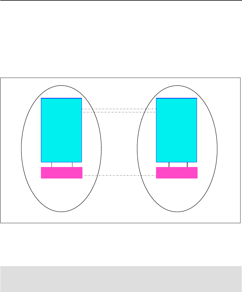
10 IBM System Storage DS6000 Series: Copy Services with IBM System z
================================================================
2107_75ABTV1/V2 IBM.2107-75ABTV0 9A2 5005076303FFFE63 On
dscli> lssi
Date/Time: 13 November 2005 19:25:34 IBM DSCLI Version: 5.1.0.204
Name ID Storage Unit Model WWNN State ESSNet
============================================================================
- IBM.2107-75ABTV1 IBM.2107-75ABTV0 9A2 5005076303FFC663 Online Enabled
- IBM.2107-75ABTV2 IBM.2107-75ABTV0 9A2 5005076303FFCE63 Online Enabled
2.1.4 What is a Storage Complex?
A Storage Complex can be one or two DS8000 Storage Units managed by one or two DS
HMCs. A Storage Complex could also be one or two DS6000 Storage Units, managed by one
or two DS SMCs. In Figure 2-1, you see a logical view of two Storage Complexes, each with
one DS6000 Storage Unit. They are running Remote Mirror and Copy. Now, because the two
DS SMCs are linked by Ethernet, you could use the DS GUI to connect to either DS SMC and
manage Copy Services on both DS6000s.
Figure 2-1 Logical view of a Storage Complex
Currently, for the DS8000 and DS6000, you can manage two Storage Units in one Storage
Complex. For ESS 800, you can manage up to eight ESS 800s in a single ESS Copy
Services domain.
Note: Only servers of the same type, like 2107, can be in the same Storage Complex.
However, Storage Complexes with different server types can be joined together. For
example, a DS8000 Storage Complex and a DS6000 Storage Complex can be connected.
Remote Mirror Copy links
Storage
Complex 1
Storage
Complex 2
Ethernet link
DS6000
DS SMC
DS6000
DS SMC
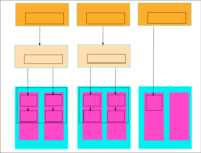
Chapter 2. Copy Services architecture 11
2.2 How the new structure of Copy Services works
With the exception of System z commands (see “System z communication path for Copy
Services” on page 13), communication to a DS6000 or DS8000 needs an available DS SMC
or DS HMC. See Figure 2-2.
Figure 2-2 Network Interface communication structure
DS8000 management structure
In Figure 2-2, you can see that:
The client uses either the DS CLI or a Web browser GUI to issue commands to the
Network Interface Server running on the DS HMC.
The Network Interface Server software on the HMC communicates with the Client.
The Network Interface Server software communicates with the Network Interface Node,
which resides on each server of an SFI. From this point, the network interface talks to the
microcode, which operates the DS8000.
1750 DS6000 management structure
In Figure 2-2, you can see that:
The client uses either the DS CLI or a Web browser GUI to issue commands to the
Network Interface Server running on the DS SMC.
The DS Network Interface Server software runs on the DS SMC. This is what the client
client communicates with.
DS SMC
Client
DS CLI or
Web browser
DS HMC
Network Interface
Server
Client
DS CLI or
Web browser
Client
DS CLI or
Web browser
Network Interface
Server
ESS800
Processor
complex2
Processor
complex1
DS8000
Processor
complex2
Processor
complex1
Micro
code
DS6000
Controller 0 Controller 1
Network
Interface
Node
Micro
code
Micro
code
Micro
code
SFISFI
Network
Interface
Node
Network
Interface
Node
Network
Interface
Node
Network
Interface
Node
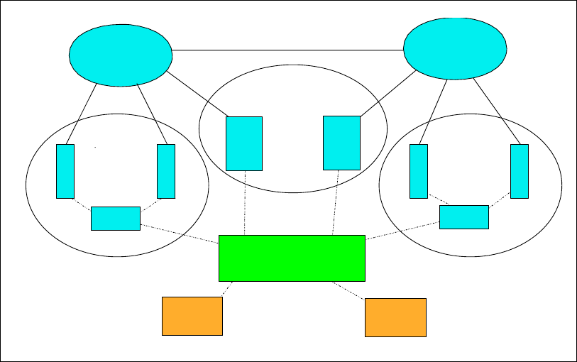
12 IBM System Storage DS6000 Series: Copy Services with IBM System z
The Network Interface Server software communicates with the Network Interface Node,
which resides on each controller of the DS6000. From this point, the Network Interface
then interacts with the microcode that operates the controllers.
2105 ESS 800 management structure
In Figure 2-2 on page 11, you can see that:
The client uses either DS CLI or a ESS Copy Services Web browser GUI to issue
commands to the ESS 800 Copy Services Server running on an ESS 800 cluster. The
client could also use the DS GUI to issue commands to the ESS 800 Copy Services
Server if a DS6000 SMC or DS8000 HMC is available to route them through (not shown in
the diagram).
The ESS 800 Copy Services Server then interacts with the microcode, which operates the
ESS 800.
2.2.1 Remote Mirror and Copy between Storage Complexes
It is possible to use Remote Mirror and Copy between Storage Complexes as depicted in
Figure 2-3. In this scenario, there are three Storage Complexes. The complexes are
connected at the top of the chart by SAN connections (solid lines) and at the bottom of the
chart by an Ethernet LAN (dashed lines).
Figure 2-3 Remote Mirror and Copy between Storage Complexes
2.2.2 Differences between the DS CLI and the DS GUI
The DS CLI cannot manage several domains in a single session. However, if a single DS CLI
client machine has network access to all Storage Complexes, then that client could issue
concurrent DS CLI commands to each complex, each of which would be managed by a
separate DS CLI session. The DS CLI can be script driven and scripts can be saved.
Therefore, by using DS CLI, you can achieve automation.
Client 1 Client 2
Storage
Complex
1
DS6000
ESS
800
ESS
800
LAN
Storage
Complex
2
SAN A SAN B
DS6000
SMC1
HMC1
DS8000
DS8000
ESS Copy
Services
Domain
(Complex 3)
Chapter 2. Copy Services architecture 13
The DS GUI is accessed with a Web browser. The DS GUI cannot save tasks (unlike the
ESS, which can), and you cannot use the DS GUI to initiate a series of saved tasks. Instead,
you must use the DS CLI. If you wish to use a single GUI to manage multiple Storage
Complexes, then, in the GUI, you must define all of the Storage Complexes. This definition
allows you to manage FlashCopy or Remote Mirror and Copy on, or between, every Storage
Unit in every defined and accessible Storage Complex.
When you look at the structure in Figure 2-2 on page 11, you can see that you need a
working DS SMC or DS HMC in every Storage Complex to communicate with the DS6000 or
DS8000 for that complex. For an inter-Storage Complex Remote Mirror and Copy, the DS
GUI establishes sessions to the source and targets Storage Complexes to show all paths and
LUNS. If no DS HMC or DS SMC is available at the remote Storage Complex, you cannot
select this Storage Complex as a target.
It is possible to have two SMCs or two HMCs in a Storage Complex for the purpose of
redundancy.
2.3 System z communication path for Copy Services
In a z/OS environment, you can issue Copy Services commands to the DS6000 and DS8000
via inband communication. This is done by sending commands via a FICON® (or ESCON® in
the case of DS8000) host link to a conduit CKD volume. From there it gets passed to the
microcode for execution. This is exactly the same as what is done with an ESS 800.
Depending on the operating system, various software packages are available to issue
commands; examples include TSO or ICKDSF.
The ability to send inband commands does not necessarily mean that the DS CLI or DS GUI
do not have a role to play. To be able to issue a command to a DS6000 or DS8000, a System
z operating system needs to be able to communicate with the relevant Storage Unit. We may
have a remote Storage Unit that is not connected via FICON (or ESCON in the case of a
DS8000) to an active z/OS. This means we would not be able to access a conduit CKD
volume on the remote Storage Unit. Now, provided we have TCP/IP connectivity and an
appropriate management station (such as a Windows host with a Web browser or DS CLI
installed), we could use the DS CLI or the DS GUI to manage the remote Storage Unit. We
could then use inband commands to manage the local Storage Unit. If the remote and local
Storage Units were connected by RMC links, then we could also send some commands
inband via the RMC links, such as commands to establish FlashCopies of the remote RMC
target volumes.
14 IBM System Storage DS6000 Series: Copy Services with IBM System z

© Copyright IBM Corp. 2006. All rights reserved. 15
Part 2 Interfaces
In this part we discuss the interfaces available to manage the Copy Services features of the
DS6000. We give an overview of the interfaces, discuss the options available, discuss
configuration considerations, and give some usage examples of the interfaces.
Part 2
16 IBM System Storage DS6000 Series: Copy Services with IBM System z

© Copyright IBM Corp. 2006. All rights reserved. 17
Chapter 3. DS Storage Manager
This chapter is an introduction to the IBM System Storage DS™ Storage Manager, which can
be used to configure and administer the DS storage system. The DS Storage Manager is an
interface that is used to perform logical configurations, service, Copy Services management,
and firmware upgrades.
The topics covered in this chapter are:
System and hardware requirements
Installation modes
Connecting to your DS6000 SMC
Real-time and simulated configuration
Accessing the Information Center
Managing the Storage Complex
3

18 IBM System Storage DS6000 Series: Copy Services with IBM System z
3.1 System and hardware requirements
The DS Storage Manager is a Web-based graphical user interface (GUI) that is used to
perform logical configuration and Copy Services management functions. It can be accessed
with a Web browser from any location that has network access to the DS management
console.
The DS Storage Manager software must be installed on a user-provided computer. We refer
to this computer as the DS Storage Management Console (SMC).
Because the DS Storage Manager is required to manage the DS6000, to perform Copy
Services operations, or to allow remote service, the DS SMC computer must always be on.
A management console is the configuration, service, and management portal for the DS6000
series. You must have a computer to use as the management console and this computer
must meet the following minimum set of hardware and operating system compatibility
requirements:
1.4 GHz Pentium® 4
256 KB cache
512 MB memory
1 GB disk space for the DS Storage Manager software
1 GB work space per managed Integrated RAID Controller (IRC)
IP Network connectivity to each RAID controller card
It is also useful to have:
IP network connectivity to an external network to enable remote support
Serial connectivity to the DS6000
3.1.1 Supported operating systems
The SMC is supported by the following operating systems:
Microsoft® Windows 2000
Microsoft Windows 2000 Server
Microsoft Windows XP Professional
Microsoft Windows 2003 Server
Supported browsers
The currently supported browsers for accessing the DS Storage Manager are:
Internet Explorer® 6.X
Netscape 6.2
Netscape 7.X
3.2 Installation modes
Install the DS Storage Manager using a graphical or silent mode for the Windows operating
systems. Access it using a Web browser from any location that has network access.
Note: For the most recent information about currently supported operating systems, refer
to the IBM System Storage DS6000 Information Center Web site at:
http://publib.boulder.ibm.com/infocenter/ds6000ic/index.jsp
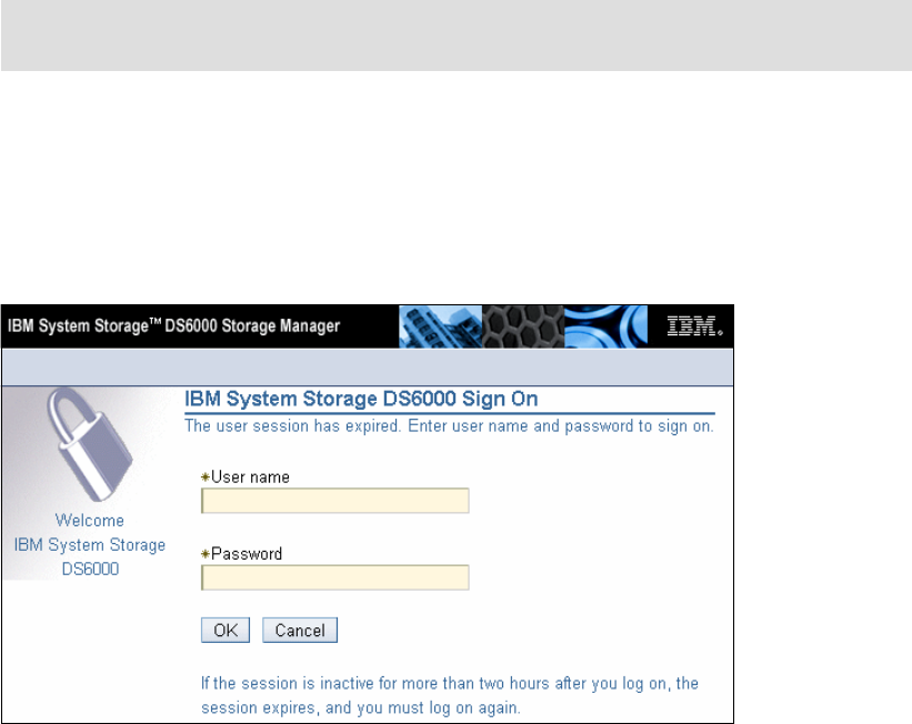
Chapter 3. DS Storage Manager 19
You can choose to install DS Storage Manager on the Windows operating system with either
of the graphical mode or the unattended mode:
The graphical mode allows you to use an online wizard that guides you through the
installation process providing prompts and information necessary to complete the
installation.
The unattended mode (also called silent mode) allows you to customize a response file
and issue a command to complete the installation process.
After you have installed the DS6000 Storage Manager, the following results occur:
The DS Storage Manager server and the IBM System Storage DS Network Interface
server are activated. These servers are set to automatic startup, so that when you start
your computer, these servers are automatically started as Windows services.
The DS Storage Manager application, which includes the real-time and simulated
manager components, is activated. These components can both be installed on the same
server and are integrated into the user interface. They are designed to help you create
and manage the physical and logical configurations of your Storage Complexes and
Storage Units. Also, the real-time manager application provides you the opportunity to use
the Copy Services features that you have purchased.
3.3 Connecting to your DS6000 SMC
To connect to the DS6000 SMC from the browser, enter the Web site address (URL) of the
PC or the DS SMC that you have purchased. The Web site consists of the TCP/IP address as
shown in Figure 3-1, or a fully qualified name that the DNS server can resolve.
Figure 3-1 Connecting to a DS6000 with a Web browser
If, for example, your SMC IP address is 10.0.0.1 and you connect to http://10.0.0.1, you will
not get a successful connection. This is because the DS Storage Manager is accessible by
connecting to either:
http://10.0.0.1:8451/DS6000
https://10.0.0.1:8452/DS6000
Note: To see the complete installation process in detail, refer to IBM System Storage
DS6000: Installation, Troubleshooting, and Recovery Guide, GC26-7924.
20 IBM System Storage DS6000 Series: Copy Services with IBM System z
Clearly, you should change the IP address to match the one used by your SMC. If you are
actually working on the SMC PC itself, you can also use 127.0.0.1 since this is the loopback
address that connects to the local PC.
Logging in to the DS Storage Manager requires that you provide your user ID and password.
This function is generally administered through your system administrator and by your
company policies. The preconfigured user ID and password are as follows:
User ID: admin
Password: admin
When you log on to the SMC for the first time using the admin user ID, you must change the
password from admin to something more secure.
3.3.1 Real-time and simulated configuration
You have the following options to access the DS Storage Manager:
Simulated (offline) manager
This application allows you to create or modify logical configurations when disconnected
from the network. After creating an initial configuration, you can save it and then apply it to
a new or unconfigured Storage Unit at a later time. However, you cannot use the
Simulated manager to perform any type of Copy Services configuration. You must perform
Copy Services configuration from the Real-time manager.
Real-time (online) manager
This provides real-time management support for logical configuration and Copy Services
functions to a DS6000 Storage Unit.
3.3.2 Advantages of using the DS GUI over the DS CLI or TSO
The DS Storage Manager GUI has the following advantages for managing Remote Mirror and
Copy functions:
It requires less specialized skills for effective use.
It is a real-time graphical interface for the DS6000 subsystem, which may present
information more easily to some users.
You do not need to install anything on your PC in order to manage Copy Services: a
simple Web browser pointed to the DS SMC is enough.
3.3.3 Disadvantages of using the DS GUI over the DS CLI or TSO
The DS Storage Manager GUI has the following disadvantages for managing Remote Mirror
and Copy functions:
You cannot perform all supported functions from this interface.
You cannot use this interface for automated actions.
You cannot save your actions and reuse them later.
You still must understand the implications of the actions you are performing (for example, you
need to understand that a FlashCopy overwrites the target LUN or volume).
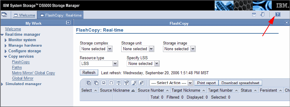
Chapter 3. DS Storage Manager 21
3.4 Accessing the Information Center
The Software Information Center provides product or application information and a GUI for
browsing and searching online documentation. The broad range of topics covered includes
accessibility, Copy Services, device storage, host system attachments, concurrent code
loads, input/output configuration programs, and volume storage.
Accessing the Information Center directly
You can connect to the Information Center directly using a Web browser. If your SMC IP
address is 10.0.0.1 then you can access the Information Center running on that SMC at:
http://10.0.0.1:8455
If you are locally logged onto the SMC then you can also use:
http://127.0.0.1:8455
To access the public version of the DS6000 Information Center, go to:
http://publib.boulder.ibm.com/infocenter/ds6000ic/index.jsp
Accessing the Information Center using the help symbol
The help panels are accessed by selecting the? symbol on the right side of the panel, which
is indicated by the arrow in Figure 3-2.
Figure 3-2 Help option location
The help panel opens on the current subject of the configuration panel. In Figure 3-3, the help
was called from the FlashCopy main page, so the help for that page opened.
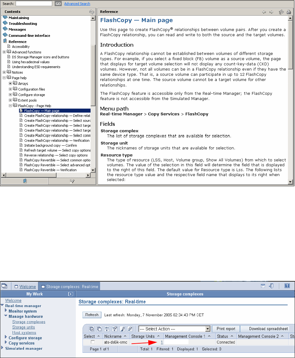
22 IBM System Storage DS6000 Series: Copy Services with IBM System z
Figure 3-3 FlashCopy help Main page
3.5 Managing the Storage Complex
When you install the DS Storage Manager software on a PC, a Storage Complex is
automatically created. You can then add up to two DS6000s to the Storage Complex. Each
DS6000 is a Storage Unit. Because an SMC can manage two DS6000s, a single Storage
Complex could consist of one SMC and two DS6000s. Figure 3-4 shows how we connected
to the Storage Complex managed by the SMC at the 10.0.0.1 IP address.
Figure 3-4 A single Storage Complex with a single Storage Unit
This complex consists of one Storage Unit, as indicated by the arrow.
A simple scenario might involve two sites. At the production site, there is a single DS6000
managed by its own SMC. Then, at a remote site a second DS6000 is managed by its own
10.0.0.1
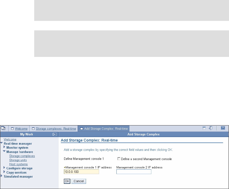
Chapter 3. DS Storage Manager 23
SMC. There is Ethernet connectivity between the sites. Because each SMC manages only
the DS6000 at its own site, this means there are two Storage Complexes. To use a single
GUI to manage Copy Services at either site, then you must add these Storage Complexes to
each other. Once you have done this, you can use one SMC to manage Copy Services on
either Storage Unit at either site. We can also use one SMC to set up Copy Services relations
between the two sites.
3.5.1 Procedure to add a Storage Complex
This section describes the procedure for adding a Storage Complex.
To add a Storage Complex:
1. Connect to the DS6000 SMC using the DS GUI.
2. Click Real-time manager.
3. Click Manage hardware.
4. Click Storage complexes.
5. Select Add Storage Complex and click Go.
Figure 3-5 on page 23 shows the Add Storage Complex panel.
Figure 3-5 Add Storage Complex panel
6. Type the IP address of the SMC for the other Storage Complex in the Management
console 1 IP address field. If the other Storage Complex has a second SMC, select Define
a second Management console box and type the second SMC address into the
Management console 2 IP address box. Click OK.
7. After the add Storage Complex operation is complete, the Storage Complex panel shows
the DS6000 SMC as an additional Storage Complex. In Figure 3-6, you can see the
successful addition of a second Storage Complex that manages two Storage Units.
Note: To use either SMC to manage the Storage Units of the other you must do this
operation once in each direction, that is, you must add Complex1 to Complex2 and then
add Complex2 to Complex1.
Important: Make sure the user ID you use to log on to the DS6000 DS GUI also exists on
the other DS6000 SMC and that it has the same password. If not, the operation to add the
Storage Complex will fail. You will need to always use this same user ID for multi-complex
management.
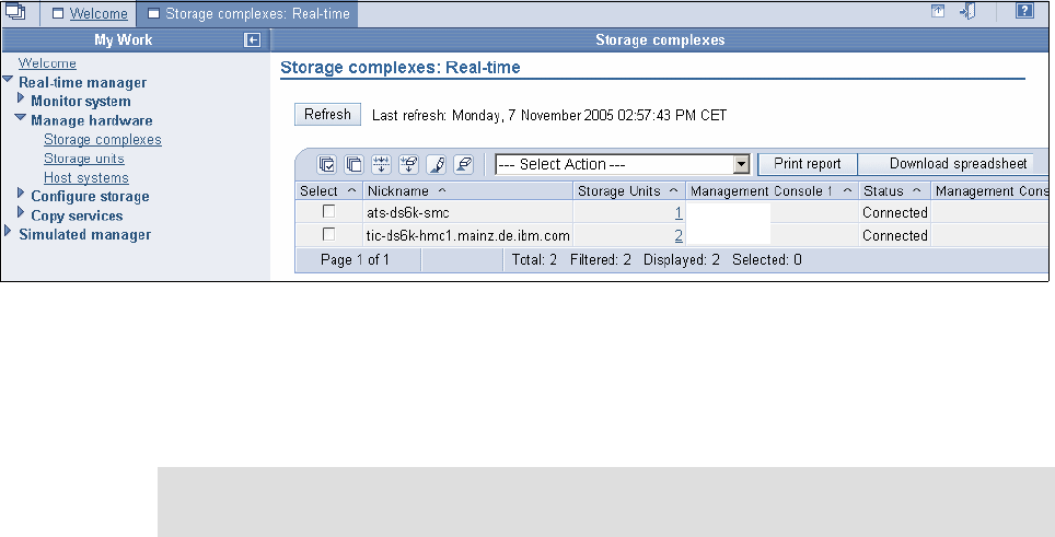
24 IBM System Storage DS6000 Series: Copy Services with IBM System z
Figure 3-6 Successful addition of a Storage Complex
8. Having added one DS6000 Storage Complex to another, you can use the DS6000 DS
GUI to create paths and Remote Mirror and Copy pairs between any of the Storage Units.
You can also use the DS6000 DS GUI to manage FlashCopy pairs on any DS6000. This
is all assuming the relevant licenses are present.
10.0.0.1
10.0.0.100
Note: The steps to add one DS6000 Storage Complex to another DS6000 Storage
Complex cannot be performed with the DS CLI.

© Copyright IBM Corp. 2006. All rights reserved. 25
Chapter 4. DS Command-Line Interface
This chapter provides an introduction to the DS Command-Line Interface (DS CLI), which can
be used to configure and administer the DS6000 storage systems. It describes how it can be
used to manage Copy Services relationships.
In this chapter we describe:
System requirements
Command modes
List of the commands
User assistance
Return codes
4

26 IBM System Storage DS6000 Series: Copy Services with IBM System z
4.1 Introduction and functionality
The IBM System Storage DS Command-Line Interface (DS CLI) enables open systems hosts
to invoke and manage FlashCopy and Remote Mirror and Copy functions through batch
processes and scripts.
While there is no support for z/OS as a server for the DS CLI, you can use the DS CLI from a
supported server to control and manage Copy Services functions on z/OS volumes.
The DS CLI provides a full-function command set that you can use to check your Storage Unit
configuration and perform specific application functions when necessary.
Before you can use the DS CLI commands, you must ensure the following:
The DS SMC must have been installed as a Full Management Console installation
management type.
You must configure your Storage Unit (part of the DS Storage Manager post-installation
instructions).
You must activate your license activation codes before you can use the DS CLI
commands associated with Copy Services functions.
The following list highlights a few of the specific types of functions that you can perform with
the DS CLI:
Create user IDs that can be used with the GUI and the DS CLI.
Manage user ID passwords.
Install activation keys for licensed features.
Manage Storage Complexes and Units.
Configure and manage Storage Facility Images.
Create and delete RAID arrays, Ranks, and Extent Pools.
Create and delete logical volumes.
Manage host access to volumes.
Check the current Copy Services configuration that is used by the Storage Unit.
Create, modify, or delete Copy Services configuration settings.
4.2 Supported operating systems for the DS CLI
The DS CLI can be installed on these operating systems:
IBM AIX 5.1, 5.2, 5.3
HP-UX 11.0, 11i v1, v2
HP-True64 5.1, 5.1A
Linux (RedHat 3.0 Advanced Server (AS) and Enterprise Server (ES))
SUSE Linux SLES 8, SLES 9, SUSE 8, SUSE 9
System i system i5/OS 5.3
Novell NetWare 6.5
Sun™ Solaris 7, 8, 9
Windows 2000, Windows Datacenter, Windows 2003, Windows XP
Note: Most z/OS environments choose to use one of the z/OS interfaces to manage their
volumes. You may choose to use the DS CLI, if you are also managing open systems
volumes and want to use a single interface. However, with recent changes to TSO
commands to enable control of open systems Copy Services functions, you may choose to
use the TSO commands to manage both z/OS and open systems volumes.

Chapter 4. DS Command-Line Interface 27
The DS CLI is supplied and installed via a CD that ships with the machine. The installation
does not require a reboot of the open systems host. The DS CLI requires Java™ 1.4.1 or
higher. Java 1.4.2 for Windows, AIX, and Linux is supplied on the CD. Many hosts may
already have a suitable level of Java installed. The installation program checks for this
requirement during the installation process and does not install DS CLI, if you do not have the
correct version of Java.
The installation process can be performed via a shell, such as the bash or Korn shell, or the
Windows command prompt, or via a GUI interface. If performed via a shell, it can be
performed silently using a profile file. The installation process also installs software that
allows the DS CLI to be completely de-installed should it no longer be required.
If you need any assistance to install the DS CLI, refer to IBM System Storage DS6000:
Command-Line Interface User´s Guide, GC26-7922.
4.3 User accounts
The administrator account is set up automatically at the time of installation. It is accessed with
the admin user ID and the default admin password. This password is temporary; you must
change the password before you can use any of the other functions. There are seven groups
the administrator can assign to a user. The groups and the associated functions allowed by
the assignment are as follows:
admin: Allows access to all storage management console server service methods and all
Storage Image resources
op_volume: Allows access to service methods and resources that relate to logical
volumes, Hosts, Host Ports, logical subsystems, and Volume Groups, excluding security
methods
op_storage: Allows access to physical configuration service methods and resources,
including Storage Complex, Storage Image, Rank, Array, and Extent Pool objects
op_copy_services: Allows access to all Copy Services service methods and resources,
excluding security methods
service: Monitors authority and access to all management console server service methods
and resources, such as performing code loads and retrieving problem logs
monitor: Allows access to list and show commands. It provides access to all read-only,
non-security management console server service methods and resources
no access: Does not allow access to any service method or Storage Image resources. By
default, this user group is associated to any user account in the security repository that is
not associated with any other user group
Note: The DS CLI cannot be installed on a Windows 64-bit operating system.
Important: For the most recent information about currently supported operating systems,
refer to the IBM System Storage DS6000 Information Center Web site at:
http://publib.boulder.ibm.com/infocenter/ds6000ic/index.jsp

28 IBM System Storage DS6000 Series: Copy Services with IBM System z
4.4 DS CLI profile
You can create default settings for the DS CLI by defining one or more profiles on the system.
For example, you can specify the SMC for the session, specify the output format for list
commands, specify the number of rows per page in the DS CLI output, and specify that a
banner is included with the DS CLI output.
If a user enters a value with a command that is different from a value in the profile, the
command overrides the profile.
You have several options for using profile files:
You can modify the default profile. The default profile, dscli.profile, is installed in the profile
directory with the software. For example, c:\Program Files\IBM\DSCLI\profile\dscli.profile
for the Windows platform and /opt/ibm/dscli/profile/dscli.profile for UNIX® and Linux
platforms.
You can make a personal default profile by making a copy of the system default profile as
<user_home>/dscli/profile/dscli.profile. The home directory, <user_home> is designated
as follows:
– Windows system: C:\Documents and settings\<user_name>
– UNIX/Linux system: /home/<user_name>
You can create a profile for the Storage Unit operations. Save the profile in the user profile
directory. Two examples are:
– c:\Program Files\IBM\DSCLI\profile\operation_name1
– c:\Program Files\IBM\DSCLI\profile\operation_name2
These profile files can be specified using the DS CLI command parameter -cfg
<profile_name>. If the -cfg file is not specified, the user’s default profile is used. If a user’s
profile does not exist, the system default profile is used.
When you install the command-line interface software, the default profile is installed in the
profile directory with the software. The file name is dscli.profile; for example. c:\Program
Files\IBM\DSCLI\profile\dscli.profile.
The available variables, detailed descriptions, and information about how to handle them can
be found in IBM System Storage DS6000: Command-Line Interface User´s Guide,
GC26-7922.
Note: A user can be assigned to more than one user group.
Important: When a new user is created, the password that was initially set automatically
expired and must be changed when the user first logs on.
Attention: The default profile file that is created when you install the DS CLI might be
replaced every time that you install a new version of the DS CLI. It is a better practice to
open the default profile and then save it as a new file. You can then create multiple profiles
and reference the relevant profile file with the -cfg parameter.
Note: A password file, generated using the managepwfile command is located at the
following directory: <user_home>/dscli/security/security.dat.

Chapter 4. DS Command-Line Interface 29
4.5 Command structure
This is a description of the components and structure of a Command-Line Interface
command.
A Command-Line Interface command consists of one to four types of components, arranged
in the following order:
1. The command name: Specifies the task that the Command-Line Interface is to perform.
2. Flags: Modify the command. They provide additional information that directs the
Command-Line Interface to perform the command task in a specific way.
3. Flags parameter: Provides information that is required to implement the command
modification that is specified by a flag.
4. Command parameters: Provides basic information that is necessary to perform the
command task. When a command parameter is required, it is always the last component
of the command, and it is not preceded by a flag.
4.6 Copy Services commands
We can classify the commands available with the DS CLI as follows:
1. ls commands: Give you brief information about the copy services state. See Table 4-1.
2. show commands: Give you detailed information about the copy services state. See
Table 4-2.
3. mk commands: Used to create relationships. See Table 4-3.
4. rm commands: Used to remove relationships. See Table 4-4.
5. options commands: Used to modify some options in relationships, that were previously
created. See Table 4-5 on page 30.
Table 4-1 List commands
Table 4-2 List detailed commands
Command Description
lsflash Lists of FlashCopy relationships
lsremoteflash Lists of Remote FlashCopy relationships (inband)
lspprc Lists of Remote Mirror and Copy volumes relationships
lspprcpath Lists of existing Remote Mirror and Copy path definition
lsavailpprcport Lists available ports that can be defined as Remote Mirror and Copy
lssession Displays a list of Global Mirror sessions for a LSS
Command Description
showgmir Displays detailed properties and performance metrics for Global Mirror
showgmircg Displays Consistency Group status for a Global Mirror session
showgmiroos Displays the number of unsynchronized (out of sync) tracks for a Global Mirror session

30 IBM System Storage DS6000 Series: Copy Services with IBM System z
Table 4-3 Creation commands
Table 4-4 Deletion commands
Table 4-5 Options commands
Command Description
mkflash Initiates a point-in-time copy from a source to a target volume
mkremoteflash Initiates a remote copy through a Remote Mirror and Copy relationship
mkgmir Starts Global Mirror for a session
mkpprc Establishes a Remote Mirror and Copy relationship
mkpprcpath Establishes or replaces a Remote Mirror and Copy path over a Fibre Channel
mkesconpprcpath Creates a Remote Mirror and Copy path over an ESCON connection
mksession Opens a Global Mirror for a session
Command Description
rmflash Removes a relationship between FlashCopy pairs
rmremoteflash Removes a relationship between remote FlashCopy pairs
rmgmir Removes Global Mirror for the specified session
rmpprc Removes a Remote Mirror and Copy relationship
rmpprcpath Removes a Remote Mirror and Copy path
rmsession Closes an existing Global Mirror session
Command Description
commitflash Commits data to a target volume to form a consistency between the source and target
resyncflash Incremental FlashCopy process
reverseflash Reverse the direction of a FlashCopy pair
revertflash Overwrites new data with data saved at the last consistency formation
setflashrevertible Modifies a remote FlashCopy pair that is part of a Global Mirror to revertible
commitremoteflash Commit data to a target volume to form a consistency (inband)
resyncremoteflash Incremental FlashCopy process (inband)
revertremoteflash Overwrites new data with data saved at the last consistency formation (inband)
setremoteflashrevertible Modifies a remote FlashCopy pair that is part of a Global Mirror to revertible (inband)
unfreezeflash Resets a FlashCopy Consistency Group
failoverpprc Changes a secondary device into a primary suspended and keep the primary in current
failbackpprc Usually used after a failoverpprc to reverse the direction of the synchronization
freezepprc Creates a new Remote Mirror and Copy Consistency Group
pausepprc Pauses an existing Remote Mirror and Copy volume pair relationship
resumepprc Resumes a Remote Mirror and Copy relationship for a volume pair

Chapter 4. DS Command-Line Interface 31
4.7 Using the DS CLI application
You have to log into the DS CLI application to use the command modes. There are three
command modes for DS CLI:
Single-shot mode
Interactive mode
Script mode
4.7.1 Single-shot mode
Use the DS CLI single-shot command mode if you want to issue an occasional command, but
do not want to keep a history of the commands that you have issued.
You must supply the login information and the command that you want to process at the
same time. Use the following example for the single-shot mode:
1. Enter dscli -HMC1 <hostname or ip address> -user <user name> -passwd <pwd>
<command>
2. Wait for the command to process and display the results.
Example 4-1 shows the use of the single-shot command mode.
Example 4-1 Single-shot command mode
C:\Program Files\ibm\dscli>dscli -HMC1 10.10.10.1 -user admin -passwd adminpwd
lsuser
Date/Time: 24 de Maio de 2005 14h38min20s BRT IBM DSCLI Version: X.X.X.X
Name Group State
=====================
admin admin locked
admin admin active
exit status of dscli = 0
unfreezepprc Thaws an existing Remote Mirror and Copy Consistency Group
pausegmir Pauses a Global Mirror processing for a session
resumegmir Resumes a Global Mirror processing for a session
chsession Allows to modify a Global Mirror session
Command Description
Important:
The Remote Mirror and Copy commands are asynchronous. This means that the
command is issued to the DS CLI server and if it is accepted successfully, you receive
a successful completion code; however, background activity may still be occurring. For
example, a Metro Mirror pair will take some time to establish, as the tracks need to be
copied across from the primary to the secondary device. In this example, you should
check the state of the volumes using the lspprc command until the pairs have reached
the Duplex state.
The mkflash and mkpprc commands offer the -wait flag, which delays command
response until copy complete status is achieved. You may choose to use this flag, if
you want to be sure of successful completion.

32 IBM System Storage DS6000 Series: Copy Services with IBM System z
4.7.2 Script command mode
Use the DS CLI script command mode, if you want to use a sequence of DS CLI commands.
Administrators can use this mode to create automated processes, for example, establishing
Remote Mirror and Copy relationships for volume pairs.
You can issue the DS CLI script from the command prompt at the same time that you provide
your login information:
1. Enter dscli -HMC1 <hostname or ip address> -user <user name> -passwd <pwd>
-script <full path of script file>
2. Wait for the script to process and provide a report regarding the success or failure of the
process.
Example 4-2 shows the use of the script command mode.
Example 4-2 Script command mode
C:\Program Files\ibm\dscli>dscli -HMC1 10.10.10.1 -user admin -passwd adminpwd
-script c:\test.cli
Date/Time: 24 de Maio de 2005 14h40min22s BRT IBM DSCLI Version: X.X.X.X DS: IBM
IBM.1750-1367890
ID WWPN State Type topo portgrp
===============================================================
I0000 500507630E01FC00 Online Fibre Channel-LW SCSI-FCP 0
I0001 500507630E03FC00 Online Fibre Channel-LW - 0
I0002 500507630E05FC00 Online Fibre Channel-LW SCSI-FCP 0
I0003 500507630E07FC00 Online Fibre Channel-LW - 0
I0100 500507630E81FC00 Online Fibre Channel-LW SCSI-FCP 0
I0101 500507630E83FC00 Online Fibre Channel-LW - 0
I0102 500507630E85FC00 Online Fibre Channel-LW SCSI-FCP 0
I0103 500507630E87FC00 Online Fibre Channel-LW - 0
Date/Time: 24 de Maio de 2005 14h40min36s BRT IBM DSCLI Version: X.X.X.X
Name ID Storage Unit Model WWNN State ESSNet
============================================================================
- IBM.1750-1312345 IBM.1750-1312345 511 500507630EFFFC6F Online Enabled
exit status of dscli = 0
4.7.3 Interactive mode
Use the DS CLI interactive command mode when you have multiple transactions to process
that cannot be incorporated into a script. The interactive command mode provides a history
function that makes repeating or checking prior command usage easy to do.
1. Log on to the DS CLI application at the directory where it is installed.
Note: When logging in to the DS CLI, you can use the hostname or the IP address of the
DS SMC.
Attention: The DS CLI script can contain only DS CLI commands. Using shell commands
results in process failure. You can add comments to the scripts prefixed by the number
sign (#).
When logging in to the DS CLI, you can use the host name or the IP address of the DS
SMC.

Chapter 4. DS Command-Line Interface 33
2. Provide the information that is requested by the information prompts. The information
prompts might not appear, if you have provided this information in your profile file. The
command prompt switches to a dscli command prompt.
3. Begin using the DS CLI commands and parameters. You are not required to begin each
command with dscli, because this prefix is provided by the dscli command prompt.
Example 4-3 shows the use of interactive command mode.
Example 4-3 Interactive command mode
C:\Program Files\ibm\dscli>dscli
Enter your username: admin
Enter your password:
Date/Time: 24 de Maio de 2005 14h42min17s BRT IBM DSCLI Version: X.X.X.X DS:
IBM.1750-1312345
.
dscli> lsarraysite
Date/Time: 24 de Maio de 2005 15h8min57s BRT IBM DSCLI Version: X.X.X.X DS: IBM.
1750-1312345
arsite DA Pair dkcap (Decimal GB) State Array
================================================
S1 0 146.0 Assigned A0
S2 0 146.0 Assigned A0
S3 0 146.0 Assigned A1
S4 0 146.0 Assigned A1
.
dscli> lssi
Date/Time: 24 de Maio de 2005 14h42min59s BRT IBM DSCLI Version: X.X.X.X
Name ID Storage Unit Model WWNN State ESSNet
============================================================================
- IBM.1750-1312345 IBM.1750-1312345 511 500507630EFFFC6F Online Enabled
dscli> quit
exit status of dscli = 0
4.8 Return codes
When the DS CLI is exited, the exit status code is provided. This is effectively a return code. If
DS CLI commands are issued as separate commands (rather than using script mode), then a
return code will be presented for every command. If a DS CLI command fails (for instance
due to a syntax error or the use of an incorrect password), then a failure reason and a return
code will be presented. Standard techniques to collect and analyze return codes can be used.
The return codes used by the DS CLI are shown in Table 4-6.
Table 4-6 Return code table
Note: When logging in to the DS CLI, you can use the host name or the IP address of the
DS SMC.
Return code Category Description
0 Success The command was successful.
2 Syntax error There is a syntax error in the command.
3 Connection error There was a connection problem to the server.

34 IBM System Storage DS6000 Series: Copy Services with IBM System z
4.9 User assistance
The DS CLI is designed to include several forms of user assistance. The main form of user
assistance is accessed from the help command, such as:
help
Lists all available DS CLI commands.
help -s
Lists all DS CLI commands with a brief description of each.
help -l
Lists all DS CLI commands with syntax information.
If you are interested in more details about a specific DS CLI command, you can use -l (long)
or -s (short) against a specific command. In Example 4-4, the -s parameter is used to obtain
a short description of the purpose of the mkflash command.
Example 4-4 Use of the help -s command
dscli> help -s mkflash
mkflash The mkflash command initiates a point-in-time copy from source volumes to target
volumes.
In Example 4-5, the -l parameter is used to obtain a list of all parameters that can be used
with the mkflash command.
Example 4-5 Use of the help -l command
dscli> help -l mkflash
mkflash [ { -help|-h|-? } ] [-dev storage_image_ID] [-tgtpprc] [-tgtoffline] [-t
gtinhibit] [-freeze] [-record] [-persist] [-nocp] [-wait] [-seqnum Flash_Sequenc
e_Num] SourceVolumeID:TargetVolumeID ... | -
Man pages
A man page is available for every DS CLI command. Man pages are most commonly seen in
UNIX-based operating systems to give information about command capabilities. This
information can be displayed by issuing the relevant command followed by -h, -help, or -?,
for example:
dscli> mkflash -help
or
dscli> help mkflash
4 Server error The DS CLI server had an error.
5 Authentication error Password or user ID details are incorrect.
6 Application error The DS CLI application had an error.
Return code Category Description

Chapter 4. DS Command-Line Interface 35
4.10 Usage examples
It is not the intent of this section to list every DS CLI command and its syntax. If you need a
list of all the available commands or assistance with DS CLI commands, refer to IBM System
Storage DS6000: Command-Line Interface User´s Guide, GC26-7922, or you can use the
online help.
Example 4-6 shows some of the common commands used on a DS6000.
Example 4-6 Examples of DS CLI commands
# The following command establishes flashcopy pairs
dscli> mkflash -dev IBM.1750-1300861 0100-0102:0300-0302
Date/Time: April 25, 2005 5:59:56 PM IST IBM DSCLI Version: 0.0.0.0 DS: IBM.1750-1300861
CMUC00137I mkflash: FlashCopy pair 0100:0300 successfully created.
CMUC00137I mkflash: FlashCopy pair 0101:0301 successfully created.
CMUC00137I mkflash: FlashCopy pair 0102:0302 successfully created.
# The following command establishes Remote Mirror and copy paths
dscli> mkpprcpath -dev IBM.1750-1300861 -remotedev IBM.1750-1300861 -remotewwnn
5005076303FFC03D -srclss 00 -tgtlss 02 I0030:I0031 I0100:I0101
Date/Time: 18:33:22 IST April 25, 2005 IBM DSCLI Version: 0.0.0.0 DS: IBM.1750-1300861
CMUC00149I mkpprcpath: Remote Mirror and Copy path 00:02 successfully established.
# The following command establishes Remote Mirror and copy pairs
dscli> mkpprc -dev IBM.1750-1300861 -remotedev IBM.1750-1300866 -type gcp 0006:0206
Date/Time: 18:43:31 IST April 25, 2005 IBM DSCLI Version: 0.0.0.0 DS: IBM.1750-1300861
CMUC00153I mkpprc: Remote Mirror and Copy volume pair relationship 0006:0206 successfully
created.
36 IBM System Storage DS6000 Series: Copy Services with IBM System z

© Copyright IBM Corp. 2006. All rights reserved. 37
Chapter 5. System z interfaces
This chapter discusses the interfaces that are available with the System z servers for
managing DS6000 Copy Services functions.
This chapter covers the following topics:
System z interfaces
TSO
ICKDSF
DFSMSdss
The ANTRQST macro
z/TPF commands
5
38 IBM System Storage DS6000 Series: Copy Services with IBM System z
5.1 System z interfaces
In addition to using the DS GUI or the DS CLI, several possible interfaces are available to
System z users for managing DS6000 Copy Services relationships. These are:
TSO
ICKDSF
DFSMSdss
The ANTRQST macro
Native TPF commands (for z/TPF only)
These interfaces have the advantage of not having to issue their commands to the DS6000
SMC. They can instead directly send commands inband over a FICON channel connection
between the DS6000 and the System z operating system. Sending inband commands allows
for a very quick command transfer that does not depend on any additional software stacks.
5.1.1 Operating system alternatives
From an operating system point of view, the alternatives to the DS GUI and DS CLI break out
as follows:
z/OS
– TSO commands
– ICKDSF
–DFSMSdss
– ANTRQST application programming interface (API)
z/VM®:
– ICKDSF
z/VSE™
– ICKDSF
z/TPF
– ICKDSF
– z/TPF itself
5.2 TSO
TSO commands are commonly used in z/OS environments to manage all kinds of operations.
TSO commands can be generated by REXX or CLIST procedures. They can also be
generated from other software tools.
You can issue the TSO commands from procedures that are similar to the scripting approach
in open systems environments.
Note that TSO requires a z/OS system at the recovery site when you recover a z/OS Global
Mirror environment at the remote site.
For a detailed description of TSO commands for managing Copy Services, refer to z/OS
DFSMS Advanced Copy Services, SC35-0428.
Chapter 5. System z interfaces 39
5.3 ICKDSF
The System z ICKDSF utility offers a means of control for Copy Services functions. ICKDSF
is the only direct interface for z/VM and z/VSE environments.
ICKDSF typically runs as a batch program and can be automatically run from batch
scheduling products (for example Tivoli® Workload Scheduler).
More information on ICKDSF can be found in Device Support Facilities User’s Guide and
Reference, GC35-0033.
5.4 DFSMSdss
The DFSMSdss commands can be used to manage Copy Services relationships. Detailed
information can be found in z/OS DFSMSdss Storage Administration Reference SC35-0424.
5.5 The ANTRQST macro
The ANTRQST macro provides an application program call to the application programming
interface (API) of the z/OS system data mover (SDM). This macro allows you to call Metro
Mirror, z/OS Global Mirror, and FlashCopy functions.
For detailed information, see the IBM publication z/OS DFSMS Advanced Copy Services,
SC35-0428.
5.6 z/TPF commands
It is also possible to use native z/TPF commands to issue Copy Services commands. An
example is the use of the ZXCPY command to initiate a FlashCopy on a z/TPF device.
Information about using z/TPF to control Copy Services can be found at the following Web
Information Center at:
http://publib.boulder.ibm.com/infocenter/tpfhelp/current/index.jsp
40 IBM System Storage DS6000 Series: Copy Services with IBM System z

© Copyright IBM Corp. 2006. All rights reserved. 41
Part 3 FlashCopy
This part of the book describes the IBM System Storage FlashCopy for DS6000 when used in
a System z environment. We discuss the features of FlashCopy and describe the options for
its setup. We also show which management interfaces can be used, as well as the important
aspects to be considered when establishing FlashCopy relationships.
This part ends with examples showing how FlashCopy is used in the daily business to
support the various environments where immediate copies of production data is a
requirement.
Part 3
42 IBM System Storage DS6000 Series: Copy Services with IBM System z

© Copyright IBM Corp. 2006. All rights reserved. 43
Chapter 6. FlashCopy overview
FlashCopy creates a copy of a volume at a specific point-in-time, which we also refer to as a
Point-in-Time copy, instantaneous copy, or time-zero copy (t0 copy).
This chapter explains the basic characteristics of FlashCopy when used in a System z
environment with the DS6000. The following topics are discussed:
FlashCopy operational areas.
FlashCopy basic concepts.
FlashCopy in combination with other Copy Services.
Data set level FlashCopy.
6
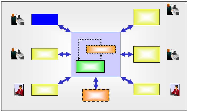
44 IBM System Storage DS6000 Series: Copy Services with IBM System z
6.1 Operational environments
It takes only a few seconds to establish the FlashCopy relationships for tens to hundreds or
more volume pairs. The copy is then immediately available for both read and write access. In
a 24x7 environment, the quickness of the FlashCopy operation allows us to use FlashCopy in
very large environments and to take multiple FlashCopies of the same volume for use with
different applications. Some of the different uses of FlashCopy are shown in Figure 6-1.
Figure 6-1 FlashCopy uses
FlashCopy is suitable for the following operational environments:
Production backup system
A FlashCopy of the production data allows data recovery from an older level of data. This
might be necessary due to a user error or a logical application error. Let’s assume that a
user deleted accidentally a customer record. The production backup system could work
with a FlashCopy of the data. The necessary part of the customer data can be exported
and then be imported into the production environment. Thus, the production continues,
and while a specific problem is being fixed, the majority of the users can work with the
application without recognizing any problems.
The FlashCopy of the data could also be used by system operations to re-establish
production in case of any server errors.
Data backup system
A FlashCopy of the production data allows the client to create backups with the shortest
possible application outage. The main reason for data backup is to provide protection in
case of source data loss due to disaster, hardware failure, software failure, or user errors.
Data mining system
A FlashCopy of the data can be used for data analysis, thus avoiding performance
impacts for the production system due to long running data mining tasks.
Test system
Test environments created by FlashCopy can be used by the development team to test
new application functions with real production data, thus speeding up the test setup
process.
Test
System
Production
System
Integration
System
Production
data
FlashCopy
Reverse
Business
Integration
Development
Production
Backup
System
System
Operation
Data
Backup
System
Data Mining
System
System
Operation
Application
Help desk
or
System
Operation
other
systems Analysis
Team

Chapter 6. FlashCopy overview 45
Integration system
New application releases (for example, SAP® releases) are likely to be tested prior to
putting them onto a production server. By using FlashCopy, a copy of the production data
can be established and used for integration tests.
With the capability to reverse a FlashCopy, a previously created FlashCopy can be used
within seconds to bring production back to the level of data it had at the time when the
FlashCopy was taken.
6.2 Terminology
When discussing Metro Mirror, Global Copy and Global Mirror, the following terms are
frequently used and interchangeable:
The terms local, production, application, primary, and source, denote the site where the
production applications run while in normal operation. These applications create, modify,
and read the data—the application data. The meaning is extended to the disk subsystem
that holds the data as well as to its components—volumes and LSS.
The terms remote, recovery, backup, secondary, and target, denote the site to where the
data is replicated—the copy of the application data. The meaning is extended to the disk
subsystem that holds the data as well as to its components—volumes and LSSs.
When discussing FlashCopy we use the term source to refer to the original data that is
created by the application. We use the term target to refer to the point-in-time backup copy.
Also, the terms LUN and volume are used interchangeably in our discussions.
6.3 Basic concepts
In a System z environment, FlashCopy can be used at volume level and at data set level.
By doing a FlashCopy, a relationship is established between a source and a target. Both are
considered to form a FlashCopy pair.
As result of the FlashCopy either all physical blocks from the source volume are copied (full
copy) or—when using the nocopy option—only those parts that are changing in the source
data since the FlashCopy was established. Currently, the target volume needs to be the
same size or bigger than the source volume whenever FlashCopy is used to flash a whole
volume.
Typically, large applications such as databases have their data spread across several
volumes; their volumes should all be FlashCopied at exactly the same point-in-time.
FlashCopy offers consistency groups, which allows multiple volumes to be FlashCopied at
exactly the same instance.
The following are basic characteristics of FlashCopy operation:
Establish FlashCopy relationship
When the FlashCopy is started, the relationship between source and target is established
within seconds. This is done by creating the necessary metadata such as a pointer table,
including a bitmap for the target.
Note: Whenever source or target is used in this chapter without further specification, it
refers to both a volume or a data set.
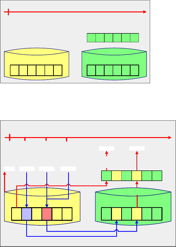
46 IBM System Storage DS6000 Series: Copy Services with IBM System z
While the FlashCopy relationship is being created, the DS6000 holds off the I/O activity to
the volume for an interval of time by putting the source volume in an extended long busy
condition. No user intervention is required. I/O activity resumes when the FlashCopy
establish process is completed.
If all bits for the bitmap representing the target are set to their initial values, this means
that no data block has been copied so far. The data in the target is not modified during
setup of the bitmaps. At this very first step the bitmap and the data look as illustrated in
Figure 6-2.
Figure 6-2 FlashCopy at time t0
Once the relationship has been established, it is possible to perform read and write I/Os
on both the source and the target. Assuming that the target is used for reads only while
production is ongoing, things will look as illustrated in Figure 6-3.
Figure 6-3 Reads from source and target volume and writes to source volume
1 1 1 111
bitmap
t t t ttt
source
data
000
target
data
000
time
t0
FlashCopy established at time t0 (time-zero)
time
Writing to the source and
reading from the source and the target
t0
1 0 1 110
bitmap
t t t ttt
data
00z t t
target
data
x000
0
write x write y
txty
read
read 1 read 2
before physical write to the source:
copy time-zero data from the source to the target
time-zero data not yet
available in the target:
read it from the source.
source
write z
tz
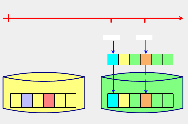
Chapter 6. FlashCopy overview 47
Reading from the source
The data is read immediately (see Figure 6-3 on page 46).
Writing to the source
Whenever data is written to the source volume while the FlashCopy relationship exists,
the storage subsystem makes sure that the time-zero-data is copied to the target volume
prior to overwriting it in the source volume.
To identify if the data of the physical block on the source volume needs to be copied to the
target volume, the bitmap is analyzed. If it identifies that the time-zero data is not available
on the target volume, then the data will be copied from source to target. If it states that the
time-zero data has already been copied to the target volume then no further action is done
(see Figure 6-3).
It is possible to use the target volume immediately—for reading data and also for writing
data.
Reading from the target
Whenever a read-request goes to the target while the FlashCopy relationship exists, the
bitmap is used to identify if the data has to be retrieved from the source or from the target.
If the bitmap states that the time-zero data hasn’t yet been copied to the target, then the
physical read is directed to the source. If the time-zero data has already been copied to
the target then the read will be performed immediately against the target (see Figure 6-3).
Writing to the target
Whenever data is written to the target volume while the FlashCopy relationship exists, the
storage subsystem makes sure that the bitmap is updated. This way the time-zero data
from the source volume never overwrites updates done directly to the target volume (see
Figure 6-4).
Figure 6-4 Writes to target volume
Terminating the FlashCopy relationship
The FlashCopy relationship is automatically ended when all tracks have been copied from
the source volume to the target volume. The relationship can also be explicitly withdrawn
by issuing the corresponding commands. If the persistent FlashCopy option was specified
then the FlashCopy relationship must be withdrawn explicitly.
time
t0
0 0 1 110
bitmap
t t t ttt
source
data
00y t t t
data
x000
b
tatb
write a write b
a
Writing to the target
target
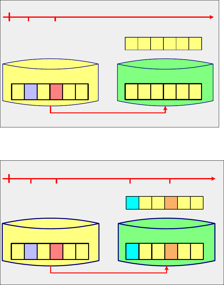
48 IBM System Storage DS6000 Series: Copy Services with IBM System z
6.3.1 Full volume copy
When the copy option is invoked and the establish process completes, a background process
is started that copies all data from the source to the target. Once this process is finished and
if there were no updates on the target, the picture we get is similar to the one in Figure 6-5. If
not explicitly defined as persistent, the FlashCopy relationship ends as soon as all data is
copied.
Figure 6-5 Target volume after a FlashCopy—copy—relationship ends
If there were writes to the target then the picture we get is similar to the one in Figure 6-6.
Figure 6-6 FlashCopy after updates to the target volume
6.3.2 Nocopy option
If FlashCopy is established using the nocopy option, then the result will be as shown in
Figure 6-3 on page 46 and Figure 6-4 on page 47. The relationship will last until it is explicitly
withdrawn or until all data in the source volume has been modified. Blocks for which no write
time
Background copy
t0
0 0 0 000
bitmap
t t t ttt
source
data
00
yt t t ttt
target
data
x00 0 0
txty
Background copy will copy all time-zero data from the source to the target
00 00
time
t0
0 0 0 000
bitmap
t t t ttt
source
data
00y t t t t tt
data
x000b
tatb
a000
target
Background copy
Background copy will copy all time-zero data from the source to the target.
txty
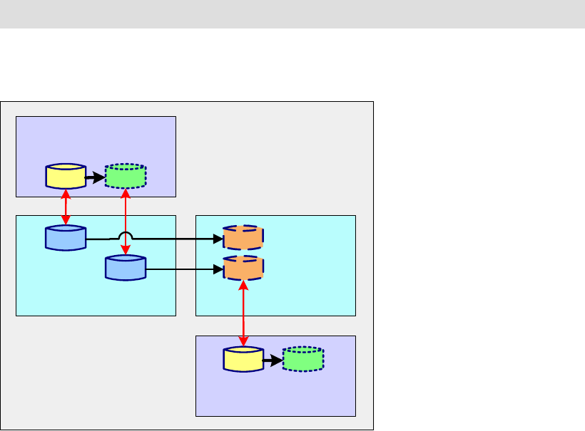
Chapter 6. FlashCopy overview 49
occurred on the source or on the target will stay as they were at the time when the FlashCopy
was established.
If the persistent FlashCopy option was specified, the FlashCopy relationship must be
withdrawn explicitly.
6.4 FlashCopy in combination with other Copy Services
Volume-based FlashCopy can be used in various combinations with other Copy Services,
whereas the most suitable will depend on the characteristics of the environment and the
requirements.
6.4.1 FlashCopy and Metro Mirror
Figure 6-7 FlashCopy and Metro Mirror
As illustrated in Figure 6-7, the following combinations are supported at the primary Metro
Mirror site:
A FlashCopy source volume can become a Metro Mirror primary volume and vice versa.
The order of creation is optional.
A FlashCopy target volume can become a Metro Mirror primary volume and vice versa. If
you wish to use a FlashCopy target volume as a Metro Mirror primary, be aware of the
following considerations:
– The recommended order is to first establish the Metro Mirror, and then create a
FlashCopy to that Metro Mirror primary using the -tgtpprc parameter if using DS CLI,
or TGTPPRIM(YES) if using TSO, or PPRCPRIM(YES) if using ICKDSF, or
FCTOPPRCPrimary if using DFSMSdss.
The Metro Mirror secondary will not be in a fully consistent state until the Metro Mirror
enters the full duplex state.
Note: The scenarios discussed in the present section do not apply to data set FlashCopy.
source target
FlashCopy
Metro
Mirror
primary
secondaryprimary
Metro
Mirror
source target
FlashCopy
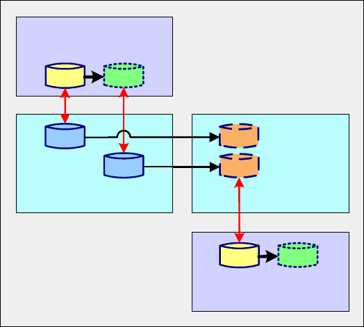
50 IBM System Storage DS6000 Series: Copy Services with IBM System z
– If you create the FlashCopy first and then do a Metro Mirror of the FlashCopy target,
you must monitor the progress of the FlashCopy background copy. In this case the
following considerations apply:
• The Metro Mirror secondary will not be in a fully consistent state until the FlashCopy
background copy process is complete.
•Use the copy option to ensure that the entire FlashCopy source volume data is
copied to the Metro Mirror secondary.
On the secondary site of the Metro Mirror, a FlashCopy source volume can be the Metro
Mirror secondary volume and vice versa. There are no restrictions on which relationship
should be defined first.
6.4.2 FlashCopy and Global Copy
Figure 6-8 FlashCopy and Global Copy
As illustrated in Figure 6-8, at the primary Global Copy site the following combinations are
possible:
A FlashCopy source volume can become a Global Copy primary volume and vice versa.
The order of creation is optional.
A FlashCopy target volume can become a Global Copy primary volume and vice versa. If
you wish to use a FlashCopy target volume as a Global Copy primary, be aware of the
following considerations:
– The recommended order is to first establish the Global Copy, and then create a
FlashCopy to that Global Copy primary using the -tgtpprc parameter if using DS CLI,
or TGTPPRIM(YES) if using TSO, or PPRCPRIM(YES) if using ICKDSF, or
FCTOPPRCPrimary if using DFSMSdss.
The Global Copy secondary will not be in a fully consistent state until the Global Copy
is forced to the full duplex state.
– If you create the FlashCopy first, and then do a Global Copy of the FlashCopy target,
you must monitor the progress of the FlashCopy background copy.
source target
FlashCopy
Global
Copy
primary
secondaryprimary
Global
Copy
source target
FlashCopy
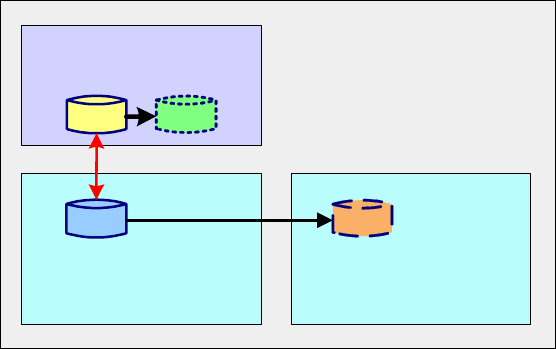
Chapter 6. FlashCopy overview 51
The Global Copy secondary will not be in a fully consistent state until the FlashCopy
background copy process is complete and the Global Copy is forced to the full duplex
state. Issue the TSO CESTPAIR command with OPTION(SYNC) to force the Global
Copy to enter the full duplex state.
Use the copy option to ensure that the entire FlashCopy source volume data is copied
to the Global Copy secondary.
On the Global Copy secondary site a FlashCopy source volume can be based on the
secondary Global Copy volume.
6.4.3 FlashCopy and Global Mirror
FlashCopy in combination with Global Mirror supports only one type of relationship at the
primary site; see Figure 6-9.
A FlashCopy source volume can become a Global Mirror primary volume and vice versa. The
relationships can be established in any sequence. A FlashCopy target volume cannot
become a Global Mirror primary volume.
Figure 6-9 FlashCopy and Global Mirror
On the Global Mirror secondary site, the Global Mirror target volume cannot be used as
FlashCopy source or FlashCopy target unless the Global Mirror pair is first suspended.
6.5 FlashCopy for z/OS data sets
The following applies when using FlashCopy for z/OS data sets (see Figure 6-10 on page 52):
All types of z/OS data sets are supported (sequential, partitioned, and VSAM data sets).
The source data set and the target data set can reside on the same or on different
volumes.
Within the volumes to which they belong, the source data set and the target data set can
have different relative locations.
source target
FlashCopy
Global
Mirror
primary secondary

52 IBM System Storage DS6000 Series: Copy Services with IBM System z
Figure 6-10 Source data set and target data set can reside in the same volume
FlashCopy
volume
source dataset
target dataset

© Copyright IBM Corp. 2006. All rights reserved. 53
Chapter 7. FlashCopy options
This chapter discusses the options of FlashCopy when working with IBM System Storage
DS6000 series in a System z environment. The following options are explained:
Multiple relationship FlashCopy
Consistency Group FlashCopy
FlashCopy on existing Metro Mirror or Global Copy source
Incremental FlashCopy
Remote FlashCopy
Persistent FlashCopy
Data set FlashCopy
Reverse restore and fast reverse restore
7
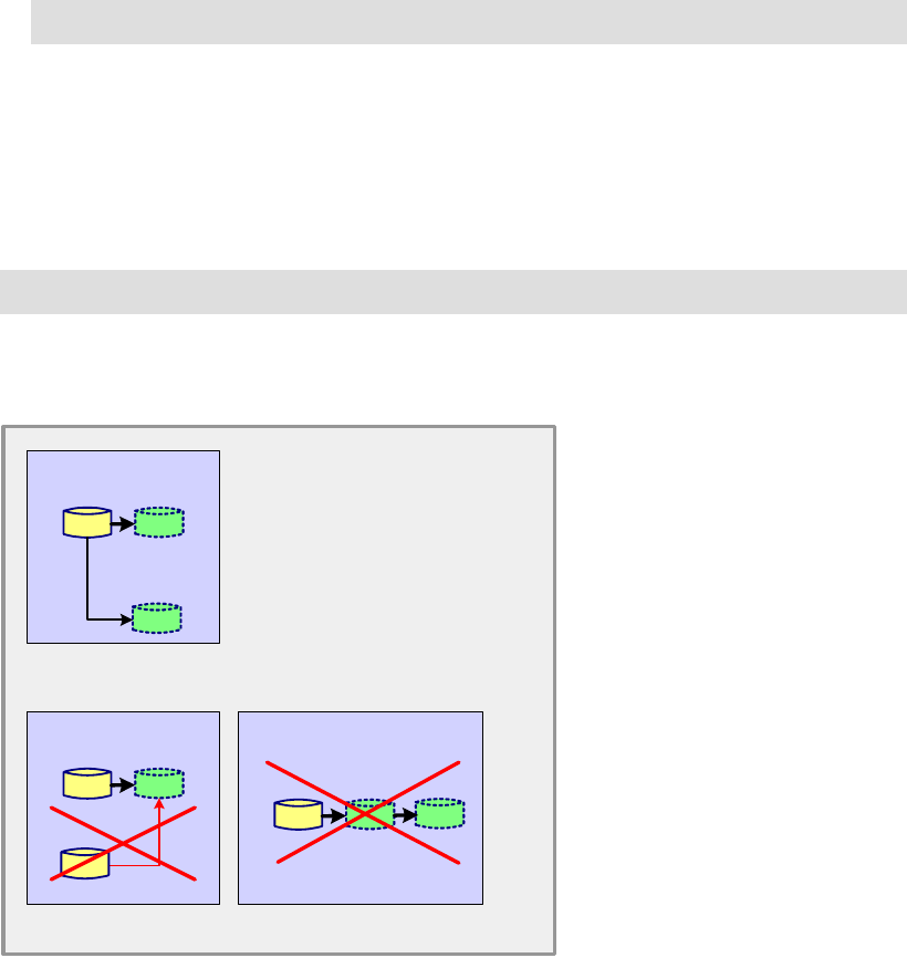
54 IBM System Storage DS6000 Series: Copy Services with IBM System z
7.1 Multiple relationship FlashCopy
It is possible to establish up to 12 FlashCopy relationships using the same source. In other
words, a source volume can have up to 12 target volumes. However, a target volume can still
only have one source. Furthermore, cascading FlashCopy is not allowed (that is, a volume
cannot be both a source and a target volume).
Following is a summary of the considerations that apply:
A FlashCopy source volume can have up to 12 FlashCopy target volumes.
For each source volume, only one FlashCopy relationship can be reversed (the one that
has been established with the TSO FCESTABL command and INCREMENTAL(YES)
option).
A FlashCopy target volume can have only one FlashCopy source volume.
A FlashCopy target volume cannot be a FlashCopy source volume at the same time.
Figure 7-1 illustrates what is possible and what is not with multiple relationship FlashCopy.
Figure 7-1 Multiple relationship FlashCopy possibilities
Multiple relationship FlashCopy at the data set level
Multiple relationship FlashCopy is also supported at the data set level, though not all
interfaces that support the multiple relationship FlashCopy will support multiple relationships
at the data set level. In Figure 7-8 on page 61 we see that neither the DS Storage Manager
nor the DS CLI support multiple relationships at the data set level. Also in Figure 7-8 on
page 61, as stated in Note 1, it is important to point out that though TSO and the ANTRQST
Note: Only one of those targets can be defined as incremental FlashCopy.
Note: At any point in time, a volume, or a data set, can only be a source or a target.
source target
FlashCopy
maximum is 12
...
...
source target
FlashCopy
not allowed
a source can have up to
12 targets
a target can have only
one source
source target
FlashCopy
not allowed
a volume or dataset can be only a
source or target at any given time
source and
target
Chapter 7. FlashCopy options 55
API support data set level FlashCopy, the VTOC and catalogs are not updated as they are
with DFSMSdss.
7.2 Consistency Group FlashCopy
Applications might have their data spread over multiple volumes. In this case, if FlashCopy
needs to be used for multiple volumes, these all have to be at a consistent level. Consistency
groups can be used to help create a consistent point-in-time copy across multiple volumes,
and even across multiple DS6000 storage systems, thus managing the consistency of
dependent writes.
It is possible to establish a consistency group using those interfaces that support this function
(see Figure 7-8 on page 61). If using TSO commands, then the TSO FCESTABL command
with ACTION(FREEZE) option should be used, specifying all FlashCopy pairs belonging to
the Consistency Group.
Dependent writes
If the start of one write operation is dependent upon the completion of a previous write, the
writes are dependent. Application examples for dependent writes are databases with their
associated logging files. Also updates to catalogs, VTOCs as well as VSAM indexes, and
VSAM data components rely on dependent writes. For instance, the database logging file will
be updated after a new entry has been successfully written to a table space.
The chronological order of dependent writes to the FlashCopy source volumes is the basis for
providing consistent data at the FlashCopy target volumes. For a more detailed
understanding of dependent writes and how extended long busy conditions enable the
creation of consistency groups, thus ensuring data integrity on the target volumes, you can
refer to the discussion in 13.3.1, “Data consistency and dependent writes” on page 136.
With the Freeze FlashCopy Consistency Group option, the DS6000 will hold off I/O activity to
a volume for a time period by putting the source volume in extended long busy state. Thus, a
time slot can be created during which the dependent write updates will not occur, and
FlashCopy will use that time slot to obtain a consistent point-in-time copy of the related
volumes. I/O activity resumes when all FlashCopies are established, and the thaw
functionality (the TSO FCWITHDR command with the ACTION(THAW) option) is invoked, or
when the extended long busy (ELB) time slot expires (the ELB window is 2 minutes by
default).
7.3 FlashCopy target as a Metro Mirror or Global Copy primary
With this option the FlashCopy target volume can also be a primary volume for a Metro Mirror
or Global Copy relationship. A user may wish to use this capability to create both a remote
copy and a local copy of a production volume.
Figure 7-2 on page 56 illustrates this capability. In this figure, the FlashCopy target and the
Metro Mirror (or Global Copy) primary are the same volume. They are displayed as two
separate volumes for ease of understanding.
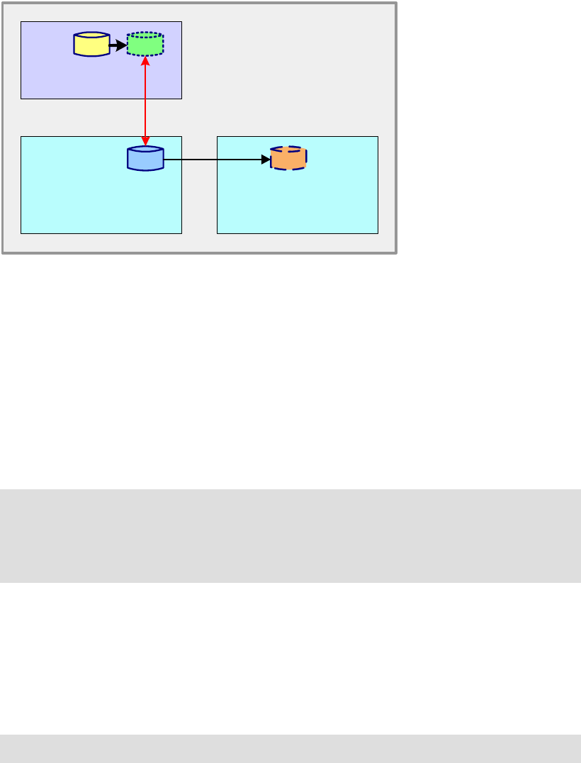
56 IBM System Storage DS6000 Series: Copy Services with IBM System z
Figure 7-2 FlashCopy target is Metro Mirror (or Global Copy) primary
It is possible to create either the FlashCopy relationship first or the Metro Mirror (or Global
Copy) relationship first. However, in general it is better to create the FlashCopy relationship
first to avoid the initial sending of unnecessary data across to the Metro Mirror (or Global
Copy) secondary.
7.4 Incremental FlashCopy - refresh target volume
Incremental FlashCopy provides the capability to refresh a FlashCopy relationship, thus
refreshing the target volume.
In order for an Incremental FlashCopy to be performed, the FlashCopy relationship must first
be established with the Start Change Recording and Persistent FlashCopy options enabled.
If Incremental FlashCopy is invoked via the ANTRQST API or the TSO FCESTABL command
with the INCREMENTAL(YES) option, the FlashCopy target is write-inhibited. Any attempt to
write to the device during this period will be failed by the hardware and surfaced as an I/O
error, an error from the access method, or both.
With Incremental FlashCopy, the initial FlashCopy—copy or nocopy—relationship between a
source and target volume is subject to the following (see Figure 7-3 on page 57):
FlashCopy with nocopy option
If the original FlashCopy was established with the nocopy option, then the bitmap for the
target volume will be reset, and, of course, the updates on the target volumes are
overwritten. However, using the incremental option will automatically convert this
relationship to a copy relationship, and the background copy will begin.
Metro
Mirror
or
Global
Copy
primary secondary
source target
FlashCopy
Remote site
Local site
Metro
Mirror
or
Global
Copy
Attention: A refresh of the target volume will always overwrite any writes previously done
to the target volume.
Restriction: If a FlashCopy source has multiple targets, an incremental FlashCopy
relationship can be established with one and only one target.
Note: Incremental FlashCopy is supported at volume level, not for data set FlashCopy.
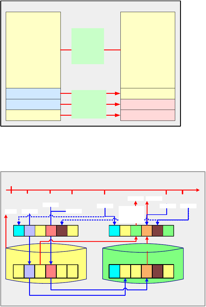
Chapter 7. FlashCopy options 57
FlashCopy with copy option
If the original FlashCopy was established with the copy option (full volume copy), then the
updates that took place on the source volume since the last FlashCopy will be copied to
the target volume. Also, the updates done on the target volume will be overwritten with the
contents of the source volume.
.
Figure 7-3 Updates to the target volume caused by a refresh
When initializing a FlashCopy with Start Change Recording activated, a second and third
bitmap will be used to identify writes done to the source or the target volume (see Figure 7-4).
Figure 7-4 FlashCopy with Start Change Recording set
no updates in source
no updates in source
updates took place
in source volume
updates took place
in source volume
no updates in target
updates took place
in target volume
no updates in target volume
updates took place
in target volume
nothing to be
done as data
was already
copied from
source to target
and is identical
on both sides
current source
data will be
copied to target
source volume target volume
time
Reads and writes with Start Change Recording option set
t0
0 0 1 000bitmap
t t t ttt
data
00z t t t t tt
target
data
x000b
write x
write y
txty
read
read 1 read 2
before physical write to the source:
copy time-zero data from the source to the target
source
write z
tz
0 0 1 100
ab
write a
t
write b
t
a
bitmap
write c
c
t
time-zero data
not yet available
in target :
read it from
source.
0
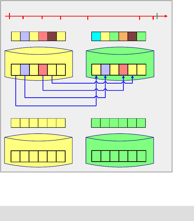
58 IBM System Storage DS6000 Series: Copy Services with IBM System z
All three bitmaps are necessary for incremental FlashCopy:
Target bitmap - This bitmap keeps track of tracks not yet copied from source to target.
Source Change Recording bitmap - This bitmap keeps track of changes to the source.
Target Change Recording bitmap - Yhis bitmap keeps track of changes to the target.
These bitmaps allow subsequent FlashCopies to transmit only those blocks of data for which
updates occurred. Every write operation to the source or target volume will be reflected in
these bitmaps by setting the corresponding bit to 0.
When the Refresh takes place, the bitmap used for change recording is used to analyze
which blocks need to be copied from the source volume to the target volume (see Figure 7-5).
Figure 7-5 Refresh of the FlashCopy target volume
After the Refresh—which takes place only on the bitmap level—the new FlashCopy based on
time-0’ is active. The copy of the time-0’ data to the target is done in the background.
Tip: You can do the incremental copy at any time. You do not have to wait for the previous
background copy to complete.
time
Refresh FlashCopy target volume
t0
0 0 1 000
bitmap
data
target
data
txty
needs to be copied as a
write occured on the target
tz
0 0 1 100
ab
t
t
bitmap c
t
source
t t t ttt
00z t t t t tt
x00xz00
00
update to the source
needs to be copied
update to the source
needs to be copied
needs to be copied as a
write occured on the target
1 1 1 111
bitmap
data
target
data
1 1 1 111
source
t t t ttt
0' 0' 0'
0' 0' 0' t t
0' 0'
t0'
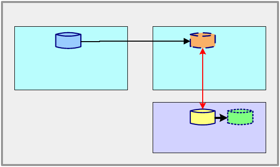
Chapter 7. FlashCopy options 59
7.5 Remote FlashCopy
There are command interfaces (see Figure 7-8 on page 61) which are able to manage a
FlashCopy relationship at a remote site. The commands can be issued from the local site and
they are then transmitted over the Metro Mirror or Global Copy links. This eliminates the need
for a network connection to the remote site solely for the management of FlashCopy.
The FlashCopy source volume at the remote site must be the secondary volume of the Metro
Mirror or Global Copy pair.
Figure 7-6 Remote FlashCopy
Figure 7-6 illustrates this capability. In this figure, the Metro Mirror (or Global Copy) secondary
and the FlashCopy source are the same volume—they are shown as two separate volumes
for ease of understanding.
7.6 Persistent FlashCopy
With this option the FlashCopy relationship continues until explicitly removed, that is, until the
user terminates the relationship using one of the interface methods. If this option is not
selected, the FlashCopy relationship will exist until all data has been copied from the source
volume to the target.
7.7 Data set FlashCopy
Data set FlashCopy is supported with z/OS and OS/390® volumes only. This option can be
invoked using the interfaces that support data set FlashCopy as per Figure 7-8 on page 61.
The following are characteristics of data set FlashCopy:
The data set source and target volumes need not be the same size.
The location within the target volume need not match the location within the source.
Data sets can be copied onto the same source volume.
Multiple relationship FlashCopy is supported with Data set FlashCopy.
If a Data set FlashCopy relationship, established with DFSMSdss and with the nocopy
parameter, is deleted, DADSM (the Direct Access Device Space Management component
of z/OS) will start a background copy prior to deleting the data set. When all data is copied
successfully, the FlashCopy relationship will end and the data set will finally be deleted.
Global
Copy
primary secondary
Global
Copy
source target
FlashCopy
Metro
Mirror
Metro
Mirror
Remote site
Local site
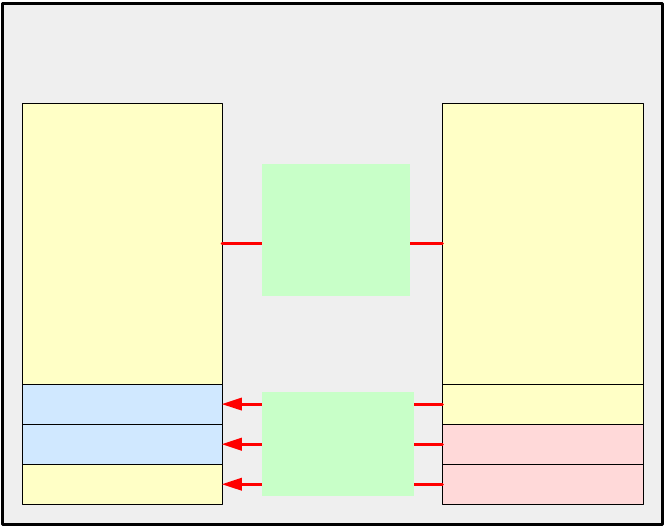
60 IBM System Storage DS6000 Series: Copy Services with IBM System z
7.8 Reverse restore
With this option the FlashCopy relationship can be reversed by copying over modified tracks
from the target volume to the source volume (see Figure 7-7). The background copy process
must complete before you can reverse the order of the FlashCopy relationship to its original
source and target relationship. Change recording is a prerequisite for reverse restore.
Figure 7-7 Reverse restore
The source and target bitmaps (illustrated in Figure 7-4 on page 57) are exchanged and then
handled as described with the Incremental FlashCopy option.
7.9 Fast reverse restore
This option is used with Global Mirror. If you specify this option, you can reverse the
FlashCopy relationship without waiting for the completion of the background copy of the
previous FlashCopy.
7.10 Options and interfaces
Now that we have discussed the options available with FlashCopy, let us see how the
DS6000-provided interfaces and the z/OS-provided interfaces support them; see Figure 7-8
on page 61.
no updates in source
no updates in source
updates took place
in source volume
updates took place
in source volume
no updates in target
updates took place
in target volume
no updates in target volume
updates took place
in target volume
nothing to be done
as data was already
copied from source
to target and is
identical on both
sides
data of previous
target (now source)
will be copied to
previous source
(now target)
source volume
will become
target volume
target volume
will become
source volume
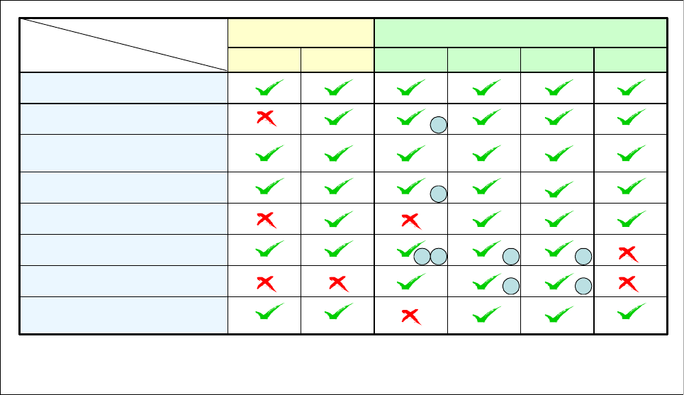
Chapter 7. FlashCopy options 61
Figure 7-8 FlashCopy options and interfaces
Note that there are some options that cannot be invoked with some of the interfaces—they
are indicated with a cross in Figure 7-8.
ANTRQST
Persistent Flashcopy
Dataset FlashCopy
Reverse restore,
fast reverse restore
Remote FlashCopy
Incremental FlashCopy
Target on existing Metro Mirror or
Global Copy primary
Consistency Group FlashCopy
Multiple relationship FlashCopy
ICKDSFTSODFSMSdssDS CLIDS SM
zOS front endsDS front endsInterface
Function
3
1
(1) Extents can be specified, but the VTOC and the catalogs are not updated
2 2
(3) With z/OS V1R6 or later, and APARs OA11002, OA12707, OA12748, and OA14105
1
3
3
(2) Persistent relationships are available via Incremental support
2
62 IBM System Storage DS6000 Series: Copy Services with IBM System z

© Copyright IBM Corp. 2006. All rights reserved. 63
Chapter 8. FlashCopy ordering and
activation
This chapter explains how to order and activate FlashCopy for the IBM System Storage
DS6000. The information presented here can be complemented with the information in
Appendix C, “Licensing” on page 525.
8

64 IBM System Storage DS6000 Series: Copy Services with IBM System z
8.1 Ordering FlashCopy
FlashCopy is an optional licensed function of the IBM System Storage DS6000 series. This
function is also referred to as the Point-In-Time Copy (PTC) licensed function.
All DS6000 series licensed functions are enabled, authorized, managed, activated, and
enforced based upon the physical capacity contained in a 1750 system.
Enablement
This refers to the purchase of a feature number to technically activate the associated licensed
function. Each licensed function is enabled for a 1750 system through acquiring the
corresponding feature numbers.
Particularly for FlashCopy, the 1750 feature that must be ordered is the Point-in-Time Copy
(PTC) licensed function, feature #52xx; see Table 8-1.
Table 8-1 FlashCopy features
Each licensed function feature number purchased for a 1750 machine enables that function
for the entire 1750 system.
Authorization
This refers to the purchase of a feature number to establish the extent of IBM authorization
—license size in terms of physical capacity— for use of an associated licensed function. This
is also referred to as the authorization level.
The extent of IBM authorization for the use of a licensed function on a 1750 system is
established by acquiring an 52xx feature number on the 1750 base enclosure. The same
52xx feature numbers acquired to enable a licensed function also establish the extent of
IBM's authorization.
The 52xx feature number on a 1750 base enclosure establishes the authorization level for the
entire 1750 system. For example, a 1750 system with a Model 522 base enclosure and two
Model EX2 expansion enclosures requires the acquisition of 52xx feature numbers only on
the Model 522. Therefore, for licensed functions authorized on the basis of physical
capacity—as in the case of PTC—the authorization level established with the acquisition of
the 52xx feature number on the Model 522 must also cover the physical capacity of the
attached Model EX2 expansion enclosures.
Note: For a detailed explanation of the features involved and the factors to be considered
when ordering FlashCopy we recommend you refer to the IBM System Storage DS6000
Series (IBM 1750-522) announcement letter.
IBM announcement letters can be found at:
http://www.ibm.com/products
Feature Description
5210 PTC - 1 TB
5211 PTC - 5 TB
5212 PTC - 10 TB
5213 PTC - 25 TB
5214 PTC - 50 TB
Chapter 8. FlashCopy ordering and activation 65
8.2 Activating FlashCopy
IBM System Storage DS6000 licensed functions are managed using the Disk Storage
Feature Activation (DSFA) application. Also, the DS6000 licensed functions are activated by
the installation of feature activation codes into the 1750 system.
The feature activation codes are made available by IBM and are obtained using the DSFA
(Disk Storage Feature Activation) application at:
http://www.ibm.com/storage/dsfa
For additional information on the activation of the DS6000 licensed function features, see
Appendix C, “Licensing” on page 525.
8.2.1 Management
The Disk Storage Feature Activation (DSFA) application can be used to:
Assign an order confirmation code
Select the license scope
Assign the license value
Deactivate a licensed function
These activities are referred to as the “management” activities that you can perform with the
DSFA application and in relation to the DS6000 licensed functions.
Order confirmation code
With the purchase of the 52xx feature number, IBM provides an order confirmation code. To
activate the function in your machine, you must assign the order confirmation code to your
1750 system (using the 1750 base enclosure serial number). This activity is performed using
the DSFA application.
You will not be able to retrieve a feature activation code for a purchased licensed function
until you have assigned the order confirmation code to the serial number of the 1750 for
which it was acquired.
License scope
Licensed functions are activated and enforced within a defined license scope. License scope
refers to the type of storage, and therefore the type of servers, that the function can be used
with:
Fixed Block (FB): the function can be used only with data from Fibre Channel-attached
servers.
Count Key Data (CKD): the function can be used only with data from FICON-attached
servers.
Both FB and CKD (ALL): the function can be used with data from all attached servers.
In particular the license scope of FlashCopy is multiple: it can either be FB, CKD, or ALL. For
this reason, when ordering FlashCopy, you must plan ahead what your point-in-time copy
requirements will be. Example 8-1 on page 66 illustrates a sample case.

66 IBM System Storage DS6000 Series: Copy Services with IBM System z
Example 8-1 FlashCopy example
A DS6000 has a total physical capacity of 15 TB and that capacity will be configured as:
10 TB open systems (FB)
5 TB System z (CKD)
Then, here's the required licenses:
Operating environment ==> 15 TB (equal to total machine capacity)
Parallel access volumes ==> 5 TB (equal to CKD-configured capacity)
Remote mirror for z/OS ==> 5TB (equal to CKD-configured capacity)
FlashCopy must either be:
10 TB if you want to use FlashCopy only with open systems (FB) data (equal to
FB-configured capacity)
5 TB if you want to use FlashCopy only with System z (CKD) data (equal to
CKD-configured capacity)
15 TB if you want to use FlashCopy with both open systems (FB) and System z (CKD) data
(equal to total machine capacity)
If a licensed function—as is the case with FlashCopy—has multiple license scope options,
you will be required to select a license scope during the initial retrieval of the feature
activation code.
You can also change the license scope using the DSFA application after a licensed function
has been activated. A new feature activation code will be generated and when you install it
into the machine, the function will be activated and enforced using the newly selected license
scope. Only an increase in the license scope (changing FB or CKD to ALL) is a nondisruptive
activity. A lateral change (changing FB to CKD or changing CKD to FB) or a reduction of the
license scope (changing ALL to FB or CKD) is a disruptive activity and requires a machine
IML.
License value
Licensed functions are activated and enforced based upon an assigned license value.
License value refers to the extent of IBM authorization and is referenced as either of the
following:
Terabytes (TB) of physical capacity for variable-sized licensed functions
ON or OFF for system-level licensed functions
Feature activation codes will always be generated using the total license value for each
variable-sized licensed function and ON for each system-level licensed function, unless you
assign a license value of zero (0.0 TB) or OFF, respectively.
You can change the license value assignment using the DSFA application. You would
generally only perform this activity when you want to deactivate a licensed function.
Deactivation
Assigning a license value of zero (0.0 TB) or OFF provides the ability to deactivate (disable) a
licensed function. A new feature activation code will be generated and when you install it into
the machine, the function will be deactivated during the next IML of the machine.
Note: The license scope is not selected during the purchase of the 52xx feature number;
the feature numbers only establish the extent of IBM authorization (in terms of physical
capacity) regardless of the storage type.

Chapter 8. FlashCopy ordering and activation 67
You can also reactivate a deactivated licensed function by changing the license value to a
non-zero value. A new feature activation code will be generated and when you install it into
the machine, the function will be activated. Reactivation is a nondisruptive activity.
When you deactivate a licensed function using the DSFA application, the 5xxx feature
numbers assigned to your machine (using the order confirmation code) remain assigned to
the machine. This means that you do not need to repurchase your 5xxx feature numbers if
you want to reactivate the licensed function at a future date.
8.2.2 Activation
Activation refers to the client retrieval and installation of the feature activation code into the
1750 system.
The feature activation code is made available by IBM and obtained using the DSFA
application at:
http://www.ibm.com/storage/dsfa
The following information is needed for the download of the keyfile and should be prepared
during planning:
Model
The model of the DS6000 can be taken from the order.
Serial number of the DS6000
The serial number of a DS6000 can be taken from the front of the base frame (lower right
corner). If several servers have been delivered, this is the only way to obtain the serial
number of a DS6000 located in a specific point in the computer center.
Machine signature
The machine signature can only be obtained with the DS SM or the DS CLI after
installation of the DS6000. In a Web browser, type the URL of the DS SMC:
https://10.10.10.10:8452/DS6000
Select Real-time manager → Monitor system → Properties. Select General, then the
Storage Complex and the Storage Unit that you are interested in from the list. This shows
the properties of the selected DS6000, including the machine signature.
Order confirmation code
The order confirmation code is printed in the DS6000 series order confirmation code
document, which is sent to the client’s contact person either with the DS6000 or before
delivery.
Note: To access DSFA, you will be required to enter information about your 1750 machine.
You can find this information on the Storage Unit General Properties page in the DS6000
series Storage Manager application.
68 IBM System Storage DS6000 Series: Copy Services with IBM System z

© Copyright IBM Corp. 2006. All rights reserved. 69
Chapter 9. FlashCopy interfaces
The setup of FlashCopy in a System z environment can be done using different interfaces.
This chapter explains and gives examples of the interfaces that can be used for FlashCopy
management when FlashCopy is used with the IBM System Storage DS6000 in a System z
environment.
9
70 IBM System Storage DS6000 Series: Copy Services with IBM System z
9.1 FlashCopy interfaces - overview
There are various interfaces that can be used for the configuration and management of
FlashCopy when used in a System z environment with the DS6000.
There are the DS6000 front end-provided interfaces:
DS Storage Manager (DS SM) - A graphical user interface (GUI) running in a Web
browser that communicates with the DS6000 Storage Management Console (DS SMC).
DS Command Line Interface (DS CLI) - Provides a set of commands that are executed on
a supported workstation communicating with the DS SMC.
TotalStorage Productivity Center for Replication (TPC for Replication) - The TPC
Replication Manager server connects to the same network where the DS SMC is.
DS Open Application Programming Interface (DS Open API).
Also, with z/OS the following interfaces can be used for FlashCopy management:
DFSMSdss utility
TSO commands
ICKDSF utility
ANTRQST application programming interface (API)
This chapter gives an overview of the DS CLI and the DS SM, as well as the z/OS-provided
interfaces. These interfaces are also covered in Part 2, “Interfaces” on page 15.
TotalStorage Productivity Center for Replication (TPC for Replication) provides management
of DS6000 series business continuance solutions, including FlashCopy, Metro Mirror, and
Global Mirror. TPC for Replication is covered in Chapter 31, “IBM TotalStorage Productivity
Center for Replication” on page 467. TPC for Replication includes similar functions to Global
Mirror Utility (GMU). GMU users should consider migrating to TPC for Replication.
Also, the DS Open Application Programming Interface (DS Open API), which is a set of
application programming interfaces that are available to be integrated in programs, can be
used for FlashCopy management and control. The DS Open API is not covered in this book.
For information on the DS Open API, refer to IBM System Storage DS Open Application
Programming Interface Reference, GC35-0516.
FlashCopy control with the interfaces
Independently of the interface that is used, when managing FlashCopy the following basic
sequence takes place:
1. FlashCopy is initiated by means of an interface.
The initialization process of a FlashCopy takes only some seconds. At the end of this
process FlashCopy is established based on the given parameters. This means that all the
necessary meta structures have been established. No data has yet been copied.
2. FlashCopy runs in the background.
This is the moment when FlashCopy copies—in the background—the necessary data to
create the point-in-time copy. The parameters given at initialization time define how
FlashCopy will work in the background. They also define which subsequent activities can
be performed with this FlashCopy.
3. FlashCopy terminates.
FlashCopy either terminates automatically if all tracks have been copied, or needs to be
terminated explicitly, by means of an interface, if it has been defined as persistent.

Chapter 9. FlashCopy interfaces 71
9.2 DS CLI and DS SM - commands and options
This section summarizes the commands and select options you can use when managing
FlashCopy at the local and at the remote site.
9.2.1 Local FlashCopy management
The commands you can use as well as the displayed panel actions and options you can
select when working with the DS6000-provided interfaces DS CLI and DS SM for local
FlashCopy management are listed in Table 9-1.
Local FlashCopy refers to the situation where the FlashCopy is local as opposed to a remote
FlashCopy. For a discussion of the characteristics of a remote FlashCopy refer to Section 7.5,
“Remote FlashCopy” on page 59.
Table 9-1 Local FlashCopy using DS CLI and DS SM
Options Command with
DS CLI
Select option
with DS SM
Create a FlashCopy
Create a local FlashCopy mkflash Create
Work with an existing FlashCopy
Display a list of FlashCopy relationships lsflash Main panel
Modify a FlashCopy pair that is part of a Global Mirror
relationship to revertible
setflashrevertible Restorable,
Record Changes
wizard
Commit data to the target volume commitflash
Increment an existing FlashCopy pair resyncflash
(prerequisites:
-record and
-persist)
Resynch target
Change the source-target-relationship A->B to B->A reverseflash Reverse
relationship
Re-establish contents of target B by contents of source A
as it was during last consistency formation
revertflash Consistency
Groups not
supported
Reset a FlashCopy Consistency Group unfreezeflash Consistency
Groups not
supported
Run new background copy for persistent FlashCopy rmflash -cp Background copy
Terminate FlashCopy
Remove local FlashCopy rmflash Delete
Is automatically removed as soon as all
data is copied and FlashCopy pair wasn’t
established using the -persist parameter

72 IBM System Storage DS6000 Series: Copy Services with IBM System z
9.2.2 Remote FlashCopy management
The commands that can be used when working with the DS6000-provided interface DS CLI
for remote FlashCopy management are listed in Table 9-2.
Table 9-2 Remote FlashCopy using DS CLI commands
9.3 z/OS-provided interfaces
When working in a z/OS environment the operating system provides you with utilities and
commands for local FlashCopy management. Table 9-3 summarizes the commands for the
different FlashCopy functions.
Table 9-3 Local FlashCopy using DFSMSdss, TSO, and ICKDSF commands
Options Command with DS CLI
Create a FlashCopy
Create a remote FlashCopy mkremoteflash
Work with an existing FlashCopy
Display a list of FlashCopy relationships lsremoteflash
Modify a FlashCopy pair that is part of a Global Mirror
relationship to revertible
setremoteflashrevertible
Commit data to the target volume commitremoteflash
Increment an existing FlashCopy pair resyncremoteflash
(prerequisites: -record and -persist)
Change the source-target- relationship A->B to B->A reverseremoteflash
Re-establish contents of target B by contents of source A
as it was during last consistency formation
revertremoteflash
Reset a FlashCopy Consistency Group not available as remote command
Run new background copy for persistent FlashCopy rmremoteflash -cp
Terminate FlashCopy
Remove local FlashCopy rmremoteflash
Is automatically removed as soon as all
data is copied and FlashCopy pair wasn’t
established using the -persist parameter
Note: Remote FlashCopy is not supported with the DS SM or DS Open API interfaces.
Options Command with
DFSMSdss
Command with
TSO
Command with
ICKDSF
Create a FlashCopy
Create a volume FlashCopy COPY FULL FCESTABL FLASHCPY
ESTABLISH
Create a Data set FlashCopy COPY DATASET

Chapter 9. FlashCopy interfaces 73
9.4 Local FlashCopy using the DS CLI
The DS CLI can be downloaded from the IBM Web site and then installed on a workstation. It
communicates with the DS SMC. For detailed information about the DS CLI, refer to IBM
System Storage DS6000: Command-Line Interface User´s Guide, GC26-7922.
9.4.1 Parameters used with local FlashCopy commands
Figure 9-1 Overview of parameters used in DS CLI FlashCopy commands
Work with an existing FlashCopy
Display a list of FlashCopy
relationships
FCQUERY FLASHCPY
QUERY
RELATION
Relocate data set extents on a
DASD volume
DEFRAG -
Provide information why
DFSMSdss couldn’t use
FlashCopy
DEBUG -
Terminate FlashCopy
Remove local FlashCopy DUMP with
FCWITHDRAW
parameter
FCWITHDR FLASHCPY
WITHDRAW
Is automatically removed as soon as all data is copied and
FlashCopy pair wasn’t established using the -persist parameter
Options Command with
DFSMSdss
Command with
TSO
Command with
ICKDSF
Parameters
freeze x x
tgtpprc x x x
tgtoffline x x x x
tgtinhibit x x x
tgtonly x
dev xxxxxxxxx
record xx xx
persist x x x x
nocp x
seqnum xxxxxxx x
source:target x x x x
fast x
source x x
cp x x
source LSS x
lx
sx
activecp x
revertible x
wait x
quie
t
x
DS CLI Commands
Target
rmflash
Source
Flashcopy pair
Command
resync
flash
reverse
flash
revert
flash
unfreeze
flash
mkflash lsflash setflash
revertible
commit
flash

74 IBM System Storage DS6000 Series: Copy Services with IBM System z
This section discusses the parameters that can be passed to FlashCopy when using the DS
CLI and what the results are. Figure 9-1 summarizes the parameters and the corresponding
DS CLI commands. When FlashCopy receives these parameters, the following actions result:
freeze: Consistency Group FlashCopy
With the DS CLI, it is possible to establish a Consistency Group by using the -freeze
parameter and identifying all FlashCopy pairs and target volumes belonging to it.
tgtpprc: establish target on existing Metro Mirror source
When this option is selected, the target volume can be, or can become, a source volume
for a Metro Mirror or Global Copy relationship.
tgtoffline: permit FlashCopy to occur if target volume is not online for host access
When setting up the relationship, a verification is done to see whether the target volume is
online or offline. This parameter only applies to CKD volumes. Table 9-4 summarizes the
actions that result, depending on the target volume status.
Table 9-4 Resulting actions when the tgtoffline parameter is used
tgtinhibit: Inhibit writes to target volume
If FlashCopy is active, writes to the target volume are not allowed (inhibited).
record: change recording
Activating the option change recording during setup of a FlashCopy enables subsequent
refreshes to the target volume. To do so, a second bitmap is created for the source
volume, which keeps track of all writes to the source. This bitmap can later be used to
refresh the target by only copying the updates from the source to the target.
persist: persistent FlashCopy
The FlashCopy relationship will continue to exist until explicitly removed by an interface
method. If this option is not selected, the FlashCopy relationship will exist until all data has
been copied from the source volume to the target.
nocp: full volume background copy
With the parameter nocp it is possible to indicate whether the data of the source volume
will be copied to the target volume in the background or not. If -nocp isn’t used, a copy of
all data from source to target takes place in the background. With -nocp selected only
updates to the source volume will cause writes to the target volume—this way the
time-zero data can be preserved.
seqnum: sequence number for FlashCopy pairs
A number that identifies the FlashCopy relationship. Once used with the initial mkflash
command, it could be used within subsequent commands to refer to multiple FlashCopy
relationships.
source:target: identification of source volume and target volume
fast: reverse FlashCopy before background copy finished
Status of target
volume in z/OS
Permit FlashCopy
to occur if target
volume is online
Resulting action
Volume is online Not selected FlashCopy definition is not possible
Volume is online Selected FlashCopy definition is queued until target
volume goes offline
Volume is offline Selected or not
selected
FlashCopy will be started immediately

Chapter 9. FlashCopy interfaces 75
Allows you to issue the reverseflash command before the background copy finished.
cp: restrict command to FlashCopy relationships with background copy
sourceLSS: reset Consistency Group for source logical subsystems
s: display of FlashCopy pairs with lsflash command
The shortened output of the lsflash command is returned. Only the FlashCopy pair IDs
are displayed.
l: display additional FlashCopy information
The standard output of the lsflash command is enhanced. The values for the copy
indicator, out of synch tracks, date created, and date synchronized are displayed.
activecp: selection of FlashCopy pairs with active background copy
revertible: selection of FlashCopy pairs with revertible attribute
9.4.2 Local FlashCopy commands - examples
This section explains the DS CLI commands that you can use to manage FlashCopy and also
shows examples of their use.
Initiating FlashCopy using mkflash
With mkflash, a local FlashCopy can be established. Five coding examples for mkflash are
shown in Example 9-1.
Example 9-1 mkflash command examples
Script
#--- script to establish FlashCopy relationships
#------------------------------------------------------------
mkflash -dev IBM.1750-13ABC2A -seqnum 00 0000:0100
Date/Time: July 8, 2005 10:31:59 AM CEST IBM DSCLI Version: 5.0.3.134 DS: IBM.1750-13ABC2A
CMUC00137I mkflash: FlashCopy pair 0000:0100 successfully created.
mkflash -dev IBM.1750-13ABC2A -freeze -seqnum 01 0001:0101 0005:0105
Date/Time: July 8, 2005 10:32:26 AM CEST IBM DSCLI Version: 5.0.3.134 DS: IBM.1750-13ABC2A
CMUC00137I mkflash: FlashCopy pair 0001:0101 successfully created.
CMUC00137I mkflash: FlashCopy pair 0005:0105 successfully created.
mkflash -dev IBM.1750-13ABC2A -record -seqnum 02 0002:0102
Date/Time: July 8, 2005 10:32:54 AM CEST IBM DSCLI Version: 5.0.3.134 DS: IBM.1750-13ABC2A
CMUC00137I mkflash: FlashCopy pair 0002:0102 successfully created.
mkflash -dev IBM.1750-13ABC2A -persist -seqnum 03 0003:0103
Date/Time: July 8, 2005 10:33:14 AM CEST IBM DSCLI Version: 5.0.3.134 DS: IBM.1750-13ABC2A
CMUC00137I mkflash: FlashCopy pair 0003:0103 successfully created.
mkflash -dev IBM.1750-13ABC2A -nocp -seqnum 04 0004:0104
Date/Time: July 8, 2005 10:33:46 AM CEST IBM DSCLI Version: 5.0.3.134 DS: IBM.1750-13ABC2A
CMUC00137I mkflash: FlashCopy pair 0004:0104 successfully created.
Listing of the properties of the FlashCopies
lsflash -dev IBM.1750-13ABC2A 0000-0004
ID SrcLSS SequenceNum Timeout ActiveCopy Recording Persistent Revertible SourceWriteEnabled TargetWriteEnabled BackgroundCopy
====================================================================================================================================
0000:0100 00 0 300 Disabled Disabled Disabled Disabled Disabled Disabled Enabled
0001:0101 00 1 300 Disabled Disabled Disabled Disabled Disabled Disabled Enabled
0002:0102 00 2 300 Disabled Enabled Enabled Disabled Disabled Disabled Enabled
0003:0103 00 3 300 Disabled Disabled Enabled Disabled Disabled Disabled Enabled
0004:0104 00 4 300 Disabled Disabled Disabled Disabled Disabled Disabled Disabled

76 IBM System Storage DS6000 Series: Copy Services with IBM System z
The following explanations apply to the cases presented in Example 9-1:
Example 1: 0000 → 0100
The FlashCopy between volume 0000 and volume 0100 is established with the property
BackgroundCopy enabled. This is the default unless specified differently using the -nocp
parameter. All other properties are disabled. The background copy takes place
immediately. Once the copy is done, the FlashCopy relationship is automatically removed.
Example 2: 0001 → 0101 and 0005 → 0105
A FlashCopy is established between volumes 0001 and 0101 and between volumes 0005
and 0105. Both FlashCopy relationships have the same sequence number. A Consistency
Group for the two FlashCopy relationships is created using the freeze parameter.
BackgroundCopy is enabled—by default if not specified differently using the -nocp
parameter. All other properties are disabled. The background copies take place
immediately for both pairs of volumes, and once the copies are completed the FlashCopy
relationships are automatically removed.
Example 3: 0002 → 0102
The FlashCopy between volume 0002 and volume 0102 is established with the following
FlashCopy properties enabled: Recording, Persistent, and BackgroundCopy.
The background copy takes place immediately and the relationship remains as a
persistent relationship. Using other DS CLI commands it could be reversed and/or
resynchronized.
Example 4: 0003 → 0103
The FlashCopy between volume 0003 and volume 0103 is established with the following
FlashCopy properties enabled: Persistent and BackgroundCopy. All other FlashCopy
properties are disabled. The background copy takes place immediately. Once the
background copy is finished the FlashCopy relationship will remain—because of the
persistent flag.
Example 5: 0004 → 0104
The FlashCopy between volume 0004 and volume 0104 is established with all the
FlashCopy options disabled. Due to the -nocp parameter, no full background copy will be
done. Only the data changed in the source is copied to the target prior to changing it. Over
time, this could result in the situation where all data is copied to the target —then the
FlashCopy relationship would end. It would also end after a background copy is initiated
using the DS SM. This way the relationship is temporarily persistent even though the
property Persistent is not activated.
Display existing FlashCopy relationships using lsflash
The command lsflash can be used to display FlashCopy relationships and its properties.
Parameters can be used with this command to identify the subset of FlashCopy relationships
to be displayed.
Example 9-2 on page 77 shows a script with several lsflash commands and the output of the
script (this script is logically based on the example for mkflash).
Note: The parameter -persist is automatically added whenever -record is used.

Chapter 9. FlashCopy interfaces 77
Example 9-2 lsflash command examples
#--- Example 1
lsflash -dev IBM.1750-13ABC2A 0004
Date/Time: July 8, 2005 3:00:49 PM CEST IBM DSCLI Version: 5.0.3.134 DS: IBM.1750-13ABC2A
ID SrcLSS SequenceNum Timeout ActiveCopy Recording Persistent Revertible SourceWriteEnabled TargetWriteEnabled BackgroundCopy
====================================================================================================================================
0004:0104 00 4 300 Disabled Disabled Disabled Disabled Disabled Disabled Disabled
#--- Example 2
lsflash -dev IBM.1750-13ABC2A 0000-0004
Date/Time: July 8, 2005 3:01:02 PM CEST IBM DSCLI Version: 5.0.3.134 DS: IBM.1750-13ABC2A
ID SrcLSS SequenceNum Timeout ActiveCopy Recording Persistent Revertible SourceWriteEnabled TargetWriteEnabled BackgroundCopy
====================================================================================================================================
0000:0100 00 0 300 Disabled Disabled Disabled Disabled Disabled Disabled Enabled
0001:0101 00 1 300 Disabled Disabled Disabled Disabled Disabled Disabled Enabled
0002:0102 00 2 300 Disabled Enabled Enabled Disabled Disabled Disabled Enabled
0003:0103 00 3 300 Disabled Disabled Enabled Disabled Disabled Disabled Enabled
0004:0104 00 4 300 Disabled Disabled Disabled Disabled Disabled Disabled Disabled
#--- Example 3
lsflash -dev IBM.1750-13ABC2A -l 0000-0004
Date/Time: July 8, 2005 3:01:17 PM CEST IBM DSCLI Version: 5.0.3.134 DS: IBM.1750-13ABC2A
ID SrcLSS SequenceNum Timeout ActiveCopy Recording Persistent Revertible SourceWriteEnabled TargetWriteEnabled BackgroundCopy
OutOfSyncTracks DateCreated DateSynced
==========================================================================================================================================
0000:0100 00 0 300 Disabled Disabled Disabled Disabled Disabled Disabled Enabled
122051 Fri Jul 08 11:02:22 CEST 2005 Fri Jul 08 11:02:22 CEST 2005
0001:0101 00 1 300 Disabled Disabled Disabled Disabled Disabled Disabled Enabled
150255 Fri Jul 08 11:02:35 CEST 2005 Fri Jul 08 11:02:35 CEST 2005
0002:0102 00 2 300 Disabled Enabled Enabled Disabled Disabled Disabled Enabled
150255 Fri Jul 08 11:02:48 CEST 2005 Fri Jul 08 11:02:48 CEST 2005
0003:0103 00 3 300 Disabled Disabled Enabled Disabled Disabled Disabled Enabled
150255 Fri Jul 08 11:03:04 CEST 2005 Fri Jul 08 11:03:04 CEST 2005
0004:0104 00 4 300 Disabled Disabled Disabled Disabled Disabled Disabled Disabled
150255 Fri Jul 08 11:03:17 CEST 2005 Fri Jul 08 11:03:17 CEST 2005
#--- Example 4
lsflash -dev IBM.1750-13ABC2A -s 0000-0001
Date/Time: July 8, 2005 3:01:36 PM CEST IBM DSCLI Version: 5.0.3.134 DS: IBM.1750-13ABC2A
ID
=========
0000:0100
0001:0101
#--- Example 5
lsflash -dev IBM.1750-13ABC2A -activecp 0000-0004
Date/Time: July 8, 2005 3:01:48 PM CEST IBM DSCLI Version: 5.0.3.134 DS: IBM.1750-13ABC2A
CMMCI9006E No FlashCopy instances named 0000-0004 found that match criteria: dev = IBM.1750-13ABC2A and activecp = true.
#--- Example 6
lsflash -dev IBM.1750-13ABC2A -record 0000-0004
Date/Time: July 8, 2005 3:02:05 PM CEST IBM DSCLI Version: 5.0.3.134 DS: IBM.1750-13ABC2A
ID SrcLSS SequenceNum Timeout ActiveCopy Recording Persistent Revertible SourceWriteEnabled TargetWriteEnabled BackgroundCopy
====================================================================================================================================
0002:0102 00 2 300 Disabled Enabled Enabled Disabled Disabled Disabled Enabled
#--- Example 7
lsflash -dev IBM.1750-13ABC2A -persist 0000-0004
Date/Time: July 8, 2005 3:02:17 PM CEST IBM DSCLI Version: 5.0.3.134 DS: IBM.1750-13ABC2A
ID SrcLSS SequenceNum Timeout ActiveCopy Recording Persistent Revertible SourceWriteEnabled TargetWriteEnabled BackgroundCopy
====================================================================================================================================
0002:0102 00 2 300 Disabled Enabled Enabled Disabled Disabled Disabled Enabled
0003:0103 00 3 300 Disabled Disabled Enabled Disabled Disabled Disabled Enabled
#--- Example 8
lsflash -dev IBM.1750-13ABC2A -revertible 0000-0004
Date/Time: July 8, 2005 3:02:29 PM CEST IBM DSCLI Version: 5.0.3.134 DS: IBM.1750-13ABC2A
#--- Example 9
lsflash -dev IBM.1750-13ABC2A -cp 0000-0004
Date/Time: July 8, 2005 3:02:45 PM CEST IBM DSCLI Version: 5.0.3.134 DS: IBM.1750-13ABC2A
ID SrcLSS SequenceNum Timeout ActiveCopy Recording Persistent Revertible SourceWriteEnabled TargetWriteEnabled BackgroundCopy

78 IBM System Storage DS6000 Series: Copy Services with IBM System z
====================================================================================================================================
0000:0100 00 0 300 Disabled Disabled Disabled Disabled Disabled Disabled Enabled
0001:0101 00 1 300 Disabled Disabled Disabled Disabled Disabled Disabled Enabled
0002:0102 00 2 300 Disabled Enabled Enabled Disabled Disabled Disabled Enabled
0003:0103 00 3 300 Disabled Disabled Enabled Disabled Disabled Disabled Enabled
The following explanations apply to the cases presented in Example 9-2:
Example 1: list FlashCopy information for a specific volume
In this example, the lsflash command shows the FlashCopy relationship information for
volume 0004, showing the status (enabled/disabled) of the FlashCopy properties.
Example 2: list existing FlashCopy relationships information within a range of volumes.
In this example, the lsflash command shows the FlashCopy relationships information for
the range of volumes 0000 to 0004, showing the properties status (enabled/disabled).
Example 3: list existing FlashCopy relationships with full information.
Using the -l parameter with the lsflash command displays the default output plus
information on the following properties: OutOfSyncTracks, DateCreated, and DateSynced.
Example 4: list IDs of existing FlashCopy pairs within a volume range.
Using the -s parameter displays only the FlashCopy source and target volume IDs for the
specified range of volumes.
Example 5: list FlashCopy relationships with active background copy running.
Using the parameter -activecp will display only those FlashCopy relationships within the
selected range of volumes for which a background copy is actively running. The output
format is the default output. In our example there were no active background copies.
Example 6: list existing FlashCopy relationships with -record enabled.
Using the -record parameter will display only those FlashCopy relationships within the
selected range of volumes that were established with the -record parameter.
Example 7: list existing FlashCopy relationships with the Persistent attribute enabled.
When using the parameter -persist only those FlashCopy relationships within the range
of selected volumes for which the Persistent option is enabled will be displayed.
Example 8: list existing FlashCopy relationships which are revertible.
When using the parameter -revertible only those FlashCopy relationships within the
range of selected volumes for which the option Revertible is enabled will be displayed.
There were no revertible relationships in our example.
Example 9: list existing FlashCopy relationships for which BackgroundCopy is enabled.
When using the parameter -cp only those FlashCopy relationships within the range of
selected volumes for which the option BackgroundCopy is enabled will be displayed.
Set an existing FlashCopy to revertible using setflashrevertible
The command setflashrevertible can be used to modify the revertible attribute of a
FlashCopy relationship that is part of a Global Mirror relationship.
The FlashCopy options Recording and Persistent must be enabled to set a FlashCopy
relationship to revertible using this command. This command needs to be executed prior to
running a commitflash or revertflash.
Example 9-3 on page 79 illustrates two situations using the setflashrevertible command.

Chapter 9. FlashCopy interfaces 79
Example 9-3 setflashrevertible command examples
#------------------------------------------------------------
#--- script to set FlashCopy property Revertible to value enabled and display values afterwards
#------------------------------------------------------------
#--- Example 1
setflashrevertible -dev IBM.1750-13ABC2A 0002:0102
Date/Time: July 8, 2005 6:52:49 PM CEST IBM DSCLI Version: 5.0.3.134 DS: IBM.1750-13ABC2A
CMUC00167I setflashrevertible: FlashCopy volume pair 0002:0102 successfully made revertible.
lsflash -dev IBM.1750-13ABC2A 0000-0004
Date/Time: July 8, 2005 7:15:30 PM CEST IBM DSCLI Version: 5.0.3.134 DS: IBM.1750-13ABC2A
ID SrcLSS SequenceNum Timeout ActiveCopy Recording Persistent Revertible SourceWriteEnabled TargetWriteEnabled BackgroundCopy
====================================================================================================================================
0002:0102 00 0 300 Disabled Enabled Enabled Enabled Enabled Disabled Enabled
#--- Example 2
setflashrevertible -dev IBM.1750-13ABC2A 0003:0103
Date/Time: July 8, 2005 6:53:16 PM CEST IBM DSCLI Version: 5.0.3.134 DS: IBM.1750-13ABC2A
CMUN03027E setflashrevertible: 0003:0103: FlashCopy operation failure: action prohibited by current FlashCopy state
The following explanations apply to the cases presented in Example 9-3:
Example 1: set the FlashCopy relationship to Revertible.
This command will set the existing FlashCopy for source volume 0002 and target volume
0102 to revertible. Once the property Revertible is enabled, any subsequent commands
will result in an error message similar to the one displayed in Example 2.
Example 2: error occurs when trying to set FlashCopy relationship to revertible.
When trying to set a FlashCopy relationship to Revertible for which the property Recording
is disabled, an error will result. The script will end after this command with return code 2
and any other commands following the one that caused the error will not be executed.
Commit data to target using commitflash
The command commitflash can be used to commit data to a target volume to set consistency
between source and target. It is intended to be used in asynchronous remote copy
environments such as Global Mirror. Therefore, its usage is discussed in greater detail in Part
6, “Global Mirror” on page 265, while this section discusses the basic use of the command.
Before the FlashCopy relationship can be committed, it needs to be made revertible.
Typically, this is done automatically by an application such as Global Mirror. However, it can
also be set manually.
Example 9-4 Commit command examples
#--- Example 1
lsflash -dev IBM.1750-13ABC2A 0000-0005
Date/Time: July 10, 2005 2:45:28 PM CEST IBM DSCLI Version: 5.0.3.134 DS: IBM.1750-13ABC2A
ID SrcLSS SequenceNum Timeout ActiveCopy Recording Persistent Revertible SourceWriteEnabled TargetWriteEnabled BackgroundCopy
======================================================================================================================================
0001:0101 00 1 300 Disabled Enabled Enabled Disabled Disabled Disabled Enabled
0005:0105 00 1 300 Disabled Enabled Enabled Disabled Disabled Disabled Enabled
setflashrevertible -dev IBM.1750-13ABC2A -seqnum 01 0001:0101 0005:0105
Date/Time: July 10, 2005 2:45:40 PM CEST IBM DSCLI Version: 5.0.3.134 DS: IBM.1750-13ABC2A
CMUC00167I setflashrevertible: FlashCopy volume pair 0001:0101 successfully made revertible.
CMUC00167I setflashrevertible: FlashCopy volume pair 0005:0105 successfully made revertible.
lsflash -dev IBM.1750-13ABC2A 0000-0005
Date/Time: July 10, 2005 2:46:07 PM CEST IBM DSCLI Version: 5.0.3.134 DS: IBM.1750-13ABC2A
ID SrcLSS SequenceNum Timeout ActiveCopy Recording Persistent Revertible SourceWriteEnabled TargetWriteEnabled BackgroundCopy
======================================================================================================================================
0001:0101 00 1 300 Disabled Enabled Enabled Enabled Enabled Disabled Enabled
0005:0105 00 1 300 Disabled Enabled Enabled Enabled Enabled Disabled Enabled

80 IBM System Storage DS6000 Series: Copy Services with IBM System z
commitflash -dev IBM.1750-13ABC2A 0001-0005
Date/Time: July 10, 2005 2:46:18 PM CEST IBM DSCLI Version: 5.0.3.134 DS: IBM.1750-13ABC2A
CMUC00170I commitflash: FlashCopy volume pair 0001:0001 successfully committed.
CMUC00170I commitflash: FlashCopy volume pair 0005:0005 successfully committed.
lsflash -dev IBM.1750-13ABC2A -l 0000-0005
Date/Time: July 10, 2005 2:46:47 PM CEST IBM DSCLI Version: 5.0.3.134 DS: IBM.1750-13ABC2A
ID SrcLSS SequenceNum Timeout ActiveCopy Recording Persistent Revertible SourceWriteEnabled TargetWriteEnabled BackgroundCopy
======================================================================================================================================
0001:0101 00 1 300 Disabled Enabled Enabled Disabled Disabled Enabled Disabled
0005:0105 00 1 300 Disabled Enabled Enabled Disabled Disabled Enabled Disabled
#--- Example 2
commitflash -dev IBM.1750-13ABC2A 0003:0103
CMUN03027E commitflash: 0003:0003: FlashCopy operation failure: action prohibited by current FlashCopy state
The following explanations apply to the cases presented in Example 9-4:
Example 1: commit the FlashCopy relationship.
This example shows the properties of the two FlashCopy relationships 0001:0101 and
0005:0105 using the lsflash command prior and after issuing the setflashrevertible
command. After the commitflash command is executed the properties of the two
FlashCopy relationships are listed again.
Example 2: error occurs when trying to commit FlashCopy relationship.
When trying to commit a FlashCopy relationship that isn’t revertible (property Revertible is
disabled) an error will be the result. The script will end after this command with return code
2 and any other commands following the one that causes the error will not be executed.
Incremental FlashCopy using resyncflash
With the resyncflash command an existing FlashCopy relationship can be incremented. To
run this command, the FlashCopy relationship must have the options Recording and
Persistent enabled.
To make sure an existing FlashCopy relationship can be incremented multiple times, it is
necessary to repeat the -record and -persist parameters with the resyncflash command.
Example 9-5 shows examples where the resyncflash command is used.
Example 9-5 resyncflash command examples
#--- Example 1
mkflash -dev IBM.1750-13ABC2A -record -persist -seqnum 01 0001:0101 0005:0105
Date/Time: July 10, 2005 5:04:48 PM CEST IBM DSCLI Version: 5.0.3.134 DS: IBM.1750-13ABC2A
CMUC00137I mkflash: FlashCopy pair 0001:0101 successfully created.
CMUC00137I mkflash: FlashCopy pair 0005:0105 successfully created.
resyncflash -dev IBM.1750-13ABC2A -seqnum 13 0003:0103
Date/Time: July 10, 2005 5:05:18 PM CEST IBM DSCLI Version: 5.0.3.134 DS: IBM.1750-13ABC2A
CMUC00137I mkflash: FlashCopy pair 0003:0103 successfully created.
lsflash -dev IBM.1750-13ABC2A 0000-0005
Date/Time: July 10, 2005 5:05:45 PM CEST IBM DSCLI Version: 5.0.3.134 DS: IBM.1750-13ABC2A
ID SrcLSS SequenceNum Timeout ActiveCopy Recording Persistent Revertible SourceWriteEnabled TargetWriteEnabled BackgroundCopy
====================================================================================================================================
0001:0101 00 1 300 Disabled Enabled Enabled Disabled Disabled Disabled Enabled
0003:0103 00 3 300 Disabled Enabled Enabled Disabled Disabled Disabled Enabled
0005:0105 00 1 300 Disabled Enabled Enabled Disabled Disabled Disabled Enabled
Tip: You do not have to wait for the background copy to complete before you do the Flash-
Copy resynchronization. The resyncflash command can be used at any time.

Chapter 9. FlashCopy interfaces 81
resyncflash -dev IBM.1750-13ABC2A -record -persist -seqnum 11 0001:0101 0005:0105
Date/Time: July 10, 2005 5:05:58 PM CEST IBM DSCLI Version: 5.0.3.134 DS: IBM.1750-13ABC2A
CMUC00168I resyncflash: FlashCopy volume pair 0001:0101 successfully resynchronized.
CMUC00168I resyncflash: FlashCopy volume pair 0005:0105 successfully resynchronized.
resyncflash -dev IBM.1750-13ABC2A seqnum 13 0003:0103
Date/Time: July 10, 2005 5:06:25 PM CEST IBM DSCLI Version: 5.0.3.134 DS: IBM.1750-13ABC2A
CMUC00168I resyncflash: FlashCopy volume pair 0003:0103 successfully resynchronized.
lsflash -dev IBM.1750-13ABC2A 0000-0005
Date/Time: July 10, 2005 5:06:39 PM CEST IBM DSCLI Version: 5.0.3.134 DS: IBM.1750-13ABC2A
ID SrcLSS SequenceNum Timeout ActiveCopy Recording Persistent Revertible SourceWriteEnabled TargetWriteEnabled BackgroundCopy
====================================================================================================================================
0001:0101 00 11 300 Disabled Enabled Enabled Disabled Disabled Disabled Enabled
0003:0103 00 13 300 Disabled Disabled Disabled Disabled Disabled Disabled Enabled
0005:0105 00 11 300 Disabled Enabled Enabled Disabled Disabled Disabled Enabled
#--- Example 2
mkflash -dev IBM.1750-13ABC2A -seqnum 03 0004:0104
Date/Time: July 10, 2005 5:05:32 PM CEST IBM DSCLI Version: 5.0.3.134 DS: IBM.1750-13ABC2A
CMUC00137I mkflash: FlashCopy pair 0004:0104 successfully created.
lsflash -dev IBM.1750-13ABC2A 0004
Date/Time: July 10, 2005 5:06:39 PM CEST IBM DSCLI Version: 5.0.3.134 DS: IBM.1750-13ABC2A
ID SrcLSS SequenceNum Timeout ActiveCopy Recording Persistent Revertible SourceWriteEnabled TargetWriteEnabled BackgroundCopy
====================================================================================================================================
0004:0104 00 4 300 Disabled Disabled Disabled Disabled Disabled Disabled Enabled
resyncflash -dev IBM.1750-13ABC2A -record -persist -seqnum 14 0004:0104
Date/Time: July 10, 2005 5:06:51 PM CEST IBM DSCLI Version: 5.0.3.134 DS: IBM.1750-13ABC2A
CMUN03027E resyncflash: 0004:0104: FlashCopy operation failure: action prohibited by current FlashCopy state
The following explanations apply to the examples shown in Example 9-5:
Example 1: increment a FlashCopy relationship.
In this example, three FlashCopy relationships are created with the -record and -persist
parameters. The resyncflash commands are executed using a different sequence
number, which overwrites the one of the current FlashCopy relationship. The sequence
number only changes if the resyncflash finishes successfully.
The resyncflash for the 0001:0101 and 0005:0105 relationships take place using the
-record and -persist parameters. Because the two parameters are omitted for the
0003:0103 FlashCopy relationship, the two properties Recording and Persistent change to
disabled for this FlashCopy relationship. As soon as the background copy for the
0003:0103 FlashCopy relationship finishes, the FlashCopy relationship terminates.
Example 2: error occurs when trying to increment FlashCopy relationship.
When trying to increment a FlashCopy relationship for which the properties Recording and
Persistent are disabled, an error will be the result. The script will end after this command
with return code 2 and any other commands following the one that caused the error will
not be executed.
Reverse source-target relationship using reverseflash
The command reverseflash can be used to change the direction of a FlashCopy
relationship. The former source becomes target and the former target becomes source. The
data is copied from the target to the source.
Example 9-6 on page 82 illustrates examples of the use of the reverseflash command.

82 IBM System Storage DS6000 Series: Copy Services with IBM System z
Example 9-6 reverseflash command examples
#--- Example 1
lsflash -dev IBM.1750-13ABC2A 0000-0005
Date/Time: July 11, 2005 5:08:49 AM CEST IBM DSCLI Version: 5.0.3.134 DS: IBM.1750-13ABC2A
ID SrcLSS SequenceNum Timeout ActiveCopy Recording Persistent Revertible SourceWriteEnabled TargetWriteEnabled BackgroundCopy
====================================================================================================================================
0001:0101 00 1 300 Disabled Enabled Enabled Disabled Disabled Disabled Enabled
0002:0102 00 2 300 Disabled Enabled Enabled Disabled Disabled Disabled Enabled
0003:0103 00 3 300 Disabled Enabled Enabled Disabled Disabled Disabled Enabled
0005:0105 00 1 300 Disabled Enabled Enabled Disabled Disabled Disabled Enabled
reverseflash -dev IBM.1750-13ABC2A -record -persist 0001:0101 0005:0105
Date/Time: July 11, 2005 5:09:14 AM CEST IBM DSCLI Version: 5.0.3.134 DS: IBM.1750-13ABC2A
CMUC00169I reverseflash: FlashCopy volume pair 0001:0101 successfully reversed.
CMUC00169I reverseflash: FlashCopy volume pair 0005:0105 successfully reversed.
reverseflash -dev IBM.1750-13ABC2A -record 0002:0102
Date/Time: July 11, 2005 5:09:28 AM CEST IBM DSCLI Version: 5.0.3.134 DS: IBM.1750-13ABC2A
CMUC00169I reverseflash: FlashCopy volume pair 0002:0102 successfully reversed.
reverseflash -dev IBM.1750-13ABC2A 0003:0103
Date/Time: July 11, 2005 5:09:42 AM CEST IBM DSCLI Version: 5.0.3.134 DS: IBM.1750-13ABC2A
CMUC00169I reverseflash: FlashCopy volume pair 0003:0103 successfully reversed.
lsflash -dev IBM.1750-13ABC2A 0000-0005
Date/Time: July 11, 2005 5:09:55 AM CEST IBM DSCLI Version: 5.0.3.134 DS: IBM.1750-13ABC2A
ID SrcLSS SequenceNum Timeout ActiveCopy Recording Persistent Revertible SourceWriteEnabled TargetWriteEnabled BackgroundCopy
====================================================================================================================================
0101:0001 01 1 300 Disabled Enabled Enabled Disabled Disabled Disabled Enabled
0102:0002 01 2 300 Disabled Enabled Enabled Disabled Disabled Disabled Enabled
0105:0005 01 1 300 Disabled Enabled Enabled Disabled Disabled Disabled Enabled
#--- Example 2
reverseflash -dev IBM.1750-13ABC2A -record 0002:0102
Date/Time: July 11, 2005 6:16:12 AM CEST IBM DSCLI Version: 5.0.3.134 DS: IBM.1750-13ABC2A
CMUC00169I reverseflash: FlashCopy volume pair 0002:0102 successfully reversed.
lsflash -dev IBM.1750-13ABC2A 0002
Date/Time: July 11, 2005 6:16:27 AM CEST IBM DSCLI Version: 5.0.3.134 DS: IBM.1750-13ABC2A
ID SrcLSS SequenceNum Timeout ActiveCopy Recording Persistent Revertible SourceWriteEnabled TargetWriteEnabled BackgroundCopy
====================================================================================================================================
0102:0002 01 2 300 Disabled Enabled Enabled Disabled Disabled Disabled Enabled
#--- Example 3
reverseflash -dev IBM.1750-13ABC2A -seqnum 12 -record 0102:0002
Date/Time: July 11, 2005 6:28:32 AM CEST IBM DSCLI Version: 5.0.3.134 DS: IBM.1750-13ABC2A
CMUC00169I reverseflash: FlashCopy volume pair 0102:0002 successfully reversed.
lsflash -dev IBM.1750-13ABC2A 0002
Date/Time: July 11, 2005 6:28:46 AM CEST IBM DSCLI Version: 5.0.3.134 DS: IBM.1750-13ABC2A
ID SrcLSS SequenceNum Timeout ActiveCopy Recording Persistent Revertible SourceWriteEnabled TargetWriteEnabled BackgroundCopy
====================================================================================================================================
0002:0102 00 12 300 Disabled Enabled Enabled Disabled Disabled Disabled Enabled
The following explanations apply to the examples shown in Example 9-6:
Example 1: reverse a FlashCopy relationship.
In this example, three FlashCopy relationships are created with the -record and -persist
parameters. The reverseflash commands are executed using a different sequence
number, which overwrites the one of the current FlashCopy relationship.
The reverseflash for the 0001:0101 and 0005:0105 relationships take place using the
-record and -persist parameters. Because the two parameters are omitted for the
0003:0103 FlashCopy relationship, the two properties Recording and Persistent change to
disabled for this FlashCopy relationship. This terminates the 0003:0103 FlashCopy
relationship as soon it is successfully reversed.

Chapter 9. FlashCopy interfaces 83
Example 2: reverse a FlashCopy relationship multiple times.
It is possible to reverse a FlashCopy relationship multiple times, thus recopying the
contents of the original FlashCopy target volume multiple times back to the original source
volume. In this example the 0002:0102 was reversed once as part of example 1. Then
changes are made to data residing on volume 0002. A subsequent reverseflash for
0002:0102 eliminates the changes made to 0002 and brings back the data from volume
0102 to volume 0002 as it was during the initial FlashCopy.
Example 3: reestablish original FlashCopy direction, reversing again.
It is possible to reverse a FlashCopy relationship back again. In Example 3 this is shown
for the reversed FlashCopy relationship 0102:0002. Reversing it a second time and
referring to it as FlashCopy pair 0102:0002 is similar to establishing a new FlashCopy for
the volume pair 0002:0102. In this case a sequence number provided with the
reverseflash is used to identify a new FlashCopy relationship.
Reset target to contents of last consistency point using revertflash
The command revertflash can be used to reset the target volume to the contents of the last
consistency point. Like the commitflash command, this command is intended to be used in
asynchronous environments like Global Mirror environments. Before this command can be
issued, the relationship must be made revertible, either automatically as with Global Mirror, or
manually using the setrevertible command. See Example 9-7.
Example 9-7 revertflash command example
#--- Example 1
mkflash -dev IBM.1750-13ABC2A -record -persist -seqnum 01 0001:0101
Date/Time: July 11, 2005 9:44:27 AM CEST IBM DSCLI Version: 5.0.3.134 DS: IBM.1750-13ABC2A
CMUC00137I mkflash: FlashCopy pair 0001:0101 successfully created.
mkflash -dev IBM.1750-13ABC2A -nocp -seqnum 04 0001:0104 0001:0105
Date/Time: July 11, 2005 9:44:42 AM CEST IBM DSCLI Version: 5.0.3.134 DS: IBM.1750-13ABC2A
CMUC00137I mkflash: FlashCopy pair 0001:0104 successfully created.
CMUC00137I mkflash: FlashCopy pair 0001:0105 successfully created.
lsflash -dev IBM.1750-13ABC2A 0000-0005
Date/Time: July 11, 2005 9:44:56 AM CEST IBM DSCLI Version: 5.0.3.134 DS: IBM.1750-13ABC2A
ID SrcLSS SequenceNum Timeout ActiveCopy Recording Persistent Revertible SourceWriteEnabled TargetWriteEnabled BackgroundCopy
====================================================================================================================================
0001:0101 00 1 300 Disabled Enabled Enabled Disabled Disabled Disabled Enabled
0001:0104 00 4 300 Disabled Disabled Disabled Disabled Disabled Disabled Disabled
0001:0105 00 4 300 Disabled Disabled Disabled Disabled Disabled Disabled Disabled
setflashrevertible -dev IBM.1750-13ABC2A 0001:0101
Date/Time: July 11, 2005 10:14:33 AM CEST IBM DSCLI Version: 5.0.3.134 DS: IBM.1750-13ABC2A
CMUC00167I setflashrevertible: FlashCopy volume pair 0001:0101 successfully made revertible.
revertflash -dev IBM.1750-13ABC2A 0001
Date/Time: July 11, 2005 10:14:47 AM CEST IBM DSCLI Version: 5.0.3.134 DS: IBM.1750-13ABC2A
CMUC00171I revertflash: FlashCopy volume pair 0001:0001 successfully reverted.
In Example 9-7, three FlashCopy relationships are created for one source volume:
0001:0101, 0001:0104 and 0105. The revertflash command is executed for source 0001
and as the FlashCopy relationship 0001:0101 has the Recording and Persistent property
enabled, this command refers to this FlashCopy relationship 0001:0101. Any updates done to
volume 0101 will be overwritten.
Run new background copy for persistent FlashCopy using rmflash
Additional background copies for persistent FlashCopy relationships can be created using the
rmflash command in combination with its -cp parameter. See Example 9-8 on page 84.

84 IBM System Storage DS6000 Series: Copy Services with IBM System z
Example 9-8 rmflash command to create new background copy
#--- Example 1
rmflash -dev IBM.1750-13ABC2A -quiet -cp 0001:0101
Date/Time: July 11, 2005 11:21:05 AM CEST IBM DSCLI Version: 5.0.3.134 DS: IBM.1750-13ABC2A
CMUC00143I rmflash: Background copy process for FlashCopy pair 0001:0101 successfully started. The persistent relationship will not be
removed
In the example presented in Example 9-8, create new background copy of a persistent
FlashCopy relationship, the existing FlashCopy relationship 0001:0101 is used to create a
new background copy.
Remove local FlashCopy using rmflash
The command rmflash can be used to remove a FlashCopy relationship. Unlike other
commands, it doesn’t return an error if the request runs for a FlashCopy relationship that
doesn’t exist.
In scripts it should always be used with the -quiet parameter to avoid the confirmation
prompt. See Example 9-9.
Example 9-9 rmflash command example
#--- Example 1
rmflash -dev IBM.1750-13ABC2A -quiet 0001:0101
Date/Time: July 11, 2005 11:21:39 AM CEST IBM DSCLI Version: 5.0.3.134 DS: IBM.1750-13ABC2A
CMUC00140I rmflash: FlashCopy pair 0001:0101 successfully removed.
In Example 9-9, the existing FlashCopy relationship 0001:0101 is removed.
9.4.3 FlashCopy Consistency Groups
Typically, large applications such as databases have their data spread across several
volumes. In order to create a consistent copy or backup, a FlashCopy of all the volumes
should be done at exactly the same point-in-time. FlashCopy Consistency Groups are
designed to achieve this exact purpose.
Creating FlashCopy Consistency Groups using mkflash
Use the mkflash command with the -freeze parameter to create a FlashCopy Consistency
Group. This command causes the DS6000 to briefly prevent I/O to the volumes in the
Consistency Group. During this time, any I/O that comes from the host will be returned with a
long busy error, which the host bus adapter will automatically retry. However, if the I/O is
frozen for an extended period of time, there will be application errors on the host. For this
reason, the Consistency Group should be unfrozen as quickly as possible.
Example 9-10 illustrates the creation of a FlashCopy Consistency Group that contains two
FlashCopy pairs.
Example 9-10 Creating FlashCopy Consistency Groups
dscli> mkflash -dev IBM.1750-7506571 -freeze 1500-1501:1502-1503
Date/Time: October 24, 2005 3:37:49 AM PDT IBM DSCLI Version: 5.0.5.6 DS: IBM.1750-7506571
CMUC00137I mkflash: FlashCopy pair 1500:1502 successfully created.
CMUC00137I mkflash: FlashCopy pair 1501:1503 successfully created.

Chapter 9. FlashCopy interfaces 85
Reset FlashCopy Consistency Group using unfreezeflash
The command unfreezeflash can be used to remove a Consistency Group for multiple
volumes for which FlashCopy relations were established using the -freeze parameter. This
command removes the long busy condition and allows I/Os to continue for the source
volumes. See Example 9-11.
The unfreezeflash command is issued to the entire logical subsystem (LSS).
Example 9-11 unfreezeflash command example
#--- Example 1
unfreezeflash -dev IBM.1750-7506571/00
Date/Time: July 12, 2005 12:27:06 AM CEST IBM DSCLI Version: 5.0.3.134 DS: IBM.1750-7506571
CMUC00172I unfreezeflash: FlashCopy consistency group for logical subsystem 00: successfully reset.
9.5 Remote FlashCopy using the DS CLI
Remote FlashCopy commands are similar to local FlashCopy commands. The remote
commands can be issued whenever a DS6000 mirroring takes place from one DS6000 to
another DS6000. In this situation the Fibre Channel links between the two DS6000s—that are
used for mirroring purposes—are also used to transmit the FlashCopy commands to the
remote DS6000. For detailed information about the DS CLI, refer to IBM System Storage
DS6000: Command-Line Interface User´s Guide, GC26-7922.
9.5.1 Remote FlashCopy commands
Table 9-5 Command names for local and remote FlashCopy
The syntax of the remote FlashCopy commands is similar to the syntax of the local
FlashCopy commands. The commands themselves have similar names except for the
“remote” character string that you can see in the remote FlashCopy commands names.
Table 9-5 shows the similarity between both sets of commands; their actions are also similar.
Local Command Remote Command Remark
mkflash mkremoteflash Establish FlashCopy
lsflash lsremoteflash List FlashCopy
setflashrevertible setremoteflashrevertible Set FlashCopy to revertible
commitflash commitremoteflash Commit FlashCopy on target
resyncflash resyncremoteflash Increment FlashCopy
reverseflash reverseremoteflash Switch source-target
revertflash revertremoteflash Reset to last consistency point
unfreezeflash - Reset Consistency Group
rmflash rmremoteflash Remove FlashCopy

86 IBM System Storage DS6000 Series: Copy Services with IBM System z
9.5.2 Parameters used in remote FlashCopy commands
Figure 9-2 DS CLI remote FlashCopy commands and parameters
Most of the parameters for remote FlashCopy commands are similar to those for local
FlashCopy commands. Two major exceptions between local and remote FlashCopy
commands are:
Each remote command has the parameter conduit to identify the link to pass the
command to the secondary DS6000.
The local FlashCopy command unfreezeflash has no remote equivalent.
Figure 9-2 summarizes the parameters and the corresponding DS CLI commands that can be
used when doing remote FlashCopy.
The description of the parameters is similar to the description presented in Section 9.4.1,
“Parameters used with local FlashCopy commands” on page 73. With regard to the
parameter conduit, which only applies to remote FlashCopy, the following explanation
applies:
conduit: within a remote mirror environment, the FlashCopy commands are sent across
the mirror paths, thus avoiding the necessity of having separate network connections to
the remote site solely for the management of the remote FlashCopy. The -conduit
parameter identifies the path to be used for transmitting the commands to the remote site.
Parameters
freeze x x
tgtpprc x x x
tgtoffline x x x x
tgtinhibit x x x
tgtonly x
dev xxxxxxxx
record xx xx
persist x x x x
nocp x
seqnum xxxxxxxx
source:target x x x x
fast x
source x x
cp x x
source LSS
lx
sx
activecp x
revertible x
conduit xxxxxxxx
quiet x
revert
remote
flash
rmflash
Source
Target
Flashcopy pair
mkremote
flash
lsremote
flash
setremote
flash
revertible
commit
remote
flash
resync
remote
flash
reverse
remote
flash
DS CLI Commands
Command
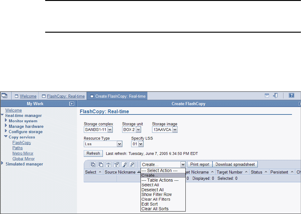
Chapter 9. FlashCopy interfaces 87
9.6 FlashCopy management using the DS SM
To use the DS SM front end GUI, a supported Web Browser needs to be installed on the
workstation. The DS SM communicates with the DS SMC.
To start using the DS SM, enter in your Web browser the IP address of the DS SMC, as
shown in Example 9-12. The password is set up by the administrator and needs to be
changed during the first use of the DS SM.
Example 9-12 Starting DS SM
https://<ip-address>:8452/DS6000
The port 8452 is currently used to communicate with the DS SMC. This might change with new
releases. Always check with your Storage Administrator.
9.6.1 Initiate FlashCopy using Create
After you log in to the DS SM, select Real-time manager on the left, then FlashCopy.
Identify the DS6000 for which you would like to initiate a FlashCopy. From the Select Action
box, select Create. See Figure 9-3.
Figure 9-3 FlashCopy Create with DS SM
This selection will give you several windows, one after the other, to define the options that will
be used with this FlashCopy.
1. Define relationship type.
Select A single source with a single target, or A single source with multiple targets
(if you want to allow Multiple Relationship FlashCopy).
2. Select source volumes
Select one or multiple source volumes by checking the box at the left of the volume
identification. For each of the source volumes, you will afterwards be presented with a
window to select one or more targets.
3. Select target volumes
Select the target volumes (you can’t have more than 12 target volumes).
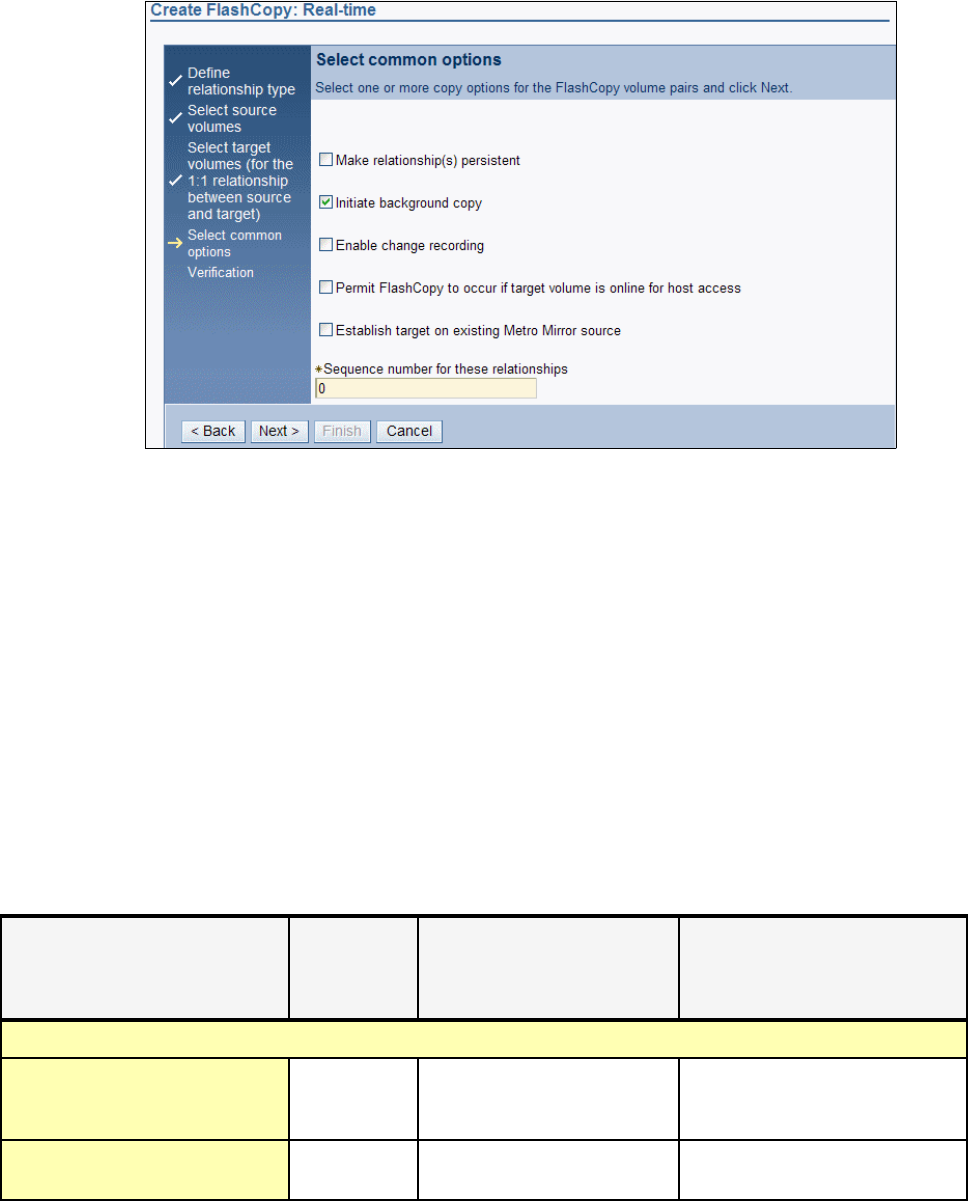
88 IBM System Storage DS6000 Series: Copy Services with IBM System z
4. Select common options
Figure 9-4 on page 88 shows the options that can be chosen. The data provided in this
window will be used for all defined FlashCopy pairs.
Figure 9-4 FlashCopy options
5. Verification.
In the following verification window, all information regarding the FlashCopy definition is
displayed. If it isn’t possible to establish the FlashCopy relationship (if, for example, a
volume was requested to be offline but it is not offline) then an information message is
displayed on this window.
Comparing parameters for initial FlashCopy using DS SM and DS CLI
A FlashCopy can be defined by using the DS SM with a browser (selecting the Create for
FlashCopy) or by using the DS CLI (using the mkflash command).
Using the DS SM, it is possible to define FlashCopies that will be generated immediately. It is
currently not possible to store any FlashCopy tasks using the DS SM.
Table 9-6 shows the corresponding parameters for the various FlashCopy options when using
the DS CLI command mkflash and the DS SM FlashCopy Create selection.
Table 9-6 Comparison of options/parameters used for FlashCopy DS CLI and DS SM
Options Parameter
with DS CLI
command
mkflash
Parameter with DS SM
FlashCopy create
Remark
Options for the source volume
Multiple relationship FlashCopy List of
source:target
volumes
Multiple target volumes can
be selected during create
Consistency Groups for
FlashCopy
Freeze - Not supported with the DS SM

Chapter 9. FlashCopy interfaces 89
9.6.2 Display properties of existing FlashCopy
On the DS SM window, select Real-time manager on the left, then FlashCopy. Identify the
DS6000 (storage unit and LSS for example) for which you would like to display FlashCopy
information. This will give you a list of all active FlashCopy relationships; see Figure 9-5.
By checking the box at the left of the FlashCopy of your interest, the Select Actions for this
FlashCopy relationship are changed, based on the attributes of the FlashCopy relationship
and the possible actions to be performed on it. Using the Select Action, select Properties.
All attributes of the selected FlashCopy will be displayed.
Options for the target volume
FlashCopy target can be Metro
Mirror or Global Copy primary
tgtpprc Establish target on existing
Metro Mirror source
Permit target volume to be online
in z/OS environment
tgtoffline Permit FlashCopy to occur if
target is online for host access
Only for CKD volumes (z/OS)
Inhibit writes to target volume tgtinhibit - Resync target for z/OS
Options for FlashCopy pair
Identification of FlashCopy pair dev or
source:target
Selected in windows
Change Recording record Enable change recording
Persistent FlashCopy persist Make relationship persistent
Full volume background
FlashCopy
nocp Initiate background copy
Sequence number seqnum Sequence number for this
relationship
Options Parameter
with DS CLI
command
mkflash
Parameter with DS SM
FlashCopy create
Remark
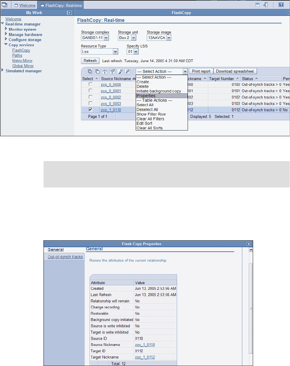
90 IBM System Storage DS6000 Series: Copy Services with IBM System z
Figure 9-5 FlashCopy display properties
This selection will give you a window, with two folders:
General
In this folder all properties of the selected FlashCopy are presented. See Figure 9-6.
Figure 9-6 General folder with FlashCopy information
Note: In case you are selecting multiple FlashCopy relationships, the Select Action →
Properties will not be presented. Select only one FlashCopy relationship to view its prop-
erties.
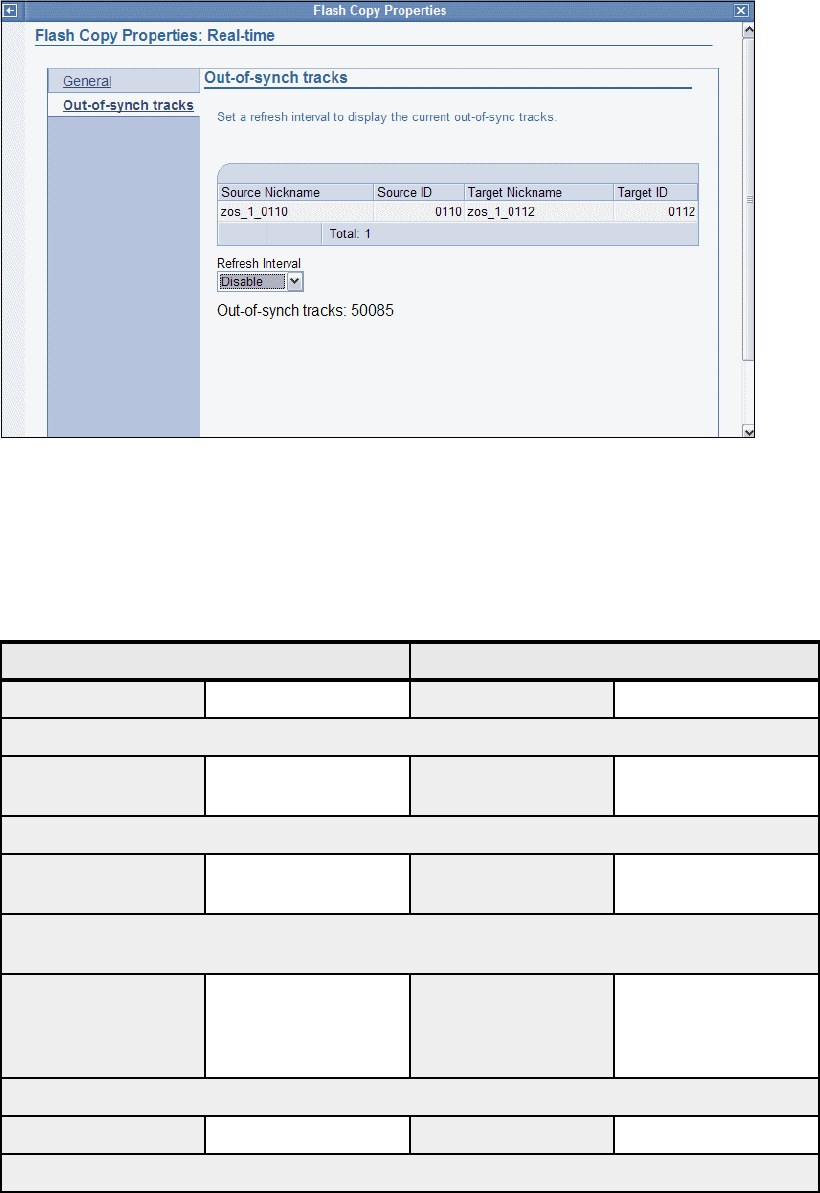
Chapter 9. FlashCopy interfaces 91
Out-of-synch tracks
The window displaying the out-of-synch tracks can be used to monitor how the FlashCopy
performs in the background; see Figure 9-7. A refresh interval can be set to refresh the
display after a preselected period of time.
Figure 9-7 Out-of-synch tracks folder
Properties display - DS CLI vs. DS SM
Table 9-7 compares the differences in the way that the FlashCopy information is displayed
when requested either using the DS CLI command lsflash, or an existing FlashCopy
relationship was selected for display using the DS SM front end.
Table 9-7 FlashCopy properties as displayed by the DS CLI vs. the DS SM front end
Properties with DS CLI command lsflash Properties with DS SM FlashCopy property
Property Contents Property Contents
Source LSS
SrcLSS # Source LSS in
selection window
From selection list
Sequence Number the FlashCopy belongs to. Can also be used for Consistency Groups.
SequenceNum ### Sequence number
from overview window
###
Shows if a Background Copy is currently running. If the DS CLI returns ActiveCopy=disabled this
could be similar to out-of-sync tracks>0 or copy complete on the DS SM.
ActiveCopy Enabled or disabled Status in overview
window
Copy complete or
out-of-sync tracks>0
or background copy
running
Shows if recording was selected for both source and target volume to allow for later usage of resync.
Recording Enabled or disabled Change recording Yes or no
Shows if the FlashCopy is a persistent one.

92 IBM System Storage DS6000 Series: Copy Services with IBM System z
9.6.3 Reverse existing FlashCopy
To reverse an existing FlashCopy relationship you first display the list of active FlashCopy
relationships as described in 9.6.2, “Display properties of existing FlashCopy” on page 89.
Then by checking the box at the left of the FlashCopy of your interest, the available Select
Actions for this FlashCopy relationship will be shown. If the existing FlashCopy relationship
can be reversed, it is possible to choose the Select Action, and then select Reverse
relationship.
The next window displayed is shown in Figure 9-8. It displays those properties of the existing
FlashCopy that might be changed during the reverse process. Changing the values of the
parameters and then clicking OK will start the reverse process for the FlashCopy.
Persistent Enabled or disabled Relationship will
remain
Yes or no
Identifies if the FlashCopy relationship can be changed by copying the contents of the target volume
to the source volume
Revertible Enabled or disabled Restorable Yes or no
Identifies if the source can be used to write on it
SourceWriteEnabled Enabled or disabled Source is write
inhibited
Yes or no
Identifies it the target can be used by another server to write on it in parallel to the FlashCopy taking
place
TargetWriteEnabled Enabled or disabled Target is write
inhibited
Yes or no
Identifies if a background copy was already done
BackgroundCopy Enabled or disabled Background copy
initiated
Yes or no
using -l parameter with DS CLI
OutOfSyncTracks A number A number
DateCreated Date Created Date
DateSynced Date Last refresh Date
Properties with DS CLI command lsflash Properties with DS SM FlashCopy property
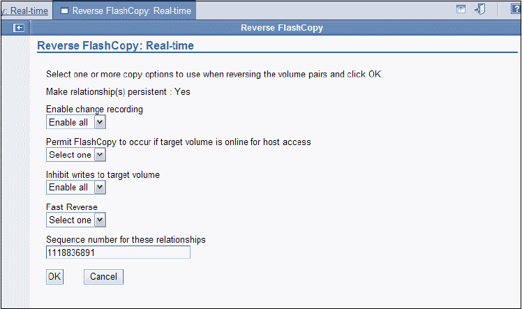
Chapter 9. FlashCopy interfaces 93
Figure 9-8 Properties that can be changed with the reverse action
9.6.4 Initiate background copy for a persistent FlashCopy relationship
To initiate a background copy for a persistent relationship, start on the DS SM front end
window and select Real Time Manager on the left, then FlashCopy. Identify the DS6000
(Storage Unit and LSS, for example) for which you would like to increment a FlashCopy. This
will give you a list of all active FlashCopy relationships similar to Figure 9-9 on page 94.
By checking the box at the left of the FlashCopy relationship of your interest, the available
Select Actions for this FlashCopy relationship will be shown. Then select Initiate
background copy.
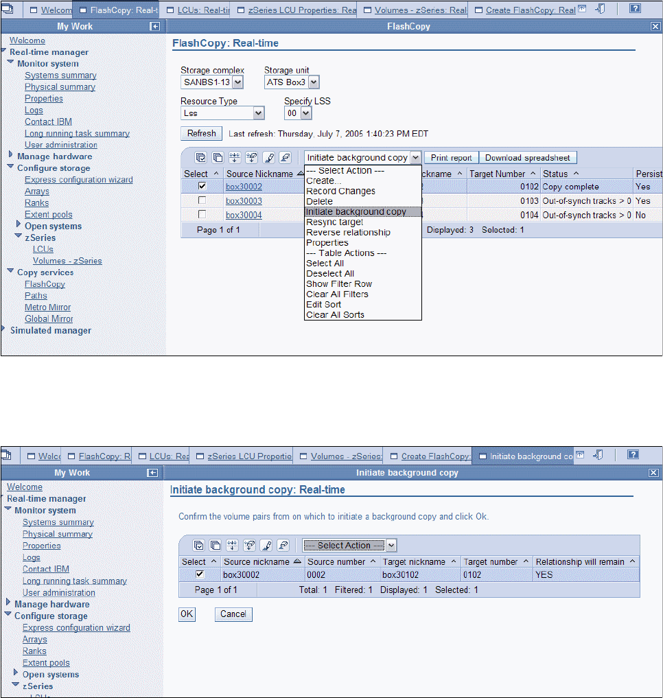
94 IBM System Storage DS6000 Series: Copy Services with IBM System z
Figure 9-9 Initiate background copy
The next window displayed is shown in Figure 9-10. It prompts for the FlashCopy pairs for
which the FlashCopy should run.
Figure 9-10 Prompt window for background copy
9.6.5 Resynchronize target
To resynchronize a target volume, start by displaying the list of active FlashCopy
relationships as shown in Figure 9-11 on page 95. Then check the box at the left of the
FlashCopy you want to resynchronize. Doing so, the available Select Actions for this
FlashCopy relationship will be shown. Then select Resync target.
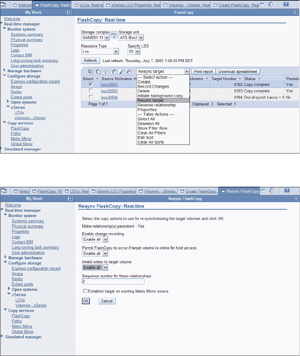
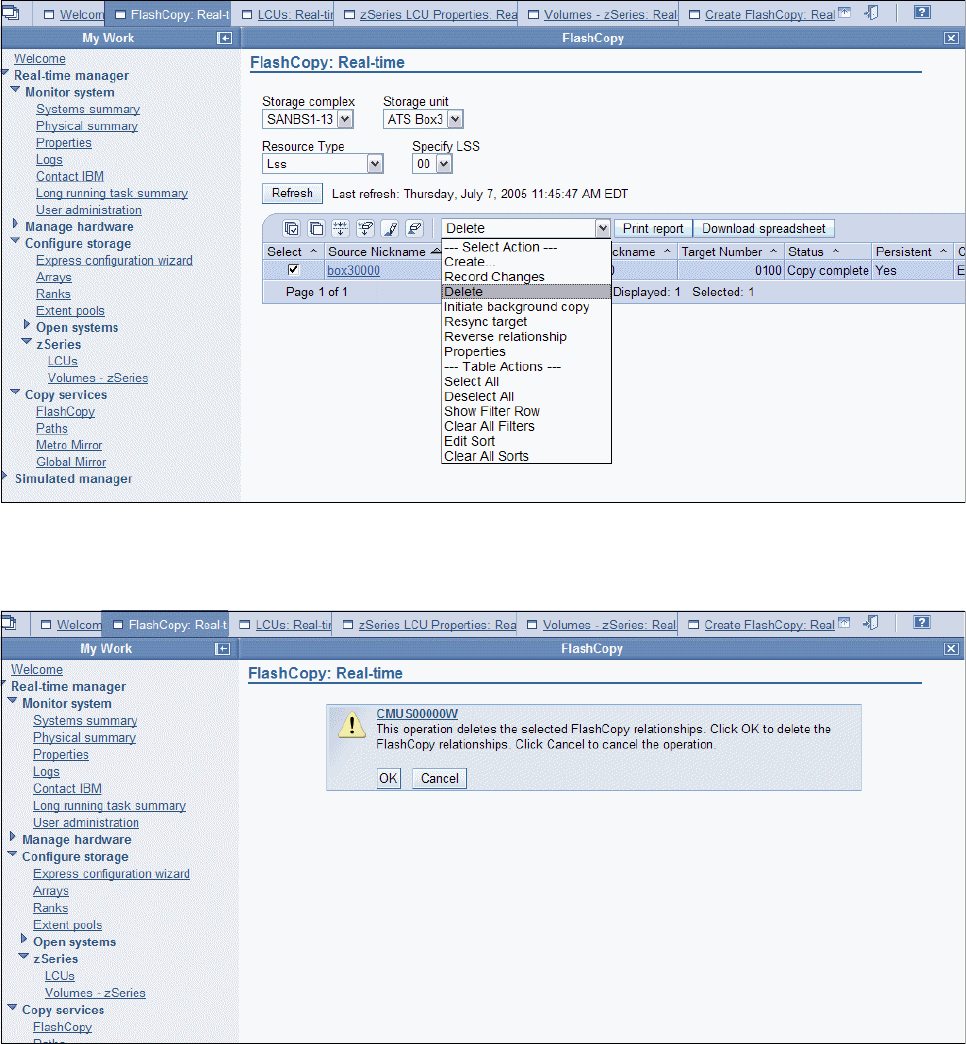
96 IBM System Storage DS6000 Series: Copy Services with IBM System z
9.6.6 Delete existing FlashCopy relationship
To delete an existing FlashCopy relationship, start by displaying the list of active FlashCopy
relationships, as shown in Figure 9-13. Then check the box at the left of the FlashCopy
relationship you want to terminate. Doing so, the available Select Actions for this FlashCopy
relationship will be shown. Then select Delete.
Figure 9-13 Select Action - Delete, to delete an existing FlashCopy relationship
The next window is a prompt asking you to confirm the delete request; see Figure 9-14.
Figure 9-14 Prompt window to confirm delete request for FlashCopy relationship

Chapter 9. FlashCopy interfaces 97
9.7 z/OS interfaces for local FlashCopy
The following z/OS-provided interfaces can be used for FlashCopy management:
DFSMSdss utility
TSO commands
ANTRQST macro
ICKDSF utility
9.7.1 Initiating FlashCopy using DFSMSdss
DFSMSdss has the COPY command that uses FlashCopy for volume copies and data set
copies. Detailed information can be found in z/OS DFSMSdss Storage Administration
Reference, SC35-0424.
For the best performance during COPY operations with DFSMSdss, it is recommended that
you specify any of the parameters in Table 9-8, as applicable for the task to be done.
Table 9-8 Parameters that may improve the performance
Full volume FlashCopy
DFSMSdss can implicitly use the hardware function of the DS6000 to perform a FlashCopy if
the following conditions are met in conjunction with the COPY FULL command:
The source and target volumes must have the same track format.
The source volumes and target volumes are in the same DS6000.
The source and target volumes must be online.
No other FlashCopy is active for the same source volume.
The FASTREPLICATION(NONE) keyword must not be specified.
Not all tracks on the volume are copied when DFSMSdss invokes FlashCopy for a full volume
copy; DFSMSdss requests FlashCopy for allocated extents only.
In order to achieve balance between excluding free space and saving the number of
FlashCopy relationships, up to 255 relations will be created for each full volume copy. If there
are more than 255 extents on the volume, extents will be merged (to reduce the number of
extents) resulting in some free space being copied.
Table 9-6 on page 88 shows the parameters used with the DS CLI command mkflash and the
corresponding selections you can make when using the DS SM Select Action → Create.
Table 9-9 on page 98 shows the options and parameters for DFSMSdss COPY FULL.
DFSMSdss COPY command
parameters
Performance improvements
ADMINISTRATOR Allow a DFSMSdss-authorized administrator to bypass access
checking to data sets and catalogs
ALLDATA(*) Copy all allocated space (for organization type PS, PSU, PO,
POU or null.
ALLEXCP Copy all allocated space (for organization type PS, PSU, PO,
POU or null), even if data sets are empty.
PURGE Unexpired data sets on the target volume can be overlaid for a
full or track copy operation

98 IBM System Storage DS6000 Series: Copy Services with IBM System z
Table 9-9 Options and parameters used for FlashCopy with DFSMSdss COPY FULL
The following considerations apply to the supported options:
Multiple relationship FlashCopy
It is possible to establish up to 12 FlashCopy relationships using the same source. When
setting up a FlashCopy, it is necessary to determine whether the source volume might be
used in other FlashCopy relationships as well. Once a source volume is used in a
FlashCopy without identifying it as a multiple relationship source volume, it is not possible
to define other FlashCopies using this volume as source volume. Once established using
the DS SM, this attribute cannot be changed for an existing FlashCopy relationship.
Consistency Groups for FlashCopy
You can use the FlashCopy Consistency Group function to minimize application impact
when making consistent copies of data spanning multiple volumes. The procedure
consists of freezing the source volume during each volume copy operation, and thawing
all the frozen volumes using the CGCREATE command after a FlashCopy Consistency
Options Parameter with
DFSMSdss
COPY FULL
Remark
Options for the source volume
Multiple relationship FlashCopy selected pairs
Consistency Groups for
FlashCopy
FCCGFREEZE
CGCREATE
FCCGVERIFY
see note (1)
Options for the target volume
FlashCopy target can be Metro
Mirror or Global Copy primary
FCTOPPRCPrimary
Permit target volume to be online
—z/OS environment
no specific parameter
required
volume online / offline will be
handled by DFSMSdss as
required
Inhibit writes to target volume not supported
Options for FlashCopy pair
Identification of FlashCopy pair in the commands
Incremental FlashCopy
Persistent FlashCopy
Change Recording
FCINCREMENTAL
FCINCREMENTALLAST
FCINCRVERIFY
FCWAIT
Persistent and change
recording available via
Incremental relationships.
Also, see note (1)
Do not perform full volume
background FlashCopy
FCNOCOPY also used: FCNC
Change copy mode (no copy to
full background copy)
FCNOCOPYTOCOPY see note (1)
Sequence number not supported
Options for DFSMSdss to force selection of FlashCopy
FlashCopy as preferred copy
method for DFSMSdss
FASTREPLICATION
Note: With z/OS V1R6 or later, and APARs OA11002, OA12707, OA12748, and OA14105

Chapter 9. FlashCopy interfaces 99
Group has been formed. During the time period between the first and last volumes being
frozen, no dependent write updates will occur, which allows a consistent copy of logically
related data that spans multiple volumes.
Freezing the source volumes: You can use the FCCGFREEZE keyword on the COPY
FULL or COPY TRACKS CPVOLUME command to specify that the FlashCopy source
volume is to be part of a FlashCopy Consistency Group. Subsequent I/O activity to the
source volumes will be held (frozen) as each volume is copied. A frozen volume remains
in long busy state until the Consistency Group Created (thaw) command is processed on
the logical subsystem (LSS) where the volume resides, or when the FlashCopy
Consistency Group timer expires.
Thawing the frozen volumes: When all volume copy operations have completed, you can
use the DFSMSdss CGCREATE command to allow I/O activity to resume on the frozen
volumes (thaw the volumes) residing in the logical subsystems. The required
ACCESSVOL keyword specifies one or more volumes residing in the LSS to which the
thaw command will be directed. Only one volume needs to be specified for each LSS
containing frozen volumes in the FlashCopy Consistency Group.
Verifying the Consistency Group: You can use the FCCGVERIFY keyword on the
CGCREATE command to validate the state of the FlashCopy Consistency Group before
thawing all the volumes. This will help you determine whether the copies of the group of
volumes are consistent. An error message is issued if the frozen state cannot be verified.
Regardless of the verification result, DFSMSdss will proceed to thaw all the volumes in the
designated logical subsystems.
Establish a target on existing Metro Mirror primary
When this option is selected, the FlashCopy target volume can be, or can become, a
primary volume for a Metro Mirror or Global Copy relationship. When FlashCopy is not
invoked by the DFSMSdss utility, then FCTOPPRCPrimary is ignored.
When FCTOPPRCPrimary is not specified, or if the capability is not supported by the
DS6000, a Metro Mirror or Global Copy primary volume is not eligible to become a
FlashCopy target volume.
Permit FlashCopy to occur if target volume is online for host access
When setting up the relationship, it is checked whether the target volume is online or not.
See Table 9-10 for valid combinations of offline and online for volumes.
Table 9-10 Resulting actions from target being online or offline
Note: A Metro Mirror volume pair in full duplex state will go to a duplex pending state
when the FlashCopy relationship is established. When Metro Mirror completes the copy
operation, the volume pair returns to the full duplex state.
Status of target
volume in z/OS
Permit FlashCopy to
occur if target
volume is online
Resulting action
volume is online not selected FlashCopy definition is not possible.
volume is online selected FlashCopy definition is queued until target
volume goes offline
volume is offline selected or not
selected
FlashCopy will be started immediately
100 IBM System Storage DS6000 Series: Copy Services with IBM System z
Incremental FlashCopy, Persistent FlashCopy, Change Recording option
Incremental FlashCopy operates at the full volume level. You can use Incremental
FlashCopy to create an initial point-in-time copy of a source volume and refresh the target
volume by copying only the changed data. After the initial full volume copy of the source
volume to the target volume, the FlashCopy relationship remains (persists) between the
source and target volume pair and the changes on the source and target volumes since
the last point-in-time copy are tracked. When you refresh the target volume at a new
point-in-time, only the changed tracks are copied.
The direction of the refresh can be reversed when you indicate that the original target now
becomes the source and the original source becomes the target.
You can use the FCINCREMENTAL keyword for a COPY FULL or COPY TRACKS
CPVOLUME operation to perform an initial full volume copy if no Incremental FlashCopy
relationship exists between the volume pair. If there is an existing Incremental FlashCopy
relationship between the volume pair, DFSMSdss will copy the changed tracks in the
(new) direction designated by the INDDNAME/INDYNAM and
OUTDDNAME/OUTDYNAM keywords. The new direction can be the same or the reverse
of the original (existing) direction.
You can use the FCINCREMENTALLAST keyword on the COPY FULL or COPY
TRACKS CPVOLUME commands to copy the changed tracks when there is an
Incremental FlashCopy relationship between the volume pair. FCINCREMENTALLAST
specifies that the new FlashCopy relationship will be nonpersistent and Change
Recording will be stopped after the final increment has been established. The FlashCopy
relationship will end when background copy for the final increment has completed.
You can use the FCINCRVERIFY(NOREVERSE | REVERSE) keyword to verify that the
existing Incremental FlashCopy direction is what you expected. DFSMSdss will fail the
copy attempt if the existing direction is not as expected.
When you reverse the direction of an Incremental FlashCopy, the storage facility requires
that the previous background copy has completed. You can specify the FCWAIT keyword
with a query interval value in seconds and a number of retries value to direct DFSMSdss
to wait for background copy completion before initiating the new Incremental FlashCopy.
No full volume background copy
It is possible to determine whether the data of the source volume should be copied to the
target volume in the background or not. If DFSMSdss uses the DS6000 FlashCopy, the
parameter FCNOCOPY is analyzed to determine whether a copy should take place or not.
If FCNOCOPY is specified, the FlashCopy relationship stays persistent and only updates
to the source are reflected in the target. If this parameter is omitted, then a physical copy
of the data is done in the background and the FlashCopy relationship is ended after all
data has been copied.
Change copy mode, no copy to full background copy
When an existing FlashCopy relationship is converted from no-background copy
(FCNOCOPY) to background copy mode, the relationship ends (unless the relationship is
persistent) when the background copy has completed.
You can change the existing FlashCopy copy mode by performing a physical full volume
or tracks copy specifying the FCNOCOPYTOCOPY keyword along with the source
volume or extents for which you want background copy to be started. The
FCNOCOPYTOCOPY function will initiate background copy of any NOCOPY FlashCopy
relationships in which the specified source volume or extents are participating.
In general, if you want a temporary copy of the data, specify FCNOCOPY and then
withdraw the FlashCopy relationship when you no longer need the copy. If you want a
permanent copy, but want to delay background copy until a convenient time, specify

Chapter 9. FlashCopy interfaces 101
FCNOCOPY to get a point-in-time copy and then perform FCNOCOPYTOCOPY later to
start background copy. If you want a permanent copy and do not want to delay
background copy, do not specify FCNOCOPY.
FlashCopy as preferred copy method for DFSMSdss
The parameter FASTREPLICATION can be used to identify whether the DS6000
FlashCopy should be used or not. See Table 9-11 for the possible values and the
corresponding actions.
Table 9-11 Combinations of volume offline or online and parameter permit target to be online
Data set FlashCopy
DFSMSdss can implicitly use the hardware function of the DS6000 to perform a FlashCopy if
the following conditions are met in conjunction with the COPY DATASET command:
The source and target types are the same.
The source devices and target devices are in the same DS6000.
The source and target volumes must be online.
The COPY DATASET command can be used with the parameters listed in Table 9-12.
Table 9-12 Parameters with COPY DATASET
Depending on the type of data set, however, the DFSMSdss command COPY DATASET
does not always invoke the FlashCopy hardware function to perform the copy. Table 9-13 on
page 102 shows which functions are invoked by DFSMSdss, depending on the type of data
set.
parameter
FASTREPLICATION(PREFERRED) This is the default. For DFSMSdss the DS6000 FlashCopy
is the preferred method for data copy. If FlashCopy cannot
be used, the parameter CONCURRENT is used to identify
Concurrent Copy to be used. If CONCURRENT is not used
or the Concurrent Copy fails, then traditional data copy
methods will be used.
FASTREPLICATION(REQUIRED) For DFSMSdss the DS6000 FlashCopy is the required
method to copy the volume. If FlashCopy cannot be used,
DFSMSdss fails the operation with error message ADR938E.
FASTREPLICATION(NONE) DFSMSdss will not try to use the DS6000 FlashCopy.
Note: Do not use FASTREPLICATION(NONE), because it prevents the use of FlashCopy.
Parameters with
COPY DATASET
Performance improvements
NOPACKING If COPY DATASET is used for a partitioned data set, the nopacking option
specifies that the data set is not to be compressed during copy. This allows
DFSMSdss to invoke FlashCopy for the copy operation.
FCNOCOPY If FlashCopy is used to perform the copy operation, then do not perform a
full background copy of the data.
ALLEXCP Copy all allocated space (for organization type PS, PSU, PO, POU or null),
even if data sets are empty.
PURGE Unexpired data sets on the target volume can be overlaid for a full or track
copy operation.

102 IBM System Storage DS6000 Series: Copy Services with IBM System z
Table 9-13 Data mover for data set copy (to device of same geometry)
Data set type Data mover Notes
Sequential DFSMSdss
Partitioned (not PDSE) DFSMSdss / IEBCOPY All partitioned data sets that are not load modules are
compressed during a copy. Specify NOPACKING if FlashCopy is
to be used.
Partitioned (not PDSE)
load modules
DFSMSdss / IEBCOPY If copying partitioned load modules with REBLOCK, DFSMSdss
calls IEBCOPY to copy the data set to a like device.
Partitioned data set
extended (PDSE)
DFSMSdss / IGWFAMS DFSMSdss calls the IGWFAMS utility when you are converting a
PDS to a PDSE.
Direct nonrelative block
address mode
DFSMSdss
Direct relative block
address mode
DFSMSdss Specify the DFSMSdss RELBLOCKADDRESS parameter.
Indexed sequential to
same track. Target
volume uses VTOC
index. Target space
available.
DFSMSdss
Indexed sequential (all
other cases)
IEBISAM
ESDS DFSMSdss / IDCAMS DFSMSdss calls IDCAMS if the target CISIZE, CASIZE, physical
record size, or physical block size of the target is different from
that of the source.
RRDS DFSMSdss / IDCAMS DFSMSdss calls IDCAMS if the target CISIZE, CASIZE, physical
record size, or physical block size of the target is different from
that of the source.
LDS DFSMSdss/IDCAMS DFSMSdss calls IDCAMS if the target CISIZE, CASIZE, physical
record size, or physical block size of the target is different from
that of the source.
KSDS or VRRDS DFSMSdss / IDCAMS DFSMSdss calls IDCAMS if any of the following are true:
The CISIZE, CASIZE, physical record size, physical block
size, imbed, or span attributes of the target are different from
that of the source.
The target data set is SMS and has an imbedded index or
has key ranges, and the target volume count is greater than
one.
The target data set is non-SMS, the source component or
components span multiple volumes, and there is not enough
space on one target volume to contain the entire data set.
Key range data set DFSMSdss / IDCAMS DFSMSdss calls IDCAMS if the source and target CASIZE,
physical record size, or physical block size are different; if the
components span multiple volumes; for a KSDS with IMBED and
either the source HURBA=HARBA or it has extended indexes.
Extended-format VSAM DFSMSdss / IDCAMS DFSMSdss calls IDCAMS if the target CISIZE, CASIZE, physical
record size, or physical block size of the target is different from
that of the source.

Chapter 9. FlashCopy interfaces 103
9.7.2 FlashCopy using TSO commands
In this section we describe the FlashCopy functions invoked via TSO commands and
parameters. For more detailed information about the TSO FlashCopy commands, refer to
DFSMS Advanced Copy Services, SC35-0428.
Consistency Group FlashCopy
In order to create a Consistency Group with a set of FlashCopy volumes, use the TSO
FCESTABL command with the ACTION(FREEZE) parameter as shown in Example 9-13.
The FlashCopy relationship is established between the source and target volumes, or
extents, and all I/O to the source volumes is put on hold (extended long busy) until one of the
following conditions is met:
A FlashCopy withdraw - FCWITHDR with ACTION(THAW) is processed by the LSS where
the volumes reside.
A two-minute timer expires.
Example 9-13 Create a FlashCopy consistency group with FCESTABL and ACTION(FREEZE)
//*********************************************************************
//* ESTABLISH FLASHCOPY RELATIONSHIP *
//* SDEVN - SOURCE FLASHCOPY VOLUME *
//* TDEVN - TARGET FLASHCOPY VOLUME *
//*********************************************************************
//STEP1 EXEC PGM=IKJEFT01,REGION=256K
//SYSTSPRT DD SYSOUT=*
//SYSUADS DD DSN=SYS1.UADS,DISP=SHR
//SYSLBC DD DSN=SYS1.BRODCAST,DISP=SHR
//SYSTSIN DD *
FCESTABL SDEVN(X'3500') TDEVN(X'4500') ACTION(FREEZE)
FCESTABL SDEVN(X'3501') TDEVN(X'4501') ACTION(FREEZE)
FCESTABL SDEVN(X'3502') TDEVN(X'4502') ACTION(FREEZE)
FCESTABL SDEVN(X'3503') TDEVN(X'4503') ACTION(FREEZE)
FCESTABL SDEVN(X'3504') TDEVN(X'4504') ACTION(FREEZE)
/*
Incremental FlashCopy
With incremental FlashCopy, the relationship remains active after initial copy is complete.
This allows subsequent changes to be tracked so that future FlashCopy operations require
only a subset of the volume to be copied—only the data that has changed.
As shown in Example 9-14 on page 104, the TSO FCESTABL command with
INCREMENTAL(YES) is used to establish a FlashCopy relationship which will remain until
explicitly terminated with a FlashCopy withdraw request (the TSO FCWITHDR command).
The FlashCopy target is write-inhibited while the incremental relationship is active. Any
attempt to write to the device during this period will be failed by the hardware and reported as
an I/O error, an error from the access method, or both.
Integrated catalog
facility user catalogs
IDCAMS
(EXPORT/IMPORT)
Undefined DSORG DFSMSdss
Data set type Data mover Notes

104 IBM System Storage DS6000 Series: Copy Services with IBM System z
Example 9-14 Incremental FlashCopy invoked with FCESTABL and INCREMENTAL(YES)
//*********************************************************************
//* ESTABLISH FLASHCOPY RELATIONSHIP *
//* SDEVN - SOURCE FLASHCOPY VOLUME *
//* TDEVN - TARGET FLASHCOPY VOLUME *
//*********************************************************************
//STEP1 EXEC PGM=IKJEFT01,REGION=256K
//SYSTSPRT DD SYSOUT=*
//SYSUADS DD DSN=SYS1.UADS,DISP=SHR
//SYSLBC DD DSN=SYS1.BRODCAST,DISP=SHR
//SYSTSIN DD *
FCESTABL SDEVN(X'3500') TDEVN(X'4500') INCREMENTAL(YES)
FCESTABL SDEVN(X'3501') TDEVN(X'4501') INCREMENTAL(YES)
/*
Full volume background copy
The type of the FlashCopy operation is specified with the TSO FCESTABL command and
MODE parameter. If a MODE(COPY) option is specified (see Example 9-15) then a full
volume copy is performed in the background. The FlashCopy relationship ends when the
background copy is completed or the FCWITHDR command is issued. If you specify
MODE(COPY), data on the target device is overlaid within the track extents specified. In case
the MODE parameter is omitted on the FCESTABL command, then a full volume copy will
take place.
Example 9-15 Full volume background copy - FCESTABL with MODE(COPY)
//*********************************************************************
//* ESTABLISH FLASHCOPY RELATIONSHIP *
//* SDEVN - SOURCE FLASHCOPY VOLUME *
//* TDEVN - TARGET FLASHCOPY VOLUME *
//*********************************************************************
//STEP1 EXEC PGM=IKJEFT01,REGION=256K
//SYSTSPRT DD SYSOUT=*
//SYSUADS DD DSN=SYS1.UADS,DISP=SHR
//SYSLBC DD DSN=SYS1.BRODCAST,DISP=SHR
//SYSTSIN DD *
FCESTABL SDEVN(X'3500') TDEVN(X'4500') MODE(COPY)
FCESTABL SDEVN(X'3501') TDEVN(X'4501')
/*
FlashCopy NOCOPY option
In case that MODE(NOCOPY) is used in a FlashCopy relationship between the source and
target devices for the specified volume or extent ranges, the background copy operation is
not initiated (see Example 9-16 on page 105).
When the DS6000 receives an update to a source track in a FlashCopy NOCOPY
relationship, a copy of the point-in-time (pre-update) data is preserved on the target volume.
A FlashCopy relationship established in NOCOPY mode remains active until one of the
following occurs:
Note: Incremental FlashCopy is only supported for full volumes, with a limit of one full
volume incremental relationship per volume. A single Incremental relationship can coexist
with as many as eleven nonincremental relationships per track, up to the maximum
number of FlashCopy relationships allowed on the volume. The normal FlashCopy
restrictions apply to the target tracks of an incremental relationship.

Chapter 9. FlashCopy interfaces 105
All specified source device tracks are updated.
The DS6000 copies all tracks from source to target when a threshold number of source
tracks are updated.
A FlashCopy withdraw (using the FCWITHDR command) is issued to remove the
FlashCopy relationship.
A NOCOPY relationship is converted to a COPY relationship through the
NOCOPY2COPY mode option.
Example 9-16 FlashCopy NOCOPY option
//*********************************************************************
//* ESTABLISH FLASHCOPY RELATIONSHIP *
//* SDEVN - SOURCE FLASHCOPY VOLUME *
//* TDEVN - TARGET FLASHCOPY VOLUME *
//*********************************************************************
//STEP1 EXEC PGM=IKJEFT01,REGION=256K
//SYSTSPRT DD SYSOUT=*
//SYSUADS DD DSN=SYS1.UADS,DISP=SHR
//SYSLBC DD DSN=SYS1.BRODCAST,DISP=SHR
//SYSTSIN DD *
FCESTABL SDEVN(X'3500') TDEVN(X'4500') MODE(NOCOPY)
FCESTABL SDEVN(X'3501') TDEVN(X'4501') MODE(NOCOPY)
/*
One of the reasons for the NOCOPY option is for backing up to tape. The FlashCopy
NOCOPY parameter generates a logical copy of source data that can be read from another
device (target). This allows read activity (from the target device) to be separate from
application read/write activity on the source device. A backup program such as DFSMSdss
can use the target device as input for backing up data to tape.
Change the NOCOPY to full volume copy relationship
In order to change the NOCOPY relationship to a full volume copy, use the TSO FCESTABL
command with the MODE(NOCOPY2COPY) option (shown in Example 9-17). This starts a
background copy for source NOCOPY relationships intersecting with the extents specified.
The relationships end when the background copy is completed.
Example 9-17 TSO FCESTABL and MODE(NOCOPY2COPY)
//*********************************************************************
//* ESTABLISH FLASHCOPY RELATIONSHIP *
//* SDEVN - SOURCE FLASHCOPY VOLUME *
//* TDEVN - TARGET FLASHCOPY VOLUME *
//*********************************************************************
//STEP1 EXEC PGM=IKJEFT01,REGION=256K
//SYSTSPRT DD SYSOUT=*
//SYSUADS DD DSN=SYS1.UADS,DISP=SHR
//SYSLBC DD DSN=SYS1.BRODCAST,DISP=SHR
//SYSTSIN DD *
FCESTABL SDEVN(X'3500') TDEVN(X'4500') MODE(NOCOPY2COPY)
Note: When a FlashCopy NOCOPY relationship is ended, the data remaining on the target
device is unpredictable and should not be used. Also consider that tracks may be copied
from the source to the target volume even if the source track is not changed. This includes
the track that contains the volume label. Therefore, to avoid duplicate volume serial
problems when the target device is later varied online, we recommend that you relabel the
target volume after withdrawing a volume-level FlashCopy NOCOPY relationship.
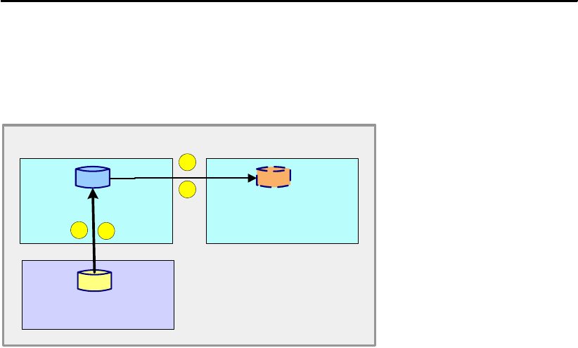
106 IBM System Storage DS6000 Series: Copy Services with IBM System z
FCESTABL SDEVN(X'3501') TDEVN(X'4501') MODE(NOCOPY2COPY)
FlashCopy to Metro Mirror or Global Copy primary volume
This FlashCopy option allows you to establish a FlashCopy pair where the FlashCopy target
is the primary device in a Metro Mirror (or Global Copy) pair. In this way you can create a
point-in-time copy and then make a copy of that point-in-time copy at a remote site.
Figure 9-15 FlashCopy to Metro Mirror or Global Copy primary
A FlashCopy to a Metro Mirror (or Global Copy) primary configuration is set up as follows
(refer to Figure 9-15):
1. Establish the Metro Mirror pair from the local to the remote site and allow the pair to reach
full duplex state.
2. When you want to make a point-in-time copy of a volume at the local site, establish a
FlashCopy relationship with the primary Metro Mirror volume as the target, specifying
MODE(COPY) and TGTPPRIM(YES) with the FCESTABL command. When the
FlashCopy is requested, the state of the Metro Mirror pair is changed from duplex to
pending.
3. When the background copy on the target FlashCopy volume (which is at the same time
the primary Metro Mirror volume) is complete, the FlashCopy relationship is
ended—unless INCREMENTAL(YES) was specified. Resynchronization of the Metro
Mirror pair begins.
4. When the Metro Mirror pair is resynchronized, the state returns to duplex and the
point-in-time copy is available at the secondary volume at the remote site.
A FlashCopy to a Metro Mirror primary volume can be used with the INCREMENTAL(YES)
option. This results in the Metro Mirror primary using incremental updates to resynchronize
with the Metro Mirror secondary volume.
Inband FlashCopy
The Inband FlashCopy option allows FlashCopy requests to be issued remotely through an
existing remote mirror and copy link—Metro Mirror or Global Copy link.
As shown in Example 9-18 on page 107, the FCESTABL command is issued with the
REMOTE(YES) parameter. Once the FlashCopy is established, the direct host connection
from local to remote DS6000 is not required for a background copy to complete. The host
connection would be needed, however, before any new FlashCopy tasks could be initiated.
primary
secondary
source
target
FlashCopy
Remote site
Local site
32
1
4
Metro
Mirror
or
Global
Copy
Metro
Mirror
or
Global
Copy

Chapter 9. FlashCopy interfaces 107
Inband FlashCopy can be useful if the host at the recovery site is not online. The Inband
option eliminates the need for a host connection from local to remote exclusively for
FlashCopy backup. The FlashCopy request must be issued at a host processor connected to
the remote mirror or copy primary volume, with the remote mirror or copy secondary volume
specified as the FlashCopy source.
Example 9-18 Inband FlashCopy
//*********************************************************************
//* ESTABLISH INBAND FLASHCOPY RELATIONSHIP *
//* DEVN - METRO MIRROR PRIMARY VOLUME AT LOCAL SITE *
//* SOURCE - DS6000 SERIAL NO, LSS, CCA AT REMOTE SITE *
//* TARGET - DS6000 SERIAL NO, LSS, CCA AT REMOTE SITE *
//*********************************************************************
//STEP1 EXEC PGM=IKJEFT01,REGION=256K
//SYSTSPRT DD SYSOUT=*
//SYSUADS DD DSN=SYS1.UADS,DISP=SHR
//SYSLBC DD DSN=SYS1.BRODCAST,DISP=SHR
//SYSTSIN DD *
FCESTABL DEVN(X'3500') SOURCE(ABTV1 05 0A) -
TARGET(ABTV1 05 0B) -
MODE(COPY) SSID(4500) REMOTE(YES)
/*
In the Example 9-18, the REMOTE(YES) parameter specifies that this relationship is to be
located on the remote DS6000 storage subsystem identified by SSID 4500. This must be the
same as the SSID value specified for the Metro Mirror secondary on the TSO CESTPAIR
command. DEVN 3500 is the Metro Mirror primary through which the FCESTABL command
will be passed.
FlashCopy in a Global Mirror session
Example 9-19 shows the TSO FCESTABL command with MODE(ASYNC), which is used
when FlashCopy is part of a Global Mirror configuration. Since the ASYNC mode establishes
an incremental relationship, the INCREMENTAL(YES) parameter is not needed. In addition,
the FlashCopy target is write-inhibited.
Example 9-19 TSO FCESTABL and MODE(ASYNC)
//*********************************************************************
//* ESTABLISH FLASHCOPY RELATIONSHIP FOR GLOBAL MIRROR SESSION *
//* SDEVN - SOURCE FLASHCOPY VOLUME *
//* TDEVN - TARGET FLASHCOPY VOLUME *
//*********************************************************************
//STEP1 EXEC PGM=IKJEFT01,REGION=256K
//SYSTSPRT DD SYSOUT=*
//SYSUADS DD DSN=SYS1.UADS,DISP=SHR
//SYSLBC DD DSN=SYS1.BRODCAST,DISP=SHR
//SYSTSIN DD *
FCESTABL SDEVN(X'3500') TDEVN(X'4500') MODE(ASYNC)
FCESTABL SDEVN(X'3501') TDEVN(X'4501') MODE(ASYNC)
/*
Fast Reverse Restore is another function to be used with a Global Mirror configuration. It is
used when recovering from an outage. This function reverses the direction of the FlashCopy
relationship when change recording is active (incremental FlashCopy), restoring the source
volume to the state it was in when it last flashed to the target. Changed tracks are copied
back from the target to the source.

108 IBM System Storage DS6000 Series: Copy Services with IBM System z
As shown in Example 9-20, Fast Reverse Restore is invoked with the FCESTABL command
and the ACTION(FRR) parameter.
Example 9-20 FlashCopy Fast Reverse Restore function
//********************************************************
//* THIS JOB WILL REVERSE THE DIRECTION OF FLASHCOPY
//* ORIGINAL SOURCE = 3500, FRR SOURCE = 4500
//* ORIGINAL TARGET = 4500, FRR TARGET = 3500
//********************************************************
//STEP1 EXEC PGM=IKJEFT01,REGION=256K
//SYSTSPRT DD SYSOUT=*
//SYSUADS DD DSN=SYS1.UADS,DISP=SHR
//SYSLBC DD DSN=SYS1.BRODCAST,DISP=SHR
//SYSTSIN DD *
FCESTABL SDEVN(X'4500') TDEVN(X'3500') ACTION(FRR)
/*
In Example 9-20, we reversed the FlashCopy direction for the previously established
FlashCopy relationship between volume 3500 (source) and 4500 (target), by specifying 4500
as a source volume and 3500 as a target volume.
Revert is a function to be used with Global Mirror for DS6000 when recovering from an
outage. It specifies a rollback to the state saved by a previous automatic FlashCopy establish
command. Revert is a function that is invoked with the FCWITHDR command and the
ACTION(REVERT) parameter. The FlashCopy relationship is not removed (withdrawn) but
the FlashCopy target is rolled back to the previous consistency group created by the Global
Mirror session. For more information, refer to 23.7.4, “Check for valid Consistency Group
state” on page 285.
Withdraw FlashCopy relationships
TSO FCWITHDR is used to remove existing FlashCopy relationships. The FlashCopy
withdraw process locates source tracks on the source device and target tracks on the target
device, and ends the FlashCopy relationship between them.
This command can be used on FlashCopy relationships whether or not a background copy is
in progress. The FCWITHDR command provides a method of manually withdrawing the
relationship.
The following examples show different options used to terminate FlashCopy relationships.
In Example 9-21 on page 109, specification of the TDEVN parameter without the SDEVN
parameter allows you to withdraw all FlashCopy relationships that have target extents on the
specified TDEVN, regardless of what source volumes are involved in those FlashCopy
relationships. In this case, the withdraw processing identifies where the source tracks are
(volume and track location) and removes all information about the relationships from all
devices involved.
Note: When a FlashCopy NOCOPY relationship is ended, the track data on the target
device is unpredictable and should not be used. Also consider that tracks may be copied
from the source to the target volume even if the source track is not changed. This includes
the track that contains the volume label. Therefore, to avoid duplicate volume serial
problems when the target device is later varied online, we recommend that you relabel the
target volume after withdrawing a volume-level FlashCopy NOCOPY relationship.

Chapter 9. FlashCopy interfaces 109
Example 9-21 FlashCopy withdraw target only
//*********************************************************************
//* WITHDRAW FLASHCOPY RELATIONSHIP *
//* TARGET ONLY *
//* TDEVN - TARGET FLASHCOPY VOLUME *
//*********************************************************************
//STEP1 EXEC PGM=IKJEFT01,REGION=256K
//SYSTSPRT DD SYSOUT=*
//SYSUADS DD DSN=SYS1.UADS,DISP=SHR
//SYSLBC DD DSN=SYS1.BRODCAST,DISP=SHR
//SYSTSIN DD *
FCWITHDR TDEVN(X'320B')
/*
In Example 9-22, both the SDEVN parameter and the TDEVN parameter allow you to limit the
scope of the withdraw to those FlashCopy relationships that have source extents on the
specified SDEVN and corresponding target extents on the TDEVN, regardless of whatever
source and target relationships with other devices may exist.
Example 9-22 FlashCopy withdraw source and target
//*********************************************************************
//* WITHDRAW FLASHCOPY RELATIONSHIP *
//* SDEVN - SOURCE FLASHCOPY VOLUME *
//* TDEVN - TARGET FLASHCOPY VOLUME *
//*********************************************************************
//STEP1 EXEC PGM=IKJEFT01,REGION=256K
//SYSTSPRT DD SYSOUT=*
//SYSUADS DD DSN=SYS1.UADS,DISP=SHR
//SYSLBC DD DSN=SYS1.BRODCAST,DISP=SHR
//SYSTSIN DD *
FCWITHDR SDEVN(X’320A’) TDEVN(X'320B')
/*
The FCWITHDR command with the DDSW(YES) (deleted data space withdraw) parameter,
when issued against an entire source volume, removes all target extents on the specified
source device from their associated FlashCopy relationships. In addition, any FlashCopy
NOCOPY source tracks on the specified source device are changed to COPY (background
copy) source tracks. This process causes all source tracks to be copied to their respective
target tracks and all FlashCopy relationships to be removed from the specified source device.
The FCWITHDR command in Example 9-23 withdraws all source extents on the source
device 320A from their associated FlashCopy relationships regardless of the location of their
corresponding target extents, and all target extents on the source device regardless of the
location of the corresponding source extents.
Example 9-23 FCWITHDR and DDSW parameter
//*********************************************************************
//* WITHDRAW FLASHCOPY RELATIONSHIP *
//* SDEVN - SOURCE FLASHCOPY VOLUME *
//* DDSW(YES) *
//*********************************************************************
//STEP1 EXEC PGM=IKJEFT01,REGION=256K
//SYSTSPRT DD SYSOUT=*
//SYSUADS DD DSN=SYS1.UADS,DISP=SHR
//SYSLBC DD DSN=SYS1.BRODCAST,DISP=SHR
//SYSTSIN DD *
FCWITHDR SDEVN(X’320A’) DDSW(YES)

110 IBM System Storage DS6000 Series: Copy Services with IBM System z
/*
The main benefit of the DDSW(YES) parameter is that it can be used to easily free up tracks
on both the source and the corresponding target volumes that are in FlashCopy relationships
that are no longer needed because the original source data—that justified the
relationship—has been deleted. Another example might be that prior to starting a backup
cycle using DFSMSdss, you might want to make sure that all relationships have been
cleaned up on the subject source volume. More details on this subject can be found in
DFSMS Advanced Copy Services, SC35-0428.
Displaying information for volumes in a FlashCopy relationship
The TSO FCQUERY command is used to display available information about FlashCopy and
other copy services relationships active on the device. If the device is not in a source or target
FlashCopy relationship, the FCQUERY report shows the number of active FlashCopy
relationships as 0.
As shown in Example 9-24, the FCQUERY output report indicates that device 350A has one
active FlashCopy relationship (ACT=1) and is in a remote mirror session as a secondary
device (PC=S). The very same device is not in a z/OS Global Mirror session (XC=N), nor in a
Concurrent Copy (CC=N), and it has a nonrevertible status (RV=N).
Example 9-24 FlashCopy report - FCQUERY
FCQUERY DEVN(350A)
*******************************************************************************************
ANTF0420I FCQUERY Formatted -2
DEVN SSID LSS CCA CU SERIAL ACT MAX XC PC CC RV SEQNUM
420A 4200 02 0A 1750 0000000ABTV1 1 50099 N S N N 00000000

© Copyright IBM Corp. 2006. All rights reserved. 111
Chapter 10. FlashCopy performance
This chapter discusses best practices when configuring FlashCopy for specific environments
or scenarios. The following topics are covered:
FlashCopy performance overview
FlashCopy establish performance
Background copy performance
FlashCopy impact to applications
FlashCopy options
FlashCopy scenarios
10

112 IBM System Storage DS6000 Series: Copy Services with IBM System z
10.1 FlashCopy performance overview
Many parameters can affect the performance of FlashCopy operations. It is important to
review the data processing requirements and hence select the proper FlashCopy options.
This chapter examines when to use the COPY versus the NOCOPY mode and where to
place the FlashCopy source and target volumes/LUNs. We also discuss when and how to
use incremental FlashCopy—which should definitely be evaluated for use in most
applications.
Terminology
Before proceeding with the discussion of FlashCopy best practices, lets review some of the
basic terminology we will be using in this chapter.
Server - A DS6000 has two servers—Server 0 and Server 1, one on each controller
card—and each server independently provides major functions for the disk subsystem:
Directing host adapters for data transferring to and from host processors, managing cache
resources, and directing lower device adapters for transferring data to and from physical
disks. You can issue the lsserver command to see the available servers.
Device Adapter (DA) - A physical component of the DS6000 that provides communications
between the servers and the storage devices. The lsda command lists the available device
adapters.
Rank - An array site made into an array which is then made into a rank. For the DS6000 a
rank is a collection of 8 disk drive modules (DDMs). The lsrank command displays detailed
information about the ranks.
10.1.1 Distribution of the workload - Source and target volumes location
In general, you can achieve the best performance by distributing the load across all of the
resources of the DS6000. In other words, you should carefully plan your usage so that the
load is:
Spread evenly across disk subsystems
Within each disk subsystem, spread evenly across servers
Within each server, spread evenly across device adapters
Within each device adapter, spread evenly across ranks
Additionally, it is always best to locate the FlashCopy target volume on the same DS6000
server as the FlashCopy source volume. It is also good practice to locate the FlashCopy
target volume on a different device adapter (DA) than the source volume, but there are some
cases where this is really a don’t care decision.
Another choice available is whether to place the FlashCopy target volumes on the same
ranks as the FlashCopy source volumes. In general it is best not to place these two volumes
in the same rank. Refer to Table 10-1 on page 113 for a summary of the volume placement
considerations.
Note: This chapter is equally valid for System z volumes and open systems LUNs. In the
following sections only the term volume or volumes will be used, but the text is equally valid
if the terms LUN and LUNs were used, unless otherwise noted.

Chapter 10. FlashCopy performance 113
Table 10-1 FlashCopy source and target volume location
10.1.2 LSS/LCU versus rank considerations
In the DS6000 it is much more meaningful to discuss volume location in terms of ranks and
not in terms of logical subsystem (LSS) or logical control unit (LCU). On the ESS 800 and
earlier IBM disk subsystems, the physical locations of the volumes were described in terms of
the logical subsystem LSS/LCU. If there existed more than a single rank in the LSS/LCU,
then each of the ranks would have a range of volumes from that specific LSS/LCU.
The LSSs/LCUs in a DS6000 disk subsystem are logical constructs that are no longer tied to
predetermined ranks. Within the DS6000 the LSS/LCU can be configured to span one or
more ranks but is not limited to specific ranks. There can be individual ranks that contain
volumes from more than a single LSS/LCU, which was not possible before the introduction of
the DS6000.
10.1.3 Rank geometry
Finally, you can achieve a small performance improvement by using identical rank
geometries for both the source and target volumes. In other words, if the source volumes are
located on a rank with a 7+p/RAID-5 configuration, then the target volumes should also be
located on a rank configured as 7+p/RAID-5.
10.1.4 Incremental FlashCopy
This chapter focuses on FlashCopy performance best practices, but there are many other
business requirements that must be weighed when using FlashCopy. The designer should
carefully consider all aspects for the implementation of each specific solution and should
definitely evaluate the use of incremental FlashCopy for all FlashCopy applications.
Tip: If the FlashCopy target volume is on the same rank as the FlashCopy source volume,
you run the risk of a rank failure causing the loss of both the source and the target volume.
Server Device Adapter Rank
FlashCopy establish
performance
Same server Don’t care Different ranks
Background copy
performance
Same server Different device adapter Different ranks
FlashCopy impact to
applications
Same server Don’t care Different ranks
Tip: To find the relative location of your volumes, you can use the following procedure:
1. Use the lsfbvol command to find out which Extent Pool contains the relevant volumes.
2. Use the lsrank command to display both the device adapter and the rank for each
Extent Pool.
3. To determine which server contains your volumes, look at the Extent Pool name. Even
numbered Extent Pools are always from Server 0, while odd numbered Extent Pools
are always from Server1.

114 IBM System Storage DS6000 Series: Copy Services with IBM System z
10.2 FlashCopy establish phase performance
The FlashCopy of a volume has two distinct periods:
The initial logical FlashCopy (also called establish)
The physical FlashCopy (also called background copy)
The FlashCopy establish phase, or logical FlashCopy, is the period of time when the
microcode is preparing things, such as the bitmaps, necessary to create the FlashCopy
relationship so the microcode can properly process subsequent reads and writes to the
related volumes. During this logical FlashCopy period, no writes are allowed to the volumes.
After the logical relationship has been established, normal I/O activity is allowed to both
source and target volumes according to the options selected.
When there are a large number of volumes, the method used to invoke the FlashCopy
commands can influence the time it takes to complete the logical FlashCopy for all FlashCopy
pairs. An in-band invocation will source the commands to the microcode faster than an
out-of-band method in most cases. An in-band establish is one that uses the CCW
commands directly, like in z/OS.
The fastest out-of-band method is the DS CLI. The method to control or invoke FlashCopy
should be selected based upon the total solution requirements and not strictly on logical
FlashCopy performance considerations, unless this is a critical performance issue.
Additionally, there is a modest performance impact to logical FlashCopy performance when
using incremental FlashCopy. In the case of incremental FlashCopy, the DS6000 must create
additional metadata (bitmaps). However, the impact is negligible in most cases.
Finally, the placement of the FlashCopy source and target volumes has an effect on the
establish performance. You can refer to the previous section for a discussion of this topic as
well as to Table 10-1 on page 113 for a summary of the recommendations.
10.3 Background copy performance
The background copy phase, or physical FlashCopy, is the actual movement of data from the
source volume to the target volume. If the FlashCopy relationship was established requesting
the NOCOPY option, then only write updates to the source volume will force a copy from the
source to the target. This forced copy is also called a collision.
If the COPY option was selected, then upon completion of the logical FlashCopy establish
phase, the source will be copied to the target in an expedient manner.
If a large number of volumes have been established, then do not expect to see all pairs
actively copying data as soon as their logical FlashCopy relationship is completed. The
DS6000 microcode has algorithms that limit the number of active pairs copying data. These
algorithms will try to balance active copy pairs across the DS6000 device adapter resources.
Additionally, they will limit the number of active pairs such that there remains bandwidth for
host or server I/Os.
Note: The term collision describes a forced copy from the source to the target because a
write to the source has occurred. This occurs on the first write to a track. Note that since
the DS6000 writes to non-volatile cache, there is typically no direct response time delay on
host writes. The forced copy only occurs when the write is destaged onto disk.

Chapter 10. FlashCopy performance 115
The recommended placement of the FlashCopy source and target volumes, regarding the
physical FlashCopy phase, was already discussed in the previous section. Refer to
Table 10-1 on page 113 for a summary of the conclusions. For the best background copy
performance, the implementation should always place the source and target volumes in
different ranks. There are additional criteria to consider if the FlashCopy is a full box copy that
involves all ranks.
For full box copies, you should still place the source and target volumes in different ranks.
When all ranks are participating in the FlashCopy, it is still possible to accomplish this by
doing a FlashCopy of volumes on rank R0 onto rank R1, and volumes on rank R1 onto rank
R0 (for example). Additionally, if there is heavy application activity in the source rank,
performance would be less affected if the background copy target was in some other rank
that could be expected to have lighter application activity.
If background copy performance is of high importance in your environment, you should use
incremental FlashCopy as much as possible. Incremental FlashCopy will greatly reduce the
amount of data that needs to be copied, and therefore greatly reduce the background copy
time.
10.4 FlashCopy impact on applications
One of the most important considerations when implementing FlashCopy is to achieve an
implementation that has minimal impact to the users’ application performance.
The relative placement of the source and target volumes has a significant impact on
application performance, and this has already been discussed in 10.1.1, “Distribution of the
workload - Source and target volumes location” on page 112.
In addition to the relative placement of volumes, the selection of COPY or NOCOPY is also
an important consideration in regard to the impact on application performance. Typically, the
choice of COPY or NOCOPY depends primarily on how the FlashCopy will be used and for
what interval of time the FlashCopy relationship exists. From a purely performance point of
view, the choice of whether to use COPY or NOCOPY depends a great deal on the type of
workload. The general answer is to use NOCOPY, but this is not always the best choice. For
most workloads, including online transaction processing (OLTP) workloads, NOCOPY is
Tip: The DS6000 gives higher priority to application performance than background copy
performance. This means that the DS6000 will throttle the background copy if necessary,
so that applications are not unduly impacted.
Note: The term full box copy has the implication that all rank resources are involved in the
copy process. Either all or nearly all ranks have both source and target volumes, or half the
ranks have source volumes and half the ranks have target volumes.
Note: As already mentioned, the recommendations discussed in this chapter only consider
the performance aspects of a FlashCopy implementation. But FlashCopy performance is
only one aspect of an intelligent system design. You must consider all business require-
ments when designing a total solution. These additional requirements—together with the
performance considerations—will guide you when choosing FlashCopy options like COPY
or NOCOPY and incremental, as well as when making choices on source and target vol-
ume locations.

116 IBM System Storage DS6000 Series: Copy Services with IBM System z
typically the preferred option. However, some workloads that contain a large number of
random writes and are not cache friendly might benefit from using the COPY option, which is
typically the preferred option.
Another important performance consideration is whether or not to use incremental
FlashCopy. Under the right circumstances, incremental FlashCopy should have no impact on
the critical online write updates and should significantly shorten the period of time needed to
complete the periodic background copy.
10.5 FlashCopy options - considerations
Incremental FlashCopy is only supported at the volume level. That is, incremental FlashCopy
does not support z/OS data set level FlashCopy. Though incremental may be used with
FlashCopy relationships established with either the COPY or the NOCOPY option, there are
some differences in how the COPY and NOCOPY relationships affect the application write
updates.
The COPY approach causes an initial copy of all source volumes, but then will only copy
changed tracks when the incremental resync command is invoked. The NOCOPY approach
does not perform an initial copy of the source volumes when the incremental resync
command is invoked, but does copy on all first updates to source tracks since the preceding
FlashCopy. Again, this copy only occurs when that track is destaged, so in many cases there
is no impact to application performance.
The designer needs to consider the consequences of bursts of background copy, initially and
following each resync (COPY option), which might impact the application, versus continuous
impact, when there are collisions that require a source to target copy before the write update
can complete (NOCOPY option).
If running incremental FlashCopy for an extended period of time, the COPY option could very
well be the proper choice.
10.6 FlashCopy scenarios
This section describes four scenarios. These scenario discussions assume that the primary
concern is to minimize the FlashCopy impact on application performance.
10.6.1 Scenario #1: Backup to disk
In environments where Recovery Time Objective (that is, how quickly you can return to
production after a failure) is of utmost importance, a FlashCopy backup to disk can help to
achieve an extremely fast restore time. As soon as the logical FlashCopy is complete, it is
possible to perform a reverse FlashCopy and restore your production data in seconds,
instead of the several hours it would normally take to retrieve the data from tape.
Note: The incremental FlashCopy resyncflash command does not have a NOCOPY
option. Using resyncflash will automatically use the COPY option, regardless of whether
the original FlashCopy was COPY or NOCOPY.

Chapter 10. FlashCopy performance 117
When backing up to disk, it is important to take the necessary steps to protect your data.
Remember that, until the background copy is complete, you still only have one physical copy
of the data, and that copy is vulnerable. Therefore, it is important to always establish the
FlashCopy with the COPY option. Otherwise, in the unlikely event you have a failure of your
production volumes, you will also lose your backup.
One method for protecting against failure is to use multiple FlashCopy targets. FlashCopy
supports up to 12 targets per source volume. With this feature, it is possible to keep up to 12
versions of your production data (for example, a FlashCopy backup every two hours for one
day). Another method is to use incremental FlashCopy. Incremental FlashCopy copies only
the data that has changed since the last FlashCopy, so the background copy completes
much faster.
10.6.2 Scenario #2: Backup to tape
If you want to create a copy of the data only to subsequently back up that data to tape, then
FlashCopy with the NOCOPY option is the preferred approach. Still there are some
implementations where the COPY option is employed.
The backup to tape is normally done shortly after the logical FlashCopy relationships have
been established, for all the volumes that are going to be backed up to tape.
If you choose the NOCOPY option, that’s probably because the data being backed up to tape
is mostly coming from the FlashCopy source volumes. If this is the case, then the location of
the target volumes is less critical and might be decided by considerations other than
performance.
If you choose the COPY option, that’s probably because the data being backed up is coming
from the target volumes, assuming that the backup to tape does not start until the background
copy completes. If the backup starts sooner, the data could be coming from a mixture of
source volumes and target volumes. As the backup continues, more and more of the data will
come from the target volumes as the background copy moves more and more of the data to
the target volumes.
To have the least impact on the application and to have a fast backup to tape, we recommend
that the source volumes be evenly spread across the available disk subsystems and the disk
subsystem resources. Once the backup to tape is complete, make sure to withdraw the
FlashCopy relationship.
These recommendations would be equally valid for a COPY or NOCOPY environment.
10.6.3 Scenario #3: FlashCopy during peak application activity
As discussed previously, the choice of whether to use COPY or NOCOPY depends mostly on
business requirements, but with regard to performance, it also depends a great deal on the
Tip: withdraw the pairs as soon as the backup to tape is finished. This eliminates any addi-
tional copying from the source volume, either due to COPY or collisions.
Tip: The recommended solution is to fully explore alternatives that would allow no
overlapping of FlashCopy activity with other peak application activity. If such alternatives
are not viable for whatever operative reasons, then consider the topics discussed in the
present section.

118 IBM System Storage DS6000 Series: Copy Services with IBM System z
type of workload. This topic has been discussed in 10.4, “FlashCopy impact on applications”
on page 115.
Still, in general, NOCOPY is the preferred method, but you should also think about the
following considerations when choosing either COPY or NOCOPY:
Using NOCOPY - The argument here is that the impact caused by the I/O resulting from
the COPY option is more significant than that of the NOCOPY option, where less I/O
activity resulting from collisions occur. Still, since the background copy only occurs when
the writes are destaged from nonvolatile cache, there is typically negligible impact. If the
workload is cache friendly, then potentially all of the operations will be served from cache,
and there will be no impact from collisions at all.
Using COPY - The goal of using COPY is to quickly complete the background copy and
hence the overlapping situations between FlashCopy and application processing end
sooner. If COPY is used, then all I/Os experience some degradation because they
compete for resources with the background copy activity. However, this impact may be
somewhat less than the impact to the individual writes that a collision causes.
If FlashCopy NOCOPY is active during a period of high application activity, there could be
a high rate of collisions, that is, destages being delayed so that the track image can be
read and then written to the FlashCopy target track to preserve the point-in-time copy. The
destage delay could cause degradation of the performance for all writes that occur during
the delay destage periods. Note that it is only the first write to a track that would cause a
collision, and only when that write gets destaged. The reads do not suffer the collision
degradation.
If using the COPY option, consider also these tips:
Examine the application environment for the highest activity volumes and the most
performance-sensitive volumes.
Consider arranging the FlashCopy order such that the highest activity and most
performance-sensitive volumes are copied early and the least active and least
performance-sensitive volumes are copied last.
The intent here is to minimize the potential for collisions.
If a background copy is the desired end result and FlashCopy is to be started just before or
during a high-activity period, consider the possibility of starting with NOCOPY and converting
to COPY after the high-activity period has completed.
One might also want to examine the use of incremental FlashCopy in a high performance
sensitive-activity period. Incremental FlashCopy automatically uses the COPY option, so if
the NOCOPY option was previously selected, using incremental FlashCopy may impact
performance by causing a full background copy.
If the incremental FlashCopy approach is chosen, it might be best to create a FlashCopy
COPY relationship during a quiet time. To minimize the amount of data to be copied when
taking the desired point-in-time copy, schedule an incremental refresh sufficiently in advance
Tip: One approach to achieve a specified FlashCopy order would be to partition the vol-
umes into priority groups. Issue the appropriate FlashCopy commands for all volumes, but
use COPY on only the highest priority group and NOCOPY on all other groups. After a
specified period of time or after some observable event, issue FlashCopy commands to
the next highest priority group from NOCOPY to COPY. Continue in this manner until all
volumes are fully copied.
Chapter 10. FlashCopy performance 119
of the point-in-time refresh to complete the copy of the changed data. Finally, take the
required point-in-time copy with the incremental refresh at the required point in time.
10.6.4 Scenario #4: Ranks reserved for FlashCopy
Another configuration worth considering is the one where 50% of the ranks (capacity) are all
FlashCopy source volumes—and where the application write I/Os take place—and the
remaining 50% of the ranks (capacity) are all FlashCopy target volumes.
Such an approach does have pros and cons. The disadvantage is the loss of 50% of the
ranks for normal application processing. The advantage is that FlashCopy writes to target
volumes will not compete with applications writing to the target volumes. This allows the
background copy to complete faster, and thus reduces the interference with application I/Os.
This is a trade-off that must be decided upon:
Use all ranks for your application
– Maximize normal application performance.
– FlashCopy performance is reduced.
Use only half of the ranks for your applications
– Maximize FlashCopy performance.
– Normal performance is reduced.
If planning a FlashCopy implementation at the disaster recovery (DR) site, two distinct
environments must be considered:
DR mirroring performance with and without FlashCopy active
Application performance if DR failover occurs
The solution should provide acceptable performance for both environments.
120 IBM System Storage DS6000 Series: Copy Services with IBM System z

© Copyright IBM Corp. 2006. All rights reserved. 121
Chapter 11. FlashCopy examples
This chapter presents examples of the use of FlashCopy in the following scenarios:
Fast setup of test systems or integration systems
Fast creation of volume copies for backup purposes
11

122 IBM System Storage DS6000 Series: Copy Services with IBM System z
11.1 Create a test system or integration system
Test systems or integration systems are needed to perform application tests or system
integration tests.
As it is assumed that with test systems or integration systems many write operations will
occur over the time period involved, we recommend doing a copy in the background
environment.
11.1.1 One-time test system
Assume there is an application using one volume, and a test system needs to be created to
allow application tests or integration tests based on the contents of the production data. A
FlashCopy is set up to copy the data once. See Example 11-1.
The application typically needs to be quiesced or briefly suspended before executing the
FlashCopy. Also, some applications cache their data, so this data may need to be flushed to
disk, using application methods, prior to running the FlashCopy; this is not covered in our
example.
Example 11-1 Create a one-time test system using TSO FlashCopy commands
//*********************************************************************
//* ESTABLISH FLASHCOPY RELATIONSHIP *
//* SDEVN - SOURCE FLASHCOPY VOLUME *
//* TDEVN - TARGET FLASHCOPY VOLUME *
//*********************************************************************
//STEP1 EXEC PGM=IKJEFT01,REGION=256K
//SYSTSPRT DD SYSOUT=*
//SYSUADS DD DSN=SYS1.UADS,DISP=SHR
//SYSLBC DD DSN=SYS1.BRODCAST,DISP=SHR
//SYSTSIN DD *
FCESTABL SDEVN(X'3200') TDEVN(X'3400') MODE(COPY)
FCQUERY DEVN(X'3200')
FCQUERY DEVN(X'3400')
/*
11.1.2 Multiple setup of a test system with same contents
Assume that an application test is needed multiple times with the same setup of data. The
production volume is 3200, the test volume is 3400. Volume 3201 is chosen as an
intermediate volume that gets its data once, copying it from the production volume using
FlashCopy. Then it is used as base for refresh of the test volume 3400.
Running Part 1 and Part 2 (see Example 11-2 on page 123) as one job would not work. The
job would fail, as volume 3201 could not be the target for one FlashCopy relationship and the
source for another FlashCopy relationship at the same time. You must wait until the
background copy for 3200 and 3201 finishes successfully before starting Part 2.

Chapter 11. FlashCopy examples 123
Example 11-2 Create a multiple setup of a test system
Part 1
//*********************************************************************
//* ESTABLISH FLASHCOPY RELATIONSHIP *
//* SDEVN - SOURCE FLASHCOPY VOLUME *
//* TDEVN - TARGET FLASHCOPY VOLUME *
//*********************************************************************
//STEP1 EXEC PGM=IKJEFT01,REGION=256K
//SYSTSPRT DD SYSOUT=*
//SYSUADS DD DSN=SYS1.UADS,DISP=SHR
//SYSLBC DD DSN=SYS1.BRODCAST,DISP=SHR
//SYSTSIN DD *
FCESTABL SDEVN(X'3200') TDEVN(X'3201') MODE(COPY)
FCQUERY DEVN(X'3200')
FCQUERY DEVN(X'3201')
/*
Part 2
//*********************************************************************
//* ESTABLISH FLASHCOPY RELATIONSHIP *
//* SDEVN - SOURCE FLASHCOPY VOLUME *
//* TDEVN - TARGET FLASHCOPY VOLUME *
//*********************************************************************
//STEP1 EXEC PGM=IKJEFT01,REGION=256K
//SYSTSPRT DD SYSOUT=*
//SYSUADS DD DSN=SYS1.UADS,DISP=SHR
//SYSLBC DD DSN=SYS1.BRODCAST,DISP=SHR
//SYSTSIN DD *
FCESTABL SDEVN(X'3201') TDEVN(X'3400') MODE(COPY)
FCQUERY DEVN(X'3201')
FCQUERY DEVN(X'3400')
/*
Whenever the test environment needs to be reset to the original data, just run Part 2 of the
job.
11.2 Create a backup
Using FlashCopy for backup purposes can be implemented in several ways, as discussed in
the present section.
11.2.1 Create a FlashCopy for backup purposes without volume copy
Volumes that are the result of a FlashCopy can be used by a backup server to back up the
data to tape. As the backup process merely reads the data, one option could be to perform a
FlashCopy without physically copying all data to the target. As soon as the backup of the data
has finished, the FlashCopy relationship could be removed explicitly. The steps involved in
this procedure are as follows:
Part 1: Establish FlashCopy volume A -> volume B with the NOCOPY option.
Run backup.
Part 2: Remove the FlashCopy relationship once volume backup has completed.
Example 11-3 and Example 11-4 on page 124 illustrate how to execute the procedure.

124 IBM System Storage DS6000 Series: Copy Services with IBM System z
Example 11-3 Create a backup copy using TSO FlashCopy commands
Part 1
//*********************************************************************
//* ESTABLISH FLASHCOPY RELATIONSHIP WITH NOCOPY *
//* SDEVN - SOURCE FLASHCOPY VOLUME *
//* TDEVN - TARGET FLASHCOPY VOLUME *
//*********************************************************************
//STEP1 EXEC PGM=IKJEFT01,REGION=256K
//SYSTSPRT DD SYSOUT=*
//SYSUADS DD DSN=SYS1.UADS,DISP=SHR
//SYSLBC DD DSN=SYS1.BRODCAST,DISP=SHR
//SYSTSIN DD *
FCESTABL SDEVN(X'3200') TDEVN(X'3400') MODE(NOCOPY)
FCQUERY DEVN(X'3200')
FCQUERY DEVN(X'3400')
/*
After the backup has been taken, remove the FlashCopy relationship if you don’t intend to
use it for other purposes. Thus, unnecessary writes can be avoided. See Example 11-4.
Example 11-4 Withdraw the FlashCopy relationship
Part 2
//*********************************************************************
//* WITHDRAW FLASHCOPY RELATIONSHIP *
//* SDEVN - SOURCE FLASHCOPY VOLUME *
//* TDEVN - TARGET FLASHCOPY VOLUME *
//*********************************************************************
//STEP1 EXEC PGM=IKJEFT01,REGION=256K
//SYSTSPRT DD SYSOUT=*
//SYSUADS DD DSN=SYS1.UADS,DISP=SHR
//SYSLBC DD DSN=SYS1.BRODCAST,DISP=SHR
//SYSTSIN DD *
FCWITHDR SDEVN(X'3200') TDEVN(X'3400')
FCQUERY DEVN(X'3200')
FCQUERY DEVN(X'3400')
/*
11.2.2 Incremental FlashCopy for backup purposes
To have the safety of a real physical copy without always copying the full volume is
something that can be achieved using the incremental FlashCopy. An initial full volume
FlashCopy is followed by subsequent incremental FlashCopies, which only copy the updates
that took place on the source volume. See Example 11-5 on page 125.

Chapter 11. FlashCopy examples 125
Example 11-5 Create a full volume copy with incremental parameter
//*********************************************************************
//* ESTABLISH INCREMENTAL FLASHCOPY RELATIONSHIP *
//* SDEVN - SOURCE FLASHCOPY VOLUME *
//* TDEVN - TARGET FLASHCOPY VOLUME *
//*********************************************************************
//STEP1 EXEC PGM=IKJEFT01,REGION=256K
//SYSTSPRT DD SYSOUT=*
//SYSUADS DD DSN=SYS1.UADS,DISP=SHR
//SYSLBC DD DSN=SYS1.BRODCAST,DISP=SHR
//SYSTSIN DD *
FCESTABL SDEVN(X'3200') TDEVN(X'3400') INCREMENTAL(YES)
FCQUERY DEVN(X'3200')
FCQUERY DEVN(X'3400')
/*
After the initial full volume copy, every time you submit the job in Example 11-5, only changed
data will be copied to the target FlashCopy volume.
11.2.3 Using a target volume to restore its contents back to the source
Logs may need to be applied to the FlashCopy target volume and then the target volume
reversed to the source volume.
To reverse the relationship, the data must have been copied completely to the target before
reversing it back to the source. To avoid a situation where the full volume needs to be copied
with each FlashCopy, the Incremental FlashCopy should be used. As logs may need to be
applied to the target volume prior to reversing it, the target volume should be varied online.
This example consists of the following steps:
Part 1: Establish incremental FlashCopy (MODE(COPY) is a default); see Example 11-6.
Part 2: Reverse the relationship; see Example 11-7 on page 126.
Applying application or DB logs needs to be carefully considered as well.
Example 11-6 Establish incremental FlashCopy
Part 1
//*********************************************************************
//* ESTABLISH INCREMENTAL FLASHCOPY RELATIONSHIP *
//* SDEVN - SOURCE FLASHCOPY VOLUME *
//* TDEVN - TARGET FLASHCOPY VOLUME *
//*********************************************************************
//STEP1 EXEC PGM=IKJEFT01,REGION=256K
//SYSTSPRT DD SYSOUT=*
//SYSUADS DD DSN=SYS1.UADS,DISP=SHR
//SYSLBC DD DSN=SYS1.BRODCAST,DISP=SHR
//SYSTSIN DD *
FCESTABL SDEVN(X'3200') TDEVN(X'3400') INCREMENTAL(YES)
FCQUERY DEVN(X'3200')
FCQUERY DEVN(X'3400')
/*
The reverse of the FlashCopy is done using the FCETSTABL command with the
ACTION(FRR) parameter. See Example 11-7 on page 126.

126 IBM System Storage DS6000 Series: Copy Services with IBM System z
Example 11-7 Reverse the FlashCopy volumes
Part 2
//********************************************************
//* THIS JOB WILL REVERSE THE DIRECTION OF FLASHCOPY
//* ORIGINAL SOURCE = 3200, FRR SOURCE = 3400
//* ORIGINAL TARGET = 3400, FRR TARGET = 3200
//********************************************************
//STEP1 EXEC PGM=IKJEFT01,REGION=256K
//SYSTSPRT DD SYSOUT=*
//SYSUADS DD DSN=SYS1.UADS,DISP=SHR
//SYSLBC DD DSN=SYS1.BRODCAST,DISP=SHR
//SYSTSIN DD *
FCESTABL SDEVN(X'4500') TDEVN(X'3500') ACTION(FRR)
/*

© Copyright IBM Corp. 2006. All rights reserved. 127
Part 4 Metro Mirror
This part of the book describes IBM System Storage Metro Mirror for DS6000 when used in a
System z environment. Here we discuss the characteristics of Metro Mirror and describe the
options for its setup. We also show which management interfaces can be used, as well as the
important aspects to be considered when establishing a Metro Mirror environment.
This part ends with examples of Metro Mirror management and setup.
Part 4
128 IBM System Storage DS6000 Series: Copy Services with IBM System z

© Copyright IBM Corp. 2006. All rights reserved. 129
Chapter 12. Metro Mirror overview
This chapter explains the basic characteristics of Metro Mirror for DS6000 when used in a
System z environment.
12
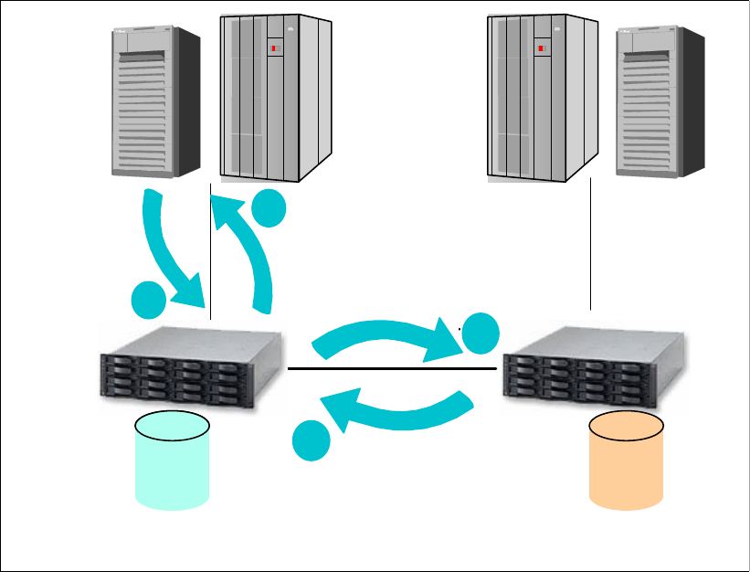
130 IBM System Storage DS6000 Series: Copy Services with IBM System z
12.1 Metro Mirror overview
Metro Mirror (previously known as synchronous Peer-to-Peer Remote Copy, or PPRC)
provides real-time mirroring of logical volumes between two DS6000s that can be located up
to 300 km from each other. It is a synchronous copy solution where write operations are
completed on both copies (local and remote site) before they are considered to be complete.
It is typically used for applications that cannot suffer any data loss in the event of a failure.
As data is synchronously transferred, the distance between primary and secondary disk
subsystems will determine the effect on application response time. Figure 12-1 illustrates the
sequence of a write update with Metro Mirror.
Figure 12-1 Metro Mirror
When the application performs a write update operation to a primary volume, this is what
happens:
1. Write to primary volume (DS6000 cache and NVS).
2. Write to secondary volume (DS6000 cache and NVS).
3. Signal write complete from the secondary DS6000.
4. Post I/O complete to host server.
The Fibre Channel connection between primary and secondary subsystems can be direct,
through a switch, or through other supported distance solutions (for example, Dense Wave
Division Multiplexor, DWDM).
2
3
1
4
Server
write
Write to secondary
Write acknowledge
Write complete
acknowledgement
LUN or
volume
Primary
(source)
LUN or
volume
Primary
(source)
LUN or
volume
Secondary
(target)
Chapter 12. Metro Mirror overview 131
12.2 Metro Mirror volume state
Volumes participating in a Metro Mirror session can be found in any of the following states:
Copy pending: volumes are in copy pending state after the Metro Mirror relationship is
established, but the primary and secondary volumes are still out of sync. In that case, data
still needs to be copied from the primary to the secondary volume of the Metro Mirror pair.
This may be the case immediately after a relationship is initially established, or
reestablished after being suspended. The Metro Mirror secondary volume is not
accessible when the pair is in copy pending state.
Full duplex: a volume copy pair is in full duplex state when its members are in sync; that
is, both primary and secondary volumes contain exactly the same data. The secondary
volume is not accessible when the pair is in full duplex.
Suspended: volumes are in the suspended state when the primary and secondary storage
subsystems cannot communicate anymore, or when the Metro Mirror pair is suspended
manually. In this state, writes to the primary volume are not mirrored onto the secondary
volume. The secondary volume becomes out of sync.
During this time, Metro Mirror keeps a bitmap record of the changed tracks in the primary
volume. Later, when the volumes are resynchronized, only the tracks that were updated
will be copied.
Target copy pending: indicates that the primary volume is unknown or cannot be queried
and the secondary state is copy pending.
Target full-duplex: indicates that the primary volume is unknown or cannot be queried and
the secondary state is full duplex.
Target suspended: indicates that the primary volume is unknown or cannot be queried and
the secondary state is suspended.
Not remote copy pair: indicates that the relationship is not a Metro Mirror pair.
Invalid-state: indicates that the relationship state is invalid.
12.3 Data consistency
In order to restart applications at the remote site successfully, the remote site volumes must
have consistent data. In normal operation, Metro Mirror keeps data consistency at the remote
site. However, in case of a rolling disaster type of situation, a certain mechanism is necessary
to keep data consistency at the remote site.
For Metro Mirror, consistency requirements are managed through use of the Consistency
Group option. You can specify this option when you are defining Metro Mirror paths between
pairs of LSSs or when you change the default LSS settings. Volumes or LUNs that are paired
between two LSSs whose paths are defined with the Consistency Group option can be
considered part of a Consistency Group.
Consistency is provided by means of the extended long busy (for z/OS) or queue full (for open
systems) conditions. These are triggered when the DS6000 detects a condition where it
cannot update the Metro Mirror secondary volume. The volume pair that first detects the error
will go into the extended long busy condition, such that it will not do any writes. For z/OS, a
system message will be issued (IEA494I state change message); for open systems, an
SNMP trap message will be issued. These messages can be used as a trigger for automation
purposes that will provide data consistency.

132 IBM System Storage DS6000 Series: Copy Services with IBM System z
Data consistency, dependent writes, extended long busy, are all discussed in detail in 13.3,
“Consistency Group function” on page 136.
12.4 Rolling disaster
In disaster situations, it is unlikely that the entire complex will fail at the same moment.
Failures tend to be intermittent and gradual, and a disaster can occur over many seconds,
even minutes. Because some data may have been processed and other data lost in this
transition, data integrity on the secondary volumes is exposed. This situation is called a
rolling disaster. The mirrored data at the recovery site must be managed so that
cross-volume or LSS data consistency is preserved during the intermittent or gradual failure.
Metro Mirror itself does not offer a means of controlling this scenario. Instead, it offers the
Consistency Group and Critical attributes, which along with appropriate automation
solutions, can manage data consistency and integrity at the remote site. The Metro Mirror
volume pairs are always consistent, due to the synchronous nature of Metro Mirror; however,
cross-volume or LSS data consistency must have an external management method. IBM
offers the GDPS® and eRCMF service offerings to deliver solutions in this area; refer to
Part 8, “Solutions” on page 431, for more information. You can also visit the IBM Web site and
refer to the Services & Industry Solutions page for more information.
12.5 Automation and management
Metro Mirror is a hardware mirroring solution. A volume (or LUN) is paired with a volume (or
LUN) in the remote disk subsystem. As the size of the environment grows, so does the
complexity of managing it. Therefore, you need a means for managing the pairs, ensuring
they are in duplex status, adding volume pairs as required, monitoring for error conditions,
and more importantly, for managing data consistency across LSS and across disk
subsystems.
When planning a Metro Mirror environment, the following topics should be considered:
Design of the automation solution
Maintenance
Testing
Support
All these considerations need to be thought about, because you do not want to be in a
situation where you are relying on your mirroring implementation for data to be consistent in a
disaster situation, only to find that it has not worked, or perhaps worse, you not being aware
that your data is not consistent.
IBM offers services and solutions for the automation and management of the Metro Mirror
environment, which include GDPS and eRCMF. For more information on GDPS and eRCMF
see Part 8, “Solutions” on page 431. You can also visit the IBM Web site and refer to the
Services & Industry Solutions page.
Note: Dduring normal Metro Mirror processing, the data on disk at the secondary site is an
exact mirror of that at the primary site. During or after an error situation this depends on the
options specified for the pair and the path. Remember that any data still in buffers or
processor memory is not yet on disk and so will not be mirrored to the secondary site. A
disaster will then appear to be a similar situation to a power failure in the primary site.

© Copyright IBM Corp. 2006. All rights reserved. 133
Chapter 13. Metro Mirror options and
configuration
This chapter discusses the options available when using Metro Mirror for DS6000. It also
discusses the configuration guidelines that should be considered when planning the Metro
Mirror environment.
13
134 IBM System Storage DS6000 Series: Copy Services with IBM System z
13.1 High availability solutions
Because the disk subsystem attached to the server is being mirrored using Metro Mirror, this
offers some improved opportunities for high availability solutions.
13.1.1 GDPS HyperSwap Manager
The GDPS services offering includes the GDPS HyperSwap™ Manager function. This
function can be used to mask some primary Metro Mirror disk subsystem problems or
planned maintenance activities, by allowing the primary DASD to be swapped transparently
from one site to another without requiring an application or system outage. For more
information, refer to Part 8, “Solutions” on page 431.
13.1.2 Open systems - Clustering
For open system environments, IBM offers several solutions in this area, including GDS for
Windows environments, and HACMP™ for AIX. For more information, refer to Part 8,
“Solutions” on page 431.
13.2 Failover and failback
The Metro Mirror Failover and Failback modes are designed to help reduce the time required
to synchronize Metro Mirror volumes after switching between the production and the recovery
sites.
In a typical Metro Mirror environment, processing will temporarily switch over to the Metro
Mirror secondary site upon an outage at the primary site. When the primary site is capable of
resuming production, processing will switch back from the secondary site to the primary site.
At the recovery site the Metro Mirror Failover function combines, into a single task, the three
steps involved in the switch over (planned or unplanned) to the remote site: terminate the
original Metro Mirror relationship, then establish and suspend a new relationship at the
remote site. Note that the state of the original source volume at the normal production site is
preserved. The state of the original target volume at the recovery site becomes a source
suspended. This design takes into account that the original source LSS may no longer be
reachable.
To initiate the switch back to the production site, the Metro Mirror Failback function at the
recovery site checks the preserved state of the original source volume at the production site
to determine how much data to copy back. Then either all tracks or only out-of-sync tracks
are copied, with the original source volume becoming a target full-duplex. In more detail, this
is how Metro Mirror Failback operates:
If a volume at the production site is in the simplex state, all of the data for that volume is
copied back from the recovery site to the production site.
If a volume at the production site is in the full-duplex or suspended state and without
changed tracks, only the modified data on the volume at the recovery site is copied back to
the volume at the production site.
If a volume at the production site is in a suspended state and has tracks that have been
updated, then both the tracks changed on the production site and the tracks marked at the
recovery site will be copied back.
Finally, the volume at the production site becomes a write-inhibited target volume. This
action is performed on an individual volume basis.
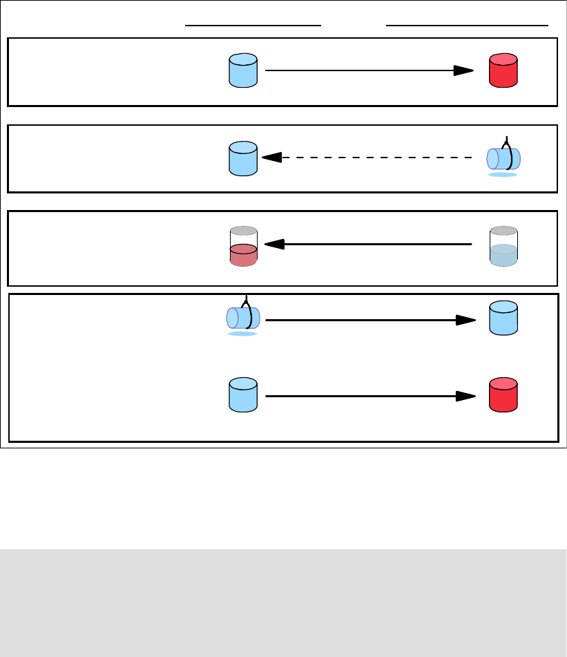
Chapter 13. Metro Mirror options and configuration 135
The switch back is completed with one more sequence of a Metro Mirror Failover followed by
a Metro Mirror Failback operations, both given at the now-recovered production site.
Figure 13-1 summarizes the process.
Figure 13-1 Metro Mirror Failover and Failback sequence
In this manner, Metro Mirror Failover and Failback are dual operations. It is possible to
implement all site switch operations with two pairs of failover and failback tasks (one pair for
each direction).
The Metro Mirror Failover and Failback modes can be invoked from the DS Storage Manager
GUI, the DS Command-Line Interface (CLI), TSO commands, or using the ICKDSF utility.
We give an example of a Metro Mirror Failover and Failback sequence and how to control it in
16.2, “Failover and failback using TSO” on page 187.
Note: For a planned switch over from site (A) to site (B), and in order to keep data consis-
tency at (B), the application at site (A) has to be quiesced before the Metro Mirror Failover
operation at (B).
Alternatively, you can use the freezepprc and unfreezepprc commands. The same
consideration applies when switching back from site (B) to (A).
Primary site (A) Secondary site (B)
Normal operation
site (A) production site
site (B) recovery site
Updates are transferred
Source = A
full duplex Target = B
full duplex
When planned/unplanned outage at (A):
At (B): Metro Mirror Failover
restart application processing
Establish with Failover
B full duplex
A full duplex
Establish with Failback
Source = B
suspended
Source = B
copy pending
Establish with Failover
Target = A
copy pending
Source = A
suspended
Establish with Failback
Source = A
full duplex Target = B
full duplex
With site (A) recovered and operable.
At (B):
1. Metro Mirror Failback
2. stop application processing
With pairs in full duplex.
At (A):
1. Metro Mirror Failover
2. start application processing
3. Metro Mirror Failback
136 IBM System Storage DS6000 Series: Copy Services with IBM System z
13.3 Consistency Group function
In order to restart applications at the remote site successfully, the remote site must have
consistent data. In normal operation, Metro Mirror keeps data consistency at the remote site.
However, as mentioned in 12.3, “Data consistency” on page 131 and in 12.4, “Rolling
disaster” on page 132, in case of a rolling disaster, a particular procedure is necessary to
keep data consistency even in a synchronous remote copy environment.
In this section we explain data consistency and then explain how the Metro Mirror Consistency
Group function keeps data consistency at the remote site, in case of a rolling disaster.
13.3.1 Data consistency and dependent writes
Many applications, such as databases, process a repository of data that has been generated
over a period of time. Many of these applications require that the repository is in a consistent
state in order to begin or continue processing. In general, consistency implies that the order
of dependent writes is preserved in the data copy. In the Metro Mirror environment, keeping
data consistency means that the order of dependent writes is preserved in all the Metro Mirror
target volumes. For example, the following sequence occurs for a basic database operation
involving a log volume and a data volume:
1. Write to log volume: Data Record #2 is being updated.
2. Update Data Record #2 on data volume.
3. Write to log volume: Data Record #2 update complete.
If the copy of the data contains any of these combinations then the data is consistent:
Operations 1, 2, and 3
Operations 1 and 2
Operation 1
If the copy of data contains any of these combinations then the data is inconsistent (the order
of dependent writes was not preserved):
Operations 2 and 3
Operations 1 and 3
Operation 2
Operation 3
When discussing the Consistency Group function, data consistency means this sequence is
always kept in the copied data. And the order of non-dependent writes does not necessarily
need to be preserved. For example, consider the following two sequences:
1. Deposit paycheck in checking account A.
2. Withdraw cash from checking account A.
3. Deposit paycheck in checking account B.
4. Withdraw cash from checking account B.
In order for the data to be consistent, the deposit of the paycheck must be applied before the
withdrawal of cash for each of the checking accounts. However, it does not matter whether
the deposit to checking account A or checking account B occurred first, as long as the
associated withdrawals are in the correct order. So, for example, the data copy would be
consistent if the following sequence occurred at the copy:
1. Deposit paycheck in checking account B.
2. Deposit paycheck in checking account A.
3. Withdraw cash from checking account B.
4. WIthdraw cash from checking account A.
Chapter 13. Metro Mirror options and configuration 137
In other words, the order of updates was not the same as it was for the source data, but the
order of dependent writes was preserved.
13.3.2 Consistency Group function - how it works
In the operation of the Consistency Group function of Metro Mirror we distinguish two parts.
One is the invocation of the Consistency Group option, and the other one is the freeze/run
operation. Together, they make it possible for the disk subsystem to hold I/O activity and
subsequently to thaw the held I/O activities.
Consistency Group option
The Consistency Group option causes the disk subsystem to hold I/O activity to a volume for
a time period by putting the source volume into a extended long busy state when the DS6000
detects a condition where it cannot update the Metro Mirror target volume. This operation can
be done across multiple LUNs or volumes, multiple LSSs, and even across multiple disk
subsystems. You can specify this option when you are defining Metro Mirror paths between
pairs of LSSs, or when you change the default Consistency Group setting on each LSS (the
Consistency Group option is disabled by default).
In the disk subsystem itself, each command is managed with each logical subsystem (LSS).
This means that there are slight time lags until each volume in the various LSSs is changed to
the extended long busy state. Some people are concerned that the time lag causes you to
lose data consistency, but that is not true. We explain how to keep data consistency in the
Consistency Group environments in the following section.
In the example in Figure 13-2, three write operations (first, second, and third) are dependent
writes. This means that these operations must be completed sequentially.
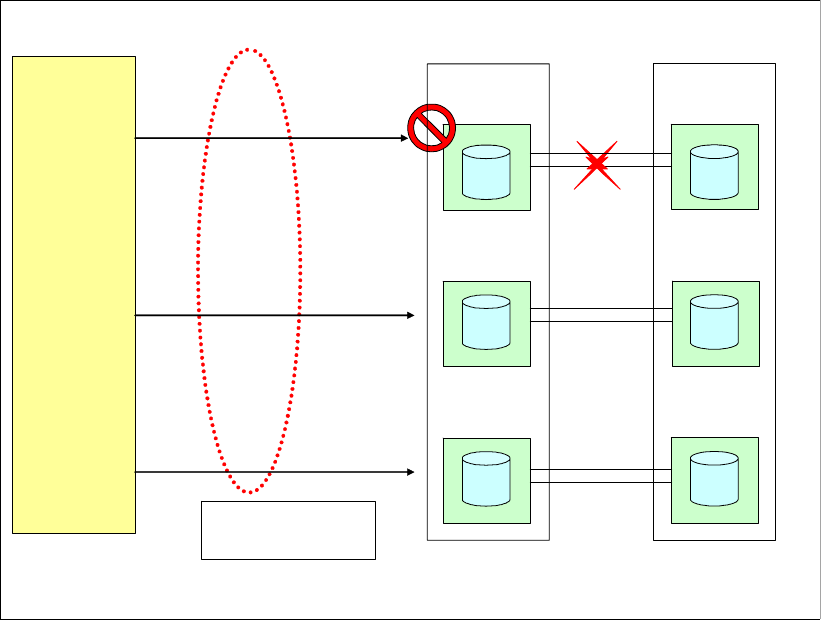
138 IBM System Storage DS6000 Series: Copy Services with IBM System z
Figure 13-2 Consistency Group: Example 1
In Figure 13-2, there are two Metro Mirror paths between LSS11 and LSS21. There are
another two Metro Mirror paths for each of the other LSS pairs (LSS12;LSS22 and
LSS13:LSS23). In a disaster, the paths may fail at different times. At the beginning of the
disaster, such as a rolling disaster, one set of paths (such as the paths between LSS11 and
LSS21) may be inoperable while other paths are working. At this time, the volumes in LSS11
are in an extended long busy condition, and the volumes in LSS12 and 13 are not.
The first operation is not completed because of the extended long busy condition, and the
second and third operations are not completed, because the first operation has not been
completed. In this case, the first, second, and third updates are not included in the Metro
Mirror target volumes in LSS21, LSS22, and LSS23. Therefore, the Metro Mirror target
volumes at the remote site keep consistent data.
In the example illustrated in Figure 13-3, the volumes in LSS12 are in an extended long busy
state and the other volumes in LSS11 and 13 are not. The first write operation is completed
because the volumes in LSS11 are not in an extended long busy condition. The second write
operation is not completed because of the extended long busy condition. The third write
operation is also not completed because the second operation is not completed. In this case,
the first update is included in the Metro Mirror target volumes, and the second and third
updates are not included. Therefore, this case is also consistent.
1st
2nd
3rd
dependent write
operation
Application
on
Servers
Wait
Wait
Wait
LSS11
LSS12
LSS13
LSS21
LSS22
LSS23
Source DS6000 Target DS6000
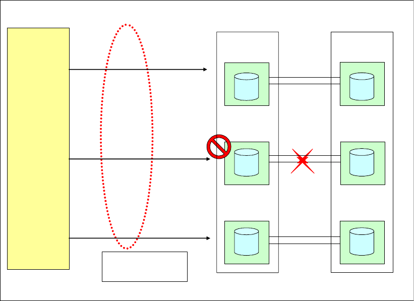
Chapter 13. Metro Mirror options and configuration 139
Figure 13-3 Consistency Group: Example 2
In all cases, if each write operation is dependent, the Consistency Group option can keep the
data consistent in the Metro Mirror target volumes until the Consistency Group time-out
occurs. After the time-out value has been exceeded, all held I/O will be released. The
Consistency Group time-out value can be specified at the LSS level.
If each write operation is not dependent, the I/O sequence is not kept in the Metro Mirror
target volumes that are in LSSs with the Consistency Group option specified. In the example
illustrated in Figure 13-4 on page 140, the three write operations are independent. If the
volumes in LSS12 are in an extended long busy state and the other volumes in LSS11 and 13
are not, the first and third operations are completed and the second operation is not
completed.
1st
2nd
3rd
dependent write
operation
Application
on
Servers
Completed
Wait
Wait
LSS11
LSS12
LSS13
LSS21
LSS22
LSS23
Source DS6000 Target DS6000
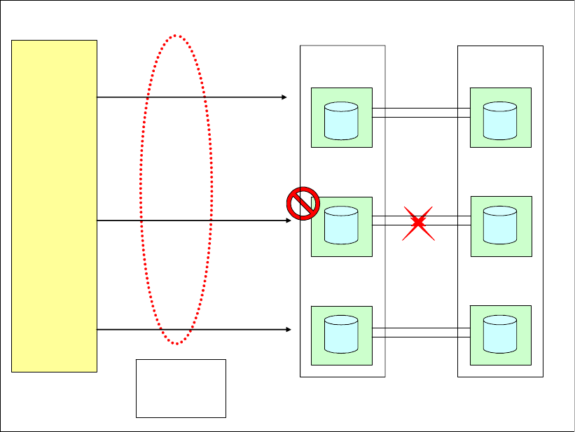
140 IBM System Storage DS6000 Series: Copy Services with IBM System z
Figure 13-4 Consistency Group: Example 3
In this case, the Metro Mirror target volumes reflect only the first and third write operation, not
including the second operation.
Typical database management software can recover its databases by using its log files if
dependent write operations are kept. At the same time, you should not need to care whether
independent write operations are kept in sequence.
13.3.3 FREEZE and RUN parameters
Messages and environmental triggers related to Metro Mirror problems can be detected by
your automation software. You can then use the TSO command CGROUP with the FREEZE
parameter (or equivalent command through the other interfaces) to suspend all required
secondary Metro Mirror operations.
The FREEZE option removes the Metro Mirror paths, and suspends the volume pairs for a
given LSS pairing. If used in combination with the CGROUP(Y) option of the CESTPATH
command, then an extended long busy (for z/OS) or queue full (for open systems) condition
will be forced on all the LSSs where the FREEZE is issued, and thus, all the I/Os to the
respective primary volumes will be queued while in the extended long busy window. Once
your automation process detects that the updates can be resumed, it can issue the CGROUP
command with the RUN parameter. This command releases all I/O to the primary devices,
but still leaves the secondary devices suspended at a point-in-time (with the FREEZE the
associated paths are removed).
The default 2-minute timer of the extended long busy state gives the automation enough time
to issue a CGROUP FREEZE command to the necessary LSSs. I/O resumes after the default
2 minutes if a CGROUP RUN command is not received.
1st
2nd
3rd
independent
write
operations
Application
on
Servers
Completed
Wait
Wait
LSS11
LSS12
LSS13
LSS21
LSS22
LSS23
Source DS6000 Target DS6000
Completed

Chapter 13. Metro Mirror options and configuration 141
The ICKDSF PPRCOPY FREEZE and PPRCCOPY RUN commands provide the same
functionality as the TSO CGROUP FREEZE and CGROUP RUN commands.
If you are using the DS Command-Line Interface (DS CLI), you can use the freezepprc and
unfreezepprc commands to provide the same functionality as the TSO CGROUP FREEZE
and CGROUP RUN commands. It is not possible to issue Consistency Group
(freeze/unfreeze) type commands from the DS Storage Manager Graphical User Interface.
13.3.4 Critical attribute
The critical attribute determines what will happen after a failed I/O to a secondary volume
occurs. What happens will depend on how this attribute was set when the pair was
established, and how the DS6000 was configured.
The critical attribute is set when establishing the volume pair. If using TSO commands, the
CRIT parameter of the CESTPAIR command is used for this. If you are using the DS CLI, the
critical attribute is set using the mkpprc -critmode parameter. If using ICKDSF, specify the
CRIT(YES) parameter of the PPRCOPY ESTPAIR command. If using the DS Storage
Manager GUI, select the Enable critical volume mode option in the Select copy options
page when defining volume pairs.
If CRIT(NO) was specified on the CESTPAIR command (or equivalent options through the
other interfaces) when the pairs were established, then following an I/O error completion to
the secondary volume, Metro Mirror will suspend the volume and allow subsequent write
requests to the Metro Mirror primary volume. The pair is suspended, the secondary volume
does not receive any more updates, and the primary DS6000 will perform change recording,
thus keeping track of the primary updates for subsequent resynchronization.
If CRIT(YES) was specified with the CESTPAIR command (or equivalent options through the
other interfaces), and if an I/O error to the secondary volume occurs, Metro Mirror will either
allow or disallow subsequent writes to the primary, depending on how the DS6000 was
configured. For z/OS, the IEA491E message will present the reason SUSPENDED,
CRITICAL-STATE, ALL WRITES FAILED. The Metro Mirror pair then remains in a suspended
state until the problem is corrected and a CESTPAIR RESYNC or CDELPAIR command is
later issued.
Whether subsequent writes to the primary volumes are allowed or not will depend on how the
DS6000 LCU is configured:
DS CLI: chlcu -critmode enable
DS Storage Manager GUI: Copy Services → Paths → Select LSS Copy Options from
the pull down list → Go → Accept or modify the selected LSSs from the Select LSS
pull-down list → Select the Critical Mode option to enable the setting → OK.
Note: In order to re-synchronize your Metro Mirror environment after the problem has been
resolved, you will need to redefine your Metro Mirror paths (they are removed as part of the
CGROUP FREEZE command). You can then issue CESTPAIR commands with
MODE(RESYNC) (or equivalent commands in the other interfaces).
Tip: We recommend using FlashCopy against your secondary volumes prior to a resyn-
chronization. This is because you do not have data consistency until all volumes have
reached the Duplex state.

142 IBM System Storage DS6000 Series: Copy Services with IBM System z
The volume pair is suspended and further writes to the source volume are not accepted if
data cannot be sent to the target volume.
13.3.5 Consistency Group and critical mode combination
Table 13-1 shows what happens when the CRIT parameter of the CESTPAIR command, and
the CGROUP parameter of CESTPATH command are combined. These options can also be
set using the DS CLI, or with the DS Storage Manager GUI.
Table 13-1 Interaction of CRIT and CGROUP parameters
The IEA494I message with SUSPENDED status is issued for the in-error pair to all z/OS images
that have the primary volume online. An IEA491E message is returned to the issuing system
of the next I/O that is attempted to the volume that is suspended. For open systems, an
SNMP trap will be issued to the address specified when the DS6000 SNMP service was
configured.
For further discussion on the CGROUP and the CRIT parameters, refer to z/OS DFSMS
Advanced Copy Services, SC35-0428.
13.4 Metro Mirror paths and links
Metro Mirror pairs are set up between volumes in LSSs, usually in different disk subsystems,
and these are normally in separate locations. A path (or group of paths) needs to be defined
between the primary (source) LSS and the secondary (target) LSS. These logical paths are
defined over physical links between the disk subsystems.
The physical link includes the host adapter in the primary DS6000, the cabling, switches or
directors, any wideband or long distance transport devices (DWDM, channel extenders,
WAN), and the host adapters in the secondary disk subsystem. Physical links can carry
multiple Metro Mirror logical paths, as shown in Figure 13-5 on page 143.
CRIT(Y) CRIT(N)
CGROUP(Y) IEA494I with long busy state
(SNMP trap for open systems)
IEA494I with long busy state
(SNMP trap for open systems)
Pair in error suspended Pair in error suspended
Unit check on primary device No unit check on primary device
IEA494I when suspended IEA494I when suspended
CGROUP(N) No long busy state No long busy state
Pair in error suspended Pair in error suspended
Unit check on primary device No unit check on primary device
IEA494I when suspended IEA494I when suspended
Note: For Metro Mirror, the DS6000 supports Fibre Channel links only. To facilitate ease of
testing, the DS6000 does support Metro Mirror source and target on the same DS6000.
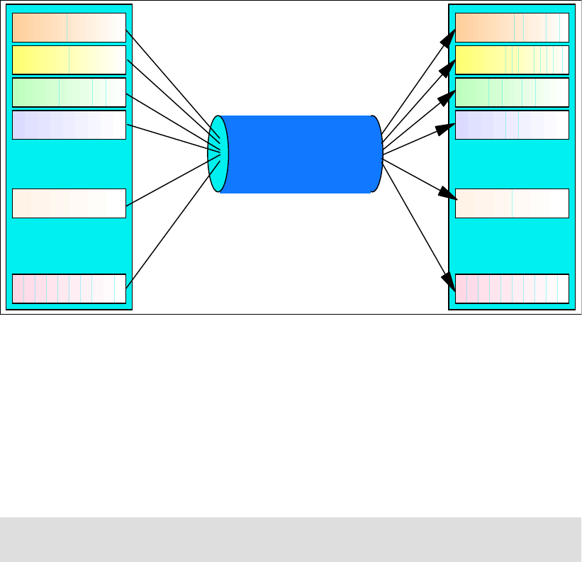
Chapter 13. Metro Mirror options and configuration 143
Figure 13-5 Logical paths
Paths are unidirectional, that is they are defined to operate in either one direction or the other.
Still, Metro Mirror is bidirectional. That is, any particular pair of LSSs can have paths defined
among them that have opposite directions—each LSS holds both source and target volumes
from the other LSS. Moreover, opposite direction paths are allowed to be defined on the
same Fibre Channel physical link.
For bandwidth and redundancy, more than one path can be created between the same LSSs.
Metro Mirror will balance the workload across the available paths between the primary and
secondary LSSs.
Physical links are bidirectional and can be shared by other Metro Mirror pairs, as well as other
remote mirror and copy functions, such as Global Copy and Global Mirror.
13.4.1 Fibre Channel links
A DS6000 Fibre Channel port can simultaneously be:
Sender for Metro Mirror primary.
Receiver for a Metro Mirror secondary.
Target for Fibre Channel Protocol (FCP) hosts I/O from open systems and Linux on
System z.
Although one FCP link would have sufficient bandwidth for most Metro Mirror environments,
for redundancy reasons we recommend configuring two Fibre Channel links between each
primary and secondary disk subsystem.
With the DS6000 you have only eight Fibre Channel ports (FC ports) available, four per
server (controller). And, each sever owns each FC port, unlike the DS8000. Therefore, we
recommend that you use two Fibre Channel links for Metro Mirror, one on each controller, for
availability and balanced configuration. See Figure 13-6.
Note: Keep in mind that the LSS is not a physical construct in the DS6000; it is a logical
construct. Volumes in an LSS can come from multiple disk arrays.
LSS 0
LSS 3
LSS 1
LSS 2
LSS 08
LSS nn
:
:
Physical
Fibre Channel link
256 logical paths
per FCP link
LSS 0
LSS 3
LSS 1
LSS 2
LSS 08
LSS nn
:
:
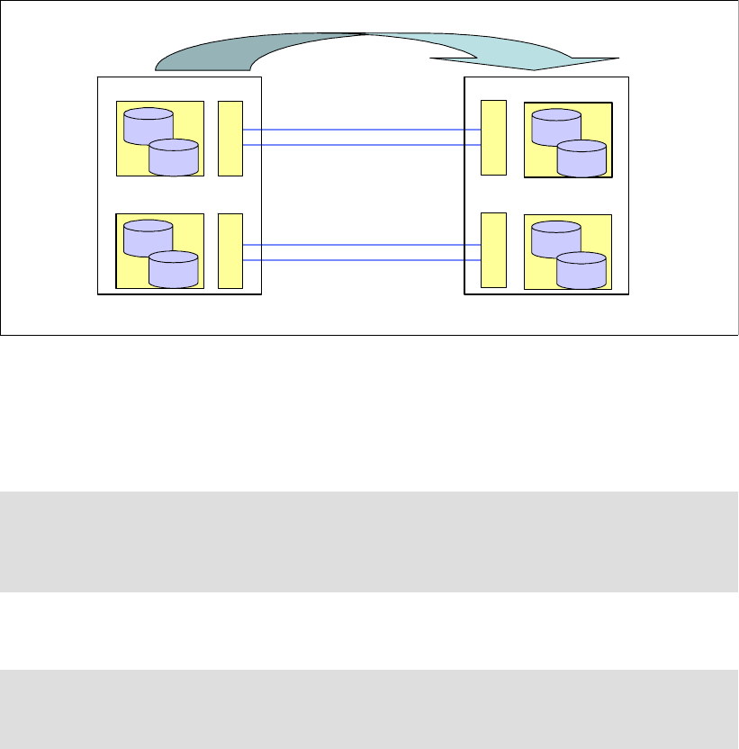
144 IBM System Storage DS6000 Series: Copy Services with IBM System z
Figure 13-6 DS6000 FC ports
Dedicating Fibre Channel ports for Metro Mirror use guarantees no interference from host I/O
activity. This is recommended with Metro Mirror, which is time-critical and should not be
impacted by host I/O activity. The Metro Mirror ports used provide connectivity for all LSSs
within the DS6000, and can carry multiple logical Metro Mirror paths.
Metro Mirror FCP links can be direct connected, or connected by up to two switches.
13.4.2 Logical paths
A Metro Mirror logical path is a logical connection between the sending LSS and the receiving
LSS. An FCP link can accommodate multiple Metro Mirror logical paths.
Figure 13-7 on page 145 shows an example where we have a 1:1 mapping of source to target
LSSs, and where the three logical paths are accommodated in one physical link:
LSS1 in DS6000 1 to LSS1 in DS6000 2
LSS2 in DS6000 1 to LSS2 in DS6000 2
LSS3 in DS6000 1 to LSS3 in DS6000 2
Alternatively, if the volumes in each of the LSSs of DS6000 1 map to volumes in all three
secondary LSSs in DS6000 2, there will be nine logical paths over the physical link (not fully
illustrated in Figure 13-7). We recommend a 1:1 LSS mapping.
Important: If you want the same set of Fibre Channel links to be shared between Metro
Mirror and Global Copy or Global Mirror, consider the impact of the aggregate data
transfer. In general, we do not recommend sharing the FCP links used for Metro Mirror,
including the physical network links, with other asynchronous remote copy functions.
Note: If you use channel extension technology devices for Metro Mirror links, verify with
the product’s vendor what environment (direct connect or with SAN switch) is supported by
the vendor, as well as which SAN switch is supported.
LSS1A
1A00
1A01
LSS1B
1B00
1B01
LSS14
1400
1401
LSS15
1500
1501
DS6000#1 DS6000#2
Server0 Server1
Server0 Server1
Metro Mirror Pairs
Fibre Channel links
Fibre Channel links
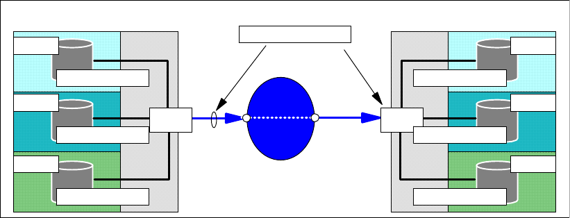
Chapter 13. Metro Mirror options and configuration 145
Figure 13-7 Logical paths for Metro Mirror
Metro Mirror paths have certain architectural limits, as follows:
A primary LSS can maintain paths to a maximum of four secondary LSSs. Each
secondary LSS can reside in a separate DS6000.
Up to eight logical paths per LSS-LSS relationship can be defined, and they will be defined
over different physical links.
An FCP port can host up to 2048 logical paths; these are the logical and directional paths
that are made from LSS to LSS.
An FCP link (the physical connection from one port to another port) can host up to 256
logical paths.
An FCP port can accommodate up to 126 different links (DS6000 port to DS6000 port
through the SAN).
13.5 Bandwidth
Prior to establishing your Metro Mirror solution, establish what your peak bandwidth
requirement will be. This will help to ensure that you have enough Metro Mirror links in place
to support that requirement.
To avoid any response time issues, establish the peak write rate for your systems and ensure
you have adequate bandwidth to cope with this load and allow for growth. Remember that
only writes are mirrored across to the secondary volumes.
Tools to assist with this data collection include RMF™ in the z/OS environment.
For more information on bandwidth and available connection options, refer to IBM
TotalStorage Business Continuity Solutions Guide, SG24-6547.
13.6 LSS design
Because the DS6000 has made the LSS a topological construct, which is not tied to a
physical array as in the ESS, the design of your LSS layout can be simplified. It is now
possible to assign LSSs to applications, for example, without concern regarding
under-allocation or over-allocation of physical disk subsystem resources. This can also
simplify the Metro Mirror environment, because it is possible to reduce the number of
commands that are required for data consistency.
DS6000 1
Port
1 logical path
LSS 2
LSS 3
LSS 1
1 logical path
1 logical path
Port
1 logical path
LSS 2
LSS 3
LSS 1
1 logical path
1 logical path
3-9 logical paths
1 Link
Metro Mirror
paths
DS6000 2
switch
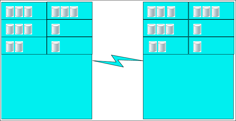
146 IBM System Storage DS6000 Series: Copy Services with IBM System z
13.7 Distance
The distance between your primary and secondary DS6000 subsystems will have an effect
on the response time overhead of the Metro Mirror implementation. The maximum supported
distance for Metro Mirror is 300 km.
13.8 Symmetrical configuration
When planning your Metro Mirror configuration, consider the possibility of a symmetrical
configuration, in terms of both physical and logical elements. This will have the following
benefits:
Simplifying management. It is easier to see where volumes will be mirrored, and
processes can be easily automated.
Reducing administrator overhead. Due to automation, and the simpler nature of the
solution, overhead can be reduced.
Simplifying the addition of new capacity into the environment. New arrays can be added in
a modular fashion.
Easing problem diagnosis. The simple structure of the solution will aid in identifying where
any problems may exist.
Figure 13-8 shows this idea in a graphical form.
Figure 13-8 Symmetrical Metro Mirror configuration
As shown in Figure 13-8, DS6000 #1 has Metro Mirror paths defined to DS6000 # 2, which is
in a remote location. On DS6000 #1, volumes defined in LSS 00 are mirrored to volumes in
LSS 00 on DS6000 #2 (volume P1 is paired with volume S1, P2 with S2, P3 with S3, and so
on). Volumes in LSS 01 on DS6000 #1 are mirrored to volumes in LSS 01 on DS6000 #2, and
so on.
Requirements for additional capacity can be added in a symmetrical way also: by the addition
of volumes into existing LSSs, and by the addition of new LSSs when needed (for example,
addition of two volumes in LSS 03 and 05, and one volume to LSS 04 will bring them to the
same number of volumes as the other LSS). Additional volumes could then be distributed
evenly across all LSSs, or additional LSSs could be added.
LSS
00
LSS
02
LSS
04
LSS
01
LSS
03
LSS
05
LSS
00
LSS
02
LSS
04
LSS
05
LSS
03
LSS
01
DS6000 #1 DS6000 #2
P1 P2 P3
P7 P8
P4
P9
P5 P6
P10
P11 P12 P13
S1 S2 S3 S4 S5 S6
S7 S8 S9 S10
S11 S12 S13
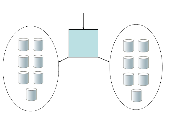
Chapter 13. Metro Mirror options and configuration 147
In addition to making the maintenance of the Metro Mirror configuration easier, the
symmetrical implementation has the added benefit of helping to balance the workload across
the DS6000. Figure 13-8 shows a logical configuration, but this idea applies equally to the
physical aspects of the DS6000. You should attempt to balance workload and apply
symmetrical concepts to other aspects of your DS6000 (for example, the Extent Pools).
13.9 Volumes
You will need to consider which volumes should be mirrored to the secondary site. One
option is to mirror all volumes. This is advantageous for the following reasons:
You will not need to consider whether any required data has been missed.
Users will not need to remember which logical pool of volumes is mirrored and which is
not.
You will not require a potentially complex volume pooling scheme (DFSMS Storage
Groups).
Addition of volumes to the environment is simplified—you will not have to have two
processes for addition of disk (one for mirrored volumes, and another for non-mirrored
volumes).
You will be able to move data around your disk environment easily without worrying about
whether the target volume is a mirrored volume or not.
You may choose not to mirror all volumes. In this case you will need careful control over what
data is placed on the mirrored volumes (to avoid any capacity issues) and what is placed on
the non-mirrored volumes (to avoid missing any required data). One method of doing this
could be to place all mirrored volumes in a particular set of LSSs, in which all volumes have
Metro Mirror enabled, and direct all data requiring mirroring to these volumes. On z/OS, this
could be accomplished using DFSMS Storage Groups and DFSMS Automatic Class
Selection routines. Figure 13-9 shows a graphical view of this concept.
Figure 13-9 DFSMS Storage Group separation
Although mirroring all volumes might be the simplest solution to manage, it could also require
significantly more network bandwidth. Because network bandwidth is a cost to the solution,
minimizing this bandwidth may well be worth the added management complexity.
DFSMS Storage Group
Mirrored Volumes
DFSMS Storage Group
Non-mirrored Volumes
DFSMS
ACS
Routines
Dataset Allocation

148 IBM System Storage DS6000 Series: Copy Services with IBM System z
13.10 Hardware requirements
Metro Mirror is an optional licensed function of the IBM System Storage DS6000 series.
All DS6000 series licensed functions are enabled, authorized, managed, activated, and
enforced based upon the physical capacity contained in a 1750 system. Particularly for Metro
Mirror, the DS6000 must have the Remote Mirror and Copy (RMC) licensed function, with the
corresponding feature #531x, based on the physical capacity.
For additional information on the DS6000 licensed function features, also refer to Appendix C,
“Licensing” on page 525.
Interoperability
Metro Mirror pairs can only be established between disk subsystems of the same (or similar)
type and features. For example, a DS6000 can have a Metro Mirror pair with another
DS6000, a DS8000, an ESS 800, or an ESS 750. It cannot have a Metro Mirror pair with an
RVA or an ESS F20.
Note that all disk subsystems must have the appropriate Metro Mirror feature installed. If your
DS6000 is being mirrored to an ESS disk subsystem, the ESS must have PPRC Version 2
(which supports Fibre Channel links) with the appropriate licensed internal code level (LIC).
Refer to the DS6000 Interoperability Matrix for more information at:
http://www-1.ibm.com/servers/storage/disk/ds6000/interop.html
Note: For a detailed explanation of the features involved and the considerations you must
have when ordering Metro Mirror, refer to the IBM System Storage DS6000 Series (IBM
1750-522) announcement letter.
IBM announcement letters can be found at:
http://www.ibm.com/products

© Copyright IBM Corp. 2006. All rights reserved. 149
Chapter 14. Metro Mirror interfaces
This chapter discusses, and provides examples of, the interfaces that can be used for Metro
Mirror management, setup and control when used with the IBM System Storage DS6000 in a
System z environment.
14
150 IBM System Storage DS6000 Series: Copy Services with IBM System z
14.1 Metro Mirror interfaces - overview
There are various interfaces available for the setup and management of Metro Mirror for
DS6000 in a System z environment:
For z/OS and OS/390, the following interfaces can be used:
– TSO commands
– ICKDSF utility
– ANTRQST application programming interface (API)
– DS6000 interfaces
For z/VM:
– ICKDSF utility
– DS6000 interfaces
For VSE:
– ICKDSF utility
– DS6000 interfaces
For TPF:
– ICKDSF utility
– TPF itself
– DS6000 interfaces
– Other attached servers that support control of Metro Mirror
The following are the DS6000 interfaces that can also be used with the previous list of
operating systems:
DS Command-Line Interface (DS CLI). The DS CLI can be used to invoke Metro Mirror
commands from a server that supports the DS CLI (for example, a Windows XP server),
provided that the server has appropriate connectivity to the DS6000 DS SMC.
DS Storage Manager (DS SM) Graphical User Interface (DS SM GUI). The DS SM
provides a graphical user interface (GUI) running in a Web browser that communicates
with the DS6000 Storage Management Console (DS SMC).
TotalStorage Productivity Center for Replication (TPC for Replication). The TPC
Replication Manager server connects to the same network where the DS SMC is.
DS Open Application Programming Interface (DS Open API).
This chapter gives an overview of the z/OS interfaces, as well as the DS CLI and the DS SM
Graphical User Interface. These interfaces are also covered in Part 2, “Interfaces” on
page 15.
TotalStorage Productivity Center for Replication (TPC for Replication) provides management
of DS6000 series business continuance solutions, including FlashCopy, Metro Mirror, and
Global Mirror. TPC for Replication is covered in Chapter 31, “IBM TotalStorage Productivity
Center for Replication” on page 467. TPC for Replication includes similar functions to Global
Mirror Utility (GMU). GMU users should consider migrating to TPC for Replication.
The DS Open Application Programming Interface (DS Open API), which is a set of application
programming interfaces that are available to be integrated in programs, can also be used for
Metro Mirror management and control. Coverage of the DS Open API is beyond the scope of
this IBM Redbook. For information on the DS Open API, refer to IBM System Storage DS
Open Application Programming Interface Reference, GC35-0516.

Chapter 14. Metro Mirror interfaces 151
Similar functions of the interfaces for Metro Mirror management
Table 14-1 lists the commands and selections for the different interfaces that provide similar
Metro Mirror control functions.
Table 14-1 Commands for the different interfaces
14.2 TSO commands for Metro Mirror management
For z/OS, the TSO Metro Mirror commands offer a powerful and flexible interface for
controlling your Metro Mirror environment. They can also be used to control open systems
volumes through the recent addition of support.
Command TSO ICKDSF DS CLI DS Storage
Manager
Establish path CESTPATH PPRCOPY
ESTPATH
mkpprcpath Copy services →
Paths → Create
Establish pair CESTPAIR PPRCOPY
ESTPAIR
mkpprc Copy services →
Metro Mirror →
Create
Freeze
Consistency
Group
CGROUP FREEZE PPRCOPY
FREEZE
freezepprc Not available
Thaw
Consistency
Group
CGROUP RUN PPRCOPY RUN unfreezepprc Not available
Suspend pair CSUSPEND PPRCOPY
SUSPEND
pausepprc Copy services →
Metro Mirror →
Suspend
Query pair CQUERY PPRCOPY
QUERY
lspprc Copy services →
Metro Mirror
Query path CQUERY PATH PPRCOPY
QUERY PATHS
lspprcpath Copy services →
Paths
Recover
secondary
CRECOVER PPRCOPY
RECOVER
rmpprc -at src Copy services →
Metro Mirror
Resume
suspended pair
CESTPAIR
MODE(RESYNC)
PPRCOPY
ESTPAIR
MODE(RESYNC)
resumepprc Copy services →
Metro Mirror →
Resume
Delete pair CDELPAIR PPRCOPY
DELPAIR
rmpprc Copy services →
Metro Mirror →
Delete
Delete path CDELPATH PPRCOPY
DELPATH
rmpprcpath Copy services →
Paths → Delete
Failover CESTPAIR
ACTION(FAILOVER)
PPRCOPY
ESTPAIR
FAILOVER
failoverpprc Copy services →
Metro Mirror →
Recovery Action
Failback CESTPAIR
ACTION(FAILBACK)
PPRCOPY
ESTPAIR
FAILBACK
failbackpprc Copy services →
Metro Mirror →
Recovery
Failback

152 IBM System Storage DS6000 Series: Copy Services with IBM System z
The TSO commands communicate with the DS6000 through a device number specified in the
command. IP connectivity is not required.
TSO commands can be integrated into REXX programs for automation purposes.
14.2.1 Commands overview
Most TSO commands require the subsystem identifier (SSID) of the LSS to be specified, and
some require the channel connection address (CCA) of the volume also.
Channel connection address
Some Metro Mirror TSO commands require the use of the channel connection address (CCA)
of the device in question. The CCA on a DS6000 is always relative to the LSS, and is always
between 00 and FF. If the device numbers on the DS6000 have been generated as a
contiguous group of 256 addresses, where each group belongs to an LSS (logical control
unit), then the CCAs that are going to be used for the Metro Mirror commands are the last two
digits of the device number.
For example, for device numbers AA00 to AAFF, the corresponding CCAs are 00 to FF. If you
did not define the device addresses contiguously, you can obtain the CCA for a device by
using the TSO CQUERY command, or the DEVSERV system command.
Subsystem identifier
During the installation and configuration process, each logical control unit (that is, each LSS)
is assigned a unique four-digit subsystem identifier (SSID). This setting is required to identify
the control unit for the host for error reporting reasons and also for functions like Metro Mirror.
Each LSS must have a different SSID. The authors recommend assigning consecutive SSID
numbers to each LSS in a DS6000. This simplifies the configuration procedure and makes it
easier for the subsequent identification of the LSSs. LSSs attached to the same operating
system image must have different SSIDs; that is, SSIDs must be unique. z/OS checks during
the IPL to ensure that there are no duplicate SSIDs.
When establishing Metro Mirror paths, the SSIDs are used in the Metro Mirror TSO
commands to identify the primary and secondary LSSs to be paired.
When issuing commands to open systems volumes from TSO commands, you use a special
SSID value. You can either use x’FFFF’, if you are unsure what the value should be, or check
the value using a CQUERY command.
14.2.2 CESTPAIR
This command is used to establish the Metro Mirror primary to secondary relationship. The
primary and secondary volumes must have the same number of tracks on each cylinder and
the same number of bytes on each track. The secondary device must have the same number,
or a greater number, of cylinders than the primary device. If you ever need to swap the Metro
Mirror direction, as in a failover/failback, then the volumes must be the same size.
Tip: if you are controlling open systems volumes with TSO commands, you must have a
z/OS volume in the same server to direct your command to. For example, for an open
systems LUN in LSS 16, a z/OS volume in LSS 00 can be used for the device address. If
you had a LUN in LSS 15, you can use a z/OS volume in LSS 01.

Chapter 14. Metro Mirror interfaces 153
This command has parameters that allow it to indicate whether the operation is an initial
establish of volumes that were in the simplex state, whether it is a resynchronization of a
suspended pair of volumes, whether it is a Metro Mirror or Global Copy pair, or whether
Failover or Failback processing is being requested.
Example 14-1 shows the command necessary to establish an initial Metro Mirror pair.
Example 14-1 TSO CESTPAIR command
ANTP8802I CESTPAIR DEVN(X'6400') PRIM(X'0002' AAVCA X'00' X'00')
SEC(X'0003' AAVCA X'00' X'01') OPTION(SYN
ANTP8802I (CONT) C) MODE(COPY) ONLINSEC(NO)
ANTP0001I CESTPAIR COMMAND COMPLETED FOR DEVICE 6400. COMPLETION CODE:
00
IEA494I 6400,DS6400,PPRC PAIR PENDING,SSID=0002,CCA=00
IEA494I 6400,DS6400,PPRC PAIR FULL DUPLEX,SSID=0002,CCA=00
In Example 14-1, the primary volume resides on LSS x’00’ of the application site DS6000.
The SSID of the LSS is x’0002’, the serial number of the DS6000 is AAVCA, its CCA is x’00’,
and the LSS is x’00’. The secondary volume resides in LSS x’00’ of the recovery site DS6000.
Its CCA is x’00’. This matching between the last two digits of the device number address and
the CCAs of the primary and the secondary volumes is not mandatory; however, it is useful
for working with the configuration. CCA is discussed in “Channel connection address” on
page 152.
The MSGREQ(YES) parameter specifies that Metro Mirror wait until the initial full volume
copy operation is complete before issuing the completion message ANTP0001I. If you are
using automation, use this message as a trigger for other operations.
14.2.3 CESTPATH
When you are establishing a path between DS6000s for Metro Mirror, use the CESTPATH
command. There must be a physical Fibre Channel connection between the two DS6000
subsystems. You need to know the SSID, World Wide Node Name (WWNN), and LSS
number for the primary and secondary DS6000s. These can be displayed with the CQUERY
command.
Example 14-2 shows an example of a CESTPATH command to establish Metro mirror paths.
Example 14-2 CESTPATH command
CESTPATH DEVN(X'6400') PRIM(X'0002' 500507630EFFFCA0 X'00') -
SEC(X'0003' 500507630EFFFCA0 X'01') -
LINK(X'00000100') CGROUP(NO)
The example shown in Example 14-2 is establishing a loopback path to the same DS6000.
The SSID of the primary volume is x’0002’, the WWNN is 500507630EFFFCA0, and the LSS is
x’00’.
The link address specifies the DS6000 host adapter ports for the Metro Mirror path. The
format of each Fibre Channel path address has the hex digit form of 00300200 where:
0000 Specifies the Fibre Channel adapter used for the path in the primary subsystem.
0100 Specifies the Fibre Channel adapter used for the path in the secondary
subsystem.

154 IBM System Storage DS6000 Series: Copy Services with IBM System z
14.2.4 CDELPAIR
The CDELPAIR command is used to specify the primary and secondary volumes to be
removed from a Metro Mirror pairing. This command should be directed to the primary device;
see Example 14-3.
Example 14-3 CDELPAIR command
CDELPAIR DEVN(X'6400') PRIM(X'0002' AAVCA X'00' X'00') -
SEC(X'0003' AAVCA X'00' X'01')
Before issuing a CDELPAIR command, you should verify that there are some active paths
between the respective primary and secondary LSSs. If all of the paths that were established
between both LSSs have been disabled, the CDELPAIR command will fail. After the failing
CDELPAIR command times out, the state of the primary volume is simplex. The secondary
volume remains in its previous state (duplex, pending, or suspended). You then must issue a
CRECOVER command to return the secondary volume to the simplex state.
In Example 14-3, the primary volume has SSID x’0002’, the serial number is AAVCA, the CCA
is x’00’, and the LSS is x’00’.
14.2.5 CDELPATH
The CDELPATH command is used to delete established Metro mirror paths between a
primary LSS and the corresponding secondary LSS; see Example 14-4. Only the paths to the
specified secondary LSS are affected. All other paths to other LSSs are not affected.
Before issuing a CDELPATH command, a CDELPAIR command to all Metro Mirror volume
pairs should be issued. The CDELPATH command may cause an ANTP0121I message if this
sequence is not followed.
Example 14-4 CDELPATH command
CDELPATH DEVN(X'6400') PRIM(X'0002' 500507630EFFFCA0 X'00') -
SEC(X'0003' 500507630EFFFCA0 X'01')
In Example 14-4, the primary device has SSID x’0002’, WWNN 500507630EFFFCA0 and LSS
x’00’.
14.2.6 CGROUP
The CGROUP command is used to control operations for multiple Metro Mirror volume pairs
on a given LSS:
CGROUP FREEZE
This command suspends Metro Mirror operations for all Metro Mirror volumes on the
specified LSS pair. With the FREEZE parameter, Metro Mirror volume pairs are
suspended and Metro Mirror paths are deleted for the specified LSS pair. If the Metro
Mirror paths for the LSS pair were defined with Consistency Group enabled (CGROUP
parameter of the CESTPATH command), then an extended long busy (ELB) condition is
initiated when CGROUP FREEZE is issued for the LSS. During the ELB window, update
activity cannot proceed in the LSS where the freeze was done.
CGROUP RUN
This command resumes all operations for the Metro Mirror volumes on the specified LSS.
The CGROUPY RUN command is used in order to reset the ELB condition and release
application I/O to the primary volumes.

Chapter 14. Metro Mirror interfaces 155
Example 14-5 illustrates the CGROUP command.
Example 14-5 CGROUP command example
CGROUP DEVN(X'6400') PRIM(X'0002' AAVCA X'00') SEC(X'0003' AAVCA X'01') FREEZE
CGROUP DEVN(X'6400') PRIM(X'0002' AAVCA X'00') SEC(X'0003' AAVCA X'01') RUN
The parameters for the CGROUP command follow the usual pattern of SSID, serial number,
and LSS.
14.2.7 CQUERY
The CQUERY command is used to query the status of one volume of a Metro Mirror volume
pair or all paths that are associated with the LSS for the device number that is specified. The
CQUERY command can be issued to either a primary or secondary Metro Mirror volume. A
host system that is attached only to a primary volume cannot obtain the status of the
secondary volume for that pair. In the same way, a host attached only to the secondary
volume cannot obtain the status of the primary volume.
Example 14-6 shows a CQUERY command for device number 6400.
Example 14-6 CQUERY command
CQUERY DEVN(6400)
The output of the CQUERY command (shown in Example 14-7) provides volume related
information, such as SSID, CCA, LSS number, DS6000 serial number and WWNN.
Example 14-7 CQUERY output
ANTP8802I CQUERY DEVN(6400)
ANTP0090I CQUERY FORMATTED LVL 3 739
VOLUME REPORT
************** PPRC REMOTE COPY CQUERY - VOLUME ********************
* (PRIMARY) (SECONDARY) *
* SSID CCA LSS SSID CCA LSS*
*DEVICE LEVEL STATE PATH STATUS SERIAL# SERIAL# *
*------ --------- ---------- ----------- --------- --------- *
* 6400 PRIMARY.. SUSPEND(3) ACTIVE.. 0002 00 00 0003 00 01 *
* CRIT(NO)....... CGRPLB(NO). 0000000AAVCA 0000000AAVCA*
* PATHS PFCA SFCA STATUS: DESCRIPTION *
* ----- --------- ------ ------------------- *
* 1 0000 0100 13 PATH ESTABLISHED... *
* ---- ---- 00 NO PATH............ *
* ---- ---- 00 NO PATH............ *
* ---- ---- 00 NO PATH............ *
* SUBSYSTEM WWNN LIC LEVEL *
* ----------- ---------------- ----------- *
* PRIMARY.... 500507630EFFFCA0 5.0.00.0000 *
Tip: The CGROUP FREEZE command deletes the paths between the specified LSS pair.
To restart normal Metro Mirror operation again, the paths will have to be reestablished and
the pairs will have to be resynchronized.
Note: A single LSS can be paired with up to four other LSSs. Therefore, you might have to
issue up to four CGROUP commands to suspend all pairs on a single primary LSS.

156 IBM System Storage DS6000 Series: Copy Services with IBM System z
* SECONDARY.1 500507630EFFFCA0 *
********************************************************************
ANTP0001I CQUERY COMMAND COMPLETED FOR DEVICE 6400. COMPLETION CODE: 00
Also, from the output information, you can check the number of primary updated tracks, which
at that moment were not reflected on the secondary volume (TRACKS OUT OF SYNC); there
were none in our example. In addition, you can see the Metro Mirror volume state of the
device and how many Metro Mirror paths are established.
The example shown in Example 14-8 shows a CQUERY for an open systems volume.
Example 14-8 CQUERY for open systems volume
CQUERY DEVN(6030) ODEVN(AAGXA X'00' X'16') VOLUME
In Example 14-9, we show an example of the output from a CQUERY for an open systems
volume. Note the SSID value FF16.
Example 14-9 CQUERY output for open systems volume
ANTP8802I CQUERY DEVN(6030) ODEVN(AAGXA X'00' X'16') VOLUME
ANTP0090I CQUERY FORMATTED LVL 3 478
VOLUME REPORT
************** PPRC REMOTE COPY CQUERY - VOLUME ********************
* (PRIMARY) (SECONDARY) *
* SSID LUN LSS SSID LUN LSS*
*DEVICE LEVEL STATE PATH STATUS SERIAL# SERIAL# *
*------ --------- ---------- ----------- --------- --------- *
* 6030 PRIMARY.. PENDING... ACTIVE.. FF16 00 16 FF16 00 16 *
* CRIT(NO)....... CGRPLB(NO). 0000000AAGXA 0000000AAVCA*
* PATHS PFCA SFCA STATUS: DESCRIPTION *
* ----- --------- ------ ------------------- *
* 2 0000 0000 13 PATH ESTABLISHED... *
* 0100 0100 13 PATH ESTABLISHED... *
* ---- ---- 00 NO PATH............ *
* ---- ---- 00 NO PATH............ *
* IF STATE = PENDING/SUSPEND: TRACKS OUT OF SYNC = 40523 *
* TRACKS ON VOLUME = 81920 *
* PERCENT OF COPY COMPLETE = 51% *
* SUBSYSTEM WWNN LIC LEVEL *
* ----------- ---------------- ----------- *
* PRIMARY.... 500507630EFFFC6F 5.0.00.0000 *
* SECONDARY.1 500507630EFFFCA0 *
* SECONDARY.2 500507630EFFFCA0 *
********************************************************************
ANTP0001I CQUERY COMMAND COMPLETED FOR DEVICE 6030. COMPLETION CODE: 00
14.2.8 CRECOVER
The CRECOVER command is used to allow the recovery system to gain control of the
volumes. This command is issued from the recovery system. It signals the recovery DS6000
to force the secondary volume into simplex state, thus allowing the recovery system to gain
control of the volume.
During this procedure, the volume serial number can be verified and it can also be relabeled.
The volume can be varied online after this command is complete.

Chapter 14. Metro Mirror interfaces 157
Example 14-10 CRECOVER command
CRECOVER DEVN(X’6400’) -
PRIM(‘X0002’ AAVCA X’00’ X’00’) -
SEC(X’0003’ AAVCA X’00’ X’01’) -
ID(VOL002 VOL001) -
MSGREQ(YES)
In Example 14-10, the CRECOVER command brings device x’6400’ (on the recovery
DS6000) to simplex state. It also changes the volume label from VOL002 to VOL001.
14.2.9 CSUSPEND
This command is used to suspend Metro Mirror operations between a volume pair. Metro
Mirror stops mirroring data to the secondary volume and starts keeping record of the primary
volume tracks that are updated. The information about which tracks were updated while the
pair was suspended is used later when the pair is re-established, to copy just the updated
tracks.
In Example 14-11, a CSUSPEND command is issued for Metro Mirror primary volume 6400.
Example 14-11 CSUSPEND command
CSUSPEND DEVN(X'6400') PRIM(X'0002' AAVCA X'00' X'00') -
SEC(X'0003' AAVCA X'00' X'01')
14.2.10 Batch execution of Metro Mirror TSO commands
Batch procedures can be used to automate the management of Metro Mirror. JCL can be
used to issue Metro Mirror commands in batch jobs, and automation procedures can be set to
watch for their completion. Automation could analyze the results from previous job executions
or Metro Mirror messages, and then schedule other jobs to be executed. Example 14-12
illustrates a batch job for executing a Metro Mirror TSO command.
Example 14-12 Batch job for executing Metro Mirror commands
//IKJEFT01 JOB MSGLEVEL=(1,1),MSGCLASS=A,NOTIFY=user id
//STEP1 EXEC PGM=IKJEFT01
//SYSTSPRT DD SYSOUT=*
//SYSTSIN DD *
CDELPATH DEVN(X'6400') PRIM(X'0002' 500507630EFFFCA0 X'00') -
SEC(X'0003' 500507630EFFFCA0 X'01')
14.3 ICKDSF
The System z ICKDSF utility offers a means of control for Metro Mirror functions. ICKDSF
typically runs as a batch program, and so can be automatically run from batch scheduling
products (for example, Tivoli Workload Scheduler). It also supports VM and VSE systems.
For more information about ICKDSF, refer to Device Support Facilities User’s Guide and
Reference, GC35-0033.

158 IBM System Storage DS6000 Series: Copy Services with IBM System z
14.3.1 Metro Mirror management with ICKDSF
Table 14-2 lists the Metro Mirror commands available with ICKDSF.
Table 14-2 ICKDSF Metro Mirror commands
All commands have to be addressed to a device that is either online or offline to the system
where the job is submitted. For offline volumes, the ICKDSF job must address the volumes
directly by specifying UNITADDRESS, as shown in Example 14-13.
Example 14-13 Addressing offline volumes
//DELPTHRV JOB (ACCT),'DEL REVRSE PPRC PATH',
// CLASS=A,MSGCLASS=H
//STEP01 EXEC PGM=ICKDSF
//SYSPRINT DD SYSOUT=*
//SYSIN DD *
PPRCOPY DELPATH -
UNITADDR(3000) -
..................
Online volumes cannot be addressed directly and DD statements with the volume serial
number must be used. This assures access to the volume serial number of the volume,
regardless of the real address of the volume; see Example 14-14.
Example 14-14 Addressing online volumes
//DELPAIR1 JOB (ACCT),'ICKDSF DELPAIR',
// MSGCLASS=X,NOTIFY=&SYSUID,MSGLEVEL=(1,1)
//**************************************
//STEP01 EXEC PGM=ICKDSF
//SYSPRINT DD SYSOUT=*
//VOL1 DD UNIT=3390,VOL=SER=DS6400,DISP=SHR
//SYSIN DD *
PPRCOPY DELPAIR DDNAME(VOL1) PRI(X'0002',AAVCA,X'00') -
SEC(X'0003',AAVCA,X'00') LSS(X'00',X'01')
Command Description
PPRCOPY ESTPATH Establishes Metro Mirror paths between a
primary and secondary LSS
PPRCOPY ESTPAIR Establishes Metro Mirror volume pairs
PPRCOPY DELPATH Deletes Metro Mirror paths between a primary
and secondary LSS
PPRCOPY RECOVER Allows a system to regain control of a volume on
the secondary DS6000
PPRCOPY SUSPEND Puts a Metro Mirror pair in the suspended state
PPRCOPY FREEZE Suspends all Metro Mirror operations at the LSS
level
PPRCOPY RUN Resumes I/O operations after a freeze with
Extended Long Busy
PPRCOPY QUERY Queries the status of Metro Mirror volume pair
and path status

Chapter 14. Metro Mirror interfaces 159
14.3.2 Display the Fibre Channel Connection Information Table
The ANALYZE command allows the user to specify the WWNN of the secondary Metro Mirror
volume connected by Fibre Channel links. The analyze pathing reports include the Fibre
Channel Connection Information Table. This information indicates the potential connectivity
of the Fibre Channel ports in the DS6000 where the I/O is issued to each system adapter port
in the DS6000 that is specified by the secondary WWNN.
For example, consider the command shown in Example 14-15.
Example 14-15 ANALYZE NODRIVE NOSCAN command
//IKJEFT01 JOB MSGLEVEL=(1,1),MSGCLASS=A,NOTIFY=user id
//STEP01 EXEC PGM=ICKDSF
//SYSPRINT DD SYSOUT=*
//VOL1 DD UNIT=3390,VOL=SER=DS6030,DISP=SHR
//SYSIN DD *
ANALYZE DDNAME(VOL1) NODRIVE NOSCAN SECWWNN(500507630EFFFCA0)
This command in Example 14-15 generates the table seen in Example 14-16 that shows that
volume DS6030 with WWNN=500507630EFFFC6F can potentially connect to a device with
WWNN=500507630EFFFCA0 from:
PRI SAID 0000 through secondary SAID 0000 and 0100
PRI SAID 0100 through secondary SAID 0000 and 0100
Example 14-16 ANALYZE NODRIVE NOSCAN command output
FIBRE CHANNEL CONNECTION INFORMATION TABLE
PRIMARY WWNN = 500507630EFFFC6F, SECONDARY WWNN = 500507630EFFFCA0
+------+-------------------------------------------------------------------+
| PRIM | |
| SAID | AVAILABLE SECONDARY SAIDS |
+------+-------------------------------------------------------------------+
| 0002 | ---- |
+------+-------------------------------------------------------------------+
| 0102 | ---- |
+------+-------------------------------------------------------------------+
| 0000 | 0000(0000) 0100(0000) |
+------+-------------------------------------------------------------------+
| 0100 | 0000(0000) 0100(0000) |
+------+-------------------------------------------------------------------+
WHERE THE NUMBER IN PARENTHESIS IS THE RETURN CODE FOR THE SAID, AS FOLLOWS
0000=POTENTIAL CONNECTION
0001=NO POTENTIAL CONNECTION
0002=PRIMARY ADAPTER OFFLINE
ICKDSF - MVS/ESA DEVICE SUPPORT FACILITIES 17.0 TIME: 13:55:57
0003=LINK FAILURE
0004=INVALID TOPOLOGY
0005=ERRORS DETECTED
0006=SECONDARY WWNN INVALID
0007=TIMEOUT DETECTED
14.3.3 PPRCOPY DELPAIR
The DELPAIR command is used to specify a Metro Mirror pair that will be removed from a
Metro Mirror relationship, thus returning the devices to a simplex state. See Example 14-17
on page 160.

160 IBM System Storage DS6000 Series: Copy Services with IBM System z
Example 14-17 ICKDSF DELPAIR example
//IKJEFT01 JOB MSGLEVEL=(1,1),MSGCLASS=A,NOTIFY=user id
//STEP01 EXEC PGM=ICKDSF
//SYSPRINT DD SYSOUT=*
//VOL1 DD UNIT=3390,VOL=SER=DS6400,DISP=SHR
//SYSIN DD *
PPRCOPY DELPAIR DDNAME(VOL1) PRI(X'0002',AAVCA,X'00') -
SEC(X'0003',AAVCA,X'00') LSS(X'00',X'01')
14.3.4 PPRCOPY DELPATH
The DELPATH command is used to delete the defined Metro Mirror paths between a primary
LSS and a secondary LSS. Only active paths to the specified recovery site LSS are affected;
all other paths to other LSSs are unaffected. Refer to the PPRCOPY ESTPATH command for
a description of the link or WWNN parameter.
Example 14-18 ICKDSF DELPATH example
//IKJEFT01 JOB MSGLEVEL=(1,1),MSGCLASS=A,NOTIFY=user id
//STEP01 EXEC PGM=ICKDSF
//SYSPRINT DD SYSOUT=*
//VOL1 DD UNIT=3390,VOL=SER=DS6400,DISP=SHR
//SYSIN DD *
PPRCOPY DELPATH DDNAME(VOL1) -
PRI(X'0002',AAVCA) -
SEC(X'0003',AAVCA) WWNN(500507630EFFFCA0,500507630EFFFCA0) -
LSS(X'00',X'01')
Example 14-18 shows how to specify the PPRCOPY DELPATH command to delete a Metro
Mirror path.
14.3.5 PPRCOPY ESTPATH
This command is used to establish paths between the primary and the secondary LSSs. Each
ESTPATH command can establish up to eight paths from one application site LSS to a single
recovery site LSS.
Example 14-19 ICKDSF ESTPATH
//IKJEFT01 JOB MSGLEVEL=(1,1),MSGCLASS=A,NOTIFY=user id
//STEP01 EXEC PGM=ICKDSF
//SYSPRINT DD SYSOUT=*
//VOL1 DD UNIT=3390,VOL=SER=DS6400,DISP=SHR
//SYSIN DD *
PPRCOPY ESTPATH DDNAME(VOL1) -
FCPP(X'00000100') PRI(X'0002',AAVCA) -
SEC(X'0003',AAVCA) WWNN(500507630EFFFCA0,500507630EFFFCA0) -
CGROUP(NO) LSS(X'00',X'01')
In Example 14-19, the FCPP parameter specifies up to 8 paths, where each path is an
eight-digit hexadecimal address in the form X’aaaabbbb’ and:
‘aaaa’ is the primary system adapter ID (SAID).
‘bbbb’ is the secondary system adapter ID (SAID).
WWNN(X'pwwnn',X'swwnn')

Chapter 14. Metro Mirror interfaces 161
This specifies the World Wide Node Name of the primary and secondary DS6000. Each
WWNN is an 8-byte hexadecimal value X’wwwwwwwwwwwwwwww’ where X’pwwnn’ represents the
primary WWNN and X’swwnn’ represents the secondary WWNN.
14.3.6 PPRCOPY ESTPAIR
The ESTPAIR command is used to establish a Metro Mirror relationship between a primary
and a secondary volume. Example 14-20 shows the PPRCOPY ESTPAIR command.
Example 14-20 ICKDSF ESTPAIR example
//IKJEFT01 JOB MSGLEVEL=(1,1),MSGCLASS=A,NOTIFY=user id
//STEP01 EXEC PGM=ICKDSF
//SYSPRINT DD SYSOUT=*
//VOL1 DD UNIT=3390,VOL=SER=DS6400,DISP=SHR
//SYSIN DD *
PPRCOPY ESTPAIR DDNAME(VOL1) PRI(X'0002',AAVCA,X'00') -
SEC(X'0003',AAVCA,X'00') MODE(COPY) MSGREQ(NO) OPTION(SYNC) -
CRIT(NO) LSS(X'00',X'01')
FAILOVER and FAILBACK are optional parameters of the PPRCOPY ESTPAIR command. A
sample failover and failback procedure is discussed in 16.2, “Failover and failback using TSO”
on page 187.
14.3.7 PPRCOPY FREEZE
The PPRCOPY FREEZE command suspends operations for the Metro Mirror volumes on a
given LSS pair. It is issued to control operations for multiple Metro Mirror volume pairs on the
specified LSS pair. With the FREEZE command, Metro Mirror volume pairs are suspended
and Metro Mirror paths are deleted.
Example 14-21 shows an example of a PPRCOPY FREEZE command.
Example 14-21 PPRCOPY FREEZE example
//IKJEFT01 JOB MSGLEVEL=(1,1),MSGCLASS=A,NOTIFY=user id
//STEP01 EXEC PGM=ICKDSF,TIME=30 ,PARM='NOREPLYU'
//SYSPRINT DD SYSOUT=*
//VOL1 DD UNIT=3390,VOL=SER=DS6400,DISP=SHR
//SYSIN DD *
PPRCOPY FREEZE DDNAME(VOL1) PRI(X'0002',AAVCA) SEC(X'0003',AAVCA) -
LSS(X'00',X'01')
14.3.8 PPRCOPY QUERY
The QUERY command is used to query the Metro Mirror status of a volume and the
associated Metro Mirror paths. A query can be issued to either a primary or secondary Metro
Mirror volume.
Note: When a Metro Mirror path has been established with the CGROUP(YES) parameter,
issuing PPRCOPY FREEZE puts devices for that LSS pairing into extended long busy until
a PPRCOPY RUN command is issued, or the timeout window (default two minutes)
expires.

162 IBM System Storage DS6000 Series: Copy Services with IBM System z
A host system that is attached only to a primary volume cannot obtain the status of the
secondary volume for that pair. In the same way, a host that is attached only to the secondary
volume cannot obtain the status of the primary volume.
Example 14-22 shows an example of the PPRCOPY QUERY command.
Example 14-22 ICKDSF QUERY command
//IKJEFT01 JOB MSGLEVEL=(1,1),MSGCLASS=A,NOTIFY=user id
//STEP01 EXEC PGM=ICKDSF,TIME=30 ,PARM='NOREPLYU'
//SYSPRINT DD SYSOUT=*
//VOL1 DD UNIT=3390,VOL=SER=DS6400,DISP=SHR
//SYSIN DD *
PPRCOPY QUERY DDNAME(VOL1)
PPRCOPY QUERY DDNAME(VOL1) PATHS
Example 14-23 shows the output from the PPRCOPY QUERY command.
Example 14-23 PPRCOPY QUERY output
ICKDSF - MVS/ESA DEVICE SUPPORT FACILITIES 17.0 TIME: 17:48:02
PPRCOPY QUERY DDNAME(VOL1) 00070000
ICK00700I DEVICE INFORMATION FOR 6400 IS CURRENTLY AS FOLLOWS:
PHYSICAL DEVICE = 3390
STORAGE CONTROLLER = 1750
STORAGE CONTROL DESCRIPTOR = E8
DEVICE DESCRIPTOR = 0A
ADDITIONAL DEVICE INFORMATION = 4800243D
TRKS/CYL = 15, # PRIMARY CYLS = 3339
ICK04029I DEVICE IS IN SUSPENDED PPRC STATE
QUERY REMOTE COPY - VOLUME
(PRIMARY) (SECONDARY)
SSID CCA SSID CCA
DEVICE LEVEL STATE PATH STATUS SER # LSS SER # LSS
------ --------- -------------- ----------- ----------- -----------
6400 PRIMARY SUSPEND(3) ACTIVE 0002 00 0003 00
AAVCA 00 AAVCA 01
PATHS SAID/DEST STATUS DESCRIPTION
----- --------- ------ ----------------
1 0000 0100 13 ESTABLISHED FIBRE CHANNEL PATH
IF PENDING/SUSPEND: COUNT OF TRACKS REMAINING TO BE COPIED = 0
ICKDSF - MVS/ESA DEVICE SUPPORT FACILITIES 17.0 TIME: 17:48:02
ICK02206I PPRCOPY QUERY FUNCTION COMPLETED SUCCESSFULLY
ICK00001I FUNCTION COMPLETED, HIGHEST CONDITION CODE WAS 0
17:48:02 06/07/05
PPRCOPY QUERY DDNAME(VOL1) PATHS 00071000
ICK00700I DEVICE INFORMATION FOR 6400 IS CURRENTLY AS FOLLOWS:
PHYSICAL DEVICE = 3390
STORAGE CONTROLLER = 1750
STORAGE CONTROL DESCRIPTOR = E8
DEVICE DESCRIPTOR = 0A
ADDITIONAL DEVICE INFORMATION = 4800243D
TRKS/CYL = 15, # PRIMARY CYLS = 3339
Chapter 14. Metro Mirror interfaces 163
ICK04029I DEVICE IS IN SUSPENDED PPRC STATE
QUERY REMOTE COPY - PATHS
PRIMARY CONTROL UNIT INFORMATION
SERIAL WORLD WIDE
NUMBER SSID LSS NODE NAME
------- ---- --- ----------------
AAVCA 0002 00 500507630EFFFCA0
ICKDSF - MVS/ESA DEVICE SUPPORT FACILITIES 17.0 TIME: 17:48:02
SECONDARY CONTROL UNIT INFORMATION
SERIAL WORLD WIDE
NUMBER SSID LSS NODE NAME
------- ---- --- ----------------
AAVCA 0003 01
PATHS:
SERIAL WORLD WIDE
NUMBER SSID LSS NODE NAME PATH SAID DEST S*
------- ---- --- ---------------- ---- ---- ---- --
1ST: AAVCA 0003 01 500507630EFFFCA0 1 0000 0100 13
2ND: ....... .... ... ................ .... .... .... 00
3RD: ....... .... ... ................ .... .... .... 00
4TH: ....... .... ... ................ .... .... .... 00
S*=PATH STATUS
00=NO PATH
01=ESTABLISHED
02=INIT FAILED
03=TIME OUT
04=NO RESOURCES AT PRI
05=NO RESOURCES AT SEC
06=SERIAL# MISMATCH
07=SCU SSID MISMATCH
ICKDSF - MVS/ESA DEVICE SUPPORT FACILITIES 17.0 TIME: 17:48:02
08=ESCON LINK IS OFFLINE
09=ESTABLISH FAILED BUT WILL RETRY AGAIN WHEN CONDITIONS CHANGE
0A=SYSTEM ADAPTER HAS A HOST PATH ALREADY ESTABLISHED
0B=PATH CANNOT BE CONNECTED IN THE SAME CLUSTER
10=CONFIGURATION ERROR
11=CANNOT ESTABLISH PATH BETWEEN CKD AND FBA
12=LSS AND LINKADDRESS MISCOMPARE
13=ESTABLISHED FIBRE CHANNEL PATH
14=FIBRE CHANNEL PATH LINK DOWN
15=FIBRE CHANNEL PATH RETRY EXCEEDED
16=FIBRE CHANNEL PATH SECONDARY ADAPTER NOT PPRC CAPABLE
17=FIBRE CHANNEL PATH SECONDARY ADAPTER NOT AVAILABLE
18=FIBRE CHANNEL PATH PRIMARY LOGIN EXCEEDED
19=FIBRE CHANNEL PATH SECONDARY LOGIN EXCEEDED
ICK02206I PPRCOPY QUERY FUNCTION COMPLETED SUCCESSFULLY
ICK00001I FUNCTION COMPLETED, HIGHEST CONDITION CODE WAS 0
17:48:02 06/07/05

164 IBM System Storage DS6000 Series: Copy Services with IBM System z
ICK00002I ICKDSF PROCESSING COMPLETE. MAXIMUM CONDITION CODE WAS 0
14.3.9 PPRCOPY RECOVER
The RECOVER command is used to allow the recovery system to regain control of a DASD
volume. This command is issued from the recovery system. It signals the recovery site
DS6000 to remove the volume from the Metro Mirror relationship (the volume becomes
simplex), and thus gives the volume control back to the recovery system. During this process
the volser can be verified and also the volume can be relabeled.
14.3.10 PPRCOPY SUSPEND
The SUSPEND command is used to suspend Metro Mirror mirroring between a primary and
the corresponding secondary volume. When the SUSPEND command is directed to the
primary or secondary device of a Metro Mirror volume pair, the pair is suspended, and data is
no longer mirrored onto the secondary volume. At the same time Metro Mirror starts tracking
the primary volume tracks that are updated while the pair is suspended. This way, when the
pair is reestablished with the PPRCOPY ESTPAIR command, the MODE(RESYNC) option
can be used to copy only the updated tracks to synchronize the volumes again. An example
is shown in Example 14-24.
Example 14-24 PPRCOPY SUSPEND command
//IKJEFT01 JOB MSGLEVEL=(1,1),MSGCLASS=A,NOTIFY=user id
//STEP01 EXEC PGM=ICKDSF
//SYSPRINT DD SYSOUT=*
//VOL1 DD UNIT=3390,VOL=SER=DS6400,DISP=SHR
//SYSIN DD *
PPRCOPY SUSPEND DDNAME(VOL1) PRI(X'0002',AAVCA,X'00') -
SEC(X'0003',AAVCA,X'00') LSS(X'00',X'01')
14.3.11 PPRCOPY RUN
The PPRCOPY RUN command resumes operations for the Metro Mirror volumes on a given
LSS pair. If an extended long busy (ELB) condition was triggered by a previous FREEZE
command, then the PPRCOPY RUN command can be used to reset the ELB condition and
resume the I/O updates on the primary LSS volumes.
14.3.12 Refreshing the VTOC
If the secondary volume has more cylinders than the primary, the VTOC must be rebuilt to
reflect the size of the volume before starting to use it. Example 14-25 illustrates an example of
an ICKDSF batch job used for this purpose.
Example 14-25 ICKDSF VTOC Refresh
//IKJEFT01 JOB MSGLEVEL=(1,1),MSGCLASS=A,NOTIFY=user id
//STEP1 EXEC PGM=ICKDSF
//SYSPRINT DD SYSOUT=*
//DD1 DD DISP=SHR,UNIT=3390,VOL=SER=VOL001
//SYSIN DD *
REFORMAT DDNAME(DD1) VERIFY(VOL001) REFVTOC
/*

Chapter 14. Metro Mirror interfaces 165
14.4 DS Command-Line Interface
Although the DS CLI will not run on a System z processor, it can be used to perform
operations on mainframe disks if you have a supported server environment (for example,
Windows XP). The DS CLI can be used to create scripts for setup and control of DS6000
functions. It is a flexible and powerful interface. The DS CLI commands are documented in
IBM System Storage DS6000: Command-Line Interface User´s Guide, GC26-7922.
14.4.1 DS CLI supported environments
The DS CLI is supported on the operating systems listed below, at the time of writing:
AIX
HP-UX
HP Tru64
Linux
Novell Netware
OpenVMS
OS/400®, i5/OS
Sun Solaris
Windows
For the most current list of DS CLI supported environments, refer to the interoperability
matrix, which is found at the IBM Products site at:
http://www-03.ibm.com/servers/storage/disk/ds6000/interop.html
14.5 DS CLI command- examples
In this section we cover the most frequently used DS CLI commands in a Metro Mirror
environment, and provide examples of their usage. For most of these commands, you must
know some (or all) of the following information:
The serial number and device type of the source and target DS6000, identified by the -dev
and -remotedev parameters.
– One way to get the serial number and device type is to use the lssi command.
– The serial number and device type will have the format IBM.1750-1300247, for
example.
The WWNN of the remote DS6000, identified by the -remotewwnn parameter. The WWNN
is also available using the lssi command.
The LSS numbers where the source and target volumes are.
–The lslss command displays all of the LSSs on the system.
– For a particular volume, the first two digits of the volume number represents the LSS.
For example, volume D000 is located in LSS D0.
– LSS numbers are two-digit hexadecimal numbers.
Note: In order to run the job to refresh the VTOC of the secondary volume, the Metro
Mirror volume pair must first be deleted.
Note: Many of the examples that are presented here omit the -dev and -remotedev
parameters because we specify them in the DS CLI profile. Using the profile can
save a significant amount of typing.

166 IBM System Storage DS6000 Series: Copy Services with IBM System z
The port IDs for source and target. Up to eight port pair IDs can be specified.
–The lsioport lists the ports on the system.
– A port ID will have the format I0102, for example.
14.5.1 Set up a Metro Mirror environment
This section gives examples of the commands you can use to set up a Metro Mirror
environment. This includes the commands needed to set up the Metro Mirror paths, as well
as the commands needed to create the Metro Mirror relationships.
lsavailpprcport
The lsavailppcport command is used to display the disk subsystems I/O ports that are
available for defining the remote mirroring paths. Example 14-26 shows an lsavailpprcport
command.
Example 14-26 lsavailpprcport command
dscli> lsavailpprcport -dev IBM.1750-1300247 -remotedev IBM.1750-1300819 -remotewwnn
500507630EFE028F 06:01
Date/Time: 23 November 2005 23:37:43 IBM DSCLI Version: 5.1.0.204 DS: IBM.1750-1300247
Local Port Attached Port Type
=============================
I0003 I0003 FCP
I0103 I0102 FCP
In this example, the following parameters are specified:
-dev the source DS6000, which includes manufacturer, type, and serial number
-remotedev the target DS6000, which includes manufacturer, type, and serial number
-remotewwnn the WWNN of the target device
06:01 the source and target LSSs
mkpprcpath
The mkpprcpath command is used to establish Metro Mirror paths between LSS pairs on
DS6000 subsystems. You can also use this command to replace existing paths. Using the
-consistgrp parameter with this command, you create Consistency Groups.
Example 14-27 shows a mkpprcpath command with two paths being defined.
Example 14-27 mkpprcpath command
dscli> mkpprcpath -dev IBM.1750-1300247 -remotedev IBM.1750-1300819 -remotewwnn
500507630EFE028F -srclss 06 -tgtlss 01 I0003:I0003 I0103:I0102
Date/Time: 23 November 2005 23:42:23 IBM DSCLI Version: 5.1.0.204 DS: IBM.1750-1300247
CMUC00149I mkpprcpath: Remote Mirror and Copy path 06:01 successfully established.
In Example 14-27, the following parameters are specified:
-dev the source DS6000, specifies the source storage image ID, which
includes manufacturer, type, and serial number
-remotedev the target DS6000, specifies the target storage image ID, which
includes manufacturer, type, and serial number
-remotewwnn the WWNN of the target device
-srclss the LSS number of the source

Chapter 14. Metro Mirror interfaces 167
-tgtlss the LSS number of the target
I0003:I0003 one of the source and target port ID pairs
mkpprc
The mkpprc command establishes a Metro mirror volume pair. Example 14-28 illustrates how
it is used.
Example 14-28 mkpprc command
dscli> mkpprc -remotedev IBM.1750-1300819 -type mmir -mode full 0600:0100 0601:0101
Date/Time: 23 November 2005 23:46:02 IBM DSCLI Version: 5.1.0.204 DS: IBM.1750-1300247
CMUC00153I mkpprc: Remote Mirror and Copy volume pair relationship 0600:0100 successfully created.
CMUC00153I mkpprc: Remote Mirror and Copy volume pair relationship 0601:0101 successfully created.
We have specified the -type mmir and -mode full parameters in this example to establish a
Metro Mirror pair, and to do a full copy of the volume. Note that the volume pair is specified at
the end of the command.
14.5.2 Remove a Metro Mirror environment
This section describes the commands you can use to remove a Metro Mirror environment.
rmpprc
The rmpprc command is used to delete a Metro Mirror volume pair. Example 14-29 shows an
example of its use. Note that we are required to confirm that we want to delete this volume
pair. We can use the -quiet parameter to suppress this confirmation request.
Example 14-29 rmpprc command
dscli> rmpprc -dev IBM.1750-1300247 -remotedev IBM.1750-1300819 0601:0101
Date/Time: 24 November 2005 0:01:05 IBM DSCLI Version: 5.1.0.204 DS: IBM.1750-1300247
CMUC00160W rmpprc: Are you sure you want to delete the Remote Mirror and Copy volume pair
relationship 0601:0101:? [y/n]: y
CMUC00155I rmpprc: Remote Mirror and Copy volume pair 0601:0101 relationship successfully withdrawn.
dscli>
rmpprcpath
The rmpprcpath command is used to remove (delete) Metro Mirror paths. An example is
shown in Example 14-30.
Example 14-30 rmpprcpath command
dscli> rmpprcpath -dev IBM.1750-1300247 -remotedev IBM.1750-1300819 06:01
Date/Time: 24 November 2005 0:02:14 IBM DSCLI Version: 5.1.0.204 DS: IBM.1750-1300247
CMUC00152W rmpprcpath: Are you sure you want to remove the Remote Mirror and Copy path
06:01:? [y/n]:y
CMUC00150I rmpprcpath: Remote Mirror and Copy path 06:01 successfully removed.
dscli>
Important: the rmpprcpath command removes all Metro Mirror paths between the pair of
LSSs specified. It is not possible to delete a particular path from a group of paths with this
command. You should use the mkpprcpath to redefine the paths and omit the path you
want to remove.

168 IBM System Storage DS6000 Series: Copy Services with IBM System z
14.5.3 Manage a Metro Mirror environment
This section describes the commands you can use to manage a Metro Mirror environment.
This includes the commands to manage Metro Mirror relationships and Consistency Groups,
as well as commands to display information about Metro Mirror relationships and paths.
freezepprc
The freezepprc command is used to remove Metro Mirror paths and suspend volume pairs
between a pair of LSSs, and is usually used to provide data consistency. If the Metro Mirror
paths were established with the -consistgrp parameter, then the volumes enter the extended
long busy state when this command is issued. Example 14-31 shows the command. Note that
the LSS pair is specified at the end of the command.
Example 14-31 freezepprc command
dscli> freezepprc -dev IBM.1750-1300247 -remotedev IBM.1750-1300819 06:01
Date/Time: 23 November 2005 23:47:08 IBM DSCLI Version: 5.1.0.204 DS: IBM.1750-1300247
CMUC00161W freezepprc: Remote Mirror and Copy consistency group 06:01 successfully created.
dscli>
unfreezepprc
The unfreezepprc command is used to take an LSS out of the extended long busy condition
after a freezepprc command has been issued. Example 14-32 shows how it can be used.
Example 14-32 unfreezepprc command
dscli> unfreezepprc -dev IBM.1750-1300247 -remotedev IBM.1750-1300819 06:01
Date/Time: 23 November 2005 23:47:38 IBM DSCLI Version: 5.1.0.204 DS: IBM.1750-1300247
CMUC00198I unfreezepprc: Remote Mirror and Copy pair 06:01 successfully thawed.
pausepprc
The pausepprc command is used to pause (or suspend) a Metro Mirror volume pair. Any
updates to the source volume are tracked so that the pair can be resumed at a later time, with
only modified tracks having to be sent across to the secondary volume. Example 14-33
shows the command.
Example 14-33 pausepprc command
dscli> pausepprc -dev IBM.1750-1300247 -remotedev IBM.1750-1300819 0601:0101
Date/Time: 23 November 2005 23:57:34 IBM DSCLI Version: 5.1.0.204 DS: IBM.1750-1300247
CMUC00157I pausepprc: Remote Mirror and Copy volume pair 0601:0101 relationship
successfully paused.
dscli>
resumepprc
The resumepprc command is used to resume a paused (suspended) Metro Mirror volume
pair. Example 14-34 shows how it can be used. Note that we used the -wait parameter,
which indicates that we want to wait for the volume pair to reach duplex state before receiving
a confirmation message.
Example 14-34 resumepprc command
dscli> resumepprc -dev IBM.1750-1300247 -remotedev IBM.1750-1300819 -type mmir -wait 0601:0101
Date/Time: 23 November 2005 23:59:50 IBM DSCLI Version: 5.1.0.204 DS: IBM.1750-1300247
CMUC00158I resumepprc: Remote Mirror and Copy volume pair 0601:0101 relationship
successfully resumed. This message is being returned before the copy completes.

Chapter 14. Metro Mirror interfaces 169
1/1 pair 0601:0101 state: Full Duplex.
failoverpprc
The failoverpprc command is used to start a failover operation. It changes a secondary
device into a primary suspended device while leaving the primary device in its current state.
This command succeeds even if the paths are down and the volume at the production site is
unavailable or nonexistent. Example 14-35 shows how it can be used for multiple volume
pairs. We issued this command to the device at the backup site (which in all previous
commands was referred to as the remotedev). We also reversed the volumes, since the
former targets are now becoming source volumes.
Example 14-35 failoverpprc command
Following command issued to SMC at backup site
dscli> failoverpprc -dev IBM.1750-1300819 -remotedev IBM.1750-1300247 -type mmir 0100:0600
0101:0601
Date/Time: 24 November 2005 0:23:03 IBM DSCLI Version: 5.1.0.204 DS: IBM.1750-1300819
CMUC00196I failoverpprc: Remote Mirror and Copy pair 0100:0600 successfully reversed.
CMUC00196I failoverpprc: Remote Mirror and Copy pair 0101:0601 successfully reversed.
Following command issued to SMC at backup site
dscli> lspprc -dev IBM.1750-1300819 0100-0101
Date/Time: 24 November 2005 0:25:14 IBM DSCLI Version: 5.1.0.204 DS: IBM.1750-1300819
ID State Reason Type SourceLSS Timeout (secs) Critical Mode First
===========================================================================================
0100:0600 Suspended Host Source Metro Mirror 01 unknown Disabled Invalid
0101:0601 Suspended Host Source Metro Mirror 01 unknown Disabled Invalid
Following command issued to SMC at production site
dscli> lspprc -dev IBM.13-00247 0600-0601
Date/Time: 24 November 2005 0:26:21 IBM DSCLI Version: 5.1.0.204 DS: IBM.1750-1300247
ID State Reason Type SourceLSS Timeout (secs) Critical Mode First Pass
===========================================================================================
0600:0100 Full Duplex - Metro Mirror 06 unknown Disabled Invalid
0601:0101 Full Duplex - Metro Mirror 06 unknown Disabled Invalid
failbackpprc
The failbackpprc command can be issued against any remote mirror and copy volume that
is in a primary suspended state. The command copies the required data from the source
volume to the target volume to resume mirroring. The command is usually used after a
failoverpprc command has been issued to restart mirroring either in the reverse direction
(recovery site to production site) or original direction (production site to recovery site).
However, this command also works if the target volume has been made simplex or is a
secondary volume. The command performs a full or partial copy as required.
Example 14-36 on page 171 shows the use of this command. We again issued this command
to the machine at the backup site. In the end, the host updates that are generated on the
volumes at the backup site are mirrored to the production site. After issuing these commands,
and getting into a full duplex state, we could do the failover and failback again in reverse. This
would restore the production site disk subsystem to being the source and the backup site disk
subsystem to being the target.

170 IBM System Storage DS6000 Series: Copy Services with IBM System z
Important: If you failback so that updates are copied from the remote disk subsystem to
the local disk subsystem (in other words, from the backup site to the production site), then
you must have the corresponding remote copy paths established from the remote site to
the local site. If you do not have these paths defined, the command fails.

Chapter 14. Metro Mirror interfaces 171
Example 14-36 failbackpprc command
Following command issued to SMC at backup site
dscli> failbackpprc -dev IBM.1750-1300819 -remotedev IBM.1750-1300247 -type mmir 0100:0600
0101:0601
Date/Time: 24 November 2005 0:39:55 IBM DSCLI Version: 5.1.0.204 DS: IBM.1750-1300819
CMUC00197I failbackpprc: Remote Mirror and Copy pair 0100:0600 successfully failed back.
CMUC00197I failbackpprc: Remote Mirror and Copy pair 0101:0601 successfully failed back.
Following command issued to SMC at backup site
dscli> lspprc 0100-0101
Date/Time: 24 November 2005 0:42:01 IBM DSCLI Version: 5.1.0.204 DS: IBM.1750-1300819
ID State Reason Type SourceLSS Timeout (secs) Critical Mode First Pass
===========================================================================================
0100:0600 Full Duplex - Metro Mirror 01 unknown Disabled Invalid
0101:0601 Full Duplex - Metro Mirror 01 unknown Disabled Invalid
Following command issued to SMC at production site
dscli> lspprc 0600-0601
Date/Time: 24 November 2005 0:40:53 IBM DSCLI Version: 5.1.0.204 DS: IBM.1750-1300247
ID State Reason Type SourceLSS Timeout (secs) Critical Mode
First Pass Status
==========================================================================================
0100:0600 Target Full Duplex - Metro Mirror 01 unknown Disabled
0101:0601 Target Full Duplex - Metro Mirror 01 unknown Disabled
lspprc
The lspprc command is used to list the status of a Metro Mirror pair. Example 14-37 shows a
sample of the command.
Example 14-37 lspprc command
dscli> lspprc -dev IBM.1750-1300247 0601
Date/Time: 23 November 2005 23:58:17 IBM DSCLI Version: 5.1.0.204 DS: IBM.1750-1300247
ID State Reason Type SourceLSS Timeout (secs) Critical Mode First
Pass Status
===========================================================================================
0601:0101 Suspended Host Source Metro Mirror 06 unknown Disabled Invalid
dscli>
lspprcpath
The lspprcpath command is used to display the status of a Metro Mirror path. Example 14-38
shows how it can be used.
Example 14-38 lspprcpath command
dscli> lspprcpath -dev IBM.1750-1300247 06
Date/Time: 23 November 2005 23:55:09 IBM DSCLI Version: 5.1.0.204 DS: IBM.1750-1300247
Src Tgt State SS Port Attached Port Tgt WWNN
=========================================================
06 01 Success 2471 I0003 I0003 500507630EFE028F
06 01 Success 2471 I0103 I0102 500507630EFE028F
dscli>
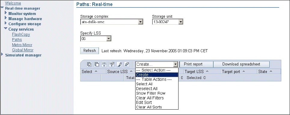
172 IBM System Storage DS6000 Series: Copy Services with IBM System z
14.6 DS Storage Manager GUI
The DS Storage Manager (DS SM) is a graphical user interface (GUI) that can be used to set
up and control Metro Mirror for DS6000 functions. It is user friendly; however, you cannot use
it for automation activities, and certain remote mirror and copy functions are not supported
from this interface.
The DS Storage Manager interface is simpler to use, however, it is usually slower than the
other interfaces, and you cannot save actions for later use. In this section, we give some
examples of common tasks that are done using the DS SM.
Our examples use a single DS GUI to manage two DS6000s, each in a different Storage
Complex. This means that we have added the remote Storage Complex to the local Storage
Complex using the process described in 3.5.1, “Procedure to add a Storage Complex” on
page 23.
14.6.1 Define Metro Mirror paths
To establish Metro Mirror paths from the GUI, you can follow the process below. Figure 14-1
shows the Copy services Paths panel. To define paths from LSS 06 of DS6000 serial number
00247 to LSS 01 of DS6000 serial number 00819, we go to the Select Action menu, then select
Create.
Figure 14-1 Copy services Paths panel
We are then taken to the panel for selecting the source LSS (see Figure 14-2 on page 173).
In this panel, in the Select LSS menu we select 06, and then click Next.
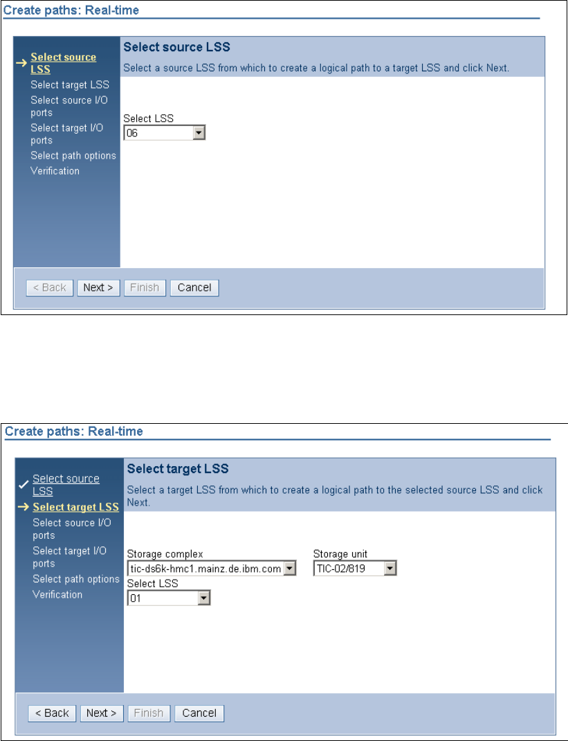
Chapter 14. Metro Mirror interfaces 173
Figure 14-2 Select source LSS panel
Now you must select the target LSS, using the panel shown in Figure 14-3. From the menus
provided, select the device to which you want to establish the path. In this example, we chose
LSS 01 on a different DS6000. Then click Next.
Figure 14-3 Select target LSS panel
Next, you select the source I/O ports, using the panel shown in Figure 14-4 on page 174. Use
the check boxes to select the I/O ports you want to use for the Metro Mirror paths that you are
establishing. Click Next.
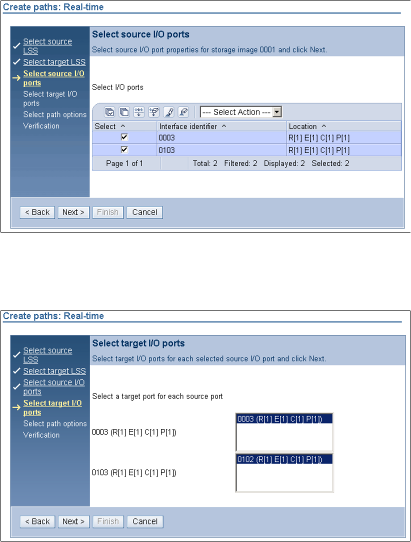
174 IBM System Storage DS6000 Series: Copy Services with IBM System z
Figure 14-4 Select source I/O ports
Now you must define a target I/O port for each source port. In the example shown in
Figure 14-5, there are no selections; however, for your setup you might see menus. Click
Next.
Figure 14-5 Select target I/O ports
Next, the panel shown in Figure 14-6 on page 175 opens. Here you can indicate whether the
paths will be a Consistency Group path by using the check box. Click Next.
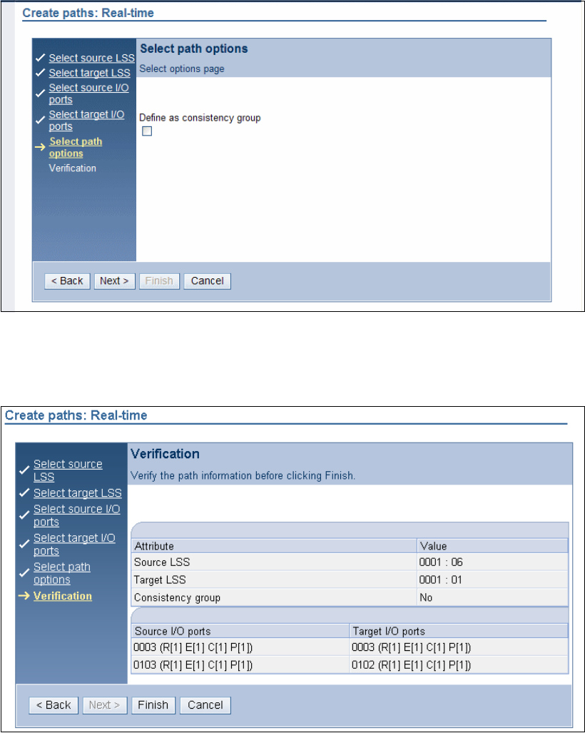
Chapter 14. Metro Mirror interfaces 175
Figure 14-6 Select path options panel
Next, the verification panel (see Figure 14-7) opens. Here you can verify that everything has
been selected correctly. If so, click Finish. If not, click Back or Cancel as appropriate.
Figure 14-7 Create paths verification panel
14.6.2 Create Metro Mirror pairs
To establish a Metro Mirror pair from the GUI, you can follow the process below. Figure 14-8
on page 176 shows the Metro Mirror panel where we have selected the Metro Mirror source
Storage complex, Storage unit, the Resource type (LSS), and the LSS. We then select
Create from the Select Action pull-down menu.
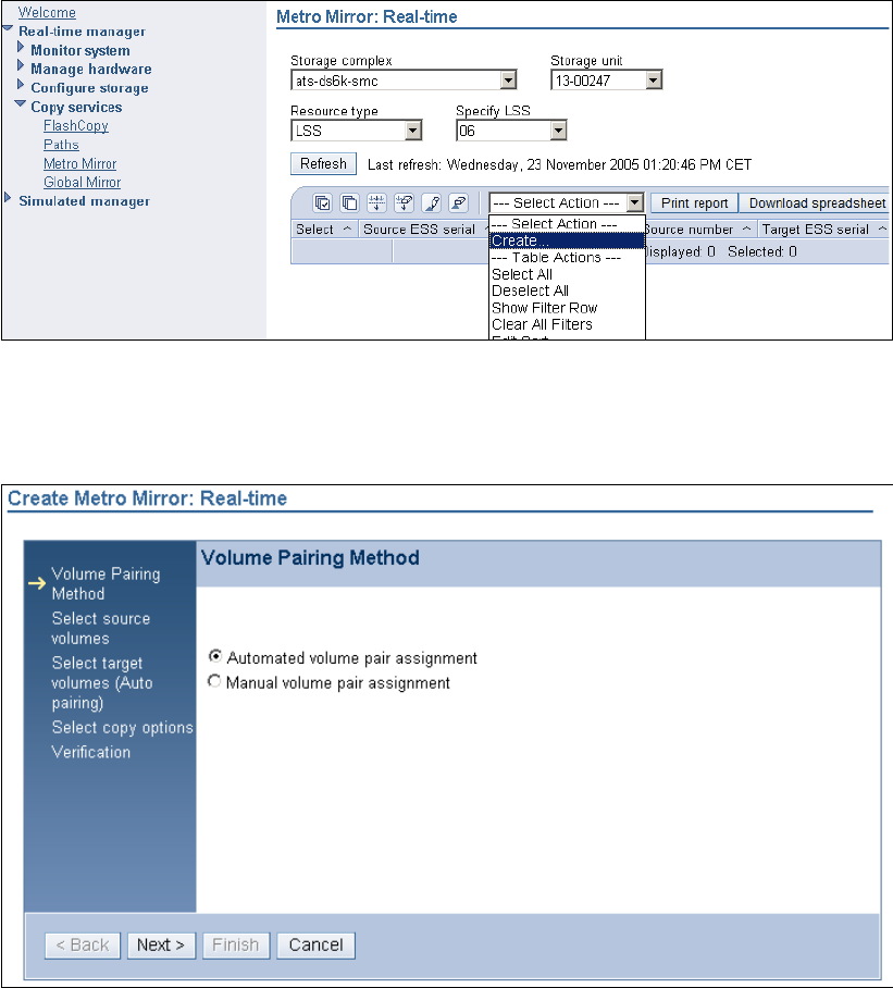
176 IBM System Storage DS6000 Series: Copy Services with IBM System z
Figure 14-8 Initial Metro Mirror panel, Create pull-down selected
The panel shown in Figure 14-9 opens. Select either automated or manual volume pairing,
and click Next.
Figure 14-9 Select volume pairing method
If you select Automatic volume pair assignment, then the panel in Figure 14-10 on page 177
opens. You then page through the list of volumes listed, and check the one you want to
establish.
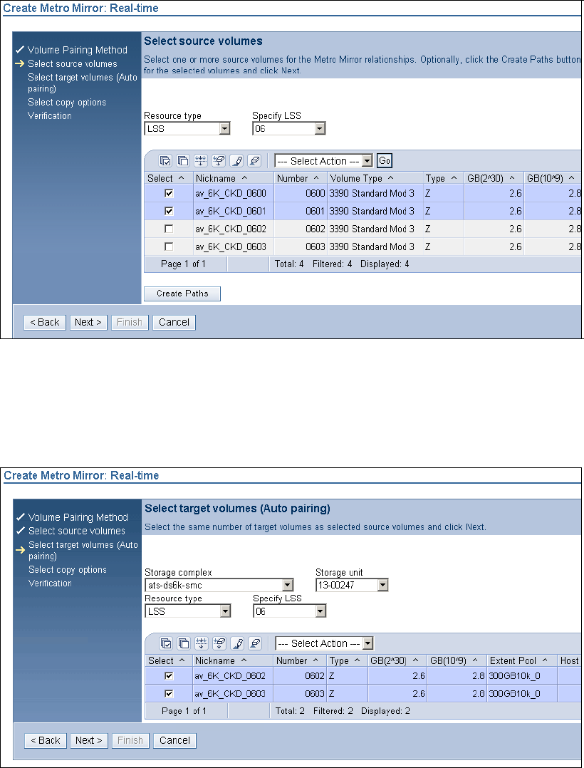
Chapter 14. Metro Mirror interfaces 177
Figure 14-10 Automatic volume assignment source volume selection panel
In our example, we selected volumes 0600 and 0601. After clicking Next, the panel shown in
Figure 14-11 opens. On this panel you select a target volume. Because we selected
automatic volume pairing, we are taken straight to the target LSS so that we can select the
target volumes.
Figure 14-11 Select target volume auto pairing
In our example, we selected volumes 0100 and 0101 and clicked Next.
When you do this, the Copy Options panel opens, and here you can select the options you
want for the Metro Mirror pair. As shown in Figure 14-12 on page 178, in our example we
selected Metro Mirror and Perform initial copy. Then, click Next.
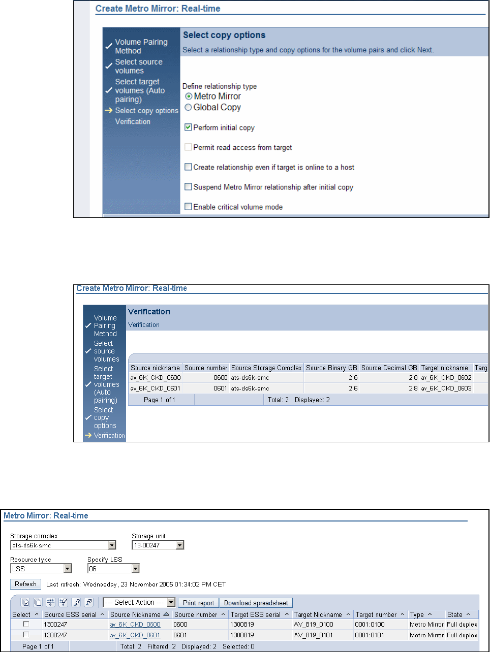
178 IBM System Storage DS6000 Series: Copy Services with IBM System z
Figure 14-12 Metro Mirror options
After making these selections, the Verification panel (see Figure 14-13) opens so that you can
check your selections. If all is correct, you can click Finish.
Figure 14-13 Metro Mirror pair verification panel
The Metro Mirror panel indicating the successful establishment of the Metro Mirror pairs
opens, as shown in Figure 14-14.
Figure 14-14 Metro Mirror pair established, full duplex state
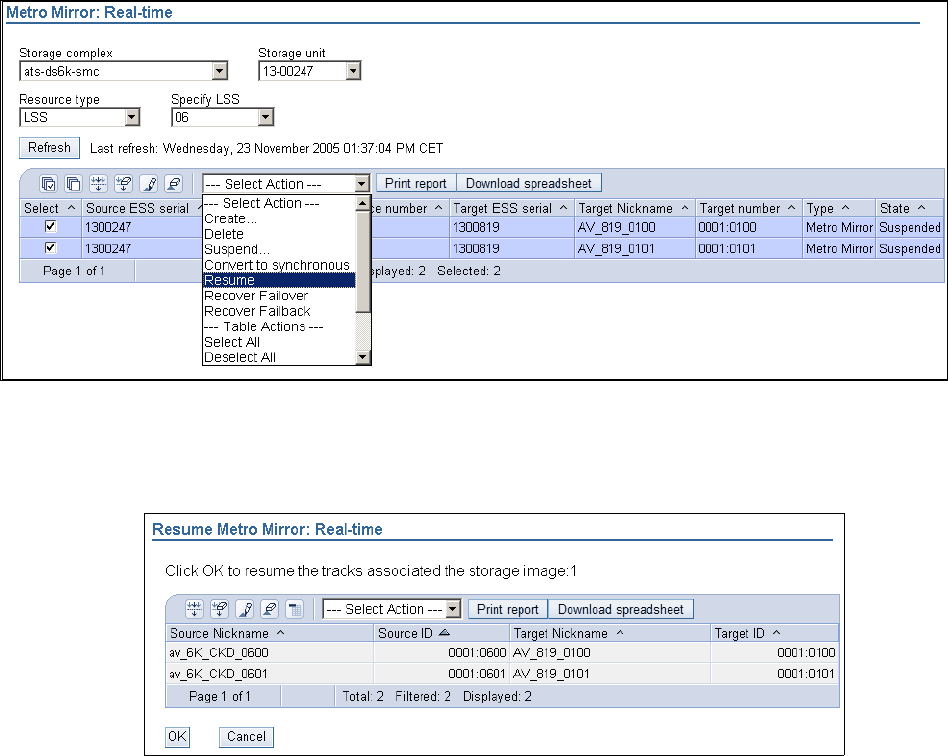
Chapter 14. Metro Mirror interfaces 179
14.6.3 Resume suspended pair
To resume a suspended pair from the DS Storage Manager, you can follow a procedure
similar to the procedure described in this section. First, you must access the Metro Mirror
panel. Then, select the volume you want to resume, then click Resume from the Select
Action menu, as shown in Figure 14-15.
Figure 14-15 Metro Mirror resume select volume and action
The panel shown in Figure 14-16 opens. This is where you confirm that you want to resume
the volume in question.
Figure 14-16 Confirm volume resume
You then return to the Metro Mirror primary panel.
14.7 ANTRQST API
The ANTRQST macro provides an application program call to the API of the z/OS system
data mover. This macro allows you to call Metro Mirror, z/OS Global Mirror, and FlashCopy
functions.
For detailed information, refer to z/OS DFSMS Advanced Copy Services, SC35-0428.
180 IBM System Storage DS6000 Series: Copy Services with IBM System z

© Copyright IBM Corp. 2006. All rights reserved. 181
Chapter 15. Metro Mirror performance and
scalability
In this chapter, we discuss performance and scalability considerations when using Metro
Mirror for DS6000.
15
182 IBM System Storage DS6000 Series: Copy Services with IBM System z
15.1 Performance
Because Metro Mirror is a synchronous mirroring technology, it introduces a performance
overhead (for write operations) as compared to a similar environment with no remote
mirroring. As part of the planning process for Metro Mirror, you should understand this.
Bandwidth analysis and capacity planning for your Metro Mirror links can help define how
many links you need, and when you need to add more, to ensure best possible performance.
As part of your implementation project you might be able to identify and then distribute hot
spots across your configuration or take other actions to manage performance.
Note that no processor resources (CPU and memory) are consumed by your Metro Mirror
volume pairs (your management solution excluded) because these resources are managed
by your DS6000 subsystem.
15.1.1 Peak bandwidth requirements
When you are researching your Metro Mirror link bandwidth requirements, you must find the
peak sustained write rate. Only writes are mirrored to the secondary volumes. For a typical
z/OS system, this peak is usually during batch processing, when many updates are occurring.
It could be higher still during month-end or year-end processing.
You must make allowances for this peak period when you are calculating bandwidth.
15.1.2 RMF
Resource Management Facility (RMF) can collect and report Metro Mirror link performance
statistics on DS6000 subsystems, and it is used for capacity planning and trending reports.
You can track the utilization of the Metro Mirror links over time and introduce new links in a
planned manner.
You can also produce reports about Extent Pool and Rank performance statistics using the
RMF Post Processor, if you have enabled the collection of this data through the RMF Parmlib
member.
15.1.3 Initial synchronization
When doing the initial synchronization of your Metro Mirror pairs, the DS6000 uses a
throttling algorithm to prevent the Metro Mirror process from using too many primary site
resources. This might prolong the synchronization process if your DS6000 is busy at the time.
You can choose to stagger your synchronization tasks or to run them at a time of low
utilization to make this process more efficient.
As an alternative, you may also choose to do the initial synchronization in the Global Copy
mode, and then switch to the Metro Mirror mode. This will allow you to bring all volumes to
duplex-pending XD state, which has little or no application impact, and then switch to full
duplex state. You can do so through TSO commands, the DS CLI, or one of the other
interfaces.
Chapter 15. Metro Mirror performance and scalability 183
15.2 Scalability
The DS6000 Metro Mirror environment can be scaled up or down as required. If new volumes
are added to the DS6000 that require mirroring, they can be dynamically added. If additional
Metro Mirror paths are required, they also can be dynamically added.
Remember that in the DS6000, you have only eight Fibre Channel ports available, four per
controller. Therefore, we recommend that you use two Fibre Channel links exclusively for
Metro Mirror, one on each controller, for availability.
If you need more bandwidth, you can increase the number of Metro Mirror links. It should be
symmetrical and it also depends on the controller used by the Extent Pool of your Metro
Mirror volumes.
We think that having no more than four exclusive Metro Mirror connections make sense. It is
the same as for your maximum host attachments at this time (unless you are using the
DS6000 mainly as a Metro Mirror target, with few or no host activities).
As previously mentioned, the logical nature of the LSS has made a Metro Mirror
implementation on the DS6000 easier to plan, implement and manage. However, if you need
to add more LSSs to your Metro Mirror environment, your management and automation
solutions should be set up to handle this.
The GDPS and eRCMF service offerings are designed to provide this functionality. Visit the
IBM Web site and see the Services & Industry Solutions page for more information. Also see
Part 8, “Solutions” on page 431.
Adding capacity to same DS6000
If you are adding capacity to an existing DS6000, providing your Metro Mirror link bandwidth
is not close to or over its limit, it is possible that you only have to add volume pairs to your
configuration. If you are adding more LSSs, then you must define Metro Mirror paths before
adding volume pairs.
Adding capacity in new DS6000s
If you are adding new DS6000s to your configuration, you must add physical Metro Mirror
links before defining your Metro Mirror paths and volume pairs. A minimum of two Metro
Mirror paths per DS6000 pair is recommended for redundancy reasons. Your bandwidth
analysis will indicate if you require more than two paths.
184 IBM System Storage DS6000 Series: Copy Services with IBM System z

© Copyright IBM Corp. 2006. All rights reserved. 185
Chapter 16. Metro Mirror examples
In this chapter we show examples using TSO, ICKDSF and DS CLI commands to manage
Metro Mirror. The examples presented are:
Resynchronization of a suspended volume pair with TSO commands
Metro Mirror Failover and Failback procedure using TSO commands
Define a Metro Mirror volume pair using TSO commands for open systems
Define a Metro Mirror path using ICKDSF
Use of the freezepprc and unfreezepprc DS CLI commands
16

186 IBM System Storage DS6000 Series: Copy Services with IBM System z
16.1 Resynchronization of suspended volume using TSO
To resynchronize a volume that is in a suspended state we need to obtain information such
as serial numbers, WWNNs, CCA and LSS numbers. We can obtain this information using
the CQUERY command, and then use it to reestablish the Metro Mirror pairs. Example 16-1
shows the CQUERY command and the output information it provides.
Example 16-1 CQUERY command to obtain information
ANTP8802I CQUERY DEVN(6400)
ANTP0090I CQUERY FORMATTED LVL 3 739
VOLUME REPORT
************** PPRC REMOTE COPY CQUERY - VOLUME ********************
* (PRIMARY) (SECONDARY) *
* SSID CCA LSS SSID CCA LSS*
*DEVICE LEVEL STATE PATH STATUS SERIAL# SERIAL# *
*------ --------- ---------- ----------- --------- --------- *
* 6400 PRIMARY.. SUSPEND(3) ACTIVE.. 0002 00 00 0003 00 01 *
* CRIT(NO)....... CGRPLB(NO). 0000000AAVCA 0000000AAVCA*
* PATHS PFCA SFCA STATUS: DESCRIPTION *
* ----- --------- ------ ------------------- *
* 1 0000 0100 13 PATH ESTABLISHED... *
* ---- ---- 00 NO PATH............ *
* ---- ---- 00 NO PATH............ *
* ---- ---- 00 NO PATH............ *
* SUBSYSTEM WWNN LIC LEVEL *
* ----------- ---------------- ----------- *
* PRIMARY.... 500507630EFFFCA0 5.0.00.0000 *
* SECONDARY.1 500507630EFFFCA0 *
********************************************************************
ANTP0001I CQUERY COMMAND COMPLETED FOR DEVICE 6400. COMPLETION CODE: 00
We see from the output that the device number 6400 is currently a primary volume and is in
suspend state. The SSID, CCA, LSS, and serial number information is on the right side of the
display for both the primary (0002, 00, 00, and AAVCA) and secondary devices (0003, 00, 01,
and AAVCA). The path information is also shown (one path from primary Fibre Channel adapter
0000 to secondary Fibre Channel adapter 0100).
We can see that this volume is mirrored to the same DS6000 via a loopback path (the serial
number for the primary and secondary DS6000 are the same).
We now have the information required for our Metro Mirror commands.
Resynchronize the pair
The CESTPAIR command can be used to establish a Metro Mirror pair from TSO. We already
had a pair established in the previous scenario; however, it was suspended. Therefore, we
had to resynchronize it so that the pair would be in duplex state again. Example 16-2 on
page 187 demonstrates how to use the CESTPAIR command with the MODE(RESYNC)
parameter to accomplish this.

Chapter 16. Metro Mirror examples 187
Example 16-2 Resume suspended Metro Mirror pair from TSO
CESTPAIR DEVN(X'6400') PRIM(X'0002' AAVCA X'00' X'00') -
SEC(X'0003' AAVCA X'00' X'01') OPTION(SYNC) MODE(RESYNC)
ANTP8802I CESTPAIR DEVN(X'6400') PRIM(X'0002' AAVCA X'00' X'00')
SEC(X'0003' AAVCA X'00' X'01') OPTION(SYN
ANTP8802I (CONT) C) MODE(RESYNC)
ANTP0001I CESTPAIR COMMAND COMPLETED FOR DEVICE 6400. COMPLETION CODE:
00
IEA494I 6400,DS6400,PPRC PAIR PENDING,SSID=0002,CCA=00
IEA494I 6400,DS6400,PPRC PAIR FULL DUPLEX,SSID=0002,CCA=00
16.2 Failover and failback using TSO
In this example we perform a failover and a failback using TSO commands. These options
can be used in both planned and unplanned scenarios. We simulate a planned outage.
In this discussion, the volumes at the primary site are referred to as the A volumes, and the
volumes at the recovery site are referred to as the B volumes. FlashCopy volumes are
referred to as C volumes.
16.2.1 Failover process
The high level process for the failover in a planned scenario is as follows:
1. Quiesce applications at the primary site.
2. Issue the Metro Mirror CESTPAIR command to the secondary (B) volume as the DEVN,
specifying the ACTION(FAILOVER) and reversing the original PRIMARY and
SECONDARY parameters. This establishes the B volumes as suspended primaries,
activates change recording on the B volumes, and releases write inhibit on the B volumes.
3. If desired, FlashCopy the B volume suspended primaries to C volumes to provide safe
copies for interim disaster recovery protection.
4. Restart applications at the recovery site. This includes bringing the B volumes online.
Here we show examples of the TSO commands that can be used to accomplish these
actions.
CESTPAIR with FAILOVER
We use the CESTPAIR command with the ACTION(FAILOVER) to the B volume to reverse
the original Metro Mirror direction and start change recording as shown in Example 16-3.
Note that we have reversed the original PRIM and SEC parameters.
Example 16-3 Establish Metro Mirror pair using TSO
ANTP8802I CESTPAIR DEVN(X'6430') SEC(X'2060' AAGXA X'30' X'00')
PRIM(X'0003' AAVCA X'30' X'01') ACTION(FAILOVER)
ANTP0001I CESTPAIR COMMAND COMPLETED FOR DEVICE 6430. COMPLETION CODE:
00
Tip: You may want to do a FlashCopy of your recovery site prior to running the
resynchronization, because the resynchronization process does not apply the updated
tracks in the order they were updated, and therefore you will have a data consistency
exposure until the last volume pair is again in duplex state.

188 IBM System Storage DS6000 Series: Copy Services with IBM System z
Syslog messages
Example 16-4 shows the syslog messages from a failover operation. We are doing a failover
from device 6030 to device 6430. In this example, both primary and secondary devices are
available to this processors LPAR; however, this might not be the case in all Metro Mirror
environments. If both devices are not available from one processor LPAR, you must issue
commands on the system where the device is located.
Example 16-4 Syslog for failover operation
ANTP8802I CQUERY DEVN(6030)
ANTP0090I CQUERY FORMATTED LVL 3 227
VOLUME REPORT
************** PPRC REMOTE COPY CQUERY - VOLUME ********************
* (PRIMARY) (SECONDARY) *
* SSID CCA LSS SSID CCA LSS*
*DEVICE LEVEL STATE PATH STATUS SERIAL# SERIAL# *
*------ --------- ---------- ----------- --------- --------- *
* 6030 PRIMARY.. DUPLEX.... ACTIVE.. 2060 30 00 0002 30 00 *
* CRIT(NO)....... CGRPLB(NO). 0000000AAGXA 0000000AAVCA*
* PATHS PFCA SFCA STATUS: DESCRIPTION *
* ----- --------- ------ ------------------- *
* 1 0000 0000 13 PATH ESTABLISHED... *
* ---- ---- 00 NO PATH............ *
* ---- ---- 00 NO PATH............ *
* ---- ---- 00 NO PATH............ *
* SUBSYSTEM WWNN LIC LEVEL *
* ----------- ---------------- ----------- *
* PRIMARY.... 500507630EFFFC6F 5.0.00.0000 *
* SECONDARY.1 500507630EFFFCA0 *
********************************************************************
ANTP0001I CQUERY COMMAND COMPLETED FOR DEVICE 6030. COMPLETION CODE: 00
ANTP8802I CQUERY DEVN(6430)
ANTP0090I CQUERY FORMATTED LVL 3 230
VOLUME REPORT
************** PPRC REMOTE COPY CQUERY - VOLUME ********************
* (PRIMARY) (SECONDARY) *
* SSID CCA LSS SSID CCA LSS*
*DEVICE LEVEL STATE PATH STATUS SERIAL# SERIAL# *
*------ --------- ---------- ----------- --------- --------- *
* 6430 SECONDARY DUPLEX.... ACTIVE.. 2060 30 00 0002 30 00 *
* ............... ........... 0000000AAGXA 0000000AAVCA*
* PATHS PFCA SFCA STATUS: DESCRIPTION *
* ----- --------- ------ ------------------- *
* 1 0000 0100 13 PATH ESTABLISHED... *
* ---- ---- 00 NO PATH............ *
* ---- ---- 00 NO PATH............ *
* ---- ---- 00 NO PATH............ *
* SUBSYSTEM WWNN LIC LEVEL *
* ----------- ---------------- ----------- *
* PRIMARY.... 500507630EFFFC6F 5.0.00.0000 *
* SECONDARY.1 500507630EFFFCA0 *
********************************************************************
ANTP0001I CQUERY COMMAND COMPLETED FOR DEVICE 6430. COMPLETION CODE: 00
IEA494I 6030,DS6030,PPRC PAIR SUSPENDED,SSID=2060,CCA=30
ANTP8802I CESTPAIR DEVN(X'6430') PRIM(X'0002' AAVCA X'30' X'00')
SEC(X'2060' AAGXA X'30' X'00') ACTION(FAI
ANTP8802I (CONT) LOVER)
ANTP0001I CESTPAIR COMMAND COMPLETED FOR DEVICE 6430. COMPLETION CODE:
00
ANTP8802I CQUERY DEVN(6030)

Chapter 16. Metro Mirror examples 189
ANTP0090I CQUERY FORMATTED LVL 3 239
VOLUME REPORT
************** PPRC REMOTE COPY CQUERY - VOLUME ********************
* (PRIMARY) (SECONDARY) *
* SSID CCA LSS SSID CCA LSS*
*DEVICE LEVEL STATE PATH STATUS SERIAL# SERIAL# *
*------ --------- ---------- ----------- --------- --------- *
* 6030 PRIMARY.. SUSPEND(3) ACTIVE.. 2060 30 00 0002 30 00 *
* CRIT(NO)....... CGRPLB(NO). 0000000AAGXA 0000000AAVCA*
* PATHS PFCA SFCA STATUS: DESCRIPTION *
* ----- --------- ------ ------------------- *
* 1 0000 0000 13 PATH ESTABLISHED... *
* ---- ---- 00 NO PATH............ *
* ---- ---- 00 NO PATH............ *
* ---- ---- 00 NO PATH............ *
* SUBSYSTEM WWNN LIC LEVEL *
* ----------- ---------------- ----------- *
* PRIMARY.... 500507630EFFFC6F 5.0.00.0000 *
* SECONDARY.1 500507630EFFFCA0 *
********************************************************************
ANTP0001I CQUERY COMMAND COMPLETED FOR DEVICE 6030. COMPLETION CODE: 00
ANTP8802I CQUERY DEVN(6430)
ANTP0090I CQUERY FORMATTED LVL 3 242
VOLUME REPORT
************** PPRC REMOTE COPY CQUERY - VOLUME ********************
* (PRIMARY) (SECONDARY) *
* SSID CCA LSS SSID CCA LSS*
*DEVICE LEVEL STATE PATH STATUS SERIAL# SERIAL# *
*------ --------- ---------- ----------- --------- --------- *
* 6430 PRIMARY.. SUSPEND(3) ACTIVE.. 0002 30 00 2060 30 00 *
* CRIT(NO)....... CGRPLB(NO). 0000000AAVCA 0000000AAGXA*
* PATHS PFCA SFCA STATUS: DESCRIPTION *
* ----- --------- ------ ------------------- *
* 1 0100 0100 13 PATH ESTABLISHED... *
* ---- ---- 00 NO PATH............ *
* ---- ---- 00 NO PATH............ *
* ---- ---- 00 NO PATH............ *
* SUBSYSTEM WWNN LIC LEVEL *
* ----------- ---------------- ----------- *
* PRIMARY.... 500507630EFFFCA0 5.0.00.0000 *
* SECONDARY.1 500507630EFFFCA0 *
* SECONDARY.2 500507630EFFFC6F *
********************************************************************
ANTP0001I CQUERY COMMAND COMPLETED FOR DEVICE 6430. COMPLETION CODE: 00
Both devices are in suspend state. Note that for device 6430, the direction of the Metro Mirror
pairing has been reversed. Because the volume is in suspend state, changes will be recorded
by the DS6000. At this stage you could start running your application at the secondary site.
16.2.2 Failback process
The high level failback process in a planned scenario is as follows:
1. Quiesce the applications at the recovery site.
2. Use Metro Mirror establish path commands to create paths from the recovery site to the
primary site (remember, paths are required for all LSS pairs).
3. Issue Metro Mirror establish pair commands to the B volume, specifying the Failback
action and reversing the original PRIM and SEC parameters. This copies any changes

190 IBM System Storage DS6000 Series: Copy Services with IBM System z
recorded on the B volumes back to the A volumes. You must vary the A volumes offline, if
they are online at the primary site.
4. If you established a FlashCopy relationship (to the C volumes), you can now withdraw it.
5. Check that Metro Mirror paths exist between the A and B volumes. Reestablish, if
necessary.
6. Allow Metro Mirror pairs to reach full Duplex state (use the CQUERY command, or check
the syslog for IEA494I messages).
7. Issue Metro Mirror establish pair commands to A volumes specifying the
ACTION(FAILOVER) with the original PRIM and SEC parameters. This reestablishes the
A volumes as suspended primaries and begins change recording on the A volumes. It also
releases write inhibit on the A volumes. You can vary the A volumes online again at this
point.
8. You can now restart your applications at the primary site.
9. Now issue the Metro Mirror Establish pair command to the A volumes, specifying the
ACTION(FAILBACK) with the original PRIM and SEC parameters. This resynchronizes
the A and B volumes in the recovery configuration and restores the pairs to the Duplex
state.
CESTPAIR with FAILBACK action (step 3, 9)
For step 3, the command shown in Example 16-5 will reestablish the Metro Mirror pair and
copy any changes to the original primary volume (remember to keep the original PRIM and
SEC parameters reversed).
Example 16-5 CESTPAIR with Failback - B to A (Step 3)
CESTPAIR DEVN(X'6430') PRIM(X'0002' AAVCA X'30' X'00') -
SEC(X'2060' AAGXA X'30' X'00') -
ACTION(FAILBACK)
A similar command is issued in step 9; however, it has the original Metro Mirror direction as
shown in Example 16-6.
Example 16-6 CESTPAIR with Failback - A to B (Step 9)
CESTPAIR DEVN(X'6430') SEC(X'0002' AAVCA X'30' X'00') -
PRIM(X'2060' AAGXA X'30' X'00') -
ACTION(FAILBACK)
Syslog messages for failback process
Example 16-7 shows the syslog messages issued for the complete failback process. Note
that we had access to both devices from one LPAR and therefore could perform all operations
from there. You might have to split operations if you do not have access to both devices.
We issued CQUERY commands between each step of the process to check the status of our
volumes. You can see the status changes and the direction of mirroring change as we
progressed through the process.
Example 16-7 Syslog messages for failback process
ANTP8802I CQUERY DEVN(6030)
ANTP0090I CQUERY FORMATTED LVL 3 257
VOLUME REPORT
************** PPRC REMOTE COPY CQUERY - VOLUME ********************
* (PRIMARY) (SECONDARY) *
* SSID CCA LSS SSID CCA LSS*
Chapter 16. Metro Mirror examples 191
*DEVICE LEVEL STATE PATH STATUS SERIAL# SERIAL# *
*------ --------- ---------- ----------- --------- --------- *
* 6030 PRIMARY.. SUSPEND(3) ACTIVE.. 2060 30 00 0002 30 00 *
* CRIT(NO)....... CGRPLB(NO). 0000000AAGXA 0000000AAVCA*
* PATHS PFCA SFCA STATUS: DESCRIPTION *
* ----- --------- ------ ------------------- *
* 1 0000 0000 13 PATH ESTABLISHED... *
* ---- ---- 00 NO PATH............ *
* ---- ---- 00 NO PATH............ *
* ---- ---- 00 NO PATH............ *
* SUBSYSTEM WWNN LIC LEVEL *
* ----------- ---------------- ----------- *
* PRIMARY.... 500507630EFFFC6F 5.0.00.0000 *
* SECONDARY.1 500507630EFFFCA0 *
********************************************************************
ANTP0001I CQUERY COMMAND COMPLETED FOR DEVICE 6030. COMPLETION CODE: 00
ANTP8802I CQUERY DEVN(6430)
ANTP0090I CQUERY FORMATTED LVL 3 260
VOLUME REPORT
************** PPRC REMOTE COPY CQUERY - VOLUME ********************
* (PRIMARY) (SECONDARY) *
* SSID CCA LSS SSID CCA LSS*
*DEVICE LEVEL STATE PATH STATUS SERIAL# SERIAL# *
*------ --------- ---------- ----------- --------- --------- *
* 6430 PRIMARY.. SUSPEND(3) ACTIVE.. 0002 30 00 2060 30 00 *
* CRIT(NO)....... CGRPLB(NO). 0000000AAVCA 0000000AAGXA*
* PATHS PFCA SFCA STATUS: DESCRIPTION *
* ----- --------- ------ ------------------- *
* 1 0100 0100 13 PATH ESTABLISHED... *
* ---- ---- 00 NO PATH............ *
* ---- ---- 00 NO PATH............ *
* ---- ---- 00 NO PATH............ *
* SUBSYSTEM WWNN LIC LEVEL *
* ----------- ---------------- ----------- *
* PRIMARY.... 500507630EFFFCA0 5.0.00.0000 *
* SECONDARY.1 500507630EFFFCA0 *
* SECONDARY.2 500507630EFFFC6F *
********************************************************************
ANTP0001I CQUERY COMMAND COMPLETED FOR DEVICE 6430. COMPLETION CODE: 00
ANTP8802I CESTPAIR DEVN(X'6430') PRIM(X'0002' AAVCA X'30' X'00')
SEC(X'2060' AAGXA X'30' X'00') ACTION(FAI
ANTP8802I (CONT) LBACK)
ANTP0001I CESTPAIR COMMAND COMPLETED FOR DEVICE 6430. COMPLETION CODE:
00
ANTP8802I CQUERY DEVN(X'6030')
ANTP0090I CQUERY FORMATTED LVL 3 266
VOLUME REPORT
************** PPRC REMOTE COPY CQUERY - VOLUME ********************
* (PRIMARY) (SECONDARY) *
* SSID CCA LSS SSID CCA LSS*
*DEVICE LEVEL STATE PATH STATUS SERIAL# SERIAL# *
*------ --------- ---------- ----------- --------- --------- *
* 6030 SECONDARY DUPLEX.... ACTIVE.. 0002 30 00 2060 30 00 *
* ............... ........... 0000000AAVCA 0000000AAGXA*
* PATHS PFCA SFCA STATUS: DESCRIPTION *
* ----- --------- ------ ------------------- *
* 1 0000 0000 13 PATH ESTABLISHED... *
* ---- ---- 00 NO PATH............ *
* ---- ---- 00 NO PATH............ *
* ---- ---- 00 NO PATH............ *
192 IBM System Storage DS6000 Series: Copy Services with IBM System z
* SUBSYSTEM WWNN LIC LEVEL *
* ----------- ---------------- ----------- *
* PRIMARY.... 500507630EFFFCA0 5.0.00.0000 *
* SECONDARY.1 500507630EFFFC6F *
********************************************************************
ANTP0001I CQUERY COMMAND COMPLETED FOR DEVICE 6030. COMPLETION CODE: 00
ANTP8802I CQUERY DEVN(X'6430')
ANTP0090I CQUERY FORMATTED LVL 3 269
VOLUME REPORT
************** PPRC REMOTE COPY CQUERY - VOLUME ********************
* (PRIMARY) (SECONDARY) *
* SSID CCA LSS SSID CCA LSS*
*DEVICE LEVEL STATE PATH STATUS SERIAL# SERIAL# *
*------ --------- ---------- ----------- --------- --------- *
* 6430 PRIMARY.. DUPLEX.... ACTIVE.. 0002 30 00 2060 30 00 *
* CRIT(NO)....... CGRPLB(NO). 0000000AAVCA 0000000AAGXA*
* PATHS PFCA SFCA STATUS: DESCRIPTION *
* ----- --------- ------ ------------------- *
* 1 0100 0100 13 PATH ESTABLISHED... *
* ---- ---- 00 NO PATH............ *
* ---- ---- 00 NO PATH............ *
* ---- ---- 00 NO PATH............ *
* SUBSYSTEM WWNN LIC LEVEL *
* ----------- ---------------- ----------- *
* PRIMARY.... 500507630EFFFCA0 5.0.00.0000 *
* SECONDARY.1 500507630EFFFCA0 *
* SECONDARY.2 500507630EFFFC6F *
********************************************************************
ANTP0001I CQUERY COMMAND COMPLETED FOR DEVICE 6430. COMPLETION CODE: 00
ANTP8802I CQUERY DEVN(6030)
ANTP0090I CQUERY FORMATTED LVL 3 272
VOLUME REPORT
************** PPRC REMOTE COPY CQUERY - VOLUME ********************
* (PRIMARY) (SECONDARY) *
* SSID CCA LSS SSID CCA LSS*
*DEVICE LEVEL STATE PATH STATUS SERIAL# SERIAL# *
*------ --------- ---------- ----------- --------- --------- *
* 6030 SECONDARY DUPLEX.... ACTIVE.. 0002 30 00 2060 30 00 *
* ............... ........... 0000000AAVCA 0000000AAGXA*
* PATHS PFCA SFCA STATUS: DESCRIPTION *
* ----- --------- ------ ------------------- *
* 1 0000 0000 13 PATH ESTABLISHED... *
* ---- ---- 00 NO PATH............ *
* ---- ---- 00 NO PATH............ *
* ---- ---- 00 NO PATH............ *
* SUBSYSTEM WWNN LIC LEVEL *
* ----------- ---------------- ----------- *
* PRIMARY.... 500507630EFFFCA0 5.0.00.0000 *
* SECONDARY.1 500507630EFFFC6F *
********************************************************************
ANTP0001I CQUERY COMMAND COMPLETED FOR DEVICE 6030. COMPLETION CODE: 00
ANTP8802I CQUERY DEVN(6430)
ANTP0090I CQUERY FORMATTED LVL 3 275
VOLUME REPORT
************** PPRC REMOTE COPY CQUERY - VOLUME ********************
* (PRIMARY) (SECONDARY) *
* SSID CCA LSS SSID CCA LSS*
*DEVICE LEVEL STATE PATH STATUS SERIAL# SERIAL# *
*------ --------- ---------- ----------- --------- --------- *
* 6430 PRIMARY.. DUPLEX.... ACTIVE.. 0002 30 00 2060 30 00 *
Chapter 16. Metro Mirror examples 193
* CRIT(NO)....... CGRPLB(NO). 0000000AAVCA 0000000AAGXA*
* PATHS PFCA SFCA STATUS: DESCRIPTION *
* ----- --------- ------ ------------------- *
* 1 0100 0100 13 PATH ESTABLISHED... *
* ---- ---- 00 NO PATH............ *
* ---- ---- 00 NO PATH............ *
* ---- ---- 00 NO PATH............ *
* SUBSYSTEM WWNN LIC LEVEL *
* ----------- ---------------- ----------- *
* PRIMARY.... 500507630EFFFCA0 5.0.00.0000 *
* SECONDARY.1 500507630EFFFCA0 *
* SECONDARY.2 500507630EFFFC6F *
********************************************************************
ANTP0001I CQUERY COMMAND COMPLETED FOR DEVICE 6430. COMPLETION CODE: 00
ANTP8802I CESTPAIR DEVN(X'6030') PRIM(X'2060' AAGXA X'30' X'00')
SEC(X'0002' AAVCA X'30' X'00') ACTION(FAI
ANTP8802I (CONT) LOVER)
ANTP0001I CESTPAIR COMMAND COMPLETED FOR DEVICE 6030. COMPLETION CODE:
00
ANTP8802I CQUERY DEVN(6030)
ANTP0090I CQUERY FORMATTED LVL 3 283
VOLUME REPORT
************** PPRC REMOTE COPY CQUERY - VOLUME ********************
* (PRIMARY) (SECONDARY) *
* SSID CCA LSS SSID CCA LSS*
*DEVICE LEVEL STATE PATH STATUS SERIAL# SERIAL# *
*------ --------- ---------- ----------- --------- --------- *
* 6030 PRIMARY.. SUSPEND(3) ACTIVE.. 2060 30 00 0002 30 00 *
* CRIT(NO)....... CGRPLB(NO). 0000000AAGXA 0000000AAVCA*
* PATHS PFCA SFCA STATUS: DESCRIPTION *
* ----- --------- ------ ------------------- *
* 1 0000 0000 13 PATH ESTABLISHED... *
* ---- ---- 00 NO PATH............ *
* ---- ---- 00 NO PATH............ *
* ---- ---- 00 NO PATH............ *
* SUBSYSTEM WWNN LIC LEVEL *
* ----------- ---------------- ----------- *
* PRIMARY.... 500507630EFFFC6F 5.0.00.0000 *
* SECONDARY.1 500507630EFFFCA0 *
********************************************************************
ANTP0001I CQUERY COMMAND COMPLETED FOR DEVICE 6030. COMPLETION CODE: 00
ANTP8802I CQUERY DEVN(6430)
ANTP0090I CQUERY FORMATTED LVL 3 286
VOLUME REPORT
************** PPRC REMOTE COPY CQUERY - VOLUME ********************
* (PRIMARY) (SECONDARY) *
* SSID CCA LSS SSID CCA LSS*
*DEVICE LEVEL STATE PATH STATUS SERIAL# SERIAL# *
*------ --------- ---------- ----------- --------- --------- *
* 6430 PRIMARY.. SUSPEND(3) ACTIVE.. 0002 30 00 2060 30 00 *
* CRIT(NO)....... CGRPLB(NO). 0000000AAVCA 0000000AAGXA*
* PATHS PFCA SFCA STATUS: DESCRIPTION *
* ----- --------- ------ ------------------- *
* 1 0100 0100 13 PATH ESTABLISHED... *
* ---- ---- 00 NO PATH............ *
* ---- ---- 00 NO PATH............ *
* ---- ---- 00 NO PATH............ *
* SUBSYSTEM WWNN LIC LEVEL *
* ----------- ---------------- ----------- *
* PRIMARY.... 500507630EFFFCA0 5.0.00.0000 *

194 IBM System Storage DS6000 Series: Copy Services with IBM System z
* SECONDARY.1 500507630EFFFCA0 *
* SECONDARY.2 500507630EFFFC6F *
********************************************************************
ANTP0001I CQUERY COMMAND COMPLETED FOR DEVICE 6430. COMPLETION CODE: 00
ANTP8802I CESTPAIR DEVN(X'6030') PRIM(X'2060' AAGXA X'30' X'00')
SEC(X'0002' AAVCA X'30' X'00') ACTION(FAI
ANTP8802I (CONT) LBACK)
ANTP0001I CESTPAIR COMMAND COMPLETED FOR DEVICE 6030. COMPLETION CODE:
00
ANTP8802I CQUERY DEVN(6030)
ANTP0090I CQUERY FORMATTED LVL 3 292
VOLUME REPORT
************** PPRC REMOTE COPY CQUERY - VOLUME ********************
* (PRIMARY) (SECONDARY) *
* SSID CCA LSS SSID CCA LSS*
*DEVICE LEVEL STATE PATH STATUS SERIAL# SERIAL# *
*------ --------- ---------- ----------- --------- --------- *
* 6030 PRIMARY.. PENDING... ACTIVE.. 2060 30 00 0002 30 00 *
* CRIT(NO)....... CGRPLB(NO). 0000000AAGXA 0000000AAVCA*
* PATHS PFCA SFCA STATUS: DESCRIPTION *
* ----- --------- ------ ------------------- *
* 1 0000 0000 13 PATH ESTABLISHED... *
* ---- ---- 00 NO PATH............ *
* ---- ---- 00 NO PATH............ *
* ---- ---- 00 NO PATH............ *
* SUBSYSTEM WWNN LIC LEVEL *
* ----------- ---------------- ----------- *
* PRIMARY.... 500507630EFFFC6F 5.0.00.0000 *
* SECONDARY.1 500507630EFFFCA0 *
********************************************************************
ANTP0001I CQUERY COMMAND COMPLETED FOR DEVICE 6030. COMPLETION CODE: 00
ANTP8802I CQUERY DEVN(6430)
ANTP0090I CQUERY FORMATTED LVL 3 295
VOLUME REPORT
************** PPRC REMOTE COPY CQUERY - VOLUME ********************
* (PRIMARY) (SECONDARY) *
* SSID CCA LSS SSID CCA LSS*
*DEVICE LEVEL STATE PATH STATUS SERIAL# SERIAL# *
*------ --------- ---------- ----------- --------- --------- *
* 6430 SECONDARY PENDING... ACTIVE.. 2060 30 00 0002 30 00 *
* ............... ........... 0000000AAGXA 0000000AAVCA*
* PATHS PFCA SFCA STATUS: DESCRIPTION *
* ----- --------- ------ ------------------- *
* 1 0000 0100 13 PATH ESTABLISHED... *
* ---- ---- 00 NO PATH............ *
* ---- ---- 00 NO PATH............ *
* ---- ---- 00 NO PATH............ *
* SUBSYSTEM WWNN LIC LEVEL *
* ----------- ---------------- ----------- *
* PRIMARY.... 500507630EFFFC6F 5.0.00.0000 *
* SECONDARY.1 500507630EFFFCA0 *
********************************************************************
ANTP0001I CQUERY COMMAND COMPLETED FOR DEVICE 6430. COMPLETION CODE: 00
16.3 Open systems volumes with TSO commands
It is possible to manage Metro Mirror, Global Copy, and FlashCopy of open systems devices
through the TSO interface. We show an example of this.

Chapter 16. Metro Mirror examples 195
Establish a volume pair
Similar to System z volumes, we first have to collect the required information. In this example,
we already had a path defined to the secondary subsystem. We issued a CQUERY command
with the ODEVN parameter to check the status of the volume, as seen in Example 16-8. Note
that we have to direct the command (using the DEVN parameter) to a z/OS device with the
same server affinity as the open systems volume (therefore, in this example, we direct it to a
volume in LSS 00, which has the same server affinity as LSS 16).
Example 16-8 CQUERY for open systems device
CQUERY DEVN(6030) ODEVN(AAGXA X'00' X'16') VOLUME
The serial number of the DS subsystem is supplied, along with the LUN number (x’00’) and
the LSS number (x’16’). The output appears similar to that shown in Example 16-9.
Example 16-9 CQUERY for open systems device output
ANTP8802I CQUERY DEVN(6030) ODEVN(AAGXA X'00' X'16') VOLUME
ANTP0090I CQUERY FORMATTED LVL 3 472
VOLUME REPORT
************** PPRC REMOTE COPY CQUERY - VOLUME ********************
* (PRIMARY) (SECONDARY) *
* SSID LUN LSS SSID LUN LSS*
*DEVICE LEVEL STATE PATH STATUS SERIAL# SERIAL# *
*------ --------- ---------- ----------- --------- --------- *
* 6030 ......... SIMPLEX... INACTIVE FF16 00 16 .......... *
* ............... ........... 0000000AAGXA ............*
* PATHS SAID DEST STATUS: DESCRIPTION *
* ----- --------- ------ ------------------- *
* 0 ---- ---- 00 NO PATH............ *
* ---- ---- 00 NO PATH............ *
* ---- ---- 00 NO PATH............ *
* ---- ---- 00 NO PATH............ *
* SUBSYSTEM WWNN LIC LEVEL *
* ----------- ---------------- ----------- *
* PRIMARY.... 500507630EFFFC6F 5.0.00.0000 *
* SECONDARY.1 500507630EFFFCA0 *
* SECONDARY.2 500507630EFFFCA0 *
********************************************************************
ANTP0001I CQUERY COMMAND COMPLETED FOR DEVICE 6030. COMPLETION CODE: 00
The device is in simplex state. Note the SSID reports with special value FF16; this is the open
systems LSS number preceded with FF.
We want to establish a pair with the secondary device on LSS 16, LUN number 00. The
command format that we use is shown in Example 16-10.
Example 16-10 CESTPAIR command for open systems LUN
CESTPAIR DEVN(X'6030') PRIM(X'FF16' AAGXA X'00' X'16') -
SEC(X'FF16' AAVCA X'00' X'16') OPENDVCS(YES) -
OPTION(SYNC) MODE(COPY)
We used the OPENDVCS parameter and the special SSID value FF16 to identify that this is
an open systems device, on LSS 16, and that we want to direct the command to the open
systems LSS. The LUN number is supplied where we would normally supply the CCA, and
the LSS number is supplied in the normal position. The output from this command and a
subsequent CQUERY are shown in Example 16-11 on page 196.

196 IBM System Storage DS6000 Series: Copy Services with IBM System z
Example 16-11 CESTPAIR and CQUERY output
ANTP8802I CESTPAIR DEVN(X'6030') PRIM(X'FF16' AAGXA X'00' X'16')
SEC(X'FF16' AAVCA X'00' X'16') OPENDVCS(YES)
ANTP8802I (CONT) OPTION(SYNC) MODE(COPY)
ANTP0001I CESTPAIR COMMAND COMPLETED FOR DEVICE 6030. COMPLETION CODE:
00
ANTP8802I CQUERY DEVN(6030) ODEVN(AAGXA X'00' X'16') VOLUME
ANTP0090I CQUERY FORMATTED LVL 3 478
VOLUME REPORT
************** PPRC REMOTE COPY CQUERY - VOLUME ********************
* (PRIMARY) (SECONDARY) *
* SSID LUN LSS SSID LUN LSS*
*DEVICE LEVEL STATE PATH STATUS SERIAL# SERIAL# *
*------ --------- ---------- ----------- --------- --------- *
* 6030 PRIMARY.. PENDING... ACTIVE.. FF16 00 16 FF16 00 16 *
* CRIT(NO)....... CGRPLB(NO). 0000000AAGXA 0000000AAVCA*
* PATHS PFCA SFCA STATUS: DESCRIPTION *
* ----- --------- ------ ------------------- *
* 2 0000 0000 13 PATH ESTABLISHED... *
* 0100 0100 13 PATH ESTABLISHED... *
* ---- ---- 00 NO PATH............ *
* ---- ---- 00 NO PATH............ *
* IF STATE = PENDING/SUSPEND: TRACKS OUT OF SYNC = 40523 *
* TRACKS ON VOLUME = 81920 *
* PERCENT OF COPY COMPLETE = 51% *
* SUBSYSTEM WWNN LIC LEVEL *
* ----------- ---------------- ----------- *
* PRIMARY.... 500507630EFFFC6F 5.0.00.0000 *
* SECONDARY.1 500507630EFFFCA0 *
* SECONDARY.2 500507630EFFFCA0 *
********************************************************************
ANTP0001I CQUERY COMMAND COMPLETED FOR DEVICE 6030. COMPLETION CODE: 00
We can see the Metro Mirror pair has established and the volume is in pending state, with
51% of tracks copied so far.
16.4 Define Metro Mirror path using ICKDSF
In this section we give an example of establishing of a Metro Mirror path using ICKDSF.
Example 16-12 ICKDSF PPRCOPY ESTPATH example
//EPATH EXEC PGM=ICKDSF
//SYSPRINT DD SYSOUT=*
//DD01 DD UNIT=3390,VOL=SER=RS4000,DISP=SHR
//SYSIN DD *
/* --------------------------------------------------------- */ -
/* ESTABLISH PPRC PATH FROM 00/ABTV1 TO 90/BYGT1 */ -
/* --------------------------------------------------------- */ -
PPRCOPY DDNAME (DD01) ESTPATH -
PRI (X'4000' ABTV1) -
SEC (X'9000' BYGT1) -
LSS (X'00' X'90') -
FCPPATHS (X'00420242') -
WWNN (5005076303FFC663 5005076304FFC671)
/*

Chapter 16. Metro Mirror examples 197
Example 16-12 on page 196 shows an ICKDSF job that is defining the Metro Mirror path.
Notice that the PPRCOPY ESTPATH command replaces any path definitions that currently
exist.
In Example 16-13 we show the output from the ESTPATH command.
Example 16-13 PPRCOPY ESTPATH output
ICKDSF - MVS/ESA DEVICE SUPPORT FACILITIES 17.0 TIME: 13:35:01
/* --------------------------------------------------------- */ -
/* ESTABLISH PPRC PATH FROM 00/ABTV1 TO 90/BYGT1 */ -
/* --------------------------------------------------------- */ -
PPRCOPY DDNAME (DD01) ESTPATH -
PRI (X'4000' ABTV1) -
SEC (X'9000' BYGT1) -
LSS (X'00' X'90') -
FCPPATHS (X'00420242') -
WWNN (5005076303FFC663 5005076304FFC671)
ICK00700I DEVICE INFORMATION FOR 4000 IS CURRENTLY AS FOLLOWS:
PHYSICAL DEVICE = 3390
STORAGE CONTROLLER = 1750
STORAGE CONTROL DESCRIPTOR = E8
DEVICE DESCRIPTOR = 0A
ADDITIONAL DEVICE INFORMATION = 4A00003C
ICK04000I DEVICE IS IN SIMPLEX STATE
ICK02201I PPRCOPY ESTPATH FUNCTION COMPLETED SUCCESSFULLY
ICK00001I FUNCTION COMPLETED, HIGHEST CONDITION CODE WAS 0
Example 16-14 shows the output from the PPRCOPY QUERY PATHS command. You can
see that the path is in state 13. This indicates an established path.
Example 16-14 PPRCOPY ESTPATH output
ICKDSF - MVS/ESA DEVICE SUPPORT FACILITIES 17.0 TIME: 13:35:01
PPRCOPY DDNAME(DD01) QUERY PATHS
ICK00700I DEVICE INFORMATION FOR 4000 IS CURRENTLY AS FOLLOWS:
PHYSICAL DEVICE = 3390
STORAGE CONTROLLER = 1750
STORAGE CONTROL DESCRIPTOR = E8
DEVICE DESCRIPTOR = 0A
ADDITIONAL DEVICE INFORMATION = 4A00003C
ICK04000I DEVICE IS IN SIMPLEX STATE
QUERY REMOTE COPY - PATHS
PRIMARY CONTROL UNIT INFORMATION
SERIAL LSS WORLD WIDE
NUMBER SSID NUM NODE NAME
------- ---- --- ----------------
ABTV1 4000 00 5005076303FFC663
SECONDARY CONTROL UNIT INFORMATION
SERIAL WORLD WIDE
NUMBER SSID NODE NAME PATH SAID DEST S*
------- ---- ---------------- ---- ---- ---- --
1ST: BYGT1 9000 5005076304FFC671 1 0042 0242 13
2ND: ....... .... ................ . .... .... 00
3RD: ....... .... ................ . .... .... 00

198 IBM System Storage DS6000 Series: Copy Services with IBM System z
4TH: ....... .... ................ . .... .... 00
S*=PATH STATUS
00=NO PATH
......
13=ESTABLISHED FIBRE CHANNEL PATH
......
ICK02206I PPRCOPY QUERY FUNCTION COMPLETED SUCCESSFULLY
ICK00001I FUNCTION COMPLETED, HIGHEST CONDITION CODE WAS 0
16.5 DS CLI freezepprc and unfreezepprc commands
When you want to suspend all Metro Mirror pairs (and remove paths) between a pair of LSSs,
you use the freezepprc command (or its equivalent in the other interfaces). It is used for data
consistency purposes to give a recovery point at your secondary site.
When the path is defined as a Consistency Group path, issuing a freezepprc command
causes an extended long busy condition for all Metro Mirror pairs on the LSS pairing. Once
you have issued freezepprc commands for all LSS pairs, you can then issue an unfreezepprc
command (or equivalent in the other interfaces) to remove the extended long busy.
Example 16-15 shows an example of the use of the DS CLI freezepprc and the unfreezepprc
commands.
Example 16-15 freezepprc DS CLI command
dscli> freezepprc -dev ibm.1750-13aavca -remotedev ibm.1750-13aavca 00:01
Date/Time: 8 June 2005 04:44:54 PM IBM DSCLI Version: 5.0.3.5 DS: IBM.1750-13AAVCA
CMUC00161W freezepprc: Remote Mirror and Copy consistency group 00:01 successfully created.
dscli>
dscli> unfreezepprc -dev ibm.1750-13aavca -remotedev ibm.1750-13aavca 00:01
Date/Time: 4 June 2005 01:27:38 PM IBM DSCLI Version: 5.0.3.134 DS: IBM.1750-13AAVCA
CMUC00198I unfreezepprc: Remote Mirror and Copy pair 00:01 successfully thawed.
dscli>
These commands can be issued by your automation routine to create data consistency at the
first error message (to prevent a rolling disaster situation). The freezepprc command is
issued to all LSS pairs as quickly as possible, followed by unfreezepprc commands.

© Copyright IBM Corp. 2006. All rights reserved. 199
Part 5 Global Copy
In this part of the book, we describe IBM System Storage Global Copy for DS6000. After
presenting an overview of Global Copy, we discuss the options available, the interfaces you
can use, and the configuration considerations. We also provide examples of the use of Global
Copy.
Part 5
200 IBM System Storage DS6000 Series: Copy Services with IBM System z

© Copyright IBM Corp. 2006. All rights reserved. 201
Chapter 17. Global Copy overview
In this chapter we describe the characteristics and operation of Global Copy. Also discussed
are the considerations for its implementation with the IBM System Storage DS6000.
17
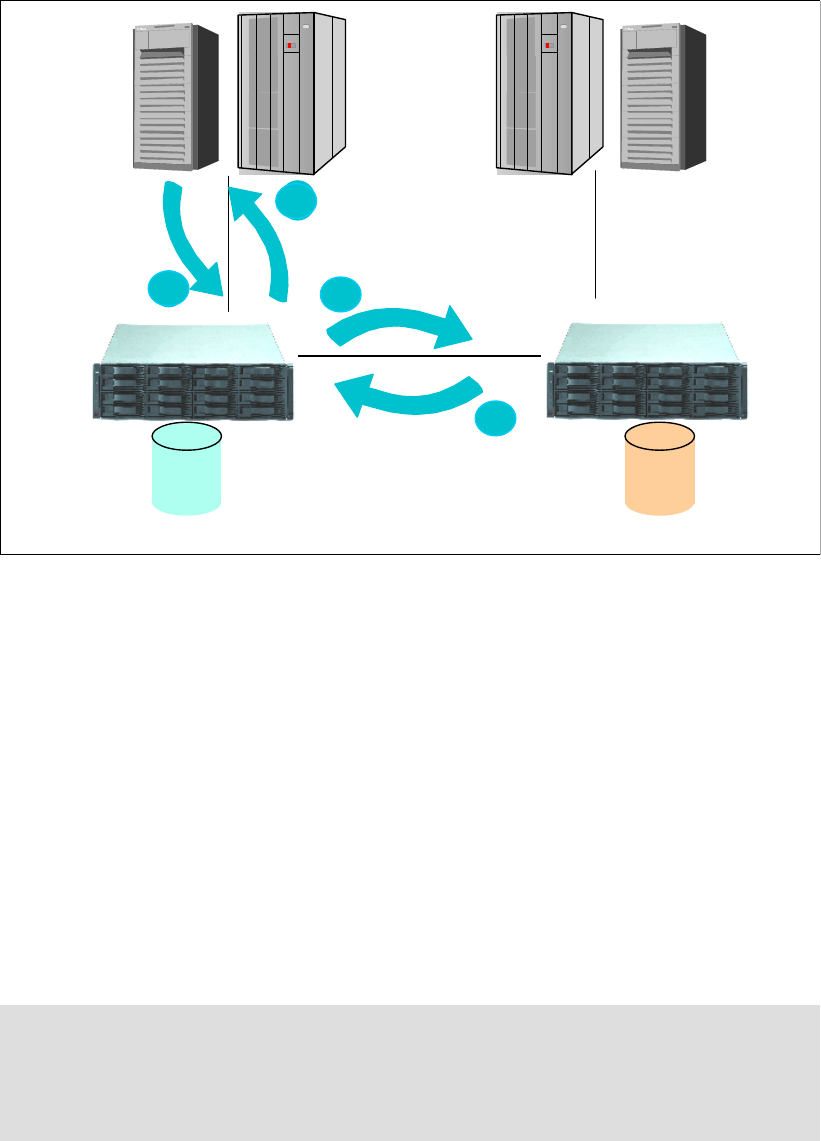
202 IBM System Storage DS6000 Series: Copy Services with IBM System z
17.1 Global Copy overview
Global Copy (formerly known as PPRC Extended Distance, or PPRC-XD) is a
non-synchronous remote copy function for System z and open systems for longer distances
than are possible with Metro Mirror. It is appropriate for remote data migration, offsite
backups, and transmission of inactive database logs at virtually unlimited distances.
Figure 17-1 Global Copy
With Global Copy, write operations complete on the primary disk subsystem before they are
received by the secondary disk subsystem. This capability is designed to prevent the primary
system’s performance from being affected by wait time from writes on the secondary system.
Therefore, the primary and secondary copies can be separated by any distance. Figure 17-1
illustrates how Global Copy operates, and the flow is described here:
1. The host server makes a write I/O to the primary DS6000. The write is staged through
cache and non-volatile storage (NVS).
2. The write returns as completed to the host server’s application.
3. At a later time (that is, in a non-synchronous manner), the primary DS6000 sends the
necessary data so that the updates are reflected on the secondary volumes. The updates
are grouped in batches for efficient transmission.
4. The secondary DS6000 returns write complete to the primary DS6000 when the updates
are secured in the secondary DS6000 cache and NVS. The primary DS6000 then resets
its Global Copy change recording information.
Note: The efficient extended distance mirroring technique of Global Copy is achieved with
sophisticated algorithms. For example, if changed data is in the cache, then Global Copy
sends only the changed sectors. There are also sophisticated queuing algorithms to
schedule the processing of updating the tracks for each volume and set the batches of
updates to be transmitted.
2
1
Server
write
Write to secondary
(non-synchronously)
Write acknowledge
13
1
2
4
LUN or
volume
Primary (source)
LUN or
volume
Secondary (target)
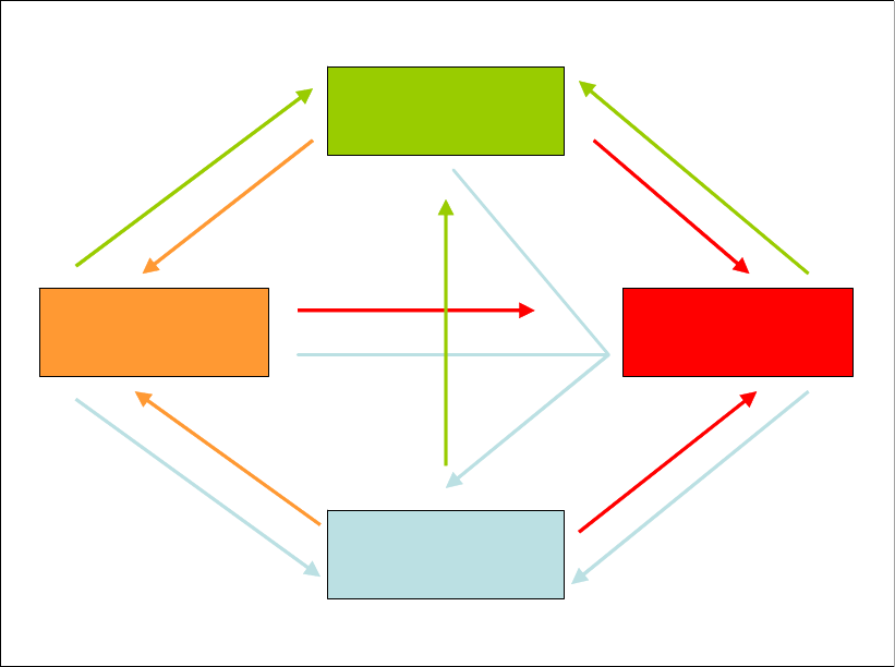
Chapter 17. Global Copy overview 203
17.2 Volume states and change logic
Figure 17-2 illustrates the basic states and the change logic of a volume that is in either a
Metro Mirror or Global Copy relationship. The following considerations apply to the volume
states when the pair is a Global Copy pair:
Simplex: The volume is not in a Global Copy relationship.
Suspended: In this state, the writes to the primary volume are not mirrored onto the
secondary volume. The secondary volume becomes out-of-sync. During this time, Global
Copy keeps a bitmap record of the changed tracks in the primary volume. Later, the
volume pair can be restarted, and then only the tracks that were updated are copied.
Full duplex: A Global Copy volume never reaches this volume state. In the full duplex
condition, updates on the primary volumes are synchronously mirrored to the secondary
volume—with Metro Mirror, this is possible. With Global Copy, however, even when no
tracks are out of sync, the pair remains in copy pending status.
Copy Pending: Updates on the primary volume are non-synchronously mirrored to the
secondary volume.
Figure 17-2 Global Copy and Mirror state change logic
In regard to the state change logic, the following considerations apply:
When you initially establish a mirror relationship from a volume in simplex state, you have
the option to request that it becomes a Global Copy pair (see the Establish Global Copy
arrow in Figure 17-2), or a Metro Mirror pair (see the Establish Metro Mirror arrow in
Figure 17-2).
Pairs can change from the copy pending state to the full duplex state when a go-to-SYNC
operation is executed (see the Go to sync arrow in Figure 17-2).
Simplex
Suspend
Copy Pending Full Duplex
Establish Global
Copy
Terminate
Establish Metro
Mirror
Terminate
Suspend Suspend
Go to sync and
suspend
Resync Resync
Go to sync
Terminate

204 IBM System Storage DS6000 Series: Copy Services with IBM System z
You can also request that a pair be suspended as soon as it reaches the full-duplex state
(see go to sync and suspend in Figure 17-2).
Pairs cannot change directly from full duplex state to copy pending state. They must go
through an intermediate suspend state.
You can go from suspended state to copy pending state during an incremental copy
(copying out-of-sync tracks only). This process is similar to the traditional transition from
suspended state to full duplex state (see the Resync arrow in Figure 17-2 on page 203).
17.3 Global Copy positioning
Figure 17-3 lists the main points for considering Global Copy.
Figure 17-3 Global Copy positioning
As summarized in Figure 17-3, Global Copy is a recommended solution when you want to
perform remote data copy, data migration, offsite backup, and transmission of inactive
database logs without impacting application performance, which is particularly relevant when
implemented over continental distances. Global Copy can also be used for application
recovery solutions based on periodic point-in-time copies of the data. This requires short
quiescings of the application’s I/O activity.
It can be used over continental distances with excellent application performance
The distances only limited by the network and channel extenders capabilities
Application write operations do not have synchronous-like overheads
Fuzzy copy of data at the recovery site (sequence of dependent writes may not be
respected at the recovery site)
Recovery data can become a consistent point-in-time copy of the primary data, if
appropiate application checkpoints are set to do global catch-ups
Pairs are synchronized with application group consistency
Synchronizations can be done more frequently, because of short catch-ups
RPO still not zero, but improves substantially
Global Copy is a recommended solution for remote data copy, data
Global Copy is a recommended solution for remote data copy, data
migration and offsite backup - over continental distances without
migration and offsite backup - over continental distances without
impacting application performance.
impacting application performance.
It can be used for application recovery implementations if application I/O
It can be used for application recovery implementations if application I/O
activity can be quiesced and non-zero data loss RPO is admissible.
activity can be quiesced and non-zero data loss RPO is admissible.

© Copyright IBM Corp. 2006. All rights reserved. 205
Chapter 18. Global Copy options and
configuration
This chapter discusses the options available when using Global Copy. It also discusses the
configuration guidelines that should be considered when planning for Global Copy with the
IBM System Storage DS6000.
18
206 IBM System Storage DS6000 Series: Copy Services with IBM System z
18.1 Global Copy basic options
First we review the basic options available when working with Global Copy. You will see that
many of these options are common to Metro Mirror. However, keep in mind that the results
may differ because Metro Mirror and Global Copy have differences in the way they work.
18.1.1 Establish Global Copy pair
This is the operation where you establish a Global Copy relationship between a primary
(source) and a secondary (target) volume—that is, you establish a Global Copy pair. During
this operation, the volumes will transition from the simplex state to the copy pending state.
When you establish a Global Copy pair, the following options are available:
No copy
This option does not copy data from the primary to the secondary volume. This option
assumes that the volumes are already synchronized. The data synchronization is your
responsibility and the DS6000 does not check its synchronization.
Target read
This option allows host servers to read from the secondary volume. In order for a host
server to read the volume, the volume pair must be in full duplex state. Note that this
parameter applies to open systems volumes; it does not apply to System z volumes.
Suspend after data synchronization
This option suspends the remote copy pairs after the data has been synchronized. You
can use this option with the Go-to-sync operation (the Go-to-sync operation is discussed
in 18.1.5, “Convert a Global Copy pair to Metro Mirror” on page 207).
Wait option
This option delays the command response until the volumes are in one of the final states:
simplex, full duplex, suspended, target full duplex, or target suspended. This parameter
cannot be used with -type gcp or -mode nocp, but it can be used with the Go-to-sync
operation.
Reset reserve on target
This option allows the establishment of a Global Copy relationship when the secondary
volume is reserved by another host. If this option is not specified and the secondary
volume is reserved, the command fails. This parameter can only be used with open
system volumes.
18.1.2 Suspend Global Copy pair
This operation stops copying data to the secondary volume and leaves the pair in suspended
state. Because the primary DS6000 keeps a record of all changed tracks on the primary
volume, you can resume the remote copy operation at a later time.
18.1.3 Resume Global Copy pair
This operation resumes a Global Copy relationship for a volume pair and starts to copy data
back again to the secondary volume. Only modified tracks are sent to the secondary volume,
because the DS6000 kept a record of all changed tracks on the primary volume while the
volumes were suspended. When resuming a Global Copy relationship, you can use the same
options you use to initially establish a Global Copy pair, except for the no copy option.

Chapter 18. Global Copy options and configuration 207
18.1.4 Terminate Global Copy pair
This operation ends the remote copy relationship between the volume pair; the volumes
return to the simplex state.
18.1.5 Convert a Global Copy pair to Metro Mirror
This operation is known as the Go-to-sync operation. There are two common situations when
you would convert a pair from Global Copy mode to Metro Mirror mode:
Situation 1
You have used Global Copy to complete the bulk transfer of data in the creation of many
copy pairs, and you now want to convert some or all of those pairs to Metro Mirror mode.
Situation 2
You have Global Copy pairs for which you want to make FlashCopy backups on the
recovery site. You convert the pairs temporarily to Metro Mirror mode in order to obtain
point-in-time consistent copies.
The transition of a volume pair from Global Copy to Metro Mirror is also referred to as the
catch-up transition, and it is discussed in the following section.
18.2 Catch-up transition
Copy Pending catch-up is the name of the transition for a Global Copy pair that goes from its
normal out-of-sync condition to a fully synchronous condition, that is, a full duplex Metro
Mirror pair. The pair goes from the pending state to the duplex state. At the end of this
transition, primary and secondary volumes are fully synchronized, with all their respective
tracks identical.
As a result of the catch-up, the Global Copy pair becomes a Metro Mirror pair. This has an
impact on application response times because write I/Os in a Metro Mirror pair are written to
both primary and secondary volumes before the host application is acknowledged. For this
reason, a Global Copy pair is normally synchronized only for short periods of time, typically to
make a FlashCopy, and host application updates are quiesced for the duration. Refer to 18.3,
“Create a consistent point-in-time copy” on page 209 for a more detailed discussion.
18.2.1 Go-to-sync using TSO
You can initiate a catch-up operation by commanding Global Copy to go-to-SYNC with the
TSO command CESTPAIR. For the go-to-SYNC, the CESTPAIR command must be used with the
OPTION(SYNC) and MODE(RESYNC) parameters; see Table 18-1.
Table 18-1 CESTPAIR parameter values for the go-to-SYNC transition
Example 18-1 shows the TSO CESTPAIR command to change a Global Copy pair to
synchronous mode.
Operation Volume pair state CESTPAIR parameter values
from to OPTION MODE
go-to-SYNC
catch-up
duplex pending XD duplex SYNC RESYNC
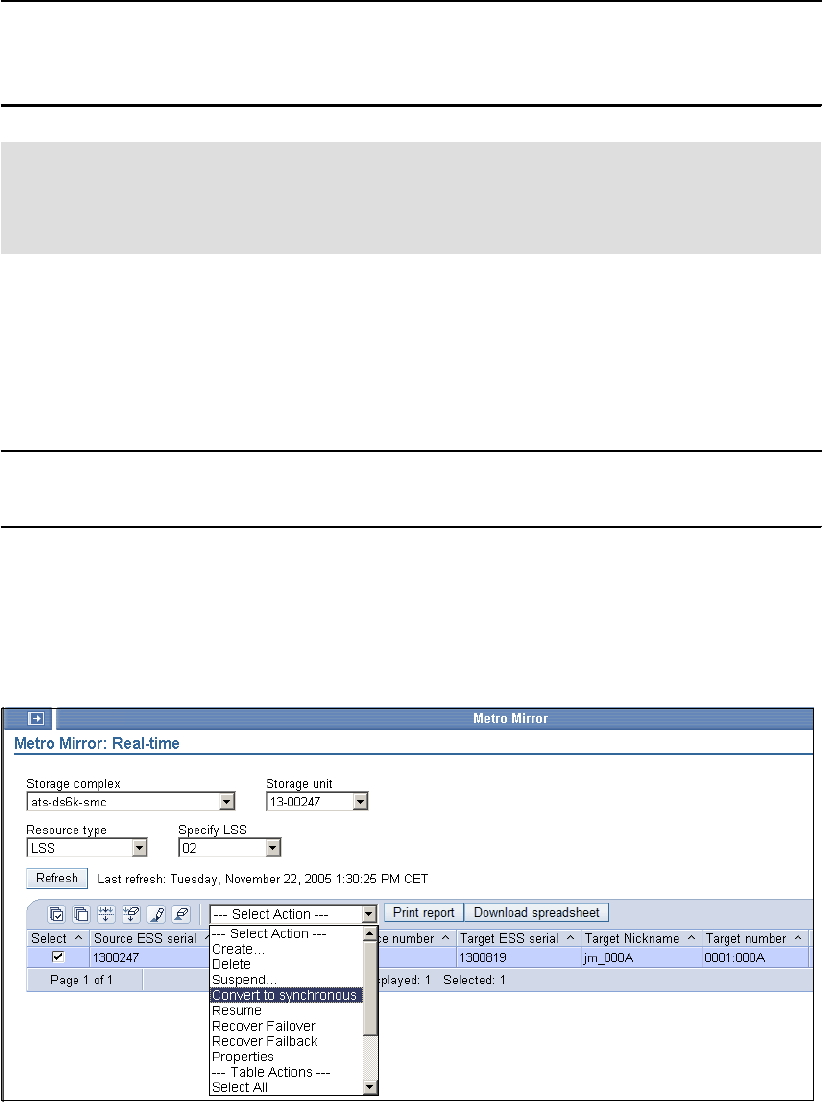
208 IBM System Storage DS6000 Series: Copy Services with IBM System z
Example 18-1 TSO initiated go-to-sync transition
CESTPAIR DEVN(X'400A') OPTION(SYNC) MODE(RESYNC) -
PRIM(X'4000' ABTV1 X'0A' X'00') -
SEC(X'8000' 20781 X'8A' X'80')
18.2.2 Go-to-sync using ICKDSF
You can initiate a catch-up operation by commanding Global Copy to go-to-SYNC using the
ICKDSF PPRCOPY CESTPAIR command; see Example 18-2. The CESTPAIR command
must be used with the OPTION(SYNC) and MODE(RESYNC) parameters.
Example 18-2 ICKDSF-initiated go-to-sync transition
PPRCOPY ESTPAIR UNIT(4C80) LSS(X’01’,X’05’) -
PRI(X’2901’,FCA29,X’00’) SEC(X’2805’,FCA28,X’00’) -
OPTION(SYNC)
18.2.3 Go-to-sync using the DS Storage Manager
In the DS Storage Manager, in the Metro Mirror panel you can display the Metro Mirror or
Global Copy pairs and perform specific actions on them; see Figure 18-1.
Figure 18-1 Convert to synchronous using GUI
To convert a Global Copy pair to a Metro Mirror pair, you can select the Global Copy pair and
select Convert to synchronous from the Select Actions menu.
Note: The CESTPAIR command does not support the go-to-SYNC and suspend
operation (ICKDSF and the DS CLI do). When using the TSO interface, to suspend as
soon as the duplex state is reached, you must automate the process by triggering on the
state change messages that the system issues.
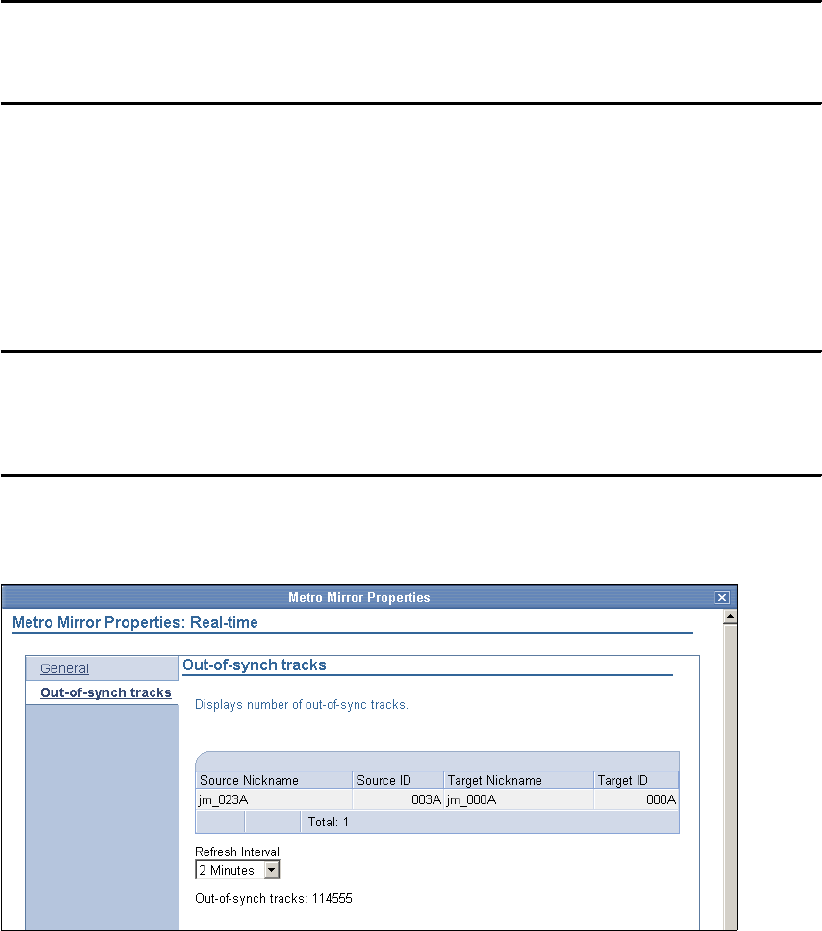
Chapter 18. Global Copy options and configuration 209
18.2.4 Go-to-sync using the DS CLI
You can also use the DS CLI command mkpprc with the option -mmir to synchronize a Global
Copy pair, as shown in Example 18-3.
Example 18-3 mkpprc command
dscli> mkpprc -dev ibm.1750-13aagxa -remotedev ibm.1750-13aavca -type mmir 000d:000d
Date/Time: 17. Juni 2005 00:01:00 CEST IBM DSCLI Version: 5.0.3.110 DS: IBM.1750-13AAGXA
CMUC00153I mkpprc: Remote Mirror and Copy volume pair relationship 000D:000D successfully
created.
18.2.5 Display out-of-sync tracks
After a Global Copy pair is established, the volumes go into the copy pending state. The copy
pending state also remains if no tracks are out-of-sync. You can display the out-of-sync
tracks with the DS CLI or with the DS Storage Manager.
With the DS CLI you can use the lspprc command; see Example 18-4.
Example 18-4 lspprc command
dscli> lspprc -dev IBM.1750-13AAGXA -remotedev IBM.1750-13AAVCA -l 1610
Date/Time: June 14, 2005 5:51:35 PM CDT IBM DSCLI Version: 5.0.3.110 DS: IBM.1750-13AAGXA
ID State Reason Type Out Of Sync Tracks Tgt Read Src Cascade Tgt Casc
==========================================================================================
1610:1609 Copy Pending - Global Copy 71030 Disabled Disabled Disabled
In the DS Storage Manager, you can display the out-of-sync tracks in the Metro Mirror
properties window; see Figure 18-2.
Figure 18-2 Out-of-sync tracks
18.3 Create a consistent point-in-time copy
While the copy pair volumes are in the copy pending state, the secondary volumes maintain a
fuzzy copy of the data:
Because of the non-synchronous data transfer characteristics, at any time there is a
certain amount of updated data that is not reflected at the secondary volume. This data
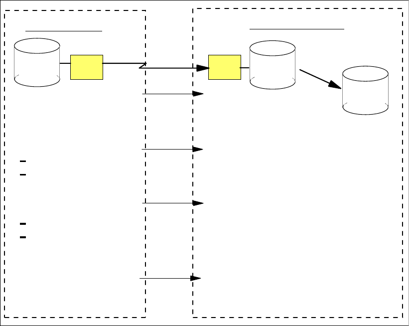
210 IBM System Storage DS6000 Series: Copy Services with IBM System z
corresponds to the sectors that were updated since the last volume bitmap scan was
done. These are the out-of-sync sectors.
Because of the bitmap scan method, writes might not be applied on to the secondary
volume in the same sequence as they are written to the primary volume.
When terminating the Global Copy relationship to establish host access to secondary
volumes, the first issue might cause you to lose transactions. Since a file system or database
consistency depends on the correct ordering of write sequences, the second issue might
cause inconsistent volumes. Therefore, to use secondary volumes by the host systems, you
must make them point-in-time consistent:
The application must be quiesced and the volume pairs temporarily suspended. This is
necessary for ensuring consistency not only at the volume level, but also at the application
level.
The secondary volumes have to catch-up to their primary counterparts. Global Copy
catch-up is the name of the transition that occurs to a Global Copy pair when it goes from
its normal out-of-sync condition until it reaches a full sync condition. At the end of this
transition, the primary and secondary volumes become fully synchronized.
A FlashCopy of the secondary volumes onto tertiary volumes should now be performed,
followed by resuming the Global Copy pairs.
These tertiary volumes are then a consistent point-in-time copy of the primary volumes.
Figure 18-3 illustrates a procedure to get a consistent point-in-time copy at the secondary
site.
Figure 18-3 Create a Global Copy consistent copy
channel
extender
channel
extender
FlashCopy
secondary
tertiary
primary
non-synchronous
copy
over long distance
5. FlashCopy
6. Reestablish suspended
pairs (resync)
consistent tertiary
copy of data
Secondary Site
Primary Site
minimum performance impact fuzzy copy of data
1. Quiesce application
updates
2. Catch-up (synchronize
volume pairs)
go-to-sync / suspend
or wait for application
writes to quiesce
3. Build consistency on
recovery data
resync and freeze
or freeze (suspend)
4. Resume application writes
as soon as freeze is done
individual volume pairs synchronize
copy of data consistent across
volume pairs
Chapter 18. Global Copy options and configuration 211
The steps in the procedure shown in Figure 18-3 are the following:
1. Quiesce the application updates.
2. Synchronize the volume pairs by one of these methods:
– Perform the catch-up by doing a go-to-sync operation. This can be done with the
Storage Manager as shown in 18.2.3, “Go-to-sync using the DS Storage Manager” on
page 208. The volume pair leaves the copy pending state and reaches the full duplex
state. At this time, if the pairs were not immediately suspended, primary write updates
would be synchronously transmitted to the recovery site.
– Perform the catch-up by waiting until all application updates are transferred to the
secondary site.
You can monitor the number of out-of-sync tracks with the DS Storage Manager or with the
DS CLI as shown in 18.2.5, “Display out-of-sync tracks” on page 209.
3. Suspend the Global Copy pairs after they reach the full duplex state. If you use
Consistency Groups, issue do a freeze operation.
At this point, we have a set of consistent secondary volumes.
4. You can resume the application. Updates are not copied to the secondary volumes
because the pairs are suspended. The secondary volumes remain consistent, and the
application does not experience any response time impact.
5. Perform a FlashCopy on the secondary volumes.
6. Resume Global Copy mode for the copy pair.
For applications recovery based on point-in-time copies, you must plan for appropriate
checkpoints to briefly quiesce the application and synchronize the volumes pairs. When the
recovery of the application is done, you must remember that, while in an active Global Copy
relationship, the secondary volumes always have a current fuzzy copy of the primary
volumes, so you have to keep the tertiary volumes where you did a FlashCopy of the last
globally consistent catch-up. Therefore, this tertiary copy does not reflect the current update,
but rather any updates up until the last global catch-up operation.
18.4 Cascading for ESS migration
Asynchronous cascading PPRC is a function of the IBM TotalStorage Enterprise Storage
Server (ESS), where the secondary volume of a Global Copy or Metro Mirror volume pair
becomes the primary volume of another Global Copy or Metro Mirror relationship. Cascading
allows you to set a remote copy relationship from a source volume through an intermediate
volume to a target volume.
The two volume pairs in a cascaded relationship can be either Global Copy or Metro Mirror
pairs with one exception: the first pair (source to intermediate) cannot be Global Copy if the
second pair (intermediate to target) is Metro Mirror. The two pairs can be established in any
order; that is, first and second here do not refer to the order of establishment.
Cascading can be useful when you are migrating data from an ESS to the DS6000. If the
volumes to be migrated are mirrored between two ESSs with Metro Mirror, you can set up a
cascaded Global Copy from the secondary ESS to the DS6000. Then, you can migrate the
volumes without having to delete the existing volume pairs.
Cascading can also be used if you need to migrate data from an ESS Model F20 to a
DS6000. This cannot be done directly with Global Copy because the ESS F20 only supports
ESCON remote copy links, while the DS6000 only supports FCP links. The migration can be

212 IBM System Storage DS6000 Series: Copy Services with IBM System z
done using an ESS 800 (or ESS 750) as an intermediate unit, because the ESS 800
supports, with PPRC Version 2, both ESCON and FCP links. In this setup, the source
volumes on the ESS F20 would be copied to intermediate volumes on the ESS 800 using
Global Copy (or Metro Mirror), and they in turn would be copied to the target volumes on the
DS6000 using cascading Global Copy. The intermediate ESS has to be at LIC level 2.4.3.65
or later in order to support Global Copy with the DS6000.
A cascaded relationship is established with the second volume pair (intermediate to target). In
TSO, this is done by specifying parameter CASCADE(YES) on the CESTPAIR command, as
shown in Example 18-5. In the example, device 4C80 is the intermediate volume.
Example 18-5 Cascading with TSO
CESTPAIR DEVN(X’4C80’) OPTION(XD) MODE(COPY) CASCADE(YES) -
LSS(X’01’,X’05’) -
PRI(X’2901’ FCA29 X’00’ X’01’) SEC(X’2805’ FCA28 X’00’ X’05’)
The respective parameter for the ICKDSF ESTPAIR command is CASCADE; see
Example 18-6.
Example 18-6 Cascading with ICKDSF
PPRCOPY ESTPAIR UNIT(4C80) OPTION(XD) MODE(COPY) CASCADE -
LSS(X’01’,X’05’) -
PRI(X’2901’,FCA29,X’00’) SEC(X’2805’,FCA28,X’00’)
In DS CLI, a cascading relationship is established by specifying parameter -cascade for the
mkpprc command, as shown in Example 18-7.
Example 18-7 Cascading with CLI
mkpprc -dev ibm.2105-22399 remotedev ibm.1750-1300247 -type gcp -mode full -cascade
050a:023a
Date/Time: November 25, 2005 10:28:17 AM EET IBM DSCLI Version: 5.1.0.204 DS:
IBM.2105-22399
CMUC00153I mkpprc: Remote Mirror and Copy volume pair relationship 050A:023A successfully
created.
lspprc -dev ibm.2105-22399 050a
Date/Time: November 25, 2005 10:28:42 AM EET IBM DSCLI Version: 5.1.0.204 DS:
IBM.2105-22399
ID State Reason Type SourceLSS Timeout (secs) Critical Mode Fir
===========================================================================================
011A:050A Target Copy Pending - Global Copy 01 unknown Disabled
050A:023A Copy Pending - Global Copy 05 unknown Disabled
In the example, 011A is the source volume, 050A is the intermediate volume, and 023A is the
target volume. The lspprc command shows the status of both volume pairs where the
intermediate volume 050A belongs. 011A:050A is the first pair where 050A is the secondary,
and 050A:023A is the second pair where 050A is the cascading primary.
Note that ESS F20 does not support DS CLI. The Global Copy relationships between the
ESS F20 and the ESS 800 can be managed using, for example, TSO. The relationships
between the ESS 800 and the DS6000 can also be managed using the DS CLI.

Chapter 18. Global Copy options and configuration 213
18.5 Hardware requirements
Global Copy is an optional licensed function of the IBM System Storage DS6000 series. The
licensed function is the Remote Mirror and Copy (RMC), and is the same that is used to
acquire the Metro Mirror and the Global Mirror licensed functions.
You have to purchase the corresponding licensed function for the primary and secondary
DS6000 systems.
For additional information on the DS6000 licensed function features, see also Appendix C,
“Licensing” on page 525.
All DS6000 series licensed functions are enabled, authorized, managed, activated, and
enforced based upon the physical capacity contained in a 1750 system.
Enablement refers to the purchase of a feature number to technically activate the associated
licensed function. Each licensed function is enabled for a 1750 system through acquiring the
corresponding feature numbers.
Particularly for Global Copy, the 1750 feature that must be ordered is the Remote Mirror and
Copy (RMC) licensed function, feature number 53xx; see Table 18-2.
Table 18-2 DS6000 Remote Mirror and Copy feature codes
Each licensed function feature number purchased for a 1750 machine enables that function
for the entire 1750 system.
Authorization refers to the purchase of a feature number to establish the extent of IBM
authorization—license size in terms of physical capacity—for use of an associated licensed
function. This is also referred to as the authorization level.
The extent of IBM authorization for the use of a licensed function on a 1750 system is
established by acquiring 53xx feature number on the 1750 base enclosure. The same 53xx
feature numbers acquired to enable a licensed function also establish the extent of IBM's
authorization.
The 53xx feature number on a 1750 base enclosure establishes the authorization level for the
entire 1750 system. For example, a 1750 system with a Model 522 base enclosure and two
Model EX2 expansion enclosures requires the acquisition of 53xx feature numbers only on
the Model 522.
Note: For a detailed explanation of the features involved and the considerations you must
keep in mind when ordering Global Copy, we recommend that you refer to the IBM System
Storage DS6000 Series (IBM 1750-522) announcement letter.
IBM announcement letters can be found at http://www.ibm.com/products
Feature Code Description
5310 RMC - 1 TB Unit
5311 RMC - 5 TB Unit
5312 RMC - 10 TB Unit
5313 RMC - 25 TB Unit
5314 RMC - 50 TB Unit
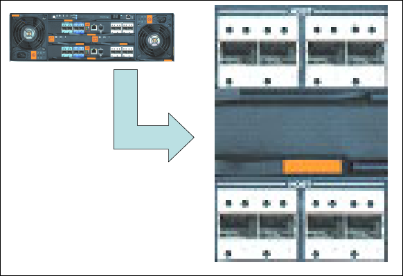
214 IBM System Storage DS6000 Series: Copy Services with IBM System z
Therefore, for licensed functions authorized on the basis of physical capacity—as in the case
of RMC—the authorization level established with the acquisition of the 53xx feature number
on the Model 522 must also cover the physical capacity of the attached Model EX2 expansion
enclosures.
Interoperability
Global Copy pairs can only be established between disk subsystems of the same (or similar)
type and features. For example, a DS6000 can have a Global Copy pair with another DS6000,
a DS8000, an ESS 800, or an ESS 750. It cannot have a Global Copy pair with an RVA or an
ESS F20. Note that all disk subsystems must have the appropriate licensed function feature
installed. If your DS6000 is being mirrored to an ESS disk subsystem, the ESS must have
PPRC Version 2 (which supports Fibre Channel links) with the appropriate licensed internal
code level (LIC).
Refer to the DS6000 Interoperability Matrix for more information:
http://www-1.ibm.com/servers/storage/disk/ds6000/interop.html
18.6 DS6800 I/O ports
The DS6800 can have a maximum number of eight I/O ports; see Figure 18-4. Each I/O port
has an I/O port number.
Figure 18-4 DS6800 I/O port numbers
The I/O ports can be configured for Fibre Channel protocol or FICON protocol. For Global
Copy paths, you need at least one Fibre Channel connection between the two DS6000
subsystems. For higher availability, it is recommended that you use at least two Fibre Channel
connections between the two subsystems on different controller cards on the DS6800.
The Fibre Channel ports used for Global Copy can be used as dedicated ports, which means
that they will only be used for the Global Copy paths. Alternatively, they can be shared
between Global Copy and Fibre Channel data traffic, but you must also have Fibre Channel
switches for connectivity.
For supported SAN switches, refer to the DS6000 Interoperability Matrix.
I0100 I0101 I0102 I0103
I0000 I0001 I0002 I0003
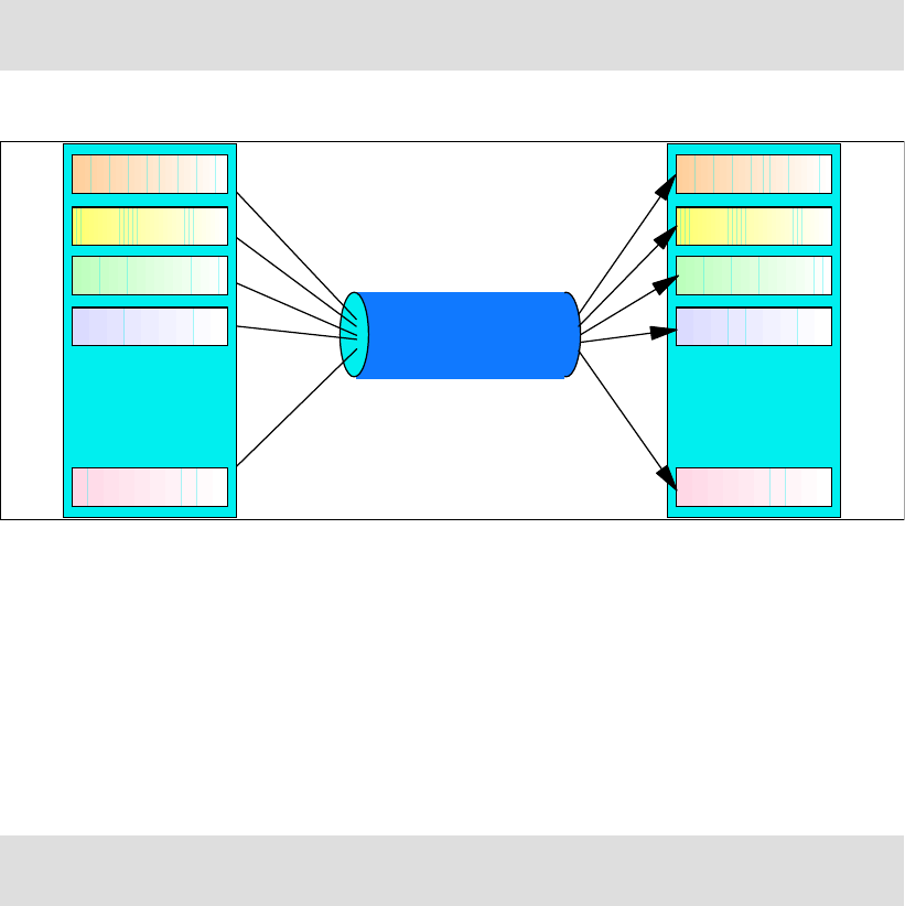
Chapter 18. Global Copy options and configuration 215
18.7 Global Copy connectivity
Global Copy pairs are set up between volumes in LSSs, usually in different disk subsystems,
and these are normally in separate locations. A path (or group of paths) needs to be defined
between the source LSS and the target LSS. These logical paths are defined over physical
links between the disk subsystems.
The physical link includes the host adapter in the source DS6000, the cabling, switches or
directors, any wideband or long distance transport devices (DWDM, channel extenders,
WAN), and the host adapters in the target disk subsystem. Physical links can carry multiple
Global Copy logical paths, as shown in Figure 18-5.
Figure 18-5 Logical paths and physical links
Paths are unidirectional, that is, they are defined to operate in either one direction or the
other. Global Copy is bidirectional; that is, any particular pair of LSSs can have paths defined
among them that have opposite directions—each LSS holds both source and target volumes
from the other LSS. Moreover, opposite direction paths are allowed to be defined on the
same Fibre Channel physical link.
For bandwidth and redundancy, more than one path can be created between the same LSSs.
Global Copy will balance the workload across the available paths between the source and
target LSSs.
Physical links are bidirectional and can be shared by other Global Copy pairs as well as other
remote mirror and copy functions, such as Metro Mirror and Global Mirror.
18.7.1 Fibre Channel links
We recommend that you read the discussion presented in 13.4.1, “Fibre Channel links” on
page 143, in the Metro Mirror chapter, because it is also valid for Global Copy.
Note: For Global Copy, the DS6000 supports Fibre Channel links only. To facilitate ease of
testing, the DS6000 does support Global Copy source and target on the same DS6000.
Note: Remember that the LSS is not a physical construct in the DS6000; it is a logical con-
struct. Volumes in an LSS can come from multiple disk arrays.
Physical
Fiber Channel link
256 paths per
FCP link
LSS 00
LSS 03
LSS 01
LSS 02
LSS 1F
:
:
LSS 00
LSS 03
LSS 01
LSS 02
LSS 1F
:
:
216 IBM System Storage DS6000 Series: Copy Services with IBM System z
18.7.2 Logical paths
We recommend that you read the discussion presented in 13.4.2, “Logical paths” on
page 144, in the Metro Mirror chapter, because it is also valid for Global Copy.
18.8 Distance considerations
The maximum distance for a direct Fibre Channel connection is 10 km. If you want to use
Global Copy over longer distances, the following connectivity technologies can be used to
extend this distance:
Fibre Channel switches
Channel Extenders over Wide Area Network (WAN) lines
Dense Wave Division Multiplexors (DWDM) on dark fibre
Channel extender
Channel extender vendors connect DS6000 systems with a variety of Wide Area Network
(WAN) connections, including Fibre Channel, Ethernet/IP, ATM-OC3, and T1/T3.
When you use channel extender products with Global Copy, the channel extender vendor
determines the maximum distance supported between the primary and secondary DS6000.
Contact the channel extender vendor for their distance capability, line quality requirements,
and WAN attachment capabilities.
A complete and current list of Global Copy supported environments, configurations, networks,
and products is available in the DS6000 Interoperability Matrix.
Consult the channel extender vendor about hardware and software prerequisites if you are
using their products in a DS6000 Global Copy configuration. Evaluation, qualification,
approval, and support of Global Copy configurations using channel extender products is the
sole responsibility of the channel extender vendor.
Dense Wave Division Multiplexor (DWDM)
Wave Division Multiplexing (WDM) and Dense Wave Division Multiplexing (DWDM) comprise
the basic technology of fibre optical networking. The technique is used to carry many
separate and independent optical channels on a single dark fibre.
A simple way to envision DWDM is to consider that, at the primary end, multiple fibre optic
input channels (such as ESCON, Fibre Channel, FICON, or Gbit Ethernet) are combined by
the DWDM into a single fibre optic cable. Each channel is encoded as light for a different
wavelength. Think of each individual channel as an individual color: the DWDM system is
transmitting a rainbow.
At the receiving end, the DWDM fans out the different optical channels. DWDM, by the very
nature of its operation, provides the full bandwidth capability of the individual channel. As the
wavelength of light is, from a practical perspective, infinitely divisible, DWDM technology is
only limited by the sensitivity of its receptors, as the total aggregate bandwidth possible.
A complete and current list of Global Copy supported environments, configurations, networks,
and products is available in the DS6000 Interoperability Matrix.
Contact the DWDM vendor regarding hardware and software prerequisites when using their
products in an DS6000 Global Copy configuration.
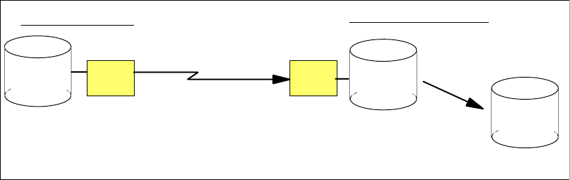
Chapter 18. Global Copy options and configuration 217
18.9 Other planning considerations
Figure 18-6 illustrates the use of Global Copy for point-in-time backup solutions.
Figure 18-6 Global Copy environment
When you are planning to use Global Copy for point-in-time backup solutions, and if you are
going to have tertiary copies, then within the target disk subsystem you should have an
available set of volumes ready to become the FlashCopy target.
If your next step is to move the tertiary volumes onto tapes, then you must ensure that the
tape resources are capable of handling these dump operations in between the point-in-time
checkpoints, unless you have additional sets of volumes ready to become alternate
FlashCopy targets.
channel
extender
channel
extender
FlashCopy
secondary
tertiary
primary
Global Copy
consistent tertiary
copy of data
Secondary Site
Primary Site
minimum performance impact fuzzy copy of data
218 IBM System Storage DS6000 Series: Copy Services with IBM System z

© Copyright IBM Corp. 2006. All rights reserved. 219
Chapter 19. Global Copy performance and
scalability
In this chapter, we discuss performance and scalability considerations when using Global
Copy for DS6000.
19
220 IBM System Storage DS6000 Series: Copy Services with IBM System z
19.1 Performance
As the distance between DS6000s increases, Metro Mirror response time is proportionally
affected, and this negatively impacts the application performance. When implementations
over extended distances are needed, Global Copy becomes an excellent trade-off solution.
You can estimate the impact of Global Copy on an application as that of the application when
working with Metro Mirror suspended volumes. For the DS6000, there is more work to do with
the Global Copy volumes, as compared to the suspended volumes, because with Global
Copy, the changes have to be sent to the remote DS6000. But this is a negligible overhead
for the application, as compared with the typical synchronous overhead.
No processor resources (CPU and memory) are consumed by your Global Copy volume
pairs, as this is managed by your DS6000 subsystem.
19.1.1 Peak bandwidth requirements
When you are researching your Global Copy link bandwidth requirements, you need to find
the peak sustained write rate - remember that only writes will be mirrored across to the
secondary volumes. For a typical z/OS system, this peak is usually reached during batch
processing, when many updates are occurring. It could be higher still during month-end or
year-end processing. You need to make allowances for this peak period when performing
your bandwidth calculations.
19.2 Scalability
The DS6000 Global Copy environment can be scaled up or down as required. If new volumes
are added to the DS6000 that require mirroring, they can be dynamically added. If additional
Global Copy paths are required, they also can be dynamically added.
19.2.1 Addition of capacity
As previously mentioned, the logical nature of the LSS has made a Global Copy
implementation on the DS6000 easier to plan, implement, and manage.
However, if you need to add more LSSs to your Global Copy environment, your management
and automation solutions should be set up to handle this. The GDPS and eRCMF service
offerings are designed to provide this functionality; see Part 8, “Solutions” on page 431, for
more information. Also visit the IBM Web site and see the Services & Industry Solutions page.
Adding capacity to the same DS6000
If you are adding capacity into an existing DS6000, and providing that your Global Copy link
bandwidth is not close to or over its limit, you might only need to add volume pairs into your
configuration. If you are adding more LSSs, then you will need to define Global Copy paths
before adding volume pairs. Keep in mind that when you add capacity for Global Copy use,
you might have to acquire a new license feature code for Global Copy that corresponds to the
new capacity.
Adding capacity to new DS6000s
If you are adding new DS6000s into your configuration, you must add physical links before
defining your Global Copy paths and volume pairs. A minimum of two Global Copy paths per
DS6000 pair is recommended for redundancy reasons. Your bandwidth analysis can indicate
if you require more than two paths.

© Copyright IBM Corp. 2006. All rights reserved. 221
Chapter 20. Global Copy interfaces
The setup of Global Copy can be done using different interfaces. This chapter explains and
gives examples of the interfaces that can be used for Global Copy management when Global
Copy is used with the IBM System Storage DS6000 in System z environments.
The information discussed in this chapter can be complemented with the following:
Chapter 3, “DS Storage Manager” on page 17
Chapter 4, “DS Command-Line Interface” on page 25
Chapter 5, “System z interfaces” on page 37
20

222 IBM System Storage DS6000 Series: Copy Services with IBM System z
20.1 Global Copy interfaces - overview
There are various interfaces available for the setup and management of Global Copy for
DS6000 in a System z environment.
For z/OS and OS/390, the following interfaces can be used:
– TSO commands
– ICKDSF utility
– ANTRQST application programming interface (API)
– DS6000 interfaces
For z/VM:
– ICKDSF utility
– DS6000 interfaces
For VSE:
– ICKDSF utility
– DS6000 interfaces
For TPF:
– ICKDSF utility
– TPF itself
– DS6000 interfaces
– Other attached servers that support control of Global Copy
The following DS6000 interfaces can be used with all of the previously-listed operating
systems:
DS Command-Line Interface (DS CLI). The DS CLI can be used to invoke Global Copy
commands from a server that supports the DS CLI (for example, a Windows XP server),
provided that the server has appropriate connectivity to the DS6000 DS SMC.
DS Storage Manager (DS SM) Graphical User Interface (DS SM GUI). The DS SM
provides a graphical user interface (GUI) running in a Web browser that communicates
with the DS6000 Storage Management Console (DS SMC).
DS Open Application Programming Interface (DS Open API).
In this chapter we provide an overview of the z/OS interfaces, as well as the DS CLI and the
DS SM Graphical User Interface. These interfaces are also covered in more detail in Part 2,
“Interfaces” on page 15.
The DS Open Application Programming Interface (DS Open API), which is a set of application
programming interfaces that are available to be integrated in programs, can be used for
Global Copy management and control. Coverage of the DS Open API is beyond the scope of
this IBM Redbook. For information on the DS Open API, refer to IBM System Storage DS
Open Application Programming Interface Reference, GC35-0516.
Similar functions of the interfaces for Global Copy management
Table 20-1 on page 223 lists similar commands and panel selections of the various interfaces
for Global Copy management, and the resulting tasks.
Note: The command set used for Global Copy management is the same as for Metro Mir-
ror. As you will see with the explanations and examples we present, what differs are the
parameters that are passed to the commands, as well as the selections made in the pan-
els.

Chapter 20. Global Copy interfaces 223
Table 20-1 Comparison of commands
Task TSO ICKDSF Command with
DS CLI
Select option
with DS SM
Global Copy paths commands
List available I/O
ports that can be
used to establish
Global Copy
paths.
lsavailpprcport This information
is shown during
the process when
a path is estab-
lished.
List established
Global Copy
paths.
CQUERY PATH PPRCOPY
QUERY PATHS
lspprcpath Copy Services →
Paths
Establish path CESTPATH PPRCOPY
ESTPATH
mkpprcpath Copy Services →
Paths →
Create
Delete path CDELPATH PPRCOPY DEL-
PATH
rmpprcpath Copy Services →
Paths →
Delete
Global Copy pairs commands
Failback CESTPAIR AC-
TION(FAILBACK)
PPRCOPY EST-
PAIR FAILBACK
failbackpprc Copy Services →
Global Copy →
Recover
Failback
Failover CESTPAIR AC-
TION(FAILOVER)
PPRCOPY EST-
PAIR FAILOVER
failoverpprc Copy Services →
Global Copy →
Recover Failover
List Global Copy
volume pairs
CQUERY PPRCOPY
QUERY
lspprc Copy Services →
Global Copy
Establish pair CESTPAIR PPRCOPY
ESTPAIR
mkpprc Copy Service →
Global Copy →
Create
Suspend pair CSUSPEND PPRCOPY
SUSPEND
pausepprc Copy Services →
Global Copy →
Suspend
Resume pair CESTPAIR
MODE(RESYNC)
PPRCOPY EST-
PAIR MODE(RE-
SYNC)
resumepprc Copy Services →
Global Copy →
Resume
Delete pair CDELPAIR PPRCOPY
DELPAIR
rmpprc Copy Services →
Global Copy →
Delete
Freeze Consis-
tency Group
CGROUP
FREEZE
PPRCOPY
FREEZE
freezepprc
Thaw Consisten-
cy Group
CGROUP RUN PPRCOPY RUN unfreezepprc

224 IBM System Storage DS6000 Series: Copy Services with IBM System z
20.2 TSO commands for Global Copy management
In z/OS systems, Global Copy can be managed using TSO commands. In this section, we
discuss the Global Copy commands that TSO provides. For a detailed description of these
commands, see the IBM publication z/OS DFSMS Advanced Copy Services, SC35-0428.
20.2.1 Commands summary and use
A summary of the available TSO commands for Global Copy management and their
corresponding use is presented in Table 20-2.
Table 20-2 TSO commands
20.2.2 CESTPAIR
This command has the optional OPTION parameter, which has two mutually exclusive
values: SYNC or XD. Specify SYNC if you want to establish Metro Mirror (synchronous) pair.
Specify XD if you want to establish a Global Copy pair.
In order for the pair to become a Global Copy pair (in addition to specifying the XD value for
the OPTION parameter), also specify whether this pair comes from the simplex or from the
suspended state. That is, whether this is an initial copy of a newly established pair, or if it is a
re-synchronization of a suspended pair. To indicate this, use the MODE parameter to specify
either COPY or RESYNC, respectively.
Example 20-1 shows the CESTPAIR command with the OPTION parameter value XD and
MODE parameter value of COPY. This example illustrates a transition from a simplex volume
state to a copy pending volume state.
Example 20-1 Establish a Global Copy pair
CESTPAIR DEVN(X'6030') OPTION(XD) MODE(COPY) ONLINSEC(NO) -
PRIM(X'2060' AAGXA X'30' X'00') -
SEC(X'0002' AAVCA X'30' X'00')
Table 20-3 on page 225 summarizes the values of the CESTPAIR command parameters that
you use when working with Global Copy pairs. Refer also to Table 20-3 for the parameter
values for a go-to-sync transition.
Command Description
CESTPAIR Establishing Global Copy volume pairs
CESTPATH Establish Global Copy path
CDELPAIR Deleting volume pairs
CDELPATH Deleting paths
CGROUP Controlling volume groups with FREEZE and RUN
CQUERY Querying of the status of volumes and paths
CRECOVER Recovering data on the recovery system
CSUSPEND Suspending Global Copy volume pairs

Chapter 20. Global Copy interfaces 225
Table 20-3 CESTPAIR parameter
20.2.3 CESTPATH
When establishing a path between DS6000s for Global Copy, use the CESTPATH command.
There must be a physical Fibre Channel connection between the two DS6000 subsystems.
You need to know the SSID, World Wide Node Name (WWNN), and LSS number for the
primary and secondary DS6000s. These can be displayed with the CQUERY command.
Example 20-2 show how to use the CESTPATH command to establish a Global Copy path.
Example 20-2 CESTPATH command
CESTPATH DEVN(6030) CGROUP(NO) -
PRIM(X'2060' 500507630EFFFC6F X'00') -
SEC(X'0002' 500507630EFFFCA0 X'00') -
LINK(X'00000000')
20.2.4 CDELPAIR
The CDELPAIR command is used to specify the primary and secondary volumes to be
removed from a Global Copy pairing. This command should be directed to the primary device
as shown in Example 20-3.
Example 20-3 CDELPAIR command
CDELPAIR DEVN(X'6030') -
PRIM(X'2060' AAGXA X'30' X'00') -
SEC(X'0002' AAVCA X'30' X'00')
Before issuing a CDELPAIR command, verify that there are some active paths between the
respective primary and secondary LSSs. If all of the paths that were established between
both LSSs have been disabled, the CDELPAIR command will fail. After the failing CDELPAIR
command times out, the state of the primary volume is simplex. The secondary volume
remains in its previous state (duplex, pending, or suspended). You then need to give a
CRECOVER command to return the secondary volume to the simplex state.
20.2.5 CDELPATH
The CDELPATH command is used to delete established Global Copy paths between a
primary LSS and the corresponding secondary LSS as shown in Example 20-4 on page 226.
Only the paths to the specified secondary LSS are affected; all other paths to other LSSs are
not affected.
Operation Volume pair state CESTPAIR parameter values
from to OPTION MODE
Establish initial
copy pair simplex copy pending XD COPY
Re-establish sus-
pended pair suspended copy pending XD RESYNC

226 IBM System Storage DS6000 Series: Copy Services with IBM System z
Example 20-4 CDELPATH command
CDELPATH DEVN(X'6030') -
PRIM(X'2060' 500507630EFFFC6F X'00') -
SEC(X'0002' 500507630EFFFCA0 X'00') -
Before issuing a CDELPATH command, a CDELPAIR command to all Global Mirror and
Copy volume pairs should be given. The CDELPATH command may cause an ANTP0121I
message if this sequence is not followed.
20.2.6 CGROUP
The CGROUP command is used to control operations for multiple Global Copy volume pairs
on a given LSS:
CGROUP FREEZE Stops all host application I/O to the primary volumes on the specified
LSS pair. With the FREEZE parameter, remote mirror and copy
volume pairs are suspended and paths for the specified LSS pair are
deleted.
If the Global Copy paths for the LSS pair were defined with
Consistency Group enabled (CGROUP parameter of the CESTPATH
command), then an extended long busy condition is initiated when
CGROUP FREEZE is issued for the LSS. All host application I/O to
the primary is held off with a long busy condition for two minutes, or
until a CGROUP command is issued with the RUN option. During the
extended long busy window, update activity cannot proceed in the
LSS where the freeze was done.
CGROUP RUN Resumes host application I/O for primary and secondary volumes of
the LSS pair identified in the CGROUP command, which were
previously halted with a CGROUP FREEZE command. The CGROUP
RUN command is used to reset the extended long busy condition set
by CGROUP FREEZE, and release application I/O to the primary
volumes. The status of the volumes does not change; the primary
volumes remain suspended.
Example 20-5 illustrates the CGROUP command.
Example 20-5 CGROUP command
CGROUP DEVN(X’1142') PRIM(X'6060' 62019 X'00') SEC(X'8060' 68006 X'00') FREEZE
CGROUP DEVN(X’1142') PRIM(X'6060' 62019 X'00') SEC(X'8060' 68006 X'00') RUN
Tip: The CGROUP FREEZE command deletes the paths between the specified LSS pair.
To restart normal Global Copy operation, the paths must be reestablished and, if the I/O
activity on the primary volumes was not interrupted during the freeze, the pairs must be
re-synchronized.
Note: A single LSS can be paired with up to four other LSSs. Therefore, you might have to
issue up to four CGROUP commands to suspend all pairs on a single primary LSS.

Chapter 20. Global Copy interfaces 227
20.2.7 CQUERY
The CQUERY command is used to query the status of one volume of a Global Copy volume
pair or all paths that are associated with the LSS for the device number that is specified. The
CQUERY command can be issued to either a primary or secondary Global Copy volume. A
host system that is attached only to a primary volume cannot obtain the status of the
secondary volume for that pair. In the same way, a host attached only to the secondary
volume cannot obtain the status of the primary volume.
In Example 20-6, a CQUERY VOLUME command for volume 6030 is issued. The VOLUME
parameter is the default, so it does not have to be specified.
Example 20-6 CQUERY command
CQUERY DEVN(X'6030')
The output of the CQUERY command, as shown in Example 20-7, provides volume-related
information, such as SSID, CCA, LSS number, and DS6000 serial number. The TSO
CQUERY command output for a Global Copy pair returns the duplex-pending state and the
number of out-of-sync tracks.
Example 20-7 CQUERY command
ANTP8802I CQUERY DEVN(X'6030')
ANTP0090I CQUERY FORMATTED LVL 3 161
VOLUME REPORT
************** PPRC REMOTE COPY CQUERY - VOLUME ********************
* (PRIMARY) (SECONDARY) *
* SSID CCA LSS SSID CCA LSS*
*DEVICE LEVEL STATE PATH STATUS SERIAL# SERIAL# *
*------ --------- ---------- ----------- --------- --------- *
* 6030 PRIMARY.. PENDING.XD ACTIVE.. 2060 30 00 0002 30 00 *
* CRIT(NO)....... CGRPLB(NO). 0000000AAGXA 0000000AAVCA*
* PATHS PFCA SFCA STATUS: DESCRIPTION *
* ----- --------- ------ ------------------- *
* 1 0000 0000 13 PATH ESTABLISHED... *
* ---- ---- 00 NO PATH............ *
* ---- ---- 00 NO PATH............ *
* ---- ---- 00 NO PATH............ *
* IF STATE = PENDING/SUSPEND: TRACKS OUT OF SYNC = 30548 *
* TRACKS ON VOLUME = 50085 *
* PERCENT OF COPY COMPLETE = 40% *
* SUBSYSTEM WWNN LIC LEVEL *
* ----------- ---------------- ----------- *
* PRIMARY.... 500507630EFFFC6F 5.0.00.0000 *
* SECONDARY.1 500507630EFFFCA0 *
********************************************************************
ANTP0001I CQUERY COMMAND COMPLETED FOR DEVICE 6030. COMPLETION CODE: 00
The number of out-of-sync tracks, tracks on volume, and percent of copy complete are not
displayed if all tracks are in sync. Path information is displayed only when the CQUERY
VOLUME command is issued to the primary volume.
20.2.8 CRECOVER
The CRECOVER command is used to allow the recovery system to gain control of the
volumes. This command is issued from the recovery system to the secondary volume. It
signals the recovery Storage Image to force the secondary volume into simplex state.

228 IBM System Storage DS6000 Series: Copy Services with IBM System z
During this procedure, the volume serial number can be verified and optionally relabeled. The
volume can be varied online after this command is complete.
Example 20-8 CRECOVER command
CRECOVER DEVN(X’2242’) -
PRIM(‘X6060’ 62019 X’42’ X’00’) -
SEC(X’8061’ 68006 X’42’ X’00’) -
ID(VOL002 VOL001) -
MSGREQ(YES)
In Example 20-8, the CRECOVER command brings device x’2242’ (on the recovery
DS6000) to simplex state. It also changes the volume label from VOL002 to VOL001.
20.2.9 CSUSPEND
This command is used to suspend Global Copy operations between a volume pair. Global
Copy stops mirroring data to the secondary volume and starts keeping a record of the primary
volume tracks that are updated. The information of which tracks were updated while the pair
was suspended is used later, when the pair is reestablished, to copy just the updated tracks.
In Example 20-9, a CSUSPEND command is issued for Global Copy primary volume 6030.
Example 20-9 CSUSPEND command
CSUSPEND DEVN(X'6030') -
PRIM(X'2060' AAGXA X'30' X'00') -
SEC(X'0002' AAVCA X'30' X'00')
20.2.10 Batch execution of Global Copy TSO commands
Batch procedures can be automated to manage some Global Copy activities. JCL can be
used to issue Global Copy commands in batch jobs, and automation procedures can be set to
watch for their completion. Automation could analyze the results from previous job executions
or Global Copy messages, and then schedule other jobs to be executed. Example 20-10
illustrates a batch job for executing a Global Copy TSO command.
Example 20-10 Batch job for executing Global Copy commands
//IKJEFT01 JOB MSGLEVEL=(1,1),MSGCLASS=A,NOTIFY=user id
//STEP1 EXEC PGM=IKJEFT01
//SYSTSPRT DD SYSOUT=*
//SYSTSIN DD *
CDELPATH DEVN(X'E12B') -
PRIM(X'1071' 5005076300BBBBBB X'01') -
SEC(X'1710' 5005076303AAAAAA X'00')
20.3 ICKDSF utility for Global Copy management
In System z environments, the ICKDSF utility offers a means for control of Global Copy
functions. ICKDSF typically runs as a batch program, and so can be automatically run from
batch scheduling products (for example, Tivoli Workload Scheduler). It also supports VM and
VSE systems.
Table 20-4 on page 229 lists the ICKDSF commands you can use for Global Copy
management.

Chapter 20. Global Copy interfaces 229
Table 20-4 ICKDSF commands
Detailed explanation for each of the ICKDSF commands, as well as examples, are included in
14.3, “ICKDSF” on page 157.
For a detailed description of the ICKDSF commands, refer to Device Support Facilities User’s
Guide and Reference, GC35-0033.
20.4 DS Command-Line Interface (DS CLI)
Although the DS CLI will not run on a System z processor, you can still use it to manage copy
services operations on mainframe disks if you have a supported server environment (for
example, Windows XP). The DS CLI can be used to create scripts for setup and control of
DS6000 functions. It is a flexible and powerful interface.
In this section, we give an overview of the available DS CLI commands that you can use for
Global Copy. For detailed information, refer to IBM System Storage DS6000: Command-Line
Interface User´s Guide, GC26-7922.
DS CLI supported environments
The DS CLI is supported on the operating systems listed below, at the time of writing:
AIX
HP-UX
HP Tru64
Linux
Novell Netware
OpenVMS
OS/400, i5/OS
Sun Solaris
Windows
Command Description
PPRCOPY ESTPATH Establishes Global Copy paths between a
primary and secondary LSS
PPRCOPY DELPATH Deletes Global Copy paths between
primary and secondary LSSs
PPRCOPY ESTPAIR Establishes a Global Copy
primary-to-secondary volume relationship
PPRCOPY DELPAIR Deletes a volume pair
PPRCOPY RECOVER Allows a system to regain control of a
volume on the secondary DS6000
PPRCOPY SUSPEND Puts a Global Copy volume pair in
suspended state
PPRCOPY FREEZE Suspends all Global Copy operations at
the LSS level
PPRCOPY RUN Resumes I/O operations after a freeze with
extended long busy
PPRCOPY QUERY Queries the status of a Global Copy
volume pair and the status of paths

230 IBM System Storage DS6000 Series: Copy Services with IBM System z
For the most current list of DS CLI supported environments, refer to the Interoperability Matrix
that is found at the IBM Products site at:
http://www-03.ibm.com/servers/storage/disk/ds6000/interop.html
20.4.1 Define Global Copy paths
You can use the following commands to define and manage Global Copy paths.
lsavailpprcport
The lsavailablepprcport command displays the Fibre Channel ports, which can be used to
establish Global Copy paths, see Example 20-11.
Example 20-11 lsavilpprcport command
dscli> lsavailpprcport -l -dev IBM.1750-13AAGXA -remotedev IBM.1750-13AAVCA -remotewwnn
500507630EFFFCA0 16:16
Date/Time: June 14, 2005 9:36:35 AM CDT IBM DSCLI Version: 5.0.3.110 DS: IBM.1750-13AAGXA
Local Port Attached Port Type Switch ID Switch Port
===================================================
I0000 I0000 FCP NA NA
I0000 I0100 FCP NA NA
I0100 I0000 FCP NA NA
I0100 I0100 FCP NA NA
lspprcpath
The lspprcpath command shows you the defined paths from an LSS. Example 20-12 lists the
paths from LSS 16.
Example 20-12 lspprcpath command
dscli> lspprcpath -dev IBM.1750-13AAGXA 16
Date/Time: June 14, 2005 9:46:31 AM CDT IBM DSCLI Version: 5.0.3.110 DS: IBM.1750-13AAGXA
Src Tgt State SS Port Attached Port
========================================
16 16 Success FF16 I0000 I0000
16 16 Success FF16 I0100 I0100
mkpprcpath
With the mkpprcpath command, you can define paths between two LSSs. In Example 20-13,
we establish a path from 1750-13AAGXA/LSS 16/I/O port I0000 to 1750-13AAVCA/LSS 16/I/O
port I0100.
Example 20-13 mkpprcpath command
dscli> mkpprcpath -dev IBM.1750-13AAGXA -remotedev IBM.1750-13AAVCA -remotewwnn
500507630EFFFCA0 -srclss 16 -tgtlss 16 I0000:I0100
Date/Time: June 14, 2005 10:00:48 AM CDT IBM DSCLI Version: 5.0.3.110 DS: IBM.1750-13AAGXA
CMUC00149I mkpprcpath: Remote Mirror and Copy path 16:16 successfully established.
rmpprcpath
The rmpprcpath command removes all paths between two LSSs; see Example 20-14 on
page 231.

Chapter 20. Global Copy interfaces 231
Example 20-14 rmpprcpath command
dscli> rmpprcpath -dev IBM.1750-13AAGXA -remotedev IBM.1750-13AAVCA 16:16
Date/Time: June 12, 2005 5:58:25 AM CDT IBM DSCLI Version: 5.0.3.110 DS: IBM.1750-13AAGXA
CMUC00152W rmpprcpath: Are you sure you want to remove the Remote Mirror and Copy path
16:16:? [y/n]:y
CMUC00150I rmpprcpath: Remote Mirror and Copy path 16:16 successfully removed.
You can suppress the CMUC00152W confirmation message by adding the -quiet parameter to
the command.
20.4.2 Manage Global Copy pairs
You can use the following commands to establish and manage Global Copy pairs.
failbackpprc
You can use the failbackpprc command against any Global Copy source volume that is in a
suspended state. The command copies the required data from the source volume to the
target volume in order to resume mirroring, as shown in Example 20-15. The command is
usually used after a failoverpprc command has been given to restart mirroring either in the
reverse direction (recovery site-to-production site) or original direction (production
site-to-recovery site).
Example 20-15 failbackpprc command
dscli>failbackpprc -dev IBM.1750-13AAVCA -remotedev IBM.1750-13AAGXA 1600:1600
Date/Time: June 14, 2005 1:40:22 PM CDT IBM DSCLI Version: 5.0.3.110 DS: IBM.1750-13AAVCA
CMUC00197I failoverpprc: Remote Mirror and Copy pair 1610:1610 successfully failed back.
failoverpprc
You can use the failoverpprc command to change a target device into a (source) suspended
device while leaving the original source device in its current state; see Example 20-16.
Example 20-16 failoverpprc command
dscli> failoverpprc -dev IBM.1750-13AAVCA -type mmir -remotedev IBM.1750-13AAGXA 1610:1610
Date/Time: June 14, 2005 1:40:22 PM CDT IBM DSCLI Version: 5.0.3.110 DS: IBM.1750-13AAVCA
CMUC00196I failoverpprc: Remote Mirror and Copy pair 1610:1610 successfully reversed.
lspprc
The lspprc command shows you which volumes are in a Global Copy relationship; see
Example 20-17.
Example 20-17 lspprc command
dscli> lspprc -dev IBM.1750-13AAGXA -remotedev IBM.1750-13AAVCA -l 1600
Date/Time: June 14, 2005 11:28:35 AM CDT IBM DSCLI Version: 5.0.3.110 DS: IBM.1750-13AAGXA
ID State Reason Type Out Of Sync Tracks Tgt Read Src Cascade Tgt
Cascade Date Suspended SourceLSS Timeout (secs) Critical Mode First Pass
Status
===========================================================================================
1600:1600 Copy Pending - Global Copy 0 Disabled Disabled Disabled
Wed Dec 31 17:59:59 CST 1969 16 300 Disabled True

232 IBM System Storage DS6000 Series: Copy Services with IBM System z
mkpprc
With the mkpprc command, you can create a Global Copy pair. To create a Global Copy pair,
specify parameter -type gcp, as shown in Example 20-18.
Example 20-18 mkpprc command
dscli> mkpprc -dev IBM.1750-13AAGXA -remotedev IBM.1750-13AAVCA -type gcp -mode full
1600:1600
Date/Time: June 14, 2005 11:25:49 AM CDT IBM DSCLI Version: 5.0.3.110 DS: IBM.1750-13AAGXA
CMUC00153I mkpprc: Remote Mirror and Copy volume pair relationship 1600:1600 successfully
created.
freezepprc
With the freezepprc command you can stop the write activity on all Global Copy primary and
secondary volumes of a given source and target LSS pair; see Example 20-19.
The command creates a new Consistency Group. It places the source logical subsystem
(LSS) in the long busy state so that no I/Os can be directed to it. It sets the primary volumes
on the source LSS in suspended state. Secondary volumes are left in their current state.
The command also removes paths between the source LSS and target LSS, and sets the
extended long busy condition for the primary volume. This causes the host to queue writes to
the primary volume until the long busy condition is reset (with the unfreezepprc command).
During the long busy condition, the primary volume reports long busy status.
Example 20-19 freezepprc command
dscli> freezepprc -dev IBM.1750-13AAGXA -remotedev IBM.1750-13AAVCA 16:16
Date/Time: June 14, 2005 5:45:52 AM CDT IBM DSCLI Version: 5.0.3.110 DS: IBM.1750-13AAGXA
CMUC00161W freezepprc: Remote Mirror and Copy consistency group 16:16 successfully created.
pausepprc
The pausepprc command suspends a Global Copy pair; see Example 20-20.
Example 20-20 pausepprc command
dscli> pausepprc -dev IBM.1750-13AAGXA -remotedev IBM.1750-13AAVCA 1600:1600
Date/Time: June 14, 2005 12:36:16 PM CDT IBM DSCLI Version: 5.0.3.110 DS: IBM.1750-13AAGXA
CMUC00157I pausepprc: Remote Mirror and Copy volume pair 1600:1600 relationship
successfully paused.
resumepprc
With the resumepprc command, you can bring a pair from suspended to copy pending mode,
as shown in Example 20-21.
Example 20-21 resumepprc command
dscli> resumepprc -dev IBM.1750-13AAGXA -remotedev IBM.1750-13AAVCA -type gcp 1600:1600
Date/Time: June 14, 2005 12:41:25 PM CDT IBM DSCLI Version: 5.0.3.110 DS: IBM.1750-13AAGXA
CMUC00158I resumepprc: Remote Mirror and Copy volume pair 1600:1600 relationship
successfully resumed. This message is being returned before the copy completes.
rmpprc
The rmpprc command removes the relationship from a Global Copy pair and sets the volumes
in simplex status; see Example 20-22 on page 233.

Chapter 20. Global Copy interfaces 233
Example 20-22 rmpprc command
dscli> rmpprc -dev IBM.1750-13AAGXA -remotedev IBM.1750-13AAVCA 1600:1600
Date/Time: June 14, 2005 12:48:09 PM CDT IBM DSCLI Version: 5.0.3.110 DS: IBM.1750-13AAGXA
CMUC00160W rmpprc: Are you sure you want to delete the Remote Mirror and Copy volume pair
relationship 1600:1600:? [y/n]:y
CMUC00155I rmpprc: Remote Mirror and Copy volume pair 1600:1600 relationship successfully
withdrawn.
You can suppress the CMUC00160W confirmation message by adding the -quiet
parameter.
unfreezepprc
With the unfreezepprc command, you can thaw an existing Consistency Group; see
Example 20-23. It resumes host application I/O activity for primary volumes on the
Consistency Group that was created by an earlier freezepprc command.
The unfreezepprc command is used to reset the extended long busy condition for the primary
volume and release application I/O to the primary volumes. All queued writes to the source
volume are written. The status of the volumes does not change; the primary volumes remain
in the suspended state as set by the freezepprc command.
Example 20-23 unfreezepprc command
dscli> unfreezepprc -dev IBM.1750-13AAGXA -remotedev IBM.1750-13AAVCA 16:16
Date/Time: June 14, 2005 5:46:37 AM CDT IBM DSCLI Version: 5.0.3.110 DS: IBM.1750-13AAGXA
CMUC00198I unfreezepprc: Remote Mirror and Copy pair 16:16 successfully thawed.
20.5 DS Storage Manager
The DS Storage Manager (DS SM) is a graphical user interface (GUI) that can be used to set
up and control Global Copy. It is user friendly, however, you cannot use it for automation
activities, and certain remote mirror and copy functions are not supported from this interface.
In this section we give examples of common tasks that are performed using the DS SM.
20.5.1 Paths panel
The Path panel is the central point in the DS Storage Manager to establish new paths and
manage existing paths. You can get to the path panel as follows:
1. Select Real-time manager.
2. Select Copy Services.
3. Click Paths.
Then the Paths panel will display; see Figure 20-1 on page 234. Here, to display existing
paths, select the storage unit and the LSS for which you want to display the paths information.
Note: Because the freezepprc command deletes the paths between the specified LSS
pair, you have to reestablish them to resume normal Global Copy operation.
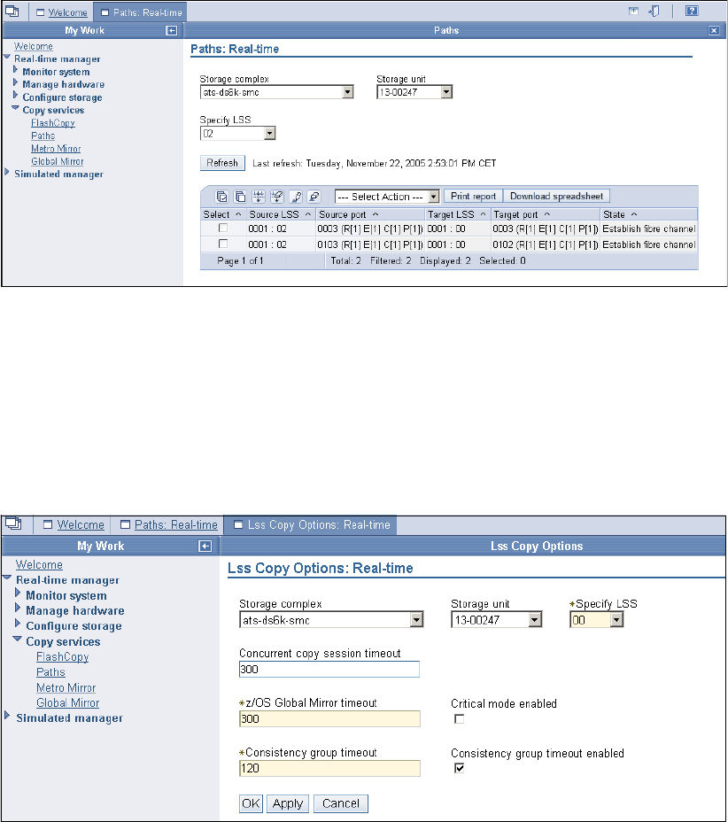
234 IBM System Storage DS6000 Series: Copy Services with IBM System z
Figure 20-1 Paths panel
To create a new path, select from the Select Actions pull-down menu Create, and a process
will then guide you to establishing a path.
Alternatively, if in the Paths panel you select one or more of the existing paths, then the
Select Actions pull-down menu will give you the following additional possible actions:
Delete, to delete the paths you have selected before.
LSS copy options, to modify the copy options for an LSS; see Figure 20-2.
Figure 20-2 LSS Copy Options
20.5.2 Metro Mirror panel
The Metro Mirror panel is the central point in the DS Storage Manager to establish new and
manage existing Global Copy pairs. You can get to the Metro Mirror panel as follows:
1. Select Real-time manager.
2. Select Copy services.
3. Click Metro Mirror.
Figure 20-3 on page 235 shows the Metro Mirror panel.
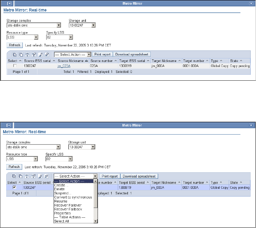
Chapter 20. Global Copy interfaces 235
Figure 20-3 Metro Mirror panel
To create a new Global Copy pair, choose Create from the Select Action pull-down menu.
The DS Storage Manager will guide you through the process to create a new pair.
Figure 20-4 Metro Mirror panel
If you select an existing Global Copy pair (see Figure 20-4), then the Select Action pull-down
menu will show additional actions you can perform with the selected volume pair:
Delete: Use this action to delete a Global Copy pair.
Suspend: Use this action to suspend a Global Copy pair.
Convert to synchronous: Use this action to convert a Global Copy pair into a
synchronous Metro Mirror pair.
Resume: Use this option to resume a suspended Global Copy pair.
Recover Failover: Use this action to change a secondary device into a primary
suspended device while leaving the primary device in its current state.
Recover Failback: Use this action to switch back to the primary site after a failover.
Properties: Use this action to view the volume pair properties, including the number of
out-of-sync tracks.
236 IBM System Storage DS6000 Series: Copy Services with IBM System z

© Copyright IBM Corp. 2006. All rights reserved. 237
Chapter 21. Global Copy examples
This chapter includes sample Global Copy scenarios and examples of the corresponding
management activities using TSO and the DS CLI. The examples presented are:
How to establish and manage Global Copy volume pairs with TSO
Use Global Copy to migrate volumes from an ESS 800 to a DS6000 using the DS CLI
21
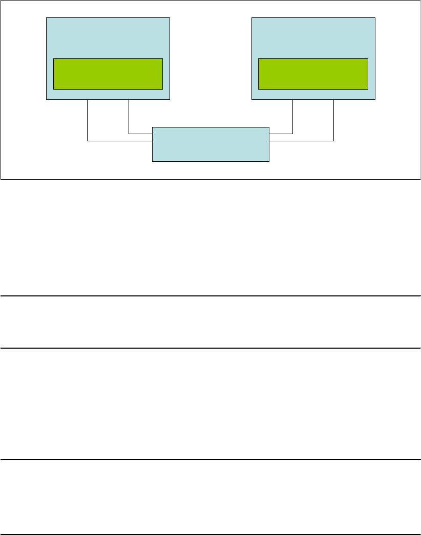
238 IBM System Storage DS6000 Series: Copy Services with IBM System z
21.1 Define and manage Global Copy pairs using TSO
Figure 21-1 shows a diagram of the test environment that we used for our example.
Figure 21-1 Configuration used to setup Global Copy pairs in our example
In our example, using TSO commands, we established a path between two LSSs and then
established the Global Copy pairs. After the pairs were established, we re-synchronized the
volumes. After the volumes were synchronized, we suspended the volumes. To do this we
followed this procedure:
1. We established a path with the CESTPATH command; see Example 21-1.
Example 21-1 CESTPATH command
CESTPATH DEVN(6030) PRIM(X'2060' 500507630EFFFC6F X'00') -
SEC(X'0002' 500507630EFFFCA0 X'00') -
LINK(X'00000000') -
CGROUP(NO)
To establish paths with TSO, we had to specify the WWNN from the storage subsystems.
We used the CQUERY PATHS command to determine the SSID and WWNN of the
primary and secondary LSSs. The WWNN can also be found by using the DS GUI or with
DS CLI lssi command. The WWNN for the DS6800 in our example are shown in
Figure 21-1.
2. We established two Global Copy pairs with the CESTPAIR command; see Example 21-2.
Example 21-2 CESTPAIR command
CESTPAIR DEVN(X'6030') PRIM(X'2060' AAGXA X'30' X'00') -
SEC(X'0002' AAVCA X'30' X'00') -
OPTION(XD) MODE(COPY) ONLINSEC(NO)
CESTPAIR DEVN(X'6031') PRIM(X'2060' AAGXA X'31' X'00') -
SEC(X'0002' AAVCA X'31' X'00') -
OPTION(XD) MODE(COPY) ONLINSEC(NO)
To establish a Global Copy pair, we used the (XD) option. After the pairs are established,
we were able to query the state of the volumes with the CQUERY command. We did this
for one volume, as shown in Example 21-3 on page 239.
DS6800 BOX 1
1750-13AAGXA
WWNN 500507630EFFFC6F
LCU 00
DS6800 BOX 2
1750-13AAVCA
WWNN 500507630EFFFCA0
LCU 00
FC Switch
I0000 I0100 I0000 I0100

Chapter 21. Global Copy examples 239
Example 21-3 CQUERY command
ANTP8802I CQUERY DEVN(X'6030')
ANTP0090I CQUERY FORMATTED LVL 3 161
VOLUME REPORT
************** PPRC REMOTE COPY CQUERY - VOLUME ********************
* (PRIMARY) (SECONDARY) *
* SSID CCA LSS SSID CCA LSS*
*DEVICE LEVEL STATE PATH STATUS SERIAL# SERIAL# *
*------ --------- ---------- ----------- --------- --------- *
* 6030 PRIMARY.. PENDING.XD ACTIVE.. 2060 30 00 0002 30 00 *
* CRIT(NO)....... CGRPLB(NO). 0000000AAGXA 0000000AAVCA*
* PATHS PFCA SFCA STATUS: DESCRIPTION *
* ----- --------- ------ ------------------- *
* 1 0000 0000 13 PATH ESTABLISHED... *
* ---- ---- 00 NO PATH............ *
* ---- ---- 00 NO PATH............ *
* ---- ---- 00 NO PATH............ *
* IF STATE = PENDING/SUSPEND: TRACKS OUT OF SYNC = 30548 *
* TRACKS ON VOLUME = 50085 *
* PERCENT OF COPY COMPLETE = 40% *
* SUBSYSTEM WWNN LIC LEVEL *
* ----------- ---------------- ----------- *
* PRIMARY.... 500507630EFFFC6F 5.0.00.0000 *
* SECONDARY.1 500507630EFFFCA0 *
********************************************************************
ANTP0001I CQUERY COMMAND COMPLETED FOR DEVICE 6030. COMPLETION CODE: 00
The output of the CQUERY command shows that the volume is in pending state and also
shows the number of tracks out of sync. When the write activity on the primary volume is
stopped, all data is eventually copied over to the secondary. The status remains
pending.xd but the number of out of sync tracks is zero. We verified this with the
CQUERY command (Example 21-4).
Example 21-4 QUERY command
ANTP8802I CQUERY DEVN(X'6030')
ANTP0090I CQUERY FORMATTED LVL 3 161
VOLUME REPORT
************** PPRC REMOTE COPY CQUERY - VOLUME ********************
* (PRIMARY) (SECONDARY) *
* SSID CCA LSS SSID CCA LSS*
*DEVICE LEVEL STATE PATH STATUS SERIAL# SERIAL# *
*------ --------- ---------- ----------- --------- --------- *
* 6030 PRIMARY.. PENDING.XD ACTIVE.. 2060 30 00 0002 30 00 *
* CRIT(NO)....... CGRPLB(NO). 0000000AAGXA 0000000AAVCA*
* PATHS PFCA SFCA STATUS: DESCRIPTION *
* ----- --------- ------ ------------------- *
* 1 0000 0000 13 PATH ESTABLISHED... *
* ---- ---- 00 NO PATH............ *
* ---- ---- 00 NO PATH............ *
* ---- ---- 00 NO PATH............ *
* IF STATE = PENDING/SUSPEND: TRACKS OUT OF SYNC = 00000 *
* TRACKS ON VOLUME = 50085 *
* PERCENT OF COPY COMPLETE = 100% *
* SUBSYSTEM WWNN LIC LEVEL *
* ----------- ---------------- ----------- *
* PRIMARY.... 500507630EFFFC6F 5.0.00.0000 *
* SECONDARY.1 500507630EFFFCA0 *
********************************************************************

240 IBM System Storage DS6000 Series: Copy Services with IBM System z
ANTP0001I CQUERY COMMAND COMPLETED FOR DEVICE 6030. COMPLETION CODE: 00
3. After the volumes were fully copied, we suspended the pairs; see Example 21-5.
Example 21-5 CSUSPEND Global Copy pair
ANTP8802I CSUSPEND DEVN(X'6030') PRIM(X'2060' AAGXA X'30' X'00')
SEC(X'0002' AAVCA X'30' X'00')
ANTP0001I CSUSPEND COMMAND COMPLETED FOR DEVICE 6030. COMPLETION CODE: 00
IEA494I 6030,DS6030,PPRC PAIR SUSPENDED,SSID=2060,CCA=30
ANTP8802I CSUSPEND DEVN(X'6031') PRIM(X'2060' AAGXA X'31' X'00')
SEC(X'0002' AAVCA X'31' X'00')
ANTP0001I CSUSPEND COMMAND COMPLETED FOR DEVICE 6031. COMPLETION CODE: 00
IEA494I 6031,DS6031,PPRC PAIR SUSPENDED,SSID=2060,CCA=31
4. We could verify whether the volumes were suspended with the CQUERY command. State
SUSPEND(3) means that the Global Copy volume pair was suspended by a host
command to the primary site storage control. In Example 21-6, we show the results for
device 6030.
Example 21-6 CQUERY command
ANTP8802I CQUERY DEVN(X'6030')
ANTP0090I CQUERY FORMATTED LVL 3 351
VOLUME REPORT
************** PPRC REMOTE COPY CQUERY - VOLUME ********************
* (PRIMARY) (SECONDARY) *
* SSID CCA LSS SSID CCA LSS*
*DEVICE LEVEL STATE PATH STATUS SERIAL# SERIAL# *
*------ --------- ---------- ----------- --------- --------- *
* 6030 PRIMARY.. SUSPEND(3) ACTIVE.. 2060 30 00 0002 30 00 *
* CRIT(NO)....... CGRPLB(NO). 0000000AAGXA 0000000AAVCA*
* PATHS PFCA SFCA STATUS: DESCRIPTION *
* ----- --------- ------ ------------------- *
* 1 0000 0000 13 PATH ESTABLISHED... *
* ---- ---- 00 NO PATH............ *
* ---- ---- 00 NO PATH............ *
* ---- ---- 00 NO PATH............ *
* SUBSYSTEM WWNN LIC LEVEL *
* ----------- ---------------- ----------- *
* PRIMARY.... 500507630EFFFC6F 5.0.00.0000 *
* SECONDARY.1 500507630EFFFCA0 *
********************************************************************
ANTP0001I CQUERY COMMAND COMPLETED FOR DEVICE 6030. COMPLETION CODE: 00
5. After the pairs were suspended, we resumed the I/O on the primary site and made a
FlashCopy on the secondary site. We made an inband FlashCopy of the secondary
volumes using the FCESTABL command; see Example 21-7. We requested inband
FlashCopy with the REMOTE(YES) parameter. The DEVN parameter specifies the
address of the Global Copy primary volume. The SOURCE and TARGET parameters
specify the FlashCopy source and target volumes. SSID is the Subsystem Identifier of the
FlashCopy source volume. This must be the same value as that specified for SSID of the
secondary device on the PPRC CESTPAIR command.
Example 21-7 Make FlashCopy
FCESTABL DEVN(6030) SOURCE(AAVCA 00 30) TARGET(AAVCA 00 40) REMOTE(YES) -
SSID(0002) MODE(COPY)
FCESTABL DEVN(6031) SOURCE(AAVCA 00 31) TARGET(AAVCA 00 41) REMOTE(YES) -

Chapter 21. Global Copy examples 241
SSID(0002) MODE(COPY)
6. The final task was to reestablish Global Copy for the volume pairs; see Example 21-8.
Example 21-8 Restart Global Copy
CESTPAIR DEVN(X'6030') PRIM(X'2060' AAGXA X'30' X'00') -
SEC(X'0002' AAVCA X'30' X'00') -
OPTION(XD) MODE(RESYNC)
CESTPAIR DEVN(X'6031') PRIM(X'2060' AAGXA X'31' X'00') -
SEC(X'0002' AAVCA X'31' X'00') -
OPTION(XD) MODE(RESYNC)
21.2 Global Copy for migration using the DS CLI
In this example, we show how to use DS CLI commands and scripts to migrate volumes from
an ESS 800 to a DS6000 using Global Copy. In the example, we have only two volumes. In
reality, you would perform the steps for a larger number of volumes. In that case, DS CLI
scripts are particularly useful because the commands can be written in advance and modified
if necessary. Our example also shows the strength of the DS CLI in the management of CKD
copy operations.
In the example, the source volumes are 050A and 050B on LSS 05 of the ESS 800
IBM.2105-22399. The target volumes are 023A and 023B on LSS 02 of the DS6000
IBM.1750-1300247.
The Web Copy Services commands for S/390 volumes ESS Control Switch has to be
enabled on the ESS-800; otherwise, the DS CLI cannot be used to establish CKD volume
pairs. If the control switch is disabled, the following message is issued: CMUN03013E mkpprc:
CKD management is disabled. Contact your IBM service representative to enable the control
switch. The control switch change should be followed by restart of the ESS Copy Services
server.
21.2.1 Migration procedure steps
To use CLI commands and scripts to migrate volumes from an ESS 800 to a DS6000 with
Global Copy, we followed this procedure.
1. We checked the WWNN of the target DS6000 system. Using the DS CLI in one-shot
mode, we issued the lssi command; see Example 21-9. Profile ds6-00247.prf contains
the necessary logon information for the DS6000 target system.
Example 21-9 Check target WWNN
C:\IBM\DSCLI>dscli -cfg ds6-00247.prf lssi
Date/Time: November 22, 2005 4:01:06 PM EET IBM DSCLI Version: 5.1.0.204
Name ID Storage Unit Model WWNN State ESSNet
============================================================================
- IBM.1750-1300247 IBM.1750-1300247 511 500507630EFFFE16 Online Enabled
2. We checked which FCP ports were available for establishing paths between LSS 05 on
the ESS 800 and LSS 02 on the DS6000. We used the DS CLI in one-shot mode to issue
the availpprcport command; see Example 21-10 on page 242. Profile ess-22399.prf
contains the necessary logon information for the ESS 800 source system.

242 IBM System Storage DS6000 Series: Copy Services with IBM System z
Example 21-10 Check ports
C:\IBM\DSCLI>dscli -cfg ess-22399.prf lsavailpprcport -dev ibm.2105-22399 -remotedev
ibm.1750-1300247 -remotewwnn 500507630efffe16 05:02
Date/Time: November 22, 2005 4:08:10 PM EET IBM DSCLI Version: 5.1.0.204 DS: IBM.2105-22399
Local Port Attached Port Type
=============================
I000C I0103 FCP
I00AC I0003 FCP
3. We established paths from source LSS 05 to target LSS 02. The CLI script file to do this is
shown in Example 21-11.
Example 21-11 Script estpath.cli
# Script to establish paths
mkpprcpath -dev ibm.2105-22399 -remotedev ibm.1750-1300247 -remotewwnn 500507630efffe16
-srclss 05 -tgtlss 02 i000c:i0103 i00ac:i0003
We executed the estpath.cli script file using CLI script mode and check path status
using CLI one-shot mode; see Example 21-12.
Example 21-12 Establish paths
C:\IBM\DSCLI>dscli -cfg ess-22399.prf -script estpath.cli
Date/Time: November 22, 2005 4:14:05 PM EET IBM DSCLI Version: 5.1.0.204 DS: IBM.2105-22399
CMUC00149I mkpprcpath: Remote Mirror and Copy path 05:02 successfully established.
C:\IBM\DSCLI>dscli -cfg ess-22399.prf lspprcpath -dev ibm.2105-22399 05
Date/Time: November 22, 2005 4:15:24 PM EET IBM DSCLI Version: 5.1.0.204 DS: IBM.2105-22399
Src Tgt State SS Port Attached Port Tgt WWNN
=========================================================
05 08 Success 8000 I0088 I0002 5005076303FFC08F
05 06 Success 6000 I000C I0103 500507630EFFFE16
05 02 Success E200 I00AC I0003 500507630EFFFE16
05 02 Success E200 I000C I0103 500507630EFFFE16
Note that the lspprcpath command output also shows other paths in addition to the paths
that we used.
4. To establish the Global Copy pairs, we first created the CLI script file; see Example 21-13.
Example 21-13 Script estpair.cli
# Script to establish Global Copy pairs
mkpprc -dev ibm.2105-22399 -remotedev ibm.1750-1300247 -type gcp -mode full 050a:023a
mkpprc -dev ibm.2105-22399 -remotedev ibm.1750-1300247 -type gcp -mode full 050b:023b
We executed the estpair.cli script and then checked the pair status; see
Example 21-14.
Example 21-14 Establish pairs
C:\IBM\DSCLI>dscli -cfg ess-22399.prf -script estpair.cli
Date/Time: November 22, 2005 4:21:54 PM EET IBM DSCLI Version: 5.1.0.204 DS: IBM.2105-22399
CMUC00153I mkpprc: Remote Mirror and Copy volume pair relationship 050A:023A successfully created.
Date/Time: November 22, 2005 4:22:08 PM EET IBM DSCLI Version: 5.1.0.204 DS: IBM.2105-22399
CMUC00153I mkpprc: Remote Mirror and Copy volume pair relationship 050B:023B successfully created.
C:\IBM\DSCLI>dscli -cfg ess-22399.prf lspprc -dev ibm.2105-22399 -l 050a-050b
Date/Time: November 22, 2005 4:22:57 PM EET IBM DSCLI Version: 5.1.0.204 DS: IBM.2105-22399
ID State Reason Type Out Of Sync Tracks Tgt Read Src Cascade Tgt Casca

Chapter 21. Global Copy examples 243
===========================================================================================
050A:023A Copy Pending - Global Copy 48148 Disabled Unknown Unknown
050B:023B Copy Pending - Global Copy 50085 Disabled Unknown Unknown
5. We synchronized the Global Copy pairs so that the target volume would be consistent.
This should not be done until the number of out-of-sync tracks for most of the volumes is
close to zero.
Before this step is performed, the hosts using the volumes that are migrated should be
shut down, because the pairs become synchronous Metro Mirror pairs. This can have an
impact on application write response times. The script to synchronize the pairs is shown in
Example 21-15.
Example 21-15 Script syncpair.cli
# Script to synchronize pairs
mkpprc -dev ibm.2105-22399 -remotedev ibm.1750-1300247 -type mmir 050a:023a
mkpprc -dev ibm.2105-22399 -remotedev ibm.1750-1300247 -type mmir 050b:023b
We executed the syncpair.cli script and then checked that all pairs were in full duplex
status; see Example 21-16.
Example 21-16 Synchronize pairs
C:\IBM\DSCLI>dscli -cfg ess-22399.prf -script syncpair.cli
Date/Time: November 22, 2005 4:42:20 PM EET IBM DSCLI Version: 5.1.0.204 DS: IBM.2105-22399
CMUC00153I mkpprc: Remote Mirror and Copy volume pair relationship 050A:023A successfully created.
Date/Time: November 22, 2005 4:42:42 PM EET IBM DSCLI Version: 5.1.0.204 DS: IBM.2105-22399
CMUC00153I mkpprc: Remote Mirror and Copy volume pair relationship 050B:023B successfully created.
C:\IBM\DSCLI>dscli -cfg ess-22399.prf lspprc -dev ibm.2105-22399 050a-050b
Date/Time: November 22, 2005 4:42:59 PM EET IBM DSCLI Version: 5.1.0.204 DS: IBM.2105-22399
ID State Reason Type SourceLSS Timeout (secs) Critical Mode First Pass
===========================================================================================
050A:023A Full Duplex - Metro Mirror 05 unknown Disabled Invalid
050B:023B Full Duplex - Metro Mirror 05 unknown Disabled Invalid
6. To stop mirroring and return the target volumes to simplex state, we used the script shown
in Example 21-17.
Example 21-17 Script delpair.cli
# Script to delete volume pairs
rmpprc -dev ibm.2105-22399 -remotedev ibm.1750-1300247 -quiet 050a:023a
rmpprc -dev ibm.2105-22399 -remotedev ibm.1750-1300247 -quiet 050b:023b
We then executed the script and verified that the volume pairs had been removed; see
Example 21-18.
Before the pairs are deleted, all pairs should be in full duplex status.
Example 21-18 Delete volume pairs
C:\IBM\DSCLI>dscli -cfg ess-22399.prf -script delpair.cli
Date/Time: November 22, 2005 4:45:09 PM EET IBM DSCLI Version: 5.1.0.204 DS: IBM.2105-22399
CMUC00155I rmpprc: Remote Mirror and Copy volume pair 050A:023A relationship successfully
withdrawn.
Date/Time: November 22, 2005 4:45:24 PM EET IBM DSCLI Version: 5.1.0.204 DS: IBM.2105-22399
CMUC00155I rmpprc: Remote Mirror and Copy volume pair 050B:023B relationship successfully
withdrawn.
C:\IBM\DSCLI>dscli -cfg ess-22399.prf lspprc -dev ibm.2105-22399 050a-050b

244 IBM System Storage DS6000 Series: Copy Services with IBM System z
Date/Time: November 22, 2005 4:45:34 PM EET IBM DSCLI Version: 5.1.0.204 DS: IBM.2105-22399
CMUC00234I lspprc: No Remote Mirror and Copy found.
After the volume pairs have been deleted, the host systems can be IPLed from the target
volumes on the DS6000 and the applications can start. To avoid duplicate volser
messages and the related operator replies during IPL, physically disconnect the ESS 800
source system from the host, or change ESCON/FICON director configurations as
relevant.
7. As a final clean-up step, we removed the paths between the ESS 800 and the DS6000.
We did this using CLI in one-shot mode; see Example 21-19.
Example 21-19 Script delpath.cli
C:\IBM\DSCLI>dscli -cfg ess-22399.prf rmpprcpath -dev ibm.2105-22399 -remotedev
ibm.1750-1300247 -quiet 05:02
Date/Time: November 22, 2005 4:57:47 PM EET IBM DSCLI Version: 5.1.0.204 DS: IBM.2105-22399
CMUC00150I rmpprcpath: Remote Mirror and Copy path 05:02 successfully removed.
C:\IBM\DSCLI>dscli -cfg ess-22399.prf lspprcpath -dev ibm.2105-22399 05
Date/Time: November 22, 2005 4:58:25 PM EET IBM DSCLI Version: 5.1.0.204 DS: IBM.2105-22399
Src Tgt State SS Port Attached Port Tgt WWNN
=========================================================
05 08 Success 8000 I0088 I0002 5005076303FFC08F
05 06 Success 6000 I000C I0103 500507630EFFFE16
Although this example was carried out with CKD volumes, the procedure applies equally well
to open systems volumes, because the same DS CLI commands are used for open systems.
21.2.2 Cascading alternative
The preceding example assumes that the source volumes on the ESS 800 are simplex.
However, they could also be secondary volumes of existing Global Copy or Metro Mirror
pairs. In that case, we could set up a cascaded Global Copy relationship by specifying the
-cascade parameter on the mkpprc command in step 4 of the previous example, as shown in
Example 21-20.
Example 21-20 Establish cascaded pairs
C:\IBM\DSCLI>dscli -cfg ess-22399.prf mkpprc -dev ibm.2105-22399 -cascade
remotedev ibm.1750-1300247 -type gcp -mode full 050a:023a
Date/Time: November 25, 2005 10:28:17 AM EET IBM DSCLI Version: 5.1.0.204 DS:
IBM.2105-22399
CMUC00153I mkpprc: Remote Mirror and Copy volume pair relationship 050A:023A successfully created.
C:\IBM\DSCLI>dscli -cfg ess-22399.prf lspprc -dev ibm.2105-22399 050a
Date/Time: November 25, 2005 10:28:42 AM EET IBM DSCLI Version: 5.1.0.204 DS:
IBM.2105-22399
ID State Reason Type SourceLSS Timeout (secs) Critical Mode Fir
===========================================================================================
011A:050A Target Copy Pending - Global Copy 01 unknown Disabled
050A:023A Copy Pending - Global Copy 05 unknown Disabled
Here, 011A is the source volume, 050A is the intermediate volume, and 023A is the target
volume. The lspprc command shows the status of both volume pairs where the intermediate
volume 050A belongs. 011A:050A is the first pair where 050A is the secondary, and 050A:023A
is the second pair where 050A is the cascading primary.

© Copyright IBM Corp. 2006. All rights reserved. 245
Chapter 22. Global Mirror overview
In this chapter we provide an overview of what Global Mirror is. We also discuss the need for
data consistency at a distant site when synchronous data replication such as Metro Mirror is
not possible. This chapter then explains how Global Mirror works in a similar manner to a
distributed application—in a server and client relationship. Finally, in this chapter you will find
a step-by-step process to establish a Global Mirror environment.
The information discussed in the present chapter can be complemented with the following
IBM publications and redbooks:
z/OS DFSMS Advanced Copy Services, SC35-0428
IBM System Storage DS6000 Series: Architecture and Implementation, SG24-6781
IBM System Storage DS6000: Command-Line Interface User´s Guide, GC26-7922
22
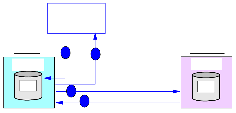
246 IBM System Storage DS6000 Series: Copy Services with IBM System z
22.1 Synchronous and non synchronous data replication
When replicating data over long distances, beyond the 300 km, asynchronous data
replication is the valid approach. This is basically so because with the asynchronous
techniques, the application I/O processing at the local storage disk subsystem (storage
server) remains independent of the process of data transmission to the remote storage disk
subsystem.
Still with the asynchronous data replication techniques, we need to provide additional means
to ensure data consistency at the remote location. It even requires a solution that guarantees
data consistency not only within a single local-remote pair of storage disk subsystems but
also across multiple local and remote storage disk subsystems.
For a given pair of local and remote storage disk subsystems, a time stamp approach leads to
consistent data at the remote storage disk subsystem. Using this approach, and by sorting
the I/Os by their time stamps, the write I/Os can be applied at the remote disk subsystem in
the same sequence as they arrived at the local disk subsystem.
But when the application volumes are spread across multiple storage disk subsystems, this
time stamp concept alone is not sufficient to replicate data and provide data consistency at
the remote site. This additionally requires a Consistency Group concept. z/OS Global Mirror,
formerly known as XRC, is an example of such a solution and utilizes the concept of
Consistency Groups combined with time stamped write I/Os for all involved primary volumes
within a Consistency Group or session. See Part 6, “Global Mirror” on page 265 for more
information regarding z/OS Global Mirror.
In the rest of the present section we discuss how consistent data, that is dependent writes,
are managed either with a synchronous technique like Metro Mirror versus different
asynchronous techniques like Global Copy or Global Mirror.
22.1.1 Synchronous data replication and dependent writes
In normal operations, the nature of synchronous data replication preserves data consistency
for dependent writes—dependent writes and data consistency are explained in detail in
Section 13.3, “Consistency Group function” on page 136.
Figure 22-1 Synchronous data replication
Primary
A
2C00
Primary
Primary
A
Primary
A1 B1
Storage Disk
Subsystem 1
Storage Disk
Subsystem 2
Replicate
Synchronous
2
SecondaryPrimary
Server
Host
4
3
1
remote site
local site
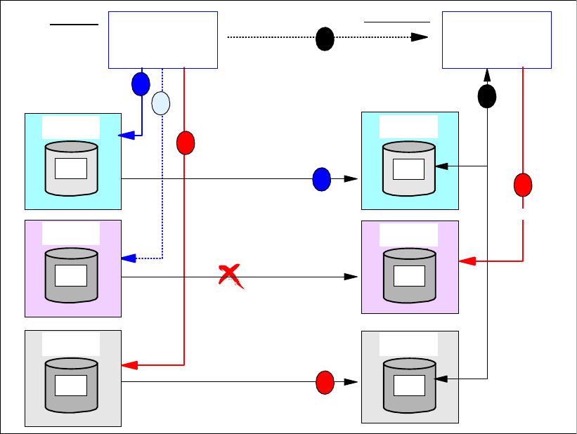
Chapter 22. Global Mirror overview 247
In synchronous data replication methods such as Metro Mirror, an application write always
goes through the following four steps; see Figure 22-1 on page 246:
1. Write the data to the primary storage disk subsystem cache and present channel end to
free up the channel for further I/O. Note this does not end the I/O and does not present an
I/O complete to the application.
2. Replicate the data from the primary storage disk subsystem cache to the secondary
storage disk subsystem cache.
3. Acknowledge to the primary storage disk subsystem that data successfully arrived at the
secondary storage disk subsystem.
4. Present device end to acknowledge successful I/O completion to the server, which is
presented to the application and concludes this I/O.
Now the next I/O that depends on the successful completion of the previous I/O can be
issued.
When you have dependent writes across multiple storage disk subsystems, synchronous
data replication alone does not guarantee that you can restart applications at the secondary
site without doing some previous data recovery.
Consider a database environment that spreads across multiple storage disk subsystems at
the local (primary) site. Further assume that the remote copy volume pairs are defined with
CRIT(HEAVY), which used to be CRIT(YES), and the remote copy paths are not defined with
the CGROUP parameter. Figure 22-2 illustrates what happens in this scenario during a
disaster, and in the absence of any automation software in place to handle I/O exceptions.
Figure 22-2 Synchronous data replication and unnecessary recovery after primary site failure
Replicate
Primary
Primary
A
Primary
Primary
A
2D00
Primary
Primary
A
Primary
B3
3E00
Subsystem
Database
Primary
A
2C00
Primary
Primary
A
Primary
A3
2E00
Primary
Primary
A
Primary
A1
2C00
B1
3C00
Synchronous
Replicate
Synchronous
Storage Disk
Subsystem 5
Storage Disk
Subsystem 6
Storage Disk
Subsystem 1
Storage Disk
Subsystem 2
1
2
3
Replicate
Primary
Primary
A
Primary
Primary
A
2D00
Primary
Primary
A
Primary
B2
3D00
Primary
Primary
A
Primary
A2
2D00
Synchronous
Storage Disk
Subsystem 3 Storage Disk
Subsystem 4
3
1
Secondary
Primary
RECON'
Log'
DB'
RECON
Log
DB
Subsystem
Database
Recover A2
6
5
Recover A2
4
Switch over to secondary site
Restart DB Subsystem
248 IBM System Storage DS6000 Series: Copy Services with IBM System z
A database update usually involves three dependent write I/Os to ensure data consistency,
even in the event of a failure during this process:
1. Update intent to the logging files—logging may happen to two logging files.
2. Update the data.
3. Indicate update complete to the logging files.
This sequence of I/Os is also called a two phase commit process.
When you are in a remote copy environment, in an outage situation, the following sequence
may occur; see Figure 22-2 on page 247:
1. Write update intent to logging volume A1.
2. Update to database on volume A2 eventually fails due to a replication problem from the
primary site to the secondary site and volume pairs are defined with CRIT(HEAVY). This
may also be a severe primary storage failure and the beginning of a rolling disaster.
3. The database subsystem recognizes the failed write I/O and indicates, in a configuration
file on volume A3, that one or more databases on A2 have to be recovered due to an I/O
error. This gets replicated to the secondary site because the paths for this storage disk
subsystem pair are still working and this particular primary storage disk subsystem did not
fail yet.
4. The failure eventually progressed and failed the primary site completely. The database
subsystem is restarted at the secondary site after switching over to the secondary site.
5. At startup, the database subsystem discovers in its configuration file that the database on
A2-B2 has to be recovered as indicated before. This is actually not necessary because the
data was synchronously replicated and both related volumes, A2 and B2, are identical and
at the very same level of data currency —that of the moment previous to the error.
Nevertheless, the database subsystem will still recover all databases that are marked for
recovery as per the information found in the configuration files on A3-B3.
6. This recovery is actually not necessary because the data in A2-B2 is perfectly in-sync due
to the synchronous replication approach. Nonetheless, the recovery will take place
because there was no automation window in place to freeze the configuration, which
would have removed the necessary paths between the primary and the secondary sites,
thus ensuring that no further I/Os continue to take place.
This does not happen with an automated solution such as GDPS, that makes use of the
freeze capabilities of the IBM System Storage DS6000. Had GDPS been there, after failing
over to the secondary site, the database subsystem would have just restarted without the
necessity for a lengthy database recovery.
Figure 22-3 on page 249 illustrates a rolling disaster situation where we have an automation
software that makes use of the freeze capability of the DS6000.
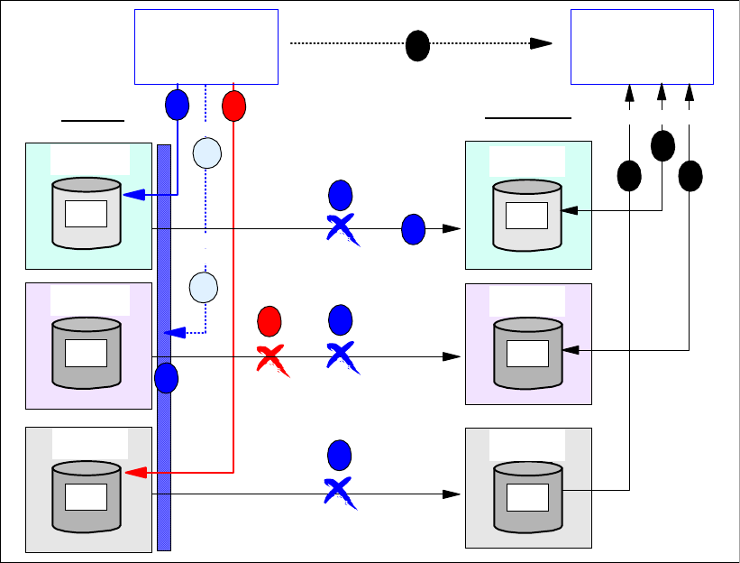
Chapter 22. Global Mirror overview 249
Figure 22-3 Synchronous data replication, freeze, and restart without recovery required
The sequence of events in Figure 22-3 is the following:
1. Update intent to logging file.
2. Link between A2 and B2 becomes unavailable, or the storage disk subsystem with A2
fails, and a rolling disaster develops.
3. The first attempt to write to the database volume A2 will return a unit check. The host
re-drives the I/O. When only the links fail, the subsystem triggers an extended long busy
(ELB). This is also called an automation window.
4. Within this automation window, or ELB window, a freeze operation removes all related
paths between both sites for the selected LSSs. From now on, no data is replicated any
longer between the selected LSSs.
5. After the ELB expires, or a RUN command is issued to end the freeze period, the I/O is
re-driven, and it may successfully complete when the pair is suspended, or may fail when
CRIT(HEAVY) is specified or the storage disk subsystem 3 is not available any longer.
6. When the I/O fails, then a recovery required is written to the database configuration file on
A3. Note volume A3 is no longer replicated due to the previous freeze. Note also that
volume A2 and B2 are still identical and at the very same level of data currency —that of
the moment previous to the error.
7. The primary site eventually becomes unavailable and a switch over to the secondary site
is carried out.
8. Database subsystem restart discovers no recovery required indication because all related
data is consistent —neither the recovery required indication in step 6 was transmitted to
B3. Then, the database subsystems continues immediately after the restart phase is
finished.
Primary
Primary
A
Primary
Primary
A
2D00
Primary
Primary
A
Primary
B3
3E00
Subsystem
Database
Primary
A
2C00
Primary
Primary
A
Primary
A3
2E00
Primary
Primary
A
Primary
A1
2C00
B1
3C00
Storage Disk
Subsystem 5
Storage Disk
Subsystem 6
Storage Disk
Subsytem 1 Storage Disk
Subsystem 2
1
3
6
Primary
Primary
A
Primary
Primary
A
2D00
Primary
Primary
A
Primary
B2
3D00
Primary
Primary
A
Primary
A2
2D00
Replicate
Synchronous
Storage Disk
Subsystem 3
Storage Disk
Subsystem 4
1
Secondary
Primary
RECON'
Log'
DB'
RECON
Log
DB
Subsystem
Database
Recover A2
8
7
4
5
88
Replicate
Synchronous
Replicate
Synchronous
4
4
4
2
Restart
Fail over to secondary site
Hold I/O
Redrive
I/O
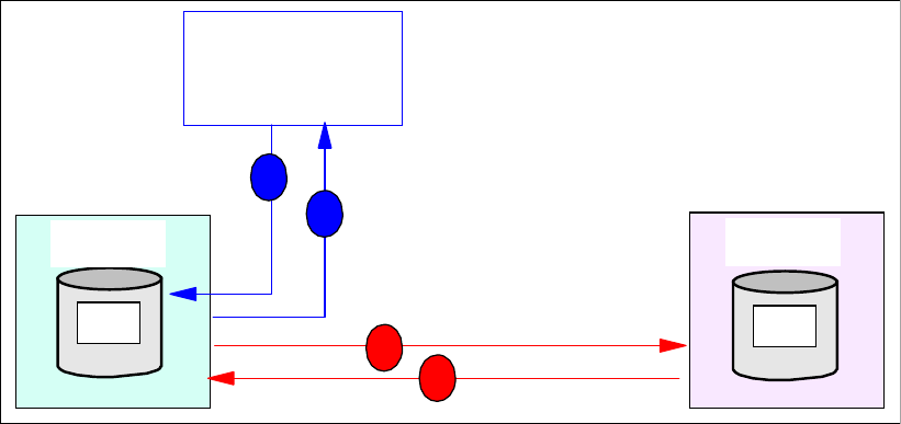
250 IBM System Storage DS6000 Series: Copy Services with IBM System z
Summary
In summary, the following characteristics are typical of a synchronous data replication
technique:
Application write I/O response time is affected —this can be modeled and predicted.
Local and remote copies of data are committed to both storage disk subsystems before
host write I/O is complete.
Data consistency is always maintained at the remote site as long as no failures occur. If a
rolling disaster occurs, freeze/run is needed to maintain consistency.
Bandwidth between both sites has to scale with the peak write I/O rate.
Data at the remote site is always current.
No extra means, such as additional journal volumes or tertiary copy, are required.
A tier 7 solution is achieved with automation software such as GDPS.
This is different with an asynchronous data replication approach. We still require data
consistency at a distant site in order to just restart at the distant site when the local site
becomes unavailable.
22.1.2 Asynchronous data replication and dependent writes
In normal operations, for asynchronous data replication, data consistency for dependent
writes will be preserved depending on the technique used to replicate the data—dependent
writes and data consistency are explained in detail in Section 13.3, “Consistency Group
function” on page 136. For example, Global Copy, that is explained in Part 5, “Global Copy”
on page 199, and Global Mirror, that we are explaining now, use different techniques.
An asynchronous remote copy approach is usually required when the distance between the
primary site and the secondary site is beyond an efficient distance for a synchronous remote
copy solution. Metro Mirror provides an efficient synchronous approach for up to 300 km,
when utilizing Fibre Channel links.
Figure 22-4 Asynchronous data replication
In an asynchronous data replication environment, an application write I/O goes through the
following steps; see Figure 22-4:
1. Write application data to the primary storage disk subsystem cache.
Primary
A
2C00
Primary
Primary
A
Primary
A1 B1
Storage Disk
Subsystem 1
Storage Disk
Subsystem 2
Replicate
Asynchronous
2
Server
Host
3
1
4
SecondaryPrimary
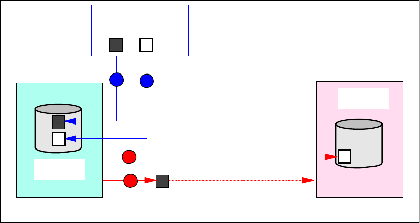
Chapter 22. Global Mirror overview 251
2. Present channel end and device end and acknowledge to the application successful I/O
completion. The application can then immediately schedule the next I/O.
3. Replicate the data from the primary storage disk subsystem cache to the secondary
storage disk subsystem cache.
4. Acknowledge to the primary storage disk subsystem that data successfully arrived at the
secondary storage disk subsystem.
From the previous procedure, note how in an asynchronous type technique, the data
transmission and the I/O completion acknowledge are independent process. This results in
virtually no application I/O impact, or at most to a minimal degree only. This also derives its
convenience when needing to replicate over long distances.
Global Copy non-synchronous technique
By its own, a non-synchronous technique like that of Global Copy, provides no guarantee that
the sequence of arrival of the applications write I/Os to the primary volumes is preserved at
the secondary site. In other words, the order of dependent writes is not preserved at the
secondary site. This is illustrated in Figure 22-5.
Figure 22-5 Global Copy sequence of data arrival not preserved at secondary site
Global Copy by itself as a non synchronous data replication method does not provide data
consistency at the secondary site.
In Figure 22-5 the sequence of data arrival at the primary site is record b after record a. Due
to the way Global Copy cycles through its out-of-sync bit map, it may replicate record a to the
secondary site after record b. This assumes that, for example, record a is written to a primary
disk location that the Global Copy replication cycle just passed before. Global Copy may
approach another disk location that experienced just before an update with record b. Then
record b gets replicated to the secondary site before the replication cycle starts from the
beginning and finds record a.
This situation may get even worse when involving multiple storage disk subsystems at the
primary site. As Figure 22-6 on page 252 shows, when using Global Copy, dependent writes
are not preserved at the recovery site when a failure occurs. This characteristic happens both
at a particular storage disk subsystem pair as well as across multiple storage disk
subsystems.
Primary
A
2C00
Primary
Primary
A
Primary
Storage Disk
Subsystem 1
Storage Disk
Subsystem 2
Server
b
ab
a
b
ain transit
SecondaryPrimary
3
12
4
Replicate
Non synchronous
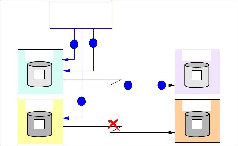
252 IBM System Storage DS6000 Series: Copy Services with IBM System z
Figure 22-6 Global Copy non synchronous data replication involving multiple disk subsystems
Notice that the numbers in Figure 22-6 indicate the transfer of data as well as the sequence of
its corresponding write I/Os. Record 3 may be replicated to storage disk subsystem 2 before
record 1 arrives to storage disk subsystem 2. Record 2 may never make it to storage disk
subsystem 4 due to the connectivity problem between storage disk subsystem 3 and storage
disk subsystem 4, which in turn may be the beginning of a rolling disaster. So, when using a
non synchronous technique like Global Copy, consistent data cannot be guaranteed at the
remote site without any additional measures, functions, and procedures.
The challenge is to provide data consistency at the distant site at any time and independent
of the combination of storage disk subsystems involved. One solution is to combine Global
Copy with FlashCopy and create a three-copy solution. This requires a series of additional
steps that have to be organized and carried out:
1. At the local site, temporarily pause the application write I/Os on the primary A volumes.
2. Wait for and make sure that the primary A volumes and the secondary B volumes become
synchronized. Note the challenge to manage all volumes.
3. Using FlashCopy, create a point-in-time (PiT) copy of the B volumes at the remote site.
4. The FlashCopy targets, that is the C volumes, will then hold a copy of the A volumes at the
time the application was paused or stopped. In this manner data consistency is kept at the
remote site.
5. Restart or resume the application write I/O activity to the A volumes
Global Mirror asynchronous technique
If we could incorporate the previous five basic steps into the storage disk subsystem internal
microcode, and we could count with the corresponding management interface, then this
would basically be an efficient asynchronous mirroring technique that would allow the
replication of data over long distances, without impacting the application I/O response time,
its operation would be transparent and autonomic from the users point of view, and most
importantly would provide a consistent copy of the data at the remote site at all times. All this
is what basically Global Mirror is about.
Replicate
Primary
Primary
A
Primary
Primary
A
2D00
Primary
Primary
A
Primary
B
3D00
Subsystem
Database
Primary
A
2C00
Primary
Primary
A
Primary
A
2D00
Primary
Primary
A
Primary
Primary
local site
A
2C00
B
3C00
non synchronous
Replicate
non synchronous
Storage Disk
Subsystem 3 Storage Disk
Subsystem 4
Storage Disk
Subsystem 1
Storage Disk
Subsystem 2
Log'
DB'
Log
DB
3
2
3 1
1
Secondary
remote site
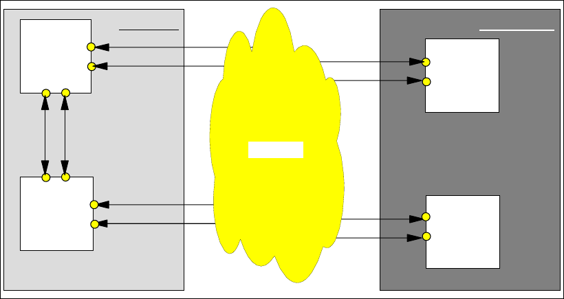
Chapter 22. Global Mirror overview 253
To accomplish the necessary activities with minimum impact on the application write I/O,
Global Mirror introduces a smart bitmap approach in the primary storage disk subsystem.
With this, Global Mirror can resume the application I/O processing immediately after a very
brief serialization period for all involved primary storage disk subsystems —this brief
serialization periodically occurs at the very beginning of a sequence of events that resemble
the ones outlined above. In the following chapters we explain in detail the characteristics of
Global Mirror, how it operates and how can you manage it.
Summary
In summary, the following characteristics are what an asynchronous data replication
technique should provide:
Data replication to the remote site independent from application write I/O processing at the
local site. This derives in no impact, or at least only minimal impact, to the application local
write I/O response time.
Data consistency and dependent writes always maintained at the remote site.
Data currency at remote site lags a little behind the local site. The remote site is always
less current than the local site. In peak write workloads this difference is going to increase.
This does not necessarily apply to XRC, which tries to throttle host write activity to keep
the data currency gap to a minimum. This in turn has the potential of blocking the primary
volumes from host write I/Os for a brief interval. Global Mirror as another asynchronous
remote copy approach does not throttle host write I/Os.
Bandwidth requirement between local and remote sites does not have to be configured for
peak write workload—link bandwidth utilization is improved over synchronous solutions.
Tertiary copies are required at the remote site to preserve data consistency.
Data loss in disaster recovery situations is limited to the data in transit plus the data that
may still be in the queue at the local site waiting to be replicated to the recovery site.
All the previous attributes are characteristics of Global Mirror.
22.2 Basic concepts of Global Mirror
Figure 22-7 Distributed application
Remote site
Local site
Server
Task1
Client
Client
Client
Network
Task1
Task2
Task2
Task3
Task3
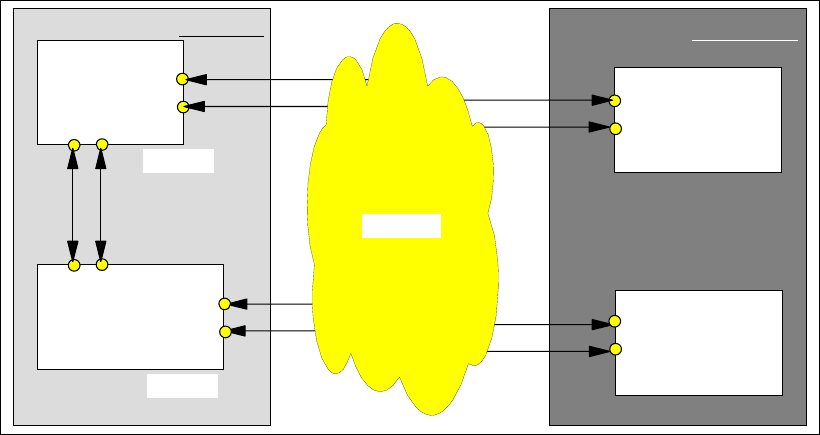
254 IBM System Storage DS6000 Series: Copy Services with IBM System z
Global Mirror works like a distributed application. A distributed application is usually built on a
server to client relationship. The server functions as a supervisor and instructs the client. The
client is able to do some work in an autonomic fashion but relies on the coordination efforts
from the server; see Figure 22-7 on page 253.
The server distributes the work to its clients. The server also coordinates all individual
feedback from the clients and decides based on this feedback further actions.
Looking at Figure 22-7 results obvious that the communication paths between the server and
all its clients are key. Without communication paths between these four components the
functions will eventually come to a complete stop. Matters get more complicated when the
communication fails unexpectedly in the middle of information exchange between the server
and his clients or to some of his clients.
Usually a two-phase commit process helps to provide a consistent state for certain functions
and whether they have successfully completed at the client site. Once a function is
successfully completed and is acknowledged to the server, the server progresses to the next
function task. At the same time the server tries to do as much as possible in parallel to
minimize the hit on throughput due to serialization and checkpoints.
When certain activities are dependent on each other it is required that the server coordinate
these activities to ensure a proper sequence.
The server and client can be replaced by terms such as Master and Subordinate; see
Figure 22-8. These terms are used later when discussing Global Mirror.
Figure 22-8 Global Mirror as a distributed application
Figure 22-8 shows the basic Global Mirror structure. A Master coordinates all efforts within a
Global Mirror environment. Once the Master is started and manages a Global Mirror
environment, the Master issues all related commands over inband communication to its
attached subordinates at the local site. This may include a subordinate within the Master
itself. This communication between the Master and an internal subordinate is transparent and
does not need any extra attention from the user. The subordinates use inband
communication to communicate with their related secondary storage disk subsystems at the
remote site. The Master also receives all acknowledgements from his subordinates and their
secondaries, and coordinates and serializes all the activities in the session.
Remote site
Local site
Master
Subordinate
Secondary
Secondary
Network
Subord Flash Sec
FlashCopy2
Primary
Primary
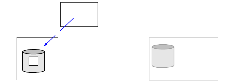
Chapter 22. Global Mirror overview 255
When the Master and Subordinate are in a single storage disk subsystem the Subordinate is
internally managed by the Master. With two or more storage disk subsystems at the local site,
which participate in a Global Mirror session, the Subordinate is external and needs separate
attention when creating and managing a Global Mirror session or environment.
The following sections explain how Global Mirror works and how Global Mirror ensures
consistent data at any time at the remote site. First we go through the process of how to
create a Global Mirror environment. At the same time, this explanation, gives us a first insight
on how Global Mirror works.
22.3 Set up a Global Mirror session
Global Mirror, as a long distance remote copy solution, is based on an efficient combination of
Global Copy and FlashCopy functions. It is the microcode that provides, from the user
perspective, a transparent and autonomic mechanism to intelligently utilize Global Copy in
conjunction with certain FlashCopy operations to attain consistent data at the remote site.
In order to understand how Global Mirror works, we start explaining first how a Global Mirror
environment, that is a Global Mirror session, is created and started. This is a step-by-step
approach and helps to understand further the Global Mirror operational aspects.
22.3.1 Simple configuration to start
In order to understand each step and to show the principles, we start with a simple application
environment where a host makes write I/Os to a single application volume (A); see
Figure 22-9.
Figure 22-9 Start with simple application environment
22.3.2 Establish connectivity to remote site
Now we add a distant site which has a storage disk subsystem (B), and we want to
interconnect both sites; see Figure 22-10 on page 256.
Primary
Primary
Primary
A
A Primary
Primary
Primary
Primary
Primary
A
Host
Write I/O
Remote site
Local site
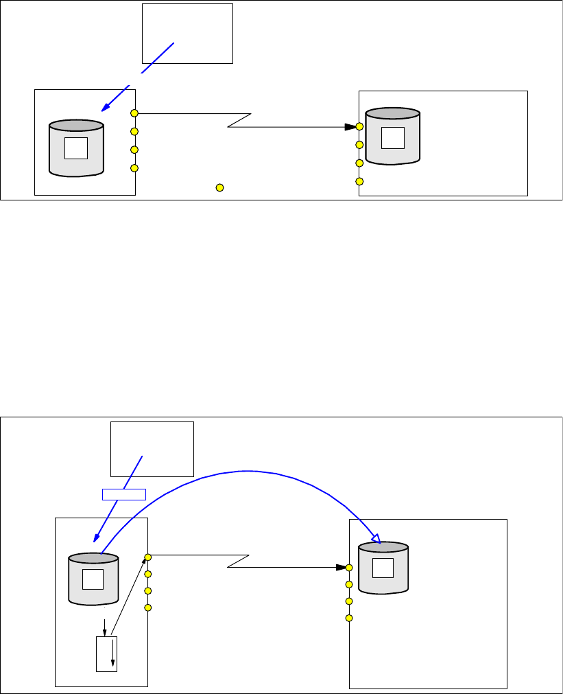
256 IBM System Storage DS6000 Series: Copy Services with IBM System z
Figure 22-10 Establish Global Copy connectivity between both sites
Note in Figure 22-10that we establish Global Copy paths over an existing network. This
network may be based on a FCP transport technology or on an IP based network.
Global Copy paths are logical connections that are defined over the physical links that
interconnect both sites. Note that all remote mirror and copy paths (that is Metro Mirror,
Global Copy, and Global Mirror paths) are similar and are based on FCP. The term Global
Copy path just denotes that the path is intended for Global Copy use.
22.3.3 Create Global Copy relationship between local and remote volume
Figure 22-11 Establish Global Copy volume pair
Next, we create a Global Copy relationship between the local, or primary, volume and the
remote, or secondary, volume; see Figure 22-11. This step changes the secondary volume
state from simplex to copy pending. This copy pending state applies to both volumes, primary
pending and secondary pending. At the same time data starts to be copied from the primary
volume to the secondary volume. After a first complete pass through the entire A volume,
Global Copy will constantly scan through the out-of-sync bit map. This bitmap indicates
changed data as it arrives from the applications to the primary disk subsystem—Global Copy
replicates the data from the A volume to the B volume based on this out-of-sync bit map.
Primary
Primary
Primary
A
A Primary
Primary
Primary
Primary
Primary
A
Host
Write I/O
Remote site
Local site
B
Global Copy path
FCP port
Global Copy
Primary
Primary
Primary
A
A Primary
Primary
Primary
Primary
Primary
A
B
O
O
S
Host
Remote site
Local site
Secondary
PENDING
PENDING
Write I/O
OOS: Out-of- sync bit map
Primary
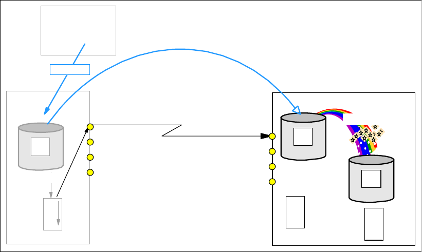
Chapter 22. Global Mirror overview 257
In the following paragraphs we refer to the primary volume as the A volume and to the
secondary volume as the B volume for simplicity.
Global Copy does not immediately copy the data as it arrives to the A volume. Instead, this is
an asynchronous process. As soon as a track is changed by an application write I/O, it is
reflected in the out-of-sync bitmap as with all the other changed tracks. There can be several
concurrent replication processes that work through this bitmap, thus maximizing the utilization
of the high bandwidth Fibre Channel links.
This replication process keeps running until the Global Copy volume pair A-B is explicitly or
implicitly suspended or terminated. Note that a Global Mirror session command, for example,
to pause or to terminate a Global Mirror session, does not affect the Global Copy operation
between both volumes.
At this point data consistency does not yet exist at the remote site.
22.3.4 Introduce FlashCopy
FlashCopy is an integral part of the Global Mirror solution, and now it follows as the next step
in the course of establishing a Global Mirror session; see Figure 22-12.
Figure 22-12 Introducing FlashCopy in the Global MIrror solution
The focus is now on the remote site. Figure 22-12 shows a FlashCopy relationship with a
Global Copy secondary volume as the FlashCopy source volume. Volume B is now both at
the same time, a Global Copy secondary volume and a FlashCopy source volume. In the
same disk subsystem is the corresponding FlashCopy target volume.
Note that this FlashCopy relationship has certain attributes that are typical and required when
creating a Global Mirror session. These attributes are:
Inhibit target write: Protect the FlashCopy target volume from being modified by anyone
other than Global Mirror related actions.
Global Copy
Primary
Primary
Primary
A
A Primary
Primary
O
O
S
Host
Remote site
Local site
Primary
Primary
Primary
Primary
A
B
Secondary
PENDING
PENDING
Write I/O
FlashCopy
C
MODE(ASYNC)
Tertiary
T
B
M
S
B
M
TBM: Target Bi t Map
SBM: Source Bit Map
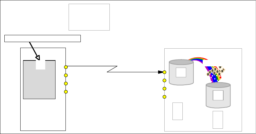
258 IBM System Storage DS6000 Series: Copy Services with IBM System z
Start change recording: Apply changes only from the source volume to the target
volume which occurred to the source volume in between FlashCopy establish operations
—except for the first time when FlashCopy is initially established.
Persist: Keep the FlashCopy relationship until explicitly or implicitly terminated. This
parameter is automatic due to the nocopy property.
Nocopy: Do not start background copy from source to target, but keep the set of
FlashCopy bitmaps required for tracking the source and target volumes. These bitmaps
are established at the first time when a FlashCopy relationship is created with the nocopy
attribute. Before a track in the source volume B is modified, between Consistency Group
creations, the track is copied to the target volume C to preserve the previous point-in-time
copy. This includes updates to the corresponding bitmaps to reflect the new location of the
track that belongs to the point-in-time copy. Note that each Global Copy write to its
secondary volume within the window of two adjacent Consistency Groups may cause
FlashCopy I/O operations.
Some interfaces to trigger this particular FlashCopy relationship combine these attributes into
a single parameter such as MODE(ASYNC) with the TSO command for z/OS.
22.3.5 Define Global Mirror session
Creating a Global Mirror session does not involve any volume within the local nor the remote
sites. Our focus is back again onto the local site; see Figure 22-13.
Figure 22-13 Define Global Mirror session
Defining a Global Mirror session, creates a kind of token, which is a number between 1 and
255. This number represents the Global Mirror session.
This session number is defined at the LSS level. Each LSS that has volumes which will be
part of the session needs a corresponding define session command. Currently only a single
session is allowed per storage server. The architecture allows for more than one session and
will be exploited in the future.
Global Copy
Primary
Primary
Primary
Primary
A
B
Host
Remote site
Local site
Secondary
PENDING
FlashCopy
C
MODE(ASYNC)
Tertiary
T
B
M
S
B
M
Define Global Mirror session
01
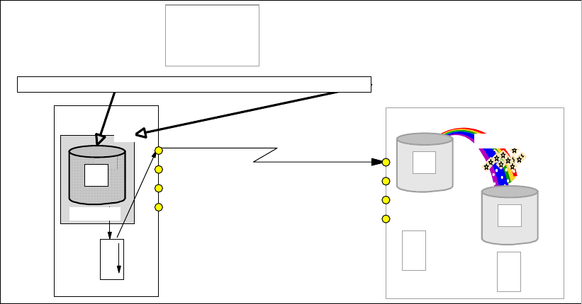
Chapter 22. Global Mirror overview 259
22.3.6 Populate Global Mirror session with volumes
Figure 22-14 Add Global Copy primary volume to Global Mirror session
The next step is the definition of volumes in the Global Mirror session. The focus is still on the
local site; see Figure 22-14. Note that only Global Copy primary volumes are meaningful
candidates to become a member of a Global Mirror session.
This process adds primary volumes to a list of volumes in the Global Mirror session. But at
this stage it does still not perform consistency group formation.
Note that Global Copy is replicating, on the Global Copy secondary volumes, the application
updates that arrive to the Global Copy primary volumes. Initially the Global Copy primary
volumes are placed in a join pending status. Once a Consistency Group is formed, the Global
Copy primary volume will then be added to the session and will be placed in an in session
status.
Nothing happens to the C volume after its initial establishment in a Global Mirror session.
22.3.7 Start Global Mirror session
This is the last step and it starts the Global Mirror session. Upon this, Global Mirror starts to
form Consistency Groups at the remote site. As Figure 22-15 on page 260 indicates, the
focus here is on the local site, with the start command issued to an LSS in the primary
storage disk subsystem. With this start command you set the Master storage disk subsystem
and the Master LSS. From now on, session related commands have to go through this Master
LSS.
Global Copy
Primary
Primary
A
A Primary
Primary
Primary
Primary
A
B
O
O
S
Host
Remote site
Local site
Primary Secondary
PENDING
PENDING
FlashCopy
C
MODE(ASYNC)
Tertiary
T
B
M
S
B
M
Add Global Copy primary volume to Global Mirror session
01
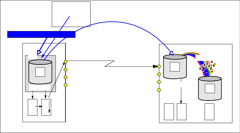
260 IBM System Storage DS6000 Series: Copy Services with IBM System z
Figure 22-15 Start Global Mirror
This start command triggers events that involve all the volumes within the session. This
includes a very fast bitmap management at the local storage disk subsystem, issuing inband
FlashCopy commands from the local site to the remote site, and verifying that the
corresponding FlashCopy operations successfully finished. This all happens at the microcode
level of the related storage disk subsystems that are part of the session, fully transparently
and in an autonomic fashion from the users perspective.
All C volumes that belong to the Global Mirror session comprise the Consistency Group. Now
let´s see some more details about the Consistency Group creation at the remote site.
22.4 Consistency Groups
To achieve the goal of creating a set of volumes at a remote site that contains consistent
data, asynchronous data replication alone is not enough—it must be complemented with
either a kind of journal or a tertiary copy of the secondary volume. With Global Mirror this third
copy is naturally created through the use of FlashCopy.
The microcode automatically triggers a sequence of autonomic events to create a set of
consistent data volumes at the remote site. We call this set of consistent data volumes a
Consistency Group. The following sections describe the sequence of events that create a
Consistency Group.
22.4.1 Consistency Group formation
The creation of a Consistency Group requires three steps that are internally processed and
controlled by the microcode. Outside of the Licensed Internal Code (LIC), these steps are
fully transparent and do not require any other external code invocation or user action.
The numbers in Figure 22-16 on page 261 illustrate the sequence of the events involved in
the creation of a Consistency Group. This illustration provides only a high level view that is
sufficient to understand how this process works.
Global Copy
Primary
Primary
A
A Primary
Primary
Primary
Primary
A
B
O
O
S
Host
Remote site
Local site
Primary Secondary
FlashCopy
C
MODE(ASYNC)
Tertiary
T
B
M
S
B
M
CR: Change recording bit map
Start Global Mirror session
C
R
PENDING
C
R
PENDING
01
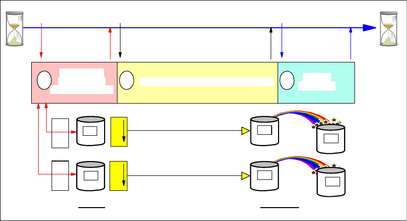
Chapter 22. Global Mirror overview 261
Figure 22-16 Formation of consistent set of volumes at the secondary site
Note that before step 1 and after step 3, Global Copy constantly scans through the
out-of-sync bitmaps and replicates data from A volumes to B volumes as described in “Create
Global Copy relationship between local and remote volume” on page 256.
When the creation of Consistency Group is triggered, the following steps occur in a serial
fashion:
1. Serialize all Global Copy primary volumes. This imposes a brief hold on all incoming write
I/Os to all involved Global Copy primary volumes. Once all primary volumes are serialized,
the pause on the incoming write I/O is released and all further write I/Os are now noted in
the change recording bitmap. They are not replicated until step 3 is done, but application
write I/Os can immediately continue.
2. Drain includes the process to replicate all remaining data that is indicated in the
out-of-sync bitmap and still not replicated. Once all out-of-sync bitmaps are empty—note
that “empty” here does not mean in a literal sense—step 3 is triggered by the microcode
from the primary site.
3. Now the B volumes contain all data as a quasi point-in-time copy, and are consistent due
to the serialization process in step 1 and the completed replication or drain process in step
2. Step 3 is now a FlashCopy that is triggered by the primary system’s microcode as an
inband FlashCopy command to volume B, as FlashCopy source, and volume C, as
FlashCopy target volume. Note that this FlashCopy is a two phase process. First, the
FlashCopy command to all involved FlashCopy pairs in the Global Mirror session. Then
the Master collects the feedback and all incoming FlashCopy completion messages.
When all FlashCopy operations are successfully completed, then the Master concludes
that a new Consistency Group has been successfully created.
FlashCopy applies here only to changed data since the last FlashCopy operation. This is
because the start change recording property was set at the time when the FlashCopy
relationship was established. The FlashCopy relationship does not end due to the nocopy
property, which is also assigned at FlashCopy establish time; see “Introduce FlashCopy”
on page 257. Note that the nocopy attribute results in that no physical background copy is
done for any tracks. Only bitmaps are maintained and updated.
2
Local
Serialize all
Global Copy
primary volumes Drain data from local to remote site Perform
FlashCopy
Primary
A2
Primary
A1
B2
Secondary
B1
Secondary
C2
Tertiary
C1
Tertiary
Start Done Start Done
Start Done
Remote
13
O
O
S
O
O
S
C
R
C
R
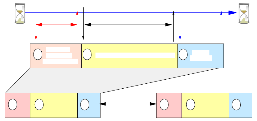
262 IBM System Storage DS6000 Series: Copy Services with IBM System z
Once step 3 is complete, a consistent set of volumes have been created at the secondary
site. This set of volumes, the C volumes, represents the Consistency Group.
At this very moment also, the B volumes and the C volumes are, but only for this brief
moment, equal in their content. Immediately after the FlashCopy process is logically
complete, the primary systems’s microcode is notified to continue with the Global Copy
process. In order to replicate the changes to the A volumes that occurred during the step 1 to
step 3 window, the change recording bitmap is mapped against the empty out-of-sync bitmap,
and from now on, all arriving write I/Os will end up again in the out-of-sync bitmap. From now
on the conventional Global Copy process, as outlined in“Create Global Copy relationship
between local and remote volume” on page 256, continues until the next Consistency Group
creation process is started.
22.4.2 Consistency Group parameters
In the previous section we described the sequence of steps followed once a Consistency
Group create event is triggered. In the first step, the serialization step, when the Consistency
Group spans over more than one primary disk subsystem, Global Mirror not only serializes all
related Global Mirror primary volumes but also does the coordination with other storage disk
subsystems.
Figure 22-17 Consistency Group tuning parameters
There are three externalized parameters, and their default values can be overridden; see
Figure 22-17:
Maximum coordination time: dictates, for the Global Copy primary volumes that belong to
this Consistency Group, how long a host write I/O may be impacted due to coordination
and serialization activities. This time is measured in milli-seconds (ms). The default is 50
ms.
Maximum drain time: is the maximum time allowed for draining the out-of-sync bitmap
once the process to form a Consistency Group is started and step 1 successfully
completed. The maximum drain time is specified in units of seconds. The default is 30
seconds.
If the maximum drain time is exceeded, Global Mirror will fail to form the Consistency
Group and will evaluate the current throughput of the environment. If this indicates that
another drain failure is likely, Global Mirror will stay in Global Copy mode while regularly
re-evaluating the situation to determine when to start to form the next Consistency Group.
2
Serialize all
Global Copy
primary volumes
Drain data from local to remote site Perform
FlashCopy
1 3
12 31 2 3
Maximum
coordination
time
time
CG interval
drain
time
Maximum
Chapter 22. Global Mirror overview 263
If this persists for a significant period of time, then eventually Global Mirror will force the
formation of a new Consistency Group. In this way Global Mirror ensures that during
periods when the bandwidth is insufficient, production performance is protected and data
is transmitted to the secondary site in the most efficient manner possible. When the peak
activity has passed, consistency group formation will resume in a timely fashion.
Consistency Group interval time: once a Consistency Group has been created, the CG
interval time determines how long to wait before starting with the formation of the next
Consistency Group. This is specified in seconds, and the default is zero (0) seconds. Zero
seconds means that Consistency Group formation happens constantly. As soon as a
Consistency Group is successfully created, the process to create a new Consistency
Group starts again immediately.
There is no external parameter to limit the time for the FlashCopy operation. This is due to its
very fast bitmap manipulation process.
Global Mirror utilizes a distributed approach as well as a two-phase commit technique for
activities between the Master and its Subordinate LSSs. The communication between the
local and the remote site is organized through the Subordinate LSS. The Subordinates
function here partly as a transient component for the Global Mirror activities, which are all
triggered and coordinated by the Master. This distributed concept allows always to provide a
set of data consistent volumes at the remote site independent of the number of involved
storage disk subsystems at the primary or at the secondary site.
264 IBM System Storage DS6000 Series: Copy Services with IBM System z

© Copyright IBM Corp. 2006. All rights reserved. 265
Part 6 Global Mirror
This part of the book describes IBM System Storage Global Mirror for DS6000 when used in
a System z environment. We discuss the characteristics of Global Mirror and describe the
options for its setup. We also show which management interfaces can be used, as well as the
important aspects to be considered when establishing a Global Mirror environment. This part
ends with examples of Global Mirror management and setup.
Part 6
266 IBM System Storage DS6000 Series: Copy Services with IBM System z

© Copyright IBM Corp. 2006. All rights reserved. 267
Chapter 23. Global Mirror options and
configuration
In this chapter we provide a detailed description of Global Mirror options, including how to
create a Global Mirror environment and how to remove it. We discuss how to change Global
Mirror tuning parameters and how to modify an active Global Mirror session. We also discuss
a scenario where a sites switch is performed due to a primary site failure.
The information discussed in this chapter can be complemented with the following IBM
publications:
z/OS DFSMS Advanced Copy Services, SC35-0428
IBM System Storage DS6000: Command-Line Interface User´s Guide, GC26-7922
Device Support Facility User’s Guide and Reference, SC35-0033
Global Mirror is intended for long distance data replication. For this, it relies on the network
infrastructure and components used between the remote sites. This chapter does not cover
network related topics. For information on these topics, refer to IBM TotalStorage Business
Continuity Solutions Guide, SG24-6547.
23
268 IBM System Storage DS6000 Series: Copy Services with IBM System z
23.1 Terminology used in Global Mirror environments
First, let us review and further define some of the terms and new elements we have
presented so far, and that are of common use when working in a Global Mirror context.
Dependent writes
If the start of one write operation is dependent upon the completion of a previous write, the
writes are dependent. Application examples for dependent writes are databases with their
associated logging files. Also updates to catalogs, VTOCs as well as VSAM indexes and
VSAM data components rely on dependent writes. For instance, the database logging file will
be updated after a new entry has been successfully written to a table space.
Compliance at the remote site, with the chronological order of dependent writes to primary
volumes, is the basis to provide consistent data at the secondary site through remote copy
operations.
Dependent writes is discussed in detail in 13.3.1, “Data consistency and dependent writes”
on page 136, in the Metro Mirror part.
Consistency
The consistency of data is ensured if the order of dependent writes to disks or disk groups is
maintained. With Copy Services solutions the data consistency at the secondary site is
important for the usability of the data. Consistent data, for instance, gives the ability to
perform a data base restart rather than a data base recovery that could take hours or even
days.
Data consistency across all secondary volumes spread across multiple storage disk
subsystems is essential for logical data integrity.
Data currency
This term describes the difference of time since the last data was written at the primary site,
versus the time the same data was written to the secondary site. It determines the amount of
data you have to recover at the remote site after a disaster. This is also called recovery point
objective or RPO. Only synchronous copy solutions such as Metro Mirror have a currency of
zero or RPO = zero. All asynchronous copy solutions have a data currency greater than zero.
With Global Mirror a data currency of a few seconds can be achieved, while data consistency
is always maintained by the Consistency Group process within Global Mirror.
For asynchronous replication, this means that the data is not replicated at the same time that
the local I/O happens, but the data is replicated with a certain time lag. Examples of different
nonsynchronous or asynchronous replication methods are:
Global Copy - a non-synchronous method that does not guarantee consistent data at the
remote site.
z/OS Global Mirror (formerly XRC) - an asynchronous replication method that guarantees
consistent data at the remote site.
Global Mirror - also an asynchronous replication method that provides consistent data at
the remote site.
Session
A Global Mirror session is a collection of volumes that are managed together when creating
consistent copies of data volumes. This set of volumes can reside in one or more LSSs and
one or more storage disk subsystems at the primary site. Open systems volumes and z/OS
volumes can both be members of the same session.
Chapter 23. Global Mirror options and configuration 269
When you start or resume a session, Consistency Groups are created, and the Master
storage disk subsystem controls the session by communicating with the Subordinate storage
disk subsystems.
There is also a session concept at the LSS level. But all LSS sessions are combined and
grouped together within a Global Mirror session.
Master
The Master is a function inside a primary storage disk subsystem that communicates with
Subordinates in other storage disk subsystems, and controls the creation of Consistency
Groups while managing the Global Mirror session. The Master is defined when the start
command for a session is issued to any LSS in a primary storage disk subsystem. This
determines who becomes the Master storage disk subsystem.
The Master needs communication paths over Fibre Channel links to any one of the LSSs in
each Subordinate disk storage server.
Subordinate
The Subordinate is a function inside a primary storage disk subsystem that communicates
with the Master and is controlled by the Master. At least one of the LSSs of each Subordinate
primary storage disk subsystems needs Fibre Channel communication paths to the Master.
This enables the communication between the Master and the Subordinate, and is required to
create Consistency Groups of volumes that spread over more than one storage disk
subsystem.
If all the volumes of a Global Mirror session reside in one primary storage disk subsystem, no
Subordinate is required, because the Master can communicate to all LSSs inside the primary
storage disk subsystem.
Consistency Group
This is a group of volumes in one or more secondary storage disk subsystems whose data
must be kept consistent at the remote site.
Local Site
This is the site that contains the production servers. This and other publications use this term
interchangeably with the terms primary, production, or source site.
Remote Site
This is the site that contains the backup servers of a disaster recovery solution. This and
other publications use this term interchangeably with the terms secondary, backup, standby,
or target site.
23.2 Create a Global Mirror environment
The following section recommends a certain sequence of steps to establish a Global Mirror
environment. This is independent of the interface used to create a Global Mirror environment.
Note that for illustration purposes, parameters and keywords are used in this section that
apply to TSO commands or to the ANTRQST macro interface. ICKDSF does use different
keywords that are described in 24.5, “Global Mirror management using ICKDSF” on
page 313.
We explain a basic Global Mirror setup, illustrated in Figure 23-1 on page 270.
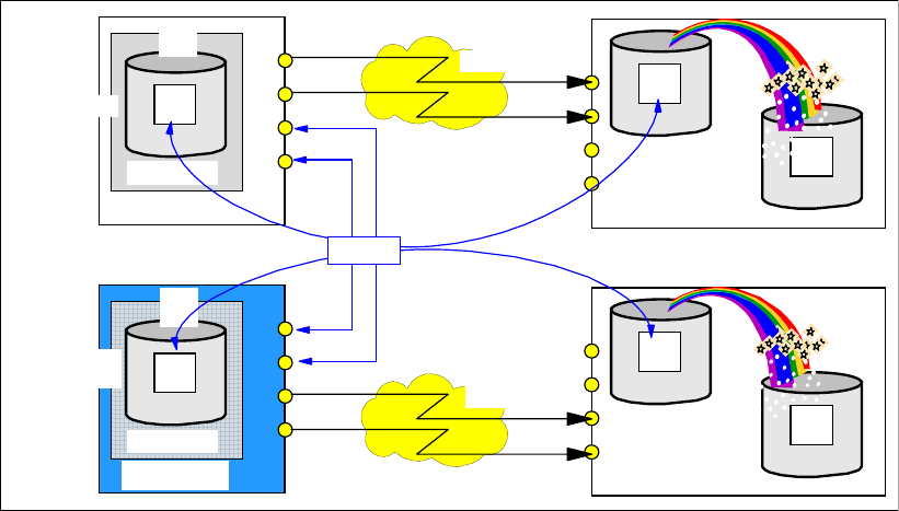
270 IBM System Storage DS6000 Series: Copy Services with IBM System z
Figure 23-1 Global Mirror basic configuration with Master and Subordinate disk subsystems
The order of commands to create a Global Mirror environment is not completely fixed and
allows for some variation. In order to be consistent with other sources and to not confuse the
user with a different sequence of commands, we recommend a meaningful order and suggest
the following steps to create a Global Mirror environment:
1. Establish the paths between the local site and the remote site. In Figure 23-1, these are
the logical communication paths between corresponding LSSs at the primary site and the
remote site, defined over Fibre Channel physical links that are configured over the
network. Global Copy primary LSSs are represented by the A volumes, and their
corresponding Global Copy secondary LSSs by the B volumes.
You may also establish logical communication paths here between the Master and any
Subordinate storage disk subsystem that will be part of the Global Mirror session. Note
that these paths are defined between primary storage disk subsystems at the local site.
With only a single primary storage disk subsystem, you do not need to define paths to
connect internal LSSs within the primary storage disk subsystem. The communication
between the Master and the Subordinates within a single primary storage disk subsystem
is transparent and internally performed.
2. Once the communication paths are defined, start the Global Copy pairs that will be part of
a Global Mirror session. Global Copy has to be established with the parameters
MODE(COPY) and OPTION(XD) when you use CESTPAIR TSO commands. When you
use ICKDSF use PPRCOPY ESTPAIR, which also has the parameters MODE(COPY)
and OPTION(XD). We recommend that you wait until the first initial copy is complete
before you continue to the next step. This avoids unnecessary FlashCopy background
I/Os in the following step.
3. The next step is to establish FlashCopy relationships between the B and C volumes. The
TSO FCESTABL command has a parameter, MODE(ASYNC), which combines and
implies the particular FlashCopy attributes that are required for this FlashCopy
relationship (see 22.3.4, “Introduce FlashCopy” on page 257). ICKDSF explicitly requires
the keywords CHRCD(YES) NOTGTWT(YES) and MODE(NOCOPY) in the
corresponding FC ESTABLISH commands.
4. With external Subordinates, that is, with more than one involved disk subsystem at the
local site, you need paths between the Master LSS and any potential Subordinate storage
Global Co
py
Primary
Primary
A
A
Primary
PENDING
Primary
Primary
A
A
Primary
PENDING
Primary
Primary
Primary
Primary
A
B
Secondary
C
Tertiary
PENDING
Primary
Primary
Primary
Primary
A
B
Secondary
C
Tertiary
PENDING
Network
Network
01
01
Subordinate
Master
Global Copy
paths
Remote site
Local site

Chapter 23. Global Mirror options and configuration 271
disk subsystem at the local site. If you did not establish these paths in the very first step,
then this is the time to create these paths before you continue with the next step.
5. Define a token that identifies the Global Mirror session. This is a session ID with a number
between 1 and 255. Define this session number to the Master storage disk subsystem and
also to all potentially involved primary LSSs that are going to be part of this Global Mirror
session and will contain Global Copy primary volumes that will belong to the Global Mirror
session. All primary LSSs include all LSSs in potential Subordinate storage disk
subsystems that are going to be part of the Global Mirror session.
6. The next step populates the session with the Global Copy primary volumes. You should
put these Global Copy primary volumes into the session after they complete their first
pass for initial copy.
7. Start the session. This command actually defines the Master LSS. All further session
commands have to go through this LSS. You may specify with the start command the
Global Mirror tuning parameters such as maximum drain time, maximum coordination
time, and Consistency Group interval time.
You go through this recommended sequence independent of the interface used.
23.3 Modify a Global Mirror session
Once a session is active and running, you may alter the Global Mirror environment to add or
remove volumes. You may also add storage disk subsystems to a Global Mirror session or
you may change the interval between the formation of Consistency Groups.
23.3.1 Add or remove volumes to a Global Mirror session
Volumes can be added to the session at any time after the session number is defined to the
LSS where the volumes reside. Once the session is started, volumes can be added to the
session or can be removed from the session also at any time.
Volumes may be added to a session in any state, for example, simplex or pending. Volumes
that have not completed their initial copy phase stay in a join pending state until the first initial
copy is complete. If a volume in a session is suspended, it will cause Consistency Group
formation to fail.
We recommend that you add only Global Copy primary volumes that have completed their
initial copy or first pass, although the microcode itself will stop volumes from joining the
Global Mirror session until the first pass is complete. Also, we recommend that you wait until
the first initial copy is complete before you establish the FlashCopy relationship between the
B and the C volumes.
When you add a rather large number of volumes at once to an existing Global Mirror session,
then the available resources for Global Copy within the affected ranks may be utilized by the
initial copy pass. To minimize the impact to the production servers when adding many new
Note: You only add Global Copy primary volumes to a Global Mirror session.
Note: You cannot add a Metro Mirror primary volume to a Global Mirror session. Global
Mirror supports only Global Copy pairs. When Global Mirror detects a volume which, for
example, is converted from Global Copy to Metro Mirror, the following formation of a
Consistency Group will fail.

272 IBM System Storage DS6000 Series: Copy Services with IBM System z
volumes, you may consider adding the new volumes to an existing Global Mirror session in
stages.
Suspending a Global Copy pair that belongs to an active Global Mirror session will impact the
formation of Consistency Groups. When you intend to remove Global Copy volumes from an
active Global Mirror session, follow these steps:
1. Remove the desired volumes from the Global Mirror session; Example 23-2 on page 274
shows how to remove Global Copy volumes from a Global Mirror session, using TSO
commands.
2. Withdraw the FlashCopy relationship between the B and C volumes.
3. Terminate the Global Copy pair to bring volume A and volume B into simplex mode.
23.3.2 Add or remove storage disk subsystems or LSSs
When you plan to add a new Subordinate storage disk subsystem to an active session, you
have to stop the session first. Then add the new Subordinate storage disk subsystem and
start the session again (with the updated RSESSION command, when you use TSO
commands). The session start command will then contain the new Subordinate storage disk
subsystem. This is valid also for any other interface used to manage a Global Mirror
environment. The same procedure applies when you remove a storage disk subsystem from
a Global Mirror session, which can be a Subordinate only—in other words, you cannot
remove the Master storage disk subsystem.
When you add a new LSS to an active session and this LSS belongs to a storage disk
subsystem that already has another LSS that belongs to this Global Mirror session, you may
add the new LSS to the session without stopping and starting the session again. This is true
for either the Master or for a Subordinate storage disk subsystem.
23.3.3 Modify Global Mirror session parameters
The parameters that are used for tuning a Global Mirror session may be modified by pausing
the session and then resuming the session with the new values. The parameters that you
may modify are:
Consistency Group interval time
Maximum coordination interval time
Maximum Consistency drain time
When you issue a start command after a pause command, as opposed to a resume, any
value for the Consistency Group interval time, maximum coordination interval time, or
maximum Consistency Group drain time in the start command is ignored. If these parameters
have to be altered, you have to give a resume command to the paused session with the
parameters specified. If you resume a paused session without specifying these parameters,
they will be set to their default values; see 22.4.2, “Consistency Group parameters” on
page 262.
Note: When you remove A volumes without pausing Global Mirror, you might see an error
condition saying that the Consistency Group formation failed. However, this does not mean
you have lost a consistent copy at the remote site because Global Mirror does not take the
FlashCopy (B to C) for the failed Consistency Group data. This message indicates that just
one Consistency Group formation has failed, and Global Mirror will retry the sequence.

Chapter 23. Global Mirror options and configuration 273
23.3.4 Global Mirror environment topology changes
The topology of a Global Mirror session, for example, the Master SSID, Subordinate SSIDs,
and Subordinate serial numbers, cannot be altered through a pause and resume command
sequence. When you resume the session after a pause and the Global Mirror topology is not
the same as it was at the pause, the start of the session will fail.
If you need to change the topology of your Global Mirror session, you have to stop the
session and start the session again with the new topology structure information in the start
command.
Topology also refers to the list of storage disk subsystems that are subordinates. You define
control paths between the Master and Subordinate LSSs—just one LSS per subordinate disk
subsystem is sufficient. When you define the control paths, you identify the source LSS on
the Master disk subsystem with its corresponding subsystem ID (SSID). The target LSS in the
path definition command points to a corresponding subordinate disk subsystem, and is also
identified by its corresponding SSID. These SSIDs go into the topology specification, which
defines the communication paths between Master and Subordinate storage disk subsystems.
This topology is specified in the SBINFO parameter and is required for the following Global
Mirror operations:
Start a Global Mirror session.
Stop a Global Mirror session.
Pause a Global Mirror session.
Resume a Global Mirror session.
In Example 23-1 the topology information is passed to Global Mirror in the context of
establishing the paths between Master and Subordinate.
Example 23-1 Context between establish path and Global Mirror topology
CESTPATH DEVN (X'6000') +
PRIM (X'6000' 500507630EFFFC6F X'00') +
SEC (X'6400' 500507630EFFFCA0 X'00') +
LINK (X'00000000' X'01000100') CGROUP(NO)
RSESSION SNBR(01) VOLSER(AA601F) +
ACTION(START) +
LSSTYPE(CKD) LSSNBR(00) +
MSSERIAL (AAGXA) MASTER(YES) +
SBINFO(6000,6400,AAVCA)
On the CESTPATH command, the sending Master SSID is 6000 and the receiving
Subordinate SSID is 6400. These are the SSIDs as they are defined in the establish path
command. Also in this command there is a link between the SSID and its corresponding LSS
number, which in both cases is x’00’.
Important: When setting new values for the tuning parameters, be sure to check for errors
in Consistency Group formation and in draining the out-of-sync bitmaps. A few errors are
not significant and do not jeopardize the consistency of your Global Mirror. However, if
failures repeatedly occur, such as, no more consistency groups are formed, or the
percentage of successful Consistency Groups is unacceptable, or the frequency of
Consistency Groups is not meeting your requirements (Recovery Point Objective-RPO),
then the new values set for the tuning parameters need to be revised and changed.

274 IBM System Storage DS6000 Series: Copy Services with IBM System z
The RSESSION command contains the topology information for the Subordinate and also the
communication paths specification. SBINFO contains positional parameters in the following
order:
SSID of the sending Master LSS
SSID of the receiving LSS in the Subordinate disk subsystem
Serial number of the Subordinate disk subsystem
When the topology changes and needs to be reflected in an existing Global Mirror
environment, you need to stop the session with the SBINFO specification, as it was at the
previous start of the Global Mirror session. Then you adjust SBINFO so that it reflects the
changed topology and then start the session again, now with the new SBINFO specifications.
See also 23.3.2, “Add or remove storage disk subsystems or LSSs” on page 272.
23.3.5 Remove a FlashCopy relationship
When you withdraw a FlashCopy relationship within a Global Mirror session, the Consistency
Group process is affected. If a withdraw is required, then first remove the Global Copy
primary volume from the session. Example 23-2 shows a TSO command that removes a
volume from LSS 0C and two volumes from LSS 0D.
Example 23-2 Remove volumes from Global Mirror session
RVOLUME SNBR(01) VOLSER(XX2C00) +
ACTION(REMOVE) +
LSSTYPE(CKD) LSSNBR(0C) +
ESSSERIAL(27131) +
VOLLIST (00)
RVOLUME SNBR(01) VOLSER(XX2D00) +
ACTION(REMOVE) +
LSSTYPE(CKD) LSSNBR(0D) +
ESSSERIAL(27131) +
VOLRANGE (00:01)
Once the volumes are removed from the session, you may explicitly terminate the
corresponding FlashCopy relationship that was tied to this primary volume.
Example 23-3 Remove FlashCopy relationship
FCWITHDR SDEVN(X'3C00') TDEVN(X'3E00')
FCWITHDR DEVN(X'2C00') SOURCE(73081 00 0C) +
TARGET(73081 00 0E) +
REMOTE(YES) SSID(3C00)
Example 23-3 shows TSO FlashCopy commands that are used to terminate FlashCopy
relationships. The first FlashCopy command assumes a host channel connectivity to the
remote storage disk subsystem. In this case you can issue a simple FCWITHDR command
with the source and target volumes addressed by their z/OS device numbers. When there is
no host connectivity established to the remote storage disk subsystem, then you may use an
inband FlashCopy command through the local Global Copy primary volume. The second
FCWITHDR command propagates the FlashCopy command over the Global Mirror paths to
the remote storage server. The SOURCE and TARGET parameters address the source and
target volumes in the remote storage server. The SSID parameter addresses the LSS that
contains the source volume. In both examples, consider that despite the removal of the
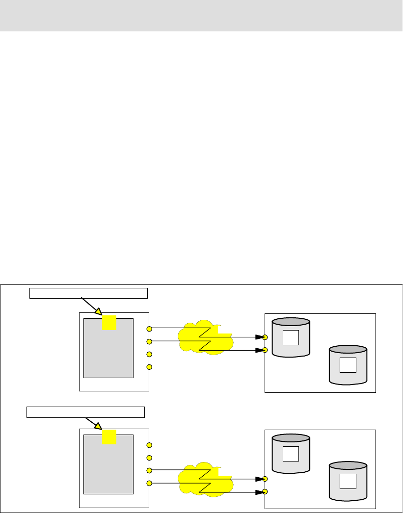
Chapter 23. Global Mirror options and configuration 275
volumes from the Global Mirror session, Global Copy keeps running and replicating newly
arrived write I/Os over the paths to the remote storage disk subsystem.
The termination of FlashCopy relationships, may be needed when you want to change the
FlashCopy targets within a Global Mirror configuration and choose, for example, another LSS
for the FlashCopy targets. This may be needed because you want to replace the FlashCopy
targets due to a skew in the load pattern in the remote storage disk subsystem. In this
situation you may pause the session before such activity, and then resume the session again
once the removal of the FlashCopy relationships is completed.
23.4 Remove a Global Mirror environment
To remove a Global Mirror environment and remove all traces of Global Mirror we
recommend the following sequence of steps:
1. Terminate the Global Mirror session.
2. Remove all Global Copy primary volumes from the Global Mirror session.
3. Close the Global Mirror session.
4. Withdraw all FlashCopy relationships between the B and C volumes.
5. Terminate all Global Copy pairs.
6. Remove the paths between the local and remote sites.
7. Remove the paths between the Master LSS and all related Subordinate LSSs.
Chapter 26, “Global Mirror examples” on page 341 has examples that illustrate how to
perform the listed steps.
23.5 Global Mirror with multiple storage disk subsystems
Figure 23-2 Define Global Mirror session to all potentially involved storage disk subsystems
Note: A pause command will complete a Consistency Group formation in progress. A stop
will immediately end the formation of Consistency Groups.
Local site
Primary
Primary
Primary
Primary
A
B
C
Primary
Primary
Primary
Primary
A
B
C
Network
Network
01
01
Define Global Mirror session
Define Global Mirror session
Remote site
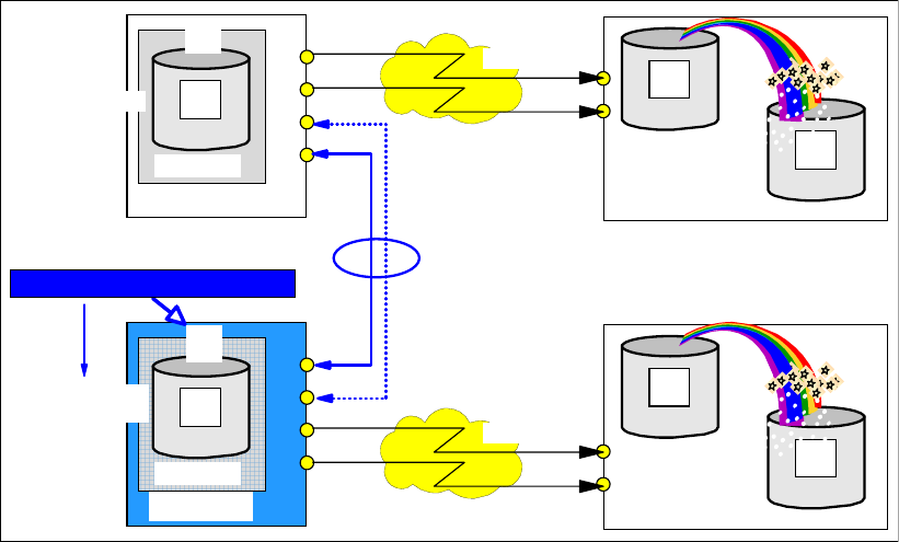
276 IBM System Storage DS6000 Series: Copy Services with IBM System z
When you create a Global Mirror environment that spans multiple storage disk subsystems at
the local site, and probably also at the remote site, then you need to establish communication
paths between the involved local storage disk subsystems.
Figure 23-2 on page 275 shows a symmetrical configuration with a one-to-one mapping. You
have to define the corresponding session, with its number, to all potentially involved LSSs at
the local site. As illustrated in Figure 23-2, there is still no connection between the two local
storage disk subsystems. Therefore, we have to define the corresponding Global Mirror
paths; see Figure 23-3.
Figure 23-3 Decide for Master storage server and start a Global Mirror session
Through the start command, you decide which LSS becomes the Master LSS and
consequently which local storage disk subsystem becomes the Master storage unit. This
Master acts indeed like a server in a client/server environment.
The required communication between the Master storage disk subsystem and the
Subordinate storage disk subsystems is inband, over the defined Global Mirror paths. This
communication is highly optimized, and minimizes any potential application write I/O impact
during the coordination phase to about a few milliseconds. For details see 22.4, “Consistency
Groups” on page 260.
Note that this communication is performed over FCP links. At least one FCP link is required
between the Master storage disk subsystem and the Subordinate storage disk subsystem.
Figure 23-4 on page 277 uses dashed lines to show the Global Mirror paths that are defined
over FCP links, between the Master storage disk subsystem and its associated Subordinate
storage disk subsystems. These FCP ports are dedicated for Global Mirror communication
between Master and Subordinates.
Also shown in Figure 23-4, is a shared port on the Master storage disk subsystem, and
dedicated ports at the Subordinates. Not considering availability, from a communications and
traffic viewpoint only, a link would be sufficient for the traffic between the Master and its
Subordinates. For redundancy, we suggest configuring two links.
Global Co
py
Start Global Mirror session
Primary
Primary
A
A
Primary
PENDING
Primary
Primary
A
A
Primary
PENDING
Primary
Primary
Primary
Primary
A
B
Secondary
C
Tertiary
PENDING
Primary
Primary
Primary
Primary
A
B
Secondary
C
Tertiary
PENDING
Network
Network
01
01
Subordinate
Master
Global Copy
paths
Remote site
Local site
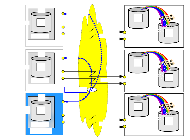
Chapter 23. Global Mirror options and configuration 277
Note that when you configure links over a SAN network, the same FCP ports of the storage
disk subsystem may be used for the Global Mirror session communication, as well as for the
Global Copy communication, and for host connectivity. However, for performance reasons,
and to prevent host errors from disrupting your Global Mirror environment, it is often a good
idea to use separate FCP ports.
Figure 23-4 Global Mirror paths over FCP links between primary storage disk subsystems
The sample configuration in Figure 23-5 shows a mix of dedicated and shared FCP ports.
Primary
Primary
A
A
Primary
PENDING
Primary
Primary
Primary
Primary
A
B
Secondary
C
Tertiary
PENDING
01
Master
Primary
Primary
A
A
Primary
PENDING
Primary
Primary
Primary
Primary
A
B
Secondary
C
Tertiary
PENDING
01
Subordinate
Primary
Primary
A
A
Primary
PENDING
Primary
Primary
Primary
Primary
A
B
Secondary
C
Tertiary
PENDING
Network
01
Subordinate
Global Copy links
GM links
Global Copy links
Global Copy links
Local site Remote site
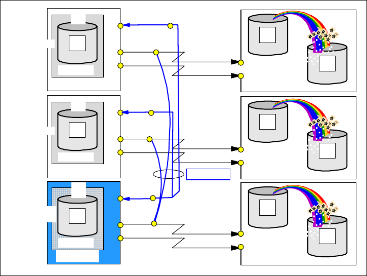
278 IBM System Storage DS6000 Series: Copy Services with IBM System z
Figure 23-5 Dedicated and shared links
In Figure 23-5 an FCP port in the Master storage disk subsystem is used as Global Mirror link
to the other two Subordinate storage disk subsystems, and is also used as Global Copy link
to the secondary storage disk subsystem. Also, there are ports at the Subordinate storage
disk subsystem that are used as Global Mirror session link as well as Global Copy link.
If possible, a better configuration is the one shown in Figure 23-6. Again, from a performance
and throughput viewpoint, you would not need two Global Mirror links between the Master
and its Subordinate storage disk subsystems. Still, dedicated ports for Global Mirror control
communication between Master and Subordinate provides a maximum of responsiveness.
Primary
Primary
A
A
Primary
PENDING
Primary
Primary
Primary
Primary
A
B
Secondary
C
Tertiary
PENDING
01
Master
Primary
Primary
A
A
Primary
PENDING
Primary
Primary
Primary
Primary
A
B
Secondary
C
Tertiary
PENDING
01
Subordinate
Primary
Primary
A
A
Primary
PENDING
Primary
Primary
Primary
Primary
A
B
Secondary
C
Tertiary
PENDING
Network
01
Subordinate
Global Copy links
GM links
Global Copy links
Global Copy links
Remote site
Local site
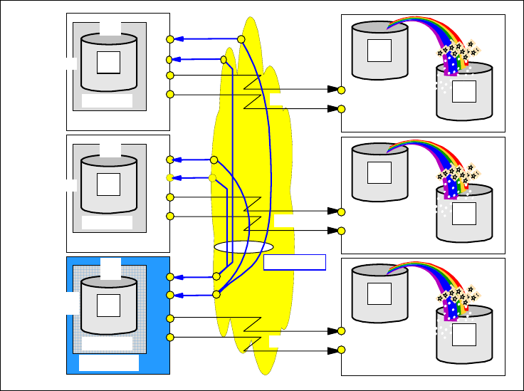
Chapter 23. Global Mirror options and configuration 279
Figure 23-6 Dedicated Global Mirror links and dedicated Global Copy links
23.6 Connectivity between local and remote site
The choice of which interface to use for Global Mirror management may depend on how the
2-site configuration is designed. A multi-host configuration allows you to configure and
manage the remote site using the host systems at the remote site. This alternative does not
require the use of inband commands. Alternatively, in a single site host configuration you can
access the remote site using the local host, when the distance does not exceed standard
FICON distance.
23.6.1 Multi-site host connectivity
Figure 23-7 on page 280 shows a configuration with hosts connected to their local disk
subsystems only. In this example there is no connection between the hosts of one site and the
storage disk subsystems of the other site. This example shows a typical 2-site disaster
recovery solution with the application host at the local site. The host at the remote site may be
a stand-by host, or a system that hosts non-critical applications and may be expanded
through CBU when a site switch from the local site to the remote site is required.
Primary
Primary
A
A
Primary
PENDING
Primary
Primary
Primary
Primary
A
B
Secondary
C
Tertiary
PENDING
01
Master
Primary
Primary
A
A
Primary
PENDING
Primary
Primary
Primary
Primary
A
B
Secondary
C
Tertiary
PENDING
01
Subordinate
Primary
Primary
A
A
Primary
PENDING
Primary
Primary
Primary
Primary
A
B
Secondary
C
Tertiary
PENDING
Network
01
Subordinate
Global Copy links
GM links
Global Copy links
Global Copy links
Remote site
Local site
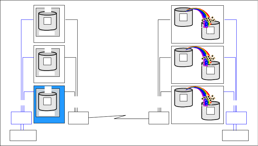
280 IBM System Storage DS6000 Series: Copy Services with IBM System z
Figure 23-7 Host connectivity at both sites
In case of a failure at the local site the host at the remote site may recover from the Global
Mirror configuration as discussed in 23.7, “Recovery scenario after primary site failure” on
page 282. Note that the host at the remote site requires a disk environment that is
independent from the Global Mirror environment.
All Global Mirror-related management commands may be executed at the respective site.
The local host may execute all commands that address the primary volumes. The remote
host may execute all the commands targeted to the secondary or tertiary volumes. From a
management viewpoint this may not be the preferable approach to managing a Global Mirror
environment.
Remote siteLocal site
Primary
Primary
A
B
Secondar y Primary
Primary
C
Tertiary
PENDING
Primary
Primary
A
B
Secondar y Primary
Primary
C
Tertiary
PENDING
Primary
Primary
A
B
Secondar y Primary
Primary
C
Tertiary
PENDING
Primary
Primary
A
A
Primary
PENDING
01
Primary
Primary
A
A
Primary
PENDING
01
Primary
Primary
A
A
Primary
PENDING
01
ISL
Host channels
Host channels Global Mirror
session links
Host
Global Copy links
FCPFICON FCP FICON
Global Mirror
session links
Host
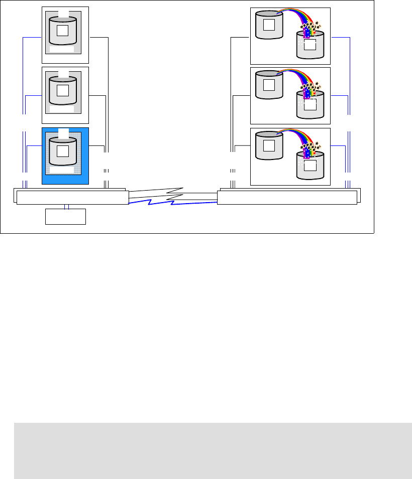
Chapter 23. Global Mirror options and configuration 281
23.6.2 Single site host connectivity
Figure 23-8 Single site host connectivity - with or without FICON connectivity between sites
Figure 23-8 shows a single host configuration example. This is again a 2-site disaster
recovery solution, although there are no hosts on one of the sites, the recovery site. Recovery
is provided at the storage disk subsystem level—data recovery.
Depending on how far apart the two sites are from each other, there are two basic
approaches to managing this configuration:
1. The sites are at FICON distance.
This allows you to connect the host to both sites and manage either site from the host via
conventional Global Mirror inband commands. Such a configuration may use cascaded
FICON directors to interconnect both sites using FICON channels. In case of a primary
site failure, limited to storage disk subsystems, the failover may be managed from the local
host. See 23.7, “Recovery scenario after primary site failure” on page 282.
2. The two sites are not interconnected over FICON due to extended distances, or the
required network technology for FICON is not available.
Global Mirror management of the remote storage disk subsystems can be done through
inband commands from the local site. This is limited to FlashCopy operations only.
Besides the TSO and ICKDSF inband FlashCopy commands, you may consider using DS
CLI commands.
Recovery operations as described in 23.7, “Recovery scenario after primary site failure”
on page 282 require host connectivity at the remote site when utilizing TSO or ICKDSF-
based Global Mirror commands. To quickly recover the remote site you may consider
using DS CLI commands, which do not require any host connectivity.
Note: This scenario is ideal for a synchronous solution, such as Metro Mirror. Metro
Mirror provides zero data loss with almost no impact to host I/O at short distances.
Additionally, Metro Mirror environments tend to be less complex than Global Mirror
environments.
Remote siteLocal site
Primary
Primary
A
B
Secondary Primary
Primary
C
Tertiary
PENDING
Primary
Primary
A
B
Secondary Primary
Primary
C
Tertiary
PENDING
Primary
Primary
A
B
Secondary Primary
Primary
C
Tertiary
PENDING
Primary
Primary
A
A
Primary
PENDING
01
Primary
Primary
A
A
Primary
PENDING
01
Primary
Primary
A
A
Primary
PENDING
01
Host
FICONFICON FCPFCP
FICON/FCP director(s) FICON/FCP director(s)
Host
channels
Global Mirror
session links
FICON Channels
Global Copy
links
ISLs
Global Mirror
session links
Host
channels
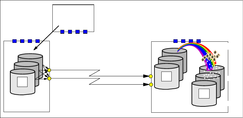
282 IBM System Storage DS6000 Series: Copy Services with IBM System z
Figure 23-8 shows more than a single FICON/FCP director at both sites, for availability
reasons. Note that the Master and Subordinate paths are defined over a local SAN fabric,
represented by the FICON/FCP directors.
23.7 Recovery scenario after primary site failure
This section covers the steps that you need to follow in a Global Mirror environment, when a
primary site failure requires you to recover at the secondary site. This discussion does not
cover the specifics concerning whether it is a single site host connectivity scenario or
multi-site host connectivity scenario, as discussed in 23.6, “Connectivity between local and
remote site” on page 279.
23.7.1 Normal Global Mirror operation
Figure 23-9 shows a simple configuration with Global Mirror active and running.
Figure 23-9 Normal Global Mirror operation
Host writes are replicated through Global Copy. Consistency Groups are created as tertiary
copies. The B volumes are Global Copy secondary volumes, and they are also FlashCopy
source volumes. The C volumes are the FlashCopy target volumes.
23.7.2 Primary site failure
A failure at the local site prevents all I/O to the local storage disk subsystems; see
Figure 23-10. This may have some impact on the formation of Consistency Groups because
the entire process is managed and controlled by the Master storage disk subsystem that is
also the primary disk subsystem—and it just failed, and cannot communicate any longer with
its partners at the remote site.
FlashCopy
Global Copy
Primary
Primary
A
Primary
Primary
A
Primary
A Primary
Primary
A
Primary
Primary
A
Tertiary
C
Primary
Primary
A
Primary
Primary
A
Secondary
B
3E00
3F00
Host
Remote siteLocal site
PENDING PENDING
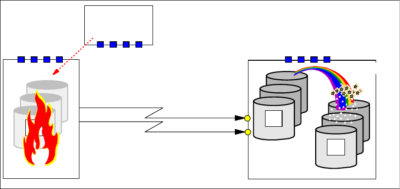
Chapter 23. Global Mirror options and configuration 283
Figure 23-10 Primary site fails
The goal is to swap to the remote site and restart the applications. This requires, first, to make
the set of consistent volumes at the remote site available for the application, before the
application can be restarted at the remote site.
Then, once the local site is back and operational again, we have to return to the local site.
Before returning to the local site, we have to apply, to the primary volumes, the changes that
the application made to the secondary data while it was running at the remote site. After this,
we should be doing a quick swap back to the local site and restart the application.
When the local storage disk subsystem fails, Global Mirror can no longer form Consistency
Groups. Depending on the state of the local storage disk subsystem, you may be able to
terminate the Global Mirror session. Usually this is not possible because the storage disk
subsystem may not respond any more. Host application I/O may have failed and the
application ended. This usually goes along with messages or SNMP alerts that indicate the
problem. With automation in place, as for example Geographically Dispersed Parallel
Sysplex™ (GDPS) or eRCMF, these alert messages trigger the initial recovery actions.
If the formation of a Consistency Group was in progress, then, most probably, not all
FlashCopy relationships between the B and C volumes at the remote site will have reached
the corresponding point-in-time. Some FlashCopy pairs may have completed the FlashCopy
phase to form a new Consistency Group, and committed the changes already. Others may
not have completed yet, and are in the middle of forming their consistent copy, and remain in
a revertible state. And there is no Master any longer to control and coordinate what may still
be going on. All of this forces a closer look at the volumes at the remote site before we can
continue to work with them. There will be more discussion of this in the following sections.
First, however, we just bring the B volumes into a usable state using the failover command.
23.7.3 Failover B volumes
Because the primary storage disk subsystem may no longer be usable, the recovery actions
and processing now occur at the remote site, using a host connected to the remote disk
subsystems. For this, you may use either TSO commands or ICKDSF.
When there is no host connected to the remote disk subsystem, you may still carry on the
necessary management activities through the Web-based GUI interface or using the DS CLI
FlashCopy
Global Copy
Primary
Primary
A
Primary
Primary
A
Tertiary
C
Primary
Primary
A
Primary
Primary
A
Secondary
B
Host
Remote site
Primary
Primary
A
Primary
Primary
A
Primary
A
PENDING PENDING
Local site
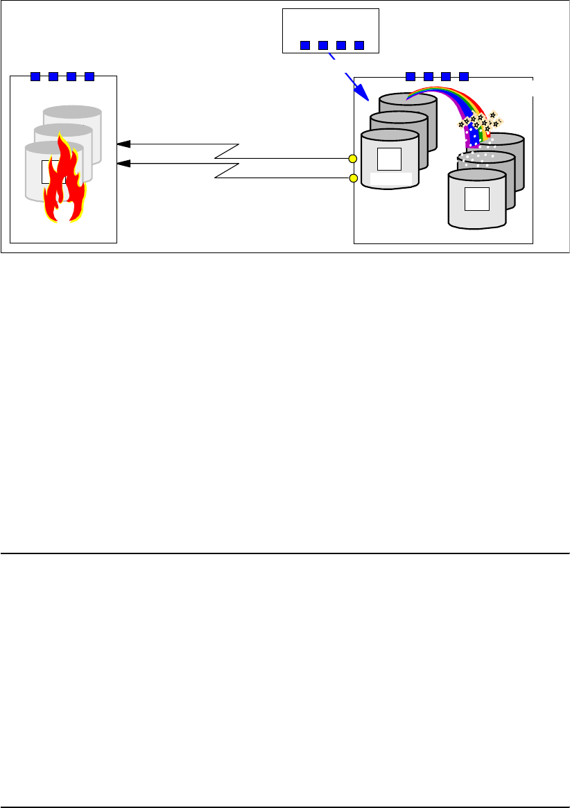
284 IBM System Storage DS6000 Series: Copy Services with IBM System z
commands. In our example, we assume that there is a host connection to the remote storage
disk subsystem; see Figure 23-11.
Figure 23-11 Failover from B to A
Doing a Failover (Copy Services Failover function) on the Global Copy secondary volumes
will turn them into primary volumes, and suspend the volumes immediately. This sets the
stage for change recording when application updates start changing the B volumes. Change
recording in turn allows you to just resynchronize the changes later from the B to the A
volumes, before returning to the local site to resume the application again at the local site. But
at this stage the B volumes do not contain consistent data—they are still useless. We just
changed their state from secondary copy pending to primary suspended. The A volumes
state remains unchanged.
Example 23-4 shows the establish command that we give at the secondary site. The key with
this command is the FAILOVER option. It is this option that invokes the Failover function of
Copy Services. After this action, the B volume becomes the primary volume, and the A
volume becomes the secondary, even though A may not be available and will remain as
primary full duplex.
Example 23-4 ESTPAIR command with Failover action
//* ---------------------------- TSO --------- FAILOVER (3) ------ ***
//* ESTABLISH GLOBAL COPY PAIR(S) FAILOVER PRIM(B) -> SEC(A) ***
//* ***
//* NOTE: ACTION IS NOT VALID WITH MODE(COPY) ***
//* -------------------------------------------------------------- ***
//EPAIRFO EXEC PGM=IKJEFT01
//SYSPRINT DD SYSOUT=*
//SYSTSPRT DD SYSOUT=*
//SYSTSIN DD DDNAME=SYSIN
CESTPAIR DEVN (X'3C00') +
PRIM (X'3C00' 73081 X'00' X'0C') +
SEC (X'2C00' 27131 X'00' X'0C') +
ACTION(FAILOVER) +
ONLINSEC(NO) MSGREQ(NO) CRIT(NO) +
OPTION(XD) CASCADE(NO)
FlashCopy
Primary
Primary
A
Primary
Primary
A
Tertiary
C
Primary
Primary
A
Primary
Primary
A
B
Host
Remote site
Primary
Primary
A
Primary
Primary
A
Primary
A
PENDING
Failover B to A
Primary
SUSPENDED
Local site
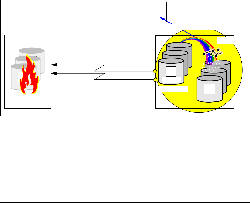
Chapter 23. Global Mirror options and configuration 285
Note that this command just changes the state of the secondary volumes from secondary
pending to primary suspended. This command does not communicate to the other storage
disk subsystem at all, even though it is specified in the SEC parameter of the command.
Once all the Failover commands are successfully executed, we can move on to the next step.
23.7.4 Check for valid Consistency Group state
Figure 23-12 Check Consistency Group state
Now you have to investigate whether all FlashCopy relationships are in a consistent state;
see Figure 23-12. This means you have to query all FlashCopy relationships between B and
C, which are part of the Consistency Group, to determine the state of the FlashCopy
relationship. Global Mirror might have been in the middle of forming a Consistency Group and
FlashCopy may not have completed the creation of a complete set of consistent C volumes.
Each FlashCopy pair needs a FlashCopy query to identify its state. Example 23-5 shows
FlashCopy query commands of four FlashCopy source volumes (B volumes).
Example 23-5 FlashCopy query of four FlashCopy relationships
TIME-09:36:44 AM. CPU-00:00:00 SERVICE-68 SESSION-00:00:00 JUNE 15,2005
READY
FCQUERY DEVN (X'6400')
FCQUERY Formatted -2
DEVN SSID LSS CCA CU SERIAL ACT MAX XC PC CC RV SEQNUM
6400 0002 00 00 1750 0000000AAVCA 1 50099 N S N N 42B03957
FCQUERY COMMAND COMPLETED FOR DEVICE 6400. COMPLETION CODE: 00
FCQUERY DEVN (X'6401')
FCQUERY Formatted -2
DEVN SSID LSS CCA CU SERIAL ACT MAX XC PC CC RV SEQNUM
6401 0002 00 01 1750 0000000AAVCA 1 50099 N S N N 42B03957
FCQUERY COMMAND COMPLETED FOR DEVICE 6401. COMPLETION CODE: 00
FCQUERY DEVN (X'6402')
FCQUERY Formatted -2
DEVN SSID LSS CCA CU SERIAL ACT MAX XC PC CC RV SEQNUM
6402 0002 00 02 1750 0000000AAVCA 1 50099 N S N N 42B03957
FCQUERY COMMAND COMPLETED FOR DEVICE 6402. COMPLETION CODE: 00
FCQUERY DEVN (X'6403')
FlashCopy
Primary
Primary
A
Primary
Primary
A
Tertiary
C
Primary
Primary
A
Primary
Primary
A
B
Host
Remote site
Primary
Primary
A
Primary
Primary
A
Primary
A
PENDING
Primary
SUSPENDED
Check Consistency Group
Local site
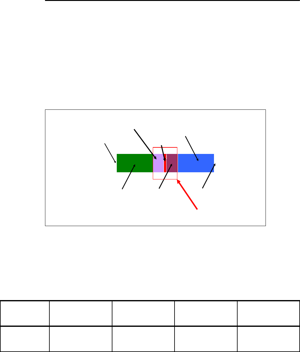
286 IBM System Storage DS6000 Series: Copy Services with IBM System z
FCQUERY Formatted -2
DEVN SSID LSS CCA CU SERIAL ACT MAX XC PC CC RV SEQNUM
6403 0002 00 03 1750 0000000AAVCA 1 50099 N S N N 42B03957
FCQUERY COMMAND COMPLETED FOR DEVICE 6403. COMPLETION CODE: 00
Example 23-5 shows, for each single FlashCopy relationship, a column titled RV, which stands
for revertible. An N indicates that this FlashCopy relationship is not revertible and all changes
are committed. All volumes show the same information for RV. The other column that you have
to check is the SEQNUM or FlashCopy sequence number. This number is also identical for all
four volumes in Example 23-5, which is good information. This leads you to conclude that:
All FlashCopy pairs are non-revertible.
All FlashCopy sequence numbers are equal.
No further action is necessary and the set of C volumes is consistent and a good copy.
Figure 23-13 shows the consistency group creation process. The action required depends on
the state of the consistency group creation process when the failure occurred.
Figure 23-13 FlashCopy consistency group creation process
Depending on when the failure occurs, there are some combinations of revertible states and
FlashCopy sequence numbers that need different corrective actions. Use Table 23-1 as a
guide. This is a decision table that is read in the following way: When column 2 and column 3
are true, then take the action in column 4. Column 5 contains additional comments. Do this
for each of the four cases. The cases are described in chronological order, starting from the
left.
Table 23-1 Consistency Group and FlashCopy validation decision table
Create consistency group by holding
application writes while creating
bitmap containing updates for this
consistency group on all volumes -
design point is 2-3ms
Maximum coordination time (eg. 10ms)
Drain consistency group and send
to remote DS using Global Copy.
Application writes for next
consistency group are recorded in
change recording bitmap
Maximum drain time – eg.1 min
Transmit updates in Global Copy mode
while between consistency groups
Consistency group interval – 0s to 18hrs
Start next consistency group
FlashCopy issued
with revertible option
FlashCopy committed
once all revertible
Flashcopies have
successfully completed Action required
All FlashCopies
revertible
Are all FC
relationships
revertible?
Are all FC sequence
numbers equal?
Action to take Comments
Case 1 NO. YES. No action needed. All
C volumes are
consistent.
CG formation ended.

Chapter 23. Global Mirror options and configuration 287
If you see a situation other than the above four situations, then the Global Mirror mechanism
has been corrupted.
Case 1: FlashCopies still committed
This indicates the situation where all FlashCopy operations have completed their task (and
the next FlashCopy operations have not been started). In this situation, we don’t need any
action to correct the FlashCopy status because we have consistent data in all C volumes.
This state is also reached after the FlashCopies are complete, and Global Mirror is waiting to
create the next Consistency Group.
Case 2: FlashCopies partially issued
In this case, there is a group of FlashCopy pairs that are all revertible and another group of
FlashCopy pairs that are all non-revertible. Consistency can be restored if these two criteria
are true:
The FlashCopy sequence number for all revertible pairs is equal.
The FlashCopy sequence number for all non-revertible pairs is also equal.
This indicates that the FlashCopy operations were interrupted. Some FlashCopy operations
for the new consistency group were started, but not all of them.
The FlashCopy relationships that have not started are in a non-revertible state and all of them
have the same FlashCopy sequence number. Other FlashCopy relationships that had already
started are in a revertible state and all of them have the same FlashCopy sequence number,
but the number is different from the sequence number of the non-revertible FlashCopy
relationships.
Case 2 SOME - Some
FlashCopy pairs are
revertible and others
are not revertible.
Revertible FlashCopy
pairs’ sequence
numbers are equal.
And non-revertible
FlashCopy pairs
sequence numbers
are equal, but do not
match the revertible
FlashCopies
sequence number.
revert FC relations. Some FlashCopy
pairs are running in a
Consistency Group
process and some
have not yet started
their incremental
process.
Case 3 YES. YES. revert to all FC
relations.
All FlashCopy pairs
are in a new
Consistency Group
process and none
have finished their
incremental process.
Case 4 SOME - Some
FlashCopy pairs are
revertible and others
are not revertible.
YES. commit FC relations. Some FlashCopy
pairs are running in a
Consistency Group
process and some
have already finished
their incremental
process.
Are all FC
relationships
revertible?
Are all FC sequence
numbers equal?
Action to take Comments

288 IBM System Storage DS6000 Series: Copy Services with IBM System z
These indications suggest that you have to return the revertible FlashCopy relationships to
the previous Consistency Group doing a FlashCopy FCWITHDR command with the REVERT
action to restore the FlashCopy relations to their prior state. You may run this command
against all volumes. As stated before, this will do nothing to the non-revertible FlashCopy
pairs but return an error message.
Case 3: FlashCopies all revertible
In the case where all of the pairs are revertible and all FlashCopy sequence numbers are
equal, this indicates that all FlashCopy operations were running and none completed their
task for the Consistency Group formation. This is indicated by the fact that all relationships
are still in a revertible state and nothing was finished and committed. Also, all were involved
in the very same Consistency Group set with identical FlashCopy sequence numbers. This
suggests to return to the previous Consistency Group.
Example 23-6 shows the TSO command FCWITHDR with the REVERT action parameter to
roll back the FlashCopy relationship between B and C to the previous Consistency Group.
Example 23-6 Withdraw Global Mirror FlashCopy relationship with ACTION(REVERT)
//* -------------------------------------------------------------- ***
//FCWITHDR EXEC PGM=IKJEFT01
//SYSPRINT DD SYSOUT=*
//SYSTSPRT DD SYSOUT=*
//SYSTSIN DD DDNAME=SYSIN
FCWITHDR SDEVN(X'6400' TDEVN(X'6500') ACTION(REVERT)
The command in Example 23-6 restores the Consistency Group to the prior state, and resets
the revertible state to NO. After this command, the FlashCopy relationship is not removed.
When the FlashCopy relationship is not in a revertible state, the withdraw operation is not
executed, as Example 23-7 shows.
Example 23-7 FlashCopy withdraw attempt with REVERT to a non-revertible state
READY
FCWITHDR SDEVN(X'6400') TDEVN(X'6500') ACTION(REVERT)
FLASHCOPY WITHDRAW DEVICE NOT IN A REVERTIBLE STATE
FCWITHDR COMMAND UNSUCCESSFUL FOR DEVICE 6400. COMPLETION CODE: 08
READY
Case 4: FlashCopies partially committed
If, at the failure point, some of the FlashCopy operations completed their task to create a
consistent copy and committed this process, they are no longer revertible. Other FlashCopy
relationships may not have completed their corresponding part of the new Consistency
Group; these are still in a revertible state. But all have the same FlashCopy sequence
number. So all were involved in the very same Consistency Group. This allows you to commit
the revertible FlashCopy relationships. To make the task easier, you may run COMMIT to all
FlashCopy pairs. Non-revertible FlashCopy relations would just return an error message.
Example 23-8 shows a FlashCopy withdraw, with ACTION(COMMIT). This commits the
FlashCopy relationship to its current state and resets the revertible state to NO. Note again,
when you issue this command to FlashCopy pairs that are not revertible any longer, you are
going to see only an error message and no action is performed.
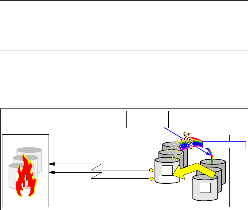
Chapter 23. Global Mirror options and configuration 289
Example 23-8 Withdraw Global Mirror FlashCopy relationship with ACTION(COMMIT)
//* -------------------------------------------------------------- ***
//FCWITHDR EXEC PGM=IKJEFT01
//SYSPRINT DD SYSOUT=*
//SYSTSPRT DD SYSOUT=*
//SYSTSIN DD DDNAME=SYSIN
FCWITHDR SDEVN(X'6400' TDEVN(X'6500') ACTION(COMMIT)
23.7.5 Set consistent data on B volumes
At this point only the C volumes comprise a set of consistent data volumes. The B volumes
per definition do not provide consistent data, because Global Copy does not provide data
consistency.
Figure 23-14 Set a consistent set of B volumes using the C volumes as source
We want to have two good copies of the data at the recovery site. The aim is to have a
consistent set of volumes to work with, still keeping a good copy to which we can resort if
needed. The next step is then to create the same consistency on the B volumes as we have
on the C volumes; see Figure 23-14. This can be achieved with the FlashCopy parameter
ACTION(FRR) in the FlashCopy establish command (FRR stands for fast reverse restore).
The DS CLI also provides this option with the reverseflash command, with the parameter
-fast.
The command with fast reverse restore is aimed to the FlashCopy target volume (C) as the
new FlashCopy source; see Figure 23-14.
Fast reverse restore (FRR) implies the following FlashCopy attributes:
Start background copy from C to B.
No change recording.
Target volume may be a Global Copy primary, which in this case is the suspended Global
Copy primary volume. This is needed because when we previously executed the Failover
function, we changed the Global Copy secondary from pending to primary suspended.
Not persistent, which ends this FlashCopy relationship once the background copy
completes. This allows you to check that all FRR operations completed before moving on
to the next step.
Primary
Primary
A
Primary
Primary
A
Tertiary
C
Primary
Primary
A
Primary
Primary
A
B
Host
Remote site
Primary
Primary
A
Primary
Primary
A
Primary
A
PENDING
Primary
SUSPENDED
FRR FlashCopy
Local site

290 IBM System Storage DS6000 Series: Copy Services with IBM System z
FRR replicates all data from C to B making a physical copy of C, with some exceptions. Note
that the previous nocopy relationship between B and C caused some I/Os from B to C.
Changed tracks between two Consistency Group creation points will be preserved on the C
volume after being copied over from the B volumes before they change there.
These tracks arrive at the C volume between Consistency Group formation and do not
contribute to a consistent state because not all required data is physically on the C volume.
So after the FRR-triggered background copy from C to B completes, the C volume is actually
not usable. You need another step to establish another FlashCopy from B to C to make both
volumes really identical. This FlashCopy may be the one you use to create a Global Mirror
environment and is going to position the Global Mirror session for a following restart.
But first we perform the FRR from C to B. Example 23-9 illustrates how to do it when using
TSO commands.
Example 23-9 Create a consistent set of B volumes
//* ---------------------------- TSO ------------- FAILOVER (4) -- ***
//* FLASHCOPY C -> B FAST REVERSE RESTORE (BACKGROUND COPY C -> B) ***
//* 3E00 -> 3C00 ***
//* ***
//* NOTE: WAIT TILL ALL BACKGROUND COPIES COMPLETED BEFORE CONT. ***
//* NOTE: FRR DOES NOT ALLOW REMOTE(YES) ***
//* -------------------------------------------------------------- ***
//FCFRR EXEC PGM=IKJEFT01
//SYSPRINT DD SYSOUT=*
//SYSTSPRT DD SYSOUT=*
//SYSTSIN DD DDNAME=SYSIN
FCESTABL SDEVN(X'3E00') TDEVN(X'3C00') ACTION(FRR)
Note that the FlashCopy source volume for this command is the former FlashCopy target
volume and vice versa. ACTION(FRR) combines all particular FlashCopy attributes for this
action into this single parameter.
You have to wait until all FRR operations complete successfully, before proceeding with the
next step. Note that when the background copy completes, the FlashCopy relation will end.
This is what you may query to determine when all FRR operations are complete.
23.7.6 Reestablish the FlashCopy relationship between B and C volumes
In this step you establish the former FlashCopy relationship between the B and C volumes, as
it was at the beginning when you set up the Global Mirror environment. This step is in
preparation for returning later to production at the local site. The command at this step,
illustrated in Example 23-10, is exactly the same FlashCopy command you may have used
when you initially created the Global Mirror environment. See 22.3.4, “Introduce FlashCopy”
on page 257.
Example 23-10 Reestablish FlashCopy between B and C volume with MODE(ASYNC)
//* ---------------------------- TSO ------------ CREATE (3) ----- ***
//* FLASHCOPY B -> C START CHANGE RECORDING NOCOPY ETC. THROUGH ***
//* MODE(ASYNC) OPTION (GET READY FOR GM) ***
//* -------------------------------------------------------------- ***
//* SOURCE AND TARGET REQUIRED ***
//* -------------------------------------------------------------- ***
//FCESTBL EXEC PGM=IKJEFT01
//SYSPRINT DD SYSOUT=*
//SYSTSPRT DD SYSOUT=*

Chapter 23. Global Mirror options and configuration 291
//SYSTSIN DD DDNAME=SYSIN
FCESTABL SDEVN(X'3C00') TDEVN(X'3E00') MODE(ASYNC)
Now you may restart the applications at the remote site using the B volumes. Note the B
volumes are Global Copy primary volumes in suspended state, which implies that change
recording takes place. Later this allows you to resynchronize from B to A, before returning to
the local site.
Eventually, here you may also decide to create another copy of this consistent set of
volumes, and create D volumes, or preserve this set of consistent volumes on tape. When
you create the D volumes, this is just a plain FlashCopy command. Example 23-11 shows an
example with the B volume as FlashCopy source and a new D volume as FlashCopy target.
Example 23-11 Create another set of consistent data volumes
//* ---------------------------- TSO ------------ CREATE (5) ----- ***
//* FLASHCOPY B -> D TO CREATE COPY TO WORK (TEST) WITH ***
//* -------------------------------------------------------------- ***
//FCESTBL EXEC PGM=IKJEFT01
//SYSPRINT DD SYSOUT=*
//SYSTSPRT DD SYSOUT=*
//SYSTSIN DD DDNAME=SYSIN
FCESTABL SDEVN(X'3C00') TDEVN(X'3E02')
Note that this is a full volume FlashCopy. This is because at a previous step we reestablished
the FlashCopy relationship between B and C, indicating it was part of a Global Mirror
environment. This indication carries the start change recording attribute, which implies that
you can only use the same source volume for full volume FlashCopy—only a single
incremental relationship is allowed per source volume.
In a disaster situation you might use the MODE(COPY) for the FlashCopy from B to C, to
remove the FlashCopy I/O overhead of MODE(ASYNC), which implies start change
recording or incremental FlashCopy.
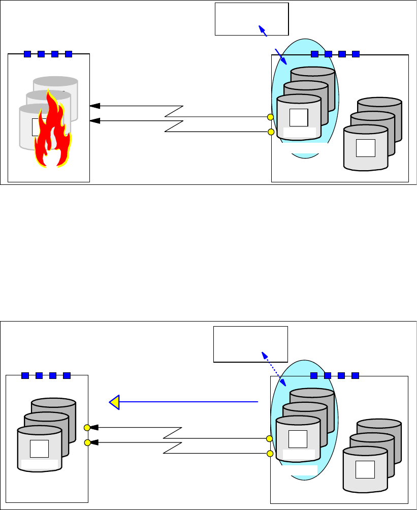
292 IBM System Storage DS6000 Series: Copy Services with IBM System z
23.7.7 Restart the application at the remote site
At this stage you may restart the application at the remote site and work with the consistent
set of B volumes; see Figure 23-15.
Figure 23-15 Restart applications at remote site
Note the primary suspended state of the B volumes, which implies change recording and
indicates the changed tracks on the B volumes.
When the local site is about to become ready to restart the applications again and resume the
operations, you prepare the remote site for the next step.
23.7.8 Prepare to switch back to the local site
Figure 23-16 Failback operation from B to A in preparation for returning to local site
The local site is back and operative again. We assume that the local site did not lose the data
at the time when the swap to the remote site was done. It is then possible to resynchronize
the changed data from B to A before restarting the application at the local site. This is
accomplished doing a Failback operation (Copy Services Failback function) from B to A; see
Figure 23-16.
Global Copy
Primary
Primary
A
Primary
Primary
A
Tertiary
C
Primary
Primary
A
Primary
Primary
A
B
Remote site
Primary
Primary
A
Primary
Primary
A
Primary
A
PENDING
Host
Primary
SUSPENDED
Restart applications
Local site
Global Copy Primary
Primary
A
Primary
Primary
A
Tertiary
C
Primary
Primary
A
Primary
Primary
A
B
Remote site
Host
Primary
Failback B to A
Primary
Primary
A
Primary
Primary
A
A
PENDING
Secondary PENDING
Resync from B to A
Local site
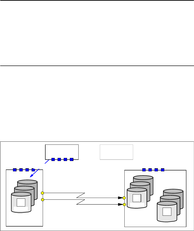
Chapter 23. Global Mirror options and configuration 293
Note that the Failback operation is issued to the B volumes as the primary and the A volumes
as the secondary. This command changes the A volume from its previous primary pending
state to secondary pending and starts the resynchronization of the changes from B to A.
Before doing the Failback operation, ensure that paths are established from the remote site
LSS to its corresponding LSS at the local site. Note that with Fibre Channel links you can
define paths in either direction on the very same FCP link. During the Failback operation the
application stays running at the remote site to minimize the application outage.
Example 23-12 shows a TSO command example for doing the Failback operation.
Example 23-12 Failback operation from B to A before returning to the local site
//* ----------------------- FAILBACK B -> A -------------------- ***
//EPAIRFB EXEC PGM=IKJEFT01
//SYSPRINT DD SYSOUT=*
//SYSTSPRT DD SYSOUT=*
//SYSTSIN DD DDNAME=SYSIN
CESTPAIR DEVN (X'3C00') +
PRIM (X'3C00' 73081 X'00' X'0C') +
SEC (X'2C00' 27131 X'00' X'0C') +
ACTION(FAILBACK) +
ONLINSEC(NO) MSGREQ(NO) CRIT(NO) +
OPTION (XD) CASCADE(NO)
A remark on the ONLINSEC parameter here: with ONLINSEC(NO) a verification is done to
check whether any connected system has the secondary volume, here device number 2C00,
online. If the path group information in the storage disk subsystem reflects that a system has
this volume online, the CESTPAIR command will not be executed. This is a safety precaution
and protects you from overwriting an online volume by accident. On the other side, there may
be a z/VM system, for example, which has this volume also defined, and is IPLed with this
device as online during startup. The TSO commands executed in another z/OS system will
fail the CESTPAIR.
23.7.9 Return to local site
Figure 23-17 Failover from A to B
Global Copy Primary
Primary
A
Primary
Primary
A
Tertiary
C
Primary
Primary
A
Primary
Primary
A
B
Remote siteLocal site
Host
Primary
Primary
Primary
A
Primary
Primary
A
A
PENDING
Host
Primary
SUSPENDED
Failover A to B
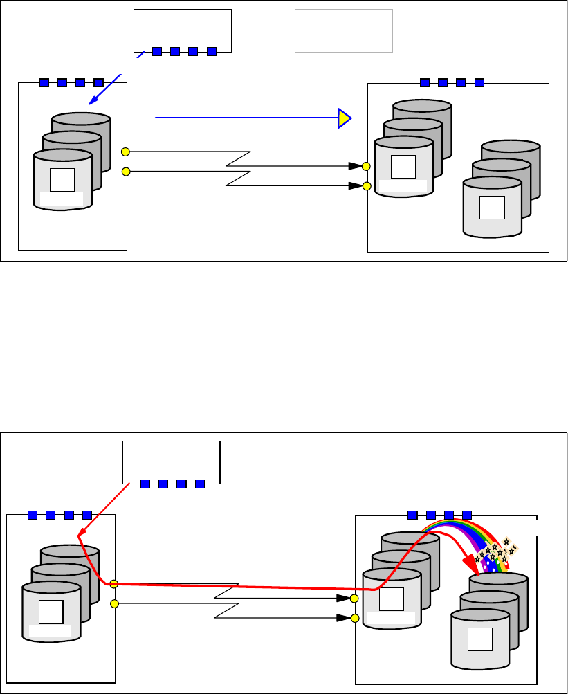
294 IBM System Storage DS6000 Series: Copy Services with IBM System z
Once the local site is ready, quiesce the application at the remote site. Then a sequence of
Failover - Failback operations from A to B will reestablish Global Copy back as it was
originally before the local site outage.
Figure 23-17 shows the action at the local site, the Failover operation from A to B. This will
change the state of the A volumes from secondary pending to primary suspended, and start
to keep a bitmap record of the changes to the A volumes.
Once the Failover is completed, a Failback operation from A to B is done; see Figure 23-18.
Figure 23-18 Failback from A to B and resync Global Copy volumes
Figure 23-18 shows the Failback operation at the local site. This will change the state of the B
volumes from primary pending to secondary pending, and start to replicate updates from A to
B.
In our example, the application did not start yet at this point, so there are no updates at the
local site. The state of the local volumes A will quickly change from primary suspended to
primary pending, which is the normal state for Global Copy pairs.
Figure 23-19 Establish Global Mirror FlashCopy relationship between B and C
Global Copy Primary
Primary
A
Primary
Primary
A
Tertiary
C
Primary
Primary
A
Primary
Primary
A
B
Remote site
Host
Primary
Primary
A
Primary
Primary
A
A Secondary
PENDING
Resync from A to B
Host
Primary
PENDING
Failback A to B
Local site
Global Copy Primary
Primary
A
Primary
Primary
A
Tertiary
C
Primary
Primary
A
Primary
Primary
A
B
Remote site
Primary
Primary
A
Primary
Primary
A
A Secondary
PENDING
Host
Primary
PENDING
FlashCopy
Local site
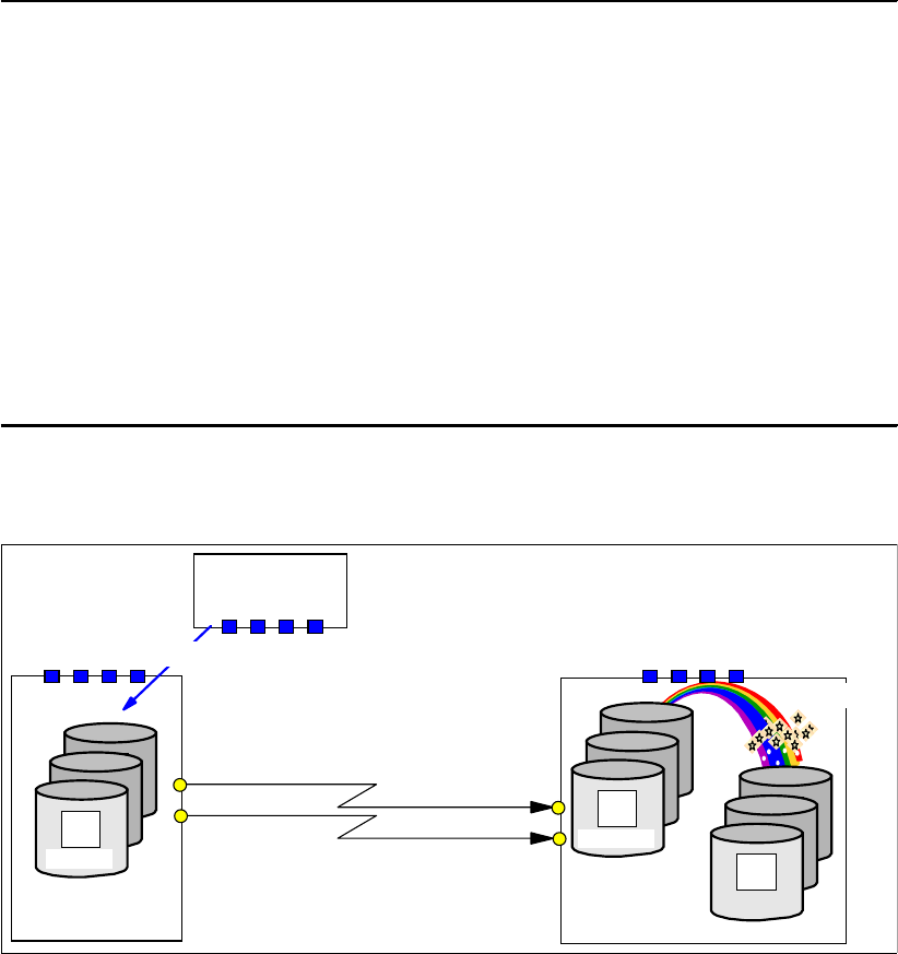
Chapter 23. Global Mirror options and configuration 295
Last but not least, if you did not already establish the FlashCopy relationship from B to C
during the Failover - Failback sequence at the remote site, then you have to do it now. This
may be an inband FlashCopy as shown in Figure 23-19.
A TSO command example is provided in Example 23-13.
Example 23-13 Establish FlashCopy from B to C via inband TSO command
//* ---------------------------- TSO ------------ CREATE (3) ----- ***
//* FLASHCOPY B -> C START CHANGE RECORDING NOCOPY ETC. THROUGH ***
//* MODE(ASYNC) OPTION (GET READY FOR GM) ***
//* -------------------------------------------------------------- ***
//* Inband Command 2C00 is Global Copy primary ***
//* LSS 0C CAA 00 is Global Copy secondary ***
//* and FlashCopy source ***
//* LSS 0D CAA 00 is FlashCopy target ***
//* -------------------------------------------------------------- ***
//FCESTBL EXEC PGM=IKJEFT01
//SYSPRINT DD SYSOUT=*
//SYSTSPRT DD SYSOUT=*
//SYSTSIN DD DDNAME=SYSIN
FCESTABL DEVN(X'2C00') SOURCE(73081 00 0C) +
TARGET(73081 00 0D) +
REMOTE(YES) SSID(3C00) MODE(ASYNC)
The last step is to start the Global Mirror session again, as shown in Figure 23-20. Then the
application may resume at the local site.
Figure 23-20 Start Global Mirror session and resume application I/O at the local site
Global Copy Primary
Primary
A
Primary
Primary
A
Tertiary
C
Primary
Primary
A
Primary
Primary
A
B
Remote siteLocal site
Primary
Primary
A
Primary
Primary
A
A Secondary
PENDING
Host
Primary
PENDING
Start session
FlashCopy
296 IBM System Storage DS6000 Series: Copy Services with IBM System z
23.7.10 Conclusions
This concludes the sequence of steps you have to go through for a swap to the remote site
and coming back to the local site after service is restored at the local site.
In particular, the check on a valid Consistency Group after a primary site failure is a challenge
when you consider a large configuration with many volume pairs. Each command usually
addresses a single pair of volumes. When you have a large quantity of volume pairs, this
requires automation, for example, to check all the FlashCopy relationships after a primary site
failure. Note that for a planned site swap, you may not have to check for a valid Consistency
Group because, through a proper command sequence and verifying their successful
completion, the possibility of an inconsistent group of C volumes is minimal.
Global Mirror is a 2-site solution that can bridge any distance between two sites. There are
ready-to-use packages and services available to implement a disaster recovery solution for
2-site remote copy configurations. IBM offers the GDPS and eRCMF service offerings to
deliver solutions in this area; see Part 8, “Solutions” on page 431, for more information. You
can also visit the IBM Web site and see the Services & Industry Solutions page for more
information.

© Copyright IBM Corp. 2006. All rights reserved. 297
Chapter 24. Global Mirror interfaces
In this chapter we provide an overview of the interfaces you can use to manage and control
Global Mirror environments. We explain the TSO command support for Global Mirror. We
also discuss the use of the DS CLI for managing a Global Mirror configuration in a System z
environment, and provide examples. Then we describe the ICKDSF utility and the ANTRQST
macro support. Finally, we also discuss the DS Storage Manager Web-based graphical user
interface (GUI), which may also be used for Global Mirror management.
The information discussed here can be complemented with the following sources:
Part 2, “Interfaces” on page 15
Chapter 9, “FlashCopy interfaces” on page 69
Chapter 20, “Global Copy interfaces” on page 221
The examples presented in Chapter 26, “Global Mirror examples” on page 341
Chapter 31, “IBM TotalStorage Productivity Center for Replication” on page 467
z/OS DFSMS Advanced Copy Services, SC35-0428
Device Support Facility User’s Guide and Reference, SC35-0033
IBM System Storage DS6000: Command-Line Interface User´s Guide, GC26-7922
24
298 IBM System Storage DS6000 Series: Copy Services with IBM System z
24.1 Global Mirror interfaces - overview
Global Mirror combines Global Copy and FlashCopy, which work together in an autonomic
fashion under microcode control. There are commands intended for Global Copy and
FlashCopy, as well as commands that address Global Mirror sessions. All of them can be
managed with the following interfaces:
TSO commands
DS CLI commands
ICKDSF utility commands
DS SM Web-based GUI
ANTRQST macro
Here we give an overview and examples of the use of these interfaces when managing a
Global Mirror environment. They are also covered in Part 2, “Interfaces” on page 15.
TotalStorage Productivity Center for Replication (TPC for Replication) provides management
of DS6000 series business continuance solutions, including FlashCopy, Metro Mirror, and
Global Mirror. TPC for Replication is covered in Chapter 31, “IBM TotalStorage Productivity
Center for Replication” on page 467. TPC for Replication includes functions similar to Global
Mirror Utility (GMU). GMU users should consider migrating to TPC for Replication.
24.2 Different interfaces for the same function
In this section we show how the same results can be achieved using the different interfaces.
The examples provide a first impression of the interfaces and give you an idea of their
usability and how they look and feel.
Also, with the examples, you will see that there are differences not only in the look and feel of
the different interfaces, but also in the options, parameters, and attributes used to get the
same results. For example, FlashCopy within Global Mirror needs the attributes NOCOPY,
INHIBIT TARGET WRITE, and START CHANGE RECORDING, but these particular
attributes are not explicitly available in all interfaces. For example, the TSO command to
create such a particular FlashCopy relationship for Global Mirror combines these three
attributes into a single parameter, the MODE(ASYNC) option.
The examples used here show how to establish the FlashCopy relationship between the B
and C volumes; see Figure 24-1 on page 299. Note that this is only one step out of the five or
six steps to establish a Global Mirror environment.
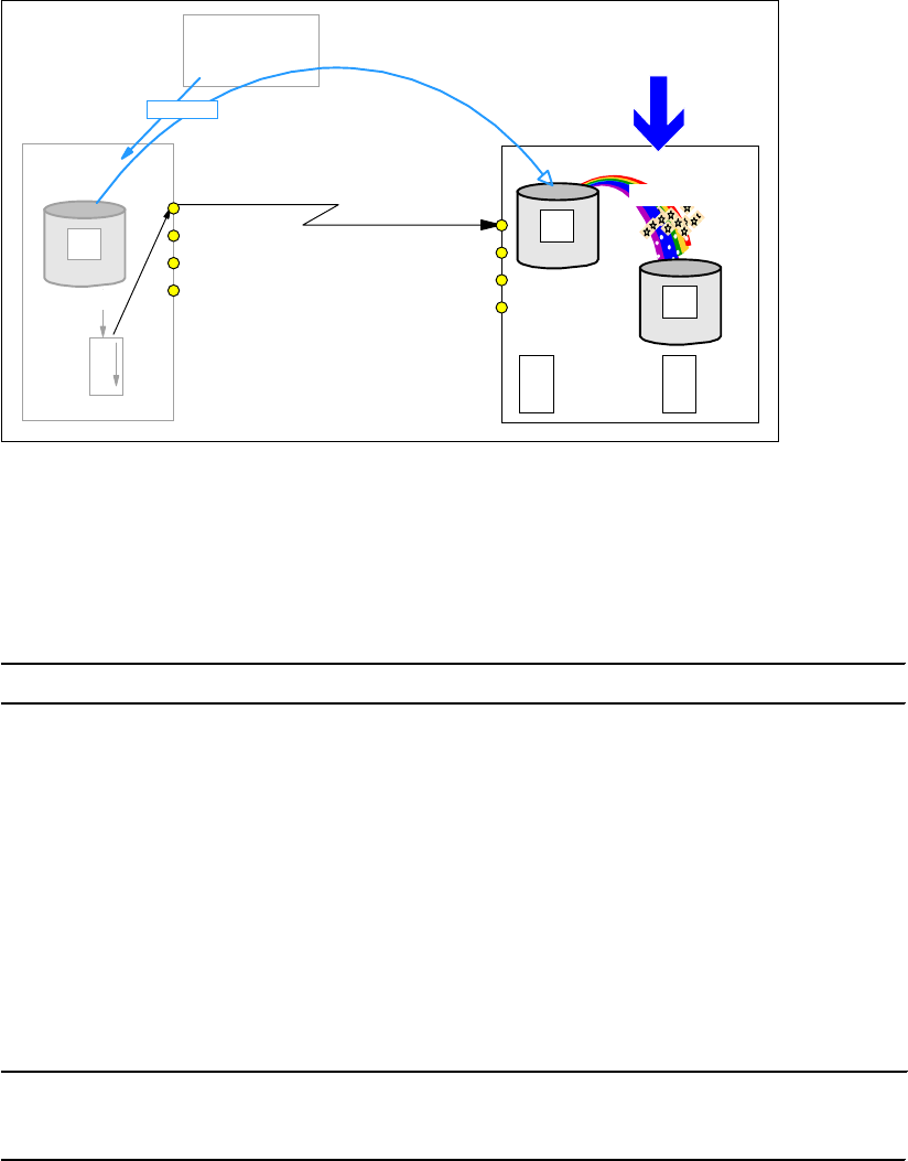
Chapter 24. Global Mirror interfaces 299
Figure 24-1 Establish FlashCopy relationship within Global Mirror
24.2.1 Establish FlashCopy using TSO
Example 24-1 shows the TSO command that creates the FlashCopy relationship between the
B and the C volumes.
Example 24-1 Establish FlashCopy between B and C volumes using a TSO command
FCESTABL SDEVN(X'3C00') TDEVN(X'3E00') MODE(ASYNC)
In the FCESTABL command, the source and target volumes are identified by their z/OS device
number. This does not require any further information, such as serial numbers or WWNNs,
nor does it need to identify an SMC to address the function. The MODE(ASYNC) parameter
implicitly combines all necessary attributes for this FlashCopy relationship: START CHANGE
RECORDING, INHIBIT TARGET WRITE, and NOCOPY.
Example 24-2 shows the inband version of this FlashCopy command when the FlashCopy is
triggered from the local site. Here the FlashCopy command is issued to the Global Copy
primary volume at the local site, and then propagated inband over the paths to the remote
site. Note that this example assumes that the Global Copy paths and pairs have already been
established.
Example 24-2 inband TSO command to create a FlashCopy between B and C
FCESTABL DEVN(X'2C00') SOURCE(73081 00 0C) +
TARGET(73081 00 0E) +
REMOTE(YES) SSID(3C00) MODE(ASYNC)
There is no change for the FlashCopy attributes. The only addition is the addressing of the
Global Copy primary volume with the z/OS device address in the DEVN parameter, and the
identification of the FlashCopy source and target volumes at the remote site, with the
corresponding SOURCE and TARGET parameters. You use inband commands when there is
no host channel connection from the local server to the remote storage disk subsystem.
Example 24-2 assumes that there is a Fibre Channel connection from the local to the remote
storage disk subsystem. It also assumes that the remote devices are defined and configured
in the system from where you issue the command.
Global Copy
Primary
Primary
Primary
A
A Primary
Primary
Primary
Primary
Primary
A
B
O
O
S
Host
Remote
site
Local
site
Primary Secondary
PENDING
PENDING
Write I/O
FlashCopy
C
MODE(ASYNC)
Tertiary
T
B
M
S
B
M
TBM: Target Bit Map
SBM: Source Bit Map

300 IBM System Storage DS6000 Series: Copy Services with IBM System z
24.2.2 Establish FlashCopy using DS CLI
Example 24-3 shows how to create the FlashCopy relationship between the B and the C
volumes using the DS CLI command mkflash.
Example 24-3 Create FlashCopy between B and C volumes using DS CLI
dscli mkflash -record -persist -nocp -seqnum 0000 6500:6502 -cfg
$DSCLI/profile/DS8300-box2.profile
The mklfash DS CLI command identifies the B and the C volumes through additional
information that is found in a configuration file, which usually contains the serial number of the
storage disk subsystems.
Example 24-4 shows an example of how this configuration file looks for commands to be run
in a DS8000 environment. In this case, it indicates that the commands have to go through the
HMC, which is identified by its corresponding IP address. For a DS6000 it also identifies the
external SMC with the necessary software stack to handle the Copy Services commands.
Example 24-4 Content of the -cfg file $DSCLI/profile/DS8300-box2.profile
hmc1: 192.168.93.14
username: Jack
password: Stor123agE
devid: IBM.2107-7573731
remotedevid: IBM.2107-7506551
For simplicity, a required user ID and password is specified in plain text. Administrators of the
storage disk subsystem have to set up a user ID and password for users who want to work
through the SMC. This information is usually hidden in an encrypted password file.
Example 24-5 shows the creation of a FlashCopy relationship. The source volume and target
volume are indicated by the LSS and device number pair 6500:6502. It also indicates the start
change recording attribute, which actually implies the persistent attribute. It also indicates the
nocopy option. An optional FlashCopy sequence number makes it simpler to refer to this
FlashCopy relationship in further commands. Note that you may either put the configuration
information in the DS CLI command as Example 24-4 shows, or use the configuration file as
explained previously.
Example 24-5 Create FlashCopy between B and C with DSCLI and explicit device specifications
dscli mkflash -record -persist -nocp -seqnum 0000 6500:6502 -dev ibm.2107-7573731-remotedev
ibm.2107-7506551
As shown here in Example 24-6, an inband triggered FlashCopy would require a different DS
CLI command, mkremoteflash.
Example 24-6 Inband FlashCopy between B and C with DS CLI
dscli mkremoteflash -dev ibm.2107-7506551 -conduit ibm.2107-7573731/00 -tgtinhibit -record
-nocp -seqnum 0000 6500:6502
The parameter -conduit is equivalent to the DEVN TSO parameter in Example 24-2 on
page 299. With it you select the primary volume at the local site to where the command is
addressed. Note that the DS CLI has to go through an SMC, whereas the TSO commands
are directly targeted to the storage disk subsystems by means of the host channel
connection.

Chapter 24. Global Mirror interfaces 301
24.2.3 Establish FlashCopy using ICKDSF
ICKDSF is usually the interface that is used to manage remote copy configurations in z/VM
and z/VSE environments. It is a batch-oriented approach and requires the JCL to invoke
ICKDSF. Example 24-7 shows the FlashCopy command used to create a Global Mirror
FlashCopy relationship.
Example 24-7 Create FlashCopy between B and C using ICKDSF
//* -------------------------------------------------------------- ***
//FCBTOC EXEC PGM=ICKDSF
//SYSPRINT DD SYSOUT=*
//SYSIN DD *
FC UNIT(3C00) ESTABLISH -
TARGETVOL (X'0E',X'00',3E00) -
CHRCD (YES) -
NOTGTWT (YES) -
MODE (NOCOPY)
ICKDSF also lists the individual attributes that are required to create a FlashCopy relationship
for Global Mirror.
Example 24-8 shows an inband FlashCopy that is given with ICKDSF at the local site, and
addresses the remote site.
Example 24-8 Inband FlashCopy between B and C using ICKDSF
//* -------------------------------------------------------------- ***
//FCBTOCIN EXEC PGM=ICKDSF
//DD01 DD UNIT=3390,VOL=SER=AA6000,DISP=SHR
//SYSPRINT DD SYSOUT=*
//SYSIN DD *
FC DDNAME(DD01) ESTABLISH -
SRCVOL (X'00',X'00',X'0002' AAVCA) -
TGTVOL (X'00',X'00',6500) -
CHRCD (YES) /* CHANGE RECORDING */ -
NOTGTWR (YES) /* INHIBIT TARGET WRITES */ -
MODE (NOCOPY) /* NO BACKGROUND COPY */ -
TGTCANCOMEONLINE (NO)
Note the syntax variation in the SRCVOL and TGTVOL parameters, when hex notation is
used and when it is not used. In the SRCVOL parameter, the serial number of the storage
disk subsystem is not in hex notation, but all the other parameters are. The TGTVOL
parameters are also in hex notation, except for the z/OS device number of the FlashCopy
target volume.
24.2.4 Which interface to choose
Which interface you choose depends on your preferences and the experience you gathered
in the past. In our examples, we left out the DS Storage Manager GUI, which is another
alternative. A fully automated solution such as GDPS relieves you of the decision as to which
interface to use to manage the Global Mirror environment.
When you set up your own Global Mirror management package, you have the choice of which
interface to use.
302 IBM System Storage DS6000 Series: Copy Services with IBM System z
TSO commands
TSO commands are submitted using an inband approach over the host channel directly to the
storage disk subsystem. No active SMC or DS SM is required to trigger Copy Services
functions.
You can issue the TSO commands from procedures that are similar to the scripting approach
in open systems environments.
Note that TSO requires a z/OS system at the recovery site when you recover a Global Mirror
environment at the remote site.
DS CLI
The strength of DS CLI is its scripting capability. You can easily create and modify script files.
From a syntax level, the DS CLI looks a bit more complicated, and it tends to extend single
lines for single commands, which makes it harder to read when you have to maintain such
script files. Again, this may be a matter of experience.
ICKDSF
ICKDSF is the only direct interface for z/VM and z/VSE environments. It is also very quick,
just as the TSO commands are, because it does not need other components and networks
in-between to trigger Copy Services functions.
DS Storage Manager
The DS Storage Manager provides a Web-based graphical user interface (GUI), which
makes it friendly and user oriented. It is best suited for when you need to perform ad hoc
actions, and creating a script would be too time-consuming. It is not the best choice when you
have to set up a big and complex Global Mirror environment.
ANTRQST Macro
We do not cover the ANTRQST macro here. This macro is used by software automation
routines to provide full function management of Global Mirror. GDPS is an example.
Again, it is mostly your choice, depending on personal preferences and experience. When
you have no bias, we consider TSO commands the preferable interface for managing Global
Mirror in a z/OS environment. Through the inband approach over host channels and without
other agents in-between, TSO commands execute very quickly. The TSO command syntax is
also rather simple. TSO is an integral part of z/OS standard software, which stands for
reliability, availability, and serviceability.
24.3 Global Mirror management using TSO commands
TSO commands are commonly used in z/OS environments to manage remote copy
configurations. TSO commands may also be executed from REXX or CLIST procedures.
TSO commands have the advantage that they do not need a DS6000 SMC, nor an ad hoc
storage management server. They are directly forwarded, via an inband approach, to the
storage disk subsystem. This happens over the host channel connection, which usually is
FICON. This inband characteristic allows a very quick command transfer—it does not have to
go through software stacks in the storage server microcode.
When working with Copy Services, TSO commands generally use a z/OS device number to
aim for the device, LSS, or storage disk subsystem. Still, with Global Mirror, TSO commands
require an online VOLSER as a parameter.
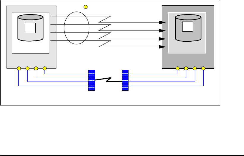
Chapter 24. Global Mirror interfaces 303
24.3.1 Establish a Global Mirror environment
The following sections discuss the setup of a Global Mirror environment using TSO
commands in a step-by-step approach. The sequence of steps in our example is the
recommended one, although it is not a mandatory one. Still, it guarantees a clean and
straightforward creation of the Global Mirror environment.
24.3.2 Define paths
When you establish Global Copy relationships between volume pairs, you have to first
establish the Global Copy paths. A Global Copy path, similar to a Metro Mirror path, is the
logical definition of the connectivity between two LSSs, the primary LSS and the secondary
LSS. This definition is accomplished upon an available physical Fibre Channel link that
connects the primary and secondary storage disk subsystems where the corresponding LSSs
are. More than one path can be defined over a single Fiber Channel link. You can also define
paths in either direction on the very same physical link.
The FCP links that provide the physical support for the logical path definitions are either
direct-connected or can use the SAN infrastructure. In the latter case, the FCP ports can be
shared with either other remote copy connections or with host connections. Still, you may
consider dedicated ports, thus separating host I/O from remote copy I/O, which is
recommended for Metro Mirror. For Global Copy and Global Mirror it is feasible to consider an
FCP port sharing approach.
Figure 24-2 shows two LSSs, one on each storage disk subsystem, with both storage disk
subsystems connected either directly or over the SAN. The figure shows four physical links,
each link connecting to an FCP port. Because the storage disk subsystems are separated
over a large distance, these links are either going through an SAN network, or over an
IP-based network. There is no distance limit for a Global Mirror configuration.
Figure 24-2 Paths definition between two LSS
Example 24-9 shows the TSO command that is used to define the four logical paths, at once,
between the primary LSS and the secondary LSS. If using TSO commands, there is no
change in how to define a path on the DS6000 or the DS8000, as compared to the ESS 800.
Example 24-9 Define logical paths
//* ---------------------------- TSO ------------ CREATE (1) ----- ***
//* ESTABLISH PATH(S) ***
//* -------------------------------------------------------------- ***
FCP port
Fiber Channel links
physical connections
DWDM or Channel Extender
network
infrastructure
LCU: 2C00
Primary
A
2C00
LCU: 3C00
Secondary
B
3C00
paths
between LSSs
logical connections
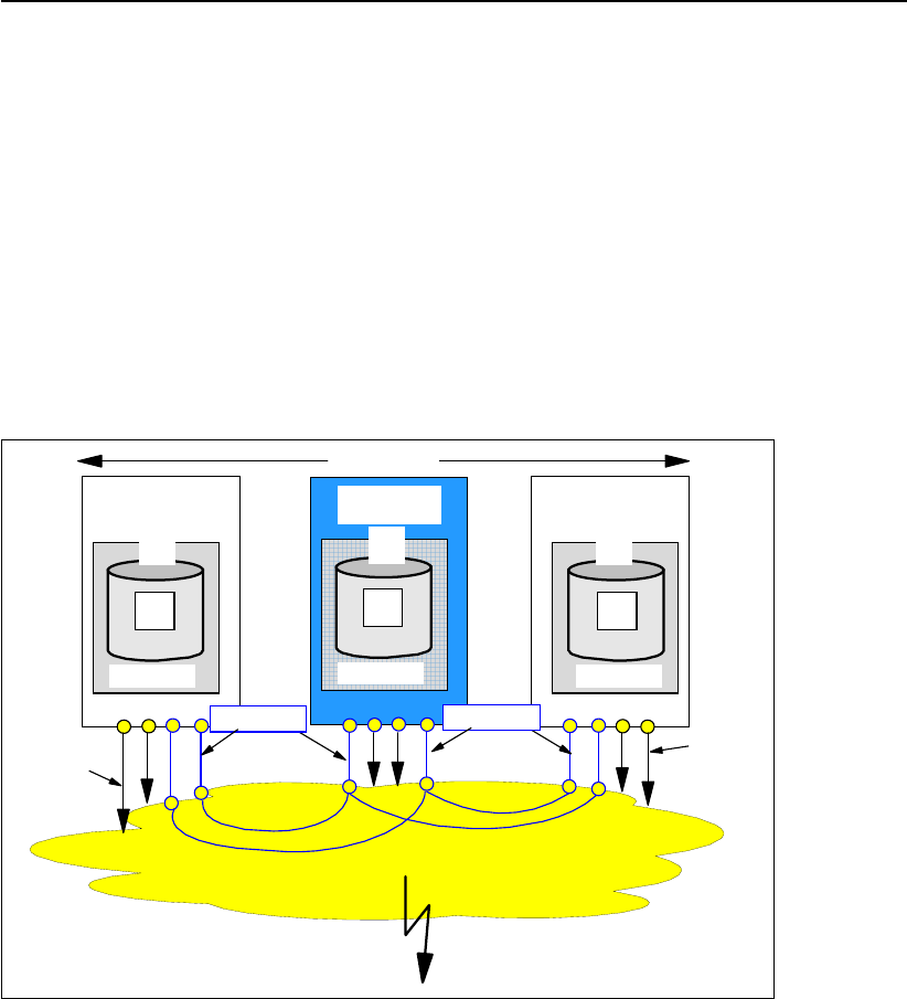
304 IBM System Storage DS6000 Series: Copy Services with IBM System z
//EPATHS EXEC PGM=IKJEFT01
//SYSPRINT DD SYSOUT=*
//SYSTSPRT DD SYSOUT=*
//SYSTSIN DD DDNAME=SYSIN
CESTPATH DEVN (X'2C00') +
PRIM (X'2C00' 5005076303FFC228 X'0C') +
SEC (X'3C00' 5005076303FFC422 X'0C') +
LINK (X'00300030' X'01300130' +
X'02300230' X'03310330') CGROUP(NO)
CQUERY DEVN (X'2C00') PATHS
Primary and secondary LSSs are identified by their respective subsystem IDs (SSIDs), the
WWNN of the storage disk subsystem, and the LSS number. The LINK parameter contains
the System Adapter ID (SAID), the source port ID, and the target port ID. A path definition
connects two individual LSSs. For each LSS pair you repeat the command, each time
adjusting the SSID and LSS numbers accordingly. Note that for Global Copy it does not make
sense to establish the CGROUP attribute that triggers the extended long busy (ELB)
condition.
Define paths for multiple primary storage disk subsystems
If, for a Global Mirror session, you intend to use Global Copy primary volumes from LSSs
from multiple primary storage disk subsystems, one thing you need to do is to define the
corresponding Global Mirror session paths between these primary storage disk subsystems.
These paths allow communication between the Master and the Subordinates; see
Figure 24-3.
Figure 24-3 Define paths between local primary storage disk subsystems; decide on a Master
This is a conventional CESTPATH command where you specify the Master storage disk
subsystem as the primary, and the corresponding Subordinates as the secondary storage
disk subsystems. At this time you decide which storage disk subsystem will become the
Master. Any LSS in the Subordinate storage disk subsystems is eligible for establishing the
Master - Subordinate relationship needed for the Global Mirror session.
To remote site
Local site
Primary
Primary
A
A
Primary
PENDING
01
Master
Primary
Primary
A
A
Primary
PENDING
01
Subordinate
Primary
Primary
A
A
Primary
PENDING
01
Subordinate
Global
Copy
links
GM links
Globa
l
Copy
links
GM links
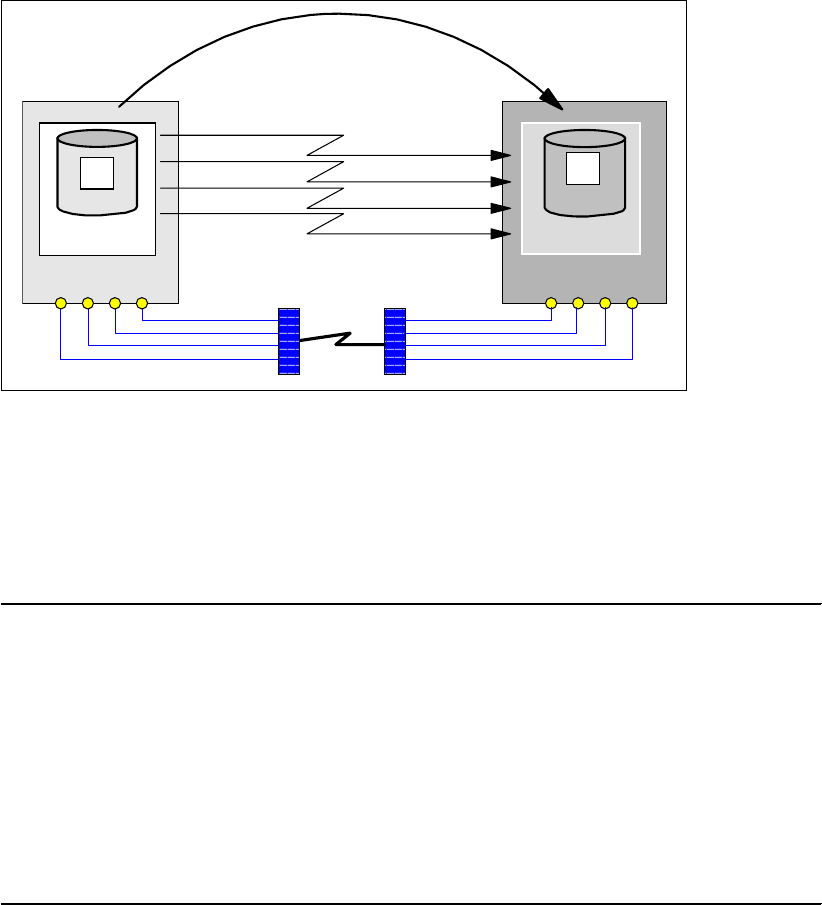
Chapter 24. Global Mirror interfaces 305
For redundancy reasons it is better to define two paths between the primary disk subsystems.
Note that the FCP ports may be shared using a SAN fabric. See Figure 24-3.
24.3.3 Establish Global Copy volume pairs
After defining the paths, you create the Global Copy volume pairs.
Figure 24-4 Establish a Global Copy pair
Figure 24-4 illustrates a Global Copy pair relationship between the primary A volume and the
secondary B volume. This relationship is maintained over the four logical paths that connect
the corresponding LSSs. These paths were defined in Example 24-9 on page 303.
Example 24-10 shows the TSO command used to define the Global Copy pair relationship.
Example 24-10 Define Global Copy pair relationship using TSO command
//* ---------------------------- TSO ------------ CREATE (2) ----- ***
//* ESTABLISH GLOBAL COPY PAIR(S) ***
//* -------------------------------------------------------------- ***
//EPAIR EXEC PGM=IKJEFT01
//SYSPRINT DD SYSOUT=*
//SYSTSPRT DD SYSOUT=*
//SYSTSIN DD DDNAME=SYSIN
CESTPAIR DEVN (X'2C01') +
PRIM (X'2C00' 27131 X'01' X'0C') +
SEC (X'3C00' 73081 X'01' X'0C') +
ONLINSEC(NO) MSGREQ(NO) CRIT(NO) +
OPTION (XD) MODE (COPY) CASCADE(NO)
OPTION(XD) indicates a Global Copy relationship. Once the command successfully ends,
Global Copy immediately does an initial copy of the primary volumes. Example 24-11 on
page 306 shows the output information from a query command to the primary volume. You
can see the pending.XD volume state, and the number of tracks out of sync, all of which is
expected for a Global Copy pair relationship that is in its initial replication phase.
LCU: 2C00
Primary
A
2C00
LCU: 3C00
Secondary
B
3C00
e
s
t
a
b
l
i
s
h
G
l
o
b
a
l
C
o
p
y
p
a
i
r
logical paths
connecting LSSs

306 IBM System Storage DS6000 Series: Copy Services with IBM System z
Example 24-11 Query Global Copy pair immediately after ESTABLISH
CQUERY DEVN(X'2C00')
CQUERY FORMATTED LVL 3
VOLUME REPORT
********************** COPY CQUERY - VOLUME ***********************
* (PRIMARY) (SECONDARY) *
* SSID CCA LSS SSID CCA LSS*
*DEVICE LEVEL STATE PATH STATUS SERIAL# SERIAL# *
*------ --------- ---------- ----------- --------- --------- *
* 2C00 PRIMARY.. PENDING.XD ACTIVE.. 2C00 00 0C 3C00 00 0C *
* CRIT(NO)....... CGRPLB(NO). 000000027131 000000073081*
* PATHS PFCA SFCA STATUS: DESCRIPTION *
* ----- --------- ------ ------------------- *
* 4 0030 0030 13 PATH ESTABLISHED... *
* 0130 0130 13 PATH ESTABLISHED... *
* 0230 0230 13 PATH ESTABLISHED... *
* 0331 0330 14 (UNDETERMINED)..... *
* IF STATE = PENDING/SUSPEND: TRACKS OUT OF SYNC = 49599 *
* TRACKS ON VOLUME = 50085 *
* PERCENT OF COPY COMPLETE = 1% *
* SUBSYSTEM WWNN LIC LEVEL *
* ----------- ---------------- ----------- *
* PRIMARY.... 5005076303FFC228 5.0.03.0097 *
* SECONDARY.1 5005076303FFC422 *
********************************************************************
CQUERY COMMAND COMPLETED FOR DEVICE 2C00. COMPLETION CODE: 00
Example 24-12 provides the same information as Example 24-11, but in a space-saving
unformatted format.
Example 24-12 Unformatted query output
CQUERY DEVN (X'2C00') UNFORMAT
CQUERY UNFORMATTED LVL 3
VOLUME REPORT
2C00,PRIMARY,PENDING XD,ACTIVE,
2C000C,00,000000027131,3C000C,00,000000073081,N,N,
1,00300030,13,01300130,13,02300230,13,03310330,14,
0047599,0050085,005,
5005076303FFC228,5005076303FFC422,
Once the initial replication phase is completed, the CQUERY command output will not show
the TRACKS OUT OF SYNC information; see Example 24-13 on page 307. Note that at a
later point-in-time, you may again observe the TRACKS OUT OF SYNC portion of the report,
as Example 24-11 showed, but then it is not related to the first replication phase.
Tip: The recommendation is to wait until this first replication phase is finished before you
proceed to establish the Global Mirror FlashCopy relationships between the B and C
volumes.
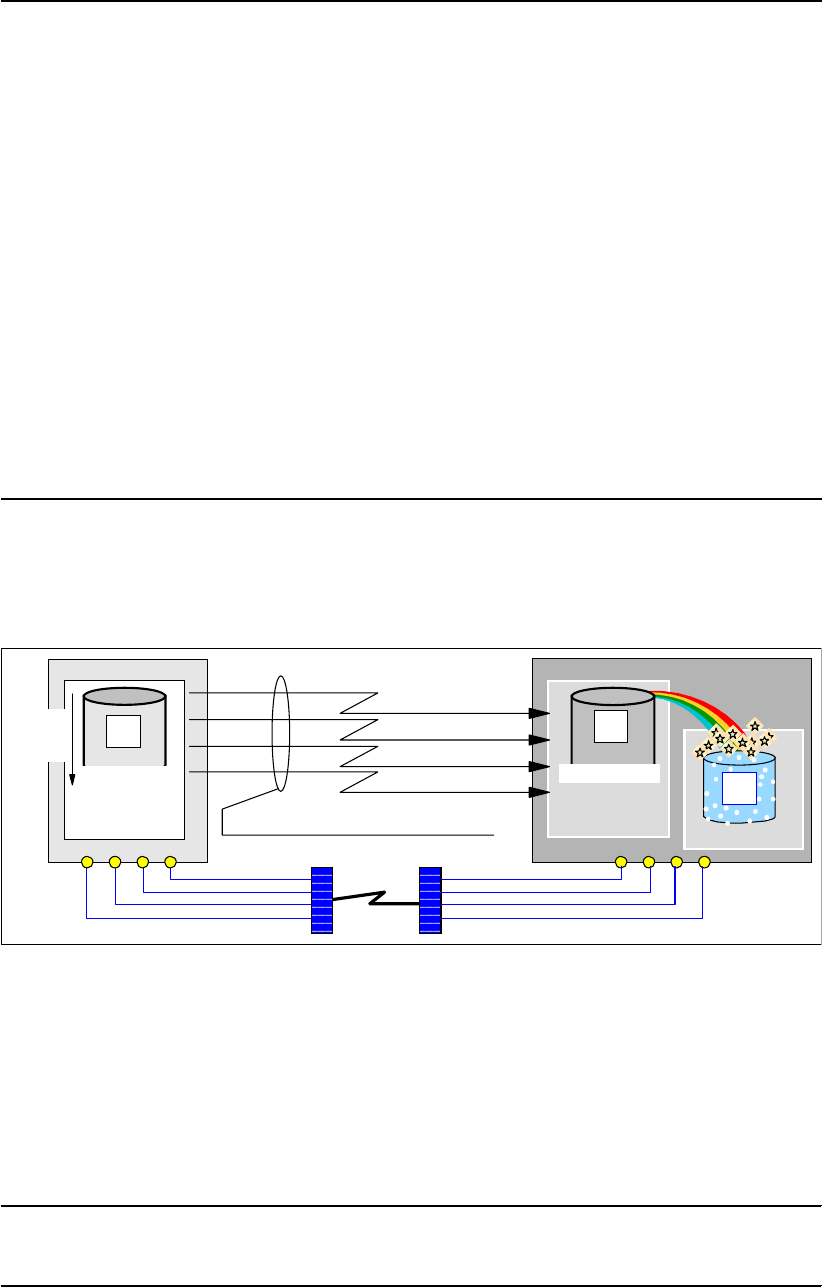
Chapter 24. Global Mirror interfaces 307
Example 24-13 Global Copy after first replication phase is completed
CQUERY DEVN(X'2C00')
CQUERY FORMATTED LVL 3
VOLUME REPORT
********************** CQUERY - VOLUME ****************************
* (PRIMARY) (SECONDARY) *
* SSID CCA LSS SSID CCA LSS*
*DEVICE LEVEL STATE PATH STATUS SERIAL# SERIAL# *
*------ --------- ---------- ----------- --------- --------- *
* 2C00 PRIMARY.. PENDING.XD ACTIVE.. 2C00 00 0C 3C00 00 0C *
* CRIT(NO)....... CGRPLB(NO). 000000027131 000000073081*
* PATHS PFCA SFCA STATUS: DESCRIPTION *
* ----- --------- ------ ------------------- *
* 4 0030 0030 13 PATH ESTABLISHED... *
* 0130 0130 13 PATH ESTABLISHED... *
* 0230 0230 13 PATH ESTABLISHED... *
* 0331 0330 14 (UNDETERMINED)..... *
* SUBSYSTEM WWNN LIC LEVEL *
* ----------- ---------------- ----------- *
* PRIMARY.... 5005076303FFC228 5.0.03.0097 *
* SECONDARY.1 5005076303FFC422 *
********************************************************************
CQUERY COMMAND COMPLETED FOR DEVICE 2C00. COMPLETION CODE: 00
24.3.4 Establish FlashCopy relationships for Global Mirror
Once the Global Copy pairs complete their initial replication phase, you must create the
FlashCopy relationships between the B and C volumes; see Figure 24-5.
Figure 24-5 Establish Global Mirror FlashCopy relationship between B and C
Because these FlashCopy relationships are part of a Global Mirror configuration, they are
defined with a set of particular attributes; see the discussion in 22.3.4, “Introduce FlashCopy”
on page 257.
Example 24-14 shows a TSO command that is issued at the local site, and upon its inband
propagation to the remote site, establishes the FlashCopy relationship between the B and C
volumes at the remote disk subsystem.
Example 24-14 TSO command to create a FlashCopy pair between B and C volumes
FCESTABL DEVN(X'2C00') SOURCE(73081 00 0C) +
TARGET(73081 00 0E) +
REMOTE(YES) SSID(3C00) MODE(ASYNC)
LCU: 3C00
LCU: 2C00
Primary
A
2C00
PENDING.XD
FlashCopy
LCU: 3E00
C
3E00
Secondary
B
3C00
PENDING.XD
Frist
phase
complete
logical paths connecting LSSs
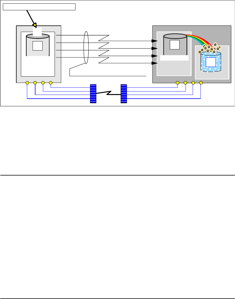
308 IBM System Storage DS6000 Series: Copy Services with IBM System z
The inband modality is used when the remote site is not connected to the local site. DEVN
refers to the primary volume, and SOURCE and TARGET refer to remote storage disk
subsystem. MODE(ASYNC) implicitly includes the specific FlashCopy attributes that are
required for Global Mirror.
24.3.5 Define a Global Mirror session
Before adding volumes to the Global Mirror session, a token is required under which the
session can be identified and addressed.
Figure 24-6 Define a Global Mirror session number
Figure 24-6 shows a volume within an LSS. This LSS contains the Global Copy primary
volumes that are going to be part of the Global Mirror session. At the moment it is
recommended to use some kind of utility device within each LSS, for addressing purposes.
This utility device needs to be online to the z/OS system where you execute the Global Mirror
commands. You may consider using a volume that will not be part of the Global Mirror
session, but within the same LSS where the Global Copy primary volumes will be.
Example 24-15 TSO command example to define a Global Mirror session
//* ---------------------------- TSO ------------ CREATE (4) ----- ***
//* DEFINE GM SESSION NUMBER X'01' TO LSS X'0C' AND LSS X'0D' ***
//* -------------------------------------------------------------- ***
//DEFSESS EXEC PGM=IKJEFT01
//SYSPRINT DD SYSOUT=*
//SYSTSPRT DD SYSOUT=*
//SYSTSIN DD DDNAME=SYSIN
RSESSION SNBR(01) VOLSER(XX2C00) +
ACTION(DEFINE) +
LSSTYPE(CKD) LSSNBR(0C) +
ESSSERIAL(27131) +
MSSERIAL (27131)
RSESSION SNBR(01) VOLSER(XX2D00) +
ACTION(DEFINE) +
LSSTYPE(CKD) LSSNBR(0D) +
ESSSERIAL(27131) +
MSSERIAL (27131)
LCU: 3C00
LCU: 2C00
A
FlashCopy
LCU: 3E00
C
3E00
Secondary
B
3C00
PENDING.XD
01
Define Global Mirror session
Primary
PENDING.XD
logical paths connecting LSSs

Chapter 24. Global Mirror interfaces 309
The TSO command RSESSION is used to set up and manage a Global Mirror session; see
Example 24-15. This includes the ability to define a Global Mirror session by means of the
ACTION(DEFINE) parameter option. Other options that can be specified for the ACTION
parameter are: START and STOP a Global Mirror session, as well as PAUSE and RESUME
of the session, or to UNDEFINE the session.
This example also shows that you have to define this Global Mirror session number to all
LSSs at the primary site that will hold the Global Copy primary volumes that are going to be
part of this session.
As with all TSO commands, you can issue this command interactively through ISPF menu 6,
or from the TSO READY status. In the z/OS SYSLOG this RSESSION command is only
logged as the command itself but not the response to this command. It is, therefore,
recommended to always use TSO in batch for documentation purposes and to be able to
track all commands and their outcomes.
24.3.6 Populate a Global Mirror session with volumes
After you successfully defined a Global Mirror session, you populate the session with the
Global Copy primary volumes. These are all the primary A volumes that are going to
participate in the Global Mirror session at the local site; see Example 24-16.
Example 24-16 Add Global Copy primary volumes to Global Mirror session
//* ---------------------------- TSO ------------ CREATE (5) ----- ***
//* POPULATE SESSION X'01' WITH PRIMARY VOLUMES ***
//* ***
//* VOLUME LIST CONTAINS CCA NUMBERS ***
//* -------------------------------------------------------------- ***
//JOIN EXEC PGM=IKJEFT01
//SYSPRINT DD SYSOUT=*
//SYSTSPRT DD SYSOUT=*
//SYSTSIN DD DDNAME=SYSIN
RVOLUME SNBR(01) VOLSER(XX2C00) +
ACTION (JOIN) +
LSSTYPE (CKD) LSSNBR(0C) +
ESSSERIAL(27131) +
VOLLIST (00)
RVOLUME SNBR(01) VOLSER(XX2D00) +
ACTION (JOIN) +
LSSTYPE (CKD) LSSNBR(0D) +
ESSSERIAL(27131) +
VOLRANGE (00:01)
Example 24-16 shows the TSO command RVOLUME. To populate the Global Mirror session
with Global Copy volumes you use the ACTION(JOIN) parameter value.
With this command you also remove the Global Copy primary volumes from the session. The
corresponding parameter value for this action is ACTION(REMOVE).
With the VOLLIST or VOLRANGE parameters, you define the volumes that are added to the
session or removed from the session. VOLLIST is a list of channel connection addresses
(CCA) that identify the A volumes. VOLRANGE allows you to specify a range of CCAs. In
Example 24-16, a volume with CCA x’00’ from LSS x’0C’ is added to the session number
x’01’. Two more volumes from LSS x’0D’are added to the session. This is indicated by the
VOLRANGE parameter value 00:01, which adds volumes from CCA x’00’ to CCA x’01’.

310 IBM System Storage DS6000 Series: Copy Services with IBM System z
24.3.7 Start a Global Mirror session
The new RSESSION command is used to start the Global Mirror session. With the
ACTION(START) parameter, you indicate the start of the Consistency Groups formation.
Example 24-17 Start Global Mirror session
//* ---------------------------- TSO ------------ CREATE (6) ----- ***
//* START SESSION X'01' THROUGH LSS X'0C' ***
//* ***
//* THEN LSS X'0C' BECOMES THE MASTER LSS (DS) ***
//* NOTE: LSS SYNTAX IS WITHOUT X AND QUOTES ... ***
//* ***
//* CGINTERVAL - BUILD CG WITHOUT A BREAK ***
//* CGDRAIN - ALLOW 10 MINUTES FOR DRAINING ***
//* COORDINTERVAL - ALLOW 5 MS MAX FOR COORDINATION ***
//* -------------------------------------------------------------- ***
//START EXEC PGM=IKJEFT01
//SYSPRINT DD SYSOUT=*
//SYSTSPRT DD SYSOUT=*
//SYSTSIN DD DDNAME=SYSIN
RSESSION SNBR(01) VOLSER(XX2C00) +
ACTION (START) +
LSSTYPE (CKD) LSSNBR(0C) +
ESSSERIAL (27131) +
MSSERIAL (27131) +
CGINTERVAL (00) +
CGDRAIN (600) +
COORDINTERVAL(05)
Example 24-17 shows the START command that begins the formation of Consistency Groups
for session number x’01’. Besides the ACTION parameter, you address the LSS number that
receives this command. This also defines the Master LSS, which is LSS number x’0C’.
You may override the default values of the Global Mirror session parameters. In our example
we keep the default value for CGINTERVAL, but we change the defaults for CGDRAIN to 10
minutes as the maximum Consistency Group Drain time. We also change the maximum
coordination time COORDINTERVAL to 5 ms.
24.3.8 Query a Global Mirror session
To obtain status information about the Global Mirror session, we use the RQUERY command.
Example 24-18 shows an RQUERY command example.
Example 24-18 New TSO RQUERY command
RQUERY SNBR(01) VOLSER(volser) ACTION(action) LSSNBR(lss) LSSTYPE(type) DVCNBR(###)
The following parameters are used with this command:
SNBR indicates the Global Mirror session number from which a query report is requested.
This parameter is optional. When omitted, RQUERY will report all session numbers that
are available in the addressed primary storage disk subsystem.
VOLSER indicates an online z/OS volume serial number. This utility volume is used to
address the RQUERY command to the particular LSS where the query report is
requested.

Chapter 24. Global Mirror interfaces 311
ACTION is required and specifies which kind of query report is requested. Three different
query reports can be requested with this parameter:
– GMLSTAT provides summary information pertaining to the Global Mirror session. This
includes information about the Master storage disk subsystem, the Subordinate
storage disk subsystems, as well as the number of successfully created Consistency
Groups and how often Consistency Group creation failed. It also includes the
parameter values for the session.
– GMPSTAT provides Global Mirror summary status information of the LSS addressed in
the VOLSER parameter. Key information from this query is the number of tracks that
are still in the out-of-sync bitmap at the primary LSS, and are waiting to be replicated to
the corresponding secondary LSS. This query also details the total number of Global
Mirror volumes within this LSS, and how many volumes out of the total contain
out-of-sync tracks.
– DVCSTAT provides an overview of all involved devices in a Global Mirror session for
the LSS addressed in the VOLSER parameter.
LSSNBR specifies the LSS number for which we query information. This parameter is
required when LSSTYPE(FB) is specified. It is not required when LSSTYPE is CKD
(default).
LSSTYPE identifies whether this is an LSS with fixed blocked (FB) devices for open
systems or count-key-data (CKD) devices for System z. CKD is the default.
DVCNBR indicates the LUN for which the query report is requested, and is required when
LSSTYPE(FB) is specified.
Example 24-19 shows an RQUERY command with ACTION(GMLSTAT). The example shows
the formatted line output information for the LSS that has VOLSER(XX2C00) in it.
Example 24-19 RQUERY TSO command example with ACTION(GMLSTAT)
RQUERY SNBR(01) VOLSER(XX2C00) ACTION(GMLSTAT)
RQUERY Output Volser(XX2C00) Action(GMLSTAT) Version(001)
SNbr GMLStat GoodCg Pct CrnBadCG TotBadCG LastGoodCGSCntlClock
-- ---------- -------- --- -------- -------- --------------------
01 Running 00000001 100 19 May 2005 22:02:35
.
Master: Serial SSID LSS CGInt CGDrn CrdInt
------------ ---- -- ----- ----- -----
000107527131 2C00 0C 0 600 5
READY
RQUERY SNBR(01) VOLSER(XX2D00) ACTION(GMLSTAT)
RQUERY Output Volser(XX2D00) Action(GMLSTAT) Version(001)
SNbr GMLStat GoodCg Pct CrnBadCG TotBadCG LastGoodCGSCntlClock
-- ---------- -------- --- -------- -------- --------------------
01 NoConfig
READY
Example 24-19 shows a second RQUERY command. The first command was issued to the
Master LSS of the Global Mirror session. The second command is issued to another LSS that
is not a Master LSS.
In the output information, besides the information related to the Master LSS, there is also
information about the number of Consistency Groups created, the number of failed attempts,
and the last successfully created Consistency Group with the internal time stamp from the
storage disk subsystem. The status of the Global Mirror session is also important.

312 IBM System Storage DS6000 Series: Copy Services with IBM System z
Example 24-19 shows for this status Running. Refer to z/OS DFSMS Advanced Copy
Services, SC35-0428, for a description of different status indications.
Example 24-20 shows Global Mirror status information for a particular LSS and its Global
Copy primary volumes, when ACTION(GMPSTAT) is used with the RQUERY command.
Example 24-20 RQUERY TSO command example with ACTION(GMPSTAT)
READY
RQUERY SNBR(01) VOLSER(XX2D00) ACTION(GMPSTAT)
RQUERY Output Volser(XX2D00) Action(GMPSTAT) Version(001)
SNbr LSS GMPStatus TotVol OOSVol OOSTrks
-- -- ---------- ------ ------ --------
01 0D CGInPrgrs 2 2 00003E02
READY
END
The formatted output provides the following information:
LSS number 0D contains 2 volumes in the session number 01 (SNbr, LSS, and TotVol).
Both volumes contain tracks that are not yet replicated by Global Copy to their
corresponding secondary volumes (OOSVol).
The number of out-of-sync tracks is indicated in hexadecimal (OOSTrks).
Consistency Group formation is in process for this LSS (GMPStatus).
Example 24-21 shows two TSO RQUERY commands with ACTION(DVCSTAT). One
command is addressed to LSS 0C and the other to LSS 0D. They both show, for the
corresponding LSS, individual information for the Global Copy primary volumes that are in the
Global Mirror session. These devices are: device with CCA x’00’ in LSS x’0C’, and devices
with CCA x’00’ and x’01’ in LSS x’0D’.
Example 24-21 RQUERY Global Copy primary volumes in premature status
READY
RQUERY SNBR(01) VOLSER(XX2C00) ACTION(DVCSTAT)
RQUERY Output Volser(XX2C00) Action(DVCSTAT) Version(001)
SNbr LSS Dvc VolStat PriPPRCStat SecCascStat
-- -- -- -------------------- ---------- ----------
01 0C 00 NIn+JoinP+1st DplxPendng Simplex
READY
RQUERY SNBR(01) VOLSER(XX2D00) ACTION(DVCSTAT)
RQUERY Output Volser(XX2D00) Action(DVCSTAT) Version(001)
SNbr LSS Dvc VolStat PriPPRCStat SecCascStat
-- -- -- -------------------- ---------- ----------
01 0D 00 NIn+JoinP+1st DplxPendng Simplex
0D 01 NIn+JoinP+1st DplxPendng Simplex
READY
Example 24-21 shows that the volumes in both LSSs are still not in session, are in their initial
copy phase, and have not completed their first pass.
Example 24-22 on page 313 shows the very same RQUERY TSO commands as in the
previous example, but this time the initial copy phase is complete and all volumes are in
session, which means they participate in the Consistency Groups formation at the remote
site.

Chapter 24. Global Mirror interfaces 313
Example 24-22 Global Copy primary volumes in Global Mirror session
READY
RQUERY SNBR(01) VOLSER(XX2C00) ACTION(DVCSTAT)
RQUERY Output Volser(XX2C00) Action(DVCSTAT) Version(001)
SNbr LSS Dvc VolStat PriPPRCStat SecCascStat
-- -- -- -------------------- ---------- ----------
01 0C 00 InSession DplxPendng Simplex
READY
RQUERY SNBR(01) VOLSER(XX2D00) ACTION(DVCSTAT)
RQUERY Output Volser(XX2D00) Action(DVCSTAT) Version(001)
SNbr LSS Dvc VolStat PriPPRCStat SecCascStat
-- -- -- -------------------- ---------- ----------
01 0D 00 InSession DplxPendng Simplex
0D 01 InSession DplxPendng Simplex
READY
For more details and different VolStat indications, refer to z/OS DFSMS Advanced Copy
Services, SC35-0428.
24.4 DS CLI to manage Global Mirror volumes in z/OS
The DS CLI has a set of commands that are common between the DS6000, the DS8000, and
the ESS 800 (from LIC level 2.4.3 and above), to manage a Copy Services environment.
Although remote mirror and copy functions over Fibre Channel links is supported since ESS
800 LIC level 2.3.0+, the newer LIC level is required for the ESS 800 to support the new DS
CLI commands.
Refer to Chapter 26., “Global Mirror examples” on page 341 for examples of how to use DS
CLI for Global Mirror management in a System z environment. Also refer to Chapter 4, “DS
Command-Line Interface” on page 25.
24.5 Global Mirror management using ICKDSF
ICKDSF used to be a disk management tool to initialize and diagnose disk volumes. Over
time it evolved and today ICKDSF contains functional support to manage all available Copy
Services functions.
ICKDSF supports all System z-based operating systems including z/OS, z/VM, and
VSE/ESA™. Therefore, ICKDSF is a common platform for all System z operating systems to
provide an interface to the DS6000, DS8000, and ESS 800 Copy Services functions. This
includes all of Metro Mirror, Global Copy, Global Mirror, and FlashCopy.
24.5.1 Establish a Global Mirror environment
The following sections discuss how to set up a Global Mirror environment with ICKDSF. The
sequence of steps we show in our discussion, although not mandatory, is the recommended
one for the creation of a Global Mirror environment.
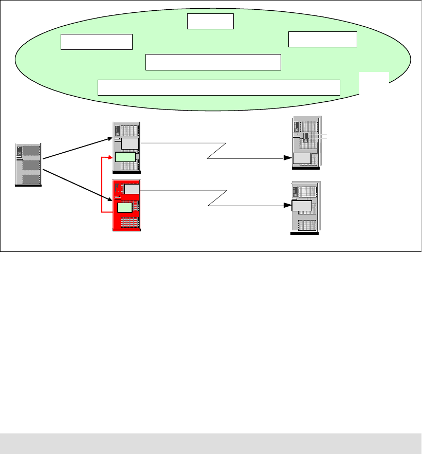
314 IBM System Storage DS6000 Series: Copy Services with IBM System z
Figure 24-7 ICKDSF support for Global Mirror
Figure 24-7 provides the complete picture of a Global Mirror session. ICKDSF is used to:
Establish Global Mirror and Global Copy paths
Establish Global Copy pairs
Create FlashCopy relationships
Manage a Global Mirror session; add and remove volumes
Manage a Global Mirror session; pause and resume, start and stop aGlobal Mirror session
24.5.2 Define paths
There is no change on how to define paths on the DS6000, or the DS8000, as compared to
the ESS 800.
Also note that when you utilize more than a single primary storage disk subsystem at the local
site, you need to define paths between them for the Global Mirror session communication
between the Master and the Subordinates. Also, you have to define the paths between the
primary LSSs at the local site and the secondary LSSs at the remote site, so the Global Copy
pairs can be established. Figure 24-8 on page 315 illustrates the needed paths for a Global
Mirror environment.
Remote Site
Long Distance
Global Copy
Local Site
Master
Subordinate
LS
S
LSS
LSS
LSS
LSS
LSS
LSS
Host I/O
ICKDSF
Query All
Establish Pairs
Manage Global Mirror Sessions
Define, Pause, Resume, Terminate Global Mirror Sessions
Global Mirror
Session paths
Global Copy
paths
Establish Paths
z/OS
z/VM
VSE
Global Copy
paths
Note: For remote copy functions, only Fibre Channel links are supported on the DS6000.
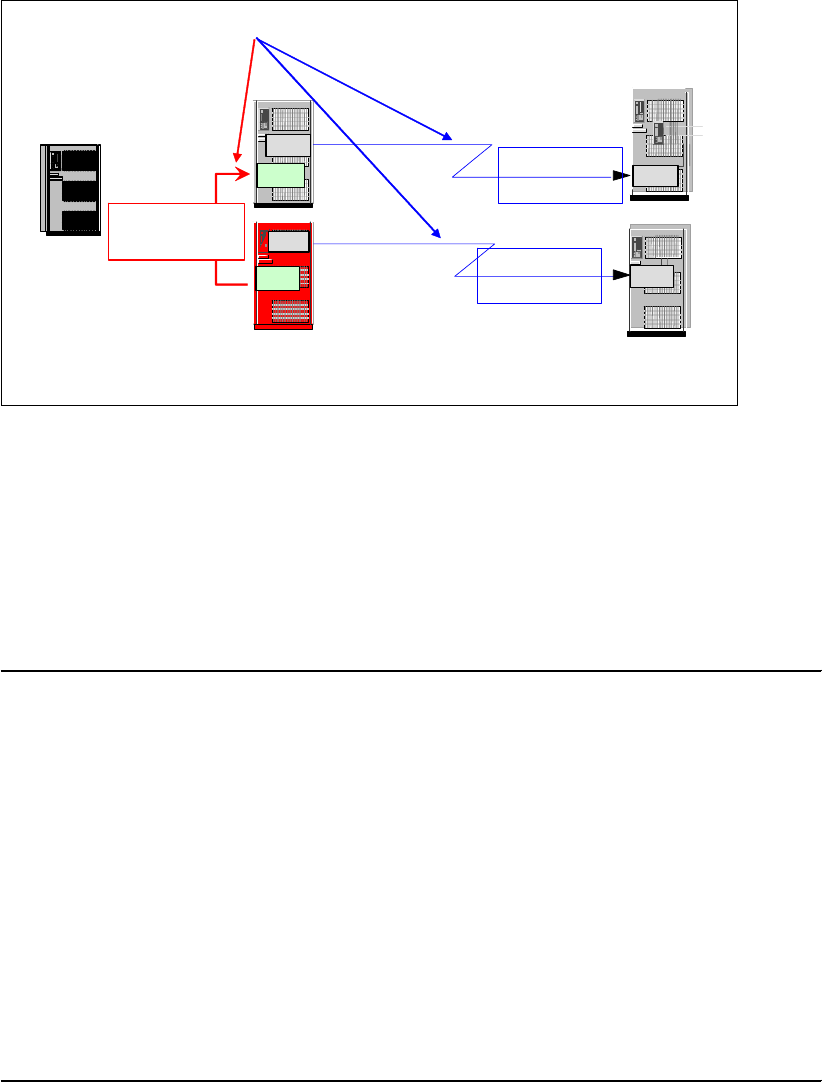
Chapter 24. Global Mirror interfaces 315
Figure 24-8 Define all needed paths for the Global Mirror environment through ICKDSF
Example 24-23 shows the JCL and command lines used to define paths between two storage
disk subsystems. Note that an online volume cannot be referred via the ICKDSF UNIT
parameter; ICKDSF assumes the volume to be offline when you use the UNIT parameter with
a corresponding z/OS device number. On the other side, it is most likely that a Global Copy
primary volume is online to the system from where you run the ICKDSF jobs. This requires
that for each device you address through an ICKDSF command, you provide a JCL DD
statement for this device; see Example 24-23.
Example 24-23 ICKDSF example to define paths
//* -------------------------------------------------------------- ***
//STEP01 EXEC PGM=ICKDSF
//SYSPRINT DD SYSOUT=*
//DD01 DD UNIT=3390,VOL=SER=RS7000,DISP=SHR
//SYSIN DD *
PPRCOPY DDNAME(DD01) ESTPATH -
PRI(X'7000' 22399) -
SEC(X'7800' 25941) -
LSS(X'00' X'00') -
FCPPATHS(X'000C000C' -
X'008C008C') -
WWNN(5005076300C09517 -
5005076300C0A2ED)
PPRCOPY DDNAME(DD01) QUERY PATHS
/*
Note the extra parameter to identify the LSS; primary and secondary parameters contain the
SSID besides the serial number. FCPPATHS contains the sending system adapter ID (SAID)
and the receiving SAID. A WWNN is also required to identify the source and target disk
subsystem.
It is recommended that you execute a query command to verify that the path definitions were
successfully accomplished. It may happen that not all paths are successfully defined, and you
want to find this out immediately.
Remote site
(secondary)
Local site
(primary)
Master
Subordinate
LSS
LSS
LSS
LSS
LSS
LSS Global Copy
paths
Global Copy
paths
Global Mirror
session paths
WWNN: 5005076300C09517 WWNN: 5005076300C0A2ED
Host
Paths
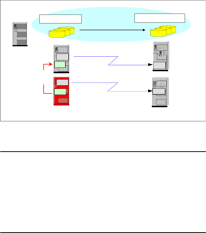
316 IBM System Storage DS6000 Series: Copy Services with IBM System z
24.5.3 Establish Global Copy pairs
When you set up a Global Mirror environment, there is nothing particularly different
concerning the Global Copy pairs. The command syntax used to establish Global Copy pairs
with ICKDSF has no changes, whether used for Global Mirror setup or not. See Figure 24-9.
Figure 24-9 Establish Global Copy pairs
Example 24-24 shows the JCL and command lines used to create a Global Copy pair.
Example 24-24 Establish Global Copy pair through ICKDSF
//* -------------------------------------------------------------- ***
//STEP01 EXEC PGM=ICKDSF
//SYSPRINT DD SYSOUT=*
//DD01 DD UNIT=3390,VOL=SER=RS7000,DISP=SHR
//SYSIN DD *
PPRCOPY DDNAME(DD01) ESTPAIR -
PRI(X'7000' 22399 X'00') -
SEC(X'7800' 25941 X'00') -
LSS(X'00' X'00') -
MODE(COPY) OPTION(XD)
PPRCOPY DDNAME(DD01) QUERY
/*
Note again the requirement for a JCL DD statement for the involved Global Copy primary
volume. This may become a bit cumbersome when you intend to establish hundreds or even
thousand of Global Copy pairs. You then need to add the same number of JCL DD
statements and refer to each DD statement through the DDNAME parameter. The volume
has to be online when you used the DDNAME approach, while with the UNIT parameter the
volume has to be offline.
Again, the LSS parameter identifies the involved LSS. The primary (PRI) and secondary
(SEC) parameters require positional parameters, with SSID in the first specification. The
second parameter is the serial number of the corresponding storage disk subsystem, not in
Remote site (secondary)
Host
Master
Subordinate
LSS
LSS
LSS
LSS
LSS
LSS
Global Copy
paths
Global Copy
paths
Local site (primary)
Secondary volumes
Primary volumes
Global Mirror
session paths
Serial # 22399 Serial # 25941
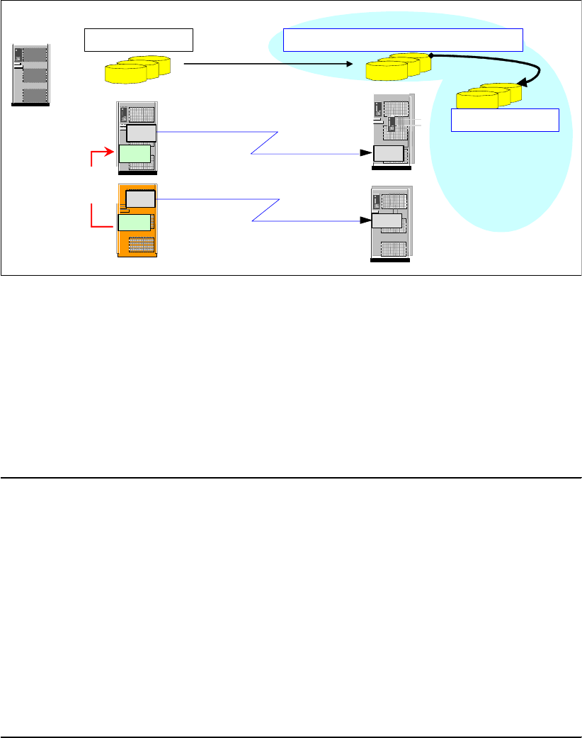
Chapter 24. Global Mirror interfaces 317
hex notation. In hex notation the third parameter refers to the channel connection address
(CCA) of the corresponding device.
24.5.4 Establish FlashCopy relationships
The next step is to create the FlashCopy relationship between the B volume and the C
volumes at the remote site; note in Figure 24-10 the particular attributes for FlashCopy
because it is being used in a Global Mirror environment.
Figure 24-10 ICKDSF - create FlashCopy relationship for Global Mirror
Depending on whether you connect to the remote site or to the local site, the FlashCopy
command is either directly issued to the remote storage disk subsystem or via an inband
command. The inband command is targeted to the local primary volume, and provides
addressing information for the FlashCopy source and target volumes at the remote site.
Example 24-25 shows an inband ICKDSF job example under the assumption that usually
there is no host connection from the local site to the remote storage disk subsystem, which
may reside on another continent.
Example 24-25 ICKDSF FlashCopy establish via an inband command
//* -------------------------------------------------------------- ***
//STEP01 EXEC PGM=ICKDSF
//SYSPRINT DD SYSOUT=*
//SYSIN DD *
FLASHCPY UNIT(7000) ESTABLISH -
SOURCEVOL(X'00' X'00' X'7800' 25941) -
TARGETVOL(X'01' X'00' 7900) -
CHANGERCD(YES) -
INHIBWRTS(YES) -
MODE(NOCOPY) -
TARGETCANCOMEONLINE(NO)
FC UNIT(7000) QUERY -
SRCVOL(X'00' X'00' X'7800' 25941
/*
Remote site
(secondary)
Master
Subordinate
LSS
LSS
LSS
LSS
LSS
LSS
Long distance
Global Copy
volume pairs
Local site
(primary)
Flashcopy target
Primary volumes Secondary volumes = Flashcopy source
Global Mirror
session paths
Change recording
Target write inhibited
Persistent
No background copy
Global Copy
paths
Global Copy
paths
Host

318 IBM System Storage DS6000 Series: Copy Services with IBM System z
The ESTABLISH inband command has some complexity. UNIT points to the local primary
volume. SOURCEVOL identifies the FlashCopy source volume at the remote site. Note this
volume is also the Global Mirror secondary volume. TARGETVOL identifies the FlashCopy
target volume. Both parameters require certain positional values. All parameters are in hex
notation except the serial number in SOURCEVOL as the last positional parameter. In
TARGETVOL, the last positional parameter is the z/OS device number of the FlashCopy
target volume, which is also not specified in hex notation. For details refer to Device Support
Facility User’s Guide and Reference Release 17, SC35-0033.
The second FlashCopy command is a query of the FlashCopy pair that has just been
established in the previous command (note that FLASHCOPY can be abbreviated, as well as
SOURCEVOL). This second FlashCopy command is also an inband command, and is
targeted to the FlashCopy source volume by the SRCVOL parameter, which is the same as in
the previous FlashCopy command.
The job shown in Example 24-25 on page 317 refers to the A volume, which is the Global
Copy primary volume, via the UNIT parameter. This requires the device on address 7000 to
be offline. When the device is online to the system, and when this job executes, ICKDSF will
return with an error message and fail the command.
Example 24-26 shows how to structure your commands and use abbreviated parameters. In
the example the commands are targeted to the online volume and, therefore, require a
corresponding JCL DD statement for the primary Global Copy volume.
Example 24-26 ICKDSF inband FlashCopy with abbreviated parameters
//* -------------------------------------------------------------- ***
//FCBTOC EXEC PGM=ICKDSF
//SYSPRINT DD SYSOUT=*
//DD01 DD UNIT=3390,VOL=SER=XX2C00,DISP=SHR local device
//SYSIN DD *
FC DDNAME(DD01) ESTAB -
SRCVOL (X'0C',X'00',X'2C00' 03461) -
TGTVOL (X'0E',X'00',3E00) -
CHRCD (YES) -
NOTGTWT (YES) -
MODE (NOCOPY)
FC DDNAME(DD01) QUERY -
SRCVOL (X'0C',X'00',X'2C00' 03461)
/*
24.5.5 Define a Global Mirror session
In this step we create a session that will involve all LSSs that will participate in this Global
Mirror environment. Each LSS that contributes with Global Copy primary volumes to this
Global Mirror setup, requires to be defined in the session before adding volumes to the
session. As Figure 24-11 on page 319 shows, the session number applies only to the LSS at
the local site.
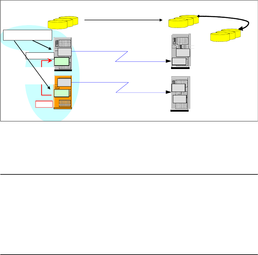
Chapter 24. Global Mirror interfaces 319
Figure 24-11 ICKDSF - define Global Mirror session
Example 24-27 shows an ICKDSF job that defines a Global Mirror session involving the LSS
that volume RS7000 belongs to. Note that with this Global Mirror command, you do not need
to define an LSS number, nor a CCA, nor the SSID.
Example 24-27 ICKDSF job to define a Global Mirror session to an LSS
//* -------------------------------------------------------------- ***
//STEP01 EXEC PGM=ICKDSF
//SYSPRINT DD SYSOUT=*
//DD01 DD UNIT=3390,VOL=SER=RS7000,DISP=SHR
//SYSIN DD *
PPRC DDNAME(DD01) DEFINESESSION -
OPEN -
SESSIONNO(001)
/*
Example 24-27 points again to an online volume by the DDNAME parameter. A session is
created involving the corresponding LSS; it is session number 001 in this example.
24.5.6 Add volumes to a session
In this step we add Global Copy primary volumes to the Global Mirror session; see
Figure 24-12 on page 320.
Remote site
(secondary)
Master
Subordinate
LSS
LSS LSS
LSS Long distance
Global Copy
volume pairs
Local site
(primary)
Flashcopy target
Primary volumes Secondary volumes = Flashcopy source
Global Mirror
session paths
Global Copy
paths
Global Copy
paths
Session number
LSS
LSS
LSS
LSS
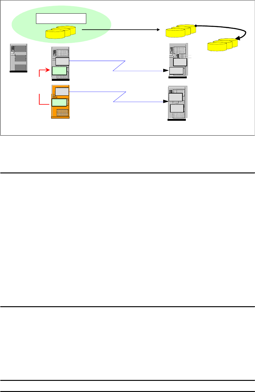
320 IBM System Storage DS6000 Series: Copy Services with IBM System z
Figure 24-12 ICKDSF - populate a Global Mirror session with primary volumes
Example 24-28 shows the JCL and commands to add volumes to a Global Mirror session.
Example 24-28 Add volumes to session through ICKDSF
//* -------------------------------------------------------------- ***
//STEP01 EXEC PGM=ICKDSF
//SYSPRINT DD SYSOUT=*
//SYSIN DD *
PPRC UNIT(7000) POPULATESESSION -
JOIN SESSIONNO(001) -
RANGE(NO) VOLCOUNT(1) -
IVOLLIST((X’00’))
PPRC UNIT(7100) POPULATESESSION -
JOIN SESSIONNO(001) -
RANGE(YES) VOLCOUNT(1) -
RVOLLIST(X'00',X'0F')
PPRC UNIT(7000) QUERY -
SESSIONSDEVICES
/*
You indicate the Global Copy primary volumes that will become part of the Global Mirror
session by either a list of CCA addresses, the IVOLLIST parameter, or a range of CCA
addresses in the RVOLLIST parameter.
Let us look at more details of the VOLCOUNT parameter. Example 24-29 shows a case of
multiple ranges of volumes specified in the PPRC POPULATESESSION command. Note that
this command applies only to the LSS that is addressed by the UNIT parameter.
Example 24-29 Multiple volume ranges in ICKDSF Global Mirror command with RVOLLIST
RVOLLIST ((X’00’,X’1F’),(X’30’,X’3F)) VOLCNT(2)
Remote site
(secondary)
Master
Subordinate
LSS
LSS LSS
LSS
Long distance
Global Copy
volume pairs
Local site
(primary)
Flashcopy target
Secondary volumes = Flashcopy source
Global Mirror
session paths
Global Copy
paths
Global Copy
paths
Host
LSS
LSS
LSS
LSS
Primary volumes
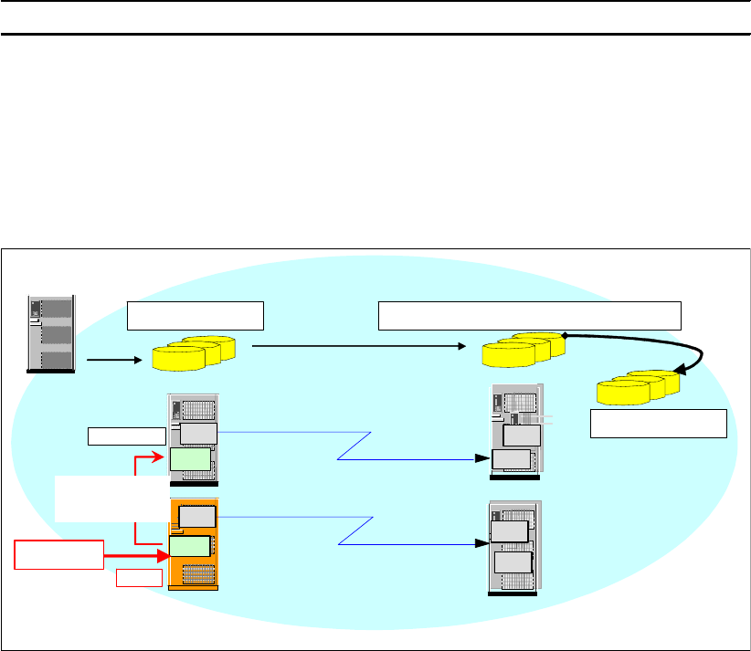
Chapter 24. Global Mirror interfaces 321
Note that the VOLCNT parameter counts the number of ranges you specify in the RVOLLIST
parameter. In Example 24-29 the VOLCNT is 2 because RVOLLIST contains two ranges.
Instead of RVOLLIST, you can select dedicated volumes that are going to become a part of
Global Mirror session through the IVOLLIST parameter. Volume count VOLCNT has a similar
meaning with IVOLLIST as with RVOLLIST; see Example 24-30.
Example 24-30 Multiple volumes in ICKDSF Global Mirror command with IVOLLIST
IVOLLIST((X'00'),(X'02')) VOLCNT(2)
Note that each POPULATESESSION command addresses an LSS, and you need at least as
many POPULATESESSION commands as LSSs are involved in a Global Mirror session.
24.5.7 Start Global Mirror
Once all Global Mirror components are defined and ready to be used, you start the Global
Mirror session; see Figure 24-13.
Figure 24-13 ICKDSF - start Global Mirror session
With the very first Global Mirror start command, you decide which LSS becomes the Master
LSS. All further Global Mirror session commands have to go through the Master LSS.
Note that the Master LSS may also contain Global Copy primary volumes that are part of the
Global Mirror session. Note also that you only need Global Mirror control paths between an
LSS in the Master storage disk subsystem and an LSS in a Subordinate storage disk
subsystem. Global Mirror communication within a storage disk subsystem is happening over
internal communication paths.
Example 24-31 on page 322 shows how to start a Global Mirror session with ICKDSF. From
now on, Global Mirror does Consistency Groups formation.
Remote site
(secondary)
Master
Subordinate
LSS
LSS LSS
LSS
Long distance
Global Copy
volume pairs
Local site
(primary)
Flashcopy target
Primary volumes Secondary volumes = Flashcopy source
Global Mirror
session paths
Global Copy
paths
Global Copy
paths
LSS
LSS
LSS
LSS
START
Host
Write I/Os
322 IBM System Storage DS6000 Series: Copy Services with IBM System z
Example 24-31 ICKDSF example to start a Global Mirror session
//* -------------------------------------------------------------- ***
//STEP01 EXEC PGM=ICKDSF
//SYSPRINT DD SYSOUT=*
//SYSIN DD *
PPRC UNIT(7000) STARTASYNCCOPY START -
SESSIONNO(001) -
MAXCOORDTIME(05) -
MAXDRAINTIME(60) -
CGINTERVALTIME(0)
PPRC UNIT(7000) QUERY ASYNCCOPY
/*
24.5.8 Query an active Global Mirror session
Figure 24-14 shows an ICKDSF command to query the devices and their session status. At
the very moment when the query was done, a Consistency Group formation was going on.
Figure 24-14 ICKDSF - query devices in a Global Mirror session
The query also shows four volumes within the LSS indicated by DDNAME, that are also part
of the Global Mirror session. The first two volumes are in session (IS). The next two volumes
are defined to the session but they are in a join pending (JP) state, and they are not Global
Copy primary volumes (simplex, SX). This means the volumes have been added to the
session with the POPULATESESSION command, although these volumes are not Global
Copy primary volumes. This is indicated by the SX code.
EXTENDED DISTANCE CONSISTENCY SESSIONS AND DEVICES TABLE
+-----------------------------------------------------------------------------+
! SESS ! SESS ! !
! NO ! STAT ! VOLUMES IN SESSION !
!------+------+---------------------------------------------------------------!
! 1 ! CGI P ! 05.00(IS,DP) 05. 01( IS,DP) 05. 02( JP, SX) 05. 03( JP, SX) !
+-----------------------------------------------------------------------------+
LEGEND
SESSION STATUS
CGIP = CONSISTENCY GROUP IN PROGRESS
INAC = NO INFORMATION, DATA STRUCTURES INACCESSIBLE
IP = INCREMENT PENDING
NAV = NO ACTIVE VOLUMES IN SESSION
N = NORMAL
NSES = NO SESSIONS DEFINED ON ESS
VOLUME STATUS (1ST ENTRY IN PARENTHESES)
IS = IN EXTENDED DISTANCE CONSISTENCY GROUP SESSION
JP = EXTENDED DISTANCE CONSISTENCY VOLUME IS JOIN PENDING
RP = EXTENDED DISTANCE CONSISTENCY VOLUME IS REMOVE PENDING
1P = PPRC PAIR IS IN FIRST PASS OF INTIAL COPY
VOLUME STATE (2ND ENTRY IN PARENTHESES)
SX = PAIR IS SIMPLEX
DP = PAIR IS DUPLEX PENDING
FD = PAIR IS FULL DUPLEX
SP = PAIR IS SUSPENDED
//* -------------------------------------------------------------- ***
//STEP01 EXEC PGM=ICKDSF
/ / SYSPRI NT DD SYSOUT=*
/ / DD01 DD UNI T=3390, VOL=SER=RSED00, DI SP=SHR
/ / SYSI N DD *
PPRCOPY DDNAME( DD0 1 ) QUERY SESSDEV
/*

Chapter 24. Global Mirror interfaces 323
Figure 24-15 ICKDSF - query session information and CG failure report
Figure 24-15 shows an ICKDSF query command of a Global Mirror session and its edited
output. The Master LSS is pointed to by the DDNAME volume serial. This query command
provides two reports:
Under Session Information you find details on forming Consistency Groups. In the table
you also find the Global Mirror session tunable variables that are active.
The Consistency Group Failure Report provides information about why forming
Consistency Groups failed. Example 24-32 provides the corresponding legend to
understand the codes that are shown in this report.
Example 24-32 Legend to address ICKDSF Consistency Group FAILURE REPORT
LEGEND
SESS NO
UA : UNABLE TO RETRIEVE INFORMATION, DATA STRUCTURES UNAVAILABLE. WAIT A FEW MINUTES
AND RETRY.
WHICH FAILURE
FIRST : FIRST Consistency Group FAILURE
PREV : PREVIOUS Consistency Group FAILURE
M RCNT: MOST RECENT Consistency Group FAILURE
LSS, ERROR REASON, OR MASTER STATE CODE
FO/IM: INFORMATION UNAVAILABLE DUE TO FAILOVER OR IML
N/A : NOT AVAILABLE, PERHAPS DUE TO FAILOVER OR IML, OR NOT APPLICABLE
ERROR REASON
01 : ASYNCHRONOUS PPRC STRUCTURES CANNNOT BE ACCESSED
02 : ASYNCHRONOUS PPRC COMMUNICATION PATH FAILURE
03 : EXTENDED DISTANCE CONSISTENCY SESSION MEMBERS NOT IN CORRECT STATE
04 : MAXIMUM Consistency Group DRAIN TIME EXCEEDED
//* -------------------------------------------------------------- ***
//STEP01 EXEC PGM=ICKDSF
/ / SYSPRI NT DD SYSOUT=*
/ / DD01 DD UNI T=3390, VOL=SER=RSED00, DI SP=SHR PPRC XD Primary
/ / SYSI N DD *
PPRCOPY DDNAME( DD0 1 ) QUERY ASYNCCOPY
/*
SESSI ON I NFORMATI ON
CURRENT TI ME = 2004. 05. 20. 16: 49: 54
+------------------------------------------------------------------------------------------------------------------+
! ! ! ! ! ! ! TOTAL # ! ! ! TOTAL # ! !
! ! ! ! ! ! ! GOOD CGS ! ! # FAILED ! UNSUCCFL ! !
! ! ! ! MAX ! MAX ! ! FORMED ! ! TRIES TO ! TRIES TO ! THIS MASTER TO OTHER !
! ! ! CG ! COORD ! CG ! TIME ! SINCE ! %AGE ! F ORM CG ! FORM CG ! SUBORDI NATES DATA !
! ! ! INTVL ! INTVL ! DRAIN ! LAST ! LAST IML ! GOOD ! SINCE ! SINCE !---------------------------!
!SESS! ! TIME ! TI ME ! TI ME ! GOOD CG ! OR ! CG ! LAST GOOD ! LAST IML !MSTR/ L SS! SUB/ L SS! SUBORD !
! NO !STATE! (SEC) ! (MSEC) ! ( SEC) ! FORMED ! FAILOVER ! FRMD ! CG FORMED !OR FAILOVR!SSID !SSID ! CUSN !
!----+-----+-------+-------+-------+----------+----------+------+-----------+----------+--------+-------+----------!
! 1 !RUN ! 0 ! 3 ! 30 ! 05/20/04 ! 3143 ! 98 ! 00 ! 46 ! NO SUBORDINATES DEFINED !
! ! ! ! ! ! 16:49:52 ! ! ! ! ! !
+------------------------------------------------------------------------------------------------------------------+
CONSI STENCY GROUP F AI L URES REPORT
+-----------------------------------------------------+
! ! ! ! ! ! MASTER !
! SESS ! WHICH ! ! ! ERROR ! STATE !
! NO ! FAILURE ! CUSN ! LSS ! REASON ! CODE !
!------+---------+------------+-----+--------+--------!
! 1 ! FIRST ! 27310 ! 05 ! FCC ! 04 !
! !---------+------------+-----+--------+--------!
! ! PREV ! 27310 ! 05 ! FC4 ! 05 !
! !---------+------------+-----+--------+--------!
! ! M RCNT ! 27310 ! 05 ! FC4 ! 05 !
+-----------------------------------------------------+
Partial output

324 IBM System Storage DS6000 Series: Copy Services with IBM System z
400 : INVALID PARAMETER
FYY : FORMAT 0X0F ERROR, WHERE YY IS THE REASON CODE
7ZZZ: MICROCODE LOGIC ERROR - ZZZ DESCRIBES ERROR
F005: TEMPORARILY UNAVAILABLE
F01D: LONG BUSY
MASTER STATE
01: PAUSE/TERMINATE ASYNCHRONOUS PPRC IN PROGRESS
02: START/RESUME ASYNCHRONOUS PPRC IN PROGRESS
03: ASYNCHRONOUS PPRC IS BETWEEN Consistency Group FORMATIONS
04: XDC START INCREMENT IN PROGRESS
05: XDC RUN IN PROGRESS
06: DRAIN IN PROGRESS
07: FLASHCOPY ESTABLISH WITH REVERTIBLE IN PROGRESS
08: FLASHCOPY WITHDRAW WITH COMMIT IN PROGRESS
09: XDC INCREMENT COMPLETE IN PROGRESS
0A: FLASHCOPY WITHDRAW WITH REVERT IN PROGRESS
0B: ASYNCHRONOUS PPRC IS PAUSED
0C: ASYNCHRONOUS PPRC IS PERFORMING POST-Consistency Group TASKS
0D: ASYNCHRONOUS PPRC IS FATAL
0E: ASYNCHRONOUS PPRC IS COMPLETING ERROR RECOVERY
For more details, refer to Device Support Facility User’s Guide and Reference, SC35-0033.
24.5.9 Remove a Global Mirror environment
The following sections discuss, in a step-by-step approach, how to remove a Global Mirror
environment using ICKDSF. The sequence of steps followed in our example is the
recommended one, although it is not a mandatory one. Still, it guarantees a clean and
straightforward removal of the Global Mirror environment.
This is the recommended sequence for removing a Global Mirror environment:
1. Stop the Global Mirror session.
2. Remove the Global Copy primary volumes (A) from the Global Mirror session.
3. Un-define or remove the session from all involved primary LSSs.
4. Withdraw the FlashCopy relationship between the B and C volumes.
5. Delete the Global Copy volume pairs.
6. Remove the paths between local and remote LSSs, as well as the paths between the
Master LSS and the Subordinate LSSs.
24.5.10 Stop the Global Mirror session
First you stop the Global Mirror session. This is a session command that you target to the
Master LSS; see Example 24-33 on page 325.
Note that the Global Copy replication process still continues, but there are no FlashCopy
operations any longer. This is because the FlashCopy operations were part of the process of
Consistency Groups formation, but now we have asked to stop the session, thus to stop the
Consistency Groups formation activity.

Chapter 24. Global Mirror interfaces 325
Example 24-33 Stop Global Mirror session with ICKDSF
//* -------------------------------------------------------------- ***
//TERMSESS EXEC PGM=ICKDSF
//SYSPRINT DD SYSOUT=*
//DD01 DD UNIT=3390,VOL=SER=AA6000,DISP=SHR
//SYSIN DD *
PPRCOPY DDNAME(DD01) TMASYNC -
SESSNO(001) -
TERMINATE -
MASTER
/*
Note also that an ongoing process to form a Consistency Group may not come to a
successful end when you TERMINATE a session. In contrast to TERMINATE, a PAUSE
would finish an ongoing Consistency Group formation before stopping further creation of
Consistency Groups.
24.5.11 Remove volumes from Global Mirror
Next we remove the Global Copy primary volumes (A) from the Global Mirror session. Note
that the session still exists; the previous TERMINATE parameter command just stopped the
formation of Consistency Groups.
Example 24-34 Remove the A volumes from the Global Mirror session through ICKDSF
//* -------------------------------------------------------------- ***
//REMOVE EXEC PGM=ICKDSF
//SYSPRINT DD SYSOUT=*
//DD01 DD UNIT=3390,VOL=SER=AA6000,DISP=SHR
//SYSIN DD *
PPRCOPY DDNAME(DD01) POPSESS -
REMOVE -
SESSNO (001) -
VOLCOUNT (1) -
RANGE (YES) -
RVOLLIST ((X'00',X'03'))
Example 24-34 is an ICKDSF example that removes four Global Copy primary volumes from
session number 001. DDNAME points to the corresponding LSS. Note also that the REMOVE
parameter command does not stop Global Copy from replicating data to the remote site.
The REMOVE parameter command is required for each LSS at the local site that contains
volumes that belong to the Global Mirror session number 001.
24.5.12 Un-define the Global Mirror session
Now we delete the session and its session number from all involved LSSs at the local site.
Although the ICKDSF command in Example 24-35 specifies DEFINESESSION (or
DEFSESS), the parameter CLOSE will in fact remove the Global Mirror session, and the
corresponding session number, from the LSS pointed to by DDNAME. This command must
be repeated for all LSSs that were involved in the Global Mirror session number 001.

326 IBM System Storage DS6000 Series: Copy Services with IBM System z
Example 24-35 Remove session from LSS with ICKDSF
//* -------------------------------------------------------------- ***
//CLOSESS EXEC PGM=ICKDSF
//SYSPRINT DD SYSOUT=*
//DD01 DD UNIT=3390,VOL=SER=AA6000,DISP=SHR
//SYSIN DD *
PPRCOPY DDNAME(DD01) DEFSESS -
SESSNO(001) -
CLOSE
/*
Now, in the next steps, we will remove the FlashCopy relationships, and later we will delete
the Global Copy pairs that belonged to the Global Mirror session we just deleted.
24.5.13 Withdraw FlashCopy relationships
Example 24-36 shows an ICKDSF example for removing the FlashCopy relationships
between the B and C volumes.
Example 24-36 Withdraw FlashCopy relationships between B and C volumes with ICKDSF
//* -------------------------------------------------------------- ***
//* FLASHCOPY WITHDRAW (B -> C VOLUME RELATIONSHIP) inband ***
//* -------------------------------------------------------------- ***
//* SRCVOL (X'LSS' X'CCA' X'SSID' SERIAL#) ***
//* TGTVOL (X'LSS' X'CCA' DEVICE#) ***
//* -------------------------------------------------------------- ***
//WITHDRW EXEC PGM=ICKDSF
//SYSPRINT DD SYSOUT=*
//DD01 DD UNIT=3390,VOL=SER=AA6000,DISP=SHR
//DD02 DD UNIT=3390,VOL=SER=AA6001,DISP=SHR
//DD03 DD UNIT=3390,VOL=SER=AA6002,DISP=SHR
//DD04 DD UNIT=3390,VOL=SER=AA6003,DISP=SHR
//SYSIN DD *
FC DDNAME(DD01) WD /* WITHDRAW */ -
SRCVOL (X'00',X'00',0002,AAVCA) /* B VOLUME */ -
TGTVOL (X'01',X'00',0003) /* C VOLUME */
FC DDNAME(DD02) WD /* WITHDRAW */ -
SRCVOL (X'00',X'01',0002,AAVCA) /* B VOLUME */ -
TGTVOL (X'01',X'01',0003) /* C VOLUME */
FC DDNAME(DD03) WD /* WITHDRAW */ -
SRCVOL (X'00',X'02',0002,AAVCA) /* B VOLUME */ -
TGTVOL (X'01',X'02',0003) /* C VOLUME */
FC DDNAME(DD04) WD /* WITHDRAW */ -
SRCVOL (X'00',X'03',0002,AAVCA) /* B VOLUME */ -
TGTVOL (X'01',X'03',0003) /* C VOLUME */
Note that we execute the FLASHCOPY WITHDRAW (or FC WD) command at the local site,
to the Global Copy primary volumes. The primary volumes are identified by the JCL DD
statement that is pointed to by the DDNAME parameter of the FC command; see
Example 24-36. This is an inband FlashCopy command. Through the SRCVOL and the
TGTVOL parameters, we identify the FlashCopy source and target volumes at the remote
site. This command will end the FlashCopy relationship between the B and C volumes.

Chapter 24. Global Mirror interfaces 327
24.5.14 Delete Global Copy pairs
Example 24-37 shows how to delete the Global Copy volume pairs.
Example 24-37 Delete Global Copy pairs with ICKDSF commands
//* -------------------------------------------------------------- ***
//DELPAIR EXEC PGM=ICKDSF
//SYSPRINT DD SYSOUT=*
//DD01 DD UNIT=3390,VOL=SER=AA6000,DISP=SHR
//DD02 DD UNIT=3390,VOL=SER=AA6001,DISP=SHR
//DD03 DD UNIT=3390,VOL=SER=AA6002,DISP=SHR
//DD04 DD UNIT=3390,VOL=SER=AA6003,DISP=SHR
//SYSIN DD *
PPRCOPY DDNAME(DD01) DELPAIR -
LSS(X'00' X'00') -
PRI(X'2060' AAGXA X'00') -
SEC(X'0002' AAVCA X'00')
PPRCOPY DDNAME(DD02) DELPAIR -
LSS(X'00' X'00') -
PRI(X'2060' AAGXA X'01') -
SEC(X'0002' AAVCA X'01')
PPRCOPY DDNAME(DD03) DELPAIR -
LSS(X'00' X'00') -
PRI(X'2060' AAGXA X'02') -
SEC(X'0002' AAVCA X'02')
PPRCOPY DDNAME(DD04) DELPAIR -
LSS(X'00' X'00') -
PRI(X'2060' AAGXA X'03') -
SEC(X'0002' AAVCA X'03')
Note that ICKDSF explicitly refers to the source and target LSS. The PRI and SEC
parameters identify the SSID, serial number, and CCA of the corresponding volumes.
24.5.15 Remove all paths
Finally, you remove the paths between the local and remote LSSs, as well as between the
Master LSS and the Subordinates.
24.6 ANTRQST macro
The ANTRQST macro is part of the System Data Mover (SDM) component of DFSMSdfp™
and supports Global Mirror.
The support for Global Mirror includes the following request types:
RSESSION
This request type allows control of the Global Mirror sessions, and includes the following
parameters: DEFINE, UNDEFINE, START, STOP, PAUSE, and RESUME.
RVOLUME
This request type is used to add (JOIN) or remove (REMOVE) Global Copy primary
volumes to a Global Mirror session.
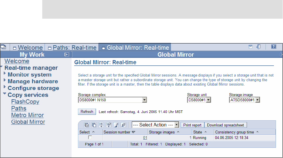
328 IBM System Storage DS6000 Series: Copy Services with IBM System z
RQUERY
There are several action parameters to determine what output information to obtain from a
Global Mirror session. The API allows you to get more information out of a Global Mirror
session than the respective TSO or ICKDSF commands. The ANTRQST macro allows
you to direct the query output to a preallocated data set, with a logical record length or
120-byte fixed length.
The ANTRQST macro is not described in detail here. If you need more information about the
Copy Services functions and how they are triggered through ANTRQST, refer to z/OS
DFSMS Advanced Copy Services, SC35-0428. This manual also contains an Assembler
sample program that starts a Global Mirror session.
24.7 DS Storage Manager GUI
Global Mirror can be managed through the DS Storage Manager-provided Web-based
graphical user interface (GUI).
In this section we illustrate, with some examples, the use of the DS SM GUI to accomplish
certain Global Mirror management activities. We are going to find out about the volumes that
are in Global Mirror session number 01, and then pause and resume the session.
Figure 24-16 shows the entry point to the Global Mirror real-time application.
Figure 24-16 Select Global Mirror real-time application
From here you select session number 01 with the check box. From the action pull-down list
you select an action.
Note: The DS SM examples that we present in this section were run in a DS8000 HMC,
but are basically similar to what you see in a DS6000 SMC when using the DS SM GUI.
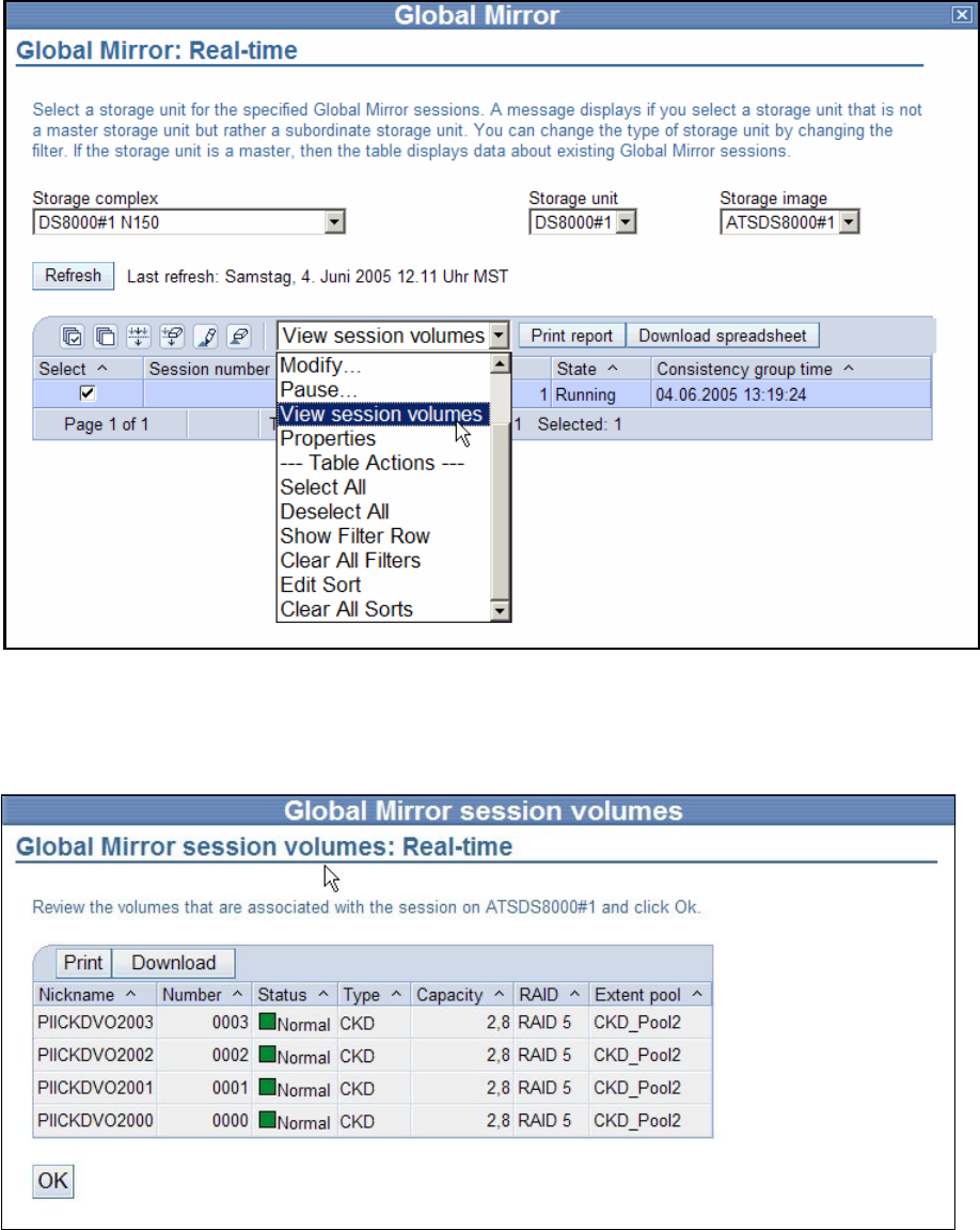
Chapter 24. Global Mirror interfaces 329
24.7.1 View Global Mirror volumes in session
From the panel in Figure 24-16 on page 328, we select the View session volumes from the
pull-down list, as shown in Figure 24-17.
Figure 24-17 View Global Mirror volumes in session1 - select action
The next panel, shown in Figure 24-18, provides the requested list of Global Copy primary
volumes that are defined to session number 01.
Figure 24-18 View Global Mirror volumes in session1 - volume list
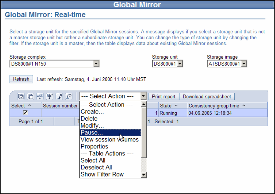
330 IBM System Storage DS6000 Series: Copy Services with IBM System z
Figure 24-18 suggests you choose meaningful nicknames for the volumeswhen you define
them to the DS6000. These nicknames indicate that the volumes belong to Extent Pool2,
which is a CKD pool, and the corresponding z/OS device numbers are 2000+. The syntax of
the nicknames is a bit limited and does, for example, not allow you to use numerics in the
prefix part of the nickname when defined through the GUI.
24.7.2 Pause and resume Global Mirror
We are now going to pause Global Mirror session number 01, and then resume the session
number again.
Figure 24-19 Pause selected session number 1 through the GUI
Start again with the pull-down action list and from the Select Action pull-down list, select
Pause; see Figure 24-19.
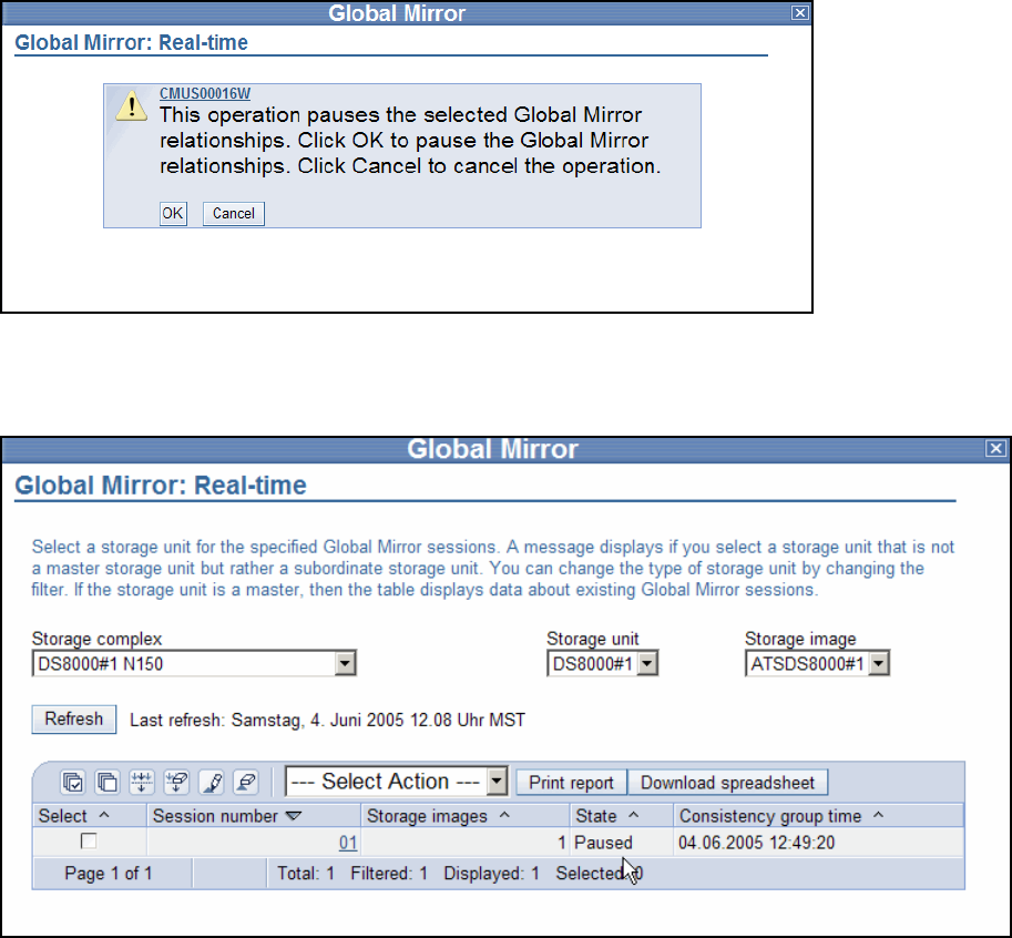
Chapter 24. Global Mirror interfaces 331
Next you receive a confirmation panel as shown in Figure 24-20.
Figure 24-20 Pause selected session number 1 - confirmation panel
Click OK and you receive the next panel; see Figure 24-21.
Figure 24-21 Session is paused
Figure 24-21 shows the result as well as the status information indicating that session number
01 is paused.
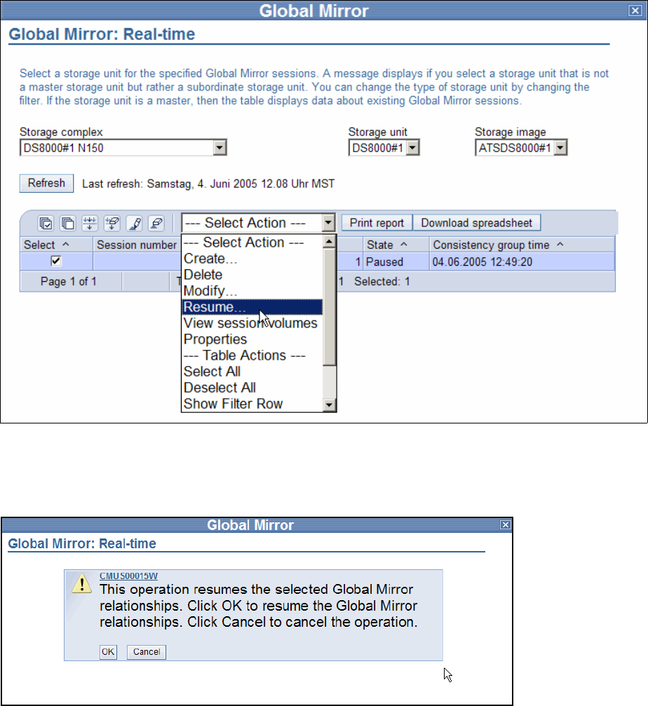
332 IBM System Storage DS6000 Series: Copy Services with IBM System z
We now resume the session. We select the corresponding action parameter, Resume, from
the Select Action pull-down list; see Figure 24-22.
Figure 24-22 Resume paused session number 1 through the GUI
You receive another confirmation panel asking whether to continue with the resume
operation; see Figure 24-23.
Figure 24-23 Resume paused session number 1 through the GUI - confirmation panel
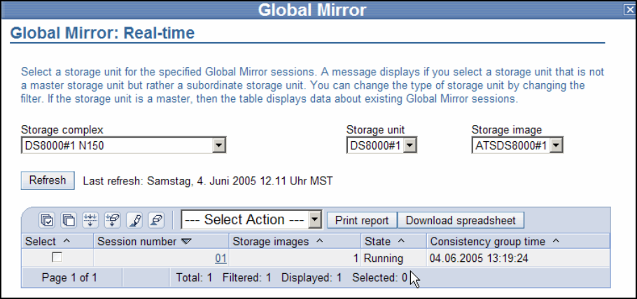
Chapter 24. Global Mirror interfaces 333
We click OK and then receive the next panel; see Figure 24-24.
Figure 24-24 Resume paused session number 1 through the GUI - session is running
The session is back and running.
There is a more extensive exercise based on the GUI in Chapter 26, “Global Mirror examples”
on page 341.
334 IBM System Storage DS6000 Series: Copy Services with IBM System z

© Copyright IBM Corp. 2006. All rights reserved. 335
Chapter 25. Global Mirror performance and
scalability
This chapter discusses performance considerations for planning and configuring Global
Mirror for DS6000. It also explains the potential impact that the three phases of Consistency
Group formation might have on application write I/Os. Finally, it covers the distribution of
B volumes and C volumes across different ranks, and how to provide extra care for very busy
volumes.
25
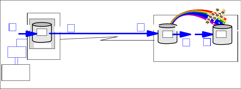
336 IBM System Storage DS6000 Series: Copy Services with IBM System z
25.1 Performance aspects for Global Mirror
Global Mirror is basically comprised of Global Copy and FlashCopy, and it combines both
functions to create a solution that provides consistent data at a distant site. Global Copy has,
at most, only a minimal impact on the response time of an application write I/O to the Global
Copy primary volumes.
In the Global Mirror environment, FlashCopy is used with the nocopy attribute. This implies
that, for any write I/Os to the FlashCopy source volume, there will be additional internally
triggered I/Os in the remote storage disk subsystem. These I/Os preserve the FlashCopy
source volume tracks by making a copy to the FlashCopy target volume before the source
tracks are updated. This happens every time within the interval in between two FlashCopy
establish operations.
Note that the nocopy attribute does not start a background copy operation from source to
target. It only maintains a set of FlashCopy bitmaps for the source and target volumes. These
bitmaps are established the first time that the FlashCopy relationship is created with the
nocopy attribute. Before a source track is modified between the creation of two Consistency
Groups, the track is copied to the target volume to preserve the previous point-in-time copy.
This includes updates to the corresponding bitmaps to reflect the new location of the track,
which belongs to the point-in-time copy. Be aware that each Global Copy write to a secondary
volume in the window of two adjacent Consistency Groups causes such a FlashCopy I/O
operation.
For an application I/O within this context, there is also a Global Copy I/O when Global Copy
replicates a track from the primary volume to the secondary volume. This implies an
additional read I/O in the primary storage disk subsystem and a corresponding write I/O to the
secondary storage disk subsystem. In a Global Mirror environment, the Global Copy
secondary volume is also the FlashCopy source volume. This might have some effect in a
very busy disk subsystem.
Figure 25-1 approximates what happens in between two Consistency Group creation events.
The application write I/O completes immediately at the local site (1). Global Copy reads the
modified track at the local site (2). Before the track gets updated on the B volume, the
FlashCopy source track is preserved on the C volume because of the nocopy attribute. This is
a read (3) and a write (4) which are done to preserve the source track writing it to the C
volume. Finally, the track is updated on the B volume by another write (5). This is not
necessarily the exact sequence of internal I/O events, but rather an approximation. There are
optimization and consolidation effects that make the entire process more efficient.
Figure 25-1 Application write I/O within two Consistency Group formation events
Primary
Primary
A
Primary
PENDING
Write
Host
FICON
A1 Read
FCP links
Primary
Primary
A
Secondary
PENDING
B1
Primary
Primary
Tertiary
C1
Write Read Write
1 2
3 4
5
Remote site
Local site
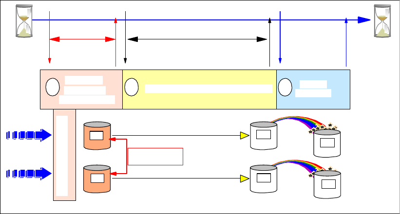
Chapter 25. Global Mirror performance and scalability 337
There is potential impact on the Global Copy data replication operation, depending on
whether persistent memory or non-volatile cache is over-committed in the secondary storage
disk subsystem. In this situation, the FlashCopy source tracks might have to be preserved
first to the FlashCopy target volume, before the Global Copy write completes. Usually,
however, all writes are quick writes to cache and persistent memory.
A write I/O to the FlashCopy source volume also triggers the maintenance of a bitmap for the
source volume, which is created when the FlashCopy volume pair is established with the start
change recording attribute. The maintenance process means that you only have to replicate
the changed recording bitmap to the corresponding bitmap for the target volume in the course
of formation of a Consistency Group. See 22.4, “Consistency Groups” on page 260, for more
information about this topic.
Note that this all applies only to write I/Os to the Global Mirror primary volumes.
25.2 Performance considerations at coordination time
When you look at the three phases that Global Mirror goes through to create a set of data
consistent volumes at the secondary site, the first question that comes to mind is whether the
coordination window imposes an impact to the application write I/O; see Figure 25-2.
Figure 25-2 Coordination time - how it impacts application write I/Os
The coordination time, which you can limit by specifying a number of milliseconds, is the
maximum impact to the write I/Os of an application, that you will allow when forming a
Consistency Group. The intention is to keep this time window as small as possible. The
default 50 ms might be a bit high in a transaction processing environment. A valid number
could also be a very low number in the single digit range. The required communication
between the master storage disk subsystem and subordinate storage disk subsystems is
inband, over the Global Mirror session paths between the master and subordinates. This
communication is highly optimized and allows you to minimize the potential application write
I/O impact to 3 ms, for example. This communication is performed over FCP links. At least
one FCP link is required between a Master storage disk subsystem and any potential
Subordinate storage disk subsystems. For redundancy, we suggest using two FCP links.
Maximum
coordination
time
drain
time
Maximum
2
Serialize all
Global Copy
primary volumes
Drain data from local to remote site Perform
FlashCopy
13
Primary
A2
Primary
A1
B2
Secondary
B1
Secondary
C2
Tertiary
C1
Tertiary
Hold write I/O
I/O
Write
Global Copy paths
Remote siteLocal site
Global Mirror
session paths
Global Copy paths
338 IBM System Storage DS6000 Series: Copy Services with IBM System z
The following example addresses the impact of the coordination time when Consistency
Group formation starts, and whether this impact has the potential to be significant or not.
Assume a total aggregated number of 5000 write I/Os over two primary storage disk
subsystems, with 2500 write I/Os per second to each storage disk subsystem. Each write I/O
takes 0.5 ms. You specified 3 ms maximum to coordinate between the master storage disk
subsystem and its subordinate storage disk subsystem. Assume further that a Consistency
Group is created every 3 seconds, which is a goal with the Consistency Group interval time of
zero. To summarize:
5000 write I/Os
0.5 ms response time for each write I/O
Maximum coordination time is 3 ms
Every 3 seconds a Consistency Group is created
This is 5 I/Os for every millisecond or 15 I/Os within 3 ms. So each of these 15 write I/Os
experience a 3 ms delay. This happens every 3 seconds. Then we observe an average
response time delay of approximately:
(15 IOs * 0.003 sec) / 3*5000 IO/sec) = 0.000003 sec or 0.003 ms.
The response time increases on average from 0.5 ms to 0.503 ms. RMF is currently not
capable of even showing such a small difference.
25.3 Consistency Group transmission
After the Consistency Group is established at the primary storage disk subsystems with the
corresponding bitmaps within the coordination time window, all remaining data that is still in
the out-of-sync bitmap is sent to the secondary storage disk subsystem with Global Copy.
This drain period can also be limited to replicate all remaining data from the primary to the
secondary storage disk subsystem in a time limit set by the maximum drain time. The default
is 30 seconds and is considered to be too small in a potentially write-intensive workload. A
number in the range of 300 seconds to 600 seconds can be considered.
This replication process usually does not impact the application write I/O. There is a very low
chance that the very same track in a Consistency Group might be updated before this track is
replicated to the secondary site, while in this drain time period. When this unlikely event
happens, the track is immediately replicated to the secondary storage disk subsystem, before
the application write I/O modifies the original track. The application write I/O is going to
experience a response time similar to that experienced if the I/O had been written to a Metro
Mirror primary volume.
25.4 Remote storage disk subsystem configuration
There will be I/O skews and hot spots in the storage disk subsystems. This is true for the local
and remote storage disk subsystems. For the local storage disk subsystems, you can
consider a horizontal pooling approach, and spread each volume type across all ranks.
Volume types are in this context, for example, DB2® database volumes, logging volumes,
batch volumes, temporary volumes, and so forth. Your goal might be to have the same
number of each volume type within each rank.
Through a one-to-one mapping from the local to the remote storage disk subsystem, you
achieve the same configuration at the remote site for the B volumes and the C volumes.
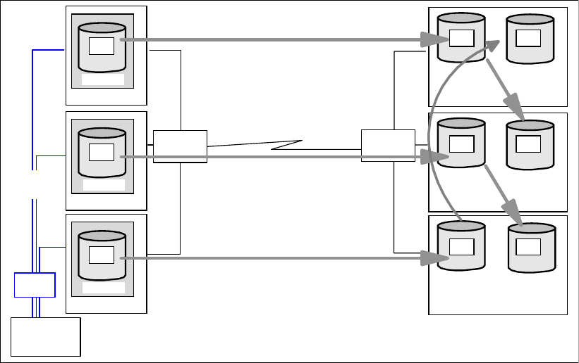
Chapter 25. Global Mirror performance and scalability 339
Figure 25-3 on page 339 proposes spreading the B and C volumes over different ranks at the
remote storage disk subsystem.
Figure 25-3 Remote disk subsystem - all ranks with equal numbers of volumes
The goal is to put the same number of each volume type into each rank. As volume type here,
we refer to the B volumes and the C volumes of the Global Mirror configuration. To prevent an
unbalanced configuration, spread busy volumes over multiple ranks. Otherwise, hot spots will
be concentrated on single ranks when you put the B and C volumes on the very same rank.
The authors recommend that you spread B and C volumes as shown in Figure 25-3.
Another aspect would be to focus on very busy volumes and keep these volumes on separate
ranks away from all the other volumes.
With mixed disk drive capacities, and different speeds, consider spreading B volumes not only
over the fast disks, but also over all ranks. Basically follow a similar approach to that in
Figure 25-3. You can keep particular busy B volumes and C volumes on the faster disks.
Figure 25-4 on page 340 shows, in addition to the three Global Mirror volumes types, the D
volumes, which can be created once in a while for test or other purposes. Here we suggest,
as an alternative, a rank with larger and perhaps slower disks. The D volumes can be read
from another host, and any other I/O to the D volumes does not impact the Global Mirror
volumes in the other ranks. An option here might be to spread all B volumes across all ranks
again, and also configure the same number of volumes in each rank.
Remote siteLocal site
Primary
Primary
A
Secondary
Primary
Primary
Tertia ry
PENDING
Primary
Primary
A
Secondary
Primary
Primary
Tertiary
PENDING
Primary
Primary
A
Secondary
Primary
Primary
Tertiary
PENDING
Primary
Primary
A
Primary
PENDING
Primary
Primary
A
Primary
PENDING
Primary
Primary
A
Primary
PENDING
Host
channels
Rank 1
links
FCP
FICON
FCP
A1
A2
A3
B1
B2
B3
C1
C2
C3
Rank 2
Rank 3
Rank 1
Rank 2
Rank 3
Host
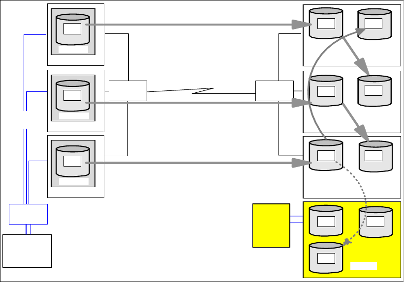
340 IBM System Storage DS6000 Series: Copy Services with IBM System z
Figure 25-4 Remote storage disk subsystem with D volumes
You should still put the B and C volumes in different ranks. It is further recommended that you
configure corresponding B and C volumes in such a way that these volumes have an affinity
to the same server. It would also be ideal to have the B volumes connected to a different DA
pair than the C volumes.
25.5 Growth within Global Mirror configurations
When you add a rather large number of volumes at once to an existing Global Mirror session,
then the available resources for Global Copy within the affected ranks might be over-utilized
or even monopolized by the initial copy pass. To avoid too much impact, consider adding
many new volumes to an existing Global Mirror session in stages. If possible, and as a rough
rule of thumb, add only a few volumes in a rank during application peak I/O periods. After the
first initial copy is complete, add the next few volumes. Again, as a rule of thumb, plan for
adding one or two volumes in a rank during peak I/O load for the first initial copy pass. If
possible, then plan a massive add of new Global Copy volumes into an existing session
during off-peak periods.
Remote siteLocal site
Primary
Primary
A
Primary
Primary
A
Secondary
Primary
Primary
Tertiary
PENDING
Primary
Primary
A
Secondary
Primary
Primary
Tertiary
PENDING
Primary
Primary
A
Primary
PENDING
Primary
Primary
A
Primary
PENDING
Primary
Primary
A
Primary
PENDING
Host
channels
Rank 1
Host
links
FCP
FICON
FCP
A1
A2
A3
B1
B2
D3
C1
C3
Rank 2
Rank 3
Rank 1
Rank 2
Rank 4
Primary
Primary
A
Secondary
Primary
Primary
Tertiary
PENDING
B3 C2
Rank 3
Primary
Primary
A Primary
Primary
D1 D2
Host

© Copyright IBM Corp. 2006. All rights reserved. 341
Chapter 26. Global Mirror examples
In this chapter we provide examples that illustrate how to set up and manage a Global Mirror
environment, using the available interfaces: TSO commands, ICKDSF, DS SM GUI, and DS
CLI. The examples show how to:
Query Global Mirror sessions.
Establish a Global Mirror environment (paths, pairs. session).
Deal with a primary site failure and the subsequent recovery at the backup site. Also, the
management of a planned outage is discussed.
Remove a Global Mirror environment.
The information discussed in this chapter can be complemented with the following IBM
publications:
z/OS DFSMS Advanced Copy Services, SC35-0428
IBM System Storage DS6000: Command-Line Interface User´s Guide, GC26-7922
Device Support Facility User’s Guide and Reference, SC35-0033
26
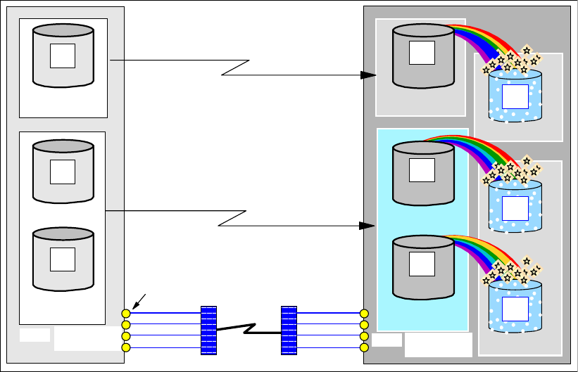
342 IBM System Storage DS6000 Series: Copy Services with IBM System z
26.1 Global Mirror examples - configuration
In order to illustrate the basic use of commands to manage a Global Mirror environment, the
following examples are limited to a few volumes only to keep these examples as simple as
possible and avoid confusing complexity.
Figure 26-1 shows the volumes with their device numbers and their SSIDs, which are used
throughout most of the examples within this chapter. Some other configuration data may be
used for the DS CLI examples, or examples based on ICKDSF.
Figure 26-1 Global Mirror base configuration for the following examples
Note that one primary volume resides in SSID 2C00, and two other primary volumes belong to
SSID 2D00, all of them in the primary storage disk subsystem 27131. These primary volumes
are also referred to as A volumes. The corresponding secondary volumes are in the
respective SSIDs in the remote disk subsystem 73081; so are the FlashCopy target volumes.
When a Global Mirror configuration is in normal operation, the Global Copy secondary
volume is at the same time the FlashCopy source volume. These volumes are referred to as
B volumes. The FlashCopy target volumes are referred to as C volumes.
26.2 Global Mirror query examples with TSO
The following examples describe how to set up a Global Mirror configuration using TSO
commands. The first examples focus on the query capabilities. All the examples are based on
the scenario illustrated in Figure 26-1.
26.2.1 Query a Global Mirror session
The RQUERY command provides information about a Global Mirror session. RQUERY has
the following options:
FCP ports
Global Copy
Global Copy
DWDM or
Channel Extender
network
infrastructure
FlashCopy
LCU: 3D00
LCU: 3F00
LCU: 3E00
LCU: 3C00
C
C
Secondary
C
B
3D01
3F01
3F00
3E00
Secondary
B
3D00
Secondary
B
3C00
73081
27131
LCU: 2C00
Primary
A
2C00
Master
LCU: 2D00
Primary
Primary
Primary
A
2D00
Primary
A
2D01
Subordinate
secondary
disk subsystem
primary
disk subsystem
FCP links FCP links

Chapter 26. Global Mirror examples 343
DVCSTAT
GMLSTAT
GMPSTAT
The RQUERY command and its options have been explained in 24.3.8, “Query a Global
Mirror session” on page 310.
26.2.2 Query Global Mirror volume status - DVCSTAT option
The DVCSTAT option returns information pertaining to the volumes in the LSS where
VOLSER points to. Note that the specified VOLSER itself does not have to be a Global Mirror
volume. You direct this command to an LSS that is part of a Global Mirror session.
Example 26-1 RQUERY TSO command with the DVCSTAT option and formatted output
RQUERY SNBR(01) VOLSER(XX2C00) ACTION(DVCSTAT)
RQUERY Output Volser(XX2C00) Action(DVCSTAT) Version(001)
SNbr LSS Dvc VolStat PriPPRCStat SecCascStat
-- -- -- -------------------- ---------- ----------
01 0C 00 InSession DplxPendng Simplex
In Example 26-1 the query is targeted to an LSS with a Global Copy volume in session
number 01. The LSS is the one that has device 2C00 in it; see Figure 26-1 on page 342.
Through the VOLSER parameter, the next RQUERY points to the another LSS that is also
involved in this Global Mirror session; see Example 26-2.
Example 26-2 RQUERY with DVCSTAT of the second LSS with Global Mirror volumes
RQUERY SNBR(01) VOLSER(XX2D00) ACTION(DVCSTAT)
RQUERY Output Volser(XX2D00) Action(DVCSTAT) Version(001)
SNbr LSS Dvc VolStat PriPPRCStat SecCascStat
-- -- -- -------------------- ---------- ----------
01 0D 00 InSession DplxPendng Simplex
0D 01 InSession DplxPendng Simplex
All three volumes are in Global Mirror session number 01. You may consider omitting the
session number parameter SNBR. In this case RQUERY returns whatever session is
currently active in the addressed LSS and its Global Mirror volumes.
26.2.3 Query Global Mirror session summary - GMLSTAT option
When used with the GMLSTAT parameter, the RQUERY command, pointing through the
VOLSER parameter to the Global Mirror Master LSS, provides summary information about
the volumes involved in the session.
When you address an LSS that is not the Global Mirror Master LSS, the GMLSTAT option
does not return Global Mirror session information, as Example 26-3 on page 344 illustrates.

344 IBM System Storage DS6000 Series: Copy Services with IBM System z
Example 26-3 RQUERY GMLSTAT output when not addressing an LSS with an active session
RQUERY SNBR(01) VOLSER(XX2D00) ACTION(GMLSTAT)
RQUERY Output Volser(XX2D00) Action(GMLSTAT) Version(001)
SNbr GMLStat GoodCg Pct CrnBadCG TotBadCG LastGoodCGSCntlClock
-- ---------- -------- --- -------- -------- --------------------
01 NoConfig
LSS 2D00 has an active Global Mirror volume but it is not the Master LSS. Therefore,
RQUERY in Example 26-3 does not provide session summary information although both
LSSs reside in the very same primary storage disk subsystem. Note that the decision of
which LSS is the Master LSS, is made when the Global Mirror session is started.
Example 26-4 shows an example of the formatted output of the RQUERY command with the
ACTION(GMLSTAT) parameter specified.
Example 26-4 Session summary as the Master LSS reports
RQUERY SNBR(01) VOLSER(XX2C00) ACTION(GMLSTAT)
RQUERY Output Volser(XX2C00) Action(GMLSTAT) Version(001)
SNbr GMLStat GoodCg Pct CrnBadCG TotBadCG LastGoodCGSCntlClock
-- ---------- -------- --- -------- -------- --------------------
01 Running 0000D0C1 99 00000005 19 May 2005 19:08:00
.
Master: Serial SSID LSS CGInt CGDrn CrdInt
------------ ---- -- ----- ----- -----
000107527131 2C00 0C 0 600 5
.
BadCGrpFormation: When Serial SSID LSS Reason Activity
----- ------------ ---- --- ---------- ----------
Last 000107527131 2C00 0C CmdRej FCC StrtIncr
Prev 000107527131 2C00 0C CmdRej FCC StrtIncr
First 000107527131 2C00 0C CmdRej FCC StrtIncr
This is the active Global Mirror session as was shown in Figure 26-1 on page 342. During
these queries, a write workload was running on all three Global Mirror primary volumes.
26.2.4 Global Mirror session status for each LSS - GMPSTAT option
The ACTION(GMPSTAT) option returns Global Mirror session information with volume
counts, and out-of-sync tracks information, related to the addressed LSS.
Example 26-5 RQUERY session status for LCU 2C00, LSS 0C
RQUERY SNBR(01) VOLSER(XX2C00) ACTION(GMPSTAT)
RQUERY Output Volser(XX2C00) Action(GMPSTAT) Version(001)
SNbr LSS GMPStatus TotVol OOSVol OOSTrks
-- -- ---------- ------ ------ --------
01 0C CGInPrgrs 1 0 00000000
Example 26-5 shows the formatted output with the session status details for LCU 2C00.

Chapter 26. Global Mirror examples 345
26.2.5 Timing information
Creating consistency groups relies also on internal timing information. It is important to
understand that the internal timer in the DS6000 is not synchronized with an external clock.
Example 26-6 shows an RQUERY command example with a TIME command just before the
RQUERY command. The TSO TIME command displays the CPU based timer, which displays
10:09:32. Consistency Group drain time limit is 60 seconds or one minute. RQUERY displays
the internal disk subsystem clock time with 14:37:59 as the time of the last good Consistency
Group. Both timers are about 4 1/2 hours apart from each other. Even with a few failed
attempts to form Consistency Groups, the disk subsystem clock time would be just a few
minutes behind the CPU-based clock.
Example 26-6 Internal timer is not synchronized with external timer
TIME-10:09:32 AM. CPU-00:00:00 SERVICE-255 SESSION-00:00:00 JUNE 17,2005
READY
RQUERY VOLSER(AA601F) ACTION(GMLSTAT)
RQUERY Output Volser(AA601F) Action(GMLSTAT) Version(001)
SNbr GMLStat GoodCg Pct CrnBadCG TotBadCG LastGoodCGSCntlClock
-- ---------- -------- --- -------- -------- --------------------
01 Running 00000125 98 00000003 00000005 17 Jun 2005 14:37:59
. .
Master: Serial SSID LSS CGInt CGDrn CrdInt
------------ ---- -- ----- ----- -----
0002013AAGXA 2060 00 15 60 5
. .
BadCGrpFormation: When Serial SSID LSS Reason Activity
----- ------------ ---- --- ---------- ----------
Last 0002013AAGXA ???? FF DrTimeExcd DrnInPrg
Prev 0002013AAGXA ???? FF DrTimeExcd DrnInPrg
First 0002013AAGXA 2060 00 CmdRej FC4 RunInPrg
READY
Note that you cannot rely on the internal disk subsystem clock time information as an
absolute wall clock timing type. You may set the internal disk subsystem clock time with the
help of an IBM customer engineer as close to the actual wall clock as possible.
26.3 Set up the Global Mirror environment using TSO
The following sequence of examples shows how to set up a Global Mirror environment using
TSO commands. Most steps to create a Global Mirror environment can be done in any order.
Still we recommend the following order:
1. Establish all necessary paths between the Global Copy primary LSSs and their
corresponding secondary LSSs. Here also, you may establish paths at the local site,
between the Master and any Subordinate storage disk subsystem LSSs, that will
participate in the Global Mirror session. When there is only one primary storage disk
subsystem involved, you do not need to define paths between the primary LSSs. In this
case, the communication between Master and Subordinate LSSs within the storage disk
subsystem is done internally.
2. Establish the Global Copy pairs between the A and B volumes. For this you use the
MODE(COPY) parameter option. You may wait until the first initial copy phase is complete
before continuing to the next step.
3. Establish FlashCopy relationships between the B and C volumes. Use the
MODE(ASYNC) parameter option with the corresponding TSO FCESTABL command.

346 IBM System Storage DS6000 Series: Copy Services with IBM System z
4. Define the Global Mirror session and create a session ID between 1 and 255. You define
this session ID to the LSS that will become the Master, as well as to the LSSs in the
Subordinate storage disk subsystems that are going to participate in this session. Still the
Master LSS has not yet been appointed, which happens later when you start the session.
5. Populate the session with the Global Copy primary volumes (A). It is recommended that
the Global Copy primary volumes be added to the session once they have completed their
initial copy phase, also referred to as the “first pass.”
6. Start the session. This command actually defines the Master LSS. All further session
commands have to go through this LSS. You may also specify with the start command the
Global Mirror tuning parameters: maximum drain time, maximum coordination time, and
Consistency Group interval time.
Volumes can be added to the session at any time after the session number is defined to the
LSS where the volumes reside. Once the session is started, volumes can be added to the
session or can be removed from the session at any time.
Volumes may be added to a session in any state: simplex, pending, duplex, or suspended.
Volumes that have not completed their initial copy phase stay in a join pending state until the
first pass is complete. If a newly added volume to a session is a primary suspended volume,
the first attempt to form a Consistency Group will fail. It is recommended to add only Global
Copy primary volumes that completed their initial copy phase.
When you plan to add a new Subordinate storage disk subsystem to an active session, you
have to stop the session first. Then add the new Subordinate storage disk subsystem and
start the session again with the updated RSESSION command, which then also contains the
new Subordinate storage disk subsystem.
When you add a new LSS to an active Global Mirror session, and this LSS belongs to a
storage disk subsystem that already has another LSS which belongs to the session, you may
just add the new LSS to the session without stop and start of the session. This is true for
either the Master storage disk subsystem or for a Subordinate disk subsystem.
26.3.1 Define paths
First you define paths from A to B; see Example 26-7 on page 347. These are the paths that
will be used for data transmission between the Global Copy pairs.
Note: If you still have not defined the paths between the Master LSS and the
Subordinate storage disk subsystem LSSs, then this is the time to do that before you
continue on.
Note: You only add Global Copy primary volumes to a Global Mirror session.

Chapter 26. Global Mirror examples 347
Example 26-7 Define paths for Global Copy from A to B
//* ---------------------------- TSO ----------------------------- ***
//* ESTABLISH PATH(S) for Global Copy pairs ***
//* -------------------------------------------------------------- ***
//EPATHS EXEC PGM=IKJEFT01
//SYSPRINT DD SYSOUT=*
//SYSTSPRT DD SYSOUT=*
//SYSTSIN DD DDNAME=SYSIN
CQUERY DEVN (X'2C00') PATHS
CESTPATH DEVN (X'2C00') +
PRIM (X'2C00' 5005076303FFC228 X'0C') +
SEC (X'3C00' 5005076303FFC422 X'0C') +
LINK (X'00300030' X'01300130' +
X'02300230' X'03310330') CGROUP(NO)
CQUERY DEVN (X'2C00') PATHS
CQUERY DEVN (X'2D00') PATHS
CESTPATH DEVN (X'2D00') +
PRIM (X'2D00' 5005076303FFC228 X'0D') +
SEC (X'3D00' 5005076303FFC422 X'0D') +
LINK (X'00300030' X'01300130' +
X'02300230' X'03310330') CGROUP(NO)
CQUERY DEVN (X'2D00') PATHS
Verify, using query commands, that all paths have been defined and are operational. In our
case, even though the previous path definition commands had completed successfully, a
subsequent CQUERY reveals that there is a problem with one of the paths; see
Example 26-8.
Example 26-8 Verify successful path creation
*************** PPRC REMOTE COPY CQUERY - PATHS ********************
* PRIMARY UNIT: SERIAL#= 000000027131 SSID= 2C00 SS= 2107 LSS= 0C *
* FIRST SECOND THIRD FOURTH *
* SECONDARY SECONDARY SECONDARY SECONDARY *
*SERIAL NO: 000000073081 ............ ............ ............ *
* SSID LSS: 3C00 0C ....... ....... ....... *
* PATHS: 4 0 0 0 *
* PFCA SFCA S* SAID DEST S* SAID DEST S* SAID DEST S* *
* --------- -- --------- -- --------- -- --------- -- *
* 1: 0030 0030 13 ---- ---- 00 ---- ---- 00 ---- ---- 00 *
* 2: 0130 0130 13 ---- ---- 00 ---- ---- 00 ---- ---- 00 *
* 3: 0230 0230 13 ---- ---- 00 ---- ---- 00 ---- ---- 00 *
* 4: 0331 0330 14 ---- ---- 00 ---- ---- 00 ---- ---- 00 *
* SUBSYSTEM WWNN LIC LEVEL *
* ----------- ---------------- ----------- *
* PRIMARY.... 5005076303FFC228 5.0.03.0097 *
* SECONDARY.1 5005076303FFC422 *
* *
* S* = PATH STATUS: *
* 00=NO PATH 01=ESTABLISHED ESCON 02=INIT FAILED *
* 03=TIME OUT 04=NO RESOURCES AT PRI 05=NO RESOURCES AT SEC*
* 06=SERIAL# MISMATCH 07=SEC SSID MISMATCH 08=ESCON LINK OFFLINE *
* 09=ESTABLISH RETRY 0A=PATH ACTIVE TO HOST 0B=PATH TO SAME CLUSTR*
* 10=CONFIG ERROR FF=UNABLE TO DETERMINE *
* 13=ESTABL FIBRE PTH 14=FIBRE PATH DOWN 15=FIBRE RETRY EXCEED *
* 16=SEC ADPTR INCPBL 17=SEC ADPTR UNAVAIL 18=FIBRE LOGIN EXCEED *
********************************************************************

348 IBM System Storage DS6000 Series: Copy Services with IBM System z
You may also consider defining paths in the reverse direction. After a site failover and before
you return to the local site it may be necessary to resynchronize the volumes from the remote
site to the local site. This requires paths from the remote site to the local site. In contrast to
ESCON, FCP links allow the definition of paths in either direction over the very same link.
26.3.2 Establish Global Copy volume pairs
Create Global Copy pairs as the next step. TSO requires one PPRC CESTPAIR command
for each Global Copy pair to be established; see Example 26-9.
In the example, note that the ONLINSEC parameter is YES. It is recommended to leave this
parameter with its default value NO, which will avoid the situation where an active volume is
overridden by accident. With a value of NO, when the potential Global Copy secondary
volume is online to any system, the establish pair command will fail. When you specify YES,
the establish will happen independently of whether the potential secondary volume is online
or offline.
Example 26-9 Establish Global Copy volume pairs
//* ---------------------------- TSO ----------------------------- ***
//* ESTABLISH PPRC-XD PAIR(S) ***
//* -------------------------------------------------------------- ***
//EPAIR EXEC PGM=IKJEFT01
//SYSPRINT DD SYSOUT=*
//SYSTSPRT DD SYSOUT=*
//SYSTSIN DD DDNAME=SYSIN
CESTPAIR DEVN (X'2C00') +
PRIM (X'2C00' 27131 X'00' X'0C') +
SEC (X'3C00' 73081 X'00' X'0C') +
ONLINSEC(YES) MSGREQ(NO) CRIT(NO) +
OPTION(XD) MODE(COPY)
CESTPAIR DEVN (X'2D00') +
PRIM (X'2D00' 27131 X'00' X'0D') +
SEC (X'3D00' 73081 X'00' X'0D') +
ONLINSEC(YES) MSGREQ(NO) CRIT(NO) +
OPTION(XD) MODE(COPY)
CESTPAIR DEVN (X'2D01') +
PRIM (X'2D00' 27131 X'01' X'0D') +
SEC (X'3D00' 73081 X'01' X'0D') +
ONLINSEC(YES) MSGREQ(NO) CRIT(NO) +
OPTION(XD) MODE(COPY)
CQUERY DEVN (X'2C00')
CQUERY DEVN (X'2D00')
CQUERY DEVN (X'2D01')
Make sure the establish commands complete successfully and their initial copy phase starts.
For this you use a CQUERY command; see Example 26-10 on page 349.

Chapter 26. Global Mirror examples 349
Example 26-10 Verify that the establish Global Copy succeeded
************** PPRC REMOTE COPY CQUERY - VOLUME ********************
* (PRIMARY) (SECONDARY) *
* SSID CCA LSS SSID CCA LSS*
*DEVICE LEVEL STATE PATH STATUS SERIAL# SERIAL# *
*------ --------- ---------- ----------- --------- --------- *
* 2D00 PRIMARY.. PENDING.XD ACTIVE.. 2D00 00 0D 3D00 00 0D *
* CRIT(NO)....... CGRPLB(NO). 000000027131 000000073081*
* PATHS PFCA SFCA STATUS: DESCRIPTION *
* ----- --------- ------ ------------------- *
* 4 0030 0030 13 PATH ESTABLISHED... *
* 0130 0130 13 PATH ESTABLISHED... *
* 0230 0230 13 PATH ESTABLISHED... *
* 0331 0330 13 PATH ESTABLISHED... *
* IF STATE = PENDING/SUSPEND: TRACKS OUT OF SYNC = 49812 *
* TRACKS ON VOLUME = 50085 *
* PERCENT OF COPY COMPLETE = 1% *
* SUBSYSTEM WWNN LIC LEVEL *
* ----------- ---------------- ----------- *
* PRIMARY.... 5005076303FFC228 5.0.03.0097 *
* SECONDARY.1 5005076303FFC422 *
********************************************************************
CQUERY COMMAND COMPLETED FOR DEVICE 2D00. COMPLETION CODE: 00
Note that the CQUERY commands and their output are also written to SYSLOG. This may
flood the SYSLOG when you issue many CQUERY commands. An alternative may be to
query the Global Copy volume pairs and their status with ICKDSF-based query commands.
26.3.3 Establish FlashCopy relationships
Once the first pass is completed for Global Copy, establish the FlashCopy relationships
between the B and C volumes. Example 26-11 shows three FCESTABL TSO commands to
establish the FlashCopy pairs: one FlashCopy pair in the first LSS pair, and two FlashCopy
pairs in the second LSS pair. Note that this example implies that there is a host connectivity to
the remote storage disk subsystem, because the FlashCopy commands are directed to the
source and target FlashCopy volumes via their z/OS device numbers. No inband FlashCopy
TSO commands are used here.
Example 26-11 Establish FlashCopy pairs between B and C volume with TSO
//* ---------------------------- TSO ----------------------------- ***
//* FLASHCOPY B -> C START CHANGE RECORDING NOCOPY ETC. THROUGH ***
//* MODE(ASYNC) ***
//* -------------------------------------------------------------- ***
//* SOURCE AND TARGET REQUIRED / ONLINTGT(YES) - JUST IN CASE ***
//* -------------------------------------------------------------- ***
//FCESTBL EXEC PGM=IKJEFT01
//SYSPRINT DD SYSOUT=*
//SYSTSPRT DD SYSOUT=*
//SYSTSIN DD DDNAME=SYSIN
FCQUERY DEVN (X'3C00')
FCESTABL SDEVN(X'3C00') TDEVN(X'3E00') +
MODE (ASYNC) ONLINTGT(YES)
FCQUERY DEVN (X'3C00')
FCQUERY DEVN (X'3D00')
FCESTABL SDEVN(X'3D00') TDEVN(X'3F00') +

350 IBM System Storage DS6000 Series: Copy Services with IBM System z
MODE (ASYNC) ONLINTGT(YES)
FCQUERY DEVN (X'3D00')
FCQUERY DEVN (X'3D01')
FCESTABL SDEVN(X'3D01') TDEVN(X'3F01') +
MODE (ASYNC) ONLINTGT(YES)
FCQUERY DEVN (X'3D01')
Note the ONLINTGT parameter. Although we used here YES to make sure that the
FlashCopy command successfully completes, independent of whether the target volume is
online or offline, we still recommend to use the default of NO. This ensures that the
FlashCopy command is only successful when the target volume is offline.
You may query the FlashCopy status of the source volumes before and after the FlashCopy
establish command, to verify that a FlashCopy relationship is successfully established. See
Example 26-12.
Example 26-12 FlashCopy status before and after FCESTABL
FCQUERY DEVN (X'3C00')
FCQUERY Formatted -2
DEVN SSID LSS CCA CU SERIAL ACT MAX XC PC CC RV SEQNUM
3C00 3C00 0C 00 2107 000000073081 0 50099 N S N N 00000000
FCQUERY COMMAND COMPLETED FOR DEVICE 3C00. COMPLETION CODE: 00
READY
FCESTABL SDEVN(X'3C00') TDEVN(X'3E00') MODE (ASYNC) ONLINTGT(YES)
FCESTABL COMMAND COMPLETED FOR DEVICE 3C00. COMPLETION CODE: 00
READY
FCQUERY DEVN (X'3C00')
FCQUERY Formatted -2
DEVN SSID LSS CCA CU SERIAL ACT MAX XC PC CC RV SEQNUM
3C00 3C00 0C 00 2107 000000073081 1 50099 N S N N 00000000
FCQUERY COMMAND COMPLETED FOR DEVICE 3C00. COMPLETION CODE: 00
This concludes the setup for Global Copy and FlashCopy. Global Copy replicates the data
from the local to the remote volumes.
26.3.4 Define Global Mirror session
Example 26-13 shows the TSO command RSESSION with the ACTION parameter with the
value DEFINE. This defines a Global Mirror session that involves the selected LSSs at the
local site. You define the same session number to all LSSs that potentially contribute to the
Global Mirror session.
Example 26-13 Define Global Mirror session to all involved LSS
//* ---------------------------- TSO ------------ CREATE (4) ----- ***
//* DEFINE GM SESSION NUMBER X'01' TO LSS X'0C' AND LSS X'0D' ***
//* -------------------------------------------------------------- ***
//DEFSESS EXEC PGM=IKJEFT01
//SYSPRINT DD SYSOUT=*
//SYSTSPRT DD SYSOUT=*
//SYSTSIN DD DDNAME=SYSIN
RSESSION SNBR(01) VOLSER(XX2C00) +
ACTION(DEFINE) +
LSSTYPE(CKD) LSSNBR(0C) +
ESSSERIAL(27131) +
MSSERIAL (27131)

Chapter 26. Global Mirror examples 351
RSESSION SNBR(01) VOLSER(XX2D00) +
ACTION(DEFINE) +
LSSTYPE(CKD) LSSNBR(0D) +
ESSSERIAL(27131) +
MSSERIAL (27131)
Note that the VOLSER parameter is used to point to the LSSs that hold the Global Copy
primary volumes that will be part of this Global Mirror configuration. These volumes have to
be online to the system on which this job executes. This asks for a kind of utility volume within
each LSS. The ACTION(DEFINE) command parameter only defines, for each LSS, a session
number, which in our example is 01. It does not affect Global Copy, which is replicating the
writes I/O data from the local site to the remote site.
26.3.5 Populate the session with Global Copy primary volumes
Once the session is defined to the primary LSSs, we add Global Copy primary volumes to the
session. Example 26-14 shows the RVOLUME TSO command used to do this.
Example 26-14 Populate Global Mirror session with Global Copy primary volumes
//* ---------------------------- TSO ------------ CREATE (5) ----- ***
//* POPULATE SESSION X'01' WITH PRIMARY VOLUMES ***
//* ***
//* VOLUME LIST CONTAINS CCA NUMBERS ***
//* -------------------------------------------------------------- ***
//JOIN EXEC PGM=IKJEFT01
//SYSPRINT DD SYSOUT=*
//SYSTSPRT DD SYSOUT=*
//SYSTSIN DD DDNAME=SYSIN
RVOLUME SNBR(01) VOLSER(XX2C00) +
ACTION (JOIN) +
LSSTYPE (CKD) LSSNBR(0C) +
ESSSERIAL(27131) +
VOLLIST (00)
RVOLUME SNBR(01) VOLSER(XX2D00) +
ACTION (JOIN) +
LSSTYPE (CKD) LSSNBR(0D) +
ESSSERIAL(27131) +
VOLRANGE (00:01)
/*
Again we need an online volume to aim into the desired LSS. The first RVOLUME command
adds a volume from LSS 0C into session 01. Here we use the VOLLIST parameter that
contains the channel connection address (CCA) of the Global Copy primary volume.
The second RVOLUME command adds two volumes from LSS 0D into session 01. Here, we
use the VOLRANGE parameter, which contains a range of CCAs of Global Copy primary
volumes. VOLRANGE reads here as CCAs from 00 to 01, which is just two volumes in this
case.
Note that the Consistency Group formation has still not started. The only activity that is going
on is the Global Copy replication of data between the primary and secondary volumes.

352 IBM System Storage DS6000 Series: Copy Services with IBM System z
26.3.6 Start Global Mirror session
The last step is to start the Global Mirror session. This will start forming Consistency Groups
at the remote site. Also with this command, you are appointing the Master LSS.
Example 26-15 shows the TSO command RSESSION, but this time with the
ACTION(START) parameter option. As this parameter option implies, the microcode now
starts to create Consistency Groups at the secondary storage disk subsystem. Again, an
online volume in VOLSER is required on the system where this job executes.
With the START option you can also provide the session with tuning values other than the
default values. Here we decided to continuously create Consistency Groups. The maximum
drain time window is set to 10 minutes. The maximum application impact time is set to 5
milliseconds, at the beginning of the process of forming a new Consistency Group.
Example 26-15 Start Global Mirror session
//* ---------------------------- TSO ------------ CREATE (6) ----- ***
//* START SESSION X'01' THROUGH LSS X'0C' ***
//* ***
//* THEN LSS X'0C' BECOMES THE MASTER LSS (DS) ***
//* NOTE: LSS SYNTAX IS WITHOUT X AND QUOTES ... ***
//* ***
//* CGINTERVAL - BUILD CG WITHOUT A BREAK ***
//* CGDRAIN - ALLOW 10 MINUTES FOR DRAINING THE STUFF ***
//* COORDINTERVAL - ALLOW 5 MS MAX FOR COORDINATION ***
//* -------------------------------------------------------------- ***
//START EXEC PGM=IKJEFT01
//SYSPRINT DD SYSOUT=*
//SYSTSPRT DD SYSOUT=*
//SYSTSIN DD DDNAME=SYSIN
RSESSION SNBR(01) VOLSER(XX2C00) +
ACTION (START) +
LSSTYPE (CKD) LSSNBR(0C) +
ESSSERIAL (27131) +
MSSERIAL (27131) +
CGINTERVAL (00) +
CGDRAIN (600) +
COORDINTERVAL(05)
/*
This last step concludes the step-by-step procedure, using TSO commands, for the setup of a
Global Mirror environment with three Global Copy primary volumes spread over two LSSs.
26.4 Primary site failure and recovery management with TSO
This example goes through the required steps to recover from a primary site failure using
TSO commands. This example starts from the configuration that was set up in 26.3, “Set up
the Global Mirror environment using TSO” on page 345. The very same volumes and LSSs
are used in all corresponding TSO command examples. Figure 26-2 on page 353 shows the
configuration during normal operations.
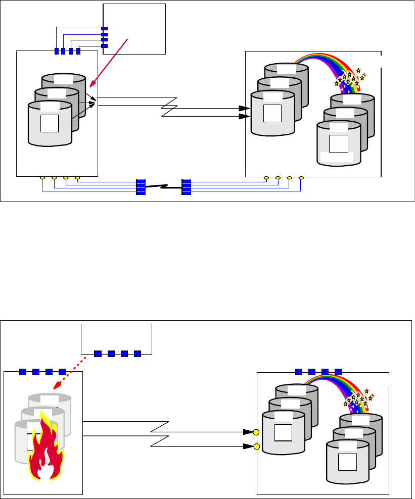
Chapter 26. Global Mirror examples 353
Figure 26-2 Global Mirror configuration before unplanned primary failure
The production applications write to three primary volumes that are part of a Global Mirror
session.
26.4.1 Primary site failure
We simulate a primary site failure that may not be fatal to the storage disk subsystem.
Figure 26-3 Unplanned primary site failure
In our testing environment, we simulated a primary site failure with a CGROUP FREEZE
command to both primary LSSs. See Figure 26-3 and Example 26-16 on page 354.
A more strict primary volume failure may be simulated through a V OFFLINE,FORCE to the
Global Copy primary volumes. This will also fail the application I/Os to the volumes. If you use
this testing procedure, do not forget to reply to the corresponding WTOR for each V
OFFLINE,FORCE.
Global Copy
Primary
Primary
A
2D01
Primary
Primary
A
2D00
Primary
A
2C00
Host
FICON
Local site
Primary
Primary
A
3F01
Primary
Primary
A
3F00
Tertiary
C
3E00
Primary
Primary
A
3D01
Primary
Primary
A
3D00
Secondary
B
3C00
73081
27131
I/O activity
FlashCopy
FCP links Remote site
FlashCopy
Global Copy
Primary
Primary
A
3F01
Primary
Primary
A
3F00
Tertiary
C
3E00
Primary
Primary
A
3D01
Primary
Primary
A
3D00
Secondary
B
3C00
Host
Remote site
Primary
Primary
A
2D01
Primary
Primary
A
2D00
Primary
A
2C00
Local site

354 IBM System Storage DS6000 Series: Copy Services with IBM System z
Example 26-16 Simulate primary site failure through CGROUP FREEZE
//* ---------------------------- TSO ------------ FAILO (2) ----- ***
//* SIMULATE PRIMARY FAILURE WITH CGROUP FREEZE/RUN ***
//* HARDER PRIMARY FAILURE THROUGH VARY OFFLINE,FORCE ***
//* -------------------------------------------------------------- ***
//FREEZE EXEC PGM=IKJEFT01
//SYSPRINT DD SYSOUT=*
//SYSTSPRT DD SYSOUT=*
//SYSTSIN DD DDNAME=SYSIN
CGROUP DEVN (X'2C00') +
PRIM (X'2C00' 27131 X'0C') +
SEC (X'3C00' 73081 X'0C') +
FREEZE
CGROUP DEVN (X'2D00') +
PRIM (X'2D00' 27131 X'0D') +
SEC (X'3D00' 73081 X'0D') +
FREEZE
//* -------------------------------------------------------------- ***
//RUN EXEC PGM=IKJEFT01
//SYSPRINT DD SYSOUT=*
//SYSTSPRT DD SYSOUT=*
//SYSTSIN DD DDNAME=SYSIN
CGROUP DEVN (X'2C00') +
PRIM (X'2C00' 27131 X'0C') +
SEC (X'3C00' 73081 X'0C') +
RUN
CGROUP DEVN (X'2D00') +
PRIM (X'2D00' 27131 X'0D') +
SEC (X'3D00' 73081 X'0D') +
RUN
CGROUP FREEZE immediately removes the paths between the primary and secondary
LSSs. An immediate CGROUP RUN command would end a potential extended long busy
(ELB) timer. Note that ELB is not possible and not useful for Global Copy.
26.4.2 Stop a Global Mirror session
When the local storage disk subsystem is still operational, you may explicitly stop the Global
Mirror session; see Example 26-17.
Example 26-17 Stop Global Mirror session when local site is still accessible
//* ------------------ TSO --------------------------------------- ***
//* Terminate GM session number X'01' ***
//* -------------------------------------------------------------- ***
//TERM EXEC PGM=IKJEFT01
//SYSPRINT DD SYSOUT=*
//SYSTSPRT DD SYSOUT=*
//SYSTSIN DD DDNAME=SYSIN
RSESSION SNBR(01) VOLSER(XX2C00) +
ACTION(STOP) +
LSSTYPE(CKD) LSSNBR(0C) +
ESSSERIAL(27131) +

Chapter 26. Global Mirror examples 355
MSSERIAL (27131)
26.4.3 Failover from B to A volumes
Once the primary volumes fail and the application I/O stops at the primary site, the status of
the secondary volumes (B) is changed from secondary pending to primary suspended. This is
done with the ACTION(FAILOVER) on the secondary volumes; see Example 26-18.
Example 26-18 Failover from B volume to A volume
//* ---------------------------- TSO --------- FAILOVER (3) ------ ***
//* ESTABLISH Global Copy PAIR(S) FAILOVER B -> A ***
//* ***
//* NOTE: ACTION IS NOT VALID WITH MODE(COPY) ***
//* -------------------------------------------------------------- ***
//EPAIRFO EXEC PGM=IKJEFT01
//SYSPRINT DD SYSOUT=*
//SYSTSPRT DD SYSOUT=*
//SYSTSIN DD DDNAME=SYSIN
CESTPAIR DEVN (X'3C00') +
PRIM (X'3C00' 73081 X'00' X'0C') +
SEC (X'2C00' 27131 X'00' X'0C') +
ACTION(FAILOVER) +
ONLINSEC(NO) MSGREQ(NO) CRIT(NO) +
OPTION(XD) CASCADE(NO)
CESTPAIR DEVN (X'3D00') +
PRIM (X'3D00' 73081 X'00' X'0D') +
SEC (X'2D00' 27131 X'00' X'0D') +
ACTION(FAILOVER) +
ONLINSEC(NO) MSGREQ(NO) CRIT(NO) +
OPTION(XD) CASCADE(NO)
CESTPAIR DEVN (X'3D01') +
PRIM (X'3D00' 73081 X'01' X'0D') +
SEC (X'2D00' 27131 X'01' X'0D') +
ACTION(FAILOVER) +
ONLINSEC(NO) MSGREQ(NO) CRIT(NO) +
OPTION(XD) CASCADE(NO)
The FAILOVER parameter value does not need to communicate to the primary volumes. This
parameter just changes the status of the secondary volumes to primary suspended. This
includes the creation of a change recording bit map for the B volumes, which allows the
re-synchronization at a later time when returning to the local site.
26.4.4 Check Global Mirror FlashCopy status between B and C volumes
At this stage you have to verify the FlashCopy status of each FlashCopy pair. For a detailed
discussion on this verification activity, refer to 23.7.4, “Check for valid Consistency Group
state” on page 285. In our test scenario all FlashCopy pairs were in good state, with the same
FlashCopy sequence number, and all FlashCopy pairs were in non-revertible state, so no
further corrective action had to be taken.
Note: Address all Global Mirror session commands to the Master LSS. This is the LSS that
was used when the Global Mirror START command was given
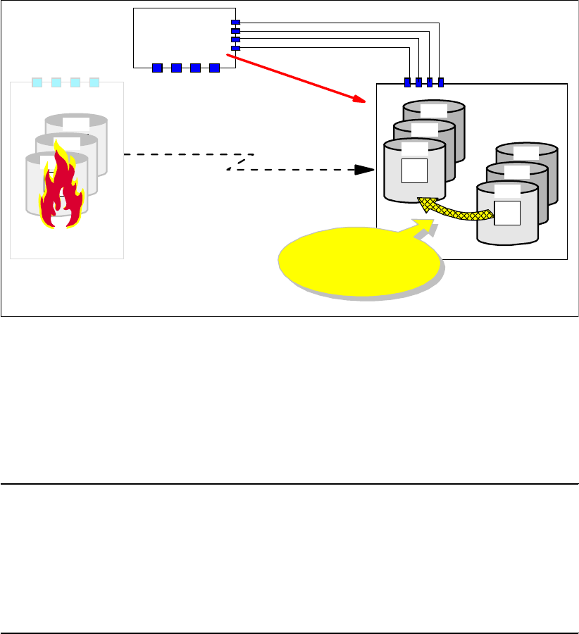
356 IBM System Storage DS6000 Series: Copy Services with IBM System z
26.4.5 Create a data consistent set of B volumes
The next step is to create a set of consistent volumes. This requires a specific FlashCopy
operation, which is fast reverse restore, FRR; see Figure 26-4.
Figure 26-4 Establish FlashCopy from last consistent C to B
This FlashCopy command uses the C volume as the source volume and the B volume as the
target volume.
Example 26-19 shows the ACTION(FRR) command parameter. In the example we use
source and target z/OS device numbers, which implies that there is host connectivity to the
secondary storage disk subsystem.
Example 26-19 Create a set of consistent B volumes
//* -------------------------------------------------------------- ***
//FCFRR EXEC PGM=IKJEFT01
//SYSPRINT DD SYSOUT=*
//SYSTSPRT DD SYSOUT=*
//SYSTSIN DD DDNAME=SYSIN
FCESTABL SDEVN(X'3E00') TDEVN(X'3C00') ACTION(FRR)
FCESTABL SDEVN(X'3F00') TDEVN(X'3D00') ACTION(FRR)
FCESTABL SDEVN(X'3F01') TDEVN(X'3D01') ACTION(FRR)
The FCESTABL command with the ACTION(FRR) parameter value does a background copy
operation that copies only the changed tracks from the C to the B volumes, those which
changed since the last Consistency Group formation. Once the background copy completes,
the FlashCopy relationship between the C and B volumes is withdrawn and ends. After that,
the C volumes are not usable and only the B volumes are now a set of data consistent
volumes.
26.4.6 Optionally create a data consistent set of D volumes
Optionally, you can create a second copy of valid data by doing a copy of the B volumes on a
set of D volumes. Example 26-20 on page 357 shows how to do this.
Global Copy
Primary
Primary
A
Primary
Primary
A
Primary
A Primary
Primary
A
3F01
Primary
Primary
A
3F00
Tertiary
C
3E00
Primary
Primary
A
3D01
Primary
Primary
A
3D00
Secondary
B
3C00
Host
Local site
FRR
FlashCopy
2D01
2D00
2C00
Remote site
FICON
Primary

Chapter 26. Global Mirror examples 357
Example 26-20 Create optional second copy of data consistent D volumes
//* ---------------------------- TSO ------------ CREATE (5) ----- ***
//* FLASHCOPY B -> D TO CREATE COPY TO WORK (TEST) WITH ***
//* -------------------------------------------------------------- ***
//FCESTBL EXEC PGM=IKJEFT01
//SYSPRINT DD SYSOUT=*
//SYSTSPRT DD SYSOUT=*
//SYSTSIN DD DDNAME=SYSIN
FCESTABL SDEVN(X'3C00') TDEVN(X'3E02')
FCQUERY DEVN (X'3C00')
FCESTABL SDEVN(X'3D00') TDEVN(X'3F02')
FCQUERY DEVN (X'3D00')
FCESTABL SDEVN(X'3D01') TDEVN(X'3F03')
FCQUERY DEVN (X'3D01')
26.4.7 Create a data consistent set of C volumes
We recommend to create a second set of consistent data on the C volumes after you have
created the B volumes as described in 26.4.5, “Create a data consistent set of B volumes” on
page 356.
Example 26-21 Setup Global Mirror FlashCopy between B and C volumes again
//* ---------------------------- TSO ----------------------------- ***
//* FLASHCOPY B -> C START CHANGE RECORDING NOCOPY ETC. THROUGH ***
//* MODE(ASYNC) OPTION (GET READY FOR GM) ***
//* -------------------------------------------------------------- ***
//FCESTBL EXEC PGM=IKJEFT01
//SYSPRINT DD SYSOUT=*
//SYSTSPRT DD SYSOUT=*
//SYSTSIN DD DDNAME=SYSIN
FCESTABL SDEVN(X'3C00') TDEVN(X'3E00') MODE(ASYNC)
FCQUERY DEVN (X'3C00')
FCESTABL SDEVN(X'3D00') TDEVN(X'3F00') MODE(ASYNC)
FCQUERY DEVN (X'3D00')
FCESTABL SDEVN(X'3D01') TDEVN(X'3F01') MODE(ASYNC)
FCQUERY DEVN (X'3D01')
Example 26-21 does a reestablish of the previous Global Mirror FlashCopy relationship
between the B and C volumes. This prepares the configuration for returning to the local site
and resuming Global Mirror as it used to be. At the same time, it also provides another copy
of data consistent volumes on the C volumes. Upon this the B volumes and the C volumes
are identical.
If you have to restart again because a previous restart to the B volumes was faulty, or the
restart was not set up correctly, you may flash again from C to B to recreate a data consistent
set of volumes on the B volumes.
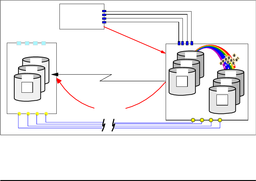
358 IBM System Storage DS6000 Series: Copy Services with IBM System z
26.4.8 Prepare to return to the local site
At some time you will plan to return to the local site. The intention here is to apply the
changes from the B volumes to the A volumes before resuming operations at the local site.
Before you can apply these changes from the B to the A volumes, you have to establish paths
from B to A.
26.4.9 Replicate the changes from B to A
With the Global Copy paths between B and A defined, you may still be running the application
at the remote site, so updates keep arriving to the B volumes. Using the ACTION(FAILBACK)
parameter, we apply the changes from the B volumes to the A volumes; see Figure 26-5.
Figure 26-5 Failback operation from B to A to prepare return to the local site
Example 26-22 illustrates how the failback is done using TSO commands. The failback
operation addresses the B volumes at the secondary site.
Example 26-22 Failback operation from B to A to prepare return to the local site
//* ---------------------------- TSO ----------------------------- ***
//* ESTABLISH Global Copy PAIR(S) FAILBACK B -> A ONCE A IS BACK ***
//* -------------------------------------------------------------- ***
//EPAIRFB EXEC PGM=IKJEFT01
//SYSPRINT DD SYSOUT=*
//SYSTSPRT DD SYSOUT=*
//SYSTSIN DD DDNAME=SYSIN
CESTPAIR DEVN (X'3C00') +
PRIM (X'3C00' 73081 X'00' X'0C') +
SEC (X'2C00' 27131 X'00' X'0C') +
ACTION(FAILBACK) +
MSGREQ(NO) CRIT(NO) +
OPTION(XD) CASCADE(NO)
CESTPAIR DEVN (X'3D00') +
PRIM (X'3D00' 73081 X'00' X'0D') +
SEC (X'2D00' 27131 X'00' X'0D') +
ACTION(FAILBACK) +
Global Copy
Primary
Primary
A
Primary
Primary
A
Primary
A
Host
Local site
2D01
2D00
2C00
Remote site
Primary
Primary
A
3D01
Primary
Primary
A
3D00
Secondary
B
3C00
Primary
Primary
A
3F01
Primary
Primary
A
3F00
Tertiary
C
3E00
FAILBACK 73081
27131
FCP links
FICON

Chapter 26. Global Mirror examples 359
MSGREQ(NO) CRIT(NO) +
OPTION(XD) CASCADE(NO)
CESTPAIR DEVN (X'3D01') +
PRIM (X'3D00' 73081 X'01' X'0D') +
SEC (X'2D00' 27131 X'01' X'0D') +
ACTION(FAILBACK) +
MSGREQ(NO) CRIT(NO) +
OPTION(XD) CASCADE(NO)
26.4.10 Return to the local site and resume Global Mirror
At some time you will plan to return the application to the local site. This requires first that you
quiesce the application at the remote site. Then, you execute an ACTION(FAILOVER)/
ACTION(FAILBACK) command sequence to the A volumes. This changes the Global Copy
direction, and leaves the A and B volumes in the same state as they originally were, before
the outage occurred. These commands are very quick because there is no data to replicate.
Example 26-23 shows the failover/failback sequence that is performed on the A volumes.
Example 26-23 Failover and Failback operations to the A volumes
//* ---------------------------- TSO --------- FAILOVER ---------- ***
//* ESTABLISH Global Copy PAIR(S) FAILOVER A -> B ***
//* -------------------------------------------------------------- ***
//EPAIRFO EXEC PGM=IKJEFT01
//SYSPRINT DD SYSOUT=*
//SYSTSPRT DD SYSOUT=*
//SYSTSIN DD DDNAME=SYSIN
CESTPAIR DEVN (X'2C00') +
PRIM (X'2C00' 27131 X'00' X'0C') +
SEC (X'3C00' 73081 X'00' X'0C') +
ACTION(FAILOVER) +
MSGREQ(NO) CRIT(NO) +
OPTION(XD) CASCADE(NO)
CESTPAIR DEVN (X'2D00') +
PRIM (X'2D00' 27131 X'00' X'0D') +
SEC (X'3D00' 73081 X'00' X'0D') +
ACTION(FAILOVER) +
MSGREQ(NO) CRIT(NO) +
OPTION(XD) CASCADE(NO)
CESTPAIR DEVN (X'2D01') +
PRIM (X'2D00' 27131 X'01' X'0D') +
SEC (X'3D00' 73081 X'01' X'0D') +
ACTION(FAILOVER) +
MSGREQ(NO) CRIT(NO) +
OPTION(XD) CASCADE(NO)
//* ---------------------------- TSO ----------------------------- ***
//* ESTABLISH Global Copy PAIR(S) FAILBACK A -> B ***
//* -------------------------------------------------------------- ***
//EPAIRFB EXEC PGM=IKJEFT01
//SYSPRINT DD SYSOUT=*
//SYSTSPRT DD SYSOUT=*
//SYSTSIN DD DDNAME=SYSIN
CESTPAIR DEVN (X'2C00') +

360 IBM System Storage DS6000 Series: Copy Services with IBM System z
PRIM (X'2C00' 27131 X'00' X'0C') +
SEC (X'3C00' 73081 X'00' X'0C') +
ACTION(FAILBACK) +
MSGREQ(NO) CRIT(NO) +
OPTION(XD) CASCADE(NO)
CESTPAIR DEVN (X'2D00') +
SEC (X'3D00' 73081 X'00' X'0D') +
PRIM (X'2D00' 27131 X'00' X'0D') +
ACTION(FAILBACK) +
MSGREQ(NO) CRIT(NO) +
OPTION(XD) CASCADE(NO)
CESTPAIR DEVN (X'2D01') +
SEC (X'3D00' 73081 X'01' X'0D') +
PRIM (X'2D00' 27131 X'01' X'0D') +
ACTION(FAILBACK) +
MSGREQ(NO) CRIT(NO) +
OPTION(XD) CASCADE(NO)
From now on the normal operation is restored, and as the production applications resume the
I/O at the local site, Global Copy will be replicating the data to the remote site, as before the
site failure occurred.
Restart Global Mirror session
Finally, to restore everything as it was, you need to restart Global Mirror to resume the
Consistency Group formation process.
26.5 Remove Global Mirror environment using TSO
To remove a Global Mirror environment, follow these steps in the following order:
1. Stop the session.
2. Remove volumes from the session.
3. Delete the session.
4. Withdraw the FlashCopy relationships.
5. Delete the Global Copy pairs.
6. Remove the paths.
The following sections go step-by-step through this procedure, and show how to execute
each of the steps using TSO commands.
26.5.1 Stop Global Mirror session
The first thing to do is to stop the Global Mirror session. Example 26-24 shows the TSO
command used to stop the session.
Example 26-24 Stop Global Mirror session
//* ------------------ TSO -------------------- CLEANUP (1) ------ ***
//* Terminate GM session number X'01' first thing to do ***
//* -------------------------------------------------------------- ***
//TERM EXEC PGM=IKJEFT01
//SYSPRINT DD SYSOUT=*
//SYSTSPRT DD SYSOUT=*
//SYSTSIN DD DDNAME=SYSIN
RSESSION SNBR(01) VOLSER(XX2C00) +

Chapter 26. Global Mirror examples 361
ACTION(STOP) +
LSSTYPE(CKD) LSSNBR(0C) +
ESSSERIAL(27131) +
MSSERIAL (27131)
RQUERY SNBR(01) VOLSER(XX2C00) ACTION(DVCSTAT)
RQUERY SNBR(01) VOLSER(XX2C00) ACTION(GMLSTAT)
RQUERY SNBR(01) VOLSER(XX2C00) ACTION(GMPSTAT)
The GMPSTAT query shown in Example 26-25 informs that session 01 is not active any
longer. Numbers are reset to zeros.
Example 26-25 Session query after session stop
RQUERY SNBR(01) VOLSER(XX2C00) ACTION(GMPSTAT)
RQUERY Output Volser(XX2C00) Action(GMPSTAT) Version(001)
SNbr LSS GMPStatus TotVol OOSVol OOSTrks
-- -- ---------- ------ ------ --------
01 0C NotStarted 1 0 00000000
26.5.2 Remove volumes from the session
After the session has been stopped, remove the Global Mirror primary volumes from the
session. Example 26-26 shows how to do this. The RQUERY commands are used to verify
the status of the devices after their removal from the session.
Example 26-26 Remove volumes from the session
//* ------------------ TSO ----------------- CLEANUP (2) --------- ***
//* REMOVE VOLUMES FROM SESSION NUMBER 01 AFTER SESSION STOPPED ***
//* ***
//* VOLUME LIST CONTAINS CCA NUMBERS ***
//* -------------------------------------------------------------- ***
//REMOVE EXEC PGM=IKJEFT01
//SYSPRINT DD SYSOUT=*
//SYSTSPRT DD SYSOUT=*
//SYSTSIN DD DDNAME=SYSIN
RVOLUME SNBR(01) VOLSER(XX2C00) +
ACTION(REMOVE) +
LSSTYPE(CKD) LSSNBR(0C) +
ESSSERIAL(27131) +
VOLLIST (00)
RVOLUME SNBR(01) VOLSER(XX2D00) +
ACTION(REMOVE) +
LSSTYPE(CKD) LSSNBR(0D) +
ESSSERIAL(27131) +
VOLLIST (00,01)
RQUERY SNBR(01) VOLSER(XX2C00) ACTION(DVCSTAT)
RQUERY SNBR(01) VOLSER(XX2D00) ACTION(DVCSTAT)
The RQUERY commands, after the Global Copy primary volumes have been removed, still
display the session number 01, but no longer any volumes. This is shown in Example 26-27
on page 362.

362 IBM System Storage DS6000 Series: Copy Services with IBM System z
Example 26-27 Query Global Mirror volumes after removal
RQUERY SNBR(01) VOLSER(XX2C00) ACTION(DVCSTAT)
RQUERY Output Volser(XX2C00) Action(DVCSTAT) Version(001)
SNbr LSS Dvc VolStat PriPPRCStat SecCascStat
-- -- -- -------------------- ---------- ----------
01 NoVolumes
READY
RQUERY SNBR(01) VOLSER(XX2D00) ACTION(DVCSTAT)
RQUERY Output Volser(XX2D00) Action(DVCSTAT) Version(001)
SNbr LSS Dvc VolStat PriPPRCStat SecCascStat
-- -- -- -------------------- ---------- ----------
01 NoVolumes
26.5.3 Delete the Global Mirror session
The next step is to delete the Global Mirror session from all the involved LSSs.
Example 26-28 shows how to do this.
Example 26-28 Delete the Global Mirror session from all involved LSSs
//* ------------------ TSO ----------------- CLEANUP (3) --------- ***
//* UNdefine GM session number X'01' through both involved LSS #s ***
//* == ***
//* -------------------------------------------------------------- ***
//UNDEFINE EXEC PGM=IKJEFT01
//SYSPRINT DD SYSOUT=*
//SYSTSPRT DD SYSOUT=*
//SYSTSIN DD DDNAME=SYSIN
RSESSION SNBR(01) VOLSER(XX2C00) +
ACTION(UNDEFINE) +
LSSTYPE(CKD) LSSNBR(0C) +
ESSSERIAL(27131) +
MSSERIAL (27131)
RSESSION SNBR(01) VOLSER(XX2D00) +
ACTION(UNDEFINE) +
LSSTYPE(CKD) LSSNBR(0D) +
ESSSERIAL(27131) +
MSSERIAL (27131)
RQUERY SNBR(01) VOLSER(XX2C00) ACTION(DVCSTAT)
RQUERY SNBR(01) VOLSER(XX2C00) ACTION(GMLSTAT)
RQUERY SNBR(01) VOLSER(XX2C00) ACTION(GMPSTAT)
26.5.4 Remove FlashCopy relationships
After the Global Mirror session is removed and deleted, you may remove the FlashCopy
relationships between the B and C volumes. Example 26-29 on page 363 shows how to do
this.

Chapter 26. Global Mirror examples 363
Example 26-29 Remove FlashCopy relationships
//* ------------------ TSO ----------------- CLEANUP (4) --------- ***
//* Remove FlashCopy relationship from B -> C ***
//* -------------------------------------------------------------- ***
//FCWDRW EXEC PGM=IKJEFT01
//SYSPRINT DD SYSOUT=*
//SYSTSPRT DD SYSOUT=*
//SYSTSIN DD DDNAME=SYSIN
FCQUERY DEVN (X'3C00')
FCWITHDR SDEVN(X'3C00') TDEVN(X'3E00')
FCQUERY DEVN (X'3C00')
FCQUERY DEVN (X'3D00')
FCWITHDR SDEVN(X'3D00') TDEVN(X'3F00')
FCQUERY DEVN (X'3D00')
FCQUERY DEVN (X'3D01')
FCWITHDR SDEVN(X'3D01') TDEVN(X'3F01')
FCQUERY DEVN (X'3D01')
You may verify, with a last FlashCopy query, that the FlashCopy relationships are removed.
Example 26-30 illustrates this.
Example 26-30 FCQUERY commands and their output
READY
FCQUERY DEVN (X'3C00')
FCQUERY Formatted -2
DEVN SSID LSS CCA CU SERIAL ACT MAX XC PC CC RV SEQNUM
3C00 3C00 0C 00 2107 000000073081 1 50099 N S N N 429334DE
FCQUERY COMMAND COMPLETED FOR DEVICE 3C00. COMPLETION CODE: 00
READY
FCWITHDR SDEVN(X'3C00') TDEVN(X'3E00')
FCWITHDR COMMAND COMPLETED FOR DEVICE 3C00. COMPLETION CODE: 00
READY
FCQUERY DEVN (X'3C00')
FCQUERY Formatted -2
DEVN SSID LSS CCA CU SERIAL ACT MAX XC PC CC RV SEQNUM
3C00 3C00 0C 00 2107 000000073081 0 50099 N S N N 00000000
FCQUERY COMMAND COMPLETED FOR DEVICE 3C00. COMPLETION CODE: 00
READY
The ACT column with the number 1 indicates an active FlashCopy relationship. The 0 (zero) in
the FlashCopy query, after the FlashCopy withdraw command, indicates that the FlashCopy
relationship is removed.
26.5.5 Delete Global Copy volume pairs
Remove all Global Copy volume pair relationships. Example 26-31 on page 364 shows the
TSO commands that are used for this.

364 IBM System Storage DS6000 Series: Copy Services with IBM System z
Example 26-31 Delete Global Copy volume pairs
//* ------------------ TSO ---------------- CLEANUP (5) ---------- ***
//* Delete Global Copy volumes pairs ***
//* ***
//* DELETE PRIMARY X'2C00' ***
//* X'2D00' ***
//* X'2D01' ***
//* ***
//* PRIM(X'2C00' 27131 X'00' X'0C') ***
//* SSID ##### CCA LSS ***
//* -------------------------------------------------------------- ***
//DPAIR EXEC PGM=IKJEFT01
//SYSPRINT DD SYSOUT=*
//SYSTSPRT DD SYSOUT=*
//SYSTSIN DD DDNAME=SYSIN
//SYSTSIN DD DDNAME=SYSIN
CQUERY DEVN(X'2C00')
CQUERY DEVN(X'2D00')
CQUERY DEVN(X'2D01')
CDELPAIR DEVN(X'2C00') +
PRIM(X'2C00' 27131 X'00' X'0C') +
SEC (X'3C00' 73081 X'00' X'0C')
CDELPAIR DEVN(X'2D00') +
PRIM(X'2D00' 27131 X'00' X'0D') +
SEC (X'3D00' 73081 X'00' X'0D')
CDELPAIR DEVN(X'2D01') +
PRIM(X'2D00' 27131 X'01' X'0D') +
SEC (X'3D00' 73081 X'01' X'0D')
CQUERY DEVN(X'2C00')
CQUERY DEVN(X'2D00')
CQUERY DEVN(X'2D01')
You may check the status of the Global Copy primary volumes before and after the
CDELPAIR command sequence. Example 26-32 and Example 26-33 show the CQUERY
commands and their formatted output.
Example 26-32 CQUERY before deleting the Global Copy pair
READY
CQUERY DEVN(X'2C00')
CQUERY FORMATTED LVL 3
VOLUME REPORT
************** PPRC REMOTE COPY CQUERY - VOLUME ********************
* (PRIMARY) (SECONDARY) *
* SSID CCA LSS SSID CCA LSS*
*DEVICE LEVEL STATE PATH STATUS SERIAL# SERIAL# *
*------ --------- ---------- ----------- --------- --------- *
* 2C00 PRIMARY.. PENDING.XD ACTIVE.. 2C00 00 0C 3C00 00 0C *
* CRIT(NO)....... CGRPLB(NO). 000000027131 000000073081*
* PATHS PFCA SFCA STATUS: DESCRIPTION *
* ----- --------- ------ ------------------- *
* 4 0030 0030 13 PATH ESTABLISHED... *
* 0130 0130 13 PATH ESTABLISHED... *
* 0230 0230 13 PATH ESTABLISHED... *
* 0331 0330 14 (UNDETERMINED)..... *
* SUBSYSTEM WWNN LIC LEVEL *
* ----------- ---------------- ----------- *

Chapter 26. Global Mirror examples 365
* PRIMARY.... 5005076303FFC228 5.0.03.0097 *
* SECONDARY.1 5005076303FFC422 *
********************************************************************
Example 26-33 CQUERY after deleting the Global Copy pair
READY
CQUERY DEVN(X'2C00')
CQUERY FORMATTED LVL 3
VOLUME REPORT
************** PPRC REMOTE COPY CQUERY - VOLUME ********************
* (PRIMARY) (SECONDARY) *
* SSID CCA LSS SSID CCA LSS*
*DEVICE LEVEL STATE PATH STATUS SERIAL# SERIAL# *
*------ --------- ---------- ----------- --------- --------- *
* 2C00 ......... SIMPLEX... INACTIVE 2C00 00 0C .......... *
* ............... ........... 000000027131 ............*
* PATHS SAID DEST STATUS: DESCRIPTION *
* ----- --------- ------ ------------------- *
* 0 ---- ---- 00 NO PATH............ *
* ---- ---- 00 NO PATH............ *
* ---- ---- 00 NO PATH............ *
* ---- ---- 00 NO PATH............ *
* SUBSYSTEM WWNN LIC LEVEL *
* ----------- ---------------- ----------- *
* PRIMARY.... 5005076303FFC228 5.0.03.0097 *
* SECONDARY.1 5005076303FFC422 *
********************************************************************
CQUERY COMMAND COMPLETED FOR DEVICE 2C00. COMPLETION CODE: 00
Note that this bulky formatted output is also written to SYSLOG. When you issue many
CQUERY commands at once, it is going to flood your SYSLOG. And this is going to quickly
exhaust the WTO buffers, which will lead to the corresponding buffer shortage messages.
There is also an unformatted output of the CQUERY command that provides the same
information as the formatted output, but in fewer output lines; see Example 26-34.
Example 26-34 CQUERY unformatted output
READY
CQUERY DEVN (X'2C00') UNFORMAT
CQUERY UNFORMATTED LVL 3
VOLUME REPORT
2C00,,SIMPLEX,INACTIVE,
2C000C,00,000000027131,,,,,,
,,,,,,,,,
,,,
5005076303FFC228,5005076303FFC422,
,,
CQUERY COMMAND COMPLETED FOR DEVICE 2C00. COMPLETION CODE: 00
This format is more difficult to read and requires knowledge about the positional output
information. Refer to z/OS DFSMS Advanced Copy Services, SC35-0428 for details.
26.5.6 Remove the paths
Last but not least, remove the Global Copy paths between the local and remote LSSs.
Example 26-35 on page 366 illustrates how to do this.
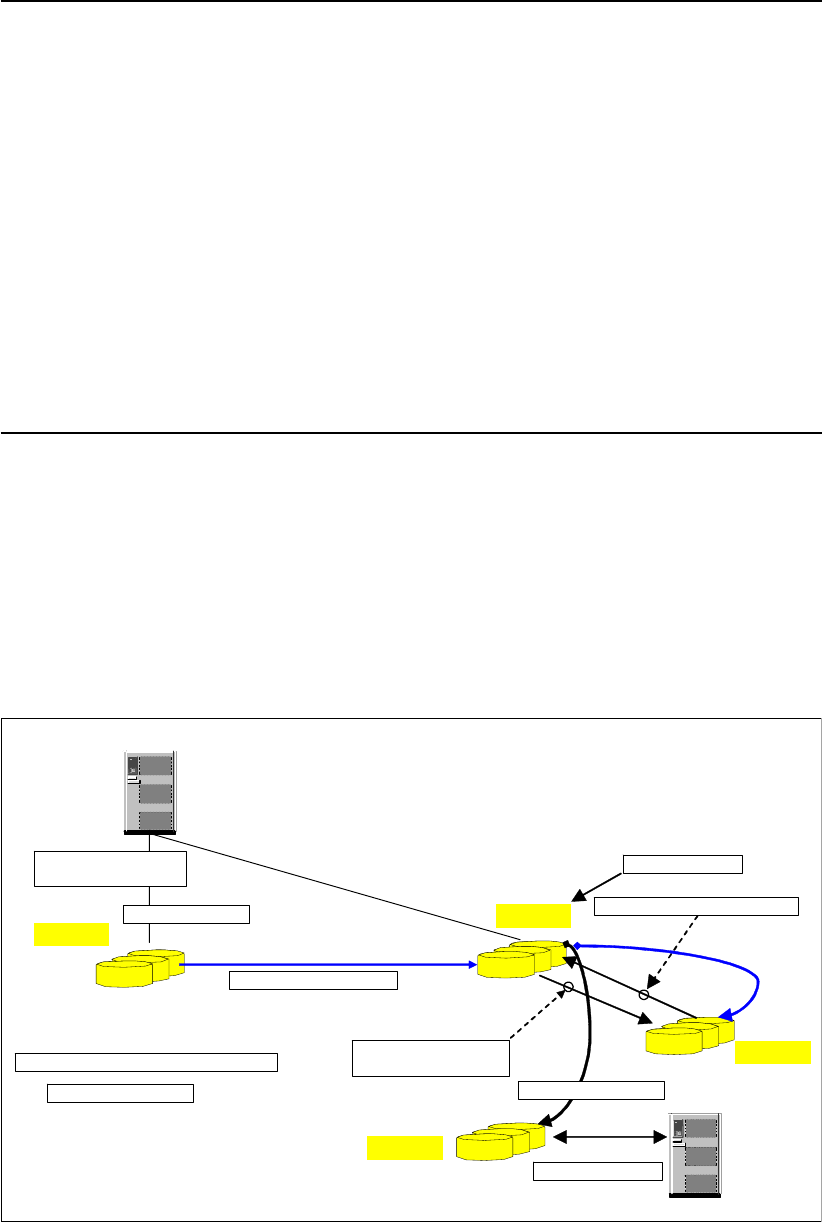
366 IBM System Storage DS6000 Series: Copy Services with IBM System z
Example 26-35 Remove the paths
//* ------------------ TSO ----------------- CLEANUP (6) --------- ***
//* Delete path(s) this completes the GM cleanup ***
//* -------------------------------------------------------------- ***
//DPATH EXEC PGM=IKJEFT01
//SYSPRINT DD SYSOUT=*
//SYSTSPRT DD SYSOUT=*
//SYSTSIN DD DDNAME=SYSIN
CQUERY DEVN(X'2C00') PATHS
CDELPATH DEVN(X'2C00') +
PRIM(X'2C00' 5005076303FFC228 X'0C') +
SEC (X'3C00' 5005076303FFC422 X'0C')
CQUERY DEVN(X'2C00') PATHS
CQUERY DEVN(X'2D00') PATHS
CDELPATH DEVN(X'2D00') +
PRIM(X'2D00' 5005076303FFC228 X'0D') +
SEC (X'3D00' 5005076303FFC422 X'0D')
CQUERY DEVN(X'2D00') PATHS
This concludes the example of how to remove the Global Mirror environment that was set up
in 26.3, “Set up the Global Mirror environment using TSO” on page 345.
26.6 Planned outage management using ICKDSF
This section briefly presents an example of a Global Mirror planned outage that is managed
using ICKDSF. The procedure presented here can be used to control a planned Global Mirror
outage that is done to create a data consistent set of D volumes at the remote site.
Figure 26-6 Global Mirror planned outage scenario
Remote site
Host
Local site
Secondary Volumes
Primary Volumes
Global Copy
(2) Suspend all GC pairs
(4) Failover B->A
A volumes
B volumes
D volumes
(10) Resume session
(6) FlashCopy B->C
Start Change Recording
Host
(7) Flashcopy B -> D
(9) Failback (A=Primary, B=Secondary)
(1) Pause session (5) Fast Reverse restore, FRR
(3) Application I/O still
going on to A volumes
C volumes
(8) Perform testing

Chapter 26. Global Mirror examples 367
Figure 26-6 summarizes the scenario. The numbers indicate the sequence of events and
main considerations, and also relate to Figure 26-7 where the corresponding ICKDSF
commands are shown.
The sequence of steps for a Global Mirror planned outage is as follows:
1. Pause the Global Mirror session.
2. Suspend Global Copy pairs.
3. Application I/O continues all the time.
4. Failover from B to A. This turns the B volumes into Global Copy primary suspended.
5. Create a data consistent set of B volumes. This is done with a Fast Reverse Restore
(FRR) from the C to the B volumes.
6. Reestablish Global Mirror FlashCopy relationships from B to C. Both volumes are identical
afterwards.
7. Optionally create a data consistent set of D volumes.
8. Use the D volumes for test or other purposes.
9. In order to prepare and continue with Global Mirror, apply the changes that were
accumulated at the local site from the A volumes to the B volumes. This is done with a
Failback operation with the A volumes as primary and the B volumes as secondary.
10.Resume Global Mirror.
Figure 26-7 shows the corresponding ICKDSF commands for each step of the procedure.
Figure 26-7 ICKDSF command sequence for Global Mirror planned outage
Note that in most command examples ICKDSF refers to a corresponding JCL DD statement
through the DDNAME parameter. This DD statement points to the LSS or volume.
(1) Pause session
PPRCOPY DDNAME( DD0 1 ) TMASYNC -
SESSNO(001) -
PAUSE -
MASTER
PPRCOPY DDNAME( DD0 1 ) SUSPEND -
LSS( X' 0 5' X' 00 ' ) -
PRI ( X' E500' 27310 X' 00 ' ) -
SEC( X' 7000' 22399 X' 00' )
PPRCOPY UNI T ( 7 0 0 0 ) ESTPAI R -
FAILOVER -
PRI ( X' 7000' 22399 X' 00' ) -
SEC( X' E500' 27310 X' 00' ) -
LSS( X' 0 0' , X' 0 5' ) -
OP T I ON ( X D)
FC UNIT(7100) ESTABLISH /* C VOLUME */ -
TARGETVOL(X'00',X'00',7000) /* B VOLUME */ -
FASTREVERSERESTORE / * REVERSE DI RECTI ON * / -
MODE (COPY) /* START BACKGROUNDCOPY */ -
ONLINTGT (YES) -
TGTOKPRIM (YES) -
TGTCANCOMEONLI NE ( NO)
(2) Suspend all XD pairs
(4) FAILOVER B->A
(5) Fast Reverse restore, FRR
(6) FlashCopy B->C Start Change Recording
FC UNIT(7000) ESTABLISH -
TARGETVOL (X'01',X'00',7100) -
CHRCD (YES) /* CHANGE RECORDING */ -
NOTGTWR (YES) /* INHIBIT TARGET WRI TES * / -
MODE (NOCOPY) /* NO BACKGROUND COPY */ -
ONLINTGT (YES) -
TGTCANCOMEONLI NE ( NO)
FC UNIT(7000) ESTABLISH /* B VOLUME */ -
TARGETVOL (X'01',X'10',7110) /* D VOLUME */ -
ONLINTGT (YES) -
TGTCANCOMEONLI NE ( NO)
(7) Flashcopy B -> D
PPRCOPY DDNAME(DD01) ESTPAIR /* A VOLUME */ -
FAILBACK -
PRI ( X' E500' 27310 X' 00' ) / * A VOLUME * / -
SEC ( X' 7000' 22399 X' 00' ) / * B VOLUME * / -
LSS (X'05',X'00') -
OPTION (XD)
(9) FAILBACK (A=Primary, B=Secondary)
(10) Resume session
PPRCOPY DDNAME( DD01) STASYNC -
MODIFY -
SESSNO(001) -
CGIT(0) -
MXCT(3) -
MXDT( 030)

368 IBM System Storage DS6000 Series: Copy Services with IBM System z
For ICKDSF command details, refer to Device Support Facility User’s Guide and Reference,
SC35-0033.
26.7 Remove a Global Mirror environment using ICKDSF
This section shows how to use ICKDSF to end and remove a Global Mirror environment that
was previously established using TSO commands.
The steps of the procedure to follow are similar for any of the interfaces. In our example in
this section, we use ICKDSF to accomplish the associated task for each step. These are the
steps we followed to remove the Global Mirror environment:
1. Stop the session.
2. Remove volumes from the session.
3. Withdraw the FlashCopy relationships.
4. Delete the session.
5. Delete the Global Copy pairs.
6. Remove the paths.
26.7.1 Stop Global Mirror session
Example 26-36 shows the ICKDSF JCL and command lines used to stop the Global Mirror
session.
Example 26-36 End Global Mirror session using ICKDSF
//* -------------------------------------------------------------- ***
//TERMSESS EXEC PGM=ICKDSF
//SYSPRINT DD SYSOUT=*
//DD01 DD UNIT=3390,VOL=SER=AA6000,DISP=SHR
//SYSIN DD *
PPRCOPY DDNAME(DD01) TMASYNC -
SESSNO(001) -
TERMINATE -
MASTER
/*
We used a JCL DD statement to point to the Master LSS, which manages the Global Mirror
session number 001. We stop the session using the TMASYNC command with the
TERMINATE parameter, in the command lines for ICKDSF.
26.7.2 Remove volumes from the session
The command shown in Example 26-37 on page 369 removes four volumes from the Global
Mirror session. The range of volumes to be removed is identified by the CCA range indicated
in the RVOLLIST parameter. The first CCA indicates the beginning of the range, and the
second CCA marks the end of the range. Do not forget to also provide the RANGE keyword.
The DDNAME parameter in the ICKDSF command line points to the JCL DD that addresses
the LSS that contains the range of volumes to be removed. The JCL DD uses a utility volume
for addressing purposes (VOL=SER=AA6000), which is also one of the volumes to be
removed. Note that the volumes must be online.

Chapter 26. Global Mirror examples 369
Example 26-37 Remove volumes from a Global Mirror session with ICKDSF
//* -------------------------------------------------------------- ***
//REMOVE EXEC PGM=ICKDSF
//SYSPRINT DD SYSOUT=*
//DD01 DD UNIT=3390,VOL=SER=AA6000,DISP=SHR
//SYSIN DD *
PPRCOPY DDNAME(DD01) POPSESS -
REMOVE -
SESSNO (001) -
VOLCOUNT (1) -
RANGE (YES) -
RVOLLIST ((X'00',X'03'))
26.7.3 Withdraw FlashCopy relationships
We are going to withdraw the FlashCopy relationships between the B and C volumes using
ICKDSF inband commands. This means directing the FlashCopy withdraw command, and
the actual I/O, to the corresponding Global Copy primary volumes.
As Example 26-38 shows, this is done with the JCL DD statements identifying the
corresponding Global Copy primary volumes. The FlashCopy withdraw is actually directed to
the FlashCopy source volumes, which are identified by the SRCVOL parameters. The
FlashCopy target volumes are identified by the TGTVOL parameters.
Example 26-38 ICKDSF withdraw via an inband FlashCopy command
//* -------------------------------------------------------------- ***
//* FLASHCOPY WITHDRAW (B -> C VOLUME RELATIONSHIP) ***
//* -------------------------------------------------------------- ***
//* SRCVOL (X'LSS' X'CCA' X'SSID' SERIAL#) ***
//* TGTVOL (X'LSS' X'CCA' DEVICE#) ***
//* -------------------------------------------------------------- ***
//* -------------------------------------------------------------- ***
//WITHDRW EXEC PGM=ICKDSF
//SYSPRINT DD SYSOUT=*
//DD01 DD UNIT=3390,VOL=SER=AA6000,DISP=SHR
//DD02 DD UNIT=3390,VOL=SER=AA6001,DISP=SHR
//DD03 DD UNIT=3390,VOL=SER=AA6002,DISP=SHR
//DD04 DD UNIT=3390,VOL=SER=AA6003,DISP=SHR
//SYSIN DD *
FC DDNAME(DD01) WD /* WITHDRAW */ -
SRCVOL (X'00',X'00',0002,AAVCA) /* B VOLUME */ -
TGTVOL (X'01',X'00',6400) /* C VOLUME */
FC DDNAME(DD02) WD /* WITHDRAW */ -
SRCVOL (X'00',X'01',0002,AAVCA) /* B VOLUME */ -
TGTVOL (X'01',X'01',6401) /* C VOLUME */
FC DDNAME(DD03) WD /* WITHDRAW */ -
SRCVOL (X'00',X'02',0002,AAVCA) /* B VOLUME */ -
TGTVOL (X'01',X'02',6402) /* C VOLUME */
FC DDNAME(DD04) WD /* WITHDRAW */ -
SRCVOL (X'00',X'03',0002,AAVCA) /* B VOLUME */ -
TGTVOL (X'01',X'03',6403) /* C VOLUME */

370 IBM System Storage DS6000 Series: Copy Services with IBM System z
Note the different positional parameters for SRCVOL and TGTVOL. It is possible to mix these
up. First comes the LSS number and then the CCA. This is the same for both parameters.
The third positional parameter for SRCVOL is the SSID, followed by the serial number of the
secondary storage disk subsystem. The third parameter in TGTVOL is the actual z/OS device
number of the FlashCopy target volume. Withdraw can be abbreviated as WD.
Note again that ICKDSF requires the DDNAME parameter when you refer to an online
volume. Volumes AA6000 to AA6003 are in the local storage disk subsystem that is connected,
over a path, to the remote disk subsystem that has the serial number AAVCA.
26.7.4 Delete the Global Mirror session
Example 26-39 shows the next step, which removes the session number 01 from the LSS that
is pointed to by the DDNAME parameter.
Example 26-39 Delete or remove a session from concerned LSS
//* -------------------------------------------------------------- ***
//CLOSESS EXEC PGM=ICKDSF
//SYSPRINT DD SYSOUT=*
//DD01 DD UNIT=3390,VOL=SER=AA6000,DISP=SHR
//SYSIN DD *
PPRCOPY DDNAME(DD01) DEFSESS -
SESSNO(001) -
CLOSE
/*
Again, the DDNAME parameter is required because the PPRCOPY command points to the
desired LSS with an online volume. Note that, although the command is called DEFSESS (or
DEFINESESSION), the session is actually removed, because of the CLOSE parameter.
26.7.5 Delete Global Copy pairs
After all traces of session number 01 are removed, the next step is to delete the Global Copy
pairs. Example 26-40 shows how to do it with ICKDSF.
Example 26-40 Delete Global Copy pairs with ICKDSF
//* -------------------------------------------------------------- ***
//DELPAIR EXEC PGM=ICKDSF
//SYSPRINT DD SYSOUT=*
//DD01 DD UNIT=3390,VOL=SER=AA6000,DISP=SHR
//DD02 DD UNIT=3390,VOL=SER=AA6001,DISP=SHR
//DD03 DD UNIT=3390,VOL=SER=AA6002,DISP=SHR
//DD04 DD UNIT=3390,VOL=SER=AA6003,DISP=SHR
//SYSIN DD *
PPRCOPY DDNAME(DD01) DELPAIR -
LSS(X'00' X'00') -
PRI(X'2060' AAGXA X'00') -
SEC(X'0002' AAVCA X'00')
PPRCOPY DDNAME(DD02) DELPAIR -
LSS(X'00' X'00') -
PRI(X'2060' AAGXA X'01') -
SEC(X'0002' AAVCA X'01')

Chapter 26. Global Mirror examples 371
PPRCOPY DDNAME(DD03) DELPAIR -
LSS(X'00' X'00') -
PRI(X'2060' AAGXA X'02') -
SEC(X'0002' AAVCA X'02')
PPRCOPY DDNAME(DD04) DELPAIR -
LSS(X'00' X'00') -
PRI(X'2060' AAGXA X'03') -
SEC(X'0002' AAVCA X'03')
For each single Global Copy pair you must specify a corresponding PPRCOPY command.
The syntax for the ICKDSF command is slightly different from the equivalent TSO command.
Again, the DDNAME parameter is required because the Global Copy primary volumes are
usually online with the system that issues the application I/Os. And this is the same system
where the ICKDSF job is executing.
ICKDSF, in contrast to TSO commands, does not propagate all commands and their results
to the z/OS SYSLOG. This can be an advantage over TSO commands. TSO commands
always appear in the SYSLOG with their results, which is valuable if you want to track the
TSO commands that you issued interactively in ISPF 6 or from the TSO READY state.
Example 26-41 shows a SYSLOG fragment with the output lines caused by the ICKDSF job
that deletes the four Global Copy pairs. You can see in the example that when the volumes
are online, ERP issues the state change message IEA494I.
Example 26-41 Delete Global Copy pairs with ICKDSF - SYSLOG output
$HASP100 WBDELPR ON INTRDR ICKDSF PPRC FROM TSU01210 WB
IRR010I USERID WB IS ASSIGNED TO THIS JOB.
ICH70001I WB LAST ACCESS AT 09:29:14 ON THURSDAY, JUNE 16, 2005
$HASP373 WBDELPR STARTED - INIT 2 - CLASS B - SYS GDP5
IEF403I WBDELPR - STARTED - TIME=09.36.00
IEA494I 6000,AA6000,PPRC PAIR TERMINATED,SSID=2060,CCA=00
IEA494I 6001,AA6001,PPRC PAIR TERMINATED,SSID=2060,CCA=01
IEA494I 6002,AA6002,PPRC PAIR TERMINATED,SSID=2060,CCA=02
IEA494I 6003,AA6003,PPRC PAIR TERMINATED,SSID=2060,CCA=03
JOBNAME PROCSTEP STEPNAME CPU TIME EXCPS RC
WBDELPR --NONE-- DELPAIR 00:00:00 49 00
IEF404I WBDELPR - ENDED - TIME=09.36.00
$HASP395 WBDELPR ENDED
$HASP309 INIT 2 INACTIVE ******** C=SODAB
SE '09.36.00 JOB01228 $HASP165 WBDELPR ENDED AT WSC245 MAXCC=0',LOGON,
USER=(WB)
Example 26-42 shows that the ICKDSF job output contains all details about each single
command executed.
Example 26-42 ICKDSF output for the DELPAIR command
PPRCOPY DDNAME(DD01) DELPAIR -
LSS(X'00' X'00') -
PRI(X'2060' AAGXA X'00') -
SEC(X'0002' AAVCA X'00')
ICK00700I DEVICE INFORMATION FOR 6000 IS CURRENTLY AS FOLLOWS:
PHYSICAL DEVICE = 3390
STORAGE CONTROLLER = 2107
STORAGE CONTROL DESCRIPTOR = E8
DEVICE DESCRIPTOR = 0A

372 IBM System Storage DS6000 Series: Copy Services with IBM System z
ADDITIONAL DEVICE INFORMATION = 4800243D
TRKS/CYL = 15, # PRIMARY CYLS = 3339
ICK04030I DEVICE IS A PEER TO PEER REMOTE COPY VOLUME
ICK02204I PPRCOPY DELPAIR FUNCTION COMPLETED SUCCESSFULLY
ICK02230I DEVICE IS NOW IN SIMPLEX STATE
ICK00001I FUNCTION COMPLETED, HIGHEST CONDITION CODE WAS 0
09:36:00 06/16/05
26.7.6 Remove Global Copy paths
Finally, remove the Global Copy paths. Use the DDNAME parameter to point to the primary
LSS, as shown in Example 26-43.
Example 26-43 Remove Global Copy paths with ICKDSF
//* -------------------------------------------------------------- ***
//DELPATH EXEC PGM=ICKDSF
//SYSPRINT DD SYSOUT=*
//DD01 DD UNIT=3390,VOL=SER=AA6000,DISP=SHR
//SYSIN DD *
PPRCOPY DDNAME(DD01) QUERY PATHS
PPRCOPY DDNAME(DD01) DELPATH -
PRI(X'2060' AAGXA) -
SEC(X'0002' AAVCA) -
LSS(X'00' X'00') -
WWNN(500507630EFFFC6F -
500507630EFFFCA0)
PPRCOPY DDNAME(DD01) QUERY PATHS
/*
The path commands, delete path and establish path, require the WWNN of both storage disk
subsystems. The PRI and SEC parameters include only two positional parameters: the SSID
and the serial number of the corresponding storage disk subsystems.
26.8 Query device information with ICKDSF
Example 26-44 shows an ICKDSF example that queries all hardware-related device
information, including all connected channel paths and their status.
Example 26-44 ICKDSF queries all device attributes
//* -------------------------------------------------------------- ***
//* ICKDSF ANALYZE ***
//* -------------------------------------------------------------- ***
//ANALYZE EXEC PGM=ICKDSF
//* UNIT(XXXX) - OFFLINE / OTHERWISE DDNAME(...) WHEN ONLINE
//DD01 DD UNIT=3390,VOL=SER=AA6000,DISP=SHR
//SYSPRINT DD SYSOUT=*
//SYSIN DD *
ANALYZE DDNAME(DD01) NODRIVE NOSCAN
/*
This is a useful command, especially when you are collecting detailed information in case of
errors and problem reporting.

Chapter 26. Global Mirror examples 373
26.9 Set up a Global Mirror environment using DS SM
You may establish a Global Mirror environment with the DS Storage Manager (DS SM) that
provides a graphical user interface (GUI).
A Global Mirror session relies on the following components, which are independent of the
interface used, but are repeated here in case you are only reading this section:
Paths for Global Copy communication between primary and secondary LSSs. Paths may
also be required for communication between Master and Subordinate LSSs, in case these
LSSs reside on different primary storage disk subsystems.
Global Copy pairs: primary A volumes and secondary B volumes.
FlashCopy pairs, which are part of Global Mirror. These FlashCopy relationships are
established at the secondary (remote) site between the B and C volumes. Note that the B
volumes are not only the FlashCopy source, but they are also Global Copy secondaries at
the same time. The C volumes are the FlashCopy target volumes.
Up to eight storage images can contribute their volumes to a Global Mirror session at the
primary site. The same number applies for the secondary site.
The creation of a Global Mirror session requires that you perform the following steps:
1. Create paths.
a. Between the source LSSs on the source Storage Images on site 1, and the target
LSSs on the target Storage Images on site 2.
b. Within site 1, between the Master storage image LSS, or for short Master, and the
Subordinate storage image LSSs. This task is not required if you have only one source
storage image. In this case, all communication between Master and Subordinate LSSs
is managed internally and does not need your attention.
2. Create Global Copy pairs with source volumes on site 1 and target volumes on site 2.
3. Create FlashCopy pairs on site 2, between the Global Copy target volumes that at the
same time are FlashCopy source volumes, and their corresponding target volumes.
4. Define the common Global Mirror session to each LSS, on the source Storage Images at
site 1, that are going to be part of this Global Mirror environment.
5. Create a Global Mirror session relationship between the Global Mirror Master and its
Subordinates.
Now the session can be started, so that the process of Consistency Groups formation begins.
The following sections show how to perform the necessary activities for the setup of a Global
Mirror environment when using the DS Storage Manager GUI.
Note: You will notice that in the present section we frequently use the terms storage
image, source, and target, instead of the terms storage disk subsystem, primary, and
secondary. Both sets of terms are similar, but here we use the first one to be more in
accordance with the terminology that you find in the DS Storage Manager panels.
Note: The DS SM examples that we present in this section were run in a DS8000 HMC,
but are basically similar to what you see in a DS6000 SMC when using the DS SM GUI.
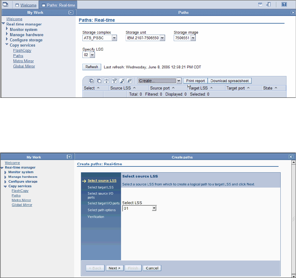
374 IBM System Storage DS6000 Series: Copy Services with IBM System z
26.9.1 Create paths
When using the DS Storage Manager to create paths between two LSSs on two different
Storage Images, it is necessary to go through a six-step process creation wizard. This wizard
needs to be repeated for each data path to be defined. Remember that you have to define
paths between site 1 and site 2, for Global Copy replication, and eventually you will also have
to define paths within site 1 if the Master and Subordinates are on different Storage images.
To launch this wizard, first you need to go to the Paths panel under the Copy Services menu
of the DS Storage Manager GUI. In the Select Action pull-down list, choose Create to
proceed with the first step of the wizard. See Figure 26-8.
Figure 26-8 Global Copy paths creation - launch the definition process
The creation wizard then displays the “Select source LSS” panel; see Figure 26-9. Here you
select from the pull-down lists the Storage complex, then the Storage unit, then the
Storage Image, and finally the LSS that contains the source volumes of the Global Copy
pairs. These are the volumes that are going to be members of the Global Mirror session.
Figure 26-9 Global Copy paths creation step 1 - select the source LSS
Click Next to proceed with the second step of this wizard.
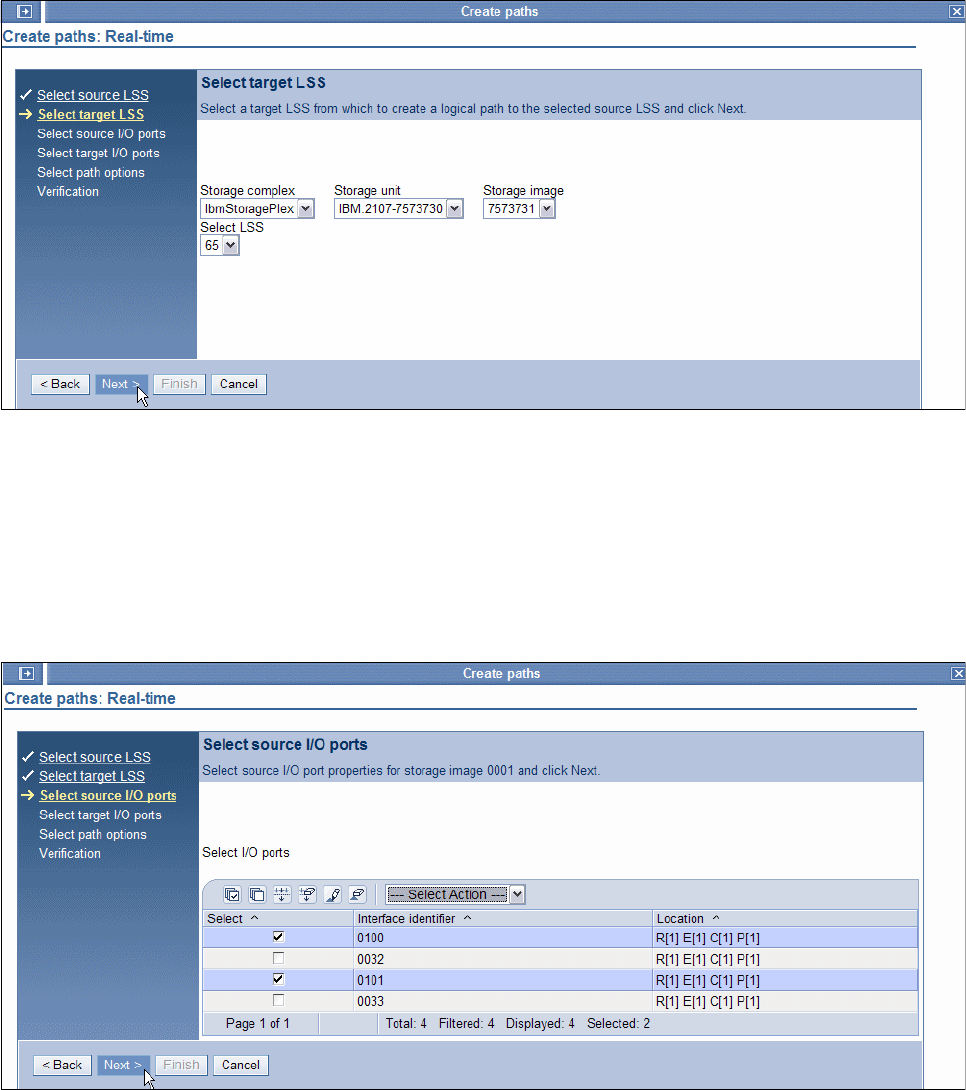
Chapter 26. Global Mirror examples 375
The creation wizard then displays the “Select target LSS” panel; see Figure 26-10. Here you
select from the pull-down lists the Storage complex, then the Storage unit, then the
Storage Image and finally the LSS, which contains the corresponding target volumes of the
Global Copy pairs. Click Next to proceed with the third step of this wizard.
Figure 26-10 Global Copy paths creation step 2 - select the target LSS
Then the creation wizard displays the “Select source I/O ports” panel; see Figure 26-11. Here
you select, with the check boxes, the I/O ports through which you intend to connect the
source LSS to the target LSS. In the location column, four digits indicate the location of a port:
The first digit - R - is to locate the frame.
The second digit - E - is for the I/O enclosure.
The third digit - C - is for the adapter.
The fourth digit - P - is for the adapter port.
Figure 26-11 Global Copy paths creation step 3 - select the source I/O ports
Click Next to proceed with the fourth step of this wizard.
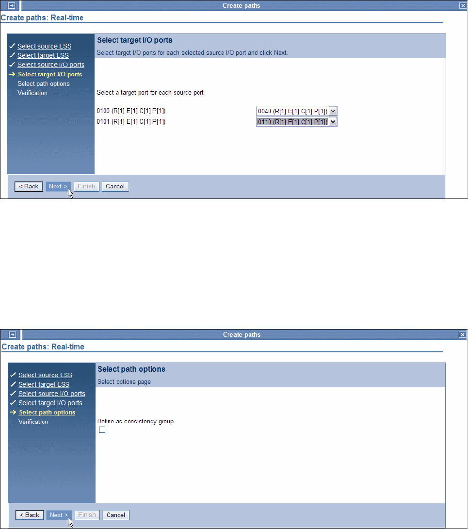
376 IBM System Storage DS6000 Series: Copy Services with IBM System z
Then the creation wizard displays the Select target I/Os ports panel; see Figure 26-12. Here
you select from the pull-down list the target I/O ports that you intend to connect with the
source I/O ports.
Figure 26-12 Global Copy paths creation step 4 - select the target I/O ports
Click Next to proceed with the next step of this wizard.
Then the creation wizard displays the “Select path options” panel; see Figure 26-13. Here you
have a box that can be checked for the option Define as Consistency Group.
This option is used in the context of Metro Mirror only. Global Mirror manages consistency by
its own design, and provides a consistent set of volumes at the remote site without relying on
this option.
Figure 26-13 Global Copy path creation step 5 - select the path options
Click Next to proceed with the sixth and last step of this wizard.
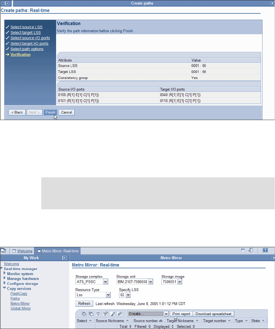
Chapter 26. Global Mirror examples 377
This brings you to the Verification panel; see Figure 26-14. Here you can check all the
components of your path definitions and, if necessary, click Back to correct any of them, or
click Finish to validate the configuration and end the wizard.
Figure 26-14 Global Copy path creation step 6 - verification
26.9.2 Create Global Copy volume pairs
To create Global Copy volume pairs for a Global Mirror session, using the DS Storage
Manager, you have to go through another staged process with corresponding panels. This
procedure is demonstrated in this section.
To launch this wizard you need first to go to the Metro Mirror panel, under the Copy Services
menu of DS Storage Manager GUI. In the Select Action pull-down list, choose Create to
proceed with the first step of the wizard. See Figure 26-15.
Figure 26-15 Global Copy creation - launch the creation process
Note: If Global Copy pairs are in several LSSs in the same storage image, do not forget to
select all of them during this wizard. Else, you will have to run the wizard again for each
LSS. If the Global Copy pairs are spread over several Storage images, then you will have
to run this wizard again for each of them.
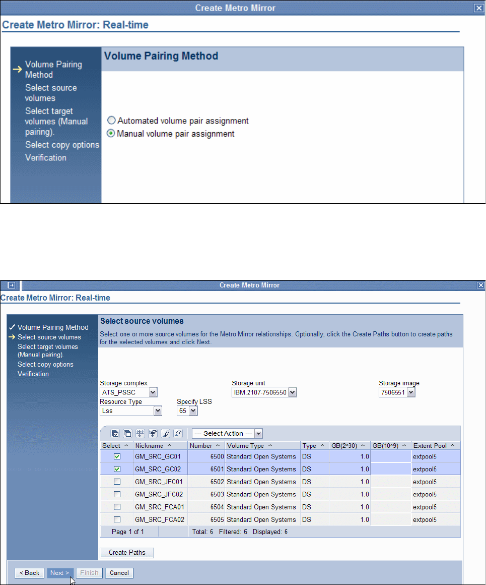
378 IBM System Storage DS6000 Series: Copy Services with IBM System z
Then the creation wizard displays the Volume Pairing Method panel; see Figure 26-16. Here
you select Manual volume pair assignment.
Figure 26-16 Global Copy creation step 1 - choose volume pairing method
Click Next to proceed with the second step of this wizard.
Then the creation wizard displays the “Select source volumes” panel; see Figure 26-17.
Figure 26-17 Global Copy creation step 2 - select the source volumes
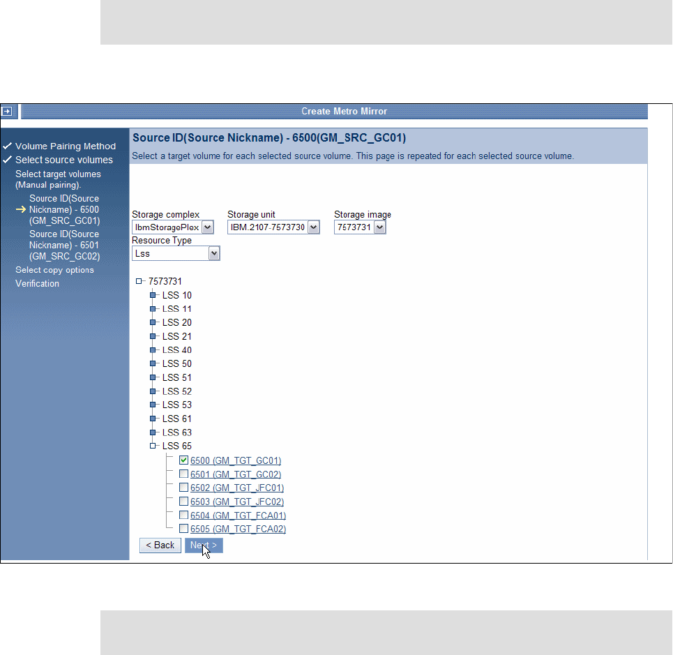
Chapter 26. Global Mirror examples 379
In the “Select source volumes” panel (see Figure 26-17), select from the pull-down lists the
Storage complex, then the Storage unit, then the Storage Image, then the Resource type
and, if necessary, its appropriate parameter to display the list of volumes. If you have chosen
the Resource type LSS, select from the pull-down list the LSS number that contains the
source volumes you intend to use. Then, check the boxes for the source volumes you plan to
use as Global Copy pairs in the Global Mirror session. Click Next to proceed with the third
step of this wizard.
Then the creation wizard displays the “Select target volumes” panel; see Figure 26-18.
Figure 26-18 Global Copy creation step 3 - select the target volume 1
In this panel (see Figure 26-18), we notice that only one source volume is indicated on the top
of the panel. It means that we need to repeat this third step for each volume we have selected
during the previous second step.
Note: If paths have not been created yet, you can click Create Paths to launch the wizard
to create paths as described in the previous section.
Note: Although the following panels refer not to CKD volumes but to open systems
volumes, it applies in the very same fashion to CKD volumes.
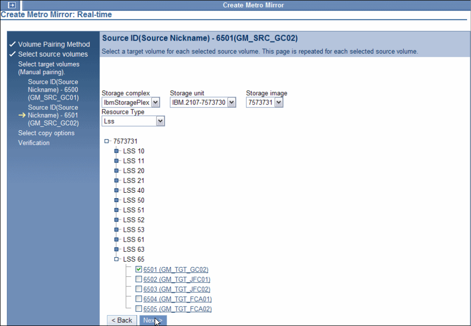
380 IBM System Storage DS6000 Series: Copy Services with IBM System z
Select from the pull-down lists the Storage complex, then the Storage unit, then the
Storage Image, then the Resource type and, if necessary, its appropriate parameter to
display the list of volumes. Click the required Storage Unit, then on the required LSS check
the box for the volume you want to use as target.
Click Next to proceed with the selection of the second target volume.
Again the “Select target volumes” panel is displayed. Now, you may notice that only the
indicated source volume on the top of the panel is different; see Figure 26-19.
Once again, select from the pull-down lists the Storage complex, then the Storage unit,
then the Storage Image, then the Resource type and, if necessary, its appropriate
parameter to display the list of volumes.
Click the required Storage Unit, then click the required LSS, and check the box for the volume
you plan to use as the Global Copy target. If you had selected more source volumes, you
would once again proceed to the next target volume selection panel. In our example, this is
the second and last volume in our selection.
Figure 26-19 Global Copy creation step 3 - select the target volume 2
Click Next to proceed with the fourth step of this wizard.
When the creation wizard displays the “Select copy options” panel (see Figure 26-20 on
page 381), select Global Copy to define the type of replication relationship. If this is the first
synchronization between source and target volumes of these pairs, check the box for
Perform initial copy.
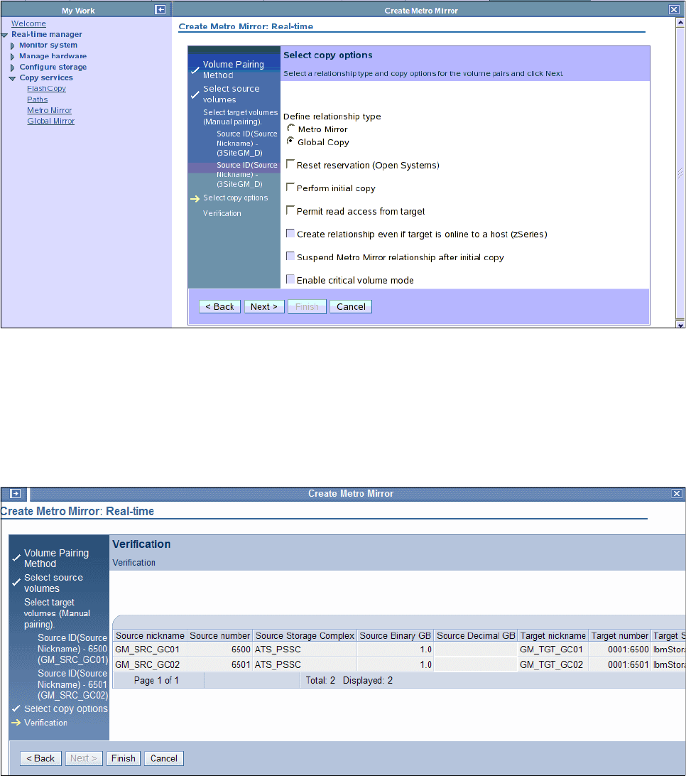
Chapter 26. Global Mirror examples 381
Figure 26-20 Global Copy creation step 4 - select the copy options
Click Next to proceed with the last step of this wizard.
The Verification panel is displayed; see Figure 26-21. In this panel check all the components
of your Global Copy session configuration, and, if necessary, click Back to correct any of
them, or click Finish to validate. In Figure 26-20 you may move back to correct the Permit
read access from target.
Figure 26-21 Global Copy creation step 5 - verification
26.9.3 Establish FlashCopy relationships
To create FlashCopy pairs with the DS Storage Manager, you have to work through another
series of steps and GUI panels.
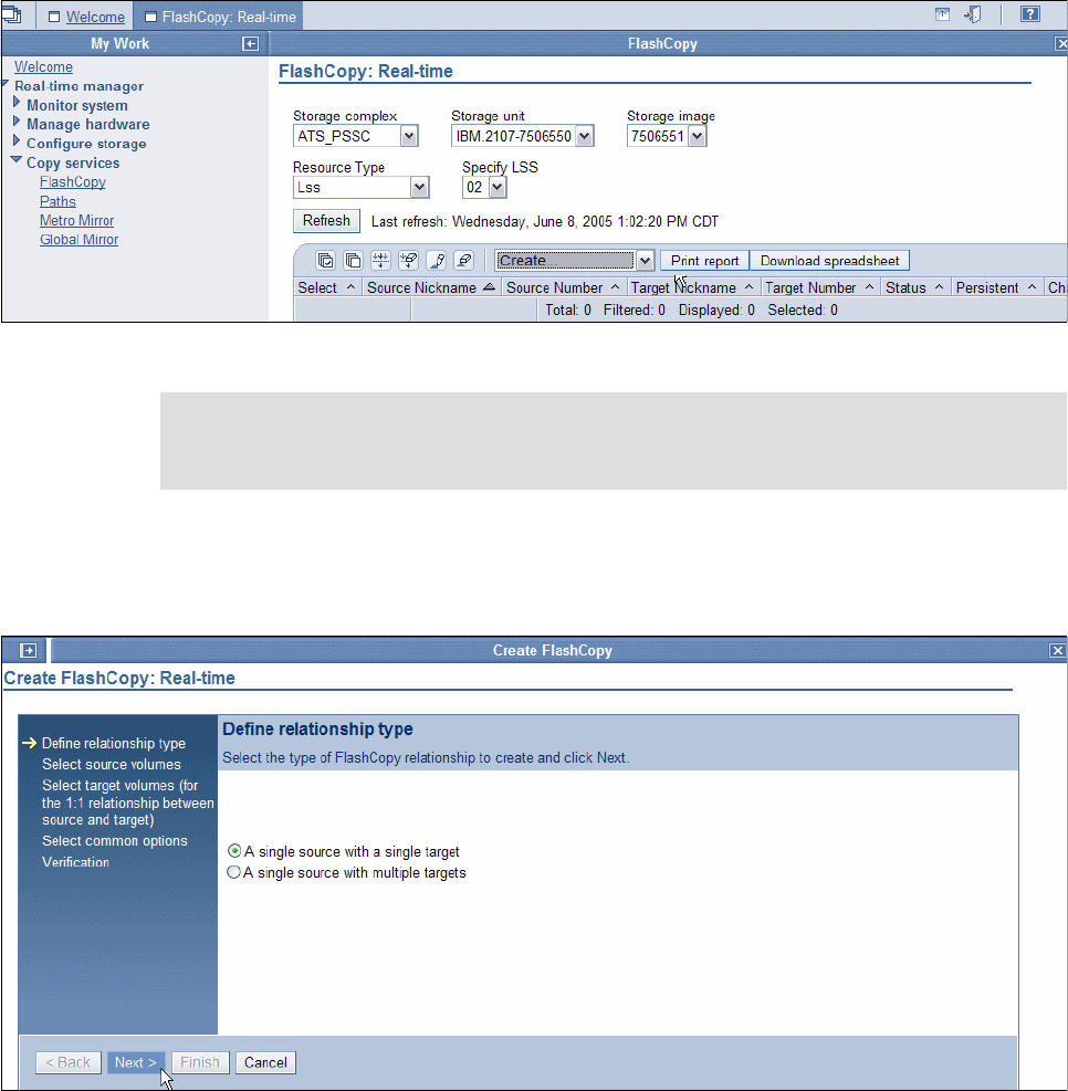
382 IBM System Storage DS6000 Series: Copy Services with IBM System z
To launch this wizard, you need to first go to the FlashCopy panel under the Copy Services
menu of DS Storage Manager GUI; see Figure 26-22. In the Select Action pull-down list
choose Create to proceed with the first step of the wizard.
Figure 26-22 FlashCopy creation - launch the creation process
Now the creation wizard displays the “Define relationship type” panel; see Figure 26-23. Here
you select A single source with a single target, because we must activate the record option
on the fourth step of this wizard.
Figure 26-23 FlashCopy creation step 1 - select the relationship type
Click Next to proceed to the second step of this wizard.
Now the creation wizard displays the “Select source volumes” panel; see Figure 26-24 on
page 383. Here you select from the pull-down lists the Storage complex, then the Storage
unit, then the Storage Image, then the Resource type and, if necessary, its appropriate
parameter to display the list of volumes. If you have chosen the Resource type LSS, then
select from the pull-down lists the LSS number that contains the source volumes you want to
Note: If FlashCopy pairs are in several LSSs, do not forget to select all of them during this
wizard, or run the wizard again on each LSS. If FlashCopy pairs are spread over several
Storage Images, run this wizard again on each of them.
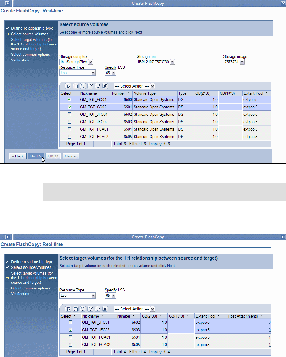
Chapter 26. Global Mirror examples 383
use. Select with the check boxes the source volumes you plan to use for FlashCopy within
the Global Mirror session.
Figure 26-24 FlashCopy creation step 2 - select the source volumes
Click Next to proceed with the third step of this wizard. The creation wizard then displays the
“Select target volumes” panel; see Figure 26-25.
Figure 26-25 FlashCopy creation step 3 - select the target volumes
Note: Although the following panels show open systems volumes, the panels and their
order apply also to CKD volumes.
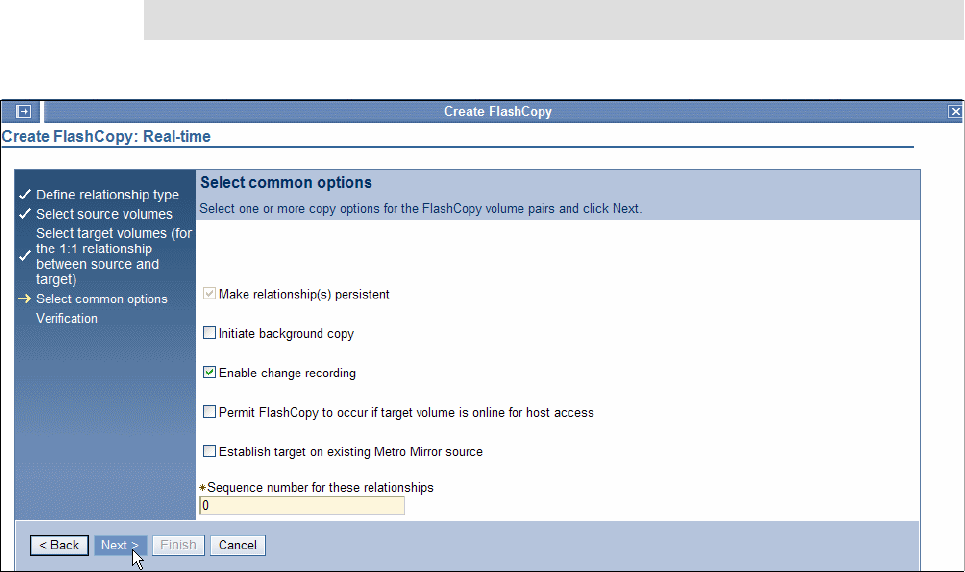
384 IBM System Storage DS6000 Series: Copy Services with IBM System z
When the creation wizard displays the “Select target volumes” panel (see Figure 26-25),
select from the pull-down lists the Resource type and if necessary its appropriate parameter
to display the list of volumes. If you have chosen the Resource type LSS, select from the
pull-down lists the LSS number that contains the target volumes you plan to use. Check the
boxes of the volumes you want to use as target FlashCopy volumes.
Click Next to proceed with the fourth step of this wizard. The creation wizard then displays
the “Select common options” panel; see Figure 26-26.
In this panel, check the box for Enable change recording. This should also automatically
check the box for Make relationship(s) persistent. You can leave the *Sequence number
for these relationships field with its default value, since Global Mirror will take care of it
automatically.
Figure 26-26 FlashCopy creation step 4 - select the common option
Click Next to proceed with last step of this wizard.
The creation wizard then displays the Verification panel; see Figure 26-27 on page 385.
In this panel check all the components of your FlashCopy session definitions and if
necessary, click Back to correct any of them, or click Finish to validate.
Note: Do not select the check box for Initiate background copy.
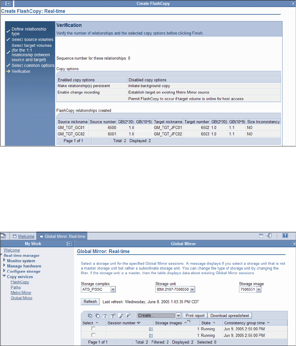
Chapter 26. Global Mirror examples 385
Figure 26-27 FlashCopy creation step 5 - verification
26.9.4 Create a Global Mirror session
To define a Global Mirror session with the DS Storage Manager, you go through another
staged panel process.
To launch this wizard you first need to go to the Global Mirror panel under the Copy Services
menu of DS Storage Manager GUI; see Figure 26-28. In the Select Action pull-down list,
choose Create to proceed with the first step of the wizard.
Figure 26-28 Global Mirror creation - launch the creation process
Then the creation wizard displays the “Select volumes” panel; see Figure 26-29 on page 386.
In this panel you click the required Storage Unit, then the required LSS, and then check the
box for the source volumes that you want to include in the Global Mirror session.
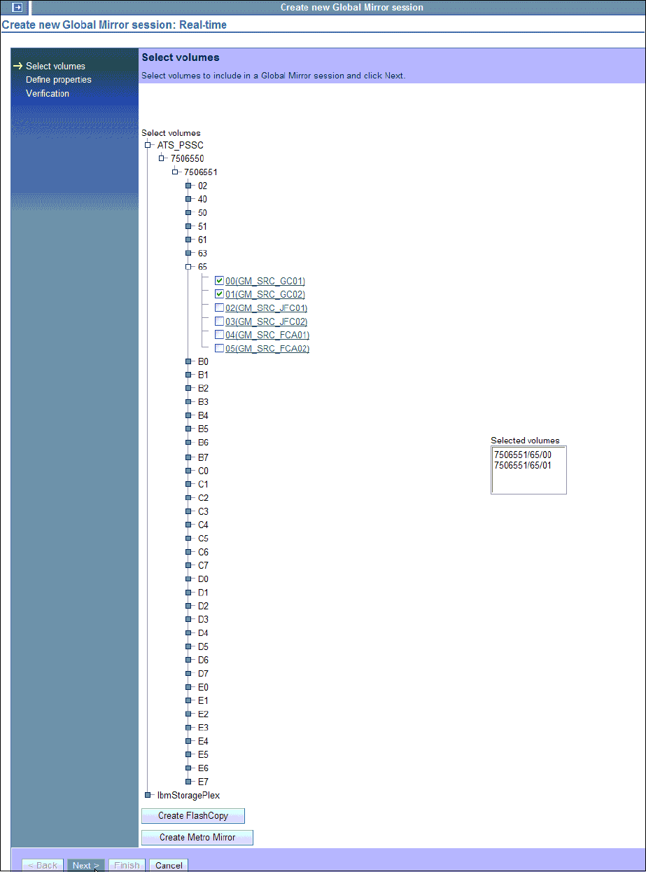
386 IBM System Storage DS6000 Series: Copy Services with IBM System z
Figure 26-29 Global Mirror session creation step 1 - select volumes
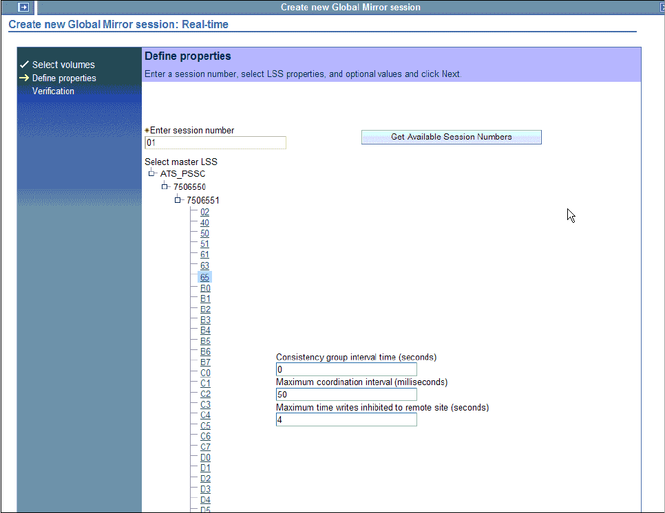
Chapter 26. Global Mirror examples 387
Click Next to proceed with the second step of this wizard. The creation wizard then displays
the “Define properties” panel; see Figure 26-30.
Figure 26-30 Global Mirror creation step 2 - define properties
When the creation wizard displays this panel, complete the “Enter session number” field with
the appropriate session number. You can click Get Available Session Numbers if you have
forgotten the one you want to use. In the panel there are also these three Global Mirror tuning
parameters that can be set at this time:
Consistency Group interval time
Specifies, in seconds, how long to wait between the formation of Consistency Groups. If
this number is not specified or is set to zero, Consistency Groups are formed
continuously. The maximum is 18 hours.
Maximum coordination interval
Indicates, in milliseconds (ms), the maximum time allowed for the Master to coordinate a
consistent data point with the Subordinates. During this time Global Mirror holds back host
I/Os, to start forming a Consistency Group.
Maximum time writes inhibited to remote site
Specifies in seconds the maximum Consistency Group drain time for the replication of the
remaining data from the primary site to the secondary site. This is the data that is still in
the out-of-sync bitmap in the primary storage disk subsystem, waiting to be replicated to
the secondary storage disk subsystem.
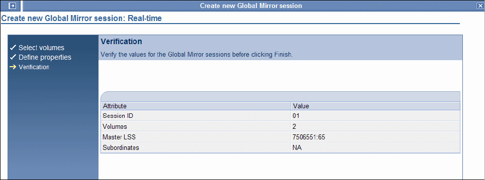
388 IBM System Storage DS6000 Series: Copy Services with IBM System z
When Global Mirror cannot complete replicating all outstanding data within this time
window, then the process to form a new Consistency Group fails. After five contiguous
failures due to this condition, Global Mirror will force the formation of a new Consistency
Group independent of how long it takes to replicate all remaining data from the primary to
secondary volumes. See also 22.4, “Consistency Groups” on page 260.
Click Next to proceed with the third and last step of this wizard. The creation wizard then
displays the Verification panel; see Figure 26-31.
In this panel, verify all the components of your Global Mirror session configuration and, if
necessary, click Back to correct any of them, or click Finish to validate.
Figure 26-31 Global Mirror creation step 3 - verification
To visualize the status of the Global Mirror session, go to the Global Mirror panel under the
Copy Services menu of DS Storage Manager GUI. Select from the pull-down lists the
Storage complex, then the Storage unit, then the Storage Image, which is the Master
Global Mirror session, and wait until the screen is refreshed. If it is necessary, click Refresh
to refresh the panel. See Figure 26-32.
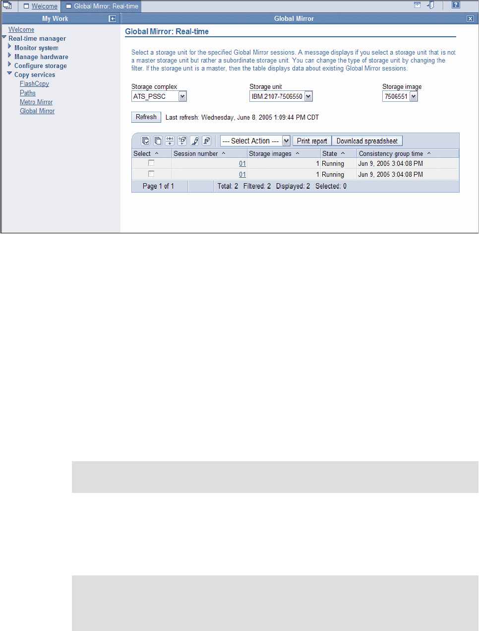
Chapter 26. Global Mirror examples 389
Figure 26-32 Global Mirror - visualize the session status
26.10 Set up a Global Mirror environment using the DS CLI
You may consider implementing a standard task such as creating a Global Mirror session,
through a more automated process than the DS SM graphical interface approach. The DS
CLI provides a good approach, which is similar to what you may do with REXX procedures, or
other software-based tools in System z environments, to assist when managing remote copy
configurations.
The DS Storage Manager GUI has its value in a situation when, for example, you have to
react somehow ad hoc. The DS SM GUI also has some advantage over the DS CLI when you
need to retrieve information from certain storage images, which may not be so easy to
understand through the DS CLI if you are not accustomed to working with it.
The following sections show how to perform the necessary activities for the setup of a Global
Mirror environment using the DS Command-Line Interface.
The components that have to be defined, as well as the procedure to be followed, to set up a
Global Mirror environment are the same, independent of the management interface that is
used. At the beginning of 26.9, “Set up a Global Mirror environment using DS SM” on
page 373, those topics are discussed.
Note: The example presented in this section was run on a DS8000. The same process
and commands are applicable to a DS6000 configuration.
Note: You will notice that here we frequently use the terms storage image, source, and
target, instead of the terms storage disk subsystem, primary, and secondary. These sets of
terms are similar, but here we use the first one to be more in accordance with the
terminology that you find in the DS CLI commands.

390 IBM System Storage DS6000 Series: Copy Services with IBM System z
26.10.1 DS CLI profile files
To simplify DS CLI commands, we use configuration files.
Example 26-45 and Example 26-46 show the configuration files that we are using in our
environment. These profiles are stored in the default directory c:\Program
Files\IBM\dscli\Profile for Windows systems.
Because we are using two storage disk subsystems, and there is a local entry and a remote
entry in these files indicated by devid and remotedevid, we created two profile files. Each file
has a local and a remote device ID with the corresponding storage disk subsystem serial
numbers.
Example 26-45 Sample DS CLI configuration file DS-01.profile
hmc1: xxx.yyy.zzz.xxx
username: admin
password: passw0rd
devid:IBM.2107-7506551
remotedevid:IBM.2107-7573731
fullid: off
banner: on
verbose: off
paging: off
olc: off

Chapter 26. Global Mirror examples 391
Example 26-46 Sample DS CLI configuration file DS-02.profile
hmc1: xxx.yyy.zzz.yyy
username: admin
password: passw0rd
devid:IBM.2107-7573731
remotedevid:IBM.2107-7506551
fullid: off
banner: on
verbose: off
paging: off
olc:off
26.10.2 Create paths
When using the DS CLI to create new paths from a source LSS to a target LSS, use the
procedure we discuss here. This process must be repeated for every path you need to define.
Remember that you have to define paths between site 1 and site 2, for Global Copy
replication, and eventually you will also have to define paths within site 1 if the Master and
Subordinates are on different storage disk subsystems.
The first step in this procedure is to find out which I/O ports are available for the definition of
Global Copy paths between the source and the target LSSs. For this, use the following
command:
dscli lsavailpprcport -remotewwnn <WWN of your remote Storage Image>
<Source_LSS_ID>:<Target_LSS_ID> -cfg <Source device configuration file>
Example 26-47 shows the command and the corresponding output information: a list of
available ports from the source LSS 65 in the storage disk subsystem at site 1, to the target
LSS 65 in the storage disk subsystem at site 2.
Example 26-47 lsavailpprcport
dscli lsavailpprcpport -remotewwnn 5005076303FFC426 65:65 -cfg $DSCLI/profile/DS-01.profile
Date/Time: June 14, 2005 6:18:16 PM EDT IBM DSCLI Version: 5.0.3.134 DS: IBM.2107-7506551
Local Port Attached Port Type
=============================
I0100 I0040 FCP
I0101 I0040 FCP
I0100 I0110 FCP
I0101 I0110 FCP
I0032 I0240 FCP
I0033 I0240 FCP
I0032 I0310 FCP
I0033 I0310 FCP
An I/O port number has four digits to indicate its location:
The first digit locates the frame - R.
The second digit indicates the I/O enclosure - E.
The third digit is for the adapter - C.
The fourth digit is for the Adapter port - P.
The second step in this process is to choose at least a pair from the list of available I/O ports
and create a path. For availability reasons, use at least two links for path definitions.

392 IBM System Storage DS6000 Series: Copy Services with IBM System z
To define a path, use the following command:
dscli mkpprcpath -remotewwnn <WWN of your remote Storage Image> -consistgrp
-srclss <Source_LSS_ID> -tgtlss <Target_LSS_ID> -cfg <Source device configuration
file> <Source_IO_Port>:<Target_IO_PORT> <Source_IO_Port>:<Target_IO_PORT> ...
Example 26-48 illustrates how to create a path from the source LSS 65 in the storage disk
subsystem at site 1, to the target LSS 65 in the storage disk subsystem at site 2.
Example 26-48 mkpprcpath command example
dscli mkpprcpath -remotewwnn 5005076303FFC426 -consistgrp -srclss 65 -tgtlss 65 -cfg
$DSCLI/profile/DS-01.profile I0100:I0040 I0101:I0110
Date/Time: June 14, 2005 3:26:06 PM EDT IBM DSCLI Version: 5.0.3.134 DS: IBM.2107-7506551
CMUC00149I mkpprcpath: Remote Mirror and Copy path 65:65 successfully established.
To list the newly created paths, use the command lspprc, which is described in 26.11.1,
“Query status of the paths” on page 395.
26.10.3 Create Global Copy volume pairs
To create Global Copy volume pairs, first list the volumes that may become Global Copy
pairs. Once the volumes are identified, establish the Global Copy relationships for these pairs
with the corresponding DS CLI commands.
The first step is to see which Fixed Block volumes are available for Global Copy on the
source and the target LSS. For this, we use the following commands:
dscli lsfbvol -lss <Source_LSS_ID> -cfg <Source device configuration file>
dscli lsfbvol -lss <Target_LSS_ID> -cfg <Target device configuration file>
Example 26-49 shows the commands and the corresponding output information: the volumes
that are available on the source LSS 65 in the storage disk subsystem at site 1, and the
potential target volumes in the storage disk subsystem at site 2.
Example 26-49 lsfbvol command example
dscli lsfbvol -lss 65 -cfg $DSCLI/profile/DS-01.profile
Date/Time: June 14, 2005 7:11:56 PM EDT IBM DSCLI Version: 5.0.3.134 DS: IBM.2107-7506551
Name ID accstate datastate configstate deviceMTM datatype extpool cap (2^30B) cap (10^9B) cap (blocks)
================================================================================================================
GM_SRC_GC01 6500 Online Normal Normal 2107-900 FB 512 P5 1.0 - 2097152
GM_SRC_GC02 6501 Online Normal Normal 2107-900 FB 512 P5 1.0 - 2097152
dscli lsfbvol -lss 65 -cfg $DSCLI/profile/DS-02.profile
Date/Time: June 14, 2005 7:12:30 PM EDT IBM DSCLI Version: 5.0.3.134 DS: IBM.2107-7573731
Name ID accstate datastate configstate deviceMTM datatype extpool cap (2^30B) cap (10^9B) cap (blocks)
================================================================================================================
GM_TGT_GC01 6500 Online Normal Normal 2107-900 FB 512 P5 1.0 - 2097152
GM_TGT_GC02 6501 Online Normal Normal 2107-900 FB 512 P5 1.0 - 2097152
GM_TGT_JFC01 6502 Online Normal Normal 2107-900 FB 512 P5 1.0 - 2097152
GM_TGT_JFC02 6503 Online Normal Normal 2107-900 FB 512 P5 1.0 - 2097152
Note: The consistgrp option is intended for Metro Mirror.
Note: The following examples cover FB volumes. This is very similar for CKD volumes.
The command sequence and structure are identical for both volume types. The focus here
is rather on which DS CLI commands to use and on the sequence of these commands.

Chapter 26. Global Mirror examples 393
Once you identify your Global Copy pairs, use the following DS CLI command to create the
pairs:
dscli mkpprc -type gcp -tgtread -mode full -cfg <Source device configuration
file> <Source_Volume>:<Target_Volume> <Source_Volume>:<Target_Volume> ...
Example 26-50 shows how to create two Global Copy pairs with source volumes 6500 and
6501 on the disk at site 1, and target volumes 6500 and 6501 on the disk subsystem at site 2.
Example 26-50 mkpprc to establish two Global Copy pairs
dscli mkpprc -type gcp -tgtread -mode full -cfg $DSCLI/profile/DS-01.profile 6500:6500 6501:6501
Date/Time: June 14, 2005 3:27:45 PM EDT IBM DSCLI Version: 5.0.3.134 DS: IBM.2107-7506551
CMUC00153I mkpprc: Remote Mirror and Copy volume pair relationship 6500:6500 successfully created.
CMUC00153I mkpprc: Remote Mirror and Copy volume pair relationship 6501:6501 successfully created.
To list the Global Copy pairs use the command lspprc as described in 26.11.1, “Query status
of the paths” on page 395.
26.10.4 Create FlashCopy relationships
The next step is to create FlashCopy pairs relationships between the B and C volumes.
If the FlashCopy pairs are in several LSSs, do not forget to select all of them during this step.
If FlashCopy pairs are spread over several Storage images, run this process again on each of
them.
You may first identify which volumes on the target storage image are available for FlashCopy.
For this use the following command:
dscli lsfbvol -lss <LSS_ID> -cfg <Device configuration file>
Example 26-51 shows the command and its corresponding output: the list of potential
volumes for FlashCopy relationships.
Example 26-51 lsfbvol to identify FlashCopy volume pairs
dscli lsfbvol -lss 65 -cfg $DSCLI/profile/DS-02.profile
Date/Time: June 14, 2005 7:12:30 PM EDT IBM DSCLI Version: 5.0.3.134 DS: IBM.2107-7573731
Name ID accstate datastate configstate deviceMTM datatype extpool cap (2^30B) cap (10^9B) cap (blocks)
================================================================================================================
GM_TGT_GC01 6500 Online Normal Normal 2107-900 FB 512 P5 1.0 - 2097152
GM_TGT_GC02 6501 Online Normal Normal 2107-900 FB 512 P5 1.0 - 2097152
GM_TGT_JFC01 6502 Online Normal Normal 2107-900 FB 512 P5 1.0 - 2097152
GM_TGT_JFC02 6503 Online Normal Normal 2107-900 FB 512 P5 1.0 - 2097152
Now that you know the available volumes, use the following command to establish FlashCopy
relationships using the selected ones:
dscli mkflash -record -persist -nocp -cfg <Device configuration file>
<Source_Volume>:<Target_Volume> <Source_Volume>:<Target_Volume> ...
Note: The type gcp option is required to create Global Copy pairs. Use the option mode
full to force a first full replication of the Global Copy pair.
Note: The record option in the command is required to keep a record of the changed
tracks on both volumes. Using record implies the persist option, which keeps the
relationship. This FlashCopy relationship for Global Mirror is also built upon the nocp
option, which inhibits a background copy between source and target volumes.

394 IBM System Storage DS6000 Series: Copy Services with IBM System z
Example 26-52 shows the command that creates two FlashCopy relationships.
Example 26-52 mkflash to establish FlashCopy relationships for Global Mirror
dscli mkflash -record -nocp -cfg $DSCLI/profile/DS-02.profile 6500:6502 6501:6503
Date/Time: June 14, 2005 3:28:58 PM EDT IBM DSCLI Version: 5.0.3.134 DS: IBM.2107-7573731
CMUC00137I mkflash: FlashCopy pair 6500:6502 successfully created.
CMUC00137I mkflash: FlashCopy pair 6501:6503 successfully created.
To list the new FlashCopy pairs, use the command lsflash as described in 26.11.3, “Query
FlashCopy pairs” on page 396.
26.10.5 Create and start the Global Mirror session
For the creation of a Global Mirror session we have the DS CLI command mksession. This
command defines a session number and populates the Global Mirror session with Global
Copy source volumes.
Issue the following command to each LSS that has potential Global Mirror volumes:
dscli mksession -lss <LSS_ID> -cfg <Device configuration file> -volume <Volume>
<Volume> ... <Session_Number>
Example 26-53 illustrates how to create Global Mirror session number 01 for LSS 65 and add
two Global Copy source volumes to this session.
Example 26-53 mksession to create a session and add two volumes
dsscli mksession -lss 65 -volume 6500-6501 -cfg $DSCLI/profile/DS-01.profile 01
Date/Time: June 14, 2005 3:29:46 PM EDT IBM DSCLI Version: 5.0.3.134 DS: IBM.2107-7506551
CMUC00145I mksession: Session 01 opened successfully.
Note that this command only adds volumes to the newly defined session number 01. It does
not start the Consistency Groups formation process.
To list the session status, use the lssession command, which is described in 26.11.4, “Query
volumes in the session” on page 396.
To start the Consistency Groups formation process, start the Global Mirror session. For this
use the mkmir command. Also, when more than one storage disk subsystem participates with
its primary volumes in a common Global Mirror session, you have to specify topology
information in the command that starts the Global Mirror session.
The mkmir command has the following syntax:
dscli mkgmir -lss <Master LSS ID> -cginterval <Number of seconds> -coordinate
<Number of milliseconds> -drain <Number of seconds> -session <Session_ID> -cfg
<Master device configuration file>
<Master_Control_Path_LSS_ID>:<Subordinate_Control_Path_LSS_ID> ...
The following tuning parameters can be set at this time with the command:
cginterval - Specifies how long to wait between the formation of Consistency Groups. If
this number is not specified or is set to zero, then Consistency Groups are formed
continuously.
coordinate - Indicates the maximum time that Global Mirror processing queues host I/Os
when Global Mirror starts to form a new Consistency Group. The default is 50 ms.

Chapter 26. Global Mirror examples 395
drain - Specifies the maximum Consistency Group drain time in seconds, and is the
maximum amount of time that the consistent set of data is allowed to drain to the remote
site before failing the current Consistency Group formation. The default is 30 seconds.
For a detailed discussion, see 22.4, “Consistency Groups” on page 260.
The command in Example 26-54 starts the session and the actual Consistency Group
creation process. It uses the default session parameters.
Example 26-54 mkgmir
dscli mkgmir -lss 65 -session 01 -cfg $DSCLI/profile/DS-01.profile
Date/Time: June 14, 2005 3:30:33 PM EDT IBM DSCLI Version: 5.0.3.134 DS: IBM.2107-7506551
CMUC00162I mkgmir: Global Mirror for session 01 successfully started.
To list a Global Mirror session, use the command showgmir as described in 26.11.5, “Query
Global Mirror session information” on page 397.
26.11 Control and Query Global Mirror with the DS CLI
This section lists the commands you use to control and query the Global Mirror environment.
26.11.1 Query status of the paths
To query the status of the paths use the DS CLI command lspprcpath:
dscli lspprcpath <Source_LSS_ID> -cfg <Source device configuration file>
Listing the path information for source LSS 65 in the storage disk subsystem at site 1, we
have the result shown in Example 26-55.
Example 26-55 lspprcpath for LSS 65
dscli lspprcpath 65 -cfg $DSCLI/profile/DS-01.profile
Date/Time: June 14, 2005 3:26:29 PM EDT IBM DSCLI Version: 5.0.3.134 DS: IBM.2107-7506551
Src Tgt State SS Port Attached Port
========================================
65 65 Success FF65 I0100 I0040
65 65 Success FF65 I0101 I0110
26.11.2 Query Global Copy pairs
Use the lspprc command to display the list of Global Copy volume relationships with the
corresponding status information. The syntax of the lspprc command is as follows:
dscli lspprc -cfg <Source device configuration file>
<Source_Volume>:<Target_Volume> <Source_Volume>:<Target_Volume> ...
or
dscli lspprc -l -cfg <Source device configuration file> <Source_Volume>
<Source_Volume> ...
dscli lspprc -l -cfg <target device configuration file> <Target_Volume>
<Target_Volume> ...

396 IBM System Storage DS6000 Series: Copy Services with IBM System z
If we query the volumes 6500 and 6501, that are in the storage disk subsystem at site 1, and
have target volumes 6500 and 6501 in the storage disk subsystem at site 2, we will see the
result shown in Example 26-56.
Example 26-56 lspprc command output
dscli lspprc -l -cfg $DSCLI/profile/DS-01.profile 6500-6501
Date/Time: June 14, 2005 3:28:08 PM EDT IBM DSCLI Version: 5.0.3.134 DS: IBM.2107-7506551
ID State Reason Type Out Of Sync Tracks Tgt Read Src Cascade Tgt Cascade Date Suspended SourceLSS Timeout (secs)
Critical Mode First Pass Status
==========================================================================================================================================
6500:6500 Copy Pending - Global Copy 0 Enabled Disabled Disabled Wed Dec 31 18:59:59 EST 1969 65 300
Disabled True
6501:6501 Copy Pending - Global Copy 0 Enabled Disabled Disabled Wed Dec 31 18:59:59 EST 1969 65 300
Disabled True
dscli lspprc -l 6500-6501 -cfg $DSCLI/profile/DS-02.profile
Date/Time: June 14, 2005 3:28:33 PM EDT IBM DSCLI Version: 5.0.3.134 DS: IBM.2107-7573731
ID State Reason Type Out Of Sync Tracks Tgt Read Src Cascade Tgt Cascade Date Suspended
SourceLSS Timeout (secs) Critical Mode First Pass Status
==========================================================================================================================================
6500:6500 Target Copy Pending - Global Copy 0 Enabled Disabled Disabled Wed Dec 31 18:59:59 EST 1969 65
unknown Disabled Invalid
6501:6501 Target Copy Pending - Global Copy 0 Enabled Disabled Disabled Wed Dec 31 18:59:59 EST 1969 65
unknown Disabled Invalid
26.11.3 Query FlashCopy pairs
Query the FlashCopy relationships with the DS CLI command lsflash. The syntax of the
lsflash command is as follows:
dscli lsflash -cfg <Device configuration file> <Source_Volume>:<Target_Volume>
<Source_Volume>:<Target_Volume> ...
If we list FlashCopy information for source volumes 6500 and 6501, which have corresponding
target volumes 6502 and 6503 on the storage disk subsystem at site 2, we see the results
shown in Example 26-57.
Example 26-57 lsflash command output
dscli lsflash -l -cfg $DSCLI/profile/DS-02.profile 6500:6502 6501:6503
Date/Time: June 14, 2005 3:29:22 PM EDT IBM DSCLI Version: 5.0.3.134 DS: IBM.2107-7573731
ID SrcLSS SequenceNum Timeout ActiveCopy Recording Persistent Revertible SourceWriteEnabled TargetWriteEnabled BackgroundCopy
OutOfSyncTracks DateCreated DateSynced
==========================================================================================================================================
6500:6502 65 0 300 Disabled Enabled Enabled Disabled Disabled Disabled Disabled 16384
Tue Jun 14 15:32:41 EDT 2005 Tue Jun 14 15:32:41 EDT 2005
6501:6503 65 0 300 Disabled Enabled Enabled Disabled Disabled Disabled Disabled 16384
Tue Jun 14 15:32:41 EDT 2005 Tue Jun 14 15:32:41 EDT 2005
26.11.4 Query volumes in the session
The lssession command is used to display Global Mirror session information regarding the
volumes in each session. Issue this command to query the status of all volumes that are
associated with the sessions of a specified LSS.
The syntax of the lssession command is as follows:
dscli lssession <LSS_ID> -cfg <Device configuration file>
To list the volumes in LSS 65, see Example 26-58 on page 397. Note that the volumes are not
participating in the Global Mirror session, they are in a join pending state. This may be
because they have not yet completed their initial copy first pass.

Chapter 26. Global Mirror examples 397
Example 26-58 lssession command (volumes not in session)
dscli lssession 65 -cfg $DSCLI/profile/DS-01.profile
Date/Time: June 14, 2005 3:30:10 PM EDT IBM DSCLI Version: 5.0.3.134 DS: IBM.2107-7506551
LSS ID Session Status Volume VolumeStatus PrimaryStatus SecondaryStatus FirstPassComplete AllowCascading
=================================================================================================================
65 01 Normal 6501 Join Pending Primary Copy Pending Secondary Simplex True Disable
65 01 Normal 6500 Join Pending Primary Copy Pending Secondary Simplex True Disable
Or we can get the result shown in Example 26-59. Note that the status of the volumes is now
active and no longer join pending.
Example 26-59 lssession command (volumes in session)
dscli lssession 65 -cfg $DSCLI/profile/DS-01.profile
Date/Time: June 14, 2005 4:47:50 PM EDT IBM DSCLI Version: 5.0.3.134 DS: IBM.2107-7506551
LSS ID Session Status Volume VolumeStatus PrimaryStatus SecondaryStatus FirstPassComplete
AllowCascading
========================================================================================================================
67 01 CG In Progress 6701 Active Primary Copy Pending Secondary Simplex True Disable
67 01 CG In Progress 6700 Active Primary Copy Pending Secondary Simplex True Disable
26.11.5 Query Global Mirror session information
The showgmir command displays detailed properties and performance metrics for the Global
Mirror operations associated with a specified LSS. This command has the following syntax:
dscli showgmir -metrics <Master_LSS_ID> -cfg <Master device configuration file>
If we ask for Global Mirror session information for the Master storage image, and there are no
Subordinates, we see the result shown in Example 26-60.
Example 26-60 showgmir of running session with Master only
dscli showgmir 65 -cfg $DSCLI/profile/DS-01.profile
Date/Time: June 14, 2005 3:30:57 PM EDT IBM DSCLI Version: 5.0.3.134 DS: IBM.2107-7506551
ID IBM.2107-7506551/65
Master Count 1
Master Session ID 0x01
Copy State Running
Fatal Reason Not Fatal
CG Interval (seconds) 0
XDC Interval(milliseconds) 50
CG Drain Time (seconds) 30
Current Time 06/14/2005 15:34:17 EDT
CG Time 06/14/2005 15:34:17 EDT
Successful CG Percentage 100
FlashCopy Sequence Number 0x42AF3139
Master ID IBM.2107-7506551
Subordinate Count 0
Master SSID -
Subordinate SSID -
If there was the Master and one Subordinate in the running Global Mirror session, we would
see the results shown in Example 26-61.
Note: The option metrics is used to display performance statistics.

398 IBM System Storage DS6000 Series: Copy Services with IBM System z
Example 26-61 showgmir of running session with Master and Subordinate
dscli showgmir 65 -cfg $DSCLI/profile/DS-01.profile
Date/Time: June 14, 2005 5:00:35 PM EDT IBM DSCLI Version: 5.0.3.134 DS: IBM.2107-7506551
ID IBM.2107-7506551/65
Master Count 1
Master Session ID 0x01
Copy State Running
Fatal Reason Not Fatal
CG Interval (seconds) 0
XDC Interval(milliseconds) 50
CG Drain Time (seconds) 30
Current Time 06/14/2005 17:03:55 EDT
CG Time 06/14/2005 17:03:55 EDT
Successful CG Percentage 93
FlashCopy Sequence Number 0x42AF463B
Master ID IBM.2107-7506551
Subordinate Count 1
Master SSID 0xFF65
Subordinate SSID 0xFF67
If there was the Master only, and no Subordinate, and the Global Mirror session is paused,
we would see the results shown in Example 26-62.
Example 26-62 showgmir of paused session with Master only)
dscli showgmir 65 -cfg $DSCLI/profile/DS-01.profile
Date/Time: June 15, 2005 10:23:07 AM EDT IBM DSCLI Version: 5.0.3.134 DS: IBM.2107-7506551
ID IBM.2107-7506551/65
Master Count 1
Master Session ID 0x01
Copy State Paused
Fatal Reason Not Fatal
CG Interval (seconds) 0
XDC Interval(milliseconds) 50
CG Drain Time (seconds) 30
Current Time 06/15/2005 10:26:25 EDT
CG Time 06/15/2005 10:25:57 EDT
Successful CG Percentage 100
FlashCopy Sequence Number 0x42B03A75
Master ID IBM.2107-7506551
Subordinate Count 0
Master SSID -
Subordinate SSID -
And if there was the Master and one Subordinate, in a paused Global Mirror session, we
would have the result shown in Example 26-63.
Example 26-63 showgmir of a paused session with Master and Subordinate
dscli showgmir 65 -cfg $DSCLI/profile/DS-01.profile
Date/Time: June 15, 2005 11:33:07 AM EDT IBM DSCLI Version: 5.0.3.134 DS: IBM.2107-7506551
ID IBM.2107-7506551/65
Master Count 1
Master Session ID 0x01
Copy State Paused
Fatal Reason Not Fatal
CG Interval (seconds) 0
XDC Interval(milliseconds) 50
CG Drain Time (seconds) 30

Chapter 26. Global Mirror examples 399
Current Time 06/15/2005 11:37:46 EDT
CG Time 06/15/2005 11:36:01 EDT
Successful CG Percentage 100
Successful CG Percentage 94
FlashCopy Sequence Number 0x42AF463B
Master ID IBM.2107-7506551
Subordinate Count 1
Master SSID 0xFF65
Subordinate SSID 0xFF67
26.11.6 Pause Global Mirror session
Use the pausegmir command to pause Global Mirror processing. This allows you to
temporarily suspend Global Mirror processing attempts to form consistency groups, for the
specified session. The syntax of the pausegmir command is as follows:
dscli pausegmir -lss <Master LSS ID> -session <session_ID> -cfg <Master device
configuration file>
<Master_Control_Path_LSS_ID>:<Subordinate_Control_Path_LSS_ID> ...
One reason you would pause a Global Mirror session is to make modifications to the Global
Mirror tuning parameters, because these parameters can be modified when you resume the
session. See 26.11.7, “Resume Global Mirror session” on page 399.
Example 26-64 shows the result of pausing the Global Mirror session 01. This session
consisted only of a Master (no Subordinates), which was running in LSS 65 on the storage
image at site 1.
Example 26-64 pausegmir with Master only
dscli pausegmir -lss 65 -session 01 -cfg $DSCLI/profile/DS-01.profile
Date/Time: June 15, 2005 10:22:39 AM EDT IBM DSCLI Version: 5.0.3.134 DS: IBM.2107-7506551
CMUC00163I pausegmir: Global Mirror for session 01 successfully paused.
Example 26-65 shows the result of pausing Global Mirror session 01. This time, the session
consisted of a Master running in LSS 65 of one storage image, and a Subordinate running in
LSS 67 of a different storage image.
Example 26-65 pausegmir with Master and Subordinate
dscli pausegmir -lss 65 -session 01 -cfg $DSCLI/profile/DS-01.profile
IBM.2107-7506551/65:IBM.2107-7505801/67
Date/Time: June 15, 2005 11:32:46 AM EDT IBM DSCLI Version: 5.0.3.134 DS: IBM.2107-7506551
CMUC00163I pausegmir: Global Mirror for session 01 successfully paused.
To visualize the paused Global Mirror session, use the command showgmir as discussed in
26.11.5, “Query Global Mirror session information” on page 397, and illustrated in
Example 26-62 and Example 26-63 on page 398.
26.11.7 Resume Global Mirror session
The resumegmir command resumes Global Mirror processing for a specified session. If you
have issued a pausegmir command to pause Global Mirror processing, issue the resumegmir
command to continue Global Mirror processing. The syntax of the resumegmir command is
as follows:

400 IBM System Storage DS6000 Series: Copy Services with IBM System z
dscli resumegmir -lss <Master LSS ID> -cginterval <Number of seconds>
-coordinate <Number of milliseconds> -drain <Number of seconds> -session
<session_ID> -cfg <Master device configuration file>
<Master_Control_Path_LSS_ID>:<Subordinate_Control_Path_LSS_ID> ...
One reason you would pause and resume a session is to be able to modify the Global Mirror
session tuning parameters. You can specify new values for these parameters:
cginterval - Specifies how long to wait between the formation of Consistency Groups. If
this number is not specified or is set to zero, Consistency Groups are formed
continuously.
coordinate - Indicates the maximum time that Global Mirror can hold the primary host I/O
processing, while coordinating to start forming a Consistency Group.
drain - Specifies the maximum Consistency Group drain time in seconds. It is the
maximum amount of time that the consistent set of data is allowed to drain to the remote
site before failing the current Consistency Group formation. The default is 30 seconds.
Example 26-66 shows the results of resuming Global Mirror session 01. This session
consisted only of a Master (no Subordinates), which was running in LSS 65 on the storage
image at site 1.
Example 26-66 resumegmir with Master only
dscli resumegmir -lss 65 -session 01 -cfg $DSCLI/profile/DS-01.profile
Date/Time: June 15, 2005 10:56:51 AM EDT IBM DSCLI Version: 5.0.3.134 DS: IBM.2107-7506551
CMUC00164I resumegmir: Global Mirror for session 01 successfully resumed.
To visualize the resumed Global Mirror session use the command showgmir as discussed in
26.11.5, “Query Global Mirror session information” on page 397, and illustrated in
Example 26-60 on page 397 and Example 26-61 on page 398.
26.11.8 Change a Global Mirror session
Issue the chsession command to add or remove volumes to/from a Global Mirror session.
The syntax of the chsession command is as follows:
dscli chsession -lss <LSS ID> -action <add or remove> -volume <volume_ID>
<Session_ID> -cfg <Device configuration file>
Example 26-67 shows the result of removing volume 6500 from the session 01 on LSS 65.
Example 26-67 chsession
dscli chsession -lss 65 -action remove -volume 6500 01 -cfg $DSCLI/profile/DS-01.profile
Date/Time: June 15, 2005 2:19:19 PM EDT IBM DSCLI Version: 5.0.3.134 DS: IBM.2107-7506551
CMUC00147I chsession: Session 01 successfully modified.
To query Global Mirror session information use the command lssession as described in
26.11.4, “Query volumes in the session” on page 396.
Note: For a deeper understanding of these options and how to use them, see 22.4.2,
“Consistency Group parameters” on page 262.

Chapter 26. Global Mirror examples 401
26.12 Site switch basic operations using the DS CLI
In this section we show examples of how to do the steps to effect a site switch, using DS CLI
commands. For a detailed discussion regarding site swap considerations see 26.4, “Primary
site failure and recovery management with TSO” on page 352.
26.12.1 Perform a Global Copy failover
When switching sites, use the failoverpprc command to change a secondary device into a
primary suspended device, while leaving the primary device in its current state. This
command succeeds even if the paths are down and the volume at the other site is
unavailable or nonexistent. The syntax of the failoverpprc command is as follows:
dscli failoverpprc -type gcp -cfg <Target device configuration file>
<Source_Volume>:<Target_Volume> <Source_Volume>:<Target_Volume> ...
A failover operation from site 1 to site 2 means that site 2 will be active in a suspended state,
but the replication process will not be active anymore, in either direction. If there was no
outage on the primary site, the primary and the recovery volumes will still be available and
accessible at the end of a failover operation on the recovery site. If there was an outage on
the primary site, only the recovery volumes will still be available and accessible at the end of
a failover operation on the recovery site.
Example 26-68 shows a failover operation on two Global Copy secondary volumes, at site 2.
Example 26-68 failover operation at site 2
dscli failoverpprc -type gcp 6500:6500 6501:6501 -cfg $DSCLI/profile/DS-02.profile
Date/Time: June 15, 2005 14:56:32 PM EDT IBM DSCLI Version: 5.0.3.134 DS: IBM.2107-7573731
CMUC00196I failoverpprc: Remote Mirror and Copy pair 6500:6500 successfully reversed.
CMUC00196I failoverpprc: Remote Mirror and Copy pair 6501:6501 successfully reversed.
To query Global Copy information use the command lspprc as described in 26.11.2, “Query
Global Copy pairs” on page 395.
26.12.2 Perform a Global Copy failback
The failbackpprc command copies the required data from the source volume to the target
volume in order to resume mirroring. The syntax of the failbackpprc command is as follows:
dscli failback -type gcp -cfg <Target device configuration file>
<Source_Volume>:<Target_Volume> <Source_Volume>:<Target_Volume> ...
A failback on site 2 means that site 2 will be active as the source of a Global Copy replication
process from site 2 to site 1. The failback operation resynchronizes the volume pairs, and is
used in combination with the failover operation as part of the site switch procedure.
Example 26-69 on page 402 shows a failback operation of two Global Copy pairs.

402 IBM System Storage DS6000 Series: Copy Services with IBM System z
Example 26-69 failback - erasing data on site 1 with data from site 2
dscli failbackpprc -type gcp -tgtread 6500:6500 6501:6501 -cfg $DSCLI/profile/DS-02.profile
Date/Time: June 15, 2005 12:32:27 PM EDT IBM DSCLI Version: 5.0.3.134 DS: IBM.2107-7573731
CMUC00197I failbackpprc: Remote Mirror and Copy pair 6500:6500 successfully failed back.
CMUC00197I failbackpprc: Remote Mirror and Copy pair 6501:6501 successfully failed back.
To query Global Copy information use the command lspprc as described in 26.11.2, “Query
Global Copy pairs” on page 395.
26.12.3 Create a FlashCopy for backup
To create new FlashCopy relationships for one or several pairs of volumes, using DS CLI
commands, it is necessary to perform a two-step procedure.
If FlashCopy pairs are in several LSSs, do not forget to select all of them during the process.
If FlashCopy pairs are spread over several storage images, run this process on each of them.
The first step is to find out which volumes are available on the Global Mirror target storage
image for establishing FlashCopy pairs. For a fixed block (FB) volume use the command:
dscli lsfbvol -lss <LSS_ID> -cfg <Device configuration file>
For CKD volumes use the command:
dscli lsckdvol -lss <LSS_ID> -cfg <Device configuration file>
Example 26-70 shows the lsfbvol command result.
Example 26-70 lsfbvol
dscli lsfbvol -lss 65 -cfg $DSCLI/profile/DS-02.profile
Date/Time: June 14, 2005 7:15:47 PM EDT IBM DSCLI Version: 5.0.3.134 DS: IBM.2107-7573731
Name ID accstate datastate configstate deviceMTM datatype extpool cap (2^30B) cap (10^9B) cap (blocks)
================================================================================================================
GM_TGT_GC01 6500 Online Normal Normal 2107-900 FB 512 P5 1.0 - 2097152
GM_TGT_GC02 6501 Online Normal Normal 2107-900 FB 512 P5 1.0 - 2097152
GM_TGT_JFC01 6502 Online Normal Normal 2107-900 FB 512 P5 1.0 - 2097152
GM_TGT_JFC02 6503 Online Normal Normal 2107-900 FB 512 P5 1.0 - 2097152
GM_TGT_FCA01 6504 Online Normal Normal 2107-900 FB 512 P5 1.0 - 2097152
GM_TGT_FCA02 6505 Online Normal Normal 2107-900 FB 512 P5 1.0 - 2097152
The second step is to create FlashCopy pairs. For this use the command mkflash:
dscli mkflash -wait -tgtinhibit -cfg <Device configuration file>
<Source_Volume>:<Target_Volume> <Source_Volume>:<Target_Volume> ...
Example 26-71 shows how to create two FlashCopy pairs on the storage unit on site 2, using
volumes 6500 and 6501 as source volumes, and volumes 6504 and 6504 as target volumes.
Example 26-71 mkflash to create two FlashCopy pairs
dscli mkflash -record -nocp -cfg $DSCLI/profile/DS-02.profile 6500:6504 6501:6505
Date/Time: June 14, 2005 3:35:09 PM EDT IBM DSCLI Version: 5.0.3.134 DS: IBM.2107-7573731
CMUC00137I mkflash: FlashCopy pair 6500:6504 successfully created.
CMUC00137I mkflash: FlashCopy pair 6501:6505 successfully created.
Note: The wait option is not required, but can help to know when the process is finished.
The tgtinhibit option is also not required, but can prevent any misuse of the target
volumes during the FlashCopy process.

Chapter 26. Global Mirror examples 403
To query the newly created FlashCopy relationships use the command lsflash as described
in 26.11.3, “Query FlashCopy pairs” on page 396.
26.12.4 Verify FlashCopy status between B and C volumes
After a local site failure, you will need to check the status of all FlashCopy pairs that were in
the Global Mirror session.
Let us see how to verify and eventually take some corrective actions on the Global Mirror
FlashCopy pairs at the remote site, when there has been a primary site failure. For a more
detailed discussion on this topic, see 26.4.4, “Check Global Mirror FlashCopy status between
B and C volumes” on page 355 and 23.7.4, “Check for valid Consistency Group state” on
page 285.
To verify the sequence number and revertible state of the FlashCopy sessions, first use the
command lsflash as described in 26.11.3, “Query FlashCopy pairs” on page 396.
Secondly, execute either the commitflash or the revertflash command, depending on
whether or not the FlashCopy pairs were successfully set to a revertible state, and whether
their sequence numbers are equal or not.
We need to remember that Global Mirror is a distributed solution:
When a Consistency Group is processed, the Master acts as a session manager and does
an incremental revertible FlashCopy on its own recovery site, while at the same time
asking its Subordinates to also perform such a task at their recovery sites.
When a Consistency Group is in progress, several incremental revertible FlashCopy
operations may be running. The FlashCopy process is looking at the change recording bit
map on the B volumes, and is comparing it with the target bit map on the C volumes.
When the incremental FlashCopy is finished, the change recording bit map is cleared and,
therefore, all the changes are committed on the C volumes. The corresponding FlashCopy
pairs are set to a nonrevertible state by the Master.
These are the reasons why one of these four situations could occur:
1. If all FlashCopy pairs are nonrevertible and their sequence numbers are equal, it means
that the Consistency Group process had finished.
There is no action required because the Consistency Group is intact on the C volumes.
2. If some FlashCopy pairs are revertible and their sequence numbers are equal, and others
are not revertible and their sequence numbers are equal but do not match the revertible
FlashCopies sequence number, it means that some FlashCopy pairs are running in a
Consistency Group process and some have not yet started their incremental process.
To preserve the consistency we need to overwrite new data with data saved at the last
consistency formation for the FlashCopy pairs already in the new Consistency Group
process. For this use the revertflash command of the DS CLI.
3. If all FlashCopy pairs are revertible and their sequence numbers are equal, it means that
all the FlashCopy pairs are running in a Consistency Group process and none have
finished their incremental process.
We need to overwrite new data with data saved at the last consistency formation for all the
FlashCopy pairs. For this use the revertflash command of the DS CLI.
Note: At this level, we do not use the command setflashrevertible because Global
Mirror has already issued this command internally.

404 IBM System Storage DS6000 Series: Copy Services with IBM System z
4. If some FlashCopy pairs are revertible and at least one is not revertible, but all their
sequence numbers are equal, it means that some FlashCopy pairs are running in a
Consistency Group process and some have already finished their incremental process.
We need to commit data to a target volume to form a consistency between the source and
target. Only the FlashCopy pairs that have not already finished their incremental process
will have to commit the changes because nonrevertible pairs have already committed
theirs. For this use the commitflash command of the DS CLI. If you use this command on
FlashCopy pairs that are not revertible, it will only display error messages.
The syntax of the revertflash and the commitflash commands is as follows:
dscli revertflash -seqnum <FlashCopy_Sequence_NB> -cfg <Device configuration
file> <Source_Volume> <Source_Volume> ...
dscli commitflash -seqnum <FlashCopy_Sequence_NB> -cfg <Device configuration
file> <Source_Volume> <Source_Volume> ...
Example 26-72 shows the revertflash command on the FlashCopy pairs with the source
volumes 6500 and 6501, which are on the storage disk subsystem that is at site 2, and the
lsflash command that displays the sequence number 9D9B as the actual sequence number
for both pairs,
Example 26-72 revertflash command
dscli revertflash -seqnum 9D9B 6500 6501 -cfg $DSCLI/profile/DS-02.profile
Date/Time: June 15, 2005 5:31:34 PM EDT IBM DSCLI Version: 5.0.3.134 DS: IBM.2107-7573731
CMUC00171I revertflash: FlashCopy volume pair 6500:6500 successfully reverted.
CMUC00171I revertflash: FlashCopy volume pair 6501:6501 successfully reverted.
To reverse the FlashCopy relationship, and copy the data from the target volume to the
source volume, do a Fast Reverse Restore (FRR) process. To do this, use the following
command:
dscli reverseflash -fast -tgtpprc -seqnum <FlashCopy_Sequence_NB> -cfg <Device
configuration file> <Source_Volume> <Source_Volume> ...
Example 26-73 shows the reverseflash command on the FlashCopy pairs with source
volumes 6500 and 6501, which are on the storage disk subsystem that is at site 2.
Example 26-73 reverseflash
dscli reverseflash -fast -tgtpprc 6500:6502 6501:6503 -cfg $DSCLI/profile/DS-02.profile
Date/Time: June 15, 2005 6:23:50 PM EDT IBM DSCLI Version: 5.0.3.134 DS: IBM.2107-7573731
CMUC00169I reverseflash: FlashCopy pair 6500:6502 successfully reverse.
CMUC00169I reverseflash: FlashCopy pair 6501:6503 successfully reverse.
To query the FlashCopy session status, use the command lsflash as described in 26.11.3,
“Query FlashCopy pairs” on page 396.
26.13 Remove the Global Mirror environment with the DS CLI
In this section we provide the details on how to remove a Global Mirror environment with the
DS Command-Line Interface.
The components to be removed, as well as the procedure to clean up the environment, are
similar to other interfaces. See also discussions in 26.5, “Remove Global Mirror environment
using TSO” on page 360 and 26.7, “Remove a Global Mirror environment using ICKDSF” on
page 368.

Chapter 26. Global Mirror examples 405
The Global Mirror environment cleanup process can be structured in five consecutive steps:
1. End Global Mirror processing.
2. Remove the Global Mirror volumes and the session from the involved LSSs.
3. Remove FlashCopy pairs.
4. Remove Global Copy pairs.
5. Remove paths:
a. Between source and target Global Copy LSSs.
b. Within site 1, between the Master and the Subordinate LSSs. This task is not required
if you have only one source storage image.
26.13.1 End Global Mirror processing
Before you end Global Mirror processing, first display the session information using the
showgmir command as described in 26.11.5, “Query Global Mirror session information” on
page 397.
To end Global Mirror processing for the specified session, use the rmgmir command. The
syntax of the rmgmir command is as follows:
dscli rmgmir -quiet -lss <Master LSS ID> -cfg <Master device configuration
file> <Master_Control_Path_LSS_ID>:<Subordinate_Control_Path_LSS_ID> ...
Example 26-74 illustrates how to end Global Mirror session 01 processing. Although this
command might interrupt the formation of a consistency group, every attempt is made to
preserve the previous consistent copy of the data on the FlashCopy target volumes. If, due to
failures, this command cannot complete without compromising the consistent copy, the
command stops processing and an error code is issued. If this occurs, reissue the rmgmir
command with the -force parameter to force the command to stop the Global Mirror process.
Example 26-74 rmgmir on Master LSS
dscli rmgmir -quiet -lss 65 -session 01 -cfg $DSCLI/profile/DS-01.profile 01
Date/Time: June 15, 2005 2:18:17 PM EDT IBM DSCLI Version: 5.0.3.134 DS: IBM.2107-7506551
CMUC00165I rmgmir: Global Mirror for session 01 successfully stopped.
26.13.2 Remove Global Mirror volumes and the session from each LSS
Before you remove the Global Mirror session from each LSS, first display the LSS session
information with the lssession command as described in 26.11.4, “Query volumes in the
session” on page 396.
Now, first remove the associated volumes from the session. For this, use the command
chsession as described in 26.11.8, “Change a Global Mirror session” on page 400.
Next, remove the session with the rmsession command. The syntax of the rmsession
command is as follows:
dscli rmsession -quiet -lss <LSS_ID> -cfg <Device configuration file>
<Session_Number>
Example 26-75 on page 406 shows how to remove session number 01 for the LSS 65 that is
the Master.
Note: The quiet option turns off the confirmation prompt for this command.

406 IBM System Storage DS6000 Series: Copy Services with IBM System z
Example 26-75 rmsession
dscli rmsession -quiet -lss 65 01 -cfg $DSCLI/profile/DS-01.profile
Date/Time: June 15, 2005 2:20:05 PM EDT IBM DSCLI Version: 5.0.3.134 DS: IBM.2107-7506551
CMUC00146I rmsession: Session 01 closed successfully.
26.13.3 Remove FlashCopy pairs
To remove the FlashCopy pairs you use the command rmflash. The syntax of the rmflash
command is as follows:
dscli rmflash -quiet -seqnum <FlashCopy_Sequence_NB> -cfg <Device configuration
file> <Source_Volume>:<Target_Volume> <Source_Volume>:<Target_Volume> ...
If FlashCopy pairs are in several LSSs, select all of them during this process. If FlashCopy
pairs are spread over several storage images, run this process again on each of them.
Example 26-76 rmflash
dscli rmflash -quiet -seqnum 0000 6500:6502 6501:6503 -cfg $DSCLI/profile/DS-02.profile
Date/Time: June 15, 2005 2:21:21 PM EDT IBM DSCLI Version: 5.0.3.134 DS: IBM.2107-7573731
CMUC00140I rmflash: FlashCopy pair 6500:6502 successfully removed.
CMUC00140I rmflash: FlashCopy pair 6501:6503 successfully removed.
In Example 26-76 we remove two FlashCopy pairs that were established between the source
volumes 6500 and 6501 and the corresponding target volumes 6502 and 6503.
26.13.4 Remove Global Copy pairs
To remove the Global Copy pairs we use the command rmpprc. The syntax of the rmpprc
command is as follows:
dscli rmpprc -dev storage_image_ID -remotedev SourceVolumeID:TargetVolumeID
If the Global Copy pairs are in several LSSs, select all of them during this process. If Global
Copy pairs are spread over several storage images, run this process again on each of them.
Example 26-77 rmpprc
dscli rmpprc -quiet 6500:6500 6501:6501 -cfg $DSCLI/profile/DS-01.profile
Date/Time: June 15, 2005 2:23:19 PM EDT IBM DSCLI Version: 5.0.3.134 DS: IBM.2107-7506551
CMUC00155I rmpprc: Remote Mirror and Copy volume pair 6500:6500 relationship successfully withdrawn.
CMUC00155I rmpprc: Remote Mirror and Copy volume pair 6501:6501 relationship successfully withdrawn.
In Example 26-77 we remove two Global Copy pairs that were established between source
volumes 6500 and 6501 in the storage disk subsystem at the local site, and the same volume
numbers in the storage disk subsystem at the remote site.
26.13.5 Remove paths
Finally we remove the paths with the command rmpprcpath. The syntax of the rmpprcpath
command is as follows:
Note: The quiet option turns off the confirmation prompt for this command.
Note: The quiet option turns off the confirmation prompt for this command.

Chapter 26. Global Mirror examples 407
dscli>rmpprcpath -dev storage_image_ID -remotedev storage_image_ID -remotewwnn
wwnn source_LSS_ID:target_LSS_ID ...
You need to repeat this process for each data path between the Global Copy source and
target storage images, as well as for the paths that connect the Global Mirror Master with its
Subordinates if there was more than one source storage image involved.
Example 26-78 rmpprcpath
dscli rmpprcpath -quiet 65:65 -cfg $DSCLI/profile/DS-01.profile
Date/Time: June 15, 2005 2:24:05 PM EDT IBM DSCLI Version: 5.0.3.134 DS: IBM.2107-7506551
CMUC00150I rmpprcpath: Remote Mirror and Copy path 65:65 successfully removed.
In Example 26-78 we remove a path from the source LSS 65 in the storage disk subsystem at
site 1 to the target LSS 65 in the storage disk subsystem at site 2.
408 IBM System Storage DS6000 Series: Copy Services with IBM System z

© Copyright IBM Corp. 2006. All rights reserved. 409
Part 7 Interoperability
In this part we discuss the interoperability of the DS6000 Copy Services functions with other
IBM storage disk subsystems.
Part 7
410 IBM System Storage DS6000 Series: Copy Services with IBM System z

© Copyright IBM Corp. 2006. All rights reserved. 411
Chapter 27. Combining Copy Service
functions
In this chapter we discuss the interoperability of Global Copy, Metro Mirror, and FlashCopy.
Examples and suggestions are also given for this interoperability.
27
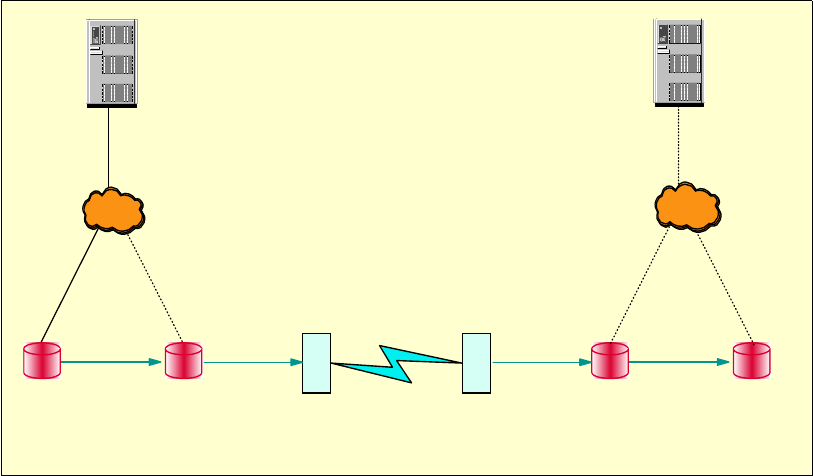
412 IBM System Storage DS6000 Series: Copy Services with IBM System z
27.1 Data migration
Combining the Copy Service functions Metro Mirror and Global Mirror into an environment
with double cascading makes it possible to maintain data consistency while migrating data.
There are two possibilities for accomplishing data consistency during a migration using an
environment that has double cascading. The first possibility is to shut down all applications at
the local site and let the out-of-sync drain completely. The second possibility is to change the
Global Copy relationships to Metro Mirror, then when the out-of-sync is approaching zero. a
freeze is issued to the changed relationships.
Figure 27-1 Double cascading example
Figure 27-1 shows double cascading with a Metro Mirror relationship from the local to the
secondary, and Global Copy from the secondary to the tertiary site, and from the tertiary to
the remote site. There is a cascading relationship at both the secondary and tertiary site
where the volumes are both secondaries and primaries. In this example, if all applications are
stopped at the local site, then the local, secondary, tertiary, and remote will reach a point after
some time where they are all equal; therefore, they will be consistent and data has
successfully been migrated to the remote site volumes.
In the second approach to provide data consistency during migration, again looking at the
example in Figure 27-1, a freeze is first issued to the Metro Mirror relationship from the local
to secondary site. Since Metro Mirror is running between the local to secondary site, there is
already a synchronous relationship. Therefore, the secondary volumes are consistent with
the local site volumes at this time.
The next step would be to change all the Global Copy relationships to Metro Mirror relations
and then issue a freeze when the out-of-sync has reached zero. When the out-of-sync is fully
drained, then there is a consistent relationship from the secondary to the remote and
migration to the remote is complete. Data migration has sent a snapshot of data to the remote
site so that there is consistency. This process would be used when production cannot be
stopped, since production keeps running at the local site. However, once the freeze is first
issued on the Metro Mirror relationship, from that point forward the remote will only be
A
AB
B
DS6K DS6K
PPRC-MM
DWDM DWDM
<50 Kms
C
CD
D
DS6K DS6k
PPRC-GCPPRC-GCPPRC-GC
Local Secondary Tertiary Remote
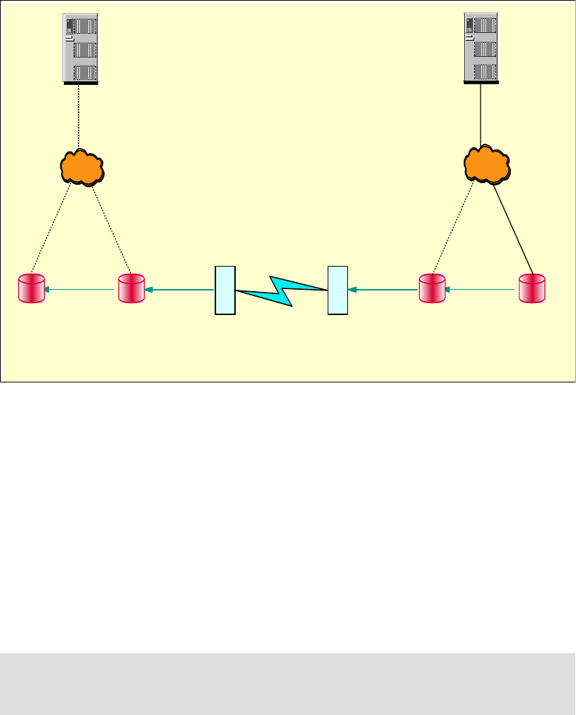
Chapter 27. Combining Copy Service functions 413
consistent with the secondary. The local during this process is still being updated and is
changing. The remote will have a snapshot of the time since the freeze was issued.
Figure 27-2 Global Copy changed to Metro Mirror and direction reversed
Once data migration and consistency have been accomplished at the remote site, you can
start production at the remote site, if desired. In this case all applications must first be
stopped at the local site and the direction of the mirror is reversed so that Metro Mirror is now
running from the remote to the tertiary site, and Global Copy is running from the tertiary site to
the secondary site and then to the primary site. Figure 27-2 shows the new configuration with
the Metro Mirror and Global Copy reversed and production running at the remote site.
In this example, it is shown that to protect the production at the remote, the remote copy
relations can be reversed to use the tertiary, secondary, or local volumes as targets. These
copy relations would be created before starting production at the remote site. Since the
relationships from the secondary to the tertiary and from the tertiary to the remote are both in
a cascaded relationship, to reverse the directions Global Copy must first be removed and
then recreated in the reverse directions.
Note: No I/O should be running at any time at any of the sites while the reversal of the
remote copy relations is being done. This would corrupt the resulting data, and
consequently require a full copy.
A
AB
B
DS6K DS6K
PPRC- - GC
DWDM DWDM
<50 Kms
C
CD
D
DS6K DS6K
PPRC- - MM
PPRC-- GC
PPRC-- GC
Local Secondary Ter t i ar y Remote
414 IBM System Storage DS6000 Series: Copy Services with IBM System z

© Copyright IBM Corp. 2006. All rights reserved. 415
Chapter 28. Interoperability between DS6000
and DS8000
In this chapter we show the interoperability between the Copy Services functions in the
DS6000 and the DS8000. It contains the following sections:
DS6000 and DS8000 Copy Services interoperability
Preparing the environment
RMC: Establishing paths between DS6000 and DS8000
Managing Metro Mirror or Global Copy pairs
Managing DS6000 to DS8000 Global Mirror
Managing DS6000 and DS8000 FlashCopy
28
Note: Remote Mirror and Copy (RMC) was formerly called Peer-to-Peer Remote Copy
(PPRC). All references to PPRC are interchangeable with RMC.
416 IBM System Storage DS6000 Series: Copy Services with IBM System z
28.1 DS6000 and DS8000 Copy Services interoperability
Copy Services operations are supported between the DS6000 and the DS8000. This means
you can have a mixed Copy Services environment that contains both devices.
28.2 Preparing the environment
Before starting Copy Services operations in a mixed DS6000 and DS8000 environment, you
must ensure that this environment is set up correctly.
28.2.1 Minimum microcode levels
To manage Copy Services in a mixed environment, you need to have licensed internal code
bundle 6.0.600.9 or later on your DS6000. You also need your IBM Service Representative to
install code bundle 6.0.500.52 or later on your DS8000.
28.2.2 Hardware and licensing requirements
To establish Remote Mirror and Copy pairs (also known as PPRC pairs) between a DS6000
and a DS8000, the DS6000 and the DS8000 must both have the appropriate Remote Mirror
and Copy (RMC) licenses.
The DS6000 and DS8000 must also have Fibre Channel adapters that have connectivity to
each other, either directly or via Fibre Channel switches. ESCON adapters cannot be used to
mirror a DS6000 with a DS8000.
z/OS Global Mirror RMZ (formerly XRC)
The DS6000 cannot be used as a z/OS Global Mirror primary Storage Unit. There is
consequently no feature code for z/OS Global Mirror (RMZ) for DS6000. The DS6000 can be
used as a secondary Storage Unit.
28.2.3 Network connectivity
Network connectivity requirements depend on how you want to manage the environment. If
you plan to use System z interfaces like TSO or ICKDSF, there are no network connectivity
requirements. The commands are sent inband through FICON or ESCON. If, however, you
plan to use the DS CLI or the DS GUI, your requirements are as follows:
For FlashCopy management:
– If you want to use the DS8000 DS GUI to manage FlashCopy on the DS6000, then you
need network connectivity between the DS8000 HMCs and the DS6000 SMCs.
– If you want to use the DS6000 DS GUI to manage FlashCopy on the DS8000, then you
need network connectivity between the DS8000 HMCs and the DS6000 SMCs.
– If you want to use the DS CLI to manage FlashCopy on either the DS6000 or the
DS8000 then the DS8000 HMCs and the DS6000 SMCs do not need to be connected
by a network. However, the server on which the DS CLI is installed must have network
connectivity to both the SMC and the HMC.
– If you have PPRC links between the DS6000 and DS8000, you can also use remote
FlashCopy to establish FlashCopies of the Remote Mirror target volumes.
For creating Remote Mirror and Copy (RMC), also known as Peer-to-Peer Remote Copy
(PPRC) paths and pairs:

Chapter 28. Interoperability between DS6000 and DS8000 417
– In a mixed environment, one system is the source (local) and one is the target. If you
want to be able to manage the PPRC paths and pairs from either machine, then you
need network connectivity between the DS6000 SMC and the DS8000 HMC. If you
use DS CLI, the SMC and HMC do have to be able to communicate with each other,
but the DS CLI machine must be able to communicate with both the HMC and the
SMC.
– If you do not plan to use the remote system as a source and you do not intend to use
the DS Storage Manager GUI to manage the pairs and paths, then network
connectivity to the remote machine (assuming the remote machine is at a remote site)
is not necessary. This is because, when you use the DS CLI, all path and pair
establishment is done by connecting to the source machine (the local machine). In a
disaster recovery scenario, you will have travel to the remote site to perform
management tasks for the remote machine. This setup is not recommended because it
is less flexible.
28.2.4 Creating matching user IDs and passwords
When you want to use the DS CLI or DS GUI to perform Copy Services operations, you must
authenticate with a valid user ID and password. When you use the DS6000 DS GUI to
perform an operation that requires it to issue a command to a DS8000, it must authenticate
with the DS8000. The DS user ID and password that you used to log on to the DS6000 DS
GUI is used to authenticate with the DS8000 HMC. The same applies if you use the DS8000
DS GUI to manage a DS6000. This means that the same user ID and password must be
defined in both the SMC and the HMC. This task must be manually performed. If, instead of
the DS GUI, you only use the DS CLI, then this requirement does not exist. However, it is still
of benefit to use a matching user ID and password to manage machines in either Storage
Complex.
28.2.5 Updating the DS CLI profile
If you plan to use the DS CLI to manage your mixed environment, you can create a profile to
simplify your connection to the DS CLI, commands, and script operations. To achieve this,
add extra lines as shown in Example 28-1. In this example, the DS6000 is considered the
local system, while the DS8000 is considered the remote system.
Example 28-1 Possible modification to a DS CLI profile
# DS6000
# hmc1 is the DS6000 SMC
hmc1: 10.0.0.100
# devid is the serial number of the DS6000
devid: IBM.1750-1300247
# remotedevid is the serial number of the DS8000
remotedevid: IBM.2107-7503461
# Username is a user created on the ESS Specialist that matches the userid on the DS6000
username:admin
# The password for the admin user id. Placing it here is not very secure.
password:passw0rd
# The password file is created using the managepwfile and is a better way to manage this.
# pwfile:security.dat
Note: A DS8000 Storage Complex is made of up of either one or two HMCs that together
manage one or two DS8000 Storage Units. A DS6000 Storage Complex consists of either
one or two SMCs that together manage one or two DS6000 Storage Units.

418 IBM System Storage DS6000 Series: Copy Services with IBM System z
Putting the password in the profile is not very secure (because it is stored in a plain text file),
but it might prove more convenient. A password file can be created using managepwfile and is
a better way to manage this. After creating the password file (which by default is called
security.dat), you can remove the password from the profile and instead specify the pwfile
file.
The command to create a passwd file in this example is:
managepwfile -action add -name admin -pw passw0rd
A simple method when you have multiple servers to manage is to create multiple profile files.
Then, when you start DS CLI, you can specify the profile file that you wish to use with the
-cfg parameter. In a Windows environment, you could have multiple Windows batch files
(BAT files), one for each machine you wish to manage. The profile shown in Example 28-1 on
page 417 could be saved in the C:\program files\ibm\dscli\profile directory as
1750source.profile. Then you could create a simple Windows BAT file with three lines as
shown in Example 28-2.
Example 28-2 Windows BAT file to start a specific profile
title DS CLI Local DS6800 1300247 Remote IBM.2107-7503461
cd C:\Program Files\ibm\dscli\profile
dscli -cfg 1750source.profile
We saved the BAT file onto the Windows desktop and started it by double-clicking the icon.
The DS CLI opened and started the specified profile. By creating a BAT file and profile for
each machine, you can simplify the process of starting the DS CLI. You can also specify the
profile when starting DS CLI from inside a script, or when running the DS CLI in script mode.
28.2.6 Adding the Storage Complex
If you wish to use a single DS GUI to manage both FlashCopy and Remote Mirror and Copy
pairs on your DS6000 and DS8000, you have to add the Storage Complex of one Storage
Unit (such as a DS6000), to the Storage Complex of the other Storage Unit (such as a
DS8000). Note that you have to do this operation once in each direction. In other words, you
have to add the DS6000 to the DS8000 and then add the DS8000 to the DS6000.
Adding the DS6000 Storage Complex to a DS8000 Storage Complex
You add a DS6000 Storage Complex to a DS8000 Storage Complex as follows.
1. Connect to the DS8000 HMC with the DS GUI.
2. Click Real-time manager.
3. Click Manage hardware.
4. Click Storage complexes.
5. Select Add.
6.
Figure 28-1 shows the Add Storage Complex panel that opens.
Important: Make sure that the user ID that you use to log on to the DS8000 DS GUI also
exists on the DS6000 SMC and that it has the same password. If not, the operation to add
the Storage Complex will fail. You must always use this user ID for multi-complex
management.
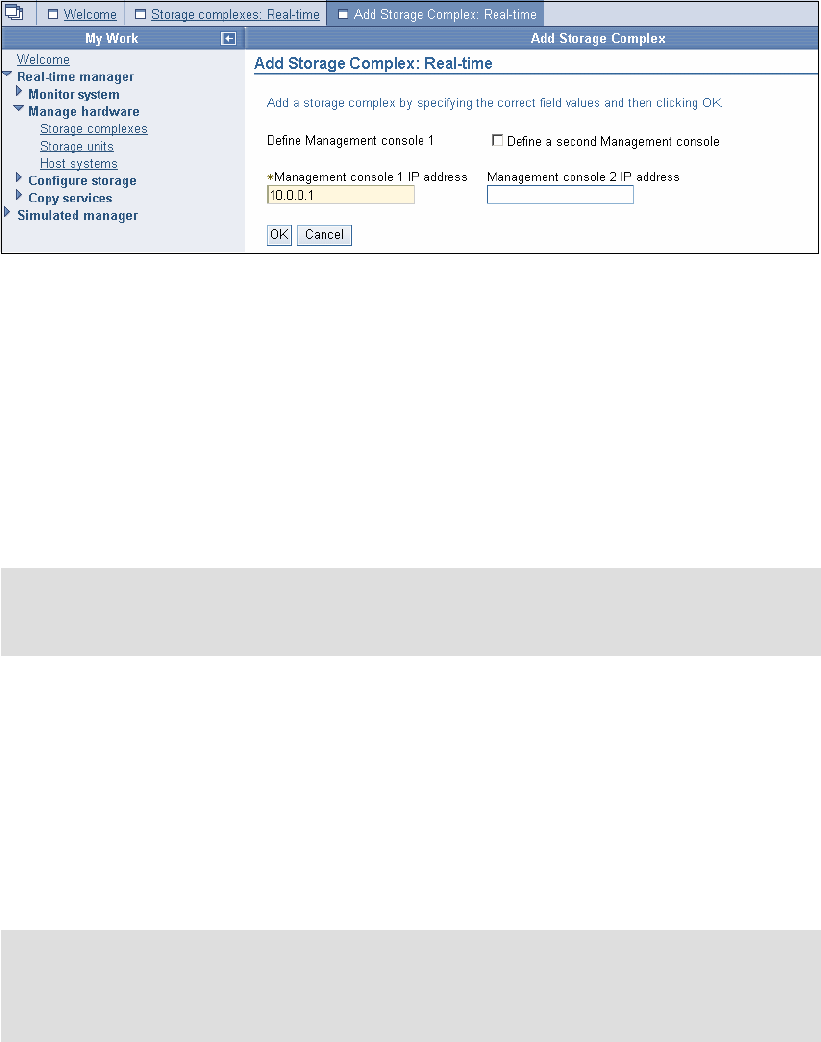
Chapter 28. Interoperability between DS6000 and DS8000 419
Figure 28-1 Add DS6000 complex to DS8000
7. Enter the IP address of the DS6000 SMC into the Management console 1 IP field. If you
have a second SMC, select Define a second Management console and enter the
second SMC address into the Management console 2 IP field. Click OK.
8. When the add Storage Complex operation is complete, the Storage Complex panel shows
the DS6000 SMC as an additional Storage Complex.
9. Having added the DS6000 Storage Complex to the DS8000 Storage Complex, you are
now able to use the DS8000 DS GUI to create paths and Remote Mirror and Copy pairs,
where the DS6000 is the source device. You can also use the DS8000 DS GUI to manage
FlashCopy pairs on the DS6000.
Adding the DS8000 Storage Complex to a DS6000 Storage Complex
You add a DS8000 Storage Complex to a DS6000 Storage Complex as follows:
1. Connect to the DS6000 SMC using the DS GUI.
2. Click Real-time manager.
3. Click Manage hardware.
4. Click Storage complexes.
5. Select Add Storage Complex.
Figure 28-2 shows the Add Storage Complex panel that opens.
Note: The steps to add the DS6000 Storage Complex to the DS8000 Storage Complex
cannot be performed with the DS CLI. This is by design. However, if you don’t plan to use
the GUI, this will not be an issue.
Important: Make sure that the user ID you use to log on to the DS6000 DS GUI also exists
on the DS8000 HMC and that it has the same password. If not, the operation to add the
Storage Complex will fail. You will need to always use this same user ID for multi-complex
management.
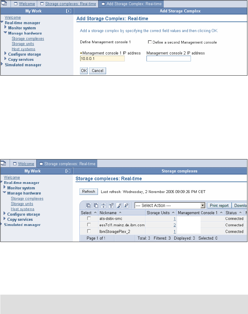
420 IBM System Storage DS6000 Series: Copy Services with IBM System z
Figure 28-2 Add DS8000 complex to DS6000
6. Enter the IP address of the DS8000 HMC in the Management console 1 IPfield. If you
have a second DS8000 HMC, select Define a second Management console and enter
the second HMC address in the Management console 2 IP field. Click OK.
7. When the add Storage Complex operation completes, the Storage Complex panel shows
the DS8000 HMC as an additional Storage Complex. In Figure 28-3, a DS6000 SMC, an
ESS 800 Copy Services Server, and a DS8000 HMC are all defined in one DS6000 DS
GUI.
Figure 28-3 DS6000 GUI showing multiple complexes
8. Having added the DS8000 Storage Complex to the DS6000 Storage Complex, you are
now able to use the DS6000 DS GUI to create paths and Remote Mirror and Copy pairs,
where the DS8000 is the source device. You can also use the DS6000 DS GUI to manage
FlashCopy pairs on the DS8000.
User ID management
There are two important considerations when you are managing multiple Storage Complexes
from a single DS GUI:
The user ID that you use to add the alternative complex must exist in both complexes. You
must continue to use this user ID for all multi complex operations. If you log on to either
DS GUI with a user ID that does not exist on the other Complex, the remote Complex will
not appear in the Storage Complex panel.
Note: The steps to add the DS8000 Storage Complex to the DS6000 Storage Complex
cannot be performed with the DS CLI.
10.0.0.1
10.0.0.2
10.0.0.3

Chapter 28. Interoperability between DS6000 and DS8000 421
Even when you have successfully added one complex to another, new user IDs created in
one complex do not mirror to the other complex. They must be manually created and
managed in each complex.
Storage management
You cannot use the DS8000 DS GUI to perform storage configuration on a DS6000.
Likewise, you cannot use the DS6000 DS GUI to perform storage configuration on a DS8000.
You can only perform Copy Services management tasks on the alternative device. If you are
logged on to the DS6000 DS GUI and wish to configure some storage on the DS8000, you
must log off and then log on to the DS8000 DS GUI. The same applies if you are logged on to
the DS8000 DS GUI and wish to configure storage on the DS6000. You must log on to the
DS6000 DS GUI to do this.
28.2.7 Volume size considerations for Remote Mirror Copy
When you use RMC (PPRC) to copy the contents of a CKD volume from one storage device
to another, it is possible for the RMC target volume to be larger than the RMC source volume.
However, if an attempt is made to reverse the relationship (so that the source becomes the
target), this attempt will fail because now the source is larger than the target. Clearly the best
way to avoid this is to ensure the source and target are exactly the same size.
28.2.8 Determining DS6000 and DS8000 CKD volume size
When CKD volumes are created on a DS6000 or DS8000, the size must be specified in
cylinders. In Example 28-3, two CKD volumes of 3339 cylinders are created. This means that
if we use these volumes in a PPRC relationship, their partner volumes should also be 3339
cylinders.
Example 28-3 CKD volume size in DS CLI
dscli> mkckdvol -extpool P2 -cap 3339 -name av_6K_CKD_#h 0600-0601
Date/Time: 8 November 2005 22:58:31 IBM DSCLI Version: 5.1.0.204 DS: IBM.1750-1300247
CMUC00021I mkckdvol: CKD Volume 0600 successfully created.
CMUC00021I mkckdvol: CKD Volume 0601 successfully created.
dscli> lsckdvol -lcu 06
Date/Time: 9 November 2005 3:58:42 IBM DSCLI Version: 5.1.0.204 DS: IBM.1750-1300247
Name ID accstate datastate configstate deviceMTM voltype orgbvols extpool cap (cyl)
================================================================================================
av_6K_CKD_0600 0600 Online Normal Normal 3390-3 CKD Base - P2 3339
av_6K_CKD_0601 0601 Online Normal Normal 3390-3 CKD Base - P2 3339
28.3 RMC: Establishing paths between DS6000 and DS8000
To create a PPRC relationship between a DS8000 and an DS6000, you must first create
logical paths (over the physical Fibre Channel connections). If you are using the DS GUI, then
provided you added the other machines Storage Complex, you can establish paths in either
direction (DS6000 to DS8000 or DS8000 to DS6000).
28.3.1 Decoding port IDs
When viewing port IDs in the DS GUI or DS CLI, the port IDs can be decoded to show which
physical port on the DS8000 or DS6000 is in use.

422 IBM System Storage DS6000 Series: Copy Services with IBM System z
For DS8000, port IDs look like I0000 or I0123, which actually breaks out as IEECP. The EE is
the enclosure number (minus 1), C is the card slot number (minus 1), and P is the port
number on the card. So I0123 is enclosure 2 (1+1), slot 3 (2+1), port 3.
For DS6000, port IDs range from I0000 to I0001 and I0100 to I0103, which actually breaks
out as IEECP. The EE is the controller number (00 or 01), C is the card slot number (always
zero), and P is the port number on the card (0 to 3). So I0103 is controller 1, card slot 0, port
3.
28.3.2 Path creation using the DS GUI
Path creation between a DS6000 and a DS8000 is no different from the process that is used
to create paths between two DS8000s or two DS6000. See 13.4, “Metro Mirror paths and
links” on page 142.
Paths in the reverse direction
The previous example showed how to create a path from the DS8000 to the DS6000. In
many cases, it is likely that you will need paths from DS6000 to the DS8000. Regardless,
having established paths in one direction you can then establish paths in the opposite
direction. Fibre Channel allows bi-directional mirroring over the same physical path.
Adding or deleting paths
You can add additional paths to an LSS pair by simply creating more paths. To remove a
path, open the Paths panel, select the relevant source machine and LSS, select the path you
wish to delete, and use the delete option from the Select Action menu.
28.3.3 Establish logical paths between DS8000 and DS6000 using DS CLI
You can use the DS CLI to establish logical paths. However, you must know the WWNN of
the target Storage Image. The three commands we will use to establish a path are: lssi,
lsavailpprcport and mkpprcpath.
Determining the remote device WWNN
If you started DS CLI by connecting to the DS8000 HMC, then the remote storage device is
the DS6000. If you started DS CLI by connecting to the DS6000, then the remote Storage
Image is the DS8000.
How to determine the DS6000 WWNN using the DS GUI
1. Click Real-time manager.
2. Click Manage hardware.
3. Click Storage units.
4. Click in the Select column for the DS6000 Storage Unit, and from the Select Action menu,
select Properties.
5. The DS6000 Storage Unit WWNN is displayed in the subsequent properties panel.
Determining the DS6000 WWNN with the DS CLI
In Example 28-5, we show how to display the WWNN of a Storage Image using the lssi
command.
Example 28-4 Determine the WWNN of a DS6000
dscli> lssi
Date/Time: 3 November 2005 1:05:50 IBM DSCLI Version: 5.1.0.204

Chapter 28. Interoperability between DS6000 and DS8000 423
Name ID Storage Unit Model WWNN State ESSNet
============================================================================
- IBM.1750-1300247 IBM.1750-1300247 511 500507630EFFFE16 Online Enabled
Determining the DS8000 WWNN with the DS GUI
To determine the DS8000 WWNN with the DS GUI:
1. Click Real-time manager.
2. Click Manage hardware.
3. Click Storage images (not the Storage Unit).
4. Click in the Select column for the DS8000 Storage Image, and from the Select Action
menu, select Properties.
5. The DS8000 Storage Image WWNN is displayed in the subsequent properties panel.
Determining the DS8000 WWNN with the DS CLI
In Example 28-5 we show how to display the WWNN of a DS8000 Storage Image using the
lssi command.
Example 28-5 Determine the WWNN of a DS8000
dscli> lssi IBM.2107-7503461
Date/Time: 1 November 2005 3:08:52 IBM DSCLI Version: 5.1.0.204
Name ID Storage Unit Model WWNN State ESSNet
============================================================================
- IBM.2107-7503461 IBM.2107-7503460 932 5005076303FFC08F Online Enabled
Listing the available ports using the DS CLI
Having determined the remote devices WWNN, we can now display the ports that are
available to establish PPRC paths. In Example 28-6 we are logged onto the DS8000 using
DS CLI, so the remote device is the DS6000. We display ports available to establish paths
between LSS 14 on the DS8000 and LSS 18 on the DS6000.
Example 28-6 Displaying available ports for PPRC path establishment
dscli> lsavailpprcport -remotedev IBM.1750-1300247 -remotewwnn 500507630EFFFE16 08:06
Date/Time: 8 November 2005 23:07:38 IBM DSCLI Version: 5.1.0.204 DS: IBM.2107-7503461
Local Port Attached Port Type
=============================
I0001 I0103 FCP
I0131 I0003 FCP
Establishing the logical paths using DS CLI
Having determined which ports are available for each LSS pair that you wish to copy and
mirror between, you now establish a one-way path using the mkpprcpath command. You can
then display established paths using the lspprcpath command.
In Example 28-7, we first established a single path between LSS 14 on the DS8000 and LSS
18 on the DS6000. We then displayed the paths available for LSS 14 on the DS8000.
Note: When using the lsavailpprcport command you must specify LSSs that actually
exist.

424 IBM System Storage DS6000 Series: Copy Services with IBM System z
Example 28-7 Using DS CLI to establish PPRC paths
dscli> mkpprcpath -remotedev IBM.1750-1300247 -remotewwnn 500507630EFFFE16 -srclss 14
-tgtlss 18 I0001:I0103
Date/Time: 3 November 2005 20:37:09 IBM DSCLI Version: 5.1.0.204 DS: IBM.2107-7503461
CMUC00149I mkpprcpath: Remote Mirror and Copy path 14:18 successfully established.
dscli> lspprcpath 14
Date/Time: 3 November 2005 20:37:14 IBM DSCLI Version: 5.1.0.204 DS: IBM.2107-7503461
Src Tgt State SS Port Attached Port Tgt WWNN
=========================================================
14 18 Success FF18 I0001 I0103 500507630EFFFE16
In Example 28-8, we added an additional path between LSS 14 on the DS8000 and LSS 18
on the DS6000. Not that we included the existing path when creating a new path. Otherwise
the existing path is removed and only the new path will be available for use.
Example 28-8 Establishing additional paths using DS CLI
dscli> mkpprcpath -remotedev IBM.1750-1300247 -remotewwnn 500507630EFFFE16 -srclss 14
-tgtlss 18 I0001:I0103 I0131:I10003
Date/Time: 3 November 2005 20:37:49 IBM DSCLI Version: 5.1.0.204 DS: IBM.2107-7503461
CMUC00149I mkpprcpath: Remote Mirror and Copy path 14:18 successfully established.
dscli> lspprcpath 14
Date/Time: 3 November 2005 20:37:53 IBM DSCLI Version: 5.1.0.204 DS: IBM.2107-7503461
Src Tgt State SS Port Attached Port Tgt WWNN
=========================================================
14 18 Success FF18 I0001 I0103 500507630EFFFE16
14 18 Success FF18 I0131 I0003 500507630EFFFE16
To establish paths where the DS6000 is the source, connect to the DS6000 with the DS CLI
and follow the same process, but specify the DS8000 as the remote device.
28.3.4 Path creation using TSO
In Example , we established Metro Mirror paths from a DS6000 to a DS8000 with a TSO
command. CESTPATH commands
/* ------------------------------------------------------------------ */
/* */
/* ISSUE PPRC CESTPATH TO ESTABLISH PPRC PATHS */
/* */
/* ------------------------------------------------------------------ */
CESTPATH DEVN(X'E200') PRIM(X'6000' 500507630EFFFE16 X'06') -
SEC(X'2105' 5005076303FFC08F X'05') -
LINK(X'00030003' X'01030103') -
CGROUP(NO)
/* ------------------------------------------------------------------ */
Important: When you connect using the DS CLI to the DS8000 HMC, the DS8000 is the
local device and the DS6000 is the remote device. If you connect with the DS CLI to the
DS6000, then the DS6000 is now the local device and the DS8000 is the remote device.
Attention: The rmpprcpath command removes all paths between the source and target
LSSs. To just reduce the path count, use the mkpprcpath command and specify only the
paths you wish to continue using.

Chapter 28. Interoperability between DS6000 and DS8000 425
The command breaks out as follows:
Device that command is issued to:E200
Primary LCU SSID: 6000
Primary DS6000 WWNN:500507630EFFFE16
Primary DS6000 LSS ID:06
Secondary DS8000 LCU SSID:2105
Secondary DS8000 WWNN:5005076303FFC08F
Secondary DS8000 LSS ID:05
First path established: I0003 to I0003
Second path established:I0103 to I0103
28.4 Managing Metro Mirror or Global Copy pairs
Having established paths, you can now establish volume pairs.
28.4.1 Managing Metro Mirror or Global Copy pairs with the DS GUI
Establishing and managing Metro Mirror and Global Copy pairs between a DS6000 and a
DS8000 using the DS GUI is no different than using the DS GUI to establish pairs between
two DS8000s or DS6000s. See 14.6, “DS Storage Manager GUI” on page 172 and
Chapter 3, “DS Storage Manager” on page 17.
28.4.2 Managing Metro Mirror pairs using the DS CLI
In this example, we show how you can establish Metro Mirror volume pairs between a
DS8000 and a DS6000 with the DS CLI. We created two Metro Mirror pairs. Volumes 0801
and 0802 from the DS8000 are the source volumes, and the target volumes on the DS6000
are 0601 and 0602.
Example 28-9 shows how we created two pairs with the mkpprc command. We then listed
them with the lspprc command and removed one pair using the rmpprc command.
Example 28-9 Creating Metro Mirror pairs using DS CLI
dscli> mkpprc -remotedev IBM.1750-1300247 -type mmir -mode full 0801:0601 0802:0602
Date/Time: 9 November 2005 2:40:32 IBM DSCLI Version: 5.1.0.204 DS: IBM.2107-7503461
CMUC00153I mkpprc: Remote Mirror and Copy volume pair relationship 0801:0601 successfully
created.
CMUC00153I mkpprc: Remote Mirror and Copy volume pair relationship 0802:0602 successfully
created.
dscli> lspprc 0801-0802
Date/Time: 9 November 2005 2:40:38 IBM DSCLI Version: 5.1.0.204 DS: IBM.2107-7503461
ID State Reason Type SourceLSS Timeout (secs) Critical Mode First
===========================================================================================
0801:0601 Copy Pending - Metro Mirror 08 unknown Disabled Invalid
0802:0602 Copy Pending - Metro Mirror 08 unknown Disabled Invalid
dscli> rmpprc -remotedev IBM.1750-1300247 0801:0601
Date/Time: 9 November 2005 2:41:18 IBM DSCLI Version: 5.1.0.204 DS: IBM.2107-7503461
CMUC00160W rmpprc: Are you sure you want to delete the Remote Mirror and Copy volume pair
relationship 0801:0601:? [y/n] y
CMUC00155I rmpprc: Remote Mirror and Copy volume pair 0801:0601 relationship successfully
withdrawn.
dscli>

426 IBM System Storage DS6000 Series: Copy Services with IBM System z
In Example 28-9 on page 425, we connected to the DS8000 HMC with the DS CLI, so the
DS6000 is the remote device. To establish pairs where the DS6000 is the source device, we
must connect to the DS6000 with DS CLI. This makes the DS8000 the remote device.
28.4.3 Managing Global Copy pairs usingthe DS CLI
In this example, we show how you can establish Global Copy volume pairs between a
DS8000 and a DS6000 with the DS CLI. We create two Global Copy pairs. Volumes 0801
and 0802 from the DS8000 are the source volumes, and the target volumes on the DS6000
are 0600 and 0601.
In Example 28-9 on page 425, we created two pairs using the mkpprc command. We then
listed them using the lspprc command and paused one pair with the pausepprc command.
Example 28-10 Using DS CLI to manage Global Copy
dscli> mkpprc -remotedev IBM.1750-1300247 -type gcp 0801:0601 0802:0602
Date/Time: 9 November 2005 2:43:39 IBM DSCLI Version: 5.1.0.204 DS: IBM.2107-7503461
CMUC00153I mkpprc: Remote Mirror and Copy volume pair relationship 0801:0601 successfully
created.
CMUC00153I mkpprc: Remote Mirror and Copy volume pair relationship 0802:0602 successfully
created.
dscli> lspprc 0801-0802
Date/Time: 9 November 2005 2:43:46 IBM DSCLI Version: 5.1.0.204 DS: IBM.2107-7503461
ID State Reason Type SourceLSS Timeout (secs) Critical Mode First Pass
===========================================================================================
0801:0601 Copy Pending - Global Copy 08 unknown Disabled False
0802:0602 Copy Pending - Global Copy 08 unknown Disabled False
dscli> pausepprc -remotedev IBM.1750-1300247 0801:0601
Date/Time: 9 November 2005 2:44:04 IBM DSCLI Version: 5.1.0.204 DS: IBM.2107-7503461
CMUC00157I pausepprc: Remote Mirror and Copy volume pair 0801:0601 relationship
successfully paused.
dscli> lspprc 0801
Date/Time: 9 November 2005 2:44:08 IBM DSCLI Version: 5.1.0.204 DS: IBM.2107-7503461
ID State Reason Type SourceLSS Timeout (secs) Critical Mode First
===========================================================================================
0801:0601 Suspended Host Source Global Copy 08 unknown Disabled False
28.5 Managing DS6000 to DS8000 Global Mirror
The establishment of Global Mirror between a DS8000 and an DS6000 is achieved with the
same methods explained in Chapter 26, “Global Mirror examples” on page 341.
28.5.1 Managing Global Mirror pairs using DS CLI
In Example 28-11, we established a Global Copy pair between volume 0601 on the DS6000
and volume 0801 on the DS8000. Next, we created session 90 for LSS 08. We then created a
Global Mirror using session 90 and LSS 08.
Important: If you specify the wrong -remotedev or you are using a profile where a remote
device that is not the remote device that you want to use is specified, you might get an
error message, CMUN03057, that you are specifying an invalid subsystem ID. This might
be because you are specifying the wrong remote device serial number. If you have multiple
possible remote devices, do not place a remotedev entry in your DS CLI profile.

Chapter 28. Interoperability between DS6000 and DS8000 427
Example 28-11 Establishing Global Mirror using DS CLI
dscli> mkpprc -remotedev IBM.1750-1300247 -type gcp -tgtread -mode full 0801:0601
Date/Time: 9 November 2005 2:45:53 IBM DSCLI Version: 5.1.0.204 DS: IBM.2107-7503461
CMUC00153I mkpprc: Remote Mirror and Copy volume pair relationship 0801:0601 successfully created.
dscli> lspprc 0801
Date/Time: 9 November 2005 2:46:04 IBM DSCLI Version: 5.1.0.204 DS: IBM.2107-7503461
ID State Reason Type SourceLSS Timeout (secs) Critical Mode First Pass Status
==================================================================================================
0801:0601 Copy Pending - Global Copy 08 unknown Disabled False
dscli> mkremoteflash -dev IBM.1750-1300247 -conduit IBM.2107-7503461 -record -nocp 0601:0602
Date/Time: 2 November 2005 21:49:00 IBM DSCLI Version: 5.1.0.204 DS: IBM.1750-1300247
CMUC00173I mkremoteflash: Remote FlashCopy volume pair 0601:0602 successfully created. Use the
lsremoteflash command to determine copy completion.
dscli> mksession -lss 08 -volume 0801 90
Date/Time: 9 November 2005 2:57:18 IBM DSCLI Version: 5.1.0.204 DS: IBM.2107-7503461
CMUC00145I mksession: Session 90 opened successfully.
dscli> lssession 08
Date/Time: 9 November 2005 2:57:55 IBM DSCLI Version: 5.1.0.204 DS: IBM.2107-7503461
LSS ID Session Status Volume VolumeStatus PrimaryStatus SecondaryStatus FirstPassComplete
===========================================================================================================
08 90 Normal 0801 Join Pending Primary Copy Pending Secondary Simplex True
dscli> mkgmir -lss 08 -session 90
Date/Time: 9 November 2005 2:58:19 IBM DSCLI Version: 5.1.0.204 DS: IBM.2107-7503461
CMUC00162I mkgmir: Global Mirror for session 90 successfully started.
ddscli> showgmir 08
Date/Time: 9 November 2005 2:58:42 IBM DSCLI Version: 5.1.0.204 DS: IBM.2107-7503461
ID IBM.2107-7503461/08
Master Count 1
Master Session ID 0x90
Copy State Running
Fatal Reason Not Fatal
CG Interval (seconds) 0
XDC Interval(milliseconds) 50
CG Drain Time (seconds) 30
Current Time 11/09/2005 02:59:58 EST
CG Time 11/09/2005 02:59:58 EST
Successful CG Percentage 100
FlashCopy Sequence Number 0x4370CB7E
Master ID IBM.2107-7503461
Subordinate Count 0
Master/Subordinate Assoc -
28.6 Managing DS6000 and DS8000 FlashCopy
The establishment of a FlashCopy pair on a DS6000 using the DS8000 DS GUI is no different
than establishing a DS8000 FlashCopy pair (see 9.6, “FlashCopy management using the DS
SM” on page 87. The establishment of a FlashCopy pair on a DS8000 using the DS6000 DS
GUI, is again no different than establishing a DS6000 FlashCopy pair. For the DS CLI, you
connect directly to the relevant SMC or HMC, so it is also not different.
28.6.1 Creating a remote FlashCopy on an DS6000 using DS CLI
It is also possible to use DS CLI to create a remote FlashCopy on a DS6000 where the
source PPRC device is a DS8000 and vice versa. In Example 28-12, we connected to a
DS8000 using the DS CLI. We determined that there are established paths from LSS 08 on
the DS8000 to LSS 06 on the DS6000. We created a Metro Mirror pair from volume 0801 on

428 IBM System Storage DS6000 Series: Copy Services with IBM System z
the DS8000 to volume 0601 on the DS6000. We then created a remote FlashCopy on the
DS6000 between DS6000 volumes 0601 and 0602. We then removed the remote FlashCopy.
Example 28-12 Creating a remote FlashCopy where the DS6000 is the remote target
dscli> lspprcpath 08
Date/Time: 9 November 2005 3:01:10 IBM DSCLI Version: 5.1.0.204 DS: IBM.2107-7503461
Src Tgt State SS Port Attached Port Tgt WWNN
=========================================================
08 06 Success 6000 I0001 I0103 500507630EFFFE16
ddscli> mkpprc -remotedev IBM.1750-1300247 -type mmir 0801:0601
Date/Time: 9 November 2005 3:02:36 IBM DSCLI Version: 5.1.0.204 DS: IBM.2107-7503461
CMUC00153I mkpprc: Remote Mirror and Copy volume pair relationship 0801:0601 successfully created.
dscli> mkremoteflash -dev IBM.1750-1300247 -conduit IBM.2107-7503461/08 -persist -nocp 0601:0602
Date/Time: 3 November 2005 22:35:45 IBM DSCLI Version: 5.1.0.204 DS: IBM.1750-1300247
CMUC00173I mkremoteflash: Remote FlashCopy volume pair 0601:0602 successfully created. Use the
lsremoteflash command to determine copy completion.
dscli> lsremoteflash -dev IBM.1750-1300247 -conduit IBM.2107-7503461/08 0601:0602
Date/Time: 9 November 2005 3:04:07 IBM DSCLI Version: 5.1.0.204 DS: IBM.1750-1300247
ID SrcLSS SequenceNum ActiveCopy Recording Persistent Revertible SourceWriteEnabled
===========================================================================================================
0601:0602 06 0 Disabled Enabled Enabled Disabled Enabled
dscli> rmremoteflash -dev IBM.1750-1300247 -conduit IBM.2107-7503461/08 0601:0602
Date/Time: 3 November 2005 22:36:19 IBM DSCLI Version: 5.1.0.204 DS: IBM.1750-1300247
CMUC00179I rmremoteflash: Are you sure you want to remove the remote FlashCopy pair {0}? [y/n]:y
CMUC00180I rmremoteflash: Removal of the remote FlashCopy volume pair 0601:0602 has been initiated
successfully. Use the lsremoteflash command to determine when the relationship is deleted.
You could also reverse the scenario and use the DS6000 as the source machine in a PPRC
pair and then create the remote FlashCopy on the DS8000.
28.7 z/OS Global Mirror
Using a DS8000 as the primary Storage Unit and a DS6000 as a secondary Storage Unit is a
supported configuration for the purposes of z/OS Global Mirror. However, the authors did not
test it for this book. More importantly, if you plan to use z/OS Global Mirror, be aware that a
z/OS Global Mirror environment that includes a DS8000 as a primary Storage Unit and a
DS6000 as a secondary Storage Unit is not recommended for failover and failback operations
because of the following limitations.
Performance mismatch (mirroring)
If the secondary Storage Unit, the DS6000, and its connectivity to the SDM that runs on z/OS
Global Mirror, is significantly less capable (lower performing) than the primary Storage Unit
and its connectivity to the application systems, the overall z/OS Global Mirror performance
may suffer. That is, if applications can write faster to primary Storage Units than the SDM can
write to the secondary Storage Units, then implementations problems can result. (The SDM is
the function that copies data from the primary Storage Unit to the secondary Storage Unit in a
z/OS Global Mirror environment.)
Note: Commands that work with remote FlashCopies use the -dev parameter to define the
server on which the FlashCopy is to be performed. Other commands, such as mkpprc
commands, refer to this same device as the remote device, using -remotedev. However,
because a FlashCopy must be sent to the remote site and then performed locally on that
site, the use of the -dev parameter to refer to the remote machine is correct.
Chapter 28. Interoperability between DS6000 and DS8000 429
Performance mismatch (running applications)
Suppose a disaster or failure occurs and applications failover to the secondary (or recovery)
site and are running using the secondary Storage Units. If the secondary Storage Unit, the
DS6000, is less capable (in performance) than the primary Storage Unit, it is likely that you
will not be able to complete primary business applications in the required or expected time
frame.
z/OS Global Mirror-capable local (or primary) Storage Units
Suppose a disaster or failure occurs in a z/OS Global Mirror environment and applications
failover to the secondary site and are running at the secondary site on the secondary Storage
Units. Later, after the primary site has been repaired and is ready to resume as the primary
site, the secondary Storage Unit can then use z/OS Global Mirror to failback to the primary
site. However, for the failover and failback operations to work successfully, the secondary
Storage Unit must be a Global Mirror-capable primary Storage Unit, which means it must be
capable of being a Global Mirror primary Storage Unit. The DS6000 does not have the
appropriate microcode functionality to be a Global Mirror-capable primary Storage Unit and,
therefore, cannot be used to failback to the primary site.
430 IBM System Storage DS6000 Series: Copy Services with IBM System z

© Copyright IBM Corp. 2006. All rights reserved. 431
Part 8 Solutions
In this part we discuss solutions offered by IBM to assist you in the management, automation,
and control of your Copy Services implementation on the DS6000. We provide an overview of
the solutions, discuss the options available, and give some examples of using the solutions.
Part 8
432 IBM System Storage DS6000 Series: Copy Services with IBM System z

© Copyright IBM Corp. 2006. All rights reserved. 433
Chapter 29. Interoperability between DS6000
and ESS 800
In this chapter we show the interoperability between the Copy Services functions in the
DS8000 and the ESS 800. This chapter contains the following sections:
Sections in this chapter include:
DS6000 and ESS 800 Copy Services interoperability
Preparing the environment
RMC: Establishing paths between DS6000 and ESS 800
Managing Metro Mirror or Global Copy pairs
Managing ESS 800 Global Mirror
Managing ESS 800 FlashCopy
29
434 IBM System Storage DS6000 Series: Copy Services with IBM System z
29.1 DS6000 and ESS 800 Copy Services interoperability
Copy Services operations are supported between the DS6000 and the ESS 800 and Model
750. For the rest of this chapter, all references to the ESS 800 also apply to the ESS 750. On
the ESS 800, RMC is called PPRC. All references to PPRC are interchangeable with RMC.
29.2 Preparing the environment
Before starting Copy Services operations in a mixed DS6000 and ESS 800 environment, you
must ensure that this environment is set up correctly.
29.2.1 Minimum microcode levels
To manage the ESS 800 Copy Services from the DS6000, you must have your IBM Service
Representative install licensed internal code Version 2.4.3.65 or higher on the ESS 800, and
DS6000 code bundle 6.0.600.9 or higher on the DS6000.
29.2.2 Hardware and licensing requirements
To establish PPRC pairs between an ESS 800 and a DS6000, the ESS 800 must have a
PPRC license and the DS6000 must have an RMC license.
The ESS 800 must also have Fibre Channel adapters that can connect to the DS6000.
ESCON adapters cannot be used to mirror an ESS 800 to a DS6000. You cannot have a
Copy Services relationship between a 2105 E20 or F20 and a DS6000. You could, however,
have a cascaded installation where an ESS F20 is mirrored to an ESS 800 that is then
mirrored to a DS6000. The ESS F20 to ESS 800 relationship must, however, be managed
with ESS management tools such as the ESS CLI or the ESS Web Copy Services GUI.
z/OS Global Mirror RMZ (formerly XRC)
The DS6000 cannot be used as a Global Mirror primary Storage Unit. There is consequently
no feature code for z/OS Global Mirror (RMZ) for DS6000. The DS6000 can be used a
secondary Storage Unit.
29.2.3 Network connectivity
Network connectivity requirements depend on how you want to manage the environment. If
you plan to use System z interfaces like TSO or ICKDSF, there are no network connectivity
requirements. The commands are sent inband by FICON. If, however, you plan to use the DS
CLI or the DS GUI, your requirements are as follows:
For FlashCopy management:
– If you want to use the DS6000 DS GUI to manage FlashCopy on the ESS 800, then
you need network connectivity between the DS6000 SMCs and the ESS 800 Copy
Services servers.
– If you want to be able to use the DS CLI to manage FlashCopy on the ESS 800, then
you need network connectivity between the machine on which you are running the DS
CLI and at least one of the ESS 800 Copy Services servers.
For creating RMC/PPRC paths and pairs:
– If you wish to use the ESS 800 as a PPRC source machine, then you need network
connectivity to the ESS 800 Copy Services servers, either from a server running DS
CLI or from the DS6000 SMC.

Chapter 29. Interoperability between DS6000 and ESS 800 435
If he ESS 800 is going to be purely a remote target for PPRC, and you do not plan to use
it as a source server or use DS GUI to manage the pairs and paths, then you do not need
to have network connectivity to the ESS 800 Copy Services servers. This is because all
path and pair establishment is done by connecting to the source server (which would be
the DS6000). This setup is not recommended because it is less flexible.
29.2.4 Creating matching user IDs and passwords
When you want to use the DS CLI or DS GUI to perform Copy Services operations, you need
to authenticate with a valid user ID and password. When you use the DS GUI to perform an
operation requires it to issue a command to an ESS 800, it must authenticate with the ESS
800. To do this, it uses the DS user ID and password that you used to log on to the GUI. This
means that this user ID and password must be defined in the ESS Specialist. This task needs
to be manually performed. If instead of the DS GUI, you only use the DS CLI, then you are
logging on to the ESS 800 Copy Services server directly and the DS user ID and password
for the GUI is not necessary. For simplified management, you can still create a matching user
ID and password.
Creating a user ID on the DS6000
Log on to the DS6000 SMC using the DS GUI and create a user ID that is in either the admin,
op_storage. or op_copy_services groups. Log off and then log on with that user ID and
change the initial password.
Creating a user ID on the ESS 800
Once you have created a DS user ID, you must create a matching user ID using the ESS 800
Web Specialist:
1. Start a Web browser and connect to the IP address of either ESS 800 cluster.
2. Click ESS Specialist.
3. Log on with a ESS Specialist user ID that has administrator privileges.
4. Click Users.
5. Click Modify Users. Type the user ID name and password that you created in the DS CLI
or GUI. It must be given the Administration access level.
6. Click Add to move the user ID to the right hand box.
7. Click Perform Configuration Update and wait for the completion message.
29.2.5 Updating the DS CLI profile
If you plan to use the DS CLI to manage your ESS 800, you can create a profile to simplify:
connection, commands, and scripted operations. Add extra lines as shown in Example 29-1.
Example 29-1 Possible modification to a DS CLI profile
# ESS 800
# SMC1 is the Copy Services server A
SMC1: 10.0.0.100
# devid is the serial number of the ESS 800 - note there are only 5 digits after the 2105
devid: IBM.2105-22399
# remotedevid is the serial number of the DS6000
remotedevid: IBM.1750-1300247
Important: The ESS Web Copy Services user IDs are not used by the DS CLI or DS GUI.
You only need to create a matching ESS Specialist user ID.

436 IBM System Storage DS6000 Series: Copy Services with IBM System z
# Username is a user created on the ESS Specialist that matches the userid on the DS6000
username:admin
# The password for the admin user id. Placing it here is not very secure.
password:passw0rd
# The password file is created using the managepwfile and is a better way to manage this.
# pwfile:security.dat
Putting the password in the profile is not very secure (because it is stored in plain text), but it
can be more convenient. A password file can be created using the managepwfile command
and is a better way to manage this. After creating the password file (which by default is called
security.dat), you can remove the password from the profile and instead specify the pwfile
file.
The command to create a passwd file in this example is:
managepwfile -action add -name admin -pw passw0rd
A simple method when you have multiple machines to manage is to create multiple profile
files. Then, when you start the DS CLI, you can specify the profile file that you wish to use
with the -cfg parameter. In a Windows environment, you can have multiple Windows batch
files (BAT files), one for each machine you wish to manage. The profile shown in
Example 29-1 on page 435 could be saved in the C:\program files\ibm\dscli\profile directory
as 2105source.profile. Then you create a simple Windows BAT file with three lines, as shown
in Example 29-2.
Example 29-2 Windows BAT file to start a specific profile
title DS CLI Local 2105-22399 Remote IBM.1750-1300247
cd C:\Program Files\ibm\dscli\profile
dscli -cfg 2105source.profile
We saved the BAT file on the Windows desktop and started it by double-clicking the icon. The
DS CLI opened and started the specified profile. By creating a BAT file and profile for each
machine, you can simplify the process of starting the DS CLI. You can also specify the profile
when starting DS CLI from inside a script, or when running the DS CLI in script mode.
29.2.6 Adding the Copy Services domain
If you wish to use the DS GUI to manage FlashCopy on an ESS 800, or RMC paths and pairs
between an ESS 800 and a DS6000, you must add the ESS Copy Services domain to the DS
SMC. You need the IP address of the ESS 800 Copy Services servers (server A and if
desired, server B). You can get these by connecting with a Web browser to either cluster of
the ESS, and clicking the Copy Services tab. They will be displayed on the first window you
see.
You add an ESS Copy Services domain with the DS Storage Manager to the DS6000 as
follows:
1. Click Real-time manager.
2. Click Manage hardware.
3. Click Storage complexes.
4. Select Add 2105 Copy Services Domain.
5. Figure 29-1 on page 437 shows the Add 2105 Copy Services Domain panel that opens.
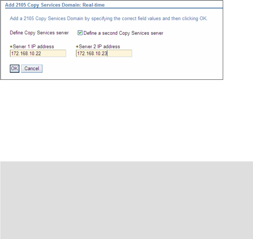
Chapter 29. Interoperability between DS6000 and ESS 800 437
Figure 29-1 Add 2105 Copy Services Domain
6. Enter the IP address of the ESS Copy Services server A in the Server 1 IP field. If you
have a Server B, select Define a second Copy Services server and enter the Server B
IP address in the Server 2 IP address. However, if Server B is running on a 2105-F20, you
should not define it.
Having added the ESS 800 Copy Services domain to the DS GUI, you are now able to use
the DS GUI to create paths and RMC pairs, where the ESS 800 is the source device. You can
also use the DS GUI to manager FlashCopy pairs on the ESS 800.
Storage management
You cannot use the DS6000 DS GUI to perform storage configuration on an ESS 800.
Likewise you cannot use the ESS 800 Web Specialist to perform storage configuration on a
DS6000. You can only perform Copy Services management tasks on the alternative device. If
you are logged on to the DS6000 DS GUI and wish to configure some storage on the ESS
800, you must log on to the ESS 800 Web Specialist.
29.2.7 Volume size considerations for RMC (PPRC)
When using PPRC to copy the contents of a CKD volume from one storage device to another,
it is possible for the PPRC target volume to be larger than the PPRC source volume.
However, if an attempt is made to reverse the relationship so that the source becomes the
target, then this attempt will fail because the source is now larger than the target. For this
reason it is always recommended that the source and target volumes be the same size. Prior
to creating a PPRC relationship, check the volumes sizes to ensure they are the same for
each storage device.
Determining DS6000 and DS8000 CKD volume size
When CKD volumes are created on a DS6000 or DS8000, the size must be specified in
cylinders. In Example 29-3, two CKD volumes of 3339 cylinders are created. This means that
Note: The steps to add the ESS 800 Copy Services Domain to a DS6000 cannot be
performed using the DS CLI. However if you do not plan to use the GUI, this is not an
issue.
Restriction: You cannot use the ESS Copy Services Server Web GUI to manage Copy
Services relationships between an ESS 800 and a DS6000. The Volumes tab only shows
ESS 800 volumes, not DS6000 volumes. The Paths tab does not show paths between an
ESS 800 and a DS6000. It only shows paths between ESS 800s. If you are using PPRC
between a DS6000 and an ESS 800, all management of that PPRC relationship must be
done with DS CLI or via the DS GUI.
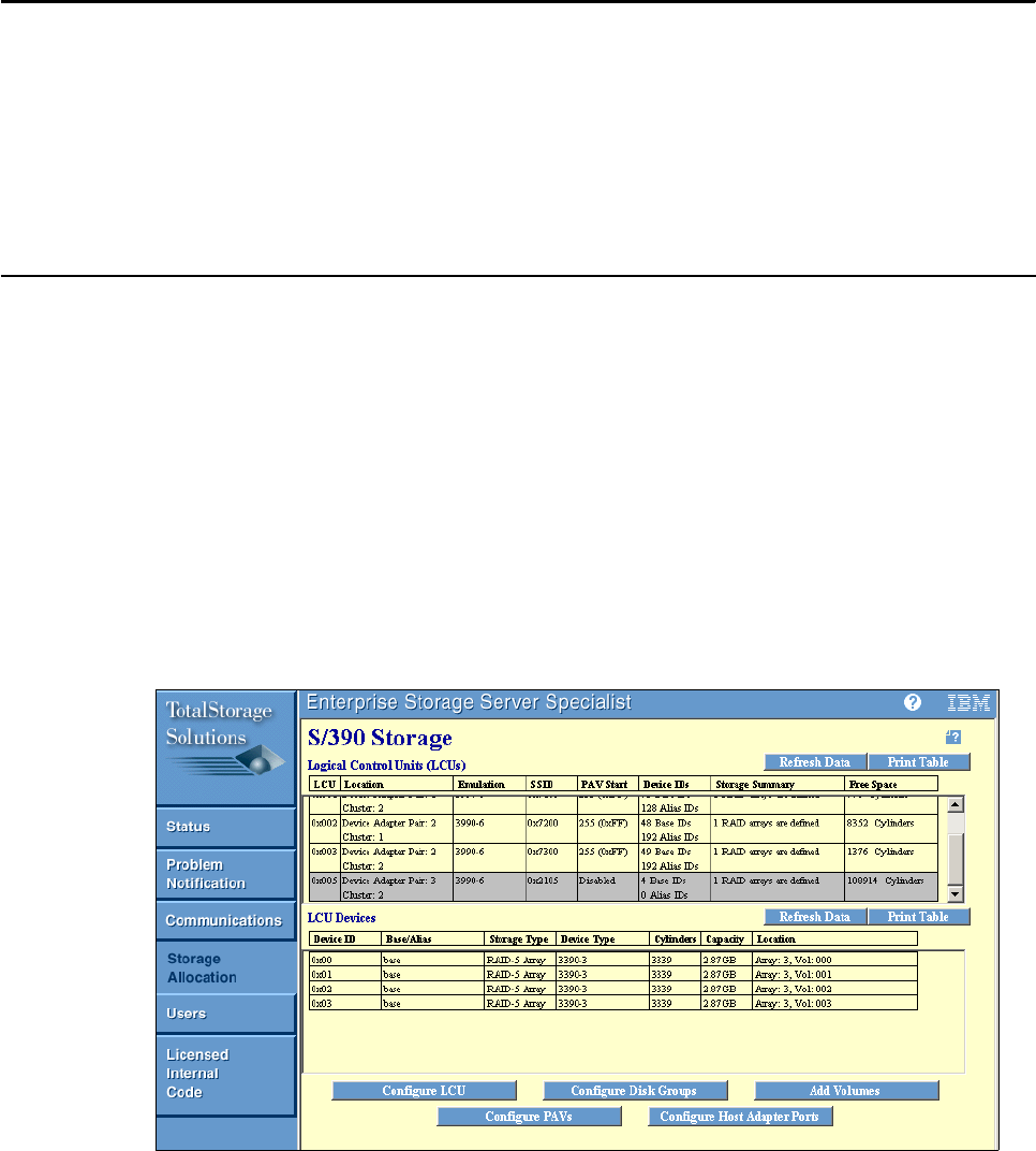
438 IBM System Storage DS6000 Series: Copy Services with IBM System z
if you use these volumes in a PPRC relationship, their partner volumes should also be 3339
cylinders.
Example 29-3 CKD volume size in DS CLI
dscli> mkckdvol -extpool P2 -cap 3339 -name av_6K_CKD_#h 0600-0601
Date/Time: 8 November 2005 22:58:31 IBM DSCLI Version: 5.1.0.204 DS: IBM.1750-1300247
CMUC00021I mkckdvol: CKD Volume 0600 successfully created.
CMUC00021I mkckdvol: CKD Volume 0601 successfully created.
dscli> lsckdvol -lcu 06
Date/Time: 9 November 2005 3:58:42 IBM DSCLI Version: 5.1.0.204 DS: IBM.1750-1300247
Name ID accstate datastate configstate deviceMTM voltype orgbvols extpool cap (cyl)
================================================================================================
av_6K_CKD_0600 0600 Online Normal Normal 3390-3 CKD Base - P2 3339
av_6K_CKD_0601 0601 Online Normal Normal 3390-3 CKD Base - P2 3339
Determining ESS volume size
To view the ESS volume sizes, you can use the ESS Specialist.
1. Start a Web browser and connect to the IP address of either ESS 800 cluster.
2. Click ESS Specialist.
3. Log on with a ESS Specialist user ID.
4. Click the Storage Allocation tab.
5. Click the S/390 Storage tab.
6. Highlight the LCU that contains the volumes you wish to check.
7. Take note of the value in the cylinders column for the volumes that you are interested in as
shown in Figure 29-2. In this example, the volumes are all 3339 cylinders in size.
Figure 29-2 Viewing ESS 800 volume size using ESS Specialist GUI
You can also use the ESS CLI to view the volume size as shown in Example 29-4 on
page 439.

Chapter 29. Interoperability between DS6000 and ESS 800 439
Example 29-4 Using ESS CLI to list CKD volumes
C:\Program Files\ibm\ESScli>esscli -u copy -p serv1ces -s 9.155.51.237 list volume
Wed Nov 09 04:07:52 EST 2005 IBM ESSCLI 2.4.0
Volume Cap Units VolType LSS VS Serial Label
------ ----- ----- ------- --- ---- -------- -----
0500 3339 Cyls 3390 05 vs6 *** ***
0501 3339 Cyls 3390 05 vs6 *** ***
0502 3339 Cyls 3390 05 vs6 *** ***
0503 3339 Cyls 3390 05 vs6 *** ***
29.2.8 Volume address considerations on the ESS 800
On the ESS 800, open systems volume IDs are given in an eight-digit format, xxx-sssss
where xxx is the LUN ID and sssss is the serial number of the ESS 800. When referring to
them in the DS CLI, you must add 1000 to the volume ID, so volume 000-22399 is volume ID
1000 and volume 001-22399 is volume ID 1001. This is very important because on the ESS
800, the following address ranges are actually used:
0000 to 0FFF CKD volumes (4096 possible addresses)
1000 to 1FFF Open systems fixed block LUNs (4096 possible addresses)
If we intend to use FlashCopy to copy ESS open systems LUN 000-22399 onto 001-22399
using DS CLI, we must specify 1000 and 1001. If instead, we specify 0000 and 0001, we
actually run the FlashCopy against CKD volumes. This might result in an unplanned outage
on the System z environment that was using CKD volume 0001.
29.3 RMC: Establishing paths between DS6000 and ESS 800
To create a PPRC relationship between a DS6000 and an ESS 800, you first must create
logical paths (over the physical Fibre Channel connections). If you are using the DS GUI, then
provided you added the ESS Copy Services Domain to the DS6000, you can establish paths
in either direction (ESS 800 to DS6000 or DS6000 to ESS 800). If the ESS Copy Services
domain was not added, then paths can only be established where the DS6000 is the source.
29.3.1 Decoding port IDs
When viewing port IDs in the DS GUI or DS CLI, you can decode the IDs to show which
physical port on the DS6000 or ESS 800 is in use. For DS6000, port IDs range from I0000 to
I0001 and I0100 to I0103. These break out as IEECP. The EE is the controller number (00 or
01), C is the card slot number (always 0), and P is the port number on the card (0 to 3). So
I0103 is controller 1, card slot 0, port 3.
The ESS 800 port IDs do not follow the same rule. To decode them, take the last two digits in
the port ID and then use Figure 29-3 on page 440. So port ID I0020 is the adapter in host bay
2, slot 1 and port ID I00AC is the adapter in host bay 4, slot 4.
Note: You cannot use the DS CLI to check volume sizes on an ESS 800. You must either
use the ESS Specialist or the ESS CLI.
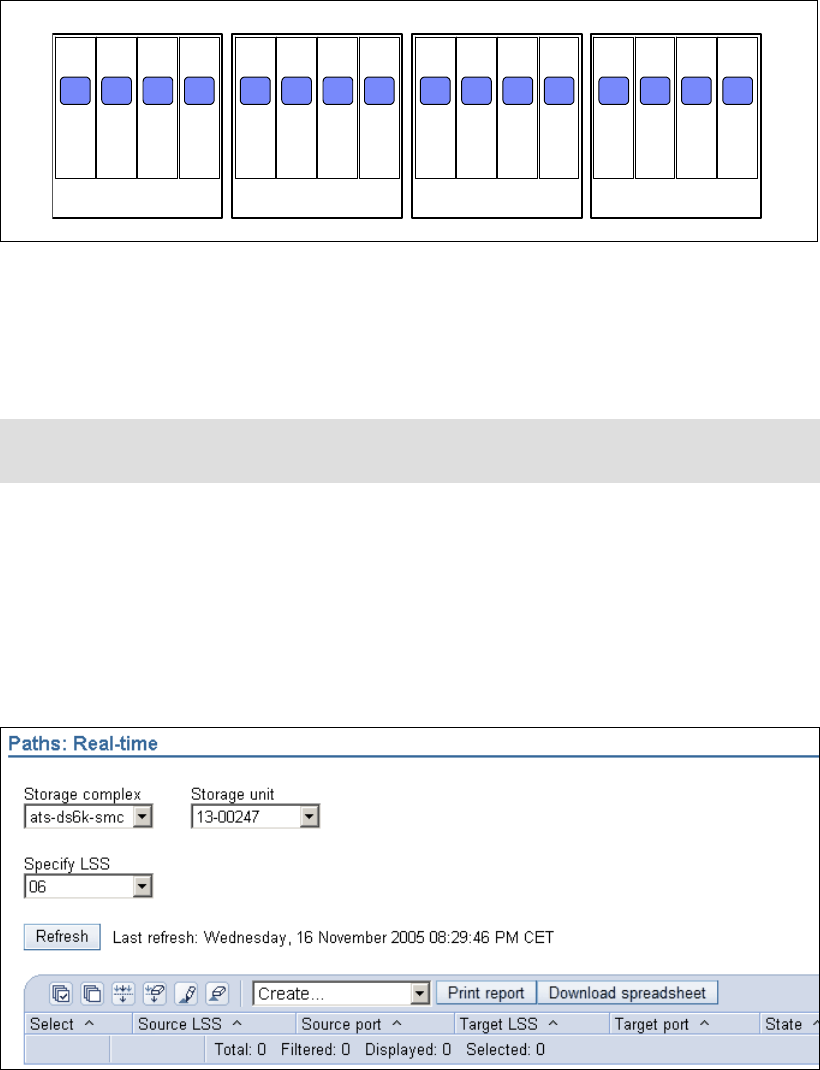
440 IBM System Storage DS6000 Series: Copy Services with IBM System z
Figure 29-3 ESS 800 I/O ports decoded
29.3.2 Creating paths with the DS GUI
In this example, we show how to establish two PPRC paths from DS6000 LSS 06 to ESS LSS
05 with the DS Storage Manager.
1. Click Real-time manager.
2. Click Copy Services.
3. Click Paths.
4. Select the Storage complex, Storage unit, and Storage image from which you want to
create PPRC paths. For this path, this server provides the source LSS.
5. Click Create. See Figure 29-4.
Figure 29-4 Path panel
6. In the panel that opens, select the source LSS of the DS6000 from which you want to
establish the PPRC paths. Click Next. In this example, we wanted to establish PPRC
paths from LSS 06 as shown in Figure 29-5 on page 441.
Slot 1 Slot 2 Slot 3 Slot 4
00 04 08 0C
Host Bay 1 Slot 1 Slot 2 Slot 3 Slot 4
20 24 28 2C
Host Bay 2 Slot 1 Slot 2 Slot 3 Slot 4
80 84 88 8C
Host Bay 3 Slot 1 Slot 2 Slot 3 Slot 4
A0 A4 A8 AC
Host Bay 4
Tip: CKD LCUs on an ESS 800 are always LSS 00 to LSS 0F. If you select ESS 800 LSS
10 to ESS 800 LSS 1F, you are working with open systems LSSs on the ESS 800.
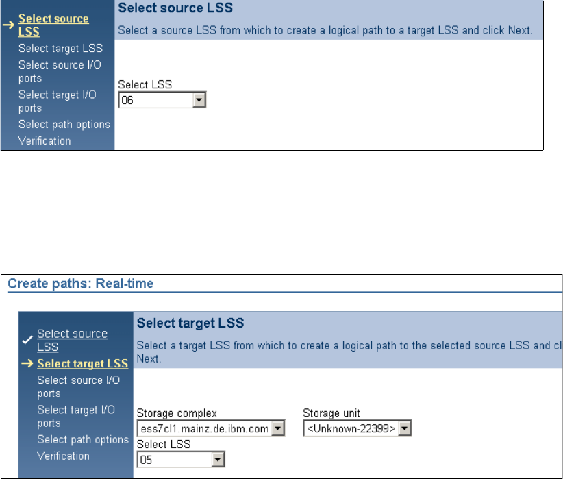
Chapter 29. Interoperability between DS6000 and ESS 800 441
Figure 29-5 Select source LSS
7. To specify the target LSS, select the Storage Complex for the ESS from the Storage
Complex menu. Then, from the Storage Unit menu, select the appropriate Storage Unit
and the LSS from the Storage Unit. When you are finished, click Next to continue. In
Figure 29-6 the target LSS on the ESS is LSS 05.
Figure 29-6 Select target LSS
8. The next panel shows you which Fibre Channel ports are available for establishing Metro
Mirror and Copy paths (see Figure 29-7 on page 442). Select the ports and click Next.
Because you want to establish two paths from the DS6000 to the ESS, you must select
both I/O ports from the DS6000 that are available for RMC. You only see physical
connections that actually exist. To get connections listed, the HBAs in the DS6000 and
ESS 800 must be either be zoned together or directly connected.
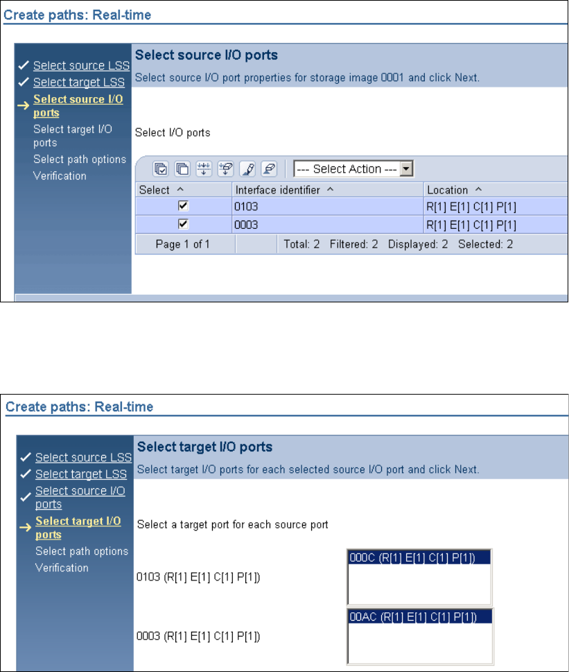
442 IBM System Storage DS6000 Series: Copy Services with IBM System z
Figure 29-7 Select source I/O ports
9. In the next panel (see Figure 29-8), you select, for each source I/O port from the DS6000,
a target I/O port on the ESS. When you are finished, click Next.
Figure 29-8 Select target I/O ports
10.In the next two panels, you are asked whether you want built a Consistency Group and to
verify the information that you entered during the process. Verify the information and click
Finish to establish the PPRC paths.
Figure 29-9 on page 443 shows the two PPRC paths that we have for LSS 06. To manage the
established paths (for example, delete path), you can select the path you want to manage and
then select the appropriate action you want to perform from the menu.
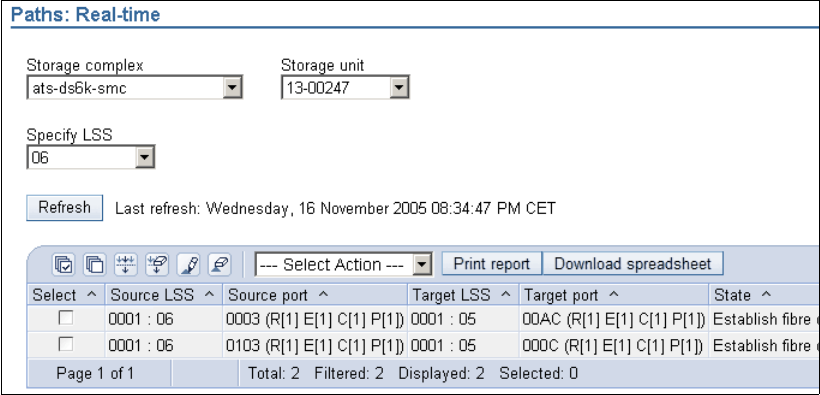
Chapter 29. Interoperability between DS6000 and ESS 800 443
Figure 29-9 Path panel
Paths in the reverse direction
The previous example showed how to create a path from the DS6000 to the ESS 800. In
many cases, it is likely that you will need paths from ESS 800 to the DS6000. Because you
have established paths in one direction, you can now establish paths in the opposite
direction. Fibre Channel allows bidirectional mirroring over the same physical path.
Adding or deleting paths
You can add additional paths to an LSS pair by simply creating more paths. To remove a
path, open the Paths panel, select the relevant source server and LSS, select the path that
you wish to delete, and use the delete option from the Select Action pull-down.
29.3.3 Establishing logical paths between DS6000 and ESS 800 using DS CLI
You can also use the DS CLI to establish logical paths. However, you must know the WWNN
of the target Storage Image. The three commands you can use to establish a path are: lssi,
lsavailpprcport and mkpprcpath.
Determining the remote device WWNN
First, we need to determine the WWNN of the remote storage device. If you started DS CLI by
connecting to the DS6000 SMC, then the remote storage device is the ESS 800. If you
started DS CLI by connecting to the ESS 800, then the remote Storage Image is the DS6000.
Determining the DS6000 WWNN with the DS GUI
To use the DS CUI to determine the DS6000 WWNN, follow these steps:
1. Click Real-time manager.
2. Click Manage hardware.
3. Click Storage units.
4. Click in the Select column for the DS6000 Storage Unit, and from the Select Action
pull-down, choose Properties.
5. The DS6000 Storage Unit WWNN will be displayed on the subsequent properties panel.
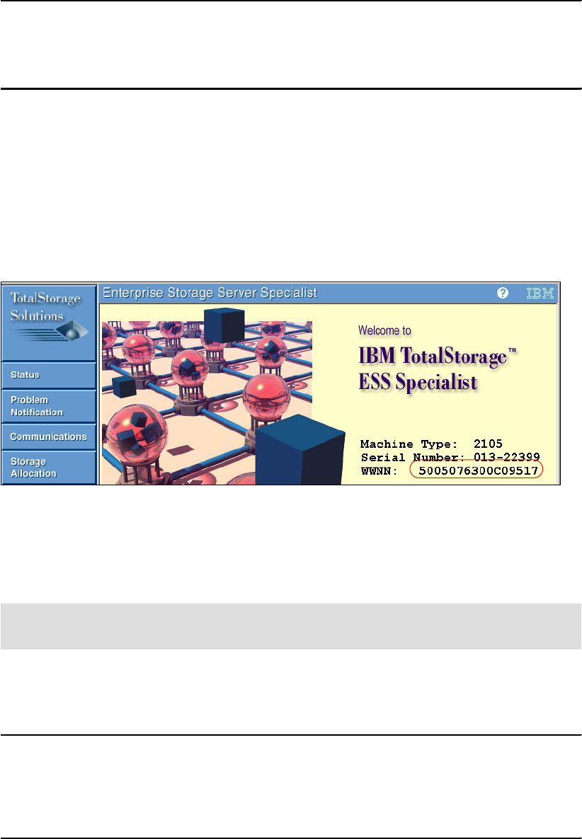
444 IBM System Storage DS6000 Series: Copy Services with IBM System z
Determining DS6000 WWNN with DS CLI
In Example 29-5, we show how to display the WWNN of a Storage Image using the lssi
command.
Example 29-5 Determine the WWNN of a DS6000
dscli> lssi
Date/Time: 3 November 2005 1:05:50 IBM DSCLI Version: 5.1.0.204
Name ID Storage Unit Model WWNN State ESSNet
============================================================================
- IBM.1750-1300247 IBM.1750-1300247 511 500507630EFFFE16 Online Enabled
Determine the WWNN of the ESS 800 with the ESS Specialist
To determine the WWN of the ESS 800 with the ESS Specialist:
1. Point your browser to the IP address of either cluster of the ESS 800.
2. On the opening panel, click ESS Specialist.
3. Using the prompt, log on to the ESS Specialist with a ESS Specialist user ID and
password.
4. On the welcome panel, you see the WWNN as shown in Figure 29-10. Write it down.
Figure 29-10 Using ESS 800 Specialist GUI to display the ESS 800 WWNN
Determining the WWNN of the ESS 800 using the ESS CLI
If you have the ESS CLI installed on a PC, then you can use the list server command to
display the ESS 800 WWNN.
An example of the command syntax is shown in Example 29-6. The advantage of this
technique is that you can copy and paste the output.
Example 29-6 Using ESS CLI to display the ESS 800 WWNN
C:\Program Files\ibm\ESScli>esscli -u storwatch -p specialist -s 10.0.0.1 list server
Tue Nov 01 03:28:59 EST 2005 IBM ESSCLI 2.4.0
Server Model Mfg WWN CodeEC Cache NVS Racks
-----------------------------------------------------------------------
2105.22399 800 013 5005076300C09517 2.4.3.79 32GB 2GB 1
Note: This is not the DS CLI. ESS CLI is a separate software package that you can get
from your IBM Service Representative if you do not already have it.

Chapter 29. Interoperability between DS6000 and ESS 800 445
Listing the available ports using DS CLI
Having determined WWNN of the remote devices, we can now display the ports that are
available for establishing PPRC paths. In Example 29-7, we are logged on to the DS6000
using DS CLI, so the remote device is the ESS 800.
Example 29-7 Displaying available ports for PPRC path establishment
dscli> lsavailpprcport -remotedev IBM.2105-22399 -remotewwnn 5005076300C09517 06:05
Date/Time: 8 November 2005 23:13:47 IBM DSCLI Version: 5.1.0.204 DS: IBM.1750-1300247
Local Port Attached Port Type
=============================
I0003 I00AC FCP
I0103 I000C FCP
Establishing the logical paths using the DS CLI
Having determined which ports are available for each LSS pair that you wish to copy and
mirror between, you now establish a one-way path with the mkpprcpath command. You can
then display established paths using the lspprcpath command.
In Example 29-8, we established a single path between LSS 06 on the DS6000 and LSS 05
on the ESS 800 and then showed the paths available for LSS 06 on the DS6000.
Example 29-8 Using DS CLI to establish PPRC paths
dscli> mkpprcpath -remotedev IBM.2105-22399 -remotewwnn 5005076300C09517 -srclss 06
-tgtlss 05 I0003:I00AC
Date/Time: 8 November 2005 23:28:53 IBM DSCLI Version: 5.1.0.204 DS: IBM.1750-1300247
CMUC00149I mkpprcpath: Remote Mirror and Copy path 06:05 successfully established.
dscli> lspprcpath 06
Date/Time: 8 November 2005 23:29:12 IBM DSCLI Version: 5.1.0.204 DS: IBM.1750-1300247
Src Tgt State SS Port Attached Port Tgt WWNN
=========================================================
06 05 Success 2105 I0003 I00AC 5005076300C09517
In Example 29-9, we add an additional path between LSS 06 on the DS6000 and LSS 05 on
the ESS 800. Note that we include the existing path when creating a new path. Otherwise, the
existing path is removed and only the new path will be available for use.
Example 29-9 Establishing additional paths using DS CLI
dscli> mkpprcpath -remotedev IBM.2105-22399 -remotewwnn 5005076300C09517 -srclss 06
-tgtlss 05 I0003:I00AC I0103:I000C
Date/Time: 8 November 2005 23:30:18 IBM DSCLI Version: 5.1.0.204 DS: IBM.1750-1300247
CMUC00149I mkpprcpath: Remote Mirror and Copy path 06:05 successfully established.
dscli> lspprcpath 06
Date/Time: 8 November 2005 23:30:27 IBM DSCLI Version: 5.1.0.204 DS: IBM.1750-1300247
Src Tgt State SS Port Attached Port Tgt WWNN
Note: When using the lsavailpprcport command, you must specify LSSs that actually
exist.
Note: When issuing commands that refer to an ESS 800, the ESS 800 serial number is
only five digits, and not the seven you see for the DS6000 or DS8000. So, in our examples,
the serial number syntax we use is IBM.2105-22399, not IBM.2105-1322399.

446 IBM System Storage DS6000 Series: Copy Services with IBM System z
=========================================================
06 05 Success 2105 I0003 I00AC 5005076300C09517
06 05 Success 2105 I0103 I000C 5005076300C09517
To establish paths where the ESS 800 is the source, you should connect to the ESS 800
using the DS CLI and follow the same process, but specify the DS6000 as the remote device.
29.3.4 Creating paths using TSO
In Example 29-10, we established Metro Mirror paths from a DS6000 to an ESS 800 using a
TSO command.
Example 29-10 CESTPATH command
/* ------------------------------------------------------------------ */
/* */
/* ISSUE PPRC CESTPATH TO ESTABLISH PPRC PATHS */
/* */
/* ------------------------------------------------------------------ */
CESTPATH DEVN(X'E200') PRIM(X'6000' 500507630EFFFE16 X'06') -
SEC(X'2105' 5005076300C09517 X'05') -
LINK(X'000300AC' X'0103000C') -
CGROUP(NO)
/* ------------------------------------------------------------------ */
The command breaks out as follows:
Device that command is issued to: E200
Primary LCU SSID: 6000
Primary DS6000 WWNN: 500507630EFFFE16
Primary DS6000 LSS ID: 06
Secondary ESS 800 LCU SSID: 2105
Secondary ESS 800 WWNN: 5005076300C09517
Secondary ESS 800 LSS ID: 05
First path established: I0003 to I00AC
Second path established: I0103 to I000C
29.4 Managing Metro Mirror or Global Copy pairs
Having established paths, we can now establish volume pairs.
29.4.1 Managing Metro Mirror or Global Copy pairs using the DS GUI
In this example, we show how you can establish Metro Mirror volume pairs between a
DS6000 and an ESS 800 with the DS Storage Manager. In this example, we created two
Important: When you connect using DS CLI to the DS6000 SMC, the DS6000 is the local
device and the ESS 800 is the remove device. If you connect using DS CLI to the ESS
800, then ESS 800 is now the local device and the DS6000 is the remote device.
Attention: The rmpprcpath command removes all paths between the source and target
LSSs. To just reduce the path count, use the mkpprcpath command and specify only the
paths that you wish to continue using.
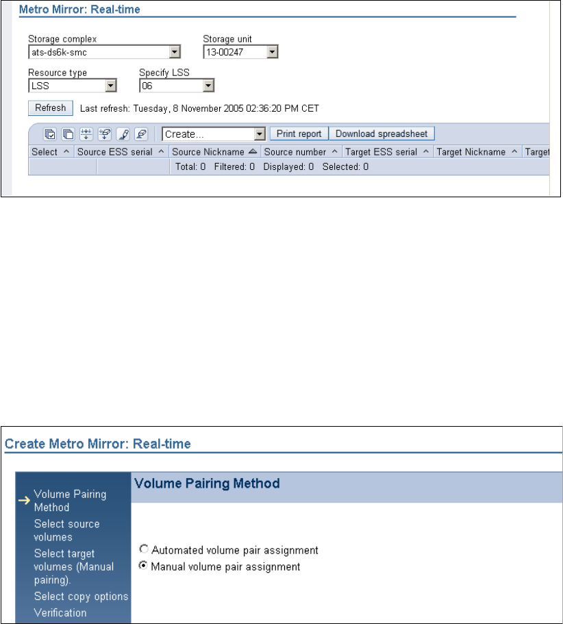
Chapter 29. Interoperability between DS6000 and ESS 800 447
Metro Mirror pairs. Volumes 0600 and 0601 from the DS6000 are the source volumes, and
the target volumes are 0500 and 0501 from the ESS 800. We followed the same method to
set up a Global Copy pair, except that Global Copy is selected (Figure 29-16 on page 449):
1. Click Real-time manager.
2. Click Copy services.
3. Click Metro Mirror.
4. Select the Storage complex, Storage unit, and Storage image for the Metro Mirror source
volumes.
5. Select Create (Figure 29-11).
Figure 29-11 Metro Mirro
The next panels guide you through the process of creating Metro Mirror volume pairs. In
the last panel, you have the opportunity to review the information you entered before you
establish the Metro Mirror pairs. Also, during the process, you can, at any time, go back to
modify specifications that you have already done, or you can cancel the process.
6. In the panel illustrated Figure 29-12, you have the option of selecting Automated volume
assignment or Manual volume pair assignment;. If you click Automated volume pair
assignment, the first selected source volume is paired automatically with the first
selected target volume. If you click Manual volume pair assignment, you must select
each specific target volume for each selected source volume. For this example, we
assigned the volume pairs manually.
Figure 29-12 Pairing method
7. The source volumes we want ed to use are on the ESS 800 in LSS 10. We selected two
volumes and clicked Next (see Figure 29-13 on page 448). Note that you also have the
option of creating paths from this panel.
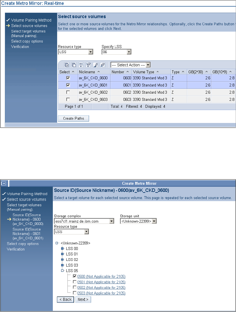
448 IBM System Storage DS6000 Series: Copy Services with IBM System z
Figure 29-13 Select source volume
8. In the next panel, select the Storage Complex and Storage Unit for the LSS with the target
volumes. Then, select the target volume for the first source volume. When you are
finished, click Next as shown in Figure 29-14. To expand your choices, you must select the
small blue boxes.
Figure 29-14 First Metro Mirror target volume
9. Next, select the target volume for the second source volume as shown in Figure 29-15 on
page 449. To expand your choices, you must select the small blue boxes.
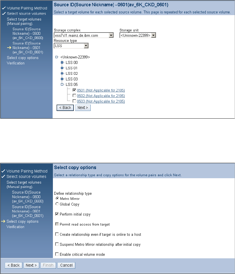
Chapter 29. Interoperability between DS6000 and ESS 800 449
Figure 29-15 Second Metro Mirror target volume
10.IIn the next panel, you can specify various copy options as shown in Figure 29-16. In this
example, we selected Metro Mirror under Define relationship type and Perform initial
copy. If you wished to instead use Global Copy, this is where you would select it.
Figure 29-16 Copy options
11.The Verify panel opens. Verify the information that you entered, and if everything is
correct, click Finish to establish the Metro Mirror volume pairs. Figure 29-17 on page 450
shows the Metro Mirror pairs for LSS 06 that we established. To manage the established
pairs (for example, suspend pair) you can select the volume pair you want to manage and
then select from the appropriate action that you want to perform from the menu.
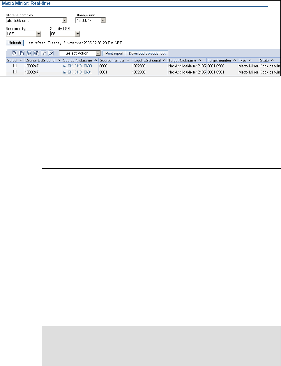
450 IBM System Storage DS6000 Series: Copy Services with IBM System z
Figure 29-17 Managing Metro Mirror pairs
29.4.2 Managing Metro Mirror pairs with the DS CLI
In this example, we show how you can establish Metro Mirror volume pairs between a
DS6000 and an ESS 800 with the DS CLI. We created two Metro Mirror pairs. Volumes 0600
and 0601 from the DS6000 are the source volumes, and the target volumes on the ESS are
0500 and 0501.
Example 29-11, we created the pairs with the mkpprc command. We then listed them with the
lspprc command and removed one pair with the rmpprc command.
Example 29-11 Creating Metro Mirror pairs using DS CLI
dscli> mkpprc -remotedev IBM.2105-22399 -type mmir -mode full 0600:0500 0601:0501
Date/Time: 9 November 2005 1:17:38 IBM DSCLI Version: 5.1.0.204 DS: IBM.1750-1300247
CMUC00153I mkpprc: Remote Mirror and Copy volume pair relationship 0600:0500 successfully
created.
CMUC00153I mkpprc: Remote Mirror and Copy volume pair relationship 0601:0501 successfully
created.
dscli> lspprc 0600-0601
Date/Time: 9 November 2005 1:17:56 IBM DSCLI Version: 5.1.0.204 DS: IBM.1750-1300247
ID State Reason Type SourceLSS Timeout (secs) Critical Mode First
===========================================================================================
0600:0500 Copy Pending - Metro Mirror 06 unknown Disabled Invalid
0601:0501 Copy Pending - Metro Mirror 06 unknown Disabled Invalid
dscli> rmpprc -remotedev IBM.2105-22399 0600:0500
Date/Time: 9 November 2005 1:19:05 IBM DSCLI Version: 5.1.0.204 DS: IBM.1750-1300247
CMUC00160W rmpprc: Are you sure you want to delete the Remote Mirror and Copy volume pair
relationship 0600:0500:? [y/n] y
CMUC00155I rmpprc: Remote Mirror and Copy volume pair 0600:0500 relationship successfully
withdrawn.
We connected to the DS6000 SMC using DS CLI, so the ESS 800 is the remote device. To
establish pairs where the ESS 800 is the source device, you must connect to the ESS 800
using the DS CLI. This will make the DS6000 the remote device.
Important: If you specify the wrong -remotedev or you are using a profile with a remote
device specified that is different from the one you intended to work on, you might get an
error message, CMUN03057, that says that you are specifying an invalid subsystem ID.
This might be because you are specifying the wrong remote device serial number. If you
have multiple potential remote devices, do not specify a remotedev in your DS CLI profile.

Chapter 29. Interoperability between DS6000 and ESS 800 451
29.4.3 Creating Metro Mirror pairs with TSO
In Example 29-12, we used the same paths that were created in 29.3.4, “Creating paths using
TSO” on page 446. We established a volume pair with Metro Mirror from the DS6000 to the
ESS 800.
Example 29-12 CESTPAIR command
//* ------------------------------------------------------------------ */
/* */
/* ISSUE PPRC CESTPAIR TO ESTABLISH VOLUME PAIRS */
/* */
/* ------------------------------------------------------------------ */
CESTPAIR DEVN(X'202B') PRIM(X'1710' 00247 X'2B' X'00') -
SEC(X'1070' 22399 X'2B' X'00') -
OPTION(SYNC) MODE(COPY)
29.4.4 Managing Global Copy pairs with the DS CLI
In this example, we show how you can establish Global Copy volume pairs between a
DS6000 and an ESS 800 with the DS CLI. We created a Global Copy pair. Volume 0603 from
the DS6000 is the source volume, and the target volume on the ESS is 0503.
In Example 29-13, we created a pair with the mkpprc command. Then, we listed the pair with
the lspprc command nand paused the pair with the pausepprc command.
Example 29-13 Using DS CLI to manage Global Copy
dscli> mkpprc -remotedev IBM.2105-22399 -type gcp 0603:0503
Date/Time: 9 November 2005 1:41:17 IBM DSCLI Version: 5.1.0.204 DS: IBM.1750-1300247
CMUC00153I mkpprc: Remote Mirror and Copy volume pair relationship 0603:0503 successfully
created.
dscli> lspprc 0603
Date/Time: 9 November 2005 1:41:30 IBM DSCLI Version: 5.1.0.204 DS: IBM.1750-1300247
ID State Reason Type SourceLSS Timeout (secs) Critical Mode First Pass
===========================================================================================
0603:0503 Copy Pending - Global Copy 06 unknown Disabled False
dscli> pausepprc -remotedev IBM.2105-22399 0603:0503
Date/Time: 9 November 2005 1:41:55 IBM DSCLI Version: 5.1.0.204 DS: IBM.1750-1300247
CMUC00157I pausepprc: Remote Mirror and Copy volume pair 0603:0503 relationship
successfully paused.
dscli> lspprc 0603
Date/Time: 9 November 2005 1:42:32 IBM DSCLI Version: 5.1.0.204 DS: IBM.1750-1300247
ID State Reason Type SourceLSS Timeout (secs) Critical Mode First
===========================================================================================
0603:0503 Suspended Host Source Global Copy 06 unknown Disabled False
29.5 Managing ESS 800 Global Mirror
The establishment of Global Mirror between a DS6000 and an ESS 800 is achieved using the
same methods as explained in Chapter 26, “Global Mirror examples” on page 341.
29.5.1 Managing Global Mirror pairs using the DS CLI
In Example 29-14 on page 452, we established a Global Copy pair between volume 0500 on
the ESS 800 and volume 0600 on the DS6000. Next, we created a FlashCopy on the remote

452 IBM System Storage DS6000 Series: Copy Services with IBM System z
device. Then, we created session 20 for LSS 05. Finally, we created a Global Mirror using
session 20 and LSS 05.
Example 29-14 Establishing Global Mirror using DS CLI
dscli> mkpprc -remotedev IBM.1750-1300247 -type gcp 0500:0600
Date/Time: 9 November 2005 1:50:05 IBM DSCLI Version: 5.1.0.204 DS: IBM.2105-22399
CMUC00153I mkpprc: Remote Mirror and Copy volume pair relationship 0500:0600 successfully created.
dscli> mkremoteflash -dev IBM.1750-1300247 -conduit IBM.2105-22399/05 -nocp -record 0600:0601
Date/Time: 9 November 2005 1:50:40 IBM DSCLI Version: 5.1.0.204 DS: IBM.1750-1300247
CMUC00173I mkremoteflash: Remote FlashCopy volume pair 0600:0601 successfully created. Use the
lsremoteflash command to determine copy completion.
dscli> mksession -lss 05 -volume 0500 20
Date/Time: 9 November 2005 1:52:26 IBM DSCLI Version: 5.1.0.204 DS: IBM.2105-22399
CMUC00145I mksession: Session 20 opened successfully.
dscli> lssession 05
Date/Time: 9 November 2005 1:52:41 IBM DSCLI Version: 5.1.0.204 DS: IBM.2105-22399
LSS ID Session Status Volume VolumeStatus PrimaryStatus SecondaryStatus FirstPassComplete
===========================================================================================================
05 20 Normal 0500 Join Pending Primary Copy Pending Secondary Simplex True
dscli> mkgmir -lss 05 -session 20
Date/Time: 9 November 2005 1:52:59 IBM DSCLI Version: 5.1.0.204 DS: IBM.2105-22399
CMUC00162I mkgmir: Global Mirror for session 20 successfully started.
dscli> showgmir 05
Date/Time: 9 November 2005 1:53:07 IBM DSCLI Version: 5.1.0.204 DS: IBM.2105-22399
ID IBM.2105-22399/05
Master Count 1
Master Session ID 0x20
Copy State Running
Fatal Reason Not Fatal
CG Interval (seconds) 0
XDC Interval(milliseconds) 50
CG Drain Time (seconds) 30
Current Time 11/09/2005 01:42:25 EST
CG Time 11/09/2005 01:42:25 EST
Successful CG Percentage 100
FlashCopy Sequence Number -
Master ID IBM.2105-22399
Subordinate Count 0
Master/Subordinate Assoc -
29.6 Managing ESS 800 FlashCopy
If there is a FlashCopy license for the ESS 800, it is possible to manage ESS FlashCopy with
the DS CLI or DS GUI. The establishment of a FlashCopy pair on an ESS 800, using the DS
GUI, is no different than establishing a DS6000 FlashCopy pair (see 9.6, “FlashCopy
management using the DS SM” on page 87). The establishment of a FlashCopy pair on an
ESS 800 using the DS CLI is also no different (see 9.4, “Local FlashCopy using the DS CLI”
on page 73). In a situation where the ESS 800 is in a PPRC relationship, it is also possible to
create remote FlashCopies using the mkremoteflash command. In each case, creating,
changing, and removing the FlashCopy is done using the same commands.
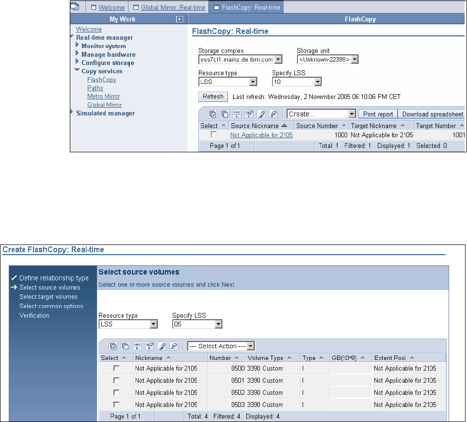
Chapter 29. Interoperability between DS6000 and ESS 800 453
29.6.1 Creating an ESS 800 FlashCopy with the DS GUI
The steps to create an ESS 800 FlashCopy using the DS GUI are:
1. Click Real-time manager.
2. Click Copy Services.
3. Click FlashCopy.
4. From the Storage Complex menu, choose the ESS 800 Copy Services Domain.
5. From the Storage Units menu, select the ESS that you wish to perform the FlashCopy on
6. Make selections from the Resource type and Specify LSS pull-downs.
7. From the Select Action menu, select Create, as shown in Figure 29-18.
Figure 29-18 Creating ESS 800 FlashCopy using DS GUI
8. Select either A single source with a single target or A single source with multiple
targets and click Next.
9. Select the source volumes as shown in Figure 29-19. Note that some of the columns have
Not Applicable for 2105 in them. This is normal.
Figure 29-19 Selecting ESS 800 source volumes for FlashCopy
10.Select the target volumes and click Next.
11.Select the options that you plan to use and click Next.

454 IBM System Storage DS6000 Series: Copy Services with IBM System z
12.The verification panel opens. Review your selections and click Finish.
29.6.2 Creating an ESS 800 FlashCopy with the DS CLI
You must start the DS CLI and connect to the ESS 800. Then issue DS CLI commands as
usual. An example is shown in Example 29-15.
Example 29-15 Using DS CLI to create an ESS 800 FlashCopy
dscli> mkflash -nocp -record -persist 0500:0501
Date/Time: 2 November 2005 20:04:33 IBM DSCLI Version: 5.1.0.204 DS: IBM.2105-22399
CMUC00137I mkflash: FlashCopy pair 0500:0501 successfully created.
dscli> lsflash 0500
Date/Time: 2 November 2005 20:04:37 IBM DSCLI Version: 5.1.0.204 DS: IBM.2105-22399
ID SrcLSS SequenceNum Timeout ActiveCopy Recording Persistent Revertible SourceWrite TargetWrite
===========================================================================================================
0500:0501 05 0 45 Disabled Enabled Enabled Disabled Enabled Enabled
dscli> rmflash 0500:0501
Date/Time: 2 November 2005 20:04:54 IBM DSCLI Version: 5.1.0.204 DS: IBM.2105-22399
CMUC00144W rmflash: Are you sure you want to remove the FlashCopy pair 0500:0501:? [y/n]:y
CMUC00140I rmflash: FlashCopy pair 0500:0501 successfully removed.
29.6.3 Creating a remote FlashCopy on an ESS 800 with the DS CLI
You can use the DS CLI to create a remote FlashCopy on an ESS 800 where the source
PPRC device is a DS6000. In Example 29-16, we connected to a DS6000. We created a
Metro Mirror pair from volume 0600 on the DS6000 to volume 0500 on the ESS 800. We then
created a remote FlashCopy on the ESS 800 between ESS 800 volumes 0500 and 0501,
using a conduit LSS to send the command. We then removed the remote FlashCopy.
Example 29-16 Creating a remote FlashCopy where the ESS 800 is the remote target
dscli> mkpprc -remotedev IBM.2105-22399 -type mmir 0600:0500
Date/Time: 3 November 2005 3:59:22 IBM DSCLI Version: 5.1.0.204 DS: IBM.1750-1300247
CMUC00153I mkpprc: Remote Mirror and Copy volume pair relationship 0600:0500 successfully created.
dscli> mkremoteflash -dev IBM.2105-22399 -conduit IBM.1750-1300247/18 -persist -nocp 0500:0501
Date/Time: 3 November 2005 4:00:11 IBM DSCLI Version: 5.1.0.204 DS: IBM.2105-22399
CMUC00173I mkremoteflash: Remote FlashCopy volume pair 0500:0501 successfully created. Use the
lsremoteflash command to determine copy completion.
dscli> lsremoteflash -dev IBM.2105-22399 -conduit IBM.1750-1300247/18 0500:0501
Date/Time: 3 November 2005 4:00:24 IBM DSCLI Version: 5.1.0.204 DS: IBM.2105-22399
ID SrcLSS SequenceNum ActiveCopy Recording Persistent Revertible SourceWriteEnabled
===========================================================================================================
0500:0501 05 0 Disabled Disabled Enabled Disabled Enabled
dscli> rmremoteflash -dev IBM.2105-22399 -conduit IBM.1750-1300247/18 0500:0501
Date/Time: 3 November 2005 4:01:36 IBM DSCLI Version: 5.1.0.204 DS: IBM.2105-22399
CMUC00179I rmremoteflash: Are you sure you want to remove the remote FlashCopy pair {0}? [y/n]:y
CMUC00180I rmremoteflash: Removal of the remote FlashCopy volume pair 0500:0501 has been initiated
successfully. Use the lsremoteflash command to determine when the relationship is deleted.
You can also reverse the scenario. using the ESS 800 as the source machine in a PPRC pair
and then creating the remote FlashCopy on the DS6000.

Chapter 29. Interoperability between DS6000 and ESS 800 455
Note: Commands that work with remote FlashCopies use the -dev parameter to define the
machine on which the FlashCopy is to be performed. Other commands, such as mkpprc
commands, refer to this device as the remote device, using -remotedev. However,
because a Flashcopy must be sent to the remote site and then performed locally there, the
use of the -dev parameter to refer to the remote machine is correct.
456 IBM System Storage DS6000 Series: Copy Services with IBM System z

© Copyright IBM Corp. 2006. All rights reserved. 457
Chapter 30. IIBM TotalStorage Rapid Data
Recovery
IBM TotalStorage Rapid Data Recovery is a service offering solution from IBM Global
Services based on enterprise Remote Copy Management Facility (eRCMF).
eRCMF is a standalone tool that provides a management layer for ESS800, DS8000, and
DS6000 Copy Services in two-site or three-site topologies. It is a common management tool
for both z/OS and open system environments. The Copy Services functions managed by
eRCMF are Metro Mirror, Global Copy, Global Mirror, and Metro/Global Copy. At each site, a
FlashCopy of the local volumes can also be managed.
This solution simplifies the process of repairing inconsistent Remote Copy pairs after an error
with the copy process. eRCMF assists the user in automating the Remote Copy and
FlashCopy processes.
30
Note: Because of its complex implementation, IBM Global Services (IGS) will work with
your IT department to install and configure the solution to match your unique business
environment. The storage servers, servers, and WebSphere software have to be ordered
through the normal process. IGS provides eRCMF software and experts that support the
implementation, education, and skill transfer for this solution.
458 IBM System Storage DS6000 Series: Copy Services with IBM System z
30.1 Introduction
eRCMF is a scalable and flexible solution that protects business data and maintains
consistent data. It can be used to manage copy relationships for:
Planned outages such as hardware and software upgrades, or disaster practice
Unplanned outages such as an actual disaster
The solution provides basic commands through the FO/FB Session Manager Proxy, which
utilizes the ESS Open API functions to accomplish either a planned or unplanned FO/FB
sequence. eRCMF commands can be incorporated in any user scripts or utilities that may
further link users’ overall data center operations. However, the users are responsible for
creation, maintenance and any liabilities associated with such scripts or utilities. Therefore,
eRCMF offers a simple way to implement Remote Copy disaster recovery procedures via
command line. eRCMF applies the commands to a set of configuration files that describe the
disk subsystem configuration (paths and sets of volumes).
The solution does not depend on the operating system because no client installation is
required.
30.1.1 Solution highlights
The eRCMF solution highlights and benefits are summarized in the following list. It:
Provides automation capability.
Simplifies disaster recovery operations.
Improves protection of critical business data, guaranteeing data consistency and ensuring
restart capabilities.
Avoids human errors.
Reduces risk of downtime.
Lets you stay competitive, maintaining market readiness by managing risk more
efficiently.
Enables test and practice of disaster recovery setup regularly.
Reduces testing risk.
Provides a central, scalable, flexible enterprise class solution that protects your business.
Simplifies the configuration:
– Offers a simple configuration description.
– Provides tools to verify the configuration.
Simplifies the utilization with simple commands to fix problems.
Needs no predefined Copy Services tasks.
30.2 Overview
In a Business Continuity solution based on disk remote mirroring, we want to restart a
database application following an outage without having to restore the database. This
process has to be consistent, repeatable, and fast: measurable in minutes.
A Database Recovery, where you have to restore the last set of Image Copy tapes and apply
the log changes to bring the database up to the point of failure, is a process that can be
measured in hours or even days. And this is what you want to avoid in a Tier 4 or higher
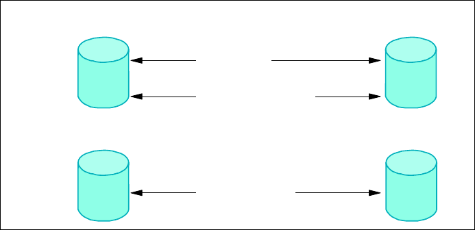
Chapter 30. IIBM TotalStorage Rapid Data Recovery 459
solution. However, in a real disaster (fire, explosion, or earthquake) you can never expect the
components of your complex to fail all at the same moment. Failures will be intermittent and
gradual, and the disaster will occur over many seconds or even minutes. This is known as a
Rolling Disaster. The architecture of a viable disk mirroring disaster recovery solution must
avoid data corruption caused during a Rolling Disaster.
In any operating system, the sequence in which updates are being made is what maintains
the integrity of the data. If that sequence is changed, data corruption will occur. The correct
sequence must be maintained within a volume, across volumes, and across multiple storage
devices. For instance, in Figure 30-1, we show the relationship between a database and its
log, which demonstrates the requirement for maintaining I/O integrity. Data consistency
across the storage enterprise must be maintained to insure data integrity.
Figure 30-1 Sample update sequence in a database
The order of Dependent Writes across volumes must be maintained at remote locations.
Failure to do so results in data corruption. The data consistency is lost.
In Figure 30-2 we illustrate this concept with an example. When a database update is about to
take place, the change is first logged in the database log files at both the primary and
secondary volumes (step 1). Assume the database data file is updated at the primary volume,
but the update does not reach the remote volume that contains the mirrored data file. The
primary location is not aware of the write failure to the secondary volume (step 2). The
database update is marked complete in the log files at both the primary and remote locations
(step 3). The result is that the secondary site log files say the update was done, but the
updated data is not in the database at the secondary location. There is no way to know that
the data was corrupted.
Primary
Primary
Log
Volume
1. Log Update
3. Mark Log Complete
Database
Volume
2. Update Database
Secondar
y
Secondary
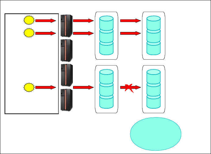
460 IBM System Storage DS6000 Series: Copy Services with IBM System z
Figure 30-2 Sample Rolling Disaster
So, the issue is that the disk subsystem can't do it all and we must avoid this Rolling Disaster
system problem.
For this reason, it is strongly recommended that, at a minimum, Consistency Groups be put in
place for any mirroring solution. Consistency Groups are an implementation of technology
that assists with the consistency of application data capable of dependent writes. To
guarantee a fully consistent remote copy, multiple volumes require a Consistency Group
functionality. ESS and DS6000/DS8000 Remote Copy microcode already has the
Consistency Group function for both z/OS and open systems. SAN Volume Controller Metro
Mirror’s and DS4000 Remote Mirror’s microcode has a Consistency Group function for open
systems.
If any volume within a Consistency Group is unable to complete a write to its counterpart in
the Remote Copy relationship, an Extended Long Busy (ELB) for mainframe environments or
a SCSI Queue Full condition for open systems will be issued, preventing further writes to any
of the volumes within the Consistency Group. This wait period is the perfect time to issue a
freeze to all volumes involved to maintain consistency.
Figure 30-3 illustrates this mechanism. If a write is unable to complete, the storage
subsystem will not back out incomplete transactions on its own. Instead the application will
need to recognize that the transaction was incomplete and take the appropriate actions. Once
the storage subsystem holds application I/O to the affected primary volumes, the write
dependent mechanism of the application prevents the Remote Copy secondaries from
becoming inconsistent.
Primary
Primary
1. Log Update
3. Mark Log
Complete
X
L
B
X
L
B
OK
OK
OK
Database
Application
Secondary
Secondary
Y
M
C
Y
M
C
Left side disk data
does not match right
side. Is this the
problem?
Yes
2. Database Update
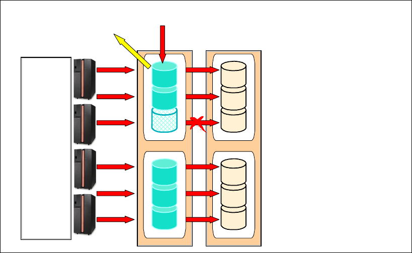
Chapter 30. IIBM TotalStorage Rapid Data Recovery 461
Figure 30-3 Dependent write protection of database integrity
Freeze is a command available through DS Command-Line Interface, DS Storage Manager
(Graphical User Interface), the ESS API, ICKDSF or TSO, that stops the write activity on all of
the active Remote Copy primary and secondary volumes of a given source and target Logical
Subsystem (LSS) pair. This function ensures consistency between the primary and
secondary volumes and can affect any LSS volumes that are in an active Remote Copy state
between the frozen LSS pair: duplex, duplex pending SYNC or duplex pending XD states. It
does not affect the suspended and simplex volumes that may be in the LSS.
The freeze operation has three effects:
1. The paths that connect the pair of LSSs being frozen are terminated.
2. The active volumes under the frozen LSS pair are suspended. This state transition, to
suspended, is then communicated to the host with alert messages. These alert messages
can be used by automation routines to trigger other recovery operations.
3. If the consistency group option was enabled at path definition time, then the ELB or SCSI
Queue Full condition is instigated, so that the write activity to the primary LSS is
temporarily queued. During this interval, other automated operations can be triggered;
such as, freezing other application-related LSS pairs.
When using freeze through DS Storage Manager (Graphical User Interface) or ICKDSF, it will
take effect on each LSS individually. This is useful for creating a point-in-time copy of the
data, but because of slight delays between the issuing of each iteration of the freeze
command it is unsuitable for preventing rolling disasters and should be done at periods of low
utilization to ensure the of the secondary data can be used.
When Remote Copy is used in conjunction with automation, such as the Geographically
Dispersed Parallel Sysplex (GDPS) or enterprise Remote Copy Management Facility
(eRCMF) service offerings from IBM Global Services, a freeze command can be
simultaneously issued to all LSSs within the configuration. This ensures globally consistent
data across all LSSs in the secondary copy of data during a disaster.
Y
M
C
Y
M
C
Consistency Group
control function
1. Mirroring failure
2. ESS suspends affected primary
and holds application I/O (SCSI
Queue full condition)
3. ESS sends a notification about
the failure
4. A program like eRCMF can
receive the SNMP trap and issue
the freeze to all LSSs in the
Consistency Group
5. ESS releases I/O if told to do so
or after PPRC Consistency
Group time out is over
Database
Application
X
L
B
X
L
B
SNMP trap
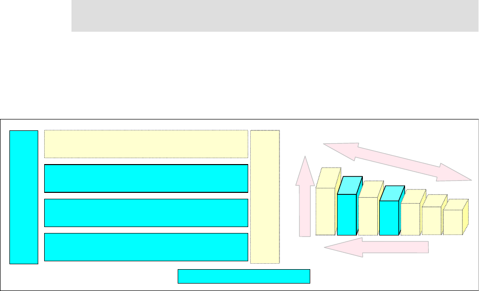
462 IBM System Storage DS6000 Series: Copy Services with IBM System z
The goal of the TotalStorage Rapid Data Recovery for UNIX and Windows solution, based on
the combination of ESS or DS6000 or DS8000 Copy Services with enterprise Remote Copy
Management Facility (eRCMF), is to protect your data from being a mirror of a dying scenario.
Using Remote Copy Consistency Group, this solution freezes your environment at a known
point instead of mirroring literally hundreds of time-offset failures in a short amount of time.
TotalStorage Rapid Data Recovery is based on enterprise Remote Copy Management
Facility (eRCMF), an IBM Global Services offering. The current eRCMF Version 4 is designed
as a 2-site or 3-site Disaster Recovery solution that runs on dedicated machines under
WebSphere on AIX 5L™, which will be used as eRCMF servers.
eRCMF is a multi-site disaster recovery solution that manages data on volumes for Fixed
Block (open systems hosts) and CKD (z/OS). The solution does not depend on the operating
system because no client installation is required.
eRCMF is a Tier 4 and 6 solution, as shown in Figure 30-4.
Figure 30-4 eRCMF protection tier
eRCMF is built on the technologies of Remote Copy, Java, WebSphere, and ESS Network
Interface. You can mix these Storage Servers in this solution because ESS800, DS6000, and
DS8000 share the same Copy Services functions. With DS8000 and DS6000, no Copy
Services Server is required since each Storage Server can handle the Copy Services.
30.3 Architecture
eRCMF is a 2-site or 3-site solution. According to the diagrams in Figure 30-5 and
Figure 30-6, one PCM is placed in each data center. The PCM in the primary data center runs
the Master Process. This process is the interface into eRCMF. It handles all queries and
commands for local processes through either a command-line or socket interface. It also
manages commands and queries from the Backup Process.
A second PCM can be placed in the secondary (or backup) data center or, in a 3-site
strategy, in the tertiary (or remote) data center. This PCM runs the Backup Process that
maintains the state information of the configuration. This information is transferred to the
Note: We strongly recommend that theRCMF servers be installed and run from different
physical sites to ensure their backup capability.
7654321
Recovery Time
disk tape
Business value
+
-+
Services
Autonomic
Software Automation for SAP, DB2,Siebel,MS SQL Server,
Exchange etc.
4
Point in Time Copy, Metro Mirror, Global Mirror, TotalStorage
Software Family, DFSMS for z/OS, TSM.
2
Hardware Infrastructure: ESS, DS family, SAN Switches, VTS,
3584, 3592, LTO .
1
Automation for Servers: z/OS, UNIX, Linux, Windows and
heterogeneous environments.
3
Areas covered and tier level
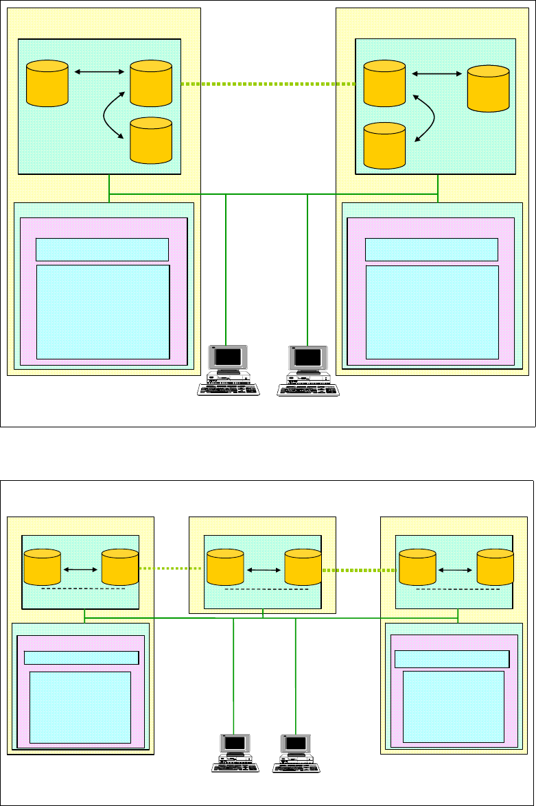
Chapter 30. IIBM TotalStorage Rapid Data Recovery 463
second PCM in the form of logs from the Master Process. These logs are then used to update
state information in case the Backup Process must take control of the configuration, as well
as for documentation purposes if there is an alternate site failure.
Figure 30-5 eRCMF Architecture: 2-site configuration
Figure 30-6 eRCMF Architecture: 3-site configuration
AIX – Backup PCM
Storage Server (s)
Site 1 - Production
AIX – Primary PCM
Storage Server (s)
Site 2 - Backup
TCP/IP / SNMP
ESCON / FCP
Metro Mirror, Global Copy
Global Mirror
FlashCopy
Management
Interface
WebSphere - HTTPS
eRCMF
eRCMFconfig.properties
Enterprise.dat
VolumeSet.dat
Hosts.dat
Authentication.file
eRCMF
eRCMFconfig.properties
Enterprise.dat
VolumeSet.dat
Hosts.dat
Authentication.file
ESS Network InterfaceESS Network Interface
Metro Mirror, up to:
Global Copy, over:
103 km / 300 km
FlashCopy
SNMP
Listener
eRCMF
eRCMFconfig.properties
Enterprise.dat
VolumeSet.dat
Hosts.dat
Authentication.file
eRCMF
eRCMFconfig.properties
Enterprise.dat
VolumeSet.dat
Hosts.dat
Authentication.file
ESS Network InterfaceESS Network Interface
WebSphere - HTTPS
Backup process
(Master process)
Master process
(Backup process)
Shadow
Volumes
Host
Volumes
Journal
Volumes
Shadow
Volumes
Shadow
Volumes
Journal
Volumes
Host
Volumes
Storage Server(s)
Copy Services
Site 2 - Backup
FlashCopy
TCP/IP
SNMP
AIX – Backup PCM
Storage Server(s)
Site 1 - Production
FlashCopy
AIX – Primary PCM
Storage Server(s)
Site 3 - Remote
FlashCopy
Metro Mirror, up to
103 km / 300 km
ESCON
FCP
Metro
Mirror
ESCON
FCP
Global
Copy
Global Copy, over
103 km / 300 km
Copy Services
(CSServer on ESS 800 / 750)
Copy Services
(CSServer on ESS 800 / 750)
eRCMF
eRCMFconfig.properties
Enterprise.dat
VolumeSet.dat
Hosts.dat
Authentication.file
eRCMF
eRCMFconfig.properties
Enterprise.dat
VolumeSet.dat
Hosts.dat
Authentication.file
ESS Network InterfaceESS Network Interface
WebSphere - HTTPS
eRCMF
eRCMFconfig.properties
Enterprise.dat
VolumeSet.dat
Hosts.dat
Authentication.file
eRCMF
eRCMFconfig.properties
Enterprise.dat
VolumeSet.dat
Hosts.dat
Authentication.file
ESS Network InterfaceESS Network Interface
WebSphere - HTTPS
Management
Interface
SNMP
Listener
Backup process
(Master process)
Master process
(Backup process)
Shadow
Volumes
Shadow
Volumes
Host
Volumes
Host
Volumes
Host
Volumes Shadow
Volumes
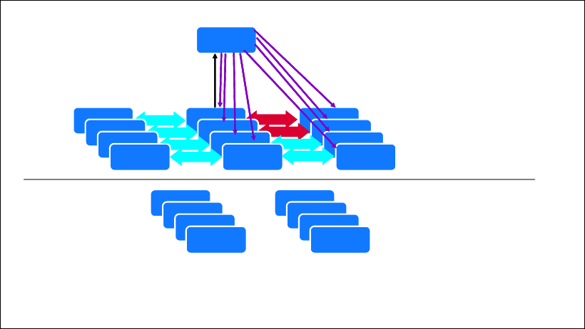
464 IBM System Storage DS6000 Series: Copy Services with IBM System z
The Master Process continuously monitors and manages the entire environment at two
levels:
The Enterprise level
The VolumeSet level
The distinction between these levels is primarily the scope of actions performed at each level.
The Enterprise level represents the entire monitored environment, which consists of two or
three data processing locations containing storage managed by eRCMF. The VolumeSet
level corresponds to a set of Storage Servers volumes which must be maintained in a
consistent state and managed using the same type of copy operations. Some examples of a
VolumeSet are the volumes used by a set of applications, the volumes allocated to a set of
servers, or the members of a volume group.
Management at the Enterprise level affects the entire monitored environment. These actions
typically affect every volume of every VolumeSet being managed by eRCMF. For example,
the freeze command will cause suspension of Remote Copy pairs between the storage
subsystems on multiple sites, as shown in Figure 30-7.
eRCMF adds a central control function to coordinate the Remote Copy Freeze function and
stops transmission of data to the remote site consistently across single/multiple frames.
When this function is centrally coordinated, data is consistent. Data consistency allows a very
fast, very consistent restart time at the secondary site.
Figure 30-7 eRCMF issues the freeze command in a disaster recovery scenario
There are two methods of maintaining consistent data:
Metro Mirror
– Use Synchronous Remote Copy to ensure that data is secure at the remote site before
signaling the host that the write is complete.
– During a disaster, you can combine the Consistency Group and Freeze functions in the
Storage Server with software, such as eRCMF, to insure that all Remote Copy pairs of
the Consistency Group are split in a manner that assures data consistency at the
remote site.
Host
eRCMF
Control
Unit
Control
Unit
Host Control
Unit
Control
Unit
Host Control
Unit
Control
Unit
Host Control
Unit
Control
Unit
During
Control
Unit
Control
Unit
Control
Unit •Both sites are suspend but in sync
•Sites are not insync, however data
to a site is consistent
Control
Unit
yNotification of mirroring
error •eRCMF issues freeze command to all Storage
Servers
•suspends all PPRC pairs
•holds I/O until told to continue
•Based on policy, eRCMF will then allow host
operation to resume or continue to hold them
Control
Unit
Control
Unit
Control
Unit
Control
Unit
After, depending on policy:
yCU holds I/Os to
suspended device until
eRCMF can handle
condition
Data at remote site is at a “Known State”
Chapter 30. IIBM TotalStorage Rapid Data Recovery 465
Global Mirror
– Storage Server periodically forms Consistency Groups. Testing has shown that given
enough bandwidth, Storage Servers can form these groups on an average of every 3
to 5 seconds.
– When recovering to the recovery copy, software such as eRCMF examines the states
of the Global Mirror relationships and directs the Storage Server through the steps
necessary to recover that data to the last committed consistent copy.
It should be noted that eRCMF neither performs an automated recovery nor an automated
restart of systems in the remote site. Instead, eRCMF's freeze performs a controlled site split
only. If a higher level of automation is required, eRCMF provides interfaces such as execution
scripts or a command line interface, which can be utilized and customized. When this occurs,
mirroring between Site 1 and Site 2 stops, ensuring the consistency of data. Further response
by the automation is determined by policies that are selected based on individual business
requirements:
Freeze and Go quickly executes the freeze to ensure data consistency, but then
immediately allows I/Os to continue. This allows processing to continue in the production
data center while maintaining a consistent copy of the data in either the backup or remote
data center. Meanwhile, the business is able to determine the cause of the event and
whether it is a disaster. If a disaster has not occurred, production has not been impacted
by an unnecessary site switch. If a disaster has occurred, then the data since the time of
the site split may need to be recreated if recovering to a backup or a remote data center.
Freeze and Stop quickly executes the freeze to ensure consistency but, rather than
immediately allowing the I/Os to continue, causes the ESS to block all further I/Os until
told otherwise. This ensures that no transactions, other than those in-flight at the time of
the event, need to be recreated following a disaster. If the event turns out not to be a
disaster, however, the production will be halted until the I/Os are freed.
30.4 Additional information
Further information can be found on the IBM Web site at:
http://www-1.ibm.com/services/us/index.wss/so/its/a1000110
For further information, you can refer to the following papers:
enterprise Remote Copy Management Facility eRCMF V4 Implementation Guide
enterprise Remote Copy Management Facility eRCMF V4 User Guide
You can find these papers at:
http://www-1.ibm.com/support/docview.wss?uid=ssg1S7001074
For more information, contact your IBM sales representative.
466 IBM System Storage DS6000 Series: Copy Services with IBM System z

© Copyright IBM Corp. 2006. All rights reserved. 467
Chapter 31. IBM TotalStorage Productivity
Center for Replication
The IBM TotalStorage Productivity Center for Replication is an automated solution to provide
a management front end to Copy Services. This chapter describes IBM’s strategic solution to
manage disaster recovery solutions based on copy service functions in DS6000 and DS8000
storage servers. For details refer to the redbook and product manuals listed below.
In addition to the DS6000 and DS8000, the IBM TotalStorage Productivity Center for
Replication or TPC for Replication can also help manage Copy Services for the SAN Volume
Controller (SVC) as well as the ESS 800 when using FCP links for PPRC paths between ESS
800s or between ESS 800 and DS6000 and/or DS8000. This applies also to FlashCopy
For installation and configuration details, refer to Replication Management with IBM
TotalStorage Productivity Center, SG24-7259
The following manuals are necessary when implementing and managing TPC for Replication
configurations:
IBM TotalStorage Productivity Center for Replication User’s Guide, SC32-0103
IBM TotalStorage Productivity Center for Replication Installation and Configuration Guide,
SC32-0102
IBM TotalStorage Productivity Center for Replication Command-Line Interface User’s
Guide, SC32-0104.
31
Note: The IBM TotalStorage Productivity Center for Replication is completely independent
from TPC for Disk, Data and Fabric.
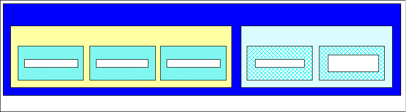
468 IBM System Storage DS6000 Series: Copy Services with IBM System z
31.1 IBM TotalStorage Productivity Center
The IBM TotalStorage Productivity Center or TPC is a suite of software products. It is
designed to support customers in monitoring and managing their storage environments.
Design and development emphasis for TPC is on scalability and standards. The approach
based on open standards allows TPC to manage any equipment or solution implementation
which follow the same open standards.
Figure 31-1 shows a split set of products with three components based on former Tivoli
products and a package with two components designed and developed to facilitate storage
replication solutions.
Figure 31-1 TPC software products suite
All three Tivoli products provide a single source and single management tool to cover the
tasks of the storage manager or network manager in their daily business.
1. TPC for Disk is software based on open standard interfaces to query, gather and collect all
available data necessary for performance management.
2. TPC for Data focus on data management and addresses aspects related to information
life cycle management.
3. TPC for Fabric is a management tool to monitor and manage a SAN fabric.
TPC for Replication, as a member of the TPC product family, is a standalone package and
does not build on anything related to the TPC Standard Edition.
It comes in two flavors as follows:
TPC for Replication includes support for:
– FlashCopy
– Planned failover and restart (one direction) for MM and GM
TPC for Replication Two Site Business Continuity (BC) includes support for:
– FlashCopy
– Planned and unplanned failover and failback for MM and GM
– High availability (2 TPC Replication servers)
We now cover the basic structures and features of TPC for Replication and TPC for
Replication Two Site BC.
This is solely related to Copy Services topics with the DS6000 and DS8000.
Replication
Two Site BC
TPC for Data Replication TPC for Fabric TPC for Disk
Standard Edtion Replication
IBM TotalStorage Productivity Center (TPC)
BC Business Continuit
y
Chapter 31. IBM TotalStorage Productivity Center for Replication 469
31.2 Where we are coming from
Since the advent of copy services functions with IBM storage servers, a framework is
required to handle and manage disk storage environments and the various combination of
software, firmware, and hardware used for replication.
To ensure and guarantee data consistency at the remote or backup site, it is even more
important to provide a framework around copy services functions that helps achieve that data
consistency and ease of management.
Other aspects are automation and scalability. Early solution attempts turned out to have
weaknesses that often would surface during actual implementation in real production
environments. Tools offered on an “as-is” basis are not suitable for managing production
environments. Other solutions are perfectly suited for certain host server platforms but cannot
manage other server platforms.
This led to the design and implementation of a framework that is platform independent and
provides the required production attributes such as scalability, stability, security and, as a
standard product offering, the guarantee to be serviced and maintained. The concept
furthermore has the potential for enhancements and can evolve over time and according to
user requirements.
TPC for Replication does build on all previous experiences with storage management tools
and framework proposals to organize all aspects of copy services for disaster recovery
solutions. TPC for Replication also addresses the need for other solutions that involve copy
services functions available with the DS6000 and DS8000, such as data or volume migration,
data center movements, or other projects that require the copying or moving of data between
like devices such as the DS6000, DS8000, and ESS 800.
31.3 What TPC for Replication provides
TPC for Replication is designed to help administrators manage copy services. This applies
not only to the copy services provided by DS6000 and DS8000, but also to copy services
provided by the ESS 800 and SAN Volume Controller (SVC).
In more detail, the functions provided by TPC for replication are:
Manage Copy Services for the IBM System Storage DS6000 and DS8000.
Extend support for ESS 800 to manage Copy Services.
Provide disaster recovery support with Failover/Failback capability for the
– ESS 800
–DS6000
–DS8000
Monitor Copy Services performance.
The optional high availability feature enables continuation of replication management
even when one TPC for Replication server goes down.
The basic functions of TPC for Replication provide management of:
FlashCopy
Metro Mirror
Global Mirror
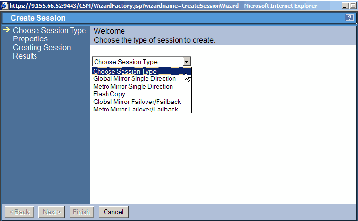
470 IBM System Storage DS6000 Series: Copy Services with IBM System z
Note that TPC for Replication does not support Global Copy.
Figure 31-2 is a screen capture from the TPC for Replication GUI, showing the different
session types, or Copy Services functions, supported.
Figure 31-2 Management of Copy Services functions supported by TPC for Replication
TPC for Replication is designed to simplify management of Copy Services by:
Automating administration and configuration of Copy Services functions with
wizard-based session and copy set definitions.
Providing simple operational control of Copy Services tasks, which includes starting,
suspending, and resuming Copy Services tasks.
Offering tools to monitor and manage Copy Services sessions.
Note that TPC for Replication also manages FlashCopy and Metro Mirror for IBM SAN
Volume Controller, SVC.
31.4 Copy Services terminology
Although it is covered in a previous part of this book, we have included here, for convenience
and to keep it in context with TPC for Replication, a brief review of Copy Services
terminology.
31.4.1 FlashCopy
FlashCopy is a point-in-time copy of a source volume mapped to a target volume. It offers
various options including the choice between a COPY option, for a background copy through
physical I/O operations in the storage server back-end, or a NOCOPY option.
FlashCopy is available on the DS6000 and DS8000 as well as on the ESS 800. FlashCopy is
also available on the DS4000 family and with SAN Volume Controller. Note, however, that the
DS400 and SVC use different implementations of the FlashCopy function that are not
compatible with the DS6000. DS8000, and ESS 800 FlashCopy.

Chapter 31. IBM TotalStorage Productivity Center for Replication 471
31.4.2 Metro Mirror
Metro Mirror (MM) is a synchronous data replication mechanism that was previously called
Peer-to-Peer Remote copy or PPRC. I/O completion is signaled when the data is secured on
both the local storage server and the remote storage server. Metro Mirror is popular for two
site disaster recovery solutions.
Metro mirror is available in any combination between DS6000, DS8000, and ESS800.
Synchronous data replication is also available on the DS4000 family and with the SVC, but
again not directly compatible with Metro Mirror on the DS6000, DS8000, and ESS 800.
31.4.3 Global Copy
Global Copy (GC) is an asynchronous data replication mechanism that used to be called
PPRC for eXtended Distance or PPRC-XD. Asynchronous in this context means that the data
transmission between local and remote storage servers is separated from signaling the I/O
completion. Note that GC does not guarantee that the arriving writes at the local site are
applied to the remote site in the same sequence. Therefore, it does not provide data
consistency. GC is suited for data migration over any distance.
Global Copy is possible in any combination between DS6000, DS8000, and ESS 800.
31.4.4 Global Mirror
Global Mirror (GM) is an asynchronous data replication over any distance. It is a combination
of GC and FlashCopy complemented by unique firmware features. The firmware drives the
copy operations in a fully autonomic fashion to guarantee consistent data at any time at the
remote site. This holds also for the requirement to provide consistent data, at any time, which
can be spread over more than a single storage server.
GM is also the base for a two-site disaster recovery solution involving any DS6000, DS8000,
and/or ESS 800. The function as such is also possible between products of the DS4000
family and the SVC.
31.4.5 Failover/Failback terminology
There is often a misconception on what Failover/Failback commands do.
Figure 31-3 on page 472 illustrates the Failover/Failback two-step process. The process is as
follows:
1. When the replication process between Primary P and Secondary S is suspended as a
result of a planned or unplanned outage, you may want to access the S volumes
immediately without any checking on the P volumes.
The Failover command always points to the S volumes and turns the S volumes from
SECONDARY state into a PRIMARY SUSPEND state, making the volumes immediately
available to the application. This state change for the S volumes at the remote site
happens without any communication or any checking of the P volumes at the local site.
The P volumes at the local site keep the status they had before the Failover command
was issued.
Restriction: TPC for Replication does not provide an interface to manage a Global Copy
environment.
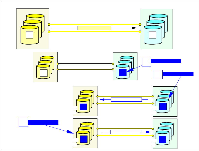
472 IBM System Storage DS6000 Series: Copy Services with IBM System z
Figure 31-3 Failover/Failback terminology
2. Once the outage is over and you decide to resume replicating data, you have a choice as
to whether to resynchronize from the remote site to the local site or vice versa. This
depends on what is required after updating one of the two sites or even updating both
sites after the suspend action.
a. When you decide to resynchronize from the remote site to the local site, the Failback
command is pointing to the remote volumes. You need a PPRC path from the remote
to the local site before you can perform the corresponding commands. Doing this will
resynchronize both sites with the level of data as it is at the remote site. Only the data
that changed at the remote site, from the moment the replication was suspended and
until the Failover happened, is replicated from remote to local volumes.
Figure 31-3 assumes a Metro Mirror (MM) environment that puts the corresponding
MM pair in PENDING state during resynchronization and once everything is replicated,
the MM pair goes into DUPLEX state.
b. If you want to resynchronize both sites with the data level at the local site, you issue
the Failback command towards the volumes at the local site. This replicates the data
changed since the suspend from the local to the remote site. Also, this resets the
tracks that were potentially changed at the remote site after the Failover.
Figure 31-3 assumes an MM environment that places the MM pair in PENDING state
during the resynchronization phase. Once all changed data is replicated, the MM pair
goes into DUPLEX state.
The option to resynchronize from either site is possible due to the availability of change
bitmaps maintained by the DS6000 or DS8000 at both sites.
Primary
Primary
A
Primary
Primary
A Primary
Primary
A
Primary
Primary
A
Failover command
Suspends due to planned
or unplanned event
Primary
Primary
A
Primary
Primary
A
Primary
P Primary
Primary
A
Primary
Primary
A
Secondary
S
Remote DS6000 / DS8000Local DS6000 / DS8000
Replication direction
Primary
Primary
A
Primary
Primary
A Primary
Primary
A
Primary
Primary
A
Primary
Primary
A
Primary
Primary
A Primary
Primary
A
Primary
Primary
A
P P
P
P
S
S
Resynchronisation
Resynchronisation
PRIMARY SUSPENDED
Failback command
SECONDARY DUPLEX
SECONDARY PENDING
PRIMARY DUPLEX
PRIMARY PENDING
OR Failback command
1.
PRIMARY DUPLEX
PRIMARY PENDING
SECONDARY DUPLEX
SECONDARY PENDING
2.
2.
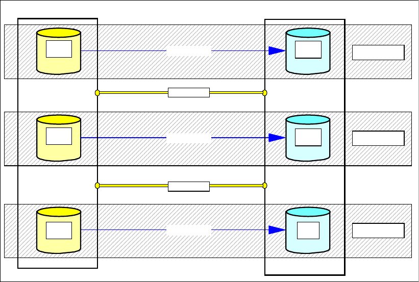
Chapter 31. IBM TotalStorage Productivity Center for Replication 473
31.5 TPC for Replication terminology
TPC for Replication manages and integrates not only the DS6000 and DS8000 but also the
SAN Volume Controller. In search of a common terminology and to describe the functions for
the different disk storage servers in a common way, new terms are introduced here that are
different from those normally used in the context of Copy Services with the ESS 800,
DS6000, and DS8000.
31.5.1 TPC for Replication Copy Set
A Copy Set in TPC for Replication is a set of volumes that have a copy of the same data. In
PPRC terms this is, for example, a PPRC primary volume and a PPRC secondary volume.
Figure 31-4 shows three Metro Mirror Copy pairs. In TPC for Replication each pair is
considered a Copy Set. A Copy Set here contains two volumes.
Figure 31-4 TPC for Replication - Metro Mirror Copy Sets
Figure 31-5 on page 474 represents two Copy Sets. In this illustration, each Copy Set
contains three volumes, which indicates a Global Mirror configuration. Note that the third
volume is a kind of journal volume and is the FlashCopy target volume for data consistency in
a Global Mirror setup.
PPRC path
Primary
Primary
A
Primary
P1 Primary
Primary
Primary
A
Secondary
S1
Primary
Primary
A
Primary
P2
Secondary
S2
PPRC path
PPRC path
Primary
Primary
A
Primary
P3
Secondary
S3
Remote DS6000 / DS8000Local DS6000 / DS8000
Copy Set
PPR link
PPR link
Copy Set
Copy Set
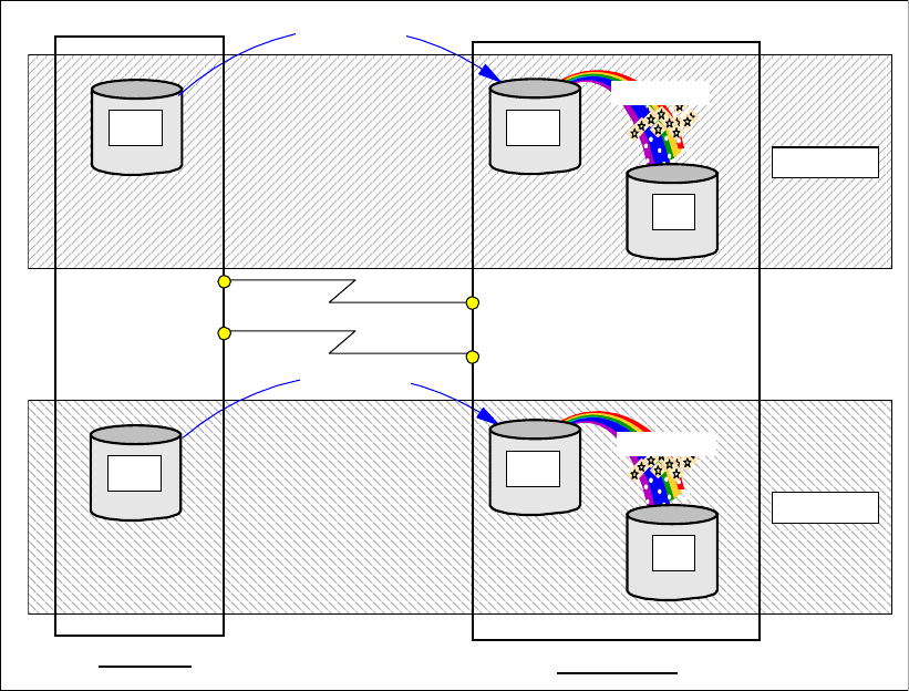
474 IBM System Storage DS6000 Series: Copy Services with IBM System z
Figure 31-5 TPC for Replication - Global Mirror Copy Sets
31.5.2 TPC for Replication session
TPC for Replication uses a session concept that is similar to what Global Mirror for System z
(XRC) uses.
A session is a logical concept that gathers multiple Copy Sets, representing a group of
volumes with the requirement to provide consistent data within the scope of all involved
volumes. Commands and processes performing against a session apply these actions to all
Copy Sets within the session. Again, this is similar to a Global Mirror for System z (XRC)
session.
Figure 31-6 on page 475 shows an example of two storage servers at the local site and two
corresponding storage servers at the remote site. The example further assumes that a Metro
Mirror relation is established to replicate data between both sites.
Copy Set
Copy Set
Remote Site
Local site
Primary
Primary
A
P1
Primary
Primary
Primary
A
S2
Secondary
FlashCopy
Primary
Primary
J2
Tertiary
Primary
Primary
A
S1
Secondary
FlashCopy
Primary
Primary
J1
Tertiary
Primary
Primary
A
P2
Primary
Global Copy
Global Copy
PPRC links
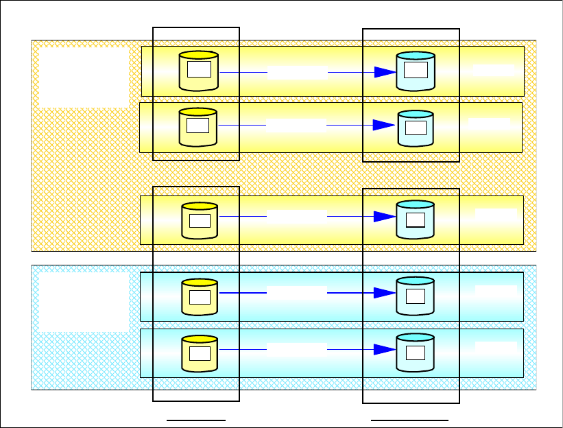
Chapter 31. IBM TotalStorage Productivity Center for Replication 475
Figure 31-6 TPC for Replication - Session concept
Metro Mirror primary volume P1 in the second storage server and volumes P2 and P3 in the
first storage server with their corresponding Metro Mirror secondary volumes are grouped
together in a session, session 1. Such a session can contain Copy Sets that span storage
server boundaries.
Metro Mirror primary volumes PA and PB with their counterparts at the remote site belong to
a different session, session 2.
Note that all application-dependent Copy Sets must belong to the same session to guarantee
successful management and to provide consistent data across all involved volumes within a
session. In this context it is recommended to have application-dependent volume granularity
within the scope of an LSS. Or, in other words, volumes or Copy Sets that require consistent
data and can be subject to a freeze trigger ought to be grouped in one or more LSS and that
LSS must not contain other Copy Sets. This is because the scope of the freeze function is at
the LSS level and affects all volumes within that LSS.
Remote DS6000 / DS8000
Local DS6000 / DS8000
Prim ary
Prim ary
A
Prim ar y
P2
Secondary
S2
PPRC path Copy Set
PPRC path
Primary
Primary
A
Primary
PB Prim ary
Prim ary
Pr im ar y
A
Secondary
SB Copy Set
PPRC path
Pr im ar y
Pr im ar y
A
Primary
P3
Secondary
S3 Copy Set
Remote DS6000 / DS8000
Local DS6000 / DS8000
Remote SiteLocal site
PPRC path
Primary
Primary
A
Primary
PA Prim ary
Prim ary
Pr im ar y
A
Secondary
SA Copy Set
PPRC path
Primary
Primary
A
Primary
P1 Prim ary
Prim ary
Pr im ar y
A
Secondary
S1 Copy Set
Session
2
Session
1
476 IBM System Storage DS6000 Series: Copy Services with IBM System z
31.6 TPC for Replication session types
There are two TPC for Replication editions, which include different levels of Copy Services
functions.
31.6.1 TPC for Replication Basic Edition
The Basic Edition also includes Metro Mirror and Global Mirror, besides FlashCopy.
However, Metro Mirror and Global Mirror are only configured to replicate data in a
unidirectional fashion.
FlashCopy
FlashCopy includes all functional flavors of FlashCopy. This includes FlashCopy with the
following:
Background copy or no background copy
Convert no background copy to background copy
Add persistent to a FlashCopy relationship
Establish incremental FlashCopy to apply only changed data since a previous FlashCopy
operation
Metro Mirror
Metro Mirror between a local site (site 1) and a remote site (site 2) in a unidirectional fashion.
It also allows to switch the replication direction from site 2 to site 1. This may happen through
Failover/Failback operations.
Global Mirror
Global Mirror implies three volumes for each Global Mirror Copy Set. Again this happens
between a local site (site 1) and a distant site (site 2) in a unidirectional way. It is possible to
reverse the replication direction but still only in a unidirectional fashion.
31.6.2 TPC for Replication Advanced Edition
The Advanced Edition has, in addition to the Basic Edition, the capability to replicate data in
either direction or in a bidirectional fashion.
Metro Mirror
Metro Mirror may be established from site 1 to site 2 or vice versa or in both directions at the
same time (bidirectional).
It also allows Failover/Failback operations for any Copy Set at any time.
Global Mirror
The Advanced Edition allows the Global Mirror to operate in either direction at the same time
(bidirectional). It may also swap sites with Failover/Failback operations.
Global Mirror builds on three volumes per Copy Set. TPC for Replication makes it possible to
also manage a configuration that only replicates data through Global Copy in the opposite
direction from what Global Mirror did before.

Chapter 31. IBM TotalStorage Productivity Center for Replication 477
31.7 TPC for Replication session states
Again, a session contains a group of Copy Sets (that is, RMC (PPRC) volume pairs or
FlashCopy pairs) that belong to a certain application. You may also consider it a collection of
volumes that belong to a certain application or system with the requirement for consistency.
Such a session may be in one of the following states:
Defined
A session is defined and may already contain Copy Sets or have no Copy Sets assigned yet.
However, a defined session is not yet started.
Preparing
The session started already and is in the process of initializing, which may be, for example, in
case of a first full initial copy for a Metro Mirror. It may also just reinitialize, which, for
example, may be the case for a resynchronization of a previously suspended Metro Mirror.
Once the initialization is complete, the session state changes to prepared.
Prepared
All volumes within the concerned session completed the initialization process.
Suspending
This is a transition state caused by either a suspend command or any other suspend trigger,
which may be an error in the storage subsystem or loss of connectivity between sites.
Eventually the process to suspend Copy Sets ends and copying has stopped, which is
indicated by a session state of suspended.
Suspended
Replicating data from site 1 to site 2 has stopped. Application writes to concerned volumes in
site 1 can continue (FREEZE & GO). An additional recoverable flag indicates whether the
data is consistent and recoverable.
Recovering
A session is about to recover.
TargetAvailable
The recover command has completed and the target volumes are write enabled and available
for application I/Os. An additional recoverable flag indicates whether the data is consistent
and recoverable.
31.8 Volumes in a copy set
With TPC for Replication, the role of a volume within Copy Services has been renamed to be
more generic and also to include other storage subsystems such as SVC.
A Copy Set contains the volumes that are part of a Copy Services relationship. Metro Mirror
knows two volumes per Copy Set. Global Mirror requires three volumes per Copy Set.
FlashCopy again consists of two volumes per Copy Set.
Important: Do not manage Copy Service volume pairs that are already managed with
TPC for Replication with some other software.
478 IBM System Storage DS6000 Series: Copy Services with IBM System z
Terminology is slightly different from what you may be used to. For example, Metro Mirror
uses a primary or source volume at the sending site and a secondary or target volume at the
receiving end. Such a pair is now called a Copy Set.
FlashCopy usually used to mention source and target volume to identify a FlashCopy pair—in
contrast to RMC, which designates volumes in that pair as primary and secondary volumes.
Again, such a FlashCopy volume pair is now a Copy Set.
Global Mirror involves three volumes per Copy Set. Global Mirror relies on Global Copy and
FlashCopy. Therefore, we have a Global Copy primary volume and a Global Copy secondary
volume. The Global Copy secondary volume has another role as FlashCopy source volume.
The third volume is then the FlashCopy target volume. All three volumes are part of a Global
Mirror Copy Set.
31.8.1 Host volume
A host volume is identical to what is called a primary or source volume in Copy Services. The
host designation represents the volume functional role from an application point of view. It is
usually connected to a host or server and receives read, write, and update application I/Os.
When a host volume becomes the target volume of a Copy Services function, it is usually no
longer accessible from the application host. FlashCopy target volumes can be considered an
exception.
31.8.2 Target volume
A target volume is what was also usually designated as a secondary t volume. It receives
data from a host volume or another intermediate volume. It may also be an intermediate
volume as in a Global Mirror Copy Set.
31.8.3 Journal volume
A journal volume is currently the FlashCopy target volume in a Global Mirror Copy Set. It is
called a journal volume because it functions like a journal and holds the required data to
reconstruct consistent data at the Global Mirror remote site. When a session needs to be
recovered at the remote site, the journal volume is used to restore data to the last consistency
point.
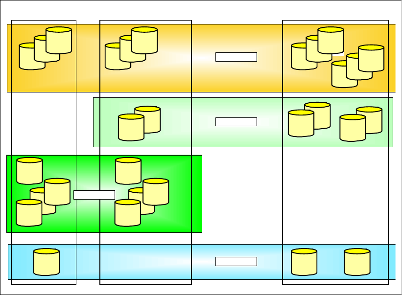
Chapter 31. IBM TotalStorage Productivity Center for Replication 479
31.9 TPC for Replication and scalability
From an architecture point of view there is no limit to the number of Copy Sets that may
belong to a single session. The implementation approach of managing Copy Sets and
sessions provides the scalability that very large installations require.
Figure 31-7 TPC for Replication - four sessions
There is also no limit to the number of sessions that TPC for Replication can manage.
Figure 31-7 shows four sessions managing different Copy Sets. The first session, Session 1,
implies a Metro/Global Mirror configuration that is not supported (at the time of writing this
redbook) by TPC for Replication.
The second session, Session 2, is a Global Mirror session between an intermediate site and
a remote site with two Copy Sets.
The third session, Session 3, is a Metro Mirror configuration between the local and
intermediate site.
The session at the bottom in Figure 31-7, Session 4, is a Global Mirror session between the
local and remote sites.
31.10 TPC for Replication system and connectivity overview
TPC for Replication is an outboard approach. Its software runs on a dedicated server or,
better, on two servers, for a high availability configuration.
Intermediate DS6000 / DS8000
Primary
Primary
A Copy Set
Remote DS6000 / DS8000
Local DS6000 / DS8000
Primary
Primary
A
Primary
Primary
A
Prim ar y
Prim ar y
A
Primary
Primary
A
Primary
Primary
A
Prim ar y
Prim ar y
A
Prim ar y
Prim ar y
A
Prim ar y
Prim ar y
A
Primary
Primary
A
Prim ar y
Prim ar y
A Pr imar y
Primary
A
Primary
Primary
A
Primary
Primary
A Primary
Primar y
A
Primary
Primary
A
Primary
Primary
A Primary
Prim ar y
A
Prim ar y
Prim ar y
A
Primary
Primary
A
Primary
Primary
A
Primary
Primary
A
Prim ar y
Prim ar y
A
Prim ar y
Prim ar y
A
Primary
Primary
A
Prim ar y
Prim ar y
A
Prim ar y
Prim ar y
A
Primary
Primary
A
Primary
Primary
A
Session 2
Session 4
Session 3
Session 1
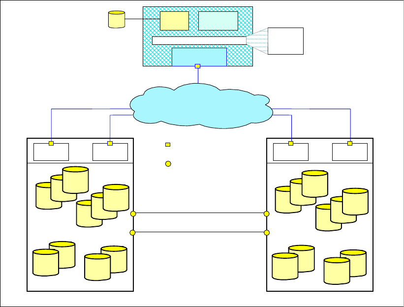
480 IBM System Storage DS6000 Series: Copy Services with IBM System z
Figure 31-8 shows how the TPC for Replication server connects to the storage servers which
are going to be managed by TPC for Replication server(s). It does not show the connectivity
of the TPC for Replication server to the network through which the users connect with their
browsers to the server itself.
Figure 31-8 TPC for Replication system overview
The TPC for Replication server contains, besides the actual functional code, DB2 UDB and
WebSphere® software.
IP communication services also contain an event listening capability to react on respective
trap messages from the storage servers. This provides a handle to plan for particular events
and provide preestablished scripts that are going to be triggered by a corresponding trap
message. This also includes a capability to distinguish between the different storage servers
that can be managed by the Replication Manager, such as DS6000, DS8000, ESS 800, and
SVC. This approach has the potential to be enhanced as storage servers change over time
without touching the functional code and the involved database.
Figure 31-9 on page 481 shows how the Replication Manager server connects to the DS6000
and DS8000.
DS6000
Copy Set
Primar y
Primar y
A Prim ary
Primar y
A
Primar y
Primar y
A
Primar y
Primar y
A Pr im ary
Primar y
A
Primar y
Primar y
A
Primar y
Primar y
A
Primary
Primary
A
Primar y
Primar y
A
Primar y
Primar y
A
DS8000
Copy Set
Primar y
Primar y
A Prim ary
Prim ar y
A
Primar y
Primar y
A
Primar y
Primar y
A Pr im ar y
Primar y
A
Primary
Primary
A
Primar y
Primar y
A
Primary
Primary
A
Primary
Primary
A
Primar y
Primar y
A
PowerPC
PPR FCP links
PowerPCSeries p Series p
FCP ports
DB2 Websphere
IP Communication
Services
Replication Manager Server
Ethernet ports
IP network
Primary
Primary
Database Linux
AIX
Windows
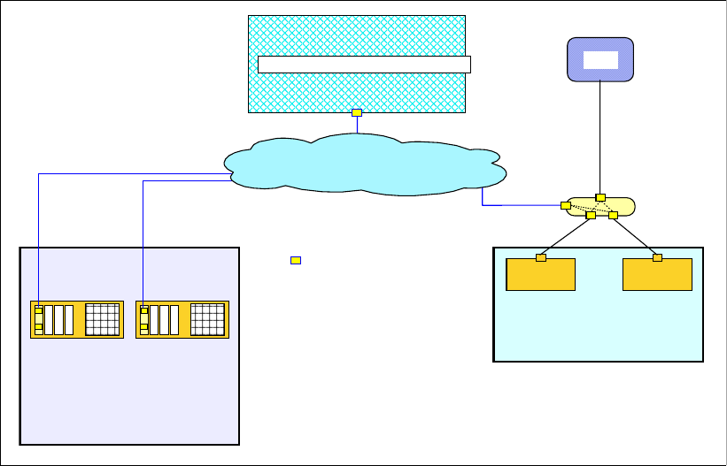
Chapter 31. IBM TotalStorage Productivity Center for Replication 481
Figure 31-9 Replication Manager server connectivity to DS6000 and DS8000
The actual connectivity between the TPC for Replication server and the storage servers is
based on Ethernet networks and connects to particular Ethernet ports in the System p™ in
the DS8000. This particular Ethernet card is a new card and slides into the first slot of these
four slots in the p570. Note that Figure 31-9 shows the DS8000 rear view because these slots
are only accessible from the rear of the DS8000.
New DS8000 Ethernet card feature codes
This new Ethernet card is required for TPC for Replication and available for the following
DS8000 models:
921, 922, 931, and 932 with feature code 1801 for the Ethernet adapter pair. Note that you
always need a pair of cards because one Ethernet card installs in sever0 and a second
card installs in server1
9A2 and 9B2 with feature code 1802 for the Ethernet adapter pair for the first LPAR.
9A2 and 9B2 with feature code 1803 for the Ethernet adapter pair for the second LPAR.
These features are chargeable and carry a minimum monthly maintenance charge.
DS8000 Ethernet card installation and configuration considerations
This new Ethernet card may come already installed or may be installed on site.
To configure the Ethernet ports, Release 2 microcode is required for the concerned DS8000.
This is a code bundle that starts with 6.2.xxx.xx.
Port numbers on the first card are I9801 and I9802. This is the card that installs in server0.
Port numbers on the second card are I9B01 and I9B02. This is the card that installs in
server1. Note that only the first port on each card is currently used.
Communication through these ports uses static IP addresses. DHCP is not supported.
DS8000
PowerPC PowerPC
System p
Ethernet ports
System p
SMC
IP network
DS6000
Replication Manager Server
server1 server1
server0 server0

482 IBM System Storage DS6000 Series: Copy Services with IBM System z
You may configure these new ports either through the GUI or the DSCLI.
The GUI provides a new panel to configure the required IP addresses. This panel is in the
GUI path of the Storage Image. Under Storage Image is a new Configure Network Port panel.
The DSCLI provides the following commands to manage these new network ports:
lsnetworkport -l
This command shows the server associations, physical port locations, and IP address
settings for all ports on the queried Storage Image Facility; see an example in
Example 31-2.
shownetworkport
This command shows the server association, physical location, and IP addresses for a
particular port on the Ethernet card; see an example in Example 31-3.
setnetworkport
This command configures the network ports. Example 31-1 displays a command example
and configures the first port on the Ethernet card in server0.
Example 31-1 setnetoworkport command example
dscli> setnetworkport -dev IBM.2107-7520781 -ipaddr 9.155.86.128 -gateway
9.155.86.1 -subnet 255.255.255.0
-primary 9.64.163.21 -secondary 9.64.162.21 N9801
Example 31-2 shows an output example of lsnetworkport -l, which provides an overview of
all available Ethernet ports on the concerned Storage Image Facility.
Example 31-2 Output of the lsnetworkport command
dscli> lsnetworkport -l
Date/Time: 28 August 2006 13:19:55 CEST IBM DSCLI Version: 5.2.200.308 DS:
IBM.2107-7503461
ID IP Address Subnet Mask Gateway Primary DNS Secondary DNS State Server
Speed Type Location
==================================================================================
==================================================
I9801 9.155.50.53 255.255.255.0 0.0.0.0 9.64.163.21 9.64.162.21 Online 00
1 Gb/sec Ethernet-Copper U7879.001.DQD04X5-P1-C1-T1
I9802 0.0.0.0 0.0.0.0 0.0.0.0 9.64.163.21 9.64.162.21 Offline 00
1 Gb/sec Ethernet-Copper U7879.001.DQD04X5-P1-C1-T2
I9B01 9.155.50.54 255.255.255.0 0.0.0.0 9.64.163.21 9.64.162.21 Online 01
1 Gb/sec Ethernet-Copper U7879.001.DQD04WH-P1-C1-T1
I9B02 0.0.0.0 0.0.0.0 0.0.0.0 9.64.163.21 9.64.162.21 Offline 01
1 Gb/sec Ethernet-Copper U7879.001.DQD04WH-P1-C1-T2
Example 31-3 shows an output example of shownetworkport, which provides an overview of
all settings for a particular Ethernet port.
Example 31-3 Output of shownetworkport for a particular Ethernet port
dscli> shownetworkport i9801
Date/Time: 28 August 2006 13:20:00 CEST IBM DSCLI Version: 5.2.200.308 DS:
IBM.2107-7503461
ID I9801
IP Address 9.155.50.53
Subnet Mask 255.255.255.0
Gateway 0.0.0.0

Chapter 31. IBM TotalStorage Productivity Center for Replication 483
Primary DNS 9.64.163.21
Secondary DNS 9.64.162.21
State Online
Server 00
Speed 1 Gb/sec
Type Ethernet-Copper
Location U7879.001.DQD04X5-P1-C1-T1
TPC for Replication server connectivity to the DS6000
For the DS6000, the Replication Manager server connects to the network that connects to the
PowerPC® servers in the DS6000. For the DS6000 this is the same network that the Storage
Management console connects to because the DS6000 controller or server card contains
only a single Ethernet port.
For the DS6000 there is only a single Ethernet port per cluster or server card. This port is
shared between the Replication Manager server or servers as well as with one or two Storage
Management consoles.
TPC for Replication configuration options
Note that Figure 31-9 on page 481 outlines the basic connectivity idea. For high availability
you may consider a second Replication Manager server that also connects to the same IP
network as the first server. Currently the Replication Manager server connects only to one
Ethernet port out of the two ports on the Ethernet card, which must reside in the first slot of
the System p server in the DS8000.
Note that the internal and potential external HMCs connect to the DS8000 through different
ports than the Replication Manager server(s).
The communication between the Replication Manager Server and the DS infrastructure is
direct as shown in Figure 31-9 on page 481. It is interesting to note that this is different than
when the Replication Manager communicates with the SAN Volume Controller, SVC.
Between the Replication Manager server and the SVC Nodes is an SVC CIMON-based
console that is part of the standard SVC master console.
For more details refer to Replication Management with IBM TotalStorage Productivity Center,
SG24-7259.
31.11 TPC for Replication monitoring and freeze capability
TPC for Replication always uses the consistency group attribute when you define PPRC
paths for Metro Mirror between a primary and a secondary storage server. This provides TPC
for Replication with the capability to freeze a Metro Mirror configuration when an incident
happens in order to guarantee consistent data at the secondary or backup site.
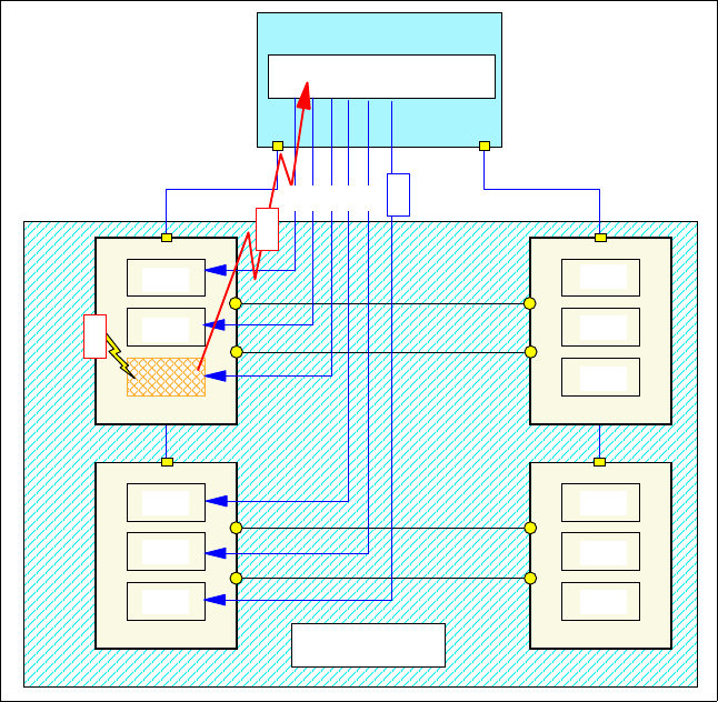
484 IBM System Storage DS6000 Series: Copy Services with IBM System z
Figure 31-10 TPC for Replication server freeze
The TPC for Replication server listens for incidents from the storage servers and takes action
when being notified of a replication error from the concerned storage server.
Figure 31-10 implies a replication error in an LSS that belongs to the session. The TPC
server receives a corresponding SNMP trap message from the concerned storage server.
The TPC for Replication server then issues a freeze command to all LSSs that are part of the
concerned session. This implies a suspend of all PPRC pairs or Copy Sets that belong to this
session. During this freeze process, write I/Os are held until the freeze process ends and the
TPC server communicates to the storage server to continue processing write I/O requests to
the concerned primary volumes in the session.
After that, write I/O can continue to the suspended primary volumes. However, both sites are
not in sync any longer but the data on the secondary site is consistent (power drop
consistent). This is a so-called freeze-and-go policy.
31.12 TPC for Replication heartbeat
Because the connectivity between the TPC for Replication server and the storage servers
that the TPC server is managing can fail, the firmware in the storage server waist for a
heartbeat signal from the TPC server. TPC for Replication can enable this heartbeat in the
corresponding LSS for Metro Mirror sessions.
Replication Manager Server
LSS
LSS
LSS
LSS
LSS
LSS
LSS
LSS
LSS
SecondariesPrimaries Session
LSS
LSS
LSS
1
FREEZE 3
2
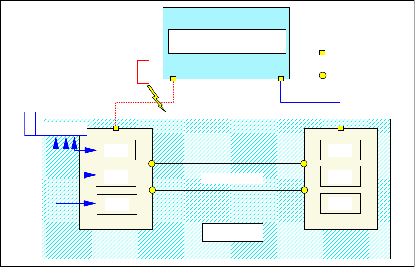
Chapter 31. IBM TotalStorage Productivity Center for Replication 485
Figure 31-11 LSS heartbeat triggers freeze when connectivity to server fails
Figure 31-11 implies a failing connectivity between the RM server and a primary storage
server. Once this heartbeat is set and the storage subsystem cannot communicate its
heartbeat information to the RM sever, the storage server internally triggers a freeze to its
involved LSSs and their primary volumes. Because this heartbeat is a timer-scheduled
function, it is based on the Consistency Group time-out value of each LSS that contains
volumes that belong to the concerned session. This session-based heartbeat timer expires
after the lowest time-out value of all concerned LSSs.
With more than one storage server involved, the RM server issues freeze commands to all
other LSS pairs in the affected session once the heartbeat expired and the RM server could
not receive heartbeat information from any one of the involved storage servers.
The disconnected storage server or LSS resumes I/O after the Consistency Group time-out
has expired. LSSs or storage servers that may still be connected to the RM server receive a
corresponding freeze command from the RM server followed by a run command when a
freeze-and-go policy has been selected.
Note that Extended Long Busy (ELB), automation window, and freeze period are synonyms
for Consistency Group time-out in the above context.
31.13 Supported platforms
The TPC for Replication server can currently run under the following operating systems:
Windows 2003 Server Edition with SP1
Windows 2003 Enterprise Edition SP1
Replication Manager Server
LSS
LSS
LSS
LSS
LSS
SecondariesPrimaries Session
FREEZE
1
2
LSS
FCP ports
Ethernet ports
PPRC FCP links

486 IBM System Storage DS6000 Series: Copy Services with IBM System z
Figure 31-12 Windows 2003 software level
SUSE Linux Enterprise Server 9 SP2
Note: SUSE Linux does not support the Two-Site BC configuration.
Red Hat Enterprise Linux RHEL4 AS 2.1
For Replication Two-Site BC: Red Hat Enterprise Linux RHEL4 Update 1 SLES9 SP2
AIX 5.3 ML3
Note: For a TPC for Replication Two-Site BC configuration that involves two servers it is
possible to run TPC for Replication on two different operating system platforms.
For the latest software requirements, refer to:
http://www.ibm.com/servers/storage/support/software/tpcrep/installing.html
31.14 Hardware requirements for TPC for Replication servers
For Windows and Linux it is suggested to use the following minimum hardware configuration:
1.5 GHz Intel® (TM) Pentium (R) III processor
2 GB RAM memory
10 GB free disk space
When TPC for Replication runs on AIX, the following minimum hardware configuration is
suggested:
Server p, IBM POWER4™ (TM) or IBM POWER5™ (TM) processor, 1 GHz
2 GB RAM memory
10 GB free disk space
Disk space is required to hold data in DB2 databases and WebSphere (R) Express
Application Server code besides the actual TPC for Replication server code.
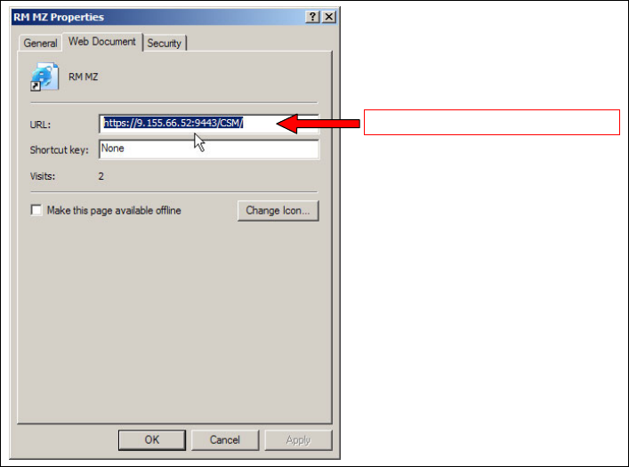
Chapter 31. IBM TotalStorage Productivity Center for Replication 487
You may refer to the following Web site for the latest information on hardware requirements:
http://www-03.ibm.com/servers/storage/support/software/tpcrep/installing.html
31.15 TPC for Replication GUI
This section describes the graphical user interface (GUI) that is used to communicate with the
the Replication server. Additional details can be found in the documents mentioned at the
beginning of this chapter.
TPC for Replication provides a graphical user interface (GUI) to manage and monitor any
Copy Services configuration and Copy Services operations. This GUI is Web browser-based
and does not rely on any other product such asTotalStorage Productivity Center and IBM
Director.
Figure 31-13 GUI URL determined during Replication Manager install time
The GUI is simply called through an Internet browser like MS Internet Explorer or Mozilla
Firefox, is intuitive, easy to use, and performs very well. The panel structure is not too deep
and makes it possible to quickly transition to any application through a hyperlink-based menu.
Figure 31-14 on page 488 displays the TPC for Replication GUI and its components, used
between the client on the user machine and the server component on the server machine.
URL of GUI (RM server)
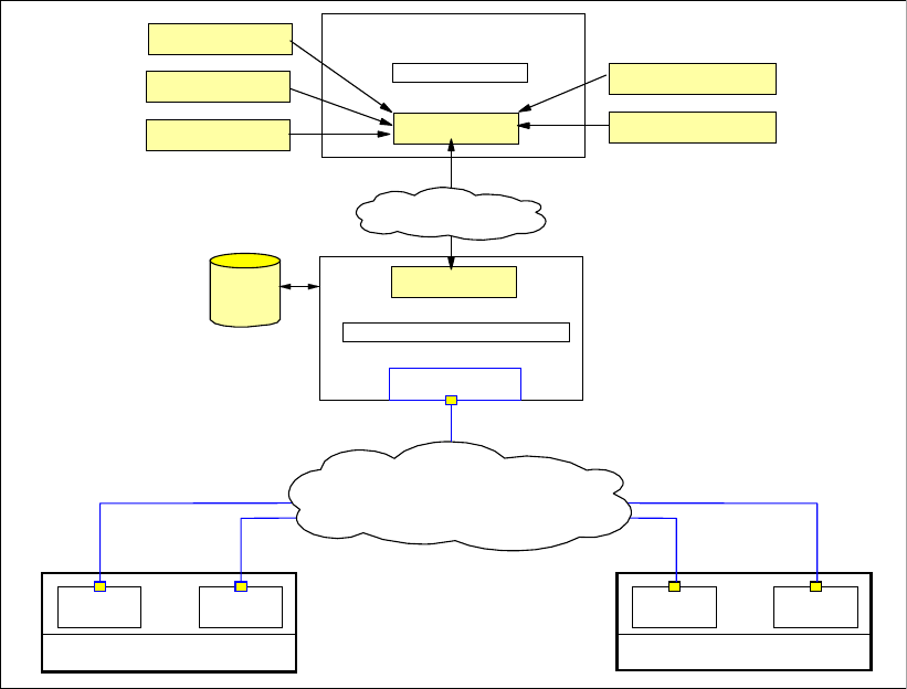
488 IBM System Storage DS6000 Series: Copy Services with IBM System z
Figure 31-14 TPC for Replication GUI
The Web-based client that runs on the user’s machine contains the GUI client, a presentation
component. This software piece on the user’s machine is highly optimized to minimize data
traffic over the LAN to the RM server.
The GUI server component runs on the RM server machine, which contains the interface to
the function code in the connected storage servers and is usually closely installed to the
storage servers that interface with the RM server.
31.15.1 Connect to the TPC for Replication GUI
You connect to the GUI by specifying the IP address of the TPC for Replication server in your
Web browser.
This will present the sign-on panel shown in Figure 31-15 on page 489.
Once you sign out from the RM server, the same panel is also displayed.
DS6000
DS8000
PowerPC PowerPCSeries p Series p
Hardware Lavers
Replication Manager Server
IP network
Data-
base
Monitor Server
User machine
Browser / GUI
Configure sessions
Login
Global Mirror settings
Advanced tools
Session States
LAN
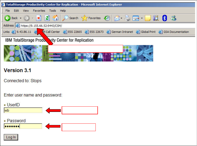
Chapter 31. IBM TotalStorage Productivity Center for Replication 489
Figure 31-15 Launch the Replication Manager GUI
You specify a user ID as a text string on the UserID field and a password in a hidden text
field. User IDs are defined and set up in the RM server system.
31.15.2 Health Overview panel
After a successful login into the Replication Manager server, the Health Overview panel is
displayed, as shown in Figure 31-16 on page 490.
password
URL of GUI (RM server)
user name
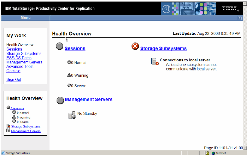
490 IBM System Storage DS6000 Series: Copy Services with IBM System z
Figure 31-16 Health Overview panel
This health panel displays an overall summary of the Replication Manager system status. It
actually shows information very similar to what is also shown in the small box at the left lower
corner of this panel. This small health overview box at the lower left corner is always present.
The Health Overview panel, however, provides some more details, for example an overall
status of the following:
Sessions
Connected storage subsystems
Management servers
Figure 31-16 reports that all sessions are in normal status and working fine. There is no high
availability server environment and one or more storage servers cannot be reached by the
Replication Manager.
The upper left box in this panel, labeled My Work, provides a list of applications that you can
use to manage various aspects of a Copy Services environment.
Health Overview
This is the currently displayed panel, as Figure 31-16 shows.
Sessions
This hyperlink brings you to the application that manages all sessions. This is the application
which you will use the most.
Storage Subsystems
Here you start when you define storage servers to the RM server that are going to be used for
Copy Services.
ESS/DS Paths
This link allows you to manage everything that is related to PPRC path management.
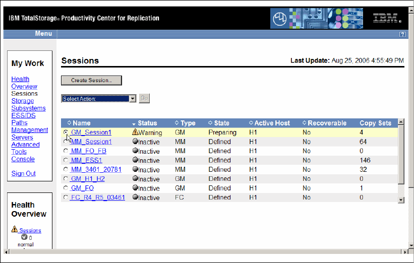
Chapter 31. IBM TotalStorage Productivity Center for Replication 491
Management Servers
This link leads you to the application that manages the RM server configuration.
Advanced Tools
Here you may trigger to collect diagnostic information or set the refresh cycle for the
displayed data.
Console
This link opens a log that contains all activities of the user and its results.
31.15.3 Sessions panel
This is the panel of all sessions within the RM server.
Figure 31-17 Sessions overview
Each session comprises a number of Copy Sets that may be distributed across LSSs and
physical storage servers. The session name functions as a token which is used to apply any
action against the session or all the volumes that belong to that session.
Figure 31-18 on page 492 illustrates that you first select a session and then choose the action
you want to perform against that session.
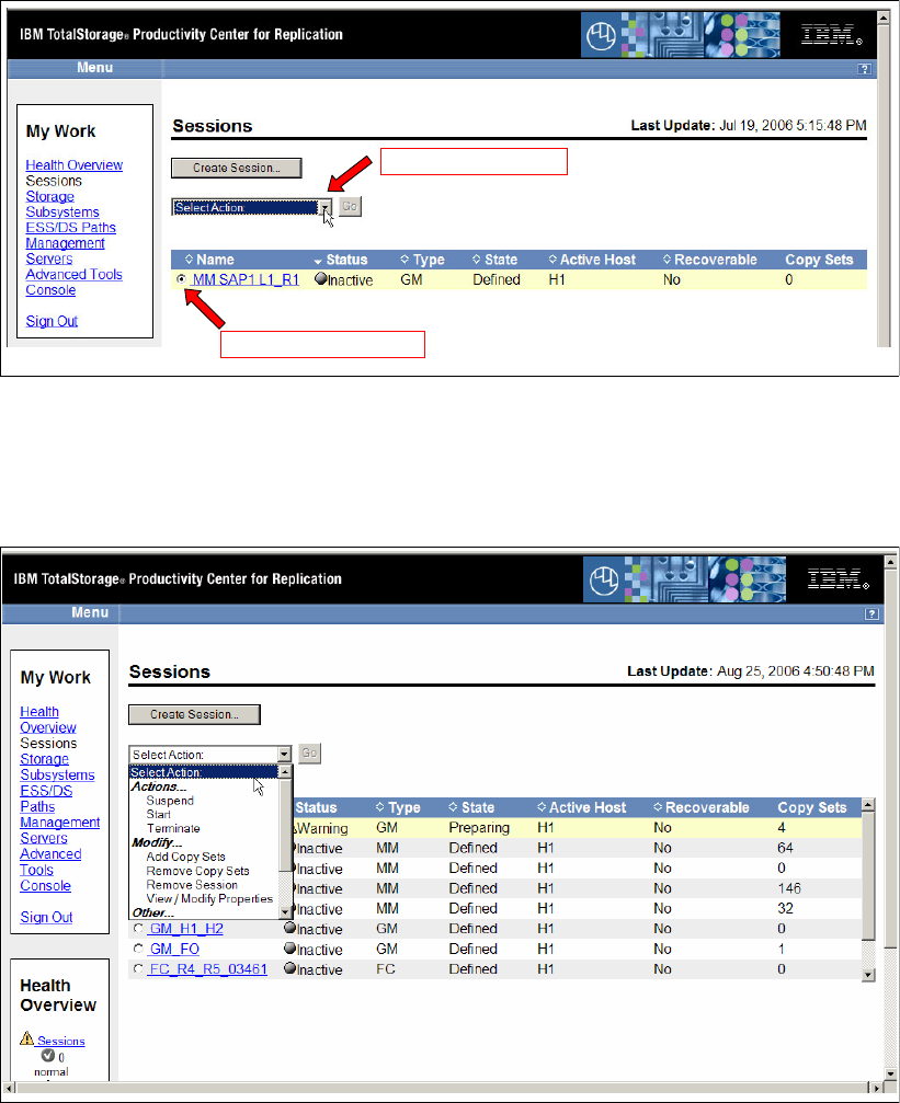
492 IBM System Storage DS6000 Series: Copy Services with IBM System z
Figure 31-18 About to create Copy Set(s) to sessions
Figure 31-19 displays a next possible step to perform an action against a session. After
selecting the session GM_Session1 shown in Figure 31-17 on page 491, you may select any
action from the action list shown in Figure 31-19.
Figure 31-19 Actions against a session
This may be an action against the entire session, such as suspending all volumes within the
session. It is also used to modify an existing session and add or remove Copy Sets.
31.15.4 Storage Subsystems panel
Figure 31-20 on page 493 displays all storage subsystems currently connected to the RM
server.
(1) Select session
(2) Select action
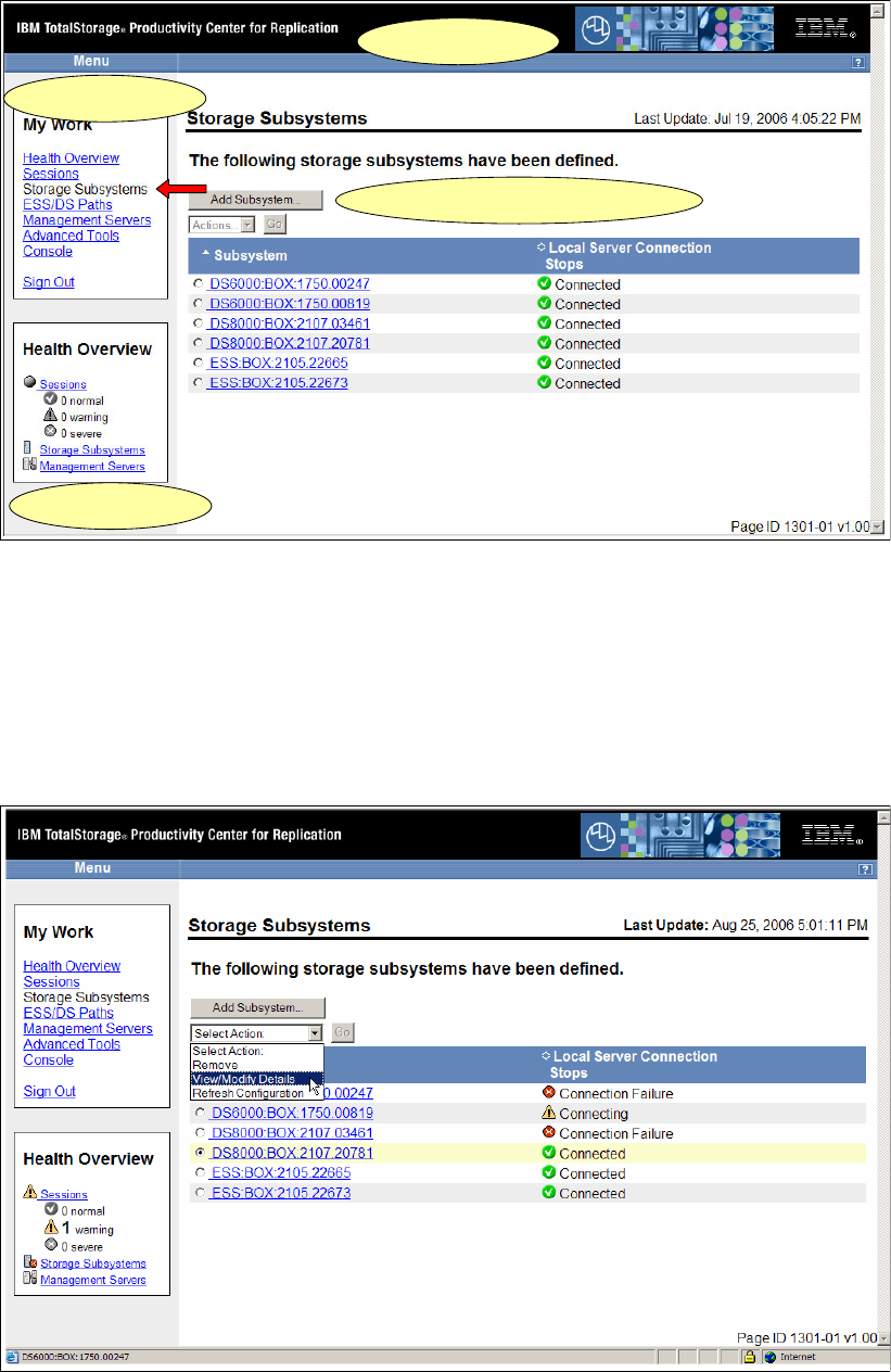
Chapter 31. IBM TotalStorage Productivity Center for Replication 493
Figure 31-20 GUI basic layout
Using the Add Subsystem button you can define another storage subsystem to the RM
server.
The panel used to add a new server is shown in Figure 31-22 on page 494.
Figure 31-21 displays the available action list. From this list you select, for instance, the
View/Modify Details action and apply it to the previously selected storage server.
Figure 31-21 Select the storage subsystem and the View/Modify Details action
Panel heading
Hyper links
Interface to functional tasks
RM summary
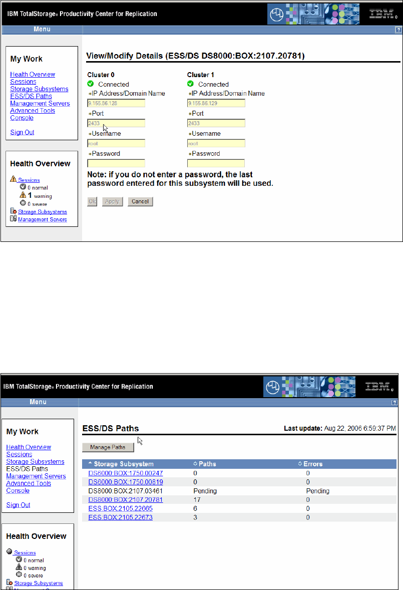
494 IBM System Storage DS6000 Series: Copy Services with IBM System z
The selected storage subsystem connectivity details are now displayed, as shown in
Figure 31-22.
Figure 31-22 Storage subsystem details
You usually use the storage subsystem application only to connect a storage server to the
RM server. Figure 31-22 also shows the standard port used by the RM server to
communicate with the storage server. All the other fields are self-explanatory.
31.15.5 Path Management panel
Figure 31-23 displays the entry panel to manage PPRC paths.
Figure 31-23 Path overview panel
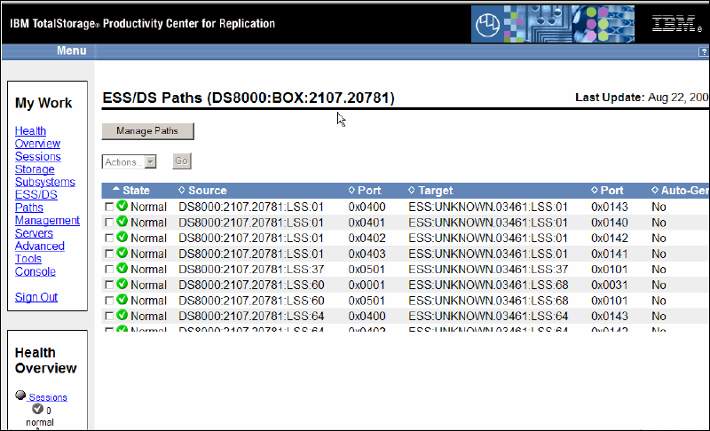
Chapter 31. IBM TotalStorage Productivity Center for Replication 495
Clicking the Manage Paths button triggers the path wizard to help you define a new PPRC
path or remove existing PPRC paths.
Clicking on a storage subsystem gives you a list of all the existing paths currently defined for
the selected storage subsystem. Figure 31-24 displays all the defined PPRC paths for the
selected LSS and the ports used for these PPRC paths.
Figure 31-24 Path overview of a DS8000
You may select any path here and the only available action in this case is to then remove the
selected path(s).
31.15.6 RM Server Configuration panel
The panel in Figure 31-25 on page 496 displays the status of the Replication management
server or servers.
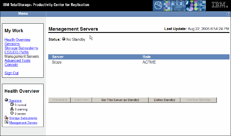
496 IBM System Storage DS6000 Series: Copy Services with IBM System z
Figure 31-25 Replication Management servers
Figure 31-25 shows only one server named Stops, which is an active server.
When it exists, a second row will show the potential second server, which is in the status
Standby. A panel with two servers has a slightly different appearance than what is shown in
Figure 31-25.
You use this panel for basic operations such as defining a server as Standby or to take over
in the event of a disaster.
In the case of two servers, each server manages its own DB2 database. The communication
between the servers is performed through the LAN to which both servers are connected.
31.15.7 Advanced Tools panel
Figure 31-26 on page 497 displays a panel through which you handle some specific tasks.
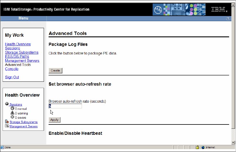
Chapter 31. IBM TotalStorage Productivity Center for Replication 497
Figure 31-26 Advanced tools option
Specific tasks in this context are tasks to create a diagnostic package or to change the
automatic refresh rate of the GUI. A third task is to enable or disable the heartbeat that
happens between the Replication Manager server and the connected storage servers; see
also 31.12, “TPC for Replication heartbeat” on page 484.
The diagnostic package contains all RM logs. Its location on the RM server is shown on the
screen.
The browser refresh rate is currently a value between 5 t0 3600 seconds. The default value is
30 seconds.
31.15.8 Console log
Figure 31-27 on page 498 displays an example of a console log. This panel shows a list of the
most recent commands which this user entered through the GUI.
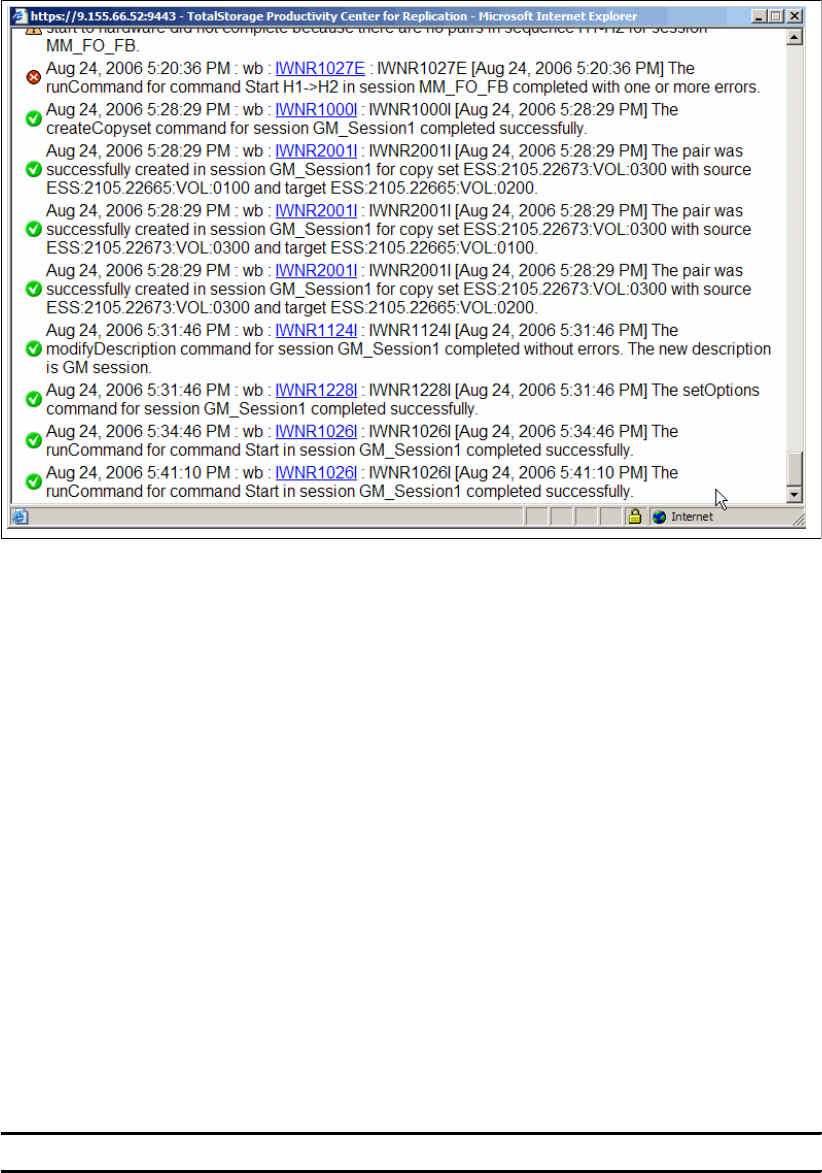
498 IBM System Storage DS6000 Series: Copy Services with IBM System z
Figure 31-27 Console log
Besides the commands this log also shows whether the command succeeded, and a
message number functions at the same time as a hyperlink to more detailed text about the
result of the concerned command execution.
31.16 Command Line Interface to TPC for Replication
Besides the GUI you may also manage TPC for Replication through a command line interface
(CSMCLI).
As with the DSCLI for DS8000 and DSCLI for DS6000, the CSMCLI command structure is
similar for all three CLI products, such as mk... for make, ch... for change, etc.
CSMCLI is also invoked in the same fashion as the DSCLI for the DS products and provides
three different modes:
Singe-shot mode
Interactive mode
Script mode
Example 31-4 shows a single-shot command.
Example 31-4 Single-shot CLI command
> csmcli lsdevice -devtype ds
To execute more than one command you may start the CLI program and perform the
commands at the shell prompt, as Example 31-5 on page 499 shows.

Chapter 31. IBM TotalStorage Productivity Center for Replication 499
Example 31-5 Interactive CLI commands
... start csmcli ...
csmcli> lsdevice -devtype ds
csmcli> lsdevice -devtype ess
The third mode is the script mode, running commands out of a file.
Example 31-6 Script mode to execute CLI commands
... start csmcli ...
csmcli -script ~/rm/scrtips/devreport
In contrast to DSCLI for the DS storage servers, the CSMCLI currently does not use a
-profile option.
500 IBM System Storage DS6000 Series: Copy Services with IBM System z

© Copyright IBM Corp. 2006. All rights reserved. 501
Chapter 32. GDPS overview
Today’s on demand data centers must be resilient enough to handle planned and unplanned
system outages without impacting the business of the enterprise.
Most solutions that help provide continuous IT service availability are based on cluster server
software, mirrored storage, and redundant networks. When a failure occurs, an integrated
disaster recovery solution will, in a predetermined fashion, execute a set of tasks to restart
the operating system, recover storage servers and networks, and restart applications on a
different set of servers and storage in another location. This level of functionality is also
defined as IT continuous availability.
GDPS or Geographically Dispersed Parallel Sysplex is such a full function solution and
provides various levels of IT continuous availability through different implementation levels.
GDPS as a continuous availability and near-transparent disaster recovery solution is based
on Parallel Sysplex server functionality and disk mirroring utilizing Metro Mirror and Global
Mirror.
This chapter provides an overview of the various features that GDPS offers. More information
is available in IBM System Storage Business Continuity Solutions Guide, SG24-6547 and
GDPS Family - An Introduction to Concepts and Capabilities, SG24-6374-01.
Also see the following URLs:
http://www.ibm.com/servers/eserver/zseries/gdps/
http://www.ibm.com/services/storage
Note that GDPS is a continuous availability solution for System z and is an IBM
implementation service and not a product.
32
Important: The various GDPS offerings are not products. They are delivered as IBM
Global Service offerings.

502 IBM System Storage DS6000 Series: Copy Services with IBM System z
32.1 GDPS solution offerings
GDPS is a family of offerings, for single site or multi-site application availability solution, with
the capability to manage the remote copy configuration and storage subsystems, automate
System z operational tasks, manage and automate planned reconfigurations, and do failure
recovery from a single point of control.
GDPS is an integrated end-to-end solution composed of software automation, software,
servers and storage, networking, and IBM Global Services to configure and deploy the
solution, as shown in Figure 32-1. The GDPS solution has components in the areas denoted
by dark shading.
Figure 32-1 Positioning of GDPS solution offerings
The benefits of GDPS are: a highly reliable, highly automated IT infrastructure solution with a
System z-based control point, which can provide very robust application availability.
GDPS is enabled by means of key IBM technologies and architectures.
GDPS supports both the synchronous (Metro Mirror) as well as the asynchronous (z/OS
Global Mirror or Global Mirror) forms of remote copy. GDPS also supports Peer-to-Peer
Virtual Tape Server (PtP VTS) for remote copying of tape data. The GDPS solution is a
non-proprietary solution, working with IBM as well as Other Equipment Manufacturer (OEM)
disk vendors, as long as the vendor meets the specific functions of the Metro Mirror, Global
Mirror, and z/OS Global Mirror architectures required to support GDPS functions.
GDPS automation manages and protects IT services by handling planned and unplanned
exception conditions. Depending on the GDPS configuration selected, availability can be
storage resiliency only, or can provide near-continuous application and data availability.
Regardless of the specific configuration variation, GDPS provides a System z-based
Business Continuity automation and integration solution to manage both planned and
unplanned exception conditions.
To attain high levels of continuous availability and near-transparent DR, the GDPS solution is
based on geographical clusters and disk mirroring.
Figure 32-2 is a diagram of some of the many possible components supported in a GDPS
configuration. GDPS is configured to meet the specific client requirements. Not all of the
components shown in Figure 32-2 are necessary in all GDPS offerings or GDPS solutions.
7654321
Recovery Time
disk tape
Business value
+
-+
Software Automation for SAP, DB2,Siebel,MS SQL Server,
Exchange etc.
4
Services
Automation for server z/OS, UNIX, Linux, Windows and
heterogeneous environments.
3
Point in Time Copy, Metro Mirror, Global Mirror, TotalStorage
Software Family, DFSMS for z/OS, TSM.
2
Hardware Infrastructure: ESS, DS family, SAN Switches, VTS,
3584, 3592, LTO
1
Autonomic
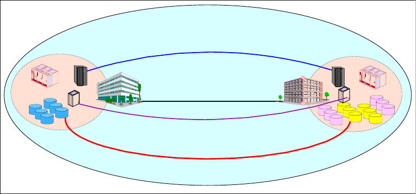
Chapter 32. GDPS overview 503
Figure 32-2 GDPS integrates many components
The GDPS family of System z Business Continuity solutions consists of two major offering
categories, and each category has several subofferings. Each GDPS solution is delivered
through IBM Global Services, and is specifically tailored to fit a specific set of client recovery
needs, budgetary requirements, physical distance and infrastructure, and other factors.
The three major categories of GDPS solutions are:
GDPS/PPRC solutions, based on Metro Mirror. Metro Mirror was formerly known as
Peer-to-Peer Remote Copy (PPRC).
GDPS/XRC solutions, based on z/OS Global Mirror. z/OS Global Mirror was formerly
known as Extended Remote Copy (XRC).
GDPS/GM (Global Mirror) solutions, based on Global Mirror.
The subofferings within these three GDPS major categories include the following:
GDPS/PPRC
– GDPS/PPRC, a Tier 7 solution
– GDPS/PPRC HyperSwap Manager, a Tier 6 solution
– RCMF/PPRC, a remote copy management solution for PPRC
GDPS/XRC
– GDPS/XRC, a Tier 7 solution
– RCMF/XRC, a remote copy management solution for XRC
Certain of the above GDPS offerings can also be combined into 3-site GDPS solutions,
providing Tier 7 recoverability in a multi-site environment.
32.1.1 GDPS/PPRC overview
GDPS/PPRC is designed to manage and protect IT services by handling planned and
unplanned exception conditions, and maintain data integrity across multiple volumes and
storage subsystems. By managing both planned and unplanned exception conditions,
GDPS/PPRC can help to maximize application availability and provide business continuity.
GDPS/PPRC is capable of the following attributes:
Near continuous availability solution
High bandwidth connections
Site A Site B
Copy Servcices
Secondary
FlashCopy
Tier 7, Tier 6 integrated solutions
Automation via GDPS
zSeries zSeries
VTS
VTS
Primary
Peer to Peer VTS
FlashCopy
Tape
504 IBM System Storage DS6000 Series: Copy Services with IBM System z
Near transparent D/R solution
Recovery Time Objective (RTO) less than an hour
Recovery Point Objective (RPO) of zero (optional)
Protects against localized area disasters with a typical distance between sites limited to up
to 100 km fiber distance
The GDPS/PPRC solution offering combines System z Parallel Sysplex capability and ESS,
DS6000, and/or DS8000 Metro Mirror disk mirroring technology to provide a Business
Continuity solution for IT infrastructures that have System z at the core. GDPS/PPRC offers
efficient workload management, system resource management, Business Continuity or
Disaster Recovery for z/OS servers and open system data, and provides data consistency
across all platforms using the Metro Mirror Consistency Group function.
The GDPS solution uses automation technology to provide end-to-end management of
z/Servers, disk mirroring, tape mirroring, and workload shutdown and startup. GDPS will
manage the infrastructure to minimize or eliminate the outage during a planned or unplanned
site failure. Critical data is disk mirrored, and processing is automatically restarted at an
alternate site in the event of a primary planned site shutdown or site failure.
GDPS/PPRC automation provides scalability to insure data integrity at a very large number of
volumes, across hundreds or thousands of Metro Mirror pairs.
32.1.2 PPRC and HyperSwap
Exclusive to GDPS in the PPRC environment is HyperSwap. This function is designed to
broaden the near continuous availability attributes of GDPS/PPRC by extending the Parallel
Sysplex redundancy to disk subsystems. The HyperSwap function can help significantly
reduce the time needed to switch to the secondary set of disks while keeping the z/OS
systems active together with their applications.
GDPS/PPRC V3.2, the HyperSwap function, exploits the Metro Mirror Failover/Failback
(FO/FB) function.
For planned reconfigurations, FO/FB may reduce the overall elapsed time to switch the disk
subsystems, thereby reducing the time that applications may be unavailable to users.
For unplanned reconfigurations, FO/FB allows the secondary disks to be configured in the
suspended state after the switch and record any updates made to the data. When the failure
condition has been repaired, resynchronizing back to the original primary disks requires only
the changed data to be copied, thus eliminating the need to perform a full copy of the data.
The window during which critical data is left without Metro Mirror protection following an
unplanned reconfiguration is thereby minimized.
32.1.3 RCMF/PPRC overview
Remote Copy Management Facility/PPRC (RCMF/PPRC) is the name given to a subset of
the GDPS/PPRC offerings. RCMF/PPRC includes the storage interface management
functions only.
RCMF/PPRC provides panels and code that execute under NetView®, and an operator
interface for easier management of a remote copy configuration in setup, initialization, and
any planned outage operational mode. This provides benefits for businesses looking to
improve their management of PPRC for normal running circumstances.
Note that RCMF/PPRC does not provide any monitoring capability and is not designed to
notify the operator of an error in the remote copy configuration. Thus RCMF does not support
Chapter 32. GDPS overview 505
the Freeze function for GDPS/PPRC, FlashCopy automation, or the unplanned outage
functions available through the other versions of GDPS.
RCMF/PPRC is positioned as a remote copy management control tool, designed to make the
task for operators to stop and start remote copy sessions much easier.
The highlights of RCMF/PPRC include:
Central point of control - full screen
Global PPRC configuration awareness
Functional, tree-structured interface
TSO commands not needed
Initialize and maintain Remote Copy configuration
Single keystroke function invocation
Initiate functions per pair, subsystem, or all
Automatically establish target configuration at system startup
Supports adding, moving, removing pairs, subsystems and links
RCMF does not manage unplanned outage secondary data consistency
Drive Peer-to-Peer/Dynamic Address Switching (P/DAS)
User-initiated status and exception reporting
Can run as a NetView application - System Automation not required
32.1.4 GDPS/XRC overview
IBM System Storage z/OS Global Mirror, formerly known as Extended Remote Copy (XRC),
is a combined hardware and z/OS software asynchronous remote copy solution for System z
data. z/OS Global Mirror is designed to provide premium levels of scalability, reaching into
the tens of thousands of System z volumes. Consistency of the data is maintained via the
Consistency Group function within the System Data Mover.
GDPS/XRC includes automation to manage z/OS Global Mirror remote copy pairs and
automates the process of recovering the production environment with limited manual
intervention, including invocation of CBU, thus providing significant value in reducing the
duration of the recovery window and requiring less operator interaction.
GDPS/XRC provides the following attributes:
Disaster recovery solution
RTO between an hour to two hours
RPO less than two minutes, typically 3-5 seconds
Protects against localized as well as regional disasters; unlimited distance between sites
Minimal remote copy performance impact
32.1.5 RCMF/XRC overview
Remote Copy Management Facility/XRC (RCMF/XRC) is a subset of GDPS/XRC that
provides the capability to manage the z/OS Global Mirror configuration for planned and
unplanned outages. RCMF/XRC is not intended to manage the system and workload
environment. RCMF/XRC provides a central point of control of z/OS Global Mirror disk
mirroring configurations where the environment does not require more than one SDM.
Environments that require multiple SDMs and/or coupled SDMs will require the full
GDPS/XRC.
RCMF/XRC solution highlights include:
Functional full screen interface
Initialize and maintain z/OS Global Mirror Remote Copy configuration
506 IBM System Storage DS6000 Series: Copy Services with IBM System z
User-initiated status collection and exception monitoring
NetView application, does not require System Automation for z/OS
RCMF/XRC provides panels and code that execute under NetView, and an operator interface
for easier management of a remote copy z/OS Global Mirror configuration in setup,
initialization, and any planned outage operational mode. This provides benefits for
businesses looking to improve their management of XRC for normal running circumstances.
RCMF/XRC is positioned as a remote copy management control tool, designed to make it
easier for operators to stop and start a single SDM z/OS Global Mirror remote copy session.
32.1.6 GDPS/GM (Global Mirror) overview
GDPS/GM is similar in some respects to GDPS/XRC in that it supports distances over 100
km. However, due to the differing characteristics of the underlying remote copy technology
(Global Mirror), GDPS/GM extends the remote copy support to FB data.
GDPS/GM could be viewed somewhat as a mixture of GDPS/PPRC and GDPS/XRC. Just as
GDPS/PPRC is a disk subsystem-based remote copy technology, GDPS/GM is also
disk-based, meaning that it supports the same mix of CKD and FB data that is supported by
GDPS/PPRC. Also, being disk-based, there is no requirement for a System Data Mover
(SDM) system to drive the remote copy process. And, like Metro Mirror, Global Mirror
requires that the primary and secondary disk subsystems are from the same vendor;
however, Global Mirror is currently only supported by IBM disk subsystems.
On the other hand, GDPS/GM resembles GDPS/XRC in that it supports virtually unlimited
distances between the application and recovery sites. Also, GDPS/GM does not provide any
automation or management of the production systems—its focus is on managing the Global
Mirror remote copy environment and automating and managing recovery of data and systems
in case of a disaster. Also, like GDPS/XRC, GDPS/GM supports the ability to remote copy
data from multiple sysplexes, whereas each GDPS/PPRC licence supports remote copy for
just a single sysplex.
In addition to its disaster recovery capabilities, GDPS/GM also provides a more user-friendly
interface for monitoring and managing the remote copy configuration. This includes the
initialization and monitoring of the GM volume pairs based upon policy, and performing
routine operations on installed storage subsystems.
More details on GDPS/GM can be found in GDPS Family - An Introduction to Concepts and
Capabilities, SG24-6374-01.
32.1.7 GDPS 3-site solution overview
GPDS also supports 3-site configuration solutions by using a combination of the previous
GDPS solutions. A 3-site solution can combine the advantages of metropolitan distance
Business Continuity and regional or long distance Disaster Recovery.
GDPS PPRC/XRC
GDPS/PPRC and GDPS/XRC is a supported configuration for the 3-site requirements, as
shown in Figure 32-3.
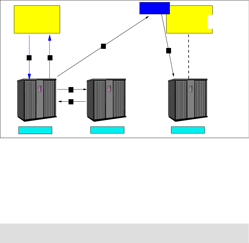
Chapter 32. GDPS overview 507
Figure 32-3 GDPS 3-site configuration with GDPS/PPRC and GDPS/XRC
The same primary volume for PPRC and XRC can be supported by two different GDPSs, a
GDPS/PPRC for metropolitan distance and Business Continuity, and a GDPS/XRC for
regional distance and Disaster Recovery.
The two mirroring technologies and GDPS implementations work independently of each
other, yet provide the synergy of a common management scheme and common skills.
More details on GDPS 3-site configurations can be obtained from your IBM GDPS
representative.
32.1.8 IBM Global Services offerings for GDPS
The various GDPS offerings are not products. They are delivered as IBM Global Service
offerings. GDPS is an end-to-end solution in which IBM Global Services tailors and installs
the specific combination of components, integrated within the client’s environment. GDPS
integration work, including education, is done using IBM Global Services, in addition to the
planning and installation of the code. This ensures that the GDPS solution provides the
intended value to all parts of the business and IT processes.
The following GDPS services and offerings are provided by IBM Global Services (IGS).
GDPS technical consulting workshop (TCW)
TCW is a 2-day workshop where IGS specialists work with your representatives to
understand your business objectives, service requirements, technological directions,
business applications, recovery processes, cross-site, and I/O requirements. High-level
education on GDPS is provided along with the service and implementation process. Various
remote and local data protection options are evaluated.
Note: GDPS/XRC supports System z data for z/OS, LINUX on z/VM, z/VM, and z/VSE.
GDPS/XRC and GDPS/PPRC off of the same volume is a System z solution only.
Tota lSt orag e TotalSto rage
Primary Secondary
Tota lSt ora ge
Metro Mirror Tertiary
1 4
56
3
2
SDM
Recovery
system
System z
Application
systems
System z
508 IBM System Storage DS6000 Series: Copy Services with IBM System z
IGS specialists present a number of planned and unplanned GDPS reconfiguration scenarios
with recommendations on how GDPS can assist you in achieving your objectives. At the
conclusion of the workshop the following items are developed: acceptance criteria for both
the test and production phases, a high-level task list, a services list, and project summary.
Remote Copy Management Facility (RCMF)
With this service, the RCMF/PPRC or RCMF/XRC automation to manage the remote copy
infrastructure will be installed, the automation policy customized, and the automation verified
along with providing operational education for the enterprise.
GDPS/PPRC HyperSwap Manager
IBM Implementation Services for GDPS/PPRC HyperSwap Manager helps simplify
implementation by working with you to get GDPS/PPRC HyperSwap Manager and its
prerequisites up and running with limited disruption to your business. On-site planning,
configuration, implementation, testing, and education will help make your new IBM
Implementation Services for GDPS/PPRC HyperSwap Manager solution accessible in the
most efficient manner.
GDPS/PPRC and GDPS/XRC
IBM Implementation Services for GDPS/PPRC or GDPS/XRC will assist you with planning,
configuration, automation code customization, testing, onsite implementation assistance, and
training in the IBM GDPS solution. Either option supports Peer-to-Peer Virtual Tape Server
(PtP VTS) form of tape data mirroring.

© Copyright IBM Corp. 2006. All rights reserved. 509
Appendix A. Concurrent Copy
In this appendix we describe the Concurrent Copy function on the DS6000 series.
A
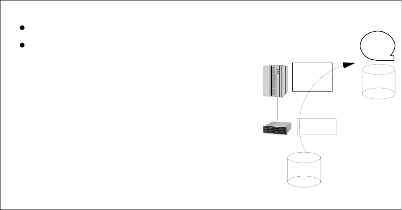
510 IBM System Storage DS6000 Series: Copy Services with IBM System z
Concurrent Copy
This appendix describes the characteristics and operation of Concurrent Copy. We also
discuss the considerations involved when planning to use Concurrent Copy.
The information presented in this chapter can be complemented with the following
publications:
z/OS DFSMS Advanced Copy Services, SC35-0428
z/OS DFSMSdss Storage Administration Reference, SC35-0424
z/OS V1R3.0 DFSMS Installation Exits, SC26-7396
DFSMS: Implementing System Managed Storage, SC26-7407
DFSMShsm Storage Administration Guide, SC35-0388
DFSMS/MVS Managing Catalogs, SC26-4914
Overview
Concurrent Copy is a copy function that helps you keep your high data availability objectives
by allowing point-in-time copies of your data concurrent with normal application processing.
Concurrent Copy works with the IBM System Storage DS6000 and the DFSMS System Data
Mover (SDM). Concurrent Copy is available for the z/OS and OS/390 operating systems, and
requires software support provided in DFSMS/MVS™.
Concurrent Copy works not only on a full-volume basis, but also at a data set level. Also, the
target is not restricted only to DASD volumes in the same DS6000, but the target can also be
a tape cartridge or a DASD volume on another DS6000 (see Figure A-1).
Figure A-1 Concurrent Copy characteristics
Concurrent Copy terminology
This section lists the definitions of the terms used with Concurrent Copy. These terms are
discussed in detail in the following sections.
- DFSMS/MVS Data Mover is used to
move the data
- Sidefile in cache is used for the updates
- Up to 64 Concurrent Copy sessions at a
time
T0 copy/dump of a volume or data set:
OS/390 and z/OS function
Backups of data at time T0
while source can be modified
Concurrent Copy and the
DS6000:
Data
Mover
Sidefile
Data set /
Volume
Data set /
Volume
Tape
Appendix A. Concurrent Copy 511
Session
A session is a logical concept that represents a single invocation of Concurrent Copy (a
single DFSMSdss DUMP/COPY command). A session can include one or more data sets or
volumes on the same DS6000 or across different DS6000s. An individual DS6000 can
support up to 16 simultaneous Concurrent Copy sessions per volume, with a maximum of 64
simultaneous sessions per LSS.
Session ID
The system assigns a unique session ID to each Concurrent Copy session. The system uses
the session ID to identify and coordinate all host and DS6000 resources associated with a
particular Concurrent Copy session.
Concurrent Copy domain
The set of devices and tracks identified during the initialization of a Concurrent Copy session
is called the Concurrent Copy domain. It represents the set of data that Concurrent Copy
copies.
Intercepted writes
When an application tries to update information that is included in a Concurrent Copy domain,
the DS6000 intercepts those writes, thus maintaining a copy of the data as it was at the time
when the Concurrent Copy was requested.
Sidefile
A sidefile is a temporary repository for Concurrent Copy domain tracks that still have not been
copied by the SDM and are about to receive an update. During the processing of an
intercepted write, the DS6000 copies a before-image of the track being updated into a sidefile
for later processing. Together, the DS6000 and the SDM maintain two sidefiles, one in the
DS6000 cache and another in processor storage.
Terminate
The Concurrent Copy terminates when DFSMSdss has copied the Concurrent Copy domain
and both the sidefiles are empty. In error situations, either the DS6000 or the SDM can
terminate the Concurrent Copy session before the entire domain has been copied.
Fuzzy copy
Without a tool like Concurrent Copy, if you make a copy of the data while the data is being
updated, then the copy does not reflect a point-in-time version of the original data. In this
case, the copy is fuzzy, because it does not represent any particular point-in-time status. A
fuzzy copy is a set of data with no logical consistency from the application perspective.
Consistent copy
A consistent copy is a set of data with logical consistency from the application perspective.
The logical consistency of the source data is guaranteed by the application itself. The logical
consistency of the copied data must be ensured by a mechanism like Concurrent Copy. With
the application taking care at all times that the original data is consistent, you are then able
with Concurrent Copy to produce a point-in-time copy of the complete set of data. The copy
will hold the same logical consistency status as the original data at that certain point-in-time.
Benefits of using Concurrent Copy
Concurrent Copy can dramatically reduce the amount of time that is required to back up your
application data, hence increasing the application’s availability time. When you use

512 IBM System Storage DS6000 Series: Copy Services with IBM System z
Concurrent Copy, application processing is interrupted for only a minimum time while the
system initializes the Concurrent Copy session. Once Concurrent Copy is active, your
applications continue to process the data, while it is being backed up using Concurrent Copy.
Concurrent Copy provides point-in-time data consistency. The system serializes access to
the data being dumped or copied just long enough for the Concurrent Copy session to be
initialized. This serialization takes a very short time to complete, and this process ensures the
point-in-time copy will be consistent, while the copy is being done with your applications
running.
Concurrent Copy operation
For details about the operation of Concurrent Copy, refer to z/OS DFSMS Advanced Copy
Services, SC35-0428.
Invoking Concurrent Copy
Concurrent Copy (CC) can be invoked by either the DFSMSdss or the DFSMShsm™
functions. IMS™, CICS®, DFSMSrmm™, and DB2 can use CC for their backups.
DFSMSdss has the option of using Concurrent Copy when data sets are copied or dumped.
To invoke Concurrent Copy, the CONCURRENT keyword must be specified on a DFSMSdss
COPY or DUMP commands.
With DFSMShsm, system-managed data can be backed up automatically with Concurrent
Copy by use of management class parameters. DFSMShsm also allows Concurrent Copy to
be used when copying data using Aggregate Backup and Recovery Support (ABARS).
Using the CONCURRENT control statement of the DB2 COPY utility, you can invoke
Concurrent Copy to make a full image copy. During recovery, DB2 can automatically use the
most recent image copy and then apply records from the log.
Concurrent Copy requires the software support provided in DFSMS/MVS. For details on
using Concurrent Copy with these products, refer to the appropriate product manual.
Concurrent Copy on the DS6000
Concurrent Copy is initiated using the CONCURRENT keyword in DFSMSdss or in
applications that internally call DFSMSdss as the copy program, such as the DB2 COPY
utility.
The SDM establishes a Concurrent Copy session with the DS6000. There can be up to 64
sessions active at a time per DS6000 logical subsystem (LSS).
Concurrent Copy and FlashCopy
Concurrent Copy and FlashCopy can coexist in the same DS6000.
If DFSMSdss is instructed to do a Concurrent Copy by specifying the CONCurrent (CC)
keyword, and the copy is for a full volume (DFSMSdss COPY FULL command), the following
will be honored based on whether FlashCopy is installed:
Note: Many of the benefits of using Concurrent Copy also apply to using FlashCopy, with
the added benefits of not using host resources (channel bandwidth, memory). However
you will need to allow for FlashCopy space in your disk subsystems. You will need to
decide which technique offers the best return for your business requirements.

Appendix A. Concurrent Copy 513
With the target within the same logical subsystem or DS6000 as the source and
FlashCopy installed, DFSMSdss will start a FlashCopy copy process instead of
Concurrent Copy.
So, you get a FlashCopy invocation with a DFSMSdss COPY FULL command even if the
CONCurrent (or CC) parameter is coded in the command.
The FASTREPLICATION parameter of the COPY command does not affect Concurrent
Copy; it only applies for FlashCopy and SnapShot invocation.
FASTREPLICATION(REQuired) and CONCURRENT cannot be used together in the same
COPY command.
Sizing and requirements
Concurrent Copy requirements and information about sizing the storage requirements can be
found in manual z/OS DFSMS Advanced Copy Services, SC35-0428.
Central and expanded storage
Running many Concurrent Copy jobs simultaneously can cause auxiliary (AUX) storage
shortages. PTF OW50284 introduced methods to limit the amount of auxiliary storage used
and will appropriately either terminate existing CC jobs, or will fail to copy data sets using
Concurrent Copy. SDM provides the ability to modify the Concurrent Copy AUX values that
are used in evaluating the AUX storage that is used by Concurrent Copy.
Example A-1 shows the system command for modifying the Concurrent Copy AUX delta to
determine at what percentage value new Concurrent Copy data sets will not be copied using
Concurrent Copy. SDM subtracts this delta value from the lower MVS percentage. The newly
computed SDM percentage is then compared to the total current system AUX storage
percentage being used. The default value is -1, indicating that SDM will not perform a
percentage check for AUX storage usage by Concurrent Copy. The nnnn value may be any
non-negative value (including zero).
Example: A-1 Modifying auxiliary storage delta for new Concurrent Copy data set
F ANTMAIN,P .CMTUN+3A X’FFFF’ X’nnnn’
Example A-2 shows the system command for modifying the Concurrent Copy AUX delta to
determine at what percentage value existing Concurrent Copy data sets will be terminated.
SDM subtracts this delta value from the upper MVS percentage. The newly computed SDM
percentage is then compared to the total current system AUX storage percentage being used.
The default value is -1, indicating that SDM will not perform a percentage check for AUX
storage usage by Concurrent Copy. The nnnn value can be any non-negative value (including
zero).
Example: A-2 Modifying auxiliary storage delta for existing Concurrent Copy data set
F ANTMAIN,P .CMTUN+3C X’FFFF’ X’nnnn’
Production and performance considerations
When planning to use Concurrent Copy, you will be paying attention to system performance
considerations such as:
Application response time
Storage subsystem utilization
System throughput
514 IBM System Storage DS6000 Series: Copy Services with IBM System z
Concurrent Copy throughput
Your workload flow and your hardware configuration determines how these factors affect your
ability to use Concurrent Copy.
When planning for the production use of Concurrent Copy, you should also address:
When to schedule Concurrent Copy operations
Where to use Concurrent Copy
Number of simultaneous sessions (z/OS Global Mirror and Concurrent Copy) that you can
run
Let us look at these considerations in more detail.
When to schedule Concurrent Copy
Many factors influence when you can schedule Concurrent Copy operations. For example,
the structure of your overnight batch processing determines at what stages in the processing
you can use Concurrent Copy. Similarly, factors such as availability of tape drives could
restrict the intervals during which running a Concurrent Copy operation is feasible.
If other considerations are not a factor, you can use Concurrent Copy at times of lowest
activity, especially lowest update activity. It might, however, be beneficial to use Concurrent
Copy to back up data even during periods of higher I/O activity. In some cases, ensuring data
availability may be more important than preserving levels of application performance.
Where to use Concurrent Copy
You can use Concurrent Copy to back up any data that can be backed up using DFSMSdss
because DFSMSdss is the external interface to Concurrent Copy. The general-purpose
design of Concurrent Copy simplifies the use of Concurrent Copy, because it builds on
existing experience with DFSMSdss.
For example, IMS databases can be backed up using DFSMSdss. During the recovery
process, IMS database recovery control (DBRC) coordinates recovery of the DFSMSdss
dump and the application of updates from the IMS log. The same is available also for DB2.
Data sets that are consistently in use, such as DFSMShsm control data sets, databases, and
libraries, require specialized facilities to ensure that data set backups are nondisruptive and
preserve data set integrity.
Management class attributes let you choose how DFSMShsm and DFSMSdss should
process data sets that are in use during availability management. Point-in-time capabilities
using Concurrent Copy on the ESS allow you to:
Use DFSMSdss to create a point of consistency backup of CICS, IMS, or DB2 databases
without needing to quiesce them during the entire backup process.
Use DFSMSdss to create backups of data sets without requiring serialization during the
entire backup process. DFSMSdss serializes the data during the Concurrent Copy
initialization period (the time between the start of DFSMSdss and the issuing of the
ADR734I message).
Create and maintain multiple backup versions of DFSMShsm control data sets, while
increasing the availability of DFSMShsm functions, such as recall.
Use the backup-while-open capability for CICS VSAM data sets with DFSMSdss in batch
mode or with automated DFSMShsm, to provide backups with data integrity even when
the data sets are being updated. Data integrity is assured for VSAM KSDSs even when
CICS access results in control interval or control area splits, or data set obtaining another
extent.
Appendix A. Concurrent Copy 515
Concurrent Copy coexistence with z/OS Global Mirror
The DS6000 is not supported as a source for z/OS Global Mirror, and so there should be no
concerns with coexistence.
Simultaneous Concurrent Copy sessions
As said before, each Concurrent Copy session generates additional channel load and
increases utilization of the storage paths within the DS6000. If you are running multiple
simultaneous Concurrent Copy sessions, it you could generate contention for these
resources, resulting in greater than normal queuing and extended response times.
Number of data mover-allowed sessions
In addition to the server and storage resources needed for running multiple SDM sessions,
you must consider the following design maximums:
16 data mover sessions per device (combined total of Concurrent Copy and/or z/OS
Global Mirror)
64 data mover sessions per DS6000 logical subsystem (combined total of Concurrent
Copy and/or z/OS Global Mirror)
2048 data mover sessions per DS6000 (2 Address Groups times 16 LSSs times 64)
If you attempt to use more than 16 data mover sessions per device, or more than 2048 data
mover sessions per DS6000 at the same time, you receive an error message, and the copy
continues using the traditional DFSMSdss copy.
Sessions for aggregate group
If you relate Concurrent Copy processing to the ABACKUP command for an aggregate group
that includes numerous data sets that are on multiple devices and LSSs, a separate
Concurrent Copy session is created for each LSS that has volumes containing data defined
by the aggregate.
SMF information
The SDM writes a system management facility (SMF) type 42 subtype 4 record that contains
session statistics for each Concurrent Copy session when the session ends. Concurrent
Copy records contain the identifier CC. Among other things, you can use the information in
this record to determine the following statistics:
Session initialization time
Maximum size of host cached storage subsystem sidefiles
Number of intercepted writes
The SMF type 42 subtype 4 record is described in detail in z/OS DFSMS Advanced Copy
Services, SC35-0428.
Examples of Concurrent Copy invocation
This section illustrates some examples of how Concurrent Copy can be invoked for either:
Full volume dump
Logical data set dump
Logical data set copy
Full volume copy invoking FlashCopy
We also discuss the invocation of Concurrent Copy from an application program.

516 IBM System Storage DS6000 Series: Copy Services with IBM System z
DFSMSdss: Dump and copy examples
Example A-3 shows a DFSMSdss full volume dump using Concurrent Copy. No special action
is required to perform a restore operation afterwards.
Example: A-3 DFSMSdss full volume dump with Concurrent Copy
//DSSJOB JOB ...
//DUMPSTEP EXEC PGM=ADRDSSU
//SYSPRINT DD SYSOUT=*
//DASD DD UNIT=SYSDA,VOL=SER=(SSDASD),DISP=OLD
//TAPE DD UNIT=TAPE,VOL=SER=(TAPE01,TAPE02,TAPE03),LABEL=(1,SL),
// DISP=(NEW,KEEP),DSN=USER.BACKUP
//SYSIN DD *
DUMP FULL INDDNAME(DASD) OUTDDNAME(TAPE) -
COMPRESS CONCURRENT
/*
Example A-4 shows a DFSMSdss logical data set dump of three fully qualified data sets using
Concurrent Copy. No special action is required to perform a restore operation after a
Concurrent Copy dump operation.
Example: A-4 Logical data set dump operation with CONCURRENT
//JOB6 JOB ...
//DUMPSTEP EXEC PGM=ADRDSSU
//SYSPRINT DD SYSOUT=*
//TAPE DD UNIT=TAPE,VOL=SER=(TAPE01,TAPE02,TAPE03),LABEL=(1,SL),
// DISP=(NEW,KEEP),DSN=USER.BACKUP
//SYSIN DD *
DUMP DATASET(INCLUDE(USER.LOG,USER.TABLE,USER.XREF)) -
OUTDDNAME(TAPE) OPTIMIZE(4) CONCURRENT
/*
Example A-5 shows a DFSMSdss logical data set copy using Concurrent Copy.
Example: A-5 Data set Copy with CONCURRENT
//DSSJOB JOB ...
//COPYSTEP EXEC PGM=ADRDSSU
//SYSPRINT DD SYSOUT=*
//SYSIN DD *
COPY DATASET(INCLUDE(USER.LOG,USER.TABLE,USER.XREF)) -
OUTDYNAM(OVOL01,OVOL02,OVOL03,OVOL08) -
ALLDATA(*) ALLEXCP CONCURRENT -
STORCLAS(BACKUP) RENAMEUNCONDITIONAL(USERX)
/*
DFSMSdss: FlashCopy example
Example A-6 shows an example of the use of FlashCopy and Concurrent Copy together. It is
a full volume copy between two volumes in the same LSS. As such, they were eligible for
FlashCopy, and FlashCopy was used as shown by the message ADR806I. At the same time,
the CC keyword is specified so that you obtain both ADR806I and ADR734I Concurrent Copy
initialization successful messages.
Example: A-6 Using FlashCopy and Concurrent Copy together
//STEPT40 EXEC PGM=ADRDSSU
//SYSPRINT DD SYSOUT=*
//SYSUDUMP DD SYSOUT=V,OUTLIM=3000

Appendix A. Concurrent Copy 517
//SYSIN DD *
//*
COPY FULL -
INDYNAM ((CP11S3)) -
OUTDYNAM ((TP11S3)) -
COPYVOLID -
CC
ADR101I (R/I)-RI01 (01), TASKID 001 HAS BEEN ASSIGNED TO COMMAND 'COPY '
ADR109I (R/I)-RI01 (01), 2000.107 16:09:59 INITIAL SCAN OF USER CONTROL STATEMENTS
COMPLETED.
ADR016I (001)-RI01 (01), RACF LOGGING OPTION IN EFFECT FOR THIS TASK
ADR006I (001)-STEND(01), 2000.107 16:10:00 EXECUTION BEGINS
ADR241I (001)-DDTFP(01), TARGET VTOC BEGINNING AT 000550:0000 AND ENDING AT 000550:0014 IS
OVERLAID
ADR806I (001)-T0MI (02), VOLUME COPIED USING A FAST REPLICATION FUNCTION.
ADR734I (001)-T0MI (03), 2000.107 16:10:12 CONCURRENT COPY INITIALIZATION SUCCESSFUL FOR
VOLUME CP11S3. SERIALIZATION FOR THIS DATA
IS RELEASED IF DFSMSDSS HELD IT. THE INTERMEDIATE RETURN CODE IS
0000.
ADR320I (001)-SBRTN(01), VOLUME SERIAL TP11S3 ON UNIT D70C IS CHANGED TO CP11S3
ADR344I (001)-SBRTN(01), VOLSER ON UCB D70C IS A DUPLICATE. VOLUME MADE UNAVAILABLE.
ADR006I (001)-STEND(02), 2000.107 16:10:35 EXECUTION ENDS
ADR013I (001)-CLTSK(01), 2000.107 16:10:35 TASK COMPLETED WITH RETURN CODE 0000
ADR012I (SCH)-DSSU (01), 2000.107 16:10:35 DFSMSDSS PROCESSING COMPLETE. HIGHEST RETURN
CODE IS 0000
Invocation from an application program
When DFSMSdss is invoked from an application program, you can use the user interaction
module (UIM) to interact with DFSMSdss. For user interactions to take place, the application
must invoke DFSMSdss and must provide a pointer to a user interaction module (UIM) list.
DFSMSdss can be invoked by any of the following system macros:
ATTACH EP=ADRDSSU,PARAM=(OPTPTR,DDPTR,PAGEPTR,UIMPTR,UAPTR),VL=1
LINK EP=ADRDSSU,PARAM=(OPTPTR,DDPTR,PAGEPTR,UIMPTR,UAPTR),VL=1
CALL (15),(OPTPTR,DDPTR,PAGEPTR,UIMPTR,UAPTR),VL
When a UIM exit routine is specified, DFSMSdss processes normally, then at each point in
the process (DFSMSdss exit points), the UIM exit routine is called conditionally to allow some
types of user operations. The exit identification block is passed to the UIM every time
DFSMSdss gives control to it.
Among the exit points that are available with DFSMSdss (EIOPTION 1 to 26), DFSMSdss
calls the UIM with option code 24 (EIOPTION 24) to inform it that the initialization of the
Concurrent Copy session for a given data set or volume has completed. For full volume or
tracks operation, there is only one call (because there is only one input volume). For a
physical data set operation, there is one call for each input volume. For a logical data set
operation, there is one call for every data set.
DFSMSdss does not call the UIM with this option code, if the CONCURRENT keyword is not
specified. DFSMSdss provides the UIM with information through the EIREC24 structure
within the exit identification block, ADREIB (in the ADREID0 macro).
For a detailed description of the DFSMSdss interaction with the user interface module (UIM)
when invoking from an application program, refer to z/OS DFSMSdss Storage Administration
Reference, SC35-0424.
518 IBM System Storage DS6000 Series: Copy Services with IBM System z
Installation options exit
Usage of the Concurrent Copy function can also be controlled through the installation options
exit, a product-sensitive programming interface intended for users. Refer to Options
Installation Exit Routine (ADRUIXIT) described in z/OS DFSMS Installation Exits,
SC26-7396, for more information.

© Copyright IBM Corp. 2006. All rights reserved. 519
Appendix B. SNMP notifications
This appendix describes SNMP traps that are sent out in a Remote Copy environment. It
repeats some of the SNMP trap information that is available in IBM System Storage DS6000
Series: Architecture and Implementation, SG24-6781.
B

520 IBM System Storage DS6000 Series: Copy Services with IBM System z
SNMP overview
The DS8000 sends out SNMP traps when a state change in a remote copy services
environment occurs. Therefore, 13 traps are implemented. The traps 1xx are sent out for a
state change of a physical link connection, and the 2xx traps are sent out for state changes in
the logical copy services setup.
The DS HMC can be set up to send SNMP traps to up to 2 defined IP addresses. eRCMF
(see Chapter 30, “IIBM TotalStorage Rapid Data Recovery” on page 457) is listening to
SNMP traps for the DS6000. Also, a Network Management program, such as Tivoli Netview,
can be used to catch and process the SNMP traps.
Physical connection events
With the trap 1xx range, a state change of the physical links is reported. The trap is sent out if
the physical remote copy link is interrupted. The link trap is sent from the primary system. The
PLink and SLink columns are only used by the Enterprise Storage Server (ESS).
If one or several links (but not all links) are interrupted, a trap 100, as shown in Example B-1,
is posted; it indicates that the redundancy is degraded. The RC column in the trap represents
the reason code for the interruption of the link. The reason codes are listed in Table B-1 on
page 521.
Example: B-1 Trap 100: PPRC links degraded
PPRC Links Degraded
UNIT: Mnf Type-Mod SerialNm LS
PRI: IBM 1750-511 13-00247 18
SEC: IBM 1750-511 13-00819 18
Path: Type PP PLink SP SLink RC
1: FIBRE 0003 XXXXXX 0003 XXXXXX OK
2: FIBRE 0103 XXXXXX 0002 XXXXXX 17
If all links are interrupted, a trap 101, as shown in Example B-2, is posted. This event
indicates that communication between primary and secondary system is no longer possible.
Example: B-2 Trap 101: PPRC links down
PPRC Links Down
UNIT: Mnf Type-Mod SerialNm LS
PRI: IBM 1750-511 13-00247 18
SEC: IBM 1750-511 13-00819 18
Path: Type PP PLink SP SLink RC
1: FIBRE 0003 XXXXXX 0003 XXXXXX 17
2: FIBRE 0103 XXXXXX 0002 XXXXXX 17
When the DS6000 can communicate again by any of the links, trap 102, as shown in
Example B-3, is sent after one or more of the interrupted links are available again.
Example: B-3 Trap 102: PPRC links up
PPRC Links Up
UNIT: Mnf Type-Mod SerialNm LS
PRI: IBM 1750-511 13-00247 18
SEC: IBM 1750-511 13-00819 18
Path: Type PP PLink SP SLink RC

Appendix B. SNMP notifications 521
1: FIBRE 0003 XXXXXX 0003 XXXXXX OK
2: FIBRE 0103 XXXXXX 0002 XXXXXX OK
Table B-1 PPRC path reason codes
Reason Code Description
00 No path.
01 ESCON path established.
02 Initialization failed. ESCON link reject threshold exceeded when attempting to send ELP or RID
frames.
03 Time out. No reason available.
04 No resources available at primary for the logical path establishment.
05 No resources available at secondary for the logical path establishment.
06 Secondary CU Sequence Number or Logical Sub- system number mismatch.
07 Secondary CU SS ID mismatch or failure of the I/O that collects secondary information for validation.
08 ESCON link is offline. This is caused the lack of light detection coming from a host, peer or switch.
09 Establish failed but will retry when conditions change.
0A The primary control unit port or link cannot be converted to channel mode since a logical path is
already established on the port or link. The establish paths operation will not be retried within the
control unit automatically.
0B Reserved for use by StorageTek™.
10 Configuration Error. The source of the error is one of the following:
1. The specification of the SA ID does not match the installed ESCON adapter cards in the primary
controller.
2. For ESCON paths, the secondary control unit destination address is zero and an ESCON
Director (switch) was found in the path.
3. For ESCON paths, the secondary control unit destination address is non-zero and an ESCON
Director does not exist in the path. That is, the path is a direct connection.
11 Reserved.
12 Reserved.
13 / OK Fibre path established.
14 Fibre Channel Path Link Down.
15 Fibre Channel Path Retry Exceeded.
16 Fibre Channel Path Secondary Adapter not PPRC capable. This could be due to:
1. Secondary Adapter not configured properly, or does not have the correct microcode loaded.
2. The secondary adapter is already a target of 32 different ESS, DS8000, DS6000.
17 Fibre Channel Path Secondary Adapter not available.
18 Fibre Channel Path Primary Login Exceeded.
19 Fibre Channel Path Secondary Login Exceeded.

522 IBM System Storage DS6000 Series: Copy Services with IBM System z
Remote copy events
If you have configured Consistency Groups and a volume in this Consistency Group is
suspended because of a write error to the secondary device, trap 200, as shown in
Example B-4, is sent. One trap is sent for each LSS that is configured with the Consistency
Group option. This trap could be handled by automation software like eRCMF to freeze this
Consistency Group.
Example: B-4 Trap 200: LSS-pair Consistency Group PPRC-pair error
LSS-Pair Consistency Group PPRC-Pair Error
UNIT: Mnf Type-Mod SerialNm LS LD SR
PRI: IBM 1750-511 13-00247 18 00 07
SEC: IBM 1750-511 13-00819 18 00
Trap 202, as shown in Example B-5, is sent if a remote Copy Pair goes into a suspend state.
The trap contains the serial number (SerialNm) of the primary and secondary machine, the
LSS (LS) and the logical device (LD). To avoid SNMP trap flooding, the number of SNMP
traps for the LSS is throttled. The complete suspended pair information is represented in the
summary. The last row of the trap represents the suspend state for all pairs in the reporting
LSS. The suspended pair information contains a hexadecimal string of 64 characters. By
converting this hex string into binary, each bit represents a single device. If the bit is 1, then
the device is suspended; otherwise, the device is still in full duplex mode.
Example: B-5 Trap 202: Primary PPRC devices on LSS suspended due to error
Primary PPRC Devices on LSS Suspended Due to Error
UNIT: Mnf Type-Mod SerialNm LS LD SR
PRI: IBM 1750-511 13-00247 18 00 07
SEC: IBM 1750-511 13-00819 18 00
Start: 2005/11/15 19:04:10 GMT
PRI Dev Flags (1 bit/Dev, 1=Suspended):
8000000000000000000000000000000000000000000000000000000000000000
Global Mirror related events
Trap 210, as shown in Example B-6, is sent when a Consistency Group in a Global Mirror
environment is successfully formed.
Example: B-6 Trap210: Asynchronous PPRC initial Consistency Group successfully formed
Asynchronous PPRC Initial Consistency Group Successfully Formed
UNIT: Mnf Type-Mod SerialNm
IBM 1750-511 13-00247
Session ID: 4001
Trap 211, as shown in Example B-7 is sent out if the Global Mirror setup is in a severe error
state, where no attempts to form a Consistency Group can be performed.
Example: B-7 Trap 211: Asynchronous PPRC Session is in a fatal state
Asynchronous PPRC Session is in a Fatal State
UNIT: Mnf Type-Mod SerialNm
IBM 1750-511 13-00247
Session ID: 4002

Appendix B. SNMP notifications 523
Trap 212, as shown in Example B-8, is sent when a Consistency Group cannot be created in
a Global Mirror Copy relation. Some of the reasons could be:
Volumes have been taken out of a copy session.
The remote copy link bandwidth might not be sufficient.
The FC link between the PPRC primary and secondary system are not available.
Example: B-8 Trap 212: Asynchronous PPRC Consistency Group failure - retry will be attempted
Asynchronous PPRC Consistency Group Failure - Retry will be attempted
UNIT: Mnf Type-Mod SerialNm
IBM 1750-511 13-00247
Session ID: 4001
Trap 213, as shown in Example B-9, is sent when a Consistency Group in a Global Mirror
environment could be formed after a previous Consistency Group formation failure.
Example: B-9 Trap 213: Asynchronous PPRC Consistency Group successful recovery
Asynchronous PPRC Consistency Group Successful Recovery
UNIT: Mnf Type-Mod SerialNm
IBM 1750-511 13-00247
Session ID: 4001
Trap 214, as shown in Example B-10, is sent out if a Global Mirror Copy Session is terminated
using the DS CLI command rmgmir or the corresponding GUI function.
Example: B-10 Trap 214: Asynchronous PPRC Master terminated
Asynchronous PPRC Master Terminated
UNIT: Mnf Type-Mod SerialNm
IBM 1750-511 13-00247
Session ID: 4001
Trap 215, as shown in Example B-11, is sent if in the Global Mirror Environment the Master
has detected a failure to complete the FlashCopy commit. The trap is sent after a number of
commit retries have failed.
Example: B-11 Trap 215: Asynchronous PPRC FlashCopy at remote site unsuccessful
Asynchronous PPRC FlashCopy at Remote Site Unsuccessful
UNIT: Mnf Type-Mod SerialNm
IBM 1750-511 13-00819
Session ID: 4001
Trap 216, as shown in Example B-12, is sent if a Global Mirror Master cannot terminate the
Global Copy relationship at one of its Subordinates (slave). This might occur if the Master is
terminated with rmgmir but the Master cannot terminate the copy relationship on the
Subordinate. Consider running a rmgmir against the Subordinate to prevent any interference
with other Global Mirror sessions.
Example: B-12 Trap 216: Asynchronous PPRC Subordinate termination unsuccessful
Asynchronous PPRC Slave Termination Unsuccessful
UNIT: Mnf Type-Mod SerialNm
Master: IBM 1750-511 13-00247
Slave: IBM 1750-511 13-00260
Session ID: 4002

524 IBM System Storage DS6000 Series: Copy Services with IBM System z
Trap 217, as shown in Example B-13, is sent if a Global Mirror Copy Environment was
suspended by the DS CLI command pausegmir or the corresponding GUI function.
Example: B-13 Trap 217: Asynchronous PPRC paused
Asynchronous PPRC Paused
UNIT: Mnf Type-Mod SerialNm
IBM 1750-511 13-00247
Session ID: 4001

© Copyright IBM Corp. 2006. All rights reserved. 525
Appendix C. Licensing
In this appendix we describe how the licensing functions for Copy Services for the DS6000
Series are arranged.
C

526 IBM System Storage DS6000 Series: Copy Services with IBM System z
Licenses
All DS6000 Series machines must have an Operating Environment License or OEL for the
total storage installed, as calculated in decimal TB. Licenses are also required for use of
Copy Services functions.
Each function is enabled for a DS6000 system by acquiring licences for specific feature
numbers, as listed in Table C-1.
Table C-1 DS6000 licensed functions
Following are the DS6000 Licensed Function feature numbers:
OEL: Operating Environment License
– OEL - 1 TB 5010
– OEL - 5 TB 5011
– OEL - 10 TB 5012
– OEL - 25 TB 5013
– OEL - 50 TB 5014
FICON: z/OS attachment
– FICON Attachment 5920
PAV: Parallel Access Volumes
– PAV - 1 TB 5110
– PAV - 5 TB 5111
– PAV - 10 TB 5112
– PAV - 25 TB 5113
– PAV - 50 TB 5114
The following licenses apply to Copy Services:
PTC: Point-in-Time Copy, also known as FlashCopy
– PTC - 1 TB 5210
– PTC - 5 TB 5211
– PTC - 10 TB 5212
– PTC - 25 TB 5213
– PTC - 50 TB 5214
RMC: Remote Mirror and Copy Licenses:
– RMC - 1 TB 5310
– RMC - 5 TB 5311
– RMC - 10 TB 5312
– RMC - 25 TB 5313
– RMC - 50 TB 5314
Licensed Function Feature Number
Operating Environment 50xx
Parallel Access Volumes 51xx
Point-in-Time Copy (FlashCopy) 52xx
Remote Mirror and Copy (Metro Mirror, Global
Mirror, Global Copy)
53xx
FICON Attachment 59xx

Appendix C. Licensing 527
It should be noted that the RMC License provides the functions of Metro Mirror, Global Copy,
and Global Mirror, depending on how it is configured during installation. These functions were
previously known as PPRC and its variants. Note also that, for the DS6000 and ESS, the
previous Extended Remote Copy (XRC) copy service is now known as Remote Mirror and
Copy for z/OS, or RMZ. You cannot order an RMZ license for DS6000.
Authorized level
All Copy Services functions require licensing to be activated. This means that you must have
purchased a license for the appropriate level of storage for each Copy Service function that is
required. You then must install the License Key that is generated using the Disk Storage
Feature Activation application (DSFA). Another consideration relates to the authorized level
required. In most cases, the total capacity installed must be licensed. This is the total capacity
in decimal TB equal to or greater than the actual capacity installed, including all RAID parity
disks and hot spares.
An exception can be where a mix of both System z and open systems hosts are using the
same storage server. In this case, it is possible to acquire Copy Services licenses for just the
capacity formatted for CKD, or just the capacity formatted for FB storage. This implies that the
licensed Copy Services function is needed only for open systems hosts, or only for System z
hosts. If, however, a Copy Services function is required for both CKD and FB, then that Copy
Services license must match the total configured capacity of the machine. Authorization level
is maintained by the licensed code in the controller and the DSFA application.
Example: Actual capacity is 15 TB, used for both CKD and FB, the scope for the OEL is
therefore a type of ALL and the installed OEL must be at least 15 TB. If the client has split
storage allocation, with 8 TB for CKD and only CKD storage is using FlashCopy, then the
scope type for the PTC license can be set to CKD. Now the PTC license can be purchased at
the CKD level of 8 TB. However, this means that no open systems hosts can use the
FlashCopy function.
The actual ordered level of any Copy Service license can be any level above that required or
installed. Licenses can be added and have their capacities increased, nondisruptively, to an
installed system.
Charging example
A client can choose to purchase any or all DS6000 licenses at an authorization level at or
above the installed raw disk capacity. It may be more cost effective to pre-install authorization
to use greater than the currently installed storage capacity.
A simple rule for charges is remembering that the required authorization level depends upon
the license scope:
If the license scope is FB, the authorization level must be equal to or greater than the total
amount of physical capacity in the system that is to be logically configured as FB.
If the license scope is CKD, the authorization level must be equal to or greater than the
total amount of physical capacity in the system that is logically configured as CKD.
If the license scope is ALL, the authorization level must be equal to or greater than the
total system physical capacity.
Important: A decrease in the scope or capacity of a license requires a disruptive power
cycle for the DS6000.
528 IBM System Storage DS6000 Series: Copy Services with IBM System z

© Copyright IBM Corp. 2006. All rights reserved. 529
Appendix D. CLI migration
This appendix discusses the ways that you can migrate Copy Services tasks on the ESS
environment to the DS Copy Services environment. The Copy Services functions described
here cover the GUI and the CLI. Excluded are the Copy Services functions that are executed
directly by z/OS.
D

530 IBM System Storage DS6000 Series: Copy Services with IBM System z
Migrating ESS CLI to DS CLI
With the introduction of the IBM DS6000 Storage Unit, a new Copy Services application is
also introduced. The Copy Services functions can be issued with the GUI or the DS CLI.
The advanced Copy Services functions that are available in the ESS 800 are also available
on the DS6000 (except for Global Mirror). Although the functions are still available, there are
also some differences that need to be considered when replacing your ESS CLI with a DS
CLI. These are:
Point-in-Time Copy (FlashCopy) does not support Consistency Groups on the GUI.
Fibre Channel is used for Metro Mirror and Global Mirror.
The GUI runs in real time only (tasks cannot be saved), while the CLI can be invoked with
a saved script.
The DS CLI supports both the ESS 800/750 and the DS6000/DS8000.
The ESS 800 must be at Licensed Internal Code (LIC) level 2.4.x or higher.
Reviewing the ESS tasks to migrate
Review the Copy Services tasks you want to migrate. You can perform this review from your
ESS GUI or ESS CLI. In Example D-1, esscli list is used to display the tasks:
Example: D-1 esscli list task
esscli list task –s copy_services-server –u csadmin –p passw0rd
Wed Nov 24 10:29:31 EST 2004 IBM ESSCLI 2.4.0
Task Name Type Status
------------------------------------------------------------------------
H_Epath_test16 PPRCEstablishPaths NotRunning
H_Epath_test17 PPRCEstablishPaths NotRunning
Brocade_pr_lss10 PPRCEstablishPair NotRunning
Brocade_pr_lss11 PPRCEstablishPair NotRunning
Flash10041005 FCEstablish NotRunning
You can use ESS CLI to display the contents of each saved task and write the contents to a
file. See Example D-2.
Example: D-2 esscli show task command
esscli show task –s copy_services_server –u csadmin –p passw0rd –d “name=Flash10041005”
Wed Nov 24 10:37:17 EST 2004 IBM ESSCLI 2.4.0
Taskname=Flash10041005
Tasktype=FCEstablish
Options=NoBackgroundCopy
SourceServer=2105.23953
TargetServer=2105.23953
SourceVol TargetVol
------------------------------------------------------------------------
1004 1005
You can also check your saved tasks via the ESS GUI. See Figure D-1 on page 531.
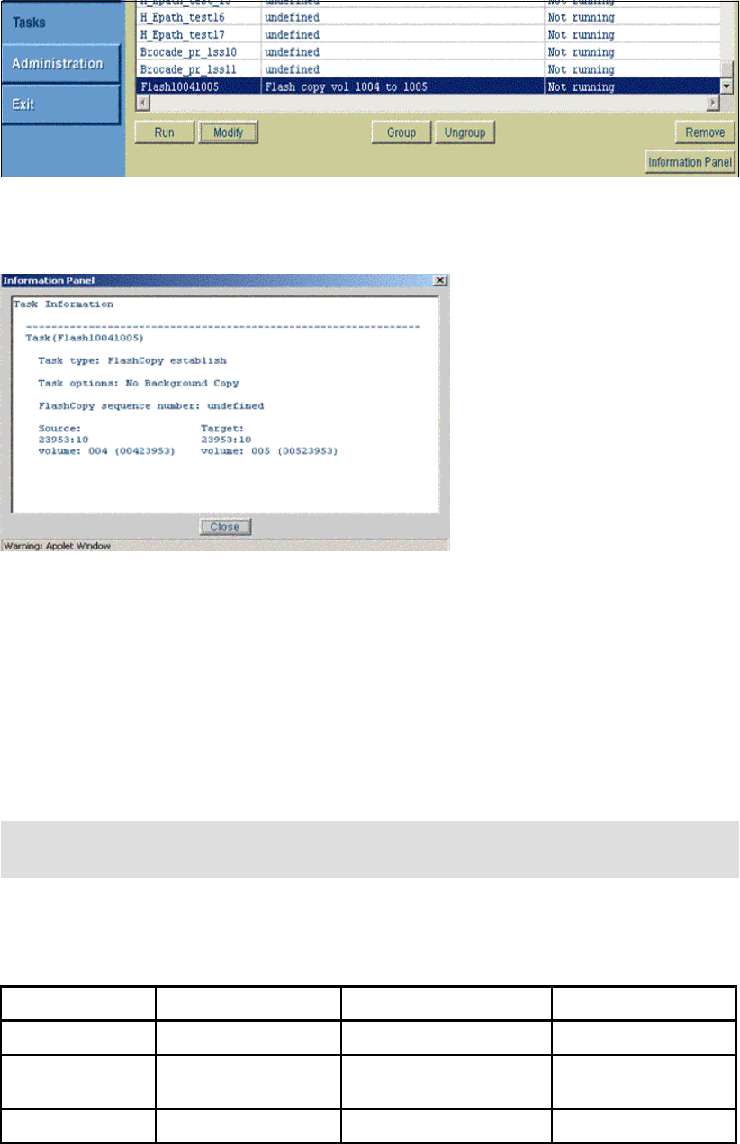
Appendix D. CLI migration 531
Figure D-1 ESS Copy Services GUI tasks panel
Highlight the task and click the information panel. See Figure D-2.
Figure D-2 ESS task information
Review also the specific server scripts (depending on the operating system), that perform
tasks that set up and execute saved ESS CLI saved tasks. You might have to edit or translate
these scripts to run your DS CLI scripts.
Convert the individual tasks
Choose the ESS CLI tasks that you need to translate to the DS CLI. Refer to IBM System
Storage DS6000: Command-Line Interface User´s Guide, GC26-7922. You can then save
each translated task and run it in the DS6000 CLI environment.
Translate also (if needed) and edit the individual server scripts that set up and execute the
saved DS CLI scripts. See Table D-1 for an example of command translation.
Table D-1 Converting ESS CLI to DS CLI
Note: The DS GUI (via the DS SMC) does not save Copy Services tasks such as the ESS
GUI. You can only use the DS GUI for Copy Services in real time mode.
Task parameter ESS CLI parameter DS CLI conversion Description
Tasktype FCEstablish mkflash establish FlashCopy
Options NoBackgroundCopy -nocp No background copy
upon FlashCopy
SourceServer 2105.23953 -dev IBM.2105-23953 device ID
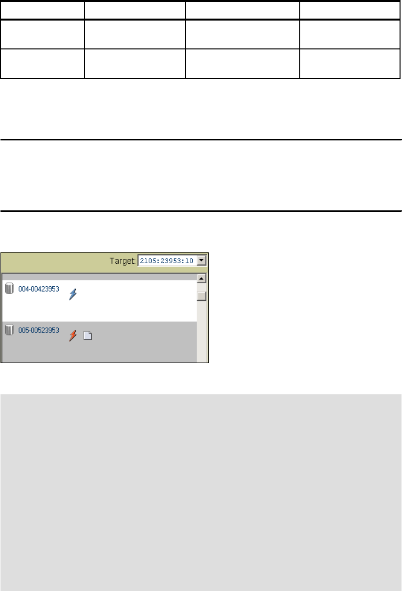
532 IBM System Storage DS6000 Series: Copy Services with IBM System z
DS CLI commands
Example D-3 shows the translation to a DS CLI command.
Example: D-3 DS CLI mkflash
dscli> mkflash -nocp -dev IBM.2105-23953 1004:1005
CMUC00137I mkflash: FlashCopy pair 1004:1005 successfully created.
dscli> lsflash -dev IBM.2105-23953 1004:1005
ID SrcLSS SequenceNum Timeout ActiveCopy Recoding Persistent Revertible
===============================================================================
1004:1005 10 0 120 Disabled Disabled Disabled Disabled
See Figure D-3 for the GUI output.
Figure D-3 ESS GUI FlashCopy window
ESS / DS CLI comparison
Table D-2 shows a brief comparison of the major components between the ESS CLI and the
DS CLI.
TargetServer 2105.23953 N/A used only once in DS
CLI
Source and Target
vols.
1004 1005 1004:1005 separated by a colon in
DS CLI
Important: On the ESS 800, open systems volume IDs are given in an eight-digit format,
xxx-sssss where xxx is the LUN ID and sssss is the serial number of the ESS 800. In the
example used in this appendix, the volumes shown are 004-23953 to 005-23953. These
volumes are open systems, or fixed block volumes. When referring to them in the DS CLI,
you must add 1000 to the volume ID, so that volume 004-23953 is volume ID 1004 and
volume 005-23953 is volume ID 1005. This is very important because on the ESS 800, the
following address ranges are actually used:
0000 to 0FFF System z CKD volumes (4096 possible addresses)
1000 to 1FFF Open systems fixed block LUNs (4096 possible addresses)
If you intend to FlashCopy ESS LUN 004-23953 onto 005-23953 with the DS CLI, you
must specify 1004 and 1005. If instead, you specify 0004 and 0005, you will actually run
the FlashCopy against CKD volumes. This can result in an unplanned outage on the
System z host that is using CKD volume 0005.
The ESS CLI command, show task, shows the correct value for the volume ID.
Task parameter ESS CLI parameter DS CLI conversion Description

Appendix D. CLI migration 533
Table D-2 ESS and DS CLI commands and parameters comparison
ESS CLI DS CLI Comments
list server lsserver Like the 2105, the 1750 storage
facility image contains one pair
of servers.
list volumespace lsextpool, showextpool, lsrank,
showrank, lsarray, showarray,
lsarraysite
See Note 1
create volumespace mkextpool, mkarray, mkrank
delete volumespace rmrank, rmarray, rmextpool
list diskgroup lsarraysite A 1750 Array Site can consist of
at least four disk drives (DDMs)
that are made into a RAID
Array. The 1750 does not
support the JBOD Array
configuration.
list port lsioport, showioport The 1750 CLI lsioport and
showioport commands include
the –metrics parameter that
returns the performance
counter values for the
respective I/O port IDs. The
–metrics parameter provides
the means to monitor I/O port
performance statistics.
set port setioport See Note 2
list volume lsfbvol, lsckdvol See Note 3
create volume mkfbvol, mkckdvol
set volume chfbvol, chckdvol
list pav lsckdvol, showckdvol
create pav mkckdvol
delete pav rmckdvol
list volumeaccess lsvolgrp, showvolgrp See Note 4
create volumeaccess mkvolgrp, chvolgrp
delete volumeaccess rmvolgrp
list hostconnection lshostconnect,
showhostconnect
The 1750 CLI commands
include the volume group ID
parameter.
For 2107, the hostconnect
commands concern SCSI-FCP
host port connections to ESS
I/O ports that are configured for
SCSI-FCP and “identified”
access mode.
create hostconnection mkhostconnect
delete hostconnection rmhostconnect
set hostconnection chhostconnect
list log N/A

534 IBM System Storage DS6000 Series: Copy Services with IBM System z
Note 1
Volume space configuration is a primary difference between 2105 and 1750. Like the
2105, a 1750 Storage Unit volume space contains a RAID-5 or RAID-10 array and a Rank
that is configured from an Array Site. For 2105, one command configures an Array Site
into a RAID array and Rank. For 1750, one command configures an Array Site into an
Array, and a second command configures an Array into a Rank. For 2105, a Rank is
configured as fixed block or CKD. For 1750, a Rank is assigned to a user-defined Extent
Pool object, which the user defines as either the fixed block or CKD storage type.
The “interleave” volume construct does not exist for 1750. For 2105, a volume is
configured from a specific Rank, and cannot span Rank boundaries. For 1750, a volume is
configured from an Extent Pool. An Extent Pool can contain multiple Ranks. A 1750
volume consists of one or more Extents that can be allocated from one or more Ranks. A
fixed block Extent is 1 GB (using binary counting).
list featurecode lsda, lshba, lsioencl, lsuser,
mkuser, rmuser, chuser,
lsstgencl
The 1750 CLI commands can
display feature codes when the
appropriate parameters are
used with the commands.
list task NA
show task NA
list pprcpaths lspprcpath Unlike the 2105, the 1750 CLI
Copy Services functions are not
task oriented. The 1750 CLI
provides a complete set of
FlashCopy and PPRC make,
change, remove, list, and show
commands.
rsExecuteTask mkflash, rmflash, mkpprc,
rmpprc, mkpprcpath,
rmpprcpath, mksession,
chsession, rmsession
The 1750 CLI provides a
complete set of FlashCopy and
PPRC commands that can be
used in the coding of scripts
that emulate 2105 Copy
Services tasks.
rsList2105s lssu The 1750 CLI lssu command
returns both 2105 and 1750
objects that are contained in the
ESS Network Interface domain
rsQuery, rsQueryComplete,
rsFlashCopyQuery
lsflash, lspprc These 1750 Copy Services CLI
commands are equivalent to
the respective 2105 CLI
commands.
The 1750 mkflashcopy and
mkpprc commands provide a
wait flag that delays command
response until copy complete
status is achieved.
rsTestConnection lsaavailpprcport
ESS CLI DS CLI Comments
Appendix D. CLI migration 535
For 2105, a Rank is either assigned to server 0 or server 1, depending on the Array Site
location. A 2105 Rank is assigned to one of 32 possible LSS IDs, depending on device
adapter pair location and storage type configuration.
For 1750, an Extent Pool is assigned to server 0 or server 1. A Rank that is configured
from any Array Site can be assigned to a server 0 or 1 Extent Pool. Array Site position and
device adapter pairs are not factors for the Rank-to-Extent Pool assignment. A volume
that is created from a server 0 Extent Pool is assigned to an even-numbered LSS ID. A
volume that is created from a server 1 Extent Pool is assigned to an odd-numbered LSS
ID. A user must define at least two Extent Pools (0 and 1), but can define as many Extent
Pools as there are Ranks. For 2105, a user can delete a Rank, but cannot delete a
volume. For 1750, a user can delete a single volume, Rank, or Extent Pool. The 1750 CLI
showrank and showextpool commands include a metrics parameter that returns the
performance counter values for a specified Rank or Extent Pool ID. The metrics parameter
provides the means to monitor Rank and Extent Pool performance statistics.
Note 2
A 1750 fibre-channel port is configured for either SCSI-FCP or FICON protocol. Like 2105,
a FICON port is restricted to the point-to-point/switched fabric topology setting. A FICON
I/O port is used for System z host attachment, but cannot be configured as a PPRC path.
A FICON port must be configured for anonymous access mode, meaning that any System
z host system port (WWNN/WWPN) has unrestricted access to all CKD volumes, up to
8192 volumes.
Like 2105, a 1750 fibre-channel SCSI-FCP I/O port can be configured for either the
point-to-point/switched fabric or FC-AL connection topologies. A port that uses the
point-to-point/switched fabric topology can be simultaneously used for OS host system I/O
and for PPRC path configurations. The Fibre Channel SCSI-FCP IO port only allows
“identified” host system ports to access volumes. A host system port WWPN must be
identified (registered) to each 1750 IO port through which volume access is intended. Host
system port WWPN identification is accomplished by the mkhostconnect CLI command.
Note 3
A 1750 Storage Unit can contain up to 8192 volumes, where either they are all FB or all
CKD, or there are 4096 CKD volumes and 4096 FB volumes. A 2105 Storage Unit can
contain up to 4096 FB volumes and 4096 CKD volumes. Otherwise, the 2105 and 1750
volume definitions and characteristics are essentially identical.
For 1750 CKD PAV volumes, the CLI list and show commands identify both the original
base and current base volume assignments. The original and current base concept exists
for 2105, but specific relationships are not identified in the output.
The 1750 CLI provides a specific set of volume commands for each storage type, fixed
block or CKD, as a means to clarify input parameter and output device adapter definitions.
The 1750 CLI showfbvol and showckdvol commands include a metrics parameter that
returns the performance counter values for a specified volume ID. The metrics parameter
provides the means to monitor volume performance statistics.
Note 4
The 2105 volume access commands concern volume ID assignment to a SCSI-FCP host
port initiator, or WWPN. For 1750, volume IDs are assigned to a user defined volume
group ID (mkvolgrp and chvolgrp). A volume group ID is then assigned to one or more
host system ports (mkhostconnect and chhostconnect) as a means of completing the
volume access configuration.
The volume group construct also exists in the 2105 internal code, but the construct is not
externalized by the 2105 Specialist or CLI commands.
536 IBM System Storage DS6000 Series: Copy Services with IBM System z
© Copyright IBM Corp. 2006. All rights reserved. 537
Related publications
The publications listed in this section are considered particularly suitable for a more detailed
discussion of the topics covered in this redbook.
IBM Redbooks
For information about ordering these publications, see “How to get IBM Redbooks” on
page 539. Note that some of the documents referenced here may be available in softcopy
only.
IBM System Storage DS6000 Series: Architecture and Implementation, SG24-6781
IBM System Storage DS6000 Series: Copy Services in Open Environments, SG24-6783
IBM System Storage DS6000 Series: Copy Services with System z servers, SG24-6782
IBM TotalStorage Business Continuity Solutions Guide, SG24-6547
The IBM TotalStorage Solutions Handbook, SG24-5250
You might find the following redbooks related to the DS8000 and ESS useful, particularly if
you are implementing a mixed systems environment with Copy Services.
IBM System Storage DS8000 Series: Architecture and Implementation, SG24-6786
IBM System Storage DS8000 Series: Copy Services in Open Environments, SG24-6788
IBM System Storage DS8000 Series: Copy Services with System z servers, SG24-6787
IBM TotalStorage Enterprise Storage Server Implementing ESS Copy Services in Open
Environments, SG24-5757
IBM TotalStorage Enterprise Storage Server Implementing ESS Copy Services with
IBM Eserver zSeries, SG24-5680
Other publications
These publications are also relevant as further information sources. Note that some of the
documents referenced here might be available in soft copy only.
IBM System Storage DS6000: Installation, Troubleshooting, and Recovery Guide,
GC26-7924
IBM System Storage DS6000 Introduction and Planning Guide, GC26-7925
IBM System Storage DS6000: Command-Line Interface User´s Guide, GC26-7922
IBM System Storage DS6000: Host Systems Attachment Guide, GC26-7923
IBM System Storage Multipath Subsystem Device Driver User’s Guide, SC30-4131
IBM System Storage DS Open Application Programming Interface Reference, GC35-0516
IBM System Storage DS8000 Messages Reference, GC26-7914
z/OS DFSMS Advanced Copy Services, SC35-0428
Device Support Facilities: User’s Guide and Reference, GC35-0033
538 IBM System Storage DS6000 Series: Copy Services with IBM System z
Online resources
These Web sites are also relevant as further information sources:
Documentation for DS6800:
http://www.ibm.com/servers/storage/support/disk/ds6800/
SDD and Host Attachment scripts at:
http://www.ibm.com/support/
IBM Disk Storage Feature Activation (DSFA) Web site at:
http://www.ibm.com/storage/dsfa
The PSP information can be found at:
http://www-1.ibm.com/servers/resourcelink/svc03100.nsf?OpenDatabase
Documentation for the DS6000 at:
http://www.ibm.com/servers/storage/support/disk/1750.html
The interoperability matrix at:
http://www.ibm.com/servers/storage/disk/ds6000/interop.html
Fibre Channel host bus adapter firmware and driver level matrix at:
http://knowledge.storage.ibm.com/servers/storage/support/hbasearch/interop/hbaS
earch.do
ATTO at :
http://www.attotech.com/
Emulex at:
http://www.emulex.com/ts/dds.html
JNI at:
http://www.jni.com/OEM/oem.cfm?ID=4
QLogic at:
http://www.qlogic.com/support/ibm_page.html
IBM at:
http://www.ibm.com/storage/ibmsan/products/sanfabric.html
McDATA at:
http://www.mcdata.com/ibm/
Cisco at:
http://www.cisco.com/go/ibm/storage
CIENA at:
http://www.ciena.com/products/transport/shorthaul/cn2000/index.asp
Nortel at:
http://www.nortelnetworks.com/
ADVA at:
http://www.advaoptical.com/
Related publications 539
How to get IBM Redbooks
You can search for, view, or download Redbooks, Redpapers, Hints and Tips, draft
publications and Additional materials, as well as order hardcopy Redbooks or CD-ROMs, at
this Web site:
ibm.com/redbooks
Help from IBM
IBM Support and downloads
ibm.com/support
IBM Global Services
ibm.com/services
540 IBM System Storage DS6000 Series: Copy Services with IBM System z
© Copyright IBM Corp. 2006. All rights reserved. 541
Index
Numerics
1750 DS6000 11
2105 ESS 800 12
A
activating 65
activating FlashCopy
machine signature 67
model 67
serial number of the DS6000 67
ANTRQST
enhanced to manage Global Mirror 327
ANTRQST API 179
architecture
Copy Services 7
asynchronous data replication 250
attributes
consistent asynchronous remote copy solution 253
synchronous data replication 250
automation and management 132
B
B volumes
consistent data 289
bandwidth 145
basic concepts 45
basic concepts of Global Mirror 253
C
catch-up transition 207
using TSO commands 208
CCA 152
CDELPAIR 154, 225
CDELPATH 154, 225
CESTPAIR 152, 224
CESTPATH 153, 225
CGROUP 154, 226
Channel Connection Address see CCA
channel extender support 216
CLI migration
convert the individual tasks 531
DS CLI commands 532
ESS / DS CLI Comparison 532
migrating ESS CLI to DS CLI 530
review the ESS tasks to migrate 530
codes
PPRC path reason 521
command overview 152, 224
Command-Line Interface see DS CLI
commitflash 79
comparison 222
Concurrent Copy 510
domain 511
DS6000 512
invoking 512
operation 512
Concurrent Copy terminology
Concurrent Copy domain 511
consistent copy 511
fuzzy copy 511
intercepted writes 511
session 511
session ID 511
sidefile 511
terminate 511
conduit 85
configuration 63
connecting to DS6000 19
connectivity 215
for Global Mirror between local and remote site 279
for Global Mirror to remote site 255
Global Mirror multi-site host connectivity 279
single site host 281
Consistency Group 55, 137, 142, 260
data consistency 136
formation 260
parameters 262
transmission 338
verify state 285
Consistency Group FlashCopy
conduit 85
consistent copy 511
coordination time
Global Mirror performance issues 337
copy pending 203
Copy Services 6
1750 DS6000 11
2105 ESS 800 12
architecture 7
differences of DS CLI and DS GUI 12
DS8000 11
how the new structure of Copy Services works 11
introduction 4
introduction to new structure 8
Remote Mirror and Copy between Storage Complex-
es 12
what is a Storage Complex 10
CQUERY 155, 227
create
Global Copy relationship between local and remote
volume 256
Global Mirror environment 269
create backup 123
create test system 122
CRECOVER 156, 227
critical attribute 141
critical mode combination 142
542 IBM System Storage DS6000 Series: Copy Services with IBM System z
CSUSPEND 157, 228
D
data backup system 44
data consistency 131, 136–137, 412
Consistency Group 136
data migration 412
data mining system 44
Data set FlashCopy 51, 59, 101
define
Global Mirror session 258
defining PPRC volume pairs
CESTPAIR command 224
deleting PPRC pairs
CDELPAIR command 225
deleting PPRC paths
CDELPATH command 225
dependent writes 246, 250
DFSMSdss 97
FASTREPLICATION parameter 97
Disaster Recovery practice 402
display out-of-sync tracks 209
distance 146
distance considerations 216
double cascading 412
DS API 70, 150, 222
DS CLI 12, 26, 70, 198, 229
cleanup a Global Mirror environment 404
command examples 165
command structure 29
comparison of display properties for FlashCopy 91
Copy Services commands 29
create FlashCopy relationships for Global Mirror 393
create Global Copy pairs with DS CLI 392
create Global Mirror session 394
create PPRC paths 391
create remote FlashCopy on DS6000 427
determine WWNN for ESS 800 444
establish Global Mirror session 389
establishing logical paths 422, 445
example to establish FlashCopy between B and C
300
freezepprc command 198
front end 85
initial FlashCopy parameters 88
interactive mode 32
introduction and functionality
listing available ports 423
managing
Global Copy pairs 426
Global Mirror pairs 426
Metro Mirror pairs 425
Metro Mirror 165
profile 28
profile files 390
return codes 33
script command mode 32
single-shot mode 31
supported environments 165
supported operating systems for the DS CLI 26
usage examples 35
user accounts 27
user assistance 34
using the application 31
DS Command-Line Interface see DS CLI
DS GUI 12
path creation 440
DS SM 70
comparison of display properties for FlashCopy 91
create Global copy volume pairs 377
create Global Mirror session 385
display properties of existing FlashCopy 89
establish a Global Mirror environment 373
establish FlashCopy relationships 381
establish PPRC paths for Global Copy 374
front end
local FlashCopies 87
Global Mirror management 328
initial FlashCopy parameters 88
initiate FlashCopy using Create 87
reverse existing FlashCopy 92
usage 172
DS SMC GUI 172
DS Storage Manager 233
advantages 20
connecting to DS6000 19
disadvantages 20
help panels (Software Information Center) 21
installation modes 18
real-time and simulated configuration 20
sample configuration 21
supported browsers 18
supported operating system 18
system and hardware requirements 18
DS6000 415
interoperabilitly of Copy Services with DS8000 415
DS6800 I/O ports 214
DS8000 11, 415
critical attribute 141
data consistency 131
distance 146
FlashCopy 4
interoperability of Copy Services with DS6000 415
interoperability with ESS 800 433
LSS design 145
symmetrical configuration 146
volumes 147
E
enterprise Remote Copy Management Facility
additional information 465
architecture 462
overview 458
enterprise Remote Copy Management Facility see eRC-
MF
Enterprise Storage Server see ESS
environment
remove Global Mirror 275
eRCMF 457
ESS 416
Index 543
logical subsystem 226
ESS 800
interoperability with DS8000 433
establish Metro Mirror pairs 175
establishing Metro Mirror paths 172
establishing PPRC volume pairs
CESTPAIR command 224
example
failover/failback 296
examples
Global Mirror 342
F
failback
Global Copy 401
Metro Mirror 134
failbackpprc 169, 231
failover
B to A 283
Global Copy 401
Metro Mirror 134
failover and failback 134
failover and failback using TSO
CESTPAIR with FAILBACK action 190
CESTPAIR with FAILOVER 187
high level failback process 189
high level failover process 187
syslog messages 188
syslog messages for failback process 190
failover/failback example 296
failoverpprc 169, 231
fast reverse restore 60
FASTREPLICATION parameter 97
Fibre Channel
Global Copy 215
Fibre Channel links 143
FlashCopy 4, 41, 51, 55
activating 65
basic concepts 45
combination with other Copy Service 49
commands 71–72
commands for remote FlashCopy 85
comparison of display properties from DS CLI and DS
SM 91
comparison of parameters for initial FC using DS SM
and DS CLI 88
configuration 63
Consistency Group 55, 85
create relationships for Global Mirror with DS CLI 393
create remote FlashCopy on DS6000 using DS CLI
427
data backup system 44
data mining system 44
Data set FlashCopy 59, 101
define relationship for Global Mirror through TSO com-
mand 307
delete existing relationship using the DS SM 96
display properties using the DS SM 89
DS CLI example to establish between B and C 300
DS front ends 71
establish relationship 45
establish with DS SM 381
establish with ICKDSF 317
fast reverse restore 60
flow 70
full volume 97
full volume copy 48
Global Copy 50
Global Copy primary 55
Global Mirror for z/OS 51
ICKDSF example to establish between B and C 301
incremental 56
initiate background copy for persistent relationship
Persistent FlashCopy 93
initiate using Create using DS SM 87
initiate using DFSMSdss 97
integration system 45
interfaces 60, 69
introduce 257
limitations 54
local 71
local FlashCopies 73
local FlashCopy commands 75
managing for ESS 800 452
Metro Mirror 49
multiple relationship 54
nocopy option 48
operational areas 44
options 53, 60
overview 43
parameters used in remote FlashCopy 86
persistent 59
planning 64
production backup system 44
reading from the source 47
reading from the target 47
remote 59, 72
remove relationship 274
remove session 406
resynchronize target using the DS SM 94
reverse existing FlashCopy using the DS SM 92
reverse restore 60
terminating the relationship 47
test system 44
TSO example to establish between B and C 299
withdraw relationships with ICKDSF 326
writing to the source 47
writing to the target 47
z/OS datasets 51
z/OS environment 72
z/OS interfaces for local FlashCopies 97
FlashCopy commands
COPY DATASET 101
FlashCopy examples
create backup 123
create test system or integration system 122
creating FlashCopy for backup purposes without vol-
ume copy 123
Incremental FlashCopy for backup purposes 124
multiple setup of a test system 122
544 IBM System Storage DS6000 Series: Copy Services with IBM System z
one time test system 122
using a target volume to restore its contents back to
the source 125
FlashCopy V2
FASTREPLICATION DFSMSdss parameter 97
flow 70
formation
Consistency Group 260
freeze
PPRC logical subsystem operation 226
freeze command 140
freezepprc 168, 198, 232
full duplex 203
full volume 48
full volume FlashCopy 97
fuzzy copy 511
G
GDPS
IBM Global Services offerings 507
PPRC and HyperSwap 504
solution offerings 502
three site solution overview 506
GDPS HyperSwap Manager 134
GDPS/PPRC 503
attributes 503
overview 503
GDPS/XRC 503
introduction 505
Global Copy 4–5, 50
addition of capacity 220
batch execution of TSO commands 228
catch-up transition 207
channel extender support 216
comparison 222
connectivity 215
create pairs with DS CLI 392
create point-in-Time Copy 209
create volume pairs through TSO commands 305
delete pairs with ICKDSF 327
display out-of-sync tracks 209
distance considerations 216
DS Storage Manager 233
DS6800 I/O ports 214
establish pair 206
establish pairs with ICKDSF 316
establish PPRC paths with DS SM 374
establish volume pairs with DS SM 377
Fibre Channel links 215
go-to-SYNC using ICKDSF 208
go-to-SYNC using the DS CLI 209
go-to-SYNC using the DS Storage Manager 208
go-to-SYNC using TSO 207
hardware requirements 213
logical paths 216
lsavailpprcport 230
lspprcpath 230
Metro Mirror panel 234
mkpprcpath 230
overview 202
path commands 230
path panel 233
peak bandwidth requirements 220
performance 220
planning considerations 217
positioning 204
remove session 406
rmpprcpath 230
scalability 220
states change logic 203
TSO commands 224
TSO example 241
TSO examples 238
using ICKDSF to control 228
Global Copy Dense Wave Division Multiplexor (DWDM)
support 216
Global Copy pair commands
failbackpprc 231
failoverpprc 231
freezepprc 232
lspprc 231
mkpprc 232
pausepprc 232
resumepprc 232
rmpprc 232
unfreezepprc 233
Global Copy primary 55
Global Copy states change logic
copy pending 203
full duplex 203
simplex 203
suspended 203
Global Mirror 4, 6, 51, 250
add or remove storage servers or LSSs 272
ANTRQST macro enhanced 327
attributes of synchronous data replication 250
basic concepts 253
change an LSS session 400
cleaning with TSO commands 360
cleanup with DS CLI 404
connectivity 279
connectivity to remote site 255
Consistency Group formation 260
Consistency Group parameters 262
Consistency Group transmission 338
consistent asynchronous remote copy solution 253
consistent data on B volumes 289
create 269
a FlashCopy for backup 402
FlashCopy relationships for Global Mirror with DS
CLI 393
Global Copy pairs with DS CLI 392
Global Copy volume pairs with DS SM 377
PPRC paths with DS CLI 391
session with DS SM 385
session with the DS CLI 394
volume pairs through TSO commands 305
define
a session through TSO command 308
FlashCopy relationship through TSO commands
Index 545
307
PPRC paths for multiple primary storage servers
304
PPRC paths through TSO commands 303
PPRC paths with ICKDSF 314
session 258
session through ICKDSF 318–319
delete Global Copy pairs with ICKDSF 327
dependent writes 246, 250
Disaster Recovery practice 402
DS CLI example to establish FlashCopy between B
and C 300
DS CLI profile files 390
DS CLI to manage volumes in z/OS 313
DS SM for management 328
establish
environment through DS SM 373
environment with ICKDSF 313
environment with TSO commands 303
Flashcopy relationships with DS SM 381
FlashCopy through ICKDSF 317
Global Copy pairs with ICKDSF 316
PPRC paths for Global copy with DS SM 374
session with DS CLI 389
examples 342
examples setup 342
failover 283
failover/failback example 296
form Consistency Group 260
growth within Global Mirror configurations 340
GUI for management 328
ICKDSF example to establish FlashCopy between
volume B and volume C 301
ICKDSF support 313
interfaces to manage environments 298
introduce FlashCopy 257
investigate the FlashCopy status between B and C
volumes 403
local site 293
modify parameters 272
modify session 271
multiple disk storage servers 275
multi-site host connectivity 279
operation 282
pause a session 399
pause and resume session through the GUI 330
perform Global Copy failback 401
perform Global Copy failover 401
performance aspects 336
performance issues at coordination time 337
planned outage managed through ICKDSF 366
populate a session through TSO commands 309
populate session with volumes 259
primary site failure 282
query 342
query a session with TSO commands 310
query active session through ICKDSF 322
query environment 395
recovery scenario 282
recovery utilizing TSO commands 352
reestablish FlashCopy relationship between B and C
volumes 290
relationship between local and remote volume 256
remote storage server configuration 338
remove
all PPRC paths with ICKDSF 327
environment 275
environment with ICKDSF 324
FlashCopy relationship 274
FlashCopy session 406
Global Copy session 406
PPRC paths 406
volumes from session with ICKDSF 325
replicating data 246
restart application 292
resume a session 399
session 255, 259
simple configuration 255
single site host connectivity 281
site failure scenario 352
start through ICKDSF 321
start with TSO command 310
stop session with ICKDSF 324
synchronous data replication 246
terminology 268
to establish utilizing TSO commands 345
topology 273
TSO commands 302
TSO example to establish FlashCopy between B and
C 299
undefine session with ICKDSF 325
utilize different interfaces 298
verify for Consistency Group state 285
view volume sessions through GUI 329
volumes 271
which interface to choose 301
withdraw Flashcopy relationships with ICKDSF 326
Global Mirror examples
delete Global Copy pairs through ICKDSF 370
delete session through ICKDSF 370
query device information through ICKDSF 372
remove Global Copy paths through ICKDSF 372
remove volumes from the Global Mirror session with
ICKDSF 368
stop the Global Mirror session with ICKDSF 368
withdraw the Global Mirror FlashCopy relationship
with ICKDSF 369
Global Mirror session 255
remove for each LSS 405
remove relationship 405
go-to-SYNC
using ICKDSF 208
using the DS CLI 209
using the DS Storage Manager 208
using TSO 207
growth within Global Mirror configurations 340
GUI
Global Mirror management 328
pause and resume Global Mirror session 330
view Global Mirror volumes in session 329
546 IBM System Storage DS6000 Series: Copy Services with IBM System z
H
hardware requirements 213
I
ICKDSF 157, 196
define PPRC paths 314
delete Global Copy pairs 327, 370
delete session 370
establish FlashCopy 317
establish Global Copy pairs 316
establish Global Mirror environment 313
establish Global Mirror session 318–319
example to establish FlashCopy between B and C
301
Metro Mirror job usage 158
planned outage 366
query active Global Mirror session 322
query device information 372
remove all PPRC paths with ICKDSF 327
remove Global Copy paths 372
remove Global Mirror environment 324
remove volumes from Global Mirror session 325
remove volumes from the Global Mirror session 368
setup of Metro Mirror 158
start Global Mirror 321
stop Global Mirror session 324
stop the Global Mirror session 368
support for Global Mirror 313
undefine or remove the Global Mirror session 325
withdraw FlashCopy relationships 326
withdraw the Global Mirror FlashCopy relationship
369
Incremental FlashCopy 56
initial synchronization 182
installation modes 18
integration system 45, 122
interactive mode 32
intercepted writes 511
interfaces 60, 69, 150
Global Mirror 298
Global Mirror environments 298
which to choose 301
Interoperability
DS6000 415
DS8000 415
interoperability 409
DS6000 and DS8000
establish logical paths using DS CLI 422
establishing RMC paths 421
managing FlashCopy 427
managing Global Mirror 426
managing Metro Mirror or Global Copy pairs 425
path creating using the DS GUI 422
volume size considerations for RMC 421
DS6000 and DS8000 Copy Services 415
DS6000 and ESS 800
managing ESS 800 FlashCopy 452
managing Metro Mirror or Global Copy pairs 446
DS8000 / ESS (Enterprise Storage Server) 416
ESS 800 and DS8000 433
volume size considerations for RMC 437
introduce FlashCopy 257
Ispprc 231
L
licensing
authorized level 527
charging example 527
links
Metro Mirror 142
local 292
local FlashCopies
using the DS CLI front end 73
using the DS SM front end 87
local FlashCopy 71
local FlashCopy commands 73, 75
commit data to target using commitflash 79
display Flashcopies using lsflash 76
increment using resyncflash 80
initiate FlashCopy using mkflash 75
parameters 74
remove local FlashCopy using rmflash 84
reset target to contents of last consistency point using
revertflash 83
reverse source-target relationship using reverse-
flash 81
run new background copy for persistent FlashCopy
using rmflash 83
set to revertible using setflashrevertible 78
local site
return 293
logical paths 144
Global Copy 216
lsavailpprcport 230
lsflash 75–76
lspprc 31, 171
lspprcpath 171, 230
LSS 272
add or remove in Global Mirror 272
design 145
freeze 226
remove common Global Mirror session 405
run 226
session change 400
M
Metro Mirror 4–5, 49, 55
adding capacity in new DS6000s 183
adding capacity to DS6000 183
addition of capacity 183
ANTRQST API 179
automation and management 132
bandwidth 145
CDELPAIR 154
CDELPATH 154
CESTPAIR 152
CESTPATH 153
CGROUP 154
Index 547
channel connection address 152
command overview 152
Consistency Group 142
CQUERY 155
CRECOVER 156
critical attribute 141
critical mode combination 142
CSUSPEND 157
data consistency 131
display Fibre Channel Connection Information Table
159
distance 146
DS CLI 165, 198
DS CLI command examples 165
DS CLI freezepprc command 198
DS CLI supported environments 165
DS SM panel 234
DS SM usage 172
DS SMC GUI 172
establishing pairs 175
establishing paths 172
failback 134
failbackpprc 169
failover 134
failover and failback 134
failover and failback using TSO 187
failoverpprc 169
Fibre Channel links 143
freeze command 140
freezepprc 168
freezepprc and unfreezepprc 198
GDPS HyperSwap Manager 134
ICKDSF 157, 196
ICKDSF job usage 158
initial synchronization 182
interfaces 150
links 142
logical paths 144
lspprc 171
lspprcpath 171
LSS design 145
management of open systems volumes with TSO
commands 194
mkpprc 172
mkpprcpath 166
overview 130
pausepprc 168
peak bandwidth requirements 182
performance 182
PPRCOPY DELPAIR 159
PPRCOPY DELPATH 160
PPRCOPY ESTPAIR 161
PPRCOPY ESTPATH 160
PPRCOPY FREEZE 161
PPRCOPY QUERY 161
PPRCOPY RECOVER 164
PPRCOPY RUN 164
PPRCOPY SUSPEND 164
refreshing the VTOC 164
resume suspended pair 179
resumepprc 168
resynchronizing a suspended volume 186
RMF 182
rmpprc 167
rmpprcpath 167
rolling disaster 132
scalability 183
setup with ICKDSF 158
subsystem identifier 152
symmetrical configuration 146
TSO 151
TSO commands 186
unfreezepprc 198
volumes 147
mkflash 31, 75
mkpprc 31, 172, 232
mkpprcpath 166, 230
modify a Global Mirror session 271
modify Global Mirror session parameters 272
multiple relationship 54
N
nocopy option 48
O
one time test system 122
operational areas 44
options 53, 60
overview 1, 43, 202
P
parameters 73–74, 272
Consistency Group 262
path commands 230
path panel 233
pausepprc 168, 232
peak bandwidth requirements 182, 220
performance 182, 220
performance aspects 336
persistent FlashCopy 59
planning 64
planning considerations 217
point-in-Time Copy 209
Point-in-Time Copy see PTC
populate Global Mirror session 259
port IDs
decoding 421
positioning 204
PPRC
and HyperSwap 504
freeze operation 226
path reason codes 521
run operation 226
volume size considerations 437
PPRC paths 327
CDELPATH command 225
create with DS CLI 391
define with ICKDSF 314
548 IBM System Storage DS6000 Series: Copy Services with IBM System z
multiple primary storage servers 304
remove 406
remove all with ICKDSF 327
PPRC see RMC
PPRC volume pairs
CDELPAIR command 225
CESTPAIR command 224
PPRCOPY DELPAIR 159
PPRCOPY DELPATH 160
PPRCOPY ESTPAIR 161
PPRCOPY ESTPATH 160
PPRCOPY FREEZE 161
PPRCOPY QUERY 161
PPRCOPY RECOVER 164
PPRCOPY RUN 164
PPRCOPY SUSPEND 164
primary site failure 282
primary storage servers
define PPRC paths 304
production backup system 44
PTC 4
Q
query
a Global Mirror environment 395
query a Global Mirror session 342
querying PPRC
CQUERY command 227
R
RCMF/PPRC 503
overview 504
RCMF/XRC 503
overview 505
solution highlights 505
real-time and simulated configuration 20
recovery
Global Mirror scenario 282
utilizing TSO commands for Global Mirror 352
Redbooks Web site 539
Contact us xx
reestablish Flashcopy relationship
B and C volumes 290
refreshing the VTOC 164
remote 72
remote FlashCopies using DS CLI front end 85
remote FlashCopy 59, 72
remote FlashCopy commands 85
Remote Mirror and Copy see RMC
remote storage server configuration 338
remove
a Global Mirror environment 275
remove FlashCopy relationship 274
remove with ICKDSF 327
replicating data over a distance 246
Resource Management Facility see RMF
restart application at remote site 292
resume suspended pair 179
resumepprc 168, 232
resyncflash 80
resynchronizing a suspended volume 186
return codes 33
return to local site 293
reverse restore 60
reverseflash 81
revertflash 83
RMC 4–5, 437
Global Copy 5
Global Mirror 6
Metro Mirror 5
PPRC 5
RMF 182
rmflash 83–84
rmpprc 167, 232
rmpprcpath 167, 230
RMZ 6
rolling disaster 132
run PPRC logical subsystem operation 226
S
sample configuration 21
scalability 183, 220
script command mode 32
session 259, 271, 511
session ID 511
setflashrevertible 78
setup
Global Mirror 342
sidefile 511
Simple Network Management Protocol see SNMP
simplex 203
single host 281
single host connectivity 281
single-shot mode 31
site failure scenario 352
SNMP 519
Metro Mirror related events 522
overview 520
physical connection events 520
remote copy events 522
trap 100 520
trap 101 520
trap 102 520
trap 200 522
trap 210 522
trap 211 522
trap 212 523
trap 213 523
trap 214 523
trap 215 523
trap 216 523
trap 217 524
traps
start Global Mirror session 259
states change logic 203
Storage Complex 10
storage servers
add or remove in Global Mirror 272
subsystem identifier 152
Index 549
suspended 203
suspending PPRC pairs
CSUSPEND command 228
symmetrical configuration 146
synchronous data replication 246
T
terminate 511
terminating
FlashCopy pairs 47
terminating PPRC pairs
CDELPAIR command 225
terminating PPRC paths
CDELPATH command 225
terminology 268, 510
test system 44
multiple setup example 122
topology 273
TSO 151
example 241
Global Mirror recovery 352
TSO commands 186, 224
batch execution for Global Copy 228
cleaning a Global Mirror session 360
command overview 224
create Global Copy volume pairs 305
define a Global Mirror session 308
define PPRC paths 303
establish a Global Mirror environment 303, 345
FlashCopy relationship for Global Mirror 307
Global Mirror site failure scenario 352
manage Global Mirror 302
populate a Global Mirror session 309
query a Global Mirror session 310
start a Global Mirror environment 310
TSO example 241
U
unfreezepprc 233
usage examples 35
user assistance 34
V
volumes 147
add or remove 271
VTOC 164
W
WWNN
determine for DS6000 using the DS GUI 422
determine for ESS 800 using DS CLI 444
determining the remote device 422
X
XRC 6
Z
z/OS 51
benefits of using Concurrent Copy 511
Concurrent Copy 510
Concurrent Copy on the DS6000 512
Concurrent Copy operation 512
Concurrent Copy overview 510
Concurrent Copy terminology 510
Copy Services 6
DS CLI to manage Global Mirror volumes 313
examples of Concurrent Copy invocation 515
FlashCopy and Global Mirror 51
invoking Concurrent Copy 512
production and performance considerations 513
sizing and requirements 513
SMF information 515
z/OS Global Mirror 4, 6
z/OS Metro/Global Mirror 6
550 IBM System Storage DS6000 Series: Copy Services with IBM System z

(1.0” spine)
0.875”<->1.498”
460 <-> 788 pages
IBM System Storage DS6000 Series: Copy Services with IBM System z
IBM System Storage DS6000 Series: Copy
Services with IBM System z
IBM System Storage DS6000 Series:
Copy Services with IBM System z
IBM System Storage DS6000 Series: Copy Services with IBM System z
IBM System Storage DS6000 Series:
Copy Services with IBM System z
IBM System Storage DS6000 Series:
Copy Services with IBM System z

®
SG24-6782-02 ISBN 0738496588
INTERNATIONAL
TECHNICAL
SUPPORT
ORGANIZATION
BUILDING TECHNICAL
INFORMATION BASED ON
PRACTICAL EXPERIENCE
IBM Redbooks are developed
by the IBM International
Technical Support
Organization. Experts from
IBM, Customers and Partners
from around the world create
timely technical information
based on realistic scenarios.
Specific recommendations
are provided to help you
implement IT solutions more
effectively in your
environment.
For more information:
ibm.com/redbooks
IBM System Storage DS6000
Series: Copy Services with
IBM System z
Plan, install and
configure DS6000
Copy Services with
System z
Learn how to use
the management
interfaces: TSO, DS
CLI, DS GUI
Learn about TPC
for replication
support
This IBM Redbook will help you plan, install, and configure the
IBM System Storage DS6000 Copy Services functions in System
z environments, and provides the details you need to implement
and manage these functions. The book includes hints and tips.
This document is intended to help you either to design and set up
a new Copy Services installation, or to migrate from an existing
installation. It also addresses functionality and terminology
differences from other IBM Copy Services products.
You can read this book in conjunction with the IBM Redbook IBM
System Storage DS6000 Series: Architecture and
Implementation, SG24-6781. You may also wish to refer to the
companion IBM Redbook for the DS6000 that supports the
configuration of the Copy Services functions in open systems
environments, IBM System Storage DS6000 Series: Copy
Services in Open Environments, SG24-6783.
Back cover
