Ibm Sc33 1683 02 Users Manual CICS Customization Guide
SC33-1683-02 to the manual 65ce88b8-5694-431b-9b93-b765341d8b07
2015-02-02
: Ibm Ibm-Sc33-1683-02-Users-Manual-431866 ibm-sc33-1683-02-users-manual-431866 ibm pdf
Open the PDF directly: View PDF ![]() .
.
Page Count: 875 [warning: Documents this large are best viewed by clicking the View PDF Link!]
CICS® Transaction Server for OS/390®
CICS Customization Guide
Release 3
SC33-1683-02
IBM
CICS® Transaction Server for OS/390®
CICS Customization Guide
Release 3
SC33-1683-02
IBM

Note!
Before using this information and the product it supports, be sure to read the general information under “Notices” on
page xvii.
Third edition (March 1999)
This edition applies to Release 3 of CICS Transaction Server for OS/390, program number 5655-147, and to all
subsequent versions, releases, and modifications until otherwise indicated in new editions. Make sure you are using
the correct edition for the level of the product.
This edition replaces and makes obsolete the previous edition, SC33-1683-01. The technical changes for this edition
are summarized under ″Summary of changes″and are indicated by a vertical bar to the left of a change.
Order publications through your IBM representative or the IBM branch office serving your locality. Publications are
not stocked at the address given below.
At the back of this publication is a page entitled “Sending your comments to IBM”. If you want to make comments,
but the methods described are not available to you, please address them to:
IBM United Kingdom Laboratories, Information Development,
Mail Point 095, Hursley Park, Winchester, Hampshire, England, SO21 2JN.
When you send information to IBM, you grant IBM a nonexclusive right to use or distribute the information in any
way it believes appropriate without incurring any obligation to you.
© Copyright International Business Machines Corporation 1977, 1999. All rights reserved.
US Government Users Restricted Rights – Use duplication or disclosure restricted by GSA ADP Schedule Contract
with IBM Corp.

Contents
Notices ...........................xvii
Programming interface information .................xviii
Trademarks..........................xix
Preface ...........................xxi
What this book is about .....................xxi
Who this book is for.......................xxi
What you need to know to understand this book ............xxi
How to use this book ......................xxi
Notes on terminology ......................xxi
Syntax notation and conventions used in this book ...........xxii
Bibliography .........................xxiii
CICS Transaction Server for OS/390 ................xxiii
CICS books for CICS Transaction Server for OS/390 .........xxiii
CICSPlex SM books for CICS Transaction Server for OS/390 ......xxiv
Other CICS books ......................xxiv
Books from related libraries ....................xxiv
ACF/TCAM books ......................xxiv
MVS books .........................xxv
VTAM books ........................xxv
Other related books......................xxv
Determining if a publication is current ................xxvi
Summary of changes......................xxvii
Changes for this edition .....................xxvii
Changes for CICS Transaction Server for OS/390 Release 2 .......xxvii
Changes for CICS Transaction Server for OS/390 Release 1 .......xxviii
Part 1. Customizing with user exit programs ................. 1
Chapter 1. Global user exit programs ............... 3
Overview — what is a global user exit? ............... 3
Global user exit programs .................... 4
Register conventions ..................... 4
31-bit addressing implications .................. 5
Using CICS services ..................... 5
Using EDF with global user exits ................. 6
The global work area ..................... 6
Making trace entries ..................... 7
Parameters passed to the global user exit program .......... 7
Returning values to CICS ...................10
Restrictions on the use of fields as programming interfaces ....... 11
Exit programs and the CICS storage protection facility .........11
Errors in user exit programs...................12
Defining, enabling, and disabling an exit program ...........13
Invoking more than one exit program at a single exit .........13
Invoking a single exit program at more than one exit .........14
Sample global user exit programs ................14
List of global user exit points ...................19
Activity keypoint program exit XAKUSER ...............25
Exit XAKUSER .......................25
Basic Mapping Support exits XBMIN and XBMOUT ...........27
© Copyright IBM Corp. 1977, 1999 iii
Exit XBMIN .........................28
Exit XBMOUT ........................28
The field element table structure .................29
Programming the XBMIN exit ..................30
Programming the XBMOUT exit .................30
Bridge facility exit .......................32
Exit XFAINTU ........................32
Data tables management exits XDTRD, XDTAD, and XDTLC .......33
Exit XDTRD ........................33
Exit XDTAD.........................36
Exit XDTLC.........................37
DBCTL interface control program exit XXDFA .............39
DBCTL tracking program exits XXDFB and XXDTO ...........40
Exit XXDFB.........................40
Exit XXDTO ........................41
Dispatcher domain exits XDSBWT and XDSAWT ............42
Exit XDSBWT ........................42
Exit XDSAWT ........................42
DL/I interface program exits XDLIPRE and XDLIPOST ..........44
Exit XDLIPRE ........................45
Exit XDLIPOST .......................47
Dump domain exits XDUREQ, XDUREQC, XDUCLSE, and XDUOUT ....49
Exit XDUREQ ........................49
The sample program for the XDUREQ exit, DFH$XDRQ ........52
Exit XDUREQC .......................52
Exit XDUCLSE .......................55
Exit XDUOUT ........................55
Enqueue EXEC interface program exits XNQEREQ and XNQEREQC ....57
Exit XNQEREQ .......................57
Exit XNQEREQC.......................58
The command-level parameter structure ..............59
Sample exit program, DFH$XNQE ................63
EXEC interface program exits XEIIN, XEIOUT, XEISPIN, and XEISPOUT . . . 65
The command parameter list ..................65
Bypassing commands .....................66
Exit XEIIN .........................66
Exit XEISPIN ........................67
Exit XEIOUT ........................68
Exit XEISPOUT .......................68
File control EXEC interface API exits XFCREQ and XFCREQC.......70
The command-level parameter structure ..............71
Modifying fields in the command-level parameter structure .......74
Modifying the EID ......................76
Use of the task token UEPTSTOK ................77
Use of the parameter UEPFSHIP.................77
TheEIB..........................78
Example of how XFCREQ and XFCREQC can be used ........78
Exit XFCREQ ........................79
Exit XFCREQC .......................80
File control EXEC interface SPI exits XFCAREQ and XFCAREQC .....83
Exit XFCAREQ .......................84
Exit XFCAREQC .......................85
The command-level parameter structure ..............86
Modifying fields in the command-level parameter structure .......91
Modifying the EID ......................94
Use of the task token UEPTSTOK ................95
iv CICS TS for OS/390: CICS Customization Guide
Modifying user arguments ...................95
File control file state program exits XFCSREQ and XFCSREQC ......96
Exit XFCSREQ .......................97
Exit XFCSREQC .......................100
File control open/close program exit XFCNREC ............105
Exit XFCNREC .......................106
File control quiesce receive exit, XFCVSDS ..............107
Exit XFCVSDS .......................108
File control quiesce send exit XFCQUIS ...............110
File control recovery program exits XFCBFAIL, XFCBOUT, XFCBOVER, and
XFCLDEL .........................112
Order of invocation ......................112
Exit XFCBFAIL, file control backout failure exit ............112
Exit XFCBOUT, file control backout exit ..............117
Exit XFCBOVER, file control backout override exit ..........119
Exit XFCLDEL, file control logical delete exit ............122
Front End Programming Interface exits XSZARQ and XSZBRQ ......125
“Good morning” message program exit XGMTEXT ...........126
Intersystem communication program exits XISCONA and XISLCLQ .....127
The XISCONA exit ......................127
The XISLCLQ exit ......................130
Interval control program exits XICREQ, XICEXP, and XICTENF ......132
Exit XICREQ ........................132
Exit XICEXP ........................133
Exit XICTENF ........................133
Interval control EXEC interface program exits XICEREQ and XICEREQC . . . 134
Exit XICEREQ........................134
Exit XICEREQC .......................135
The command-level parameter structure ..............137
Loader domain exits XLDLOAD and XLDELETE ............147
Exit XLDLOAD .......................147
Exit XLDELETE .......................148
Log manager domain exit XLGSTRM ................149
Exit XLGSTRM .......................150
An example of how XLGSTRM can be used.............151
Message domain exit XMEOUT ..................152
Exit XMEOUT ........................153
The sample XMEOUT global user exit programs ...........155
Monitoring domain exit XMNOUT ..................156
Exit XMNOUT ........................156
Program control program exits XPCREQ, XPCREQC, XPCFTCH, XPCHAIR,
XPCTA, and XPCABND ....................158
XPCREQ and XPCREQC ...................158
Exit XPCFTCH .......................165
Exit XPCHAIR ........................166
Exit XPCTA .........................168
Exit XPCABND .......................169
Resource manager interface program exits XRMIIN and XRMIOUT .....171
Exit XRMIIN ........................171
Exit XRMIOUT........................172
Resource management install and discard exit XRSINDI .........173
Exit XRSINDI ........................173
Signon and signoff exits XSNON and XSNOFF ............177
Exit XSNON ........................177
Exit XSNOFF ........................178
Statistics domain exit XSTOUT ..................180
Contents v
Exit XSTOUT ........................180
System recovery program exit XSRAB ................182
Exit XSRAB.........................182
System termination program exit XSTERM ..............186
Exit XSTERM ........................186
Temporary storage domain exits XTSQRIN, XTSQROUT, XTSPTIN, and
XTSPTOUT .........................187
Exit XTSQRIN ........................187
Exit XTSQROUT .......................188
Exit XTSPTIN ........................190
Exit XTSPTOUT .......................191
Temporary storage EXEC interface program exits XTSEREQ and XTSEREQC . 193
Exit XTSEREQ .......................194
Exit XTSEREQC .......................195
The command-level parameter structure ..............196
Terminal allocation program exit XALCAID ..............203
Exit XALCAID ........................203
Terminal control program exits XTCIN, XTCOUT, XTCATT, XTCTIN, and
XTCTOUT .........................205
Exit XTCIN .........................205
Exit XTCOUT ........................205
Exit XTCATT ........................206
Exit XTCTIN ........................206
Exit XTCTOUT .......................207
‘Terminal not known’ condition exits XALTENF and XICTENF .......208
The exits..........................208
Exit XALTENF ........................209
Exit XICTENF ........................212
The sample program for the XALTENF and XICTENF exits, DFHXTENF . . 214
Transaction manager domain exit XXMATT ..............216
Exit XXMATT ........................216
Transient data program exits XTDREQ, XTDIN, and XTDOUT .......218
Exit XTDREQ ........................218
Exit XTDIN .........................219
Exit XTDOUT ........................220
Transient data EXEC interface program exits XTDEREQ and XTDEREQC . . 221
Exit XTDEREQ .......................221
Exit XTDEREQC .......................223
The command-level parameter structure ..............224
User log record recovery program exits XRCINIT and XRCINPT ......230
Coding the exit programs....................230
Enabling the exit programs ...................231
Exit XRCINIT ........................232
Exit XRCINPT ........................232
VTAM terminal management program exit XZCATT ...........234
Exit XZCATT ........................234
VTAM working-set module exits XZCIN, XZCOUT, XZCOUT1, and XZIQUE . . 235
Exit XZCIN .........................235
Exit XZCOUT ........................235
Exit XZCOUT1 .......................236
XZIQUE exit for managing intersystem queues............237
Designing an XZIQUE global user exit program ...........243
XRF request-processing program exit XXRSTAT ............246
Exit XXRSTAT ........................246
Chapter 2. Task-related user exit programs .............249
vi CICS TS for OS/390: CICS Customization Guide
Introduction to the task-related user exit mechanism (the adapter)......249
The stub program .......................250
Returning control to the application program.............251
Task-related user exits and EDF .................252
The task-related user exit program .................252
User exit parameter lists ....................253
The schedule flag word ....................265
Register handling in the task-related user exit program .........266
Addressing-mode implications ..................267
Exit programs and the CICS storage protection facility .........267
Recursion within a task-related user exit program ...........268
Using CICS services in your task-related user exit program .......268
Work areas .........................269
Coding a program to be invoked by the CICS SPI ..........270
Coding a program to be invoked by the CICS syncpoint manager .....270
Coding a program to be invoked by the CICS task manager .......274
Coding a program to be invoked at CICS termination .........275
Using EDF with your task-related user exit program ..........278
Adapter administration ......................280
What you must do before using the adapter .............280
Tracing a task-related user exit program ..............282
Chapter 3. The user exit programming interface (XPI) .........283
Overview...........................283
General form of an XPI call ....................286
Setting up the XPI environment .................290
XPI register usage ......................291
The XPI copy books .....................291
Reentrancy considerations resulting from XPI calls ..........291
Global user exit XPI examples, showing the use of storage ........292
An example showing how to build a parameter list incrementally .....297
The XPI functions .......................298
Dispatcher functions ......................300
Synchronization protocols for SUSPEND and RESUME processing ....300
The ADD_SUSPEND call....................302
The SUSPEND call ......................304
The RESUME call ......................307
The DELETE_SUSPEND call ..................308
The WAIT_MVS call .....................309
The CHANGE_PRIORITY call ..................313
Dump control functions .....................314
The SYSTEM_DUMP call ...................314
The TRANSACTION_DUMP call .................316
Enqueue domain functions ....................318
The ENQUEUE function ....................318
The DEQUEUE function ....................319
Kernel domain functions .....................320
The START_PURGE_PROTECTION function ............320
The STOP_PURGE_PROTECTION function.............320
Nesting purge protection calls ..................321
Loader functions ........................321
The DEFINE_PROGRAM call ..................321
The ACQUIRE_PROGRAM call .................325
The RELEASE_PROGRAM call .................327
The DELETE_PROGRAM call ..................328
Log manager functions .....................329
Contents vii

The INQUIRE_PARAMETERS call ................329
The SET_PARAMETERS call ..................329
Monitoring functions.......................330
The MONITOR call ......................330
The INQUIRE_MONITORING_DATA call ..............333
Program management functions ..................334
The INQUIRE_PROGRAM call..................335
The INQUIRE_CURRENT_PROGRAM call .............341
The SET_PROGRAM call ...................343
The START_BROWSE_PROGRAM call ..............346
The GET_NEXT_PROGRAM call.................347
The END_BROWSE_PROGRAM call ...............349
The INQUIRE_AUTOINSTALL call ................350
The SET_AUTOINSTALL call ..................350
State data access functions ....................352
The INQ_APPLICATION_DATA call ................352
The INQUIRE_SYSTEM call ..................355
The SET_SYSTEM call ....................359
Storage control functions .....................361
The GETMAIN call ......................361
The FREEMAIN call .....................364
The INQUIRE_ACCESS call ..................364
The INQUIRE_ELEMENT_LENGTH call ..............365
The INQUIRE_SHORT_ON_STORAGE call .............366
The INQUIRE_TASK_STORAGE call ...............367
The SWITCH_SUBSPACE call..................368
Trace control function ......................369
The TRACE_PUT call .....................369
Transaction management functions .................370
The INQUIRE_CONTEXT call ..................370
The INQUIRE_DTRTRAN call ..................371
The INQUIRE_MXT call ....................372
The INQUIRE_TCLASS call...................374
The INQUIRE_TRANDEF call ..................375
The INQUIRE_TRANSACTION call ................383
The SET_TRANSACTION call ..................387
User journaling function .....................388
The WRITE_JOURNAL_DATA call ................388
Part 2. Customizing with initialization and shutdown programs.........391
Chapter 4. Writing initialization and shutdown programs........393
Initialization programs ......................393
First phase PLT programs ...................393
Second phase PLT programs ..................394
Shutdown programs.......................394
First phase PLT programs ...................395
PLT programs for the second quiesce stage .............395
The shutdown assist utility program, DFHCESD ...........395
General considerations .....................396
Storage keys for PLT programs .................396
Part 3. Customizing with user-replaceable programs..............399
Chapter 5. General notes about user-replaceable programs.......401
viii CICS TS for OS/390: CICS Customization Guide
Rewriting user-replaceable programs ................401
Assembling and link-editing user-replaceable programs..........402
User-replaceable programs and the storage protection facility .......405
Execution key for user-replaceable programs ............405
Data storage key for user-replaceable programs ...........406
Chapter 6. Writing a program error program.............407
The sample programs and copy books................410
Chapter 7. Writing a transaction restart program ...........411
The DFHREST communications area ................412
The CICS-supplied transaction restart program.............414
Chapter 8. Writing a terminal error program .............415
Background to error handling for TCAM and sequential devices ......415
When an abnormal condition occurs................416
Terminal control program ....................416
Terminal abnormal condition program ...............416
Terminal error program ....................416
The communication area ....................417
Terminal abnormal condition line entry (TACLE) ...........417
The sample terminal error program .................417
Components of the sample terminal error program ..........418
Structure of the sample terminal error program............419
Sample terminal error program messages .............423
Generating the sample terminal error program ............425
User-written terminal error programs ................437
Why write your own terminal error program? ............438
Restrictions on the use of EXEC CICS commands ..........438
Addressing the contents of the communication area ..........438
Addressing the contents of the TACLE ...............441
Example of a user-written terminal error program ...........445
Chapter 9. Writing a node error program ..............449
Background to CICS-VTAM error handling ..............450
Why use a NEP to supplement CICS default actions? .........450
An overview of writing a NEP ..................451
The default NEP .......................452
The sample NEP .......................452
Multiple NEPs ........................455
When an abnormal condition occurs.................457
The communication area ....................458
The sample node error program ..................465
Compatibility with the sample terminal error program .........466
Components of the sample node error program ...........466
Generating the sample node error program .............469
User-written node error programs..................475
Restrictions on the use of EXEC CICS commands ..........475
Entry and addressability ....................476
Coding for the 3270 ‘unavailable printer’ condition ..........476
Coding for session failures ...................477
Coding for specific VTAM sense codes...............478
Writing multiple NEPs .....................478
DFHZNEPI macros ......................478
Handling shutdown hung terminals in the node error program ......480
Using the node error program with XRF or persistent sessions .......480
Contents ix
The node error program in an XRF environment ...........480
The node error program with persistent session support ........481
Changing the recovery notification ................481
Changing the recovery message .................482
Changing the recovery transaction ................482
Using the node error program with VTAM generic resources ........482
Chapter 10. Writing a program to control autoinstall of terminals ....485
Preliminary considerations ....................485
Coding entries in the VTAM LOGON mode table ...........486
Using model terminal support (MTS) ...............487
The autoinstall control program for terminals, DFHZATDX........487
The autoinstall control program at INSTALL ..............487
The communication area at INSTALL for terminals ..........488
How CICS builds the list of autoinstall models ............490
Returning information to CICS ..................491
CICS action on return from the control program ...........494
The autoinstall control program at DELETE ..............495
The communication area at DELETE for terminals ..........495
Naming, testing, and debugging your autoinstall control program ......496
Naming ..........................496
Testing and debugging.....................496
The sample programs and copy books................497
Customizing the sample program .................499
Chapter 11. Writing a program to control autoinstall of consoles ....505
Preliminary considerations ....................505
Leaving it all to CICS .....................505
Using an autoinstall control program................506
The autoinstall control program at INSTALL ..............506
The communication area at INSTALL for consoles ..........507
How CICS builds the list of autoinstall models ............508
Returning information to CICS ..................508
CICS action on return from the control program ...........510
The autoinstall control program at DELETE ..............510
The sample programs and copy books................511
Chapter 12. Writing a program to control autoinstall of APPC connections 513
Preliminary considerations ....................513
Local APPC single-session connections initiated by CINIT .......513
Local APPC parallel-session and single-session connections initiated by
BIND ..........................514
Autoinstall templates for APPC connections .............514
Benefits of autoinstall .....................514
Requirements for autoinstall...................514
The autoinstall control program for APPC connections .........515
Recovery and restart .....................515
The autoinstall control program at INSTALL ..............515
The communication area at INSTALL for APPC connections .......516
The autoinstall control program at DELETE ..............519
When autoinstalled APPC connections are deleted ..........520
The sample autoinstall control program for APPC connections .......520
Default actions of the sample program ...............520
Resource definitions .....................521
Chapter 13. Writing a program to control autoinstall of shipped terminals . 523
xCICS TS for OS/390: CICS Customization Guide
Installing shipped terminals and connections .............523
CICS-generated aliases ....................524
Resetting the terminal identifier .................524
The autoinstall control program at INSTALL ..............525
The communications area at INSTALL for shipped terminals .......526
The autoinstall control program at DELETE ..............528
Default actions of the sample programs ...............529
Chapter 14. Writing a program to control autoinstall of Client virtual
terminals .........................531
How Client virtual terminals are autoinstalled .............531
Autoinstall models ......................531
Terminal identifiers ......................532
Why override TERMIDs? ....................533
The autoinstall control program at INSTALL ..............534
The communications area at INSTALL for Client virtual terminals .....534
The autoinstall control program at DELETE ..............536
Default actions of the sample programs ...............537
Chapter 15. Writing a program to control autoinstall of programs ....539
Preliminary considerations ....................539
Autoinstall model definitions...................540
Autoinstalling programs invoked by EXEC CICS LINK commands .....540
Autoinstall processing of mapsets ................541
System autoinstall ......................541
Benefits of autoinstall ......................541
Reduced system administration costs ...............541
Saving in virtual storage ....................541
Faster startup times......................542
Requirements for autoinstall....................542
The autoinstall control program at INSTALL ..............543
The sample autoinstall control program for programs, DFHPGADX .....546
Customizing the sample program .................546
Resource definition ......................547
Testing and debugging your program ...............548
Chapter 16. Writing a dynamic routing program ...........549
Dynamic transaction routing....................550
Dynamic transactions .....................550
When the dynamic routing program is invoked ............550
Information passed to the dynamic routing program ..........551
Changing the target CICS region .................552
Changing the program name ..................553
Telling CICS whether to route or terminate a transaction ........553
If the system is unavailable or unknown ..............554
Invoking the dynamic routing program at end of routed transactions ....554
Invoking the dynamic routing program on abend ...........555
Modifying the initial terminal data .................555
Modifying the application’s communications area ...........555
Receiving information from a routed transaction ...........556
Some processing considerations .................556
Unit of work considerations ...................557
Dynamic routing of DPL requests ..................557
When the dynamic routing program is invoked ............558
Changing the target CICS region .................559
Changing the program name ..................559
Contents xi

Changing the transaction ID...................560
Telling CICS whether to route or terminate a DPL request........560
If an error occurs in route selection ................561
Invoking the dynamic routing program at end of routed requests .....561
Modifying the application’s input communications area .........561
Monitoring the application’s output communications area ........562
Some processing considerations .................562
Unit of work considerations ...................562
Parameters passed to the dynamic routing program ...........562
Naming your dynamic routing program ................573
Testing your dynamic routing program ................573
Dynamic transaction routing sample programs .............574
Chapter 17. Writing a distributed routing program ..........575
Differences from the dynamic routing interface .............576
Distributed routing of BTS activities .................577
Which BTS activities can be dynamically routed? ...........577
When the distributed routing program is invoked ...........578
Changing the target CICS region .................579
Telling CICS whether to route the activity ..............579
If an error occurs in route selection ................579
Invoking the distributed routing program on the target region.......580
Some processing considerations .................580
Routing of non-terminal-related START requests ............581
Which requests can be dynamically routed? .............581
When the distributed routing program is invoked ...........582
Changing the target CICS region .................583
Telling CICS whether to route the request..............583
If an error occurs in route selection ................584
Invoking the distributed routing program on the target region.......584
Some processing considerations .................584
Parameters passed to the distributed routing program ..........585
Naming your distributed routing program ...............593
Distributed transaction routing sample programs ............593
Chapter 18. Writing a CICS–DBCTL interface status program ......595
The sample program and copy book ................596
Chapter 19. Writing a 3270 bridge exit program ...........599
Chapter 20. Writing a security exit program for IIOP .........601
Chapter 21. Writing a program to tailor JVM execution environment
variables..........................603
Environment variables ......................603
Part 4. Customizing the XRF overseer program ................607
Chapter 22. The extended recovery facility overseer program ......609
The sample overseer program ...................609
The functions of the sample program ...............609
How the sample overseer program interfaces with CICS ........613
How to tell the overseer which actives and alternates to monitor .....613
The DFHWOSM macros .....................614
The DFHWOSM tokens ....................615
DFHWOSM FUNC=BUILD macro ................615
xii CICS TS for OS/390: CICS Customization Guide

DFHWOSM FUNC=CLOSE macro ................616
DFHWOSM FUNC=DSECT macro ................616
DFHWOSM FUNC=JJC macro..................616
DFHWOSM FUNC={JJS|QJJS} macro ...............617
DFHWOSM FUNC=OPEN macro.................618
DFHWOSM FUNC=OSCMD macro ................618
DFHWOSM FUNC=READ macro .................619
DFHWOSM FUNC=TERM macro.................622
Customizing the sample overseer program ..............623
Loop or wait detection .....................624
Assembling and link-editing the overseer program ..........625
Part 5. CICS journaling, monitoring, and statistics...............627
Chapter 23. CICS logging and journaling ..............629
Log stream storage .......................629
Enabling, disabling, and reading journals ...............631
Enabling and disabling a journal .................631
Reading journal records offline ..................632
Structure and content of CICS Transaction Server for OS/390 format journal
records ..........................632
Format of general log block header ................634
Format of general log journal record................635
Start-of-run record ......................636
Format of caller data .....................636
Structure and content of COMPAT41-format journal records ........645
Format of COMPAT41 journal control label header ..........646
Format of journal record ....................648
Identifying records for the start of tasks and UOWs ..........653
Format of journal records written to SMF ...............653
The SMF block header ....................654
The CICS product section ...................654
The CICS data section.....................655
Chapter 24. CICS monitoring...................657
Introduction to CICS monitoring ..................657
The classes of monitoring data .................657
Performance class monitoring data ................658
Exception class data .....................661
How performance and exception class data is passed to SMF ......662
Controlling CICS monitoring...................662
CICS monitoring record formats ..................663
SMF header and SMF product section ...............663
CICS data section ......................666
Chapter 25. CICS statistics ...................677
Introduction to CICS statistics ...................677
Types of statistics data ....................677
Resetting statistics counters...................681
The EXEC CICS COLLECT STATISTICS command ..........682
CICS statistics record format ...................682
SMF header and SMF product section ...............683
CICS statistics data section ...................685
Global user exit in the CICS statistics domain .............687
Processing the output from CICS statistics ..............688
Contents xiii

Part 6. Customizing CICS compatibility interfaces ...............689
Chapter 26. Using TCAM with CICS ................691
CICS with TCAM SNA ......................692
Protocol management .....................692
Function management header processing..............693
Batch processing.......................694
Error processing for batch logical units...............694
Error processing .......................694
The TCAM application program interface ...............694
The CICS-TCAM interface ....................695
Data format.........................696
Logic flow .........................697
Terminal error program ....................699
Message routing .......................700
Segment processing .....................700
Line pool specifications ....................701
Line locking.........................702
TCAM queues ........................703
TCAM devices.........................704
Generalized TCAM message format................705
TCAM with 3270 devices ....................706
TCAM user exits ........................707
Starting and terminating TCAM ..................707
CICS-TCAM startup......................707
CICS-TCAM abend and restart .................707
CICS-TCAM termination ....................708
CICS and TCAM: program interrelationship ..............709
TCAM message control program (non-SNA) .............710
Chapter 27. The dynamic allocation sample program .........713
Overview of the dynamic allocation program..............713
Installing the program and transaction definitions ............714
Terminal operation .......................714
Help feature .........................715
Values............................715
Abbreviation rules for keywords .................716
System programming considerations ...............716
The flow of control when a DYNALLOC request is issued .........717
Part 7. Customizing CICS security processing.................719
Chapter 28. Invoking a user-written external security manager .....721
An overview of the CICS-ESM interface ...............721
The MVS router ........................721
The MVS router exit .....................722
How ESM exit programs access CICS-related information.........724
For non-RACF users — the ESM parameter list ...........724
For RACF users — the RACF user exit parameter list .........724
The installation data parameter list ................725
CICS security control points....................727
Early verification processing....................729
Writing an early verification routine ................730
Using CICS API commands in an early verification routine .......730
Return and reason codes from the early verification routine .......731
xiv CICS TS for OS/390: CICS Customization Guide

Chapter 29. Writing a “good night” program ............733
The sample “good night” program, DFH0GNIT .............735
What the sample program does .................736
Customizing the sample program .................736
Part 8. Examining and modifying resource attributes .............739
Chapter 30. User programs for the system definition utility program
(DFHCSDUP) ........................741
An overview of DFHCSDUP....................741
DFHCSDUP as a batch program ..................742
Writing a program to be invoked during EXTRACT processing ......742
The EXTRACT command ...................742
When the user program is invoked ................743
Parameters passed from DFHCSDUP to the user program .......743
The sample EXTRACT programs .................744
Assembling and link-editing EXTRACT programs ...........747
Invoking DFHCSDUP from a user program ..............751
Entry parameters for DFHCSDUP ................752
Responsibilities of the user program................754
The user exit points in DFHCSDUP ................755
The sample program, DFH$CUS1 ................760
Chapter 31. The programmable interface to the RDO transaction, CEDA. . 761
Use of the programmable interface .................762
Using DFHEDAP in a DTP environment ...............762
Part 9. Appendixes .............................765
Appendix A. Coding entries in the VTAM LOGON mode table ......767
Overview...........................767
TYPETERM device types and pointers to related LOGON mode data ....768
VTAM MODEENT macro operands .................770
PSERVIC screen size values for LUTYPEx devices ...........775
Matching models and LOGON mode entries..............776
LOGON mode definitions for CICS-supplied autoinstall models .......786
Appendix B. Default actions of the node abnormal condition program . . 789
Default actions for terminal error codes ...............789
CICS messages associated with VTAM errors .............795
Default actions for system sense codes ...............800
Action flag settings and meanings .................802
Appendix C. Transient data write-to-terminal program (DFH$TDWT) ...803
Resource definitions required ...................803
Appendix D. Uppercase translation ................805
Uppercase translation of national characters..............805
Using the XZCIN exit .....................805
Using DFHTCTDY ......................805
TS data sharing messages ....................806
Appendix E. The example program for the XTSEREQ global user exit,
DFH$XTSE .........................807
Contents xv

Notices
This information was developed for products and services offered in the U.S.A. IBM
may not offer the products, services, or features discussed in this document in other
countries. Consult your local IBM representative for information on the products and
services currently available in your area. Any reference to an IBM product, program,
or service is not intended to state or imply that only that IBM product, program, or
service may be used. Any functionally equivalent product, program, or service that
does not infringe any IBM intellectual property right may be used instead. However,
it is the user’s responsibility to evaluate and verify the operation of any non-IBM
product, program, or service.
IBM may have patents or pending patent applications covering subject matter
described in this document. The furnishing of this document does not give you any
license to these patents. You can send license inquiries, in writing, to:
IBM Director of Licensing
IBM Corporation
North Castle Drive
Armonk, NY 10504-1785
U.S.A.
For license inquiries regarding double-byte (DBCS) information, contact the IBM
Intellectual Property Department in your country or send inquiries, in writing, to:
IBM World Trade Asia Corporation
Licensing
2-31 Roppongi 3-chome, Minato-ku
Tokyo 106, Japan
The following paragraph does not apply in the United Kingdom or any other
country where such provisions are inconsistent with local law:
INTERNATIONAL BUSINESS MACHINES CORPORATION PROVIDES THIS
PUBLICATION “AS IS” WITHOUT WARRANTY OF ANY KIND, EITHER EXPRESS
OR IMPLIED, INCLUDING, BUT NOT LIMITED TO, THE IMPLIED WARRANTIES
OF NON-INFRINGEMENT, MERCHANTABILITY, OR FITNESS FOR A
PARTICULAR PURPOSE. Some states do not allow disclaimer of express or
implied warranties in certain transactions, therefore this statement may not apply to
you.
This publication could include technical inaccuracies or typographical errors.
Changes are periodically made to the information herein; these changes will be
incorporated in new editions of the publication. IBM may make improvements and/or
changes in the product(s) and/or the program(s) described in this publication at any
time without notice.
Licensees of this program who wish to have information about it for the purpose of
enabling: (i) the exchange of information between independently created programs
and other programs (including this one) and (ii) the mutual use of the information
which has been exchanged, should contact IBM United Kingdom Laboratories,
MP151, Hursley Park, Winchester, Hampshire, England, SO21 2JN. Such
information may be available, subject to appropriate terms and conditions, including
in some cases, payment of a fee.
© Copyright IBM Corp. 1977, 1999 xvii

The licensed program described in this document and all licensed material available
for it are provided by IBM under terms of the IBM Customer Agreement, IBM
International Programming License Agreement, or any equivalent agreement
between us.
This book contains sample programs. Permission is hereby granted to copy and
store the sample programs into a data processing machine and to use the stored
copies for study and instruction only. No permission is granted to use the sample
programs for any other purpose.
Programming interface information
This book is intended to help you to customize your CICS Transaction Server for
OS/390 Release 3 system. This book primarily documents Product-sensitive
Programming Interface and Associated Guidance Information provided by CICS.
Product-sensitive programming interfaces allow the customer installation to perform
tasks such as diagnosing, modifying, monitoring, repairing, tailoring, or tuning of
CICS. Use of such interfaces creates dependencies on the detailed design or
implementation of the IBM software product. Product-sensitive programming
interfaces should be used only for these specialized purposes. Because of their
dependencies on detailed design and implementation, it is to be expected that
programs written to such interfaces may need to be changed in order to run with
new product releases or versions, or as a result of service.
However, this book also documents General-use Programming Interface and
Associated Guidance Information.
General-use programming interfaces allow the customer to write programs that
request or receive the services of CICS.
General-use Programming Interface and Associated Guidance Information is
identified where it occurs, either by an introductory statement to a chapter or
section or by the following marking:
General-use programming interface
General-use Programming Interface and Associated Guidance Information...
End of General-use programming interface
xviii CICS TS for OS/390: CICS Customization Guide

Trademarks
The following terms are trademarks of International Business Machines Corporation
in the United States, or other countries, or both:
ACF/VTAM IMS
BookManager IMS/ESA
C/370 Language Environment
CICS MVS/ESA
CICS/ESA MQSeries
CICSPlex OS/390
DB2 RACF
DFSMS System/370
IBM VTAM
Java and all Java-based trademarks and logos are trademarks or registered
trademarks of Sun Microsystems Inc, in the United States, or other countries, or
both.
Other company, product, and service names may be trademarks or service marks
of others.
Notices xix
xx CICS TS for OS/390: CICS Customization Guide

Preface
What this book is about
This book provides the information needed to extend and modify an IBM® CICS®
Transaction Server for OS/390® system to match your requirements. It describes
how you can tailor your system by coding exit programs, by replacing specific
CICS-supplied default programs with versions that you write yourself, and by
adapting sample programs.
Who this book is for
This book is for those responsible for extending and enhancing a CICS system to
meet the special processing needs of an installation.
What you need to know to understand this book
To use the information in this book, you need to be familiar with some of the
architecture of CICS and the programming interface to CICS. General-use
programming interface information is given in the
CICS Application Programming
Reference
manual and the
CICS System Programming Reference
manual.
Resource definition information is in the
CICS Resource Definition Guide
.
To use the following chapters you need to be familiar with the telecommunications
access methods (IBM ACF/VTAM® and IBM TCAM):
v“Chapter 8. Writing a terminal error program”
v“Chapter 9. Writing a node error program”
v“Chapter 10. Writing a program to control autoinstall of terminals”
v“Chapter 12. Writing a program to control autoinstall of APPC connections”
v“Chapter 26. Using TCAM with CICS”.
If your task involves error processing, you may need to consult the
CICS Messages
and Codes
manual, the
CICS Problem Determination Guide
,orthe
CICS Diagnosis
Reference
manual.
How to use this book
The parts and chapters of the book are self-contained. Use an individual part or
chapter as a guide when performing the task described in it.
Notes on terminology
In this book, the term “CICS”, used without any qualification, refers to the CICS
element of IBM CICS Transaction Server for OS/390. The term “VTAM®” refers to
ACF/VTAM. The term “TCAM” refers to the DCB interface of ACF/TCAM. The term
“APPC” (advanced program-to-program communication) refers to the LUTYPE6.2
intersystem connection (ISC) protocol.
© Copyright IBM Corp. 1977, 1999 xxi

CICS Transaction Server for OS/390 Release 3 supports CICS applications written
in:
vAssembler language
vC
vCOBOL
vPL/I.
In this book, the phrase “the languages supported by CICS” refers to the above
languages.
Syntax notation and conventions used in this book
The symbols { }, [ ], and | are used in the syntax descriptions of the EXEC CICS
commands and macros referred to in this book. They are not part of the command
and you should not include them in your code. Their meanings are as follows:
vBraces { } enclose two or more alternatives, one of which you must code.
vSquare brackets [ ] tell you that the enclosed is optional.
vThe “or” symbol | separates alternatives.
In addition to these symbols, the following conventions apply:
vPunctuation symbols and uppercase characters should be coded exactly as
shown.
vLowercase characters indicate that user text should be coded as required.
vDefault values are shown like this: DEFAULT.
vOptions that are enclosed neither in braces { } nor in square brackets[]are
mandatory.
vThe ellipsis ... means that the immediately preceding option can be coded one or
more times.
vAll EXEC CICS commands require a delimiter appropriate to the language of the
application. For a COBOL program this is ‘END-EXEC’, for example. Delimiters
are not included in the syntax descriptions of the commands.
xxii CICS TS for OS/390: CICS Customization Guide

Bibliography
CICS Transaction Server for OS/390
CICS Transaction Server for OS/390: Planning for Installation
GC33-1789
CICS Transaction Server for OS/390: Release Guide
GC34-5352
CICS Transaction Server for OS/390: Migration Guide
GC34-5353
CICS Transaction Server for OS/390: Installation Guide
GC33-1681
CICS Transaction Server for OS/390: Program Directory
GC33-1706
CICS Transaction Server for OS/390: Licensed Program Specification
GC33-1707
CICS books for CICS Transaction Server for OS/390
General
CICS Master Index
SC33-1704
CICS User’s Handbook
SX33-6104
CICS Glossary
(softcopy only) GC33-1705
Administration
CICS System Definition Guide
SC33-1682
CICS Customization Guide
SC33-1683
CICS Resource Definition Guide
SC33-1684
CICS Operations and Utilities Guide
SC33-1685
CICS Supplied Transactions
SC33-1686
Programming
CICS Application Programming Guide
SC33-1687
CICS Application Programming Reference
SC33-1688
CICS System Programming Reference
SC33-1689
CICS Front End Programming Interface User’s Guide
SC33-1692
CICS C
⁺⁺
OO Class Libraries
SC34-5455
CICS Distributed Transaction Programming Guide
SC33-1691
CICS Business Transaction Services
SC34-5268
Diagnosis
CICS Problem Determination Guide
GC33-1693
CICS Messages and Codes
GC33-1694
CICS Diagnosis Reference
LY33-6088
CICS Data Areas
LY33-6089
CICS Trace Entries
SC34-5446
CICS Supplementary Data Areas
LY33-6090
Communication
CICS Intercommunication Guide
SC33-1695
CICS Family: Interproduct Communication
SC33-0824
CICS Family: Communicating from CICS on System/390
SC33-1697
CICS External Interfaces Guide
SC33-1944
CICS Internet Guide
SC34-5445
Special topics
CICS Recovery and Restart Guide
SC33-1698
CICS Performance Guide
SC33-1699
CICS IMS Database Control Guide
SC33-1700
CICS RACF Security Guide
SC33-1701
CICS Shared Data Tables Guide
SC33-1702
CICS Transaction Affinities Utility Guide
SC33-1777
CICS DB2 Guide
SC33-1939
© Copyright IBM Corp. 1977, 1999 xxiii

CICSPlex SM books for CICS Transaction Server for OS/390
General
CICSPlex SM Master Index
SC33-1812
CICSPlex SM Concepts and Planning
GC33-0786
CICSPlex SM User Interface Guide
SC33-0788
CICSPlex SM View Commands Reference Summary
SX33-6099
Administration and Management
CICSPlex SM Administration
SC34-5401
CICSPlex SM Operations Views Reference
SC33-0789
CICSPlex SM Monitor Views Reference
SC34-5402
CICSPlex SM Managing Workloads
SC33-1807
CICSPlex SM Managing Resource Usage
SC33-1808
CICSPlex SM Managing Business Applications
SC33-1809
Programming
CICSPlex SM Application Programming Guide
SC34-5457
CICSPlex SM Application Programming Reference
SC34-5458
Diagnosis
CICSPlex SM Resource Tables Reference
SC33-1220
CICSPlex SM Messages and Codes
GC33-0790
CICSPlex SM Problem Determination
GC33-0791
Other CICS books
CICS Application Programming Primer (VS COBOL II)
SC33-0674
CICS Application Migration Aid Guide
SC33-0768
CICS Family: API Structure
SC33-1007
CICS Family: Client/Server Programming
SC33-1435
CICS Family: General Information
GC33-0155
CICS 4.1 Sample Applications Guide
SC33-1173
CICS/ESA 3.3 XRF Guide
SC33-0661
If you have any questions about the CICS Transaction Server for OS/390 library,
see
CICS Transaction Server for OS/390: Planning for Installation
which discusses
both hardcopy and softcopy books and the ways that the books can be ordered.
Books from related libraries
This section lists the non-CICS books that are referred to in this manual.
ACF/TCAM books
ACF/TCAM Installation and Migration Guide
, SC30-3121
ACF/TCAM System Programmer’s Guide
, SC30-3117
ACF/TCAM Version 3 Application Programming
, SC30-3233.
xxiv CICS TS for OS/390: CICS Customization Guide

MVS books
Short Title Full Title
Assembler Programming Guide OS/390 MVS Assembler Services Guide
,
GC28-1762
Authorized Assembler Programming Guide OS/390 MVS Authorized Assembler Services
Guide
, GC28-1763
Authorized Assembler Programming
Reference Volume 1 OS/390 MVS Authorized Assembler Services
Reference ALE-DYN
, GC28-1764
Authorized Assembler Programming
Reference Volume 2 OS/390 MVS Authorized Assembler Services
Reference ENF-IXG
, GC28-1765
Authorized Assembler Programming
Reference Volume 3 OS/390 MVS Authorized Assembler Services
Reference LLA-SDU
, GC28-1766
Authorized Assembler Programming
Reference Volume 4 OS/390 MVS Authorized Assembler Services
Reference SET-WTO
, GC28-1767
Data Areas Volume 1 OS/390 MVS Data Areas, Vol 1
(ABEP-DALT)
, SY28-1164
Data Areas Volume 2 OS/390 MVS Data Areas, Vol 2
(DCCB-ITTCTE)
, SY28-1165
Data Areas Volume 3 OS/390 MVS Data Areas, Vol 3 (IVT-RCWK)
,
SY28-1166
Data Areas Volume 4 OS/390 MVS Data Areas, Vol 4 (RD-SRRA)
,
SY28-1167
Data Areas Volume 5 OS/390 MVS Data Areas, Vol 5
(SSAG-XTLST)
, SY28-1168
—
MVS/ESA Resource Measurement Facility
(RMF), Version 5–MonitorI&IIReference
and User’s Guide
, LY28-1007
System Management Facilities OS/390 MVS System Management Facilities
(SMF)
, GC28-1783
VTAM books
OS/390 eNetwork Communications Server: SNA Network Implementation
,
SC31-8563
OS/390 eNetwork Communications Server: SNA Programming
, SC31-8573
Other related books
IBM ESA/370 Principles of Operation
, SA22-7200
IMS/ESA Application Programming: DL/I Calls
, SC26-3062
OS/390 Security Server External Security Interface (RACROUTE) Macro
Reference
, GC28-1922
OS/390 Security Server (RACF) Security Administrator’s Guide
, SC28-1915
Service Level Reporter Version 3 General Information
, GH19-6529
SNA Formats
, GA27-3136
SNA Sessions Between Logical Units
, GC20-1868
Bibliography xxv

Determining if a publication is current
IBM regularly updates its publications with new and changed information. When first
published, both hardcopy and BookManager softcopy versions of a publication are
usually in step. However, due to the time required to print and distribute hardcopy
books, the BookManager version is more likely to have had last-minute changes
made to it before publication.
Subsequent updates will probably be available in softcopy before they are available
in hardcopy. This means that at any time from the availability of a release, softcopy
versions should be regarded as the most up-to-date.
For CICS Transaction Server books, these softcopy updates appear regularly on the
Transaction Processing and Data Collection Kit
CD-ROM, SK2T-0730-xx. Each
reissue of the collection kit is indicated by an updated order number suffix (the -xx
part). For example, collection kit SK2T-0730-06 is more up-to-date than
SK2T-0730-05. The collection kit is also clearly dated on the cover.
Updates to the softcopy are clearly marked by revision codes (usually a “#”
character) to the left of the changes.
xxvi CICS TS for OS/390: CICS Customization Guide

Summary of changes
This book is based on the
Customization Guide
for CICS Transaction Server for
OS/390 Release 2, SC33-1683-01. Changes from that edition are indicated by
vertical bars in the left margin.
Changes for this edition
These are the most significant changes for this edition:
vThe following new global user exits are described in “Chapter 1. Global user exit
programs” on page 3:
– XBMIN and XBMOUT, in CICS Basic Mapping Support
– XLDLOAD and XLDELETE, in the CICS loader domain
vThe following global user exits have been modified:
– XDTAD, XDTLC, and XDTRD
– XISCONA
– XNQEREQ and XNQEREQC
– XFAINTU
– XRSINDI
– XTSPTIN, XTSQRIN, and XTSQROUT
– XTSEREQ and XTSEREQC
vInformation about using the dynamic routing program to route DPL requests and
transactions started by EXEC CICS START commands has been added to
“Chapter 16. Writing a dynamic routing program” on page 549.
vA new user-replaceable program, DFHDSRP, is described in “Chapter 17. Writing
a distributed routing program” on page 575.
vA new user-replaceable program, DFHJVMAT, is described in “Chapter 21.
Writing a program to tailor JVM execution environment variables” on page 603.
DFHJVMAT can be used to customize the execution attributes of the CICS Java
virtual machine.
vA new user-replaceable program, DFHXOPUS, is described in “Chapter 20.
Writing a security exit program for IIOP” on page 601. DFHXOPUS provides a
USERID for inbound IIOP requests.
Changes for CICS Transaction Server for OS/390 Release 2
These were the most significant changes:
vThe following new global user exits were described in “Chapter 1. Global user
exit programs” on page 3:
– In the dump domain:
- XDUREQC
– In the enqueue EXEC interface program:
- XNQEREQ
- XNQEREQC
– In the EXEC interface program:
- XEISPIN
© Copyright IBM Corp. 1977, 1999 xxvii
|
|
|
|
|

- XEISPOUT
– In the file control recovery program:
- XFCAREQ
- XFCAREQC
– In the 3270 bridge facility management program:
- XFAINTU
vThe following new exit programming interface (XPI) function calls were
introduced:
– INQUIRE_CONTEXT
vA new user-replaceable program was described in “Chapter 19. Writing a 3270
bridge exit program” on page 599.
Changes for CICS Transaction Server for OS/390 Release 1
These were the most significant changes for this edition:
vChanges to global user exits:
The following new global user exits were described in “Chapter 1. Global user
exit programs” on page 3:
– In the file control recovery program:
- XFCBFAIL
- XFCBOUT
- XFCBOVER
- XFCLDEL
– In the file control quiesce program:
- XFCQUIS
- XFCVSDS
– In the Log Manager domain:
- XLGSTRM
– In the Temporary Storage domain:
- XTSPTIN
- XTSPTOUT
- XTSQRIN
- XTSQROUT
Changes were made to the following global user exits:
– XALTENF
– XFCNREC
– XFCREQ
– XFCREQC
– XFCSREQ
– XFCSREQC
– XICTENF
– XRCINIT
– XRCINPT
– XRSINDI
xxviii CICS TS for OS/390: CICS Customization Guide
The following global user exits became obsolete:
– XDBDERR
– XDBFERR
– XDBIN
– XDBINIT
– XJCWB
– XJCWR
– XKCREQ
– XRCFCER
– XRCOPER
– XTSIN
– XTSOUT
– XTSREQ
vChanges to task-related user exits:
“Chapter 2. Task-related user exit programs” on page 249 describes how
task-related user exits can be invoked for SPI calls; and, if CICS is in-doubt
about the outcome of a unit of work, can be told to wait rather than to take a
forced decision.
vChanges to the exit programming interface (XPI):
The following new XPI function calls were introduced:
– INQUIRE_PARAMETERS
– SET_PARAMETERS
The following existing XPI calls were modified—that is, new options were added,
or obsolete options removed:
– INQUIRE_SYSTEM
– INQUIRE_TRANDEF
– INQUIRE_TRANSACTION
– SET_SYSTEM
– WRITE_JOURNAL_DATA
vExtensions to the interface to the autoinstall user program:
Two new chapters were added:
– “Chapter 13. Writing a program to control autoinstall of shipped terminals” on
page 523
– “Chapter 14. Writing a program to control autoinstall of Client virtual terminals”
on page 531.
Also, “Chapter 12. Writing a program to control autoinstall of APPC connections”
on page 513 was extended, to describe extensions for generic resource support.
vThe CICS log manager:
“Chapter 23. CICS logging and journaling” on page 629 was rewritten and
extended to describe the functions of the new CICS log manager.
vMiscellaneous changes:
– “The shutdown assist utility program, DFHCESD” on page 395 describes the
utility program that replaces the DFH$SDAP program of CICS/ESA® 4.1.
Summary of changes xxix

Part 1. Customizing with user exit programs
© Copyright IBM Corp. 1977, 1999 1
2CICS TS for OS/390: CICS Customization Guide

Chapter 1. Global user exit programs
This chapter describes the CICS global user exit points, and how you can use
them, in conjunction with programs of a special type that you write yourself (global
user exit programs), to customize your CICS system. The chapter is divided into
the following sections:
1. “Overview — what is a global user exit?” is an introduction to global user
exits, describing their main features and what they can be used for.
2. “Global user exit programs” on page 4 covers topics that you need to
consider when writing a global user exit program. It deals with the following:
v“Register conventions” on page 4
v“31-bit addressing implications” on page 5
v“Using CICS services” on page 5
v“Using EDF with global user exits” on page 6
v“The global work area” on page 6
v“Making trace entries” on page 7
v“Parameters passed to the global user exit program” on page 7
v“Returning values to CICS” on page 10
v“Restrictions on the use of fields as programming interfaces” on page 11
v“Exit programs and the CICS storage protection facility” on page 11
v“Errors in user exit programs” on page 12
v“Defining, enabling, and disabling an exit program” on page 13
v“Invoking more than one exit program at a single exit” on page 13
v“Invoking a single exit program at more than one exit” on page 14
v“Sample global user exit programs” on page 14.
3. “List of global user exit points” on page 19 lists the global user exit points in
alphabetical order. The sections that follow contain detailed information about
each global user exit point, including the place in the CICS code at which it
occurs, and the specific (as distinct from the standard) parameters that are
passed to an exit program.
Overview — what is a global user exit?
A global user exit
point
(sometimes referred to simply as a “global user exit”) is a
place in a CICS module or domain
1
at which CICS can transfer control to a
program that you have written (a global user exit
program
), and at which CICS can
resume control when your exit program has finished its work. You do not have to
use any of the global user exits, but you can use them to extend and customize the
function of your CICS system according to your own requirements. For a complete
list of the global user exit points, see Table 2 on page 19.
1. A domain is an isolated functional unit of CICS Transaction Server for OS/390 Release 3 that communicates with the rest of CICS
and with other programs using a set of strictly defined and controlled interfaces.
© Copyright IBM Corp. 1977, 1999 3

Each global user exit point has a unique identifier, and is located at a point in the
module or domain at which it could be useful to do some extra processing. For
example, at exit point XSTOUT in the statistics domain, an exit program can be
given control before each statistics record is written to the SMF data set, and can
access the relevant statistics record. You might want to use an exit program at this
exit point to examine the statistics record and suppress the writing of unwanted
records.
Global user exit support is provided automatically by CICS. However, there are
several conventions that govern how you write your exit program, which are
described in “Global user exit programs”. Also in that section is a list of the standard
parameters that the calling modules and domains pass to an exit program, and
some information about returning values to the caller.
Because global user exit programs work as if they were part of the CICS module or
domain, there are limits on the use you can make of CICS services. Most global
user exit programs cannot use EXEC CICS commands. By contrast, most global
user exit programs can invoke some CICS services using the exit programming
interface (XPI). For more information, see “Using CICS services” on page 5.
Note: Neither source nor object compatibility of CICS management modules is
guaranteed from release to release. Any changes that affect exit programs
are documented in the appropriate manual.
Global user exit programs
A global user exit program must be written in assembler language and must be
quasireentrant. However, if your user exit program calls the XPI, it must be fully
reentrant.
2
(For details about coding programs using XPI calls, refer to “Chapter 3.
The user exit programming interface (XPI)” on page 283.)
Register conventions
The following register values are provided on entry to an exit program:
vRegister 1 contains the address of the user exit parameter list DFHUEPAR.
Write-to-operator (WTO) commands use register 1. If your exit program uses
WTO commands, you should save the address of DFHUEPAR first.
vRegister 13 contains the address of the standard register save area where your
exit program should store its own registers immediately after being invoked. This
address is also in the field UEPEPSA in the parameter list pointed to by register
1.
If you want to issue operating system requests that use register 13 to point to a
save area, you must switch register 13 to point to another save area. You must
restore register 13 to its original contents before returning from your user exit
program to the caller.
vRegister 14 contains the return address to which the exit program should branch
on completion of its work. You do this using the BR 14 instruction after restoring
the calling module’s registers, or using the RETURN macro.
2. A “reentrant” program is coded to allow one copy of itself to be used concurrently by several tasks; it does not modify itself while
running. A “quasireentrant” program is serially reusable by different tasks. When it receives control it must be in the same state as
when it relinquished control. Such a program can modify itself while running, and is therefore not fully reentrant.
global user exit programs
4CICS TS for OS/390: CICS Customization Guide
vRegister 15 contains the entry address of the exit program.
No other register values are guaranteed, and they should not be relied on. The exit
program should save and restore any registers that it modifies, using the save area
addressed by register 13.
31-bit addressing implications
vThe global user exit is invoked in 31-bit AMODE.
vThe global user exit may be either RMODE 24 or RMODE ANY.
vIf you find it necessary to switch to 24-bit AMODE in the exit program, be sure to
return correctly in 31-bit AMODE.
vEnsure the exit program is in 31-bit AMODE for XPI calls.
vSome of parameters passed in DFHUEPAR are addresses of storage above the
16MB line.
Access register implications
vThe global user exit is invoked in primary-space translation mode. For
information about translation modes, see the
IBM ESA/370 Principles of
Operation
manual.
vThe contents of the access registers are unpredictable. For information about
access registers, see the
IBM ESA/370 Principles of Operation
manual.
vIf the global user exit modifies any access registers, it must restore them before
returning control. CICS does not provide a save area for this purpose.
vThe global user exit must return control in primary addressing mode.
Using CICS services
The rules governing the use of CICS services in exit programs vary, depending on
the exit point from which the exit program is being invoked. The following general
rules apply:
vNo CICS services can be invoked from any exit point in the dispatcher domain.
vCICS services can be invoked using the exit programming interface (XPI) from
most exits. If you use the XPI, note the rules and restrictions that are listed for
each exit and each of the XPI macros. The XPI is described in “Chapter 3. The
user exit programming interface (XPI)” on page 283.
vSome CICS services can be requested using EXEC CICS commands from some
exits. The valid commands are listed in the detailed descriptions of the exits. If
no commands are listed, it means that no EXEC CICS API or SPI commands are
supported.
An exit program invoked at an exit that does not support the use of EXEC CICS
commands should not call a task-related user exit program (TRUE). (Calling a
TRUE is equivalent to issuing an EXEC CICS command.) TRUEs are described
in “Chapter 2. Task-related user exit programs” on page 249.
vAll exit programs that issue EXEC CICS commands must first address the EIB.
This is not done automatically via the DFHEIENT macro, as is the case with
normal EXEC assembler-language programs. Therefore, the first EXEC
command to be issued from an exit program must be EXEC CICS ADDRESS
EIB (eib-register), where “eib-register” is the default register (R11) or the register
given as a parameter to the DFHEIENT macro.
global user exit programs
Chapter 1. Global user exit programs 5
|
|
|
|

All exit programs that issue EXEC CICS commands, and that use the DFHEIENT
macro, should use the DFHEIRET macro to set a return code and return to
CICS. See “Returning values to CICS” on page 10.
Important
vIf your global user exit program does
not
contain EXEC CICS commands,
do not use the CICS command-level translator when assembling the
program.
vDo not make non-CICS (for example, RACF® or MVS) system service calls
from global user exit programs.
vIf an operating system request causes a wait, your whole CICS system will
stop until the operating system request has been serviced.
Using EXEC CICS and XPI calls in the same exit program
There are a number of exits where you can use both EXEC CICS commands and
XPI calls, but you should ensure that there is no conflict in the usage of register 13.
To avoid such conflict, use the DATAREG option on the DFHEIENT macro (see
“XPI register usage” on page 291 for information).
For an example of how to use EXEC CICS commands and XPI calls in the same
global user exit program, see “Appendix E. The example program for the XTSEREQ
global user exit, DFH$XTSE” on page 807
Using EDF with global user exits
If you use the Execution Diagnostic Facility (EDF) to debug your applications, you
must take care when compiling exit programs that issue EXEC CICS commands.
Normally, if an exit program issues EXEC CICS commands, these are displayed by
EDF, if the latter is active. They appear between the “Start of Command” and “End
of Command” screens for the command that caused the exit to be driven. If you
want to suppress the display of EXEC CICS commands issued by your exit
program, you must specify the NOEDF option when you translate the program. You
should always specify NOEDF for programs in a production environment.
If an exit program that may be invoked during recovery processing issues EXEC
CICS commands, you must translate it with the NOEDF option. Failure to do so
may cause EDF to abend.
The global work area
When you enable an exit program, you can ask CICS to provide a global work area
for the exit program. An exit program can have its own global work area, or it can
share a work area that is owned by another exit program. Note that the work area
is associated with the exit program rather than with the exit point. For ease of
problem determination, the global work area should be shared only by exit
programs that are invoked from the same management module or domain. The
address and length of the global work area are addressed by parameters UEPGAA
and UEPGAL of the DFHUEPAR parameter list, which is described in “DFHUEPAR
standard parameters” on page 8. If a user exit program does not own a global work
area, UEPGAA is set to zero.
global user exit programs
6CICS TS for OS/390: CICS Customization Guide
Application programs can communicate with user exit programs that use or share
the same global work area. The application program uses the EXEC CICS
EXTRACT EXIT command to obtain the address and length of the global work area.
A work area is freed only when all of the exit programs that use it are disabled. For
examples of how to use a global work area, see the sample global user exit
programs. They are listed in “Sample global user exit programs” on page 14.
Making trace entries
If tracing is active, an entry in the CICS trace table can be made immediately
before and immediately after the execution of an exit program. To specify that these
entries are to be made, use the UE option of either:
vThe CETR transaction
vThe EXEC CICS SET TRACETYPE command.
For global user exits in domains, extra trace calls giving more information are also
available if you have set the AP option of EXEC CICS SET TRACETYPE to level 1
or 2. For information about trace entries, refer to the
CICS Problem Determination
Guide
.
In some cases, when tracing is active, you can also make trace entries from within
a user exit program, using the XPI DFHTRPTX TRACE_PUT macro described in
“Chapter 3. The user exit programming interface (XPI)” on page 283. The individual
descriptions of the global user exit points show whether the XPI DFHTRPTX macro
can be used at each point.
Parameters passed to the global user exit program
The address of a parameter list is passed to the user exit program in register 1.
The list contains some standard parameters that are passed to all global user exit
programs, and may also contain some exit-specific parameters that are unique to
the exit point from which the exit program is being invoked. Not all of the exit points
have these extra parameters.
The exit-specific parameters are described with the individual exits in the section
“List of global user exit points” on page 19. The standard parameter list is described
in the following section.
You can map the parameter list using the DSECT DFHUEPAR, which is generated
by the macro instruction
DFHUEXIT TYPE=EP,ID=exit_point_identifier
The ID parameter provides the extra data definitions that you need to map any
exit-specific parameters. For example, the macro instruction
DFHUEXIT TYPE=EP,ID=XTDIN
generates the DSECT to map the standard parameters followed by the parameters
that are specific to exit point XTDIN in the transient data program. If your exit
program is to be invoked at more than one exit point, you can code up to 256
characters of relevant exit identifiers on a single DFHUEXIT macro instruction. For
example:
DFHUEXIT TYPE=EP,ID=(XMNOUT,XSTOUT,XTDIN)
global user exit programs
Chapter 1. Global user exit programs 7
If your exit program is to be invoked at every global user exit point, you can code:
DFHUEXIT TYPE=EP,ID=ALL
If your user exit program is to be used both as a global user exit program and as a
task-related user exit program, you must code both:
DFHUEXIT TYPE=EP,ID=exit_point_identifier
and:
DFHUEXIT TYPE=RM
(in this order) to generate the DSECTs appropriate to both types of user exit.
If a global user exit program needs to use the DFHRMCAL macro to invoke an
external RMI, the DFHRMCAL macro instruction must follow the DFHUEXIT macro.
DFHUEPAR standard parameters
DFHUEPAR DSECT
* STANDARD PARAMETERS
UEPEXN DS A ADDRESS OF EXIT NUMBER
UEPGAA DS A ADDRESS OF GLOBAL WORK AREA
* (ZERO = NO WORK AREA)
UEPGAL DS A ADDRESS OF GLOBAL WORK AREA LENGTH
UEPCRCA DS A ADDRESS OF CURRENT RETURN-CODE
UEPTCA DS A RESERVED
UEPCSA DS A RESERVED
UEPEPSA DS A ADDRESS OF REGISTER SAVE AREA
* FOR USE BY EXIT PROGRAM
UEPHMSA DS A ADDRESS OF SAVE AREA USED FOR
* HOST MODULE'S REGISTERS
UEPGIND DS A ADDRESS OF CALLER'S TASK INDICATORS
UEPSTACK DS A ADDRESS OF KERNEL STACK ENTRY
UEPXSTOR DS A ADDRESS OF STORAGE FOR XPI PARAMETERS
UEPTRACE DS A ADDRESS OF TRACE FLAG
UEPEXN
points to a 1-byte binary field whose contents identify the global user exit point
from which the exit program is being invoked. You need this information if your
exit program can be invoked from more than one exit point.
DFHUEXIT TYPE=EP generates a list of equated values that relate the exit
names (exitids) to the exit numbers used internally by CICS to identify the exits.
You should always use the exitids, because the exit numbers may change in
any future releases of CICS.
UEPGAA
points to the global work area that was provided for the exit program when it
was enabled. This is set to zero if no global work area is provided.
UEPGAL
points to a halfword that contains the length of the global work area.
UEPCRCA
points to a halfword that is to contain the return code value from the exit
program. When more than one program is called at a user exit, this field
contains (on entry to the second and subsequent programs) the return code
that was set by the previously invoked program.
global user exit programs
8CICS TS for OS/390: CICS Customization Guide

UEPTCA
points to fetch-protect storage. Use of this field results in an abend ASRD at
execution time.
UEPCSA
points to fetch-protect storage. Use of this field results in an abend ASRD at
execution time.
UEPEPSA
points to a save area in which the exit program should store its own registers
on entry. When the exit program is entered, register 13 is also pointing to this
area. The convention is to save registers 14, 15, 0–12 at offset 12 (decimal)
onward.
UEPHMSA
points to the save area containing the registers of the calling module. Values for
registers 14, 15, 0–13 are stored in this order from offset 12 (decimal) in this
area.
Apart from register 15, which contains the return code value from the exit
program, the values in this save area are used by CICS to reload the registers
when returning to the calling CICS module. They should not be corrupted.
This address is not passed to global user exit programs invoked from exit
points in CICS domains.
UEPGIND
points to a 3-byte field containing indicators for use in AP domain user exits.
For non-AP domain user exits, the indicators are always zero.
The first indicator byte can take one of two symbolic values, UEPGANY and
UEPGCICS, which you can test to determine whether data locations can be
above or below 16MB, and whether the application’s storage is in CICS-key or
user-key storage:
UEPGANY
The application can accept addresses above 16MB. If the symbolic
value is not UEPGANY, the application must be returned an address
below 16MB.
UEPGCICS
The application’s working storage and the task’s life-time storage are in
CICS-key storage (TASKDATAKEY=CICS). If the symbolic value is not
UEPGCICS, the application’s working storage and the task’s life-time
storage are in user-key storage (TASKDATAKEY=USER).
The second and third bytes contain a value indicating the TCB mode of the
global user exit program’s caller. This is represented in DFHUEPAR as both a
two-character code and a symbolic value, as follows:
Table 1. TCB indicators in DFHUEPAR. Description
Symbolic
value 2-byte
code Description
UEPTQR QR The quasi-reentrant mode TCB
UEPTCO CO The concurrent mode TCB
UEPTFO FO The file-owning mode TCB
UEPTRO RO The resource-owning mode TCB
global user exit programs
Chapter 1. Global user exit programs 9
|
|
|
|
|
|
|
|
|
|
|
|
|
|
|
|
|
|
|
|
|
|
|
|
|
|
|||
|||
|||
|||

Table 1. TCB indicators in DFHUEPAR (continued). Description
Symbolic
value 2-byte
code Description
UEPTRP RP The ONC/RPC mode TCB
UEPTSZ SZ The FEPI mode TCB
UEPTJ8 J8 The JVM mode TCB
UEPTL8 L8 An open mode TCB
UEPTSL SL The sockets listener mode TCB
UEPTSO SO The sockets mode TCB
UEPTS8 S8 The secure sockets layer mode TCB
UEPSTACK
points to the kernel stack entry. This value must be moved to the exit program’s
register 13 before invoking the XPI. For more information, refer to “Chapter 3.
The user exit programming interface (XPI)” on page 283. The storage
addressed by this field must not be altered. If it is corrupted, your exit program
will have unpredictable effects on your CICS system.
UEPXSTOR
points to a 320-byte area of DFHUEH-owned LIFO storage that the exit
program should use when invoking the XPI. For more information, refer to
“Chapter 3. The user exit programming interface (XPI)” on page 283.
UEPTRACE
points to the trace flag, which indicates whether tracing is on in the calling
management module or domain. This enables you to control your use of the
XPI TRACE_PUT macro in line with the tracing in the CICS module or domain.
The XPI TRACE_PUT function should be used only when tracing is on. The
trace flag is a single byte, whose top bit is set on when tracing is switched on.
You test this setting using the symbolic value UEPTRON. The rest of the byte
addressed by UEPTRACE is reserved, and its contents should not be
corrupted.
Returning values to CICS
At some exit points, you can influence what CICS does on return from an exit
program by supplying a return code value. The return code value must be set in
register 15 before leaving the exit program. Character strings equating to valid
return code values are provided with the parameter list appropriate for each exit
point. Always use the equated values rather than using hard-coded values. For
example, at exit XMNOUT in the monitor domain, you are presented with the
address of a monitoring record. If you decide in your exit program that this record
should not be written to SMF, you can set the return code value UERCBYP
(meaning “bypass this record”) before returning to CICS, and CICS suppresses the
record.
You cannot influence CICS actions in this way at all exit points. If you supply a
return code value that is not expected at a particular exit point, the default return
code indicating a normal response (usually UERCNORM) is assumed, unless the
return code UERCPURG is set (see note below about UERCPURG). You are
strongly advised not to let the return code default to the normal response as the
result can be unpredictable. The normal response tells CICS to continue processing
global user exit programs
10 CICS TS for OS/390: CICS Customization Guide
|
|
|
|
|
|
|||
|||
|||
|||
|||
|||
|||
|
#
#
#

as if the exit program had not been invoked, and it is a valid option at most global
user exit points. The exceptions are shown in the list of return codes provided with
each exit description.
The return code currently established for an exit is addressed by parameter
UEPCRCA of DFHUEPAR, and it is needed when two or more exit programs are
used at one exit. For more information, see “Invoking more than one exit program
at a single exit” on page 13.
The return codes that are valid at each of the global user exit points are described
in “List of global user exit points” on page 19.
Important
vAt some exit points, the return code UERCPURG is valid. These exits are
identified in the following tables. To prevent unpredictable results, you must
not set the return code UERCPURG except as described on page 289.
vExit programs that issue EXEC CICS commands, and that use the
DFHEIENT macro, should use the DFHEIRET macro to set a return code
and return to CICS. The DFHEIRET macro:
– Restores registers
– Places a return code in register 15 after the registers are restored
– Returns control to the address in register 14.
For example:
DFHEIRET RCREG=nn
where “nn” is the number of any register (other than 13) that contains the
return code to be placed in register 15 after the registers are restored.
Restrictions on the use of fields as programming interfaces
The
CICS Data Areas
manual contains definitions of the control block fields that
form part of the Product-sensitive and General-use programming interfaces of
CICS. Fields that are not defined in the
CICS Data Areas
manual as either
Product-sensitive programming interface or General-use programming interface
fields are not intended for your use as part of a CICS programming interface.
Exit programs and the CICS storage protection facility
When you are running CICS with the storage protection facility, there are two points
you need to consider for global user exits:
1. The execution key in which your user exit programs run
2. The storage key of data storage obtained for your exit programs.
Execution key for global user exit programs
When you are running with storage protection active, CICS always invokes global
user exit programs in CICS key. Even if you specify EXECKEY(USER) on the
program resource definition, CICS forces CICS key when it passes control to the
exit program. However, if a global user exit program itself passes control to another
global user exit programs
Chapter 1. Global user exit programs 11

program (via a link or transfer-control command), the program thus invoked is
executed according to the execution key (EXECKEY) defined in its program
resource definition.
Important
You are strongly recommended to specify EXECKEY(CICS) when defining
both global user exit programs and programs to which an exit program passes
control.
Data storage key for global user exit programs
The storage key of storage used by global user exit programs depends on how the
storage is obtained:
vThe CICS-supplied storage addressed by the UEPXSTOR parameter of
DFHUEPAR, and any global work area specified when an exit program is
enabled, are always in CICS key.
vGlobal user exit programs that can issue EXEC CICS commands can obtain
storage by:
– Explicit EXEC CICS GETMAIN commands
– Implicit storage requests as a result of EXEC CICS commands that use the
SET option.
The default storage key for storage obtained by EXEC CICS commands is set by
the TASKDATAKEY of the transaction under which the exit program is invoked.
As an example, consider a transaction defined with TASKDATAKEY(USER) that
issues a file control request, which causes an XFCREQ global user exit program
to be invoked. In this case, any implicit or explicit storage acquired by the exit
program by means of an EXEC CICS command is, by default, in user-key
storage. However, on an EXEC CICS GETMAIN command, the exit program can
override the TASKDATAKEY option by specifying either CICSDATAKEY or
USERDATAKEY.
vWhen an exit program obtains storage by means of an XPI GETMAIN call, the
storage key depends on the value specified on the STORAGE_CLASS option,
which is mandatory, and which overrides the value of TASKDATAKEY.
Errors in user exit programs
Because global user exit programs are an extension to CICS code, they are subject
to the environment that CICS is running in when they are called. If an error is
detected at an exit point, CICS issues messages indicating which exit program was
in error, the place in the program at which the error occurred, and the name of the
associated exit point. The detection of an error is not guaranteed, because it
depends on the CICS environment at the time of error, and on the nature of the
error. For example, CICS might not recognize a looping user exit program, since the
detection mechanism may have been turned off. Also, an abend in one of the exits
XPCABND, XPCTA, or XSRAB may cause CICS to terminate abnormally, because
an abend during abend processing causes CICS to terminate.
Exit programs invoked at some exit points (for example, XTSEREQ, XTSEREQC,
XICEREQ, XICEREQC, XTDEREQ, or XTDEREQC) can enter a loop by issuing a
global user exit programs
12 CICS TS for OS/390: CICS Customization Guide

recursive command (such as a TS command at exit point XTSEREQ). The exits
most likely to be affected provide a recursion count parameter, UEPRECUR, that
you can use to prevent such loops.
Important
When coding user exit programs, you should bear in mind that the code is
executed as an extension of CICS code, rather than as a transaction, and any
errors could have disastrous results.
Defining, enabling, and disabling an exit program
When you have written an exit program, you must define it to CICS using the CEDA
DEFINE PROGRAM command. (Note that you must specify RELOAD(NO).)
Having defined the exit program, you must also enable it. You do this using the
EXEC CICS ENABLE command.
3
When you have finished using the exit program,
you should disable it, using the EXEC CICS DISABLE command.
Note: If a global user exit program is enabled before it has been installed and
LPA=YES is specified as a system initialization parameter, CICS scans the
LPA for the program. If message DFHLD0107I is issued, it means that CICS
was unable to find the program in the LPA and is using the DFHRPL version.
For programming information about the EXEC CICS ENABLE and DISABLE
commands, see the
CICS System Programming Reference
manual. For examples
of how to enable and disable global user exit programs, see the sample programs
listed on page 14.
Invoking more than one exit program at a single exit
There may be times when you want to invoke more than one exit program from a
single global user exit point. For example, you might have two or more application
packages that supply programs for the same CICS exit. Although such programs
may work independently, you should note the following points:
vAn exit program is only called at an exit if it has been made available for
execution with the START option of the EXEC CICS ENABLE command. The
order of invocation, when more than one exit program has been started at an exit
point, is the order in which the programs were activated (that is, the order in
which the EXEC CICS ENABLE commands associated them with the exit point).
When programs work on the same data area, you should consider the order in
which they are invoked. For example, in a terminal control output exit, an exit
program might manipulate the same message in different ways, depending on
the way an earlier exit program acted.
vReturn code management is more complicated than it is for single programs.
Each exit program sets a return code in register 15 as usual. The second and
subsequent programs invoked from a single exit point can access the return code
value set by the preceding program (the “current return code”) using the
parameter UEPCRCA of DFHUEPAR.
3. Exit programs for exits in the user log record recovery program and the file control recovery control program can also be enabled
using the TBEXITS system initialization parameter.
global user exit programs
Chapter 1. Global user exit programs 13
The following rules apply to return codes if a second user exit program sets a
different return code value from that selected by the previous program:
– If the new program supplies the same return code value as the current return
code (addressed by UEPCRCA), then CICS acts on that value.
– If the new program supplies a different return code value from the current
value addressed by UEPCRCA, CICS ignores both values and resets the
“current return code” to the default value, usually UERCNORM, before calling
any further exit programs for that exit point.
– If the new program sets an eligible value in register 15 and changes the
“current value” field to match (as addressed by UEPCRCA), the new value is
adopted and passed on to the next program (if any), or back to the calling
CICS module or domain.
Invoking a single exit program at more than one exit
To invoke a single exit program from more than one exit point, you must issue an
ENABLE command for each of the exit points. For programming information about
how to issue an ENABLE command, see the
CICS System Programming Reference
manual. Be careful to specify GALENGTH or GAENTRYNAME on only the first
ENABLE command, otherwise ‘INVEXITREQ’ may be returned.
Take into account the restrictions that apply to the use of CICS services, because
these are dictated by the exit point itself rather than by the exit program. A
command that can be issued from one exit point may cause problems when issued
from a different exit point.
The global work area is associated with the exit program, rather than with the exit
point: this means that the same global work area is used at each of the exit points
at which the exit program is invoked.
Sample global user exit programs
CICS provides sample global user exit programs for the following global user exit
points:
vXALTENF and XICTENF
vXBMIN and XBMOUT
vXDTAD, XDTLC, and XDTRD
vXDUREQ
vXFCBFAIL, XFCBOVER, and XFCLDEL
vXICEREQ
vXISCONA
vXMEOUT
vXNQEREQ and XNQEREQC
vXPCFTCH
vXPCTA
vXZCATT
vXZIQUE
The source of all the sample programs, and any associated copy books, is supplied
in the CICSTS13.CICS.SDFHSAMP library. You can use the supplied programs as
models on which to base your own versions.
global user exit programs
14 CICS TS for OS/390: CICS Customization Guide
|
|
|
Global work area (GWA) sample exit programs
This set of sample programs shows you how to:
vEnable a global user exit program and allocate a global work area (GWA).
vObtain the address of an exit program’s GWA.
vAccess CICS system information, and make that information available to other
global user exit programs.
vShare a GWA between global user exit programs, thereby making the information
it contains available to more than one program, and overcoming limitations on
the size of GWAs.
vAccess information held in a global user exit program’s GWA.
The GWA sample programs and copy books are:
DFH$PCEX
A sample global user exit program, designed to be invoked at the
XPCFTCH exit.
CICS also provides copy book DFH$PCGA for use in this sample program.
DFH$ZCAT
A sample global user exit program, designed to be invoked at the XZCATT
exit.
CICS also provides copy book DFH$ZCGA for use in this sample program.
DFH$PCPI and DFH$PCPL
DFH$PCPI is designed to be invoked during program list table post
initialization (PLTPI) processing, and is described in “The DFH$PCPI
program”.
DFH$PCPL is a dummy program, invoked by DFH$PCPI, that causes the
XPCFTCH user exit to be driven.
The DFH$PCPI program:
DFH$PCPI consists of three main sections:
1. Section 1 obtains and processes any parameters passed to DFH$PCPI on the
INITPARMS system initialization parameter.
2. Section 2 shows how to use standard CICS facilities to obtain system
information, and make that information available to a global user exit program. It
performs the following processing:
vUses the EXEC CICS ENABLE command to enable the XPCFTCH sample
user exit program, DFH$PCEX, and allocate it a global work area.
vUses the EXEC CICS EXTRACT EXIT command to obtain the address of
DFH$PCEX’s global work area.
vObtains CICS system information, and places it in DFH$PCEX’s global work
area. The information obtained includes:
– Job name
– Applid
– Sysid
– CICS release
– Date in various formats, including DATFORM
– The address of the common work area (CWA)
– CICS startup type (COLD, WARM).
global user exit programs
Chapter 1. Global user exit programs 15
Most of the above information is obtained using EXEC CICS API commands
such as:
– INQUIRE SYSTEM
– ASSIGN
– ADDRESS
– ASKTIME
– FORMATTIME.
vUses the START option of the EXEC CICS ENABLE command to make
DFH$PCEX available for execution. This causes DFH$PCEX to be driven for
all LINKs and XCTLs.
vLinks to the dummy program, DFH$PCPL, in order to drive DFH$PCEX.
vUses the STOP option of the EXEC CICS DISABLE command to make
DFH$PCEX unavailable for execution. Note that this leaves DFH$PCEX’s
global work area still allocated and accessible through the EXEC CICS
EXTRACT EXIT command.
3. Section 3 of DFH$PCPI shows how to share the system information in an exit
program’s global work area with other exit programs. (In doing so it
demonstrates how application programs can access the same information by
means of the EXEC CICS EXTRACT EXIT command.) It also shows how to use
CICS shared storage to overcome the limitation of 32KB on the size of a GWA.
The program obtains an area of 64KB below 16MB and an area of 128KB
above 16MB (using GETMAIN). The use of shared storage enables the second
user exit program (DFH$ZCAT) to use a work area of only 12 bytes below
16MB.
The section performs the following processing:
vUses EXEC CICS ENABLE to enable the DFH$ZCAT user exit program, and
allocate it a global work area
vUses EXEC CICS EXTRACT EXIT to obtain the address of DFH$ZCAT’s
global work area
vStores the address of DFH$PCEX’s global work area in DFH$ZCAT’s global
work area
vUses GETMAIN to obtain the shared storage above and below the 16MB
line, and stores the addresses in DFH$ZCAT’s global work area.
Sample program definitions:
The following are examples of the RDO definitions
required to define the sample programs to the CSD:
DEFINE PROGRAM(DFH$PCEX) GROUP(EXITGRP)
LANGUAGE(ASSEMBLER) RELOAD(NO) RESIDENT(NO) USAGE(NORMAL)
USELPACOPY(NO) STATUS(ENABLED) CEDF(YES) DATALOCATION(ANY)
EXECKEY(CICS)
DEFINE PROGRAM(DFH$PCPI) GROUP(EXITGRP)
LANGUAGE(ASSEMBLER) RELOAD(NO) RESIDENT(NO) USAGE(NORMAL)
USELPACOPY(NO) STATUS(ENABLED) CEDF(YES) DATALOCATION(ANY)
EXECKEY(CICS)
DEFINE PROGRAM(DFH$PCPL) GROUP(EXITGRP)
LANGUAGE(ASSEMBLER) RELOAD(NO) RESIDENT(NO) USAGE(NORMAL)
USELPACOPY(NO) STATUS(ENABLED) CEDF(YES) DATALOCATION(ANY)
EXECKEY(CICS)
DEFINE PROGRAM(DFH$ZCAT) GROUP(EXITGRP)
LANGUAGE(ASSEMBLER) RELOAD(NO) RESIDENT(NO) USAGE(NORMAL)
USELPACOPY(NO) STATUS(ENABLED) CEDF(YES) DATALOCATION(ANY)
EXECKEY(CICS)
global user exit programs
16 CICS TS for OS/390: CICS Customization Guide
DFH$PCPI is designed to be run as a PLT program. If you write a similar program,
you should define it in the second part of the PLTPI list (after the
PROGRAM=DFHDELIM entry). Information about how to do this is in the
CICS
Resource Definition Guide
.
The Basic Mapping Support sample exit program
CICS supplies a sample global user exit program for the Basic Mapping support
exits:
DFH$BMXT
A sample global user exit program, designed to be invoked at the XBMIN
and XBMOUT exits. The program shows how you can use the exits to
modify mapped input and output data.
The data tables sample exit programs
CICS supplies one sample global user exit program for each of the data tables exit
points. These are:
DFH$DTAD
A sample global user exit program, designed to be invoked at the XDTAD
exit.
DFH$DTLC
A sample global user exit program, designed to be invoked at the XDTLC
exit.
DFH$DTRD
A sample global user exit program, designed to be invoked at the XDTRD
exit.
DFH$DTAD, DFH$DTLC, and DFH$DTRD are listed in the
CICS Shared Data
Tables Guide
.
The dump domain sample exit program
There is one dump domain sample global user exit program:
DFH$XDRQ
A sample global user exit program, designed to be invoked at the XDUREQ
exit.
The enqueue EXEC interface sample exit program
There is one sample global user exit program for the enqueue EXEC interface.
DFH$XNQE
A sample global user exit program, designed to be invoked at the
XNQEREQ and XNQEREQC exits. The program demonstrates three ways
of adding a SCOPE value to EXEC CICS ENQ and DEQ requests, to make
the requests apply to multiple regions within the sysplex.
The file control recovery program sample exit programs
CICS provides three sample file control global user exit programs:
DFH$FCBF
A sample exit program designed to be invoked at the XFCBAIL exit for
handling backout failures. See “DFH$FCBF sample global user exit
program” on page 116.
global user exit programs
Chapter 1. Global user exit programs 17
|
|
|
|
|
|
|
|
|
|
|
|
|
|
|
|
|
DFH$FCBV
A sample exit program designed to be invoked at the XFCBOVER exit; it
allows you to decide whether to allow an update to be backed out, following
a batch update run that has overridden retained locks. See “DFH$FCBV
sample global user exit program” on page 121.
DFH$FCLD
A sample exit program designed to be invoked at the XFCLDEL exit, which
allows you to perform logical deletion of records from a VSAM ESDS data
set or a BDAM data set, during backout. See “DFH$FCLD sample global
user exit program” on page 123.
You can define these programs by including the supplied resource group,
DFH$FCB, in your startup grouplist, or by using CEDA to install DFH$FCB.
The function-shipping and DPL queue control sample exit
program
You can use the XISCONA sample global user exit program to control the queueing
of function-shipping and DPL requests:
DFHXISA sample global user exit program, designed to be invoked at the XISCONA
exit.
The interval control EXEC interface sample exit program
DFH$ICCN
A sample global user exit program, designed to be invoked at the XICEREQ
exit. DFH$ICCN is for use in a distributed routing environment, where you
want to cancel a previously-issued interval control request but have no way
of knowing to which region to direct the CANCEL. For examples of
situations which DFH$ICCN is designed to cope with, see the
CICS
Intercommunication Guide
.
The ISC session queue management sample exit program
This sample program implements the same basic function provided by the
QUEUELIMIT and MAXQTIME parameters on a connection resource definition.
These parameters are passed to the XZIQUE global user program, which can
change the way in which these parameters are used:
DFH$XZIQ
A sample global user exit program, designed to be invoked at the XZIQUE
exit, which is described on page “XZIQUE exit for managing intersystem
queues” on page 237.
See “Sample exit program design” on page 244 for more details.
The message domain sample exit programs
These sample programs show you how to write a program to be invoked at a
specific exit, to do a specific task. For example, the DFH$SXP4 sample program
shows you how to use the XMEOUT exit to reroute a console message to a
transient data queue.
DFH$SXPn
A set of sample global user exit programs designed to be invoked at the
XMEOUT exit (where ‘n’ is 1 through 6).
global user exit programs
18 CICS TS for OS/390: CICS Customization Guide
|
|
|
|
|
|
|
|
|
|
|

The terminal-not-known sample exit program
You can use this sample global user exit program to handle terminal-not-known
conditions arising from START and ATI requests:
DFHXTENF
A sample global user exit program, designed to be invoked at the XALTENF
or XICTENF exit. The sample source code is shown on page “The sample
program for the XALTENF and XICTENF exits, DFHXTENF” on page 214.
The transaction-abend sample exit program
There is one sample global user exit program for the XPCTA exit point:
DFH$PCTA
This sample global user exit program is designed to be invoked at the
XPCTA exit, to test whether the abend was caused by a storage protection
exception condition. It is described on page “The sample XPCTA global
user exit program, DFH$PCTA” on page 169.
Example program
As well as the sample programs supplied in source code, there is an example
listing, DFH$XTSE, that shows you how to:
vUse EXEC CICS commands in a global user exit program
vUse EXEC CICS commands and XPI calls in the same exit program
vModify the command parameter list in EXEC interface exits such as XTSEREQ
and XICEREQ.
DFH$XTSE is listed on page 807.
List of global user exit points
Table 2 lists the global user exit points in alphabetical order, giving a brief
description and a page reference at which more information about each exit can be
found.
Table 2. Alphabetical list of global user exit points
Exit name Module or
domain Where or when invoked Page
XAKUSER Activity keypoint
program Immediately before the ‘end of keypoint’
record is written. 25
XALCAID Terminal
allocation
program
Whenever an AID with data is canceled. 203
XALTENF When an ATI request from transient
data or interval control requires a
terminal that is unknown in this system.
209
XBMIN Basic Mapping
Support When an input mapping operation
completes successfully. 28
XBMOUT When a page of output has been built
successfully. 28
XDLIPOST DL/I interface
program On exit from the DL/I interface program. 47
XDLIPRE On entry to the DL/I interface program. 45
global user exit programs
Chapter 1. Global user exit programs 19
|||
|
|
|
|||
|

Table 2. Alphabetical list of global user exit points (continued)
Exit name Module or
domain Where or when invoked Page
XDSAWT Dispatcher
domain After an operating system wait. 42
XDSBWT Before an operating system wait. 42
XDTAD Data tables
management When a write request is issued to a
data table. 36
XDTLC At the completion of loading of a data
table. 37
XDTRD During the loading of a data table,
whenever a record is retrieved from the
source data set.
34
XDUCLSE Dump domain After the domain closes a transaction
dump data set. 55
XDUOUT Before the domain writes a record to
the transaction dump data set. 55
XDUREQ Before the domain takes a system or
transaction dump. 49
XDUREQC After a system or transaction dump has
been taken (or failed or been
suppressed).
52
XEIIN EXEC interface
program Before the execution of any EXEC
CICS API or SPI command. 66
XEIOUT After the execution of any EXEC CICS
API or SPI command. 68
XEISPIN Before the execution of any EXEC
CICS SPI command
except
EXEC
CICS ENABLE, EXEC CICS DISABLE,
or EXEC CICS EXTRACT EXIT.
67
XEISPOUT After the execution of any EXEC CICS
SPI command
except
EXEC CICS
ENABLE, EXEC CICS DISABLE, or
EXEC CICS EXTRACT EXIT.
68
XFAINTU 3270 bridge
facility
management
program
When a bridge facility is created or
deleted. 32
XFCAREQ File control EXEC
interface program Before CICS processes a file control
SPI request. 83
XFCAREQC After a file control SPI request has
completed. 83
global user exit points
20 CICS TS for OS/390: CICS Customization Guide

Table 2. Alphabetical list of global user exit points (continued)
Exit name Module or
domain Where or when invoked Page
XFCBFAIL File control
recovery control
program
When an error occurs during the
backout of a UOW. 112
XFCBOUT When CICS is about to back out a file
update. 117
XFCBOVER When CICS is about to skip backout of
a UOW because a batch program has
overridden RLS retained lock protection
and opened a data set for batch
processing.
119
XFCLDEL When backing out writes to a VSAM
ESDS or a BDAM data set. 122
XFCNREC File control
open/close
program
When a mismatch is detected between
the backout recovery setting for a file
and its associated data set during file
open processing.
106
XFCQUIS File control
quiesce send
program
On completion, successful or failed, of a
SET DSNAME QUIESCESTATE
command.
110
XFCREQ File control EXEC
interface program Before CICS processes a file control
API request. 79
XFCREQC After a file control API request has
completed. 80
XFCSREQ File control file
state program Before a file OPEN, CLOSE, ENABLE,
or DISABLE command is attempted. 96
XFCSREQC After a file OPEN, CLOSE, CANCEL
CLOSE, ENABLE, or DISABLE
command has been completed.
96
XFCVSDS File control
quiesce receive
program
After RLS has informed CICS that
processing is required as a result of a
data set-related action occurring in the
sysplex.
107
XGMTEXT “Good morning”
message program Before the “good morning” message is
sent. 126
XICEREQ Interval control
EXEC interface
program
Before CICS processes an interval
control API request. 134
XICEREQC After an interval control API request has
completed. 135
XICEXP Interval control
program After expiry of an interval control time
interval. 133
XICREQ At the start of the interval control
program, before request analysis. 132
XICTENF When an EXEC CICS START command
requires a terminal that is unknown in
this system.
212
global user exit points
Chapter 1. Global user exit programs 21

Table 2. Alphabetical list of global user exit points (continued)
Exit name Module or
domain Where or when invoked Page
XISCONA Intersystem
communication
program
When a function shipping or DPL
request is about to be queued because
no sessions to the remote region are
immediately available.
127
XISLCLQ After an attempt to allocate a session
for a function shipped START
NOCHECK request fails because the
remote system is not in service, a
connection to the remote system cannot
be established, or no sessions are
immediately available and your
XISCONA exit program has specified
that the request is not to be queued in
the issuing region.
130
XLDLOAD Loader domain After an instance of a program is
brought into storage, and before the
program is made available for use.
147
XLDELETE After an instance of a program is
released by CICS and just before the
program is freed from storage.
148
XLGSTRM Log manager
domain After the CICS log manager detects that
a log stream does not exist, and before
calling the MVS system logger to define
the log stream.
149
XMEOUT Message domain Before a message is sent from the
message domain to its destination. 153
XMNOUT Monitoring
domain Before a record is either written to SMF
or buffered before a write to SMF. 156
XNQEREQ Enqueue EXEC
interface program Before CICS processes an enqueue
API request. 57
XNQEREQC After an enqueue API request has
completed. 58
XPCABND Program control
program Before a dump call is made. 169
XPCFTCH Before an application program is given
control. 165
XPCHAIR Before a HANDLE ABEND routine is
given control. 166
XPCREQ Before a LINK request is processed. 158
XPCREQC After a LINK request has been
completed. 159
XPCTA After an abend occurs, and before the
environment is modified. 168
XRCINIT User log record
recovery program During warm and emergency restart, if
user recovery log records are detected
in the CICS system log.
232
XRCINPT During warm and emergency restart, for
each user recovery log record found in
the CICS system log.
232
global user exit points
22 CICS TS for OS/390: CICS Customization Guide
|
|
|
|
||||
|
|
|||
|
|

Table 2. Alphabetical list of global user exit points (continued)
Exit name Module or
domain Where or when invoked Page
XRMIIN Resource
manager interface
program
Before execution of an EXEC DLI,
EXEC SQL, or RMI command. 171
XRMIOUT After execution of an EXEC DLI, EXEC
SQL, or RMI command. 171
XRSINDI Resource
management
modules
Immediately after a successful install or
discard of a resource. 173
XSNOFF Security manager
domain After a terminal user signs off. 178
XSNON After a terminal user signs on. 177
XSRAB System recovery
program When the system recovery program
finds a match for an MVS abend code
in the SRT.
182
XSTERM System
termination
program
During a normal system shutdown,
immediately before TD buffers are
cleared.
186
XSTOUT Statistics domain Before a statistics record is written to
SMF. 180
XSZARQ Front End
Programming
Interface
After a FEPI request has completed. 125
XSZBRQ Before a FEPI request is actioned. 125
XTCATT Terminal control
program Before task attach. 206
XTCIN After an input event. 205
XTCOUT Before an output event. 205
XTCTIN After a TCAM input event. 206
XTCTOUT Before a TCAM output event. 207
XTDEREQ Transient data
EXEC interface
program
Before CICS processes a transient data
API request. 221
XTDEREQC After a transient data API request has
completed. 223
XTDIN Transient data
program After receiving data from QSAM
(extrapartition) or VSAM (intrapartition). 219
XTDOUT Before passing data to a QSAM
(extrapartition) or VSAM (intrapartition)
user-defined transient data queue.
220
XTDREQ Before request analysis. 218
XTSEREQ Temporary
storage EXEC
interface program
Before CICS processes a temporary
storage API request. 194
XTSEREQC After a temporary storage API request
has completed. 195
XTSPTIN Temporary
storage domain Before invocation of a TSPT function. 190
XTSPTOUT After invocation of a TSPT function. 191
XTSQRIN Before invocation of a TSQR function. 187
XTSQROUT After invocation of a TSQR function. 188
XXDFA DBCTL interface
control program In the active CICS when CICS-DBCTL
connection fails. 39
global user exit points
Chapter 1. Global user exit programs 23

Table 2. Alphabetical list of global user exit points (continued)
Exit name Module or
domain Where or when invoked Page
XXDFB DBCTL tracking
program In the alternate CICS when DBCTL
fails. 40
XXDTO In the alternate CICS when active
DBCTL fails. 41
XXMATT Transaction
manager domain When a user transaction is attached. 216
XXRSTAT XRF request
processing
program
After a VTAM failure or a predatory
takeover. 246
XZCATT VTAM terminal
management
program
Before task attach. 234
XZCIN VTAM working set
module After an input event. 235
XZCOUT Before an output event. 235
XZCOUT1 Before a message is broken into RUs. 236
XZIQUE 1. When an allocate request for a
session is about to be queued.
2. When an allocate request succeeds
following previous suppression of
queuing.
237
The following sections give detailed information about each of the global user exit
points, including:
vThe exit identifier
vThe location of the exit
vThe DFHUEPAR parameters, if any, that are unique to the exit
vThe return codes that are valid for this exit point
vXPI calls that can be invoked.
In the following sections, the exit points are grouped according to their functional
relationships. This usually means according to the CICS module or domain in which
they occur. However, where exit points in different modules serve a similar function
(XALTENF in the terminal allocation program and XICTENF in the interval control
program, for example), the exits are grouped under a generic name (for example,
“Terminal not known” condition exits). The groups of exits are presented in
alphabetical order of module or generic name.
Accessing fields in CICS control blocks
When writing a program to be invoked from any of the global user exit points,
note the warning contained in “Restrictions on the use of fields as
programming interfaces” on page 11 about the use of control block fields as
programming interfaces.
global user exit points
24 CICS TS for OS/390: CICS Customization Guide

Activity keypoint program exit XAKUSER
The XAKUSER exit is invoked during the activity keypointing process. You can use
this exit to record, on the system log, user data that must be restored following an
emergency restart. For further information about the use of the exit, see the
CICS
Recovery and Restart Guide
.
For best performance, journal control requests should not specify WAIT. CICS will
force the records by writing a synchronous end of keypoint record upon return from
the exit program.
Your exit program should be translated with the NOEDF option. Any program it links
to should also be translated with this option. It is not possible to link to programs
written in PL/I.
To ensure that it is called during every keypoint, your exit program should be
enabled by means of a first phase PLTPI program—see “Initialization programs” on
page 393. However, if it enabled at this stage, your program should not attempt to
link to any program coded in VS COBOL II or C, as it may be invoked before these
are initialized.
Important
Your exit program forms part of a critical CICS system activity. If it fails, CICS
terminates.
Exit XAKUSER
When invoked
During the activity keypointing process.
Exit-specific parameters
UEPAKTYP
Address of a 1-byte field indicating the type of keypoint for which
the exit is invoked. The possible values are:
UEPAKPER
Activity keypoint
UEPAKWSD
Warm shutdown keypoint.
Return codes
UERCNORM
Continue processing.
XPI calls
XPI must not be used.
API and SPI calls
The following commands are supported:
ADDRESS CWA
ADDRESS EIB
LINK (but only to local programs; distributed program links may not be
used).
RETURN
activity keypoint program exit
Chapter 1. Global user exit programs 25

WRITE JOURNALNAME.
Important
Only the listed EXEC CICS commands are allowed in the XAKUSER exit. The
exit should link only to other programs with the same restrictions.
activity keypoint program exit
26 CICS TS for OS/390: CICS Customization Guide

Basic Mapping Support exits XBMIN and XBMOUT
The XBMIN exit allows you to intercept a RECEIVE MAP request after BMS has
successfully processed the request. The XBMOUT exit allows you to intercept a
SEND MAP request after BMS has successfully processed the request; or, if
cumulative mapping is in progress, on completion of each page of output.
The XBMIN exit is called, if enabled, when all the following are true:
vA RECEIVE MAP command has been successfully processed.
vThe map referenced in the command contains at least one field specified as
VALIDN=USEREXIT.
vAt least one USEREXIT field has been returned in the inbound datastream and
has been mapped into the application data structure.
Using XBMIN, you can:
vAnalyze each field defined as VALIDN=USEREXIT mapped to the application on
this request
vUse the mapset name, map name, and field length defined in the map, and the
actual length of field data returned in the inbound datastream
vModify the data in each field.
The XBMOUT exit is called, if enabled, when all the following are true:
vA SEND MAP command has been successfully processed.
vThe map referenced in the command contains at least one field specified as
VALIDN=USEREXIT.
vAt least one USEREXIT field has been generated in the outbound datastream.
Using XBMOUT, you can:
vAnalyze each field defined as VALIDN=USEREXIT which has been generated in
the outbound datastream
vUse the mapset name, map name, and field length defined in the map, and the
actual length of field data placed in the outbound datastream
vModify the data in each field
vModify the attributes sent with each field.
Both exits are passed four exit-specific parameters:
1. The address of the TCTTE associated with the mapping request
2. The address of the system EIB associated with the task issuing the mapping
request
3. The address of a halfword binary count of the number of elements in the
field
element table
4. The address of the field element table.
Basic Mapping Support exits
Chapter 1. Global user exit programs 27
|
|
|
|
|
|
|
|
|
|
|
|
|
|
|
|
|
|
|
|
|
|
|
|
|
|
|
|
|
|
|
|
|
|
|
|
|

Sample program, DFH$BMXT
CICS supplies a sample program, DFH$BMXT, that shows how mapped input
and output data can be modified with reference to the information provided in
the “field element” table. A copybook, DFHXBMDS, is also supplied. This
copybook is a DSECT which defines the structure of the field element.
Exit XBMIN
When invoked
After BMS has successfully processed an input mapping operation.
Exit-specific parameters
UEPBMTCT
Address of the TCTTE associated with the mapping request.
UEPEXECB
Address of the system EIB associated with the task.
UEPBMCNT
Address of the halfword binary number of “field elements” in the
field element table.
UEPBMTAB
Address of the field element table.
Return codes
UERCNORM
Continue processing.
UERCPURG
Task purged during XPI call.
XPI calls
All can be used.
Exit XBMOUT
When invoked
After BMS has successfully completed a page of output during an output
mapping operation.
Exit-specific parameters
UEPBMTCT
Address of the TCTTE associated with the mapping request.
UEPEXECB
Address of the system EIB associated with the task.
UEPBMCNT
Address of the halfword binary number of “field elements” in the
field element table.
UEPBMTAB
Address of the field element table.
Return codes
UERCNORM
Continue processing.
Basic Mapping Support exits
28 CICS TS for OS/390: CICS Customization Guide
|
|
|
|
|
|||
|
|
|
|
|
|
|
|
|
|
|
|
|
|
|
|
|
|
|
|
|
|
|
|
|
|
|
|
|
|
|
|
|
|
|
|
|
UERCPURG
Task purged during XPI call.
XPI calls
All can be used.
The field element table structure
The
field element table
contains one or more elements which provide information
about each “field of interest” passed to the exit. A “field of interest” is a field which
has been defined as VALIDN=USEREXIT in the map source file used to create the
mapset referenced in the mapping operation.
Each field element has the following structure:
BMXMAPST
is an 8-byte area which contains the name of the mapset associated with this
field. If terminal or alternate suffixes are used with mapset names in your CICS
installation, the mapset name may have a suffix appended to the name
specified in the mapping request.
BMXMAP
is a 7-byte area which contains the name of the map associated with this field.
BMXFDFB
is a one-byte field copied from the field specification in the map load module. It
contains indicators as follows:
X'80' CASE=MIXED
X'40' Group field entry
X'20' Group field descriptor
X'10' ATTRB=DET
X'08' JUSTIFY=ZERO
X'04' JUSTIFY=RIGHT
X'02' INITIAL,XINIT, or GINIT specified
X'01' Named field (DSECT entry exists)
BMXMAPLN
is a halfword binary value which contains the field length defined in the
LENGTH option of the DFHMDF macro.
BMXACTLN
is a halfword binary value which contains the actual length of the data received
or transmitted in this field.
BMXDATA
is the address of the field data.
In the XBMIN exit, BMXDATA points into a work area which BMS has obtained
for input mapping purposes. When the exit returns control, this work area is
copied to the application data structure associated with this map.
In the XBMOUT exit, BMXDATA points into a terminal input/output area (TIOA)
in which BMS has generated an output datastream. When the exit returns
Basic Mapping Support exits
Chapter 1. Global user exit programs 29
|
|
|
|
|
|
|
|
|
|
|
|
|
|
|
|
|
|
|
|
||
||
||
||
||
||
||
||
|
|
|
|
|
|
|
|
|
|
|
|
|
control, the TIOA is disposed of in accordance with the disposition of the
TERMINAL (the default), SET, or PAGING option specified on the SEND MAP
request.
BMXATTR
is only relevant in the XBMOUT exit. It is the address of the attributes (if any)
which BMS has placed in the output datastream preceding this field.
BMXMAPOF
is the offset of the field in the map. For example, if a map is defined as
MYMAP DFHMDI SIZE=(12,40)
and a field in this map is defined as
FLDA DFHMDF POS=(5,1)
the offset of this field (relative to zero) is 160 in decimal notation. In this
example, BMXMAPOF would contain the value X'00A0'.
BMXBUF
is the offset of the field in the device buffer. Usually—that is, when the map
dimensions are the same as the current screensize in use by the device—this
value will be the same as that of BMXMAPOF. However, using the example
given in the BMXMAPOF description above, if MYMAP is sent to a device
currently using a 24 by 80 screensize, the offset of the field in the device buffer
(again relative to zero) is 320 in decimal notation. In this example, BMXBUF
would contain the value X'0140'.
Programming the XBMIN exit
This section contains some considerations specific to the XBMIN exit.
The actual data length (in BMXACTLN) may be less than the length defined in the
map (in BMXMAPLN). This could happen, for example, if a terminal operator does
not completely fill a data entry field. In this case, BMS will have right- or left-justified
the data in the field and padded the field with blank or zero characters. This
justification and padding occurs before the exit is invoked. Your exit program can,
by checking the bit settings in the BMXFDFB field, determine how BMS performed
justification and padding for the field.
The actual data length (in BMXACTLN) may be greater than the length defined in
the map (in BMXMAPLN). This could happen, for example, if a map contains an
unprotected field which is not immediately followed by another field. This allows the
terminal operator to enter data past the end of the field. When this occurs, the data
field is truncated by BMS according to the length defined for the field in the map.
However, BMXACTLN contains the length of data found in the inbound datastream.
When modifying data in the XBMIN exit, the safest method is to use the length
provided in BMXMAPLN, but to ensure that any pad characters added by BMS are
preserved.
BMXATTR must be ignored in the XBMIN exit; it always contains binary zeroes.
Programming the XBMOUT exit
This section contains some considerations specific to the XBMOUT exit.
Basic Mapping Support exits
30 CICS TS for OS/390: CICS Customization Guide
|
|
|
|
|
|
|
|
|
|
|
|
|
|
|
|
|
|
|
|
|
|
|
|
|
|
|
|
|
|
|
|
|
|
|
|
|
|
|
|
|
|
The actual data length (in BMXACTLN) may be less than the length defined in the
map (in BMXMAPLN). This occurs due to the compression of trailing nulls
performed by BMS for each output field.
The actual length of data cannot be changed in the exit program. The exit is
invoked after the output datastream has been generated; consequently, an attempt
to alter the data length could result in an invalid datastream. Therefore, if an
XBMOUT exit program modifies data, it must do so with reference to the length
value in BMXACTLN.
BMXDATA may contain a null value. This can be caused by a SEND MAP request
with the MAPONLY option when the map has fields without default data; this causes
BMS to send an attribute sequence for the field but no data.
BMXATTR may contain a null value. This can be caused by a SEND MAP request
with the DATAONLY option, when the application is updating the data in a field and
not the attributes.
Cumulative mapping operations
When an application is performing cumulative mapping—that is, issuing a sequence
of SEND MAP commands with the ACCUM option—BMS builds composite display
in which a single page of output might be constructed from multiple SEND MAP
requests. When cumulative mapping occurs, the XBMOUT exit is called when a
page has been built, not as each SEND MAP request is processed.
Message routing
When an application builds a routing message—for example, it issues a ROUTE
command followed by one or more SEND MAP commands with the SET or
PAGING option specified—the XBMOUT exit is invoked in the same way as for a
non-routed mapping request.
However, the UEPBMTCT parameter is passed as a null value for a routed
message. This is because a routed message may be destined for multiple devices,
and BMS has optimized the features supported by the devices targeted by the
routed message. When processing a routed message in the XBMOUT exit,
referencing the TCTTE for any of these devices would probably not be relevant.
Basic Mapping Support exits
Chapter 1. Global user exit programs 31
|
|
|
|
|
|
|
|
|
|
|
|
|
|
|
|
|
|
|
|
|
|
|
|
|
|
|
|
|
|

Bridge facility exit
When enabled, XFAINTU (Facility Initialization and Tidy Up) is called:
vJust after a new bridge facility has been built.
vJust before a bridge facility is deleted. This may be at the end of a task (when
zero keep time is specified), or when a keep time expires before the facility is
re-used.
Exit XFAINTU
When invoked
Just after a bridge facility is created and just before it is freed.
Exit-specific parameters
UEPFAREQ
Address of a 1-byte field that indicates why the exit has been
called. Possible values are:
UEPFAIN
Initialization.
UEPFATU
Tidy-up.
UEPFATUT
Address of a 1-byte field that indicates the type of tidy-up required.
Possible values are:
UEPFANTU
Normal tidy-up.
UEPFAETU
Expired tidy-up.
UEPFANAM
Address of the bridge facility name.
UEPFATYP
Address of a 1-byte field that indicates the facility type. The value is
always:
UEPFABR
3270 bridge facility.
UEPFAUAA
Address of the bridge facility user area (TCTUA).
UEPFAUAL
Address of a one-byte field containing the length of the bridge
facility user area.
Return codes
UERCNORM
Continue processing.
XPI calls
All can be used, except those that use Recovery Manager services.
API calls
All can be used except those that invoke task-related user exits, or use
Recovery Manager services.
Bridge facility exit
32 CICS TS for OS/390: CICS Customization Guide
|
|
|

Data tables management exits XDTRD, XDTAD, and XDTLC
These exits apply to both:
vCICS shared data tables
vCICS coupling facility data tables.
XDTRD and XDTAD allow you to control the selection of records for inclusion in a
data table, XDTRD being used to make such selections during loading, and XDTAD
being invoked when records are subsequently added to a loaded data table (or to a
CFDT that did not require loading). XDTRD also allows the contents of records that
are included in a user-maintained table, or a coupling facility data table, to be
modified before they are added.
For CICS shared data tables, XDTLC enables you to take action based on the fact
that a data table has completed loading, which might be to end some restrictions
that you have decided to place on access to the data table during loading, or to
cater for an unsuccessful completion of the loading.
For a coupling facility data table, XDTLC allows your global user exit program to
decide whether to accept an unsuccessfully loaded coupling facility data table. If the
user exit program decides to accept the table, it remains open and available for
access, but CICS does not mark it as loading completed. This is also the default
action if no XDTLC exit is enabled. This means that application programs continue
to receive the LOADING condition for any records that are beyond the key range of
records successfully loaded into the table. This ensures that application programs
are aware that not all the expected data is available. It also allows you to retry the
load, when the cause of the failure has been corrected, by closing the file that
initiated the load and reopening it. Alternatively, you could open another
load-capable file that refers to the same data table. If your exit program decides to
reject the table, it is closed and the records already loaded remain in the table. If
the cause of the failure is corrected, a subsequent open for the data table allows
the load to complete. XDTLC is not invoked for a coupling facility data table that is
not loaded from a source data set.
Note that a program invoked from any of these exit points must declare a DSECT
defining the data tables user exit parameter list pointed to by field UEPDTPL.
(Although UEPDTPL is defined by a DFHUEXIT call, the parameter list that it
addresses is not.) To do this, your program can include the copybook DFHXDTDS,
which defines the DT_UE_PLIST DSECT.
If any tables specify OPENTIME=STARTUP or are opened implicitly, you should
provide a program list table post-initialization (PLTPI) program to activate the user
exits. Otherwise, the data table may start loading before the exits can be enabled.
For more details about PLTPI programs, see “Chapter 4. Writing initialization and
shutdown programs” on page 393.
Note: For additional information about using these exits with CICS shared data
table support, see the
CICS Shared Data Tables Guide
.
Exit XDTRD
The XDTRD user exit is invoked just before CICS attempts to add to the data table
a record that has been retrieved from the source data set.
data tables program exits
Chapter 1. Global user exit programs 33
|
|
|
|
|
|
|
|
|
|
|
|
|
|
|
|
|
|
|
This normally occurs when the loading process retrieves a record during the
sequential copying of the source data set. However, it can also occur when an
application retrieves a record that is not in the data table and:
vFor a user-maintained data table, loading is still in progress, or
vFor a CICS-maintained data table, loading terminated before the end of the
source data set was reached (because, for example, the data table was full).
Note: For a coupling facility data table the XDTRD exit is invoked only for a table
that is loaded from a source data set.
The record retrieved from the source data set is passed as a parameter to the user
exit program—see fields UEPDTRA and UEPDTRL. Your exit program can choose
(depending, for example, on the key value—see fields UEPDTKA and UEPDTKL)
whether to include the record in the data table or not.
Alternatively, the exit program can request that all subsequent records up to a
specified key are skipped—see field UEPDTSKA; these records are not passed to
the exit program. This facility is available only during loading. You can specify the
key as a complete key, or you can specify just the leading characters by padding
the skip-key area with binary zeros.
For a user-maintained data table, the program can also modify the data in the
record to reduce the storage needed for the data table. Application programs that
use the data table must be aware of any changes made to the record format by the
exit program. If the record length is changed, the exit program must set the new
length in the parameter list—see field UEPDTRL. The new length must not exceed
the data buffer length—see field UEPDTRBL.
When invoked
Just before CICS tries to add to the data table a record that has been
retrieved from the source data set.
Exit-specific parameters
UEPDTPL
Address of the data table user exit parameter list, which is mapped
by DSECT DT_UE_PLIST in copybook DFHXDTDS. The data table
user exit parameter list contains:
UEPDTNAM
The 8-character data table name.
UEPDTFLG
A 1-byte flag field. The possible bit settings are:
UEPDTSDT (X'80')
The exit has been invoked by CICS shared data
table support.
UEPDTCMT (X'40')
This is a CICS-maintained table. Only meaningful if
UEPDTSDT is on.
UEPDTOPT (X'20')
The exit has been invoked for table loading. This
means that optimization by skipping can be
requested.
data tables program exits
34 CICS TS for OS/390: CICS Customization Guide
|
|
|
UEPDTCFT(X'10')
The exit has been invoked by coupling facility data
table support.
UEPDTUMT (X'08')
This is a user-maintained table. Only meaningful if
UEPDTSDT is on.
UEPDTRA
The address of the data record.
UEPDTRBL
The fullword length of the data table buffer.
UEPDTRL
The fullword length of the data record.
For user-maintained tables, the exit program can set a new
length in this field, if it amends the record.
UEPDTKA
The address of the data table key.
UEPDTKL
The fullword length of the data table key.
UEPDTDSL
The fullword length of the name of the source data set.
Only meaningful if either UEPDTSDT or UEPDTCFT is on.
UEPDTDSN
A 44-character field containing the name of the source data
set. Only meaningful if either UEPDTSDT or UEPDTCFT is
on.
UEPDTSKA
The address of a skip-key area. When invoked for table
loading, your exit program can return a key of length
UEPDTKL in this area, and request load optimization by
setting a return code of UERCDTOP. Only meaningful if
either UEPDTSDT or UEPDTCFT is on.
Return codes
UERCDTAC
Add the record to the data table.
UERCDTRJ
Reject the record: that is, do not add it to the table.
UERCDTOP
Skip this and the following records until a key is found that is equal
to or greater than the key specified in the skip-key area. Only
meaningful if either UEPDTSDT or UEPDTCFT is on.
XPI calls
All can be used.
data tables program exits
Chapter 1. Global user exit programs 35
|
|
|
|
|
|
Exit XDTAD
The XDTAD user exit is invoked when a write request is issued to a data table.
vFor a user-maintained data table and coupling facility data table, the user exit is
invoked once—before the record is added to the data table.
vFor a CICS-maintained data table, the user exit is invoked twice—before the
record is added to the source data set and then again before the record is added
to the data table.
The record written by the application is passed as a parameter to the user exit
program—see fields UEPDTRA and UEPDTRL. Your exit program can choose
(depending on the key value, for example—see fields UEPDTKA and UEPDTKL)
whether to include the record in the data table or not. This decision is indicated by
setting the return code.
The XDTAD exit must not modify the data in the record. If you used XDTRD to
truncate the data records when the data table was loaded, you must code your
application so that it only tries to write records of the correct format for the data
table.
A sample XDTAD exit program is listed in the
CICS Shared Data Tables Guide
.
When invoked
One or more times during the processing of a write request to a data table.
Exit-specific parameters
UEPDTPL
Address of the data table user exit parameter list, which is mapped
by DSECT DT_UE_PLIST in copybook DFHXDTDS. The data table
user exit parameter list contains:
UEPDTNAM
The 8-character data table name.
UEPDTFLG
A 1-byte flag field. The possible bit settings are:
UEPDTSDT (X'80')
The exit has been invoked by CICS shared data
table support.
UEPDTCMT (X'40')
This is a CICS-maintained table. Only meaningful if
UEPDTSDT is on.
UEPDTCFT(X'10')
The exit has been invoked by coupling facility data
table support.
UEPDTUMT (X'08')
This is a user-maintained table. Only meaningful if
UEPDTSDT is on.
UEPDTRA
The address of the data record.
UEPDTRBL
The fullword length of the data table buffer.
data tables program exits
36 CICS TS for OS/390: CICS Customization Guide
|
|
|
|
|
|
|
UEPDTRL
The fullword length of the data record.
UEPDTKA
The address of the data table key.
UEPDTKL
The fullword length of the data table key.
UEPDTDSL
The fullword length of the name of the source data set.
Only meaningful if either UEPDTSDT or UEPDTCFT is on.
UEPDTDSN
A 44-character field containing the name of the source data
set. Only meaningful if either UEPDTSDT or UEPDTCFT is
on.
Return codes
UERCDTAC
Add the record to the data table.
UERCDTRJ
Reject the record: that is, do not add it to the table.
XPI calls
All can be used.
Exit XDTLC
The XDTLC user exit is invoked at the completion of data table loading—whether
successful or not. The user exit is not invoked if the data table is closed for
any reason before loading is complete. The XDTLC exit is invoked for a coupling
facility data table only if the table is loaded from a source data set.
The exit program is informed if the loading did not complete successfully—see field
UEPDTORC. This could occur, for example, if the maximum number of records was
reached or there was insufficient virtual storage. In this case, the exit program can
request that the file is closed immediately, by setting the return code.
When invoked
At the completion of table loading. It is not invoked if the loading process
was terminated because the data table had been closed.
Exit-specific parameters
UEPDTPL
Address of the data table user exit parameter list, which is mapped
by DSECT DT_UE_PLIST in copybook DFHXDTDS. The data table
user exit parameter list contains:
UEPDTNAM
The 8-character data table name.
UEPDTFLG
A 1-byte flag field. The possible bit settings are:
UEPDTSDT (X'80')
The exit has been invoked by CICS shared data
table support.
data tables program exits
Chapter 1. Global user exit programs 37
|
|
UEPDTCMT (X'40')
This is a CICS-maintained table. Only meaningful if
UEPDTSDT is on.
UEPDTCFT(X'10')
The exit has been invoked by coupling facility data
table support.
UEPDTUMT (X'08')
This is a user-maintained table. Only meaningful if
UEPDTSDT is on.
UEPDTORC
Data table open result code. The possible values are:
UEPDTLCS
Load successful
UEPDTLFL
Load unsuccessful.
UEPDTDSL
The fullword length of the name of the source data set.
Only meaningful if either UEPDTSDT or UEPDTCFT is on.
UEPDTDSN
A 44-character field containing the name of the source data
set. Only meaningful if either UEPDTSDT or UEPDTCFT is
on.
Return codes
UERCDTOK
Accept the data table in its present state
UERCDTCL
Close the data table.
XPI calls
All can be used.
data tables program exits
38 CICS TS for OS/390: CICS Customization Guide
|
|
|
|
|
|

DBCTL interface control program exit XXDFA
When invoked
By an active CICS when its connection to DBCTL fails. Your exit program is
invoked after the active CICS has informed the alternate CICS of the
failure.
Exit-specific parameters
UEPDBXR
Address of CICS XRF information for use with DBCTL. The CICS
XRF information can be mapped using the DSECT DFHDXUEP.
Return codes
UERCNOAC
Take no action.
UERCSWCH
Switch to the alternate DBCTL.
UERCABNO
Abend CICS without a dump.
UERCABDU
Abend CICS with a dump.
XPI calls
TRANSACTION_DUMP must not be used.
DBCTL interface control program exit
Chapter 1. Global user exit programs 39

DBCTL tracking program exits XXDFB and XXDTO
Exit XXDFB
When invoked
By the alternate CICS when it receives a message from the active CICS
indicating that connection to DBCTL has failed. The alternate and active
CICS systems are running in different MVS images, perhaps in different
central processing complexes (CPCs). More information about these exits is
provided in the
CICS IMS Database Control Guide
.
Exit-specific parameters
UEPDBXR
Address of CICS XRF information for use with DBCTL. The CICS
XRF information can be mapped using the DSECT DFHDXUEP.
Return codes
UERCNOAC
Take no action.
UERCSWCH
Switch to the alternate DBCTL.
UERCABNO
Abend CICS without a dump.
UERCABDU
Abend CICS with a dump.
The return code ‘UERCNORM’ is not available for use at this exit point.
XPI calls
The following must not be used:
INQUIRE_MONITORING_DATA
MONITOR
TRANSACTION_DUMP
WRITE_JOURNAL_DATA.
DBCTL tracking program exits
40 CICS TS for OS/390: CICS Customization Guide
Exit XXDTO
When invoked
By an alternate CICS when it performs takeover under the following
conditions:
vThe active and alternate CICS systems are in different MVS images,
perhaps in different processors.
vThe active CICS was connected to, or trying to connect to, a DBCTL
subsystem. (This does not include disconnecting from one DBCTL and
reconnecting to another.)
vThe takeover was not initiated by the XXDFB exit, or the takeover was
initiated by XXDFB but the active system reestablished a DBCTL
connection before takeover occurred and XXDTO was driven for a new
DBCTL takeover decision.
Exit-specific parameters
UEPDBXR
Address of CICS XRF information for use with DBCTL. The CICS
XRF information can be mapped using the DSECT DFHDXUEP.
Return codes
UERCNOAC
Take no action.
UERCSWCH
Switch to the alternate DBCTL.
UERCABNO
Abend CICS without a dump.
UERCABDU
Abend CICS with a dump.
The return code UERCNORM is not available for use at this exit point.
XPI calls
The following must not be used:
INQUIRE_MONITORING_DATA
MONITOR
TRANSACTION_DUMP
WRITE_JOURNAL_DATA.
DBCTL tracking program exits
Chapter 1. Global user exit programs 41

Dispatcher domain exits XDSBWT and XDSAWT
The XDSBWT and XDSAWT exit points are located before and after the operating
system wait. CICS services cannot be used in any exit program invoked from these
exit points.
The XDSBWT and XDSAWT exits can be used to control the swapping state of the
CICS address-space. It should be noted, however, that if the default state of the
address-space is non-swappable then these exits cannot be used to override this
state.
CICS uses a counter which is incremented for every SYSEVENT DONTSWAP
request and decremented for every SYSEVENT OKSWAP request down to a
minimum of 0. A SYSEVENT DONTSWAP request is issued when this counter goes
up from 0 to 1. A SYSEVENT OKSWAP request is issued when this counter goes
down from 1 to 0. In all other circumstances, the SYSEVENT is not issued.
Exit XDSBWT
When invoked
Before an operating system wait issued by the quasireentrant CICS TCB.
Exit-specific parameters
None.
Return codes
UERCNORM
Continue processing.
UERCSWAP
Issue SYSEVENT to allow address-space swapping.
XPI calls
Must not be used.
Exit XDSAWT
When invoked
After an operating system wait issued by the quasireentrant CICS TCB.
Exit-specific parameters
UEPSYSRC
Address of the 4-byte return code from the SYSEVENT request
made before the operating system wait. This return code will be in
one of two different forms:
1. The SYSEVENT OKSWAP return code, or
2. If the SYSEVENT request was rejected by CICS, a special
CICS return code which will take one of the following fullword
decimal values:
17 The SYSEVENT OKSWAP was not issued. The
outstanding count of SYSEVENT OKSWAP requests
exceeds the count of SYSEVENT DONTSWAP
requests. Before a SYSEVENT OKSWAP can be
issued, a SYSEVENT DONTSWAP must be requested.
19 The SYSEVENT OKSWAP was not issued. The
outstanding count of SYSEVENT DONTSWAP requests
dispatcher domain exits
42 CICS TS for OS/390: CICS Customization Guide
still exceeds the count of SYSEVENT OKSWAPs.
Further SYSEVENT OKSWAPs must be requested
before a SYSEVENT OKSWAP is issued by CICS.
Return codes
UERCNORM
Continue processing.
UERCNOSW
Issue SYSEVENT to suppress address-space swapping.
XPI calls
Must not be used.
dispatcher domain exits
Chapter 1. Global user exit programs 43

DL/I interface program exits XDLIPRE and XDLIPOST
The XDLIPRE and XDLIPOST exit points are invoked following the issue of an
EXEC DLI command or DL/I call. Exit XDLIPRE is invoked before the request is
processed and XDLIPOST is invoked after the request is processed.
When the request is function shipped, the exits are invoked from both the
application-owning region and the database-owning region. However, there are
restrictions when they are invoked in a database-owning region, as described
below.
The
CICS IMS Database Control Guide
contains a sample program for the
XDLIPRE exit.
Notes:
1. The descriptions of the exits that follow show the general format of the
application’s parameter list. For detailed information about the format of the
CALL-level DL/I parameter list, refer to the
IMS/ESA Application Programming:
DL/I Calls
manual.
2. For all EXEC DLI calls, the application’s parameter list is in assembler-language
format (that is, the value of the program language byte pointed to by UEPLANG
is always UEPASM, and the parameter list pointed to by UEPAPLIST is always
in assembler-language format). This is because all EXEC DLI calls are
converted into assembler-language CALL-level requests.
3. In an XDLIPRE exit program you can change the PSB name and the SYSID
name. This helps availability if the originally specified SYSID fails.
You can change the SYSID from:
vA remote value to another remote value
vThe local value to a remote value
vA remote value to the local value.
Changing the SYSID has an effect only if the associated PSB has a PDIR entry.
The SYSID may be the local CICS (that is, the SYSIDNT specified on the CICS
region) or a remote connection name. For the new SYSID to be used, the PSB
name must have a PDIR entry; if it does not have a PDIR entry, the assumption
is made that the local CICS is connected to DBCTL, and an attempt is made to
run the IMS™ request there. An IMS schedule failure is handled in the same
way as a failure to route to a connection that does not exist. If the SYSID is
changed to either the same value as the SYSIDNT of the local CICS or blanks
(hex ’40404040’), CICS attempts to run the IMS request on the local system.
DL/I interface program exits
44 CICS TS for OS/390: CICS Customization Guide
Exit XDLIPRE
When invoked
On entry to the DL/I interface program.
Exit-specific parameters
UEPCTYPE
Address of type-of-request byte. Values are:
UEPCEXEC
The original request was an EXEC DLI request.
UEPCCALL
The original request was a CALL-level request.
UEPCSHIP
The request has been function shipped from another region.
When this value is set, restrictions apply to the setting and
use of the rest of the exit parameters, as described below.
UEPAPLIST
Address of application’s parameter list. The general format for
COBOL and assembler language is:
plist address --> parm1 address --> parm1
parm2 address --> parm2
parm3 address --> parm3
..............
up to a maximum of 18 parameters
excluding the optional parmcount.
The general format for PL/I is:
plist address --> parm1 address --> parm1 (parmcount)
parm2 address --> locator descriptor --> parm2
parm3 address --> locator descriptor --> parm3
..............
up to a maximum of 18 parameters
When UEPCTYPE is not UEPCSHIP, your exit program can change any of
the parameters in the application parameter list. For UEPCSHIP requests,
your exit program cannot change any of the parameters. Furthermore, for
UEPCSHIP requests, UEPAPLIST points to a copy of the parameter list in
the above format, but which contains only the first two parameters, parm1
and parm2.
Note: For PL/I applications, parm1 may or may not contain a
parameter-count. Your exit program should check this field before
using it.
UEPLANG
Address of program language byte. Values are:
UEPPLIPL/I
UEPCBL
COBOL
UEPASM
Assembler language.
For UEPCSHIP requests, the language is always assembler.
DL/I interface program exits
Chapter 1. Global user exit programs 45
UEPIOAX
Address of I/O area existence flag byte:
UEPIOA1
I/O area exists.
For UEPCSHIP requests, the I/O area existence flag is
always off.
UEPIOA
Address of I/O area. This is the application’s IOAREA, or
DFHEDP’s IOAREA in the case of EXEC DLI. The contents
of the IOAREA can be overwritten in the exit: the new
contents are used when the DL/I request is processed.
However, it should be noted that IOAREAs can be in a
program’s static storage and, in this case, should not be
overwritten.
For UEPCSHIP requests, UEPIOA is always zero.
UEPPSBNX
Address of PSB existence flag byte:
UEPPSB1
A PSB exists.
UEPPSBNM
Address of an area containing the 8-character PSB name.
The contents of the area can be overwritten by the exit, for
all types of request including UEPCSHIP; the new contents
are used when the DL/I request is processed.
UEPSYSDX
Address of the SYSID existence flag byte:
UEPSYS1
A SYSID exists.
UEPSYSID
Address of an area containing the 4-character SYSID name.
The contents of the area can be overwritten by the exit, for
all types of request including UEPCSHIP; the new contents
are used when the DL/I request is processed.
Return codes
UERCNORM
Continue processing
UERCBYP
Bypass DL/I request and return
UERCPURG
Task purged during XPI call.
XPI calls
All can be used.
DL/I interface program exits
46 CICS TS for OS/390: CICS Customization Guide
Exit XDLIPOST
When invoked
On exit from the DL/I interface program.
Exit-specific parameters
UEPCTYPE
Address of type-of-request byte. Values are:
UEPCEXEC
An EXEC DLI request.
UEPCCALL
A CALL-level request.
UEPCSHIP
The request has been function shipped from another region.
When this value is set, restrictions apply to the setting and
use of the rest of the exit parameters, as described below.
UEPAPLIST
Address of application’s parameter list. The general format for
COBOL and assembler language is:
plist address --> parm1 address --> parm1
parm2 address --> parm2
parm3 address --> parm3
..............
up to a maximum of 18 parameters
excluding the optional parmcount.
The general format for PL/I is:
plist address --> parm1 address --> parm1 (parmcount)
parm2 address --> locator descriptor --> parm2
parm3 address --> locator descriptor --> parm3
..............
up to a maximum of 18 parameters.
When UEPCTYPE is not UEPCSHIP, your exit program can change any of
the parameters in the application parameter list. For UEPCSHIP requests,
your exit program cannot change any of the parameters. Furthermore, for
UEPCSHIP requests, UEPAPLIST points to a copy of the parameter list in
the above format, but which contains only the first two parameters parm1
and parm2. See also the notes on page 44.
Note: For PL/I applications, parm1 may or may not contain a
parameter-count. Your exit program should check this field before
using it.
UEPLANG
Address of program language byte. Its values are:
UEPPLIPL/I
UEPCBL
COBOL
UEPASM
Assembler language.
For UEPCSHIP requests, the language is always assembler.
DL/I interface program exits
Chapter 1. Global user exit programs 47
UEPIOAX
Address of I/O area existence flag byte:
UEPIOA1
I/O area exists.
For UEPCSHIP requests, the I/O area existence flag is
always off.
UEPIOA
Address of I/O area. This is the application’s IOAREA, or
DFHEDP’s IOAREA in the case of EXEC DLI. The contents
of the IOAREA can be overwritten in the exit and are
returned to the application program in the new form.
However, it should be noted that the application’s IOAREA
could be in the program’s static storage and, in this case,
should not be overwritten.
For UEPCSHIP requests, UEPIOA is always zero.
UEPUIBX
Address of UIB existence flag byte:
UEPUIB1
a UIB exists.
UEPUIB
Address of the UIB, which is mapped by DFHUIB in module
DFHDBCOP. The contents of the UIB can be overwritten in
the exit for all types of request, including UEPCSHIP. The
new contents are returned to the application or to the region
that function shipped the request.
Return codes
UERCNORM
Continue processing.
UERCPURG
Task purged during XPI call.
XPI calls
All can be used.
DL/I interface program exits
48 CICS TS for OS/390: CICS Customization Guide

Dump domain exits XDUREQ, XDUREQC, XDUCLSE, and XDUOUT
There are four exits in the dump domain.
Exit XDUREQ
When invoked
Immediately before a system or transaction dump is taken.
Exit-specific parameters
UEPTRANID
Address of the 4-byte transaction ID.
UEPUSER
Address of the 8-byte user ID.
UEPTERM
Address of the 4-byte terminal ID.
UEPPROG
Address of the 8-byte application program name, or nulls if there is
no current application.
UEPDUMPC
Address of copy of the 8-byte dump code.
UEPABCDE
Address of a copy of the 8-byte Kernel error code in the format
xxx/yyyy. xxx denotes the 3-digit hexadecimal MVS completion code
(for example 0C1 or D37). If an MVS completion code is not
applicable, xxx is three hyphens. The 4-digit code yyyy is a user
abend code produced either by CICS or by another product on your
system. UEPABCDE is completed only for abend codes
corresponding to the following dump codes:
AP0001
SR0001
ASRA
ASRB
ASRD
Otherwise this field contains null characters.
UEPDUMPT
Address of the 1-byte dump-type identifier, which contains one of
the following values:
UEPDTRAN
A transaction dump was requested.
UEPDSYST
A system dump was requested.
Note: The dump-type identifier indicates the type of dump request
that was passed to the dump domain. It does not reflect any
modification that may have been made to the original
request by a user entry in the dump table.
dump domain exits
Chapter 1. Global user exit programs 49
UEPXDSCP
Address of a 1-byte field indicating the current dump table
DUMPSCOPE setting. It contains one of the following values:
UEPXDLOC
A system dump will be taken on the local MVS image only.
UEPXDREL
System dumps will be taken on both the local MVS image,
and on related MVS images within the sysplex.
This field may be modified by the exit to update the dump table
DUMPSCOPE setting.
UEPXDTXN
Address of a 1-byte field indicating the current dump table
TRANDUMP setting. It contains one of the following values:
UEPXDYES
A transaction dump will be taken.
UEPXDNO
A transaction dump will not be taken.
This field may be modified by the exit to update the dump table
TRANDUMP setting.
Note: This field is only valid if UEPDUMPT contains the value
UEPDTRAN.
UEPXDSYS
Address of a 1-byte field indicating the current dump table
SYSDUMP setting. It contains one of the following values:
UEPXDYES
A system dump will be taken.
UEPXDNO
A system dump will not be taken.
This field may be modified by the exit to update the dump table
SYSDUMP setting.
UEPXDTRM
Address of a 1-byte field indicating the current dump table
SHUTDOWN setting. It contains one of the following values:
UEPXDYES
The CICS system is to shutdown.
UEPXDNO
The CICS system is not to shutdown.
This field may be modified by the exit to update the dump table
SHUTDOWN setting.
UEPXDMAX
Address of a 4-byte field which contains the current dump table
MAXIMUM setting. This field may be modified by the exit to change
the current dump table MAXIMUM setting. A change to the
dump domain exits
50 CICS TS for OS/390: CICS Customization Guide
MAXIMUM setting will not suppress this dump request. A return
code of UERCBYP may be used to suppress the current dump
request.
UEPDXDCNT
Address of a 4-byte field which contains the current dump table
CURRENT setting.
UEPXDTST
Address of a 16-byte field which contains the current dump table
statistics for this dump code. The addressed field consists of four
4-byte fields containing binary integers:
Number of transaction dumps taken
Number of transaction dumps suppressed
Number of system dumps taken
Number of system dumps suppressed
Note: Statistics for transaction dumps are valid only if UEPDUMPT
contains the value UEPDTRAN.
UEPXDDAE
Address of a 1-byte field which represents the current dump table
DAEOPTION setting. It contains one of the following values:
UEPXDYES
The dump is eligible for DAE suppression.
UEPXDNO
The dump will not be suppressed by DAE.
This field may be modified by the exit to update the dump table
DAEOPTION setting.
UEPDMPID
Address of a 9-character field in the format xxxx/xxxx, containing
the dump identifier. The dump ID is the same as that output by the
corresponding dump message.
UEPFMOD
Address of an 8-byte area containing, if the dump code is AP0001,
the name of the failing module; otherwise null characters.
Note that field UEPPROG always addresses the name of the
current
application, regardless of where the failure occurred.
UEPFMOD addresses the name of the module where the failure
occurred, if known.
If the dump code is AP0001, there are three possibilities:
1. The field addressed by UEPFMOD contains the same name as
the field addressed by UEPPROG—the failure occured in
application code.
2. The field addressed by UEPFMOD contains a different name
from the field addressed by UEPPROG—the failure occurred in
non-application code.
3. The field addressed by UEPFMOD contains '????????'—the
failure was not in application code, but CICS was unable to
determine the name of the failing module.
dump domain exits
Chapter 1. Global user exit programs 51
Return codes
UERCNORM
Continue processing.
UERCBYP
Suppress dump.
UERCPURG
Task purged during XPI call.
XPI calls
WAIT_MVS can be used only when a UEPDUMPT indicates that a
transaction dump is being taken. Do not use any other calls.
The sample program for the XDUREQ exit, DFH$XDRQ
CICS supplies a sample program for the XDUREQ exit. The sample shows you how
to manipulate the dump table entry, and how to permit or suppress the dump.
Exit XDUREQC
When invoked
Immediately after a system or transaction dump has been taken (or has
failed or been suppressed).
Exit-specific parameters
UEPTRANID
Address of the 4-byte transaction ID.
UEPUSER
Address of the 8-byte user ID.
UEPTERM
Address of the 4-byte terminal ID.
UEPPROG
Address of the 8-byte application program name.
UEPDUMPC
Address of copy of the 8-byte dump code.
UEPABCDE
Address of a copy of the 8-byte Kernel error code in the format
xxx/yyyy. xxx denotes the 3-digit hexadecimal MVS completion code
(for example X'0C1' or X'D37'). If an MVS completion code is not
applicable, xxx is three hyphens. The 4-digit code yyyy is a user
abend code produced either by CICS or by another product on your
system. UEPABCDE is completed only for abend codes
corresponding to the following dump codes:
AP0001
SR0001
ASRA
ASRB
ASRD
Otherwise this field contains null characters.
dump domain exits
52 CICS TS for OS/390: CICS Customization Guide
UEPDUMPT
Address of the 1-byte dump-type identifier, which contains one of
the following values:
UEPDTRAN
A transaction dump was requested.
UEPDSYST
A system dump was requested.
Note: The dump-type identifier indicates the type of dump request
that was passed to the dump domain. It does not reflect any
modification that may have been made to the original
request by a user entry in the dump table.
UEPXDSCP
Address of a 1-byte field indicating the current dump table
DUMPSCOPE setting. It contains one of the following values:
UEPXDLOC
A system dump will be taken on the local MVS image only.
UEPXDREL
System dumps will be taken on both the local MVS image,
and on related MVS images within the sysplex.
This field may be modified by the exit to update the dump table
DUMPSCOPE setting.
UEPXDTXN
Address of a 1-byte field indicating the current dump table
TRANDUMP setting. It contains one of the following values:
UEPXDYES
A transaction dump will be taken.
UEPXDNO
A transaction dump will not be taken.
This field may be modified by the exit to update the dump table
TRANDUMP setting.
Note: This field is only valid if UEPDUMPT contains the value
UEPDTRAN.
UEPXDSYS
Address of a 1-byte field indicating the current dump table
SYSDUMP setting. It contains one of the following values:
UEPXDYES
A system dump will be taken.
UEPXDNO
A system dump will not be taken.
This field may be modified by the exit to update the dump table
SYSDUMP setting.
UEPXDTRM
Address of a 1-byte field indicating the current dump table
SHUTDOWN setting. It contains one of the following values:
dump domain exits
Chapter 1. Global user exit programs 53
UEPXDYES
The CICS system is to shutdown.
UEPXDNO
The CICS system is not to shutdown.
This field may be modified by the exit to update the dump table
SHUTDOWN setting.
UEPXDMAX
Address of a 4-byte field which contains the current dump table
MAXIMUM setting. This field may be modified by the exit to change
the current dump table MAXIMUM setting.
UEPDXDCNT
Address of a 4-byte field which contains the current dump table
CURRENT setting.
UEPXDTST
Address of a 16-byte field which contains the current dump table
statistics for this dumpcode. The addressed field consists of four
4-byte fields containing binary integers:
Number of transaction dumps taken
Number of transaction dumps suppressed
Number of system dumps taken
Number of system dumps suppressed.
Note: Statistics for transactions dumps are valid only if
UEPDUMPT contains the value UEPDTRAN.
UEPXDDAE
Address of a 1-byte field which represents the current dump table
DAEOPTION setting. It contains one of the following values:
UEPXDYES
The dump was suppressed by DAE.
UEPXDNO
The dump was not suppressed by DAE.
This field may be modified by the exit to update the dump table
DAEOPTION setting.
UEPDMPID
Address of a 9-character field in the format xxxx/xxxx, containing
the dump identifier. The dump ID is the same as that output by the
corresponding dump message.
UEPDRESP
Address of the 2-byte dump response code.
UEPDREAS
Address of the 2-byte dump reason code.
Return codes
UERCNORM
Continue processing.
dump domain exits
54 CICS TS for OS/390: CICS Customization Guide
XPI calls
WAIT_MVS can be used only when a UEPDUMPT indicates that a
transaction dump is being taken. Do not use any other calls.
Exit XDUCLSE
When invoked
Immediately after a transaction dump data set has been closed.
Exit-specific parameters
UEPTRANID
Address of the 4-byte transaction ID.
UEPUSER
Address of the 8-byte user ID.
UEPTERM
Address of the 4-byte terminal ID.
UEPPROG
Address of the 8-byte application program name.
UEPDMPDD
Address of the 8-byte dump data set ddname.
UEPDMPDSN
Address of the 44-byte dump data set dsname.
Return codes
UERCNORM
Continue processing.
UERCSWCH
The autoswitch flag is set on.
XPI calls
WAIT_MVS can be used. Do not use any other calls.
Exit XDUOUT
When invoked
Before a record is written to the transaction dump data set.
Exit-specific parameters
UEPTRANID
Address of the 4-byte transaction ID.
UEPUSER
Address of the 8-byte user ID.
UEPTERM
Address of the 4-byte terminal ID.
UEPPROG
Address of the 8-byte application program name.
UEPDMPFC
Address of the 1-byte function code. The equated values are:
UEPDMPWR
Buffer is about to be written.
dump domain exits
Chapter 1. Global user exit programs 55
UEPDMPRE
Dump is about to restart after autoswitch.
UEPDMPAB
Abnormal termination of dump.
UEPDMPDY
Buffer is about to be written, and the CICS dump data set is
a dummy file or is closed.
UEPDMPBF
Address of the dump buffer, whose length is addressed by the
parameter UEPDMPLEN.
UEPDMPLEN
Address of the 2-byte dump-buffer length.
Return codes
UERCNORM
Continue processing.
UERCBYP
Suppress dump record output.
XPI calls
WAIT_MVS can be used. Do not use any other calls.
dump domain exits
56 CICS TS for OS/390: CICS Customization Guide

Enqueue EXEC interface program exits XNQEREQ and XNQEREQC
The XNQEREQ exit allows you to intercept enqueue API requests before any action
has been taken on the request. The XNQEREQC exit allows you to intercept the
response after an enqueue API request has completed.
The API requests affected are:
vEXEC CICS ENQ
vEXEC CICS DEQ.
Using XNQEREQ, you can:
vAnalyze the API parameter list (function, keywords, argument values, and
responses).
vModify any input parameter value prior to execution of a request.
vPrevent execution of a request. This enables you to replace the CICS function
with your own processing.
Using XNQEREQC, you can analyze the API parameter list.
You can also:
vPass data between your XNQEREQ and XNQEREQC exit programs when they
are invoked for the same request
vPass data between your enqueue exit programs when they are invoked within
the same task.
Exit XNQEREQ
When invoked
Before CICS processes an EXEC CICS ENQ or DEQ request, or attempts
to match it to an installed ENQMODEL resource definition.
Exit-specific parameters
UEPCLPS
Address of a copy of the command parameter list. See “The
command-level parameter structure” on page 59.
UEPNQTOK
Address of a 4-byte area which can be used to pass information
between XNQEREQ and XNQEREQC for a single enqueue
request.
UEPRCODE
Address of a 6-byte hexadecimal copy of the EIB return code
EIBRCODE. For details of EIB return codes, see the
CICS
Application Programming Reference
manual.
UEPRESP
Address of a 4-byte binary copy of the EIB response code
EIBRESP.
UEPRESP2
Address of a 4-byte binary copy of the EIB response code
EIBRESP2.
UEPTSTOK
Address of a 4-byte token which can be used to pass information
enqueue EXEC interface program exits
Chapter 1. Global user exit programs 57
|
|
between successive enqueue requests within the same task (for
example, between successive invocations of the XNQEREQ exit).
UEPRECUR
Address of a halfword recursion counter. The counter is set to 0
when the exit is first invoked, and is incremented for each recursive
call.
UEPSCOPE
Address of the 4-byte ENQSCOPE name to be used.
Return codes
UERCBYP
Bypass this request.
UERCNORM
Continue processing.
UERCPURG
Task purged during XPI call.
XPI calls
All can be used.
API and SPI commands
All can be used.
Note: Take care when issuing recursive commands. For example, you must avoid
entering a loop when issuing an enqueue request from the XNQEREQ exit.
Use of the recursion counter UEPRECUR is recommended.
Exit XNQEREQC
When invoked
After an enqueue API request has completed, before return from the
enqueue EXEC interface program.
Exit-specific parameters
UEPCLPS
Address of a copy of the command parameter list. See “The
command-level parameter structure” on page 59.
UEPNQTOK
Address of a 4-byte area which can be used to pass information
between XNQEREQ and XNQEREQC for a single enqueue
request.
UEPRCODE
Address of a 6-byte hexadecimal copy of the EIB return code
EIBRCODE. For details of EIB return codes, see the
CICS
Application Programming Reference
manual.
UEPRESP
Address of a 4-byte binary copy of the EIB response code
EIBRESP.
UEPRESP2
Address of a 4-byte binary copy of the EIB response code
EIBRESP2.
enqueue EXEC interface program exits
58 CICS TS for OS/390: CICS Customization Guide
|
|
UEPTSTOK
Address of a 4-byte token which can be used to pass information
between successive enqueue requests within the same task (for
example, between successive invocations of the XNQEREQC exit).
UEPRECUR
Address of a halfword recursion counter. The counter is set to 0
when the exit is first invoked, and is incremented for each recursive
call.
UEPSCOPE
Address of the 4-byte ENQSCOPE name used.
Return codes
UERCNORM
Continue processing.
UERCPURG
Task purged during XPI call.
XPI calls
All can be used.
API and SPI commands
All can be used.
You can update the copies of EIBRCODE, EIBRESP, and EIBRESP2 that you are
given in the parameter list. If you update the values, CICS copies the new values
into the application program’s EIB after the completion of XNQEREQC or if you
specify a return code of UERCBYP in XNQEREQ.
You must set valid enqueue responses. You must set all three of EIBRCODE,
EIBRESP, and EIBRESP2 to a consistent set of values, such as would be set by
the enqueue domain to describe a valid completion. CICS does not check the
consistency of EIBRCODE, EIBRESP, and EIBRESP2. If EIBRCODE is set to a
non-zero value and EIBRESP is set to zero, CICS will override EIBRESP with a
non-zero value. To help you set values for EIBRCODE, EIBRESP, and EIBRESP2,
the values used by the enqueue domain are specified in DSECT DFHNQUED.
Note: Take care when issuing recursive commands not to cause a loop. For
example, it is your responsibility to avoid entering a loop when issuing an
enqueue request from the XNQEREQC exit. Use of the recursion counter
UEPRECUR is recommended.
The command-level parameter structure
The command-level parameter structure consists of a series of addresses. The first
address points to the EXEC interface descriptor (EID), which consists of a bit string
that describes the type of request and identifies each keyword specified with the
request. The remaining addresses point to pieces of data associated with the
request.
You can examine the EID to determine the type of request and the keywords
specified. You can examine the other parameters in the list to determine the values
of the keywords. You can also modify values of keywords specified on the request.
enqueue EXEC interface program exits
Chapter 1. Global user exit programs 59
|
|

End of parameter list indicator
The high-order bit is set on in the last address set in the parameter list to
indicate that it is the last one in the list. On return from your user exit program,
CICS scans the parameter list for the high-order bit to find the last parameter.
Therefore, if you modify the length of the parameter list, you must also reset
the high-order bit to indicate which is the new last address.
The UEPCLPS exit-specific parameter
The UEPCLPS exit-specific parameter is included in both exit XNQEREQ and exit
XNQEREQC. It is the address of the command-level parameter structure. The
command-level parameter structure contains four addresses, NQ_ADDR0 through
NQ_ADDR3. It is defined in the DSECT NQ_ADDR_LIST, which you should copy
into your exit program by including the statement COPY DFHNQUED.
The command-level parameter list is made up as follows.
Note: The relationship between arguments, keywords, data types, and input/output
types is summarized for the enqueue commands in Table 3 on page 62.
NQ_ADDR0
is the address of a 9-byte area called the EID, which is made up as follows:
NQ_GROUP
NQ_FUNCT
NQ_BITS1
NQ_BITS2
NQ_EIDOPT5
NQ_EIDOPT6
NQ_EIDOPT7
NQ_EIDOPT8
NQ_GROUP
Always X'12', indicating that this is a task control request.
NQ_FUNCT
One byte that defines the type of request:
X'04' ENQ
X'06' DEQ
NQ_BITS1
Existence bits that define which arguments were specified. To obtain
the argument associated with a keyword, you need to use the
appropriate address from the command-level parameter structure.
Before using this address, you must check the associated existence bit.
If the existence bit is set off, the argument was not specified in the
request and the address should not be used.
X'80' Set if the request contains an argument for the RESOURCE
keyword. If set, NQ_ADDR1 is meaningful.
X'40' Set if the request contains an argument for the LENGTH
keyword. If set, NQ_ADDR2 is meaningful.
enqueue EXEC interface program exits
60 CICS TS for OS/390: CICS Customization Guide
X'20' Set if the request contains an argument for the MAXLIFETIME
keyword. If set, NQ_ADDR3 is meaningful.
NQ_BITS2
Two bytes not used by the enqueue domain.
NQ_EIDOPT5
One byte not used by the enqueue domain.
NQ_EIDOPT6
One byte not used by the enqueue domain.
NQ_EIDOPT7
One byte not used by the enqueue domain.
NQ_EIDOPT8
Indicates whether certain keywords were specified on the request.
X'04' NOSUSPEND was specified.
X'02' DEQ was specified.
X'01' ENQ was specified.
NQ_ADDR1
is the address of an area containing the value from RESOURCE.
NQ_ADDR2
is the address of the halfword value of LENGTH.
NQ_ADDR3
is the address of the fullword value of MAXLIFETIME.
Modifying fields in the command-level parameter structure
The fields that are passed to the enqueue domain are used as input to the request.
The correct method of modifying an input field is to create a new copy of it, and to
change the address in the command-level parameter list to point to your new data.
Notes:
1. You must never modify an input field by altering the data that is pointed to by
the command-level parameter list. To do so would corrupt storage belonging to
the application program and would cause a failure when the program attempted
to reuse the field.
2. There are no output fields on EXEC CICS ENQ and DEQ requests.
Modifying the EID
It is not possible to modify the EID to make major changes to requests. It is not
possible, for example, to change an ENQ request to a DEQ request. However, you
can make minor changes to requests, such as to turn on the existence bit for
LENGTH. The list that follows shows the bits in the EID that can be modified. Any
attempt to modify any other part of the EID is ignored.
NQ_BITS1
X'40' The existence bit for LENGTH
X'20' The existence bit for MAXLIFETIME.
NQ_EIDOPT7
A user exit program at XNQEREQ can set the following on or off for ENQ
commands:
enqueue EXEC interface program exits
Chapter 1. Global user exit programs 61

X'04' The existence bit for NOSUSPEND.
The EID is reset to its original value before return to the application program. That
is, changes made to the EID are retained for the duration of the enqueue request
only.
Note: Your user exit program is prevented from making major changes to the EID.
However, you must take great care when making the minor modifications
that are permitted.
Use of the task token UEPTSTOK
UEPTSTOK provides the address of a 4-byte area that you can use to pass
information between successive enqueue requests in the same task. (By contrast,
UEPNQTOK is usable only for the duration of a single enqueue request, because
its contents may be destroyed at the end of the request.) For example, if you need
to pass information between successive invocations of the XNQEREQ exit,
UEPTSTOK provides a means of doing this.
Table 3. User arguments and associated keywords, data types, and input/output types
Argument Keyword Data type Input/output type
Arg1 RESOURCE DATA-AREA input
Arg2 LENGTH BIN(15) input
Arg3 MAXLIFETIME CVDA input
Modifying user arguments
User exit programs can modify user input arguments by:
1. Obtaining sufficient storage to hold the modified argument
2. Setting the storage to the required value
3. Setting the associated pointer in the parameter list to the address of the
newly-acquired area.
Notes:
1. CICS does not check changes to argument values, so any changes must be
verified by the user exit program making the changes.
2. It is not advisable for XNQEREQC to modify input arguments.
Adding user arguments
Global user exit programs can add arguments associated with the LENGTH and
MAXLIFETIME keywords. You must ensure that the arguments you specify or
modify in your exit programs are valid. The valid values for MAXLIFETIME are
DFHVALUE(TASK) and DFHVALUE(UOW), which are 233 and 246 respectively.
Assuming that the argument to be added does not already exist, the user exit
program must:
1. Obtain storage for the argument to be added
2. Initialize the storage to the required value
3. Select and set up the appropriate pointer from the parameter list
4. Select and set up the appropriate argument existence bit in the EID
5. Modify the parameter list to reflect the new end of list indicator.
enqueue EXEC interface program exits
62 CICS TS for OS/390: CICS Customization Guide
Removing user arguments
User exit programs can remove arguments (for which the program is totally
responsible) associated with the LENGTH and MAXLIFETIME keywords:
Assuming that the argument to be removed exists, the user exit program must:
1. Switch the corresponding argument existence bit to ’0’b in the EID
2. Modify the parameter list to reflect the new end of list indicator.
Sample exit program, DFH$XNQE
CICS supplies a sample exit program, DFH$XNQE, for the XNQEREQ exit.
The program gives examples of:
vCoding Exec Interface Global User Exits
vIssuing a mixture of XPI and EXEC CICS API calls within Global User Exits
vThree methods of adding a SCOPE value to exec ENQ and DEQ requests, so
that they apply to multiple regions within the Sysplex. Methods A and B force a
match to an installed ENQMODEL resource definition. Method C bypasses the
use of ENQMODEL resource definitions even if there would have been a match.
The methods are:
Method A
Prefix the Resource name with a 1- to 255-character value (this sample
uses a 4-character value) for the ENQNAME on the ENQMODEL
resource definition to which you wish to force a match. The exit
terminates and processing continues as though the chosen ENQMODEL
had been matched normally. The scope is then supplied by the matched
ENQMODEL definition.
This method applies only to resource names shorter than 255-n (where n
is the length of you chosen prefix).
Method B
Similar to method A, but you replace the first 1- to 8-characters of the
resource name with your chosen string instead of prefixing it. This
method:
– applies only to resource names of length equal to or greater than that
of your replacement string.
– is an alternative to method A when a resource name too long to allow
the use of that method.
Method C
Place a 4-character Scope value in UEPSCOPE, and return UERCSCPE
in R15. This will bypass any installed ENQMODEL resource definition,
forcing a Sysplex Scope ENQ/DEQ request.
This method is not recommended if you have an ENQMODEL table,
because the latter is designed to preserve data integrity by preventing
the possibility of a region scope enqueue and a sysplex scope enqueue
(or two sysplex scope enqueues with different scopes) existing for the
same resource. (Because sysplex and region scope enqueues use
separate namespaces, a region scope enqueue will never wait on a
sysplex enqueue, nor will a sysplex scope enqueue wait on a region
enqueue.)
enqueue EXEC interface program exits
Chapter 1. Global user exit programs 63
|
|
Notes about the use of XNQEREQ to alter ENQ or DEQ scope.
1. XNQEREQ enables you to allow existing applications to be converted to use
sysplex enqueues without changing the application.
Note: Use of either the ENQMODEL resource definition or the user exit allows
this in most cases, but those applications where the resource name is
determined dynamically and not known in advance can only be so
converted by use of this exit.
2. Sysplex and region scope enqueues use separate namespaces. A region scope
enqueue will never wait on a sysplex enqueue, nor will a sysplex scope
enqueue wait on a region enqueue.
Note: This situation can only arise when you use the exit. Use of the
ENQMODEL resource definitions as your only method of defining the
SCOPE of an ENQ or DEQ avoids this potential risk.
3. Both region and sysplex scope are supported for string ENQs, but sysplex
scope is not supported for address ENQs.
enqueue EXEC interface program exits
64 CICS TS for OS/390: CICS Customization Guide
|
|
|
|
|
|
|
|
|
|
|
|
|
|
|

EXEC interface program exits XEIIN, XEIOUT, XEISPIN, and XEISPOUT
There are four global user exit points in the EXEC interface program:
XEIIN Invoked before the execution of any EXEC CICS application programming
interface (API) or system programming interface (SPI) command.
XEISPIN
Invoked before the execution of any EXEC CICS SPI command
except
:
vEXEC CICS ENABLE
vEXEC CICS DISABLE
vEXEC CICS EXTRACT EXIT.
The sequence is:
TRACE – XEIIN – XEISPIN – EDF – command
XEIOUTInvoked after the execution of any EXEC CICS API or SPI command.
XEISPOUT
Invoked after the execution of any EXEC CICS SPI command
except
those
listed for XEISPIN.
The sequence is:
command – EDF – XEISPOUT – XEIOUT – TRACE
Note: Asynchronous processing of these exits may occur if the transaction is
suspended (for example, during file I/O wait). This situation may also occur
under CEDF because CEDF issues its own EXEC CICS commands between
the application’s XEISPIN and XEISPOUT exits.
If, for example, the same GWA is shared between the XEIIN and XEIOUT
exits, you must allow for the possibility of asynchronous processing, in order
to ensure integrity of the data and to prevent unpredictable results.
On entry to the exits, the exit-specific parameter UEPARG contains the address of
the command parameter list.
The command parameter list
The first parameter in the list points to a string of data known as argument 0. The
other parameters point to the values specified for the parameters passed on the
command.
Argument 0 begins with a 2-byte function code that identifies the command.
(Function codes are documented in Appendix A of the
CICS Application
Programming Reference
manual and in Appendix B of the
CICS System
Programming Reference
manual.) The function code is followed by a 2-byte field
containing “existence bits” which indicate whether arguments are passed on the
command. For example, consider the command:
EXEC CICS LINK PROGRAM(‘MYPROG’)
Here, argument 0 begins with the function code X'0E02' (LINK). Existence bit 1 is
set, indicating that there is an argument 1 (namely, ‘MYPROG’).
EXEC interface program exits
Chapter 1. Global user exit programs 65

The correspondence between command parameters (such as PROGRAM) and their
positions and values in the parameter list (in this case, argument 1, ‘MYPROG’) can
be deduced from the translated code for the particular command.
Important
Modifying CICS commands by tampering with argument 0 is
not
supported,
and leads to unexpected errors or results.
For example, if an application program is written in assembler or PL/I and you
modify argument 0, you will be writing to program storage (that is, storage
occupied by the program itself), which could cause 0C4 abends. Furthermore,
modifying argument 0 not only alters the CICS command for
this execution
of
the command in the application program, it changes the CICS command in the
virtual storage copy of the application program. This means that the next task
to invoke the same copy of the program will also execute the modified
command.
This particular example of the danger of tampering with argument 0 does not
apply to COBOL or C/370™ application programs, but nevertheless you
should not modify CICS commands for application programs written in any
supported language.
Bypassing commands
An XEIIN or XEISPIN exit program can bypass execution of a command by setting
the UERCBYP return code. If it does this, EDF is not invoked, but XEISPOUT,
XEIOUT, and exit trace are invoked if they are active.
Bypassing an EXEC CICS command allows an exit program to replace the CICS
function with its own processing, for example.
Before setting UERCBYP, your program should check the value pointed to by
UEPPGM, to ensure that it is not bypassing an EXEC CICS command issued by
CICS.
Exit XEIIN
When invoked
Before the execution of any EXEC CICS API or SPI command.
Exit-specific parameters
UEPARG
Address of the EXEC command parameter list.
UEPEXECB
Address of the system EIB.
UEPUSID
Address of the 8-character userid.
UEPPGM
Address of the 8-character application program name.
UEPLOAD
Address of the application program’s load-point.
EXEC interface program exits
66 CICS TS for OS/390: CICS Customization Guide
UEPRSA
Address of the application’s register save area. This contains the
contents of the registers at the point when the program issued the
EXEC CICS command.
Return codes
UERCNORM
Continue processing.
UERCBYP
Bypass the execution of this command.
UERCPURG
Task purged during XPI call.
XPI calls
All can be used.
Exit XEISPIN
When invoked
Before the execution of any EXEC CICS SPI command
except
:
vEXEC CICS ENABLE
vEXEC CICS DISABLE
vEXEC CICS EXTRACT EXIT.
Exit-specific parameters
UEPARG
Address of the EXEC command parameter list.
UEPEXECB
Address of the system EIB.
UEPUSID
Address of the 8-character userid.
UEPPGM
Address of the 8-character application program name.
UEPLOAD
Address of the application program’s load-point.
UEPRSA
Address of the application’s register save area. This contains the
contents of the registers at the point when the program issued the
EXEC CICS command.
Return codes
UERCNORM
Continue processing.
UERCBYP
Bypass the execution of this command.
UERCPURG
Task purged during XPI call.
XPI calls
All can be used.
EXEC interface program exits
Chapter 1. Global user exit programs 67
Exit XEIOUT
When invoked
After the execution of any EXEC CICS API or SPI command.
Exit-specific parameters
UEPARG
Address of the EXEC command parameter list.
UEPEXECB
Address of the system EIB.
UEPUSID
Address of the 8-character userid.
UEPPGM
Address of the 8-character application program name.
UEPLOAD
Address of the application program’s load-point.
UEPRSA
Address of the application’s register save area. This contains the
contents of the registers at the point when the program issued the
EXEC CICS command.
Return codes
UERCNORM
Continue processing.
UERCPURG
Task purged during XPI call.
XPI calls
All can be used.
Exit XEISPOUT
When invoked
After the execution of any EXEC CICS SPI command
except
:
vEXEC CICS ENABLE
vEXEC CICS DISABLE
vEXEC CICS EXTRACT EXIT.
Exit-specific parameters
UEPARG
Address of the EXEC command parameter list.
UEPEXECB
Address of the system EIB.
UEPUSID
Address of the 8-character userid.
UEPPGM
Address of the 8-character application program name.
UEPLOAD
Address of the application program’s load-point.
EXEC interface program exits
68 CICS TS for OS/390: CICS Customization Guide
UEPRSA
Address of the application’s register save area. This contains the
contents of the registers at the point when the program issued the
EXEC CICS command.
Return codes
UERCNORM
Continue processing.
UERCPURG
Task purged during XPI call.
XPI calls
All can be used.
EXEC interface program exits
Chapter 1. Global user exit programs 69

File control EXEC interface API exits XFCREQ and XFCREQC
The XFCREQ exit allows you to intercept a file control application programming
interface (API) request before any action has been taken on it by file control. The
XFCREQC exit allows you to intercept a file control API request after file control has
completed its processing.
Note: For information about the XFCAREQ and XFCAREQC exits that are invoked
for file control SPI requests, see “File control EXEC interface SPI exits
XFCAREQ and XFCAREQC” on page 83. The API commands affected are:
vREAD
vWRITE
vREWRITE
vDELETE
vUNLOCK
vSTARTBR
vREADNEXT
vREADPREV
vENDBR
vRESETBR.
The XFCREQ and XFCREQC exits can be written only in assembler language.
Using XFCREQ, you can:
vAnalyze the request, to determine its type, the keywords specified, and their
values.
vModify values specified by the request before the command is executed.
vSet return codes to specify that either:
– CICS should continue with the (possibly modified) request.
– CICS should bypass the request. (Note that if you set this return code, you
must also set up return codes for the EXEC interface block (EIB), as if you
had processed the request yourself.)
Using XFCREQC, you can:
vAnalyze the request, to determine its type, the keywords specified, and their
values.
vSet return codes for the EIB.
Both exits are passed nine parameters as follows:
vThe address of the command-level parameter structure
vThe address of a token (UEPFCTOK) used to pass 4 bytes of data from
XFCREQ to XFCREQC
vThe addresses of copies of four pieces of return code and resource information
from the EIB
vThe address of a token (UEPTSTOK) that is valid throughout the life of a task
vThe address of a recursion count field
vThe address of a 16-byte area that is used if the request has been function
shipped.
file control EXEC interface API exits
70 CICS TS for OS/390: CICS Customization Guide

The command-level parameter structure
The command-level parameter structure consists of a series of addresses. The first
address points to the EXEC interface descriptor (EID), which consists of a bit string
that describes the type of request and identifies each keyword specified with the
request. The remaining addresses point to pieces of data associated with the
request. (For example, the second address always points to the file name.)
Only the first 8 addresses and the last address can be referenced by the user
exit. The ninth through eleventh addresses are reserved for CICS internal use.
You can examine the EID to determine the type of request and the keywords
specified. You can examine the other parameters in the list to determine the values
of the keywords. You can also modify values of keywords specified on the request.
(For example, you could change the name of the file involved in the request.)
End of parameter list indicator
The high-order bit is set on in the last address set in the parameter list to
indicate that it is the last one in the list. On return from your user exit program,
CICS scans the parameter list for the high-order bit to find the last parameter.
Therefore, if you modify the length of the parameter list, you must also reset
the high-order bit to indicate which is the new last address.
The original parameter list, as it was before XFCREQ was invoked, is restored after
the completion of XFCREQC. It follows that the execution diagnostic facility (EDF)
displays the original command before and after execution. EDF does not display
any changes made by the exit.
The UEPCLPS exit-specific parameter
The UEPCLPS exit-specific parameter is included in both exit XFCREQ and exit
XFCREQC. It is the address of the command-level parameter structure. The
command-level parameter structure contains 12 addresses, FC_ADDR0 through
FC_ADDRB. It is defined in the DSECT FC_ADDR_LIST, which you should copy
into your exit program by including the statement COPY DFHFCEDS.
The command-level parameter list is made up as follows:
FC_ADDR0
is the address of a 9-byte area called the EID, which is made up as follows:
FC_GROUP
FC_FUNCT
FC_BITS1
FC_BITS2
FC_EIDOPT5
FC_EIDOPT6
FC_EIDOPT7
FC_EIDOPT8
The name of the DSECT mapping the EID is FC_EID.
FC_GROUP
Always X'06', indicating that this is a file control request.
file control EXEC interface API exits
Chapter 1. Global user exit programs 71
FC_FUNCT
One byte that defines the type of request:
X'02' READ
X'04' WRITE
X'06' REWRITE
X'08' DELETE
X'0A' UNLOCK
X'0C' STARTBR
X'0E' READNEXT
X'10' READPREV
X'12' ENDBR
X'14' RESETBR
FC_BITS1
Existence bits that define which keywords that contain values were
specified. To obtain the value associated with a keyword, you need to
use the appropriate address from the command-level parameter
structure. Before using this address, you must check the associated
existence bit. If the existence bit is set off, the keyword was not
specified in the request and the address should not be used.
X'80' Set if the request contains the keyword FILE. If set, FC_ADDR1
is meaningful.
X'40' Set if the request contains any of the keywords INTO, SET, or
FROM. If set, FC_ADDR2 is meaningful.
X'20' Set if the request specifies LENGTH or NUMREC, or if a
STARTBR, RESETBR, or ENDBR request specifies REQID. If
set, FC_ADDR3 is meaningful.
X'10' Set if the request specifies RIDFLD. If set, FC_ADDR4 is
meaningful.
X'08' Set if the request specifies KEYLENGTH. If set, FC_ADDR5 is
meaningful.
X'04' Set if the request is READNEXT or READPREV and specifies
REQID. If set, FC_ADDR6 is meaningful.
X'02' Set if the request specifies SYSID. If set, FC_ADDR7 is
meaningful.
X'01' Not used by file control.
FC_BITS2
Second set of existence bits.
X'20' Set if the request specifies TOKEN. If set, FC_ADDRB is
meaningful.
FC_EIDOPT5
Indicates whether certain keywords that do not take values were
specified on the request.
X'04' MASSINSERT specified.
X'02' RRN specified.
file control EXEC interface API exits
72 CICS TS for OS/390: CICS Customization Guide
X'01' SET (and not INTO) was specified.
Note: Your program must test for keywords at the bit level, because
there may be more than one of these keywords present.
FC_EIDOPT6
Indicates whether certain keywords that do not take values were
specified on the request.
X'80' RBA specified.
X'40' GENERIC specified.
X'20' GTEQ specified.
X'10' UNCOMMITTED specified.
X'08' CONSISTENT specified.
X'04' REPEATABLE specified.
X'01' NOSUSPEND specified (on READ, READNEXT, READPREV,
WRITE, DELETE, or REWRITE).
Notes:
1. If the read integrity bits (for UNCOMMITTED, CONSISTENT, and
REPEATABLE) are off (zero) on the command, the read integrity
options specified on the file resource definition are used. If you
need to know what these are, you can issue an EXEC CICS
INQUIRE FILE command.
2. Your program must test for keywords at the bit level, because there
may be more than one of these keywords present.
FC_EIDOPT7
Indicates whether certain keywords that do not take values were
specified on the request.
X'04' UPDATE specified. This setting is meaningful only for READ
requests. For other requests, X'04' may or may not be set.
X'01' Either DEBREC or DEBKEY specified (see FC_EIDOPT8). This
setting is meaningful only for READ requests. For other
requests, X'01' may or may not be set.
Note: Your program must test for keywords at the bit level, because
there may be more than one of these keywords present.
FC_EIDOPT8
Indicates whether certain keywords that do not take values were
specified on the request.
X'80' DEBKEY specified.
X'40' DEBREC specified.
X'20' TOKEN specified.
FC_ADDR1
is the address of an 8-byte area containing the name specified on the FILE
keyword.
FC_ADDR2
is the address of one of the following:
file control EXEC interface API exits
Chapter 1. Global user exit programs 73
vA 4-byte address returned for SET (if the request is READ, READNEXT, or
READPREV, and if FC_EIDOPT5 indicates that this is SET).
vData returned for INTO (if the request is READ, READNEXT, or READPREV,
and if FC_EIDOPT5 indicates that this is not SET).
vData from FROM (if the request is WRITE or REWRITE).
FC_ADDR3
is the address of one of the following:
vThe halfword value of LENGTH (if the request is READ, WRITE, REWRITE,
READNEXT, or READPREV).
Warning: For requests that specify INTO, do not change the value of
LENGTH to a value greater than that specified by the application. To do so
causes a storage overlay in the application.
vThe returned halfword value of NUMREC (if the request is DELETE).
vThe halfword value of REQID (if the request is STARTBR, RESETBR, or
ENDBR).
FC_ADDR4
is the address of an area containing the value of the RIDFLD keyword.
FC_ADDR5
is the address of the halfword value of KEYLENGTH.
FC_ADDR6
is the address of the halfword value of REQID (if the request is READNEXT or
READPREV).
FC_ADDR7
is the address of an area containing the value of SYSID.
FC_ADDR8
is the address of a value intended for CICS internal use only. It must not be
used.
FC_ADDR9
is the address of a value intended for CICS internal use only. It must not be
used.
FC_ADDRA
is the address of a value intended for CICS internal use only. It must not be
used.
FC_ADDRB
is the address of the fullword value of TOKEN (if the request is READ,
READNEXT, READPREV, REWRITE, DELETE, or UNLOCK).
Modifying fields in the command-level parameter structure
Some fields that are passed to file control are used as input to the request, some
are used as output fields, and some are used for both input and output. The
method your user exit program uses to modify a field depends on the usage of the
field.
A list of input and output fields
The following are always input fields:
FILE
FROM
file control EXEC interface API exits
74 CICS TS for OS/390: CICS Customization Guide

KEYLENGTH
REQID
SYSID
The following are always output fields:
INTO
NUMREC
SET
Whether LENGTH and RIDFLD are input or output fields depends on the request,
as shown in Table 4. A dash (—) means that the keyword cannot be specified on
the request.
Table 4. LENGTH and RIDFLD as input and output fields
Request LENGTH RIDFLD
READ Output See Note 1.
WRITE Input See Note 2.
REWRITE Input —
DELETE — See Note 3.
UNLOCK — —
STARTBR — Input
READNEXT Output Output
READPREV Output Output
ENDBR — —
RESETBR — Input
Notes:
1. Normally, this is an input field. However, if UPDATE is specified and the file is a
BDAM file using extended key search, RIDFLD is used for both input and
output.
2. The use of RIDFLD on a WRITE request depends on the file type. For a VSAM
KSDS or RRDS, or a fixed-format BDAM file, RIDFLD is an input field. For all
other file types, it is used either for output only, or for both input and output, and
should be treated like an output field.
3. RIDFLD is an input field on DELETE requests that are not preceded by a READ
UPDATE. It is not specified on requests that are preceded by a READ UPDATE.
Modifying input fields
The correct method of modifying an input field is to create a new copy of it, and to
change the address in the command-level parameter list to point to your new data.
Note: You must never modify an input field by altering the data that is pointed to by
the command-level parameter list. To do so would corrupt storage belonging
to the application program and would cause a failure when the program
attempted to reuse the field.
file control EXEC interface API exits
Chapter 1. Global user exit programs 75
Modifying output fields
The technique described in “Modifying input fields” on page 75 is not suitable for
modifying output fields. (The results would be returned to the new area instead of
the application’s area, and would be invisible to the application.)
An output field is modified by altering the data that is pointed to by the
command-level parameter list. In the case of an output field, you can modify the
application’s data in place, because the application is expecting the field to be
modified anyway.
Modifying fields used for both input and output
An example of a field that is used for both input and output is LENGTH on a READ
request that specifies INTO. You can treat such fields in the same way as output
fields, and they are considered to be the same.
Modifying the EID
It is not possible to modify the EID to make major changes to requests. It is not
possible, for example, to change a WRITE request to a READ request.
However, you can make minor changes to requests, such as to turn on the
existence bit for SYSID so that the request can be changed into one that is shipped
to a remote system.
The list that follows shows the bits in the EID that can be modified. Any attempt to
modify any other part of the EID is ignored.
FC_BITS1
X'20' The existence bit for LENGTH, NUMREC, or (if the request is
STARTBR, RESETBR, or ENDBR) REQID.
X'08' The existence bit for KEYLENGTH.
X'04' The existence bit for REQID if the request is READNEXT or
READPREV.
X'02' The existence bit for SYSID.
FC_BITS2
X'20' Token specified.
FC_EIDOPT5
X'04' MASSINSERT specified.
FC_EIDOPT6
X'40' GENERIC specified.
X'20' GTEQ specified.
X'10' UNCOMMITTED specified.
X'08' CONSISTENT specified.
X'04' REPEATABLE specified.
X'02' UPDATE specified on READNEXT or READPREV.
file control EXEC interface API exits
76 CICS TS for OS/390: CICS Customization Guide
X'01' NOSUSPEND specified (on READ, READNEXT, READPREV, WRITE,
DELETE, or REWRITE).
Bits in the EID should be modified in place. You should not modify the pointer to the
EID: any attempt to do so is ignored by CICS.
The EID is reset to its original value before return to the application program. That
is, changes made to the EID are retained for the duration of the file control request
only.
If more than one of UNCOMMITTED, CONSISTENT, or REPEATABLE is specified,
CONSISTENT takes precedence over UNCOMMITTED, and REPEATABLE takes
precedence over CONSISTENT and UNCOMMITTED.
Example of modifying read integrity bits
You might want all RLS read requests from all programs against a specific file to
specify CONSISTENT read. You could code a user exit program that turns on the
bit for CONSISTENT and turns off the other two read integrity bits in all requests to
the file. You could partially achieve this effect by specifying CONSISTENT on the
FILE definition. However, that would only override requests that did not explicitly
specify a level of read integrity. Using a global user exit program for this purpose
also overrides programs that explicitly specify UNCOMMITTED or REPEATABLE.
Warnings:
1. If a global user exit program changes a file request to request a higher level of
read integrity (for example, it changes the request from UNCOMMITTED to
REPEATABLE), this could cause CICS either to acquire extra read locks, or to
keep its read locks for a longer period of time. This may degrade system
throughput, by causing other transactions to wait, or introduce deadlocks.
2. If a global user exit program changes the request to one that requests a lower
level of read integrity (for example, it changes the request from REPEATABLE
to UNCOMMITTED), this could cause application logic errors to occur in the
program that originated the request. The errors could occur because the
application program may be relying on the record to remain unchanged while it
reads a series of other, related, records. This can be guaranteed with
REPEATABLE, but not if the option is changed to UNCOMMITTED.
3. Your user exit program is prevented from making major changes to the EID.
However, you must take great care when making the minor modifications that
are permitted. For instance, it is possible to change a DELETE into a GENERIC
DELETE, but to make such a change may be dangerous.
Use of the task token UEPTSTOK
UEPTSTOK provides the address of a 4-byte area that you can use to pass
information between successive file control requests in the same task. (By contrast,
UEPFCTOK is usable only for the duration of a single file control request, because
its contents may be destroyed at the end of the request.) For example, if you need
to pass information between successive invocations of the XFCREQ exit,
UEPTSTOK provides a means of doing this.
Use of the parameter UEPFSHIP
UEPFSHIP contains the address of a 16-byte area. This area consists of 4
characters, followed by 3 fullwords. If the first byte contains 'Y', this request has
file control EXEC interface API exits
Chapter 1. Global user exit programs 77
been function shipped to this region. In this case, if your exit program wants to
bypass file control (by setting a return code of UERCBYP), it must set the 3
fullwords as follows:
Fullword 1
The length of the buffer area
Fullword 2
The length of the record
Fullword 3
The length of the modified RIDFLD.
Doing this ensures that the data and RIDFLD are correctly shipped back.
The EIB
Copies of EIBRSRCE, EIBRCODE, EIBRESP, and EIBRESP2 are passed to the
exit, so that you can:
vModify or set completion and resource information in XFCREQ and XFCREQC
vExamine completion and resource information in XFCREQC.
You can update the copies of EIBRSRCE, EIBRCODE, EIBRESP, and EIBRESP2
that you are given in the parameter list. File Control copies your values into the real
EIB after the completion of XFCREQC; or if you specify a return code of ‘bypass’ in
XFCREQ.
You must set valid file control responses. You must set all three of EIBRCODE,
EIBRESP, and EIBRESP2 to a consistent set of values, such as would be set by
File Control to describe a valid completion. File Control does not police the
consistency of EIBRCODE, EIBRESP, and EIBRESP2. To aid you in setting the
values of EIBRCODE, EIBRESP, and EIBRESP2, the values used by File Control
are specified in DFHFCEDS.
Example of how XFCREQ and XFCREQC can be used
XFCREQ and XFCREQC can be used for a variety of purposes. One example of a
possible use is given below.
In this example, XFCREQ and XFCREQC are used to obtain a record containing
compressed data, to decompress the data, and to return it to the area specified by
the user program as INTO. The example shows only the capabilities of the exits; it
is not intended to indicate an ideal way of achieving the function.
In XFCREQ:
1. Issue an EXEC CICS GETMAIN to obtain an area large enough to hold
the decompressed data.
2. Change the INTO pointer to point to this new area, so that File Control
uses it when it processes the request. (The decompressed data is
copied to the
user’s
INTO area, and the INTO pointer reset, before
return to the application program—see stages 4 on page 79 and 7 on
page 79 of the processing to be done by XFCREQC.)
3. Set UEPFCTOK to be the address of the new area so that XFCREQC
can also use this area.
4. Return to CICS.
file control EXEC interface API exits
78 CICS TS for OS/390: CICS Customization Guide
In XFCREQC:
1. Check ‘UEPRCODE’ to make sure that the file control request
completed without error.
2. Use UEPFCTOK to find the address of the area. This area now holds
the compressed data.
3. Decompress the data in place.
4. Copy the data from the new area to the user’s INTO area. Use the
user-specified LENGTH (from the command-level parameter list) to
ensure that the data fits and that the copy does not cause a storage
violation.
5. Set ‘LENGERR’ in UEPRESP, UEPRESP2, and UEPRCODE if the data
does not fit.
6. Use EXEC CICS FREEMAIN to free the work area pointed to by
UEPFCTOK.
7. At this point the command-level parameter list points to the now free
area as the address for INTO. This is not a problem, because after
completion of XFCREQC File Control restores this pointer to point to the
area supplied by the user program.
8. Return to CICS.
Exit XFCREQ
When invoked
Before CICS processes a file control API request.
Exit-specific parameters
UEPCLPS
Address of the command-level parameter structure. See “The
UEPCLPS exit-specific parameter” on page 71.
UEPFCTOK
Address of the 4-byte token to be passed to XFCREQC. This allows
you, for example, to pass a work area to exit XFCREQC.
UEPRCODE
Address of a 6-byte hexadecimal copy of the EIB return code
‘EIBRCODE’. For details of EIB return codes, refer to the
CICS
Application Programming Reference
manual.
UEPRESP
Address of a 4-byte binary copy of the EIB response code
‘EIBRESP’.
UEPRESP2
Address of a 4-byte binary copy of the EIB response code
‘EIBRESP2’.
UEPTSTOK
Address of a 4-byte token that is valid throughout the life of a task.
See “Use of the task token UEPTSTOK” on page 77.
UEPRECUR
Address of a halfword recursion counter. The counter is set to 0
when the exit is first invoked, and is incremented for each recursive
call.
file control EXEC interface API exits
Chapter 1. Global user exit programs 79
UEPFSHIP
Address of a 16 byte area. See “Use of the parameter UEPFSHIP”
on page 77.
UEPRSRCE
Address of an 8-character copy of the EIB resource value,
EIBRSRCE.
Return codes
UERCNORM
Continue processing.
UERCBYP
The file control EXEC interface program should ignore this request.
UERCPURG
Task purged during XPI call.
XPI calls
All can be used.
Although the exit permits the use of XPI GETMAIN and FREEMAIN calls,
we recommend that you use the EXEC CICS GETMAIN and FREEMAIN
commands instead.
API and SPI calls
All can be used.
Notes:
1. Take care when issuing recursive commands not to cause a loop. For example,
it is your responsibility to avoid entering a loop when a file control request is
issued from the XFCREQ exit. Use of the recursion counter UEPRECUR is
recommended.
2. Exit programs that issue EXEC CICS commands must first address the EIB.
See “Using CICS services” on page 5.
3. Exit programs that issue EXEC CICS commands, and that use the DFHEIENT
macro, should use the DFHEIRET macro to set a return code and return to
CICS. See “Returning values to CICS” on page 10.
Exit XFCREQC
When invoked
After a file control API request has completed, and before return from the
file control EXEC interface program.
Exit-specific parameters
UEPCLPS
Address of the command-level parameter structure. See “The
UEPCLPS exit-specific parameter” on page 71.
UEPFCTOK
Address of the 4 byte token passed from XFCREQ.
UEPRCODE
Address of a 6-byte hexadecimal copy of the EIB return code
‘EIBRCODE’. For details of EIB return codes, refer to the
CICS
Application Programming Reference
manual.
file control EXEC interface API exits
80 CICS TS for OS/390: CICS Customization Guide
UEPRESP
Address of a 4-byte binary copy of the EIB response code
‘EIBRESP’.
Note: If the file that has just been accessed is remote, the
addressed field contains zeros (even if UEPRCODE is
non-zero).
UEPRESP2
Address of a 4-byte binary copy of the EIB response code
‘EIBRESP2’.
Note: If the file that has just been accessed is remote, the
addressed field contains zeros (even if UEPRCODE is
non-zero).
UEPTSTOK
Address of a 4-byte token that is valid throughout the life of a task.
See “Use of the task token UEPTSTOK” on page 77.
UEPRECUR
Address of a halfword recursion counter. The counter is set to 0
when the exit is first invoked, and is incremented for each recursive
call.
UEPRSRCE
Address of an 8-character copy of the EIB resource value,
EIBRSRCE.
Return codes
UERCNORM
Continue processing.
UERCPURG
Task purged during XPI call.
XPI calls
All can be used.
Although the exit permits the use of XPI GETMAIN and FREEMAIN calls,
we recommend that you use the EXEC CICS GETMAIN and FREEMAIN
commands instead.
API and SPI calls
All can be used.
Notes:
1. Take care when issuing recursive commands not to cause a loop. For example,
it is your responsibility to avoid entering a loop when a file control request is
issued from the XFCREQC exit. Use of the recursion counter UEPRECUR is
recommended.
2. Exit programs that issue EXEC CICS commands must first address the EIB.
See “Using CICS services” on page 5.
3. Exit programs that issue EXEC CICS commands, and that use the DFHEIENT
macro, should use the DFHEIRET macro to set a return code and return to
CICS. See “Returning values to CICS” on page 10.
file control EXEC interface API exits
Chapter 1. Global user exit programs 81

Example program
CICS supplies, in CICSTS13.CICS.SDFHSAMP, an example program,
DFH$XTSE, that shows how to modify fields in the command-level parameter
structure passed to EXEC interface exits. DFH$XTSE is listed on page 807.
file control EXEC interface API exits
82 CICS TS for OS/390: CICS Customization Guide

File control EXEC interface SPI exits XFCAREQ and XFCAREQC
The XFCAREQ exit allows you to intercept a file control system programming
interface (SPI) request before any action has been taken on it by file control. The
XFCAREQC exit allows you to intercept the response after a file control SPI request
has completed.
Note: For information about the XFCREQ and XFCREQC exits that are invoked for
file control API requests, see “File control EXEC interface API exits XFCREQ
and XFCREQC” on page 70.
The SPI requests affected are:
vEXEC CICS INQUIRE FILE
vEXEC CICS SET FILE.
Using XFCAREQ, you can:
vAnalyze the SPI parameter list (function, keywords, argument values, and
responses)
vModify any input parameter prior to execution of the request
vPrevent execution of a request and set appropriate responses.
Using XFCAREQC, you can:
vAnalyze the SPI parameter list
vModify any output parameter value and set responses after execution.
You can also:
vPass data between your XFCAREQ and XFCAREQC exit programs when they
are invoked for the same request.
vPass data between your file control exit programs when they are invoked within
the same task. You can pass data between successive invocations of XFCAREQ
and XFCAREQC and also between invocations of other EXEC-enabled user
exits.
If you make changes to file states (that is, if you open, close, enable, or disable a
file) it is possible that exits in the file state change program (XFCSREQ and
XFCSREQC) could modify situations set up by XFCAREQ. Therefore you must
consider the order in which the exits are invoked. If all four exits are enabled, the
order of invocation is as follows:
vFor the SET FILE command:
1. XFCAREQ
2. XFCSREQ
3. XFCSREQC
4. XFCAREQC
vFor the INQUIRE FILE command, only the XFCAREQ and XFCAREQC exits are
invoked:
1. XFCAREQ
2. XFCAREQC
File control EXEC interface SPI exits XFCAREQ and XFCAREQC
Chapter 1. Global user exit programs 83
Exit XFCAREQ
When invoked
Before CICS processes a file control SPI request.
Exit-specific parameters
UEPCLPS
Address of a copy of the SPI command parameter list. See “The
command-level parameter structure” on page 86.
UEPFATOK
Address of a 4-byte area that can be used to pass information
between XFCAREQ and XFCAREQC on a single file control SPI
request.
UEPRCODE
Address of a 6-byte hexadecimal copy of the EIB return code
EIBRCODE. For details of EIB return codes, see the
CICS
Application Programming Reference
manual.
UEPRESP
Address of a 4-byte binary copy of the EIB response code
EIBRESP.
UEPRESP2
Address of a 4-byte binary copy of the EIB response code
EIBRESP2.
UEPTSTOK
Address of a 4-byte token which can be used to pass information
between successive file control SPI requests within the same task
(for example, between successive invocations of the XFCAREQC
exit).
UEPRECUR
Address of a halfword recursion counter. The counter is set to zero
when the exit is first invoked and is incremented for each recursive
call.
Return codes
UERCBYP
Bypass this request.
UERCNORM
Continue processing.
UERCPURG
Task purged during XPI call.
XPI commands
All can be used.
API and SPI commands
All can be used.
Note: Take care when using recursive commands. For example, you must avoid
entering a loop when issuing a file control SPI request from the XFCAREQ
exit. Use of the recursion counter UEPRECUR is recommended.
File control EXEC interface SPI exits XFCAREQ and XFCAREQC
84 CICS TS for OS/390: CICS Customization Guide
Exit XFCAREQC
When invoked
After a file control SPI request has completed, before return from the file
control SPI EXEC interface program.
Exit specific parameters:
UEPCLPS
Address of a copy of the API command parameter list. See “The
command-level parameter structure” on page 86.
UEPFATOK
Address of a 4-byte area that can be used to pass information
between XFCAREQ and XFCAREQC on a single file control SPI
request.
UEPRCODE
Address of a 6-byte hexadecimal copy of the EIB return code
EIBRCODE. For details of EIB return codes, see the
CICS
Application Programming Reference
manual.
UEPRESP
Address of a 4-byte binary copy of the EIB response code
EIBRESP.
UEPRESP2
Address of a 4-byte binary copy of the EIB response code
EIBRESP2.
UEPTSTOK
Address of a 4-byte token which can be used to pass information
between successive file control SPI requests within the same task
(for example, between successive invocations of the XFCAREQC
exit).
UEPRECUR
Address of a halfword recursion counter. The counter is set to zero
when the exit is first invoked and is incremented for each recursive
call.
Return codes
UERCNORM
Continue processing.
UERCPURG
Task purged during XPI call.
XPI commands
All can be used.
API and SPI commands
All can be used.
You can update the copies of EIBRCODE, EIBRESP, and EIBRESP2 that you are
given in the parameter list. If you update the values, file control copies the new
values into the application program’s EXEC interface block (EIB) after the
completion of XFCAREQC or if you specify a return code of UERCBYP in
XFCAREQ.
You must set valid file control responses. You must set all three of EIBRCODE,
EIBRESP, and EIBRESP2 to a consistent set of values, such as would be set by
File control EXEC interface SPI exits XFCAREQ and XFCAREQC
Chapter 1. Global user exit programs 85
file control to describe a valid completion. CICS does not check the consistency of
the values you set. If EIBRCODE is set to a non-zero value and EIBRESP is set to
zero, CICS overrides EIBRESP with a non-zero value. To help you set values for
EIBRCODE, EIBRESP, and EIBRESP2, the values used by file control for SPI
requests are specified in DSECT DFHFAUED.
Note: Take care when using recursive commands. For example, you must avoid
entering a loop when issuing a file control SPI request from the XFCAREQ
exit. Use of the recursion counter UEPRECUR is recommended.
The command-level parameter structure
The command-level parameter structure consists of a series of addresses. The first
address points to the EXEC interface descriptor (EID), which consists of a bit string
that describes the type of request and identifies each keyword specified with the
request. The remaining addresses point to pieces of data associated with the
request.
You can examine the EID to determine the type of request and the keywords
specified. You can examine the other parameters in the list to determine the values
of the keywords. You can also modify values of keywords specified on the request.
Note: The relationship between arguments, keywords, data types, and input/output
types on the file control SPI commands is summarized in the following
tables:
vFor INQUIRE FILE, see Table 5 on page 92.
vFor SET FILE, see Table 6 on page 93.
The UEPCLPS exit-specific parameter
The UEPCLPS exit-specific parameter is passed to both XFCAREQ and
XFCAREQC. It is the address of the command-level parameter structure. The
command-level parameter list contains 53 addresses, FC_ADDR0 through
FC_ADDR52. These are described in DSECT DFHFAUED, which you should copy
into your program by including the statement COPY DFHFAUED.
The command-level parameter list is made up as follows:
FC_ADDR0
is the address of an 13-byte area called the EID which is made up as follows:
FC_GROUP
FC_FUNCT
FC_BITS1
FC_BITS2
FC_EIDOPT4
FC_EIDOPT5
FC_EIDOPT6
FC_BITS3
FC_BITS4
FC_BITS5
FC_BITS6
FC_BITS7
File control EXEC interface SPI exits XFCAREQ and XFCAREQC
86 CICS TS for OS/390: CICS Customization Guide
FC_BITS8
FC_GROUP
Always X'4C', indicating that this is a file control SPI request.
FC_FUNCT
One byte that defines the type of request:
X'02' INQUIRE FILE
X'04' SET FILE.
FC_BITS1
Existence bits which specify which arguments were specified. To obtain
the argument associated with a keyword, you need to obtain the
appropriate address from the command-level parameter structure.
Before using this address you must check the associated existence bit.
If the existence bit is set off, the argument was not specified in the
request and the address should not be used.
X'80' Set if the request contains an argument for the FILE keyword. If
set, FC_ADDR1 is meaningful.
X'40' Set if the request contains an argument for the DSNAME
keyword. If set, FC_ADDR2 is meaningful.
X'20' Set if the request contains an argument for the
FWDRECSTATUS keyword. If set, FC_ADDR3 is meaningful.
X'10' Set if the request contains an argument for the STRINGS
keyword. If set, FC_ADDR4 is meaningful.
X'08' Set if the request contains an argument for the BASEDSNAME
keyword. If set, FC_ADDR5 is meaningful.
X'04' Set if the request contains an argument for the LSRPOOLID
keyword. If set, FC_ADDR6 is meaningful.
X'02' Set if the request contains an argument for the READ keyword.
If set, FC_ADDR7 is meaningful.
X'01' Set if the request contains an argument for the UPDATE
keyword. If set, FC_ADDR8 is meaningful.
FC_BITS2
Existence bits which specify which arguments were specified. The
comments below FC_BITS1 also apply to FC_BITS2.
X'80' Set if the request contains an argument for the BROWSE
keyword. If set, FC_ADDR9 is meaningful.
X'40' Set if the request contains an argument for the ADD keyword. If
set, FC_ADDR10 is meaningful.
X'20' Set if the request contains an argument for the DELETE
keyword. If set, FC_ADDR11 is meaningful.
X'10' Set if the request contains an argument for the DISPOSITION
keyword. If set, FC_ADDR12 is meaningful.
X'08' Set if the request contains an argument for the EMPTYSTATUS
keyword. If set, FC_ADDR13 is meaningful.
X'04' Set if the request contains an argument for the OPENSTATUS
keyword. If set, FC_ADDR14 is meaningful.
File control EXEC interface SPI exits XFCAREQ and XFCAREQC
Chapter 1. Global user exit programs 87
X'02' Set if the request contains an argument for the
ENABLESTATUS keyword. If set, FC_ADDR15 is meaningful.
X'01' Set if the request contains an argument for the RECOVSTATUS
keyword. If set, FC_ADDR16 is meaningful.
FC_EIDOPT4
Not used by file control.
FC_EIDOPT5
Not used by file control.
FC_EIDOPT6
Not used by file control.
FC_BITS3
Existence bits which specify which arguments were specified. The
comments below FC_BITS1 also apply to FC_BITS3.
X'80' Set if the request contains an argument for the
ACCESSMETHOD keyword. If set, FC_ADDR17 is meaningful.
X'40' Set if the request contains an argument for the TYPE keyword.
If set, FC_ADDR18 is meaningful.
X'20' Set if the request contains an argument for the OBJECT
keyword. If set, FC_ADDR19 is meaningful.
X'10' Set if the request contains an argument for the
REMOTESYSTEM keyword. If set, FC_ADDR20 is meaningful.
X'08' Set if the request contains an argument for the REMOTENAME
keyword. If set, FC_ADDR21 is meaningful.
X'04' Set if the request contains an argument for the
RECORDFORMAT keyword. If set, FC_ADDR22 is meaningful.
X'02' Set if the request contains an argument for the
BLOCKFORMAT keyword. If set, FC_ADDR23 is meaningful.
X'01' Set if the request contains an argument for the KEYLENGTH
keyword. If set, FC_ADDR24 is meaningful.
FC_BITS4
Existence bits which specify which arguments were specified. The
comments below FC_BITS1 also apply to FC_BITS4.
X'80' Set if the request contains an argument for the KEYPOSITION
keyword. If set, FC_ADDR25 is meaningful.
X'40' Set if the request contains an argument for the RECORDSIZE
keyword. If set, FC_ADDR26 is meaningful.
X'20' Set if the request contains an argument for the RELTYPE
keyword. If set, FC_ADDR27 is meaningful.
X'10' Set if the request contains an argument for the EXCLUSIVE
keyword. If set, FC_ADDR28 is meaningful.
X'08' Set if the request contains an argument for the BLOCKKEYLEN
keyword. If set, FC_ADDR29 is meaningful.
X'04' Set if the request contains an argument for the BLOCKSIZE
keyword. If set, FC_ADDR30 is meaningful.
X'02' Not used by file control.
File control EXEC interface SPI exits XFCAREQ and XFCAREQC
88 CICS TS for OS/390: CICS Customization Guide
X'01' Not used by file control.
FC_BITS5
Existence bits which specify which arguments were specified. The
comments below FC_BITS1 also apply to FC_BITS5.
X'80' Set if the request contains an argument for the TABLE keyword.
If set, FC_ADDR33 is meaningful.
X'40' Set if the request contains an argument for the MAXNUMRECS
keyword. If set, FC_ADDR34 is meaningful.
X'20' Set if the request contains an argument for the READINTEG
keyword. If set, FC_ADDR35 is meaningful.
X'10' Set if the request contains an argument for the RLSACCESS
keyword. If set, FC_ADDR36 is meaningful.
X'08' Not used by file control.
X'04' Not used by file control.
X'02' Not used by file control.
X'01' Not used by file control.
FC_BITS6
Specifies whether certain keywords were specified on the File control
SPI command.
X'80' Set if the request contains the START keyword.
X'40' Set if the request contains the NEXT keyword.
X'20' Set if the request contains the END keyword.
X'10' Set if the request contains the WAIT keyword.
X'08' Set if the request contains the NOWAIT keyword.
X'04' Set if the request contains the FORCE keyword.
X'02' Set if the request contains the ENABLED keyword.
X'01' Set if the request contains the DISABLED keyword.
FC_BITS7
Specifies whether certain keywords were specified on the File control
SPI command. Also contains the existence bit for JOURNALNUM,
which seems to be far from home.
X'80' Set if the request contains the OPEN keyword.
X'40' Set if the request contains the CLOSED keyword.
X'20' Set if the request contains the EMPTY keyword.
X'10' Set if the request contains an argument for the JOURNALNUM
keyword. If set, FC_ADDR52 is meaningful.
X'08' Not used by file control.
X'04' Not used by file control.
X'02' Not used by file control.
X'01' Not used by file control.
FC_BITS8
This byte is not used by file control.
File control EXEC interface SPI exits XFCAREQ and XFCAREQC
Chapter 1. Global user exit programs 89
FC_ADDR1
is the address of an 8-byte area containing the name from FILE.
FC_ADDR2
is the address of a 44-byte area containing the name from DSNAME.
FC_ADDR3
is the address of a 4-byte area containing the CVDA from
FWDRECOVSTATUS.
FC_ADDR4
is the address of a 4-byte area containing the data from STRINGS.
FC_ADDR5
is the address of a 44-byte area containing the name from BASEDSNAME.
FC_ADDR6
is the address of a 4-byte area containing the data from LSRPOOLID.
FC_ADDR7
is the address of a 4-byte area containing the CVDA from READ.
FC_ADDR8
is the address of a 4-byte area containing the CVDA from UPDATE.
FC_ADDR9
is the address of a 4-byte area containing the CVDA from BROWSE.
FC_ADDR10
is the address of a 4-byte area containing the CVDA from ADD.
FC_ADDR11
is the address of a 4-byte area containing the CVDA from DELETE.
FC_ADDR12
is the address of a 4-byte area containing the CVDA from DISPOSITION.
FC_ADDR13
is the address of a 4-byte area containing the CVDA from EMPTYSTATUS.
FC_ADDR14
is the address of a 4-byte area containing the CVDA from OPENSTATUS.
FC_ADDR15
is the address of a 4-byte area containing the CVDA from ENABLESTATUS.
FC_ADDR16
is the address of a 4-byte area containing the CVDA from RECOVSTATUS.
FC_ADDR17
is the address of a 4-byte area containing the CVDA from ACCESSMETHOD.
FC_ADDR18
is the address of a 4-byte area containing the CVDA from TYPE.
FC_ADDR19
is the address of a 4-byte area containing the CVDA from OBJECT.
FC_ADDR20
is the address of a 4-byte area containing the name from REMOTESYSTEM.
FC_ADDR21
is the address of an 8-byte area containing the name from REMOTENAME.
FC_ADDR22
is the address of a 4-byte area containing the CVDA from RECORDFORMAT.
File control EXEC interface SPI exits XFCAREQ and XFCAREQC
90 CICS TS for OS/390: CICS Customization Guide
FC_ADDR23
is the address of a 4-byte area containing the CVDA from BLOCKFORMAT.
FC_ADDR24
is the address of a 4-byte area containing the CVDA from KEYLENGTH.
FC_ADDR25
is the address of a 4-byte area containing the data from KEYPOSITION.
FC_ADDR26
is the address of a 4-byte area containing the data from RECORDSIZE.
FC_ADDR27
is the address of a 4-byte area containing the CVDA from RELTYPE.
FC_ADDR28
is the address of a 4-byte area containing the CVDA from EXCLUSIVE.
FC_ADDR29
is the address of a 4-byte area containing the data from BLOCKKEYLEN.
FC_ADDR30
is the address of a 4-byte area containing the data from BLOCKSIZE.
FC_ADDR31
is not used by file control.
FC_ADDR32
is not used by file control.
FC_ADDR33
is the address of a 4-byte area containing the CVDA from TABLE.
FC_ADDR34
is the address of a 4-byte area containing the data from MAXNUMRECS.
FC_ADDR35
is the address of a 4-byte area containing the CVDA from READINTEG.
FC_ADDR36
is the address of a 4-byte area containing the CVDA from RLSACCESS.
FC_ADDR37 to FC_ADDR51
are not used by file control.
FC_ADDR52
is the address of a 4-byte area containing the data from JOURNALNUM.
Modifying fields in the command-level parameter structure
Some fields that are passed to file control SPI requests are used as input to the
request and some are used as output to the request. The method that your user
exit program uses to modify a field depends on the usage of the field. As a general
rule:
vOn INQUIRE FILE requests, all fields except FILE are output fields.
vOn SET FILE requests, all fields are input fields.
For a full description of the parameters to INQUIRE FILE, see Table 5 on page 92.
For a full description of the parameters to SET FILE, see Table 6 on page 93.
File control EXEC interface SPI exits XFCAREQ and XFCAREQC
Chapter 1. Global user exit programs 91

Table 5. INQUIRE FILE requests. The relationship between arguments, keywords, data
types, and input/output types.
Argument Keyword Data Type Input/Output
Arg1 FILE CHAR(8) See note.
Arg2 DSNAME CHAR(44) Output
Arg3 FWDRECSTATUS BIN(31) Output
Arg4 STRINGS BIN(31) Output
Arg5 BASEDSNAME CHAR(44) Output
Arg6 LSRPOOLID BIN(31) Output
Arg7 READ BIN(31) Output
Arg8 UPDATE BIN(31) Output
Arg9 BROWSE BIN(31) Output
Arg10 ADD BIN(31) Output
Arg11 DELETE BIN(31) Output
Arg12 DISPOSITION BIN(31) Output
Arg13 EMPTYSTATUS BIN(31) Output
Arg14 OPENSTATUS BIN(31) Output
Arg15 ENABLESTATUS BIN(31) Output
Arg16 RECOVSTATUS BIN(31) Output
Arg17 ACCESSMETHOD BIN(31) Output
Arg18 TYPE BIN(31) Output
Arg19 OBJECT BIN(31) Output
Arg20 REMOTESYSTEM CHAR(4) Output
Arg21 REMOTENAME CHAR(8) Output
Arg22 RECORDFORMAT BIN(31) Output
Arg23 BLOCKFORMAT BIN(31) Output
Arg24 KEYLENGTH BIN(31) Output
Arg25 KEYPOSITION BIN(31) Output
Arg26 RECORDSIZE BIN(31) Output
Arg27 RELTYPE BIN(31) Output
Arg28 EXCLUSIVE BIN(31) Output
Arg29 BLOCKKEYLEN BIN(31) Output
Arg30 BLOCKSIZE BIN(31) Output
Arg31 * * *
Arg32 * * *
Arg33 TABLE BIN(31) Output
Arg34 MAXNUMRECS BIN(31) Output
Arg35 READINTEG BIN(31) Output
Arg36 RLSACCESS BIN(31) Output
Arg37 to
Arg50 ***
Arg51 JOURNALNUM BIN(15) Output
File control EXEC interface SPI exits XFCAREQ and XFCAREQC
92 CICS TS for OS/390: CICS Customization Guide

Note: The file parameter on INQUIRE FILE commands is:
vAn input field if the request does not specify START, NEXT, or END
vAn output field if the request specifies NEXT
vOmitted if the request specifies START or END.
Table 6. SET FILE requests. The relationship between arguments, keywords, data types,
and input/output types.
Argument Keyword Data Type Input/Output
Arg1 FILE CHAR(8) Input
Arg2 DSNAME CHAR(44) Input
Arg3 FWDRECSTATUS BIN(31) Input
Arg4 STRINGS BIN(31) Input
Arg5 * * *
Arg6 LSRPOOLID BIN(31) Input
Arg7 READ BIN(31) Input
Arg8 UPDATE BIN(31) Input
Arg9 BROWSE BIN(31) Input
Arg10 ADD BIN(31) Input
Arg11 DELETE BIN(31) Input
Arg12 DISPOSITION BIN(31) Input
Arg13 EMPTYSTATUS BIN(31) Input
Arg14 OPENSTATUS BIN(31) Input
Arg15 ENABLESTATUS BIN(31) Input
Arg16 RECOVSTATUS BIN(31) Input
Arg17 * * *
Arg18 * * *
Arg19 * * *
Arg20 * * *
Arg21 * * *
Arg22 * * *
Arg23 * * *
Arg24 * * *
Arg25 * * *
Arg26 * * *
Arg27 * * *
Arg28 EXCLUSIVE BIN(31) Input
Arg29 * * *
Arg30 * * *
Arg31 * * *
Arg32 * * *
Arg33 TABLE BIN(31) Input
Arg34 MAXNUMRECS BIN(31) Input
Arg35 READINTEG BIN(31) Input
File control EXEC interface SPI exits XFCAREQ and XFCAREQC
Chapter 1. Global user exit programs 93

Table 6. SET FILE requests (continued). The relationship between arguments, keywords,
data types, and input/output types.
Argument Keyword Data Type Input/Output
Arg36 RLSACCESS BIN(31) Input
Modifying input fields
The correct method of modifying an input field is to create a new copy of it, and to
change the address in the command-level parameter list to point to your new data.
Note: You must never modify an input field by altering the data that is pointed to by
the command-level parameter list. To do so would corrupt storage belonging
to the application program and would cause a failure when the program
attempted to reuse the field.
Modifying output fields
The technique described in “Modifying input fields” is not suitable for modifying
output fields. (The results would be returned to the new area instead of the
application’s area, and would be invisible to the application.)
An output field is modified by altering the data that is pointed to by the
command-level parameter list. In the case of an output field, you can modify the
application’s data in place, because the application is expecting the field to be
modified anyway.
Modifying the EID
It is not possible to modify the EID to make major changes to requests. It is not
possible, for example, to change an INQUIRE FILE request to a SET FILE request.
However, you can make minor changes to requests, such as to turn on the
existence bit for a variable that had not been specified on the current request. The
following paragraph lists the bits in the EID that can be modified. Any attempt to
modify any other part of the EID is ignored.
Your exit program can modify any bit in FC_BITS1, FC_BITS2, FC_BITS3,
FC_BITS4, FC_BITS5, FC_BITS6 and FC_BITS7,
except for
:
vThe existence bit for the FILE keyword.
vThe bits for the START, NEXT, and END keywords.
vAny bits described as “not used by file control”.
vAny bit corresponding to a keyword that is not applicable to the command being
executed. For example, the bit for the CLOSED keyword can be modified on a
SET FILE request but not on an INQUIRE FILE request, because CLOSED has
meaning only for a SET FILE request. See the descriptions in Table 5 on page 92
and Table 6 on page 93.
Your program can provide its own command-level parameter structure and EID, in
which case you should modify UEPCLPS and TS_ADDR0 respectively to point to
the new structures.
The EID is reset to its original value before return to the application program. That
is, changes to the EID are retained for the duration of the file control SPI request
only.
File control EXEC interface SPI exits XFCAREQ and XFCAREQC
94 CICS TS for OS/390: CICS Customization Guide
Note: If you modify the EID, you must be careful not to create inconsistent
parameters. For example, if the original request specified SET FILE OPEN
and your exit turned on the EID bit for CLOSED, the resulting SET FILE
request would specify both OPEN and CLOSED. In this case, the results of
the command would be unpredictable.
Use of the task token UEPTSTOK
UEPTSTOK provides the address of a 4-byte area that you can use to pass
information between successive file control SPI requests in the same task. (By
contrast, UEPFATOK is usable only for the duration of a single file control SPI
request, because its contents may be destroyed at the end of the request.) For
example, if you need to pass information between successive invocations of
XFCAREQ exit, UEPTSTOK provides a means of doing this.
Modifying user arguments
User exit programs can modify user arguments as follows:
vFor input arguments, your exit program should obtain sufficient storage to hold
the modified argument, set up the required value, and set the associated pointer
in the parameter list to the address of the newly acquired area.
vFor output and input/output arguments, your exit program can update the
argument in place, because the area of storage is represented in the application
by a variable that is expected to receive a value from CICS.
Adding user arguments
Your exit program can add user arguments, provided that it is allowed to modify the
corresponding existence bit in the EID. Assuming that the argument to be added
does not already exist, your exit program must:
1. Obtain storage for the argument to be added
2. Initialize the storage to the required value
3. Select and set up the appropriate pointer from the parameter list
4. Select and set up the appropriate existence bit in Arg0
5. If necessary, modify the parameter list to reflect the new end-of-list indicator.
Removing user arguments
Your exit program can remove user arguments, provided that it is allowed to modify
the corresponding existence bit in the EID. Assuming that the argument to be
removed exists, your exit program must:
1. Switch the corresponding argument existence bit in Arg0 to zero
2. Modify the parameter list to reflect the new end-of-list indicator.
File control EXEC interface SPI exits XFCAREQ and XFCAREQC
Chapter 1. Global user exit programs 95

File control file state program exits XFCSREQ and XFCSREQC
Two user exits are provided in the file control state program. You can use
XFCSREQ, which is invoked before a file ENABLE, DISABLE, OPEN, CLOSE, or
CANCEL CLOSE request is acted on, to gather information about the state of the
file—for example, which file requests (SERVREQs) are valid, which journaling
options are set. Based on this information, you can suppress the request, if
appropriate. (See return code UERCBYP on page 99.)
You can use XFCSREQC, which is invoked after the file request has been acted
on, to gather information about the data set associated with the file—for example,
which recovery options are set. Note that XFCSREQC is invoked even if you have
used XFCSREQ to suppress the file request.
For ENABLE, DISABLE, OPEN, and CANCEL CLOSE requests, each exit is
invoked only once. However, for CLOSE requests, because a file can be quiesced
before actual closure, the exits might be invoked more than once, as described
below.
For a single CLOSE request, XFCSREQ and XFCSREQC are invoked more than
once if closure is attempted while the file is being accessed by other tasks. For
example, the result of a CLOSE NOWAIT command in these circumstances is that
XFCSREQ is invoked before the closure is attempted. Because there are still users
of the file, the closure is delayed. However, because it specified NOWAIT, the
CLOSE request completes, and invokes XFCSREQC with UEPFSRSP set to
‘UEFSPEND’, meaning closure is pending. When all activity against the file is
complete, the file is closed, and XFCSREQ and XFCSREQC are invoked under the
task that actually closed it.
For a CLOSE WAIT command, the exits are invoked as follows. XFCSREQ is
invoked, the task requests a closure of the file and waits for the closure to happen.
When all activity against the file is complete, the file is closed, and XFCSREQ and
XFCSREQC are invoked under the task that closed it. Finally, because the closure
has now been completed, the task that issued the CLOSE WAIT is resumed,
completes its CLOSE request, and invokes XFCSREQC.
A CANCEL CLOSE request is issued by CICS in response to an UNQUIESCE
command that cancels a pending QUIESCE command. A QUIESCE data set
command immediately sets all files opened against the specified data set as
unenabled, to prevent new tasks being allowed access to the data set. The close
part of the operation, however, waits until the last user task finishes before a file is
actually closed. (This is the same as any close operation against a file.) An
UNQUIESCE issued while the close is still waiting causes a CANCEL CLOSE
request and the invocation of the XFCSREQ and XFCSREQC exits. Note that a
CANCEL CLOSE is issued only for close requests that were initiated by a
QUIESCE command, not for any other close requests.
Note: There are two occasions when the user exits XFCSREQ and XFCSREQC
are not invoked during a close request:
1. On a controlled, non-immediate shutdown of CICS, when CICS closes all
files.
2. After loading a user maintained data table. When the data table load has
completed the source data set is no longer required. CICS subsequently
closes and de-allocates the file, leaving the data table open.
file control file state program exits
96 CICS TS for OS/390: CICS Customization Guide
Exit XFCSREQ
When invoked
Before a file ENABLE, DISABLE, OPEN, CLOSE, or CANCEL CLOSE is
attempted.
Exit-specific parameters
UEPFSREQ
Address of a 2-byte field that indicates the type of file request. The
first byte contains one of the following values:
UEPFSOPN
Open request
UEPFSCLS
Close request
UEPFSENB
Enable request
UEPFSDIS
Disable request
UEPFSCAN
Cancel close file request.
If the first byte indicates an open request (UEPFSOPN), the second
byte shows the type of open:
UEPFSNOP
Normal open
UEPFSOFB
Open for backout.
If the first byte indicates a close request (UEPFSCLS), the second
byte shows the type of close:
UEPFSNC
Normal close
UEPFSCP
Close pending
UEPFSELM
End of load mode close
UEPFSIMM
Immediate close
UEPFSICP
Immediate close pending
UEPFSQU
RLS quiesce close.
UEPFILE
Address of the 8-byte file name.
UEPFINFO
Address of a storage area containing information about the file. The
area can be mapped using the DSECT DFHUEFDS, which contains
the following fields:
file control file state program exits
Chapter 1. Global user exit programs 97
UEFLNAME
The 8-character file name.
UEDSNAME
The 44-character dsname of the data set associated with
the file, if this has been set before the file request was
issued.
UEFSERV
One byte indicating the SERVREQ settings for this file. The
possible values are:
UEFRDIM
Read valid
UEFUPDIM
Update valid
UEFADDIM
Add valid
UEFDELIM
Delete valid
UEFBRZIM
Browse valid.
UEFDSJL
One byte indicating the automatic journaling options set for
this file. The possible values are:
UEFJRO
Journal read-only
UEFJRU
Journal read for update
UEFJWU
Journal write update
UEFJWA
Journal write add
UEFJDSN
Dsname has been journaled
UEFJSYN
Journal read synchronously
UEFJASY
Journal write asynchronously.
UEFDSVJL
One byte indicating a further automatic journaling option
which applies to VSAM files only. The value is:
UEFJWAC
Write add complete.
UEFDSJID
One byte containing the number of the journal to be used
for automatic journaling, if any.
file control file state program exits
98 CICS TS for OS/390: CICS Customization Guide
UEFDSACC
One byte indicating the access method of the file. The
possible values are:
UEFVSAM
VSAM file
UEFBDAM
BDAM file.
UEFBCRV
Set to nulls for this exit.
UEFFRLOG
Set to nulls for this exit.
UEFFRCLG
Set to blanks for this exit.
UEFCDATE
Set to nulls for this exit.
UEFCTIME
Set to nulls for this exit.
UEFBCAS
Set to nulls for this exit.
UEFACBCP
This field is set to nulls in this exit.
Note: Only the first seven fields of UEPFINFO are set for this exit.
Of the remaining fields, URFFRCLG is set to blanks, and the
others are set to nulls.
UEPRECUR
Address of a halfword recursion counter. The counter is set to 0
when the exit is first invoked, and is incremented for each recursive
call.
Return codes
UERCNORM
Continue processing.
UERCBYP
Suppress the file request. You cannot use UERCBYP:
vTo suppress a CLOSE request if the second byte of UEPFSREQ
indicates it is one of the following types of close:
End of load-mode close (UEPFSELM)
Immediate close (UEPFSIMM)
Immediate close pending (UEPFSICP)
vTo suppress an OPEN request if a file is being opened to carry
out backout processing, because this would cause a backout
failure. The second byte of UEPFSREQ is set to UEPFSOFB if
the file is being opened for backout.
In the case of a valid suppression, CICS issues message
DFHFC0996:
Open/Close/Enable/Disable/Cancel of close of file
filename suppressed due to intervention of user exit
file control file state program exits
Chapter 1. Global user exit programs 99
UERCPURG
Task purged during XPI call.
XPI calls
All can be used.
API and SPI calls
All can be used.
Notes:
1. Take care when issuing recursive commands not to cause a loop. For example,
it is your responsibility to avoid entering a loop when a file control request is
issued from the XFCSREQ exit. Use of the recursion counter UEPRECUR is
recommended.
2. Exit programs that issue EXEC CICS commands must first address the EIB.
See “Using CICS services” on page 5.
3. Exit programs that issue EXEC CICS commands, and that use the DFHEIENT
macro, should use the DFHEIRET macro to set a return code and return to
CICS. See “Returning values to CICS” on page 10.
Exit XFCSREQC
When invoked
After a file ENABLE, DISABLE, OPEN, CLOSE, or CANCEL CLOSE
command has completed.
Exit-specific parameters
UEPFSREQ
Address of a 2-byte field that indicates the type of file request. The
first byte contains one of the following values:
UEPFSOPN
Open request
UEPFSCLS
Close request
UEPFSENB
Enable request
UEPFSDIS
Disable request
UEPFSCAN
Cancel file close request.
If the first byte indicates an open request (UEPFSOPN), the second
byte shows the type of open:
UEPFSNOP
Normal open
UEPFSOFB
Open for backout.
If the first byte indicates a close request (UEPFSCLS), the second
byte shows the type of close:
UEPFSNC
Normal close
file control file state program exits
100 CICS TS for OS/390: CICS Customization Guide
UEPFSCP
Close pending
UEPFSELM
End of load mode close
UEPFSIMM
Immediate close
UEPFSICP
Immediate close pending
UEPFSQU
RLS quiesce close.
UEPFILE
Address of the 8-byte file name.
UEPFINFO
Address of a storage area containing information about the file. The
area can be mapped using the DSECT DFHUEFDS, which contains
the following fields:
UEFLNAME
The 8-character file name.
UEDSNAME
The 44-character dsname of the data set associated with
the file.
UEFSERV
One byte indicating the SERVREQ settings for this file. The
possible values are:
UEFRDIM
Read valid
UEFUPDIM
Update valid
UEFADDIM
Add valid
UEFDELIM
Delete valid
UEFBRZIM
Browse valid.
UEFDSJL
One byte indicating the automatic journaling options set for
this file. The possible values are:
UEFJRO
Journal read-only
UEFJRU
Journal read for update
UEFJWU
Journal write update
UEFJWA
Journal write add
file control file state program exits
Chapter 1. Global user exit programs 101
UEFJDSN
Dsname has been journaled
UEFJSYN
Journal read synchronously
UEFJASY
Journal write asynchronously.
UEFDSVJL
One byte indicating a further automatic journaling option
which applies to VSAM files only. The value is:
UEFJWAC
Write add complete.
UEFDSJID
One byte containing the number of the journal to be used
for automatic journaling, if any.
UEFDSACC
One byte indicating the access method of the file. The
possible values are:
UEFVSAM
VSAM file
UEFBDAM
BDAM file.
UEFBCRV
One byte indicating the recovery attributes of the data set
associated with this file. The possible values are:
UEFBCFR
Forward recovery specified
UEFBCLOG
Logging specified
UEFBCVAL
Flag indicating that recovery attributes are valid.
UEFFRLOG
A 1-byte field containing the forward recovery log identifier
in the range 1—99, taken from the recovery attributes in the
CICS file resource definition. This number corresponds to a
CICS internal journal name of the form DFHJ
nn
, where
nn
is the forward recovery log number. CICS maps this journal
name to a forward recovery log stream.
The field is set to zero if forward recovery logging is not
specified for the file, or if the forward recovery log stream
name has been obtained from the ICF catalog.
UEFFRCLG
A 26-byte field containing the name of the forward recovery
log stream taken from the ICF catalog, to be used for
forward recovery. Set to blanks if not specified in the ICF
catalog or if forward recovery is not being used for the file.
UEFCDATE
A date (YYYYDDD+) in packed decimal format. This field is
set only when the file is the last file to close against the
file control file state program exits
102 CICS TS for OS/390: CICS Customization Guide
VSAM sphere with which it is associated. It contains the
date when activity against the VSAM sphere was brought to
an end (quiesced).
UEFCTIME
A time (HHMMSST+) in packed decimal format. This field is
set only when the file is the last file to close against the
VSAM sphere with which it is associated. It contains the
time when activity against the VSAM sphere was brought to
an end.
UEFBCAS
A flag-byte indicating the availability of this data set. If set,
the value is:
UEPFBCAS
Data set marked unavailable.
UEFACBCP
Address of a read-only copy of the ACB for a VSAM file, or
the DCB for a BDAM file. Set only after completion of a
successful open.
UEPFSRSP
Address of a byte containing the return codes for the request. This
has one of the following values:
UEFSNORM
Normal response.
UEFSWARN
Warning response.
UEFSFAIL
Failure response.
UEFSPEND
Pending response. The ‘Pending’ response can be returned
only after a CLOSE request. It indicates that, as a result of
the CLOSE request, a closure is pending on the file, the file
is being quiesced. When all activity against the file has
completed, it is closed. Note that, if enabled, the XFCSREQ
and XFCSREQC exits are driven again, when the actual
closure takes place.
UEPRECUR
Address of a halfword recursion counter. The counter is set to 0
when the exit is first invoked, and is incremented for each recursive
call.
Notes:
1. The first seven fields of UEPFINFO (UEFLNAME through UEFDSACC)
are set for all requests; that is, following an OPEN, CLOSE, ENABLE,
or DISABLE request.
2. The next three fields (UEFBCRV, UEFFRLOG, and UEFFRCLG) are
valid only after a successful OPEN request.
3. The fields UEFCDATE through UEFCBCAS are set only after a
successful CLOSE request. After all other requests, if the file is already
closed, if the closure fails, or if the closure is pending, these fields are
set to nulls.
file control file state program exits
Chapter 1. Global user exit programs 103
Return codes
UERCNORM
Continue processing.
UERCPURG
Task purged during XPI call.
XPI calls
All can be used.
API and SPI calls
All can be used.
Notes:
1. Take care when issuing recursive commands not to cause a loop. For example,
it is your responsibility to avoid entering a loop when a file control request is
issued from the XFCSREQC exit. Use of the recursion counter UEPRECUR is
recommended.
2. Exit programs that issue EXEC CICS commands must first address the EIB.
See “Using CICS services” on page 5.
3. Exit programs that issue EXEC CICS commands, and that use the DFHEIENT
macro, should use the DFHEIRET macro to set a return code and return to
CICS. See “Returning values to CICS” on page 10.
file control file state program exits
104 CICS TS for OS/390: CICS Customization Guide

File control open/close program exit XFCNREC
You can use XFCNREC to suppress the open failure that occurs when a mismatch
is detected between the backout recovery setting for a file and its associated
(non-RLS) data set.
Note: This exit is not invoked for RLS opens. For RLS, recovery is a property of
the data set. Therefore it is not possible for files and their base data set to
have unmatched recovery attributes.
XFCNREC is intended for those who want to continue with open processing even
though the backout recovery settings for different files associated with the same
base data set are not consistent.
After an open failure has been suppressed, CICS can no longer guarantee integrity
for the data set and marks it accordingly. Any subsequent EXEC CICS INQUIRE
DSNAME OR CEMT INQUIRE DSNAME RECOVSTATUS command returns
NOTRECOVABLE. Logging continues for the data set for requests via any file that
has BACKOUT on its definitions, but not for those that do not have BACKOUT.
The mismatched state of the data set continues until an EXEC CICS or CEMT SET
DSNAME REMOVE command is issued, or until an initial or cold start of CICS. (if
the associated data set is not in backout failed state).
At the point at which the mismatch is accepted, CICS issues a message to warn
that integrity can no longer be guaranteed.
The order in which files are opened for the same base data set will determine the
content of the message received on suppression of an open failure using
XFCNREC. If the base cluster block is set as unrecoverable and a mismatch has
been allowed, access may be allowed to the data set, via an unrecoverable file,
before the data set is fully recovered.
To provide a means of selecting which mismatches to accept and which to reject,
three parameters are passed to the exit. These are the address of the filename, the
address of the base data set name, and the address of a byte containing the file
backout indicator. Because the exit is driven only if there is a mismatch, the data
set backout indicator can be derived from the setting for the file.
Note: If XFCNREC is used to suppress an open failure due to a mismatch, the
global user exit XFCSREQC will pass the base data set backout setting as
the exit parameter UEFBCRV, and not the file backout setting, which may be
different.
For more information about writing an XFCNREC exit program, see the
CICS
Recovery and Restart Guide
.
file control open/close program exit
Chapter 1. Global user exit programs 105
Exit XFCNREC
When invoked
Before file open when a mismatch is detected between the backout
recovery setting for the file and its associated non-RLS data set.
Exit-specific parameters
UEFILEAddress of the 8-bit file name. If the file name is less than 8
characters in length, it will be padded with blanks.
UEDSETN
Address of the 44-byte base data set name. If the data set name is
less than 44 characters in length, it will be padded with blanks.
UEPFRCV
Address of a 1-byte field containing the backout recovery setting for
the file, as specified in the FILE definition. The possible value is:
UEPFLOG
Backout logging specified.
If RECOV(NONE) is specified in the FILE definition, the addressed
field contains hexadecimal zeros.
Note: In releases of CICS before 4.1, UEDSETN was called UEDSNAME,
and UEPFLOG was called UEFBCLOG. If you are migrating exit
programs from CICS/ESA 3.3 or earlier to CICS Transaction Server
for OS/390 Release 3, all references to these parameters must be
changed.
Return codes
UERCNORM
Fail open as normal.
UERCBYP
Bypass open failure—accept mismatch.
XPI calls
Must not be used.
SPI calls
Must not be used.
API and SPI calls
Must not be used.
file control open/close program exit
106 CICS TS for OS/390: CICS Customization Guide

File control quiesce receive exit, XFCVSDS
The XFCVSDS exit is invoked when VSAM RLS notifies CICS that processing is
required as a result of some data set-related events occurring in the sysplex.
XFCVSDS is invoked
before
CICS processing takes place, and only if a data set
name block (DSNB) exists for the data set. The actions that cause XFCVSDS to be
invoked are:
vA data set is being quiesced throughout the sysplex.
CICS is informed about this action only if it has files open in RLS mode against
the data set.
If CICS is notified about a quiesce action, the XFCVSDS global user exit
program can cancel the data set quiesce, in which case it cancels the quiesce
throughout the sysplex, and the data set remains in the unquiesced state.
vA data set is being unquiesced throughout the sysplex.
All CICS regions in the sysplex that are registered with a VSAM RLS control ACB
are informed about unquiesce actions.
vDFSMSdss wants to start a non-BWO backup of a data set.
CICS is notified about a non-BWO backup start action only if it has files open in
RLS mode against the data set.
If CICS is notified about a non-BWO backup start action, XFCVSDS can be used
to cancel the backup.
vDFSMS™ has completed a non-BWO backup of a data set.
All CICS regions in the sysplex that are registered with a VSAM RLS control ACB
are informed about non-BWO backup complete actions.
vDFSMS wants to start a BWO backup of a data set.
CICS is notified about a BWO backup start action only if it has files open in RLS
mode against the data set.
If CICS is notified about a BWO backup start action, XFCVSDS can be used to
cancel the backup.
vDFSMS has completed a BWO backup of a data set.
All CICS regions in the sysplex that are registered with a VSAM RLS control ACB
are informed about BWO backup complete actions.
file control quiesce receive exit
Chapter 1. Global user exit programs 107
Exit XFCVSDS
When invoked
Invoked after VSAM RLS has informed CICS that processing is required as
a result of a data set-related action occurring in the sysplex.
Exit-specific parameters
UEPDSNAM
Address of a 44-byte field containing the name of the data set to
which the action applies
UEPVSACT
Address of a 1-byte field indicating the RLS action of which CICS
has been informed. Possible values are:
UEQUIES
Quiesce
UEUNQUIS
Unquiesce
UENBWST
Non-BWO backup start
UENBWCMP
Non-BWO backup complete
UEBWOST
BWO backup start
UEBWOCMP
BWO backup complete.
UEPQUCLS
Address of a 1-byte field indicating, for UEQUIES only, how files
open in RLS mode are to be closed. Possible values are:
UEORDCLO
Wait until all in-flight UOWs that are accessing the data set
have completed syncpoint before closing.
UEIMMCLO
Abend all in-flight UOWs that are accessing the data set
before closing.
UEPCPTEC
Address of a 1-byte field indicating, for UENBWST and UEBWOST
only, whether the backup is to use the concurrent copy technique.
Possible values are:
UEORDCOP
Concurrent copy is not being used.
UECONCOP
Concurrent copy is being used.
Return codes
UERCNORM
Continue processing—complete the actions required to support the
VSAM RLS operation.
UERCBYP
This applies only to actions UEQUIES, UENBWST and UEBWOST.
file control quiesce receive exit
108 CICS TS for OS/390: CICS Customization Guide
CICS is
not
to carry out the processing required for the VSAM RLS
action, and is to cancel the action throughout the sysplex.
A return code of UERCPURG is not allowed.
XPI calls
All can be used.
API and SPI calls
You can use CICS API and SPI commands at this exit. In general all can be
used, with the following restrictions:
vYou should avoid the use of commands that cause the issuing task to
suspend.
vYou must not use the QUIESCESTATE option of EXEC CICS SET
DSNAME for data set UEPDSNAM.
vYou must not use the OPENSTATUS option of EXEC CICS SET FILE, or
issue file control requests, for files that reference data set UEPDSNAM.
file control quiesce receive exit
Chapter 1. Global user exit programs 109

File control quiesce send exit XFCQUIS
The XFCQUIS global user exit is invoked on completion of a VSAM RLS quiesce or
unquiesce of a data set that was requested either by a CEMT or EXEC CICS SET
DSNAME QUIESCESTATE command.
The exit is invoked regardless of whether the QUIESCESTATE action has
completed successfully or unsuccessfully. This enables you to perform, or schedule,
any processing that cannot take place until quiesce or unquiesce processing has
finished.
When invoked
On completion, successful or failed, of a SET DSNAME QUIESCESTATE
command.
Exit-specific parameters
UEPQDSNM
Address of a 44-byte field containing the name of the data set that
was being quiesced or unquiesced.
UEPQSTAT
Address of a 1-byte field indicating whether the data set was being
quiesced or unquiesced. Possible values are:
UEQSDData set was being quiesced by
QUIESCESTATE(QUIESCED). In-flight UOWs accessing
the data set completed syncpoint before files open in RLS
mode were closed.
UEIMQSD
Data set was being quiesced by
QUIESCESTATE(IMMQUIESCED). In-flight UOWs
accessing the data set were abended before files open in
RLS mode were closed.
UEUNQSD
Data set was being unquiesced by
QUIESCESTATE(UNQUIESCED).
UEPQRCDE
Address of a 1-byte field indicating the result of the quiesce or
unquiesce. Possible values are:
UEQOKSuccessful.
UEQREJEC
Rejected—see UEPQCONF for the reason code.
UEQUNKNO
Failed because data set not known to DFSMS as a VSAM
data set.
UEQIOERR
Failed because of RLS error or SMSVSAM server not
available.
UEQCANCL
Failed because quiesce was canceled by user (UEQSD and
UEIMQSD only).
file control quiesce send exit
110 CICS TS for OS/390: CICS Customization Guide
UEQTIMED
Failed because quiesce was canceled due to timeout
(UEQSD and UEIMQSD only).
UEQMIGRT
Failed because the data set has been migrated.
UEPQCONF
Address of a 1-byte field indicating the reason why the quiesce or
unquiesce was rejected (for UEQREJEC only). Possible values are:
UEQUIINP
Quiesce is in progress (UEQSD and UEIMQSD status
only).
UEUNQINP
Unquiesce is in progress.
UENBWINP
Non-BWO copy is in progress.
UEBWOINP
BWO copy is in progress.
UEUNKINP
Unknown event is in progress.
Return codes
UERCNORM
Continue processing.
A return code of UERCPURG is not allowed.
XPI calls
All can be used.
API and SPI calls
You can use CICS API and SPI commands at this exit. In general, all can
be used, but you must not use the QUIESCESTATE keyword of EXEC
CICS SET DSNAME.
file control quiesce send exit
Chapter 1. Global user exit programs 111

File control recovery program exits XFCBFAIL, XFCBOUT, XFCBOVER,
and XFCLDEL
CICS provides four global user exits that you can use in connection with file control
recovery operations. These are:
XFCBFAIL
Invoked when an error occurs during backout.
XFCBOUT
Invoked when CICS is about to back out a file update.
XFCBOVER
Invoked when CICS is about to skip unit-of-work (UOW) backout because a
batch program has overridden RLS retained lock protection and opened a
data set for batch processing.
XFCLDEL
Invoked when backing out a write to a BDAM or a VSAM ESDS data set.
Order of invocation
Each of the exits in the file control recovery program may or may not be invoked
during an attempt to backout a file update. If the backout fails, each may (or may
not) be reinvoked when the backout is retried. If an exit program needs to know
whether it is being invoked during the original backout attempt, or during a retry, it
can check the value of the RE_ATTACHED_TRANSACTION field returned by an
XPI INQUIRE_TRANSACTION call.
The way in which the exits interact, and the order in which they are invoked, is
shown in the following list. Assuming that all the exits are enabled, for each backout
attempt or retried backout attempt:
1. If an open during backout fails, XFCBFAIL is invoked. None of the other exits
is invoked.
2. If the SHCDS PERMITNONRLSUPDATE command has been issued for the
data set being backed out, XFCBOVER is invoked. If it returns UERCNORM
(do not perform the backout), no further exits are invoked.
3. Unless item 1 applies, or XFCBOVER has been invoked and returned
UERCNORM, XFCBOUT is invoked.
4. Backout issues a read update request for the record being backed out.
If the read update fails, XFCBFAIL is invoked, followed by no further exits.
5. If the update to be backed out was a write to a data set which does not support
physical deletes (that is, a BDAM data set or a VSAM ESDS), XFCLDEL is
invoked.
6. If a failure occurs after this point, XFCBFAIL is invoked.
Exit XFCBFAIL, file control backout failure exit
XFCBFAIL is invoked whenever there is a failure during backout of an update made
to a file record.
If, within a given UOW, there are backout failures for more than one record in the
same file, or for records in multiple files, the exit is invoked:
vFor the first record in each data set for which backout fails.
file control recovery program exits
112 CICS TS for OS/390: CICS Customization Guide
If more than one file is associated with a single data set, only the first record in
the first of the files to fail backout within the UOW causes CICS to invoke the
exit. All subsequent records are failed with the same error, but the exit is not
invoked again.
vFor the first record for each data set that fails during any retry of the backout for
this UOW.
It is not invoked for backout failures to other (non-file-control) resources within the
UOW.
For VSAM data sets, backout failure processing saves information that allows the
backout to be retried later.
For BDAM data sets, the backout cannot be retried. If backout fails against a BDAM
data set, you can use the XFCBFAIL exit to preserve data integrity by terminating
CICS immediately. If the XFCBFAIL exit is not enabled, or does not terminate CICS,
the BDAM data is committed and the locks are released. If the exit is enabled, you
can use the XFCBFAIL global user exit program to save information that you can
use to manually correct the data. However, you need to be careful that in doing this
you do not back out other changes made between the time of the backout failure
and the time of your own manual recovery action.
When invoked
If an error occurs during backout of a change made to a file (on the first
failure in the UOW for the data set associated with the file).
Exit-specific parameters
UEPBLOGR
Address of the file control portion of the log record that represents
the update that was being backed out when the file control failure
occurred. The log record can be mapped using the DSECT
DFHFCLGD.
UEPTRANS
Address of a 4-byte field containing the transaction id under which
the update that is being backed out was made.
UEPTRMNL
Address of the 4-byte terminal id for the terminal or principal facility
from which the update that is being backed out was made.
UEPTASK
Address of the 4-byte (packed decimal) field containing the task
number for the task under which the update that is being backed
out was made.
UEPFCRSP
Address of the file control response byte. This can have one of the
following values:
UEAIXFUL
No space in non-unique alternate index.
UECACHE
RLS cache failure or cache connectivity failure.
UENBWBAK
Non-BWO backup in progress.
file control recovery program exits
Chapter 1. Global user exit programs 113
UEDLOCK
Deadlock detected.
UEDUPREC
Duplicate key on unique alternate index.
UEIOEROR
I/O error.
UELCKFUL
RLS lock structure full.
UENOLDEL
Logical delete not carried out (XFCLDEL exit point is either
not enabled or the XFCLDEL global user exit program
chose not to perform the logical delete).
UENOSPAC
Data set out of storage.
UEOPENER
Error opening the file.
UERLSERR
SMSVSAM RLS server failure.
UERLSDIS
RLS access is currently disabled.
UERLSCON
Attempt to continue a thread with a new instance of the
SMSVSAM RLS server.
UEUNEXP
Unexpected error.
UEPERR
Address of a one-byte field containing the error type. The values of
the error-byte and their meanings are described in “Values of the
error-type byte referenced by UEPERR” on page 115.
Return codes
UERCNORM
Continue processing and invoke CICS backout failure control.
This causes a backout failure error message to be issued
(DFHFC4701 for a VSAM data set, and DFHFC4702 for a BDAM
data set). For a VSAM data set CICS converts the record lock into
a retained lock, and the log record is saved for a later retry of the
backout.
UERCBYP
Ignore the error (do not invoke CICS backout failure control) and
continue. Setting this return code could be damaging to the integrity
of your data.
A return code of UERCPURG is not allowed. There is no need to set a
UERCPURG return code, because the conditions under which this exit is
invoked mean that a purged condition cannot be returned by any XPI or API
calls.
XPI calls
All can be used, but subject to the same caution as for API and SPI calls.
file control recovery program exits
114 CICS TS for OS/390: CICS Customization Guide
API and SPI calls
Although this exit is allowed to issue API and SPI calls, you should be very
careful about which commands you use because the exit is invoked during
file backout, which is part of syncpoint phase 2.
It is recommended that you restrict EXEC CICS commands to inquiries, and
avoid commands that update CICS resources, because the resources may
themselves be in a state of recovery. In particular, the following restrictions
apply:
1. Do not issue any recoverable operations.
2. Do not use operations that access systems or resource owners external
to this CICS, even if the target resource is non-recoverable.
3. Do not disable or close files, because this could cause further error
conditions.
4. It is possible for this exit to be invoked under a different transaction
environment from that under which the updates that are being backed
out were originally made. If your exit program wants to perform any
actions (such as writing a message to the terminal) that require it to be
running under the original transaction environment, it must first check
the value returned in the RE_ATTACHED_TRANSACTION parameter of
a transaction manager INQUIRE_TRANSACTION XPI call.
Values of the error-type byte referenced by UEPERR
The UEPERR field in the XFCBFAIL parameter list points to an error-type byte,
which contains one of the following values:
XBFERU
An error response has been returned from the file control
file-request-handler program while processing a READ UPDATE request.
This request is issued by file control backout to retrieve the existing copy of
the record before backing it out.
Use UEPFCRSP in combination with the type of record, shown in the file
control portion of the log record addressed by parameter UEPBLOGR, to
determine the specific problem. The storage area addressed by
UEPBLOGR contains either the before-image of a “read-update” record or
the new copy of a “write-add” to be deleted. The type-of-record field,
FLJB_RECORD_TYPE, is defined in DSECT DFHFCLGD.
XBFERE
An error response has been returned from the file control
file-request-handler program while processing a REWRITE request. This
request is issued by file control backout to replace the existing copy of the
record on the data set with the “before-image” held in the log record
addressed by UEPBLOGR. Use parameter UEPFCRSP to determine which
error occurred.
XBFEWR
An error response has been returned from the file control
file-request-handler program while processing a WRITE request. This
request is issued by file control backout to add the “before-image” of a
deleted record. Use parameter UEPFCRSP to determine which error
occurred.
XBFEDL
An error response has been returned from the file control
file-request-handler program while processing a REWRITE DELETE
file control recovery program exits
Chapter 1. Global user exit programs 115
request. This request is issued by file control backout to delete a new
record added to a VSAM data set. Use parameter UEPFCRSP to determine
which error occurred.
XBFENO
The failure that occurred during file control backout was not as a result of
an error response from the file control file-request-handler program. Use
parameter UEPFCRSP to determine which error occurred.
DFH$FCBF sample global user exit program
DFH$FCBF provides sample processing for the file control backout failure global
user exit, XFCBFAIL. The exit program, if enabled at the XFCBFAIL exit point, is
invoked if an error occurs during backout of a file control update.
There is more information about using the XFCBFAIL user exit, and the sample
program, in the comments within the DFH$FCBF source code. The comments also
include some suggested extensions to the sample program.
In summary, DFH$FCBF performs the following processing:
vIf tracing is active for file control, makes a user trace entry. This has trace point
id X'01D0' and traces:
– An eye-catcher ‘DFH$FCBF ENTRY’
– The file control response byte
– The error type
– The file control portion of the log record.
vIssues an EXEC CICS INQUIRE FILE command to check the access method to
see if the data set is BDAM. If it is, CICS does not support backout retries.
Therefore, a message is written to the console advising that either this file and
any other files using the base data set (named in message DFHFC4702) should
be closed, or CICS should be shut down to prevent further corruption. Sets a
response of UERCNORM and takes the normal exit from the program.
vIf the access method is neither BDAM nor VSAM, takes the error exit from the
program.
vChecks whether the file is one for which it has been decided that backout failures
will be ignored, by checking the filename (field FLJB_FILE_NAME in the log
record). The sample program writes a message to the console to this effect, then
sets a response of UERCBYP and takes the normal exit from the program. A
return code of UERCBYP specifies that the error should be ignored. This causes
CICS not to retry the backout; the result is as if the data were committed instead
of being backed out.
The sample program takes this step to demonstrate the use of the UERCBYP
return code. It is not recommended that you use UERCBYP with important data
sets.
vExamines the file control response code and issues a message to the console
describing the procedure to be followed for this error. The sample program
provides slots for each possible file control response code, and includes
suggested messages for some of them. The sample program should be
customized by expanding the set of messages to describe procedures that are
appropriate for your installation for each error, or to take other action within the
exit program. If you do not add a message for any particular response code, the
operator still sees message DFHFC4701, which advises on any action that needs
to be taken. This is issued as part of CICS backout failure processing.
file control recovery program exits
116 CICS TS for OS/390: CICS Customization Guide
vSets a response code of UERCNORM and takes the normal exit from the
program. A return code of UERCNORM specifies that CICS backout failure
processing is to be carried out. This means that CICS issues a backout failure
error message and, for a VSAM data set, ensures that the record remains locked
until the backout can be retried and saves the log record for later retry.
vNormal exit from the program writes a user trace entry if tracing is active for file
control and there were no errors during processing. This has trace point id
X'01D1' and traces:
– An eye-catcher ‘DFH$FCBF EXIT OK’
– The file control portion of the log record
– Some text: ‘Handle backout failure’ or ‘Bypass backout failure’ as appropriate.
vError exit from the program (taken if errors occur during processing or if CICS
functions fail):
– Writes a user exception trace entry regardless of the trace setting. This has
trace point id X'01D2' and traces:
- An eye-catcher ‘USEREXC’
- An eye-catcher ‘DFH$FCBF EXIT FAIL’
- The file control portion of the log record.
– Returns a response of UERCNORM so that, although an error has occurred in
the exit, CICS still performs its normal backout failure processing.
Exit XFCBOUT, file control backout exit
XFCBOUT is invoked when a file control update is about to be backed out. The log
record containing the before-image of the record being backed out is passed to the
exit program.
XFCBOUT does not provide a return code to allow your exit program to bypass the
backout of the update, because this would result in data corruption.
Migration note
XFCBOUT replaces the function provided for file control, in releases before CICS
Transaction Server for OS/390 Release 1, by the XDBIN and XRCINPT exits. In
earlier releases:
vXDBIN was invoked when a dynamic log record was processed during dynamic
backout. It was passed the log record being processed.
vXRCINPT was invoked when a log record from the restart data set was
processed during backout of in-flight work at emergency restart. It was passed
the log record, and the address of the FBO table entry.
Because the same backout code is executed following an emergency restart as at
any other time, XFCBOUT replaces both XRCINPT and XDBIN for file data. The
address of an FBO entry is not supplied (there is no FBO table in CICS Transaction
Server for OS/390 Release 3). However, the file name is in the log record, so your
exit program can use an EXEC CICS INQUIRE FILE command to get information
about the file.
When invoked
Invoked when an update (represented by a before-image log record) is
being backed out by File Control.
file control recovery program exits
Chapter 1. Global user exit programs 117
Exit-specific parameters
UEPFLOGR
The address of the file control portion of the log record that is being
presented for backout. This is mapped by the DSECT DFHFCLGD.
Return codes
UERCNORM
Continue processing.
A return code of UERCPURG is not allowed. There is no need to set a
UERCPURG return code, because this exit is invoked during syncpoint
phase 2, and therefore cannot get a purged response from any calls it
makes.
XPI calls
All can be used, but subject to the same caution as for API and SPI calls.
API and SPI calls
Although this exit is allowed to issue API and SPI calls, you should be very
careful about which commands you use because the exit is invoked during
file backout, which is part of syncpoint phase 2.
It is recommended that you restrict EXEC CICS commands to inquiries, and
avoid commands that update CICS resources, because the resources may
themselves be in a state of recovery. In particular, the following restrictions
apply:
1. Do not issue any recoverable operations.
2. Do not use operations that access systems or resource owners external
to this CICS, even if the target resource is non-recoverable.
3. Do not disable or close files, because this could cause further error
conditions.
4. It is possible for this exit to be invoked under a different transaction
environment from that under which the updates that are being backed
out were originally made. If your exit program wants to perform any
actions (such as writing a message to the terminal) that require it to be
running under the original transaction environment, it must first check
the value returned in the RE_ATTACHED_TRANSACTION parameter of
a transaction manager INQUIRE_TRANSACTION XPI call.
Because it is anticipated that XFCBOUT will be used for specific applications, no
general-purpose sample exit program is provided. You could use any of samples for
the other file control recovery exits—DFH$FCBF, DFH$FCBV, or DFH$FCLD—as
the basis for an XFCBOUT exit program.
file control recovery program exits
118 CICS TS for OS/390: CICS Customization Guide
Exit XFCBOVER, file control backout override exit
XFCBOVER is part of the support CICS file control provides for “batch windows” in
a VSAM RLS environment.
VSAM RLS locks individual records within a data set, and these locks are converted
to retained locks for those UOWs that are not completed because of backout or
in-doubt failures, thus preserving data integrity. To avoid corruption of a data set by
a non-RLS batch job, which is not aware of the retained record locks, a data set
cannot normally be opened for update in non-RLS mode if it has any locked
records.
Retained lock override for batch
There may be circumstances in which you want to override these locks and force
the open of a data set for batch processing. For example, when:
vThere is insufficient time available, before running the batch job, in which to
resolve the situation that caused the records to be locked, or
vIt is known that the batch job cannot harm data integrity (because it does not
update existing records in the data set, or it does not update any records that
CICS may have updated).
To override the open restriction, VSAM RLS provides the SHCDS
PERMITNONRLSUPDATE command, to allow a non-RLS batch job to open a
sphere for update even when there are retained locks.
Effect of retained lock override on CICS
VSAM records the use of the option to override retained locks, so that it can notify
a CICS region when the region next opens the data set. Because data could have
been altered by the non-RLS batch job, the results of CICS performing any
recovery (on UOWs that were in a backout-failed or indoubt-failed state at the time
of the batch job) are unpredictable. In this situation, therefore, the default CICS
action is not to back out any updates that were outstanding at the time that locks
were overridden, and to write diagnostic information about each backout ignored to
the CSFL transient data queue.
The XFCBOVER global user exit is provided to enable you, for each UOW log
record for which backout is being ignored, to:
vWrite application-related diagnostics to supplement those provided by CICS
vTo perform application-related recovery actions
vTo reverse the default by requesting that the backout should be carried out after
all. This option is required for the case where the batch job is known not to
corrupt data integrity (for example, because it only inserts records).
file control recovery program exits
Chapter 1. Global user exit programs 119
When invoked
Whenever CICS is about to ignore a UOW log record that is due to be
backed out, because the lock that protected the updated record could have
been overridden by a non-RLS batch program.
Exit-specific parameters
UEPOLOGR
Address of the file control portion of a shunted log record that
represents an update to a data set for which retained locks may
have been overridden. The file control portion of the log record can
be mapped using the DSECT DFHFCLGD.
UEPODSN
Address of a 44-byte area of storage containing the name of the
data set whose locks were overridden.
Return codes
UERCNORM
Do not perform the backout of this log record. Any updates
performed by the batch run should take precedence.
UERCBCKO
Perform the backout. It is known that the actions of the batch job
could not have affected this update.
A return code of UERCPURG is not allowed. There is no need to set a
UERCPURG return code, because this global user exit is invoked during
syncpoint phase 2, and therefore cannot get a purged response from any
calls that it makes.
XPI calls
All can be used, but subject to the same caution as for API and SPI calls.
API and SPI calls
Although this exit is allowed to issue API and SPI calls, you should be very
careful about which commands you use because the exit is invoked during
file backout, which is part of syncpoint phase 2.
It is recommended that you restrict EXEC CICS commands to inquiries, and
avoid commands that update CICS resources, because the resources may
themselves be in a state of recovery. In particular, the following restrictions
apply:
1. Do not issue any recoverable operations.
2. Do not use operations that access systems or resource owners external
to this CICS, even if the target resource is non-recoverable.
3. Do not disable or close files, because this could cause further error
conditions.
4. It is possible for this exit to be invoked under a different transaction
environment from that under which the updates that are being backed
out were originally made. If your exit program wants to perform any
actions (such as writing a message to the terminal) that require it to be
running under the original transaction environment, it must first check
the value returned in the RE_ATTACHED_TRANSACTION parameter of
a transaction manager INQUIRE_TRANSACTION XPI call.
file control recovery program exits
120 CICS TS for OS/390: CICS Customization Guide
DFH$FCBV sample global user exit program
DFH$FCBV provides sample processing for the file control backout override global
user exit, XFCBOVER. The exit program, if enabled at the XFCBOVER exit point, is
invoked when a log record is presented to file control for backing out an update to a
data set in RLS access mode, after the data set has been used in a batch update
despite the existence of retained locks. A consequence of running a batch program
while there are retained locks is that a lock that protected a record updated by
CICS could have been overridden by a non-RLS batch program.
There is more information about using the XFCBOVER exit, and about the
DFH$FCBV sample program, in the comments within the DFH$FCBV source code.
The comments also include some suggested extensions that you can make to the
sample program to reflect the pattern of batch usage at your installation.
In summary, DFH$FCBV performs the following processing:
vMakes a user trace entry if tracing is active for file control. This has trace point id
X'01E0' and traces:
– An eye-catcher ‘DFH$FCBV ENTRY’
– The data set name
– The file control portion of the log record.
vChecks the data set name to see if it is one of those for which it is known that
batch programs never update existing records, but only insert new records, or do
not make updates at all. The sample program contains a table of such data sets.
If this data set is in the table, UERCBCKO is returned. UERCBCKO means that
CICS is to perform the backout, despite the override option having been used,
because the locked record cannot have been updated by a batch job.
vFor all other data sets, it must be assumed that the batch job could have
updated the record being backed out. The sample therefore returns
UERCNORM, which instructs CICS to take the default action of not backing out
the update.
vExit from the program, making:
– A user trace entry if tracing is active for file control. This has trace point id
X'01E1' and traces:
- An eye-catcher ‘DFH$FCBV EXIT’
- The data set name
- Some text: ‘Update will be backed out’, or ‘Update will not be backed out’
as appropriate.
file control recovery program exits
Chapter 1. Global user exit programs 121
Exit XFCLDEL, file control logical delete exit
XFCLDEL is invoked whenever a WRITE to a VSAM ESDS, or to a BDAM data set,
is being backed out. Because these types of data set do not support deletion, you
can use XFCLDEL to perform a logical delete by amending the record in some way
that flags it as deleted.
When invoked
Invoked when backing out a WRITE to a VSAM ESDS or a BDAM data set.
Exit-specific parameters
UEPBLOGR
Address of the file control portion of the log record representing the
update that is to be backed out by logical deletion. The log record
can be mapped using the DSECT DFHFCLGD.
UEPTRANS
Address of the 4-byte transaction id under which the update that is
being backed out was made.
UEPTRMNL
Address of the 4-byte terminal id for the terminal or principal facility
from which the update that is being backed out was made.
UEPTASK
Address of the 4-byte (packed decimal) task number for the task
under which the update that is being backed out was made.
UEPFDATA
Address of a variable-length field containing the data in the file
control request. The exit program can amend the record data
addressed by this field, marking it in some way that applications
can recognize as representing a logically deleted record.
UEPFLEN
Address of a fullword containing the length of the data in the file
control request.
Return codes
UERCFAIL
Do not perform the logical delete, and treat this as a backout
failure. This is the default action taken if the exit is not enabled.
UERCLDEL
Perform the logical delete by reapplying the updated record.
A return code of UERCPURG is not allowed. There is no need to set a
UERCPURG return code, because the conditions under which this exit is
invoked should mean that “purged” cannot be returned by any XPI or API
calls.
XPI calls
All can be used, but subject to the same caution as for API and SPI calls.
API and SPI calls
Although this exit is allowed to issue API and SPI calls, you should be very
careful about which commands you use because the exit is invoked during
file backout, which is part of syncpoint phase 2.
file control recovery program exits
122 CICS TS for OS/390: CICS Customization Guide
It is recommended that you restrict EXEC CICS commands to inquiries, and
avoid commands that update CICS resources, because the resources may
themselves be in a state of recovery. In particular, the following restrictions
apply:
1. Do not issue any recoverable operations.
2. Do not use operations that access systems or resource owners external
to this CICS, even if the target resource is non-recoverable.
3. Do not disable or close files, because this could cause further error
conditions.
4. It is possible for this exit to be invoked under a different transaction
environment from that under which the updates that are being backed
out were originally made. If your exit program wants to perform any
actions (such as writing a message to the terminal) that require it to be
running under the original transaction environment, it must first check
the value returned in the RE_ATTACHED_TRANSACTION parameter of
a transaction manager INQUIRE_TRANSACTION XPI call.
DFH$FCLD sample global user exit program
DFH$FCLD provides sample processing for the file control logical delete global user
exit, XFCLDEL. The exit program, if enabled at the XFCLDEL exit point, is invoked
when a WRITE to a VSAM ESDS or BDAM data set is being backed out. Because
these access methods do not support a physical delete operation, special action
must be taken to provide a logical delete function. Normally this involves flagging
the record in a way that application programs that use the data set recognize as
meaning the record has been deleted.
There is more information about using the XFCLDEL user exit, and about the
DFH$FCLD sample program, in the comments within the DFH$FCLD source code.
In summary, DFH$FCLD performs the following processing:
vMakes a user trace entry if tracing is active for file control. This has trace point id
X'01F0' and traces:
– An eye-catcher ‘DFH$FCLD ENTRY’
– The unmarked file control request data
– The file control portion of the log record.
vIssues an EXEC CICS INQUIRE FILE command to check the access method
and type to confirm that the file is a VSAM ESDS or BDAM data set. The logical
delete exit should have been invoked only if the file is one of these types.
vFor a VSAM ESDS:
– Flags the record (whose address is passed to the exit in UEPFDATA) as
logically deleted. The sample adopts what is probably the most common
convention, which is to flag the first byte with a logical delete mark of X'FF'.
– Takes the normal exit from the program.
vFor BDAM:
– Flags the record (whose address is passed to the exit in UEPFDATA) as
logically deleted. The sample adopts a convention for BDAM of flagging the
first byte with a logical delete mark of X'C0'.
– Takes the normal exit from the program.
vFor any other combination of access method and type:
– Does not process the request, and the record is not flagged as deleted
– Takes the error exit from the program.
file control recovery program exits
Chapter 1. Global user exit programs 123
vNormal exit from the program:
– Makes a user trace entry if tracing is active for file control. This has trace
point id X'01F1' and traces:
- An eye-catcher ‘DFH$FCLD EXIT OK’
- An eye-catcher ‘RECORD MARKED AS DELETED’
- The marked file control request data
- The file control portion of the log record.
– Returns to CICS with return code UERCLDEL, which instructs CICS to rewrite
the marked record and therefore to logically delete it.
vError exit from the program:
– Makes a user exception trace entry regardless of the trace setting. This has
trace point id X'01F2' and traces:
- An eye-catcher ‘USEREXC’
- An eye-catcher ‘DFH$FCLD EXIT FAIL’
- The unmarked file control request data
- The file control portion of the log record.
– Returns to CICS with return code UERCFAIL, which instructs CICS to regard
the logical delete as having failed. (The return code UERCNORM is not
intended for use by this exit. Returning UERCNORM has the same effect as
UERCFAIL.)
file control recovery program exits
124 CICS TS for OS/390: CICS Customization Guide

Front End Programming Interface exits XSZARQ and XSZBRQ
Exits XSZARQ and XSZBRQ are invoked from the CICS/ESA Front End
Programming Interface (FEPI), if FEPI is installed. For details of these exits, see the
CICS Front End Programming Interface User’s Guide
.
Front End Programming Interface exits
Chapter 1. Global user exit programs 125

“Good morning” message program exit XGMTEXT
When invoked
Before the “good morning” message is transmitted.
Exit-specific parameters
UEPTCTTE
Address of the terminal control table terminal entry (TCTTE). The
TCTTE can be mapped using the DSECT DFHTCTTE.
UEPTIOA
Address of the terminal input/output area (TIOA). The TIOA can be
mapped using the DSECT DFHTIOA. However, fields TIOASAL and
TIOASCA are not programming interfaces.
Return codes
UERCNORM
Continue processing.
UERCPURG
Task purged during XPI call.
XPI calls
All can be used.
good morning message program exit
126 CICS TS for OS/390: CICS Customization Guide

Intersystem communication program exits XISCONA and XISLCLQ
The two exits in the intersystem communication program allow you to control the
length of intersystem queues.
Note: There are several methods that you can use to control the length of
intersystem queues. For a description of the available methods, see the
CICS Intercommunication Guide
.
The XISCONA exit
Important
It is recommended that you use the XZIQUE exit, in the VTAM working-set
module, to control the length of intersystem queues, rather than XISCONA.
(XZIQUE is described on page 237.) XZIQUE provides more functions, and is
of more general use than XISCONA (it is driven for function shipping, DPL,
transaction routing, and distributed transaction processing requests, whereas
XISCONA is driven only for function shipping and DPL). If you enable both
exits, XZIQUE and XISCONA could both be driven for function shipping and
DPL requests, which is not recommended.
If you already have an XISCONA exit program, you may be able to modify it
for use at the XZIQUE exit point.
The purpose of XISCONA is to help you prevent the performance problems that can
occur when function shipping or DPL requests awaiting free sessions for a
connection are queued in the issuing region. The exit permits you to control the
number of outstanding ALLOCATE requests by allowing you to reject any function
shipping or DPL request that would otherwise be queued.
Function shipping and DPL requests for a resource-owning region are queued by
default if all bound contention winner
4
sessions are busy, so that no sessions are
immediately available. If the resource-owning region is unresponsive (for example, if
it is a file-owning region, it may be waiting for a system journal to be archived), the
queue can become so long that the performance of the issuing region is severely
impaired. Further, if the issuing region is an application-owning region, its impaired
performance can spread back to the terminal-owning region.
To control the queuing of function shipping and DPL requests, use the XISCONA
exit to tell CICS, whenever a session cannot be allocated immediately, whether to
queue the request, or to return ‘SYSIDERR’ to the application. The exit works like
this:
1. If the XISCONA exit program is not active, CICS queues the request when
necessary.
2. If the exit program is active, it is invoked
only if all bound contention winner
sessions are in use
. For other failures (for example, ‘Mode name not found’ or
‘Out of service’), CICS bypasses the exit and returns to the application.
4. “Contention winner” is the terminology used for LU6.2 connections. The XISCONA exit applies also to MRO and LU6.1
connections: in these, the SEND sessions (defined in the session definitions) are used first for ALLOCATE requests; when all
SEND sessions are in use, queuing starts.
intersystem communication program exits
Chapter 1. Global user exit programs 127
|
|
|
|
|
|
|
|
|
|
|
|
3. If it is invoked, your exit program must decide whether or not to queue the
request by analyzing the statistics provided through the user exit parameter list.
Your exit program could:
vStipulate that queuing is never to be used. This is the simplest way to code
the exit, and avoids complexities of tuning. It should be effective if you define
enough contention winner sessions to handle the peak transaction load for
the connection. If you suppress all queuing, you must specify
AUTOCONNECT(YES) on the SESSIONS definition, because the queuing
mechanism no longer binds sessions for you.
With this approach, a danger arises if you base your estimate of required
sessions on average conditions and the transaction load subsequently varies
widely; when CICS cannot use queuing to cope with the variation, users may
suffer transaction abends when there is no significant problem in the
resource-owning region.
vExamine the number of requests currently in the queue. The program could,
for example, stop queuing when the number exceeds 120% of the maximum
number of sessions. You could use this approach to cope with intermittent
stoppages in the resource-owning region.
You could use a table of thresholds for the connections in your system, with
values determined from previous experience of queuing problems.
Alternatively, you could use the EXEC CICS interface in a separate program
to inquire about the state of the connection, and pass the information in a
work area to the XISCONA exit program.
vExamine the type of request and the resource being accessed (which can be
discovered by examining the request parameter list). The program could, for
example, reject file read requests but queue file updates.
Note: Because a failure of the exit program could affect system availability, it is
recommended that you make the logic of your program as simple as
possible, thus reducing the possibility of errors.
There are some problems that XISCONA cannot solve. For example, if you have
specified both a large number of sessions and a large value for MXT, CICS may
develop the short-on-storage (SOS) condition
before
XISCONA is invoked because
there are no further sessions available.
The sample XISCONA global user exit program, DFHXIS
Note that there is a CICS-supplied sample exit program, DFHXIS, that shows one
way of limiting the queue of ALLOCATE requests, based on the information passed
to the program. For more information about the sample global user exit programs,
see “Sample global user exit programs” on page 14.
Exit XISCONA
When invoked
When a function shipping or DPL request is about to be queued because all
bound contention winner sessions to the remote region are in use.
Note: For DPL requests that are routed dynamically, the dynamic routing
program is invoked before XISCONA. If there are no free sessions
the routing program may choose not to queue a DPL request; in
these circumstances, XISCONA is not invoked. For information about
the dynamic routing of DPL requests, see the
CICS
Intercommunication Guide
.
intersystem communication program exits
128 CICS TS for OS/390: CICS Customization Guide
|
|
|
|
|
|
|
|
Exit-specific parameters
UEPISPCA
Address of a parameter list containing the following fields. You can
map the parameter list using the DSECT DFHXISDS.
UEPCONST
Address of the Connection statistics record.
Connection statistics records are of type STICONSR (STID
value 52). Your exit program can map the record using the
DSECT DFHA14DS. See notes.
UEPMODST
Address of the Mode Entry statistics record, or zero. A
Mode Entry statistics record is built
only
if:
vThe connection-type is LU6.2 (see field UEPCONTY).
vThe profile DFHCICSF (which is always used for function
shipping) defines a specific MODENAME to be used in
the allocation of LU6.2 sessions.
Mode Entry statistics records are of type STICONMR (STID
value 76). Your exit program can map the record (if present)
using the DSECT DFHA20DS.
UEPEIPPL
Address of the request parameter list.
UEPCONTY
A 1-byte field indicating the connection-type. Possible
values are:
UEPMRO (X'80')
Request for an MRO connection
UEPLU6 (X'40')
Request for an LU6.1 connection
UEPLUC (X'20')
Request for an LU6.2 connection.
UEPNETNM
An 8-character field containing the NETNAME for the
connection- that is, the identifier (applid) of the remote
CICS region or system.
Notes:
1. The general format of statistics records is described in “CICS statistics
record format” on page 682.
2. For a list of statistics record-types and their associated copy books, see
Figure 97 on page 686.
3. For a description of the fields in Connection and Mode Entry statistics
records, see the
CICS Performance Guide
.
Return codes
UERCAQUE
Queue the request. This is the default.
UERCAPUR
Do not queue the request, unless local queuing is possible.
intersystem communication program exits
Chapter 1. Global user exit programs 129
|

XPI calls
All can be used.
Important
There is no ‘UERCNORM’ return code at this exit point, because the exit is
invoked after a failure. The choice is whether or not to take the system default
action of queuing the request.
The XISLCLQ exit
XISLCLQ enables you to specify what action to take after a function shipping
request fails to allocate a session with a remote system for one of the following
reasons:
vThe remote system is not in service.
vA connection to the remote system cannot be established.
vNo sessions are immediately available, and your XISCONA exit program has
specified that the request is not to be queued in the issuing region.
Note that this exit is invoked
only
if the request to be shipped is of type EXEC CICS
START NOCHECK. For EXEC CICS requests other than those with the NOCHECK
option (which is only available on START commands) the ‘SYSIDERR’ condition is
raised in the application program.
You can use the exit to specify whether or not the failed request is to be locally
queued, to be executed when the connection is reestablished.
Exit XISLCLQ
When invoked
After a function shipping request of type EXEC CICS START NOCHECK
has failed because the remote system is not in service, a connection to the
remote system cannot be established, or no sessions are immediately
available, and your XISCONA exit program has specified that the request is
not to be queued in the issuing region.
Exit-specific parameters
UEPISPP
Address of a parameter list that contains:
UEPTCTSE
Address of the relevant terminal control table system entry.
The TCT system entry can be mapped using the DSECT
DFHTCTTE.
UEPXXTE
Address of the local transaction name, or 0 if SYSID was
specified in the command.
Note: Your program can use the transaction manager XPI
call INQUIRE_TRANDEF to obtain details of the
local transaction (see page 375).
UEPPLIST
Address of the parameter list for the command.
intersystem communication program exits
130 CICS TS for OS/390: CICS Customization Guide

Note: No DSECT is provided for the above parameter list. You have to
code your own DSECT to access the named fields.
Return codes
UERCSYS
Take the system action. This is determined by the value of the
LOCALQ attribute in the local TRANSACTION definition for the
remote transaction:
LOCALQ(YES)
The request is queued locally.
LOCALQ(NO)
‘SYSIDERR’ is returned to the application program.
UERCQUE
Queue the request locally (overriding the LOCALQ(NO) attribute, if
specified).
UERCIGN
Override the LOCALQ(YES) attribute, if specified, and return with
‘SYSIDERR’.
UERCPURG
Task purged during XPI call.
XPI calls
All can be used.
Important
There is no ‘UERCNORM’ return code at this exit point, because the exit is
invoked after a failure. The choice is whether to take the system default action
or to handle the error in some other way.
intersystem communication program exits
Chapter 1. Global user exit programs 131

Interval control program exits XICREQ, XICEXP, and XICTENF
You can use some XPI calls in exit programs invoked from the interval control
program. However, when any of these exits are invoked for expiry analysis, any
actions that delay the execution of the interval control program can have adverse
effects on other transactions that are waiting for intervals to expire. You can
determine whether the exits have been invoked for expiry analysis by examining the
type-of-request field, TCAICTR, a copy of which is pointed to by the UEPICRQ1
exit-specific parameter.
Note: The XICREQ exit is invoked by internal requests made by CICS code, as
well as by requests made by applications. For example, if you use the CICS
extended recovery facility (XRF), the XRF surveillance program uses interval
control services. DFHXRSP issues an interval control WAIT every 2 seconds;
this means that any interval control exit programs are also invoked every 2
seconds.
Exit XICREQ
When invoked
At the beginning of the interval control program, before request analysis.
Exit-specific parameters
UEPICQID
Address of an 8-byte field containing the request ID parameter on
request. See notes below.
UEPICTID
Address of a 4-byte field containing the terminal ID, if any, specified
on an EXEC CICS START command. See notes below.
UEPICTI
Address of 4 bytes containing the transaction ID specified on an
EXEC CICS START command. See notes below.
UEPICRQ1
Address of a 1-byte field containing a copy of TCAICTR, the first
request code field for requests to the interval control program.
UEPICRQ2
Address of a 1-byte field containing a copy of TCAICTR2, the
second request code field for requests to the interval control
program.
UEPICRT
Address of a 4-byte field containing the expiry time or interval, in
packed decimal format. The value is in the form 0HHMMSSF, where
H=hours, M=minutes, S=seconds, and F is a positive sign.
Notes:
1. The contents of the fields addressed by UEPICQID and UEPICTID are
unpredictable if the associated data items were not specified on the
request. You must test the copy of TCAICTR to determine whether they
contain meaningful values.
2. Your exit program can change the values of the fields addressed by
UEPICQID, UEPICTID UEPICTI, and UEPICRT. Changing the values of
the fields addressed by UEPICRQ1 or UEPICRQ2 has no effect.
interval control program exits
132 CICS TS for OS/390: CICS Customization Guide
Return codes
UERCNORM
Continue processing.
UERCPURG
Task purged during XPI call.
XPI calls
The following must not be used:
ADD_SUSPEND
DELETE_SUSPEND
DEQUEUE
ENQUEUE
RESUME
SUSPEND
WAIT_MVS.
Exit XICEXP
When invoked
After an interval control time interval has expired.
Exit-specific parameters
UEPICEAddress of the interval control element (ICE) that has just expired.
The ICE can be mapped using the DSECT DFHICEDS.
Return codes
UERCNORM
Continue processing.
UERCPURG
Task purged during XPI call.
XPI calls
The following must not be used:
ADD_SUSPEND
DELETE_SUSPEND
RESUME
SUSPEND
WAIT_MVS.
Exit XICTENF
When invoked
Exit XICTENF is also invoked from the interval control program. However,
this exit relates to the ‘terminal not known’ condition and so is considered in
detail in “‘Terminal not known’ condition exits XALTENF and XICTENF” on
page 208.
interval control program exits
Chapter 1. Global user exit programs 133
|
|

Interval control EXEC interface program exits XICEREQ and
XICEREQC
XICEREQ is invoked on entry to the interval control program before CICS
processes an interval control request. Using XICEREQ, you can:
vAnalyze the request to determine its type, the keywords specified, and their
values.
vModify any value specified by the request before the command is executed.
vSet return codes to specify that either:
– CICS should continue with the request, modified or unmodified.
– CICS should bypass the request. (Note that if you set this return code, you
must also set up return codes for the EXEC interface block (EIB), as if you
had processed the request yourself.)
XICEREQC is invoked after the interval control program request is completed.
Using XICEREQC, you can:
vAnalyze the request, to determine its type, the keywords specified, and their
values.
vSet return codes for the EIB.
CICS passes eight parameters to these exits as follows:
vThe address of the command-level parameter structure (UEPCLPS)
vThe address of a token (UEPICTOK) used to pass 4 bytes of data from
XICEREQ to XICEREQC
vThe addresses of copies of four pieces of return code and resource information
from the EIB
vThe address of a token (UEPTSTOK) that is valid throughout the life of a task
vThe address of an exit recursion count (UEPRECUR).
Note: The XICEREQ exit is invoked by internal requests made by CICS code, as
well as by requests made by applications.
Exit XICEREQ
When invoked
Before CICS processes an interval control API request.
Exit-specific parameters
UEPCLPS
Address of the command-level parameter structure. See “The
UEPCLPS exit-specific parameter” on page 138.
UEPICTOK
Address of a 4-byte token to be passed to XICEREQC. This allows
you, for example, to pass a work area to exit XICEREQC.
UEPRCODE
Address of a 6-byte hexadecimal copy of the EIB return code
‘EIBRCODE’. For details of EIB return codes, refer to the
CICS
Application Programming Reference
manual.
UEPRESP
Address of a 4-byte binary copy of the EIB response code
‘EIBRESP’.
interval control EXEC interface program exits
134 CICS TS for OS/390: CICS Customization Guide
UEPRESP2
Address of a 4-byte binary copy of the EIB response code
‘EIBRESP2’.
UEPTSTOK
Address of a 4-byte token that is valid throughout the life of a task.
See “Using the task token UEPTSTOK” on page 145.
UEPRECUR
Address of a halfword recursion counter. The counter is set to 0
when the exit is first invoked, and is incremented for each recursive
call.
UEPRSRCE
Address of an 8-character copy of the EIB resource value,
EIBRSRCE.
Return codes
UERCNORM
Continue processing.
UERCBYP
The interval control EXEC interface program should ignore this
request.
UERCPURG
Task purged during XPI call.
XPI calls
All can be used. You can also use EXEC CICS API commands at this user
exit.
Although the exit permits the use of XPI GETMAIN and FREEMAIN calls,
you are recommended to use the EXEC CICS GETMAIN and FREEMAIN
commands instead.
API and SPI commands
All can be used.
Note: Take care when issuing recursive commands not to cause a loop. For
example, it is your responsibility to avoid entering a loop when an interval
control request is issued from the XICEREQ exit. Use of the recursion
counter UEPRECUR is recommended.
Exit XICEREQC
When invoked
After an interval control API request has completed, and before return from
the interval control EXEC interface program.
Exit-specific parameters
UEPCLPS
Address of the command-level parameter structure. See “The
UEPCLPS exit-specific parameter” on page 138.
UEPICTOK
Address of a 4-byte token passed from XICEREQ. This allows
XICEREQ to, for example, pass a work area to XICEREQC.
UEPRCODE
Address of a 6-byte hexadecimal copy of the EIB return code
interval control EXEC interface program exits
Chapter 1. Global user exit programs 135
‘EIBRCODE’. For details of EIB return codes, refer to the
CICS
Application Programming Reference
manual.
UEPRESP
Address of a 4-byte binary copy of the EIB response code
‘EIBRESP’.
UEPRESP2
Address of a 4-byte binary copy of the EIB response code
‘EIBRESP2’.
UEPTSTOK
Address of a 4-byte token that is valid throughout the life of a task.
See “Using the task token UEPTSTOK” on page 145.
UEPRECUR
Address of a halfword recursion counter. The counter is set to 0
when the exit is first invoked, and is incremented for each recursive
call.
UEPRSRCE
Address of an 8-character copy of the EIB resource value,
EIBRSRCE.
Return codes
UERCNORM
Continue processing.
UERCPURG
Task purged during XPI call.
XPI calls
All can be used.
Although the exit permits the use of XPI GETMAIN and FREEMAIN calls,
you are recommended to use the EXEC CICS GETMAIN and FREEMAIN
commands instead.
API and SPI commands
All can be used.
Note: Take care when issuing recursive commands. For example, you must avoid
entering a loop when issuing an interval control request from the XICEREQC
exit. Use of the recursion counter UEPRECUR is recommended.
interval control EXEC interface program exits
136 CICS TS for OS/390: CICS Customization Guide
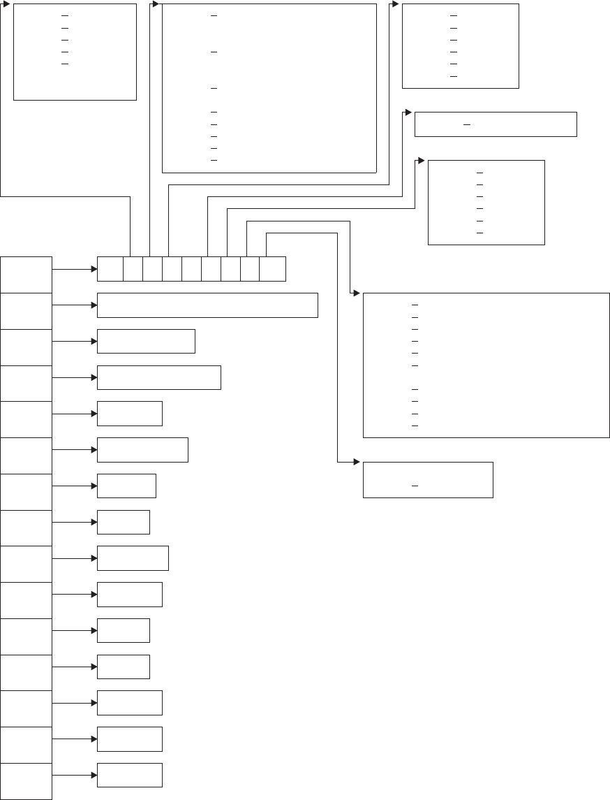
The command-level parameter structure
The command-level parameter structure consists of a series of addresses. The first
address points to the EXEC interface descriptor (EID), which consists of a 9-byte
X'02' ASKTIME X'80' INTERVAL|TIME X'80' RTERMID
X'04' DELAY - REQID (cancel) X'40' QUEUE
X'06' POST - A(INTO)|SET (retrieve) X'20' HOURS
X'08' START X'40' REQID X'10' MINUTES
X'0A' RETRIEVE - LENGTH (retrieve) X'08' SECONDS
X'0C' - CANCEL X'04' USERID
X'20' TRANSID (cancel|start)
- SET|INTO
X'10' FROM
X'08' LENGTH X'01' SET (not INTO)
X'04' TERMID
X'02' SYSID
X'01' RTRANSID X'20' HOURS
X'10' FMH
X'08' SECONDS
X'04' MINUTES
X'02' PROTECT
X'01' NOCHECK
ADDR0 10 .. .. .. 08 .. .. .. ..
ADDR1 interval|time|reqid|A(into)|set X'13' ASKTIME
X'20' DELAY
X'30' POST
ADDR2 reqid|length X'40' START(without data)
X'50' START(with FROM)
X'70' START(with RTRANSID|RTERMID
ADDR3 transid|set|into QUEUE or FMH)
X'82' RETRIEVE
X'08' WAIT(retrieve) or TIME
ADDR4 A(from) X'04' REQID
X'01' TERMID
ADDR5 data length
X'80' - FOR|AFTER
ADDR6 termid X'40' AT|UNTIL
ADDR7 sysid
ADDR8 rtransid
ADDR9 rtermid
ADDRA queue
ADDRB hours
ADDRC minutes
ADDRD seconds
ADDRE userid
Figure 1. The command-level parameter structure for interval control
interval control EXEC interface program exits
Chapter 1. Global user exit programs 137

area that describes the type of request and identifies each keyword specified with
the request. The remaining addresses point to pieces of data associated with the
request. For example, the second address points to the interval for START
requests.
You can examine the EID to determine the type of request and the keywords
specified. You can examine the other parameters in the list to determine the values
of the keywords. You can also modify values of keywords specified on the request.
For example, you could change the SYSID specified in the request.
End of parameter list indicator
The high-order bit is set on in the last address set in the parameter list to
indicate that it is the last one in the list. On return from your user exit program,
CICS scans the parameter list for the high-order bit to find the last parameter.
Therefore, if you modify the length of the parameter list, you must also reset
the high-order bit to indicate which is the new last address.
For example, if the parameter list specifies only the first four addresses
(IC_ADDR0, the address of the EID, to IC_ADDR3, the address of the name
of the transaction named in a START request), the high-order bit is set on in
IPC_ADDR3. If you extend the parameter list by setting the address of a
SYSID in IC_ADDR7, you must unset the high-order bit in IC_ADDR3 and set
it on in IC_ADDR7 instead.
The maximum size of parameter list is supplied to the exit, thus allowing your exit
program to add any parameters not already specified without needing to first obtain
more storage.
The original parameter list, as it was before XICEREQ was invoked, is restored
after the completion of XICEREQC. It follows that the execution diagnostic facility
(EDF) displays the original command before and after execution: EDF does not
display any changes made by the exit.
The UEPCLPS exit-specific parameter
The UEPCLPS exit-specific parameter is included in both exit XICEREQ and exit
XICEREQC. It is the address of the command-level parameter structure. The
command-level parameter structure contains 15 addresses, IC_ADDR0 through
IC_ADDRE. It is defined in the DSECT IC_ADDR_LIST, which you should copy into
your exit program by including the statement COPY DFHICUED.
The command-level parameter list is made up as follows:
IC_ADDR0
is the address of a 9-byte area called the EXEC interface descriptor (EID),
which is made up as follows:
IC_GROUP
IC_FUNCT
IC_BITS1
IC_BITS2
IC_BITS3
IC_EIDOPT5
IC_EIDOPT6
interval control EXEC interface program exits
138 CICS TS for OS/390: CICS Customization Guide
IC_EIDOPT7
IC_EIDOPT8
IC_GROUP
Always X'10', indicating that this is an interval control request.
IC_FUNCT
One byte that defines the type of request:
X'02' ASKTIME
X'04' DELAY
X'06' POST
X'08' START
X'0A' RETRIEVE
X'0C' CANCEL
IC_BITS1
Existence bits that define which arguments were specified. To obtain
the argument associated with a keyword, you need to use the
appropriate address from the command-level parameter structure.
Before using this address, you must check the associated existence bit.
If the existence bit is set off, the argument was not specified in the
request and the address should not be used.
X'80' Set if the request contains INTERVAL or TIME arguments, or if
a CANCEL request specifies REQID, or if a RETRIEVE request
specifies SET or INTO. If set, IC_ADDR1 is meaningful.
X'40' Set if the request other than CANCEL specifies REQID or if a
RETRIEVE request specifies LENGTH. If set, IC_ADDR2 is
meaningful.
X'20' Set if the request specifies TRANSID or if a request other than
RETRIEVE specifies SET or INTO. If set, IC_ADDR3 is
meaningful.
X'10' Set if the request specifies FROM. If set, IC_ADDR4 is
meaningful.
X'08' Set if a request other than RETRIEVE specifies LENGTH. If
set, IC_ADDR5 is meaningful.
X'04' Set if the request specifies TERMID. If set, IC_ADDR6 is
meaningful.
X'02' Set if the request specifies SYSID. If set, IC_ADDR7 is
meaningful.
X'01' Set if the request specifies RTRANSID. If set, IC_ADDR8 is
meaningful.
IC_BITS2
Further argument existence bits.
X'80' Set if the request specifies RTERMID. If set, IC_ADDR9 is
meaningful.
X'40' Set if the request specifies QUEUE. If set, IC_ADDRA is
meaningful.
interval control EXEC interface program exits
Chapter 1. Global user exit programs 139
X'20' Set if the request specifies HOURS. If set, IC_ADDRB is
meaningful.
X'10' Set if the request specifies MINUTES. If set, IC_ADDRC is
meaningful.
X'08' Set if the request specifies SECONDS. If set, IC_ADDRD is
meaningful.
X'04' Set if the request specifies USERID. If set, IC_ADDRE is
meaningful.
IC_BITS3
One byte not used by interval control.
IC_EIDOPT5
Indicates whether certain keywords were specified on the request.
X'01' On a RETRIEVE command, SET (and not INTO) was specified.
On a START command, ATTACH was specified. You cannot
modify this field in your user exit.
IC_EIDOPT6
Existence bits that indicate whether certain keywords were specified on
the request.
X'20' HOURS specified.
X'10' FMH specified.
X'08' SECONDS specified.
X'04' MINUTES specified.
X'02' PROTECT specified.
X'01' NOCHECK specified.
IC_EIDOPT7
Indicates whether certain functions or keywords were specified on the
request.
X'F0' CANCEL specified.
X'82' RETRIEVE specified.
X'40' START specified.
X'30' POST specified.
X'20' DELAY, RTRANSID, RTERMID, or QUEUE specified, and/or
FMH.
X'13' ASKTIME specified.
X'10' FROM, RTRANSID, or RTERMID specified, and/or QUEUE.
X'08' TIME or WAIT specified.
X'04' REQID specified.
X'01' TERMID specified.
IC_EIDOPT8
Indicates whether certain keywords were specified on the request.
X'80' FOR or AFTER specified.
X'40' AT or UNTIL specified.
interval control EXEC interface program exits
140 CICS TS for OS/390: CICS Customization Guide
IC_ADDR1
is the address of one of the following:
vAn 8-byte area containing the value of the INTERVAL keyword (or TIME
keyword if IC_EIDOPT7 indicates that TIME is specified).
vAn 8-byte area containing the value of REQID (if the request is CANCEL).
vData returned for INTO (if the request is RETRIEVE, and if IC_EIDOPT5
indicates that this is not SET).
vA 4-byte address returned for SET (if the request is RETRIEVE and
IC_EIDOPT5 indicates that this is SET).
IC_ADDR2
is the address of one of the following:
vAn 8-byte area containing the value of REQID (if the request is DELAY,
POST or START).
vA halfword containing the value of LENGTH (if the request is RETRIEVE).
Warning: For requests that specify INTO, do not change the value of
LENGTH to a value greater than that specified by the application. To do so
causes a storage overlay in the application.
IC_ADDR3
is the address of one of the following:
vAn area containing the value of TRANSID (if the request is CANCEL or
START).
vA 4-byte address returned for SET (if the request is START or POST and
IC_EIDOPT5 indicates that this is SET).
IC_ADDR4
is the address of an area containing the data from FROM.
IC_ADDR5
is the address of the halfword value of LENGTH.
Warning: For requests that specify INTO, do not change the value of LENGTH
to a value greater than that specified by the application. To do so causes a
storage overlay in the application.
IC_ADDR6
is the address of an area containing the value of TERMID.
IC_ADDR7
is the address of an area containing the value of SYSID.
IC_ADDR8
is the address of an area containing the value of RTRANSID.
IC_ADDR9
is the address of an area containing the value of RTERMID.
IC_ADDRA
is the address of an area containing the value of QUEUE.
IC_ADDRB
is the address of an area containing the value of HOURS.
IC_ADDRC
is the address of an area containing the value of MINUTES.
IC_ADDRD
is the address of an area containing the value of SECONDS.
interval control EXEC interface program exits
Chapter 1. Global user exit programs 141
IC_ADDRE
is the address of an area containing the value of USERID.
Modifying fields in the command-level parameter structure
Some fields that are passed to interval control are used as input to the request,
some are used as output fields, and some are used for both input and output. The
method your user exit program uses to modify a field depends on the usage of the
field.
The following are always input fields:
INTERVAL
TIME
REQID
FROM
TERMID
SYSID
HOURS
MINUTES
SECONDS
USERID
The following are always output fields:
INTO
SET
The following are input fields on a START request and output fields on a
RETRIEVE request:
RTRANSID
RTERMID
QUEUE
LENGTH is an input field on a START request, an output field on a RETRIEVE with
SET specified, and an input/output field on a RETRIEVE with INTO specified.
Modifying input fields
The correct method of modifying an input field is to create a new copy of it, and to
change the address in the command-level parameter list to point to your new data.
Note: You must never modify an input field by altering the data that is pointed to by
the command-level parameter list. To do so would corrupt storage belonging
to the application program and would cause a failure when the program
attempted to reuse the field.
Modifying output fields
The technique described in “Modifying input fields” is not suitable for modifying
output fields. (The results would be returned to the new area instead of the
application’s area, and would be invisible to the application.)
interval control EXEC interface program exits
142 CICS TS for OS/390: CICS Customization Guide
An output field is modified by altering the data that is pointed to by the
command-level parameter list. In the case of an output field, you can modify the
application’s data in place, because the application is expecting the field to be
modified anyway.
Modifying the EID
It is not possible to modify the EID to make major changes to requests, such as
changing a DELAY request to a START request.
However, you can make minor changes to requests, such as turning on the
existence bit for SYSID so that the request can be changed into one that is shipped
to a remote system.
Some interval control commands use 2 bits in the EID to indicate a single keyword;
the EXEC CICS START command, for example, uses 2 bits to indicate TERMID.
The first bit, in IC_BITS1, indicates that ADDR6 in the command parameter list is
valid (ADDR6 points to TERMID) and the second, in IC_EIDOPT7, is the keyword
existence bit to show that the TERMID keyword was specified on the command.
Where this occurs you must ensure that both bit settings are changed (consistently)
if you wish to modify these commands from within a user exit program, or the
results will be unpredictable.
The list that follows shows the bits in the EID that can be modified. Any attempt to
modify any other part of the EID is ignored.
IC_BITS1
X'80' The existence bit for REQID (if the request is CANCEL)
X'40' The existence bit for LENGTH (if the request is RETRIEVE) or REQID
X'10' The existence bit for FROM
X'08' The existence bit for LENGTH
X'04' The existence bit for TERMID
X'02' The existence bit for SYSID
X'01' The existence bit for RTRANSID.
IC_BITS2
X'80' The existence bit for RTERMID
X'40' The existence bit for QUEUE
X'20' The existence bit for HOURS
X'10' The existence bit for MINUTES
X'08' The existence bit for SECONDS.
IC_EIDOPT6
X'20' The secondary existence bit for HOURS
X'10' The existence bit for FMH
X'08' The secondary existence bit for SECONDS
X'04' The secondary existence bit for MINUTES
X'02' The existence bit for PROTECT
interval control EXEC interface program exits
Chapter 1. Global user exit programs 143
X'01' The existence bit for NOCHECK.
IC_EIDOPT7
Bits in IC_EIDOPT7 should only be modified within the same functional group -
that is, only those existence bits defined as valid for a START request should
be set on a START request.
ASKTIME requests
X'13' ASKTIME request. This value is fixed for all ASKTIME requests, and
should not be modified.
DELAY requests
X'20' DELAY request
X'08' TIME specified
X'04' REQID specified.
POST requests
X'30' POST request
X'08' TIME specified
X'04' REQID specified.
START requests
X'40' START request (without DATA)
X'50' START with DATA request
X'70' START with one or more of RTRANSID, RTERMID, QUEUE, or FMH
specified.
X'08' TIME specified
X'04' REQID specified
X'01' TERMID specified.
RETRIEVE requests
X'82' RETRIEVE request.
CANCEL requests
X'F0' CANCEL request
X'04' REQID specified.
The EID is reset to its original value before return to the application program. That
is, changes made to the EID are retained for the duration of the interval control
request only.
Note: Your user exit program is prevented from making major changes to the EID.
However, you must take great care when making the minor modifications
that are permitted.
Using the interval control request token UEPICTOK
UEPICTOK provides the address of a 4-byte area that you can use to pass
information between the XICEREQ and XICEREQC user exits for the same interval
control request. For example, the address of a piece of storage obtained by the
XICEREQ user exit, which is to be freed by the XICEREQC exit, can be passed in
the UEPICTOK field.
interval control EXEC interface program exits
144 CICS TS for OS/390: CICS Customization Guide
Using the task token UEPTSTOK
UEPTSTOK provides the address of a 4-byte area that you can use to pass
information between successive interval control requests in the same task. (By
contrast, UEPICTOK is usable only for the duration of a single interval control
request, because its contents may be destroyed at the end of the request.) For
example, if you need to pass information between successive invocations of the
XICEREQ exit, UEPTSTOK provides a means of doing this.
The EIB
Copies of EIBRSRCE, EIBRCODE, EIBRESP, and EIBRESP2 are passed to the
exit, so that you can:
vModify or set completion and resource information in XICEREQ and XICEREQC
vExamine completion and resource information in XICEREQC.
You can update the copies of EIBRSRCE, EIBRCODE, EIBRESP, and EIBRESP2
that you are given in the parameter list. Interval control copies your values into the
real EIB after the completion of XICEREQC; or if you specify a return code of
‘bypass’ in XICEREQ.
You must set valid interval control responses. You must set all three of EIBRCODE,
EIBRESP, and EIBRESP2 to a consistent set of values, such as would be set by
CICS interval control to describe a valid completion. CICS does not police the
consistency of EIBRCODE, EIBRESP, and EIBRESP2. However, if EIBRCODE is
set to a non-zero value and EIBRESP is set to zero, CICS overrides EIBRESP with
a non-zero value. To aid you in setting the values of EIBRCODE, EIBRESP, and
EIBRESP2, the values used by interval control are specified in DFHICUED.
Example of how XICEREQ and XICEREQC can be used
XICEREQ and XICEREQC can be used for a variety of purposes. One example of
a possible use is given below.
In this example, XICEREQ and XICEREQC are used to route START requests to a
number of different CICS regions to provide a simple load balancing mechanism.
The example shows only the capabilities of the exits; it is not intended to indicate
an ideal way of achieving the function.
In XICEREQ:
1. Scan the global work area (GWA) to locate a suitable CICS region (for
example, the region currently processing the least number of START
requests).
2. Having decided which system to route the request to, increment the use
count for this system.
3. Obtain a 4-byte area in which to store the SYSID for this request. This
can be allocated from the GWA to avoid issuing a GETMAIN. If the area
is obtained by issuing a GETMAIN, set UEPICTOK to the address of
the storage obtained.
4. Set IC_ADDR7 to be the address of the 4-byte area so that XICEREQC
can also use this area.
5. If setting IC_ADDR7 now makes it the last address, set the high-order
bit in the address, and reset the high-order bit in what was previously
the last address.
interval control EXEC interface program exits
Chapter 1. Global user exit programs 145

6. Set the X'02' existence bit on in IC_BITS1 to indicate that a SYSID is
specified.
7. Return to CICS.
In XICEREQC:
1. Scan the global work area (GWA) and locate the entry for the CICS
region specified in the SYSID parameter.
2. Decrement the use count for this system.
3. If a GETMAIN was issued in XICEREQ to obtain an area to hold the
SYSID, issue a FREEMAIN for the address held in UEPICTOK.
4. Return to CICS.
Example and sample programs
CICS supplies two programs for use at the XICEREQ exit:
vDFH$XTSE, supplied in hardcopy only, is an example program that shows
how to modify fields in the command-level parameter structure passed to all
the EXEC interface exits. DFH$XTSE is listed on page 807.
vDFH$ICCN is a sample program for use in a distributed routing
environment, where you want to cancel a previously-issued interval control
request but have no way of knowing to which region to direct the CANCEL.
For examples of situations which DFH$ICCN is designed to cope with, see
the
CICS Intercommunication Guide
.
interval control EXEC interface program exits
146 CICS TS for OS/390: CICS Customization Guide
|
|
|
|
|
|
|
|
||

Loader domain exits XLDLOAD and XLDELETE
There are two global user exits in the loader domain. XLDLOAD is invoked when a
new instance of a program is loaded into storage, before the program is made
available for use.
XLDELETE is invoked after an instance of a program is released by CICS and
before the program is freed from storage.
For LPA-resident programs, the exits are still invoked when a program is acquired
or released, even though the program is not physically loaded or freed.
These are both information-only exits. Any changes made to the exit parameters by
the exit program are ignored by CICS, as is any return code which it sets.
Exit XLDLOAD
When invoked
After an instance of a program is brought into storage, and before the
program is made available for use.
Exit-specific parameters
UEPPROGN
Address of an 8-character field containing the name of the program
that is being loaded.
UEPPROGL
Address of a 4-byte field containing the length, in bytes, of the
program that is being loaded.
UEPLDPT
Address of a 4-byte field containing the address at which the
program has been loaded.
UEPENTRY
Address of a 4-byte field containing the address of the program’s
entry point.
UEPTRANID
Zero, or the address of a 4-byte field containing the transaction ID
which applied when the exit was invoked.
UEPUSER
Zero, or the address of an 8-byte field containing the userid in
control at the time the exit was invoked.
UEPTERM
Zero, or the address of a 4-byte field containing the terminal name
associated with the transaction under which the exit was invoked.
UEPPROG
Zero, or the address of an 8-character field containing the name of
the program that was in control at the time the exit was invoked.
Return codes
UERCNORM
Continue processing.
loader domain exits
Chapter 1. Global user exit programs 147
|
|
|
|
|
|
|
|
|
|
|
|
|
|
|
|
|
|
|
|
|
|
|
|
|
|
|
|
|
|
|
|
|
|
|
|
|
|
|
|
|
|
|
XPI calls
Must not be used.
API and SPI calls
Must not be used.
Exit XLDELETE
When invoked
After an instance of a program is released by CICS, and before the
program is freed from storage.
Exit-specific parameters
UEPPROGN
Address of an 8-character field containing the name of the program
that is being freed.
UEPPROGL
Address of a 4-byte field containing the length, in bytes, of the
program that is being freed.
UEPLDPT
Address of a 4-byte field containing the address at which the
program resides in storage.
UEPENTRY
Address of a 4-byte field containing the address of the program’s
entry point.
UEPTRANID
Zero, or the address of a 4-byte field containing the transaction ID
which applied when the exit was invoked.
UEPUSER
Zero, or the address of an 8-byte field containing the userid in
control at the time the exit was invoked.
UEPTERM
Zero, or the address of a 4-byte field containing the terminal name
associated with the transaction under which the exit was invoked.
UEPPROG
Zero, or the address of an 8-character field containing the name of
the program that was in control at the time the exit was invoked.
Return codes
UERCNORM
Continue processing.
XPI calls
Must not be used.
API and SPI calls
Must not be used.
loader domain exits
148 CICS TS for OS/390: CICS Customization Guide
|
|
|
|
|
|
|
|
|
|
|
|
|
|
|
|
|
|
|
|
|
|
|
|
|
|
|
|
|
|
|
|
|
|
|
|
|
|
|
|
|

Log manager domain exit XLGSTRM
There is one exit point, XLGSTRM, in the log manager domain.
You can use XLGSTRM to modify a request to MVS to create a new log stream.
You can change the model log stream name and other parameters before they are
passed to the MVS system logger.
If a log stream connection request from CICS to the MVS system logger fails
because the log stream is not defined to MVS, CICS issues a request to the MVS
system logger to create the log stream dynamically, using a model log stream
definition.
The model log stream name that CICS passes to MVS depends on whether the
journal name refers to the system log or a CICS general log, as follows:
CICS system logs
sysname
.DFHLOG.MODEL—for example, MV10.DFHLOG.MODEL.
CICS general logs
LSN_qualifier_1.LSN_qualifier2.MODEL. The defaults for these two
qualifiers are the CICS region userid and the CICS region APPLID, but they
can be user-defined values specified in a JOURNALMODEL resource
definition.
For example, if the CICS region userid is CICSHT## and the APPLID is
CICSHTA1, the default model name is CICSHT##.CICSHTA1.MODEL.
The following information is passed to an XLGSTRM global user exit program:
vActual log stream name
vDefault model log stream name
vSystem log flag
vMVS system logger IXGINVNT parameter list.
The exit can amend the model stream name by updating UEPMLSN. Use the
IXGINVNT MF=M form which allows the exit to override other MVS system logger
options from the model log stream, allowing for even greater flexibility.
Here is an example of how your exit program can change the structure name:
L R9,UEPIXG
IXGINVNT REQUEST=DEFINE,
TYPE=LOGSTREAM,
STRUCTNAME=NEW_STRUCTURE,
MF=(M,(R9),NOCHECK)
...
NEW_STRUCTURE DC CL16'LOG_SYSTEST_009'
Here is an example of how your exit program can change the model stream name:
L R3,UEPMLSN R3 = address of stream name
MVC 0(26,R3),=CL26'NEW.MODEL.NAME'
You do not need to code the list and execute forms of the macro or include the
IXGCON or IXGANSAA macros in your exit—these are provided by the CICS code
which actually issues the DEFINE request.
For information about the IXGINVNT service, see the
OS/390 MVS Authorized
Assembler Services Reference ALE-DYN
manual.
log manager domain exit
Chapter 1. Global user exit programs 149
An XLGSTRM global user exit program can set explicit attributes for the log stream
definition, and can also set a return code that causes the log stream definition to be
bypassed.
Exit XLGSTRM
When invoked
After the CICS log manager detects that a log stream does not exist and
before calling the MVS system logger to define the log stream dynamically.
Exit-specific parameters
UEPTRANID
The address of the 4-byte transaction id.
UEPUSER
The address of the 8-byte userid associated with the transaction if
the current task is a user task.
UEPTERM
The address of the 4-byte terminal id associated with the
transaction, if any.
UEPPROG
The address of the 8-byte application program name for this
transaction, if any.
UEPLSN
Address of a 26-character field specifying the log stream name that
is to be defined.
UEPMLSN
Address of a 26-character field specifying the name of model log
stream to be used to provide the attributes for the new log stream.
This field is modifiable to allow the global user exit program to
specify a different model log stream name from the one generated
by CICS.
UEPIXG
Address of the IXGINVNT macro parameter list for use by the MVS
system logger to define the log stream. Using the MF=M form of the
IXGINVNT macro, the global user exit program can specify the log
stream attributes to be used.
For details of the IXGINVNT macro, see the
OS/390 MVS
Authorized Assembler Services Reference ALE-DYN
manual.
UEPLGTYP
Address of a 1-byte field indicating whether the log stream being
created is for a system log or a general log. Valid values are:
UEPSYSLG
The log stream is for a CICS system log.
UEPGENLG
The log stream is for a general log (a forward recovery log,
a user journal, or auto-journal).
Return codes
UERCNORM
CICS continues and attempts to define the log stream.
log manager domain exit
150 CICS TS for OS/390: CICS Customization Guide
UERCBYP
CICS does not attempt to define the log stream. The process that
was attempting to use the log stream may fail (for example, a data
set open).
XPI calls
All can be used.
API and SPI commands
Must not be used.
An example of how XLGSTRM can be used
Imagine that you have 200 CICS regions, running on, say, 20 MVS images. To
avoid having to define explicitly each log stream used by each CICS region, you
decide to use model definitions. Log streams will be defined to MVS dynamically on
their first usage, with an XLGSTRM exit program being used to select from
alternative model log streams. This is how it might work:
1. On an intitial start of a CICS region, the INITPARM system intialization
parameter specifies:
INITPARM=(Exit_enabler_pgmname=nnn)
where:
vExit_enabler_pgmname is the name of the program that enables the
XLGSTRM user exit program.
vnnn is a number that identifies the CICS region.
2. The program that enables the XLGSTRM user exit program issues an EXEC
CICS ASSIGN INITPARM command to retrieve the value nnn, and places it in
the exit program’s global work area.
3. When the region tries to connect to its system log, because the log stream is
not defined the XLGSTRM exit program is invoked. The exit program selects
model CICS.DFHLOG.MODELnnn.
log manager domain exit
Chapter 1. Global user exit programs 151

Message domain exit XMEOUT
The XMEOUT exit allows you to suppress or reroute CICS messages that use the
message domain.
Note that your exit program is subject to certain restrictions:
vIt cannot suppress or reroute messages sent to terminal operators, but only
those sent to the system console or to transient data queues. (XMEOUT is not
invoked for the former type of message.)
vIt can only suppress or reroute messages that use the message domain. You
can deduce which messages this applies to from the
CICS Messages and Codes
manual: the description of each message that causes XMEOUT to be driven
contains a list of “XMEOUT parameters”; if no XMEOUT parameters are listed for
a message, the latter does not cause the exit to be driven. For example,
message ‘DFHDX8320’ causes XMEOUT to be invoked, but message
‘DFHDU0205’ does not.
vIt cannot change the text of a message, nor the message inserts. (If it tries to do
so, CICS ignores the changes.)
vIt cannot suppress or reroute messages issued during the early stages of CICS
initialization (because the exit cannot be enabled then).
vIt cannot reroute a message to transient data queues during CICS shutdown
unless the original message destination included one or more transient data
queues. If it attempts to do so, the message in question is routed to its original
destination, and message DFHME0120I is issued to the console. Message
DFHME0120I cannot be re-routed by the user exit program but it may be
suppressed.
This restriction is necessary because the message domain is required to handle
messages during CICS shutdown even after the transient data queue function
has ended.
To discover whether CICS shutdown has started, your exit program can check for
the first instance of message DFHME0120. It can stop rerouting messages to TD
queues after DFHME0120 has been issued.
Note: If a message is being rerouted to a transient data queue and the transient
data request fails, the message is lost. The MEME exception trace point ID
X’0328’ is written. The interpretation string of this trace entry provides an
explanation of why the transient data request failed.
message domain exit
152 CICS TS for OS/390: CICS Customization Guide

Important
Because of the danger of recursion, your XMEOUT exit program should not
try to reroute:
vAny DFHTDxxxx messages, produced by the transient data program.
vUser domain messages in the range DFHUS0002-DFHUS0006, plus
message DFHUS0150.
vTransaction manager messages DFHXM0212, DFHXM0213, DFHXM0304
and DFHXM0308.
vApplication messages DFHAP0001, DFHAP0002, DFHAP0004,
DFHAP0601, DFHAP0602, and DFHAP0603.
v
Any
user domain (DFHUSxxxx) messages to an intrapartition queue defined
with a TRIGLEV value of anything other than zero, if the messages are
produced while the user domain is performing error recovery processing.
The message definition template contains an indicator called “noreroute”. This
indicator is set on if the message being issued cannot be rerouted to a
transient data queue by the XMEOUT exit program. The address of the
indicator is passed to XMEOUT in the UEPNRTE exit-specific parameter. Your
exit program can check the value of the indicator before deciding whether or
not to reroute a particular message.
Note: If the exit program tries to reroute an ineligible message, the message
domain inhibits the rerouting and issues the message to the console
instead, along with message DFHME0137.
Each of the messages affected by this restriction is identified by a note in the
CICS Messages and Codes
manual.
Your exit program can suppress or reroute messages by altering the values held in
the addresses pointed to by the UEPMROU, UEPMNRC, UEPMTDQ, and
UEPMNTD fields of the parameter list. These four sets of values (route codes,
number of route codes, transient data queue names, and number of TDQs) are the
only ones that your program can change.
Exit XMEOUT
When invoked
Before the message domain sends a CICS message to its destination.
Exit-specific parameters
UEPTRANID
Address of the 4-byte transaction ID.
UEPUSER
Address of the 8-byte user ID.
UEPTERM
Address of the 4-byte ID of the terminal under which the current
transaction is running. If the current transaction is not associated
with a terminal, the addressed field contains hexadecimal zeroes.
UEPPROG
Address of the 8-byte application program name, or nulls if there is
no current application.
message domain exit
Chapter 1. Global user exit programs 153
UEPMNUM
Address of a 4-byte field containing the message number.
UEPMDOM
Address of a 2-byte field containing the domain identifier of the
CICS message.
UEPMROU
Address of an array of up to 28 route codes. Route codes must be
numbers in the range 1 through 28.
UEPMNRC
Address of a halfword containing the number of route codes in the
route code array.
UEPMTDQ
Address of an array of up to 25 transient data queue names to
which the message is to be sent. TD queue names must consist of
4 alphanumeric characters.
UEPMNTD
Address of a halfword containing the number of TDQs in the
queues array.
UEPINSN
Address of a 2-byte field containing the number of message inserts.
UEPINSA
Address of an array, each element of which contains information
about a single message insert. The size of the array depends on
the number of inserts. Each array element has the following
structure:
INSERT_FORMAT_P DS A Address of the 1-byte insert
type-code, which has one of
the following hexadecimal values:
0 Not present
1 Character
2 Hexadecimal
3 Decimal
4 The insert is a number
representing one item in
a list of options.
(See the example below.)
INSERT_P DS A Address of the message insert
INSERT_LENGTH_P DS A Address of a fullword contain-
ing the length of the insert
INSERT_TYPE_P DS A Reserved.
You can find the order of the inserts in the array from the entry for the
particular message in the
CICS Messages and Codes
manual. For
example,
DFHFC0531
date time applid
Automatic journal
journal
journalname
, opened for file
filename
is not of
type MVS. Module
module
.
The XMEOUT inserts are
date, time, applid
,
journal
,
journalname
,
filename
,
and
module
. The fourth insert (
journal
) is the number specified for
JOURNAL on the file definition.
message domain exit
154 CICS TS for OS/390: CICS Customization Guide
UEPNRTE
Address of 1-character flag indicating whether or not the message
can be rerouted by XMEOUT. The possible values are:
C'0:' The message can be routed.
C'1:' The message cannot be routed.
Return codes
UERCNORM
Continue processing.
UERCBYP
Suppress the message for all destinations.
XPI calls
WAIT_MVS can be used. Do not use any other calls.
The sample XMEOUT global user exit programs
CICS supplies the following sample programs, which show you how to use the
XMEOUT exit to suppress or reroute messages:
DFH$SXP1
Suppress a message by message number
DFH$SXP2
Suppress a message by destination route code
DFH$SXP3
Suppress a message destined for the CSCS transient data queue (which
receives signon and sign-off messages)
DFH$SXP4
Reroute a console message to a TDQ
DFH$SXP5
Reroute a TDQ message to another TDQ
DFH$SXP6
Reroute a TDQ message to a console.
message domain exit
Chapter 1. Global user exit programs 155

Monitoring domain exit XMNOUT
XMNOUT is invoked before an exception class monitoring record is passed to SMF,
and before a performance class monitoring record is written to the performance
record buffer. You can use this exit to examine the record, to suppress its output to
SMF, or to change the data it contains. You must be ensure that any changes you
make do not conflict with the dictionary description of the data.
You can also add data to performance class data records. To do this you need to
define dummy user event-monitoring points (EMPs) in the monitoring control table
(MCT) to reserve data fields of the required size and type.
Exit XMNOUT
When invoked
Before an exception class monitoring record is written to SMF, and before a
performance class monitoring record is buffered for a later write to SMF.
Exit-specific parameters
UEPTRANID
Address of the 4-byte transaction ID. This field is not available at
task termination.
UEPUSER
Address of the 8-byte user ID. This field is not available at task
termination.
UEPTERM
Address of the 4-byte terminal ID. This field is not available at task
termination.
UEPPROG
Address of the 8-byte application program name. This field is not
available at task termination.
UEPDICT
Address of the dictionary. The sequence of dictionary entries is
mapped by the DSECT generated from the macro DFHMCTDR.
This field only has meaning for performance class records. If the
monitoring record type is exception class (see parameter
UEPMRTYP), this field is set to 0.
UEPDICTE
Address of the fullword number of dictionary entries. This field only
has meaning for performance class records. If the monitoring record
type is exception class (see parameter UEPMRTYP), this field is set
to 0.
UEPFCL
Address of the field connector list, containing a series of halfword
connector values. This field only has meaning for performance class
records. If the monitoring record type is exception class (see
parameter UEPMRTYP), this field is set to 0.
UEPFCLNO
Address of the fullword number of field connectors. This field only
has meaning for performance class records. If the monitoring record
type is exception class (see parameter UEPMRTYP), this field is set
to 0.
monitoring domain exit
156 CICS TS for OS/390: CICS Customization Guide
UEPMRTYP
Address of the halfword monitoring record type. If the value is 3,
the type is performance class. If the value is 4, the type is
exception class.
UEPMRLEN
Address of the fullword monitoring record length.
UEPMREC
Address of monitoring record, whose length is addressed by the
parameter UEPMRLEN.
UEPSRCTK
Address of the MVS workload manager service reporting class
token for the current transaction. If CICS support for MVS workload
management is not available, this token is null.
UEPMPREC
Address of the monitoring performance record. This field has
meaning only for performance class records. If the monitoring
record type is exception class (see the UEPMRTYP parameter), this
field is set to 0. The performance record addressed by this
parameter must be mapped using the DFHMNTDS dsect, and must
not be mapped using the UEPDICT and UEPDICTE dictionary
parameters.
Return codes
UERCNORM
Continue processing.
UERCBYP
Suppress monitor record output.
UERCPURG
Task purged during XPI call.
XPI calls
WAIT_MVS can be used. Do not use any other calls.
monitoring domain exit
Chapter 1. Global user exit programs 157

Program control program exits XPCREQ, XPCREQC, XPCFTCH,
XPCHAIR, XPCTA, and XPCABND
There are six user exit points in the program control program.
XPCREQ and XPCREQC
XPCREQ is invoked by the EXEC interface program before a link request is
processed. If the request is a distributed program link, the XPCREQ exit is driven
on both sides of the link; that is, in both the client and the server regions. The exit
program is passed the address of the application’s parameter list (in UEPCLPS),
and can modify this as required. For example, you can use this exit to modify the
SYSID at the time of a distributed program link request. One way you can achieve
this is to write an application program to manage a list of SYSIDs in a global work
area (GWA). The global user exit program can obtain access to the GWA, and use
the information stored there to redirect DPL requests.
XPCREQC is invoked after the link request is completed. You can use this exit to
pass back a response to the application via the EIBRESP or EIBRESP2 fields.
Such responses could be used to keep status information about a link request
up-to-date. For example, if a link request fails because a connection is unavailable,
XPCREQC could set EIBRESP=500 (a response code not used by CICS) to
indicate the failure, enabling the application, in conjunction with the other exit,
XPCREQ, to determine a suitable course of action.
Exit XPCREQ
When invoked
By the EXEC interface program before a link request is processed.
Exit-specific parameters
UEPCLPS
Address of the command parameter list.
UEPPCTOK
Address of a 4-byte token to be passed to XPCREQC. This allows
you, for example, to pass a work area to exit XPCREQC.
UEPRCODE
Address of a 6-byte hexadecimal copy of EIBRCODE.
UEPRECUR
Address of a halfword recursion counter. The counter is set to 0
when the exit is first invoked, and is incremented for each recursive
call.
UEPRESP
Address of a 4-byte copy of EIBRESP.
UEPRESP2
Address of a 4-byte copy of EIBRESP2.
UEPTSTOK
Address of a 4-byte token that is valid throughout the life of a task.
See “Using the task token UEPTSTOK” on page 163.
UEPRSRCE
Address of an 8-character copy of the EIB resource value,
EIBRSRCE.
program control program exits
158 CICS TS for OS/390: CICS Customization Guide
Return codes
UERCBYP
Program control is to ignore the request.
UERCNORM
Continue processing.
UERCPURG
Task purged during XPI call.
XPI calls
All can be used.
Although the exit permits the use of XPI GETMAIN and FREEMAIN calls,
we recommend that you use the EXEC CICS GETMAIN and FREEMAIN
commands instead.
API and SPI calls
All can be used.
Exit XPCREQC
When invoked
On completion of a program control link request.
Exit-specific parameters
UEPCLPS
Address of the command parameter list.
UEPPCTOK
Address of a 4-byte token passed from XPCREQ. This allows
XPCREQ to, for example, pass a work area to XPCREQC.
UEPRCODE
Address of a 6-byte hexadecimal copy of EIBRCODE.
UEPRECUR
Address of a halfword recursion counter. The counter is set to 0
when the exit is first invoked, and is incremented for each recursive
call.
UEPRESP
Address of a 4-byte copy of EIBRESP.
UEPRESP2
Address of a 4-byte copy of EIBRESP2.
UEPTSTOK
Address of a 4-byte token that is valid throughout the life of a task.
See “Using the task token UEPTSTOK” on page 163.
UEPRSRCE
Address of an 8-character copy of the EIB resource value,
EIBRSRCE.
Return codes
UERCNORM
Continue processing.
UERCPURG
Task purged during XPI call.
program control program exits
Chapter 1. Global user exit programs 159

XPI calls
All can be used.
Although the exit permits the use of XPI GETMAIN and FREEMAIN calls,
we recommend that you use the EXEC CICS GETMAIN and FREEMAIN
commands instead.
API and SPI calls
All can be used.
Note: Take care when issuing recursive commands not to cause a loop. For
example, it is your responsibility to avoid entering a loop when a program
control request is issued from the XPCREQ or XPCREQC exits.
Use of the recursion counter UEPRECUR is recommended.
The command parameter structure
The command parameter structure consists of a series of addresses. The first
address points to the EXEC interface descriptor (EID), which consists of a bit string
that describes the type of request and identifies each keyword specified with the
request. The remaining addresses point to pieces of data associated with the
request; for instance, the second address always points to the program name. You
can examine the parameters in the list to determine the values of the keywords.
You can also modify values of parameters specified on the request. For example,
you could change the name of the program involved in the request, or add the
SYSID to route the link request to a remote system.
End of parameter list indicator
The high-order bit is set on in the last address set in the parameter list to
indicate that it is the last one in the list. On return from your user exit program,
CICS scans the parameter list for the high-order bit to find the last parameter.
Therefore, if you modify the length of the parameter list, you must also reset
the high-order bit to indicate which is the new last address.
For example, if the parameter list specifies only the first two addresses
(PC_ADDR0, the address of the EID, and PC_ADDR1, the address of the
name of the program named in the link request), the high-order bit is set on in
PC_ADDR1. If you extend the parameter list by setting the address of a
SYSID in PC_ADDR7, you must unset the high-order bit in PC_ADDR1 and
set it on in PC_ADDR7 instead.
The original parameter list, as it was before XPCREQ was invoked, is restored after
the completion of XPCREQC. It follows that EDF will display the original command
before and after execution: EDF will not display any changes made by the exit.
The UEPCLPS exit-specific parameter:
The UEPCLPS exit-specific parameter is
included in both exit XPCREQ and exit XPCREQC. It is the address of the
command-level parameter structure. The command-level parameter structure
contains 9 addresses, PC_ADDR0 through PC_ADDR8. It is defined in the DSECT
PC_ADDR_LIST, which you should copy into your exit program by including the
statement COPY DFHPCEDS.
The command-level parameter list is made up as follows:
program control program exits
160 CICS TS for OS/390: CICS Customization Guide
PC_ADDR0
is the address of a 7-byte area called the EXEC interface descriptor (EID),
which is made up as follows:
PC_GROUP
PC_FUNCT
PC_BITS1
PC_BITS2
PC_EIDOPT5
PC_EIDOPT6
PC_GROUP
Always X'0E', indicating that this is a program control request.
PC_FUNCT
One byte which defines the type of request, which for XPCREQ and
XPCREQC is always X'02', indicating a LINK request.
PC_BITS1
Existence bits that define which keywords that contain values were
specified. To obtain the value associated with a keyword, you need to
use the appropriate address from the command-level parameter list.
Before using this address you must check the associated existence bit
to ensure that the address is valid. If the existence bit is set off, the
keyword was not specified in the request and the address should not be
used. The symbolic and hexadecimal values of the existence bits are as
follows:
PC_EXIST1 (X'80')
Set if the request contains the keyword PROGRAM. If set,
PC_ADDR1 is meaningful. (This bit should always be set for a
LINK request.)
PC_EXIST2 (X'40')
Set if the request specifies the COMMAREA parameter. If set,
PC_ADDR2 is meaningful.
PC_EXIST3 (X'20')
Set if the request specifies the LENGTH parameter. If set,
PC_ADDR3 is meaningful.
PC_EXIST4 (X'10')
Set if the request specifies the INPUTMSG parameter. If set,
PC_ADDR4 is meaningful.
PC_EXIST5 (X'08')
Set if the request specifies the INPUTMSGLEN parameter. If
set, PC_ADDR5 is meaningful.
PC_EXIST6 (X'04')
Set if the request specifies the DATALENGTH parameter. If set,
PC_ADDR6 is meaningful.
PC_EXIST7 (X'02')
Set if the request specifies the SYSID parameter. If set,
PC_ADDR7 is meaningful.
PC_EXIST8 (X'01')
Set if the request specifies the TRANSID parameter. If set,
PC_ADDR8 is meaningful.
program control program exits
Chapter 1. Global user exit programs 161
PC_BITS2
Two bytes not used by program control.
PC_EIDOPT5
Not used by program control.
PC_EIDOPT6
Indicates whether the request specifies the SYNCONRETURN option. If
it does, X'80' is set.
PC_ADDR1
is the address of an 8-byte area containing the program name from the
PROGRAM parameter.
PC_ADDR2
is the address of the COMMAREA data.
PC_ADDR3
is the address of a 2-byte area containing the length of the COMMAREA, as a
half-word binary value.
PC_ADDR4
is the address of the INPUTMSG data.
PC_ADDR5
is the address of a 2-byte area containing the length of the INPUTMSG, as a
half-word binary value.
PC_ADDR6
is the address of a 2-byte area containing the length specified on the
DATALENGTH parameter, defining how much data is to be sent from the
COMMAREA. The length is held as a half-word binary value.
PC_ADDR7
is the address of the 4-byte name of the remote system the LINK request is to
be shipped to, as specified on the SYSID parameter.
PC_ADDR8
is the address of the 4-byte name of the mirror transaction to be attached in the
remote system, as specified on the TRANSID parameter.
Modifying fields in the command parameter structure
Some fields that are passed to program control are used as input to the request,
some are used as output fields, and some are used for both input and output. The
method your user exit program uses to modify a field depends on the usage of the
field.
Modifying input fields:
The correct method of modifying an input field is to create
a new copy of it, and to change the address in the command parameter list to point
to your new data.
Note: You must never modify an input field by altering the data that is pointed to by
the command parameter list. To do so would corrupt storage belonging to the
application program and could cause a failure when the program attempted
to reuse the field.
Modifying output fields:
The technique described in “Modifying input fields” is not
suitable for modifying output fields. (The results would be returned to the new area
instead of the application’s area, and would be invisible to the application.)
program control program exits
162 CICS TS for OS/390: CICS Customization Guide
An output field is modified by altering the data that is pointed to by the
command-level parameter list. In the case of an output field you can modify the
application’s data in place, because the application is expecting the field to be
modified anyway.
Modifying the EID
It is not possible to modify the EID to make major changes to requests. It is not
possible, for example, to change a LINK request to a different type of Program
Control request.
However, you can make minor changes to requests, such as to turn on the
existence bit for SYSID so that the request can be changed into one that is shipped
to a remote system.
The list that follows shows the bits in the EID that can be modified. Any attempt to
modify any other part of the EID is ignored.
PC_BITS1
X'40' The existence bit for the COMMAREA
X'20' The existence bit for LENGTH
X'10' The existence bit for INPUTMSG
X'08' The existence bit for INPUTMSGLEN
X'04' The existence bit for DATALENGTH
X'02' The existence bit for SYSID
X'01' The existence bit for TRANSID.
PC_EIDOPT5
Not used for a PC link request.
Bits in the EID should be modified in place. You should not modify the pointer to the
EID. (Any attempt to do so is ignored by CICS.)
The EID is reset to its original value before return to the application program. That
is, changes made to the EID are retained for the duration of the program control
request only.
Your user exit program is prevented from making major changes to the EID.
Using the program control request token, UEPPCTOK
UEPPCTOK provides the address of a 4-byte area that you can use to pass
information between the XPCREQ and XPCREQC user exits for the same program
control request. For example, the address of a piece of storage obtained by the
XPCREQ user exit, which has to be freed by the XPCREQC user exit, can be
passed in the UEPPCTOK field.
Using the task token UEPTSTOK
UEPTSTOK provides the address of a 4-byte area that you can use to pass
information between successive program control requests in the same task. (By
contrast, UEPPCTOK is usable only for the duration of a single program control
request, because its contents may be destroyed at the end of the request.) For
program control program exits
Chapter 1. Global user exit programs 163
example, if you need to pass information between successive invocations of the
XPCREQ exit, UEPTSTOK provides a means of doing this.
The EIB
Copies of EIBRSRCE, EIBRCODE, EIBRESP, and EIBRESP2 are passed to the
exit, so that you can:
vModify or set completion or resource information in XPCREQ and XPCREQC.
vExamine completion information in XPCREQC.
You can update the copies of EIBRSRCE, EIBRCODE, EIBRESP and EIBRESP2
that you are given in the parameter list. Program Control copies your values into the
real EIB after the completion of XPCREQC; or if you specify a return code of
‘bypass’ in XPCREQ.
You must set valid program control responses. You must set all three of
EIBRCODE, EIBRESP and EIBRESP2 to a consistent set of values, such as would
be set by Program Control to describe a valid completion. Program Control does
not police the consistency of EIBRCODE, EIBRESP, and EIBRESP2. To aid you
in setting the values of EIBRCODE, EIBRESP, and EIBRESP2, the values used by
Program Control are specified in DFHPCEDS.
Example of how XPCREQ and XPCREQC can be used
XPCREQ and XPCREQC can be used for a variety of purposes. One example of a
possible use is given below.
In this example, XPCREQ and XPCREQC are used to route LINK requests to a
number of different CICS regions to provide a simple load balancing mechanism.
The example shows only the capabilities of the exits; it is not intended to indicate
an ideal way of achieving the load balancing function. For the purpose of this
example, it is assumed that a global work area (GWA) already exists, and that it
contains a list of available SYSIDs together with a count of the number of LINK
requests currently being processed by each SYSID.
In XPCREQ:
1. Scan the global work area (GWA) to locate a suitable CICS region - for
example, the region currently processing the least number of LINK requests.
2. Having decided which system to route the request to, increment the use count
for this system.
3. Obtain a 4-byte area in which to store the SYSID for this request (this can be
allocated from the GWA to avoid issuing a GETMAIN). If the area is obtained by
issuing a GETMAIN, set UEPPCTOK to the address of the storage obtained.
4. Set PC_ADDR7 to the address of the 4-byte area.
5. If setting PC_ADDR7 now makes it the last address, set the high-order bit in the
address, and unset the high-order bit in what was previously the last address.
6. Set the X'02' existence bit on in PC_BITS1 to indicate that a SYSID is specified.
7. Return to CICS.
In XPCREQC:
1. Scan the global work area (GWA) and locate the entry for the CICS region
specified in the SYSID parameter.
2. Decrement the use count for this system.
program control program exits
164 CICS TS for OS/390: CICS Customization Guide
3. If a GETMAIN was issued in XPCREQ to obtain an area to hold the SYSID,
issue a FREEMAIN for the address held in UEPPCTOK.
4. Return to CICS.
Exit XPCFTCH
XPCFTCH is invoked before a PPT-defined program (including internal CICS
modules) receives control, which could be because it is the first program in a
transaction, or as a result of a LINK, XCTL, or HANDLE ABEND PROGRAM
request. You can use this exit to modify the entry address used when linking to the
program. If the exit sets a return code of zero, or a modified address of zero, the
entry address of the original application program is used.
The exit is intended to allow you to pass control to an application program or
routine
before the original program is invoked
. This first program, after it has
finished its processing, should pass control back to the entry point of the original
program. You should not use the exit to cause a program to be invoked
instead of
the original program. If you do so, the results are unpredictable.
If a modified entry address is supplied, the program that is invoked receives control
in the execution key that the original application program would have received
control in—that is, as specified on the EXECKEY option of the original program’s
resource definition.
When invoked
Before an application program receives control.
Exit-specific parameters
UEPPCDS
Address of a storage area that contains program- and
terminal-related information, and that can be mapped using the
DSECT DFHPCUE. When XPCFTCH is invoked, the following
DFHPCUE fields are significant:
PCUE_CONTROL_BITS
1-byte flag field. A setting of PCUECBTE indicates that the
transaction is linked to a terminal. A setting of PCUENOTX
(X'40') indicates that the program is not command level.
PCUE_TASK_NUMBER
3-character packed decimal field containing the task
number.
PCUE_TRANSACTION_ID
4-character field containing the ID of the original
transaction. Note that this may differ from the current
transaction ID.
PCUE_TERMINAL_ID
4-character field containing the terminal ID (if any).
PCUE_PROGRAM_NAME
8-character field containing the name of the program that is
to receive control.
PCUE_PROGRAM_LANGUAGE
3-character field containing the language of the program
that is to receive control.
program control program exits
Chapter 1. Global user exit programs 165
PCUE_LOAD_POINT
The program’s load point.
PCUE_ENTRY_POINT
The program’s entry point.
PCUE_PROGRAM_SIZE
Fullword containing the size of the program, in bytes.
PCUE_COMMAREA_ADDRESS
Address of the program’s communication area.
PCUE_COMMAREA_SIZE
Fullword containing the length of the program’s
communication area.
PCUE_LOGICAL_LEVEL
Fullword containing the number of chained DFHRSADS
blocks (that is, logical level).
PCUE_BRANCH_ADDRESS
Fullword. Use this field to supply an alternative entry
address. Set the top bit to specify that the alternative
program is to run AMODE (31).
Return codes
UERCNORM
Continue processing.
UERCPURG
Task purged during XPI call.
UERCMEA
Entry address has been modified.
XPI calls
All can be used.
The sample XPCFTCH global user exit program, DFH$PCEX
Note that there is a CICS-supplied sample exit program, DFH$PCEX, that is
designed to be driven by the XPCFTCH exit. For more information about
DFH$PCEX, see “Sample global user exit programs” on page 14.
Exit XPCHAIR
XPCHAIR is invoked before a HANDLE ABEND LABEL routine is given control.
Note that this occurs only when a program abend causes a branch to an internal
abend routine. (When the HANDLE ABEND request specifies PROGRAM, exit
XPCFTCH is invoked, as described above.) You can use this exit to supply an
alternative handle-abend address. If the exit sets a return code of zero, or an
alternative address of zero, CICS passes control to the application program’s
specified internal routine.
If a modified entry address is supplied, the code that is invoked receives control in
the execution key that the internal abend routine would have received control
in—that is, the key in force when the EXEC CICS HANDLE ABEND LABEL
command was issued.
When invoked
Before a HANDLE ABEND routine is given control.
program control program exits
166 CICS TS for OS/390: CICS Customization Guide
Exit-specific parameters
UEPPCDS
Address of a storage area that contains program- and
terminal-related information, and that can be mapped using the
DSECT DFHPCUE. When XPCHAIR is invoked, the following
DFHPCUE fields are significant:
PCUE_CONTROL_BITS
1-byte flag field. A setting of PCUECBTE indicates that the
transaction is linked to a terminal.
PCUE_TASK_NUMBER
3-character packed decimal field containing the task
number.
PCUE_TRANSACTION_ID
4-character field containing the transaction ID.
PCUE_TERMINAL_ID
4-character field containing the terminal ID (if any).
PCUE_PROGRAM_NAME
8-character field containing the name of the program that
issued the HANDLE ABEND LABEL command.
PCUE_LOGICAL_LEVEL
Fullword containing the number of chained DFHRSADS
blocks (that is, logical level).
PCUE_BRANCH_ADDRESS
Fullword. Use this field to supply the address of an
alternate abend routine. Set the top bit to specify that the
alternate abend routine is to run AMODE (31).
UEPTACB
Address of the transaction abend control block (TACB) for the
abend. If the abend occurred because of a program check, the
information in the TACB includes:
vThe program status word (PSW)
vThe registers at the time of the abend
vDetails of the subspace and access registers current at the time
of the abend.
You can map the TACB using the DFHTACB TYPE=DSECT macro.
Return codes
UERCNORM
Continue processing.
UERCPURG
Task purged during XPI call.
UERCMEA
The address of an alternate abend routine has been supplied.
XPI calls
All can be used.
program control program exits
Chapter 1. Global user exit programs 167
Exit XPCTA
XPCTA is invoked immediately after a transaction abend, and before any
processing that might modify the existing environment so that the task could not be
resumed. You can use it to:
vSet a resume address, instead of letting CICS process the abend
vSpecify the subspace that control is passed in.
If a resume address is passed back, registers 0 through 13 and 15 are restored to
their values at the time of the abend. Register 14 is used to branch to the resume
address. If the exit sets a return code of zero, or a resume address of zero, CICS
processes the abend.
Note: If the transaction abend occurs as a result of a program check or an
operating system abend, it is possible that the XDUREQ dump domain exit
may be invoked before XPCTA. (For details of XDUREQ, see page “Exit
XDUREQ” on page 49.)
When invoked
After an abend and before the environment is modified.
Exit-specific parameters
UEPPCDS
Address of a storage area that contains program- and
terminal-related information, and that can be mapped using the
DSECT DFHPCUE. When XPCTA is invoked, the following
DFHPCUE fields are significant:
PCUE_CONTROL_BITS
1-byte flag field. A setting of PCUECBTE indicates that the
transaction is linked to a terminal.
PCUE_TASK_NUMBER
3-character packed decimal field containing the task
number.
PCUE_TRANSACTION_ID
4-character field containing the transaction ID.
PCUE_TERMINAL_ID
4-character field containing the terminal ID (if any).
PCUE_PROGRAM_NAME
8-character field containing the name of the failing program.
PCUE_LOGICAL_LEVEL
Fullword containing the number of chained DFHRSADS
blocks (that is, logical level).
PCUE_BRANCH_ADDRESS
Fullword. You can use this field to supply a resume
address. Set the top bit to specify that the resumed task is
to run AMODE (31).
PCUE_BRANCH_EXECKEY
If storage protection is active, you can use this 1-byte field
to specify the execution key of the resumed task. The
possible values are:
PCUE_BRANCH_USER
User key
program control program exits
168 CICS TS for OS/390: CICS Customization Guide
PCUE_BRANCH_CICS
CICS key.
If storage protection is active, and you do not specify a
value, the resumed task executes in User key.
If storage protection is not active, the resumed task
executes in CICS key.
UEPTACB
Address of the transaction abend control block (TACB) for the
abend. If the abend occurred because of a program check, the
information in the TACB includes:
vThe program status word (PSW)
vThe registers at the time of the abend
vThe execution key at the time of the abend
vDetails of the subspace and access registers current at the time
of the abend.
You can map the TACB using the DFHTACB TYPE=DSECT macro.
Return codes
UERCNORM
Continue processing.
UERCPURG
Task purged during XPI call.
UERCMEA
A resume address has been supplied.
XPI calls
All can be used.
The sample XPCTA global user exit program, DFH$PCTA
The sample program tests whether the abend was caused by the application
program trying to overwrite CICS-key storage in the CDSA or ECDSA, while running
in user key. If this was the case, the sample changes the execution key to CICS,
and retries the failing instruction.
You can use the sample program to identify, without abending, those programs that
need to be defined with EXECKEY(CICS), because they intentionally modify a
CICS-key DSA. For details of how to do this, see the prolog of DFH$PCTA.
DFH$PCTA can be extended for transaction isolation.
Exit XPCABND
XPCABND is invoked before a transaction dump call: you can use it to suppress
the dump.
When invoked
Before a transaction dump call is made.
program control program exits
Chapter 1. Global user exit programs 169
Exit-specific parameters
UEPPCDS
Address of a storage area that contains program-related and
terminal-related information. The storage area is mapped by the
DSECT DFHPCUE.
When XPCABND is invoked, the following DFHPCUE fields are
significant:
PCUE_CONTROL_BITS
A 1-byte flag field. A setting of PCUECBTE indicates that
the transaction is linked to a terminal.
PCUE_TASK_NUMBER
A 3-character packed decimal field containing the task
number.
PCUE_TRANSACTION_ID
A 4-character field containing the transaction ID.
PCUE_TERMINAL_ID
A 4-character field containing the terminal ID (if any).
PCUE_PROGRAM_NAME
An 8-character field containing the name of the program
that is abending.
PCUE_LOGICAL_LEVEL
A fullword containing the number of chained DFHRSADS
blocks (that is, the logical level).
UEPTACB
Address of the transaction abend control block (TACB) for
the abend. If the abend occurred because of a program
check, the information in the TACB includes:
vThe program status word (PSW)
vThe registers at the time of the abend.
vDetails of the subspace and access registers current at
the time of the abend.
You can map the TACB using the DFHTACB TYPE=DSECT
macro.
Return codes
UERCNORM
Continue processing – make the dump call.
UERCBYP
Suppress the dump call.
UERCPURG
Task purged during XPI call.
XPI calls
All can be used.
program control program exits
170 CICS TS for OS/390: CICS Customization Guide

Resource manager interface program exits XRMIIN and XRMIOUT
Exit XRMIIN
When invoked
Before a task-related user exit program is invoked due to an application
program issuing an RMI API request.
Exit-specific parameters
UEPTRUEN
Address of the name of the task-related user exit program.
UEPTRUEP
Address of the parameter list to be passed to the task-related user
exit program. See note.
UEPRECUR
Address of a halfword recursion counter. The counter is set to 0
when the exit is first invoked, and is incremented for each recursive
call.
Note: The task-related user exit program’s parameter list is mapped by a
DFHUEPAR DSECT that shares common field names with the global
user exit program’s DFHUEPAR parameter list. To include both
DSECT definitions in your exit program, you must code:
DFHUEXIT TYPE=EP,ID=XRMIIN
DFHUEXIT TYPE,TYPE=RM
The statements must be coded in this order.
The two DFHUEPAR parameter lists, the global user exit’s and the
task-related user exit’s, occupy separate areas of storage. The
task-related user exit’s parameter list is provided for information only;
you should not amend it in any way.
Return codes
UERCNORM
Continue processing.
UERCPURG
Task purged during XPI call.
XPI calls
All can be used.
API and SPI commands
All can be used. However, CALLDLI, EXEC DLI, or EXEC SQL commands
must not be used.
resource manager interface program exits
Chapter 1. Global user exit programs 171
Exit XRMIOUT
When invoked
After a task-related user exit program has returned from handling an RMI
API request.
Exit-specific parameters
UEPTRUEN
Address of the name of the task-related user exit program.
UEPTRUEP
Address of the parameter list passed to the task-related user exit
program. See note.
UEPRECUR
Address of a halfword recursion counter. The counter is set to 0
when the exit is first invoked, and is incremented for each recursive
call.
Note: The task-related user exit program’s parameter list is mapped by a
DFHUEPAR DSECT that shares common field names with the global
user exit program’s DFHUEPAR parameter list. To include both
DSECT definitions in your exit program, you must code:
DFHUEXIT TYPE=EP,ID=XRMIOUT
DFHUEXIT TYPE,TYPE=RM
The statements must be coded in this order.
The two DFHUEPAR parameter lists, the global user exit’s and the
task-related user exit’s, occupy separate areas of storage. The
task-related user exit’s parameter list is provided for information only;
you should not amend it in any way.
Return codes
UERCNORM
Continue processing.
UERCPURG
Task purged during XPI call.
XPI calls
All can be used.
API and SPI commands
All can be used. However, CALLDLI, EXEC DLI, or EXEC SQL commands
must not be used.
Note: It is not recommended that your exit program make calls to other external
resource managers that use the RMI, because this causes recursion, and
may result in a loop. It is your exit program’s responsibility to avoid entering
a loop. It could use the recursion counter field UEPRECUR to guard against
this.
resource manager interface program exits
172 CICS TS for OS/390: CICS Customization Guide

Resource management install and discard exit XRSINDI
The XRSINDI global user exit is driven, if it is enabled, immediately after CICS
successfully installs or discards a resource definition.
The install and discard activities that drive the exit are as follows:
vThe install function of the group list on an initial or cold start of CICS
vThe CEDA INSTALL command
vAll autoinstall operations, as follows:
– The autoinstall of a terminal, connection, program, mapset, partitionset, or
journal
– The automatic discard of an unused terminal, controlled by the AILDELAY
system initialization parameter and the SIGNOFF parameter on the
TYPETERM resource definition.
vThe connection to, and disconnection from, an MVS log stream
vA CEMT DISCARD and EXEC CICS DISCARD command
vThe front-end programming interface (FEPI) install and discard operations: the
EXEC CICS FEPI INSTALL command and EXEC CICS FEPI DISCARD
command.
The parameter list is designed to pass the names of more than one resource
installed or discarded, in field UEPIDNAM. When designing your global user exit
program, do not assume that the number of resource names passed is always one.
You are recommended to analyze the resources within a loop based on the value
referenced by UEPIDNUM.
Note that the names of modegroups are prefixed with the corresponding connection
name. There is no separator between the two names: the first four characters form
the connection name, followed by eight characters for the modegroup. The parts of
the concatenated name are fixed length—if connection names are defined with less
than four characters, they are padded with blanks in the concatenated names.
Similarly, the connection names for a front-end programming interface (FEPI)
connection is a concatenation of a FEPI node name and a FEPI target name, each
of which is 8 characters long (fixed length) with no separator.
The exit is driven once for each individual resource in a group list installed during a
CICS initial or cold start. If you are concerned about the performance overhead on
an initial or cold start, do not enable the exit until after the group list is installed. To
obtain the information about resources installed prior to enabling the exit, you can
write a program to scan the tables of installed resources, using the EXEC CICS
INQUIRE
resource_name
browse function.
Exit XRSINDI
When invoked
Whenever CICS installs or discards a resource definition.
Exit-specific parameters
UEPTRANID
Address of the 4-byte transaction ID.
UEPUSER
Address of the 8-byte user ID.
resource management module exit
Chapter 1. Global user exit programs 173
UEPTERM
Address of the 4-byte terminal ID.
UEPPROG
Address of the 8-byte application program name.
UEPIDREQ
Address of the 1-byte install or discard identifier. The values are:
UEIDINS
This request is for an install (or in the case of a log stream,
it is a connection to a log stream).
UEIDDIS
This request is for a discard (or in the case of a log stream,
it is a disconnection from a log stream).
UEPIDTYP
Address of the 1-byte type of resource. The values are:
UEIDAITM
An autoinstall terminal model
UEIDCONN
A connection
UEIDDB2C
A DB2® connection
UEIDDB2E
A DB2 entry (DB2ENTRY)
UEIDDB2T
A DB2 transaction (DB2TRAN)
UEIDDOCT
A DOCTEMPLATE
UEIDFECO
A FEPI connection
UEIDFENO
A FEPI node
UEIDFEPO
A FEPI pool
UEIDFEPS
A FEPI propertyset
UEIDFETA
A FEPI target
UEIDFILE
A file
UEIDJNMD
A journal model
UEIDJNNM
A journal name
UEIDMAP
A mapset
resource management module exit
174 CICS TS for OS/390: CICS Customization Guide
|
|
UEIDMODE
A modegroup
UEIDNQRN
An ENQMODEL
UEIDPART
A partner
UEIDPROF
A profile
UEIDPROG
A program
UEIDPRTY
A BTS process-type
UEIDPSET
A partitionset
UEIDRQMD
A request model (IIOP)
UEIDSESS
A session
UEIDSTRM
An MVS log stream
UEIDTCLS
A transaction class
UEIDTCPS
A TCP/IP service
UEIDTDQU
A transient data queue
UEIDTERM
A terminal
UEIDTRAN
A transaction
UEIDTSMD
A temporary storage queue model.
UEPIDLEN
Address of the length of an individual resource name, as a full-word
binary value.
UEPIDNUM
Address of the number of resources reported by this call, as a
full-word binary value.
UEPIDNAM
Address of a variable-length list containing the names of the
individual resources reported by this call.
UEPIDREC
Address of a 1-byte identifier indicating whether resources are
recovered at a warm or emergency restart. The values are:
resource management module exit
Chapter 1. Global user exit programs 175
|
|
|
|
|
|
|
|
|
|

UEIDKEEP
The resources are recoverable at a warm or emergency
restart.
UEIDLOSE
The resources are not recoverable.
Note: The exit is not driven during a CICS restart.
Return codes
UERCNORM
Continue processing. This is the default.
UERCPURG
Task purged during XPI call.
XPI calls
You can use all XPI calls.
Important
Abends in a program enabled at the XRSINDI exit point may cause CICS to
terminate, because for some resources the exit is driven during syncpoint. If
the exit returns code UERCPURG during syncpoint for these resources, abend
code AUEP is produced and CICS terminates.
resource management module exit
176 CICS TS for OS/390: CICS Customization Guide

Signon and signoff exits XSNON and XSNOFF
Exit XSNON is invoked after a terminal user signs on, and exit XSNOFF is invoked
after a terminal user signs off (whether the signon or sign-off is successful or not).
XSNON and XSNOFF do not make any security decisions; they are merely a
means of tracking users logging on and off a CICS system.
The activities which drive the exits are:
vInvocation of an EXEC CICS SIGNON command for a terminal (when, for
example, the terminal user enters the CICS-supplied CESN, or an equivalent,
user-written, signon transaction)
vInvocation of an EXEC CICS SIGNON command for a surrogate terminal (that is,
a terminal attached by the CRTE routing transaction, or by dynamic transaction
routing)
vInvocation of an EXEC CICS SIGNOFF command for a terminal
vWhen a 'CANCEL' command is entered to terminate a CRTE routing session
vA timeout sign-off.
Exit XSNON
When invoked
When a user signs on.
Exit-specific parameters
UEPUSRID
Address of the terminal userid.
UEPUSRLN
Address of the terminal userid length.
UEPGRPID
Address of the group ID. If the signon was successful, the group ID
is that which the user is associated with in this signon session. If
the signon was unsuccessful, it is that specified by the user when
he or she tried to sign on.
UEPGRPLN
Address of the group ID length.
UEPNETN
Address of the terminal’s netname.
UEPTRMID
Address of the terminal id.
UEPTCTUA
Address of the TCT user area.
UEPTCTUL
Address of the TCT user area length.
UEPTRMTY
Address of the terminal-type byte.
UEPSNFLG
Address of a 2-byte field containing flags:
UEPSNOK
Signon was successful
sign on and sign off exits
Chapter 1. Global user exit programs 177
UEPSNFL
Signon failed.
Return codes
UERCNORM
Continue processing.
UERCPURG
Task purged during XPI call.
XPI calls
All can be used.
Exit XSNOFF
When invoked
When a user signs off.
Exit-specific parameters
UEPUSRID
Address of the terminal userid.
UEPUSRLN
Address of the terminal userid length.
UEPGRPID
Address of the group ID.
UEPGRPLN
Address of the group ID length.
UEPNETN
Address of the terminal’s netname.
UEPTRMID
Address of the terminal id.
UEPTCTUA
Address of the TCT user area.
UEPTCTUL
Address of the TCT user area length.
UEPTRMTY
Address of the terminal-type byte.
UEPSNFLG
Address of a 2-byte field containing flags:
UEPSNOK
Sign-off was successful
UEPSNFL
Sign-off failed
UEPSNNML
Normal sign-off
UEPSNTIM
Timeout sign-off.
Return codes
UERCNORM
Continue processing.
sign on and sign off exits
178 CICS TS for OS/390: CICS Customization Guide
UERCPURG
Task purged during XPI call.
XPI calls
All can be used.
sign on and sign off exits
Chapter 1. Global user exit programs 179

Statistics domain exit XSTOUT
On invocation, XSTOUT is passed the address of a buffer containing one or more
statistics records. The buffer can contain records for various resource types (for
example, connections and modenames), and both specific and global information
(for example, loader statistics for individual programs, and loader statistics for all
programs).
Your exit program can identify the types of records in the buffer by their STID
values. (STID values are described in “CICS statistics data section” on page 685.)
You can use XSTOUT to prevent the contents of the statistics data buffer being
written to SMF. Note that you cannot use it to selectively suppress individual
records within the buffer. Your exit program should not modify the values of any of
the exit-specific parameters.
Exit XSTOUT
When invoked
Before a statistics record is written to SMF.
Exit-specific parameters
Fields UEPTRANID, UEPUSER, UEPTERM, and UEPPROG have meaning
only for requested statistics (when using CEMT PERFORM STATISTICS
RECORD or the EXEC CICS PERFORM STATISTICS RECORD
command).
UEPTRANID
Address of the 4-byte transaction ID.
UEPUSER
Address of the 8-byte user ID.
UEPTERM
Address of the 4-byte terminal ID.
UEPPROG
Address of the 8-byte application program name.
UEPSTATS
Address of a buffer containing one or more statistics records. For
unsolicited statistics, the buffer always contains one record; for
other types of statistics, it may contain several records. The length
of the buffer is addressed by the UEPSRLEN parameter.
UEPSRLEN
Address of the 4-byte hexadecimal length of the statistics record.
UEPSTYPE
Address of the 3-byte character field statistics type. The values of
the types are:
INT Interval statistics
EOD End-of-day statistics
REQ Requested statistics
RRT Requested reset statistics
USS Unsolicited statistics.
statistics domain exit
180 CICS TS for OS/390: CICS Customization Guide
UEPSDATE
Address of a 6-byte character field containing the collection date
(MMDDYY).
UEPSTIME
Address of a 6-byte character field containing the collection time
(HHMMSS).
UEPSIVAL
Address of a 6-byte character field containing the interval time
(HHMMSS). This field has meaning only for interval statistics.
UEPSIVN
Address of the 4-byte interval number. This field has meaning only
for interval statistics.
UEPSCLD
Address of an 8-byte character field containing the collection date
(MMDDYYYY).
Return codes
UERCNORM
Continue processing.
UERCBYP
Suppress output of statistics data buffer to SMF.
XPI calls
WAIT_MVS can be used. Note, however, that the wait cannot be purged
using CEMT or SPI.Do not use any other calls.
statistics domain exit
Chapter 1. Global user exit programs 181

System recovery program exit XSRAB
Exit XSRAB
When invoked
When the system recovery program (DFHSRP) finds a match in the SRT for
an MVS/ESA™ abend code. For information about defining entries in the
SRT, refer to the
CICS Resource Definition Guide
.
Note: The SRT table is only processed, and the exit driven, when an an
MVS abend occurs under a CICS essential TCB—that is, one of QR,
RO, CO, SZ, RP, FO. For non-essential TCB types, such as L8, J8,
SL, SO, or S8, the exit is not driven.
Exit-specific parameters
UEPERROR
Address of the error data structure, SRP_ERROR_DATA, which
contains the following fields:
SRP_ERROR_TYPE
The 4-character error type—always ‘ASRB’.
SRP_SYS_ABCODE
2 bytes containing the system abend code XXX in binary
format (for example, D37).
SRP_USER_ABCODE
2 bytes containing the user abend code NNNN in binary
format (for example, 0999).
SRP_ERROR_TRANID
4-character field containing the ID of the abending
transaction.
SRP_ERROR_STACK_NAME
8-character field containing the name of the current kernel
stack entry for the transaction at the time of the abend.
SRP_ERROR_PPT_NAME
8-character field containing the name of the current PPT
entry for the transaction, if one exists. This field contains a
value only if flag SRP_PPT_ENTRY is set.
SRP_ERROR_OFFSET
Fullword containing the offset into the program that
abended, as follows:
vIf flag SRP_PPT_ENTRY is set, gives the offset in
SRP_ERROR_PPT_NAME
vOtherwise, gives the offset in
SRP_ERROR_STACK_NAME.
This field contains a value only if flag SRP_VALID_OFFSET
is set.
SRP_ERROR_FLAGS
1 byte containing flags:
SRP_CICS_CODE
The abend occurred while running CICS code.
system recovery program exit
182 CICS TS for OS/390: CICS Customization Guide
SRP_USER_CODE
The abend occurred while running user application
code.
SRP_PPT_ENTRY
The abend occurred while running
SRP_ERROR_PPT_NAME. If this flag is not set,
the abend occurred while running
SRP_ERROR_STACK_NAME.
SRP_VALID_OFFSET
A meaningful offset could be determined.
SRP_VALID_REASON
MVS has supplied a reason code for the abend.
SRP_NOT_CICS_RB
CICS RB was not in control at the time of the
abend (that is, the abend occurred in a system
service invoked by CICS).
SRP_CICS_ERROR_REASON
4-character field containing the MVS abend reason code. It
contains a value only if flag SRP_VALID_REASON is set.
SRP_CICS_ERROR_DATA
An area describing the last thing that CICS did, prior to the
abend. It contains the following:
SRP_CICS_EC_PSW
8-character field containing the extended control
(EC) mode program status word (PSW)
SRP_CICS_EC_INT
8-character field containing the interrupt code and
ILC
SRP_CICS_REGST
64-character field containing the contents of the
general-purpose (GP) registers
SRP_CICS_EXEC_KEY
1 byte containing the PSW key, in the form X'0n'.
SRP_SYSTEM_ERROR_DATA
An area describing the last thing “the system” did, prior to
the abend. It contains the following:
SRP_SYSTEM_EC_PSW
8-character field containing the EC mode PSW
SRP_SYSTEM_EC_INT
8-character field containing the interrupt code and
ILC
SRP_SYSTEM_REGST
64-character field containing the contents of the GP
registers
SRP_SYSTEM_EXEC_KEY
1 byte containing the PSW key, in the form X'0n'.
system recovery program exit
Chapter 1. Global user exit programs 183
SRP_ERROR_FP_REGS
An area describing the contents of the floating point
registers at the time of the abend. It contains:
SRP_FP_REG_0
FP register 0
SRP_FP_REG_2
FP register 2
SRP_FP_REG_4
FP register 4
SRP_FP_REG_6
FP register 6.
Notes:
1. If flag SRP_NOT_CICS_RB is set, SRP_CICS_ERROR_DATA
describes the last thing that CICS did, prior to the abend;
SRP_SYSTEM_ERROR_DATA describes the last thing that the system
service (for example, VTAM, VSAM, or MVS) did.
2. The format of SRP_ERROR_DATA is shown in the
CICS Data Areas
manual.
Return codes
UERCNOCA
Abnormally terminate the task with abend code ‘ASRB’. Do not
cancel any program-level abend exits that are associated with this
task.
UERCCANC
Abnormally terminate the task with abend code ‘ASRB’. Cancel any
program-level abend exits that are associated with this task.
UERCCICS
Abnormally terminate CICS.
XPI calls
Because CICS invokes the exit XSRAB in an error environment, you can
only use a subset of the XPI calls.
Only TRACE_PUT is available for general use.
You can use WAIT_MVS, but only after the exit program has determined
(from the SRP_CICS_CODE and SRP_USER_CODE fields) that the abend
has occurred in user application code, and not in CICS code.
system recovery program exit
184 CICS TS for OS/390: CICS Customization Guide

Important
Notes:
1. Take care when coding a program to run at the XSRAB exit point. If your
exit program causes the system recovery program to be reentered (if, for
example, a program check occurs) then CICS terminates abnormally, with
a DFHSR06xx message.
2. The default return code is ‘UERCNOCA’. This ensures that the task
abends if the exit is in error.
3. There is no ‘UERCNORM’ return code at this exit point, because the exit is
invoked after a failure.
4. The exit should not set the return code ‘UERCPURG’.
system recovery program exit
Chapter 1. Global user exit programs 185

System termination program exit XSTERM
The XSTERM exit could be used to output final statistics to your statistics SMF data
sets, and to close them. (Note that CICS VSAM and BDAM data sets have already
been closed by CICS file control before the exit is invoked.)
Exit XSTERM
When invoked
During the second quiesce stage of a normal system shutdown,
immediately before the transient data and temporary storage buffers are
cleared. The exit is not invoked during an IMMEDIATE shutdown.
Exit-specific parameters
None.
Return codes
UERCNORM
Continue processing.
XPI calls
All XPI calls except WRITE_JOURNAL_DATA can be used. However, their
use is not recommended, because they could cause the task to lose
control, thus allowing another task to write more monitoring data.
system termination program exit
186 CICS TS for OS/390: CICS Customization Guide

Temporary storage domain exits XTSQRIN, XTSQROUT, XTSPTIN, and
XTSPTOUT
The temporary storage domain exits XTSQRIN, XTSQROUT, XTSPTIN, and
XTSPTOUT allow you to:
vSpecify, for a request that creates a queue, whether the queue is to be held in
main or auxiliary storage, and its recoverability
vMonitor the use of temporary storage
vControl security for temporary storage queues.
The temporary storage domain has two main gates, TSQR, and TSPT, which
support the following functions:
TSQR Write, Rewrite, Read_into, Read_set, Read_next_into, Read_next_set,
Delete.
TSPT Put, Put_replace, Get, Get_set, Get_release, Get_release_set, Release.
The TSQR functions correspond to those available through the EXEC CICS
interface (or through DFHTS TYPE=PUTQ, GETQ, or PURGE). The TSPT functions
are used by the interval control program in support of START and RETRIEVE
functions (or DFHTS TYPE=PUT, GET, or RELEASE).
Exit XTSQRIN
When invoked
Before execution of a user temporary storage interface request for a user
TS queue (for example, a WRITEQ TS, or READQ TS request).
Exit-specific parameters
UEPTRANID
Address of the 4-byte transaction ID.
UEPUSER
Address of the 8-byte user ID.
UEPTERM
Address of the 4-byte terminal ID.
UEPPROG
Address of the 8-byte application program name.
UEP_TS_FUNCTION
Address of a byte containing the function:
UEP_TS_FUN_WRITE
UEP_TS_FUN_REWRITE
UEP_TS_FUN_READ_INTO
UEP_TS_FUN_READ_SET
UEP_TS_FUN_READ_NEXT_INTO
UEP_TS_FUN_READ_NEXT_SET
UEP_TS_FUN_DELETE
UEP_TS_QUEUE_NAME
Address of a 16-byte field containing the queue name.
temporary storage domain exits
Chapter 1. Global user exit programs 187
|
UEP_TS_DATA_P
Address of a fullword containing the address of the data. (Write and
rewrite requests).
UEP_TS_DATA_L
Address of a fullword containing the length of the data. (Write and
rewrite requests).
UEP_TS_ITEM_NUMBER
Address of a fullword containing the item number. (Rewrite,
read_into and read_set requests).
UEP_TS_STORAGE_TYPE
Address of a byte containing the storage type. (Write requests).
On input to the exit, the parameter will be set to either
UEP_TS_STORAGE_TYPE_MAIN or
UEP_TS_STORAGE_TYPE_AUX_TST. This parameter may be
modified by the exit to any of the values below.
Note that if CICS has been initialized with TS main-only support,
setting this parameter has no effect.
UEP_TS_STORAGE_TYPE_MAIN
Main storage.
UEP_TS_STORAGE_TYPE_AUX_TST
Auxiliary storage (recoverability determined by the TST).
UEP_TS_STORAGE_TYPE_AUX_RECOV_YES
Auxiliary storage (recoverable).
UEP_TS_STORAGE_TYPE_AUX_RECOV_NO
Auxiliary storage (non-recoverable).
Return codes
UERCNORM
Normal.
UERCPURG
Purged.
XPI calls
All can be used.
API and SPI calls
None can be used.
Exit XTSQROUT
When invoked
After execution of a user temporary storage interface request for a user TS
queue (for example, a WRITEQ TS, or READQ TS request).
Exit-specific parameters
UEPTRANID
Address of the 4-byte transaction ID.
UEPUSER
Address of the 8-byte user ID.
UEPTERM
Address of the 4-byte terminal ID.
temporary storage domain exits
188 CICS TS for OS/390: CICS Customization Guide
UEPPROG
Address of the 8-byte application program name.
UEP_TS_FUNCTION
Address of a byte containing the function:
UEP_TS_FUN_WRITE
UEP_TS_FUN_REWRITE
UEP_TS_FUN_READ_INTO
UEP_TS_FUN_READ_SET
UEP_TS_FUN_READ_NEXT_INTO
UEP_TS_FUN_READ_NEXT_SET
UEP_TS_FUN_DELETE
UEP_TS_QUEUE_NAME
Address of a 16-byte field containing the queue name.
UEP_TS_DATA_P
Address of a fullword containing the address of the data. (All
requests except delete).
UEP_TS_DATA_L
Address of a fullword containing the length of the data. (All requests
except delete).
UEP_TS_ITEM_NUMBER
Address of a fullword containing the item number. (Rewrite,
read_into and read_set requests).
UEP_TS_TOTAL_ITEMS
Address of a fullword containing the total number of items in the
queue. (All requests except delete).
UEP_TS_RESPONSE
Address of a byte containing the response after a request has been
completed.
UEP_TS_RESPONSE_OK
UEP_TS_RESPONSE_PURGED
UEP_TS_RESPONSE_EXCEPTION
UEP_TS_RESPONSE_DISASTER
UEP_TS_RESPONSE_INVALID
Return codes
UERCNORM
Normal response.
UERCPURG
A purged response was received from an XPI request.
XPI calls
All can be used.
API and SPI calls
None can be used.
temporary storage domain exits
Chapter 1. Global user exit programs 189
|
Exit XTSPTIN
When invoked
Before execution of a temporary storage interface request for a CICS
internal queue (for example, for interval control or BMS queues).
Exit-specific parameters
UEPTRANID
Address of the 4-byte transaction ID.
UEPUSER
Address of the 8-byte user ID.
UEPTERM
Address of the 4-byte terminal ID.
UEPPROG
Address of the 8-byte application program name.
UEP_TS_FUNCTION
Address of a byte containing the function:
UEP_TS_FUN_PUT
UEP_TS_FUN_PUT_REPLACE
UEP_TS_FUN_GET
UEP_TS_FUN_GET_SET
UEP_TS_FUN_GET_RELEASE
UEP_TS_FUN_GET_RELEASE_SET
UEP_TS_FUN_RELEASE
UEP_TS_QUEUE_NAME
Address of a 16-byte field containing the queue name.
UEP_TS_DATA_P
Address of a fullword containing the address of the data. (Put and
put_replace).
UEP_TS_DATA_L
Address of a fullword containing the length of the data. (Put and
put_replace).
UEP_TS_STORAGE_TYPE
Address of a byte containing the storage type. (Put requests).
On input to the exit, the parameter will be set to either
UEP_TS_STORAGE_TYPE_MAIN or
UEP_TS_STORAGE_TYPE_AUX_TST. This parameter may be
modified by the exit to any of the values below.
Note that if CICS has been initialized with TS main-only support,
setting this parameter has no effect.
UEP_TS_STORAGE_TYPE_MAIN
Main storage.
UEP_TS_STORAGE_TYPE_AUX_TST
Auxiliary storage (recoverability determined by the TST).
UEP_TS_STORAGE_TYPE_AUX_RECOV_YES
Auxiliary storage (recoverable).
temporary storage domain exits
190 CICS TS for OS/390: CICS Customization Guide
|
UEP_TS_STORAGE_TYPE_AUX_RECOV_NO
Auxiliary storage (non-recoverable).
Return codes
UERCNORM
Normal.
UERCPURG
Task purged during XPI call.
XPI calls
All can be used.
API and SPI calls
None can be used.
Exit XTSPTOUT
When invoked
After execution of a temporary storage interface request for a CICS internal
queue (for example, for interval control or BMS queues). After execution of
a TSPT request. No parameters may be modified.
Exit-specific parameters
UEPTRANID
Address of the 4-byte transaction ID.
UEPUSER
Address of the 8-byte user ID.
UEPTERM
Address of the 4-byte terminal ID.
UEPPROG
Address of the 8-byte application program name.
UEP_TS_FUNCTION
Address of a byte containing the function:
UEP_TS_FUNCTION_PUT
UEP_TS_FUN_PUT_REPLACE
UEP_TS_FUN_GET
UEP_TS_FUN_GET_SET
UEP_TS_FUN_GET_RELEASE
UEP_TS_FUN_GET_RELEASE_SET
UEP_TS_FUN_RELEASE
UEP_TS_QUEUE_NAME
Address of a 16-byte field containing the queue name.
UEP_TS_DATA_P
Address of a fullword containing the address of the data. (All
requests except release).
UEP_TS_DATA_L
Address of a fullword containing the length of the data. (All requests
except release).
UEP_TS_RESPONSE
Address of a byte containing the response after a request has been
completed.
temporary storage domain exits
Chapter 1. Global user exit programs 191
|
UEP_TS_RESPONSE_OK
UEP_TS_RESPONSE_PURGED
UEP_TS_RESPONSE_EXCEPTION
UEP_TS_RESPONSE_DISASTER
UEP_TS_RESPONSE_INVALID
Return codes
UERCNORM
Normal response.
UERCPURG
A purged response was received from an XPI request.
XPI calls
All can be used.
API and SPI calls
None can be used.
temporary storage domain exits
192 CICS TS for OS/390: CICS Customization Guide

Temporary storage EXEC interface program exits XTSEREQ and
XTSEREQC
The XTSEREQ exit allows you to intercept temporary storage API requests before
any action has been taken on the request. The XTSEREQC exit allows you to
intercept the response after a temporary storage API request has completed.
The API requests affected are:
vEXEC CICS WRITEQ TS
vEXEC CICS READQ TS
vEXEC CICS DELETEQ TS.
Using XTSEREQ, you can:
vAnalyze the API parameter list (function, keywords, argument values, and
responses)
vModify any input parameter value prior to execution of a request
vPrevent execution of a request.
Using XTSEREQC, you can:
vAnalyze the API parameter list
vModify any output parameter value after request completion.
You can also:
vPass data between your XTSEREQ and XTSEREQC exit programs when they
are invoked for the same request
vPass data between your temporary storage exit programs when they are invoked
within the same task.
It is possible that programs invoked from the exits in the temporary storage domain
(XTSQRIN, XTSQROUT, XTSPTIN, and XTSPTOUT) could modify situations set up
by XTSEREQ; therefore you must consider the order in which the exits are invoked.
If all the temporary storage exits are enabled, the order of invocation is as follows:
1. XTSEREQ
2. XTSQRIN
3. XTSQROUT
4. XTSEREQC
temporary storage EXEC interface program exits
Chapter 1. Global user exit programs 193
Exit XTSEREQ
When invoked
Before CICS processes a temporary storage API request.
Exit-specific parameters
UEPCLPS
Address of a copy of the command parameter list. See “The
command-level parameter structure” on page 196.
UEPTQTOK
Address of a 4-byte area which can be used to pass information
between XTSEREQ and XTSEREQC for a single temporary storage
request.
UEPRCODE
Address of a 6-byte hexadecimal copy of the EIB return code
EIBRCODE. For details of EIB return codes, see the
CICS/ESA
Application Programming Reference
manual.
UEPRESP
Address of a 4-byte binary copy of the EIB response code
EIBRESP.
UEPRESP2
Address of a 4-byte binary copy of the EIB response code
EIBRESP2.
UEPTSTOK
Address of a 4-byte token which can be used to pass information
between successive temporary storage requests within the same
task (for example, between successive invocations of the
XTSEREQ exit).
UEPRECUR
Address of a halfword recursion counter. The counter is set to 0
when the exit is first invoked, and is incremented for each recursive
call.
UEPRSRCE
Address of an 8-character copy of the EIB resource value,
EIBRSRCE.
Return codes
UERCBYP
Bypass this request.
UERCNORM
Continue processing.
UERCPURG
Task purged during XPI call.
XPI calls
All can be used.
API and SPI commands
All can be used.
Note: Take care when issuing recursive commands. For example, you must avoid
entering a loop when issuing a temporary storage request from the
XTSEREQ exit. Use of the recursion counter UEPRECUR is recommended.
temporary storage EXEC interface program exits
194 CICS TS for OS/390: CICS Customization Guide
Exit XTSEREQC
When invoked
After a temporary storage API request has completed, before return from
the temporary storage EXEC interface program.
Exit-specific parameters
UEPCLPS
Address of a copy of the command parameter list. See “The
command-level parameter structure” on page 196.
UEPTQTOK
Address of a 4-byte area which can be used to pass information
between XTSEREQ and XTSEREQC for a single temporary storage
request.
UEPRCODE
Address of a 6-byte hexadecimal copy of the EIB return code
EIBRCODE. For details of EIB return codes, see the
CICS/ESA
Application Programming Reference
manual.
UEPRESP
Address of a 4-byte binary copy of the EIB response code
EIBRESP.
UEPRESP2
Address of a 4-byte binary copy of the EIB response code
EIBRESP2.
UEPTSTOK
Address of a 4-byte token which can be used to pass information
between successive temporary storage requests within the same
task (for example, between successive invocations of the
XTSEREQC exit).
UEPRECUR
Address of a halfword recursion counter. The counter is set to 0
when the exit is first invoked, and is incremented for each recursive
call.
UEPRSRCE
Address of an 8-character copy of the EIB resource value,
EIBRSRCE.
Return codes
UERCNORM
Continue processing.
UERCPURG
Task purged during XPI call.
XPI calls
All can be used.
API and SPI commands
All can be used.
You can update the copies of EIBRSRCE, EIBRCODE, EIBRESP, and EIBRESP2
that you are given in the parameter list. If you update the values, temporary storage
copies the new values into the application program’s EIB after the completion of
XTSEREQC or if you specify a return code of UERCBYP in XTSEREQ.
temporary storage EXEC interface program exits
Chapter 1. Global user exit programs 195
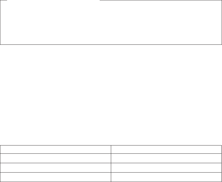
You must set valid temporary storage responses. You must set all three of
EIBRCODE, EIBRESP, and EIBRESP2 to a consistent set of values, such as would
be set by temporary storage to describe a valid completion. CICS does not check
the consistency of EIBRCODE, EIBRESP, and EIBRESP2. If EIBRCODE is set to a
non-zero value and EIBRESP is set to zero, CICS will override EIBRESP with a
non-zero value. To help you set values for EIBRCODE, EIBRESP, and EIBRESP2,
the values used by temporary storage are specified in DSECT DFHTSUED.
Note: Take care when issuing recursive commands not to cause a loop. For
example, it is your responsibility to avoid entering a loop when issuing a
temporary storage request from the XTSEREQC exit. Use of the recursion
counter UEPRECUR is recommended.
The command-level parameter structure
The command-level parameter structure consists of a series of addresses. The first
address points to the EXEC interface descriptor (EID), which consists of a bit string
that describes the type of request and identifies each keyword specified with the
request. The remaining addresses point to pieces of data associated with the
request.
You can examine the EID to determine the type of request and the keywords
specified. You can examine the other parameters in the list to determine the values
of the keywords. You can also modify values of keywords specified on the request.
End of parameter list indicator
The high-order bit is set on in the last address set in the parameter list to
indicate that it is the last one in the list. On return from your user exit program,
CICS scans the parameter list for the high-order bit to find the last parameter.
Therefore, if you modify the length of the parameter list, you must also reset
the high-order bit to indicate which is the new last address.
The UEPCLPS exit-specific parameter
The UEPCLPS exit-specific parameter is included in both exit XTSEREQ and exit
XTSEREQC. It is the address of the command-level parameter structure. The
command-level parameter structure contains 8 addresses, TS_ADDR0 through
TS_ADDR7. It is defined in the DSECT TS_ADDR_LIST, which you should copy
into your exit program by including the statement COPY DFHTSUED.
The command-level parameter list is made up as follows.
Note: The relationship between arguments, keywords, data types, and input/output
types is summarized for the temporary storage commands in the following
tables:
Command See
WRITEQ TS Table 7 on page 200
READQ TS Table 8 on page 200
DELETEQ TS Table 9 on page 201
TS_ADDR0
is the address of a 9-byte area called the EID, which is made up as follows:
TS_GROUP
temporary storage EXEC interface program exits
196 CICS TS for OS/390: CICS Customization Guide
TS_FUNCT
TS_BITS1
TS_BITS2
TS_EIDOPT5
TS_EIDOPT6
TS_EIDOPT7
TS_EIDOPT8
TS_GROUP
Always X'0A', indicating that this is a temporary storage request.
TS_FUNCT
One byte that defines the type of request:
X'02' WRITEQ
X'04' READQ
X'06' DELETEQ
TS_BITS1
Existence bits that define which arguments were specified. To obtain
the argument associated with a keyword, you need to use the
appropriate address from the command-level parameter structure.
Before using this address, you must check the associated existence bit.
If the existence bit is set off, the argument was not specified in the
request and the address should not be used.
X'80' Set if the request contains an argument for the QUEUE or
QNAME keyword. If set, TS_ADDR1 is meaningful.
X'40' Set if the request contains an argument for any of the FROM,
INTO, or SET keywords. If set, TS_ADDR2 is meaningful.
X'20' Set if the request contains an argument for the LENGTH
keyword. If set, TS_ADDR3 is meaningful.
X'10' Set if the request contains an argument for the NUMITEMS
keyword. If set, TS_ADDR4 is meaningful.
X'08' Set if the request contains an argument for the NUMITEMS or
ITEM keyword. If set, TS_ADDR5 is meaningful.
X'02' Set if the request contains an argument for the SYSID keyword.
If set, TS_ADDR7 is meaningful.
TS_BITS2
Two bytes not used by temporary storage.
TS_EIDOPT5
Indicates whether certain keywords were specified on the request.
X'80' QNAME was specified (otherwise QUEUE). You can modify this
bit in your user exit if you wish.
TS_EIDOPT6
One byte not used by temporary storage.
TS_EIDOPT7
Indicates whether certain functions and/or keywords were specified on
the request.
X'10' WRITEQ NOSUSPEND specified.
temporary storage EXEC interface program exits
Chapter 1. Global user exit programs 197
|
|
|
|
|||
|
X'80' WRITEQ MAIN or READQ ITEM specified.
X'04' WRITEQ REWRITE or READQ NUMITEMS specified.
TS_EIDOPT8
Indicates whether certain keywords were specified on the request.
X'80' ITEM was specified (otherwise NUMITEMS).
TS_ADDR1
is the address of area containing 8-byte name from QUEUE. or 16-byte name
from QNAME. To determine which of these is applied, see 197.
TS_ADDR2
is the address of one of the following:
vA 4-byte address from SET (if the request is READQ and TS_EIDOPT5
indicates that this is SET).
vData from INTO (if the request is READQ and TS_EIDOPT5 indicates that
this is not SET).
vData from FROM (if the request is WRITEQ).
TS_ADDR3
is the address of the halfword value of LENGTH (if the request is READQ or
WRITEQ).
Warning: For requests that specify INTO, do not change the value of LENGTH
to a value greater than that specified by the application. To do so
causes a storage overlay in the application.
TS_ADDR4
is the address of the halfword value of NUMITEMS (if the request is READQ).
TS_ADDR5
is the address of one of the following:
vThe halfword value of NUMITEMS (if the request is WRITEQ)
vThe halfword value of ITEM (if the request is READQ or WRITEQ).
TS_ADDR6
is the address of a value intended for CICS internal use only. It must not be
used.
TS_ADDR7
is the address of an area containing the value of SYSID.
Modifying fields in the command-level parameter structure
Some fields that are passed to temporary storage are used as input to the request,
some are used as output fields, and some are used for both input and output. The
method your user exit program uses to modify a field depends on the usage of the
field.
The following are always input fields:
QUEUE|QNAME
FROM
SYSID
The following are always output fields:
INTO
temporary storage EXEC interface program exits
198 CICS TS for OS/390: CICS Customization Guide
|
|
|
|
NUMITEMS
SET
LENGTH is an input field on a WRITEQ request, and an output field on a READQ
request that specifies SET. It is both an input and an output field on a READQ
request that specifies INTO.
ITEM is an input field on a READQ request, and on a WRITEQ request that
specifies REWRITE. It is both an input and an output field on a WRITEQ request
that does not specify REWRITE.
Modifying input fields
The correct method of modifying an input field is to create a new copy of it, and to
change the address in the command-level parameter list to point to your new data.
Note: You must never modify an input field by altering the data that is pointed to by
the command-level parameter list. To do so would corrupt storage belonging
to the application program and would cause a failure when the program
attempted to reuse the field.
Modifying output fields
The technique described in “Modifying input fields” is not suitable for modifying
output fields. (The results would be returned to the new area instead of the
application’s area, and would be invisible to the application.)
An output field is modified by altering the data that is pointed to by the
command-level parameter list. In the case of an output field, you can modify the
application’s data in place, because the application is expecting the field to be
modified anyway.
Modifying fields used for both input and output
An example of a field that is used for both input and output is LENGTH on a
READQ request that specifies INTO. You can treat such fields in the same way as
output fields, and they are considered to be the same.
Modifying the EID
It is not possible to modify the EID to make major changes to requests. It is not
possible, for example, to change a READQ request to a WRITEQ request.
However, you can make minor changes to requests, such as to turn on the
existence bit for SYSID so that the request can be changed into one that is shipped
to a remote system.
The list that follows shows the bits in the EID that can be modified. Any attempt to
modify any other part of the EID is ignored.
TS_BITS1
X'02' The existence bit for SYSID.
TS_EIDOPT7
A user exit program at XTSEREQ can set the following on or off for all WRITEQ
TS commands:
temporary storage EXEC interface program exits
Chapter 1. Global user exit programs 199

X'10' The existence bit for NOSUSPEND.
X'08' The existence bit for MAIN.
The EID is reset to its original value before return to the application program. That
is, changes made to the EID are retained for the duration of the temporary storage
request only.
Note: Your user exit program is prevented from making major changes to the EID.
However, you must take great care when making the minor modifications
that are permitted.
Use of the task token UEPTSTOK
UEPTSTOK provides the address of a 4-byte area that you can use to pass
information between successive temporary storage requests in the same task. (By
contrast, UEPTQTOK is usable only for the duration of a single temporary storage
request, because its contents may be destroyed at the end of the request.) For
example, if you need to pass information between successive invocations of the
XTSEREQ exit, UEPTSTOK provides a means of doing this.
Table 7. WRITEQ TS: User arguments and associated keywords, data types, and
input/output types
Argument Keyword Data type Input/output type
Arg1 QUEUE CHAR(8) input
Arg1 QNAME CHAR(16) input
Arg2 FROM DATA-AREA input
Arg3 LENGTH BIN(15) input
Arg4 * * *
Arg5 ITEM BIN(15) input/output
Arg5 NUMITEMS BIN(15) output
Arg6 * * *
Arg7 SYSID CHAR(4) input
Note: The different uses of Arg5 are shown, because Arg5 is used by the ITEM and
NUMITEMS keywords which are alternatives and the argument to the ITEM keyword is an
input field when REWRITE is specified.
Table 8. READQ TS: User arguments and associated keywords, data types, and
input/output types
Argument Keyword Data type Input/output type
Arg1 QUEUE CHAR(8) input
Arg1 QNAME CHAR(16) input
Arg2 SET DATA-AREA, PTR output
Arg2 INTO DATA-AREA output
Arg3 LENGTH BIN(15) input/output
Arg4 NUMITEMS BIN(15) output
Arg5 ITEM BIN(15) input
Arg6 * *
Arg7 SYSID CHAR(4) input
temporary storage EXEC interface program exits
200 CICS TS for OS/390: CICS Customization Guide
||||
||||

Table 9. DELETEQ TS: User arguments and associated keywords, data types, and
input/output types
Argument Keyword Data type Input/output type
Arg1 QUEUE CHAR(8) input
Arg1 QNAME CHAR(16) input
Arg2 * * *
Arg3 * * *
Arg4 * * *
Arg5 * * *
Arg6 * * *
Arg7 SYSID CHAR(4) input
Modifying user arguments
User exit programs can modify user arguments, as follows:
For input arguments, the user exit program should obtain sufficient storage to hold
the modified argument, set up that storage to the required value, and set the
associated pointer in the parameter list to the address of the newly acquired area.
For output arguments, and for input/output arguments, the user exit program can
update the argument in place, because the area of storage is represented by a
variable in the application which is expected to receive a value from CICS.
Notes:
1. CICS does not check changes to argument values, so any changes must be
verified by the user exit program making the changes.
2. It is not advisable for XTSEREQ to modify output arguments or for XTSEREQC
to modify input arguments.
Adding user arguments
Global user exit programs can add arguments associated with the SYSID keyword.
You must ensure that the arguments you specify or modify in your exit programs
are valid.
Assuming that the argument to be added does not already exist, the user exit
program must:
1. Obtain storage for the argument to be added
2. Initialize the storage to the required value
3. Select and set up the appropriate pointer from the parameter list
4. Select and set up the appropriate argument existence bit in the EID
5. Modify the parameter list to reflect the new end of list indicator.
Removing user arguments
User exit programs can remove arguments (for which the program is totally
responsible) associated with the SYSID keyword:
Assuming that the argument to be removed exists, the user exit program must:
1. Switch the corresponding argument existence bit to ’0’b in the EID
2. Modify the parameter list to reflect the new end of list indicator.
temporary storage EXEC interface program exits
Chapter 1. Global user exit programs 201
||||

Example program
CICS supplies—in hardcopy only—an example program, DFH$XTSE, that
shows how temporary storage requests can be modified. See “Appendix E.
The example program for the XTSEREQ global user exit, DFH$XTSE” on
page 807.
temporary storage EXEC interface program exits
202 CICS TS for OS/390: CICS Customization Guide

Terminal allocation program exit XALCAID
XALCAID is driven when an AID with data is canceled in one of the following ways:
vBy means of the CEMT transaction
vDuring execution of a SET TERMINAL or SET CONNECTION command
vDuring reinstallation of a terminal or connection.
XALCAID is invoked only if there is data associated with the AID.
Exit XALCAID
When invoked
Whenever an AID with data is canceled.
Note: It is not possible for the exit to prevent the request from being
canceled.
Exit-specific parameters
UEPALTSD
Address of a 4-byte field containing the symbolic identifier of the
transaction which was to be started by this request.
UEPALTRM
Address of a 4-byte field containing the identifier of the terminal or
connection to which this request was directed.
UEPALDAT
Address of an area of storage containing the data specified in the
FROM option; or hexadecimal zeros, if the AID was created by a
START request without a FROM option.
UEPALLEN
Address of a fullword binary field containing the length of the FROM
data; or hexadecimal zeros, if the FROM option was not specified.
UEPALRQD
Address of an 8-byte field containing the value of the REQID
associated with the FROM data. The data was stored in a
temporary storage queue with this name. This value was either
specified explicitly using the REQID option on the START
command, or created internally by CICS.
UEPALQUE
Address of an 8-byte field containing the value specified in the
QUEUE option on the START command, or hexadecimal zeros if
QUEUE was not specified.
UEPALRTE
Address of a 4-byte field containing the value specified in the
RTERMID option on the START command, or hexadecimal zeros if
RTERMID was not specified.
UEPALRTA
Address of a 4-byte field containing the value specified in the
RTRANSID option on the START command, or hexadecimal zeros if
RTRANSID was not specified.
UEPALFMH
Address of a 1-byte field containing the value X'FF' if the data
terminal allocation program exit
Chapter 1. Global user exit programs 203
contains FMHs, as specified by the FMH option on the associated
START command; or hexadecimal zeros otherwise.
UEPALSTC
Address of a 2-byte field containing the start code. This is "SZ" for
FEPI starts; otherwise it is "SD".
Return codes
UERCNORM
No other return codes are supplied. The value of the return code is
not inspected.
XPI calls
You can use:
INQ_APPLICATION_DATA
INQUIRE_SYSTEM
No other XPI calls should be used.
API and SPI commands
No EXEC CICS commands can be used.
Note: The XALTENF exit, used to handle the “terminal not known” condition, is
also invoked from the terminal allocation program. XALTENF is described on
page 208.
terminal allocation program exit
204 CICS TS for OS/390: CICS Customization Guide

Terminal control program exits XTCIN, XTCOUT, XTCATT, XTCTIN, and
XTCTOUT
Exit XTCIN
When invoked
After an input event for a sequential device.
Exit-specific parameters
UEPTCTTE
Address of the terminal control table terminal entry (TCTTE). The
TCTTE can be mapped using the DSECT DFHTCTTE.
UEPTIOA
Address of the terminal input/output area (TIOA). Your exit program
should not change the address. The TIOA can be mapped using the
DSECT DFHTIOA. However, fields TIOASAL and TIOASCA are not
programming interfaces.
UEPTCTLE
Address of the terminal control table line entry (TCTLE). The
TCTLE can be mapped using the DSECT DFHTCTLE.
Return codes
UERCNORM
Continue processing.
XPI calls
All can be used. However, note that you cannot use a GETMAIN call to
obtain terminal-class storage for use as a replacement TIOA.
Exit XTCOUT
When invoked
Before an output event for a sequential device.
Exit-specific parameters
UEPTCTTE
Address of the terminal control table terminal entry (TCTTE). The
TCTTE can be mapped using the DSECT DFHTCTTE.
UEPTIOA
Address of the terminal input/output area (TIOA). Your exit program
should not change the address. The TIOA can be mapped using the
DSECT DFHTIOA. However, fields TIOASAL and TIOASCA are not
programming interfaces.
UEPTCTLE
Address of the terminal control table line entry (TCTLE). The
TCTLE can be mapped using the DSECT DFHTCTLE.
Return codes
UERCNORM
Continue processing.
XPI calls
All can be used. However, note that you cannot use a GETMAIN call to
obtain terminal-class storage for use as a replacement TIOA.
terminal control program exits
Chapter 1. Global user exit programs 205
Exit XTCATT
When invoked
Before task attach.
Exit-specific parameters
UEPTCTTE
Address of the terminal control table terminal entry (TCTTE). The
TCTTE can be mapped using the DSECT DFHTCTTE.
UEPTIOA
Address of the terminal input/output area (TIOA). The TIOA can be
mapped using the DSECT DFHTIOA. However, fields TIOASAL and
TIOASCA are not programming interfaces.
UEPTCTLE
Address of the terminal control table line entry (TCTLE). The
TCTLE can be mapped using the DSECT DFHTCTLE.
UEPTRAN
Address of the 4-byte transaction id.
Return codes
UERCNORM
Continue processing.
XPI calls
All can be used.
Exit XTCTIN
When invoked
After a TCAM input event.
Exit-specific parameters
UEPTCTTE
Address of the terminal control table terminal entry (TCTTE). The
TCTTE can be mapped using the DSECT DFHTCTTE.
UEPTIOA
Address of the terminal input/output area (TIOA). The TIOA can be
mapped using the DSECT DFHTIOA. However, fields TIOASAL and
TIOASCA are not programming interfaces.
UEPTCTLE
Address of the terminal control table line entry (TCTLE). The
TCTLE can be mapped using the DSECT DFHTCTLE.
Return codes
UERCNORM
Continue processing – format the TCAM header.
UERCBYP
Suppress formatting of the TCAM header.
XPI calls
All can be used.
terminal control program exits
206 CICS TS for OS/390: CICS Customization Guide
Exit XTCTOUT
When invoked
Before a TCAM output event.
Exit-specific parameters
UEPTCTTE
Address of the terminal control table terminal entry (TCTTE). The
TCTTE can be mapped using the DSECT DFHTCTTE.
UEPTIOA
Address of the terminal input/output area (TIOA). The TIOA can be
mapped using the DSECT DFHTIOA. However, fields TIOASAL and
TIOASCA are not programming interfaces.
UEPTCTLE
Address of the terminal control table line entry (TCTLE). The
TCTLE can be mapped using the DSECT DFHTCTLE.
Return codes
UERCNORM
Continue processing – format the TCAM header.
UERCBYP
Suppress formatting of the TCAM header.
XPI calls
All can be used.
terminal control program exits
Chapter 1. Global user exit programs 207

‘Terminal not known’ condition exits XALTENF and XICTENF
The ‘terminal not known’ condition can occur when intercommunicating CICS
regions use both SHIPPABLE terminal definitions and automatic transaction
initiation (ATI). The condition is especially likely to arise if autoinstall is used.
SHIPPABLE attribute
Terminals defined with the SHIPPABLE attribute in a terminal-owning region
(TOR) do not need a definition in a connected application-owning region (AOR).
If necessary to support transaction routing, CICS ships a copy of the definition
from the TOR to the AOR. For further information, refer to the
CICS Resource
Definition Guide
.
Automatic transaction initiation (ATI)
ATI occurs when an internally generated request leads to the initiation of a
transaction. For example, when:
vAn application issues an EXEC CICS START command, or
vThe transient data trigger level is reached.
Two CICS modules handle ATI requests:
The interval control program processes a START command, checks that the
terminal is known in the local system, and (when any START time interval
elapses) calls the terminal allocation program.
The terminal allocation program is called by the interval control program or by
the transient data triggering mechanism, and checks that the terminal is known
in the local system. If the requested terminal is remote, the terminal allocation
program ships an ATI request to the remote system, which initiates transaction
routing back to the local system.
For guidance information about ATI, refer to the
CICS Intercommunication
Guide
.
‘Terminal not known’ condition
The ‘terminal not known’ condition arises when an ATI request is made for a
terminal not known in the region. An ATI request can occur in the AOR for a
SHIPPABLE terminal before any transaction routing has taken place for the
terminal, and so before the definition of the terminal can have been shipped
from the TOR to the AOR.
If the ‘terminal not known’ condition occurs, both the interval control program
and the terminal allocation program reject the transaction-initiation request as
‘TERMIDERR’.
The exits
To deal with the ‘terminal not known’ condition, CICS provides global user exits in
the interval control and terminal allocation programs:
XICTENF
In the interval control program
XALTENF
In the terminal allocation program.
terminal not known condition exits
208 CICS TS for OS/390: CICS Customization Guide
CICS drives the XICTENF exit when the ‘terminal not known’ condition occurs after
the interval control program has been invoked by an EXEC CICS START command.
CICS drives the XALTENF exit when the ‘terminal not known’ condition occurs after
the terminal allocation program has been invoked by the transient data trigger level
or the interval control program. Note that an EXEC CICS START command could
result in both exits being invoked.
The exit program must indicate whether the terminal exists on another system and,
if so, on which one. CICS passes data to the exit program to help establish this
information. You can use the same exit program at both exit points. CICS supplies a
sample exit program, DFHXTENF (see Figure 2 on page 214), that can be used at
both exits and that can deal unchanged with some typical situations.
The exits are designed to deal with ‘terminal not known’ conditions that occur in
CICS regions other than the TOR. For a TOR/AOR pair, enable the exit program in
the AOR. The exits cannot deal with a ‘terminal not known’ condition in the TOR
and the exit program should not normally be enabled there. However, if more than
one TOR exists, you may need to enable the exit program in each TOR to deal with
requests for terminals owned by other TORs. In this case, the exit program must
recognize terminals that should be owned by this system and reject the requests
(‘UERCTEUN’). Although the exit provides as much data as possible, the logic of
your program depends entirely on your system design. A simple solution to the most
complex case would be to make the name of each terminal reflect the netname or
sysid of its owning region.
Data returned by exit
The exit program must set a return code in register 15 as follows:
UERCTEUN
Terminal does not exist
UERCNETN
Netname of TOR returned
UERCSYSI
Sysid of TOR returned.
For return codes UERCNETN and UERCSYSI, the exit program must place the
netname or sysid of the terminal-owning region in fields UEPxxNTO or UEPxxSYO
(where xx is AL or IC).
If the terminal-owning region is a member of a VTAM generic resource, the exit
program should place the netname of the terminal in field UEPxxNNO. For
information about using ATI with VTAM generic resources, see the
CICS
Intercommunication Guide
.
Exit XALTENF
When invoked
By the terminal allocation program when the terminal that an ATI request
from transient data or interval control requires is unknown in this system.
The exit program is expected to give a return code indicating whether the
terminal exists on another connected CICS system and, if so, on which one.
terminal not known condition exits
Chapter 1. Global user exit programs 209
Exit-specific parameters
UEPALEVT
Address of 2 bytes containing the type of request. The equated
values of the types are:
UEPALESD
START command with data
UEPALES
START command without data
UEPALETD
Transient data trigger level reached.
UEPALTR
Address of 1 byte containing an indication of whether the task
issuing the START command was started by transaction routing.
The equated values are:
UEPALTY
A START command was being processed and the task
issuing the command was transaction routed to.
UEPALTN
A START command was not being processed or aSTART
command was being processed but the task issuing the
command was not transaction routed to.
UEPALFS
Address of 1 byte containing an indication of whether the START
command was function shipped. The equated values are:
UEPALFY
A START command was being processed and the START
was function shipped.
UEPALFN
A START command was not being processed or aSTART
was being processed but it was not function shipped.
UEPALTRN
Address of 4 bytes containing the name of the transaction to be
run.
UEPALRTR
Address of 4 bytes containing the name of the terminal on which
the transaction should run. (If a transient data trigger level was
reached and the transient data queue definition specified a system,
then this would contain a system identifier.)
UEPALCTR
Address of 4 bytes containing, for START commands, the name of
the current terminal if the command was transaction routed, or the
name of the session if the command was function shipped.
For other START commands and for transient data trigger events,
the field pointed to contains blanks.
UEPALNTI
Address of 8 bytes containing, for function-shipped START
commands, the netname of the last system from which the request
came.
terminal not known condition exits
210 CICS TS for OS/390: CICS Customization Guide
For START commands issued in this system by transaction routing
to a task, the netname of the last system from which the task was
routed.
For other START command situations and for transient data trigger
level events, the field pointed to contains blanks.
UEPALSYI
Address of 4 bytes containing, if UEPALNTI contains a netname,
the corresponding sysid.
If UEPALNTI does not contain a netname, the field pointed to is
blank.
UEPALNTO
Address of 8 bytes containing the contents of UEPALNTI.
If it sets a return code of ‘UERCNETN’, your exit program must
place in this field the netname of the system to which the ATI
request should be sent.
UEPALSYO
Address of 4 bytes containing the contents of UEPALSYI.
If it sets a return code of ‘UERCSYSI’, your exit program must
place in this field the sysid of the system to which the ATI
request should be sent.
UEPALNNI
Address of a 4-byte input field containing the netname of the
terminal on which the transaction is to run, if this is known to CICS.
If CICS does not know the netname, the addressed field contains
blanks.
UEPALNNO
Address of a 4-byte input/output field containing, on invocation, the
contents of UEPALNNI. Your exit program can use this field to
supply the netname of the terminal on which the transaction is to
run. It is important that your exit program supply a terminal
netname if the TOR to which it directs the ATI request is a member
of a VTAM generic resource.
Return codes
UERCTEUN
Terminal unknown, reject request.
UERCNETN
Terminal known, netname returned in UEPALNTO.
UERCSYSI
Terminal known, sysid returned in UEPALSYO.
XPI calls
You can use:
INQ_APPLICATION_DATA
INQUIRE_SYSTEM.
No other XPI calls should be used.
terminal not known condition exits
Chapter 1. Global user exit programs 211
Exit XICTENF
When invoked
By the interval control program when the terminal that an EXEC CICS
START command requires is unknown in this system. The exit program is
expected to give a return code indicating whether the terminal exists on
another connected CICS system and, if so, on which one.
Exit-specific parameters
UEPICEVT
Address of 2 bytes containing the type of request. The equated
values of the types are:
UEPICESD
START command with data
UEPICES
START command without data.
UEPICTR
Address of 1 byte containing an indication of whether the task
issuing the START command was started by transaction routing.
The equated values are:
UEPICTY
A START command was being processed and the task
issuing the command was transaction routed to.
UEPICTN
A START command was not being processed or aSTART
command was being processed but the task issuing the
command was not transaction routed to.
UEPICFS
Address of 1 byte containing an indication of whether the START
command was function shipped. The equated values are:
UEPICFY
A START command was being processed and the START
was function shipped.
UEPICFN
A START command was not being processed or aSTART
was being processed but it was not function shipped.
UEPICTRN
Address of 4 bytes containing the name of the transaction to be
run.
UEPICRTR
Address of 4 bytes containing the name of the terminal on which
the transaction should run.
UEPICCTR
Address of 4 bytes containing, for START commands, the name of
the current terminal if the command was transaction routed, or the
name of the session if the command was function shipped.
For other START commands, the field pointed to contains blanks.
terminal not known condition exits
212 CICS TS for OS/390: CICS Customization Guide
UEPICNTI
Address of 8 bytes containing, for function-shipped START
commands, the netname of the last system from which the request
came.
For START commands issued in this system by transaction routing
to a task, the netname of the last system from which the task was
routed.
For other START command situations, the field pointed to contains
blanks.
UEPICSYI
Address of 4 bytes containing, if UEPICNTI contains a netname,
the corresponding SYSID.
If UEPICNTI does not contain a netname, the field pointed to is
blank.
UEPICNTO
Address of 8 bytes containing the contents of UEPICNTI.
If it sets a return code of ‘UERCNETN’, your exit program must
place in this field the netname of the system to which the ATI
request should be sent.
UEPICSYO
Address of 4 bytes containing the contents of UEPICSYI.
If it sets a return code of ‘UERCSYSI’, your exit program must
place in this field the sysid of the system to which the ATI
request should be sent.
UEPICNNI
Address of a 4-byte input field containing the netname of the
terminal on which the transaction is to run, if this is known to CICS.
If CICS does not know the netname, the addressed field contains
blanks.
UEPICNNO
Address of a 4-byte input/output field containing, on invocation, the
contents of UEPICNNI. Your exit program can use this field to
supply the netname of the terminal on which the transaction is to
run. It is important that your exit program supply a terminal
netname if the TOR to which it directs the ATI request is a member
of a VTAM generic resource.
Return codes
UERCTEUN
Terminal unknown, reject request.
UERCNETN
Terminal known, netname returned in UEPICNTO.
UERCSYSI
Terminal known, sysid returned in UEPICSYO.
UERCPURG
Task purged during XPI call.
XPI calls
The following must not be used:
ADD_SUSPEND
terminal not known condition exits
Chapter 1. Global user exit programs 213

DELETE_SUSPEND
DEQUEUE
ENQUEUE
RESUME
SUSPEND
WAIT_MVS.
The sample program for the XALTENF and XICTENF exits, DFHXTENF
One program can be used for both exits, or a separate program can be written for
each. Figure 2 shows the executable code from the supplied sample program
DFHXTENF, which can be used for both exits. DFHXTENF rejects transient data
requests, because the action in this case is very much installation-dependent.
Important
The example is intended purely as a demonstration of some of the possibilities
available, and would be impractical in a production environment.
DFHXTENF CSECT
DFHVM XTENF
ENTRY DFHXTENA
DFHXTENA DS 0H
STM R14,R12,12(R13) save registers
BALR R11,0 set up base register
USING *,R11
*
USING DFHUEPAR,R1 DFHUEH parameter list
*
* Could check the terminal ID at this point. In this
* program we assume it is valid. We also choose to accept
* START requests and reject Transient Data trigger level
* events.
*
L R2,UEPICEVT access type of request
CLC 0(2,R2),START START command?
BE STARTCMD yes
*
CLC 0(2,R2),STARTDAT START command with data?
BNE NOTSTART no, must be Transient Data
*
STARTCMD DS 0H
*
* Accept the default netname if we are Function Shipping.
* Otherwise build a netname.
*
L R2,UEPICFS access FS information
CLI 0(R2),UEPICFY Function Shipping?
BNE BLDNETNM no, build a netname
*
LH R15,NETNAME accept the default netname
B EXIT
Figure 2. Sample program for XALTENF and XICTENF exits (Part 1 of 2)
terminal not known condition exits
214 CICS TS for OS/390: CICS Customization Guide
|
|
*BLDNETNM DS 0H
*
* Build a netname by taking the first character of the
* terminal ID and appending it to the characters 'CICS'.
*
L R2,UEPICNTO access the output netname field
L R3,UEPICRTR access ID of requested terminal
MVC 0(8,R2),=C'CICS '
MVC 4(1,R2),0(R3) first character of terminal ID
LH R15,NETNAME netname returned
B EXIT
*
NOTSTART DS 0H
LH R15,UNKNOWN reject Transient Data trigger *
level events
*
EXIT DS 0H
L R14,12(R13) restore registers except 15
LM R0,R12,20(R13) which contains the return code
BR R14
*
***********************************************************************
* Local constants
***********************************************************************
START DC AL2(UEPICES)
STARTDAT DC AL2(UEPICESD)
NETNAME DC AL2(UERCNETN)
UNKNOWN DC AL2(UERCTEUN)
*
DFHEND DFHXTENF
Figure 2. Sample program for XALTENF and XICTENF exits (Part 2 of 2)
terminal not known condition exits
Chapter 1. Global user exit programs 215

Transaction manager domain exit XXMATT
Exit XXMATT
When invoked
During transaction attach. This exit is able to change some of the attributes
of the transaction that is being attached.
Exit-specific parameters
UEPTRANID
The address of transaction id (see Notes).
UEPUSER
The address of the userid associated with the transaction if the
current task is a user task (see Notes).
UEPTERM
The address of the terminal id associated with the transaction, if
any (see Notes).
UEPPROG
The address of the application program name for this transaction, if
any (see Notes).
UEPATPTI
The address of a 4-byte field containing the primary transaction id.
You can change the primary transaction id by modifying the
addressed field.
UEPATOTI
The address of the 4-byte attach transaction id. A transid of
X'00000000' indicates that a transid was not supplied on the attach.
UEPATTPL
The address of an area containing the length of the attach
TPName. A length of zero indicates that a TPName was not
supplied on the attach.
UEPATTPA
The address of a fullword containing the address of the attach
TPName. The attach TPName can be 1 through 64 bytes long, as
defined by UEPTTPL.
UEPATLOC
The address of a 1-byte field indicating whether the transaction was
found. Equated values are:
UEATFND
The transaction was found.
UEATNFND
The transaction was not found.
UEPATTST
The address of a one-byte transaction definition state. Equated
values for the definition state are:
UEATENAB
The transaction is enabled.
UEATDISA
The transaction is disabled.
transaction manager domain exit
216 CICS TS for OS/390: CICS Customization Guide
UEPATTTK
The address of a doubleword containing a transaction token. Note
that some of the transaction manager XPI calls require this token to
identify the transaction that is being attached.
Return codes
UERCNORM
Continue attach processing.
XPI calls
The user exit can inquire on the transaction being attached, using the
UEPATTTK transaction token as input to the XMIQ
INQUIRE_TRANSACTION XPI call.
The exit can also set the total priority and TCLASS, using the XMIQ
SET_TRANSACTION XPI call.
Most of the XPI calls can be used, but with caution since typically this exit
is invoked under the TCP task. Thus it is advisable not to issue any XPI
calls that might cause the TCP task to wait.
Notes:
1. The following XPI calls can be useful for obtaining information that could be
used to modify the attach of a transaction:
INQUIRE_TRANSACTION
INQUIRE_MXT
INQUIRE_TCLASS
INQUIRE_TRANDEF
INQUIRE_SYSTEM
2. The fields UEPTRANID, UEPUSER, UEPTERM, and UEPPROG are common
to many of the domain global user exit points, and normally return values
associated with the current user task. In the case of XXMATT, however, the user
task that is being attached is not the current task when the exit is invoked. Until
task attach is complete, the current task is the CICS task that is performing the
attach.
When the task being attached is for a task started by an immediate START
command; that is, a START without an interval, the current task is the task that
issues the START command, and the fields contain values associated with that
task.
transaction manager domain exit
Chapter 1. Global user exit programs 217

Transient data program exits XTDREQ, XTDIN, and XTDOUT
Exit XTDREQ
When invoked
Before request analysis.
Exit-specific parameters
UEPTDQUE
Address of 4-byte TD queue name.
UEPTDTYP
Address of 1-byte TD request type. Values are:
UEPTDPUT
PUT request
UEPTDGET
GET request
UEPTDPUR
PURGE request.
Return codes
UERCNORM
Continue TD processing.
UERCTDOK
Quit TD processing – returning ‘NORMAL’ to the caller.
UERCTDNA
Quit TD processing – returning ‘NOTAUTH’ to the caller.
UERCPURG
Task purged during XPI call.
XPI calls
You can use:
INQ_APPLICATION_DATA
INQUIRE_SYSTEM
WAIT_MVS
Do not use any other calls.
transient data program exits
218 CICS TS for OS/390: CICS Customization Guide
Exit XTDIN
When invoked
After receiving data from QSAM (for extrapartition) or VSAM (for
intrapartition).
Exit-specific parameters
UEPTDQUE
Address of the 4-byte TD queue name.
UEPTDAUD
Address of the unmodified TD data.
UEPTDLUD
Address of the fullword length of the unmodified TD data.
UEPTDAMD
Address of the TD data modified by the exit program.
UEPTDLMD
Address of the fullword length of the TD data modified by the exit
program.
Return codes
UERCNORM
Continue TD processing.
UERCPURG
Task purged during XPI call.
XPI calls
You can use:
INQ_APPLICATION_DATA
INQUIRE_SYSTEM
WAIT_MVS
Do not use any other calls.
transient data program exits
Chapter 1. Global user exit programs 219
Exit XTDOUT
When invoked
Before passing the data to a QSAM (for extrapartition) or VSAM (for
intrapartition) user-defined transient data queue.
Exit-specific parameters
UEPTDQUE
Address of the 4-byte TD queue name.
UEPTDAUD
Address of the unmodified TD data.
UEPTDLUD
Address of the fullword length of the unmodified TD data.
UEPTDAMD
Address of the TD data modified by the exit program.
UEPTDLMD
Address of the fullword length of TD data modified by the exit
program.
UEPTDNUM
Address of the fullword containing the number of items in the list.
UEPTDCUR
Address of the fullword containing the number of the current item.
Return codes
UERCNORM
Continue TD processing.
UERCTDOK
Quit TD processing – returning ‘NORMAL’ to the caller.
Note: If you return UERCTDOK to suppress the first line of a
multiline message, the rest of the message is not presented
to XTDOUT, but is also suppressed.
UERCPURG
Task purged during XPI call.
XPI calls
You can use:
INQ_APPLICATION_DATA
INQUIRE_SYSTEM
WAIT_MVS
Do not use any other calls.
transient data program exits
220 CICS TS for OS/390: CICS Customization Guide
|
|
|
|
|

Transient data EXEC interface program exits XTDEREQ and
XTDEREQC
The XTDEREQ exit allows you to intercept a transient data request before any
action has been taken on it by transient data. The XTDEREQC exit allows you to
intercept a transient data request after transient data has completed its processing.
Using XTDEREQ, you can:
vAnalyze the request to determine its type, the keywords specified, and their
values.
vModify any value specified by the request before the command is executed.
vSet return codes to specify that either:
– CICS should continue with the (possibly modified) request.
– CICS should bypass the request. (Note that if you set this return code, you
must also set up return codes for the EXEC interface block (EIB), as if you
had processed the request yourself.)
Using XTDEREQC, you can:
vAnalyze the request, to determine its type, the keywords specified, and their
values.
vSet return codes for the EIB.
Both exits are passed eight parameters as follows:
vThe address of the command-level parameter structure
vThe address of a token (UEPTDTOK) used to pass 4 bytes of data from
XTDEREQ to XTDEREQC
vThe addresses of copies of four pieces of return code and resource information
from the EIB
vThe address of a token (UEPTSTOK) that is valid throughout the life of a task
vThe address of an exit recursion count (UEPRECUR).
Example program
CICS supplies—in hardcopy only—an example program, DFH$XTSE, that
shows how to modify fields in the command-level parameter structure passed
to EXEC interface exits. DFH$XTSE is listed on page 807.
Exit XTDEREQ
When invoked
Before CICS processes a transient data API request.
Exit-specific parameters
UEPCLPS
Address of the command-level parameter structure. See “The
UEPCLPS exit-specific parameter” on page 225.
UEPTDTOK
Address of the 4-byte token to be passed to XTDEREQC. This
allows you, for example, to pass a work area to exit XTDEREQC.
transient data EXEC interface program exits
Chapter 1. Global user exit programs 221
UEPRCODE
Address of a 6-byte hexadecimal copy of the EIB return code
‘EIBRCODE’. For details of EIB return codes, refer to the
CICS
Application Programming Reference
manual.
UEPRESP
Address of a 4-byte binary copy of the EIB response code
‘EIBRESP’.
UEPRESP2
Address of a 4-byte binary copy of the EIB response code
‘EIBRESP2’.
UEPTSTOK
Address of a 4-byte token that is valid throughout the life of a task.
See “Use of the task token UEPTSTOK” on page 228.
UEPRECUR
Address of a halfword recursion counter. The counter is set to 0
when the exit is first invoked, and is incremented for each recursive
call.
UEPRSRCE
Address of an 8-character copy of the EIB resource value,
EIBRSRCE.
Return codes
UERCNORM
Continue processing.
UERCBYP
The transient data EXEC interface program should ignore this
request.
UERCPURG
Task purged during XPI call.
XPI calls
All can be used.
Although the exit permits the use of XPI GETMAIN and FREEMAIN calls,
we recommend that you use the EXEC CICS GETMAIN and FREEMAIN
commands instead.
API and SPI commands
All can be used.
Note: Take care when issuing recursive commands. For example, you must avoid
entering a loop when issuing a transient data request from the XTDEREQ
exit. Use of the recursion counter UEPRECUR is recommended.
transient data EXEC interface program exits
222 CICS TS for OS/390: CICS Customization Guide
Exit XTDEREQC
When invoked
After a transient data API request has completed, and before return from
the transient data EXEC interface program.
Exit-specific parameters
UEPCLPS
Address of the command-level parameter structure. See “The
UEPCLPS exit-specific parameter” on page 225.
UEPTDTOK
Address of the 4 byte token to be passed to XTDEREQC. This
allows you, for example, to pass a work area to exit XTDEREQC.
UEPRCODE
Address of a 6-byte hexadecimal copy of the EIB return code
‘EIBRCODE’. For details of EIB return codes, refer to the
CICS
Application Programming Reference
manual.
UEPRESP
Address of a 4-byte binary copy of the EIB response code
‘EIBRESP’.
UEPRESP2
Address of a 4-byte binary copy of the EIB response code
‘EIBRESP2’.
UEPTSTOK
Address of a 4-byte token that is valid throughout the life of a task.
See “Use of the task token UEPTSTOK” on page 228.
UEPRECUR
Address of a halfword recursion counter. The counter is set to 0
when the exit is first invoked, and is incremented for each recursive
call.
UEPRSRCE
Address of an 8-character copy of the EIB resource value,
EIBRSRCE.
Return codes
UERCNORM
Continue processing.
UERCPURG
Task purged during XPI call.
XPI calls
All can be used.
Although the exit permits the use of XPI GETMAIN and FREEMAIN calls,
we recommend that you use the EXEC CICS GETMAIN and FREEMAIN
commands instead.
API and SPI commands
All can be used.
Note: Take care when issuing recursive commands. For example, you must avoid
entering a loop when issuing a transient data request from the XTDEREQC
exit. Use of the recursion counter UEPRECUR is recommended.
transient data EXEC interface program exits
Chapter 1. Global user exit programs 223
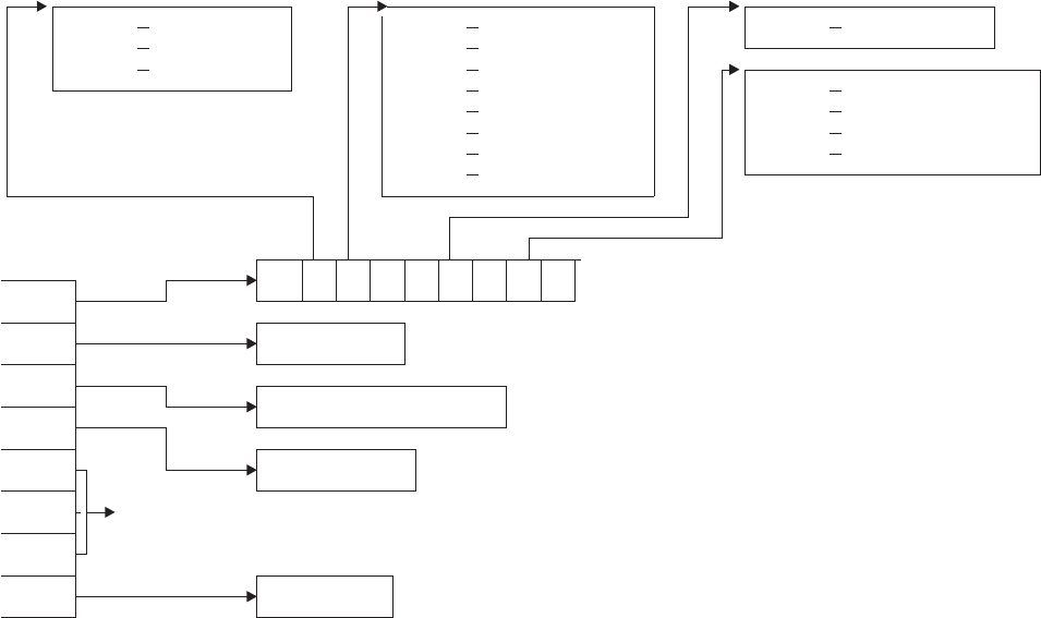
The command-level parameter structure
The command-level parameter structure consists of a series of addresses. The first
address points to the EXEC interface descriptor (EID), which consists of an 8-byte
area that describes the type of request and identifies each keyword specified with
the request. The remaining addresses point to pieces of data associated with the
request. (For example, the second address points to the queue name.)
You can examine the EID to determine the type of request and the keywords
specified. You can examine the other parameters in the list to determine the values
of the keywords. You can also modify values of keywords specified on the request.
(For example, you could change the sysid specified in the request.)
X'02' WRITEQ X'80' QUEUE X'01' SET
X'04' READQ X'40' FROM|SET|INTO
X'06' DELETEQ X'20' LENGTH
X'10' X'40' WRITEQ
X'08' X'80' READQ
X'04' X'C0' READQ(nosuspend)
X'02' SYSID X'04' DELETEQ
X'01'
08 .. .. 00 08 .. 00 .. 00
Addr0
Addr1 queue name char(4)
Addr2 set address or data fullword/char(*)
Addr3
Addr4 data length halfword
Addr5 dummy args
Addr6
Addr7 system id char(4)
Figure 3. The command-level parameter structure for transient data
transient data EXEC interface program exits
224 CICS TS for OS/390: CICS Customization Guide

End of parameter list indicator
The high-order bit is set on in the last address set in the parameter list to
indicate that it is the last one in the list. On return from your user exit program,
CICS scans the parameter list for the high-order bit to find the last parameter.
Therefore, if you modify the length of the parameter list, you must also reset
the high-order bit to indicate which is the new last address.
For example, if the parameter list specifies only the first two addresses
(TD_ADDR0, the address of the EID, and TD_ADDR1, the address of the
name of the queue named in a DELETEQ request), the high-order bit is set on
in TD_ADDR1. If you extend the parameter list by setting the address of a
SYSID in TD_ADDR7, you must reset the high-order bit in TD_ADDR1 and set
it on in TD_ADDR7 instead.
The maximum size of parameter list is supplied to the exit, thus allowing your exit
program to add any parameters not already specified without needing to first obtain
more storage.
The original parameter list, as it was before XTDEREQ was invoked, is restored
after the completion of XTDEREQC. It follows that the execution diagnostic facility
(EDF) displays the original command before and after execution. EDF does not
display any changes made by the exit.
The UEPCLPS exit-specific parameter
The UEPCLPS exit-specific parameter is included in both exit XTDEREQ and exit
XTDEREQC. It is the address of the command-level parameter structure. The
command-level parameter structure contains 8 addresses, TD_ADDR0 through
TD_ADDR7. It is defined in the DSECT TD_ADDR_LIST, which you should copy
into your exit program by including the statement COPY DFHTDUED.
The command-level parameter list is made up as follows:
TD_ADDR0
is the address of an 8-byte area called the EID, which is made up as follows:
TD_GROUP
TD_FUNCT
TD_BITS1
TD_BITS2
TD_EIDOPT5
TD_EIDOPT6
TD_EIDOPT7
TD_GROUP
Always X'08', indicating that this is a transient data request.
TD_FUNCT
One byte that defines the type of request:
X'02' WRITEQ
X'04' READQ
X'06' DELETEQ.
transient data EXEC interface program exits
Chapter 1. Global user exit programs 225
TD_BITS1
Existence bits that define which arguments were specified. To obtain
the argument associated with a keyword, you need to use the
appropriate address from the command-level parameter structure.
Before using this address, you must check the associated existence bit.
If the existence bit is set off, the argument was not specified in the
request and the address should not be used.
X'80' Set if the request contains an argument for the QUEUE
keyword. If set, TD_ADDR1 is meaningful.
X'40' Set if the request contains an argument for any of the INTO,
SET, or FROM keywords. If set, TD_ADDR2 is meaningful.
X'20' Set if the request contains an argument for the LENGTH
keyword. If set, TD_ADDR3 is meaningful.
X'02' Set if the request contains an argument for the SYSID keyword.
If set, TD_ADDR7 is meaningful.
TD_BITS2
Two bytes not used by transient data.
TD_EIDOPT5
Indicates whether certain keywords were specified on the request.
X'01' SET (and not INTO) was specified.
TD_EIDOPT6
One byte not used by transient data.
TD_EIDOPT7
Indicates whether certain functions and/or keywords were specified on
the request:
X'40' WRITEQ specified
X'80' READQ specified
X'C0' READQ(nosuspend) specified
X'04' DELETEQ specified.
TD_ADDR1
is the address of a 4-byte area containing the name from QUEUE.
TD_ADDR2
is the address of one of the following:
vA 4-byte address from SET (if the request is READQ and TD_EIDOPT5
indicates that this is SET).
vData from INTO (if the request is READQ and TD_EIDOPT5 indicates that
this is not SET). You cannot modify this bit in your user exit.
vData from FROM (if the request is WRITEQ).
TD_ADDR3
is the address of one of the following:
vThe halfword value of LENGTH (if the request is READQ or WRITEQ).
Warning: For requests that specify INTO, do not change the value of
LENGTH to a value greater than that specified by the application. To do so
causes a storage overlay in the application.
transient data EXEC interface program exits
226 CICS TS for OS/390: CICS Customization Guide
TD_ADDR4
is the address of a value intended for CICS internal use only. It must not be
used.
TD_ADDR5
is the address of a value intended for CICS internal use only. It must not be
used.
TD_ADDR6
is the address of a value intended for CICS internal use only. It must not be
used.
TD_ADDR7
is the address of an area containing the value of SYSID.
TD_ADDR8
is the address of a value intended for CICS internal use only. It must not be
used.
Modifying fields in the command-level parameter structure
Some fields that are passed to transient data are used as input to the request,
some are used as output fields, and some are used for both input and output. The
method your user exit program uses to modify a field depends on the usage of the
field.
The following are always input fields:
QUEUE
FROM
SYSID
The following are always output fields:
INTO
SET
LENGTH is an input field on a WRITEQ request, and an output field on a READQ
request that specifies SET. It is both an input and an output field on a READQ
request that specifies INTO.
Modifying input fields
The correct method of modifying an input field is to create a new copy of it, and to
change the address in the command-level parameter list to point to your new data.
Note: You must never modify an input field by altering the data that is pointed to by
the command-level parameter list. To do so would corrupt storage belonging
to the application program and would cause a failure when the program
attempted to reuse the field.
Modifying output fields
The technique described in “Modifying input fields” is not suitable for modifying
output fields. (The results would be returned to the new area instead of the
application’s area, and would be invisible to the application.)
transient data EXEC interface program exits
Chapter 1. Global user exit programs 227
An output field is modified by altering the data that is pointed to by the
command-level parameter list. In the case of an output field, you can modify the
application’s data in place, because the application is expecting the field to be
modified.
Modifying fields used for both input and output
An example of a field that is used for both input and output is LENGTH on a
READQ request that specifies INTO. You can treat such fields in the same way as
output fields, and they are considered to be the same.
Modifying the EID
It is not possible to modify the EID to make major changes to requests, such as
changing a READQ request to a WRITEQ request.
However, you can make minor changes to requests, such as turning on the
existence bit for SYSID so that the request can be changed into one that is shipped
to a remote system.
The list that follows shows the bits in the EID that can be modified. Any attempt to
modify any other part of the EID is ignored.
TD_BITS1
X'20' The existence bit for LENGTH.
X'02' The existence bit for SYSID.
TD_EIDOPT5
X'01' Existence bit for SET keyword. You cannot modify this bit from your
user exit.
TD_EIDOPT7
Changes to TD_EIDOPT7 are limited to READQ requests. X'80'-READQ is
interchangeable with X'C0'-READQ(nosuspend). No other changes may be
made to this byte.
The EID is reset to its original value before return to the application program. That
is, changes made to the EID are retained for the duration of the transient data
request only.
Note: Your user exit program is prevented from making major changes to the EID.
However, you must take great care when making the minor modifications
that are permitted.
Use of the task token UEPTSTOK
UEPTSTOK provides the address of a 4-byte area that you can use to pass
information between successive transient data requests in the same task. (By
contrast, UEPTDTOK is usable only for the duration of a single transient data
request, because its contents may be destroyed at the end of the request.) For
example, if you need to pass information between successive invocations of the
XTDEREQ exit, UEPTSTOK provides a means of doing this.
transient data EXEC interface program exits
228 CICS TS for OS/390: CICS Customization Guide
The EIB
Copies of EIBRSRCE, EIBRCODE, EIBRESP, and EIBRESP2 are passed to the
exit, so that you can:
vModify or set completion and resource information in XTDEREQ and
XTDEREQC
vExamine completion and resource information in XTDEREQC.
You can update the copies of EIBRSRCE, EIBRCODE, EIBRESP, and EIBRESP2
that you are given in the parameter list. Transient data copies your values into the
real EIB after the completion of XTDEREQC; or if you specify a return code of ‘
bypass’ in XTDEREQ.
You must set valid transient data responses. You must set all three of EIBRCODE,
EIBRESP, and EIBRESP2 to a consistent set of values, such as would be set by
CICS transient data to describe a valid completion. CICS does not police the
consistency of EIBRCODE, EIBRESP, and EIBRESP2. However, if EIBRCODE is
set to a non-zero value and EIBRESP is set to zero then CICS will override
EIBRESP with a non-zero value. To aid you in setting the values of EIBRCODE,
EIBRESP, and EIBRESP2, the values used by transient data are specified in
DFHTDUED.
transient data EXEC interface program exits
Chapter 1. Global user exit programs 229

User log record recovery program exits XRCINIT and XRCINPT
At warm and emergency restart, updates made to recoverable CICS resources that
were not committed when the system terminated must be backed out. XRCINIT and
XRCINPT are invoked from the user log record recovery program, which is used to
back out, where necessary, user-written system log entries. XRCINIT is invoked at
warm and emergency restart:
vBefore the first user recovery record is delivered to XRCINPT
vWhen all such records have been delivered to XRCINPT.
XRCINPT is invoked whenever a user log record is read from the system log.
You can use XRCINPT to change the default actions taken by CICS at emergency
restart for particular user-journaled records. Records passed to XRCINPT are those
in UOWs that:
vAppeared in the last complete activity keypoint
vWere in flight when CICS terminated
vCommitted, backed out, or went in-doubt after the start of the last complete
activity keypoint. (However, this only applies to those records for which the
leftmost bit of the JTYPEID specified in the WRITE JOURNALNAME(DFHLOG)
request was a one.)
Records written by the activity keypoint exit XAKUSER are passed only if they
appear in the last complete activity keypoint. They are passed after all other
records. The order of presentation of records may therefore be different from their
order in the reverse log stream sequence.
The format of records passed to the exit is:
Offset Field contents
0JTYPEID
2Reserved
4Length of prefix data (L). (Zero if no prefix)
8Prefix data (if any)
8+L Log data
The record is mapped by the DSECT CL_USER_HEADER in copybook
DFHLGGFD.
When using XRCINIT and XRCINPT, you should bear in mind that the exits may be
invoked before recovery of temporary storage and transient data resources is
complete.
For further guidance information about exits for unit of work backout, refer to the
CICS Recovery and Restart Guide
.
Coding the exit programs
CICS services can be used in exit programs invoked from these exits using the XPI
or EXEC CICS commands. However, you need to consider the following:
user log record recovery program exits
230 CICS TS for OS/390: CICS Customization Guide
vThere is a restriction on using the XPI early during initialization: do not invoke
exit programs that use the XPI functions TRANSACTION_DUMP,
WRITE_JOURNAL_DATA, MONITOR and INQUIRE_MONITOR_DATA until the
second phase of the PLTPI.
vThere are also restrictions on the use of EXEC CICS commands in these exits:
– You cannot use EXEC CICS commands to access terminal control services.
– You are strongly advised not to use temporary storage, transient data, file
control, journal control, or DL/I services, because the resources that you try to
access may also be in a state of recovery and therefore “not open for
business”. Attempting to access resources in these circumstances causes, at
best, serialization of the recovery tasks and, at worst, a deadlock.
If you do issue file control requests in programs invoked from these exits, note
that:
- If an exit program acquires an area as a result of a file control request, it is
the responsibility of the program to release that area.
- An exit program must not attempt to make any file control requests to a file
referring to a VSAM data set with a string number of 1, unless no action is
specified for that file during the initialization exit.
– Your exit program must not issue EXEC CICS commands if the recovery is as
the result of an EXEC CICS SYNCPOINT ROLLBACK request.
– Exit programs that issue EXEC CICS commands must first address the EIB.
See “Using CICS services” on page 5.
– Exit programs that issue EXEC CICS commands, and that use the DFHEIENT
macro, should use the DFHEIRET macro to set a return code and return to
CICS. See “Returning values to CICS” on page 10.
– Exit programs invoked from these exits must be translated with the NOEDF
option, if they issue EXEC CICS commands. See “Using EDF with global user
exits” on page 6.
vTask-chained storage acquired in an exit program is released at the completion
of emergency restart processing. However, the exit program should attempt to
release the storage as soon as its contents are no longer needed.
vNo exit program should reset either the absent or no-action indicators set by the
file control backout program.
vTake care when issuing recursive commands not to cause a loop. For example, it
is your responsibility to avoid entering a loop when an RC request is issued from
these exits.
Enabling the exit programs
To enable these exits, you must do one of the following:
vSpecify the system initialization parameter
TBEXITS=(name1,name2,name3,name4,name5,name6), where name1 through
name6 are the names of your user exit programs for XRCINIT, XRCINPT,
XFCBFAIL, XFCLDEL, XFCBOVER, and XFCBOUT.
vEnable the exits during the first stage of initialization using a PLTPI program.
If you use the TBEXITS parameter to enable the exits, a global work area of 4
bytes is provided. If you use a PLTPI program, you can select the size of the global
work area. You can also enable more than one exit program for use at each exit
point; the TBEXITS parameter allows only one exit program at each exit point.
PLTPI processing is described in “Chapter 4. Writing initialization and shutdown
user log record recovery program exits
Chapter 1. Global user exit programs 231
programs” on page 393.
Exit XRCINIT
When invoked
At warm and emergency restart:
vBefore the first user recovery record is delivered to XRCINPT
vWhen all such records have been delivered to XRCINPT.
Exit-specific parameters
UEPTREQ
Address of a 1-byte flag indicating the reason for the call. When
UEPTREQ has a value of UEUSINIT, the exit has been invoked at
the start of user recovery, and when UEPTREQ has a value of
UEUSTERM, the exit has been invoked at the end of user recovery.
UEPRSTRT
Address of a 1-byte flag that indicates how CICS was restarted:
UEPRWARM
Warm start
UEPREMER
Emergency start.
Return codes
UERCNORM
Continue processing. No other return codes are supported.
XPI calls
All can be used. See page 230 for restrictions.
Exit XRCINPT
When invoked
At warm and emergency restart, once for each user log record found in the
system log.
Exit-specific parameters
UEPUOWST
Address of a 1-byte flag indicating the disposition of the UOW. The
possible values are:
UEPUOWAK
Activity keypoint record
UEPUOWCM
UOW committed
UEPUOWBO
UOW backed out
UEPUOWIF
UOW was in-flight
UEPUOWID
UOW was in-doubt.
UEPLGREC
Address of the log record just read. The journal control record can
user log record recovery program exits
232 CICS TS for OS/390: CICS Customization Guide
be mapped using the information supplied in “Chapter 23. CICS
logging and journaling” on page 629.
UEPLGLEN
Address of a fullword containing the length of the log record.
UEPTAID
Address of a 4-byte field containing the task identifier.
UEPTRID
Address of a 4-byte field containing the transaction identifier.
UEPTEID
Address of a 4-byte field containing the terminal identifier.
Note: The values of the fields addressed by UEPTAID, UEPTRID, and
UEPTEID are meaningless for activity keypoint records (that is, if the
field addressed by UEPUOWST contains UEPUOWAK).
Return codes
UERCNORM
Continue processing.
UERCBYP
Bypass this record.
XPI calls
All can be used. See page 230 for restrictions.
user log record recovery program exits
Chapter 1. Global user exit programs 233

VTAM terminal management program exit XZCATT
Exit XZCATT
When invoked
Before task attach for terminal tasks.
Exit-specific parameters
UEPTCTTE
Address of the terminal control table terminal entry (TCTTE). The
TCTTE can be mapped using the DSECT DFHTCTTE.
UEPTIOA
Address of the terminal input/output area (TIOA). The TIOA can be
mapped using the DSECT DFHTIOA. However, fields TIOASAL and
TIOASCA are not programming interfaces.
UEPTPN
Address of the APPC transaction process name (TPN), or the
LU6.1 process name (DPN), whose length is addressed by the
parameter UEPTPNL.
UEPTPNL
Address of a 1-byte field containing the length of the TPN or DPN.
UEPTRAN
Address of the 4-byte transaction ID.
Note: The exit program must not change the TRANSID of tasks
started by automatic transaction initiation (ATI). (This is
because CICS needs to match the TRANSID in its program
control table with the TRANSID in the automatic initiate
descriptor (AID) that was created in the AOR.)
Return codes
UERCNORM
Continue processing.
XPI calls
All can be used.
VTAM terminal management program exit
234 CICS TS for OS/390: CICS Customization Guide

VTAM working-set module exits XZCIN, XZCOUT, XZCOUT1, and
XZIQUE
Note: None of the exits in the VTAM working-set module is available for advanced
program-to-program communication (APPC, or LUTYPE6.2) links.
Exit XZCIN
When invoked
After an input event.
Exit-specific parameters
UEPTCTTE
Address of the terminal control table terminal entry (TCTTE). The
TCTTE can be mapped using the DSECT DFHTCTTE.
UEPTIOA
Address of the terminal input/output area (TIOA). Your exit program
should not change the address. The TIOA can be mapped using the
DSECT DFHTIOA. However, fields TIOASAL and TIOASCA are not
programming interfaces.
Return codes
UERCNORM
Continue processing.
XPI calls
All can be used. However, we do not recommend that you use a GETMAIN
call to obtain terminal-class storage for use as a replacement TIOA. This is
because there are several internal pointers to the TIOA, and if any one of
these is not updated the application may experience problems.
Exit XZCOUT
When invoked
Before an output event.
Exit-specific parameters
UEPTCTTE
Address of the terminal control table terminal entry (TCTTE). The
TCTTE can be mapped using the DSECT DFHTCTTE.
UEPTIOA
Address of the terminal input/output area (TIOA). Your exit program
should not change the address. The TIOA can be mapped using the
DSECT DFHTIOA. However, fields TIOASAL and TIOASCA are not
programming interfaces.
Note: In certain circumstances—for example, when XZCOUT is
invoked before the send of a NULL RU—UEPTIOA contains
zeroes.
Return codes
UERCNORM
Continue processing.
VTAM working-set module exits
Chapter 1. Global user exit programs 235
|
|
|
|
|
XPI calls
All can be used. However, we do not recommend that you use a GETMAIN
call to obtain terminal-class storage for use as a replacement TIOA. This is
because there are several internal pointers to the TIOA, and if any one of
these is not updated the application may experience problems.
Exit XZCOUT1
When invoked
Before a message is broken into RUs.
Exit-specific parameters
UEPTCTTE
Address of the terminal control table terminal entry (TCTTE). The
TCTTE can be mapped using the DSECT DFHTCTTE.
UEPTIOA
Address of the terminal input/output area (TIOA). Your exit program
should not change the address. The TIOA can be mapped using the
DSECT DFHTIOA. However, fields TIOASAL and TIOASCA are not
programming interfaces.
Return codes
UERCNORM
Continue processing.
XPI calls
All can be used. However, we do not recommend that you use a GETMAIN
call to obtain terminal-class storage for use as a replacement TIOA. This is
because there are several internal pointers to the TIOA, and if any one of
these is not updated the application may experience problems.
VTAM working-set module exits
236 CICS TS for OS/390: CICS Customization Guide
XZIQUE exit for managing intersystem queues
You can use the XZIQUE exit to control the number of queued requests for
sessions on intersystem links (allocate queues).
Note: There are several methods that you can use to control the length of
intersystem queues. For a description of the various methods, see the
CICS
Intercommunication Guide
.
The XZIQUE exit enables you detect queuing problems (bottlenecks) early. It
extends the function provided by the XISCONA global user exit (introduced in
CICS/ESA 3.3 and described on page 127), which is invoked only for function
shipping and DPL requests. XZIQUE is invoked for transaction routing,
asynchronous processing, and distributed transaction processing requests, as well
as for function shipping and DPL. Compared with XISCONA, it receives more
detailed information on which to base its decisions.
XZIQUE enables allocate requests to be queued or rejected, depending on the
length of the queue. It also allows a connection on which there is a bottleneck to be
terminated and then re-established.
Interaction with the XISCONA exit
There is no interaction between the XZIQUE and XISCONA global user exits. If you
enable both exits, XISCONA and XZIQUE could both be invoked for function
shipping and DPL requests, which is not recommended. You should ensure that
only one of these exits is enabled. Because of it provides more function and greater
flexibility, it is recommended that you use XZIQUE rather than XISCONA.
If you already have an XISCONA global user exit program, you could possibly
modify it for use at the XZIQUE exit point.
When the XZIQUE exit is invoked
The XZIQUE global user exit is invoked, if it is enabled, at the following times:
vWhenever CICS tries to acquire a session with a remote system and there is no
free session available. It is invoked whether or not you have specified the
QUEUELIMIT option on the CONNECTION definition, and whether or not the
limit has been exceeded. It is not invoked if the allocate request specifies
NOQUEUE or NOSUSPEND.
Requests for sessions can arise in a number of ways, such as explicit EXEC
CICS ALLOCATE commands issued by DTP programs, or by transaction routing
or function shipping requests.
vWhenever an allocate request succeeds in finding a free session, after the queue
on the connection has been purged by a previous invocation of the exit program.
In this case, your exit program can indicate that CICS is to continue processing
normally, resuming queuing when necessary.
Using an XZIQUE global user exit program
When the exit is enabled, your XZIQUE global user exit program is able to check
on the state of the allocate queue for a particular connection in the local system.
Information is passed to the exit program in a parameter list, that is structured to
provide data about non-specific allocate requests, or requests for specific
VTAM working-set module exits
Chapter 1. Global user exit programs 237
|
|
|
|
|
|
modegroups, depending on the session request. Non-specific allocate requests are
for MRO, LU6.1, and APPC sessions that do not specify a modegroup.
Using the information passed in the parameter list, your global user exit program
can decide (based on queue length, for example) whether CICS is to queue the
allocate request. Your program communicates its decision to CICS by means of one
of the return codes CICS provides. These are:
UERCAQUE
This return code indicates that CICS is to queue the allocate request.
The total number of allocate requests queued against the connection is
provided in field A14ESTAQ of the system entry statistics (for all non-specific
allocates) or A20ESTAQ of the mode entry statistics (for specific modegroup
allocates). See DSECTs DFHA14DS or DFHA20DS for details. CICS passes to
the exit program, in the exit specific parameter UEPQUELIM, the QUEUELIMIT
parameter from the connection definition.
If the limit has not been reached, you can return control to CICS with return
code UERCAQUE.
UERCAPUR
This return code indicates that CICS is to reject the allocate request and return
SYSIDERR to the application program, but leave the existing queue unchanged.
If the number of queued allocate requests has reached the limit set on the
QUEUELIMIT parameter for the connection, you can request that CICS rejects
the request. However, you should first check whether the state of the link is
satisfactory. This means checking that the rate of allocation of sessions is
acceptable. Use the time the queue was started, the current time, and the total
number of allocates processed since the queue began, to determine the rate at
which CICS is processing requests. The relevant fields are: UEPSAQTS and
UEPSACNT for non-specific allocate requests; and UEPMAQTS and
UEPMACNT for specific modegroup requests.
To determine whether CICS is allocating requests for sessions on this
connection at an acceptable rate, you can compare the calculated time with
either of the following:
1. The parameter from the connection definition, MAXQTIME, which is passed
in the exit specific parameter UEPEMXQT
2. Some other preset time value.
If the processing time using this kind of formula is acceptable, return control to
CICS with return code UERCAPUR to purge only this request.
UERCAKLL or UERCAKLM
These return codes indicate that you want CICS to deal with the request as
follows:
vUERCAKLL—reject this request, purge all other queued allocate requests on
this connection, and send an information message to the operator console.
vUERCAKLM—reject this request, purge all other queued modegroup allocate
requests on this connection, and send an information message to the
operator console.
VTAM working-set module exits
238 CICS TS for OS/390: CICS Customization Guide
If the queue limit has been reached but the performance of allocate processing
against the queue is below the acceptable limits defined in your user exit
program, you can return control to CICS as follows:
vFor non-specific allocate requests, use return code UERCAKLL. UERCAKLL
also returns SYSIDERR to all application programs waiting on the purged
allocate requests. CICS sets the UEPFLAG parameter to UEPRC8 on
subsequent calls to your XZIQUE exit program to indicate that UERCAKLL
was returned previously to purge the queue.
vFor specific modegroup allocate requests, use return code UERCAKLM.
UERCAKLM also returns SYSIDERR to all application programs waiting on
the purged allocate requests. CICS sets the UEPFLAG parameter to
UEPRC12 on subsequent calls to your XZIQUE exit program to indicate that
UERCAKLM was returned previously to purge the queue.
Purging a queue that is causing congestion in the flow of tasks frees task slots
that are needed to prevent the system becoming clogged. The more you allow
a session queue to grow, the more likely you are to reach the task ceiling set by
the MAXT parameter, and then cause a queue of incoming tasks in the local
region that cannot be attached. Note that some internal CICS requests (such as
those for the LU services model transactions CLS1, CLS2, and CLS3) are not
purged by return codes UERCAKLL and UERCAKLM.
If a queue has been purged previously (with UERCAKLL or UERCAKLM) but
there are no queued requests currently, check the number of successful
allocates since the queue was last purged. For non-specific allocate requests,
this number is in UEPSARC8, and for specific modegroup requests, this
number is in UEPMAR12. If no requests of this type have been allocated on
this connection since the queue was last purged, the problem that caused the
purge previously has not been resolved, and this request should be rejected
with UERCAPUR.
If the UEPSARC8 or UEPMAR12 parameters show that allocates are being
processed, you should use UERCAQUE to resume queuing of requests. If you
return with UERCAQUE in this case, CICS issues an information message to
the console to signal that queuing has been resumed.
Note: The address of the system entry statistics record, UEPCONST, is supplied
for both non-specific and specific modegroup allocate requests.
The address of the modegroup statistics record, UEPMODST, is set to zeros
for non-specific allocate requests. This address is supplied only if the request
is for a specific modegroup.
If the exit is invoked after a successful allocate following the suppression of
queuing, you can use the following return code:
UERCNORM
This return code indicates that CICS is to resume normal processing on the
link, including queuing of requests.
Statistics fields in DFHA14DS and DFHA20DS
There are some statistics fields that your XZIQUE global user exit program can use
to control queues.
VTAM working-set module exits
Chapter 1. Global user exit programs 239
A14EALRJ:
Each time an XZIQUE global user exit program returns with a request
to reject a request, CICS increments a new field in the system entry connection
statistics. This is A14EALRJ (allocate rejected) in DSECT DFHA14DS. This field is
provided to help you to tune the queue limit. Normally, if the number of sessions
and the queue limit defined for a link are correctly balanced, and there has been no
abnormal congestion on the link, the A14EALRJ should be zero. If the rejected
allocates field is non-zero it probably indicates that some action is needed.
A14EQPCT and A20EQPCT:
Each time an XZIQUE global user exit program
returns with a request to purge a queue, CICS increments a new field in either the
system entry or mode entry connection statistics. These fields are:
A14EQPCT
The count of the number of times the queue has been purged for the
connection as a whole.
A20EQPCT
The count of the number of times the mode group queue has been purged.
For detailed information about statistics fields, what they contain and how they are
updated, see the
CICS Performance Guide
.
Exit XZIQUE
When invoked
Whenever:
1. An allocate request for a session is about to be queued
2. An allocate request succeeds following previous suppression of
queuing.
Exit-specific parameters
UEPZDATA
Address of the 70-byte area containing the information listed below.
This area is mapped by the DSECT in copybook DFHXZIDS.
Area addressed by UEPZDATA
UEPSYSID
The 4-byte SYSID of the connection.
UEPREQ
A 2-byte origin-of-request code, which can have the following
values:
TR Transaction routing
FS Function shipping (includes distributed program link)
AL Other kinds of intercommunication (for example, distributed
transaction processing (DTP) or CPI Communications).
UEPREQTR
The 4-byte identifier of the requesting transaction (applicable only
when the origin-of-request code is FS or AL).
UEPTRAN
The 4-byte identifier of the transaction being routed (applicable only
when origin of request is TR).
UEPFLAG
A 1-byte flag indicating whether a return code 8 or return code 12
was issued last time the exit was invoked.
VTAM working-set module exits
240 CICS TS for OS/390: CICS Customization Guide
UEPRC8
The exit program returned control to CICS on the previous
invocation with return code 8.
UEPRC12
The exit program returned control to CICS on the previous
invocation with return code 12.
UEPPAD
A 1-byte padding field.
UEPFSPL
Address of the 10-byte function shipping parameter list.
UEPCONST
Address of the 158-byte system entry statistics record (this can be
mapped using DSECT DFHA14DS).
UEPMODST
Address of the 84-byte modegroup statistics record for the
modegroup specified in the relevant CICS profile. This field applies
only to APPC connections for a specific allocate. For LU61, IRC, or
non-specific APPC allocates, it contains zero.
The statistics record can be mapped using DSECT DFHA20DS.
The modegroup name field (A20MODE) may contain blanks. The
record is followed by a fullword of X'FFFFFFFF'.
UEPSTEX
A 6-byte area containing additional current statistics for APPC that
are not already in the modegroup statistics record (DFHA20DS).
For specific allocates, the numbers refer to the specified
modegroup only. For non-specific allocates, they refer to the whole
connection—that is, they are the totals of each modegroup.
The 6-byte area contains:
UEPEBND
A halfword binary field containing the number of bound
sessions
UEPEWWT
A halfword binary field containing the number of contention
winners with tasks
UEPELWT
A halfword binary field containing the number of contention
losers with tasks.
UEPEMXQT
A halfword binary field containing the maximum queuing time
specified for the connection (MAXQTIME on the CONNECTION
resource definition).
UEPMDGST
Address of a set of 84-byte modegroup statistics records—one for
each user modegroup for the connection. This field applies only to
APPC connections for a non-specific allocate. For LU61, IRC, and
APPC specific allocates, it contains zero.
Each statistics record can be mapped using DSECT DFHA20DS.
The modegroup name field (A20MODE) may contain blanks. The
end of the set of records is indicated by a fullword of X'FFFFFFFF'.
VTAM working-set module exits
Chapter 1. Global user exit programs 241
Non-specific allocates data:The following three fields contain data relating
to MRO, LU6.1, and non-specific APPC allocates:
UEPSAQTS
A double-word binary field containing the time stamp from the TCT
system entry indicating the time the queue of non-specific requests
was started.
UEPSACNT
A half-word binary field containing the number of all non-specific
allocates processed since the queue was started (see UEPSAQTS
for the start time).
UEPSARC8
A half-word binary field containing the number of sessions freed
since the queue was last purged as a result of a UEPCAKLL return
code to CICS.
Specific allocates data:The following three fields contain data relating to
specific modegroup allocates. They are applicable only when UEPMODST
is non-zero (that is, it contains the address of the relevant modegroup
statistics).
UEPMAQTS
A double-word binary field containing the time stamp from the TCT
mode entry indicating the time that the modegroup queue was
started for this specific modegroup.
UEPMACNT
A half-word binary field containing the number of all specific
allocates for this modegroup processed since the queue was
started (see UEPMAQTS for the start time).
UEPMAR12
A half-word binary field containing the number of modegroup
sessions freed since the queue was last purged as a result of a
UEPCAKLL return code to CICS.
UEPQUELM
A half-word binary field containing the queue limit specified for this
connection (QUEUELIMIT on the CONNECTION definition).
Return codes
In the case of an allocate that is about to be queued, use one of the
following:
UERCAQUE
Queue the allocate request.
UERCAPUR
Reject the allocate request with SYSIDERR.
UERCAKLL
Reject this allocate request with SYSIDERR. Purge all other
queued allocate requests and send an information message to the
operator console. CICS also returns SYSIDERR to all application
programs waiting on the purged allocate requests.
UERCAKLM
Reject this allocate request for the modegroup and return
SYSIDERR. Purge all other queued allocate requests for the
VTAM working-set module exits
242 CICS TS for OS/390: CICS Customization Guide
modegroup specified on this allocate request and send an
information message to the operator console. Retry the modegroup
after an interval.
UERCPURG
Task purged during XPI call.
In the case of a successful allocate following the use of UERCAKLL or
UERCAKLM, on a previous invocation of the exit, use one of the following:
UERCNORM
Resume normal operation of the link or modegroup.
UERCPUR
Reject the allocate request with SYSIDERR.
XPI calls
All can be used.
Designing an XZIQUE global user exit program
The functions of your XZIQUE exit should be designed:
1. To control of the number of tasks (and the amount of associated resource) that
are waiting in a queue for a free intersystem session. Waiting tasks can degrade
the performance of the local system.
2. To detect poor response from the receiving (remote) system and to notify the
operator (or automatic operations program).
3. To cause CICS to issue a message when the link resumes normal operation.
The XZIQUE global user exit parameter list is designed to support these objectives.
Design considerations
The information passed at XZIQUE is designed to enable your XZIQUE global user
exit program to:
vAvoid false diagnosis of problems on the connection by distinguishing poor
response times from a complete bottleneck
vEnsure that a link resumes normal operation quickly and without operator
intervention once any problem in a remote system is resolved.
Some guidance on the use of IRC/ISC statistics
CICS adds an entry for unsatisfied allocate requests to the following queues:
Non-specific (generic) allocate queue
All non-specific allocate requests are queued in this single queue. CICS makes
the total number of entries in this queue available in the system entry statistics
field A14ESTAQ, to which your global user exit program has access by means
of the address of the system entry statistics, which is passed in UEPCONST.
Specific modegroup allocate queues
Specific allocate requests are queued in the appropriate modegroup
queue—one queue for each specific modegroup name. CICS makes the total
number of entries in all these queues available, as a single total, in the mode
entry statistics field A20ESTAQ, to which your global user exit program has
access by means of the address of the mode entry statistics, which is passed in
UEPMODST.
VTAM working-set module exits
Chapter 1. Global user exit programs 243
Sample exit program design
A sample XZIQUE exit program is provided with CICS Transaction Server for
OS/390 Release 3 as a base for you to design your own global user exit program. It
is called DFH$XZIQ, and is supplied in the CICSTS13.CICS.SDFHSAMP library.
The DSECT used by the sample program to map the area addressed by
UEPZDATA is called DFHXZIDS, and this is supplied in the
CICSTS13.CICS.SDFHMAC library.
As supplied, the sample exit program implements the same basic function as
described for the QUEUELIMIT and MAXQTIME parameters on the connection
resource definition. If the XZIQUE exit is not enabled, CICS uses these parameters
to control the existence and length of the queue of allocate requests. If you enable
the exit, the parameters from the connection definition are passed to your XZIQUE
global user exit program, which can change the way in which these parameters are
used.
The exit program also demonstrates how to control allocate requests for a particular
modegroup, based on the same QUEUELIMIT and MAXQTIME parameters.
Overview of the sample exit program:
The program uses the exit-specific
parameters passed by CICS to determine the state of the connection, and to
request the appropriate action, as follows:
1. The connection is operating normally; a queue may exist, but is of short length.
In this case, the exit program returns with UERCAQUE to indicate that CICS is
to queue the request.
2. The response from the partner system is slower than the rate of requests
demands, and the queue length has grown to the limit specified on the
QUEUELIMIT parameter. The partner system is still operating normally, but is
overloaded.
In this case, the exit program returns with UERCAPUR to indicate that CICS is
to purge the request.
3. The queue has reached the limit specified by the QUEUELIMIT parameter, and
requests that join the queue are expected to take longer to be satisfied than the
time defined by the MAXQTIME parameter. (The estimated time for a request to
complete is calculated by dividing the number of successful requests since the
queue first formed by the time elapsed since it formed. These statistics are
passed to the exit in the parameter list.)
These criteria are used to determine that the connection is not operating
correctly, and that continued queuing of tasks is not helpful. In this case:
vThe exit returns with UERCAKLL requesting CICS to purge all queued user
requests from the connection. The SYSIDERR condition is returned to the
application program.
vCICS issues message DFHZC2300 to warn that a connection is not
performing as expected.
4. The queue has been purged as a result of a previous invocation of the global
user exit program, there are still no free sessions, and the request is about to
be queued.
In this case, the exit program returns with UERCAPUR to indicate that CICS is
to purge the request. This also leaves the UEPRC8 flag set.
5. The queue has been purged as a result of a previous invocation of the global
user exit program. A new allocate request has been received and is about to be
allocated because a session has become free.
VTAM working-set module exits
244 CICS TS for OS/390: CICS Customization Guide
CICS invokes the exit program to enable it to indicate that normal processing
can continue.
In this case, the exit program returns with UERCNORM to indicate that CICS is
to continue processing normally. This also causes the UEPRC8 flag to be
unset following this invocation, and CICS to issue message DFHZC2301.
The sample program also monitors the length of queues for modegroup-specific
allocate requests and controls these—in the same way as the queue for the whole
connection—using the QUEUELIMIT parameter and MAXQTIME parameters.
If both UEPRC8 and UEPRC12 are set, UERCNORM is required twice to resume
normal operation. The UEPRC8 condition is reset first in this case.
Extensions to the sample program:
The sample exit program does not attempt
to control the queue length, or detect poor response for a particular modegroup
differently from the whole connection. This kind of enhancement is something you
might want to add to your own exit program if your applications request specific
modegroups via the allocate command (or via a transaction profile) and you think it
would be useful to control the modegroups individually.
You can also use more complex decisions (such as adding time delays to lessen
the risk of false diagnosis) to decide when to issue the return codes that purge the
queue, and allow queuing to restart.
VTAM working-set module exits
Chapter 1. Global user exit programs 245

XRF request-processing program exit XXRSTAT
XXRSTAT enables you to decide whether to terminate CICS when either of the
following occurs:
vCICS is notified of a VTAM failure by the TPEND exit.
vApredatory takeover. A “predatory takeover” can occur, if you are using VTAM
Release 3.4.0 or above, and a VTAM application with the same APPLID as that
of the executing CICS system assumes control of all the sessions of the
executing CICS system.
XXRSTAT gives you the choice of allowing the system which has suffered the
takeover to continue or to terminate.
To avoid potential integrity exposures, CICS default action after a predatory
takeover is to terminate without a dump. If you want CICS to terminate with a
dump, your exit program should return UERCABDU. CICS terminates with the
abend code specified by your exit program.
If you want CICS to continue after a predatory takeover, your exit program must
return UERCCOIG. Message DFHZC0101 is issued and CICS continues
processing without VTAM support. The predatory application assumes control of
all VTAM sessions (all TCAM sessions remain bound to CICS).
Note: Allowing CICS to continue after a predatory takeover could cause integrity
problems and is not recommended. You are also recommended to use
RACF to protect your CICS APPLIDs.
For more information about this exit and the circumstances in which you can use it,
refer to the
CICS/ESA 3.3 XRF Guide
.
Exit XXRSTAT
When invoked
After either of the following:
vCICS is notified of a VTAM failure by the TPEND exit.
vA predatory takeover.
Exit-specific parameters
UEPERRA
Address of parameter list containing:
UEPGAPLD
Address of the 8-byte generic applid
UEPSAPLD
Address of the 8-byte specific applid
UEPDOMID
Address of the 4-byte domain ID
UEPERRID
Address of the 4-byte error ID.
Notes:
1. No DSECT is provided for the above parameter list. You need to code
your own DSECT to access the named fields.
2. When VTAM has failed, the domain ID is ‘ZC ’ (uppercase Z,
uppercase C, and two blanks), and the error ID is the character string
‘3443’.
XRF request-processing program exit
246 CICS TS for OS/390: CICS Customization Guide
Return codes
UERCNORM
Take the system action. The system action depends on the reason
why the exit was invoked:
vFor XRF, in the event of a VTAM failure: CICS continues
processing as if the exit program had not been invoked.
vFor VTAM persistent sessions, in the event of a predatory
takeover: CICS abends without a dump.
UERCCOIG
Ignore.
UERCABNO
Abend CICS without a dump.
UERCABDU
Abend CICS with a dump.
UERCPURG
Task purged during XPI call.
XPI calls
All can be used.
XRF request-processing program exit
Chapter 1. Global user exit programs 247
XRF request-processing program exit
248 CICS TS for OS/390: CICS Customization Guide

Chapter 2. Task-related user exit programs
This chapter describes a special kind of user exit called a task-related user exit.A
task-related user exit allows you to write your own program to access a resource,
such as a database, that would not otherwise be available to your CICS system.
Such a resource is known as a non-CICS resource. The exit is said to be
task-related because it becomes part of the task that invoked it and because, unlike
a global user exit, it is not associated with an exit point. You do not have to use any
of the task-related user exits, but you can use them to extend and customize the
function of your CICS system according to your own requirements.
The most common use of a task-related user exit is to communicate with a
resource manager external to CICS, for example, a file or database manager. The
CICS interface modules that handle the communication between the task-related
user exit and the resource manager are usually referred to as the resource
manager interface (RMI) or the task-related user exit interface.
The chapter is divided into the following sections:
1. “Introduction to the task-related user exit mechanism (the adapter)”
2. “The stub program” on page 250
3. “The task-related user exit program” on page 252
4. “Adapter administration” on page 280.
Introduction to the task-related user exit mechanism (the adapter)
The task-related user exit mechanism is known as an adapter because it provides
the connection between an application program that needs to access a non-CICS
resource and the manager of that resource. Figure 4 on page 250 illustrates the
adapter concept.
The adapter is made up of three or more locally-written programs. These are a
“stub” program, a task-related user exit program, and one or more administration
routines or programs.
The stub program intercepts a request (for example, to access data held on an
external database manager) issued by the calling application program. The stub can
be used to resolve a locally-defined high-level language command into a
task-related user exit macro call, DFHRMCAL, which then causes CICS to pass
control to the task-related user exit program.
The task-related user exit program translates commands for accessing a
non-CICS resource into a form acceptable to the resource manager. The program
must be written in assembler language, and can reside above or below the 16MB
line. For more guidance information about addressing and residency modes, refer to
“Addressing-mode implications” on page 267. The program must not alter the
contents of any access registers. It is executed in response to a specific application
program request, for example, to read data from an external database. In this
instance, it may be passed application data, such as a search argument for a
required record. Responses from the resource manager are passed back to the
calling program by the task-related user exit program.
© Copyright IBM Corp. 1977, 1999 249
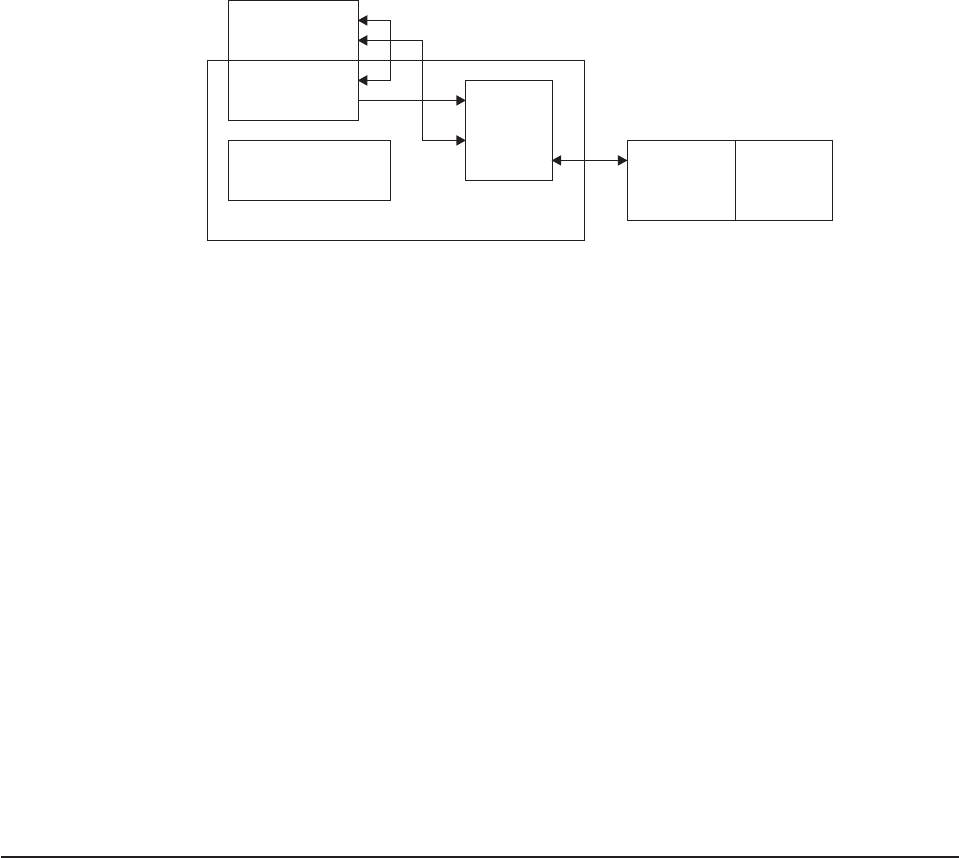
The task-related user exit program is provided with a parameter list (DFHUEPAR)
by the CICS management module that handles task-related user exits. This
parameter list gives the task-related user exit access to information such as the
addresses and sizes of its own work areas.
The task-related user exit program may be invoked by the CICS task manager and
the CICS syncpoint manager, as well as by an application program. It may also be
invoked at CICS termination or by the Execution Diagnostic Facility (EDF). The
parameter list serves to distinguish between these various callers, and gives access
to a register save area containing the caller’s registers.
The administration routines contain the EXEC CICS ENABLE and DISABLE
commands that you use to install and withdraw the task-related user exit program.
The administration routines may also contain commands to retrieve information
about one of the exit program’s work areas (the EXEC CICS EXTRACT EXIT
command), and to resolve any inconsistency between CICS and a non-CICS
resource manager after a system failure (the EXEC CICS RESYNC command). For
programming information about the EXEC CICS RESYNC command, refer to the
CICS System Programming Reference
manual.
The remainder of this chapter discusses each of these parts of the adapter in turn.
The stub program
The purpose of the stub program is to shield your application programmers from the
mechanics of non-CICS resource managers. It is written in assembler language.
After assembly, the stub is link-edited to each application program that wants to use
it. See Figure 5 on page 251.
Application
program
Stub
program Task-
related
user
Administration program Resource Non-CICS
routines manager resource
THE ADAPTER
Figure 4. The adapter concept
the adapter
250 CICS TS for OS/390: CICS Customization Guide
statname
is a label that can be referenced externally. It should conform to the
requirements of an assembler-language ENTRY statement, and typically
resolves a V-type address constant, or the target of a high-level language
CALL. A single stub may contain several such labels.
ename is the entry name (specified on the EXEC CICS ENABLE command) of the
task-related user exit program that you want to handle resource manager
requests.
You can define high-level language commands for your programmers to use when
they want to access a non-CICS resource. If you do this, you must use a translator
to convert a locally-defined high-level language command into a conventional CALL
to the required entry point of the stub program. Alternatively, the application
program can issue a CALL naming the stub entry point, as shown in Figure 5. For
example, to read a record from a non-CICS resource, an application program can
use the COBOL statement:
CALL 'XYZ' USING PARM1 PARM2...
XYZ is an entry point (the statname) in your stub program. The stub converts the
command into a macro call (DFHRMCAL) to the task-related user exit program,
specified in the TO= operand. Return from the task-related user exit program is to
the calling application program, not to the stub program.
The application can use a parameter to determine whether the resource manager
was called. For example, if the application sets a parameter to zero and the
resource manager sets it to nonzero, the parameter value on return indicates
whether the resource manager was invoked.
Returning control to the application program
If you specify RTNABND=YES in the DFHRMCAL macro, control returns to the
application program when the task-related user exit is not available, for example,
because it is not enabled or started. Note that for assembler-language application
programs, a negative value in register 15 signals to the application program that
control has returned because the exit is not available. The task-related user exit
program can use positive values (including zero) in register 15 to pass resource
manager response codes to the application program.
Application program
.
CALL statname
.
.
Stub ENTRY statname Task-related
. user exit
.
statname DFHRMCAL TO=ename ename
.
END
Figure 5. The stub concept
the stub program
Chapter 2. Task-related user exit programs 251

If you do not specify RTNABND=YES and the task-related user exit is not available,
the application program terminates abnormally with the abend code ‘AEY9’.
Task-related user exits and EDF
When a task-related user exit (TRUE) is invoked for a call to a non-CICS resource
manager from an application that is being monitored by EDF, EDF’s default action is
to display the parameters that are addressed by the parameter list passed by the
DFHRMCAL macro. However, the parameter list can be transformed into a more
meaningful display by the TRUE itself. This is done by specifying FORMATEDF on
the EXEC CICS ENABLE command that enables the TRUE. The latter is then
invoked several times, before and after the invocation to satisfy the call to the
resource manager, to format the data to be displayed by EDF and to deal with any
changes made by the user to the data on the EDF screen.
For more information about how to format screens for EDF, refer to “CICS EDF
build parameters” on page 261 and “Using EDF with your task-related user exit
program” on page 278.
If a task-related user exit program contains EXEC CICS commands, EDF may be
useful in debugging the TRUE itself. If you want EDF to display commands from the
TRUE, you must specify the EDF option when the TRUE program is translated. The
standard EDF screens for the CICS commands are then displayed between the
“About to Execute” and “Command Execution Complete” screens for the call to the
resource manager. However, as EDF is primarily an application debugging tool and
the CICS commands within the TRUE would not generally be of interest to the
application programmer, the TRUE program is normally translated with the
“NOEDF” option; in this case, screens for CICS commands within the TRUE are
suppressed.
Note: If you specify SUPPEDF=YES on the DFHRMCAL macro, the “About to
Execute” and “Command Execution Complete” screens relating to
DFHRMCAL’s invocation of the TRUE are suppressed; in other words,
DFHRMCAL becomes “invisible” to EDF. (Specifying SUPPEDF=YES has no
effect in determining whether EDF displays EXEC CICS commands within
the TRUE—the factors governing this are as described above—but it does
suppress the display of parameters passed to the TRUE.)
The task-related user exit program
The main function of the task-related user exit program is to translate the calling
program’s parameters into a form acceptable to your non-CICS resource manager,
and then to pass control to the resource manager. You therefore need to be familiar
with your resource manager’s syntax requirements. The calling program’s
parameters are described on page 257.
This section describes the user exit parameter lists, the schedule flag word, which
is used by the exit program to register its need to be invoked by CICS management
services, and register-handling in the task-related user exit program. This section
also discusses the use of the CICS syncpoint manager and the CICS task manager.
the stub program
252 CICS TS for OS/390: CICS Customization Guide
User exit parameter lists
When a task-related user exit is invoked, the CICS management module that
handles task-related user exits provides the exit with a parameter list. The address
of this parameter list is passed in register 1. The list contains the following
information:
vThe identity of the caller
vAddresses and sizes of any work areas that are available to the task-related user
exit program
vThe address of the register save area of the caller
vThe address of an EXEC interface block (EIB) that is for use by the task-related
user exit program during this invocation
vThe address of the identifier of the current unit of recovery
vThe address of the schedule flag word
vThe address of the kernel stack entry
vThe address of the APPC unit of work (UOW) identifier
vThe address of the user security block flag
vThe address of the user security block
vThe address of the resource manager qualifier name
vThe address of the resource manager’s “single-update” and “read-only” indicator
byte
vThe address of the caller’s AMODE indicator byte
vThe address of the application’s DATALOC and TASKDATAKEY indicator byte
vThe address of the performance block token
vThe address of a trace flag.
To enable your exit program to access this parameter list, you must include in it the
macro:
DFHUEXIT TYPE=RM
The DFHUEXIT TYPE=RM macro causes the assembler to create the storage
definitions (DSECTs) DFHUEPAR and DFHUERTR. If you want your task-related
user exit to be able to format screens for EDF, you must include in it the macro:
DFHUEXIT TYPE=RM,DSECT=EDF
This causes the assembler to create the UEPEDFRM DSECT, which is described in
“CICS EDF build parameters” on page 261. All of the user exit parameter lists are
summarized in Figure 7 on page 264.
The format and the purpose of these definitions are described below.
DFHUEPAR
DFHUEPAR gives you the following symbolic names for address parameters:
UEPEXN
Address of the function definition, which tells the task-related user exit
program why it is being called. See “DFHUERTR (the function definition)”
on page 257 for more details.
UEPGAA
Address of the global work area requested in the EXEC CICS ENABLE
the task-related user exit program
Chapter 2. Task-related user exit programs 253
command. The global work area is described on page “The global work
area” on page 269. CICS initializes this work area to X'00' when the
task-related user exit program is enabled.
UEPGAL
Address of a halfword containing the length (binary value) of the global
work area.
UEPTCA
This field is retained for historical reasons. It should not be referenced by
your exit program.
UEPCSA
This field is retained for historical reasons. It should not be referenced by
your exit program.
UEPHMSA
Address of the register save area (RSA) of the caller. It is an 18-word save
area, with the contents of registers 14 through 12 stored in the fourth and
subsequent words. Its fifth word, representing the calling program’s register
15, is cleared by CICS before the task-related user exit program is invoked,
so that it can be used to convey response codes from the resource
manager to the calling program. For this reason you cannot use register 15
to send data to the task-related user exit program. The seventh word of the
save area contains the caller’s register 1. Register 1 addresses the caller’s
parameter list if the exit program is being invoked by the CICS task
manager or the CICS syncpoint manager, by EDF, or at CICS termination.
When the caller is an application program, the contents of register 1 are
determined by the linkage conventions of the adapter’s language interface.
UEPTAA
Address of the local work area requested in the EXEC CICS ENABLE
command. The local work area is described on page “The local work area”
on page 269. CICS initializes the work area to X'00' throughout on first
acquiring the area; that is, when the task first invokes the task-related user
exit program.
UEPTAL
Address of a halfword containing the binary length of the local work area.
UEPEIBAddress of the EXEC interface block (EIB) created by CICS for the
task-related user exit program. The EIB exists only for the duration of the
call and it allows the task-related user exit program to request CICS
services through the command-level interface. This is not the same EIB that
is available to the calling program, so you cannot access the calling
program’s environment other than by UEPHMSA (see above), which
provides the address of the calling program’s register save area (RSA).
UEPURID
Address of CICS unit of recovery identifier. This field contains the 8-byte
date and time value that is generated by an STCK instruction, and it
identifies the current unit of work.
UEPFLAGS
Address of the schedule flag word. This is a fullword that the task-related
user exit program uses to register its need for CICS management programs’
services. For more information, see “The schedule flag word” on page 265.
UEPRMSTK
Address of the kernel stack entry.
the task-related user exit program
254 CICS TS for OS/390: CICS Customization Guide
UEPUOWDS
Address of the APPC unit of work (UOW) identifier.
UEPSECFLG
Address of the user security flag. The user security flag is a 1-byte field that
can take the following values:
UEPNOSEC (X'80')
Security is not active for this CICS system.
UEPSEC (X'20')
Security is active for this CICS system. Only in this case is the
address of the “user security block” set.
UEPSECBLK
Address of a fullword that addresses the “user security block”—that is, the
ACEE.
UEPRMQUA
Address of an 8-byte field into which the task-related user exit can move
the qualifier name of the resource manager on each API request. This is
useful where the same exit program is used to connect to more than one
instance of a resource manager; the qualifier identifies the instance of the
resource manager to which the exit is currently connected.
Where different resource manager qualifiers are returned on the responses
to various API requests within a UOW, it is the resource manager qualifier
returned on the final API request immediately before a prepare or backout
invocation that is used when recording any in-doubt information.
UEPCALAM
Address of caller’s AMODE indication byte.
X'80' Indicates that the original caller was in AMODE 31. If the top bit is
not set, then the caller was in AMODE 24.
UEPSYNCA
Address of the single-update and read-only indication byte. This field
contains flags that your exit program can set to indicate that the resource
manager “understands” the single-update protocol, and to record the status
of the current unit of work (UOW). See “Increasing efficiency –
single-update and read-only protocols” on page 271.
UEPSUPDR (X'80')
The resource manager understands the single-update protocol. That
is, your exit program can instruct the resource manager to perform
a single-phase commit, in appropriate circumstances.
UEPREADO (X'40')
The resource manager understands the read-only protocol, and has
been in read-only mode for this UOW so far. (If this flag is not set, it
means either that the UOW contains updates for this resource
manager, or that the UOW may be read-only but the resource
manager does not understand the read-only protocol.)
UEPTIND
Address of a 3-byte field containing indicators.
The first indicator byte can take one of three symbolic values, UEPTANY,
UEPTCICS, and UEPTUTCB, which you can test to determine: whether
the task-related user exit program
Chapter 2. Task-related user exit programs 255
|
|
|
|

data locations can be above or below 16MB; whether the application’s
storage is in CICS-key or user-key storage; and whether the TRUE has
been called by an unexpected TCB:
UEPTANY (X'80')
The application can accept addresses above 16MB. If the symbolic
value is not UEPTANY, the application must be returned an address
below 16MB.
UEPTCICS (X'40')
The application’s working storage and task life-time storage are in
CICS-key storage (TASKDATAKEY=CICS). If the symbolic value is
not UEPTCICS, the application’s working storage and the task’s
life-time storage are in user-key storage (TASKDATAKEY=USER).
UEPTUTCB (X'20')
Indicates an unexpected TCB. Set on a syncpoint or end-of-task
call only, this indicates a failure to switch to the TCB expected by
the task-related user exit. In these two cases, the task-related user
exit is called on the QR TCB with the UEPTUTCB bit set. For all
other calls, CICS abends the transaction without invoking the
task-related user exit.
The second and third bytes contain a value indicating the TCB mode of it’s
caller. This is represented in DFHUEPAR as both a two-character code and
a symbolic value, as follows:
Table 10. TCB indicators in DFHUEPAR. Description
Symbolic
value 2-byte
code Description
UEPTQR QR The quasi-reentrant mode TCB
UEPTCO CO The concurrent mode TCB
UEPTFO FO The file-owning mode TCB
UEPTRO RO The resource-owning mode TCB
UEPTRP RP The ONC/RPC mode TCB
UEPTSZ SZ The FEPI mode TCB
UEPTJ8 J8 The JVM mode TCB
UEPTL8 L8 An open mode TCB
UEPTSL SL The sockets listener mode TCB
UEPTSO SO The sockets mode TCB
UEPTS8 S8 The secure sockets layer mode TCB
UEPPBTOK
Address of the performance block token used for workload management, to
enable resource managers to relate their own performance blocks for the
work request with the original CICS performance block. For example,
DBCTL and DB2 need to correlate the work they do on behalf of CICS with
the originating CICS task, so that MVS workload manager can measure the
performance of the whole CICS task.
UEPTRCE
Address of a 1-byte trace flag indicating whether RMI tracing (the RI trace
component) is active.
the task-related user exit program
256 CICS TS for OS/390: CICS Customization Guide
|
|
|
|
|
|
|
|
|
|
|
|
|
|
|
|
|
|
|
|
|
|
|
|
|
|
|
|
|
|||
|||
|||
|||
|||
|||
|||
|||
|||
|||
|||
|
UEPTRLV1 (X'80')
RMI level 1 trace is active.
UEPTRLV2 (X'40')
RMI level 2 trace is active.
Having tested this field, the task-related user exit could, for example, issue
an EXEC CICS SET TRACETYPE command to reset the level of RMI
tracing.
DFHUERTR (the function definition)
The function definition identifies the caller of the task-related user exit program. The
DSECT contains two symbolic definitions (fields).
UERTFGP
A single byte that is set to X'00'. The zero setting shows that this is a
task-related user exit invocation and that the parameter list therefore
includes the fields UEPTAA, UEPTAL, UEPEIB, UEPURID, and
UEPFLAGS.
UERTFID
A single-byte identifier that shows whether this call has been made by the
CICS SPI, an application program, the CICS syncpoint manager, the CICS
task manager, or EDF, or whether this is a CICS termination call. It can
have one of the following six settings:
UERTSPI
(X'01') CICS SPI call.
UERTAPPL
(X'02') Application program call.
UERTSYNC
(X'04') CICS syncpoint manager call.
UERTTASK
(X'08') CICS task manager call.
UERTCTER
(X'0A') CICS termination call.
UERTFEDF
(X'0C') EDF call.
It is important to know which type of program has made the call because it affects
how the calling program’s parameter list is interpreted by the task-related user exit
program.
Caller parameter lists
In addition to the DSECTs DFHUEPAR and DFHUERTR, the inclusion of
DFHUEXIT TYPE=RM in the task-related user exit program provides some field
definitions that are specific to the caller of the task-related user exit. The calling
program’s parameter list is normally addressed by R1 in the calling program’s RSA.
This RSA is addressed by field UEPHMSA of DFHUEPAR. These parameters are
described below.
CICS SPI parameters:
If you enable your task-related exit program with the SPI
option of the EXEC CICS ENABLE PROGRAM command (or the program itself
“expresses interest” in SPI calls—see “The schedule flag word” on page 265), the
the task-related user exit program
Chapter 2. Task-related user exit programs 257
exit program can be invoked to satisfy EXEC CICS INQUIRE EXITPROGRAM
commands on which the CONNECTST or QUALIFIER option is specified. This
allows applications to query whether the exit program is connected to its resource
manager, and its entryname-qualifier. For information about the INQUIRE
EXITPROGRAM command, see the
CICS System Programming Reference
manual.
The CICS SPI parameter list contains two entries:
Parameter 1
The address of a 1-byte output field, which your task-related exit program
should use to indicate whether it is connected to its external resource manager.
The equated return code values are:
UERTCONN
(X'80') The exit is connected to its resource manager.
UERTNCONN
(X'40') The exit is not connected to its resource manager.
Parameter 2
The address of an 8-character output field, in which your task-related exit
program should return the qualifier of the external resource manager, if known.
See the UEPRMQUA parameter on page 255 for more information on qualifier
names.
Application program parameters:
If the caller is an application program, the
format and addressing of its parameter list are decided locally.
CICS syncpoint manager parameters:
The CICS syncpoint manager’s parameter
list contains ten entries, although on most invocations only parameters 1 and 10
contain values. The operation bytes pointed to by parameters 1 and 10 contain
flags which, when combined, form an operation code that tells the TRUE why it has
been invoked.
Parameters 2 through 9 contain values only when the syncpoint manager makes a
“Commit Unconditionally” or “Backout” call to the TRUE, for resynchronization
purposes after a session or system failure. These extra parameters point to fields
that identify the task, the transaction that started the task, the terminal from which it
was initiated, the identity of the terminal operator, the date and time of the failing
syncpoint, and (if there are no further units of recovery associated with the task) the
next transaction code. Typically, you would use these values to create meaningful
messages for resource recovery. They are presented explicitly because, after a
system failure, the task driving the exit is not the task that originally scheduled the
recoverable work. These additional parameters describe the original task’s
environment and are accessed directly.
The full parameter list is as follows:
Parameter 1
The address of operation byte 1, which contains the following flags:
UERTPREP
(X'80') Prepare to commit (that is, perform the first phase of a
two-phase commit).
UERTCOMM
(X'40') Commit unconditionally (perform the second phase of a
two-phase commit).
the task-related user exit program
258 CICS TS for OS/390: CICS Customization Guide
UERTBACK
(X'20') Backout.
UERTDGCS
(X'10') Unit of recovery has been lost because of an initial start of
CICS.
UERTDGNK
(X'08') Resource manager should not be in doubt about this unit of
recovery.
UERTWAIT
(X'04') Resource manager must wait for the outcome of this unit of
recovery. This value is set at phase two of a two-phase commit, if CICS
is in-doubt about the outcome of a UOW. It occurs only if the
task-related user exit is enabled with the INDOUBTWAIT option (see
“Enabling for specific invocation-types” on page 280).
UERTRSYN
(X'02') This syncpoint request was generated as the result of an EXEC
CICS RESYNC command.
UERTLAST
(X'01') There are no further units of recovery associated with this task.
Note that when this bit is not set, there may or may not be further units
of recovery. For this reason, it is not recommended that you rely on this
bit to signal end-of-task. You should instead schedule the CICS task
manager to drive you at end-of-task by setting the task manager bit in
the schedule flag word. If you do use UERTLAST to signal end-of-task,
and if at that stage you can complete your clean-up process, you can
set the task manager bit off in the schedule flag word when the
clean-up process is finished, to avoid an unnecessary invocation by the
CICS task manager.
The only valid bit combinations are those produced by combining one of
UERTPREP, UERTCOMM, UERTBACK, UERTDGCS, and UERTDGNK with
either UERTLAST or UERTRSYN, or both; or by combining UERTWAIT and
UERTLAST.
Your exit program should examine the flags set both in this byte and in
operation byte 2 (see parameter 10), to determine what action is expected of it.
Parameter 2
If not zero, the address of a 4-byte, packed-decimal field identifying the original
task. But note that, on many invocations of the exit program, parameters 2
through 9 do not contain values. See note 1 on page 260.
Parameter 3
Address of a 4-character field identifying the transaction that started the original
task. See note 1 on page 260.
Parameter 4
Address of a 4-character field identifying the terminal from which the original
task was initiated. See note 1 on page 260.
Parameter 5
Address of a 4-character field containing the identity of the terminal operator
(OPID) who initiated the original task. See note 1 on page 260.
the task-related user exit program
Chapter 2. Task-related user exit programs 259
Parameter 6
Address of a 4-byte, packed-decimal field containing the date of the failing
syncpoint, in the format 00yyddd+. See note 1.
Parameter 7
Address of a 4-byte, packed-decimal field containing the time of the failing
syncpoint, in the format 0hhmmss+. See note 1.
Parameter 8
Address of an 8-byte field containing the resource manager qualifier. See note
1.
To verify that this is a resync for this instance of the resource manager, your
exit program should check that the qualifier passed is the one that is currently
in use. If it is not, the exit program should ignore the resync and set a return
code of UERFHOLD, to indicate that CICS should keep the disposition of the
unit of work.
Parameter 9
Address of a 4-character field containing the next transaction code. If the
transaction ended with an EXEC CICS RETURN without specifying the next
transaction code, the addressed field is set to nulls; otherwise, it is set to the
value specified by the application. See note 2.
Parameter 10
The address of operation byte 2, which contains the following flags:
UERTONLY
(X'80') Perform a single-phase commit. (No recoverable resources other
than those owned by the resource manager being invoked have been
updated during the current UOW.)
UERTELUW
(X'40') Perform a single-phase commit. (The resource manager was in
read-only mode throughout the current UOW.)
Your exit program should examine the flags set both in this byte and in
operation byte 1 (see parameter 1), to determine what action is expected of it.
Notes:
1. Parameters 2 through 8 contain values only if the CICS syncpoint manager call
is prompted by the issue of an EXEC CICS RESYNC command after a session
or system failure, and operation byte 1 contains the bit settings UERTCOMM or
UERTBACK. Otherwise, they are set to X'00' (hexadecimal zero). For
programming information about the EXEC CICS RESYNC command and about
the completion of the syncpointing procedure following a system failure, refer to
the
CICS System Programming Reference
manual.
Note that parameters 2 through 8 describe the environment of the original task
(not of the task that is currently driving the TRUE).
2. Unless the UERTLAST bit is set in operation byte 1, parameter 9 is a zero
address. Although for a call prompted by an EXEC CICS RESYNC call, the
UERTLAST bit will be set on, in this case the next transaction code does not
apply and so Parameter 9 addresses a field set to nulls.
CICS task manager parameters:
There are either one or two entries in the CICS
task manager’s parameter list, depending on the reason for the call to the TRUE:
on start-of-task calls, the parameter list contains one entry, while on end-of-task
calls, it contains two. Each entry consists of an address, and the end of the
parameter list is indicated by the top bit of the address being set.
the task-related user exit program
260 CICS TS for OS/390: CICS Customization Guide
The significance of the parameters is as follows:
Parameter 1
The address of a single byte with bit definitions indicating the reason for the
call:
UERTSOTR
(X'40') Start of CICS task
UERTEOTR
(X'80') End of CICS task.
Parameter 2
This parameter is passed only on end-of-task calls. It is the address of a
4-character field which contains the next transaction code specified on the
EXEC CICS RETURN command. If the transaction ends with an EXEC CICS
RETURN without specifying a next transaction, this field is set to nulls.
The schedule flag word should be set during the start-of-task call if you want your
task-related user exit program to be invoked unconditionally by the CICS syncpoint
manager.
CICS termination manager parameters:
All task-related user exit programs that
have been enabled with the SHUTDOWN option of the EXEC CICS ENABLE
command, and started, are invoked at CICS termination to allow them to do the
clean-up processing that is appropriate to the type of termination. At CICS
termination, the address of a one-byte termination code is passed to your exit
program. The code may consist of any of the following bit settings:
UERTCORD
(X'80') CICS orderly shutdown
UERTCIMM
(X'40') CICS immediate shutdown
UERTCABY
(X'20') CICS abend, retry possible, TCBs dispatchable
UERTCABN
(X'10') CICS abend, retry not possible, TCBs dispatchable
UERTOPCA
(X'01') CICS abend, retry not possible, TCBs not dispatchable.
For further information about shutdown TRUEs, see “Coding a program to be
invoked at CICS termination” on page 275.
CICS EDF build parameters:
On EDF invocations, the address contained in
register 1 of the calling program’s RSA points to the UEPEDFRM DSECT. This
contains the following fields:
UEPEDFR1
The address of the application’s R1 parameter list.
the task-related user exit program
Chapter 2. Task-related user exit programs 261
UEPEDFFI
The input flag byte. When a task-related user exit is invoked by EDF,
UEPEDFFI can take the following bit settings:
UEPEDFRQ
(X'80') “About to Execute” invocation.
UEPEDFRS
(X'40') “Command Execution Complete” invocation.
UEPEDFRA
(X'20') About to display command to EDF.
UEPEDFRC
(X'10') Command has been displayed to EDF.
UEPEDFSC
(X'08') EDF user has changed the screen.
UEPEDFWS
(X'04') EDF user has changed working storage.
UEPEDFNO
(X'01') EDF user has requested NOOP.
UEPEDFFO
The output flag byte. If the task-related user exit requires, it can set the
UEPEDFFO flag byte to indicate to EDF what action the task-related user
exit wants EDF to take. It can take the following values:
UEPEDFDF
(X'80') Take default CICS action. (EDF screen contains the
uninterpreted caller’s R1 parameter list.)
UEPEDFND
(X'40') Do not display command to EDF.
UEPEDFRD
(X'20') Redisplay command to EDF.
UEPEDFDL
EDF screen attributes. These are for information only: the task-related user
exit program cannot change these fields.
UEPEDFPS (halfword binary)
Page size (number of lines).
UEPEDFLS (halfword binary)
Line size.
UEPEDFMP (halfword binary)
Maximum number of pages.
UEPEDFPA
The address of the EDF display data parameter list, supplied by the
task-related user exit. The display data parameter list is composed of
alternating pairs of attribute-byte addresses and data-field addresses.
Attribute bytes refer to the line of display data pointed to by the data-field
addresses. The data field must be the same size as the value specified in
UEPEDFLS. The display data is in the format shown in Figure 6 on
page 263.
the task-related user exit program
262 CICS TS for OS/390: CICS Customization Guide

Notes:
1. CICS provides a list of named standard attribute bytes that you may
want to use. These standard attribute bytes are contained within
DFHBMSCA, which must be copied into your program. For
programming information, including a list of the attribute bytes and their
meanings, refer to the
CICS Application Programming Reference
manual.
2. The high-order bit must be set on in the last address, to indicate to EDF
that this is the last address.
Summary of the task-related user exit parameter lists
Figure 7 on page 264 shows, in diagrammatic form, the relationships between the
parameter lists that are discussed in the preceding sections.
DISPLAY DATA
UEPEDFPA Address of
attribute byte
Address of
data field
Address of
attribute byte
.
.
.
Address of
attribute byte
Address of
data field
Figure 6. Display data parameter list
the task-related user exit program
Chapter 2. Task-related user exit programs 263
CICS SPI Application Syncpoint Task manager Termination CICS EDF
call program call manager call call manager call call
DFHUEPAR DFHUEPAR DFHUEPAR DFHUEPAR DFHUEPAR DFHUEPAR
UEPEXN UEPEXN UEPEXN UEPEXN UEPEXN UEPEXN
UEPGAA UEPGAA UEPGAA UEPGAA UEPGAA UEPGAA
UEPGAL UEPGAL UEPGAL UEPGAL UEPGAL UEPGAL
UEPHMSA UEPHMSA UEPHMSA UEPHMSA UEPHMSA UEPHMSA
UEPTAA UEPTAA UEPTAA UEPTAA UEPTAA UEPTAA
UEPTAL UEPTAL UEPTAL UEPTAL UEPTAL UEPTAL
UEPEIB UEPEIB UEPEIB UEPEIB UEPEIB UEPEIB
UEPURID UEPURID UEPURID UEPURID UEPURID UEPURID
UEPFLAGS UEPFLAGS UEPFLAGS UEPFLAGS UEPFLAGS UEPFLAGS
UEPRMSTK UEPRMSTK UEPRMSTK UEPRMSTK UEPRMSTK UEPRMSTK
UEPUOWDS UEPUOWDS UEPUOWDS UEPUOWDS UEPUOWDS UEPUOWDS
UEPSECFLG UEPSECFLG UEPSECFLG UEPSECFLG UEPSECFLG UEPSECFLG
UEPSECBLK UEPSECBLK UEPSECBLK UEPSECBLK UEPSECBLK UEPSECBLK
UEPRMQUA UEPRMQUA UEPRMQUA UEPRMQUA UEPRMQUA UEPRMQUA
UEPCALAM UEPCALAM UEPCALAM UEPCALAM UEPCALAM UEPCALAM
UEPSYNCA UEPSYNCA UEPSYNCA UEPSYNCA UEPSYNCA UEPSYNCA
UEPTIND UEPTIND UEPTIND UEPTIND UEPTIND UEPTIND
UEPPBTOK UEPPBTOK UEPPBTOK UEPPBTOK UEPPBTOK UEPPBTOK
UEPTRCE UEPTRCE UEPTRCE UEPTRCE UEPTRCE UEPTRCE
DFHUERTR DFHUERTR DFHUERTR DFHUERTR DFHUERTR DFHUERTR
UERTFGP UERTFGP UERTFGP UERTFGP UERTFGP UERTFGP
(X'00') (X'00') (X'00') (X'00') (X'00') (X'00')
UERTFID UERTFID UERTFID UERTFID UERTFID UERTFID
(X'01') (X'02') (X'04') (X'08') (X'0A') (X'0C')
RSA (R1) RSA (R1) RSA (R1) RSA (R1) RSA (R1) RSA (R1)
System Prog. Resource Syncpoint Task Address of UEPEDFRM
Interface manager- manager manager Termination
parmlist dependent parmlist parmlist code
parmlist
Output Operation Reason Termination
fields byte 1 code code
UERTCONN UERTPREP UERTSOTR UERTCORD
UERTNCON UERTCOMM UERTEOTR UERTCIMM
UERTBACK UERTCABY
UERTDGCS UERTCABN
RM UERTDGNK Next tran UERTOPCA
qualifier UERTRSYN code
UERTLAST
UERTWAIT
'Extra'
parameters
2-9
Operation
byte 2
UERTONLY
UERTELUW
Figure 7. Task-related user exit parameter lists
the task-related user exit program
264 CICS TS for OS/390: CICS Customization Guide

The schedule flag word
The schedule flag word is a fullword indicator that the task-related user exit
program uses to control its own invocation. It is also used by CICS to schedule the
first invocation of a task-related user exit program. The schedule flag word is
accessed by the address parameter UEPFLAGS of DFHUEPAR. There is a unique
schedule flag word for each association between a CICS task and the
ENTRYNAME specified when a task-related user exit program is enabled.
The default setting of the schedule flag word is for application program requests
(that is, the last two bytes are set to X'0004').
The format of the schedule flag word is shown in Table 11.
Table 11. Format of the schedule flag word
Byte Setting Comments
0 — Reserved.
1 — Reserved.
2
UEFDFEDF
UEFDTASK UEFMFEDF (X'10')
UEFMTASK (X'01') Bit mask for EDF invocation.
Bit mask for task manager.
3
UEFDSYNC
UEFDAPPL
UEFDSPI
UEFMSYNC (X'10')
UEFMAPPL (X'04')
UEFMSPI (X'02')
Bit mask for syncpoint manager.
Bit mask for application program.
Bit mask for SPI.
The bit settings of the schedule flag word show which programs invoke your
task-related user exit program. For example, if an exit program is to be invoked by
the CICS task manager, the CICS syncpoint manager, and an application program,
then the last two bytes of the schedule flag word are set to X'0114'. If an exit
program is to be called by the CICS task manager and an application program only,
the last two bytes of the flag word are set to X'0104'. Before the exit program is first
called by a task, CICS sets the API flag bit on.
Before returning from any call, the task-related user exit can change the bit settings
of the flag word to register its need to be invoked by a different CICS management
service, or to register lack of interest in a service by setting the relevant flag bit to
zero.
For example, a task-related user exit may be called by an application program that
needs to access a non-CICS recoverable resource. When the exit program is first
called, the API bit is set on by CICS. If the calling program then issues a request to
update a record, the exit program sets the syncpoint manager bit on in the schedule
flag word. When the calling application program subsequently issues a syncpoint
command, or when end-of-task is reached, the CICS syncpoint manager calls the
exit program.
Note: CICS sets the syncpoint manager bit off after every call to the syncpoint
manager. This is to avoid the CICS syncpoint manager invoking the
task-related user exit program for a unit of recovery during which the exit
program did no recoverable work. The syncpoint manager bit must therefore
be set on whenever the exit program performs any recoverable work.
If you set the task manager bit in the schedule flag word on, CICS invokes your
task-related exit program at the end of this task. (Note that, if you want your exit
the task-related user exit program
Chapter 2. Task-related user exit programs 265
program to be called at the start as well as at the end of a task, you must specify
TASKSTART on the EXEC CICS ENABLE command for the TRUE. This causes the
TRUE to be invoked at the start and end of every task.)
If the last two bytes of the schedule flag word are set to X'1000', this indicates that
the task-related user exit is interested in being invoked by EDF to format requests
for display. This schedule flag bit UEFDFEDF is set on either by the EXEC CICS
ENABLE FORMATEDF command, or by the task-related user exit. Unlike other
schedule flag bits, there are restrictions on when the task-related user exit can
register a lack of interest in EDF (that is, restrictions on when UEFEDFDF can be
set off). Once a task-related user exit has formatted the initial screen for EDF to
display on “About to Execute” or “Command Execution Complete”, CICS does not
allow it to set the EDF bit UEFDFEDF off until the screen build cycle is complete.
Register handling in the task-related user exit program
In this section, two sets of registers are discussed:
1. The registers belonging to the CICS management module that handles
task-related user exits. These are referred to as the CICS registers.
2. The registers belonging to the calling program and that are addressed by
parameter UEPHMSA of DFHUEPAR. These are referred to as the calling
program’s registers.
Saving CICS registers
Your task-related user exit program should begin by saving the contents of the
CICS registers. Register 13 addresses an 18-word area into whose 4th and
subsequent words your exit program should store registers 14 through 12. Three of
the saved values have significance, as follows:
vThe saved contents of register 14 contain the address within CICS to which the
task-related user exit program returns control.
vThe saved contents of register 15 contain the address at which the task-related
user exit program has just been entered.
vThe saved contents of register 1 address the parameter list (DFHUEPAR) that is
provided by CICS for the task-related user exit program.
Note: As a general rule, if you fail to understand the origin or the purpose of a call,
you should:
1. Restore any registers that you have used to the state they were in on
entry to your code
2. Return to the address contained in CICS register 14.
The calling program’s registers
The calling program’s registers are stored at the address specified by UEPHMSA of
DFHUEPAR. Where the calling program is a CICS management program, for
example the syncpoint manager, the only caller registers that have significance are
registers 1 and 15. Register 1 addresses the calling program’s parameter list. CICS
sets the calling program’s register 15 to zero before the task-related user exit
program is invoked. The calling program’s register 15 can sometimes be used to
pass responses back to the calling program from the task-related user exit program,
depending on the identity of the caller. If the calling program is a CICS
management program, and the register is still zero on return, CICS assumes that its
call was not understood. If the calling program is an application program, the
the task-related user exit program
266 CICS TS for OS/390: CICS Customization Guide

significance of register settings on return are either described in your resource
manager’s documentation, or defined locally.
Addressing-mode implications
The task-related user exit is invoked in the AMODE of the caller, unless the exit has
been enabled with the LINKEDITMODE option of the EXEC CICS ENABLE
command. This option enables the task-related user exit in its link-edit AMODE.
Therefore, if the TRUE has been link-edited AMODE 31 and is enabled with the
LINKEDITMODE option, it can be placed above the 16MB line. For programming
information about the LINKEDITMODE option of the EXEC CICS ENABLE
command, refer to the
CICS System Programming Reference
manual.
Important
You should avoid the use of the LINKEDITMODE option where the TRUE has
been link-edited AMODE 24. This combination forces the TRUE
always
to run
AMODE 24, which is unwise because:
vAn AMODE 24 TRUE cannot be invoked from a transaction running with
TASKDATALOC(ANY). This results in an ‘AEZB’ abend.
vEnabling an AMODE 24 TRUE for task start causes CICS to force all
transactions to run with TASKDATALOC(BELOW).
vOn a CICS termination call, CICS ignores LINKEDITMODE and invokes the
TRUE in AMODE 31, if it detects that the TCA it is running under is above
the 16MB line. (This is because, for some types of termination, such as a
cancel, the TCA under which the TRUE will run is not predetermined.)
It is recommended that TRUEs are:
vWritten so that they can always run AMODE 31
vLink-edited AMODE 31
vEnabled with the LINKEDITMODE option.
If the task-related user exit has not been enabled with the LINKEDITMODE option
of EXEC CICS ENABLE, it is invoked in the AMODE of the caller. For example, in
the case of an application request, if the application is AMODE 24 at the time of the
DFHRMCAL, the task-related user exit is invoked in AMODE 24. For this reason,
task-related user exits which have been enabled without the LINKEDITMODE
option must reside below the 16MB line.
Exit programs and the CICS storage protection facility
When you are running CICS with the storage protection facility, there are two points
you need to consider for task-related user exits:
1. The execution key in which your task-related user exit programs run
2. The storage key of data storage obtained for your exit programs.
Execution key for task-related user exit programs
When you are running with storage protection active, CICS always invokes
task-related user exit programs in CICS key. Even if you specify EXECKEY(USER)
on the program resource definition, CICS forces CICS key when it passes control to
the TRUE. However, if a task-related user exit program itself passes control to
the task-related user exit program
Chapter 2. Task-related user exit programs 267

another program (via a link or transfer-control command), the program thus invoked
executes according to the execution key (EXECKEY) defined in its program
resource definition.
Important
You are strongly recommended to specify EXECKEY(CICS) when defining
both task-related user exit programs, and programs to which an exit program
passes control.
Data storage key for task-related user exit programs
The storage key of storage used by task-related user exit programs depends on
how the storage is obtained:
vGlobal or local work areas specified when an exit program is enabled, are always
in CICS key.
vAny working storage obtained for the exit program is in the key set by the
TASKDATAKEY of the transaction under which the exit program is invoked.
vTask-related user exit programs can use EXEC CICS commands to obtain
storage by issuing:
– Explicit EXEC CICS GETMAIN commands
– Implicit storage requests as a result of EXEC CICS commands that use the
SET option.
The default storage key for storage obtained by EXEC CICS commands is set by
the TASKDATAKEY of the transaction under which the exit program is invoked.
As an example, consider a transaction defined with TASKDATAKEY(USER) that
causes a task-related user exit program to be invoked. In this case, any implicit
or explicit storage acquired by the exit program by means of an EXEC CICS
command is, by default, in user-key storage. However, on an EXEC CICS
GETMAIN command, the exit program can override the TASKDATAKEY option by
specifying either CICSDATAKEY or USERDATAKEY.
Recursion within a task-related user exit program
The task-related user exit has the ability to invoke itself recursively. It can do this,
for example, by issuing a DFHRMCAL call to its own entry name (as specified on
the EXEC CICS ENABLE command). It can also be entered recursively if it
performs an EXEC CICS SYNCPOINT when it is interested in SYNCPOINT
invocations.
Using CICS services in your task-related user exit program
You might find some CICS services useful in your exit program. These can be
invoked using EXEC CICS commands. However, you should take note of the
following:
vIf your program is invoked because of a CICS abend, it must not use any CICS
services. See “Coding a program to be invoked at CICS termination” on
page 275.
the task-related user exit program
268 CICS TS for OS/390: CICS Customization Guide
vDFHEIENT and DFHEIRET must be in your program.
But see the note about not
using DFHEIENT in abend invocations, on page 276.
For further details of the
DFHEIENT and DFHEIRET macros, see the
CICS Application Programming
Reference
manual.
vIf your exit program entry point is immediately followed by an occurrence of a
DFHEIENT macro, inserted either implicitly by CICS or explicitly in the program,
then the expansion of the DFHEIENT macro stores incorrect values at DFHEIBP
and DFHEICAP. Your code can subsequently correct this by copying UEPEIB into
DFHEIBP, reloading the EIB base register (DFHEIBR) from UEPEIB, and setting
DFHEICAP to X'80000000'. For example,
TESTPROG DFHEIENT CODEREG=2,EIBREG=11,DATAREG=10
USING DFHUEPAR,1
MVC DFHEIBP,UEPEIB Get correct EIB address
L DFHEIBR,UEPEIB Reload EIB base register
MVC DFHEICAP,=X'80000000'
Note that the entry point of a program does not have to be at the start of the
program and can be positioned after the DFHEIENT macro.
vThe DFHEIENT macro allocates dynamic storage to be mapped by the
DFHEISTG DSECT. You must return to CICS by means of the DFHEIRET macro,
which frees the dynamic storage.
vCommand-level calls use registers 0, 1, 14, and 15.
vDo not issue a syncpoint in start-of-task, end-of-task, or syncpoint invocations.
vOn each invocation of a task-related user exit program, a new EXEC
environment is created, even when the program is being invoked from the same
task. This means that CICS operations, such as browse of a resource definition
table, cannot be continued from one invocation of the exit program to the next.
Work areas
When you use the EXEC CICS ENABLE command to identify a task-related user
exit program to CICS, you may specify that the program must have access to one
local and one global work area. The EXEC CICS ENABLE command allows you to
specify the size, in bytes, of the work areas to be acquired for your task-related
user exit program. CICS acquires storage for the areas and initializes pointers to
them. The user exit parameter list, DFHUEPAR, gives you access to the pointers.
For more information, see the description of DFHUEPAR under “User exit
parameter lists” on page 253.
The global work area
A global work area is associated with an exit program. Whenever the exit program
is invoked, it has access to the area through the parameter UEPGAA of
DFHUEPAR. The global work area may be shared by a number of exit programs.
You must have specified the size of the global work area using the GALENGTH
parameter or the GAENTRYNAME parameter of the EXEC CICS ENABLE
command.
The local work area
A local work area is associated with a single task and lasts only for the duration of
the task. It is for the use of a single task-related user exit program. It can be
thought of as a logical extension to the transaction work area (TWA, TWACOBA)
the task-related user exit program
Chapter 2. Task-related user exit programs 269
that is exclusively for the exit program’s use. It is specified using the TALENGTH
option of the EXEC CICS ENABLE command and is accessed using the UEPTAA
parameter of DFHUEPAR.
Coding a program to be invoked by the CICS SPI
If you enable your task-related exit program with the SPI option of the EXEC CICS
ENABLE PROGRAM command (or your program “expresses interest” in SPI calls
by setting the SPI bit-mask in the schedule flag word), your program is invoked to
satisfy EXEC CICS INQUIRE EXITPROGRAM commands that query whether the
exit program is connected to its resource manager, and its entryname-qualifier. (For
information about the INQUIRE EXITPROGRAM command, see the
CICS System
Programming Reference
manual.)
When invoked for SPI calls, your exit program should:
vIndicate whether it is connected to its external resource manager, by returning
the appropriate value in the first field addressed by the caller’s parameter list.
The equated values are:
UERTCONN
(X'80') The exit is connected to its resource manager.
UERTNCONN
(X'40') The exit is not connected to its resource manager.
vReturn the resource manager qualifier—that is, the entryname-qualifier, as
returned by the UEPRMQUA parameter of an API call, and used on an EXEC
CICS RESYNC command—in the second field addressed by the caller’s
parameter list.
Typically, both the above pieces of information are kept in the exit program’s global
work area. The caller parameter list for SPI calls is described in “CICS SPI
parameters” on page 257.
The RMI SPI call allows a task-related user exit to be called by long-running
monitor tasks, even if it has been disabled and reenabled since it was last called by
the task. (All other types of RMI call fail if this is the case.)
Note: When invoked for an SPI call, your exit program should not rely on the
contents of the task local work area. If the exit has been disabled and
reenabled, a new version may have been loaded, which may have a different
mapping of the task local work area. The long-running task, however, is
running with the original task local work area allocated to it on its first call.
Coding a program to be invoked by the CICS syncpoint manager
All task-related user exit programs can be invoked by the CICS syncpoint manager.
An exit program must “schedule” the syncpoint manager by setting the syncpoint
manager bit-mask in the schedule flag word. The bit-mask must be set after every
piece of recoverable work to ensure that the CICS syncpoint manager calls the exit
program during syncpoint processing. (The identification of the current unit of
recovery—or unit of work—is addressed by the 8-byte field UEPURID. This is
available on all invocations of your exit program in which recoverable actions are
possible, for example, application calls and subsequent syncpoint manager calls.)
the task-related user exit program
270 CICS TS for OS/390: CICS Customization Guide
Increasing efficiency – single-update and read-only protocols
If your resource manager is capable of performing a single-phase commit, you can
increase the efficiency of your system by means of CICS single-update and
read-only protocols.
Single-update protocol:
Many CICS transactions use only one external resource
manager. In this case, a single-phase commit is in order. The benefits of a
single-phase commit are:
vThe resource manager can reduce from two to one the number of log forces
required for transactions.
vThe number of transaction-related log records written by CICS is reduced.
vA path length reduction is achieved, because the TRUE is invoked only once at
the syncpoint, rather than twice.
To take advantage of these benefits, your task-related user exit program must
indicate to CICS that the resource manager understands the single-update protocol,
and that it (the TRUE) can process a syncpoint call to perform a single-phase
commit. It indicates this by setting the UEPSUPDR flag in the field pointed to by
UEPSYNCA in the DFHUEPAR parameter list. It must do this every time it sets the
syncpoint manager bit in the schedule flag word.
If the exit program has set the UEPSUPDR flag, then, when the syncpoint manager
next invokes the TRUE, it informs it whether the resource manager is the only one
to have updated resources in the current UOW. It does this by means of the
UERTONLY bit (in operation byte 2 of the syncpoint manager’s parameter list); if
this is set on, then the resource manager can be asked to perform a single-phase
commit.
Read-only protocol:
Similar gains in efficiency can be made if the resource
manager is in read-only mode throughout the current UOW. Again, a single-phase
commit is in order. To benefit, the resource manager must return to the TRUE a flag
indicating whether the UOW is read-only or not. The flag may show either the
“history” of the UOW so far (for example, so far it is read-only), or simply whether
the current request is read-only. In turn, the TRUE must update the UEPREADO
flag in the DFHUEPAR parameter list with the history of the UOW so far. That is, it
must set UEPREADO initially, but unset it as soon as the UOW contains updates.
(Once UEPREADO has been unset, CICS ignores any subsequent setting of the
flag during the current UOW, and treats the UOW as containing updates.)
At the end of the UOW, if the UEPREADO flag is still set, the syncpoint manager
invokes the TRUE with instructions to issue a single-phase commit to the resource
manager (by setting the UERTELUW bit on).
Return codes
When a task-related user exit program is invoked by the CICS syncpoint manager,
the return codes it is able to set depend on the reason for the invocation. Table 12
on page 272 shows the relationship between the request flags in the syncpoint
manager’s parameter list and the TRUE return codes. (The CICS syncpoint
manager parameters are described on page 258.)
the task-related user exit program
Chapter 2. Task-related user exit programs 271

Table 12. Valid return codes for a TRUE invoked by the CICS syncpoint manager
Request-type Return codes Meaning
UERTPREP UERFPREP Phase 1 of 2-phase commit successful
UERFBACK Phase 1 of 2-phase commit unsuccessful
UERTWAIT None Not applicable
UERTCOMM UERFDONE Phase 2 of 2-phase commit successful
UERFHOLD Phase 2 of 2-phase commit unsuccessful
UERTBACK UERFDONE Backout successful
UERFHOLD Backout unsuccessful
UERTONLY UERFOK Single-phase commit successful
UERFBOUT Single-phase commit failed and backed out
UERTELUW None Not applicable
What is expected of your resource manager
If every request from the syncpoint manager prompts a meaningful response from
the resource manager, CICS ensures that changes to recoverable resources (such
as databases) can be synchronized. That is, either all the changes take effect or all
are backed out, even across system failures.
Limitations
Do not update a recoverable CICS resource during a syncpoint call because any
changes will not be seen by the CICS syncpoint manager.
Sample code for a TRUE invoked by the CICS syncpoint
manager
The pseudocode given in Figure 8 on page 273 is only an example. It is not
complete, and includes only some of the conditions that a task-related user exit
invoked at a syncpoint might be required to check.
the task-related user exit program
272 CICS TS for OS/390: CICS Customization Guide
|
|
|
|
As described in “Increasing efficiency – single-update and read-only protocols” on
page 271 , if the UERTONLY bit is set (indicating that the resource manager is the
only one to have updated resources) the exit program should cause the resource
manager to perform a single-phase commit. If the commit is successful, the exit
program should return ‘UERFOK’ in register 15; if not, it should return ‘UERFBOUT’,
meaning that the commit was unsuccessful and the resources were backed out. If
the exit program is unsure about the outcome of a single-phase commit, it must
abend the task, having saved or displayed any diagnostic information that it
considers necessary.
Note that “register 15” in this section refers to the syncpoint manager’s register 15,
the fifth word of the area addressed by UEPHMSA.
Similarly, when the UERTELUW bit is set (indicating that the resource manager was
in read-only mode throughout this UOW), the exit program should cause the
resource manager to perform a single-phase commit. There are no return codes for
if UERTFID = UERTSYNC then /* Caller is CICS syncpoint manager */
select; /* Type of syncpoint manager request */
when (UERTONLY) /* ONLY resource manager */
invoke RM for single-phase commit /* Single-phase commit */
if RM single-phase commit succeeded then
give CICS syncpoint manager 'YES' vote (UERFOK)
else /* Single-phase commit failed */
/* If RM completed backout */
if RM single-phase commit failed and backed out
give CICS syncpoint manager 'NO' vote (UERFBOUT)
else /* Don't know what happened */
put out message and issue transaction abend
endif
endif
when (UERTELUW) /* RM read-only for current UOW */
invoke RM for single-phase commit /* Single-phase commit */
when (UERTPREP) /* Not ONLY resource manager, nor read-only */
invoke RM for PREPARE /* Prepare - phase 1 of 2-phase commit */
select (resource manager vote)
when (YES) /* Phase 1 completed */
give CICS syncpoint manager 'YES' vote (UERFPREP)
otherwise
give CICS syncpoint manager 'NO' vote (UERFBACK)
endselect
when (UERTCOMM) /* Commit - phase 2 of 2-phase commit */
invoke RM for commit phase 2
if RM commit succeeded then
tell CICS sync manager OK (UERFDONE)
else
tell CICS sync manager remember could not commit (UERFHOLD)
endif
when (UERTBACK) /* Backout request */
invoke RM for backout
if RM backout succeeded then
tell CICS sync manager OK (UERFDONE)
else
tell CICS sync manager remember could not backout (UERFHOLD)
endif
when (UERTWAIT) /* CICS in-doubt about UOW */
invoke RM to free thread
(but maintain locks for UOW and record UOW is in-doubt)
endselect
endif
Figure 8. Sample pseudocode for a task-related user exit program to be invoked by the CICS
syncpoint manager
the task-related user exit program
Chapter 2. Task-related user exit programs 273
a UERTELUW call. Because no updates were made, data integrity is not at risk,
and therefore no action is taken if the commit fails.
On receiving a request to perform the first phase of a two-phase commit, the
resource manager is expected to get into a state where recoverable changes made
since the last syncpoint can be either committed or backed out on demand, even if
there is an intervening system failure. For example, buffer contents must be moved
to nonvolatile storage. If the resource manager is unable to get into this state, the
exit program should return ‘UERFBACK’ in register 15, to request backout.
Normally, it should return ‘UERFPREP’, to indicate a successful phase 1 of a
2-phase commit.
On receiving a request to wait (indicating that CICS is in-doubt about the outcome
of the UOW), the resource manager should free any task-related resources, such
as the thread. However, it should maintain any locks held by the UOW, and record
that the UOW is in-doubt. See “Enabling for specific invocation-types” on page 280.
On receiving a request to perform the second phase of a two-phase commit, or a
request to back out, the resource manager should take the corresponding
irreversible step, and have the exit program send the syncpoint manager a return
code: either ‘UERFDONE’, meaning that the commit or abend process is complete;
or ‘UERFHOLD’, meaning that the commit or abend must be resolved later. These
return code constants are available to you when you code the macro DFHUEXIT
TYPE=RM in your exit program.
If a resource manager cannot understand a call, it should not change the contents
of the caller’s register 15 before returning to the caller, because it cannot anticipate
how the caller will interpret the change.
Resynchronization
If a failure occurs between returning from the exit after performing phase 1 of a
2-phase commit and the subsequent phase 2 or back out call, the resource
manager must be ready, on restart, to discover the state of the unit of recovery, and
to act accordingly. For programming information about restart resynchronization
using the EXEC CICS RESYNC command, see the
CICS System Programming
Reference
manual.
If CICS is in-doubt about a unit of work, it sends the exit program a request to wait
(UERTWAIT). When the status of the in-doubt UOW is resolved, CICS initiates a
resynchronization task, to inform the exit program of the outcome of the unit of
work.
Information about in-doubt units of work is retained across both warm and cold
starts of CICS. CICS initialization and keypoint management routines recover from
the system log all information associating resource managers with outstanding units
of recovery, which are resolved automatically when CICS reconnects to the
resource managers concerned.
Coding a program to be invoked by the CICS task manager
If your exit program sets the task manager bit in the schedule flag word, it is
invoked at end-of-task. If you specify TASKSTART on the EXEC CICS ENABLE
command for the TRUE, it is invoked at start-of-task, and (providing it does not
unset the task manager bit), at end-of-task too. To determine whether a particular
the task-related user exit program
274 CICS TS for OS/390: CICS Customization Guide
invocation is at start- or end-of-task, you can examine the CICS task manager
parameters described in “CICS task manager parameters” on page 260. Typically,
your program shows interest in task manager events if it needs to save task-related
information, such as performance or accounting data, before the task ends.
Limitations
If your exit program is invoked at end-of-task, you must be alert to possible
limitations on exit program activity at task-detach. For example:
vDo not update any CICS resources at all during a task-detach exit call, because
the CICS syncpoint manager is not invoked again for that task. Note also that all
resources (terminals, and so on) except task-storage have been released by
end-of-task.
Note: You should also be aware that transactions with resource security or
command security defined may not run successfully after the terminal has
been released. See the
CICS RACF Security Guide
to determine which
resources and commands are subject to security checking. Failure to
observe these limitations can result in an ABENDAEY7 - NOTAUTH
condition arising.
vIt is possible to schedule a new CICS task from your exit program using the
EXEC CICS START command and to pass data to a new task. However, you
should note that EXEC CICS START uses a temporary storage queue to pass
data to the new transaction. If this queue is recoverable (DFHTST
TYPE=RECOVERY), it is locked to the detaching task. It is never unlocked,
because, when the task-detach exit call is made, the resources of the detaching
task have already been freed. Use of the PROTECT option would cause a
different problem: the new task could not be scheduled until the next syncpoint of
the detaching task, but there will be no such syncpoint.
vIt is recommended that you do not access remote resources using a task-related
user exit program. However, if you do so, then you must understand fully the
circumstances in which the function shipping conversation may be terminated.
Coding a program to be invoked at CICS termination
If you specify the SHUTDOWN option when enabling your task-related user exit
program, it is invoked at system termination. The CICS system termination manager
passes the exit program the address of a one-byte code that identifies the type of
termination (see “CICS termination manager parameters” on page 261). You can
use this invocation of your program to do processing appropriate to the type of
termination. For example, at an orderly shutdown you could use it, rather than a
PLT program, to shut down the adapter; at a CICS abend you could use it to take
special actions, related to the seriousness of the abend.
Limitations
Note that, due to the nature of CICS abends and operator cancels, there is no
guarantee that CICS will be able to invoke your exit program at system termination,
even if you have specified SHUTDOWN; it may be too impaired to do so.
the task-related user exit program
Chapter 2. Task-related user exit programs 275

The limitations on what your program can do, if invoked, depend on the type of
termination:
Orderly shutdown (UERTCORD)
Your exit program must follow the rules for programs that execute during
the first quiesce stage of CICS shutdown—that is, all CICS services are
available, but programs must not start any new tasks.
Immediate shutdown (UERTCIMM)
As for orderly shutdown, except that your exit program should do the
minimum required and return control, so that shutdown can proceed.
CICS abend, retry possible, TCBs dispatchable (UERTCABY)
MVS has flagged the failure as being “eligible for retry”. Your exit program
must follow the MVS rules for this type of failure, documented in the
OS/390 MVS Authorized Assembler Services Guide
.
Subtasks in the region (that is, task control blocks (TCBs) in addition to the
CICS job-step TCB) are still dispatchable, and your exit program can
execute code under them.
You must not use any CICS services.
CICS abend, retry not possible, TCBs dispatchable (UERTCABN)
MVS has flagged the failure as “not eligible for retry”. Your exit program
must follow the MVS rules for this type of failure. Note that your exit
program is invoked from code within the CICS extended subtask abend exit
(ESTAE). MVS imposes more restrictions on ESTAE code than on
non-ESTAE code.
Subtasks in the region are still dispatchable, and your exit program can
execute code under them.
You must not use any CICS services.
CICS abend, retry not possible, TCBs not dispatchable (UERTOPCA)
As for UERTCABN, except that subtasks in the region are not dispatchable;
your exit program must not try to execute code under any TCBs that it may
have attached.
Important
In the abend invocations (UERTCABY through UERTOPCA), your exit
program must not use any CICS services. This includes the DFHEIENT call,
which performs a CICS GETMAIN. To prevent a DFHEIENT call being issued
automatically on each invocation of your program, specify the NOPROLOG
translator option; but include in the program source your own DFHEIENT call
to be issued on non-abend invocations only. An example of how to code a
task-related user exit program to be invoked at CICS termination is given in
Figure 9 on page 277. For further information about coding a DFHEIENT call,
see the
CICS Application Programming Reference
manual.
Sample code for a TRUE invoked at CICS termination
Note that the sample in Figure 9 on page 277 is a multipurpose program—that is, it
is coded to be invoked at many task-related user exit points. However, to avoid the
need to test for CICS abends in all of your multipurpose TRUEs, it is recommended
that you use a separate program for termination invocations.
the task-related user exit program
276 CICS TS for OS/390: CICS Customization Guide
JTRUE1A CSECT TERMINATION TRUE ENTRYPOINT
STM 14,12,12(13) Save registers
USING JTRUE1A,R3
LR R3,R15 Use R3 as base register
USING DFHUEPAR,R1 Address DFHUEPAR parameter list
L R2,UEPEXN
USING DFHUERTR,R2
CLI UERTFID,UERTCTER CICS Termination call?
BNE CONT No, so continue
L R10,UEPHMSA Address Host register save area
USING SA,R10
L R5,RSAR1 Get Caller's R1
USING DFHCTERM,R5
L R5,CTERML Get termination type
USING CTERMLIST,R5
TM CTERMTYPE,UERTCORD CICS orderly shutdown?
BO CONT Yes, so can use CICS services
TM CTERMTYPE,UERTCIMM CICS immediate shutdown?
BO CONT Yes, so can use CICS services
* ...
* ...
* Insert code here for any processing when CICS is abending
* (No CICS services should be used)
* ...
* ...
LM 14,12,12(13) Restore caller's registers
BSM 0,14 Return to caller
CONT DS 0H Continue in new CSECT
LM 14,12,12(13) Restore callers's registers
DROP R3
USING JTRUE1A,R15 Use R15 as temporary base register
L R15,=V(JTRUE1B) Get address of new CSECT
BR R15 Branch to new CSECT
DROP R15
LTORG
JTRUE1B CSECT POST TEST CSECT
DFHEIENT
LR R4,R1 Use R4 to address parm list
USING DFHUEPAR,R4 Address parm list
L R5,UEPEXN
USING DFHUERTR,R5
Figure 9. Sample code for a task-related user exit program to be invoked at CICS termination
(Part 1 of 2)
the task-related user exit program
Chapter 2. Task-related user exit programs 277
Using EDF with your task-related user exit program
If your exit program sets the EDF bit in the schedule flag word and EDF is active,
the exit program is invoked before and after each API request to format screens for
EDF to display.
Communication between the task-related user exit and EDF is controlled by the
task-related user exit interface. The command flow between this interface, EDF, and
the task-related user exit is summarized in Figure 10 on page 279.
MVC DFHEIBP,UEPEIB
MVC DFHEICAP,=X'80000000'
* .....
* Insert code here for all types of call other than when CICS
* is abending
* (CICS services can be used)
* .....
EXIT DS 0H
DFHEIRET
*
LTORG
*
DFHCTERM DSECT
CTERML DS A
*
CTERMLIST DSECT
CTERMTYPE DS CL1
*
DFHEISTG DSECT
*
* Local working storage for CSECT JTRUE1B
*
RSA DS 18F Register save area
SA DSECT Register save area DSECT
DS F
*
RSACB DS F +004
RSACF DS F +008
RSAR14 DS F +00C
RSAR15 DS F +010
RSAR0 DS F +014
RSAR1 DS F +018
RSAR2 DS F
RSAR3 DS F
RSAR4 DS F
RSAR5 DS F
RSAR6 DS F
RSAR7 DS F
RSAR8 DS F
RSAR9 DS F
RSAR10 DS F
RSAR11 DS F
RSAR12 DS F
DFHREGS
DFHUEXIT TYPE=RM
DFHEISTG
DFHEIEND
PRINT NOGEN
PRINT GEN
END
Figure 9. Sample code for a task-related user exit program to be invoked at CICS termination
(Part 2 of 2)
the task-related user exit program
278 CICS TS for OS/390: CICS Customization Guide

Table 13 describes each stage of the interface between the task-related user exit
and EDF, relating the descriptions to the (T
n
) and (E
n
) expressions in Figure 10.
Table 13. Description of each stage of the task-related user exit/EDF interface
Invocation Description
(T1) Task-related user exit invoked to set up its EDF requirements. At this
stage the task-related user exit prepares the “About to Execute” screen
based on the application request.
(E1) Using information passed back from the task-related user exit at
invocation T1, the task-related user exit interface invokes EDF to display
the “About to Execute” screen. EDF sets up the EDF user response, for
example, if the user has changed the screen.
(T2) Task-related user exit is invoked with the EDF user response to the
“About to Execute” screen.
(T3) Task-related user exit invoked to access external resource manager for
application request.
(T4) Task-related user exit invoked to prepare a “Command Execution
Complete” screen, based on the result of the application request.
(E2) Using information passed back from the task-related user exit at
invocation T4, the task-related user exit interface invokes EDF to display
the “Command Execution Complete” screen. EDF sets up the EDF user
response, for example, if the user has changed the screen.
(T5) Task-related user exit is invoked with the EDF user response to the
“Command Execution Complete” screen.
Task-related user
exit interface Task-related user exit (T1)
Prepare 'About to Execute' EDF screen
EDF (E1) Display screen
Task-related user exit (T2)
Response EDF user
Task-related user exit (T3)
Access resource manager
Task-related user exit (T4)
Prepare 'Command Execution Complete' EDF screen
EDF (E2) Display screen
Task-related user exit (T5)
Response EDF user
Figure 10. Interface between the task-related user exit and EDF
the task-related user exit program
Chapter 2. Task-related user exit programs 279

Important
The E1/T2 and E2/T5 cycles can be used repeatedly. This may occur, for
example, if the EDF user changes the screen a number of times.
Adapter administration
Careful use of task-related user exits can allow your application programmers to be
unaffected by the invocation of non-CICS resource managers from CICS application
programs. Enabling and disabling task-related user exit programs for an installation
should be the responsibility of one or more supervisory or master terminal
operators. This section lists what you must do before you can use the adapter, and
describes the commands used by the supervisor to administer task-related user exit
programs.
For programming information about the use of commands in CICS application
programs, see the
CICS Application Programming Reference
manual.
What you must do before using the adapter
1. A task-related user exit program must be defined to the system using the CEDA
INSTALL PROGRAM command.
2. To enable the task-related user exit program and to define its working storage
needs, you must use the EXEC CICS ENABLE command. A task-related user
exit program must be both enabled and started before it is available for
execution. For example:
EXEC CICS ENABLE PROGRAM('EP9')
TALENGTH(750) GALENGTH(200) SHUTDOWN
EXEC CICS ENABLE PROGRAM('EP9')
START
The first command loads the task-related user exit program EP9, and causes a
200-byte work area to be obtained and associated with it. The first command
also schedules the allocation of a further 750-byte work area for each task that
subsequently invokes EP9, and the invocation of EP9 at CICS termination. The
second command starts the exit program, that is, it makes its entry point
capable of being invoked.
Note: If a task-related user exit program is enabled before it has been installed,
CICS scans the LPA for the program and may issue message
DFHLD0107I, meaning that it was unable to find the program in the LPA
and is using the DFHRPL version.
Enabling for specific invocation-types
Use the following options of the EXEC CICS ENABLE command to cause your exit
program to be invoked at specific events:
INDOUBTWAIT
specifies that, at phase 2 syncpoint time, if CICS is in-doubt about the
outcome of the UOW, the exit program is to be invoked with the UERTWAIT
verb (wait), instead of a forced definition of UERTCOMM (commit) or
UERTBACK (backout). UERTWAIT signifies that CICS does not yet know
the outcome of the UOW. In response to a UERTWAIT call, the task-related
the task-related user exit program
280 CICS TS for OS/390: CICS Customization Guide
user exit should invoke its resource manager to free any task-related
resources, such as the thread. However, the resource manager should
maintain any locks held by the UOW, and record that the UOW is in-doubt.
When CICS receives the outcome of the UOW from its coordinator, a
resynchronization task is attached to notify the task-related user exit about
the outcome of the UOW.
If CICS is in-doubt about the outcome of a UOW for which an external
resource manager has requested resynchronization (using the EXEC CICS
RESYNC command), CICS waits until the in-doubt has been resolved
before initiating a resynchronization task.
The effects of not enabling a task-related user exit with the INDOUBT
keyword are:
vIf CICS is in-doubt about a UOW, a forced decision is taken and the
task-related user exit invoked with the forced decision.
vIf CICS is forced to take a decision because a task-related user exit is
not enabled with INDOUBTWAIT, it takes a forced decision for all
resources updated by the UOW, even if all the other resources are
capable of waiting for in-doubt resolution. This applies to local resources
such as files, and also other RMCs, such as LU6.1, LU6.2, or MRO
connections to other systems.
vAn inbound RESYNC command from a resource manager that requests
resynchronization for a UOW that CICS was in-doubt about, results in
CICS invoking the task-related user exit with a forced decision.
SHUTDOWN
specifies that the exit program is to be invoked at CICS shutdown.
SPI specifies that the exit program is to be invoked to satisfy EXEC CICS
INQUIRE EXITPROGRAM calls that specify the CONNECTST or
QUALIFIER options. Use this option to enable user programs to discover
whether the exit program is connected to its resource manager, and what
its entryname qualifier is.
Note: The exit program can set this option dynamically, by setting the
UEFMSPI bit-mask in the schedule flag word.
For programming information about the EXEC CICS ENABLE PROGRAM
command, refer to the
CICS System Programming Reference
manual.Í
The administration routines
As well as being enabled before they can be used, task-related user exit programs
should be disabled when you have finished using them. You should prepare
procedures (the administration routines) for enabling and disabling your task-related
user exit programs, using the EXEC CICS ENABLE and DISABLE commands, and
for resynchronizing between sessions or after a system failure. Your enabling
routines could be PLT initialization programs or online programs. Your disabling
routines could, for example, be started by a TRUE invoked at CICS termination.
The EXTRACT EXIT command obtains the address and the length of a global work
area that is owned by, or shared by, a named task-related user exit program.
For programming information about these commands and the rules governing them,
and also about resynchronization, refer to the
CICS System Programming
Reference
manual.
adapter administration
Chapter 2. Task-related user exit programs 281
Tracing a task-related user exit program
CICS outputs a trace entry just before control is passed to the task-related user exit
and just after returning from the exit. You can control these trace entries using the
RI option of the CETR trace control transaction or the EXEC CICS SET
TRACETYPE command.
adapter administration
282 CICS TS for OS/390: CICS Customization Guide

Chapter 3. The user exit programming interface (XPI)
This chapter describes the user exit programming interface (XPI) of CICS
Transaction Server for OS/390 Release 3. It is divided into the following sections:
v“Overview” is an introduction to the XPI.
v“General form of an XPI call” on page 286 contains information that applies to
all the XPI calls.
v“Global user exit XPI examples, showing the use of storage” on page 292
contains two pieces of sample code.
v“The XPI functions” on page 298 describes the syntax of the individual XPI
calls. The calls are grouped according to the type of function they perform (for
example, dump control, storage control). The functional groups are ordered
alphabetically.
Overview
The user exit programming interface provides global user exit programs with access
to some CICS services. It consists of a set of macro function calls that you can use
in your user exit programs. It provides opportunities to extend CICS functions
beyond the facilities provided in the standard CICS system, but it must be used with
care. Any exit programs you write that use the interface must be written following
the guidance in this chapter, and they must be carefully tested to ensure that they
cannot cause system errors.
The user exit programs must be in assembler language; the XPI is not provided for
other languages. You should also note that programs containing XPI calls must be
written to 31-bit standards, and must be reentrant.
You must be in primary-space translation mode when you invoke the XPI. (For
information about translation modes, see the
IBM ESA/370 Principles of Operation
manual.)
vUsing the XPI dispatcher functions, you can:
– Obtain a suspend token for a task—see “The ADD_SUSPEND call” on
page 302
– Suspend execution of the issuing task—see “The SUSPEND call” on
page 304
– Resume execution of a suspended task—see “The RESUME call” on
page 307
– Release a suspend token associated with a task—see “The
DELETE_SUSPEND call” on page 308
– Request a wait on one or more MVS event control blocks (ECBs)—see “The
WAIT_MVS call” on page 309
– Change the priority of the issuing task—see “The CHANGE_PRIORITY call”
on page 313.
© Copyright IBM Corp. 1977, 1999 283
vUsing the XPI dump control functions, you can:
– Request a system dump—see “The SYSTEM_DUMP call” on page 314
– Request a transaction dump—see “The TRANSACTION_DUMP call” on
page 316.
vUsing the XPI enqueue domain functions, you can:
– Enqueue on a named resource—see “The ENQUEUE function” on page 318
– Release a resource previously enqueued by an ENQUEUE function call—see
“The DEQUEUE function” on page 319.
vUsing the XPI kernel domain functions, you can:
– Inhibit purge for the current task—see “The START_PURGE_PROTECTION
function” on page 320
– Reenable purge for the current task—see “The
STOP_PURGE_PROTECTION function” on page 320.
vUsing the XPI loader functions, you can:
– Define a new program to the loader domain—see “The DEFINE_PROGRAM
call” on page 321
– Load a program or, if it is already loaded, obtain its load and entry-point
addresses—see “The ACQUIRE_PROGRAM call” on page 325
– Release the storage occupied by a program, or decrement its use count by
one—see “The RELEASE_PROGRAM call” on page 327
– Delete a program definition from the list of current programs—see “The
DELETE_PROGRAM call” on page 328.
vUsing the XPI log manager functions, you can:
– Retrieve information about the activity keypoint frequency of the system—see
“The INQUIRE_PARAMETERS call” on page 329
– Set the activity keypoint frequency of the system—see “The
SET_PARAMETERS call” on page 329.
vUsing the XPI monitoring functions, you can:
– Process a user event-monitoring point—see “The MONITOR call” on page 330
– Retrieve the current monitoring data for the issuing task—see “The
INQUIRE_MONITORING_DATA call” on page 333.
vUsing the XPI program management functions, you can:
– Inquire about the attributes of a specified program—see “The
INQUIRE_PROGRAM call” on page 335
– Inquire about the attributes of the program that is currently running—see “The
INQUIRE_CURRENT_PROGRAM call” on page 341
– Set selected attributes in the definition of a specified program—see “The
SET_PROGRAM call” on page 343
– Browse through program definitions, optionally starting at the definition of a
specified program—see “The START_BROWSE_PROGRAM call” on
page 346, “The GET_NEXT_PROGRAM call” on page 347, and “The
END_BROWSE_PROGRAM call” on page 349
– Inquire about the settings of the autoinstall function for programs, mapsets,
and partitionsets—see “The INQUIRE_AUTOINSTALL call” on page 350
user exit programming interface
284 CICS TS for OS/390: CICS Customization Guide
– Change the settings of the autoinstall function for programs, mapsets, and
partitionsets—see “The SET_AUTOINSTALL call” on page 350.
vUsing the XPI state data access functions, you can:
– Inquire on application system data in the AP domain—see “The
INQ_APPLICATION_DATA call” on page 352
– Inquire on CICS system data in the AP domain—see “The INQUIRE_SYSTEM
call” on page 355
– Set CICS system data values in the AP domain—see “The SET_SYSTEM
call” on page 359.
vUsing the XPI storage control functions, you can:
– Obtain and initialize storage—see “The GETMAIN call” on page 361
– Release storage—see “The FREEMAIN call” on page 364
– Inquire about the access-key of an element of storage—see “The
INQUIRE_ACCESS call” on page 364
– Obtain the start address and length of an element of task-lifetime
storage—see “The INQUIRE_ELEMENT_LENGTH call” on page 365
– Discover whether CICS is short on storage—see “The
INQUIRE_SHORT_ON_STORAGE call” on page 366
– Inquire about a task’s task-lifetime storage—see “The
INQUIRE_TASK_STORAGE call” on page 367
– Cause CICS to switch from a subspace to base space—see “The
SWITCH_SUBSPACE call” on page 368.
vUsing the XPI trace control function, you can:
– Write a trace entry to the active trace destinations—see “The TRACE_PUT
call” on page 369.
vUsing the XPI transaction management functions, you can:
– Inquire about the environment in which a transaction is running—see “The
INQUIRE_CONTEXT call” on page 370
– Discover the name of the dynamic transaction routing transaction
definition—see “The INQUIRE_DTRTRAN call” on page 371
– Discover the current value of the MXT system initialization parameter—see
“The INQUIRE_MXT call” on page 372
– Inquire about a specified transaction class—see “The INQUIRE_TCLASS call”
on page 374
– Inquire about a specified transaction definition—see “The
INQUIRE_TRANDEF call” on page 375
– Inquire about an attached transaction—see “The INQUIRE_TRANSACTION
call” on page 383
– Change the task priority and transaction class of the current task—see “The
SET_TRANSACTION call” on page 387.
vUsing the XPI user journaling function, you can:
– Write a record to a CICS journal—see “The WRITE_JOURNAL_DATA call” on
page 388.
user exit programming interface
Chapter 3. The user exit programming interface (XPI) 285

Note: Using the XPI feature table, you can register a CICS-supplied feature (such
as ONC/RPC) to CICS. After it has been registered, you can inquire on the
feature, update it, write a trace entry, and deregister it. For details of the XPI
feature table, see the
CICS External Interfaces Guide
.
Important
1. You cannot use all of the XPI calls at every global user exit point. You will
find an indication of when these calls cannot be used both with the
description of each function call, and in the lists of exit points in
“Chapter 1. Global user exit programs” on page 3.
XPI calls are used to invoke CICS services; using them in the wrong exits
causes unpredictable errors in your CICS system.
2. There is a restriction on using the XPI early during initialization. Do not
start exit programs that use the XPI functions INQUIRE_MONITOR_DATA,
MONITOR, TRANSACTION_DUMP, and WRITE_JOURNAL_DATA until
the second phase of the PLTPI. For further information about the PLTPI,
refer to “Chapter 4. Writing initialization and shutdown programs” on
page 393.
3. These XPI functions are likely to cause the task executing the user exit
program to lose control to another task while the XPI function is being
executed. Therefore the use of XPI functions must be very carefully
considered, as interrupting the flow of CICS functions could cause
problems, such as lockouts, to occur.
General form of an XPI call
If you make an XPI call, it must be in the form described below. It consists of two
sets of parameters:
vInput parameters, including the XPI function call and the parameters passed to
the call
vOutput parameters, by which CICS can return values to you, including response
and reason codes that tell you whether the call was successful.
To use an XPI macro call, you must include a copy book that defines the input and
output parameters. The name of the macro is always of the form DFH
xxyy
X, and
the associated copy book has the name DFH
xxyy
Y. For example, the GETMAIN
call is part of the storage control XPI. The macro you would use is DFHSMMCX
and the associated copy book is DFHSMMCY.
user exit programming interface
286 CICS TS for OS/390: CICS Customization Guide
The general format (omitting the assembler-language continuation character) of all
XPI calls is:
macro-name [CALL],
[CLEAR],
[IN,
FUNCTION(call_name),
mandin1(value),
mandin2(value),
...
[optin1(value),]
[optin2(value),]
...]
[OUT,
mandout1(value),
mandout2(value),
...
[optout1(value),]
[optout2(value),]
...
RESPONSE,
REASON]
XPI calls follow assembler-language coding conventions:
vThe “macro-name” must begin before column 16.
vThe continuation lines must begin in column 16.
vThere must be no embedded blanks apart from the blank between the
macro-name and the first keyword (usually CALL).
vEntries on lines other than the final line must end with a comma.
vLines other than the final line must have a continuation character in column 72.
vParentheses around the input and output values are required—and if you use a
register reference as an input or output value, it must be enclosed in an inner
pair of parentheses, thus: ((R6)).
vFor details about how to set the values of the XPI options, refer to “The XPI
functions” on page 298.
There are three uses of these XPI functions. You can:
vClear the parameter list used by the XPI call
vSet up the input parameters
vMake the call to the CICS function.
You can code all of these individually (see “An example showing how to build a
parameter list incrementally” on page 297), or include them in a single statement.
Some options are common to all uses of the XPI. They are included in all of the
syntax descriptions, but their explanation is given here. The options are CALL,
CLEAR, IN, FUNCTION, OUT, RESPONSE, and REASON.
CALL causes code generation that issues a call to the XPI function. If you specify
CALL, IN, FUNCTION, and OUT, then code is generated to perform the
whole operation of building the parameter list, invoking the function, and
receiving the result. You can omit the CALL, but specify IN to build your
parameter list incrementally; later you can use CALL with that list, coding
CALL, IN, FUNCTION, OUT, and all required options. You can then
represent the values of the preset options by an asterisk (*) to show that
the value is already present in the list.
form of an XPI call
Chapter 3. The user exit programming interface (XPI) 287

Note: If you build your parameter list incrementally, do not specify CLEAR
when you finally issue the call, because the CLEAR option sets the
parameter list to zeros, which will cause you to lose the preset
values.
CLEARsets the existence bits in the parameter list (both mandatory and optional
parameters) to binary zeros. Each macro has a COPY code, which defines
the parameter list by a DSECT consisting of a header section, followed by a
set of existence bits, and the parameters themselves. For performance
reasons, the header section and the existence bits only are cleared. The
rest of the parameter list is left unchanged.
Important
Failure to clear the parameter list can cause unpredictable results,
such as program checks or storage violations. If you are building the
parameter list incrementally, specify CLEAR before specifying any
parameters. If you are not building the parameter incrementally,
specify CLEAR when the CALL is issued.
IN tells CICS that any parameter following the IN option and preceding the
OUT option is an input value. It must be specified when CALL is specified.
If you use the function without CALL to build a parameter list, you can
specify IN and some parameter values to store values into your list.
FUNCTION
specifies which function of the macro you require; for instance, GETMAIN
or FREEMAIN. It must be specified when CALL is specified, and unlike
other options, it must always be explicit—you cannot code “FUNCTION(*)”.
mandin(value)
“mandin” represents an option that becomes mandatory if CALL is specified.
“value” may be represented by an asterisk (*) to show that a previous use
of the macro has already set the value in the parameter list (see above
under “CALL”). For further details about how to complete “value”, refer to
the specific function calls in “The XPI functions” on page 298.
OUT tells CICS that any parameter following the OUT option is a receiver field. It
must be specified when CALL is specified.
Note: The use of the following output parameters with values other than an
asterisk (*) is invalid if CALL is not specified.
mandout(value)
“mandout” represents an option that becomes mandatory if CALL is
specified. The output is placed in the parameter list if an asterisk (*) is
coded, or in the location that you have specified in “value”. RESPONSE is a
special case of a mandout option (see below). For further details about how
to complete “value”, refer to the specific function calls (see “The XPI
functions” on page 298).
optin1,2...; optout1,2....
represent items that are completely optional for all forms of the macro; in
particular, they do not have to be specified when CALL is specified.
RESPONSE
is a mandatory data area that you define to receive the response from your
XPI call. You can use an asterisk (*) to indicate to CICS that the
RESPONSE value is to be placed in the parameter list, or you can specify
form of an XPI call
288 CICS TS for OS/390: CICS Customization Guide
the name of a field in which you want the RESPONSE value to be placed.
You need not code the RESPONSE option if you are using the macro
without CALL to build a parameter list.
The response from any XPI call is always one of ‘OK’, ‘EXCEPTION’,
‘DISASTER’, ‘INVALID’, ‘KERNERROR’, and ‘PURGED’. There are
standardized names (EQU symbols) for the response code values provided
by CICS:
xxyy_OK, xxyy_EXCEPTION, xxyy_DISASTER, xxyy_INVALID,
xxyy_KERNERROR, and xxyy_PURGED,
where “xxyy” is a prefix derived from the four letters of the relevant
macro-name following the string ‘DFH’. Thus for DFHSMMCX the prefix is
SMMC; for DFHLDLDX the prefix is LDLD. Equate values with these names
are generated when you include the copy book DFHxxyyY for the macro
DFHxxyyX. You cannot assume that the arithmetic values of corresponding
RESPONSE codes are the same for all macro calls. The meanings of the
RESPONSE codes are as follows:
OK The XPI request was completed successfully.
EXCEPTION
The function was not completed successfully for a reason which
could be expected to happen, and which may be coded for by a
program (for example, TRANSACTION_DUMP, EXCEPTION =
SUPPRESSED_BY_DUMPTABLE). Any REASON value may
provide more information.
DISASTER
The request has failed completely. You cannot recover from this
failure within the user exit program. When this failure occurs, CICS
takes a system dump, issues an error message, and sets a
‘DISASTER’ response. On receiving this, your user exit program
should exit without attempting any further processing. The REASON
value for this response, shown only in the trace, may provide more
information. There is no REASON value returned to the calling
program.
INVALID
You have omitted a mandatory value, or you have supplied an
invalid value for an option. You cannot recover from this failure
within the user exit program. When this failure occurs, CICS takes a
system dump, issues an error message, and sets an ‘INVALID’
response. On receiving this response, your user exit program
should return to the caller without attempting any further
processing. The REASON value for this response, shown only in
the trace, may provide more information. This may help you to
correct any error in your exit program. There is no REASON value
returned to the calling program.
KERNERROR
The kernel has detected an error with the CICS function you are
trying to invoke. Either the function you have requested is
unavailable or not valid, or there is an error within CICS.
PURGED
The task has been purged, or an interval specified on your XPI call
has expired. Examine the REASON code.
form of an XPI call
Chapter 3. The user exit programming interface (XPI) 289
Note that if an XPI call other than DFHDSSRX SUSPEND or
WAIT_MVS gets this RESPONSE, your exit program should set the
return code to ‘UERCPURG’ and return to the caller.
If a DFHDSSRX SUSPEND or WAIT_MVS call specifies an
INTERVAL and gets this RESPONSE with a REASON of
‘TIMED_OUT’, it indicates that the INTERVAL you specified has
passed. It is up to you to decide what you do next.
If a DFHDSSRX SUSPEND or WAIT_MVS call specifies an
INTERVAL and gets this RESPONSE with a REASON of
‘TASK_CANCELLED’, this indicates that the INTERVAL you
specified has not passed but that the task has been purged by an
operator or an application. In this case, you must set a return code
of ‘UERCPURG’ and return.
If a DFHDSSRX SUSPEND or WAIT_MVS call does not specify an
INTERVAL, and gets this RESPONSE with a REASON of
‘TASK_CANCELLED’ or ‘TIMED_OUT’, it indicates that the task has
been purged by an operator or an application, or by the deadlock
time-out facility. In this case, you must set a return code of
‘UERCPURG’ and return.
You must not return the response code ‘UERCPURG’ to CICS for
any other reason. If you attempt to do so, your program will have
unpredictable results.
REASON
This is a mandatory data area that you define in order to receive more
information about the RESPONSE value. You can use (*) to indicate to
CICS that the REASON value is to be placed in the parameter list. On most
XPI calls, standardized reason names (EQU symbols) are provided only for
RESPONSE values of ‘EXCEPTION’ and ‘PURGED’. The REASON values
that accompany responses vary from one XPI function to another, so details
are provided with the descriptions of the XPI calls.
REASON is not applicable where RESPONSE was ‘OK’. In these
circumstances, you should not test the REASON field.
Note: For examples of how to initialize the parameter list, set up parameters, make
the call, and receive output parameters, refer to “Global user exit XPI
examples, showing the use of storage” on page 292. That section includes
both a complete example, and also an example in which each step is
executed separately.
Setting up the XPI environment
The exit programming interface (XPI) does not require the usual CICS transaction
environment, but you do need to set up a special exit programming environment
before you can use any XPI calls. If you are going to use any of the XPI functions
in an exit program, you must include in your program, at a point before you issue
any XPI calls, the macro:
DFHUEXIT TYPE=XPIENV
The expansion of this macro provides the DSECTs that are used in all XPI calls. It
also provides a list of register equates (R0 EQU 0, R1 EQU 1, and so on), that you
can use in your exit program. The other fields generated by the macro are used by
form of an XPI call
290 CICS TS for OS/390: CICS Customization Guide
CICS to perform the XPI call processing. You must not use any of these fields: if
you do so, your user exit program will have unpredictable results.
The user exit program should be in 31-bit addressing mode.
XPI register usage
Before you can issue an XPI call from a global user exit program, you must move
the contents of the parameter UEPSTACK (the kernel stack entry) of DFHUEPAR to
the exit program’s register 13.
The XPI function expansion uses registers 0, 1, 14, and 15, so the exit program
must save and restore them if necessary around an XPI call.
For an example of how to use EXEC CICS commands and XPI calls in the same
exit program, see “Appendix E. The example program for the XTSEREQ global user
exit, DFH$XTSE” on page 807.
The XPI copy books
There is a copy book for each XPI function, to provide the DSECTs associated with
that function. These DSECTs allow you to map the parameters and the response
and reason codes of an XPI call. You must include in your exit program a COPY
statement for each XPI function that you are going to use. The copy book name is
the same as the macro name, except that the final letter “X” becomes a letter “Y”.
For example, to include the copy book for the XPI function DFHSMMCX, you must
include the statement:
COPY DFHSMMCY
Trace entries for your XPI calls show these parameter lists if you have tracing on
for the function you are using.
Reentrancy considerations resulting from XPI calls
During an XPI call, CICS may give control to another task while processing the XPI
call. This second task could also cause the same exit program to be invoked and
the same XPI call to be made, but perhaps this time with different parameter
values. It is your responsibility to ensure that lockout situations do not occur.
While processing an XPI call, CICS may encounter another user exit point that uses
the same user exit program. Therefore the XPI parameter lists must be built in
storage associated with a single invocation of the exit program.
If your exit program is a global user exit, CICS provides it with 320 bytes of LIFO
storage, which is exclusive to a single invocation of your exit program. Your exit
program can access this storage using parameter UEPXSTOR of the DFHUEPAR
parameter list. Use this storage to base the DSECT provided by the DFHxxyyY
copy book when building the XPI parameter list. In this way, the parameters are not
corrupted if the exit program is reentered.
Parameter lists for the XPI services provided here do not exceed 256 bytes. The
remaining 64 bytes of the UEPXSTOR storage can be used by your exit program
for its own purpose. It is expected that the 64 bytes of spare storage will, in most
cases, avoid the need for your exit programs to obtain more storage. If you do need
form of an XPI call
Chapter 3. The user exit programming interface (XPI) 291
#
#
#
#
#
#
#
#
#
#

to to obtain more than the extra 64 bytes provided, obtain it by either a
DFHSMMCX FUNCTION (GETMAIN) macro, or an MVS GETMAIN request.
Information to be kept across invocations of an exit program can be stored in the
global work area that you can define for an exit program (or group of exit
programs). The 320 bytes of LIFO storage cannot be used for this purpose because
it is dynamic.
Global user exit XPI examples, showing the use of storage
The example in Figure 11 on page 293 illustrates the use of the XPI and storage in
a global user exit program. It is not a complete program, but merely an example of
entry and exit code for any global user exit program, and the use of the XPI
function.
The options of the DFHSMMCX macro used in the example are described in
“Storage control functions” on page 361.
The example uses the technique of obtaining some storage for this invocation of the
program using the XPI GETMAIN call, and then saving the address of this storage
in the first 4 bytes of the LIFO storage addressed by UEPXSTOR. In this example,
the initialization of the parameter list (using the CLEAR option), the building of the
parameter list, and the GETMAIN call occur in a single macro. For details of how to
build the parameter list incrementally, and how to separate the CLEAR and the
GETMAIN call, refer to “An example showing how to build a parameter list
incrementally” on page 297.
form of an XPI call
292 CICS TS for OS/390: CICS Customization Guide
#
#
#
#
#
#
TITLE 'GUEXPI - GLOBAL USER EXIT PROGRAM WITH XPI'
*************************************************************************
* The first three instructions set up the global user exit *
* environment, identify the user exit point, prepare for the use of *
* the exit programming interface, and copy in the definitions that *
* are to be used by the XPI function. *
*************************************************************************
*
DFHUEXIT TYPE=EP,ID=XFCREQ PROVIDE DFHUEPAR PARAMETER
* LIST FOR XFCREQ IN THE FILE
* CONTROL PROGRAM AND LIST
* OF EXITID EQUATES
*
DFHUEXIT TYPE=XPIENV SET UP ENVIRONMENT FOR
* EXIT PROGRAMMING INTERFACE --
* MUST BE ISSUED BEFORE ANY
* XPI MACROS ARE ISSUED
*
COPY DFHSMMCY DEFINE PARAMETER LIST FOR
* USE BY DFHSMMCX MACRO
*
*************************************************************************
* The following DSECT maps a storage area you can use to make the *
* exit program reentrant by storing the address of the storage you *
* acquire in the first four bytes of the 260-byte area provided by *
* the user exit handler (DFHUEH) and addressed by UEPXSTOR. *
*************************************************************************
*
TRANSTOR DSECT DSECT FOR STORAGE OBTAINED BY
* GETMAIN
.
.
.
storage declarations
.
.
.
*
Figure 11. Global user exit program with XPI (Part 1 of 5)
XPI examples
Chapter 3. The user exit programming interface (XPI) 293
*************************************************************************
* The next seven instructions form the normal start of a global user *
* exit program, setting the program addressing mode to 31-bit, saving *
* the calling program's registers, establishing base addressing, and *
* establishing the addressing of the user exit parameter list. *
*************************************************************************
*
GXPI CSECT
GXPI AMODE 31 SET TO 31-BIT ADDRESSING
*
SAVE (14,12) SAVE CALLING PROGRAM'S REGISTERS
*
LR R11,R15 SET UP USER EXIT PROGRAM'S
USING GXPI,R11 BASE REGISTER
*
LR R2,R1 SET UP ADDRESSING FOR USER
USING DFHUEPAR,R2 EXIT PARAMETER LIST -- USE
* REGISTER 2 AS XPI CALLS USE
* REGISTER 1
*
**************************************************************************
* Before issuing an XPI function call, set up addressing to XPI *
* parameter list. *
*************************************************************************
*
L R5,UEPXSTOR SET UP ADDRESSING FOR XPI
* PARAMETER LIST
*
USING DFHSMMC_ARG,R5 MAP PARAMETER LIST
*
*************************************************************************
* Before issuing an XPI function call, you must ensure that register *
* 13 addresses the kernel stack. *
*************************************************************************
*
L R13,UEPSTACK ADDRESS KERNEL STACK
*
Figure 11. Global user exit program with XPI (Part 2 of 5)
XPI examples
294 CICS TS for OS/390: CICS Customization Guide
*************************************************************************
* Issue the DFHSMMCX macro call, specifying: *
* *
* CALL -- the macro is to be called immediately *
* *
* CLEAR -- initialize the parameter list before inserting values. *
* *
* IN -- input values follow. *
* *
* FUNCTION(GETMAIN) -- acquire storage *
* GET_LENGTH(120) -- 120 bytes of it *
* SUSPEND(NO) -- don't suspend if storage not available *
* INITIAL_IMAGE(X'00') -- clear acquired storage *
* to hex zero throughout. *
* STORAGE_CLASS(USER) -- class of storage to be *
* acquired is user storage *
* above the 16MB line. *
* *
* OUT -- output values follow *
* *
* ADDRESS((R6)) -- put address of acquired storage in *
* register 6. *
* RESPONSE(*) -- put response at SMMC_RESPONSE in *
* macro parameter list. *
* REASON(*) -- put reason at SMMC_REASON in macro *
* parameter list. *
* *
*************************************************************************
*
DFHSMMCX CALL, *
CLEAR, *
IN, *
FUNCTION(GETMAIN), *
GET_LENGTH(120), *
SUSPEND(NO), *
INITIAL_IMAGE(X'00'), *
STORAGE_CLASS(USER), *
OUT, *
ADDRESS((R6)), *
RESPONSE(*), *
REASON(*)
* *
Figure 11. Global user exit program with XPI (Part 3 of 5)
XPI examples
Chapter 3. The user exit programming interface (XPI) 295
*************************************************************************
* Test SMMC_RESPONSE -- if OK, then branch round error handling. *
*************************************************************************
* *
CLI SMMC_RESPONSE,SMMC_OK CHECK RESPONSE AND...
BE STOK ...IF OK, BYPASS ERROR ROUTINES
* *
.
.
.
error-handling routines
.
.
.
**************************************************************************
* The next section maps TRANSTOR on the acquired storage. *
**************************************************************************
STOK DS 0H
USING TRANSTOR,R6 MAP ACQUIRED STORAGE
ST R6,0(R5) SAVE STORAGE ADDRESS IN FIRST
* 4 BYTES OF STORAGE ADDRESSED
* BY UEPXSTOR
*
LA R5,4(R5) ADDRESS 4-BYTE OFFSET
DROP R5 REUSE REGISTER 5 TO BASE ALL
USING DFHxxyy_ARG,R5 FOLLOWING XPI PARAMETER LISTS
* AT 4-BYTE OFFSET INTO STORAGE
* ADDRESSED BY UEPXSTOR
.
.
.
rest of user exit program
.
.
.
*
*************************************************************************
* When the rest of the exit program is completed, free the storage
* and return.
*************************************************************************
*
DROP R5 REUSE REGISTER 5 TO MAP DFHSMMC
USING DFHSMMC_ARG,R5 XPI PARAMETER LIST
*
L R13,UEPSTACK ADDRESS KERNEL STACK
*
Figure 11. Global user exit program with XPI (Part 4 of 5)
XPI examples
296 CICS TS for OS/390: CICS Customization Guide
An example showing how to build a parameter list incrementally
In the following example, the parameter list is built incrementally. The initialization of
the parameter list (using the CLEAR option), the building of the parameter list, and
the GETMAIN call are separated into discrete steps.
*************************************************************************
* Issue the DFHSMMCX macro call, specifying: *
* *
* CALL -- the macro is to be called immediately. *
* *
* CLEAR -- initialize the parameter list before inserting values. *
* *
* IN -- input values follow. *
* *
* FUNCTION(FREEMAIN) -- release storage *
* ADDRESS((R6)) -- address of storage is in register 6. *
* STORAGE_CLASS(USER) -- class of acquired storage was *
* 31-bit user storage. *
* *
* OUT -- output values follow *
* *
* RESPONSE(*) -- put response at SMMC_RESPONSE in *
* macro parameter list. *
* REASON(*) -- put reason at SMMC_REASON in macro *
* parameter list. *
* *
*************************************************************************
*
DFHSMMCX CALL, +
CLEAR, +
IN, +
FUNCTION(FREEMAIN), +
ADDRESS((R6)), +
STORAGE_CLASS(USER), +
OUT, +
RESPONSE(*), +
REASON(*)
* *
*************************************************************************
* Test SMMC_RESPONSE -- if OK, then branch round error handling. *
*************************************************************************
* *
CLI SMMC_RESPONSE,SMMC_OK CHECK RESPONSE AND...
BE STEND ...IF OK, BYPASS ERROR ROUTINES
* *
.
.
.
error-handling routines
.
.
.
*
*************************************************************************
* Restore registers, set return code, and return to user exit handler *
*************************************************************************
* *
STEND DS 0H
L R13,UEPEPSA
RETURN (14,12),RC=UERCNORM
LTORG
END GXPI
Figure 11. Global user exit program with XPI (Part 5 of 5)
XPI examples
Chapter 3. The user exit programming interface (XPI) 297

DFHSMMCX CLEAR
.
.
.
DFHSMMCX GET_LENGTH(100)
.
.
.
DFHSMMCX CALL, *
IN, *
FUNCTION(GETMAIN), *
GET_LENGTH(*), *
SUSPEND(NO), *
INITIAL_IMAGE(X'00'), *
STORAGE_CLASS(USER), *
OUT, *
ADDRESS((R6)), *
RESPONSE(*), *
REASON(*)
Important
You must set your parameters using only the XPI functions.
The XPI functions
The following sections of the chapter provide details of the individual XPI function
calls. The description of each function defines only the options that are specific to
that call. Options that are applicable to all function calls are described in “General
form of an XPI call” on page 286. The following argument types are used:
name1, name2,....
Each of these refers to the name of a field of the given size in bytes.
“name1” means that the name you specify should be that of a 1-byte field.
literalconst
A number in the form of a literal, for example B'00000000', X'FF', X'FCF4',
"0", or an equate symbol with a similar value.
expression
A valid assembler-language expression: a decimal integer, or any arithmetic
expression (including symbolic values) valid in assembler language; for
example:
20; L'AREA; L'AREA+10; L'AREA+X'22'; SYMB/3+20 .
(Rn) A register reference. The parentheses shown here are required in addition
to those that surround the argument. For example: OPTION((R5)).
block-descriptor
Represents a source of both the data address and the data length fields. A
block-descriptor can be either a single value or a double value. The
following is the single-value form:
OPTION(blkdname)
blkdname
The name of a block-descriptor. A pair of contiguous fullwords, in
which the first word contains the address of the data, and the
second word contains the length in bytes of the data, as a fullword
binary value. Register notation is not accepted for this single-value
form.
The following is the double-value form:
XPI examples
298 CICS TS for OS/390: CICS Customization Guide
OPTION(addr,len)
addr The data address as {namea | (Ra) | aliteral}:
namea The name of a location containing the data address
(Ra) A register containing the data address
aliteral An address constant literal; for example: A(data).
len The data length as {namel | (Rn) | expression}:
namel The name of a location containing a binary fullword giving
the data length in bytes
(Rn) A register, the contents of which specify in fullword binary
the number of bytes of data
expression
A decimal integer, or any arithmetic expression, including
symbolic values, valid in assembler language; for example:
L'AREA ; L'AREA+10 ; L'AREA+X'22' ; SYMB/3+20 .
buffer-descriptor
Represents a source of both the data address and the maximum data
length fields. Parts of the buffer-descriptor are also reserved to act as
receiving fields for output information. A buffer-descriptor can be either a
single value or a multiple value. The following is the single-value form:
OPTION(bufdname)
bufdname
The name of a buffer-descriptor. A group of four contiguous
fullwords, in which:
vThe first word contains the address of the data (input).
vThe second word is reserved to receive the current length in
bytes of the data, as a fullword binary value (output).
vThe third word contains the maximum length in bytes of the data,
as a fullword binary value (input).
vThe fourth word is reserved for use by the XPI.
Register notation is not accepted for this single-value form.
The following is the multiple-value form:
OPTION(addr,maxlen,*)
addr The data address as {namea | (Ra) | aliteral}:
namea The name of a location containing the data address
(Ra) A register containing the data address
aliteral An address constant literal, for example, A(data).
the XPI functions
Chapter 3. The user exit programming interface (XPI) 299

maxlenThe maximum data length as {namel | (Rn) | expression}:
namel The name of a location containing a binary fullword giving
the maximum data length in bytes
(Rn) A register, the contents of which specify in fullword binary
the maximum number of bytes of data
expression
A decimal integer, or any arithmetic expression, including
symbolic values, valid in assembler language; for example:
L'AREA ; L'AREA+10 ; L'AREA+X'22' ; SYMB/3+20 .
*A required parameter to indicate that the parameter list is to be
used for the reserved fields.
Dispatcher functions
There are six XPI dispatcher functions. These are the DFHDSSRX calls
ADD_SUSPEND, SUSPEND, RESUME, DELETE_SUSPEND, and WAIT_MVS, and
the DFHDSATX call CHANGE_PRIORITY.
Usage of these dispatcher calls is very limited. Check the details supplied for each
exit in “Chapter 1. Global user exit programs” on page 3 before using any functions.
Notes:
1. You must issue an ADD_SUSPEND call to create a suspend token before you
issue a SUSPEND or RESUME call.
2. If a suspended task is canceled, the SUSPEND fails with a RESPONSE value
of ‘PURGED’ and a REASON value of ‘TASK_CANCELLED’. A corresponding
RESUME call returns with a RESPONSE value of ‘EXCEPTION’ and a
REASON value of ‘TASK_CANCELLED’.
3. If a suspended task is timed out, the SUSPEND fails with a RESPONSE value
of ‘PURGED’ and a REASON value of ‘TIMED_OUT’. A corresponding
RESUME call returns with a RESPONSE value of ‘EXCEPTION’ and a
REASON value of ‘TIMED_OUT’.
4. Dispatcher protocols require that you issue a RESUME even if the SUSPEND
was purged (due to task cancel or time-out). You must issue one and only one
RESUME for each SUSPEND call.
Synchronization protocols for SUSPEND and RESUME processing
This section describes the protocols that must be observed by users of XPI
SUSPEND and RESUME processing, so that task purging can be handled
effectively.
The normal synchronization protocol
In the normal case, synchronization involves two tasks and three operations. In the
following sample operations, the tasks are A (the task that requests a service) and
B (the task that processes a request from task A).
1. Task A starts the request by:
vSetting the parameters to be used by task B
vResuming task B
the XPI functions
300 CICS TS for OS/390: CICS Customization Guide

vIssuing the SUSPEND call.
2. Task B performs the action by:
vGetting the parameters
vPerforming the action
vSetting the results
vTerminating (or waiting for new work).
3. Task A ends the interaction by:
vGetting the results left by task B.
This sequence looks like:
Ignoring the Resume and Suspend, the execution amounts to:
where these actions are always sequential.
The synchronization protocol and task purge
If one of the tasks is to be purged, it is task A, because task A is the one
suspended. In this case, execution of task A after the failed SUSPEND would be in
parallel with task B; the proper serialization would be lost. If the program were left
unchanged, Process request and Set results would be taking place at the same
time as Get results, with unpredictable results.
One way of preventing this problem is to ensure that task A, if it is to be purged,
does not do anything that could interfere with task B. (This may well mean that
A must not detach, if doing so releases storage that B needs to access.) Because
the only task that is now involved is task B, B is left with the responsibility of
cleaning up for both tasks.
The sequence is:
Because task-purging is effective only if performed between SUSPEND and
RESUME, Suspend-fail precedes Resume-fail. This means that, with the same
constraints on serialization as in the normal synchronization protocol, the task-purge
protocol can be logically reduced to:
Task A: Set parameters Resume task B Suspend Get results
Task B: Get parameters Process request Set results Resume Detach
task A
Set parameters; Get parameters; Process request; Set results; Get results
Task A: Set parameters; Resume task B; Suspend-fail
Task B: Get parameters; Process request; Resume-fail; Clean up both
dispatcher functions
Chapter 3. The user exit programming interface (XPI) 301

The difference is that Set results and Get results are replaced by Clean up. It is
vital that only these two sequences can happen; this means that both programs
must be coded correctly. CICS ensures that both tasks are told either that
SUSPEND and RESUME processing worked, or that it failed.
The following shows the programming steps that conform to these rules:
If both the SUSPEND and RESUME return ‘OK’, the example follows the rules for
the normal synchronization; processing finishes at Get results. If neither SUSPEND
nor RESUME returns ‘OK’, the example follows the rules for the task-purge
protocol, and processing finishes at Clean up.
For further information about SUSPEND and RESUME processing, see the
CICS
Problem Determination Guide
.
Alternative approach to task purge
The sequence described above is one method for dealing with the problem of
task purge. Using this method, task B does not know, when it is processing
the request, whether or not task A has been purged; this means that B must
take great care in its use of resources owned by A (in case A has been
purged). In some situations, this restriction may cause difficulties.
A different approach is as follows; if task A is to be purged:
1. A communicates to B that it is no longer available, thus informing B not to
use any resources owned by A.
2. A performs its own clean-up processing (including issuing the RESUME
call for the purged SUSPEND, as required by the dispatcher protocols),
and abends.
3. B performs its own clean-up processing.
The ADD_SUSPEND call
ADD_SUSPEND acquires a suspend token that can later be used to identify a
SUSPEND/RESUME pair.
Set parameters; Get parameters; Process request; Clean up
Program for Task A Program for Task B
SET PARAMETERS; GET PARAMETERS;
RESUME B; PROCESS REQUEST;
SUSPEND A; RESUME A;
if if
RESPONSE = OK RESPONSE ¬= OK
then then
GET RESULTS; CLEAN UP
endif endif
dispatcher functions
302 CICS TS for OS/390: CICS Customization Guide

ADD_SUSPEND
DFHDSSRX [CALL,]
[CLEAR,]
[IN,
FUNCTION(ADD_SUSPEND),
[RESOURCE_NAME(name16 | string | 'string'),]
[RESOURCE_TYPE(name8 | string | 'string'),]]
[OUT,
SUSPEND_TOKEN(name4 | (Rn)),
RESPONSE(name1 | *),
REASON(name1 | *)]
RESOURCE_NAME(name16 | string | "string")
specifies a 16-character string that can be used to document andtrace the
resource involved in suspend and resume processing. You cannot use register
notation to specify the address of the string.
name16The name of the location where a 16-byte value is stored.
string A string of characters without intervening blanks; if it is not 16 bytes
long, it is extended with blanks or truncated as required.
"string"A string of characters enclosed in quotation marks. Blanks are permitted
in the enclosed string. If you want to document a name (label) in your
program, use this form.
Note: RESOURCE_NAME on ADD_SUSPEND supplies a default value which
is used if RESOURCE_NAME is not specified on a SUSPEND call.
RESOURCE_TYPE(name8 | string | "string")
specifies an 8-character string that can be used to document and trace the
resource involved in suspend and resume processing. You cannot use register
notation to specify the address of the string.
name8 The name of the location where an 8-byte value is stored.
string A string of characters without intervening blanks; if it is not 8 bytes long,
it is extended with blanks or truncated as required.
"string"A string of characters enclosed in quotation marks. Blanks are permitted
in the enclosed string. If you want to document a name (label) in your
program, use this form.
Note: RESOURCE_TYPE on ADD_SUSPEND supplies a default value which
is used if RESOURCE_TYPE is not specified on a SUSPEND call.
SUSPEND_TOKEN(name4 | (Rn))
returns a token assigned by the system to identify the SUSPEND/RESUME pair
of operations used on the task.
name4 The name of a 4-byte field where the token is stored
(Rn) A register into which the token value is loaded.
dispatcher functions
Chapter 3. The user exit programming interface (XPI) 303
|
|
|
|
|
|

RESPONSE and REASON values for ADD_SUSPEND:
RESPONSE REASON
OK None
EXCEPTION None
DISASTER None
INVALID None
KERNERROR None
PURGED None
Note: For more detail, refer to the explanation of RESPONSE and REASON in
“General form of an XPI call” on page 286.
The SUSPEND call
SUSPEND suspends execution of a running task. The task can be resumed in one
of two ways. You can issue the XPI RESUME call, or the task is resumed
automatically if the INTERVAL value that you specify on the DFHDSSRX macro
expires. Suspended tasks can also be purged by the operator, or by an application,
or by the deadlock time-out facility.
SUSPEND
DFHDSSRX [CALL,]
[CLEAR,]
[IN,
FUNCTION(SUSPEND),
PURGEABLE(YES|NO),
SUSPEND_TOKEN(name4 | (Rn)),
[INTERVAL(name4 | (Rn)),]
[RESOURCE_NAME(name16 | string | 'string'),]
[RESOURCE_TYPE(name8 | string | 'string'),]
[TIME_UNIT(SECOND|MILLI_SECOND),]
[WLM_WAIT_TYPE,]]
[OUT,
[COMPLETION_CODE(name1 | (Rn)),]
RESPONSE(name1 | *),
REASON(name1 | *)]
COMPLETION_CODE (name1 | (Rn))
returns a user-defined “reason for action” code during suspend and resume
processing.
name1 The name of a 1-byte area to receive the code. The value in this field is
user-defined, and is ignored by CICS.
(Rn) A register in which the low-order byte contains the completion code and
the other bytes are zero.
INTERVAL(name4 | (Rn))
specifies in seconds or milliseconds the time after which the task is
automatically resumed and given a RESPONSE value of ‘PURGED’ and a
REASON value of ‘TIMED_OUT’. The time unit used on the INTERVAL option
depends on the setting of the TIME_UNIT option. The INTERVAL value
overrides any time-out (DTIMOUT) value specified for the transaction.
name4 The name of a 4-byte area, which is interpreted as a binary fullword.
dispatcher functions
304 CICS TS for OS/390: CICS Customization Guide
|
|
|
|
(Rn) A register containing the interval value, a binary fullword.
PURGEABLE(YES|NO)
specifies whether your code can cope with the request being abnormally
terminated as a result of a purge. There are four types of purge, as shown in
Table 14. Specifying PURGEABLE(NO) tells the dispatcher:
vTo reject any attempt to PURGE the task.
vTo suppress the deadlock time-out (DTIMOUT) facility (if applicable to this
task) for the duration of this request.
Table 14. SUSPEND call - RESPONSE(PURGED)
REASON TASK_CANCELLED TIMED_OUT
CONDITION PURGE FORCEPURGE DTIMOUT INTERVAL
PURGEABLE (NO) Canceled Proceeds normally Canceled Proceeds normally
PURGEABLE (YES) Proceeds normally Proceeds normally Proceeds normally Proceeds normally
Note: A FORCEPURGE always assumes that the user wants the task to be
purged, and so overrides the PURGEABLE(NO) option. If the user has
set an INTERVAL, then this, too, overrides the PURGEABLE(NO) option.
RESOURCE_NAME(name16 | string | "string")
specifies a 16-character string that can be used to document andtrace the
resource involved in suspend and resume processing. You cannot use register
notation to specify the address of the string.
name16The name of the location where a 16-byte value is stored.
string A string of characters without intervening blanks; if it is not 16 bytes
long, it is extended with blanks or truncated as required.
"string"A string of characters enclosed in quotation marks. Blanks are permitted
in the enclosed string. If you want to document a name (label) in your
program, use this form.
Notes:
1. CICS does not use the RESOURCE_NAME information but includes it in
trace entries, and displays it on appropriate CEMT screens to help you to
see what your task is doing. CICS internal requests specify values, and you
should use different values to avoid ambiguity. CICS internal request values
are documented in the
CICS Problem Determination Guide
.
2. If RESOURCE_NAME is not specified, the default value, if any, from
ADD_SUSPEND is used.
RESOURCE_TYPE(name8 | string | "string")
specifies an 8-character string that can be used to document and trace the
resource involved in suspend and resume processing. You cannot use register
notation to specify the address of the string.
name8 The name of the location where an 8-byte value is stored.
string A string of characters without intervening blanks; if it is not 8 bytes long,
it is extended with blanks or truncated as required.
dispatcher functions
Chapter 3. The user exit programming interface (XPI) 305
|
|
|
|
|
|

"string"A string of characters enclosed in quotation marks. Blanks are permitted
in the enclosed string. If you want to document a name (label) in your
program, use this form.
Notes:
1. CICS does not use the RESOURCE_TYPE information but includes it in
trace entries, and displays it on appropriate CEMT screens to help you to
see what your task is doing. CICS internal requests specify values, and you
should use different values to avoid ambiguity. CICS internal request values
are documented in the
CICS Problem Determination Guide
.
2. If RESOURCE_TYPE is not specified, the default value, if any, from
ADD_SUSPEND is used.
SUSPEND_TOKEN(name4 | (Rn))
specifies a token assigned by the system to identify the SUSPEND/RESUME
pair of operations used on the task.
name4 The name of a location where you have a 4-byte token previously
obtained as output from an ADD_SUSPEND call
(Rn) A register containing the token value.
TIME_UNIT(SECOND | MILLI_SECOND)
specifies the time unit used on the INTERVAL option.
SECOND
The INTERVAL option specifies the number of seconds before timeout.
MILLI_SECOND
The INTERVAL option specifies the number of milliseconds before
timeout.
WLM_WAIT_TYPE(name1)
specifies, in a 1-byte location, the reason for suspending the task. This
indicates the nature of the task’s wait state to the MVS workload manager.
The equated values for the type of wait are as follows:
CMDRESP
Waiting on a command response.
CONV
Waiting on a conversation.
DISTRIB
Waiting on a distributed request.
IDLE
A CICS task, acting as a work manager, that has no work request that is
allowed to service within the monitoring environment. For example,
journaling code that suspends itself when there are no journaling I/O
operations to perform.
IO Waiting on an I/O operation or indeterminate I/O-related operation (locks,
buffer, string, and so on).
LOCK
Waiting on a lock.
MISC
Waiting on an unidentified resource.
dispatcher functions
306 CICS TS for OS/390: CICS Customization Guide
|
|
|
|
|
|
|
|
Note: This is the default reason given to the wait if you suspend a task and
do not specify the WLM_WAIT_TYPE parameter.
OTHER_PRODUCT
Waiting on another product to complete its function; for example, when the
workload has been passed to DB2.
SESS_LOCALMVS
Waiting on the establishment of a session in the MVS image on which this
CICS region is running.
SESS_NETWORK
Waiting on the establishment of a session elsewhere in the network (that is,
not on this MVS image).
SESS_SYSPLEX
Waiting on establishment of a session somewhere in the sysplex (that is,
not on this MVS image).
TIMER
Waiting on the timeout of a timer (for example, a task that puts itself to
sleep).
If you are running CICS in an MVS goal-mode workload management
environment (that is, you are using goal-oriented performance management),
you are recommended to specify the reason for suspending the task on the
WLM_WAIT_TYPE parameter.
RESPONSE and REASON values for SUSPEND:
RESPONSE REASON
OK None
EXCEPTION None
DISASTER None
INVALID None
KERNERROR None
PURGED TASK_CANCELLED
TIMED_OUT
Notes:
1. For more detail, refer to the explanation of RESPONSE and REASON in
“General form of an XPI call” on page 286.
2. ‘TASK_CANCELLED’ means that the task has been canceled by operator action
or by an application command.
3. After a ‘PURGED’ response, the suspend token must not be reused in another
SUSPEND until it has been reset by a RESUME corresponding to the purged
SUSPEND.
4. ‘TIMED_OUT’ means that the task has been automatically resumed because the
specified INTERVAL (or the time-out value specified at task attach) has expired.
The token, however, remains suspended and must be the object of a RESUME
before it can be the object of a DELETE_SUSPEND.
The RESUME call
RESUME restarts execution of a task that is suspended or timed out. There must
be only one RESUME request for each SUSPEND. However, because this is an
asynchronous interface, a SUSPEND can be received either before or after its
dispatcher functions
Chapter 3. The user exit programming interface (XPI) 307

corresponding RESUME. You must ensure that you keep account of the SUSPEND
and RESUME requests issued from your exit program.
RESUME
DFHDSSRX [CALL,]
[CLEAR,]
[IN,
FUNCTION(RESUME),
SUSPEND_TOKEN(name4 | (Rn)),
[COMPLETION_CODE(name1 | (Rn)),]]
[OUT,
RESPONSE(name1 | *),
REASON(name1 | *)]
COMPLETION_CODE(name1 | (Rn))
specifies a user-defined “reason for RESUME” code during suspend and
resume processing.
name1 The name of a 1-byte area to receive the code
(Rn) A register, in which the low-order byte contains the completion code and
the other bytes are zero.
SUSPEND_TOKEN(name4 | (Rn))
specifies a token assigned by the system to identify the SUSPEND/RESUME
pair of operations used on the task.
name4 The name of a location where you have a 4-byte token previously
obtained as output from an ADD_SUSPEND call
(Rn) A register containing the token value.
RESPONSE and REASON values for RESUME:
RESPONSE REASON
OK None
EXCEPTION TASK_CANCELLED
TIMED_OUT
DISASTER None
INVALID None
KERNERROR None
PURGED None
Notes:
1. For more detail, refer to the explanation of RESPONSE and REASON in
“General form of an XPI call” on page 286.
2. ‘TASK_CANCELLED’ means that the task was canceled by operator action
while it was suspended, and that the suspend token is available for use.
The DELETE_SUSPEND call
DELETE_SUSPEND releases a suspend token associated with this task.
dispatcher functions
308 CICS TS for OS/390: CICS Customization Guide

DELETE_SUSPEND
DFHDSSRX [CALL,]
[CLEAR,]
[IN,
FUNCTION(DELETE_SUSPEND),
SUSPEND_TOKEN(name4 | (Rn)),]
[OUT,
RESPONSE(name1 | *),
REASON(name1 | *)]
SUSPEND_TOKEN(name4 | (Rn) )
specifies a token assigned by the system to identify the SUSPEND/RESUME
pair of operations used on the task.
name4 The name of a 4-byte field, where the token obtained by an
ADD_SUSPEND call has been stored
(Rn) A register containing the token value previously obtained.
RESPONSE and REASON values for DELETE_SUSPEND:
RESPONSE REASON
OK None
EXCEPTION None
DISASTER None
INVALID None
KERNERROR None
PURGED None
Note: For more detail, refer to the explanation of RESPONSE and REASON in
“General form of an XPI call” on page 286.
The WAIT_MVS call
WAIT_MVS requests a wait on an MVS event control block (ECB) or on a list of
MVS ECBs. For example, you could issue the WAIT_MVS to wait for completion of
an MVS task for which you have issued ATTACH and provided a task-completion
ECB.
The dispatcher does not clear the ECBs when a WAIT_MVS request is received. If
any ECB is already posted, control is returned immediately to the exit program with
a response of ‘OK’.
A single ECB must not be the subject of more than one wait at a time. If any ECB
is already being waited on when a WAIT_MVS request is received, the request is
rejected. The RESPONSE code is ‘DSSR_INVALID’, and the REASON code
‘DSSR_ALREADY_WAITING’.
Note: ECBs used in WAIT_MVS requests must never be “hand posted”. They must
be posted using the MVS POST macro.
dispatcher functions
Chapter 3. The user exit programming interface (XPI) 309

WAIT_MVS
DFHDSSRX [CALL,]
[CLEAR,]
[IN,
FUNCTION(WAIT_MVS),
{ECB_ADDRESS(name4 | (Ra)) | ECB_LIST_ADDRESS(name4 | (Ra)),}
PURGEABLE(YES|NO),
[INTERVAL(name4 | (Rn)),]
[RESOURCE_NAME(name16 | string | 'string'),]
[RESOURCE_TYPE(name8 | string | 'string'),]]
[TIME_UNIT(SECOND|MILLI_SECOND),]
[WLM_WAIT_TYPE,]
[OUT,
RESPONSE(name1 | *),
REASON(name1 | *)]
ECB_ADDRESS(name4 | (Ra))
specifies the address of the ECB to be waited on.
name4 The name of a location that contains an ECB address.
(Ra) A register that contains the address of an ECB.
ECB_LIST_ADDRESS(name4 | (Ra))
specifies the address of a list of ECB addresses to be waited on.
name4 The name of a location that contains an ECB address, possibly followed
by more ECB addresses. The last address word in the list has the
high-order bit set to 1.
(Ra) A register pointing to an address list as described above.
INTERVAL(name4 | (Rn))
specifies in seconds or milliseconds the time after which the task is
automatically resumed and given a RESPONSE value of ‘PURGED’ and a
REASON value of ‘TIMED_OUT’. The time unit used on the INTERVAL option
depends on the setting of the TIME_UNIT option.
The INTERVAL value overrides any time-out (DTIMOUT) value specified for the
transaction.
name4 The name of a 4-byte area, which is interpreted as a binary fullword
(Rn) A register containing the interval value, a binary fullword.
PURGEABLE(YES|NO)
specifies whether your code can cope with the request being abnormally
terminated as a result of a purge. There are four types of purge, as shown in
Table 15 on page 311. Specifying PURGEABLE(NO) tells the dispatcher:
vTo reject any attempt to PURGE the task
vTo suppress the deadlock time-out (DTIMOUT) facility (if applicable to this
task) for the duration of this request.
dispatcher functions
310 CICS TS for OS/390: CICS Customization Guide
|
|
|
|

Table 15. WAIT_MVS call - RESPONSE(PURGED)
REASON TASK_CANCELLED TIMED_OUT
CONDITION PURGE FORCEPURGE DTIMOUT INTERVAL
PURGEABLE (NO) Canceled Proceeds normally Canceled Proceeds normally
PURGEABLE (YES) Proceeds normally Proceeds normally Proceeds normally Proceeds normally
Note: A FORCEPURGE always assumes that the user wants the task to be
purged, and so overrides the PURGEABLE(NO) option. If the user has
set an INTERVAL, then this, too, overrides the PURGEABLE(NO) option.
RESOURCE_NAME(name16 | string | "string")
specifies a 16-character string that can be used to document and trace the
resource involved in suspend and resume processing. You cannot use register
notation to specify the address of the string.
name16The name of the location where a 16-byte value is stored.
string A string of characters without intervening blanks; if it is not 16 bytes
long, it is extended with blanks or truncated as required.
"string"A string of characters enclosed in quotation marks. Blanks are permitted
in the enclosed string. If you want to document a name (label) in your
program, use this form.
Note: CICS does not use the RESOURCE_NAME information but includes it in
trace entries, and displays it on appropriate CEMT screens to help you
to see what your task is doing. CICS internal requests specify values,
and you should use different values to avoid ambiguity. CICS internal
request values are documented in the
CICS Problem Determination
Guide
.
RESOURCE_TYPE(name8 | string | "string")
specifies an 8-character string that can be used to document and trace the
resource involved in suspend and resume processing. You cannot use register
notation to specify the address of the string.
name The name of the location where an 8-byte value is stored.
string A string of characters without intervening blanks; if it is not 8 bytes long,
it will be extended with blanks or truncated as required.
"string"A string of characters enclosed in quotation marks. Blanks are permitted
in the enclosed string. If you want to document a name (label) in your
program, use this form.
Note: CICS does not use the RESOURCE_TYPE information but includes it in
trace entries, and displays it on appropriate CEMT screens to help you
to see what your task is doing. CICS internal requests specify values,
and you should use different values to avoid ambiguity. CICS internal
request values are documented in the
CICS Problem Determination
Guide
.
TIME_UNIT(SECOND | MILLI_SECOND)
specifies the time unit used on the INTERVAL option.
SECOND
The INTERVAL option specifies the number of seconds before timeout.
dispatcher functions
Chapter 3. The user exit programming interface (XPI) 311
|
|
|
|
|
|
|
|
|
|
MILLI_SECOND
The INTERVAL option specifies the number of milliseconds before
timeout.
WLM_WAIT_TYPE(name1)
specifies, in a 1-byte location, the reason for suspending the task. This
indicates the nature of the task’s wait state to the MVS workload manager.
The equated values for the type of wait are as follows:
CMDRESP
Waiting on a command response.
CONV
Waiting on a conversation.
DISTRIB
Waiting on a distributed request.
IDLE
A CICS task, acting as a work manager, that has no work request that is
allowed to service within the monitoring environment. For example,
journaling code that suspends itself when there are no journaling I/O
operations to perform.
IO Waiting on an I/O operation or indeterminate I/O-related operation (locks,
buffer, string, and so on).
LOCK
Waiting on a lock.
MISC
Waiting on an unidentified resource.
Note: This is the default reason given to the wait if you suspend a task and
do not specify the WLM_WAIT_TYPE parameter.
OTHER_PRODUCT
Waiting on another product to complete its function; for example, when the
workload has been passed to DB2.
SESS_LOCALMVS
Waiting on the establishment of a session in the MVS image on which this
CICS region is running.
SESS_NETWORK
Waiting on the establishment of a session elsewhere in the network (that is,
not on this MVS image).
SESS_SYSPLEX
Waiting on establishment of a session somewhere in the sysplex (that is,
not on this MVS image).
TIMER
Waiting on the timeout of a timer (for example, a task that puts itself to
sleep).
If you are running CICS in an MVS goal-mode workload management
environment (that is, you are using goal-oriented performance management),
you are recommended to specify the reason for suspending the task on the
WLM_WAIT_TYPE parameter.
dispatcher functions
312 CICS TS for OS/390: CICS Customization Guide
|
|
|
|

RESPONSE and REASON values for WAIT_MVS:
RESPONSE REASON
OK None
EXCEPTION None
DISASTER None
INVALID None
KERNERROR None
PURGED TASK_CANCELLED
TIMED_OUT
Notes:
1. For more detail, refer to the explanation of RESPONSE and REASON in
“General form of an XPI call” on page 286.
2. ‘TIMED_OUT’ is returned if the INTERVAL expires, or if a deadlock time-out
interval expires.
3. ‘TASK_CANCELLED’ means that the task has been canceled by operator action
or by an application command.
The CHANGE_PRIORITY call
CHANGE_PRIORITY allows the issuing task to change its own priority. It cannot be
used to change the priority of another task. This command causes the issuing task
to release control, and so provide other tasks with the opportunity to run.
CHANGE_PRIORITY
DFHDSATX [CALL,]
[CLEAR,]
[IN,
FUNCTION(CHANGE_PRIORITY),
PRIORITY(name1 | (Rn) | decimalint | literalconst),]
[OUT,
[OLD_PRIORITY(name1 | (Rn)),]
RESPONSE(name1 | *),
REASON(name1 | *)]
OLD_PRIORITY(name1 | (Rn))
returns the previous priority of the issuing task.
name1 The name of a 1-byte field where the task’s previous priority is stored
(Rn) A register in which the low-order byte receives the previous priority
value and the other bytes are set to zero.
PRIORITY(name1 | (Rn) | decimalint | literalconst)
specifies the new priority to be assigned to the issuing task.
name1 The name of a 1-byte field, with a value in the range 0 through 255.
(Rn) A register with the low-order byte containing the new priority value.
decimalint
A decimal integer not exceeding 255 in value. Neither an expression
nor hexadecimal notation is allowed.
dispatcher functions
Chapter 3. The user exit programming interface (XPI) 313

literalconst
A number in the form of a literal, for example B'00000000', X'FF',
X'FCF4', "0" or an equate symbol with a similar value.
RESPONSE and REASON values for CHANGE_PRIORITY:
RESPONSE REASON
OK None
DISASTER None
INVALID None
KERNERROR None
Note: For more detail, refer to the explanation of RESPONSE and REASON in
“General form of an XPI call” on page 286.
Dump control functions
There are two XPI dump control functions. These are the DFHDUDUX macro calls
SYSTEM_DUMP and TRANSACTION_DUMP.
DFHDUDUX calls cannot be used in any exit program invoked from any global
user exit point in the:
vStatistics domain
vMonitor domain
vDump domain
vDispatcher domain
vTransient data program.
The SYSTEM_DUMP call
SYSTEM_DUMP causes a system dump to be taken. If the system dump code that
you supply on input is in the system dump code table, the dump may be
suppressed. For information about the dump table and how it works, refer to the
CICS Problem Determination Guide
and the
CICS System Programming Reference
manual.
SYSTEM_DUMP
DFHDUDUX [CALL,]
[CLEAR,]
[IN,
FUNCTION(SYSTEM_DUMP),
SYSTEM_DUMPCODE(name8 | string | "string"),
[CALLER(block-descriptor),]
[TITLE(block-descriptor),]]
[OUT,
DUMPID(name9 | *),
RESPONSE(name1 | *),
REASON(name1 | *)]
dispatcher functions
314 CICS TS for OS/390: CICS Customization Guide
CALLER(block-descriptor)
specifies the source of a system dump request. The information that you supply
here appears in the dump header, so you could use it to identify the exit
program that initiated the system dump request. For a description of valid
block-descriptors, see page 298.
DUMPID(name9 | *)
returns the dump identifier.
name9 The name of a 9-byte field to receive the assigned ID.
SYSTEM_DUMPCODE(name8 | string | "string")
specifies the code corresponding to the error that caused this system dump call.
System dump codes are held in the dump table; for information about the dump
table and how it works, refer to the
CICS Problem Determination Guide
and the
CICS System Programming Reference
manual.
name8 The name of a location containing an 8-byte string.
string A string of characters without intervening blanks. The macro generates,
from the string, a literal constant of length 8 bytes, extending with
blanks or truncating as required.
"string"A string, enclosed in quotation marks and possibly containing blanks.
This value is processed in the same way as the “string” above.
TITLE(block-descriptor)
specifies an area containing the text you want to appear in the dump header
when the system dump is printed.
RESPONSE and REASON values for SYSTEM_DUMP:
RESPONSE REASON
OK None
EXCEPTION FESTAE_FAILED
INSUFFICIENT_STORAGE
IWMWQWRK_FAILED
NO_DATASET
PARTIAL_SYSTEM_DUMP
SDUMP_BUSY
SDUMP_FAILED
SDUMP_NOT_AUTHORIZED
SUPPRESSED_BY_DUMPOPTION
SUPPRESSED_BY_DUMPTABLE
SUPPRESSED_BY_USEREXIT
DISASTER None
INVALID INVALID_DUMPCODE
INVALID_PROBDESC
INVALID_SVC_CALL
KERNERROR None
PURGED None
Note: For more detail, refer to the explanation of RESPONSE and REASON in
“General form of an XPI call” on page 286.
dump control functions
Chapter 3. The user exit programming interface (XPI) 315

The TRANSACTION_DUMP call
TRANSACTION_DUMP causes a transaction dump to be taken. If the transaction
dump code that you supply on input is in the transaction dump code table, the
dump may be suppressed and, optionally, a system dump may be taken. For
information about the dump table and how it works, refer to the
CICS Problem
Determination Guide
and the
CICS System Programming Reference
manual.
Important
There is a restriction in using the XPI early during initialization. Do not start
exit programs that use the XPI functions TRANSACTION_DUMP,
WRITE_JOURNAL_DATA, MONITOR, and INQUIRE_MONITOR_DATA until
the second phase of the PLTPI. For further information about the PLTPI, refer
to “Chapter 4. Writing initialization and shutdown programs” on page 393.
TRANSACTION_DUMP
DFHDUDUX [CALL,]
[CLEAR,]
[IN,
FUNCTION(TRANSACTION_DUMP),
TRANSACTION_DUMPCODE(name4 | string | 'string')
[CSA(NO|YES),]
[PROGRAM(NO|YES),]
[SEGMENT(block-descriptor),]
[SEGMENT_LIST(block-descriptor),]
[TCA(NO|YES),]
[TERMINAL(NO|YES),]
[TRANSACTION(NO|YES),]
[TRT(NO|YES),]]
[OUT,
DUMPID(name9 | *),
RESPONSE(name1 | *),
REASON(name1 | *)]
CSA(NO|YES)
specifies whether the common system area (CSA) is to be included in the
transaction dump. The default is NO.
DUMPID(name9 | *)
returns the dump identifier.
name9 The name of a 9-byte field to receive the assigned ID.
PROGRAM(NO|YES)
specifies whether all program storage areas associated with this task are to be
included in the transaction dump. The default is NO.
SEGMENT(block-descriptor)
specifies the address and the length of a single block of storage that is to be
dumped. See page 298 for a description of valid block-descriptors. SEGMENT
and SEGMENT_LIST are mutually exclusive.
SEGMENT_LIST(block-descriptor)
specifies the address and length of a
set
of contiguous word pairs. The first
word in each pair specifies the length in bytes of a storage segment to be
dumped; the second word contains the address of the storage segment. The
end of the list must be marked by a word containing X'FFFFFFFF'. SEGMENT
dump control functions
316 CICS TS for OS/390: CICS Customization Guide

and SEGMENT_LIST are mutually exclusive.
TCA(NO|YES)
specifies whether the task control area (TCA) is to be included in the
transaction dump. The default is NO.
TERMINAL(NO|YES)
specifies whether all terminal storage areas associated with the task are to be
included in the transaction dump. The default is NO.
TRANSACTION(NO|YES)
specifies whether all transaction storage areas associated with the task are to
be included in the transaction dump. The default is NO.
TRANSACTION_DUMPCODE(name4 | string | "string")
specifies the code corresponding to the error that caused this transaction dump
call. Transaction dump codes are held in the dump table; for information about
the dump table and how it works, refer to the
CICS Problem Determination
Guide
and the
CICS System Programming Reference
manual.
name4 The name of a location containing a 4-byte string.
string A string of characters without intervening blanks. The macro generates
a literal constant of length 4 bytes from the string, extending with blanks
or truncating as required.
"string"A string, enclosed in quotation marks and possibly containing blanks.
This value is processed in the same way as the “string” above.
TRT(NO|YES)
specifies whether the trace table (TRT) is to be included in the transaction
dump. The default is NO.
RESPONSE and REASON values for TRANSACTION_DUMP:
RESPONSE REASON
OK None
EXCEPTION FESTAE_FAILED
INSUFFICIENT_STORAGE
IWMWQWRK_FAILED
NOT_OPEN
OPEN_ERROR
PARTIAL_SYSTEM_DUMP
PARTIAL_TRANSACTION_DUMP
SDUMP_BUSY
SDUMP_FAILED
SDUMP_NOT_AUTHORIZED
SUPPRESSED_BY_DUMPOPTION
SUPPRESSED_BY_DUMPTABLE
SUPPRESSED_BY_USEREXIT
DISASTER None
INVALID INVALID_DUMPCODE
INVALID_PROBDESC
INVALID_SVC_CALL
KERNERROR None
PURGED None
dump control functions
Chapter 3. The user exit programming interface (XPI) 317

Notes:
1. For more detail, refer to the explanation of RESPONSE and REASON in
“General form of an XPI call” on page 286.
2. ‘NOT_OPEN’ means that the CICS dump data set is closed.
3. ‘OPEN_ERROR’ means that an error occurred while a CICS dump data set was
being opened.
4. ‘PARTIAL’ means that the transaction dump resulting from this request is
incomplete.
Enqueue domain functions
There are two XPI enqueue domain functions. These are the DFHNQEDX macro
calls ENQUEUE and DEQUEUE.
The ENQUEUE function
The ENQUEUE functions is provided on the DFHNQEDX macro call. It allows you
to enqueue on a named resource.
ENQUEUE
DFHNQEDX [CALL,]
[CLEAR,
[IN,
FUNCTION(ENQUEUE),
ENQUEUE_NAME1(address,length),
[ENQUEUE_NAME2(address,length),]
MAX_LIFETIME(DISPATCHER_TASK),
[WAIT(YES|NO),]
[PURGEABLE(YES|NO),]
[OUT,
ENQUEUE_TOKEN,
DUPLICATE_REQUEST,
RESPONSE (name1 | *),
REASON(name1 | *)]
DUPLICATE_REQUEST
indicates that the requesting dispatcher task already owns the resource being
enqueued.
ENQUEUE_NAME1(address,length)
specifies the high-order part of name to be enqueued.
ENQUEUE_NAME2(address,length)
specifies the low-order part, if any, of name to be enqueued.
ENQUEUE_TOKEN
enables a subsequent DEQUEUE request to identify the resource by a token
rather than enqueue name, allowing the NQ domain to locate the enqueue
control block directly, and hence more efficiently.
MAX_LIFETIME(DISPATCHER_TASK)
MAX_LIFETIME(DISPATCHER_TASK) is required and specifies that all XPI
enqueues are owned by the requesting dispatcher task.
If you use the ENQUEUE XPI call to ensure that your global user exit progams
are threadsafe, you are recommended to free (dequeue) resources during the
invocation of the global user exit program in which they were enqueued.
dump control functions
318 CICS TS for OS/390: CICS Customization Guide
|
|
|
|
|
|
|
|
|
|
|
|
|
|
|
|
|
|
|
|
|
|
|
|
|
|
|
|
|
|
|
|
|
|
|
|
|
|
|
|
|
|

However, as no recovery services are provided for abending global user exits,
CICS ensures that any outstanding XPI enqueues are dequeued automatically
when the dispatcher task terminates. Note that if the dispatcher task is running
a CICS transaction, the dispatcher task terminates when the CICS transaction
terminates (whether normally or abnormally).
Normally enqueues are owned by the requesting transaction, which contains
units of work (UOWs), and these are used to anchor the enqueue control
blocks. The XPI, however, does not require a transaction environment, and
global user exits may be invoked under dispatcher tasks which have no
transactions or UOWs.
PURGEABLE(YES|NO)
specifies whether a purge (or timeout) request against the task is to be honored
if the requesting dispatcher task has to wait for the enqueue.
WAIT(YES|NO)
specifies whether the dispatcher task is to wait if the resource is currently
enqueued to another dispatcher task.
RESPONSE and REASON values for ENQUEUE
RESPONSE REASON
OK None
EXCEPTION ENQUEUE_BUSY
ENQUEUE_LOCKED
ENQUEUE_DISABLED
LIMIT_EXCEEDED
SYSENQ_FAILURE
PURGED TASK_CANCELLED
TIMED_OUT
The DEQUEUE function
The DEQUEUE function is provided on the DFHNQEDX macro call. It releases a
resource previously enqueued by an ENQUEUE function call.
DEQUEUE
DFHNQEDX [CALL,]
[CLEAR,
[IN,
FUNCTION(DEQUEUE),
{ENQUEUE_TOKEN,|
ENQUEUE_NAME1(address,length)[ENQUEUE_NAME2(address,length)],}
[OUT,
RESPONSE (name1 | *),
REASON(name1 | *)]
The ENQUEUE_TOKEN, ENQUEUE_NAME1, and ENQUEUE_NAME2 parameters
are the same as in the ENQUEUE function call.
RESPONSE and REASON values for DEQUEUE
RESPONSE REASON
OK None
EXCEPTION ENQUEUE_NOT_OWNED
ENQUEUE_LOCKED
enqueue domain functions
Chapter 3. The user exit programming interface (XPI) 319
|
|
|
|
|
|
|
|
|
|
|
|
|
|
|
|
|
|
|||||||
|
|
|
|||
|
|
|
|
|
|
|
|
|
|
|
|
|
|
|
|
|
|
|
|
|||||||

Kernel domain functions
The START_PURGE_PROTECTION function
The START_PURGE_PROTECTION function is provided on the DFHKEDSX macro
call. It inhibits purge, but not force-purge, for the current task. This function can be
used by all global user exit programs if they want to inhibit purge during a global
user exit call.
In general, each START_PURGE_PROTECTION call should have a corresponding
STOP_PURGE_PROTECTION function call to end the purge protection period on
completion of any program logic that needs such protection.
START_PURGE_PROTECTION
DFHKEDSX [CALL,]
[CLEAR,]
[IN,
FUNCTION(START_PURGE_PROTECTION),]
[OUT,
RESPONSE (name1 | *)]
There are no input or output parameters on this call, only a RESPONSE.
RESPONSE values for START_PURGE_PROTECTION:
RESPONSE REASON
OK None
DISASTER None
INVALID None
The STOP_PURGE_PROTECTION function
The STOP_PURGE_PROTECTION function is provided on the DFHKEDSX macro
call. It is re-enables purge for the current task after purge has been suspended by a
preceding START_PURGE_PROTECTION function call.
STOP_PURGE_PROTECTION
DFHKEDSX [CALL,]
[CLEAR,]
[IN,
FUNCTION(STOP_PURGE_PROTECTION),]
[OUT,
RESPONSE (name1 | *)]
There are no input or output parameters on this call, only a RESPONSE.
RESPONSE values for STOP_PURGE_PROTECTION:
RESPONSE REASON
OK None
DISASTER None
INVALID None
kernel domain functions
320 CICS TS for OS/390: CICS Customization Guide
|

Nesting purge protection calls
Note that the START_ and STOP_PURGE_PROTECTION functions can be nested.
You should ensure that, if multiple START_PURGE_PROTECTION calls are issued
for a task, that the correct number of STOP_PURGE_PROTECTION calls are
issued to cancel the purge protection. If you issue two starts and only one stop,
purge protection is left on for the current task.
For example, for any current task, more than one global user exit program may be
driven. You must design your exit programs to ensure that purge protection is
correctly cancelled. An example of nesting is shown as follows:
XEIIN:
EXIT_PROG1: Calls START_PURGE_PROTECTION
XFCREQ:
EXIT_PROG2: Calls START_PURGE_PROTECTION
XFCREQC:
EXIT_PROG3: Calls STOP_PURGE_PROTECTION
XEIOUT:
EXIT_PROG4: Calls STOP_PURGE_PROTECTION
Loader functions
There are four XPI loader functions. These are the DFHLDLDX calls
ACQUIRE_PROGRAM, RELEASE_PROGRAM, DEFINE_PROGRAM, and
DELETE_PROGRAM.
DFHLDLDX calls cannot be used in any exit program invoked from any global
user exit point in the:
vStatistics domain
vMonitor domain
vDump domain
vDispatcher domain
vTransient data program.
The DEFINE_PROGRAM call
DEFINE_PROGRAM allows you to define new programs to the loader domain, or to
change the details of programs that have already been defined. The details that you
provide are recorded on the local catalog, and become immediately available. They
are used on all subsequent ACQUIRE requests for the named program. However,
note that program definitions made in this way are not retained over an XRF
takeover.
kernel domain functions
Chapter 3. The user exit programming interface (XPI) 321

DEFINE_PROGRAM
DFHLDLDX [CALL,]
[CLEAR,]
[IN,
FUNCTION(DEFINE_PROGRAM),
PROGRAM_NAME(name8 | string | 'string' ),
[EXECUTION_KEY(CICS|USER),]
[PROGRAM_ATTRIBUTE(RELOAD|RESIDENT|REUSABLE|TRANSIENT),]
[PROGRAM_TYPE(PRIVATE|SHARED|TYPE_ANY),]
[REQUIRED_AMODE(24|31|AMODE_ANY),]
[REQUIRED_RMODE(24|RMODE_ANY),]]
[OUT,
[NEW_PROGRAM_TOKEN(name4),]
RESPONSE(name1 | *),
REASON(name1 | *)]
EXECUTION_KEY(CICS|USER)
specifies, in conjunction with other program attributes, the type of dynamic
storage area (DSA) into which the loader is to load the program.
CICS For non-reentrant programs, means that the program is to be loaded
into a CICS DSA, above or below the 16MB line; that is, the CDSA or
ECDSA. The choice of CICS DSA is dependent on the residence mode
(RMODE) attribute of the program as defined to the linkage-editor.
For reentrant RMODE(24) programs, means that the program is to be
loaded into the CDSA.
USER For non-reentrant programs, means that the program is to be loaded
into a user DSA, above or below the 16MB line; that is, the UDSA or
EUDSA. The choice of user DSA is dependent on the residence mode
(RMODE) attribute of the program as defined to the linkage-editor.
For reentrant RMODE(24) programs, means that the program is to be
loaded into the UDSA.
Reentrant programs eligible to reside above the 16MB line: If a program is
link-edited as reentrant with AMODE(31),RMODE(ANY), the EXECUTION_KEY
option is ignored, and it is loaded into a read-only DSA (the RDSA or ERDSA).
For details of the type of storage allocated for the ERDSA, see the RENTPGM
system initialization parameter.
See Table 16 for a summary of the effect of the EXECUTION_KEY option in
conjunction with other factors.
Table 16. Summary of attributes defining DSA eligibility
EXECUTION_KEY
option Reentrant Above or below
16MB line Dynamic storage
area (DSA)
CICS No Below CDSA
CICS Yes Below RDSA
CICS No Above ECDSA
CICS Yes Above ERDSA
USER No Below UDSA
USER Yes Below RDSA
USER No Above EUDSA
loader functions
322 CICS TS for OS/390: CICS Customization Guide
|
|

Table 16. Summary of attributes defining DSA eligibility (continued)
EXECUTION_KEY
option Reentrant Above or below
16MB line Dynamic storage
area (DSA)
USER Yes Above ERDSA
NEW_PROGRAM_TOKEN(name4)
returns the token supplied for the newly-defined program.
name4 The name of a location to contain the 4-byte token obtained.
PROGRAM_ATTRIBUTE(RELOAD|RESIDENT|REUSABLE|TRANSIENT)
specifies the residency status of the program.
RELOAD
Every ACQUIRE_PROGRAM request for this program is satisfied by
loading a new copy into storage. When a RELEASE request is issued
for a copy, it is removed from storage.
Note: Do not use this attribute when defining an exit program.
RESIDENT
There is a single copy of the program that is not removed from storage
unless deleted. RESIDENT programs must be at least quasireentrant.
REUSABLE
The program is at least quasireentrant; a single copy in storage can be
used by several tasks in the system. A REUSABLE program becomes
eligible for removal from storage as part of the normal dynamic program
compression scheme when its use count reaches zero.
TRANSIENT
Similar to REUSABLE, except that the program is removed from
storage immediately its use count reaches zero. This should be
specified only for less-frequently used programs, or for programs in
systems that are critically short on storage.
PROGRAM_NAME(name8 | string | "string")
specifies the name of the program to be defined.
name8 The name of a location where there is an 8-byte program name.
string A string of characters, without intervening blanks, naming the program.
"string"A string of characters within quotation marks. The string length is set to
8 by padding with blanks or by truncation.
PROGRAM_TYPE(PRIVATE|SHARED|TYPE_ANY)
specifies where to load the program from.
PRIVATE
The program is in the relocatable program library (RPL). A PRIVATE
program need not be reentrant, and is given only limited protection from
unauthorized overwriting. The degree of protection depends on the type
of dynamic storage area (DSA) into which the program is loaded (see
the EXECUTION_KEY option):
DSA Protection from unauthorized overwriting
CDSA Cannot be overwritten by USER tasks
loader functions
Chapter 3. The user exit programming interface (XPI) 323
ECDSACannot be overwritten by USER tasks
ERDSAComplete—cannot be overwritten by USER tasks or CICS tasks
EUDSANone
RDSA Complete—cannot be overwritten by USER tasks or CICS tasks
UDSA None.
SHARED
The program is located in the link pack area (LPA), is reentrant, and is
protected.
TYPE_ANY
Either the RPL or the LPA copy of the program may be used, though
preference is given to the LPA copy.
REQUIRED_AMODE(24|31|AMODE_ANY)
specifies the addressing mode of the program. If, during subsequent
ACQUIRE_PROGRAM processing, no copy of the program that meets the
defined addressing requirement can be found, the ACQUIRE_PROGRAM call
receives an ‘EXCEPTION’ response and the REASON value
‘PROGRAM_NOT_FOUND’.
Notes:
1. AMODE_ANY and AMODE 31 have identical meanings for this function.
2. You cannot use this option to override the link-edited addressing mode of
the program.
REQUIRED_RMODE(24|RMODE_ANY)
specifies the residency mode of the program. If, during subsequent
ACQUIRE_PROGRAM processing, no copy of the program that meets the
defined addressing requirement can be found, the ACQUIRE_PROGRAM call
receives an ‘EXCEPTION’ response and the REASON value
‘PROGRAM_NOT_FOUND’.
Note: You cannot use this option to override the link-edited residence mode of
the program.
RESPONSE and REASON values for DEFINE_PROGRAM:
RESPONSE REASON
OK None
EXCEPTION CATALOG_ERROR
CATALOG_NOT_OPERATIONAL
DISASTER None
INVALID None
KERNERROR None
PURGED None
Note: For more detail, refer to the explanation of RESPONSE and REASON in
“General form of an XPI call” on page 286.
loader functions
324 CICS TS for OS/390: CICS Customization Guide
||

The ACQUIRE_PROGRAM call
ACQUIRE_PROGRAM returns the entry and load point addresses, the length, and
a new program token for a usable copy of the named program, which can be
identified by either its name or a program token.
ACQUIRE_PROGRAM
DFHLDLDX [CALL,]
[CLEAR,]
[IN,
FUNCTION(ACQUIRE_PROGRAM),
{PROGRAM_NAME(name8 | string | 'string')|
PROGRAM_TOKEN(name4)},
[SUSPEND(NO|YES),]]
[OUT,
ENTRY_POINT(name4 | (Ra)),
[LOAD_POINT(name4 | (Ra)),]
[NEW_PROGRAM_TOKEN(name4),]
[PROGRAM_ATTRIBUTE(name1 | (Rn)),]
[PROGRAM_LENGTH(name4 | (Rn)),]
RESPONSE(name1 | *),
REASON(name1 | *)]
ENTRY_POINT(name4 | (Ra))
returns the program’s entry point address.
name4 The name of a 4-byte location to receive the 31-bit entry address
(Ra) A register to receive the entry address.
LOAD_POINT(name4 | (Ra))
returns the program’s load point address.
name4 The name of a 4-byte location to receive the loaded address
(Ra) A register that is to contain the load address.
NEW_PROGRAM_TOKEN(name4)
returns the new program token for a usable copy of the named program.
name4 The name of a location to receive a 4-byte token that identifies this
program and instance.
PROGRAM_ATTRIBUTE(name1 | (Rn))
returns the program attribute.
name1 The name of a 1-byte location to receive the program attribute.
(Rn) A register in which the low-order byte receives the program attribute
and the other bytes are set to zero. It can have the values RELOAD,
RESIDENT, REUSABLE, or TRANSIENT.
RELOAD
The program is not reusable, and therefore several copies of
the program may be loaded. A copy is removed from storage
when a RELEASE_PROGRAM call (for that copy) is issued.
RESIDENT
There is a single copy of the program that is not removed from
loader functions
Chapter 3. The user exit programming interface (XPI) 325
storage unless deleted. RESIDENT programs must be at least
quasireentrant. Any program of PROGRAM_TYPE SHARED
has the RESIDENT attribute by default. The
DELETE_PROGRAM call has no effect on this type of
RESIDENT program.
REUSABLE
Similar to RESIDENT, except that a REUSABLE program that is
not in use can be removed from storage by CICS, for storage
optimization reasons.
TRANSIENT
Similar to RESIDENT, except that a TRANSIENT program is
removed from storage as soon as its use count drops to zero.
PROGRAM_LENGTH(name4 | (Rn))
returns the length of the named program.
name4 The name of a 4-byte location that is to receive the length in bytes,
expressed in binary
(Rn) A register to contain the length in bytes, expressed in binary.
PROGRAM_NAME(name8 | string | "string")
specifies the name of the program to be acquired.
name8 The name of a location containing an 8-byte program name.
string A string of characters naming the program.
"string"A string in quotation marks. The string length is set to 8 by padding with
blanks or truncating.
PROGRAM_TOKEN(name4),
specifies a token identifying the program whose details are to be acquired.
name4 The name of a location containing a 4-byte token obtained by a
previous DEFINE_PROGRAM or ACQUIRE_PROGRAM call.
SUSPEND(NO|YES)
specifies whether execution is to be suspended until the request can be
granted.
RESPONSE and REASON values for ACQUIRE_PROGRAM:
RESPONSE REASON
OK None
EXCEPTION NO_STORAGE
PROGRAM_NOT_DEFINED
PROGRAM_NOT_FOUND
DISASTER None
INVALID None
KERNERROR None
PURGED None
Notes:
1. For more detail, refer to the explanation of RESPONSE and REASON in
“General form of an XPI call” on page 286.
loader functions
326 CICS TS for OS/390: CICS Customization Guide

2. A REASON of ‘NO_STORAGE’ with a RESPONSE of ‘EXCEPTION’ means that
there was insufficient storage to satisfy this request, and SUSPEND(NO) was
specified.
3. A REASON of ‘PROGRAM_NOT_FOUND’ is returned if the program has not
been included in the library concatenation, or if the link-edit failed. In such a
case, the program is marked as “not executable”; it must be re-linked before it
can be successfully acquired.
The RELEASE_PROGRAM call
RELEASE_PROGRAM decrements the use count of a currently loaded program by
one.
If the program has been defined with the RELOAD attribute, the storage occupied
by this copy of the program is released.
You should issue the ACQUIRE_PROGRAM and RELEASE_PROGRAM requests
for a single program during the same execution of the exit program. If you do not
want to do this, you should acquire the program once during CICS initialization, and
leave it resident until CICS termination.
RELEASE_PROGRAM
DFHLDLDX [CALL,]
[CLEAR,]
[IN,
FUNCTION(RELEASE_PROGRAM),
ENTRY_POINT(pointer),
{PROGRAM_NAME(name8 | string | 'string')|
PROGRAM_TOKEN(name4)},]
[OUT,
RESPONSE(name1 | *),
REASON(name1 | *)]
ENTRY_POINT(pointer)
specifies the address of the entry point of this copy of the named program.
PROGRAM_NAME(name8 | string | "string")
specifies the name of the program to be released.
name8 The name of a location containing an 8-byte program name.
string A string of characters naming the program.
"string"A string in quotation marks. The string length is set to 8 by padding with
blanks or truncating.
PROGRAM_TOKEN(name4),
specifies a token identifying the program to be released.
name4 The name of a location containing an 4-byte token obtained by a
previous DEFINE_PROGRAM or ACQUIRE_PROGRAM call.
RESPONSE and REASON values for RELEASE_PROGRAM:
RESPONSE REASON
OK None
loader functions
Chapter 3. The user exit programming interface (XPI) 327

RESPONSE REASON
EXCEPTION PROGRAM_NOT_DEFINED
PROGRAM_NOT_IN_USE
DISASTER None
INVALID None
KERNERROR None
PURGED None
Notes:
1. For more detail, refer to the explanation of RESPONSE and REASON in
“General form of an XPI call” on page 286.
2. ‘PROGRAM_NOT_DEFINED’ is returned if the program that you name is not
known to the system.
3. ‘PROGRAM_NOT_IN_USE’ is returned when the use count for the named
program is already zero.
The DELETE_PROGRAM call
DELETE_PROGRAM removes the definition of a named program from the catalog
and from the list of current programs. When this request executes successfully,
subsequent ACQUIRE_PROGRAM requests fail with a REASON value of
‘PROGRAM_NOT_DEFINED’.
DELETE_PROGRAM
DFHLDLDX [CALL,]
[CLEAR,]
[IN,
FUNCTION(DELETE_PROGRAM),
PROGRAM_NAME(name8 | string | 'string' ),]
[OUT,
RESPONSE(name1 | *),
REASON(name1 | *)]
PROGRAM_NAME(name8 | string | "string")
specifies the name of the program to be deleted.
name8 The name of a location containing an 8-byte program name.
string A string of characters naming the program.
"string"A string in quotation marks. The string length is set to 8 by padding with
blanks or truncating.
RESPONSE and REASON values for DELETE_PROGRAM:
RESPONSE REASON
OK None
EXCEPTION PROGRAM_NOT_DEFINED
DISASTER None
INVALID None
KERNERROR None
PURGED None
Note: For more detail, refer to the explanation of RESPONSE and REASON in
“General form of an XPI call” on page 286.
loader functions
328 CICS TS for OS/390: CICS Customization Guide

Log manager functions
There are two XPI log manager functions. These are the DFHLGPAX calls:
INQUIRE_PARAMETERS
SET_PARAMETERS
These calls allow you to inquire upon, and set, the log manager parameter,
KEYPOINT_FREQUENCY. The value in this parameter specifies the activity
keypoint frequency of the CICS region.
The INQUIRE_PARAMETERS call
INQUIRE_PARAMETERS returns information about the activity keypoint frequency
of the system.
INQUIRE_PARAMETERS
DFHLGPAX [CALL,]
[CLEAR,]
[IN,
FUNCTION(INQUIRE_PARAMETERS),
[OUT,
[KEYPOINT_FREQUENCY(name4 | *),]
RESPONSE(name1 | *),
REASON(name1 | *)]
KEYPOINT_FREQUENCY(name4 | *)
returns the activity keypointing frequency of the CICS region.
name4 The name of a 4-byte location that is to receive the frequency value.
RESPONSE and REASON values for INQUIRE_PARAMETERS:
RESPONSE REASON
OK None
DISASTER None
INVALID None
KERNERROR None
The SET_PARAMETERS call
SET_PARAMETERS allows you to set the activity keypoint frequency for the CICS
region.
log manager functions
Chapter 3. The user exit programming interface (XPI) 329

SET_PARAMETERS
DFHLGPAX [CALL,]
[CLEAR,]
[IN,
FUNCTION(SET_PARAMETERS),
[KEYPOINT_FREQUENCY(name4 | (Rn) ),]]
[OUT,
RESPONSE(name1 | *),
REASON(name1 | *)]
KEYPOINT_FREQUENCY(name4 | *)
specifies the activity keypointing frequency of the CICS region.
Permitted values are 0, or any integer between 200 and 65535 inclusive.
name4 The name of a 4-byte location that contains the new frequency value.
(Rn) A register that contains the new frequency value.
RESPONSE and REASON values for SET_PARAMETERS:
RESPONSE REASON
OK None
EXCEPTION OUT_OF_RANGE
DISASTER None
INVALID None
KERNERROR None
Note: For more detail, refer to the explanation of RESPONSE and REASON in
“General form of an XPI call” on page 286.
Monitoring functions
There are two XPI monitoring functions. These are the DFHMNMNX calls
MONITOR and INQUIRE_MONITORING_DATA.
DFHMNMNX calls cannot be used in any exit program invoked from any global
user exit point in the:
vDispatcher domain
vDump domain
vMonitor domain
vStatistics domain
vTransient data program.
INQUIRE_MONITORING_DATA calls cannot be used in any exit program invoked
from any global user exit point in DFHTCP or DFHZCP (that is, at any of the exit
points named “XTCx...” or “XZCx...”).
The MONITOR call
The MONITOR XPI call is similar to the EXEC CICS MONITOR command. It
enables you to invoke user event-monitoring points (EMPs) in your exit programs.
log manager functions
330 CICS TS for OS/390: CICS Customization Guide

The user event-monitoring points must be defined in the usual way in the
monitoring control table (MCT). For more information about CICS monitoring, read
“Chapter 24. CICS monitoring” on page 657.
At a user EMP, you can add your own data (up to 256 counters, up to 256 clocks,
and a single character string of up to 256 bytes) to fields reserved unconditionally
for you in performance class monitoring data records.
MONITOR
DFHMNMNX [CALL,]
[CLEAR,]
[IN,
FUNCTION(MONITOR),
POINT(expression | name2 | (Rn)),
[DATA1(expression | name4 | (Ra) | *),]
[DATA2(expression | name4 | (Ra) | *),]
[ENTRYNAME(name8 | string | 'string'),]]
[OUT,
RESPONSE(name1 | *),
REASON(name1 | *)]
Important
There is a restriction in using the XPI early during initialization. Do not start
exit programs that use the XPI functions TRANSACTION_DUMP,
WRITE_JOURNAL_DATA, MONITOR, and INQUIRE_MONITOR_DATA until
the second phase of the PLTPI. For further information about the PLTPI, refer
to “Chapter 4. Writing initialization and shutdown programs” on page 393.
DATA1(expression | name4 | (Ra) | *)
specifies a fullword binary variable whose contents depend on the type of user
EMP being used:
vIf the MCT user EMP definition contains an ADDCNT, SUBCNT, NACNT,
EXCNT, or ORCNT option, the DATA1 variable is an area used as defined by
the user EMP definition.
vIf the MCT user EMP definition contains an MLTCNT option, the DATA1
variable is an area with the address of a series of adjacent fullwords
containing the values to be added to the user count fields defined in the user
EMP definition.
vIf the MCT user EMP definition contains a MOVE option, the DATA1 variable
is an area with the address of the character string to be moved.
For details of the user EMP options, see the
CICS Resource Definition Guide
.
expression
A valid assembler-language expression giving the fullword binary
variable for this EMP.
name4 The name of a 4-byte field containing the fullword binary variable for
this EMP.
(Ra) A register containing the fullword binary variable for this EMP.
*The value of this option is already present in the parameter list, or the
option is not specified for this EMP.
monitoring functions
Chapter 3. The user exit programming interface (XPI) 331
DATA2(expression | name4 | (Rn) | *)
specifies a fullword binary variable whose contents depend on the type of user
EMP being used:
vIf the MCT user EMP definition contains an ADDCNT, SUBCNT, NACNT,
EXCNT, or ORCNT option, the DATA2 variable is an area used as defined by
the user EMP definition.
vIf the MCT user EMP definition contains an MLTCNT option, the DATA2
variable is an area with the number of user count fields to be updated.
The number specified in DATA2 overrides the default value defined in the
MCT for the operation. A value of 0 instructs monitoring to use the default.
Not specifying a value for DATA2 does not prevent the MLTCNT operation
from being successful; but, if it is, an exception response of
‘DATA2_NOT_SPECIFIED’ is returned. See note 5 on page 333.
vIf the MCT user EMP definition contains a MOVE option, the DATA2 variable
is an area with the length of the character string to be moved.
The length specified in DATA2 overrides the default value defined in the MCT
for the operation. A value of 0 instructs monitoring to use the default. Not
specifying a value for DATA2 does not prevent the MOVE operation from
being successful; but, if it is, an exception response of
‘DATA2_NOT_SPECIFIED’ is returned. See note 5 on page 333.
For details of the user EMP options, see the
CICS Resource Definition Guide
.
expression
A valid assembler-language expression giving the fullword binary
variable for this EMP.
name4 The name of a 4-byte field containing the fullword binary variable for
this EMP.
(Rn) A register containing the fullword binary variable for this EMP.
*The value of this option is already present in the parameter list, or the
option is not specified for this EMP.
ENTRYNAME(name8 | string | "string")
specifies the monitoring point entry name, which qualifies the POINT value and
which is defined in the monitoring control table (MCT).
name8 The name of a location containing an 8-byte string.
string A string of characters without intervening blanks. The macro generates,
from the string, a literal constant of length 8 bytes, extending with
blanks or truncating as required.
"string"A string, enclosed in quotation marks, and possibly containing blanks.
This value is processed in the same way as the “string” above.
Note: If, when defining the EMP in the MCT, you do not specify an entry name,
the entry name defaults to ‘USER’. ENTRYNAME likewise defaults to
‘USER’ if not specified.
POINT(expression | name2 | (Rn))
specifies the monitoring point identifier as defined in the MCT, and is in the
range 0 through 255. Note, however, that point identifiers in the range 200
through 255 are reserved for use by IBM program products.
monitoring functions
332 CICS TS for OS/390: CICS Customization Guide
expression
A valid assembler-language expression that can be expressed in 2
bytes.
name2 The name of a 2-byte source of point data
(Rn) A register containing the point data in the low-order 2 bytes
RESPONSE and REASON values for MONITOR:
RESPONSE REASON
OK None
EXCEPTION DATA1_NOT_SPECIFIED
DATA2_NOT_SPECIFIED
POINT_NOT_DEFINED
INVALID_DATA1_VALUE
INVALID_DATA2_VALUE
DISASTER None
INVALID None
KERNERROR None
PURGED None
Notes:
1. For more detail, refer to the explanation of RESPONSE and REASON in
“General form of an XPI call” on page 286.
2. ‘POINT_NOT_DEFINED’ means that the EMP you have specified was not
defined in the MCT.
3. ‘INVALID_DATA1_VALUE’ and ‘INVALID_DATA2_VALUE’ are most likely to have
been caused by provision of bad addresses; this causes a program check.
4. DATA1_NOT_SPECIFIED and DATA2_NOT_SPECIFIED mean that you have
not specified DATA1 or DATA2 respectively when the operation required them.
See the description of DATA2.
5. Any error response terminates processing of the EMP. Operations defined to
execute before the point of failure will have done so; later operations are
canceled.
The INQUIRE_MONITORING_DATA call
The INQUIRE_MONITORING_DATA function returns to the exit program the
performance class monitoring data that has been accumulated for the issuing task.
The DFHMNTDS DSECT that maps the data is of fixed format. Note that:
v
All
the CICS system-defined fields in the performance records (including fields
that you have specified for exclusion using the EXCLUDE option of the DFHMCT
TYPE=RECORD macro) are listed.
v
No
user-defined data fields are listed.
monitoring functions
Chapter 3. The user exit programming interface (XPI) 333

INQUIRE_MONITORING_DATA
DFHMNMNX [CALL,]
[CLEAR,]
[IN,
FUNCTION(INQUIRE_MONITORING_DATA),
DATA_BUFFER(buffer-descriptor),]
[OUT,
RESPONSE(name1 | *),
REASON(name1 | *)]
Important
There is a restriction in using the XPI early during initialization. Do not start
exit programs that use the XPI functions TRANSACTION_DUMP,
WRITE_JOURNAL_DATA, MONITOR, and INQUIRE_MONITOR_DATA until
the second phase of the PLTPI. For further information about the PLTPI, refer
to “Chapter 4. Writing initialization and shutdown programs” on page 393.
DATA_BUFFER(buffer-descriptor)
specifies the address and the length of a buffer to contain the returned
monitoring data; see page 299 for a full definition of a buffer-descriptor. The
DSECT DFHMNTDS maps the monitoring data.
RESPONSE and REASON values for
INQUIRE_MONITORING_DATA:
RESPONSE REASON
OK None
EXCEPTION LENGTH_ERROR
MONITOR_DATA_UNAVAILABLE
DISASTER None
INVALID None
KERNERROR None
PURGED None
Notes:
1. For more detail, refer to the explanation of RESPONSE and REASON in
“General form of an XPI call” on page 286.
2. ‘LENGTH_ERROR’ means that the length specified in the buffer-descriptor was
too short for the monitoring data returned from the XPI call.
Program management functions
There are eight XPI program management functions. These are the DFHPGISX
calls:
INQUIRE_PROGRAM
INQUIRE_CURRENT_PROGRAM
SET_PROGRAM
START_BROWSE_PROGRAM
GET_NEXT_PROGRAM
END_BROWSE_PROGRAM
monitoring functions
334 CICS TS for OS/390: CICS Customization Guide

and the DFHPGAQX calls:
INQUIRE_AUTOINSTALL
SET_AUTOINSTALL.
Used with the Loader functions DEFINE_PROGRAM, ACQUIRE_PROGRAM,
RELEASE_PROGRAM, and DELETE_PROGRAM, these calls give you a
comprehensive set of tools for manipulating programs. (Note, however, that the
tokens returned in the NEW_PROGRAM_TOKEN fields of DFHPGISX calls are
different from those returned by DFHLDLDX Loader calls. You should not use a
token obtained from a DFHPGISX call in a DFHLDLDX call, or vice versa.)
The INQUIRE_PROGRAM call
INQUIRE_PROGRAM returns information about the attributes of a specified
program.
INQUIRE_PROGRAM
DFHPGISX [CALL,]
[CLEAR,]
[IN,
FUNCTION(INQUIRE_PROGRAM),
{PROGRAM_NAME(name8 | string | 'string')|
PROGRAM_TOKEN(name4)},]
[OUT,
[ACCESS(CICS|NONE|READ_ONLY|USER),]
[AVAIL_STATUS(DISABLED|ENABLED),]
[CEDF_STATUS(CEDF|NOCEDF|NOT_APPLIC),]
[DATA_LOCATION(ANY|BELOW|NOT_APPLIC),]
[DYNAMIC_STATUS(DYNAMIC|NOT_DYNAMIC),]
[ENTRY_POINT(name4),]
[EXECUTION_KEY(CICS|NOT_APPLIC|USER),]
[EXECUTION_SET(DPLSUBSET|FULLAPI|NOT_APPLIC),]
[HOLD_STATUS(CICS_LIFE|NOT_APPLIC|TASK_LIFE),]
[INSTALL_TYPE(AUTO|CATALOG|GROUPLIST|MANUAL|RDO|SYSAUTO),]
[LANGUAGE_DEDUCED(ASSEMBLER|C370|COBOL|
COBOL2|LE370|NOT_APPLIC|NOT_DEDUCED|PLI),]
[LANGUAGE_DEFINED(ASSEMBLER|C370|COBOL|
LE370|NOT_APPLIC|NOT_DEFINED|PLI),]
[LOAD_POINT(name4),]
[LOAD_STATUS(LOADABLE|NOT_APPLIC|NOT_LOADABLE|NOT_LOADED),]
[LOCATION(CDSA|ECDSA|ELPA|ERDSA|ESDSA|LPA|NONE|RDSA|SDSA),]
[MODULE_TYPE(MAPSET|PARTITIONSET|PROGRAM),]
[NEW_PROGRAM_TOKEN(name4),]
[PROGRAM_ATTRIBUTE(RELOAD|RESIDENT|REUSABLE|TRANSIENT),]
[PROGRAM_LENGTH(name4),]
[PROGRAM_TYPE(NOT_APPLIC|PRIVATE|SHARED|TYPE_ANY),]
[PROGRAM_USAGE(APPLICATION|NUCLEUS),]
[PROGRAM_USE_COUNT(name4),]
[PROGRAM_USER_COUNT(name4),]
[REMOTE_DEFINITION(LOCAL|REMOTE),]
[REMOTE_PROGID(name8),]
[REMOTE_SYSID(name4),]
[REMOTE_TRANID(name4),]
[SPECIFIED_AMODE(24|31|AMODE_ANY|AMODE_NOT_SPECIFIED),]
[SPECIFIED_RMODE(24|RMODE_ANY|RMODE_NOT_SPECIFIED),]
RESPONSE(name1 | *),
REASON(name1 | *)]
ACCESS(CICS|NONE|READ_ONLY|USER)
returns a value indicating the type of storage into which the program has been
loaded.
program management functions
Chapter 3. The user exit programming interface (XPI) 335
|
CICS CICS-key
NONE The program has not been loaded
READ_ONLY
Readonly
USER User-key.
AVAIL_STATUS(DISABLED|ENABLED)
returns a value indicating whether the program can be used—that is, whether or
not it has been enabled.
CEDF_STATUS(CEDF|NOCEDF|NOT_APPLIC)
returns the EDF status of the program.
CEDF When the program is running under the control of the CICS execution
diagnostic facility (EDF), EDF diagnostic screens are displayed.
NOCEDF
EDF diagnostic screens are not displayed.
NOT_APPLIC
Not applicable. This is a mapset, partitionset, or a remote program.
DATA_LOCATION(ANY|BELOW|NOT_APPLIC)
returns a value indicating whether or not the program can access data located
above the 16MB line.
ANY The program can handle 31-bit addresses, and can therefore be passed
data located above or below the 16MB line.
BELOWThe program can handle only 24-bit addresses, and must therefore only
be passed data located below the 16MB line.
NOT_APPLIC
Not applicable. This is a mapset, partitionset, or a remote program.
DYNAMIC_STATUS(DYNAMIC|NOT_DYNAMIC)
returns a value indicating whether, if the program is the subject of a
program-link request, the request can be dynamically routed.
DYNAMIC
If the program is the subject of a program-link request, the CICS
dynamic routing program is invoked. Providing that a remote server
region is not named explicitly on the SYSID option of the EXEC CICS
LINK command, the routing program can route the request to the region
on which the program is to execute.
NOT_DYNAMIC
If the program is the subject of a program-link request, the dynamic
routing program is not invoked.
For a distributed program link (DPL) request, the server region on which
the program is to execute must be specified explicitly on the
REMOTESYSTEM option of the PROGRAM definition or on the SYSID
option of the EXEC CICS LINK command; otherwise it defaults to the
local region.
For information about the dynamic routing of DPL requests, see the
CICS
Intercommunication Guide
.
program management functions
336 CICS TS for OS/390: CICS Customization Guide
|
|
|
|
|
|
|
|
|
|
|
|
|
|
|
|
|
|
|
ENTRY_POINT(name4)
returns the program’s entry point address, as it would be returned by a Loader
domain ACQUIRE_PROGRAM call.
EXECUTION_KEY(CICS|NOT_APPLIC|USER)
returns the key in which CICS gives control to the program, which determines
whether the program can modify CICS-key storage.
CICS CICS gives control to the program in CICS key. The program is loaded
into a CICS dynamic storage area (DSA), above or below the 16MB
line; that is, the CDSA or ECDSA, depending on its residency mode
(RMODE) attribute as defined to the linkage-editor.
NOT_APPLIC
Not applicable. This is a mapset, partitionset, or a remote program.
USER CICS gives control to the program in user key. The program is loaded
into a user DSA, above or below the 16MB line; that is, the UDSA or
EUDSA, depending on its residency mode (RMODE) attribute as
defined to the linkage-editor.
EXECUTION_SET(DPLSUBSET|FULLAPI|NOT_APPLIC)
returns a value indicating whether CICS links to and runs the program as if it
were running in a remote CICS region.
DPLSUBSET
CICS links to and runs the program with the API restrictions of a remote
DPL program. The program can use only a subset of the CICS API.
FULLAPI
CICS links to and runs the program without the API restrictions of a
remote DPL program. The program can use the full CICS API.
NOT_APPLIC
Not applicable. This is a mapset, partitionset, or a remote program.
(The EXECUTIONSET option of DEFINE PROGRAM applies only to
local program definitions. Its purpose is to test programs in a local CICS
environment as if they were running as DPL programs.)
HOLD_STATUS(CICS_LIFE|NOT_APPLIC|TASK_LIFE)
returns a value indicating how long the program is to remain loaded.
CICS_LIFE
The program remains loaded until CICS is shut down.
NOT_APPLIC
Not applicable. The program is not loaded, or is remote.
TASK_LIFE
The program remains loaded for the lifetime of the task.
INSTALL_TYPE(AUTO|CATALOG|GROUPLIST|MANUAL|RDO|SYSAUTO)
returns the method that was used to install the PROGRAM resource definition.
AUTO Autoinstall.
CATALOG
The CICS global catalog, after a restart.
GROUPLIST
The CICS startup grouplist.
program management functions
Chapter 3. The user exit programming interface (XPI) 337
MANUAL
The program is a CICS internal module explicitly defined to the
Program Manager by another CICS component.
RDO RDO commands.
SYSAUTO
System autoinstall (that is, autoinstalled by CICS without calling the
autoinstall user program). The program may be a CICS internal module
or, for example, a first phase PLTPI program.
LANGUAGE_DEDUCED(ASSEMBLER|C370|COBOL|COBOL2|LE370|
NOT_APPLIC|NOT_DEDUCED|PLI)
returns the language deduced by CICS for the program.
LANGUAGE_DEFINED(ASSEMBLER|C370|COBOL|LE370|
NOT_APPLIC|NOT_DEFINED|PLI)
returns the programming language specified on the resource definition.
LOAD_POINT(name4)
returns the program’s load point address, as it would be returned by a Loader
domain ACQUIRE_PROGRAM call.
LOAD_STATUS(LOADABLE|NOT_APPLIC|NOT_LOADABLE|NOT_LOADED)
returns a value indicating whether or not the program can be loaded.
LOADABLE
The program is loadable.
NOT_APPLIC
Not applicable. The program is remote.
NOT_LOADABLE
CICS has tried to load the program and failed; the program is not in the
library.
NOT_LOADED
CICS has not yet tried to load the program.
LOCATION(CDSA|ECDSA|ELPA|ERDSA|ESDSA|LPA|NONE|RDSA|SDSA)
returns a value indicating where the most recently loaded copy of the program
resides.
CDSA The CICS dynamic storage area
ECDSAThe extended CICS dynamic storage area
ELPA The extended link pack area
ERDSAThe extended readonly dynamic storage area
ESDSAThe extended shared dynamic storage area
LPA The link pack area
NONE The program has not been loaded.
RDSA The readonly dynamic storage area
SDSA The shared dynamic storage area
program management functions
338 CICS TS for OS/390: CICS Customization Guide
MODULE_TYPE(MAPSET|PARTITIONSET|PROGRAM)
returns the kind of program resource.
NEW_PROGRAM_TOKEN(name4)
returns a token that can be used to identify the named program.
name4 The name of a location to receive a 4-byte token that identifies this
program.
If PROGRAM_NAME is specified on the request, NEW_PROGRAM_TOKEN is
set to a program token that can be used on subsequent requests for the same
program. If PROGRAM_TOKEN is specified on the request,
NEW_PROGRAM_TOKEN is set to the same value.
PROGRAM_ATTRIBUTE(RELOAD|RESIDENT|REUSABLE|TRANSIENT)
returns the residency status of the program—that is, when its storage is
released.
RELOAD
The program is not reusable, and therefore several copies may be
loaded. A copy is removed from storage when a RELEASE_PROGRAM
call (for that copy) is issued.
RESIDENT
There is a single copy of the program that is not removed from storage
unless deleted. RESIDENT programs must be at least quasireentrant.
Any program of PROGRAM_TYPE SHARED is RESIDENT by default.
REUSABLE
Similar to RESIDENT, except that a REUSABLE program that is not in
use can be removed from storage by CICS, for storage optimization
reasons.
TRANSIENT
Similar to RESIDENT, except that a TRANSIENT program is removed
from storage as soon as its user count drops to zero.
PROGRAM_LENGTH(name4)
returns the length of the program, in bytes, expressed in binary.
PROGRAM_NAME(name8 | string | 'string')
specifies the name of the program to be queried.
name8 The name of a location containing an 8-byte program name.
string A string of characters naming the program.
'string' A string of characters in quotation marks. The string length is set to 8
by padding with blanks or truncating.
PROGRAM_TOKEN(name4)
specifies a token identifying the program to be queried.
name4 The name of a location containing a 4-byte token obtained from a
previous INQUIRE_PROGRAM call.
PROGRAM_TYPE(NOT_APPLIC|PRIVATE|SHARED|TYPE_ANY)
returns a value indicating where the next new copy of the program is to be
loaded from.
program management functions
Chapter 3. The user exit programming interface (XPI) 339
NOT_APPLIC
Not applicable. The program is remote.
PRIVATE
The program is to be loaded from the relocatable program library (RPL).
A PRIVATE program need not be reentrant, and is given only limited
protection against unauthorized overwriting. The degree of protection
depends on the type of dynamic storage area into which the program is
loaded (see the description of the PROGRAM_TYPE option of the
DEFINE_PROGRAM call).
SHARED
The program is to be loaded from the link pack area (LPA). SHARED
programs must be reentrant, and are protected.
The next time a NEWCOPY or PHASEIN is received, an LPA copy of
the program is used if it is available. If no LPA version is available, the
program is loaded from DFHRPL.
TYPE_ANY
Either the RPL or the LPA copy of the program can be used, though
preference is given to the LPA copy.
PROGRAM_USAGE(APPLICATION|NUCLEUS)
returns a value indicating whether the program is used as a CICS nucleus
program or as a user application program.
PROGRAM_USE_COUNT(name4)
returns the current number of users of the program.
PROGRAM_USER_COUNT(name4)
returns the number of different users that have invoked the program.
REMOTE_DEFINITION(LOCAL|REMOTE)
returns a value indicating whether this program is a local or a remote resource.
If it is a remote resource, CICS treats requests to link to the program as
distributed program link (DPL) requests, and ships them to the remote region.
REMOTE_PROGID(name8)
returns the name by which the program is known in the remote CICS region, if
the program is a remote resource. If REMOTESYSTEM was specified on the
PROGRAM definition, and REMOTENAME omitted, the remote name will be
the same as the local name (that is, REMOTE_PROGID will default to the value
of PROGRAM_NAME).
REMOTE_SYSID(name4)
returns the name of the remote CICS region that owns the program, if the
program is a remote resource.
REMOTE_TRANID(name4)
returns the name of the transaction that the remote CICS attaches, and under
which it runs the program, if the program is a remote resource.
SPECIFIED_AMODE(24|31|AMODE_ANY|AMODE_NOT_SPECIFIED)
returns the addressing mode specified on a DEFINE_PROGRAM call.
SPECIFIED_RMODE(24|RMODE_ANY|RMODE_NOT_SPECIFIED)
returns the residency mode (that is, whether the program should be loaded
above or below the 16MB line) specified on a DEFINE_PROGRAM call.
program management functions
340 CICS TS for OS/390: CICS Customization Guide

RESPONSE and REASON values for INQUIRE_PROGRAM:
RESPONSE REASON
OK None
EXCEPTION PROGRAM_NOT_DEFINED_TO_LD
PROGRAM_NOT_DEFINED_TO_PG
DISASTER ABEND
LOCK_ERROR
INVALID INVALID_PROGRAM_TOKEN
KERNERROR None
PURGED None
The INQUIRE_CURRENT_PROGRAM call
INQUIRE_CURRENT_PROGRAM returns information about the attributes of the
program that is currently running. If this call is issued from within a global or
task-related user exit, it returns the attributes of the global or task-related user exit
program itself.
INQUIRE_CURRENT_PROGRAM
DFHPGISX [CALL,]
[CLEAR,]
[IN,
FUNCTION(INQUIRE_CURRENT_PROGRAM),]
[OUT,
[AVAIL_STATUS(DISABLED|ENABLED),]
[CEDF_STATUS(CEDF|NOCEDF|NOT_APPLIC),]
[CURRENT_AMODE(24|31),]
[CURRENT_CEDF_STATUS(CEDF|NOCEDF),]
[CURRENT_ENTRY_POINT(name4),]
[CURRENT_ENVIRONMENT(EXEC|GLUE|PLT|SYSTEM|TRUE|URM),]
[CURRENT_EXECUTION_SET(DPLSUBSET|FULLAPI),]
[CURRENT_LOAD_POINT(name4),]
[CURRENT_PROGRAM_LENGTH(name4),]
[CURRENT_PROGRAM_NAME(name8),]
[DATA_LOCATION(ANY|BELOW|NOT_APPLIC),]
[DYNAMIC_STATUS(DYNAMIC|NOT_DYNAMIC),]
[EXECUTION_KEY(CICS|NOT_APPLIC|USER),]
[EXECUTION_SET(DPLSUBSET|FULLAPI|NOT_APPLIC),]
[HOLD_STATUS(CICS_LIFE|NOT_APPLIC|TASK_LIFE),]
[INSTALL_TYPE(AUTO|CATALOG|GROUPLIST|MANUAL|RDO|SYSAUTO),]
[INVOKING_ENVIRONMENT (EXEC|GLUE|PLT|SYSTEM|TRUE|URM),]
[INVOKING_PROGRAM_NAME(name8),]
[LANGUAGE_DEDUCED(ASSEMBLER|C370|COBOL|
COBOL2|LE370|NOT_APPLIC|NOT_DEDUCED|PLI),]
[LANGUAGE_DEFINED(ASSEMBLER|C370|COBOL|
LE370|NOT_APPLIC|NOT_DEFINED|PLI),]
[LOAD_STATUS(LOADABLE|NOT_APPLIC|NOT_LOADABLE|NOT_LOADED),]
[MODULE_TYPE(MAPSET|PARTITIONSET|PROGRAM),]
[NEW_PROGRAM_TOKEN(name4),]
[REMOTE_DEFINITION(LOCAL|REMOTE),]
[REMOTE_PROGID(name8),]
[REMOTE_SYSID(name4),]
[REMOTE_TRANID(name4),]
[RETURN_PROGRAM_NAME(name8),]
RESPONSE(name1 | *),
REASON(name1 | *)]
Note: The options not described in the following list are identical to the equivalent
options of the INQUIRE_PROGRAM call.
program management functions
Chapter 3. The user exit programming interface (XPI) 341
|
CURRENT_AMODE(24|31)
returns the addressing mode which the running program is currently using.
CURRENT_CEDF_STATUS(CEDF|NOCEDF)
returns the EDF status of the current instance of the program. The value
returned is the same as for CEDF_STATUS, which is the EDF status specified
on the program definition. See the CEDF_STATUS option of
INQUIRE_PROGRAM.
CURRENT_ENTRY_POINT(name4)
returns the entry point address of the current program.
CURRENT_ENVIRONMENT(EXEC|GLUE|PLT|SYSTEM|TRUE|URM)
returns the environment in which the current program is running—that is, the
type of program it is.
EXEC User application program
GLUE Global user exit program
PLT Program list table program
SYSTEM
CICS system code
TRUE Task-related user exit program
URM User-replaceable program.
CURRENT_EXECUTION_SET(DPLSUBSET|FULLAPI)
returns the API execution set used by the current instance of the program. The
value returned is the same as for EXECUTION_SET (which is the API
execution set specified on the program definition)
unless
this is the first program
in a transaction, when the value may be different. This is because the
DPLSUBSET attribute applies only to linked-to programs. It is ignored for the
first program in a transaction, because this cannot be the target of a DPL call.
Therefore, for the first program in a transaction, if EXECUTION_SET returns
DPLSUBSET, CURRENT_EXECUTION_SET nevertheless returns FULLAPI.
See the EXECUTION_SET option of INQUIRE_PROGRAM.
CURRENT_LOAD_POINT(name4)
returns the load point address of the current program.
CURRENT_PROGRAM_LENGTH(name4)
returns the length of the current program, in bytes, expressed in binary.
CURRENT_PROGRAM_NAME(name8)
returns the name of the program that is currently running.
INVOKING_ENVIRONMENT (EXEC|GLUE|PLT|SYSTEM|TRUE|URM)
returns the environment from which the current program was invoked. The
values are as described for CURRENT_ENVIRONMENT.
INVOKING_PROGRAM_NAME(name8)
returns the name of the most recent program
that was not a global user exit or
task-related user exit program
to invoke the current program.
RETURN_PROGRAM_NAME(name8)
returns the name of the program to which control will be returned, after any
intermediate global user exit or task-related user exit programs have completed.
program management functions
342 CICS TS for OS/390: CICS Customization Guide

RESPONSE and REASON values for
INQUIRE_CURRENT_PROGRAM:
RESPONSE REASON
OK None
EXCEPTION NO_CURRENT_PROGRAM
DISASTER LOCK_ERROR
ABEND
INVALID None
KERNERROR None
PURGED None
The SET_PROGRAM call
SET_PROGRAM allows you to set selected attributes in the definition of a specified
program.
SET_PROGRAM
DFHPGISX [CALL,]
[CLEAR,]
[IN,
FUNCTION(SET_PROGRAM),
{PROGRAM_NAME(name8 | string | 'string')|
PROGRAM_TOKEN(name4)},]
[AVAIL_STATUS(DISABLED|ENABLED),]
[CEDF_STATUS(CEDF|NOCEDF),]
[EXECUTION_KEY(CICS|USER),]
[EXECUTION_SET(DPLSUBSET|FULLAPI),]
[PROGRAM_ATTRIBUTE(RELOAD|RESIDENT|REUSABLE|TRANSIENT),]
[PROGRAM_TYPE(PRIVATE|SHARED|TYPE_ANY),]
[PROGRAM_USAGE(APPLICATION|NUCLEUS),]
[REQUIRED_AMODE(24|31|AMODE_ANY),]
[REQUIRED_RMODE(24|RMODE_ANY),]]
[OUT,
RESPONSE(name1 | *),
REASON(name1 | *)]
AVAIL_STATUS(DISABLED|ENABLED)
specifies whether the program can be used—that is, whether or not it is
enabled.
CEDF_STATUS(CEDF|NOCEDF)
specifies whether, when the program is running under the control of the CICS
execution diagnostic facility (EDF), EDF diagnostic screens are displayed.
EXECUTION_KEY(CICS|USER)
specifies the key in which CICS is to give control to the program. The key
determines whether the program can modify CICS-key storage.
CICS CICS gives control to the program in CICS key. The program is loaded
into a CICS dynamic storage area (DSA), above or below the 16MB
line; that is, the CDSA or ECDSA, depending on its residency mode
(RMODE) attribute as defined to the linkage-editor.
USER CICS gives control to the program in user key. The program is loaded
into a user DSA, above or below the 16MB line; that is, the UDSA or
EUDSA, depending on its residency mode (RMODE) attribute as
defined to the linkage-editor.
program management functions
Chapter 3. The user exit programming interface (XPI) 343
Note: If the program has been link-edited as reentrant with
AMODE(31),RMODE(ANY), the EXECUTION_KEY option is ignored,
and it is loaded into the extended readonly DSA (ERDSA). For details of
the type of storage allocated for the ERDSA, see the RENTPGM system
initialization parameter.
EXECUTION_SET(DPLSUBSET|FULLAPI)
specifies whether CICS is to link to and run the program as if it were running in
a remote CICS region.
Note: EXECUTION_SET applies only to local program definitions. Its purpose
is to test programs in a local CICS environment as if they were running
as DPL programs.
DPLSUBSET
CICS links to and runs the program with the API restrictions of a
remote DPL program. The program can use only a subset of the
CICS API.
FULLAPI
CICS links to and runs the program without the API restrictions
of a remote DPL program. The program can use the full CICS
API.
PROGRAM_ATTRIBUTE(RELOAD|RESIDENT|REUSABLE|TRANSIENT)
specifies the residency status of the program—that is, when its storage is to be
released.
RELOAD
The program is not reusable, and therefore several copies may be
loaded. A copy is removed from storage when a RELEASE_PROGRAM
call (for that copy) is issued.
RESIDENT
At any one time there will be no more than a single copy of the
program in storage, and this will not be removed unless deleted.
RESIDENT programs must be at least quasireentrant. Any program of
PROGRAM_TYPE SHARED is RESIDENT by default.
REUSABLE
Similar to RESIDENT, except that a REUSABLE program that is not in
use can be removed from storage by CICS, for storage optimization
reasons.
TRANSIENT
Similar to RESIDENT, except that a TRANSIENT program is removed
from storage as soon as its user count drops to zero.
PROGRAM_NAME(name8 | string | 'string')
specifies the name of the program whose attributes are to be changed.
name8 The name of a location containing an 8-byte program name.
string A string of characters naming the program.
'string' A string of characters in quotation marks. The string length is set to 8
by padding with blanks or truncating.
PROGRAM_TOKEN(name4)
specifies a token identifying the program.
program management functions
344 CICS TS for OS/390: CICS Customization Guide
name4 The name of a location containing a 4-byte token obtained from a
previous INQUIRE_PROGRAM, INQUIRE_CURRENT_PROGRAM,
START_BROWSE_PROGRAM, or GET_NEXT_PROGRAM call.
PROGRAM_TYPE(PRIVATE|SHARED|TYPE_ANY)
specifies where the program is to be loaded from.
PRIVATE
The program is in the relocatable program library (RPL). A PRIVATE
program need not be reentrant, and is given only limited protection
against unauthorized overwriting. The degree of protection depends on
the type of dynamic storage area into which the program is loaded (see
the description of the PROGRAM_TYPE option of the
DEFINE_PROGRAM call).
SHARED
The program is located in the link pack area (LPA), is reentrant, and is
protected.
TYPE_ANY
Either the RPL or the LPA copy of the program can be used, though
preference is given to the LPA copy.
PROGRAM_USAGE(APPLICATION|NUCLEUS)
specifies whether the program is used as a CICS nucleus program or as a user
application program.
REQUIRED_AMODE(24|31|AMODE_ANY)
specifies the addressing mode of the program. If, during subsequent
processing, no copy of the program that meets the defined addressing
requirement can be found, an exception occurs.
Notes:
1. AMODE_ANY and 31 have identical meanings for this function.
2. You cannot use this option to override the link-edited addressing mode of
the program.
REQUIRED_RMODE(24|AMODE_ANY)
specifies the residency mode of the program (that is, whether it is to be loaded
above or below the 16MB line). If, during subsequent processing, no copy of
the program that meets the defined residency requirement can be found, an
exception occurs.
Note: You cannot use this option to override the link-edited residency mode of
the program.
program management functions
Chapter 3. The user exit programming interface (XPI) 345

RESPONSE and REASON values for SET_PROGRAM:
RESPONSE REASON
OK None
EXCEPTION CEDF_STATUS_NOT_FOR_MAPSET
CEDF_STATUS_NOT_FOR_PTNSET
CEDF_STATUS_NOT_FOR_REMOTE
EXEC_KEY_NOT_FOR_MAPSET
EXEC_KEY_NOT_FOR_PTNSET
EXEC_KEY_NOT_FOR_REMOTE
EXEC_SET_NOT_FOR_MAPSET
EXEC_SET_NOT_FOR_PTNSET
EXEC_SET_NOT_FOR_REMOTE
PROGRAM_NOT_DEFINED_TO_LD
PROGRAM_NOT_DEFINED_TO_PG
DISASTER ABEND
CATALOG_ERROR
CATALOG_NOT_OPERATIONAL
LOCK_ERROR
INVALID INVALID_MODE_COMBINATION
INVALID_PROGRAM_NAME
INVALID_PROGRAM_TOKEN
INVALID_TYPE_ATTRIB_COMBIN
KERNERROR None
PURGED None
The START_BROWSE_PROGRAM call
START_BROWSE_PROGRAM returns a token that enables you to begin browsing
through program definitions, optionally starting at the definition of a specified
program.
START_BROWSE_PROGRAM
DFHPGISX [CALL,]
[CLEAR,]
[IN,
FUNCTION(START_BROWSE_PROGRAM),
[PROGRAM_NAME(name8 | string | 'string'),]]
[OUT,
BROWSE_TOKEN(name4)
RESPONSE(name1 | *),
REASON(name1 | *)]
BROWSE_TOKEN(name4)
returns a token to be used on a GET_NEXT_PROGRAM call, to initiate a
sequential browse of program definitions.
name4 The name of a location to receive a 4-byte token.
PROGRAM_NAME(name8 | string | 'string')
specifies the name of the program whose definition you want to look at first.
The browsing sequence is alphabetical. If there is no program with the specified
name, CICS returns a token for the next definition in the alphabetic sequence. If
you do not specify a program, CICS returns a token for the first definition.
name8 The name of a location containing an 8-byte program name.
program management functions
346 CICS TS for OS/390: CICS Customization Guide
string A string of characters naming the program.
'string' A string of characters in quotation marks. The string length is set to 8
by padding with blanks or truncating.
RESPONSE and REASON values for
START_BROWSE_PROGRAM:
RESPONSE REASON
OK None
EXCEPTION None
DISASTER ABEND
INVALID_DIRECTORY
LOCK_ERROR
INVALID None
KERNERROR None
PURGED None
The GET_NEXT_PROGRAM call
GET_NEXT_PROGRAM allows you to inquire on the next program definition during
a browse sequence initiated by START_BROWSE_PROGRAM. The browsing
sequence is alphabetical. The end of the alphabetic list of definitions is indicated by
an 'END_LIST' exception response.
program management functions
Chapter 3. The user exit programming interface (XPI) 347

GET_NEXT_PROGRAM
DFHPGISX [CALL,]
[CLEAR,]
[IN,
FUNCTION(GET_NEXT_PROGRAM),
BROWSE_TOKEN(name4),]
[OUT,
PROGRAM_NAME(name8),
[ACCESS(CICS|NONE|READ_ONLY|USER),]
[AVAIL_STATUS(DISABLED|ENABLED),]
[CEDF_STATUS(CEDF|NOCEDF|NOT_APPLIC),]
[DATA_LOCATION(ANY|BELOW|NOT_APPLIC),]
[ENTRY_POINT(name4),]
[EXECUTION_KEY(CICS|NOT_APPLIC|USER),]
[EXECUTION_SET(DPLSUBSET|FULLAPI|NOT_APPLIC),]
[HOLD_STATUS(CICS_LIFE|NOT_APPLIC|TASK_LIFE),]
[INSTALL_TYPE(AUTO|CATALOG|GROUPLIST|MANUAL|RDO|SYSAUTO),]
[LANGUAGE_DEDUCED(ASSEMBLER|C370|COBOL|
COBOL2|LE370|NOT_APPLIC|NOT_DEDUCED|PLI),]
[LANGUAGE_DEFINED(ASSEMBLER|C370|COBOL|
LE370|NOT_APPLIC|NOT_DEFINED|PLI),]
[LOAD_POINT(name4),]
[LOAD_STATUS(LOADABLE|NOT_APPLIC|NOT_LOADABLE|NOT_LOADED),]
[LOCATION(CDSA|ECDSA|ELPA|ERDSA|ESDSA|LPA|NONE|RDSA|SDSA),]
[MODULE_TYPE(MAPSET|PARTITIONSET|PROGRAM),]
[NEW_PROGRAM_TOKEN(name4),]
[PROGRAM_ATTRIBUTE(RELOAD|RESIDENT|REUSABLE|TRANSIENT),]
[PROGRAM_LENGTH(name4),]
[PROGRAM_TYPE(NOT_APPLIC|PRIVATE|SHARED|TYPE_ANY),]
[PROGRAM_USAGE(APPLICATION|NUCLEUS),]
[PROGRAM_USE_COUNT(name4),]
[PROGRAM_USER_COUNT(name4),]
[REMOTE_DEFINITION(LOCAL|REMOTE),]
[REMOTE_PROGID(name8),]
[REMOTE_SYSID(name4),]
[REMOTE_TRANID(name4),]
[SPECIFIED_AMODE(24|31|AMODE_ANY|AMODE_NOT_SPECIFIED),]
[SPECIFIED_RMODE(24|RMODE_ANY|RMODE_NOT_SPECIFIED),]
RESPONSE(name1 | *),
REASON(name1 | *)]
Note: The options not described in the following list are identical to the equivalent
options of the INQUIRE_PROGRAM call.
BROWSE_TOKEN(name4)
specifies a token identifying the definition to be browsed. This can be either the
token returned in the NEW_PROGRAM_TOKEN field of the last
GET_NEXT_PROGRAM call, or that in the BROWSE_TOKEN field of the
START_BROWSE_PROGRAM call (this token is updated after every
GET_PROGRAM call).
name4 The name of a location containing a 4-byte token.
program management functions
348 CICS TS for OS/390: CICS Customization Guide

NEW_PROGRAM_TOKEN(name4)
returns a token that identifies the next definition in the browse sequence. You
can use it in the BROWSE_TOKEN field of your next GET_NEXT_PROGRAM
call (or END_BROWSE_PROGRAM call, if you want to end the sequence). You
can also use it in the PROGRAM_TOKEN field of INQUIRE_PROGRAM and
SET_PROGRAM calls.
name4 The name of a location to receive a 4-byte token that identifies the next
program definition.
RESPONSE and REASON values for GET_NEXT_PROGRAM:
RESPONSE REASON
OK None
EXCEPTION END_LIST
INVALID_BROWSE_TOKEN
PROGRAM_NOT_DEFINED_TO_LD
DISASTER ABEND
LOCK_ERROR
INVALID None
KERNERROR None
PURGED None
The END_BROWSE_PROGRAM call
END_BROWSE_PROGRAM allows you to end a browse of program definitions
initiated by START_BROWSE_PROGRAM.
END_BROWSE_PROGRAM
DFHPGISX [CALL,]
[CLEAR,]
[IN,
FUNCTION(END_BROWSE_PROGRAM),
BROWSE_TOKEN(name4),]
[OUT,
RESPONSE(name1 | *),
REASON(name1 | *)]
BROWSE_TOKEN(name4)
specifies either the token returned in the NEW_PROGRAM_TOKEN field of the
last GET_NEXT_PROGRAM call, or that in the BROWSE_TOKEN field of the
START_BROWSE_PROGRAM call (this token is updated after every
GET_NEXT_PROGRAM call).
RESPONSE and REASON values for END_BROWSE_PROGRAM:
RESPONSE REASON
OK None
EXCEPTION INVALID_BROWSE_TOKEN
DISASTER ABEND
LOCK_ERROR
INVALID None
KERNERROR None
PURGED None
program management functions
Chapter 3. The user exit programming interface (XPI) 349

The INQUIRE_AUTOINSTALL call
INQUIRE_AUTOINSTALL returns information about the current settings of the
autoinstall function for programs, mapsets, and partitionsets.
INQUIRE_AUTOINSTALL
DFHPGAQX [CALL,]
[CLEAR,]
[IN,
FUNCTION(INQUIRE_AUTOINSTALL),]
[OUT,
[AUTOINSTALL_CATALOG (ALL|MODIFY|NONE),]
[AUTOINSTALL_EXIT_NAME(name8),]
[AUTOINSTALL_STATE (ACTIVE|INACTIVE),]
RESPONSE(name1 | *),
REASON(name1 | *)]
AUTOINSTALL_CATALOG(ALL|MODIFY|NONE)
returns the catalog status for autoinstalled program definitions.
ALL All autoinstalled program, map, and partitionset definitions are
cataloged.
MODIFY
Autoinstalled program, map, and partitionset definitions are recorded on
the CICS global catalog only if they are modified by a SET PROGRAM
command after being autoinstalled.
NONE No autoinstalled program, map, or partitionset definitions are cataloged.
AUTOINSTALL_EXIT_NAME(name8)
returns the name of the user-replaceable autoinstall control program for
programs, mapsets, and partitionsets.
AUTOINSTALL_STATE(ACTIVE|INACTIVE)
returns the status of the program autoinstall function.
ACTIVEAutoinstall is enabled for programs, mapsets, and partitionsets.
INACTIVE
Autoinstall is not enabled for programs, mapsets, and partitionsets.
RESPONSE and REASON values for INQUIRE_AUTOINSTALL:
RESPONSE REASON
OK None
EXCEPTION None
DISASTER None
INVALID INVALID_FUNCTION
KERNERROR None
PURGED None
The SET_AUTOINSTALL call
SET_AUTOINSTALL enables you to change the settings of the autoinstall function
for programs, mapsets, and partitionsets.
program management functions
350 CICS TS for OS/390: CICS Customization Guide

SET_AUTOINSTALL
DFHPGAQX [CALL,]
[CLEAR,]
[IN,
FUNCTION(SET_AUTOINSTALL),
[AUTOINSTALL_CATALOG (ALL|MODIFY|NONE),]
[AUTOINSTALL_EXIT_NAME(name8),]
[AUTOINSTALL_STATE (ACTIVE|INACTIVE),]
[LANGUAGES_AVAILABLE(NO|YES),]]
[OUT,
RESPONSE(name1 | *),
REASON(name1 | *)]
AUTOINSTALL_CATALOG(ALL|MODIFY|NONE)
specifies the catalog status for autoinstalled program definitions.
ALL All autoinstalled program, map, and partitionset definitions are to be
cataloged.
MODIFY
Autoinstalled program, map, and partitionset definitions are to be
recorded on the CICS global catalog only if they are modified by a SET
PROGRAM command after being autoinstalled.
NONE No autoinstalled program, map, or partitionset definitions are to be
cataloged.
AUTOINSTALL_EXIT_NAME(name8)
specifies the name of the user-replaceable autoinstall control program for
programs, mapsets, and partitionsets.
AUTOINSTALL_STATE(ACTIVE|INACTIVE)
specifies the status of the program autoinstall function.
ACTIVEEnable autoinstall for programs, mapsets, and partitionsets.
INACTIVE
Disable autoinstall for programs, mapsets, and partitionsets.
LANGUAGES_AVAILABLE(NO|YES)
specifies whether the autoinstall control program can be called. It can only be
called after language establishment.
NO The control program cannot be called.
YES The control program can be called.
RESPONSE and REASON values for SET_AUTOINSTALL:
RESPONSE REASON
OK None
EXCEPTION None
DISASTER None
INVALID INVALID_FUNCTION
KERNERROR None
PURGED None
program management functions
Chapter 3. The user exit programming interface (XPI) 351

State data access functions
The state data access functions allow you to inquire on and set certain system data
in the AP domain.
The INQ_APPLICATION_DATA call
The INQ_APPLICATION_DATA call enables you to inquire on application system
data in the AP domain.
INQ_APPLICATION_DATA
DFHAPIQX [CALL,]
[CLEAR,]
[IN,
FUNCTION(INQ_APPLICATION_DATA),]
[OUT,
[DSA(name4 | (Rn)|*),]
[EIB(name4 | (Rn)|*),]
[RSA(name4 | (Rn)|*),]
[SYSEIB(name4 | (Rn)|*),]
[TCTUA(name4 | (Rn)|*),]
[TCTUASIZE(name4|*),]
[TWA(name4 | (Rn)|*),]
[TWASIZE(name4 | (Rn)|*),]
RESPONSE (name1|*),
REASON (name1|*)]
DSA(name4 | (Rn|*)
returns the head of the chain of dynamic storage used by application programs
to make them reentrant (for example, for assembler programs, the DFHEISTG
storage).
name4 The name of a 4-byte area that is to receive the address of the head of
the dynamic storage chain.
(Rn) A register that is to receive the DSA address.
*The parameter list itself, in name APIQ_DSA, is used to hold the
address.
EIB(name4 | (Rn) | *)
returns the address of the EXEC interface block (EIB) for the current task.
name4 The name of a fullword area that is to receive the address of the EIB.
(Rn) A register that is to receive the address of the EIB.
*The parameter list itself, in name APIQ_EIB, is used to hold the
address.
RSA(name4 | (Rn|*)
returns the address of the register save area for the current task.
name4 The name of a fullword area that is to receive the address of the
register save area.
(Rn) A register that is to receive the address of the register save area.
*The parameter list itself, name APIQ_RSA, is used to hold the address.
state data access functions
352 CICS TS for OS/390: CICS Customization Guide
SYSEIB(name4 | (Rn) | *)
returns the address of the system EXEC interface block of the current task.
name4 The name of a fullword area that is to receive the address of the
system EXEC interface block.
(Rn) A register that is to receive the address of the system EXEC interface
block.
*The parameter list itself, name APIQ_SYSEIB, is used to hold the
address.
TCTUA(name4 | (Rn) | *)
returns the address of the terminal control table user area (TCTUA) for the
current task.
name4 The name of a fullword area that is to receive the address of the
TCTUA.
(Rn) A register that is to receive the address of the TCTUA.
*The parameter list itself, name APIQ_TCTUA, is used to hold the
address.
TCTUASIZE(name4 | (Rn) | *)
returns the length in bytes of the TCTUA for the current task.
name4 The name of a 4-byte area that is to receive the length in bytes of the
TCTUA.
(Rn) A register that is to receive the length of the TCTUA.
*The parameter list itself, name APIQ_TCTUASIZE, is used to hold the
length of the TCTUA.
TWA(name4 | (Rn) | *)
returns the address of the transaction work area.
name4 The name of a fullword area that is to receive the address of the TWA.
(Rn) A register that is to receive the address of the TWA.
*The parameter list itself, name APIQ_TWA, is used to hold the address
of the TWA.
TWASIZE(name4 | (Rn) | *)
returns the length, in bytes, of the transaction work area (TWA).
name4 The name of a 4-byte area that is to receive the length, in bytes, of the
TWA.
(Rn) A register that is to receive the length of the TWA.
*The parameter list itself, name APIQ_TWASIZE, is used to hold the
length of the TWA.
state data access functions
Chapter 3. The user exit programming interface (XPI) 353
RESPONSE and REASON values for INQ_APPLICATION_DATA:
RESPONSE REASON
OK None
EXCEPTION DPL_PROGRAM
NO_TRANSACTION_ENVIRONMENT
TRANSACTION_DOMAIN_ERROR
DISASTER ABEND
LOOP
INQ_FAILED
INVALID INVALID_FUNCTION
KERNERROR None
PURGED None
state data access functions
354 CICS TS for OS/390: CICS Customization Guide

The INQUIRE_SYSTEM call
The INQUIRE_SYSTEM call gives you access to CICS system data in the AP
domain.
INQUIRE_SYSTEM
DFHSAIQX [CALL,]
[CLEAR,]
[IN,
FUNCTION(INQUIRE_SYSTEM),
[GMMTEXT(name4),]]
[OUT,
[CICSREL(name4 | *),]
[CICSSTATUS(ACTIVE | FINALQUIESCE |
FIRSTQUIESCE| INITIALIZING),]
[CICSSYS(name1 | *),]
[CICTSLEVEL(name6 | *),]
[CWA(name4 | (Rn) | *),]
[CWALENGTH(name2 | *),]
[DATE(name4|*),]
[DTRPRGRM(name8 | *),]
[GMMLENGTH(name2 | *),]
[GMMTRANID(name4 | *),]
[INITSTATUS(FIRSTINIT | INITCOMPLETE | SECONDINIT |
THIRDINIT),]
[JOBNAME(name8 | *),]
[OPREL(name2 | *),]
[OPSYS(name1 | *),]
[OSLEVEL(name4 | *),]
[PLTPI(name2 | *),]
[SDTRAN(name4 | *),]
[SECURITYMGR(EXTSECURITY | NOSECURITY),]
[SHUTSTATUS(CONTROLSHUT | NOTSHUTDOWN | SHUTDOWN),]
[STARTUP(COLDSTART | EMERGENCY | WARMSTART),]
[STARTUPDATE(name4| *),]
[TERMURM(name8 | *),]
[TIMEOFDAY(name4| *),]
[XRFSTATUS(NOXRF | PRIMARY | TAKEOVER),]
RESPONSE (name1|*),
REASON (name1|*)]
CICSREL(name4 | *)
returns the level number of the CICS code under which the CICS region is
running.
name4 The name of a 4-byte location that is to receive the level number
characters as hexadecimal values.
CICSSTATUS(ACTIVE|FINALQUIESE|FIRSTQUIESCE|INITIALIZING)
returns the status of the CICS region.
ACTIVEThe CICS region is active and ready to receive work.
FINALQUIESCE
The CICS region is shutting down, and is in the final stage of quiescing.
FIRSTQUIESCE
The CICS region is shutting down, and is in the first stage of quiescing.
INITIALIZING
The CICS region is initializing.
state data access functions
Chapter 3. The user exit programming interface (XPI) 355
|
CICSSYS(name1 | *)
returns the operating system for which the running CICS has been built.
name1 The name of a 1-byte area that is to receive the hexadecimal character
of the operating system. A value of “X” represents MVS/ESA.
CICSTSLEVEL(name6 | *)
returns the release of CICS Transaction Server under which CICS is running.
name6 The name of a 6-byte area that is to receive the release characters as
hexadecimal values.
CWA(name4 | (Rn) | *)
returns the address of the common work area.
name4 The name of a 4-byte field that is to receive the address of the CWA.
(Rn) A register to receive the address of the CWA.
CWALENGTH(name2 | *)
returns the length in bytes of the CWA.
name2 The name of a 2-byte field that is to receive the length of the CWA.
DATE(name4 | *)
returns today’s date in packed-decimal form—4-bytes 0iyydddc, where:
iis a century indicator. (0=1900, 1=2000, 2=2100, and so on.)
yy=years.
ddd=days.
cis the sign.
name4 The name of a 4-byte location that is to receive the date.
DTRPRGRM(name8 | *)
returns the name of the dynamic routing program.
name8 The name of an 8-byte area that is to receive the name of the dynamic
routing program.
GMMLENGTH(name2 | *)
returns the length in bytes of the “good morning” message.
name2 The name of a 2-byte area that is to receive the length of the good
morning message.
GMMTEXT(name4)
specifies the address of an area of storage, at least 244 bytes in length and
owned by the caller, into which CICS is to return the good morning message.
name4 The address of an area of storage that is to receive the good morning
message.
Note: The GMMTEXT parameter must follow the IN statement as an input
parameter.
state data access functions
356 CICS TS for OS/390: CICS Customization Guide
|
|
|
|
|
|
|
|
GMMTRANID(name4 | *)
returns the transaction identifier of the CICS good morning transaction.
name4 The name of a 4-byte area that is to receive the CICS good morning
transaction id.
INITSTATUS(FIRSTINIT|INITCOMPLETE|SECONDINIT|THIRDINIT)
returns a value indicating the stage reached during CICS initialization.
FIRSTINIT
The first stage of CICS initialization.
INITCOMPLETE
CICS initialization is complete.
SECONDINIT
The second stage of CICS initialization. This stage corresponds to the
period when first phase PLTPI programs are run; that is those programs
in a PLT that are defined before the DFHDELIM statement.
THIRDINIT
The third stage of CICS initialization. This stage corresponds to the
period when second phase PLTPI programs are run; that is those
programs in a PLT that are defined after the DFHDELIM statement.
JOBNAME(name8 | *)
returns the 8-character MVS job name under which the CICS region is running.
name8 The name of a 8-byte area that is to receive the MVS job name.
OPREL(name2 | *)
returns the last 2 digits of the level number of the MVS element of OS/390,
under which the CICS region is running.
name2 The name of a 2-byte area that is to receive, as a half-word binary
value, the level number of the MVS element of OS/390. For example,
OS/390 Release 3 MVS is represented by 03.
Note: This field is supported for compatibility purposes only. The information is
derived from the last two numbers held in the MVS CVTPRODN field.
For example, CVTPRODN holds SP5.2.2 for MVS/ESA SP Version 5
Release 2.2 (in which case OPREL returns 22), and SP6.0.3 for OS/390
Release 3. You are recommended to use the OSLEVEL field for the full
version and release number of the OS/390 product.
OPSYS(name1 | *)
returns the type of operating system on which the CICS regions is running.
name1 The name of a 1-byte area that is to receive the hexadecimal character
of the operating system on which CICS is running. A value of “X”
represents MVS/ESA.
OSLEVEL(name4 | *)
is the version, release, and modification level of the OS/390 product on which
CICS is running.
state data access functions
Chapter 3. The user exit programming interface (XPI) 357
name1 The name of a 4-byte area that is to receive the version and release
number of OS/390 on which CICS is running. A value of “0240”
represents OS/390 Release 4.
PLTPI(name2 | *)
returns the suffix that identifies the program list table (PLT) containing the list of
programs to be run during CICS initialization—the program list table post
initialization (PLTPI) list.
name2 The name of a 2-byte area that is to receive the suffix.
SDTRAN(name4 | *)
returns the name of the “shutdown assist” transaction to be run at the beginning
of normal or immediate shutdown. The shutdown assist transaction is described
on page 395.
name4 The name of a 4-byte area to receive the name.
SECURITYMGR(EXTSECURITY|NOSECURITY)
returns a value indicating whether security is active.
EXTSECURITY
CICS is using an external security manager (for example, RACF).
NOSECURITY
Security is not in use in the CICS region—SEC=NO is specified as a
system initialization parameter.
SHUTSTATUS(CONTROLSHUT|NOTSHUTDOWN|SHUTDOWN)
returns the shutdown status of the CICS region.
CONTROLSHUT
CICS is performing a controlled shutdown; that is, a normal shutdown
with a warm keypoint.
NOTSHUTDOWN
CICS is not in shutdown mode.
SHUTDOWN
CICS is performing an immediate shutdown.
STARTUP(COLDSTART|EMERGENCY|WARMSTART)
returns the type of startup the CICS region performed.
COLDSTART
CICS performed a cold start, either because this was explicitly specified
on the system initialization parameter, or because CICS forced a cold
start because of the state of the global catalog.
EMERGENCY
CICS performed an emergency restart because the previous run did not
shut down normally with a warm keypoint.
WARMSTART
CICS performed a warm restart following the normal shutdown of the
previous run.
STARTUPDATE(name4 | *)
returns the start-up-date of this CICS region, in packed decimal form (4-bytes
00yydddc where yy=years, ddd=days, cis the sign).
state data access functions
358 CICS TS for OS/390: CICS Customization Guide
name4 The name of a 4-byte location that is to receive the startup date of this
CICS system.
TERMURM(name8 | *)
returns the name of the autoinstall user program for terminals.
name8 The name of an 8-byte area that is to receive the name of the
autoinstall user program for terminals.
TIMEOFDAY(name4 | *)
returns the current time-of-day in packed decimal form (4-bytes hhmmsstc
where hh=hours, mm=minutes, ss=seconds, t=tenths of a second, and cis the
sign).
name4 The name of a 4-byte location that is to receive the time.
XRFSTATUS(NOXRF|PRIMARY|TAKEOVER)
returns the XRF status of the CICS region.
NOXRFCICS was started with the system initialization parameter XRF=NO
specified. XRF is not active.
PRIMARY
The CICS region was started as an active CICS in an XRF
environment.
TAKEOVER
The CICS region was started as an alternate CICS, with the
START=STANDBY system initialization parameter.
RESPONSE and REASON values for INQUIRE_SYSTEM
RESPONSE REASON
OK None
INVALID INVALID_FUNCTION
EXCEPTION LENGTH_ERROR
UNKNOWN_DATA
DISASTER INQ_FAILED
PURGED None
The SET_SYSTEM call
The SET_SYSTEM call allows you to set CICS system data values in the AP
domain.
state data access functions
Chapter 3. The user exit programming interface (XPI) 359

SET_SYSTEM
DFHSAIQX [CALL,]
[CLEAR,]
[IN,
FUNCTION(SET_SYSTEM),
[DTRPRGRM(name8 | string | 'string'),]
[GMMLENGTH(name2 | (Rn) | expression),]
[GMMTEXT(name8 | (Rn)),]]
[OUT,
RESPONSE (name1|*),
REASON (name1|*)]
DTRPRGRM(name8 | string | ’string’)
specifies the name of the dynamic routing program.
name8 The name of an 8-byte area that contains the name of the dynamic
routing program.
string A string of character, without intervening blanks, that defines the name
of the dynamic routing program being set.
‘string’ A string of character without intervening blanks. If you want to
document a name (label) in your program, use this form.
GMMLENGTH(name2 | (Rn))
specifies the length of the new “good morning” message supplied by the
GMMTEXT parameter.
name2 The name of a 2-byte area that contains, as a half-word binary value,
the length of the new good morning message.
(Rn) A register that contains the length of the new good morning message.
GMMTEXT(name4 | (Rn))
specifies the new good morning message.
name4 The name of a 4-byte location that contains the address of a storage
area (up to a maximum of 246 bytes long) that contains the good
morning message.
(Rn) A register that contains the address of a storage area (up to a
maximum of 246 bytes long) that contains the good morning message.
RESPONSE and REASON values for SET_SYSTEM:
RESPONSE REASON
OK None
INVALID INVALID_FUNCTION
EXCEPTION AKP_SIZE_ERROR
NO_KEYPOINT
DISASTER SET_FAILED
PURGED None
state data access functions
360 CICS TS for OS/390: CICS Customization Guide

Storage control functions
There are seven XPI storage control functions. These are the DFHSMMCX macro
calls GETMAIN, FREEMAIN, INQUIRE_ELEMENT_LENGTH, and
INQUIRE_TASK_STORAGE, and the DFHSMSRX calls INQUIRE_ACCESS,
INQUIRE_SHORT_ON_STORAGE, and SWITCH_SUBSPACE.
DFHSMMCX calls cannot be used in any exit program invoked from any global
user exit point in the:
vDispatcher domain
vDump domain
vMonitor domain
vStatistics domain
vTransient data program.
The GETMAIN call
GETMAIN acquires an element of storage for use by your exit program. You can
ask for a particular CLASS of storage, and you can request that it be initialized to a
single-byte value.
Storage in the following classes, acquired by a GETMAIN call, is released by CICS
when the TCA being used at the time of the acquisition terminates:
CICS
CICS24
USER
USER24.
In contrast, storage in the following classes is not released automatically at
task-end: you should use the FREEMAIN call to release it:
SHARED_CICS
SHARED_CICS24
SHARED_USER
SHARED_USER24
TERMINAL.
In addition, some user exits may be invoked from system tasks, and in these
circumstances storage is not released until the next CICS shutdown. Therefore you
should use FREEMAIN to release all storage areas acquired by GETMAIN as soon
as you have finished using them.
storage control functions
Chapter 3. The user exit programming interface (XPI) 361

GETMAIN
DFHSMMCX [CALL,]
[CLEAR,]
[IN,
FUNCTION(GETMAIN),
GET_LENGTH(name4 | (Rn) | expression),
STORAGE_CLASS(CICS|CICS24|SHARED_CICS|SHARED_CICS24|
SHARED_USER|SHARED_USER24|USER|USER24|TERMINAL),
SUSPEND(NO|YES),
[INITIAL_IMAGE(name1 | literalconst),]
[TCTTE_ADDRESS(name4 | (Ra)),]]
[OUT,
ADDRESS(name4 | (Rn) | *),
RESPONSE(name1 | *),
REASON(name1 | *)]
ADDRESS(name4 | (Rn) | *)
returns the address of the storage obtained by the call.
name4 The name of a fullword where the obtained storage address is saved
(Rn) A register that is set to point to the obtained storage
*The parameter list itself, name SMMC_ADDRESS, is used to keep the
address.
GET_LENGTH(name4 | (Rn) | expression)
specifies the number of bytes of storage you want, expressed in any of the
following ways:
name4 The name of a fullword specifying, in binary, the number of bytes
(Rn) A register containing, in binary, the number of bytes
expression
A valid assembler-language expression; for instance, a number, a
symbolic expression, or a combination of the two.
If you request TERMINAL storage, the length you specify should not include the
length of the storage accounting area (SAA). The maximum length you can
specify is 65 515 bytes. CICS storage management adds an 8-byte SAA, and
the address returned by the XPI call is that of the start of the SAA.
If you request CICS24, CICS, USER24, USER, SHARED_CICS24,
SHARED_CICS, SHARED_USER24, or SHARED_USER storage, you need
only specify the length needed by your program. The address returned is that of
the start of your data storage. The maximum size of storage for these storage
classes is the same as the size of the DSA from which they are allocated.
INITIAL_IMAGE(name1 | literalconst)
specifies the initializing pattern. For example, you might want to set the
acquired storage to binary zeros.
name1 The name of a location where the one-byte initializing pattern is stored
literalconst
A number in the form of a literal, for example B'00000000', X'FF', X'FC',
"0", or an equate symbol with a similar value.
storage control functions
362 CICS TS for OS/390: CICS Customization Guide

STORAGE_CLASS(CICS|CICS24|SHARED_CICS|SHARED_CICS24|
SHARED_USER|SHARED_USER24|USER|USER24|TERMINAL)
specifies the class of the storage that is the subject of the call. The values you
can assign to this option, and the type of storage each represents, are listed in
Table 17.
Table 17. CICS storage classes
STORAGE_CLASS Type of storage
CICS Task-lifetime CICS-key storage above 16MB
CICS24 Task-lifetime CICS-key storage below 16MB
SHARED_CICS Shared CICS-key storage above 16MB
SHARED_CICS24 Shared CICS-key storage below 16MB
SHARED_USER Shared user-key storage above 16MB
SHARED_USER24 Shared user-key storage below 16MB
TERMINAL This class of storage has an 8-byte SAA.
USER Task-lifetime user-key storage above 16MB
USER24 Task-lifetime user-key storage below 16MB
You must specify a storage class on a GETMAIN request. On a FREEMAIN
request it is an optional parameter, and any value that you specify is not
checked by CICS.
SUSPEND(YES|NO)
specifies whether to suspend your request if there is less storage available than
you have asked for on the GET_LENGTH option.
TCTTE_ADDRESS(name4 | (Ra))
specifies the address of the terminal control table terminal entry (TCTTE). On
GETMAIN requests, you must code this option if, on the STORAGE_CLASS
option, you specify a class of TERMINAL. On FREEMAIN requests, you must
code it if you are freeing TERMINAL-class storage.
Note: Before obtaining TERMINAL class storage, check TCAFCI bit 7 to
ensure that the TCA is running under a terminal.
name4 The name of a fullword containing the address
(Ra) A register that points to the TCTTE.
RESPONSE and REASON values for GETMAIN:
RESPONSE REASON
OK None
EXCEPTION INSUFFICIENT_STORAGE
DISASTER None
INVALID None
KERNERROR None
PURGED None
Notes:
1. For more detail, refer to the explanation of RESPONSE and REASON in
“General form of an XPI call” on page 286.
storage control functions
Chapter 3. The user exit programming interface (XPI) 363

2. ‘INSUFFICIENT_STORAGE’ is returned if the GETMAIN request was specified
with SUSPEND(NO), and there was not enough storage available to satisfy the
request.
3. ‘PURGED’ is returned if the GETMAIN request was specified with SUSPEND
(YES), there was not enough storage to satisfy the request, and the task was
purged.
The FREEMAIN call
FREEMAIN releases an area of storage that is currently allocated to your exit
program.
FREEMAIN
DFHSMMCX [CALL,]
[CLEAR,]
[IN,
FUNCTION(FREEMAIN),
ADDRESS(name4 | (Rn) | *),
[STORAGE_CLASS(CICS|CICS24|SHARED_CICS|SHARED_CICS24|
SHARED_USER|SHARED_USER24|USER|USER24|TERMINAL),]
[TCTTE_ADDRESS(pointer),]]
[OUT,
RESPONSE(name1 | *),
REASON(name1 | *)]
The explanation of the options is the same as that given above for the GETMAIN
function.
RESPONSE and REASON values for FREEMAIN:
RESPONSE REASON
OK None
EXCEPTIONNone None
DISASTER None
INVALID None
KERNERROR None
PURGED None
Note: For more detail, refer to the explanation of RESPONSE and REASON in
“General form of an XPI call” on page 286.
The INQUIRE_ACCESS call
INQUIRE_ACCESS returns the access-key of an element of storage specified by
start address and length. If the element is not wholly contained within one of the
CICS dynamic storage areas (DSAs), CICS returns an exception response.
storage control functions
364 CICS TS for OS/390: CICS Customization Guide

INQUIRE_ACCESS
DFHSMSRX [CALL,]
[CLEAR,]
[IN,
FUNCTION(INQUIRE_ACCESS),
ELEMENT_ADDRESS(name4 | (Rn) | *),
ELEMENT_LENGTH(name4 | (Rn) | *),]
[OUT,
ACCESS(CICS | READ_ONLY | USER),
RESPONSE(name1 | *),
REASON(name1 | *)]
ACCESS(CICS|READ_ONLY|USER)
returns the access-key of the storage element.
CICS CICS-key
READ_ONLY
Readonly storage
USER User-key.
ELEMENT_ADDRESS(name4 | (Rn) | *)
specifies the address of the storage element.
ELEMENT_LENGTH(name4 | (Rn) | *)
specifies the length of the storage element, in bytes. A length of zero is treated
as a length of one.
RESPONSE and REASON values for INQUIRE_ACCESS:
RESPONSE REASON
OK None
EXCEPTION INVALID_ELEMENT
DISASTER None
INVALID None
KERNERROR None
The INQUIRE_ELEMENT_LENGTH call
INQUIRE_ELEMENT_LENGTH enables you to pass the address of any part of an
element of task-lifetime storage, and to obtain from CICS the start address and the
length of the storage element that contains the passed address.
storage control functions
Chapter 3. The user exit programming interface (XPI) 365

INQUIRE_ELEMENT_LENGTH
DFHSMMCX [CALL,]
[CLEAR,]
[IN,
FUNCTION (INQUIRE_ELEMENT_LENGTH),
ADDRESS (name4 | (Rn) | *),]
[OUT,
ELEMENT_ADDRESS(name4 | (Rn) | *),
ELEMENT_LENGTH(name4 | (Rn) | *),
RESPONSE (name1 | *),
REASON (name1 | *)]
ADDRESS(name4 | (Rn) | *)
specifies an address that lies within an element of task-lifetime storage of the
current task.
CICS accepts addresses that reference the leading or trailing check zones as
being valid addresses for the element of storage you are inquiring upon.
ELEMENT_ADDRESS(name4 | (Rn) | *)
returns the start address of the element of task-lifetime storage referenced by
the ADDRESS parameter. The start address returned does not include the
leading check zone.
ELEMENT_LENGTH(name4 | (Rn) | *)
returns the length of the element of task-lifetime storage referenced by the
ADDRESS parameter. The length returned does not include the leading or
trailing check zones.
RESPONSE and REASON values for
INQUIRE_ELEMENT_LENGTH:
RESPONSE REASON
OK None
EXCEPTION INVALID_ADDRESS
DISASTER None
INVALID None
KERNERROR None
PURGED None
The INQUIRE_SHORT_ON_STORAGE call
INQUIRE_SHORT_ON_STORAGE enables you to determine whether CICS is short
on storage either above or below the 16MB line.
storage control functions
366 CICS TS for OS/390: CICS Customization Guide

INQUIRE_SHORT_ON_STORAGE
DFHSMSRX [CALL,]
[CLEAR,]
[IN,
FUNCTION(INQUIRE_SHORT_ON_STORAGE),]
[OUT,
SOS_ABOVE_THE_LINE(NO|YES),
SOS_BELOW_THE_LINE(NO|YES),
RESPONSE (name1 | *),
REASON (name1 | *)]
SOS_ABOVE_THE_LINE(NO|YES),
returns YES if CICS is currently short-on-storage in any of the DSAs above the
16MB line, and NO if not.
SOS_BELOW_THE_LINE(NO|YES),
returns YES if CICS is currently short-on-storage in any of the DSAs below the
16MB line, and NO if not.
RESPONSE and REASON values for
INQUIRE_SHORT_ON_STORAGE:
RESPONSE REASON
OK None
DISASTER None
KERNERROR None
The INQUIRE_TASK_STORAGE call
INQUIRE_TASK_STORAGE enables you to request details of all elements of
task-lifetime storage belonging to a task. You can specify the transaction number of
the task explicitly on the call, or let it default to the current task.
INQUIRE_TASK_STORAGE
DFHSMMCX [CALL,]
[CLEAR,]
[IN,
FUNCTION (INQUIRE_TASK_STORAGE),
[TRANSACTION_NUMBER(name4 | (Rn) | *),]
ELEMENT_BUFFER(buffer-descriptor),
LENGTH_BUFFER(buffer-descriptor),]
[OUT,
NUMBER_OF_ELEMENTS(name4 | (Rn) | *),
RESPONSE (name1 | *),
REASON (name1 | *)]
ELEMENT_BUFFER(buffer-descriptor)
defines the address and length of a buffer into which CICS returns a list of start
addresses of all the elements of task-lifetime storage belonging to either the
specified task or, by default, the current task.
The start addresses returned do not include the leading check zone. For a
description of a buffer descriptor, see 299.
LENGTH_BUFFER(buffer-descriptor)
defines the address and length of a buffer into which CICS returns a list of the
storage control functions
Chapter 3. The user exit programming interface (XPI) 367
|
|
|
|
|
|
|
|
|
|

lengths of the elements of task-lifetime storage belonging to either the specified
task or, by default, the current task. The lengths returned do not include the
leading or trailing check zones.
For a description of a buffer descriptor, see 299.
NUMBER_OF_ELEMENTS(name4 | (Rn) | *)
returns the number of entries in each of the two buffers, ELEMENT_BUFFER
and LENGTH_BUFFER, as a full-word binary value.
TRANSACTION_NUMBER(name4 | (Rn) | *)
specifies, as a 4 byte packed decimal value, the transaction number of the task
to whom the storage belongs.
If you omit the transaction (task) number, CICS assumes the current task.
RESPONSE and REASON values for INQUIRE_TASK_STORAGE:
RESPONSE REASON
OK None
EXCEPTION INSUFFICIENT_STORAGE
NO_TRANSACTION_ENVIRONMENT
DISASTER None
INVALID None
KERNERROR None
PURGED None
The SWITCH_SUBSPACE call
SWITCH_SUBSPACE causes CICS to switch from a subspace to base space, if the
task is not already executing in the base space. If the task is already in the base
space, storage manager ignores the call.
This function can be used by global user exit programs that receive control in
subspace and for some reason need to switch into basespace.
SWITCH_SUBSPACE
DFHSMSRX [CALL,]
[CLEAR,]
[IN,
FUNCTION(SWITCH_SUBSPACE),
SPACE(BASESPACE),]
[OUT,
RESPONSE (name1 | *),
REASON (name1 | *)]
SPACE(BASESPACE)
specifies that CICS is to switch the task issuing the call to the basespace, if it is
currently executing within a subspace. This enables the task to read and write
to another task’s user-key task-lifetime storage.
RESPONSE and REASON values for SWITCH_SUBSPACE:
RESPONSE REASON
OK None
DISASTER None
KERNERROR None
storage control functions
368 CICS TS for OS/390: CICS Customization Guide
|
|
|
|

Trace control function
There is one XPI trace control function. This is the DFHTRPTX call TRACE_PUT.
DFHTRPTX calls cannot be used in any exit program invoked from any global
user exit point in the:
vDispatcher domain
vDump domain
vMonitor domain
vStatistics domain
vTransient data program.
The TRACE_PUT call
TRACE_PUT writes a trace entry to the active trace destinations. You should only
make a TRACE_PUT call when UEPTRON indicates that tracing is active for the
function containing the exit program (see UEPTRON in DFHUEPAR). You may
prefer to make “exception” trace entries, in case of serious errors, without testing
UEPTRON.
If you use TRACE_PUT to write exception trace entries, you should identify these
so they are highlighted as exception trace entries by the trace formatting utility
program. To identify an exception trace entry, enter the literal string ‘USEREXC’ in
the DATA1 block descriptor field on the DFHTRPTX call. See the
CICS Problem
Determination Guide
for details of how an exception trace entry is interpreted.
TRACE_PUT
DFHTRPTX [CALL,]
[CLEAR,]
[IN,
FUNCTION(TRACE_PUT),
POINT_ID(literalconst | name2 | (Rn)),
[DATA1(block-descriptor),]
[DATA2(block-descriptor),]
[DATA3(block-descriptor),]
[DATA4(block-descriptor),]
[DATA5(block-descriptor),]
[DATA6(block-descriptor),]
[DATA7(block-descriptor),]
[RETURN_ADDR(expression | name4 | (Ra)),]]
[OUT,
RESPONSE(name1 | *)]
DATA
n
(block-descriptor)
specifies up to seven areas to be included in the data section of the trace entry.
For a description of valid block-descriptors, see page 298. If you specify any
given DATA
n
, then DATA1 through DATA(
n
−1) must be coded before DATA
n
.
The specified DATA items are printed in the trace output in the order specified,
that is, in order of DATA1 through DATA
n
. A 2-byte length field is printed before
the data field itself. The maximum total length of the data that can be traced in
one call is 4040 – (2 *
n
) bytes, where
n
is the number of data fields that you
specify.
POINT_ID(literalconst|name2|(Rn))
specifies the trace entries made as a result of this request. Every TRACE_PUT
trace control function
Chapter 3. The user exit programming interface (XPI) 369

call within a calling domain should specify a unique POINT_ID. This enables
you to locate the origin of a trace call when examining a formatted trace. The
POINT_IDs must be in the range decimal 256 through 511 (X'100' through
X'1FF'). This range is not used in CICS modules, but is reserved for user exits.
literalconst
A number in the form of a literal, containing the ID
name2 The name of a 2-byte field containing the ID
(Rn) A register, the two low-order bytes of which contain the ID.
RETURN_ADDR(expression|name4|(Ra))
specifies the value that appears in the return address field of the trace entry.
expression
A valid assembler-language expression that results in the address
name4 The name of a fullword containing the address
(Ra) A register containing the address.
RESPONSE values for TRACE_PUT
The RESPONSE field is never set for the TRACE_PUT function. This is for
performance reasons. It is not considered that any useful purpose could be served
by testing for this value. Note, however, that the syntax requires that RESPONSE is
always specified as a parameter on the call. It is recommended that RESPONSE(*)
is always used.
Transaction management functions
This section describes the transaction management XPI calls.
The INQUIRE_CONTEXT call
INQUIRE_CONTEXT returns information about the environment in which a
transaction is running. Specifically, it provides information for transactions running in
a bridge environment.
INQUIRE_CONTEXT
DFHBRIQX [CALL,]
[CLEAR,]
[IN,
FUNCTION(INQUIRE_CONTEXT),]
[OUT,
[BRIDGE_EXIT_PROGRAM(name8),]
[BRIDGE_FACILITY_TOKEN(name4),]
[BRIDGE_TRANSACTION_ID(name4),]
[BRXA_TOKEN(name4),]
[CONTEXT(byte1),]
RESPONSE (name1 | *),
REASON (name1 | *)]
BRIDGE_EXIT_PROGRAM(name8)
returns the name of the bridge exit program used by this task. If CONTEXT
returns NORMAL, the contents of this field are meaningless.
trace control function
370 CICS TS for OS/390: CICS Customization Guide
name8 The name of an 8-byte location to receive the name of the bridge exit
program.
BRIDGE_FACILITY_TOKEN(name4)
returns a token that contains the address of the bridge facility used by this task.
This has the same format as a TCTTE and can be mapped using the DSECT
DFHTCTTE. If CONTEXT returns NORMAL, the contents of this field are
meaningless.
name4 The name of a 4-byte location to receive the token.
BRIDGE_TRANSACTION_ID(name4)
returns the name of the bridge monitor transaction that issued a START
BREXIT TRANSID command to start this transaction. If CONTEXT returns
NORMAL, the contents of this field are meaningless.
name4 The name of a 4-byte location to receive the name of the bridge
monitor transaction.
BRXA_TOKEN(name4)
returns a token that contains the address of the bridge exit area (BRXA) used
by this task. The format of BRXA is defined by the DFHBRARx copy books. If
CONTEXT returns NORMAL, the contents of this field are meaningless.
name4 The name of a 4-byte location to receive the token.
CONTEXT(byte1)
returns, in a 1-byte location (
byte1
), the type of environment in which the
transaction is running.
BRIDGE
A user transaction that was started using a bridge
BREXITA bridge exit program
NORMAL
A transaction that is not running in a bridge environment.
RESPONSE and REASON values for INQUIRE_CONTEXT:
RESPONSE REASON
OK None
DISASTER ABEND
LOOP
INVALID None
EXCEPTION NO_TRANSACTION_ENVIRONMENT
KERNERROR None
The INQUIRE_DTRTRAN call
INQUIRE_DTRTRAN returns the name of the dynamic transaction routing (DTR)
transaction definition.
transaction management functions
Chapter 3. The user exit programming interface (XPI) 371
|
|
|
|
|
|
|
|

The DTR transaction definition provides common attributes for transactions that are
to be dynamically routed and which do not have a specific transaction definition. It
is specified on the DTRTRAN system initialization parameter; the CICS-supplied
default definition is CRTX.
INQUIRE_DTRTRAN
DFHXMSRX [CALL,]
[CLEAR,]
[IN,
FUNCTION(INQUIRE_DTRTRAN),]
[OUT,
DTRTRAN(name4),
RESPONSE (name1 | *),
REASON (name1 | *)]
DTRTRAN(name4)
returns the name of the DTR transaction definition to used for routing
transactions that are not defined by an explicit transaction resource definition.
name4 The name of a 4-byte location that is to receive the name of the DTR
transaction definition. If 'NO' was specified on the DTRTRAN system
initialization parameter, 'NO' will be placed in this field.
RESPONSE and REASON values for INQUIRE_DTRTRAN:
RESPONSE REASON
OK None
DISASTER ABEND
LOGIC_ERROR
LOOP
INVALID INVALID_FUNCTION
KERNERROR None
PURGED None
The INQUIRE_MXT call
The INQUIRE_MXT function is provided on the DFHXMSRX macro call. Its purpose
is to provide current value of the MXT parameter.
INQUIRE_MXT
DFHXMSRX [CALL,]
[CLEAR,]
[IN,
FUNCTION(INQUIRE_MXT),]
[OUT,
CURRENT_ACTIVE(name4 | (Rn) ),
MXT_LIMIT(name4 | (Rn)),
MXT_QUEUED(name4 | (Rn) ),
TCLASS_QUEUED(name4 | (Rn) ),
RESPONSE (name1 | *),
REASON (name1 | *)]
CURRENT_ACTIVE(name4 | (Rn))
returns the current number of all active user tasks.
transaction management functions
372 CICS TS for OS/390: CICS Customization Guide
name4 The name of a 4-byte location that is to receive the current number of
active user tasks, expressed as a binary value.
(Rn) A register to receive the current number of active user tasks, expressed
as a binary value.
MXT_LIMIT(name4 | (Rn))
returns the current number of the MXT parameter.
name4 The name of a 4-byte location that is to receive the maximum number
of all user tasks currently allowed, expressed as a binary value.
(Rn) A register to receive the maximum number of all tasks currently
allowed, expressed as a binary value.
MXT_QUEUED(name4 | (Rn))
returns the current number of user transactions that are queued as a result of
the maximum tasks (MXT) being reached.
name4 The name of a 4-byte location that is to receive the current number of
queued user tasks, expressed as a binary value.
(Rn) A register to receive the current number of queued user tasks,
expressed as a binary value.
TCLASS_QUEUED(name4 | (Rn))
returns the current number of all transactions that are queued for transaction
class membership.
name4 The name of a 4-byte location that is to receive the current number of
queued transaction class members, expressed as a binary value.
(Rn) A register to receive the current number of queued transaction class
members, expressed as a binary value.
RESPONSE and REASON values for INQUIRE_MXT:
RESPONSE REASON
OK None
DISASTER LOGIC_ERROR
ABEND
LOOP
INVALID INVALID_FUNCTION
KERNERROR None
PURGED None
transaction management functions
Chapter 3. The user exit programming interface (XPI) 373

The INQUIRE_TCLASS call
The INQUIRE_TCLASS function is provided on the DFHXMCLX macro call. Its
purpose is to provide current information about the specified transaction class
(TCLASS).
INQUIRE_TCLASS
DFHXMCLX [CALL,]
[CLEAR,]
[IN,
FUNCTION(INQUIRE_TCLASS),
INQ_TCLASS_NAME(name8 | string | ‘string’),]
[OUT,
[CURRENT_ACTIVE(name4 | (Rn)),]
[CURRENT_QUEUED(name4 | (Rn)),]
[MAX_ACTIVE(name4 | (Rn)),]
[PURGE_THRESHOLD(name4 | (Rn)),]
RESPONSE (name1 | *),
REASON (name1 | *)]
CURRENT_ACTIVE(name4 | (Rn))
returns the current number of active user tasks in this transaction class.
name4 The name of a 4-byte location that is to receive the current number of
active user tasks for this transaction class, expressed as a binary value.
(Rn) A register to receive the current number of active user tasks for this
transaction class, expressed as a binary value.
CURRENT_QUEUED(name4 | (Rn))
returns the current number of queued user tasks.
name4 The name of a 4-byte location that is to receive the current number of
queued user tasks in this transaction class, expressed as a binary
value.
(Rn) A register to receive the current number of queued user tasks,
expressed as a binary value.
INQ_TCLASS_NAME(name8 | string | ‘string’)
specifies the name of the transaction class for this inquiry.
name8 The name of an 8-byte location that contains the name of the
transaction class being inquired on.
string A string of characters, without intervening blanks, naming the
transaction class.
‘string’ A string of characters, within quotation marks, naming the transaction
class. The string length is set to 8 by padding with blanks within the
quotation marks.
MAX_ACTIVE(name4 | (Rn))
returns the current maximum number of active tasks allowed for the transaction
class.
transaction management functions
374 CICS TS for OS/390: CICS Customization Guide
name4 The name of a 4-byte location that is to receive the current maximum
number of active tasks currently allowed for this transaction class,
expressed as a binary value.
(Rn) A register to receive the current maximum number of active tasks
currently allowed for this transaction class, expressed as a binary value.
PURGE_THRESHOLD(name4 | (Rn))
returns the purge threshold limit for this transaction class.
name4 The name of a 4-byte location that is to receive the current purge
threshold limit for this transaction class, expressed as a binary value.
(Rn) A register to receive the current purge threshold limit for this transaction
class, expressed as a binary value.
RESPONSE and REASON values for INQUIRE_TCLASS:
RESPONSE REASON
OK None
DISASTER LOGIC_ERROR
INVALID None
EXCEPTION UNKNOWN_CLASS
The INQUIRE_TRANDEF call
The INQUIRE_TRANDEF function is provided on the DFHXMXDX macro call. Its
purpose is to allow you to obtain information about the specified transaction
definition. In general, this function call is equivalent to the EXEC CICS INQUIRE
TRANSACTION command, with some differences.
transaction management functions
Chapter 3. The user exit programming interface (XPI) 375

INQUIRE_TRANDEF
DFHXMXDX [CALL,]
[CLEAR,]
[IN,
FUNCTION(INQUIRE_TRANDEF),
INQ_TRANSACTION_ID(name4 | string | ‘string’),]
[OUT,
[BREXIT(name8),]
[CMDSEC(name1),]
[DTIMEOUT(name4 | (Rn)),]
[DUMP(name1),]
[DYNAMIC(name1),]
[INDOUBT(name1),]
[INDOUBT_WAIT(name1),]
[INDOUBT_WAIT_TIME(name4),]
[INITIAL_PROGRAM(name8),]
[ISOLATE(name1),]
[LOCAL_QUEUING(name1),]
[PARTITIONSET(name1),]
[PARTITIONSET_NAME(name8),]
[PROFILE_NAME(name8),]
[REMOTE(name1),]
[REMOTE_NAME(name8),]
[REMOTE_SYSTEM(name4),]
[RESSEC(name1),]
[RESTART(name1),]
[ROUTABLE_STATUS(ROUTABLE|NOT_ROUTABLE),]
[RUNAWAY_LIMIT(name4 | (Rn)),]
[SHUTDOWN(name1),]
[SPURGE(name1),]
[STATUS(name1),]
[STORAGE_CLEAR(name1),]
[STORAGE_FREEZE(name1),]
[SYSTEM_ATTACH(name1),]
[SYSTEM_RUNAWAY(name1),]
[TASKDATAKEY(name1),]
[TASKDATALOC(name1),]
[TCLASS(name1),[TCLASS_NAME(name8),]]
[TPURGE(name1),]
[TRACE(name1),]
[TRAN_PRIORITY(name4 | (Rn)),]
[TRAN_ROUTING_PROFILE(name8),]
[TRANSACTION_ID(name4),]
[TWASIZE(name4 | (Rn)),]
RESPONSE (name1 | *),
REASON (name1 | *)]
The following parameter descriptions explain briefly the possible values that can be
returned on an INQUIRE_TRANDEF call. For a more detailed explanation of some
of these parameters, see the corresponding parameter descriptions for the
TRANSACTION resource definition in the
CICS Resource Definition Guide
.
BREXIT(name8)
returns the name of the default bridge exit program specified for the named
transaction. If no bridge exit is specified, blanks are returned.
name8 The name of an 8-byte location to receive the name of the bridge exit
program.
transaction management functions
376 CICS TS for OS/390: CICS Customization Guide
|
|
|
CMDSEC(name1)
returns, in a 1-byte location (
name1
), a value indicating whether command
security checking is required for the transaction.
YES Command security checking is required.
NO Command security checking is not required.
DTIMEOUT(name4)
returns the deadlock time-out value for the transaction.
name4 The name of a 4-byte location that is to receive the deadlock time-out
value, expressed as a binary value.
(Rn) A register to receive the deadlock time-out value, expressed as a binary
value.
Note that a value of zero means that the transaction resource definition
specifies DTIMOUT(NO).
DUMP(name1)
returns, in a 1-byte location (
name1
), a value indicating whether CICS is to take
a transaction dump if the transaction abends.
YES A transaction dump is required.
NO A transaction dump is not required.
DYNAMIC(name1)
returns, in a 1-byte location (
name1
), a value indicating whether the transaction
is defined for dynamic transaction routing.
YES The transaction is to be dynamically routed to a remote CICS.
NO The transaction is not to be dynamically routed.
INDOUBT(name1)
returns, in a 1-byte location (
name1
), the action to be taken if the CICS region
fails or loses connectivity with its coordinator while a unit of work is in the
in-doubt period. (The action is based on the ACTION attribute of the
TRANSACTION resource definition.)
The action is dependent on the values returned in INDOUBT_WAIT and
INDOUBT_WAIT_TIME; if INDOUBT_WAIT returns YES, the action is not taken
until the time returned in INDOUBT_WAIT_TIME expires.
BACKOUT
Any changes made by the transaction to recoverable resources are to
be backed out.
COMMIT
Any changes made by the transaction to recoverable resources are to
be committed.
INDOUBT_WAIT(name1)
returns, in a 1-byte location (
name1
), how a unit of work (UOW) is to respond if
a failure occurs while it is in an in-doubt state.
NO The UOW is not to wait, pending recovery from the failure. CICS is to
take immediately whatever action is specified on the ACTION attribute
of the TRANSACTION definition.
transaction management functions
Chapter 3. The user exit programming interface (XPI) 377
YES The UOW is to wait, pending recovery from the failure, to determine
whether recoverable resources are to be backed out or committed.
INDOUBT_WAIT_TIME(name4)
returns the length of time, in minutes, after a failure during the in-doubt period,
before the transaction is to take the action returned in the INDOUBT field. The
returned value is valid only if the unit of work is in-doubt and INDOUBT_WAIT
returns YES.
name4 The name of a 4-byte location that is to receive the delay time,
expressed as a binary value.
See also INDOUBT and INDOUBT_WAIT.
INITIAL_PROGRAM(name8)
returns the name of the initial program to be given control for the transaction.
name8 The name of an 8-byte location to receive the initial program name.
INQ_TRANSACTION_ID(name4 | string | ‘string’)
specifies the transaction identifier for this transaction definition inquiry.
name4 The name of a 4-byte location that contains the name of the transaction
identifier.
string A string of characters, without intervening blanks, naming the
transaction identifier.
‘string’ A string of characters, within quotation marks, naming the transaction
identifier. The string length is set to 4 by padding with blanks within the
quotation marks.
ISOLATE(name1)
returns, in a 1-byte location (
name1
), a value indicating whether transaction
isolation is required for the transaction’s task-lifetime user-key storage.
NO Transaction isolation is not required for task-lifetime user-key storage.
YES Transaction isolation is required for task-lifetime user-key storage.
LOCAL_QUEUING(name1)
returns, in a 1-byte location (
name1
), a value indicating whether a start request
for this transaction is eligible to queue locally if the transaction is to be started
on another system, and the remote system is not available.
NO The request is not to be queued locally.
YES The request can be queued locally.
transaction management functions
378 CICS TS for OS/390: CICS Customization Guide
PARTITIONSET(name1)
returns, in a 1-byte location (
name1
), the partitionset specified on the
transaction definition.
KEEP The reserved name KEEP is specified for the partitionset, which means
tasks running under this transaction definition use the application
partitionset for the terminal associated with the transaction.
NAMEDThe partitionset is named specifically on the transaction definition. The
name is returned on the PARTITIONSET_NAME parameter.
NONE There is no partitionset specified for the transaction definition.
OWN The reserved name OWN is specified for the partitionset, which means
tasks running under this transaction definition perform their own
partitionset management.
PARTITIONSET_NAME(name8)
returns the name of the partitionset defined on the transaction definition.
name8 The name of an 8-byte location that is to receive the name of the
partitionset.
PROFILE_NAME(name8)
returns the name of the profile definition that is associated with the transaction
definition.
name8 The name of an 8-byte location to receive the name of the profile
definition associated with the transaction definition.
REMOTE(name1)
returns, in a 1-byte location (
name1
), a value indicating whether the transaction
is defined as remote.
NO The transaction is not a remote transaction.
YES The transaction is a remote transaction.
REMOTE_NAME(name8)
returns the name by which the transaction is known in a remote system.
name8 The name of an 8-byte location to receive the transaction’s remote
name.
REMOTE_SYSTEM(name4)
returns the name of the remote system as specified on the transaction
definition.
If the DYNAMIC parameter returns YES, REMOTE_SYSTEM returns the default
name, which can be changed by the dynamic routing program.
If the DYNAMIC parameter returns NO, this is the actual remote system to
which the transaction is to be routed.
name4 The name of a 4-byte location to receive the defined name of the
remote system.
transaction management functions
Chapter 3. The user exit programming interface (XPI) 379
RESSEC(name1)
returns, in a 1-byte location (
name1
), a value indicating whether resource
security checking is required for the transaction.
NO Resource security checking is not required.
YES Resource security checking is required.
RESTART(name1)
returns, in a 1-byte location (
name1
), a value indicating whether the transaction
is to be considered for transaction restart.
NO The transaction cannot be restarted.
YES The transaction can be restarted.
ROUTABLE_STATUS(ROUTABLE|NOT_ROUTABLE)
returns a value indicating whether, if the transaction is the subject of an eligible
EXEC CICS START command, it will be routed using the enhanced routing
method.
NOT_ROUTABLE
If the transaction is the subject of a START command, it will be routed
using the “traditional” method.
ROUTABLE
If the transaction is the subject of an eligible START command, it will be
routed using the enhanced method.
For details of the enhanced and “traditional” methods of routing transactions
invoked by EXEC CICS START commands, see the
CICS Intercommunication
Guide
.
RUNAWAY_LIMIT(name4 | (Rn))
returns the runaway-task time limit specified on the transaction definition. If
SYSTEM_RUNAWAY is YES, the value returned is the value defined by the
ICVR system initialization parameter.
name4 The name of a 4-byte location that is to receive the task runaway limit,
expressed as a binary value.
(Rn) A register to receive the task runaway limit, expressed as a binary
value.
SHUTDOWN(name1)
returns, in a 1-byte location (
name1
), a value indicating whether the transaction
can be run during CICS shutdown.
DISABLED
The transaction is disabled from running during CICS shutdown.
ENABLED
The transaction is enabled to run during CICS shutdown.
SPURGE(name1)
returns, in a 1-byte location (
name1
), a value indicating whether the transaction
is defined as system-purgeable.
NO The transaction is not system-purgeable.
YES The transaction is system-purgeable.
STATUS(name1)
returns, in a 1-byte location (
name1
), the status of the transaction definition.
transaction management functions
380 CICS TS for OS/390: CICS Customization Guide
|
|
|
|
|
|
|
|
|
|
|
|
|
DISABLED
The transaction definition is disabled.
ENABLED
The transaction definition is enabled.
STORAGE_CLEAR(name1)
returns, in a 1-byte location (
name1
), a value indicating whether task-lifetime
storage, of tasks associated with this transaction definition, is to be cleared
before it is freed by a FREEMAIN command.
NO Task-lifetime storage need not be cleared before it’s freed.
YES Task-lifetime storage must be cleared before it’s freed.
STORAGE_FREEZE(name1 | (Rn))
returns, in a 1-byte location (
name1
), a value indicating whether storage freeze
is defined for the transaction by means of the STGFRZ option on the
CICS-supplied field engineering transaction, CSFE.
NO Storage is freed normally during the running of the transaction.
YES Storage that is normally freed during the running of a transaction is
frozen.
SYSTEM_ATTACH(name1)
returns, in a 1-byte location (
name1
), a value indicating whether the tasks
attached with this tranid are always to be attached as system tasks.
NO A user task is being attached for this transaction.
YES A system task is being attached for this transaction.
SYSTEM_RUNAWAY(name1)
returns, in a 1-byte location (
name1
), a value indicating whether the transaction
definition specifies the system default runaway-task time limit, which is specified
on the ICVR system initialization parameter.
NO The transaction is not governed by the system runaway limit.
YES The transaction definition specifies the system default runaway limit.
TASKDATAKEY(name1)
returns, in a 1-byte location (
name1
), the storage key of task-lifetime storage for
tasks associated with this transaction definition.
CICS CICS key is specified for task-lifetime storage.
USER USER key is specified for task-lifetime storage.
TASKDATALOC(name1)
returns, in a 1-byte location (
name1
), the data location of task-lifetime storage
for tasks associated with this transaction definition.
ANY Task-lifetime storage can be located above 16MB in virtual storage.
BELOWTask-lifetime storage must be located below 16MB in virtual storage.
TCLASS(name1)
returns, in a 1-byte location (
name1
), a value indicating whether the transaction
belongs to a transaction class.
NO The transaction is not a member of a transaction class.
YES The transaction is a member of the transaction class named in the
TCLASS_NAME parameter.
transaction management functions
Chapter 3. The user exit programming interface (XPI) 381
TCLASS_NAME(name8)
returns the name of the transaction class to which the transaction belongs.
name8 The name of an 8-byte location to receive transaction class name to
which the transaction belongs.
TPURGE(name1)
returns, in a 1-byte location (
name1
), a value indicating whether the transaction
is defined as purgeable in the event of a VTAM terminal error.
NO The transaction can not be purged if a terminal error occurs.
YES The transaction can be purged if a terminal error occurs.
TRACE(name1)
returns, in a 1-byte location (
name1
), the level of tracing defined for the
transaction:
SPECIAL
CICS special-level trace This is the result of special trace being set by
means of an EXEC CICS SET TRANSACTION command.
STANDARD
CICS standard-level trace This equates to TRACE(YES) in the
TRANSACTION resource definition.
SUPPRESSED
Tracing is suppressed for the transaction This equates to TRACE(NO)
in the TRANSACTION resource definition.
TRAN_PRIORITY(name4 | (Rn))
returns the transaction priority specified on the transaction definition.
name4 The name of a 4-byte location to receive the transaction priority,
expressed as a binary value.
(Rn) A register to receive the transaction priority, expressed as a binary
value.
TRAN_ROUTING_PROFILE(name8)
returns the name of the profile that CICS is to use to route the transaction to a
remote system.
name8 The name of an 8-byte location to receive the transaction-routing
profile.
TRANSACTION_ID(name4)
returns the primary transaction identifier for this transaction definition inquiry.
name4 The name of a 4-byte location that contains the name of the transaction
identifier.
TWASIZE(name4 | (Rn))
returns the size of the transaction work area specified on the transaction
definition.
name4 The name of a 4-byte location to receive the size of the transaction
work area, expressed as a binary value.
transaction management functions
382 CICS TS for OS/390: CICS Customization Guide

(Rn) A register to receive the size of the transaction work area, expressed as
a binary value.
RESPONSE and REASON values for INQUIRE_TRANDEF:
RESPONSE REASON
OK None
EXCEPTION UNKNOWN_TRANSACTION_ID
INVALID None
DISASTER LOGIC_ERROR
PURGED None
The INQUIRE_TRANSACTION call
The INQUIRE_TRANSACTION function is provided on the DFHXMIQX macro call.
Its purpose is to allow you to obtain information about a transaction that is attached
(task). In general, this call is equivalent to the EXEC CICS INQUIRE TASK
command, with some minor differences.
INQUIRE_TRANSACTION
DFHXMIQX [CALL,]
[CLEAR,]
[IN,
FUNCTION(INQUIRE_TRANSACTION),
[TRANSACTION_TOKEN(name8),]]
[OUT,
[ATTACH_TIME(name8),]
[CICS_UOW_ID(name8),]
[DTIMEOUT(name4 | (Rn)),]
[DYNAMIC(name1),]
[FACILITY_NAME(name4),]
[FACILITY_TYPE(name1),]
[INITIAL_PROGRAM(name8),]
[NETNAME(name8),]
[ORIGINAL_TRANSACTION_ID(name4),]
[OUT_TRANSACTION_TOKEN(name8),]
[RE_ATTACHED_TRANSACTION(name1),]
[REMOTE(name1),]
[REMOTE_NAME(name8),]
[REMOTE_SYSTEM(name4),]
[RESOURCE_NAME(name8),]
[RESOURCE_TYPE(name8),]
[RESTART(name1),]
[RESTART_COUNT(name2 | (Rn)),]
[SPURGE(name1),]
[START_CODE(name1),]
[STATUS(name1),]
[SUSPEND_TIME(name4 | (Rn)),]
[SYSTEM_TRANSACTION(name1),]
[TASK_PRIORITY(name1),]
[TCLASS(name1),[TCLASS_NAME(name8),]]
[TPURGE(name1),]
[TRANNUM(name4 | string | ‘string’),]
[TRAN_PRIORITY(name1),]
[TRAN_ROUTING_PROFILE(name8),]
[TRANSACTION_ID(name4),]
[USERID(name8),]
RESPONSE (name1 | *),
REASON (name1 | *)]
transaction management functions
Chapter 3. The user exit programming interface (XPI) 383
The descriptions of the following parameters are the same as the corresponding
parameters on the INQUIRE_TRANDEF function call.
DTIMEOUT
DYNAMIC
INITIAL_PROGRAM
REMOTE
REMOTE_NAME
REMOTE_SYSTEM
RESTART
SPURGE
STATUS
TCLASS
TRAN_ROUTING_PROFILE
TRANSACTION_ID
The parameter descriptions that follow explain briefly the possible values that can
be returned on an INQUIRE_TRANSACTION call. For a more detailed explanation
of these parameters, see the corresponding parameter descriptions for the
TRANSACTION resource definition in the
CICS Resource Definition Guide
.
ATTACH_TIME(name8)
returns the time in milliseconds since the task was attached.
name8 The name of an 8-byte location to receive the time, in packed decimal
ABSTIME format.
CICS_UOW_ID(name8)
returns the CICS unit of work identifier for the task.
name8 The name of an 8-byte location to receive the unit of work id.
FACILITY_NAME(name4)
returns the name of the principal facility associated with the task.
name4 The name of a 4-byte location to receive the name of the principal
facility.
FACILITY_TYPE(name1)
returns, in a 1-byte location (
name1
), the type of principal facility associated
with the task.
NONE There is no principal facility.
START The principal facility is an interval control element.
TD The principal facility is a transient data queue.
TERMINAL
The principal facility is a terminal.
NETNAME(name8)
returns the network name of the principal facility associated with this task.
name8 The name of an 8-byte location to receive the network name.
transaction management functions
384 CICS TS for OS/390: CICS Customization Guide
ORIGINAL_TRANSACTION_ID(name4)
returns the transaction id that was used to attach the transaction. For example,
if an alias was used at a terminal, this field returns the alias.
name4 The name of a 4-byte location to receive the name of the original
transaction identifier.
OUT_TRANSACTION_TOKEN(name8)
returns the token that represents the task.
name8 The name of an 8-byte location to receive the transaction token for the
task.
RE_ATTACHED_TRANSACTION(name1)
returns, in a 1-byte location (
name1
), a value indicating whether the transaction
has been re-attached.
NO The transaction has not been re-attached and the global user exit
program is invoked in the same environment as the original
transaction-attach.
YES The transaction has been re-attached and the global user exit program
is invoked in a different environment from the original
transaction-attach.
RESOURCE_NAME(name8)
returns the name of a resource that the (suspended) transaction waiting for.
name8 The name of an 8-byte location to receive the name of the resource on
which the transaction is waiting.
RESOURCE_TYPE(name8)
returns the type of resource that the (suspended) transaction waiting for.
name8 The name of an 8-byte location to receive the type of resource on
which the transaction is waiting.
RESTART_COUNT(name2 | (Rn))
returns the number of times this instance of the transaction has been restarted.
name2 The name of a 2-byte location to receive the number of times the
transaction has been restarted, expressed as a half-word binary value.
(Rn) A register to receive the number of times the transaction has been
restarted, expressed as a half-word binary value.
START_CODE(name1)
returns, in a 1-byte location (
name1
), a value indicating how the task was
started:
CA CICS internal attach.
DF The start code isn’t yet known—to be set later.
QD A transient data trigger level attach.
SA START command without any data.
SD A START command with data.
SZ A front end programming interface (FEPI) attach.
transaction management functions
Chapter 3. The user exit programming interface (XPI) 385
TA terminal input attach.
TT A permanent transaction terminal attach.
SUSPEND_TIME(name4 | (Rn))
returns the length of time that the task has been in its current suspended state.
name4 The name of a 4-byte location to receive the number of seconds,
rounded down, the task has been suspended, expressed as a binary
value.
(Rn) A register to receive the number of seconds, rounded down, the task
has been suspended, expressed as a binary value.
SYSTEM_TRANSACTION(name1)
returns, in a 1-byte location (
name1
), a value indicating whether the task is
CICS system task.
NO The task is not a CICS system task.
YES The task is a CICS system task.
TASK_PRIORITY(name1)
returns the combined task priority, which is the sum of the priorities defined for
the terminal, transaction, and operator.
name1 The name of a 1-byte location to receive the task priority, expressed as
a binary number.
TRANNUM(name4)
returns the task number of the transaction.
name4 The name of a 4-byte location to receive the task number.
TRANSACTION_TOKEN(name8)
specifies the transaction token for the task being inquired upon. This parameter
is optional, and if omitted, the current task is assumed.
If you issue this call within an XXMATT global user exit program, the current
task may be a CICS system task. To inquire on the user task for which
XXMATT is invoked, you must specify the transaction token passed on the
XXMATT exit-specific parameter list.
name8 The name of an 8-byte location that contains the transaction token.
USERID(name8)
returns the userid associated with this task.
name8 The name of an 8-byte location to receive the userid.
transaction management functions
386 CICS TS for OS/390: CICS Customization Guide

RESPONSE and REASON values for INQUIRE_TRANSACTION:
RESPONSE REASON
OK None
DISASTER ABEND
LOOP
INVALID None
EXCEPTION NO_TRANSACTION_ENVIRONMENT
BUFFER_TOO_SMALL
INVALID_TRANSACTION_TOKEN
KERNERROR None
The SET_TRANSACTION call
The SET_TRANSACTION function is provided on the DFHXMIQX macro call. Its
purpose is to allow you to change the task priority and transaction class of the
current task.
Note that you can use this call to change the TCLASS_NAME only when it is
invoked from an XXMATT global user exit program.
SET_TRANSACTION
DFHXMIQX [CALL,]
[CLEAR,]
[IN,
FUNCTION(SET_TRANSACTION),
[TASK_PRIORITY(name4),]
[TCLASS_NAME(name8),]
[TRANSACTION_TOKEN(name8),]]
[OUT,
RESPONSE (name1 | *),
REASON (name1 | *)]
TASK_PRIORITY(name4)
specifies the new task priority being set for the task identified by
TRANSACTION_TOKEN.
name4 The name of a 4-byte location that contains the new task priority
number, expressed as a binary value.
TCLASS_NAME(name8)
specifies the new transaction class name that you want to associate this task
with. To specify that the task is not to be in any transaction class, specify the
special default system name DFHTCL00.
name8 The name of an 8-byte location that contains the name of the new
transaction class. Set this field to DFHTCL00 for no transaction class.
TRANSACTION_TOKEN(name8)
specifies the transaction token that represents the task being modified. If you
omit this parameter, the call defaults to the current task.
name8 The name of an 8-byte location that contains the transaction token.
transaction management functions
Chapter 3. The user exit programming interface (XPI) 387

RESPONSE and REASON values for SET_TRANSACTION:
RESPONSE REASON
OK None
EXCEPTION NO_TRANSACTION_ENVIRONMENT
UNKNOWN_TCLASS
INVALID_TRANSACTION_TOKEN
DISASTER ABEND
LOOP
INVALID None
KERNERROR None
User journaling function
There is one XPI user journaling function, which is the DFHJCJCX call
WRITE_JOURNAL_DATA.
DFHJCJCX calls cannot be used in any exit program invoked from any global
user exit point in the:
vStatistics domain
vMonitor domain
vDump domain
vDispatcher domain
vTransient data program.
The WRITE_JOURNAL_DATA call
WRITE_JOURNAL_DATA writes a single journal record to the journal specified in
the journal model definition that matches the journal name (either a journal on an
MVS system logger log stream, an SMF data set, or no record is written where
DUMMY is defined in the definition).
transaction management functions
388 CICS TS for OS/390: CICS Customization Guide

WRITE_JOURNAL DATA
DFHJCJCX [CALL,]
[CLEAR,]
[IN,
FUNCTION(WRITE_JOURNAL_DATA),
FROM(block-descriptor),
JOURNALNAME(name8 | string | 'string' ) |
JOURNAL_RECORD_ID(name2 | string | 'string'),
WAIT(YES|NO),
[RECORD_PREFIX(block-descriptor),]]
[OUT,
RESPONSE(name1 | *),
REASON(name1 | *)]
Important
There is a restriction in using the XPI early during initialization. Do not start
exit programs that use the XPI functions TRANSACTION_DUMP,
WRITE_JOURNAL_DATA, MONITOR, and INQUIRE_MONITOR_DATA until
the second phase of the PLTPI. For further information about the PLTPI, refer
to “Chapter 4. Writing initialization and shutdown programs” on page 393.
FROM(block-descriptor)
specifies the address and the length of the journal record.
JOURNALNAME(name8 | string | "string")
specifies the name of the CICS journal or log to which the FROM data is to be
written.
JOURNAL_RECORD_ID(name2 | string | "string")
specifies a 2-character value to be written to the journal record to identify its
origin.
name2 The name of a 2-byte location
string A character string that is limited to a length of 2 in the generated code
"string"A character string enclosed in quotation marks, limited to a length of 2
in the generated code.
RECORD_PREFIX(block-descriptor)
specifies the optional user prefix.
WAIT(YES|NO)
specifies whether CICS is to wait until the record is written to the journal or log
before returning control to the exit program.
user journaling function
Chapter 3. The user exit programming interface (XPI) 389
RESPONSE and REASON values for WRITE_JOURNAL_DATA:
RESPONSE REASON
OK None
EXCEPTION IO_ERROR
JOURNAL_NOT_FOUND
JOURNAL_NOT_OPEN
LENGTH_ERROR
STATUS_ERROR
DISASTER None
INVALID None
KERNERROR None
PURGED None
Note: For more detail, refer to the explanation of RESPONSE and REASON in
“General form of an XPI call” on page 286.
user journaling function
390 CICS TS for OS/390: CICS Customization Guide

Part 2. Customizing with initialization and shutdown programs
© Copyright IBM Corp. 1977, 1999 391
392 CICS TS for OS/390: CICS Customization Guide

Chapter 4. Writing initialization and shutdown programs
You can write programs to run during the initialization and shutdown phases of
CICS processing. Any program that is to run at these times must be defined to
CICS in a program list table (PLT). Information about how to code the PLT is
provided in the
CICS Resource Definition Guide
.
The chapter is divided into the following sections:
1. “Initialization programs”
2. “Shutdown programs” on page 394
3. “General considerations” on page 396.
Initialization programs
Any program that is to execute during CICS initialization must be specified in a
program list table (PLT), and the suffix of that PLT must be named on the program
list table post initialization (PLTPI) system initialization parameter.
There are two phases of program list table (PLT) execution, separated by the
DFHDELIM statement in the PLT.
First phase PLT programs
During the early stages of CICS initialization processing, the only PLT programs that
can execute are those containing the enabling commands for global and
task-related user exit programs. These programs are specified in the first part of the
PLTPI list (before the DFHDELIM statement). This allows you to enable those exit
programs that are needed during recovery.
The following points apply to all first phase PLTPI programs:
vThe programs must be written in assembler language.
vThey must run AMODE 31.
vThe only EXEC CICS commands they should contain are:
– ASSIGN INITPARM
– ENABLE
– EXTRACT EXIT
Because this stage occurs before recovery when initialization is incomplete, no
other CICS services can be invoked.
vIf a first phase PLTPI program enables an exit program that issues any of the
XPI calls INQUIRE_MONITORING_DATA, MONITOR, TRANSACTION_DUMP, or
WRITE_JOURNAL_DATA, it must not specify the START option on the EXEC
CICS ENABLE COMMAND.
vFirst phase PLTPI programs must not enable any task-related user exit program
with the TASKSTART option.
vYou do not have to define first phase PLTPI programs to CICS. If you do not,
default definitions are installed automatically by CICS. Note that this happens
whether or not program autoinstall is specified as active on the PGAIPGM
© Copyright IBM Corp. 1977, 1999 393

system initialization parameter. The autoinstall user program is not invoked to
allow the definitions to be modified. The programs are defined with the following
attributes:
LANGUAGE(Assembler)
RELOAD(No)
STATUS(Enabled)
CEDF(No)
DATALOCATION(Below)
EXECKEY(CICS)
EXECUTIONSET(Fullapi)
If any of the default attributes are unsuitable, you must define the programs
statically (by defining entries in the CSD and installing the definitions).
Second phase PLT programs
During the final stages of CICS initialization, most CICS services are available to
PLT programs. These programs are specified in the second part of the PLTPI list
(after the DFHDELIM entry). The limitations on the services that are available to
second phase PLTPI programs are described below.
vBecause interregion communication (IRC) and intersystem communication (ISC)
have pseudo-terminal entries associated with their function, you cannot run any
IRC or ISC functions during PLTPI processing. This includes performing inquiries
on those ISC/IRC functions.
vPLTPI programs may request services that could suspend the issuing task. (But
note that this affects the time at which control is given to CICS.) The SUSPEND
must not require the decision to resume to be taken by another task.
vAlthough PLTPI programs can issue interval control START commands, the
requested transactions are not attached before the initialization stages have
completed. Because this cannot happen until after the PLTPI programs
themselves have been completed, the latter must not be dependent on anything
that the requested transactions might do.
vPLTPI programs must not issue dump requests.
vPLTPI programs must not use the EXEC CICS PERFORM SHUTDOWN
command, or a severe error will occur in DFHDMDM. The EXEC CICS
PERFORM SHUTDOWN IMMEDIATE command is allowed.
vYou must define second phase PLTPI programs to CICS. You can either define
the programs statically, or use program autoinstall (program autoinstall is
described in the
CICS Resource Definition Guide
).
Shutdown programs
Any program that is to execute during CICS shutdown must be defined in a
program list table (PLT), and the PLT must be named on the program list table
shutdown (PLTSD) system initialization parameter. You can override the PLTSD
value by providing a PLT name on the CEMT PERFORM SHUTDOWN command,
or on the EXEC CICS PERFORM SHUTDOWN command. If a PLTSD program
abends, syncpoint rollback occurs.
initialization programs
394 CICS TS for OS/390: CICS Customization Guide
First phase PLT programs
Programs that are to execute during the first quiesce stage of CICS shutdown are
specified in the first half of the PLT (before the DFHDELIM statement).
You must define first stage PLTSD programs to CICS. You can either define the
programs statically, or use program autoinstall.
Although terminals are still available during the first quiesce stage, tasks that are
started by terminal input are rejected unless they are named in a shutdown
transaction list table (XLT), or are CICS-supplied transactions, such as CEMT,
CSAC, CSTE, and CSNE, that are defined as SHUTDOWN(ENABLED) in the
supplied definitions.
The first quiesce stage is complete when all of the first-stage PLT programs have
executed, and when there are no user tasks in the system.
PLT programs for the second quiesce stage
Programs that are to execute during the second quiesce stage of CICS shutdown
are specified in the second half of the PLT (after the DFHDELIM statement).
You do not have to define second stage PLTSD programs to CICS. If you do not,
default definitions are installed automatically by CICS, as described for first phase
PLTPI programs. If any of the default attributes are unsuitable, you must define the
programs statically.
During the second quiesce stage, no new tasks can start, and no terminals are
available. Because of this, second phase PLT programs must not cause other tasks
to be started, and they cannot communicate with terminals. Further, second phase
PLT programs must not cause any resource security checking to be performed.
If a transaction abend occurs while the PLTSD program is running, CICS is left in a
permanent wait state. To avoid this happening, ensure that your PLTSD program
handles all abend conditions.
The second quiesce stage is complete when all of the second phase PLT programs
have been executed.
The shutdown assist utility program, DFHCESD
CICS provides a
shutdown assist transaction
, that can be run during the first
quiesce stage of shutdown. It can be run on a normal or an immediate shutdown.
You specify the name of the shutdown transaction on the SDTRAN system
initialization parameter, or on the SDTRAN option of the PERFORM SHUTDOWN
and PERFORM SHUTDOWN IMMEDIATE commands. You can also specify that no
shutdown assist transaction is to be run. If you do specify that no shutdown assist
transaction is to be run:
vOn a normal shutdown, CICS waits for all running tasks to finish before entering
the second stage of quiesce. Long running or conversational transactions can
cause an unacceptable delay or require operator intervention.
shutdown programs
Chapter 4. Writing initialization and shutdown programs 395

vOn an immediate shutdown, CICS does not allow running tasks to finish and
backout is not performed until emergency restart. This can cause an
unacceptable number of units of work to be shunted, and locks to be retained
unnecessarily.
The purpose of the shutdown assist transaction is to help solve these problems;
that is, to ensure that as many tasks as possible commit or back out cleanly within
a reasonable time.
The default shutdown assist transaction is CESD, which starts the CICS-supplied
program DFHCESD. DFHCESD attempts to purge and back out long-running tasks
using increasingly stronger techniques. It ensures that as many tasks as possible
commit or back out cleanly, enabling CICS to shut down in a controlled manner. For
information about DFHCESD, and about how to write your own shutdown assist
transaction, see the
CICS Operations and Utilities Guide
.
General considerations
The comments in the remainder of the chapter apply to both initialization and
shutdown programs.
vIt is recommended that you terminate all PLT programs with an EXEC CICS
RETURN command.
vPLT programs receive control in primary-space translation mode. (For information
about translation modes, see the
IBM ESA/370 Principles of Operation
manual.)
They must return control to CICS in the same mode, and must restore any
general purpose registers or access registers that they use.
vAll PLTPI programs run under the CICS internal transaction name CPLT.
Therefore, because CICS internal transactions are defined with the WAIT indoubt
attribute set to 'YES', an in-doubt failure that occurs while running a PLTPI
program causes the relevant unit of work to be shunted. The PLTPI program
abends ASP1, and CICS runs the next program defined in the PLTPI table, if any.
vPLTSD programs run under the transaction that issued the PERFORM
SHUTDOWN command. The CEMT transaction is defined with WAIT(YES).
Therefore, if shutdown is as the result of a CEMT PERFORM SHUTDOWN
command, an in-doubt failure that occurs while running a PLTSD program causes
the unit of work to be shunted. If, however, shutdown is as the result of a user
transaction issuing an EXEC CICS PERFORM SHUTDOWN command, whether
an in-doubt failure causes the unit of work to be shunted or a forced decision
taken depends on the indoubt attributes of the user transaction. For details of the
indoubt options of the CEDA DEFINE TRANSACTION command, see the
CICS
Resource Definition Guide
.
Storage keys for PLT programs
You need to consider the following (whether or not you are running CICS with the
storage protection facility):
vThe execution key in which your PLT programs are invoked
vThe storage key of data storage obtained for your PLT programs.
Execution key for PLT programs
CICS always gives control to PLT programs in CICS key. Even if you specify
EXECKEY(USER) on the program resource definition, CICS forces CICS key when
it passes control to any PLT programs invoked during initialization or shutdown.
shutdown programs
396 CICS TS for OS/390: CICS Customization Guide

However, if a PLT-defined
shutdown
program itself passes control to another
program (via a link or transfer-control command), the program thus invoked
executes according to the execution key (EXECKEY) defined in its program
resource definition.
Important
You are strongly recommended to specify EXECKEY(CICS) when defining
both PLT programs and programs to which a PLT program passes control.
Data storage key for PLT programs
The storage key of storage used by PLT programs depends on how the storage is
obtained:
vAny working storage requested by the PLT program is in the key set by the
TASKDATAKEY of the transaction under which the PLT program is invoked. In
the case of those PLT programs that run during initialization (PLTPI programs),
the transaction is always an internal CICS transaction, in which case the
TASKDATAKEY is always CICS. In the case of those programs that run during
shutdown (PLTSD programs), it depends on the transaction you use to issue the
shutdown command. If you issue a CEMT PERFORM SHUTDOWN command,
the TASKDATAKEY is always CICS. If you run a user-defined transaction, to
invoke a program that issues an EXEC CICS PERFORM SHUTDOWN
command, the TASKDATAKEY can be either USER or CICS.
vPLT programs can use EXEC CICS commands to obtain storage by issuing:
– Explicit EXEC CICS GETMAIN commands
– Implicit storage requests as a result of EXEC CICS commands that use the
SET option.
The default storage key for storage obtained by EXEC CICS commands is set by
the TASKDATAKEY of the transaction under which the PLT program is invoked,
exactly as described for working storage.
As an example, consider a transaction defined with TASKDATAKEY(USER) that
causes a PLT shutdown program to be invoked. In this case, any implicit or
explicit storage acquired by the PLT program by means of an EXEC CICS
command is, by default, in user-key storage. However, on an EXEC CICS
GETMAIN command, the PLT program can override the TASKDATAKEY option
by specifying either CICSDATAKEY or USERDATAKEY.
PLT programs—general
Chapter 4. Writing initialization and shutdown programs 397
PLT programs—general
398 CICS TS for OS/390: CICS Customization Guide

Part 3. Customizing with user-replaceable programs
© Copyright IBM Corp. 1977, 1999 399
400 CICS TS for OS/390: CICS Customization Guide

Chapter 5. General notes about user-replaceable programs
The comments in this chapter apply to all the user-replaceable programs described
in Part 3 of this book.
A user-replaceable program is a CICS-supplied program that is always invoked at a
particular point in CICS processing, as if it were part of the CICS code. You can
modify the supplied program by including your own logic, or replace it with a version
that you write yourself.
The chapter is divided into the following sections:
1. “Rewriting user-replaceable programs”
2. “Assembling and link-editing user-replaceable programs” on page 402
3. “User-replaceable programs and the storage protection facility” on page
405.
Rewriting user-replaceable programs
There are some general considerations that you must bear in mind when creating
your own versions of user-replaceable programs:
vUser-replaceable programs are all command-level programs (not user exits).
vYou can code user-replaceable programs in any of the languages supported by
CICS (that is, in assembler language, COBOL, PL/I, or C). An
assembler-language version of each program is provided, in source form, in the
CICSTS13.CICS.SDFHSAMP library. In addition, COBOL, PL/I, or C versions are
provided for some programs. The relevant chapter lists the sample programs,
copy books, and macros supplied in each case.
vYou can trap an abend in a user-replaceable program by making the program
issue an EXEC CICS HANDLE ABEND command. However, if no HANDLE
ABEND is issued, CICS does not abend the task but returns control to the CICS
module that called the program. The action taken by the CICS module depends
on the user-replaceable program concerned.
vUpon return from any user-replaceable program, CICS must always receive
control in primary-space translation mode, with the original contents of all access
registers restored, and with all general purpose registers restored (except for
those which provide return codes or linkage information).
For information about translation modes, refer to the
IBM ESA/370 Principles of
Operation
manual.
vUser-replaceable programs, and any programs invoked by user-replaceable
programs, can be RMODE ANY but must be AMODE 31.
vYou must ensure that user-replaceable programs are defined as local.
User-replaceable programs cannot be run in a remote region. This applies to all
user-replaceable programs, including the autoinstall control program and the
dynamic routing program.
vUser-replaceable programs produce only system dumps when a program check
occurs; they do not produce transaction dumps.
vYou can use the CICS Execution Diagnostic Facility (EDF) to test
user-replaceable programs. However, EDF does not work if the initial transaction
is a CICS-supplied transaction.
© Copyright IBM Corp. 1977, 1999 401

Assembling and link-editing user-replaceable programs
The source for the CICS-supplied user-replaceable programs is installed in the
CICSTS13.CICS.SDFHSAMP library. If you intend changing any of these programs,
take a copy of the CICSTS13.CICS.SDFHSAMP library and update the copy only. If
the original SDFHSAMP is serviced, and a user-replaceable program is modified,
you may like to reflect the changes in your own version of the code.
To replace one of these CICS-supplied programs, assemble and link-edit your
version of the program. All programs are supplied as command-level programs, and
must be translated before assembly and link-edit. Note that the translator options
NOPROLOG and NOEPILOG should be coded with your versions of DFHZNEP and
DFHTEP.
If you have user-written versions of DFHZNEP, DFHPEP, or DFHTEP from an
earlier release of CICS, and they use macros, recode the programs to use EXEC
CICS commands.
To translate, assemble, and link-edit user-replaceable programs, you can use the
CICS-supplied procedure DFHEITAL. For information about using DFHEITAL, see
the
CICS System Definition Guide
. If you use SMP/E, you can give the object-deck
output after translation and assembly to SMP/E for link-editing.
When link-editing a user-replaceable program, you must link-edit it with the EXEC
interface module (stub). This stub enables the program to communicate with the
EXEC interface program (DFHEIP). If you use the DFHEITAL procedure, it link-edits
programs with the EXEC interface stub by default. For more information about the
EXEC interface stub, see the
CICS System Definition Guide
.
The job stream in Figure 12 is an example of the assembly and link-edit of a
user-replaceable program. The figure is followed by some explanatory notes.
//ASSMBLE EXEC DFHASMVS,MOD='program_name', 12
// INDEX='CICSTS13.CICS',ASMBLR=IEV90,
// LIST='LIST,XREF(SHORT),RENT,ALIGN'
//ASSEM.SYSPUNCH DD DSN=yourtext_dataset(program_name),DISP=OLD 3
//ASSEM.SYSIN DD *
TITLE 'CICS/ESA : V3.2.1 : ASSEMBLE AND LINK-EDIT OF program_name'
COPY DFHGDEFS GLOBAL SYMBOL DEFINITIONS 4
&MVS SETB 1 SET WHEN MVS
&MVS811 SETB 1 SET WHEN MVS/ESA
&VSDSECT SETA 1 PRINT NO DSECTS
DFHCOVER OS
// DD DSN=your_dataset(program_name),DISP=SHR 5
/*
//LNKEDIT EXEC DFHLNKVS,
// PARM='LIST,XREF,LET,RENT,REFR',
// NAME=SDFHLOAD,
// INDEX='CICSTS13.CICS',
// INDEX2='CICSTS13.CICS'
//SDFHLOAD DD DSN=CICSTS13.CICS.SDFHLOAD,DISP=SHR
//USERTEXT DD DSN=yourtext_dataset,DISP=SHR
//SYSLIN DD *
/* link-edit statements, see Figure 13 on page 404 */ 6
/*
Figure 12. Job stream to assemble and link-edit a user-replaceable program
notes about user-replaceable programs
402 CICS TS for OS/390: CICS Customization Guide
Notes:
1This job stream uses the CICS-supplied procedure DFHASMVS to assemble
and link-edit user-replaceable programs. The DFHASMVS procedure refers to the
MVS library SYS1.MODGEN. If you have not yet restructured MVS/ESA (moving
members from SYS1.AMODGEN to SYS1.MODGEN), change the SYS1.MODGEN
reference to SYS1.AMODGEN in the DFHASMVS procedure, until you have
restructured MVS/ESA. When you have restructured MVS/ESA, you must return the
SYS1.AMODGEN reference to SYS1.MODGEN.
2program_name is the name of the program (on your_dataset) being modified.
3yourtext_dataset is the name of the data set containing the text after
assembly.
4The assembler statements perform the following functions:
vDefine the global symbols for the assembly (by a copy statement for the
DFHGDEFS module)
vSet the following global symbols to ‘1’:
Statement
Description
&MVS SETB 1
CICS is to run under MVS.
&MVS811 SETB 1
CICS is to run under MVS/ESA.
&VSDSECT SETA 1
Stop printing of CICS dummy sections (DSECTS).
5your_dataset is the name of the data set containing your version of the code.
6The input to the linkage editor must include several statements specific to the
user-replaceable module. The appropriate statements are given in Figure 13 on
page 404.
notes about user-replaceable programs
Chapter 5. General notes about user-replaceable programs 403
Link-edit statements for DFHPEP.
ORDER DFHEAI this CSECT is in SDFHLOAD(DFHEAI)
ORDER DFHPEP this CSECT is in USERTEXT(DFHPEP)
ORDER DFHEAI0 this CSECT is in SDFHLOAD(DFHEAI0)
INCLUDE SDFHLOAD(DFHEAI)
INCLUDE USERTEXT(DFHPEP)
INCLUDE SDFHLOAD(DFHEAI0)
MODE AMODE(31),RMODE(ANY)
ENTRY DFHPEP
NAME DFHPEP(R)
Link-edit statements for DFHREST.
ORDER DFHEAI
ORDER DFHREST
ORDER DFHEAI0
INCLUDE SDFHLOAD(DFHEAI)
INCLUDE SDFHLOAD(DFHREST)
INCLUDE SDFHLOAD(DFHEAI0)
MODE AMODE(31),RMODE(ANY)
Link-edit statements for DFHTEP.
ORDER DFHEAI this CSECT is in SDFHLOAD(DFHEAI)
ORDER DFHTEP this CSECT is in USERTEXT(DFHXTEP)
ORDER DFHEAI0 this CSECT is in SDFHLOAD(DFHEAI0)
INCLUDE SDFHLOAD(DFHEAI)
INCLUDE USERTEXT(DFHXTEP)
INCLUDE SDFHLOAD(DFHEAI0)
MODE AMODE(31),RMODE(ANY)
ENTRY DFHTEPNA
NAME DFHTEP(R)
Link-edit statements for DFHZNEP.
ORDER DFHEAI this CSECT is in SDFHLOAD(DFHEAI)
ORDER DFHZNEP0 this CSECT is in USERTEXT(DFHZNEP0)
ORDER DFHEAI0 this CSECT is in SDFHLOAD(DFHEAI0)
INCLUDE SDFHLOAD(DFHEAI)
INCLUDE USERTEXT(DFHZNEP0)
INCLUDE SDFHLOAD(DFHEAI0)
MODE AMODE(31),RMODE(ANY)
ENTRY DFHZNENA
NAME DFHZNEP(R)
Figure 13. Link-edit statements for user-replaceable programs (Part 1 of 2)
notes about user-replaceable programs
404 CICS TS for OS/390: CICS Customization Guide

User-replaceable programs and the storage protection facility
When you are running CICS with the storage protection facility, there are two points
you need to consider:
vThe execution key in which your user-replaceable programs run
vThe storage key of data storage obtained for your user-replaceable programs.
Execution key for user-replaceable programs
When you are running with storage protection active, CICS always gives control to
user-replaceable programs in CICS key. Even if you specify EXECKEY(USER) on
the program resource definition, CICS forces CICS key when it invokes the
program. However, if a user-replaceable program itself passes control to another
Link-edit statements for DFHZATDX.
ORDER DFHEAI this CSECT is in SDFHLOAD(DFHEAI)
ORDER DFHZATDX this CSECT is in USERTEXT(DFHZATDX)
ORDER DFHEAI0 this CSECT is in SDFHLOAD(DFHEAI0)
INCLUDE SDFHLOAD(DFHEAI)
INCLUDE USERTEXT(DFHZATDX)
INCLUDE SDFHLOAD(DFHEAI0)
MODE AMODE(31),RMODE(ANY)
NAME DFHZATDX(R)
Link-edit statements for DFHDYP.
ORDER DFHEAI this CSECT is in SDFHLOAD(DFHEAI)
ORDER DFHDYP this CSECT is in USERTEXT(DFHDYP)
ORDER DFHEAI0 this CSECT is in SDFHLOAD(DFHEAI0)
INCLUDE SDFHLOAD(DFHEAI)
INCLUDE USERTEXT(DFHDYP)
INCLUDE SDFHLOAD(DFHEAI0)
MODE AMODE(31),RMODE(ANY)
ENTRY DFHDYP
NAME DFHDYP(R)
Link-edit statements for DFHDBUEX.
ORDER DFHEAI this CSECT is in SDFHLOAD(DFHEAI)
ORDER DFHDBUEX this CSECT is in USERTEXT(DFHDBUEX)
ORDER DFHEAI0 this CSECT is in SDFHLOAD(DFHEAI0)
INCLUDE SDFHLOAD(DFHEAI)
INCLUDE USERTEXT(DFHDBUEX)
INCLUDE SDFHLOAD(DFHEAI0)
MODE AMODE(31),RMODE(ANY)
ENTRY DFHDBUEX
NAME DFHDBUEX(R)
Link-edit statements for DFHXCURM.
ORDER DFHEAI this CSECT is in SDFHLOAD(DFHEAI)
ORDER DFHXCURM this CSECT is in USERTEXT(DFHXCURM)
ORDER DFHEAI0 this CSECT is in SDFHLOAD(DFHEAI0)
INCLUDE SDFHLOAD(DFHEAI)
INCLUDE USERTEXT(DFHXCURM)
INCLUDE SDFHLOAD(DFHEAI0)
MODE AMODE(31),RMODE(ANY)
ENTRY DFHXCURM
NAME DFHXCURM(R)
Figure 13. Link-edit statements for user-replaceable programs (Part 2 of 2)
notes about user-replaceable programs
Chapter 5. General notes about user-replaceable programs 405

program, the program thus invoked executes according to the execution key
(EXECKEY) defined in its program resource definition.
Important
You are strongly recommended to specify EXECKEY(CICS) when defining
both user-replaceable programs and programs to which a user-replaceable
program passes control.
Data storage key for user-replaceable programs
The storage key of storage used by user-replaceable programs depends on how
the storage is obtained:
vThe communication area passed to the user-replaceable program by its caller is
always in CICS key.
vAny working storage obtained for the user-replaceable program is in the key set
by the TASKDATAKEY of the transaction under which the program is invoked.
vUser-replaceable programs can use EXEC CICS commands to obtain storage, by
issuing:
– Explicit EXEC CICS GETMAIN commands
– Implicit storage requests as a result of EXEC CICS commands that use the
SET option.
The default storage key for storage obtained by EXEC CICS commands is set by
the TASKDATAKEY of the transaction under which the user program is invoked.
As an example, consider a transaction defined with TASKDATAKEY(USER) that
causes a user-replaceable program to be invoked. In this case, any implicit or
explicit storage acquired by the user program by means of an EXEC CICS
command is, by default, in user-key storage. However, on an EXEC CICS
GETMAIN command, the user program can override the TASKDATAKEY option
by specifying either CICSDATAKEY or USERDATAKEY.
notes about user-replaceable programs
406 CICS TS for OS/390: CICS Customization Guide

Chapter 6. Writing a program error program
Considerations common to all user-replaceable programs
Note that the comments contained in “Chapter 5. General notes about
user-replaceable programs” on page 401 apply to this chapter.
The CICS-supplied default program error program (DFHPEP) contains code to:
vObtain program addressability
vAccess the communication area
vReturn control to CICS through an EXEC CICS RETURN command.
The source of DFHPEP is provided in assembler-language and C versions; you can
modify one of these to include your own logic, or you can write your own program
error program in any of the languages supported by CICS. There is a discussion of
the reasons for using your own program error program in the
CICS Recovery and
Restart Guide
. Note, however, that when writing a program error program you are
subject to specific restrictions:
vYour program must be named DFHPEP.
vIt must not issue any EXEC CICS commands that make use of MRO or ISC
facilities (such as distributed transaction processing or function shipping).
vIt must not issue any commands that access recoverable resources.
vIt cannot influence the taking of a transaction dump.
The default DFHPEP module is a dummy module. If you want to customize it, you
have to code the source yourself. To help you, a listing of DFHPEP is provided in
Figure 14 on page 409. When you have written your program error program,
translate and assemble it, and use it to replace the supplied dummy program. For
information about the job control statements necessary to assemble and link-edit
user-replaceable programs, refer to “Assembling and link-editing user-replaceable
programs” on page 402.
Information available to DFHPEP in the communication area includes:
vThe current abend code, at PEP_COM_CURRENT_ABEND_CODE.
vThe original abend code, at PEP_COM_ORIGINAL_ABEND_CODE. The
“original” and “current” abend codes are different if the transaction has suffered
more than one abend—for example, if the failing program abended while
handling a previous abend. In this case, the “original” abend is the first abend
that the transaction suffered.
vThe EIB at the time of the last EXEC CICS command, at
PEP_COM_USERS_EIB.
vThe name of the program that suffered the (current) abend, at
PEP_COM_ABPROGRAM. PEP_COM_ABPROGRAM identifies the program as
follows:
– If the abend occurred in a distributed program link (DPL) server program
running in a remote system, it identifies the server program.
– If the abend is a local ‘ASRA’, ‘ASRB’, or ‘ASRD’, it identifies the program in
which the program check or operating system abend occurred.
– In all other cases, it identifies the current PPT entry.
© Copyright IBM Corp. 1977, 1999 407
vThe program status word (PSW) at the time of the (current) abend, at
PEP_COM_PSW. The full contents of PEP_COM_PSW are significant for abend
codes ‘ASRA’, ‘ASRB’, and ‘ASRD’ only; the last four characters (the PSW
address) apply also to code ‘AICA’.
vThe GP registers (0-15) at the time of the (current) abend, at
PEP_COM_REGISTERS.
vThe execution key of the program at the time it suffered the (current) abend, at
PEP_COM_KEY. The value of PEP_COM_KEY is significant for abend codes
‘ASRA’ and ‘ASRB’ only.
vWhether the (current) abend occurred as the result of a storage protection
exception, at PEP_COM_STORAGE_HIT. The value of
PEP_COM_STORAGE_HIT is significant for abend code ‘ASRA’ only, and
indicates which of the protected dynamic storage areas (the CDSA, ECDSA, or
ERDSA), if any, the failing program attempted to overwrite.
vThe address of the task abend control block (TACB). This provides details of the
subspace and access registers current at the time of the abend. The subspace
value is in PEP_COM_SPACE.
vProgram status word interrupt information, at PEP_COM_INT.
Note that information about the PSW, registers, execution key, and type of storage
“hit” is meaningful only if the abend occurred in the local system; these fields are
set to zeros if the abend occurred in a DPL server program running in a remote
system.
In order to disable the transaction, you should assign the value
‘PEP_COM_RETURN_DISABLE’ to the field PEP_COM_RETURN_CODE.
Otherwise, you should allow the field to default to zero, or set it to the value
‘PEP_COM_RETURN_OK’. CICS does not allow CICS-supplied transactions to be
disabled; you should not, therefore, attempt to disable transactions whose IDs begin
with “C”.
The assembler-language source code of the default program error program is
shown in Figure 14 on page 409. The communication area is shown in Figure 15 on
page 409.
the program error program
408 CICS TS for OS/390: CICS Customization Guide
DFHEISTG DSECT ,
*
* Insert your own storage definitions here
*
DFHPCOM TYPE=DSECT
***********************************************************************
***** PROGRAM ERROR *****
***** PROGRAM *****
***********************************************************************
DFHPEP CSECT PROGRAM ERROR PROGRAM CSECT
DFHPEP RMODE ANY
DFHREGS , EQUATE REGISTERS
XR R1,R1
ICM R1,B'0011',EIBCALEN Get Commarea length
BZ RETURNX ...no Commarea; exit
EXEC CICS ADDRESS COMMAREA(R2) ,
USING DFHPEP_COMMAREA,R2
*
* Insert your own code here
*
LA R1,PEP_COM_RETURN_OK
B RETURN
DFHEJECT
*
RETURNER DS 0H Return for error cases
LA R1,PEP_COM_RETURN_DISABLE
RETURN DS 0H
ST R1,PEP_COM_RETURN_CODE
RETURNX DS 0H
EXEC CICS RETURN ,
END DFHPEP
Figure 14. Source code of the default program error program (DFHPEP)
DFHPEP_COMMAREA DSECT
*
* Standard header section
*
PEP_COM_STANDARD DS 0F
PEP_COM_FUNCTION DS CL1 Always '1'
PEP_COM_COMPONENT DS CL2 Always 'PC'
PEP_COM_RESERVED DS C Reserved
*
* Abend codes and EIB
*
PEP_COM_CURRENT_ABEND_CODE DS CL4 Current abend code
PEP_COM_ORIGINAL_ABEND_CODE DS CL4 Original abend code
PEP_COM_USERS_EIB DS CL(EIBRLDBK-EIBTIME+L'EIBRLDBK)
* EIB at last EXEC CICS command
Figure 15. Source of DFHPEP communication area (assembler-language) (Part 1 of 2)
the program error program
Chapter 6. Writing a program error program 409

The sample programs and copy books
Two source-level versions of the default program are provided: DFHPEP, coded in
assembler language, and DFHPEPD, coded in C. Both are in the
CICSTS13.CICS.SDFHSAMP library. There is an assembler-language macro,
DFHPCOM, and a corresponding C copy book, DFHPCOMD, that you can use to
define the communication area. These are found in the CICSTS13.CICS.SDFHMAC
and CICSTS13.CICS.SDFHC370 libraries, respectively.
You can code your program error program in any of the languages supported by
CICS, but you must always name it DFHPEP.
*
* Debugging information (program, PSW, registers and execution key at
* time of abend, hit storage indicator). If the abend occurred in a
* DPL server program running remotely, only program is meaningful.
*
PEP_COM_DEBUG DS 0F
PEP_COM_ABPROGRAM DS CL8 Program causing abend
PEP_COM_PSW DS CL8 PSW at abend
* (codes ASRA, ASRB, AICA, ASRD)
PEP_COM_REGISTERS DS CL64 GP registers at abend
* (registers 0-15)
PEP_COM_KEY DS X Execution key at abend
* (ASRA and ASRB only)
PEP_COM_USER_KEY EQU 9 User key
PEP_COM_CICS_KEY EQU 8 CICS key
*
PEP_COM_STORAGE_HIT DS X Storage type hit by 0C4
* (ASRA only)
PEP_COM_NO_HIT EQU 0 No hit, or not 0C4
PEP_COM_CDSA_HIT EQU 1 CDSA hit
PEP_COM_ECDSA_HIT EQU 2 ECDSA hit
PEP_COM_ERDSA_HIT EQU 3 ERDSA hit
PEP_COM_RDSA_HIT EQU 4 RDSA hit
PEP_COM_EUDSA_HIT EQU 5 EUDSA hit
PEP_COM_UDSA_HIT EQU 6 EUDSA hit
*
PEP_COM_SPACE DS X Subspace/basespace
PEP_COM_NOSPACE EQU 0
PEP_COM_SUBSPACE EQU 10 Abending task was in
* subspace
PEP_COM_BASESPACE EQU 11 Abending task was in
* basespace
PEP_COM_PADDING DS CL2 Reserved
*
* Return code
*
PEP_COM_RETURN_CODE DS F
PEP_COM_RETURN_OK EQU 0
PEP_COM_RETURN_DISABLE EQU 4 Disable transaction
*
* Additional Program status word information
*
PEP_COM_INT DS CL8 PSW interrupt codes
*
* length of DFHPEP_COMMAREA
PEP_COM_LEN EQU *-PEP_COM_STANDARD
Figure 15. Source of DFHPEP communication area (assembler-language) (Part 2 of 2)
the program error program
410 CICS TS for OS/390: CICS Customization Guide

Chapter 7. Writing a transaction restart program
The transaction restart user-replaceable program (DFHREST) enables you to
participate in the decision as to whether a transaction should be restarted or not.
CICS invokes DFHREST when a transaction abends, if RESTART(YES) is specified
in the transaction’s resource definition (the default is RESTART(NO)).
The default program requests restart under certain conditions; for example, in the
event of a program isolation deadlock (that is, when two tasks each wait for the
other to release a particular DL/I database segment or file record), one of the tasks
is backed out and automatically restarted, and the other is allowed to complete its
update.
For general information about restarting transactions, see the
CICS Recovery and
Restart Guide
.
Notes:
1. If your transaction restart program chooses to restart a transaction, a new task
is attached that invokes the initial program of the transaction. This is true even if
the task abended in the second or subsequent UOW, and DFHREST requested
a restart.
2. Statistics on the total number of restarts against each transaction are kept.
3. Emergency restart does not restart any tasks.
4. In some cases, the benefits of transaction restart can be obtained instead by
using the SYNCPOINT ROLLBACK command. Although use of the ROLLBACK
command is not usually recommended, it does keep all the executable code in
the application programs. For more information about the use of the ROLLBACK
option when working in an ISC or MRO environment, see the
CICS
Intercommunication Guide
.
When planning to replace the default DFHREST, check to see if the logic of any of
your transactions is inappropriate for restart.
vTransactions that execute as a single unit of work are safe. Those that execute a
loop, and on each pass reading one record from a recoverable destination,
updating other recoverable resources, and closing with a syncpoint, are also
safe.
vThere are two types of transaction that need to be modified to avoid erroneously
repeating work done in the units of work that precede an abend:
1. A transaction in which the first and subsequent units of work change different
resources
2. A transaction where the contents of the input data area are used in several
units of work.
© Copyright IBM Corp. 1977, 1999 411

All the following conditions must be true for CICS to invoke the transaction restart
program:
vA transaction must be terminating abnormally.
vThe transaction abend which caused the transaction to be terminating abnormally
must have been detected before the commit point of the implicit syncpoint at the
end of the transaction has been reached.
vThe transaction must be defined as restartable in its transaction definition.
vThe transaction must be related to a principal facility.
If these conditions are satisfied, CICS invokes the transaction restart program,
which then decides whether or not to request that the transaction be restarted.
CICS can subsequently override the decision (for example, if dynamic backout
fails). Also, if the transaction restart program abends, the transaction is not
restarted.
If the above conditions are not satisfied, CICS does not invoke the transaction
restart program and the transaction is not restarted.
The DFHREST communications area
The CICS-supplied default transaction restart program is written in assembler and
contains logic to:
vAddress the communications area passed to it by CICS
vDecide whether or not to request transaction restart
vSend a message to CSMT if restart is requested
vReturn control to CICS using the EXEC CICS RETURN command.
The communications area is mapped by the XMRS_COMMAREA DSECT, which is
supplied in the DFHXMRSD copybook. The equivalent structures for C/370,
COBOL, VS COBOL II, and PL/1 are contained in the copybooks DFHXMRSH,
DFHXMRSO, and DFHXMRSP, respectively.
The information passed in the communications area is as follows:
XMRS_FUNCTION
Indicates, in a 1-byte field, the function code for this call to the restart program.
This is always set to 1, which equates to XMRS_TRANSACTION_RESTART, which
means that DFHREST is called to handle transaction restart.
XMRS_COMPONENT_CODE
Indicates, in a 2-byte field, the component code of the caller. This is always set
to XM, which equates to XMRS_TRANSACTION_MANAGER. The transaction manager
is the CICS component that coordinates the decision whether or not to restart a
transaction.
XMRS_READ
Indicates, in a 1-byte field, whether the transaction has issued any terminal read
requests, other than for initial input.
The equated values for this parameter are:
XMRS_READ_YES
Means a terminal read has been performed by the transaction.
XMRS_READ_NO
Means no terminal read has been performed.
the transaction restart program
412 CICS TS for OS/390: CICS Customization Guide
XMRS_WRITE
Indicates, in a 1-byte field, whether the transaction has issued any terminal
write requests.
The equated values for this parameter are:
XMRS_WRITE_YES
Means a terminal write has been performed by the transaction.
XMRS_WRITE_NO
Means a terminal write has not been performed by the transaction.
XMRS_SYNCPOINT
Indicates, in a 1-byte field, whether the transaction has performed any
syncpoints.
The equated values for this parameter are:
XMRS_SYNCPOINT_YES
Means one or more syncpoints have been performed.
XMRS_SYNCPOINT_NO
Means no syncpoints have been performed.
XMRS_RESTART_COUNT
This indicates, as an unsigned, half-word binary value, the number of times the
transaction has been restarted.
It is zero if the transaction has not been restarted. It is not the total number of
restarts for the transaction definition. Rather it is the total number of restarts for
transactions that are attempting, for example, to process a single piece of
operator input.
XMRS_ORIGINAL_ABEND_CODE
Provides the first abend code recorded by the transaction.
XMRS_CURRENT_ABEND_CODE
Provides the current abend code. The values of the original abend code and the
current abend code can be different if, for example, a transaction handles an
abend and then abends later.
XMRS_RESTART
This is a 1-byte output field that the transaction restart program sets to indicate
whether it wants CICS to restart the transaction.
The equated values for this field are:
XMRS_RESTART_YES
Requests a restart.
XMRS_RESTART_NO
Requests no restart.
the transaction restart program
Chapter 7. Writing a transaction restart program 413

The CICS-supplied transaction restart program
The CICS-supplied default transaction restart program requests that the transaction
be restarted if:
1. The transaction has not performed a terminal read (other than reading the initial
input data), terminal write or syncpoint, and
2. The restart count is less than 20 (to limit the number of restarts), and
3. The current abend code is one of the following:
vADCD, indicating that the transaction abended due to a DBCTL deadlock
vAFCF, indicating that the transaction abended due to a file control-detected
deadlock
vAFCW, indicating that the transaction abended due to a VSAM-detected
deadlock (RLS only).
The source of the CICS-supplied default transaction restart program, DFHREST, is
supplied in assembler language only, in the CICSTS13.CICS.SDFHSAMP library.
The assembler copybook for mapping the communications area is in the
CICSTS13.CICS.SDFHMAC library.
the transaction restart program
414 CICS TS for OS/390: CICS Customization Guide

Chapter 8. Writing a terminal error program
Considerations common to all user-replaceable programs
Note that the comments contained in “Chapter 5. General notes about
user-replaceable programs” on page 401 apply to this chapter.
This chapter contains information about the CICS terminal error program (TEP),
which handles error conditions for devices that use the TCAM DCB interface or the
sequential access method. Note that node error programs, not terminal error
programs, must be used for VTAM-supported devices. The chapter is divided
into three sections:
1. “Background to error handling for TCAM and sequential devices” is an
overview.
2. “The sample terminal error program” on page 417 describes the
CICS-supplied sample TEP. It contains:
v“Components of the sample terminal error program” on page 418
v“Structure of the sample terminal error program” on page 419
v“Sample terminal error program messages” on page 423
v“Generating the sample terminal error program” on page 425.
3. “User-written terminal error programs” on page 437 discusses factors you
need to consider when writing your own terminal error program. It contains:
v“Why write your own terminal error program?” on page 438
v“Restrictions on the use of EXEC CICS commands” on page 438
v“Addressing the contents of the communication area” on page 438
v“Addressing the contents of the TACLE” on page 441
v“Example of a user-written terminal error program” on page 445.
Background to error handling for TCAM and sequential devices
CICS terminal error handling is based on the assumption that most users want to
modify CICS operations in response to terminal errors. Because CICS cannot
anticipate all possible courses of action, the error-handling facilities have been
designed to allow maximum freedom for users to create unique solutions for errors
that occur within a terminal network.
The following CICS components are involved in the detection and correction of
errors that occur when TCAM terminals or sequential devices are used:
vTerminal control program (DFHTCP)
vTerminal abnormal condition program (DFHTACP)
vTerminal error program (DFHTEP).
These components are discussed in the following sections. (The corresponding
CICS components for logical units are discussed in “Chapter 9. Writing a node error
program” on page 449.)
© Copyright IBM Corp. 1977, 1999 415
When an abnormal condition occurs
When an abnormal condition associated with a particular terminal or line occurs, the
terminal control program puts the terminal out of service and passes control to the
terminal abnormal condition program (DFHTACP) which, in turn, passes control to a
version of the terminal error program (DFHTEP, either CICS-supplied or
user-written), so that it can take the appropriate action.
Terminal control program
When the terminal from which the error was detected has been put out of service,
the terminal control program creates a terminal abnormal condition line entry
(TACLE), which is chained off the real entry, the terminal control table line entry
(TCTLE) for the line on which the error occurred. The TACLE contains information
about the error.
Terminal abnormal condition program
After the TACLE has been established, a task that executes DFHTACP is attached
by the terminal control program and is provided with a pointer to the real line entry
(TCTLE) on which the error occurred. After performing basic error analysis and
establishing the default actions to be taken, DFHTACP gives control to DFHTEP,
and passes a communication area (DFHTEPCA) so that DFHTEP can examine the
error and provide an alternative course of action.
The communication area provides access to all the error information necessary for
correct evaluation of the error; and contains special action flags that can be
manipulated to alter the default actions previously set by DFHTACP.
After DFHTEP has performed the desired function, it returns control to DFHTACP
by issuing an EXEC CICS RETURN command. DFHTACP then performs the
actions dictated by the action flags within the communication area, and the
error-handling task terminates.
Notes:
1. DFHTACP default actions, message codes, error codes, and conditions are
listed in the
CICS Problem Determination Guide
.
2. If DFHTACP has more than eight errors on a line before action can be taken,
the line is put out of service to avoid system degradation.
Terminal error program
The terminal error program analyzes the cause of the terminal or line error that has
been detected by the terminal control program. The CICS-supplied version (the
sample terminal error program, DFHXTEP) is designed to attempt basic and
generalized recovery actions. A user-written version of this program can be provided
to handle specific application-dependent recovery actions. The user-written terminal
error program is linked-to in the same way as the CICS-supplied version, by the
terminal abnormal condition program. Information relating to the error is carried in
the communication area and the TACLE.
The macros that are provided for generating the sample terminal error program are
described in the sections that follow. The main steps are generating the sample
background
416 CICS TS for OS/390: CICS Customization Guide

DFHTEP module and tables by means of the DFHTEPM and DFHTEPT macros,
respectively. You can select the appropriate options in this sample program, and
you can base your own version on it.
There is a description of the CICS-supplied sample terminal error program
(DFHXTEP), and advice about how to generate a user-written version, later in this
chapter.
Note: If DFHTEP abends, then the default actions specified in DFHTACP are
reinstated.
The communication area
The communication area is the basic interface used by the sample DFHTEP, and
should be used by a user-written DFHTEP to:
vAddress the TACLE
vIndicate the course of action to be taken on return to DFHTACP.
Before giving control to DFHTEP, DFHTACP establishes which default actions
should be taken. This depends on the particular error condition that has been
detected. The default actions are indicated by appropriate bit settings in the 1-byte
communication area field TEPCAACT. For details about communication area fields,
default actions, and bit settings, refer to “User-written terminal error programs” on
page 437.
Terminal abnormal condition line entry (TACLE)
The TACLE contains further information about the type of error, and about the type
of terminal that is in error.
The code indicating the detected error condition is passed to DFHTEP in the 1-byte
field of the TACLE labeled TCTLEPFL. (These DFHTACP error codes, message
codes, conditions, and default actions are also listed in the
CICS Problem
Determination Guide
.)
A format description of the terminal abnormal condition line entry (TACLE) DSECT
is provided under “User-written terminal error programs” on page 437.
The sample terminal error program
CICS provides a sample terminal error program that can be used as a generalized
program structure for handling terminal errors. Note that, although the source code
form of the sample TEP (DFHXTEP) is provided in assembler language only, you
can write your own terminal error program in any of the languages supported by
CICS.
After DFHXTEP has been assembled, it is link-edited as DFHTEP. For information
about the job control statements necessary to assemble and link-edit
user-replaceable programs, refer to “Assembling and link-editing user-replaceable
programs” on page 402.
You can generate and use the sample terminal error program with the default
options provided, or you can customize the terminal error support to the needs of
background
Chapter 8. Writing a terminal error program 417

the operating environment by selecting the appropriate generation options and
variables. Because each error condition is processed by a separate routine, you
can replace a CICS-provided routine with a user-written one when the sample TEP
is generated.
Components of the sample terminal error program
The sample terminal error program consists of the terminal error program itself and
two terminal error program tables:
vThe TEP error table
vThe TEP default table.
Both tables contain “thresholds” defined for the various error conditions to be
controlled and accounted for by the sample DFHTEP. A “threshold” may be thought
of as the number of error occurrences that are permitted for a given type of error on
a given terminal before the sample DFHTEP accepts the DFHTACP default actions.
Optionally, the number of occurrences can be controlled and accounted for over
prescribed time intervals (for example, if more than three of a given type of error
occur in an hour, the terminal is put out of service).
TEP error table
The terminal error program (TEP) error table maintains information about errors that
have occurred on a terminal. The table consists of two parts (shown in Figure 16):
vThe TEP error table header (TETH), which contains addresses and constants
related to the location and size of the TEP error table components.
vTerminal error blocks (TEBs), which can be either:
– Permanent (P-TEBs), each associated with a particular terminal
– Reusable (R-TEBs), not permanently associated with any particular terminal.
TEBs maintain error information associated with terminals. You must specify the
total number of TEBs to be generated. The maximum number needed is one per
terminal. In this case the TEBs are permanent.
You can reduce the total amount of storage used for TEBs by allocating a pool of
reusable TEBs, that are not permanently associated with a particular terminal.
Reusable TEBs are assigned dynamically on the first occurrence of an error
associated with a terminal, and are released for reuse when the appropriate error
processor places the terminal out of service.
Note: Ensure that the pool is large enough to hold the maximum number of
terminals for which errors are expected to be outstanding at any one time. If
the pool limit is exceeded, handling of terminal errors may become
intermittent. No warning is given of this condition.
TEP error table header (TETH)
Terminal error blocks (P-TEBs and R-TEBs)
Figure 16. TEP error table
the sample terminal error program
418 CICS TS for OS/390: CICS Customization Guide

You should assign permanent TEBs to terminals that are critical to the network. For
the remainder of the network, you can generate a pool of reusable TEBs.
Each TEB currently in use or permanently assigned contains the symbolic terminal
identifier of the terminal, and one or more error status elements (ESEs), as shown
in Figure 17.
An ESE records the occurrence of a particular type of error associated with the
terminal. The contents of an error status element are described in the TEPCD
DSECT (generated by the DFHTEPM TYPE=INITIAL macro) under the comment
“ERROR STATUS ELEMENT FORMAT”. The number of ESEs per TEB remains
constant for all TEBs. You specify the number when the TEP tables are generated.
If fewer than the maximum number of error types recognized by DFHTACP (25) are
specified, one additional ESE, referred to as the “common error bucket”, is
generated for each TEB.
You can permanently reserve ESE space in each TEB for specific error types.
Those not permanently reserved are considered reusable, and are assigned
dynamically on the first occurrence of a particular error type associated with the
terminal. If an error type occurs that is not currently represented by an ESE, and if
all reusable ESEs are assigned to other error types, the occurrence of this error is
recorded in the common error bucket. DFHTACP can recognize far more error types
than can occur in a typical terminal network. By specifying less than the maximum
and allowing the sample DFHTEP to assign ESEs dynamically, you can minimize
the table size, and still control and account for the types of errors relevant to the
network.
TEP default table
The terminal error program (TEP) default table contains the “number and time”
thresholds for each type of error to be controlled and accounted for. An index array
at the beginning of the default table serves a dual function. If the value in the index
is positive, then the error code has a permanently defined ESE in each TEB and
the index value is the displacement to the reserved ESE. If the index value is
negative, then an ESE must be assigned dynamically from a reusable ESE if one
has not already been created by a prior occurrence. The complement of the
negative index value is the displacement to the thresholds for the error type
retained in the TEP default table.
Structure of the sample terminal error program
The structure of the sample terminal error program (DFHXTEP) can be broken
down into six major areas as follows:
SYMBOLIC TERMINAL ID
ERROR STATUS ELEMENT
.. .
.. .
.. .
COMMON ERROR BUCKET
Figure 17. Terminal error block (TEB)
the sample terminal error program
Chapter 8. Writing a terminal error program 419
1. Entry and initialization
2. Terminal identification and error code lookup
3. Error processor selection
4. Error processing execution
5. General exit
6. Common subroutines.
These areas are described in detail in the sections that follow.
Figure 18 on page 423 gives an overview of the structure of the sample terminal
error program.
Entry and initialization
On entry, the sample TEP uses DFHEIENT to establish base registers and
addressability to EXEC Interface components. It obtains addressability to the
communication area passed by DFHTACP by means of an EXEC CICS ADDRESS
COMMAREA, and addressability to the EXEC interface block with an EXEC CICS
ADDRESS EIB command. It gets the address of the TACLE from the
communication area, and establishes access to the TEP tables with an EXEC CICS
LOAD. If time support has been generated, the error is time-stamped for
subsequent processing. (Current time of day is passed in the communication area.)
The first entry into the sample TEP after the system is initialized causes the TEP
tables to be initialized.
Terminal ID and error code lookup
After the general entry processing, the TEP error table is scanned for a terminal
error block (TEB) entry for the terminal associated with the error. If no matching
entry is found, a new TEB is created. If all TEBs are currently in use (if no reusable
TEBs are available), the processing is terminated and a RETURN request is issued,
giving control back to DFHTACP, where default actions are taken.
After the terminal’s TEB has been located or created, a similar scan is made of the
error status elements (ESEs) in the TEB to determine whether the type of error
currently being processed has occurred before, or if it has permanently reserved
ESE space. If an associated ESE is not found, an ESE is assigned for the error
type from a reusable ESE. If a reusable ESE does not exist, the error is accounted
for in the terminal’s common error bucket. The addresses of the appropriate control
areas (TEB and ESE) are placed in registers for use by the appropriate error
processor.
Error processor selection
User-specified message options are selected and the messages are written to a
specified transient data destination. The type of error code is used as an index to a
table to determine the address of an error processor to handle this type of error. If
the error code is invalid, or the sample TEP was not generated to process this type
of error, the address points to a routine that optionally generates an error message
and returns control to DFHTACP, where default actions are taken. If an address of a
valid error processor is obtained from the table, control is passed to that routine.
Error processing execution
The function of each error processor is to determine whether the default actions
established by DFHTACP for a given error, or the actions established by the error
the sample terminal error program
420 CICS TS for OS/390: CICS Customization Guide
processor, are to be performed. The common error bucket is processed by the
specific error processor. However, the thresholds of the common error bucket are
used in determining whether the limit has been reached. Subroutines are provided
in the sample TEP to maintain count and time threshold totals for each error
associated with a particular terminal to assist the error processor to make its
decision. Also available are subroutines for logging the status of the error and any
recovery action taken by the error processor.
You can replace any of the error processors supplied in the sample TEP with
user-written ones. Register linkage conventions, error conditions, DFHTACP default
actions, and sample TEP error processor actions are described in comments given
in the sample DFHXTEP source listing. However, sample DFHXTEP actions, in
many cases, can be altered by changing the thresholds when generating the TEP
tables.
General exit
Control is passed to a general exit routine from each error processor. This routine
determines whether the terminal is to remain in service. If the terminal is to be put
out of service, the terminal error block and all error status elements for that terminal
are deleted from the TEP error table unless the terminal was defined as a
permanent entry. When the terminal is placed back in service, a new terminal error
block is assigned if a subsequent error occurs.
Common subroutines
A number of subroutines are provided in the sample DFHXTEP for use by the error
processors. Each subroutine entry has a label of the form “TEPxxxxx” where
“xxxxx” is the subroutine name. All labels within a subroutine start with TEPx where
“x” is the first character of the subroutine name. All subroutines are arranged within
the module in alphabetical order in the subroutine section. Register conventions and
use of the subroutine are given as comments at the beginning of each subroutine in
the source listing.
The following subroutines are available for writing your own error processors:
TEPACT
Used to output the names of the action bits set by DFHTACP and the sample
DFHTEP in the communication area field TEPCAACT if appropriate PRINT
options are selected when the program is generated.
TEPDEL
Used to delete the terminal error block and error status elements for a terminal
from the TEP error table on exit from an error processor.
TEPHEXCN
Used by TEPPUTTD to convert a 4-bit hexadecimal value to its 8-bit printable
equivalent.
TEPINCR
Used to update and test the count and time threshold totals maintained in the
terminal’s error status element.
TEPLOC
Used to locate or assign terminal error blocks and error status elements for a
terminal ID.
the sample terminal error program
Chapter 8. Writing a terminal error program 421
TEPPUTTD
Used to output character or hexadecimal data to a user-defined transient data
destination.
TEPTMCHK
Used by TEPINCR to determine whether the time threshold has been passed.
TEPWGHT
Used to update the weight/time threshold values maintained in the terminal’s
error status elements.
the sample terminal error program
422 CICS TS for OS/390: CICS Customization Guide
Sample terminal error program messages
The messages logged to the transient data destination CSMT (or, optionally, to the
destination specified in the OPTIONS operand of DFHTEPM TYPE=INITIAL) are of
DFHTACP
Entry and
initialization
Terminal ID
and error
code lookup
Error
processing
selection
Error Error ... Error Error
processor processor processor processor
General Common
exit subroutine
DFHTACP
Figure 18. Overview of the sample terminal error program (DFHXTEP)
the sample terminal error program
Chapter 8. Writing a terminal error program 423
six types, each identified by a unique message prefix. You can control the selection
of each type of message by using the appropriate parameters specified on the
PRINT operand of DFHTEPM TYPE=INITIAL.
These messages are:
DFHTEP, ERROR – error text
During DFHTEP module generation, the PRINT parameter specified ERRORS.
This message can be suppressed by using the NOERRORS option. The error
text is one of the following:
Unsupported error code, “xx”
The error code presented to DFHTEP by DFHTACP is unknown to
DFHTEP.
“DFHTEPT” not defined in system
The DFHTEP table could not be loaded into storage.
Unknown error status message, “xxxx”
The error status message presented from a remote 3270 type device could
not be decoded.
None of these errors should occur.
DFHTEP, ACTION – action flag names
During DFHTEP module generation, the PRINT parameter specified
TACPACTION or TEPACTION or both. If both are specified, this message is
logged twice each time DFHTEP is called. The first message indicates the
action flags as set by DFHTACP on entry to DFHTEP. The second message
indicates the action flags as returned to DFHTACP by DFHTEP after error
processing. These messages can be suppressed by using the NOTACPACTION
and NOTEPACTION options.
The action flag names and descriptions are listed below. For further information
about the actions taken by DFHTACP, see the description of the TEPCAACT
field in “Addressing the contents of the communication area” on page 438.
Flag name
Description
LINEOSPlace line out of service
NONPRGT
Nonpurgeable task exists on terminal
TERMOS
Place terminal out of service
ABENDT
Abend task on terminal
ABORTWR
Abort write, free terminal storage
RELTTIOA
Release TCAM incoming message
SIGNOFF
Sign off terminal.
DFHTEP, TID - tid
During the DFHTEP module generation, the PRINT parameter specified TID.
the sample terminal error program
424 CICS TS for OS/390: CICS Customization Guide

This message contains the symbolic terminal ID of the device associated with
the error. This message can be suppressed by using the NOTID option.
DFHTEP, DECB - DECB information
During the DFHTEP module generation, the PRINT parameter specified DECB.
This two-line message contains the DECB (printed in hexadecimal format) of
the terminal causing the error. The DECB is contained in the TACLE
(displacement +16 [decimal]). See the TACLE DSECT described in
“User-written terminal error programs” on page 437. This message can be
suppressed by using the NODECB option.
DFHTEP, TACLE - TACLE information
During the DFHTEP module generation, the PRINT parameter specified TACLE.
This message (printed in hexadecimal format) contains the first 16 bytes of the
TACLE passed to DFHTEP by DFHTACP. See the TACLE DSECT described in
“User-written terminal error programs” on page 437. This message can be
suppressed by using the NOTACLE option.
DFHTEP, ESE - ESE information
During the DFHTEP module generation, the PRINT parameter specified ESE.
This message contains the error status element. The message can be
suppressed by using the NOESE option.
An ESE is either 6 bytes or 12 bytes long, depending on whether the TIME
option was specified when generating the TEP tables. The formats are as
follows:
Table 18. Format of error status element on DFHTEP, ESE messages—NOTIME specified
NOTIME Display Length
(bytes) Significance
0 2 Error threshold counter or weight value
in binary format
2 2 Current error count or weight value in
binary
4 1 Error code
5 1 Not used.
Table 19. Format of error status element on DFHTEP, ESE messages—TIME specified
TIME Display Length
(bytes) Significance
0 5 Error threshold counter or weight value
in binary format
5 3 Timed threshold value in hundredths of
a second
8 4 Time of first occurrence of this error.
Time given as binary integer in
hundredths of a second.
Generating the sample terminal error program
For information about how to generate the sample terminal error program and the
sample terminal error table, refer to “Assembling and link-editing user-replaceable
programs” on page 402.
The sample program and tables provide you with default error processing for
terminal errors. If you want to replace the supplied error processors with
user-written error processors, you must use the DFHTEPM and DFHTEPT macros
the sample terminal error program
Chapter 8. Writing a terminal error program 425
to generate a sample error program and tables that include your user-written
routines. Some of the parameters specified in the DFHTEPM and DFHTEPT
macros are related and care must be taken to ensure compatibility. The parameters
concerned are identified in the descriptions of the macros later in this chapter.
If you use the sample terminal error program (DFHXTEP), you can generate the
required program and transaction definitions by using the CEDA INSTALL
GROUP(DFHSTAND) command.
Job control for generating the sample terminal error program
The generation of the sample terminal error program consists of two separate
assembly and link-edit steps, one to create the sample TEP module itself, and the
other to create the TEP tables. The names under which the components must be
link-edited are:
DFHTEP
Sample TEP module, assembled from DFHXTEP
DFHTEPT
Sample TEPT table, assembled from DFHXTEPT.
For information about the job control statements necessary to assemble and
link-edit user-replaceable programs, refer to “Assembling and link-editing
user-replaceable programs” on page 402.
DFHTEPM–generating the sample DFHTEP module
The sample DFHTEP module is generated by the following macros:
vDFHTEPM TYPE=USTOR—to indicate the start of user storage definitions.
vDFHTEPM TYPE=USTOREND—to indicate the end of user storage definitions.
vDFHTEPM TYPE=INITIAL—to control the printing of CICS DSECTs, provide
optional routines, and indicate the type of information to be logged when errors
occur.
vDFHTEPM TYPE=ENTRY—to code a user “ENTRY” routine.
vDFHTEPM TYPE=EXIT—to code a user “EXIT” routine.
vDFHTEPM TYPE=ERRPROC—to allow you to replace the error processors
supplied with the sample terminal error program with user-written versions.
vDFHTEPM TYPE=FINAL—to indicate the end of the sample DFHTEP module.
Note: You must code the translator options NOPROLOG and NOEPILOG in your
error processors if you use these macros.
This macro indicates the start of user storage definitions. It must be followed by
your storage definitions, and then by DFHTEPM TYPE=USTOREND. If you use
DFHTEPM TYPE=USTOR to define storage, then both it and DFHTEPM
TYPE=USTOREND must be coded before DFHTEPM TYPE=INITIAL.
DFHTEPM TYPE=USTOR
DFHTEPM TYPE=USTOREND
the sample terminal error program
426 CICS TS for OS/390: CICS Customization Guide

This macro indicates the end of user storage definitions. Its use is mandatory if
DFHTEPM TYPE=USTOR has been coded. If you use DFHTEPM TYPE=USTOR to
define storage, then both it and DFHTEPM TYPE=USTOREND must be coded
before DFHTEPM TYPE=INITIAL.
TYPE=INITIAL
establishes the beginning of the generation of the sample DFHTEP module
itself.
DSECTPR={YES|NO}
controls the printing of CICS DSECTs on the sample DFHTEP assembly listing.
Its purpose is to reduce the size of the listing. The default is DSECTPR=YES.
YES
Printing of the DSECTs is allowed.
NO Printing of selected CICS DSECTs is suppressed. This parameter should
not be used under Assembler F.
OPTIONS=optional-routines
includes or excludes optional routines in the DFHTEP module. The parentheses
are required even when only one option is specified. If this operand is omitted,
all default options are generated.
TD|(TD, destid)|NOTD
specifies whether information regarding the errors is to be written to a
transient data destination.
TD The transient data output routine is to be generated. The implied
transient data destination is CSMT.
(TD, destid)
The transient data output routine is to be generated. The messages are
sent to the destination specified by “destid”, which must be defined in
the destination control table.
NOTD
No messages are to be written to a transient data destination.
EXITS|NOEXITS
specifies whether “ENTRY” and “EXIT” user routine support is to be
included.
EXITS
Branches are taken to ENTRY and EXIT routines before and after error
processing. Dummy routines are provided if user routines are not used.
DFHTEPM TYPE=INITIAL
[,DSECTPR={YES|NO}]
[,OPTIONS=([TD|(TD,destid)|NOTD]
[,EXITS|,NOEXITS]
[,TIME|,NOTIME]
[,TCAM|,NOTCAM])]
[,PRINT=([ERRORS|NOERRORS]
[,TACPACTION|,NOTACPACTION]
[,TEPACTION|,NOTEPACTION]
[,TID|,NOTID]
[,DECB|,NODECB]
[,TACLE|,NOTACLE]
[,ESE|,NOESE])]
the sample terminal error program
Chapter 8. Writing a terminal error program 427

NOEXITS
No branches are taken to user routines.
TIME|NOTIME
specifies whether threshold tests are to be controlled over prescribed time
intervals. An example might be putting a terminal out of service if more than
three instances of a given type of error occur in one hour. The parameter
must be the same as the OPTIONS operand in the DFHTEPT
TYPE=INITIAL macro.
TIME
This type of threshold testing is supported.
NOTIME
This type of threshold testing is not supported.
TCAM|NOTCAM
specifies whether optional TCAM support is to be included.
TCAM
TCAM error code ‘9F’ is supported.
NOTCAM
TCAM error code ‘9F’ is not supported.
PRINT=print-information
specifies which types of information are to be logged to the transient data
destination each time an error occurs. If NOTD is specified on the OPTIONS
operand, all PRINT parameters default to NO. All PRINT parameters require the
transient data output routine. The parentheses are required even when only one
parameter is specified.
ERRORS|NOERRORS
specifies whether unprocessable conditions detected by the sample
DFHTEP are to be recorded on the transient data destination.
ERRORS
Error messages are to be logged.
NOERRORS
No error messages are to be logged.
TACPACTION|NOTACPACTION
specifies whether DFHTACP default actions are to be recorded on the
transient data destination.
TACPACTION
The default actions are logged.
NOTACPACTION
No default actions are logged.
TEPACTION|NOTEPACTION
specifies whether the actions selected as a result of sample DFHTEP
processing are to be recorded on the transient data destination.
TEPACTION
The final actions are logged.
NOTEPACTION
No final actions are logged.
the sample terminal error program
428 CICS TS for OS/390: CICS Customization Guide

TID|NOTID
specifies whether the symbolic terminal ID of the terminal associated with
an error is to be recorded on the transient data destination.
TID The terminal ID is to be logged.
NOTID
No terminal IDs are to be logged.
DECB|NODECB
specifies whether the DECB of the line associated with error is to be
recorded on the transient data destination.
DECB
The DECB is logged. The hexadecimal representation of the DECB is
logged as two 24-byte messages.
NODECB
No DECB logging occurs.
TACLE|NOTACLE
specifies whether the TACLE prefix is to be recorded on the transient data
destination.
TACLE
The 16-byte TACLE prefix as received from DFHTACP is logged.
NOTACLE
No TACLE prefix logging occurs.
ESE|NOESE
specifies whether the ESE associated with the error is to be recorded on
the transient data destination.
ESE
The ESE, after being updated, and before being deleted (if the action
puts the terminal out of service) is logged.
NOESE
No ESE logging occurs.
DFHTEPM TYPE=ENTRY and EXIT–for user entry and exit
routines
The sample DFHTEP provides guidance about how to prepare error processor
routines, particularly with regard to register and subroutine linkage conventions. The
routines must also observe the following restrictions:
vThe error processor must be coded in assembler language.
vThe first executable statement in the routine must be labeled TEPCDxx, where
“xx” is the error code specified in the DFHTEPM
TYPE=ERRPROC,CODE=errcode macro.
vRegister usage conventions and restrictions are stated in the sample DFHTEP
source.
vThe error processor must exit to the sample DFHTEP symbolic label TEPRET.
the sample terminal error program
Chapter 8. Writing a terminal error program 429
The macro required for a user “ENTRY” routine is:
This macro must be immediately followed by user “ENTRY” routine code, starting
with the label “TEPENTRY” and ending with a BR 14 instruction.
The macro required for a user “EXIT” routine is:
This macro must be immediately followed by user “EXIT” routine code, starting with
the label “TEPEXIT” and ending with a BR 14 instruction.
DFHTEPM TYPE=ERRPROC–replacing error processors
The macro necessary to replace error processors supplied with the sample
DFHTEP with user-written error processors is:
TYPE=ERRPROC
indicates that a CICS-supplied error processor routine is to be replaced with the
user-written error processor that immediately follows the macro. This macro is
optional; if used, it must follow the DFHTEPM TYPE=INITIAL macro. One
DFHTEPM TYPE=ERRPROC macro must precede each user-written error
processor source routine.
CODE=errcode
is used to identify the error code assigned to the appropriate error condition.
These codes are listed in Figure 22 on page 443. For example, the TCAM
invalid destination would be entered as code ‘9F’.
DFHTEPM TYPE=FINAL–ending the sample DFHTEP module
The macro to terminate the sample DFHTEP module is:
This is followed by an END DFHTEPNA statement.
DFHTEPM macro examples
1. The following is an example of the minimum number of statements required to
generate a sample DFHTEP module:
DFHTEPM TYPE=INITIAL
DFHTEPM TYPE=FINAL
END DFHTEPNA
This example generates a sample DFHTEP module with CICS-supplied error
processors and all default options. This is equivalent to the CICS-supplied
sample terminal error program.
2. Figure 19 on page 431 is an example of a more tailored sample DFHTEP
module. In this example no 3270 support is generated, but TCAM support is
provided. All default types of information except for TACP and TEP actions are
DFHTEPM TYPE=ENTRY
DFHTEPM TYPE=EXIT
DFHTEPM TYPE=ERRPROC
,CODE=errcode
(followed by the appropriate error
processor source statements)
DFHTEPM TYPE=FINAL
the sample terminal error program
430 CICS TS for OS/390: CICS Customization Guide
to be logged to the TEPQ transient data destination. The CICS DSECTs are not
printed on the sample DFHTEP assembler-language listing. There are two error
processor routines (codes ‘87’ and ‘9F’ respectively).
* GENERATE USER STORAGE
DFHTEPM TYPE=USTOR
USORFLD DS F
DFHTEPM TYPE=USTOREND
* MODULE SPECIFICATIONS
DFHTEPM TYPE=INITIAL, *
OPTIONS=((TD,TEPQ),NO3270,EXITS), *
PRINT=(NOTEPACTION,NOTACPACTION), *
DSECTPR=NO
* USER-SUPPLIED ERROR PROCESSORS
DFHTEPM TYPE=ERRPROC,CODE=87
TEPCD81 DS 0H
-
- error processor "87" source statements
-
B TEPRET
DFHTEPM TYPE=ERRPROC,CODE=9F
TEPCD9C DS 0H
-
- error processor "9F" source statements
-
B TEPRET
* USER "EXIT" EXIT CODE
DFHTEPM TYPE=EXIT
TEPEXIT DS 0H
-
-
Additional user source statements to be executed after
error processing:
-
-
BR R14
* CONCLUDE MODULE GENERATION
DFHTEPM TYPE=FINAL
END DFHTEPNA
Figure 19. Example of DFHTEPM macros used to generate a sample DFHTEP module
the sample terminal error program
Chapter 8. Writing a terminal error program 431

DFHTEPT–generating the sample DFHTEP tables
The following macros are required to generate the terminal error program tables:
vDFHTEPT TYPE=INITIAL—to establish the control section.
vDFHTEPT TYPE=PERMTID—to define permanently reserved terminal error
blocks (TEBs) for specific terminals.
vDFHTEPT TYPE=PERMCODE|ERRCODE—to define permanently reserved error
status elements (ESEs).
vDFHTEPT TYPE=BUCKET—to define specific error conditions to be accounted
for in the common error bucket.
vDFHTEPT TYPE=FINAL—to end the set of DFHTEPT macros.
DFHTEPT TYPE=INITIAL–establishing the control section
The DFHTEPT TYPE=INITIAL macro necessary to establish the control section for
the TEP tables is:
TYPE=INITIAL
establishes the beginning of the generation of the TEP tables.
MAXTIDS=number
specifies the total number of permanent and reusable terminal error blocks to
be generated in the TEP error table. Permanent entries are defined by the
DFHTEPT TYPE=PERMTID macro described later in this section. Any entries
not defined as permanent are reused when the terminal is taken out of service,
or are deleted at the request of an error processor. If an error occurs, and no
TEB space is available, the error is not processed, and DFHTACP default
actions are taken. The minimum number of blocks is 1. A maximum number is
not checked for but should be no greater than the number of terminals in your
network.
MAXERRS=25|number
specifies the number of errors to be recorded for each terminal. This value
determines the number of permanent and reusable error status elements in
each TEB. The maximum number that can be specified is 25 (the default
value). If more are requested, only the maximum are generated. If fewer are
requested, one extra ESE is generated for each TEB. The extra ESE is the
common error bucket. Permanently reserved ESEs are defined by the
DFHTEPT TYPE=PERMCODE macro described later in this section. Any ESEs
not defined as permanent are dynamically assigned on the first occurrence of a
nonpermanent error type associated with the terminal. By defining a number
less than the maximum, and allowing the sample DFHTEP to assign ESEs
dynamically, you can minimize the size of the table and still control and account
for the error types relevant to the network. The minimum number that can be
specified is zero. In this case only a common error bucket is generated.
OPTIONS={TIME|NOTIME}
specifies whether time threshold space is to be reserved in support of the TIME
option specified in the DFHTEPM TYPE=INITIAL macro. The default is
OPTIONS=TIME.
TIME
Time threshold space is reserved.
DFHTEPT TYPE=INITIAL
,MAXTIDS=number
[,MAXERRS={25|number}]
[,OPTIONS={TIME|NOTIME}]
the sample terminal error program
432 CICS TS for OS/390: CICS Customization Guide
NOTIME
Time threshold space is not reserved.
DFHTEPT TYPE=PERMTID–assigning permanent terminal error
blocks
The DFHTEPT TYPE=PERMTID macro to define permanently reserved terminal
error blocks for specific terminals is:
TYPE=PERMTID
defines permanently reserved terminal error blocks for specific terminals.
Permanent TEBs are defined for terminals that are critical to system operation
to ensure that error processors are always executed in the event of errors
associated with that terminal. If no permanent TEBs are to be defined, this
macro is not required. A separate macro must be issued for each permanently
reserved TEB. The maximum number of permanent TEBs is the number
specified in the MAXTIDS operand of the DFHTEPT TYPE=INITIAL macro.
TRMIDNT=name
is used to provide the symbolic terminal ID (1-4 characters) for a permanently
defined TEB. Only one terminal can be specified in each macro.
DFHTEPT TYPE=PERMCODE|ERRCODE–defining error status
elements
The DFHTEPT TYPE=PERMCODE|ERRCODE macro is used to change the default
threshold constants of the sample DFHTEP, and to define permanently reserved
error status elements:
TYPE={PERMCODE|ERRCODE}
identifies whether the error code specified in the macro is to have a
permanently reserved or a dynamically assigned ESE. These macros are
required only if permanently reserved ESEs are to be defined, or if the sample
DFHTEP default threshold constants are to be overridden. These are listed in
Table 20 on page 435.
PERMCODE
Identifies the error code specified as having a permanently reserved ESE.
Each permanently reserved ESE must be identified by a separate
DFHTEPT TYPE=PERMCODE macro. All DFHTEPT TYPE=PERMCODE
macros must precede all DFHTEPT TYPE=ERRCODE macros.
ERRCODE
Indicates that the error code specified does not require a permanently
reserved ESE, but that the sample DFHTEP default threshold constants are
to be changed. Each error code requiring a threshold constant change,
other than those defined as permanently reserved, must be identified by a
separate DFHTEPT TYPE=ERRCODE macro. All DFHTEPT
TYPE=ERRCODE macros must follow all DFHTEPT TYPE=PERMCODE
macros.
DFHTEPT TYPE=PERMTID
,TRMIDNT=name
DFHTEPT TYPE={PERMCODE|ERRCODE}
,CODE={errcode|BUCKET}
[,COUNT=number]
[,TIME=(number[,SEC|,MIN|,HRS])]
the sample terminal error program
Chapter 8. Writing a terminal error program 433
CODE={errcode|BUCKET}
identifies the error code referred to by the TYPE=PERMCODE|ERRCODE
parameter. These codes are listed in Figure 22 on page 443. CODE=BUCKET
is only applicable to the DFHTEPT TYPE=ERRCODE macro. It is used to
override the default threshold constants established for the common error
bucket.
COUNT=number
can be used in either the DFHTEPT TYPE=PERMCODE or TYPE=ERRCODE
macro to override the sample DFHTEP default count threshold (see Table 20 on
page 435). When the number of occurrences of the error type specified reaches
the threshold, an error processor normally takes a logic path that causes
DFHTACP default actions to be taken. If the number of occurrences is less than
the threshold, the error processor normally takes a logic path that overrides the
DFHTACP default actions. The updating and testing of the current threshold
counts are normally performed by a DFHTEP subroutine that sets a condition
code that the error processor can test to determine whether the limit has been
reached. If you specify 0 as the number in the COUNT operand, you are
not told when the threshold is reached.
TIME=(number[,SEC|,MIN|,HRS])
can be used in either the DFHTEPT TYPE=PERMCODE or TYPE=ERRCODE
macros to override the sample DFHTEP default time threshold (see Table 20 on
page 435). This operand is only applicable when OPTIONS=TIME is specified
on both the DFHTEPM and DFHTEPT TYPE=INITIAL macros. When the
number of occurrences reaches the threshold specified on the COUNT operand
(above) within the interval specified on this parameter, an error processor
normally takes a logic path that causes DFHTACP default actions to be taken. If
the number of occurrences within the interval is less than the threshold, the
error processor normally takes a logic path that overrides the DFHTACP default
actions. If the time interval has expired, the sample DFHTEP subroutine that
normally updates and tests the current threshold count resets the occurrence
counts, and establishes a new expiration time. In this case, the condition code
set by the subroutine indicates that the thresholds had not been reached.
Time control in the sample DFHTEP starts with the first occurrence of an error
type. Subsequent occurrences of the same error type do not establish new
starting times, but are accounted for as having occurred within the interval
started by the first occurrence. This continues until an error count reaches the
threshold within the interval started by the first occurrence, or until the interval
has expired. In the latter case, the error being processed becomes a first
occurrence, and a new interval is started. A time interval of 0 means that the
number of occurrences is to be accounted for and controlled without regard to a
time interval. Zero is the implied time interval if the value of the COUNT
operand is 0 or 1. It is also the implied time interval if the time options are not
generated.
The time interval can be expressed in any one of four units; hours, minutes,
seconds, or hundredths of a second. The maximum interval must be the
equivalent of less than 24 hours. A practical minimum would be 1 to 2 minutes.
This allows for access method retries and the time required to create the task to
service each error. The four methods of expressing the threshold time interval
are:
the sample terminal error program
434 CICS TS for OS/390: CICS Customization Guide

number
The interval in units of one hundredth of a second. Parentheses are not
required if this method is used. The maximum number must be less than
8 640 000 (24 hours).
(number,SEC)
The interval in whole seconds, which must be enclosed in parentheses. The
maximum number must be less than 86 400 (24 hours).
(number,MIN)
The interval in whole minutes, which must be enclosed in parentheses. The
maximum number must be less than 1440 (24 hours).
(number,HRS)
The interval in whole hours, which must be enclosed in parentheses. The
maximum number must be less than 24.
Table 20 illustrates the default thresholds of the sample terminal error program,
referred to in the TYPE, COUNT, and TIME operands of the DFHTEPT
TYPE=PERMCODE|ERRCODE macro.
Table 20. Default thresholds of the sample TEP
CODE= COUNT= TIME=
81 3 (7,MIN)
84 1 0
85 1 0
87 (Note 1) 50 (Note 3) 0
88 1 0
8C 1 0
8D 1 0
8E 1 0
8F 1 0
90 0 0
91 0 0
94 7 (10,MIN)
95 (Note 2) 0 0
96 2 (1,MIN)
97 (Note 2) 0 0
99 1 0
9F (Note 2) 0 0
BUCKET 5 (5,MIN)
Notes:
1. For TCAM conditions without TACP defaults, TEP retries five times and releases the
TIOA. Otherwise the default TACP actions are taken.
2. The error processor maintains an error count only. DFHTACP default actions are always
taken regardless of the thresholds.
3. The error processor uses a threshold “weight” instead of a threshold count (see the
source code of the sample DFHTEP).
the sample terminal error program
Chapter 8. Writing a terminal error program 435
DFHTEPT TYPE=BUCKET–using the error bucket for specific
errors
The DFHTEPT TYPE=BUCKET macro is used to ensure that specific error
conditions are always accounted for in the common error bucket:
TYPE=BUCKET
generates the macro to account for specific error conditions in the common
error bucket. If MAXERR=25 on the DFHTEPT TYPE=INITIAL macro, this
macro cannot be used. This macro is not required if no error codes are to be
specifically accounted for in the common error bucket. Each error code must be
identified by a separate DFHTEPT TYPE=BUCKET macro.
CODE=errcode
identifies the error code to be specifically accounted for in the common error
bucket. The error code must not be specified in the DFHTEPT
TYPE=PERMCODE or TYPE=ERRCODE macro.
DFHTEPT TYPE=FINAL–terminating DFHTEPT entries
The DFHTEPT TYPE=FINAL macro terminates the generation of the DFHTEP
tables.
DFHTEPT–examples of how the macros are used
1. The following is an example of the minimum number of statements required to
generate the TEP tables:
DFHTEPT TYPE=INITIAL,MAXTIDS=10
DFHTEPT TYPE=FINAL
END
This example generates 10 reusable terminal error blocks, each capable of
accounting for the maximum number of error types. Time threshold control is
supported, and all threshold values are the defaults supported by the sample
DFHTEP. This is equivalent to the CICS-supplied sample terminal error
program.
2. Figure 20 on page 437 is an example of a customized TEP table (continuation
characters omitted).
DFHTEPT TYPE=BUCKET
,CODE=errcode
DFHTEPT TYPE=FINAL
the sample terminal error program
436 CICS TS for OS/390: CICS Customization Guide

This example generates 10 terminal error blocks, one of which is reserved for
the terminal whose symbolic ID is TM02, and the other nine are reusable. Each
TEB has space for five error status elements plus a common error bucket. Of
the five ESEs, two are reserved for error codes ‘81’ and ‘87’; the remaining
ESEs are available to be assigned dynamically. The thresholds for error code
‘87’ and the common error bucket are being changed. No specific error code is
to be accounted for in the common error bucket.
User-written terminal error programs
You can write your own terminal error program in any of the languages supported
by CICS. However, CICS-supplied code is provided in assembler language only.
The names of the supplied source files and macros, and the libraries in which they
can be found, are listed in Table 21.
Table 21. Supplied source files and macros
Name Type Description Library
DFHXTEP Source Sample terminal error
program (assembler
language)
CICSTS13.CICS.SDFHSAMP
DFHXTEPT CSECT Sample terminal error
tables (assembler
language)
CICSTS13.CICS.SDFHSAMP
DFHTEPM Macro Sample TEP program
generator (assembler
language)
CICSTS13.CICS.SDFHMAC
DFHTEPT Macro TEP table generator
(assembler language) CICSTS13.CICS.SDFHMAC
* TABLE SPECIFICATIONS
DFHTEPT TYPE=INITIAL,MAXTIDS=10,
MAXERRS=5
* PERMANENT TERMINAL DEFINITIONS
DFHTEPT TYPE=PERMTID,TRMIDNT=TM02
* PERMANENT ERROR CODE DEFINITIONS
DFHTEPT TYPE=PERMCODE,CODE=81
DFHTEPT TYPE=PERMCODE,CODE=87,
COUNT=2,TIME=(1,MIN)
* OTHER THRESHOLD OVERRIDES
DFHTEPT TYPE=ERRCODE,CODE=BUCKET,
COUNT=3,TIME=(3,MIN)
* CONCLUDE TABLE GENERATION
DFHTEPT TYPE=FINAL
END
Figure 20. Example of the use of DFHTEPT macros to generate DFHTEP tables
the sample terminal error program
Chapter 8. Writing a terminal error program 437
Table 21. Supplied source files and macros (continued)
Name Type Description Library
DFHTEPCA Macro Assembler-language
communication area CICSTS13.CICS.SDFHMAC
The user-written DFHTEP receives control in the same manner as the
CICS-supplied sample DFHTEP, described in “The communication area” on
page 417. It should therefore use the communication area as its basic interface with
DFHTACP.
Why write your own terminal error program?
vThere are some situations in which CICS may try to send a message to an
input-only terminal; for example, an ‘invalid transaction ID’ message, or a
message wrongly sent by an application program. You should provide a terminal
error program to reroute these messages to a system destination such as CSMT
or CSTL or other destinations, by means of transient data or interval control
facilities.
vThere could be application-related activity to be carried out when a terminal error
occurs. For example, if a message is not delivered to a terminal because of an
error condition, it may be necessary to notify applications that the message
needs to be redirected.
vNot all errors represent communication-system failures - for example, SAM
end-of-data conditions.
Restrictions on the use of EXEC CICS commands
There are certain restrictions on the commands that a TEP can issue. The use of
any commands that require a principal facility causes unpredictable results,
and should be avoided. In particular, you should not use commands that invoke
the following functions:
vTerminal control (“CEMT-type” commands, such as EXEC CICS INQUIRE
TERMINAL,
are
permissible)
vBMS (except routing)
vISC communication (including function shipping).
Addressing the contents of the communication area
After your terminal error program receives control from DFHTACP, it should obtain
the address of the communication area by means of an EXEC CICS ADDRESS
COMMAREA command.
user-written terminal error programs
438 CICS TS for OS/390: CICS Customization Guide
You generate the communication area DSECT by coding DFHTEPCA
TYPE=DSECT in your program. The layout of the communication area is shown in
Figure 21.
The parameter list contains the following information:
TEPCALDS
Function Code. The Function Code is a printable character representing the
identity of the task within the TCP which invoked DFHTEP. It always has
the value ‘1’.
TEPCAGDS
Component Code. This always has the value ‘TC’, representing a
component of the TCP.
TEPCATCA
Contains the address of the TACLE being processed.
TEPCECIA
Contains the address of the terminal control table user area (TCTUA).
TEPCECIL
Contains the length of the TCTUA.
TEPCAACT
The User action byte. One of the main uses of the communication area is
to transmit the actions that are to be taken for a terminal. TEPCAACT
contains the following flags, which can be reset within DFHTEP:
LINEOS (X'80')
Place line out of service
NONPRGT (X'40')
Nonpurgeable task exists on the terminal
TERMOS (X'20')
Place terminal out of service
ABENDT (X'10')
Abend the task on the terminal
ABORTWR (X'08')
Abend write, free terminal storage
RELTTIOA (X'04')
Release TCAM incoming message
IN/OUT
PARM
0XL4 Standard Header
TEPCALDS DS XL1 I Function Code Always '1'
TEPCAGDS DS XL2 I Component Code Always 'TC'
DS XL1 Reserved
TEPCATCA DS A I Address of TACLE being processed
TEPCECIA DS A I Address of TCTUA
TEPCECIL DS H I Length of TCTUA
TEPCAACT DS XL1 I/O User action byte
TEPCATID DS CL4 I Terminal identity
TEPCATDB DS F I Current time of day binary
Figure 21. The DFHTACP/DFHTEP communication area
user-written terminal error programs
Chapter 8. Writing a terminal error program 439
SIGNOFF (X'02')
Call sign-off program.
On entry to DFHTEP, the above flags represent the default actions set by
DFHTACP. The write-abend bit (communication area field ABORTWR) and
the abend-task bit (communication area field ABENDT) are always set if the
place-line-out-of-service bit (X'80') is set; but both bits are suppressed if
“dummy terminal” is indicated (see Resetting the flags in the user action
byte, TEPCAACT).
On return to DFHTACP, the flags represent the actions as modified by
DFHTEP.
TEPCATID
Contains the identity of the terminal in error.
TEPCATDB
Contains the time of day when the error occurred, in binary format.
Resetting the flags in the user action byte, TEPCAACT
The following factors should be considered when altering the action bits in
TEPCAACT:
vYou should consider how to preserve data security. For example, if a terminal is
put out of service for some time (until the cause of the failure is removed) the
signon information is still in the TCTTE when the terminal is put back into
service, although the original operator may no longer be present. To prevent a
possible security violation, you can set the SIGNOFF bit to sign off the terminal.
vFor TCAM unsolicited input errors with either the terminal out of service or in
receive-only state, a loop occurs if the default action of purging the incoming
message does not occur and the status of the terminal is not altered.
vThe dummy terminal indicator at TCTLEPF2 is set on errors from which no
specific terminal is indicated. Therefore, if a dummy terminal is indicated, abend
task and abend write are not set (see below). The dummy terminal is only used
to identify the line.
vThe abend-task bit (X'10' in TEPCAACT) is always associated with two other
bits as part of TACP’s abend transaction processing. These other bits are
nonpurgeable task and abend write (X'40' and X'08' respectively, both in
TEPCAACT).
vAbend write is always set on at the same time as abend task. It has the effect of
clearing the TCTTE of the original write request indicators, if the error being
processed occurred on a TC WRITE.
vNonpurgeable task is set on if a transaction is currently associated with the
terminal, and the transaction ID was specified with TPURGE=NO.
None of the abend-task, abend-write, or nonpurgeable-task bits is set if the dummy
terminal indicator is on, even if DFHTACP would normally set abend task as the
default for the error being processed. Therefore, the following remarks apply only to
errors related to a real terminal.
vAbend task has no effect if no transaction is associated with the terminal; (except
where a pseudoconversational task is associated with the terminal, in which
case, the next transid is cleared). Otherwise, if nonpurgeable task is indicated,
the transaction remains attached to the terminal (normally in SUSPEND state)
user-written terminal error programs
440 CICS TS for OS/390: CICS Customization Guide
and DFHTACP writes the ‘DFHTC2522 INTERCEPT REQUIRED’ message to
CSMT; if the task is not marked nonpurgeable, it is abended with code ‘AEXY’ or,
rarely, ‘AEXZ’.
vAbend write has no effect if the TCTTE was associated with a READ request. In
this case the normal result is that, if the line and terminal remain in service, the
read is retried.
vFor TCAM pooled terminals, the DFHTACP default action of ABENDT is
inappropriate for unsolicited input and ‘invalid TCAM destination’ types of error.
Abend task results in the pooled terminal entry being placed out of service, which
may lead to line lockouts as available in-service pooled entries become
exhausted. You should therefore set the ABENDT action bit off in the TEP.
Addressing the contents of the TACLE
The TACLE is created by the terminal control program when the error occurs, and
contains all the I/O error information provided by TCAM and BSAM.
To address the contents of the TACLE, the user-written terminal error program
should contain the COPY DFHTACLE and COPY DFHTCTLE statements, in that
order. These define the complete DFHTCTLE DSECT. The symbolic names in this
DSECT are used to address fields in both the TACLE and the real line entry
associated with the error.
The TACLE consists of a 16-byte prefix (defined by COPY DFHTACLE) and a
further 48-byte section, which is a modified copy of the DECB of the real line entry
at the time the TACLE was created.
To address the TACLE, the user-written terminal error program should therefore
contain the statements:
COPY DFHTACLE
COPY DFHTCTLE
L TCTLEAR,TEPCATCA POINT TO TACLE
USING DFHTCTLE,TCTLEAR
Note that fields normally part of the real line entry DECB have offsets increased by
16 in the TACLE.
The following fields in the DECB copy in the TACLE do not represent data copies
from the real line entry:
TCTLEDCB (Offset 24 in TACLE,
8 in real TCTLE)
This field in the TACLE points to the real line entry; in the real line entry, it points to
the TCAM/BSAM DCB for the line group.
TCTLECSW (Offsets 46, 48 in TACLE,
TCTLEALP 30, 32 in real TCTLE)
These are used in the TACLE for SAM error information.
The following statements give direct addressability to the real line entry:
COPY DFHTCTLE
COPY DFHTCTTE
L TCTLEAR,TEPCATCA POINT TO TACLE
USING DFHTCTLE,TCTLEAR
user-written terminal error programs
Chapter 8. Writing a terminal error program 441
L TCTTEAR,TCTLEPTE POINT TO ERROR TCTTE
USING DFHTCTTE,TCTTEAR
DROP TCTLEAR
L TCTLEAR,TCTTELEA POINT TO TCTLE
USING DFHTCTLE,TCTLEAR
After you have carried out the required functions and, optionally, altered the default
actions scheduled by DFHTACP, the user-written DFHTEP must return control to
DFHTACP by issuing the EXEC CICS RETURN command. DFHTACP then
performs the actions specified in the TACLE and causes the error processing task
to terminate.
The format of the TACLE DSECT is shown in Figure 22 on page 443.
user-written terminal error programs
442 CICS TS for OS/390: CICS Customization Guide

TERMINAL ABNORMAL CONDITION LINE ENTRY
Dec Hex 4 BYTES
00 TCTLEPSA
STORAGE ACCOUNTING AREA
44
RESERVED
88TCTLEPFL TCTLEPF2 NOT USED
ERROR FLAGS SPECIAL IND
12 C TCTLEPTE
TCTTE ADDRESS
16 10 TCTLEECB TCAM
BEGINNING RESERVED RETURN
OF DECB FOR DFHTACP CODE
20 14
24 18 TCTLEDCB
ACTUAL LINE ENTRY ADDRESS
28 1C
44 2C TCTLECSW
NOT USED BSAM STATUS
48 30 TCTLEALP
BSAM
SENSE
60 3C
TCTLEOA
Figure 22. Format description of the TACLE DSECT (Part 1 of 2)
user-written terminal error programs
Chapter 8. Writing a terminal error program 443
Displacement
Dec Hex Code Bytes Label Meaning
0 0 4 TCTLEPSA Storage accounting
RESERVED
8 8 1 TCTLEPFL Error flags
81 Message too long
84 TCT search error
85 Write not valid
87 Unsolicited input
88 Input event rejected
8C Output event rejected
8D Output length of zero
8E No output area
8F Output area exceeded
94 Unit check
95 Unit check
(should not occur)
96 Unit exception
97 Unit exception
(should not occur)
99 Undetermined I/O error
9F Invalid destination
(TCAM)
.
. (All codes not listed are reserved and are
. not intended for use by DFHTEP)
.
9 9 1 TCTLEPF2 Special indicator
01 dummy terminal
12 C 4 TCTLEPTE Address of terminal
entry for terminal
in error
16 10 4 TCTLEECB DECB/copy of line
when error occurred
60 3C 4 TCTLEOA For TCAM lines only.
Address of the line
I/O area containing
the input or output
message, or zero if
none available.
Figure 22. Format description of the TACLE DSECT (Part 2 of 2)
user-written terminal error programs
444 CICS TS for OS/390: CICS Customization Guide
Example of a user-written terminal error program
The “DFHTEP recursive retry routine” on page 446 is an example of the logic steps
necessary to design a portion of the terminal error program. In Figure 23 on
page 446, 10 retries are provided for each terminal; however, the logic could be
used for any number of retries. The following assumptions are made:
USER FIELD A
(PCISAVE)
represents a 6-byte field in the process control information (PCI) area of the
TCTTE. This field is used to preserve the count of input and output from the
TCTTE when the first error occurs. These counts are contained in 3-byte fields
located at TCTTENI and TCTTENO within the TCTTE.
USER FIELD B
(PCICNT)
represents a user-defined field used to accumulate the count of recursive
errors. It should be in the process control information (PCI) area of the TCTTE.
SYSTEM COUNT
(TCTTENI)
represents the 6-byte field in the TCTTE that contains the terminal input and
output counts (TCTTENI+TCTTENO). In the example, these two adjacent fields
are considered as one 6-byte field.
Because this example requires access to the TCT terminal entry (TCTTE) to
examine the SYSTEM COUNT and to locate the process control information (PCI)
area, the DFHTCTTE symbolic storage definition is included so that fields can be
symbolically referenced.
Note that the code in Figure 23 on page 446 is intended only as an illustration of a
recursive error handling technique and of the steps necessary to establish
addressability to the applicable control blocks.
user-written terminal error programs
Chapter 8. Writing a terminal error program 445
DFHTEP recursive retry routine
*ASM XOPTS(NOPROLOG NOEPILOG SP)
************************************************************************
* *
* DFHTEP RECURSIVE RETRY ROUTINE *
* *
************************************************************************
DFHEISTG
DFHEIEND
DFHTEPCA TYPE=DSECT COMMAREA passed by TACP
COPY DFHA06DS Statistics DSECT
USING DFHA06DS,STATBAR
PCIAREA DSECT
PCISAVE DS XL6 User Field A
PCICNT DS PL2 User Field B
*
TCTLEAR EQU 2 Pointer to TACLE
STATBAR EQU 4 Pointer to statistics DSECT
TCTUABAR EQU 5 Pointer to TCTUA
COMMABAR EQU 12 Pointer to COMMAREA passed by TACP
EJECT
DFHTEP CSECT
***********************************************************************
* Establish addressability *
***********************************************************************
DFHEIENT
*
EXEC CICS ADDRESS EIB(11)
*
EXEC CICS ADDRESS COMMAREA(COMMABAR)
*
USING DFHTEPCA,COMMABAR
L TCTLEAR,TEPCATCA Load TACLE address
*
USING PCIAREA,TCTUABAR
L TCTUABAR,TEPCECIA Load TCTUA address
*
***********************************************************************
* Start processing *
***********************************************************************
TM PCICNT+1,X'0C' Has User Field B been initialized
* to a packed decimal number?
BO CKCOUNT YES .... so compare the system count
* with the existing count in Field B
RESET DS 0H
MVC PCICNT,=PL2'+0' NO .... so initialize field B to
* packed zero.
*
Figure 23. DFHTEP recursive retry routine (Part 1 of 2)
user-written terminal error programs
446 CICS TS for OS/390: CICS Customization Guide
EXEC CICS COLLECT STATISTICS TERMINAL(TEPCATID) SET(STATBAR)
* Get statistics for this terminal
* using TERMID passed in Commarea
*
MVC PCISAVE,A06TENI Save the current system counts. This
* is a new error, or first time
* through.
INCR DS 0H
AP PCICNT,=P'1' Increment the number of times this
* error has occurred (recursive count)
*
CP PCICNT,=P'10' Has the maximum recursive error
* limit been reached?
BNE RETRY NO .... set action
*
ZAP PCICNT,=P'0' Clear and reset user fields for next
* error set
EXEC CICS COLLECT STATISTICS TERMINAL(TEPCATID) SET(STATBAR)
* Get statistics for this terminal
* using TERMID passed in COMMAREA
*
MVC PCISAVE,A06TENI Get current system counts
B NORETRY Action indicators for no retry
*
CKCOUNT DS 0H
EXEC CICS COLLECT STATISTICS TERMINAL(TEPCATID) SET(STATBAR)
* Get statistics for this terminal
* using TERMID passed in COMMAREA
*
CLC PCISAVE,A06TENI Has system count changed since last
* entry to TEP?
BNE RESET YES .... this is a new error since
* some I/O activity has occurred on
* terminal.
B INCR NO .... this is a recursive error,
* so increment the recursive count and
* check for retry.
RETRY DS 0H
* The user would include here the code
* necessary to alter the flags in the
* COMMAREA so that a retry can be
* performed on the terminal.
NORETRY DS 0H
* The user would include here the code
* necessary to allow DFHTACP to take
* final actions on the terminal; that
* is, abend task, put line out of
* service, and others.
LTORG ,
END
Figure 23. DFHTEP recursive retry routine (Part 2 of 2)
Chapter 8. Writing a terminal error program 447
448 CICS TS for OS/390: CICS Customization Guide

Chapter 9. Writing a node error program
Considerations common to all user-replaceable programs
Note that the comments contained in “Chapter 5. General notes about
user-replaceable programs” on page 401 apply to this chapter.
This chapter contains information about the node error program (NEP) of CICS
Transaction Server for OS/390 Release 3. Node error programs, not terminal error
programs, must be used for terminals and logical units supported via the
ACF/VTAM interface.
The chapter is divided into the following sections:
1. “Background to CICS-VTAM error handling” is an overview. If you are not
familiar with the node error program, you should read this section. If you are
familiar with NEPs, you may be able to go straight to the detailed information in
the following sections, and look at the subjects that particularly interest you.
2. “When an abnormal condition occurs” on page 457 describes the CICS
components that are invoked when an abnormal condition is detected from a
VTAM logical unit.
3. “The sample node error program” on page 465 describes the CICS-supplied
sample NEP.
4. “User-written node error programs” on page 475 discusses the factors you
need to consider when writing your own node error program.
5. “Using the node error program with XRF or persistent sessions” on page
480.
Notes:
1. Like the terminal error program for non-VTAM devices, the node error program
for VTAM-attached terminals is available in three forms:
a. The default node error program
b. The CICS-supplied sample node error program
c. User-written versions.
All three types are discussed in the following sections.
2. In this chapter, “VTAM 3270” refers to a non-SNA 3270 connected through
VTAM, and “3270 compatibility mode” refers to an SNA 3270 connected through
VTAM.
3. If you code an EXEC CICS HANDLE CONDITION TERMERR command in your
application program, it is sometimes possible for the application program to
handle exceptional cases, rather than using a node error program. The
‘TERMERR’ condition is driven if the node abnormal condition program
(DFHZNAC) actions an ABTASK (‘ATNI’ abend). Note that ‘TERMERR’ is
application-related, and is not an alternative to the node error program, which
must be used for session-related problems. Dealing with errors in the
application program is particularly useful in an intersystem communication (ISC)
environment. For further information, refer to the
CICS Intercommunication
Guide
.
© Copyright IBM Corp. 1977, 1999 449

Background to CICS-VTAM error handling
In general, errors detected by CICS-VTAM terminal control are queued for handling
by a special task, the CICS node error handler (transid CSNE). (Note that CICS
finds it convenient to use the same technique for some housekeeping work, such as
sending “good morning” messages, and logging session starts and ends, which are
not errors at all.)
In a few cases, exceptions signaled to CICS by VTAM are not treated as errors,
and are not passed to the node error handler. For example, CICS often sends an
SNA BID command as part of automatic transaction initiation. Rejection of the BID
with exception code ‘0813’ (wait) is a standard response, and CICS handles the
retry in terminal control without calling this an error. In the rest of this description,
only the errors are considered.
The CSNE task runs as a “background” task, meaning that it is not associated with
any one CICS terminal. At any time, there is at most one such task, working on the
single node error queue.
All node errors on the queue are analyzed in turn by a table-driven, CICS-supplied
program called DFHZNAC (node abnormal condition program). It is not intended
that you should ever modify this.
DFHZNAC links to a module called DFHZNEP (if present in the CICS system) when
processing most node errors. (It does not link to DFHZNEP for errors that are not
related to a specific node—for example, those caused by a VTAM shutdown.) The
interface for this link is described in “When an abnormal condition occurs” on
page 457. This formal DFHZNAC-DFHZNEP interface gives you the opportunity to
supply your own code to analyze error conditions, change default actions by setting
various “action flags”, and take additional actions specific to your applications.
CICS supplies a pregenerated default DFHZNEP, which simply sets the “print
TCTTE” action flag if a VTAM storage problem is detected, and returns control to
DFHZNAC. Because it leaves all other action flags unchanged, DFHZNAC’s default
actions are not otherwise affected. (DFHZNAC’s default actions for different error
conditions are listed in “Appendix B. Default actions of the node abnormal condition
program” on page 789.)
Why use a NEP to supplement CICS default actions?
The following list gives some of the reasons why you might want to write your own
node error program to add to the default actions provided by CICS and VTAM.
vNot all errors represent communication system failures. Some errors (such as
trying to write zero-length data) may reflect special situations in applications,
needing special action.
vYou might want to output extra data, in addition to the error messages sent by
DFHZNAC. (Note that you cannot use the node error program to suppress
messages from DFHZNAC.) All data output from DFHZNAC and DFHZNEP is
written to the transient data queue CSNE.
vIn other cases, you might want to change the amount of diagnostic information
produced by CICS: the default varies with the error type. For example, the VTAM
RPL associated with an error may be printed when you do not want it, or not
printed when you do.
background to VTAM error handling
450 CICS TS for OS/390: CICS Customization Guide
vThere could be application-related activity to be performed when a node error
occurs. For example, if a message fails to be delivered to a terminal, it may need
redirecting to another. With messages sent with exception-response only, CICS
may not have the data available to send it again, but the requesting application
might be able to re-create it. For example, if an error were signaled during the
sending of a document to a printer, it might be able to restart from the beginning,
or from a specific page.
vSome devices, such as the 3650 Retail Store System, return application-type
data in “User Sense Data” fields. This can only be retrieved in a NEP. The NEP
has to catch and save data for further application programs.
An overview of writing a NEP
Your DFHZNEP module must conform to the defined interface: that is, it must be a
linked-to program that uses defined communication area fields to analyze an error
and then returns to DFHZNAC. The source code of the default NEP provided by
CICS can be used as a skeleton on which to build a single NEP.
CICS also provides macros to help you generate more complex sample NEPs.
These are aids to help you develop your own NEPs; you do not have to use any of
them.
Your error-handling logic can be written as a number of modules, but the one that
receives control from DFHZNAC must be called DFHZNEP.
DFHZNEP code can use standard CICS functions (LINK, XCTL) to invoke other
user modules. Each module thus requested must, of course, have an installed CSD
program definition. Installed definitions are also needed for DFHZNAC and
DFHZNEP themselves; these are contained in the supplied CSD group DFHVTAM.
The key features of the DFHZNAC-DFHZNEP interface are as follows:
vDFHZNEP can be written in any of the CICS-supported languages.
Note: CICS-supplied NEP code is provided in assembler language only. The
communication area parameter list is supplied in assembler-language and
C versions.
vDFHZNEP is linked-to separately for each node-related error on the queue. (Note
that, because sense codes are always associated with an error, DFHZNEP is not
linked-to separately for these.)
vCommunication between the two modules is through a communication area
(DFHNEPCA).
The structure of the communication area is described in “The communication area”
on page 458.
On each DFHZNEP invocation, one field in the communication area contains a
1-byte internal error code, assigned by DFHZNAC, which identifies the type of error.
Other fields identify the CICS TCTTE (LU) associated with the error, and any SNA
sense codes. There are also fields for DFHZNEP to pass back user messages for
subsequent logging by DFHZNAC.
Further fields contain “action flags”. Each flag represents an action that DFHZNAC
may take when DFHZNEP returns control to it. These actions are of different types:
vReporting (dumps of control blocks, actions taken)
background to VTAM error handling
Chapter 9. Writing a node error program 451
vStatus changes (for example, of TCTTE)
vClean-up work (cancel any associated transaction, end the VTAM session).
The action flags can be set or reset within DFHZNEP.
The action flags set by DFHZNAC for specific error codes and sense codes are
listed in “Appendix B. Default actions of the node abnormal condition program” on
page 789.
The default NEP
The CICS-supplied default NEP, DFHZNEP, sets the “print TCTTE” action flag
(TWAOTCTE in the user option byte TWAOPT1—see page 461) if a VTAM storage
problem is detected; otherwise it performs no processing, leaves the action flags set
by DFHZNAC unchanged, and returns control to DFHZNAC.
The sample NEP
The CICS sample node error program is a generalized program structure for
handling errors detected from logical units. None of its components is generated as
part of the standard CICS generation process, but instead may be optionally
generated as described in this section and in “The sample node error program” on
page 465.
The sample NEP that CICS provides is designed with two main features:
vIt sample assumes that you want to invoke separate user-supplied error
processors to handle different “groups” of error types. You specify which of the
DFHZNAC internal error codes are to be regarded as a “group” for processing by
any one routine, and then supply the code for that routine. CICS has some
standard cases to help you. More information is given about them below.
vThe supplied error processors may work in association with a separately
generated module called a node error table. This can be used to build up
statistics for each error group that the NEP processes. This table is analogous to
the terminal error table, DFHTEPT, used by the equivalent CICS-TCAM sample
terminal error program.
Some of the CICS-supplied error processors use the node error table—for
example, that for errors affecting 3270 LUs (GROUP=1) (see “DFHSNEP
TYPE=DEF3270—including error processors for 3270 LUs” on page 470).
The node error table
To understand the sample NEP, first look at the node error table structure in more
detail.
Node error table is often abbreviated to NET. You should not confuse this acronym
with “net” (as in “network”), or with a NETNAME.
You can generate a node error table using the CICS macro DFHSNET. See “Node
error table” on page 467 and “DFHSNET—generating the node error table” on
page 473. You choose how complex this table is to be.
background to VTAM error handling
452 CICS TS for OS/390: CICS Customization Guide
The node error table must be defined as a RESIDENT program. This makes it easy
for the NEP to find it (using a CICS LOAD request), and ensures that any counters
are not reset by reloading. You can give the table any name you like. The default is
DFHNET.
The table consists of sets of error-recording areas. Each set is called a node error
block (NEB) and is used to count node errors relating to a single LU. You can
dedicate specific NEBs to specific LUs throughout a CICS run; and you can leave
other, reusable NEBs for general use. If you expect to accumulate error statistics
about 10 LUs concurrently, you need 10–12 NEBs.
Each NEB may contain multiple recording areas, one being used for each group of
errors you want to distinguish. The error groups correspond to those in the NEP.
That is, they are groups of error types requiring separate processing logic.
Each recording area is known as an error status block (ESB). You specify the space
reserved for each ESB, and it typically includes space to count the errors, or record
when the first of the present series occurred. Note that in any one NEB the
counting is for one LU only.
Finally, you can specify a threshold count and a time limit in the table. These are
constants that can be used by code in the NEP to test an ESB, to see if a given
type of error has occurred more than the threshold number of times in the stated
interval. The time limit also affects the interval between using a general NEB for
one LU and then reusing it for another.
A minimal NET would simply consist of a handful of NEBs, each with just one ESB,
grouping together all types of error that are of interest.
Note: If you write your own node error program, you must generate a NET, even if
it contains no entries because your error processors do not use it.
Coding the sample NEP
The sample NEP is coded using the macro DFHSNEP. The basic form is as follows:
DFHSNEP TYPE=INITIAL
Specific error handling code. For example:
DFHSNEP TYPE=DEF3270
DFHSNEP TYPE=FINAL
END DFHNEPNA
By default, this generates a module called DFHZNEP, which works with a node
error table called DFHNET. If you want to use another table, you could code
NETNAME=MYTABLE after TYPE=INITIAL. Details of the DFHSNEP macro are
given in “Generating the sample node error program” on page 469.
To understand the sample code, generate a standard NEP, as with
TYPE=DEF3270, shown in “DFHSNEP TYPE=DEF3270—including error processors
for 3270 LUs” on page 470, and look at the resulting assembler-language listing.
Here is a description of the code.
The INITIAL and FINAL macros generate the basic skeleton of the NEP. This
comprises some initialization code and some common routines. All the code is built
round the assumption that you have a node error table as previously described.
background to VTAM error handling
Chapter 9. Writing a node error program 453
The initial code first tests the internal error code passed from DFHZNAC to see if it
belongs to a group that the NEP needs to handle. (The groups are identified by the
code you supply between the DFHSNEP INITIAL and FINAL macros. This is
described in “Generating the sample node error program” on page 469.) If the
particular error code is not of interest to the NEP, control is returned at once to
DFHZNAC, to take default actions.
Otherwise, the relevant node error table is located by a CICS LOAD request. (As
previously explained, this table should be resident in virtual storage.) The NEP code
will then locate the correct ESB within a selected NEB. The latter may be
permanently dedicated to the LU in error (a named NEB), or may be one taken
from the general pool.
The initial code then invokes the appropriate user logic for that error group. The
initial code also sets up pointers to the communication area, the NEB, and the ESB.
For details, see “Generating the sample node error program” on page 469.
The common routines in the NEP provide common services for your own logic.
They count and time stamp errors in the ESB, and test whether error thresholds
have been exceeded. They are not documented outside the sample listings. You
can generate a NEP without them if you prefer.
Your own code is inserted between the DFHSNEP TYPE=INITIAL and TYPE=FINAL
macros.
Note: If the user code you insert between the DFHSNEP macros contains EXEC
CICS commands, you must translate the commands, and enter the
translated code
between the DFHSNEP macros.
Each section of user logic, intended to handle a particular group of error types, is
headed by a macro of the type:
DFHSNEP TYPE=ERRPROC,CODE=(ab,cd,...),GROUP=n
where X'ab', X'cd',... are the DFHZNAC internal error codes you want to process,
and n is the number of the error group, and therefore also of the corresponding
ESB, within a NEB, in the node error table. Successive DFHSNEP
TYPE=ERRPROC macros should use groups 1, 2, 3, and so on.
The DFHSNEP TYPE=ERRPROC macros serve several purposes. They:
vInform the NEP generation how many error groups there are
vShow which error types are to be included in each group
vIntroduce the code for each group.
Note that any one DFHZNAC error code should only figure in one error group, and
that any code not mentioned is simply ignored by the NEP. You follow each
DFHSNEP TYPE=ERRPROC macro with your own logic. This should begin with
standard code to save registers, or set up addressability, which is best copied from
sample NEP listings.
CICS provides some standard error processors to handle specific errors on two
different types of LU. These are for non-SNA 3270s (BSC 3270s attached to
CICS-VTAM), and for interactive SNA logical units like a 3767. More information is
given in “When an abnormal condition occurs” on page 457.
background to VTAM error handling
454 CICS TS for OS/390: CICS Customization Guide
The code for non-SNA 3270s can be generated by coding
DFHSNEP TYPE=DEF3270
where you would otherwise code a DFHSNEP TYPE=ERRPROC macro plus logic
of your own. In effect, TYPE=DEF3270 defines two error groups, and associates
each with an error processor. The first group comprises the four DFHZNAC error
codes X'D9', X'DC', X'DD', and X'F2'. The second group contains only error code
X'42', corresponding to the ‘unavailable printer’ condition, a specific exception
condition signaled when CICS cannot allocate a printer in response to a 3270 print
request.
The 3270 sample code is not intended to cover all error conditions. Note that the
code is not suitable for SNA 3270s (LU session type 2). Error conditions arising
from these result in different DFHZNAC error codes and may require different
handling.
You may find that the CICS-supplied code is not sufficient for other,
application-related, reasons. Perhaps you want to try to reacquire lost sessions after
a time interval. The code supplied for the 3767 covers only one error group with
one DFHZNAC error code, X'DC', which may occur under contention protocol.
You can use these CICS-supplied error processors to generate a valid DFHZNEP
listing, for tutorial purposes, without having to write any user code.
You should be aware of the following limitations of this NEP design:
vAny error types you have not allowed for are ignored by the NEP, and not
accumulated into error buckets.
vYou may want to handle a particular situation whenever it arises, even though
DFHZNAC may assign it different error codes in different situations. For example,
on an SNA 3270, switching in and out of TEST state generates status X'082B'
(presentation-space integrity lost). This might result in one of several DFHZNAC
error codes.
In the sample NEP structure, you would need either to test for this last case in
separate error processors, or group all the DFHZNAC error codes together. If you
wrote your own NEP code from scratch, you would simply, on entry to your NEP,
test the communication area field containing the status.
Multiple NEPs
CICS allows you to define a NEP transaction class that applies to every transaction
that uses a particular profile, session, or terminal-type. To do this you use the
NEPCLASS option of the CEDA DEFINE PROFILE, CEDA DEFINE SESSIONS, or
CEDA DEFINE TYPETERM command. (Note that any value of NEPCLASS that you
specify using CEDA DEFINE PROFILE overrides any specified using CEDA
DEFINE SESSIONS or CEDA DEFINE TYPETERM.) NEPCLASS is a 1-byte binary
field containing a value in the range 0–255. The purpose of NEPCLASS is that,
while a transaction is running on the LU, you can obtain a special version of node
error handling, suitable for that transaction. (This is sometimes called a
“transaction-class error routine”.) The default value NEPCLASS(0) indicates that no
NEPCLASS is in effect.
The DFHZNEP that gets control from DFHZNAC must test the NEPCLASS in effect
at that time for the LU associated with the error. Then it either transfers control to a
suitable module (the actual NEP), or branches to a specific bit of code within itself.
background to VTAM error handling
Chapter 9. Writing a node error program 455
The DFHZNEPI macros (see “DFHZNEPI macros” on page 478) generate a
DFHZNEP module that is purely a routing module. This inspects the NEPCLASS in
effect for the node error passed by DFHZNAC, and transfers control (links) to
another module, the real NEP, according to a NEPCLASS/name routing table built
up by the macros.
If no NEPCLASS is in effect (equivalent to CEDA DEFINE PROFILE
NEPCLASS(0)), or the NEPCLASS is not in the routing table, a default module is
invoked. You must specify the name of this in the DFHZNEPI TYPE=INITIAL macro.
(See “DFHZNEPI TYPE=INITIAL—specifying the default routine” on page 479.) If
you do not specify the name, no module is invoked.
You also have to provide the sub-NEPs for the various NEP transaction classes,
including, of course, one for the default NEPCLASS(0). Each of these sub-NEPs
needs a separate program definition. You have the same choice in coding each
sub-NEP as you had when there was just one; you can code your own, or use the
CICS sample macro DFHSNEP. If you use DFHSNEP, note that there is another
operand on the DFHSNEP TYPE=INITIAL macro, NAME=, which means that the
generated module can be given any name you choose (to match the DFHZNEPI
routing). You can use a different node error table with each sub-NEP.
Before you start using NEP routing, consider the following:
vThe association of an LU (TCTTE) with a transaction NEPCLASS is only valid for
about the time that the CICS task exists. Errors detected after a CICS task has
ended (for example, because of a problem with a delayed output message) may
not be associated with the NEPCLASS of the creating transaction.
Another problem can occur when CICS is about to start a new task for the LU as
a result of an internal request from another CICS task (by an EXEC CICS START
request, for example). This is usually called automatic transaction initiation.
Before the task is started, CICS has to open a fresh session if none exists, by
issuing a VTAM SIMLOGON request, and then, as mentioned earlier, send a BID
command. The intended task is not attached until all this is completed
successfully. The NEPCLASS is not picked up from the transaction definition until
then. This means that any errors arising in the ATI process (perhaps an error on
BIND or BID) occur before the NEPCLASS is correctly set, so they may get
routed to the default NEP and not the one for the NEPCLASS. This complicates
the total node error handling for the application.
As an example, consider an application that contacts unattended programmable
controllers overnight in order to read in the day’s input. Recovery design in such
an application is fundamental, and has to allow for errors both in ATI and in file
transmission. To separate these into two NEPs could be an unnecessary
complication.
vThe extra development effort for a NEP split on a NEPCLASS basis might not be
justified. Generally, if logic is to be split, it is on an LU basis (programmable
controllers may be running applications other than 3270).
To conclude this overview, remember that the CICS sample NEPs are a good
source of ideas for you to write your own NEPs, but they might not be the ideal
framework for your particular needs. It is recommended that you write
straightforward NEPs at first.
background to VTAM error handling
456 CICS TS for OS/390: CICS Customization Guide

When an abnormal condition occurs
The following CICS components are involved when an abnormal condition is
detected from a logical unit:
vThe terminal control program VTAM section: DFHZCA, DFHZCB, DFHZCC,
DFHZCP, DFHZCQ, DFHZCW, DFHZCX, DFHZCY, and DFHZCZ.
vThe node abnormal condition program, DFHZNAC.
vThe CICS-supplied default node error program, DFHZNEP, or your own version
of it.
For logical units, all information concerning the processing state of the terminal is
contained in the TCTTE and the request parameter list (RPL). Consequently, when
a terminal error must be handled for a logical unit, the TCTTE itself is placed onto
the system error queue.
DFHZNAC assumes that system sense codes are available upon receipt of an
exception response from the logical unit. Thus, analysis is performed to determine
the reason for the response. Decisions, such as which action flags to set and which
requests are needed, are made based upon the system sense codes received. If
sense information is not available, default action flags are set, and DFHZEMW is
scheduled to send a negative response, if a response is outstanding, with an error
message to the terminal.
The action flags set by DFHZNAC on receipt of specific inbound system sense
codes are listed in “Appendix B. Default actions of the node abnormal condition
program” on page 789.
Before executing the specified routines, DFHZNAC links to DFHZNEP. You can use
DFHZNEP to perform additional error processing beyond that performed by
DFHZNAC; or to alter the default actions previously set by DFHZNAC. You need to
code a node error program only if you want to do either of these things.
The action flags, set by DFHZNAC to assist the node error program, are in field
TWAOPTL of the communication area.
If you want to modify DFHZNAC’s actions following an abnormal situation,
DFHZNEP can interrogate field TWAOPTL and modify the bit settings. If you agree
with DFHZNAC’s proposed actions, field TWAOPTL is left unaltered.
In most cases, DFHZNEP can modify DFHZNAC’s proposed actions. The only time
that DFHZNAC overrides DFHZNEP’s modification of field TWAOPTL is when a
logical unit is to be disconnected from CICS; that is, when DFHZNAC determines
that the abnormal situation requires that CICS issue the ACF/VTAM CLSDST macro
for a logical unit. In such a case, DFHZNAC disconnects the terminal and
abnormally terminates the task, even if DFHZNEP tries to block such actions.
Resetting of the task termination flag by the node error program is also ignored if a
negative response has been sent to a logical unit, or if DFHZEMW is to write an
error message to the logical unit.
When the node error program has performed its functions, it returns control to
DFHZNAC by an EXEC CICS RETURN command.
when an abnormal condition occurs
Chapter 9. Writing a node error program 457

When control is returned from DFHZNEP, DFHZNAC performs the actions specified
in field TWAOPTL (except when disconnecting logical units, as noted above),
issuing messages and setting error codes, as necessary.
The communication area
After DFHZNEP receives control from DFHZNAC, it obtains the address of the
communication area by means of an EXEC CICS ADDRESS COMMAREA
command. Figure 24 illustrates the general structure of the communication area.
The significance of each section of the communication area is described below:
Header A 4-byte header common to all user-replaceable programs.
Error_being_processed
Identifiers of the error code and the terminal associated with the error.
User option bytes
Flags that indicate the default actions set by DFHZNAC, and that may be
reset within DFHZNEP.
VTAM information
Sense and RPL codes.
Additional info. for NEP
Other useful information for the NEP.
Additional system parameters
Locations of indirect parameters, such as the TCTTE, and other system
information.
XRF parameters
Recovery notification data.
A detailed listing of the communication area is given in Figure 25 on page 459.
Header
Error_being_processed
User option bytes
VTAM information
Additional information for NEP
Additional system parameters
XRF parameters
Figure 24. General structure of the communication area
when an abnormal condition occurs
458 CICS TS for OS/390: CICS Customization Guide
**********************************************************************
** Header **
** These fields are READ ONLY **
**********************************************************************
NEPCAHDR DS 0XL4 Standard Header
NEPCAFNC DS XL1 Function Code Always '1'
NEPCACMP DS XL2 Component Code Always 'ZC'
DS XL1 Reserved
**********************************************************************
** Error_being_processed **
** Identity of terminal and the error code associated with it **
** These fields are READ ONLY **
**********************************************************************
TWAEC DS XL1 Error Code
DS CL3 Reserved
TWANID DS CL4 Terminal identity
TWANETN DS CL8 Netname
**********************************************************************
** User option bytes **
** Initially set to the default actions. **
** DFHZNEP can change the defaults. **
**********************************************************************
TWAOPTL DS 0XL3 User option bytes
TWAOPT1 DS XL1 User option byte 1
TWAOPT2 DS XL1 User option byte 2
TWAOPT3 DS XL1 User option byte 3
DS XL1 Reserved
Figure 25. The DFHZNAC/DFHZNEP communication area (Part 1 of 3)
when an abnormal condition occurs
Chapter 9. Writing a node error program 459
**********************************************************************
** VTAM information - Any VTAM sense and RPL codes **
** These fields are READ ONLY **
**********************************************************************
TWAVTAM DS 0XL12 VTAM information
TWARPLCD DS H VTAM RPL feedback codes
DS H Reserved
TWASENSS DS 0F Sense codes to be sent
TWASS1 DS XL1 System sense byte No 1
TWASS2 DS XL1 System sense byte No 2
TWAUS1 DS XL1 User sense byte No 1
TWAUS2 DS XL1 User sense byte No 2
*
TWASENSR DS 0F Sense codes received
TWASR1 DS X System sense byte No 1
TWASR2 DS X System sense byte No 2
TWAUR1 DS X User sense byte No 1
TWAUR2 DS X User sense byte No 2
*
**********************************************************************
** Additional information for the NEP **
**Except for TWANPFW, TWANLD, and TWANLDL these fields are READ ONLY**
**********************************************************************
TWAADINF DS 0XL22
DS F Reserved
TWACTLB DS X General use control byte
* EQU X'80' Reserved
* EQU X'40' Reserved
TWACSC EQU X'20' Clear sense code indicator
TWAPSC EQU X'10' Print VTAM sense codes
TWATIOA EQU X'08' Print portion of I/O area
* EQU X'04' Reserved
TWAVTRTC EQU X'02' VTAM return code available
TWANEPR DS XL1 NEP return code byte
TWANPFW EQU X'80' Retry write with FORCE=YES
TWAREASN DS XL1 VTAM reason code
TWASTAT DS XL1 VTAM status code
TWAXRSN DS H Exception response seq number recd
TWAR EQU *
TWAPFLG DS XL1 CLSDST pass flag
TWAPIP EQU X'80' CLSDST pass in progress
TWANEPC DS XL1 NEP class flag
TWAEISAB DS XL1 Stand-alone begin bracket indicator
TWAESAB EQU X'04' Stand-alone begin bracket
DS XL3 Reserved
TWANLD DS A Address of data to be logged
TWANLDL DS H Length of data to be logged
Figure 25. The DFHZNAC/DFHZNEP communication area (Part 2 of 3)
when an abnormal condition occurs
460 CICS TS for OS/390: CICS Customization Guide
The next sections describe fields in the parameter list that can be reset within
DFHZNEP. See also “Coding for the 3270 ‘unavailable printer’ condition” on
page 476, which describes the use of the flags in the “unavailable printer return
code” field, and “Using the node error program with XRF or persistent sessions” on
page 480, which describes how the flags in the XRF part of the parameter list can
be manipulated.
The user option bytes (TWAOPTL)
TWAOPTL contains the user option bytes TWAOPT1, TWAOPT2, and TWAOPT3,
each of which contains action flags. On entry to DFHZNEP, these flags represent
the default actions previously set by DFHZNAC. They can be reset by DFHZNEP.
TWAOPT1
User option byte 1. TWAOPT1 contains flags which are principally debugging
**********************************************************************
** Additional system parameters **
**Except for TWAPNETN, TWAPNTID, TWAUPRRC these fields are READ ONLY**
**********************************************************************
TWASYSPM DS 0XL68
TWATCTA DS AL4 Address of TCTTE being processed
TWARPL DS AL4 Address of VTAM RPL
TWATIOAA DS AL4 Address of data portion of TIOA
TWATIOAL DS H Length of data portion of TIOA
TWACOMML DS H Length of commarea data for TCTTE
TWACOMMA DS CL4 Address of commarea data for TCTTE
TWATECIA DS AL4 Address of TCTTE user area
TWATECIL DS H Length of TCTTE user area
TWAPPNTN DS CL8 Primary 3270 printer netname
TWAPPTID DS CL4 Primary 3270 printer termid
TWAPPELG DS X Primary printer eligible indicator
TWAPPELY EQU X'01' Primary printer is eligible flag
TWASPNTN DS CL8 Secondary 3270 printer netname
TWASPTID DS CL4 Secondary 3270 printer termid
TWASPELG DS X Secondary printer eligible indicator
TWASPELY EQU X'01' Secondary printer is eligible flag
TWAPNETN DS CL8 Selected 3270 printer netname
TWAPNTID DS CL4 Selected 3270 printer termid
TWAUPRRC DS B Unavailable Printer return code
TWAUPRNP EQU X'00' No printer selected
TWAUPRPS EQU X'01' Printer selected
TWAUPRDD EQU X'FF' Data disposal complete
TWAUPRPE EQU X'FE' Error on Put request
TWAERRF1 DS B Error flag byte 1
TWALXS EQU X'80' Logon crossed simlogon
DS XL2 Reserved
**********************************************************************
** XRF parameters **
** XRF recovery notification data **
** DFHZNEP can change these default actions **
**********************************************************************
TWAXRNOT DS X Recovery notification options
TWAXRNON EQU X'80' Recov notification = none
TWAXRMSG EQU X'40' Recov notification = message
TWAXRTRN EQU X'20' Recov notification = transact.
DS XL3 Reserved
TWAXMSTN DS CL8 Recovery mapset name
TWAXMAPN DS CL8 Recovery map name
TWAXTRAN DS CL4 Recovery transaction ID
*
Figure 25. The DFHZNAC/DFHZNEP communication area (Part 3 of 3)
when an abnormal condition occurs
Chapter 9. Writing a node error program 461
aids. The first five flags cause DFHZNAC to write the desired information to the
CSNE log if the appropriate bit is set. Setting the sixth flag (TWAODNTA) on
causes CICS to take a system dump when there is no task attached to the
terminal at the time of error detection, if the flag TWAOAT in TWAOPT2 is also
set on.
The flags are:
TWAOAF (X'80')
Print action flags
TWAORPL (X'40')
Print VTAM RPL
TWAOTCTE (X'20')
Print TCTTE
TWAOTIOA (X'10')
Print TIOA
TWAOBIND (X'08')
Print BIND area
TWAODNTA (X'04')
System dump if no task attached.
TWAOPT2
User option byte 2. TWAOPT2 contains flags which are task-related.
The NEP can abend the task by setting TWAOAT, or cancel it by setting
TWAOCT. The difference is that abend task does not take effect until the task
requests or completes a terminal control operation: cancel task takes effect as
soon as system and data integrity can be maintained. Setting TWAOAT to
abend the task is normally sufficient, except where the task performs lengthy
processing (such as a database browse) between terminal requests. If both
TWAOAT and TWAOCT are set, TWAOCT (cancel task) takes priority.
If the task is to be abnormally terminated, sends and receives are purged. If
TWAOGMM is set, the next transid is cleared and any communication area
associated with the terminal is released—except in the case of permanent
transids (specified on the TERMINAL definition as TRANSACTION(name)),
when the communication area is not released. If the TYPETERM of the terminal
indicates that the “good morning” message is supported (LOGONMSG(YES)), if
TWAONINT is off, and if the terminal is not in a BMS paging session, then the
“good morning” message transaction is initiated (the transaction specified by the
system initialization parameter GMTRAN).
The flags are:
TWAOAS (X'80')
Abandon any SEND for this terminal
TWAOAR (X'40')
Abandon any RECEIVE for this terminal
TWAOAT (X'20')
Abend any task attached to TCTTE
TWAOCT (X'10')
Cancel any task attached to TCTTE
when an abnormal condition occurs
462 CICS TS for OS/390: CICS Customization Guide

TWAOGMM (X'08')
“good morning” message to be sent
TWAOPBP (X'04')
Purge any BMS pages for this session
TWAOASM (X'02')
SIMLOGON required.
Notes:
1. If a definite response SEND has been performed, CICS has to issue a
RECEIVE in order to obtain the response. If the response is negative,
DFHZNAC is entered and sets flags TWAOAS (abandon the SEND) and
TWAOAR (abandon the RECEIVE). TWAOAR must be left on to ensure that
the RECEIVE for the response is abandoned.
2. If the request is to be retried, and the break connection action flag is off
(that is, if TWAOCN in TWAOPT3 is off), then one or more of TWAOAS,
TWAOAR, and TWAONEGR must be off as well as TWAOAT.
3. The abend code returned as a result of setting TWAOCT is unpredictable.
4. TWAOGMM forces TWAOAT only if set on by the node error program.
5. TWAOPBP forces TWAOAT to be set on.
6. For non-pipeline terminals, TWAOAT acts as a cancel request (TWAOCT) if
the task has not yet been dispatched for the first time.
TWAOPT3
User option byte 3. TWAOPT3 contains flags which are node-related.
The flags are:
TWAOINT (X'80')
Internally generated logons (INTLOGs) allowed
TWAONINT (X'40')
No internally-generated logons allowed
5
TWAONCN (X'10')
Normal CLSDST (no reset allowed)
TWAOSCN (X'08')
Normal CLSDST (reset allowed)
TWAONEGR (X'04')
Send negative response
TWAOOS (X'02')
Keep node out of service
TWAOCN (X'01')
CLSDST node.
5
TWAONINT forces TWAOCN.
TWAONEGR forces TWAOAR and TWAOAT.
TWAOOS forces TWAOCN.
TWAOCN forces TWAOAR, TWAOAS, and TWAOAT.
5. Do not set this flag when processing error code X'49' (TCZCLSIN).
when an abnormal condition occurs
Chapter 9. Writing a node error program 463
TWAOOS indicates that no further processing is to be done for this node. The
node is logically out of service.
For an LU6.1 intersystem communication session, TWAOOS or TWAONINT
causes the system entry to be put out of service if, as a result of the specified
action, there are no allocatable sessions left. (A session can also be put out of
service because of either an unknown modename being passed to VTAM
during an attempt to bind an APPC session, or an invalid logmode name for a
VTAM 3270-type terminal. However, the CICS default action resulting from this
condition cannot be overridden in the NEP.)
If TWAOCN is set, the task is abnormally terminated and communication with
the node is lost. Note that the NEP cannot reset this flag.
TWAOSCN provides the same function as TWAONCN, but the NEP can reset it
if the session is not to be closed.
If DFHZNAC is scheduled because of the receipt of an exception response, the
sense information in the TCTTE is available to DFHZNAC and DFHZNEP to
determine any necessary actions.
If DFHZNAC is scheduled because of loss of the connection between CICS and
a logical unit, DFHZNAC abnormally terminates any transaction in progress at
the time of the failure. DFHZNEP and transaction-class error routine analysis
and processing are permitted, but you should not attempt to retry the message.
However, if the application program handles the ‘TERMERR’ condition, the
transaction is not abended. Control is returned to the program. In this
circumstance, no further use can be made of the failed session.
Additional information for the NEP (TWAADINF)
Fields TWANPFW, TWANLD, and TWANLDL can be reset by the NEP. For
information about the use of TWANPFW, see the supplied sample node error
program, and “Optional error processor for interactive logical units” on page 469.
TWANLD and TWANLDL — using the DFHZNAC logging facility:
You can use
the logging facility available in DFHZNAC to aid in retrieving information. You
specify the address of the data that you want to examine in field TWANLD of the
communication area, and the length of the data in field TWANLDL. The data is
logged to the CSNE transient data queue for future inspection.
Note: No data in excess of 220 bytes is logged.
You can also send user-written messages to the CSNE log using the transient data
facility. To write your messages, you must code the EXEC CICS WRITEQ TD
instruction directly into the node error program.
TWAPIP — and application routing failure:
The EXEC CICS ISSUE PASS
command passes control from CICS to another named VTAM application. For
programming information about the EXEC CICS ISSUE PASS command, see the
CICS Application Programming Reference
manual. The ISSUE PASS command in
turn invokes the VTAM macro CLSDST with OPTCD=PASS, and, in addition, if
NOTIFY has been specified on the CLSDSTP system initialization parameter, with
PARMS=(THRDPTY=NOTIFY). CICS is then notified of the outcome of any
CLSDST request.
when an abnormal condition occurs
464 CICS TS for OS/390: CICS Customization Guide

This notification results in an informative message being issued, and causes
DFHZNAC to invoke your NEP, whether the CLSDST request has failed or
succeeded. The NEP can discover that a CLSDST OPTCD=PASS request is in
progress by examining field TWAPFLG for the pass-in-progress indicator, TWAPIP.
The success or failure of the CLSDST OPTCD=PASS request can be determined
by examining the error code at TWAEC.
If the pass operation fails, DFHZNAC sets up a default set of recovery actions that
can be modified by your NEP. A possible recovery, when, for example, the target
application program is not active, would be to reestablish the session with the initial
application using a SIMLOGON request and for CICS to send its “good morning”
message to the terminal. The default action is to leave the session disconnected
and to make it NOCREATE.
If CLSDSTP=NONOTIFY has been specified, and autoinstall is being used, CICS
takes no action, even if the ISSUE PASS fails.
If persistent sessions support is active, autoinstall terminals are deleted after the
AIRDELAY, so any expected NEP processing as a result of CLSDSTP=NOTIFY
being coded does not take place.
The additional system parameters (TWASYSPM)
If a data element referenced in this section of the parameter list (for example, the
TIOA) does not exist when the NEP is driven, its address and length fields are set
to zero.
Fields TWAPNETN, TWAPNTID, and TWAUPRRC can be reset by the NEP. The
use of these fields is discussed in “Data storage key for task-related user exit
programs” on page 268.
XRF parameters (TWAXRNOT)
These fields can be reset by the NEP. See “Using the node error program with XRF
or persistent sessions” on page 480.
The sample node error program
The sample node error program provides a general environment for the execution
of error processing routines (error processors), each of which is specific to certain
error codes generated by the node abnormal condition program. Sufficient optional
error processors for normal operation of VTAM 3270 or interactive logical unit
networks are provided; these can be easily supplemented or replaced by
user-supplied error processors.
There are three types of error that may occur in a VTAM network:
vErrors in the host system
vCommunication errors, such as session failures
vAbnormal conditions at the terminal, such as intervention required and invalid
requests.
A sample node error program is supplied with CICS, and can be used as the basis
of each subsequent node error program that you write. This provides you with:
when an abnormal condition occurs
Chapter 9. Writing a node error program 465
vA general environment within which your error processing programs can be
added
vThe default node error program in a system that has several node error
programs.
The CICS-supplied sample node error program is described in greater detail below.
Compatibility with the sample terminal error program
Receipt of sense or status codes corresponds to error codes X'D9', X'DC', X'DD',
and X'F2'. Weighted counts of these messages are maintained against numeric and
time thresholds. If the numeric threshold is exceeded, default actions are taken. If
the time threshold is reached, the count is reset. This is equivalent to the function in
the sample TEP, except that sense or status arising out of the “from” device on a
COPY command is now presented to the node error program as an error on the “to”
device; this causes the threshold to be exceeded, resulting in the request being
terminated, although the terminal remains in service. Some of the weights for errors
that occur on the 3270 display device have been revised, but otherwise the weight
and threshold values are the same as the defaults used in the sample TEP. Time
threshold maintenance for the sample NEP is mandatory, and not optional as in the
sample TEP.
For further information about time and threshold count limits, see the information
about the sample terminal error program in “Chapter 8. Writing a terminal error
program” on page 415.
The 3270 message ‘unavailable printer’ corresponds to error code X'42' (interval
control PUT request has failed). The algorithm used for printer selection differs in
VTAM support. The retry algorithm in the sample node error program is similar to
this new selection algorithm.
Components of the sample node error program
The sample node error program comprises the following components:
vAn entry section.
vThe routing mechanism.
vThe node error table.
vOptional common subroutines.
vOptional error processors for 3270 or interactive logical units. A node error
program cannot be generated with both 3270 and interactive logical unit error
processors.
The components are described in the sections that follow.
Entry section
On entry, the sample NEP uses DFHEIENT to establish base registers and
addressability to the EXEC interface. It uses an EXEC CICS LOAD PROGRAM
command to establish addressability to the node error table (NET) and, if included,
the common subroutine vector table (CSVT). It uses an EXEC CICS ADDRESS
COMMAREA command to obtain addressability to the communication area passed
by DFHZNAC, and an EXEC CICS ADDRESS EIB command to obtain
addressability to the EXEC interface block. If time support has been generated, the
error is time-stamped for subsequent processing.
the sample node error program
466 CICS TS for OS/390: CICS Customization Guide
Routing mechanism
The routing mechanism invokes the appropriate error processor depending on the
error code provided by the node abnormal condition program.
Groups of one or more error codes are defined in the DFHSNEP macro (see
below). Each group is associated with an index (in the range X'01' through X'FF')
and an error processor. A translate table is generated and the group index is placed
at the appropriate offset for each error code. Error codes not defined in groups
have a zero value in the table. An error processor vector table (EPVT) contains the
addresses of the error group processors, positioned according to their indexes. The
vector table extends up to the maximum index defined; undefined intermediate
values are represented by zero addresses.
The error code is translated to obtain the error group index. A zero value causes
the node error program to take no further action; otherwise the index is used to
obtain the address of the appropriate error processor from the EPVT. A zero
address causes the node error program to take no further action; otherwise a call is
made to the error processor. This is entered with direct addressability to the NET
and CSVT areas. When the error processor has been executed, the node error
program returns control to the node abnormal condition program.
Node error table
The node error program may use a node error table (NET) that comprises the node
error blocks (NEBs) used to maintain error status information for individual nodes
(see Figure 26 on page 468). Some or all of the NEBs can be permanently reserved
for specific nodes; others are dynamically assigned to nodes when errors occur.
Dynamically assigned NEBs are used exclusively for the nodes to which they are
assigned until they are explicitly released. All the NEBs have an identical structure
of error status blocks (ESBs). Each ESB is reserved for one error processor and
associated with it by means of the appropriate error group index. The ESB length
and format can be customized to the particular error processor that it serves.
the sample node error program
Chapter 9. Writing a node error program 467
Note: If you write your own node error program, you must generate a NET, even if
it contains no entries because your error processors do not use it.
Optional common subroutines
The common subroutines are addressed via the CSVT and provide error processors
with the following functions:
vLocate or assign NEBs and ESBs on the basis of node ID and error group index.
vTime stamp an error, update an error count, and test an error count against
numeric and time threshold values.
vRelease a dynamically assigned NEB from a particular node.
Optional error processors for 3270 logical units
Two error processors are supplied for 3270 LUs, as follows:
1. Group index 1, error codes X'D9', X'DC', X'DD', and X'F2'.
These error codes correspond to the receipt of sense or status bytes in the user
sense fields of the RPL. The error processor locates an ESB of the standard
format and updates a weighted error count. The weight, threshold, and timer
values are based on those used by the sample terminal error program 3270
except as noted in the previous section. If the threshold is not exceeded, the
abend SEND, abend RECEIVE, abend transaction flags, and all the print action
flags are turned off. Otherwise the default actions are taken and the NEB is
released if it is reusable.
2. Group index 2, error code X'42'.
This code means that no 3270 printer was available to satisfy a print request
made at a 3270 screen. The error processor examines the printers defined for
this screen to determine why they were unavailable. If either is busy on a
previous PRINT or COPY request (that is, a task is attached with a transaction
ID of CSPP or CSCY) or is no longer unavailable, that printer address is
returned to the node abnormal condition program which retries the print request
Node Error Table Node Error Block
NODE ERROR NODE ERROR
TABLE HEADER BLOCK HEADER
NODE ERROR ERROR STATUS
BLOCK BLOCK
PERMANENTLY
ASSIGNED
NEBs ESBs
DYNAMICALLY
ASSIGNED
NEBs
Figure 26. Format of node error table and node error block
the sample node error program
468 CICS TS for OS/390: CICS Customization Guide
with an IC PUT command. Otherwise the default actions are taken. (For more
details, see the section “Coding for the 3270 ‘unavailable printer’ condition” on
page 476.)
Optional error processor for interactive logical units
Only one error processor is supplied for interactive LUs: group index 1, with error
code X'DC'.
This error code, in combination with a user sense value of X'081B', indicates a
‘receiver in transmit mode’ condition. The action flags in TWANPFW are
manipulated to allow the failing SEND request to be retried.
Generating the sample node error program
The routing mechanism, common subroutines, CICS-supplied error processors, and
user-supplied error processors are generated by means of DFHSNEP macros.
The sample node error program and table need to be translated, assembled, and
link-edited. For information about the job control statements required to assemble
and link-edit user-replaceable programs, refer to “Assembling and link-editing
user-replaceable programs” on page 402.
Note that you should code the translator options NOPROLOG and NOEPILOG in
your node error program.
Note also that an extra 24 bytes are required for the common subroutines register
save area, and further space is required for the error processor save area. The
CICS sample processors use 4 bytes of this area.
The DFHSNEP macro to generate the sample node error program has seven types,
as follows:
TYPE=USTOR
to indicate the start of user storage definitions.
TYPE=USTOREND
to indicate the end of user storage definitions.
TYPE=INITIAL
to generate the routing mechanism and, optionally, the common subroutines.
TYPE=DEF3270
to generate the default CICS-supplied error processors for 3270 devices.
TYPE=DEFILU
to generate the default CICS-supplied error processor for interactive logical
units operating in contention mode.
TYPE=ERRPROC
to indicate the start of a user-supplied error processor.
TYPE=FINAL
to indicate the end of the sample node error program.
the sample node error program
Chapter 9. Writing a node error program 469
DFHSNEP TYPE=USTOR and USTOREND—defining user storage
The DFHSNEP TYPE=USTOR macro has the following format:
This macro indicates the start of user storage definitions. It must be followed by
your storage definitions, and then by DFHSNEP TYPE=USTOREND. If you use
DFHSNEP TYPE=USTOR to define storage, then both it and DFHSNEP
TYPE=USTOREND must be coded before DFHSNEP TYPE=INITIAL.
The DFHSNEP TYPE=USTOREND macro has the following format:
This macro indicates the end of user storage definitions. Its use is mandatory if
DFHSNEP TYPE=USTOR has been coded. If you use DFHSNEP TYPE=USTOR to
define storage, then both it and DFHSNEP TYPE=USTOREND must be coded
before DFHSNEP TYPE=INITIAL.
DFHSNEP TYPE=INITIAL—generating the routing mechanism
One DFHSNEP TYPE=INITIAL macro must appear immediately after DFHSNEP
TYPE=USTOR and DFHSNEP TYPE=USTOREND (if they are coded) and before
the remaining macros.
TYPE=INITIAL
indicates the start of the sample node error program and causes the routing
mechanism to be generated.
CS=NO
specifies that the generation of the common subroutines is to be suppressed.
NAME=name
specifies the name of the node error program module identifier. The name must
be a string of 1 through 8 characters. This operand is optional, and the default
is DFHZNEP0. If you allow the NAME operand to default, you can use the
examples on page 404 to create link-edit statements, but if you specify a
different NAME, you must change the link-edit statements accordingly. If the
interface module DFHZNEP (generated by the DFHZNEPI macro) is used, this
operand must be specified (with a name other than DFHZNEP).
NETNAME=netname
specifies the name of the node error table to be loaded at initialization. The
name must be a string of 1 through 8 characters. This operand is optional, and
the default is DFHNET.
DFHSNEP TYPE=DEF3270—including error processors for 3270
LUs
The DFHSNEP TYPE=DEF3270 macro has the following format:
DFHSNEP TYPE=USTOR
DFHSNEP TYPE=USTOREND
DFHSNEP TYPE=INITIAL
[,CS=NO]
[,NAME=name]
[,NETNAME=netname]
DFHSNEP TYPE=DEF3270
the sample node error program
470 CICS TS for OS/390: CICS Customization Guide
TYPE=DEF3270
specifies that the CICS-supplied error processors for 3270 logical units are to
be included in the node error program. This macro causes the following source
code to be generated:
DFHSNEP TYPE=ERRPROC,GROUP=1,CODE=(D9,DC,DD,F2)
Sense/status error processor code.
DFHSNEP TYPE=ERRPROC,GROUP=2,CODE=42
Unavailable printer error processor code.
DFHSNEP TYPE=DEFILU—including error processors for INTLUs
The DFHSNEP TYPE=DEFILU macro has the following format:
TYPE=DEFILU
specifies that the CICS-supplied error processor for interactive logical units is to
be included in the node error program. This macro causes the following source
code to be generated:
DFHSNEP TYPE=ERRPROC,GROUP=1,CODE=DC
(receiver in transmit mode error processor code)
DFHSNEP TYPE=FINAL—terminating DFHSNEP entries
One DFHSNEP TYPE=FINAL macro must follow all the other DFHSNEP macros. It
has the following format:
TYPE=FINAL
indicates the end of the node error program and causes the error processor
vector table (EPVT) to be generated.
DFHSNEP TYPE=ERRPROC—specifying a user error processor
The DFHSNEP TYPE=ERRPROC macro is used to indicate the start of a
user-supplied error processor. The actual error processor code should immediately
follow this macro. The assembly should be terminated by the statement END
DFHNEPNA.
The following operands can be used on the DFHSNEP TYPE=ERRPROC macro:
TYPE=ERRPROC
indicates the start of a user-supplied error processor.
CODE=(error-code,...)
specifies the error codes that make up the error group, and which are therefore
handled by the error processor supplied. The operand is coded as a sublist of
2-character representations of 1-byte hexadecimal codes. (The parentheses can
be omitted for a single code.) For each code specified, the error group index is
placed at the equivalent offset in the translate table. Thus, when this code
occurs, the appropriate error processor can be identified.
DFHSNEP TYPE=DEFILU
DFHSNEP TYPE=FINAL
DFHSNEP TYPE=ERRPROC
,CODE=(error-code,...)
,GROUP=error-group-index
the sample node error program
Chapter 9. Writing a node error program 471

GROUP=error-group-index
specifies an error group index for the error processor. This index is used to
name the error processor, locate its address from the error processor vector
table (EPVT), and optionally associate it with an ESB in each NEB. The index
specified must be a 2-character representation of a 1-byte hexadecimal number
in the range X'01' through X'FF' (a leading zero can be omitted). The error
processor name has the form NEPROCxx, where “xx” is the error group index.
A CSECT statement of this name is generated, which causes the error
processor code to be assembled at the end of the node error program module
and to have its own addressability.
If you intend to add your own error processors to the sample node error program,
you should consider the following factors:
vThe layout of the communication area. The communication area is described in
detail in Figure 25 on page 459.
vThe fact that certain functions cannot be used within DFHZNEP. (See
“Restrictions on the use of EXEC CICS commands” on page 475.)
vThe register conventions used by the sample node error program. These are
described in Table 22.
Table 22. Register assignment
Register Use
0 Work register
1 Address of the EXEC parameter list
2 NEB base register (DFHSNEP only)
3 ESB base register (DFHSNEP only) NEP error class register (DFHZNEPI
only)
4 NEP name pointer register (DFHZNEPI only)
5 NEP interface base register (DFHZNEPI only)
6 Work register
7 Work register
8 Work register
9 Work register
10 Code base register
11 Address of the EIB
12 Address of the communication area
13 Address of DFHEISTG storage
14 CSVT base and error processor link register Common subroutine link
register
15 Error processor branch register Common subroutine branch register.
Notes:
1. Register 14 must be saved for return from error processors. The common
subroutine vector table (CSVT) is coded after the BALR to the error processor
and so this register is also the CSVT base.
2. Registers 1, 10, 12, 13, 14, and 15 are set up on entry to error processors.
3. Registers 14 through 11 can be saved by error processors in an area reserved
in EXEC interface storage at label NEPEPRS. Registers 15 through 11 do not
need to be restored before return from error processors.
the sample node error program
472 CICS TS for OS/390: CICS Customization Guide

4. Registers 4 through 9 can be saved by common subroutines in an area
reserved in EXEC interface storage at label NEPCSRS. They must be restored
before return from the subroutines.
DFHSNET—generating the node error table
The DFHSNET macro is used to generate a node error table. Each node error table
that you generate must be defined to CICS.
Note: If you write your own node error program, you must generate a NET, even if
it contains no entries because your error processors do not use it.
NAME=DFHNET|name
specifies the identifier to be included in the NET header. It must be a string of
one through eight characters. This operand is optional, and the default is
DFHNET.
COUNT=100|threshold
specifies the error count threshold that is to be stored in the NET header for
use by the common subroutines to update standard ESBs. If the threshold is
exceeded, the error processor that invoked the subroutine is informed by a
return code. The maximum value is 32 767. This operand is optional, and the
default is 100.
ESBS=1|(index,length,...)
specifies the ESB structure for each NEB. This operand is coded as a sublist.
Each element of the sublist comprises two values: “index” specifies an error
group index for which an ESB is to be included in the NEB; “length” specifies
the status area length, in bytes, for that ESB. The parentheses can be omitted
for a single element. The “index” must be specified as a 2-character
representation of a 1-byte hexadecimal number in the range X'01' through X'FF'
(a leading 0 can be omitted). The “length” is constrained only because an
8-byte NEB header plus a 4-byte header for each ESB must be contained
within the maximum NEB length of 32 767 bytes. If a null value is specified, a
standard ESB with a status area length of 10 bytes is assumed. This is suitable
for use by the common subroutines in maintaining a time-stamped error count.
This operand is optional and defaults to 1. This causes each NEB to be
generated with one ESB for error group 1 with a status area length of 6 bytes.
NEBNAME=(name,...)
specifies the names of nodes that are to have a permanently assigned NEB.
The names specified are assigned, in the order specified, to the set of NEBs
requested by the NEBS operand. Any remaining NEBs are available for
dynamic allocation to other nodes as errors occur. The name must be a string
of 1 through 4 characters. The parentheses can be omitted for a single name.
This operand is optional and has no default.
NEBS=10|number
specifies the number of NEBs required in the NET. The maximum valid number
is 32 767; the default is 10.
DFHSNET [NAME=DFHNET|name]
[,COUNT=100|threshold]
[,ESBS=1|(index,length,...)]
[,NEBNAME=(name,...)]
[,NEBS=10|number]
[,TIME=(7,MIN)|(interval,units)]
the sample node error program
Chapter 9. Writing a node error program 473

TIME=(7,MIN)|(interval,units)
specifies the time interval that is to be stored in the NET header for use by the
common subroutines to maintain error counts in standard ESBs. If the threshold
specified in the COUNT operand is not exceeded before this time interval
elapses, the error count is reset to 0. Specify “units” as SEC, MIN, or HRS. The
maximum values for “interval” are as follows: (86400,SEC), (1440,MIN), or
(24,HRS). This operand is optional, and the default is set to (7,MIN).
DSECTs
The following DSECTs are provided:
Node Error Table Header: This contains the table name and common information
relevant for all the node error blocks (NEBs) in the table.
DFHNETH DSECT
NETHNAM DS CL8 Table name
NETHNBN DS H Number of NEBs in table
NETHNBL DS H Length of NEBs in table
NETHTIM DS PL8 Error count time interval
NETHECT DS H Error count threshold
NETHFLG DS X Flag byte
NETHINI EQU X'01' Table initialized
DS X Reserved
NETHFNB DS 0F First NEB
Node Error Block: The table contains node error blocks that are used for recording
error information for individual nodes. These can be permanently assigned to
specific nodes or dynamically assigned at the request of error processors.
DFHNETB DSECT
NEBNAM DS CL4 Node name
NEBFLG DS X Flag byte
NEBPERM EQU X'01' Permanently assigned NEB
DS XL3 Reserved
NEBFESB DS 0X First NEB
Error Status Block: The NEBs can contain error status blocks. These are reserved
for specific error processors and are identified by the corresponding error group
index. An ESB can have a format defined by you, or can have a standard format
suitable for counting errors over a fixed time interval.
DFHNETE DSECT
ESBEGI DS X Error group index
ESBFLG DS X Flag byte
ESBSTAN EQU X'01' Standard format ESB
ESBTTE EQU X'02' Time threshold exceeded
ESBCTE EQU X'04' Count threshold exceeded
ESBSLEN DS XL2 Status area length
ESBHLEN EQU *-DFHNETE ESB header length
ESBSTAT DS 0X Status area
The following fields apply to the standard format:
ESBTIM DS PL8 Time stamp
ESBEC DS XL2 Error count
Common Subroutine Vector Table: The CSVT provides error processors with
addressability to the common subroutines. The error processor link register gives
addressability to the CSVT and so the first section of the DSECT overlies the code
required to branch around the actual table.
the sample node error program
474 CICS TS for OS/390: CICS Customization Guide

DFHNEPC DSECT
DS F Load instruction
DS F Branch instruction
CSVTNEP DS A Node error program base address
CSVTESBL DS A NEPESBL - ESB locate routine
CSVTNEBD DS A NEPNEBD - NEB delete routine
CSVTECUP DS A NEPECUP - error count update
routine
User-written node error programs
You can write your own NEP in any of the CICS-supported languages. However,
CICS-supplied NEP code is provided in assembler language only. The
communication area parameter list is supplied in assembler-language and C
versions. The names of the supplied source files, copy books, and macros, and the
libraries in which they can be found, are listed in Table 23.
Table 23. Supplied source files, copy books, and macros
Name Type Description Library
DFHZNEP0 Program Default node error
program (assembler
language)
CICSTS13.CICS.SDFHSAMP
DFHZNEPX Source Default NEP (embedded
by DFHZNEP0 via COPY
statement)
CICSTS13.CICS.SDFHSAMP
DFHSNEP Macro Sample NEP program
generator (assembler
language)
CICSTS13.CICS.SDFHMAC
DFHZNEPI Macro NEP interface generator
(for multiple NEPs) CICSTS13.CICS.SDFHMAC
DFHNEPCA Macro Assembler-language
communication area CICSTS13.CICS.SDFHMAC
DFHNEPCA Copy
book C-language
communication area CICSTS13.CICS.SDFHC370
If you code in assembler language, you can use the sample NEP as a framework
on which to construct your own node error program.
Restrictions on the use of EXEC CICS commands
There are certain restrictions on the commands that a NEP can issue. The use of
any commands which require a principal facility causes unpredictable results,
and should be avoided. In particular, you should not use commands which invoke
the following functions:
vTerminal control (“CEMT-type” commands, such as EXEC CICS INQUIRE
TERMINAL,
are
permissible)
vBMS (except routing)
vISC communication (including function shipping). This includes START requests
for remote transactions. Such requests are not recommended because CSNE
(Node Abnormal Condition task) might become suspended while doing an
ALLOCATE to the remote system.
If you need to start a remote transaction, start a local transaction which starts a
remote one in turn.
the sample node error program
Chapter 9. Writing a node error program 475
vUpdates to recoverable resources. If the resources are locked by another task,
the CSNE unit of work could be suspended or shunted.
You should also note that you cannot use the NEP to suppress DFHZNAC
messages.
Entry and addressability
On entry, your NEP should issue the commands:
EXEC CICS ADDRESS COMMAREA
EXEC CICS ADDRESS EIB
These commands provide addressability to the communication area passed by
DFHZNAC, and to the EXEC interface block, respectively.
If you write your node error program in assembler language, you generate the
communication area DSECT by coding:
DFHNEPCA TYPE=DSECT
If you write your program in C/370, you include the communication area definitions
by coding:
#include <dfhnepca>
Coding for the 3270 ‘unavailable printer’ condition
The ‘unavailable printer’ condition arises when a print request is made using the
3270 print request facility, and there are no printers on the control unit, or when the
printers are in one of the following conditions:
vOut of service
vNot in TRANSCEIVE or RECEIVE status for automatic transaction initiation
vWith a task currently attached
vBusy on a previous operation
vRequiring intervention.
The procedure is applicable to 3270 logical units or to the 3270 compatibility mode
logical unit when using the PRINTER and ALTPRINTER operands of the CEDA
DEFINE TERMINAL command.
The terminal control program recognizes this condition, and issues a READ
BUFFER request to collect the data into a terminal I/O area. The TIOA is of the
same format as it is when an application program has issued a terminal control
read buffer request.
The terminal control program VTAM section (DFHZCP) then queues the TCTTE to
the node abnormal condition program with error code X'42' (TCZCUNPRT). The
node abnormal condition program (DFHZNAC) writes to the CSNE transient data
queue:
vDFHZC2497 UNAVAILABLE PRINTER (device types 3270P and LUTYPE3)
vDFHZC3493 INVALID DEVICE TYPE FOR A PRINT REQUEST (all other printer
device types).
user-written node error programs
476 CICS TS for OS/390: CICS Customization Guide
Before linking to the node error program, DFHZNAC inserts the primary and
secondary printer netnames and terminal IDs into the communication area,
indicating also whether either printer is eligible for a print request. DFHZNAC links
to the node error program with no default actions set.
On return from the node error program, DFHZNAC checks the additional system
parameter TWAUPRRC in the communication area (see Figure 25 on page 459)
and, based on its contents, performs one of the following actions:
vIf your NEP sets TWAUPRRC to X'FF' (−1), DFHZNAC assumes that the node
error program has disposed of the data to be printed and therefore takes no
further action.
vIf your NEP sets TWAUPRRC to zero, DFHZNAC assumes that no printer is
available and takes no further action.
vIf your NEP sets TWAUPRRC to neither zero nor −1, DFHZNAC assumes that
one of either field TWAPNETN or field TWAPNTID is set. (If both are set,
TWAPNTID(termid) takes precedence.) An interval control PUT is performed to
the provided terminal. The transaction to be initiated is CSPP (print program),
and the time interval is zero.
– If an error occurs on the interval control PUT, DFHZNAC writes the
‘DFHZC2496 IC FAILURE’ message to the destination CSNE. DFHZNAC then
links to the node error program again with the TWAUPRRC field set to −2.
This is done to give the node error program a last chance to dispose of the
data. On the second return from the node error program to DFHZNAC, the
latter reexamines TWAUPRRC. If TWAUPRRC is −1, then the node error
program has disposed of the data.
– If no error occurs on the interval control PUT, DFHZNAC checks for the
following printer conditions:
- ‘Out of service’
- ‘Intervention required’
- Any condition other than RECEIVE or TRANSCEIVE status.
If one of these conditions is true, DFHZNAC issues the ‘DFH2495 PRINTER
OUTSERV/IR/INELIGIBLE-REQ QUEUED’ message to the destination CSNE.
Finally, DFHZNAC terminates any print requests on the originating terminal and
performs normal action flag processing on that terminal.
Coding for session failures
Following some categories of error associated with logical unit or path failures, the
session between CICS and the logical unit may be lost. The default action taken by
DFHZNAC may be to put the TCTTE out of service.
A method of automatically reacquiring the session is for your node error program to
alter the default DFHZNAC actions and to keep the TCTTE in service. Your node
error program can then issue an EXEC CICS START TERMID(name) command
against that TCTTE for a transaction written in a similar manner to the CICS “good
morning” signon message (CSGM). When the transaction is initiated using
automatic transaction initiation (ATI), CICS tries to reacquire the session. If the
session fails again, DFHZNAC is reinvoked and the process is repeated.
The time specified on the EXEC CICS START command is determined by
installation-dependent expected-mean-time-to values.
user-written node error programs
Chapter 9. Writing a node error program 477
If used in this way, the initiated transaction can write an appropriate signon
message when the session has been acquired. Note, however, that if
LOGONMSG=YES is specified on the CEDA DEFINE TYPETERM command, the
CICS “good morning” message is also initiated when the session is opened. Refer
to “Restrictions on the use of EXEC CICS commands” on page 475.
Coding for specific VTAM sense codes
Figure 27 shows how your NEP error processors could test for the presence of
specific VTAM sense codes.
Writing multiple NEPs
You can write several node error programs, as described in “Multiple NEPs” on
page 455. When an error occurs, the node abnormal condition program passes
control to an interface module, DFHZNEPI, which determines the transaction class
and passes control to the appropriate node error program.
If only one node error program is used, the interface module (DFHZNEPI) is not
required. If the node error program is named DFHZNEP, the node abnormal
condition program branches directly to that. If more than one node error program is
used, the interface module (DFHZNEPI) is required. In this case, the node error
programs must be given names other than DFHZNEP. There must be an installed
program definition for every node error program generated.
DFHZNEPI macros
The following macros are required to generate the node error program interface
module (DFHZNEPI):
vDFHZNEPI TYPE=INITIAL to specify the name of the default transaction-class
routine.
vDFHZNEPI TYPE=ENTRY to associate a transaction-class with a
transaction-class error handling routine.
vDFHZNEPI TYPE=FINAL to end the DFHZNEPI entries.
The DFHZNEPI interface module must be generated when you require the node
abnormal condition program to pass control to the appropriate user-written node
error program for resolution of the error.
TEST1 EQU *
CLC TWASENSR(2),SNS1 SENSE CODE EQUAL TO NNNN
BNE TEST2 NO, THEN NEXT TEST
NI TWAOPT1,TWAOAF PRINT ACTION MESSAGES ONLY
OI TWAOPT2,TWAOAS+TWAOAR+TWAOAT ABANDON SEND,RECEIVE AND TASK
NI TWAOPT2,255-TWAOASM SET SIMLOGON OFF
OI TWAOPT3,TWAOINT SET INTLOG NOW ALLOWED
NI TWAOPT3,255-TWAONINT OR RESET NOINTLOG
B END
.
.
.
SNS1 DC X'NNNN'
Figure 27. Sample code, showing how your node error program could test for specific VTAM
sense codes
user-written node error programs
478 CICS TS for OS/390: CICS Customization Guide
DFHZNEPI TYPE=INITIAL—specifying the default routine
The DFHZNEPI TYPE=INITIAL macro specifies the name of the default
transaction-class routine to be used for the DFNZNEPI module.
DEFAULT=name
specifies the name of the default transaction-class routine to be used. A link is
made to this default routine if you specify for the transaction (using the CEDA
DEFINE PROFILE, CEDA DEFINE SESSIONS, or CEDA DEFINE TYPETERM
command) a NEPCLASS value of 0 (the default) or higher than 255, or if you
do not specify a transaction-class routine using the DFHZNEPI TYPE=ENTRY
macro for the class specified on the NEPCLASS operand.
If either of the preceding conditions is true, but you do not code the DEFAULT
operand, then no routine is invoked.
The DFHZNEPI TYPE=INITIAL macro must always be specified, and must be
placed before any other forms of the DFHZNEPI macro. Only one TYPE=INITIAL
macro can be specified.
DFHZNEPI TYPE=ENTRY—specifying a transaction-class routine
You use the DFHZNEPI TYPE=ENTRY macro to associate a transaction class
(NEPCLASS) with a transaction-class error handling routine. The format of this
macro is:
NEPCLAS=integer
specifies the transaction-class, and must be in the range 1 through 255. No
value should be specified that has been specified in a previous DFHZNEPI
TYPE=ENTRY instruction.
NEPNAME=name
specifies a name for the transaction-class routine to be associated with the
specified transaction-class. An error condition results if the name is specified
either as DFHZNEP, or is longer than 8 characters.
Note: You can use the sample node error program (with a name other than
DFHZNEP) as a transaction-class routine for the interface module,
DFHZNEPI.
DFHZNEPI TYPE=FINAL—terminating DFHZNEPI entries
TYPE=FINAL
completes the definition of module DFHZNEPI and must be specified last. The
assembly should be terminated by an END statement with no entry name
specified, or by the statement: END DFHZNENA.
DFHZNEPI TYPE=INITIAL
[,DEFAULT=name]
DFHZNEPI TYPE=ENTRY
,NEPCLAS=integer
,NEPNAME=name
DFHZNEPI TYPE=FINAL
user-written node error programs
Chapter 9. Writing a node error program 479

Handling shutdown hung terminals in the node error program
Error Code: X'6F'
Symbolic Name: TCZSDAS
Message Number: DFHZC2351
For error code X'6F', DFHZNAC passes the setting of TCSACTN and the
DFHZC2351 reason code to DFHZNEP, and DFHZNEP can modify the force-close
action for the current terminal.
How DFHZNAC passes the setting of TCSACTN to DFHZNEP
For error code X'6F', DFHZNAC passes the setting of the TCSACTN system
initialization parameter to DFHZNEP by setting TWAOSCN. TWAOSCN off (B'0')
indicates TCSACTN=NONE, and TWAOSCN on (B'1') indicates
TCSACTN=UNBIND.
How DFHZNAC passes the DFHZC2351 reason code to DFHZNEP
For error code X'6F', the DFHZC2351 reason code is passed to DFHZNEP in the
NEP communications area (NEPCA) field TWATRSN. TWATRSN is a 1-byte code
field. Note that, currently, TWATRSN overlays TWAREASN (also a 1-byte field). The
codes, and their meaning, are:
01 Request in progress 06 Waiting for RTR
02 Task still active 07 BID in progress
03 Waiting for SHUTC 08 Other TC work pending
04 Waiting for BIS 99 (X'63') Undetermined
05 Waiting for UNBIND
See Terminal Control message DFHZC2351 for further details.
How DFHZNEP can modify the force-close action for the current
terminal
For error code X'6F', DFHZNEP can modify the force-close action, for the current
terminal, by setting TWAOSCN. If DFHZNEP sets TWAOSCN off (B'0'), DFHZNAC
will not attempt to force-close the terminal (TCSACTN=NONE), however, if
DFHZNEP sets TWAOSCN on (B'1'), DFHZNAC will attempt to force-close the
terminal (TCSACTN=UNBIND). Internally, DFHZNAC achieves this by converting
the TWAOSCN normal close to a TWAOCN forced close. DFHZNEP cannot modify
either of the system initialization parameters TCSWAIT or TCSACTN.
Using the node error program with XRF or persistent sessions
This section contains guidance information about the NEP in an XRF or persistent
sessions environment for CICS Transaction Server for OS/390 Release 3.
The node error program in an XRF environment
The CICS extended recovery facility (XRF) is described in the
CICS/ESA 3.3 XRF
Guide
. If you are using XRF, a VTAM failure in your active CICS system may cause
a takeover by the alternate CICS system. Each terminal from the failing system that
is switched to the alternate system is passed to DFHZNAC for “conversation-restart”
processing. This is similar to “session opened” processing for a normal session
start.
user-written node error programs
480 CICS TS for OS/390: CICS Customization Guide
|
|
|
|
|
|
|
|
|
|
|
|
|
|
|
|
|
|
|
|
|
|
|
|
|
|
|
|
|
|
|
|
|
One of the steps in the conversation-restart process is to link to the node error
program with error code X'3F'. If you want to be able to change any of the
system-wide recovery notification options (whether terminal users are notified of a
recovery, the recovery message, or the recovery transaction) for some terminals,
you should write your own error processor to handle code X'3F'. (For details of the
recovery notification parameters passed to the NEP, see the listing of
communication area fields in Figure 25 on page 459.)
The node error program with persistent session support
Persistent session support is described in the
CICS Recovery and Restart Guide
.
One of the steps in the conversation-restart process is to link to the node error
program with error code X'FD'. If you want to be able to change any of the
system-wide recovery notification options (whether terminal users are notified of a
recovery, the recovery message, or the recovery transaction) for some terminals,
you should write your own error processor to handle code X'FD'.
When using persistent sessions, note the following:
vWhen a session has been recovered, it may be a good idea to run NEP
processing equivalent to your normal “session started” (code X'48') processing,
because code X'48' is not passed on session recovery when persistent sessions
are used.
vIn certain situations where sessions have persisted over a failure but have been
unbound on restart (for example, a COLD start occurs after a CICS failure), the
NEP is not driven. (In systems without persistent session support, the NEP is
always driven with code X'49', “session terminated”, when a VTAM session
terminates.) Conditions leading to the issuing of the following messages do not
drive the NEP. The messages appear on the system console:
DFHZC0120 DFHZC0124
DFHZC0121 DFHZC0129
DFHZC0122 DFHZC0130
DFHZC0123
Conditions leading to the issuing of messages DFHZC0125 and DFHZC0131 drive the
NEP with codes X'FB' and X'FC' respectively. It is recommended that you run
NEP processing equivalent to your normal “session terminated” NEP processing
for these conditions.
vIf zero is specified on the AIRDELAY system initialization parameter, autoinstalled
terminals are not recovered after a restart. Similarly, if the delay period specified
on AIRDELAY expires before an autoinstalled terminal is used after a restart, the
terminal definition is deleted. In these circumstances, any expected NEP
processing as a result of CLSDSTP=NOTIFY being coded does not take place.
Changing the recovery notification
The method of recovery notification for a terminal is defined using the
RECOVNOTIFY option of the TYPETERM definition, which is described in the
CICS
Resource Definition Guide
. This is the most efficient way to specify the recovery
notification method for the whole network, because CICS initiates the notification
procedure during the early stages of takeover.
You can use the node error program to change the recovery notification method for
some of the switched terminals. For example, you may want most terminals of a
particular type to receive the recovery message at takeover, but the rest to get no
the node error program and XRF
Chapter 9. Writing a node error program 481

notification that service has been restored. To achieve this, you could code
RECOVNOTIFY(MESSAGE) in the TYPETERM definition, and then use the node
error program to change the recovery notification to NONE for the relatively few
terminals that are not to be notified.
Changing the recovery message
If you define a terminal with RECOVNOTIFY(MESSAGE) in its TYPETERM
definition, a recovery message is sent to the terminal after takeover. By default, for
an XRF takeover, this is the following CICS-supplied message in BMS map
DFHXRC1 of map set DFHXMSG:
CICS/ESA has recovered after a system failure.
Execute recovery procedures.
For a persistent sessions recovery, BMS map DFHXRC3 is used; this map prefixes
the above message with CICS/ESA message number DFHZC0199. You can specify
your own map set in the node error program if you want to change the recovery
message for some of the switched terminals. This could be useful, for example, if
signon security is in force and you want to tell terminal users to sign on again. The
map set that you specify must have an installed program definition. If you choose to
change the recovery message for all terminals, it would be more efficient to replace
the CICS-supplied map with your own.
Changing the recovery transaction
The recovery transaction, to be started at a terminal after takeover, is specified
using the RMTRAN system initialization parameter. This is the most efficient way of
specifying a recovery transaction for the network. You can specify a different
transaction for some of the switched terminals by overwriting field TWAXTRAN in
the communication area. The transaction that you specify must have an installed
transaction definition, and the terminal must be defined with the option ATI(YES).
If the transaction specified in TWAXTRAN does not exist, CICS tries to start the
CSGM transaction. If this also fails, CICS terminates the session.
Using the node error program with VTAM generic resources
The EXEC CICS ISSUE PASS command can be used (either from an application
program, or by means of CECI) to disconnect a terminal from CICS, and transfer it
to the VTAM application specified on the LUNAME option. For example, to transfer
a terminal from this CICS to another terminal-owning region, you could issue the
command:
CECI ISSUE PASS LUNAME(applid)
where applid is the APPLID of the TOR to which the terminal is to be transferred.
If your TORs are members of a VTAM generic resource group, you can transfer a
terminal to any member of the group by specifying LUNAME as the generic
resource name. For example:
CECI ISSUE PASS LUNAME(grname)
where grname is the generic resource name. VTAM chooses the most suitable group
member to which to transfer the terminal. (If you need to transfer a terminal to a
the node error program and XRF
482 CICS TS for OS/390: CICS Customization Guide
specific TOR within the CICS generic resource group, you must specify LUNAME
as the member name—that is, the CICS APPLID, as in the first example.)
Note that, if the system that issues an ISSUE PASS LUNAME(grname) command is
the
only
CICS currently registered under the generic resource name (for example,
the others have all been shut down), the ISSUE PASS command does not fail with
an INVREQ. Instead, the terminal is logged off and message DFHZC3490 is written
to the CSNE log.
You may want to code your node error program to deal with the situation when
message DFHZC3490 (DFHZNAC error code X'C3') is issued.
the node error program and generic resources
Chapter 9. Writing a node error program 483
484 CICS TS for OS/390: CICS Customization Guide

Chapter 10. Writing a program to control autoinstall of
terminals
Considerations common to all user-replaceable programs
Note that the comments contained in “Chapter 5. General notes about
user-replaceable programs” on page 401 apply to this chapter.
This chapter describes how to write a program to control the automatic installation
of locally-attached VTAM terminals (including APPC single-session devices). For
information about controlling the automatic installation of local APPC connections
that are initiated by BIND requests, see “Chapter 12. Writing a program to control
autoinstall of APPC connections” on page 513. For information about controlling the
installation of shipped terminals and connections, see “Chapter 13. Writing a
program to control autoinstall of shipped terminals” on page 523. For information
about controlling the installation of virtual terminals used by the CICS Client
products, see “Chapter 14. Writing a program to control autoinstall of Client virtual
terminals” on page 531.
The chapter is divided into the following sections:
1. “Preliminary considerations”.
2. “The autoinstall control program at INSTALL” on page 487. This contains:
v“The communication area at INSTALL for terminals” on page 488
v“How CICS builds the list of autoinstall models” on page 490
v“Returning information to CICS” on page 491
v“CICS action on return from the control program” on page 494.
3. “The autoinstall control program at DELETE” on page 495.
4. “Naming, testing, and debugging your autoinstall control program” on
page 496.
5. “The sample programs and copy books” on page 497.
Preliminary considerations
You use the DEFINE TERMINAL(..) and DEFINE TYPETERM(..) commands to
define VTAM devices to CICS. These commands define the resource definitions in
the CICS system definition file (CSD). Your definitions can specify that they can be
used as models for autoinstall purposes. Defining and installing model resource
definitions for terminal control enables CICS to create required entries in the
terminal control table (TCT) automatically, whenever unknown devices request
connection to CICS. A particular advantage of automatic installation (autoinstall) is
that the resource occupies storage in the TCT only while it is connected to CICS
and for a specified delay period after last use.
You use the autoinstall control program to select some of the data needed to
automatically install your terminals—notably the CICS terminal name and the model
name to be used in each instance. You can use the CICS-supplied autoinstall
program, or extend it to suit your own purposes.
© Copyright IBM Corp. 1977, 1999 485
|
|
|
|
|
|
|
|
|
For an overview of autoinstall, see the
CICS Resource Definition Guide
. You should
also read the sections in the same manual that describe the CEDA commands that
create the environment in which your control program can work.
If you choose automatic installation for some or all of your terminals, you must:
vCreate some model TERMINAL definitions.
vDefine the terminals to VTAM, so that their definitions in VTAM match the model
TERMINAL definitions in CICS.
vIf you are using model terminal support (MTS), define the MTS tables to VTAM.
vUse the default autoinstall control program for terminals (DFHZATDX), or write
your own program, using the source-code of the default program and the
customization examples in this chapter as a basis. (You can write an entirely new
program if the default program does not meet your needs, but you are
recommended to try a default-based program first.) You can write your program
in any of the languages supported by CICS—the source of the default program is
provided in assembler language, COBOL, PL/I, and C. You can rename your
user-written program.
Notes:
1. If you use the VS COBOL II compiler to compile your autoinstall control
program (or to compile the supplied COBOL version, DFHZCTDX) you must
run the program under the Language Environment®.
2. You can have only one active autoinstall control program to handle both
terminals and APPC connections. You specify the name of the active program
on the AIEXIT system initialization parameter. The DFHZATDY program
described in “Chapter 12. Writing a program to control autoinstall of APPC
connections” on page 513 provides the same function for terminal autoinstall
as DFHZATDX, but in addition provides function to autoinstall APPC
connections initiated by BIND requests. Both DFHZATDX and DFHZATDY
provide function to install shipped terminals and connections. So, for
example, if you want to autoinstall APPC connections as well as VTAM
terminals, you should use a customized version of DFHZATDY, rather than
DFHZATDX.
Coding entries in the VTAM LOGON mode table
CICS uses the logmode data in the VTAM LOGON mode table when processing an
autoinstall request. Autoinstall functions properly only if the logmode entries that you
define to VTAM have matches among the model TERMINAL definitions that you
specify to CICS.
The tables in “Appendix A. Coding entries in the VTAM LOGON mode table” on
page 767 show, for a variety of possible terminal devices, what you must have
coded on the VTAM MODEENT macros that define, in your logmode table, the
terminals that you want to install automatically. Between them, the tables show the
values that must be specified for each of the operands of the MODEENT macro.
Some of the examples in the appendix correspond exactly to entries in the
IBM-supplied logon mode table called ISTINCLM. Where this is so, the table gives
the name of the entry in ISTINCLM.
the autoinstall control program for terminals
486 CICS TS for OS/390: CICS Customization Guide

Using model terminal support (MTS)
CICS Transaction Server for OS/390 supports the model terminal support (MTS)
function of VTAM 3.3 and above.
Using MTS, you can define the model name, the printer (PRINTER), and the
alternate printer (ALTPRINTER) for each terminal in a VTAM table. This information
is sent by VTAM in an extended CINIT RU. CICS captures it as part of autoinstall
processing at logon, and uses it to create a TCTTE for the terminal.
Coding entries for MTS
You need to define model names (MDLTAB, MDLENT, and MDLPLU macros) and
printer and associated printer names (ASLTAB, ASLENT, and ASLPLU macros) to
VTAM.
The autoinstall control program for terminals, DFHZATDX
In addition to managing your resource definition, your autoinstall control program
can perform any other processes that you want at this time. Its access to the
command-level interface is that of a normal, nonterminal user task. Some possible
uses are listed on page 498.
The control program is invoked when:
1. An autoinstall INSTALL request is being processed
2. An autoinstall DELETE request has just been completed
3. An autoinstall request has previously been accepted by the user program, but
the subsequent INSTALL process has failed.
On each invocation of the autoinstall control program, a parameter list is passed
(using a communication area), describing the function being performed (INSTALL or
DELETE), and providing data relevant to the particular event. (In case 3 above, the
control program is invoked as if for DELETE).
The INSTALL and DELETE events are now described in detail.
The autoinstall control program at INSTALL
If autoinstall is operative, the autoinstall control program is invoked at INSTALL for:
vLocal VTAM terminals
vLocal APPC single-session connections initiated by a CINIT
vLocal APPC parallel-session connections initiated by a BIND
vLocal APPC single-session connections initiated by a BIND
vClient virtual terminals
vShipped terminals and connections.
vMVS consoles
On each invocation, CICS passes a parameter list to the control program by means
of a communication area addressed by DFHEICAP. The parameter list passed at
INSTALL of local APPC connections initiated by BIND requests is described in “The
communication area at INSTALL for APPC connections” on page 516. The
parameter list passed at INSTALL of shipped terminals and connections is
the autoinstall control program for terminals
Chapter 10. Writing a program to control autoinstall of terminals 487
|
described in “The communications area at INSTALL for shipped terminals” on
page 526 . The parameter list passed at INSTALL of client virtual terminals is
described in “The communications area at INSTALL for Client virtual terminals” on
page 534. The parameter list passed at INSTALL of MVS consoles is described in
“Chapter 11. Writing a program to control autoinstall of consoles” on page 505. This
section describes only INSTALL of local terminals (including APPC single-session
connections initiated by a CINIT).
The control program is invoked at INSTALL for terminals when both:
vA VTAM logon request has been received from a resource eligible for automatic
installation whose NETNAME is not in the TCT.
vAutoinstall processing has been completed to a point where information (a
terminal identifier and autoinstall model name) from the control program is
required to proceed.
The communication area at INSTALL for terminals
The layout of the communication area is shown in Figure 28.
The parameter list contains the following information:
1. Standard Header. Byte 1 indicates the request type (this is character ‘0’ for
INSTALL).
2. Pointer to a 2-byte length field, followed by the NETNAME of the resource
requesting LOGON.
3. Pointer to an array of names of eligible autoinstall models. The array is
preceded by a 2-byte field describing the number of 8-byte name elements in
the array. If there are no elements in the array, the number field is set to zero.
4. Pointer to the area of storage that you use to return information to CICS, and
where the MTS information from the VTAM CINIT is stored.
5. Pointer to VTAM LOGON data (the CINIT request unit). The data is preceded by
a 2-byte length field, indicating the length of the CINIT request unit, and
includes the 3-character NS header. The format of the CINIT request unit is
described in the
SNA Network Product Formats
manual.
CICS passes a list of eligible autoinstall models in the area addressed by fullword 3
of the parameter list.
If the model name is not supplied by MTS, the control program must select a model
from this list that is suitable for the device logging on, and move the model name to
the first 8 bytes of the area addressed by fullword 4 of the parameter list.
Fullword 1 Standard Header
Byte 1 Function Code (X'F0' for INSTALL)
Bytes2-3 Component Code Always 'ZC'
Byte 4 Reserved Always X'00'
Fullword 2 Pointer to NETNAME_FIELD
Fullword 3 Pointer to MODELNAME_LIST
Fullword 4 Pointer to SELECTED_PARMS
Fullword 5 Pointer to CINIT_RU
Figure 28. Autoinstall control program’s communication area at INSTALL
the autoinstall control program for terminals
488 CICS TS for OS/390: CICS Customization Guide
|
|
For example, if a 3270 printer attempts to autoinstall, the subset of matching
models includes all the types in VTAM category 2 that you have defined as models.
This subset could include any of the following:
vDEVICE(3270) TERMMODEL(2)
vDEVICE(3270) TERMMODEL(1)
vDEVICE(3270P) TERMMODEL(2)
vDEVICE(3270P) TERMMODEL(1)
vDEVICE(3275) TERMMODEL(2)
vDEVICE(3275) TERMMODEL(1).
The control program selects one model from this list, and CICS uses this model to
build the TCTTE for the device. The default autoinstall control program,
DFHZATDX, always selects the first model name in the list.
If you are not using MTS but need a printer ID or NETNAME (or an alternative
printer ID or NETNAME) associated with this terminal, then your control program
can supply this in the area addressed by fullword 4.
If you are using MTS, CICS passes the control program the printer and alternative
printer NETNAMEs specified on the VTAM ASLTAB macro.
Before returning to CICS, the control program must supply a CICS terminal name
for the device logging on, and must set the return code field to X'00' if the
autoinstall request is to be allowed.
Figure 29 on page 490 shows all of these fields in their required order.
the autoinstall control program for terminals
Chapter 10. Writing a program to control autoinstall of terminals 489
How CICS builds the list of autoinstall models
If CICS finds an MTS model name (and the model is defined to CICS and is
compatible with the VTAM information describing the resource), CICS puts the
model name into the model name list (Autinstmodelname_1), and also into the
model name field (Modelname) in the selection list addressed by fullword 4 of the
parameter list.
If CICS is unable to find an MTS model name in the MTS Control Vector, or the
named model does not exist or is invalid, it builds the list of autoinstall models by
selecting from the complete list of terminal models those models that are
compatible with the VTAM information describing the resource. The complete list of
autoinstall models available to CICS at any time comprises all the definitions with
AUTINSTMODEL(YES) and AUTINSTMODEL(ONLY) that have been installed, both
by the GRPLIST at a CICS initial or cold start, and by INSTALL GROUP commands
issued by CEDA. The
CICS Resource Definition Guide
describes the definition of
models.
Table 40 on page 768 gives you the information to work out which model types
could be included in the subset of models passed to the autoinstall control program
when a particular terminal attempts to install. The subset is determined by the
'FO' Z C
Fullword 2 LL LL Netname
Fullword 3 nn nn
Fullword 4 Autinstmodelname_1
Fullword 5
Autinstmodelname_n
LL LL Cinit_RU
Modelname i/o i/o i/o i/o i/o i/o i/o i/o
Terminal ID
Printer ID
Altprinter ID
Return code
Printer NETNAME i/o i/o i/o i/o i/o i/o i/o i/o
Altprinter NETNAME i/o i/o i/o i/o i/o i/o i/o i/o
Note: i/o designates an input/output field.
The other fields in SELECTED_PARMS are output only.
Input may be supplied by MTS from the MTS CINIT.
Figure 29. Autoinstall control program’s parameter list at INSTALL
the autoinstall control program for terminals
490 CICS TS for OS/390: CICS Customization Guide
VTAM characteristics of the device attempting to log on. The number in the
right-hand column of the figure indicates the selection of the subset from the full list.
When a terminal with a given combination of DEVICE, SESSIONTYPE, and
TERMMODEL values attempts to logon, the subset of matching models passed to
the control program includes all the models with DEVICE, SESSIONTYPE, and
TERMMODEL values that have a corresponding VTAM category number in the
right-hand column of the table.
If CICS finds no model that exactly matches the BIND, and if the return code in the
area addressed by fullword 4 of the parameter list is nonzero, then CICS issues
error message ‘DFHZC6987’. This message contains a “best failure” model name,
which is provided for diagnostic purposes only. It is described in detail in “CICS
action on return from the control program” on page 494, and in the
CICS Messages
and Codes
.
Returning information to CICS
At the INSTALL event, the autoinstall control program is responsible for allowing or
denying the connection of a new terminal resource to the CICS system. This
decision can be based on a number of installation-dependent factors, such as
security, or the total number of connected terminals. CICS takes no part in any such
checking. You decide whether any such checking takes place, and how it is done.
If the INSTALL request is to proceed, the control program must do the following:
vReturn an autoinstall model name in the first 8 bytes of the area addressed by
fullword 4 of the parameter list, unless this has already been set by MTS support.
If the control program returns a model name not in the subset passed to it by
CICS, CICS cannot guarantee what will happen when further processing takes
place. It is the user’s responsibility to determine the effect of associating any
particular logon request with a particular model name, because no interface is
provided to the in-storage “model” objects.
vSupply a CICS terminal name (TERMID) in the next four bytes of the return area.
DFHZATDX takes the last four nonblank characters of the NETNAME (addressed
by fullword 2 of the parameter list) as the terminal name, so you must code your
own autoinstall program if this does not match your installation’s naming
conventions. See “Setting the TERMINAL name” on page 493 for information on
this.
Note that when processing an AUTOINSTALL request for an LU6.2 single
session terminal the four byte terminal identifier returned by the user program is
used to name a CONNECTION. It should therefore conform to the naming
standards for a CONNECTION (rather than a TERMINAL) as defined in the
CICS
Resource Definition Guide
. The user program could identify an LU6.2
AUTOINSTALL request in one of the following ways:
– Use a MODEL naming convention and examine the model name pointed to by
fullword 3.
– Test bytes 14 and 15 of the CINIT BIND which is pointed to by fullword 5 for
X’0602’ (LU6.2).
vSet the return code to X'00'.
On entry to the autoinstall control program, the return code always has a nonzero
value. If you do not change this, the autoinstall request is rejected.
If you are not using MTS, your control program can also supply or change any of
the optional values, such as PRINTER and ALTPRINTER IDs or NETNAMEs,
the autoinstall control program for terminals
Chapter 10. Writing a program to control autoinstall of terminals 491
before returning to CICS. If you need information about the formats and acceptable
character ranges for any of the return values, refer to the
CICS Resource Definition
Guide
.
If you are using MTS, then VTAM supplies the PRINTER and ALTPRINTER
NETNAMEs, if specified.
The printers need not be installed at this stage; however, they must be installed
before you use Print Key support. PRINTER and ALTPRINTER IDs override
PRINTER and ALTPRINTER NETNAMEs.
Note that TERMID, PRINTER, and ALTPRINTER are the only attributes of the
TERMINAL definition that can be set by the autoinstall control program; all other
attributes must come from one of these sources:
vThe VTAM LOGMODE entry (MODEENT)
vThe autoinstall model TERMINAL definition
vThe TYPETERM definition that it refers to
vThe QUERY function
vModel names from VTAM MDLTAB MDLENT and printers’ NETNAMEs from
VTAM ASLTAB ASLENT (if you are using MTS).
Notes:
1. The QUERY function overrides any extended attributes specified in the
TYPETERM definition.
2. You cannot override information in the LOGMODE entry, with the model
TERMINAL and TYPETERM; they must match.
If your control program decides to reject the INSTALL request, it should return to
CICS with a nonzero value in the return code.
Having completed processing, the control program must return to CICS by issuing
an EXEC CICS RETURN command.
Selecting the autoinstall model
If you are using model terminal support to supply the model name (and the named
model exists and is valid), CICS passes the model name to your autoinstall control
program—you do not need to make any further selection.
As a general rule, all the models in the list passed to your program match the
VTAM data for the terminal. That is, a viable TCT entry usually results from the use
of any of the models. (The exception to this rule involves the VTAM RUSIZE; if this
value is incompatible, CICS issues an error message.) The default autoinstall
control program merely picks the first model in the list. However, this model may not
provide the attributes required in all cases. For instance, you do not want a 3270
display device definition for a 3270 printer. Your control program must be able to
select the model that provides the characteristics you require for this terminal—for
example, security characteristics.
To save on storage, you should try to minimize the number of different models
available to the control program, and the number of different TYPETERM definitions
referenced by those models. If you are migrating your definitions from DFHTCT
macros, look carefully at them and eliminate those that are unnecessarily different
from others. Use the QUERY function for all devices that can support it. For
the autoinstall control program for terminals
492 CICS TS for OS/390: CICS Customization Guide
bisynchronous devices, which do not support QUERY, one approach is to make the
definition as straightforward as possible, with no special features.
If you need special models for special cases, you can use a simple mapping of, for
example, NETNAME (generic or specific) to AUTINSTNAME. Your control program
could go through a table of special case NETNAMEs, choosing the specified model
for each. The default model would be used for any terminal not in the table. (Note
that the list of models presented to the control program is in alphabetical order with
one exception which is described in the notes to Table 41 on page 770.)
Setting the TERMINAL name
The TERMINAL name must be unique, and one through four characters long. For a
list of the acceptable characters, see the
CICS Resource Definition Guide
. (The
TERMINAL name is the identifier CICS uses for the terminal. The NETNAME is the
identifier VTAM uses for the terminal.)
You may have transactions that depend on the terminals from which they are
initiated, or to which they will be attached, having particular TERMINAL names.
Some transactions are restricted to particular terminals and others behave in
different ways, depending on the terminal. In some cases, the transaction may
gather statistics about terminal use, using the TERMINAL name as a reference. The
TERMINAL name may have meaning to those managing, using, or maintaining the
network: it may, for instance, denote geographical location or departmental function.
The NETNAME is really more suitable for these purposes than the TERMINAL
name, because it is eight characters in length. If you can use the NETNAME, the
TERMINAL name can be randomly assigned by the autoinstall control program, and
it does not matter if a terminal has a different TERMINAL name every time the user
logs on. The control program is required, in this case, only to make the TERMINAL
name unique within the system in which the terminal is to be autoinstalled. If the
control program attempts to install a TCT entry for a TERMINAL name that already
has a TCT entry, the installation is rejected, despite the fact that the terminal is
eligible and a suitable model has been found. (By contrast, if the NETNAME
already has a TCT entry, the terminal uses it and autoinstall can never be invoked.)
The default autoinstall control program creates the TERMINAL name from the last
four nonblank characters of the NETNAME. This may not satisfy the requirement for
uniqueness. One way of overcoming this problem is to use the EXEC CICS
INQUIRE command from the control program, to determine whether the TERMINAL
name is already in use. If it is, modify the last character and check again.
However, you may be in a situation where you must continue to use unique and
predictable TERMINAL names for your terminals. Your control program must be
able to assign the right TERMINAL name to each terminal, every time the user logs
on. Two possible approaches to this problem are:
vDevise another algorithm to generate predictable TERMINAL names from
NETNAMEs
vUse a table or file to map TERMINAL names to NETNAMEs.
Devising an algorithm avoids the disadvantages of using a table or a file, but it
might be difficult to ensure both uniqueness and predictability. If some of the
information in the NETNAME is not needed by CICS, it can be omitted from the
TERMINAL name. An algorithm is probably most appropriate in this situation.
the autoinstall control program for terminals
Chapter 10. Writing a program to control autoinstall of terminals 493
Using a table has two disadvantages, each of which loses you some of the
benefits of autoinstall: it takes up storage and it must be maintained. You could
create a table in main temporary storage, so that it is placed in extended storage,
above the 16MB line. You could use a VSAM file rather than a table, to avoid the
storage problem. However, this might be slower, because of the I/O associated with
a file. The table or file can contain information such as PRINTER and
ALTPRINTER, and you can add information such as AUTINSTNAME for devices
that need particular autoinstall models. (See “Selecting the autoinstall model” on
page 492.)
CICS action on return from the control program
When CICS receives control back from the autoinstall control program, it examines
the return code field. If this is zero, and if the other required information supplied is
satisfactory, CICS schedules the new resource for OPNDST in order to complete
the logon request. If the installation process fails, then the control program is driven
again, as though a DELETE had occurred. (See the section “The autoinstall control
program at DELETE” on page 495 for details.) This is necessary to allow the
program to free any allocations (for example, terminal identifiers) made on the
assumption that this INSTALL request would succeed.
If the return code is not zero, then CICS rejects the connection request in the same
way as it rejects an attempt by an unknown terminal to log on to CICS when
autoinstall is not enabled.
For all autoinstall activity, messages are written to the transient data destination
CADL. If an INSTALL fails, a message is sent to CADL, with a reason code. You
can therefore check the output from CADL to find out why an autoinstall request
failed.
If an autoinstall attempt fails for lack of an exact match, then details of the “best
failure” match between a model and the BIND image are written to the CADL
transient data destination.
The message takes the following form:
DFHZC6987 BEST FAILURE FOR NETNAME: nnnnnnnn,
WAS MODEL_NAME: mmmmmmmm,
CINIT BIND: cccccccc...,
MODEL BIND: bbbbbbbb...,
MISMATCH BITS: xxxxxxxx...
where
v‘nnnnnnnn’ is the netname of the LU which failed to log on.
v‘mmmmmmmm’ is the name of model that gave the best failure. (That is, the one
that had the fewest bits different from the BIND image supplied by VTAM.)
v‘cccccccc...’ is the CINIT BIND image.
v‘bbbbbbbb...’ is the model BIND image.
v‘xxxxxxxx...’ is a string of hexadecimal digits, where ‘xx’ represents one byte, and
each byte position represents the corresponding byte position in the BIND image.
A bit set to ‘1’ indicates a mismatch in that position between the BIND image
from VTAM and the BIND image associated with the model.
the autoinstall control program for terminals
494 CICS TS for OS/390: CICS Customization Guide

A suggested course of action is as follows:
1. Determine whether a model such as ‘mmmmmmmm’ is suitable. If there are
several models that have identical BIND images, differing only in end-user
options, then only the first such model is named in the above message. It will
be up to your control program to make the choice, when the logmode table
entry is corrected.
2. Identify the VTAM logmode table entry that is being used.
3. Check that this logmode table entry is not successfully in use with other
applications, so that to change it might cause this other use of it to fail.
4. Amend the logmode table entry by switching the bits corresponding to 1-bits in
the mismatch string. That is, if the bit in the VTAM BIND image corresponding to
the bit position set to ‘1’ in ‘xxxxxxxx...’ above is ‘1’, set it to ‘0’; if it is ‘0’, set it
to ‘1’.
More information about the meaning of the bits in a BIND image, and some more
references, may be found in
ACF/VTAM Version 3 Programming
.
The autoinstall control program at DELETE
To provide symmetry of control over the autoinstall process, the autoinstall control
program is also invoked when:
vA session with a previously automatically-installed resource has been ended
vAn autoinstall request was accepted by the user program, but the subsequent
INSTALL process failed for some reason.
To make it easier for you to write your control program, these two events can be
considered to be identical. (There is no difference in the environment that exists, or
in the actions that might need to be performed.)
Invoking the control program at DELETE enables you to reverse the processes
carried out at the INSTALL event. For example, if the control program at INSTALL
incremented a count of the total number of automatically installed resources, then
the control program at DELETE would decrement that count.
The communication area at DELETE for terminals
Input to the program is via a communication area, addressed by DFHEICAP. The
layout of the communication area is shown in Figure 30.
The parameter list contains the following information:
Fullword 1 Standard Header
Byte 1 Function Code (X'F1')
Bytes2-3 Component Code Always "ZC"
Byte 4 Reserved Always X'00'
Fullword 2 Terminal ID of terminal to be deleted
Fullword 3 NETNAME of terminal to be deleted
Bytes 1-2 Delete netname length
Bytes 3-4 Start of Delete netname ID
Next 15 bytes Remainder of Delete netname ID
Figure 30. Autoinstall control program’s communication area at DELETE. For terminals
(including APPC single-session devices).
the autoinstall control program for terminals
Chapter 10. Writing a program to control autoinstall of terminals 495
1. Standard Header. Byte 1 indicates the request type. For deletion of local
terminals (including APPC single-session devices installed via CINIT requests)
the value is X'F1'.
Note: A value of X'F5' or X'F6' represents the deletion of a local APPC
connection that was installed by a BIND request—see page 519. A value
of X'FA' or X'FB' represents the deletion of a shipped terminal or
connection—see page 528. A value of X'FC' represents the deletion of a
client virtual terminal—see page 536.
2. The terminal identifier of the deleted resource, as shown in Table 24.
Table 24. Autoinstall control program’s parameter list at DELETE
1st byte 2nd byte 3rd byte 4th byte
First fullword "F1" "Z" "C" Reserved
Second fullword ID of terminal to be deleted
Third fullword Length of netname to be
deleted First two bytes of netname
Next 15 bytes Remainder of netname
Note that the named resource has been deleted by the time the control program is
invoked, and is not therefore found by any TC LOCATE type functions.
Naming, testing, and debugging your autoinstall control program
Naming
The supplied, user-replaceable autoinstall control program for terminals and APPC
single-session connections initiated by CINIT is named DFHZATDX. If you write
your own version, you can name it differently.
After the system has been loaded, to find the name of the autoinstall control
program currently identified to CICS, use either the EXEC CICS INQUIRE
AUTOINSTALL command or the CEMT INQUIRE AUTOINSTALL command.
The default is DFHZATDX.
To change the current program:
vUse the AIEXIT system initialization parameter. For guidance information about
how to do this, refer to the
CICS System Definition Guide
.
vMake the change online using either the EXEC CICS SET AUTOINSTALL
command or the CEMT SET AUTOINSTALL command. For further information
about these commands, refer to the
CICS System Programming Reference
manual, and the
CICS Supplied Transactions
manual, respectively.
Testing and debugging
To help you test the operation of your autoinstall control program, you can run the
program as a normal terminal-related application. Define your program and initiate it
from a terminal. The parameter list passed to the program is described in “The
autoinstall control program at INSTALL” on page 487. You can construct a dummy
the autoinstall control program for terminals
496 CICS TS for OS/390: CICS Customization Guide

parameter list in your test program, upon which operations can be performed.
Running your program on a terminal before you use it properly means that you can
use the EDF transaction to help debug your program. You can also make the
program interactive, sending and receiving data from the terminal.
If you find that CICS does not offer any autoinstall models to your program, you can
create a test autoinstall program that forces the model name (AUTINSTNAME) you
want. With a VTAM buffer trace running, try to log the device on to CICS. If CICS
does not attempt to send a BIND, check the following:
vDoes the model TERMINAL refer to the correct TYPETERM? (Or alternatively, is
the TYPETERM in question referred to by the correct TERMINAL definition?)
vIs the TERMINAL definition AUTINSTMODEL(YES or ONLY)?
vHave you installed the group containing the autoinstall models (TERMINAL and
TYPETERM definitions)?
If CICS attempts to BIND, compare the device’s CINIT RU to the CICS BIND, and
make corrections accordingly.
It is very important that you ensure that the VTAM LOGMODE table entries for your
terminals are correct, rather than defining new autoinstall models to fit incorrectly
coded entries. Bear in mind, while you are testing, that CICS autoinstall does not
work if a LOGMODE entry is incorrectly coded.
Note that you cannot force device attributes by specifying them in the TYPETERM
definition. For autoinstall, the attributes defined in the LOGMODE entry must match
those defined in the model; otherwise the model will not be selected. You cannot
define a terminal in one way to VTAM and in another way to CICS.
If your control program abends, CICS does not, by default, cause a transaction
dump to be written. To cause a dump to be taken after an abend, your program
must issue an EXEC CICS HANDLE ABEND command.
The sample programs and copy books
The CICS-supplied default autoinstall program is an assembler-language
command-level program, named DFHZATDX. The source of the default program is
provided in COBOL, PL/I, and C, as well as in assembler language. The names of
the supplied programs and their associated copy books, and the CICSTS13.CICS
libraries in which they can be found, are summarized in Table 25. Note that the
COBOL, PL/I, and C copy books each have an alias of DFHTCUDS.
Table 25. Autoinstall programs and copy books
Language Member name Alias Library
Programs:
Assembler
COBOL
PL/I
C/370
DFHZATDX
DFHZCTDX
DFHZPTDX
DFHZDTDX
None
None
None
None
SDFHSAMP
SDFHSAMP
SDFHSAMP
SDFHSAMP
naming and testing the control program
Chapter 10. Writing a program to control autoinstall of terminals 497

Table 25. Autoinstall programs and copy books (continued)
Language Member name Alias Library
Copy books:
Assembler
COBOL
PL/I
C/370
DFHTCUDS
DFHTCUDO
DFHTCUDP
DFHTCUDH
None
DFHTCUDS
DFHTCUDS
DFHTCUDS
SDFHMAC
SDFHCOB
SDFHPL1
SDFHC370
Note: If you use the COBOL version of the program, you must compile it using the
VS COBOL II compiler.
The module generated from the assembler-language source program is part of the
pregenerated library shipped in CICSTS13.CICS.SDFHLOAD. You can use it
without modification, or you can customize it according to your own requirements. If
you choose to alter the code in the sample program, take a copy of the sample and
modify it. After modification, use the DFHEITAL procedure to translate, assemble,
and link-edit your module. Then put the load module into a user library that is
concatenated before CICSTS13.CICS.SDFHLOAD in the DFHRPL statement. (This
method applies to completely new modules as well as modified sample modules.)
For more guidance information about this procedure, refer to the
CICS System
Definition Guide
. Do not overwrite the sample with your customized module,
because subsequent service may overwrite your module. You must install a new
resource definition for a customized user program.
The default action of the sample program, on INSTALL, is to select the first model
in the list, and derive the terminal identifier from the last four nonblank characters of
the NETNAME, set the status byte, and return to CICS. If there are no models in
the list, it returns with no action.
The default action, on DELETE, is to address the passed parameter list, and return
to CICS with no action.
You can customize the sample program to carry out any processing that suits your
installation. Examples of customization are given in “Customizing the sample
program” on page 499. Generally, your user program could:
vCount and limit the total number of logged-on terminals.
vCount and limit the number of automatically installed terminals.
vKeep utilization information about specific terminals.
vMap TERMINAL name and NETNAME.
vDo general logging.
vHandle special cases (for example, always allow specific terminals or users to
log on).
vSend messages to the operator.
vExercise network-wide control over autoinstall. A network-wide, global autoinstall
control program can reside on one CICS system. When an autoinstall request is
received by a control program on a remote CICS system, this global control
program can be invoked and data transferred from one control program to
another.
sample autoinstall programs
498 CICS TS for OS/390: CICS Customization Guide
Customizing the sample program
Here are three pieces of code that customize the sample program.
Assembler language
Figure 31, in assembler language, limits logon to netnames L77A and L77B. The
model names utilized are known in advance. A logon request from any other
terminal, or a request for a model which cannot be found, is rejected.
* REGISTER CONVENTIONS = *
* R0 used by DFHEICAL expansion *
* R1 -------"-------"------"---- *
* R2 Base for Input parameters *
* R3 Base for code addressability *
* R4 Base for model name list *
* R5 Base for output parameter list *
* R6 Work register *
* R7 -----"------- *
* R8 -----"------- *
* R9 free *
* R10 Internal subroutine linkage return *
* R11 Base for EIB *
* R12 free *
* R13 Base for dynamic storage *
* R14 used by DFHEICAL expansion *
* R15 -------"-------"------"---- *
*
* SELECT MODEL
*
LH R6,TABLEN Number of valid netnames
LA R7,TABLE Address the table
*
LOOP1 CLC NETNAME(4),0(R7) Is this netname in table?
BE VALIDT
*
LA R7,16(R7) Next table entry
BCT R6,LOOP1
*
* Now we know its not a valid netname
* simply return and the logon is rejected
*
B RETURN
*
Figure 31. Example of how to customize the DFHZATDX sample program (Part 1 of 2)
sample autoinstall programs
Chapter 10. Writing a program to control autoinstall of terminals 499
COBOL
Figure 32 on page 501, in COBOL, redefines the NETNAME, so that the last four
characters are used to select a more suitable model than that selected in the
sample control program.
* R7 now points to model name
VALIDT CLI SELECTED_MODELNAME,C' ' MTS model name supplied?
BNE VALIDM1 Yes
LH R6,MODELNAME_COUNT Count of models
LTR R6,R6 Were any presented?
BZ RETURN No
LA R8,MODELNAME First model name
*
LOOP2 CLC 8(8,R7),0(R8) Is this model name here?
BE VALIDM
*
LA R8,L'MODELNAME(R8) Next model name
BCT R6,LOOP2
*
* Now we know the required model name was not presented
* to this exit by CICS, a return rejects the logon
*
B RETURN
*
* At this point the model name was found in those presented
* It is given to CICS and the new termid is
* the netname
*
VALIDM MVC SELECTED_MODELNAME,0(R8) R8 was left pointing at
* model name
VALIDM1 DS 0H
MVC SELECTED_TERM_ID,NETNAME Use netname for termid
* (4 chars)
*
*
* SELECTIONS COMPLETE, RETURN
*
MVI SELECTED_RETURN_CODE,X'00' Indicate all OK
B RETURN Exit program
*
* Table of netnames allowed to log on and the model name
* necessary for the logon to be successful
*
* Format of table :
* Bytes 1 to 8 Netname allowed to log on
* 9 to 16 Model required for netname
*
DS 0D
TABLE DC CL8'L77A',CL8'3270064'
DC CL8'L77B',CL8'3270065'
TABLEN DC Y((*-TABLE)/16)
*
Figure 31. Example of how to customize the DFHZATDX sample program (Part 2 of 2)
sample autoinstall programs
500 CICS TS for OS/390: CICS Customization Guide
PL/I
Figure 33 on page 502, in PL/I, extracts information from the VTAM CINIT RU,
which carries the BIND image. Part of this information is the screen presentation
services information, such as the default screen size and alternate screen size. The
alternate screen size is used to determine the model of terminal that is requesting
logon. The presented models are searched for a match, and if there is no match,
the first model from those presented is used.
.
*
* Redefine the netname so that the last 4 characters (of 7)
* can be used to select the autoinstall model to be used.
*
* The netnames to be supplied are known to be of the form:
*
* HVMXNNN
*
* HVM is the prefix
* X is the system name
* NNN is the address of the terminal
*
01 NETNAME-BITS.
02 FIRST-CHRS PIC X(3).
02 NEXT-CHRS.
03 NODE-LETTER PIC X(1).
03 NODE-ADDRESS PIC X(3).
02 LAST-CHR PIC X(1).
.
.
PROCEDURE DIVISION.
.
.
*
* Select the autoinstall model to be used according to the
* node letter (see above). The models to be used are user
* defined.
*
* (It is assumed that the netname supplied in the commarea by CICS
* has been moved to NETNAME-BITS).
*
* If the node letter is C then use model AUTO2
* If the terminal netname is HVMC289 (a special case) then use
* model AUTO1.
* Otherwise (node letters A,B,D...) use model AUTO3.
*
IF NODE-LETTER = 'C' THEN MOVE 'AUTO2' TO SELECTED-MODELNAME.
IF NEXT-CHRS = 'C289' THEN MOVE 'AUTO1' TO SELECTED-MODELNAME.
IF NODE-LETTER = 'A' THEN MOVE 'AUTO3' TO SELECTED-MODELNAME.
IF NODE-LETTER = 'B' THEN MOVE 'AUTO3' TO SELECTED-MODELNAME.
IF NODE-LETTER = 'D' THEN MOVE 'AUTO3' TO SELECTED-MODELNAME.
.
.
Figure 32. Example of how to customize the DFHZCTDX sample program
sample autoinstall programs
Chapter 10. Writing a program to control autoinstall of terminals 501
DCL 1 CINIT BASED(INSTALL_CINIT_PTR),
2 CINIT_LENG FIXED BIN(15),
2 CINIT_RU CHAR(256);
DCL SAVE_CINIT CHAR(256);
/* Temp save area for CINIT RU */
DCL 1 SCRNSZ BASED(ADDR(SAVE_CINIT)),
2 SPARE CHAR(31),
/* Bypass first part of CINIT and reach */
/* into BIND image carried in CINIT */
2 DHGT BIT(8),
/* Screen default height in BIND PS area */
2 DWID BIT(8),
/* Screen default width in BIND PS area */
2 AHGT BIT(8),
/* Screen alternate height in BIND PS area */
2 AWID BIT(8);
/* Screen alternate width in BIND PS area */
DCL NAME CHAR(2);
/* Used to work up a screen model type */
DCL TERMID PIC'9999' INIT(1) STATIC;
/* Used to work up a unique termid */
DCL ENQ CHAR(8) INIT('AUTOPRG');
/* Used to prevent multiple access to termid */
/* If model name supplied by MTS, bypass model name selection */
IF SELECTED_MODELNAME ¬= ' '
THEN GO TO MODEL_EXIT;
/* Clear the CINIT save area and move in the VTAM CINIT RU.*/
/* This is useful if you fail to recognize the model */
/* of terminal; provide a dump and analyze this data */
SAVE_CINIT = LOW(256);
SUBSTR(SAVE_CINIT,1,CINIT_LEN) = SUBSTR(CINIT_RU,1,CINIT_LEN);
Figure 33. Example of how to customize the DFHZPTDX sample program (Part 1 of 2)
sample autoinstall programs
502 CICS TS for OS/390: CICS Customization Guide
/* Now access the screen PS area in the portion of the BIND
image presented in the CINIT RU */
/* using the screen alternate height as a guide to the model
of terminal attempting logon. If this cannot be determined
then default to the first model in the table */
SELECT (AHGT); /* NOW GET SCRN ALTERNATE HEIGHT */
WHEN (12) NAME = 'M1'; /* MODEL 1 */
WHEN (32) NAME = 'M3'; /* 3 */
WHEN (43) NAME = 'M4'; /* 4 */
WHEN (27) NAME = 'M5'; /* 5 */
OTHERWISE NAME = 'M2'; /* 2 */
END;
/* Search the model entries for a matching entry. */
/* The criterion here is that a model definition should*/
/* contain the chars M2 for a model 2, and so on. */
/* For example, L3270M2, L3270M5 */
/* TERMM2, TERMM5 */
IF MODELNAME_COUNT = 0
THEN GO TO EXIT;
DOI=1TOMODELNAME_COUNT;
IF INDEX(MODELNAME(I),NAME)
THEN GO TO FOUND_MODEL;
END;
NO_MODEL: /* Matching entry was not found, default to first model*/
SELECTED_MODELNAME = MODELNAME(1);
GO TO MODEL_EXIT;
FOUND_MODEL: /* Move the selected model name to the return area */
SELECTED_MODELNAME = MODELNAME(I);
MODEL_EXIT: /* ENQ to stop multiple updates of counter. */
/* A simple counter is used to generate unique */
/* terminal identities, so concurrent access to */
/* this counter is denied to ensure no two get */
/* the same identifier or update the counter. */
/* To use this method the program must be defined as resident.*/
EXEC CICS ENQ RESOURCE(ENQ);
SELECTED_TERMID = TERMID; /* Set SELECTED_TERMID to
count value */
TERMID = TERMID + 1; /* Increase the count value by 1 */
IF TERMID = 9999 THEN TERMID = 1; /* Reset if too large*/
EXEC CICS DEQ RESOURCE(ENQ);
NAME_EXIT:
INSTALL_RETURN_CODE = LOW(1);
/* Set stat field to X'00' to allow
logon to be processed */
GO TO EXIT;
END INSTALL;
Figure 33. Example of how to customize the DFHZPTDX sample program (Part 2 of 2)
Chapter 10. Writing a program to control autoinstall of terminals 503
|
504 CICS TS for OS/390: CICS Customization Guide

Chapter 11. Writing a program to control autoinstall of
consoles
Considerations common to all user-replaceable programs
Note that the comments contained in “Chapter 5. General notes about
user-replaceable programs” on page 401 apply to this chapter.
This chapter describes how to write a program to control the automatic installation
of MVS console devices (including TSO consoles). For information about controlling
the automatic installation of locally-attached VTAM terminals, see “Chapter 10.
Writing a program to control autoinstall of terminals” on page 485.
The chapter is divided into the following sections:
1. “Preliminary considerations”.
2. “The autoinstall control program at INSTALL” on page 506
3. “The autoinstall control program at DELETE” on page 510
4. “The sample programs and copy books” on page 511
Preliminary considerations
The reasons for using autoinstall for MVS consoles are the same as those that
apply to the autoinstall for VTAM devices: you don’t have to define each device
explicitly, and you save on storage (see “Preliminary considerations” on page 485).
Leaving it all to CICS
For consoles, in addition to the normal autoinstall support, you can also choose to
let CICS autoinstall consoles without calling the autoinstall program. In this case,
CICS uses either:
vA model console definition with an AUTINSTNAME (model name) that matches
the MVS console name, or
vThe first suitable console model it finds in alphanumeric sequence
If the autoinstall control program is not called, CICS generates a 4-character termid
starting with the ¬(logical not) symbol.
If you want CICS to install your consoles automatically:
vSpecify AICONS=AUTO (or issue a CEMT (or EXEC CICS) SET AUTOINSTALL
CONSOLES(FULLAUTO) command).
vCreate at least one model TERMINAL definition that references a TYPETERM
definition specifying DEVICE(CONSOLE). You can use the IBM-supplied
definition in group DFHTERMC if it suits your needs.
vInstall the model TERMINAL and TYPETERM definition.
© Copyright IBM Corp. 1977, 1999 505
|
|
|
|
|
|
|||
|
|
|
|
|
|
|
|
|
|
|
|
|
|
|
|
|
|
|
|
|
|
|
|
|
|
|
|
|
|

Using an autoinstall control program
If you choose to have your autoinstall control program invoked for consoles, follow
these steps:
vUse the default autoinstall control program for terminals (DFHZATDX or
DFHZATDY), or write your own program, using the source code of the default
program and the customization examples in this chapter as a basis.
Notes:
1. If you use a VS COBOL II or later COBOL compiler to compile your
autoinstall control program (or to compile the sample COBOL version,
DFHZCTDX) run the program under Language Environment for MVS.
2. You can have only one active autoinstall control program to handle terminals,
consoles, and APPC connections. You specify the name of the active
program on the AIEXIT system initialization parameter.
3. Your autoinstall program must be able to recognise the console INSTALL and
DELETE parameter lists and return a model name, termid and return code.
vEnable the CICS AUTOINSTALL function for consoles. You can do this either by
specifying AICONS=YES as a system initialization parameter, or by issuing a
SET AUTOINSTALL CONSOLES(PROGAUTO) command.
vSpecify the AIEXIT system initialization parameter to define your autoinstall
control program to CICS.
If AICONS=YES is specified, or a CEMT (or EXEC CICS) SET AUTOINSTALL
CONSOLES(PROGAUTO) has been issued, CICS invokes your autoinstall control
program when:
vAn autoinstall INSTALL request is being processed.
vAn autoinstall request has previously been accepted by the autoinstall control
program, but the subsequent INSTALL process has failed.
vThe delay period since the console was last used has elapsed.
The autoinstall control program at INSTALL
If autoinstall is operative, you can specify that CICS is to invoke the autoinstall
control program for MVS consoles, in addition to those devices listed on page 487.
To enable CICS to invoke the autoinstall control program for consoles, specify
AICONS=YES as a system initialization parameter, or issue a SET AUTOINSTALL
CONSOLES(PROGAUTO) command.
On each invocation of the autoinstall control program, CICS passes a parameter list
to the control program by means of a communication area addressed by
DFHEICAP. This section describes only the install function of console definitions.
The control program is invoked at INSTALL for a console when:
vCICS has received a MODIFY command from an MVS console whose console
name or console id is not defined in the TCT.
vCICS has completed autoinstall processing to a point where it needs a terminal
identifier and autoinstall model name, from the autoinstall control program, in
order to process the CICS transaction passed on the MVS modify command.
the autoinstall control program for consoles
506 CICS TS for OS/390: CICS Customization Guide
|
|
|
|
|
|
|
|
|
|
|
|
|
|
|
|
|
|
|
|
|
|
|
|
|
|
|
|
|
|
|
|
|
|
|
|
|
|
|
|
|
|
|
The communication area at INSTALL for consoles
The layout of the communication area is shown in Figure 34.
The parameter list contains the following information:
1. A standard header. Byte 1 indicates the request type (this is hexadecimal
character X’FD’ for INSTALL), and bytes 2 to 3 contain the component code,
which is always ZC for consoles. (Byte 4 is reserved.)
2. A pointer to a 2-byte length field, followed by the console name of the console
which sent the message.
If no name exists this field contains a printable 3 character version of the
console id instead.
3. A pointer to an array of names of eligible autoinstall models. The array is
preceded by a 2-byte field containing the number of 8-byte name elements in
the array. If there are no elements in the array, the number field is set to zero.
4. A pointer to the area of storage that you use to return information to CICS.
CICS passes a list of eligible autoinstall models in the area addressed by fullword 3
of the parameter list. From this list, the control program must select a model that is
suitable for the console device, and move the model name to the first 8 bytes of the
area addressed by fullword 4 of the parameter list. Before returning to CICS, the
control program must supply a CICS 4-character terminal ID for the console being
logged on, and set the return code field to X’00’ if the autoinstall request is to be
allowed. Your program can also set the delay period that is to follow the last use of
a console before it is automatically deleted by CICS. On entry to your autoinstall
control program, this value is set to a default value of 60 minutes. Override this by
storing your own delay period, in minutes, as a fullword binary value. Setting this
field to zero (0) means that CICS never deletes the console.
Figure 35 on page 508 shows all of these fields in their required order.
Fullword 1 Standard Header
Byte 1 Function Code (X'FD' for INSTALL)
Bytes2-3 Component Code Always 'ZC'
Byte 4 Reserved Always X'00'
Fullword 2 Pointer to CONSOLENAME_FIELD
Fullword 3 Pointer to MODELNAME_LIST
Fullword 4 Pointer to SELECTED_PARMS
Fullword 5 Reserved
Figure 34. Autoinstall control program’s communication area at INSTALL for consoles
the autoinstall control program for consoles
Chapter 11. Writing a program to control autoinstall of consoles 507
|
|
|
|
|
|
|
|
|
|
|
|
|
|
|
|
|
|
|
|
|
|
|
|
|
|
|
|
How CICS builds the list of autoinstall models
CICS builds the list of autoinstall models by selecting from its complete list of
terminal models those models that define console devices. The complete list of
autoinstall models available to CICS at any time comprises all the definitions with
AUTINSTMODEL(YES) and AUTINSTMODEL(ONLY) that are installed, and which
reference a TYPETERM definition that specifies DEVICE(CONSOLE). If CICS
cannot find a model for consoles, it issues message DFHZC6902. If the return code
in the area addressed by fullword 4 of the parameter list is nonzero, CICS issues
error message DFHZC6987. You can obtain a list of autoinstall model definitions
using the CEMT (or EXEC CICS) INQUIRE AUTINSTMODEL command.
Returning information to CICS
At the INSTALL event, the autoinstall control program is responsible for allowing or
denying the installation of a new console resource in the CICS region. This decision
can be based on a number of installation-dependent factors, such as security, or
the total number of connected terminals. CICS takes no part in any such checking.
You decide whether any such checking takes place, and how it is done.
'FD' Z C
Fullword 2 LL LL Console name
Fullword 3 nn|nn
Fullword 4 Autinstmodelname_1
Autinstmodelname_n
Modelname
Terminal ID
Reserved
Reserved
Return code i/o
Reserved
Reserved
Reserved
Delete Delay i/o i/o i/o i/o
Note: i/o designates an input/output field.
The other fields in SELECTED_PARMS are
output only.
Figure 35. Autoinstall control program’s paramater list at INSTALL
the autoinstall control program for consoles
508 CICS TS for OS/390: CICS Customization Guide
|
|
|
|
|
|
|
|
|
|
|
|
|
|
|
|
If you want an INSTALL request to proceed, perform these steps in your autoinstall
control program:
vReturn an autoinstall model name in the first 8 bytes of the area addressed by
fullword 4 of the parameter list.
vSupply a CICS terminal name (TERMID) in the next four bytes of the return area.
DFHZATDX and DFHZATDY take the last four non-blank characters of the
console name (addressed by fullword 2 of the parameter list) as the terminal
name. If this does not meet with your installation’s naming conventions, code
your own autoinstall program.
vSet the return code to X’00’. On entry to the autoinstall control program, the
return code always has a nonzero value. If you do not change this, the autoinstall
request is rejected.
vSet the delete delay period, or leave it set to the default value of 60 minutes.
Note that these are the only attributes of the TERMINAL definition that can be set
by the autoinstall control program; all other attributes must come from one of the
following sources:
vThe MVS console interface block (CIB)
vThe autoinstall model TERMINAL definition
vThe TYPETERM definition to which it refers.
If your control program decides to reject the INSTALL request, it should return to
CICS with a non-zero value in the return code. Having completed processing, the
control program must return to CICS by issuing an EXEC CICS RETURN
command.
Selecting the autoinstall model
All the models in the list passed to your program are for consoles. That is to say, a
viable TCT entry usually results from the use of any one of them. The default
autoinstall control program simply picks the first model in the list. However, this
model may not provide the attributes required in all cases. Your control program
must be able to select the model that provides the characteristics you require for
the console—for example, one that has the required security characteristics.
Setting the TERMINAL name
The TERMINAL name must be unique, and be one- through four-characters long.
The TERMINAL name is the identifier CICS uses for the console. The CONSNAME
value is the identifier MVS uses for the console.
If the control program attempts to install a TCT entry for a TERMINAL name that
already has a TCT entry, the installation is rejected, even if the terminal is eligible
and a suitable model has been found. On the other hand, if a MODIFY command is
received from an MVS console for which CICS already has an entry in the TCT with
a matching CONSNAME, CICS uses that entry and does not invoke your autoinstall
control program.
The default autoinstall control program creates the TERMINAL name from the last
four non-blank characters of the CONSNAME. This may not satisfy the requirement
for uniqueness. One way of overcoming this problem is to use the EXEC CICS
INQUIRE command from the control program, to determine whether the TERMINAL
name is already in use. If it is, modify the last character and check again.
the autoinstall control program for consoles
Chapter 11. Writing a program to control autoinstall of consoles 509
|
|
|
|
|
|
|
|
|
|
|
|
|
|
|
|
|
|
|
|
|
|
|
|
|
|
|
|
|
|
|
|
|
|
|
|
|
|
|
|
|
|
|
|
|

CICS action on return from the control program
When CICS receives control back from the autoinstall control program, it examines
the return code field:
vIf the return code is zero, and the other required information supplied is
satisfactory, CICS schedules the transaction specified on the MODIFY command
to complete the request. If the installation process fails, the autoinstall control
program is driven again, as though a DELETE function is being processed.
vIf the return code is not zero, CICS rejects the connection request in the same
way that it rejects an attempt by an unknown console to send a modify request to
CICS when autoinstall is not enabled.
For all autoinstall activity, messages are written to the transient data destination
CADL. If an INSTALL fails, a message is sent to CADL, with a reason code. You
can check the output from CADL to find out why an autoinstall request failed.
The autoinstall control program at DELETE
To provide symmetry of control over the autoinstall process, the autoinstall control
program is also invoked when:
vA console autoinstall request was accepted by the user program, but the
INSTALL process failed.
vThe delete delay period has passed since the console was last used and CICS is
running with AICONS=YES in effect. You can query this status of autoinstall for
consoles by issuing a CEMT INQUIRE AUTOINSTALL command. If
AICONS=YES is specified, CEMT INQUIRE AUTOINSTALL displays
CONSOLES(PROGAUTO).
Input to the program is through a communication area, addressed by DFHEICAP.
The layout of the communication area is shown in Figure 36.
The parameter list contains the following information:
1. A standard header, where byte 1 indicates the request type (this is hexadecimal
character X’FE’ for DELETE), and bytes 2 to 3 contain the component code,
which is always ZC for consoles.
2. The second fullword contains the termid of the console that is being deleted.
3. The third fullword contains, in the first two bytes, the length of the deleted
console name and, in the last two bytes, the first and second characters of the
console name.
4. The last 6 bytes of the communications area contains the remainder of the
console name (third to eighth characters).
Fullword 1 Standard Header
Byte 1 Function Code (X'FE')
Bytes2-3 Component Code Always 'ZC'
Byte 4 Reserved Always X'00'
Fullword 2 Terminal ID of console being deleted
Fullword 3 Consolename of console being deleted
Bytes 1-2 Deleted consolename length
Bytes 3-4 Start of deleted consolename ID
Next 6 bytes Remainder of deleted consolename ID
Figure 36. Autoinstall control program’s communication area at DELETE for consoles
the autoinstall control program for consoles
510 CICS TS for OS/390: CICS Customization Guide
|
|
|
|
|
|
|
|
|
|
|
|
|
|
|
|
|
|
|
|
|
|
|
|
|
|
|
|
|
|
|
|
|
|
|
|
|

The sample programs and copy books
IBM supplies a default autoinstall control program, written in each of the supported
programming languages, all of which contain the necessary support for handling
consoles. For details of these, see “The sample programs and copy books” on
page 497.
the autoinstall control program for consoles
Chapter 11. Writing a program to control autoinstall of consoles 511
|
|
|
|
|
|
512 CICS TS for OS/390: CICS Customization Guide

Chapter 12. Writing a program to control autoinstall of APPC
connections
Considerations common to all user-replaceable programs
Note that the comments contained in “Chapter 5. General notes about
user-replaceable programs” on page 401 apply to this chapter.
This chapter describes how to write a program to control the automatic installation
of local APPC connections. For information about controlling the automatic
installation of local VTAM terminals, see “Chapter 10. Writing a program to control
autoinstall of terminals” on page 485. For information about controlling the
installation of shipped terminals and connections, see “Chapter 13. Writing a
program to control autoinstall of shipped terminals” on page 523. For information
about controlling the installation of virtual terminals used by the CICS Client
products, see “Chapter 14. Writing a program to control autoinstall of Client virtual
terminals” on page 531.
The chapter is divided into the following sections:
1. “Preliminary considerations”
2. “The autoinstall control program at INSTALL” on page 515
3. “The autoinstall control program at DELETE” on page 519
4. “The sample autoinstall control program for APPC connections” on page
520.
Note: In this chapter, “connection” and “session” are used as general terms when
explaining autoinstall. The names “CONNECTION” and “SESSIONS” are
used to indicate the CICS resource types used to create the definitions.
Preliminary considerations
In considering the autoinstall of local APPC connections, we need to distinguish
between the following:
1. Local APPC single-session connections initiated by CINIT requests
2. Local APPC parallel- and single-session connections initiated by incoming bind
requests. (By “incoming” we mean that the request is initiated by the partner
system.)
Local APPC single-session connections initiated by CINIT
Autoinstall of local APPC single-session connections that are initiated by CINIT
requests works in the same way as autoinstall for terminals. You must provide a
TERMINAL—TYPETERM model pair, and a customized version of one of the
supplied autoinstall control programs, DFHZATDX or DFHZATDY. See “Chapter 10.
Writing a program to control autoinstall of terminals” on page 485.
© Copyright IBM Corp. 1977, 1999 513
Local APPC parallel-session and single-session connections initiated
by BIND
If autoinstall is enabled, and an incoming APPC BIND request is received for an
APPC service manager (SNASVCMG) session (or for the only session of a
single-session connection), and there is no matching CICS CONNECTION
definition, a new connection is created and installed automatically.
Like autoinstall for other resources, autoinstall for APPC connections requires model
definitions. However, unlike the model definitions used to autoinstall terminals, those
used to autoinstall APPC links do not need to be defined explicitly as models.
Instead, CICS can use any previously-installed connection definition as a “template”
for a new definition. In order for autoinstall to work, you must have a template for
each kind of connection you want to be autoinstalled.
Autoinstall templates for APPC connections
The purpose of a template is to provide CICS with a definition that can be used for
all connections with the same properties. You customize the supplied autoinstall
control program, DFHZATDY, to select an appropriate template for each new
connection, depending on the information it receives from VTAM.
A template consists of a CONNECTION definition and its associated SESSIONS
definitions. You should have a definition installed for each different set of session
properties you are going to need.
Any installed connection definition can be used as a template, but for performance
reasons, your template should be an installed connection definition that you do not
actually use. The definition is locked while CICS is copying it, and if you have a
very large number of sessions autoinstalling, the delay may be noticeable.
Benefits of autoinstall
Autoinstall support is likely to be beneficial if you have large numbers of APPC
parallel session devices with identical characteristics. For example, if you had 1000
personal computers (PC)s, all with the same characteristics, you would set up one
template to autoinstall all of them. If 500 of your PCs had one set of characteristics,
and 500 had another set, you would set up two templates to autoinstall them.
Restart of any kind should be noticeably faster, especially when large numbers of
terminals are involved.
Savings can also be made on systems management overheads, and on storage, as
autoinstalled resources do not occupy space before they are used.
Requirements for autoinstall
Autoinstall of APPC connections works with any supported release of ACF/VTAM.
You can have only one active autoinstall control program for terminals and
connections. You must specify the name of the active program on the AIEXIT
system initialization parameter. As well as providing function to autoinstall APPC
connections initiated by BIND requests, the sample program, DFHZATDY, provides
the same function for terminal autoinstall as the default control program,
the autoinstall control program for APPC connections
514 CICS TS for OS/390: CICS Customization Guide

DFHZATDX, described in “Chapter 10. Writing a program to control autoinstall of
terminals” on page 485. Thus, you can use a customized version of DFHZATDY to
autoinstall both terminals and APPC connections.
Note: Both DFHZATDX and DFHZATDY provide function to install shipped
terminals and connections, and Client virtual terminals.
You may find the supplied version of DFHZATDY adequate for your purposes. If
not, you can write a customized version of the supplied program, or create your
own program to provide enhanced function.
The autoinstall control program for APPC connections
The purpose of the autoinstall control program is to provide CICS with any extra
information it needs to complete an autoinstall request. For APPC connections, the
control program selects the template to be used, and provides a name for the new
connection.
If autoinstall is enabled, when CICS receives an APPC BIND request for an
SNASVCMG session (or for the only session of a single-session connection), if
there is no matching CONNECTION definition, CICS passes the partner’s VTAM
NETNAME to the autoinstall control program. The control program uses information
from the BIND, which is passed in the communications area, to select the most
appropriate template on which to base a new connection.
The control program needs to know the NETNAME or SYSID of all the templates, in
order to return the name of the most suitable one. If it attempts to use an unsuitable
template, message DFHZC6922 is issued, explaining why the template is unusable.
If the template is usable, CICS makes a copy of the definitions within it and
attempts to install the new CONNECTION definition. If the installation is not
successful, message DFHZC6903 is issued.
Recovery and restart
Autoinstalled connections are not cataloged by CICS, so they are not recovered at
an emergency restart or a warm restart.
The autoinstall control program at INSTALL
The autoinstall control program is invoked at INSTALL for:
vLocal VTAM terminals
vLocal APPC single-session connections initiated by a CINIT
vLocal APPC parallel-session connections initiated by a BIND
vLocal APPC single-session connections initiated by a BIND
vShipped terminals and connections
vClient virtual terminals.
On each invocation, CICS passes a parameter list to the control program by means
of a communication area addressed by DFHEICAP. The parameter list passed at
INSTALL of local terminals and APPC single-session connections initiated by CINIT
is described in “The communication area at INSTALL for terminals” on page 488.
The parameter list passed at INSTALL of shipped terminals and connections is
the autoinstall control program for APPC connections
Chapter 12. Writing a program to control autoinstall of APPC connections 515
described in “The communications area at INSTALL for shipped terminals” on
page 526 . The parameter list passed at INSTALL of Client virtual terminals is
described in “The communications area at INSTALL for Client virtual terminals” on
page 534. This section describes only INSTALL of local APPC connections initiated
by BIND requests.
The communication area at INSTALL for APPC connections
The communications area is mapped by the DSECT for the assembler version of
DFHZATDY, which is supplied in CICSTS13.CICS.SDFHMAC.
INSTALL_APPC_STANDARD header
A fullword input field comprising the following information:
*---------------------------------------------------------------------*
* APPC Install parameter list - Functions 2, 3, and 4 *
*---------------------------------------------------------------------*
INSTALL_APPC_COMMAREA DSECT Install Parameter List
*
INSTALL_APPC_STANDARD DS F Standard field
ORG INSTALL_APPC_STANDARD
INSTALL_APPC_EXIT_FUNCTION DS XL1 Install request type
INSTALL_APPC_PS_CINIT EQU X'F2' Install PS via CINIT
INSTALL_APPC_PS_BIND EQU X'F3' Install PS via BIND
INSTALL_APPC_SS_BIND EQU X'F4' Install SS via BIND
INSTALL_APPC_EXIT_COMPONENT DS CL2 Component ID 'ZC'
DS XL1 Reserved
*
ORG ,
INSTALL_APPC_NETNAME_PTR DS A -> NETNAME Input
INSTALL_APPC_CINIT_PTR DS 0A -> CINIT_RU Input
INSTALL_APPC_BIND_PTR DS A -> BIND Input
INSTALL_APPC_SELECTED_PTR DS A -> Return fields Output
INSTALL_APPC_SYNCLEVEL_PTR DS A -> Sync level Input
*
INSTALL_APPC_TEMPLATE_NETNAME_PTR DS A -> Template NETNAME I/O
INSTALL_APPC_TEMPLATE_SYSID_PTR DS A -> Template SYSID Output
INSTALL_APPC_SYSID_PTR DS A -> New SYSID Output
INSTALL_APPC_NETNAME2_PTR DS A -> Generic or Input
* member NETNAME
INSTALL_APPC_NETID_PTR DS A -> Network ID of Input
* incoming bind
INSTALL_APPC_TYPE_PTR DS A -> Generic Input
resource type
*
TEMPLATE_NETNAME DS CL8 Put netname of template here
TEMPLATE_SYSID DS CL4 Put sysid of template here
SYSID DS CL4 Put name of new connection here
SYNCLEVEL DS XL2 Synclevel of new connection
APPC_NETID DS CL8 NETID of incoming bind
APPC_GR_TYPE DS CL1 G = NETNAME is generic resource name
M = NETNAME is member name
blank = This CICS is not a generic
resource or the partner is not a
generic resource.
APPC_NETNAME2_FIELD DSECT
APPC_NETNAME2_LENGTH DS XL2 Length of NETNAME
APPC_NETNAME2 DS 0X Generic or member NETNAME
Figure 37. Autoinstall control program’s communications area at INSTALL. For APPC
connections initiated by BIND requests.
autoinstall control program at INSTALL
516 CICS TS for OS/390: CICS Customization Guide
INSTALL_APPC_EXIT_FUNCTION
A 1-byte field that defines the install request type. The equated values
are:
INSTALL_APPC_PS_CINIT
X'F2' represents an install request for an APPC parallel-session
connection from a secondary node via a CINIT request.
Note: These requests cannot be received by CICS Transaction
Server for OS/390 Release 3.
INSTALL_APPC_PS_BIND
X'F3' represents an install request for an APPC parallel-session
connection via a BIND.
INSTALL_APPC_SS_BIND
X'F4' represents an install request for an APPC single-session
connection via a BIND.
Note: The values X'F0' and X'F1' represent, respectively, install and
delete requests for terminals (including APPC single-session
devices). See “Chapter 10. Writing a program to control
autoinstall of terminals” on page 485.
INSTALL_APPC_EXIT_COMPONENT
A 2-byte component code, which is set to ‘ZC’.
INSTALL_APPC_NETNAME_PTR
A fullword pointer to a 2-byte length field, followed by the NETNAME to be
installed (input field).
For connections to CICS TORs where the partner is a generic resource,
NETNAME can be the partner’s generic resource name, or its member name,
depending on the setting of APPC_GR_TYPE. (For introductory information
about generic resources, see the
CICS Intercommunication Guide
.)
INSTALL_APPC_CINIT_PTR
A fullword pointer to an input field containing the incoming CINIT, if the incoming
session is a secondary.
Note: Not applicable to CICS Transaction Server for OS/390 Release 3.
INSTALL_APPC_BIND_PTR
A fullword pointer to an input field containing the incoming BIND.
INSTALL_APPC_SELECTED_PTR
A fullword pointer to the return fields. These are in the same format as those for
autoinstall of terminals.
Note that for APPC autoinstall (functions X'F3' and X'F4') only the return code is
used. You return other information for APPC in other fields defined in the
communications area.
INSTALL_APPC_SYNCLEVEL_PTR
A fullword pointer to a 2-byte input field specifying the syncpoint level for the
connection, which is extracted from the BIND. The possible values are:
X'0000' Synclevel 0
autoinstall control program at INSTALL
Chapter 12. Writing a program to control autoinstall of APPC connections 517
X'0001' Synclevel 1
X'0002' Synclevel 2.
INSTALL_APPC_TEMPLATE_NETNAME_PTR
A fullword pointer to an 8-byte input/output area (TEMPLATE_NETNAME). On
invocation, TEMPLATE_NETNAME normally contains blanks. However, if both
the partner and the local CICS are registered as generic resources, it contains
the NETNAME of the generic resource name connection, if one is present.
(Generic resource name connections are described in the
CICS
Intercommunication Guide
.)
Your control program can use the TEMPLATE_NETNAME field to specify the
NETNAME of the template. For connections between generic resources, your
program can accept the suggested template passed by CICS, or specify a
different one—either in this field or by overwriting the suggested template with
blanks and putting a value in the TEMPLATE_SYSID field.
If the specified name is less than 8 bytes, it must be padded with trailing
blanks. If, as an alternative to specifying the NETNAME of the template, your
program specifies its CONNECTION name in TEMPLATE_SYSID, it should fill
TEMPLATE_NETNAME with blanks.
INSTALL_APPC_TEMPLATE_SYSID_PTR
A fullword pointer to a 4-byte output area (TEMPLATE_SYSID) that your control
program can use to specify the SYSID (connection name) of the template. If the
name is less than 4 bytes, it must be padded with trailing blanks. If, as an
alternative to specifying the SYSID of the template, your program specifies its
NETNAME in TEMPLATE_NETNAME, it should fill TEMPLATE_SYSID with
zeros.
INSTALL_APPC_SYSID_PTR
A fullword pointer to a 4-byte output area in which your program must put the
SYSID for the new autoinstalled connection. The name you supply must be
unique. You can use the same or similar logic to create it that you use for
creating a terminal ID. If the name is less than 4 bytes, it must be padded with
trailing blanks.
If you are using recoverable resources, the SYSID chosen for a connection
after a restart must be the same as that chosen in the previous CICS run.
INSTALL_APPC_NETNAME2_PTR
A fullword pointer to a 2-byte length field, followed by an 8-byte input field
(APPC_NETNAME2).
If both the partner and the local CICS are generic resources,
APPC_NETNAME2 is the partner’s generic resource name or member name,
depending on the setting of APPC_GR_TYPE.
If the partner is not a generic resource, APPC_NETNAME2 contains the same
value as NETNAME.
If the local CICS is not a generic resource, the value of APPC_NETNAME2 is
meaningless.
INSTALL_APPC_NETID_PTR
A fullword pointer to an 8-byte input field containing the Network ID of the
autoinstall control program at INSTALL
518 CICS TS for OS/390: CICS Customization Guide

partner. This field is set whenever the local CICS is registered as a generic
resource. At all other times it has a value of 0.
INSTALL_APPC_GR_TYPE_PTR
A fullword pointer to a 1-byte input field indicating whether this is a connection
between generic resources and, if so, whether the NETNAME passed on the
BIND is the partner’s generic resource name or its member name. The equated
values are:
GNETNAME is the partner’s generic resource name and
APPC_NETNAME2 is its member name (applid).
MNETNAME is the partner’s member name (applid) and
APPC_NETNAME2 is its generic resource name.
Blank This CICS is not registered as a generic resource or the partner is not
registered.
The autoinstall control program at DELETE
To provide symmetry of control over the autoinstall process, the autoinstall control
program is also invoked when an autoinstalled APPC connection is deleted.
Invoking the control program at DELETE enables you to reverse the processes
carried out at the INSTALL event. For example, if the control program at INSTALL
incremented a count of the total number of automatically installed resources, then
the control program at DELETE would decrement that count.
Input to the program is by a communication area, addressed by DFHEICAP. The
layout of the communication area is shown in Figure 38.
The Function Code byte (byte 1 of fullword 1) indicates why the user program has
been invoked:
X'F5' After deletion of a parallel-session APPC connection that was initiated by a
BIND.
X'F6' After deletion of a single-session APPC connection that was initiated by a
BIND.
Note: The value X'F1' represents the deletion of a local terminal, or an APPC
single-session device that was autoinstalled via a CINIT request—see page
495. The value X'FA' or X'FB' represents the deletion of a shipped terminal
or connection—see page 528. The value X'FC' represents the deletion of a
Client virtual terminal—see page 536.
Fullword 1 Standard Header
Byte 1 Function Code (X'F5' or X'F6')
Bytes2-3 Component Code Always "ZC"
Byte 4 Reserved Always X'00'
Fullword 2 SYSID of deleted connection
Fullword 3 NETNAME of deleted connection
Bytes 1-2 NETNAME length
Bytes 3-10 NETNAME
Figure 38. Autoinstall control program’s communication area at DELETE. For APPC
connections initiated by BIND requests.
autoinstall control program at INSTALL
Chapter 12. Writing a program to control autoinstall of APPC connections 519

When autoinstalled APPC connections are deleted
Any autoinstalled APPC connection entry is deleted if the connection is discarded
(using the CEMT DISCARD command). In addition, connection entries can be
deleted when the terminal or system logs off, or is disconnected from CICS. This
kind of “implicit deletion” occurs for the following types of APPC autoinstalled
connection:
Single-session connections installed via a CINIT
These are deleted when the terminal user logs off, after the expiry of the AILDELAY
system initialization value.
Synclevel 1 connections installed via a BIND
Synclevel 1-only APPC connections autoinstalled via a BIND request (
except
for
limited resource connections installed on a CICS generic resource member—see
next section) are implicitly deleted at the following times:
vWhen the connection is released
vIf VTAM abends
vWhen the VTAM ACB is closed by CICS
vAfter the expiry of the AIRDELAY interval following a warm or emergency start (if
the value of the AIRDELAY system initialization parameter is greater than zero).
Synclevel 2 connections installed via a BIND
Synclevel 2-capable APPC connections installed by a BIND request are implicitly
deleted
only
if they are installed on a CICS generic resource member, and an
affinity is ended. Otherwise, they are never implicitly deleted.
The same applies to synclevel 1-only, limited resource connections that are installed
on a CICS generic resource member.
The sample autoinstall control program for APPC connections
The sample control program for autoinstall of APPC connections is DFHZATDY. The
source code, in assembler-language only, is in library CICSTS13.CICS.SDFHSAMP.
As well as providing function to autoinstall APPC connections initiated by BIND
requests, DFHZATDY provides the same function for terminal autoinstall as the
DFHZATDX program described in “Chapter 10. Writing a program to control
autoinstall of terminals” on page 485. Thus, you can use a customized version of
DFHZATDY to autoinstall both terminals and APPC connections.
Default actions of the sample program
The role of DFHZATDY in installing APPC connections is to choose the template to
be used (by supplying its NETNAME or SYSID), and to supply the name (SYSID) of
the new connection.
autoinstall control program at DELETE
520 CICS TS for OS/390: CICS Customization Guide
The actions taken by the supplied version of the program are to:
1. Examine the request type passed in the INSTALL_APPC_EXIT_FUNCTION
field:
X'F0' An incoming CINIT for a terminal or APPC single-session device.
Proceed as for DFHZATDX. See “Chapter 10. Writing a program to
control autoinstall of terminals” on page 485.
X'F1' A delete request for a terminal or APPC single-session device. Proceed
as for DFHZATDX. See “Chapter 10. Writing a program to control
autoinstall of terminals” on page 485.
INSTALL_APPC_PS_CINIT (X'F2')
An incoming CINIT for an APPC parallel-session connection. Specify a
template by setting the field pointed to by
INSTALL_APPC_TEMPLATE_SYSID to 'CCPS'.
Note: This type of request cannot be received by CICS Transaction
Server for OS/390 Release 3.
INSTALL_APPC_PS_BIND (X'F3')
An incoming BIND for an APPC parallel-session connection. Specify a
template. This is done in one of two ways:
vFor connections between two generic resources, by accepting the
suggested template (the generic resource name connection) whose
NETNAME is passed in TEMPLATE_NETNAME. If there is no
generic resource name connection, set TEMPLATE_SYSID to
'CBPS'.
vIn all other cases, by setting TEMPLATE_SYSID to 'CBPS'.
INSTALL_APPC_SS_BIND (X'F4')
An incoming BIND for an APPC single-session connection. Specify a
template by setting the field pointed to by
INSTALL_APPC_TEMPLATE_SYSID to 'CBSS'.
X'F5' A delete request for an APPC parallel-session connection installed by a
BIND. Establish addressability to the COMMAREA and return.
X'F6' A delete request for an APPC single-session connection installed by a
BIND. Establish addressability to the COMMAREA and return.
2. Specify a name for the new connection by copying the last 4 non-blank
characters of the input NETNAME pointed to by
INSTALL_APPPC_NETNAME_PTR to the field pointed to by
INSTALL_APPC_SYSID_PTR.
3. Indicate that a selection has been made by setting the return code to
RETURN_OK.
Resource definitions
CICS supplies a resource definition group called DFHAI62, which defines
DFHZATDY, and contains CONNECTION definitions for CCPS, CBPS, and CBSS. If
you want to use the supplied version of DFHZATDY, you should append DFHAI62
to your CICS startup grouplist. However, if you customize DFHZATDY you will
probably need to create your own definitions.
sample autoinstall programs
Chapter 12. Writing a program to control autoinstall of APPC connections 521
DFHZATDY is defined as follows in DFHAI62:
DEFINE PROGRAM(DFHZATDY)
DESCRIPTION(Assembler definition for sessions autoinstall control program)
GROUP(DFHAI62)
LANGUAGE(ASSEMBLER) RELOAD(NO) RESIDENT(NO)
USAGE(NORMAL) STATUS(ENABLED) CEDF(NO)
DATALOCATION(ANY) EXECKEY(CICS) EXECUTIONSET(FULLAPI)
sample autoinstall programs
522 CICS TS for OS/390: CICS Customization Guide

Chapter 13. Writing a program to control autoinstall of
shipped terminals
Considerations common to all user-replaceable programs
Note that the comments contained in “Chapter 5. General notes about
user-replaceable programs” on page 401 apply to this chapter.
This chapter describes how to write a program to control the installation of shipped
terminals and connections. Both the supplied autoinstall control programs,
DFHZATDX and DFHZATDY, provide function to install shipped definitions of remote
terminals and connections. You can therefore base your customized control
program on either DFHZATDX or DFHZATDY.
Just as you can use an autoinstall user program in a terminal-owning region (TOR)
to control the automatic installation of
local
terminals and connections, so you can
use a similar program in an application-owning region (AOR) to control the
installation of shipped terminals and connections. (Bear in mind when reading this
chapter that it assumes that your user program is installed in an AOR—or in a
combined AOR/TOR—rather than in a TOR.)
The chapter is divided into the following sections:
1. “Installing shipped terminals and connections”
2. “The autoinstall control program at INSTALL” on page 525
3. “The autoinstall control program at DELETE” on page 528
4. “Default actions of the sample programs” on page 529.
Installing shipped terminals and connections
In releases of CICS before 4.1, the terminal identifiers (TERMIDs) of shippable
terminals had to be unique in the transaction routing network. That is, you could not
ship a terminal definition to an AOR on which a remote terminal of the same name
was already installed. From CICS/ESA 4.1 onwards, this restriction does not apply.
Because your autoinstall control program is invoked for shipped terminals and
connections, you can use it to reset the TERMINAL (or CONNECTION) attribute of
a shipped definition to an alias, thereby avoiding conflicts with names of remote
terminals and connections already installed in the AOR. There is no need to reset
the REMOTENAME attribute, which remains set to the name by which the terminal
is known in the TOR; and autoinstall model names are not applicable to shipped
definitions.
Note: If the name of a shipped definition clashes with the name of a
local
terminal
or connection installed in the AOR, the install is rejected, and the autoinstall
control program is not invoked.
For more information about using aliases on remote definitions, see the
CICS
Intercommunication Guide
.
Note: The autoinstall control program is invoked for all shipped terminals and
connections, including shipped definitions of the virtual terminals used by
CICS Clients.
© Copyright IBM Corp. 1977, 1999 523
CICS-generated aliases
The autoinstall control program is invoked once for each shipped terminal or
connection definition to be installed.
If CICS detects that the name on a shipped definition clashes with the name of a
remote terminal or connection already installed in the AOR, it generates an alias
TERMID and passes it to the control program in field
SELECTED_SHIPPED_TERMID of the communications area.
If CICS detects that there is no clash of names, it passes in
SELECTED_SHIPPED_TERMID the name by which the terminal or connection is
known in the TOR—that is, the value of the TERMINAL or CONNECTION attribute
on the shipped definition.
Your control program can accept the passed TERMID, change it, or reject the
installation of the shipped definition.
CICS-generated aliases consist of a 1-character prefix and a 3-character suffix. The
prefix is always '{'. The suffix can have the values 'AAA' through '999'. That is, each
character in the suffix can have the value 'A' through 'Z' or '0' through '9'. The first
suffix generated by CICS has the value 'AAA'. This is followed by 'AAB', 'AAC', ...
'AAZ', 'AA0', 'AA1', and so on, up to '999'.
Each time that it needs to create an alias, CICS generates a 3-character suffix that
it has not recorded as being in use. If your autoinstall control program overrides a
CICS-generated TERMID, CICS does not record the suffix as being in use, and
supplies the same suffix for the next alias.
Resetting the terminal identifier
You need to think about the algorithm by which your control program allocates alias
TERMIDs.
You must consider the consequences of a definition being deleted by the CICS
timeout delete mechanism, and subsequently being re-shipped and re-installed. You
must decide whether your autoinstall program should allocate the
same
TERMID as
before (which implies a file mapping the name by which the terminal is known in the
TOR to the alias allocated by the AOR), or whether allocation of a different TERMID
is acceptable—in which case you could use the default aliases generated by CICS.
This decision may depend on several factors. For example:
vHow your application programs allocate temporary storage queue names. If they
derive them from the TERMID (so as to associate the queue with a particular
end-user), problems of data mismatch could occur if the queue is not emptied by
transaction end (possibly due to a failure), and TERMIDs are not allocated to the
same terminals consistently.
The best solution is for your application programs always to check before
creating a temporary storage queue whether a queue of the same name already
exists, and, if so, to delete it. This dispenses with the need for your autoinstall
program to allocate TERMIDs consistently.
However, if your application programs do not already implement this check, it
may not be possible to correct them all. In this case, your autoinstall program
may need to use a mapping file, as described above.
the autoinstall control program for shipped terminals
524 CICS TS for OS/390: CICS Customization Guide

vWhether your application programs record TERMIDs for later use. For example,
an application might issue an EXEC CICS START TERMID command, with a
time interval after which the transaction is to be initiated against the named
terminal. If, during the delay interval, the terminal definition is deleted, re-shipped,
and re-installed with a different local TERMID, the started transaction could fail
because the TERMID no longer exists.
If your application programs record TERMIDs in this way, your autoinstall
program may need to use a mapping file.
Example
Assume that you have two terminal-owning regions, TORA and TORB, and that
they use the same set of terminal identifiers, T001 through T500. TORA and TORB
route transactions to the same application-owning region, AOR1. To prevent naming
conflicts when terminals are shipped to AOR1, your control program in AOR1 could:
vAccept the TERMIDs allocated by TORA. That is, leave the TERMINAL attribute
of the remote definition set to the same as the REMOTENAME attribute.
vCreate aliases for the TERMIDs allocated by TORB. That is, reset the
TERMINAL attribute of the remote definition, using a mapping file as described
above. For example, TERMIDs of T001 through T500 could be mapped to
aliases of A001 through A500.
This solution allows two TORs using the same set of TERMIDs to access the same
AOR. However, even though the aliases created in the AOR are mapped
consistently to TERMIDs in the TOR, the solution does not
guarantee
that data
mismatch problems cannot occur if terminals are re-shipped. This is because it
relies on TERMIDs being allocated consistently
in the TOR
—that is, on specific
TERMIDs always being assigned to the same physical devices.
Note: Your control program could use the correlation identifier contained in each
terminal and connection definition to check whether a definition has been
re-installed in the TOR—see the description of the
INSTALL_SHIPPED_CORRID_PTR parameter on page 528.
A better solution might be to map the terminal alias in the AOR to the netname of
the terminal. This would at least guarantee that a specific alias always relates to the
same physical device. But it would still require TERMIDs for which aliases are
not
created to be consistently allocated in the TOR.
The autoinstall control program at INSTALL
The autoinstall control program is invoked at INSTALL for:
vLocal VTAM terminals
vLocal APPC single-session connections initiated by a CINIT
vLocal APPC parallel-session connections initiated by a BIND
vLocal APPC single-session connections initiated by a BIND
vClient virtual terminals
vRemote shipped terminals and connections, including shipped definitions of
Client virtual terminals.
On each invocation, CICS passes a parameter list to the control program by means
of a communication area addressed by DFHEICAP. The parameter list passed at
the autoinstall control program for shipped terminals
Chapter 13. Writing a program to control autoinstall of shipped terminals 525
INSTALL of local terminals and APPC single-session connections initiated by CINIT
is described in “The communication area at INSTALL for terminals” on page 488.
The parameter list passed at INSTALL of local APPC connections initiated by BIND
requests is described in “The communication area at INSTALL for APPC
connections” on page 516. The parameter list passed at INSTALL of Client virtual
terminals is described in “The communications area at INSTALL for Client virtual
terminals” on page 534. This section describes only INSTALL of shipped terminals
and connections.
The communications area at INSTALL for shipped terminals
The communications area is mapped by the DSECT for the assembler version of
DFHZATDX, which is supplied in CICSTS13.CICS.SDFHMAC.
INSTALL_SHIPPED_STANDARD
A fullword input field containing the following information:
INSTALL_SHIPPED_EXIT_FUNCTION
A 1-byte field that indicates the type of resource being installed. For
install of remote terminals and connections the equated values are:
INSTALL_SHIPPED_TERM (X'F7')
A shipped terminal
INSTALL_SHIPPED_RSE (X'F8')
A shipped connection (remote system entry).
INSTALL_SHIPPED_EXIT_COMPONENT
A 2-byte component code, which is set to ‘ZC’.
*--------------------------------------------------------------------------*
* Remote install parameter list - Shipped definition functions 7 & 8 *
*--------------------------------------------------------------------------*
INSTALL_SHIPPED_COMMAREA DSECT Install Parameter List
*
INSTALL_SHIPPED_STANDARD DS F Standard field
ORG INSTALL_SHIPPED_STANDARD
INSTALL_SHIPPED_EXIT_FUNCTION DS XL1 Install type
INSTALL_SHIPPED_TERM EQU X'F7' Install terminal
INSTALL_SHIPPED_RSE EQU X'F8' Install remote system entry
INSTALL_SHIPPED_EXIT_COMPONENT DS CL2 Component ID 'ZC'
INSTALL_SHIPPED_CLASH DS CL1 Install clash Y/N
ORG ,
INSTALL_SHIPPED_NETNAME_PTR DS A Pointer to netname
INSTALL_SHIPPED_SELECTED_PTR DS A Pointer to return fields
INSTALL_SHIPPED_TERMID_PTR DS A Pointer to incoming TERMID
INSTALL_SHIPPED_APPLID_PTR DS A Pointer to applid of TOR
INSTALL_SHIPPED_SYSID_PTR DS A Pointer to sysid
INSTALL_SHIPPED_CORRID_PTR DS A Pointer to correlation ID
INSTALL_SHIPPED_SELECTED_PARMS DSECT ,
DS CL8 Reserved
SELECTED_SHIPPED_TERMID DS CL4 Selected TERMID
SELECTED_SHIPPED_RETURN_CODE DS CL1 Selected return code
RETURN_OK EQU X'00' Accept request
REJECT EQU X'01' Reject request
*
Figure 39. Autoinstall control program’s communications area at INSTALL. For shipped
terminals and connections.
the autoinstall control program for shipped terminals
526 CICS TS for OS/390: CICS Customization Guide
INSTALL_SHIPPED_CLASH
A 1-character input field that indicates whether the TERMID of the shipped
definition is already in use in the AOR.
YThe name by which the terminal or connection is known in the TOR
(the value of the TERMINAL or CONNECTION attribute on the shipped
definition) is already in use in the AOR to identify an installed remote
terminal or connection.
NThe name by which the terminal or connection is known in the TOR is
not in use in the AOR to identify a remote terminal or connection.
INSTALLED_SHIPPED_NETNAME_PTR
A fullword pointer to an 8-character input field containing the netname of the
terminal or connection to be installed.
INSTALL_SHIPPED_SELECTED_PTR
A fullword pointer to the return fields. The output fields, for use by your
program, are:
SELECTED_SHIPPED_TERMID
A 4-character field used to specify the name by which the remote
terminal or connection is to be known to this system. If the name is less
than 4 characters long, it must be padded with trailing blanks. For a list
of the characters you can use in terminal names, see the
CICS
Resource Definition Guide
.
On invocation, if INSTALL_SHIPPED_CLASH is set to 'N' (indicating no
conflict of terminal names), SELECTED_SHIPPED_TERMID contains
the same value as the field pointed to by
INSTALL_SHIPPED_TERMID_PTR (the value of the TERMINAL or
CONNECTION attribute on the shipped definition). If
INSTALL_SHIPPED_CLASH is set to 'Y',
SELECTED_SHIPPED_TERMID contains a CICS-generated alias.
Your user program can use this field to override a CICS-generated
alias. For advice on choosing terminal and connection names, see
“Resetting the terminal identifier” on page 524.
SELECTED_SHIPPED_RETURN_CODE
The 1-character return code field. The equated values are:
RETURN_OK (X'00')
Install the remote terminal or connection. Your user program
must return this value if the resource is to be autoinstalled.
REJECT (X'01')
Do not install the remote terminal or connection. This is the
default value.
INSTALL_SHIPPED_TERMID_PTR
A fullword pointer to a 4-character input field containing the name by which the
terminal or connection is known in the TOR. (This is the value of the
TERMINAL or CONNECTION attribute on the shipped definition.)
INSTALL_SHIPPED_APPLID_PTR
A fullword pointer to an 8-character input field containing the netname (applid)
of the TOR.
INSTALL_SHIPPED_SYSID_PTR
A fullword pointer to a 4-character input field containing the name (sysid) of the
connection to the TOR.
the autoinstall control program for shipped terminals
Chapter 13. Writing a program to control autoinstall of shipped terminals 527
|
|
|
|
|
|
|

INSTALL_SHIPPED_CORRID_PTR
A fullword pointer to an 8-character input field containing the shipped definition’s
correlation identifier
. A correlation identifier is a unique “instance token” that is
created when a CICS/ESA 4.1 or later terminal or connection definition is
installed, and stored within the definition. Thus, if the definition is shipped to
another region, the value of the token is shipped too. The correlation ID is used
by CICS during attach processing, to check whether existing shipped definitions
in an AOR are up-to-date, or whether they need to be deleted and reshipped
because the terminal has been re-installed in the TOR. For further information
about instance tokens, see the
CICS Intercommunication Guide
.
If your control program maps TOR-allocated TERMIDs to the aliases that it
assigns in the AOR, by recording correlation IDs it could check whether a
terminal has been re-installed in the TOR. If the terminal
has
been re-installed,
it is possible that the TOR-allocated TERMID relates to a
different
physical
device from that last installed under this TERMID.
The autoinstall control program at DELETE
The autoinstall control program is reinvoked when an autoinstalled resource is
deleted. (The resources that can be autoinstalled are listed under “The autoinstall
control program at INSTALL” on page 525.) Invoking the user program at DELETE
enables you to reverse the processes carried out at INSTALL.
The parameter list passed to your user program at DELETE of local terminals is
described on page 495. The parameter list passed at DELETE of local APPC
connections is described on page 519. The parameter list passed at DELETE of
Client virtual terminals is described on page 536. This section describes only
DELETE of shipped terminals and connections.
Shipped terminal and connection definitions are deleted by the CICS Transaction
Server for OS/390 Release 3 timeout delete mechanism. For details of the timeout
delete mechanism, see the
CICS Intercommunication Guide
.
Figure 40 shows the communications area passed to the autoinstall user program at
DELETE.
At DELETE, all fields in the communications area are input only. Fields not listed
below are as described for INSTALL.
DELETE_SHIPPED_COMMAREA DSECT , Delete parameter list
DELETE_SHIPPED_STANDARD DS F Standard field
DELETE_SHIPPED_EXIT_FUNCTION DS XL1 Delete type
DELETE_SHIPPED_TERM EQU X'FA' Delete terminal
DELETE_SHIPPED_RSE EQU X'FB' Delete remote system entry
DELETE_SHIPPED_EXIT_COMPONENT DS CL2 Component ID 'ZC'
DS CL1 Reserved
DELETE_SHIPPED_TERMID DS CL4 TERMID in TOR
DELETE_SHIPPED_APPLID DS CL8 Applid of TOR
DELETE_SHIPPED_LTERMID DS CL4 TERMID in AOR
DELETE_SHIPPED_NETNAME DS CL8 Netname of terminal
Figure 40. Autoinstall control program’s communications area at DELETE. For shipped
terminals and connections.
the autoinstall control program for shipped terminals
528 CICS TS for OS/390: CICS Customization Guide

DELETE_SHIPPED_EXIT_FUNCTION
A 1-byte field that indicates the type of resource being deleted. The equated
values are:
DELETE_SHIPPED_TERM (X'FA')
A shipped terminal
DELETE_SHIPPED_RSE (X'FB')
A shipped connection (remote system entry).
Note: A value of X'F1' represents the deletion of a local terminal, or an APPC
single-session device that was autoinstalled via a CINIT request—see
page 495. A value of X'FC' represents the deletion of a Client virtual
terminal—see page 536. A value of X'F5' or X'F6' represents the deletion
of an APPC connection that was installed by a BIND request—see page
519.
DELETE_SHIPPED_TERMID
A 4-character field containing the identifier (TERMID) of the terminal or
connection in the TOR.
DELETE_SHIPPED_APPLID
An 8-character field containing the netname (applid) of the TOR.
DELETE_SHIPPED_LTERMID
A 4-character field containing the name by which the terminal or connection is
known in the AOR. This may or may not be the same as
DELETE_SHIPPED_TERMID, depending on whether an alias has been used in
the AOR.
DELETE_SHIPPED_NETNAME
An 8-character field containing the netname of the terminal being deleted.
Default actions of the sample programs
When DFHZATDX or DFHZATDY is invoked at INSTALL of a shipped terminal or
connection, it:
1. Updates, if necessary, the SELECTED_SHIPPED_TERMID field, so that it
contains the name by which the terminal or connection is known in the TOR.
Notes:
a. If CICS detected a conflict with a currently-installed remote TERMID, on
invocation of the sample programs SELECTED_SHIPPED_TERMID
contains a CICS-generated alias. The sample programs overwrite this value.
b. If CICS detected no conflict with a currently-installed remote TERMID, on
invocation of the sample programs SELECTED_SHIPPED_TERMID
contains the value of the TERMINAL attribute on the shipped definition (the
value pointed to by INSTALL_SHIPPED_TERMID_PTR). The sample
programs accept this value.
2. Permits the remote definition to be installed by setting the return code field to
RETURN_OK, and returning.
When DFHZATDX or DFHZATDY is invoked at DELETE of a shipped terminal or
connection, it takes no action and returns.
the autoinstall control program for shipped terminals
Chapter 13. Writing a program to control autoinstall of shipped terminals 529
|
|
530 CICS TS for OS/390: CICS Customization Guide

Chapter 14. Writing a program to control autoinstall of Client
virtual terminals
Considerations common to all user-replaceable programs
Note that the comments contained in “Chapter 5. General notes about
user-replaceable programs” on page 401 apply to this chapter.
This chapter describes how to write a program to control the installation of virtual
terminals. Virtual terminals are used by the External Presentation Interface (EPI)
and terminal emulator functions of the CICS Clients products. For an introduction to
the CICS Clients products, and detailed information about CICS Transaction Server
for OS/390 support for them, see the
CICS for MVS/ESA Server support for CICS
Clients
manual.
Both the supplied autoinstall control programs, DFHZATDX and DFHZATDY, provide
function to install definitions of Client virtual terminals. You can therefore base your
customized control program on either DFHZATDX or DFHZATDY.
The chapter is divided into the following sections:
1. “How Client virtual terminals are autoinstalled”
2. “The autoinstall control program at INSTALL” on page 534
3. “The autoinstall control program at DELETE” on page 536
4. “Default actions of the sample programs” on page 537.
How Client virtual terminals are autoinstalled
Client virtual terminals are defined to CICS Transaction Server for OS/390 as
remote 3270 datastream devices.
Autoinstall models
The autoinstall model used to install a virtual terminal is determined using the
following sequence:
1. For EPI programs:From the DevType parameter of the CICS_EpiAddTerminal
function, if specified by the Client EPI program. (For details of EPI calls, see the
CICS Family: Client/Server Programming
manual.)
For the Client terminal emulator:From the /m parameter of the cicsterm
command used to start the emulator, if specified by the workstation user. (For
details of the cicsterm command, see the
CICS Clients: Administration
manual.)
Note: Any autoinstall models specified by Clients must, of course, be defined to
CICS. However, because VTAM definitions are not required for Client
virtual terminals, there is no need to create matching entries in the VTAM
LOGMODE table.
2. The CICS-supplied autoinstall model, DFHLU2.
The autoinstall control program cannot choose a different autoinstall model.
© Copyright IBM Corp. 1977, 1999 531
Terminal identifiers
The terminal identifier (TERMID) passed to the CICS autoinstall function at install of
a virtual terminal is determined using the following sequence:
1. For EPI programs:From the NetName parameter of the
CICS_EpiAddTerminal function, if specified by the Client EPI program.
For the Client terminal emulator:From the /n parameter of the cicsterm
command used to start the emulator, if specified by the workstation user.
2. A name generated automatically by CICS.
TERMIDs generated by CICS for Client terminals consist of a 1-character prefix
and a 3-character suffix. The default prefix is '\', but you can specify a different
prefix using the VTPREFIX system initialization parameter. The suffix can have
the values 'AAA' through '999'. That is, each character in the suffix can have the
value 'A' through 'Z' or '0' through '9'. The first suffix generated by CICS has the
value 'AAA'. This is followed by 'AAB', 'AAC', ... 'AAZ', 'AA0', 'AA1', and so on,
up to '999'.
Each time a Client virtual terminal is autoinstalled, CICS generates a
3-character suffix that it has not recorded as being in use.
Note: By specifying a prefix, you can ensure that the TERMIDs of Client
terminals autoinstalled on this system are unique in your transaction
routing network. This prevents the conflicts that could occur if two or
more regions ship definitions of virtual terminals to the same
application-owning region (AOR).
For details of the VTPREFIX system initialization parameter, see the
CICS
System Definition Guide
.
For brevity, we shall refer to the name specified by the Client or the
CICS-generated “VTPREFIX” name as the
supplied name
. The Client always knows
the virtual terminal by the supplied name. However, your autoinstall control program
can allocate an alias, by which the virtual terminal will be known to CICS.
If the CICS autoinstall function detects that the supplied name clashes with the
name of a remote terminal or connection already installed on this region, it
generates an alias TERMID. CICS generates alias TERMIDs for virtual terminals in
the same way as it generates aliases for shipped terminals—see “CICS-generated
aliases” on page 524.
Note: If the supplied name clashes with the name of a
local
terminal or connection,
the install of the virtual terminal is rejected, and the autoinstall control
program is not invoked.
The autoinstall control program is invoked once for each virtual terminal definition to
be installed. When it is invoked, field INSTALL_SHIPPED_TERMID_PTR of the
communications area points to the supplied TERMID. Field
SELECTED_SHIPPED_TERMID contains either the supplied TERMID, or a
CICS-generated alias, depending on whether a clash of names has been detected.
Your control program can accept the TERMID passed in
SELECTED_SHIPPED_TERMID, change it, or reject the installation of the virtual
terminal.
the autoinstall control program for virtual terminals
532 CICS TS for OS/390: CICS Customization Guide

Why override TERMIDs?
Why might you want to create an alias for the supplied TERMID (or, in the case of
a clash of names, to override the alias generated by CICS)? You may not need to;
it may depend on the way in which your server programs are written. By “server
programs” we mean both the transaction programs started by Client EPI programs,
and those started from the Client terminal emulator.
Overriding CICS-generated TERMIDs
If you are using CICS-generated TERMIDs (and have specified a different prefix,
reserved for virtual terminals, on each region on which Client terminals can be
installed), there should be no clash of names, either in the regions in which the
virtual terminals are installed, or when different regions ship Client definitions to the
same AOR. However, if you are using CICS-generated TERMIDs, your server
programs must not rely on TERMIDs being allocated consistently to particular Client
terminals.
A Client terminal can be deleted by a Client sending a CICS_EpiDelTerminal
request, by an end user shutting down a Client terminal emulator or the Client itself,
or if a connection failure occurs.
6
When it is reinstalled, CICS does not
necessarily generate the same TERMID as it had previously. This could create
problems if, for example:
vYour server programs derive temporary storage queue names from the TERMID
(to associate each queue with a particular end user). Problems of data mismatch
could occur if the queue is not deleted by transaction end (possibly due to a
failure).
The best solution is for your application programs always to check before
creating a temporary storage queue whether a queue of the same name already
exists, and, if so, to delete it. However, if you have a large number of server
applications, it may not be possible to check or change them all.
vYour server programs record TERMIDs for later use. For example, an application
might issue an EXEC CICS START TERMID command, with a time interval after
which the transaction is to be initiated against the named terminal. If, during the
delay interval, the virtual terminal is deleted, and re-installed with a different
TERMID, the started transaction could fail because the TERMID no longer exists.
If your server programs cannot be rewritten, it may be necessary for your autoinstall
control program to create aliases for the CICS-generated TERMIDs. It could, for
example, use a mapping file to relate particular aliases to particular Client
workstations (identified by connection name).
If your server programs are located on a back-end AOR, the autoinstall control
program is invoked in the AOR when a virtual terminal is shipped in, just as for any
other shipped definition. It can, if necessary, allocate an alias terminal identifier to
the shipped definition. (For details of writing a control program to install shipped
definitions, see “Chapter 13. Writing a program to control autoinstall of shipped
terminals” on page 523.)
6. Definitions of Client virtual terminals are not deleted by the CICS Transaction Server for OS/390 Release 3 timeout delete
mechanism that operates on shipped terminal definitions. That is, the timeout delete mechanism does not operate on the (remote)
definitions of Client terminals on the CICS Transaction Server for OS/390 Release 3 system on which the install Client terminal
transaction (CTIN) runs. It does operate on Client definitions that are shipped to a back-end CICS/ESA 4.1 or later system.
the autoinstall control program for virtual terminals
Chapter 14. Writing a program to control autoinstall of Client virtual terminals 533

Overriding Client-specified TERMIDs
If TERMIDs are always nominated, in a consistent way, by your Client EPI
programs, the problem of data mismatch due to server programs recording
TERMIDs should not occur.
However, Client-specified TERMIDs could clash with non-Client remote TERMIDs;
or, if several Clients are attached to the same CICS system, with each other. If this
occurs in the region on which the CTIN transaction runs, for consistency your
autoinstall control program may need to allocate alias TERMIDs, rather than relying
on the aliases provided by CICS. (That is, it may need to relate particular TERMIDs
to particular Client workstations, as previously described.)
If a name clash occurs in an AOR, the autoinstall control program is invoked in the
AOR. It can resolve the conflict by allocating an alias terminal identifier to the
shipped definition.
The autoinstall control program at INSTALL
The autoinstall control program is invoked at INSTALL for:
vLocal VTAM terminals
vLocal APPC single-session connections initiated by a CINIT
vLocal APPC parallel-session connections initiated by a BIND
vLocal APPC single-session connections initiated by a BIND
vClient virtual terminals
vRemote shipped terminals and connections (including shipped definitions of
Client virtual terminals).
On each invocation, CICS passes a parameter list to the control program by means
of a communication area addressed by DFHEICAP. The parameter list passed at
INSTALL of local terminals and APPC single-session connections initiated by CINIT
is described in “The communication area at INSTALL for terminals” on page 488.
The parameter list passed at INSTALL of local APPC connections initiated by BIND
requests is described in “The communication area at INSTALL for APPC
connections” on page 516. The parameter list passed at INSTALL of shipped
terminals and connections is described in “The communications area at INSTALL for
shipped terminals” on page 526. This section describes only INSTALL of Client
virtual terminals.
The communications area at INSTALL for Client virtual terminals
The communications area is mapped by the DSECT for the assembler version of
DFHZATDX, which is supplied in CICSTS13.CICS.SDFHMAC.
Note: The communications area for INSTALL of virtual terminals is the same as
that for INSTALL of shipped terminals and connections—that is why the field
names contain the word “SHIPPED”.
the autoinstall control program for virtual terminals
534 CICS TS for OS/390: CICS Customization Guide
INSTALL_SHIPPED_STANDARD
A fullword input field containing the following information:
INSTALL_SHIPPED_EXIT_FUNCTION
A 1-byte field that indicates the type of resource being installed. For
install of Client virtual terminals the equated value is
INSTALL_SHIPPED_TERM (X'F7').
INSTALL_SHIPPED_EXIT_COMPONENT
A 2-byte component code, which is set to ‘ZC’.
INSTALL_SHIPPED_CLASH
A 1-character input field that indicates whether the supplied TERMID is already
in use in this region.
YThe name passed to the CICS autoinstall function is already in use in
this region to identify an installed remote terminal or connection.
NThe name passed to the CICS autoinstall function is not already in use
in this region to identify a remote terminal or connection.
INSTALL_SHIPPED_NETNAME_PTR
A fullword pointer to an 8-character field containing the netname of the Client
workstation. This field contains the same value as the field pointed to by
INSTALL_SHIPPED_APPLID_PTR.
INSTALL_SHIPPED_SELECTED_PTR
A fullword pointer to the return fields. The output fields, for use by your
program, are:
SELECTED_SHIPPED_TERMID
A 4-character field used to specify the name by which the virtual
terminal will be known to CICS. If the name is less than 4 characters
*--------------------------------------------------------------------------*
* Remote install parameter list - Client virtual terminal function 9 *
*--------------------------------------------------------------------------*
INSTALL_SHIPPED_COMMAREA DSECT Install Parameter List
*
INSTALL_SHIPPED_STANDARD DS F Standard field
ORG INSTALL_SHIPPED_STANDARD
INSTALL_SHIPPED_EXIT_FUNCTION DS XL1 Install type
INSTALL_SHIPPED_TERM EQU X'F9' Install virtual terminal
INSTALL_SHIPPED_EXIT_COMPONENT DS CL2 Component ID 'ZC'
INSTALL_SHIPPED_CLASH DS CL1 Install clash Y/N
ORG ,
INSTALL_SHIPPED_NETNAME_PTR DS A Pointer to netname of Client
INSTALL_SHIPPED_SELECTED_PTR DS A Pointer to return fields
INSTALL_SHIPPED_TERMID_PTR DS A Pointer to incoming TERMID
INSTALL_SHIPPED_APPLID_PTR DS A Pointer to applid of Client
INSTALL_SHIPPED_SYSID_PTR DS A Pointer to sysid of Client
INSTALL_SHIPPED_CORRID_PTR DS A Pointer to correlation ID
INSTALL_SHIPPED_SELECTED_PARMS DSECT ,
DS CL8 Reserved
SELECTED_SHIPPED_TERMID DS CL4 Selected TERMID
DS CL4 Reserved
DS CL4 Reserved
SELECTED_SHIPPED_RETURN_CODE DS CL1 Selected return code
RETURN_OK EQU X'00' Accept request
REJECT EQU X'01' Reject request
*
Figure 41. Autoinstall control program’s communications area at INSTALL. For Client virtual
terminals.
the autoinstall control program for virtual terminals
Chapter 14. Writing a program to control autoinstall of Client virtual terminals 535

long, it must be padded with trailing blanks. For a list of the characters
you can use in terminal names, see the
CICS Resource Definition
Guide
.
On invocation, if INSTALL_SHIPPED_CLASH is set to 'N' (indicating no
conflict of terminal names), SELECTED_SHIPPED_TERMID contains
the same value as the field pointed to by
INSTALL_SHIPPED_TERMID_PTR (the supplied name). If
INSTALL_SHIPPED_CLASH is set to 'Y',
SELECTED_SHIPPED_TERMID contains a CICS-generated alias.
Your user program can override the suggested name.
SELECTED_SHIPPED_RETURN_CODE
The 1-character return code field. The equated values are:
RETURN_OK (X'00')
Install the virtual terminal. This is the default value. Your user
program must return this value if the resource is to be
autoinstalled.
REJECT (X'01')
Do not install the virtual terminal.
INSTALL_SHIPPED_TERMID_PTR
A fullword pointer to a 4-character input field containing the TERMID passed to
the CICS autoinstall function (that is, the supplied name).
INSTALL_SHIPPED_APPLID_PTR
A fullword pointer to an 8-character input field containing the netname (applid)
of the Client workstation.
INSTALL_SHIPPED_SYSID_PTR
A fullword pointer to a 4-character input field containing the name (sysid) of the
connection to the Client workstation.
INSTALL_SHIPPED_CORRID_PTR
A fullword pointer to an 8-character input field that is not used for install of
virtual terminals.
The autoinstall control program at DELETE
The autoinstall control program is reinvoked when an autoinstalled resource is
deleted. (The resources that can be autoinstalled are listed under “The autoinstall
control program at INSTALL” on page 534.) Invoking the user program at DELETE
enables you to reverse the processes carried out at INSTALL.
The parameter list passed to your user program at DELETE of local terminals is
described on page 495. The parameter list passed at DELETE of local APPC
connections is described on page 519. The parameter list passed at DELETE of
shipped definitions is described on page 528. This section describes only DELETE
of Client virtual terminals.
Shipped terminal and connection definitions are deleted by the CICS Transaction
Server for OS/390 Release 3 timeout delete mechanism. For details of the timeout
delete mechanism, see the
CICS Intercommunication Guide
.
Figure 42 on page 537 shows the communications area passed to the autoinstall
user program at DELETE.
the autoinstall control program for virtual terminals
536 CICS TS for OS/390: CICS Customization Guide

At DELETE, all fields in the communications area are input only. Fields not listed
below are as described for INSTALL.
DELETE_SHIPPED_EXIT_FUNCTION
A 1-byte field that indicates the type of resource being deleted. The equated
value for Client virtual terminals is DELETE_SHIPPED_TERM (X'FC').
Note: A value of X'F1' represents the deletion of a local terminal, or an APPC
single-session device that was autoinstalled via a CINIT request—see
page 495. A value of X'F5' or X'F6' represents the deletion of an APPC
connection that was installed by a BIND request—see page 519. A value
of X'FA' or X'FB' represents the deletion of a shipped terminal or
connection—see page 528.
DELETE_SHIPPED_TERMID
A 4-character field containing the name by which the virtual terminal is known to
the Client.
DELETE_SHIPPED_APPLID
An 8-character field containing the netname (applid) of the Client workstation.
DELETE_SHIPPED_LTERMID
A 4-character field containing the name by which the virtual terminal is known in
this region. This may or may not be the same as the value in
DELETE_SHIPPED_TERMID, depending on whether an alias was used at
install.
DELETE_SHIPPED_NETNAME
An 8-character field containing the netname of the Client workstation. This field
contains the same value as DELETE_SHIPPED_APPLID.
Default actions of the sample programs
When DFHZATDX or DFHZATDY is invoked at INSTALL of a Client virtual terminal,
it:
1. Accepts the terminal name placed by CICS in SELECTED_SHIPPED_TERMID.
If CICS detected no conflict with a currently-installed remote TERMID,
SELECTED_SHIPPED_TERMID contains the value pointed to by
INSTALL_SHIPPED_TERMID_PTR (that is, the name specified by the Client, or
the “VTPREFIX” name generated by CICS).
If CICS detected a conflict with a currently-installed remote TERMID,
SELECTED_SHIPPED_TERMID contains a CICS-generated alias.
DELETE_SHIPPED_COMMAREA DSECT , Delete parameter list
DELETE_SHIPPED_STANDARD DS F Standard field
DELETE_SHIPPED_EXIT_FUNCTION DS XL1 Delete type
DELETE_SHIPPED_TERM EQU X'FC' Delete virtual terminal
DELETE_SHIPPED_EXIT_COMPONENT DS CL2 Component ID 'ZC'
DS CL1 Reserved
DELETE_SHIPPED_TERMID DS CL4 TERMID
DELETE_SHIPPED_APPLID DS CL8 Applid of Client workstation
DELETE_SHIPPED_LTERMID DS CL4 TERMID in this region
DELETE_SHIPPED_NETNAME DS CL8 Netname of Client workstation
Figure 42. Autoinstall control program’s communications area at DELETE. For Client virtual
terminals.
the autoinstall control program for virtual terminals
Chapter 14. Writing a program to control autoinstall of Client virtual terminals 537
2. Permits the remote definition to be installed by leaving the return code field set
to its default value of RETURN_OK, and returning.
When DFHZATDX or DFHZATDY is invoked at DELETE of a Client virtual terminal,
it takes no action and returns.
the autoinstall control program for virtual terminals
538 CICS TS for OS/390: CICS Customization Guide

Chapter 15. Writing a program to control autoinstall of
programs
Considerations common to all user-replaceable programs
Note that the comments contained in “Chapter 5. General notes about
user-replaceable programs” on page 401 apply to this chapter.
This chapter describes the user-replaceable program that controls the automatic
installation of programs, mapsets, and partitionsets.
Note: In this chapter, the term “program autoinstall” is used to mean autoinstall of
all three program types (program, mapset, and partitionset) unless otherwise
specified.
The chapter is divided into the following sections:
1. “Preliminary considerations”
2. “Benefits of autoinstall” on page 541
3. “Requirements for autoinstall” on page 542
4. “The autoinstall control program at INSTALL” on page 543
5. “The sample autoinstall control program for programs, DFHPGADX” on
page 546.
Preliminary considerations
As well as terminals and APPC connections, you can autoinstall:
vUser programs
vMapsets
vPartitionsets.
If the autoinstall program function is enabled, and an implicit or explicit load request
is issued for a previously undefined program, mapset, or partitionset, CICS
dynamically creates a definition, and installs and catalogs it, as appropriate. An
implicit or explicit load occurs when:
vCICS starts a transaction.
vAn application program issues one of the following commands:
EXEC CICS LINK—see “Autoinstalling programs invoked by EXEC CICS
LINK commands” on page 540
EXEC CICS XCTL
EXEC CICS LOAD
EXEC CICS ENABLE (for a global user exit, or task-related user exit,
program)
EXEC CICS RECEIVE or SEND MAP
EXEC CICS SEND PARTNSET
EXEC CICS RECEIVE PARTN.
vA program abend occurs, and CICS transfers control to the program named on
an EXEC CICS HANDLE ABEND command.
© Copyright IBM Corp. 1977, 1999 539
|
|
vCICS calls any user-replaceable program other than the program or terminal
autoinstall program.
vA program is named in the PLTPI or PLTSD list.
Autoinstall model definitions
Like autoinstall for terminals, program autoinstall uses model definitions, together
with a user-replaceable control program, to create explicit definitions for resources
that need to be autoinstalled. The purpose of a model is to provide CICS with a
definition that can be used for all programs with the same properties. CICS calls the
autoinstall control program with a parameter list that includes the name of a
CICS-supplied, default model definition appropriate to the program type (program,
mapset, or partitionset). Your autoinstall control program can accept the default
model, or specify another (any installed program definition can be used as a
model). It can also specify explicitly any properties that are unique to a program,
thus overriding those specified on the model definition. It can specify that a local or
a remote definition should be installed.
On return from the control program, CICS creates a resource definition from the
model and properties returned in the parameter list.
Note that CICS does not call your control program for CICS programs, mapsets, or
partitionsets—that is, for any objects that begin with the letters “DFH”.
Autoinstalling programs invoked by EXEC CICS LINK commands
Distributed program link (DPL) requests can be dynamically routed. (For information
about the dynamic routing of DPL requests, see the
CICS Intercommunication
Guide
.) This section describes the relationship between the autoinstall control
program and the dynamic routing program.
When the autoinstall control program is invoked because there is no installed
definition of a program named on an EXEC CICS LINK command, it can install:
A local definition of the server program
CICS runs the server program on the local region.
A definition that specifies REMOTESYSTEM(remote_region) and
DYNAMIC(NO)
CICS ships the LINK request to the remote region.
A definition that specifies DYNAMIC(YES)
CICS invokes the dynamic routing program to route the LINK request.
Note: The DYNAMIC attribute takes precedence over the
REMOTESYSTEM attribute. Thus, a definition that specifies both
REMOTESYSTEM(remote_region) and DYNAMIC(YES) defines the
program as dynamic, rather than as residing on a particular remote
region. (In this case, the REMOTESYSTEM attribute names the
default server region passed to the dynamic routing program.)
No definition of the server program
CICS invokes the dynamic routing program to route the LINK request.
Note: This assumes that the autoinstall control program
chooses
not to
install a definition. If no definition is installed because autoinstall
fails, the dynamic routing program is not invoked.
the autoinstall control program for programs
540 CICS TS for OS/390: CICS Customization Guide
|
|
|
|
|
|
|
|
|
|
|
|
|
|
|
|
|
|
|
|
|
|
|
|
|
|
|
|

Autoinstall processing of mapsets
Table 26 shows the differences in mapset processing between CICS regions with
program autoinstall active and inactive.
Table 26. Differences in mapset processing between autoinstall and non-autoinstall
Program autoinstall INACTIVE Program autoinstall ACTIVE
CSD definition is required. CICS attempts to
load a referenced mapset with a suffix. If this
fails, CICS tries an unsuffixed version. If that
is unsuccessful, abend APCT is issued.
CSD definition is not required. Using
autoinstall, CICS attempts to load the
referenced suffixed mapset or partitionset,
then the unsuffixed one. (In each case, a
definition is autoinstalled.) The transaction
requesting the resource abends only if no
version of the resource exists in the library,
either suffixed or unsuffixed.
If the suffixed mapset was not found in the
library, the definition is marked ‘not loadable’.
System autoinstall
Some programs are autoinstalled automatically (if they have not been statically
defined) by the CICS system autoinstall function, which does not require model
definitions or the support of the autoinstall control program. Programs in this
category include:
vFirst phase program list table post initialization (PLTPI) programs (that is, PLTPI
programs that are defined
before
the PLT table delimiter DFHDELIM).
vSecond phase program list table shutdown (PLTSD) programs (that is, PLTSD
programs that are defined
after
the PLT table delimiter DFHDELIM).
Note: PLTPI programs that are defined
after
DFHDELIM, and PLTSD programs
that are defined
before
DFHDELIM, are treated like any other user
programs—they are eligible for program autoinstall.
Benefits of autoinstall
Program autoinstall reduces system administration, virtual storage usage, and,
potentially, restart times.
Reduced system administration costs
Without autoinstall, you have to define all new programs, mapsets, and partitionsets
to CICS before they can be used. Autoinstall eliminates this requirement, enabling
these resources to be used without prior definition. Furthermore, the need to
maintain predefined definitions also disappears, leading to a significant saving in
system administration effort.
Saving in virtual storage
There is a saving in virtual storage within the CICS address space, as the
definitions of autoinstalled resources do not occupy table space until they are
generated.
the autoinstall control program for programs
Chapter 15. Writing a program to control autoinstall of programs 541
|

Faster startup times
Warm and emergency starts
If you are using program autoinstall
with cataloging
, restart times are similar to
those of restarting a CICS region that is not using program autoinstall. This is
because, in both cases, resource definitions are reinstalled from the catalog during
the restart. The definitions after the restart are those that existed before the system
was terminated.
If you are using autoinstall
without cataloging
, CICS restart times are improved
because CICS does not install definitions from the CICS global catalog. Instead,
definitions are autoinstalled as required whenever programs, mapsets, and
partitionsets are referenced following the restart.
See the
CICS Recovery and Restart Guide
for information on cataloging.
Initial and cold starts
Startup times are faster than for a region that does not use program autoinstall,
because program definitions are installed singly, as required, rather than all together
at startup.
Requirements for autoinstall
To use autoinstall with programs, mapsets, and partitionsets, you must:
1. Write a customized version of the autoinstall control program for programs,
DFHPGADX (unless the supplied version is entirely suitable for your purposes).
2. Specify the name of your control program on the PGAIEXIT system initialization
parameter (the default name is DFHPGADX), or on a SET SYSTEM
PROGAUTOEXIT command.
3. Make program autoinstall active by specifying 'ACTIVE' on the PGAIPGM
system initialization parameter (or by issuing a SET SYSTEM
PROGAUTOINST(AUTOACTIVE) command).
4. Specify whether you want autoinstalled program definitions to be recorded on
the CICS global catalog, on the PGAICTLG system initialization parameter (or
on a SET SYSTEM PROGAUTOCTLG command).
5. Include the DFHPGAIP resource definition group in your CICS startup grouplist.
DFHPGAIP (which is already included in the CICS-supplied startup list,
DFHLIST) contains the default program, mapset, and partitionset model
definitions passed to the autoinstall control program, and a definition of
DFHPGADX (that you may need to amend).
6. Create any additional program, mapset, and partitionset model definitions that
you need, and add this group to your startup grouplist.
7. If you want to log messages associated with program autoinstall, define the
CSPL transient data (TD) queue.
For information about coding system initialization parameters, see the
CICS System
Definition Guide
. For information about defining programs, mapsets, partitionsets,
and TD queues, see the
CICS Resource Definition Guide
.
the autoinstall control program for programs
542 CICS TS for OS/390: CICS Customization Guide

The autoinstall control program at INSTALL
On invocation, CICS passes a parameter list to the autoinstall control program by
means of a communication area addressed by DFHEICAP. The communications
area is mapped by a copybook that is supplied in each of the languages supported
by CICS.
The assembler form of the parameter list is as follows:
PGAC_PROGRAM
passes the 8-byte name of the object to be autoinstalled. This is an input-only
field, which your user-replaceable program must not alter.
PGAC_MODULE_TYPE
passes a 1-byte indicator of the type of object to be installed. The equated
values are:
PGAC_TYPE_PROGRAM
A program
PGAC_TYPE_MAPSET
A mapset
PGAC_TYPE_PARTITIONSET
A partitionset.
This is an input-only field, which your user-replaceable program must not alter.
PGAC_MODEL_NAME
allows your control program to specify the 8-byte autoinstall model name to be
used. If you do not set this field, CICS uses the default model name for the type
of object:
DFHPGAPG
For a program
DFHPGAMP
For a mapset
DFHPGAPT
For a partitionset.
PGAC_LANGUAGE
allows your control program to specify, in a 1-byte field, the language of the
program to be autoinstalled. The equated values are:
PGAC_ASSEMBLER
Assembler
PGAC_COBOL
COBOL
PGAC_C370
C
PGAC_LE370
Language Environment/370
PGAC_PLI
PL/I.
the autoinstall control program for programs
Chapter 15. Writing a program to control autoinstall of programs 543
If you do not set this field, the autoinstall routine uses the language defined in
the model, if one is specified. However, when control is passed to the program,
CICS determines the language from the program itself, and overrides any
specification provided.
You should not need to specify the language of executable programs that have
been translated using the EXEC CICS translator before compiling.
PGAC_CEDF_STATUS
allows you to specify, in a 1-byte field, the execution diagnostic facility (EDF)
status of the program to be autoinstalled. The equated values are:
PGAC_CEDF_YES
EDF can be used with this program.
PGAC_CEDF_NO
EDF cannot be used with this program.
PGAC_DATA_LOCATION
allows you to specify, in a 1-byte field, the data location for task-lifetime storage.
The equated values are:
PGAC_LOCATION_BELOW
Task-lifetime storage must be located below 16MB.
PGAC_LOCATION_ANY
Task-lifetime storage can be below or above 16MB.
PGAC_EXECUTION_KEY
allows you to specify, in a 1-byte field, the execution key for the program. The
equated values are:
PGAC_CICS_KEY
The program is to execute in CICS key.
PGAC_USER_KEY
The program is to execute in user key.
PGAC_LOAD_ATTRIBUTE
allows you to specify, in a 1-byte field, the load attributes for the object. The
equated values are:
PGAC_RELOAD
CICS is to load a fresh copy of the object for each request.
PGAC_RESIDENT
CICS is to make the object permanently resident.
PGAC_TRANSIENT
The storage for this object is to be released whenever the use count
reaches zero.
PGAC_REUSABLE
CICS can use any copy of the object currently in storage.
PGAC_USE_LPA_COPY
allows you to specify, in a 1-byte field, whether CICS is to use an LPA-resident
copy of the program. The equated values are:
PGAC_LPA_YES
CICS is to use a copy from the LPA.
the autoinstall control program for programs
544 CICS TS for OS/390: CICS Customization Guide
PGAC_LPA_NO
CICS is to load a private copy from its own DFHRPL library
concatenation.
PGAC_EXECUTION_SET
allows you to specify, in a 1-byte field, whether or not the program is restricted
to using the distributed program link (DPL) subset of the CICS API. The
equated values are:
PGAC_DPLSUBSET
The program is to be restricted to the DPL subset of the EXEC CICS
API.
PGAC_FULLAPI
The program can use the full API.
PGAC_REMOTE_SYSID
allows you to specify, in a 4-byte field, the name of the remote system where
the program is to execute. CICS function ships any request for this program to
the specified remote CICS.
PGAC_REMOTE_PROGID
allows you to specify, in an 8-byte field, the name by which the program is
known in the remote CICS region. For a remote program, the remote name
defaults to the local name if you set this field to blank.
PGAC_REMOTE_TRANSID
allows you to specify, in a 4-byte field, the name of the CICS mirror transaction
under which the program, if remote, is to run. By default, this is set to the name
of the CICS mirror transaction, CSMI.
PGAC_RETURN_CODE
allows you to specify, in a 1-byte field, the autoinstall control program’s return
code to CICS. The equated values are:
PGAC_RETURN_OK
Install the program definition using the values returned in the
communications area parameter list.
PGAC_RETURN_DONT_DEFINE_PROGRAM
Do not define the program.
PGAC_DYNAMIC_STATUS
allows you to specify, in a 1-byte field, whether, if the program is the subject of
a program-link request, the request can be dynamically routed. The equated
values are:
PGAC_DYNAMIC_NO
If the program is the subject of a program-link request, the dynamic
routing program is not invoked.
For a distributed program link (DPL) request, the server region on which
the program is to execute must be specified explicitly on the
REMOTESYSTEM option of the PROGRAM definition or on the SYSID
option of the EXEC CICS LINK command; otherwise it defaults to the
local region.
PGAC_DYNAMIC_YES
If the program is the subject of a program-link request, the dynamic
routing program is invoked. Providing that a remote server region is not
the autoinstall control program for programs
Chapter 15. Writing a program to control autoinstall of programs 545
|
|
|
|
|
|
|
|
|
|
|
|
|
|
|

named explicitly on the SYSID option of the EXEC CICS LINK
command, the routing program can route the request to the region on
which the program is to execute.
The sample autoinstall control program for programs, DFHPGADX
The CICS-supplied default autoinstall program is an assembler-language
command-level program, named DFHPGADX. The source of the default program is
provided in COBOL, PL/I, and C, as well as in assembler language. The names of
the supplied programs and their associated copy books, and the CICSTS13.CICS
libraries in which they can be found, are summarized in Table 27.
Table 27. Sample programs and copy books for program autoinstall
Language Member name Library
Executable file:
Assembler only DFHPGADX SDFHLOAD
Program source:
Assembler
COBOL
PL/I
C/370
DFHPGADX
DFHPGAOX
DFHPGALX
DFHPGAHX
SDFHSAMP
SDFHSAMP
SDFHSAMP
SDFHSAMP
Copy books:
Assembler
COBOL
PL/I
C/370
DFHPGACD
DFHPGACO
DFHPGACL
DFHPGACH
SDFHMAC
SDFHCOB
SDFHPL1
SDFHC370
Customizing the sample program
You can write your autoinstall control program in any of the languages supported by
CICS, with full access to the CICS application and system programming interfaces.
If you customize the supplied control program, or write your own version, you
should note the following:
vInput:The first two fields of the parameter list are input-only fields and should not
be altered by your program.
vOutput:The remaining fields on the parameter list are input/output or output only
fields, which you can use to specify attributes that override those of the model
definition.
vSome of the output fields in the parameter list are not applicable to mapsets or
partitionsets. CICS ignores any parameters you specify that are not applicable to
the type of object being installed.
vAny attributes you return to CICS in the parameter list are used to modify the
model definition, and CICS installs the modified definition. Once installed, the
definition can be modified normally using the EXEC CICS SET PROGRAM or
CEMT SET PROGRAM commands.
vIf you modify your control program, you can make the new version available by
using the EXEC CICS SET PROGRAM NEWCOPY or CEMT SET PROGRAM
NEWCOPY command.
the autoinstall control program for programs
546 CICS TS for OS/390: CICS Customization Guide
|
|
|
|

vYou can discard definitions after they have been installed; they are reinstalled
when next referenced.
vYou must ensure that the parameters you return to CICS are valid, and
consistent with other system attributes in your CICS region. For example:
– Do not return PGAC_LPA_YES on the PGAC_USE_LPA_COPY parameter if
CICS is running with the system initialization parameter LPA=NO.
– Do not return PGAC_USER_KEY (which is the default) on the
PGAC_EXECUTION_KEY parameter if the task for which your control
program is called is running with CICS-key task-lifetime storage.
You can determine the storage key for the task by testing the TASKDATAKEY
option in its transaction definition by means of the following EXEC CICS
commands:
EXEC CICS ADDRESS EIB
EXEC CICS INQUIRE TRANSACTION(eibtrans) TASKDATAKEY(...)
Important
When creating an autoinstalled program definition, CICS ignores the program
language specified on the model program definition. CICS determines the
language from the load module itself, when the autoinstalled program is
invoked.
However, CICS does
not
deduce characteristics other than language from the
load module. These other program characteristics must be explicitly defined by
the autoinstall control program or by RDO. If your programs have varying
characteristics (varying AMODE or DATALOCATION requirements, for
example), you must be able to distinguish between the various types when
using autoinstall. You could do this by keeping a list of exceptions to the
default characteristics, and coding your autoinstall control program to refer to
this list; or you might decide to install explicit RDO definitions of the
exceptions.
Resource definition
The autoinstall control program cannot itself be autoinstalled, nor can any program
it references. You must define a program resource definition in the CSD for the
control program and for any other programs it references. You must also ensure
these definitions are installed in the CICS region during startup by including the
group containing the definitions in your startup grouplist. If you specify an invalid
name for the control program, CICS disables the program, thus disabling the
program autoinstall function.
The following program resource definitions are supplied by CICS for the autoinstall
control program; the default is the assembler version, DFHPGADX. If these
definitions are not suitable for your use, you can create your own, using RDO or the
DFHCSDUP utility.
vDefault autoinstall control program definition for DFHPGADX. This defines the
assembler version, and its status is set to ENABLED:
GROUP(DFHPGAIP) PROGRAM(DFHPGADX)
DESCRIPTION(Assembler definition for program autoinstall exit)
LANGUAGE(ASSEMBLER) EXECKEY(CICS) EXECUTIONSET(FULLAPI)
RELOAD(NO) RESIDENT(NO) USAGE(NORMAL)
STATUS(ENABLED) CEDF(NO) DATALOCATION(ANY)
sample autoinstall programs
Chapter 15. Writing a program to control autoinstall of programs 547
|
|
|
|
|
|
|
|
|
|
|
|
|
vAutoinstall control program definition for DFHPGAOX. This defines the
CICS-supplied COBOL version, and its status is set to DISABLED:
GROUP(DFHPGAIP) PROGRAM(DFHPGAOX)
DESCRIPTION(COBOL definition for program autoinstall exit)
LANGUAGE(COBOL) EXECKEY(CICS) EXECUTIONSET(FULLAPI)
RELOAD(NO) RESIDENT(NO) USAGE(NORMAL)
STATUS(DISABLED) CEDF(NO) DATALOCATION(ANY)
vAutoinstall control program definition for DFHPGAHX. This defines the
CICS-supplied C/370 version, and its status is set to DISABLED:
GROUP(DFHPGAIP) PROGRAM(DFHPGAHX)
DESCRIPTION(C definition for program autoinstall exit)
LANGUAGE(C) EXECKEY(CICS) EXECUTIONSET(FULLAPI)
RELOAD(NO) RESIDENT(NO) USAGE(NORMAL)
STATUS(DISABLED) CEDF(NO) DATALOCATION(ANY)
vAutoinstall control program definition for DFHPGALX. This defines the
CICS-supplied PL/I version, and its status is set to DISABLED:
GROUP(DFHPGAIP) PROGRAM(DFHPGALX)
DESCRIPTION(PL/I definition for program autoinstall exit)
LANGUAGE(PLI) EXECKEY(CICS) EXECUTIONSET(FULLAPI)
RELOAD(NO) RESIDENT(NO) USAGE(NORMAL)
STATUS(DISABLED) CEDF(NO) DATALOCATION(ANY)
Testing and debugging your program
You can use the CICS execution diagnostic facility (EDF) to help you test your
autoinstall control program. However, EDF is inhibited for programs with names that
begin with the letters DFH; so to use EDF you must name your program something
other than one of the default names.
sample autoinstall programs
548 CICS TS for OS/390: CICS Customization Guide

Chapter 16. Writing a dynamic routing program
Considerations common to all user-replaceable programs
Note that the comments contained in “Chapter 5. General notes about
user-replaceable programs” on page 401 apply to this chapter.
This chapter describes the CICS default dynamic routing program and tells you how
to write your own version. It assumes you are familiar with the principles of
transaction routing, distributed program link (DPL), and dynamic routing described
in the
CICS Intercommunication Guide
.
You can use the dynamic routing program to route:
vTransactions initiated from user terminals
vTransactions initiated by a subset of terminal-related EXEC CICS START
commands
vProgram-link requests.
For detailed information about which transactions initiated by START commands,
and which program-link requests, are eligible for dynamic routing, see the
CICS
Intercommunication Guide
.
Notes:
1. You cannot use the
dynamic
routing program—that is, the program named on
the DTRPGM system initialization parameter—to route transactions:
vThat implement CICS business transaction services activities
vThat are initiated by non-terminal-related EXEC CICS START commands.
To route these types of transactions you must use the
distributed
routing
program named on the DSRTPGM system initialization parameter. How to write
a distributed routing program is described in “Chapter 17. Writing a distributed
routing program” on page 575.
2. The dynamic routing program and the distributed routing program may, of
course, be the same program.
Important
If you use the CICSPlex® System Manager (CICSPlex SM) product to
manage your CICSplex, you may not need to write a dynamic routing
program. CICSPlex SM provides a fully-functioning dynamic routing program
that supports workload balancing and workload separation. All you have to do
is to tell CICSPlex SM, through its user interface, which regions in the
CICSplex can participate in dynamic routing, and define any transaction
affinities that govern the target regions to which particular transactions must
be routed. For introductory information about CICSPlex SM, see the
CICSPlex
SM Concepts and Planning
manual.
The rest of the chapter is divided into the following sections:
1. “Dynamic transaction routing”
2. “Dynamic routing of DPL requests” on page 557
3. “Parameters passed to the dynamic routing program” on page 562
© Copyright IBM Corp. 1977, 1999 549
|
|
|
|
|
|
|
|
|
|
|
|
|
|
|
|
|
|
|
|
|
|
|
|

4. “Naming your dynamic routing program” on page 573
5. “Testing your dynamic routing program” on page 573
6. “Dynamic transaction routing sample programs” on page 574.
Dynamic transaction routing
This section refers to the dynamic routing of transactions initiated from user
terminals or by eligible terminal-related EXEC CICS START commands.
When you define transactions to CICS, you can describe them as “remote” or
“local”. Local transactions are always executed in the terminal-owning region;
remote transactions can be routed to other regions connected to the
terminal-owning region by MRO links, or to other systems that are connected by
APPC (LUTYPE6.2) ISC links.
You can select both the system to which the transaction is to be routed and the
transaction’s remote name dynamically, rather than when the transaction is defined
to CICS. To do this you must use a dynamic routing program. The CICS-supplied
default routing program is called DFHDYP. Its source-level code is supplied in
assembler-language, COBOL, PL/I, and C versions. You can write your own
program in any of these languages, using the default program as a model.
Dynamic transactions
When you want to route transactions dynamically, you must define them with the
value DYNAMIC(YES). (The default value is DYNAMIC(NO).) You must also supply
values for both the remote and the local options. This allows CICS to select the
appropriate values when the transaction is routed, and to ignore those values that
are not needed. For information about defining transactions for dynamic transaction
routing, see the
CICS Intercommunication Guide
.
When the dynamic routing program is invoked
For transactions initiated from user terminals or by eligible terminal-related EXEC
CICS START commands, CICS invokes the dynamic routing program as follows:
vWhen a transaction defined as DYNAMIC(YES) is initiated.
Notes:
1. If a transaction definition is not found, CICS uses the common transaction
definition specified on the DTRTRAN system initialization parameter. (For
information about DTRTRAN, see the
CICS System Definition Guide
.)
2. If a transaction defined as DYNAMIC(YES) and initiated by a terminal-related
EXEC CICS START command is ineligible for dynamic routing, the routing
program is invoked for notification only—it cannot route the transaction.
vIf an error occurs in route selection—for example, if the target region returned by
the routing program on its initial (route selection) call is unavailable. This gives
the routing program an opportunity to specify an alternate target. This process
iterates until the routing program selects a target that is available or sets a
non-zero return code.
vAfter the routed transaction has completed, if the routing program has requested
to be reinvoked at termination.
the dynamic routing program
550 CICS TS for OS/390: CICS Customization Guide
|
|
|
|
|
|
|
|
|
|
|
|
|
|

vIf the routed transaction abends, if the routing program has requested to be
reinvoked at termination.
Figure 43 shows the points at which the dynamic routing program is invoked.
Information passed to the dynamic routing program
The CICS relay program, DFHAPRT, passes information to the dynamic routing
program by means of a communications area. The communications area contains
fields that are mapped by the DSECT DFHDYPDS, and is described in detail in
“Parameters passed to the dynamic routing program” on page 562. For transaction
routing, some of the data passed to the dynamic routing program in the
communications area are:
vThe SYSID of the remote CICS region specified when the transaction was
installed
vThe netname of the remote CICS region
vThe name of the remote transaction
vThe dispatch priority (MRO only) of the remote transaction
vWhether or not the request is to be queued if no sessions are immediately
available to the remote CICS region
vThe address of the remote transaction’s communications area
vThe address of a copy of the transaction’s terminal input/output area (TIOA)
vA task-local user data area.
The communications area DSECT contains comments to describe the information
passed.
The dynamic routing program can accept these values, or change them, or tell
CICS not to continue routing the transaction. The values used depend on the
function being performed; that is, some values may be ignored.
The information passed to the dynamic routing program indicates whether the
transaction is being routed dynamically or statically. If the transaction is being
routed dynamically, the dynamic routing program can change the SYSID or
netname to determine where the transaction is to run.
Route selection
Notification
Route selection error
Transaction/link request termination
Transaction abend
Requesting region
Figure 43. When the dynamic routing program is invoked
dynamic transaction routing
Chapter 16. Writing a dynamic routing program 551
|
|
|
|
|
|
|
Sometimes, the dynamic routing program may be invoked for transactions that are
routed statically. This happens if a transaction defined as DYNAMIC(YES) is
initiated by automatic transaction initiation (ATI)—for example, by the expiry of an
interval control start request—but the transaction is ineligible for dynamic routing. In
this case, the dynamic routing program is called only to notify it of where the
transaction is going to run. It cannot change the remote system name, and any
changes it makes to the SYSID or NETNAME fields in the communications area are
ignored.
For transactions that are run remotely, either because they are defined as remote or
because they are dynamically routed to a remote CICS region, CICS monitoring is
informed of the SYSID of the remote CICS region. For transactions that the
dynamic routing program routes locally, the monitoring field is set to nulls.
Changing the target CICS region
The communications area passed to the dynamic routing program initially contains
the system identifier (sysid) and netname of the default CICS region to which the
transaction is to be routed. These are derived from the value of the
REMOTESYSTEM option of the installed transaction definition. If the transaction
definition does not specify a REMOTESYSTEM value, the sysid and netname
passed are those of the local CICS region.
The dynamic routing program can change the sysid and netname. If it does so
when it is invoked for route selection, the region to which the transaction is routed
is determined as follows:
vThe NETNAME and the SYSID are not changed.
CICS tries to route to the SYSID as originally specified in the communications
area.
vThe NETNAME is not changed, but the SYSID is changed.
CICS updates the communications area with the NETNAME corresponding to the
new SYSID, and tries to route to the new SYSID.
vThe NETNAME is changed, but the SYSID is not changed.
CICS updates the communications area with a SYSID corresponding to the new
NETNAME, and tries to route to the new SYSID.
vThe NETNAME is changed and the SYSID is changed.
CICS overwrites the communications area with a SYSID corresponding to the
new NETNAME, and tries to route to that new SYSID.
If the NETNAME specified is invalid, or cannot be found, SYSIDERR is returned to
the dynamic routing program—which may deal with the error by returning a different
SYSID or NETNAME—see “If the system is unavailable or unknown” on page 554.
If the routing program changes the SYSID or NETNAME when it is invoked for
notification, the changes have no effect.
Using a common transaction definition in the TOR
The recommended method is to use a single, common definition for all remote
transactions that are to be dynamically routed. The name of the common definition
is specified on the DTRTRAN system initialization parameter. You can use the
REMOTESYSTEM option of the common definition to specify a default AOR to
dynamic transaction routing
552 CICS TS for OS/390: CICS Customization Guide
|
|
|
|
|
|
|
|
|

which transactions are to be routed. For information about defining remote
transactions for dynamic transaction routing, see the
CICS Intercommunication
Guide
.
Important
To route a transaction defined by the DTRTRAN definition, your dynamic
routing program must set the DYRDTRRJ field of the communications area to
'N' (the default is 'Y'). If you leave DYTDTRRJ set to 'Y', the transaction is
rejected.
You can test the DYRDTRXN field to check if the transaction passed to your routing
program is defined by the DTRTRAN definition. Figure 44 contains skeleton code
for routing transactions defined by DTRTRAN.
Changing the program name
For transactions defined as DYNAMIC, on invocation of the routing program the
DYRLPROG field in the communications area contains the name of the initial
program associated with the transaction to be routed. If you decide to route the
transaction locally, you can use this field to specify an alternative program to be
run. For example, if all remote CICS regions are unavailable and the transaction
cannot be routed, you may want to run a program in the local CICS terminal-owning
region to send an appropriate message to the user.
Telling CICS whether to route or terminate a transaction
When the routing program is invoked for routing, it can choose whether the
transaction should be routed or terminated. If you want the transaction to be routed,
whether you have changed any values or not, return a zero value to CICS in field
DYRRETC of the communications area. When you return control to CICS with
return code zero, CICS first compares the returned SYSID with its own local SYSID:
vIf the SYSIDs are the same (or the returned SYSID is blank) CICS executes the
transaction locally.
vIf the two SYSIDs are not the same, CICS routes the transaction to the remote
CICS region, using the remote transaction name.
If you want to terminate the transaction with a message or an abend, set a return
code of X'8' (or any other non-zero return code other than X'4').
if DYRDTRXN='Y' then /* Is DYP invoked because of DTRTRAN */
do /* .. Yes */
Call Find_AOR(sysid) /* Select the SYSID of the AOR */
if rc=0 then /* Is AOR available? */
do /* .. Yes */
DYRRETC=RETCOD0 /* Set OK Return Code */
DYRSYSID=sysid /* Set the sysid */
DYRDTRRJ='N' /* Don't reject DTRTRAN defns */
... /* Set other commarea fields */
end /* */
else /* .. No */
... /* AOR unavailable logic */
end /* */
Figure 44. Example pseudocode to route transactions defined by DTRTRAN
dynamic transaction routing
Chapter 16. Writing a dynamic routing program 553
|
If you want to terminate the transaction without issuing a message or abend, set a
return code of X'4'.
Warning: Setting a return code of X'4' for APPC transaction routing leads to
unpredictable results, and should be avoided.
Returning a value in DYRRETC has no effect when the routing program is invoked
for notification or at termination of the transaction.
If the system is unavailable or unknown
The dynamic routing program is invoked again if the remote system name that you
specify on the route selection call is not known or is unavailable. When this
happens, you have a choice of actions:
vYou can tell CICS not to continue trying to route the transaction, by issuing a
return code of ‘8’ in DYRRETC. If the reason for the error is that the system is
unavailable, CICS issues message ‘DFHAC2014’ or ‘DFHAC2029’ to the terminal
user. If the reason for the error is that the system is unknown, DFHAPRT abends
the transaction.
vYou can tell CICS to terminate the transaction without issuing a message or
abend by placing a return code of ‘4’ in DYRRETC. However, note the above
warning about setting return code ‘4’.
vIf the reason for the error is that no sessions are immediately available to the
remote system, you can reset field DYRQUEUE to ‘Y’ (it must previously have
been set to ‘N’—the request is not to be queued—for this error to occur), issue a
return code of ‘0’ in DYRRETC, and try to route the transaction again.
If you try to route the transaction again without resetting DYRQUEUE to ‘Y’ (and
without changing the sysid), and the system is still unavailable, DFHDYP is
reinvoked. If you then choose to set return code ‘8’, CICS terminates the
transaction with message ‘DFHAC2030’.
vYou can change the sysid, and issue a return code of ‘0’ in DYRRETC to try to
route the transaction again. Note that if you change the sysid, you may also need
to supply a different remote transaction ID. You need to do this if, for example,
the transaction has a different remote transaction name on each system.
A count of the times the routing program has been invoked for routing purposes for
this transaction is passed in field DYRCOUNT. Use this count to help you decide
when to stop trying to route the transaction.
Invoking the dynamic routing program at end of routed transactions
If you want your dynamic routing program to be invoked again when the routed
transaction has completed, you must set the DYROPTER field in the
communications area to 'Y' before returning control to CICS. You might want to do
this, for example, if you are keeping a count of the number of transactions currently
executing on a particular CICS region. However, during this reinvocation, the
dynamic routing program should update only its own resources. This is because, at
this stage, the final command to the terminal from the application program in the
AOR may be pending, and the dynamic routing program is about to terminate.
dynamic transaction routing
554 CICS TS for OS/390: CICS Customization Guide
Invoking the dynamic routing program on abend
If you have set DYROPTER to 'Y', and the routed transaction abends, the dynamic
routing program is invoked again to notify it of the abend. You could use this
invocation to initiate a user-defined program in response to the transaction abend.
If the routed transaction abends, the DFHAPRT program in the TOR:
1. Passes back a response to the CICS transaction manager indicating that a
transaction abend has occurred
2. If the dynamic routing program requested to be reinvoked at termination of the
transaction (by setting DYROPTER to 'Y' when invoked for routing), reinvokes
the dynamic routing program
3. Returns to CICS transaction manager.
Modifying the initial terminal data
The dynamic routing program should not perform an EXEC CICS RECEIVE or an
EXEC CICS GDS RECEIVE command, because this prevents the routed-to
transaction from obtaining the initial terminal data.
The CICS relay program, DFHAPRT, places a
copy
of the user’s initial terminal
input into a separate buffer. This information includes SNA presentation services
headers for APPC mapped and unmapped conversations. A pointer to this buffer
(DYRBPNTR), and its length (DYRBLGTH), are provided in the communications
area passed from DFHAPRT to the dynamic routing program.
Because the transaction profile has not been queried at this point, uppercase
translation has not been performed on the input data unless UCTRAN(YES) is
specified on the TYPETERM definition.
Sometimes you may want to modify the initial data input by the user. (It may be
necessary to do this if, for example, you change the ID of the remote transaction,
using field DYRTRAN of the communications area.) To modify the input data, your
routing program should, when invoked for route selection:
1. Copy the input data pointed to by DYRBPNTR into a named variable, of length
DYRBLGTH
2. Modify the data in the named variable
3. Use the INPUTMSG option of the EXEC CICS RETURN command to make the
modified data available to the application program.
For guidance information about using INPUTMSG on EXEC CICS RETURN
commands, see the other methods described in the
CICS Application Programming
Guide
. For programming information about the INPUTMSG option, see the
CICS
Application Programming Reference
manual.
Note: If, after modifying the input data, the dynamic routing program is reinvoked
because an error occurs in routing to the selected transaction, it should
“remember” that it has modified the original user-input.
Modifying the application’s communications area
Sometimes you may want to modify the routed application’s communications area.
For example, if your routing program changes the ID of the remote transaction, it
dynamic transaction routing
Chapter 16. Writing a dynamic routing program 555

may also need to change the input communications area passed to the routed
application. Field DYRACMAA of the routing program’s communications area
enables you to do this; it is a pointer to the application’s communications area.
Receiving information from a routed transaction
If your dynamic routing program chooses to be reinvoked at the end of a routed
transaction, it can obtain information about the transaction by monitoring its output
communications area and output TIOA.
Monitoring the output communications area
A routed transaction can pass information back to the dynamic transaction routing
program in its output communications area. When invoked at transaction
termination, your routing program can examine the output communications area
(pointed to by DYRACMAA). The following is an example of how this facility could
be used:
You have a CICSplex consisting of sets of functionally-equivalent TORs and
AORs, and need to identify any intertransaction affinities that may affect
transaction routing. You could use the Transaction Affinities Utility
7
to do this,
but there are some affinities that the utility cannot detect (for example, those
created by non-CICS functions). Also, some transactions may sometimes create
affinities, and sometimes not.
However, the routed transactions themselves “know” when an affinity is created,
and can communicate this to the dynamic transaction routing program. The
routing program is then able to route such transactions accordingly.
Monitoring the output TIOA
When invoked at transaction termination, your routing program can examine the
copy of the routed transaction’s output TIOA pointed to by DYRBPNTR. This can be
useful, for example, to guard against the situation where one AOR in a CICSplex
develops software problems. These may be reported by means of a message to the
end user, rather than by a transaction abend. If this happens, the routing program is
unaware of the failure and cannot bypass the AOR that has the problem. By
reading the output TIOA, your routing program can check for messages indicating
specific kinds of failure, and bypass any AOR that is affected.
Some processing considerations
vAny of the EXEC CICS commands (except EXEC CICS RECEIVE—see
“Modifying the initial terminal data” on page 555) can be issued from the routing
program. You are likely to find the EXEC CICS INQUIRE CONNECTION and
INQUIRE IRC commands particularly useful if you want to confirm that a link is
available before routing a transaction. The EXEC CICS INQUIRE and SET
commands are described in the
CICS System Programming Reference
manual.
vAlthough the routing program can issue any EXEC CICS command, you should
consider carefully the effect of commands that alter protected resources, because
changes to those resources may be committed or backed out inadvertently as a
result of logic in the routed transaction. You should also consider carefully the
effect of EXEC CICS SYNCPOINT and ABEND commands on APPC transaction
routing.
7. For information about the Transaction Affinities Utility, see the
CICS Transaction Affinities Utility Guide
.
dynamic transaction routing
556 CICS TS for OS/390: CICS Customization Guide

vIf you want to keep information about how transactions are routed, it must be
done in the user routing program, perhaps by writing the information to a
temporary storage queue associated with this terminal.
vSeveral transactions can form a single conversation with the end user. At the
start of the conversation, resources are allocated to record the state of the
conversation. Because these resources are local to the system to which the first
transaction in the conversation was routed, the routing program must be able to
continue to route to this system until the end of the conversation.
vIt is important to avoid creating “tangled daisychains”: for any transaction that is
being dynamically routed, you must avoid routing back to a node that has
previously been routed from.
vThe dynamic routing program can be RMODE ANY but must be AMODE 31.
Unit of work considerations
Depending on the terminal type, the CICS relay program, the dynamic routing
program, and the routed transaction may constitute a single unit of work. Any
protected resources owned by the dynamic routing program could therefore be
affected by the syncpoint activity of the routed transaction. This means that these
resources may be committed or backed out inadvertently by the routed transaction.
If you want to avoid this, you have to define the routing program’s resources as
unprotected rather than protected.
Dynamic routing of DPL requests
For a program-link request to be eligible for dynamic routing, the remote program
must either:
vBe defined to the local system as DYNAMIC(YES)
or
vNot be defined to the local system.
Note: If the program specified on an EXEC CICS LINK command is not currently
defined, what happens next depends on whether program autoinstall is
active:
– If program autoinstall is inactive, the dynamic routing program is
invoked.
– If program autoinstall is active, the autoinstall user program is invoked.
The dynamic routing program is then invoked only if the autoinstall
user program:
- Installs a program definition that specifies DYNAMIC(YES), or
- Does not install a program definition.
See “Autoinstalling programs invoked by EXEC CICS LINK commands”
on page 540.
As well as “traditional” CICS-to-CICS DPL calls instigated by EXEC CICS LINK
PROGRAM commands, program-link requests received from outside CICS can also
be dynamically routed. For example, all the following types of program-link request
can be dynamically routed:
vCalls received from:
– The CICS Web Interface
dynamic transaction routing
Chapter 16. Writing a dynamic routing program 557
|
|
|
|
|
|
|
|
|
|
|
|
|
|
|
|
|
|
|
|
|
|
|
|
|
|

– The CICS Gateway for Java™
vCalls from external CICS interface (EXCI) client programs
vExternal Call Interface (ECI) calls from any of the CICS Client workstation
products
vDistributed Computing Environment (DCE) remote procedure calls (RPCs)
vONC/RPC calls.
A program-link request received from outside CICS can be dynamically routed by:
vDefining the program to CICS Transaction Server for OS/390 as DYNAMIC(YES)
vCoding your dynamic routing program to route the request.
When the dynamic routing program is invoked
For eligible program-link requests, CICS invokes the dynamic routing program as
follows:
vBefore the linked-to program is executed, to either:
– Obtain the SYSID of the region to which the link should be routed.
Note: The address of the caller’s communications area (COMMAREA) is
passed to the routing program, which can therefore route requests by
COMMAREA contents if this is appropriate.
– Notify the routing program of a statically-routed request. This occurs if the
program is defined as DYNAMIC(YES)—or is not defined—but the caller
specifies the name of a remote region on the SYSID option of the LINK
command.
In this case, specifying the target region explicitly takes precedence over any
SYSID returned by the dynamic routing program.
vIf an error occurs in route selection—for example, if the SYSID returned by the
dynamic routing program is unavailable or unknown, or the link fails on the
specified target region—to provide an alternate SYSID. This process iterates until
either the program-link is successful or the return code from the dynamic routing
program is not equal to zero.
Special case—care!
If all the following are true, the route selection call fails
but the routing
program is not reinvoked for a route selection error
:
1. The program is not defined on the local region.
2. Program autoinstall is not active on the local region.
3. On the route selection call, the routing program routes the link request
to the local region.
Therefore, to dynamically route a program link request
that the routing
program may route locally
, you should do either of the following:
1. Install a program definition on the local region, specifying
DYNAMIC(YES).
2. Set program autoinstall active, using it to install a definition that
specifies DYNAMIC(YES).
vAfter the link request has completed, if reinvocation was requested by the routing
program.
dynamic routing of DPL requests
558 CICS TS for OS/390: CICS Customization Guide
|
|
|
|
|
|
|
|
|
|
|
|
|
|
|
|
|
|
|
|
|
|
|
|
|
|
|
|
|
|
|
|
|
|
|
|
|
|
|
|
|
|||
|
|

vIf an abend is detected after the link request has been shipped to the specified
remote system, if reinvocation was requested by the routing program.
Figure 43 on page 551 shows the points at which the dynamic routing program is
invoked.
Changing the target CICS region
The communications area passed to the dynamic routing program initially contains
the system identifier (sysid) and netname of the default CICS region to which the
link request is to be routed. These are derived from the value of the
REMOTESYSTEM option of the installed program definition. If REMOTESYSTEM is
not specified, or there is no program definition, the sysid and netname passed are
those of the local CICS region.
The dynamic routing program can change the sysid and netname.
8
If it does so
when it is invoked for route selection, the region to which the link request is routed
is determined as follows:
vThe NETNAME and the SYSID are not changed.
CICS tries to route to the SYSID as originally specified in the communications
area.
vThe NETNAME is not changed, but the SYSID is changed.
CICS updates the communications area with the NETNAME corresponding to the
new SYSID, and tries to route the request to the new SYSID.
vThe NETNAME is changed, but the SYSID is not changed.
CICS updates the communications area with a SYSID corresponding to the new
NETNAME, and tries to route the request to the new SYSID.
vThe NETNAME is changed and the SYSID is changed.
CICS overwrites the communications area with a SYSID corresponding to the
new NETNAME, and tries to route the request to that new SYSID.
If the NETNAME specified is invalid, or cannot be found, SYSIDERR is returned to
the dynamic routing program—which may deal with the error by returning a different
SYSID or NETNAME—see “If an error occurs in route selection” on page 561.
If the routing program changes the SYSID or NETNAME when it is invoked for
notification, the changes have no effect.
Changing the program name
When the routing program is invoked for route selection or for notification of a
program-link request, the DYRLPROG field in the communications area contains
the name of the program to be linked, obtained using the following sequence:
1. From the REMOTENAME option of the installed program definition
2. If REMOTENAME is not specified, or there is no program definition, from the
PROGRAM option of the EXEC CICS LINK command.
8. If the REMOTESYSTEM option of the program definition names a remote region, the routing program cannot route the request
locally.
dynamic routing of DPL requests
Chapter 16. Writing a dynamic routing program 559
|
|
|
|
|
|
|
|
|
|
|
|
|
|
|
|
|
|
|
|
|
|
|
|
|
|
|
|
|
|
|
|
|
|
|
|
|
|

When it is invoked for routing
9
(not for notification of a statically-routed request),
your routing program can, by overwriting the DYRLPROG field, specify that an
alternative program is to be linked. You can specify a local or remote program,
depending on the region to which the request is to be routed.
Care!
Be aware that, if you change the value of DYRLPROG, and the alternative
program you choose is defined as DYNAMIC(YES), the dynamic routing
program will be reinvoked for route selection.
Changing the transaction ID
A transaction identifier is always associated with each dynamic program-link
request. CICS obtains the transaction ID using the following sequence:
1. From the TRANSID option on the LINK command
2. From the TRANSID option on the program definition
3. 'CSMI', the generic mirror transaction. This is the default if neither of the
TRANSID options are specified.
When it is invoked for routing (not for notification of a statically-routed request), your
routing program can change the remote transaction ID by overwriting the
DYRTRAN field in the communications area.
Note: If you use CICSPlex SM to route your program-link requests, the transaction
ID becomes highly significant, because CICSPlex SM’s routing logic is
transaction-based. CICSPlex SM routes each DPL request according to the
rules specified for its associated transaction.
The CICSPlex SM system programmer can use the EYU9WRAM
user-replaceable module to change the transaction ID associated with a DPL
request.
Telling CICS whether to route or terminate a DPL request
When the routing program is invoked for routing, it can choose whether the link
request should be routed or rejected. If you want the request to be routed, whether
you have changed any values or not, return a zero value to CICS in field
DYRRETC of the communications area. When you return control to CICS with
return code zero, CICS first compares the returned SYSID with its own local SYSID:
vIf the SYSIDs are the same (or the returned SYSID is blank) CICS executes the
link request locally.
vIf the two SYSIDs are not the same, CICS routes the request to the remote CICS
region, using the returned program and transaction names.
To make CICS reject the link request, return a non-zero value. The program that
issued the EXEC CICS LINK command receives a PGMIDERR condition, with a
RESP2 value of 25.
Returning a value in DYRRETC has no effect when the routing program is invoked
for notification or at termination of the request.
9. By “invoked for routing” we mean both “invoked for route selection” and “invoked because an error occurred in route selection”.
dynamic routing of DPL requests
560 CICS TS for OS/390: CICS Customization Guide
|
|
|
|
|
|
|
|
|||
|
|
|
|
|
|
|
|
|
|
|
|
|
|
|
|
|
|
|
|
|
|
|
|
|
|
|
|
|
|
|
|

If an error occurs in route selection
If an error occurs in route selection—for example, if the SYSID returned by the
dynamic routing program is unavailable or unknown, or the link fails on the specified
target region— the dynamic routing program is invoked again. When this happens,
you have a choice of actions:
vYou can tell CICS not to continue trying to route the request, by issuing a
non-zero return code in DYRRETC.
vIf the reason for the error is that no sessions are immediately available to the
remote system, you can reset field DYRQUEUE to ‘Y’ (it must previously have
been set to ‘N’—the request is not to be queued—for this error to occur), issue a
return code of ‘0’ in DYRRETC, and try to route the request again.
vYou can change the sysid, and issue a return code of ‘0’ in DYRRETC to try to
route the request again. Note that if you change the sysid, you may also need to
supply a different remote program name or transaction ID.
A count of the times the routing program has been invoked for routing purposes for
this request is passed in field DYRCOUNT. Use this count to help you decide when
to stop trying to route the transaction.
Special case—care!
If all the following are true, the route selection call fails
but the routing program
is not reinvoked for a route selection error
:
1. The program is not defined on the local region.
2. Program autoinstall is not active on the local region.
3. On the route selection call, the routing program routes the link request to
the local region.
Therefore, to dynamically route a program link request
that the routing
program may route locally
, you should do either of the following:
1. Install a program definition on the local system, specifying
DYNAMIC(YES).
2. Set program autoinstall active, using it to install a definition that specifies
DYNAMIC(YES).
Invoking the dynamic routing program at end of routed requests
If you want your dynamic routing program to be invoked again when the routed
request has completed, you must set the DYROPTER field in the communications
area to 'Y' before returning control to CICS. You might want to do this, for example,
if you are keeping a count of the number of link requests currently executing on a
particular CICS region.
If you have set DYROPTER to 'Y', and the linked program abends, the dynamic
routing program is invoked to notify it of the abend.
Modifying the application’s input communications area
Sometimes you may want to modify the routed application’s communications area.
For example, if your routing program changes the name of the remote program, it
may also need to change the input communications area passed to the program.
Field DYRACMAA of the routing program’s communications area enables you to do
dynamic routing of DPL requests
Chapter 16. Writing a dynamic routing program 561
|
|
|
|
|
|
|
|
|
|
|
|
|
|
|
|
|
|
|
|
|
|
|
|
|
|
|
|
|
|
|||
|
|
|
|
|
|
|
|
|
|
|
|
|

this; it is a pointer to the application’s communications area (or null, if no
communications area was specified on the LINK command).
Monitoring the application’s output communications area
A routed application can pass information back to the dynamic transaction routing
program in its output communications area. If your dynamic routing program
chooses to be reinvoked at the end of a routed DPL request, it can examine the
output communications area (if any) pointed to by DYRACMAA.
Some processing considerations
vWhen invoked for program-link requests, the dynamic routing program should
restrict its use of EXEC CICS commands to those in the DPL subset. For
information about which commands constitute the DPL subset, see the
CICS
Application Programming Reference
manual.
vAlthough the routing program can issue any EXEC CICS command in the DPL
subset, you should consider carefully the effect of commands that alter protected
resources, because changes to those resources may be committed or backed
out inadvertently as a result of logic in the routed program.
vIf you want to keep information about how link requests are routed, it must be
done in the user routing program, perhaps by writing the information to a
temporary storage queue.
vIt is important to avoid creating “tangled daisychains”: for any program-link
request that is being dynamically routed, you should avoid routing back to a node
that has previously been routed from. For definitive information about the
“daisy-chaining” of DPL requests, see the
CICS Intercommunication Guide
.
vThe dynamic routing program can be RMODE ANY but must be AMODE 31.
Unit of work considerations
The client program, the dynamic routing program, and possibly the server program
constitute a single unit of work. Any recoverable resources owned by the dynamic
routing program could therefore be affected by the syncpoint activity of the client
program. This means that these resources may be committed or backed out
inadvertently by the client program. If you want to avoid this, you have to define the
routing program’s resources as non-recoverable.
For information about the syncpoint activity of DPL client and server programs, see
the
CICS Intercommunication Guide
.
Parameters passed to the dynamic routing program
Figure 45 on page 563 shows all the parameters passed from DFHAPRT, the CICS
relay program, to the dynamic routing program by means of a communications
area. The communications area is mapped by the copy book DFHDYPDS, which is
in the appropriate CICS library for all the supported programming languages.
dynamic routing of DPL requests
562 CICS TS for OS/390: CICS Customization Guide
|
|
|
|
|
|
|
|
|
|
|
|
|
|
|
|
|
|
|
|
|
|
|
|
|
|
|
|
|
|
|
|
|
DS OCL4 Standard header
DYRFUNC DS CL1 Function code
DYRCOMP DS CL2 Component code
DYRFILL1 DS CL1 Reserved
DYRERROR DS CL1 Route selection error code
DYROPTER DS CL1 Transaction termination option
DYRQUEUE DS CL1 Queue-the-request indicator
DYRFILL2 DS CL1 Reserved
DYRRETC DS F Return code
DYRSYSID DS CL4 Default/Selected sysid
DYRVER DS H Version of the interface
DYRTYPE DS CL1 Type of routing request
DYRFILL3 DS H Reserved
DYRTRAN DS CL8 Default/Selected remote tranid
DYRCOUNT DS F Number of invocations count
DYRBPNTR DS F Address of input buffer
DYRBLGTH DS F Length of input buffer
DYRRTPRI DS CL1 Pass priority to AOR?
DYRFILL4 DS CL1 Reserved
DYRPRTY DS H Dispatch priority passed to AOR
DYRNETNM DS CL8 Netname matching sysid
DYRLPROG DS CL8 Run this program if routed locally
DYRDTRXN DS CL1 DTRTRAN indicator
DYRDTRRJ DS CL1 DTRTRAN reject?
DYRFILL5 DS CL2 Reserved
DYRSRCTK DS XL4 MVS WLM source token
DYRABNLC DS XL4 Abnormal event code
DYRABCDE DS CL4 Transaction abend code
DYRCABP DS CL1 Continue abend processing?
DYRFILL6 DS CL1 Reserved
DYRFILL7 DS CL2 Reserved
DYRACMAA DS F Address of applications's commarea
DYRACMAL DS F Length of application's commarea
* THE FOLLOWING 7 FIELDS APPLY ONLY TO BTS TRANSACTIONS
DYRCBTS DS 0CL176
DYRPROCN DS CL36 BTS process name
DYRPROCT DS CL8 BTS process-type
DYRACTN DS CL16 BTS activity name
DYRACTID DS CL52 BTS activity ID
DYRPROCID DS CL52 BTS process ID
DYRACTCMP DS CL1 BTS activity completing?
DYRPROCCMP DS CL1 BTS process completing?
DYRFILL8 DS CL2 Reserved
DYRFILL9 DS CL8 Reserved
DYRUAPTR DS F Address of user area
DYRUSER DS CL1024 User area
Figure 45. The communications area passed to a dynamic routing program
parameters passed to DFHDYP
Chapter 16. Writing a dynamic routing program 563

Important
The same communications area is passed to both the dynamic routing
program and the distributed routing program. Some parameters are
meaningful to one routing program but not to the other. Some
parameter-values may be passed to one routing program but never to the
other. The following list describes in detail only the parameters that are
significant to the dynamic routing program; parameter-values that are never
passed to the dynamic routing program are not listed. For example, under the
DYRFUNC parameter the value X'5' is not listed because it is never passed to
the dynamic routing program—it occurs only on a route initiate call to the
distributed routing program.
If you use the same program as both a dynamic routing program and a
distributed routing program, for descriptions of the parameters and values that
are significant on distributed routing calls refer to “Parameters passed to the
distributed routing program” on page 585.
DYRABCDE
is the abend code returned when a routed transaction or program-link request
abends.
DYRABNLC
is an abnormal event code, or null.
This field is significant when the dynamic routing program is invoked for
termination of a routed request. Any value other than null indicates that an
abnormal event,
other than a transaction abend
, has occurred in the region to
which the request was routed. Your routing program should not route further
requests to the same region until the cause of the error has been investigated
and rectified.
This field is intended for use by CICSPlex SM.
DYRACMAA
is the 31-bit address of the routed application’s communications area. If there is
no communications area, this field is set to null.
When your dynamic routing program is invoked for routing (DYRFUNC=0), the
address is that of the input communications area (if any). Likewise, when your
routing program is invoked because of a route-selection error or for notification
(DYRFUNC=1 and 3, respectively), the address is that of the input
communications area.
When your routing program is invoked because a previously-routed transaction
or link request has terminated normally (DYRFUNC=2), the address is that of
the output communications area (if any). Routed applications can use their
output communications area to pass information to the dynamic routing
program—see “Receiving information from a routed transaction” on page 556
and “Monitoring the application’s output communications area” on page 562.
When your routing program is invoked because the routed transaction has
abended (DYRFUNC=4), the information in the communications area is not
meaningful.
parameters passed to DFHDYP
564 CICS TS for OS/390: CICS Customization Guide
|
|
|
|
|
|
|
|
|
|
|
|
|
|
|
|
|
|
|
|
|
|
|
|
|
|
Your routing program can alter the data in the application’s communications
area.
DYRACMAL
is the length of the routed-to application’s communications area. If there is no
communications area, this field is set to zero.
DYRACTCMP
is not used by the dynamic routing program. On invocation, it is set to nulls.
DYRACTID
is not used by the dynamic routing program. On invocation, it is set to nulls.
DYRACTN
is not used by the dynamic routing program. On invocation, it is set to nulls.
DYRBLGTH
is the length of the copy of the TIOA/LUC buffer.
This field applies only to dynamic transaction routing (not to the the routing of
program-link requests).
DYRBPNTR
is the 31-bit address of a copy of the TIOA/LUC buffer.
This field applies only to dynamic transaction routing (not to the the routing of
program-link requests).
When your dynamic routing program is invoked for routing, because of a
route-selection error, or for notification (DYRFUNC=0, 1, and 3, respectively), it
is given a copy of the input TIOA. Your routing program can alter the terminal
input data passed to the routed transaction—see “Modifying the initial terminal
data” on page 555.
When your routing program is invoked because a previously-routed transaction
has terminated normally (DYRFUNC=2), it is given a copy of the output TIOA.
Your routing program can monitor the output TIOA to detect possible problems
in the AOR—see “Receiving information from a routed transaction” on page 556.
DYRCABP
indicates whether or not you want CICS to continue standard abend processing.
Note: This field applies only to dynamic transaction routing, not to the the
routing of program-link requests. (If a linked-to program abends on a
remote region, the abend is mirrored in the local region—that is, it is
passed to the program that issued the EXEC CICS LINK command.)
The possible values are:
YContinue with CICS abend processing.
NTerminate the transaction, do not continue with CICS abend processing,
and give control to the program specified by DYRLPROG.
This option enables you to pass control to a local program that can
handle the condition in your own way, and issue appropriate messages
to terminal users.
If you enter N, you must ensure that DYRLPROG specifies the name of
a valid program on the local system.
parameters passed to DFHDYP
Chapter 16. Writing a dynamic routing program 565
|
|
|
|
|
|
|
|
|
|
|
|
|
|
|
|
|
There is no default value.
DYRCOMP
is the CICS component code. For calls to the dynamic routing program, it is
always set to 'RT'.
DYRCOUNT
is a count of the times the dynamic routing program has been invoked for this
transaction or link request with DYRFUNC set to ‘0’, ‘1’, or ‘3’. This field allows
you to limit the number of times your program tries to route a request.
DYRDTRRJ
indicates whether the transaction, which is defined by the common transaction
definition specified on the DTRTRAN system initialization parameter, is to be
rejected, or accepted for processing.
This field applies only to dynamic transaction routing (not to the the routing of
program-link requests), and is only relevant when DYRTRXN is set to Y.
The possible values are:
YThe transaction is rejected. This is the default.
NThe transaction is not rejected.
This indicator is always set to the reject condition when the dynamic routing
program is invoked. To dynamically route a transaction defined by the
DTRTRAN definition, you must change this to the accept condition.
If you reject the transaction, message DFHAC2001—“Transaction
‘tranid’
is
unrecognized”—is sent to the user’s terminal.
DYRDTRXN
indicates whether the transaction to be routed is defined by the common
transaction definition specified on the DTRTRAN system initialization parameter,
or by a specific transaction definition.
This field applies only to dynamic transaction routing (not to the the routing of
program-link requests).
The possible values are:
YThe transaction is defined by the definition specified by the system
initialization parameter DTRTRAN. That is, there is no resource
definition for the input transaction identifier (id).
The transaction is initiated in the terminal-owning region using the
transaction id specified by the system initialization parameter,
DTRTRAN. The input transaction id is passed to the dynamic routing
program in the DYRTRAN field.
NThe transaction is not defined by the definition specified by the system
initialization parameter, DTRTRAN. There is an installed resource
definition for the input transaction id.
The transaction is initiated in the terminal-owning region using the input
transaction id. The transaction id passed to the dynamic routing
program in the DYRTRAN field is the remote transaction id from the
transaction resource definition (if this is different from the input
transaction id).
parameters passed to DFHDYP
566 CICS TS for OS/390: CICS Customization Guide
|
|
|
|
|
|
|
|
For an explanation of the DTRTRAN system initialization parameter, see the
CICS System Definition Guide
.
DYRERROR
has a value only when DYRFUNC is set to ‘1’. It indicates the type of error that
occurred during the last attempt at route selection. The possible values are:
0The selected sysid is unknown.
1The selected system is not in service.
2The selected system is in service, but no sessions are available.
3An allocate request has been rejected, and SYSIDERR returned to the
application program. This error occurs for one of the following reasons:
1. An XZIQUE global user exit program requested that the allocate be
rejected, or
2. CICS rejected the allocate request automatically because the
QUEUELIMIT value specified on the CONNECTION resource
definition has been reached.
4A queue of allocate requests has been purged, and SYSIDERR
returned to all the waiting application programs. This error occurs for
one of the following reasons:
1. An XZIQUE global user exit program requested that the queue be
purged, or
2. CICS purged the queue automatically because the MAXQTIME limit
specified on the CONNECTION resource definition has been
reached.
5The selected system does not support this function. This occurs if the
routing program tries to:
1. Route a transaction initiated by an EXEC CICS START command to
a pre-CICS TS Release 3 region, or to a CICS TS Release 3
region that is not connected by an MRO or APPC parallel-session
link.
2. Route a program-link request across an LU6.1 connection.
The following values all apply to attempts to route program-link requests. For
the meanings of these error conditions, see the
CICS Application Programming
Reference
manual.
6The EXEC CICS LINK command returned LENGERR.
7The EXEC CICS LINK command returned PGMIDERR.
8The EXEC CICS LINK command returned INVREQ.
9The EXEC CICS LINK command returned NOTAUTH.
AThe EXEC CICS LINK command returned TERMERR.
BThe EXEC CICS LINK command returned ROLLEDBACK.
DYRFUNC
tells you the reason for this invocation of the dynamic routing program. The
possible values are:
0Invoked for route selection.
1Invoked because an error occurred in route selection.
parameters passed to DFHDYP
Chapter 16. Writing a dynamic routing program 567
|
|||
|
|
|
|
|
|
|
|
||
||
||
||
||
||
|
2Invoked because a previously routed transaction or program-link
request has terminated successfully.
3Invoked for notification of the destination of a statically-routed request.
This applies in the following cases:
ATI requests
A transaction defined as DYNAMIC(YES) has been initiated by a
terminal-related automatic transaction initiation (ATI) request—for
example, by the expiry of an interval control start request—but the
transaction is ineligible for dynamic routing.
For information about which transactions initiated by
terminal-related EXEC CICS START commands are eligible for
dynamic routing, see the
CICS Intercommunication Guide
.
Program-link requests
The program is defined as DYNAMIC(YES)—or is not defined—but
the caller specified the name of a remote region on the SYSID
option of the EXEC CICS LINK command.
In this case, specifying the target region explicitly takes precedence
over any SYSID returned by the dynamic routing program.
4Invoked because the routed transaction abended.
The DYRTYPE field tells you the type of routing or notification request.
DYRLPROG
is the name of the initial program of the transaction to be routed; or the name of
the program specified on the link command to be routed.
Transaction routing
You can use this field to specify the name of an alternative program to be
run if the transaction is routed locally. For example, if all remote CICS
regions are unavailable, and the transaction cannot be routed, you may
want to run a program in the local terminal-owning region to send an
appropriate message to the user.
Note: DYRLPROG must not be set to blanks when you specify
DYRCABP=N. If you specify DYRCABP=N, ensure you also specify
a valid program name on DYRLPROG.
Program-link requests
When DYRFUNC is ‘0’ or ‘3’, DYRLPROG contains the name of the
program to be linked, obtained using the following sequence:
1. From the REMOTENAME option of the installed program definition
2. If REMOTENAME is not specified, or there is no program definition,
from the PROGRAM option of the EXEC CICS LINK command.
You can use this field to specify that an alternative program, other than that
named on the program-link request, is to be linked. You can specify a local
or remote program, depending on the region to which the request is to be
routed.
Note: Be aware that, if you change the value of DYRLPROG, and the
alternate program you choose is defined as DYNAMIC(YES), the
dynamic routing program will be reinvoked for route selection.
parameters passed to DFHDYP
568 CICS TS for OS/390: CICS Customization Guide
|
|
|||
|
|
|
|
|
|
|
|
|
|
|
|
|
|
|
|
|
|
|
|
|
|
|
|
|
|
|
|
|
|
|
|
You can change DYRLPROG on any call to the dynamic routing program, but it
is effective only when DYRFUNC is ‘0’ or ‘1’.
DYRNETNM
is the netname of the CICS region identified in DYRSYSID.
If the DYRNETNM value is changed by the initial invocation of the dynamic
routing program, CICS tries to route the request to the CICS region with the
new netname.
DYROPTER
specifies whether the dynamic routing program is to be reinvoked when the
routed transaction or link request terminates (successfully or unsuccessfully).
The possible values are:
NThe dynamic routing program is not to be reinvoked. This is the default.
YThe dynamic routing program is to be reinvoked.
You can specify this option for transactions or link requests that are routed to
remote CICS regions and also for those that are executed locally.
DYRPROCCMP
is not used by the dynamic routing program. On invocation, it is set to nulls.
DYRPROCID
is not used by the dynamic routing program. On invocation, it is set to nulls.
DYRPROCN
is not used by the dynamic routing program. On invocation, it is set to nulls.
DYRPROCT
is not used by the dynamic routing program. On invocation, it is set to nulls.
DYRPRTY
can be used to set the dispatch priority of the task in the application-owning
region, if the connection between the terminal-owning region and
application-owning region is MRO.
Transaction routing
Before invoking the dynamic routing program, CICS sets this value to ‘0’
(zero).
Program-link requests
Before invoking the dynamic routing program, CICS sets this value to the
priority of the task that issued the program-link request.
On return from the initial invocation of the dynamic routing program, if the
DYRRTPRI value is ‘Y’ CICS passes the DYPPRTY value to the
application-owning region.
DYRQUEUE
identifies whether or not the request is to be queued if no sessions are
immediately available to the remote system identified by DYRSYSID. The
possible values are:
YThe request is to be queued if necessary. This is the default.
NThe request is not to be queued.
DYRRETC
contains a return code that tells CICS how to proceed.
parameters passed to DFHDYP
Chapter 16. Writing a dynamic routing program 569
|
|
|
|
|
|
|
|
|
|
|
|
|
|
|
|
|
Transaction routing
The possible values are:
0Continue processing the transaction.
4Terminate the transaction without message or abend.
8Terminate the transaction with either a message or an abend.
Whenever the routing program is invoked, DYRRETC is set to ‘0’. When it
is invoked for route selection or because an error occurs in route selection,
if you want CICS to continue processing the transaction, you must leave it
set to ‘0’.
To make CICS terminate the transaction (issuing a message or abend),
return a value of ‘8’.
To make CICS terminate the transaction without issuing a message or
abend (indicating that DFHDYP has done all the processing that is
necessary), return a value of ‘4’.
Notes:
1. Setting a return code of ‘4’ for APPC transaction routing leads to
unpredictable results, and should be avoided.
2. Setting any non-zero return code other than X'4' is equivalent to setting
X'8'.
Program-link requests
The possible values are:
0Continue processing the link request.
Non-zero
Return an error condition to the program.
Whenever the routing program is invoked, DYRRETC is set to ‘0’. When it
is invoked for route selection or because an error occurs in route selection,
if you want CICS to continue processing the link request, you must leave it
set to ‘0’.
To make CICS reject the link request, return a non-zero value. The program
that issued the EXEC CICS LINK command receives a PGMIDERR
condition, with a RESP2 value of 27.
You do not need to set a return code when the routing program is invoked for
notification or at transaction termination. (Any code you set is ignored by CICS.)
DYRRTPRI
indicates whether or not the dispatch priority of the transaction or link request
should be passed to the application-owning region, if the connection between
the terminal-owning region and the application-owning region is MRO. The
possible values are:
NThe dispatch priority is not passed. This is the default.
YThe dispatch priority is passed.
DYRSRCTK
is the MVS workload management service and reporting class token for the
routed transaction.
parameters passed to DFHDYP
570 CICS TS for OS/390: CICS Customization Guide
|
|
|
|
|
|
|
||
|
|
|
|
|
|
|
|
|
|
DYRSYSID
is the system identifier (sysid) of a CICS region. The exact meaning of this
parameter depends on the values of DYRFUNC and DYRTYPE:
vWhen DYRFUNC is set to ‘0’ (route selection):
– If DYRTYPE is set to ‘0’, ‘2’, or ‘3’ (any type of transaction routing),
DYRSYSID contains:
- The CICS region name specified on the REMOTESYSTEM option of
the installed transaction definition, or,
- If REMOTESYSTEM is not specified, the system name of the local
CICS region.
– If DYRTYPE is set to ‘4’ (DPL routing), DYRSYSID contains one of the
following:
- The CICS region name specified on the REMOTESYSTEM option of
the installed program definition.
Note: If the REMOTESYSTEM option names a remote region, the
routing program cannot route the request locally.
- If REMOTESYSTEM is not specified, or there is no program definition,
the system name of the local CICS region.
The dynamic routing program can accept the value of DYRSYSID or change
it before returning to CICS.
If the SYSID you return to CICS is the same as the local sysid, CICS runs
the transaction or program in the local region.
vWhen DYRFUNC is set to ‘1’ (route selection error), DYRSYSID contains the
CICS region name returned to CICS by the dynamic routing program on its
previous invocation.
The action your dynamic routing program can take when DYRFUNC=1
depends on the DYRERROR parameter setting:
– If DYRERROR is set to ‘0’ (unknown sysid) or ‘1’ (CICS region not in
service) and you want CICS to retry routing, you must change DYRSYSID
before returning to CICS.
– If DYRERROR is set to ‘2’ (no session available) and you want CICS to
retry routing, you must change DYRSYSID or change the value of
DYRQUEUE to ‘Y’ (queue the request until a session is available).
vWhen DYRFUNC is set to ‘2’ (termination of a routed request), DYRSYSID
contains the name of the CICS region on which the completed transaction or
link request executed.
vWhen DYRFUNC is set to ‘3’ (notification):
– For ATI requests, DYRSYSID contains:
- The remote CICS region name specified on the SYSID option of the
EXEC CICS START command, or
- If SYSID is not specified, the remote CICS region name specified on
the REMOTESYSTEM option of the installed transaction definition, or
- If REMOTESYSTEM is not specified, the system name of the local
CICS region.
– For program-link requests, DYRSYSID contains the remote CICS region
name specified on the SYSID option of the EXEC CICS LINK command.
Any changes to the value of DYRSYSID, or to DYRNETNAME, are ignored.
parameters passed to DFHDYP
Chapter 16. Writing a dynamic routing program 571
|
|
|
|
|
|
|
|
vWhen DYRFUNC is set to ‘4’ (abend), DYRSYSID contains the name of the
CICS region on which the transaction abended.
DYRTRAN
contains the remote transaction id.
Transaction routing
When DYRFUNC is set to ‘0’ or ‘3’, DYRTRAN contains the remote
transaction id specified on the REMOTENAME option of the installed
transaction definition.
Program-link requests
When DYRFUNC is set to ‘0’ or ‘3’, DYRTRAN contains the remote
transaction id obtained using the following sequence:
1. From the TRANSID option on the LINK command
2. From the TRANSID option on the program definition
3. 'CSMI', the generic mirror transaction. This is the default if neither of the
TRANSID options are specified.
Your dynamic routing program can accept this remote transaction id, or supply
a different transaction name for forwarding to the remote CICS region. If the
supplied name is longer than four characters, it is truncated by CICS.
You can change DYRTRAN on any call to the dynamic routing program, though
it is effective only when DYRFUNC is set to ‘0’ or ‘1’.
DYRTYPE
is the type of routing request for which the program is being invoked. For
transaction routing, this field is meaningful only when DYRFUNC is set to ‘0’
(route selection) or ‘3’ (notify). The possible values are:
0For routing a transaction initiated from a terminal.
1For notification that an ATI request is to be statically routed.
2For routing a transaction initiated by a terminal-related EXEC CICS
START command, where there is no data associated with the START.
3For routing a transaction initiated by a terminal-related EXEC CICS
START command, where there is data associated with the START.
4For routing, notification, or termination of a program-link request.
(Whenever the dynamic routing program is invoked for a program-link
request, DYRTYPE is set to ‘4’.)
DYRUAPTR
is the address of the user area (DYRUSER).
DYRUSER
is a 1024-byte user area.
CICS initializes this user area to zeroes before invoking the dynamic routing
program for a given task. This user area can be modified by the dynamic
routing program; the modified area is passed to subsequent invocations of the
dynamic routing program for the same request.
DYRVER
is the version number of the dynamic routing program interface. For CICS
Transaction Server for OS/390 Release 3, the number is “5”.
parameters passed to DFHDYP
572 CICS TS for OS/390: CICS Customization Guide
|
|
|
|
|
|
|
|
|
|
|
|
|
|
|
||
||
|||
|||
|||
|
|
|
|
|
|
|
|

Naming your dynamic routing program
The supplied, user-replaceable dynamic routing program is named DFHDYP. If you
write your own version, you can name it differently.
After the system has been loaded, to find the name of the dynamic routing program
currently identified to CICS, use the EXEC CICS INQUIRE SYSTEM command.
Field DTRPROGRAM contains the name of the current program.
The default is DFHDYP.
To change the current program:
vUse the DTRPGM system initialization parameter. For more guidance information
about how to do this, refer to the
CICS System Definition Guide
.
vMake the change online using the EXEC CICS SET SYSTEM DTRPROGRAM
command. For programming information about this command, refer to the
CICS
System Programming Reference
manual.
Note: A sample definition is provided for DFHDYP, but you must install a new
resource definition for a customized dynamic routing program.
Testing your dynamic routing program
You can use the CICS execution diagnostic facility (EDF) to test your dynamic
routing program. To do so, you must name your program something other than
DFHDYP, because you cannot use EDF for programs that begin with “DFH”. For
details of how to use EDF, see the
CICS Application Programming Guide
.
You can use EDF in either single- or dual-terminal mode. If you choose
single-terminal mode, EDF displays screens for both the dynamic routing program
and the application program that is invoked by the routed transaction. The screens
relate to:
vThe initial invocation of the dynamic routing program for route selection or
notification (DYRFUNC=0 or DYRFUNC=3)
vThe invocation of the dynamic routing programm if an error occurs in route
selection (DYRFUNC=1)
vThe invocation of the application program
vThe termination of the task
vThe invocation of the dynamic routing program at termination of the routed
transaction or link request (DYRFUNC=2), if you have specified DYROPTER=Y
vThe invocation of the dynamic routing program if the routed transaction abends
(DYRFUNC=4), if you have specified DYROPTER=Y.
If you want EDF to display the execution of your dynamic routing program only,
either choose dual-terminal mode, or use one of the other methods described in the
CICS Application Programming Guide
.
naming your dynamic routing program
Chapter 16. Writing a dynamic routing program 573
|
|
|
|

Dynamic transaction routing sample programs
The CICS-supplied sample dynamic routing program is named DFHDYP. The
corresponding copy book that defines the communications area is DFHDYPDS.
There are assembler-language, COBOL, PL/I, and C source-level samples and
copy books. The supplied programs and copy books, and the CICSTS13.CICS
libraries in which they can be found, are summarized in Table 28.
Table 28. Dynamic transaction routing programs and copy books
Language Member name Library
Programs:
Assembler
COBOL
PL/I
C/370
DFHDYP
DFHDYP
DFHDYP
DFHDYP
SDFHSAMP
SDFHCOB
SDFHPL1
SDFHC370
Copy books:
Assembler
COBOL
PL/I
C/370
DFHDYPDS
DFHDYPDS
DFHDYPDS
DFHDYPDS
SDFHMAC
SDFHCOB
SDFHPL1
SDFHC370
You can write your own dynamic routing program in VS COBOL II, PL/I, C, or
assembler language, and you can change the name of the program.
When invoked with DYRFUNC set to ‘0’, the sample programs accept the sysid and
remote transaction name that are passed in fields DYRSYSID and DYRTRAN of the
communications area, and set DYRRETC to ‘0’ before returning to CICS. When
invoked with DYRFUNC set to ‘2’ or ‘3’, they set a return code of ‘0’. When invoked
with DYRFUNC set to ‘1’ or ‘4’, they set a return code of ‘8’.
If you want to route transactions or DPL requests dynamically, you must customize
DFHDYP, replace it completely with your own routing program, or use
CICSPlex SM.
sample transaction routing programs
574 CICS TS for OS/390: CICS Customization Guide
|
|
|
|
|
|
|
|
|
|
|
|
|
|
|
|
|
|
|

Chapter 17. Writing a distributed routing program
Considerations common to all user-replaceable programs
Note that the comments contained in “Chapter 5. General notes about
user-replaceable programs” on page 401 apply to this chapter.
This chapter describes the CICS default distributed routing program and tells you
how to write your own version. It assumes you are familiar with the principles of
dynamic and distributed routing described in the
CICS Intercommunication Guide
,
and that you have read the
CICS Business Transaction Services
manual.
You can use the distributed routing program to route:
vCICS business transaction services (BTS) processes and activities
vNon-terminal-related EXEC CICS START requests.
For detailed information about which non-terminal-related START requests are
eligible for distributed routing, see the
CICS Intercommunication Guide
.
Notes:
1. You cannot use the
distributed
routing program—that is, the program named on
the DSRTPGM system initialization parameter—to route:
vTransactions initiated from user terminals
vTransactions initiated by terminal-related EXEC CICS START commands
vProgram-link requests.
To route these, you must use the
dynamic
routing program named on the
DTRPGM system initialization parameter. How to write a dynamic routing
program is described in “Chapter 16. Writing a dynamic routing program” on
page 549.
2. The dynamic routing program and the distributed routing program may, of
course, be the same program.
Important
If you use the CICSPlex System Manager (CICSPlex SM) product to manage
your CICSplex, you may not need to write a distributed routing program.
CICSPlex SM provides a fully-functioning routing program that supports
workload balancing and workload separation. All you have to do is to tell
CICSPlex SM, through its user interface, which regions in the CICSplex can
participate in the workload, and define any transaction affinities that govern the
regions to which particular requests must be routed. For introductory
information about CICSPlex SM, see the
CICSPlex SM Concepts and
Planning
manual.
The rest of the chapter is divided into the following sections:
1. “Differences from the dynamic routing interface” on page 576
2. “Distributed routing of BTS activities” on page 577
3. “Routing of non-terminal-related START requests” on page 581
4. “Parameters passed to the distributed routing program” on page 585
5. “Naming your distributed routing program” on page 593
© Copyright IBM Corp. 1977, 1999 575
|
|
|
|
|
|||
|
|
|
|
|
|
|
|
|
|
|
|
|
|
|
|
|
|
|
|
|
|
|
|
|
|
|
|
|
|
|
|||
|
|
|
|
|
|

6. “Distributed transaction routing sample programs” on page 593.
Differences from the dynamic routing interface
This section discusses some significant ways in which the distributed routing
interface differs from the dynamic routing interface. If you have previously written a
dynamic routing program, and are about to write a distributed routing program, bear
in mind that:
1. The dynamic routing program is only invoked if the resource (the transaction or
program) is defined as DYNAMIC(YES). The distributed routing program, on the
other hand, is invoked (for BTS activities that are run asynchronously and
eligible non-terminal-related START requests) even if the associated transaction
is defined as DYNAMIC(NO); though it cannot route the request. What this
means is that the distributed routing program is better able to monitor the effect
of statically-routed requests on the relative workloads of the target regions.
2. Because the dynamic routing program uses the hierarchical “hub” routing
model—one routing program controls access to resources on several target
regions—
the routing program that is invoked at termination of a routed request
is the same program that was invoked for route selection
.
The distributed routing program, on the other hand, uses the distributed model,
which is a peer-to-peer system; the routing program itself is distributed.
The
routing program that is invoked at initiation, termination, or abend of a routed
transaction is not the same program that was invoked for route selection
—it is
the routing program on the target region.
Because the dynamic routing program is invoked only on the requesting region,
the order of its invocations is strictly defined:
a. Route selection or notification
b. Route selection error (if appropriate, and possibly repeated)
c. Transaction termination or abend (if requested).
For a single request, the user area passed to each invocation of the dynamic
routing program is the same piece of storage; any modifications made to the
user area on one invocation are retained and passed to the next invocation.
The distributed routing program, on the other hand, may be invoked on the
target region as well as on the requesting region; because of this, the order of
its invocations is less strictly defined. For example, the final invocation on the
requesting region (for “routing attempt complete”) may occur before or after the
first invocation on the target region (for “transaction initiation”). To cope with this
uncertainty, the user area passed to the distributed routing program on its first
invocation on the target region is a
copy
of the user area on the requesting
region. This means that any modifications to the user area made on the target
region have no effect on the user area in the requesting region. For more
details, see the description of the DYRUSER field of the communications area
on page 592.
3. The distributed routing program is invoked at more points than the dynamic
routing program. Figure 46 on page 578 shows the points at which the
distributed routing program is invoked, and the region on which each invocation
occurs.
4. Unlike the dynamic routing program, the distributed routing program cannot:
the distributed routing program
576 CICS TS for OS/390: CICS Customization Guide
|
|
|
|
|
|
|
|
|
|
|
|
|
|
|
|
|
|
|
|
|
|
|
|
|
|
|
|
|
|
|
|
|
|
|
|
|
|
|
|
|
|
|
|
|
|
|

vSelect a target region by supplying a netname (any value set in the
DYRNETNM field of the communications area is ignored). The target must be
specified by its CICS system identifier (sysid).
vChange the remote transaction name passed to the target region. (Any value
set in the DYRTRAN field of the communications area is ignored.)
vChange the initial program associated with a routed request. (Any value set
in the DYRLPROG field of the communications area is ignored).
vChoose that the request is not to be queued if there are no MRO sessions to
the target region. (The DYRQUEUE field of the communications area is
always set to 'Y'.)
vModify the routed application’s communications area. (The routing program is
not passed the address of the routed application’s communications area in
field DYRACMAA.)
vPass the dispatch priority of the transaction to the target region. (The
DYRRTPRI field of the communications area is always set to 'N'.)
These restrictions are documented more fully in the descriptions of the relevant
fields in the DFHDYPDS communications area.
Distributed routing of BTS activities
This section describes how to use a distributed routing program to dynamically
route CICS business transaction services (BTS) processes and activities. It
assumes that you have read the introduction to the distributed routing of BTS
processes and activities in the
CICS Business Transaction Services
manual.
Which BTS activities can be dynamically routed?
Not all activations of BTS processes and activities can be routed.
Processes and activities that are activated asynchronously with the requestor—by
means of a RUN ASYNCHRONOUS command—can be routed either dynamically
or statically.
Processes and activities that are activated synchronously with the requestor—by
means of a RUN SYNCHRONOUS or LINK command—are always run locally. They
cannot be routed,
neither dynamically nor statically
. A RUN SYNCHRONOUS or
LINK command issued against an activity whose associated transaction is defined
as DYNAMIC(YES), or as residing on a remote region, results in the activity being
run locally.
Thus, to be eligible for dynamic routing:
1. A BTS process or activity must be run asynchronously with the requestor, by
means of a RUN ASYNCHRONOUS command.
2. The TRANSACTION definition for the transaction associated with the process or
activity must specify DYNAMIC(YES).
“Daisy-chaining” is not supported. That is, once a BTS activity has been routed to a
target region it cannot be re-routed from the target to a third region, even though its
associated transaction is defined as DYNAMIC(YES).
differences from the dynamic routing interface
Chapter 17. Writing a distributed routing program 577
|
|
|
|
|
|
|
|
|
|
|
|
|
|
|
|
|
|
|
|
|
|
|
|
|
|
|
|
|
|
|
|
|
|
|
|
|
|
|
|
|
|

When the distributed routing program is invoked
For BTS processes and activities started by RUN ASYNCHRONOUS commands,
CICS invokes the distributed routing program at the following points:
On the requesting region:
1. Either of the following:
vFor routing the activity. This occurs when the transaction associated with
the activity is defined as DYNAMIC(YES).
vFor notification of a statically-routed request. This occurs when the
transaction associated with the activity is defined as DYNAMIC(NO). The
routing program is not able to route the activity. It could, however, do
other things.
2. If an error occurs in route selection—for example, if the target region
returned by the routing program on the route selection call is unavailable.
This gives the routing program the opportunity to specify an alternate target.
This process iterates until the routing program selects a target that is
available or sets a non-zero return code.
3. After CICS has tried (successfully or unsuccessfully) to route the activity to
the target region.
This invocation signals that (unless the requesting region and the target
region are one and the same) the requesting region’s responsibility for this
transaction has been discharged. The routing program might, for example,
use this invocation to release any resources that it has acquired on behalf
of the transaction.
On the target region:
These invocations occur only if the routing program on the requesting region
has specified that it should be reinvoked on the target region
:
1. When the activation starts on the target region (that is, when the transaction
that implements the activity starts).
2. If the routed activation (transaction) ends successfully.
3. If the routed activation (transaction) abends.
Figure 46 shows the points at which the distributed routing program is invoked, and
the region on which each invocation occurs. Note that the “target region” is not
necessarily remote—it could be the local (requesting) region, if the routing program
chooses to run the activity locally.
Route selection
Notification
Route selection error
Routing attempt complete
Requesting region
Transaction initiation
Transaction termination
Transaction abend
Target region
Figure 46. When and where the distributed routing program is invoked
routing BTS activities
578 CICS TS for OS/390: CICS Customization Guide
|
|
|
|
|
|
|
|
|
|
|
|
|
|
|
|
|
|
|
|
|
|
|
|
|
|
|
|
|
|
|
|
|
|
|
Changing the target CICS region
The DYRSYSID field of the communications area passed to the distributed routing
program initially contains the system identifier (sysid) of the default target region to
which the process or activity is to be routed. This is derived from the value of the
REMOTESYSTEM option of the installed transaction definition on the requesting
region. If REMOTESYSTEM is not specified, the sysid passed is that of the local
CICS region.
When it is invoked for route selection, the distributed routing program can change
the target region by changing the value in DYRSYSID.
If the specified sysid is invalid, or cannot be found, SYSIDERR is returned to the
distributed routing program—which may deal with the error by returning a different
sysid—see “If an error occurs in route selection”.
If the routing program changes the sysid when it is invoked for notification, routing
complete, transaction initiation, transaction termination, or abend, the change has
no effect.
Telling CICS whether to route the activity
When the routing program is invoked for routing, if you want the process or activity
to be routed (whether you have changed any values or not) return a zero value to
CICS in field DYRRETC of the communications area. When you return control to
CICS with return code zero, CICS first compares the returned sysid with its own
local sysid:
vIf the sysids are the same (or the returned sysid is blank) CICS executes the
RUN request locally. When it executes the request locally, CICS writes message
DFHSH0102 to the CSSH transient data queue.
vIf the two sysids are not the same, CICS routes the request to the remote CICS
region.
If you want CICS to treat the request as
unserviceable
, return a non-zero value. For
information about unserviceable requests, see the
CICS Business Transaction
Services
manual.
Returning a value in DYRRETC has no effect when the routing program is invoked
for notification, routing complete, transaction initiation, transaction termination, or
abend.
If an error occurs in route selection
If an error occurs in route selection—for example, if the sysid returned by the
distributed routing program is unavailable or unknown—the distributed routing
program is invoked again. When this happens, you have a choice of actions:
1. You can try to route the request to a different target region, by changing the
sysid, and issuing a return code of ‘0’ in DYRRETC.
If this region too is unavailable, the routing program is again invoked for a route
selection error. A count of the times the routing program has been invoked for
routing purposes for this request is passed in field DYRCOUNT. Use this count
to help you decide when to stop trying to route the request.
routing BTS activities
Chapter 17. Writing a distributed routing program 579
|
|
|
|
|
|
|
|
|
|
|
|
|
|
|
|
|
|
|
|
|
|
|
|
|
|
|
|
|
|
|
|
|
|
|
|
|
|
|
|
|
|
2. You can tell CICS to treat the request as “unserviceable”, by issuing a non-zero
return code in DYRRETC.
Sometimes, perhaps because of a transaction affinity, it is essential that an
activity should execute on a particular target region, and on no other. If this is
the case, and the target region is unavailable, classify the request as
unserviceable. Instead of reinvoking the routing program for a route selection
error, CICS:
a. Tries repeatedly to route the request to the specified target region, at
1-minute intervals.
If one of these attempts is successful, CICS issues message DFHSH0108.
The routing program is invoked on the requesting region for “routing attempt
complete”, and, if specified, on the target region for “transaction initiation”.
b. Every hour, if the target region is still unavailable, issues message
DFHSH0106.
c. If the target region is still unavailable 24 hours after the request was issued,
issues message DFHSH0107, and stops trying to route the request, which is
discarded. The routing program is invoked on the requesting region for
“routing attempt complete”.
Invoking the distributed routing program on the target region
The route selection, notification, route selection error, and routing complete
invocations of the distributed routing program all occur on the requesting region. If
the routing program wants to be re-invoked
on the target region
, it must set the
DYROPTER field in the communications area to 'Y'. It must do this on its initial
(route selection or notification) invocation—and again, if it is reinvoked for a route
selection error.
If the routing program sets DYROPTER to 'Y', it is re-invoked on the target region:
vWhen the activation is about to be initiated on the target region
vIf the routed activation (transaction) terminates successfully
vIf the routed activation (transaction) abends.
Each time it is invoked on the target region, the routing program could update a
count of BTS activities that are currently running on that region. When it is invoked
for routing, the routing program could use the counts maintained by all the regions
in the routing set (including itself) as input to its routing decision. This requires that
each region in the routing set has access to a common data set on which the
counts are recorded.
Some processing considerations
vWhen writing your routing program, you are likely to find the EXEC CICS
INQUIRE CONNECTION and INQUIRE IRC commands particularly useful if you
want to confirm that a link is available before routing an activity. The EXEC CICS
INQUIRE and SET commands are described in the
CICS System Programming
Reference
manual.
vBecause the distributed routing program executes outside a unit of work
environment, your program must not:
– Alter any recoverable resources
– Issue file control or temporary storage requests.
vIf you want to keep information about how activities are routed, it must be done
in the user routing program, perhaps by writing the information to a data set.
routing BTS activities
580 CICS TS for OS/390: CICS Customization Guide
|
|
|
|
|
|
|
|
|
|
|
|
|
|
|
|
|
|
|
|
|
|
|
|
|
|
|
|
|
|
|
|
|
|
|
|
|
|
|
|
|
|
|
|
|
|
|

Note that, because the routing program is distributed, all the CICS regions in the
transaction routing set must have access to the data set.
vThe distributed routing program can be RMODE ANY but must be AMODE 31.
Routing of non-terminal-related START requests
This section describes how to use a distributed routing program to dynamically
route non-terminal-related EXEC CICS START requests.
Which requests can be dynamically routed?
For a non-terminal-related START request to be eligible for dynamic routing, all of
the following conditions must be met:
vThe request is eligible for
enhanced
routing. For general information about the
“enhanced” method of routing transactions invoked by EXEC CICS START
commands, and for specific information about which non-terminal-related START
requests are eligible for enhanced routing, see the
CICS Intercommunication
Guide
.
vThe transaction definition in the requesting region specifies both
ROUTABLE(YES) and DYNAMIC(YES).
vThe SYSID option of the START command does not specify the name of a
remote region. (That is, the remote region on which the transaction is to be
started must not be specified explicitly.)
If the request is fully eligible for dynamic routing, the distributed routing program is
invoked for routing. The START request is function-shipped to the target region
returned by the routing program.
Notes:
1. If the request is ineligible for enhanced routing, the distributed routing program
is not invoked. Unless the SYSID option of the START command specifies a
remote region explicitly, the START request is function-shipped to the target
region named in the REMOTESYSTEM option; if REMOTESYSTEM is not
specified, the START executes locally.
2. If the request is eligible for enhanced routing but not for dynamic routing (the
transaction may, for example, be defined as DYNAMIC(NO)) the distributed
routing program is invoked for notification only—it cannot route the request.
Unless the SYSID option of the START command specifies a remote region
explicitly, the START request is function-shipped to the target region named in
the REMOTESYSTEM option; if REMOTESYSTEM is not specified, the START
executes locally.
“Daisy-chaining” is not supported. That is, once a non-terminal-related START
request has been dynamically routed to a target region it cannot be dynamically
routed from the target to a third region, even though the transaction is defined as
ROUTABLE(YES) and DYNAMIC(YES). The transaction may, however, be
statically
routed from the target region to a third region.
For definitive information about which non-terminal-related START requests are
eligible for dynamic routing, see the
CICS Intercommunication Guide
.
routing BTS activities
Chapter 17. Writing a distributed routing program 581
|
|
|
|
|
|
|
|
|
|
|
|
|
|
|
|
|
|
|
|
|
|
|
|
|
|
|
|
|
|
|
|
|
|
|
|
|
|
|
|
|
|
|
When the distributed routing program is invoked
For non-terminal-related START requests that are eligible for enhanced routing,
CICS invokes the distributed routing program at the following points:
On the requesting region:
1. Either of the following:
vFor routing the request.
vFor notification of a statically-routed request. This occurs when a
transaction defined as ROUTABLE(YES) is eligible for
enhanced
routing
but not for
dynamic
routing because one or both of the following applies:
– The transaction definition specifies DYNAMIC(NO).
– The SYSID option of the START command names a remote region
explicitly.
The routing program is not able to route the request. It could, however,
do other things.
2. If an error occurs in route selection—for example, if the target region
returned by the routing program on the route selection call is unavailable.
This gives the routing program the opportunity to specify an alternate target.
This process iterates until the routing program selects a target that is
available or sets a non-zero return code.
3. After CICS has tried (successfully or unsuccessfully) to route the request to
the target region.
This invocation signals that (unless the requesting region and the target
region are one and the same) the requesting region’s responsibility for this
transaction has been discharged. The routing program might, for example,
use this invocation to release any resources that it has acquired on behalf
of the transaction.
On the target region:
These invocations occur only if the target region is CICS TS Release 3 or later
and the routing program on the requesting region has specified that it should be
reinvoked on the target region
:
1. When the transaction associated with the request starts on the target
region.
2. If the transaction ends successfully.
3. If the transaction abends.
Figure 47 on page 583 shows the points at which the distributed routing program is
invoked, and the region on which each invocation occurs. Note that the “target
region” is not necessarily remote—it could be the local (requesting) region, if the
routing program chooses to execute the START request locally.
routing of non-terminal-related STARTs
582 CICS TS for OS/390: CICS Customization Guide
|
|
|
|
|
|
|
|
|
|
|
|
|
|
|
|
|
|
|
|
|
|
|
|
|
|
|
|
|
|
|
|
|
|
|
|
|
|
|

Changing the target CICS region
The DYRSYSID field of the communications area passed to the distributed routing
program initially contains the system identifier (sysid) of the default target region to
which the request is to be routed. This is derived from the value of the
REMOTESYSTEM option of the installed transaction definition on the requesting
region. If REMOTESYSTEM is not specified, the sysid passed is that of the local
CICS region.
When it is invoked for route selection, the distributed routing program can change
the target region by changing the value in DYRSYSID.
If the specified sysid is invalid, or cannot be found, SYSIDERR is returned to the
distributed routing program—which may deal with the error by returning a different
sysid—see “If an error occurs in route selection” on page 584.
If the routing program changes the sysid when it is invoked for notification, routing
complete, transaction initiation, transaction termination, or abend, the change has
no effect.
Telling CICS whether to route the request
When the routing program is invoked for routing, if you want the request to be
routed (whether you have changed any values or not) return a zero value to CICS
in field DYRRETC of the communications area. When you return control to CICS
with return code zero, CICS first compares the returned sysid with its own local
sysid:
vIf the sysids are the same CICS executes the request locally.
vIf the two sysids are not the same, CICS routes the request to the remote CICS
region.
If you want CICS to reject the START request, return a non-zero value. The EXEC
CICS START command receives a SYSIDERR condition, with a RESP2 value
indicating that the START request has been rejected by the routing program.
Returning a value in DYRRETC has no effect when the routing program is invoked
for notification, routing complete, transaction initiation, transaction termination, or
abend.
Route selection
Notification
Route selection error
Routing attempt complete
Requesting region
Transaction initiation
Transaction termination
Transaction abend
Target region
Figure 47. When and where the distributed routing program is invoked
routing of non-terminal-related STARTs
Chapter 17. Writing a distributed routing program 583
|
|
|
|
|
|
|
|
|
|
|
|
|
|
|
|
|
|
|
|
|
|
|
|
|
|
|
|
|
|
If an error occurs in route selection
If an error occurs in route selection—for example, if the sysid returned by the
distributed routing program is unavailable or unknown—the routing program is
invoked again. When this happens, you have a choice of actions:
1. You can try to route the request to a different target region, by changing the
sysid, and issuing a return code of ‘0’ in DYRRETC.
If this region too is unavailable, the routing program is again invoked for a route
selection error. A count of the times the routing program has been invoked for
routing purposes for this request is passed in field DYRCOUNT. Use this count
to help you decide when to stop trying to route the request.
2. You can tell CICS not to continue trying to route the request, by issuing a
non-zero return code in DYRRETC.
Invoking the distributed routing program on the target region
The route selection, notification, route selection error, and routing complete
invocations of the distributed routing program all occur on the requesting region. If
the routing program wants to be re-invoked
on the target region
, it must set the
DYROPTER field in the communications area to 'Y'. It must do this on its initial
(route selection or notification) invocation—and again, if it is reinvoked for a route
selection error.
If the routing program sets DYROPTER to 'Y', it is re-invoked on the target region:
vWhen the transaction associated with the routed request is about to be initiated
on the target region
vIf the transaction terminates successfully
vIf the transaction abends.
This is effective only if the target region is CICS TS Release 3 or later.
Each time it is invoked on the target region, the routing program could update a
count of transactions that are currently running on that region. When it is invoked
for routing, the routing program could use the counts maintained by all the regions
in the routing set (including itself) as input to its routing decision. This requires that
each region in the routing set has access to a common data set on which the
counts are recorded.
Some processing considerations
vAny of the EXEC CICS commands can be issued from the routing program. You
are likely to find the EXEC CICS INQUIRE CONNECTION and INQUIRE IRC
commands particularly useful if you want to confirm that a link is available before
routing a request. The EXEC CICS INQUIRE and SET commands are described
in the
CICS System Programming Reference
manual.
vAlthough the routing program can issue any EXEC CICS command, you should
consider carefully the effect of commands that alter recoverable resources,
because changes to those resources may be committed or backed out
inadvertently as a result of logic in the program that issued the START command.
vIf you want to keep information about how requests are routed, it must be done
in the user routing program, perhaps by writing the information to a data set.
Note that, because the routing program is distributed, all the CICS regions in the
routing set must have access to the data set.
routing of non-terminal-related STARTs
584 CICS TS for OS/390: CICS Customization Guide
|
|
|
|
|
|
|
|
|
|
|
|
|
|
|
|
|
|
|
|
|
|
|
|
|
|
|
|
|
|
|
|
|
|
|
|
|
|
|
|
|
|
|
|
|

vThe distributed routing program can be RMODE ANY but must be AMODE 31.
Parameters passed to the distributed routing program
Figure 48 shows the communications area passed to the distributed routing
program. The communications area is mapped by the copy book DFHDYPDS,
which is in the appropriate CICS library for all the supported programming
languages.
DS OCL4 Standard header
DYRFUNC DS CL1 Function code
DYRCOMP DS CL2 Component code
DYRFILL1 DS CL1 Reserved
DYRERROR DS CL1 Route selection error code
DYROPTER DS CL1 Transaction termination option
DYRQUEUE DS CL1 Queue-the-request indicator
DYRFILL2 DS CL1 Reserved
DYRRETC DS F Return code
DYRSYSID DS CL4 Default/Selected sysid
DYRVER DS H Version of the interface
DYRTYPE DS CL1 Type of routing request
DYRFILL3 DS H Reserved
DYRTRAN DS CL8 Default/Selected remote tranid
DYRCOUNT DS F Number of invocations count
DYRBPNTR DS F Address of input buffer
DYRBLGTH DS F Length of input buffer
DYRRTPRI DS CL1 Pass priority to AOR?
DYRFILL4 DS CL1 Reserved
DYRPRTY DS H Dispatch priority passed to AOR
DYRNETNM DS CL8 Netname matching sysid
DYRLPROG DS CL8 Run this program if routed locally
DYRDTRXN DS CL1 DTRTRAN indicator
DYRDTRRJ DS CL1 DTRTRAN reject?
DYRFILL5 DS CL2 Reserved
DYRSRCTK DS XL4 MVS WLM source token
DYRABNLC DS XL4 Abnormal event code
DYRABCDE DS CL4 Transaction abend code
DYRCABP DS CL1 Continue abend processing?
DYRFILL6 DS CL1 Reserved
DYRFILL7 DS CL2 Reserved
DYRACMAA DS F Address of applications's commarea
DYRACMAL DS F Length of application's commarea
* THE FOLLOWING 7 FIELDS APPLY ONLY TO BTS TRANSACTIONS
DYRCBTS DS CL176
DYRPROCN DS CL36 BTS process name
DYRPROCT DS CL8 BTS process-type
DYRACTN DS CL16 BTS activity name
DYRACTID DS CL52 BTS activity ID
DYRPROCID DS CL52 BTS process ID
DYRACTCMP DS CL1 BTS activity completing?
DYRPROCCMP DS CL1 BTS process completing?
DYRFILL8 DS CL2 Reserved
DYRFILL9 DS CL8 Reserved
DYRUAPTR DS F Address of user area
DYRUSER DS CL1024 User area
Figure 48. The communications area passed to a distributed routing program
routing of non-terminal-related STARTs
Chapter 17. Writing a distributed routing program 585
|
|
|
|
|
|
|
|

Important
The same communications area is passed to both the distributed routing
program and the dynamic routing program. Some parameters are meaningful
to one routing program but not to the other. Some parameter-values may be
passed to one routing program but never to the other. The following list
describes in detail only the parameters that are significant to the distributed
routing program; parameter-values that are never passed to the distributed
routing program are not listed. For example, under the DYRTYPE parameter
the value X'4' is not listed because it is never passed to the distributed routing
program—it occurs only on a program-link-related call to the dynamic routing
program.
If you use the same program as both a distributed routing program and a
dynamic routing program, for descriptions of the parameters and values that
are significant on dynamic routing calls refer to “Parameters passed to the
dynamic routing program” on page 562.
DYRABCDE
is the abend code returned when a routed transaction abends.
DYRABNLC
is an abnormal event code, or null.
This field is significant when the distributed routing program is invoked for
termination of a routed request. Any value other than null indicates that an
abnormal event,
other than a transaction abend
, has occurred in the region to
which the request was routed (which, for the distributed routing program, is also
the region in which the routing program is invoked). Your routing program
should not route further requests to the same region until the cause of the error
has been investigated and rectified.
This field is intended for use by CICSPlex SM.
DYRACMAA
is not used by the distributed routing program. On invocation, it is set to zeroes.
DYRACMAL
is not used by the distributed routing program. On invocation, it is set to zeroes.
DYRACTCMP
indicates whether or not the BTS activity is completing. (When a process is
being routed, DYRACTCMP indicates whether the root activity is completing.)
This field applies only to the routing of BTS processes and activities,
not
to the
routing of non-terminal-related START requests. Its contents are significant on
transaction termination calls.
The possible values are:
YThis is the final activation of the BTS activity.
NThis is not the final activation of the BTS activity.
DYRACTID
is the CICS-assigned, 52-character activity identifier of the BTS activity being
routed. (When a process is being routed, DYRACTID returns the identifier of the
root activity.)
parameters passed to DFHDSRP
586 CICS TS for OS/390: CICS Customization Guide
|
|
|
|
|
|
|
|
|
|
|
|
|
|
|
|||
|
|
|
|
|
|
|
|
|
|
|
|
|
|
|
|
|
|
|
|
|
|
|
||
||
|
|
|
|
This field applies only to the routing of BTS processes and activities,
not
to the
routing of non-terminal-related START requests.
DYRACTN
is the name of the BTS activity being routed. (When a process is being routed,
DYRACTN returns the name of the root activity—that is, DFHROOT.)
This field applies only to the routing of BTS processes and activities,
not
to the
routing of non-terminal-related START requests.
DYRBLGTH
is not used by the distributed routing program. On invocation, it is set to zeroes.
DYRBPNTR
is not used by the distributed routing program. On invocation, it is set to zeroes.
DYRCABP
indicates whether or not you want CICS to continue standard abend processing.
This field is not used by the distributed routing program. On invocation, it is set
to 'Y'.
DYRCOMP
is the CICS component code. For calls to the distributed routing program, it is
always set to 'SH'.
DYRCOUNT
is a count of the times the distributed routing program has been invoked for this
request with DYRFUNC set to ‘0’, ‘1’, or ‘3’. This field allows you to limit the
number of times your program tries to route a request.
DYRDTRRJ
indicates whether the transaction, which is defined by the common transaction
definition specified on the DTRTRAN system initialization parameter, is to be
rejected, or accepted for processing.
This field is not used by the distributed routing program. On invocation, it is set
to 'N'.
DYRDTRXN
indicates whether the transaction to be routed is defined by the common
transaction definition specified on the DTRTRAN system initialization parameter,
or by a specific transaction definition.
This field is not used by the distributed routing program. On invocation, it is set
to 'N'.
DYRERROR
has a value only when DYRFUNC is set to ‘1’. It indicates the type of error that
occurred during the last attempt at route selection. The possible values are:
0The selected sysid is unknown.
1The selected system is not in service.
2The selected system is in service, but no sessions are available.
3An allocate request has been rejected, and SYSIDERR returned to the
application program. This error occurs for one of the following reasons:
1. An XZIQUE global user exit program requested that the allocate be
rejected, or
parameters passed to DFHDSRP
Chapter 17. Writing a distributed routing program 587
|
|
|
|
|
|
|
|
|
|
|
|
|
|
|
|
|
|
|
|
|
|
|
|
|
|
|
|
|
|
|
|
|
|
|
|
|
||
||
||
|||
|
|
2. CICS rejected the allocate request automatically because the
QUEUELIMIT value specified on the CONNECTION resource
definition has been reached.
4A queue of allocate requests has been purged, and SYSIDERR
returned to all the waiting application programs. This error occurs for
one of the following reasons:
1. An XZIQUE global user exit program requested that the queue be
purged, or
2. CICS purged the queue automatically because the MAXQTIME limit
specified on the CONNECTION resource definition has been
reached.
5The selected system does not support this function. This occurs if the
distributed routing program tries to route a request to a pre-CICS TS
Release 3 region, or to a CICS TS Release 3 region that is not
connected by an MRO or APPC parallel-session link.
The following values all apply to attempts to route START requests. For the
meanings of these error conditions, see the
CICS Application Programming
Reference
manual.
CThe EXEC CICS START command returned TRANSIDERR.
DThe EXEC CICS START command returned IOERR.
EThe EXEC CICS START command returned USERIDERR.
DYRFUNC
tells you the reason for this invocation of the distributed routing program. The
possible values are:
0Invoked for route selection.
This invocation occurs on the requesting region.
1Invoked because an error occurred in route selection.
This invocation occurs on the requesting region.
2Invoked because the transaction associated with a previously routed
request has terminated successfully.
This invocation occurs on the target region.
3Invoked for notification of the destination of a statically-routed request.
This invocation occurs on the requesting region. It applies in the
following cases:
BTS processes and activities
A RUN ASYNCHRONOUS command has been issued, but the
transaction associated with the BTS process or activity is defined
as DYNAMIC(NO).
Non-terminal-related START requests
A transaction defined as ROUTABLE(YES) is eligible for
enhanced
routing but not for
dynamic
routing because one or both of the
following applies:
vThe transaction definition specifies DYNAMIC(NO).
vThe SYSID option of the START command names a remote
region explicitly.
parameters passed to DFHDSRP
588 CICS TS for OS/390: CICS Customization Guide
|
|
|
|||
|
|
|
|
|
|
|||
|
|
|
|
|
||
||
||
|
|
|
||
|
||
|
|||
|
||
|
|
|
|
|
|
|
|
|
|
|
|
|
For detailed information about which non-terminal-related START
requests are eligible for dynamic routing, see the
CICS
Intercommunication Guide
.
4Invoked because the transaction associated with the routed request
abended.
This invocation occurs on the target region.
5Invoked for transaction initiation. The transaction associated with the
routed request is about to be started on the target region.
This invocation occurs on the target region.
6Invoked because CICS has finished trying (successfully or
unsuccessfully) to route the request to the target region.
This invocation occurs on the requesting region. It signals that (unless
the requesting region and the target region are one and the same) the
requesting region’s responsibility for this transaction has been
discharged. The routing program might, for example, use this invocation
to release any resources that it has acquired on behalf of the
transaction.
The DYRTYPE field tells you the type of routing or notification request.
DYRLPROG
is not used by the distributed routing program. On invocation, it is set to null
characters.
DYRNETNM
is not used by the distributed routing program. On invocation, it is set to null
characters.
Note: To set the target region, the distributed routing program must use the
DYRSYSID field.
DYROPTER
specifies whether the distributed routing program is to be reinvoked
on the
target region
when the transaction associated with the routed request:
1. Is to be started on the target region
2. Terminates (successfully or unsuccessfully).
This field is for use on route selection, notification, and route selection error
calls. The possible values are:
NThe distributed routing program is not to be invoked for transaction
initiation, termination or abend—that is, it is
not to be invoked on the
target region
. This is the default.
YThe distributed routing program is to be reinvoked on the target region.
This is effective only if the target region is CICS TS Release 3 or later.
You can specify this option for requests that are routed to remote CICS regions
and also for those that are executed locally.
DYRPROCCMP
indicates whether or not the BTS process is completing.
parameters passed to DFHDSRP
Chapter 17. Writing a distributed routing program 589
|
|
|
|||
|
|||
|
|||
|
|
|
|
|
|
|
|
|
|
|
|
|
|
|
|
|
|
|
|
|
|
|||
|
|||
|
|
|
|
This field applies only to the routing of BTS processes and activities,
not
to the
routing of non-terminal-related START requests. Its contents are significant on
transaction termination calls.
The possible values are:
YThis is the final activation of the BTS process.
NThis is not the final activation of the BTS process.
When it is invoked at transaction termination, the routing program could use the
value of this field to decide whether to end any transaction affinities.
DYRPROCID
is the CICS-assigned, 52-character identifier of the BTS process to which the
activity being routed belongs.
This field applies only to the routing of BTS processes and activities,
not
to the
routing of non-terminal-related START requests.
DYRPROCN
is the name of the BTS process to which the activity being routed belongs.
This field applies only to the routing of BTS processes and activities,
not
to the
routing of non-terminal-related START requests.
DYRPROCT
is the process-type of the BTS process to which the process or activity being
routed belongs.
This field applies only to the routing of BTS processes and activities,
not
to the
routing of non-terminal-related START requests.
DYRPRTY
is not used by the distributed routing program. On invocation, it is set to zeroes.
DYRQUEUE
identifies whether or not the request is to be queued if no sessions are
immediately available to the remote system identified by DYRSYSID.
This field is not used by the distributed routing program. On invocation, it is set
to 'Y'.
DYRRETC
contains a return code that tells CICS how to proceed. The possible values are:
0Route the request.
Non-zero
Do not route the request. CICS treats BTS processes and activities as
“unserviceable” (see page 580). START requests receive the
SYSIDERR condition.
Whenever the routing program is invoked, DYRRETC is set to ‘0’. When it is
invoked for route selection or because an error occurs in route selection, if you
want CICS to route the request to the region specified in the DYRSYSID field,
you must leave it set to ‘0’.
You do not need to set a return code when the routing program is invoked for
notification, routing complete, transaction initiation, transaction termination, or
abend. (Any code you set is ignored by CICS.)
parameters passed to DFHDSRP
590 CICS TS for OS/390: CICS Customization Guide
|
|
|
|
||
||
|
|
|
|
|
|
|
|
|
|
|
|
|
|
|
|
|
|
|
|
|
|
|
|
|
||
|
|
|
|
|
|
|
|
|
|
|
DYRRTPRI
indicates whether or not the dispatch priority of the transaction should be
passed to the application-owning region, if the connection between the
terminal-owning region and the application-owning region is MRO.
This field is not used by the distributed routing program. On invocation, it is set
to 'N'.
DYRSRCTK
is the MVS workload management service and reporting class token for the
routed transaction.
DYRSYSID
is the system identifier (sysid) of a CICS region. The exact meaning of this
parameter depends on the value of DYRFUNC:
vWhen DYRFUNC is set to ‘0’ (route selection), DYRSYSID contains:
– The CICS region name specified on the REMOTESYSTEM option of the
installed transaction definition, or,
– If REMOTESYSTEM is not specified, the system name of the local CICS
region.
The distributed routing program can accept the value of DYRSYSID or
change it before returning to CICS.
If the sysid you return to CICS is the same as the local sysid, CICS executes
the request on the local region.
vWhen DYRFUNC is set to ‘1’ (route selection error), DYRSYSID contains the
CICS region name returned to CICS by the distributed routing program on its
previous invocation. If you want CICS to retry routing, you must change
DYRSYSID before returning to CICS.
vWhen DYRFUNC is set to ‘2’ (termination of a routed request), DYRSYSID
contains the name of the target region on which the completed transaction
executed. (This is also the region on which the distributed routing program is
invoked.)
vWhen DYRFUNC is set to ‘3’ (notification):
– For BTS processes and activities, DYRSYSID contains:
- The CICS region name specified on the REMOTESYSTEM option of
the installed transaction definition, or,
- If REMOTESYSTEM is not specified, the system name of the local
CICS region.
– For non-terminal-related START requests, DYRSYSID contains:
- The remote CICS region name specified on the SYSID option of the
EXEC CICS START command, or
- If SYSID is not specified, the remote CICS region name specified on
the REMOTESYSTEM option of the installed transaction definition, or
- If REMOTESYSTEM is not specified, the system name of the local
CICS region.
Any change to the value of DYRSYSID is ignored.
vWhen DYRFUNC is set to ‘4’ (transaction abend), DYRSYSID contains the
name of the target region on which the transaction abended. (This is also the
region on which the distributed routing program is invoked.)
parameters passed to DFHDSRP
Chapter 17. Writing a distributed routing program 591
|
|
|
|
|
|
|
|
|
|
|
|
|
|
|
|
|
|
|
|
|
|
|
|
|
|
|
|
|
|
|
|
|
|
|
|
|
|
|
|
|
|
|
|
|
|
vWhen DYRFUNC is set to ‘5’ (transaction initiation), DYRSYSID contains the
name of the target region on which the routed request is to be executed.
(This is also the region on which the distributed routing program is invoked.)
vWhen DYRFUNC is set to ‘6’ (routing completed), DYRSYSID contains the
name of the target region to which CICS tried (successfully or
unsuccessfully) to route the request.
DYRTRAN
contains the transaction name.
Note that this is
the name by which the transaction is known in the requesting
region
. Unlike the dynamic routing program, the distributed routing program:
1. Is passed the local, not the remote, transaction name
2. Cannot specify an alternative remote transaction name, for forwarding to the
target region.
DYRTYPE
is the type of routing request for which the program is being invoked. The
possible values are:
5For routing, notification, completion of routing, initiation, termination, or
abend of a BTS process or activity.
6For routing, notification, completion of routing, initiation, termination, or
abend of a non-terminal-related START request.
DYRUAPTR
is the address of the user area (DYRUSER).
DYRUSER
is a 1024-byte user area.
CICS initializes this user area to nulls before invoking the distributed routing
program for a given task. This user area can be modified by the distributed
routing program; the modified area is passed to subsequent invocations of the
distributed routing program for the same request.
However, note that:
1. The user area passed to the routing program on its first call on the target
region (“transaction initiation”) is a
copy
of the user area on the requesting
region. This means that any modifications to the user area made on the
target region have no effect on the user area in the requesting region. For
example, a change to the user area made on the transaction initiation call
has no effect on the user area passed to the routing complete call, even if
the latter occurs after the transaction initiation call.
2. The user area passed to the first (“transaction initiation”) call on the target
region is a copy of that returned by
the call on the requesting region that
caused the transaction initiation call to occur
. That is:
vIf there was no error in route selection, it is a copy of the user area
returned by the route selection or notification call.
vIf there was a route selection error, it is a copy of the user area returned
by the final route selection error call.
vIt is
never
a copy of the user area returned by the routing attempt
complete call on the requesting region, even if the latter occurs before
the transaction initiation call on the target region.
parameters passed to DFHDSRP
592 CICS TS for OS/390: CICS Customization Guide
|
|
|
|
|
|
|
|
|
|
|
|
|
|
|
|
|||
|||
|
|
|
|
|
|
|
|
|
|
|
|
|
|
|
|
|
|
|
|
|
|
|
|
|
|

DYRVER
is the version number of the dynamic routing interface. For CICS Transaction
Server for OS/390 Release 3, the number is “5”.
Naming your distributed routing program
The supplied, sample distributed routing program is named DFHDSRP. If you write
your own version, you can name it differently.
After the system has been loaded, to find the name of the distributed routing
program currently identified to CICS, use the EXEC CICS INQUIRE SYSTEM
command. Field DSRTPROGRAM contains the name of the current program.
To change the current program:
vUse the DSRTPGM system initialization parameter. For information about how to
do this, refer to the
CICS System Definition Guide
.
vMake the change online using the EXEC CICS SET SYSTEM DSRTPROGRAM
command. For programming information about this command, refer to the
CICS
System Programming Reference
manual.
Note: A sample definition is provided for DFHDSRP, but you must install a new
resource definition for a customized distributed routing program.
Distributed transaction routing sample programs
The CICS-supplied sample distributed routing program is named DFHDSRP. The
corresponding copy book that defines the communications area is DFHDYPDS.
There are assembler-language, COBOL, PL/I, and C source-level samples and
copy books. The supplied programs and copy books, and the CICSTS13.CICS
libraries in which they can be found, are summarized in Table 29.
Table 29. Distributed routing programs and copy books
Language Member name Library
Programs:
Assembler
COBOL
PL/I
C/370
DFHDSRP
DFHDSRP
DFHDSRP
DFHDSRP
SDFHSAMP
SDFHCOB
SDFHPL1
SDFHC370
Copy books:
Assembler
COBOL
PL/I
C/370
DFHDYPDS
DFHDYPDS
DFHDYPDS
DFHDYPDS
SDFHMAC
SDFHCOB
SDFHPL1
SDFHC370
You can write your own distributed routing program in VS COBOL II, PL/I, C, or
assembler language, and you can change the name of the program.
When invoked with DYRFUNC set to ‘0’, the sample programs accept the sysid that
is passed in field DYRSYSID of the communications area, and set DYRRETC to ‘0’
before returning to CICS. When invoked with DYRFUNC set to ‘2’, ‘3’, ‘5’, or ‘6’,
they set a return code of ‘0’. When invoked with DYRFUNC set to ‘1’ or ‘4’, they set
a return code of ‘8’.
parameters passed to DFHDSRP
Chapter 17. Writing a distributed routing program 593
|
|
|
|
|
|
|
|
|
|
|
|
|
|
|
|
|
|
|
|
|
|
|
|
|
|
|
|||
|
|
|
|
|
|
|
|
|
|
|
|
|
|
|
|
|
|
|
|
|
|
|
|
|
|
|
|
|
|
|
|
|
|
|
|
|
|
|
|
|
|
|
If you want to route requests dynamically, you must customize DFHDSRP, or
replace it completely with your own routing program.
sample distributed routing programs
594 CICS TS for OS/390: CICS Customization Guide
|
|

Chapter 18. Writing a CICS–DBCTL interface status program
Considerations common to all user-replaceable programs
Note that the comments contained in “Chapter 5. General notes about
user-replaceable programs” on page 401 apply to this chapter.
The CICS–DBCTL interface status program DFHDBUEX is a user-replaceable
program forming part of the support for the CICS–DBCTL interface. It is designed to
invoke user-supplied code whenever CICS successfully connects to or disconnects
from DBCTL. It runs in a CICS application environment and is driven at specific
points to allow you to enable and disable your CICS-DL/I transactions when the
CICS–DBCTL interface initializes or terminates.
DFHDBUEX is invoked in the following case for the ENABLE command:
vCICS has connected to DBCTL successfully. This occurs after a connection
request has been issued from CICS to DBCTL. The control exit (DFHDBCTX) is
invoked by the database resource adapter (DRA)
10
for ‘initialization complete’.
The control exit posts the control transaction (CDBO). The control program
(DFHDBCT) then invokes DFHDBUEX.
DFHDBUEX is invoked in the following cases for the DISABLE command:
vA request has been issued to disconnect from DBCTL. The CICS–DBCTL menu
program (DFHDBME) starts the disconnection transaction (CDBT) to disconnect
from DBCTL. The disconnection program (DFHDBDSC) invokes DFHDBUEX
before issuing the interface termination request to the adapter.
vThe control transaction (CDBO) has been notified of one of the following events:
– A checkpoint freeze request to DBCTL
– DRA abnormal termination
– DBCTL abnormal termination.
In each of these cases, the control program (DFHDBCT) invokes DFHDBUEX.
Input to DFHDBUEX is by means of a communication area addressed by
DFHEICAP. The layout of the communication area is shown in Figure 49 on
page 596.
10. The interface that enables DBCTL databases to be accessed from CICS.
© Copyright IBM Corp. 1977, 1999 595

The parameter list contains the following information:
DBUREQT
Request Type. The function code has one of the following values:
DBUCONN (X'01')
Connected
DBUDISC (X'02')
Disconnected.
DBUREAS
Reason for Disconnection. Contains flags:
DBUMENU (X'01')
Disconnected from menu
DBUDBCC (X'02')
Checkpoint Freeze input to DBCTL
DBUDRAF (X'03')
DRA Failure has taken place
DBUDBCF (X'04')
DBCTL Failure has taken place.
DBUSUFF
DRA startup table suffix.
DBUDBCTL
DBCTL identifier.
The sample program and copy book
The source-code of the supplied CICS–DBCTL interface status program,
DFHDBUEX, is provided, in assembler language only, in the
CICSTS13.CICS.SDFHSAMP library. A corresponding copy book, DFHDBUCA, that
maps the communication area, is in CICSTS13.CICS.SDFHMAC.
The sample program checks for the presence of the input parameters (passed in
the communication area). If these do not exist, control returns to the calling
program.
The type of request (CONNECTION|DISCONNECTION) is then determined, and a
branch is taken to the appropriate function routine (CONPROC|DISPROC).
DBUSHEAD DS OCL4 Standard Header
DBUREQT DS CL1 Function Code
DBUCOMP DS CL2 Component Code Always "DB"
DBURESV DS CL1 Reserved
DBUREAS DS CL1 Reason for disconnection
DBUSUFF DS CL2 DRA startup table suffix
DBUDBCTL DS CL4 DBCTL identifier
Figure 49. The DFHDBUEX communication area
the CICS–DBCTL interface status program
596 CICS TS for OS/390: CICS Customization Guide
The sample contains an example, as part of a comment, of how to enable and how
to disable a transaction. To use the program, it is necessary for transactions using
DBCTL to be defined in the CSD as DISABLED.
You can code your own CICS–DBCTL interface status program in any of the
languages supported by CICS. For information about the job control statements
necessary to assemble and link-edit user-replaceable programs, refer to
“Assembling and link-editing user-replaceable programs” on page 402.
the CICS–DBCTL interface status program
Chapter 18. Writing a CICS–DBCTL interface status program 597
598 CICS TS for OS/390: CICS Customization Guide

Chapter 19. Writing a 3270 bridge exit program
Considerations common to all user-replaceable programs
Note that the comments contained in “Chapter 5. General notes about
user-replaceable programs” on page 401 apply to this chapter.
The 3270 bridge provides an interface so that you can run 3270-based CICS
transactions without a 3270 terminal. In the bridge environment, terminal commands
are intercepted by CICS and passed to a bridge exit user-replaceable program.
The bridge exit provides the mechanism by which data needed to run a 3270
transaction can be sent and received from an external resource. For example, you
can use MQSeries® commands in a bridge exit so that CICS can GET and PUT
messages to MQSeries queues.
For a detailed description of the 3270 bridge exit and its interfaces, see the
CICS
External Interfaces Guide
.
© Copyright IBM Corp. 1977, 1999 599
|
600 CICS TS for OS/390: CICS Customization Guide

Chapter 20. Writing a security exit program for IIOP
Considerations common to all user-replaceable programs
Note that the comments contained in “Chapter 5. General notes about
user-replaceable programs” on page 401 apply to this chapter.
Incoming requests using the Internet Inter-Orb Protocol (IIOP) are processed by
CICS under a default USERID, unless you provide a security user-replaceable
program to assign a new USERID.
You can define the name of the program in the URM option of the TCPIPSERVICE
resource definition for the IIOP port. If no name is specified, CICS will call
DFHXOPUS for IIOP requests.
If present, the IIOP security program is called for all incoming IIOP requests, before
processing by the CICS Object Request Broker (ORB) function. It is passed:
vThe incoming IIOP message buffer
vThe TRANSID defined in the TCPIPSERVICE resource definition for the TCP/IP
port receiving the request
A USERID can be returned, and the TRANSID may be changed, but other fields are
provided for information only.
For a detailed description of the DFHXOPUS user-replaceable program, and its
interfaces, see the
CICS Internet Guide
.
© Copyright IBM Corp. 1977, 1999 601
|
|
|
|
|
|||
|
|
|
|
|
|
|
|
|
|
|
|
|
|
|
602 CICS TS for OS/390: CICS Customization Guide

Chapter 21. Writing a program to tailor JVM execution
environment variables
Considerations common to all user-replaceable programs
Note that the comments contained in “Chapter 5. General notes about
user-replaceable programs” on page 401 apply to this chapter.
This chapter describes how to write a user-replaceable program to tailor the
environment variables that control the execution of the CICS Java® virtual machine
(JVM). The supplied program is called DFHJVMAT.
CICS supplies default environment variable settings in a partitioned dataset called
SDFHENV. You can edit this file with TSO, or you can write your own version of
DFHJVMAT to change any of the default values. DFHJVMAT uses the MVS
Language Edition (LE) commands getenv and setenv to change the variable values.
For example, you could use the following command to replace the CLASSPATH
environment variable with the specified value:
setenv(eclasspath, classpathval,1)
where:
char *eclasspath = "CLASSPATH";
char *classpathval =
"/usr/lpp/jdk114/j1.1/lib/classes.zip:/u/jtilli1/Java/test:.";
The JVM attributes JVMCLASS and JVMDEBUG must be defined using CEDA
DEFINE PROGRAM. You can use EXEC CICS or CEMT INQUIRE PROGRAM and
SET PROGRAM commands to modify them, as well as DFHJVMAT, before control
is passed to the JVM. Note that the setenv command has no effect on the CICS
PROGRAM definition and remains in effect only for the lifetime of the JVM.
If you write your own program to tailor JVM environment variables based on the
supplied version, it must be named DFHJVMAT and must be written in C.
You can use EXEC CICS commands within DFHJVMAT but you should be aware
that this might incur a processing overhead. DFHJVMAT must be defined as
threadsafe in its program definition, because multiple invocations of this module
may run in parallel.
Environment variables
You can reset the following environment variables in DFHJVMAT:
CHECKSOURCE
Tells the JVM to check the source file and .class file. If the .class file is out of
date, the JVM recompiles the source. This variable is set to NO in SDFHENV.
CICS_HOME
specifies the HFS directory that is used by the CICS JVM interface when
creating stdin,stdout and stderr files. A period is defined in SDFHENV, which
means that the current directory will be used. If CICS_HOME is not set at all,
then /tmp will be used as the directory.
© Copyright IBM Corp. 1977, 1999 603
|
|
|
|
|
|
|||
|
|
|
|
|
|
|
|
|
|
|
|
|
|
|
|
|
|
|
|
|
|
|
|
|
|
|
|
|
|
|
|
|
|
|
|
CICS_PROGRAM
Contains the name of the CICS program (1-8 characters) associated with the
Java class to be run. No value is set in SDFHENV. This name is established at
run-time; it is returned to DFHJVMAT for information only, any changes will be
ignored by CICS.
CICS_PROGRAM_CLASS
Specifies the CICS user class name. This is the equivalent of the JVMCLASS
attribute on the CICS PROGRAM resource definition. No value is set in
SDFHENV.
CLASSPATH
Sets the directory path to be searched by the JVM for .class files. The default
shipped in SDFHENV includes dfjcics.jar and dfjwrap.jar (required to support
JCICS).
DEBUGPORT
Sets a TCP/IP port number to be used by the JVM in debugging mode. This
variable is not set in SDFHENV. The default is to allow the JVM to choose a
port number.
DISABLEASYNCGC
Indicates whether asynchronous garbage collection should be disabled. This
variable is set to NO in SDFHENV (asynchronous garbage collection should be
performed).
ENABLECLASSGC
Indicates whether the JVM should perform garbage collection on loaded classes
that are not being used. This variable is set to YES in SDFHENV.
ENABLEVERBOSEGC
Indicates whether the JVM should issue a message when the garbage collector
frees memory. This variable is set to NO in SDFHENV.
INVOKE_DFHJVMAT
Specifies whether the user replaceable module DFHJVMAT should be invoked
before executing the JVM. This variable is set to NO in SDFHENV.
JAVASTACKSIZE
Sets the size of each thread’s Java code stack, in bytes. A default value of
409600 bytes (400K) is set in SDFHENV. This is the recommended default for
the MVS JVM.
JAVA_COMPILER
Specifies whether the Java just-in-time (JIT) compiler should be invoked by the
JVM. This variable is set to OFF in DFHENV.
JAVA_HOME
Defines the installation directory prefix of the JDK.
JVM_DEBUG
Indicates whether the JVM should operate in debugging mode. This is the
equivalent of the JVMDEBUG attribute on the CICS PROGRAM resource
definition. No value is set in SDFHENV.
LIBPATH
Sets the directory path to be searched by the JVM for native C dll files. The
default directory path set in SDFHENV includes the path to the native C dll files
required to support JCICS.
the JVM execution options program
604 CICS TS for OS/390: CICS Customization Guide
|
|
|
|
|
|
|
|
|
|
|
|
|
|
|
|
|
|
|
|
|
|
|
|
|
|
|
|
|
|
|
|
|
|
|
|
|
|
|
|
|
|
|
|
|
|
|
MAXHEAPSIZE
Sets the maximum heap size for the JVM, in bytes. A default value of 8000000
bytes (8M) is set in SDFHENV. This is the recommended default for the MVS
JVM. This is above-the-line storage.
MINHEAPSIZE
Sets the minimum heap size for the JVM, in bytes. A default value of 1000000
bytes (1M) is set in SDFHENV. This is the recommended default for the MVS
JVM. This is above-the-line storage.
NATIVESTACKSIZE
Sets the size of each thread’s stack, in bytes. A default value of 262144 bytes
(256K) is set in SDFHENV. This is the recommended default for the MVS JVM.
Note: The initial process thread (IPT) stack is governed by the STACK run-time
option on the DFHCJVM C program that invokes the JVM. This program
sets the following value:
#pragma runopts(STACK(64K,16K,ANYWHERE,KEEP))
STDERR
specifies the name of the HFS file to be used for stderr. The default shipped in
SDFHENV is dfhjvmerr. The file will be created if it does not exist. If the file
already exists, output is appended at the end of the file. On completion of the
JVM program, if the stderr file is empty, it is deleted.
STDIN
specifies the name of the HFS file to be used for stdin. The default shipped in
SDFHENV is dfhjvmin. The will be created if it does not exist.
STDOUT
specifies the name of the HFS file to be used for stdout. The default shipped in
SDFHENV is dfhjvmout. The file will be created if it does not exist. If the file
already exists, output is appended at the end of the file. On completion of the
JVM program, if the stdout file is empty, it is deleted.
VERBOSE
Indicates whether the JVM should issue a message each time it loads a class.
This variable is set to NO in SDFHENV.
VERIFYMODE
Indicates whether the bytecode verifier should be run on all classes that are
loaded. This variable is set to NO in SDFHENV.
The CICS supplied DFHIVMAT:
vIssues getenv requests for each variable.
vIssues a printf to destination MSGUSR, to record the setting of each variable.
vContains sample code (commented out) demonstrating how to use the setenv
command—including how to append TASKnnnn (where 'nnnn' is the CICS task
number) to the supplied names for stdout and stderr. This shows how to make
unique output and error files for each CICS task.
You can use the supplied DFHIVMAT as an example for your own program.
the JVM execution options program
Chapter 21. Writing a program to tailor JVM execution environment variables 605
|
|
|
|
|
|
|
|
|
|
|
|
|
|
|
|
|
|
|
|
|
|
|
|
|
|
|
|
|
|
|
|
|
|
|
|
|
|
|
|
|
|
606 CICS TS for OS/390: CICS Customization Guide

Part 4. Customizing the XRF overseer program
© Copyright IBM Corp. 1977, 1999 607

A general note about user-written programs
On return from any user-written program, CICS must always receive control in
primary-space translation mode, with the original contents of all access
registers restored, and with all general purpose registers restored (except for
those which provide return codes or linkage information).
For information about translation modes, refer to the
IBM ESA/370 Principles
of Operation
manual.
608 CICS TS for OS/390: CICS Customization Guide

Chapter 22. The extended recovery facility overseer program
The information in this chapter is of interest only to users of the extended recovery
facility (XRF). Details of XRF are provided in the
CICS/ESA 3.3 XRF Guide
.
Guidance information about running the overseer, including a sample job stream, is
provided in the
CICS Operations and Utilities Guide
.
The XRF overseer program has two major functions:
vTo display the current status of active and alternate CICS regions
vTo restart failed CICS regions in place without operator intervention.
There is a CICS-supplied sample overseer program that performs these two
functions and which you may find adequate for your installation.
The chapter is divided into the following sections:
1. “The sample overseer program” contains:
v“The functions of the sample program”
v“How the sample overseer program interfaces with CICS” on page 613
v“How to tell the overseer which actives and alternates to monitor” on
page 613.
2. “The DFHWOSM macros” on page 614 describes the macros that you use to
provide services to the overseer program.
3. “Customizing the sample overseer program” on page 623 describes how
you can extend the functions of the sample program.
The sample overseer program
The CICS-supplied sample overseer is an assembler-language batch program that
runs in its own address space. The source of the sample program is in four
members of CICSTS13.CICS.SDFHSAMP:
vDFH$AXRO
vDFH$AGCB
vDFH$ADSP
vDFH$ARES.
The associated DSECTs are supplied in DFH$XRDS in the same library. An
assembled version of the sample program is supplied in
CICSTS13.CICS.SDFHLOAD.
The functions of the sample program
The program acts on five commands entered by the console operator. (Minimum
abbreviations are shown like this: D.) The commands are as follows:
Display
to display the current status of all active-alternate pairs being monitored by the
overseer program
Restart
to enable or disable the restart-in-place function of the overseer program
© Copyright IBM Corp. 1977, 1999 609

Snap
to take a snap dump of the sample program
Endto terminate the sample program
Open
to ask the overseer to try to open CICS availability manager (CAVM) data sets
that it has previously failed to open.
The full format of the operator command entered at the MVS console is:
MODIFY overseer-jobname,command-identifier
where “command-identifier” is Display, Restart, Snap, End, or Open, or an
abbreviation of any of these. The Display and Restart commands control the two
major functions of the sample overseer program, which are described below. The
Open command is described under “Opening CAVM data sets dynamically” on
page 613.
The display function
When the operator enters the Display command at the MVS console, the sample
overseer program issues a multiline write-to-operator (MLWTO) command showing
the last known state of each of the active-alternate pairs that it is monitoring. The
overseer retrieves this information from the control and message data sets, in which
the CICS availability manager (CAVM) has been recording state and surveillance
information. The display includes a title line and one line of status information for
each active-alternate pair. The title line is as follows:
GEN-APP ACT-JOB ACT-APP ACPU A-ST BKP-JOB BKP-APP BCPU B-ST
Each line of status information provides the following:
vThe generic applid of the active-alternate pair (GEN-APP)
vThe CICS job name of the active (ACT-JOB) and of the alternate (BKP-JOB)
vThe specific applid of the active (ACT-APP) and of the alternate (BKP-APP)
vThe SMF IDs of the CPUs on which the active and the alternate were last known
to be executing (ACPU and BCPU)
vThe last known status of the active (A-ST) and of the alternate (B-ST). The status
value can be one of the following:
ACT Active signed on normally and running the active CICS workload.
BACK Alternate signed on and running normally.
SOFN Signed off normally.
SOFA Signed off abnormally.
TKOV Taking over (alternate only).
INCA Incipient active, meaning that an alternate CICS is taking over from an
active CICS. The active job has signed off abnormally, and the incipient
active is waiting for the active job to terminate.
TKIP Takeover in progress. An alternate CICS is attempting a takeover of this
active system. When the takeover is complete, the status is changed.
UNKN Unknown—the overseer has no current information about the status,
the XRF overseer program
610 CICS TS for OS/390: CICS Customization Guide
which was in an intermediate state when the Display command was
processed. Reissuing the Display command causes UNKN to be
replaced by another status value.
OLD The information displayed for the alternate refers to out-of-date
information about the system that was the alternate until a recent
takeover. That system is the current active, and the information displayed
for the alternate is marked as OLD until a new alternate is signed on and
running normally.
An example of the status display is shown, for guidance purposes, in the
CICS
Operations and Utilities Guide
.
Note: An ‘X’ following any of these status values indicates that the associated job
is currently executing. However, because JES services are used to discover
the execution state of a job, only those jobs that are running on the same
JES as the overseer program (or on the same JES shared spool) show the
correct execution state. Any job that is not on the same JES shared spool
appears not to be executing.
There are two additional items that may appear on the status display. These are:
NO ACTIVE DATA
NO BACKUP DATA.
These are displayed instead of status data when no data was extracted from the
CAVM data sets. This happens when newly-created data sets are used—CICS has
not yet written any data to them—or when the overseer fails to open the data sets.
The restart-in-place function
The overseer program can restart failed CICS regions in place automatically, if they
are in the same MVS image as the overseer. The alternatives to automatic restart
are operator-initiated restart, automatic takeover to the alternate, and
operator-initiated takeover.
Automatic restart in place of failed regions is most useful in the multi-MVS image
MRO environment. Because related regions must operate in the same MVS image,
a takeover of one region means that all related regions must also be taken over by
their alternates. A region may not be important enough for you to want every failure
to cause a takeover to the alternate MVS image. This could disrupt users who
would not otherwise have been affected by the failure. Automatic restart in place of
the failed region is therefore likely to be preferred to takeover in these
circumstances.
If your system consists of one or more independent regions, with actives and
alternates located in separate MVS images, you can:
vAllow the overseer to restart an active region in place automatically when it fails.
vChoose automatic takeover by the alternate.
vLeave the operator to decide what to do. The operator could decide to restart the
failing region in place or to initiate a takeover by the alternate, and this decision
is likely to depend on which part of your system has failed.
If you are operating an MRO system in a single MVS image, the failure of an active
region can be handled by a takeover by the alternate, without causing all the
the XRF overseer program
Chapter 22. The extended recovery facility overseer program 611
related regions to be taken over, because the new active region can continue
communication with the other active regions. Takeover is therefore likely to be your
preferred course of action.
Enabling and disabling restart in place:
The restart-in-place function of the
overseer program can be enabled and disabled using the Restart command. When
you enter this command, restart processing is enabled or disabled for all generic
applids that the overseer is monitoring. You can also specify that particular
active-alternate pairs are not to be automatically restarted in place, regardless of
whether restart processing is enabled or disabled. This is described in “How to tell
the overseer which actives and alternates to monitor” on page 613.
The Restart command works like an ON/OFF switch. Restart in place is enabled
when the sample program is initialized. When the Restart command is first entered,
restart in place is disabled. If you issue the command again, restart is enabled
again, and so on. If a region fails while restart in place is disabled, no attempt to
restart it is made, even if restart in place is enabled again.
Rules that control restart in place:
The sample overseer program concludes that
a region has failed if both:
vThe region is not executing now, and was known to have been executing during
the previous examination of the relevant CAVM data sets by the overseer.
vThe region did not sign off normally from the CICS availability manager (CAVM).
The overseer program can restart a failed active region in place, if all the following
conditions are met:
vRestart in place is enabled for this overseer.
vRestart in place is enabled for this active-alternate pair.
vThere is no executing alternate region for this active, or the alternate region is
currently defined with TAKEOVER=COMMAND. If the alternate region is defined
with TAKEOVER=AUTO or TAKEOVER=MANUAL, the overseer assumes that
the alternate will initiate a takeover or that the console operator will decide what
action to take.
vThe failing region was running in the same MVS image as the overseer.
vAn attempt to restart the region in place is not already in progress.
vIf the failing region belongs to a group of related regions (an MRO environment,
for example), a takeover to another MVS image, perhaps initiated by another
region, is not under way.
When a failed active region is restarted in place, whether by the operator or by the
overseer, the corresponding alternate region cannot continue to support the new
active region, and must be restarted. The overseer program restarts the alternate
region automatically in these circumstances, if restart processing is enabled for both
the failing region and the overseer.
If you want to be able to restart regions in place in both MVS images in a
two-image environment, an overseer program must execute in each image.
If the failed region was started originally as a started task, the overseer program
restarts it as a started task, and if the failed region was started as a job, the
overseer restarts it as a job. For more guidance information about how the sample
overseer program restarts failed regions in place, refer to the
CICS Operations and
Utilities Guide
.
the XRF overseer program
612 CICS TS for OS/390: CICS Customization Guide
Opening CAVM data sets dynamically
When the overseer program is initialized, it is possible that some CAVM data sets
have not yet been formatted by a CICS system. The overseer program obtains an
‘open error’ return code on these data sets, and subsequent attempts to display
details about the associated CICS systems receive the response ‘NO ACTIVE DATA
AVAILABLE’.
This problem arises only if the overseer is initialized before all the CAVM data sets
have been formatted. If it occurs, the operator can use the Open command (see
page 610) to retry the opening of those CAVM data sets on which the Open
previously failed. The overseer retries an Open only if the previous attempt failed
with the return code X'C'. (See “DFHWOSM FUNC=OPEN macro” on page 618.)
The use of the Open command is indicated when:
vThe overseer displays ‘NO ACTIVE DATA AVAILABLE’ for a system that the
operator knows has successfully signed on to the CAVM.
vIn an already established XRF environment, a new CICS/XRF system has just
started up and formatted its CAVM data sets, and the operator wants future
displays from the overseer to display information for the new job.
How the sample overseer program interfaces with CICS
The overseer service is made up of a CICS overseer module (name DFHWOS),
which you cannot customize, and a CICS-supplied sample overseer program
(module name DFH$AXRO), which you can customize or replace with your own
overseer program. DFHWOS loads the overseer program. DFHWOS and
DFH$AXRO are supplied in CICSTS13.CICS.SDFHAUTH.
The CICS overseer module DFHWOS provides a stable interface to the CAVM data
sets and to those MVS-authorized services that the overseer program requires. The
overseer program invokes those services by means of a CICS-supplied group of
macros called the DFHWOSM macros, which are described, beginning on page
614.
DFHWOS therefore invokes the sample program, and is subsequently invoked by
the sample program whenever the sample issues a DFHWOSM macro. The
DFHWOSM macros do not interact directly with either the active or the alternate
CICS address spaces.
How to tell the overseer which actives and alternates to monitor
The sample overseer program is written to handle active-alternate pairs and “related
system names”. A related system name identifies those regions or systems that
cannot be considered in isolation by the overseer. The most common example of
this is an MRO environment, where the overseer needs to be able to identify related
regions when deciding whether to restart a failed region in place. Those regions or
systems that are identified with a common related system name must be executed
in the same MVS image.
The maximum number of active-alternate pairs that the overseer can monitor is 50.
The sample program discovers which active-alternate pairs it is monitoring from a
VSAM key-sequenced data set called DFHOSD, which contains a single entry for
the XRF overseer program
Chapter 22. The extended recovery facility overseer program 613

each active-alternate pair. You create this data set and initialize it with information
about active-alternate pairs before you use the overseer for the first time. You also
have to redefine the DFHOSD data set whenever you want to change the
information that it holds. CICS provides a sample job stream that you can use to:
vDelete and define the DFHOSD data set
vInitialize the DFHOSD data set with information about sample active-alternate
pairs
vExecute the overseer code and the sample overseer program.
The sample job stream is called DFHIVXRO and is in CICSTS13.CICS.INSTLIB.
Guidance information about this sample job stream is provided in the
CICS
Operations and Utilities Guide
.
The sample overseer program reads the DFHOSD records in key sequence and
builds a table of entries. Each active-alternate pair is known by its generic applid on
this data set. Every entry on the data set contains the following information:
vA 12-byte key field, containing the 4-byte value ‘GNbb’ followed by the 8-byte
generic applid of the active-alternate pair.
vThe ddnames of the control data set and the message data set associated with
this generic applid. Each of these is an 8-byte value.
vAn optional 8-byte RELATEID, to identify related systems.
vA restart-in-place indicator to show whether a region can be restarted in place.
The only value that prevents an attempt to restart in place is ‘N’.
The data structure of the DFHOSD data set entries is provided in member
DFH$XRDS of CICSTS13.CICS.SDFHSAMP.
For a sample of the job log from an overseer job, refer to the
CICS Operations and
Utilities Guide
.
The DFHWOSM macros
The DFHWOSM macros invoke the CICS module DFHWOS to provide services to
the overseer program. The macros are the supported interface to the CAVM data
sets, and are supplied to perform the following functions:
DFHWOSM FUNC=BUILD
Open communication with DFHWOS
DFHWOSM FUNC=CLOSE
Terminate access to the CAVM data sets for a named generic applid
DFHWOSM FUNC=DSECT
Generate required DSECTs
DFHWOSM FUNC=JJC
Issue a JES cancel for a named job
DFHWOSM FUNC={JJS|QJJS}
Discover current JES JOB status
DFHWOSM FUNC=OPEN
Initialize access to the CAVM data sets for a named generic applid
DFHWOSM FUNC=OSCMD
Issue MVS commands
the XRF overseer program
614 CICS TS for OS/390: CICS Customization Guide

DFHWOSM FUNC=READ
Retrieve status information for a named generic applid from the CAVM data
sets
DFHWOSM FUNC=TERM
Close communication with DFHWOS.
The macros are described in detail in the following sections. For all the DFHWOSM
macros, the following rules apply:
vThe “label” field is optional.
vIf the macro has an input parameter list, the address of that parameter list must
be supplied as the value of the PARM operand. The address itself may be
specified as a register number or as a label. Register 1 is the default value.
vIf the macro has to supply either a BUILD TOKEN or an OPEN TOKEN to
DFHWOS (as described in “The DFHWOSM tokens”), the token must be
provided in the register specified in the TOKEN operand. Register 14 is the
default value.
The DFHWOSM tokens
When DFHWOS first invokes the overseer program, it passes a value in register 1
which is known as the ENTRY token. The ENTRY token value is stored by the
overseer program on entry and is passed back to DFHWOS as input to the BUILD,
OSCMD, JJS, and JJC macros.
The DFHWOSM FUNC=BUILD macro must be the first macro issued by the
overseer program and must complete successfully. The register 1 output from this
macro is a second token called the BUILD token. The BUILD token value is stored
by the overseer program and passed back to DFHWOS as input to the OPEN,
CLOSE, READ, QJJS, and TERM macros.
DFHWOSM FUNC=BUILD macro
The DFHWOSM FUNC=BUILD macro must be issued by the overseer program to
initialize its communication with DFHWOS. No other macro can be issued by the
overseer program until DFHWOS FUNC=BUILD has completed successfully.
Input
The TOKEN value is the ENTRY token that was passed to the sample overseer
program when it was first invoked by DFHWOS.
Output
Register 1
Contains the BUILD token value, which must be returned as an input
value by the overseer program on certain subsequent requests. This
value is returned to register 1 only if register 15 has a return code of ‘0’.
label DFHWOSM FUNC=BUILD
[,TOKEN={token register|14}]
DFHWOSM macros
Chapter 22. The extended recovery facility overseer program 615

Register 15
Contains one of the following completion codes:
0Communication successfully initialized between the overseer
program and DFHWOS
4Incorrect TOKEN value supplied
8Insufficient storage.
DFHWOSM FUNC=CLOSE macro
The DFHWOSM FUNC=CLOSE macro terminates access to the CAVM data sets
for a named generic applid.
Input
The PARM value is a pointer to the address of the generic applid whose
associated CAVM data sets are no longer to be accessed by the overseer
program.
The TOKEN value is the BUILD token.
Output
Register 15
Completion codes:
0CLOSE request was successful and the CAVM data sets
associated with this generic applid can no longer be accessed
by the overseer program.
4Incorrect TOKEN value supplied.
8Access to CAVM data sets for the named generic applid had
not been initialized.
DFHWOSM FUNC=DSECT macro
The DFHWOSM FUNC=DSECT macro generates a number of DSECTs, including
the DSECT of the DBLID definitions.
DFHWOSM FUNC=JJC macro
The DFHWOSM FUNC=JJC macro issues a JES cancel for a named job with a
JES job identifier.
Input
The PARM value is a pointer to the addresses of the following:
vAn 8-byte job name
label DFHWOSM FUNC=CLOSE
[,PARM={parm address|1}]
[,TOKEN={token register|14}]
DFHWOSM FUNC=DSECT
DFHWOSM FUNC=JJC
[,PARM={parm address|1}]
[,TOKEN={token register|14}]
DFHWOSM macros
616 CICS TS for OS/390: CICS Customization Guide

vAn 8-byte JES job ID
vA 256-byte SSOB return area.
The TOKEN value is the ENTRY token.
Output
Register 15
Contains the following completion codes:
0JES cancel completed; SSOB and status array returned from
JES
Nonzero
Return code from JES.
DFHWOSM FUNC={JJS|QJJS} macro
Supplied with a job name and JES job identifier, both versions of the DFHWOSM
FUNC={JJS|QJJS} macro return the current JES job status into a copy of the JES
subsystem options block (SSOB).
The FUNC=JJS macro returns control when the JES call has completed
successfully or unsuccessfully. The FUNC=QJJS macro returns control immediately
and posts an event control block (ECB) once the JES request has completed.
Input
For FUNC=JJS, the PARM value is a pointer to the addresses of the following:
vAn 8-byte job name
vAn 8-byte JES job ID
vA 256-byte SSOB return area.
The TOKEN value is the ENTRY token.
For FUNC=QJJS, the PARM value is a pointer to the addresses of the
following:
vAn 8-byte job name
vAn 8-byte JES job ID
vA 256-byte SSOB return area
vA doubleword area to hold two ECBs.
The FUNC=QJJS macro requires 2 ECBs: the first is posted when the JES call
completes; the second is posted if a time-out occurs before JES returns.
The TOKEN value is the BUILD token.
Output
Register 15
Contains the following completion codes:
0JES status returned as requested in the SSOB return area
label DFHWOSM FUNC={JJS|QJJS}
[,PARM={parm address|1}]
[,TOKEN={token register|14}]
DFHWOSM macros
Chapter 22. The extended recovery facility overseer program 617

Nonzero
Return code from JES.
DFHWOSM FUNC=OPEN macro
The DFHWOSM FUNC=OPEN macro initializes access to the CAVM data sets for a
named generic applid.
Input
The PARM value is a pointer to three further addresses, and these are:
1. The address of the generic applid
2. The address of the ddname of the control data set
3. The address of the ddname of the message data set.
The TOKEN value is the BUILD token.
Output
Register 15
Contains one of the following completion codes:
0Access initialized, active and alternate signed on
1Access initialized, active signed on
2Access initialized, alternate signed on
3Access initialized, nothing signed on
4Same SMF MVS name; IPL time of active earlier than MVS IPL
time
5Same SMF MVS name; IPL time of alternate earlier than MVS
IPL time
6Insufficient storage
7Generic applid is not associated with the named CAVM data
sets
8Access already initialized for this generic applid or for this
ddname
9Version numbers of the named CAVM data sets do not match
CData set open failure
10 SHOWCB failure.
A register 15 return code value of ‘0’ through ‘5’ indicates that a DFHWOSM
FUNC=READ macro can now be issued. A return code value of ‘6’ or above
indicates that the OPEN has failed and that the overseer program will not be able to
access the CAVM data sets.
DFHWOSM FUNC=OSCMD macro
The DFHWOSM FUNC=OSCMD macro is used to issue MVS commands. (The
overseer program restarts a failed region in place by issuing this macro.) The text of
label DFHWOSM FUNC=OPEN
[,PARM={parm address|1}]
[,TOKEN={token register|14}]
DFHWOSM macros
618 CICS TS for OS/390: CICS Customization Guide

the required MVS command is provided as input to the macro, and the OSCMD
service issues an SVC 34 specifying this command text. In addition, the OSCMD
service issues an MVS WTO request so that a copy of the command text appears
on the MVS console to keep the operator informed of what is about to happen. This
copy has the comment ‘(BY IOP)’ appended to show that the command is going to
be issued by an overseer program. A second copy of the command text is sent to
the console when the MVS command is issued.
Input
The PARM value is a single address that points to a “command area”. The
command area is made up of a 4-byte length field followed by the command
data. The length field contains the length of the whole command area. The
command data must be in write-to-operator (WTO) command format.
The TOKEN value is the ENTRY token.
Output
Register 0
Completion code set by SVC 34 as a response to the MVS command
that was issued by the macro.
Register 15
Response to the macro itself. A return code of ‘16’ indicates that the
OSCMD has failed.
DFHWOSM FUNC=READ macro
The DFHWOSM FUNC=READ macro returns information about a named generic
applid from its associated CAVM data sets.
Input
The PARM value is a pointer to a parameter list that contains the addresses of
the generic applid and the “dbllist”. The dbllist is a list of one or more
doublewords.
In the first two bytes of the second word of each of these doublewords you
supply the DBLID of the information you require. Each piece of information that
you can request is identified by a DBLID, and a list of these is provided in
Figure 51 on page 620.
The first word of each doubleword is an output area to contain the address of
the requested information, and the last two bytes of the second word of each
doubleword contain the length of the information. The end of the dbllist is
signaled by setting the high-order bit of the last doubleword to ‘1’. Figure 50 on
page 620 illustrates the input to and output from the READ macro.
The TOKEN value is the BUILD token.
label DFHWOSM FUNC=OSCMD
[,PARM={parm address|1}]
[,TOKEN={token register|14}]
label DFHWOSM FUNC=READ
[,PARM={parm address|1}]
[,TOKEN={token register|14}]
DFHWOSM macros
Chapter 22. The extended recovery facility overseer program 619
Parameter list pointer
Generic Applid
Address Generic Applid
DBLLIST Address
OUTPUT INPUT OUTPUT
Item 1 address DBLID 1 Item 1 length
Item 2 address DBLID 2 Item 2 length
...
...
Item n address DBLID n Item n length
Figure 50. Input to and output from the DFHWOSM FUNC=READ macro
DBLIDs for the active:
DBLID1 EQU X'0001' JOB NAME
DBLID2 EQU X'0002' JES JOB ID
DBLID3 EQU X'0003' JOB SUBMISSION TIME (STIME)
DBLID4 EQU X'0004' JOB STEP TASK ATTACH TIME (ATIME)
DBLID5 EQU X'0005' CANCEL NAME
DBLID6 EQU X'0006' JES SSNAME
DBLID7 EQU X'0007' MVS SMF NAME
DBLID8 EQU X'0008' MVS IPL TIME
DBLID9 EQU X'0009' SPECIFIC APPL NAME
DBLID10 EQU X'000A' ADDRESS SPACE IDENTIFIER (ASID)
DBLID11 EQU X'000B' RESTART TYPE
DBLID12 EQU X'000C' –X'001F' SPARE FOR STATE CTL ITEMS
DBLID32 EQU X'0020' HEARTBEAT INTERVAL
DBLID33 EQU X'0021' HEARTBEAT COUNTER
DBLID34 EQU X'0022' MSG FILE CURSOR
DBLID35 EQU X'0023' STATUS VALUE (STATE)
DBLID36 EQU X'0024' INQUIRE HEALTH DATA
DBLID37 EQU X'0025' INQUIRE GLOBAL DATA
DBLID38 EQU X'0026' SYSPLEX NAME
DBLID39 EQU X'0027' MVS SYSTEM NAME
DBLID40 EQU X'0028' MVS SYSTEM TOKEN
Figure 51. DBLIDs for the DFHWOSM FUNC=READ macro (Part 1 of 2)
DFHWOSM macros
620 CICS TS for OS/390: CICS Customization Guide
Notes:
1. The data structures of the status information pointed to by items X'0024' and
X'0124' are provided in DSECT DFHXRHDS of CICSTS13.CICS.SDFHMAC.
2. The data structures of the status information pointed to by items X'0025' and
X'0125' are provided in DSECT DFHXRGDS of CICSTS13.CICS.SDFHMAC.
3. The data structures of the status information pointed to by items X'000B' and
X'010B' are mirrors of the field WSJRST in DSECT WSJDESC within
DFHWSMDS.
Output
Register 15
Contains one of the following completion codes:
0Read successful, active and alternate signed on
1Read successful, active signed on
2Read successful, alternate signed on.
3Read successful, nothing signed on
4Same SMF MVS name; IPL time of active earlier than MVS IPL
time
5Same SMF MVS name; IPL time of alternate earlier than MVS
IPL time
8CAVM data set access not initialized
10C DBLID not known
1xx Read subtask problem.
If a completion code of ‘0’ through ‘5’ is returned to register 15, each doubleword of
the DBLLIST contains the address (4 bytes) and the length (2 bytes) of the output
from this read. A completion code of ‘8’, ‘10C’, or ‘1xx’ indicates a READ failure.
DBLIDs for the alternate:
DBLID257 EQU X'0101' JOB NAME
DBLID258 EQU X'0102' JES JOB ID
DBLID259 EQU X'0103' JOB SUBMISSION TIME (STIME)
DBLID260 EQU X'0104' JOB STEP TASK ATTACH TIME (ATIME)
DBLID261 EQU X'0105' CANCEL NAME
DBLID262 EQU X'0106' JES SSNAME
DBLID263 EQU X'0107' MVS SMF NAME
DBLID264 EQU X'0108' MVS IPL TIME
DBLID265 EQU X'0109' SPECIFIC APPL NAME
DBLID266 EQU X'010A' ADDRESS SPACE IDENTIFIER (ASID)
DBLID267 EQU X'010B' RESTART TYPE
DBLID268 EQU X'010C' –X'011F' SPARE FOR STATE CTL ITEMS
DBLID288 EQU X'0120' HEARTBEAT INTERVAL
DBLID289 EQU X'0121' HEARTBEAT COUNTER
DBLID290 EQU X'0122' MSG FILE CURSOR
DBLID291 EQU X'0123' STATUS VALUE (STATE)
DBLID292 EQU X'0124' INQUIRE HEALTH DATA
DBLID293 EQU X'0125' INQUIRE GLOBAL DATA
DBLID294 EQU X'0126' SYSPLEX NAME
DBLID295 EQU X'0127' MVS SYSTEM NAME
DBLID296 EQU X'0128' MVS SYSTEM TOKEN
Figure 51. DBLIDs for the DFHWOSM FUNC=READ macro (Part 2 of 2)
DFHWOSM macros
Chapter 22. The extended recovery facility overseer program 621

Reading DBCTL status information from the CAVM data sets
If you are using DBCTL and have active and alternate DBCTL subsystems, status
information about the subsystem connected to the active CICS is written to the
CAVM data sets. However, the supplied sample overseer program does not read
the DBCTL information from the CAVM data set. If you want the overseer to retrieve
this information and to display or use it, you must write your own overseer program.
The information in the CAVM data set about the connected DBCTL subsystem is
updated when the active CICS:
vEstablishes a connection to a DBCTL subsystem
vDisconnects normally from a DBCTL subsystem
vLoses a connection to a DBCTL subsystem.
If more than one active CICS is connected to a single DBCTL subsystem, the
CAVM data set for each CICS contains information about the same DBCTL
subsystem. The overseer can recognize this situation because in every case the
DBCTL startup time stamp is the same.
Copy book DFHDXGHD contains the information shown in Figure 52.
DFHWOSM FUNC=TERM macro
The DFHWOSM FUNC=TERM macro terminates communication between the
overseer program and DFHWOS, and releases any associated storage. It must be
issued before the overseer program completes to ensure an orderly termination.
Input
The TOKEN value is the BUILD token.
DFHDXGHD DSECT
GHDDXADB DS CL4 DBCTL SSID
GHDDXRSE DS CL8 IMS RSE name
GHDDXCTM DS CL4 IMS connect time
GHDDXDTM DS CL4 IMS disconnect time
GHDDXJNM DS CL8 JES Job name of old active IMS
GHDDXJID DS CL8 JES Job ID of old active IMS
GHDDXASD DS H ASID of old active IMS
GHDDXIRT DS X IMS region type
DXRHTSBY EQU X'01' region type is hot standby
DXRDBDC EQU X'02' region type is IMS DB/DC
DXRDBCTL EQU X'04' region type is DBCTL
GHDDXTYP DS X GHD message type
DXMCNNCT EQU X'01' Message type = DBCTL connection
DXMDISC EQU X'02' Message type = DBCTL disconnect
DXMDRAF EQU X'04' Message type = DRA failure
DXMABEND EQU X'08' Message type = DBCTL abend
DXMERROR EQU X'80' Indicates severe error in DFHDBCT
DXGHDLEN EQU *-DFHDXGHD length of CICS XRF/DBCTL GHD
ORG ,
Figure 52. DFHDXGHD copy book
label DFHWOSM FUNC=TERM
[,TOKEN={token register|14}]
DFHWOSM macros
622 CICS TS for OS/390: CICS Customization Guide

Output
Register 15
Contains the following completion codes:
0Communication terminated successfully
Nonzero
Request failed.
Customizing the sample overseer program
The sample overseer program consists of four modules link-edited together. The
main module is DFH$AXRO; the other three modules are subroutines, described
below:
DFH$AGCB
sets up request parameter lists (RPLs), access method control blocks
(ACBs), and parameter lists.
DFH$ADSP
displays status information.
DFH$ARES
performs restart in place.
The associated DSECTs are provided in member DFH$XRDS of
CICSTS13.CICS.SDFHSAMP. There are several ways in which you can change the
supplied code to make the overseer program more suitable for your installation.
Here are some customization suggestions:
vIf the supplied display of status information (DSECT DSPDS) is not suitable, you
can change the layout for your installation. You may also want to change the
content of the status display if you are using DBCTL. The supplied sample
overseer program does not read the DBCTL-related information from the CAVM
data sets, and so cannot display DBCTL information on the MVS console. If you
want this to be displayed, you have to issue a DFHWOSM FUNC=READ macro
to retrieve the global data, and you have to change the status display to
accommodate the extra information. DFHWOSM FUNC=READ is described on
page 619.
vThe CSECT DFH$ADSP can be customized so that, for example, status
information is displayed automatically at regular intervals, or whenever a region is
in trouble, as well as when the console operator enters the Display command.
This would require interpretation of the status information by the overseer.
vAny of the messages to the system console, which are listed in the prolog of the
source module DFH$AXRO, can be changed.
vYou can change the format or the content of the DFHOSD data set (DSECT
OSDDS) if, for example, you want it to contain more information.
vYou can change the restart function so that, for example, a failed region is
restarted only during periods of heavy use, while at other times a takeover to the
alternate is initiated by the operator.
vWhen an active region fails and is taken over by the alternate, the old active
region must be restarted as the new alternate. In those cases where the cause of
the takeover was not an MVS failure, restart of the old active as an alternate
region could be automated in the overseer program.
DFHWOSM macros
Chapter 22. The extended recovery facility overseer program 623
vTo extend the function of the overseer program, you can incorporate the CEBT
command, which is normally issued by the console operator to control the
alternate. The CEBT command is described in the
CICS Supplied Transactions
manual.
All of the CEBT functions are available for use in the overseer program, though it
is unlikely that you will find it helpful to automate all of them, and there would, in
some cases, be difficulties in handling the responses from the INQUIRE
commands. However, it might be helpful for you to be able to automate the
takeover process in some circumstances. Here are two examples of situations in
which you could use the CEBT command to influence or to initiate takeover from
the overseer program:
– The active CICS may place error information in the CAVM data sets when a
VTAM failure occurs, depending on whether you have coded an exit program
at the global user exit point XXRSTAT, and, if so, how you have coded it. (An
exit program at this point can be used to decide whether or not VTAM failure
data is recorded in the CAVM data sets.) If such data is placed in the CAVM
data sets, information about the last eight failures detected by the active CICS
region is available to the overseer. The overseer can evaluate this information
and, if necessary, initiate a takeover by issuing the following CEBT command:
MODIFY jobname,CEBT PERFORM TAKEOVER
In this case, you should ensure that the actions taken by the global user exit
program at exit point XXRSTAT do not conflict with or duplicate those taken
by the overseer program. For example, it would be possible for the global
user exit program to request a CICS abend, and thereby initiate a takeover,
and for the overseer program to issue the PERFORM TAKEOVER command
while acting on the same information.
– At particular times of the day, perhaps when fewer operational staff are
available than at other times, you may find it convenient to change the
TAKEOVER setting for some, or all, of your regions. For example, you can
change the TAKEOVER value for a region from COMMAND or MANUAL to
AUTO, without shutting down the alternate, so that takeover is automatic until
the setting is next changed. The CEBT command is as follows:
MODIFY jobname,CEBT SET TAKEOVER AUTO
In both of these examples, you would include takeover commands in the
command list tables (CLTs) of these regions to ensure that their related regions
are also switched when appropriate.
There is one optional section of code in the overseer program, which is described
below.
Loop or wait detection
The sample overseer program includes some code that you can use to detect
possible loops or waits in the active CICS region.
The sample program monitors the CICS task control block (TCB) time stamp. If this
remains the same for a period defined by the variable LOOPTM, a message is sent
to the console warning of a possible loop or wait. The value of LOOPTM is the
number of seconds (wait time) before a loop is suspected, and may need to be
changed to suit your requirements and to avoid the detection of “false” loops. It
should be set to a value greater than the largest runaway task time interval (as
specified on the ICVR system initialization parameter) to avoid detection of user
transaction loops.
customizing the sample overseer
624 CICS TS for OS/390: CICS Customization Guide
To include this LOOP WARNING code, set the variable &LOOPWARN to ‘1’ and
reassemble the sample.
Assembling and link-editing the overseer program
The non-specific job control statements required to assemble and link-edit the
overseer program are the same as those required for user-replaceable programs,
and are described in “Assembling and link-editing user-replaceable programs” on
page 402.
The specific link-edit statements that you require are:
ORDER DFH$AXRO this CSECT is in USERTEXT(DFH$AXRO)
ORDER DFH$AGCB this CSECT is in DLOADLIB(DFH$AGCB)
ORDER DFH$ARES this CSECT is in DLOADLIB(DFH$ARES)
ORDER DFH$ADSP this CSECT is in DLOADLIB(DFH$ADSP)
INCLUDE USERTEXT(DFH$AXRO)
INCLUDE DLOADLIB(DFH$ADSP)
INCLUDE DLOADLIB(DFH$AGCB)
INCLUDE DLOADLIB(DFH$ARES)
ENTRY DFHXRONA
NAME DFH$AXRO(R)
If you change the overseer code in any way, note that the libraries
SYS1.SDFHMAC and SYS1.AMODGEN are required for the assembly, and that the
link-edit job step requires the entry name DFHXRONA. If you change any of the
DSECTs used by the sample overseer program, you should reassemble the four
modules.
customizing the sample overseer
Chapter 22. The extended recovery facility overseer program 625
626 CICS TS for OS/390: CICS Customization Guide

Part 5. CICS journaling, monitoring, and statistics
© Copyright IBM Corp. 1977, 1999 627

A general note about user-written programs
The following comment applies to all user-written programs mentioned in Part
5 of this book:
vUpon return from any user-written program, CICS must always receive
control in primary-space translation mode, with the original contents of all
access registers restored, and with all general purpose registers restored
(except for those which provide return codes or linkage information).
For information about translation modes, refer to the
IBM ESA/370
Principles of Operation
manual.
628 CICS TS for OS/390: CICS Customization Guide

Chapter 23. CICS logging and journaling
The CICS log manager provides facilities for the creation, control, and retrieval of
journals during real-time CICS execution. Journals are intended to record, in
chronological order, any information that you may later need to reconstruct data or
events. For example, you could create journals to act as audit trails; to record
database updates, additions, and deletions for backup purposes; or to track
transaction activity in the system.
The CICS log manager controls all logging and journaling using services provided
by the MVS system logger. The CICS log manager supports:
vThe CICS system log
vForward recovery logs
vAuto-journals for file control and terminal control operations
vUser journals.
The MVS system logger provides:
vMedia management and archiving
vLog data availability through direct, and sequential, access to log records.
The chapter is divided into the following sections:
1. “Log stream storage”
2. “Enabling, disabling, and reading journals” on page 631
3. “Structure and content of COMPAT41-format journal records” on page 645
4. “Format of journal records written to SMF” on page 653.
Log stream storage
A log stream is a sequence of data blocks, with each log stream identified by its
own log stream identifier—the log stream name (LSN). The CICS system log,
forward recovery logs, and user journals map onto specific MVS log streams. CICS
forward recovery logs and user journals are referred to as general logs, to
distinguish them from system logs.
Each log stream is a sequence of blocks of data, which the MVS system logger
internally partitions over three different types of storage:
1. Primary storage, which holds the most recent records written to the log stream.
Primary storage can consist of either:
a. A structure within a coupling facility. (The use of a coupling facility allows
CICS regions in different MVS images to share the same general log
streams.) Log data written to the coupling facility is also copied to either a
data space or a staging data set.
b. A data space in the same MVS image as the system logger. Log data
written to the data space is also copied to a staging data set.
2. Secondary storage—when the primary storage for a log stream becomes full,
the older records automatically spill into secondary storage, which consists of
data sets managed by the storage management subsystem (SMS). Each log
stream, identified by its log stream name (LSN), is written to its own log data
sets.
© Copyright IBM Corp. 1977, 1999 629
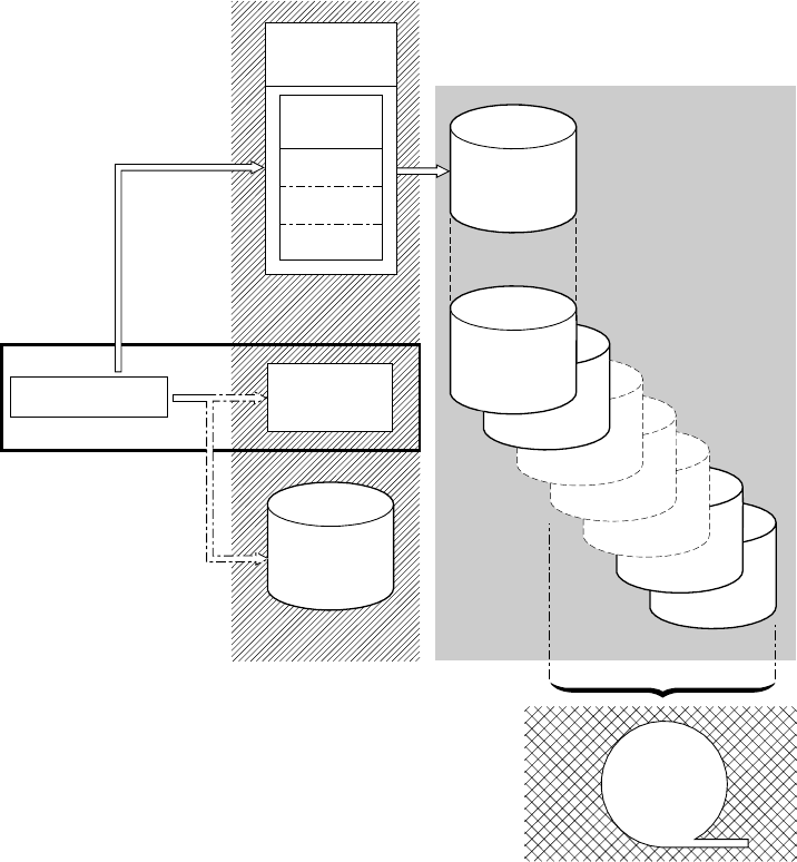
3. Tertiary storage—a form of archive storage, used as specified in your
hierarchical storage manager (HSM) policy. Optionally, older records can be
migrated to tertiary storage, which can be either DASD data sets or tape
volumes.
Figure 53 and Figure 54 on page 631 show the types of storage used by the MVS
system logger.
MVS1
Current
Data Set
LSN1
LSN1
Staging
Data Sets
Full
Data Set
Primary storage
Tertiary storage
DFHSM
Storage
Coupling
Facility
LSN
n
Log
Structures
LSN1
LSN2
Secondary storage
Data Space
System Logger
Figure 53. The types of storage used by the MVS system logger. This diagram shows a log
stream that uses a coupling facility. Primary storage consists of space in a structure within
the CF, and either staging data sets or a data space in the same MVS image as the system
logger.
journaling
630 CICS TS for OS/390: CICS Customization Guide
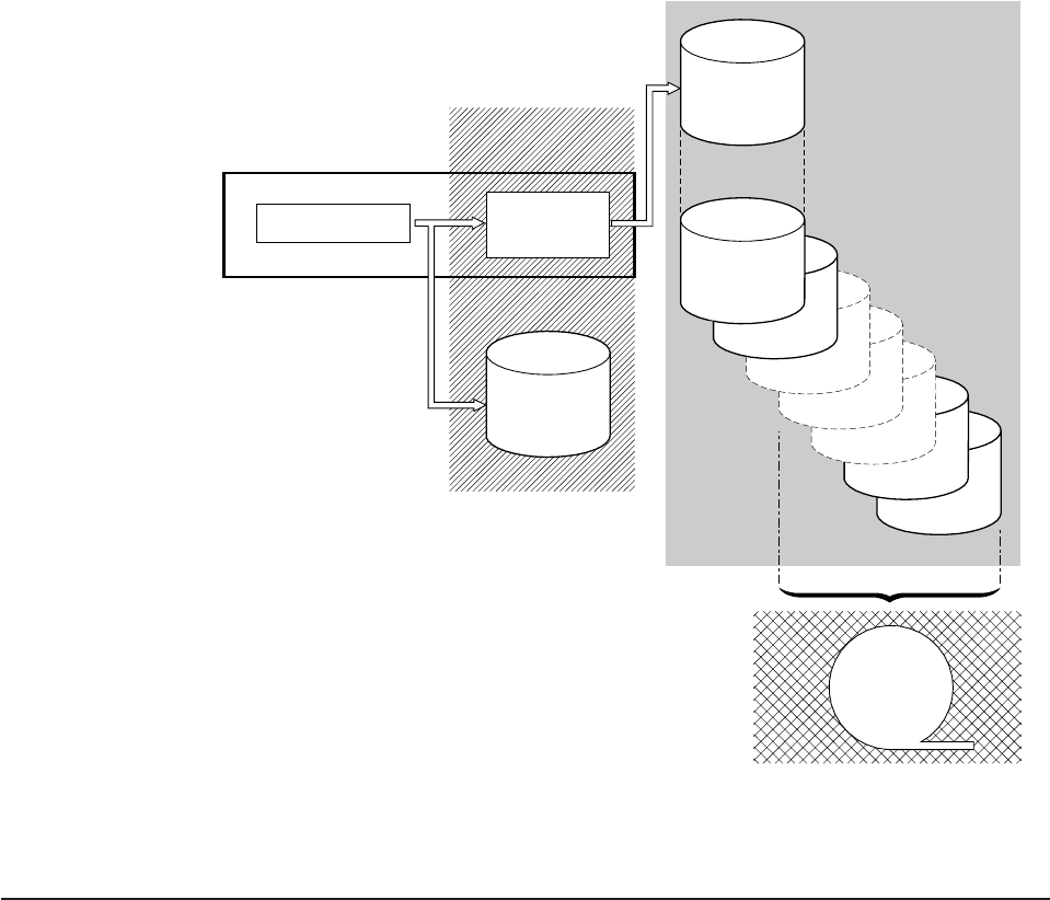
Enabling, disabling, and reading journals
Journal records are written to a log stream either directly from a user application
program, or from a CICS management program on behalf of a user application.
Journal records can be written from a user application using the EXEC CICS
WRITE JOURNALNAME command. For programming information about the EXEC
CICS WRITE JOURNALNAME command, see the
CICS Application Programming
Reference
manual.
This section describes the commands that you use for enabling and disabling
journals, and for reading journals offline.
Enabling and disabling a journal
To enable or disable a journal from an application program, use the EXEC CICS
SET JOURNALNAME command. For programming information about the EXEC
CICS SET JOURNALNAME command, see the
CICS System Programming
Reference
manual.
System Logger
Current
Data Set
LSN1
LSN1
Staging
Data Sets
Full
Data Set
Data Space
Primary storage
Tertiary storage
DFHSM
Storage
Secondary storage
MVS1
Figure 54. The types of storage used by the MVS system logger. This diagram shows a log
stream that uses DASD-only logging. Primary storage consists of a data space in the same
MVS image as the system logger, and a single staging data set.
journaling
Chapter 23. CICS logging and journaling 631
Reading journal records offline
Access to journaled data in log streams is provided through an MVS subsystem
interface (SSI), LOGR. Your existing user programs can read the general log
streams, providing you specify, in your batch job JCL, the SUBSYS parameter and
supporting options on the DD for log streams. By specifying the LOGR subsystem
name on the SUBSYS parameter, you enable LOGR to intercept data set open and
read requests at the SSI, and convert them into log stream accesses.
Depending on the options specified on the SUBSYS parameter, general log stream
journal records are presented either:
vIn the record format used at CICS/ESA 4.1 and earlier, for compatibility with
older utilities (selected by the COMPAT41 option), or
vIn the CICS Transaction Server for OS/390 format (introduced at CICS
Transaction Server for OS/390 Release 1), for newer or upgraded utilities
needing to access log record information.
CICS system log records are only available in the CICS Transaction Server for
OS/390 format, so you must ensure that any utilities that handled system log
records in releases prior to CICS Transaction Server for OS/390 Release 1 are
converted to handle this format.
Journal records can be read offline by user-written programs. You can generate the
DSECTs that such programs need by including certain statements in the program
code, as follows:
vFor records in the CICS Transaction Server for OS/390 format on general logs,
offline user-written programs can map journal records by including an INCLUDE
DFHLGGFD statement. This generates the assembler version of the DSECT.
vFor records formatted with the COMPAT41 option, offline user-written programs
can map journal records by issuing the DFHJCR CICSYST=YES statement,
which results in the DFHJCRDS DSECT being included in the program.
The DSECT thus generated is identical to that obtained for CICS programs by
the COPY DFHJCRDS statement, except that the fields are not preceded by a
CICS storage accounting area. The DSECT is intended to map journal records
directly in the block, rather than in a CICS storage area.
The following section describes the structure of CICS Transaction Server for
OS/390-formatted journal records. The structure and content of CICS/ESA
4.1-format journal records are described in “Structure and content of
COMPAT41-format journal records” on page 645.
Structure and content of CICS Transaction Server for OS/390 format
journal records
SMF records
The following description does not apply to journal records written to an SMF
data set. These are described on page 653.
General logs (that is, those containing forward-recovery logs, auto-journals, and
user journals) can be presented in the format introduced at CICS Transaction
journaling
632 CICS TS for OS/390: CICS Customization Guide
Server for OS/390 Release 1. Each journal record in these logs, if presented in the
newer format, contains more information than in the equivalent journal record
presented in the CICS/ESA 4.1 format.
System logs are always presented in CICS Transaction Server for OS/390 format..
Each general log comprises a stream of contiguous blocks of journaled data. Each
block comprises a block header followed by a variable number of CICS journal
records. Each CICS journal record comprises a record header followed by caller
data.
Figure 55 gives a graphical overview of a general log, showing the format of a
complete block, and the format of a complete journal record.
The format of the caller data depends on the CICS component that is issuing the
journal record, and also on the function being journaled at the time. Thus, for
example, the format of caller data in journal records issued by file control differs
from that of caller data in journal records issued by FEPI.
Block
header
CICS
Journal
record
CICS
Journal
record
Record
header Caller
data
Log block Log block Log block Log block
Figure 55. Layout of a general log
journaling
Chapter 23. CICS logging and journaling 633
Format of general log block header
The log block header contains information of a general system-wide nature such as
the CICS applid writing the journal block. Figure 56 shows the format of the log
block header.
Start time (GMT) Start time (Local)
8888
LGBH GLOBAL INFO
LGBH GENERIC APPLID
LGBH START GMT LGBH START LOCAL
CICS applid
nn = block version number
t = Log type
>DFHtrnn
Where
LGBH BLOCK NUMBER
8
Seq no.
Fixed length
r = reserved
Figure 56. Format of a general log block header
journaling
634 CICS TS for OS/390: CICS Customization Guide
Format of general log journal record
The journal record comprises a record header followed by caller data. The record
header contains information that describes some of the attributes of the record,
such as the time it was written. Figure 57 shows the format of the record header.
The caller data differs depending on the CICS component issuing the record, and
on the function being journaled.
4831
Domain ID
8
GLRH REC
COMPID
X'8n' equivalent to JCSPSOTK
(start of task)
X'4n' equivalent to JCSPLSTK
(start of uow)
X'0001' Start of run record
X'0002' Any other record
GLRH TERM ID
GLRH TASK ID
GLRH REC TYPE
GLRH TRAN IDGLRH LOCALGLRH GMT
GLRH HEADER LENGTH
GLRH RECORD LENGTH
Record type
Term ID
Task ID
Tran IDTime (Local)Time (GMT)
Header length
Record length
22444844
Reserved
Journal name
GLRH REC
JOURNAL
Record data length
GLRH REC
DATA LEN
Fixed length
Figure 57. Format of a general log record header
journaling
Chapter 23. CICS logging and journaling 635
Start-of-run record
When CICS connects to a general log, it writes a start-of-run record to it as the first
record for this run of CICS. This record comprises a record header (with the same
format as that for any general log journal record) followed by a start-of-run body. Its
format is shown in Figure 58.
Format of caller data
Caller data follows the record header.
The format of the caller data part of a general log journal record differs according to
the CICS component writing the record, and the function being journaled.
Journal records can be written by any of the four following CICS components:
journal control (in the case of a request issued by a user), file control, the front end
programming interface (FEPI), and terminal control. The field GLRH_REC_COMPID
in the record header tells you which component has written the record: UJ, FC, SZ,
or TC respectively.
File control adds information to the start of the actual journaled data, and this is
described in “Caller data written by file control” on page 637. The other components
(journal control, FEPI, and terminal control) do not add any further information to
the journaled data.
If the record has been written by the CICS API, the caller data section starts with an
API user header, the format of which is shown in Figure 59 on page 637.
48 8
Fixed length
CICS release
CICS applid CICS username
SOR CICS RELEASE
SOR SPECIFIC APPLID SOR CICS USERNAME
Figure 58. Format of the start-of-run record
journaling
636 CICS TS for OS/390: CICS Customization Guide
Caller data written by file control
The file log and journal block (FLJB) describes the caller data that file control writes
as part of its journal records. The copybook DFHFCLGD defines the FLJB DSECT.
There are two sections in the FLJB: the first section contains data that is applicable
to all journal records written by file control; the second section contains information
specific to the record type. Both sections are of fixed length.
Some records have a third and fourth section which are of variable length.
Table 30 outlines the sections in a journal record written by file control.
Table 30. FLJB sections in journal records issued by file control
Record type First section Second section Third section Fourth section
Read-only
Read-update
Write-update
Write-add
Write-add
complete
FLJB_GENERAL_DATA FLJB_COMMON_DATA FLJB_CD_KEY FLJB_CD_DATA
Write delete FLJB_GENERAL_DATA FLJB_WRITE_DELETE _DATA FLJB_WDD_BASE_KEY FLJB_WDD_PATH _KEY
File close FLJB_GENERAL_DATA FLJB_FILE_CLOSE_DATA None None
Tie-up FLJB_GENERAL_DATA FLJB_TIE_UP_RECORD
_DATA None None
A description of each of the structures, and the sections within them, now follows:
Read-only, read-update, write-update, write-add, write-add
complete record types
There are four sections in the journal records written for read-only, read-update,
write-update, write-add, and write-add complete record types:
vThe FLJB_GENERAL_DATA section,
User dataPrefix areaPrefix length
Journal type
24
42
Header length
CL UH LENGTH
CL UH JOURNAL TYPE
CL UH PREFIX LENGTH
Reserved
Variable length
Fixed length
Figure 59. Format of the API user header
journaling
Chapter 23. CICS logging and journaling 637
vThe FLJB_COMMON_DATA section, and
vThe caller data image sections which consist of the FLJB_CD_KEY (the length of
which is given in FLJB_COMMON_DATA) and the FLJB_CD_DATA section. The
FLJB_CD_DATA section (the length of which is given in FLJB_COMMON_DATA)
contains the image of the caller data.
The format of such a record written for these record types is shown in Figure 60.
The format of the FLJB_GENERAL_DATA section is shown in Figure 61 on
page 639.
12 16
Variable length
FLJB GENERAL DATA FLJB CD KEY FLJB CD DATAFLJB COMMON DATA
Fixed length
Figure 60. Layout of record written for read-only, read-update, write-update, write-add, and write-add-complete record
types
journaling
638 CICS TS for OS/390: CICS Customization Guide
The format of the FLJB_COMMON_DATA section is shown in Figure 62 .
11
Fixed length
82
Record type Flag byte
X'80' file control autojournal record
X'40' forward recovery log record
X'20' system log record
X'10' log-of-log record
ReservedFile name
FLJB FILE NAME
FLJB BITSFLJB RECORD TYPE
X'80' read-only
X'81' read-update
X'82' write-update
X'83' write-add
X'84' write-add complete
X'86' write-delete
X'8E' file-close
X'8F' file tie-up record
Figure 61. Format of FLJB_GENERAL_DATA section
14224
FLJB CD BITS
Length of user data
FLJB CD DATA LENGTH
FLJB CD BASE ESDS RBA
FLJB CD KEY LENGTH
Relative byte address
of record in base
data set for ESDS
(0 if file does
not refer to ESDS)
Length of
user data key
Reserved
Flag byte
Reserved
x
x
x
x
x
'80'
'40'
'20'
'10'
'8'
UOW has been shunted at least once
write massinsert
first write-add-complete in massinsert
sequence
end of massinsert sequence
fixed length record
(combinations of settings are possible)
3
Fixed length
Figure 62. Format of FLJB_COMMON_DATA section
journaling
Chapter 23. CICS logging and journaling 639
Write-delete record types
There are four sections in the journal records written for write-delete record types:
vThe FLJB_GENERAL_DATA section,
vThe FLJB_WRITE_DELETE_DATA section, and
vThe two caller data image sections, which consist of:
– FLJB_WDD_BASE_KEY (the length of which is given by
FLJB_WDD_BASE_KEY_LENGTH in FLJB_WRITE_DELETE_DATA)
– FLJB_WDD_PATH_KEY (the length of which is given by
FLJB_WDD_PATH_KEY_LENGTH in FLJB_WRITE_DELETE_DATA).
These sections contain the image of the caller data as the base key, and, if the
data set is a path, the path.
The format of such a record written for write-delete record types is shown in
Figure 63.
See Figure 61 on page 639 for the format of the FLJB_GENERAL_DATA section.
The format of the FLJB_WRITE_DELETE_DATA section is shown in Figure 64 on
page 641.
FLJB GENERAL DATA
FLJB DELETE DATA
Fixed length Variable length
Base key Path key
12 12
Figure 63. Layout of record written for write-delete record types
journaling
640 CICS TS for OS/390: CICS Customization Guide
File-close record types
There are two sections in the journal records written for file-close record types:
vThe FLJB_GENERAL_DATA section
vThe FLJB_CLOSE_DATA section.
The format of such a record written for file-close record types is shown in Figure 65.
See Figure 61 on page 639 for the format of the FLJB_GENERAL_DATA section.
The format of the FLJB_CLOSE_DATA section is shown in Figure 66 on page 642.
242
FLJB WDD BITS
Path key length
(0 if file does not refer to a path)
FLJB WDD PATH KEY LENGTH
Base key length
FLJB WDD BASE KEY LENGTH
FLJB WDD BASE ESDS RBA
Relative byte address of
record in base data set for EDS
(0 if file does not refer to ESDS) Flag byte
X'80' UOW has been shunted at least once
X'40' fixed length record
13
Fixed length
Reserved
Figure 64. Format of the FLJB_WRITE_DELETE_DATA section
12
FLJB GENERAL DATA FILE CLOSE DATA
Fixed length
28
Figure 65. Layout of record written for file-close record types
journaling
Chapter 23. CICS logging and journaling 641
Tie-up record types
There are two sections in the journal records written for tie-up record types:
vThe FLJB_GENERAL_DATA section
vThe TIE_UP_RECORD_DATA section.
The format of such a record written for tie-up record types is shown in Figure 67.
See Figure 61 on page 639 for the format of the FLJB_GENERAL_DATA section.
The format of the TIE_UP_RECORD_DATA section is shown in Figure 68 on
page 643.
26
Fixed length
11
FLJB FCD BITS
Reserved
Log stream name of the forward recovery log
FLJB FCD FWDRECOVLOG NAME Flag byte
X'80' forward recovery specified for file or data set
X'40' autojournaling specified for file
Figure 66. Format of the FILE_CLOSE_DATA section
FLJB GENERAL DATA TIE UP RECORD DATA
12 136
Fixed length
Figure 67. Layout of record written for tie-up record types
journaling
642 CICS TS for OS/390: CICS Customization Guide
444211
26
244
442
FLJB TUR BITS
Fixed length
Fixed length
Fixed length
Fixed length
Log stream name of forward recovery log
FLJB TUR FWDRECOVLOG NAME
FLJB TUR PATH DSNAME
FLJB TUR BASE DSNAME
FLJB TUR BASE DSNAME LENGTH
FLJB TUR RECORD FORMAT
FLJB TUR DATASET TYPE
Base data set name
Path data set name
Path data set name length
Base data set name length
CI size of base data set
FLJB TUR BASE CI SIZE
Maximum record length
FLJB TUR MAXIMUM LRECL
Base key position in record
FLJB TUR BASE KEY POSITION
Base key length
FLJB TUR BASE KEY LENGTH
Reserved
FLJB TUR PATH DSNAME LENGTH
11
= ESDS
=KSDS
=Path
= RRDS
= VRRDS
Data set type
x
x
x
x
x
x
x
= Variable
=Fixed
Record format
'E5'
'C6'
'C5'
'D2'
'D7'
'D9'
'E5'
Figure 68. Format of TIE_UP_RECORD_DATA section
journaling
Chapter 23. CICS logging and journaling 643
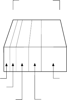
Note: The format of caller data in journal records written by file control in RLS
mode is identical to that in journal records written by file control in non-RLS
mode except for FLJB_TUR_BITS where a value of X'80' indicates
RLS-access.
Terminal control prefix data
CICS terminal control (TC) writes journal records to track the messages it issues.
Each TC journal record contains a prefix area, which lies in the position of the prefix
area in the API user header. For LU6.1-related records only, the prefix area
contains the VTAM physical sequence numbers at syncpoint time; for all other TC
journal records, it contains binary zeros. The format of the TC prefix area is shown
in Figure 69.
FEPI prefix data
Each FEPI journal record contains a prefix area that allows you to identify the FEPI
conversation for which the data was journaled. This prefix area lies in the position
of the prefix area in the API user header. Its format is shown in Figure 70 on
page 645.
221 1
Fixed length
Function identifier
Module identifier
Inbound VTAM sequence number Outbound VTAM sequence number
4
JCAUP TID
Terminal identifier
(padded with blanks if unused)
Figure 69. Format of the terminal control prefix area
journaling
644 CICS TS for OS/390: CICS Customization Guide
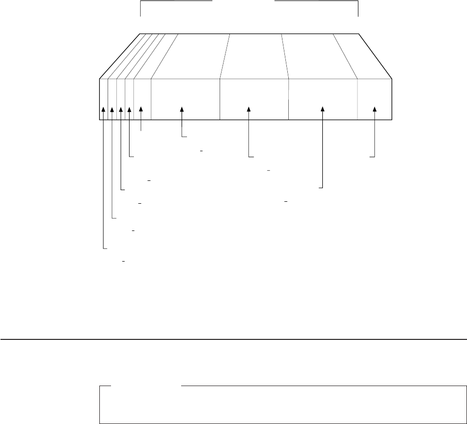
See the
CICS Front End Programming Interface User’s Guide
for more information
about FEPI journaling.
Structure and content of COMPAT41-format journal records
SMF records
The following description does not apply to journal records written to an SMF
data set. These are described on page 653.
CICS allows you to format journal records so that they are presented in the format
used at CICS/ESA 4.1. Use the COMPAT41 option on the SUBSYS=(LOGR...) step
of your JCL.
Within the data presented, certain fields are not presented at CICS Transaction
Server for OS/390. They appear as X'00' in the formatted output. These fields are:
Table 31. Fields formatted as X'00'
JCLRJFID
JCLRVCD
JCLRVSN
JCLRLBW
JCLRTBAL
JCRBB
JCSPFS
JCSPDSP
JCSPEMER
JCSPMIDT
JCSPRRIF
Each general log comprises a stream of contiguous blocks of journaled data. Each
block comprises a journal control label header followed by a variable number of
CICS journal records. Each CICS journal record comprises a system header,
system prefix, user prefix, and journaled data.
Fixed length
4
81 88
2
111
Module identifier
UP SVMID
Module function
UP MODFN
UP FEPDF
UP FEPES
Reserved
Escape character
for keystroke
Pool name
UP FEPPL
Reserved
Target name
UP FEPTG
Conversation identifier
UP FEPCV
Data function
Figure 70. Format of the FEPI prefix area
journaling
Chapter 23. CICS logging and journaling 645
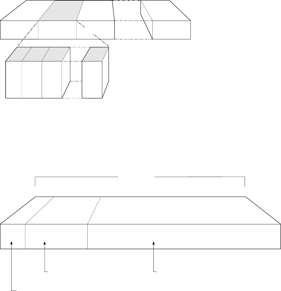
A graphical overview of the format of a general log, showing the format of a
complete block, is shown in Figure 71.
Format of COMPAT41 journal control label header
Each log block starts with a journal control label header. There is one journal
control label header per log block. It is 42 bytes long, and comprises a length field,
label header, and label prefix. The format of the journal control label header is
shown in Figure 72.
The label header part of the journal control label header is 10 bytes long, and its
format is shown in Figure 73 on page 647.
Log block Log block Log block
Journal
control
label
header
Journal
record
1
Journal
record
2
Journal
record
nn
Log block
Figure 71. Format of general log formatted using the COMPAT41 option
32
Fixed length
Label prefixLabel header
104
Length of block
Not presented unless the
caller is reading data blocks
rather than records
Figure 72. Format of journal control label header
journaling
646 CICS TS for OS/390: CICS Customization Guide
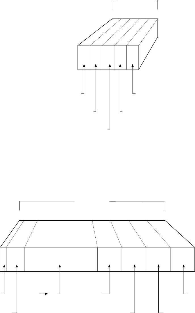
The label prefix part of the journal control label header is 32 bytes long, and its
format is shown in Figure 74.
Record number
within block
JCRLRN
Length of record
JCRLL
22222
User-type ID
JCRUTRID
System-type ID
JCRSTRID
X'0000'
'0000' if CICS journal request.
Otherwise code specified in JTYPEID
keyword of user request
'0000' if user journal request.
Otherwise 1-byte function ID
followed by 1-byte module ID
Fixed length
Figure 73. Format of label header part of journal control label header
13 12
Fixed length
4444
Journal block
number
JCRBLKN
X'00' X'00' '00' Journal block
sequence number
JCLRSEQ
Date block
written
JCLRDATE
Run start
time
JCLRRST
Time block
written
JCLRTIME
(hhmmss)-
local or GMT
set in LOGR SSI
Figure 74. Format of label prefix part of journal control label header
journaling
Chapter 23. CICS logging and journaling 647
Format of journal record
Each CICS journal record comprises a system header, system prefix, user prefix,
and journaled data. The format of a journal record is shown in Figure 75.
The system header is 10 bytes long. Its format is shown in Figure 76.
System header
Variable length
User prefix Journal data
Fixed length
System prefix
10
Figure 75. Format of COMPAT41 journal record
Record number
within block
JCRLRN
Length of record
JCRLL
22222
User-type ID
JCRUTRID
System-type ID
JCRSTRID
X'0000'
'0000' if CICS journal request.
Otherwise code specified in JTYPEID
keyword of user request
'0000' if user journal request.
Otherwise 1-byte function ID
followed by 1-byte module ID
Fixed length
Figure 76. Format of the system header
journaling
648 CICS TS for OS/390: CICS Customization Guide
The field JCRSTRID (the system-type ID) and the field JCRUTRID (the user-type
ID) in the system header allow you to distinguish those journal records output by
CICS (by such components as terminal control), from those issued by direct user
requests.
For CICS journal requests, JCRUTRID contains binary zeros, and JCRSTRID
contains a 1-byte function code followed by a 1-byte module code. The function
code tells you which function was being journaled, and the module code shows
which module caused the record to be written. Valid settings of these codes are
contained in the member DFHFMIDS of the CICS assembler-language macro
library. Figure 79 on page 651 shows the valid function identifiers of those CICS
components that issue journal requests. Figure 80 on page 652 shows the valid
module identifiers.
For user journal requests, JCRSTRID always contains binary zeros, and JCRUTRID
contains the 2-byte hexadecimal code specified by the JTYPEID keyword of the
WRITE JOURNALNAME request in the application program.
The system prefix is 25 bytes long. Its format is shown in Figure 77.
For some CICS journal requests, additional data is included in the system prefix to
identify more specifically the originator of the request. This extra data follows the
common fields of the system prefix, and is usually variable in length; hence the
need for the length field JCSPLL at the start of the system prefix. All the following
have their own prefix layout, and these are described, for the purposes of diagnosis
and recovery, in the
CICS Data Areas
manual.
The user prefix is a variable length area. It is present if this record has been written
by a user request, an EXEC CICS WRITE JOURNALNAME command. The
information contained in the record is set by the user within the terms of the
Task number
JCSPTASK
13 4 4 4
Terminal ID
JCSPTERM
Transaction ID
JCSPTRAN
Time of request
JCSPTIME
Length of system
prefix
JCSPLL
22
Reserved
Flag
JCSPF1
Fixed length
X'01' User prefix present
X'02' Physical start-of-task, JCSPSOTK
X'04' Logical start-of-task, JCSPLSTK
Figure 77. Format of the system prefix
journaling
Chapter 23. CICS logging and journaling 649
command via the JTYPEID, PREFIX, and PFXLENG parameters. Its format is
shown in Figure 78.
Field JCSPUP is set in the system prefix area if a user prefix is present in a journal
record.
The journaled data then follows. If you want a length field for the data, you must
include it in the data. Alternatively, you can compute the length of the data portion
of a journal record by taking the length of the system header (10 bytes), plus the
length of the system prefix (JCSPLL), plus the length of the user prefix (in the field,
if any, defined by yourself), and subtracting the total from the length of the journal
record (JCRLL):
JCRLL - (system header (10) bytes + JCSPLL + user prefix)
Not all journal records contain journaled data.
The CICS components that issue journaling requests are journal control, file control,
FEPI, and terminal control.
Variable
length
User prefix dataLength of user prefix
Figure 78. Format of the user prefix
journaling
650 CICS TS for OS/390: CICS Customization Guide
***********************************************************************
** FUNCTION IDENTIFIERS **
***********************************************************************
* *
* X'20' PLUS X'8-' ...USE FOR AUTOMATIC JOURNALING *
* X'40' PLUS X'8-' ...USE FOR AUTOMATIC LOGGING *
***********************************************************************
* * JOURNAL CONTROL * *
***********************************************************************
FIDJCLAB EQU X'80' ...JOURNAL CONTROL LABEL
* RECORD (DFHJCR) *
***********************************************************************
* * FILE CONTROL * *
***********************************************************************
FIDALOG EQU X'40' ...AUTOMATICALLY LOGGED
FIDAJRN EQU X'20' ...AUTOMATICALLY JOURNALED
FIDMASS EQU X'10' ...MASSINSERT REQ. (FIDFCWA ONLY)
* PLUS ONE OF... *
FIDFCRO EQU X'80' ...FILE CONTROL READ-ONLY
FIDFCRU EQU X'81' ...FILE CONTROL READ-UPDATE
FIDFCWU EQU X'82' ...FILE CONTROL WRITE-UPDATE
FIDFCWA EQU X'83' ...FILE CONTROL WRITE-ADD
FIDFCWAC EQU X'84' ...FILE CONTROL WRITE-ADD-COMPLETE
FIDFCWD EQU X'86' ...FILE CONTROL WRITE DELETE
FIDFCBOF EQU X'88' ...BACKOUT FAILED LOG RECORD
FIDFCDSN EQU X'8F' ...DSNAME RECORD
* *
* NOTE THAT FID* VALUES (AS ABOVE) ARE OFTEN USED BOTH TO *
* IDENTIFY THE FUNCTION OF THE DWE AND THE FUNCTION OF THE *
* LOG RECORD. IN THE CASE OF THE FIDFC* EQU'S ABOVE, THEY *
* ARE USED FOR LOG RECORDS ONLY. THOSE BELOW APPLY ONLY *
* TO DWE'S *
* *
FIDFCVWA EQU X'80' THIS DWE ADDRESSES A VSWA.
FIDFCRVY EQU X'40' THIS DWE IS ASSOCIATED WITH A *
RECOVERABLE CHANGE.
Figure 79. Journal function identifiers (Part 1 of 2)
journaling
Chapter 23. CICS logging and journaling 651
***********************************************************************
* TERMINAL CONTROL FUNCTION IDENTIFIERS *
* *
FIDTCML EQU X'F0' SYNCPOINT - LOG SEQUENCE
* NUMBERS *
* CAN BE OR'ED WITH ANY OF *
THE FOLLOWING THREE FIELDS:
FIDTCDWL EQU X'01' ...DEFERRED WRITE DATA
FIDTCFMH EQU X'02' ...+ FUNCTION MANAGEMENT
* HEADER
FIDTCDIP EQU X'04' ...+ DIP REQUEST
* *
* EQU X'08' ...DYNAMIC BACKOUT MASK *
RESERVED
FIDTCAL EQU X'40' AUTOMATIC LOGGING MASK...
FIDTCAJ EQU X'20' AUTOMATIC JOURNALING MASK..
* ...THE ABOVE 2 PLUS 1 OF FOLLOWING SET *
FIDTCTL EQU X'80' ...SEQUENCE NUMBER ONLY
* (LOG ONLY) *
FIDTCIM EQU X'81' ...INPUT MESSAGE (LOG AND
* JOURNAL) *
FIDTCOM EQU X'82' ...OUTPUT MESSAGE (JOURNAL
* ONLY) *
FIDTCWP EQU X'83' ...WRITE WAS PURGED (LOG
* ONLY) *
FIDTCPRR EQU X'84' ...POSITIVE RESPONSE
* RECEIVED (LOG ONLY) *
FIDTCIMF EQU X'85' ...INPUT MESSAGE (W/FMH,
* LOG AND JOURNAL) *
FIDTCOMN EQU X'86' ...OUTPUT MESSAGE, (W/O
* FMH, JOURNAL ONLY) *
FIDTCON EQU X'87' ...OUTPUT MESSAGE, FMH,
* CCOMPL=NO *
FIDTCONN EQU X'88' ...OUTPUT MESSAGE, W/O FMH,
...CCOMPL=NO
FIDTCUA EQU X'89' ...INITIAL TCT USER AREA
FIDTCEIB EQU X'8A' ...INITIAL EXEC COMM AREA
FIDTCIMN EQU X'8B' INPUT MSG, NO FMH, COMPLETE
FIDTCINN EQU X'8C' INPUT MSG, NO FMH, INCOMPLETE
***********************************************************************
* FRONT END PROGRAMMING INTERFACE IDENTIFIERS *
FIDFEPIN EQU X'F0' FEPI INBOUND DATA API <--- FEPI
FIDFEPOU EQU X'F1' FEPI OUTBOUND DATA API ---> FEPI
***********************************************************************
Figure 79. Journal function identifiers (Part 2 of 2)
***********************************************************************
** MODULE IDENTIFIERS **
***********************************************************************
* *
MODIDTC EQU X'10' ...TERMINAL CONTROL
MODIDFC EQU X'11' ...FILE CONTROL
MODIDJC EQU X'45' ...JOURNAL CONTROL
MODIDFEP EQU X'50' ...FEPI
* *
***********************************************************************
Figure 80. Journal module identifiers
journaling
652 CICS TS for OS/390: CICS Customization Guide
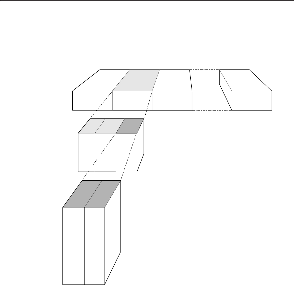
Identifying records for the start of tasks and UOWs
You can identify records written to mark the start of tasks by examining the value of
the system prefix field JCSPF1. If the JCSPSOTK bit is set, the record has been
written at the start of the task.
If the JCSPLSTK bit is set in field JCSPF1, then the record has been written at the
start of the UOW.
Format of journal records written to SMF
This section describes the format of journaling records that are written to an SMF
data set. You need this information if you write your own program to analyze the
data. The three components of the journaling record are an SMF block header, a
CICS product section, and a CICS data section. The layout of an MVS SMF log,
showing log blocks and CICS sections, is in Figure 81.
Journal records written to SMF can be read offline by user-written programs. Such
programs can map journal records by including an INCLUDE DFHLGMSD
statement. This generates the assembler version of the DSECT.
CICS
Product
section
CICS
Data
section
SMF
Block
header
Record
header
LG
Caller
data
Log block Log block Log block Log block
Figure 81. Layout of a CICS log written to MVS SMF
journaling
Chapter 23. CICS logging and journaling 653
The SMF block header
This block describes the system creating the output. Its format is shown in
Figure 82.
Note: CICS sets only the subsystem-related bits of the operating system indicator
flag byte in the SMF header (SMFH_LG). SMF sets the remainder of the
byte according to the operating system level and other factors. For an
explanation of the setting of the other bits, refer to the
OS/390 MVS System
Management Facilities (SMF)
manual.
The CICS product section
This section identifies the subsystem to which the journaling data relates. Its format
is shown in Figure 83 on page 655.
Fixed length
24244422211 442222
Record
length
SMFH LEN
Segment descriptor
X'0000'
SMFH SEG
Record
type
SMFH RTY
Operating system
indicator
SMFH FLG
Time record
moved
SMFH TME (local)
Date record
moved
SMFH DTE
System ID
SMFH SID
Subsystem ID
SMFH SSI
Record
subtype
SMFH STY
No.oftriplets
in record
SMFH TRN
Offset to CICS
product section
SMFH APS
Length of CICS
product section
SMFH LPS
Number of CICS
product section
SMFH NPS
Offset to CICS
data section
SMFH ASS
Length of CICS
data section
SMFH ASL
Number of CICS
data sections
SMFH ASN
Reserved
Figure 82. Format of the SMF block header
journaling
654 CICS TS for OS/390: CICS Customization Guide
The CICS data section
This section contains a variable number of CICS journal records. Each record
comprises a general log record header, the format of which is shown in Figure 57
on page 635. This is followed by a user header, the format of which is shown in
Figure 59 on page 637. This is then followed by the caller data.
If this is the first record being written to the journal after CICS initialization, the
record comprises the general log record header, followed by a start-of-run record,
the format of which is shown in Figure 58 on page 636. Subsequent records then
take the form already described.
Job date
SMFPS RSD
Journal name
SMFPS JNM Job name
SMFPS JBN Job time
SMFPS RST
(local)
User ID
SMFPS UIF Op. system
product level
SMFPS PDN
88 8844
28 8
X'0vrm'
SMFPS VRM
v=version
r=release
m = modification
Product name
(generic APPLID)
SMFPS PRN
Product name
(specific APPLID)
SMFPS SPN
ReservedRecord maintenance
indicator
SMFPS MFL
Fixed length
Fixed length
254
set by
DFHSYS
Figure 83. Format of the CICS product section
journaling
Chapter 23. CICS logging and journaling 655
656 CICS TS for OS/390: CICS Customization Guide

Chapter 24. CICS monitoring
This chapter describes the monitoring facilities of CICS Transaction Server for
OS/390, and tells you how to:
vControl the types of monitoring data collected by CICS
vGather more performance data about specific transactions than is provided
automatically by CICS.
The chapter is divided into the following sections:
1. “Introduction to CICS monitoring” describes the classes of monitoring data,
event-monitoring points, and the use of the monitoring control table.
2. “CICS monitoring record formats” on page 663 describes the formats of
CICS monitoring SMF type 110 records.
The
CICS Performance Guide
lists all the system-defined data that can be
produced by CICS monitoring.
Introduction to CICS monitoring
CICS monitoring collects data about the performance of all user- and CICS-supplied
transactions during online processing for later offline analysis. The records
produced by CICS monitoring are of the MVS System Management Facility (SMF)
type 110, and are written to an SMF data set.
Note: Statistics records and some journaling records are also written to the SMF
data set as type 110 records. You might find it particularly useful to process
the statistics records and the monitoring records together, because statistics
provide resource and system information that is complementary to the
transaction data produced by CICS monitoring. The contents of the statistics
fields, and the procedure for processing them, are described in “Chapter 25.
CICS statistics” on page 677.
Monitoring data is useful both for performance tuning and for charging your users
for the resources they use.
The classes of monitoring data
Three types, or “classes”, of monitoring data can be collected. These are
performance class data, exception class data, and SYSEVENT data.
Performance class data is detailed transaction-level information, such as the
processor and elapsed time for a transaction, or the time spent waiting for I/O. At
least one performance record is written for each transaction that is being monitored.
See “Performance class monitoring data” on page 658 for further information.
Exception class data is information about exceptional conditions suffered by a
transaction, such as queuing for file strings, or waiting for temporary storage. This
data highlights possible problems in system operation. There is one exception
record for each exception condition.
SYSEVENT class data is a special kind of transaction timing information. For more
information about SYSEVENT data, see the
CICS Performance Guide
.
© Copyright IBM Corp. 1977, 1999 657
You can choose which classes of monitoring data you want to be collected. How to
do this is described in “Controlling CICS monitoring” on page 662.
Performance class monitoring data
CICS performance class monitoring data is collected at system-defined
event-monitoring points (EMPs) in the CICS code. You cannot relocate these
monitoring points, but you can create additional ones, at which user-defined
performance data can be gathered.
Coding additional event-monitoring points
If you want to gather more performance class data than is provided at the
system-defined EMPs, you can code additional EMPs in your application programs.
You could use these additional EMPs to count the number of times a certain event
occurs, or to time the interval between two events, for example. If the performance
class was active when a transaction was started, but was not active when a user
EMP was issued, the operations defined in that user EMP would still be executed
on that transaction’s monitoring area. The DELIVER option would result in a loss of
data at this point, because the generated performance record cannot be output
while the performance class is not active. If the performance class was not active
when a transaction was started, the user EMP would have no effect.
To code user EMPs in your application programs, you use the EXEC CICS
MONITOR command. For programming information about this command, see the
CICS Application Programming Reference
manual.
Additional EMPs are provided in some IBM program products, such as IMS DBCTL.
From a CICS point of view, these are like any other user-defined EMP. EMPs in
user applications and in IBM program products are identified by a decimal number.
The numbers 1 through 199 are available for EMPs in user applications, and the
numbers 200 through 255 are for use in IBM program products. The numbers can
be qualified with an entry name, so that you can use each number more than once.
For example, ‘ENTRYA.4’, ‘ENTRYB.4’, and ‘4’ identify three different EMPs.
Furthermore, any counts, clocks, or byte-strings updated at one of them are
different objects from those updated at any of the others. If you do not specify an
entry name, CICS assumes the default of ‘USER’.
For each EMP that you code in an application program, there must be a
corresponding monitoring control table (MCT) definition, with the same entry name
and identification number as the EMP that it describes. (The following sections refer
to the combination of entry name and identification number as an “empid”.)
If you want to record the same type of data for different transactions, you can code
the same empids in several application programs. This causes similar fields in the
corresponding transaction performance records to be updated.
You do not have to assign empids to system-defined EMPs, and you do not have to
code MCT entries for them.
The monitoring control table (MCT)
You use the monitoring control table (MCT):
vTo tell CICS about the EMPs that you have coded in your application programs
and about the data that is to be collected at these points. See “DFHMCT
TYPE=EMP” on page 659.
monitoring—introduction
658 CICS TS for OS/390: CICS Customization Guide
vTo tell CICS that you want specific system-defined performance data not to be
recorded during a particular CICS run. See “DFHMCT TYPE=RECORD”.
Full details of the DFHMCT macros are provided in the
CICS Resource Definition
Guide
, and you should refer to that book when reading the following sections.
DFHMCT TYPE=EMP
There must be a DFHMCT TYPE=EMP macro definition for every user-coded EMP.
This macro has an ID operand, whose value must be made up of the ENTRYNAME
and POINT values specified on the EXEC CICS MONITOR command. The
PERFORM operand of the DFHMCT TYPE=EMP macro tells CICS which user
count fields, user clocks, and character values to expect at the identified user EMP,
and what operations to perform on them.
Note that, in a single run of CICS, the format of all performance records is identical,
and that the length of records increases relative to the number of data fields in the
user EMPs defined in the MCT.
The maximum amount of user data that can be added to performance records is
16384 bytes. The user data is divided into user areas. Each user area is defined by
coding an entry name qualifier on the ID operand of the DFHMCT TYPE=EMP
macro. If you code the same entry name when defining multiple EMPs, all the
EMPs operate on fields in the same user area. Correspondingly, by coding different
entry names you can append multiple user areas to the monitoring records.
Provided that the overall maximum of 16384 bytes is not exceeded, each user area
can contain:
v0 through 256 counters
v0 through 256 clocks
vA single 8192-byte character string.
Each user area is uniquely referenced by its entry name. For example:
DFHMCT TYPE=EMP,ID=ENTRYA.1,PERFORM=...
DFHMCT TYPE=EMP,ID=ENTRYA.2,PERFORM=...
DFHMCT TYPE=EMP,ID=ENTRYB.1,PERFORM=...
DFHMCT TYPE=EMP,ID=ENTRYB.1,PERFORM=...
DFHMCT TYPE=EMP,ID=1,PERFORM=...
In the above examples, in addition to the system-defined performance fields, three
user areas, ‘ENTRYA’, ‘ENTRYB’, and ‘USER’, are defined (if no entry name is
specified, the default is ‘USER’). If the application codes an EMP invocation with
ENTRYNAME(ENTRYA), only the ENTRYA user area is operated on. The only
operation that spans all user areas is DELIVER, which operates across the whole
monitoring area.
DFHMCT TYPE=RECORD
The DFHMCT TYPE=RECORD macro allows you to
exclude
specific
system-defined performance data from a CICS run. (Each performance monitoring
record is approximately 572 bytes long, without taking into account any user data
that may be added, or any excluded fields.)
Each field of the performance data that is gathered at the system-defined EMPs
belongs to a group of fields that has a group identifier. Each performance data field
monitoring—introduction
Chapter 24. CICS monitoring 659

also has its own numeric identifier that is unique within the group identifier. For
example, the transaction sequence number field in a performance record belongs to
the group DFHTASK, and has the numeric identifier ‘031’. Using these identifiers,
you can exclude specific fields or groups of fields, and reduce the size of the
performance records.
Examples of MCT coding
The examples below show some EXEC CICS MONITOR commands with the MCT
entries that must be coded for them.
Example 1:
Example 1 shows a user clock being started by an application that is identified as
PROG3. This is the eleventh EMP in this application. To prevent confusion with the
eleventh EMP in another application, this EMP is uniquely identified by the empid
PROG3.11. The clock that is being started is the first clock in a string, and has the
identifier CLOCKA.
Example 2:
Example 2 shows the same user clock (CLOCKA) being stopped. Although this is
the same clock being stopped by the same application as in example 1, it is being
stopped from a different EMP. The EMP is uniquely identified by the empid
PROG3.12.
EXEC CICS MONITOR command MCT entry
EXEC CICS MONITOR DFHMCT TYPE=EMP, *
POINT(11) CLASS=PERFORM, *
ENTRYNAME(PROG3) ID=(PROG3.11), *
CLOCK=(1,CLOCKA), *
PERFORM=SCLOCK(1)
EXEC CICS MONITOR command MCT entry
EXEC CICS MONITOR DFHMCT TYPE=EMP, *
POINT(12) CLASS=PERFORM, *
ENTRYNAME(PROG3) ID=(PROG3.12), *
PERFORM=PCLOCK(1)
monitoring—introduction
660 CICS TS for OS/390: CICS Customization Guide
Example 3:
Example 3 shows 32 bytes of user data being updated in the character string
reserved for that purpose. The updated data starts at offset 0, and the data is not
more than 32 bytes in length.
DFHMCT TYPE=EMP entries for DBCTL
The following MCT entries make use of the two event-monitoring points in the
performance class used by the CICS-DBCTL interface modules:
These MCT entries are coded in the sample copy book DFH$MCTD.
The DBCTL data recorded by these event monitoring points can be mapped using
the IMS macro DFSDSTA DSECT=YES, which is available in the IMS genlibs.
For more information about monitoring in DBCTL, refer to the
CICS IMS Database
Control Guide
.
Exception class data
Exception class data is information on exceptional conditions suffered by a
transaction. This data highlights possible problems in system operation. There is
one exception record for each exception condition. Exception records are produced
after each of the following conditions encountered by a transaction has been
resolved:
vWait for storage in the CDSA
vWait for storage in the UDSA
vWait for storage in the SDSA
vWait for storage in the RDSA
vWait for storage in the ECDSA
vWait for storage in the EUDSA
vWait for storage in the ESDSA
vWait for storage in the ERDSA
vWait for auxiliary temporary storage
vWait for auxiliary temporary storage string
vWait for auxiliary temporary storage buffer
vWait for auxiliary temporary storage write buffer
vWait for temporary storage queue
EXEC CICS MONITOR command MCT entry
EXEC CICS MONITOR DFHMCT TYPE=EMP, *
POINT(13) CLASS=PERFORM, *
DATA1(address of data) ID=(PROG3.13), *
DATA2(length of data) PERFORM=MOVE(0,32)
ENTRYNAME(PROG3)
DFHMCT TYPE=EMP,ID=(DBCTL.1),CLASS=PERFORM,PERFORM=(MOVE(0,256)), *
FIELD=(1,RMIDATA)
DFHMCT TYPE=EMP,ID=(DBCTL.2),CLASS=PERFORM,PERFORM=(DELIVER)
monitoring—introduction
Chapter 24. CICS monitoring 661
vWait for temporary storage data set extension
vWait for shared temporary storage
vWait for shared temporary storage pool
vWait for file string
vWait for file buffer
vWait for LSRPOOL string.
An exception record is created each time any of the resources covered by
exception class monitoring becomes constrained by system bottlenecks. If
performance data is also being recorded, it keeps a count of the number of
exception records generated for each task. The exception records can be linked to
the performance data by the transaction identifier in both records.
This data is intended to help you identify constraints that affect the performance of
your transaction. The information is written to a SMF data set as soon as the task
that was originally constrained has been released.
You can enable exception-class monitoring by coding MNEXC=ON (together with
MN=ON) in the SIT. Alternatively you can use, either the CEMT command (CEMT
SET MONITOR ON EXCEPT) or EXEC CICS SET MONITOR STATUS(ON)
EXCEPTCLASS(EXCEPT).
How performance and exception class data is passed to SMF
Performance class records and exception class records are not written to SMF in
the same way by CICS monitoring.
Performance data records are written to a performance record buffer, which is
defined and controlled by CICS, as they are produced. The performance records
are passed to SMF for processing when the buffer is full, when the performance
class of monitoring is switched off, and when CICS itself quiesces. When Monitoring
itself is deactivated or when there is an immediate shutdown of CICS, the
performance records are not written to SMF and the data is lost.
Exception records are passed directly to SMF when the exception condition
completes. Each exception record describes one exception condition. You can link
performance records with their associated exception records by matching the value
of the TRANNUM field in each type of record; each contains the same transaction
number.
Controlling CICS monitoring
When CICS is initialized, you switch the monitoring facility on by specifying the
system initialization parameter MN=ON. MN=OFF is the default setting. You can
select the classes of monitoring data you want to be collected using the MNPER,
MNEXC, and MNEVE system initialization parameters. You can request the
collection of any combination of performance class data, exception class data, and
SYSEVENT data. The class settings can be changed whether monitoring itself is
ON or OFF. For guidance information about system initialization parameters, refer to
the
CICS System Definition Guide
.
monitoring—introduction
662 CICS TS for OS/390: CICS Customization Guide
When CICS is running, you can control the monitoring facility dynamically. Just as
at CICS initialization, you can switch monitoring on or off, and you can change the
classes of monitoring data that are being collected. There are two ways of doing
this:
1. You can use the master terminal CEMT INQ|SET MONITOR command, which is
described in the
CICS Supplied Transactions
manual.
2. You can use the EXEC CICS INQUIRE MONITOR and EXEC CICS SET
MONITOR commands, which are described in the
CICS System Programming
Reference
.
If you activate a class of monitoring data in the middle of a run, the data for that
class becomes available only for transactions that are started thereafter. You cannot
change the classes of monitoring data collected for a transaction after it has started.
It is often preferable, particularly for long-running transactions, to start all classes of
monitoring data at CICS initialization.
CICS monitoring record formats
This section describes the formats of CICS monitoring SMF type 110 records in
detail. You need this information if you write your own program to analyze the
monitoring data. CICS writes several types of SMF 110 record. Each type, or
subtype as it is known, can be identified using the record subtype field in the SMF
header. The subtype values are as follows:
X'0000' - CICS journaling
X'0001' - CICS monitoring
X'0002' - CICS statistics
X'0003' - Shared temporary storage queue server
X'0004' - Coupling facility data table server statistics
X'0005' - Named counter sequence number server statistics.
For more information about SMF journaling records, refer to “Chapter 23. CICS
logging and journaling” on page 629. For more information about SMF statistics
records, refer to “Chapter 25. CICS statistics” on page 677.
The three components of a CICS monitoring record are an SMF header, an SMF
product section, and a CICS data section. Each of these is described in the
sections that follow.
SMF header and SMF product section
The SMF header describes the system creating the output. The SMF product
section identifies the subsystem to which the monitoring data relates, which, in the
case of CICS monitoring (and also of CICS statistics), is the CICS region. Both the
SMF header and the SMF product section can be mapped by the DSECT
MNSMFDS, which you can generate using the DFHMNSMF macro as follows:
MNSMFDS DFHMNSMF PREFIX=SMF
SMF SMF Product CICS Data
Header Section Section
Figure 84. Format of an SMF type 110 monitoring record
monitoring—introduction
Chapter 24. CICS monitoring 663
|
|
The label ‘MNSMFDS’ is the default DSECT name, and SMF is the default PREFIX
value, so you could also generate the DSECT simply by coding:
DFHMNSMF
The MNSMFDS DSECT has the format shown in Figure 85.
* START OF THE SMF HEADER
*
MNSMFDS DSECT
SMFMNLEN DS XL2 RECORD LENGTH
SMFMNSEG DS XL2 SEGMENT DESCRIPTOR
SMFMNFLG DS X OPERATING SYSTEM INDICATOR (see note 1)
SMFMNRTY DC X'6E' RECORD 110 FOR CICS
SMFMNTME DS XL4 TIME RECORD MOVED TO SMF
SMFMNDTE DS XL4 DATE RECORD MOVED TO SMF
SMFMNSID DS CL4 SYSTEM IDENTIFICATION
SMFMNSSI DS CL4 SUBSYSTEM IDENTIFICATION
SMFMNSTY DS XL2 RECORD SUBTYPE - MONITORING USES TYPE 1
SMFMNTRN DS XL2 NUMBER OF TRIPLETS
DS XL2 RESERVED
SMFMNAPS DS XL4 OFFSET TO PRODUCT SECTION
SMFMNLPS DS XL2 LENGTH OF PRODUCT SECTION
SMFMNNPS DS XL2 NUMBER OF PRODUCT SECTIONS
SMFMNASS DS XL4 OFFSET TO DATA SECTION
SMFMNASL DS XL2 LENGTH OF DATA SECTION
SMFMNASN DS XL2 NUMBER OF DATA SECTIONS
*
* THIS CONCLUDES THE SMF HEADER
*
Figure 85. Format of the SMF header and product section for monitoring records (Part 1 of 2)
monitoring record formats
664 CICS TS for OS/390: CICS Customization Guide
Notes:
1. CICS sets only the subsystem-related bits of the operating system indicator flag
byte in the SMF header (SMFMNFLG). SMF sets the remainder of the byte
according to the operating system level and other factors. For an explanation of
the setting of the other bits, refer to the
OS/390 MVS System Management
Facilities (SMF)
manual.
2. For dictionary class monitoring records (described in “Dictionary data sections”
on page 666), the fields SMFMNDRA, SMFMNDRL, and SMFMNDRN in the
SMF product section have the following meaning:
SMFMNDRA
Offset to the first dictionary entry
SMFMNDRL
Length of a single dictionary entry
SMFMNDRN
Number of dictionary entries within the CICS data section.
3. The copy book DFHSMFDS is also provided and can be used to map the SMF
header and the SMF product sections of all four subtypes of SMF 110 records
written by CICS journaling, CICS monitoring, CICS statistics, and the shared
temporary storage queue server.
*
* START OF THE SMF PRODUCT SECTION
*
SMFMNRVN DS XL2 RECORD VERSION (CICS)
SMFMNPRN DS CL8 PRODUCT NAME (GENERIC APPLID)
SMFMNSPN DS CL8 PRODUCT NAME (SPECIFIC APPLID)
SMFMNMFL DS XL2 RECORD MAINTENANCE INDICATOR
DS XL2 RESERVED
SMFMNCL DS XL2 CLASS OF DATA
* 1 = DICTIONARY
* 3 = PERFORMANCE
* 4 = EXCEPTION
SMFMNDCA DS XL4 OFFSET TO CICS FIELD CONNECTORS
SMFMNDCL DS XL2 LENGTH OF EACH CICS FIELD CONNECTOR
SMFMNDCN DS XL2 NUMBER OF CICS FIELD CONNECTORS
SMFMNDRA DS XL4 OFFSET TO FIRST CICS DATA RECORD
SMFMNDRL DS XL2 LENGTH OF EACH CICS DATA RECORD
SMFMNDRN DS XL2 NUMBER OF CICS DATA RECORDS
*
DS XL20 RESERVED
SMFMNTAD DS XL4 LOCAL TOD CLOCK ADJUSTMENT VALUE
SMFMNLSO DS XL8 LEAP SECOND OFFSET TOD FORMAT
SMFMNDTO DS XL8 LOCAL TIME/DATE OFFSET
DS XL2 RESERVED
SMFMNJBN DS CL8 JOBNAME
SMFMNRSD DS XL4 JOB DATE
SMFMSRST DS XL4 JOB TIME
SMFMNUIF DS CL8 USER IDENTIFICATION
SMFMNPDN DS CL8 OPERATING SYSTEM PRODUCT LEVEL
*
* THIS CONCLUDES THE SMF PRODUCT SECTION
Figure 85. Format of the SMF header and product section for monitoring records (Part 2 of 2)
monitoring record formats
Chapter 24. CICS monitoring 665
CICS data section
The CICS data section can be made up of a dictionary data section, a performance
data section, or an exception data section. You can identify which of these you are
dealing with by looking at the value of field SMFMNCL in the SMF product section.
Each of the data section types is described in the sections that follow.
Dictionary data sections
Dictionary data sections describe all the fields in the performance data records that
are gathered during this CICS run. They describe all the system-provided data
fields (whether you have excluded any or not), plus any user-provided data fields,
which CICS takes at initialization time from the MCT entries you have coded. This
means that the descriptions of the system-provided data fields never change,
though the user data fields can be changed each time CICS is initialized. The
contents of the dictionary data sections cannot be changed while CICS is running.
Dictionary data sections contain a variable number of 26-byte dictionary entries.
Each dictionary entry provides the following information about a single performance
record data field:
CMODNAME
The identifier of the group to which the field belongs
CMODTYPE
The field type
CMODIDNT
The field identifier
CMODLENG
The length of the field
CMODCONN
The connector value assigned to the field
CMODOFST
The offset of the field
CMODHEAD
The informal name of the field.
You can map the dictionary entries by generating a DSECT with the DFHMCTDR
macro as shown in Figure 86 on page 667.
monitoring record formats
666 CICS TS for OS/390: CICS Customization Guide
Whenever the monitoring of performance class data is switched on, whether at
CICS initialization or while CICS is running, a dictionary data section is written. So,
if the monitoring of performance class data is switched on and off three times
during a single CICS run, there are three separate, but identical, dictionary data
sections for that run. The dictionary data section is passed to SMF, together with
any performance data sections, when the first buffer of performance data sections
for a performance class data monitoring session is output to SMF. Any offline utility
should use the most recent dictionary record encountered when processing CICS
monitoring records.
The format of dictionary data sections is shown in Figure 87. A list of the default
CICS dictionary entries is given in Figure 88 on page 668.
DFHMCTDR TYPE=(PREFIX,CMO)
CMO is the default label prefix. The DSECT is as follows:
CMODNAME DS CL8 + 0 NAME OF OWNER (entry name)
CMODTYPE DS C + 8 OBJECT TYPE
* 'S' = STOPWATCH (CLOCK)
* 'A' = ACCUMULATOR (COUNT)
* 'C' = BYTE-STRING FIELD
* 'T' = TIMESTAMP (STCK FORMAT)
* 'P' = PACKED-DECIMAL FIELD
CMODIDNT DS CL3 +9 ID WITHIN TYPE
* CLOCK-, COUNT-, OR FIELD-NO.
CMODLENG DS H +12 LENGTH OF OBJECT
CMODCONN DS XL2 +14 ASSIGNED CONNECTOR
CMODOFST DS XL2 +16 ASSIGNED OFFSET
CMODHEAD DS CL8 +18 INFORMAL NAME
CMODNEXT EQU *
Figure 86. CICS monitoring dictionary entry DSECT
SMF Header SMF Product Section Dictionary Data Section
Dictionary Dictionary Dictionary Dictionary Dictionary
Entry 1 Entry 2 Entry 3 Entry 4 Entry n
Field Field Field Field Field Field Field
Owner Type Identifier Length Connector Offset Title
Figure 87. Format of the CICS monitoring dictionary data section
monitoring record formats
Chapter 24. CICS monitoring 667
FIELD-NAME SIZE CONNECTOR OFFSET NICKNAME
DFHTASK C001 4 X'0001' X'0000' TRAN
DFHTERM C002 4 X'0002' X'0004' TERM
DFHCICS C089 8 X'0003' X'0008' USERID
DFHTASK C004 4 X'0004' X'0010' TTYPE
DFHCICS T005 8 X'0005' X'0014' START
DFHCICS T006 8 X'0006' X'001C' STOP
DFHTASK P031 4 X'0007' X'0024' TRANNUM
DFHTASK A109 4 X'0008' X'0028' TRANPRI
DFHTASK C166 8 X'0009' X'002C' TCLSNAME
DFHTERM C111 8 X'000A' X'0034' LUNAME
DFHPROG C071 8 X'000B' X'003C' PGMNAME
DFHTASK C097 20 X'000C' X'0044' NETUOWPX
DFHTASK C098 8 X'000D' X'0058' NETUOWSX
DFHCICS C130 4 X'000E' X'0060' RSYSID
DFHCICS A131 4 X'000F' X'0064' PERRECNT
DFHTASK T132 8 X'0010' X'0068' RMUOWID
DFHCICS C167 8 X'0011' X'0070' SRVCLSNM
DFHCICS C168 8 X'0012' X'0078' RPTCLSNM
DFHTASK C163 4 X'0013' X'0080' FCTYNAME
DFHTASK A164 8 X'0014' X'0084' TRANFLAG
DFHTERM A165 4 X'0015' X'008C' TERMINFO
DFHTERM C169 4 X'0016' X'0090' TERMCNNM
DFHTASK C124 4 X'0017' X'0094' BRDGTRAN
DFHTASK C190 16 X'0018' X'0098' RRMSURID
DFHCBTS C200 36 X'0019' X'00A8' PRCSNAME
DFHCBTS C201 8 X'001A' X'00CC' PRCSTYPE
DFHCBTS C202 52 X'001B' X'00D4' PRCSID
DFHCBTS C203 52 X'001C' X'0108' ACTVTYID
DFHCBTS C204 16 X'001D' X'013C' ACTVTYNM
DFHSOCK C244 16 X'001E' X'014C' CLIPADDR
DFHTASK C082 28 X'001F' X'015C' TRNGRPID
DFHTASK C064 4 X'0020' X'0178' TASKFLAG
DFHPROG C113 4 X'0021' X'017C' ABCODEO
DFHPROG C114 4 X'0022' X'0180' ABCODEC
DFHCICS C112 4 X'0023' X'0184' RTYPE
DFHTERM A034 4 X'0024' X'0188' TCMSGIN1
DFHTERM A083 4 X'0025' X'018C' TCCHRIN1
DFHTERM A035 4 X'0026' X'0190' TCMSGOU1
DFHTERM A084 4 X'0027' X'0194' TCCHROU1
DFHTERM A067 4 X'0028' X'0198' TCMSGIN2
DFHTERM A085 4 X'0029' X'019C' TCCHRIN2
DFHTERM A068 4 X'002A' X'01A0' TCMSGOU2
DFHTERM A086 4 X'002B' X'01A4' TCCHROU2
DFHTERM A135 4 X'002C' X'01A8' TCM62IN2
DFHTERM A137 4 X'002D' X'01AC' TCC62IN2
DFHTERM A136 4 X'002E' X'01B0' TCM62OU2
DFHTERM A138 4 X'002F' X'01B4' TCC62OU2
DFHTERM A069 4 X'0030' X'01B8' TCALLOCT
DFHSTOR A054 4 X'0031' X'01BC' SCUGETCT
DFHSTOR A105 4 X'0032' X'01C0' SCUGETCT
Figure 88. Default CICS dictionary entries (Part 1 of 4)
monitoring record formats
668 CICS TS for OS/390: CICS Customization Guide
FIELD-NAME SIZE CONNECTOR OFFSET NICKNAME
DFHSTOR A117 4 X'0033' X'01C4' SCCGETCT
DFHSTOR A120 4 X'0034' X'01C8' SCCGETCT
DFHSTOR A033 4 X'0035' X'01CC' SCUSRHWM
DFHSTOR A106 4 X'0036' X'01D0' SCUSRHWM
DFHSTOR A116 4 X'0037' X'01D4' SC24CHWM
DFHSTOR A119 4 X'0038' X'01D8' SC31CHWM
DFHSTOR A095 8 X'0039' X'01DC' SCUSRSTG
DFHSTOR A107 8 X'003A' X'01E4' SCUSRSTG
DFHSTOR A118 8 X'003B' X'01EC' SC24COCC
DFHSTOR A121 8 X'003C' X'01F4' SC31COCC
DFHSTOR A144 4 X'003D' X'01FC' SC24SGCT
DFHSTOR A145 4 X'003E' X'0200' SC24GSHR
DFHSTOR A146 4 X'003F' X'0204' SC24FSHR
DFHSTOR A147 4 X'0040' X'0208' SC31SGCT
DFHSTOR A148 4 X'0041' X'020C' SC31GSHR
DFHSTOR A149 4 X'0042' X'0210' SC31FSHR
DFHSTOR A087 4 X'0043' X'0214' PCSTGHWM
DFHSTOR A139 4 X'0044' X'0218' PC31AHWM
DFHSTOR A108 4 X'0045' X'021C' PC24BHWM
DFHSTOR A142 4 X'0046' X'0220' PC31CHWM
DFHSTOR A143 4 X'0047' X'0224' PC24CHWM
DFHSTOR A122 4 X'0048' X'0228' PC31RHWM
DFHSTOR A162 4 X'0049' X'022C' PC24RHWM
DFHSTOR A161 4 X'004A' X'0230' PC31SHWM
DFHSTOR A160 4 X'004B' X'0234' PC24SHWM
DFHFILE A036 4 X'004C' X'0238' FCGETCT
DFHFILE A037 4 X'004D' X'023C' FCPUTCT
DFHFILE A038 4 X'004E' X'0240' FCBRWCT
DFHFILE A039 4 X'004F' X'0244' FCADDCT
DFHFILE A040 4 X'0050' X'0248' FCDELCT
DFHFILE A093 4 X'0051' X'024C' FCTOTCT
DFHFILE A070 4 X'0052' X'0250' FCAMCT
DFHDEST A041 4 X'0053' X'0254' TDGETCT
DFHDEST A042 4 X'0054' X'0258' TDPUTCT
DFHDEST A043 4 X'0055' X'025C' TDPURCT
DFHDEST A091 4 X'0056' X'0260' TDTOTCT
DFHTEMP A044 4 X'0057' X'0264' TSGETCT
DFHTEMP A046 4 X'0058' X'0268' TSPUTACT
DFHTEMP A047 4 X'0059' X'026C' TSPUTMCT
DFHTEMP A092 4 X'005A' X'0270' TSTOTCT
DFHMAPP A050 4 X'005B' X'0274' BMSMAPCT
DFHMAPP A051 4 X'005C' X'0278' BMSINCT
DFHMAPP A052 4 X'005D' X'027C' BMSOUTCT
DFHMAPP A090 4 X'005E' X'0280' BMSTOTCT
DFHPROG A055 4 X'005F' X'0284' PCLINKCT
DFHPROG A056 4 X'0060' X'0288' PCXCTLCT
DFHPROG A057 4 X'0061' X'028C' PCLOADCT
DFHPROG A072 4 X'0062' X'0290' PCLURMCT
DFHPROG A073 4 X'0063' X'0294' PCDPLCT
DFHJOUR A058 4 X'0064' X'0298' JNLWRTCT
DFHJOUR A172 4 X'0065' X'029C' LOGWRTCT
Figure 88. Default CICS dictionary entries (Part 2 of 4)
monitoring record formats
Chapter 24. CICS monitoring 669
FIELD-NAME SIZE CONNECTOR OFFSET NICKNAME
DFHTASK A059 4 X'0066' X'02A0' ICPUINCT
DFHTASK A066 4 X'0067' X'02A4' ICTOTCT
DFHSYNC A060 4 X'0068' X'02A8' SPSYNCCT
DFHCICS A025 4 X'0069' X'02AC' CFCAPICT
DFHFEPI A150 4 X'006A' X'02B0' SZALLOCT
DFHFEPI A151 4 X'006B' X'02B4' SZRCVCT
DFHFEPI A152 4 X'006C' X'02B8' SZSENDCT
DFHFEPI A153 4 X'006D' X'02BC' SZSTRTCT
DFHFEPI A154 4 X'006E' X'02C0' SZCHROUT
DFHFEPI A155 4 X'006F' X'02C4' SZCHRIN
DFHFEPI A157 4 X'0070' X'02C8' SZALLCTO
DFHFEPI A158 4 X'0071' X'02CC' SZRCVTO
DFHFEPI A159 4 X'0072' X'02D0' SZTOTCT
DFHCBTS A205 4 X'0073' X'02D4' BARSYNCT
DFHCBTS A206 4 X'0074' X'02D8' BARASYCT
DFHCBTS A207 4 X'0075' X'02DC' BALKPACT
DFHCBTS A208 4 X'0076' X'02E0' BADPROCT
DFHCBTS A209 4 X'0077' X'02E4' BADACTCT
DFHCBTS A210 4 X'0078' X'02E8' BARSPACT
DFHCBTS A211 4 X'0079' X'02EC' BASUPACT
DFHCBTS A212 4 X'007A' X'02F0' BARMPACT
DFHCBTS A213 4 X'007B' X'02F4' BADCPACT
DFHCBTS A214 4 X'007C' X'02F8' BAACQPCT
DFHCBTS A215 4 X'007D' X'02FC' BATOTPCT
DFHCBTS A216 4 X'007E' X'0300' BAPRDCCT
DFHCBTS A217 4 X'007F' X'0304' BAACDCCT
DFHCBTS A218 4 X'0080' X'0308' BATOTCCT
DFHCBTS A219 4 X'0081' X'030C' BARATECT
DFHCBTS A220 4 X'0082' X'0310' BADFIECT
DFHCBTS A221 4 X'0083' X'0314' BATIAECT
DFHCBTS A222 4 X'0084' X'0318' BATOTECT
DFHWEBB A231 4 X'0085' X'031C' WBRCVCT
DFHWEBB A232 4 X'0086' X'0320' WBCHRIN
DFHWEBB A233 4 X'0087' X'0324' WBSENDCT
DFHWEBB A234 4 X'0088' X'0328' WBCHROUT
DFHWEBB A235 4 X'0089' X'032C' WBTOTCT
DFHWEBB A236 4 X'008A' X'0330' WBREPRCT
DFHWEBB A237 4 X'008B' X'0334' WBREPWCT
DFHDOCH A226 4 X'008C' X'0338' DHCRECT
DFHDOCH A227 4 X'008D' X'033C' DHINSCT
DFHDOCH A228 4 X'008E' X'0340' DHSETCT
DFHDOCH A229 4 X'008F' X'0344' DHRETCT
DFHDOCH A230 4 X'0090' X'0348' DHTOTCT
DFHDOCH A240 4 X'0091' X'034C' DHTOTDCL
DFHSOCK A242 4 X'0092' X'0350' SOBYENCT
DFHSOCK A243 4 X'0093' X'0354' SOBYDECT
DFHDATA A179 4 X'0094' X'0358' IMSREQCT
DFHDATA A180 4 X'0095' X'035C' DB2REQCT
DFHTASK A248 4 X'0096' X'0360' CHMODECT
DFHTASK A251 4 X'0097' X'0364' TCBATTCT
DFHTASK S007 8 X'0098' X'0368' USRDISPT
Figure 88. Default CICS dictionary entries (Part 3 of 4)
monitoring record formats
670 CICS TS for OS/390: CICS Customization Guide
Note: The “field types” in Figure 88 are:
ACount
CByte-string
PPacked decimal number
SClock
TTime stamp.
FIELD-NAME SIZE CONNECTOR OFFSET NICKNAME
DFHTASK S008 8 X'0099' X'0370' USRCPUT
DFHTASK S014 8 X'009A' X'0378' SUSPTIME
DFHTASK S102 8 X'009B' X'0380' DISPWTT
DFHTASK S255 8 X'009C' X'0388' QRDISPT
DFHTASK S256 8 X'009D' X'0390' QRCPUT
DFHTASK S257 8 X'009E' X'0398' MSDISPT
DFHTASK S258 8 X'009F' X'03A0' MSCPUT
DFHTASK S259 8 X'00A0' X'03A8' L8CPUT
DFHTASK S260 8 X'00A1' X'03B0' J8CPUT
DFHTASK S261 8 X'00A2' X'03B8' S8CPUT
DFHTASK S249 8 X'00A3' X'03C0' QRMODDLY
DFHTASK S250 8 X'00A4' X'03C8' MAXOTDLY
DFHCICS S103 8 X'00A5' X'03D0' EXWTTIME
DFHTERM S009 8 X'00A6' X'03D8' TCIOWTT
DFHFILE S063 8 X'00A7' X'03E0' FCIOWTT
DFHJOUR S010 8 X'00A8' X'03E8' JCIOWTT
DFHTEMP S011 8 X'00A9' X'03F0' TSIOWTT
DFHTERM S100 8 X'00AA' X'03F8' IRIOWTT
DFHDEST S101 8 X'00AB' X'0400' TDIOWTT
DFHPROG S115 8 X'00AC' X'0408' PCLOADTM
DFHTASK S125 8 X'00AD' X'0410' DSPDELAY
DFHTASK S126 8 X'00AE' X'0418' TCLDELAY
DFHTASK S127 8 X'00AF' X'0420' MXTDELAY
DFHTASK S129 8 X'00B0' X'0428' ENQDELAY
DFHTASK S123 8 X'00B1' X'0430' GNQDELAY
DFHTERM S133 8 X'00B2' X'0438' LU61WTT
DFHTERM S134 8 X'00B3' X'0440' LU62WTT
DFHFEPI S156 8 X'00B4' X'0448' SZWAIT
DFHTASK S170 8 X'00B5' X'0450' RMITIME
DFHTASK S171 8 X'00B6' X'0458' RMISUSP
DFHSYNC S173 8 X'00B7' X'0460' SYNCTIME
DFHFILE S174 8 X'00B8' X'0468' RLSWAIT
DFHFILE S175 8 X'00B9' X'0470' RLSCPUT
DFHTASK S128 8 X'00BA' X'0478' LMDELAY
DFHTASK S181 8 X'00BB' X'0480' WTEXWAIT
DFHTASK S182 8 X'00BC' X'0488' WTCEWAIT
DFHTASK S183 8 X'00BD' X'0490' ICDELAY
DFHTASK S184 8 X'00BE' X'0498' GVUPWAIT
DFHTEMP S178 8 X'00BF' X'04A0' TSSHWAIT
DFHFILE S176 8 X'00C0' X'04A8' CFDTWAIT
DFHSYNC S177 8 X'00C1' X'04B0' SRVSYWTT
DFHTASK S191 8 X'00C2' X'04B8' RRMSWAIT
DFHTASK S195 8 X'00C3' X'04C0' RUNTRWTT
DFHSYNC S196 8 X'00C4' X'04C8' SYNCDLY
DFHSOCK S241 8 X'00C5' X'04D0' SOIOWTT
DFHDATA S186 8 X'00C6' X'04D8' IMSWAIT
DFHDATA S187 8 X'00C7' X'04E0' DB2RDYQW
DFHDATA S188 8 X'00C8' X'04E8' DB2CONWT
DFHDATA S189 8 X'00C9' X'04F0' DB2WAIT
DFHTASK S253 8 X'00CA' X'04F8' JVMTIME
DFHTASK S254 8 X'00CB' X'0500' JVMSUSP
Figure 88. Default CICS dictionary entries (Part 4 of 4)
monitoring record formats
Chapter 24. CICS monitoring 671
Performance data sections
Each performance data section is made up of a string of field connectors, followed
by one or more performance data records. All of the performance records produced
by a single CICS run have the same format, and each record is, by default, 664
bytes long. However, the length of the performance records changes if you add
user data at user EMPs, or if you exclude any system-defined data from the
monitoring process. All of the system-defined data fields in the performance records
are described in the
CICS Performance Guide
. The format of the performance data
section is shown in Figure 89.
Relationship of the dictionary record to the performance records
Following the performance records’ SMF product section, and before the
performance records themselves, is a string of field connectors. The purpose of
the field connectors is to tell you which fields are going to occur in the performance
records produced by this CICS run. Each field connector corresponds to one field in
each of the succeeding performance records. The first field connector corresponds
to the first field, the second to the second field, and so on. Each field connector
also corresponds to a single dictionary entry in the associated dictionary record: the
connector value is equal to the value of CMODCONN in the corresponding
dictionary entry. In this way, each performance record field is connected to the
dictionary entry that describes it. A useful technique for calculating the offset of a
particular dictionary entry is to take the connector, subtract one, and multiply the
result by the length of a single dictionary entry.
Thus, the string of field connectors is the key to the dictionary. And without the
dictionary, reporting and analysis programs cannot interpret the performance data.
The successive performance records can be regarded as rows in a table, with each
column corresponding to one type of field within the records. Each field connector
then describes the contents of one column. This view of the data is helpful when
designing tabular reports, which are often arranged in this way.
Figure 90 on page 673 illustrates the relationship between the dictionary record, the
field connectors, and the performance records.
SMF Header SMF Product Section Performance Data Section
Field Performance Performance Performance Performance
Connectors Record 1 Record 2 Record 3 Record n
Data for Data for Data for Data for Data for Data for
field 1 field 2 field 3 field 4 field 5 field n
Figure 89. Format of the performance data section
monitoring record formats
672 CICS TS for OS/390: CICS Customization Guide

How the string of field connectors is constructed:
When CICS is initialized, a
unique connector value is assigned to every dictionary entry. CICS then examines
the MCT entries for this run to see if you have excluded any system-defined
performance data. If you have, the offset values for their corresponding dictionary
entries are set to X'FFFF'. CICS then constructs a sequence of field connectors that
excludes those with offsets of X'FFFF'. In this way, the connectors tell you which
system- and user-data fields are going to occur in your performance records for this
run. If you have not excluded any system-defined performance data, there is one
field connector for every dictionary entry.
Please note the following:
Field connectors
link the fields in a performance record with their dictionary entries. They are
unique values that are assigned at initialization time. They may, therefore,
change from one run of CICS to the next.
Field identifiers
allow you to exclude specific system-defined performance data from being
collected during a CICS run. They are unique within a group name and
record type, and they do not change between CICS runs. There is more
information about field identifiers in the
CICS Resource Definition Guide
.
Field offsets
in the performance record allow you to build a table for fast selection of
required fields in your monitoring data processing programs.
Dictionary Record
Dictionary Dictionary Dictionary Dictionary Dictionary
Entry 1 Entry 2 Entry 3 Entry 4 Entry n
Field 001 002 004 nnn
Connectors
Performance Data for Data for Data for Data for
Record 1 field 1 field 2 field 4 field n
Performance Data for Data for Data for Data for
Record 2 field 1 field 2 field 4 field n
Performance Data for Data for Data for Data for
Record 3 field1 field2 field4 fieldn
Performance Data for Data for Data for Data for
Record 4 field 1 field 2 field 4 field n
Figure 90. Relationship between the dictionary record and the performance records. In this
example, the data that is defined by Dictionary Entry 3 has been excluded, so there is no
field connector value for it and it does not appear in the performance records.
monitoring record formats
Chapter 24. CICS monitoring 673

Exception data sections
The format of an exception data record (including the SMF header and SMF
product section) is shown in Figure 91. The exception data section contains a single
exception record representing one exception condition.
The format of the exception data section can be mapped by the DSECT
MNEXCDS, which you can generate using the DFHMNEXC macro as follows:
MNEXCDS DFHMNEXC PREFIX=EXC
The label ‘MNEXCDS’ is the default DSECT name, and EXC is the default PREFIX
value, so you could also generate the DSECT simply by coding
DFHMNEXC
The MNEXCDS DSECT has the format shown in Figure 92.
SMF SMF Product Exception
Header Section Data Section
Figure 91. Format of an SMF exception data record
MNEXCDS DSECT
EXCMNTRN DS CL4 TRANSACTION IDENTIFICATION
EXCMNTER DS XL4 TERMINAL IDENTIFICATION
EXCMNUSR DS CL8 USER IDENTIFICATION
EXCMNTST DS CL4 TRANSACTION START TYPE
EXCMNSTA DS XL8 EXCEPTION START TIME
EXCMNSTO DS XL8 EXCEPTION STOP TIME
EXCMNTNO DS PL4 TRANSACTION NUMBER
EXCMNTPR DS XL4 TRANSACTION PRIORITY
DS CL4 RESERVED
EXCMNLUN DS CL8 LUNAME
DS CL4 RESERVED
EXCMNEXN DS XL4 EXCEPTION NUMBER
EXCMNRTY DS CL8 EXCEPTION RESOURCE TYPE
EXCMNRID DS CL8 EXCEPTION RESOURCE ID
EXCMNTYP DS XL2 EXCEPTION TYPE
EXCMNWT EQU X'0001' WAIT
EXCMNBWT EQU X'0002' BUFFER WAIT
EXCMNSWT EQU X'0003' STRING WAIT
DS CL2 RESERVED
EXCMNTCN DS CL8 TRANSACTION CLASS NAME
EXCMNSRV DS CL8 SERVICE CLASS NAME
EXCMNRPT DS CL8 REPORT CLASS NAME
EXCMNNPX DS CL20 NETWORK UNIT-OF-WORK PREFIX
EXCMNNSX DS XL8 NETWORK UNIT-OF-WORK SUFFIX
EXCMNTRF DS XL8 TRANSACTION FLAGS
EXCMNFCN DS CL4 TRANSACTION FACILITY NAME
EXCMNCPN DS CL8 CURRENT PROGRAM NAME
EXCMNBTR DS CL4 BRIDGE TRANSACTION ID
EXCMNURI DS XL16 RRMS/MVS UNIT OF RECOVERY ID
EXCMNRIL DS F EXCEPTION RESOURCE ID LENGTH
EXCMNRIX DS XL256 EXCEPTION RESOURCE ID (EXTENDED)
* END OF EXCEPTION RECORD...
Figure 92. CICS monitoring exception record DSECT
monitoring record formats
674 CICS TS for OS/390: CICS Customization Guide
For further information about exception class data, see the
CICS Performance
Guide
, which lists all the system-defined data that can be produced by CICS
monitoring.
monitoring record formats
Chapter 24. CICS monitoring 675
676 CICS TS for OS/390: CICS Customization Guide

Chapter 25. CICS statistics
This chapter is divided into the following sections:
1. “Introduction to CICS statistics” describes the types of statistics data, and
the use of the EXEC CICS COLLECT STATISTICS command.
2. “CICS statistics record format” on page 682 describes the format of CICS
statistics SMF type 110 records.
3. “Global user exit in the CICS statistics domain” on page 687 suggests ways
in which you can use the XSTOUT statistics exit.
4. “Processing the output from CICS statistics” on page 688 lists the methods
of processing statistics data.
Introduction to CICS statistics
CICS statistics contain information about the CICS system as a whole—for
example, its performance and usage of resources. Statistics data is therefore useful
both for performance tuning and for capacity planning.
Statistics are collected during CICS online processing for later offline analysis. The
statistics domain writes statistics records to a System Management Facility (SMF)
data set. The records are of SMF type 110, subtype 0002.
11
Statistics records are also written by:
vTemporary storage (TS) data sharing pool server regions. These records are of
SMF type 110, subtype 0003.
vCoupling facility data table (CFDT) server regions. These records are of SMF
type 110, subtype 0004.
vNamed counter sequence number server regions. These records are of SMF
type 110, subtype 0005.
Types of statistics data
CICS produces five types of statistics: interval, end-of-day, requested, requested
reset, and unsolicited. The TS data sharing server only produces interval and
end-of-day statistics.
Interval statistics
are gathered by CICS during a specified interval. CICS writes the interval
statistics to the SMF data set automatically at the expiry of that interval if:
vStatistics recording status was set ON by the STATRCD system initialization
parameter (and has not subsequently been set OFF by a CEMT SET
STATISTICS or EXEC CICS SET STATISTICS RECORDING command). The
default value of STATRCD is OFF.
or
vON is specified on CEMT SET STATISTICS.
11. Monitoring records, and statistics records produced by the temporary storage shared-queue server, are also written to the SMF
data set as type 110 records. (Some journaling type 110 records can be written there, too.) You might find it useful to process the
statistics records and the monitoring records together, because statistics provide resource and system information that is
complementary to the transaction data produced by CICS monitoring.
© Copyright IBM Corp. 1977, 1999 677
|
|
|
|
or
vThe RECORDING option of the EXEC CICS SET STATISTICS command is
set to ON.
The TS data sharing server writes interval statistics if statistics recording was
set to SMF or BOTH by the STATSOPTIONS server initialization parameter, or
by the server command SET STATSOPTIONS.
When interval statistics are written, the statistics counters are reset. See
“Resetting statistics counters” on page 681.
You can change the interval duration for CICS using CEMT SET STATISTICS
and the EXEC CICS SET STATISTICS command. The default interval duration
is 3 hours for a cold start of CICS.
For the TS data sharing server, you can change the interval using the
STATSINTERVAL server initialization parameter, or the server command SET
STATSINTERVAL.
End-of-day statistics
are a special case of interval statistics. They are the statistics for the duration
between the last time the statistics counters were reset and:
vThe end-of-day expiry time, or
vWhen CICS quiesces (normal shutdown), or
vWhen CICS terminates (immediate shutdown), or
vWhen the TS data sharing server terminates.
For details of the events at which statistics counters are reset, see “Resetting
statistics counters” on page 681.
The end-of-day value defines a logical point in the 24-hour operation of CICS.
You can change the end-of-day value for CICS using CEMT SET STATISTICS
or the EXEC CICS SET STATISTICS command. For the TS data sharing server,
you can change the end-of-day value using the ENDOFDAY server initialization
parameter, or the server command SET ENDOFDAY.
CICS writes end-of-day statistics to SMF even if, on one of the following, you
have specified OFF:
vThe STATRCD system initialization parameter
vThe CEMT SET STATISTICS command
vThe RECORDING option of the EXEC CICS SET STATISTICS command.
The TS data sharing server writes end-of-day statistics to the server print file
even if the STATSOPTIONS parameter specifies NONE, but it does not write
the statistics to SMF.
The default end-of-day value is 12 midnight. When end-of-day statistics are
written, the statistics counters are reset.
Requested statistics
are statistics which the user has asked for using one of the following
commands:
vCEMT PERFORM STATISTICS RECORD
vEXEC CICS PERFORM STATISTICS RECORD
statistics—introduction
678 CICS TS for OS/390: CICS Customization Guide
vEXEC CICS SET STATISTICS ON|OFF RECORDNOW.
CICS writes requested statistics to SMF even if, on one of the following, you
have specified OFF:
vThe STATRCD system initialization parameter
vThe CEMT SET STATISTICS command
vThe RECORDING option of the EXEC CICS SET STATISTICS command.
Statistics counters are not reset.
Requested reset statistics
differ from requested statistics in that all statistics are collected, and all statistics
counters are reset. They are invoked by either of the commands:
vCEMT PERFORM STATISTICS RECORD ALL(RESETNOW)
vEXEC CICS PERFORM STATISTICS RECORD ALL(RESETNOW).
You can also invoke requested reset statistics when setting statistics recording
status ON or OFF, using either of the commands:
vCEMT SET STATISTICS ON|OFF RECORDNOW RESETNOW
vEXEC CICS SET STATISTICS ON|OFF RECORDNOW RESETNOW.
Note that it is valid to specify the RECORDNOW RESETNOW options only
when there is a genuine change of recording status. For example, coding EXEC
CICS SET STATISTICS ON RECORDNOW RESETNOW when STATISTICS is
already set ON causes an error response.
CICS writes requested reset statistics to SMF even if, on one of the following,
you have specified OFF:
vThe STATRCD system initialization parameter
vThe CEMT SET STATISTICS command
vThe RECORDING option of the EXEC CICS SET STATISTICS command.
Unsolicited statistics
are automatically gathered by CICS for dynamically allocated and deallocated
resources. CICS writes these statistics to SMF just before the resource is
deleted if:
vStatistics recording status was set ON by the STATRCD system initialization
parameter (and has not subsequently been set OFF by a CEMT SET
STATISTICS or EXEC CICS SET STATISTICS RECORDING command).
or
vON is specified on CEMT SET STATISTICS.
or
vThe RECORDING option of the EXEC CICS SET STATISTICS command is
set to ON.
CICS collects unsolicited statistics for:
Autoinstall
Whenever an autoinstalled terminal entry in the TCT is deleted, CICS
collects statistics covering the autoinstalled period since the last
interval. This period includes any delay interval specified on the system
initialization parameters AILDELAY or AIRDELAY.
statistics—introduction
Chapter 25. CICS statistics 679
If an autoinstall terminal logs on again before the expiry of the delay
interval, then the accumulation of statistics continues until the next
interval. At that interval, the accumulation of statistics is restarted.
DBCTL Whenever CICS disconnects from DBCTL, CICS collects the statistics
covering the whole of the DBCTL connection period.
DB2 Whenever CICS disconnects from DB2, it collects the statistics for the
DB2 connection and all DB2ENTRYs covering the period since the last
interval.
Whenever a DB2ENTRY is discarded, CICS collects the statistics for
that DB2ENTRY covering the period since the last interval.
FEPI nodes
Whenever an installed FEPI node definition is discarded, CICS collects
the statistics covering the installed period since the last interval.
FEPI pools
Whenever an installed FEPI pool definition is discarded, CICS collects
the statistics covering the installed period since the last interval.
FEPI targets
Whenever an installed FEPI target definition is discarded, CICS collects
the statistics covering the installed period since the last interval.
Files Whenever CICS closes a file, CICS collects statistics covering the
period from the last interval.
Journalnames
Whenever an installed journalname definition is discarded, CICS
collects the statistics covering the installed period since the last interval.
Log streams
Whenever CICS disconnects a log stream from the MVS Logger, it
collects the statistics covering the installed period since the last interval.
LSRPOOL files
Whenever CICS closes a file which is in an LSRPOOL, it collects
LSRPOOL file statistics (as well as the file statistics), covering the
period from the last interval.
LSRPOOLs
When CICS closes the last file in an LSRPOOL, it collects the statistics
for the LSRPOOL.
Note that the following peak values are reset at each interval collection:
vPeak number of requests waiting for a string
vMaximum number of concurrent active file control strings.
However, the other statistics, which are not reset at an interval
collection, cover the entire period from the time the LSRPOOL is
created (when the first file is opened) until the LSRPOOL is deleted
(when the last file is closed).
Programs
Whenever an installed program definition is discarded, CICS collects
the statistics covering the installed period since the last interval.
statistics—introduction
680 CICS TS for OS/390: CICS Customization Guide
System dumps
Whenever a system dump table entry is deleted, CICS collects the
statistics covering the period since the last interval.
TCP/IP services
Whenever a TCP/IP service is closed, CICS collects the statistics
covering the installed period since the last interval.
Transaction classes
Whenever an installed transaction class definition is discarded, CICS
collects the statistics covering the installed period since the last interval.
Transaction dumps
Whenever a transaction dump table entry is deleted, CICS collects the
statistics covering the period since the last interval.
Transactions
Whenever an installed transaction definition is discarded, CICS collects
the statistics covering the installed period since the last interval.
Transient data queues
Whenever an installed transient data queue definition is discarded, or
an extrapartition transient data queue is closed, CICS collects the
statistics covering the installed period since the last interval.
For information about how to use the CEMT statistics commands, refer to the
CICS
Supplied Transactions
manual. For programming information about the EXEC CICS
statistics commands, see the
CICS System Programming Reference
manual.
Resetting statistics counters
Statistics counters are reset in the following circumstances:
vAt CICS startup
vWhen interval statistics are written (but not when an interval occurs and no
statistics are written)
vAt end of day
vWhen requested reset statistics are written.
However, you can cause statistics counters to be reset without writing records to
the SMF data set. You do this by changing the statistics recording status, using
either of the commands:
vCEMT SET STATISTICS ON|OFF RESETNOW
vEXEC CICS SET STATISTICS ON|OFF RESETNOW.
Note that it is valid to specify the RESETNOW option only when there is a genuine
change of recording status. For example, coding EXEC CICS SET STATISTICS ON
RESETNOW when STATISTICS is already set ON causes an error response.
statistics—introduction
Chapter 25. CICS statistics 681
|
|
|
|
|
|
|
|
|

Important
Statistics counters are reset in various ways. Specific counters may be reset
to:
v0
v1
vA new peak value
vNot reset
vNone of the above.
For information about the resetting of specific statistics counters, refer to the
CICS Performance Guide
.
The EXEC CICS COLLECT STATISTICS command
In addition to the types of statistics data described above, there is an online EXEC
CICS COLLECT STATISTICS function. Online statistics are collected and returned
to the invoking application.
The three sample programs DFH0STAT, DFH$STCN, and DFH$STAS show how
you can use the EXEC CICS COLLECT STATISTICS and EXEC CICS INQUIRE
commands to produce a useful analysis of a CICS system. The programs produce
a report showing critical system parameters from the CICS dispatcher, together with
loader statistics and an analysis of the CICS storage manager. DFH0STAT is
provided in VS COBOL II; DFH$STCN and DFH$STAS are provided in assembler
language.
For programming information about the EXEC CICS COLLECT STATISTICS
command, see the
CICS System Programming Reference
manual.
For information about installing and operating the sample statistics programs, see
the
CICS System Definition Guide
. For information about the data produced by the
programs, see the
CICS Performance Guide
.
CICS statistics record format
This section describes the format of CICS statistics SMF type 110 records in detail.
You need this information if you write your own program to analyze the statistics
data. The three components of a CICS statistics record are an SMF header, an
SMF product section, and a CICS data section, as shown in Figure 93. Each of
these is described in the sections that follow.
SMF SMF Product CICS Data
Header Section Section
Figure 93. Format of an SMF type 110 statistics record
statistics—introduction
682 CICS TS for OS/390: CICS Customization Guide
SMF header and SMF product section
The SMF header describes the system creating the output. The SMF product
section identifies the subsystem to which the statistics data relates, which, in the
case of CICS statistics, is the CICS region, or the TS data sharing server. Both the
SMF header and the SMF product section can be mapped by the DSECT
STSMFDS, which you can generate using the DFHSTSMF macro as follows:
STSMFDS DFHSTSMF PREFIX=SMF
The label ‘STSMFDS’ is the default DSECT name, and SMF is the default PREFIX
value, so you could also generate the DSECT simply by coding DFHSTSMF.
The STSMFDS DSECT has the format shown in Figure 94 on page 684.
format of statistics records
Chapter 25. CICS statistics 683
Notes:
1. CICS sets only the subsystem-related bits of the operating system indicator flag
byte in the SMF header (SMFSTFLG). SMF sets the remainder of the byte
according to the operating system level and other factors. For an explanation of
the setting of the other bits, refer to the
OS/390 MVS System Management
Facilities (SMF)
manual.
2. The copy book DFHSMFDS is also provided and can be used to map the SMF
header and the SMF product sections of all three subtypes of SMF 110 records
written by CICS journaling, CICS monitoring, and CICS statistics.
* START THE SMF HEADER
*
STSMFDS DSECT
SMFSTLEN DS XL2 RECORD LENGTH
SMFSTSEQ DS XL2 SEGMENT DESCRIPTOR
SMFSTFLG DS X OPERATING SYSTEM INDICATOR (see note 1)
SMFSTRTY DC X'6E' RECORD TYPE 110 FOR CICS
SMFSTTME DS XL4 TIME RECORD MOVED TO SMF
SMFSTDTE DS XL4 DATE RECORD MOVED TO SMF
SMFSTSID DS XL4 SYSTEM IDENTIFICATION
SMFSTSSI DS CL4'CICS' SUBSYSTEM IDENTIFICATION
SMFSTSTY DS XL2 RECORD SUBTYPE X'0002' FOR STATISTICS
* (see note 4)
SMFSTTRN DS XL2 NUMBER OF TRIPLETS
DS XL2 RESERVED
SMFSTAPS DS XL4 OFFSET TO PRODUCT SECTION
SMFSTLPS DS XL2 LENGTH OF PRODUCT SECTION
SMFSTNPS DS XL2 NUMBER OF PRODUCT SECTIONS
SMFSTASS DS XL4 OFFSET TO DATA SECTION
SMFSTASL DS XL2 LENGTH OF DATA SECTION
SMFSTASN DS XL2 NUMBER OF DATA SECTIONS
*
* THIS CONCLUDES THE SMF HEADER
*
* START THE SMF PRODUCT SECTION
*
SMFSTRVN DS XL2 RECORD VERSION
SMFSTPRN DS CL8 PRODUCT NAME (GENERIC APPLID)
SMFSTSPN DS CL8 PRODUCT NAME (SPECIFIC APPLID)
SMFSTMFL DS XL2 RECORD MAINTENANCE INDICATOR
DS XL2 RESERVED
DS XL2 RESERVED
SMFSTDTK DS XL4 DOMAIN TOKEN
SMFSTDID DS CL2 DOMAIN ID
SMFSTRQT DS CL3 USS/EOD/REQ/INT STATISTICS TYPE
SMFSTICD DS CL3 YES IF INCOMPLETE DATA RECORDED
SMFSTDAT DS CL8 COLLECTION DATE MMDDYYYY
SMFSTCLT DS CL6 COLLECTION TIME HHMMSS
SMFSTINT DS CL6 INTERVAL HHMMSS. See note 3.
SMFSTINO DS XL4 INTERVAL NUMBER. See note 3.
SMFSTRTK DS XL8 REQUEST TOKEN
SMFSTLRT DS CL6 LAST RESET TIME HHMMSS
SMFSTCST DS XL8 CICS START TIME
SMFSTJBN DS CL8 JOBNAME
SMFSTRSD DS XL4 JOB DATE
SMFSTRST DS XL4 JOB TIME
SMFSTUIF DS CL8 USER IDENTIFICATION
SMFSTPDN DS CL8 OPERATING SYSTEM PRODUCT LEVEL
*
* THIS CONCLUDES THE SMF PRODUCT SECTION
Figure 94. Format of the SMF header and product section for statistics records
format of statistics records
684 CICS TS for OS/390: CICS Customization Guide
3. Fields SMFSTINT and SMFSTINO are only relevant if SMFSTRQT is ‘INT’.
Otherwise both values should be ignored.
4. For TS data sharing, the record subtype is X’0003’ and certain fields are not set
or are used in a different way. SMFSTPRN and SMFSTSPN contain the server
prefix (DFHXQ) and the pool name.
5. For coupling facility data table (CFDT) servers, the record subtype is X'0004'
and certain fields are not set or are used in a different way. SMFSTPRN and
SMFSTSPN contain the server prefix (DFHCF) and the coupling facility data
table pool name.
6. For named counter sequence number servers, the record subtype is X'0005'
and certain fields are not set or are used in a different way. SMFSTPRN and
SMFSTSPN contain the server prefix (DFHNC) and the pool name.
CICS statistics data section
The format of the CICS statistics data section is shown in Figure 95.
If the data records are incomplete, the flag field SMFSTICD is set to ‘YES’. In this
case, the statistics data section is not present.
For complete data records, the statistics data section is made up of one or more
statistics data records. There are different formats of data records. Each has a
common format for the first 5 bytes. These 5 bytes are described in the extract from
copy book DFHSTIDS in Figure 96.
STILEN
is the length of the data record.
STID
identifies which type of statistics record you have (see Figure 97 on page 686).
You can use the STID symbolic name or value to determine which copy book to
use when processing the statistics data records. For details about the
relationship between the STID name or value and the copy book, see Figure 97
on page 686
SMF Header SMF Product Section Statistics Data Section
Statistics Statistics Statistics Statistics Statistics
Record 1 Record 2 Record 3 Record 4 Record n
Figure 95. Format of the statistics data section
DFHSTIDS DSECT Statistics record header
*
DS 0F Fullword alignment
STILEN DS H Length of the record
STID DS AL2 Statistics identifier
STIVERS DS CL1 Statistics record version
Figure 96. Extract from copy book DFHSTIDS
format of statistics records
Chapter 25. CICS statistics 685
|
|
|
|
|
|
|
on page 682. For further guidance information about the fields within the
statistics data records, see the
CICS Performance Guide
.
STIVERS
takes the value ‘1’ for this release of CICS.
The TS data sharing statistics use no symbolic names, but relate to the STID
values as follows:
STID STID
Symbolic Value Copy book Type of record
name
STISMDSA 2 DFHSMSDS Storage manager DSA id
STISMD 5 DFHSMDDS Storage mgr domain subpool id
STISMT 6 DFHSMTDS Storage manager task subpool id
STIXMG 10 DFHXMGDS Transaction manager (Globals) id
STIXMR 11 DFHXMRDS Transaction manager (Trans) id
STIXMC 12 DFHXMCDS Transaction manager (Tclass) id
STIFEPIP 16 DFHA22DS FEPI pool id
STIFEPIC 17 DFHA23DS FEPI connection id
STIFEPIT 18 DFHA24DS FEPI target id
STIVT 21 DFHA03DS VTAM stats id
STIPAUTO 23 DFHPGGDS Program Autoinstall id
STIAUTO 24 DFHA04DS Terminal Autoinstall stats id
STILDR 25 DFHLDRDS Loader (Resid) id
STIDBUSS 28 DFHDBUDS DBCTL USS id
STILDG 30 DFHLDGDS Loader (Globals) id
STITCR 34 DFHA06DS Terminal control (resid) id
STILSRR 39 DFHA08DS LSRPOOL pool stats (resid) id
STILSRFR 40 DFHA09DS LSRPOOL File statistics (by file)
STITDQR 42 DFHTQRDS TDQUEUE (Resid) id
STITDQG 45 DFHTQGDS TDQUEUE (globals) id
STITSQ 48 DFHTSGDS TSQUEUE statistics id
STICONSR 52 DFHA14DS ISC/IRC system entry (resid) id
STICONSS 54 DFHA21DS ISC connection - system security
STIDS 55 DFHDSGDS Dispatcher stats id
STIUSG 61 DFHUSGDS User domain stats id
STITM 63 DFHA16DS Table manager statistics id
STIST 66 DFHSTGDS Statistics statistics id
STIFCR 67 DFHA17DS File Control (resid) id
STICONMR 76 DFHA20DS ISC/IRC mode entry (resid) id
STIM 81 DFHMNGDS Monitoring stats (global) id
STIMNR 82 DFHMNTDS Monitoring stats (Resid) id
STITDR 85 DFHTDRDS Transaction dump (resid) id
STITDG 87 DFHTDGDS Transaction dump (global) id
STISDR 88 DFHSDRDS System dump (resid) id
STISDG 90 DFHSDGDS System dump (global) id
STILGR 93 DFHLGRDS Logger stats (resid) id
STILGS 94 DFHLGSDS Logstream stats (resid) id
STINQG 97 DFHNQGDS Enqueue mgr stats (global) id
STIRMG 99 DFHRMGDS Recovery mgr stats (global) id
STID2G 102 DFHD2GDS DB2 connection stats (global) id
STID2R 103 DFHD2RDS DB2 entry stats (resource) id
STISOR 108 DFHSORDS TCPIP services (resource) id
Figure 97. Statistics data record copy books related to STID name and value
format of statistics records
686 CICS TS for OS/390: CICS Customization Guide

The coupling facility data table server statistics use no symbolic names, but relate
to the STID values as follows:
The named sequence number server statistics use no symbolic names, but relate to
the STID values as follows:
Global user exit in the CICS statistics domain
There is one global user exit point (XSTOUT) in the CICS statistics domain. The
exit is invoked before the contents of a statistics data buffer are written to SMF. At
this exit, the following information is available:
vThe address of the statistics buffer
vThe length of the statistics buffer
vThe address of the statistics type.
This applies to all five types of statistics: interval, end-of-day, requested, requested
reset, and unsolicited statistics.
If you write a global user exit program to be invoked at this exit, you can examine
this information and tell CICS either to write the contents of the buffer to SMF or to
suppress its output.
For more information about global user exits in general, and about the statistics exit
in particular, refer to “Chapter 1. Global user exit programs” on page 3.
STID STID
Symbolic Value Copy book Type of record
name
- 121 DFHXQS1D TS server list structure stats id
- 122 DFHXQS2D TS buffer stats id
- 123 DFHXQS3D TS storage stats id
Figure 98. TS data sharing statistics related to STID
STID STID
Symbolic Value Copy book Type of record
name
- 126 DFHCFS6D CFDT server list stats
- 127 DFHCFS7D CFDT buffer stats id
- 128 DFHCFS8D CFDT request stats id
- 129 DFHCFS9D CFDT storage stats id
Figure 99. Coupling facility data table server statistics related to STID
STID STID
Symbolic Value Copy book Type of record
name
- 124 DFHNCS4D NC server list structure stats id
- 125 DFHNCS5D NC server storage stats id
Figure 100. Named sequence server statistics related to STID
format of statistics records
Chapter 25. CICS statistics 687
|
|
|
|
|
|
|

Processing the output from CICS statistics
There are several utilities to help you process statistics output. You can use:
The CICS-supplied DFHSTUP program
For information about how to run DFHSTUP, refer to the
CICS Operations and
Utilities Guide
. For information about how to interpret the report produced by
DFHSTUP, see the
CICS Performance Guide
.
Your own program
to report and analyze the data in the statistics records.
Performance Reporter for MVS
enables you to store CICS statistics (and other data) into a DB2 data set, and
to present the data in a variety of forms. For information about the Performance
Reporter for MVS, see the
CICS Performance Guide
.
processing statistics
688 CICS TS for OS/390: CICS Customization Guide

Part 6. Customizing CICS compatibility interfaces
© Copyright IBM Corp. 1977, 1999 689

A general note about user-written programs
The following comment applies to all user-written programs mentioned in Part
6 of this book:
vUpon return from any customer-written program, CICS must always receive
control in primary-space translation mode, with the original contents of all
access registers restored, and with all general purpose registers restored
(except for those which provide return codes or linkage information).
For information about translation modes, refer to the
IBM ESA/370
Principles of Operation
manual.
690 CICS TS for OS/390: CICS Customization Guide

Chapter 26. Using TCAM with CICS
This chapter describes the use of the telecommunications access method (TCAM)
with CICS Transaction Server for OS/390 Release 3.
Important
CICS Transaction Server for OS/390 Release 3 supports only the DCB
interface to TCAM, and not the ACB interface. This means that, in order for
CICS to use it, TCAM has to be run as a VTAM application—it cannot be used
independently of ACF/VTAM.
The chapter is divided into the following sections:
1. “CICS with TCAM SNA” on page 692 describes the use of TCAM in an SNA
network, with reference to protocol management, FMH processing, and error
processing.
2. “The TCAM application program interface” on page 694 includes information
about the process control block and the TPROCESS control block.
3. “The CICS-TCAM interface” on page 695 includes information about terminal
entries (TCTTEs) and line entries (TCTLEs) data flow, logic flow, the terminal
error program, message routing, pooling, and segment processing.
4. “TCAM devices” on page 704 deals with message formats for devices (in
particular, the 3270-system devices) being used on a TCAM line.
5. “TCAM user exits” on page 707 describes the three TCAM exits that may be
specified in the terminal control program.
6. “Starting and terminating TCAM” on page 707 describes the processes of
starting up, restarting after an abend, and terminating TCAM under CICS.
7. “CICS and TCAM: program interrelationship” on page 709 describes the
TCAM message control program (MCP) and its relationship to the application
program (in this case, CICS).
The majority of independent teleprocessing applications require a dedicated
network. The telecommunications access method (TCAM) permits multiple
applications to share a single network, resulting in more efficient use of terminals
and lines. The CICS-TCAM interface enables CICS to run as an application
program under TCAM.
One practical use of the CICS-TCAM interface is to run a production CICS system
in one region and a test CICS system in another. If they run in separate regions,
the applications are protected from one another. Operating under TCAM, terminals
and lines can be shared by the two CICS applications. Other TCAM applications,
such as the time sharing option (TSO), can also run concurrently.
CICS user tasks that run under BTAM can, in general, run under TCAM without
modification to the task code. This assumes that you have correctly designed and
coded the TCAM message control program. However, to obtain the benefits of
TCAM SNA and to maintain an acceptable operator interface, it is usually necessary
to change the CICS application programs to use EXEC CICS CONVERSE and
EXEC CICS SEND LAST facilities so that the MCP is provided with sufficient
information about the transaction to maintain the optimum SNA message flows.
© Copyright IBM Corp. 1977, 1999 691

CICS with TCAM SNA
The CICS-TCAM interface has an enhanced data stream support that enables an
appropriate TCAM message control program (MCP) to control the SNA session. The
TCAMFET=SNA operand in DFHTCT TYPE=LINE allows TCTTEs to be specified
for SNA devices. You must be prepared to write an appropriate TCAM SNA
message control program to complement the CICS support and the SNA devices
attached to the system. In order to obtain a good operator interface, the CICS
application programs should be designed to inform the MCP of their intentions.
Thus, it is better to design the MCP and the application programs together.
Sample TCAM SNA MCPs are provided in CICSTS13.CICS.SDFHSAMP. The
second sample MCP (DFHSPTM2) uses the information passed in the CCB to
optimize the message flows to the actual logical unit. This represents
transaction-oriented processing.
TCAM provides data stream support for SNA devices running under CICS. Both the
SNA character string (SCS) and the 3270 data streams are supported.
To understand how CICS works with TCAM in an SNA environment, it is important
to understand the TCAM SNA structure. The device message handler (DMH) is the
logical unit in SNA terms. All data flow control (DFC), session startup and shutdown,
and response handling are provided in the DMH. There is no CICS control of these
SNA functions, so the application programmer need not be concerned with them.
For a more detailed discussion of the TCAM SNA functions provided, see the
ACF/TCAM System Programmer’s Guide
.
Protocol management
There may be many different protocols in an SNA network. The various protocols
are established on a session basis using the BIND image. You decide which
protocols to use with which SNA session, and you should understand the
requirements of the installation’s application programs before deciding on a specific
protocol.
Some of the more common of these SNA protocols are: bracket, half-duplex flip-flop
(HDX-FF), and half-duplex contention (HDX-CON). The enforcement of these
protocols is a function of the device message handler (DMH).
There are two methods of protocol management in a CICS-TCAM system:
vDevice message handler control
vTransaction control.
These methods are discussed in the sections that follow.
Device message handler control
The device message handler method of protocol management is used when the
transaction does not need to know which device it is communicating with. Although
the communication control bytes (CCBs) are passed between CICS and TCAM,
they are not used to control the SNA session. All the protocol control is provided in
the DMH. You (the message handler writer, not the application programmer) choose
the appearance at the outboard LU.
CICS with TCAM SNA
692 CICS TS for OS/390: CICS Customization Guide
Transaction control
In the transaction control method of protocol management, the transaction controls
the protocol. The SNA session should be bound with a protocol of HDX-FF with
brackets when running this type of management.
When using transaction control, the communication control byte (CCB) is used to
relay information from the transaction to the DMH. For example:
vEXEC CICS SEND LAST should be used to end a transaction. This causes an
indicator to be set in the CCB requesting that the DMH send an end-of-bracket
(EB) character.
vEXEC CICS CONVERSE should be used when terminal input is required after a
SEND request. This causes an indicator to be set in the CCB requesting that the
DMH send the CHANGE DIRECTION indicator to the device.
vEXEC CICS ISSUE DISCONNECT should be used to end the logical unit
session. This causes an indicator to be set in the CCB requesting that the DMH
terminate the LU-LU session (that is, issue the IEDHALT macro).
Function management header processing
The function management header (FMH) enables function management information
to be directed to particular components within the logical unit. The FMH also
provides a mechanism in which control information relating to the operation of those
components may be passed. FMH processing is a BIND-time option (that is, a
BIND parameter is available to indicate whether an FMH may or may not appear in
the LU-LU session).
CICS-TCAM SNA provides support for the logical device code (LDC), which is
transmitted in the FMH to the logical unit. The LDC provides for the communication
of the logical disposition of output to the logical unit. It can represent any meaning
that is useful to the installation.
There are two ways that FMH handling can be provided. The first is for the
transaction to provide the FMH as part of the data passed to TCAM, by issuing an
EXEC CICS SEND FMH command. An indicator is set in the CCB so that the DMH
can set the “FMH included” indicator in the request handler (RH) by using the
IEDRH macro. On input, the DMH should interrogate the RH (using the IEDRH
macro) to determine whether an FMH is included in the data. If the FMH indicator is
set in the RH, the DMH should set the FMH indicator in the CCB relating to the
transaction in which the input data contains an FMH.
A second method of FMH handling is to provide the entire function in the DMH. The
DMH should remove the FMH before passing the input data to the transaction, and
insert the necessary FMH into the output data. For the DMH to build the correct
FMH for output, some form of private interface must be established between the
DMH and the application program. For example, the first byte of data following the
CCB can contain unique values that request specific FMH functions such as begin
data set, erase record, and so on.
It is recommended that if FMH processing is required, the transaction (or preferably
BMS) be used to provide the appropriate FMH.
CICS with TCAM SNA
Chapter 26. Using TCAM with CICS 693

Batch processing
When running a batch logical unit, a point to consider is how to get the transaction
identification to CICS on the “begin data set” condition. The alternative methods are
discussed below.
The first method is for the DMH to recognize the “begin data set” condition by
interrogating the FMH and by editing the transaction ID into the input data. This
method is demonstrated in the sample message control programs DFHSPTM1 and
DFHSPTM2.
The second method of providing the transaction ID is for the DMH to concatenate
the “begin data set” chain with the first chain of the data set, using the SETEOM
macro. When you use this method, the first chain of the data set must contain the
transaction ID. Alternatively, the transaction ID could be set with the TCTTE
beforehand by means of a permanent TRANSID or by using EXEC CICS RETURN
TRANSID.
Error processing for batch logical units
During batch processing with a logical unit, there are some logical errors from which
the DMH cannot recover (for example, ‘data set overflow’ or ‘incorrect data set
name’). A transaction can be provided to handle these error conditions. If the
transaction builds the data set on the TCAM queue and ends before the data set is
transmitted, an error transaction should be created. The DMH should generate the
appropriate error message or pass the SNA sense bytes to this error transaction,
which then handles the error condition. If the transaction that builds the data set
remains active throughout the transmission of that data set to the device, then the
same transaction could be coded to recognize the error indicators passed to it from
the DMH, rather than a separate error transaction created for that purpose.
Error processing
All error conditions, other than logical errors, are handled by the DMH. The
ACF/TCAM System Programmer’s Guide
contains a discussion on the handling of
the various sense codes returned by SNA devices. The transaction is not involved
in error processing and recovery.
The TCAM application program interface
The TCAM application program interface is a portion of the TCAM message control
program (MCP). It consists of two types of control blocks, the process control block
(PCB) and the TPROCESS block.
The PCB defines the application program interface of a region in the system using
TCAM. Its purpose is to control communication and storage protection across
region boundaries. It also defines the user-written message handler (MH)
responsible for processing messages to and from the application program. Because
a PCB is required for each application program running with the MCP, one PCB is
also required to define the CICS application program.
The TPROCESS control block controls communication to and from the application
program. A separate block is required for both input and output to the application
program. A TPROCESS block is required for each input queue to CICS, and for
CICS with TCAM SNA
694 CICS TS for OS/390: CICS Customization Guide
each output queue from CICS. In CICS, there are corresponding terminal control
table line entries (TCTLEs) for each input queue, and for each output queue (that
is, for each TPROCESS block).
DD cards (such as those shown in Figure 101) are used to correlate the TCAM
control blocks with the CICS control blocks. The CICS terminal control table
contains the DCB. The DDNAME specified in the terminal control table macro
(DFHTCT TYPE=SDSCI,DDNAME=name) names the DD card. In the DD card, the
QNAME field names the TCAM TPROCESS block.
You do not need to make any exceptions for CICS to the TCAM application
program interface described above. For more information, see the
ACF/TCAM
Version 3 Application Programming
manual.
The CICS-TCAM interface
CICS treats a TCAM input process queue as a “line”. For each input process queue
there is a CICS terminal control table line entry (TCTLE). Note that TCAM requires
the application program (CICS) to have a DCB for each TPROCESS block;
separate TPROCESS blocks are required for input to and output from the
application program. Therefore, each TCAM output process queue is also treated as
a line and has a corresponding CICS TCTLE. Each TCTLE references its own DCB,
which is generated by the DFHTCT TYPE=SDSCI macro in CICS.
MCP (TCAM) MPP (CICS)
Application Application
message handler program interface
TPROCESS //DD TCTLE
PCB= QNAME= DDNAME=
STARTMH
PCB
MH=
TPROCESS //DD TCTLE
PCB= QNAME= DDNAME=
Figure 101. DD card correlation of TCAM and CICS control blocks
the TCAM API
Chapter 26. Using TCAM with CICS 695
The CICS terminal control table terminal entries (TCTTEs) define the terminals
associated with a particular line entry (TCTLE). For each physical terminal
communicating with CICS through TCAM, a corresponding TCTTE containing the
terminal identification must be associated with a TCTLE. Duplicating individual
TCTTEs for both the input TCTLE and the output TCTLE is avoided by attaching a
single, special TCTTE to the input TCTLE and attaching all the individual TCTTEs
to the output TCTLE. Although attached to the output TCTLE, they are used for
both input and output processing.
Each input record from TCAM must contain the source terminal identification. Using
this identification as a search argument, the corresponding TCTTE can be located
by CICS by comparing against the NETNAME value for each TCTTE.
Note: The usual way of ensuring that the input records contain the source terminal
identification is to specify OPTCD=W in the CICS DFHTCT TYPE=SDSCI
macro. If this specification is omitted, the TCAM user is responsible for
ensuring that the record contains a suitable source terminal identification.
Using the POOL=YES operand of the DFHTCT TYPE=LINE macro, you can
establish a pool of common TCTTEs on the output TCTLE that do not contain
terminal identifiers. As required, terminal identifiers are assigned to the TCTTEs or
removed from association with the TCTTEs. POOL=YES necessarily imposes a
number of restrictions and should be thoroughly understood before being
implemented. For additional information, see the discussion of the POOL operand in
“Line pool specifications” on page 701.
Data format
When TCAM is specified, CICS assumes that the user transaction data passed to it
from the TCAM queue is in the proper format to be passed directly to the user task.
Except for the removal of the source terminal identification and the 2-byte CCB (if
on a TCAM SNA line), CICS does not alter the data it receives. It is your
responsibility (using your message control program (MCP)) to prepare the data, for
example, by translating to EBCDIC, removing function management headers
(FMHs), stripping line control characters, and deblocking. You may optionally
bypass the CICS routine that removes the source terminal identification, by
returning from the user-written input exit (XTCTIN) in TCP with a displacement of 0
bytes.
Similarly, CICS assumes that the user transaction data passed to it for TCAM has
been properly formatted and can be placed directly on the TCAM output process
queue. Except for the insertion of the destination identification, the CCB, and the
data stream control characters, CICS does not alter the data it receives. It is your
responsibility (using your MCP) to prepare the data for the destination terminal, for
example, by translating and inserting line control characters.
Optionally, BMS can be used with TCAM to prepare the input data for the user task,
and the output data for the specific terminal type. When BMS is required with
TCAM, the TRMTYPE operand in DFHTCT TYPE=LINE or in DFHTCT
TYPE=TERMINAL must indicate the specific terminal type for 3270 data streams.
TRMTYPE=TCAM can be used to obtain EBCDIC data stream support. For BMS
support within SNA, the TCAMFET=SNA and SESTYPE operands must also be
specified in DFHTCT TYPE=LINE, and in DFHTCT TYPE=TERMINAL, respectively.
the CICS-TCAM interface
696 CICS TS for OS/390: CICS Customization Guide
For information about the DFHTCT macros, see the
CICS Resource Definition
Guide
.
Logic flow
The following is a generalized description of the sequence of events that occurs in
CICS when interfacing with TCAM.
INPUT STEP
ACTION
ATCAM notifies CICS that it has data for a particular input TCTLE, by posting
its ECB.
BCICS gets a TIOA and attaches it to the special input TCTTE in the TCTLE.
CCICS issues a READ to TCAM that results in TCAM passing the data over
the region boundaries to the CICS TIOA. CICS then indicates that it has
data to process. (See Figure 102 on page 698.)
DThe input TCTLE points to the corresponding output TCTLE in response to
the OUTQ specification of the DFHTCT TYPE=LINE macro.
EThe individual TCTTEs on the output TCTLE are searched for a matching
source terminal netname. If POOL=YES has been specified, a free TCTTE
is assigned to this source terminal identification. (See Figure 103 on
page 699.)
FIf an input user exit (XTCTIN) has been specified, CICS links to the user
exit routine where you may edit input data before passing it to a task (refer
to page “Exit XTCTIN” on page 206). If no exit has been specified, CICS
removes the 8-byte source terminal identification field inserted by TCAM.
For SNA devices, the input communication control byte (CCB) is removed.
No other editing of the data is performed.
GA check is made to determine whether a task is attached to the individual
TCTTE. If there is no task attached, see Step H. If a task is attached, a
check is made to see if the task has issued a READ. If a READ request
exists, see Step J. If not, CICS halts the processing of data in the queue
until the TCTTE is available or the attached task issues a READ.
HCICS attaches the appropriate task. A user exit is available before the
actual attach (refer to page “Exit XTCATT” on page 206). If the task could
not be attached (for example, if a ‘short on storage’ or ‘maximum tasks’
condition exists), CICS records that it has data to process, and exits from
DFHTCP.
IAfter a task is attached, and if segment processing was specified by
including the C parameter on the OPTCD operand of the DFHTCT
TYPE=SDSCI macro, CICS stores the TCAM segment identifier in the
TCTTE.
JCICS passes control to the attached task.
the CICS-TCAM interface
Chapter 26. Using TCAM with CICS 697
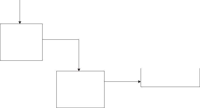
OUTPUT STEP
ACTION
AYou issue an EXEC CICS SEND request in your application program.
BThe TCP terminal scan recognizes the SEND request.
CCICS checks whether an output user exit (XTCTOUT) has been specified. If
it has, CICS links to the user exit routine, where you may edit your output
data before passing it to TCAM. (See the discussion of XTCTOUT under
“TCAM user exits” on page 707.)
DCICS checks the 4-byte TCTTE field TCTTEDES for a destination saved as
a result of DEST(name) having been specified on the EXEC CICS SEND
instruction. If it is present, CICS inserts it in the 8-byte destination field and
left-aligns the field, padding blanks to the right. Otherwise, CICS moves the
source terminal netname from the TCTTE to the destination field.
ECICS moves the communication control byte (or bytes in TCAM SNA) into
the 9th byte (9th and 10th bytes in TCAM SNA) of the TCAM work area.
(See “TCAM devices” on page 704.)
FCICS issues a TCAM WRITE to transfer the data to TCAM.
GAfter checking for successful completion of the WRITE to TCAM, CICS
flags the user task “dispatchable” if a task is still attached to the TCTTE.
Otherwise, CICS frees the TCTTE for a new task.
TCAM input
process queue
Input
TCTLE
Special
TCTTE TIOA
Figure 102. CICS issues a TCAM read
the CICS-TCAM interface
698 CICS TS for OS/390: CICS Customization Guide
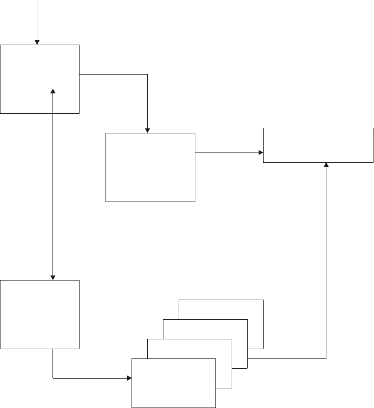
Terminal error program
The CICS-TCAM interface implementation has resulted in the expansion of the
CICS terminal error program (DFHTEP) error codes and conditions. The errors and
actions shown in Table 32 on page 700 are unique to TCAM, and should be
considered in DFHTEP.
TCAM input
process queue
Input
TCTLE
QUTQ=
(ABC)
Special
TCTTE TIOA
Output
TCTLE Terminal ABC
Individual
TCTTEs
Figure 103. After a TCAM read, CICS attaches a TIOA to the corresponding TCTTE
the CICS-TCAM interface
Chapter 26. Using TCAM with CICS 699

Table 32. DFHTEP error codes and conditions unique to TCAM
Error code Condition Action
X'87'(TCEMCUI) Unsolicited input
Terminal ‘receive only’
Terminal ‘out of service’
Task has not issued a read
No available TCTTE from pool.
a
a, b
No default
No default
X'9F'(TCEMIDR) TCAM has issued an invalid destination
return code to CICS. c
where: a = Release TCAM TIOA (X'04' in TEPCAACT)
b = Terminal out of service (X'20' in TEPCAACT)
c = Abend transaction (X'10' in TEPCAACT).
Message routing
The DEST option of the EXEC CICS SEND command can be used to route an
output message to a destination that you defined in the TCAM MCP. This operand
can be used to send a message to a destination other than the source terminal
(such as to another terminal, a list of terminals, or another application program).
CICS moves the data from TCTTEDES into the destination identification field before
placing the data on the TCAM output process queue. You may bypass the CICS
routine that inserts the destination field by taking the XTCMOUT user exit and
returning to CICS from the exit with a displacement of zero. In this case, you must
ensure that the TCAM header is correctly formatted for output.
If the DEST option is omitted, CICS inserts the source terminal NETNAME from the
TCTTE into the destination identification field.
Segment processing
The CICS-TCAM interface supports TCAM segment processing, except when BMS
is used. It permits segments of a message to be forwarded to CICS rather than
waiting for the entire message to be received. If you specify segment processing
(by including the parameter C on the OPTCD operand of the DFHTCT
TYPE=SDSCI macro), CICS passes the segment to you, and places the position
field control byte in the TCTTE field labeled TCTTETCM. Your application program
can read the contents of TCTTETCM by means of an EXEC CICS INQUIRE
TERMINAL command:
EXEC CICS INQUIRE TERMINAL(4-character data-value)
TCAMCONTROL(1-character data-area)
This returns a 1-byte hexadecimal value that indicates which segment of the
message is being passed.
the CICS-TCAM interface
700 CICS TS for OS/390: CICS Customization Guide
The possible values of TCTTETCM are:
Value Message segment
X'00' Null
X'40' Intermediate portion of message
X'F1' First portion of message
X'F2' Last portion of message
X'F3' Entire message
X'F4' Intermediate portion of message, end of record
X'F5' First portion of message, end of record
X'F6' Last portion of message, end of record
X'F7' Entire message, end of record
X'FE' TCAM is not active
X'FF' INQUIRE attempted on non-TCAM terminal.
On output, your application program must supply the control byte in TCTTETCM for
CICS to pass to TCAM. The required command is:
EXEC CICS SET TERMINAL(4-character data-value)
TCAMCONTROL(1-character data-value)
The possible values that can be passed are as listed above. For further information
about EXEC CICS INQUIRE|SET TERMINAL commands, refer to the
CICS System
Programming Reference
manual.
If multiple terminals have been defined for one output line (that is, multiple terminals
related to one TPROCESS queue), you must ensure that an entire message is
passed to TCAM for a specific destination before putting the first segment for
another destination on the queue. In other words, an error is returned to you if a
“PUT first segment to destination A” is followed by a “PUT first segment to
destination B”. For additional information about segment processing, see the
discussion of the OPTCD operand of the application input and output DCB in the
ACF/TCAM Version 3 Application Programming
manual.
Line pool specifications
When generating the TCAM message control program, you define each physical
terminal and logical unit to TCAM by means of a TCAM TERMINAL macro.
Because CICS also requires terminal definitions, you must prepare a terminal
control table terminal entry (TCTTE) for each terminal, or logical unit, in a DFHTCT
TYPE=TERMINAL macro. As a result, there is a one-to-one correlation between
terminal definitions in TCAM and in CICS.
In a highly restricted environment, this duplication of terminal definitions can be
reduced by using the POOL feature (DFHTCT TYPE=LINE,POOL=YES), and by
specifying LASTTRM=POOL in DFHTCT TYPE=TERMINAL on the last TCTTE.
Instead of a one-to-one relationship, a “pool” of generalized TCTTEs is defined for a
TCAM process queue (line). When a transaction is received over the TCAM line, a
search is made for an available TCTTE in the pool. When one is found, it is
assigned a source terminal identification and netname for the duration of the task.
When the task has been completed, the TCTTE can be reassigned. If there are no
available TCTTEs to handle the next transaction from the line, the line remains
the CICS-TCAM interface
Chapter 26. Using TCAM with CICS 701
locked until a TCTTE becomes available because the task has ended. The number
of TCTTEs in the pool influences the degree of multitasking.
You should consider providing enough terminal entries in the pool to avoid an
‘unsolicited input’ condition (see “TCAM queues” on page 703), because there is no
available entry in the pool. When DFHTCAM scans for a free entry, it does not scan
the entire table because it carries a pseudo-end-of-table value. Therefore, unused
entries at the end of the table can never be referred to.
Line pool restrictions
You must be aware of the following line pool restrictions:
vBecause of device dependencies within CICS, only one terminal type is permitted
for each TCAM line (process queue).
vAutomatic transaction initiation (ATI), transaction routing, and BMS message
routing are not applicable in the pool environment. If ATI is required for functions
and you still want to use pooling, you should consider using a special queue of
nonpooled entries suitable for ATI. For example, 3270 displays could be put on a
pooled entry, and 3270 printers on a nonpooled queue to cause ATI to the
printers.
vStatistics are accumulated for each TCTTE in the pool; however, the statistics
cannot be correlated to the physical terminals or specific logical units.
vOnly one signon can exist for all terminal entries in a given line pool at any one
time. The first signon received by CICS is communicated to all terminals in the
pool. Any subsequent signon is rejected. A sign-off clears the signon data from all
terminal entries in the pool; a subsequent signon is then accepted.
vTerminal and line requests issued by the master terminal are not valid for pooled
terminals.
vTCAM segment processing is not supported for pooled terminals.
Line locking
Two types of line locking can occur:
vA temporary lock that resolves itself in time
vA permanent lock that remains permanent unless you take action in the terminal
error program.
A temporary line lock occurs when no TCTTEs are available in the pool and a new
transaction appears on the input queue. CICS locks the queue until an existing task
completes execution, thus freeing a TCTTE. In this case, the completion of existing
tasks is not dependent upon additional input from the queue.
A permanent line lock can occur when multiple reads are required to complete a
task. For example, suppose that there are two TCTTEs in the pool, that a task is
attached to each, and that the messages in the input queue are in the following
order:
1. Message 1 for a third transaction
2. Subsequent messages for the two active tasks.
Because no TCTTE is available in the pool for the third transaction, it must wait for
a task to complete for a TCTTE to become available. Because the TCAM input
queue is processed sequentially, the two active tasks are unable to receive their
subsequent messages. Hence, they cannot complete, and the queue remains
the CICS-TCAM interface
702 CICS TS for OS/390: CICS Customization Guide
permanently locked.
TCAM queues
Because a queue is a sequential data set, the second message on the queue
cannot be retrieved until the first message has been processed. To keep messages
flowing smoothly through the queue, it is essential that each message be processed
as soon as it arrives. In the CICS-TCAM interface, “processing the message”
means detaching the message from the special input TCTTE and attaching it to the
individual TCTTE correlated to the actual physical terminal or logical unit. Each
individual TCTTE may be considered to be a “destination” for the purpose of this
discussion.
If a particular destination (TCTTE) is not ready to accept the current message on
the queue, the queue locks until the destination can accept the message. Queue
locks are only a problem when a queue is serving more than one destination. In this
case, if a queue locks, any new transaction on the queue, or messages queued for
existing tasks, are not processed until the required destination has accepted the
current message.
Because queue locks can adversely affect system performance, it is important that
you understand their cause and effect, as described below. Proper configuration of
the TCAM process queue and CICS terminal control tables reduces the occurrence
and duration of queue locks to a minimum.
The maximum number of terminals that can be attached to one queue is governed
by the amount of activity expected, and by the response time required from the
system. For high activity and low response times, you should not exceed 25
terminals. Note that only a real performance test can verify whether this figure is
acceptable.
Because TCAM can read ahead from the terminals, it is possible for TCAM to
present to CICS a new transaction message destined for a TCTTE that is already
processing a task. Also, TCAM can present a message for an existing task before
that task issues a READ request. In either case, CICS cannot process the message
(as described above) until the TCTTE is ready to accept the new TIOA. Such input
is called “unsolicited input”.
These conditions can produce unsolicited input:
1. The CICS TCTTE for which the data is destined is out of service.
2. The CICS TCTTE for which the data is destined is in RECEIVE status.
3. The CICS TCTTE for which the data is destined has an associated task that
has not issued a READ, and for which the period of time indicated by the
NPDELAY specification has expired.
4. A terminal in a pool has entered data and is unable to find an available TCTTE.
In all cases, the action taken by the CICS-TCAM interface is to place the input line
out of service, and attach DFHTACP to process the error condition.
The default action taken by DFHTACP (which can be altered by a user-written
DFHTEP) for conditions 1 and 2 is to discard the data and place the input line in
service. No default action is taken by DFHTACP for condition 3 or 4; therefore, the
input line is placed in service, but with the same message still to be processed,
thereby preventing CICS from reading any subsequent messages from the input
queue.
the CICS-TCAM interface
Chapter 26. Using TCAM with CICS 703

To allow processing of input to continue, DFHTEP may take either of the following
steps:
vIf the input line is placed in service by DFHTEP, the CICS-TCAM interface retries
the operation. In this case, a count mechanism is recommended in DFHTEP to
prevent a loop occurring if the task never issues a READ, or a TCTTE never
becomes available.
vPerhaps when a count limit is reached, DFHTEP might abend the task, dispose
of the data, and place the line in service.
For further information about DFHTEP, see “Terminal error program” on page 416.
The problem of unsolicited input caused by condition 4 can be eliminated entirely by
having a separate TCAM input process queue for each CICS terminal (TCTTE).
However, as the number of terminals increases, this solution may quickly use up
too much main storage.
You should analyze the type of traffic that you anticipate over the queues. If a 2770
Data Communication System, or a 2780 Data Transmission Terminal, is to read in
volumes of cards, you should consider having separate queues for these devices.
However, devices can share queues if traffic is conversational with short-lived tasks.
The same TCAM output process queue can be specified for multiple input process
queues. (See the discussion of the DFHTCT TYPE=LINE,OUTQ=symbolic name
specification in the
CICS Resource Definition Guide
.)
You need not be concerned with locking the TCAM output process queue, because
TCAM requeues the data according to its final destination once it arrives over the
output queue.
It is possible for the TCAM output process queue to become congested because of
lack of queuing space. In this case, CICS has a WRITE to the queue outstanding
until TCAM accepts the data.
If the length of a message passed to a TCAM queue exceeds the queue’s block
size (specified in the DCB), DFHTCAM causes DFHTACP to be attached with
‘output area exceeded’ (error code X'8F').
TCAM devices
In a non-TCAM environment, the CICS terminal control program is responsible for
polling and addressing terminals, code translation, transaction initiation, task and
line synchronization, and the line control necessary to read from or write to a
terminal. When TCAM is specified, terminal control relinquishes responsibility to the
TCAM MCP for polling and addressing terminals, code translation, and line control.
To take advantage of TCAM facilities, code, in the MCP message handler, functions,
such as code translation, that were previously handled by the CICS terminal control
program.
For some terminal services, it is necessary for CICS to pass the user request on to
the TCAM MCP message handler. A communication control byte (2 bytes in TCAM
SNA) in the TCAM work area has been established for this purpose. It is passed to
TCAM along with the 8-byte destination name field. You must execute the
appropriate MCP message-handler macros according to the contents of the
communication byte.
the CICS-TCAM interface
704 CICS TS for OS/390: CICS Customization Guide
The terminal services parameters that do not set bits in the communication control
byte are SEND, WAIT TERMINAL, and SAVE. Bits in the communication control
byte are set for the ISSUE DISCONNECT and CONVERSE parameters, and for the
FMH and LAST parameters on the EXEC CICS SEND command.
The CICS-TCAM interface does not support the RESET parameter or the 3270
parameters READB and COPY.
All messages to TCAM from CICS are prefixed with the standard CICS-TCAM
communication area. This is one byte for the non-SNA TCAM interface, and
two-bytes for the TCAM SNA interface (that is, when TCAMFET=SNA is specified in
DFHTCT TYPE=LINE). This area is used to convey to TCAM special requests and
options that cannot be used within CICS.
The format of the communication area is:
First byte
X'01' FMH present in stream
X'04' Extended CCB (2-byte CCB)
X'08' DISCONNECT request
X'10' READL (read keyboard)
X'20' WRITEL (write keyboard).
Second byte (present if extended CCB is on)
X'01' Last output from transaction (WRITE,LAST)
X'02' READ requested after this WRITE (WRITE,READ request or CONVERSE).
All other flags are reserved and are set to 0.
Generalized TCAM message format
Messages passed between CICS and TCAM and
vice versa
have the format shown
in Table 33.
Table 33. General format of TCAM messages
Destination CCB Device-
dependent data FMH Message
8 bytes 2 bytes
(optional) (SNA
only)
x bytes (device-
dependent) y bytes (SNA
only)
Destination
Destination name (8 bytes) taken from TCTTE’s netname parameter or from
DEST specification on output.
CCB Communication control bytes. This determines the options specified for the
message (for example, whether an FMH is present or not). The length of
the CCB varies, and can be:
0 bytes (input message, non-SNA)
1 byte (output message, non-SNA)
2 bytes (input/output messages, SNA).
TCAM devices
Chapter 26. Using TCAM with CICS 705

Device-dependent data
Dependent on the device: 3270, or other. See the following sections on the
relevant devices.
FMH Function management header.
SNA only = length in first byte
non-SNA = not applicable.
Message
User data.
TCAM with 3270 devices
The CCB and device-dependent data for an input message from TCAM to CICS
have the following format:
The CCB is present for TCAM SNA lines only.
The CCB and device-dependent data for 3270 output messages from CICS to
TCAM have the following format:
All SOH% status messages input to CICS are passed to DFHTACP or DFHTEP.
Terminal control copy and read buffer requests are not supported by the
CICS-TCAM interface.
In addition to normal read and write functions, the ERASEAUP, CTLCHAR, and
UCTRAN operands are also valid for the 3270.
All 3270 printer scheduling and error handling is provided by the TCAM message
handler.
Note: For 3270 SDLC devices, the escape character must be removed by the
message handler.
CCB1 CCB2 Attention CURSOR
1 byte 1 byte identifier 2 bytes
SNA only SNA only 1 byte
CCB1 CCB2 1 2 3
1 byte 1 byte 1 byte 1 byte 1 byte
(2 bytes - SNA) device-dependent data
(1 byte - non-SNA)
1 Escape character
2 Command
3 WCC (write control character)
TCAM devices
706 CICS TS for OS/390: CICS Customization Guide

TCAM user exits
There are three TCAM global user exit points:
1. XTCATT, invoked before issuing a transaction manager ATTACH for a
transaction identification received in response to polling
2. XTCTIN, invoked following the completion of any TCAM input event, (that is,
after the individual TCTTE has been located, but just before CICS checks to
see if a task is attached to the TCTTE)
3. XTCTOUT, invoked for output events before placing data on the TCAM output
process queue.
For more information about global user exits, you should read “Chapter 1. Global
user exit programs” on page 3.
Starting and terminating TCAM
CICS-TCAM startup
The TCAM MCP must be in operation before completing CICS system initialization.
When you start up CICS with the CICS-TCAM interface, CICS checks for the
presence of a TCAM region and issues the operator message:
DFHSI1513 - CICS CHECKING FOR TCAM MCP
If CICS discovers the MCP is not operational, the following messages are issued:
DFHSI1520 - TCAM MCP NOT CURRENTLY AVAILABLE
DFHSI1520 - REPLY 'RETRY' OR 'CANCEL' OR 'CONT'
The operator must then respond:
RETRY
when the TCAM region becomes active; or
CANCEL
to terminate CICS; or
CONTINUE
to continue initialization of CICS in the absence of the TCAM region.
If the operator responds CONTINUE, all DD cards that refer to a TCAM queue must
have been previously removed from the startup deck to avoid an abnormal
termination of CICS. The CONTINUE response is applicable to a mixed
BTAM/TCAM mode of operation when TCAM lines are not being used during
execution of CICS.
CICS-TCAM abend and restart
If the TCAM message control program (MCP) terminates abnormally, any TCAM
application programs currently active are automatically terminated abnormally, if
there is at least one open line group in the MCP. This also applies to the CICS
application program. For further information, see the relevant sections in the
ACF/TCAM System Programmer’s Guide
and the
ACF/TCAM Version 3 Application
Programming
manual. CICS does not provide RESTART capability.
TCAM user exits
Chapter 26. Using TCAM with CICS 707
CICS-TCAM termination
CICS is terminated in the normal manner. No modifications to termination
procedures are required to support the CICS-TCAM interface. If both CICS and
TCAM are being terminated, CICS should be terminated first, to avoid an abnormal
termination of CICS.
starting and terminating TCAM
708 CICS TS for OS/390: CICS Customization Guide
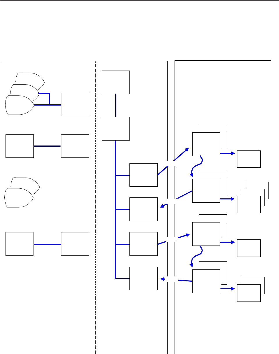
CICS and TCAM: program interrelationship
Figure 104 illustrates the interrelationship between the TCAM message control
program (MCP) and the TCAM application program. CICS is regarded as an
application program by TCAM.
S70A
Terminal
S70B
S75A
T32C
3271
MH3270
message
handler
PG3270
DCB
TRM2
TRM1
LG2260
DCB
TOTCAM
message
handler
3270 (Remote)
2260s (Local)
To CICS
message
handler
QPROC
PCB
R70I
TPROCESS
R70O
TPROCESS
RIS1
TPROCESS
WIS1
TPROCESS
SDSCI(DCB)
TCTLE
DDNAME=
R3270IN
OUTQ=
SDSCI(DCB)
SDSCI(DCB)
SDSCI(DCB)
TCTLE
DDNAME=
R3270OUT
TCTLE
DDNAME=
QIN1
OUTQ=
TCTLE
DDNAME=
QOUT1
TCTTE
"DMMX"
TCTTE
"DMMY"
TRM1
TCTTE
S70A
TCTTE
S75A
S70B
TRM2
DD Cards
DD Cards
DDLG3270
DDLG2260
DD
DD
UNIT=xxx
UNIT=(a, b)
//QIN1
//QOUT1
//R3270IN
//R3270OUT
DD
DD
DD
DD
QNAME=RIS1
QNAME=WIS1
QNAME=R70I
QNAME=R70O
TCAM MCP CICS Application program
Read
Read
Write
Write
Figure 104. TCAM message control and application program
CICS-TCAM program interrelationship
Chapter 26. Using TCAM with CICS 709
TCAM message control program (non-SNA)
This section gives an example of a non-SNA TCAM message control program. This
MCP shows the relationship between the MCP definition and the CICS terminal
control table generation. It should not be construed as a typical or usable MCP for
CICS. For further information about MCP definition for a variety of devices, see the
ACF/TCAM Installation and Migration Guide
. An example of a CICS terminal control
table for TCAM is given in the
CICS Resource Definition Guide
.
Note: Two sample TCAM message control programs for use in an SNA network
are provided in CICSTS13.CICS.SDFHSAMP. These are DFHSPTM1 (in
which control of SNA sessions is independent of the CICS application
programs), and DFHSPTM2 (in which control of SNA sessions is according
to the requirements of the CICS application programs).
MCPCICS CSECT
TCAMINIT INTRO DISK=NO, *
PROGID=TCAM/CICS, *
LUNITS=40, *
MSUNITS=20, *
KEYLEN=132, *
CROSSRF=4, *
DLQ=TRM1, *
STARTUP=CY, *
TRACE=10, *
LINETYP=BOTH, *
OLTEST=0
LTR 15,15
BZ OPENLINE
NOEXEC ABEND 123,DUMP
OPENLINE OPEN (PG3270,(INOUT))
TM PG3270+48,DCBOFLGS
BNO NOEXEC
WTO 'TIME TO START APPLICATION PROGRAM'
READY
FINISH CLOSE (,PG3270)
L 13,4(13)
RETURN (14,12)
PG3270 DCB DSORG=TX,MACRV=(G,P),CPRI=S,DDNAME=DDPG3270, *
MH=MH3270,PCI=(N,N),BUFSIZE=464, *
INVLIST=(POLL70R,,),TRANS=EBCD
QPROC PCB MH=TOCICS, *
BUFSIZE=464, *
RESERVE=(20)
TTABLE LAST=TRM2
RIS1 TPROCESS PCB=QPROC,QUEUES=MO *
WIS1 TPROCESS PCB=QPROC
R70I TPROCESS PCB=QPROC,QUEUES=MO
R700 TPROCESS PCB=QPROC
T32C TERMINAL QBY=T,DCB=LG3270R,RLN=1,TERM=327C,QUEUES=MO
S70A TERMINAL QBY=T,DCB=PG3270,RLN=1,TERM=327R,QUEUES=MO, *
ADDR=616140402D,NTBLKSZ=1856,SECTERM=YES
S70B TERMINAL QBY=T,DCB=PG3270,RLN=1,TERM=327R,QUEUES=MO, *
ADDR=6161C1C12D,NTBLKSZ=1856,SECTERM=YES
Figure 105. Example of a TCAM message control program (non-SNA) (Part 1 of 2)
CICS-TCAM program interrelationship
710 CICS TS for OS/390: CICS Customization Guide
S75A TERMINAL QBY=T,DCB=PG3270,RLN=1,TERM=327R,QUEUES=MO, *
ADDR=E2E240402D,NTBLKSZ=1856
POLLST1 INVLIST ORDER=(TRM1+02)
POLLST2 INVLIST ORDER=(TRM2+02)
POLL70R INVLIST ORDER=(T32C-C1C17F7F2D,S70A+C1C140402D, *
S70B+C1C1C1C12D, *
S75A+C2C27F7F2D,S75A+C2C240402D), *
EOT=37
*
TOTCAM STARTMH LC=OUT 2260 MH
INHDR PROCESS INCOMING MSG HEADER
CODE
FORWARD DEST=C'RIS1'
INMSG PROCESS INCOMING COMPLETE MSG
INEND END OF INCOMING SECTION
OUTHDR PROCESS OUTGOING MSG HEADER
OUTEND END OF OUTGOING SECTION
*
MH3270 STARTMH LC=OUT,CONV=YES,STOP=YES 3270 MH
INHDR, PROCESS INCOMING MSG HEADER
MSGTYPE X'6C' IS IT A STATUS MESSAGE
B SOH IF SO, BRANCH ROUND
MSGTYPE ALL OTHER MSGS TO HERE
MSGEDIT ((R,CONTRACT,SCAN,(2))),BLANK=NO REMOVE CUDV BYTES
SOH EQU*orDS0H
CODE
FORWARD DEST=C'R70I'
INBUF INCOMING MSG SEGMENT SECTION
INMSG SECTION FOR COMPLETE MSGS
INEND END INCOMING SECTION
OUTHDR
SETSCAN 1
MSGEDIT ((R,,SCAN)) REMOVE CCB
MSGFORM SETS IN LINE CONTROL CHARS
CODE
OUTBUF,
OUTMSG
OUTEND END OUTPUT SECTION
TOCICS STARTMH LC=OUT MH FOR APPLICATION
INHDR
CODE TRANSLATE TO EBCDIC
FORWARD DEST=PUT WRITE TO CICS
INEND
OUTHDR
OUTEND
DCBOFLGS EQU X'10'
END
Figure 105. Example of a TCAM message control program (non-SNA) (Part 2 of 2)
Chapter 26. Using TCAM with CICS 711
712 CICS TS for OS/390: CICS Customization Guide

Chapter 27. The dynamic allocation sample program
This chapter suggests ways in which you can customize the dynamic allocation
sample application program, used to allocate or deallocate data sets dynamically. It
is divided into the following sections:
1. “Overview of the dynamic allocation program”
2. “Installing the program and transaction definitions” on page 714
3. “Terminal operation” on page 714
4. “Help feature” on page 715
5. “Values” on page 715
6. “The flow of control when a DYNALLOC request is issued” on page 717.
Overview of the dynamic allocation program
The dynamic allocation (DYNALLOC) sample application program makes available
to the CICS terminal operator most of the functions of DYNALLOC (SVC 99). These
functions are described fully in the
MVS/ESA SPL: Application Development Guide
.
Functions that require authorized program facility (APF) authorization are not
supported.
The application consists of one command-level assembler-language program,
DFH99, which is invoked by the transaction ADYN. The source code is provided in
CICSTS13.CICS.SDFHSAMP.
Using DYNALLOC functions, the terminal operator can dynamically allocate or
deallocate any data set that CICS can open and close. With suitable operating
discipline and CEMT commands, these can include:
vExtrapartition transient data sets
vJournals
vDump and trace data sets.
You should not use the dynamic allocation program to allocate and deallocate data
sets that are to be associated with files managed by file control. You should use the
dynamic allocation and deallocation facility which is part of CICS. If a file has not
been allocated as part of CICS startup, CICS dynamic allocation occurs
immediately before the file is opened, if sufficient information is in the file control
table. The information needed is the data set name and disposition of the file. This
information is set by the CEMT SET FILE master terminal transaction, described in
the
CICS Supplied Transactions
manual, or the EXEC CICS INQUIRE FILE and
EXEC CICS SET FILE commands, which provide additional inquiry and control
facilities, and which are described in the
CICS System Programming Reference
manual.
To use the dynamic allocation sample program effectively, the terminal operator
should:
vHave an understanding of MVS job control language, or TSO ALLOCATE and
FREE commands.
© Copyright IBM Corp. 1977, 1999 713

vHave read the relevant sections of the
MVS/ESA SPL: Application Development
Guide
and have that manual available for reference while using the sample
program, in particular for looking up error and reason codes returned by
DYNALLOC.
The application uses a 3270 display screen terminal, and adjusts its formatting to
suit the screen size. BMS is not required. The program is designed so that the
installation can easily modify the functions supported to suit installation standards.
Installing the program and transaction definitions
Transaction and program definitions for the dynamic allocation sample program are
provided in the sample utilities group DFH$UTIL on the CSD. These definitions are
installed using the CEDA command:
CEDA INSTALL GROUP(DFH$UTIL)
Notes:
1. DFH99 must be defined with EXECKEY(CICS).
2. If you make any changes to the sample program, you must run the DFH99BLD
procedure before using the ADYN transaction.
Terminal operation
When transaction ADYN is entered at a terminal, the operator is presented with a
formatted display. The top part of the display is for entering commands, the bottom
part for receiving messages from the program.
The operator types a command in TSO-like syntax, for example,
verb {keyword[(value...)]}...
and presses the ENTER key. The program checks the command for correct syntax,
builds a DYNALLOC parameter list, and, if no serious errors are detected, issues a
DYNALLOC SVC. Messages are then displayed to diagnose syntax errors, give the
DYNALLOC return codes, and show any values returned by DYNALLOC
information retrieval features. The command remains on the display, and the editing
features of the terminal can be used to correct it for reentry, or to enter a different
command.
If there are too many messages to fit into the message area of the screen,
messages that cannot be displayed are queued, and the messages already on the
screen are displayed with a brighter intensity to indicate that there are more
messages to come. The operator can correct those errors that are being displayed,
and reenter the command for further checking, when the queued messages, if any,
are regenerated.
The program is terminated by entering a null command, which consists of pressing
the ERASE INPUT key, followed by the ENTER key. PA keys 1 and 2 are ignored
by the program. If you press the CLEAR key, you redisplay the last command
entered. Pressing a program function key is equivalent to pressing ENTER.
the dynamic allocation sample program
714 CICS TS for OS/390: CICS Customization Guide

Help feature
The program includes a limited “help” feature, driven by the program’s keyword
table.
In response to “?”, the verb keywords are displayed. In response to “verb?”, all the
operand keywords of that verb are displayed. For “verb operand(?)” a short
description of the value expected for that operand is displayed. When a command
containing “?” is entered, no DYNALLOC SVC is issued. “?” is recognized only in
the positions specified above; the rest of the command is ignored.
Values
Values are classified as follows:
Keyword value
Keyword values must be specified for some keywords. For example, the
STATUS keyword may have a keyword value of SHR, NEW, MOD, or OLD
(which can be abbreviated).
String of key letters
The value can be a string of letters in any order. The program does not check
that the combination of letters provided is meaningful. For example, for the
RECFM keyword, the value can be a string of letters from A, B, D, F, G, M, R,
S, T, U, and V.
Returned values
No value should be provided by the terminal operator, because this keyword
requests a value to be returned by the DYNALLOC information retrieval
features. The further description refers to the kind of value that will be returned.
This is usually in the form in which the operator would enter it, although in a
few cases the value is as a hexadecimal string.
Not allowed
Some keywords do not require a value, and you must not provide one.
Required
A value must be provided if the keyword coded is designated as requiring a
value.
Optional
Specification of a value is optional for some keywords.
Single
Only one value may be provided for some keywords.
Multiple
For some keywords, more than one value is permitted. (In some cases,
DYNALLOC requires more than one value, although the dynamic allocation
sample program does not enforce this.)
Character string
Any characters are permitted in this type of value, although in most cases there
will be additional rules to follow, for example, for the DSNAME keyword.
Numeric string
Only numeric characters are allowed for this type of value, for example, for the
EXPDT keyword.
help feature
Chapter 27. The dynamic allocation sample program 715
Maximum and minimum lengths
For character and numeric values, the maximum and minimum lengths of the
value are checked by the program. For a fixed-length string, these values are
the same. The value is still passed to DYNALLOC as specified.
Convertible to n byte binary
A numeric value is required, of a magnitude representable in binary in the
specified number of bytes. Values that are too large are truncated to the
maximum possible for the width.
The dynamic allocation sample program does not support negative numbers. It
does not cross-check operand keywords; errors of this type usually cause
DYNALLOC to return error codes of the form 03xx.
Abbreviation rules for keywords
Keywords can be abbreviated. A word in the command matches a keyword if:
vThe spelling is the same.
vThe first letter is the same, and the remaining letters in the word appear in the
same order as they do in the keyword.
If an ambiguity occurs, the program diagnoses the ambiguity, and lists the possible
keywords.
System programming considerations
Keyword spellings are defined in the program’s table, DFH99T, which is link-edited
with the program. Where possible, these are the same as the corresponding job
control or TSO keywords. Comments in the source code for DFH99T explain how
the system programmer can:
vChange the spelling of keywords
vDefine alternative spelling for keywords
vDivide the functions of a verb into subsets
vAdd new verbs with subset function
vAdd new operands as they become available in the SVC.
Member DFH99BLD in CICSTS13.CICS.SDFHINST is the job stream used to build
the program. If part of the program has been modified, reassemble that part and
link-edit the program again.
The macros IEFZB4D0 (DYNALLOC parameter list structure) and IEFZB4D2
(symbolic key equates), provided by MVS, are used in the dynamic allocation
program and its keyword table. The meaning of each keyword in the table is
defined in terms of a symbolic name, defined by one of the macros IEFZB4D0 or
IEFZB4D2. The definitions of command keywords given in that manual should be
regarded in preference to those from any other source. To obtain a list of command
keywords and their symbolic values, for use as a cross-reference to the MVS
manual, assemble DFH99T with option SYSPARM(LIST), and print the resulting
object code. If the table is changed, repeat the assembly to obtain a new list.
keywords and values
716 CICS TS for OS/390: CICS Customization Guide

The flow of control when a DYNALLOC request is issued
The flow in a normal invocation is as follows. The main program, DFH99M, receives
control from CICS and carries out initialization. This includes determining the screen
size, allocating input and output buffer sections, and issuing initial messages. It then
invokes DFH99GI to get the input command from the terminal. Upon return, if the
command was null, the main program terminates, issuing a final message.
The command obtained has its start and end addresses stored in the global
communication area, COMM. The main program allocates storage for tokenized
text, and calls DFH99TK to tokenize the command. If errors were detected at this
stage, further analysis of the command is bypassed.
Following successful tokenizing, the main program calls DFH99FP to analyze the
verb keyword. DFH99FP calls DFH99LK to look up the verb keyword in the table,
DFH99T. DFH99LK calls DFH99MT if an abbreviation is possible. Upon finding the
matching verb, DFH99FP puts the address of the operand section of the table into
COMM, and puts the function code into the DYNALLOC request block.
The main program now calls DFH99KO to process the operand keywords. Each
keyword in turn is looked up in the table by calling DFH99LK, and the value coded
for the keyword is checked against the attributes in the table. DFH99KO then starts
off a text unit with the appropriate code and, depending on the attributes the value
should have, calls a conversion routine.
For character and numeric strings, DFH99CC is called. It validates the string, and
puts its length and value into the text unit.
For binary variables, DFH99BC is called. It validates the value, converts it to binary
of the required length, and puts its length and value into the text unit.
For keyword values, DFH99KC is called. It looks up the value in the description part
of the keyword table using DFH99LK, and puts the coded equivalent value and its
length into the text unit.
When a keyword specifying a returned value is encountered, DHF99KO makes an
entry on the returned value chain, which is anchored in COMM. This addresses the
keyword entry in DFH99T, the text unit where the value is returned, and the next
entry. In this case the conversion routine is still called, but it only reserves storage
in the text unit, setting the length to the maximum and the value to zeros.
When all the operand keywords have been processed, DFH99KO returns to the
main program, which calls DFH99DY to issue the DYNALLOC request.
DFH99DY sets up the remaining parts of the parameter list and, if no errors too
severe have been detected, a subtask is attached to issue the DYNALLOC SVC. A
WAIT EVENT is then issued against the subtask termination ECB. When the
subtask ends and CICS dispatches the program again, the DYNALLOC return code
is captured from the subtask ECB and the error and reason codes from the
DYNALLOC request block and a message is issued to give these values to the
terminal.
DFH99DY then returns to the main program, which calls DFH99RP to process
returned values. DFH99RP scans the returned value chain, and for each element
issues a message containing the keyword and the value found in the text unit. If a
DYNALLOC flow of control
Chapter 27. The dynamic allocation sample program 717
returned value corresponds to a keyword value, DFH99KR is called to look up the
value in the description, and issue the message.
Processing of the command is now complete, and the main program is reinitialized
for the next one, and loops back to the point where it calls DFH99GI.
Messages are issued at many places, using macros. The macro expansion ends
with a call to DFH99MP, which ensures that a new line is started for each new
message, and calls DFH99ML, the message editor. Input to the message editor is a
list of tokens, and each one is picked up in turn and converted to displayable text.
For each piece of text, DFH99TX is called, which inserts the text into the output
buffer, starting a new line if necessary. This ensures that a word is never split over
two lines.
At the end of processing the command, the main program calls DFH99MP with no
parameters, which causes it to send the output buffer to the terminal, and initialize it
to empty.
DYNALLOC flow of control
718 CICS TS for OS/390: CICS Customization Guide

Part 7. Customizing CICS security processing
© Copyright IBM Corp. 1977, 1999 719

General notes
The following comments apply to the chapters in Part 7 of this book:
vThe only aspects of CICS security processing covered are:
– Invoking a user-written external security manager
– Writing a “good night” transaction.
For a comprehensive view of security processing using the Resource
Access Control Facility (RACF) product, see the
CICS RACF Security
Guide
.
vUpon return from any customer-written program, CICS must always receive
control in primary-space translation mode, with the original contents of all
access registers restored, and with all general-purpose registers restored
(except for those which provide return codes or linkage information).
For information about translation modes, refer to the
IBM ESA/370
Principles of Operation
manual.
720 CICS TS for OS/390: CICS Customization Guide

Chapter 28. Invoking a user-written external security manager
CICS provides an interface to an external security manager (ESM), which may be
user-written or may be the Resource Access Control Facility (RACF) program
product. This chapter gives an overview of the CICS-ESM interface, and describes
how you can use the MVS router exit to pass control to a user-written ESM. It
describes how ESM exit programs can access CICS-related information. Finally, it
lists the control points at which CICS invokes the ESM.
Note that this chapter is intended primarily for non-RACF users. For definitive
information about security processing using RACF, you should refer to the
CICS RACF Security Guide
.
The chapter is divided into the following sections:
1. “An overview of the CICS-ESM interface”
2. “The MVS router”
3. “How ESM exit programs access CICS-related information” on page 724
4. “CICS security control points” on page 727
5. “Early verification processing” on page 729.
An overview of the CICS-ESM interface
CICS security uses, via the RACROUTE macro, the MVS system authorization
facility (SAF) interface to route authorization requests to the ESM. Normally, if
RACF is present, the MVS router passes control to it. However, you can modify the
action of the MVS router by invoking the router exit. The router exit can be used, for
example, to pass control to a user-written or vendor-supplied ESM. (If you want to
use your own security manager, you must supply an MVS router exit routine.)
The control points at which CICS issues a RACROUTE macro to route authorization
requests are described in “CICS security control points” on page 727.
The MVS router
SAF provides your installation with centralized control over security processing, by
using a system service called the MVS router. The MVS router provides a common
system interface for all products providing resource control. The resource-managing
components and subsystems (such as CICS) call the MVS router as part of certain
decision-making functions in their processing, such as access control checking and
authorization-related checking. These functions are called control points. This
single SAF interface encourages the use of common control functions shared
across products and across systems.
If RACF is available in the system, the MVS router may pass control to the RACF
router, which in turn invokes the appropriate RACF function. (The parameter
information and the RACF router table, which associates router invocations with
RACF functions, determine the appropriate function.) However, before calling the
RACF router, the MVS router calls an optional, installation-supplied
security-processing exit, if one has been installed.
© Copyright IBM Corp. 1977, 1999 721
The MVS router exit
The MVS router provides an optional installation exit that is invoked whether or not
RACF is installed and active on the system. If your installation does not use RACF,
you can use the router exit to pass control to your own ESM. If you do use RACF,
you could use the exit for preprocessing before RACF is invoked.
The MVS router exit routine is invoked whenever CICS (or another component of
your system) issues a RACROUTE macro. The router passes a parameter list
(generated by the RACROUTE macro) to the exit routine. In addition, the exit
receives the address of a 150-byte work area.
On entry to the exit routine, register 1 contains the address of the area described in
Table 34.
Table 34. Area addressed by register 1, on entry to exit routine
Offset Length Description
04Parameter list address: points to the MVS router parameter list.
(See “The MVS router parameter list”.)
44Work area address: points to a 150-byte work area that the exit
can use.
The exit must be named ICHRTX00 and must be located in the link pack area
(LPA).
Note: During signon processing, CICS Transaction Server for OS/390 Release 3
issues the RACROUTE REQUEST=VERIFY macro with the ENVIR=VERIFY
option, in problem-program state. (For an explanation of why CICS does this,
see “Early verification processing” on page 729.) RACF requires RACROUTE
calls with the ACEE option to be issued in supervisor state. Therefore, if you
use an ICHRTX00 exit that intercepts CICS RACROUTE calls, and replaces
them with its own RACROUTE requests, your exit program should not
assume that a REQUEST=VERIFY call was made in supervisor state.
When intercepting a REQUEST=VERIFY call, your exit program should
check the settings of the two high-order bits of the byte at offset 3 in the
RACINIT parameter list. If ENVIR=VERIFY was specified on the call (as in
CICS early verification), these bits are both set on. If this is the case, your
exit program should not issue any further RACROUTE macros. To do so
could cause abends in RACF.
The MVS router parameter list
The MVS router parameter list is generated when the RACROUTE macro is issued,
and describes the security processing request by providing the request type. If the
router exit routine exists, the router passes the parameter list to this exit. (If it does
not exist, and if RACF is active, the router passes the parameter list to the RACF
router.)
You can map the MVS router parameter list using the ICHSAFP macro. Its format is
shown in the
OS/390 Security Server External Security Interface (RACROUTE)
Macro Reference
manual.
the MVS router
722 CICS TS for OS/390: CICS Customization Guide

Router exit return codes
Your exit routine must return a return code in register 15. The hexadecimal values
of the return code are shown in Table 35.
Table 35. MVS router exit return codes
Code Meaning
0 The exit has completed successfully. Control proceeds to the RACF front-end
routine for further security processing and an invocation of RACF.
C8 The exit has completed successfully. The MVS router translates this return
code to a router return code of ‘0’ and returns control to the issuer of the
RACROUTE macro (CICS), bypassing RACF processing. (See the next
section.)
CC The exit has completed successfully. The MVS router translates this return
code to a router return code of ‘4’ and returns control to CICS, bypassing
RACF processing. (See the next section.)
D0 The exit has completed successfully. The MVS router translates this return
code to a router return code of ‘8’ and returns control to CICS, bypassing
RACF processing. (See the next section.)
Other If the exit routine sets any return code other than those described above, the
MVS router returns control directly to CICS and passes the untranslated code
as the router return code. Further RACF processing is bypassed.
Passing control to a user-supplied ESM
Normally, a caller (such as CICS) invokes the MVS router and passes it request
type, requester, and subsystem parameters via the RACROUTE exit parameter list.
Using these parameters, the MVS router calls the router exit which, on completing
its processing, passes a return code to the router. If the return code is ‘0’, as
defined above, the router invokes RACF. RACF reports the result of that invocation
to the router by entering return and reason codes in register 15 and register 0
respectively. The router converts the RACF return and reason codes to router return
and reason codes and passes them to the caller. The router provides additional
information to the caller by placing the unconverted RACF return and reason codes
in the first and second words of the router input parameter list.
If your installation does not use RACF, you can make the MVS router exit pass
control to an alternative ESM. However, if you do so you must still provide CICS
with the RACF return and reason codes that it expects to receive. You set the
router exit return code, as defined in Table 35, so that RACF is not invoked; and
you simulate the results of a RACF invocation by coding the exit so that it places
the RACF return and reason codes in the first and second fullwords of the router
input parameter list. RACF return and reason codes are documented in the
MVS
Authorized Assembler Programming Reference
manual.
Note: Remember that it is possible for a subsystem other than CICS to call the
MVS router by issuing a RACROUTE macro. (Application programs too, may
issue RACROUTE macros directly.) Your router exit program can establish
whether the caller is CICS by checking the “eyecatcher” fields (UXPARROW,
UXPDFHXS, and UXPBLKID) in the installation data parameter list—see
“The installation data parameter list” on page 725.
the MVS router
Chapter 28. Invoking a user-written external security manager 723

How ESM exit programs access CICS-related information
When CICS invokes the ESM, it passes information about the current CICS
environment, for use by an ESM exit program, in an installation data parameter
list. How your exit programs access the installation data parameter list depends on
whether or not your ESM is RACF.
For non-RACF users — the ESM parameter list
CICS (or another caller) passes information to your external security manager in the
ESM parameter list, the address of which can be calculated using field SAFPRACP
of the MVS router parameter list.
When the caller is CICS, the “INSTLN” field of the ESM parameter list points to the
installation data parameter list, which contains CICS-related information that can be
used by ESM exit programs.
The format of the ESM parameter list, and the actual name of the “INSTLN” field,
vary, depending on which CICS security event is being processed. (The “request
type” field (SAFPREQT) of the router parameter list shows why the ESM is being
called by indicating the RACROUTE REQUEST type.) Table 36 shows how some
formats of the ESM parameter list can be mapped using MVS macros.
Table 36. Mapping the ESM parameter list
RACROUTE REQUEST
type Parameter list mapping macro INSTLN field name
VERIFY IRRPRIPL INITIPTR (X'10')
AUTH ICHACHKL ACHKIN31 (X'20')
FASTAUTH Not available Offset X'18'
LIST Not available Offset X'0C'
EXTRACT Not available None
Note: The INSTLN field points to the installation parameter list only if you specify
INSTLN on the ESMEXITS system initialization parameter. The default value
of this parameter is NOINSTLN, which means that no installation data is
passed.
For RACF users — the RACF user exit parameter list
If you are a RACF user, you can find the address of the installation data parameter
list directly from the RACF user exit parameter list. The name of the relevant field in
the user exit parameter list varies according to the RACROUTE REQUEST type
and the RACF user exit that is invoked. The relationships between REQUEST type,
exit name, and field name are shown in Table 37 on page 725.
ESM exit programs
724 CICS TS for OS/390: CICS Customization Guide

Table 37. Obtaining the address of the installation data parameter list
RACROUTE
REQUEST type RACF exit Exit list mapping
macro Parameter list field
name
VERIFY ICHRIX01 ICHRIXP RIXINSTL
ICHRIX02 ICHRIXP RIXINSTL
AUTH ICHRCX01 ICHRCXP RCXINSTL
ICHRCX02 ICHRCXP RCXINSTL
FASTAUTH ICHRFX01 ICHRFXP RFXANSTL
ICHRFX02 ICHRFXP RFXANSTL
LIST ICHRLX01 ICHRLX1P RLX1INST
ICHRLX02 ICHRLX2P RLX2PRPA See note
2.
EXTRACT Not available Not available None
Notes:
1. The “xxxINSTL” field points to the installation parameter list only if you specify
INSTLN on the ESMEXITS system initialization parameter. The default value of
this parameter is NOINSTLN, which means that no installation data is passed.
2. RLX2PRPA contains the address of the ICHRLX01 user exit parameter list
(RLX1P). Field RLX1INST of RLX1P in turn points to the installation data
parameter list.
For full descriptions of the RACF exit parameter lists, see the
OS/390 Security
Server (RACF) Security Administrator’s Guide
manual. For more information about
CICS security processing using RACF, see the
CICS RACF Security Guide
.
The installation data parameter list
The installation data parameter list gives your ESM exit programs access to the
following information:
vThe CICS security event being processed.
vDetails of the current CICS environment. That is:
– The applid of the CICS region
– The common work area (CWA)
– The transaction being invoked
– The program being executed
– The CICS terminal identifier
– The VTAM LU name
– The terminal user area.
You can map the installation parameter list using the macro DFHXSUXP. The
DSECT DFHXSUXP contains the following fields:
UXPLEN
A halfword containing the length of this parameter list in bytes.
UXPARROW
Arrow “eyecatcher” (>).
UXPDFHXS
The name of the owning component (DFHXS).
ESM exit programs
Chapter 28. Invoking a user-written external security manager 725
UXPBLKID
The name of the block identifier (UXPARMS).
UXPPHASE
Address of a 1-byte code that indicates the reason for the call to the ESM
(that is, the security event being processed). The code can have one of the
following values:
DEFAULT_SIGN_ON (X'01')
Signon of default userid
PRESET_SIGN_ON (X'02')
Signon of preset security terminal
IRC_SIGN_ON (X'03')
Link signon for IRC (MRO) links
LU61_SIGN_ON (X'04')
Link signon for LUTYPE6.1 links
LU62_SIGN_ON (X'05')
Link signon for APPC links
XRF_SIGN_ON (X'06')
XRF tracking of signon
ATTACH_SIGN_ON (X'07')
Attach-time signon of link user
USER_SIGN_ON (X'10')
Normal user signon
DELETE_SIGN_OFF (X'22')
Sign-off when terminal deleted
LINK_SIGN_OFF (X'25')
Sign-off when link is closed
XRF_SIGN_OFF (X'26')
XRF tracking of sign-off
ATTACH_SIGN_OFF (X'27')
End-of-task sign-off of link user
USER_SIGN_OFF (X'30')
Normal user sign-off
ABNORMAL_SIGN_OFF (X'31')
Sign-off forced by the terminal abnormal condition program, or
time-out by the CSSC transaction
USER_ATTACH_CHECK (X'40')
Transaction attach check for user
LINK_ATTACH_CHECK (X'41')
Transaction attach check for link
EDF_ATTACH_CHECK (X'42')
Transaction attach check for CEDF
USER_COMMAND_CHECK (X'50')
Command checking for user
LINK_COMMAND_CHECK (X'51')
Command checking for link
ESM exit programs
726 CICS TS for OS/390: CICS Customization Guide

USER_RESOURCE_CHECK (X'60')
Resource checking for user
LINK_RESOURCE_CHECK (X'61')
Resource checking for link
USER_QUERY_CHECK (X'70')
Query checking for user
LINK_QUERY_CHECK (X'71')
Query checking for link
INITIALIZE_SECURITY (X'80')
Initialization of CICS security
REBUILD_SECURITY (X'81')
CEMT or command-level SECURITY REBUILD
XRF_TRACK_INITIALIZE (X'82')
XRF tracking of initial or rebuild.
UXPSUBSY
Address of an area containing the CICS subsystem identifier.
UXPAPPL
Address of an area containing the CICS application ID.
UXPCWA
Address of the Common Work Area.
UXPTRAN
Address of an area containing the transaction identifier.
UXPPROG
Address of an area containing the program name. The address may be
zero if no program name can be identified.
UXPTERM
Address of an area containing the terminal identifier. The address may be
zero if no terminal is associated with the request.
UXPLUNAM
Address of an area containing the VTAM LU name. The address may be
zero if no terminal is associated with the request, or the area may be blank
if the terminal is not a VTAM terminal.
UXPTCTUA
Address of the TCT user area.
UXPTCTUL
Address of a fullword containing the length of the TCTUA.
UXPCOMM
Address of a 2-word communication area.
CICS security control points
The following list summarizes the RACROUTE macros used by CICS to invoke the
ESM, and the control points at which they are issued.
RACROUTE
The “front end” to the macros described below, it invokes the MVS router. If
RACF is not present on the system, RACROUTE can route to an alternative
ESM, via the MVS router exit.
ESM exit programs
Chapter 28. Invoking a user-written external security manager 727
RACROUTE REQUEST=VERIFY
Issued at operator signon (with the parameter ENVIR=CREATE), and at sign-off
(with the parameter ENVIR=DELETE). This macro creates or destroys an
access control environment element (ACEE). It is issued at the following CICS
control points:
Normal signon through EXEC CICS SIGNON
Signon of the default userid DFLTUSER
Signon of preset security terminals
Signon of MRO sessions
Signon of LUTYPE6.1 sessions
Signon of APPC sessions
Signon for XRF tracking of the above
Signon of the userid on attach requests (for all values of ATTACHSEC
except LOCAL)
Normal sign-off through EXEC CICS SIGNOFF
Sign-off when deleting a terminal
Sign-off when TIMEOUT expires
Sign-off of MRO sessions
Sign-off of LUTYPE6.1 sessions
Sign-off of APPC sessions
Sign-off for XRF tracking of the above
Sign-off of the userid on attach requests (for all values of ATTACHSEC
except LOCAL).
RACROUTE REQUEST=VERIFYX
This creates or deletes an ACEE in a single call. It is issued at the following
CICS control points:
vSignon, as an alternative to VERIFY, when an optimized signon is performed
for subsequent signons across an LU6.2 link with ATTACHSEC(VERIFY).
vWhen an invalid password, or a passticket is presented, or an EXEC CICS
VERIFY PASSWORD command is issued.
RACROUTE REQUEST=FASTAUTH
Issued during resource checking, on behalf of a user who is identified by an
ACEE. It is the high-performance form of REQUEST=AUTH, using in-storage
resource profiles, and is issued at the following CICS control points:
When attaching local transactions
When checking link security for transaction attach
Transaction validation for MRO tasks
CICS resource checking
Link security check for a CICS resource
Transaction validation for EDF
Transaction validation for the transaction being tested (by EDF)
DBCTL PSB scheduling resource security check
DBCTL PSB scheduling link security check
Remote DL/I PSB scheduling resource check
QUERY SECURITY with the RESTYPE option.
RACROUTE REQUEST=AUTH
This is a higher path length form of resource checking. It is used:
CICS security control points
728 CICS TS for OS/390: CICS Customization Guide

vAfter a call to FASTAUTH indicates an access failure that requires logging.
vWhen a QUERY SECURITY request with the RESCLASS option is used.
This indicates a request for a resource for which CICS has not built
in-storage profiles. (If CICS has in fact built in-storage profiles,
REQUEST=AUTH uses them.)
RACROUTE REQUEST=LIST
Issued to create and delete the in-storage profile lists needed by
REQUEST=FASTAUTH. (One REQUEST=LIST macro is required for each
resource class.) It is issued at the following CICS control points:
When CICS security is being initialized
When an EXEC CICS REBUILD SECURITY is issued
When XRF tracks either of these events.
RACROUTE REQUEST=EXTRACT
Issued (with the parameters SEGMENT=SESSION,CLASS=APPCLU) during
verification of APPC BIND security, at the following CICS control point:
BIND of APPC sessions.
It is also issued (with the parameters SEGMENT=CICS,CLASS=USER) during
signon, at all the control points listed under RACROUTE REQUEST=VERIFY.
For a detailed description of these macros, see the
OS/390 Security Server
External Security Interface (RACROUTE) Macro Reference
manual.
Early verification processing
The CICS signon routine invokes the SAF interface, using the RACROUTE
REQUEST=VERIFY macro with the ENVIR=VERIFY option in problem-program
state. Invoking this version of the macro has no effect if the ESM is RACF, but other
external security manager products can get control through the SAF exit interface,
and perform their own early verification routine.
CICS defers the creation of the accessor environment element until the
RACROUTE REQUEST=VERIFY macro with the ENVIR=CREATE option is issued
to perform the normal verification routine. The ENVIR=CREATE version of the
macro is issued by the security manager domain running in supervisor state.
CICS passes the following information on the ENVIR=VERIFY version of the
RACROUTE REQUEST=VERIFY macro:
USERID
The userid of the user signing on to the CICS region.
GROUP
The group name, if specified, of the group into which the user wants to sign on.
PASSWRD
The user’s password to verify the userid.
NEWPASS
A new value, if specified, for the user’s password. This changes the existing
password and is to be used for subsequent signons.
OIDCARD
The contents, if supplied, of an operator identification card.
CICS security control points
Chapter 28. Invoking a user-written external security manager 729
APPL
The APPLID of the CICS region on which the user is signing on. Which APPLID
is passed depends on what is specified as system initialization parameters.
INSTLN
A pointer to a vector of CICS-related information, which you can map using the
DFHXSUXP mapping macro. This pointer is valid only if ESMEXITS=INSTLN is
specified as a system initialization parameter for the CICS region.
The installation data referenced by the INSTLN parameter includes a pointer,
UXPCOMM, to a two-word communications area that can be used to pass
information between the two phases of the signon verification process—between
the early verification routine initiated by ENVIR=VERIFY, and the normal verification
routine initiated by ENVIR=CREATE.
CICS maintains a separate communications area for each task, in CICS-key
storage.
Writing an early verification routine
An early verification routine, written for the ENVIR=VERIFY option, receives control
from SAF in the usual way from the external security manager whose entry point is
addressed by field SAFVRACR in the SAF vector table. It receives control in the
same state as its caller, as follows:
vProblem-program state
vTask mode (usually the CICS quasi-reentrant TCB)
vPSW storage key 8
v31-bit addressing mode
vPrimary address translation mode.
Register 13 points to a standard 18-word save area. Register 1 points to a 2-word
parameter list, where:
vThe first word is the address of the SAF parameter list for the VERIFY function.
vThe second word is the address of a 152-byte work area.
Using CICS API commands in an early verification routine
An early verification routine can use CICS application programming interface (API)
commands, provided it obeys the following interface rules:
vThe routine must be written in assembler.
vEntry to the routine must be via the DFHEIENT macro, which saves the caller’s
registers and establishes a CICS early verification API environment.
vExit from the routine must be via the DFHEIRET macro, which releases the CICS
early verification API environment and restores the caller’s registers.
vThe routine
must
be link-edited with the special security domain API stub,
DFHXSEAI,
instead of
the normal CICS API stub, DFHEAI0. The CICS early
verification stub causes linkage to a special interface routine that is aware of the
SAF interface linkage requirements, and saves the current CICS command
environment. In addition, the standard EXEC interface stub DFHEAI should also
be included, immediately before the early verification routine, with an ORDER
statement:
early verification processing
730 CICS TS for OS/390: CICS Customization Guide
INCLUDE SYSLIB(DFHXSEAI)
INCLUDE SYSLIB(DFHEAI)
ORDER DFHEAI,verify-program,DFHEAI0
ENTRY verify-program
The DFHEIENT and DFHEIRET macros are inserted by the CICS translator unless
you specify
*ASM XOPTS(NOPROLOG,NOEPILOG)
as the first statement of the program. The DFHEIENT macro assumes that register
15 points to its first executable instruction.
Upon return from the DFHEIENT macro, a CICS storage area mapped by the
DFHEISTG macro has been established. The pointer DFHEIBP (and the register
specified in the EIBREG parameter of DFHEIENT) contains the address of an
EXEC interface block (EIB). DFHEICAP contains the pointer to the original
parameter list supplied by the SAF interface.
Return and reason codes from the early verification routine
Before returning control, the early verification routine should set a return code and
reason code in fields SAFPRRET and SAFPRREA of the SAF parameter list. It
should also pass a value to be returned as the SAF return code in a register that is
specified in the RCREG keyword of the DFHEIRET macro that is used to exit the
program. These return codes are examined by the CICS signon function, and any
non-zero value in SAFPRRET is interpreted as a verification failure and causes the
signon to fail. A zero return code allows the signon to proceed, and eventually CICS
issues a RACROUTE REQUEST=VERIFY,ENVIR=CREATE macro in supervisor state and
under control of the CICS resource-owning TCB. It is only at this invocation that
CICS accepts an ACEE address from the external security manager.
early verification processing
Chapter 28. Invoking a user-written external security manager 731
732 CICS TS for OS/390: CICS Customization Guide

Chapter 29. Writing a “good night” program
You can use the GNTRAN system initialization parameter to specify a “good night”
transaction that you want CICS to invoke when a user’s terminal-timeout period
expires. The default value for GNTRAN is 'NO', which means that CICS does not
schedule a “good night” transaction, but instead tries to sign off the terminal user.
(Whether or not the sign off is successful depends on the value of the SIGNOFF
attribute on the terminal’s TYPETERM definition.)
Notes:
1. Any transaction that you specify on the GNTRAN parameter must be able to
handle the type of communication area it is passed when terminal timeout
occurs. The CICS sign-off transaction, CESF, can do this, but CESN and all
other CICS-supplied transactions cannot.
2. GNTRAN=NO must be specified if TCAM terminals are being used and users’
terminal-timeout values are specified in their RACF profiles.
For further information about GNTRAN, see the
CICS System Definition Guide
.
Writing your own “good night” program allows you to include functions in addition to,
or instead of, sign-off. For example, your program could prompt the terminal user to
enter their password, and allow the session to continue if the correct response is
received. CICS supplies a sample “good night” program, DFH0GNIT, that
demonstrates this, and a sample transaction definition, GNIT, that points to
DFH0GNIT.
CICS passes the “good night” program a parameter list in the communications area
shown in Figure 106 on page 734. If a terminal times out during a
pseudoconversational transaction, your program could, using information in the
parameter list:
vAsk for and check a response from the user
vRestore the screen left by the timed-out transaction
vRestore the cursor position
vReceive the communications area of the timed-out transaction, which is passed
to the “good night” transaction as an input message
vReturn with the TRANSID of the next transaction in the conversation.
© Copyright IBM Corp. 1977, 1999 733
|
|
|
|
GNTRAN_START_TRANSID
The identifier of the transaction that started the “good night” transaction. If it
was started by CICS because of a terminal timeout,
GNTRAN_START_TRANSID is set to 'CEGN'. Your program should examine
this field to check that timeout processing is appropriate (that is, that the “good
night” transaction was started because of a terminal timeout and for no other
reason).
GNTRAN_PSEUDO_CONV_FLAG
A flag indicating whether the terminal timed out during a pseudoconversational
transaction.
YThe terminal timed out between transactions that form part of a
pseudoconversational application.
NThe terminal did not time out between transactions that form part of a
pseudoconversational application.
GNTRAN_SCREEN_TRUNCATED
A flag indicating whether the 3270 screen buffer had to be truncated.
YThe screen buffer was truncated.
NThe screen buffer was not truncated.
GNTRAN_TRANSLATE_TIOA
An internal flag indicating whether DFHZSUP is to translate the TIOA to
uppercase, if required by the TYPETERM or PROFILE setting:
YThe TIOA is to be translated.
NUppercase translation is to be bypassed.
GNTRAN_TIMEOUT_TIME
The time that the terminal timed out, in CICS ABSTIME format.
GNTRAN_TIMEOUT_REASON
The reason for the timeout:
TNo input from the terminal
XAn XRF takeover.
DFHSNGS
DFHSNGS_FIXED DS 0CL64 Fixed part of parameter list
GNTRAN_START_TRANSID DS CL4 TRANSID that invoked GNTRAN
GNTRAN_PSEUDO_CONV_FLAG DS CL1 Pseudoconversational flag
GNTRAN_SCREEN_TRUNCATED DS CL1 Screen buffer truncation flag
GNTRAN_TRANSLATE_TIOA DS CL1 Uppercase translation flag
DS CL9 Reserved
GNTRAN_TIMEOUT_TIME DS CL8 Time of terminal timeout
GNTRAN_TIMEOUT_REASON DS CL1 Reason for timeout
DS CL11 Reserved
GNTRAN_PSEUDO_CONV_TRANSID DS CL4 Next transaction ID
GNTRAN_SCREEN_LENGTH DS FL2 Length of screen buffer
GNTRAN_CURSOR_POSITION DS FL2 Cursor position
GNTRAN_SCREEN_WIDTH DS FL2 Width of screen
GNTRAN_SCREEN_HEIGHT DS FL2 Height of screen
GNTRAN_USER_FIELD DS CL16 Available to user program
DFHSNGS_VARIABLE DS 0X Variable part of parameter list
GNTRAN_SCREEN_BUFFER DS 0X Contents of screen buffer
Figure 106. Communications area passed to the “good night” program (assembler)
writing a good night program
734 CICS TS for OS/390: CICS Customization Guide

GNTRAN_PSEUDO_CONV_TRANSID
The identifier of the next transaction, if the terminal timed out during a
pseudoconversational sequence. (If the terminal did
not
time out during a
pseudoconversational sequence, the value of this field is meaningless.)
GNTRAN_SCREEN_LENGTH
The length of the screen buffer.
GNTRAN_CURSOR_POSITION
The cursor position.
GNTRAN_SCREEN_WIDTH
The width of the screen in use when the terminal timed out.
GNTRAN_SCREEN_HEIGHT
The height of the screen in use when the terminal timed out.
You can use GNTRAN_SCREEN_WIDTH and GNTRAN_SCREEN_HEIGHT to
decide whether to use the ERASE DEFAULT or ERASE ALTERNATE option
when restoring the user’s screen.
GNTRAN_USER_FIELD
This field is available for use by your “good night” user program. It is initialized
to binary zeroes and is not changed by CICS. You can use it to help develop a
pseudoconversational “good night” transaction.
GNTRAN_SCREEN_BUFFER
A variable length field containing the contents of the screen buffer.
The sample “good night” program, DFH0GNIT
The sample “good night” program is a pseudoconversational COBOL program
named DFH0GNIT. Copy books of the communications area passed to the “good
night” program are supplied in assembler language, COBOL, PL/I, and C/370. The
names of the supplied program, copy books, and mapset, and the CICSTS13.CICS
libraries in which they can be found, are summarized in Table 38.
Table 38. Sample “good night” program, copy books, and mapset
Language Member name Library
Program source:
COBOL only DFH0GNIT SDFHSAMP
Copy books:
Assembler
COBOL
PL/I
C/370
DFHSNGSD
DFHSNGSO
DFHSNGSL
DFHSNGSH
SDFHMAC
SDFHCOB
SDFHPL1
SDFHC370
Mapset:
DFH$GMAP SDFHSAMP
writing a good night program
Chapter 29. Writing a “good night” program 735
What the sample program does
The DFH0GNIT sample program:
1. Checks that it has been invoked for a terminal timeout, by testing the
GNTRAN_START_TRANSID field of the communications area passed by CICS.
If this contains anything other than 'CEGN', it quits.
2. If a flag within GNTRAN_USER_FIELD shows that this is the first invocation for
this timeout:
a. If GNTRAN_PSEUDO_CONV_FLAG indicates that the terminal timed out
during a pseudoconversation, issues EXEC CICS RECEIVE to retrieve the
communications area.
b. Saves the length of the communications area in another field within
GNTRAN_USER_FIELD.
c. Writes the communication area, if any, to a temporary storage queue.
d. Displays a screen asking the user to input his or her password, and sets the
flag indicating that this has been done.
e. Issues EXEC CICS RETURN with TRANSID GNIT and the COMMAREA
option, to continue the timeout process as a pseudoconversation.
3. If this is not the first invocation for this timeout:
a. Recovers the original communication area, if any, from the temporary
storage queue.
b. Checks the password received from the user, and redisplays the timeout
screen with an error message if it is incorrect.
4. If the number of incorrect responses exceeds the maximum specified to your
external security manager, DFH0GNIT returns immediately with TRANSID
CESF, which tries to sign off the userid.
5. If the correct password is entered, DFH0GNIT:
vRestores the screen contents
vRestores the cursor position.
If the terminal timed out during a pseudoconversational transaction, DFH0GNIT
also:
vRestores the communications area of the timed-out transaction
vReturns with the TRANSID of the next transaction in the interrupted
conversation.
Customizing the sample program
You can write your “good night” program in any of the languages supported by
CICS, with full access to the CICS application and system programming interfaces.
If you customize the supplied program, or write your own “good night” program,
note the following:
vLike the sample, your program should be pseudoconversational, because it could
be invoked simultaneously for many users (if, for example, many terminals time
out during the lunch period). If your program is conversational, CICS maximum
number of tasks (MXT) could quickly be reached.
When you are continuing your timeout program’s pseudoconversation, always
specify the name of your “good night” transaction (for example, GNIT) as the
next TRANSID. If you do not, CICS does not know that you are still handling the
timeout, and results may be unpredictable.
sample good night program
736 CICS TS for OS/390: CICS Customization Guide
|
|
|
|
|
vYour program should always start, like the sample program, by testing the
GNTRAN_START_TRANSID field of the communications area passed by CICS.
If it finds that the “good night” transaction was started for any reason other than a
terminal timeout (for example, by an EXEC CICS START request), timeout
processing may not be appropriate.
vTo obtain the communications area of the timed-out transaction in a
pseudoconversation, your program must issue an EXEC CICS RECEIVE
command. (The communication area passed to it on invocation is not that of the
timed-out transaction, but contains information about the timed-out transaction.)
vIf your program tries to sign off the terminal user, the result depends on what is
specified on the SIGNOFF option of the terminal’s TYPETERM definition:
YES The terminal is signed off, but not logged off.
NO The terminal remains logged on and signed on.
LOGOFF
The terminal is both signed off and logged off.
vSpecify the identifier (TRANSID) of your “good night” transaction on the GNTRAN
system initialization parameter.
If you have customized the sample program, DFH0GNIT, specify the supplied
sample transaction definition, GNIT.
If you have written your own “good night” program, named something other than
DFH0GNIT, you must create and install a transaction definition that points to your
program, and specify this definition on the GNTRAN SIT parameter.
sample good night program
Chapter 29. Writing a “good night” program 737
|
|
|
|
|
|
|
|
|
|
sample good night program
738 CICS TS for OS/390: CICS Customization Guide

Part 8. Examining and modifying resource attributes
© Copyright IBM Corp. 1977, 1999 739

A general note about user-written programs
The following comment applies to all user-written programs mentioned in Part
8 of this book:
vUpon return from any customer-written program, CICS must always receive
control in primary-space translation mode, with the original contents of all
access registers restored, and with all general purpose registers restored
(except for those which provide return codes or linkage information).
For information about translation modes, refer to the
IBM ESA/370
Principles of Operation
manual.
740 CICS TS for OS/390: CICS Customization Guide

Chapter 30. User programs for the system definition utility
program (DFHCSDUP)
This chapter tells you how to write programs for use with the CICS system definition
utility program (DFHCSDUP). It is divided into the following sections:
1. “An overview of DFHCSDUP” contains background information.
2. “DFHCSDUP as a batch program” on page 742 describes the DFHCSDUP
EXTRACT command, and tells you how to write a user program to be invoked
from DFHCSDUP.
3. “Invoking DFHCSDUP from a user program” on page 751 tells you how to
write a program from which DFHCSDUP itself can be invoked.
An overview of DFHCSDUP
The CICS system definition utility program (DFHCSDUP) is a component of
resource definition online (RDO). DFHCSDUP is an offline utility program that
allows you to read from and write to a CICS system definition (CSD) file, either
while CICS is running or while it is inactive.
Using DFHCSDUP, you can do the following:
vAdd a group to the end of a named list in a CSD file
vAlter the definition of a single resource, on the CSD
vAppend a group list from one CSD file to a group list in another, or in the same,
CSD file
vCopy all of the resource definitions in one group to another group in the same, or
in a different, CSD file
vDefine a single resource, or a group of resources, on the CSD
vDelete from the CSD a single resource definition, all of the resource definitions in
a group, or all of the group names in a list
vExtract requested data from the CSD and pass it to a named user program for
processing
vInitialize a new CSD file, and add to it the CICS-supplied resource definitions
vList selected resource definitions, groups, and lists
vMigrate the contents of a table from a CICS load library to a CSD file
vProcess an APAR—that is, apply maintenance for a specific APAR to the CSD
vRemove a single group from a list on the CSD file
vScan all IBM-supplied and user-defined groups for a resource
vService a CSD file when necessary
vUpgrade the CICS-supplied resource definitions in a primary CSD file for a new
release of CICS
vVerify a CSD file by removing internal locks on groups and lists.
You can invoke DFHCSDUP in two ways:
vAs a batch program. The next section refers to this method.
vFrom a user program running either in batch mode or in a TSO environment.
“Invoking DFHCSDUP from a user program” on page 751 describes this method.
© Copyright IBM Corp. 1977, 1999 741
|

DFHCSDUP as a part of the resource definition process is described in the
CICS
Resource Definition Guide
. Guidance information about the execution JCL for
DFHCSDUP, and the formats of the DFHCSDUP commands, are given in the
CICS
Operations and Utilities Guide
.
DFHCSDUP as a batch program
This section refers to DFHCSDUP as a batch program. It describes the DFHCSDUP
EXTRACT command, and the three sample programs that can be invoked during
EXTRACT processing.
Writing a program to be invoked during EXTRACT processing
The DFHCSDUP LIST command produces reports about the current status of the
CSD file that vary only according to the input parameters you provide. Another
DFHCSDUP command, EXTRACT, causes the CSD data you select to be passed
unformatted to a user program. The user program can then create reports of the
CSD data that meet local requirements. For example, you could cross-refer related
definitions (such as TERMINALs and TYPETERMs), or you could sort the data by
attribute values, such as security keys or processing priorities. The user program
could also write the requested resource attributes to a data set to be used as input
to a database product, such as SQL, DB2, or the Data Extract program product.
The user progrm must be linked RMODE(24), AMODE(24). It receives control in
24-bit primary-space translation mode. (For information about translation modes,
see the
IBM ESA/370 Principles of Operation
manual.) The contents of the access
registers are unpredictable. The program must return control in 24-bit primary-space
translation mode, and it must restore any access registers that it modifies (in
addition to restoring the general purpose registers).
There are three sample programs that can be invoked from DFHCSDUP during
EXTRACT processing. The sample programs, and how to replace them with your
own versions, are described on page 744.
The EXTRACT command
The EXTRACT command takes requested data from the CSD and passes it to a
user program for processing. The command has the following format:
GROUP
selects only those resource definitions within the named group. You can specify
a generic group name, as on the DFHCSDUP LIST command.
LIST
selects only those resource definitions within the groups contained in the named
list. You can specify a generic list name only if you do not specify the OBJECTS
option.
OBJECTS
returns the detail of each resource definition. You can extract resource definition
data at two levels of detail:
1. If you omit the OBJECTS option, the command extracts one of the
following:
EXTRACT {GROUP(name)|LIST(name)} USERPROGRAM(name) [OBJECTS]
user programs for DFHCSDUP
742 CICS TS for OS/390: CICS Customization Guide
|
vThe names of all the resource definitions within the specified group
vThe names of all the groups within the specified list.
2. If you specify the OBJECTS option, all the attributes of the resource
definitions are also extracted.
USERPROGRAM
is the name of the user-written program that is to process the data retrieved by
the EXTRACT command. You must supply a USERPROGRAM value.
When the user program is invoked
The user program can be invoked at nine different points during the processing of
the EXTRACT command by DFHCSDUP. However, your program is invoked at all
of these points only if you specify both LIST and OBJECTS on the EXTRACT
command. The invocation points are as follows:
1. At the beginning of EXTRACT processing. This is to allow for activities such as
file opening and storage acquisition.
2. At the beginning of LIST processing, but only if you have specified a LIST value
on the EXTRACT command.
3. At the start of every group being processed by the EXTRACT command.
4. At the start of each object (that is, resource type—TERMINAL, PROGRAM, and
so on) that is being processed, to allow for selection on an object or group
basis.
Note: If you have specified LIST but not OBJECTS on the EXTRACT
command, this invocation does not occur.
5. For every keyword (attribute) in the extracted object, but only if you have
specified OBJECTS on the EXTRACT command. This is to allow for the detailed
processing that may be necessary for cross-referencing.
6. At the end of every object—that is, when all of the keywords within an object
have been processed. This is to allow for the processing of data built up from
the detailed items, and it occurs once for each object.
7. At the end of every group, to allow for processing of the accumulated data.
8. At the end of LIST processing, if you have specified a LIST value on the
EXTRACT command.
9. When EXTRACT processing is complete, to allow for closing of files, release of
storage, and so on.
Parameters passed from DFHCSDUP to the user program
On every invocation of the user program, DFHCSDUP passes a parameter list
addressed by general register 1. The parameter list consists of a series of fullwords
that address the fields described in more detail below. The addresses set in the
parameter list vary, depending on the point that EXTRACT processing has reached.
The parameter list contains the following fields:
Function Type Ptr
The address of a halfword field that contains a code defining the point in
EXTRACT processing reached.
The function codes are as follows:
DFHCSDUP as a batch program
Chapter 30. User programs for the system definition utility program (DFHCSDUP) 743
0 Initial call
2 List start call
4 Group start call
6 Object start call
8 Keyword detail call
10 Object end call
12 Group end call
14 List end call
16 Final call.
Workarea Ptr
This is the address of a field containing the address of a fullword to be used by
the user application to store the address of any user-acquired work area.
Back translated command Ptr
The address of a fullword that contains the address of a 75-byte area of storage
that contains the EXTRACT command that is being processed.
List name Ptr
The address of an 8-byte field that identifies the RDO list from which the current
object is taken. This value is set only on the ‘list start’ and ‘list end’ calls.
Group name Ptr
The address of an 8-byte field that identifies the RDO group from which the
current object is taken. This value is set on the ‘group start’, ‘group end’, ‘object
start’, ‘object end’, and ‘keyword’ calls.
Object type Ptr
The address of a 12-byte field that identifies the type of object (such as
TRANSACTION, PROGRAM, and so on), and is set only on the ‘object start’,
‘object end’, and ‘keyword’ calls.
Object name Ptr
The address of an 8-byte field that contains the name of the object, and is set
only on the ‘object start’, ‘object end’, and ‘keyword’ calls.
Keyword name Ptr
The address of a 12-byte field that contains the name of the keyword being
processed, and is set only on ‘keyword’ calls.
Keyword length Ptr
The address of a halfword field that contains the length of the value associated
with the keyword, and is set only on ‘keyword’ calls.
Keyword Value Ptr
The address of the storage area that contains the value associated with the
keyword, and is set only on ‘keyword’ calls.
Note: Fields not set with a pointer value contain a null value.
The sample EXTRACT programs
There are three CICS-supplied sample programs that can be invoked during
DFHCSDUP EXTRACT processing. Two of these are provided in VS COBOL II,
PL/I, and assembler language, and the third is provided in VS COBOL II only. They
are outlined in Table 39 on page 745.
DFHCSDUP as a batch program
744 CICS TS for OS/390: CICS Customization Guide

Table 39. Sample EXTRACT user programs for the DFHCSDUP utility program
Program
names Languages Description
DFH$CRFA
DFH0CRFC
DFH$CRFP
Assembler
VS COBOL II
PL/I
Produces a cross-reference listing of the resource
definitions defined in the group or list you specify on the
EXTRACT command.
DFH$FORA
DFH0FORC
DFH$FORP
Assembler
VS COBOL II
PL/I
Formats the group or list of resource definitions you specify
on the EXTRACT command into a form suitable for the
DB2 table load utility.
DFH0CBDC VS COBOL II Writes the list or group of resource definitions you specify
on the EXTRACT command in the form of DEFINE
commands, suitable for use as a backup copy of the
resources extracted.
You can use the sample programs as supplied, or as models on which to base your
own programs.
Only the assembler-language versions of DFH$CRFx and DFH$FORx are supplied
in executable form in CICSTS13.CICS.SDFHLOAD, but for each of these programs
the source statements are supplied in CICSTS13.CICS.SDFHSAMP.
The CICS-supplied sample DB2 formatting programs (DFH$FORx) cannot be used
when the CSD compatibility option (COMPAT) is specified on the DFHCSDUP utility
program. The output from the CSD cross-reference listing and CSD backup utility
programs depends on whether the compatibility option is specified. If the
compatibility option is specified, the output includes obsolete keywords from
releases before CICS Transaction Server for OS/390 Release 3; if the option is not
specified, only keywords from CICS Transaction Server for OS/390 Release 3 are
output. For further information about running the DFHCSDUP utility program with
the compatibility option, see the
CICS Resource Definition Guide
.
Note that the sample programs require you to specify the OBJECTS keyword on
the DFHCSDUP EXTRACT command.
The output data definition names (ddnames) for the sample programs are as
follows:
CRFOUT
CSD cross-referencing program
FOROUT
DB2 formatting program
CBDOUT
CSD backup utility program.
The sample programs are discussed in the next three sections.
The CSD cross-referencing program
The CICS-supplied sample CSD cross-referencing program produces a
cross-reference listing of objects and keywords on the CSD. The data gathered by
the EXTRACT command is passed to the sample program, where it is saved in a
cross-reference table. On the final call to this sample program, the contents of the
table are printed in collating sequence.
DFHCSDUP as a batch program
Chapter 30. User programs for the system definition utility program (DFHCSDUP) 745
The program must be run against an EXTRACT command of the form:
EXTRACT GROUP(group name) OBJECTS USERPROGRAM(program-name)
or:
EXTRACT LIST(list name) OBJECTS USERPROGRAM(program-name)
Note that the sample program requires you to specify the OBJECTS keyword.
For this program only, in addition to the EXTRACT command, you must define, in a
sequential data set, the objects and keywords for which you want a cross-reference
listing. The data set is read by the sample program using the ddname CRFINPT.
CRFINPT is a sequential file containing 80-byte records. Each record contains one
object or keyword to be cross-referenced. You can cross-reference any valid
resource type or attribute known to CEDA. For example, your CRFINPT file may
contain the following entries (one per line):
PROGRAM
TRANSACTION
TYPETERM
DSNAME
For each record in the file, a report is produced detailing the different values
assigned to the keyword, where they are defined, and where they are used. Note
that keyword values longer than 44 characters are truncated.
You should define the DCB subparameters for CRFINPT as DSORG=PS,
RECFM=F, LRECL=80, and BLKSIZE=80.
The DB2 formatting program
The CICS-supplied sample DB2 formatting program organizes the CSD data
passed to it from DFHCSDUP into a format suitable for the DB2 table load utility.
The data is organized into columns that correspond to the columns defined in the
load utility’s input. Each selected resource causes a record to be written to this
program’s output file, with the first 4 characters identifying the resource type.
The program must be run against an EXTRACT command of the form:
EXTRACT GROUP(group name) OBJECTS USERPROGRAM(program-name)
or:
EXTRACT LIST(list name) OBJECTS USERPROGRAM(program-name)
Note that the sample program requires you to specify the OBJECTS keyword.
The CSD backup utility program
The CICS-supplied sample CSD backup utility program produces a file of
DFHCSDUP DEFINE control statements. The file can be used:
vFor later editing and commenting to document CSD resources
vFor distribution, in part or as a whole, to other CICS installations
vTo recreate or add resource definitions to any CSD using DFHCSDUP.
DFHCSDUP as a batch program
746 CICS TS for OS/390: CICS Customization Guide
The program must be run against an EXTRACT command of the form:
EXTRACT GROUP(group name) OBJECTS USERPROGRAM(program-name)
or:
EXTRACT LIST(list name) OBJECTS USERPROGRAM(program-name)
Note that the sample program requires you to specify the OBJECTS keyword.
Note the following points when using DFH0CBDC:
vIt can deal with only one set of data during each invocation of DFHCSDUP; if two
EXTRACT commands are issued, the second set of data overwrites the first.
vIn the file produced by DFH0CBDC, any DEFINE statements that relate to
CICS-supplied resources are preceded by an asterisk (*) in column 1; in other
words, they are commented out. This is important if you use the file as input to
define resources to a CSD. (The CICS-supplied definitions are already present in
the CSD, having been produced automatically when it was initialized.)
vIf you remove an asterisk from column 1 (to reinstate the DEFINE statement), do
so by deleting it, not by overtyping it with a blank. This ensures that the resulting
command is no more than 72 characters long; if it is longer than this, errors
occur when the output is passed back through DFHCSDUP.
Assembling and link-editing EXTRACT programs
You must assemble (or compile) and link-edit DFHCSDUP user programs as batch
programs, not as CICS applications, and you need link-edit control statements
appropriate to the language in which they are written.
Note: DFHCSDUP user programs should not be translated, or unpredictable results
could occur.
When you compile the COBOL versions of the sample programs, you must specify
the compiler attributes NORENT and NORES.
When you link-edit the programs, you must specify the following link-edit control
statements:
vAn ENTRY statement that defines the entry name as DFHEXTRA
vAn INCLUDE statement for a CICS-supplied stub that must be included in your
user program
vA CHANGE statement to change the dummy CSECT name in the CICS-supplied
stub from EXITEP to the name of your user program.
These requirements are explained in more detail for each of the languages
(assembler, VS COBOL II, and PL/I ) shown in the following sample job streams.
DFHCSDUP as a batch program
Chapter 30. User programs for the system definition utility program (DFHCSDUP) 747
An assembler-language version
The sample job in Figure 107 shows the link-edit statements you need for an
assembler-language version of a DFHCSDUP user program.
Notes for the assembler job:
1Specify the entry name as DFHEXTRA, which is the entry name in the
CICS-supplied stub, DFHEXAI. (See 3.)
2The CICS-supplied stub, DFHEXAI, is generated with a link to the user program
using a dummy CSECT name (EXITEP). Use the link-edit CHANGE statement to
change the CSECT name from EXITEP to the name of the CSECT in the user
program. In the two CICS-supplied assembler-language sample programs, these
names are:
CREFCSD
The CSECT name in DFH$CRFA, the cross-reference listing user program.
FORMCSD
The CSECT name in DFH$FORA, the DB2-formatting user program.
3Include DFHEXAI in any assembler-language user program that you write for
use with the DFHCSDUP EXTRACT command. DFHEXAI is the interface stub
between DFHCULIS, a module in DFHCSDUP, and the user program.
4obj-name is the name of the library member that contains the assembled object
module.
5progname is the name you want to call the load module; this is the name that
you specify on the USERPROGRAM parameter of the EXTRACT command.
//DFHCRFA JOB (accounting information),CLASS=A,MSGCLASS=A,NOTIFY=userid
//* .
//* Assembler job step here
//* .
//LINK EXEC PGM=IEWL,PARM='XREF,LIST,LET'
//OBJLIB DD DSN=object.module.library,DISP=SHR
//SYSLIB DD DSN=CICSTS13.CICS.SDFHLOAD,DISP=SHR
//SYSLMOD DD DSN=user.library,DISP=SHR
//SYSUT1 DD UNIT=SYSDA,SPACE=(1024,(100,10))
//SYSPRINT DD SYSOUT=A
//SYSLIN DD *
ENTRY DFHEXTRA 1
CHANGE EXITEP(csectname) 2
INCLUDE SYSLIB(DFHEXAI) 3
INCLUDE OBJLIB(obj-name) 4
NAME progname(R) 5
Figure 107. Link-edit control statements for a DFHCSDUP user program
(assembler-language)
DFHCSDUP as a batch program
748 CICS TS for OS/390: CICS Customization Guide
A VS COBOL II version
The sample job in Figure 108 shows the link-edit statements you need for a VS
COBOL II version of a DFHCSDUP user program.
Notes for the VS COBOL II job:
1Specify the entry name as DFHEXTRA, which is the entry name in the
CICS-supplied stub, DFHEXCI. (See 3.)
2The CICS-supplied stub, DFHEXCI, is generated with a link to the user program
using a dummy CSECT name (EXITEP). Use the link-edit CHANGE statement to
change the CSECT name from EXITEP to the name specified on the PROGRAM-ID
statement in the user program. In the three CICS-supplied COBOL sample
programs, these names are:
CREFCSD
The PROGRAM-ID in DFH0CRFC, the cross-reference listing user program.
FORMCSD
The PROGRAM-ID in DFH0FORC, the DB2-formatting user program.
BDEFCSD
The PROGRAM-ID in DFH0CBDC, the CSD backup definitions user
program.
3Include DFHEXCI in any COBOL language user program that you write for use
with the DFHCSDUP EXTRACT command. DFHEXCI is the interface stub between
DFHCULIS, a module in DFHCSDUP, and the COBOL user program.
4Specify the COBOL routines on the INCLUDE statements as shown.
5obj-prog is the name of the object program.
6progname is the name you want for the load module; this is the name that you
specify on the USERPROGRAM parameter of the EXTRACT command.
//DFHCRFC JOB (accounting information),CLASS=A,MSGCLASS=A,NOTIFY=userid
// .
// COBOL compile job step here
// .
//LINK EXEC PGM=IEWL,PARM='XREF,LIST,LET'
//SYSLIB DD DSN=SYS1.COBOL2.COB2LIB,DISP=SHR
//CICSLIB DD DSN=CICSTS13.CICS.SDFHLOAD,DISP=SHR
//OBJLIB DD DSN=object.module.library,DISP=SHR
//SYSLMOD DD DSN=user.library,DISP=SHR
//SYSUT1 DD UNIT=SYSDA,SPACE=(1024,(100,10))
//SYSPRINT DD SYSOUT=A
//COBLIB DD DSN=SYS1.COBOL2.COB2LIB,DISP=SHR
//SYSLIN DD *
ENTRY DFHEXTRA 1
CHANGE EXITEP(prog-id) 2
INCLUDE CICSLIB(DFHEXCI) 3
INCLUDE SYSLIB(ILBOSRV) 4
INCLUDE SYSLIB(ILBOCMM) 4
INCLUDE SYSLIB(ILBOBEG) 4
INCLUDE OBJLIB(obj-prog) 5
NAME progname(R) 6
//
Figure 108. Link-edit control statements for a DFHCSDUP user program (COBOL)
DFHCSDUP as a batch program
Chapter 30. User programs for the system definition utility program (DFHCSDUP) 749
A PL/I version
The sample job in Figure 109 shows the link-edit statements you need for a PL/I
version of a DFHCSDUP user program.
Notes for the PL/I job:
1Specify the entry name as DFHEXTRA, which is the entry name in the
CICS-supplied stub, DFHEXPI (see 3).
2The CICS-supplied stub, DFHEXPI, is generated with a link to the user program
using a dummy CSECT name (EXITEP). Use the link-edit CHANGE statement to
change the CSECT name from EXITEP to the name specified on the PROC
statement in the PL/I user program. In the two CICS-supplied PL/I sample
programs, these names are:
CREFCSD
The PROC name in DFH$CRFP, the cross-reference listing user program.
FORMCSD
The PROC name in DFH$FORP, the DB2-formatting user program.
3Include DFHEXPI in any PL/I language user program that you write for use with
the DFHCSDUP EXTRACT command. DFHEXPI is the interface stub between
DFHCULIS, a module in DFHCSDUP, and the PL/I user program.
4Include the PL/I dummy program, DFH$PDUM, to establish the PL/I
environment, and enable the PL/I user program to run as a subroutine. Before you
can include DFH$PDUM, by specifying it on the INCLUDE statement as shown, you
must compile it using your PL/I compiler. The compiled version of the dummy
program must be included in one of the libraries available to the linkage editor (for
example, SYS1.PLI.PLIBASE).
5obj-prog is the name of the object program.
6progname is the name you want for the load module; this is the name that you
specify on the USERPROGRAM parameter of the EXTRACT command.
//DFHCRFP JOB (accounting information),CLASS=A,MSGCLASS=A,NOTIFY=userid
//* .
//* PL/I compile job step here
//* .
//LINK EXEC PGM=IEWL,PARM='XREF,LIST,LET'
//SYSLIB DD DSN=object.module.library,DISP=SHR
// DD DSN=SYS1.PLI.PLIBASE,DISP=SHR
// DD DSN=CICSTS13.CICS.SDFHLOAD,DISP=SHR
//OBJLIB DD DSN=object.module.library,DISP=SHR
//SYSLMOD DD DSN=user.library,DISP=SHR
//SYSUT1 DD UNIT=SYSDA,SPACE=(1024,(100,10))
//SYSPRINT DD SYSOUT=A
//SYSLIN DD *
ENTRY DFHEXTRA 1
CHANGE EXITEP(CREFCSD) 2
INCLUDE SYSLIB(DFHEXPI) 3
INCLUDE SYSLIB(DFH$PDUM) 4
INCLUDE SYSLIB(DFH$CRFP)
INCLUDE OBJLIB(obj-prog) 5
NAME progname(R) 6
Figure 109. Link-edit control statements for a DFHCSDUP user program (PL/I)
DFHCSDUP as a batch program
750 CICS TS for OS/390: CICS Customization Guide
|

A Language Environment version
The sample job in Figure 110 shows the link-edit statements you need for a
DFHCSDUP user program written in a Language Environment/370 (LE)-conforming
high-level language.
Notes for the LE job:
1Specify the entry name as DFHEXTRA, which is the entry name in the
CICS-supplied stub, DFHEXLE (see 3).
2The CICS-supplied stub, DFHEXLE, is generated with a link to the user
program using a dummy CSECT name (EXITEP). Use the link-edit CHANGE
statement to change the CSECT name from EXITEP to the name specified on the
PROC statement in the user program.
3Include DFHEXLE in any LE-conforming user program that you write for use
with the DFHCSDUP EXTRACT command. DFHEXLE is the interface stub between
DFHCULIS, a module in DFHCSDUP, and the LE user program.
4obj-prog is the name of the object program.
5progname is the name you want for the load module; this is the name that you
specify on the USERPROGRAM parameter of the EXTRACT command.
Invoking DFHCSDUP from a user program
It is possible to invoke DFHCSDUP from a user program. This method enables you
to create a flexible interface to the utility. By specifying the appropriate entry
parameters, your program can cause DFHCSDUP to pass control to an exit routine
at any of five exit points. The exits can be used, for example, to pass commands to
DFHCSDUP, or to respond to messages produced by DFHCSDUP processing.
You can run your user program:
vIn batch mode
vUnder TSO.
//DFHCRFA JOB (accounting information),CLASS=A,MSGCLASS=A,NOTIFY=userid
//* .
//* Compile job step here
//* .
//LINK EXEC PGM=IEWL,PARM='XREF,LIST,LET'
//SYSLIB DD DSN=PP.ADLE370.OS39025.SCEELKED
//CICSLIB DD DSN=CICSTS13.CICS.CICS.SDFHLOAD,DISP=SHR
//OBJLIB DD DSN=object.module.library,DISP=SHR
//SYSLMOD DD DSN=user.library,DISP=SHR
//SYSUT1 DD UNIT=SYSDA,SPACE=(1024,(100,10))
//SYSPRINT DD SYSOUT=A
//SYSLIN DD *
ENTRY DFHEXTRA 1
CHANGE EXITEP(prof-id) 2
INCLUDE CICSLIB(DFHEXLE) 3
INCLUDE OBJLIB(obj-prog) 4
NAME progname(R) 5
Figure 110. Link-edit control statements for a DFHCSDUP user program (LE)
DFHCSDUP as a batch program
Chapter 30. User programs for the system definition utility program (DFHCSDUP) 751
|
|
|
|
|
|
|
|
|
|
|
|
|
|
|
|
|
|

Notes:
1. In a TSO environment, it is normally possible for the terminal operator to
interrupt processing at any time by means of an ATTENTION interrupt. In
order to protect the integrity of the CSD file, DFHCSDUP does not respond to
such an interrupt until after it has completed the processing associated with
the current command. It then writes message number ‘DFH5618’ to the
put-message exit (see “The put-message exit” on page 759), where this is
available, and also to the default output file:
AN ATTENTION INTERRUPT WAS
REQUESTED DURING DFHCSDUP PROCESSING
Your put-message exit routine can terminate DFHCSDUP, if desired. (Note
that you must supply a put-message routine if you want your operators to
regain control after an ATTENTION interrupt.)
2. Suitably authorized TSO operators can use the CEDA INSTALL transaction to
install resources that have previously been defined with DFHCSDUP. For
information about the CEDA INSTALL command, see the
CICS Resource
Definition Guide
.
Entry parameters for DFHCSDUP
When invoking DFHCSDUP, your program passes a parameter list addressed by
register 1. It may pass up to five parameters, as described below:
OPTIONS
A list of character strings, separated by commas. (The information passed here
is that which would otherwise be passed on the PARM keyword of the EXEC
statement of JCL.) A maximum of four options can be specified:
CSD({READWRITE|READONLY})
specifies whether you require read-write or read-only access to the
CSD.
PAGESIZE(nnnn)
specifies the number of lines per page on output listings. Valid values
for nnnn are 4 through 9999. The default value is 60.
NOCOMPAT|COMPAT
specifies whether DFHCSDUP is to be invoked in compatibility mode.
By default, it is invoked in noncompatibility mode. For details of
compatibility mode, see the
CICS Resource Definition Guide
.
UPPERCASE
specifies that output listings are to be printed entirely in uppercase
characters. The default is to print in mixed case.
DDNAMES
A list of ddnames that, if specified, are substituted for those normally used by
DFHCSDUP.
HDING
The starting page number of any listing produced by DFHCSDUP. You can use
this parameter to ensure that subsequent invocations produce logically
numbered listings. If this parameter is not specified, the starting page number is
set to 1.
invoking DFHCSDUP from a user program
752 CICS TS for OS/390: CICS Customization Guide
The length of the page number data (field ‘bb’ in Figure 111) must be 0 or 4.
The page number, if supplied, must be four numeric EBCDIC characters. The
field, if present, is updated upon exit from DFHCSDUP with a number one
greater than that of the last page printed.
DCBS
The addresses of a set of data control blocks for use internally by DFHCSDUP.
Any DCBs (or ACBs) that you specify are used internally, instead of those
normally used by DFHCSDUP.
Note that if you specify both replacement ddnames and replacement DCBs, the
alternative DCBs are used, but the alternative ddnames are disregarded.
EXITS
The addresses of a set of user exit routines to be invoked during processing of
DFHCSDUP.
The structure of the parameter list is shown in Figure 111.
You should note the following:
vEach parameter contains a length field, followed by some functional data.
vThe functional data for the DDNAMES, DCBS, and EXITS parameters contains
multiple subentries.
vThe parameters OPTIONS, DDNAMES, and HDING are aligned on a halfword
boundary, and the first two bytes ‘bb’ contain the binary number of bytes in the
following functional data.
General options bb Parm-field
Register 1 ddnames
hding bb nnnn
dcbs
exits
00bb bb
00bb 0000 0000 00000000
A(initialization-exit) 0000 0000 00000000
A(termination-exit) 0000 0000 00000000
A(extract-exit) 0000 A(CSD-acb) DDCSD
A(get-Command-exit) 0000 A(INPUT-dcb) DDINPUT
A(put-Message-exit) 0000 A(OUTPUT-dcb) DDOUTPUT
bb is a two-byte field containing the length of the functional data
00 represents two bytes of binary zeros
A() means "address of"
Figure 111. Entry parameters for DFHCSDUP
invoking DFHCSDUP from a user program
Chapter 30. User programs for the system definition utility program (DFHCSDUP) 753
vThe parameters DCBS and EXITS are aligned on a fullword boundary, and the
first four bytes ‘00bb’ contain the binary number of fullwords in the following
functional data.
vIf the ‘bb’ field for any parameter is zero, the parameter is ignored.
vIf a subentry in the functional data is all binary zeros, it is ignored.
vIf any subentry is not within the length indicated by ‘bb’, it is ignored.
vIn the DDNAMES functional data, each subentry consists of an 8-byte ddname to
replace a default ddname used by DFHCSDUP. DFHCSDUP does not use the
first three subentries of the DDNAMES parameter. The fourth, fifth, and sixth
subentries, if present, replace the ddnames of DFHCSD, SYSIN, and SYSPRINT,
respectively.
vIn the DCBS functional data, each subentry consists of two fullwords. The first
word is not used by CICS. The second word contains the address of an open
DCB or ACB. You must ensure that the DCB or ACB has been opened with the
correct attributes, which are:
PRIMARY CSD
AM=VSAM,MACRF=(KEY,DIR,SEQ,IN,OUT)
INPUT FILE
DSORG=PS,MACRF=GL,LRECL=80,RECFM=FB
The address of any end-of-data routine (EODAD) or I/O error routine
(SYNAD) in the DCB is overlaid by DFHCSDUP.
OUTPUT FILE
DSORG=PS,MACRF=PL,LRECL=125,RECFM=VBA
DFHCSDUP does not use the first three subentries of the DCBS parameter. The
fourth, fifth, and sixth subentries, if present, are used instead of the internal
DCBs or ACBs for DFHCSD, SYSIN, and SYSPRINT, respectively.
vIn the EXITS parameter, each subentry consists of a single fullword containing
the address of an exit routine. You must specify the exit routines in the order
shown in Figure 111 on page 753. (The user exits are described in “The user exit
points in DFHCSDUP” on page 755.)
Responsibilities of the user program
Before invoking DFHCSDUP, your calling program must ensure that:
vAMODE(24) and RMODE(24) are in force
vSystem/370™ register conventions are obeyed
vIf the EXITS parameter is passed, any programming environment needed by the
exit routines has been initialized
vAny ACBs or DCBs passed for use by DFHCSDUP are OPEN.
invoking DFHCSDUP from a user program
754 CICS TS for OS/390: CICS Customization Guide
The user exit points in DFHCSDUP
There are five user exit points in DFHCSDUP. By specifying the appropriate entry
parameters, you can cause DFHCSDUP to pass control to an exit routine at any of
these points.
None of the user exits supports XPI calls.
Parameters passed to the user exit routines
The address of a parameter list is passed to the user exit routine in register 1. The
list contains some standard parameters that are passed to all of the exit routines,
and may also contain some exit-specific parameters that are unique to the exit point
from which the exit routine is being invoked.
The format of the parameter list is identical to that used by CICS global user exits.
For a description of the standard parameters, see “DFHUEPAR standard
parameters” on page 8. Explanations of the exit-specific parameters are included in
the descriptions of the individual exits, which follow.
The initialization exit
The initialization exit is invoked once during DFHCSDUP initialization. Its purpose is
to allow a routine to perform exit-related initialization. For example, the routine may
obtain its own global work area and save its address in UEPGAA and its length in
the halfword pointed to by UEPGAL. These values are retained by DFHCSDUP and
become available at the other exit points.
When invoked
Invoked once, on entry to DFHCSDUP.
Exit-specific parameters
None.
Return codes
UERCNORM (X'00')
Continue processing.
UERCERR
Irrecoverable error. This causes DFHCSDUP to terminate with a
return code of ‘8’.
XPI calls
Must not be used.
invoking DFHCSDUP from a user program
Chapter 30. User programs for the system definition utility program (DFHCSDUP) 755
The get-command exit
The purpose of the get-command exit is to read in command lines. If it is specified,
no commands are read from SYSIN.
On invocation, your exit routine must supply the address and length of a complete
command. It must return control with either the normal return code ‘UERCNORM’ or
with the code ‘UERCDONE’, signifying that it has no more commands to pass. After
it has processed each command, DFHCSDUP reinvokes the exit until return code
‘UERCDONE’ is received.
When invoked
Invoked multiple times, at the point where DFHCSDUP would otherwise
read commands from SYSIN.
Exit-specific parameters
UEPCMDA
Address of a fullword containing a pointer to a command
UEPCMDL
Address of a halfword containing the length of the command text.
The maximum length that can be specified is 1536 bytes.
Return codes
UERCNORM (X'00')
Continue processing.
UERCDONE (X'04')
No more commands to process. (This is equivalent to reaching
end-of-file on the SYSIN file.)
UERCERR
Irrecoverable error. This causes DFHCSDUP to terminate with a
return code of ‘8’.
XPI calls
Must not be used.
invoking DFHCSDUP from a user program
756 CICS TS for OS/390: CICS Customization Guide
The extract exit
The extract exit is invoked at various points during processing of the EXTRACT
command. The points are listed on page 743.
Notes:
1. If you do not specify an EXTRACT user exit routine on the entry linkage to
DFHCSDUP, or on the USERPROGRAM keyword, a syntax error occurs.
2. A user exit routine specified on the USERPROGRAM keyword is used in
preference to one specified on the entry linkage.
When invoked
Invoked multiple times during processing of the EXTRACT command.
Exit-specific parameters
EXTRACT_FUNCTION_CODE_PTR
Address of a halfword containing a code that defines the point in
EXTRACT processing reached. The EXTRACT function codes are
listed on page 743.
EXTRACT_WORK_AREA_PTR
Address of a fullword containing the address of the EXTRACT work
area.
EXTRACT_BACKTRAN_COMMAND_PTR
Address of a fullword containing the address of the EXTRACT
command being processed.
EXTRACT_CSD_LIST_NAME_PTR
Address of an 8-byte field containing the name of the list whose
data is being extracted. This value is set only on ‘list start’ and ‘list
end’ calls.
EXTRACT_CSD_GROUP_NAME_PTR
Address of an 8-byte field containing the name of the group whose
data is being extracted. This value is set on ‘group start’, ‘group
end’, ‘object start’, ‘object end’, and ‘keyword’ calls.
EXTRACT_CSD_OBJECT_TYPE_PTR
Address of a 12-byte field that identifies the type of object (such as
TRANSACTION, PROGRAM, and so on). This value is set only on
‘object start’, ‘object end’, and ‘keyword’ calls.
EXTRACT_CSD_OBJECT_NAME_PTR
Address of an 8-byte field containing the name of the object. This
value is set only on ‘object start’, ‘object end’, and ‘keyword’ calls.
EXTRACT_KEYWORD_NAME_PTR
Address of an 12-byte field containing the name of the keyword
being processed. This value is set on ‘keyword’ calls only.
EXTRACT_KEYWORD_LENGTH_PTR
Address of a halfword containing the length of the value associated
with the keyword. This value is set on ‘keyword’ calls only.
EXTRACT_KEYWORD_VALUE_PTR
Address of a character string which contains the value associated
with the keyword. This value is set on ‘keyword’ calls only.
Note that these parameters are similar to those passed when DFHCSDUP
is invoked as a batch program. (See “Parameters passed from DFHCSDUP
invoking DFHCSDUP from a user program
Chapter 30. User programs for the system definition utility program (DFHCSDUP) 757
to the user program” on page 743.) However, when DFHCSDUP is invoked
from a user program, the parameter list also includes the standard
parameters mentioned under “Parameters passed to the user exit routines”
on page 755.
Return codes
UERCNORM (X'00')
Continue processing.
UERCERR
Irrecoverable error. This causes DFHCSDUP to terminate with a
return code of ‘8’.
XPI calls
Must not be used.
invoking DFHCSDUP from a user program
758 CICS TS for OS/390: CICS Customization Guide
The put-message exit
The put-message exit is invoked whenever a message is to be issued. If you are
running under TSO, you could use this exit to terminate DFHCSDUP after the
operator inputs an ATTENTION interrupt. (See “Invoking DFHCSDUP from a user
program” on page 751.) Or you could use it to provide messages in the operator’s
national language.
Even if this exit is supplied, messages are always additionally written to the default
output file (that is, to SYSPRINT, or to the replacement ddname specified on the
entry linkage to DFHCSDUP).
When invoked
Invoked when a message is to be issued.
Exit-specific parameters
UEPMNUM
Address of a 4-character field containing the message number
UEPMDOM
Reserved
UEPINSN
Address of a 2-byte field containing the number of insert fields
UEPINSA
Address of the following message structure:
DS F Reserved
INS_1_TEXT_PTR DS A Address of insert 1
INS_1_LEN_PTR DS A Address of a fullword containing
the length of insert 1
DS F Reserved
DS F Reserved
INS_2_TEXT_PTR DS A Address of insert 2
INS_2_LEN_PTR DS A Address of a fullword containing
the length of insert 2
DS F Reserved
...
DS F Reserved
INS_n_TEXT_PTR DS A Address of insert n
INS_n_LEN_PTR DS A Address of a fullword containing
the length of insert n
DS F Reserved
The exit-specific parameters provide a message number and insert fields
only, to enable you to provide messages in the language of your TSO
operators. The structure pointed to by UEPINSA is repeated as many times
as UEPINSN requires.
Return codes
UERCNORM (X'00')
Continue processing.
UERCERR
Irrecoverable error. This causes DFHCSDUP to terminate with a
return code of ‘8’.
XPI calls
Must not be used.
invoking DFHCSDUP from a user program
Chapter 30. User programs for the system definition utility program (DFHCSDUP) 759
The termination exit
The purpose of the termination exit is to allow you to perform final housekeeping
duties. It is invoked before a normal or an abnormal termination of DFHCSDUP.
When invoked
Invoked once, before termination of DFHCSDUP.
Exit-specific parameters
UEPTRMFL
Address of a 1-byte field that indicates the mode of termination. Its
possible values are:
X'00' Normal termination
X'F0' Abnormal termination.
Your exit program cannot reset the value in this field.
Return codes
UERCNORM (X'00')
Continue processing.
UERCERR
Irrecoverable error. This causes DFHCSDUP to terminate with a
return code of ‘8’.
XPI calls
Must not be used.
The sample program, DFH$CUS1
The CICS-supplied sample program, DFH$CUS1, illustrates how DFHCSDUP can
be invoked from a user program. It is written as a command processor (CP) for
execution under the TSO/E operating system.
Note that DFH$CUS1 uses different DCB and ACB names from those normally
used by DFHCSDUP. Ensure that these are allocated before running the program
under TSO/E.
invoking DFHCSDUP from a user program
760 CICS TS for OS/390: CICS Customization Guide

Chapter 31. The programmable interface to the RDO
transaction, CEDA
This chapter describes a programmable interface to the resource definition online
(RDO) transaction, CEDA. The functions provided by RDO can be invoked from
application programs, by a command such as:
EXEC CICS LINK PROGRAM('DFHEDAP')
COMMAREA(CEDAPARM)
where DFHEDAP is the name of the entry point in the RDO program, and
CEDAPARM is a user-defined name of a parameter list consisting of five 31-bit
addresses (each contained in a fullword) as follows:
1. Address of a field containing the RDO command in source form.
2. Address of a halfword binary field specifying the length of the command. The
maximum length of the input command is 1022 bytes.
3. Address of a 1-byte indicator field defined as follows:
X'80' Display output at terminal instead of returning it to caller.
X'00' Do not display output at terminal.
4. Address of a field in which output is to be placed by DFHEDAP.
5. Address of a halfword binary field specifying the maximum length of output that
the application can handle.
If the indicator in address 3 is X'80', output is displayed at the terminal. In this case,
you can enter any number of CEDA commands at the terminal, in response to the
output displayed on your screen. Control is returned to your application program
when you press PF3.
However, if the indicator is X'00' (output is not to be displayed at the terminal),
DFHEDAP returns control to your application program immediately after processing
the RDO command specified in the first address. At the same time, DFHEDAP
returns the output as one or two concatenated, structured fields. The output from a
single request comprises one field for the translation stage and one or none for the
execution stage. Each field has the format:
vBinary halfword containing inclusive length of field.
vBinary halfword containing the number of messages produced.
vBinary halfword containing the highest message-severity: ‘0’ and ‘4’ continue to
execution; ‘8’ and ‘12’ do not continue to execution.
vVariable-length data containing:
– For the translation stage: diagnostic messages if there are any.
– For the execution stage: data that would normally appear on the CEDA
screen, including messages. Each line begins with a new line (NL) character
and, otherwise, consists of blanks and uppercase alphanumeric characters.
The format of this data is not guaranteed from release to release, but it is the same
as that displayed by CEDA. (Analysis of this data should not normally be necessary.
Typically, your program is interested only in whether or not the command was
successful.) If the total output is longer than the maximum length specified by the
user, it is truncated.
© Copyright IBM Corp. 1977, 1999 761

Notes:
1. An attempt to start CEDA from an application program by an EXEC CICS
START command must fail. This is because CEDA’s first action is to request
input from its associated terminal, whereas an automatically initiated transaction
must first send data to the terminal.
An attempt to start CEDA under CECI by an EXEC CICS START command fails
for similar reasons.
2. The RDO command passed in address 1 of the CEDAPARM parameter list
must be valid. (For example, spelling errors such as PRORGAM for PROGRAM
are not corrected automatically when you use the programmable interface.)
3. You cannot use the programmable interface to change the values of CEDA
keywords that are obsolete in this release of CICS, but which are retained for
compatibility with earlier releases. That is, the interface does not support
compatibility mode
.
4. CEDA issues various syncpoints as part of its processing. Therefore, when your
program links to DFHEDAP the current unit of work (UOW) of the transaction is
completed. This may result in problems if, for example, there are outstanding
browse operations against VSAM datasets.
Use of the programmable interface
Remember that you can use the offline utility program, DFHCSDUP, to examine and
amend CSD files; and that DFHCSDUP can be invoked from a user program,
running either in batch mode or under TSO. (See “Chapter 30. User programs for
the system definition utility program (DFHCSDUP)” on page 741.)
Using DFHCSDUP is the recommended method for updating CSD files in bulk.
You should only use the interface described in this chapter where the required
function includes the INSTALL command, which is not available from DFHCSDUP.
Using DFHEDAP in a DTP environment
The LINK DFHEDAP function is intended to be used in a single environment. It is
not supported within a distributed transaction programming (DTP)
environment—using it such an environment can result in abends.
In a DTP environment, CICS may attempt to propagate SYNCPOINT and
SYNCPOINT ROLLBACK requests across sessions to other systems. These
requests are issued by CEDA modules that are invoked by the use of LINK
DFHEDAP. Note that the issuing of SYNCPOINT ROLLBACK means that LINK
DFHEDAP cannot be used in a DTP environment that owns LU6.1 links.
Generally, a session should be in SEND state to initiate a SYNCPOINT, but the
session may not remain in SEND state once a LINK DFHEDAP command is issued.
(For information about valid commands and states, see the
CICS Distributed
Transaction Programming Guide
. This book also explains the APPC architecture
rules on a session’s state after SYNCPOINT and SYNCPOINT ROLLBACK
requests are made.)
The code invoked by LINK DFHEDAP can result in wrong sequence of commands.
For example, if the code invoked by DFHEDAP issues a SYNCPOINT ROLLBACK
the programmable interface to CEDA
762 CICS TS for OS/390: CICS Customization Guide
from a back-end application program whose session is in SEND state (and which
has never issued a SYNCPOINT), the session will be put into RECEIVE state. If the
code invoked by DFHEDAP then issues a SYNCPOINT, an abend occurs. This can
be prevented by all DTP applications issuing a SYNCPOINT request when they get
into SEND state (on all of their sessions) and before they issue the LINK DFHEDAP
command.
Do not attempt to use LINK DFHEDAP when more than a pair of DTP application
programs are involved—that is, one front end and one back end.
The general rules for using LINK DFHEDAP within a simple DTP environment (one
front end and one back end) are that all sessions in a DTP environment should be
in SEND state when the LINK DFHEDAP command is issued, and they should
revert to SEND state in the event of a SYNCPOINT ROLLBACK being issued by
the DFHEDAP code.
DFHEDAP in a DTP environment
Chapter 31. The programmable interface to the RDO transaction, CEDA 763
764 CICS TS for OS/390: CICS Customization Guide

Part 9. Appendixes
© Copyright IBM Corp. 1977, 1999 765
766 CICS TS for OS/390: CICS Customization Guide

Appendix A. Coding entries in the VTAM LOGON mode table
This appendix shows you what to code in your VTAM LOGON mode table for a
terminal to be automatically installed. It is divided into the following sections:
1. “Overview”
2. “TYPETERM device types and pointers to related LOGON mode data” on
page 768
3. “VTAM MODEENT macro operands” on page 770
4. “PSERVIC screen size values for LUTYPEx devices” on page 775
5. “Matching models and LOGON mode entries” on page 776
6. “LOGON mode definitions for CICS-supplied autoinstall models” on page
786.
Overview
CICS uses the data that to code in your VTAM LOGON mode table when
processing an automatic installation (autoinstall) request. Automatic installation
functions properly only if the logmode entries that you define to VTAM have
matches among the TYPETERMs and model TERMINAL definitions that you specify
to CICS. “Matching models and LOGON mode entries” on page 776 and “LOGON
mode definitions for CICS-supplied autoinstall models” on page 786 show examples
of matching definitions.
The following tables show, for a variety of possible terminal devices, what you must
code on the VTAM MODEENT macros that define your logmode table if you want to
use autoinstall. Between them they show the values that must be specified for each
of the operands of the MODEENT macro. Where all bit settings of an operand’s
value have significance for CICS, the data is shown in hexadecimal form. If some of
an operand’s bit settings are not significant to CICS, its data bytes are shown as bit
patterns. The bit settings that have significance for CICS are shown set to the
values that CICS expects. Those bits that have no significance to CICS are shown
as periods. Thus, for example:
01..0011
shows that six bits in the subject byte must be given specific values; the remaining
two have no significance.
Some of the examples shown here correspond exactly to entries in the
CICS-supplied LOGON mode table called ISTINCLM. Where this is so, the table
gives the name of the entry in ISTINCLM.
The PSERVIC setting shows fields called aaaaaaaa, bbbbbbbb, and so on. The
contents of these vary for LUTYPE0, LUTYPE2, and LUTYPE3 devices, according
to how you specify certain attributes of the terminals. You can work out the values
you need by looking at “PSERVIC screen size values for LUTYPEx devices” on
page 775.
© Copyright IBM Corp. 1977, 1999 767

TYPETERM device types and pointers to related LOGON mode data
Search Table 40 for the TYPETERM device type that corresponds to the terminal
you want to autoinstall. When you find the right one, use the number to its right to
locate, in Table 41 on page 770, what has to be coded on the VTAM MODEENT
macros.
Note that Table 40 is a complete list of TYPETERM device types; not all of these
can be used with autoinstall. Those that cannot are marked with an asterisk (*). For
details about coding TYPETERM definitions, and for a list of terminals that can be
autoinstalled, see the
CICS Resource Definition Guide
.
Table 40. TYPETERM device types, with cross-references to VTAM logmode entries
TYPETERM device type Reference
number in
Table 41 on
page 770
DEVICE(APPC) 24
DEVICE(BCHLU) 17
DEVICE(BCHLU) SESSIONTYPE(BATCHDI) 15
DEVICE(BCHLU) SESSIONTYPE(USERPROG) 16
DEVICE(CONTLU) 10
DEVICE(INTLU) 11
DEVICE(LUTYPE2) 18
DEVICE(LUTYPE2) TERMMODEL(1) 18
DEVICE(LUTYPE3) 19
DEVICE(LUTYPE3) TERMMODEL(1) 19
DEVICE(LUTYPE4) 12
DEVICE(SCSPRINT) 11, 13
DEVICE(TLX) 8
DEVICE(TLX) SESSIONTYPE(CONTLU) 8
DEVICE(TLX) SESSIONTYPE(INTLU) 9
DEVICE(TWX) 8
DEVICE(TWX) SESSIONTYPE(CONTLU) 8
DEVICE(TWX) SESSIONTYPE(INTLU) 9
DEVICE(3270) 2
DEVICE(3270) BRACKET(NO) 1
DEVICE(3270) TERMMODEL(1) 2
DEVICE(3270) TERMMODEL(1) BRACKET(NO) 1
DEVICE(3270P) 2
DEVICE(3270P) BRACKET(NO) 1
DEVICE(3270P) TERMMODEL(1) 2
DEVICE(3270P) TERMMODEL(1) BRACKET(NO) 1
DEVICE(3275) 2
DEVICE(3275) BRACKET(NO) 1
DEVICE(3275) TERMMODEL(1) 2
TYPETERM device types
768 CICS TS for OS/390: CICS Customization Guide

Table 40. TYPETERM device types, with cross-references to VTAM logmode
entries (continued)
TYPETERM device type Reference
number in
Table 41 on
page 770
DEVICE(3275) TERMMODEL(1) BRACKET(NO) 1
DEVICE(3600) 16, 22, 23
DEVICE(3600) SESSIONTYPE(PIPELINE) * 21
DEVICE(3600) SESSIONTYPE(PIPELN) * 21
DEVICE(3614) * 3
DEVICE(3650) SESSIONTYPE(PIPELINE) * 21
DEVICE(3650) SESSIONTYPE(PIPELN) * 21
DEVICE(3650) SESSIONTYPE(USERPROG) BRACKET(YES) 6
DEVICE(3650) SESSIONTYPE(USERPROG) BRACKET(NO) 7
DEVICE(3650) SESSIONTYPE(3270) 5
DEVICE(3650) SESSIONTYPE(3270) BRACKET(NO) 4
DEVICE(3650) SESSIONTYPE(3653) 5
DEVICE(3650) SESSIONTYPE(3653) BRACKET(NO) 4
DEVICE(3767) 11
DEVICE(3767C) 10
DEVICE(3767I) 11
DEVICE(3770) 17
DEVICE(3770) SESSIONTYPE(BATCHDI) 15
DEVICE(3770) SESSIONTYPE(USERPROG) 16
DEVICE(3770B) 17
DEVICE(3770B) SESSIONTYPE(BATCHDI) 15
DEVICE(3770B) SESSIONTYPE(USERPROG) 16
DEVICE(3770C) 10
DEVICE(3770I) 11
DEVICE(3790) 20
DEVICE(3790) SESSIONTYPE(BATCHDI) 14
DEVICE(3790) SESSIONTYPE(SCSPRT) 13
DEVICE(3790) SESSIONTYPE(SCSPRINT) 13
DEVICE(3790) SESSIONTYPE(USERPROG) 16
DEVICE(3790) SESSIONTYPE(3277CM) 18
DEVICE(3790) SESSIONTYPE(3284CM) 19
DEVICE(3790) SESSIONTYPE(3286CM) 19
TYPETERM device types
Appendix A. Coding entries in the VTAM LOGON mode table 769

VTAM MODEENT macro operands
Table 41 VTAM LOGON mode table entry for each TYPETERM you might define.
You should have reached this table by looking up the TYPETERM device types in
Table 40 on page 768.
Look down the left hand side of the table for the reference number (RN) that
brought you here from Table 40 on page 768. When you find it, look across to the
middle column. This shows the macro operands that affect the way CICS handles
automatic installation. Your MODEENT macro entries for devices to be installed
must match what is specified there. Any MODEENT macro entries not shown in the
table, such as PSERVIC for some reference numbers, are not tested by CICS. Any
bit settings that do not matter to CICS during bind analysis for autoinstalled
terminals appear as periods (.).
Note: Some fields in the PSERVIC data for LUTYPE0, LUTYPE2, and LUTYPE3
devices have values that depend on the ALTSCREEN and DEFSCREEN
characteristics of the device. For this reason, you have to consult “PSERVIC
screen size values for LUTYPEx devices” on page 775 to find out the values
you need to specify instead of aaaaaaaa, bbbbbbbb, cccccccc, dddddddd,
and eeeeeeee.
The right-hand column in the table names entries in the CICS-supplied LOGON
mode table that could meet your needs. The CICS-supplied table is called
ISTINCLM. For further VTAM information, refer to
ACF/VTAM Network
Implementation Guide
.
Table 41. LOGON mode table and ISTINCLM entries
RN VTAM MODEENT macro entries that are needed for related
CICS TYPETERM definitions
Suitable
supplied
entries
1FMPROF=X'02'
TSPROF=X'02'
PRIPROT=X'70'
SECPROT=X'40'
COMPROT=B'0000.000 00000.00'
2FMPROF=X'02'
TSPROF=X'02'
PRIPROT=X'71'
SECPROT=X'40'
COMPROT=B'0010.000 00000.00'
DSILGMOD
D4B32781
D4B32782
D4B32783
D4B32784
D4B32785
NSX32702
S3270
3FMPROF=X'04'
TSPROF=X'04'
PRIPROT=X'B0'
SECPROT=X'B0'
COMPROT=B'0000.000 00000.00'
4FMPROF=X'04'
TSPROF=X'03'
PRIPROT=X'B0'
SECPROT=X'90'
COMPROT=B'0100.000 00000.00'
VTAM MODEENT macro operands
770 CICS TS for OS/390: CICS Customization Guide

Table 41. LOGON mode table and ISTINCLM entries (continued)
RN VTAM MODEENT macro entries that are needed for related
CICS TYPETERM definitions
Suitable
supplied
entries
5FMPROF=X'04'
TSPROF=X'03'
PRIPROT=X'B1'
SECPROT=X'90'
COMPROT=B'0110.000 00000.00'
6FMPROF=X'04'
TSPROF=X'04'
PRIPROT=X'31'
SECPROT=X'30'
COMPROT=B'0110.000 00000.00'
INTRUSER
7FMPROF=X'04'
TSPROF=X'04'
PRIPROT=X'B0'
SECPROT=X'30'
COMPROT=B'0100.000 00000.00'
8FMPROF=X'03'
TSPROF=X'03'
PRIPROT=X'B1'
SECPROT=X'90'
COMPROT=B'0011.000 01000.00'
PSERVIC=B'00000001 00000000 00000000 0000000.
........ 00000000 00000000 00000000
00000000 ........ 00000000 00000000'
9FMPROF=X'03'
TSPROF=X'03'
PRIPROT=X'B1'
SECPROT=X'90'
COMPROT=B'0011.000 10000.00'
PSERVIC=B'00000001 00000000 00000000 0000000.
........ 00000000 00000000 00000000
00000000 ........ 00000000 00000000'
SCS
10 FMPROF=X'03'
TSPROF=X'03'
PRIPROT=X'B1'
SECPROT=X'90'
COMPROT=B'0011.000 01000.00'
PSERVIC=X'01'
11 FMPROF=X'03'
TSPROF=X'03'
PRIPROT=X'B1'
SECPROT=X'90'
COMPROT=B'0011.000 10000.00'
PSERVIC=X'01'
SCS
See note 2
12 FMPROF=X'07'
TSPROF=X'07'
PRIPROT=X'B1'
SECPROT=X'B0'
COMPROT=B'0101.000 10000.01'
PSERVIC=B'00000100 10101000 01000000 10100000
........ 10101000 01000000 10100000
00000000 ........ 00001100 00000000'
VTAM MODEENT macro operands
Appendix A. Coding entries in the VTAM LOGON mode table 771

Table 41. LOGON mode table and ISTINCLM entries (continued)
RN VTAM MODEENT macro entries that are needed for related
CICS TYPETERM definitions
Suitable
supplied
entries
13 FMPROF=X'03'
TSPROF=X'03'
PRIPROT=X'B1'
SECPROT=X'B0'
COMPROT=B'0011.000 10000.00'
PSERVIC=X'01'
SCS3790
See note 2
14 FMPROF=X'03'
TSPROF=X'04'
PRIPROT=X'B1'
SECPROT=X'B0'
COMPROT=B'0111.000 10000.00'
PSERVIC=B'00000001 00110001 00011000 0100000.
........ 00000000 10010010 00000000
00000000 ........ 00000000 01010000'
15 FMPROF=X'03'
TSPROF=X'03'
PRIPROT=X'B1'
SECPROT=X'B0'
COMPROT=B'0111.000 10000.00'
PSERVIC=B'00000001 00110001 00001100 0111000.
........ 00000000 11010010 00000000
00000000 ........ 00000000 11010000'
16 FMPROF=X'04'
TSPROF=X'04'
PRIPROT=X'B1'
SECPROT=X'B0'
COMPROT=B'0111.000 10000.00'
See note 3
17 FMPROF=X'03'
TSPROF=X'03'
PRIPROT=X'B1'
SECPROT=X'90'
COMPROT=B'0111.000 10000.00'
PSERVIC=B'00000001 00100000 00000000 0000000.
........ 00000000 11000010 00000000
00000000 ........ 00000000 11000000'
VTAM MODEENT macro operands
772 CICS TS for OS/390: CICS Customization Guide

Table 41. LOGON mode table and ISTINCLM entries (continued)
RN VTAM MODEENT macro entries that are needed for related
CICS TYPETERM definitions
Suitable
supplied
entries
18 FMPROF=X'03'
TSPROF=X'03'
PRIPROT=X'B1'
SECPROT=B'10..0000'
COMPROT=B'0011.000 10000.00'
PSERVIC=B'00000010 10000000 00000000 00000000
00000000 00000000 aaaaaaaa bbbbbbbb
cccccccc dddddddd eeeeeeee'
D329001
D4A32771
D4A32772
D4A32781
D4A32782
D4A32783
D4A32784
D4A32785
D4C32771
D4C32772
D4C32781
D4C32782
D4C32783
D4C32784
D4C32785
D6327801
D6327802
D6327803
D6327804
D6327805
EMUDPCX
EMU3790
SNX32702
See note 1
19 FMPROF=X'03'
TSPROF=X'03'
PRIPROT=X'B1'
SECPROT=B'10..0000'
COMPROT=B'0011.000 10000.00'
PSERVIC=B'00000011 10000000 00000000 00000000
00000000 00000000 aaaaaaaa bbbbbbbb
cccccccc dddddddd eeeeeeee'
BLK3790
DSC2K
DSC4K
D6328902
D6328904
See note 1
20 FMPROF=X'04'
TSPROF=X'03'
PRIPROT=X'31'
SECPROT=X'B0'
COMPROT=B'0111.000'
21 FMPROF=X'04'
TSPROF=X'04'
PRIPROT=X'50'
SECPROT=X'10'
COMPROT=B'0000.000 00000.00'
22 FMPROF=X'04'
TSPROF=X'04'
PRIPROT=X'B0'
SECPROT=X'B0'
COMPROT=B'0100.000 00000.00'
IBMS3650
VTAM MODEENT macro operands
Appendix A. Coding entries in the VTAM LOGON mode table 773

Table 41. LOGON mode table and ISTINCLM entries (continued)
RN VTAM MODEENT macro entries that are needed for related
CICS TYPETERM definitions
Suitable
supplied
entries
23 FMPROF=X'04'
TSPROF=X'04'
PRIPROT=X'B1'
SECPROT=X'B0'
COMPROT=B'0111.000 00000.00'
24 TYPE=X'00'
FMPROF=X'13'
TSPROF=X'07'
PRIPROT=X'B0'
SECPROT=X'B0'
COMPROT=B'101.000 10110.01'
PSERVIC='00000110 00000010
........ 00000000 00000000 00000000
........ 00000000 00000000 00000000
........ 0010..00 00000000'
Notes:
1. PSERVIC (RN 18 and 19): BYTE 2 BIT 0 should be set on where extended data stream
(EXTDS) support is required.
2. RN 11 or 13 is used to determine the MODEENT macro operands for device
SCSPRINT. However, if you have specified any of the attributes EXTENDEDDS,
COLOR, PROGSYMBOLS, HILIGHT, SOSI, OUTLINE, QUERY(COLD), or QUERY(ALL)
for the TYPETERM, then the COMPROT parameter of RN 13 should be modified to
read COMPROT=B’0111.000 10000.00’.
3. This LOGMODE may be used for either device type 4700 in half duplex mode or device
types BCHLU, 3770, 3770B and 3790 with SESSIONTYPE(USERPROG). To enable
these devices to be autoinstalled with the correct model, the model names list supplied
to the autoinstall exit will list the names of models defined as DEVICE(3600) after the
names of all other eligible models. The exit can be coded to select a name from the end
of the list for a 4700 half duplex device.
VTAM MODEENT macro operands
774 CICS TS for OS/390: CICS Customization Guide

PSERVIC screen size values for LUTYPEx devices
Table 42 is to help you decide what screen size values you should specify on the
PSERVIC operand of the VTAM MODEENT macro, for LUTYPE0, LUTYPE2, and
LUTYPE3 devices.
If, on your CICS TYPETERM definition, you code the values shown in columns 1
through 4 of Table 42, the screen size values in the CICS model bind image are as
shown in column 5. The values you code for screen sizes on the PSERVIC operand
must match this.
Table 42. Autoinstall model device definition options
Device-type DEFSCRN ALTSCRN QUERY MODEL BIND
0,2,3 00,00 ? ? INVALID
0,2,3 12,40 , ? 0000000001
0,2,3 12,40 00,00 ? 0C2800007E
0,2,3 12,40 YY,YY ? 0C28YYYY7F
0,2,3 24,80 , NO 0000000002
3 24,80 , COLD/ALL 0000000002
0,2 24,80 , COLD/ALL 0000000003
0,2,3 24,80 00,00 ? 185000007E
0,2,3 24,80 YY,YY ? 1850YYYY7F
0,2,3 XX,XX , ? XXXX00007E
0,2,3 XX,XX 00,00 ? XXXX00007E
0,2,3 XX,XX YY,YY ? XXXXYYYY7F
Where:
0indicates local non-SNA 3270
2indicates LUTYPE2
3indicates LUTYPE3
,indicates the default
XX,XX indicates a screen size that is not 12,40 or 24,80
YY,YY indicates a screen size that is not 00,00 or blanks
?means any (that is, QUERY=ALL|COLD|NO, and ALTSCRN=any)
CICS treats some differently-coded PSERVIC screen size specifications as
equivalent. See Table 43 on page 776.
PSERVIC screen size values
Appendix A. Coding entries in the VTAM LOGON mode table 775

Table 43. Equivalent PSERVIC screen size values
Bytes 20—24 of CICS model bind Valid screen size values on PSERVIC
definition
0000 0000 01 0000 0000 00
0000 0000 01
0C28 0000 7E
0000 0000 02 0000 0000 00
0000 0000 02
1850 0000 7E
0000 0000 03 0000 0000 00
0000 0000 03
1850 0000 03
xxxx 0000 7E
Plus, if xxxx=1850
0000 0000 00
xxxx 0000 7E
0000 0000 02
xxxx yyyy 7F 0000 0000 00
xxxx yyyy 7F
Where:
xxxx indicates 2 bytes containing the default screen size, in hexadecimal
yyyy indicates 2 bytes containing the alternate screen size, in hexadecimal
Matching models and LOGON mode entries
This section contains a set of VTAM LOGON mode table definitions, and their
matching CICS autoinstall definitions. Each entry consists of a VTAM logmode
definition, the matching CICS TYPETERM and model TERMINAL definitions, and
(for information) the BIND that CICS sends based on the specified model definition.
Note that the CICS-specific attributes are purely arbitrary. Only device attributes
affect the match algorithm. It is the responsibility of the autoinstall user program to
distinguish between matching models.
******************************************************************
1) LOCAL NON-SNA 3277 / 3278 / 3279 (without special features)
******************************************************************
MT32772 MODEENT LOGMODE=MT32772, 3277/8 MODEL 2
TYPE=1,
FMPROF=X'02',
TSPROF=X'02',
PRIPROT=X'71',
SECPROT=X'40',
COMPROT=X'2000',
PSERVIC=X'000000000000000000000200'
OR
PSERVIC=X'00000000000018502B507F00' Others
OR
PSERVIC=X'000000000000185000007E00' Model 2, no Altscreen
TERMINAL definition
*************************
AUTINSTNAME ==> M3278A
PSERVIC screen size values
776 CICS TS for OS/390: CICS Customization Guide
AUTINSTMODEL ==> ONLY
GROUP ==> PDATD
TYPETERM ==> T3278
INSERVICE ==> YES
TYPETERM definition
*************************
TYPETERM ==> T3278
GROUP ==> PDATD
DEVICE ==> 3270
TERMMODEL ==> 2
LIGHTPEN ==> YES
AUDIBLEALARM ==> YES
UCTRAN ==> YES
IOAREALEN ==> 2000,2000
ERRLASTLINE ==> YES
ERRINTENSIFY ==> YES
USERAREALEN ==> 32
ATI ==> YES
TTI ==> YES
AUTOCONNECT ==> NO
LOGONMSG ==> YES
BIND SENT BY CICS depends on PSERVIC value on LOGMODE definition above:
EITHER : 01020271 40200000 00000080 00000000
00000000 00000002 00009300 00300000
OR : 01020271 40200000 00000080 00000000
00000018 502B507F 00009300 00300000
OR : 01020271 40200000 00000080 00000000
Real Model 2 00000018 5000007E 00009300 00300000
******************************************************************
2) LOCAL SNA 3277/78/79 (without special features) LUTYPE2
******************************************************************
S32782 MODEENT LOGMODE=S32782, SNA LUTYPE2 3270
TYPE=1,
FMPROF=X'03',
TSPROF=X'03',
PRIPROT=X'B1',
SECPROT=X'B0',
COMPROT=X'3080',
RUSIZES=X'8585',
PSERVIC=X'028000000000185018507F00'
TERMINAL definition
*************************
AUTINSTNAME ==> M32782
AUTINSTMODEL ==> ONLY
GROUP ==> PDATD
TYPETERM ==> T32782
INSERVICE ==> YES
TYPETERM definition
*************************
TYPETERM ==> T32782
GROUP ==> PDATD
DEVICE ==> LUTYPE2
TERMMODEL ==> 2
LIGHTPEN ==> YES
AUDIBLEALARM ==> YES
UCTRAN ==> YES
IOAREALEN ==> 256,256
ERRLASTLINE ==> YES
ERRINTENSIFY ==> YES
USERAREALEN ==> 32
ATI ==> YES
TTI ==> YES
matching models and LOGON mode entries
Appendix A. Coding entries in the VTAM LOGON mode table 777
LOGONMSG ==> YES
DISCREQ ==> YES
RECEIVESIZE ==> 256
BUILDCHAIN ==> YES
BIND SENT BY CICS : 010303B1 B0308000 0085C780 00028000
00000018 5018507F 00000000 00000000
******************************************************************
3) 3770 BATCH LU (3777)
******************************************************************
BATCH MODEENT LOGMODE=BATCH, 3770 BATCH
TYPE=1,
FMPROF=X'03',
TSPROF=X'03',
PRIPROT=X'B1',
SECPROT=X'B0',
COMPROT=X'7080',
PSERVIC=X'01310C70E100D20000E100D0'
TERMINAL definition
*************************
AUTINSTNAME ==> M3770
AUTINSTMODEL ==> ONLY
GROUP ==> PDATD
TYPETERM ==> T3770
INSERVICE ==> YES
TYPETERM definition
*************************
TYPETERM ==> T3770
GROUP ==> PDATD
DEVICE ==> 3770
SESSIONTYPE ==> BATCHDI
PAGESIZE ==> 12,80
DISCREQ ==> YES
AUTOPAGE ==> YES
RECEIVESIZE ==> 256
SENDSIZE ==> 256
IOAREALEN ==> 256,2048
BUILDCHAIN ==> YES
BRACKET ==> YES
ATI ==> YES
TTI ==> YES
AUTOCONNECT ==> NO
HORIZFORM ==> YES
VERTFORM ==> YES
LDCLIST ==> LDC2
Needs LDC declaration in TCT :
LDC2 DFHTCT TYPE=LDC,LOCAL=INITIAL
DFHTCT TYPE=LDC,LDC=BCHLU
DFHTCT TYPE=LDC,LOCAL=FINAL
BIND SENT BY CICS : 010303B1 B0708000 00000080 0001310C
70E100D2 0000E100 D0000000 00000000
******************************************************************
4) 6670 LUTYPE4
******************************************************************
S6670 MODEENT LOGMODE=S6670, 6670 LUTYPE4
TYPE=1,
FMPROF=X'07',
TSPROF=X'07',
RUSIZES=X'8585',
PRIPROT=X'B1',
SECPROT=X'B0',
COMPROT=X'5081',
PSERVIC=X'04A840A000A840A000000C00'
matching models and LOGON mode entries
778 CICS TS for OS/390: CICS Customization Guide
TERMINAL definition
*************************
AUTINSTNAME ==> M6670
AUTINSTMODEL ==> ONLY
GROUP ==> PDATD
TYPETERM ==> T6670
INSERVICE ==> YES
TYPETERM definition
*************************
TYPETERM ==> T6670
GROUP ==> PDATD
DEVICE ==> LUTYPE4
BUILDCHAIN ==> YES
DISCREQ ==> YES
RECEIVESIZE ==> 256
UCTRAN ==> YES
IOAREALEN ==> 256,4096
FORMFEED ==> YES
HORIZFORM ==> YES
VERTFORM ==> YES
ATI ==> YES
TTI ==> YES
PAGESIZE ==> 50,80
AUTOPAGE ==> YES
LOGONMSG ==> NO
LDCLIST ==> LDC1
Needs LDC declaration in TCT :
LDCS DFHTCT TYPE=LDC,LDC=SYSTEM
LDC1 DFHTCT TYPE=LDC,LOCAL=INITIAL
DFHTCT TYPE=LDC,DVC=(BLUCON,01),PROFILE=DEFAULT,LDC=PC,
PGESIZE=(50,80),PGESTAT=AUTOPAGE
DFHTCT TYPE=LDC,DVC=(BLUPRT,02),PROFILE=BASE,LDC=PP,
PGESIZE=(50,80),PGESTAT=AUTOPAGE
DFHTCT TYPE=LDC,DVC=(BLUPRT,08),PROFILE=BASE,LDC=P8,
PGESIZE=(50,80),PGESTAT=AUTOPAGE
DFHTCT TYPE=LDC,DVC=(BLUPRT,08),PROFILE=DEFAULT,LDC=DP,
PGESIZE=(50,80),PGESTAT=AUTOPAGE
DFHTCT TYPE=LDC,DVC=(BLUPCH,03),PROFILE=JOB,LDC=PM,
PGESIZE=(50,80),PGESTAT=AUTOPAGE
DFHTCT TYPE=LDC,DVC=(BLUPCH,03),PROFILE=DEFAULT,LDC=DM,
PGESIZE=(50,80),PGESTAT=AUTOPAGE
DFHTCT TYPE=LDC,DVC=(WPMED1,04),PROFILE=WPRAW,LDC=P1,
PGESIZE=(50,80),PGESTAT=AUTOPAGE
DFHTCT TYPE=LDC,DVC=(WPMED1,04),PROFILE=DEFAULT,LDC=D1,
PGESIZE=(50,80),PGESTAT=AUTOPAGE
DFHTCT TYPE=LDC,DVC=(WPMED2,05),PROFILE=OII1,LDC=P2,
PGESIZE=(50,80),PGESTAT=AUTOPAGE
DFHTCT TYPE=LDC,DVC=(WPMED2,05),PROFILE=DEFAULT,LDC=D2,
PGESIZE=(50,80),PGESTAT=AUTOPAGE
DFHTCT TYPE=LDC,DVC=(WPMED3,06),PROFILE=OII2,LDC=P3,
PGESIZE=(50,80),PGESTAT=AUTOPAGE
DFHTCT TYPE=LDC,DVC=(WPMED4,07),PROFILE=OII3,LDC=P4,
PGESIZE=(50,80),PGESTAT=AUTOPAGE
DFHTCT TYPE=LDC,LOCAL=FINAL
BIND SENT BY CICS : 010707B1 B0508100 00858580 0004A840
A000A840 A000000C 00000000 00000000
******************************************************************
5) 3790 FULL FUNCTION LU
******************************************************************
S3790A MODEENT LOGMODE=S3790A, 3790 FULL FUNCTION LU
TYPE=1,
FMPROF=X'04',
TSPROF=X'04',
matching models and LOGON mode entries
Appendix A. Coding entries in the VTAM LOGON mode table 779
PRIPROT=X'B1',
SECPROT=X'B0',
RUSIZES=X'8585',
COMPROT=X'7080'
TERMINAL definition
*************************
AUTINSTNAME ==> M3790A
AUTINSTMODEL ==> ONLY
GROUP ==> PDATD
TYPETERM ==> T3790A
INSERVICE ==> YES
TYPETERM definition
*************************
TYPETERM ==> T3790A
GROUP ==> PDATD
DEVICE ==> 3790
SENDSIZE ==> 256
RECEIVESIZE ==> 256
SESSIONTYPE ==> USERPROG
BRACKET ==> YES
IOAREALEN ==> 256
ATI ==> YES
TTI ==> YES
BIND SENT BY CICS : 010404B1 B0708000 00858580 00000000
******************************************************************
6) 3790 BATCH DATA INTERCHANGE
******************************************************************
S3790B MODEENT LOGMODE=S3790B, 3790 BATCH
TYPE=1,
FMPROF=X'03',
TSPROF=X'04',
PRIPROT=X'B1',
SECPROT=X'B0',
COMPROT=X'7080',
RUSIZES=X'8585',
PSERVIC=X'013118400000920000E10050'
TERMINAL definition
*************************
AUTINSTNAME ==> M3790B
AUTINSTMODEL ==> ONLY
GROUP ==> PDATD
TYPETERM ==> T3790B
INSERVICE ==> YES
TERMPRIORITY ==> 50
TYPETERM definition
*************************
TYPETERM ==> T3790B
GROUP ==> PDATD
DEVICE ==> 3790
SESSIONTYPE ==> BATCHDI
AUTOPAGE ==> YES
BUILDCHAIN ==> YES
OBOPERID ==> YES
IOAREALEN ==> 256,2048
RELREQ ==> YES
SENDSIZE ==> 256
RECEIVESIZE ==> 256
ATI ==> YES
TTI ==> YES
LDCLIST ==> LDC2
Needs LDC declaration in TCT :
LDC2 DFHTCT TYPE=LDC,LOCAL=INITIAL
DFHTCT TYPE=LDC,LDC=BCHLU
DFHTCT TYPE=LDC,LOCAL=FINAL
matching models and LOGON mode entries
780 CICS TS for OS/390: CICS Customization Guide
BIND SENT BY CICS : 010304B1 B0708000 00858580 00013118
40000092 0000E100 50000000 00000000
******************************************************************
7) 3790 SCSPRT
******************************************************************
S3790C MODEENT LOGMODE=S3790C, 3790 WITH SCS
TYPE=1,
FMPROF=X'03',
TSPROF=X'03',
PRIPROT=X'B1',
SECPROT=X'B0',
COMPROT=X'3080',
RUSIZES=X'8585',
PSERVIC=X'010000000000000000000000'
TERMINAL definition
*************************
AUTINSTNAME ==> M3790C
AUTINSTMODEL ==> ONLY
GROUP ==> PDATD
TYPETERM ==> T3790C
INSERVICE ==> YES
TYPETERM definition
*************************
TYPETERM ==> T3790C Note that CEDA changes DEVICE=3790,
GROUP ==> PDATD SESSIONTYPE=SCSPRT to DEVICE=SCSPRINT,
DEVICE ==> 3790 SESSIONTYPE=blanks, PRINTERTYPE=3284.
SESSIONTYPE ==> SCSPRT
BRACKET ==> YES
SENDSIZE ==> 256
RECEIVESIZE ==> 256
ATI ==> YES
TTI ==> YES
BIND SENT BY CICS : 010303B1 B0308000 00858580 00010000
******************************************************************
8) 3767 INTERACTIVE (FLIP-FLOP) LU
******************************************************************
S3767 MODEENT LOGMODE=S3767, 3767 INTERACTIVE
TYPE=1,
FMPROF=X'03',
TSPROF=X'03',
PRIPROT=X'B1',
SECPROT=X'90',
COMPROT=X'3080',
PSERVIC=X'010000000000000000000000'
TERMINAL definition
*************************
AUTINSTNAME ==> M3767
AUTINSTMODEL ==> ONLY
GROUP ==> PDATD
TERMPRIORITY ==> 60
TYPETERM ==> T3767
INSERVICE ==> YES
TYPETERM definition
*************************
TYPETERM ==> T3767
GROUP ==> PDATD
DEVICE ==> 3767
VERTFORM ==> YES
HORIZFORM ==> YES
RELREQ ==> YES
DISCREQ ==> YES
IOAREALEN ==> 256
AUTOPAGE ==> NO
PAGESIZE ==> 12,80
matching models and LOGON mode entries
Appendix A. Coding entries in the VTAM LOGON mode table 781
ATI ==> YES
TTI ==> YES
BRACKET ==> YES
RECEIVESIZE ==> 256
SENDSIZE ==> 256
BIND SENT BY CICS : 010303B1 90308000 00000080 00010000
******************************************************************
9) 3650 INTERPRETER LU
(SESTYPE = USERPROG BRACKET = YES)
******************************************************************
S3650A MODEENT LOGMODE=S3650A, 3650 SESTYPE=USERPROG
TYPE=1, BRACKET=YES
FMPROF=X'04',
TSPROF=X'04',
PRIPROT=X'31',
SECPROT=X'30',
COMPROT=X'6000'
TERMINAL definition
*************************
AUTINSTNAME ==> M3650A
AUTINSTMODEL ==> ONLY
GROUP ==> PDATD
TYPETERM ==> T3650A
INSERVICE ==> YES
TYPETERM definition
*************************
TYPETERM ==> T3650A
GROUP ==> PDATD
DEVICE ==> 3650
SESSIONTYPE ==> USERPROG
ROUTEDMSGS ==> SPECIFIC
FMHPARM ==> YES
RELREQ ==> YES
DISCREQ ==> YES
BRACKET ==> YES
RECEIVESIZE ==> 256
IOAREALEN ==> 256,256
ATI ==> YES
TTI ==> YES
AUTOCONNECT ==> NO
BIND SENT BY CICS : 01040431 30600000 00000080 00000000
******************************************************************
10) 3650 HOST CONVERSATIONAL (3270) LU
******************************************************************
S3650B MODEENT LOGMODE=S3650B, 3650 SESTYPE=3270
TYPE=1, AND SESTYPE=3653
FMPROF=X'04',
TSPROF=X'03',
PRIPROT=X'B1',
SECPROT=X'90',
COMPROT=X'6000'
TERMINAL definition
*************************
AUTINSTNAME ==> M3650B1
AUTINSTMODEL ==> ONLY
GROUP ==> PDATD
TYPETERM ==> T3650B1
INSERVICE ==> YES
TYPETERM definition
*************************
TYPETERM ==> T3650B1
GROUP ==> PDATD
DEVICE ==> 3650
OBFORMAT ==> YES
matching models and LOGON mode entries
782 CICS TS for OS/390: CICS Customization Guide
SESSIONTYPE ==> 3270
RELREQ ==> YES
DISCREQ ==> YES
IOAREALEN ==> 256
BRACKET ==> YES
RECEIVESIZE ==> 240
ATI ==> NO
TTI ==> YES
BIND SENT BY CICS : 010403B1 90600000 00000080 00000000
******************************************************************
11) 3650 HOST CONVERSATIONAL (3653) LU
(N.B. LOGMODE SAME AS HC (3270) LU)
******************************************************************
S3650B MODEENT LOGMODE=S3650B, 3650 SESTYPE=3270
TYPE=1, AND SESTYPE=3653
FMPROF=X'04',
TSPROF=X'03',
PRIPROT=X'B1',
SECPROT=X'90',
COMPROT=X'6000'
TERMINAL definition
*************************
AUTINSTNAME ==> M3650B2
AUTINSTMODEL ==> ONLY
GROUP ==> PDATD
TYPETERM ==> T3650B2
INSERVICE ==> YES
TYPETERM definition
*************************
TYPETERM ==> T3650B2
GROUP ==> PDATD
DEVICE ==> 3650
SESSIONTYPE ==> 3653
RELREQ ==> YES
DISCREQ ==> NO
BRACKET ==> YES
IOAREALEN ==> 256
RECEIVESIZE ==> 240
ROUTEDMSGS ==> NONE
ATI ==> NO
TTI ==> YES
BIND SENT BY CICS : 010403B1 90600000 00000080 00000000
******************************************************************
12) 3650 HOST COMMAND PROCESSOR LU
(SESTYPE = USERPROG BRACKET = NO)
******************************************************************
S3650C MODEENT LOGMODE=S3650C, 3650 SESTYPE=USERPROG
TYPE=1, BRACKET=NO
FMPROF=X'04',
TSPROF=X'04',
PRIPROT=X'B0',
SECPROT=X'30',
COMPROT=X'4000'
TERMINAL definition
*************************
AUTINSTNAME ==> M3650C
AUTINSTMODEL ==> ONLY
GROUP ==> PDATD
TYPETERM ==> T3650C
INSERVICE ==> YES
TYPETERM definition
*************************
TYPETERM ==> T3650C
GROUP ==> PDATD
matching models and LOGON mode entries
Appendix A. Coding entries in the VTAM LOGON mode table 783
DEVICE ==> 3650
SESSIONTYPE ==> USERPROG
BRACKET ==> NO
RELREQ ==> NO
DISCREQ ==> NO
RECEIVESIZE ==> 256
IOAREALEN ==> 256
ATI ==> YES
TTI ==> YES
BIND SENT BY CICS : 01040430 30400000 00000080 00000000
******************************************************************
13) 8815 SCANMASTER (APPC SINGLE SESSION)
******************************************************************
SIN62 MODEENT LOGMODE=SIN62, 8815 SCANMASTER.
TYPE=0,
FMPROF=X'13',
TSPROF=X'07',
PRIPROT=X'B0',
SECPROT=X'B0',
COMPROT=X'50B1',
PSNDPAC=X'00',
SRCVPAC=X'00',
SSNDPAC=X'00',
RUSIZES=X'8585',
PSERVIC=X'060200000000000000002C00'
TERMINAL definition
*************************
AUTINSTNAME ==> MLU62
AUTINSTMODEL ==> ONLY
GROUP ==> PDATD
TYPETERM ==> SINLU62
INSERVICE ==> YES
TYPETERM definition
*************************
TYPETERM ==> SINLU62
GROUP ==> PDATD
DEVICE ==> APPC
RECEIVESIZE ==> 2048
SENDSIZE ==> 2048
ATI ==> YES
TTI ==> YES
Note: There is no RDO keyword equivalent of the MACRO
keyword 'FEATURE=SINGLE', because this is assumed with
RDO DEFINE TYPETERM when DEVICE=APPC.
BIND SENT BY CICS : 001307B0 B050B100 00858580 00060200
00000000 0000002C 00000800 00000000
0000001D 00090240 40404040 40404009
03006765 71D98A6C 300704C3 C9C3E2E6
F1000000 00000000 00000000 00000000
******************************************************************
14) 3290 (SDLC)
******************************************************************
S3290 MODEENT LOGMODE=S3290, 3290 SDLC
TYPE=1,
FMPROF=X'03',
TSPROF=X'03',
PRIPROT=X'B1',
SECPROT=X'90',
COMPROT=X'3080',
RUSIZES=X'8787',
PSERVIC=X'02800000000018503EA07F00'
TERMINAL definition
*************************
AUTINSTNAME ==> M3290
matching models and LOGON mode entries
784 CICS TS for OS/390: CICS Customization Guide
AUTINSTMODEL ==> ONLY
GROUP ==> PDATD
TYPETERM ==> T3290
INSERVICE ==> YES
TYPETERM definition
*************************
TYPETERM ==> T3290
GROUP ==> PDATD
DEVICE ==> LUTYPE2
TERMMODEL ==> 2
ALTSCREEN ==> 62,160
DEFSCREEN ==> 24,80
AUDIBLEALARM ==> YES
UCTRAN ==> YES
IOAREALEN ==> 2000,2000
ERRLASTLINE ==> YES
ERRINTENSIFY ==> YES
USERAREALEN ==> 32
ATI ==> YES
TTI ==> YES
LOGONMSG ==> YES
ERRHILIGHT ==> BLINK
RECEIVESIZE ==> 1024
BIND SENT BY CICS : 010303B1 90308000 00878780 00028000
00000018 503EA07F 00000000 00000000
******************************************************************
15) 3601 WITH A 3604 ATTACHED
******************************************************************
S3600 MODEENT LOGMODE=S3600, 3601
TYPE=1,
FMPROF=X'04',
TSPROF=X'04',
PRIPROT=X'B1',
SECPROT=X'B0',
COMPROT=X'7000',
RUSIZES=X'0000'
TERMINAL definition
*************************
AUTINSTNAME ==> M3600
AUTINSTMODEL ==> ONLY
GROUP ==> PDATD
TERMPRIORITY ==> 50
TYPETERM ==> T3600
INSERVICE ==> YES
TYPETERM definition
*************************
TYPETERM ==> T3600
GROUP ==> PDATD
DEVICE ==> 3600
AUTOPAGE ==> NO
PAGESIZE ==> 6,40
RELREQ ==> YES
DISCREQ ==> NO
IOAREALEN ==> 256
SENDSIZE ==> 224
RECEIVESIZE ==> 256
USERAREALEN ==> 100
ATI ==> NO
TTI ==> YES
BRACKET ==> YES
LDCLIST ==> BMSLLDC1
Needs LDC declaration in TCT :
BMSLLDC1 DFHTCT TYPE=LDCLIST,
LDC=(DS,JP,PB=5,LP,MS)
DFHTCT TYPE=LDC,
matching models and LOGON mode entries
Appendix A. Coding entries in the VTAM LOGON mode table 785

LDC=(DS=1),
DVC=3604,
PGESIZE=(6,40),
PGESTAT=PAGE
DFHTCT TYPE=LDC,LDC=SYSTEM
BIND SENT BY CICS : 010404B1 B0700000 00000080 00000000
LOGON mode definitions for CICS-supplied autoinstall models
This section contains VTAM LOGON mode table definitions that match the
CICS-supplied TYPETERM and model TERMINAL definitions for autoinstall. The
first six entries are example definitions; that is, they are not supplied with VTAM.
DFHLU3 MODEENT LOGMODE=DFHLU3, LU TYPE 3 PRINTER.
TYPE=1,
FMPROF=X'03',
TSPROF=X'03',
PRIPROT=X'B1',
SECPROT=X'B0',
COMPROT=X'3080',
RUSIZES=X'8585',
PSERVIC=X'038000000000000000000200'
DFHSCSP MODEENT LOGMODE=DFHSCSP, LU TYPE 1 SCS PRINTER
TYPE=1,
FMPROF=X'03',
TSPROF=X'03',
PRIPROT=X'B1',
SECPROT=X'B0',
COMPROT=X'7080',
RUSIZES=X'8585',
PSERVIC=X'010000010000000000000000'
DFHLU62T MODEENT LOGMODE=DFHLU62T, APPC SINGLE-SESSION
TYPE=0,
FMPROF=X'13',
TSPROF=X'07',
PRIPROT=X'B0',
SECPROT=X'B0',
COMPROT=X'50B1',
RUSIZES=X'8888',
PSERVIC=X'060200000000000000002C00'
DFH3270 MODEENT LOGMODE=DFH3270, 3270
TYPE=1,
FMPROF=X'02',
TSPROF=X'02',
PRIPROT=X'71',
SECPROT=X'40',
COMPROT=X'2000',
RUSIZES=X'0000'
DFH3270P MODEENT LOGMODE=DFH3270P, 3284/3286 BISYNC 3270P (QUERY)
TYPE=1,
FMPROF=X'02',
TSPROF=X'02',
PRIPROT=X'71',
SECPROT=X'40',
COMPROT=X'2000',
RUSIZES=X'0000'
matching models and LOGON mode entries
786 CICS TS for OS/390: CICS Customization Guide
DFHLU2 MODEENT LOGMODE=DFHLU2, SNA LUTYPE2 3270
TYPE=1,
FMPROF=X'03',
TSPROF=X'03',
PRIPROT=X'B1',
SECPROT=X'B0',
COMPROT=X'3080',
RUSIZES=X'85C7',
PSERVIC=X'028000000000000000000300'
The following entries are those LOGMODE definitions supplied by VTAM that match
CICS-supplied TYPETERM definitions.
DFHLU0E2 MODEENT LOGMODE=NSX32702, LU0 model 2 queryable
FMPROF=X'02',
TSPROF=X'02',
PRIPROT=X'71',
SECPROT=X'40',
COMPROT=X'2000',
RUSIZES=X'0000',
PSERVIC=X'008000000000185000007E00'
DFHLU0M2 MODEENT LOGMODE=D4B32782, LU0 model 2 nonqueryable
FMPROF=X'02',
TSPROF=X'02',
PRIPROT=X'71',
SECPROT=X'40',
COMPROT=X'2000',
RUSIZES=X'0000',
PSERVIC=X'000000000000185000007E00'
DFHLU0M3 MODEENT LOGMODE=D4B32783, LU0 model 3 nonqueryable
FMPROF=X'02',
TSPROF=X'02',
PRIPROT=X'71',
SECPROT=X'40',
COMPROT=X'2000',
RUSIZES=X'0000',
PSERVIC=X'000000000000185020507F00'
DFHLU0M4 MODEENT LOGMODE=D4B32784, LU0 model 4 nonqueryable
FMPROF=X'02',
TSPROF=X'02',
PRIPROT=X'71',
SECPROT=X'40',
COMPROT=X'2000',
RUSIZES=X'0000',
PSERVIC=X'00000000000018502B507F00'
DFHLU0M5 MODEENT LOGMODE=D4B32785, LU0 model 5 nonqueryable
FMPROF=X'02',
TSPROF=X'02',
PRIPROT=X'71',
SECPROT=X'40',
COMPROT=X'2000',
RUSIZES=X'0000',
PSERVIC=X'00000000000018501B847F00'
DFHLU2E2 MODEENT LOGMODE=SNX32702, LU2 model 2 queryable
FMPROF=X'03',
TSPROF=X'03',
PRIPROT=X'B1',
SECPROT=X'90',
COMPROT=X'3080',
RUSIZES=X'87F8',
PSERVIC=X'028000000000185000007E00'
matching models and LOGON mode entries
Appendix A. Coding entries in the VTAM LOGON mode table 787
DFHLU2E3 MODEENT LOGMODE=SNX32703, LU2 model 3 queryable
FMPROF=X'03',
TSPROF=X'03',
PRIPROT=X'B1',
SECPROT=X'90',
COMPROT=X'3080',
RUSIZES=X'87F8',
PSERVIC=X'028000000000185020507F00'
DFHLU2E4 MODEENT LOGMODE=SNX32704, LU2 model 4 queryable
FMPROF=X'03',
TSPROF=X'03',
PRIPROT=X'B1',
SECPROT=X'90',
COMPROT=X'3080',
RUSIZES=X'87F8',
PSERVIC=X'02800000000018502B507F00'
DFHLU2M2 MODEENT LOGMODE=D4A32782, LU2 model 2 nonqueryable
FMPROF=X'03',
TSPROF=X'03',
PRIPROT=X'B1',
SECPROT=X'90',
COMPROT=X'3080',
RUSIZES=X'87C7',
PSERVIC=X'020000000000185000007E00'
DFHLU2M3 MODEENT LOGMODE=D4A32783, LU2 model 3 nonqueryable
FMPROF=X'03',
TSPROF=X'03',
PRIPROT=X'B1',
SECPROT=X'90',
COMPROT=X'3080',
RUSIZES=X'87C7',
PSERVIC=X'020000000000185020507F00'
DFHLU2M4 MODEENT LOGMODE=D4A32784, LU2 model 4 nonqueryable
FMPROF=X'03',
TSPROF=X'03',
PRIPROT=X'B1',
SECPROT=X'90',
COMPROT=X'3080',
RUSIZES=X'87C7',
PSERVIC=X'02000000000018502B507F00'
DFHLU2M5 MODEENT LOGMODE=D4A32785, LU2 model 5 nonqueryable
FMPROF=X'03',
TSPROF=X'03',
PRIPROT=X'B1',
SECPROT=X'90',
COMPROT=X'3080',
RUSIZES=X'87C7',
PSERVIC=X'02000000000018501B847F00'
matching models and LOGON mode entries
788 CICS TS for OS/390: CICS Customization Guide

Appendix B. Default actions of the node abnormal condition
program
This appendix describes the default actions of the node abnormal condition
program, DFHZNAC. The actions vary, depending on the terminal error code and
system sense codes received from VTAM. In most cases, DFHZNAC issues
messages and sets one or more “action flags” in the communication area passed to
the node error program, DFHZNEP. DFHZNEP then has the opportunity to change
the default actions (though not the messages) by setting or resetting flags. (Note,
however, that in some circumstances, the actions actually taken can vary from the
actions set, depending on the state of the node at the time of the error.)
For more information about DFHZNAC and DFHZNEP, see “Chapter 9. Writing a
node error program” on page 449.
The appendix is divided into the following sections:
1. “Default actions for terminal error codes”
2. “CICS messages associated with VTAM errors” on page 795
3. “Default actions for system sense codes” on page 800
4. “Action flag settings and meanings” on page 802.
Default actions for terminal error codes
Terminal error codes from VTAM are put in a 1-byte field (TWAEC) of the
communications area passed to DFHZNEP.
Table 44 shows the message issued and action flags set by DFHZNAC for each
terminal error code.
For error codes with CICS messages associated with them, see the
CICS
Messages and Codes
manual for descriptions of the corresponding error conditions.
The figures in the “Action flags set” column are translated into bit settings and
explained in Table 47 on page 802.
Table 44. Messages issued and flags set by DFHZNAC for specific error codes
Error code Symbolic label Message Action flags set
X'10' TCZSRCTU DFHZC2405 18
X'11' TCZSRCBF DFHZC2403 2 5 18 24
X'13' TCZSRCVH DFHZC2416 18 24
X'14' TCZLRCER DFHZC2404 23910112324
X'15' TCZSRCPF DFHZC2407 239101124
X'16' TCZDMIT DFHZC3492 None
X'18' TCZLRCNR DFHZC2404 23910112324
X'19' TCZSRCTS DFHZC2406 9 10 11 18
X'1A' TCZSRCVE DFHZC2408 239101124
X'1D' TCZSRCVI DFHZC2417 2 24
© Copyright IBM Corp. 1977, 1999 789

Table 44. Messages issued and flags set by DFHZNAC for specific error codes (continued)
Error code Symbolic label Message Action flags set
X'1E' TCZSRCV2 DFHZC2408 239101124
X'20' TCZVTAMI DFHZC2417 None
X'21' TCZLUCF1 DFHZC4902 3 9 10 11 24
X'22' TCZLUCF2 DFHZC4903 3 9 10 11 24
X'23' TCZFSMBE DFHZC4904 3 9 10 11 24
X'24' TCZFSMCS DFHZC4905 3 9 10 11 24
X'25' TCZFSMCR DFHZC4906 3 9 10 11 24
X'26' TCZSDLER DFHZC4907 3 9 10 11 24
X'28' TCZRVLER DFHZC4909 3 9 10 11 24
X'29' TCZRVLRB DFHZC4910 3 9 10 11 24
X'2A' TCZRLPEX DFHZC4911 239101124
X'2B' TCZRLPBD DFHZC4912 239101124
X'2C' TCZRLPDR DFHZC4913 239101124
X'2D' TCZRLPIL DFHZC4914 239101124
X'2E' TCZRLPEC DFHZC4915 239101124
X'2F' TCZRLPRR DFHZC4916 239101124
X'30' TCZRLPIF DFHZC4917 239101124
X'31' TCZRLPIR DFHZC4918 239101124
X'32' TCZRLXCL DFHZC4922 20
X'33' TCZIVIND DFHZC4919 239101124
X'34' TCZIVDAT DFHZC4920 239101124
X'35' TCZRTMT DFHZC4930 239101124
X'36' TCZXSBL None 24
X'37' TCZXSHRA DFHZC3470 9 10 11 24
X'38' TCZXSWAS DFHZC6596 2 3 15 24
X'39' TCZXSABN DFHZC6595 23524
X'3A' TCZXSHR DFHZC6594 24
X'3B' TCZXSBC DFHZC6593 None
X'3C' TCZXUVAR DFHZC3488 239101124
X'3D' TCZXMSG None None
X'3E' TCZXERR DFHZC6591 9 10 11 15 24
X'3F' TCZXRST DFHZC6590 None
X'40' TCZINCPY DFHZC2489 3 9 11
X'41' TCZTOLRQ DFHZC2490 23910111524
X'42' TCZUNPRT DFHZC2497
1
None
X'43' TCZCPYNS DFHZC2434 3 11
X'44' TCZSRCDE DFHZC2456 239101124
X'45' TCZCHMX DFHZC3400 3 10 11 22
X'46' TCZOCIR DFHZC3402 3 9 10 11
X'47' TCZGMMS None
2
13
default actions of DFHZNAC
790 CICS TS for OS/390: CICS Customization Guide

Table 44. Messages issued and flags set by DFHZNAC for specific error codes (continued)
Error code Symbolic label Message Action flags set
X'48' TCZOPSIN DFHZC3461 None
X'49' TCZCLSIN DFHZC3462 None
X'4A' TCZOPACB DFHZC3463 None
X'4B' TCZICPUT DFHZC2498 None
X'4C' TCZDSPCL DFHZC3481 239101124
X'4D' TCZSLSRL DFHZC3473 None
X'4E' TCZUNBFE DFHZC3479 239101124
X'4F' TCZCNOS0 None None
X'50' TCZSDRE3 DFHZC3417 3 9 10 11 24
X'51' TCZBDPRI DFHZC3418 3 9 10 11 24
X'52' TCZBDUAC DFHZC3419 2 3 5
X'53' TCZBDTOS DFHZC3420 20
X'54' TCZUNBIS DFHZC3434 239101124
X'55' TCZEMWBK DFHZC3440 None
X'56' TCZXRFVS DFHZC6598 None
X'57' TCZRELIS DFHZC3464 20
X'58' TCZERMGR DFHZC3433 None
X'59' TCZROCT DFHZC2443 239101124
X'5A' TCZSBIRV DFHZC3421 20
X'5B' TCZNSP01 DFHZC3422 239101124
X'5C' TCZNSP02 DFHZC3424 9 10 11 15 24
X'5D' TCZPRDTO DFHZC0101 None
X'5E' TCZBRUAC DFHZC3454 2351824
X'5F' TCZBDSQP DFHZC3455 2351824
X'60' TCZUNCMD DFHZC2421 239101124
X'62' TCZVTAMQ None
3
24
X'63' TCZVTAMO DFHZC3441 None
X'64' TCZVTAMA DFHZC3443 None
X'65' TCZINVRR DFHZC2448 2 3 10 11 22 23 24
X'66' TCZSIGR DFHZC3452 None
X'67' TCZVTAMK DFHZC3442 None
X'69' TCZSEXOS DFHZC3466 20 23
X'6A' TCZTIOAE DFHZC3444 1239101124
X'6B' TCZNOTNA DFHZC3495 24
X'6C' TCZPSAF DFHZC0155 369101124
X'6D' TCZPSAR DFHZC0156 None
X'70' TCZCLRRV DFHZC3468 9 10 11 15 24
X'71' TCZPSLE DFHZC0147 369101124
X'72' TCZPSVF DFHZC0148 9 10 11 24
X'73' TCZSDSE4 DFHZC2437 3 9 11
default actions of DFHZNAC
Appendix B. Default actions of the node abnormal condition program 791

Table 44. Messages issued and flags set by DFHZNAC for specific error codes (continued)
Error code Symbolic label Message Action flags set
X'74' TCZSDSE5 DFHZC2423 3 9 10 11 24
X'75' TCZSESE1 DFHZC2424 3 9 10 11 15 24
X'76' TCZLGNA DFHZC2487 3
X'77' TCZDMRY DFHZC2488 None
X'78' TCZSDRE2 DFHZC2430 3 9 11 22
X'79' TCZPSRAF DFHZC0145 369101124
X'7A' TCZPSRAC DFHZC0144 11
X'7D' TCZRABUS DFHZC4949 239101124
X'80' TCZSRCSP DFHZC2414 None
X'81' TCZSSXNR DFHZC2432 None
X'82' TCZSSXUC DFHZC2419 23910112324
X'83' TCZSSXAR DFHZC2450 None
X'84' TCZSSXIB DFHZC2446 23910112324
X'85' TCZUNEGR DFHZC3409 23910112324
X'88' TCZLEXCI DFHZC2467 23910112324
X'89' TCZLEXUS DFHZC2468 239101124
X'8A' TCZLUSRR DFHZC4937 23524
X'8B' TCZLUSRF DFHZC4938 23524
X'8C' TCZLUPUN DFHZC4939 23524
X'8D' TCZLUPLK DFHZC4941 23524
X'8E' TCZLUPEX DFHZC4942 23524
X'8F' TCZLUSKN DFHZC4940 23524
X'90' TCZLGCER DFHZC2422 1236910112324
X'91' TCZRSTLE DFHZC2429 3 10 11
X'92' TCZSDSE6 DFHZC2428 3 9 11
X'93' TCZRACET DFHZC2455 2391011
X'94' TCZRACES DFHZC2426 239101122
X'95' TCZSDSE8 DFHZC2445 3 9 11
X'96' TCZRVSZ1 DFHZC2435 3 10 11 24
X'97' TCZRVSZ3 DFHZC2436 3 10 11
X'98' TCZACT01 DFHZC2439 2 18
X'99' TCZSDSE7 DFHZC2459 3 9 11
X'9A' TCZDOMCF DFHZC2447 3 9 10 11 23
X'9B' TCZRACNL DFHZC2486 3
X'9D' TCZRSPER DFHZC3465 1239101123
X'9E' TCZDEVND DFHZC3472 None
X'A0' TCZNOISC DFHZC3480 23 24
X'A1' TCZRVSZ2 DFHZC2438 3 10 11
X'A2' TCZPRGE DFHZC4945 3 9 10 11 24
X'A3' TCZBKTSE DFHZC2444 239101124
default actions of DFHZNAC
792 CICS TS for OS/390: CICS Customization Guide
||||
|

Table 44. Messages issued and flags set by DFHZNAC for specific error codes (continued)
Error code Symbolic label Message Action flags set
X'A7' TCZBOEB DFHZC2449 2 3 11 18 22 24
X'A8' TCZFMHLE DFHZC2471 23410112224
X'A9' TCZRACRF DFHZC2472 11
X'AA' TCZSDSE9 DFHZC2473 3 9 11
X'AB' TCZLUERR DFHZC3470 9 10 11 24
X'AC' TCZVRDAC DFHZC3474 9 10 11 24
X'AD' TCZNRLUF DFHZC3475 9 10 11 24
X'AE' TCZRCLUF DFHZC3476 9 10 11 24
X'AF' TCZCLEAN DFHZC3477 9 10 11 24
X'B0' TCZEXRO DFHZC3491 15 24
X'B1' TCZRPLAC DFHZC2401 23910112324
X'B2' TCZSDAUC DFHZC2425 3 9 10 11 15 24
X'B3' TCZBDBND DFHZC4929 23524
X'B4' TCZRSNE DFHZC2402 3 11
X'B5' TCZSAXUC DFHZC2420 23910112324
X'B6' TCZNSEED DFHZC4924 23524
X'B7' TCZASINC DFHZC4925 23524
X'B8' TCZEVBAD DFHZC4926 23524
X'B9' TCZFMH12 DFHZC4927 23524
X'BB' TCZSEXUC DFHZC2418 23910112324
X'BC' TCZINIIR DFHZC3410 2391011
X'BD' TCZDESGM DFHZC4928 24
X'BE' TCZBFAIL DFHZC4944 23524
X'BF' TCZCPFAL DFHZC3490 24
X'C0' TCZDWEGF DFHZC3499 None
X'C1' TCZSRCAT DFHZC2400 23910112324
X'C2' TCZLUINP DFHZC3486 24
X'C3' TCZCPFAL DFHZC3490 24
X'C5' TCZSRCNA DFHZC2427 2
X'C6' TCZPASSD DFHZC3484 None
X'C7' TCZPSPRE DFHZC3485 24
X'C8' TCZLUINH DFHZC3489 18 24
X'C9' TCZNPSAU DFHZC3487 24
X'CB' TCZSRCTC DFHZC2431 2391011
X'CC' TCZSRCCI DFHZC2451 2391011
X'CD' TCZSRCCX DFHZC2454 2391011
X'CE' TCZVHOLD DFHZC3469 9 10 11 24
X'CF' TCZVRNOP DFHZC3471 9 10 11 24
X'D0' TCZTXCS DFHZC2409 23910111524
X'D1' TCZTXCU DFHZC2410 239101124
default actions of DFHZNAC
Appendix B. Default actions of the node abnormal condition program 793

Table 44. Messages issued and flags set by DFHZNAC for specific error codes (continued)
Error code Symbolic label Message Action flags set
X'D3' TCZDMPD DFHZC2463 None
X'D4' TCZCXRR DFHZC2453 123910
X'D5' TCZCXE2 DFHZC2452 3 9 10 11 18 24
X'D6' TCZSXC2 DFHZC2441 None
X'D7' TCZSXC1 DFHZC2440 None
X'D8' TCZRNCH DFHZC2457 239101124
X'D9' TCZYX43 DFHZC2469 2391011
X'DA' TCZSXC3 DFHZC2470 9 10 11 24
X'DB' TCZPIPL DFHZC2117 9 10 11 23 24
X'DC' TCZPXE1 DFHZC2442 None
X'DD' TCZPXE2 DFHZC2458 None
X'DF' TCZDMGF DFHZC3482 None
X'E0' TCZDMSN DFHZC2411 None
X'E1' TCZDMRA DFHZC2412 None
X'E2' TCZDMCL DFHZC2413 2
X'E3' TCZCNCL DFHZC2485 3 9 10 11
X'E4' TCZAIER DFHZC2433 None
X'E6' TCZDMLG DFHZC2404 None
X'E8' TCZDMSLE DFHZC3416 2 3
X'E9' TCZSTIND DFHZC2102 3
X'EA' TCZSTLER DFHZC3432 2 3
X'EB' TCZSTRMH DFHZC3428 3
X'EC' TCZSTRMM DFHZC3429 2 3
X'ED' TCZSTON DFHZC3430 2 3
X'EF' TCZSTIN DFHZC3431 2 3
X'F1' TCZBDMOD DFHZC4931 18 24
X'F2' TCZEXRVT DFHZC2469 2391011
X'F3' TCZICTYP DFHZC4932 2 3 24
X'F4' TCZIDBA DFHZC4933 2 3 24
X'F5' TCZISYNL DFHZC4934 2 3 24
X'F6' TCZIUOW DFHZC4935 2 3 24
X'F7' TCZIFMHL DFHZC4936 2 3 24
X'F8' TCZFSMRB DFHZC4943 3 9 10 11 24
X'F9' TCZINVAT DFHZC4946 2 3 24
X'FA' TCZLUSEC DFHZC4947 2 3 24
X'FB' TCZPSUNB DFHZC0125 None
X'FC' TCZPSOPN DFHZC0131 None
X'FD' TCZPSRC DFHZC0146 None
X'FE' TCZPSRF DFHZC0150 36910111524
X'FF' TCZPSPE DFHZC0149 None
default actions of DFHZNAC
794 CICS TS for OS/390: CICS Customization Guide

Notes:
1. See message DFHZC2497 or DFHZC3493, depending on the device type.
2. “Good morning” message to be sent.
3. Cancel task, and close VTAM session owing to quick close or abend.
CICS messages associated with VTAM errors
Table 45. CICS messages associated with VTAM errors
Message Symbolic label Error code Action flags set
DFHZC0101 TCZPRDTO X'5D' None
DFHZC0125 TCZPSUNB X'FB' None
DFHZC0131 TCZPSOPN X'FC' None
DFHZC0144 TCZPSRAC X'7A' 11
DFHZC0145 TCZPSRAF X'79' 369101124
DFHZC0146 TCZPSRC X'FD' None
DFHZC0147 TCZPSLE X'71' 369101124
DFHZC0148 TCZPSVF X'72' 9 10 11 24
DFHZC0149 TCZPSPE X'FF' None
DFHZC0150 TCZPSRF X'FE' 36910111524
DFHZC0155 TCZPSAF X'6C' 369101124
DFHZC0156 TCZPSAR X'6D' None
DFHZC2102 TCZSTIND X'E9' 3
DFHZC2400 TCZSRCAT X'C1' 23910112324
DFHZC2401 TCZRPLAC X'B1' 23910112324
DFHZC2402 TCZRSNE X'B4' 3 11
DFHZC2403 TCZSRCBF X'11' 2 5 18 24
DFHZC2404 TCZLRCER X'14' 23910112324
DFHZC2404 TCZLRCNR X'18' 23910112324
DFHZC2404 TCZDMLG X'E6' None
DFHZC2405 TCZSRCTU X'10' 18
DFHZC2406 TCZSRCTS X'19' 9 10 11 18
DFHZC2407 TCZSRCPF X'15' 239101124
DFHZC2408 TCZSRCVE X'1A' 239101124
DFHZC2408 TCZSRCV2 X'1E' 239101124
DFHZC2409 TCZTXCS X'D0' 23910111524
DFHZC2410 TCZTXCU X'D1' 239101124
DFHZC2411 TCZDMSN X'E0' None
DFHZC2412 TCZDMRA X'E1' None
DFHZC2413 TCZDMCL X'E2' 2
DFHZC2414 TCZSRCSP X'80' None
DFHZC2416 TCZSRCVH X'13' 18 24
DFHZC2417 TCZSRCVI X'1D' 2 24
DFHZC2417 TCZVTAMI X'20' None
default actions of DFHZNAC
Appendix B. Default actions of the node abnormal condition program 795

Table 45. CICS messages associated with VTAM errors (continued)
Message Symbolic label Error code Action flags set
DFHZC2418 TCZSEXUC X'BB' 23910112324
DFHZC2419 TCZSSXUC X'82' 23910112324
DFHZC2420 TCZSAXUC X'B5' 23910112324
DFHZC2421 TCZUNCMD X'60' 239101124
DFHZC2422 TCZLGCER X'90' 1236910112324
DFHZC2423 TCZSDSE5 X'74' 3 9 10 11 24
DFHZC2424 TCZSESE1 X'75' 3 9 10 11 15 24
DFHZC2425 TCZSDAUC X'B2' 3 9 10 11 15 24
DFHZC2426 TCZRACES X'94' 239101122
DFHZC2427 TCZSRCNA X'C5' 2
DFHZC2428 TCZSDSE6 X'92' 3 9 11
DFHZC2429 TCZRSTLE X'91' 3 10 11
DFHZC2430 TCZSDRE2 X'78' 3 9 11 22
DFHZC2431 TCZSRCTC X'CB' 2391011
DFHZC2432 TCZSSXNR X'81' None
DFHZC2433 TCZAIER X'E4' None
DFHZC2434 TCZCPYNS X'43' 3 11
DFHZC2435 TCZRVSZ1 X'96' 3 10 11 24
DFHZC2436 TCZRVSZ3 X'97' 3 10 11
DFHZC2437 TCZSDSE4 X'73' 3 9 11
DFHZC2438 TCZRVSZ2 X'A1' 3 10 11
DFHZC2439 TCZACT01 X'98' 2 18
DFHZC2440 TCZSXC1 X'D7' None
DFHZC2441 TCZSXC2 X'D6' None
DFHZC2442 TCZPXE1 X'DC' None
DFHZC2443 TCZROCT X'59' 239101124
DFHZC2444 TCZBKTSE X'A3' 239101124
DFHZC2445 TCZSDSE8 X'95' 3 9 11
DFHZC2446 TCZSSXIB X'84' 23910112324
DFHZC2447 TCZDOMCF X'9A' 3 9 10 11 23
DFHZC2448 TCZINVRR X'65' 2 3 10 11 22 23 24
DFHZC2449 TCZBOEB X'A7' 2 3 11 18 22 24
DFHZC2450 TCZSSXAR X'83' None
DFHZC2451 TCZSRCCI X'CC' 2391011
DFHZC2452 TCZCXE2 X'D5' 3 9 10 11 18 24
DFHZC2453 TCZCXRR X'D4' 123910
DFHZC2454 TCZSRCCX X'CD' 2391011
DFHZC2455 TCZRACET X'93' 2391011
DFHZC2456 TCZSRCDE X'44' 239101124
DFHZC2457 TCZRNCH X'D8' 239101124
default actions of DFHZNAC
796 CICS TS for OS/390: CICS Customization Guide
|

Table 45. CICS messages associated with VTAM errors (continued)
Message Symbolic label Error code Action flags set
DFHZC2458 TCZPXE2 X'DD' None
DFHZC2459 TCZSDSE7 X'99' 3 9 11
DFHZC2463 TCZDMPD X'D3' None
DFHZC2467 TCZLEXCI X'88' 23910112324
DFHZC2468 TCZLEXUS X'89' 239101124
DFHZC2469 TCZYX43 X'D9' 2391011
DFHZC2469 TCZEXRVT X'F2' 2391011
DFHZC2470 TCZSXC3 X'DA' 9 10 11 24
DFHZC2117 TCZPIPL X'DB' 9 10 11 23 24
DFHZC2471 TCZFMHLE X'A8' 23410112224
DFHZC2472 TCZRACRF X'A9' 11
DFHZC2473 TCZSDSE9 X'AA' 3 9 11
DFHZC2485 TCZCNCL X'E3' 3 9 10 11
DFHZC2486 TCZRACNL X'9B' 3
DFHZC2487 TCZLGNA X'76' 3
DFHZC2488 TCZDMRY X'77' None
DFHZC2489 TCZINCPY X'40' 3 9 11
DFHZC2490 TCZTOLRQ X'41' 23910111524
DFHZC2497 TCZUNPRT X'42' None
DFHZC2498 TCZICPUT X'4B' None
DFHZC3400 TCZCHMX X'45' 3 10 11 22
DFHZC3402 TCZOCIR X'46' 3 9 10 11
DFHZC3409 TCZUNEGR X'85' 23910112324
DFHZC3410 TCZINIIR X'BC' 2391011
DFHZC3416 TCZDMSLE X'E8' 2 3
DFHZC3417 TCZSDRE3 X'50' 3 9 10 11 24
DFHZC3418 TCZBDPRI X'51' 3 9 10 11 24
DFHZC3419 TCZBDUAC X'52' 2 3 5
DFHZC3420 TCZBDTOS X'53' 20
DFHZC3421 TCZSBIRV X'5A' 20
DFHZC3422 TCZNSP01 X'5B' 239101124
DFHZC3424 TCZNSP02 X'5C' 9 10 11 15 24
DFHZC3428 TCZSTRMH X'EB' 3
DFHZC3429 TCZSTRMM X'EC' 2 3
DFHZC3430 TCZSTON X'ED' 2 3
DFHZC3431 TCZSTIN X'EF' 2 3
DFHZC3432 TCZSTLER X'EA' 2 3
DFHZC3433 TCZERMGR X'58' None
DFHZC3434 TCZUNBIS X'54' 239101124
DFHZC3440 TCZEMWBK X'55' None
default actions of DFHZNAC
Appendix B. Default actions of the node abnormal condition program 797

Table 45. CICS messages associated with VTAM errors (continued)
Message Symbolic label Error code Action flags set
DFHZC3441 TCZVTAMO X'63' None
DFHZC3442 TCZVTAMK X'67' None
DFHZC3443 TCZVTAMA X'64' None
DFHZC3444 TCZTIOAE X'6A' 1239101124
DFHZC3452 TCZSIGR X'66' None
DFHZC3454 TCZBRUAC X'5E' 2351824
DFHZC3455 TCZBDSQP X'5F' 2351824
DFHZC3461 TCZOPSIN X'48' None
DFHZC3462 TCZCLSIN X'49' None
DFHZC3463 TCZOPACB X'4A' None
DFHZC3464 TCZRELIS X'57' 20
DFHZC3465 TCZRSPER X'9D' 1239101123
DFHZC3466 TCZSEXOS X'69' 20 23
DFHZC3468 TCZCLRRV X'70' 9 10 11 15 24
DFHZC3469 TCZVHOLD X'CE' 9 10 11 24
DFHZC3470 TCZXSHRA X'37' 9 10 11 24
DFHZC3470 TCZLUERR X'AB' 9 10 11 24
DFHZC3471 TCZVRNOP X'CF' 9 10 11 24
DFHZC3472 TCZDEVND X'9E' None
DFHZC3473 TCZSLSRL X'4D' None
DFHZC3474 TCZVRDAC X'AC' 9 10 11 24
DFHZC3475 TCZNRLUF X'AD' 9 10 11 24
DFHZC3476 TCZRCLUF X'AE' 9 10 11 24
DFHZC3477 TCZCLEAN X'AF' 9 10 11 24
DFHZC3479 TCZUNBFE X'4E' 239101124
DFHZC3480 TCZNOISC X'A0' 23 24
DFHZC3481 TCZDSPCL X'4C' 239101124
DFHZC3482 TCZDMGF X'DF' None
DFHZC3484 TCZPASSD X'C6' None
DFHZC3485 TCZPSPRE X'C7' 24
DFHZC3486 TCZLUINP X'C2' 24
DFHZC3487 TCZNPSAU X'C9' 24
DFHZC3488 TCZXUVAR X'3C' 239101124
DFHZC3489 TCZLUINH X'C8' 18 24
DFHZC3490 TCZCPFAL X'C3' 24
DFHZC3491 TCZEXRO X'B0' 15 24
DFHZC3492 TCZDMIT X'16' None
DFHZC3495 TCZNOTNA X'6B' 24
DFHZC3499 TCZDWEGF X'C0' None
DFHZC4902 TCZLUCF1 X'21' 3 9 10 11 24
default actions of DFHZNAC
798 CICS TS for OS/390: CICS Customization Guide

Table 45. CICS messages associated with VTAM errors (continued)
Message Symbolic label Error code Action flags set
DFHZC4903 TCZLUCF2 X'22' 3 9 10 11 24
DFHZC4904 TCZFSMBE X'23' 3 10 11 9 24
DFHZC4905 TCZFSMCS X'24' 3 10 11 9 24
DFHZC4906 TCZFSMCR X'25' 3 10 11 9 24
DFHZC4907 TCZSDLER X'26' 3 10 11 9 24
DFHZC4909 TCZRVLER X'28' 3 10 11 9 24
DFHZC4910 TCZRVLRB X'29' 3 10 11 9 24
DFHZC4911 TCZRLPEX X'2A' 239101124
DFHZC4912 TCZRLPBD X'2B' 239101124
DFHZC4913 TCZRLPDR X'2C' 239101124
DFHZC4914 TCZRLPIL X'2D' 239101124
DFHZC4915 TCZRLPEC X'2E' 239101124
DFHZC4916 TCZRLPRR X'2F' 239101124
DFHZC4917 TCZRLPIF X'30' 239101124
DFHZC4918 TCZRLPIR X'31' 239101124
DFHZC4919 TCZIVIND X'33' 239101124
DFHZC4920 TCZIVDAT X'34' 239101124
DFHZC4922 TCZRLXCL X'32' 20
DFHZC4924 TCZNSEED X'B6' 23524
DFHZC4925 TCZASINC X'B7' 23524
DFHZC4926 TCZEVBAD X'B8' 23524
DFHZC4927 TCZFMH12 X'B9' 23524
DFHZC4928 TCZDESGM X'BD' 24
DFHZC4929 TCZBDBND X'B3' 23524
DFHZC4930 TCZRTMT X'35' 239101124
DFHZC4931 TCZBDMOD X'F1' 18 24
DFHZC4932 TCZICTYP X'F3' 2 3 24
DFHZC4933 TCZIDBA X'F4' 2 3 24
DFHZC4934 TCZISYNL X'F5' 2 3 24
DFHZC4935 TCZIUOW X'F6' 2 3 24
DFHZC4936 TCZIFMHL X'F7' 2 3 24
DFHZC4937 TCZLUSRR X'8A' 23524
DFHZC4938 TCZLUSRF X'8B' 23524
DFHZC4939 TCZLUPUN X'8C' 23524
DFHZC4940 TCZLUSKN X'8F' 23524
DFHZC4941 TCZLUPLK X'8D' 23524
DFHZC4942 TCZLUPEX X'8E' 23524
DFHZC4943 TCZFSMRB X'F8' 3 10 11 9 24
DFHZC4944 TCZBFAIL X'BE' 23524
DFHZC4945 TCZPRGE X'A2' 3 9 10 11 24
default actions of DFHZNAC
Appendix B. Default actions of the node abnormal condition program 799

Table 45. CICS messages associated with VTAM errors (continued)
Message Symbolic label Error code Action flags set
DFHZC4946 TCZINVAT X'F9' 2 3 24
DFHZC4947 TCZLUSEC X'FA' 2 3 24
DFHZC4949 TCZRABUS X'7D' 239101124
DFHZC6590 TCZXRST X'3F' None
DFHZC6591 TCZXERR X'3E' 9 10 11 15 24
DFHZC6593 TCZXSBC X'3B' None
DFHZC6594 TCZXSHR X'3A' 24
DFHZC6595 TCZXSABN X'39' 23524
DFHZC6596 TCZXSWAS X'38' 2 3 15 24
DFHZC6598 TCZXRFVS X'56' None
Default actions for system sense codes
Table 46 shows the message issued and action flags set by DFHZNAC for each
inbound system sense code received. See the
CICS Messages and Codes
manual
for a description of the conditions that correspond to the system sense codes. The
figures in the “Action flags set” column are translated into bit settings and
explained in Table 47 on page 802.
Table 46. Messages issued and flags set by DFHZNAC for specific sense codes
Sense code Message Action flags set
X'0001'
1
DFHZC3401 2
X'0002'
1
DFHZC3415 2, 3, 10, 11
X'0003'
1
DFHZC3449 None
X'0004'
1
DFHZC3450 None
X'0007'
1
DFHZC3451 None
2
X'00FF' DFHZC3446 2, 3, 9, 10, 11, 23, 24
X'0801' DFHZC2476 3, 9, 10, 11
X'0802' DFHZC2461 None
X'0806' DFHZC3426 None
X'0807' DFHZC3411 None
X'080B' DFHZC2462 2, 3, 9, 10, 11, 15, 24
X'080E' DFHZC3448 23
X'080F' DFHZC3436 9, 10, 11
X'0811' DFHZC2464 9, 10, 11
X'0812' DFHZC2465 2, 3
X'081B' DFHZC2483 2, 3
3
X'081C' DFHZC2466 2, 3, 9, 10, 11
X'0824' DFHZC2475 3, 9, 10, 11
X'0825' DFHZC2484 2, 3, 9, 10, 11
X'0826' DFHZC3423 2, 3, 9, 10, 11
X'0827' DFHZC2480 3
default actions of DFHZNAC
800 CICS TS for OS/390: CICS Customization Guide
||||

Table 46. Messages issued and flags set by DFHZNAC for specific sense codes (continued)
Sense code Message Action flags set
X'0829' DFHZC3407 1, 2, 3, 10, 11, 24
X'082A' None
4
9
X'082B' DFHZC3408 2, 3, 10, 11, 13
X'082D' DFHZC3413 None
X'082E' DFHZC3412 None
X'082F' DFHZC3414 2, 3, 9, 10, 11
X'0831' DFHZC3438 None
X'0833' DFHZC3427 None
X'0847' DFHZC3439 None
X'084A' None
5
None
X'084C' DFHZC3467 9, 10, 11
X'0860' DFHZC3459 None
X'0863' DFHZC3460 9, 10, 11
X'0864' DFHZC2475 3, 9, 10, 11
X'0865' DFHZC2465 3, 9, 10, 11
X'0866' DFHZC2475 3, 9, 10, 11
X'0867' None
6
9, 10, 11
X'0868' DFHZC3456 2, 9, 10, 11
X'0869' DFHZC3457 2, 9, 10, 11
X'08FF' DFHZC3447 2, 3, 9, 10, 11, 24
X'1000' DFHZC3494 2, 3, 9, 10, 11
X'1001' DFHZC2481 2, 3, 9, 10, 11, 14
X'1002' DFHZC2481 2, 3, 9, 10, 11, 14
X'1003' DFHZC2479 2, 3, 9, 10, 11, 14
X'1005' DFHZC3406 2, 3, 4, 9, 10, 11, 14
X'1008' DFHZC2478 None
X'1009' DFHZC3458 2, 9, 10, 11
X'10FF' DFHZC3446 2, 3, 9, 10, 11, 23, 24
X'2003' DFHZC3405 2, 3, 9, 10, 11, 15, 24
X'20FF' DFHZC3445 2, 3, 9, 10, 11, 23, 24
X'400B' DFHZC2477 1, 3, 11
X'40FF' DFHZC3453 2, 3, 9, 10, 11, 23, 24
X'8000' DFHZC3435 2, 3, 9, 10, 11, 18, 24
X'8005' DFHZC3435 2, 3, 9, 10, 11, 18, 24
X'80FF' DFHZC3435 2, 3, 9, 10, 11, 18, 23, 24
X'FFFF' DFHZC2460 2, 3, 9, 10, 11, 23, 24
Notes:
1. The system sense code is in the form of an LUSTATUS command code.
2. No action flags are set if a task is attached or if outstanding operations are to
complete. Otherwise, flag 21 is set.
default actions for system sense codes
Appendix B. Default actions of the node abnormal condition program 801

3. Action flags 2 and 3 are set for negative response received for a SEND that
requested a definite response.
4. Presentation space error.
5. Presentation error on read. Display buffer alteration, due to operator
intervention, detected on a READ command to a compatibility-mode logical unit.
6. Function abend received from a device. A negative response to a chain was
sent, but purged.
Action flag settings and meanings
Table 47 shows the “action flags” that can be set by DFHZNAC in the
communication area passed to DFHZNEP. The flags set by DFHZNAC represent
the default actions that will be taken if the settings are not changed by DFHZNEP.
The figures in the “Flag” column refer to those in columns 3 of Table 44 on
page 789 and Table 46 on page 800.
Table 47. Meanings of action flags set by DFHZNAC
Flag Field Bit mask Hex bit
setting Action
1 TWAOPT1 1... .... X'80' Print action flags
2 .1.. .... X'40' Print VTAM RPL
3 ..1. .... X'20' Print TCTTE
4 ...1 .... X'10' Print TIOA
5 .... 1... X'08' Print BIND area
6 .... .1.. X'04' System dump if no task attached
9 TWAOPT2 1... .... X'80' Abort any send for this terminal
10 .1.. .... X'40' Abort any receive for this terminal
11 ..1. .... X'20' Abend any task attached to TCTTE
12 ...1 .... X'10' Cancel any task attached to TCTTE
13 .... 1... X'08' Good Morning message to be sent
14 .... .1.. X'04' Purge any BMS pages for this TCTTE
15 .... ..1. X'02' SIMLOGON required
17 TWAOPT3 1... .... X'80' Set INTLOG now allowed
18 .1.. .... X'40' Set no internal general logons
20 ...1 .... X'10' Normal CLSDST (no reset allowed)
21 .... 1... X'08' Normal CLSDST (reset allowed)
22 .... .1.. X'04' Send negative response
23 .... ..1. X'02' AOS - keep node out of service
24 .... ...1 X'01' CLSDST node
default actions for system sense codes
802 CICS TS for OS/390: CICS Customization Guide
|||||

Appendix C. Transient data write-to-terminal program
(DFH$TDWT)
DFH$TDWT is a sample program that sends transient data messages to a terminal
or printer. You can use it to send messages from a single transient data queue, or
from several queues, to one terminal.
In the definition for the transient data queue, you can specify that particular
categories of message (for example, those from the abnormal condition program
and signon and sign-off messages) should be sent to destinations defined as
indirect. If these indirect destinations are defined so that they refer to the same
intrapartition queue with a transaction identifier and a trigger level of 1, the receipt
of a single message in any of the specified categories causes the transaction to be
started. The program thus invoked displays or prints the message. The transaction
that invokes the DFH$TDWT sample program is TDWT.
To use the sample program, your CICS system must include automatic transaction
initiation and an intrapartition transient data set. The source code for the
DFH$TDWT sample program is provided in CICSTS13.CICS.SDFHSAMP, and the
object code is provided in CICSTS13.CICS.SDFHLOAD.
For detailed information about defining transient data queues, see the
CICS
Resource Definition Guide
.
Resource definitions required
To use the DFH$TDWT sample program as supplied, you need the following
resource definitions installed on your CICS region:
vA program definition for the DFH$TDWT program
vA transaction definition for the TDWT transaction
vA terminal definition for the L86P terminal
vA definition for the intrapartition queue, L86P
vDefinitions for the indirect intrapartition queues pointing to the L86P queue.
These required resource definitions are provided in the CICS-supplied group,
DFH$UTIL. Add DFH$UTIL to your CICS startup group list.
However, you must define the other resources. Add a terminal definition for the
L86P terminal to the CSD, and install it in your CICS region.
© Copyright IBM Corp. 1977, 1999 803
804 CICS TS for OS/390: CICS Customization Guide

Appendix D. Uppercase translation
This appendix describes how to translate lower- and mixed-case characters to
uppercase. “Uppercase translation of national characters” describes how to
translate national characters that CICS cannot handle by standard means. “TS data
sharing messages” on page 806 describes how to translate operator messages
produced by CICS temporary storage data sharing.
Uppercase translation of national characters
In CICS, translation of terminal user-input to uppercase characters can be done
either by using the UCTRAN option on the PROFILE and TYPETERM definitions, or
by using the EXEC CICS SET TERMINAL(termid) UCTRANST command.
However, some languages have characters which are not part of the set of EBCDIC
characters translated by UCTRAN, and so are never translated to uppercase,
regardless of what you have specified on your resource definitions. To translate
these national characters, you have two options:
vUse the XZCIN exit
vModify the translation table in DFHTCTDY.
Whichever method you use, the
Character Data Representation Architecture Level 1
- Registry
manual, SC09-1391-00, is a useful reference for information on code
pages.
Using the XZCIN exit
XZCIN is described on page 121. To use it for uppercase translation, you must
supply your own translation routine, which is then invoked when terminal input
occurs.
Using DFHTCTDY
CICS provides the source for DFHTCTDY in CICS321.SDFHSAMP; you can use
this to modify the translation table to translate your national characters. Figure 112
on page 806 shows a suggested way to code the assembler source statements
used to generate DFHTCTDY.
© Copyright IBM Corp. 1977, 1999 805

If you use this method, you must reassemble your modified copy of DFHTCTDY,
keeping the 'DY' suffix. The 'DY' suffix is necessary because, even if you use RDO
for all your terminals and have TCT=NO specified in your SIT or its overrides, CICS
uses DFHTCTDY by default to create control blocks for RDO-defined and
autoinstalled terminals.
If you specify a suffix other than 'DY' on the SIT TCT parameter, you must add your
translation code to the TCT you are using.
TS data sharing messages
CICS temporary storage (TS) data sharing uses AXM services to write operator
messages. These messages are in mixed-case English; table AXMMSTAB is used
to remove unprintable characters. If necessary, you can modify AXMMSTAB to
convert the messages to uppercase English.
The modules that use AXM message services are AXMSI, AXMSC, and
DFHXQMN. AXMSI and AXMSC are both in a linklist library; DFHXQMN is in the
CICS authorized library. To convert TS data sharing messages to uppercase, modify
the copy of AXMMSTAB used by each of these modules by using SPZAP with the
following input (for each module):
NAME modulename AXMMSTAB VER 0081
818283848586878889 VER 0091 919293949596979899 VER 00A2 A2A3A4A5A6A7A8A9 REP
0081 C1C2C3C4C5C6C7C8C9 REP 0091 D1D2D3D4D5D6D7D8D9 REP 00A2 E2E3E4E5E6E7E8E9
MACRO
NATLANG
DFHUCTRT CSECT Resume UCTRAN table CSECT
.*
.* This example translates lowercase 'a' ( EBCDIC X'81') to
.* uppercase 'A' (EBCDIC X'C1') for a US code page.
.*
ORG TCZUCTAB+X'81' Reset the counter to the
character to be translated.
DC X'C1' Declare the replacement
character as a constant.
.*
.* Repeat the above two statements for each extra character you wish
.* to be translated.
.*
ORG , Reset the location counter
&SYSLOC LOCTR Resume previous location counter
MEND End of macro definition
DFHTCT TYPE=INITIAL,SUFFIX=DY, *
MIGRATE=COMPLETE, *
ACCMETH=(VTAM), *
DUMMY=DUMMY
NATLANG Execute NATLANG
DFHTCT TYPE=FINAL
END DFHTCTBA
Figure 112. Suggested coding for national language character translation
uppercase translation
806 CICS TS for OS/390: CICS Customization Guide
|
|

Appendix E. The example program for the XTSEREQ global
user exit, DFH$XTSE
This appendix lists the example global user exit program, DFH$XTSE. The example
shows you how to:
vUse EXEC CICS commands in a global user exit program
vUse EXEC CICS commands and XPI calls in the same exit program
vModify the command parameter list in EXEC interface exits such as XTSEREQ,
XICEREQ, and XFCREQ
vModify Temporary Storage (TS) requests.
***********************************************************************
* *
* MODULE NAME = DFH$XTSE *
* *
* FUNCTION = *
* Example global user exit program to run at the XTSEREQ and *
* XTSEREQC exits. *
* *
* DESCRIPTION = *
* The program gives examples of: *
* 1) Coding Exec Interface global user exits, showing how to *
* modify and add parameters to the Command Parameter List. *
* 2) Issuing a mixture of EXEC CICS API and XPI calls within *
* the same global user exit program. *
* 3) Modifying Temporary Storage requests, by renaming the queue *
* name and allowing the SYSID to be added so that the request *
* is routed to a queue-owning region (QOR). *
* *
* ------------------------------------------------------------------- *
* NOTE that this program is only intended to DEMONSTRATE the use *
* of the TS request user exit XTSEREQ, and to show the sort of *
* information which can be obtained from the exit parameter list. *
* IT SHOULD BE TAILORED BEFORE BEING USED IN A PRODUCTION ENVIRONMENT.*
* ------------------------------------------------------------------- *
* *
* NOTES = *
* The important notes to remember when coding similar global user *
* exits are: *
* *
* 1) If the exit program modifies the Command Parameter List, you *
* MUST ensure that the storage used for additional fields such *
* as the SYSID is non-volatile. Here are examples of storage *
* that is safe: *
* a) Shared storage obtained by GETMAIN. This should be *
* obtained in the Request exit, and freed in the Request *
* Complete exit.. The shared storage address can be passed *
* using the 4-byte token in the DFHUEPAR parameter list. *
* b) Shared global work area storage. *
* c) Storage obtained by using the LOAD HOLD option. *
* d) TCTUA or CWA storage. *
Figure 113. Example exit program for the XTSEREQ exit (Part 1 of 16)
© Copyright IBM Corp. 1977, 1999 807
* *
* It is not safe to use the following storage: *
* Program storage (DFHEISTG) since this is freed as soon *
* as the exit program returns control to CICS. *
* *
* 2) When adding or removing a field in the command parameter list, *
* you must remember: *
* a) To set/clear the field's existence bit in the EID *
* b) To set/clear the appropriate address in the Addr_List *
* c) To set the hi-order bit in the LAST address in the *
* Addr_List. *
* *
* 3) If you are planning to use the CICS API in the exit, you *
* must: *
* a) Use the DFHEIENT macro to control module entry. *
* b) Use the DFHEIRET macro to return control to CICS. However,*
* the exit return code MUST be set in Register 15. *
* c) Issue an ADDRESS EIB command before issuing any EXEC CICS *
* commands. *
* *
* 4) If you are planning to use the API and XPI in the same *
* global user exit program, take care to ensure that Register *
* 13 points to the kernel stack entry (UEPSTACK) for XPI calls, *
* and is restored for API calls if necessary. *
* *
* *
***********************************************************************
EJECT ,
*---------------------------------------------------------------------*
* *
* Copybook and DSECTS required by the exit program *
* *
*---------------------------------------------------------------------*
DFHUEXIT TYPE=EP,ID=(XTSEREQ,XTSEREQC)
DFHUEXIT TYPE=XPIENV Exit programming interface (XPI)
COPY DFHTRPTY Trace XPI definitions
COPY DFHTSUED Command Level Plist definitions
*
*---------------------------------------------------------------------*
* The following DSECT maps the shared storage obtained by the *
* EXEC CICS GETMAIN API call. This storage is used to store the *
* modified SYSID and/or TS QNAME that is passed to CICS on return *
* from the exit program. *
*---------------------------------------------------------------------*
SHARED_STORAGE DSECT
SHARED_EYECATCHER DS CL16
SHARED_NAME DS CL8
SHARED_SYSID DS CL4
*
Figure 113. Example exit program for the XTSEREQ exit (Part 2 of 16)
example XTSEREQ global user exit program
808 CICS TS for OS/390: CICS Customization Guide
*---------------------------------------------------------------------*
* The TS Routing table is made up of a set of entries. Each entry *
* can be mapped by the TABLE_ENTRY DSECT *
*---------------------------------------------------------------------*
TABLE_ENTRY DSECT
ENTRY_NAME DS CL8
NEW_NAME DS CL8
NEW_SYSID DS CL4
ENTRY_ACTION DS XL1
FILLER DS CL3
*
*---------------------------------------------------------------------*
* The following definitions are for program working storage. *
*---------------------------------------------------------------------*
DFHEISTG DSECT
RETCODE DS XL4 Program Return Code
TR_ERROR_N DS X Error Number for Trace Entry
RESP DS X API Response
EJECT ,
***********************************************************************
* PROGRAM REGISTER USAGE : *
* R0 - Work Register *
* R1 - Points to DFHUEPAR plist on entry *
* Work Register *
* R2 - DFHUEPAR parameter List *
* R3 - Code Base Register *
* R4 - <unused> *
* R5 - <unused> *
* R6 - Subroutine Linkage Register *
* R7 - Address of TS Queue Name from Command Plist *
* R8 - Command Parameter list UEPCLPS *
* R9 - Address of Table_Entry in TS_Routing_Table *
* R10- <unused> *
* R11- EIB Register *
* R12- Work Register *
* R13- DFHEISTG for API calls *
* Kernel Stack for XPI calls *
* R14- Work Register *
* R15- Work Register *
***********************************************************************
EJECT ,
***********************************************************************
* DFH$XTSE - Main Routine *
* This is the entry point for the exit program. Control is passed *
* to the TS_REQUEST or TS_REQUEST_COMPLETE routines depending *
* on whether the exit was invoked at the XTSEREQ or XTSEREQC exit *
* points. *
* *
Figure 113. Example exit program for the XTSEREQ exit (Part 3 of 16)
example XTSEREQ global user exit program
Appendix E. The example program for the XTSEREQ global user exit, DFH$XTSE 809
* Registers: *
* R1 = UEPAR plist (set on entry) *
* = Work register *
* R2 = UEPAR plist *
* R3 = Program base register (set by DFHEIENT) *
* R6 = Linkage register *
* R11= EIB register *
* R13= EISTG register (set by DFHEIENT) *
* R15= Work register *
* User Exit Return Code *
* *
* Logic: *
* DFH$XTSE: *
* Exec Interface Entry *
* Address DFHUEPAR plist *
* Set OK Return Code *
* Address the EIB *
* Trace entry *
* Select Exitid *
* When(XTSEREQ) then call TS_Request *
* When(XTSEREQC) then call TS_Request_Complete *
* Otherwise call Error(Invalid_Exit) *
* End Select *
* Trace exit *
* Set Exit return code *
* Return *
***********************************************************************
DFH$XTSE DFHEIENT
DFH$XTSE AMODE 31
DFH$XTSE RMODE ANY
LR R2,R1 DFHUEPAR plist provided by caller
USING DFHUEPAR,R2 Use R2 to address UEPAR PLIST
*
LA R15,UERCNORM Set OK Response
ST R15,RETCODE in working storage
*
EXEC CICS ADDRESS EIB(R11)
USING DFHEIBLK,R11
*
BAL R6,TRACE_ENTRY Trace program entry
*
L R1,UEPEXN Address of the 1 byte Exit Id
CLI 0(R1),XTSEREQ Is this XTSEREQ exit?
BE TS_REQUEST ..Yes Branch to routine
CLI 0(R1),XTSEREQC Is this XTSEREQC exit?
BE TS_REQUEST_COMPLETE .. Yes Branch to routine
B ERROR1 Otherwise Branch to error routine
*
RETURN DS 0H Return point
BAL R6,TRACE_EXIT Trace program exit
*
L R15,RETCODE Fetch return code
DFHEIRET RCREG=15 Return to CICS
EJECT ,
Figure 113. Example exit program for the XTSEREQ exit (Part 4 of 16)
example XTSEREQ global user exit program
810 CICS TS for OS/390: CICS Customization Guide
*=====================================================================*
* TS_REQUEST - Invoked at XTSEREQ exit point *
* Determine the TS Queue Name and scan the TS_Routing_Table for *
* a match. If an entry exists in the table, then check the action *
* field and call the ROUTE_REQUEST or LOCAL_REQUEST routines. *
* *
* The TS_Routing_Table is made up of entries with the following *
* structure: *
* *
* TABLE_ENTRY: *
* ---------------------------------------------------------- *
* | Entry_Name | New_Name | QOR_Sysid | Action | *filler* | *
* | Char 8 | Char 8 | Char 4 | Bin 1 | Char 3 | *
* ---------------------------------------------------------- *
* Last Entry is indicated by special TS_Queue Name *
* *
* Registers: *
* R1 = Work register *
* R7 = Set to the TS Queue Name *
* R8 = Command Parameter List (CLPS) *
* R9 = Points to the next entry in the TS_Routing_Table *
* R15= Work register *
* *
* Logic: *
* TS_Request: *
* If called recursively then *
* call Error(Recursive_Call1) *
* Else *
* If the Command GROUP code is not a TS request then *
* call Error(Invalid_Group_Code1) *
* Else *
* Clear the UEPTQTOK *
* Address the Command Plist UEPCLPS *
* Fetch tsq_name *
* Fetch start of TS_Routing_Table *
* Check_Next_Entry: *
* Get the next table entry *
* Select (entry_name) *
* When (last_entry) call Entry_Not_Found *
* When (tsq_name) *
* Select (entry_action) *
* When (Route) call Route_Request *
* When (Local) call Local_Request *
* Otherwise call Error(Invalid_Table_Action) *
* End Select *
* Otherwise *
* Goto Check_Next_Entry *
* End Select *
* End If *
* End If *
* Return *
Figure 113. Example exit program for the XTSEREQ exit (Part 5 of 16)
example XTSEREQ global user exit program
Appendix E. The example program for the XTSEREQ global user exit, DFH$XTSE 811
*=====================================================================*
TS_REQUEST DS 0H
* Check for possible recursion
L R1,UEPRECUR Address of recursive count
LH R1,0(R1) Fetch count
LTR R1,R1 Has exit been invoked recursively?
BNZ ERROR2 ..Yes Branch to error routine
*
* Extract pointer to the EID and TS queue name from CLPS
L R8,UEPCLPS Fetch address of Command Plist
USING TS_ADDR_LIST,R8 Use R8 to address CLPS
L R1,TS_ADDR0 Address the EID..
L R7,TS_ADDR1 Fetch address of TS QUEUE
DROP R8 Drop addressability to CLPS
*
* Check that the Command GROUP code corresponds to a TS request
USING TS_EID,R1 ..with Register 1
CLI TS_GROUP,TS_TEMPSTOR_GROUP Is this a TS request?
BNE ERROR3 ..No Branch to error routine
DROP R1 Drop addressability to EID
*
* Clear the TS Request token
L R1,UEPTQTOK Fetch address of token
XC 0(4,R1),0(R1) Clear Token for XTSEREQC
*
*
*---------------------------------------------------------------------*
* Start scan of TS_Routing Table *
*---------------------------------------------------------------------*
LA R9,TS_ROUTING_TABLE Fetch address of routing table
USING TABLE_ENTRY,R9 Address entries from R9
*
CHECK_NEXT_ENTRY DS 0H
CLC ENTRY_NAME,ENTRY_NAME_LAST Is this the last entry
BE ENTRY_NOT_FOUND ..Yes Take default routing action
CLC ENTRY_NAME,0(R7) Is this the wanted TS queue name?
BE ENTRY_FOUND ..Yes Check for the action required
LA R9,24(R9) Point to next entry
B CHECK_NEXT_ENTRY Start search again
*
ENTRY_FOUND DS 0H
CLI ENTRY_ACTION,ROUTE Is the action to route request?
BE ROUTE_REQUEST ..Yes Branch to Route routine
CLI ENTRY_ACTION,LOCAL Is the action to rename queue?
BE LOCAL_REQUEST ..Yes Branch to Local routine
B ERROR4 Otherwise Branch to error routine
DROP R9 Drop addressability to Entry
EJECT ,
*
Figure 113. Example exit program for the XTSEREQ exit (Part 6 of 16)
example XTSEREQ global user exit program
812 CICS TS for OS/390: CICS Customization Guide
*=====================================================================*
* TS_REQUEST_COMPLETE - Invoked at XTSEREQC exit point *
* Free any shared storage that was acquired during previous *
* invocation at XTSEREQ. *
* *
* Registers: *
* R1 = Work register *
* R6 = Linkage register *
* R8 = Command Parameter List (CLPS) *
* *
* Logic: *
* TS_Request_Complete: *
* If called recursively then *
* call Error(Recursive_Call2) *
* Else *
* If the Command GROUP code is not a TS request then *
* call Error(Invalid_Group_Code2) *
* Else *
* If UEPTQTOK->token ¬= 0 then Call Freemain_Shared_Plist *
* End If *
* End If *
* Return *
*=====================================================================*
TS_REQUEST_COMPLETE DS 0H
* Check for possible recursion
L R1,UEPRECUR Address of recursive count
LH R1,0(R1) Fetch count
LTR R1,R1 Has exit been invoked recursively?
BNZ ERROR5 ..Yes Branch to error routine
*
* Check that the Command GROUP code corresponds to a TS request
L R8,UEPCLPS Fetch address of Command Plist
USING TS_ADDR_LIST,R8 Use R8 to address CLPS
L R1,TS_ADDR0 Address the EID..
USING TS_EID,R1 ..with Register 1
CLI TS_GROUP,TS_TEMPSTOR_GROUP Is this a TS request?
BNE ERROR6 ..No Branch to error routine
DROP R1 Drop addressability to EID
DROP R8 Drop addressability to CLPS
*
L R1,UEPTQTOK Fetch address of Token
L R1,0(R1) Fetch actual token
LTR R1,R1 Did XTSEREQ GETMAIN any storage?
BZ RETURN ..No Return to caller
BAL R6,FREEMAIN_SHARED ..Yes Issue FREEMAIN
B RETURN Return to caller
EJECT ,
*
Figure 113. Example exit program for the XTSEREQ exit (Part 7 of 16)
example XTSEREQ global user exit program
Appendix E. The example program for the XTSEREQ global user exit, DFH$XTSE 813
*=====================================================================*
* LOCAL_REQUEST: Process Local TS Queues *
* An entry has been found in the TS_Routing Table for this TS *
* Queue Name. If required, rename the TS Queue Name, but do not *
* modify the SYSID. *
* *
* Registers: *
* R1 = Work register *
* R6 = Link Register *
* R7 = Address of current Queue name (Set on entry) *
* R8 = Command Parameter List (CLPS) *
* R9 = Address of table entry (Set on entry) *
* R12= Work register (Shared_storage) *
* *
* Logic: *
* Local_Request: *
* If entry_name ¬= new_name then *
* Call Getmain_Shared *
* Copy new_name into shared storage *
* Address the command plist *
* Update ADDR1 to point to address of the new TS QUEUE name *
* Set the Hi-order bit if last address in CLPS *
* End If *
* Return *
*=====================================================================*
LOCAL_REQUEST DS 0H
USING TABLE_ENTRY,R9 R9 points to the table entry
CLC NEW_NAME,0(R7) Is the new_name=current_queue name?
BE RETURN ..Yes Return
*
* Obtain Shared storage to hold the new queue name
BAL R6,GETMAIN_SHARED GETMAIN SHARED storage
L R12,UEPTQTOK Fetch address of token
L R12,0(R12) Fetch shared storage pointer
USING SHARED_STORAGE,R12 Address using R12
MVC SHARED_NAME,NEW_NAME Copy QNAME into shared storage
*
* Update the Queue Name in CLPS
L R8,UEPCLPS Address the CLPS.
USING TS_ADDR_LIST,R8 ..with Register 8
LA R1,SHARED_NAME Fetch address of the new QNAME
TM TS_ADDR1,X'80' Is the hi-order bit on?
BZ LOCAL1 ..No continue
O R1,=X'80000000' Indicate ADDR1 is last parameter
LOCAL1 DS 0H
ST R1,TS_ADDR1 Store address in TS_ADDR1
B RETURN Return
DROP R8 Drop TS_ADDR_LIST
DROP R12 Drop SHARED_STORAGE
DROP R9 Drop addressability to Entry
EJECT ,
*
Figure 113. Example exit program for the XTSEREQ exit (Part 8 of 16)
example XTSEREQ global user exit program
814 CICS TS for OS/390: CICS Customization Guide
*=====================================================================*
* ROUTE_REQUEST: Ship request to remote system *
* An entry has been found in the TS_Routing Table for this TS *
* Queue Name. The request is modified by adding a SYSID to the *
* command and renaming the queue if required. *
* *
* Registers: *
* R1 = Work register *
* R6 = Link Register *
* R7 = Address of current Queue name (Set on entry) *
* R8 = Command Parameter List (CLPS) *
* R9 = Address of table entry (Set on entry) *
* R12= Work register (Shared_storage) *
* *
* Logic: *
* Route_Request: *
* Call Getmain_Shared *
* If entry_name ¬= new_name then *
* Copy new_name into shared storage *
* Address the command plist *
* Update ADDR1 to point to address of the new TS QUEUE name *
* End If *
* Copy new_sysid into shared storage *
* Address the command plist *
* Update ADDR7 to point to the address of the new SYSID *
* Set the SYSID existence bit in the EID *
* Set the Hi-order bit in last address in CLPS *
* Return *
*=====================================================================*
ROUTE_REQUEST DS 0H
BAL R6,GETMAIN_SHARED GETMAIN SHARED storage
L R12,UEPTQTOK Fetch address of token
L R12,0(R12) Fetch Shared storage address
USING SHARED_STORAGE,R12 Address using R12
*
* Update the Queue Name in CLPS
USING TABLE_ENTRY,R9 R9 points to the table entry
CLC NEW_NAME,0(R7) Is the new_name=current_queue name?
BE ROUTE1 ..Yes No need to update Queue Name
MVC SHARED_NAME,NEW_NAME Copy QNAME into shared storage
L R8,UEPCLPS Address the CLPS..
USING TS_ADDR_LIST,R8 ..with Register 8
LA R1,SHARED_NAME Fetch address of the new QNAME
ST R1,TS_ADDR1 Store address in TS_ADDR1
DROP R8 Drop TS_ADDR_LIST
*
Figure 113. Example exit program for the XTSEREQ exit (Part 9 of 16)
example XTSEREQ global user exit program
Appendix E. The example program for the XTSEREQ global user exit, DFH$XTSE 815
* Update the Sysid in CLPS
ROUTE1 DS 0H
MVC SHARED_SYSID,NEW_SYSID Copy SYSID into shared storage
L R8,UEPCLPS Address the CLPS..
USING TS_ADDR_LIST,R8 ..with Register 8
L R1,TS_ADDR0 Address the EID..
USING TS_EID,R1 ..with Register 1
OI TS_BITS1,TS_SYSID_V Indicate SYSID now present in CLPS
DROP R1 Drop addressability to EID
LA R1,SHARED_SYSID Fetch address of the new SYSID
ST R1,TS_ADDR7 Store address in TS_ADDR7
OI TS_ADDR7,X'80' Indicate SYSID is end of plist
*
* Clear hi-order bits in ARGs 1 to 5
NI TS_ADDR1,X'7F' Indicate not last parameter in CLPS
NI TS_ADDR2,X'7F' Indicate not last parameter in CLPS
NI TS_ADDR3,X'7F' Indicate not last parameter in CLPS
NI TS_ADDR4,X'7F' Indicate not last parameter in CLPS
NI TS_ADDR5,X'7F' Indicate not last parameter in CLPS
B RETURN Return
DROP R8 Drop TS_ADDR_LIST
DROP R12 Drop SHARED_STORAGE
DROP R9 Drop addressability to Entry
EJECT ,
*
*=====================================================================*
* ENTRY_NOT_FOUND - No entry was found in the TS_Routing_Table *
* No entry found in Routing Table for this TS Queue Name. In the *
* sample program, all such requests are routed. *
* *
* Registers: *
* R1 = Work register *
* R6 = Link Register *
* R8 = Command Parameter List (CLPS) *
* R12= Work register (Shared_storage) *
* *
Figure 113. Example exit program for the XTSEREQ exit (Part 10 of 16)
example XTSEREQ global user exit program
816 CICS TS for OS/390: CICS Customization Guide
* Logic: *
* Entry_Not_Found: *
* Call Getmain_Shared *
* Copy default_sysid into shared storage *
* Address the command plist *
* Update ADDR7 to point to the address of the default SYSID *
* Set the SYSID existence bit in the EID *
* Set the Hi-order bit in last address in CLPS *
* Return *
*=====================================================================*
ENTRY_NOT_FOUND DS 0H
BAL R6,GETMAIN_SHARED GETMAIN SHARED storage
L R12,UEPTQTOK Fetch address of token
L R12,0(R12) Fetch shared storage address
USING SHARED_STORAGE,R12 Address using R12
*
* Update the Sysid in CLPS
MVC SHARED_SYSID,DEFAULT_SYSID Copy SYSID to shared storage
L R8,UEPCLPS Address the CLPS..
USING TS_ADDR_LIST,R8 ..with Register 8
L R1,TS_ADDR0 Address the EID..
USING TS_EID,R1 ..with Register 1
OI TS_BITS1,TS_SYSID_V Indicate SYSID now present in CLPS
DROP R1 Drop addressability to EID
LA R1,SHARED_SYSID Fetch address of the new SYSID
ST R1,TS_ADDR7 Store address in TS_ADDR7
OI TS_ADDR7,X'80' Indicate SYSID is end of plist
*
* Clear hi-order bits in ARGs 1 to 5
NI TS_ADDR1,X'7F' Indicate not last parameter in CLPS
NI TS_ADDR2,X'7F' Indicate not last parameter in CLPS
NI TS_ADDR3,X'7F' Indicate not last parameter in CLPS
NI TS_ADDR4,X'7F' Indicate not last parameter in CLPS
NI TS_ADDR5,X'7F' Indicate not last parameter in CLPS
B RETURN Return
DROP R8 Drop TS_ADDR_LIST
DROP R12 Drop SHARED_STORAGE
EJECT ,
*
Figure 113. Example exit program for the XTSEREQ exit (Part 11 of 16)
example XTSEREQ global user exit program
Appendix E. The example program for the XTSEREQ global user exit, DFH$XTSE 817
*=====================================================================*
* GETMAIN_SHARED - Obtain Shared storage *
* *
* Registers: *
* R0 = Used by EXEC CICS call *
* R1 = Used by EXEC CICS call *
* Work Register *
* R6 = Link Register - Return Address *
* R11= EIB register (set on entry) *
* R12= Work register *
* R14= Used by EXEC CICS call *
* R15= Used by EXEC CICS call *
* *
* Logic: *
* Getmain_Shared: *
* EXEC CICS GETMAIN LENGTH(32) SET(UEPTQTOK) SHARED RESP(resp) *
* If resp ¬= OK then *
* Call Error(Getmain_Failed) *
* Else *
* Address shared storage *
* Set eyecatcher 'XTSEREQ Storage' *
* End If *
* Return *
*=====================================================================*
GETMAIN_SHARED DS 0H
L R12,UEPTQTOK Fetch address of token
L R12,0(R12) Fetch shared storage anchor
LTR R12,R12 Is the storage already present?
BNZR R6 ..Yes Return
EXEC CICS GETMAIN LENGTH(32) SET(R12) SHARED X
INITIMG(X'00') RESP(RESP)
CLC RESP,DFHRESP(NORMAL) GETMAIN worked OK?
BNE ERROR7 ..No Goto Error routine
L R1,UEPTQTOK Fetch address of token
ST R12,0(R1) Save address of storage
USING SHARED_STORAGE,R12
MVC SHARED_EYECATCHER,EYE_CATCHER Set Eyecatcher
DROP R12 Drop R12
BR R6 Return to caller
EJECT ,
*
Figure 113. Example exit program for the XTSEREQ exit (Part 12 of 16)
example XTSEREQ global user exit program
818 CICS TS for OS/390: CICS Customization Guide
*=====================================================================*
* FREEMAIN_SHARED - Free shared storage *
* Free the shared storage associated with this command. *
* Registers: *
* R0 = Used by EXEC CICS call *
* R1 = Used by EXEC CICS call *
* R6 = Link Register - Return Address *
* R11= EIB register (set on entry) *
* R12= Work register *
* R14= Used by EXEC CICS call *
* R15= Used by EXEC CICS call *
* Logic: *
* Freemain_Shared: *
* Address shared storage *
* If eyecatcher ¬= 'XTSEREQ Storage' then *
* Call Error(Freemain_Logic_Error) *
* Else *
* EXEC CICS FREEMAIN DATAPOINTER(UEPTQTOK) RESP(resp) *
* If resp ¬= OK then *
* Call Error(Freemain_Failed) *
* End If *
* End If *
* Return *
*=====================================================================*
FREEMAIN_SHARED DS 0H
L R12,UEPTQTOK Fetch token address
L R12,0(R12) Address shared storage address
USING SHARED_STORAGE,R12 ..Using R12
CLC SHARED_EYECATCHER,EYE_CATCHER Is this our storage?
BNE ERROR8 ..No Goto Error routine
DROP R12 Drop R12
EXEC CICS FREEMAIN DATAPOINTER(R12) RESP(RESP)
CLC RESP,DFHRESP(NORMAL) FREEMAIN worked OK?
BNE ERROR9 ..No Goto Error routine
L R12,UEPTQTOK Fetch token address
XC 0(4,R12),0(R12) Clear token address
BR R6 Return to caller
EJECT ,
*=====================================================================*
* Trace Routines *
* Issue a Trace XPI call *
* *
* Registers: *
* R0 = Used by XPI call *
* R1 = DFHTRPT plist *
* R6 = Link Register - Return Address *
* R12= Work register *
* R13= EISTG register (set by DFHEIENT) *
* Kernel Stack entry *
* R14= Used by XPI call *
* R15= Used by XPI call *
*=====================================================================*
Figure 113. Example exit program for the XTSEREQ exit (Part 13 of 16)
example XTSEREQ global user exit program
Appendix E. The example program for the XTSEREQ global user exit, DFH$XTSE 819
USING DFHTRPT_ARG,R1
TRACE_ENTRY DS 0H
L R1,UEPXSTOR Prepare for XPI call
DFHTRPTX CLEAR, X
POINT_ID(TR_ENTRY)
B ISSUE_TRACE
TRACE_EXIT DS 0H
L R1,UEPXSTOR Prepare for XPI call
DFHTRPTX CLEAR, X
POINT_ID(TR_EXIT)
B ISSUE_TRACE
TRACE_ERROR DS 0H
L R1,UEPXSTOR Prepare for XPI call
DFHTRPTX CLEAR, X
POINT_ID(TR_ERROR), X
DATA1(TR_ERROR_N,1)
BAL R6,ISSUE_TRACE
B RETURN
*
*---------------------------------------------------------------------*
* Issue the Trace XPI call *
*---------------------------------------------------------------------*
ISSUE_TRACE DS 0H
L R8,UEPTRACE Address of trace flag
TM 0(R8),UEPTRON Is trace on?
BZ NO_TRACE No - do not issue trace then
LR R12,R13 Save R13 round XPI call
L R13,UEPSTACK
DFHTRPTX CALL, X
IN, X
FUNCTION(TRACE_PUT), X
POINT_ID(*), X
OUT, X
RESPONSE(*), X
REASON(*)
LR R13,R12 Restore R13 (DFHEISTG)
NO_TRACE DS 0H
BR R6 Return to caller
DROP R1
*
*=====================================================================*
* ERRORn *
* Error has occurred during processing *
* Issue a trace point and return to the CICS *
*=====================================================================*
ERROR1 DS 0H
MVI TR_ERROR_N,1
B TRACE_ERROR
ERROR2 DS 0H
MVI TR_ERROR_N,2
B TRACE_ERROR
ERROR3 DS 0H
MVI TR_ERROR_N,3
B TRACE_ERROR
Figure 113. Example exit program for the XTSEREQ exit (Part 14 of 16)
example XTSEREQ global user exit program
820 CICS TS for OS/390: CICS Customization Guide
ERROR4 DS 0H
MVI TR_ERROR_N,4
B TRACE_ERROR
ERROR5 DS 0H
MVI TR_ERROR_N,5
B TRACE_ERROR
ERROR6 DS 0H
MVI TR_ERROR_N,6
B TRACE_ERROR
ERROR7 DS 0H
MVI TR_ERROR_N,7
B TRACE_ERROR
ERROR8 DS 0H
MVI TR_ERROR_N,7
B TRACE_ERROR
ERROR9 DS 0H
MVI TR_ERROR_N,7
B TRACE_ERROR
EJECT ,
DROP R2 Drop DFHUEPAR
DROP R11 Drop EIB
LTORG ,
***********************************************************************
* CONSTANTS *
***********************************************************************
DS 0D
EYE_CATCHER DC CL16'XTSEREQ Storage '
DEFAULT_SYSID DC CL4'MQ1 '
LOCAL EQU X'01'
ROUTE EQU X'02'
*
* Trace point ids
TR_ENTRY DC XL2'120'
TR_EXIT DC XL2'121'
TR_ERROR DC XL2'122'
*
*---------------------------------------------------------------------*
* TABLE_ENTRY: *
* ---------------------------------------------------------- *
* | Entry_Name | New_Name | QOR_Sysid | Action | *filler* | *
* | Char 8 | Char 8 | Char 4 | Bin 1 | Char 3 | *
* ---------------------------------------------------------- *
* Last Entry is indicated by special TS_Queue Name *
*---------------------------------------------------------------------*
Figure 113. Example exit program for the XTSEREQ exit (Part 15 of 16)
example XTSEREQ global user exit program
Appendix E. The example program for the XTSEREQ global user exit, DFH$XTSE 821
TS_ROUTING_TABLE DS 0D
ENTRY_NAME_1 DC CL8'AAAAAAAA' Rename Queue AAAAAAAA as
NEW_NAME_1 DC CL8'BBBBBBBB' BBBBBBBBB
QOR_SYSID_1 DC CL4' '
ACTION_1 DC XL1'01' Local request
FILLER_1 DC CL3' '
ENTRY_NAME_2 DC CL8'A1 ' Rename Queue A1 as
NEW_NAME_2 DC CL8'B1 ' B1
QOR_SYSID_2 DC CL4' '
ACTION_2 DC XL1'01' Local request
FILLER_2 DC CL3' '
ENTRY_NAME_3 DC CL8'A2 ' Rename Queue A2 as
NEW_NAME_3 DC CL8'B2 ' B2
QOR_SYSID_3 DC CL4' '
ACTION_3 DC XL1'01' Local request
FILLER_3 DC CL3' '
ENTRY_NAME_4 DC CL8'RRRRRRRR' Rename Queue RRRRRRRR as
NEW_NAME_4 DC CL8'REMOTE ' REMOTE and ship request
QOR_SYSID_4 DC CL4'MQ1 ' to System MQ1
ACTION_4 DC XL1'02'
FILLER_4 DC CL3' '
ENTRY_NAME_5 DC CL8'R1 ' Don't rename Queue R1, but
NEW_NAME_5 DC CL8'R1 ' ship request to System MQ1
QOR_SYSID_5 DC CL4'MQ1 '
ACTION_5 DC XL1'02'
FILLER_5 DC CL3' '
ENTRY_NAME_LAST DC XL8'FFFFFFFFFFFFFFFF'
NEW_NAME_LAST DC CL8' '
QOR_SYSID_LAST DC CL4' '
ACTION_LAST DC XL1'00'
FILLER_LAST DC CL3' '
END DFH$XTSE
Figure 113. Example exit program for the XTSEREQ exit (Part 16 of 16)
822 CICS TS for OS/390: CICS Customization Guide

Index
Special Characters
“good night” transaction
customizing the sample program 736
overview 733
sample program, DFH0GNIT 735
Numerics
3270 bridge
bridge exit 599
bridge exit program 599
3270 information display system
error processors (optional) 468
TCAM 706
unavailable printer
DFHZNEP 476
A
abends
abend and restart, TCAM 707
transaction bit 440
abnormal conditions
in terminal error programs 437
sample node error program 465
sample terminal error program 417
user-written node error programs 475
abort write bit 440
ACF/VTAM
application routing failure 464
automatic installation 485
CINIT request unit 488
CLSDST PASS function 464
default DFHZNEP 450
DFHZNAC logging facility 464
entries in LOGON mode table 767
error-handling 450
DFHZNAC/DFHZNEP interface 450
DFHZNAC/DFHZNEP interface action flags 451
generic resources 517
node error program 482
ISTINCLM values 770
node error program (DFHZNEP) 465
PSERVIC values 775
session failures
user-written NEPs 477
transaction-class error-handling routine 457
VTAM LOGON mode table 486
ACQUIRE PROGRAM function of the XPI 325
action flag names, DFHTEP 424
adapter, task-related user exits 249
ADD SUSPEND function of the XPI 302
addressing mode implications 267
ADYN, dynamic allocation transaction 714
AIEXIT, system initialization parameter 486, 514
AILDELAY, system initialization parameter 173, 679
AIRDELAY, system initialization parameter 481, 679
allocate queues
controlling the length of
using the XISCONA global user exit 127
using the XZIQUE global user exit 237
APPC connections, automatic installation of 513
assembling and link-editing a user-replaceable
program 402
autoinstall user-replaceable programs
for APPC connections (DFHZATDY) 513
for programs (DFHPDADX) 539
for shipped terminals
DFHZATDX 523
DFHZATDY 523
for terminals (DFHZATDX) 497
for virtual terminals
DFHZATDX 531
DFHZATDY 531
link-edit statements 405
automatic installation of APPC connections
benefits of 514
control program
at delete 519
parameter list at install 515
purpose of 515
introduction 513
model definitions 514
parallel-session 514
recovery and restart 515
requirements for 514
single-session
initiated by BIND 514
initiated by CINIT 513
supplied resource definitions 521
templates 514
the sample program 520
default actions 520
automatic installation of programs
benefits of 541
control program
parameter list at install 543
testing 548
installation of mapsets 541
introduction 539
model definitions 540
requirements for 542
supplied resource definitions 547
system autoinstall 541
the sample programs
customizing 546
DFHPGADX 546
DFHPGAHX 546
DFHPGALX 546
DFHPGAOX 546
automatic installation of shipped terminals
control program
parameter list at delete 528
parameter list at install 526
introduction 523
© Copyright IBM Corp. 1977, 1999 823
automatic installation of terminals
control program
action at delete 495
action at install 487
action on return 494
information returned to CICS 491
link-edit statements 405
naming 496
testing and debugging 496
parameter list at logon 488
the sample programs
customizing 499
DFHZATDX 497
DFHZCTDX 497
DFHZDTDX 497
DFHZPTDX 497
VTAM LOGON mode table 486
automatic installation of virtual terminals
control program
parameter list at delete 536
parameter list at install 534
introduction 531
B
Basic Mapping Support (BMS)
global user exit points 27
batch processing, TCAM SNA 694
bridge (3270)
bridge exit 599
C
CAVM data sets, opening by overseer program 613
CEBT function in the overseer program 624
CEDA transaction
programmable interface to 761
CEMT INQUIRE AUTOINSTALL 496
CEMT INQUIRE MONITOR 662
CEMT PERFORM STATISTICS 679
CEMT SET AUTOINSTALL 496
CEMT SET MONITOR 662
CESD, default shutdown assist transaction 396
CHANGE PRIORITY function of the XPI 313
CICS-DBCTL interface status program (DFHDBUEX)
link-edit statements 405
CICS–DBCTL interface status program (DFHDBUEX)
communications area 596
introduction to 595
sample program 596
CICS system definition utility program (DFHCSDUP)
EXTRACT command 742
invocation from a user program 751
running under TSO 751
sample programs 744
DFH$CRFA 745
DFH$CRFP 745
DFH$FORA 745
DFH$FORP 745
DFH0CBDC 745
DFH0CRFC 745
CICS system definition utility program (DFHCSDUP)
(continued)
sample programs 742
(continued)
DFH0FORC 745
user exits 755
writing a user program 742
invocation points 743
link-edit statements 747
parameters passed from DFHCSDUP 743
sample JCL, assembler-language 748
sample JCL, LE 751
sample JCL, PL/I 750
sample JCL, VS COBOL II 749
CINIT, VTAM 497
CINIT request unit 488
CLSDSTP, system initialization parameter 464
CODE operand
DFHSNEP TYPE=ERRPROC 471
DFHTEPM TYPE=ERRPROC 430
DFHTEPT TYPE=BUCKET 436
DFHTEPT TYPE=PERMCODE|ERRCODE 434
common subroutine vector table (CSVT) 466, 474
communication area
terminal error program 417
communication control bytes 692, 704
communications area
autoinstall control program
APPC connections 516
programs 543
terminals 488
CICS-DBCTL interface status program 596
distributed routing program 585
dynamic routing program 562
node error program 458
program error program 409
terminal error program 439
transaction restart program 412
consoles, automatic installation 505
COUNT operand
DFHSNET macro 473
DFHTEPT TYPE=PERMCODE|ERRCODE 434
limits, default threshold for TEP 434
CS operand
DFHSNEP TYPE=INITIAL 470
CSD utility program (DFHCSDUP) 746
CSNE transaction 450
CSVT (common subroutine vector table) 466
customizing the overseer program 623
D
data format
TCAM 696
data tables 33
database control (DBCTL)
DBCTL information about the CAVM data sets 622
DFHDBUEX 595
DFHMCT TYPE=EMP entries 661
in an XRF environment 623
interface status 595
DBCTL (database control)
DBCTL information about the CAVM data sets 622
824 CICS TS for OS/390: CICS Customization Guide
DBCTL (database control)
(continued)
DFHDBUEX 622
DFHMCT TYPE=EMP entries 661
in an XRF environment 623
interface status 595
DBLID values 620
DD card correlation TCAM 694
DECB, terminal error program
information 425
operand 425
DEFAULT operand
DFHZNEPI TYPE=INITIAL 479
default threshold count limits
DFHTEP (terminal error program) 434
DEFINE PROGRAM function of the XPI 321
defining terminal error blocks 433
DELETE PROGRAM function of the XPI 328
DELETE SUSPEND function of the XPI 308
DEQUEUE function of the XPI 319
device message handler (DMH) 692
DFH$AXRO, sample overseer program 613
DFH$CRFA, cross-reference program,
assembler-language 745
DFH$CRFP, cross-reference program, PL/I 745
DFH$DTAD, sample global user exit program 17
DFH$DTLC, sample global user exit program 17
DFH$DTRD, sample global user exit program 17
DFH$FCBF, sample global user exit program 116
DFH$FCBV, sample global user exit program 121
DFH$FCLD, sample global user exit program 123
DFH$FORA, formatting program, assembler-
language 745
DFH$FORP, formatting program, PL/I 745
DFH$ICCN, sample global user exit program 146
DFH$PCEX, sample global user exit program 166
DFH$PCPI, sample program for global user exits 15
DFH$PCTA, sample global user exit program 169
DFH$SXPn, sample global user exit programs 155
DFH$TDWT, transient data write-to-terminal
program 803
DFH$XTSE, example program for XTSEREQ exit 807
DFH$XZIQ, sample global user exit program 244
DFH$ZCAT, sample global user exit program 15
DFH0CBDC program, write DEFINE commands for VS
COBOL II 745
DFH0CRFC, cross-reference program, VS COBOL
II 745
DFH0FORC, formatting program, VS COBOL II 745
DFH0GNIT, sample “good night” program 735
DFHAPIQX macro 352
DFHBRIQX macro 370
DFHCESD, shutdown assist program 396
DFHDBUEX, CICS-DBCTL interface status program
link-edit statements 405
DFHDBUEX, CICS–DBCTL interface status program
communications area 596
introduction to 595
sample program 596
DFHDSATX macro 300
DFHDSRP, distributed routing program
changing the target region 579, 583
DFHDSRP, distributed routing program
(continued)
communications area 579
differences from dynamic routing program 576
error handling 579, 584
invoking on abend 580, 584
overview 575
processing considerations 580, 584
renaming customized version 593
routing a BTS activity 579
routing non-terminal-related START requests 583
sample program 593
when invoked 578, 582
DFHDSSRX macro 300
DFHDUDUX macro 314
DFHDXGHD DSECT 622
DFHDYP, dynamic routing program
changing the program name 553, 559
changing the target region 552, 559
communications area 562
error handling 554, 561
information passed to 551
invoking on abend 555, 561
link-edit statements 405
modifying application’s communications area 555,
561
modifying initial terminal data 555
overview 549
processing considerations 556, 562
receiving information from routed DPL request
monitoring the output COMMAREA 562
receiving information from routed transaction
monitoring the output COMMAREA 556
monitoring the output TIOA 556
renaming customized version 573
routing a program-link request 560
routing a transaction 553
sample program 574
testing customized version 573
UOW considerations 557, 562
when invoked 550, 558
DFHEIP, EXEC interface program 402
DFHJCJCX macro 388
DFHJVMAT, JVM environment variables program 603
variables 603
DFHKEDSX macro 320
DFHLDLDX macro 321
DFHLGPAX macro 329
DFHMCTDR, monitoring dictionary DSECT 666
DFHMNMNX macro 330
DFHNET DSECTs 474
DFHNQEDX macro 318
DFHOSD data set 613
DFHPEP, program error program
communication area for assembler-language
programs 409
link-edit statements 404
source code 409
writing 407
DFHPGADX, user-replaceable autoinstall program
customizing 546
installation of mapsets 541
Index 825
DFHPGADX, user-replaceable autoinstall program
(continued)
introduction to 546
parameter list at install 543
sample program 546
supplied definition of 547
use of model definitions 540
when invoked 539
DFHPGAQX macro 334
DFHPGISX macro 334
DFHREST, transaction restart program
communications area 412
default program 414
introduction 411
link-edit statements 404
transactions suitable for restart 411
when invoked 411
DFHRMCAL macro 249
DFHSAIQX macro 355, 359
DFHSIT (system initialization table)
entries for CICS monitoring 662
DFHSMFDS, SMF header DSECT 663
DFHSMMCX macro 361
DFHSMSRX macro 366
DFHSNEP, sample node error program 469
DFHSNEP macro
TYPE=DEF3270 471
TYPE=DEFILU 471
TYPE=ERRPROC 454, 471
TYPE=FINAL 471
TYPE=INITIAL 453, 470
TYPE=USTOR 470
TYPE=USTOREND 470
DFHSNET macro 473
COUNT operand 473
ESB structure 473
ESBS operand 473
NAME operand 473
NEBNAME operand 473
NEBS operand 473
TIME operand 474
DFHSTUP, statistics processing program 688
DFHTACP, terminal abnormal condition program 416
terminal error-handling 416
DFHTACP (terminal abnormal condition program)
default actions (TCAM) 703
DFHTEPM macro
examples 430
TYPE=ENTRY 429
TYPE=ERRPROC 430
TYPE=EXIT 430
TYPE=FINAL 430
TYPE=INITIAL 427
DFHTEPT macro
examples 436
TYPE=BUCKET 436
TYPE=FINAL 436
TYPE=INITIAL 432
TYPE=PERMCODE|ERRCODE 433
TYPE=PERMTID 433
DFHTRPTX macro 369
DFHUEPAR DSECT 8, 253
DFHUERTR DSECT 257
DFHUEXIT macro 7
DFHWOS, overseer module 613
DFHWOSM macros
FUNC=BUILD 615
FUNC=CLOSE 616
FUNC=DSECT 616
FUNC=JJC 616
FUNC=JJS 617
FUNC=OPEN 618
FUNC=OSCMD 618
FUNC=QJJS 617
FUNC=READ 619, 620
FUNC=TERM 622
token values 614
DFHXIS, sample global user exit program 128
DFHXMCLX macro 374
DFHXMIQX macro 383, 387
DFHXMSRX macro 371, 372
DFHXMXDX macro 375
DFHXTENF, sample global user exit program 19
DFHXTEP, sample terminal error program 417
DFHZATDX, user-replaceable autoinstall program
action at delete 495
action at install 487
communications area 495
customizing 499
for consoles 505
introduction 485
link-edit statements 405
sample control program 498
source code 497
suggestions for use 498
used to install shipped terminals 523
used to install virtual terminals 531
DFHZATDY, user-replaceable autoinstall program
communications area 516
default actions 520
for APPC single-session connections
initiated by CINIT 513
for parallel-session APPC connections 514
for single-session APPC connections
initiated by BIND 514
introduction to 513
purpose of 515
supplied definition of 521
the sample program 520
used to install shipped terminals 523
used to install virtual terminals 531
when invoked 515
DFHZNAC, node abnormal condition program 450
action flag settings 802
default actions
for system sense codes 800
for terminal error codes 789
execution after XRF takeover 480
execution with persistent session support 481
execution with VTAM generic resources 482
logging facility 464
terminal error-handling 457
826 CICS TS for OS/390: CICS Customization Guide
DFHZNEP, user-replaceable node error program 449
DFHZNEPI macros
TYPE=ENTRY 479
TYPE=FINAL 479
TYPE=INITIAL 479
dictionary data section, CICS monitoring records 666,
672
disabling journals 631
dispatcher functions of the XPI 300
display function of the overseer program 610
distributed program link (DPL)
dynamic routing of requests
changing the program name 559
changing the target region 559
eligibility for routing 557
error handling 561
terminating a request 560
when the routing program is invoked 558
distributed routing
of BTS activities
changing the target region 579
eligibility for routing 577
error handling 579
running the activity locally 579
when the routing program is invoked 578
of non-terminal-related START requests
changing the target region 583
eligibility for routing 581
error handling 584
running the transaction locally 583
when the routing program is invoked 582
overview 575
sample programs 593
the user program
error handling procedure 579, 584
naming of 593
parameters 585
when invoked 578, 582
distributed routing of BTS activities
eligibility for routing 577
distributed routing program, DFHDSRP
differences from dynamic routing program 576
overview 575
distributed routing program (DFHDSRP)
changing the target region 579, 583
communications area 585
error handling 579, 584
invoking on abend 580, 584
processing considerations 580, 584
renaming customized version 593
routing a BTS activity 579
routing non-terminal-related START requests 583
sample program 593
when invoked 578, 582
DMH (device message handler) 692
DSECTPR operand
DFHTEPM TYPE=INITIAL 427
DSRTPGM, system initialization parameter 593
DTRPGM, system initialization parameter 573
DTRTRAN, system initialization parameter 552
dump control functions of the XPI 314
dynamic allocation sample program (DYNALLOC)
flow of control 717
help feature 715
introduction 713
keywords, abbreviation rules 716
system programming considerations 716
terminal operation 714
values 715
DYNAMIC option 550
dynamic routing
of program-link requests
changing the program name 559
changing the target region 559
eligibility for routing 557
error handling 561
terminating a request 560
when the routing program is invoked 558
of transactions
changing the program name 553
changing the target region 552
error handling 554
information passed to routing program 551
overview 550
resource definition 550
terminating a transaction 553
the user program 550
overview 549
sample programs 574
the user program
error handling procedure 554, 561
link-edit statements 405
naming of 573
parameters 562
testing of 573
when invoked 550, 558
dynamic routing of DPL requests
eligibility for routing 557
when the routing program is invoked 558
dynamic routing program (DFHDYP)
changing the program name 553, 559
changing the target region 552, 559
communications area 562
error handling 554, 561
information passed to 551
invoking on abend 555, 561
link-edit statements 405
modifying application’s communications area 555,
561
modifying initial terminal data 555
overview 549
processing considerations 556, 562
receiving information from routed DPL request
monitoring the output COMMAREA 562
receiving information from routed transaction
monitoring the output COMMAREA 556
monitoring the output TIOA 556
renaming customized version 573
routing a program-link request 560
routing a transaction 553
sample program 574
testing customized version 573
Index 827
dynamic routing program (DFHDYP)
(continued)
UOW considerations 553, 562
when invoked 550, 558
dynamic transactions 550
E
EDF (Execution Diagnostic Facility)
with global user exits 6
with task-related user exits 252
EMP (event-monitoring point) 658
END_BROWSE_PROGRAM function of the XPI 349
ENQUEUE 318
enqueue domain functions of the XPI 318
error group index 467, 473
error groups 452
error processing
in node error program (NEP) 465
in terminal error program (TEP) 415
error status block (ESB) 473
error status element (ESE) 419, 425
DFHTEPT TYPE=PERMCODE|ERRCODE 433
ESB (error status block) 473
ESBS operand
DFHSNET macro 473
ESE (error status element) 419, 425
DFHTEPT TYPE=PERMCODE|ERRCODE 433
ESM (external security manager) 721
ESMEXITS, system initialization parameter 724
event-monitoring point (EMP) 658
exception class monitoring 661
exception class monitoring records 657
exception class statistics records 677
exception data section format 674
EXEC CICS HANDLE command
as alternative to node error program 449
EXEC CICS INQUIRE command
for autoinstall 496
EXEC CICS PERFORM command
for requested statistics 679
EXEC CICS SET command
for autoinstall 496
for enabling and disabling journals 631
EXEC CICS WRITE JOURNALNAME command 631
EXEC interface program (DFHEIP) 402
Execution Diagnostic Facility (EDF)
with global user exits 6
with task-related user exits 252
with user-replaceable programs 401
Exit XTSPTOUT 191
Exit XTSQRIN 187
extended recovery facility (XRF)
node error program 480
overseer program 609
external CICS interface
the user program
link-edit statements 405
external security manager (ESM) 721
EXTRACT command
for task-related user exits 281
of DFHCSDUP 742
F
FEPI
journal records
prefix area 644
field connectors, CICS monitoring 672, 673
field identifiers, CICS monitoring 673
FILE_CLOSE_DATA section, journal records 641
file control
journal records
FILE_CLOSE_DATA section 641
file-close record types 641
FLJB 637
FLJB_COMMON_DATA section 639
FLJB_GENERAL_DATA section 638
FLJB_WRITE_DELETE_DATA section 640
read-only record type 637
read-update record type 637
TIE_UP_RECORD_DATA section 642
tie-up record types 642
write-add complete record type 637
write-add record type 637
write-delete record types 640
write-update record type 637
FLJB, file control journal block 637
FLJB_COMMON_DATA section, journal records 639
FLJB_GENERAL_DATA section, journal records 638
FLJB_WRITE_DELETE_DATA section, journal
records 640
FMH processing 693
FREEMAIN function of the XPI 364
G
generalized message format, TCAM 705
generic resources, VTAM 517
node error program 482
GET_NEXT_PROGRAM function of the XPI 347
GETMAIN function of the XPI 362
global user exits
example programs 19
for EXEC interface exits 807
for mixing API and XPI calls 6, 807
for modifying TS requests 202, 807
for XFCREQ 78, 82
for XFCREQC 78, 82
for XICEREQ 145, 146
for XICEREQC 145, 146
for XPCREQ 164
for XPCREQC 164
for XTDEREQ 221
for XTDEREQC 221
for XTSEREQ 202, 807
for XTSEREQC 202, 807
exit points
bridge facility creation 32
bridge facility deletion 32
for ‘terminal not known’ condition 208
in activity keypoint program 25
in BMS 27
in data tables management 33
in data tables programs 33
828 CICS TS for OS/390: CICS Customization Guide
global user exits
(continued)
in DBCTL interface control program 19
in DBCTL tracking program 40
in dispatcher domain 42
in DL/I interface program 44
in dump domain 49
in enqueue EXEC interface program 57
in EXEC interface program 65
in file control EXEC interface program 70, 83
in file control file state program 96
in file control open/close program 105
in file control quiesce receive program 107
in file control quiesce send program 110
in file control recovery program 112
in Front End Programming Interface 125
in good-morning message program 126
in intersystem communication program 127
in interval control EXEC interface program 134
in interval control program 132
in loader domain 147
in log manager domain 149
in message domain 152
in monitoring domain 156
in program control program 158
in resource management modules 173
in resource manager interface program 171
in security manager domain 177
in statistics domain 180, 687
in system recovery program 182
in system termination program 186
in temporary storage domain 187
in temporary storage EXEC interface
program 193
in terminal allocation program 203
in terminal control program 205
in transaction manager domain 216
in transient data EXEC interface program 221
in transient data program 218
in user log record recovery program 230
in VTAM terminal management program 234
in VTAM working-set module 235
in XRF request-processing program 246
exit programs
addressing implications 5
defining, enabling, and disabling 13
errors 12
global work area 6
multiple at one exit 13
one at several exits 14
parameters passed 7
programming interface restrictions 11
register conventions 4
returning values to CICS 10
using CICS services 5
using EDF 6
overview 3
sample programs
DFH$BMXT 17
DFH$DTAD 17
DFH$DTLC 17
DFH$DTRD 17
global user exits
(continued)
sample programs
(continued)
DFH$FCBF 17
DFH$FCBV 18
DFH$FCLD 18
DFH$ICCN 146
DFH$PCEX 15, 166
DFH$PCPI 15
DFH$PCTA 19, 169
DFH$SXP1 155
DFH$SXP2 155
DFH$SXP3 155
DFH$SXP4 155
DFH$SXP5 155
DFH$SXP6 155
DFH$SXPn set 18
DFH$XDRQ 17
DFH$XNQE 17, 63
DFH$XZIQ 18
DFH$ZCAT 15
DFHXIS 128
DFHXTENF 214
summary of 14
trace table entries 7
with storage protection
data storage key 12
execution key 11
GMTRAN, system initialization parameter 462
GNTRAN, system initialization parameter 733, 737
GROUP operand
DFHSNEP TYPE=ERRPROC 472
I
IEDRH macro 693
IIOP
DFHXOPUS 601
IIOP inbound to Java
security exit program 601
initialization programs
considerations when writing 393
INITPARMS, system initialization parameter 15
INQ_APPLICATION_DATA function of the XPI 352
INQUIRE_ACCESS function of the XPI 364
INQUIRE_AUTOINSTALL function of the XPI 350
INQUIRE_CONTEXT function of the XPI 370
INQUIRE_CURRENT_PROGRAM function of the
XPI 341
INQUIRE_DTRTRAN function of the XPI 371
INQUIRE_ELEMENT_LENGTH function of the
XPI 365
INQUIRE MONITOR command 662
INQUIRE MONITORING DATA function of the XPI 334
INQUIRE_MXT function of the XPI 372
INQUIRE_PARAMETERS function of the XPI 329
INQUIRE_PROGRAM function of the XPI 335
INQUIRE_SHORT_ON_STORAGE function of the
XPI 366
INQUIRE_SYSTEM function of the XPI 355
INQUIRE_TASK_STORAGE function of the XPI 367
INQUIRE_TCLASS function of the XPI 374
Index 829
INQUIRE_TRANDEF function of the XPI 375
INQUIRE_TRANSACTION function of the XPI 383
interactive logical unit error processor 469
intersystem queues
controlling the length of
using the XISCONA global user exit 127
using the XZIQUE global user exit 237
INTLU error processor 469
ISSUE PASS command 464
ISTINCLM entries for automatic installation 770
J
job control for sample DFHTEP generation 426
journal control label header 646
journal module identifiers 652
journal record, old format 648
journal record formats
caller data, file control 637
CICS Transaction Server for OS/390 format 632
FEPI prefix 644
journal control label header 646
label header 646
label prefix 647
log block header 634
new format journal record 635
old format 645
old format journal record 648
start-of-run record 636
system header 648
system prefix 649
terminal control prefix 644
user prefix 649
journal records
data section format 655
module identifiers 652
written to SMF 653
journals
disabling 631
enabling 631
reading 631
offline 632
JVM environment variables program, DFHJVMAT 603
K
kernel domain functions of the XPI 320
L
label header 646
label prefix 647
line locking
permanent lock, TCAM 702
temporary lock, TCAM 702
line pool specifications (TCAM)
POOL feature 701
restrictions 702
loader functions of the XPI 321
log block header, journal records 634
log manager functions of the XPI 329
logic flow, TCAM 697
logical units (LUs)
node error program 457
LOGON mode table, VTAM 767
M
MAXERRS operand
DFHTEPT TYPE=INITIAL 432
MAXTIDS operand
DFHTEPT TYPE=INITIAL 432
MCT (monitoring control table)
entries for DBCTL 661
entries for EMPs 658
messages, TCAM
control program 704, 710
DEST operand 700
format 705
handler 694
MCP (message control program) 710
routing 700
MN, system initialization parameter 662
MNEVE, system initialization parameter 662
MNEXC, system initialization parameter 662
MNPER, system initialization parameter 662
model definitions
for autoinstall of APPC connections 514
for automatic installation of programs 540
model terminal support
coding entries 487
MONITOR function of the XPI 331
monitoring
control commands 662
control table (MCT) 658
data section format 666
DFHMCT entries for DBCTL 661
DFHMCTDR, the dictionary DSECT 666
DFHSIT entries 662
DFHSMFDS, SMF header DSECT 663
dictionary data section 666, 672
event-monitoring point (EMP) 658
exception class data 657
exception data section format 674
exception data sections 674
field connectors 672, 673
field identifiers 673
functions of the XPI 330
monitoring control table 658
overview 657
passing the data to SMF 662
performance class data 657
performance record format 672
purpose 657
record formats 663
record types 657
SMF 662
SMF header 663
SMF product section 663
monitoring control table (MCT) 658
MVS consoles
automatic installation 505
MVS router exit 722
830 CICS TS for OS/390: CICS Customization Guide
N
NAME operand
DFHSNEP TYPE=INITIAL 470
DFHSNET macro 473
national characters
uppercase translation 805
NEB (node error block) 474
NEBNAME operand
DFHSNET macro 473
NEBS operand
DFHSNET macro 473
NEP (node error program)
3270 unavailable printer 476
ACF/VTAM error handling
background 450
application routing failure 464
common subroutine vector table (CSVT) 474
communication area 458
conventions for registers 472
default actions of DFHZNAC
for system sense codes 800
for terminal error codes 789
default node error program 452
default transaction-class routine 479
DFHNET DSECT 474
DFHSNET 473
DFHZNAC 457
DFHZNAC action flag settings 802
DFHZNAC/DFHZNEP interface 450
DFHZNAC logging facility 464
DFHZNEP 450, 457
DFHZNEPI interface module 478
DFHZNEPI macros 478
DFHZNEPI TYPE=INITIAL 479
DSECTs 474
error groups 452
error status blocks 474
error table header 474
in an XRF environment 480
changing the recovery message 482
changing the recovery notification 481
changing the recovery transaction 482
link-edit statements 404
multiple NEPs 455
NEPCLASS 455
NET generation 452
node abnormal condition program 457
node error block, format 468
node error blocks 474
node error table 467
format 468
generation 452
reasons for writing your own 450
routing considerations 456
sample 452, 465
addressability 466
coding description 453
common subroutine vector table (CSVT) 466
compatibility with sample TEP 466
components 466
conditions 455
NEP (node error program)
(continued)
sample 476, 465
(continued)
CSVT (common subroutine vector table) 466
DFHSNEP TYPE=INITIAL macro 470
DFHSNEP TYPE=USTOR macro 470
DFHSNEP TYPE=USTOREND macro 470
error processor vector table (EPVT) 467, 471
error processors, DFHSNEP
TYPE=DEF3270 470
error processors for INTLU, DFHSNEP
TYPE=DEFILU 471
error status information 467
generating by DFHSNEP 469
node error table 467
optional common subroutines 468
optional error processor for INTLU 469
optional error processors for 3270 468
routing mechanism (ACF/VTAM) 467
session failures 477
TERMERR condition 449
terminal control program (ACF/VTAM section) 457
user-supplied error processors, DFHSNEP
TYPE=ERRPROC 471
user-written 475
addressability 476
restrictions on use 475
user-written error processors 471
when abnormal condition occurs 457
with persistent session support 481
with VTAM generic resources 482
writing overview 451
NEPCLAS operand
DFHZNEPI TYPE=ENTRY 479
NEPCLASS operand
for CEDA 455
NEPNAME operand
DFHZNEPI TYPE=ENTRY 479
NET (node error table) 452
NETNAME operand
DFHSNEP TYPE=INITIAL 470
node abnormal condition program (NACP) 457
node error block (NEB) 474
node error handler (CSNE transaction) 450
node error program (NEP)
3270 unavailable printer 476
ACF/VTAM error handling
background 450
application routing failure 464
common subroutine vector table (CSVT) 474
communication area 458
conventions for registers 472
default actions of DFHZNAC
for system sense codes 800
for terminal error codes 789
default node error program 452
default transaction-class routine 479
DFHNET DSECT 474
DFHSNET 473
DFHZNAC 457
DFHZNAC action flag settings 802
DFHZNAC/DFHZNEP interface 450
Index 831
node error program (NEP)
(continued)
DFHZNAC logging facility 476
DFHZNEP 450, 457
DFHZNEPI interface module 478
DFHZNEPI macros 478
DFHZNEPI TYPE=INITIAL 479
DSECTs 474
error groups 452
error status blocks 474
error table header 474
in an XRF environment 480
changing the recovery message 482
changing the recovery notification 481
changing the recovery transaction 482
link-edit statements 404
multiple NEPs 455
NEPCLASS 455
NET generation 452
node abnormal condition program 457
node error block, format 468
node error blocks 474
node error table 467
format 468
generation 452
reasons for writing your own 450
routing considerations 456
sample 452, 465
addressability 466
coding description 453
common subroutine vector table (CSVT) 466
compatibility with sample TEP 466
components 466
conditions 455
CSVT (common subroutine vector table) 466
DFHSNEP TYPE=INITIAL macro 470
DFHSNEP TYPE=USTOR macro 470
DFHSNEP TYPE=USTOREND macro 470
error processor vector table (EPVT) 467, 471
error processors, DFHSNEP
TYPE=DEF3270 470
error processors for INTLU, DFHSNEP
TYPE=DEFILU 471
error status information 467
generating by DFHSNEP 469
node error table 467
optional common subroutines 468
optional error processor for INTLU 469
optional error processors for 3270 468
routing mechanism (ACF/VTAM) 467
session failures 477
TERMERR condition 449
terminal control program (ACF/VTAM section) 457
user-supplied error processors, DFHSNEP
TYPE=ERRPROC 471
user-written 475
addressability 476
restrictions on use 475
user-written error processors 471
when abnormal condition occurs 457
with persistent session support 481
with VTAM generic resources 482
node error program (NEP)
(continued)
writing overview 476
node error table (NET) 452
nonpurgeable task 440
O
OPTCD operand 700
OPTIONS operand
DFHTEPM TYPE=INITIAL 427
DFHTEPT TYPE=INITIAL 432
overseer program
customizing the sample program 623
including the CEBT command 624
loop or wait detection in the active 624
DFH$AXRO 613
DFHOSD data set 613
DFHWOSM macros 614
FUNC=BUILD 615
FUNC=CLOSE 616
FUNC=DSECT 616
FUNC=JJC 616
FUNC=JJS 617
FUNC=OPEN 618
FUNC=OSCMD 618
FUNC=QJJS 617
FUNC=READ 619
FUNC=TERM 622
display function 610
interface with CICS 613
module DFHWOS 613
opening CAVM data sets dynamically 613
restart-in-place function 611
enabling and disabling 612
rules governing restart in place 612
P
PEP (program error program)
communication area for assembler-language
programs 409
source code 409
writing 407
performance class monitoring records 657
performance class statistics records 677
performance record format 672
permanent line lock, TCAM 702
persistent session support
node error program 481
PGAICTLG, system initialization parameter 542
PGAIEXIT, system initialization parameter 542
PGAIPGM, system initialization parameter 394, 542
PLT programs 396
PLTPI, system initialization parameter 393
PLTPI programs
first phase 393
general considerations 396
introduction 393
second phase 394
PLTSD, system initialization parameter 394
PLTSD programs
first phase 395
832 CICS TS for OS/390: CICS Customization Guide
PLTSD programs
(continued)
general considerations 395
introduction 394
second phase 395
POOL feature, TCAM 701
pool of common TCTTEs 696
PRINT operand
DFHTEPM TYPE=INITIAL 428
processing output from CICS statistics 688
program error program (PEP)
communication area for assembler-language
programs 409
link-edit statements 404
source code 409
writing 407
program list table (PLT) programs
general considerations 396
PLTPI programs
first phase 393
introduction 393
second phase 394
PLTSD programs
first phase 395
introduction 394
second phase 395
with storage protection
data storage key 397
execution key 396
program management functions of the XPI 334
programmable interface to RDO transactions 761
programs, automatic installation of 539
protocol management, TCAM 692
PSERVIC values for automatic installation 775
Q
queue considerations, TCAM 703
queues for intersystem sessions
controlling the length of
using the XISCONA global user exit 127
using the XZIQUE global user exit 237
R
RACROUTE macros 727
RDO transactions
EXEC CICS LINK to DFHEDAP 761
programmable interface to 761
reading DBCTL information from the CAVM data
sets 622
recovery and restart
node error program (DFHZNEP) 449
program error program (PEP) 407
routing mechanism (ACF/VTAM) 467
recursive retry routine, in DFHTEP
example 446
RELEASE PROGRAM function of the XPI 327
RENTPGM, system initialization parameter 322, 344
resource definition online transactions
EXEC CICS LINK to DFHEDAP 761
programmable interface to 761
resource manager interface (RMI) 249
restart-in-place function of the overseer program 611
RESUME function of the XPI 308
RMI (resource manager interface) 249
RMTRAN, system initialization parameter 482
routing mechanism, VTAM 467
S
sample programs
“good night” transaction (DFH0GNIT) 735
CICS–DBCTL interface status program
(DFHDBUEX) 596
for automatic installation of APPC connections 520
for automatic installation of programs 546
for automatic installation of terminals 497
for distributed routing 593
for dynamic allocation (DYNALLOC) 713
for dynamic routing 574
for global user exits
DFH$DTAD, for the XDTAD exit 17
DFH$DTLC, for the XDTLC exit 17
DFH$DTRD, for the XDTRD exit 17
DFH$FCBF, for the XFCFAIL exit 116
DFH$FCBV, for the XFCFAIL exit 121
DFH$FCLD, for the XFCFAIL exit 123
DFH$ICCN 18
DFH$PCEX, for the XPCFTCH exit 166
DFH$PCPI, description of 15
DFH$PCTA, for the XPCTA exit 169
DFH$SXPn, for the XMEOUT exit 155
DFH$XZIQ, for the XZIQUE exit 244
DFH$ZCAT, for the XZCATT exit 15
DFHXIS 18
DFHXIS, for the XISCONA exit 128
DFHXTENF, for the XALTENF exit 19, 214
DFHXTENF, for the XICTENF exit 19
for the system definition utility program,
DFHCSDUP 744
node error program (DFHSNEP) 465
program error program (DFHPEP) 410
terminal error program (DFHXTEP) 417
transaction restart program (DFHREST) 414
transient data write-to-terminal program
(DFH$TDWT) 803
schedule flag word 265
SCS (SNA character string) 692
security
interface to external manager 721
MVS router 721
MVS router exit 722
RACROUTE macros 727
system authorization facility (SAF) 721
the CICS-ESM interface 721
segment processing, TCAM 700
sequence of events, TCAM 697
session failures, user actions 477
SET_AUTOINSTALL function of the XPI 350
SET MONITOR command 662
SET_PARAMETERS function of the XPI 329
SET_PROGRAM function of the XPI 343
SET_SYSTEM function of the XPI 359
SET_TRANSACTION function of the XPI 387
Index 833
SETEOM macro 694
shipped terminals, automatic installation of 523
shutdown (PLTSD) programs
considerations when writing 394
shutdown assist program, DFHCESD 396
shutdown assist transaction 396
SMF (system management facility) 662
header 654, 663, 683
product section 654, 683
SNA character string (SCS) 692
specifying processing at EMPs
MCT entries for DBCTL 661
START_BROWSE_PROGRAM function of the XPI 346
start-of-run record, journal records 636
START_PURGE_PROTECTION function of the
XPI 320
startup, TCAM 707
state data access functions of the XPI 352
statistics
control commands 679
data section format 685
exception class data 677
global user exit 687
overview 677
performance class data 677
processing output from 688
purpose 677
record formats 682
record types 677
SMF header 683
SMF product section 683
STATRCD, system initialization parameter 677
STOP_PURGE_PROTECTION function of the XPI 320
storage control functions of the XPI 361, 366
storage protection facility
with global user exit programs 11
with PLT programs 396
with task-related user exit programs 267
with user-replaceable programs 405
stub program, for task-related user exits 249, 250
SUSPEND function of the XPI 304
SWITCH_SUBSPACE function of the XPI 368
syncpoint management
syncpoint manager parameters 258
system autoinstall 541
system-defined event-monitoring point 658
SYSTEM DUMP function of the XPI 314
system header, journal records 648
system initialization parameters
AIEXIT 486, 514
AILDELAY 173, 679
AIRDELAY 481, 679
CLSDSTP 464
DSRTPGM 593
DTRPGM 573
DTRTRAN 552
ESMEXITS 724
GMTRAN 462
GNTRAN 733, 737
INITPARMS 15
MN 662
system initialization parameters
(continued)
MNEVE 486
MNEXC 662
MNPER 662
PGAICTLG 542
PGAIEXIT 542
PGAIPGM 394, 542
PLTPI 393
PLTSD 394
RENTPGM 322, 344
RMTRAN 482
STATRCD 677
TBEXITS 13, 231
system initialization table (DFHSIT)
entries for CICS monitoring 662
system management facility (SMF) 662
header 654, 663
product section 654, 663
system prefix, journal records 649
T
TACLE (terminal abnormal condition line entry)
address contents 441
DSECT, format description 442
terminal error program 417
task manager parameters in task-related user
exits 260
task-related user exits 249
adapter
installing and withdrawing 280
responses to the caller 266
structure and components 249
addressability of the parameter list 253
addressing mode implications 267
administration 250, 280
application program parameters 258
caller parameter lists 257
CEDA 280
CICS termination calls 275
limitations 275
sample code 276
use of DFHEIENT 276
DFHEIENT macros 269
DFHUEPAR DSECT 253
DFHUERTR, function definition 257
DFHUEXIT TYPE=RM macro 253
EDF 252
enabling and disabling
EXEC CICS DISABLE command 281
EXEC CICS ENABLE command 281
EXTRACT command 281
global work area 269, 281
local work area 269
parameter lists 253
PPT entries 280
protocols
read-only 271
single-update 271
recovery considerations 270
sample code for CICS termination call 276
sample code for syncpoint manager calls 272
834 CICS TS for OS/390: CICS Customization Guide
task-related user exits 280
(continued)
schedule flag word 280
SPI parameters 257
stub program 249, 250
ename 251
statname 251
syncpoint manager calls 270
backing out changes 274
committing changes 274
restart resynchronization 274
sample pseudocode 272
syncpoint manager parameters 258
table entries 280
task manager calls 274
limitations 275
task manager parameters 260
UEPCALAM, address of the caller’s AMODE
indication byte 255
UEPEIB, address of EIB 254
UEPEXN, address of function definition 253
UEPFLAGS, address of schedule flag word 254
UEPGAA, address of global work area 253
UEPGAL, length of global work area 254
UEPHMSA, address of register save area 254
UEPPBTOK, address of performance block
token 256
UEPRMQUA, address of the resource manager
qualifier name 255
UEPRMSTK, address of the kernel stack entry 254
UEPSECBLK, address of a fullword addressing the
user security block 255
UEPSECFLG, address of the user security flag 255
UEPSYNCA, address of the single-update indication
byte 255
UEPTAA, address of local work area 254
UEPTAL, length of local work area 254
UEPTIND, address of the caller’s task
indicators 255
UEPUOWDS, address of the APPC unit of work
identifier 255
UEPURID, address of unit of recovery identifier 254
UERTFGP, function group indicator 257
UERTFID, caller identifier 257
using CICS commands 269
using EDF 278
with storage protection
data storage key 268, 397
execution key 267
work areas 269
TBEXITS, system initialization parameter 13, 231
TCAM (telecommunications access method)
3270 706
abend and restart 707
application program 709
application program interface 694
attach TIOA 698
communication control bytes 704
data format 696
DD card correlation 694
default actions taken by DFHTACP 703
devices 704
TCAM (telecommunications access method)
(continued)
generalized message format 706
input process queue 695
line locking 702
line pool restrictions 702
line pool specifications 701
logic flow 697
message control program (MCP) 694, 710
message handler 694
message routing 700
OPTCD operand 700
permanent line lock 702
POOL feature 701
pool of common TCTTEs 696
queue considerations 703
queue locks 703
read 697
segment processing 700
sequence of events 697
startup 707
temporary line lock 702
terminal abnormal condition program
(DFHTACP) 415
terminal control program 415
terminal entries 696
terminal error program 699
terminal error program (DFHTEP) 415
termination 708
TPROCESS block 694
unsolicited input 703
user exits 707
TCAM SNA
batch processing 694
communication control bytes 692
device message handler (DMH) 692
error processing 694
batch logical units 694
FMH processing 693
IEDRH macro 693
protocol management 692
SETEOM macro 694
SNA character string (SCS) 692
TCAMFET=SNA operand 692
transaction control 693
with CICS 692
TCP (terminal control program)
ACF/VTAM section 457
TACLE (terminal abnormal condition line entry) 416
TEB (terminal error block) 418
templates, for autoinstall of APPC connections 514
temporary line lock 702
TEP (terminal error program)
abnormal conditions 416
CICS components 415
communication area 417
address contents 438
default table 419
define terminal error blocks
tables, DFHTEPT TYPE=PERMTID 433
DFHTEP recursive retry routine 445
example 446
Index 835
TEP (terminal error program)
(continued)
system count (TCTTENI) 416
user field a (PCISAVE) 445
user field b (PCICNT) 445
DFHTEP tables 432
DFHTEPM TYPE=ENTRY 429
DFHTEPM TYPE=EXIT 430
DFHTEPT TYPE=PERMCODE|ERRCODE 433
error processor source 429
error table 418
errors and actions unique to TCAM 699
generating 425
job control for sample DFHTEP generation 426
link-edit statements 404
replace error processors, DFHTEPM
TYPE=ERRPROC 430
sample
action flag names 424
common subroutines 421
components 418
DECB information 425
DECB operand 425
DFHTEPM TYPE=INITIAL 426
entry and initialization 420
error processing execution 420
error processor selection 420
error status element (ESE) 419
ESE information 425
exit 421
generate sample module 426
messages 423
overview 420
TACLE information 425
terminal error block (TEB) 418
terminal identification and error-code lookup 420
tables
default threshold count limits 435
DFHTEPT macro examples 436
DFHTEPT TYPE=BUCKET 436
DFHTEPT TYPE=INITIAL 432
TCAM 699
terminal abnormal condition line entry (TACLE) 417
user-written program
abend-transaction bit 440
abnormal conditions 437
abort write bit 440
address contents of communication area 438
address contents of TACLE 441
dummy terminal indicator 440
example 445
format description of TACLE DSECT 442
nonpurgeable task 440
TERMERR condition 449
terminal abnormal condition line entry (TACLE) 417
terminal abnormal condition program (DFHTACP) 416
terminal control
journal records
prefix area 644
terminal entries, TCAM 696
terminal error block (TEB) 418
terminal error program (TEP)
abnormal conditions 416
CICS components 415
communication area 417
address contents 438
default table 419
define terminal error blocks
tables, DFHTEPT TYPE=PERMTID 433
DFHTEP recursive retry routine 445
example 446
system count (TCTTENI) 445
user field a (PCISAVE) 445
user field b (PCICNT) 445
DFHTEP tables 432
DFHTEPM TYPE=ENTRY 429
DFHTEPM TYPE=EXIT 430
DFHTEPT TYPE=PERMCODE|ERRCODE 433
error processor source 429
error table 418
generating 425
job control for sample DFHTEP generation 426
link-edit statements 404
replace error processors, DFHTEPM
TYPE=ERRPROC 430
sample
action flag names 424
common subroutines 421
components 418
DECB information 425
DECB operand 425
DFHTEPM TYPE=INITIAL 426
entry and initialization 420
error processing execution 420
error processor selection 420
error status element (ESE) 419
ESE information 425
exit 421
generate sample module 426
messages 423
overview 420
TACLE information 425
terminal error block (TEB) 418
terminal identification and error-code lookup 420
tables
default threshold count limits 435
DFHTEPT macro examples 436
DFHTEPT TYPE=BUCKET 436
DFHTEPT TYPE=INITIAL 432
terminal abnormal condition line entry (TACLE) 417
user-written program
abend-transaction bit 440
abnormal conditions 437
abort write bit 440
address contents of communication area 438
address contents of TACLE 441
dummy terminal indicator 440
example 445
format description of TACLE DSECT 442
nonpurgeable task 440
terminal identification and error-code lookup 420
terminals, automatic installation 485
836 CICS TS for OS/390: CICS Customization Guide
termination, TCAM 708
TIE_UP_RECORD_DATA section, journal records 642
TIME operand
DFHSNET macro 474
of DFHTEPT TYPE=PERMCODE|ERRCODE
macro 434
TPROCESS block 694
trace control functions of the XPI 369
TRACE_PUT function of the XPI 369
trace table entries, global user exit interface 7
transaction abends
program error program (PEP) 407
transaction-class error-handling routine 457, 479
transaction control
TCAM SNA 693
TRANSACTION DUMP function of the XPI 316
transaction management functions of the XPI 370
transaction restart program (DFHREST) 411
communications area 412
default program 414
introduction 411
link-edit statements 404
transactions suitable for restart 411
when invoked 411
transient data write-to-terminal program
(DFH$TDWT) 803
TRMIDNT operand
DFHTEPT TYPE=PERMTID 433
TSO
DFHCSDUP 751
U
unsolicited input
TCAM 703
uppercase translation
of national characters 805
user event-monitoring points 658
user exits
DFHCSDUP 755
global 3
task-related 249
TCAM 707
user journaling functions of the XPI 388
user prefix, journal records 649
user-replaceable programs 405
3270 bridge exit 599
assembling and link-editing 402
DBCTL interface status program (DFHDBUEX) 595
distributed routing program (DFHDSRP) 575
dynamic routing program (DFHDYP) 549
for automatic installation of APPC connections
(DFHZATDY) 513
for automatic installation of consoles
(DFHZATDX) 505
for automatic installation of programs
(DFHPGADX) 539
for automatic installation of shipped terminals
DFHZATDX 523
DFHZATDY 523
user-replaceable programs 485
(continued)
for automatic installation of terminals
(DFHZATDX) 599
for automatic installation of virtual terminals
DFHZATDX 531
DFHZATDY 531
general rules 401
IIOP security program 601
JVM environment variables program
(DFHJVMAT) 603
node error program (DFHZNEP) 449
program error program (DFHPEP) 407
rewriting 401
terminal error program (DFHTEP) 415
testing with EDF 401
transaction restart program (DFHREST) 411
with storage protection
data storage key 406
execution key 405
user-supplied error processors, DFHSNEP
TYPE=ERRPROC 471
user-written node error programs 475
utility programs
shutdown assist, DFHCESD 396
V
virtual terminals, automatic installation of 531
W
work areas in task-related user exits 269
WRITE JOURNAL DATA function of the XPI 388
X
XAKUSER, global user exit 25
XALCAID, global user exit 203
XALTENF, global user exit 209
XBMIN, global user exit 28
XBMOUT, global user exit 28
XDLIPOST, global user exit 47
XDLIPRE, global user exit 45
XDSAWT, global user exit 42
XDSBWT, global user exit 42
XDTAD, global user exit 36
XDTLC, global user exit 37
XDTRD, global user exit 33, 34
XDUCLSE, global user exit 55
XDUOUT, global user exit 55
XDUREQ, global user exit 49
XDUREQC, global user exit 52
XEIIN, global user exit 66
XEIOUT, global user exit 68
XEISPIN, global user exit 67
XEISPOUT, global user exit 68
XFAINTU, global user exit 32
XFCAREQ, global user exit
description 83
parameter list and return codes 84
XFCAREQC, global user exit
description 83
Index 837
XFCAREQC, global user exit
(continued)
parameter list and return codes 83
XFCBFAIL, global user exit 112
XFCBOUT, global user exit 117
XFCBOVER, global user exit 119
XFCFAIL, global user exit
DFH$FCBF sample program 116
XFCLDEL, global user exit 122
XFCNREC, global user exit
description 105
parameter list and return codes 106
XFCQUIS, global user exit
description 110
XFCREQ, global user exit
command parameter structure 71
description 70
example of use 78
parameter list and return codes 79
UEPCLPS parameter 71
XFCREQC, global user exit
command parameter structure 71
description 70
example of use 78
parameter list and return codes 80
UEPCLPS parameter 71
XFCSREQ, global user exit 97
XFCSREQC, global user exit 100
XFCVSDS, global user exit
description 107
XGMTEXT, global user exit 126
XICEREQ, global user exit
command parameter structure 137
example of use 145
parameter list and return codes 134
UEPCLPS parameter 138
XICEREQC, global user exit
command parameter structure 137
example of use 145
parameter list and return codes 135
UEPCLPS parameter 138
XICEXP, global user exit 133
XICREQ, global user exit 132
XICTENF, global user exit 212
XISCONA, global user exit 127, 128
XISLCLQ, global user exit 130
XLDELETE, global user exit 148
XLDLOAD, global user exit 147
XLGSTRM, global user exit 149
XMEOUT, global user exit 153
XMNOUT, global user exit 156
XNQEREQ, global user exit 57
command parameter structure 59
UEPCLPS parameter 60
XNQEREQC, global user exit 58
command parameter structure 59
UEPCLPS parameter 60
XPCABND, global user exit 169
XPCFTCH, global user exit 165
XPCHAIR, global user exit 166
XPCREQ, global user exit
command parameter structure 160
XPCREQ, global user exit
(continued)
description 160
example of use 164
parameter list and return codes 158
UEPCLPS parameter 160
XPCREQC, global user exit
command parameter structure 160
description 158
example of use 164
parameter list and return codes 159
UEPCLPS parameter 160
XPCTA, global user exit 168
XPI (exit programming interface)
dispatcher functions
ADD SUSPEND 302
CHANGE PRIORITY 313
DELETE SUSPEND 308
RESUME 308
SUSPEND 304
WAIT_MVS 309
dump control functions
SYSTEM DUMP 314
TRANSACTION DUMP 316
enqueue domain functions
DEQUEUE 319
ENQUEUE 318
format of an XPI call 286
journaling function
WRITE JOURNAL DATA 388
kernel domain functions
START_PURGE_PROTECTION 320
STOP_PURGE_PROTECTION 320
loader functions
ACQUIRE PROGRAM 325
DEFINE PROGRAM 321
DELETE PROGRAM 328
RELEASE PROGRAM 327
log manager functions
INQUIRE_PARAMETERS 329
SET_PARAMETERS 329
mixing API and XPI calls 6, 807
monitoring functions
INQUIRE MONITORING DATA 334
MONITOR 331
overview 283
program management functions
END_BROWSE_PROGRAM 349
GET_NEXT_PROGRAM 347
INQUIRE_AUTOINSTALL 350
INQUIRE_CURRENT_PROGRAM 341
INQUIRE_PROGRAM 335
SET_AUTOINSTALL 350
SET_PROGRAM 343
START_BROWSE_PROGRAM 346
programming examples 292, 807
state data access functions
INQ_APPLICATION_DATA 352
INQUIRE_SYSTEM 355
SET_SYSTEM 359
storage control functions
FREEMAIN 364
838 CICS TS for OS/390: CICS Customization Guide
XPI (exit programming interface)
(continued)
GETMAIN 302
INQUIRE_ACCESS 364
INQUIRE_ELEMENT_LENGTH 365
INQUIRE_SHORT_ON_STORAGE 366
INQUIRE_TASK_STORAGE 367
SWITCH_SUBSPACE 368
trace control function
TRACE_PUT 369
transaction management functions
INQUIRE_CONTEXT 370
INQUIRE_DTRTRAN 371
INQUIRE_MXT 372
INQUIRE_TCLASS 374
INQUIRE_TRANDEF 375
INQUIRE_TRANSACTION 383
SET_TRANSACTION 387
XRCINIT, global user exit 232
XRCINPT, global user exit 232
XRF (extended recovery facility)
node error program 480
overseer program 609
XRF overseer program
customizing the sample program 623
including the CEBT command 624
loop or wait detection in the active 624
DFH$AXRO 613
DFHOSD data set 613
DFHWOSM macros 614
FUNC=BUILD 615
FUNC=CLOSE 616
FUNC=DSECT 616
FUNC=JJC 616
FUNC=JJS 617
FUNC=OPEN 618
FUNC=OSCMD 618
FUNC=QJJS 617
FUNC=READ 619
FUNC=TERM 622
display function 610
interface with CICS 613
module DFHWOS 613
opening CAVM data sets dynamically 613
restart-in-place function 611
enabling and disabling 612
rules governing restart in place 612
XRMIOUT, global user exit 172
XRMMI, global user exit 171
XRSINDI, global user exit 173
XSNOFF, global user exit 178
XSNON, global user exit 177
XSRAB, global user exit 182
XSTERM, global user exit 186
XSTOUT, global user exit 180
XSZARQ, global user exit 125
XSZBRQ, global user exit 125
XTCATT, global user exit 206, 707
XTCIN, global user exit 205
XTCOUT, global user exit 205
XTCTIN, global user exit 206
XTCTOUT, global user exit 207
XTDEREQ, global user exit
command parameter structure 224
parameter list and return codes 221
UEPCLPS parameter 225
XTDEREQC, global user exit
command parameter structure 224
parameter list and return codes 223
UEPCLPS parameter 225
XTDIN, global user exit 219
XTDOUT, global user exit 220
XTDREQ, global user exit 218
XTSEREQ, global user exit 194
command parameter structure 196
example program 202, 807
UEPCLPS parameter 196
XTSEREQC, global user exit 195
command parameter structure 196
example program 202, 807
UEPCLPS parameter 196
XTSPTIN global user exit 190
XTSQROUT, global user exit 188
XXDFA, global user exit 39
XXDFB, global user exit 40
XXDTO, global user exit 41
XXMATT, global user exit 216
XXRSTAT, global user exit 246
XZCATT, global user exit 234
XZCIN, global user exit 235
XZCOUT, global user exit 235
XZCOUT1, global user exit 236
XZIQUE, global user exit 237, 240
designing your exit program 243
how to use 237
interaction with XISCONA 237
overview 237
the sample program, DFH$XZIQ 244
using IRC/ISC statistics 243
when invoked 237
Index 839
840 CICS TS for OS/390: CICS Customization Guide

Sending your comments to IBM
If you especially like or dislike anything about this book, please use one of the
methods listed below to send your comments to IBM.
Feel free to comment on what you regard as specific errors or omissions, and on
the accuracy, organization, subject matter, or completeness of this book.
Please limit your comments to the information in this book and the way in which the
information is presented.
To request additional publications, or to ask questions or make comments about the
functions of IBM products or systems, you should talk to your IBM representative or
to your IBM authorized remarketer.
When you send comments to IBM, you grant IBM a nonexclusive right to use or
distribute your comments in any way it believes appropriate, without incurring any
obligation to you.
You can send your comments to IBM in any of the following ways:
vBy mail, to this address:
Information Development Department (MP095)
IBM United Kingdom Laboratories
Hursley Park
WINCHESTER,
Hampshire
United Kingdom
vBy fax:
– From outside the U.K., after your international access code use
44–1962–870229
– From within the U.K., use 01962–870229
vElectronically, use the appropriate network ID:
– IBM Mail Exchange: GBIBM2Q9 at IBMMAIL
– IBMLink
™
: HURSLEY(IDRCF)
– Internet: idrcf@hursley.ibm.com
Whichever you use, ensure that you include:
vThe publication number and title
vThe topic to which your comment applies
vYour name and address/telephone number/fax number/network ID.
© Copyright IBM Corp. 1977, 1999 841

IBMR
Program Number: 5655-147
Printed in the United States of America
on recycled paper containing 10%
recovered post-consumer fiber.
SC33-1683-02
Spine information:
IBM CICS TS for OS/390 CICS Customization Guide Release 3
