Ibm Suremark Tf6 Users Manual Printers User's Guide
SUREMARK TI1 4610_userguide
TI9 to the manual a4b44c1c-5a56-4cfb-bd10-c00cb07791a8
2015-03-11
: Ibm Ibm-Suremark-Tf6-Users-Manual-431772 ibm-suremark-tf6-users-manual-431772 ibm pdf
Open the PDF directly: View PDF ![]() .
.
Page Count: 244 [warning: Documents this large are best viewed by clicking the View PDF Link!]
- Contents
- Figures
- Tables
- Preface
- Summary of changes
- GA27-4151-07 (April, 2009)
- GA27-4151-07 (February/March, 2007 update)
- GA27-4151-07 (May, 2006)
- Web-only update GA27-4151-06 (December, 2005)
- GA27-4151-06 (August, 2005)
- Web-only update for corrections to GA27-4151-05 (August, 2004)
- Web-only update for corrections to GA27-4151-05 (August, 2003)
- Web-only update for Model TI8, GA27-4151-05 (April, 2003)
- Web-only update for GA27-4151-04 (March, 2002)
- Web update for GA27-4151-04 (June, 2001)
- GA27-4151-04
- GA27-4151-03
- GA27-4151-02
- Part 1. General information
- Chapter 1. Introduction
- Chapter 2. Installation instructions
- Chapter 3. SureMark installation, service, and utility software
- Software adjustments (Models TI1, TI2, TI3, TI4, TI8, TI9, TG3, TG4, TG8, and TG9)
- 4610 fonts and logos utilities
- Proportional font conversion utility
- Firmware update
- Using a firmware update diskette (Models TI1 and TI2 only)
- Using POSS for Windows to update SureMark printer firmware (RS-485 and USB only)
- Using JavaPOS for Windows to update SureMark printer firmware (EIA-232, RS-485, and USB)
- Updating SureMark firmware using temporary EIA-232 attachment
- Limitation on updating firmware
- Emulating the IBM Model 3 or Model 4 printers
- Emulating an Epson single-station printer (single-station only)
- MICR data parser sample code (Models TI2, TI4, TI8, TI9, TG4, TG8, and TG9 only)
- Resources on the Internet
- Part 2. Models TI1, TI2, TI3, TI4, TI8, TI9, TG3, TG4, TG8, TG9
- Chapter 4. Operation
- Chapter 5. Testing and problem analysis
- Part 3. Models TF6 and TM6
- Chapter 6. Operation (Models TF6 and TM6)
- Chapter 7. Testing and problem analysis (Models TF6 and TM6)
- Part 4. Appendixes
- Appendix A. Consumable supplies
- Appendix B. Printer maintenance procedures
- Appendix C. Technical information
- Appendix D. EIA-232 programming information
- EIA-232 commands summary by function
- Alphabetized EIA-232 commands summary
- System commands
- Preset or Onetime-Set commands
- All models
- Models TI8 and TI9 only
- Download graphics (logo) commands
- Predefine messages
- Download user-defined characters
- Thermal code page
- Proportional font
- Impact code page
- Flash storage write
- Erase flash EPROM sector
- Send checksum of flash EPROM sector
- Microcode tolerance (MCT) information - loading
- Microcode tolerance (MCT) information - request
- Setup commands
- Set print mode
- Set or cancel double-wide mode
- Set or cancel double-high mode
- Set or cancel underline mode
- Set or cancel overline mode
- Set or cancel invert mode
- Set or cancel emphasized printing
- Select maximum print speed
- Set or cancel unidirectional printing
- Request document length for landscape print
- Set document length for landscape print
- Set print station
- Select user-defined or resident character sets
- Set code page
- Set intercharacter spacing
- Set or cancel rotated characters
- Set print station parameters
- Select 1/8-inch line spacing
- Select 1/6-inch line spacing
- Select color printing
- Set line spacing using minimum units
- Set sheet eject length
- Set horizontal tab positions
- Set left margin position
- Set relative position
- Align positions
- Set error recovery function
- Define document wait time
- Status sent to system
- Select character for reprinted lines
- Re-initialize the printer
- Enable or disable the feed buttons
- Enable or disable the beeper (Models TF6 and TM6 only)
- Enable or disable upside-down printing
- Select character size for scalable fonts
- Fix font matrix
- Print logo inline
- Select thermal paper
- Bar code commands
- Print bar code
- Select horizontal size of bar code
- Select bar code height
- Select printing position of human readable information (HRI)
- Select font for HRI
- Print PDF417 bar code
- Print PDF417 bar code using binary mode
- Select PDF417 ECC (error correction codewords) level
- Select aspect ratio PDF417 bar code
- Enable PDF417 truncation
- Print character commands
- Print graphic messages
- Miscellaneous commands
- Check processing commands (Models TI2, TI4, TI8, TI9, TG4, TG8, and TG9 only)
- Document scanner commands
- Asynchronous (real-time) commands
- Data buffer management and batch printing
- Page mode printing commands
- Select page mode
- Select standard mode
- Select printable area
- Select printing direction/position
- Set vertical position
- Set relative vertical position
- Set left margin position (standard mode), set absolute print position (page mode)
- Set relative horizontal position
- Set printing position
- Print and form feed and cut the paper
- Print page in page mode
- Clear print data in page mode
- Document handling
- Appendix E. Uploading electronic journal data
- Appendix F. Proportional fonts
- Appendix G. Emulation support for Epson single-station printer
- Appendix H. Safety information
- Appendix I. Notices
- Electronic emission notices
- Federal Communications Commission (FCC) statement
- European Union EMC Directive conformance statement
- Industry Canada Class A Emission Compliance statement
- Avis de conformité aux normes d'Industrie Canada
- Germany
- Australia and New Zealand
- Chinese Class A warning statement
- Japanese power line harmonics compliance statement
- Japanese Voluntary Control Council for Interference (VCCI) statement
- Korean communications statement
- Taiwanese Class A warning statement
- Taiwan contact information
- Cable ferrite requirement
- Electrostatic Discharge (ESD)
- Product Recycling and disposal
- Battery return program
- Flat panel displays
- Monitors and workstations
- Trademarks
- Electronic emission notices
- Index
- Readers’ Comments — We'd Like to Hear from You
SureMark 4610 Printers
User’s Guide for
Models TI1, TI2, TI3, TI4, TI8, TI9, TG3,
TG4, TG8, TG9, TF6, and TM6
GA27-4151-07Updated April 2, 2009
SureMark 4610 Printers
User’s Guide for
Models TI1, TI2, TI3, TI4, TI8, TI9, TG3,
TG4, TG8, TG9, TF6, and TM6
GA27-4151-07Updated April 2, 2009

Note
Before using this information and the product it supports, be sure to read Appendix H, “Safety information,” on page 197 and
the general information under Appendix I, “Notices,” on page 203.
April 2009
This edition applies to IBM SureMark Printer Models TI1, TI2, TI3, TI4, TI8, TI9, TG3, TG4, TG8, TG9, TF6 and TM6.
Current versions of Retail Store Solutions documentation are available on the IBM Retail Store Solutions Web site at
http://www.ibm.com/solutions/retail/store/support/. Click Publications.
A form for reader’s comments is also provided at the back of this publication. If the form has been removed, address
your comments to:
IBM Corporation
Retail Store Solutions Information Development
Department ZBDA
PO Box 12195
Research Triangle Park, North Carolina 27709 USA
When you send information to IBM, you grant IBM a nonexclusive right to use or distribute whatever information you
supply in any way it believes appropriate without incurring any obligation to you.
© Copyright International Business Machines Corporation 1997, 2006.
US Government Users Restricted Rights – Use, duplication or disclosure restricted by GSA ADP Schedule Contract
with IBM Corp.
Updated April 2, 2009

Contents
Figures ............................xi
Tables............................xiii
Preface ...........................xv
Who should read this manual....................xv
How this manual is organized ...................xv
Related publications and diskettes..................xvi
Where to find more information ...................xvi
Tell us what you think ......................xvi
Summary of changes .....................xvii
GA27-4151-07 (April, 2009) ....................xvii
GA27-4151-07 (February/March, 2007 update) .............xvii
GA27-4151-07 (May, 2006) ....................xvii
Web-only update GA27-4151-06 (December, 2005) ...........xvii
GA27-4151-06 (August, 2005) ...................xvii
Web-only update for corrections to GA27-4151-05 (August, 2004) ......xvii
Web-only update for corrections to GA27-4151-05 (August, 2003) ......xvii
Web-only update for Model TI8, GA27-4151-05 (April, 2003) .......xviii
Web-only update for GA27-4151-04 (March, 2002) ...........xviii
Web update for GA27-4151-04 (June, 2001) .............xviii
GA27-4151-04 ........................xviii
GA27-4151-03 .........................xix
GA27-4151-02 .........................xx
Part 1. General information ..........................1
Chapter 1. Introduction ......................3
Printer overview .........................3
Description of models .......................4
Features used with the SureMark printers ..............6
Comparison of the SureMark models ................7
Planning information .......................9
Your responsibilities ......................9
Limitations ..........................9
Communication interfaces ....................10
Temperature and humidity limits .................10
Physical dimensions ......................10
Power requirements ......................12
Hardware requirements .....................13
Software requirements .....................13
Resident code pages .....................15
Bar codes..........................15
Chapter 2. Installation instructions.................17
Unpacking the printer ......................18
Installing a SureMark printer ....................18
Installing for EIA-232/RS-485 communication .............18
Installing SureMark for USB communication .............21
Using the wall mounting feature...................23
Installing the fillers .......................24
Installing fillers for EIA-232/RS-485 printers .............24
Updated April 2, 2009
© Copyright IBM Corp. 1997, 2006 iii
%%

Installing fillers for USB printers..................26
EIA-232 communication mode selections (all models except TI8, TI9, TG8, TG9) 28
Baud rate selection ......................28
EIA-232 communications protocol selection .............28
EIA-232 communication mode selections (Models TI8, TI9, TG8, TG9) ....30
Baud rate selection ......................30
EIA-232 communications protocol selection .............30
USB communication mode ....................31
USB selection .........................31
Chapter 3. SureMark installation, service, and utility software ......33
Software adjustments (Models TI1, TI2, TI3, TI4, TI8, TI9, TG3, TG4, TG8, and
TG9) ............................34
Offline configurations for Models TI8, TI9, TG8, TG9 ..........34
Using the IBM Diagnostics for the POS Systems and Peripherals (all models
except Models TI1 and TI2) ..................34
Using the reference/service diskettes (Models TI1 and TI2) .......35
4610 fonts and logos utilities ....................37
Utility diskette ........................37
IBM Diagnostics for POS Systems and Peripherals package (all models
except TI1 and TI2) .....................37
Proportional font conversion utility ..................37
Firmware update ........................37
Using a firmware update diskette (Models TI1 and TI2 only) .......38
Using POSS for Windows to update SureMark printer firmware (RS-485 and
USB only) .........................39
Using JavaPOS for Windows to update SureMark printer firmware (EIA-232,
RS-485, and USB)......................39
Updating SureMark firmware using temporary EIA-232 attachment .....40
Limitation on updating firmware ..................41
Emulating the IBM Model 3 or Model 4 printers .............41
Limitations for emulation ....................41
Printing saved data ......................41
Emulating an Epson single-station printer (single-station only) .......43
Enabling Epson emulation....................43
Limitations for Epson emulation ..................43
MICR data parser sample code (Models TI2, TI4, TI8, TI9, TG4, TG8, and TG9
only) ............................44
Resources on the Internet .....................44
Part 2. Models TI1, TI2, TI3, TI4, TI8, TI9, TG3, TG4, TG8, TG9 .........45
Chapter 4. Operation ......................47
Operating controls and indicators ..................47
Ribbon loading .........................51
Paper loading .........................53
Clearing jams in the check flipper area ................55
MICR reader read head cleaning ..................56
Thermal print head cleaning ....................57
Document scanner cleaning (Model TI8, TI9, TG8, TG9) .........59
Document scanner calibration (Models TI8, TI9, TG8, TG9) ........60
Chapter 5. Testing and problem analysis ..............61
Testing the printer ........................61
Offline tests ..........................62
Customer receipt test .....................62
Updated April 2, 2009
iv SureMark Printers User’s Guide
%%

Document insert test ......................63
MICR reader and check flipper test (Models TI2, TI4, TI8, TI9, TG4, TG8, and
TG9 only) .........................65
EIA-232 hex dump ......................66
Resetting the printer - offline ...................66
Electronic journal dump.....................66
Problem determination ......................67
Part 3. Models TF6 and TM6 .........................69
Chapter 6. Operation (Models TF6 and TM6) .............71
Operating controls and indicators ..................71
Paper loading .........................71
Thermal print head cleaning ....................73
Chapter 7. Testing and problem analysis (Models TF6 and TM6) .....75
Testing the printer ........................75
Offline test ..........................76
EIA-232 hex dump .......................77
Resetting the printer - offline ....................78
Problem determination ......................78
Part 4. Appendixes..............................79
Appendix A. Consumable supplies.................81
Paper specifications .......................81
Thermal paper ........................81
Document insert forms (Models TI1, TI2, TI3, TI4, TI8, TI9, TG3, TG4, TG8,
and TG9 only) .......................82
Print ribbons (Models TI1, TI2, TI3, TI4, TI8, TI9, TG3, TG4, TG8, and TG9
only) ............................83
Expendable supplies .......................83
Appendix B. Printer maintenance procedures ............85
Product care procedures .....................85
Service provider system maintenance procedures ............85
Models TI1, TI2, TI3, TI4, TI8, TI9, TG3, TG4, TG8, and TG9 .......85
Models TF6 and TM6 .....................85
Appendix C. Technical information.................87
General description .......................87
Specifications .........................87
Memory units .........................89
Immediate commands ......................89
Voltage conversion circuitry ....................89
RS-485 serial I/O parameters ...................90
Cash drawer connector pin assignments ...............90
EIA-232 connector pin assignments .................91
EIA-232 parameters .......................91
USB connector pin assignments ..................92
Code page definitions ......................92
Generic code page ......................93
Code page 437........................94
Code page 858........................95
Code page 860........................96
Updated April 2, 2009
Contents v
%%
%%
Code page 863........................97
Code page 865........................98
Character fonts .........................98
Thermal printing font ......................98
Impact printing fonts (Models TI1, TI2, TI3, TI4, TI8, TI9, TG3, TG4, TG8, and
TG9) ...........................99
Appendix D. EIA-232 programming information ...........101
EIA-232 commands summary by function...............104
Alphabetized EIA-232 commands summary ..............108
System commands .......................111
Exercise program ......................111
Verify previous commands completed ...............111
Status request........................112
Extended address command-request printer ID ...........112
Preset or Onetime-Set commands .................114
All models .........................114
Models TI8 and TI9 only ....................114
Download graphics (logo) commands ...............115
Predefine messages .....................117
Download user-defined characters ................118
Thermal code page ......................119
Proportional font .......................120
Impact code page ......................122
Flash storage write ......................123
Erase flash EPROM sector ...................123
Send checksum of flash EPROM sector ..............124
Microcode tolerance (MCT) information - loading ...........124
Microcode tolerance (MCT) information - request ...........125
Setup commands .......................129
Set print mode .......................129
Set or cancel double-wide mode .................130
Set or cancel double-high mode .................131
Set or cancel underline mode ..................131
Set or cancel overline mode ..................131
Set or cancel invert mode ...................131
Set or cancel emphasized printing ................132
Select maximum print speed ..................132
Set or cancel unidirectional printing ................133
Request document length for landscape print ............133
Set document length for landscape print ..............133
Set print station .......................134
Select user-defined or resident character sets ............134
Set code page .......................135
Set intercharacter spacing ...................135
Set or cancel rotated characters .................135
Set print station parameters...................136
Select 1/8-inch line spacing ...................136
Select 1/6-inch line spacing ...................136
Select color printing......................137
Set line spacing using minimum units ...............137
Set sheet eject length .....................138
Set horizontal tab positions ...................138
Set left margin position ....................138
Set relative position......................139
Align positions........................139
Updated April 2, 2009
vi SureMark Printers User’s Guide
Set error recovery function ...................140
Define document wait time ...................141
Status sent to system .....................141
Select character for reprinted lines ................142
Re-initialize the printer.....................142
Enable or disable the feed buttons ................143
Enable or disable the beeper (Models TF6 and TM6 only) .......143
Enable or disable upside-down printing ..............144
Select character size for scalable fonts ..............145
Fix font matrix........................146
Print logo inline .......................146
Select thermal paper .....................147
Bar code commands ......................147
Print bar code ........................147
Select horizontal size of bar code ................152
Select bar code height ....................152
Select printing position of human readable information (HRI) ......152
Select font for HRI ......................153
Print PDF417 bar code ....................153
Print PDF417 bar code using binary mode .............154
Select PDF417 ECC (error correction codewords) level ........154
Select aspect ratio PDF417 bar code ...............155
Enable PDF417 truncation ...................155
Print character commands ....................156
Print and line feed ......................156
Print and line feed ......................156
Print, form feed, and cut the paper (FF) ..............156
Print and feed paper n lines...................156
Print and feed paper using minimum units .............156
Print and feed paper in reverse using minimum units .........157
Print graphic messages .....................157
Select and print a graphics (logo) command.............157
Print predefined graphics (logo) command .............159
Print predefined messages ...................159
Miscellaneous commands ....................160
Tab to next tab stop .....................160
Return home (select print head location) ..............160
Paper cut/DI eject ......................161
Generate drive pulse for cash drawer ...............161
Retrieve the flash storage ...................161
Retrieve size of user flash storage ................162
Retrieve printer usage statistics .................162
Check processing commands (Models TI2, TI4, TI8, TI9, TG4, TG8, and TG9
only) ...........................164
Models TI8 and TI9 MICR read commands .............164
MICR read .........................165
Flip check .........................166
Document scanner commands...................166
Start scan .........................166
Print scanned image .....................168
Store scanned image and/or select partial image for retrieval ......169
Retrieve scanned image ....................172
Scanner calibration ......................173
Retrieve next image location ..................174
Retrieve first unread image location ................174
Select compression format and scanned image threshold ........174
Updated April 2, 2009
Contents vii
Asynchronous (real-time) commands ................175
Real-time requests ......................175
Data buffer management and batch printing ..............176
Reset line count .......................176
Disable line count ......................176
Hold printing until buffer is released ................177
Page mode printing commands ..................177
Select page mode ......................177
Select standard mode .....................177
Select printable area .....................178
Select printing direction/position .................178
Set vertical position......................178
Set relative vertical position ...................179
Set left margin position (standard mode), set absolute print position (page
mode) ..........................179
Set relative horizontal position ..................180
Set printing position......................180
Print and form feed and cut the paper ...............181
Print page in page mode ....................181
Clear print data in page mode ..................181
Document handling .......................181
Portrait mode ........................181
Landscape mode ......................182
Status summary .......................184
Message from the printer....................184
Status byte 1 ........................184
Status byte 2 ........................185
Status byte 3 ........................185
Status byte 4 ........................185
Status byte 5 ........................186
Status byte 6 ........................186
Status byte 7 ........................186
Status byte 8 ........................186
Appendix E. Uploading electronic journal data ...........187
Enable the upload of EJ data ...................187
Disable the upload of EJ data ...................187
Upload the EJ data .......................188
Request the size of the EJ space .................188
Erase the EJ data in the printer ..................188
Appendix F. Proportional fonts ..................189
Preparing the fonts .......................189
Implementing proportional fonts ..................189
Layout using align commands ..................190
Layout using set tab position ..................191
Appendix G. Emulation support for Epson single-station printer.....193
Commands supported in emulation mode...............193
Commands with limited support in emulation mode ...........195
Commands not supported in emulation mode .............196
Connectivity differences .....................196
Functional differences ......................196
Appendix H. Safety information .................197
Updated April 2, 2009
viii SureMark Printers User’s Guide
Appendix I. Notices ......................203
Electronic emission notices ....................205
Federal Communications Commission (FCC) statement ........205
European Union EMC Directive conformance statement ........205
Industry Canada Class A Emission Compliance statement .......206
Avis de conformité aux normes d’Industrie Canada ..........206
Germany .........................206
Australia and New Zealand ...................206
Chinese Class A warning statement ................207
Japanese power line harmonics compliance statement .........207
Japanese Voluntary Control Council for Interference (VCCI) statement 207
Korean communications statement ................207
Taiwanese Class A warning statement ...............208
Taiwan contact information ....................208
Cable ferrite requirement.....................208
Electrostatic Discharge (ESD) ...................208
Product Recycling and disposal ..................209
Battery return program .....................210
For Taiwan:.........................210
For the European Union: ....................211
For California: ........................211
Flat panel displays .......................212
Monitors and workstations ....................212
Trademarks..........................212
Index ............................213
Updated April 2, 2009
Contents ix
Updated April 2, 2009
xSureMark Printers User’s Guide

Figures
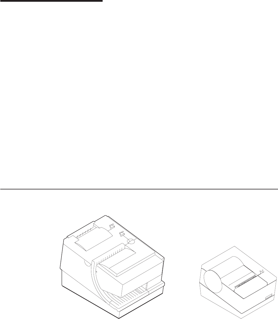
1. IBM SureMark printers .............................3
2. SureMark printer dimensions (Models TI1, TI2, TI3, TI4, TG3, and TG4) ..........11
3. SureMark printer dimensions (Models TI8, TI9, TG8, TG9) ...............11
4. SureMark printer dimensions (Models TF6 and TM6) .................12
5. Cable connectors and EIA-232 settings switch for thermal/impact SureMark printers ......18
6. Cable connectors for single-station SureMark printers .................19
7. EIA-232 mode switches for single-station SureMark printers ...............19
8. EIA-232 and RS-485 cable routing for single-station SureMark printers ...........20
9. USB Ports for thermal/impact SureMark printers ...................21
10. USB ports for single-station SureMark printers ....................22
11. USB cable routing for single-station SureMark printers .................22
12. Mounting a single-station SureMark on a wall ....................24
13. Installing the fillers for EIA-232/RS-485 systems ...................25
14. Installing the fillers for USB systems........................27
15. SurePOS 500 integration ............................28
16. Adjustment and alignment printouts ........................36
17. Switch for Epson emulation ...........................43
18. SureMark printer indicators, controls, and printing stations (Models TI1, TI2, TI3, TI4, TI8, TI9,
TG3, TG4, TG8, and TG9) ...........................47
19. Inserting checks for all models except TF6 and TM6..................48
20. Inserting checks or documents in a Model TI2, TI4, TI8, TI9, TG4, TG8, or TG9 printer .....48
21. Inserting checks or documents in a Model TI2 or TI4 printer ...............49
22. Side insertion of documents in a Model TI8 printer ..................49
23. Printable area of an inserted document (portrait) ...................50
24. Printable area of an inserted document (landscape) ..................50
25. Opening the ribbon cover............................51
26. Ribbon cartridge loading ............................51
27. Ribbon path around the print head ........................52
28. Paper cover (Models TI1, TI2, TI3, TI4, TI8, TI9, TG3, TG4, TG8, and TG9) .........53
29. Paper loading path (Models TI1, TI2, TI3,TI4, TI8, TI9, TG3, TG4, TG8, and TG9) .......54
30. Removing the lower document insert cover .....................55
31. Removing the check flipper cartridge (except Models TI8, TI9) ..............56
32. MICR reader read head ............................57
33. Print head and print line area (Models TI1, TI2, TI3, TI4, TI8, TI9, TG3, TG4, TG8, and TG9) 58
34. Scanner and print head location (Model TI8, TI9, TG8, TG9)...............59
35. Printer buttons................................62
36. Offline printer test pattern from the customer receipt station (Models TI1, TI2, TI3, TI4, TI8, TI9,
TG3, TG4, TG8, TG9) .............................64
37. MICR reader test results (Models TI2, TI4, and TG4): Good noise level ...........65
38. MICR reader test results (Models TI8, TI9, TG8, TG9): Good noise level ..........65
39. MICR reader test results: Noise level needs adjusting .................66
40. SureMark printer indicator, control, and printing station (Models TF6 and TM6) ........71
41. Paper loading path (Models TF6 and TM6) .....................72
42. Print head and print line area (Models TF6 and TM6) .................73
43. Offline printer test pattern (Models TF6 and TM6) ...................77
44. Printer’s resident character set - generic code page ..................93
45. Code Page 437 ...............................94
46. Code Page 858 ...............................95
47. Code Page 860 ...............................96
48. Code Page 863 ...............................97
49. Code Page 865 ...............................98
50. Proportional font example ...........................122
51. Scanned image layout ............................169
Updated April 2, 2009
© Copyright IBM Corp. 1997, 2006 xi
%%

Tables
1. Warranty information ..............................5
2. J2 connector pin assignments ..........................12
3. Troubleshooting (Models TI1, TI2, TI3, TI4, TI8, TI9, TG3, TG4, TG8, and TG9)........67
4. Troubleshooting (Models TF6 and TM6) ......................78
5. Station characteristics .............................88
6. Sound characteristics .............................88
7. Cash drawer connector pin assignments ......................90
8. EIA-232 connector pin functions .........................91
9. 9-pin to 9-pin EIA-232 connector layout ......................91
10. 25-pin to 25-pin EIA-232 connector layout .....................91
11. Standard USB connector pin assignments .....................92
12. Powered USB connector pin assignments .....................92
13. Driver documentation by operating system .....................103
14. EIA-232 commands organized by function .....................104
15. EIA-232 commands in alphabetical order .....................108
16. Memory allocation for Models TI8 and TI9 functions .................115
17. MCT command definitions ...........................125
18. Fonts for Models TI3, TI4, TG3, TG4, TG8, TG9, TI8, TI9, TF6, and TM6 .........129
19. Fonts for Models TI1 and TI2 ..........................130
20. Width and height for scalable fonts........................145
21. Code 128 character set ............................149
22. Print bar code examples ...........................152
23. Buffer sizes ................................158
24. Retrievable usage data ............................162
25. Data table .................................172
26. Average size for a personal check with little background data ..............174
27. Print direction ...............................178
28. Commands supported in Epson emulation mode...................193
29. Commands with limited support in Epson emulation mode ...............195
30. Commands not supported in Epson emulation mode .................196
Updated April 2, 2009
© Copyright IBM Corp. 1997, 2006 xiii
Updated April 2, 2009
xiv SureMark Printers User’s Guide

Preface
This manual assists you with installation, testing, and problem determination of
IBM®SureMark™printers.
Who should read this manual
This manual is intended for use by persons who are installing, testing, or
programming an IBM SureMark printer. The manual should also be used for
problem determination on the printer.
How this manual is organized
Part 1, “General information,” on page 1 contains information that applies to
SureMark printers in general:
vChapter 1, “Introduction” provides an overview of the features and options of the
SureMark printers.
vChapter 2, “Installation instructions” provides information on installing the
SureMark printers.
vChapter 3, “SureMark installation, service, and utility software” provides
information about using SureMark utilities to setup or modify your system
configuration.
Part 2, “Models TI1, TI2, TI3, TI4, TI8, TI9, TG3, TG4, TG8, TG9,” on page 45
contains information that is specific to the thermal/impact SureMark printers:
vChapter 4, “Operation” provides information about the controls and indicators.
Ribbon loading and paper loading instructions are also included.
vChapter 5, “Testing and problem analysis” provides information on testing and on
problem determination.
Part 3, “Models TF6 and TM6,” on page 69 contains information that is specific to
the single-station SureMark printers:
vChapter 6, “Operation (Models TF6 and TM6)” provides information on the
controls and indicators. Paper loading instructions are also included.
vChapter 7, “Testing and problem analysis (Models TF6 and TM6)” provides
information on testing and on problem determination.
The appendixes contain the following information:
vAppendix A, “Consumable supplies” provides information about consumable
supplies.
vAppendix C, “Technical information” provides information about technical
specifications.
vAppendix D, “EIA-232 programming information” provides information about
EIA-232 programming commands.
vAppendix E, “Uploading electronic journal data” provides information about
uploading electronic journal data while the SureMark is in Model 4 emulation
mode.
vAppendix F, “Proportional fonts” provides information about creating and using
proportional fonts.
vAppendix G, “Emulation support for Epson single-station printer” provides
expanded information about Epson emulation mode.
Updated April 2, 2009
© Copyright IBM Corp. 1997, 2006 xv

vAppendix H, “Safety information” provides important safety warnings in several
languages.
vAppendix I, “Notices” provides information about trademarks and electronic
emission notices.
vFor California: provides information about perchlorate material.
Related publications and diskettes
vIBM SureMark Printers: Hardware Service Manual, GY27-0355
vIBM SureMark Printers: Fonts and Logos Utility Diskette
vIBM SureMark Printers: Firmware Update Diskettes
vIBM 4693 Point-of-Sale Terminals Reference Diskette
vIBM 4694/4695 Point-of-Sale Terminals Service Diskette
vIBM Safety Information—Read This First, GA27-4004.
vIBM SurePOS 700 Series: System Reference, SA27-4220.
vIBM SurePOS 500 Series: System Reference, SA27-4255.
vPOSS Programming Reference and User’s Guide, SC30-3560
Diskettes are available by download from the Internet. See “Resources on the
Internet” on page 44 for more information.
For information about ordering IBM publications not shipped with the SureMark
printers, contact your IBM representative or your place of purchase.
Where to find more information
A CD-ROM is available that contains books that are part of the IBM Retail Store
Solutions Library Collection, SK2T-0331.
Current versions of Retail Store Solutions documentation and downloadable
diskettes are available on our Web site. See “Resources on the Internet” on page
44 for information about accessing the site.
Tell us what you think
Your feedback is important in helping to provide the most accurate and high-quality
information. Please take a few moments to tell us what you think about this book.
The only way for us to know if you are satisfied with our books, or how we might
improve their quality, is through feedback from customers like you. If you have any
comments about this book, there is a comment form at the back of this book. You
can also get a copy of the form from the PDF version of the book on the Web.
To access a PDF version of this book, visit the Retail Store Solutions Web site at
http://www.ibm.com/solutions/retail/store/support/. From there, select Publications.
After you have filled out the form, return it by mail, by fax, or by giving it to an IBM
representative. If applicable, include a reference to the specific location of the text
on which you are commenting. For instance, include the page or table number.
Between major revisions of this manual we may make minor technical updates. The
latest softcopy version of this manual is available under Publications on the IBM
Retail Store Solutions Web site.
Updated April 2, 2009
xvi SureMark Printers User’s Guide

Summary of changes
This section summarizes the changes included in the latest editions of this manual.
GA27-4151-07 (April, 2009)
This update provides changes to the MICR reader read head cleaning procedures,
expandable supplies, and product care procedures.
Changes or additions to the text are indicated by a change bar (%) to the left of the
text.
GA27-4151-07 (February/March, 2007 update)
vModel 3 and Model 4 emulation support notes
vVarious clarifications and corrections
vUpdated notices Appendix I, “Notices,” on page 203
GA27-4151-07 (May, 2006)
This update provides new part numbers for existing products that are manufactured
using updated methods or materials required in certain jurisdictions, such as the
European Union. It also includes other edits based on user feedback.
Web-only update GA27-4151-06 (December, 2005)
This update provides new and updated commands and programming information,
and more references to Models TI8/TG8 and TI9/TG9.
GA27-4151-06 (August, 2005)
This Web-only update adds Model TI9 and TG9, as well as references to Model
TI8.
Web-only update for corrections to GA27-4151-05 (August, 2004)
Corrections and clarifications for:
v“Paper specifications” on page 81
v“Microcode tolerance (MCT) information - request” on page 125
v“Re-initialize the printer” on page 142
v“Start scan” on page 166
v“Select standard mode” on page 177
vMinor changes to formatting
Web-only update for corrections to GA27-4151-05 (August, 2003)
Corrections and clarifications for:
v“Document scanner calibration (Models TI8, TI9, TG8, TG9)” on page 60
vMinor changes to formatting
Updated April 2, 2009
© Copyright IBM Corp. 1997, 2006 xvii
%
%
%
%
%

Web-only update for Model TI8, GA27-4151-05 (April, 2003)
This update adds the new Model TI8 to this User’s Guide. This model provides
document-scanning capability and a powered flipper.
Web-only update for GA27-4151-04 (March, 2002)
This update contains changes to the paper loading procedure for Models TF6 and
TM6.
Web update for GA27-4151-04 (June, 2001)
This update contains the following changes and additions:
vThe location of the Euro character for code page 858 has been corrected. See
“Code page 858” on page 95.
vInformation on the new Models TG3 and TG4.
vCommand format details about bar codes 128a and 128b.
vFlash memory usage message. See the remarks in Flash storage write on page
123.
vNew table for Code 128 character set. See Table 21 on page 149.
vThe commands in Appendix D, “EIA-232 programming information,” on page 101
are to be used for EIA-232 connections only. Additional information about where
to find commands when using RS-485 or USB communications has been added
to the beginning of that appendix.
GA27-4151-04
This edition adds information about the new single-station SureMark printers, which
are Models TF6 and TM6, and also about updates for Models TI3 and TI4.
Changes for this edition include:
vBecause there are important differences between Models TF6 and TM6, which
are single-station SureMark printers, and the thermal/impact SureMark printers,
the book has been reorganized into three parts.
– Part 1 contains information that is similar for all SureMark models. Information
about the new single-station printers has been added throughout this part.
– Part 2 contains information that is specific to the thermal/impact SureMark
printer Models TI1, TI2, TI3, TI4, TG3, and TG4.
– Part 3 contains information that is specific to the new single-station SureMark
printer Models TF6 and TM6.
vA new thermal font has been added. See “Set print mode” on page 129 and
“Thermal printing font” on page 98.
vSupport for emulation of an Epson single-station printer has been added. See
“Emulating an Epson single-station printer (single-station only)” on page 43 for
information about how to enable emulation and an overview of the limitations to
using emulation mode. See Appendix G, “Emulation support for Epson
single-station printer,” on page 193 for detailed information about what Epson
commands are supported in emulation mode.
vA font conversion utility has been added as part of the support for proportional
fonts. See “Proportional font conversion utility” on page 37.
Updated April 2, 2009
xviii SureMark Printers User’s Guide

vInformation about uploading electronic journal data while the printer is emulating
a Model 4 printer has been added. See Appendix E, “Uploading electronic journal
data,” on page 187.
vThe following commands have been added:
Note: These commands are not supported for Models TI1 and TI2. Currently
installed Model TI3, TG3, TI4, and TG4 printers support these commands
after you download the latest firmware.
– “Proportional font” on page 120
– “Select color printing” on page 137
–n=09 (Align Column Right) for “Align positions” on page 139
– “Enable or disable upside-down printing” on page 144
– “Select character size for scalable fonts” on page 145
– “Fix font matrix” on page 146
– “Print logo inline” on page 146
– “Select thermal paper” on page 147
–n=09 (Code 128A, 128B, and 128C) for “Print bar code” on page 147
vThe following command, which is supported only on Models TF6 and TM6, has
been added:
– “Enable or disable the beeper (Models TF6 and TM6 only)” on page 143
GA27-4151-03
This edition includes information for the support of a USB logic card.
Information that was added includes:
v“USB connector pin assignments” on page 92.
vUSB information has been added to “Voltage conversion circuitry” on page 89.
vThe part number for the available USB cables has been added to “Features used
with the SureMark printers” on page 6.
vInformation about your responsibilities when using USB communications has
been added to “Planning information” on page 9.
vThe data rate for USB communications has been added to “Communication
interfaces” on page 10.
vUSB information has been added to “Hardware requirements” on page 13.
vInformation about installing the SureMark printer for use with USB
communications has been added to “Installing SureMark for USB communication”
on page 21.
vInformation about installing fillers for the SureMark printer when the USB feature
is used has been added to “Installing fillers for USB printers” on page 26.
vCommunication mode information for USB has been added to “USB
communication mode” on page 31.
vRelevant information for performing problem determination with USB has been
added to Table 3 on page 67.
Updated April 2, 2009
Summary of changes xix

GA27-4151-02
This edition includes information about two new models of the SureMark printer:
Model TI3 and Model TI4. Because Model TI3 is a new version of Model TI1, and
Model TI4 is a new version of Model TI2, in some cases only the new model
number was added to the existing text.
Information that was added includes:
v“Comparison of the SureMark models” on page 7, which describes the
microcode, hardware, and operating system differences.
v“Firmware update” on page 37, which describes the methods that you can use to
update the SureMark firmware.
v“Enable or disable the feed buttons” on page 143 and “Select maximum print
speed” on page 132, which describe new EIA-232 commands.
Information that was changed includes:
v“Software requirements” on page 13, which includes operating system and driver
requirements, and application requirements.
v“Code page definitions” on page 92. Code page 850, which is resident in Model
TI1 and TI2, has been replaced in this document by code page 858, which is
resident in Models TI3 and TI4. Code page 858 is the same as code page 850
plus the euro character symbol.
vZero (0) is no longer valid for the EIA-232 command “Microcode tolerance (MCT)
information - request” on page 125.
vThe Remarks under “Define document wait time” on page 141 have been
corrected and expanded.
Because documentation, drivers, and diskettes are now available on the Web,
“Resources on the Internet” on page 44 was added to describe how to locate the
applicable Web site.
Along with these changes and additions, the manual was also reorganized. The
information that was in Appendixes B and E, along with some additional information,
is now in Chapter 3, “SureMark installation, service, and utility software,” on page
33.
Updated April 2, 2009
xx SureMark Printers User’s Guide

Part 1. General information
This part contains descriptions of the SureMark printers and information about
installing the printers.
Updated April 2, 2009
© Copyright IBM Corp. 1997, 2006 1
Updated April 2, 2009
2SureMark Printers User’s Guide
Chapter 1. Introduction
Printer overview .........................3
Description of models .......................4
Features used with the SureMark printers ..............6
Comparison of the SureMark models ................7
Differences among SureMark models ...............7
Differences between Models TI3, TI4, TI8, TI9, TG3, TG4, TG8, TG9, and
Models TF6, TM6 .....................8
Planning information .......................9
Your responsibilities ......................9
Limitations ..........................9
Communication interfaces ....................10
Temperature and humidity limits .................10
Physical dimensions ......................10
Models TI1, TI2, TI3, TI4, TG3, and TG4 .............10
Models TI8, TI9, TG8, TG9 ..................11
Models TF6 and TM6 ....................12
Power requirements ......................12
Hardware requirements .....................13
Software requirements .....................13
Operating system requirements .................13
Application requirements ...................14
Resident code pages .....................15
Bar codes..........................15
Printer overview
The IBM SureMark printers are high-performance, high-function printers. The
SureMark is available in several models:
vModels TI3, TI4, TG3, and TG4 feature a thermal customer receipt station and an
impact document insert station. The dual print heads enable quiet, fast printing at
the customer receipt station while providing the capability to print and frank
Figure 1. IBM SureMark printers
Updated April 2, 2009
© Copyright IBM Corp. 1997, 2006 3

checks and to print multipart forms through the document insert station. (Models
TI1 and TI2 are older versions of Models TI3 and TI4, respectively. Production of
the older models has ceased.)
vModels TI8, TI9, TG8, and TG9 provide a document scanner and a powered
flipper, in addition to all the features of Model TI4.
vModels TF6 and TM6 are single-station thermal printers. They contain no
document insert station. These models cost less, weigh less, and have a smaller
footprint than the thermal/impact SureMark printers. Models TF6 and TM6 have
been designed for wall mounting, if desired by the retailer.
All SureMark printers provide:
vFast, quiet receipt printing
vEasy paper loading
v256-KB flash memory for storing messages, logos, code pages, and electronic
journal data
vModels TI8, TI9, TG8 and TG9 have 1 MB of flash memory for scanned image
storage
vBar code generation
vDownloadable fonts and code pages
vDownloadable microcode
vSmall footprint
vSupport for EIA-232 (RS-232) and RS-485 (EIA-485) interfaces
Note: RS-232 and EIA-232 are synonymous; EIA-232 is used throughout this
document. RS-485 and EIA-485 are synonymous; RS-485 is used
throughout this document.
vSupport for Universal Serial Bus (USB) interface
The single-station SureMark printers, the SureMark Model TI8, TI9, TG8 and TG9,
and SureMark Models TI3, TI4, TG3, and TG4 that have been updated with the
latest firmware, support the following in the thermal station:
vProportional fonts
vScalable fonts
vColor printing: black plus one accent on two-color thermal paper (thermal station
only)
vUpside-down printing
Additional features of some SureMark models include:
vSingle-pass handling of checks (Models TI2, TI4, TI8, TI9, TG4, TG8, TG9)
vEasy-to-load ribbon cartridge (Models TI1, TI2, TI3, TI4, TI8, TI9, TG3, TG4,
TG8, TG9)
vEpson emulation (Models TF6, TM6)
vDocument scanning (Models TI8, TG8, TI9, TG9)
vCheck 21 compliance (Models TI9, TG9)
Description of models
Note: All TGxmodels are functionally equivalent to the corresponding TIxmodels.
TGxmodels have iron gray covers, while TIxmodels have pearl white
covers.
The SureMark printers are available in the following models:
Updated April 2, 2009
4SureMark Printers User’s Guide

Models TI1 and TI3
Standard models that support receipt and document printing. (Model TI1
can no longer be ordered.)
Models T12 and TI4
High-function models that feature improved check handling. Check handling
uses the magnetic character ink recognition (MICR) reader and check
flipper that are included in these models. (Model TI2 can no longer be
ordered.)
With one insertion of a check into a Model TI2, TI4, TI8, or TI9 printer, the
printer uses its MICR reader to read the magnetic-ink-character line on the
check, franks the check, and prints the face of the check. While the printer
is processing the check, the operator is free to attend to the customer’s
needs, which shortens the total transaction time.
Model TI8
In addition to the features of the Model TI4, these models have a document
scanner feature. Scanned documents can be stored and retrieved in TIFF,
JPEG, and BMP formats. The Model TI8 has increased flipper speed due to
a powered flipper. (Model TI8 can no longer be ordered.)
Model TI9
In addition to the features of the Model TI8, the TI9 is compliant with Check
21 legislation, which means that it enables single-insertion check handling
and scanning of both sides of the full length of the document.
Models TF6 and TM6
Smaller models that contain only a thermal customer receipt station.
Because there is no document insert station, these models do not support
document printing.
Models TF6 and TM6 have an audible alarm, a spill-resistant design, and
an optional wall mount.
For Food Service customers, Model TF6 covers match the IBM SurePOS™
500 Series systems. For Retail customers, Model TM6 covers match the
IBM 4694 systems if the EIA-232/RS-485 interface is ordered, and the
covers match the IBM SurePOS 700 Series systems if the USB interface is
ordered.
Note: Model TG3 is functionally equivalent to TI3, TG4 is functionally equivalent to
TI4, and so on.
Table 1 shows the warranty information for each printer model.
Table 1. Warranty information
Machine type Description Warranty
service
Warranty
upgrade
4610-TI3 EIA-232, RS-485, USB (Pearl white covers) IOR 24x7 none
4610-TI4 EIA-232, RS-485, USB (Pearl white covers) IOR 24x7 none
4610-TI5 (DBCS,
AP only)
EIA-232, RS-485, USB (Pearl white covers) IOR 24x7 none
4610-TI8 EIA-232, RS-485, USB (Pearl white covers) IOR 24x7 none
4610-TI9 EIA-232, RS-485, USB (Pearl white covers) IOR 24x7 none
4610-TM6 EIA-232, RS-485, USB (Pearl white covers) IOR 24x7 none
Updated April 2, 2009
Chapter 1. Introduction 5

Table 1. Warranty information (continued)
Machine type Description Warranty
service
Warranty
upgrade
4610-TM7
(DBCS, AP only)
EIA-232, RS-485, USB (Pearl white covers) IOR 24x7 none
4610-TF6 TM6 with iron gray covers Depot
repair
IOR 24x7,
9x5
4610-TF7 TM7 with iron gray covers Depot
repair
IOR 24x7,
9x5
4610-IF6 Functionally equivalent to TF6 with iron gray
covers but with IOR warranty
IOR 24x7 none
4610-TG3 Functionally equivalent to Model TI3 with iron
gray covers
IOR 24x7 none
4610-TG4 Functionally equivalent to Model TI4 with iron
gray covers
IOR 24x7 none
4610-TG5
(DBCS, AP only)
Functionally equivalent to Model TI5 with iron
gray covers
IOR 24x7 none
4610-TG8 Functionally equivalent to Model TI8 with iron
gray covers
IOR 24x7 none
4610-TG9 Functionally equivalent to Model TI9 with iron
gray covers
IOR 24x7 none
4610-DG3 Functionally equivalent to Model TG3 but
with Depot warranty
Depot
repair
IOR 24x7,
9x5
4610-DG4 Functionally equivalent to Model TG4 but
with Depot warranty
Depot
repair
IOR 24x7,
9x5
4610-DI3 Functionally equivalent to Model TI3 but with
Depot warranty
Depot
repair
IOR 24x7,
9x5
4610-DI4 Functionally equivalent to Model TI4 but with
Depot warranty
Depot
repair
IOR 24x7,
9x5
4610-DI8 Functionally equivalent to Model TI8 but with
Depot warranty
Depot
repair
IOR 24x7,
9x5
4610-DI9 Functionally equivalent to Model TI9 but with
Depot warranty
Depot
repair
IOR 24x7,
9x5
4610-DM6 Functionally equivalent to Model TM6 but
with Depot warranty
Depot
repair
IOR 24x7,
9x5
4610-DG8 Functionally equivalent to Model TG8 but
with Depot warranty
Depot
repair
IOR 24x7,
9x5
4610-DG9 Functionally equivalent to Model TG9 but
with Depot warranty
Depot
repair
IOR 24x7,
9x5
Note: IOR 24x7 is IBM on-site repair 24 hours times seven days per week. 9x5 is
nine hours per day for five days per week.
Features used with the SureMark printers
All models support the following features:
vIntegration Panel
v40-Character VFD or LCD Post Extension
vDistributed Printer Cable (RS-485)
vIntegrated Cable (RS-485)
Updated April 2, 2009
6SureMark Printers User’s Guide
vShort EIA-232 Communications Cable, 2 m (about 6.6 ft), P/N 40N4780
vLong EIA-232 Communications Cable, 4 m (about 13.1 ft), P/N 40N4781
vPower Supply (EIA-232 and USB), P/N 40N5051
vPower Cords (country-specific)
vEIA-232/RS-485 Interface Card
Models TI3, TI4, TI8, TI9, TG3, TG4, TG8, TG9, TM6 and TF6 support the following
features:
vUSB Cable, Powered, 0.5 m (about 1.6 ft), P/N 40N4715
vUSB Cable, Powered, 3.8 m (about 12.5 ft), P/N 40N4716
vUSB Cable, Standard, 5.0 m (about 16.4 ft), P/N 40N4767
vUSB Interface Card
Because a cash drawer can attach directly to the SureMark, all models also support
the following features:
vCompact Cash Drawer, Vertical Till
vCompact Cash Drawer, Horizontal Till
vFull-size Cash Drawer, Adjustable Till
vFull-size Cash Drawer, Fixed Till Insert
vShort Cash Drawer Cable, P/N 40N4778
vLong Cash Drawer Cable, P/N 40N4779
Comparison of the SureMark models
The SureMark models can be divided into three groups:
vModels TI1 and TI2 can no longer be ordered. Because these are not currently
being manufactured, they do not support some functions that are on the current
models.
vModels TI3, TI4, TI8, TI9, TG3, TG4, TG8, and TG9 have a thermal print station
for customer receipts and an impact print station for document processing. These
models are currently being manufactured.
– Models TI8 and TG8 additionally have document scanning.
– Models TI9 and TG9 additionally have document scanning compliant with
Check 21.
vModels TF6 and TM6 have only a thermal print station for customer receipts.
Differences among SureMark models
vDifferent microcode is required to operate each of the following groups of
printers:
– Models TI1 and TI2
– Models TI3, TI4, TG3, TG4, TM6, TF6
– Models TI3, TI4, TG3, TG4, TF6, TM6 with the 2 MB card option
– Models TI3, TI4, TG3, and TG4 with the 8 MB card option
– Models TI8, TI9, TG8, and TG9
vTotal amount of data space available for the download of graphic messages is
65 376 bytes for Models TI1 and TI2, but only 65 136 bytes for Models TI3, TI4,
TG3, and TG4. Models TI8, TI9, TG8, and TG9 have from 0 KB to 1 MB, user
allocatable.
Updated April 2, 2009
Chapter 1. Introduction 7
vMemory allocated to store incoming commands and data is 16 KB for Models
TI3, TI4, TI8, TI9, TG3, TG4, TG8, and TG9, but only 4 KB for Models TI1 and
TI2.
vModels TI3, TI4, TI8, TI9, TG3, TG4, TG8, and TG9 operate at higher speeds
than Models TI1 and TI2.
vCode page 858, which contains the euro character symbol, is resident in Models
TI3, TI4, TI8, TI9, TG3, and TG4. Code page 850, which contains all character
symbols from code page 858 excluding the euro character symbol, is resident in
Models TI1 and TI2.
vThe second byte of the device ID specifies what model of SureMark is being
used. The 4690 OS uses the printer model to determine the name of the
microcode update file:
– ADXPJPUF.DAT for Models TI1 and TI2
– ADXPJPFF.DAT for Models TI3, TI4, TG3, TG4, TM6, TF6
– ADXPJP2F.DAT for Models TI3, TI4, TG3, and TG4 with the 2 MB card option
– For microcode update information for Models TI8, TI9, TG8, and TG9, see the
IBM Retail Store Solutions Web site at http://www.ibm.com/solutions/retail/
store/support/.
Differences between Models TI3, TI4, TI8, TI9, TG3, TG4, TG8,
TG9, and Models TF6, TM6
Models TF6 and TM6 are single-station thermal printers. These models do not
include an impact station. Therefore they can not be used for any of the check
handling that thermal/impact SureMark Models TI3, TI4, TI8, TI9, TG3, TG4, TG8,
and TG9 support.
The single-station SureMark printers have a lower weight, lower cost, and smaller
footprint than the thermal/impact printers. The single-station SureMark printers are
designed to provide a cost-effective printer in environments that do not require
document printing and check processing.
The single-station SureMark printers are spill-resistant, which makes them a good
choice for food service customers. In the single-station printers, the logic card and
interface card are mounted vertically, which minimizes the possibility of damage
from spills. (In the thermal/impact printers, although the logic card is mounted
vertically, the interface card is mounted horizontally.) For particularly hazardous
locations, an optional spill cover is available for Models TF6 and TM6.
Models TI3, TI4, TI8, TI9, TG3, TG4, TG8, and TG9 have a trap-door design that
allows you to easily change to a new interface, for example when upgrading from
EIA-232 to USB. To change the interface on a single-station SureMark, you must
remove the bottom cover, then remove both the logic card and the interface card
(they are joined by a connector).
The single-station SureMark printers support a 90 mm diameter paper roll, instead
of the 80 mm paper roll that is used with the thermal/impact printers. The
single-station printers also support an external larger paper roll via RPQ. When the
external paper roll is used, the paper feeds into the printer through a slot in the
bottom cover of the printer.
A power switch is located inside the top cover of the single-station SureMark
printers. Power to the thermal/impact SureMark printers is controlled by the system
or by an external power supply.
Updated April 2, 2009
8SureMark Printers User’s Guide

Because of their smaller size and lighter weight, the single-station SureMark
printers are designed for wall mounting. Like the other SureMark printers, they can
also be mounted on a system unit or a countertop.
Planning information
This section contains information that helps you plan your environment, supply
requirements, and power requirements.
Your responsibilities
You are responsible for replenishing consumable supplies, including roll paper for
the thermal (customer receipt station) printer, and, depending on your model, forms,
ribbon cartridges for the impact (document insert) station, and MICR read head
cleaning cards for the MICR reader. (See Appendix A, “Consumable supplies,” on
page 81.)
It is your responsibility to update printer firmware as needed prior to installing
printers, and as desired during the printer’s life.
If you plan to use EIA-232 communications, you are responsible for ordering a 24 V
dc power supply with a power cord. You are also responsible for ordering the
EIA-232 cable.
Note: If a 3-wire EIA-232 cable is to be used, the printer must be set to
XON/XOFF mode. (See “EIA-232 communications protocol selection” on
page 28.)
If you plan to use RS-485 communications, you are responsible for ordering the
RS-485 cable.
If you plan to use USB communications, you are responsible for ordering one of the
following:
vA powered USB cable. The 3.8-m USB cable for a distributed configuration is
P/N 40N4716 and the 0.5-m USB cable for an integrated configuration is P/N
40N4715.
vA standard USB cable, P/N 40N4767, with a Type B connector for the printer,
and a power brick.
With SureMark printer models you can use an electronic journaling
application. Electronic journaling eliminates the need to store paper journal tapes
and the time-consuming task of searching papers should the need arise.
Limitations
SureMark printers have a safety feature which slows printing if excessive duty
cycles are used. This feature protects the printer hardware from potential damage
and should not be noticeable during normal operation.
For Model TI2, TI4, TI8, and TI9, sources of electromagnetic noise (for example,
displays, security towers, and other sources) can interfere with the MICR read
head. The printer is equipped to filter noise from many of these devices. If the
MICR reader does not function properly, rearranging the printer relative to the
device may improve MICR reading. The noise source should be as far away as
possible from the right side of the printer. For additional information on
troubleshooting MICR reader problems, see “Offline tests” on page 62.
Updated April 2, 2009
Chapter 1. Introduction 9
The single-insert check handling feature of SureMark Models TI2, TI4, TI8, TI9,
TG4, TG8, and TG9 is provided as an added convenience when customer service
is a priority. Checks in good condition will feed reliably; damaged checks may not.
Communication interfaces
All SureMark printers can support the EIA-232 and RS-485 interfaces. Models TI3,
TI4, TI8, TI9, TG3, TG4, TG8, TG9, TM6, and TF6 can also support the USB
interface. For SureMark models that can support the USB interface, you can
upgrade installed printers from EIA-232/RS-485 to USB by ordering a USB interface
card.
EIA-232 supports 9600 and 19 200 bps baud rates and, in the Models TI8, TG8,
TI9, and TG9 only, 115 200 bps.
RS-485 operates at a 187.5 Kbps baud rate.
USB supports data rates up to 12 Mbps.
Temperature and humidity limits
Shipping -40° to 60° C (-40° to 140° F) with 5% to 100% relative humidity
including condensation, but excluding rain
Storage 0° to 60° C (32° to 140° F)
Operating 0° to 40° C (32° to 104° F) with 8% to 80% relative humidity
To allow convection cooling, ventilation holes in the covers must not be blocked.
Physical dimensions
Models TI1, TI2, TI3, TI4, TG3, and TG4 all have the same dimensions. Models TI8,
TI9, TG8, are TG9 are taller, whereas Models TF6 and TM6 have a smaller
footprint.
Models TI1, TI2, TI3, TI4, TG3, and TG4
Width 190.5 mm (7.5 in.)
Depth 255 mm (10 in.)
Height Front: 140 mm (5.5 in.), Rear: 190 mm (7.5 in.)
Weight 4.4 kg (9.6 lb) without paper
Updated April 2, 2009
10 SureMark Printers User’s Guide
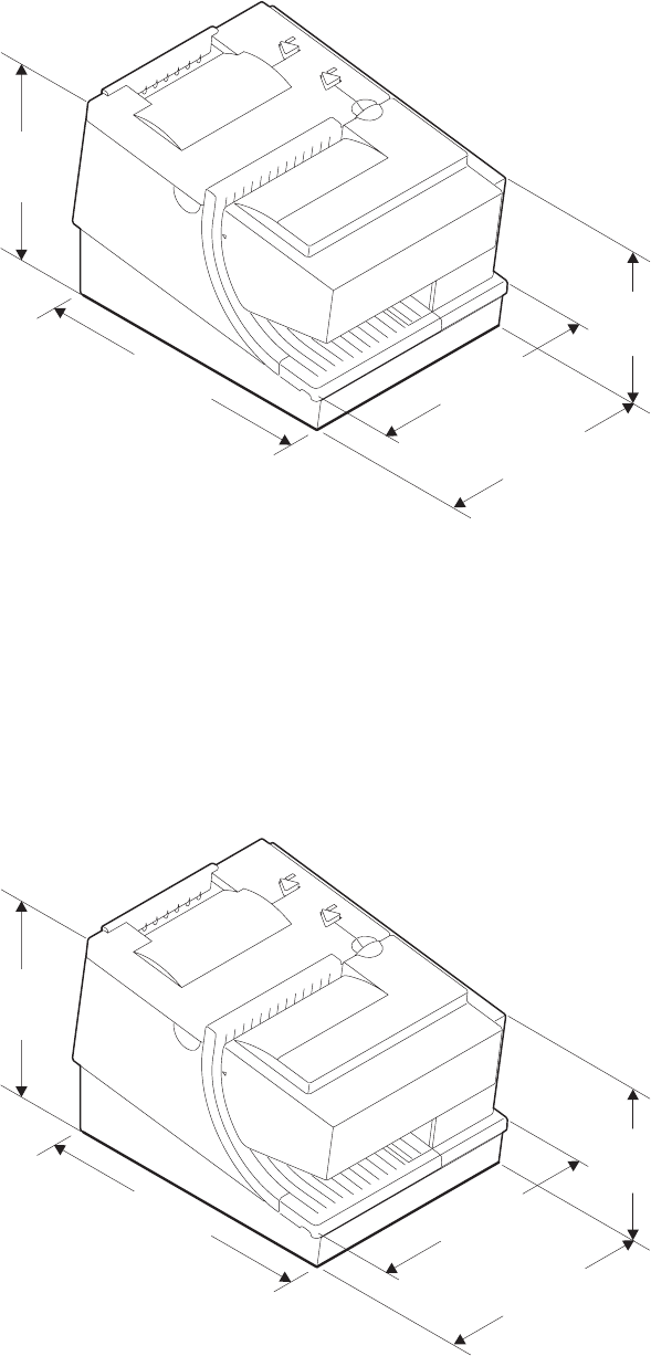
Models TI8, TI9, TG8, TG9
Width 190.5 mm (7.5 in.)
Depth 255 mm (10 in.)
Height Front: 153.4 mm (6.0 in.), Rear: 199.5 mm (7.9 in.)
Weight 4.9 kg (10.8 lb) without paper
190.5 mm
(7.5 in.)
140 mm
(5.5 in.)
255 mm
(10 in.)
190.5 mm
(7.5 in.)
200.5 mm
(7.9 in.)
Figure 2. SureMark printer dimensions (Models TI1, TI2, TI3, TI4, TG3, and TG4)
199.5 mm
(7.9 in.)
153.4 mm
(6.0 in.)
255 mm
(10 in.)
190.5 mm
(7.5 in.)
200.5 mm
(7.9 in.)
Figure 3. SureMark printer dimensions (Models TI8, TI9, TG8, TG9)
Updated April 2, 2009
Chapter 1. Introduction 11
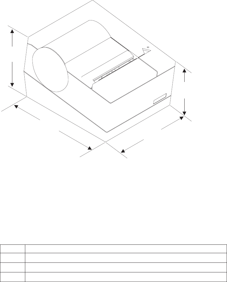
Models TF6 and TM6
Width 145 mm (5.7 in.)
Depth 177 mm (7.0 in.)
Height Front: 95 mm (3.7 in.), Rear: 121 mm (4.8 in.)
Weight 1.4 kg (3.0 lb) without paper
Power requirements
SureMark printers do not contain a power supply. When the printer is operating in
EIA-232 mode, an external power supply must be attached to connector J2 of the
interface card of the printer. This connector is located under the printer and is
accessible without removing the printer covers. (See Figure 5 on page 18 for
thermal/impact SureMark printers, and Figure 6 on page 19 for single-station
SureMark printers.) Connector J2 has the following pin functions:
Table 2. J2 connector pin assignments
Pin Signal
1 +24Vdc
2 Not Connected
3 Ground
When the SureMark is operating in RS-485 mode, power is supplied to the printer
from the IBM POS system. The system supplies 38V dc and 5V dc to the printer.
When the SureMark has the USB feature installed and is using the powered USB
cable with a SurePOS 700 Series system, 24 V is supplied from the system unit.
95 mm
(3.7 in.)
145 mm
(5.7 in.)
121 mm
(4.8 in.)
177 mm
(7.0 in.)
Figure 4. SureMark printer dimensions (Models TF6 and TM6)
Updated April 2, 2009
12 SureMark Printers User’s Guide
When the SureMark has the USB feature installed and is using a 4-wire cable with
a Type B connector, an external power brick (+24 V dc) must be used.
Hardware requirements
SureMark printers work with the following systems:
vIBM 4614 SureOne®POS terminal (EIA-232 connection only)
vIBM 4683 systems (RS-485 connection only)
vIBM 4693 systems
vIBM 4694 systems
vIBM 4695 systems (EIA-232 connection only and with power supply)
v7497 POS Attachment Adapter (RPQ 8Q1238 in US, RS-485 only)
vPC or other store controller with an EIA-232 or USB port
vSurePOS 700 Series systems
vSurePOS 500 Series systems
vSurePOS 300 Series systems
vIBM Self Checkout solution
Software requirements
Operating system requirements
POSS drivers can be downloaded from the Retail Store Solutions Web site. See
“Resources on the Internet” on page 44 for more information.
If you use the RS-485 interface, you must use POSS or 4690 OS drivers. If you use
the EIA-232 interface, use the commands described in Appendix D, “EIA-232
programming information,” on page 101.
EIA-232 interface: When using the EIA-232 interface, attach thermal/impact
SureMark printers to systems that are running one of these operating systems:
vWindows®XP Professional
vNovell Linux®Point of Service (NLPOS)
vIBM Retail Environment for SUSE Linux
vWindows 2000 Professional with OPOS and JavaPOS support from POS Suite
V1.2 or later
vWindows 98 Second Edition or Windows NT®4.0 with OPOS and JavaPOS
support from POS Suite V1.0 or later
When using the EIA-232 interface, attach single-station SureMark printers to
systems that are running Windows 2000 Professional, Windows 98 Second Edition,
or Windows NT 4.0 with OPOS and JavaPOS support from POS Suite V1.3.1 or
later.
RS-485 interface: When using the RS-485 interface, attach thermal/impact
SureMark printers to systems that are running one of these operating systems:
v4690 Operating System Version 1 at maintenance level 9910, 4690 OS V2 or
4690 OS V2R3
vIBM Retail Environment for SUSE Linux
vNovell Linux Point of Service
vIBM PC DOS 2000 or later with POSS for DOS V1.60(b) plus delta package
160(D), or later
vWindows XP Professional
vWindows 2000 Professional with:
– POSS for Windows from POS Suite V1.1 or later
– OPOS and JavaPOS support from POS Suite V1.2 or later
Updated April 2, 2009
Chapter 1. Introduction 13

vWindows 98 Second Edition or Windows NT 4.0 with POSS for Windows, OPOS
and JavaPOS support from POS Suite V1.0 or later
When using the RS-485 interface, attach single-station SureMark printers to
systems that are running one of these operating systems:
vIBM PC DOS 2000 with POSS for DOS V2.10 or later (Model TM6 only)
vWindows XP Professional, Windows 2000 Professional, Windows 98 Second
Edition, or Windows NT 4.0 with:
– POSS for Windows from POS Suite V1.3.0 or later
– IBM Retail Environment for SUSE Linux
– OPOS and JavaPOS support from POS Suite V1.3.1 or later
USB interface: When using the USB interface, attach thermal/impact SureMark
printers to systems that are running one of these operating systems:
v4690 OS V2R3, which includes JavaPOS 1.4
vWindows XP Professional
vIBM Retail Environment for SUSE Linux
vNovell Linux Point of Service
vWindows 2000 Professional with:
– POSS for Windows from POS Suite V1.1 or later
– OPOS and JavaPOS support from POS Suite V1.2 or later
vWindows 98 Second Edition or Windows NT 4.0 with POSS for Windows, OPOS
and JavaPOS support from POS Suite V1.0 or later
When using the USB interface, attach single-station SureMark printers to systems
that are running one of these operating systems:
vWindows XP Professional, Windows 2000 Professional, Windows 98 Second
Edition, or Windows NT 4.0 with:
– POSS for Windows from POS Suite V1.3.0 or later
– OPOS and JavaPOS support from POS Suite V1.3.1 or later
Application requirements
Customers must be at these application levels (or higher) when running the 4690
OS:
Application Name Product
Number
Maintenance Level
IBM SUREPOS Application Client/Server
Environment for 4690 OS
5745-C44 N/A
IBM Chain Drug Sales Application 5669-212 9701 with PRPQ 5799-QYP
IBM 4680/4690 General Sales Application 5696-546 9701 with APAR IR33229 and
PRPQ 5799-QYN
IBM 4680/4690 Supermarket Application 5696-536 9701 with APAR IR33228 plus
PRPQ 5799-QYL
StoreFlow™(see note 1) Release 1.4
Notes:
1. Where available, supports Models TI3, TI4, TG3, and TG4 at the point of sale.
2. 4690 Terminal Services for Windows NT is required when you use Windows NT 4.0 or
Windows 2000 as the primary operating system with these 4690 applications.
Updated April 2, 2009
14 SureMark Printers User’s Guide
Resident code pages
These code pages are resident in the printer:
vGeneric
v437 (US)
v850 (International) – only Models TI1 and TI2
v858 (International) – only Models TI3, TI4, TI8, TG3, TG4, TF6 and TM6
v860 (Portuguese)
v863 (Canadian French)
v865 (Norwegian)
Additional code pages (four thermal and two impact) can be downloaded, if desired,
using diskettes that are available on the Web. See “Resources on the Internet” on
page 44 for more information about downloading diskettes.
Bar codes
SureMark printers can generate these bar codes:
vUPC-A
vUPC-E
vJAN13 (EAN-13)
vJAN8 (EAN-8)
vCode 39
vITF
vCodabar
vCode 128C
vCodes 128A, 128B, and 128C (only Models TI3, TI4, TI8, TI9, TG3, TG4, TG8,
TG9, TF6 and TM6)
vCode 93
vPDF417
Updated April 2, 2009
Chapter 1. Introduction 15
Updated April 2, 2009
16 SureMark Printers User’s Guide
Chapter 2. Installation instructions
Unpacking the printer ......................18
Installing a SureMark printer ....................18
Installing for EIA-232/RS-485 communication .............18
Installing SureMark for USB communication .............21
Using the wall mounting feature...................23
Installing the fillers .......................24
Installing fillers for EIA-232/RS-485 printers .............24
Installing fillers for USB printers..................26
EIA-232 communication mode selections (all models except TI8, TI9, TG8, TG9) 28
Baud rate selection ......................28
EIA-232 communications protocol selection .............28
DTR/DSR control ......................29
XON/XOFF control .....................29
EIA-232 communication mode selections (Models TI8, TI9, TG8, TG9) ....30
Baud rate selection ......................30
EIA-232 communications protocol selection .............30
DTR/DSR control ......................30
XON/XOFF control .....................30
USB communication mode ....................31
USB selection .........................31
Before installing an IBM SureMark printer, be sure to read “Electronic emission
notices” on page 205.
DANGER
To avoid a shock hazard, do not connect or disconnect any cables
or perform installation, maintenance, or reconfiguration of this
product during an electrical storm.
DANGER
To avoid shock hazard:
The power cord must be connected to a properly wired and
earthed receptacle.
Any equipment to which this product will be attached must also
be connected to properly wired receptacles.
Note: For translations of these safety notices, see IBM Safety Information—Read
This First, GA27-4004.
Updated April 2, 2009
© Copyright IBM Corp. 1997, 2006 17
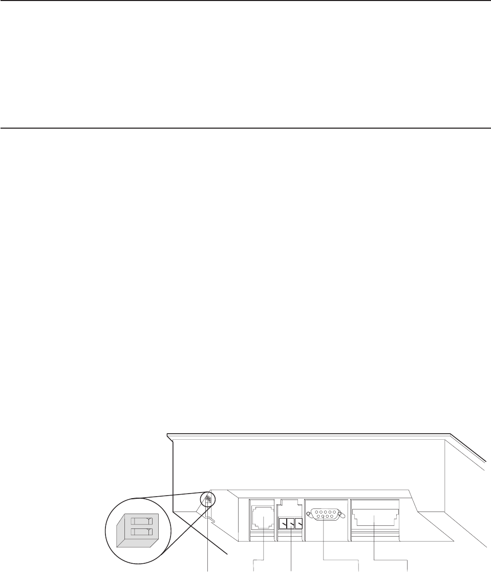
Unpacking the printer
Note: Save all packing material and shipping containers.
1. Remove the SureMark printer from the shipping container and place it on a flat
surface.
2. Open any shipping containers of additional options and accessories to install
with the SureMark printer.
3. Carefully remove any remaining packing material and packing tape.
Installing a SureMark printer
This section describes SureMark printer installation.
Installing for EIA-232/RS-485 communication
1. Power the system off and disconnect the EIA-232 power supply.
2. Locate the rear cable connectors.
3. If you are using the EIA-232 communication port:
a. For all models except TI8, TG8, TI9, TG9, check the settings on the
EIA-232 mode switch, which is near the rear cable connections. See
Figure 5 for thermal/impact printers. See Figure 6 on page 19 and Figure 7
on page 19 for single-station printers.
Notes:
1) If the EIA-232 communication cable has only 3 wires or if the system
output is 3 pins (2 signals and a ground), you must use XON/XOFF
mode.
2) Models TI8, TG8, TI9, TG9 do not have a mode switch for EIA-232
settings. See “EIA-232 communication mode selections (Models TI8,
TI9, TG8, TG9)” on page 30.
b. Connect the power supply to the printer.
EIA-232
Mode
Switch
(some
models)
Cash
Drawer
Port
Power Supply
Port (EIA-232
Only)
EIA 232
Port RS-485 Port
12
OFF
Figure 5. Cable connectors and EIA-232 settings switch for thermal/impact SureMark printers.
(View is from the bottom rear of the printer)
Updated April 2, 2009
18 SureMark Printers User’s Guide
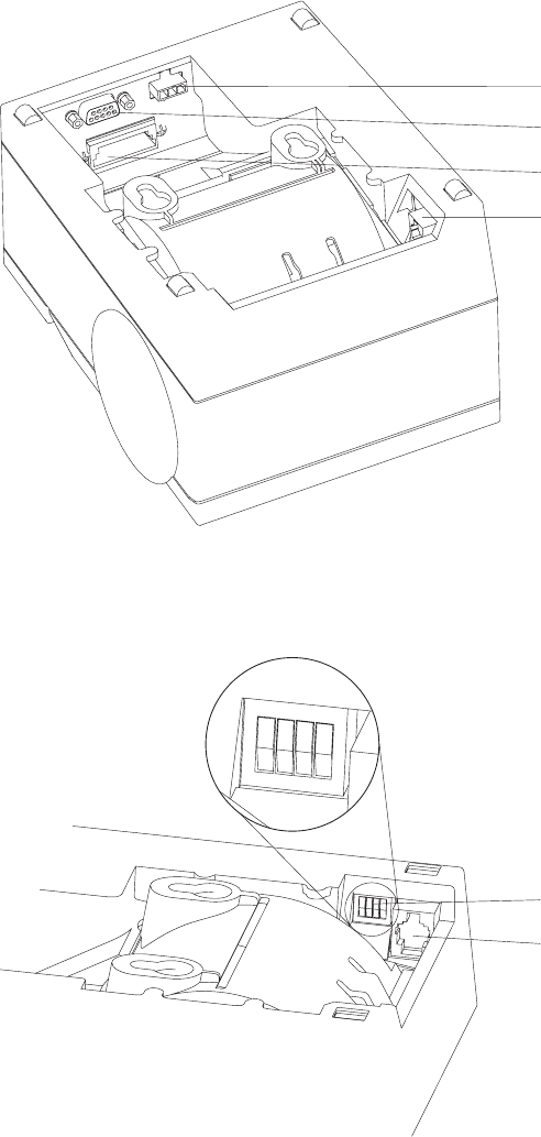
4. Connect the RS-485 or EIA-232 communication cable to the correct port.
5. For single-station printers, route any power cord and cables as shown in
Figure 8 on page 20.
Power supply port (EIA-232 only)
EIA-232 port
RS-485 port
Cash drawer connector
Figure 6. Cable connectors for single-station SureMark printers. (View is from the bottom rear
of the printer)
123
OFF
4
EIA-232 mode switches
Cash drawer connector
Figure 7. EIA-232 mode switches for single-station SureMark printers. (View is from the
bottom rear of the printer)
Updated April 2, 2009
Chapter 2. Installation instructions 19
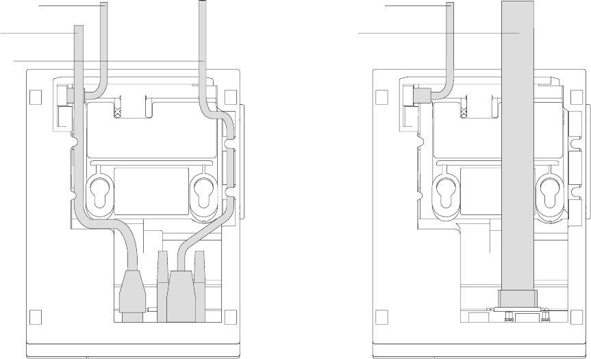
6. Connect any other signal cables for I/O devices to the correct ports.
7. Check that all signal cables are installed and seated in the correct ports.
8. If you are installing the printer on an integrated unit:
a. Pull out the locking lever at the left side of the system unit. (wide systems
only)
b. For single-station printers, place the printer in the square-shaped filler
panel.
c. Route the keyboard cable to the side of the tab as shown in Figure 13 on
page 25.
d. Route all cables attached to the printer through the center opening of the
system unit and place the printer (with its filler panel, if it is a single-station
printer) on the system unit.
e. If you have additional fillers to install, go to “Installing the fillers” on page
24.
f. Lift the system unit rear cover and attach any cables from the printer to the
system unit. (If this is a EIA-232-attached printer, reattach the brick power
cord if you had to detach it to route it through the center opening.)
9. Power on the printer by either:
vConnecting the brick power supply cable to a properly wired and grounded
power source and powering it on.
vPowering on the POS system unit for an RS-485-attached printer.
Attention: Never connect both voltage sources to the printer at the same
time, even if one of the sources is powered off. Potential system damage
could occur under these conditions.
10. For single-station SureMark printers, turn on the power on/off switch on the
printer.
Cash drawer cable
Power cord
EIA-232 cable
Cash drawer cable
RS-485 cable
Figure 8. EIA-232 and RS-485 cable routing for single-station SureMark printers
Updated April 2, 2009
20 SureMark Printers User’s Guide
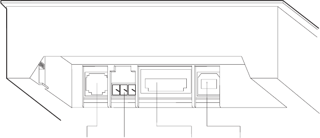
11. For thermal/impact SureMark printers, locate the ribbon cartridge and install it
in the printer. (See “Ribbon loading” on page 51.) Be sure that the ribbon is
routed through the print head correctly.
12. Load the paper roll into the printer. See “Paper loading” on page 53 for
thermal/impact SureMark printers or “Paper loading” on page 71 for
single-station SureMark printers.
13. Installation is now complete. Go to Chapter 5, “Testing and problem analysis,”
on page 61 for thermal/impact printers or Chapter 7, “Testing and problem
analysis (Models TF6 and TM6),” on page 75 for single-station printers and run
the offline tests.
Installing SureMark for USB communication
1. Disconnect the power brick from the printer, if one is connected.
2. Locate the rear cable connectors on the printer.
Cash
Drawer
Port
Power
Supply
Port
Powered
USB Port
Standard
USB Port
Figure 9. USB Ports for thermal/impact SureMark printers. (View is from the bottom rear of
the printer)
Updated April 2, 2009
Chapter 2. Installation instructions 21
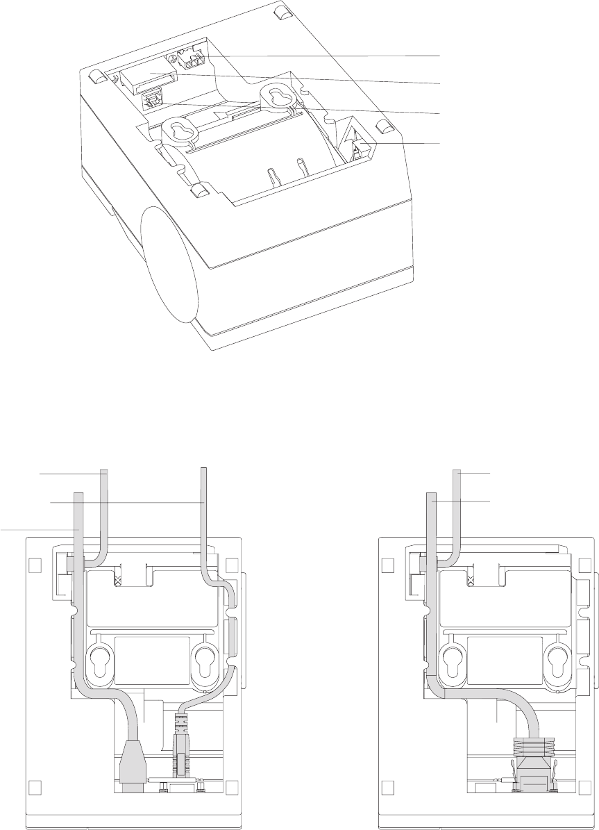
3. For single-station printers, route any power cord and cables as shown in
Figure 11.
4. Connect the USB communication cable to the correct port.
5. Connect any other signal cables for I/O devices to the correct ports.
Power supply port
Powered USB port
Standard USB port
Cash drawer connector
Figure 10. USB ports for single-station SureMark printers. (View is from the bottom rear of
the printer)
Cash drawer cable
Power cord
Standard USB cable
Cash drawer cable
Powered USB cable
Figure 11. USB cable routing for single-station SureMark printers
Updated April 2, 2009
22 SureMark Printers User’s Guide

6. Check that all signal cables are installed and seated in the correct ports.
7. If you are installing the printer on an integrated SurePOS 700 Series system:
a. For single-station printers, place the printer in the square-shaped filler
panel.
b. Route all cables attached to the printer through a rear opening of the
system unit and place the printer (with its filler panel, if it is a single-station
printer) on the system unit.
c. Make the side of the printer overlap the tab on the side of the system unit
(wide systems only).
d. If you have additional fillers to install, go to “Installing the fillers” on page
24.
e. If a fence or I/O tray is installed, lift the system unit rear cover and attach
any cables from the printer to the system unit. (If a power brick was
disconnected at the beginning of the installation or is needed because a
standard USB cable is being used, attach the power brick.)
8. If you are using a power brick, power on the printer by connecting the power
brick supply cable to a properly wired and grounded power source and
powering it on.
9. For single-station SureMark printers, turn on the power on/off switch on the
printer.
10. For thermal/impact printers, locate the ribbon cartridge and install it in the
printer. (See “Ribbon loading” on page 51.) Be sure that the ribbon is routed
through the print head correctly.
11. Load the paper roll into the printer. See “Paper loading” on page 53 for
thermal/impact SureMark printers or “Paper loading” on page 71 for
single-station SureMark printers.
12. Installation is now complete. Go to Chapter 5, “Testing and problem analysis,”
on page 61 for thermal/impact printers or Chapter 7, “Testing and problem
analysis (Models TF6 and TM6),” on page 75 for single-station printers and run
the offline tests.
Using the wall mounting feature
Because of their light weight and small footprint, the single-station SureMark
printers can be mounted on a wall. This is a useful feature when counter space is
limited.
Note: To correctly function in a wall mount, a SureMark printer must have paper
roll pivots.
To use the printer with the wall mounting feature:
1. Position the mounting bracket on a wall that has no dangerous objects, such as
electrical wires or pipes hidden beneath the wall surface.
Note: Position the bracket so that the installed printer will not extend more than
10 cm (4 in.) into a walk, hall, corridor, passageway or aisle.
2. Attach the bracket securely to the wall with four 6 mm (0.25 in.) screws. The
screws are not provided. You should use fasteners that are suitable for the type
of wall construction, such that the bracket is securely attached to the wall. For
walls that are constructed of gypsum wallboard on wood or metal studs, use
four good-quality medium-capacity or high-capacity hollow-wall anchors.
3. Route the communication cable up the wall surface or through the bracket.
Updated April 2, 2009
Chapter 2. Installation instructions 23
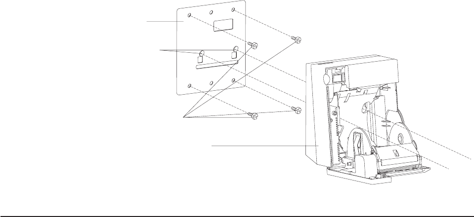
4. Connect the cables to the printer.
5. Place the SureMark printer on the two bracket posts. Slide the printer down until
a click sounds.
Installing the fillers
Installing fillers for EIA-232/RS-485 printers
Notes:
1. On an integrated unit, pull out on the locking lever at the left side of system unit.
2. Ensure that the side of each filler overlaps the tab on the side of the system
unit.
To install fillers:
1. Power the system off and disconnect the EIA-232 power supply (if connected).
See Figure 5 on page 18.
2. If you have a video display on an integrated system:
a. Move the display on its arm to the side and remove any tape holding the
alignment ring.
b. Remove the knockout section of the display filler.
c. Align the display filler with the alignment ring and slide the filler onto the
ring. Press the display filler into place. See Figure 13 on page 25.
Wall bracket
Mounting posts
Screws (not provided)
SureMark with top cover open
Figure 12. Mounting a single-station SureMark on a wall
Updated April 2, 2009
24 SureMark Printers User’s Guide
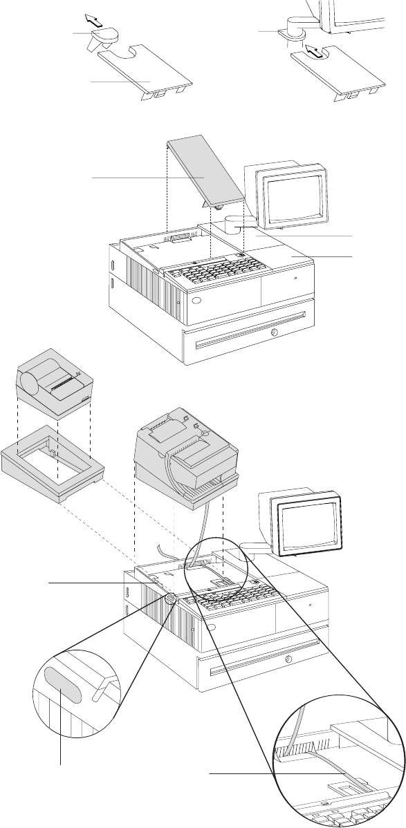
3. If you do not have a video display, place the display filler on the system unit.
Knockout
Section
Display Filler
Printer Filler
Alignment
Ring
Display Filler
Keyboard Filler
Tab
Locking Lever Cable
Figure 13. Installing the fillers for EIA-232/RS-485 systems
Updated April 2, 2009
Chapter 2. Installation instructions 25
4. If you have a short keyboard, place the keyboard filler beside the keyboard. See
Figure 13 on page 25.
5. Place the printer filler beside the display filler. Make sure you route the printer
cable to the side, as shown in Figure 13 on page 25.
Installing fillers for USB printers
1. Disconnect the power brick from the printer (if connected).
2. Place the display filler appropriate for the video display on the system unit. See
Figure 14 on page 27.
3. If you have a short keyboard, place the keyboard filler beside the keyboard. See
Figure 14 on page 27.
4. Place the printer filler beside the display filler. Make sure you route the
keyboard cable to the side, as shown in Figure 14 on page 27.
Updated April 2, 2009
26 SureMark Printers User’s Guide
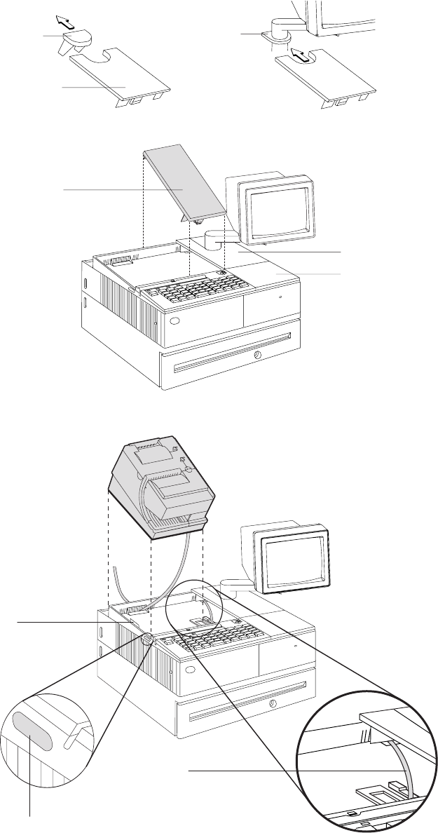
DisplayFiller
Printer Filler
Alignment
Ring
DisplayFiller
KeyboardFiller
Knockout
Section
Tab
Locking Lever
Cable
Figure 14. Installing the fillers for USB systems
Updated April 2, 2009
Chapter 2. Installation instructions 27

EIA-232 communication mode selections (all models except TI8, TI9,
TG8, TG9)
Switch settings described in this section apply only when the printer is connected to
the system with the EIA-232 cable. The switch is accessible without removing the
printer covers. (See Figure 5 on page 18 to see how to access the switch.)
Baud rate selection
SureMark printers support two EIA-232 baud rates, 9600 and 19 200 bps. The baud
rate is selected using switch 1 on the EIA-232 settings switch. Set the switch as
follows:
Switch 1 OFF 9600 bps
Switch 1 ON 19 200 bps
The printer normally ships with switch 1 in the OFF position, which selects the 9600
bps baud rate.
EIA-232 communications protocol selection
SureMark printers support EIA-232 protocol using either DTR/DSR or XON/XOFF to
control data transmission. XON/XOFF mode uses system and printer software to
control the flow of data. This is called flow control.
Use switch 2 on the EIA-232 settings switch to select the mode. Switch settings
are:
Switch 2 OFF DTR/DSR control
Figure 15. SurePOS 500 integration
Updated April 2, 2009
28 SureMark Printers User’s Guide
Switch 2 ON XON/XOFF control (required with a 3-wire interface)
The printer normally ships with switch 2 in the OFF position, which selects
DTR/DSR control.
DTR/DSR control
DSR DSR is an output from the printer. It indicates when the printer is ready to
receive data. A DSR signal becomes inactive when the printer is not ready
to receive data (for example, at power-on reset or when its buffer is full).
DTR DTR is an input to the printer. It indicates to the printer that the system is
ready to receive data. A DTR signal becomes inactive when the system is
not ready to receive data (for example, at power-on reset or when its buffer
is full).
XON/XOFF control
XON = DC1 (X'11')
XOFF = DC3 (X'13')
During XON/XOFF control, the printer transmits an XON every 3 seconds after a
power-on reset (POR) completes to indicate the printer is ready to receive data.
When the first message is received, the printer stops transmitting the XON signal.
The printer transmits an XOFF when the EIA-232 input buffer is 80% full, after
which it transmits one XON when the buffer is 20% full.
XON/XOFF transparent mode operation: This is the default mode. See
“Message from the printer” on page 184 for the format of printer to system
messages, which include a byte count, status bytes, and optional extended status
bytes or user data.
Transparent mode should always be used when selecting XON/XOFF mode for
Models TI8 and TI9.
XON and XOFF are transmitted independently, and can occur at any point inside or
outside of messages transmitted by the printer. When a message includes optional
user data, the byte count (bytes 1 and 2) can include X'10', X'11', or X'13'. When
X'10', X'11', or X'13' occur in transparent XON/XOFF mode, the byte count is
bit-exclusive-ORed with X'21' and is prefixed by the DLE (X'10') character to
become:
Value in message Becomes
X'10' X'1031'
X'11' X'1030'
X'13' X'1032'
User data with X'10', X'11', or X'13' is also treated this way in transparent
XON/XOFF mode. The byte count is not incremented for such extra characters.
Determining XON/XOFF control: You can determine whether XON/XOFF control
is being used by sending the extended address command and checking the feature
byte, bit 3. If this bit is set, the printer is in XON/XOFF mode. (See “Extended
address command-request printer ID” on page 112.)
Disabling XON/XOFF transparent mode: You can disable transparent
XON/XOFF mode as described in “Real-time requests” on page 175. When
Updated April 2, 2009
Chapter 2. Installation instructions 29

disabled, X'10', X'11', or X'13' can occur within messages. However, because such
values are actual count bytes or data bytes and are not XON or XOFF characters
(DLE, XON, and XOFF characters do not occur within messages), no transform
takes place. The values are not bit-exclusive-ORed with X'21' because no transform
occurs for such values within messages as it does during transparent XON/XOFF
mode. DLE, XON, or XOFF occur only before or after a message.
EIA-232 communication mode selections (Models TI8, TI9, TG8, TG9)
Settings described in this section apply only when the printer is connected to the
system with the EIA-232 cable.
Baud rate selection
You must have power ON and paper installed in the thermal print station.
1. Open both the document cover and the receipt cover.
2. Press and hold both operator buttons until the Customer Receipt (CR) light
blinks rapidly.
3. Close the Document Insert (DI) cover. This is the front cover.
4. Close the CR cover. This is the rear cover. A menu is printed on the CR paper.
5. Follow the instructions on the menu to set the baud rate and the communication
protocol. The information provided in “EIA-232 communications protocol
selection” describes the selections and their purposes.
EIA-232 communications protocol selection
SureMark printers support the EIA-232 protocol using either DTR/DSR or
XON/XOFF to control data transmission. XON/XOFF mode uses system and printer
software to control the flow of data. This is called flow control.
DTR/DSR control
DSR DSR is an output from the printer. It indicates when the printer is ready to
receive data. A DSR signal becomes inactive when the printer is not ready
to receive data (for example, at power-on reset or when its buffer is full).
DTR DTR is an input to the printer. It indicates to the printer that the system is
ready to receive data. A DTR signal becomes inactive when the system is
not ready to receive data (for example, at power-on reset or when its buffer
is full).
XON/XOFF control
XON = DC1 (X'11')
XOFF = DC3 (X'13')
During XON/XOFF control, the printer transmits an XON every 3 seconds after a
POR completes to indicate the printer is ready to receive data. When the first
message is received, the printer stops transmitting the XON signal. The printer
transmits an XOFF when the EIA-232 input buffer is 80% full, after which it
transmits one XON when the buffer is 20% full.
XON/XOFF transparent mode operation: This is the default mode. See
“Message from the printer” on page 184 for the format of printer to system
messages, which include a byte count, status bytes, and optional extended status
bytes or user data.
Updated April 2, 2009
30 SureMark Printers User’s Guide

XON and XOFF signals are always transmitted independently and are not inside
any part of the message, including the byte count, status bytes, or user data. When
a message includes optional user data, the byte count (bytes 1 and 2) can include
X'10', X'11', or X'13'. When X'10', X'11', or X'13' occur in transparent XON/XOFF
mode, the byte count is bit-exclusive-ORed with X'21' and is prefixed by the DLE
(X'10') character to become:
Value in message Becomes
X'10' X'1031'
X'11' X'1030'
X'13' X'1032'
User data with X'10', X'11', or X'13' is also treated this way in transparent
XON/XOFF mode. The byte count is not incremented for such extra characters.
Determining XON/XOFF control: You can determine whether or not XON/XOFF
control is being used by sending the extended address command and checking bit
3 of the feature byte. If this bit is set, the printer is in XON/XOFF mode. (See
“Extended address command-request printer ID” on page 112.)
Disabling XON/XOFF transparent mode: You can disable transparent
XON/XOFF mode as described in “Real-time requests” on page 175. When
disabled, X'10', X'11', or X'13' can occur within messages. The values are not
bit-exclusive-ORed with X'21' because no transform occurs for such values within
messages as it does during transparent XON/XOFF mode.
Note: Disabling XON/XOFF transparent mode should be done with Model TI4 only.
It is not recommended with Model TI8.
USB communication mode
No switches or special commands are required for USB communication. With the
USB interface card and cables in place, the system automatically detects the printer
when it is attached and performs any necessary setup. The printer operates at data
rates up to 12 Mbps.
USB selection
USB is an industry standard communication interface. It is used to attach devices
such as printers, displays, and keyboards to personal computers or to IBM POS
systems that have USB ports. The standard USB port (with a power brick) is used
to attach the SureMark to personal computers. The powered USB port is used to
attach the SureMark to IBM POS systems. See Figure 9 on page 21 for the
thermal/impact SureMark printers and Figure 10 on page 22 for the single-station
SureMark printers.
Updated April 2, 2009
Chapter 2. Installation instructions 31
Updated April 2, 2009
32 SureMark Printers User’s Guide

Chapter 3. SureMark installation, service, and utility software
Software adjustments (Models TI1, TI2, TI3, TI4, TI8, TI9, TG3, TG4, TG8, and
TG9) ............................34
Offline configurations for Models TI8, TI9, TG8, TG9 ..........34
Using the IBM Diagnostics for the POS Systems and Peripherals (all models
except Models TI1 and TI2) ..................34
Using the reference/service diskettes (Models TI1 and TI2) .......35
4610 fonts and logos utilities ....................37
Utility diskette ........................37
IBM Diagnostics for POS Systems and Peripherals package (all models
except TI1 and TI2) .....................37
Proportional font conversion utility ..................37
Firmware update ........................37
Using a firmware update diskette (Models TI1 and TI2 only) .......38
Using POSS for Windows to update SureMark printer firmware (RS-485 and
USB only) .........................39
Using JavaPOS for Windows to update SureMark printer firmware (EIA-232,
RS-485, and USB)......................39
Automatic update ......................39
Command line utility (AipFlash46s) ...............40
Updating SureMark firmware using temporary EIA-232 attachment .....40
Limitation on updating firmware ..................41
Emulating the IBM Model 3 or Model 4 printers .............41
Limitations for emulation ....................41
Printing saved data ......................41
Printing buffer data on thermal/impact printers ...........42
Printing buffer data on single-station printers ............42
Emulating an Epson single-station printer (single-station only) .......43
Enabling Epson emulation....................43
Limitations for Epson emulation ..................43
MICR data parser sample code (Models TI2, TI4, TI8, TI9, TG4, TG8, and TG9
only) ............................44
Resources on the Internet .....................44
This chapter describes how to make software adjustments using either the IBM
Diagnostics for POS Systems and Peripherals (POSS for Windows, RS-485 and
USB only) or diskettes and other resources that are available from the Retail Store
Solutions Web site. See “Resources on the Internet” on page 44 for more
information.
Updated April 2, 2009
© Copyright IBM Corp. 1997, 2006 33

Software adjustments (Models TI1, TI2, TI3, TI4, TI8, TI9, TG3, TG4,
TG8, and TG9)
When a printer main logic card is replaced, the following software adjustments
should be run:
vCharacter alignment procedure (see Figure 16 on page 36)
vDocument insert front load print line adjustment (see Figure 16 on page 36)
vDocument landscape adjustment (see Figure 16 on page 36)
vStore printer's serial number
vUpdate the firmware to the latest level
vReset printer statistics
vScanner calibration (Models TI8, TI9, TG8, TG9)
v4610 Model configuration (If the configuration is not set correctly, the printer may
act unpredictably.)
Notes:
1. Cards for TI1s and TI2s are set up as TI2s.
2. Cards for Tx3s and Tx4s are set up as Tx4s.
3. Cards for Tx8s and Tx9s are set up as Tx8s.
Depending on your SureMark model, you can use the following to make software
adjustments to the printer:
vOffline configuration for Models TI8, TI9, TG8, TG9
vIBM Diagnostics for POS Systems and Peripherals (except Models TI1 and TI2)
vReference/service diskettes (Models TI1 and TI2 only)
Offline configurations for Models TI8, TI9, TG8, TG9
You must use the calibration procedure to calibrate the scanner.
You must have power ON and paper installed in the thermal print station.
1. Open both the document cover and the receipt cover.
2. Press and hold both operator buttons until the Customer Receipt (CR) light
blinks rapidly.
3. Close the Document Insert (DI) cover. This is the front cover.
4. Close the CR cover. This is the rear cover. A menu is printed on the CR paper.
5. Follow the instructions on the menu to:
vset the EIA-232 parameter
vset the baud rate
vset the communication protocol
vinvoke scanner calibration
vset the 4610 model configuration
The information provided in “EIA-232 communications protocol selection” on
page 30 describes the selections and their purposes.
Using the IBM Diagnostics for the POS Systems and Peripherals (all
models except Models TI1 and TI2)
The IBM Diagnostics for the POS Systems and Peripherals is a GUI-based
diagnostic package on a USB flash drive. It is used to troubleshoot hardware
problems, and it includes these 4610 printer utilities:
Updated April 2, 2009
34 SureMark Printers User’s Guide
vMicrocode update
vLogo download
vMessage download
vPrinter Configuration Utility, which includes:
– Scanner calibration
– Print current adjustment values (see Figure 16 on page 36)
– Character alignment procedure (see Figure 16 on page 36)
– Backlash adjustment (document landscape, see Figure 16 on page 36)
– DI front load print line adjustment (see Figure 16 on page 36)
– Set serial number
– Reset printer statistics
– Set printer type (4610 model configuration)
Using the reference/service diskettes (Models TI1 and TI2)
1. Load the reference/service diskette. See the hardware service manual for your
system for reference/service diskette procedures.
2. Select Test Menu.
3. Select Run POS Device Tests for an RS-485 connection. Select EIA-232 4610
Printer Test for an EIA-232 connection.
4. If another system is attached, select the system whose printer you want to
adjust. This is unnecessary when there is no other system attached.
5. Select Printer Utilities.
6. Select the adjustment you want to make from the menu.
vPrint current adjustment values: see Figure 16 on page 36.
vCharacter alignment procedure: see Figure 16 on page 36.
vDI front load print line adjustment: see Figure 16 on page 36.
vDocument landscape adjustment: see Figure 16 on page 36.
vEngineering use only
vChange 4610 Model Configuration
vReset printer statistics
Note: Because the first four adjustments affect only the document insert
station, they are not displayed as selectable options if the printer is a
single-station SureMark.
Updated April 2, 2009
Chapter 3. SureMark installation, service, and utility software 35
7. Follow the instructions that are printed on the printer or displayed on the screen.
8. Press S1 (Esc on the Enhanced A/N Keyboard) to return to the previous menu.
CURRENT ADJUSTMENT VALUES
H 5 = Character alignment
TL5 = Top line front insert
BL3 = Bottom line top insert
Press the key (1-9) that corresponds
to the pair of H's that appear to be
most aligned
5 = selected line
CHARACTER ALIGNMENT PROCEDURE
Measure from the top edge of this
paper to the top of each print line.
Press the key (1-9) that corresponds
to the print line that is closest to 5MM.
TL1
TL4
TL7
TL2
TL5
TL8
TL3
TL6
TL9
Figure 16. Adjustment and alignment printouts
Updated April 2, 2009
36 SureMark Printers User’s Guide

4610 fonts and logos utilities
There are utilities available on the Retail Store Solutions Web site. Depending on
your model, you may either use the utility diskette or use the IBM Diagnostics for
POS Systems and Peripherals package.
The utility program allows you to perform the following functions:
vUpdate printer firmware
vConfigure the printer model
vCreate, edit, and download user-defined character fonts, logo images, and
messages
vDownload proportional fonts (not supported for Models TI1 and TI2)
vConvert fonts and logo files from impact to thermal
Utility diskette
This utility is for both EIA-232 and RS-485 operation. You can download the utility
from the Retail Store Solutions Web site. See “Resources on the Internet” on page
44 for more information.
From the same Web site, you can also download the following sample files for use
with the utility program:
vUser-defined characters file
vMessage file
vLogo file
IBM Diagnostics for POS Systems and Peripherals package (all models
except TI1 and TI2)
This utility is for EIA-232, RS-485, and USB operation. Refer to the README file in
this package for details on how to run these utilities.
Proportional font conversion utility
As part of its support for proportional fonts, IBM provides three TrueType fonts and
a utility that you can use to convert the fonts to files that the SureMark printer can
use.
The application and instructions for downloading the converted fonts are available
from the Retail Store Solutions Web site. See “Resources on the Internet” on page
44 for more information.
Note: You might have TrueType fonts other than those supplied by IBM on your
system. Before using the conversion utility to convert and download any
non-IBM fonts for use by the SureMark printer, you must confirm that you
have received authorization from the owner of the fonts to convert and
download the fonts.
Firmware update
The SureMark printer has the capability to receive SureMark firmware updates from
the host system unit to which it is attached for either RS-485-attached,
EIA-232-attached, or USB-attached SureMark printers.
The following mediums can be used to update the SureMark firmware:
vFirmware update diskettes
Updated April 2, 2009
Chapter 3. SureMark installation, service, and utility software 37
vPOSS for Windows 4610 Printer Firmware Update Program
vAlternative 4610 firmware update method via EIA-232 attachment cable
Use the appropriate procedure that follows to update the SureMark firmware, after
downloading the latest level software from the Retail Store Solutions Web site (see
“Resources on the Internet” on page 44).
Using a firmware update diskette (Models TI1 and TI2 only)
Use a firmware update diskette to update the firmware in configurations when the
SureMark is attached by either an EIA-232 or RS-485 cable and when the system
has a floppy diskette drive, a PC keyboard, and display.
1. Download the latest level of firmware update diskette from the Web (see
“Resources on the Internet” on page 44). You can select from several update
methods, including attended, unattended, and automatic.
2. Insert the firmware update diskette in drive A.
3. Power on the system unit that has the SureMark attached by either an EIA-232
or RS-485 cable.
4. Select RS-485 or EIA-232 connection.
5. Follow the messages displayed to complete the firmware update.
a. Press Enter (OK) at the logo screen to proceed.
b. Choose connection type (RS-485 or EIA-232). For EIA-232 connections,
also make the following selections (refer to the communications mode
selections switches, located on the bottom rear of the SureMark printer, to
determine the following selections):
vCommunications port (COM1, COM2, COM3, COM4)
vBaud rate (9600 or 19 200 bps)
vControl Flow (DTR/DSR or XON/XOFF)
c. Press Enter (OK) to proceed.
d. Press F10 (Menu).
e. Select O (Operations).
f. Select A (Advanced Options).
g. Select U (Update Firmware).
h. Press Enter twice to select the desired firmware image file (usually only the
latest firmware image file is available for selection).
i. Press Enter (YES) again to commit to firmware update.
j. The Information screen will display the update percent completed.
Note: The SureMark flash update will take several minutes. Do not power off
the host system or the SureMark printer after the update has started.
6. After the firmware update is complete, the SureMark printer will be reset.
a. Press Enter (OK) to confirm.
b. Press Alt+X (Exit).
c. Press Enter to exit.
7. Remove the diskette from drive A.
8. Press Ctrl+Alt+Del to reboot the system.
Updated April 2, 2009
38 SureMark Printers User’s Guide
Using POSS for Windows to update SureMark printer firmware (RS-485
and USB only)
Windows users with SureMark printers can use the POSS for Windows 4610 Printer
Firmware Update program (AIPFLD46.EXE) to update SureMark firmware. For
additional information, refer to the POSS Programming Reference and User’s
Guide.
Note: POSS Suite V1.0.0 or greater is required to use this utility.
1. Download the latest SureMark firmware update image file from the Web. The file
is:
vAIP46MC.HEX for Models TI1 and TI2
vAIP46MCH.HEX for Models TI3, TI4, TG3, and TG4. This file is also for
single-station printers with 512 KB or 8 MB of memory
vAIP46MCD.HEX for Models TI3, TI4, TG3, TG4, TF6, and TM6 with the 2 MB
memory option.
vFor Model TI8, see the IBM Retail Store Solutions Web site at
http://www.ibm.com/solutions/retail/store/support/.
2. Copy the latest SureMark firmware update image file to the C:\POS\BIN
directory. Because the file in the directory is more current than the old file, the
firmware will be automatically updated when the system is powered off and
back on.
3. To update the firmware manually, enter the AIPFLD46.EXE -S slot_number -P
port_number -F microcode_file [-Q] command to update the SureMark firmware,
where:
slot_number
SureMark slot number, usually = 1. The slot number must be specified
with decimal values only; hexadecimal values are not accepted.
port_number
SureMark port number specified with a decimal value, usually = 17
microcode_file
Either C:\POS\BIN\AIP46MC.HEX, C:\POS\BIN\AIP46MCH.HEX, or
C:\POS\BIN\AIP46MCD.HEX
-Q (Optional) Quiet mode installation (no progress information)
4. The SureMark flash update will take several minutes.
Using JavaPOS for Windows to update SureMark printer firmware
(EIA-232, RS-485, and USB)
The firmware can be updated by automatic update or by the command line utility.
Automatic update
Follow these steps to update the POSPrinter firmware for Linux:
1. Obtain the appropriate flash file from the Web:
vAIP46MCH.HEX for 4610 Tx3, Tx4 and Tx6
vAIP46MCD.HEX for 4610 TI5 and TI7
vAIP46TI8.HEX for TI8 and TI9
Go to http://www.ibm.com/solutions/retail/store/support/. Click the links to
JavaPOS POSPrinter support.
2. Create an rs485 directory as follows:
Updated April 2, 2009
Chapter 3. SureMark installation, service, and utility software 39
vFor Linux, go to the directory /opt/ibm/javapos/flash on the target system and
create an rs485 directory. This is done as shown in the following example:
%cd /opt/ibm/javapos/flash
%mkdir rs485
vFor Windows, go to the directory root install directory\IBMJPOS\res\
flash on the target system and create an rs485 directory. This is shown in
the following example, where the root install directory is C:\POS.
C:\> cd\POS\IBMJPOS\res\flash
C:\> mkdir rs485
3. Place the correct flash file (ensure it matches the printer type) into the new
directory.
4. Make sure the printer is attached and reboot the system. (The flash will take a
few minutes to complete during boot-up.)
Command line utility (AipFlash46s)
The IBM 4610 printer firmware can be downloaded using a command utility. The
syntax for the utility is java com.ibm.jpos.util.flash.AipFlash46s [param]
[RS-485_flash_filename].
Valid values for the variables are:
param -e: flash printer EC level
RS-485_flash_filename
Includes the absolute path name of the flash file (for example:
/opt/ibm/javapos/flash/aipmch46.hex)
Updating SureMark firmware using temporary EIA-232 attachment
To use the firmware update diskettes to update SureMark firmware for
configurations that do not have a floppy diskette drive and PC display and
keyboard, you must provide a temporary EIA-232 attachment to a host PC that
does have a floppy diskette drive.
Note: A 4610 firmware update diskette at V3.10 or greater is required to use this
utility.
Before starting the firmware update, you must obtain the following parts:
vEIA-232 attachment cable, either 2 meters in length (P/N 40N4780) or 4 meters
in length (P/N 86H2195).
vSureMark Power Supply for EIA-232 configurations only (P/N 40N5051).
If the SureMark is currently attached to a host system unit that does not support a
floppy diskette drive, use the following procedure to temporarily connect the printer
to a host PC that has a floppy diskette drive, EIA-232 port, PC keyboard and
display.
1. Disconnect the SureMark (RS-485 #7) attachment cable and temporarily
connect a EIA-232 attachment cable to the SureMark.
2. Connect the SureMark via the EIA-232 port connector to an alternate host PC
that has a floppy diskette drive.
3. Follow the procedure in “Using a firmware update diskette (Models TI1 and TI2
only)” on page 38 to complete the SureMark firmware update.
4. Reconnect the SureMark to the original host system unit using the original
attachment cables.
Updated April 2, 2009
40 SureMark Printers User’s Guide

Limitation on updating firmware
The following limitation must be considered when updating firmware on the
SureMark printer:
vSureMark firmware update can not be performed if the printer currently has
Model 4 emulation enabled. If emulation is enabled, temporarily disable Model 4
emulation, then start the SureMark firmware update. After the firmware update is
complete, re-enable Model 4 emulation. See “Emulating the IBM Model 3 or
Model 4 printers” for additional information.
Emulating the IBM Model 3 or Model 4 printers
Note: All SureMark firmware levels for Models TI3, TI4, TG3, TG4, TF6 and TM6
support emulation; no other models support this emulation.
It is possible to emulate the IBM Model 3 or Model 4 printer with the SureMark
printer. You must change the configuration to enable the SureMark to emulate the
Model 3 or Model 4 printers.
To set up the Model 3 or Model 4 emulation, use the IBM Diagnostics for POS
Systems and Peripherals package. Refer to the README file in that package for
the Change Printer Type utility.
Note: Model 3 and Model 4 emulation is not supported in firmware levels 43 and
greater. For the latest level of firmware that includes Model 3 and 4
emulation please use the Model 4 Emulation Support diskette.
Limitations for emulation
The following limitations must be considered when using the SureMark printer to
emulate the Model 3 or Model 4 printer.
vPrinting the face of checks requires application changes (franking the back of
checks should not).
vPrinting wide documents may require changes. The document station on the
Model 4 printer supports 86 characters, the SureMark supports 47 characters.
vJournal commands can be ignored or stored in the flash memory of the printer.
This needs to be decided when the printer is initially configured.
vThere is no top document registration (documents must be inserted from the
front).
vUser-defined special characters are not supported.
vBecause SureMark Models TF6 and TM6 do not have a document insert station,
they do not emulate document station commands.
vEmulation mode does not support the Model 4A double-byte character set.
vFor RS-485, emulation mode is currently only supported on 4690 OS and DOS
systems. For USB, emulation mode is currently only supported on 4690 OS.
Emulation is not supported for EIA-232.
vOn the DI portrait station, 1 inch = 51 motor steps (1 mm = 2 steps). This is
different from a Model 3 or 4 printer, where 1 inch = 48 steps.
Printing saved data
When the printer is offline in Model 3 or 4 emulation mode and the option for
storing data to the printer is selected, it is possible to fill up the printer flash
memory. When the memory is full, a printer error indicates the journal station is out
Updated April 2, 2009
Chapter 3. SureMark installation, service, and utility software 41
of paper. You can empty the printer buffer by printing out the data that is stored in
the flash memory. The data prints on the customer receipt station. The data in the
buffer is erased only after the last line of data is printed.
Note: If the SureMark has the 2 MB option installed, up to three rolls of paper
might be needed to print all the electronic journal data.
You can upload an electronic journal while in Model 4 emulation mode. See
Appendix E, “Uploading electronic journal data,” on page 187 for detailed
information.
Printing buffer data on thermal/impact printers
To print the buffer data from the beginning:
1. Press and hold both buttons. When the printer ready indicator begins blinking,
release both buttons.
2. Press and release both buttons again.
Notes:
1. If the SureMark printer encounters an error (for example, the paper runs out or
the cover is opened) while printing the data, the data remains intact.
2. To stop printing the data, open and close the ribbon cover. When you are ready
to print the data, use the procedure above to restart printing from the beginning.
3. To stop printing and restart at the current position, open and close the paper
cover. Printing immediately restarts.
Printing buffer data on single-station printers
To print the buffer data from the beginning:
1. Open the top cover. The LED will flash quickly.
2. Press and hold the paper feed button for 5 seconds.
Note: The paper feed button is the small button next to the LED.
3. The LED will show one short blink, accompanied by a beep, followed by a 1
second pause.
4. Press and hold the paper feed button for 5 seconds.
5. The LED will change to a long blink. The beeper will sound continuously.
6. Close the cover to begin printing the electronic journal data.
Notes:
1. If the SureMark printer encounters an error (for example, the paper runs out or
the cover is opened) while printing the data, the data remains intact.
2. To stop printing the data, open the top cover, turn the printer power switch OFF,
turn the printer power switch back ON, and close the top cover. When you are
ready to print the data, use the procedure above to restart printing from the
beginning.
3. To stop printing and restart at the current position, open and close the top cover.
Printing immediately restarts.
4. To return the printer to normal mode, press and release the paper feed button a
third time before closing the top cover.
Updated April 2, 2009
42 SureMark Printers User’s Guide
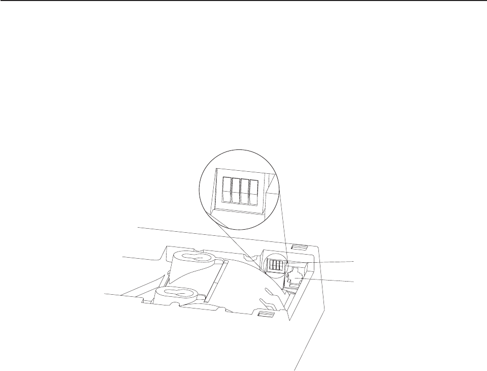
Emulating an Epson single-station printer (single-station only)
Emulation of an Epson single-station printer is supported on the single-station
SureMark printers. See Appendix G, “Emulation support for Epson single-station
printer,” on page 193.
Enabling Epson emulation
To enable emulation of an Epson single-station printer on a single-station SureMark
printer, you must set switch 3 on the main logic card. See Figure 17 for the location
of the switch.
Limitations for Epson emulation
The following limitations must be considered when using a single-station SureMark
printer to emulate an Epson single-station printer:
vLogos and downloadable characters are supported in emulation mode. However,
because the Epson printer prints at 180 dpi and the SureMark prints at 200 dpi,
the emulated printout will be smaller.
vEmulation of page mode is not supported on the SureMark.
vEpson supports the Select paper sensor to stop printing command. IBM does not
support a low paper sensor.
vIn order to implement fixes, new functionality, and other improvements, new
releases of printer microcode are routinely published. It is advisable that you run
the most recent version of firmware on the printer; however, the 4610 firmware
can not be updated when running in Epson emulation mode. Therefore, you must
first switch the printer to native mode, to upgrade the microcode.
123
OFF
4
EIA-232 mode switches
Cash drawer connector
Figure 17. Switch for Epson emulation
Updated April 2, 2009
Chapter 3. SureMark installation, service, and utility software 43

MICR data parser sample code (Models TI2, TI4, TI8, TI9, TG4, TG8,
and TG9 only)
The MICR data parser download package includes:
vSample source code (in C) that contains algorithms for parsing MICR data from a
check.
vAn exception data file that is used with the parsing code. You can edit this file to
add new check formats, if necessary.
Refer to the README file in this download package for additional information.
Resources on the Internet
The IBM Retail Store Solutions Web site at http://www.ibm.com/solutions/retail/store/
support/ contains publications for the SureMark printer. The Web site also provides
access to diskettes, drivers, and miscellaneous documentation, such as README
files and information about OEM papers that have been certified.
Select IBM SureMark Printer. The displayed page contains links both to
documentation and to diskettes and drivers that you can download for the SureMark
printers.
Updated April 2, 2009
44 SureMark Printers User’s Guide

Part 2. Models TI1, TI2, TI3, TI4, TI8, TI9, TG3, TG4, TG8, TG9
This part contains operational, testing, and problem determination information for
the thermal/impact SureMark printers Models TI1, TI2, TI3, TI4, TI8, TI9, TG3, TG4,
TG8, TG9. All references to Model TI3 pertain to Model TG3, references to TI4
pertain to Model TG4, and so on.
Updated April 2, 2009
© Copyright IBM Corp. 1997, 2006 45
Updated April 2, 2009
46 SureMark Printers User’s Guide
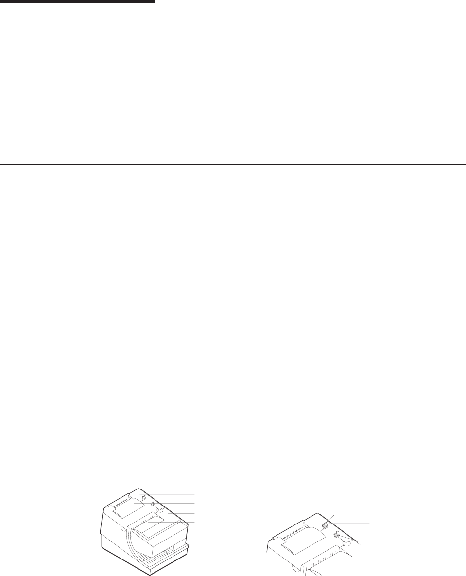
Chapter 4. Operation
Operating controls and indicators ..................47
Ribbon loading .........................51
Paper loading .........................53
Clearing jams in the check flipper area ................55
MICR reader read head cleaning ..................56
Thermal print head cleaning ....................57
Document scanner cleaning (Model TI8, TI9, TG8, TG9) .........59
Document scanner calibration (Models TI8, TI9, TG8, TG9) ........60
Note: All covers must be installed on the SureMark printer during operation.
Operating controls and indicators
There are two triangular-shaped buttons and two LED indicators located on top of
the printer. The buttons serve multiple functions.
When the topmost indicator is on continuously, the printer is powered ON and ready
for printing. When the indicator blinks, one of the following conditions exists:
vThe printer is out of paper.
vThe cover is open.
vThe printer is offline.
vThe printer has a nonrecoverable home error.
The second LED is the Document Present indicator. It lights when a document is
inserted far enough into the document insert station to reach the DI sensor. When
this LED blinks, the DI station is waiting for you to insert a document.
The topmost button is the customer receipt paper feed button. Press this button to
advance the CR paper. The lower button is the document feed button. Press this
button to advance the document.
If you press both buttons at the same time and then release them, the document
insert throat opens. The throat must be open to insert a document from the side.
Press and then release both buttons again to close the throat.
Both buttons are also used to test the printer. See “Offline tests” on page 62 for
additional button functions.
The printer is capable of printing verification information on a check and printing
information on an inserted document. Figure 19 on page 48, Figure 20 on page 48,
and Figure 21 on page 49 show the correct positioning of checks and documents in
Printer Ready LED
Document Present LED
Customer Receipt Feed Button
Document Feed Button
Customer Receipt Printer
Document Printer
Ribbon Cover
Paper Cover
Figure 18. SureMark printer indicators, controls, and printing stations (Models TI1, TI2, TI3,
TI4, TI8, TI9, TG3, TG4, TG8, and TG9)
Updated April 2, 2009
© Copyright IBM Corp. 1997, 2006 47
%%

SureMark printers with impact (document insert) stations. Those figures also show
how to side load a document to align it exactly where you want it to be printed.
Notes:
1. When side loading a Model TI8 or TG8, the document must be placed lower
than with the other models.
2. Side loading is not available with Models TI9 and TG9.
Insertion of Check
for MICR Reading
and Franking
Insertion of Check
for Printing the Face
4001
19
PayToThe
Order Of
Memo
$
Dollars
Endorse Here
Do Not Sign / Write / Stamp Below This Line
For Financial Usage Only
Federal Reserve Bank Regulation CC
041117847096 095867238671 4001
Figure 19. Inserting checks for all models except TF6 and TM6
Insertion of Document
(Front Load)
Figure 20. Inserting checks or documents in a Model TI2, TI4, TI8, TI9, TG4, TG8, or TG9
printer
Updated April 2, 2009
48 SureMark Printers User’s Guide
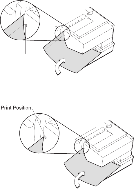
Figure 23 and Figure 24 on page 50 show the printable area on an inserted
document for both portrait and landscape.
Insertion of Document
(Side Load)
Print Position
Figure 21. Inserting checks or documents in a Model TI2 or TI4 printer
Figure 22. Side insertion of documents in a Model TI8 printer
Updated April 2, 2009
Chapter 4. Operation 49
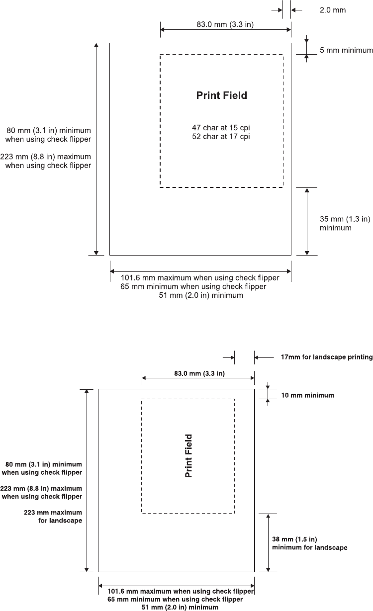
Figure 23. Printable area of an inserted document (portrait)
Figure 24. Printable area of an inserted document (landscape)
Updated April 2, 2009
50 SureMark Printers User’s Guide
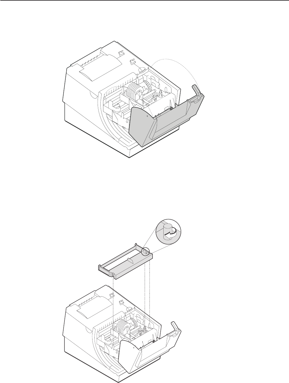
Ribbon loading
1. Open the ribbon cover. As the cover is opened, the print head moves to a
position where you can easily load a ribbon.
2. If there is already a ribbon cartridge installed, remove it by lifting it straight up.
Note: You might need to grasp the body of the cartridge rather than the top to
remove it.
Figure 25. Opening the ribbon cover
Figure 26. Ribbon cartridge loading
Updated April 2, 2009
Chapter 4. Operation 51
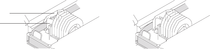
3. Maintain ribbon tension by turning the ribbon cartridge knob as shown in
Figure 26 on page 51. Lower the cartridge into position until the notches on its
sides snap into place on the printer guides. Once the cartridge is in place, turn
the knob until the ribbon slides into place between the print head and the ribbon
shield. See Figure 27 for correct ribbon positioning.
4. Close the ribbon cover.
Correct Not Correct
Ribbon Shield
Printhead
Figure 27. Ribbon path around the print head
Updated April 2, 2009
52 SureMark Printers User’s Guide
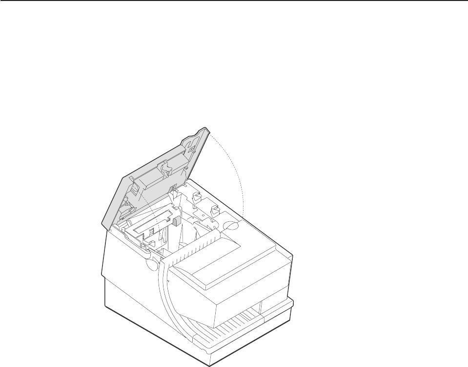
Paper loading
1. Open the paper cover.
2. If there is any unused paper or if there is an empty paper roll core in the paper
roll bucket inside the printer, remove it before inserting a new paper roll. You
can throw the core in the trash can.
Note: Refer to the label on the inside of the paper cover for a diagram of how
to load paper.
3. See Figure 29 on page 54 and place the paper roll into the paper roll bucket as
shown. The leading edge of the paper should come from the direction of the
front of the printer and go across the top of the roll as shown in the diagram. If
it feeds from the bottom of the roll, nothing will be printed on the paper.
Note: The thermal print head will not print on paper with glue on it. If the new
paper roll was sealed by glue, tear off the 6 to 8 inches of paper with
glue on it before loading it.
Figure 28. Paper cover (Models TI1, TI2, TI3, TI4, TI8, TI9, TG3, TG4, TG8, and TG9)
Updated April 2, 2009
Chapter 4. Operation 53
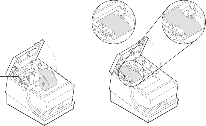
4. See Figure 29. Place the leading edge of the paper over the metal guide.
5. Close the paper cover.
6. Press the customer receipt feed button to advance the paper, to verify that the
paper is feeding correctly. Feed 30 cm (about 1 ft.) of paper through to test for
correct alignment.
Attention: Do not pull the receipt paper out of the printer with the paper access
cover closed. This disengages the paper feed. The paper feed motor must then
catch up before the printer can feed the paper, which causes missing lines or partial
lines of print. Use the customer receipt feed button to advance the receipt and all
lines will print.
Paper Roll
Not Correct Correct
Paper
Roll Core
Thermal
Platen
Figure 29. Paper loading path (Models TI1, TI2, TI3,TI4, TI8, TI9, TG3, TG4, TG8, and TG9)
Updated April 2, 2009
54 SureMark Printers User’s Guide
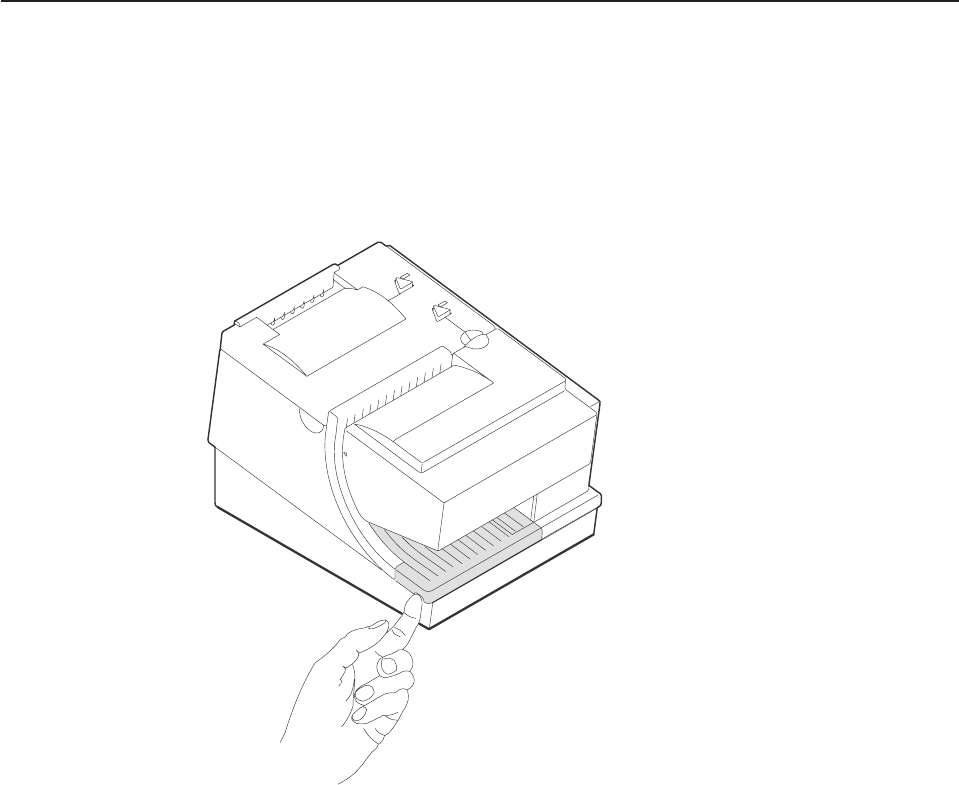
Clearing jams in the check flipper area
This procedure is for the SureMark printer Models TI2, TI4, TI8, and TI9 (MICR
Reader and Check Flipper features) only.
If a check jams in the Check Flipper mechanism:
1. Lift up the left front corner of the lower document insert cover and pull the cover
from the printer. (See Figure 30.)
2. The action you take in this step depends on whether the document is visible
and can be removed:
vIf you can remove the document:
a. Remove the document.
b. Replace the lower document insert cover.
c. You are finished with this procedure.
vIf you can not remove the document, continue with Step 3.
3. Lift up the tab on the left side of the check flipper cartridge and remove the
assembly from the printer. (See Figure 31 on page 56.)
Note: For printers with a powered flipper (Models TI8, TI9, TG8, TG9) the
cartridge is attached to the printer with an electrical cable and can not be
removed. Simply raise the front edge of the cartridge to remove a
jammed document underneath.
Figure 30. Removing the lower document insert cover
Updated April 2, 2009
Chapter 4. Operation 55
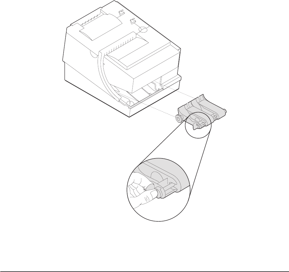
4. Reach inside the document insert station and carefully remove the jammed
check.
5. Reinstall the check flipper cartridge and the lower DI cover.
MICR reader read head cleaning
The MICR reader read head should be cleaned after 10000 checks are processed
or every 3 months, as required.
1. Open the ribbon cover.
2. Move the impact printhead to its rightmost position.
3. Rotate the document sensor assembly towards the front of the printer to expose
the MICR read head.
4. Use a cotton swab that is lightly soaked with alcohol to wipe any residue or dirt
from the MICR read head surface.
5. Gently return the document sensor assembly to its original position.
Figure 31. Removing the check flipper cartridge (except Models TI8, TI9)
Updated April 2, 2009
56 SureMark Printers User’s Guide
%
%
%
%
%
%
%
%
%
%
%
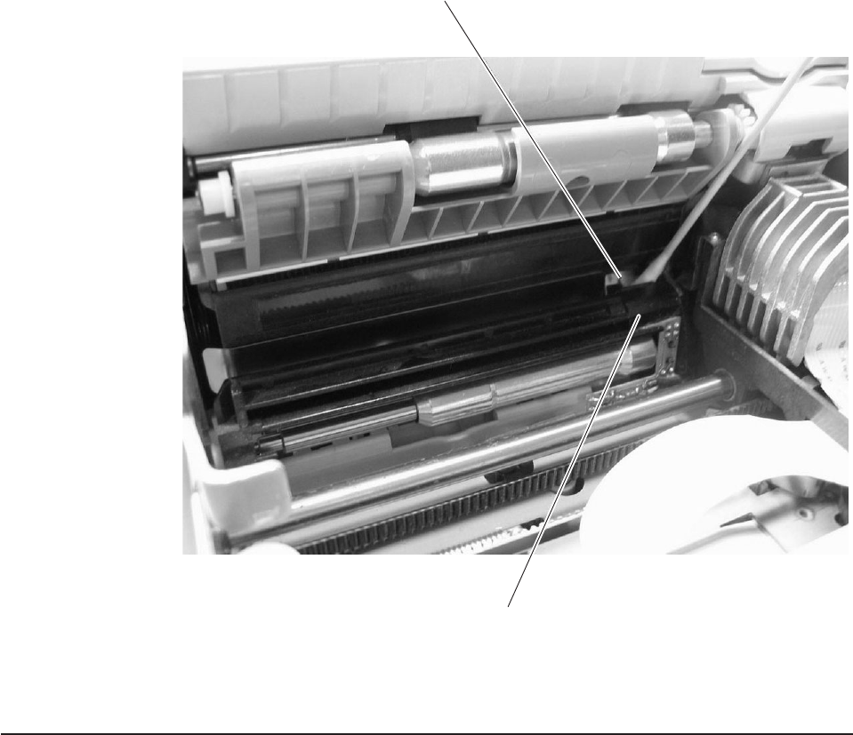
Thermal print head cleaning
The thermal print head can be cleaned whenever print quality deteriorates.
1. Open the paper cover.
2. Using a cotton swab soaked in isopropyl alcohol, gently wipe the print head
several times on its print line and on the surrounding area. See Figure 33 on
page 58.
MICR Read Head
Document Sensor Assembly
Figure 32. MICR reader read head
Updated April 2, 2009
Chapter 4. Operation 57
%
%
%
%
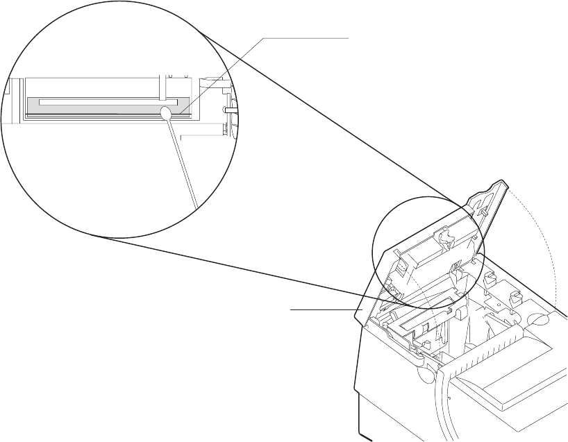
3. Wipe off any residual alcohol with a dry swab.
If print quality does not improve after cleaning the thermal print head, call for
service.
Thermal Print Line
Detailed View of Thermal Printhead
Paper Cover
Figure 33. Print head and print line area (Models TI1, TI2, TI3, TI4, TI8, TI9, TG3, TG4, TG8, and TG9)
Updated April 2, 2009
58 SureMark Printers User’s Guide
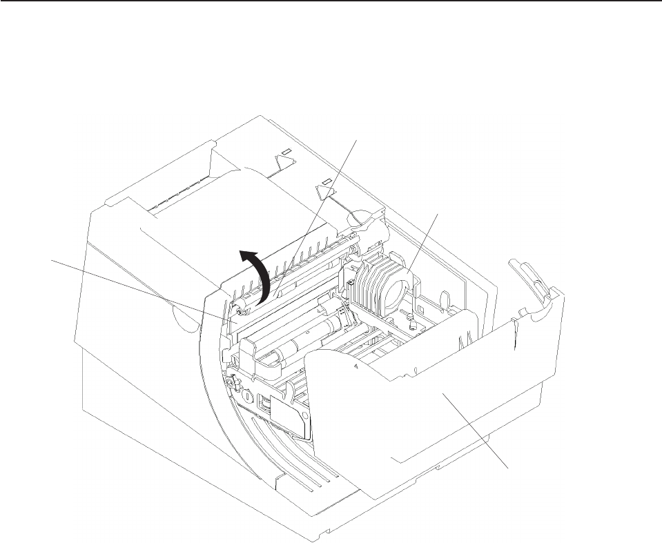
Document scanner cleaning (Model TI8, TI9, TG8, TG9)
The scanner surface should be cleaned after 10 000 documents or every three
months or whenever image quality deteriorates.
1. Open the ribbon cover. See Figure 34.
2. Move the impact print head to its rightmost position, as shown.
3. Rotate the scanner registration plate 180° up to expose the glass scanner
surface. See Figure 34.
4. Use a cotton swab that is lightly soaked with alcohol to wipe any residue from
the scanner glass surface.
5. Gently return the scanner registration plate to its original position.
6. The scanner should be recalibrated after it has been cleaned. See “Document
scanner calibration (Models TI8, TI9, TG8, TG9)” on page 60.
Scanner
Surface
Registration Plate
Print Head
Ribbon Access Cover
Figure 34. Scanner and print head location (Model TI8, TI9, TG8, TG9)
Updated April 2, 2009
Chapter 4. Operation 59

Document scanner calibration (Models TI8, TI9, TG8, TG9)
The printer must have power ON. Use a clean sheet of white copier paper (not
recycled paper) as the calibration target. Fold the paper in half. (Optional: cut paper
to 4.25 in. wide.)
1. Always begin by making sure the scanner window is clean.
2. Put paper in the CR station (paper will be used for printing in later step).
3. Insert the target paper into the document insert station as you would insert a
check. The folded edge should be up (or inserted first) and the right edge
should be against the right side of the paper path. Press the DI button to
automatically advance the paper to the ready position.
4. Enter offline mode by doing the following:
a. Open the CR cover and the DI cover.
b. Press and hold both buttons until the LED flashes rapidly.
c. Close the DI cover.
d. Close the CR cover.
5. Follow the directions that are printed in the CR station to perform the calibration.
6. Remove the target paper when complete.
7. Power the printer OFF and then ON for the changes to take effect.
Updated April 2, 2009
60 SureMark Printers User’s Guide
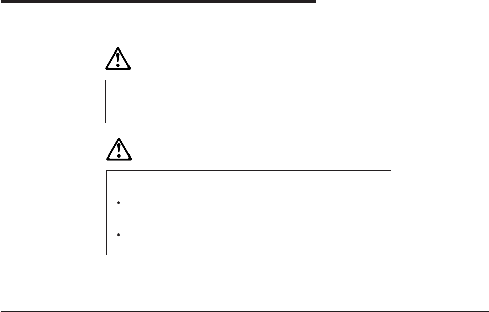
Chapter 5. Testing and problem analysis
DANGER
To avoid a shock hazard, do not connect or disconnect any cables
or perform installation, maintenance, or reconfiguration of this
product during an electrical storm.
DANGER
To avoid shock hazard:
The power cord must be connected to a properly wired and
earthed receptacle.
Any equipment to which this product will be attached must also
be connected to properly wired receptacles.
Note: For translations of these safety notices, see IBM Safety Information—Read
This First, GA27-4004.
Testing the printer
When you power ON the SureMark printer, it runs a power-on self-test (POST). If
the POST finds no errors, the printer is ready for operation. Follow this procedure to
determine if there are errors.
Note: Never connect or disconnect the printer when power is applied (when LEDs
are ON).
1. If the printer is powered ON, power OFF the printer and power it ON again.
vIf the printer is attached to the system with the EIA-232 cable or the standard
USB cable with a power brick, disconnect the power cord, then reconnect the
power cord to a properly wired and grounded power source.
vIf the printer is attached to the system with the RS-485 cable, power OFF the
POS system, and then power ON the system, which also powers ON the
printer.
vIf the printer is attached to the system with a powered USB cable, the USB
attached printer can be hot-plugged.
Updated April 2, 2009
© Copyright IBM Corp. 1997, 2006 61

2. Check the status of the Printer Ready indicator:
Printer ready indicator ON:
The power-on self-test completed successfully.
Printer ready indicator OFF or blinking:
The POST failed.
3. If the POST fails or if you suspect problems with your system, see “Problem
determination” on page 67.
4. See “Offline tests” and run the offline tests. If the offline tests fail or you suspect
problems with your system, see “Problem determination” on page 67.
Offline tests
The following offline tests are used as diagnostic tools to ensure the printer is
operating correctly.
Customer receipt test
1. Press and hold both buttons to enter offline mode. When the printer ready
indicator begins blinking, release both buttons.
2. Press and release the customer receipt feed button to start this test.
3. See Figure 36 on page 64 and verify that your printer has printed correct
information for your model and configuration:
vMICR reader enabled and check flipper enabled (Model TI2, TI4, TI8, TI9,
TG4, TG8, TG9)
vOptical scanner enabled (Model TI8, TI9, TG8, TG9)
vFull check scan enabled (Model TI9, TG9)
vDouble-byte character sets enabled (2 MB RPQ)
vEIA-232 or RS-485 serial interface or USB interface
v2 MB card with user flash storage enabled (Model TI3, TI4, TG3, TG4)
v2 MB card in single-byte mode (2 MB RPQ)
vApplicable parameters for EIA-232 communications:
– Baud rate (9600, 19 200, or 115 200 bps)
– DTR/DSR or XON/XOFF control
vA solid line should appear as the last line of the test pattern.
If any characters that appear in Figure 36 on page 64 are missing from the test
pattern that you print, or if the solid line is missing, go to “Problem
determination” on page 67.
Printer Ready LED
Document Present LED
Customer Receipt Feed Button
Document Feed Button
Figure 35. Printer buttons
Updated April 2, 2009
62 SureMark Printers User’s Guide
Document insert test
1. Insert a document in the document insert station. The document present
indicator should come on.
vIf the document present indicator does not come on, realign the document.
vIf pressing the document feed button does not feed the document, go to
“Problem determination” on page 67.
2. Press and hold both buttons to enter offline mode. When the printer ready
indicator begins blinking, release both buttons.
3. Press and release the document feed button to print the test pattern. The test
pattern includes all printable characters in the resident code page, printed in the
default font.
4. See Figure 36 on page 64 and verify that your printer has printed correct
information for your model and configuration:
vMICR reader enabled and check flipper enabled (Model TI2, TI4, TI8, TI9,
TG4, TG8, TG9)
vOptical scanner enabled (Model TI8, TI9, TG8, TG9)
vFull check scan enabled (Model TI9, TG9)
vDouble-byte character sets enabled (2 MB RPQ)
vEIA-232 or RS-485 serial interface or USB interface
v2 MB card with user flash storage enabled (Model TI3, TI4, TG3, TG4)
v2 MB card in single-byte mode (2 MB RPQ)
vApplicable parameters for EIA-232 communications:
– Baud rate (9600, 19 200, or 115 200 bps)
– DTR/DSR or XON/XOFF control
vA solid line should appear as the last line of the test pattern.
If any characters that appear in Figure 36 on page 64 are missing from the test
pattern that you print, or if the solid line is missing, go to “Problem
determination” on page 67.
Updated April 2, 2009
Chapter 5. Testing and problem analysis 63
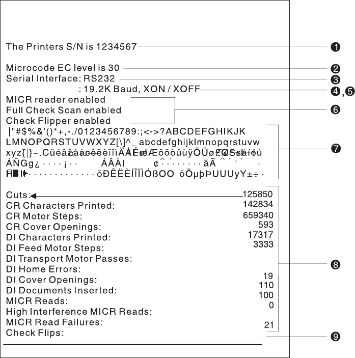
Test Pattern Notes:
1. The serial number that prints will be the actual serial number of your printer.
2. The microcode level will be the actual level of your printer’s microcode.
3. The serial interface will be specified as EIA-232,RS-485,orUSB, depending on
which interface is used to attach the printer to the system unit.
4. The line speed information appears only when the EIA-232 interface is used.
The value can be either 9.6 Kbps or 19.2 Kbps, depending on the EIA-232
switch settings. See “EIA-232 communication mode selections (all models
except TI8, TI9, TG8, TG9)” on page 28.
5. The EIA-232 control mode information appears only when the EIA-232 interface
is used. The value can be either DTR/DSR or XON/XOFF, depending on the
EIA-232 switch settings. See “EIA-232 communication mode selections (all
models except TI8, TI9, TG8, TG9)” on page 28 or “EIA-232 communication
mode selections (Models TI8, TI9, TG8, TG9)” on page 30.
6. The feature enabled lines will appear only when the feature is installed.
7. These lines break at different points for the test pattern printed in the document
insert station.
8. This section contains printer usage statistics that you can use for problem
determination.
9. The line across the bottom should be solid with no blank spaces.
Figure 36. Offline printer test pattern from the customer receipt station (Models TI1, TI2, TI3,
TI4, TI8, TI9, TG3, TG4, TG8, TG9)
Updated April 2, 2009
64 SureMark Printers User’s Guide
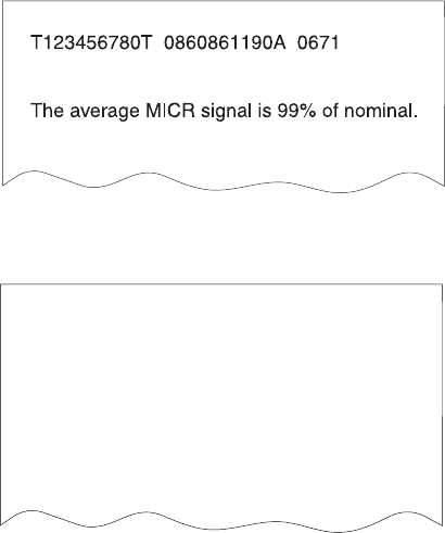
MICR reader and check flipper test (Models TI2, TI4, TI8, TI9, TG4, TG8,
and TG9 only)
Attention: Failure to perform these steps in the sequence shown will cause the
entire electronic journal to print on the CR station. Printing the electronic journal
erases the information from flash storage.
1. Insert the check face down with the magnetic ink characters to the right.
2. Press and hold both buttons to enter offline mode. When the printer ready
indicator begins blinking, release both buttons.
3. Press and release both buttons again.
4. The printer will then perform a self-test of the MICR/flipper function.
5. Remove the check.
Characters that match the magnetic ink characters are printed on the customer
receipt and the check is flipped over. Characters that can not be read will be
replaced with question marks and will be printed at the customer receipt station. If
the characters are not read properly or the check does not flip, go to “Problem
determination” on page 67.
If the Model TI2, TI4, TI8, TI9, TG4, TG8, or TG9 detects noise, it prints a message
on the customer receipt below the magnetic characters from the check (Figure 37
and Figure 39 on page 66 are examples; actual numbers may vary). The message
shows noise characteristics. You can use the noise level to position your printer to
minimize outside interference with the MICR reader. An acceptable noise level is
less than 5 percent, if possible.
Sources of electromagnetic noise (for example, displays, security towers, and other
sources) can interfere with the MICR reader read head. If the printer shows an
external noise source, rearrange the printer to make the noise source as far away
as possible from the right side of the printer. This may eliminate the external noise.
Figure 37. MICR reader test results (Models TI2, TI4, and TG4): Good noise level
Magnetic: T1234567890T 0860861190A 0671
Optical 1: T1234567890T 0860861190A 0671
Optical 2: T1234567890T 0860861190A 0671
Composite result:
T1234567890T 0860861190A 0671
The average MICR signal is 99% of normal
Figure 38. MICR reader test results (Models TI8, TI9, TG8, TG9): Good noise level
Updated April 2, 2009
Chapter 5. Testing and problem analysis 65
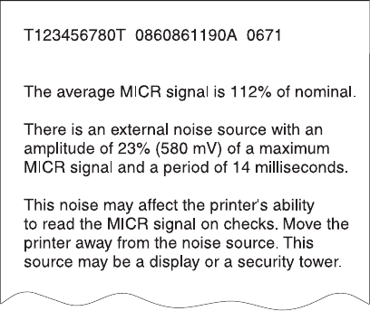
Scanned check printout (ModelsTI8, TI9, TG8, TG9)
Following the description of the test, Models TI8, TI9, TG8, and TG9 also print a
copy of the check that has been scanned. This printout is in black and white, not
grayscale.
EIA-232 hex dump
To enable hex dump mode for the printer:
Power off the printer, press and hold the paper feed button and then power on the
printer with the paper feed button still pressed.
To exit, power OFF or reset the printer.
Resetting the printer - offline
1. Press and hold both buttons (Customer Receipt Feed button and Document
Feed button) to enter offline mode.
2. Release both buttons when the Printer Ready indicator begins to blink.
3. Open the customer receipt cover, then close it. The printer resets.
Electronic journal dump
Note: Electronic journal data must be formatted and stored as printed lines for the
journal data to be printed in readable format.
1. Press and hold both buttons (Customer Receipt Feed button and Document
Feed button) to enter offline mode.
2. Release both buttons when the Printer Ready indicator begins to blink.
3. Press and release both buttons.
Figure 39. MICR reader test results: Noise level needs adjusting
Updated April 2, 2009
66 SureMark Printers User’s Guide

Problem determination
Any problems that arise with a SureMark printer are either software errors or
hardware failures. This section contains information to help you determine the
cause of a problem and how to solve it.
If the SureMark printer fails, use Table 3 to identify and report the problem. Follow
the procedures described in the table. If you can not identify and solve the problem,
call your service representative.
Table 3. Troubleshooting (Models TI1, TI2, TI3, TI4, TI8, TI9, TG3, TG4, TG8, and TG9)
If the problem is... Then do this...
Printer ready indicator is OFF. vIf connected to a system using the RS-485 communication port, check that
the system is powered ON and cable 7 is connected.
vIf using the EIA-232 communication port or a USB port with a power brick,
check that the brick power supply is connected to the printer and plugged into
an ac power source.
vIf using USB communication with a powered USB cable, check that the
system is powered ON.
Printer ready indicator is blinking. vCheck that the customer receipt station has paper loaded correctly. Close the
cover and push the Customer Receipt Feed button to feed a small amount of
paper.
vCheck the document insert station print head and paper path for any
obstructions.
vCheck that the paper and ribbon covers are closed.
Checks not flipping Go to “Clearing jams in the check flipper area” on page 55.
Checks not reading Go to “MICR reader read head cleaning” on page 56 or “Document scanner
cleaning (Model TI8, TI9, TG8, TG9)” on page 59 or “Document scanner
calibration (Models TI8, TI9, TG8, TG9)” on page 60.
Customer receipt station is feeding
paper, but is not printing.
vEnsure that the paper roll is not upside down. Go to “Paper loading” on page
53.
vClean the print head. See “Thermal print head cleaning” on page 57.
Document insert station is not
printing
vCheck the paper path.
vCheck to see if the ribbon is installed correctly.
vChange the ribbon, go to “Ribbon loading” on page 51.
Scanned images streaked, too
light, or too dark
vClean the scanner window. Go to “Document scanner cleaning (Model TI8,
TI9, TG8, TG9)” on page 59.
vCalibrate the scanner. Go to “Document scanner calibration (Models TI8, TI9,
TG8, TG9)” on page 60
vClean or replace the registration plate.
Notes:
1. Record all symptoms before calling for service.
2. If you receive software error messages, refer to the application program’s
software manual.
3. Call your service representative.
Updated April 2, 2009
Chapter 5. Testing and problem analysis 67
Updated April 2, 2009
68 SureMark Printers User’s Guide

Part 3. Models TF6 and TM6
This part contains operational, testing, and problem determination information for
SureMark printer Models TF6 and TM6.
Updated April 2, 2009
© Copyright IBM Corp. 1997, 2006 69
Updated April 2, 2009
70 SureMark Printers User’s Guide
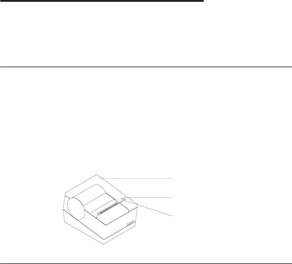
Chapter 6. Operation (Models TF6 and TM6)
Operating controls and indicators ..................71
Paper loading .........................71
Thermal print head cleaning ....................73
Note: All covers must be installed on the SureMark printer during operation.
Operating controls and indicators
There is one triangular-shaped button and one LED indicator located on top of the
printer.
When the LED indicator is on continuously, the printer is powered ON and ready for
printing. When the indicator blinks, one of the following conditions exists:
vThe printer is offline (offline testing is enabled).
vThe printer is out of paper.
vThe cover is open.
vThe cutter is jammed.
See “Offline test” on page 76 for additional button functions.
Paper loading
1. Open the paper cover.
2. If there is any unused paper or if there is an empty paper roll core in the paper
roll holder inside the printer, remove it before inserting a new paper roll. You can
throw the core in the trash can.
3. Drop the roll into the bucket. The leading edge of the paper should come from
the direction of the back of the printer and go across the bottom of the roll as
shown in the diagram. See Figure 41 on page 72.
Note: The thermal print head will not print on paper with glue on it. If the new
paper roll was sealed by glue, tear off the 15 to 20 cm (6 to 8 in.) of
paper with glue on it before loading it.
Top cover
Printer ready
LED
Customer receipt
feed button
Figure 40. SureMark printer indicator, control, and printing station (Models TF6 and TM6)
Updated April 2, 2009
© Copyright IBM Corp. 1997, 2006 71
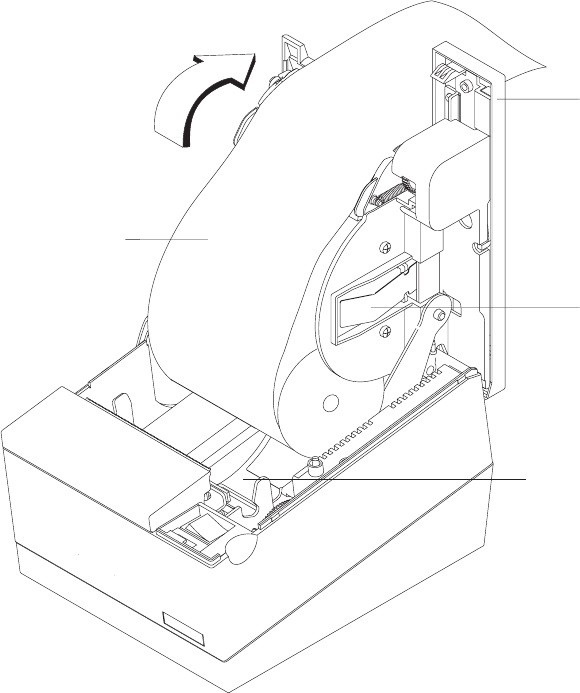
4. Pull the end of the paper up over the paper roll and toward the back of the
printer.
Note: Refer to the label on the inside of the bottom cover for a diagram of how
to load paper.
5. Close the paper cover.
6. Press the customer receipt feed button to advance the paper and verify that the
paper is feeding correctly. Feed 30 cm (about 1 ft) of paper through to test for
correct alignment.
Attention: Do not pull the receipt paper out of the printer with the paper access
cover closed. This might cause partial lines of print. Use the customer receipt feed
button to advance the receipt.
Paper roll
Top cover
Metal
Spring
Bucket
Figure 41. Paper loading path (Models TF6 and TM6)
Updated April 2, 2009
72 SureMark Printers User’s Guide
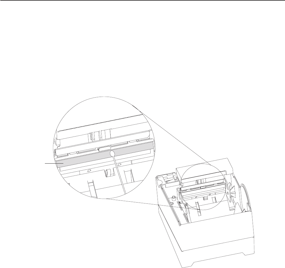
Thermal print head cleaning
The thermal print head can be cleaned whenever print quality deteriorates.
1. Open the paper cover.
2. Using a cotton swab soaked in isopropyl alcohol, gently wipe the print head
several times on its print line and on the surrounding area. See Figure 42.
3. Wipe off any residual alcohol with a dry swab.
If print quality does not improve after cleaning the thermal print head, call for
service.
Thermal Print Line
Detail View of Thermal Print Head
Figure 42. Print head and print line area (Models TF6 and TM6)
Updated April 2, 2009
Chapter 6. Operation (Models TF6 and TM6) 73
Updated April 2, 2009
74 SureMark Printers User’s Guide
Chapter 7. Testing and problem analysis (Models TF6 and
TM6)
Testing the printer ........................75
Offline test ..........................76
EIA-232 hex dump .......................77
Resetting the printer - offline ....................78
Problem determination ......................78
DANGER
To avoid a shock hazard, do not connect or disconnect any cables
or perform installation, maintenance, or reconfiguration of this
product during an electrical storm.
DANGER
To avoid shock hazard:
The power cord must be connected to a properly wired and
earthed receptacle.
Any equipment to which this product will be attached must also
be connected to properly wired receptacles.
Note: For translations of these safety notices, see IBM Safety Information—Read
This First, GA27-4004.
Testing the printer
When you power on the SureMark printer, it runs a power-on self-test (POST). If the
POST finds no errors, the printer is ready for operation. Follow this procedure to
determine if there are errors.
Note: Never connect or disconnect the printer when power is applied (when the
LED is on).
1. If the printer is powered on, power OFF the printer and power it on again.
vIf the printer is attached to the system with the EIA-232 cable or the standard
USB cable with a power brick, disconnect the power cord, then reconnect the
power cord to a properly wired and grounded power source.
vIf the printer is attached to the system with the RS-485 cable, power OFF the
POS system, and then power on the system, which also powers on the
printer.
vIf the printer is attached to the system with a powered USB cable, the USB
attached printer can be hot-plugged.
vFor single-station printers, use the printer’s power ON/OFF switch that is
located under the top cover. Power OFF the printer, then power ON the
printer.
Updated April 2, 2009
© Copyright IBM Corp. 1997, 2006 75
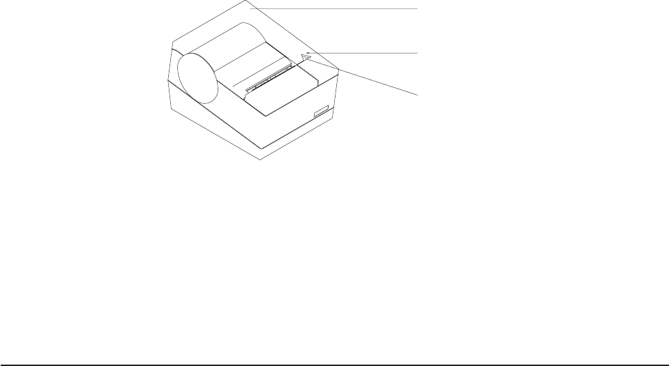
Top cover
Printer ready
LED
Customer receipt
feed button
2. Check the status of the Printer Ready indicator:
Printer Ready indicator ON:
The POST completed successfully.
Printer Ready indicator OFF or blinking:
The POST failed.
3. If the POST fails or if you suspect problems with your system, see “Problem
determination” on page 78.
4. See “Offline test” and run the offline test. If the offline test fails or you suspect
problems with your system, see “Problem determination” on page 78.
Offline test
An offline printing test is provided as a diagnostic tool to ensure the printer is
operating correctly.
1. Open the top cover.
2. Press and hold the paper feed button for 5 seconds. The LED indicator will
make one quick flash followed by a pause. The beeper will make a short single
tone periodically.
Note: The paper feed button is the small button next to the LED.
3. Release the paper feed button.
4. Close the top cover.
5. See Figure 43 on page 77 and verify that your printer has printed correct
information for your model and configuration:
v2 MB card with user flash storage enabled
vEIA-232, RS-485, or USB serial interface
vApplicable parameters for EIA-232 communications:
– Baud rate (9600 or 19 200 bps)
– DTR/DSR or XON/XOFF control
vA solid line should appear as the last line of the test pattern.
If any characters that appear in Figure 43 on page 77 are missing from the test
pattern you print, or if the solid line is missing, go to Table 4 on page 78.
Updated April 2, 2009
76 SureMark Printers User’s Guide

Test Pattern Notes:
1. The serial number that prints will be the actual serial number of your printer. (If
the logic card has been replaced, this number must be reset to the original
serial number.)
2. The microcode level will be the actual level of your printer’s microcode.
3. The serial interface will be specified as EIA-232,RS-485,orUSB, depending on
which interface is used to attach the printer to the system unit.
4. The line speed information appears only when the EIA-232 interface is used.
The value can be either 9.6 K Baud or 19.2 K Baud, depending on the EIA-232
switch settings. See “EIA-232 communication mode selections (all models
except TI8, TI9, TG8, TG9)” on page 28.
5. The EIA-232 control mode information appears only when the EIA-232 interface
is used. The value can be either DTR/DSR or XON/XOFF, depending on the
EIA-232 switch settings. See “EIA-232 communication mode selections (all
models except TI8, TI9, TG8, TG9)” on page 28.
6. The feature-enabled lines will appear only when a feature is installed.
7. This section contains the test pattern.
8. This section contains printer usage statistics that you can use for problem
determination.
9. The line across the bottom should be solid with no blank spaces.
EIA-232 hex dump
An EIA-232 hex dump is provided to help diagnose problems with Models TM6 and
TF6.
To enable hex dump mode for the Model TF6 or TM6 printer:
Power off the printer, press and hold the paper feed button and then power on the
printer with the paper feed button still pressed.
The Printers S/N is 12345678
Microcode EC level is 30
Serial Interface: RS232
: 19.2K Baud, XON / XOFF
|"#$%&'()*+,-./0123456789:;<->?ABCDEFGHIKJK
LMNOPQRSTUVWXYZ[\]^_ abcdefghijklmnopqrstuvw
xyz{|}~.CüéâäàåcêëèïîìÄÅÉæÆôöòûùÿÖÜø£ØSsáíóú
ÁÑGg¿ · · · · ¡ · · ÁÂÀ ¢ · · · · · · · · ãà ·
H III · · · · · · · · · · · · · Ð ·
Cuts: 12301
CR Characters Printed: 77626
CR Motor Steps: 88974
CR Cover Openings: 40
CR Cut Fails: 7
Serial Interface
I
I õ ÊËÈÍÎÏÌÓßOO õÕµþÞUUUyY±÷
Serial Interface
·
1
3
9
8
2
6
7
`
`
`
^^
`
`
45
,
Figure 43. Offline printer test pattern (Models TF6 and TM6)
Updated April 2, 2009
Chapter 7. Testing and problem analysis (Models TF6 and TM6) 77

To exit, power OFF or reset the printer.
Resetting the printer - offline
To reset the printer:
1. Open the top cover.
2. Power off the printer using the power ON/OFF switch that is located in the right
front corner of the printer.
3. Power on the printer.
Problem determination
Any problems that arise with a SureMark printer are either software errors or
hardware failures. This section contains information to help you determine the
cause of a problem and how to solve it.
If the SureMark printer fails, use Table 4 to identify and report the problem. Follow
the procedures described in the table. If you can not identify and solve the problem,
call your service representative.
Table 4. Troubleshooting (Models TF6 and TM6)
If the problem is... Then do this...
Printer ready indicator is OFF. vCheck that the printer power switch, which is located under the top cover, is
set ON.
vIf connected to a system using the RS-485 communication port, check that
the system is powered on and cable 7 is connected.
vIf using the EIA-232 communication port or a USB port with a power brick,
check that the brick power supply is connected to the printer and plugged into
an ac power source.
vIf using USB communication with a powered USB cable, check that the
system is powered ON.
Printer ready indicator is blinking. vCheck that the customer receipt station has paper loaded correctly. Close the
cover and push the Customer Receipt Feed button to feed a small amount of
paper.
vCheck that the cover is closed.
Customer receipt station is feeding
paper, but is not printing.
vEnsure that the paper roll is in correctly. Go to “Paper loading” on page 53.
vClean the print head. See “Thermal print head cleaning” on page 57.
Notes:
1. Record all symptoms before calling for service.
2. If you receive software error messages, refer to the application program’s
software manual.
3. Call your service representative.
Updated April 2, 2009
78 SureMark Printers User’s Guide

Part 4. Appendixes
Updated April 2, 2009
© Copyright IBM Corp. 1997, 2006 79
Updated April 2, 2009
80 SureMark Printers User’s Guide

Appendix A. Consumable supplies
Paper specifications .......................81
Thermal paper ........................81
Document insert forms (Models TI1, TI2, TI3, TI4, TI8, TI9, TG3, TG4, TG8,
and TG9 only) .......................82
Single and multipart form specifications ..............82
Specifications for documents that can be flipped ..........82
Print ribbons (Models TI1, TI2, TI3, TI4, TI8, TI9, TG3, TG4, TG8, and TG9
only) ............................83
Expendable supplies .......................83
Paper specifications
Attention: Using an inferior grade of paper can affect print quality as well as the
life of print heads and the printer mechanism. See “Resources on the Internet” on
page 44 for information about OEM paper recommended for SureMark printers.
Note: When selecting a paper, ensure that the paper’s archive life meets the
requirements of the tax authorities of your country for archiving tax-related
data.
Thermal paper
The paper used in the thermal receipt station must meet the following requirements:
Width 79.5 ± 0.5 mm (3.13 ± 0.02 in.)
Outside Diameter
80 mm (3.15 in.) maximum for thermal/impact SureMark printers
90 mm (3.54 in.) maximum for single-station SureMark printers
Thickness
0.0457–0.094 mm (0.0018–0.0037 in.) operating thickness range
Important
Paper has a significant manufacturing tolerance and nominal paper
designations do not reflect actual measurements. The manufacturing
tolerance must fall within the published operating thickness range. IBM
strongly recommends that customers test paper in their specific
configuration before use. The intent of this specification is that if any
spot measurement of the paper is outside the specified range, the
paper is deemed not to meet the specification and the customer is
responsible for any problems caused by paper jams.
Weight
60±19g/m
2(16 ± 5 lb)
The paper must be wound with the printing side facing out and with the outer edge
glued to prevent unraveling. The paper should not be attached to the core in any
manner. There should be 1.5 to 2.1 m (5 to 7 ft.) of red stripe at the end of the roll.
Note: Non-topcoated thermal paper can be recycled along with other paper
products. They can also be incinerated and sent to landfills with no more
effect on the environment than regular office paper waste.
Updated April 2, 2009
© Copyright IBM Corp. 1997, 2006 81
%%

Important
Printer reliability and performance are directly related to the quality of the
supplies used by the customer. The published parameters for printer
performance are established using supplies that meet the specifications listed
above.
Thermal paper with post-processing, such as (but not limited to) watermarks,
coupons, or advertisements printed on the front or back of the paper, is not
covered by IBM specifications. Some inks and printing processes will work
acceptably, while others will not. Printer problems that are caused by supplies
that do not meet IBM specifications may result in a billable service call,
regardless of the existence of a service contract.
Document insert forms (Models TI1, TI2, TI3, TI4, TI8, TI9, TG3, TG4,
TG8, and TG9 only)
The printers will accommodate single and multipart forms.
Single and multipart form specifications
Specification Value
Minimum width: 50 mm (2 in.)
Maximum thickness of multipart forms: 0.47 mm (0.0185 in.)
Maximum thickness of front sheet, multipart
forms:
0.08 mm (0.003 in.)
Minimum thickness of single-part form: 0.10 mm (0.004 in.)
Maximum thickness of single-part form: 0.2 mm (0.008 in.)
Weight range for single-part forms: 68–90 g/m2(18–24 #)
For best reliability, paper grain should be in the direction that the paper is fed into the
printer.
Notes:
1. Test all forms in the printer to ensure acceptable performance prior to buying a
significant quantity. There should be no binding holes or other holes within 10
mm (0.4 in.) from the right edge of the form.
2. Forms less than 0.15 mm (0.006 in.) thick with the grain of the paper
perpendicular to the feed direction (short-grain paper) should not be used for
landscape printing.
Specifications for documents that can be flipped
Multipart forms and short-grain single-part forms are not supported.
Specification Value
Minimum form length: 80 mm (3.14 in.)
Maximum form length: 223 mm (8.78 in.)
Maximum form width: 102 mm (4 in.)
Paper weight: 75–95 g/m2
Updated April 2, 2009
82 SureMark Printers User’s Guide

Print ribbons (Models TI1, TI2, TI3, TI4, TI8, TI9, TG3, TG4, TG8, and
TG9 only)
The ribbon is an Epson ERC-35 or equivalent. In addition to the Epson ERC-35, the
Infotech RE35P ribbon was tested and approved for use in the SureMark printer.
The Infotech ribbon, order number RE35P, Black, is available from:
Infotech, Inc.
2215 29th Street SE #B-1
Grand Rapids, MI 49508
Phone: (616) 452-5444
Fax: (616) 452-5499
Attention: Using an inferior grade of ribbon can affect print quality and the life of
print heads and the printer mechanism.
Expendable supplies
See “Resources on the Internet” on page 44 for information about OEM paper
certifications for the SureMark printers.
vPaper for the printer, order P/N locally
vQ-Tip/Cotton Swab, P/N 69X7671
Updated April 2, 2009
Appendix A. Consumable supplies 83
%
%
%
%
%
Updated April 2, 2009
84 SureMark Printers User’s Guide

Appendix B. Printer maintenance procedures
Note: Power OFF all system components and unplug all power cables prior to
cleaning.
Product care procedures
Owners and users should periodically inspect their system unit and its components
for cleanliness and perform the following procedures based on usage and
environmental characteristics.
1. Clean the cover for cosmetic purposes as required.
vIBM suggests the use of a soft clean cloth with warm soapy water for
cleaning the plastic parts on IBM product
vDon’t use abrasives or any alkaline, ammonia, or chloride-based cleaner.
Note: Do not apply cleaning solution directly to the cover. Always apply the
cleaner on a clean cloth and then wipe the cover with the damp cloth.
Be certain that the cloth is only damp and not dripping wet.
2. MICR Reader Read Head Cleaning as required.
vThe MICR reader read head should be cleaned after 10 000 checks are
processed or every 3 months. See “MICR reader read head cleaning” on
page 56.
3. Document scanner cleaning as required. (Model TI8, TI9, TG8, TG9 only.) See
“Document scanner cleaning (Model TI8, TI9, TG8, TG9)” on page 59.
4. Thermal Printhead Cleaning as required.
The thermal printhead can be cleaned whenever print quality deteriorates.
a. Open the paper cover.
b. Using a cotton swab soaked in isopropyl alcohol, gently wipe the printhead
several times on its print line and on the surrounding area. (See Figure 33
on page 58 for more details.)
c. Wipe off any residual alcohol with a dry swab.
If the print quality does not improve after cleaning the thermal printhead, call
for Service.
Service provider system maintenance procedures
Preventive Maintenance Scheduling
The following procedures can be performed during normal service call
routines:
Models TI1, TI2, TI3, TI4, TI8, TI9, TG3, TG4, TG8, and TG9
vClean the dust and debris from the paper cover and ribbon cover areas.
vIf the printer has a check flipper, clean dust and debris from the area under the
flipper cover and the flipper cartridge.
vCheck the document scanner for dust and dirt (Models TI8, TI9, TG8, TG9 only).
Models TF6 and TM6
vClean the dust and debris from the top cover area.
Updated April 2, 2009
© Copyright IBM Corp. 1997, 2006 85
%
%
%
%
%
%
%
%
%
%
%
%
%
%
%
%
%
%
%
%
%
%
%
%
%
%
Updated April 2, 2009
86 SureMark Printers User’s Guide

Appendix C. Technical information
General description .......................87
Specifications .........................87
Memory units .........................89
Immediate commands ......................89
Voltage conversion circuitry ....................89
RS-485 serial I/O parameters ...................90
Cash drawer connector pin assignments ...............90
EIA-232 connector pin assignments .................91
EIA-232 parameters .......................91
USB connector pin assignments ..................92
Code page definitions ......................92
Generic code page ......................93
Code page 437........................94
Code page 858........................95
Code page 860........................96
Code page 863........................97
Code page 865........................98
Character fonts .........................98
Thermal printing font ......................98
Impact printing fonts (Models TI1, TI2, TI3, TI4, TI8, TI9, TG3, TG4, TG8, and
TG9) ...........................99
General description
All SureMark printers print the customer receipt using the thermal print head. For
SureMark printers that include a document insert station, documents are printed
using the impact head.
Thermal printing occurs by placing a heating element against a thermally sensitive
paper. By energizing the elements, dots are formed. Thermal printers print dot rows
horizontally across the page; 576 dots make up a single dot row across the paper.
Printing continues row by row until the entire character is formed.
Impact printing utilizes a standard ballistic print head. Each wire is fired against an
inked ribbon which places a dot on the paper.
SureMark printers contain all the circuitry, processing hardware, and software for
operating a thermal and, except for Models TF6 and TM6, an impact printer
mechanism. SureMark printers do not contain a power supply. However, they do
contain voltage conversion circuitry to allow connection to a standard IBM system
interface or to an EIA-232 24 V power supply. (See “Power requirements” on page
12 for specific power supply specifications.)
Specifications
The information in the Document Insert Station column of Table 5 on page 88
applies only to SureMark Models TI1, TI2, TI3, TI4, TI8, TI9, TG3, TG4, TG8, and
TG9. There is no document insert station on Models TF6 and TM6.
Updated April 2, 2009
© Copyright IBM Corp. 1997, 2006 87
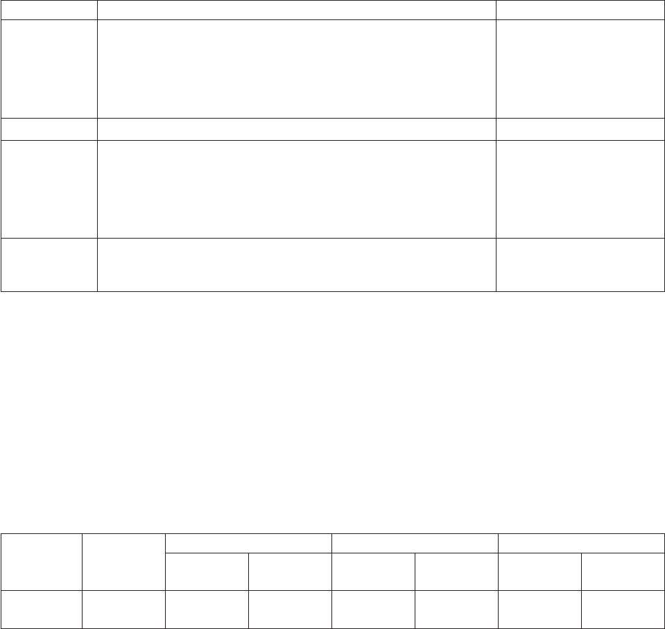
Table 5. Station characteristics
Characteristic Customer Receipt Station Document Insert Station
Speed (see
note following
table)
Models TI1 and TI2: 19.6 lps at 6 lpi, 26 lps at 8 lpi
Models TI3/TI4/TI8/TI9/TG3/TG4/TG8/TG9:
39.2 lps at 6 lpi, 52 lps at 8 lpi;
Models TF6 and TM6: 39.2 lps at 6 lpi, 52 lps at 8 lpi
4.3 lps
Paper Width All models: 80 mm (3.54 in.)
Print Width All SureMark printers: 34 characters at 12 cpi,
44 characters at 15 cpi,
48 characters at 17 cpi
All models except TI1 and TI2:
57 characters at 20 cpi
37 characters at 12 cpi,
47 characters at 15 cpi,
52 characters at 17 cpi.
Pitch All SureMark printers: 12, 15, 17 cpi
All models except TI1 and TI2: 20 cpi
12, 15, 17 cpi
Note: In order to conserve power, SureMark Models TI3, TI4, TI8, TI9, TG3, TG4,
TG8, TG9, TF6 and TM6 reduce their throughput when printing high print
densities, such as logo messages or full black lines. Because these types of
print messages are used on a limited basis, the overall performance when
printing a customer receipt is not noticeably affected.
The reduced print speed is based on the number of print dots that are turned
on for a given print line, which is defined as dot utilization. Dot utilization is
typically low for normal character printing and up to 100% for full black line
printing. The SureMark printer operates at 52 lps at low dot utilization, and at
slower speeds as the dot utilization increases.
Table 6. Sound characteristics
Type Description LwAd LpAm <LpA>m
Operating
(bels)
Idling (bels) Operating
(dB)
Idling (dB) Operating
(dB)
Idling (dB)
SureMark
TI1
Printer 5.7 N/A 61.5 N/A 47 N/A
Notes:
LwAd The declared upper limit of the sound power level for a random
sample of machines.
LpAm The mean value of the A-weighted sound pressure levels at the
operator position (if any) for a random sample of machines.
<LpA>m
The mean value of the A-weighted sound pressure levels at the
one-meter (bystander) positions for a random sample of machines.
N/A Indicates not applicable.
All measurements were made in accordance with ISO 7779 and reported in
conformance with ISO 9296.
Updated April 2, 2009
88 SureMark Printers User’s Guide

Memory units
Random access memory (RAM) is used for storing the image data for the thermal
print head and program code. It is also used for storing incoming data from the
communication port.
Flash memory is used for many purposes, including:
vCharacter set storage (80 KB)
vPersonalized message storage (8 KB)
vLogo or APA message storage (64 KB)
vFlash memory data storage (104 KB on standard printers, 1.9 MB on printers
with the 2 MB memory option, 8 MB on printers with the 8 MB memory option)
vProgram code and resident character sets (256 KB) (except Models TI8 and TI9)
vFor Models TI8 and TI9, 1.25 MB is available for all uses.
Personalized messages are those messages that are printed on each receipt in a
POS environment. Storing these messages in the flash memory greatly reduces the
data transmission time to the printer and the processing time of that data by the
microprocessor. This is also true of graphics or APA messages, which require a
significant amount of transmission and processing time.
Flash memory can also be used as a storage place for customer data. This data
could be journal data.
Immediate commands
The SureMark printer has 4 KB of memory on Models TI1 and TI2, and 16 KB of
memory on Models TI3, TI4, TI8, TI9, TG3, TG4, TG8, TG9, TF6, and TM6 to store
incoming commands and data.
Most commands are received and then executed sequentially. However, several
commands execute immediately upon receipt. These commands are:
v“Download graphics (logo) commands” on page 115
v“Predefine messages” on page 117
v“Download user-defined characters” on page 118
v“Extended address command-request printer ID” on page 112
v“Real-time requests” on page 175.
Voltage conversion circuitry
The printer requires two voltages. The print heads and motors use +24 V dc.
Powering the logic circuitry requires +5 V dc. Printer input voltage is one of the
following:
Communication Mode Power Requirement
RS-485 +38Vdcand+5Vdc
EIA-232 +24Vdc
USB +24Vdc
Updated April 2, 2009
Appendix C. Technical information 89
In each case, a single dc-to-dc converter converts voltage to +24 V dc and +5 V dc.
An auto-switch circuit on the interface card senses the operating mode (RS-485,
EIA-232, powered USB, or standard USB with power brick) and routes input
voltages appropriately.
vWhen operating in RS-485 mode, the +38 V dc is converted to +24 V dc and the
+5 V dc is passed straight through.
vWhen operating in EIA-232 or USB mode, the +24 V dc is passed through and is
also converted to +5 V dc.
Note: Both voltage sources should not be connected to the printer at the same
time, even if one of the sources is powered off. System damage could occur
under these conditions.
RS-485 serial I/O parameters
Printer Address
35
AWAIT-60H
extra stop bits (after printer address)
BWAIT-48H
extra bits/byte (after printer data bytes)
For more information about serial I/O communications, see 4680 Store Systems
Serial I/O Channel Attachment Information, which is available from IBM Industry
Corporate Relations.
Cash drawer connector pin assignments
The SureMark printers have a single cash drawer connector. This connector can
drive either a single cash drawer (see “Description of models” on page 4 for the
cable part number) or two cash drawers using a special cable. The connector also
provides a status line which indicates if one of the cash drawers is open.
Drive voltage for each cash drawer solenoid is 24 V dc at a current of 1 ampere.
Connector pins are assigned as follows:
Table 7. Cash drawer connector pin assignments
Pin Signal
1 Not Connected
2 Solenoid 1 Driver
3 Cash Drawer Status
4 +24Vdc
5 Solenoid 2 Driver
6 Ground
The cash drawer solenoids should be connected between pins 4 and 2 for cash
drawer 1 and between pins 4 and 5 for cash drawer 2. A Y-cable is required to bring
out all the appropriate lines to attach the two units.
The cash drawer status line has a 10k resistor pull-up connected to the +5 V dc.
Updated April 2, 2009
90 SureMark Printers User’s Guide
Note: The drawer sensor should switch pin 6 to pin 3 when the drawer is open.
EIA-232 connector pin assignments
SureMark printers contain a 9-pin D-shell connector port for EIA-232
communication. This port is on the interface card, accessible under the printer
without removing printer covers. The connector has the following pin functions:
Table 8. EIA-232 connector pin functions
Pin Signal Pin Signal
1 Not Connected 6 DSR (Not connected on 3-wire
cable)
2 Transmit 7 Not Connected
3 Receive 8 RTS
4 DTR (Not connected on 3-wire
cable)
9 Not Connected
5 Signal Ground
See “Description of models” on page 4 for the cable part number.
EIA-232 parameters
Protocol
DTR/DSR mode or XON/XOFF mode. Dip switch selectable.
Baud rate
9600 or 19 200 kbps. Dip switch selectable.
Start 1 bit
Data 8 bits
Parity None
Stop 1 bit
Table 9. 9-pin to 9-pin EIA-232 connector layout
System Description Printer Description
Pin2-Rx(input) Pin 2- Tx (Output)
Pin 3 - Tx (Output) Pin3-Rx(Input)
Pin 4 - DTR (Output) Pin 4 - DTR (Input)
Pin 5 - Gnd Pin 5 - Gnd
Pin 6 - DSR (Input) Pin 6 - DSR (Output)
Pin 8 - CTS (Input) Pin8-RTS(Output)
Table 10. 25-pin to 25-pin EIA-232 connector layout
System Description Printer Description
Pin 2 - Tx (Output) Pin3-Rx(Input)
Pin3-Rx(Input) Pin 2 - Tx (Output)
Pin 5 - CTS (Input) Pin8-RTS(Output)
Pin 6 - DSR (Input) Pin 6 - DSR (Output)
Pin 7 - Gnd Pin 5 - Gnd
Pin 20 - DTR (Output) Pin 4 - DTR (Input)
Updated April 2, 2009
Appendix C. Technical information 91
USB connector pin assignments
SureMark printers contain a USB port, if the USB feature is installed. This port is on
the interface card, accessible under the printer without removing printer covers.
Connection to the port can be with either the standard USB Type B connector,
which requires a 24 V power brick, or with the powered USB connector, which
contains 24 V power lines within the communications cable.
The standard USB Type B connector has the following pin functions:
Table 11. Standard USB connector pin assignments
Pin Signal
1 Vbus (+5 V dc)
2 Minus data
3 Plus data
4 Ground
The powered USB connector has the following pin functions:
Table 12. Powered USB connector pin assignments
Pin Signal
1 Ground (+24 V dc)
2 +24Vdc
3 Ground (Vbus)
4 Plus data
5 Minus data
6 Vbus +5 V dc
7 +24Vdc
8 Ground (+24 V dc)
See “Description of models” on page 4 for the cable part numbers.
Code page definitions
The SureMark printer has a resident character set that supports these code pages:
vGeneric
v437 (US)
v850 (International) – Models TI1 and TI2 only
v858 (International) – Models TI3, TI4, TI8, TI9, TG3, TG4, TG8, TG9, TF6 and
TM6
v860 (Portuguese)
v863 (Canadian French)
v865 (Norwegian)
Note: Code page 850 contains all characters from code page 858, except the
EURO character.
Four user-defined character sets for thermal printing and two character sets for
impact printing can be downloaded, if desired, using the 4610 Installation Utility
Diskette. See “Resources on the Internet” on page 44 for more information.
Updated April 2, 2009
92 SureMark Printers User’s Guide
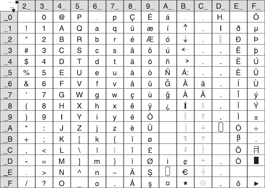
Generic code page
§
¥
Pt
°
Hex1st
2nd
C
tm
sm
R
Figure 44. Printer’s resident character set - generic code page
Updated April 2, 2009
Appendix C. Technical information 93
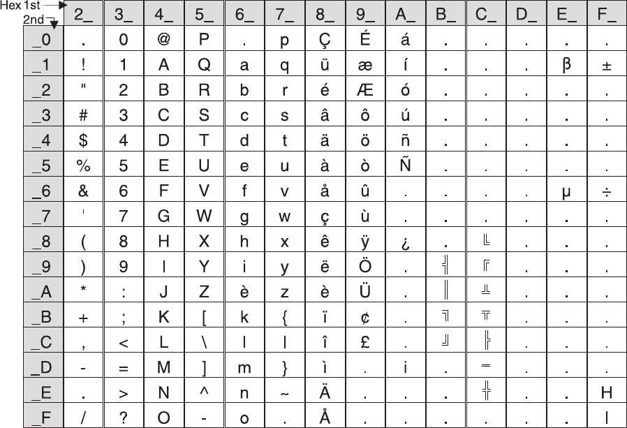
Code page 437
Figure 45. Code Page 437
Updated April 2, 2009
94 SureMark Printers User’s Guide
Code page 858
2_
.
!
"
#
$
%
&
'
(
)
*
+
,
-
.
/
_0
_1
_2
_3
_4
_5
_6
_7
_8
_9
_A
_B
_C
_D
_E
_F
3_
0
1
2
3
4
5
6
7
8
9
:
;
<
=
>
?
4_
@
A
B
C
D
E
F
G
H
I
J
K
L
M
N
O
5_
P
Q
R
S
T
U
V
W
X
Y
Z
[
\
]
^
-
6_
.
a
b
c
d
e
f
g
h
i
j
k
l
m
n
o
7_
p
q
r
s
t
u
v
w
x
y
z
{
|
}
~
.
8_
Ç
ü
é
â
ä
à
å
ç
ê
ë
è
ï
î
ì
Ä
Å
9_
É
æ
Æ
ô
ö
ò
û
ù
ÿ
Ö
Ü
ø
£
Ø
S
s
A_
á
í
ó
ú
ñ
Ñ
G
g
¿
.
.
.
.
i
.
.
C_
.
.
.
.
.
.
.
.
.
¤
E_
Ó
Ô
Ò
õ
Õ
µ
Þ
þ
Ú
Û
Ù
ý
Ý
.
.
F_
.
±
.
.
.
.
÷
.
.
.
.
.
.
H
I
Hex1st
2nd B_
.
.
.
.
.
Á
Â
À
I
¢
.
C
D_
ð
Ð
Ê
Ë
È
.
Í
Î
Ï
.
.
.
.
.
Ì
.
Figure 46. Code Page 858
Updated April 2, 2009
Appendix C. Technical information 95
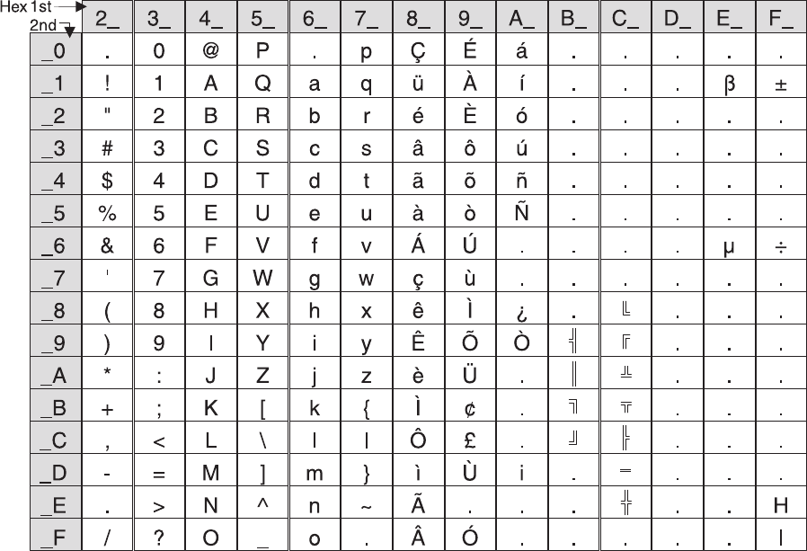
Code page 860
Figure 47. Code Page 860
Updated April 2, 2009
96 SureMark Printers User’s Guide
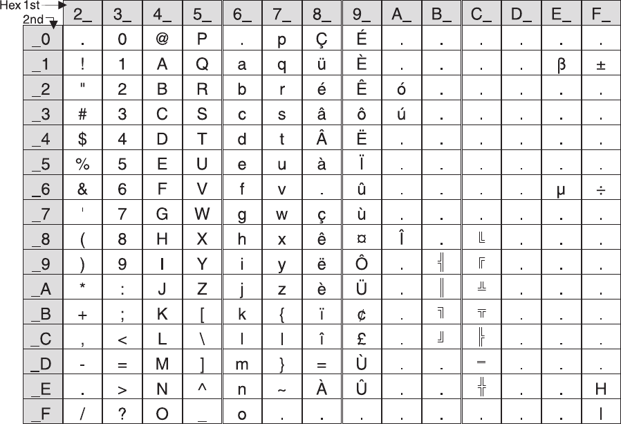
Code page 863
Figure 48. Code Page 863
Updated April 2, 2009
Appendix C. Technical information 97
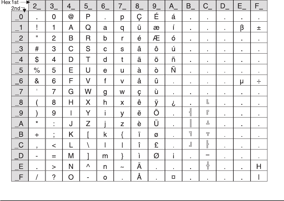
Code page 865
Character fonts
This section describes font capabilities. For more information about font-related
commands, see:
v“Download user-defined characters” on page 118
v“Set print station” on page 134
v“Set print mode” on page 129
v“Set code page” on page 135
v“Set intercharacter spacing” on page 135
v“Select user-defined or resident character sets” on page 134
Thermal printing font
There are three font sizes for the resident character set on Models TI3, TI4, TI8,
TI9, TG3, TG4, TG8, TG9, TF6, and TM6 (only fonts A and B are available for
Models TI1 and TI2):
vFont A is 10 dots (wide) × 20 dots (high) with the last 2-dot row used for
descenders.
(1.25 mm × 2.5 mm character height including descenders, 1.25 mm × 2.25 mm
excluding descenders)
vFont B is 12 dots (wide) × 24 dots (high) with the last 2-dot row used for
descenders.
(1.5 mm × 3.0 mm character height including descenders, 1.5 mm × 2.75 mm
excluding descenders)
Figure 49. Code Page 865
Updated April 2, 2009
98 SureMark Printers User’s Guide
vFont C is 8 dots (wide) × 16 dots (high) with the last 2-dot row used for
descenders.
(1.0 mm × 2.0 mm character height including descenders, 1.0 mm × 1.75 mm
excluding descenders)
vFont C, starting with level 38 micro code, is 8 dots (wide) and 20 dots (high) with
the last 2-dot row used for descenders.
(1.0 mm × 2.5 mm character height including descenders, 1.0 mm × 2.25 mm
excluding descenders)
The number of characters printed per inch depends on the character size, the
intercharacter spacing, and the chosen font. For example:
v17 cpi ⇒10-dot wide character + 2-dot space (font A) ⇒48 characters per line
v15 cpi ⇒10-dot wide character + 3-dot space (font A) ⇒44 characters per line
v12 cpi ⇒12-dot wide character + 5-dot space (font B) ⇒34 characters per line
v20 cpi ⇒8-dot wide character + 2-dot space (font C) ⇒57 characters per line
You can choose the character size of four user-defined character sets (code pages)
or two proportional fonts. The parameter ranges for user-defined character sets are:
v8≤dot width ≤16
v16 ≤dot height ≤32 (must be a multiple of 2)
The parameter ranges for characters in proportional fonts are:
v8≤dot width ≤32
v8≤dot height ≤32
Notes:
1. Any of the thermal printing fonts can be scaled up to eight times the defined
width and eight times the defined height. The scaling factor for the width does
not have to equal the scaling factor for the height. For example, you could
specify twice the width and five times the height.
2. For paper that has a width of 80 mm, the cash receipt print line is 72 mm (2.83
in.) long. There are 576 dots per line and 203 dots per inch.
Impact printing fonts (Models TI1, TI2, TI3, TI4, TI8, TI9, TG3, TG4, TG8,
and TG9)
The resident character set has a font of 7 half-dots (wide) × 9 dots (high). There are
no descenders.
vFont A prints 150 half-dots per inch = resident character size is 1.2 mm×2mm.
vFont B prints 120 half-dots per inch = resident character size is 1.5 mm×2mm.
The number of characters printed per inch depends on the character size, the
intercharacter spacing, and the chosen font. For example:
v17 cpi ⇒font A with 7 half-dot-wide character + 2 half-dot space ⇒52
characters per line
v15 cpi ⇒font A with 7 half-dot-wide character + 3 half-dot space ⇒47
characters per line
v12 cpi ⇒font B with 7 half-dot-wide character + 3 half-dot space ⇒37
characters per line
You can choose the character size of the two user-defined character sets (code
pages) within the following parameters:
v4≤half-dot width ≤16
v4≤dot height ≤16
Updated April 2, 2009
Appendix C. Technical information 99
Notes:
1. Any of the impact printing fonts can be printed double-wide, double-high, or both
double-wide and double-high unless the dot height is more than 9. With Models
TI1 and TI2, you can not print the character double-high if its dot height is more
than 9. For better print quality with double-high characters, set the printer to
unidirectional print mode. (See “Set or cancel unidirectional printing” on page
133.)
2. User-defined characters greater than 9 dots high can not be printed in
landscape mode.
3. The portrait document print line is 80.35 mm (3.16 inches) long. There are 474
half-dots per line for font A, and 379 half-dots per line for font B. The landscape
print line depends on the size of the document inserted.
4. You can print in two densities on the impact printer: 120 half-dots per inch or
150 half-dots per inch. Refer to the description of bits 0 and 1 in “Set print
mode” on page 129 for information about changing the density.
Updated April 2, 2009
100 SureMark Printers User’s Guide

Appendix D. EIA-232 programming information
EIA-232 commands summary by function...............104
Alphabetized EIA-232 commands summary ..............108
System commands .......................111
Exercise program ......................111
Verify previous commands completed ...............111
Status request........................112
Extended address command-request printer ID ...........112
Preset or Onetime-Set commands .................114
All models .........................114
Models TI8 and TI9 only ....................114
Download graphics (logo) commands ...............115
Predefine messages .....................117
Download user-defined characters ................118
Thermal code page ......................119
Proportional font .......................120
Impact code page ......................122
Flash storage write ......................123
Erase flash EPROM sector ...................123
Send checksum of flash EPROM sector ..............124
Microcode tolerance (MCT) information - loading ...........124
Microcode tolerance (MCT) information - request ...........125
Setup commands .......................129
Set print mode .......................129
Set or cancel double-wide mode .................130
Set or cancel double-high mode .................131
Set or cancel underline mode ..................131
Set or cancel overline mode ..................131
Set or cancel invert mode ...................131
Set or cancel emphasized printing ................132
Select maximum print speed ..................132
Set or cancel unidirectional printing ................133
Request document length for landscape print ............133
Set document length for landscape print ..............133
Set print station .......................134
Select user-defined or resident character sets ............134
Set code page .......................135
Set intercharacter spacing ...................135
Set or cancel rotated characters .................135
Set print station parameters...................136
Select 1/8-inch line spacing ...................136
Select 1/6-inch line spacing ...................136
Select color printing......................137
Set line spacing using minimum units ...............137
Set sheet eject length .....................138
Set horizontal tab positions ...................138
Set left margin position ....................138
Set relative position......................139
Align positions........................139
Set error recovery function ...................140
Define document wait time ...................141
Status sent to system .....................141
Select character for reprinted lines ................142
Re-initialize the printer.....................142
Updated April 2, 2009
© Copyright IBM Corp. 1997, 2006 101
Enable or disable the feed buttons ................143
Enable or disable the beeper (Models TF6 and TM6 only) .......143
Enable or disable upside-down printing ..............144
Select character size for scalable fonts ..............145
Fix font matrix........................146
Print logo inline .......................146
Select thermal paper .....................147
Bar code commands ......................147
Print bar code ........................147
Print bar code examples ...................152
Select horizontal size of bar code ................152
Select bar code height ....................152
Select printing position of human readable information (HRI) ......152
Select font for HRI ......................153
Print PDF417 bar code ....................153
Print PDF417 bar code using binary mode .............154
Select PDF417 ECC (error correction codewords) level ........154
Select aspect ratio PDF417 bar code ...............155
Enable PDF417 truncation ...................155
Print character commands ....................156
Print and line feed ......................156
Print and line feed ......................156
Print, form feed, and cut the paper (FF) ..............156
Print and feed paper n lines...................156
Print and feed paper using minimum units .............156
Print and feed paper in reverse using minimum units .........157
Print graphic messages .....................157
Select and print a graphics (logo) command.............157
Print predefined graphics (logo) command .............159
Print predefined messages ...................159
Miscellaneous commands ....................160
Tab to next tab stop .....................160
Return home (select print head location) ..............160
Paper cut/DI eject ......................161
Generate drive pulse for cash drawer ...............161
Retrieve the flash storage ...................161
Retrieve size of user flash storage ................162
Retrieve printer usage statistics .................162
Check processing commands (Models TI2, TI4, TI8, TI9, TG4, TG8, and TG9
only) ...........................164
Models TI8 and TI9 MICR read commands .............164
MICR read .........................165
Flip check .........................166
Document scanner commands...................166
Start scan .........................166
Print scanned image .....................168
Store scanned image and/or select partial image for retrieval ......169
Retrieve scanned image ....................172
Scanner calibration ......................173
Retrieve next image location ..................174
Retrieve first unread image location ................174
Select compression format and scanned image threshold ........174
Asynchronous (real-time) commands ................175
Real-time requests ......................175
Data buffer management and batch printing ..............176
Reset line count .......................176
Updated April 2, 2009
102 SureMark Printers User’s Guide
Disable line count ......................176
Hold printing until buffer is released ................177
Page mode printing commands ..................177
Select page mode ......................177
Select standard mode .....................177
Select printable area .....................178
Select printing direction/position .................178
Set vertical position......................178
Set relative vertical position ...................179
Set left margin position (standard mode), set absolute print position (page
mode) ..........................179
Set relative horizontal position ..................180
Set printing position......................180
Print and form feed and cut the paper ...............181
Print page in page mode ....................181
Clear print data in page mode ..................181
Document handling .......................181
Portrait mode ........................181
Landscape mode ......................182
Landscape printing commands ................183
Status summary .......................184
Message from the printer....................184
Status byte 1 ........................184
Status byte 2 ........................185
Status byte 3 ........................185
Status byte 4 ........................185
Status byte 5 ........................186
Status byte 6 ........................186
Status byte 7 ........................186
Status byte 8 ........................186
This information applies only to SureMark printers that attach to a POS system with
an EIA-232 cable connection.
If you use the RS-485 or USB communications interface, refer to either the
SureMark driver documentation in the appropriate IBM book for your operating
system (see Table 13) or, when using OPOS drivers, to the OLE for Retail POS
Application Programming Guide.
Table 13. Driver documentation by operating system
Operating System IBM Publication
4690 OS Version 1 and
Version 2
IBM 4690 OS API Specification for IBM 4610 Printers
DOS IBM Point-of-Sale Subsystem for DOS Programming
Reference
OS/2, Windows NT, Windows
95, and Windows 3.1x
IBM Point of Sale Subsystem Programming Reference and
User’s Guide
The 4690 OS manual is available on the current maintenance diskette for the IBM
4690 Operating System. Current versions of all three manuals are available on the
Internet. See “Resources on the Internet” on page 44 for more information.
Updated April 2, 2009
Appendix D. EIA-232 programming information 103

EIA-232 commands summary by function
The commands listed in Table 14 are described in detail in following sections of this
appendix.
Table 14. EIA-232 commands organized by function
Description Command Page
System Commands
Exercise Program ESC x or X'1B78' 111
Status request ESC v or X'1B76' 112
Extended address command
(request printer ID)
GS | SOH or X'1D4901' This is an IMMEDIATE command. 112
Verify previous commands
completed
X'1B008000' 111
Preset or Onetime-Set Commands
Download graphics (logo)
commands
GS * logo# n1 n2 data or X'1D2A';logo#;n1;n2;data 115
Predefine messages GS : message# data GS : or X'1D3A; message#;data;'X'1D3A' 117
Download user-defined characters ESC & s n m data or X'1B26;s;n;m;data' 118
Thermal code page MCT commands 119
Proportional font ESC & s n m data or X'1B26;s;n;m;data' 120
Flash storage write ESC ’ n1 n2 data or X'1B27;n1;n2;data' 123
Erase flash EPROM sector ESC # nor X'1B23;n' 123
Send checksum of flash EPROM
sector
ESC ″nor X'1B22;n' 124
Microcode tolerance (MCT)
information - loading
ESC M nhlor X'1B4D;n;h;l'. 124
Microcode tolerance (MCT)
information - request
ESC S nor X'1B53;n' 125
Setup Commands
Set print mode ESC ! nor X'1B21;n' 129
Set or cancel double-wide mode ESC W nor X'1B57;n' 130
Set or cancel double-high mode ESC h nor X'1B68;n' 131
Set or cancel underline mode ESC − nor X'1B2D;n': 131
Set or cancel overline mode ESC x‘5F’ nor X'1B5F;n' 131
Set or cancel invert mode ESC H nor X'1B48;n' 131
Set or cancel emphasized printing ESC G nor X'1B47;n' 132
Select maximum print speed ESC / nor X'1B;2F;n' 132
Set or cancel unidirectional
printing
ESC U nor X'1B55;n' 133
Set or cancel rotated character ESC V nor X'1B56;n' 135
Set print station ESC c 0 nor X'1B6330;n' 134
Select user-defined or resident
character sets
ESC % nor X'1B25;n' 134
Set code page ESC t nor X'1B74;n' 135
Set intercharacter spacing ESC SP nor X'1B20;n' 135
Updated April 2, 2009
104 SureMark Printers User’s Guide

Table 14. EIA-232 commands organized by function (continued)
Description Command Page
Set print station parameters ESC c 1 nor X'1B6331;n' 136.
Select 1/8-inch line spacing ESC 1 or X'1B31'. 136
Select 1/6-inch line spacing ESC 2 or X'1B32' 136
Select color printing ESC r nor X'1B72;n' 137
Set line spacing using minimum
units
ESC 3 nor X'1B33;n' 137
Set sheet eject length ESC C nor X'1B43;n' 138
Set horizontal tab positions ESC D [n1 n2] NUL NUL or X'1B44[n1 n2]0000' 138
Set left margin position ESC $ n1 n2 or X'1B24;n1;n2' 138
Set relative position ESC \ n1 n2 or X'1B5C;n1;n2' 139
Align positions ESC a nor X'1B61;n'. 139
Set error recovery function ESC c 4 nor X'1B63;34;n' 140
Define document wait time ESC f xyor X'1B66;x;y' 141
Status sent to system ESC ) nor X'1B29;n' 141
Select character for reprinted lines ESC + nor X'1B2B;n' 142
Re-initialize the printer ESC @ or X'1B40'. 142
Enable/disable the feed buttons ESCc5nX'1B6335;n' 143.
Enable/disable the beeper ESC BEL n1 n2 or X'1B07;n1;n2' 143
Enable/disable upside-down
printing
ESC { nor X'1B7B;n' 144
Select character size for scalable
fonts
GS ! nor X'1D21;n' 145
Fix font matrix ESC : nor X'1B3A n' 146
Print logo inline GS J d n1 n2 data or X'1D4A;d;n1;n2;data' 146
Enable/disable two-color printing GS ; nor X'1D3B;n' 147
Request document length for
landscape print
GS N X'02' Null or X'1D4E0200' 133
Set document length for
landscape print
GSc1nwhere n is 2 bytes indicating the length of the document
in print motor steps
133
Bar Code Commands
Print bar code GS k nNUL or X'1D6B;n;data;00' 147
Select horizontal size of bar code GS w nor X'1D77;n' 152
Select bar code height GS h nor X'1D68;n' 152
Select printing position of
human-readable information (HRI)
GS H nor X'1D48;n' 152
Select font for HRI GS f nor X'1D66;n' 153
Print PDF417 bar code GS P data NUL or X'1D50;data;00' 153
Print PDF417 bar code using
binary mode
GS U datalength data or X'1D;55;datalength;data;00' 154
Select PDF417 ECC Level GS R nor X'1D52;n1;n2' 154
Select Aspect Ratio PDF417 bar
code
GS S r;c or X'1D53;r;c' 155
Updated April 2, 2009
Appendix D. EIA-232 programming information 105

Table 14. EIA-232 commands organized by function (continued)
Description Command Page
Enable PDF417 truncation GS T nor X'1D54;n' 155
Print Character Commands
Print and line feed LF or X'0A' 156
Print and line feed CR or X'0D' 156
Print, form feed, and cut the paper
(FF)
FF or X'0C' 156
Print and feed paper n lines ESC d nor X'1B64;n' 156
Print and feed paper using
minimum units
ESC J nX'1B4A;n' 156
Print and feed paper in reverse
using minimum units
ESC K nX'1B4B;n' 157
Print Graphic Messages
Select and print a graphics (logo)
command
ESC * d w h data or X'1B2A;d;w;h;data' 157
Print predefined graphics (logo)
command
GS/m logo# or X'1D2F;m;logo#' 159
Print predefined messages GS ^ message# or X'1D5E;message#' 159.
Miscellaneous Commands
Tab to next tab stop HT or X'09' 160
Return home (select print head
location)
ESC <nor 1B3C;n 160
Paper cut/DI eject ESC i or ESC m -- X'1B69' or X'1B6D' 161
Generate drive pulse for cash
drawer
ESC p mn1n2or X'1B70;m;n1;n2' 161.
Retrieve the flash storage ESC 4 n1 n2 X'1B34;n1;n2' 161
Retrieve size of user flash storage ESC 4 x ’03 FF FF FF’ or X'1B3403FFFFFF' 162
Retrieve printer usage statistics X'1B51 xx' 162
Check Processing Commands
MICR read ESC I or X'1B49' 165
Flip check ESC 5 or X'1B35' 166
Document Scanner Commands
Start scan X'1B3E;n' 166
Print scanned image X'1B30;n1;x;y;dx;dy;s1;s2;n2' 168
Store scanned image X’1B41;n1;x0;y0;dx0;dy0;x1;y1;dx1;dy1;x2;y2;
dx2;dy2;x3;y3;dx3;dy3;tagdata’
169
Retrieve scanned image X'1B39;n1;n2;n3' 172
Scanner calibration GSc0orX'1D 63 30' 173
Retrieve next image location GS N SOH NULL or X'1D4E0100' 174
Retrieve first unread image
location
GS N SOH SOH or X'1D4E0101' 174
Select compression format and
scanned image threshold
X'1B4d;x;n1;n2' 174
Updated April 2, 2009
106 SureMark Printers User’s Guide
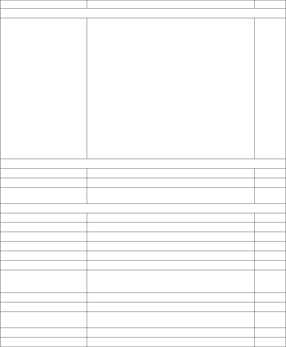
Table 14. EIA-232 commands organized by function (continued)
Description Command Page
Asynchronous (Real-Time) Commands
Real-time requests DLE ENQ nor X'1005n'
n Description
31 Release print buffer
32 Cancel print buffer
33 Undefined
34 EC request; send status
35 Undefined
36 Undefined
37 Undefined
38 Undefined
40 Reset printer
41 Enable unsolicited status
42 Disable unsolicited status
43 Disable transparent XON/XOFF
175
Data Buffer Management and Batch Printing
Reset line count ESC 6 or X'1B36' 176
Disable line count ESC 8 nor X'1B38'n 176
Hold printing until buffer is
released
ESC 7 or X'1B37' 177
Page Mode Printing Commands
Select page mode ESC L or X'1B4C' 177
Select standard mode ESC S or X'1B4f' 177
Select printable area ESC X or X'1B58;x;y;dx;dy' 178
Select printing direction/position ESC T nor X'1B54;n' 178
Set vertical position GS $ yor X'1D24;y' 178
Set relative vertical position GS \ yor X'1D5C;y' 179
Set left margin position (standard
mode), Set absolute print position
(page mode)
ESC $ n1 n2 or X'1B24;n1;n2' 179
Set relative horizontal position ESC <5C>h n1 n2 or X'1B5C;n1;n2' 180
Set printing position GS ] xyor X'1D5D;x;y' 180
Print and form feed and cut the
paper
FF or X'0C' 181
Print page in page mode ESC FF or X'1B0C' 181
Clear print data in page mode CAN or X'18' 181
Updated April 2, 2009
Appendix D. EIA-232 programming information 107

Alphabetized EIA-232 commands summary
Table 15. EIA-232 commands in alphabetical order
Description Command Page
Align positions ESC a nor X'1B61;n' 139
Clear print data in page mode CAN or X'18' 181
Disable line count ESC 8 nor X'1B;38'n 176
Define document wait time ESC f xyor X'1B66;x;y' 141
Download graphics (logo)
commands
GS * logo# n1 n2 data or X'1D2A;logo#;n1;n2;data' 115
Download user-defined characters ESC & s n m data or X'1B26;s;n;m;data' 118
Enable PDF417 truncation GS T nor X'1D;54;n' 155
Enable/disable the beeper ESC BEL n1 n2 or X'1B;07;n1;n2' 143
Enable/disable the feed buttons ESCc5nX'1B;63;35;n' 143.
Enable/disable two-color printing GS ; nor X'1D 3B n' 147
Enable/disable upside-down
printing
ESC { nor X'1B 7B n' 144
Erase flash EPROM sector ESC # nor X'1B23;n' 123
Exercise program ESC x or X'1B;78' 111
Extended address
command-request printer ID
GS | or X'1D49;01' 112
Fix font matrix ESC : nor X'1B 3A n' 146
Flash storage write ESC ’ n1 n2 data or X'1B27;n1;n2;data' 123
Flip check ESC 5 or X'1B35' 166
Generate drive pulse for cash
drawer
ESC p mn1n2or X'1B70;m;n1;n2' 161
Hold printing until buffer is released ESC 7 or X'1B37' 177
Impact code page MCT commands. 122
MICR read ESC I or X'1B49' 165
Microcode tolerance (MCT)
information - loading
ESC M nhlor X'1B4D;n;h;l' 124
Microcode tolerance (MCT)
information - request
ESC S nor X'1B53;n' 125
Paper cut/DI eject ESC i or ESC m or X'1B69' or X'1B;6D' 161
Predefine messages GS : message# data GS : or X'1D3A;message#;data;1D3A' 117
Print and feed paper n lines ESC d nor X'1B64;n' 156
Print and feed paper in reverse
using minimum units
ESC K nX'1B4B;n' 157
Print and feed paper using
minimum units
ESC J nor X'1B4A;n'
Print and form feed and cut the
paper
FF or X'0C' 181
Print and line feed LF or X'0A' 156
Print and line feed CR or X'0D' 156
Print bar code GS k nNUL or X'1D6B;n;data;00' 147
Updated April 2, 2009
108 SureMark Printers User’s Guide

Table 15. EIA-232 commands in alphabetical order (continued)
Description Command Page
Print logo inline GS J d n1 n2 data or X'1D 4A d n1 n2 data' 146
Print page in page mode ESC FF or X'1B 0C' 181
Print PDF417 bar code GS P data NUL or X'1D;50;data;00' 153
Print PDF417 bar code using binary
mode
GS U datalength data or X'1D;55;datalength;data;00' 154
Print predefined graphics (logo)
command
GS/m logo# or X'1D2F;m;logo#' 159
Print predefined messages GS ^ message# or X'1D5E;message#' 159
Print scanned image X'1B;30;n1;x;y;dx;dy;s1;s2;n2' 168
Proportional font ESC & s n m data or X'1B;26;s;n;m;data' 120
Real-time requests DLE ENQ mor X'1005n'
n Description
31 Release print buffer
32 Cancel print buffer
33 Undefined
34 EC request; send status
35 Undefined
36 Undefined
37 Undefined
38 Undefined
40 Reset printer
41 Enable unsolicited status
42 Disable unsolicited status
43 Disable transparent XON/XOFF
175
Re-initialize the printer ESC @ or X'1B40' 142
Request document length for
landscape print
GS N X'02' Null or X'1D;4E;02;00' 133
Reset line count ESC 6 or X'1B36' 176
Retrieve first unread image location GS N SOH SOH or X'1D 4E 01 01' 174
Retrieve next image location GS N SOH NULL or X'1D 4E 01 00' 174
Retrieve printer usage statistics X'1B 51 xx' 162
Retrieve scanned image X'1B;39;n1;n2;n3' 172
Retrieve size of user flash storage ESC 4 x ’03 FF FF FF’ or X'1B;34;03;FF;FF;FF' 162
Retrieve the flash storage ESC 4 n1 n2 X'1B34;n1;n2' 161
Return home (select print head
location)
ESC < nor X'1B3C;n' 160
Scanner calibration GSc0orX'1D 63 30' 173
Select and print a graphics (logo)
command
ESC * d w h data or X'1B2A;d;w;h;data' 157
Select aspect ratio PDF417 bar
code
GS S r;c or X'1D;53;r;c' 155
Updated April 2, 2009
Appendix D. EIA-232 programming information 109

Table 15. EIA-232 commands in alphabetical order (continued)
Description Command Page
Select bar code height GS h nor X'1D68;n' 152
Select character for reprinted lines ESC + nor X'1B2B;n' 142
Select character size for scalable
fonts
GS ! nor X'1D;21;n' 145
Select color printing ESC r nor X'1B;72;n' 137
Select compression format and
scanned image threshold
X'1B;4d;x;n1;n2' 174
Select font for HRI GS f nor X'1D66;n' 153
Select horizontal size of bar code GS w nor X'1D77;n' 152
Select page mode ESC L or X'1B;4C' 177
Select PDF417 ECC level GS R nor X'1D;52;n1;n2' 154
Select printable area ESC X or X'1B;58;x;y;dx;dy' 178
Select printing direction/position ESC T nor X'1B;54;n' 178
Select printing position of
human-readable information (HRI)
GS H nor X'1D48;n' 152
Select standard mode ESC S or X'1B;4f' 177
Select user-defined or resident
character sets
ESC % nor X'1B25;n' 134
Select 1/6-inch line spacing ESC 2 or X'1B32' 136
Select 1/8-inch line spacing ESC 1 or X'1B31' 136
Send checksum of flash EPROM
sector
ESC ″nor X'1B22;n' 124
Select maximum print speed ESC / nor X'1B;2F;n' 132
Set code page ESC t nor X'1B74;n' 135
Set document length for landscape
print
GSc1nwhere n is 2 bytes indicating the length of the document
in print motor steps
133
Set error recovery function ESC c 4 nor X'1B63;34;n' 140
Set horizontal tab positions ESC D [n1 n2] NUL NUL or X'1B44[n1n2]0000' 138
Set intercharacter spacing ESC SP nor X'1B20;n' 135
Set left margin position ESC $ n1 n2 or X'1B24;n1;n2' 138
Set left margin position (standard
mode), Set absolute print position
(page mode)
ESC $ n1 n2 or X'1B;24;n1;n2' 179
Set line spacing using minimum
units
ESC 3 nor X'1B33;n' 137
Set or cancel double-high mode ESC h nor X'1B68;n' 131
Set or cancel double-wide mode ESC W nor X'1B57;n' 130
Set or cancel emphasized printing ESC G nor X'1B47;n' 132
Set or cancel invert mode ESC H nor X'1B48;n' 131
Set or cancel overline mode ESC x‘5F’ nor X'1B5F;n' 131
Set or cancel rotated character ESC V nor X'1B56;n' 135
Set or cancel underline mode ESC − nor X'1B2D;n' 131
Set or cancel unidirectional printing ESC U nor X'1B55;n' 133
Updated April 2, 2009
110 SureMark Printers User’s Guide

Table 15. EIA-232 commands in alphabetical order (continued)
Description Command Page
Set print mode ESC ! nor X'1B21;n' 129
Set print station parameters ESC c 1 nor X'1B63;31;n' 136
Set print station ESC c 0 nor X'1B63;30;n' 134
Set printing position GS ] xyor X'1D;5D;x;y' 180
Set relative horizontal position ESC <5C>h n1 n2 or X'1B;5C;n1;n2' 180
Set relative position ESC \ n1 n2 or X'1B5C;n1;n2' 139
Set relative vertical position GS \ yor X'1D;5C;y' 179
Set sheet eject length ESC C nor X'1B43;n' 138
Set vertical position GS $ yor X'1D;24;y' 178
Start scan X'1B;3E;n' 166
Status request ESC v or X'1B76' 112
Status sent to system ESC ) nor X'1B29;n' 141
Store scanned image X’1B;41;n1;x0;y0;dx0;dy0;x1;y1;dx1;dy1;x2;y2;
dx2;dy2;x3;y3;dx3;dy3;tagdata’
169
Tab to next tab stop HT or X'09' 160
Thermal code page MCT commands; see Table 17 on page 125. 119
Verify previous commands
completed
X'1B;00;80;00' 111
System commands
Exercise program
EIA-232 Syntax:
ESC x or X'1B;78'
Purpose:
This tests printing functions of the printer. A test message is printed. (See
Figure 36 on page 64.) If there is a document in the printer, the test
message prints on the document. Otherwise, it prints at the customer
receipt station.
Error Conditions:
Home Error (on document station only)
Cash Receipt Print Error
Verify previous commands completed
EIA-232 Syntax:
X'1B;00;80;00'
Purpose:
This command can be used to ensure that all commands preceding it have
been completed. The application would just wait for the status return with
status byte 5, bit 1 set.
Updated April 2, 2009
Appendix D. EIA-232 programming information 111
Remarks:
The printer status is returned in status bytes 1–8. Status byte 5, bit 1 is set
after this request has been executed. See “Status summary” on page 184
for more information.
Error Conditions:
None.
Status request
EIA-232 Syntax:
ESC v or X'1B;76'
Purpose:
The printer status is sent to the system. This command will be processed in
the order it was received.
Remarks:
The printer status is returned in status bytes 1–8. See “Status summary” on
page 184 for more information.
Error Conditions:
None.
Extended address command-request printer ID
EIA-232 Syntax:
GS | SOH or X'1D;49;01'
Purpose:
This will return 8 bytes of printer status plus 5 bytes of printer-specific
information.
Status byte 5, bit 0 is set to 1 when responding to the extended address
command. (See “Status summary” on page 184.)
where:
Byte 1
vDevice type = X'30' for non-TI8/TG8 or TI9/TG9 models and for
Model TI8/TG8 or TI9/TG9 in TI4 mode
vDevice type = X'31' TI8/TG8 or TI9/TG9 models in TI8 or TI9
mode
Byte 2
Device ID
00 Models TI1 and TI2 (impact DI/thermal CR)
01 Models TI3, TI4, TI8, TI9, TG3, and TG4 (high speed;
impact DI/thermal CR)
02 Models TI3, TI4, TG3. and TG4 with the 2 MB option
03 Models TF6 and TM6 (512K; thermal CR)
04 Models TI3, TI4, TG3, and TG4 with the 8 MB option
05 Models TF6 and TM6 with the 8 MB option
06 Reserved
07 Models TF6 and TM6 with the 2 MB option
Updated April 2, 2009
112 SureMark Printers User’s Guide
Byte 3
First byte of features
Bit 0
vWhen byte 1 = X'30': Set to 1 when MICR is present
vWhen byte 1 = X'31': Reserved
Bit 1
vWhen byte 1 = X'30': Set to 1 when Check Flipper is
present
vWhen byte 1 = X'31': Reserved
Bit 2
vWhen byte 1 = X'30': Set to 1 when the printer has the 2
MB option
vWhen byte 1 = X'31': Reserved
Bit 3 Set to 1 when the printer is in XON/XOFF mode
Bit 4 Reserved
Bit 5
vWhen byte 1 = X'30': Set to 1 when the 2 MB option is
used for user flash memory
vWhen byte 1 = X'31': Reserved
Bit 6 Set to 1 when two-color printing is enabled.
Bit 7 Set to 1 when the printer is in Model 4 emulation mode.
Byte 4
Second byte of features
Bit 0 Set to 1 when printer is set for 58 mm paper
Bit 1 Set to 1 if Model TI8/TG8 or TI9/TG9 is in TI4 mode when
byte 1 is set to X'30'
Bit 2 Set to 1 if full scanning Model TI9 or TG9 printer
Bit 3 Set to 1 when the USB interface is internal to the printer
Bits 4
Set to 1 when the printer is an RPQ, which disables the
scanner
Bits 5–7
Reserved
Byte 5
EC level = EC level of loaded code
Error Conditions:
None.
Remarks:
This is an IMMEDIATE command.
Updated April 2, 2009
Appendix D. EIA-232 programming information 113

Preset or Onetime-Set commands
All models
The SureMark printer has commands to specialize and tune each printer to improve
its usability, performance, and uniqueness. This flexibility is provided through the
use of flash erasable programmable read-only memory (flash EPROM) and an
electrically erasable programmable read-only memory (EEPROM). Data in these
memory devices will stay valid until it is redefined. This information only needs to be
defined once because it will remain for the life of the printer or until it is redefined.
To verify that data was previously stored in the printer, the system can request a
checksum on data stored in each sector.
Flash EPROM has 5 sectors. To rewrite information in a sector, you must first erase
the sector.
vFor logo commands and predefined messages, erasing the sector is necessary
only to replace a logo or predefined message number, or when the length of the
logo or message exceeds space available in that sector.
vFor user flash memory, erasing the sector is necessary only when writing to an
address that has already been written to.
vFor user-defined thermal and impact characters, new characters can be added if
they have the same matrix as characters already in the character set. If new
character sets are added, the flash memory does not have to be erased. To
replace characters, you must first erase the sector.
Sector Function
1Download graphics (logo) Commands
2Predefined Messages
3Two user-defined impact character sets
4User-defined thermal character set: four fixed matrix or 2 proportional
5User Flash Memory
The EEPROM stores microcode tolerances (MCT) values.
Models TI8 and TI9 only
Note: Model TG8 is equivalent to TI8 and Model TG9 is equivalent to TI9.
Models TI8 and TI9 provide five functions with which you can store and define data.
They are:
vUser-defined thermal characters
vUser-defined impact characters
vLogos
vPredefined messages
vUser storage
vScanned image storage
This allows greater flexibility in allocating memory because you can allocate
additional memory for one function that has not been used by another function.
Updated April 2, 2009
114 SureMark Printers User’s Guide

There are twenty-two 64 KB sectors, for a total of 1.4 MB of flash memory available
for allocation. The MCT value represents the number of 64 KB sectors assigned to
the respective function. The amount of memory allocated to each function is
specified by the value stored in its respective MCT location.
The user-defined thermal characters and user-defined impact characters are limited
to one 64 KB sector each.
To change the memory allocation for any function, all memory partitions must be
erased. If memory is not erased, an MCT write error status is returned. After the
MCT values are written, the new ones take effect only after a reset. The new
memory allocations begin with the lowest MCT address and increment up. Memory
is allocated until all requests are satisfied or until all memory has been used.
Table 16. Memory allocation for Models TI8 and TI9 functions
Function Default memory allocation MCT location
User-defined impact
characters
64 KB X'A0'
User-defined thermal
characters
64 KB X'A1'
Logos 64 KB X'A2'
Predefined messages 64 KB X'A3'
User memory 128 KB X'A4'
Scanned image storage 1 MB X'A5'
Download graphics (logo) commands
EIA-232 Syntax:
GS*logo# n1 n2 data or X'1D;2A;logo#;n1;n2;data'
where:
logo# The logo number being stored.
vrange=1to40forallmodels except TI8 and TI9
vrange=1to255forModels TI8 and TI9
n1 One-eighth the number of dots in the horizontal direction (width = 8
× n1).
range=1to72forathermal logo.
range=1to59foranimpact logo.
n2 One-eighth the number of dots in the vertical direction (height=8×
n2).
range=1to255forathermal logo.
range=1to5foranimpact logo.
data The data to form the graphics image. The number of data bytes for
the image is n1×n2×8
Purpose:
To store all-points-addressable print messages.
Updated April 2, 2009
Appendix D. EIA-232 programming information 115
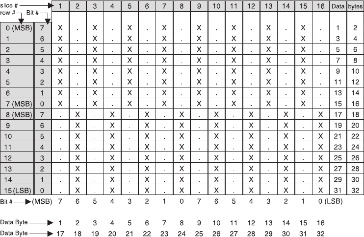
Remarks:
These messages can be positioned on the page using the commands for
setting positions.
Decimal values are shown, but all parameter values (logo number, n1, n2)
must be hex values when sent to the printer.
The dot density of these messages is specified when the message is
printed. See “Print predefined graphics (logo) command” on page 159.
The total number of data bytes defined for all (up to 40) defined graphics
messages must be less than 65 376 in all models except TI8 and TI9, in
which the value is user-defineable.
If the parameters logo#,n1,orn2 are out of range, the command is
discarded and its remaining data is processed as print data.
This command should be sent only when the data buffer is empty. See the
description of bit 6 in “Status byte 2” on page 185.
Images for the thermal logo commands will be defined by one-dot-high rows
(horizontal slices), and the impact will be defined by eight-dot-high rows
(vertical slices).
This command can be used to print signature captures at the printer.
1. Capture the signature as a bitmap.
2. Convert the bitmap to a series of graphics (logo) messages.
3. Hold the printer’s buffer.
4. Send the graphics messages to the printer.
5. Release the printer’s buffer.
Note: For a thermal graphic message that is 24 dots high, across the page (n1 =
72, n2 = 3) takes over 2000 bytes of data.
Example: n1=2&n2=2
Updated April 2, 2009
116 SureMark Printers User’s Guide
For Thermal Graphics - Defined as:
X'1D2A010202AAAAAAAAAAAAAAAAAAAAAAAAAAAAAAAA
55555555555555555555555555555555'
For Impact Graphics - Defined as:
X'1D2A020202FF00FF00FF00FF00FF00FF00FF00FF00
00FF00FF00FF00FF00FF00FF00FF00FF'
Error Conditions:
Flash EPROM load error - Verify the sector was erased before downloading
images.
Memory sector is full - The sector can store up to 64 KB of graphics data,
after which the sector is full.
Predefine messages
EIA-232 Syntax:
GS:message# data GS : or X'1D3A;message#;data;1D3A'
where:
message# The message number being stored.
range is 1 to 25 for all models except TI8 and TI9
range is 1 to 255 for Models TI8 and TI9
data All data and commands to be included in this message. No
immediate commands can be included in the data.
Purpose:
To store predefined messages. This cuts transmission time. This is where
you can store the header and the trailer of receipts, for example.
Remarks:
vAfter a ″GS :″occurs, all incoming commands are stored in the message
until another ″GS :″occurs.
v“Print predefined graphics (logo) command” on page 159 can be included
in this command.
vThe size of all predefined messages can not exceed 8000 bytes for all
models except TI8 and TI9, in which the value is user-defineable.
Example:
Store a trailer message:
X'1D3A01'
’Thank You For Shopping’ X'0D'
’ At RSD STORE’ X'0D'
’Store #1234567’ X'0D'
X'1D3A'
This would store this message as predefined message 1. See “Print
predefined messages” on page 159 for printing this trailer message.
Commands for selecting the print station and print characteristics must be
included with the stored message.
Limitations:
Updated April 2, 2009
Appendix D. EIA-232 programming information 117
v“Print predefined graphics (logo) command” on page 159 can be included
in this command. Select and print a graphics command can not be used.
See “Print graphic messages” on page 157.
v“Print predefined messages” on page 159 can be included in this
command, but can only be nested one message deep.
Example: Store a predefined message (’Jane Doe’) at location 3, then
issue the following commands:
1. X'1D3A06'
2. ’Welcome to Our Store’ X'0D'
3. X'1D5E03' (This prints the message that has been stored at location
3. The message can not have a X'1D5Exx' in it, because that would
be more than one level of nesting.)
4. ’Is Your Cashier Today’ X'0D'
5. X'1D3A'
Using the stored message and the above commands, the resulting text
will be:
Welcome to Our Store
Jane Doe Is Your Cashier Today
vThese commands can not be included in the predefined message:
– “Define document wait time” on page 141.
– “Select character for reprinted lines” on page 142.
– “Set sheet eject length” on page 138.
– “Select and print a graphics (logo) command” on page 157.
vThis command should be sent only when the data buffer is empty. See
the description of bit 6 in “Status byte 2” on page 185.
Error Conditions:
Flash EPROM load error - Verify the sector was erased before downloading
the messages.
Memory sector is full
Download user-defined characters
EIA-232 Syntax:
ESC & snmdataor X'1B26;s;n;m;data'
where:
sThe character set being defined.
1User-defined thermal code page 1
2User-defined thermal code page 2
3User-defined thermal code page 3
4User-defined thermal code page 4
5User-defined impact code page 1
6User-defined impact code page 2
nThe beginning ASCII address of the characters being defined.
mThe ending ASCII address of the characters being defined.
data The slice data for the defined characters. Note the number of bytes
is determined by which code page is being defined and the
character matrix of that code page.
Updated April 2, 2009
118 SureMark Printers User’s Guide
Purpose:
To define a matrix pattern for user-definable code pages stored in flash
EPROM.
Remarks:
vAfter characters are downloaded to the printer, they remain valid until you
redefine them. This is true even if power to the printer is removed.
vBefore the characters are defined, the sector of the flash EPROM which
stores this data must be erased. (See “Erase flash EPROM sector” on
page 123.) Also, the character matrix for the code page must have
already been defined. (See Table 17 on page 125, MCT# 3, 4, and 5.)
vFlash EPROM sector 4 contains all user-defined code pages for the
thermal print head. To redefine a code page, you must erase and
reprogram all of them.
vFlash EPROM sector 3 contains both user-defined code pages for the
impact print head. To redefine a code page, you must erase and
reprogram both of them.
vThermal height must be even.
vThere is no way to redefine one character only. You must redefine a
whole code page.
vIf the parameter s,n,ormis out of range, the command is discarded
and the remaining data is processed as print data.
vThis command should be sent only when the data buffer is empty. See
the description of bit 6 in “Status byte 2” on page 185.
vASCII characters 0 through 31 are reserved for EIA-232 functions and
can not be defined.
Thermal code page
You define the character matrix for each code page with MCT #2, MCT #3, MCT
#23, and MCT #24 for thermal code pages 1, 2, 3, and 4, respectively. See
Table 17 on page 125.
The number of data bytes per character loaded is 2 × the character height. The
total number of data bytes for this command is 2 × the character height × (1+m−n).
Updated April 2, 2009
Appendix D. EIA-232 programming information 119
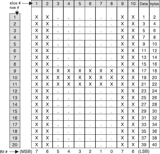
Example: 10 wide × 20 high
Defined as:
X'1B26014848 C0C0C0C0C0C0C0C0C0C0C0C0C0C0FFC0FFC0F
C0C0C0C0C0C0C0C0C0C0C0C0C0C0C0C0C0C0'
The above statement defines character X'48' as an ’H’.
Note: The number of data bytes=2×dotheight (20) = 40 bytes.
Proportional font
This command is supported only for Models TI3, TI4, TI8, TI9, TG3, TG4, TG8,
TG9, TF6 and TM6.
EIA-232 Syntax:
ESC & snmdataor X'1B;26;s;n;m;data'
where:
sThe character set being defined.
1User-defined thermal code page 1.
3User-defined thermal code page 3.
nThe beginning ASCII address of the characters being defined.
mThe ending ASCII address of the characters being defined.
data The height and width of the character, and the matrix pattern for the
data. The number of data bytes is (m−n+1) × (2+wb×32).wb is
defined in the MCT command.
Purpose:
To download and print proportional fonts (True Type fonts) in the thermal
station. Each character in the code page has its own unique width and
height. The matrix must be within the following ranges:
Updated April 2, 2009
120 SureMark Printers User’s Guide
Width 8≤width ≤32
Height
8≤width ≤32
Remarks:
vProportional and standard fonts may be used on the same line. If both
types of fonts are used on a line, you would probably use proportional
fonts for the description and resident fonts for the amounts.
vFor alignment, a command that will allow right and left alignment on the
same line may be used. This will allow the user to align a column
(decimal point) on the right, and still be left-aligned. (See “Align positions”
on page 139.)
vOnce characters are downloaded to the printer, they remain valid until
you redefine them. This is true even if power to the printer is removed.
vBefore the characters are defined, the sector of the flash EPROM which
stores this data must be erased. (See “Erase flash EPROM sector” on
page 123.)
vThere is no way to redefine one character only. You must redefine a
whole code page.
vIf the parameter s,n,ormis out of range, the command is discarded
and the remaining data is processed as print data.
vThis command should be sent only when the data buffer is empty. See
the description of bit 6 in “Status byte 2” on page 185.
vASCII characters 0 through 31 are reserved for EIA-232 functions and
can not be defined.
vSee Appendix F, “Proportional fonts,” on page 189 for suggestions about
how to implement proportional fonts.
Limitations:
The memory required for proportional fonts is much greater than the
memory that was required for user-defined fonts. Therefore, when code
page 1 (or 3) is set up as proportional, code page 2 (or 4) is not valid.
You can not set up code page 2 or code page 4 as a proportional font.
To download the font:
1. Store the code page matrix as an MCT value. Use the command X'1B
4D x 55 wb' where:
xX'02' for thermal code page 1, X'17' for thermal code page 3
wb The number of bytes, which is also 1⁄8 the number of dots, in
the width of the widest character. The valid range is 2≤wb≤4.
2. Erase the existing character set using the command X'1B 23 04'.
3. Use the Proportional Font command to download the font.
Example:
To define an A to code page 1 when wb is set to 02, enter the following:
X'1B260141410C16'
X'0F001F803FC070E06060C030C030C030C030C030C030'
X'C030FFF0FFF0C030C030C030C030C030C030C030'
X'C030000000000000000000000000000000000000000000'
This command specifies a character width of 12 dots (X'0C') and a
character height of 22 dots (X'16'). Following the width and height are 64
Updated April 2, 2009
Appendix D. EIA-232 programming information 121
bytes that define the character. If, as in this case, the character is defined
before all 64 bytes have been used, the rest of the bytes are filled with X'0'
(see Figure 50).
Note: If wb were set to 03, then the total number of data bytes would be
98 (3×32+2)
Impact code page
You define the character matrix for each code page with MCT #4 for impact code
page 1 and MCT #5 for impact code page 2. See Table 17 on page 125.
If the matrix defines the characters as 9 dots high or less, a print line will be printed
in one pass of the print head. When the matrix is defined as greater than 9 dots
high, it takes two passes of the print head per print line.
Landscape printing is limited to characters with a height of 9 dots or less. If
user-defined characters are to be used in landscape print mode, they must be less
than 10 dots high.
The number of data bytes per character loaded is 2 × character width. The total
number of data bytes for this command is 2 × character width × (1+m−n). Each
slice is defined with two bytes; the most significant bit (MSB) of each slice is the
bottom of the character.
0000111100000000
0001111110000000
0011111111000000
0111000011100000
0110000001100000
1100000000110000
1100000000110000
1100000000110000
1100000000110000
1100000000110000
1100000000110000
1100000000110000
1111111111110000
1111111111110000
1100000000110000
1100000000110000
1100000000110000
1100000000110000
1100000000110000
1100000000110000
1100000000110000
1100000000110000
0000000000000000
0000000000000000
0000000000000000
0000000000000000
0000000000000000
0000000000000000
0000000000000000
0000000000000000
0000000000000000
0000000000000000
0F00
1F80
3FC0
70E0
6060
C030
C030
C030
C030
C030
C030
C030
FFF0
FFF0
C030
C030
C030
C030
C030
C030
C030
C030
0000
0000
0000
0000
0000
0000
0000
0000
0000
0000
1
2
3
4
5
6
7
8
9
10
11
12
13
14
15
16
17
18
19
20
21
22
23
24
25
26
27
28
29
30
31
32
row #
Figure 50. Proportional font example
Updated April 2, 2009
122 SureMark Printers User’s Guide
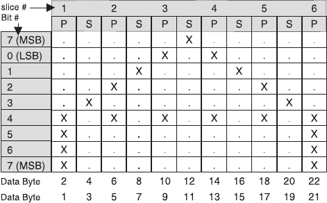
When defining wire patterns, the same wire does not fire in consecutive, primary (P)
and secondary (S) positions. (The printer does not check for errors in defining the
character.) If the character is defined with dots in consecutive positions only one of
the dots is fired.)
Example: 11 half-dots wide (or 5.5 full dots) × 9 high
Defined as:
X'1B26034141FO00080014000200110000081100020014000800F000'
The above statement defines character X'41' as an ‘A’.
Note: The number of data bytes=2×dotwidth (11) = 22 bytes.
Error Conditions:
Flash EPROM load error - Verify the sector was erased before downloading
images.
Flash storage write
EIA-232 Syntax:
ESC ’ n1 n2 data or X'1B;27;n1;n2;data'
where:
n1 = number of data bytes to store
n2 = 3-byte address where data bytes are to be stored
Error Conditions:
Flash EPROM load error - Verify the sector was erased before downloading
images.
Remarks:
The valid address range for each SureMark depends on the model number
and which memory option, if any, is installed. Use “Retrieve size of user
flash storage” on page 162 to determine the valid range for your printer.
The command is rejected when the address is out of range.
The flash EPROM is guaranteed for a minimum life of 100,000 write/erase
commands by the Flash manufacturer.
Erase flash EPROM sector
EIA-232 Syntax:
ESC # nor X'1B;23;n'
Updated April 2, 2009
Appendix D. EIA-232 programming information 123
where:
n
01 downloaded graphics
02 predefined messages
03 user-defined impact character set
04 user-defined thermal character sets
05 flash storage
06-07
Reserved
08 Scanned image storage area
09-FF
Reserved
Purpose:
To erase the flash EPROM before downloading the data into the printer.
Remarks:
The command should only be sent to the printer when the buffer is empty
(status byte 2, bit 6). No other commands should be sent until this
command is complete.
Status byte 3, bit 7 (command complete bit) is set to show erasing is
finished and the command is complete.
The flash EPROM is guaranteed for a minimum life of 100,000 write/erase
commands by the Flash manufacturer.
Send checksum of flash EPROM sector
EIA-232 Syntax:
ESC ″nor X'1B;22;n'
where:
n=
01 downloaded graphics
02 predefined messages
03 user-defined impact character set
04 user-defined thermal character sets
05 flash storage
06 Reserved
Purpose:
To verify data integrity of the data loaded in the flash EPROM in the printer.
A 2-byte checksum is returned.
Microcode tolerance (MCT) information - loading
EIA-232 Syntax:
ESC M nhlor X'1B;4D;n;h;l'
where:
nMicrocode tolerance (MCT) that is being adjusted
Updated April 2, 2009
124 SureMark Printers User’s Guide

hThe high-order byte of MCT data
lThe low-order byte of MCT data
Purpose:
The microcode tolerance (MCT) information is used to make adjustments to
the printer’s microcode. MCT data is nonvolatile data stored in the printer
EPROM that is specific to a printer. For example, an MCT parameter can
be defined to adjust for mechanical tolerances which cause a print line to
not be centered on a receipt. Another would be for adjusting for the number
of motor steps to the first print position on a document. This data remains
intact until changed by the user.
Remarks:
Table 17 lists the MCT values by the parameter (n). The table includes the
default, the minimum, and the maximum values of each MCT.
If you try to set an MCT value out of its defined range, it is set to the
closest limit (the minimum or maximum value) or rejected.
Error Conditions:
EPROM load error
Microcode tolerance (MCT) information - request
EIA-232 Syntax:
ESC S nor X'1B;53;n'
where:
nMicrocode tolerance (MCT) information that is being requested
Purpose:
To enable reading MCT information from EEPROM.
Remarks:
vMCT data is sent over the serial line in status bytes 9 and 10. See
Table 17 for the values of parameter n.
vMCT write command values that are out of range cause the command to
be rejected. (See bit 7 of “Status byte 1” on page 184.)
Table 17. MCT command definitions
DEC HEX MCT Default Min Max
2 2 Matrix of user-defined thermal code page
1
Byte 1: Dot row width
Byte 2: Dot row height
X'0A14'
(10x20)
X'0810' X'1020'
(16x32)
3 3 Matrix of user-defined thermal code page
2
Byte 1: Dot row width
Byte 2: Dot row height
X'0A14'
(10x20)
X'0810' X'1020'
(16x32)
4 4 Matrix of user-defined impact code page
1
Byte 1: Half-dot row width
Byte 2: Dot row height
X'0707'
(07x07)
X'0404' X'1010'
(16x16)
Updated April 2, 2009
Appendix D. EIA-232 programming information 125

Table 17. MCT command definitions (continued)
DEC HEX MCT Default Min Max
5 5 Matrix of user-defined impact code page
2
Byte 1: Half-dot row width
Byte 2: Dot row height
X'0707'
(07x07)
X'0404' X'1010'
(16x16)
6-22 6-16 Reserved - ATTENTION: Changing these values might damage the printer.
23 17 Matrix of user-defined thermal code page
3
Byte 1: Dot row width
Byte 2: Dot row height
X'0A14'
(10x20)
X'0810' X'1020'
(16x32)
24 18 Matrix of user-defined thermal code page
4
Byte 1: Dot row width
Byte 2: Dot row height
X'0A14'
(10x20)
X'0810' X'1020'
(16x32)
25-29 19-1D Reserved - ATTENTION: Changing these values might damage the printer.
30 1E Mode options
Bits 0–12
Reserved for future use, should
be left at 1
Bit 13: (DI portrait mode only)
v1 = Line feeds NOT executed
until DI ready. (non-IBM
mode)
v0 = Line feeds are executed
without regard for the state of
DI ready. (IBM mode)
Bit 14:
v1 = Normal operations (IBM
mode)
v0 = Switch order of font A
and font B (non-IBM mode)
Bit 15:
v0 = Disable CR (X'0D') in CR
station. No line feeds in DI.
(non-IBM mode)
v1 = Normal operations. Treat
CR (X'0D') the same as line
feeds (X'0A'). (IBM mode)
X'FFFF' N/A N/A
31–53 1F–35 Reserved – IMPORTANT: Changing these values might change the printer function.
Updated April 2, 2009
126 SureMark Printers User’s Guide
Table 17. MCT command definitions (continued)
DEC HEX MCT Default Min Max
54 36 TI8 and TI9 only: Reserved – IMPORTANT: Changing these values might change the
printer function.
TI3, TI4, TI6, TM6, TF6, and TI7:
Bits 9–15:
Reserved for future use, should
be left at 1
Bit 8:
v1 = Function disabled
v0 = DBCS page mode,
underline moved up two dot
rows
Bits 2–7:
Reserved for future use
Bit 1:
v1 = Function disabled
v0 = CR; paper is cut when
button is pressed for at least
120 motor steps
Bit 0:
v1 = No mapping of user flash
storage
v0 = Map user flash storage to
logo space
X'FFFF' X'0000' X'FFFF'
55–159 37–9F Reserved – IMPORTANT: Changing these values might damage the printer.
160 A0 User-defined impact character memory
allocation
X'0001' X'0000' X'FFFF'
161 A1 User-defined thermal character memory
allocation
X'0001' X'0000' X'FFFF'
162 A2 User-defined Logos X'0001' X'0000' X'FFFF'
163 A3 Predefined messages memory allocation X'0001' X'0000' X'FFFF'
164 A4 User flash storage memory allocation X'0002' X'0000' X'FFFF'
165 A5 Scanned image storage memory
allocation
X'0010' X'0000' X'FFFF'
166–175 A6–AF Reserved
176 B0 Scan1storage template #1 predefined
location X0
177 B1 Scan1storage template #1 predefined
location Y0
178 B2 Scan1storage template #1 predefined
location DX0
179 B3 Scan1storage template #1 predefined
location DY0
180 B4 Scan1storage template #1 predefined
location X1
Updated April 2, 2009
Appendix D. EIA-232 programming information 127

Table 17. MCT command definitions (continued)
DEC HEX MCT Default Min Max
181 B5 Scan1storage template #1 predefined
location Y1
182 B6 Scan1storage template #1 predefined
location DX1
183 B7 Scan1storage template #1 predefined
location DY1
184 B8 Scan1storage template #1 predefined
location X2
185 B9 Scan1storage template #1 predefined
location Y2
186 BA Scan1storage template #1 predefined
location DX2
187 BB Scan1storage template #1 predefined
location DY2
188 BC Scan1storage template #1 predefined
location X3
189 BD Scan1storage template #1 predefined
location Y3
190 BE Scan1storage template #1 predefined
location DX3
191 BF Scan1storage template #1 predefined
location DY3
192 C0 Scan1storage template #2 predefined
location X0
193 C1 Scan1storage template #2 predefined
location Y0
194 C2 Scan1storage template #2 predefined
location DX0
195 C3 Scan1storage template #2 predefined
location DY0
196 C4 Scan1storage template #2 predefined
location X1
197 C5 Scan1storage template #2 predefined
location Y1
198 C6 Scan1storage template #2 predefined
location DX1
199 C7 Scan1storage template #2 predefined
location DY1
200 C8 Scan1storage template #2 predefined
location X2
201 C9 Scan1storage template #2 predefined
location Y2
202 CA Scan1storage template #2 predefined
location DX2
203 CB Scan1storage template #2 predefined
location DY2
Updated April 2, 2009
128 SureMark Printers User’s Guide
Table 17. MCT command definitions (continued)
DEC HEX MCT Default Min Max
204 CC Scan1storage template #2 predefined
location X3
205 CD Scan1storage template #2 predefined
location Y3
206 CE Scan1storage template #2 predefined
location DX3
207 CF Scan1storage template #2 predefined
location DY3
Notes:
1. See “Store scanned image and/or select partial image for retrieval” on page 169
Setup commands
Setup commands change character font, intercharacter spacing, and the target print
station.
Set print mode
EIA-232 Syntax:
ESC ! nor X'1B;21;n'
where:
nSpecifies print characteristics, such as user-defined thermal and
impact code pages.
Bit Number Function Bit=0 Bit=1 Thermal Impact
(LSB) 0 Char/Page 0 See Below See Below yes yes
1 Char/Page 1 See Below See Below yes yes
2 Overline Cancel Set yes no
3 Emphasized Cancel Set yes yes
4 Double-high Cancel Set yes yes
5 Double-wide Cancel Set yes yes
6 Inverted Mode Cancel Set yes no
(MSB) 7 Underlined Cancel Set yes no
Table 18. Fonts for Models TI3, TI4, TG3, TG4, TG8, TG9, TI8, TI9, TF6, and TM6
Bit 0 Bit 1 User-Defined Thermal
Code Page
User-Defined Impact Code
Page @ Density
Resident
Thermal
Resident
Impact
0 0 Code Page 1 Code Page 1 @ 150 half-dots
per inch
Font A Font A
1 0 Code Page 2 Code Page 1 @ 120 half-dots
per inch
Font B Font B
0 1 Code Page 3 Code Page 2 @ 150 half-dots
per inch
Font C Font A
1 1 Code Page 4 Code Page 2 @ 120 half-dots
per inch
Reserved Font B
1.
Updated April 2, 2009
Appendix D. EIA-232 programming information 129

Table 19. Fonts for Models TI1 and TI2
Bit 0 Bit 1 User-Defined Thermal
Code Page
User-Defined Impact Code
Page @ Density
Resident
Thermal
Resident
Impact
0 0 Code Page 1 Code Page 1 @ 150 half-dots
per inch
Font A Font A
1 0 Code Page 2 Code Page 1 @ 120 half-dots
per inch
Font B Font B
0 1 Code Page 3 Code Page 2 @ 150 half-dots
per inch
Font A Font A
1 1 Code Page 4 Code Page 2 @ 120 half-dots
per inch
Font B Font B
Default:
n=00
Remarks:
vFor thermal printing with resident character sets:
Font A = 10-dots (wide) × 20 dots (high) or 1.25 mm × 2.5 mm
Font B = 12-dots (wide) × 24 dots (high) or 1.5 mm × 3.0 mm
FontC=8dots (wide) × 16 dots (high) or 1.0 mm × 2.0 mm
Font C, starting with level 38 micro code = 8-dots (wide) x 20 dots (high)
or 1.0 mm x 2.5 mm
vFor impact printing:
Font A = dot density of 150 half-dots per inch (resident characters = 1.2
mm × 2.5 mm).
Font B = dot density of 120 half-dots per inch (resident characters = 1.5
mm × 2.5 mm).
Emphasized printing enable and disable, and font A or font B selection
must be at the beginning of a print line to be recognized.
User-defined characters greater than 9 dots high can not be printed
double high in landscape mode or in the portrait mode of Models TI1 and
TI2.
Double-high and emphasized characters are not valid in landscape
mode.
vInvert can not be used with overline or underline.
vSee “Character fonts” on page 98, “Download user-defined characters”
on page 118, “Set print station” on page 134, and “Select user-defined or
resident character sets” on page 134 for related information.
Example:
Print mode set to font B, emphasized and underlined enabled (n = 89 hex).
Set or cancel double-wide mode
EIA-232 Syntax:
ESC W nor X'1B;57;n'
where:
n=00 Cancel double-wide mode
n=01 Set double-wide mode
Updated April 2, 2009
130 SureMark Printers User’s Guide
Default:
n=00
Set or cancel double-high mode
EIA-232 Syntax:
ESC h nor X'1B;68;n'
where:
n=00 Cancel double-high mode
n=01 Set double-high mode
Default:
n=00
Purpose:
For better print quality with double-high characters in the document station.
Remarks:
See “Set or cancel unidirectional printing” on page 133.
Set or cancel underline mode
EIA-232 Syntax:
ESC − nor X'1B;2D;n'
where:
n=00 Cancel underline mode
n=01 Set underline mode
Default:
n=00
Remarks:
This is valid in the customer receipt station only.
Set or cancel overline mode
EIA-232 Syntax:
ESC x‘5F’ nor X'1B;5F;n'
where:
n=00 Cancel overline mode
n=01 Set overline mode
Default:
n=00
Remarks:
This is valid in the customer receipt station only.
Set or cancel invert mode
EIA-232 Syntax:
ESC H nor X'1B;48;n'
where:
n=00 Cancel Invert Mode
Updated April 2, 2009
Appendix D. EIA-232 programming information 131
n=01 Set Invert Mode
Default:
n=00
Remarks:
This is valid in the customer receipt station only.
Set or cancel emphasized printing
EIA-232 Syntax:
ESC G nor X'1B;47;n'
where:
n=00 Cancel Emphasized Mode
n=01 Set Emphasized Mode
Default:
n=00
Remarks:
This must be at the beginning of a print-line in the document portrait station.
It is enabled for the entire line.
Select maximum print speed
EIA-232 Syntax:
ESC ? nor X'1B;2F;n'
where:
n=00 52 lines per second
n=01 35 lines per second
n=02 26 lines per second
n=03 15 lines per second
Default:
n=00
Remarks:
vIn the cash receipt station, the printing will slow down to the maximum
selected speed. This will increase the quality of the printing and lower the
current draw from the power supply when printing high density images,
such as dark logos.
vThis is the maximum speed being selected, so the dot utilization
algorithms can still slow the speed further when necessary.
vIf MCT 11 hex (17 dec), bit 11 has been set to a value of zero (maximum
speed of 35 lps), then this command will not have an effect on the
maximum print speed (the MCT value takes precedence).
vThis command does not affect the document station.
vThis command is not supported in TI-1/2 printers.
vThis command used to be called set/cancel high quality print mode
and only supported parameter byte values of 0 and 1. Code level 40
added parameter byte values of 2 and 3.
Updated April 2, 2009
132 SureMark Printers User’s Guide
Set or cancel unidirectional printing
EIA-232 Syntax:
ESC U nor X'1B55;n'
where:
n=00 Cancels unidirectional printing
n=01 Sets unidirectional printing
Default:
n=00
Remarks:
This is valid in the document station in portrait mode only, when there must
be two passes of the print head to print one print line.
Example: double-high or emphasized print.
When unidirectional mode is set to double-high characters, it takes three
passes of the print head.
In bidirectional mode, printing double-high characters takes only two passes
of the print head.
Unidirectional printing takes longer but increases the quality of the print.
Request document length for landscape print
EIA-232 Syntax:
GS N X'02' NULL or X'1D;4E;02;00'
Purpose
To determine the length of the document in the Landscape Print station
Remarks
vNot supported on printer Models TI1 and TI2.
vDocument length data is sent in status bytes 9 and 10.
vStatus byte 5, bit 3, is sent to indicate that extra data (beyond status byte
8) is attached.
Set document length for landscape print
EIA-232 syntax:
GSc1nwhere n= 2 bytes indicating the length of the document in print
motor steps.
Remarks
vNot supported on printer Models TI1 and TI2.
vDocument length data is sent in status bytes 9 and 10.
vStatus byte 5, bit 3, is sent to indicate that extra data (beyond status byte
8) is attached.
Note: There are 50 motor steps per inch. A 6-inch document = 300 steps. (Use
295 to allow a margin for error; n=0x127.) To calculate the number of dots
per printed line:
vfor 150 DPI (dots per inch)
[(motor_steps - 75 * 3.12] - 10 = dots per line
vor for a 6-inch document
Updated April 2, 2009
Appendix D. EIA-232 programming information 133
(676 dots) / (10 = dots per character) = 67 characters per line
vfor 120 DPI
[(motor steps - 75) * 2.5] - 10 = dots per line
vor for a 6-inch document
(540 dots) / (10 = dots per character) = 54 characters per line
or
Attention: It is recommended that you set the document length a few steps
shorter than the actual document. If you set the document length too long the
printer will feed the document out of the printer roller and an error will be generated.
Set print station
EIA-232 Syntax:
ESCc0nor X'1B;6330;n'
where:
nSpecifies the print station.
Bit # ↓Station
(LSB) 0 Reserved
1 Customer Receipt Station
2 Document Station - Portrait Mode
3 Document Station - Landscape Mode
4 Reserved
5 Reserved
6 Reserved
( MSB) 7 Reserved
Default:
n=02
Remarks:
See “Document handling” on page 181.
Only one station can be set at a time. If you select more than one station,
the command is ignored.
Select user-defined or resident character sets
EIA-232 Syntax:
ESC % nor X'1B;25;n'
where:
n=00 Select resident character sets
n=01 Select user-defined character sets
Default:
n=00
Remarks:
See “Character fonts” on page 98 and “Download user-defined characters”
on page 118.
Updated April 2, 2009
134 SureMark Printers User’s Guide
Set code page
EIA-232 Syntax:
ESC t nor X'1B;74;n'
where:
n=00 Code Page 437 - United States
n=01 Code Page 858 - Multilingual
n=02 Code Page 863 - Canadian-French
n=03 Code Page 860 - Portugal
n=04 Code Page 865 - Norway
n=05 Printer’s Generic Code Page
Default:
n=01
Remarks:
Changing code pages is valid for resident character sets only. If
user-defined character sets are enabled, this command will not do anything.
Set intercharacter spacing
EIA-232 Syntax:
ESC SP nor X'1B20;n'
where:
nThe number of dot-spaces in the thermal print station or half-dot
spaces in the impact print station.
Default:
n=03
Maximum:
n=08
Remarks:
If you select double-width printing, the space to the right of each character
is doubled.
Set or cancel rotated characters
EIA-232 Syntax:
ESC V nor X'1B56;n'
where:
n=00 Cancel Rotated Characters
n=01 Set Rotated Character
n=02 Code Page 863 - Canadian-French
Default:
n=00
Remarks:
Rotation is 90 degrees clockwise. This command is supported only in the
thermal print station.
Updated April 2, 2009
Appendix D. EIA-232 programming information 135
Set print station parameters
EIA-232 Syntax:
ESCc1nor X'1B6331;n'
where:
nSpecifies the print station.
Bit # ↓Station
LSB 0 Reserved
1 Customer Receipt Station
2 Document Station - Portrait Mode
3 Document Station - Landscape Mode
4 Reserved
5 Reserved
6 Reserved
7 Reserved
Purpose:
This command is used for setting the line spacing, margins, and tabs.
Remarks:
More than one station can be selected at the same time if the settings are
common to all of the selected stations.
Default:
n = 02 (customer receipt station)
Select 1/8-inch line spacing
EIA-232 Syntax:
ESC 1 or X'1B31'
Remarks:
In the thermal (receipt) station this would set line feeding to 25 steps/line.
In the impact (document - portrait) station this would be set to 6 steps/line.
Note: Spacing in the document-portrait is actually 8.5 lines per inch. Line
spacing dimension is approximate. For the impact printer in portrait
mode, the actual line spacing must be calculated using 51 steps per
inch.
In the impact (document - landscape) station this would be set to 16
steps/line.
This command should be sent after “Set print station parameters.”
Select 1/6-inch line spacing
EIA-232 Syntax:
ESC 2 or X'1B32'
Remarks:
In the thermal (receipt) station this would set line feeding to 34 steps/line.
In the impact (document - portrait) station this would be set to 8 steps/line.
Updated April 2, 2009
136 SureMark Printers User’s Guide
Note: Spacing in the document-portrait is actually 6.375 lines per inch. Line
spacing dimension is approximate. For the impact printer in portrait
mode, the actual line spacing must be calculated using 51 steps per
inch.
In the impact (document - landscape) station this would be set to 21
steps/line.
This command should be sent after “Set print station parameters” on page
136.
Select color printing
This command is not supported for Models TI1 and TI2.
EIA-232 Syntax:
ESC r nor X'1B;72;n;'
where:
n=
00 Cancel color printing
01 Enable full-character color printing
02 Enable half-character color printing
Default:
n=00
Purpose:
To enable half-character or full-character color printing, or to disable color
printing.
Remarks:
vYou can enable and disable full-character color printing within a print line.
This enables you to print one word in a different color.
vThis command can be used up to 8 times in a line when full-character
color printing is used.
vHalf-character color printing is only supported at the beginning of a print
line.
vIf both bit 1 and bit 0 of nare set (n=03), only half-character color
printing will be enabled.
Limitations:
vThis command is only valid if the Enable Color Printing command (see
“Select thermal paper” on page 147) is sent first.
vWhen color paper is enabled, depending on the paper, the printer might
be limited to printing at 15 lps when printing 8 lpi.
Set line spacing using minimum units
EIA-232 Syntax:
ESC 3 nor X'1B33;n'
where:
nSpecifies line feed steps.
In the customer receipt station, 1 inch = 204 steps and 1 mm = 8
steps. Thermal must be an even number.
Updated April 2, 2009
Appendix D. EIA-232 programming information 137
In the document portrait station, 1 inch = 51 steps and 1 mm = 2
steps.
In the document landscape station, 1 inch = 127 steps and 1 mm =
5 steps.
This command should be sent after “Set print station parameters”
on page 136.
Set sheet eject length
EIA-232 Syntax:
ESC C nor X'1B43;n'
where:
nSpecifies the number of line feed steps using minimum units moved
when a FF is sent in the receipt station.
In the document station, an eject will feed until the document has
exited the lower document sensors - this length is not used.
Default:
n = A0 (160 decimal)
Maximum:
255 steps (FF hex)
This value is stored in the EEPROM in the printer so that it is not lost when the
printer is reset.
Set horizontal tab positions
EIA-232 Syntax:
ESC D [n1 n2] NUL NUL or X'1B44[n1n2]0000'
where:
n1 The high-order-byte dot offset for the horizontal tab.
n2 The low-order-byte dot offset for the horizontal tab.
Default:
There is a tab every 100 dots.
Remarks:
This command should be sent after “Set print station parameters” on page
136.
Up to 5 tab positions can be stored. All 5 n1 n2 value pairs can be included
in one command. Values must be entered in hex.
A tab is calculated from the left margin position.
Tab values must be in ascending order.
Example: To set 3 tab positions - at the 100, 150 and 300 dot positions:
vX'1B4400640096012C0000'
See “Tab to next tab stop” on page 160.
Set left margin position
EIA-232 Syntax:
ESC $ n1 n2 or X'1B24;n1;n2'
Updated April 2, 2009
138 SureMark Printers User’s Guide
where:
n1 The high-order byte of the dot offset from the beginning of the print
line.
n2 The low-order byte of the dot offset from the beginning of the print
line.
Default:
n1=0,n2=0
Remarks:
In the customer receipt station, 1 mm = 8 dots.
In the document station, 1 inch = 150 half-dots (75 dots).
n1 and n2 are hex values. Convert each to decimal. Then, use this formula
to get the decimal equivalent: (n1 × 256) + n2.
If the number exceeds the printable area, it is ignored.
The maximum value for the customer receipt station is 576. The maximum
value for the document insert station is 474.
In the customer receipt station, this number is rounded back to a factor of
8.
This command should be sent after “Set print station parameters” on page
136.
Set relative position
EIA-232 Syntax:
ESC <5C>h n1 n2 or X'1B5C;n1;n2'
where:
n1 The high-order byte of the dot offset from the left margin.
n2 The low-order byte of the dot offset from the left margin.
Default:
n1=0,n2=0
Remarks:
In the thermal station, 1 mm = 8 dots.
In the impact station, 1 in. = 75-dots (150 half-dots).
n1 and n2 are hex values. Convert each to decimal, then use this formula
to get the decimal equivalent: (n2 × 256) + n1
To move the position to the left, use a negative number.
Example: To move N dots to the left⇒65536 − N.
If this number plus the left margin exceeds the printable area it is ignored.
See “Set left margin position” on page 138.
In the customer receipt station, this number is rounded back to a factor of
8.
Align positions
EIA-232 Syntax:
ESC a nor X'1B61;n'
Updated April 2, 2009
Appendix D. EIA-232 programming information 139
where:
n=00 Align Left
n=01 Align Center
n=02 Align Right
n=04 Align Column Right
Default:
n=00
Remarks:
vValues 00, 01, and 02 are only valid at the beginning of a line.
vTabs are only valid when printing is aligned to the left. If tabs are used
when left alignment is not used, results can be unpredictable. (See “Tab
to next tab stop” on page 160.)
vAlignment is relative to the left margin.
vTo use the Align Column Right command:
1. Send the characters that you want to be left aligned.
2. Send the Align Column Right command.
3. Send the characters that you want to be right aligned.
4. Send an end of line command, for example X'0A' or X'0D'.
The printer will return to left aligned after the line is printed.
Limitations for n=04:
vThe command is only valid in the cash receipt station.
vThis command is not supported for Models TI1 and TI2.
vThe command is ignored if the printer is not left aligned when the
command is received.
vIf the Align Column Right command is received but the line is filled
before an EOL is received, the filled line is treated as an EOL. There are
usually a few dot positions available, but not enough for a full character.
The column alignment will occur on the few dot positions available.
Set error recovery function
EIA-232 Syntax:
ESCc4nor X'1B63;34;n'
where:
nSelects the function.
Bit # ↓Function Bit=0 Bit=1
LSB 0 Reserved N/A N/A
1 Reserved N/A N/A
2 Release Print Buffer after Error
Correction
Release Hold
32 Automatic retry on a Home Error Enabled Not Enabled
4 Hold buffer when waiting for a
document
Release Hold
5 Hold buffer after a flip error Release Hold
Default:
n=00
Updated April 2, 2009
140 SureMark Printers User’s Guide
Remarks:
When set to not automatically release the print buffer after error correction
(bit #2), the printer does not execute commands until it receives a
“Real-time requests” on page 175 command to cancel or release the print
buffer.
When automatic retry on a home error is selected, the printer will try to
reset the print head to a known location, then reprint the line on which the
error occurred. If the printer is unable to reset the print head, operator
intervention is needed.
An error will be sent back to the system and the LED will blink.
Define document wait time
EIA-232 Syntax:
ESC f xyor X'1B66;x;y'
where:
xTime the printer should wait, from receiving a print line for the
document station until the document is inserted.
If the document has not been detected by the time the wait time
ends, a document error is sent to the system. The system continues
to wait for a document to be inserted.
WaitTime=x*0.5seconds
yDelay from the time the document is detected until it is grabbed by
the printer (start of document printing):
vSide insertion - closes the document throat.
vFront insertion - pulls the document into the printer and feeds it
to its top of form.
Delay=y×0.1seconds
Defaults:
x=02y=03
Remarks:
Ify=0,theprinter does not grab the document. The operator must use the
document feed button to pull the document into the printer.
Ifx=0,theprinter never sends error status if no print data is sent to the
document station.
This value is stored in the EEPROM in the printer so that it is not lost when
the printer is reset.
Status sent to system
EIA-232 Syntax:
ESC ) nor X'1B29;n'
where:
nSelects the function.
Bit # ↓Function Bit=0 Bit=1
LSB 0 Print Buffer Empty/Full Yes No
1 Reserved Yes No
2 Front Document Sensor Change Yes No
Updated April 2, 2009
Appendix D. EIA-232 programming information 141
3 Top Document Sensor Change Yes No
4 After status byte 6 is incremented or
status byte 3, bit 7, is set
Yes No
5 Cash Draw Sensor Change Yes No
6 Key In Use Yes No
7 Cover Open Yes No
Remarks:
Bit 4 can be used in place of the Command Complete. When the buffer is
empty, the system can assume that everything stored in the printer has
been completed. To enable these status messages, unsolicited status must
be enabled. See “Asynchronous (real-time) commands” on page 175.
Select character for reprinted lines
EIA-232 Syntax:
ESC + nor X'1B2B;n'
where:
nThe ASCII representation of the character printed in the first
character position on the print line when recovering from a home
error. This occurs in impact print stations only.
Default:
n = 2A hex (This is an asterisk (*) in most code pages.)
Remarks:
The value is stored in EEPROM to prevent loss when the printer is reset.
The default value after the reset is the value last sent.
Re-initialize the printer
EIA-232 Syntax:
ESC @ or X'1B40'
Purpose:
Re-initialize all printer setting to their default values and reset the impact
print head.
Remarks:
Commands in the print buffer are not lost when this command is issued.
The settings that are re-initialized follow (all numbers are in hex):
Updated April 2, 2009
142 SureMark Printers User’s Guide
Setting Default Value
Print Mode 00
Print Station Selected 02
User-Defined/Resident Character Sets 00
Code Page 01
Intercharacter Spacing (Single Byte) 03
Rotated Characters 00
Station for line spacing 02
Line Spacing all stations Six LPI
Tab Positions every 100 dots
Left Margin 00
Relative Position 00
Align Positions 00
Unidirectional printing 00
Horizontal Size of Bar Code 03
Vertical Size of Bar Code A2
Position of HR 00
Font for HRI 00
Error Conditions:
None
Enable or disable the feed buttons
EIA-232 Syntax:
ESCc5nor X'1B;63;35;n'
where:
n=0 Enables feed buttons
n=1 Disables feed buttons
Default:
n=0
Purpose:
To disable the feed buttons while in the middle of a transaction.
Remarks:
If the printer is set to have the buttons disabled, the offline tests will also be
disabled. Supported on all models except TI1 and TI2.
Enable or disable the beeper (Models TF6 and TM6 only)
This command is supported only for Models TF6 and TM6.
EIA-232 Syntax:
ESC BEL n1 n2 or X'1B 07 n1 n2'
where:
n1 Enables or disables beeper.
X'00' Disable beeper.
X'01'–X'FE'
Timed enable beeper.
X'FF' Enable beeper.
n2 Sets the beeper volume and tone.
Updated April 2, 2009
Appendix D. EIA-232 programming information 143

Bits 0–3
The note. Bit 0 is the LSB.
Bits 4–5
The octave.
Bit 6 Reserved.
Bit 7 Volume. 0 = loud, 1 = soft.
Value (Bits 0–3) Note Value (Bits 0–3) Note Value (Bits 4–5) Octave
0000–0 C 1000–8 G# 00–0 1
0001–1 C# 1001–9 A 01–1 2
0010–2 D 1010–A A# 10–2 3
0011–3 D# 1011–B B 11–3 4
0100–4 E 1100–C Rest / Silence
0101–5 F 1101–D Reserved
0110–6 F# 1110–E Reserved
0111–7 G 1111–F 1 KHz (normal
beep)
Default:
n = X'00'
Purpose:
To enable or disable the beeper.
Remarks:
vAny value other than X'00' or X'FF' is treated as an amount of time that
the beeper is to be enabled. The time is calculated as n1×0.1 seconds.
vTo stop a beep command early, send the Disable Beeper command.
vTimed beeps can be chained together. They can also be downloaded as
canned messages.
vA value of n2=X'2F' is recommended for the most audible tone.
vSet bits 0–3 to 1100 to put a timed silence in a beep sequence.
Enable or disable upside-down printing
This command is not supported for Models TI1 and TI2. This command is only
supported in the thermal station.
EIA-232 Syntax:
ESC { nor X'1B 7B n'
where:
n enables or disables upside-down printing.
X'00' Disable upside-down printing.
X'01' Enable upside-down printing.
Default:
n = X'00'
Purpose:
When the printer is wall-mounted, the front of the printer points up.
Updated April 2, 2009
144 SureMark Printers User’s Guide

Therefore, the print data appears upside down when data is printed
normally. This command allows the data to be right-side up as it comes out
of the printer.
Remarks:
vWhen upside-down printing is enabled, the last line of data must be sent
to the print first.
vThis command is valid only at the beginning of a print line.
Select character size for scalable fonts
This command is not supported for Models TI1 and TI2. This command is only
supported in the thermal station.
EIA-232 Syntax:
GS!nor X'1D;21;n'
where:
nDefines the height and width of a character. The four least
significant bits (LSBs) specify the height and the four most
significant bits (MSBs) specify the width of the character. See
Table 20.
For example, if n=X'14' the scaled character will be twice the
defined width and five times the defined height.
Table 20. Width and height for scalable fonts
Four MSBs (in
hex)
Character Width Four LSBs (in
hex)
Character Height
0 As defined 0 As defined
1 2 × defined width 1 2 × defined height
2 3 × defined width 2 3 × defined height
3 4 × defined width 3 4 × defined height
4 5 × defined width 4 5 × defined height
5 6 × defined width 5 6 × defined height
6 7 × defined width 6 7 × defined height
7 8 × defined width 7 8 × defined height
Default:
n=00
Purpose:
To select the size of a character.
Remarks:
vThis command is valid only in the thermal print station.
vBits 3 and 8 of nare ignored.
vThe Set Print Mode command (see “Set print mode” on page 129) can
also select the character height (double high and double wide). The last
command that is received is the effective command.
vUnderline and overline is not supported when the height is scaled 8x
except on the TI8, TI9, TG8, and TG9.
vThe bar for overline and underline is not magnified in thickness except
on the TI8, TI9, TG8, and TG9.
Updated April 2, 2009
Appendix D. EIA-232 programming information 145
Fix font matrix
This command is not supported for Models TI1 and TI2.
EIA-232 Syntax:
ESC : nor X'1B 3A n'
where:
nThe character width to which all proportional characters will be
adjusted. The range of valid values is 8 ≤n≤32. Use X'00' to
disable this command and print proportional characters normally.
Default:
n=00
Purpose:
To fix the matrix of proportional fonts. This command will be used mostly to
align numbers and decimal points.
Remarks:
vThis command is valid only on proportional user-defined fonts.
vIf the character is larger than the width defined by this command, then
the right side of the character will be truncated.
vIf the character is smaller than the width defined by this command, then
the character will be centered in the space.
Print logo inline
This command is not supported for Models TI1 and TI2.
EIA-232 Syntax:
GSJd n1 n2 data or X'1D 4A d n1 n2 data'
where:
dRelative height of the character.
0Single high
1Double high
n1 MSB of the logo width.
n2 LSB of the logo width.
data The data to form the graphics image.
Purpose:
To print a small logo inline with characters.
Remarks:
vThermal station only
vRotate characters must be disabled
vn1 and n2 indicate the number of dots of the bit image in the horizontal
direction. The number of dots is calculated as n1×256+n2 (after first
converting n1 and n2 to decimal).
vThe logo is 24 dot rows high. If printed in double-high mode, the logo will
be 48 rows high.
vThe number of data bytes to form the image is figured by
{((n1×256+n2)−1)/8+1}×24.
Updated April 2, 2009
146 SureMark Printers User’s Guide

vLike user-defined characters, if the image is only 14 dots wide, the last
two dots should be zero to complete the byte. When printed, the image
will be only 14 dots wide.
Select thermal paper
This command is not supported for Models TI1 and TI2.
EIA-232 Syntax:
GS;nor X'1D 3B n'
where:
n = X'00'
Disable two-color printing.
n = X'01'
Enable color printing using print parameter set 1.
n = X'02'
Enable color printing using print parameter set 2.
n = X'03'
Enable color printing using print parameter set 3.
X'n = 04'–X'FF'
Select the print parameters to be defined.
Purpose:
To enable two-color printing and select the print parameters that are best
suited for the paper selected.
Remarks:
vNew parameters will be defined as new color papers become available.
vThe speed of printing will change depending on the print parameters.
When print parameter set 1 is used, the print speed will be 15 lines per
second.
vThis command setting is saved in nonvolatile memory.
Bar code commands
Bar code commands are valid in the thermal print station only.
Print bar code
EIA-232 Syntax:
GSknNUL or X'1D6B;n;data'
where: n =
Bar Code
X'00' UPC-A
X'01' UPC-E
X'02' JAN13 (EAN-13)
X'03' JAN8 (EAN-8)
X'04' CODE 39
X'05' ITF
X'06' CODABAR
Updated April 2, 2009
Appendix D. EIA-232 programming information 147
X'07' CODE 128C
X'08' CODE 93
X'09' CODE 128A, 128B, and 128C (This command is not supported for
Models TI1 and TI2.)
data For n=00 through n=08, the ASCII representation of the characters to be
printed.
For n=09, the hexadecimal representation of the characters to be printed.
The first byte of data must be the byte-count of the remaining data. The
trailing X'00' should not be included for this command.
Remarks:
vValid at the beginning of a line only.
vThis command will increment status byte 6.
vPrinting will not start until X'00' is received, or the end of a data packet in
RS-485.
vData after any invalid character for a particular bar code will be
discarded. The printer will continue to wait for X'00'.
vIf X'00' or an invalid character is received before the required number of
data bytes, zeros will be inserted following the data until the required
number is reached (for UPC-A, UPC-E, JAN13, and JAN8).
vExcess characters will be discarded.
vA check digit will be generated if one is not supplied for UPC-A, JAN13,
and JAN8.
vCheck digits will be figured and added for Code 128C and Code 93.
vModels TI1 and TI2 support only Code 128C (n=07). They do not support
codes 128A and 128B (n=09).
vFor UPC-E, the printer will expand the data, generate a check digit and
parse the data before generating the bar code (6 or 7 digits are
executed). If 7 digits are received and digit 1 is 0, the last 6 digits are
used.
If digit 1 is not 0, digit 1 is used and the digit 7 is ignored.
vFor CODABAR, a stop and start character is required.
vA leading zero will be added to the data for ITF bar codes if the data
received has an odd number of bytes.
vIf a bar code width is greater than the paper width, the right of the bar
code is truncated, making the bar code unreadable.
vBar codes will always be printed in black, regardless of color printing
settings.
Updated April 2, 2009
148 SureMark Printers User’s Guide

Table 21. Code 128 character set
Value Code
Decimal Hex Set A Set B Set C
0 0 SP SP 00
11! !01
22““02
33##03
44$$04
55%%05
66&&06
77‘ ‘07
88( (08
99) )09
10 A * * 10
11 B + + 11
12 C ‘ ‘ 12
13 D – – 13
14 E . . 14
15 F / / 15
16 10 0 0 16
17 11 1 1 17
18 12 2 2 18
19 13 3 3 19
20 14 4 4 20
21 15 5 5 21
22 16 6 6 22
23 17 7 7 23
24 18 8 8 24
25 19 9 9 25
26 1A : : 26
27 1B ; ; 27
28 1C < < 28
29 1D = = 29
30 1E > > 30
31 1F ? ? 31
32 20 @ @ 32
33 21 A A 33
34 22 B B 34
35 23 C C 35
36 24 D D 36
37 25 E E 37
38 26 F F 38
Updated April 2, 2009
Appendix D. EIA-232 programming information 149

Table 21. Code 128 character set (continued)
Value Code
Decimal Hex Set A Set B Set C
39 27 G G 39
40 28 H H 40
41 29 I I 41
42 2A J J 42
43 2B K K 43
44 2C L L 44
45 2D M M 45
46 2E N N 46
47 2F O O 47
48 30 P P 48
49 31 Q Q 49
50 32 R R 50
51 33 S S 51
52 34 T T 52
53 35 U U 53
54 36 V V 54
55 37 W W 55
56 38 X X 56
57 39 Y Y 57
58 3A Z Z 58
59 3B [ [ 59
60 3C \ \ 60
61 3D ] ] 61
62 3E ∧∧62
63 3F _ _ 63
64 40 MUL ‘ 64
65 41 SOH a 65
66 42 STX b 66
67 43 ETX c 67
68 44 EOT d 68
69 45 ENO e 69
70 46 ACK f 70
71 47 BEL g 71
72 48 BS h 72
73 49 HT i 73
74 4A LF j 74
75 4B VT k 75
76 4C FF l 76
77 4D CR m 77
Updated April 2, 2009
150 SureMark Printers User’s Guide

Table 21. Code 128 character set (continued)
Value Code
Decimal Hex Set A Set B Set C
78 4E SO n 78
79 4F SI o 79
80 50 DLE p 80
81 51 DC1 q 81
82 52 DC2 r 82
83 53 DC3 s 83
84 54 DC4 t 84
85 55 NAK u 85
86 56 SYN v 86
87 57 ETB w 87
88 58 CAN x 88
89 59 EM y 89
90 5A SUB z 90
91 5B ESC { 91
92 5C FS | 92
93 5D GS } 93
94 5E RS ~ 94
95 5F US DEL 95
96 60 FNC3 FNC3 96
97 61 FNC2 FNC2 97
98 62 SHIFT SHIFT 98
99 63 CODE C CODE C 99
100 64 CODE B FNC4 CODE B
101 65 FNC4 CODE A CODE A
102 66 FNC1 FNC1 FNC1
103 67 START CODE A
104 68 START CODE B
105 69 START CODE C
Updated April 2, 2009
Appendix D. EIA-232 programming information 151

Print bar code examples
Table 22. Print bar code examples
Command n = Data
UPC-A X'1D 68' X'00' X'30 33 31 33 32 33
31 32 30 37 38'
UPC-E X'1D 68' X'01' X'34 39 30 36 39 30
00'
JAN 13 (EAN-130 X'1D 68' X'02' X'34 39 31 32 33 34
35 36 37 38 39 30
00'
JAN8 (EAN-8) X'1D 68' X'03' 34 39 31 32 33 34 35
36 00
CODE 39 X'1D 68' X'04' 30 31 32 33 34 35 36
37 00
ITF X'1D 68' X'05' 31 32 33 34 35 36 37
38 39 30 31 32 00
CODABAR X'1D 68' X'06' 42 39 30 2E 2B 3A
2F 24 2D 43 00
CODE 128C X'1D 68' X'07' 35 34 35 35 35 36 35
37 35 38 35 39 00
CODE 93 X'1D 68' X'08' 31 32 33 34 35 36 00
Reserved X'1D 68' X'0A - FF'
Select horizontal size of bar code
EIA-232 Syntax:
GSwnor X'1D77;n'
where:
nThe horizontal magnification of the line width in the bar code, (2 ≤n
≤4).
Default:
n=03
Note: The last valid value is kept when an invalid value is sent.
Select bar code height
EIA-232 Syntax:
GShnor X'1D68;n'
where:
nThe dot height of the bar code, (1 ≤n≤255).
Default:
n = X'A2' (162 decimal)
Select printing position of human readable information (HRI)
EIA-232 Syntax:
GSHnor X'1D48;n'
where:
Updated April 2, 2009
152 SureMark Printers User’s Guide
n = the print position
n = X'00'
Not Printed
n = X'01'
Above the bar code
n = X'02'
Below the bar code
n = X'03'
Both above and below the bar code.
Default:
n = X'00'
Remarks:
Human readable information is normal text associated with the bar code.
Note: The last valid value is kept when an invalid value is sent.
Select font for HRI
EIA-232 Syntax:
GSfnor X'1D66;n'
where: n = the font for the HRI
n = X'00'
Font A
n = X'01'
Font B
Default:
n = X'00'
Remarks:
Only resident character sets are used:
vFont A = 10-dots (W) × 20 dots (H) or 1.25 mm × 2.5 mm
vFont B = 12-dots (W) × 24 dots (H) or 1.5 mm × 3.0 mm
Note: The last valid value is kept when an invalid value is sent.
Print PDF417 bar code
EIA-232 Syntax:
GS P data NUL or X'1D;50;data;00'
where:
data The ASCII representation of the characters to be printed.
Remarks:
Valid only at the beginning of a line. Printing will not start until a X'00' is
received.
This command will increment status byte 6.
The maximum number of characters to be encoded is 1000.
Updated April 2, 2009
Appendix D. EIA-232 programming information 153
Error Conditions:
If an image can not be printed, status byte 7, bit 2 will be set. This may
happen when the image is too big to print. Try decreasing the ECC level.
Print PDF417 bar code using binary mode
EIA-232 Syntax:
GSUdatalength data or X'1D;55;datalength;data;00'
where:
datalength
The number of data bytes to follow the bytecount. This is a two-byte
variable to accommodate the 1000 maximum data bytes, i.e.
X'0200' = 512 decimal data bytes.
data The ASCII representation of the characters to be printed.
Characters can have a value of X'00' to X'FF' inclusive.
Remarks:
This command encodes data into PDF417 bar codes using binary mode.
Valid only at the beginning of a line. Printing will not start until all data is
received.
This command will increment status byte 6.
The maximum number of characters to be encoded is 1000.
Error Conditions:
If the encoder detects an error, status byte 7, bit 2 will be set. This may
happen when the amount of data is too large to be encoded. In this case,
try decreasing the ECC level or decreasing the amount of data to be
encoded. An unsolicited status message will be sent. (A status will be sent
even if the system is ready to receive it or not.)
Select PDF417 ECC (error correction codewords) level
EIA-232 Syntax:
GSRnor X'1D;52;n1;n2'
where:
n1 The high-order byte of the ECC level.
n2 The low-order byte of the ECC level.
Default:
n1=00
n2=15
Range:
0≤n1n2 ≤400 decimal (170 hex)
Remarks:
For 0 ≤n1n2 ≤8, the ECC level is assumed as that particular security level.
The security level determines the number of error correction codewords
added to the symbol.
Error Correction
Security Level Codewords
00
Updated April 2, 2009
154 SureMark Printers User’s Guide
12
26
314
430
562
6126
7254
8510
For 9 ≤n1n2 ≤400, the ECC level is assumed as a percentage of
the codewords in the bar code.
Select aspect ratio PDF417 bar code
EIA-232 Syntax:
GSSr;c or X'1D;53;r;c'
where:
rThe height dimension for the ratio; 1 ≤r≤9.
cThe width dimension for the ratio; 1 ≤c≤9.
Default:
r=1,c=2
Remarks:
This is not an exact ratio. The image will get as close as possible to the
ratio. However, the maximum width of an image is 12 columns and the
maximum height is 90 rows.
Enable PDF417 truncation
EIA-232 Syntax:
GSTnor X'1D;54;n'
where:
n Whether to enable truncation
0Disable truncation.
1Enable truncation.
Default:
n=0
Remarks:
Truncated PDF generates a symbol with the right row indicator and stop
pattern replaced by a single width bar. There is a slight degradation in
decode performance if truncation is enabled, which allows more data to fit
in the image width.
Updated April 2, 2009
Appendix D. EIA-232 programming information 155

Print character commands
These commands should be sent after ASCII data is sent to the printer and is being
held in the print buffer. Any of these commands will increment the line count by 1.
(See “Status byte 6” on page 186 and “Reset line count” on page 176.)
Print and line feed
EIA-232 Syntax:
LF or X'0A'
Purpose:
Prints data in the print buffer and feeds the paper by a preset amount.
Print and line feed
EIA-232 Syntax:
CR or X'0D'
Purpose:
Prints data in the print buffer and feeds the paper by a preset amount.
Remarks:
There is an MCT to enable or disable this command. The default is to
disable or ignore the CR command.
Print, form feed, and cut the paper (FF)
EIA-232 Syntax:
FF or X'0C'
Purpose:
Prints data in the print buffer and feeds the paper in the customer receipt
station or document insert station by a preset amount, until the document
exits the feed rollers. If a cutter is available at the station (CR station only),
it cuts the paper.
Print and feed paper n lines
EIA-232 Syntax:
ESC d nor X'1B64;n'
where:
nSpecifies the number of line feeds.
Purpose:
Prints data in the print buffer and feeds the paper by the amount specified
in this command.
Print and feed paper using minimum units
EIA-232 Syntax:
ESC J nor X'1B4A;n'
where:
nSpecifies the line feed steps.
In the receipt station: 1 in. = 204 steps (1 mm = 8 steps).
In the document portrait station: 1 in. = 51 steps (1 mm = 2 steps).
Updated April 2, 2009
156 SureMark Printers User’s Guide

In the document landscape station: 1 in. = 127 steps (1 mm = 5
steps).
Note: Line spacing dimension is approximate. For the impact printer in
portrait mode, the actual line spacing must be calculated using 51
steps per inch.
Purpose:
Prints data in the print buffer and feeds the paper by the amount specified
in this command.
Print and feed paper in reverse using minimum units
EIA-232 syntax:
ESC K nX'1B;4B;n' where nspecifies the number of line feed steps. One
inch = 51 steps (1 mm = 2 steps)
Purpose:
This command may be used to print on a particular line on a document.
The data in the print buffer is printed and the paper is fed by the amount
specified in this command. When the document is inserted until the line can
just be seen at the printer cover, and this command is sent with n=0x65, the
next line printed lines up with the line seen at the top cover. This replaces
the Open Throat command for full check scan (TI9/TG9) printers.
Limitations:
vThis command is valid only for the document station.
vThis command is valid only for Models Tx8 and Tx9.
Print graphic messages
Select and print a graphics (logo) command
EIA-232 Syntax:
ESC * dwhdataor X'1B2A;d;w;h;data'
where:
dDot density.
00 Normal Print - 200 dpi in the receipt station, 150 dpi in the
document station.
Note: In the document station, this takes three passes of
the print head for a logo that is 8 dots high.
01 Double wide - 100 dpi in the receipt station, 75 dpi in the
document station.
Note: In the document station, this takes one pass of the
print head for a logo that is 8 dots high.
02 Double wide and high - 100 dpi in the receipt station, 75 dpi
in the document station. Every dot row in the vertical
direction will be printed twice.
wOne-eighth the number of dots in the horizontal direction, (width = 8
×w)
range=1to72forathermal logo.
Updated April 2, 2009
Appendix D. EIA-232 programming information 157

range=1to59foranimpact logo.
In the receipt station,1=8dots = 1 mm.
In the document station,6=48dots = 1 inch.
hOne-eighth the number of dots in the vertical direction, (height = 8
× h).
range=1to255forathermal logo.
range=1to5foranimpact logo.
data The data to form the graphics image.
The number of data bytes for the image is (h×w)×8. See
“Download graphics (logo) commands” on page 115 for an example
of the data.
Purpose:
To print all-points-addressable print messages.
Remarks:
The margin will be ignored if this causes the logo to overrun the line length.
These messages can be positioned on the page using the commands for
setting positions.
Not supported in document landscape mode.
To print graphics on the printers when the data is greater:
1. Hold the buffer.
2. Send all the data.
3. Release the buffer.
Note: When the buffer is held, care must be taken to avoid exceeding the
capacity of the printer memory (see Table 23).
Table 23. Buffer sizes
4610 model Buffer size
TI1, TI2 2 KB
Tx3, Tx4, Tx6 16 KB
Tx8, Tx9 64 KB
The left margin will be rounded down to a factor of 8. For example, if the
margin = 74, the logo starts at 72.
Retries are not attempted on print errors.
Valid at the beginning of the line only.
When printing in the document station, a line feed command must be sent
to advance the paper past the last line of the logo.
If the parameter d,w,orhis out of the defined range for this command, the
command is discarded and the remaining data is processed as print data.
This command will increment status byte 6.
If this message is printed on a regular basis, consider downloading it to
save communication time. (See “Download graphics (logo) commands” on
page 115.)
The data buffer can be used for signature capture.
Updated April 2, 2009
158 SureMark Printers User’s Guide
Print predefined graphics (logo) command
EIA-232 Syntax:
GS/m logo# or X'1D2F;m;logo#'
where:
mThe dot-density:
00 Normal Print - 200 dpi in the receipt station, 150 dpi in the
document station.
Note: In the document station, this takes three passes of
the print head for a logo that is 8 dots high.
01 Double wide - 100 dpi in the receipt station, 75 dpi in the
document station.
Note: In the document station, this takes one pass of the
print head for a logo that is 8 dots high.
02 Double wide and high - 100 dpi in the receipt station, 75 dpi
in the document station. Every dot row in the vertical
direction will be printed twice.
logo # The number associated with the logo that is stored.
vrange=1to40forallmodels except TI8, TI9, TG8, and TG9
vrange=1to255forModels TI8, TI9, TG8, and TG9
Purpose:
To print predefined all-points-addressable print messages.
Remarks:
The margin is ignored if it causes the logo to overrun the line length.
Printing this message in the document station at 150 dpi will take three
passes of the print head.
These messages can be positioned on the page using the commands for
setting positions.
Valid at the beginning of the line only.
This command is not valid in landscape mode.
This command will increment status byte 6.
Retries will not be attempted on print errors.
In the document portrait station, a line feed command must be sent to
advance the paper past the last line of the logo.
See “Download graphics (logo) commands” on page 115.
Print predefined messages
EIA-232 Syntax:
GS^message# or X'1D5E;message#'
where:
message#
The number associated with the stored predefined message.
vrange=1to25forallmodels except TI8, TI9, TG8, and TG9
vrange=1to255forModels TI8, TI9, TG8, and TG9
Updated April 2, 2009
Appendix D. EIA-232 programming information 159

Purpose:
To print predefined print messages.
Remarks:
Valid at the beginning of the line only.
Retries will not be attempted on print errors.
Attention: Stored commands can increment status byte 6.See “Predefine
messages” on page 117.
Miscellaneous commands
Tab to next tab stop
EIA-232 Syntax:
HT or X'09'
Purpose:
Moves the print position to the next tab stop.
Remarks:
See “Set horizontal tab positions” on page 138.
Tabs are valid when printing is aligned to the left only. If the tabs are used
when alignment is not left, results can be unpredictable. (See “Align
positions” on page 139.)
Return home (select print head location)
EIA-232 Syntax:
ESC < nor X'1B3C;n'
where:
nThe print-head position:
00 Document home position
01 Open document throat position. On Models TI3, TI4, TI8,
TG3, TG4, and TG8, the DI station throat will automatically
be closed if the CR station is exercised. (The Model
TI9/TG9 throat can not be opened.)
02 Reserved
03 Left home position
04 Refined document home position. This can be used to
recover from a home error.
05 Register document
vClose throat if open
vAdvance paper forward to first position
06 Re-register the document. If the document is in the printer,
it is pulled back to the first print position. Valid for Models
Tx8 and Tx9 only.
07-FF Reserved
Remarks:
Only valid at the beginning of the line. Only valid for impact print
stations.
Updated April 2, 2009
160 SureMark Printers User’s Guide
Purpose:
To move the print head to the desired location.
Remarks:
Valid at the beginning of the line only. Valid in impact print stations only.
Paper cut/DI eject
EIA-232 Syntax:
ESC i or ESC m or X'1B69 or 1B;6D'
Purpose:
To cut the paper in the customer receipt station, or eject the document in
the document insert station.
Remarks:
vThis command is the equivalent of a form feed (0C) in the document
insert station but does not feed the customer receipt in the CR station.
vESC i or X'1B69' does not increment status byte 6.
vESC m or X'1B6D' does increment status byte 6.
Generate drive pulse for cash drawer
EIA-232 Syntax:
ESC p mn1n2or X'1B70;m;n1;n2'
where:
mThe cash drawer number-0or1.
n1 Pulse width on time = (n1 × 2) milliseconds.
n2 Pulse width off time = (n2 × 2) milliseconds.
Purpose:
To open one of the cash drawers attached to the printer.
Remarks:
Printing will be suspended while a cash drawer is being opened.
Retrieve the flash storage
EIA-232 Syntax:
ESC 4 n1 n2 or X'1B;34;n1;n2'
where:
n1 One-byte count of the bytes to be returned
n2 Three-byte address of the first byte to be returned
Purpose:
Retrieve data from user flash storage.
Remarks:
One byte will be returned if a byte count of X'00' is specified.
In many RS-485 printers, the number of bytes retrieved should be kept
under 200 to ensure that the system’s receive buffer is not overrun.
The valid address range for each SureMark depends on the model number
and which memory option, if any, is installed. Use “Retrieve size of user
flash storage” on page 162 to determine the valid address range for your
printer.
Updated April 2, 2009
Appendix D. EIA-232 programming information 161

Retrieve size of user flash storage
EIA-232 Syntax:
ESC 4 x ’08 FF FF FF’ or X'1B;34;08;FF;FF;FF'
Purpose:
Retrieve the size of the user flash storage in the printer.
Remarks:
The size of the user flash storage will be returned in 8 bytes after the
printer status bytes. The data will be in the form of ASCII decimal data.
Retrieve printer usage statistics
EIA-232 Syntax:
X'1B 51 xx'
where:
xx The hex value of the requested statistic. See Table 24.
Purpose:
To send printer usage statistics from the printer to the host.
Remarks:
vThe usage statistics are sent over the serial line in status bytes 9 and 10.
See Table 24 for the values of parameter xx.
Use this procedure to retrieve printer usage statistics from the printer:
1. Reset the printer. (This is an optional step. It ensures that the most recent
counts will be retrieved.)
EIA-232 Syntax:
X'10 05 40'
2. Perform the Retrieve Printer Usage Statistics command.
3. Multiply the returned value by the factor given in Table 24 to get the actual
printer statistic.
Table 24. Retrievable usage data
Hex Value Usage Data Being Tracked Factor
6D Runtime monitoring for image brightness; Runtime
monitoring for image contrast (see Note 3)
N/A
6E Runtime monitoring for image focus (see Note 3) N/A
70 Manufacture Week Code: ww,yy where 2405 would be the
24th week of 2005
N/A
80 FRU Card/Invalid usage numbers (set to X'0164' at the
factory, not set for FRU logic cards)
N/A
81 Number of paper cuts 32
82 Low byte of the number of characters printed on the CR
(thermal) station (see Note 1 and 2)
None
83 High byte of the number of characters printed on the CR
(thermal) station (see Note 1 and 2)
None
84 Number of steps performed by the CR paper feed motor
(200 steps per inch of paper)
50 000
85 Number of times the customer receipt cover was opened
(see Note 2)
None
Updated April 2, 2009
162 SureMark Printers User’s Guide

Table 24. Retrievable usage data (continued)
Hex Value Usage Data Being Tracked Factor
86 Number of failed paper cuts - single-station printers only None
87 Number of characters printed at the DI (impact) station -
thermal/impact printers only (see Note 1)
1 000
88 Number of steps performed by the DI paper feed motor 50 000
89 Number of DI transport motor starts 5 000
8A Number of home errors - thermal/impact printers only (see
Note 2)
None
8B Number of times the DI cover was opened - thermal/impact
printers only (see Note 2)
None
8C Number of forms that were inserted into the DI station -
thermal/impact printers only
100
8D Number of MICR reads - Tx4, Tx8, Tx9 16
8E Number of high-interference MICR reads 8
8F Number of failed MICR reads 8
90 Number of check flips performed 16
91 Number of check flip failures 8
92 Remainder value of CR motor steps (from 0x84) (see Note
2)
None
93 Remainder values of paper cuts (from #0x84) (see Note 1
and 2)
None
94 Remainder values of DI characters printed (from #0x87) (see
Note 1 and 2)
None
95 Remainder values of DI paper feed motor steps (from #0x88)
(see Note 2)
None
96 Remainder values of forms inserted into DI station (from
#0x8C) (see Note 2)
None
97 Remainder values of DI transport motor starts (from #0x89)
(see Note 2)
None
98 Remainder values of check flip failures - Tx4, Tx8, Tx9 (from
#0x91) (see Note 2)
None
99 Remainder values of failed MICR reads - Tx4, Tx8, Tx9
(from #0x8F) (see Note 2)
None
9A Remainder values of check flips performed - Tx4, Tx8, Tx9
(from #0x90) (see Note 2)
None
9B Remainder values of MICR reads - Tx4, Tx8, Tx9 (from
#0x8D) (see Note 2)
None
9C Remainder values of high interference MICR reads - Tx4,
Tx8, Tx9 (from #0x8E) (see Note 2)
None
9D Remainder values of bar codes printed (from #0xD8) (see
Note 2)
None
9E Remainder values of scanned documents - Tx8, Tx9 only
(from #0xD3) (see Note 2)
None
9F Remainder values of cash drawer successful (from #0xD6)
(see Note 2)
None
D2 Number of flash erase commands performed (NVRAM write
count) (see Note 2)
None
Updated April 2, 2009
Appendix D. EIA-232 programming information 163
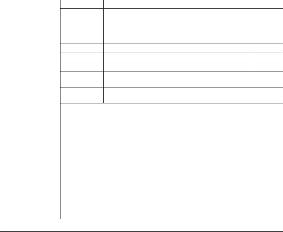
Table 24. Retrievable usage data (continued)
Hex Value Usage Data Being Tracked Factor
D3 Number of checks scanned - Tx8, Tx9 only 16
D4 Check Quality Count: the number of times a scanned check
fails quality measurement - Tx8, Tx9 only (see Note 2)
None
D5 Tone Sounded Count: single station printers only 32
D6 Cash drawer opened successful count (see Note 2) 16
D7 Cash drawer failed to open count (see Note 2) None
D8 Number of Bar Codes printed 32
D9 Number of times the maximum temperature of either motors
or print heads has been reached (see Note 2)
None
DA Remainder value of Tone Sounded Count, single station
printers only (see Note 2)
None
Notes:
1. The number of printed characters is based on the number of dots that were printed,
assuming 64 dots per character for thermal characters and 16 dots per character for
impact characters.
2. Reads from these values will add in the values that have accumulated since the last
store to FLASH. These values will be added into the "Remainder" MCTs when one exits.
3. Retrievable usage data, 6D and 6E, are the runtime monitoring variables for the image
quality produced by the scanner. The variables monitored are Image Brightness (the
high byte of 0x6D), Image Contrast (the low byte of 0x6D), and Image Focus (the high
byte of 0x6E). The low byte of 0x6E is reserved for future use; it is set to 0xFF. The
maximum value is127; they are a running average of the quality of the scanner. On a
new calibrated scanner, the brightness and contrast values will be ~120 and the focus
will be ~105. A bad scanner or a scanner in need of calibration would have values of 90
for brightness and contrast and 77 for focus. If the scanner is recalibrated these values
will be reset. The offline MICR test will report back if a given scan has values outside of
normal range.
Check processing commands (Models TI2, TI4, TI8, TI9, TG4, TG8, and
TG9 only)
This printer can process the check entirely without taking it from the printer. It can
read the magnetic ink character line, frank the back of the check, and flip the check
to print the face of the check.
Note: To print the face of the check, select the document station in landscape
mode as the print station.
Models TI8 and TI9 MICR read commands
Note: Model TG8 is equivalent to TI8 and TG9 is equivalent to TI9.
The Models TI8 and TI9 have two MICR read commands. TheX'1B49' command,
which is used in the Model TI4 printer and the MICR command X'1B3E01', which
also scans a check. Both commands use the OCR decoding algorithm for reading
the MICR line, which is available on these models.
Updated April 2, 2009
164 SureMark Printers User’s Guide

MICR read
EIA-232 Syntax:
ESC I or X'1B49'
Purpose:
To read account information from the magnetic ink character line on
customers’ checks.
Remarks:
vChecks should be inserted upside-down from the front and against the
right wall of the printer. The check can be, but does not have to be,
registered in the printer before this command is given. The check will be
fed, forward, until the bottom sensor is uncovered, then fed back for the
MICR reader reading. After the reading is complete, the check is fed to
the first print position.
vThis command increments the line count (status byte 6).
vAt the completion of this command, information read by the MICR reader
is sent over the serial I/O following the eighth status byte.
vThe next byte represents a percentage of an average signal level of the
MICR characters for the E13b check only. (In CMC7, this byte is always
100.) A nominal signal has a strength of 100.
vCharacters are sent as read from left to right, up to a maximum of 65
characters.
vIf no magnetic ink characters are detected, a single question mark (X'3F')
is sent back.
vIf the printer is unable to read any character on its first try, it will feed the
check forward and backward for a second try. Complete status will then
be sent to the system - if the character was still not read it will be
identified by a single question mark (X'3F').
vChecks with magnetic ink printing within 1.2 inches of the right edge of
the check are not read correctly. This occurs when the amount field is
printed on the check.
Character Description ASCII Representation hex value returned
MICR data representation
0–9 Numerical data
blank
Unreadable
Character
0–9
?
30–9
20
3F
E13-B - Special characters
Dash - 2D
Transit T 54
On Us A 41
Amount $ 24
CMC7 - Special characters
Special character 1 a 61
Special character 2 b 62
Updated April 2, 2009
Appendix D. EIA-232 programming information 165

Character Description ASCII Representation hex value returned
Special character 3 c 63
Special character 4 d 64
Special character 5 e 65
Error Conditions:
Document feed error (status byte 7). This bit is set if the inserted check is
too long. The maximum check length is 10 inches. The error is also set if
the check does not clear the document sensor when expected.
Flip check
EIA-232 Syntax:
ESC 5 or X'1B35'
Purpose:
To flip the check after a MICR read. This will allow the face of the check to
be printed.
Remarks:
vSet print station to document landscape mode to print the face of the
check as it comes out of the flipper mechanism.
vThis command increments the line count (status byte 6).
Error Conditions:
Document feed error (status byte 7). This bit is set if the inserted check is
too long. The maximum check length is 10 inches. The error is also set if
the check does not clear the document sensor when expected.
Document scanner commands
Scanner commands are supported on SureMark printer Models TI8, TI9, TG8, and
TG9 only.
Start scan
EIA-232 syntax:
X'1B;3E;n'
where:
n=00 optical scan only, document is ejected
n=01 scan and MICR/OCR read
n=02 optical scan and re-read document (Models TI9/TG9 only)
n=03 scan, MICR/OCR read, and prepare for flip (start the check into the
flipper)
n=04 partial scan, MICR/OCR, and prepare for flip (start the check into
the flipper)
Remarks:
vPulls in document present at scanner input.
Updated April 2, 2009
166 SureMark Printers User’s Guide
vDocument image is retained in RAM until another scan command is
received, or the printer is reset.
vSet the dots per inch (DPI) and file compression type prior to scanning.
The printer begins to compress immediately after scanning. There,
changing the compression type after scanning would make the check
process take much longer as it now has to compress twice if the
compression type changes.
vSuccessful read returns status with status byte 05, bit 06 set, and a
2-byte image width, and a 2-byte image height and 2-byte image width
(in hundredths of an inch) follows the status.
vWhen using the X'01', X'03', or X'04'option, the MICR data is returned
after the successful scan status, and matches the format in the MICR
command section.
vIf the scan is not successful, the Document feed error bit is returned
(status byte 7, bit 7).
vWhen using the X'03' or X'04'option, the check will only start into the
flipper for personal check (~6 in.). Otherwise, it will function the same as
X'01'. With the check partially in the flipper mechanism, the printer can
print in the portrait station or flip the document. If any other command is
received at this point, the document must come fully out of the flip
mechanism and be re-readied.
vImage Quality detection will be run on the quality of the image scanned
and if the image "fails" the Image Quality test an error bit will be set in
the header information of the retrieved image.
vWhen only a partial image or no image is required, the X'04' command
will take less time than the X'01' or X'03' options.
TI8/TG8 printer
vX'00' and X'02' options: scans the full document and ejects the document
out the top.
vX'01', X'03', and X'04' options: the bottom 1.5 in. of the document is not
captured in the scanned image.
vX'03' and X'04' options: the document is less than 6.5 in.; it is fed into
the flipper while reading the MICR line.
TI9/TG9 printer
vX'00' option: scans the full document and ejects the document out the
top.
vX'01' option: scans the entire document, reads MICR and re-readies the
document.
vX'02' option: scans the check and re-readies the document.
vX'03' option: scans the entire document and if the document is less than
6.5 in., it is fed into the flipper while reading MICR line.
vX'04' option: scans a partial document (bottom 1.5 in. not scanned) and if
the document is less than 6.5 in., it is fed into the flipper while reading
the MICR line.
Check 21 flow - with the TI9
Assume that the check must be fully filled out and both the front and back
of the check imaged. Assume the printer prints the check face information.
1. Customer gives signs the check and gives it to the cashier.
2. Cashier is prompted to insert the check to be imaged.
3. The check is inserted face down. The MICR is read with '1B, 3E, 04.'
Updated April 2, 2009
Appendix D. EIA-232 programming information 167
4. The transaction information (MIRC, amount, and so on) is sent to the
host for approval. The rest of flow is based on successful approval.
5. Back of the check is franked.
6. Flip and scan the back of the check. Select landscape print station,
flip, and scan. (1B 63 30 08 1B 35 1B 3E 02)
7. An image of the check back is read and stored.
8. The face of the check is printed.
9. Flip and scan the front of the check (1B 35 1B 3E 03).
10. An image of the check face is read and stored.
11. Flip the check. ( 1B 35)
12. Print the face of check with void and eject. (VOIDx"0c")
Assume that the customer fills out the check.
1. Customer fills out and signs the check and gives it to the cashier.
2. Cashier is prompted to insert the check to be imaged.
3. Check is inserted, face down. Check is scanned and MICR is read with
the option (1B, 3E 03).
4. Transaction information (MICR, amount, and so on) is sent to the host
for approval. The remaining flow is based on successful approval.
5. Image of the check face is read and stored.
6. Check is franked.
7. Flip and scan the back of the check. Select landscape print station, flip,
and scan. (1B 63 30 08 1B 35 1B 3E 02)
8. Image of the check back is read and stored.
9. Check is printed on the face of the check with void and ejected.
(VOIDx"0c")
Print scanned image
EIA-232 syntax:
X'1B;30;n1;x;y;dx;dy;s1;s2;n2'
where:
n1 2 bytes, reserved, X'00 00'
x,y 2 bytes each, top-left corner of area to be printed
dx, dy 2 bytes each, offset in the x and y direction respectively, to be
included in the print area
s1 1 byte, percentage to scale image in the x direction (A value of 100
or 0 results in no scaling.)
s2 1 byte, percentage to scale image in the y direction (A value of 100
or 0 results in no scaling.)
n2 print options, bit 0; value0=donotrotate, value 1 = rotate 90
degrees counterclockwise
Updated April 2, 2009
168 SureMark Printers User’s Guide

Remarks
Image location (n1) of 0 prints the most recently scanned image to the
thermal station.
The top-left corner of the scanned document is used as the point of
reference. All x, dx, y, and dy, values are based on 0.01 inch. The paper
movement path is the y axis, and the scan head dot row is the x axis.
In all cases, dx and dy define the area’s width to the right, and height down.
If dx and dy extend the printer area further than the boundaries of the
image, the value is truncated to the image boundary. If the size of the print
area is greater than the thermal print head can print (either from image size
or scaling), the image is truncated to the width of the print head. The only
scaling options are 100% (no scaling) and 200% (double). Tag data
included with the image is not printed.
If the image is stored in JPEG format, then graphics printing is not
supported.
Store scanned image and/or select partial image for retrieval
EIA-232 syntax:
X'1B;41;n1;x0;y0;dx0;dy0;x1;y1;dx1;dy1;x2;y2;dx2;dy2;x3;y3;dx3;
dy3;tagdata'
where:
n1 Select storage method, one byte
vX'00' store entire image
vX'01' store image using template 1
vX'02' store image using template 2
vX'03' store image using user defined values
vX'11' Compress a section and keep in RAM using user defined
values (x0, y0, dx0, dy0)
x0, y0 2 bytes each, top-left corner of area to be stored
dx0, dy0
2 bytes each, offset in the x and y direction respectively, to be
stored
x1, x2, x3, y1, y2, y3
2 bytes each, corresponding offset in the x and y direction to define
size of subblock to store
tagdata
ASCII string terminated by null character, maximum 100 characters
(x,y)
+
(dy)
(dx)
Figure 51. Scanned image layout
Updated April 2, 2009
Appendix D. EIA-232 programming information 169
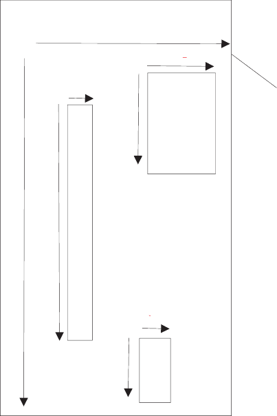
Remarks:
Images are stored sequentially. The locations where the images are stored
are obtained with a Retrieve next table location command before issuing
the store command. The image is compressed using the compression
algorithm last selected by the Select compression format command, and is
then stored in memory.
When storing an image, the user can elect to store the entire image within
the defined area, or just selected blocks within the defined area. Saving
selected blocks reduces storage use, but keeps related data together.
When storing multiple blocks of data, each block gets a unique storage
location. A byte in the header message indicates that the block is part of a
group. The first half-byte indicates which block of the group it is, the second
half-byte indicates the number of blocks in the group. If the byte returned is
X'14', then the block is the first of a group of four. All blocks contain header
information, but only the first block in a group contains tag data.
The Select storage method byte (n1) defines how the image should be
stored.
When n1 = 0, all data defined y x0, y0, dx0, dy0 is stored. The command
parameters, x1, x2, x3, y1, y2, y3, dx1, dx2, dx3, and dy1, dy2, dy3 should
not be included.
When n1 = 1, a predefined template, based on a personal check is used to
store the image. The area defined is the entire personal check, however the
name/address and the MICR blocks are saved. The command parameters,
x0, x1, x2, x3, y0, y1, y2, y3, dx0, dx1, dx2, dx3, and dy0, dy1, dy2, dy3
+
(0,0)
Scanned Document
(dx0)
(dx1)
(dy1)
(dx2)
(dy2)
(dy0)
(dy3)
(dx3)
(x0,y0)
(x1,y1)
(x2,y2)
(x3,y3)
Figure 52. Scanned image organization
Updated April 2, 2009
170 SureMark Printers User’s Guide
should not be included. These parameters are defined in MCT locations
X'0xB0' through X'0xBF' and can be viewed or adjusted using the MCT
Read and MCT Write commands. If fewer than four blocks are required, a
block can be disabled by storing a value of X'FFFF' for a coordinate MCT
location. The block is then ignored.
When n1 = 2, a predefined template, based on a business check is used to
store the image. The area defined is the entire business check, however
only the name/address, and MICR blocks are saved. The command
parameters, x0, x1, x2, x3, y0, y1, y2, y3, dx0, dx1, dx2, dx3, and dy0, dy1,
dy2, dy3 should not be included. These parameters are defined in MCT
locations X'0xC0' through X'0xCF' and can be viewed or adjusted using the
MCT Read and MCT Write commands. If fewer than four blocks are
required, a block can be disabled by storing a value of X'FFFF' to a
coordinate MCT location. The block is then ignored.
When n1 = 3, this method allows the user to define subblocks of data to
store. All command parameters must be sent. If fewer than four blocks of
data are to be saved, the value of X'FFFF' must be sent for unused
parameters. The top-left corner of the scanned document is used as the
point of reference. All xn, dxn, yn, and dyn values are based on 0.01 inch.
The xn command parameters are horizontal offsets from the left side of the
scanned document. The yn parameters are vertical offsets from the top of
the scanned document. The dxn and dyn parameters define the width and
height, respectively, of the defined area or block.
When n1=0x11, this command allows the user to obtain a partially scanned
image without having to spend time storing it into Flash. Since the
command does not destroy the original scanned image, successive
commands using n1 of 0x11 is possible. Executing this command will
compress a partial image of the check using the user defined values
defined in x0, y0, dx0, dx1. The new image will be stored in RAM location
0. Though the command does not technically store the image into flash,
upon compressing the partial image check, Bit 7 of Status byte 3 will be set
to true to comply with the existing Store Scanned Image commands.
The printer attempts to determine the width and height of the document,
and returns the value when the document is scanned. If the value of xn
plus dxn is greater than the total width scanned by the printer, the printer
uses the data detected up to the maximum scan width. If the value of yn
plus dyn is greater than the length of the document, the printer uses blank
(white) data to fill the area to the lesser of the yn+dyn value, or maximum
document length allowed.
If yn or xn is greater than the maximum allowed, the command is rejected.
If x1 and y2 extend the printer area beyond the boundaries of the image,
the values are truncated to the image boundary.
Errors:
Status byte 3 is set:
vWhen the image to be stored is larger than the remaining unused
memory for the image boundary.
vIf an error occurs during the flash write (hardware error).
Example 1:
Method 0: X'1B 41 00 00 19 00 32 01 13 02 26 30 33 2F 30 34 2F 30 32
20 30 30 31 2E 33 34 00'
Updated April 2, 2009
Appendix D. EIA-232 programming information 171

An image 2.75 in. by 5.5 in. that begins 0.25 in. from the left side, and 0.5
in. from the top of the document is stored with the tag data: 03/04/02
001.34
Example 2:
Method 3: X'1B 41 03 00 AF 01 DB 00 28 00 64 00 B4 00 64 00 64 00 96
00 96 00 64 00 19 01 13 FF FF FF FF FF FF FF FF 00'
Three separate areas are stored. No tag data is included. Table 25 provides
details.
Table 25. Data table
Document width = 3 in. Document height=6in.
x0 = 1.75 in. y0 = 4.25 in.
dx0 = 0.40 in. dy0 = 1.0 in.
x1 = 1.80 in. y1 = 1.0 in.
dx1 = 1.0 in. dy1 = 1.50 in.
x2 = 1.50 in. y2 = 1.0 in.
dx2 = 0.25 in. dy2 = 2.75 in
x3 = not applicable y3 = not applicable
dx3 = not applicable dy3 = not applicable
Tag data, stored with the image, allows the user to include additional
information about the image. It must be an ASCII string, terminated by a
null character.
Example 3:
Method 0x11-Compress partial check image defined by user: X'1B 41 11 00
00 00 00 00 64 00 C8 00'
Retrieve the image using Retrieve Scanning Image command X'1B 39 00
00'
Method 0x11-Compress another part of the check image: X'1B 41 11 00 64
00 C8 00 64 00 C8 00'
Retrieve the image using Retrieve Scanning Image command X'1B 39 00
00'
Retrieve scanned image
EIA-232 syntax:
X'1B;39;n1;n2;n3'
where:
vn1, 2 bytes, Image location to retrieve
vn2, 4 bytes, Offset into image from which to retrieve data
vn3, 2 bytes, Number of bytes to retrieve
Remarks:
Image location (n1) of 0 returns the image last scanned. To return just a
part of the image from RAM, compress the partial image using Store
Scanned Image and/or select partial image for retrieval first. Offset (n2) and
size (n3) of 0 retrieve the header information for the specified image. When
n1 = 0, the header consists of the 12 data bytes and a null character for the
Updated April 2, 2009
172 SureMark Printers User’s Guide
tag data. In this case, only the Compression, Size1, and Size2 fields
contain data. The header has the following format:
vStatus; 1 byte
– Bit 7, Image read; 1 = image has been read, 0 = image has not been
read
– Bit 6, 1= IQD (Image Quality Detection) Error
– Bits 5–0; Reserved
vCompression; 1 byte
– Bits 7–5; Reserved
– Bits 4–0; Algorithm used to compress image. See “Select
compression format and scanned image threshold” on page 174
command
vSize1; 4 bytes
– Number of bytes in image, not including tag data.
vSize2; 4 bytes (x1, y1)
– Width of image in the x direction (in hundredths of inch increments), 2
bytes
Note: Scanner resolution is 200 dots per inch.
– Height of image in the y direction (in hundredths of inch increments),
2 bytes
vBlock position; 1 byte
– Lower four bits indicate the number of blocks that were saved for the
image.
– Upper four bits represent the current block number.
vFuture; 1 byte
– Reserved
vTag data
– ASCII data supplied by the application, terminated by a null string.
Offset (n2) = X'FF FF FF FF' with size (n3) = X'FF FF'sets to 0 the Image
Read bit in the specified image header.
For stored images (n1>0), the image data format is the format that was
active when the image was stored.
For immediate images (n1=0), the image data format is the currently
selected format.
Error conditions:
If any parameter is out of range, Command Reject is returned.
Scanner calibration
EIA-232 syntax:
GSc0orX'1D 63 30'
Purpose:
Used to initiate the calibration routine for the scanner. The printer scans the
document multiple times and updates the printer’s calibration data. See
“Document scanner calibration (Models TI8, TI9, TG8, TG9)” on page 60 for
more information about the document to be used.
Updated April 2, 2009
Appendix D. EIA-232 programming information 173
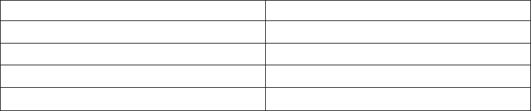
Retrieve next image location
EIA-232 syntax:
GS N SOH NULL or X'1D 4E 01 00'
Remarks:
Returns the table position where the next image is stored. Command is
Extend MCT Request command (2-byte address). Status byte 5, bit 3 is set
to indicate data is attached.
Retrieve first unread image location
EIA-232 syntax:
GS N SOH SOH or X'1D 4E 01 01'
Remarks:
Stored images are searched sequentially, and the first location that has not
been set to ″read″is returned. The command is Extend MCT Request
(2-byte address). Status byte 5, bit 3 is set to indicate data is attached.
Select compression format and scanned image threshold
EIA-232 syntax:
X'1B;4d;x;n1;n2'
where:
vx = X'1F'
– address to store data
vn1
– 00 200 DPI TIFF-CCITT-Group 4 compression
– 01 200 DPI JPEG compression
– 02 200 DPI BMP (uncompressed)
– 04 200 DPI TIFF file, no compression (gray scale)
– 10 100 DPI TIFF-CCITT compression (black and white)
– 11 100 DPI JPEG compression (gray scale)
– 12 100 DPI BMP (uncompressed gray scale)
– 14 100 DPI TIFF File (no compression)
vn2
– Lightens or darkens the contrast of a scanned image. Higher numbers
print darker.
Remarks:
The current format applies to retrieval and storage of the currently scanned
image. Changing the format does not change the format of any images
already stored in flash. The setting is persistent across reset and power
cycles.
Table 26. Average size for a personal check with little background data
Compression type Size
00 - TIFF-CCITT compression - 200 DPI 5K Bytes
01 - JPEG compression - 200 DPI 45K Bytes
02, 04 - no compression - 200 DPI 660K Bytes
10 - TIFF-CCITT - 100 DPI 3.5K Bytes
Updated April 2, 2009
174 SureMark Printers User’s Guide
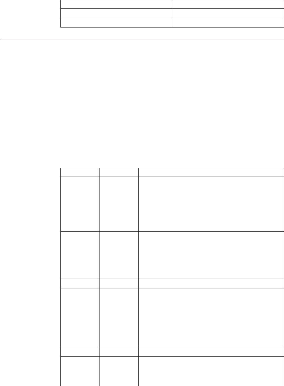
Table 26. Average size for a personal check with little background data (continued)
Compression type Size
11 - JPEG compression - 100 DPI 15K Bytes
12, 14 no compression 100 DPI 170K Bytes
Asynchronous (real-time) commands
These commands are processed as soon as they are received. They do not go into
the printer buffer.
Note: These commands are not recognized when they occur in the middle of
another command. For example, sending this command after the second
byte of a 3-byte command, as in ESC J n.
Real-time requests
EIA-232 Syntax:
DLE ENQ mor X'1005:n'
where:
mSpecifies the ASCII command character
nSpecifies the hexadecimal command character
m n Description
1 31 Release the print buffer for printing. This should be sent
after an error has occurred and the print buffer is held. If
an error occurred during the transaction that was being
held, the printer sends back the line number with the error
and the error status. The system can then decide to cancel
or continue printing after the error is corrected. The system
uses this command to continue printing after the error is
corrected.
2 32 Cancel print buffer. This clears the print buffer of all data.
In EIA-232 mode, the user must wait for buffer empty
status (status byte 2, bit 6) before sending any more
commands.
Note: A status message is returned immediately after
execution of this command.
3 33 Undefined.
4 34 EC request - transmit printer status. Sends the printer’s
status to the system. This command does not go into the
printer’s data buffer but is processed immediately.
The printer status is returned in status bytes 1–8. See
“Status summary” on page 184 for more information.
Status byte 5, bit 1, will be set after the EC request has
been executed.
5-8 35-38 Undefined
@ 40 Reset the printer. The printer stops what it is doing and
goes through its reset routine. The print buffer is canceled
and all commands erased. All printer settings go back to
default values.
Updated April 2, 2009
Appendix D. EIA-232 programming information 175

m n Description
A 41 Enable unsolicited status.
Note: A status message is returned immediately after
execution of this command. To enable these status
messages, the Status Sent to System setup command
must be enabled. See “Status sent to system” on page
141.
B 42 Disable unsolicited status
C 43 Disable transparent XON/XOFF
Purpose:
To process a command immediately.
Remarks:
Either the Release print buffer or the Cancel print buffer command must be
used in these situations:
vWhen recovering from a cash receipt print error
vAfter clearing an unrecoverable home error
After the printer resets, it defaults to not sending status unless requested. If
an error occurs, the printer appears hung, unless a status is requested. If
unsolicited status is enabled, the printer sends the error to the system as
soon as it occurs.
Note: If transparent XON/OFF is disabled, X'10', X'11', and X'13' can be
imbedded in returned status and data. (See “XON/XOFF control” on
page 29.) To re-enable the printer, the printer must be reset.
Data buffer management and batch printing
Reset line count
EIA-232 Syntax:
ESC 6 or X'1B36'
Purpose:
Resetting the line count lets the system track the print line where an error
occurs.
Remarks:
The line count is incremented at every print command. The count is sent in
every status message to the system. The count can go to 256 (X'FF'), when
it rolls back to 0. (See “Print character commands” on page 156.)
Disable line count
EIA-232 Syntax:
ESC 8 nor X'1B;38'n
where
vn = 1, disable line count
vn = 0, enable line count
Purpose:
To temporarily not increment the line count. This can be used when printing
predefined messages, if the number of lines embedded in the message is
unknown.
Updated April 2, 2009
176 SureMark Printers User’s Guide

Hold printing until buffer is released
EIA-232 Syntax:
ESC 7 or X'1B37'
Purpose:
If the system can not send data to the printer at a speed needed to keep
the printer in constant motion, it can hold the printer queue until it sends all
data lines for a transaction.
Remarks:
The printer must be printing one line while processing the next line. If the
printer is unable to completely process a line, the print speed reduces to
half.
The line count is reset when the buffer is held.
Page mode printing commands
Note: Not supported on the TI1 and TI2.
Select page mode
EIA-232 Syntax:
ESC L or X'1B;4C'
Remarks:
vEnables page mode printing.
vSupported on thermal station only.
vStarting position is set by Set printable area X'1B;57..' and Set print
direction X'1B;54..' commands.
vIntercharacter spacing X'1B;20;n' and line spacing X'1B;31', X'1B;32',
X'1B;33' commands are set independently for page mode and standard
mode.
vThe following commands are allowed:
– Rotate characters
– Set alignment
– Set/Clear upside-down
– Set margins
Select standard mode
EIA-232 Syntax:
ESC O or X'1B;4f'
Epson emulation syntax:
ESC S or X'1B;53'
Remarks:
vThis command is effective in page mode only.
vData buffered in page mode is cleared.
vThis command sets the print position to the beginning of the line.
Updated April 2, 2009
Appendix D. EIA-232 programming information 177
Select printable area
EIA-232 Syntax:
ESC X or X'1B;58;x;y;dx;dy'
where:
vx, y
– Two-byte horizontal and vertical starting position (in dots)
vdx, dy
– Two-byte horizontal and vertical printing area (in dots)
Remarks:
vWhen sent in standard mode, this command sets the printable area for
page mode, but has no effect on standard mode printing.
vIf the starting position (x, y) is outside the maximum range, the entire
command is ignored.
vIf the printing area is defined outside the maximum page size, the
printing area is limited to the page size.
vMaximum page size is 576 dots in the horizontal direction, and 800 dots
in the vertical direction (except Models Tx8 and Tx9, which is 1250 dots
in the vertical direction).
Select printing direction/position
EIA-232 Syntax:
ESC T nor X'1B;54;n'
where:
n
Table 27. Print direction
n= Direction / position
X'00' Left to right / top left
X'01' Bottom to top / bottom left
X'02' Right to left / bottom right
X'03' Top to bottom / top right
Remarks:
When sent in standard mode, this command sets the print direction for
page mode, but has no effect on standard mode printing.
Starting position is within the printable area defined by the Select printable
area command (X'1B;58...)'.
Set vertical position
EIA-232 Syntax:
GS$yor X'1D;24;y'
where:
yis a two-byte vertical printing position (in dots)
Remarks:
vApplies to page mode only.
Updated April 2, 2009
178 SureMark Printers User’s Guide
vMoves the printing position to the specified dot position perpendicular to
the printing direction specified by the Select printing direction command.
If printing direction is bottom-to-top, or top-to-bottom, this command
adjusts the printing position in the horizontal direction.
vIf the value of yis outside the specified printable area, this command is
ignored.
Set relative vertical position
EIA-232 Syntax:
GS\yor X'1D;5C;y'
where:
yis the two-byte vertical printing position (in dots).
Remarks:
vApplies to page mode only.
vMoves the printing position the specified number of dots from the current
print position, in the direction perpendicular to the printing direction
specified by the Select printing direction/position command (X'1B;54...'). If
the print direction is bottom-to-top, or top-to-bottom, this command
adjusts the printing position in the horizontal direction.
vIf the value of y is outside the specified printable area defined by the
Select printable area command, this command is ignored.
vIf y is a negative value, the current print position will move in the
opposite direction.
Set left margin position (standard mode), set absolute print position
(page mode)
EIA-232 Syntax:
ESC $ n1 n2 or X'1B;24;n1;n2'
where:
vn1 is the high-order byte of the dot offset from the beginning of the print
line.
vn2 is the low-order byte of the dot offset from the beginning of the print
line.
Default:
n1 =0,n2 =0
Remarks:
vIn the thermal station, 1 mm = 8 dots.
vIn the impact station, 1 inch = 150 half-dots (75 dots).
vn1 and n2 are hex values. Convert each to decimal, and use this formula
to get the decimal equivalent: (n1 x 256) + n2.
vThe maximum value in the thermal CR station is 576. The maximum
value in the impact DI station is 474.
vIn the CR station, this number is rounded back to a factor of 8.
vIf the n1,n2 value exceeds the maximum, it is ignored.
vThis command should be sent only after the command that selects the
station, Set print station (ESC c1 n).
vIn Page mode, the printing position is moved the specified number of
dots from the beginning of the print line, in the same direction as printing,
Updated April 2, 2009
Appendix D. EIA-232 programming information 179
specified by the Select printing direction/position command (X'1B;54...'). If
the print position is bottom-to-top, or top-to-bottom, this command adjusts
the print position in the vertical direction.
vThis is a one-time adjustment on the current line. If this command moves
the print position outside the printable area specified by the Select
printable area command, it is ignored.
Set relative horizontal position
EIA-232 Syntax:
ESC <5C>h n1 n2 or X'1B;5C;n1;n2'
where:
vn1 is the high-order byte of the dot offset, relative to the left margin in
standard mode or the current print position in page mode.
vn2 is the low-order byte of the dot offset, relative to the left margin in
standard mode or the current print position in page mode.
default:
n1 =0,n2 =0
Remarks:
vIn the thermal station, 1 mm = 8 dots.
vIn the impact station, 1 inch = 150 half-dots (75 dots).
vn1 and n2 are hex values. To get the decimal equivalent, convert each to
decimal, and then use this formula: (n1 x 256) + n2..
vTo move the position to the left, use a negative number.
vIf this number plus the left margin exceeds the printable area, the
command is ignored.
vIn the CR station, this number is rounded back to factor of 8. See the Set
left margin position command for more information.
vWhen printing in page mode, this is a one-time adjustment on the current
line. If this command moves the current print position outside the
printable area defined by the Select printable area command, the
command is ignored.
Set printing position
EIA-232 Syntax:
GS]xyor X'1D;5D;x;y'
where:
vx is the two-byte horizontal position, with respect to the paper, regardless
of printing direction.
vy is the two-byte vertical position, with respect to the paper, regardless of
printing direction.
Remarks:
vThis command allows complete control of the printing position with a
single command.
vIf either parameter is outside the printable area defined by the Select
printable area command, the command is ignored.
Updated April 2, 2009
180 SureMark Printers User’s Guide

Print and form feed and cut the paper
EIA-232 Syntax:
FF or X'0C'
Epson compatibility syntax:
FF or X'0C'
Remarks:
vIn standard mode, the data in the print buffer feeds the paper in the CR
station or DI station by a preset amount, until the document exits the
feed rollers. If a cutter is available (CR station only), it cuts the paper.
vIn page mode, the printer prints the page, then returns to standard mode.
The page loaded in the printer’s buffer is cleared. The paper is not cut.
Print page in page mode
EIA-232 Syntax:
ESC FF or X'1B 0C'
Epson compatibility mode:
ESC FF or X'1B 0C'
Remarks:
vIn standard mode, this command is ignored.
vIn page mode, this command prints the page that is loaded in the printer.
The page remains loaded in the printer’s buffer and the printer remains in
page mode. This should be used for repeatedly printing the same page,
or if there is a template that is filled in with each printout.
Clear print data in page mode
EIA-232 Syntax:
CAN or X'18'
Remarks:
This command deletes all print data in the current printable area of the
page stored in the printer’s buffer.
Document handling
To read checks, insert them from the front of the printer. Use the side load
capability only for documents that must be positioned to begin printing at a
particular location on the document. (There is an arrow on the side of the cover to
indicate where printing begins.) Use front load for all other cases.
Portrait mode
This is a suggested method of document handling:
1. ESC f (x) (y): Set up document wait time
xTime the printer should wait from receiving a print line for the
document station until the document is inserted.
If the document has not been detected by the time the wait time
ends, a document error is sent to the system but the system
continues to wait for a document to be inserted.
Updated April 2, 2009
Appendix D. EIA-232 programming information 181
yDelay from the time the document is detected until it is grabbed by
the printer (the start of document printing):
vSide insertion - closes the document throat.
vFront insertion - pulls the document into the printer and feeds it
to the Top of Form.
2. ESC c 0 X'04': Select document station - normal print mode:
The document present indicator blinks until a document is detected, when it
stays on continuously.
vIf the document is inserted from the front, it is fed to the first print
position after the document wait time. Then commands in the printer
buffer begin executing.
vIf the document is inserted from the side, printing starts at the location
where it was inserted.
(The document throat must be open to insert the document from the
side.) Manually, open the throat by pressing and then releasing both
buttons. You can also open it with these commands - ESC q or ESC <
X'01'.
If a document is not detected within the wait time (specified in the ESC f
command), the printer sends error status to the system, and continues to
wait.
Notes:
1. The system can either cancel the print buffer, thereby deleting all
data in the print buffer, or wait for a document to be inserted.
2. Models TI9/TG9 do not support side insertion. Alignment to a
particular line can be done using the buttons and the reverse line
feed command.
The printer appears to be hung until an action is taken.
3. Send print lines to be printed in this station.
4. Final handling.
You have an option on final handling, finish printing and either eject the
document or open the document throat to allow manual removal of the
document:
FF: Print and Eject Document.
Finish printing and eject the document.
Landscape mode
Landscape mode printing is primarily for printing the face of a check.
Notes on landscape printing:
vLines you send to print start at the bottom of the form, against the right stop, and
continue to the top of the form, to a maximum of 80 mm from the bottom of the
form. This is because the bottom of the form is known (against the right stop)
and the top of the form is unknown to the printer.
vDifferent lengths of paper allow different print-line lengths. Therefore, the
application must know the size of the print line.
vThe printer calculates the length of a document it is to print. To do that, it must
feed the document up past the bottom sensor and back to the top sensor. (On a
5-inch document this takes 2 seconds.) If a MICR read was done previously, the
length was calculated at that time.
Updated April 2, 2009
182 SureMark Printers User’s Guide
vWhen landscape mode is used without the check flipper, the document should be
inserted so that the right edge is at the top of the printer, and the bottom edge is
against the printer’s right wall.
vTo position the printing in landscape mode to the correct position, the system
must send line feeds. The printer assumes that the top of form for a document in
landscape mode is the far left edge of the document (to a maximum of 80 mm
from the bottom of the form).
vLine feeding is 5 steps per mm or 21 steps per line, at 6 lpi.
vAll landscape printing must be done with one printing pass. Therefore:
– Double-high printing is not allowed.
– User-defined characters greater than 9 dots high are not allowed.
vThere is no error recovery for landscape printing.
vSet print station to document landscape mode to print the face of the check as it
comes out of the flipper machanism.
Landscape printing commands
1. ESC f (x) (y): Set up document wait time
Same as for portrait mode.
2. ESC c 0 X'08': Select document station - landscape print mode:
AIf the document was not previously loaded:
vThe document present indicator blinks until a document is
detected.
vOnce detected, the document will be grabbed by the printer and
fed to the right margin on the document. Because the document
is inserted on its side, this is at the top of the printer.
vIf a document is not detected within the wait time (specified in
the ESC f command), the printer sends error status to the
system, and continues to wait.
The system can either cancel the print buffer, deleting all data in
the print buffer, or wait for a document to be inserted.
The printer appears to be hung until an action is taken.
BIf the document was previously loaded, the printer feeds the paper
to the right margin on the document.
3. Send print lines to be printed in this station.
The number of characters that can be printed on a line depends on the
width of the document. The print area is:
v63 mm high, starting 17 mm from the bottom of the document
vThe entire width of the document less 34 mm from the right edge and 10
mm from the left edge
4. Final handling.
You have an option on final handling, finish printing and either eject the
document or open the document throat to allow manual removal of the
document:
4a. FF: Print and Eject Document.
Finish printing and eject the document.
4b. ESC q or ESC < X'01': Open Document Throat
Finish printing and release the document from the printer’s rollers.
Updated April 2, 2009
Appendix D. EIA-232 programming information 183

Note: The document station stays selected. The printer will wait for
another document until the station is changed.
Status summary
Status is sent to the system for:
vCash receipt print error. The cover is open or out of paper.
vPrinter buffer empty. If enabled, see “Status sent to system” on page 141.
vDocument sensor state changed. If enabled, see “Status sent to system” on page
141.
vCash drawer sensor change. If enabled, see “Status sent to system” on page
141.
vCommand has timed out. The printer is waiting for additional bytes to complete
the command.
vNonrecoverable home error.
vDocument not inserted after document station was selected.
vDocument has exited sensor before document print is finished.
vFlash EPROM load error.
vMemory sector is full.
vFlash Storage is full.
vPrinter ID request (extended address command).
vMICR read command.
vMCT read command.
vFlash read command.
vPrint buffer being held.
vRibbon cover sensor change.
vDocument feed error.
Message from the printer
A message from the printer has this format:
Bytes Contents
1-2 Data count (X'000A' to X'00FF'). The data count includes the two data-count
bytes.
3-10 Status bytes 1-8. See the descriptions of each byte in the sections that
follow.
11 - nEither 5 bytes of additional status from the “Extended address
command-request printer ID” on page 112 command, or up to 246 bytes of
user data that can include:
vMICR data
vUser flash data
vMCT data
Status byte 1
Bit Description
0 (LSB) Command complete (immediate command and flash storage commands). Set
to 1 when the command is complete, except for “Erase flash EPROM sector”
on page 123, for which it is set to 1 when the command is sent. (See bit 7 of
“Status byte 3” on page 185.)
1 Cash receipt right home position. Set to 1 when the print head is in the
customer receipt right home position.
2 Left home position Set to 1 when the print head is in the left home position.
Updated April 2, 2009
184 SureMark Printers User’s Guide

Bit Description
3 Document right home position. Set to 1 when the print head is in the document
right home position.
4 Reserved. Always 0.
5 Ribbon cover open. Set to 1 when the ribbon cover is open.
6 Cash receipt print error. Paper cover is open, the customer receipt station is
out of paper, or the cutter is jammed in the closed position.
7 (MSB) Command reject.
Status byte 2
Bit Description
0 (LSB) Document ready. Set to 0 when the document insert station is ready for
printing. This occurs when both document sensors detect the document and the
document has been fed to the first print position.
1 Document present under the front sensor. Set to 0 when a document is under
the front document sensor.
2 Document present under the top sensor. Set to 0 when a document is under
the top document sensor.
3 Reserved. Always equals 1.
4 Print buffer held. Set to 1 when the print buffer is being held. Cleared when
buffer released.
5 Open throat position. Set to 1 when the print head is in the open throat
position.
6 Buffer empty. Set to 1 when no print data and no commands are in the buffer.
7 (MSB) Buffer Full. Set when only 1K bytes are available in the buffer.
Status byte 3
Bit Description
0 (LSB) Memory sector is full.
1 Home error.
2 Document error. The document was not inserted after the document station was
selected, and the wait subsequently timed out.
3 Flash EPROM load error or MCT load error.
4 Reserved. Always equals 0.
5 User flash storage sector is full.
6 Firmware error. CRC on the firmware failed. The printer is running out of the
boot sector. Only system commands and firmware commands are accepted.
7 (MSB) Command complete (“Erase flash EPROM sector” on page 123, “Flip check” on
page 166, and whenever a physical line is printed). Set to 1 when the
command is complete or a physical line is printed.
Status byte 4
Contains the printer engineering code (EC) level with all status messages.
Updated April 2, 2009
Appendix D. EIA-232 programming information 185

Status byte 5
Bit Description
0 (LSB) Printer ID Request/Extended Address command. Set to 1 when responding to a
Printer ID request.
1 EC Level. Set to 1 when responding to an EC level request.
2 MICR Read. Set to 1 when responding to a MICR read command.
3 MCT Read. Set to 1 when responding to an MCT read command.
4 User flash read. Set to 1 when responding to a flash read command.
5 Reserved. Defaults to 1.
6 Scan Complete. Set to 1 when scan completed successfully.
7 (MSB) Set to 1 when responding to a ″Retrieve scanned image″command.
Status byte 6
Contains the current line count.
Status byte 7
Bit Description
0 (LSB) Reserved.
1 Reserved
2 Reserved
3 Cash drawer status (0 if cash drawer status (port pin 3) at ground.
4 Print key pressed (1 = pressed).
5 Reserved. Defaults to 1.
6 Station selected. Set to 1 when document insert station is selected.
7 (MSB) Document feed error. Set when there is an error after a MICR read command
or a flip check command is executed.
Status byte 8
Bit Description
0 (LSB) Reserved.
1 Reserved
2 Reserved
3 Reserved
4 Reserved (always 0)
5 Reserved
6 Reserved
7 (MSB) Thermal print head or motor is almost too hot to continue printing. This bit is
set to ON when the printer determines that the print head or motor are getting
close to the point where the printer must slow down to keep from overheating
the station.
This is only supported on Models TI8/TG8 and TI9/TG9.
Updated April 2, 2009
186 SureMark Printers User’s Guide

Appendix E. Uploading electronic journal data
Enable the upload of EJ data ...................187
Disable the upload of EJ data ...................187
Upload the EJ data .......................188
Request the size of the EJ space .................188
Erase the EJ data in the printer ..................188
This section describes the procedure for uploading electronic journal (EJ) data while
the SureMark printer is in Model 4 emulation mode.
Note: Models TI8, TI9, TG8, and TG9 do not support Model 4 emulation.
To put the SureMark into the mode for starting the EJ upload, the SureMark must
receive a print command with a unique message. The message will include the line
number where the upload should start. Because the starting line number is
specified, if the printer is reset during the upload, the application will not have to
restart from the beginning. The application can send a command to start at the last
line that was sent.
When the EJ upload is enabled, all MICR commands will be interpreted as EJ
upload.
The commands that are related to uploading EJ data, which are described in the
sections that follow, are:
1. Enable the upload
2. Disable the upload
3. Upload the data
4. Request the size of the EJ space
5. Erase the EJ in the printer
Enable the upload of EJ data
Command Syntax:
X'010100010C'^EJ RQ n1 n2
where:
n1 The line number, which is specified as six decimal ASCII numbers.
n2 25 undefined bytes
Example:
X'010100010C'’^EJ RQ 00405X'0000000000000000.....' or
X'010100010C5E454A205251203030303430450000000000.....'
Disable the upload of EJ data
Command Syntax:
X'010100010C'^EJ DIsable n1
where:
n1 27 undefined bytes
Example:
X'010100010C5E454A204449..............'
Updated April 2, 2009
© Copyright IBM Corp. 1997, 2006 187

Upload the EJ data
Command Syntax:
X'0117'
Remarks:
In response to this command, the printer will send four status bytes, then
43 bytes of print data, followed by the line number.
The line number will be sent as decimal ASCII numbers.
Request the size of the EJ space
Command Syntax:
X'0101xxxxxx'^EJSIze n1
where:
n1 30 undefined bytes
Example:
X'010100010C5E454A204449..............'
Remarks:
When the next MICR read command is sent after this command is sent, the
SureMark will send the number of lines that are stored in the printer’s
memory. It will also send the total number of lines that can be stored in the
printer’s memory. The printer will then return to normal operation and
process MICR commands as MICR commands.
Erase the EJ data in the printer
Command Syntax:
X'0101xxxxxx'^EJERase n1
where:
n1 30 undefined bytes
Updated April 2, 2009
188 SureMark Printers User’s Guide
Appendix F. Proportional fonts
Preparing the fonts .......................189
Implementing proportional fonts ..................189
Layout using align commands ..................190
Layout using set tab position ..................191
This section describes the procedure for converting and downloading proportional
fonts. It also gives recommendations that will simplify implementing proportional
fonts on a receipt.
Preparing the fonts
Downloading proportional fonts to the SureMark is a two-step process:
1. Convert a TrueType font to the SureMark proportional font format. Use the IBM
Proportional Fonts Conversion Utility, fontconvert.exe, to convert the fonts. See
“Proportional font conversion utility” on page 37.
2. Download the converted font file to the printer.
Implementing proportional fonts
The variable width of proportional fonts can make it difficult to layout a receipt using
traditional methods. You can simplify the process of laying out the format of a
receipt by using the alignment and tab features of the SureMark printer.
The following topics show how to use the alignment and tab features with
proportional fonts. Command descriptions are given in EIA-232 command format.
For the command syntax when you use a printer driver, please consult the driver
documentation.
A single proportional character set requires two user-defined code pages.
Therefore, the printer allows the following combination of user-defined and
proportional character sets to be stored in the printer.
Number of Proportional Character Sets Number of User-Defined Character Sets
04
12
20
Selecting code page 2 when a proportional character set is defined for code page 1
(or selecting code page 4 when proportional characters are defined in code page 3)
will result in unreadable characters being printed. See the Select Print Mode
command (“Set print mode” on page 129) for more information on selecting code
pages.
A proportional character set is enabled using the Select User-Defined Characters
command. See “Select user-defined or resident character sets” on page 134.
Updated April 2, 2009
© Copyright IBM Corp. 1997, 2006 189
Layout using align commands
A common requirement for receipt layout includes aligning item prices. This is
commonly accomplished using fixed field lengths for item descriptions or counting
characters. Using proportional fonts makes this method of alignment practically
impossible.
The simplest method to align prices is to use the Align Column Right command
(see “Align positions” on page 139) with the Fix Font Matrix command (see “Fix font
matrix” on page 146).
vUnlike other Align Position commands, the Align Positions-Align Column Right
command can be sent in the middle of a print line. Print characters sent before
the alignment command will be left aligned, while characters sent after the
alignment command will be right aligned.
vThe Fix Font Matrix command forces proportional characters to print using a
single width defined by the command. This essentially negates the proportional
characteristic of the font, while still allowing the user to utilize the custom font.
The following sequence assumes proportional characters have been downloaded
and selected for printing. The following sequence should be used for each item line.
The printer output would resemble the following:
Candy Bar $ .45
Fountain Soda $ 1.11
1. Print the item description. For the first item, this is the ASCII data Candy Bar.
2. Issue the Set Alignment command with n=4 (Right Align Column). The
command syntax is X'1B 61 04'.
3. Issue the Fix Font Matrix command with n=dot width of the widest number used.
The command syntax is X'1B 3A xx'.
Note: Finding the optimum value of xx for this command will vary depending on
the proportional character set being used, and may require some
experimentation.
4. Print the item price. For the first item, this is the ASCII data $ .45.
5. Issue the Fix Font Matrix command with n=0, which disables the fixed font
matrix. The command syntax is X'1B 3A 00'.
6. Issue the Print and Line Feed command. Use the command syntax X'0A' or
X'0D'.
Updated April 2, 2009
190 SureMark Printers User’s Guide
Layout using set tab position
There are situations where the customer might not want the price right aligned, or
requires an additional column (for example, a column for quantity). In such a case,
using tabs is the best method to guarantee alignment. Tab positions that you define
during the setup operation (see “Set horizontal tab positions” on page 138) will
remain intact until the printer is reset or re-initialized. Once tabs are setup, all that is
required is to send a tab character X'09' to move to the next tab position. It is still
recommended that the Fix Font Matrix be used, if alignment of the individual
characters in a field is important (for example, to align the decimal points of prices).
The following Set Tab Positions command will define tab positions for 3 columns:
item description, quantity and price. The command assumes that the font width is
approximately 10 dots. This procedure assumes that proportional characters have
been downloaded and selected for printing, and that the item description will be left
aligned.
X'1B 44 01 90 01 D6 00 00'
The following sequence should be used for each item line. The printer output would
resemble the following:
Candy Bar 03 $ 1.00
Fountain Soda 10 $11.10
1. Print the item description. For the first item, this is the ASCII data Candy Bar.
2. Issue the Tab command. The command syntax is X'09'.
3. Issue the Fix Font Matrix command with n=dot width of the widest number used.
The command syntax is X'1B 3A xx'.
Note: Finding the optimum value of xx for this command will vary depending on
the proportional character set being used, and may require some
experimentation.
4. Print the quantity. For the first item, this is the ASCII data 03.
5. Issue the Tab command. The command syntax is X'09'.
6. Print the price. For the first item, this is the ASCII data $1.00.
7. Issue the Fix Font Matrix command with n=0, which disables the fixed font
matrix. The command syntax is X'1B 3A 00'.
8. Issue the Print and Line Feed command. Use the command syntax X'0A' or
X'0D'.
Updated April 2, 2009
Appendix F. Proportional fonts 191
Updated April 2, 2009
192 SureMark Printers User’s Guide
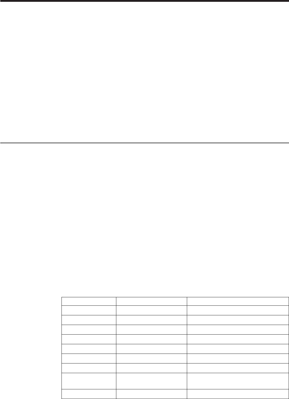
Appendix G. Emulation support for Epson single-station
printer
Commands supported in emulation mode...............193
Commands with limited support in emulation mode ...........195
Commands not supported in emulation mode .............196
Connectivity differences .....................196
Functional differences ......................196
The SureMark single-station printers in single-byte character set (SBCS) mode can
emulate an Epson single-station printer. Emulation mode provides full support for
most Epson commands. However, some commands are supported partially and a
few commands are not supported at all. This section describes the commands that
have each of the three levels of support and also lists the connectivity differences
between an Epson single-station printer and the SureMark.
Note: Ensure that the dip switch on the printer is set to "Other," rather than "IBM."
Commands supported in emulation mode
The commands listed in Table 28 are supported in Epson emulation mode.
However, there will be some differences in the printed output, because of different
dot pitches in the print heads and the minimum distance that the paper feed motors
can move the paper. These differences will appear when there are a number of
printed lines, and the method of aligning the data is different.
Examples of the printed differences that might occur:
vLogos will appear smaller in emulation mode. The logo will still contain the same
number of dots in the width and height. However, because the SureMark print
head has a finer dot pitch, the logo will appear smaller. If text is aligned around
the logo, the text on receipts that are printed in emulation mode might not line up
the same as receipts that are printed on the Epson printer.
vIf one line is aligned using spaces and another line is aligned using the relative
position commands, the data might appear misaligned. The commands, such as
the relative position and margin commands, that use the minimum unit of motion
values are based on a fraction of an inch, which eliminates the differences in the
dot pitch. Tabs and spaces are subject to pitch differences.
Table 28. Commands supported in Epson emulation mode
Hex Command ASCII Command Description
9HT Tab
0A LF Line feed
0C FF Print and return to standard mode
0D CR Print and carriage return
1B 20 n ESC SP n Set right-side character spacing
1B 21 n ESC ! n Select print mode
1B 24 nL nH ESC $ nL nH Set absolute print position
1B 25 n ESC % n Select or cancel user-defined character
set
1B 26 y c1 c2... ESC&yc1c2... Define user-defined characters
Updated April 2, 2009
© Copyright IBM Corp. 1997, 2006 193

Table 28. Commands supported in Epson emulation mode (continued)
Hex Command ASCII Command Description
1B 2A m nL nH dl..k ESC*mnLnHdl...k Select bit-image mode
1B 32 ESC 2 Select default line spacing
1B 33 n ESC 3 n Set line spacing
1B 3D n ESC = n Set peripheral device
1B 3F n ESC ? n Cancel user-defined characters
1B 40 ESC @ Initialize printer
1B 45 n ESC E n Turn emphasized mode on or off
1B 47 n ESC G n Turn double-strike mode on or off
1B 4A n ESC J n Print and feed paper
1B 52 n ESC R n Select an international character set
1B 53 ESC S Select standard mode
1B 56 n ESC V n Turn 90° clockwise rotation mode on or
off
1B 5C nL nH ESC \ nL nH Set relative print position
1B 61 n ESC a n Select alignment
1B6333n ESCc3n Select paper sensor to output paper end
signals
1B6335n ESCc5n Enable or disable panel buttons
1B 64 n ESC d n Print and feed n lines
1B70mt1t2 ESCpmt1t2 Generate pulse
1B 7B n ESC { n Turn upside-down printing mode on or
off
1C 67 32 m a1 a2
a3 a4...
FSg2ma1a2a3a4... Read from user NV memory
1C70nm FSpnm Print NV bit image
1D 21 n GS ! n Select character size
1D 2A xydl
...d(x*y*8)
GS * xydl ...d(x*y*8) Define user-defined bit image
1D 2F m GS / m Print user-defined bit image
1D 3A GS : Start or end user-defined message
1D 42 n GS B n Turn white/black reverse printing mode
1D 48 n GS H n Select printing position for HRI
characters
ID 49 n GS I n Transmit printer ID
ID 4C nL nH GS L nL nH Set left margin
1D 50 x y GS P x y Set horizontal and vertical motion units
1D56mn GSVmn Select cut mode and cut paper
ID 57 nL nH GS nL nH Set printing area width
1D 61 n GS a n Enable or disable automatic status back
1D 66 n GS f n Select font for HRI characters
1D 68 n GS h n Select bar code height
1D 72 n GS r n Transmit status
Updated April 2, 2009
194 SureMark Printers User’s Guide

Commands with limited support in emulation mode
The commands listed in Table 29 are supported in a limited manner in Epson
emulation mode. The table describes the limitation on each command.
Table 29. Commands with limited support in Epson emulation mode
Command Description of Limitation
10 04 n Real-time status
transmission
A status byte will be returned when the
command is sent. The following status
bits will not be supported.
vOffline status bit 6
vError status bits 5 and 6
vPaper roll status bits 2 and 3 (near
end of paper) - Bit will be set when
out of paper
1B 2D n Turn underline mode on/off There is no thickness option available. A
value of n=1, 2, 49 or 50 will enable
underline mode.
1B 44 m1...nk 00 Set horizontal tab positions The number of tab positions is limited to
5.
1B 63 34 n Select paper sensor to stop
printing
The command will be accepted, but it
has no function. There is no paper low
sensor on the SureMark. The printer will
only return out of paper status.
1B 74 n Select character code table All characters on all code pages are not
supported. The Katakana code page is
not supported.
1D5Ertm Execute user-defined
message
Does not support the mode where the
user-defined message is printed when
the paper advance button is pressed.
1D 77 n Set bar code width The maximum width is 4 dots on the
SureMark. Widths of 5 and 6 will be
forced to 4 dots.
1C 67 31 m a1 a2
a3 a4...
Write to user NV memory If received during user-defined message
definition, this command will be
embedded in the NV memory. Epson
will stop the definition and store the
data in NV memory.
The user is required to erase the NV
memory before the address can be
overwritten.
1C 71 n [xL xH yL
yH...
Define NV bit image The width is limited to 576 dots wide
and 255 rows high.
Updated April 2, 2009
Appendix G. Emulation support for Epson single-station printer 195
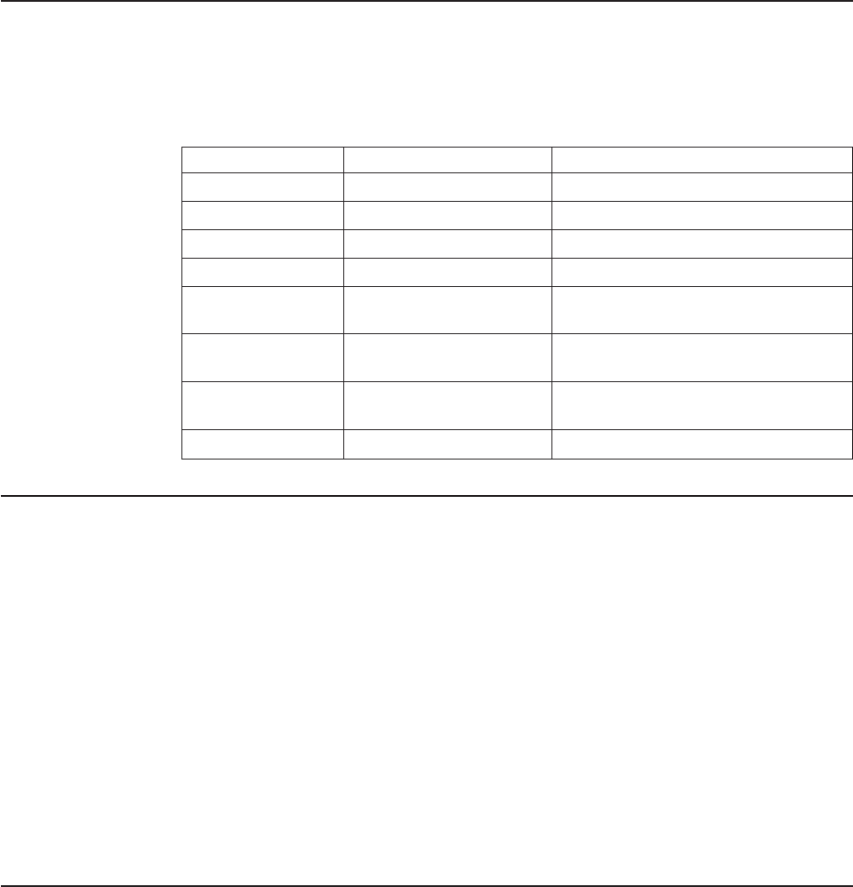
Commands not supported in emulation mode
In Epson emulation mode, the SureMark printer supports all Epson commands
except the page mode commands and smoothing. Table 30 lists the commands that
are not supported.
Table 30. Commands not supported in Epson emulation mode
Hex Command ASCII Command Description of Limitation
18 CAN Cancel print data in page mode
1B 0C ESC FF Print data in page mode
1B 4C ESC L Select page mode
1B 54 n ESC T n Select print direction in page mode
1B 57 xL xH yL yH
...
ESC W xL xH yL yH... Set printing area in page mode
1D 24 nL nH GS $ nL nH Set absolute vertical print position in
page mode
1D 5C nL nH GS \ nL nH Set relative vertical print position in
page mode
1D 62 n GS b n Turn smoothing mode on or off
Connectivity differences
The connectivity differences between an Epson single-station printer and the
SureMark printers are:
vThe Epson printer offers a parallel interface that the SureMark printer does not
support.
vThe following EIA-232 modes of communication, which are supported by the
Epson single-station printer, are not supported by the SureMark printer:
– 2400 kbps and 4800 kbps baud
– 7 bits of data
– Parity
– More than one stop bit
– 25-pin D shell
vTo attach the printer to a standard PC serial port:
– The Epson single-station printer requires a Null Modem cable.
– The SureMark requires a standard 9-pin D-shell EIA-232 cable.
Functional differences
The following limitations must be considered when using a single-station SureMark
printer to emulate an Epson single-station printer:
vWhen applications switch from Epson printers to IBM printers, there is sometimes
a difference in the receipt line spacing. The receipt appears double spaced
because, by default, the SureMark printer treats carriage returns (CRs) the same
as line feeds (LFs). To change this behavior see “Mode Option” MCT #30 (1E
hex) in Table 17 on page 125.
vTo provide a more seamless transition between OPOS-driven Epson and IBM
printers, IBM now supports an OEM Printer Emulation setting in the OPOS
printer device configuration dialog. Enable this setting to produce behavior that is
more consistent with that of an Epson printer. (Refer to the Application
Programming Guide for your driver.)
Updated April 2, 2009
196 SureMark Printers User’s Guide
Appendix H. Safety information
Danger
Before you begin to install this product, read the safety information in
IBM Safety Information—Read This First, GA27-4004. This booklet describes
safe procedures for cabling and plugging in electrical equipment.
Gevaar
Voordat u begint met de installatie van dit produkt, moet u eerst de
veiligheidsinstructies lezen in de brochure Veiligheidsinstructies—Lees dit
eerst, GA27-4004. Hierin wordt beschreven hoe u electrische apparatuur op
een veilige manier moet bekabelen en aansluiten.
Perigo
Antes de começar a instalar este produto, leia as informações de
segurança contidas em Informações Sobre Seguranaça—Leia Isto Primeiro,
GA27-4004. Esse folheto descreve procedimentos de segurança para a
instalação de cabos e conexões em equipamentos elétricos.
Fare!
Før du installerer dette produkt, skal du læse sikkerhedsforskrifterne i
Sikkerhedsforskrifter—Lœs dette først GA27-4004. Vejledningen beskriver den
fremgangsmåde, du skal bruge ved tilslutning af kabler og udstyr.
Gevaar
Voordat u begint met het installeren van dit produkt, dient u eerst de
veiligheidsrichtlijnen te lezen die zijn vermeld in de publikatie IBM Safety
Information—Read This First, GA27-4004. In dit boekje vindt u veilige
procedures voor het aansluiten van elektrische appratuur.
VAARA
Ennen kuin aloitat tämän tuotteen asennuksen, lue julkaisussa
Turvaohjeet—Luetämä ensin, GA27-4004, olevat turvaohjeet. Tässä kirjasessa
on ohjeet siitä, miten sähkölaitteet kaapeloidaan ja kytketään turvallisesti.
Updated April 2, 2009
© Copyright IBM Corp. 1997, 2006 197
Danger
Avant d’installer le présent produit, consultez le livret Informations pour
la sécurité—Lisez-moi d’abord, GA27-4004, qui décrit les procédures à
respecter pour effectuer les opérations de câblage et brancher les
équipements électriques en toute sécurité.
Vorsicht
Bevor mit der Installation des Produktes begonnen wird, die
Sicherheitshinweise in Sicherheitsinformationen—Bitte zuerst lesen, IBM Form
GA27-4004. Diese Veröffentlichung beschreibt die Sicherheitsvorkehrungen für
das Verkabeln und Anschlieβen elektrischer Geräte.
Vigyázat
Mielôtt megkezdi a berendezés üzembe helyezését, olvassa el a IBM
Safety Information—Read This First, GA27-4004 könyvecskében leírt
biztonsági információkat. Ez a könyv leírja, milyen biztonsági intézkedéseket
kell megtenni az elektromos berendezés huzalozásakor illetve
csatlakoztatásakor.
Pericolo
Prima di iniziare l’installazione di questo prodotto, leggere le
informazioni relative alla sicurezza riportate nell’opuscolo Informazioni di
sicurezza—Prime informazioni da leggere in cui sono descritte le procedure
per il cablaggio ed il collegamento di apparecchiature elettriche.
Fare
Før du begynner å installere dette produktet, må du lese
sikkerhetsinformasjonen i Sikkerhetsinformasjon—Les dette først, GA27-4004
som beskriver sikkerhetsrutinene for kabling og tilkobling av elektrisk utstyr.
Perigo
Antes de iniciar a instalação deste produto, leia as informações de
segurança Informações de Segurança—Leia Primeiro, GA27-4004. Este
documento descreve como efectuar, de um modo seguro, as ligações
eléctricas dos equipamentos.
Updated April 2, 2009
198 SureMark Printers User’s Guide

Peligro
Antes de empezar a instalar este producto, lea la información de
seguridad en Información de Seguridad—Lea Esto Primero, GA27-4004. Este
documento describe los procedimientos de sequridad para cablear y enchufar
equipos eléctricos.
Varning—livsfara
Innan du börjar installera den här produkten bör du läsa
säkerhetsinformationen i dikumentet Säkerhetsföreskrifter—Läs detta först,
GA27-4004. Där beskrivs hur du på ett säkert sätt ansluter elektrisk utrustning.
Updated April 2, 2009
Appendix H. Safety information 199
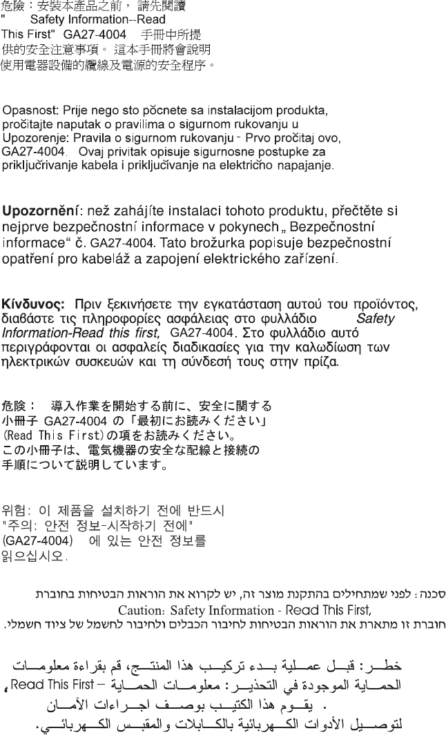
IBM
IBM
GA27-4004
GA27-4004
Updated April 2, 2009
200 SureMark Printers User’s Guide
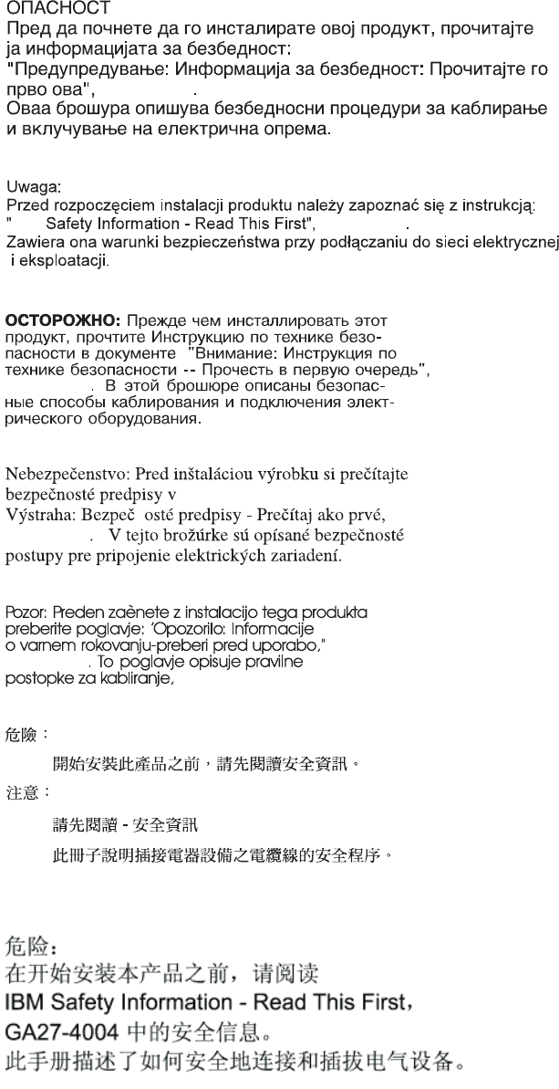
GA27-4004
GA27-4004
GA27-4004
GA27-4004
GA27-4004
GA27-4004
IBM
Updated April 2, 2009
Appendix H. Safety information 201
Updated April 2, 2009
202 SureMark Printers User’s Guide

Appendix I. Notices
This information was developed for products and services offered in the U.S.A.
IBM may not offer the products, services, or features discussed in this document in
other countries. Consult your local IBM representative for information on the
products and services currently available in your area. Any reference to an IBM
product, program, or service is not intended to state or imply that only that IBM
product, program, or service may be used. Any functionally equivalent product,
program, or service that does not infringe any IBM intellectual property right may be
used instead. However, it is the user’s responsibility to evaluate and verify the
operation of any non-IBM product, program, or service.
IBM may have patents or pending patent applications covering the subject matter in
this document. The furnishing of this document does not give you any license to
these patents. You can send license inquiries, in writing, to:
IBM Director of Licensing
IBM Corporation
North Castle Drive
Armonk, NY 10504-1785
U.S.A.
For license inquiries regarding double-byte character set (DBCS) information,
contact the IBM Intellectual Property Department in your country or send inquiries,
in writing, to:
IBM World Trade Asia Corporation
Licensing
2-31 Roppongi 3-chome, Minato-ku
Tokyo 106, Japan
The following paragraph does not apply to the United Kingdom or any other country
where such provisions are inconsistent with local law: INTERNATIONAL BUSINESS
MACHINES CORPORATION PROVIDES THIS PUBLICATION "AS IS" WITHOUT
WARRANTY OF ANY KIND, EITHER EXPRESS OR IMPLIED, INCLUDING, BUT
NOT LIMITED TO, THE IMPLIED WARRANTIES OF NON-INFRINGEMENT,
MERCHANTABILITY, OR FITNESS FOR A PARTICULAR PURPOSE. Some states
do not allow disclaimer of express or implied warranties in certain transactions,
therefore, this statement may not apply to you.
This information could include technical inaccuracies or typographical errors.
Changes are periodically made to the information herein; these changes will be
incorporated in new editions of the publication. IBM may make improvements and/or
changes in the product(s) and/or program(s) described in this publication at any
time without notice.
IBM may use or distribute any of the information you supply in any way it believes
appropriate without incurring any obligation to you.
Any references in this information to non-IBM Web sites are provided for
convenience only and do not in any manner serve as an endorsement of those
Web sites. The materials at those Web sites are not part of the materials for this
IBM product and use of those Web sites is at your own risk.
Updated April 2, 2009
© Copyright IBM Corp. 1997, 2006 203
Information concerning non-IBM products was obtained from the suppliers of those
products, their published announcements or other publicly available sources. IBM
has not tested those products and cannot confirm the accuracy of performance,
compatibility or any other claims related to non-IBM products. Questions on the
capabilities of non-IBM products should be addressed to the suppliers of those
products.
This information is for planning purposes only. The information herein is subject to
change before the products described become available.
Updated April 2, 2009
204 SureMark Printers User’s Guide

Electronic emission notices
Federal Communications Commission (FCC) statement
This equipment has been tested and found to comply with the limits for a Class A
digital device, pursuant to Part 15 of the FCC Rules. These limits are designed to
provide reasonable protection against harmful interference when the equipment is
operated in a commercial environment. This equipment generates, uses, and can
radiate radio frequency energy and, if not installed and used in accordance with the
instruction manual, may cause harmful interference to radio communications.
Operation of this equipment in a residential area is likely to cause harmful
interference, in which case the user will be required to correct the interference at
his own expense.
Properly shielded and grounded cables and connectors must be used in order to
meet FCC emission limits. IBM is not responsible for any radio or television
interference caused by using other than recommended cables and connectors or by
unauthorized changes or modifications to this equipment. Unauthorized changes or
modifications could void the user’s authority to operate the equipment.
This device complies with part 15 of the FCC Rules. Operation is subject to the
following two conditions:
1. This device may not cause harmful interference, and
2. This device must accept any interference received, including interference that
may cause undesired operation.
European Union EMC Directive conformance statement
This product is in conformity with the protection requirements of EU Council
Directive 2004/108/EC on the approximation of the laws of the Member States
relating to electromagnetic compatibility. IBM cannot accept responsibility for any
failure to satisfy the protection requirements resulting from a non-recommended
modification of the product, including the fitting of non-IBM option cards.
This product has been tested and found to comply with the limits for Class A
Information Technology Equipment according to CISPR 22/European Standard EN
55022. The limits for Class A equipment were derived for commercial and industrial
environments to provide reasonable protection against interference with licensed
communication equipment.
Attention: This is a Class A product. In a domestic environment this product may
cause radio interference in which case the user may be required to take adequate
measures.
European Community contact:
IBM Technical Regulations
Pascalstr. 100, Stuttgart, Germany 70569
Telephone: 0049 (0)711 785 1176
Fax: 0049 785 1283
E-mail: tjahn@de.ibm.com
Updated April 2, 2009
Appendix I. Notices 205

Industry Canada Class A Emission Compliance statement
This Class A digital apparatus complies with Canadian ICES-003.
Avis de conformité aux normes d’Industrie Canada
Cet appareil numérique de la classe A est conforme à la norme NMB-003 du
Canada.
Germany
Zulassungsbescheinigung laut dem Deutschen Gesetz über die
elektromagnetische Verträglichkeit von Geräten (EMVG) vom 30. August 1995
(bzw. der EMC EG Richlinie 89/336).
Dieses Gerät ist berechtigt in Übereinstimmung mit dem Deutschen EMVG das
EG-Konformitätszeichen - CE - zu führen.
Verantwortlich für die Konformitätserklärung nach Paragraph 5 des EMVG ist die
IBM Deutschland Informationssysteme GmbH, 70548 Stuttgart
Informationen in Hinsicht EMVG Paragraph 3 Abs. (2) 2:
Das Gerät erfüllt die Schutzanforderungen nach EN 50082–1 und EN 55022 Klasse A.
EN 55022 Klasse A Geräte müssen mit folgendem Warnhinweis versehen werden:
″Warnung: dies ist eine Einrichtung der Klasse A. Diese Einrichtung kann im
Wohnbereich Funkstörungen verursachen; in diesem Fall kann vom Betreiber
verlangt werden, angemessene Maβnahmen durchzuführen und dafür
aufzukommen.″
EN 50082–1 Hinweis:
″Wird dieses Gerät in einer industriellen Umgebung betrieben (wie in EN 50082–2
festgelegt), dann kann es dabei eventuell gestört werden. In solch einem Fall ist der
Abstand bzw. die Abschirmung zu der industriellen Störquelle zu vergröβern.″
Anmerkung:
Um die Einhaltung des EMVG sicherzustellen sind die Geräte, wie in den IBM
Handbüchern angegeben, zu installieren und zu betreiben.
Australia and New Zealand
Attention: This is a Class A product. In a domestic environment this product may
cause radio interference, in which case the user may be required to take adequate
measures.
Updated April 2, 2009
206 SureMark Printers User’s Guide
Chinese Class A warning statement
Attention: This is a Class A product. In a domestic environment this product may
cause radio interference in which case the user may be required to take adequate
measures.
Japanese power line harmonics compliance statement
Japanese Voluntary Control Council for Interference (VCCI) statement
Attention: This product is a Class A Information Technology Equipment and
conforms to the standards set by the Voluntary Control Council for Interference by
Technology Equipment (VCCI). In a domestic environment this product may cause
radio interference in which case the user may be required to take adequate
measures.
Korean communications statement
Please note that this device has been approved for business purposes with regard
to electromagnetic interference. If you find this is not suitable for your use, you may
exchange it for a non-business purpose one.
Updated April 2, 2009
Appendix I. Notices 207
Taiwanese Class A warning statement
Taiwan contact information
IBM Taiwan Product Service Contact Info:
IBM Taiwan Corporation
3F, No 7, Song Ren Road, Taipei Taiwan
Telephone: 0800-016-888
Cable ferrite requirement
All cable ferrites are required to suppress radiated EMI emissions and must not be
removed.
Electrostatic Discharge (ESD)
Attention: ESD damage can occur when there is a difference in charge between
the part, the product, and the service person. No damage will occur if the service
person and the part being installed are at the same charge level.
Updated April 2, 2009
208 SureMark Printers User’s Guide

ESD Damage Prevention
Anytime a service action involves physical contact with logic cards, modules,
back-panel pins, or other ESD sensitive (ESDS) parts, the service person must be
connected to an ESD common ground point on the product through the ESD wrist
strap and cord.
The ESD ground clip can be attached to any frame ground, ground braid, green
wire ground, or the round ground prong on the AC power plug. Coax or connector
outside shells can also be used.
Handling Removed Cards
Logic cards removed from a product should be placed in ESD protective containers.
No other object should be allowed inside the ESD container with the logic card.
Attach tags or reports that must accompany the card to the outside of the container.
Product Recycling and disposal
This unit must be recycled or discarded according to applicable local and national
regulations. IBM encourages owners of information technology (IT) equipment to
responsibly recycle their equipment when it is no longer needed. IBM offers a
variety of product return programs and services in several countries to assist
equipment owners in recycling their IT products. Information on IBM product
recycling offerings can be found on IBM’s Internet site at http://www.ibm.com/ibm/
environment/products/prp.shtml.
Español:
Esta unidad debe reciclarse o desecharse de acuerdo con lo establecido en la
normativa nacional o local aplicable. IBM recomienda a los propietarios de equipos
de tecnología de la información (TI) que reciclen responsablemente sus equipos
cuando éstos ya no les sean útiles. IBM dispone de una serie de programas y
servicios de devolución de productos en varios países, a fín de ayudar a los
propietarios de equipos a reciclar sus productos de TI. Se puede encontrar
información sobre las ofertas de reciclado de productos de IBM en el sitio web de
IBM http://www.ibm.com/ibm/environment/products/prp.shtml.
Notice: This mark applies only to countries within the European Union (EU) and
Norway.
Appliances are labeled in accordance with European Directive 2002/96/EC
concerning waste electrical and electronic equipment (WEEE). The Directive
determines the framework for the return and recycling of used appliances as
applicable throughout the European Union. This label is applied to various products
to indicate that the product is not to be thrown away, but rather reclaimed upon end
of life per this Directive.
Remarque : Cette marque s’applique uniquement aux pays de l’Union Européenne
et à la Norvège. L’etiquette du système respecte la Directive européenne
2002/96/EC en matière de Déchets des Equipements Electriques et Electroniques
Updated April 2, 2009
Appendix I. Notices 209
(DEEE), qui détermine les dispositions de retour et de recyclage applicables aux
systèmes utilisés à travers l’Union européenne. Conformément à la directive, ladite
étiquette précise que le produit sur lequel elle est apposée ne doit pas être jeté
mais être récupéré en fin de vie.
In accordance with the European WEEE Directive, electrical and electronic
equipment (EEE) is to be collected separately and to be reused, recycled, or
recovered at end of life. Users of EEE with the WEEE marking per Annex IV of the
WEEE Directive, as shown above, must not dispose of end of life EEE as unsorted
municipal waste, but use the collection framework available to customers for the
return, recycling, and recovery of WEEE. Customer participation is important to
minimize any potential effects of EEE on the environment and human health due to
the potential presence of hazardous substances in EEE. For proper collection and
treatment, contact your local IBM representative.
Disposal of IT products should be in accordance with local ordinances and
regulations.
Battery return program
This product may contain sealed lead acid, nickel cadmium, nickel metal hydride,
lithium, or lithium ion battery. Consult your user manual or service manual for
specific battery information. The battery must be recycled or disposed of properly.
Recycling facilities may not be available in your area. For information on disposal of
batteries outside the United States, go to http://www.ibm.com/ibm/environment/
products/batteryrecycle.shtml or contact your local waste disposal facility.
In the United States, IBM has established a return process for reuse, recycling, or
proper disposal of used IBM sealed lead acid, nickel cadmium, nickel metal hydride,
and other battery packs from IBM equipment. For information on proper disposal of
these batteries, contact IBM at 1-800-426-4333. Please have the IBM part number
listed on the battery available prior to your call.
For Taiwan:
Please recycle batteries.
Updated April 2, 2009
210 SureMark Printers User’s Guide
For the European Union:
Notice: This mark applies only to countries within the European Union (EU)
Batteries or packaging for batteries are labeled in accordance with European
Directive 2006/66/EC concerning batteries and accumulators and waste batteries
and accumulators. The Directive determines the framework for the return and
recycling of used batteries and accumulators as applicable throughout the European
Union. This label is applied to various batteries to indicate that the battery is not to
be thrown away, but rather reclaimed upon end of life per this Directive.
Les batteries ou emballages pour batteries sont étiquetés conformément aux
directives européennes 2006/66/EC, norme relative aux batteries et accumulateurs
en usage et aux batteries et accumulateurs usés. Les directives déterminent la
marche à suivre en vigueur dans l’Union Européenne pour le retour et le recyclage
des batteries et accumulateurs usés. Cette étiquette est appliquée sur diverses
batteries pour indiquer que la batterie ne doit pas être mise au rebut mais plutôt
récupérée en fin de cycle de vie selon cette norme.
In accordance with the European Directive 2006/66/EC, batteries and accumulators
are labeled to indicate that they are to be collected separately and recycled at end
of life. The label on the battery may also include a chemical symbol for the metal
concerned in the battery (Pb for lead, Hg for mercury and Cd for cadmium). Users
of batteries and accumulators must not dispose of batteries and accumulators as
unsorted municipal waste, but use the collection framework available to customers
for the return, recycling and treatment of batteries and accumulators. Customer
participation is important to minimize any potential effects of batteries and
accumulators on the environment and human health due to the potential presence
of hazardous substances. For proper collection and treatment, contact your local
IBM representative.
This notice is provided in accordance with Royal Decree 106/2008 of Spain: The
retail price of batteries, accumulators and power cells includes the cost of the
environmental management of their waste.
For California:
Perchlorate material – special handling may apply
Refer to http://www.dtsc.ca.gov/hazardouswaste/perchlorate.
Updated April 2, 2009
Appendix I. Notices 211

The foregoing notice is provided in accordance with California Code of Regulations
Title 22, Division 4.5, Chapter 33: Best Management Practices for Perchlorate
Materials. This product/part includes a lithium manganese dioxide battery which
contains a perchlorate substance.
Flat panel displays
The fluorescent lamp in the liquid crystal display contains mercury. Dispose of it as
required by local ordinances and regulations.
Monitors and workstations
Connecticut - Please see the web site of the Department of Environmental
Protection at http://www.ct.gov/dep for information about recycling covered
electronic devices in the State of Connecticut, or telephone the Connecticut
Department of Environmental Protection at 1-860-424-3000.
Oregon - For information regarding recycling covered electronic devices in the state
of Oregon, go to the Oregon Department of Environmental Quality site at
http://www.deq.state.or.us/lq/electronics.htm.
Washington - For information about recycling covered electronic devices in the
State of Washington, go to the Department of Ecology Web site at
https://fortress.wa.gov/ecy/recycle/ or telephone the Washington Department of
Ecology at 1-800Recycle.
Trademarks
The following are trademarks of International Business Machines Corporation in the
United States or other countries, or both:
AnyPlace Kiosk(tm)
AnyPlace POS Hub(tm)
DB2
DB2 Universal Database
IBM and the IBM logo
PS/2
SureMark
SurePoint
SurePOS
Wake on LAN
WebSphere
Microsoft, Windows, Windows NT, and the Windows logo are trademarks of
Microsoft Corporation in the United States, other countries, or both.
Celeron and Intel are trademarks of Intel corporation in the United States, or other
countries.
Java and all Java-based trademarks and logos are trademarks or registered
trademarks of Sun Microsystems, Inc. in the United States, or other countries, or
both.
Other company, product, or service names may be trademarks or service marks of
others.
Updated April 2, 2009
212 SureMark Printers User’s Guide

Index
Numerics
4610 fonts and logos 37
4610 fonts and logos utilities 37
A
AipFlsh46 40
align positions command 139
application requirements 14
asynchronous commands 175
B
bar code commands
enable PDF417 truncation 155
print bar code 147
print PDF417 bar code 153
select aspect ratio PDF417 bar code 155
select bar code height 152
select font for HRI 153
select horizontal size of bar code 152
select PDF417 ECC level 154
select printing position of HRI 152
bar codes, supported 15
batch printing commands 176
battery return program 210
battery, European Union 210
baud rate selection, EIA-232 28
baud rate selection, EIA-232, Model TI8 30
BMP 5
C
cable ferrite requirement 208
calibration, document scanner 60
cash drawer drive pulse command 161
cash drawer pin assignments 90
character fonts 98
check processing commands 164
check verification, printing 47
checks, clearing jams 55
Class A compliance statement
Australia and New Zealand 206
China 207
European Union 205
FCC (USA) 205
Germany 206
Industry Canada 206
Japan 207
Taiwan 208
cleaning
MICR reader read head 56
scanner 59
thermal print head (Model TI1, TI2, TI3, TI4, TI8,
TG3, TG4) 57
thermal print head (Models TF6 and TM6) 73
clearing jams, DI station 55
code page command, set 135
code pages
code page 437 94
code page 858 95
code page 860 96
code page 863 97
code page 865 98
definitions 92
generic 93
resident 15
code pages, resident 15
command line utility 40
commands, EIA-232
asynchronous 175
bar code commands 147
batch printing 176
check processing 164
data buffer management 176
document handling 181
document scanner 166
miscellaneous 160
page mode printing 177
preset 114
print character 156
print graphics (logo) command 157
setup 129
system 111
commands, immediate 89
communication interfaces 10
communication mode selection
EIA-232 28, 30
USB 31
consumable supplies 81
controls, printer
Models TF6 and TM6 71
Models TI1, TI2, TI3, TI4, TI8, TI9, TG3, TG4, TG8,
TG9 47
conversion utility, proportional fonts 37
D
damage from electrostatic discharge 208
data buffer management commands 176
define document wait time command 141
dimensions, physical 10
disable feed buttons 143
disable line count 176
disable the beeper 143
disable upside-down printing 144
diskette, fonts and logos utilities, 4610 37
diskettes
related xvi
disposal of equipment 209
document format 5
document handling
landscape mode 182
portrait mode 181
document handling, landscape mode commands 182
Updated April 2, 2009
© Copyright IBM Corp. 1997, 2006 213
document handling, portrait mode commands 181
document insert forms 82
document length, setting 133
document scanner calibration 60
double-high mode command, set or cancel 131
double-wide mode command, set or cancel 130
download graphics (logo) commands 115
download user-defined characters command 118
DTR and DSR
control description 29, 30
selection 28
E
EC request command 175
edition notice ii
EIA-232 commands 101
1/6-in. line spacing, select 136
1/8-in. line spacing, select 136
align positions 139
asynchronous 175
bar code commands 147
enable PDF417 truncation 155
print bar code 147
print font, select HRI 153
print PDF417 bar code 153
print position, select HRI 152
select aspect ratio PDF417 bar code 155
select PDF417 ECC level 154
set bar code height 152
set bar code horizontal size 152
batch printing 176
cash drawer drive pulse 161
character for reprinted line, select 142
check processing 164
data buffer management 176
define document wait time 141
disable line count 176
document handling 181
document scanner 166
download graphics (logo) 115
download user-defined characters 118
EC request 175
EIA-232 parameters 91
emphasized printing, set or cancel 132
enable/disable the beeper 143
enable/disable upside-down printing 144
erase flash EPROM sector 123
exercise program 111
extended address command 112
feed buttons 143
feed minimum units 156
feed n lines 156
fix font matrix 146
flash storage write 123
flip check 166
form feed and cut 156
hold printing 177
impact code page 122
landscape printing 183
line feed, print 156
EIA-232 commands (continued)
line spacing, minimum units 137
maximum print speed 132
MICR read 165
microcode tolerance, loading 124
microcode tolerance, request 125
miscellaneous 160
onetime-set 114
page mode printing 177
paper cut/DI eject 161
predefine messages 117
preset 114
print and line feed 156
print character 156
print graphics (logo) command 157
print head home position, select 160
print logo inline 146
print mode, set 129
print predefined logo 159
print predefined messages 159
proportional font 120
real-time 175
real-time status request 175
release print buffer 175
Request document length 133
reset line count 176
retrieve flash storage 161
retrieve printer usage statistics 162
retrieve size of flash storage 162
reverse print and feed paper 157
select character sets 134
select character size for scalable fonts 145
select color printing 137
select thermal paper 147
send checksum flash EPROM sector 124
send status to system 141
set code page 135
Set document length for landscape print 133
set error recovery 140
set horizontal tabs 138
set intercharacter spacing 135
set left margin 138
set or cancel double-high mode 131
set or cancel double-wide mode 130
set or cancel invert 131
set or cancel overline mode 131
set or cancel rotated characters 135
set or cancel underline mode 131
set print station 134
set print station parameters 136
set relative position 139
set sheet eject length 138
setup 129
status bytes 184, 186
status request 112
status summary 184
system 111
tab to next tab stop 160
thermal code page 119
unidirectional printing, set or cancel 133
verify previous commands completed 111
Updated April 2, 2009
214 SureMark Printers User’s Guide
EIA-232 communication mode selections 28, 30
EIA-232 pin assignments 91
electronic emissions notices 205
Australia and New Zealand 206
China 207
European Union 205
FCC (USA) 205
Germany 206
Industry Canada 206
Japan 207
Korea 207
Taiwan 208
electronic journal data, upload during emulation 187
electrostatic discharge (ESD) 208
emphasized printing command, set or cancel 132
emptying printer buffer 41
emulate Epson single-station printer
commands with limited support 195
connectivity differences 196
enabling 43
fully-supported commands 193
limitations 43
overview 43
unsupported commands 196
emulate Model 3 or 4 printer
limitations 41
overview 41
upload electronic journal data 187
emulation, Epson 193
enable feed buttons 143
enable the beeper 143
enable upside-down printing 144
end of life disposal 209
Epson emulation 193
equipment disposal 209
erase flash EPROM sector command 123
error recovery command, set 140
exercise program 111
expendable supplies 83
extended address command 112
F
features, all models 6
ferrite requirement 208
fillers, installing
for EIA-232/RS-485 printers 24
for USB printers 26
firmware update image 39
firmware update, printer 39
firmware, updating
firmware update diskette 38
limitation 41
methods 37
POSS for Windows 39
via EIA-232 attachment 40
fix font matrix 146
flash memory
printing 41
usage 89
flash storage
retrieve 161
retrieve size 162
flash storage write command 123
flat panel displays 212
flip check command 166
flippable document specifications 82
fonts
character 98
impact printing 99
thermal printing 98
fonts and logos utilities, 4610 37
fonts and logos, 4610 37
fonts, character 98
fonts, proportional 189
forms, document insert, specifications 82
G
general description 87
generic code page 93
H
hardware requirements 13
height, all models 10
hex dump, EIA-232 66, 77
hold printing command 177
horizontal tabs command, set 138
humidity requirements 10
I
IBM Diagnostics for POS Systems and Peripherals 41
IBM Retail Store Solutions Web site 44
immediate commands 89
impact code page command 122
indicators, printer
Models TF6 and TM6 71
Models TI1, TI2, TI3, TI4, TI8, TI9, TG3, TG4, TG8,
TG9 47
information, planning 9
installation, single-station
power-on self-test, TF6 and TM6 75
problem determination, Models TF6 and TM6 78
testing, Models TF6 and TM6 75
installation, thermal/impact
fillers for EIA-232/RS-485 printers 24
fillers for USB printers 26
for EIA-232/RS-485 communication 18
for USB communication 21
power-on self-test, Models TI1/TI2/TI3/TI4/TI8 61
preparation 17
problem determination, Models TI1/TI2/TI3/TI4/TI8/
TI9/TG3/TG4/TG8/TG9 67
testing, Models TI1/TI2/TI3/TI4 61
unpacking 18
intercharacter spacing command, set 135
interfaces, communication 10
introduction 3
invert command, set or cancel 131
Updated April 2, 2009
Index 215
J
Japanese power line harmonics compliance
statement 207
Japanese Voluntary Control Council for Interference
statement 207
JavaPOS for Windows 39
JPEG 5
K
Korean communications statement 207
L
landscape printing commands 183
left margin command, set 138
limitations 9
line spacing, minimum units 137
line spacing, select 1/6 136
line spacing, select 1/8 136
M
maintenance, printers 85
maintenance, service provider 85
memory units 89
mercury-added statement 212
MICR data parser sample code 44
MICR read
read command 165
MICR reader and check flipper test 65
MICR reader read head cleaning 56
microcode tolerance (MCT)
loading command 124
request command 125
miscellaneous EIA-232 commands 160
Model 3 or 4 printer, emulate
limitations 41
overview 41
model comparison 7
multipart form specifications 82
N
notices 203
battery recycling 210
cable ferrites 208
electronic emissions 205
electrostatic discharge (ESD) 208
end of life disposal 209
IBM 203
safety information 197
O
offline test, single-station printer
customer receipt 76
reset printer 78
test pattern 77
offline test, thermal/impact printer
customer receipt test 62
document insert test 63
MICR reader and check flipper test 65
onetime-set commands 114
operating system requirements 13
overline mode command, set or cancel 131
overview 3
P
paper cut/DI eject command 161
paper width 87
paper, document insert, specifications 82
paper, select thermal 147
paper, thermal, specifications 81
parameters, serial RS-485 90
perchlorate 211
physical dimensions 10
pin assignments
cash drawer connector 90
EIA-232 connector 91
USB connector 92
planning information 9
power requirements 12
predefine messages command 117
preset commands 114
print and line feed command 156
print character commands 156
print head cleaning, thermal
Models TF6 and TM6 73
Models TI1, TI2, TI3, TI4, TI8, TG3, TG4 57
print head cleaning, thermal head 57
print logo inline 146
print mode command, set 129
print predefined graphics (logo) command 159
print scanned image command 168
print station command, set 134
print station parameters command, set 136
print width 87
printed copy of scanned check 66
printer firmware update using JavaPOS 39
printer, single-station
indicators and controls 71
operation 71
paper loading 71
printer, thermal/impact
check verification 47
clearing jams, DI station 55
indicators and controls 47
installing EIA-232/RS-485 fillers 24
installing for EIA-232/RS-485 18
installing for USB 21
installing USB fillers 26
operation 47
paper loading 53
ribbon loading 51
ribbon specifications 83
printing flash memory 41
printing saved data 41
Updated April 2, 2009
216 SureMark Printers User’s Guide
problem determination, single-station printer
customer receipt test 76
symptoms 78
problem determination, thermal/impact printer
customer receipt test 62
symptoms 67
product care 85
programming information 101
proportional font command 120
proportional fonts 189
conversion utility 37
implementing 189
layout using alignment 190
layout using tabs 191
publications
CD-ROM book collection xvi
Web site xvi
publications, related xvi
R
RAM
usage 89
re-initialize the printer command 142
real-time commands 175
real-time status request command 175
related publications and diskettes xvi
relative position command, set 139
release print buffer command 175
Request document length 133
request printer ID command 112
requirements
application programs 14
hardware 13
humidity 10
operating system 13
power 12
software 13
temperature 10
reset line count 176
reset printer 175
resetting the printer
Models TF6 and TM6 78
Models TI1, TI2, TI3, TI4, TI8, TG3, TG4 66
resident code pages 15
retrieve first unread image location command 174
retrieve flash storage command 161
retrieve next image location command 174
retrieve printer usage statistics command 162
retrieve scanned image command 172
retrieve size of flash storage command 162
reverse print and feed paper 157
ribbon loading 51
ribbons, print 83
rotated characters command, set or cancel 135
RS-485
parameters, serial 90
S
safety information 197
saved data, printing 41
scanned check printout 66
scanned document format 5
scanner
cleaning 59
scanner calibration 60
scanner calibration command 173
scanner commands
print scanned image 168
retrieve first unread image location 174
retrieve next image location 174
retrieve scanned image 172
scanner calibration 173
select compression format and scanned image
threshold 174
start scan 166
store scanned image 169
scanner resolution 173
select
1/6-in. line spacing, select 136
1/8-in. line spacing command 136
character for reprinted line command 142
character sets command 134
HRI (bar code) font 153
HRI (bar code) position 152
print graphics (logo) command 157
print head home position command 160
select character size for scalable fonts 145
select color printing command 137
select compression format and scanned image
threshold command 174
select maximum print speed 132
send checksum flash EPROM sector command 124
send status to system command 141
service proficer, system maintenance 85
Set document length for landscape print 133
set horizontal tabs command 138
setup
commands 129
set or cancel high quality print mode 132
sheet eject length command, set 138
single form specifications 82
software adjustments
updating firmware 37
using reference/service diskette 35
software requirements 13
specifications
cash drawer pins 90
document insert forms 82
documents to be flipped 82
EIA-232 pins 91
fonts 98
forms, single and multipart 82
memory 89
paper width 87
pitch 87
print ribbons 83
print width 87
RS-485 serial I/O 90
Updated April 2, 2009
Index 217
specifications (continued)
speed 87
thermal paper 81
USB pins 92
speed, print 87
start scan command 166
status
request 111, 112
summary 184
status bytes, EIA-232 184
status request command 112
store scanned image command 169
supplies 83
supplies, where to order 81
T
tab to next tab stop command 160
Taiwanese battery recycling statement 210
temperature requirements 10
testing
Models TF6 and TM6 75
Models TI1/TI2/TI3/TI4/TI8 61
thermal code page command 119
thermal paper specifications 81
thermal paper, select 147
TIFF 5
trademarks 212
TrueType fonts conversion utility 37
U
underline mode command, set or cancel 131
unidirectional printing command, set or cancel 133
unpacking the printer 18
update firmware
firmware update diskette 38
limitation 41
methods 37
POSS for Windows 39
via EIA-232 attachment 40
upload electronic journal data during emulation 187
USB communication mode 31
USB pin assignments 92
V
verify previous commands completed 111
voltage conversion circuitry 89
W
wall mounting feature, single-station printers 23
warranty information, all models 5
Web site, IBM Retail Store Solutions 44
weight, all models 10
where to order supplies 81
X
XON and XOFF
control description 29, 30
selection 28
Updated April 2, 2009
218 SureMark Printers User’s Guide

Readers’ Comments — We’d Like to Hear from You
SureMark 4610 Printers
User’s Guide for
Models TI1, TI2, TI3, TI4, TI8, TI9, TG3, TG4, TG8, TG9, TF6, and TM6
Publication No. GA27-4151-07
We appreciate your comments about this publication. Please comment on specific errors or omissions, accuracy,
organization, subject matter, or completeness of this book. The comments you send should pertain to only the
information in this manual or product and the way in which the information is presented.
For technical questions and information about products and prices, please contact your IBM branch office, your IBM
business partner, or your authorized remarketer.
When you send comments to IBM, you grant IBM a nonexclusive right to use or distribute your comments in any
way it believes appropriate without incurring any obligation to you. IBM or any other organizations will only use the
personal information that you supply to contact you about the issues that you state on this form.
Comments:
Thank you for your support.
Send your comments to the address on the reverse side of this form.
If you would like a response from IBM, please fill in the following information:
Name Address
Company or Organization
Phone No. E-mail address

Readers’ Comments — We’d Like to Hear from You
GA27-4151-07
GA27-4151-07
Cut or Fold
Along Line
Cut or Fold
Along Line
Fold and Tape Please do not staple Fold and Tape
Fold and Tape Please do not staple Fold and Tape
NO POSTAGE
NECESSARY
IF MAILED IN THE
UNITED STATES
BUSINESS REPLY MAIL
FIRST-CLASS MAIL PERMIT NO. 40 ARMONK, NEW YORK
POSTAGE WILL BE PAID BY ADDRESSEE
IBM Corporation
Dept ZBDA/Bldg. 307
P. O. Box 12195
Research Triangle Park, NC 27709-9990
_________________________________________________________________________________________
_________________________________________________________________________________________
___________________________________________________________________________________________________

Updated April 2, 2009
GA27-4151-07
