Ibm Surepos 500 Users Manual 4846 Tech Ref V1.1
500 to the manual 3c6d8f0b-a00e-49af-98ce-4073827ec9ad
2015-02-02
: Ibm Ibm-Surepos-500-Users-Manual-431363 ibm-surepos-500-users-manual-431363 ibm pdf
Open the PDF directly: View PDF ![]() .
.
Page Count: 63

SurePOS 500 4846-XX5 Technical Reference
Page 1 of 63
SurePOS 500 4846-545/565
Technical Reference
Version: 1.1

SurePOS 500 4846-XX5 Technical Reference
Page 2 of 63
Change History
Version Date Change Description
1.0 2/16/07 Initial Release

SurePOS 500 4846-XX5 Technical Reference
Page 3 of 63
Table of Contents
1.0 Introduction....................................................................................................................................................5
1.1 Highlights.......................................................................................................................................................5
1.2 Models ...........................................................................................................................................................5
1.3 Specifications ................................................................................................................................................5
1.4 Related Publications......................................................................................................................................6
2.0 Product Structure ..........................................................................................................................................8
2.1 Factory Select Feature ..................................................................................................................................8
2.2 Key optional features.....................................................................................................................................8
2.3 Ship Group ....................................................................................................................................................8
2.4 Supported Devices ........................................................................................................................................9
2.5 Operating System/POS Driver Support.........................................................................................................9
2.6 System management.....................................................................................................................................9
2.6.1 System management programs............................................................................................................9
2.6.2 Remote management .........................................................................................................................10
2.7 System Diagnostics.....................................................................................................................................10
2.7.1 Supported memory keys.....................................................................................................................10
2.8 Physical Characteristics ..............................................................................................................................10
2.8.1 Dimensions and weights.....................................................................................................................10
2.8.1.1 System .......................................................................................................................................10
2.8.1.2 Weights of features ....................................................................................................................11
2.8.1.3 Dimensions with Trays...............................................................................................................11
2.8.2 Controls...............................................................................................................................................12
2.8.3 Visual Indicators..................................................................................................................................12
2.8.4 Connector/Controls Identifier..............................................................................................................13
2.9 Product Description .....................................................................................................................................15
2.9.1 Block Diagram.....................................................................................................................................15
2.10 Logic ............................................................................................................................................................16
2.11 Component specifications ...........................................................................................................................17
2.11.1 4GB Modular Flash Drive ...................................................................................................................17
2.11.2 Hard Disk Drive...................................................................................................................................17
2.11.3 LCD.....................................................................................................................................................18
2.11.4 Magnetic Stripe Reader......................................................................................................................18
2.11.5 Integrated and Distributed 2x20..........................................................................................................18
2.11.6 All Points Addressable (APA) Display ................................................................................................19
2.11.7 Built-in speakers (XX5 models only)...................................................................................................20
3.0 BIOS and software description ..................................................................................................................21
3.1 Setup ...........................................................................................................................................................21
3.2 Functional Standards...................................................................................................................................21
3.3 Standard BIOS Features .............................................................................................................................21
3.4 BIOS Interrupts............................................................................................................................................22
3.5 Fixed BIOS Entry Points..............................................................................................................................23
3.6 BDA Memory Addresses .............................................................................................................................24
3.7 EBDA Memory Addresses...........................................................................................................................26
3.8 Memory Map................................................................................................................................................26
3.9 COM Port Setup ..........................................................................................................................................27
3.10 Video Modes................................................................................................................................................27
3.10.1 Display mode and operating system restrictions................................................................................30
3.11 Power Management ....................................................................................................................................31
3.11.1 APM ....................................................................................................................................................31
3.11.2 ACPI....................................................................................................................................................32
3.12 System Information Data.............................................................................................................................33
3.12.1 SMBIOS..............................................................................................................................................33
3.12.2 Cumulative Structure List....................................................................................................................33
3.13 Vital Product Data........................................................................................................................................34
3.13.1 VPD Layout in SMBIOS......................................................................................................................34
3.13.2 SMBIOS Type 11 Structure Layout ....................................................................................................34
4.0 Reliability and Serviceability......................................................................................................................34
SurePOS 500 4846-XX5 Technical Reference
Page 4 of 63
4.1 Usage ........................................................................................................... Error! Bookmark not defined.
5.0 Environmental Specifications ....................................................................................................................35
5.1 Temperature/Humidity Limits.......................................................................................................................35
5.2 Altitude Limits ..............................................................................................................................................35
5.3 Power...........................................................................................................................................................35
5.4 Acoustics .....................................................................................................................................................35
5.5 Standards Compliance ................................................................................................................................35
5.5.1 Product Certifications..........................................................................................................................35
5.5.2 Ergonomics and accessibility..............................................................................................................36
6.0 External Ports ..............................................................................................................................................37
6.1 Port Listing...................................................................................................................................................37
6.2 Port Power Ratings......................................................................................................................................37
6.3 Connector Pinouts.......................................................................................................................................38
6.3.1 Customer Display Connector..............................................................................................................38
6.3.2 MSR connector ...................................................................................................................................38
6.3.3 USB Plus Power (2x) ..........................................................................................................................39
6.3.4 USB port connector (7x) .....................................................................................................................39
6.3.5 Keyboard, Mouse connector (2x)........................................................................................................39
6.3.6 Microphone connector ........................................................................................................................40
6.3.7 Headphone Connector........................................................................................................................40
6.4 Serial Connector (x3)...................................................................................................................................40
6.4.1 Ethernet connector..............................................................................................................................41
6.4.2 External video connector ....................................................................................................................41
6.4.3 Cash Drawer (x2)................................................................................................................................42
6.4.4 Internal Customer Display ..................................................................................................................42
SurePOS 500 4846-XX5 Technical Reference
Page 5 of 63
1.0 Introduction
1.1 Highlights
The SurePOS 500 system units with integrated touch screens will help you easily create the right solution for your
business.
The SurePOS 500 Series models offer:
• An Intel Celeron D 326 (2.53 GHz) processor
• 512MB of DDR2 memory standard, upgradeable to 1 GB, 1.5GB, or 2GB.
• 8 to 128 MB UMA video memory
• A 80 GB SATA II HDD or greater
• 15" (12.1" and 17” optional) Infrared (IR) touch
• Enhanced wireless integration kit providing coverage and flexibility to meet most country-specific wireless
requirements by utilizing USB technology (USB wireless Dongle not included). The Performance multimedia
models also offer the capability to add wireless support via PC card slot
• Enhanced systems management
• Port enhancements, including powered 12V and 24V USB 2.0 ports, standard
• A wide range of optional features including receipt printers, displays, and trays to keep the counter neat.
1.2 Models
Model Base/Admin Model WEPOS Bundled
Printer Audio/PC Card
function Warranty
545 Base No No No Depot
565 Base No No Yes Depot
E45 Base Yes No No Depot
E65 Base Yes No Yes Depot
54Z Admin of 545 No No No IOR 24x7
56Z Admin of 565 No No Yes IOR 24x7
E4Z Admin of E45 Yes No No IOR 24x7
E6Z Admin of E65 Yes No Yes IOR 24x7
P45 Admin of 545 No Yes No IOR 24x7
P65 Admin of 565 No Yes Yes IOR 24x7
1.3 Specifications
4846 Model 545 4846 Model 565
Processor 2.53Ghz Intel 326 Celeron D
FSB Speed 533/800 Mhz Celeron/Pentium4
Chipset Intel 915GV / ICH6
BIOS Award
Main Memory 512MB – 1GB DDR2 DIMM, 2 slots, (2 GB max)
Video Integrated 2D/3D Intel graphics controller
(simultaneous support only for CRT output)
Secondary Video Adapter ATI Radeon 7000
LCD One of the following:
800x600 12.1-in TFT (2 bulb)
1024x768 15-in TFT (2 bulb)

SurePOS 500 4846-XX5 Technical Reference
Page 6 of 63
1280x1024 17-in TFT (4 bulb)
Touch IBM enhanced ELO Infra-red
Audio None
AC97 compliant codec;
Amplified stereo speakers
Mass Storage 80GB SATA II
4GB Modular Flash Drive
LAN 10BaseT/100BaseTx Ethernet
Expansion N/A Type II PC-Card Slot
I/O Ports and Connectors
7 Standard USB (3 display tablet, 4 tower rear)
Mouse, Keyboard (rear)
1 12V Powered USB 2.0 (rear)
1 24V Powered USB (rear)
2 Cash Drawer
3 Unpowered RS232
1 Powered RS232 (External Customer Display)
Headphone/Microphone – on 565 Model
RJ45 Ethernet LAN
External CRT
I/O Devices
External Floppy (USB)
MSR (3-Track/JUCC)
Integrated 2x20
Distributed 2x20
Distributed APA
Indicators Power
HDD activity
Controls Power
LCD Brightness
Volume (with speaker kit)
OS PC DOS 2000, Windows (2000, XP, WEPOS)
Ruggedization Spill resistant (NEMA/IEC)
Retail Hardened (ESD)
Power Supply 155 W Continuous Duty / 225W Maximum Internal Switching Supply
Mounting Free Standing
Integration Trays
Security Power On Password
Bolt down/Tray Mounting
1.4 Related Publications
SurePOS 500 Series Planning, Installation, and Operation Guide for Models 545 and 565, GA27-4365
This guide provides information necessary to install and set up the IBM SurePOS® 500 Series Models 545 and
565. This document is intended for the person who will install, set up, and manage the 4846-xx5 systems
IBM SurePOS 500 Series Hardware Service Guide for Models 545 and 565, SY27-0417
This document provides information on repairing and maintaining the system unit device, including parts listings,
troubleshooting, and removal and replacement procedures.
IBM SurePOS 500 Series Operating System Installation Guide for Models 545 and 565, GA30-4132
This guide provides step-by-step information on installing the operating software for the product.
IBM Point of Sale Options and I/O Devices Service Guide, GC30-9737
This guide describes the problem-determination and repair procedures for cash drawers, displays, keyboards, and
options that are attached to IBM(R) SurePOS(TM) systems.
To access these publications:
• Go to www.ibm.com/solutions/retail/store/

SurePOS 500 4846-XX5 Technical Reference
Page 7 of 63
• Select Support, then select Publications.
1.5 Comparison with predecessor products
Feature 4846-XX5 4840-XX3/XX4 4851-514
Processor Pentium 4/Celeron
(Prescott) Pentium 4/Celeron (Northwood) Via C3
Processor, max
clock speed
Celeron D 326 (2.53GHZ )
upgradable to Prescott
551 (3.4Ghz)
Celeron 2.0GHz upgradable to
2.8Ghz 1.2Ghz
North
Bridge/GMCH Intel 82915GV (Lakeport) Intel 82845GV (Brookdale)
GMCH CLE266
South Bridge/ICH ICH6 ICH4 VT8237R
System Memory 2.0GB Max. 2.0GB Max. 2.0GB Max.
System Memory
Technology DDR2 533Mhz maximum Double Data Rate (DDR)
SDRAM, 266Mhz * DDR 266Mhz *
Integrated Video
Controller
Intel Graphics Media
Accelerator 900 integrated
into chipset
Intel Extreme Graphics, 2D/3D
128b BLT/256b Fill engine S3 Graphics, 2D/3D 128b
engine
Video Memory Up to 128 MB,shared with
system memory Up to 64MB UMA with Windows
Driver, 8MB DOS legacy mode Up to 32MB UMA
Multi Monitor True multi monitor with
dual video adapter True multi monitor w/ Cedar
adapter No 2nd display option
Touch Screen
Technology IBM enhanced ELO IR ELO IR (Carroll Touch) ELO 5 Wire-Resistive
(Accutouch)
Keyboard ports Rear PS/2 KB Side and Rear (exclusive) PS/2
KB Rear PS/2 KB
Parallel Port None One None
10/100Mbit
Ethernet
ICH6 integrated MAC,
External Intel 82562GT
PHY
ICH4 integrated MAC, External
Intel 82562ET PHY VT8237 integrated MAC, Via
External PHY
USB Specification All Ports Low, Full, and
High Speed
Tower - Low, Full, High Speed
(480Mb/s) Ports
Tablet – Low, Full Speed
All Ports Low, Full, and High
Speed
Flash Storage Internal M-Systems USB
flash card, mb mount Compact Flash card and
adapter, replaces HDD RPQ required
Powered USB
Ports One 12v and One 24v
Power Ports One 12v and One 24v Powered
Ports One 24V Power Port
Standard USB
Ports 7 Standard (9 total ports) 6 Standard ports (8 total ports) 4 Standard (5 total ports)
Operating System Supported: Windows
2000, XP, WEPOS, DOS Supported: Win 2000, Win XP,
DOS, IBM IRES (XX3 only) Supported: Windows 2000,
XP, WEPOS, DOS

SurePOS 500 4846-XX5 Technical Reference
Page 8 of 63
2.0 Product Structure
For detailed product offering information:
• Go to www-306.ibm.com/common/ssi/OIX.wss
• Select HW and SW desc (sales manual)
• Enter 4846-545 as keyword
2.1 Factory Select Feature
Feature Description
Memory 512 MB, 1 GB, 2 GB DDR2 533MHz (2 x 1GB)
LCD Size 12-inch, 15-inch, 17-inch
Dual Video Dual Video adapter card
Modular Flash Drive 4GB Modular Flash Drive
2.2 Key optional features
Feature Comments
Integrated 2x20 Customer Display New P/N to 4846
Distributed 2x20 Customer Display Common with 4840
Distributed APA Customer Display Common with 4840
3-Track MSR New P/N to 4846
JUCC MSR New P/N to 4846
Counter Integration Tray (SST) New P/N – new fillers added
Standard CD Integration Tray (4610/kybd) New P/N – new fillers added
Compact CD Integration Tray (keyboard only) Not offered
Cash Drawer (standard, compact) Existing P/N
Compact A/N POS Keyboard Existing P/N
Serial Cable, RJ45 to DB9, 0.7m Existing P/N
Serial Cable, RJ45 to DB9, 2.0m Existing P/N
4610-TF6/7 Power Cable, 0.7m Existing P/N
4610-TF6/7 Power Cable, 2.0m Existing P/N
2.3 Ship Group
The following items are included with the unit:
• Cat 5 Ethernet Cable (4.3m), P/N 41A3531
• Serial Cable, RJ45 to DB9 (0.7m), P/N 40N5341
The following items are picked packed per order at fulfillment center:
• Warranty Sheet
• Regulatory and Safety Messages Booklet (GA27-4004)
• Hazardous Substance Table (China)
SurePOS 500 4846-XX5 Technical Reference
Page 9 of 63
• Power cord selected by country code
2.4 Supported Devices
The following industry standard devices have been tested for use subject to restrictions defined in the Operating
System support section. Other industry devices may be supported using standard interfaces; however, no testing has
been done to insure functionality in all aspects.
Device Comments
4610 Printers (RS232 or USB interfaces) All models. RS232 models can powered via USB Plus power
port using 4810 Power cable (feature code 3912 or 3913)
4820 Surepoint Display (RS232 or USB interface) All Models. Touch models provide dual touch in addition to
dual display.
Compact Retail A/N Keyboard Keyboard MSR not supported if system MSR installed
PC Cards Refer to IBM RSS Knowledgebase for latest listing of tested
devices
2.5 Operating System/POS Driver Support
SurePOS 500 Models 545 and 565 supported operating systems
Operating system Support for Point of Sale application drivers
(MSRs, customer displays, cash drawers,
tone) Application Driver Notes
PC DOS 2000 Hardware direct interface only
Windows 2000, XP
Windows Embedded
Point of Service (WEPOS)
Power management via ACPI
Notes:
• Only DOS full screen mode
supported due to touch screen
alignment requirements.
• Windows DBCS versions
supported.
IBM UPOS Drivers for Windows, Version
1.9.2 or later. (Includes JavaPOS drivers for
Windows and OPOS drivers.)
Driver updates are required
from previous SurePOS 500
models. MSR and Scanner in
Wedge mode is not
supported.
Linux Via RPQ only
IBM Retail Environment for SUSE
Linux Ask IBM sales representative regarding
availability
Note:
1The standby and hibernation modes are not supported with WEPOS.
2.6 System management
This section describes the types of system management available with the SurePOS 500.
2.6.1 System management programs
The SurePOS 500 Series supports the following system and power management programs:
Desktop Management Interface
The SurePOS 500 Series supports System Management BIOS (SMBIOS) v2.4, supporting a DMI-compliant agent
such as Tivoli(R). This allows access to low-level information. Examples of information that can be accessed are the
BIOS level, processor type, speed, manufacturer, system-board information, and detailed memory information.
SurePOS 500 4846-XX5 Technical Reference
Page 10 of 63
RDM (Remote Deployment Manager) and IBM Director.
RDM can install an OS and update BIOS remotely and probe machines for low-level information. IBM Director can
remotely configure applications and operating systems, transfer files, and inventory workstations on a network.
APM
APM consists of several layers of software that allow the operating system, applications, and BIOS to work
together to reduce power consumption. APM is supported on DOS and Linux platforms.
Advanced Configuration and Power Interface
Advanced Configuration and Power Interface (ACPI) V1.0 defines a hardware and software interface and tables by
which the operating system can alter the characteristics of the hardware-specific devices. ACPI is supported on
Windows 2000 and Windows XP.
Power up on LAN
This feature enables the system to power on when it receives a specific frame over the local area network (LAN)
through the 10/100-Mbps Ethernet feature. You can enable power up (wake) on LAN by enabling Wake on LAN in
the CMOS Setup Utility program.
Power up (wake) on daily alarm
This feature enables the system to turn on at the same time every day. You can enable power up (wake) on daily
alarm by enabling Wake on Alarm in the CMOS Setup Utility program.
RMA
IBM Remote Management Agent is a component of IBM Store Integration Framework that simplifies the delivery of
new consumer-facing devices in stores to support the delivery of superior service. For more information, see the
Retail Store Solutions web site.
2.6.2 Remote management
The SurePOS 500 Models 545 and 565 supports remote system management over the network. The following
functions are supported:
• Selectable startup sequence
• Update POST/BIOS from the network
• Ethernet
• Power up (wake) on LAN
2.7 System Diagnostics
Diagnostics for the SurePOS 500 Models 545 and 565 are available on the IBM Diagnostics for POS Systems and
Peripherals package. This package installs to a memory key.
2.7.1 Supported memory keys
The following memory keys are supported by the SurePOS 500 Models 545 and 565:
• IBM USB 2.0 (1 GB), FRU: 41D9746
Go to www.ibm.com for details on this USB key
• PNY USB 2.0 (1 GB), PNY P-FD01GU20-RF
Go to http://www2.pny.com for details on this USB key.
2.8 Physical Characteristics
2.8.1 Dimensions and weights
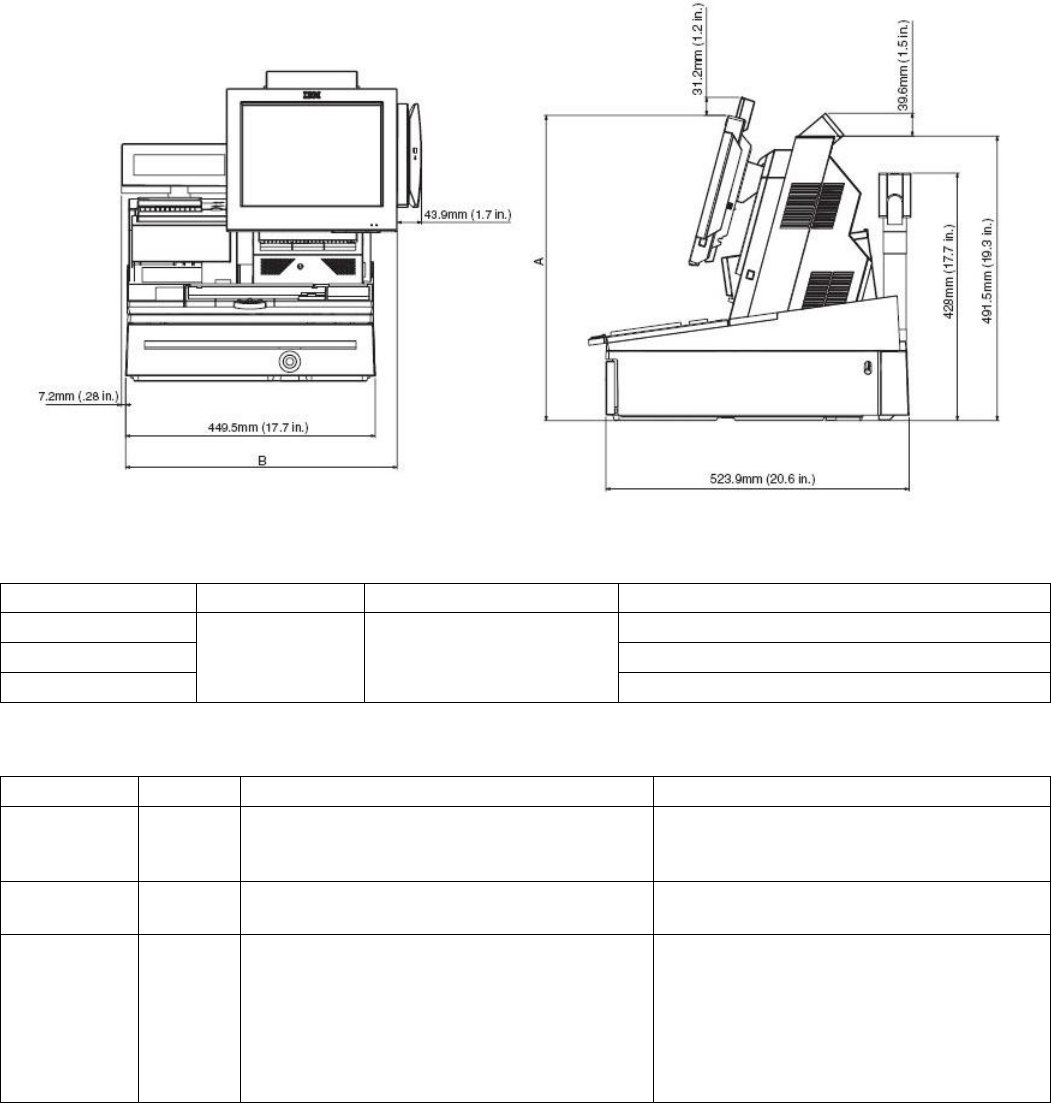
2.8.1.1 System
4846 Weight Height: Height Depth: Depth: Width
SurePOS 500 4846-XX5 Technical Reference
Page 11 of 63
Tablet at 15
degrees maximum Tablet at 15
degrees Tablet at 60
degrees
Tower and 12-in. tablet 11.3 kg
(25 lbs) 357.9 mm
(14.0 in.) 374.1 mm
(14.7 in.) 316.8 mm
(12.5 in.) 385.8 mm
(15.2 in.) 307.9 mm
(12.12 in.)
Tower and 15-in. tablet 12.2 kg
(27 lbs) 381.8 mm
(15.0 in.) 393.6 mm
(15.5 in.) 324.4 mm
(12.8 in.) 405.8 mm
(15.9 in.) 369 mm
(14.5 in.)
Tower and 17-in. tablet 14.51 kg
(32 lbs) 404.5 mm
(15.93 in.) 414.6 mm
(16.32 in.) 335.2 mm
(13.2 in.) 423.9 mm
(16.7 in.) 402.3 mm
(15.83 in.)
2.8.1.2 Weights of features
Component Weight
Integrated 2x20 display 0.2 kg (0.38 lbs)
Distributed 2x20 display 0.5 kg (1.2 lbs)
Distributed APA display 0.7 kg (1.6 lbs)
MSR (three-track or JUCC) 0.16 kg (0.41 lbs)
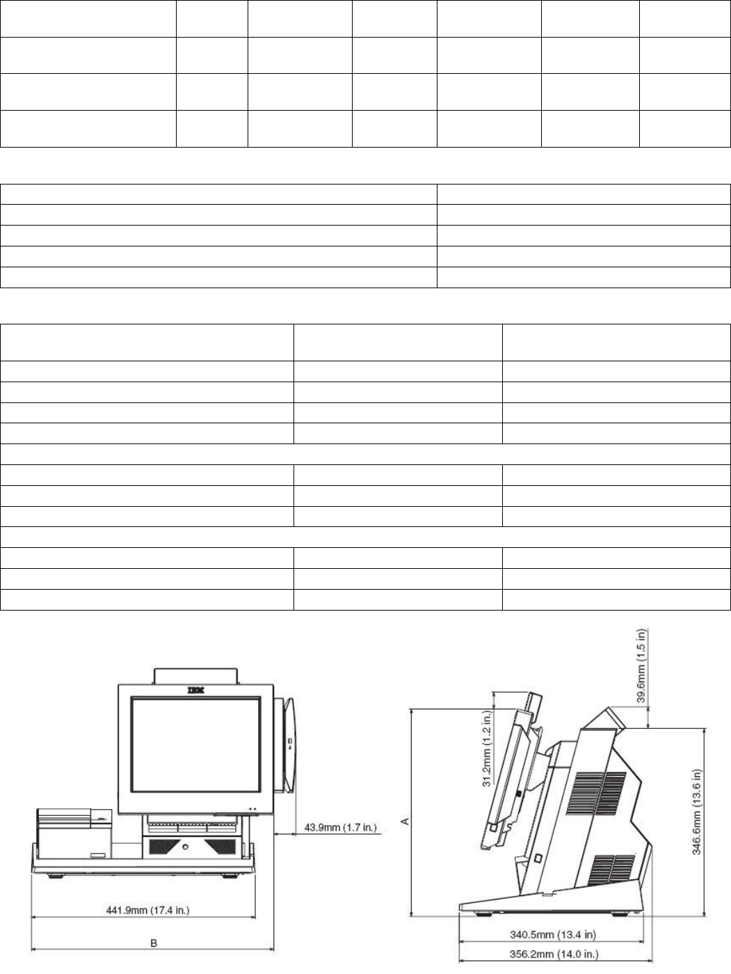
2.8.1.3 Dimensions with Trays
Measurement A
(see figure below) Measurement B
(see figure below)
Product with 12 in. tablet and the following:
Counter top tray 382.4 mm (15.1 in.) 478.6 mm (18.8 in.)
Cash drawer tray 493.5 mm (19.4 in.) 480.9 mm (18.9 in.)
Retail tray 527.4 mm (20.8 in.) 489.2 mm (19.2 in.)
Product with 15 in. tablet and the following:
Counter top tray 406.2 mm (15.9 in. ) 509.2 mm (20.0 in.)
Cash drawer tray 517.3 mm (20.4 in.) 511.4 mm (20.1 in)
Retail tray 551.1 mm (21.7 in.) 519.7 mm (20.5 in.)
Product with 17 in. tablet and the following:
Counter top try 428.9 mm (16.9 in.) 525.9 mm (20.7 in.)
Cash drawer 540 mm (21.3 in.) 528.1 mm (20.8 in.)
Retail tray 573.8 mm (22.6 in.) 536.4 mm (21.1 in.)
SurePOS 500 4846-XX5 Technical Reference
Page 12 of 63
2.8.2 Controls
Function Actuation Location Operation
Power Toggles state between OFF and ON
Brightness up Increases brightness by 1 step
Brightness down
Momentary
contact button Under LCD chin
Decreases brightness by 1 step
2.8.3 Visual Indicators
Function Color Location State
Power Green Front bezel Off - System Off
Blinking - Standby/during POST
On – Operational
HDD Yellow Front bezel Off - No activity
Blinking - HDD activity
Wired LAN Green Tailgate (RJ45 connector)
Left LED States
– Off - 10 Mb mode
– On - 100 Mb mode
Right LED States
– Off - No link
– On - Good Link
– Blinking - Network activity
SurePOS 500 4846-XX5 Technical Reference
Page 13 of 63
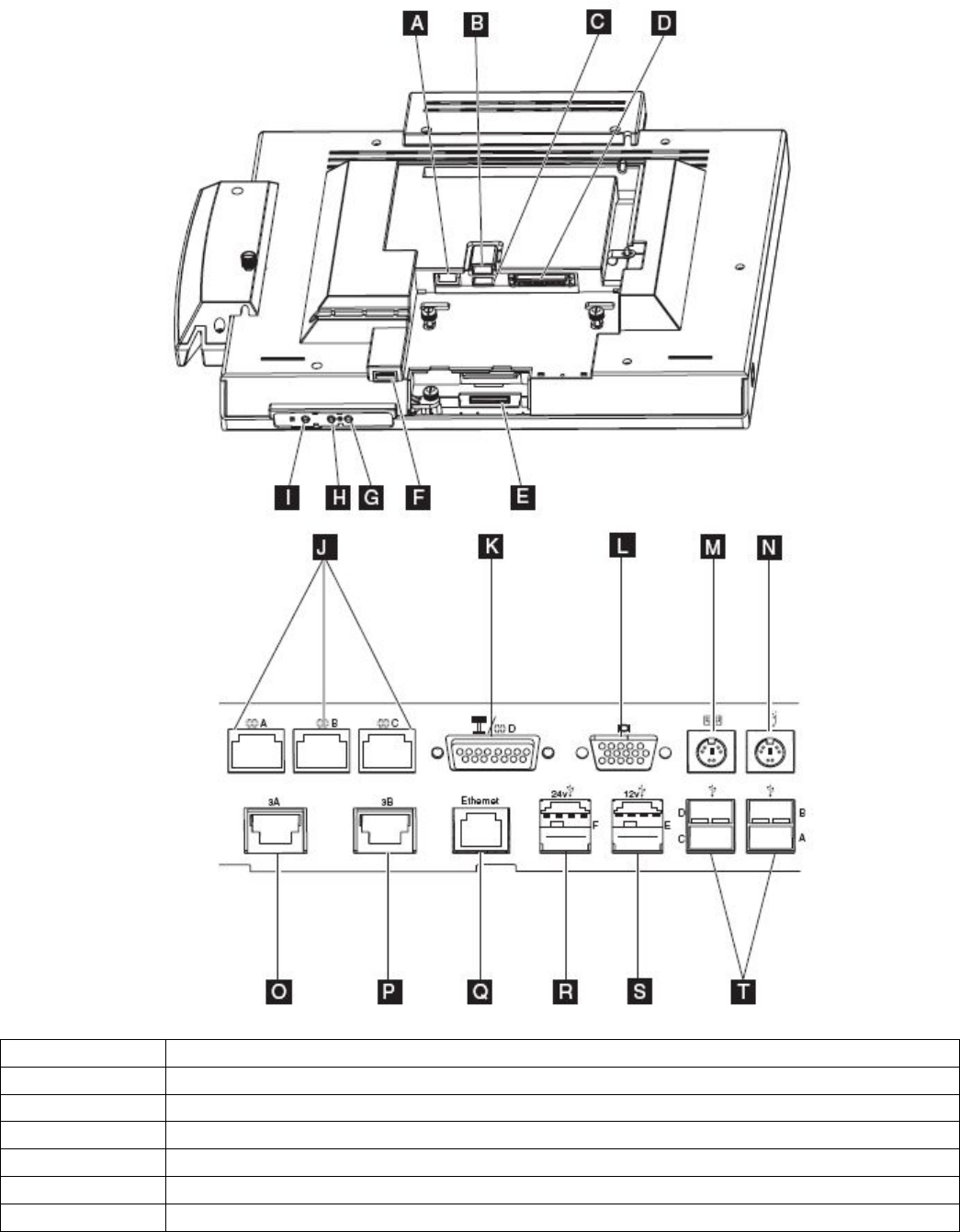
2.8.4 Connector/Controls Identifier
Identifier Function
A MSR
B, C USB 2.0
D Tablet attachment
E Touch Ring
F USB 2.0
G/H Brightness up/down buttons

SurePOS 500 4846-XX5 Technical Reference
Page 14 of 63
I Power control
J RS232
K External Display / RS232
L Analog Video
M Keyboard
N Mouse
O/P Cash Drawer
Q Ethernet
R 24V USB 2.0 Plus Power
S 12V USB 2.0 Plus Power
T USB 2.0 (4x)
SurePOS 500 4846-XX5 Technical Reference
Page 15 of 63
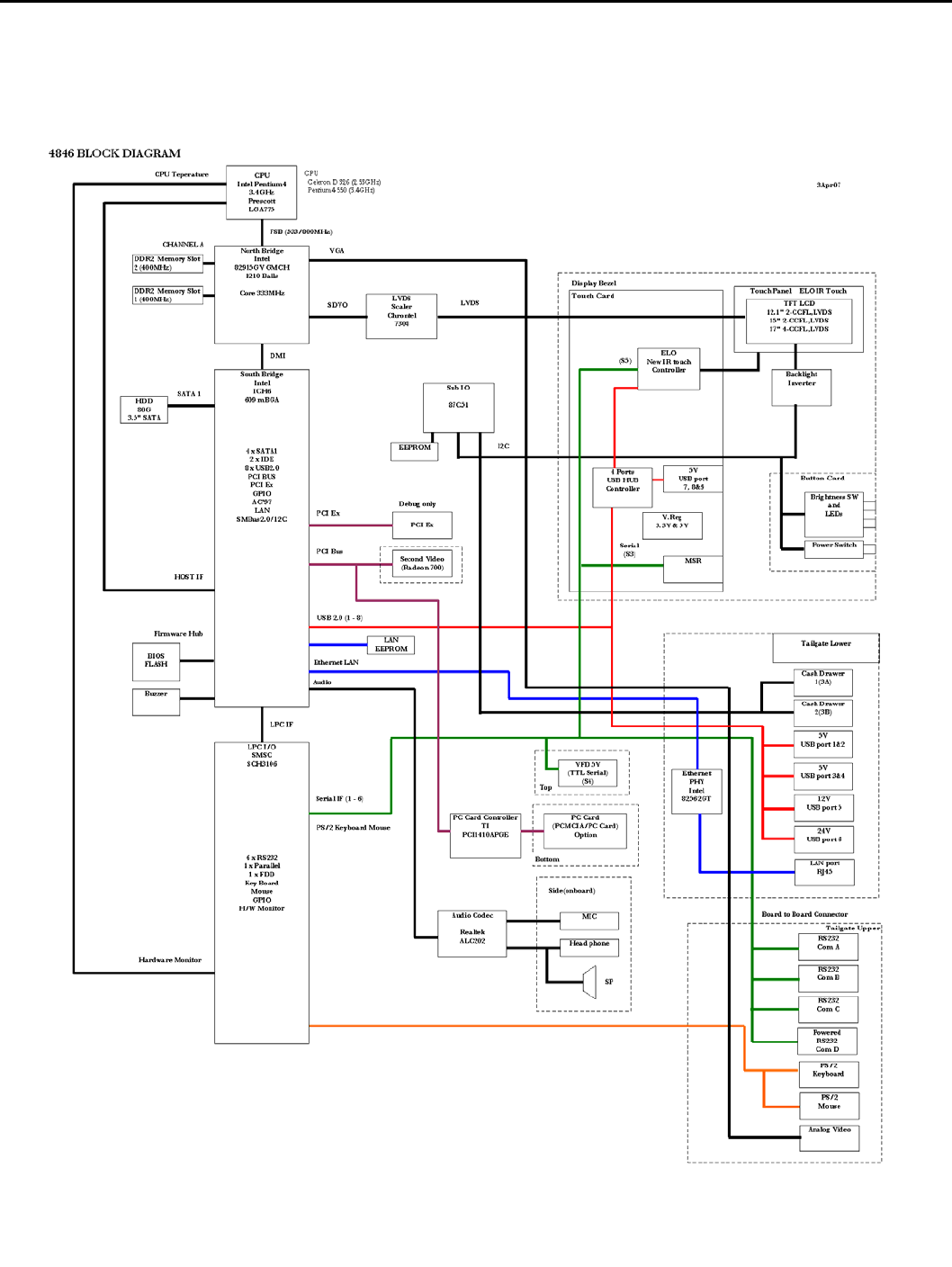
2.9 Product Description
2.9.1 Block Diagram

SurePOS 500 4846-XX5 Technical Reference
Page 16 of 63
2.10 Logic
Processor: Intel Celeron D 326 2.53Ghz
• LGA775 Socket
• 16K Level 1 cache / 256KB Level 2 cache
• 533Mhz Front Side Bus
• Streaming SIMD Extensions 3
• Execute Disable Bit
• Hyperthreading is not supported by Celeron
• Support Extended Memory 64 Technology (EM64T)
To inquire about P4 support, contact an IBM sales representative
North Bridge: Intel 82915GV
• Processor Interface
− 533Mhz front side bus (800Mhz capable)
• System Memory
− Supports up to 2GB DDR2 533Mhz DRAM (PC2-4200 DDR2): 512GB, 512GB, 1GB DIMM’s supported
− One or two 64-bit wide DDR2 SDRAM data channels
− Bandwidth up to 8.5 GB/s in dual-channel interleaved mode
− Non-ECC memory only
• Intel GMA 900 2D/3D
− 133 Mhz Core
− Direct 9x Support
− Dynamic Memory Video Technology V3.0 using up to 128MB video memory
• 2.0 GB/s Link to South Bridge
• Digital Display Support
− SDVO output
− 200Mhz dot clock
− Scaling using Chrontel 7308 LVDS scaler
• Analog Display Support
− 400Mhz Integrated 24-bit RAMDAC
− Up to 2047x1536@85Hz refresh
Note:
Dual channel mode requires two matching size DIMM’s installed. When a single DIMM is installed or two dissimilar
size DIMM’s are installed, the memory operates in single channel mode.
South Bridge: Intel ICH6
• PCI Bus support, Rev 2.3, 33 Mhz
• Serial ATA II support, 150 Mbps
• Support for up to 8 USB 2.0/USB 1.1 ports
− Support for wake up from sleeping states
− Supports legacy keyboard/mouse software
• Power Management Support
− ACPI 2.0 compliant
− APM-based legacy power management
• Integrated LAN controller
− Wake on LAN with Magic Packet
− 10/100 Mb/s Ethernet
• Support for AC-’97 2.3 audio codec
• SMBus 2.0/I²C support
I/O Subsystem: SMSC SC3106 Super I/O Controller
• RS232 support
• Keyboard/Mouse support
• Power Control
• Temperature monitoring and fan control
Audio Subsystem: Realtek ALC202 codec (X6X models only)

SurePOS 500 4846-XX5 Technical Reference
Page 17 of 63
• AC ’97 compliant audio
• Supports 44.1K/48K/96K/192KHz DAC Independent Sample Rate
• All ADCs Support 48K/192KHz Independent Sample Rate
• 1W + 1W amplifier
PC Card Support (TI PCI140A) (X6X models only)
• Support for 1 Type II 5V/3.3V PC Card or 3.3V CardBus Cards
• Hot insertion/removal support
• Register-compatible with the Intel⎢ 82365SL-DF and 82365SL ExCA controllers
Secondary Video Adapter - ATI Radeon 7000 graphics processor
• 2D/3D capability, supports 3D resolutions (32-bit color) up to 2048x1536
• 32MB DDR onboard memory
• Better 3D performance (than base video)
• PCI 2.2 compliant : PCI-33
Touch
• ELO-based Infra-redesign
• RS232 interface to touch, mouse emulation
• Flashable firmware via USB
Touch Specifications
Attribute Specification
Technology Modified ELO Infra-red
Calibration Not required
Input Method Finger, stylus (8mm diameter min.)
Controller Resolution 1024x1024
Accuracy (std dev) 0.080-in.
Accuracy (max err) 0.047-in. (96%)
0.222-in (4%)
Drift None
Glass Finish Anti-glare
Transmissiveness 92%
Travel N/A
Touch Activation Force None
2.11 Component specifications
2.11.1 4GB Modular Flash Drive
Characteristic Specification
Interface USB 2.0
Data Reliability < 1 non-recoverable error in 1014 bits read
Performance 20Mbps read / 10Mps write
2.11.2 Hard Disk Drive
Characteristics Specification
Form Factor 3.5-in
Formatted Capacity (GB) 80GB or greater
Interface SATA II, up to 3.0Gb/s
Rotational Speed 7200 rpm
SurePOS 500 4846-XX5 Technical Reference
Page 18 of 63
Access Time – Read (inc. overhead) 13 ms typ
Access Time – Write (inc. overhead) 15 ms typ
2.11.3 LCD
12-inch TFT 15-inch TFT 17-inch TFT
Interface Single Channel LVDS Single Channel LVDS Dual Channel LVDS
Minimum Brightness (cd/m2)
(without front glass) 450 230 300
Number of CCFL bulbs 2 2 4
Active Area (mm) 246.0H x 184.5 V 304.128H x 228.096 V 337.92H × 270.34 V
Resolution (pixels) 800 x 600 1024 x 768 1280 x 1024
Color 24 bit 24 bit 24 bit
Contrast Ratio (typ) 300:1 500:1 500:1
Minimum Backlight Life
(half brightness) 30,000 hrs 30,000 hrs 40,000 hrs
2.11.4 Magnetic Stripe Reader
Characteristic Specification
Features
• ISO 7811 Tracks 1,2,3 capability
• Enable/Disable Carriage Return
• Enable/Disable Sentinels
• Programmable Sentinels
• Individually selectable Tracks
• Flashable firmware
For details on configuring the MSR, go to the
www.ibm.com/solutions/retail/store/support and search for knowledge base
entry number R1001036
Card Support
• Standard
• Mini-cards
• Foil laminated cards
Coercivity of Magnetic Stripe 300 to 4000 Oe
Read Direction Bi-directional
Swipe Speed 5 to 60 inches per second
Maximum Jitter 12%
Error Rate Less than 0.5%
Electrical Interface Serial
Rated Life 500,000 swipes
2.11.5 Integrated and Distributed 2x20
Integrated 2x20 Distributed 2x20
Technology Vacuum Fluorescent
Format 2 rows, 20 characters
Brightness (w/o lens) 300 cd/m2 300 cd/m2
Display Color (w/o
lens) Green
Adjustment n/a Multi-position detent
Character Box 5 x 7 5 x 7
Character Height (mm) 7.74 x 4.15 9.5 x 4.45

SurePOS 500 4846-XX5 Technical Reference
Page 19 of 63
Emulations Logic Controls Emulation or IBM Multi-Mode
Character Sets
(IBM Multi-mode)
Code Page 437 (US/Euro)
Code Page 897 (Katakana)
Code Page 858 (Int'l)
Code Page 852 (Central Europe)
Code Page 855 (Cyrillic)
Code Page 857 (Turkey)
Code Page 862 (Israel)
Code Page 863 (Can Fr)
Code Page 864 (Arabic)
Code Page 865 (Nordic)
Code Page 808 (Cyrillic Russian)
Code Page 869 (Greece)
User Defined
Characters Logic Controls Mode: 1
IBM Mode: 8
Electrical Interface TTL Serial RS232
Power 5V 12V
Power Consumption
(all pixels energized) 6W 7.2 W
Attachment Cable Pigtail 3.8 m (12 ft)
2.11.6 All Points Addressable (APA) Display
An external all points addressable customer display is supported. This is intended to meet DBCS language
requirements. It attaches to the 15-Pin Powered serial port which provides power and signaling.
Attribute Specification
Technology Vacuum Fluorescent
Brightness 300 cd/m2
Format (dot) 160 x 40
Active Area (mm) 132.55 x 32.95
Dot Size (mm) 0.58 (W) x 0.58 (H)
Dot Pitch (mm) 0.83 (W) x 0.83 (H)
Display Color Green
(peak wavelength 505 nm)
Modes All Points Addressable (160x40)
Character Mode
Built in Font Code Pages for Character Mode
5x7 A/N (4 and 5 line mode)
8x16 A/N English (2 line mode)
8x16 A/N Katakana (2 line mode)
16x16 Kanji (2 line mode)
16x16 Hanguel (2 line mode)
16x16 Simplified Chinese (2 line mode)
16x16 Traditional Chinese (2 line mode)
Futaba Standard
IBM Code Page 437 modified
Futaba Standard
JIS X 208-1990
KS C 5601-1992
GB-2321-80
BIG5
Character Box Height (mm)
5x7
8x16
16x16
3.90 (H) x 5.56 (W)
6.39 (H) x 13.03 (W)
13.03 (H) x 13.03 (W)
Electrical Interface RS232 with 12 V power
Power Consumption 6W (typ)
8.4 (max)
Adjustment Multi-position
Attachment Cable 3.8m

SurePOS 500 4846-XX5 Technical Reference
Page 20 of 63
2.11.7 Built-in speakers (X6X models only)
Attribute Specification
Drivers 2 element, 1 way, sealed design
Type 7 x 4 (28 mm x 40 mm x 15 mm deep)
Impedance 12 ohm impedance
Magnetic Shielding Yes
Frequency Response 160Hz - 11 kHz (+/- 3 dB)
Output
(rms EIAJ 10% THD 1kHz) 1W + 1 W
Loudness 82 dB +/- 3 dB (1 Watt/ch @ 1 m)
S/N Ratio 65 dB (IEC A weighted, ref 1 W)
Volume Adjustment Knob Easily accessible on front of speaker unit
Channel Separation 40 dB
Total Harmonic Distortion 10%
Input Voltage 10.8V V DC +/- 10%
Input Sensitivity 1 V (1 W, 1kHz)
Input Impedance 12 ohm (1 kHz)
Power Consumption 4 W at maximum volume setting
Input Terminal Molex 70555-0038 (power + signal)

SurePOS 500 4846-XX5 Technical Reference
Page 21 of 63
3.0 BIOS and software description
This section provides an overview of BIOS, SETUP, and system software.
3.1 Setup
The POST CMOS Setup Utility program provides menus for querying and configuration the system. The menus can
be navigated using touch OR a keyboard attached to a USB or PS/2 port.
The CMOS Setup Configuration Utility has optional password protection. The password can be entered through on
screen keypad or keyboard, and can only be numerical. If the password is forgotten, it can be cleared using the CMOS
Clear Jumper located on the main card.
3.2 Functional Standards
• BIOS Boot Specification, v1.01, January 11, 1996
• Plug and Play BIOS Specification, v1.0A, May 5, 1994
• Plug and Play BIOS MODIFICATION Paper for Plug and Play BIOS Specification, v1.0A, October 4, 1994
• ATAPI Removable Media Device BIOS Specification, v1.0, January 30, 1997
• PCI Local Bus Specification, Revision 2.1, June 1, 1995
• PCI BIOS Specification, Revision 2.3, March 29, 2002
• El Torito Bootable CD-ROM Format Specification, v1.0, January 25, 1995
• Preboot Execution Environment (PXE) Specification, Version 2.1.
• Advanced Power Management Specification, v1.2
• Advanced Configuration and Power Interface Specification, Revision 1.0b, February 2, 1999
• DMI Specifications, v2.0
• SMBIOS Specification, v2.4
• Simple Boot Flag Specification, Version 2.1
• PC 2001 System Design Guide
• Wired for Management Baseline 2.0 Review Request 77 Remote Lockout API
3.3 Standard BIOS Features
BIOS supports the following features:
• Display checkpoints during POST on top-right corner
• WfM Remote Lockout
• Power-On Self Test (POST)
• Warm Boot support
• Memory Auto-detection
• Hard Disk Auto-detection
• Fast A20 Interface
• Advanced Storage Features
− SATA support
− 48-bit LBA (Logical Block Addressing) support with Int 13h extensions for drives>528MB
− UDMA (Ultra DMA)
− Storage Auto-detection
− Self Monitoring Analysis and Reporting Technology (S.M.A.R.T.) Support
• USB Legacy Support
− USB 2.0 support
− USB Keyboard/mouse for non-USB enabled OS’s
− USB Keyboard support in Setup
• Simple Boot Flag support
• APM 1.2 Support
• ACPI 1.0b Support

SurePOS 500 4846-XX5 Technical Reference
Page 22 of 63
• Thermal management
3.4 BIOS Interrupts
This section lists the supported interrupt in DOS. Refer to the IBM Personal System/2 and Personal Computer BIOS
Interface Technical Reference for additional information.
• Int 02h – NMI
• Int 05h - Print Screen
• Memory Location 50:00h.
This is a byte memory location. A value of 00h indicates that the print screen successfully completed or was not
invoked. A value of 01h indicates that a print screen is in progress and subsequent print screens are ignored. A
value of FFh indicates that the print screen terminated due to an error.
• Int 08h - System Timer
This interrupt modifies memory locations 40:6Ch, 40:70h, 40:40h, and 40:3Fh. It also invokes interrupt 1Ch.
• Memory Location 40:6Ch
This dword is incremented every Int 08h tick or 18.2 times per second. The memory location is reset to
00000000h when a 24-hour duration has elapsed.
• Memory Location 40:70h
This byte has a value of 00h until a 24 hour duration has elapsed. It is then set to 01h. The byte must be
manually reset back to 00h.
• Memory Location 40:40h
This byte is decremented every interrupt 08h tick or 18.2 times per second. If the timer goes to 00h, the floppy
motor is turned off and resets the floppy flags in memory location 40:3Fh.
• Int 09h – Keyboard
Called on every make or break keystroke. The 32-byte buffer starting at 40:1Eh is updated at the address pointed
by the keyboard buffer tail pointer. The keyboard buffer tail pointer at memory location 40:1Ch is incremented by 2
unless it extends past the keyboard buffer, in which case it wraps. When a key is read, the keyboard buffer head
pointer at memory location 40:1Ah is incremented by 2 unless it extends pass the keyboard buffer, in which case it
wraps. Special keys such as CTRL, ALT, or Shift update the status at memory location 40:17h, 40:18h and
40:96h. A CTRL-ALT-DELETE key sequence sets the reset flag at memory location 40:72h to 1234h and jumps to
the reset vector.
Pressing the Pause key causes the interrupt handler to loop until a valid ASCII keystroke occurs.
Pressing the Print Screen key causes an Interrupt 05h to be issued.
A CTRL-BREAK sequence causes Interrupt 1Bh to be issued.
Pressing the SysReq key causes Interrupt 15h Function 85h (System Request Key Pressed) to be issued.
Any make keystroke causes Interrupt 15h Function 91h, Subfunction 02h (Interrupt complete from Keyboard) to be
issued.
After any scan code is read from I/O port 60h and Int 15h, Function 4Fh (Keyboard Intercept) is issued. An EOI is
issued upon returning from the Keyboard Intercept.
• Memory Location 40:1Eh
This location is the start of a 32-byte keyboard buffer.
• Memory Location 40:1Ah
This word points to the next character in the keyboard buffer.
• Memory Location 40:1Ch
This word points to the last character in the keyboard buffer. If the value equals the value in memory location
40:1Ah, the keyboard buffer is empty. If the value is two bytes from the contents of memory location 40:1Ah, the
keyboard buffer is full.
• Memory Location 40:17h
This byte contains the keyboard status byte.
• Memory Location 40:18h
This byte contains the extended keyboard status byte.

SurePOS 500 4846-XX5 Technical Reference
Page 23 of 63
• Memory Location 40:96h
This word contains the extended keyboard status.
• Memory Location 40:72h
This word contains the soft reset flag.
• Int 10h – Video
This interrupt is supported by the video ROM.
Int 11h - Equipment Determination
Returns the data at memory location 40:10h.
• Memory Location 40:10h
This word contains the equipment list.
• Int 12h - Base Memory Size
Returns the value at memory location 40:13h.
• Memory Location 40:13h
This word contains the amount of memory up to 640 KB. This count will often be less than 640 KB due to NIC
ROM bootloaders.
• Int 13h - HDD and Floppy Diskette Services
• Int 14h - Serial Communication Services
• Int 15h - System Services
Sub functions are those defined by the IBM Personal System/2 and Personal Computer BIOS Interface Technical
Reference manual. Additional sub function support is OEM dependent.
• Int 16h - Keyboard Services
• Int 1Ah - System-Timer Services, PCI BIOS
• Int 1Bh – CTRL+Break Handler
• Int 1Ch - Periodic Timer Interrupt
• Int 1Dh - Video Parameter Table
Set by the video BIOS
• Int 1Eh - Floppy Diskette Drive Parameters
Points to an 11-byte data structure
• Int 1Fh - Video Graphics Characters
Set by the video BIOS
• Int 23h - CTRL+C, CTRL+Break Handler
• Int 41h - HDD C: Drive Parameters
Points to a 16-byte data structure for drive C:
• Int 46h - HDD D: Drive Parameters
Points to a 16-byte data structure for drive D:
3.5 Fixed BIOS Entry Points
The fixed entry points in F000:xxxx must be supported for traditional reasons. The table below lists the fixed BIOS
entry points.
Location Description
F000:E05Bh POST Entry Point
F000:E2C3h NMI Entry Point
F000:E6F2h Int 19h Entry Point
F000:E6F5h Configuration Data Table
F000:E729h Baud Rate Generator Table
F000:E739h Int 14h Entry Point
F000:E82Eh Int 16h Entry Point
F000:E987h Int 09h Entry Point
F000:EC59h Int 13h Floppy Entry Point
F000:EF57h Int 0Eh Entry Point
F000:EFC7h Floppy Disk Controller Parameter Table
F000:EFD2h Compatibility for printer Int 17h

SurePOS 500 4846-XX5 Technical Reference
Page 24 of 63
F000:F065h Compatibility for Video interrupt
F000:F0A4h MDA and CGA Video Parameter Table Int 1Dh
F000:F841h Int 12h Entry Point
F000:F84Dh Int 11h Entry Point
F000:F859h Int 15h Entry Point
F000:FA6Eh Low 128 character of graphic video font
F000:FE6Eh Int 1Ah Entry Point
F000:FEA5h Int 08h Entry Point
F000:FF53h Dummy Interrupt Handler
F000:FF54h Int 05h Print Screen Entry Point
F000:FFF0h Power-On Entry Point
F000:FFF5h 8 character ROM Date in ASCII “MM/DD/YY”
F000:FFFEh System Model (FCh) (outdated – use SMBIOS)
3.6 BDA Memory Addresses
The BIOS Data Area (BDA) starts at 40:0 and should be populated as follows.
Start
Location Length in
bytes Description Interrupt
Using It Comments
00h 2 COM1 base address 14h motherboard UART1 I/O address
02h 2 COM2 base address 14h motherboard UART2 I/O address
04h 2 COM3 base address 14h motherboard UART5 I/O address
06h 2 COM4 base address 14h motherboard UART4 I/O address
08h 2 LPT1 base address 17h Should be 0000h
0Ah 2 LPT2 base address 17h Should be 0000h
0Ch 2 LPT3 base address 17h Should be 0000h
0Eh 2 EBDA segment
10h 2 Installed hardware 11h
12h 1 Reserved
13h 2 Base memory size 12h
15h 2 Reserved
17h 1 Keyboard control 1 16h
18h 1 Keyboard control 2 16h
19h 1 Work area for ALT key 16h
1Ah 2 Keyboard-buffer Head 16h
1Ch 2 Keyboard-buffer Tail 16h
1Eh 32 Keyboard Buffer 16h
3Eh 1 Floppy recalibrate status 13h
3Fh 1 Floppy motor status 13h
40h 1 Floppy motor timeout 13h
41h 1 Floppy operation status 13h
42h 7 Floppy controller status 13h
49h 30 Video info 10h
67h 4 POST callback address
6Bh 1 Last Unexpected
interrupt

SurePOS 500 4846-XX5 Technical Reference
Page 25 of 63
6Ch 4 Timer Counter 1Ah
70h 1 Timer Overflow 1Ah
71h 1 Break key state 16h
72h 2 Reset Flag
74h 1 HDD operation status 13h
75h 1 Number of HDDs
attached 13h
76h 2 Reserved 13h
78h 1 LPT1 time-out 14h
79h 1 LPT2 time-out 14h
7Ah 1 LPT3 time-out 14h
7Bh 1 Reserved
7Ch 1 COM1 time-out
7Dh 1 COM2 time-out
7Eh 1 COM3 time-out
7Fh 1 COM4 time-out
80h 2 Keyboard buffer start ptr 16h
82h 2 Keyboard buffer end ptr 16h
84h 7 Video info 10h
89h 2 Reserved
8Bh 1 Floppy media control 13h
8Ch 1 HDD Controller status 13h
8Dh 1 HDD Controller error
status 13h
8Eh 1 HDD Interrupt control 13h
8Fh 1 Reserved
90h 1 Floppy 0 media status 13h
91h 1 Floppy 1 media status 13h
92h 1 Floppy 2 media status 13h
93h 1 Floppy 3 media status 13h
94h 1 Drive 0 current cylinder 13h
95h 1 Drive 1 current cylinder 13h
96h 1 Keyboard mode state &
flags 16h
97h 1 Keyboard LED flags 16h
98h 2 User Wait flag offset 15h
9Ah 2 User wait flag segment 15h
9Ch 2 Low word of user wait
count 15h
9Eh 2 High word of user wait
count 15h
A0h 1 Wait active flag 15h
A1h 7 Reserved
A8h 4 Video info 10h
ACh 54h Reserved
100h 1 Print Screen status 05h

SurePOS 500 4846-XX5 Technical Reference
Page 26 of 63
3.7 EBDA Memory Addresses
The Extended BIOS Data Area (EBDA) starts at the segment pointed to by the contents of 40:0Eh.
Start Location Length in bytes Description Comments
00h 1 Length of EBDA in KB
01h 32 Reserved
17h 1 Number of POST errors not required
18h 5 POST error log not required
22h 4 Mouse Driver Ptr Int 74h
26h 1 Mouse flag byte 1 Int 74h
27h 1 Mouse flag byte 2 Int 74h
28h 8 Mouse data Int 74h
30h 3d0h Reserved Reserved
3.8 Memory Map
This section documents the default memory map. Note that add-in cards or changing CMOS Setup items may alter
the memory map, particularly below 1 MB.
Memory Map with USB Legacy Support enabled (default)
Physical
Address Range
(Dec)
Physical
Address Range (Hex) Size Description
0-639 KB 00000-9FC00 512 KB Conventional DOS memory (size may decrease if booted
via LAN)
639 KB 9FC00-9FFFF 1 KB EBDA (Extended BIOS Data) moveable by Himem,
memory managers
640-767 KB A0000-BFFFF 128 KB Legacy Video Buffer
768-831 KB C0000-CFFFF 64 KB Video BIOS ROM (shadowed)
832-863 KB D0000-D7FFF 32 KB USB Legacy Support
864-867 KB D8000-D8FFF 4 KB Network ROM boot loader
868-895 KB D9000-DFFFF 28 KB Free for EMM386
896 KB-959KB E0000-EFFFF 64 KB Free for EMM386
960KB – 1MB F00000-FFFFFF 64KB System ROM BIOS
1- 16 MB 100000-FFFFFF 15 MB PCI/ISA Space
16 MB – 4095.5
MB 1000000-FFF7FFFF 4079.5
MB OS, PCI adapter memory decode, etc.
4095.5 MB - 4096
MB FFF80000-FFFFFFF 512 KB System ROM BIOS (ISA Bus)
Memory Map with USB Legacy support disabled:
Physical
Address Range
(Dec)
Physical
Address Range (Hex) Size Description
0-639 KB 00000-9FC00 512 KB Conventional DOS memory (size may decrease if
booted via LAN)
639 KB 9FC00-9FFFF 1 KB EBDA (Extended BIOS Data) moveable by Himem,
memory managers
640-767 KB A0000-BFFFF 128 KB Legacy Video Buffer

SurePOS 500 4846-XX5 Technical Reference
Page 27 of 63
768-831 KB C0000-CFFFF 64 KB Video BIOS ROM (shadowed)
832-835 KB D0000-D0FFF 4 K Network ROM boot loader
836-895 KB D0FFF-EFFFF 124 KB Free for EMM386
896 – 959KB E0000-EFFFF 64KB Free for EMM386
960 KB - 1MB F0000-FFFFF 64 KB System ROM BIOS
1- 16 MB 100000-FFFFFF 15 MB PCI/ISA Space
16 MB – 4095.5
GB 1000000-FFF7FFFF 4079.5 MB OS, PCI adapter memory decode, etc.
4095.5 MB -
4096 MB FFF80000-FFFFFFF 512 KB System ROM BIOS (ISA Bus)
3.9 COM Port Setup
Physical
UART
Tailgate
Port
Name Function Connector
Type Location Notes Default
I/O and
IRQ
UART1 COM1 Available to
user RJ45 Rear
Tailgate BDA COM1 3F8/4
UART2 COM2 Available to
user RJ45 Rear
Tailgate BDA COM2 2F8/3
UART3 COM3 Available to
user RJ45 Rear
Tailgate COM6 2E0/11
Distributed
VFD
connection DB15 F Rear
Tailgate
Integrated
VFD
connection Custom Tower Top
BDA COM4
Only one of integrated or
distributed VFD may be
enabled at the same time.
CMOS Setup allows
selection.
UART4 Dist-VFD
8051 1 Internal Internal Communications with 8051
for EEPROM, cash drawer,
and LCD control.
2E8/6
UART5 n/a MSR
connection RJ45 Tablet Side BDA COM3 3E8/5
UART6 n/a Touch Internal Internal COM5
Resources hardcoded to
2F0h/IRQ 7 2D8/7
3.10 Video Modes
Supported VGA Video Display Modes
Video
Mode Pixel
Resolution
Color
Depth
(bpp)
Mode
Type Display
Adapter Font
Size Character
Resolution
Dot
Cloc
k
(MHz
)
Horiz.
Freq.
(KHz)
Vert
Freq(Hz)
Video
Memory
(KBytes)
1 Information for communicating with the 8051 can be found in the Bryce I/O Subsystem Microcontroller Firmware
Specification.

SurePOS 500 4846-XX5 Technical Reference
Page 28 of 63
320 x 200 16
(gray)
(4 bpp) Text CGA 8 x 8 40 x 25 25 31.5 70 256
320 x 350 16
(gray)
(4 bpp) EGA 8 x 14 40 x 25 25 31.5 70 256
00h
360 x 400 16
(4 bpp) VGA 9 x 16 40 x 25 28 31.5 70 256
320 x 200 16
(4 bpp) Text CGA 8 x 8 40 x 25 25 31.5 70 256
320 x 350 16
(4 bpp) EGA 8 x 14 40 x 25 25 31.5 70 256
01h
360 x 400 16
(4 bpp) VGA 9 x 16 40 x 25 28 31.5 70 256
640 x 200 16
(gray)
(4 bpp) Text CGA 8 x 8 80 x 25 25 31.5 70 256
640 x 350 16
(gray)
(4 bpp) EGA 8 x 14 80 x 25 25 31.5 70 256
02h
720 x 400 16
(4 bpp) VGA 9 x 16 80 x 25 28 31.5 70 256
640 x 200 16
(4 bpp) Text CGA 8 x 8 80 x 25 25 31.5 70 256
640 x 350 16
(4 bpp) EGA 8 x 14 80 x 25 25 31.5 70 256
03h
720 x 400 16
(4 bpp) VGA 9 x 16 80 x 25 28 31.5 70 256
04h 320 x 200 4 Graph All 8 x 8 40 x 25 25 31.5 70 256
320 x 200 4
(gray) Graph CGA 8 x 8 40 x 25 25 31.5 70 256
320 x 200 4
(gray) EGA 8 x 8 40 x 25 25 31.5 70 256
05h
320 x 200 4 VGA 8 x 8 40 x 25 25 31.5 70 256
06h 640 x 200 2 Graph All 8 x 8 80 x 25 25 31.5 70 256
720 x 350 Mono Text MDA 9 x 14 80 x 25 28 31.5 70 256
720 x 350 Mono EGA 9 x 14 80 x 25 28 31.5 70 256
07h
720 x 400 Mono VGA 9 x 16 80 x 25 28 31.5 70 256
08h-0Ch Reserved - -
0Dh 320 x 200 16
(4 bpp) Graph E/VGA 8 x 8 40 x 25 25 31.5 70 256
0Eh 640 x 200 16
(4 bpp) Graph E/VGA 8 x 8 80 x 25 25 31.5 70 256
0Fh 640 x 350 Mono Graph E/VGA 8 x 14 80 x 25 25 31.5 70 256
10h 640 x 350 16
(4 bpp) Graph E/VGA 8 x 14 80 x 25 25 31.5 70 256
11h 640 x 480 2
(4 bpp) Graph VGA 8 x 16 80 x 30 25 31.5 60 256
12h 640 x 480 16
(4 bpp) Graph VGA 8 x 16 80 x 30 25 31.5 60 256
13h 320 x 200 256
(8 bpp) Graph VGA 8 x 8 40 x 25 25 31.5 70 256

SurePOS 500 4846-XX5 Technical Reference
Page 29 of 63
VESA Modes Supported by Video BIOS
Video
Mode Pixel
Resolution Colors (bpp) Mode Type Display Adapter Vertical
Frequency
(Hz)
Video Memory
(MB)
640 x 480 256
(8 bpp) Graph VGA 60 0.5
640 x 480 256
(8 bpp) Graph VGA 75 0.5
101h
640 x 480 256
(8 bpp) Graph VGA 85 0.5
800 x 600 256
(8 bpp) Graph SVGA 60 1
800 x 600 256
(8 bpp) Graph SVGA 75 1
103h
800 x 600 256
(8 bpp) Graph SVGA 85 1
1024 x 768 256
(8 bpp) Graph XVGA 60 1
1024 x 768 256
(8 bpp) Graph XVGA 75 1
105h
1024 x 768 256
(8 bpp) Graph XVGA 85 1
1280 x
1024 256
(8 bpp) Graph SXGA 60 2
1280 x
1024 256
(8 bpp) Graph SXGA 75 2
107h
1280 x
1024 256
(8 bpp) Graph SXGA 85 2
640 x 480 64K
(16 bpp) Graph VGA 60 1
640 x 480 64K
(16 bpp) Graph VGA 75 1
111h
640 x 480 64K
(16 bpp) Graph VGA 85 1
800 x 600 64K
(16 bpp) Graph SVGA 60 2
800 x 600 64K
(16 bpp) Graph SVGA 75 2
114h
800 x 600 64K
(16 bpp) Graph SVGA 85 2
1024 x 768 64K
(16 bpp) Graph XVGA 60 2
1024 x 768 64K
(16 bpp) Graph XVGA 75 2
117h
1024 x 768 64K
(16 bpp) Graph XVGA 85 2
11Ah 1280 x
1024 64K
(16 bpp) Graph SXGA 60 4
SurePOS 500 4846-XX5 Technical Reference
Page 30 of 63
1280 x
1024 64K
(16 bpp) Graph SXGA 75 4
1280 x
1024 64K
(16 bpp) Graph SXGA 85 4
640 x 480 16M
(32 bpp) Graph VGA 60 2
640 x 480 16M
(32 bpp) Graph VGA 75 2
112
640 x 480 16M
(32 bpp) Graph VGA 85 2
800 x 600 16M
(32 bpp) Graph SVGA 60 4
800 x 600 16M
(32 bpp) Graph SVGA 75 4
115
800 x 600 16M
(32 bpp) Graph SVGA 85 4
1024 x 768 16M
(32 bpp) Graph XVGA 60 4
1024 x 768 16M
(32 bpp) Graph XVGA 75 4
118
1024 x 768 16M
(32 bpp) Graph XVGA 85 4
3.10.1 Display mode and operating system restrictions
The operating system, the display size, and any attached CRTs can affect the display resolution. The following
definitions describe the terms and various display configurations:
Display Configuration Definition
Single A type of display configuration that supports only one display device.
Twin A type of display configuration that supports two display devices, each of which has
the same content, resolution, and timings. Also referred to as Simultaneous mode.
Clone A type of display configuration that drives two display devices, each displaying the
same content, but can have different resolutions and (independent) timings.
Dual Independent Head
(DIH) A type of display configuration that supports two displays with different content on
each display device. Also referred to as an Extended Desktop.
The onboard LCD supports the following modes when using the indicated operating system:
• DOS: Single
• Windows 2000 and Windows XP: Clone (default), twin
• WEPOS: Clone (default), twin
The onboard LCD and one extra attached LCD:
• DOS: Single; the onboard LCD is primary
• Windows 2000 and Windows XP: Clone (default), twin, DIH
• WEPOS: Clone (default), twin, DIH
Operating system with display combinations and restrictions
Display DOS Windows
Image Single1 Single
Onboard LCD only Restrictions None

SurePOS 500 4846-XX5 Technical Reference
Page 31 of 63
Image Single Dual-same
Onboard LCD + external
display Restrictions External display not
supported
Media clips show on
onboard LCD only; External
display must be the same
resolution as onboard LCD
Image Single, on board LCD Dual-independent2
Onboard LCD + Add-in
video card Restrictions None Onboard LCD becomes
secondary display when
installing Windows
General Restrictions
Touch on primary display
only None
1. Dual-same: same data on both displays; simultaneous mode
2. Dual-independent; different/independent data on both displays; extended desktop
Supported video resolutions in Windows operating system
LCD size Available video resolutions for onboard LCD
12 in. 640 x 480, 720 x 480, 800 x 600
15 in. 640 x 480, 720 x 480, 800 x 600,
960 x 540, 1024 x 768
17 in. 640 x 480, 720 x 480, 800 x 600,
960 x 540, 1024 x 768, 1152 x 864,
1280 x 720, 1280 x 768, 1280 x 960, 1280 x 1024
3.11 Power Management
3.11.1 APM
Function Supported From State Comments
Global Standby Yes power button, inactivity
timer
Wake on LAN Yes Standby,Off Default=disable, configurable in
Setup
Wake on Alarm Yes Standby,Off Default=disable, configurable in
Setup
Wake on Ring Yes Standby/Off
Serial D only
Default=disable, configurable in
Setup
Power off Yes power button, APM call Power button default = Instant Off
Wake on Touch Yes Standby Default=enable, configurable in
Setup
CPU Idle calls from OS Yes On OS must have APM
engaged/connected (i.e. DOS

SurePOS 500 4846-XX5 Technical Reference
Page 32 of 63
power.exe loaded)
Wake from PS/2
keyboard/mouse Yes Standby Always enabled
Wake from USB
keyboard/mouse Yes Standby Always enabled
Standby Timer Yes On Default=disabled, configurable in
Setup
Hard Disk Standby Yes On
Video Standby Yes On
Clock Throttling Yes On
Wake on Presence Sensor No no presence sensor
PCMCIA ring No
Global Suspend (Save to disk
or RAM) State No
Power on by keyboard No
Battery support No
3.11.2 ACPI
Function Supported From State Comments
Global Standby Yes power button, inactivity timer
Wake on LAN Yes S1/S5
Wake on Alarm Yes S1/S5
Power off Yes All
Wake on Touch Yes S1
Wake on Ring Yes S1/S5 Serial D only
Wake from PS/2
keyboard/mouse Yes S1
Wake from USB
keyboard/mouse Yes S1 Provide support, enabled/disabled
through Device Manager
Clock Throttling Yes S0
Wake on Presence
Sensor No no presence sensor
PCMCIA ring No
Global Suspend
(Save to disk or RAM)
State No

SurePOS 500 4846-XX5 Technical Reference
Page 33 of 63
Power on by keyboard No
Battery support No
3.12 System Information Data
3.12.1 SMBIOS
System Management BIOS (SMBIOS) is a standard interface to provide information configured by the manufacturer
about the PC hardware. BIOS complies with the minimum specifications in the SMBIOS v2.4 specification Appendix
Section 4.
Note: According to the SMBIOS spec (section 2.1: Table Convention), SMBIOS provides static information only,
gathered each POST or before booting. SMBIOS cannot provide run-time, dynamic information to software.
3.12.2 Cumulative Structure List
• BIOS Information (Type 0)
− Vendor
− BIOS Version
− BIOS Characteristics Extension Byte 1
• BIOS Characteristics Extension Byte 2
• System Information (Type 1)
− Manufacturer = “IBM CORPORATION”
− Product Name
− Version
− Serial number
− Wake up Type
• Base Board (or Module) Information (Type 2)
• System Enclosure (Type 3)
• Processor information (Type 4)
• Cache Information (Type 7)
• On Board Devices Information (Type 10)
• Physical Memory Array (Type 16)
• Memory Device (Type 17)
• Built-in Pointing Device (Type 21)
− For built-in Touch Screen
• Hardware security (Type 24)
− Power-on Password Status
− Administrator Password Status
• Voltage Probe (Type 26)
− One structure for each voltage probe
• Cooling Device (Type 27)
− One structure for each of CPU, chassis, and power supply fan
• Temperature Probe (Type 28)
− One structure for each of CPU and motherboard (ambient)
• System boot information (Type 32)
− Boot status
• Management Device (Type 34)
• Management Device Component (Type 35)
− One for each type26-28 management device, except power supply fan
− Each type35 "Threshold Handle" points to respective type 36
• Management Device Threshold Data (Type 36)
− One for each type 35 device
− Each type35 "Threshold Handle" points to respective type 36
• System Power Supply (Type 39)
SurePOS 500 4846-XX5 Technical Reference
Page 34 of 63
3.13 Vital Product Data
Vital Product Data (VPD) is the IBM-specific information about a system. The data includes values such as machine
type, model, serial number, BIOS/Flash revision, system board unique ID, etc. VPD is accessed through SMBIOS, as
defined in the SMBIOS specification.
3.13.1 VPD Layout in SMBIOS
This section describes the traditional VPD. Refer to the SMBIOS specification for methods of accessing these fields.
Data field SMBIOS record Type and Field Data type Field length
Type 0 “BIOS Version” ASCII
string 7
BIOS level
Example: X6KT100
Type 1 “Product name” and “Version” ASCII
string 7
Machine
type/model Example: 4846545
The machine type/model does not have dashes or spaces in SMBIOS
System serial
number Type 1 “Serial Number” ASCII
string 7
Product Family Type 1 “Family”, Type 11 ASCII
string 11
Type 1 “UUID”, offset 0Ah
hex 6
LAN MAC
Address Usage: The LAN MAC address can be parsed from the Type 01 “UUID” field, offset 10 (0Ah).
For example, if the UUID is 40 3E 4C 58 76 7B DA 11 A4 29 00 14 5E 14 00 15, the MAC
address is 00 14 5E 14 00 15.
3.13.2 SMBIOS Type 11 Structure Layout
The format of the SMBIOS Type 11 Structure for OEM strings is as follows:
Offset Name Length Value Description
00h Type 1 byte 0Bh OEM strings structure indicator
01h Length 1 byte 05h Length of structure
02h Handle 2 bytes varies
04h Count 1 byte varies Number of strings in this structure
05h Product Family
String 11 bytes ASCII
string “SurePOS 500”
3.13.3 VPD using Int 15h
;Get pointer to VPD block
mov ax, 0d207h
int 15h
;ES:DI now points to the following structure:
vpdDataStruc STRUC
header DW 55aah
vpdSignature DB 'VPD'
vpdLength DB 48
reserved DB 7 dup(20h)
buildID DB 9 dup(20h)
boxSerial DB 7 dup(20h)
uniqueID DB 11 dup(20H)
machineType DB 7 dup(20h)
vpdChecksum DB ?
vpdDataStruc ENDS
SurePOS 500 4846-XX5 Technical Reference
Page 35 of 63
4.0 Environmental Specifications
4.1 Temperature/Humidity Limits
Condition Temp Limits (Dry Bulb) Relative Humidity Max. Wet Bulb Temp
Operating / Standby 5 to 40° 8 to 80 % 27°C
Storage (packaged) 0 to 60°C 5 to 80 % 29°C
Shipment (packaged) -40 to 60°C 5 to 100 % 29°C
4.2 Altitude Limits
The product is designed to operate up to 3050 meters (10,000 feet).
4.3 Power
Off (attached to mains) 4W
Suspend Not supported
Standby 80W
On (idle) 120W
Power Consumption
(system)
On (max) 170W
Input Voltage 100 - 127, 200 - 240 VAC (nominal), 50 or 60 Hz (+/- 3 Hz)
Sinusoidal, trapezoidal, or square wave inputs
kVA 0.3
AC Input Connector/Cable IEC 320 C14, unshielded right angle type
Leakage current 3.5 mA maximum
Inrush < 30 A (peak, first cycle)
4.4 Acoustics
Measurement Operator -Idle
LwAu (bels) 5.0
All measurements made in accordance with ISO 7779 and reported in conformance with ISO 9296.
4.5 Standards Compliance
4.5.1 Product Certifications
Category Standard
External Safety
• IEC 60950-1 1st Edition with all national deviations
• UL 60950-1 1st Edition
• CAN/CSA C22.2 No. 60950-1 3rd Edition
• CCC (China)
• IRAM (Argentina)
• PSE (Japan)
• GOST (Russia)
• BSMI (Taiwan)
Electrostatic Discharge (ESD) EN 55024:1998 (EN 61000-4-2:1995)

SurePOS 500 4846-XX5 Technical Reference
Page 36 of 63
Susceptibility Air: Level 3 (8KV)
Contact: Level 2 (4KV)
Performance Criterion: B
Electromagnetic Interference (EMI)
FCC Part 15 Class A
Canada EMI Class A (ICES-003)
CISPR 22 Radiated Class A, Conducted Class B (EN55022): 1998
VCCI Class A
Taiwan EMI CNS-13438 Class A
Korea EMI MIC Notice No. 1996-78 Class A
New Zealand EMI Class A
Australia EMI Class A
Radiated Electromagnetic
Susceptibility (RES) EN 50024: 1998 (EN61000-4-3) Criteria A
Electrical Fast Transient/Power
Line Transient (EFT/PLT) EN 50024: 1998 (EN61000-4-4) Criteria B
Near Field Phenomena MPRII
Power Line Disturbance/Ring EN50024: 1998 (EN 61000-4-11)
Lightning Surge Susceptibility EN50024: 1998 (EN61000-4-5, Criteria B)
Immunity to conducted
disturbances
EN55024:1998
EN61000-4-6 Criteria A
Power Frequency Magnetic Field
Immunity EN55024:1998
EN61000-4-8 Criteria A
Power Line Harmonics
(Power Correction Factor) EN 61000-3-2
4.5.2 Ergonomics and accessibility
Category Standard
Flat Panel ISO/FDIS 13406-2, Flat Panel Standards
Accessibility Section 508 of U.S. Rehabilitation Act

SurePOS 500 4846-XX5 Technical Reference
Page 37 of 63
5.0 External Ports
5.1 Port Listing
Port Electrical Interface Connector Type Location
Keyboard, Mouse IBM PS/2 PS/2 mini-DIN Tower Rear
Headphone Audio Output
3.5 mm stereo mini
plug Tower Side
Microphone Audio Input 3.5 mm mini plug Tower Side
External Speaker Audio Output + power Custom Not accessible
MSR RS232/Keyboard
Wedge RJ45 Tablet side
Integrated Customer
Display RS232, +5V Custom Tower Top
Distributed Customer
Display (Serial D) RS232, +5V, +12v
power DB15F Rear Tailgate
Serial A RS232 RJ45 Rear Tailgate
Serial B RS232 RJ45 Rear Tailgate
Serial F RS232 RJ45 Rear Tailgate
Cash Drawer A IBM 24v CD Interface 4-pin AMP SDL Rear Tailgate
Cash Drawer B IBM 24v CD Interface 4-pin AMP SDL Rear Tailgate
USB 1 USB 2.0 USB Type A Rear Tailgate
USB 2 USB 2.0 USB Type A Rear Tailgate
USB 3 USB 2.0 USB Type A Rear Tailgate
USB 4 USB 2.0 USB Type A Rear Tailgate
USB 5 USB 2.0 USB Type A Tablet
USB 6 USB 2.0 USB Type A Tablet
USB 7 USB 2.0 USB Type A Tablet Chin – near brightness buttons
USB 12V USB 2.0 + 12V USB Plus Power Rear Tailgate
USB 24V USB 2.0 + 24V USB Plus Power Rear Tailgate
External Video Analog CRT VGA (DB15F) Rear Tailgate
5.2 Port Power Ratings
• Each port has a maximum continuous rating. There is also a total maximum rating from a combination of all ports.
• Total 12V current available for all external loads is 5A max. Total 5V current available for all external loads is 5A
max.
• Only one cash drawer may be activated at any instance in time.
• Hot plugging of powered USB devices, especially printers, is not supported. Some powered USB devices create
surge currents that may cause the system power supply to initiate over-current shut down.
Port # / name Voltage Spec. Tolerance Maximum current
5V +5, -7% 0.95A
Distributed VFD/Serial D 12V +5, -7% 0.65A
USB (7x) 5V +5,-7% 0.5 A
5V +5%,-7% 0.5 A USB Plus Power
12V +5%, -10% 1.5 A
SurePOS 500 4846-XX5 Technical Reference
Page 38 of 63
24V +10%, -1% 3.0 A continuous, 5.0 A peak
Kybd and Mouse
(combined) 5V +5, -7% 2.26A
Cash Drawer (3A/3B) 24V 1A
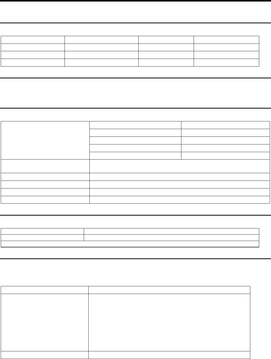
5.3 Connector Pinouts
5.3.1 Customer Display Connector
Pin Connector Pin Connector
1 CD (carrier
detect) 9 +12 V dc
2 RXD (receive
data) 10 +5 V dc Main
3 TXD (transmit
data) 11 Dist_VFD present
4 DTR (data
terminal
ready)
12 DSR (data set ready)
5 Ground 13 RTS (request to send)
6 Ground 14 CTS (clear to send)
7 +5 V dc Main 15 RI (ring indicate)
8 +12 V dc
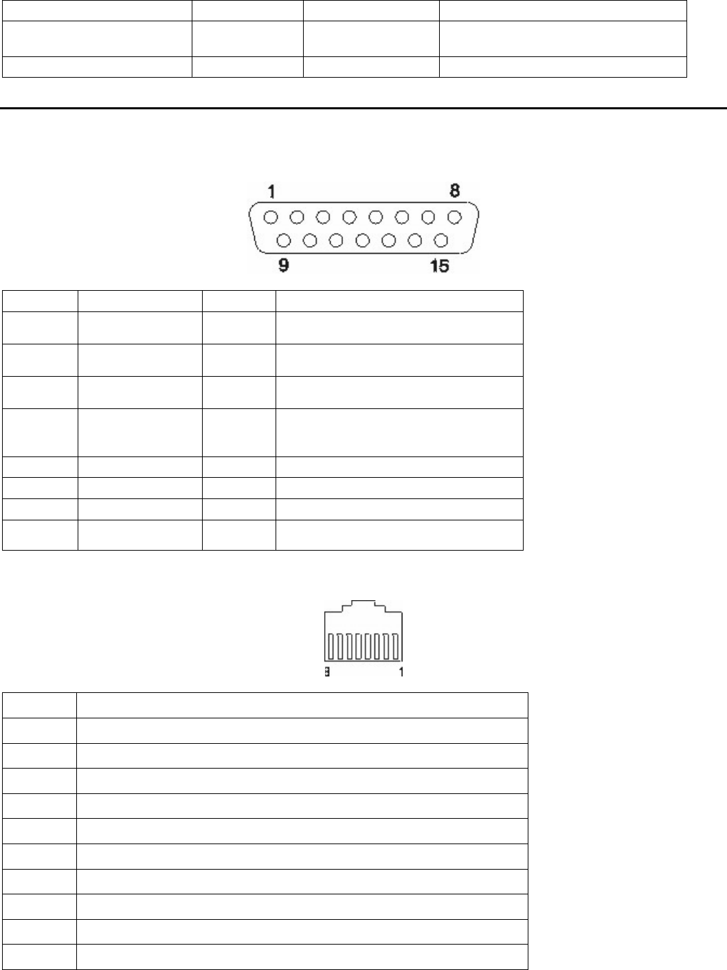
5.3.2 MSR connector
Pin Connector
1 +5 V dc Main
2 Serial Data In (TTL Level)
3 Serial Data Out (TTL Level)
4 Ground
5 MSR Present (low indicated MSR is present)
6 MSR Mode (low indicated keyboard wedge, high indicated RS-232)
7 Keyboare Enable (low enables keyboard data to the system
8 Keyboard Data (to system shipset)
9 Keyboard Clock (to system chipset)
10 Ground
SurePOS 500 4846-XX5 Technical Reference
Page 39 of 63
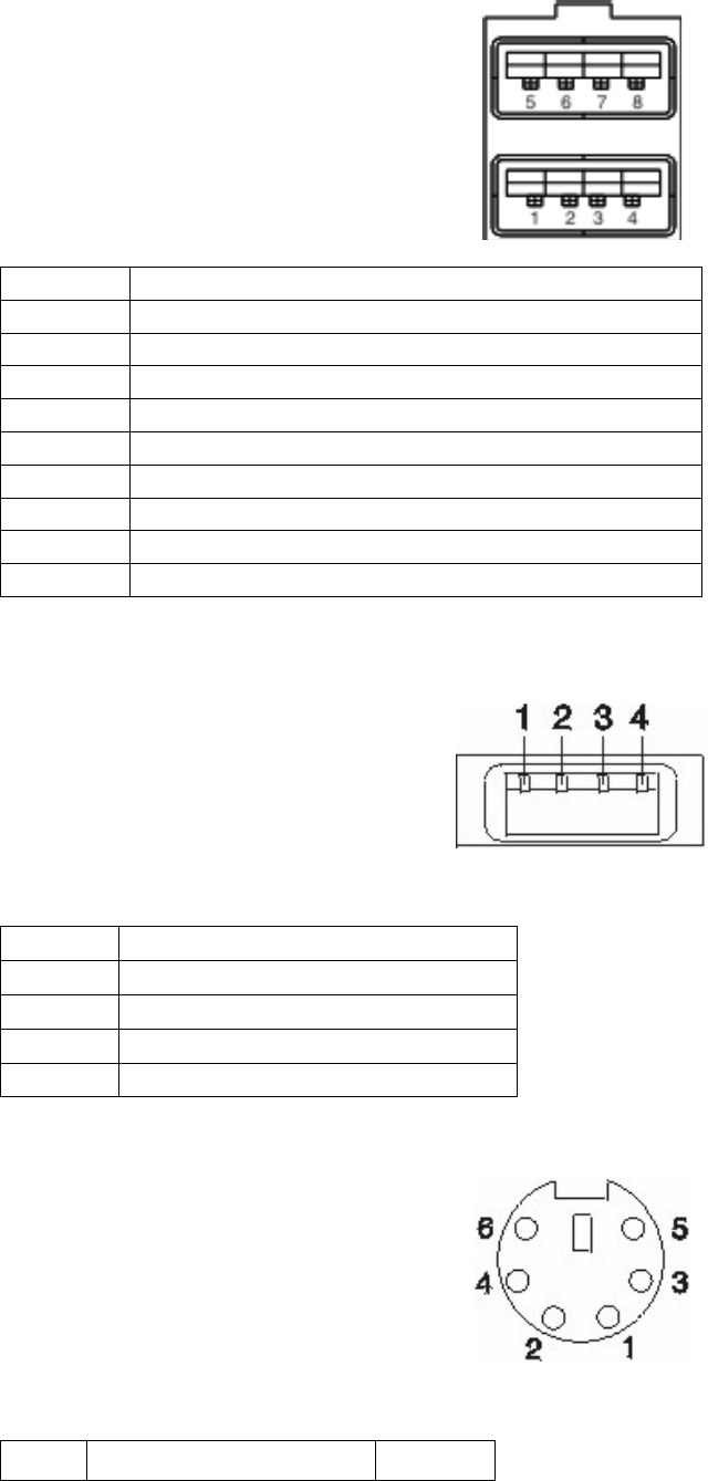
5.3.3 USB Plus Power (2x)
Pin Signal
Shell Shield
1 VBus 5V
2 D-
3 D+
4 Ground
5 Ground
6 Vplus (12V or 24V)
7 Vplus (12 or 24V)
8 Ground
5.3.4 USB port connector (7x)
Pin Connector
1 5V VBus
2 -Data
3 +Data
4 Ground
5.3.5 Keyboard, Mouse connector (2x)
Pin Signal I/O
SurePOS 500 4846-XX5 Technical Reference
Page 40 of 63
1 Keyboard Data I/O
2 Mouse Data I/O
3 Ground
4 +5 V Main
5 Keyboard Clock I/O
6 Mouse Clock
5.3.6 Microphone connector
This connector is only present on X6X models
Pin Signal
Tip Signal
Ring +5 V
Base Ground
5.3.7 Headphone Connector
This connector is only present on X6X models
Pin Signal
Tip Left channel audio
Ring Right channel audio
Base Ground
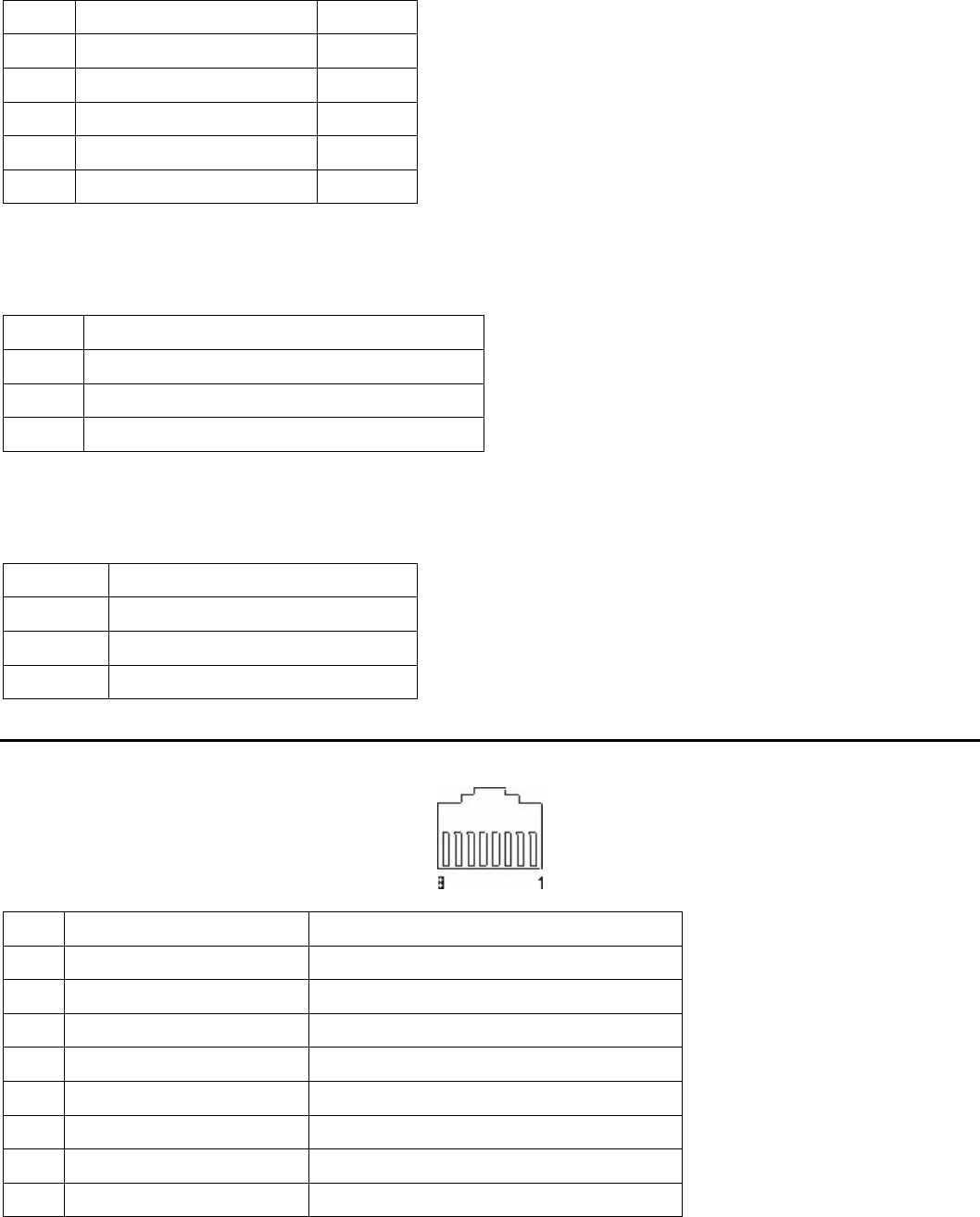
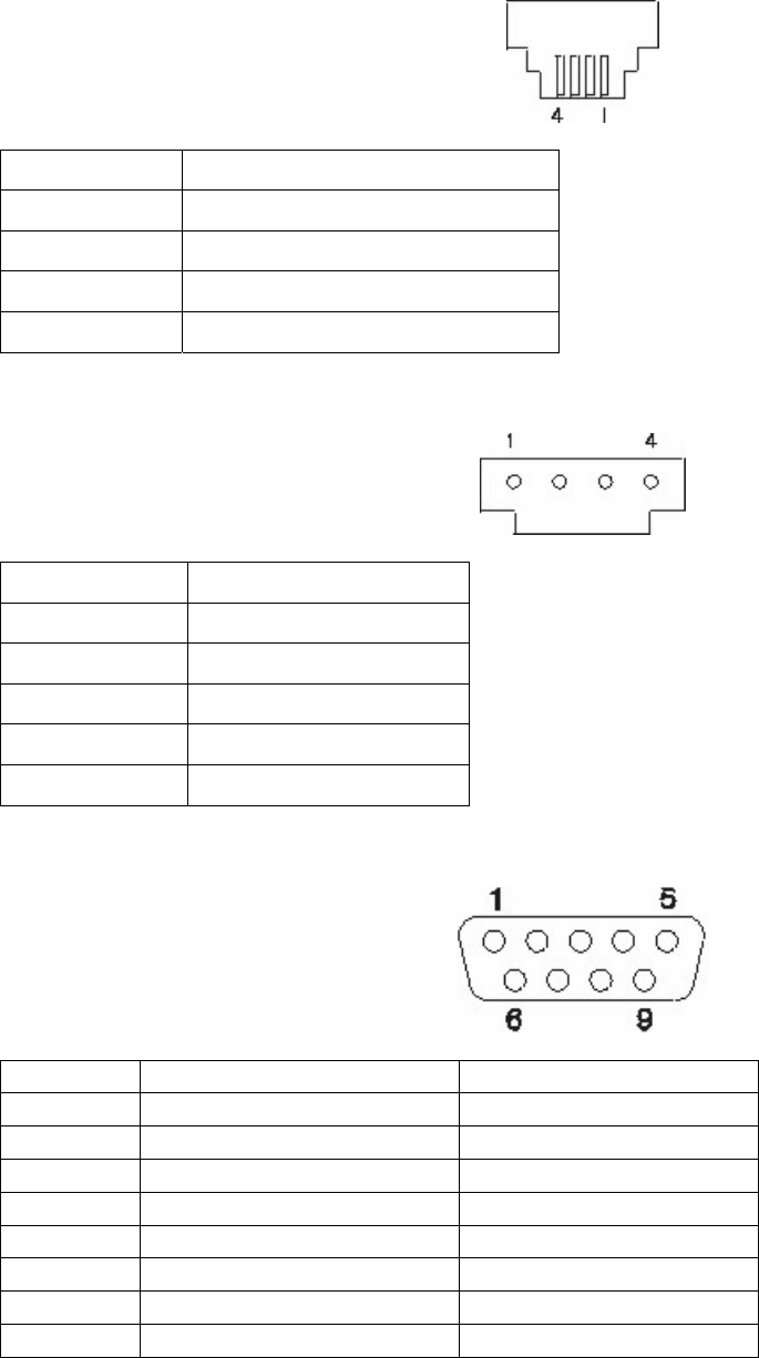
5.4 Serial Connector (x3)
Pin Signal I/O
1 Carrier detect I
2 Receive data I
3 Transmit data O
4 Data terminal ready O
5 Signal ground
6 Data set ready I
7 Request to send O
8 Clear to send I
SurePOS 500 4846-XX5 Technical Reference
Page 41 of 63
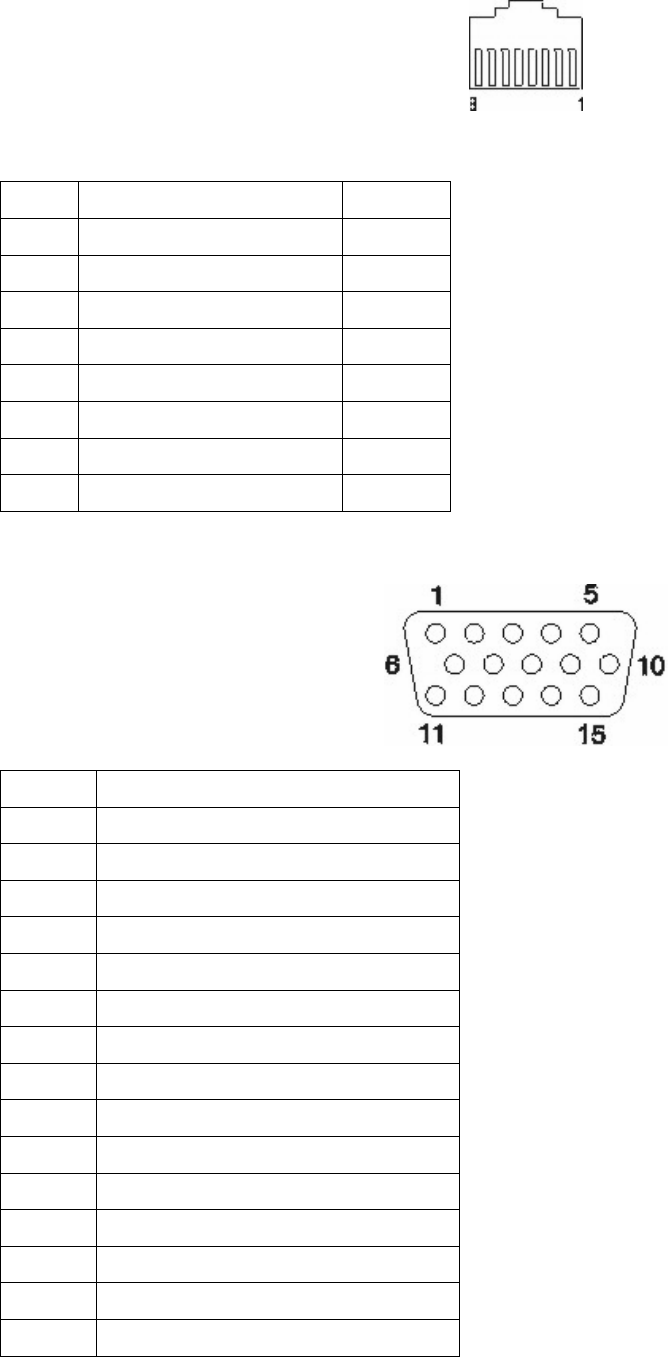
5.4.1 Ethernet connector
Pin Signal I/O
1 TxD+ O
2 TxD- O
3 RxD+ I
4 Ground
5 Ground
6 RxD- I
7 Ground
8 Ground
5.4.2 External video connector
Pin Connector
1 Red
2 Green
3 Blue
4 Monitor ID2 - not used
5 Ground
6 Red ground
7 Green ground
8 Blue ground
9 no connector
10 Gound
11 No connector
12 MON ID1
13 Horizontal sync
14 Vertical Sync
15 MON ID3
SurePOS 500 4846-XX5 Technical Reference
Page 42 of 63
5.4.3 Cash Drawer (x2)
Pin Connector
1 Ground
2 Sense
3 Open
4 24V
5.4.4 Internal Customer Display
Pin Connector
1 +5V Main
2 Transmit Data
3 Int VFD Present
4 Ground
5.4.5 RJ45 to RS232 Cable
Signal Pin number, RJ45 End Pin number, RS232 end
DSR/RI 1 6
CD 2 1
DTR 3 4
GND 4 5
RXD 5 2
TXD 6 3
CTS 7 8
RTS 8 7
SurePOS 500 4846-XX5 Technical Reference
Page 43 of 63
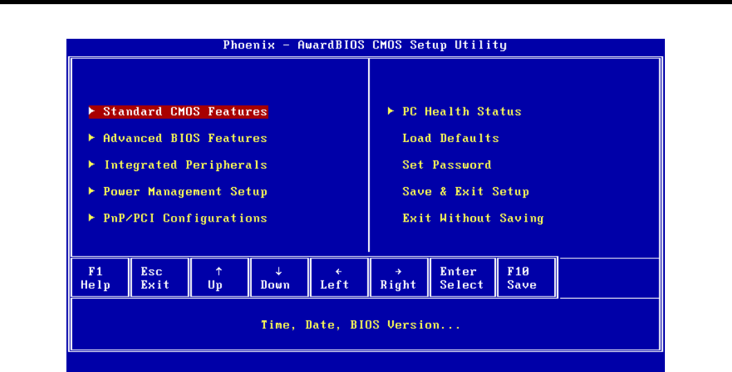
6.0 CMOS Setup Utility
Standard CMOS Features
See section x
Advanced BIOS Features
See section x
Integrated Peripherals
See section x
Power Management Setup
See section x
PnP/PCI Configurations
See section x
PC Health Status
See section x
Load Defaults
Loads default values for all configurable items in CMOS Setup.
Set Password
Sets the numeric password used for the “Security Option” item using a keyboard or on-screen numpad. See section x.
Select <Enter> at the “Enter Password:” prompt to clear the password.
Save & Exit Setup
Select “Yes” to saves any changes made in the CMOS Setup Utility and restarts the system. Select “No” to return to
the CMOS Setup utility.
Exit Without Saving
Select “Yes” to restart the system without saving any changes made in the CMOS Setup utility. Select “No” to return to
the CMOS Setup utility.
SurePOS 500 4846-XX5 Technical Reference
Page 44 of 63
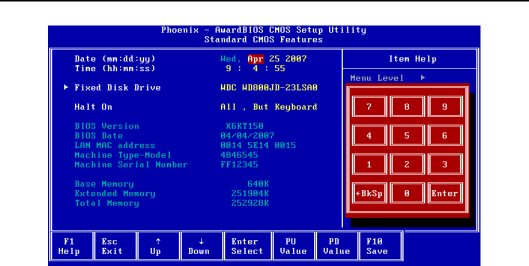
6.1 Standard CMOS Features
Date
Sets the Date using a keyboard or on-screen numpad.
Time
Sets the Time using a keyboard or on-screen numpad.
Fixed Disk Drive
Select <Enter> to view the sub-menu.
BIOS Version
Shows the current BIOS revision.
BIOS Date
Shows the BIOS revision date.
LAN MAC Address
Shows the onboard NIC MAC Address.
Machine Type-Model
Shows the Machine Type and Model.
Machine Serial Number
Shows the machine Serial Number.
Base Memory
Shows the base memory amount up to 640 Kilobytes (KB).
Extended Memory
Shows the amount of memory above 1 MB in KB.
Total Memory
Shows the total memory amount in KB. This amount does not include the shared video memory.
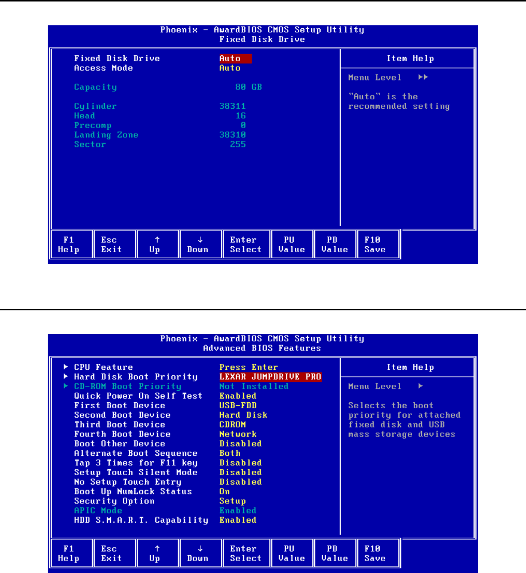
SurePOS 500 4846-XX5 Technical Reference
Page 45 of 63
6.2 Fixed Disk Drive
Shows the Hard Disk Drive Size and parameters. Changing settings on this menu is not recommended.
6.3 Advanced BIOS Features
CPU Feature
Select <Enter> to view the sub-menu. See section
Hard Disk Boot Priority
Shows the Hard Disk devices that will be booted if “Hard Disk” is selected as one of the First through Fourth Boot
Devices.
Select <Enter> to view the sub-menu and set the priority.
CD-ROM Boot Priority
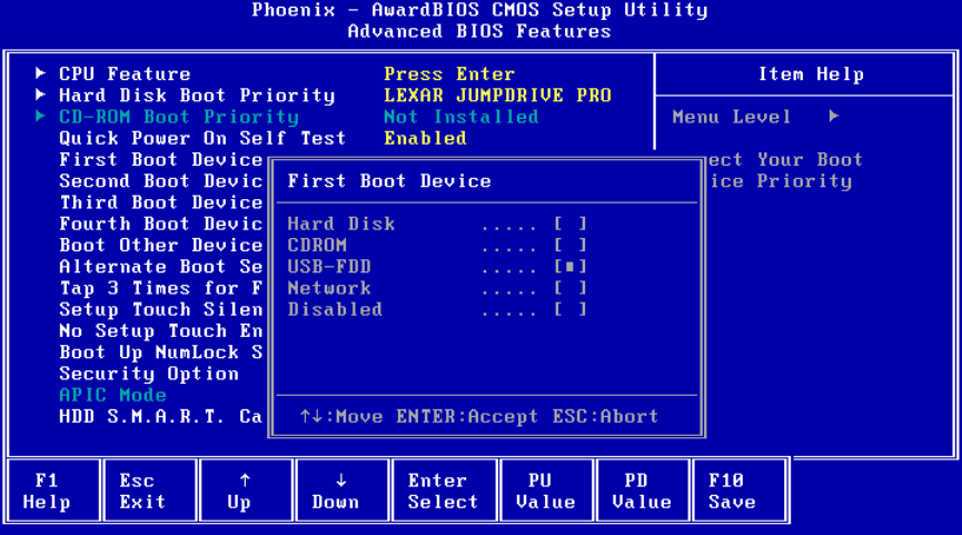
SurePOS 500 4846-XX5 Technical Reference
Page 46 of 63
Shows the CD-ROM devices that will be booted if “CDROM” is selected as one of the First through Fourth Boot
Devices.
Select <Enter> to view the sub-menu and set the priority.
Quick Power On Self Test
If enabled, allows the system to skip certain tests while booting. This will decrease the time needed to boot the
system.
Default: Enabled
Options:
• Disabled
• Enabled
6.3.1 First Boot Device
The system will attempt to boot from the specified device category before trying other boot devices.
Default: USB-FDD (USB Floppy Drive)
Options:
• Hard Disk
• CDROM
• USB-FDD
• Network
• Disabled
Second Boot Device
The system will attempt to boot from the specified device category after trying the first boot device.
Default: Hard Disk (see Hard Disk Boot Priority)
Options:
• Hard Disk
• CDROM
• USB-FDD
• Network
SurePOS 500 4846-XX5 Technical Reference
Page 47 of 63
• Disabled
Third Boot Device
The system will attempt to boot from the specified device category after trying the second boot device.
Default: CDROM (See CD-ROM Boot Priority)
Options:
• Hard Disk
• CDROM
• USB-FDD
• Network
• Disabled
Fourth Boot Device
The system will attempt to boot from the specified device category after trying the third boot device.
Default: Network
Options:
• Hard Disk
• CDROM
• USB-FDD
• Network
• Disabled
Boot Other Device
If enabled, the system will try all booting all device categories if the first through fourth boot devices fail.
Default: Disabled
Options:
• Disabled
• Enabled
Alternate Boot Sequence
Specifies whether a Magic Packet(TM) powering on the system, pressing <F12> during the POST, or both, will cause
the normal boot sequence to be skipped and a Network-only boot to be attempted. If “Boot Other Device” is enabled,
other boot devices are tried if the Network boot fails.
Default: Both
Options:
• Disabled
• Magic Packet
• <F12> Key
• Both
Tap 3 Times for F11 key
Enters an F11 key scan code if the onboard touchscreen is tapped three times at the prompt. Enables support for
Rescue and Recovery Software.
Default: Disabled
Options:
• Disabled
• Enabled
Setup Touch Silent Mode
SurePOS 500 4846-XX5 Technical Reference
Page 48 of 63
Prevents messages prompting the user to touch the screen to enter CMOS Setup, unless an error occurs.
Default: Disabled
Options:
• Disabled
• Enabled
No Setup Touch Entry
If enabled, prevents entering CMOS Setup using the touch screen. A keyboard can still be used to enter CMOS
Setup.
Default: Disabled
Options:
• Disabled
• Enabled
Boot Up NumLock Status
Selects the power-on state for the keyboard NumLock. Select “Off” when using a keyboard in DOS that shares the
numpad keys with letter keys.
Default: On
Options:
• Off
• On
Security Option
Select whether the password is required every time the system boots or only when entering CMOS Setup.
Select “Setup” to require a password before entering the CMOS Setup Utility. Select “System” to require a password
before entering CMOS setup or before booting from one of the selected boot devices.
Use the “Set Password” option on the main menu to set the password. If the password is blank, this option has no
affect.
Default: Setup
Options:
• Setup
• System
APIC Mode
This item is for information only and cannot be configured. It shows whether the Advanced Programmable Interrupt
Controller is enabled. Some operating systems will utilize the APIC.
HDD S.M.A.R.T. Capability
Select "Enabled" to allow detecting and reporting of some hard disk errors during the POST (Power On Self Test).
The BIOS does not detect errors; it only shows errors detected and reported by the hard disk.
Default: Enabled
Options:
• Disabled
• Enabled
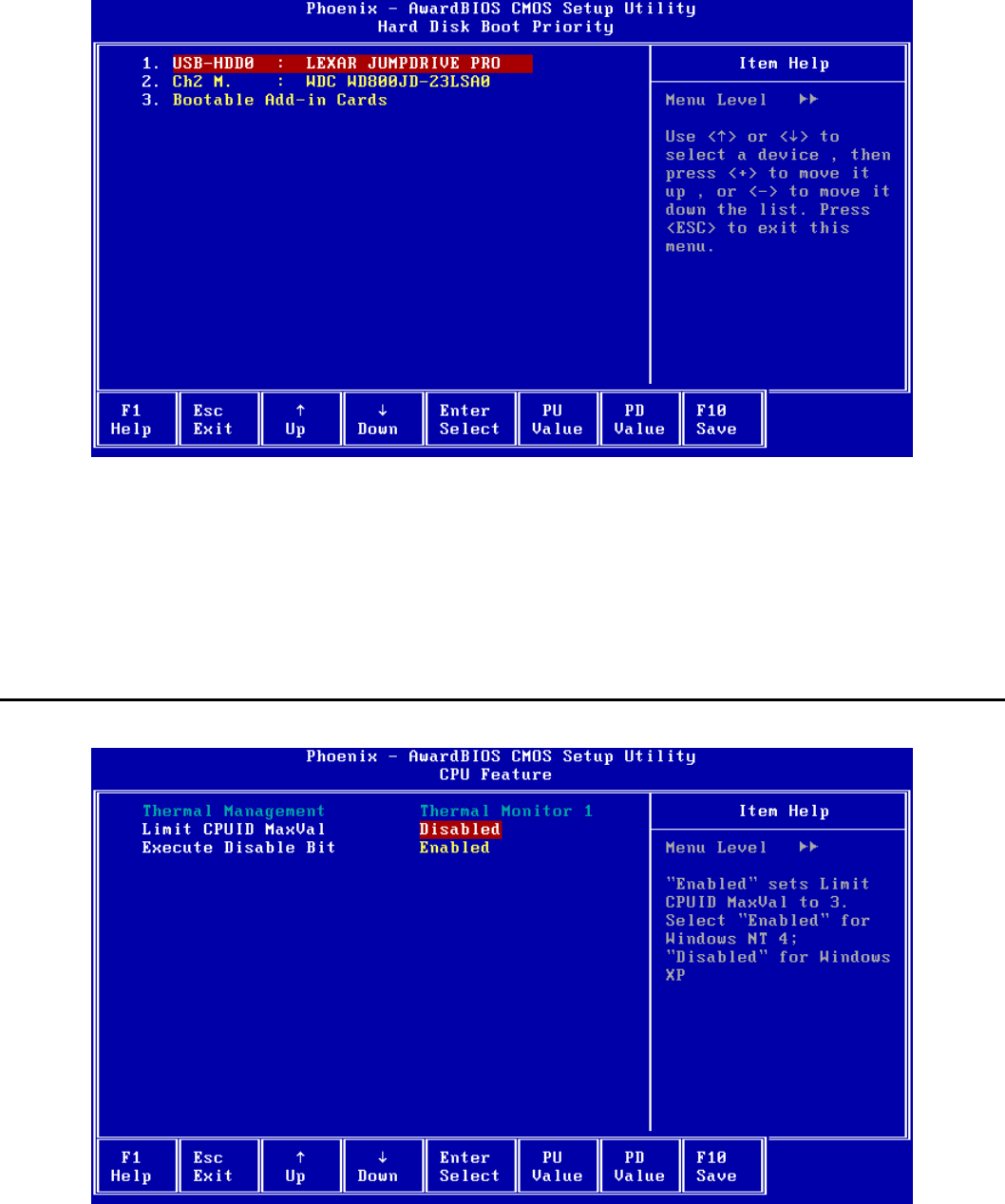
SurePOS 500 4846-XX5 Technical Reference
Page 49 of 63
6.3.2 Hard Disk Boot Priority
Selects the boot priority for attached fixed disk and USB mass storage devices. Hard Disk devices include USB
Memory Keys, Hard Disk drives, and the Modular Flash Drive.
Select an item and use <PageUp> and <PageDown> to adjust the boot priority.
Only the first item in the list is booted as a Hard Disk device.
The device must be installed in the system in order to appear in the list.
6.4 CPU Feature
Thermal Management
Shows the built-in CPU thermal management method being used.
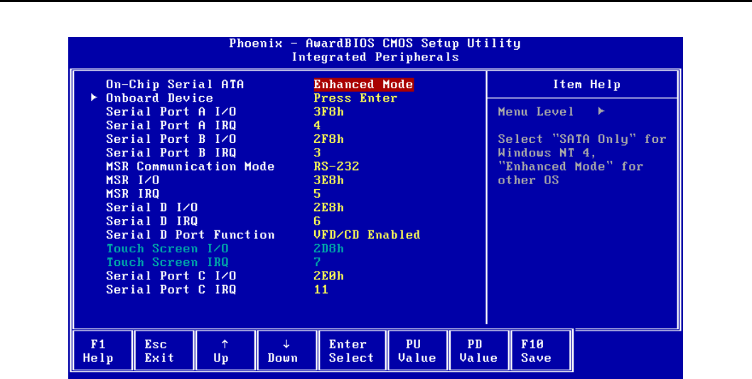
SurePOS 500 4846-XX5 Technical Reference
Page 50 of 63
This item is for information only and cannot be configured.
Limit CPUID MaxVal
"Enabled" sets Limit CPUID MaxVal to 3. Select "Enabled" for Windows NT 4; "Disabled" for Windows XP.
Default: Disabled
Options:
• Disabled
• Enabled
Execute Disable Bit
When disabled, forces the XD feature flag in the CPU to always return 0. See the following article for more
information: http://technet2.microsoft.com/WindowsServer/en/Library/b0de1052-4101-44c3-a294-
4da1bd1ef2271033.mspx?mfr=true
Default: Enabled
Options:
• Enabled
• Disabled
6.5 Integrated Peripherals
On-Chip Serial ATA
Select "SATA Only" for Windows NT 4 or "Enhanced Mode" for other Operating Systems.
When “SATA Only” is selected, the IDE controller is configured for Legacy IDE mode. When "Enhanced Mode" is
selected, the IDE controller is configured as Native IDE mode capable.
Default: Enhanced Mode
Options:
• Disabled
• Enhanced Mode
SurePOS 500 4846-XX5 Technical Reference
Page 51 of 63
• SATA Only
Onboard Device
Select <Enter> to view the sub-menu.
Serial Port A I/O
Selects the I/O address used for Serial Port A. Using the default value is recommended. If modified, ensure the
selected I/O address does not conflict with other ports as values cannot be shared.
Default: 3F8h
Options:
• Disabled
• 2E0h
• 2E8h
• 2F8h
• 2D8h
• 3E8h
• 3F8h
Serial Port A IRQ
Selects the IRQ used for Serial Port A. Using the default value is recommended. If modified, ensure the selected IRQ
does not conflict with other ports as values cannot be shared.
Default: 4
Options:
• 3
• 4
• 5
• 6
• 7
• 11
Serial Port B I/O
Selects the I/O address used for Serial Port B. Using the default value is recommended. If modified, ensure the
selected I/O address does not conflict with other ports as values cannot be shared.
Default: 2F8h
Options:
• Disabled
• 2E0h
• 2E8h
• 2F8h
• 2D8h
• 3E8h
• 3F8h
Serial Port B IRQ
Selects the IRQ used for Serial Port B. Using the default value is recommended. If modified, ensure the selected IRQ
does not conflict with other ports as values cannot be shared.
Default: 3
Options:
• 3
• 4
• 5
SurePOS 500 4846-XX5 Technical Reference
Page 52 of 63
• 6
• 7
• 11
MSR Communication Mode
This option should be set to the same mode as the switch on the MSR.
Default: RS-232
Options:
• Keyboard Wedge
• RS-232
MSR I/O
Selects the I/O address used for the MSR if “MSR Communication Mode” is set to “RS-232”. If the MSR is configured
for Keyboard Wedge mode, this item may be set to Disabled.
Using the default value is recommended. If modified, ensure the selected address does not conflict with other ports as
values cannot be shared.
Default: 3E8h
Options:
• Disabled
• 2E0h
• 2E8h
• 2F8h
• 2D8h
• 3E8h
• 3F8h
MSR IRQ
Selects the IRQ used for the MSR if “MSR Communication Mode” is set to “RS-232”. If the MSR is configured for
Keyboard Wedge mode, the selected IRQ is not used by the MSR but is not available for other use.
Using the default value is recommended. If modified, ensure the selected IRQ does not conflict with other ports as
values cannot be shared. This item cannot be disabled.
Default: 5
Options:
• 3
• 4
• 5
• 6
• 7
• 11
Serial Port D I/O
Selects the I/O address used for Serial Port D. Using the default value is recommended. If modified, ensure the
selected I/O address does not conflict with other ports as values cannot be shared.
Default: 2E8h
Options:
• Disabled
• 2E0h
• 2E8h
• 2F8h
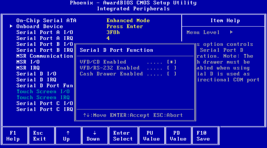
SurePOS 500 4846-XX5 Technical Reference
Page 53 of 63
• 2D8h
• 3E8h
• 3F8h
Serial Port D IRQ
Selects the IRQ used for Serial Port D. Using the default value is recommended. If modified, ensure the selected IRQ
does not conflict with other ports as values cannot be shared.
Default: 6
Options:
• 3
• 4
• 5
• 6
• 7
• 11
Serial Port D Function
This option controls the Serial Port D operation.
The IBM Character Display (both integrated and distributed) and the IBM cash drawers share serial Port D. If you do
not use either type of these types of I/O devices, then serial port D is available as a fourth standard serial port. Port D
is a 15-pin D-shell connector that includes power as well as the serial port signals. The system communicates with the
displays in a unidirectional mode. The cash drawer operates in bi-directional mode. The cash drawer must be disabled
when Serial D is used as a bi-directional COM port.
If you have at least one IBM cash drawer attached, you must specify the Cash Drawer setting as Enabled. The
Disabled setting allows you to connect an OEM device to the Serial D port when a cash drawer is not present. If you
use an IBM cash drawer, you can only attach an IBM character display (integrated or distributed) to the system.
Default: VFD/CD Enabled
Options:
• VFD/CD Enabled
• VFD/RS-232 Enabled
• Cash Drawer Enabled
SurePOS 500 4846-XX5 Technical Reference
Page 54 of 63
Touch Screen I/O
Shows the I/O address used by the touchscreen controller. This item is for information only and cannot be configured.
Touch Screen IRQ
Shows the IRQ used by the touchscreen controller. This item is for information only and cannot be configured.
Serial Port C I/O
Selects the I/O address used for Serial Port C. Using the default value is recommended. If modified, ensure the
selected I/O address does not conflict with other ports as values cannot be shared.
Default: 2E0h
Options:
• Disabled
• 2E0h
• 2E8h
• 2F8h
• 2D8h
• 3E8h
• 3F8h
Serial Port C IRQ
Selects the IRQ used for Serial Port C. Using the default value is recommended. If modified, ensure the selected IRQ
does not conflict with other ports as values cannot be shared.
Default: 11
Options:
• 3
• 4
• 5
• 6
• 7
• 11
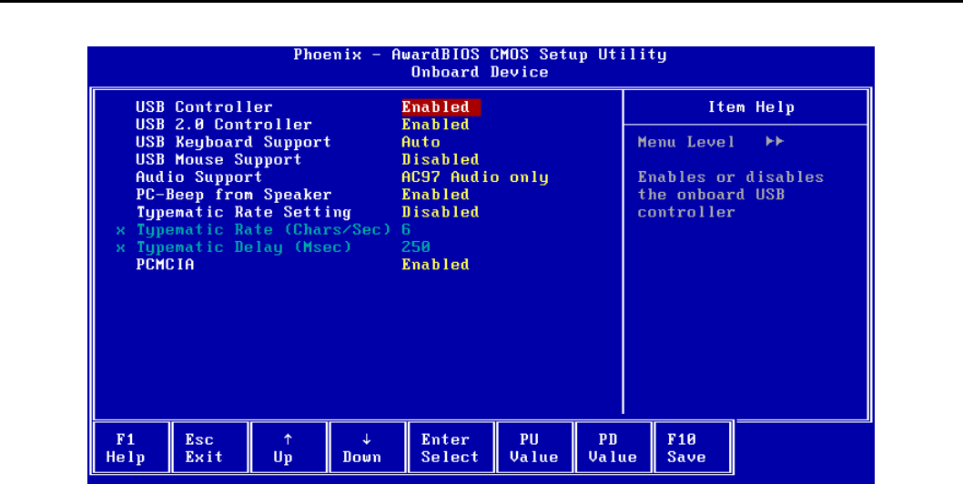
SurePOS 500 4846-XX5 Technical Reference
Page 55 of 63
6.6 On Board Device
USB Controller
Enables or disables the onboard USB controller.
USB devices will not function if the controller is disabled. An additional 32 KB of UMB space can be made available
for DOS by disabling the USB Controller.
Default: Enabled
Options:
• Enabled
• Disabled
USB 2.0 Controller
Enables or disables the EHCI USB 2.0 controller. If disabled, the USB ports will operate as 1.X ports only.
Default: Enabled
Options:
• Enabled
• Disabled
USB Keyboard Support
Enables or disables USB keyboard support in non-USB aware environments such as DOS. If ‘Auto’ is selected, BIOS
will enable USB keyboard support if a USB keyboard is detected the POST or disable support if a USB keyboard is not
detected.
Default: Auto
Options:
• Disabled
• Enabled
• Auto
USB Mouse Support
Enables or disables USB mouse support in non-USB aware environments such as DOS. A mouse driver is still
required if support is enabled.
SurePOS 500 4846-XX5 Technical Reference
Page 56 of 63
Default: Disabled
Options
• Disabled
• Enabled
Audio Support
Enables or disables the onboard AC’97 audio controller. These should be set to disabled on all 545 models.
Default: AC97 Audio only
Options:
• AC97 Audio only
• All Disabled
PC-Beep from Speaker
Enables or disables PC beeps from the integrated speakers, if present. PC beeps are always enabled from the
motherboard beeper.
Default: Enabled
Options:
• Disabled
• Enabled
Typematic Rate Setting
If disabled, keystrokes repeat at a rate determined by the keyboard controller. If enabled, “Typematic Rate” and
“Typematic Delay” can be selected.
Default: Disabled
Options:
• Disabled
• Enabled
Typematic Rate (Chars/Sec)
Sets the chars/sec rate at which a character repeats when you hold down a key.
Default: 6
Options:
• 6
• 8
• 10
• 12
• 15
• 20
• 24
• 30
Typematic Delay (Msec)
Sets the delay before key strokes begin to repeat when a key is depressed.
Default: 250
Options:
• 250
• 500
• 750
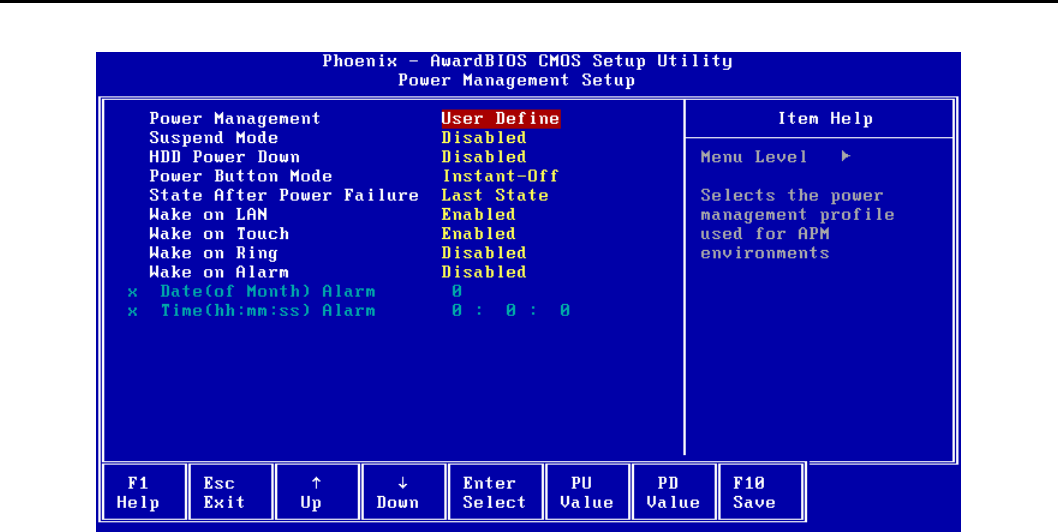
SurePOS 500 4846-XX5 Technical Reference
Page 57 of 63
• 1000
PCMCIA
Enables or disables PCMCIA support if your system has the PCMCIA controller option.
Default: Enabled
Options:
• Enabled
• Disabled
6.7 Power Management Setup
Power Management
Selects the power management profile used for Advanced Power Management (APM) environments such as DOS.
“Min Saving” and “Max Saving” are pre-defined profiles for the Suspend Mode and HDD Power Down timeout values.
“User Define” allows selection of the Suspend Mode and HDD Power Down timeouts.
This item does not apply to ACPI environments such as Windows.
Default: User Define
Options:
• User Define
• Min Saving
• Max Saving
Suspend Mode
Selects the timeout for entering the suspend state in APM environments. After the selected amount of inactivity time,
the system will enter the APM suspend state.
The power LED blinks when the system in suspended. Pressing the power button will resume the system from
Suspend.
This option is only available if “Power Management” is set to “User Define”.
SurePOS 500 4846-XX5 Technical Reference
Page 58 of 63
This item does not apply to ACPI environments such as Windows.
Default: Disabled
Options:
Disabled
• 1 Min
• 2 Min
• 4 Min
• 8 Min
• 12 Min
• 20 Min
• 30 Min
• 40 Min
• 1 Hour
HDD Power Down
Selects the timeout for powering down the hard disk in APM environments. After the selected amount of inactivity
time, the hard disk will spin down. Hard disk activity will cause the hard disk to spin back up.
This option is only available if “Power Management” is set to “User Define”.
This item does not apply to ACPI environments such as Windows.
Default: Disabled
Options:
• Disabled
• 1 Min
• 2 Min
• 3 Min
• 4 Min
• 5 Min
• 6 Min
• 7 Min
• 8 Min
• 9 Min
• 10 Min
• 11 Min
• 12 Min
• 13 Min
• 14 Min
• 15 Min
Power Button Mode
Selects the power button behavior for non-ACPI environments such as DOS.
Default: Instant-Off
Options:
• Instant-Off
• Suspend/Disabled
State After Power Failure
Specifies the power state of the system after power is lost and then restored.
Default: Last State
SurePOS 500 4846-XX5 Technical Reference
Page 59 of 63
Options:
• Last State
• Turn On
• Stay Off
Wake on LAN
If enabled, allows a Magic Packet(TM) sent to the onboard LAN adapter to wake the system from a suspend or off
state.
Default: Enabled
Options:
• Disabled
• Enabled
Wake on Touch
If enabled, allows a touch on the onboard LCD to wake the system from a suspend state.
Default: Enabled
Options:
• Disabled
• Enabled
Wake on Ring
If enabled, allows a modem attached to Serial Port D to wake the system via Ring Indicate. Ports A-C can be
jumpered to tie DSR (pin1) to Ring Indicate if required.
Default: Disabled
Options:
• Disabled
• Enabled
Wake on Alarm
If enabled, the allows the system to wake up at the specified time and date.
Default: Disabled
Options:
• Disabled
• Enabled
Date (of Month) Alarm
If “Wake on Alarm” is enabled, sets the Alarm date using a keyboard or on-screen numpad. Setting the date to zero
specifies that all days are alarm days.
This item is not available if “Wake on Alarm” is disabled.
Time (hh:mm:ss) Alarm
If “Wake on Alarm” is enabled, sets the Alarm time using a keyboard or on-screen numpad.
This item is not available if “Wake on Alarm” is disabled.
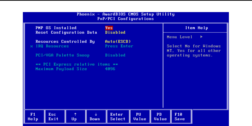
SurePOS 500 4846-XX5 Technical Reference
Page 60 of 63
6.8 PnP/PCI Configurations
PNP OS Installed
Selects whether the BIOS or the operating system configures certain onboard devices. Select “No” for Windows NT or
“Yes” for all other operating systems.
Default: Yes
Options:
• No
• Yes
Reset Configuration Data
This item is for diagnostic purposes only. Select Enabled to reset the Extended System Configuration Data (ESCD) if
the operating system cannot boot. The option automatically returns to Disabled on the next boot.
Default: Disabled
Options:
• Disabled
• Enabled
Resources Controlled By
BIOS can automatically configure the boot and Plug and Play compatible devices. Select “Auto (ESCD)” to have BIOS
automatically assign the IRQ resources to PCI devices. Select “Manual” to select which IRQs are not available for PCI
device use.
Changing this item is not recommended.
Default: Auto(ESCD)
Options:
• Auto(ESCD)
• Manual
IRQ Resources
Select <Enter> to view the sub-menu.
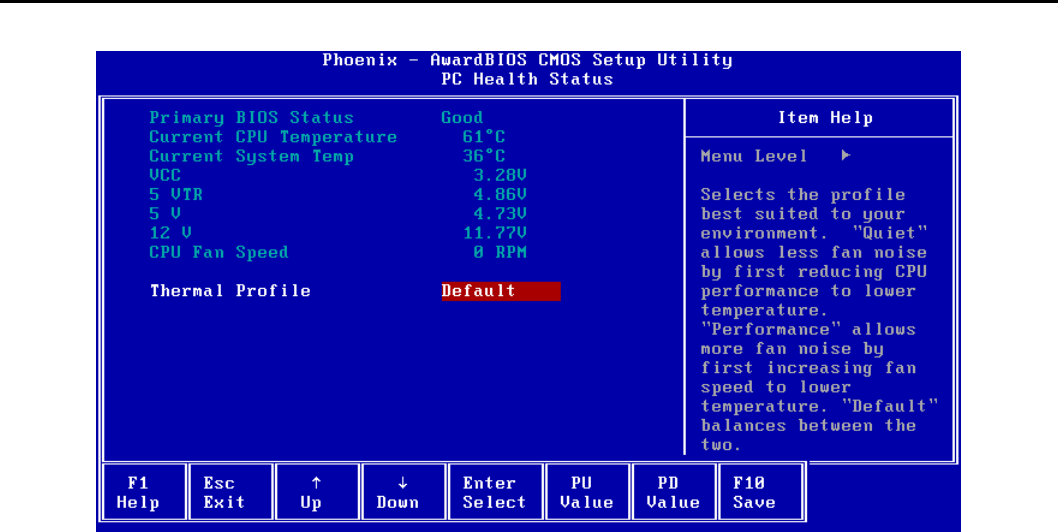
SurePOS 500 4846-XX5 Technical Reference
Page 61 of 63
When the selected IRQ is set to “Reserved”, PCI devices will not use that IRQ.
This item is only available when “Resources Controlled By” is set to “Auto (ESCD)”.
Default: PCI Device
Options:
• PCI Device
• Reserved
PCI/VGA Palette Snoop
This item is for diagnostic purposes only.
Maximum Payload Size
Shows the maximum TLP payload size for PCI Express devices in bytes.
This item is for information only and cannot be configured.
6.9 PC Health Status
Primary BIOS Status
Shows the status of the primary (boot) flash ROM. If the primary BIOS becomes corrupted due to power loss during a
BIOS update, the status may show “Bad” indicating that the BIOS update should be re-applied.
This item is for information only and cannot be configured.
Current CPU Temperature
Shows the current CPU temperature.
This item is for information only and cannot be configured.
Current System Temp
Shows the ambient temperature inside the system chassis.
This item is for information only and cannot be configured.
VCC, 5 VTR, 5 V, 12 V
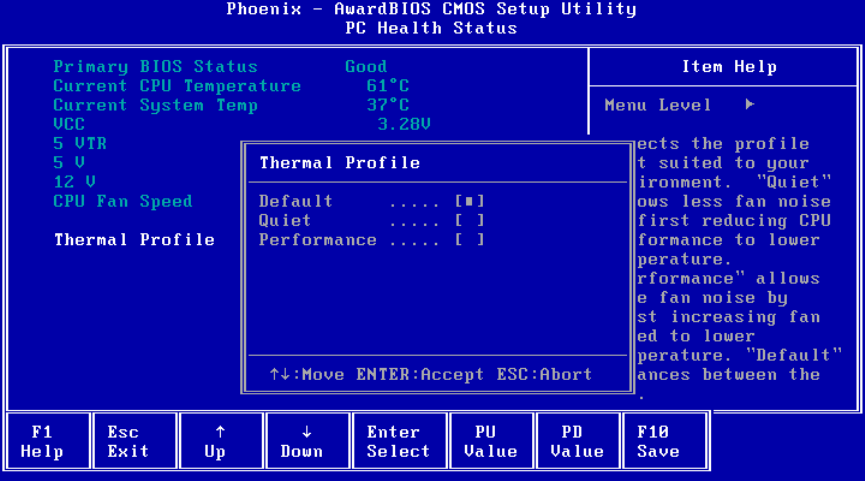
SurePOS 500 4846-XX5 Technical Reference
Page 62 of 63
Shows the current voltages for the associated voltage sensors.
This item is for information only and cannot be configured.
CPU Fan Speed
Shows the current CPU fan speed in RPMs.
This item is for information only and cannot be configured.
6.9.1 Thermal Profile
Thermal Profile
Selects the thermal management profile best suited to your environment. "Quiet" allows less fan noise by first
reducing CPU performance to lower temperature. "Performance" allows more fan noise by first increasing fan speed
to lower temperature. "Default" balances between the two.
Default: Default
Options:
• Default
• Quiet
• Performance

SurePOS 500 4846-XX5 Technical Reference
Page 63 of 63
END OF DOCUMENT
