Ibm Thinkpad I Series 1400 Users Manual TPMST
ThinkPad 1500 i Series thinkpad iseries 1400 1500
Series 1500 to the manual fcb6ad5e-52b8-4b64-ad11-f40cd9138b3d
2015-02-02
: Ibm Ibm-Thinkpad-I-Series-1400-Users-Manual-431455 ibm-thinkpad-i-series-1400-users-manual-431455 ibm pdf
Open the PDF directly: View PDF ![]() .
.
Page Count: 172 [warning: Documents this large are best viewed by clicking the View PDF Link!]
- Preface
- ThinkPad i Series 1400/1500 (2621, 2651)
- General Descriptions
- Introduction
- Read this first
- FRU replacement notices
- Related service information
- Checkout guide
- Symptom-to-FRU Index
- Numeric Error Codes and Messages
- LCD-Related Symptoms
- Keyboard/TrackPoint-Related
- Indicator-Related Symptoms
- Power-Related Symptoms
- Memory-Related Symptoms
- Audio-Related Symptoms
- PC Card (PCMCIA)-Related Symptoms
- Power Management-Related Symptoms
- Peripheral-Device-Related Symptom
- Modem-Related Symptoms
- Intermittent Problems
- Undetermined Problems
- Locations
- ThinkPad i Series 1400/1500 (Part I)
- Product overview
- FRU removals and replacements
- Battery assembly
- CD player panel and CD player control
- Hard disk drive assembly
- Hard disk drive kitting pack
- Memory cover and memory card
- Modem cover and modem card
- Middle cover and launch key assembly
- Keyboard
- Upper heat sink
- CD-ROM/DVD-ROM assembly
- CD-ROM/DVD-ROM chassis assembly
- PCMCIA holder
- LCD assembly
- Backup battery
- Keyboard bezel
- Diskette drive assembly
- Fan assembly
- DC-DC charger board
- System board
- Bottom case
- LCD bezel assembly (12.1")
- LCD bezel assembly (13.0")
- LCD bezel assembly (14.1")
- LED board (12.1")
- LED board (13.0")
- LED board (14.1")
- LCD inverter (12.1")
- LCD inverter (13.0")
- LCD inverter (14.1")
- Cable assembly of microphone (12.1")
- Cable assembly of microphone (13.0")
- Cable assembly of microphone (14.1")
- LCD bracket hinge assembly, speaker
- LCD bracket hinge assembly, speaker
- LCD bracket hinge assembly, speaker
- LCD FPC assembly (12.1")
- LCD FPC assembly (13.0")
- LCD FPC assembly (14.1")
- Parts list (ThinkPad i Series 1400/1500)
- ThinkPad i Series 1400/1500 (Part II)
- Product overview
- FRU removals and replacements
- Battery assembly
- CD player panel and CD player control
- Hard disk drive assembly
- Hard disk drive kitting pack
- Memory cover and memory card
- Modem cover and modem card
- Launch key assembly
- Left hinge cap
- Keyboard
- Upper heat sink
- CD-ROM/DVD-ROM assembly
- CD-ROM/DVD-ROM chassis assembly
- PCMCIA holder
- LCD assembly
- LED board assembly and Cable assembly
- Backup battery
- Keyboard bezel
- Diskette drive assembly
- Fan assembly
- DC-DC charger board and System board
- Bottom case
- LCD bezel assembly (15.0")
- LCD inverter (15.0")
- LCD bracket hinge assembly (15.0")
- LCD FPC assembly (15.0")
- Speaker assembly (15.0")
- Parts list (ThinkPad i Series 1400/1500)
- LCD FRU
- Keyboard
- Common parts list
- Notices
- Trademarks
S09N-1084-01
IBM Mobile Systems
ThinkPad i Series 1400/1500 (2621, 2651)
Hardware Maintenance
Manual
February 2000
S09N-1084-01
IBM Mobile Systems
ThinkPad i Series 1400/1500 (2621, 2651)
Hardware Maintenance
Manual
February 2000
IBM
Before using this information and the product it supports,
be sure to read the general information under
“Introduction” on page 2, and “Read this first” on page 19.
First Edition (February 2000)
The following paragraph does not apply to the United
Kingdom or any country where such provisions are
inconsistent with local law:
INTERNATIONAL BUSINESS MACHINES CORPO-
RATION PROVIDES THIS PUBLICATION "AS IS"
WITHOUT ANY WARRANTY OF ANY KIND, EITHER
EXPRESS OR IMPLIED, INCLUDING, BUT NOT LIMITED
TO, THE LIMITED WARRANTIES OF
MERCHANTABILITY OR FITNESS FOR A PARTICULAR
PURPOSE. Some states do not allow disclaimers or
express or implied warranties in certain transactions; there-
fore, this statement may not apply to you.
This publication could include technical inaccuracies or
typographical errors. Changes are periodically made to the
information herein; these changes will be incorporated in
new editions of the publication. IBM may make improve-
ments or changes in the products or the programs
described in this publication at any time.
Requests for technical information about IBM products
should be made to your IBM Authorized Dealer or your
IBM Marketing Representative.
Copyright International Business Machines Corpo-
ration 2000. All rights reserved. Note to US Government
Users — Documentation related to restricted rights — Use,
duplication, or disclosure is subject to restrictions set forth
in GSA ADP Schedule Contract with IBM Corp.

Preface
About this manual
This manual contains service and reference information for
IBM ThinkPad i Series 1400/1500 (2621) products. Use
this manual along with the advanced diagnostic tests to
troubleshoot problems effectively.
The manual is divided into sections as follows:
Common sections provides general information,
guidelines, and safety information required to service
computers.
Product-specific sections includes service, reference,
and product-specific parts information.
– Part I includes information on the models in
Group-A and B. (See the 2621 model table on
page iii.)
– Part II includes information on the models in
Group-C. (See the 2621 model table on page iii.)
Table 1 (Page 1 of 2). 2621– Model Table
I: 12.1"
TFT II: 14.1"
TFT
III:
15.0"
TFT
IV:
13.0"
HPA
Group-A 447,
44T/44C,
44H/44K,
44S/44X
480/48U,
460/46U,
484/464,
487/467,
48M/46M,
48A/46A,
48T/46T,
48C/46C,
48H/46H,
48K/46K,
48F/46F,
48S/46S,
48P/46P,
48X/46X,
560/567
420/42U,
424/42N,
427,
42A/42M,
42S/42F,
42D/42X,
540/547
Group-B 441/445,
448/4BA,
4BT/4BC,
4BH/4BY,
4BK/4BF,
4BS/4BP,
4BX,
541/548
465/4CM,
4CA/4CT,
4CC/4CH,
4CK/4CF
421/428,
425/43J,
4AA/4AM,
4AF/4AS,
4AP/4AX
Preface iii

Important
This manual is intended for trained servicers who are
familiar with ThinkPad products. Use this manual
along with the advanced diagnostic tests to trouble-
shoot problems effectively. Before servicing an IBM
ThinkPad product, be sure to review the safety infor-
mation under “Safety Notices (Multilingual
Translations)” on page 4 and “Safety Information” on
page 11.
Related publications
The following product publications are available through
IBM or your IBM Authorized Dealer.
Related diskettes
The following diskettes are available through IBM or your
IBM Authorized Dealer.
Table 1 (Page 2 of 2). 2621– Model Table
I: 12.1"
TFT II: 14.1"
TFT
III:
15.0"
TFT
IV:
13.0"
HPA
Group-C 442/4FT,
4FC/4FH,
4FK/4FF,
4FS/4FP,
4FX,
542/549,
5FF
482/489,
486/4GM,
4GA/4GT,
4GC/4GH,
4GK/4GF,
4GS/4GP,
4GX,
562/569
492/499,
496/49M,
49A/49T,
49C/49H,
49K/49F,
592
442/4E2,
429/4EM,
4EA/4EF,
4ES/4EP,
4EX
Publication Part, Form Number
Mobile Systems HMM Volume
1: Laptop, Notebook, Portable,
and ThinkPad Computers
(Models L40, CL57, N45, N51,
P70/P75, ThinkPad 300, 350,
500, 510, 710T, Expansion
Unit, Dock I, Dock II)
30H2356, S82G-1501-01
Mobile Systems HMM Volume
2: ThinkPad Computers
(Models 340, 355, 360, 370,
700, 701, 720, 750, 755)
30H2357, S82G-1502-03
Mobile Systems HMM Volume
3: ThinkPad Computers
(Models 365, 380, 385, 560,
760, SelectaDock)
84H8099, S82G-1503-05
Mobile Systems HMM Volume
4: ThinkPad Computers
(Models 380, 385, 560, 760,
765)
05L1271, S05L-1270-01
iv ThinkPad i Series 1400/1500 HMM

Diskette Part, Form Number
ThinkPad 300 (2615) Advanced
Diagnostics Diskette
33G9361, S33G-9361
ThinkPad 350, 350C, 425,
425C (2618) Advanced Diag-
nostics Diskette
A211000, GA21-1000
ThinkPad 365 (2625) Advanced
Diagnostics Diskette
76H7578, S30H-2498
ThinkPad 380/385 (2635) Main-
tenance Diskette
06J0333, S06J-0333
ThinkPad 500 (2603) Advanced
Diagnostics Diskette
71G3702, S71G-3702
ThinkPad 510 (2604) Advanced
Diagnostics Diskette
83G8095, S83G-8095
ThinkPad 700 (9552) Reference
Diskette
42G2017, S42G-2017
ThinkPad 700C (9552) Refer-
ence Diskette
42G2023, S42G-2023
ThinkPad 720/720C (9552) Ref-
erence Diskette
61G1194, S61G-1194
ThinkPad i Series 1400 (2611)
Diagnostic and Utilities
diskettes
01K4841, S01K-4841-00
ThinkPad Hardware Mainte-
nance Diskette (for all Models
355, 360, 560, 750, 755, 760)
78H5384, S78H-5384
ThinkPad Dock I (3545) 71G4140, S71G-4140
Docking Station (3550) 42G2428, S42G-2428
Data/Fax Modem 61G1556, S61G-1556
FaxConcentrator/A 84F8540, S84F-8540
Preface v
vi ThinkPad i Series 1400/1500 HMM

Contents
Preface . . . . . . . . . . . . . . . . . . . . . iii
ThinkPad i Series 1400/1500 Hardware Maintenance
Manual . . . . . . . . . . . . . . . . . . . . . 1
General Descriptions . . . . . . . . . . . . . . . 1
Introduction . . . . . . . . . . . . . . . . . . . . 2
Important Service Information .......... 2
Drive and Diskette Compatibility Matrix ..... 3
Safety Notices (Multilingual Translations) .... 4
Safety Information . . . . . . . . . . . . . . . 11
Laser Compliance Statement .......... 16
Read this first ................... 19
What to do first ................ 19
FRU replacement notices ............. 21
LCD replacement notice ............ 21
Screw notices . . . . . . . . . . . . . . . . . 21
System board/Inverter replacement notice .... 22
Bios Levels . . . . . . . . . . . . . . . . . . 23
Flash (BIOS) update procedure ......... 23
Related service information ............ 24
Power button as reset switch .......... 24
Running a low-level format ........... 24
Service Web site ............... 24
Passwords . . . . . . . . . . . . . . . . . . 24
Power management features .......... 26
Fn key combinations .............. 27
Checkout guide . . . . . . . . . . . . . . . . . . 28
Testing the computer ............. 28
Related service information ........... 29
Power systems checkout ............ 30
Symptom-to-FRU Index . . . . . . . . . . . . . . 33
Numeric Error Codes and Messages ...... 33
LCD-Related Symptoms . . . . . . . . . . . . 34
Keyboard/TrackPoint-Related Symptoms . . . . 35
Indicator-Related Symptoms . . . . . . . . . . 35
Power-Related Symptoms . . . . . . . . . . . 35
Memory-Related Symptoms . . . . . . . . . . 36
Audio-Related Symptoms . . . . . . . . . . . 36
PC Card (PCMCIA)-Related Symptoms ..... 37
Power Management-Related Symptoms ..... 37
Peripheral-Device-Related Symptom . . . . . . 37
Modem-Related Symptoms . . . . . . . . . . . 38
Intermittent Problems . . . . . . . . . . . . . 38
Undetermined Problems . . . . . . . . . . . . 38
Locations . . . . . . . . . . . . . . . . . . . . . 40
Front View . . . . . . . . . . . . . . . . . . 40
Rear View . . . . . . . . . . . . . . . . . . . 41
Bottom View . . . . . . . . . . . . . . . . . . 42
Switch Locations . . . . . . . . . . . . . . . . 43
ThinkPad i Series 1400/1500 (Part I) ........ 43
Contents vii
Product overview . . . . . . . . . . . . . . . 44
FRU removals and replacements ........ 50
Parts list (ThinkPad i Series 1400/1500) ..... 90
ThinkPad i Series 1400/1500 (Part II) ...... 107
Product overview . . . . . . . . . . . . . . 108
FRU removals and replacements ....... 113
Parts list (ThinkPad i Series 1400/1500) .... 142
Notices . . . . . . . . . . . . . . . . . . . . . 160
Trademarks . . . . . . . . . . . . . . . . . . 161
viii ThinkPad i Series 1400/1500 HMM

ThinkPad i Series 1400/1500
Hardware Maintenance Manual
General Descriptions
This chapter includes descriptions for any ThinkPad model
that has the PC-Doctor DOS diagnostics program. Some
descriptions might not apply to your particular computer.
ThinkPad i Series 1400/1500 1

Introduction
Important Service Information
Important
Diskette fixes are customer installable. The diskette
fixes are located on the PC Company Bulletin Board
Service (BBS). The direct phone line for modem con-
nection is 919-557-0001 or tieline 255-0001.
Advise customers to contact the PC Company
HelpCenter at 800-772-2227 if they need assistance in
obtaining or installing any diskette fixes.
Customers in Canada should call IBM HelpPC at
800-565-3344 for assistance or download information.
The Canadian BBS phone numbers are:
Montreal 514-938-3022
Toronto 905-316-4255
Vancouver 604-664-6464
Winnipeg 204-934-2735
FRU Replacement Strategy
Before Replacing Parts
Ensure that all diskette fixes are installed prior to
replacing any FRUs listed in this manual.
Use the following strategy to prevent unnecessary FRU
replacement and service expense:
If you are instructed to replace a FRU and that
does not correct the problem, reinstall the original
FRU before you continue.
Some computers have both a processor board and a
system board. If you are instructed to replace either
the processor board or the system board, and the first
board that you replaced does not correct the problem,
reinstall the original board, then replace the other
(processor or system) board.
If an adapter or device consists of more than one
FRU, an error code may be caused by any of the
FRUs. Before replacing the adapter or device, remove
the FRUs, one by one, to see if the symptoms
change. Replace only the FRU that changed the
symptoms.
Attention: A customized setup configuration (other than
default settings) may exist on the computer you are ser-
vicing. Running Automatic Configuration may alter those
settings. Note the current configuration settings (using the
2ThinkPad i Series 1400/1500 HMM

View Configuration option) and verify that the settings are
in place when service is complete.
Hard Disk Drive Replacement Strategy:
Always try to run a low-level format before replacing a hard
disk drive.
Attention: The drive startup sequence in the computer you
are servicing might have been changed. Be extremely
careful during write operations such as copying, saving, or
formatting. Data or programs can be over-written if you
select an incorrect drive.
How to Use Error Messages: Use the error
codes displayed on the screen to diagnose failures. If more
than one error code is displayed, begin the diagnosis with
the first error code. The cause of the first error code can
result in false error codes being displayed. If no error code
is displayed, see if the error symptom is listed in the
Symptom-to-FRU Index for the computer you are servicing.
How to Read POST Error Messages: POST
error messages are displayed on the screen as three, four,
five, or eight digits. The error messages that can be dis-
played as shorter POST messages are highlighted in this
index. Some digits will represent different information for
SCSI errors versus non-SCSI errors. The following
example shows which digits display the shorter POST error
messages and also defines the SCSI information in an
eight-digit error message.
POST
All SCSI devices are set to a different SCSI ID. Duplicate
SCSI ID settings can generate a false error message. Use
the SCSI ID to determine whether the error message is
coming from an internal or an external device.
Drive and Diskette Compatibility Matrix
The following table provides identification information for
3.5-inch drives.
The following table provides compatibility information for
3.5-inch diskettes and 3.5-inch diskette drives.
Diskette Drive Identifying Mark
3.5-Inch - 1.44MB 1.44 on the eject button
3.5-Inch - 2.88MB 2.88 on the eject button
Diskette
Capacity 1.44MB Drive 2.88MB Drive
1.0MB Read/Write Read/Write
2.0MB Read/Write Read/Write
4.0MB Not Compatible Read/Write
ThinkPad i Series 1400/1500 3

The following table provides identification information for
5.25-inch diskette drives.
The following table provides compatibility information for
5.25-inch diskettes and 5.25-inch diskette drives.
Note: A 360KB diskette written to or formatted on a
1.2MB drive can be read reliably only on a 1.2MB
drive.
Diskette Drive Identifying Mark
5.25-Inch - 360KB (External) Asterisk on bezel
5.25-Inch - 1.2MB (Internal) 1.2 on the eject button
Diskette
Capacity 360KB Drive 1.2MB Drive
360KB Read/Write Read/Write
1.2MB Not Compatible Read/Write
Safety Notices (Multilingual
Translations)
In this manual, safety notices appear in English with a
page number reference to the appropriate multilingual,
translated safety notice found in this section.
The following safety notices are provided in English,
French, German, Italian, and Spanish languages.
4ThinkPad i Series 1400/1500 HMM

Safety Notice 1
Before the computer is powered-on after FRU replace-
ment, make sure all screws, springs, or other small
parts are in place and are not left loose inside the
computer. Verify this by shaking the computer and lis-
tening for rattling sounds. Metallic parts or metal flakes
can cause electrical shorts.
Avant de remettre l'ordinateur sous tension après
remplacement d'une unité en clientèle, vérifiez que
tous les ressorts, vis et autres piòces sont bien en
place et bien fixées. Pour ce faire, secouez l'unité et
assurez-vous qu'aucun bruit suspect ne se produit.
Des pièces métalliques ou des copeaux de métal
pourraient causer un court-circuit.
Bevor nach einem FRU-Austausch der Computer
wieder angeschlossen wird, muβ sichergestellt
werden, daβ keine Schrauben, Federn oder andere
Kleinteile fehlen oder im Gehäuse vergessen wurden.
Der Computer muβ geschüttelt und auf
Klappergeräusche geprüft werden. Metallteile oder
-splitter können Kurzschlüsse erzeugen.
Prima di accendere l'elaboratore dopo che é stata
effettuata la sostituzione di una FRU, accertarsi che
tutte le viti, le molle e tutte le altri parti di piccole
dimensioni siano nella corretta posizione e non siano
sparse all'interno dell'elaboratore. Verificare ciò
scuotendo l'elaboratore e prestando attenzione ad
eventuali rumori; eventuali parti o pezzetti metallici
possono provocare cortocircuiti pericolosi.
Antes de encender el sistema despues de sustituir
una FRU, compruebe que todos los tornillos, muelles
y demás piezas pequeñas se encuentran en su sitio y
no se encuentran sueltas dentro del sistema.
Compruébelo agitando el sistema y escuchando los
posibles ruidos que provocarõan. Las piezas metálicas
pueden causar cortocircuitos eléctricos.
ThinkPad i Series 1400/1500 5

Safety Notice 2
Some standby batteries contain a small amount of
nickel and cadmium. Do not disassemble it, recharge
it, throw it into fire or water, or short-circuit it. Dispose
of the battery as required by local ordinances or regu-
lations. Use only the battery in the appropriate parts
listing. Use of an incorrect battery can result in ignition
or explosion of the battery.
Certaines batteries de secours contiennent du nickel
et du cadmium. Ne les démontez pas, ne les
rechargez pas, ne les exposez ni au feu ni à l'eau. Ne
les mettez pas en court-circuit. Pour les mettre au
rebut, conformez-vous à la réglementation en vigueur.
Lorsque vous remplacez la pile de sauvegarde ou
celle de l'horloge temps réel, veillez à n'utiliser que les
modèles cités dans la liste de pièces détachées
adéquate. Une batterie ou une pile inappropriée risque
de prendre feu ou d'exploser.
Die Bereitschaftsbatterie, die sich unter dem
Diskettenlaufwerk befindet, kann geringe Mengen
Nickel und Cadmium enthalten. Sie darf nur durch die
Verkaufsstelle oder den IBM Kundendienst
ausgetauscht werden. Sie darf nicht zerlegt,
wiederaufgeladen, kurzgeschlossen, oder Feuer oder
Wasser ausgesetzt werden. Die Batterie kann schwere
Verbrennungen oder Verätzungen verursachen. Bei
der Entsorgung die örtlichen Bestimmungen fÎr
Sondermüll beachten. Beim Ersetzen der
Bereitschafts- oder Systembatterie nur Batterien des
Typs verwenden, der in der Ersatzteilliste aufgeführt
ist. Der Einsatz falscher Batterien kann zu Entzündung
oder Explosion führen.
Alcune batterie di riserva contengono una piccola
quantità di nichel e cadmio. Non smontarle, ricaricarle,
gettarle nel fuoco o nell'acqua né cortocircuitarle.
Smaltirle secondo la normativa in vigore (DPR 915/82,
successive disposizioni e disposizioni locali). Quando
si sostituisce la batteria dell'RTC (real time clock) o la
batteria di supporto, utilizzare soltanto i tipi inseriti
nell'appropriato Catalogo parti. L'impiego di una
batteria non adatta potrebbe determinare l'incendio o
l'esplosione della batteria stessa.
Algunas baterías de reserva contienen una pequeña
cantidad de níquel y cadmio. No las desmonte, ni
recargue, ni las eche al fuego o al agua ni las
cortocircuite. Deséchelas tal como dispone la
normativa local. Utilice sólo baterías que se
encuentren en la lista de piezas. La utilización de una
batería no apropiada puede provocar la ignición o
explosión de la misma.
6ThinkPad i Series 1400/1500 HMM

Safety Notice 3
The battery pack contains small amounts of nickel. Do
not disassemble it, throw it into fire or water, or short-
circuit it. Dispose of the battery pack as required by
local ordinances or regulations. Use only the battery in
the appropriate parts listing when replacing the battery
pack. Use of an incorrect battery can result in ignition
or explosion of the battery.
La batterie contient du nickel. Ne la démontez pas, ne
l'exposez ni au feu ni à l'eau. Ne la mettez pas en
court-circuit. Pour la mettre au rebut, conformez-vous
à la réglementation en vigueur. Lorsque vous
remplacez la batterie, veillez à n'utiliser que les
modèles cités dans la liste de pièces détachées
adéquate. En effet, une batterie inappropriée risque de
prendre feu ou d'exploser.
Akkus enthalten geringe Mengen von Nickel. Sie
dürfen nicht zerlegt, wiederaufgeladen,
kurzgeschlossen, oder Feuer oder Wasser ausgesetzt
werden. Bei der Entsorgung die örtlichen
Bestimmungen für Sondermüll beachten. Beim
Ersetzen der Batterie nur Batterien des Typs
verwenden, der in der Ersatzteilliste aufgeführt ist. Der
Einsatz falscher Batterien kann zu Entzündung oder
Explosion führen.
La batteria contiene piccole quantità di nichel. Non
smontarla, gettarla nel fuoco o nell'acqua né
cortocircuitarla. Smaltirla secondo la normativa in
vigore (DPR 915/82, successive disposizioni e
disposizioni locali). Quando si sostituisce la batteria,
utilizzare soltanto i tipi inseriti nell'appropriato
Catalogo parti. L'impiego di una batteria non adatta
potrebbe determinare l'incendio o l'esplosione della
batteria stessa.
Las baterías contienen pequeñas cantidades de
níquel. No las desmonte, ni recargue, ni las eche al
fuego o al agua ni las cortocircuite. Deséchelas tal
como dispone la normativa local. Utilice sólo baterías
que se encuentren en la lista de piezas al sustituir la
batería. La utilización de una batería no apropiada
puede provocar la ignición o explosión de la misma.
ThinkPad i Series 1400/1500 7

Safety Notice 4
The lithium battery can cause a fire, explosion, or
severe burn. Do not recharge it, remove its polarized
connector, disassemble it, heat it above 100°C
(212°F), incinerate it, or expose its cell contents to
water. Dispose of the battery as required by local
ordinances or regulations. Use only the battery in the
appropriate parts listing. Use of an incorrect battery
can result in ignition or explosion of the battery.
La pile de sauvegarde contient du lithium. Elle
présente des risques d'incendie, d'explosion ou de
brûlures graves. Ne la rechargez pas, ne retirez pas
son connecteur polarisé et ne la démontez pas. Ne
l'exposez pas à une temperature supérieure à 100°C,
ne la faites pas brûler et n'en exposez pas le contenu
à l'eau. Mettez la pile au rebut conformément à la
réglementation en vigueur. Une pile inappropriée
risque de prendre feu ou d'exploser.
Die Systembatterie ist eine Lithiumbatterie. Sie kann
sich entzünden, explodieren oder schwere
Verbrennungen hervorrufen. Batterien dieses Typs
dürfen nicht aufgeladen, zerlegt, über 100 C erhitzt
oder verbrannt werden. Auch darf ihr Inhalt nicht mit
Wasser in Verbindung gebracht oder der zur richtigen
Polung angebrachte Verbindungsstecker entfernt
werden. Bei der Entsorgung die örtlichen
Bestimmungen für Sondermüll beachten. Beim
Ersetzen der Batterie nur Batterien des Typs
verwenden, der in der Ersatzteilliste aufgeführt ist. Der
Einsatz falscher Batterien kann zu Entzündung oder
Explosion führen.
La batteria di supporto e una batteria al litio e puo
incendiarsi, esplodere o procurare gravi ustioni.
Evitare di ricaricarla, smontarne il connettore
polarizzato, smontarla, riscaldarla ad una temperatura
superiore ai 100 gradi centigradi, incendiarla o gettarla
in acqua. Smaltirla secondo la normativa in vigore
(DPR 915/82, successive disposizioni e disposizioni
locali). L'impiego di una batteria non adatta potrebbe
determinare l'incendio o l'esplosione della batteria
stessa.
La bateria de repuesto es una bateria de litio y puede
provocar incendios, explosiones o quemaduras
graves. No la recargue, ni quite el conector
polarizado, ni la desmonte, ni caliente por encima de
los 100°C (212°F), ni la incinere ni exponga el
contenido de sus celdas al agua. Deséchela tal como
dispone la normativa local.
8ThinkPad i Series 1400/1500 HMM

Safety Notice 5
If the LCD breaks and the fluid from inside the LCD
gets into your eyes or on your hands, immediately
wash the affected areas with water for at least 15
minutes. Seek medical care if any symptoms from the
fluid are present after washing.
Si le panneau d'affichage à cristaux liquides se brise
et que vous recevez dans les yeux ou sur les mains
une partie du fluide, rincez-les abondamment pendant
au moins quinze minutes. Consultez un médecin si
des symptômes persistent après le lavage.
Die Leuchtstoffröhre im LCD-Bildschirm enthält
Quecksilber. Bei der Entsorgung die örtlichen
Bestimmungen für Sondermüll beachten. Der
LCD-Bildschirm besteht aus Glas und kann
zerbrechen, wenn er unsachgemäβ behandelt wird
oder der Computer auf den Boden fällt. Wenn der
Bildschirm beschädigt ist und die darin befindliche
Flüssigkeit in Kontakt mit Haut und Augen gerät,
sollten die betroffenen Stellen mindestens 15 Minuten
mit Wasser abgespült und bei Beschwerden
anschlieβend ein Arzt aufgesucht werden.
Nel caso che caso l'LCD si dovesse rompere ed il
liquido in esso contenuto entrasse in contatto con gli
occhi o le mani, lavare immediatamente le parti
interessate con acqua corrente per almeno 15 minuti;
poi consultare un medico se i sintomi dovessero
permanere.
Si la LCD se rompe y el fluido de su interior entra en
contacto con sus ojos o sus manos, lave
inmediatamente las áreas afectadas con agua durante
15 minutos como mínimo. Obtenga atención medica si
se presenta algún síntoma del fluido despues de
lavarse.
ThinkPad i Series 1400/1500 9

Safety Notice 6
To avoid shock, do not remove the plastic cover that
surrounds the lower portion of the inverter card.
Afin d'éviter tout risque de choc électrique, ne retirez
pas le cache en plastique protégeant la partie
inférieure de la carte d'alimentation.
Aus Sicherheitsgründen die Kunststoffabdeckung, die
den unteren Teil der Spannungswandlerplatine umgibt,
nicht entfernen.
Per evitare scosse elettriche, non rimuovere la
copertura in plastica che avvolge la parte inferiore
della scheda invertitore.
Para evitar descargas, no quite la cubierta de plástico
que rodea la parte baja de la tarjeta invertida.
Safety Notice 7
Though main batteries have low voltage, a shorted or
grounded battery can produce enough current to burn
combustible materials or personnel.
Bien que le voltage des batteries principales soit peu
élevé, le court-circuit ou la mise à la masse d'une
batterie peut produire suffisamment de courant pour
brûler des matériaux combustibles ou causer des
brûlures corporelles graves.
Obwohl Hauptbatterien eine niedrige Spannung
haben, können sie doch bei Kurzschluβ oder Erdung
genug Strom abgeben, um brennbare Materialien zu
entzünden oder Verletzungen bei Personen
hervorzurufen.
Sebbene le batterie di alimentazione siano a basso
voltaggio, una batteria in corto circuito o a massa può
fornire corrente sufficiente da bruciare materiali
combustibili o provocare ustioni ai tecnici di
manutenzione.
Aunque las baterías principales tienen un voltaje bajo,
una batería cortocircuitada o con contacto a tierra
puede producir la corriente suficiente como para
quemar material combustible o provocar quemaduras
en el personal.
10 ThinkPad i Series 1400/1500 HMM

Safety Notice 8
Before removing any FRU, power-off the computer,
unplug all power cords from electrical outlets, remove
the battery pack, then disconnect any interconnecting
cables.
Avant de retirer une unitÒ rempla able en clientèle,
mettez le système hors tension, débranchez tous les
cordons d'alimentation des socles de prise de courant,
retirez la batterie et déconnectez tous les cordons
d'interface.
Die Stromzufuhr muβ abgeschaltet, alle Stromkabel
aus der Steckdose gezogen, der Akku entfernt und
alle Verbindungskabel abgenommen sein, bevor eine
FRU entfernt wird.
Prima di rimuovere qualsiasi FRU, spegnere il
sistema, scollegare dalle prese elettriche tutti i cavi di
alimentazione, rimuovere la batteria e poi scollegare i
cavi di interconnessione.
Antes de quitar una FRU, apague el sistema,
desenchufe todos los cables de las tomas de corriente
eléctrica, quite la batería y, a continuación,
desconecte cualquier cable de conexión entre
dispositivos.
Safety Information
The following section contains the safety information that
you need to be familiar with before servicing an IBM
mobile computer.
General Safety: Follow these rules to ensure
general safety:
Observe good housekeeping in the area of the
machines during and after maintenance.
When lifting any heavy object:
1. Ensure you can stand safely without slipping.
2. Distribute the weight of the object equally
between your feet.
3. Use a slow lifting force. Never move suddenly or
twist when you attempt to lift.
4. Lift by standing or by pushing up with your leg
muscles; this action removes the strain from the
muscles in your back.
Do not attempt to lift any
objects that weigh more than 16 kg (35 lb) or
objects that you think are too heavy for you.
Do not perform any action that causes hazards to the
customer, or that makes the equipment unsafe.
ThinkPad i Series 1400/1500 11

Before you start the machine, ensure that other
service representatives and the customer's personnel
are not in a hazardous position.
Place removed covers and other parts in a safe
place, away from all personnel, while you are ser-
vicing the machine.
Keep your tool case away from walk areas so that
other people will not trip over it.
Do not wear loose clothing that can be trapped in the
moving parts of a machine. Ensure that your sleeves
are fastened or rolled up above your elbows. If your
hair is long, fasten it.
Insert the ends of your necktie or scarf inside clothing
or fasten it with a nonconductive clip, approximately 8
centimeters (3 inches) from the end.
Do not wear jewelry, chains, metal-frame eyeglasses,
or metal fasteners for your clothing.
Attention: Metal objects are good electrical conduc-
tors.
Wear safety glasses when you are: hammering,
drilling soldering, cutting wire, attaching springs, using
solvents, or working in any other conditions that might
be hazardous to your eyes.
After service, reinstall all safety shields, guards,
labels, and ground wires. Replace any safety device
that is worn or defective.
Reinstall all covers correctly before returning the
machine to the customer.
Electrical Safety: Observe the following rules when
working on electrical equipment.
Important
Use only approved tools and test equipment. Some
hand tools have handles covered with a soft material
that does not insulate you when working with live elec-
trical currents. Many customers have, near their equip-
ment, rubber floor mats that contain small conductive
fibers to decrease electrostatic discharges. Do not use
this type of mat to protect yourself from electrical
shock.
Find the room emergency power-off (EPO) switch,
disconnecting switch, or electrical outlet. If an elec-
trical accident occurs, you can then operate the
switch or unplug the power cord quickly.
Do not work alone under hazardous conditions or
near equipment that has hazardous voltages.
Disconnect all power before:
– Performing a mechanical inspection
12 ThinkPad i Series 1400/1500 HMM
– Working near power supplies
– Removing or installing main units
Before you start to work on the machine, unplug the
power cord. If you cannot unplug it, ask the customer
to power-off the wall box that supplies power to the
machine and to lock the wall box in the off position.
If you need to work on a machine that has exposed
electrical circuits, observe the following precautions:
– Ensure that another person, familiar with the
power-off controls, is near you.
Attention: Another person must be there to
switch off the power, if necessary.
– Use only one hand when working with
powered-on electrical equipment; keep the other
hand in your pocket or behind your back.
Attention: There must be a complete circuit to
cause electrical shock. By observing the above
rule, you may prevent a current from passing
through your body.
– When using testers, set the controls correctly
and use the approved probe leads and accesso-
ries for that tester.
– Stand on suitable rubber mats (obtained locally,
if necessary) to insulate you from grounds such
as metal floor strips and machine frames.
Observe the special safety precautions when you
work with very high voltages; these instructions are in
the safety sections of maintenance information. Use
extreme care when measuring high voltages. Regu-
larly inspect and maintain your electrical hand tools
for safe operational condition.
Do not use worn or broken tools and testers.
Never assume that power has been disconnected
from a circuit. First, check that it has been
powered-off.
Always look carefully for possible hazards in your
work area. Examples of these hazards are moist
floors, nongrounded power extension cables, power
surges, and missing safety grounds.
Do not touch live electrical circuits with the reflective
surface of a plastic dental mirror. The surface is
conductive; such touching can cause personal injury
and machine damage.
Do not service the following parts with the power on
when they are removed from their normal operating
places in a machine:
– Power supply units
– Pumps
– Blowers and fans
ThinkPad i Series 1400/1500 13
– Motor generators
and similar units. (This practice ensures correct
grounding of the units.)
If an electrical accident occurs:
–Use caution; do not become a victim your-
self.
–Switch off power.
–Send another person to get medical aid.
Safety Inspection Guide: The intent of this
inspection guide is to assist you in identifying potentially
unsafe conditions on these products. Each machine, as it
was designed and built, had required safety items installed
to protect users and service personnel from injury. This
guide addresses only those items. However, good judg-
ment should be used to identify potential safety hazards
due to attachment of non-IBM features or options not
covered by this inspection guide.
If any unsafe conditions are present, you must determine
how serious the apparent hazard could be and whether
you can continue without first correcting the problem. Con-
sider these conditions and the safety hazards they present:
Electrical hazards, especially primary power (primary
voltage on the frame can cause serious or fatal elec-
trical shock).
Explosive hazards, such as a damaged CRT face or
bulging capacitor.
Mechanical hazards, such as loose or missing hard-
ware.
The guide consists of a series of steps presented in a
checklist. Begin the checks with the power off, and the
power cord disconnected.
Checklist:
1. Check exterior covers for damage (loose, broken, or
sharp edges).
2. Power-off the computer. Disconnect the power cord.
3. Check the power cord for:
a. A third-wire ground connector in good condition.
Use a meter to measure third-wire ground conti-
nuity for 0.1 ohm or less between the external
ground pin and frame ground.
b. The power cord should be the appropriate type
as specified in the parts listings.
c. Insulation must not be frayed or worn.
4. Remove the cover.
5. Check for any obvious non-IBM alterations. Use good
judgment as to the safety of any non-IBM alterations.
14 ThinkPad i Series 1400/1500 HMM
6. Check inside the unit for any obvious unsafe condi-
tions, such as metal filings, contamination, water or
other liquids, or signs of fire or smoke damage.
7. Check for worn, frayed, or pinched cables.
8. Check that the power-supply cover fasteners (screws
or rivets) have not been removed or tampered with.
Handling Electrostatic Discharge-Sensitive
Devices: Any computer part containing transistors or
integrated circuits ( ICs) should be considered sensitive to
electrostatic discharge (ESD). ESD damage can occur
when there is a difference in charge between objects.
Protect against ESD damage by equalizing the charge so
that the machine, the part, the work mat, and the person
handling the part are all at the same charge.
Notes:
1. Use product-specific ESD procedures when they
exceed the requirements noted here.
2. Make sure that the ESD protective devices you use
have been certified (ISO 9000) as fully effective.
When handling ESD-sensitive parts:
Keep the parts in protective packages until they are
inserted into the product.
Avoid contact with other people.
Wear a grounded wrist strap against your skin to
eliminate static on your body.
Prevent the part from touching your clothing. Most
clothing is insulative and retains a charge even when
you are wearing a wrist strap.
Use the black side of a grounded work mat to provide
a static-free work surface. The mat is especially
useful when handling ESD-sensitive devices.
Select a grounding system, such as those listed
below, to provide protection that meets the specific
service requirement.
Note: The use of a grounding system is desirable
but not required to protect against ESD
damage.
– Attach the ESD ground clip to any frame ground,
ground braid, or green-wire ground.
– Use an ESD common ground or reference point
when working on a double-insulated or battery-
operated system.
– You can use coax or connector-outside shells on
these systems.
– Use the round ground-prong of the AC plug on
AC-operated computers.
ThinkPad i Series 1400/1500 15

Grounding Requirements: Electrical grounding of
the computer is required for operator safety and correct
system function. Proper grounding of the electrical outlet
can be verified by a certified electrician.
Laser Compliance Statement
Some IBM Personal Computer models are equipped from
the factory with a CD-ROM drive. CD-ROM drives are also
sold separately as options. The CD-ROM drive is a laser
product. The CD-ROM drive is certified in the U.S. to
conform to the requirements of the Department of Health
and Human Services 21 Code of Federal Regulations
(DHHS 21 CFR) Subchapter J for Class 1 laser products.
Elsewhere, the drive is certified to conform to the require-
ments of the International Electrotechnical Commission
(IEC) 825 and CENELEC EN 60 825 for Class 1 laser pro-
ducts.
When a CD-ROM drive is installed, note the following.
16 ThinkPad i Series 1400/1500 HMM

CAUTION:
Use of controls or adjustments or performance of pro-
cedures other than those specified herein might result
in hazardous radiation exposure.
O uso de controles, ajustes ou desempenho de
procedimentos diferentes daqueles aqui especificados
pode resultar em perigosa exposição à radiação.
Pour éviter tout risque d'exposition au rayon laser,
respectez les consignes de réglage et d'utilisation des
commandes, ainsi que les procédures décrites.
Werden Steuer- und Einstellelemente anders als hier
festgesetzt verwendet, kann gefährliche
Laserstrahlung auftreten.
L'utilizzo di controlli, regolazioni o l'esecuzione di pro-
cedure diverse da quelle specificate possono
provocare l'esposizione a
El uso de controles o ajustes o la ejecución de
procedimientos distintos de los aquí especificados
puede provocar la exposición a radiaciones
peligrosas.
Opening the CD-ROM drive could result in exposure to
hazardous laser radiation. There are no serviceable parts
inside the CD-ROM drive. Do not open.
Some CD-ROM drives contain an embedded Class 3A or
Class 3B laser diode. Note the following.
ThinkPad i Series 1400/1500 17
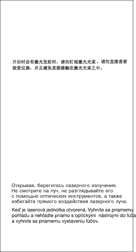
DANGER
Laser radiation when open. Do not stare into
the beam, do not view directly with optical
instruments, and avoid direct exposure to the
beam.
Radiação por raio laser ao abrir. Não olhe
fixo no feixe de luz, não olhe diretamente por
meio de instrumentos óticos e evite
exposição direta com o feixe de luz.
Rayonnement laser si carter ouvert. Évitez de
fixer le faisceau, de le regarder directement
avec des instruments optiques, ou de vous
exposer au rayon.
Laserstrahlung bei geöffnetem Gerät. Nicht
direkt oder über optische Instrumente in den
Laserstrahl sehen und den Strahlungsbereich
meiden.
Kinyitáskor lézersugár ! Ne nézzen bele se
szabad szemmel, se optikai eszközökkel.
KerÎlje a sugárnyalábbal való érintkezést !
Aprendo l'unità vengono emesse radiazioni
laser. Non fissare il fascio, non guardarlo
direttamente con strumenti ottici e evitare
l'esposizione diretta al fascio.
Radiación láser al abrir. No mire fijamente ni
examine con instrumental óptico el haz de
luz. Evite la exposición directa al haz.
18 ThinkPad i Series 1400/1500 HMM

Read this first
Before you go to the check procedures, be sure to read
this section.
Important Notes
Only certified trained personnel should service
the computer.
Read the entire FRU service procedures before
replacing any FRUs.
Use new nylon-coated screws when you replace
FRUs.
Be extremely careful during write operations such
as copying, saving, or formatting. Drives in the
computer that you are servicing might have been
rearranged or the drive startup sequence might have
been altered. If you select an incorrect drive, data or
programs could be overwritten.
Replace FRUs only for the correct model. When
you replace a FRU, make sure that the model of the
machine and FRU part number are correct by refer-
ring to the FRU parts list.
A FRU should not be replaced because of a
single, unreproducible failure. Single failure can
occur for a variety of reasons that have nothing to do
with a hardware defect, such as: cosmic radiation,
electrostatic discharge, or software error. FRU
replacement should be considered only when a recur-
ring problem exists. In this case, clear the error log
and run the test again. Do not replace FRUs if log
errors do not reappear.
Be careful not to replace a non-defective FRU.
What to do first
The servicer must include the following in the parts
exchange form or parts return form that is attached to the
returned FRU:
1. Name and phone number of servicer
2. Date of service
3. Date when part failed
4. Date of purchase
5. Failure symptoms, error codes appearing on display,
and beep symptoms
6. Procedure index and page number in which failing
FRU was detected
7. Failing FRU name and part number
8. Machine type, model number and serial number
9. Customer's name and address
ThinkPad i Series 1400/1500 19

Before checking problems with the computer, determine
whether the damage is covered under the warranty by
referring to the following:
Note for Warranty:
For Warranty:
During the warranty period, the customer may be
responsible for repair costs if the computer damage
was caused by misuse, accident, modification, unsuit-
able physical or operating environment, or improper
maintenance by the customer. The following list pro-
vides some common items that are not covered under
warranty and some symptoms that may indicate the
system was subjected to stresses beyond normal use.
The following is not covered under warranty:
LCD panel cracked by applying excessive force
or by being dropped.
Scratched (cosmetic) parts.
Cracked or broken plastic parts, broken latches,
broken pins, or broken connectors caused by
excessive force.
Damage caused by liquid spilled into the system.
Damage caused by improperly inserting a PC
Card or installation of an incompatible card.
Damage caused by foreign material in the FDD.
Diskette drive damage caused by pressing the
diskette drive cover or inserting diskettes with
multiple labels.
Damaged or bent diskette drive eject button.
CD-ROM/DVD-ROM drive damage caused by
excessive force, shock, or by being dropped.
Fuses blown by attaching a nonsupported device.
Forgotten computer password (making the com-
puter unusable).
The following symptoms might indicate damage
caused by non-warranted activities:
Missing parts may be a symptom of unauthorized
service or modification.
HDD spindles can become noisy if subjected to
excessive force or by being dropped.
I9990303 errors can be caused by exposure to
strong magnetic fields.
20 ThinkPad i Series 1400/1500 HMM

FRU replacement notices
This section contains notices for removal and replacement.
Read this section carefully before replacing any FRU.
LCD replacement notice
The TFT LCD for the computer contains many thin-film
transistors (TFTs). A small number of missing, discolored,
or lighted dots (on all the time) is characteristic of TFT
LCD technology, but excessive pixel problems can cause
viewing concerns. The LCD should be replaced if the
number of missing, discolored, or lighted dots in any back-
ground is:
SVGA (12.1"): 5 or more bright dots, 5 or more dark
dots, or a total of 9 or more bright and dark dots.
XGA (14.1"/15.0"): 8 or more bright dots, 8 or more
dark dots, or a total of 9 or more bright and dark dots.
Screw notices
This computer uses special nylon-coated screws with the
following characteristics:
They maintain tight connections.
They do not easily come loose, even with shock or
vibration.
They need additional force to tighten.
They should be used only once.
Do the following when you service this machine:
Keep the screw kit (P/N 08K5877) in your tool bag.
Always use new screws if you are instructed.
Use a torque screwdriver if you have one.
Loose screws can cause a reliability problem. The IBM
ThinkPad computer addresses this problem with nylon-
coated screws. Tighten screws as follows:
Plastic to plastic
Turn an additional 90 degrees after the screw head
touches the surface of the plastic part:
Logic card to plastic
ThinkPad i Series 1400/1500 21

Turn an additional 180 degrees after the screw head
touches the surface of the plastic part:
Torque driver
If you have a torque driver, refer to the "Torque"
column with each step.
Make sure you use the correct screw, and tighten all
screws firmly to the torque shown in the table if you
have a torque screwdriver. Never use a screw that
you removed. Use a new one. Make sure the
screws are tightened firmly.
System board/Inverter replacement
notice
Restoring the system unit serial number:
The EEPROM on the inverter contains vital product data
(VPD), such as the system unit serial number and the
system board serial number. You must restore the system
unit serial number to its original number when the system
board is replaced.
To restore the system unit serial number, do the following:
1. Install the ThinkPad CE Utility Diskette Version 1.60
and restart the computer.
2. Select 1. Set System Identification from the main
menu.
3. Select 2. Read S/N data from EEPROM.
Each serial number is displayed with its device type. Write
down the system unit serial number. The device type des-
ignations for each serial number are as follows:
20: System unit serial number
40: System board serial number
To restore the serial number after you have replaced the
system board, do the following:
1. Install the ThinkPad CE Utility Diskette Version 1.60
and restart the computer.
2. Select 1. Set System Identification from the main
menu.
3. Select 1. Add S/N data from EEPROM.
Follow the instructions on the screen.
22 ThinkPad i Series 1400/1500 HMM
Note: The system unit serial number is written in the label
attached on bottom of the computer.
Bios Levels
An incorrect level of BIOS can cause false error and
unnecessary FRU replacement. Use the following informa-
tion to determine the current level of BIOS installed in the
computer, the latest BIOS available for the computer, and
where to obtain the latest level of BIOS.
Current Level BIOS information.
1. Power-on the computer.
2. Press F1 at the IBM log screen to enter Setup.
3. Click on System Information and press Enter.
4. The System BIOS version will be displayed.
Sources for determining the latest level of BIOS avail-
able.
1. IBM PC Company Home Page
www.ibm.com/pc/us/
2. PC PartnerInfo-Technical Database
3. RETAIN
Sources for obtaining the latest level BIOS available.
1. IBM PC Company Home Page
www.ibm.com/pc/us/
2. PC PartnerInfo-Technical Database
To update the BIOS, see “Flash (BIOS) update procedure.”
Flash (BIOS) update procedure
1. Insert the System Program Service Diskette into the
diskette drive.
2. Power-on the computer
3. Select Update System Programs from the menu and
follow the instructions displayed on the screen.
ThinkPad i Series 1400/1500 23

Related service information
This section provides information about the following:
“Power button as reset switch”
“Running a low-level format”
“Service Web site”
“Passwords”
“Power management features” on page 26
“Fn key combinations” on page 27
Power button as reset switch
The power button acts as a reset switch when pressed for
more than 4 seconds. This resets the system (regardless
of the microcode status) and forces the power off. Use this
only when power is not completely off or the microcode is
in a hung state.
Running a low-level format
Attention: Make sure the drive address to be formatted is
correct. This procedure erases all information on the disk.
To format the hard disk, use the Full Erase Hard Drive or
Quick Erase Hard Drive in Utility of the PC-Doctor DOS
program. Refer to “Testing the computer” on page 28.
Service Web site
When the latest maintenance diskette and system program
service diskette are available, they are posted on:
Maintenance diskette:
http://www.pc.ibm.com/partner/infotips
System program service diskette:
http://www.pc.ibm.com/partner/infotips
Passwords
When the power-on password (POP), hard disk password
(HDP), and setup password (SUP) (the same function as
supervisor password) are used, the following situations
may occur:
If the POP is the same as the HDP, the POP
prompt appears, but the HDP prompt does not
appear.
If the POP is not the same as the HDP, both
prompts appear.
Hard disk password: Hard disk password is a
security feature that is used to protect the hard disk data
from unauthorized access. No overriding capability is pro-
vided, so it can not be replaced if it is forgotten. If the cus-
tomer forgets the hard disk password, the hard disk drive
must be replaced.
24 ThinkPad i Series 1400/1500 HMM

Removing the power-on and setup pass-
words: Removing the power-on and setup passwords:
Do the following to remove the passwords::
1. Power off the computer.
2. Remove the battery and the AC Adapter.
3. Remove the keyboard, see "Keyboard" on page 60.
4. Change DIP switch position (Pin 6) to "Check Pass-
word Disabled", see "Switch Locations" on page
43.
5. Put back keyboard.
6. Connect the AC Adapter.
7. Power on the computer and press F1 to enter the
BIOS Utility menu.
8. The main screen displays as below:
BIOS Utility
System Information
Basic System Settings
Startup Configuration
Onboard Devices Configuration
System Security
Load Default Settings
↑↓ ↵= Move highlight bar, = Select, Esc = Exit
9. Using the up or down arrow key, select System Secu-
rity.
10. Press the Enter Key. The password selection window
appears:
System Security Page 1/1
Setup Password -----------------------------------------------
Power-on Password ------------------------------------------
Hard Disk Password ------------------------------------------
↑↓ ←→= Move highlight bar, = Change setting, F1 = Help
[ None ]
[ None ]
[ None ]
11. Move the highlight bar to Power-on Password.
12. Select None.
13. Move the highlight bar to Setup Password.
ThinkPad i Series 1400/1500 25
14. Select None.
15. Save the changes, and exit the BIOS Utility menu.
16. Power off the computer.
17. Disconnect the AC Adapter.
18. Remove the keyboard.
19. Change DIP switch position (Pin 6) to "Check Pass-
word Enabled".
20. Put back the keyboard.
Power management features
Two power management modes are available in the com-
puter system to reduce power consumption and to prolong
battery life.
Standby mode: When in standby mode, the fol-
lowing occurs:
The LCD backlight turns off.
The hard disk motor either spins down or stops (con-
trolled by OS).
CPU enters stop-grant mode.
Events that cause the computer to enter standby mode:
Note: These events depend on the Power buttons set-
tings (options set to standby mode) in the
"Advanced" page of the "Power Management Prop-
erties" screen.
Standby requested by the Sleep button (Fn+F4)
Standby requested by the power button
Standby requested by closing the lid.
Events that cause the computer to exit standby mode:
RTC alarm
Power-on switch is operated
Any key or Easy Launch button operation
The LCD is opened (if the system entered standby
mode from closing the lid).
Note: This is true if When I close the lid of my
portable computer: is set to Standby in the
"Advanced" page of the "Power Management
Properties" screen
Plug-in or plug-out of USB devices
A serial or PC Card device signals the modem ring
indicator
Note: The modem ring wakeup function is effective
only on embedded PC Card modem devices.
The battery power is at a critical level.
26 ThinkPad i Series 1400/1500 HMM

Hibernation mode: When in hibernation mode, the
following occurs:
The system status, RAM, VRAM, and setup data are
stored on the hard disk.
The system is powered off.
Events that cause the computer to enter hibernation mode:
Note: These events depend on the Power buttons set-
tings (options set to hibernation mode) in the
"Advanced" page of the "Power Management Prop-
erties" screen.
Hibernation requested by the Sleep button (Fn+F4)
Hibernation requested by the power button
Hibernation requested by closing the lid.
Events that cause the computer to exit hibernation mode:
RTC alarm
Power-on switch is operated
When power is turned on, the hibernation history in the
boot record on the hard disk is recognized and the system
status is restored from the hard disk to resume operation.
Fn key combinations
The following table shows the Fn key and function key
combinations and their corresponding functions. The Fn
key works independently of the operating system. The
operating system obtains the status through the system
management interface to control the system.
Fn key Function
Fn+F1 Launch Control at a glance.
Fn+F2 Launch Power Management Properties.
Fn+F4 Sleep button
Fn+F7 Switch display output location.
Fn+Home Brightness up
Fn+End Brightness down
Fn+Ins Contrast up (HPA LCD models only)
Fn+Del Contrast down (HPA LCD models only)
ThinkPad i Series 1400/1500 27

Checkout guide
Use the following procedure as a guide for computer prob-
lems.
Note: The diagnostic tests are intended to test only IBM
products. Non-IBM products, prototype cards, or
modified options can give false errors and invalid
system responses.
1. Obtain the failing symptoms in as much detail as pos-
sible.
2. Verify the symptoms by attempting to recreate the
failure by running the diagnostic test or by repeating
the same operation.
Testing the computer
The ThinkPad computer has a test program called
PC-Doctor DOS (hereafter called
PC-Doctor
). You can
detect errors by running the diagnostics test of PC-Doctor.
This section is an overview on detecting the problem.
Refer to “Product overview” on page 44 for details that
depend on model-unique functions.
To run the test, do the following:
Note: In the following procedure, you can select an item
not only with the arrow keys, but also with the
TrackPoint. Instead of pressing Enter, you can
click the left click button.
1. Insert the PC-Doctor DOS Disk into the diskette drive;
then power on the computer.
If the computer cannot be powered on, go to “Power
systems checkout” on page 30 and check the power
sources.
If an error code appears, go to “Symptom-to-FRU
Index” on page 33.
The PC-Doctor main panel appears.
2. Select Diagnostics with the arrow keys, and press
Enter.
A pull-down menu appears:
Note: The pull-down menu differs depending on the
model.
3. Run the applicable function test.
4. Follow the instructions on the screen. If there is a
problem, PC-Doctor shows some messages.
5. Reseat the cable or connector of the detected FRU
and run the test again.
If the error recurs, replace the FRU that caused the
error.
Note: With some FRUs, especially the system
board, the problem might be caused by
peripheral FRUs. Verify that each peripheral
28 ThinkPad i Series 1400/1500 HMM

FRU, such as the flexible cable, has no
problem by doing the following:
a. Replace each peripheral FRU one at a
time, and run the test again.
b. If the peripheral FRUs have no problem,
replace the main FRU itself.
To see the FRU structure of each model,
refer to “Product overview” on page 44.
6. To exit the test, select Quit – Exit Diag.
To cancel the test, press Esc.
The following table lists the options on the test menu.
Diagnostics Interactive Tests
Run Normal Test
Run Quick Test
CPU/Coprocessor
System board
Video Adapter
Serial Ports
Fixed Disks
Diskette Drives
Other Devices
Memory Test – Full
Memory Test – Quick
Keyboard
Video
Internal Speaker
Mouse
Joystick
Diskette
System Load
CD-ROM/DVD
Stereo Speaker
Note: In Keyboard test within Interactive Tests, the Fn key
is scanned only once. Each key should be pressed for
at least 2 seconds; otherwise, it cannot be sensed.
Related service information
PC-Doctor can detect the following system information:
Hardware Info:
System Configuration
Memory Contents
Physical Disk Drive
Logical Disk Drive
VGA Information
IDE Drive Information
PCI Information
PNPISA Information
SMBIOS Information
FRU Information
Utility:
Run External Tests
Surface Scan Hard Disk
Benchmark System
ThinkPad i Series 1400/1500 29
DOS Shell
Tech Support Form
Battery Rundown
View Test Log
Print Log
Save Log
Full Erase Hard Drive
Quick Erase Hard Drive
Power systems checkout
To verify the symptom of the power problem on the com-
puter, do the following:
1. Power off the computer.
2. Remove the battery pack.
3. Connect the AC Adapter.
4. Check that power is supplied when you power on the
computer.
5. Power off the computer.
6. Disconnect the AC Adapter and install the charged
battery pack.
7. Check that power is supplied by the battery pack
when you power on the computer.
If you suspect a power problem, refer the appropriate
power supply check listed below:
“Checking the AC Adapter”
“Checking operational charging” on page 31
“Checking the Battery ASM” on page 31
Checking the AC Adapter: You care here
because the computer fails only when the AC Adapter is
used:
If the power-on indicator does not turn on, check the
power cord of the AC Adapter for correct continuity
and installation.
If the operational charge does not work, go to
“Checking operational charging” on page 31.
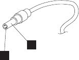
Unplug the AC Adapter cable from the computer and
measure the output voltage at the plug of the AC Adapter
cable. See the following figure:
12
30 ThinkPad i Series 1400/1500 HMM

If the voltage is not correct, replace the AC Adapter.
If the voltage is within the range, do the following:
Replace the DC-DC & BATT board.
Replace the system board.
If the problems still persist, go to “Undetermined
Problems” on page 38.
Note: An audible noise from the AC Adapter does not
always indicate a defect.
Checking operational charging: To check
operational charging, use a discharged battery pack
(Battery ASM) or a Battery ASM that has less than 50% of
the total power remaining when installed in the computer.
Perform operational charging. If the battery status indicator
or icon does not turn on or does not show orange color,
remove the Battery ASM and let it return to room temper-
ature. Reinstall the Battery ASM. If the charge indicator or
icon still does not turn on or still does not show orange
color, replace the Battery ASM.
If the charge indicator still does not turn on, replace the
DC-DC & BATT board, then the system board. Then
reinstall the Battery ASM. If the reinstalled Battery ASM is
not charged, go to the next section.
Checking the Battery ASM: After the battery is
fully charged, charger can not charge battery until the Fuel
Gauge shows that less than 95% of total power remains;
with this condition the battery pack can charge to 100% of
its capacity. This protects the Battery ASM from being
overcharged or from having a shortened life.
Note: The Battery ASM might not be able to charged
when it is hot. In that case, remove it from the
computer and leave it at room temperature for a
while. After it cools down, reinstall it and recharge
it.
Do the following:
1. Power off the computer.
2. Remove the battery pack and measure the voltage
between battery terminals 1 (+) and 7 (-). See the fol-
lowing figure.
Pin Voltage (V dc)
1 15.5V — 17.0V
2 Ground
ThinkPad i Series 1400/1500 31
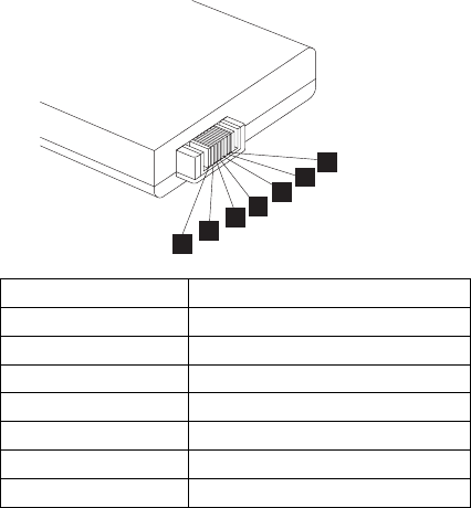
1234567
Note: Signal lines, not used in these steps, are used
for communications between the system and
the battery.
3. First, discharge the battery, until the voltage is less
than 10.8V (LiIon) or 9.6V (NiMH). Then, charge the
battery for 30 minutes. Now, check the voltage. If the
voltage is still less than 10.8V (Li-Ion) or 9.6V (NiMH),
replace the battery.
4. If the voltage is more than 10.8V (LiIon) or 9.6V
(NiMH), measure the resistance between battery ter-
minals 5 and 7. The resistance must be 390Ω (Li-Ion)
or 10KΩ (NiMH). If the resistance is not correct,
replace the Battery ASM. If the resistance is correct,
replace the DC-DC & BATT board, then the system
board.
Terminal Signal / Voltage (V dc)
1 BT-
2 BT-SENSE
3 BT-SCLK
4 BT-SDATA
5 BT-TH
6 BT+SENSE
7 BT+
32 ThinkPad i Series 1400/1500 HMM

Symptom-to-FRU Index
The Symptom-to-FRU Index lists the symptoms and errors
and the possible causes. The most likely cause is listed
first.
Note: Perform the FRU replacement or actions in the
sequence shown in the FRU/Action columns. If a
FRU does not solve the problem, put the original
part back in the computer. Do not replace a non-
defective FRU.
This index can also be used to help you decide which
FRUs should be available when servicing a computer.
Numeric error codes show the errors detected in POST or
system operation (runtime). In the following error codes, X
can be any number.
If no codes are available, use narrative symptoms.
If the symptom, is not listed, go to “Undetermined
Problems” on page 38.
Note: For any IBM device not supported by the diagnostic
codes in this ThinkPad computer, see the manual
for that device.
Numeric Error Codes and Messages
Error
Code Message FRU/Action in Sequence
006 Equipment
Configuration
Error
Enter BIOS Utility and
execute "Load Setup
Default Settings"; then
reboot the system.
040 Diskette Drive
Controller
Error
Go to “FRU tests” on
page 48.
Diskette drive
System board
070 Real Time
Clock Error 1
Backup battery (RTC
battery)
Enter BIOS Utility and
execute "Load Setup
Default Settings"; then
reboot the system.
System board
071 CMOS Battery
Bad 4
Backup battery (RTC
battery)
Enter BIOS Utility and
execute "Load Setup
Default Settings"; then
reboot the system.
System board
ThinkPad i Series 1400/1500 33

Error
Code Message FRU/Action in Sequence
072 CMOS
Checksum
Error 1
Enter BIOS Utility and
execute "Load Setup
Default Settings"; then
reboot the system.
110 Incorrect
Password
Specified.
System Halted
1
Set SWZ1 Pin 6
(Check Password) to
"0".
Enter BIOS Utility and
clear password.
Set SWZ1 Pin 6
(Check Password) to
"1".
252 VPD
Checksum
Error
Run CE Utility.
Input correct data.
Operating
system not
found
Boot from system diskette.
LCD-Related Symptoms
LCD FRU Replacement Notice
The TFT LCD for the computer contains many thin-film
transistors (TFTs). A small number of missing, discol-
ored, or lighted dots (on all the time) is characteristic
of TFT LCD technology, but excessive pixel problems
can cause viewing concerns. The LCD should be
replaced if the number of missing, discolored, or
lighted dots in any background is:
SVGA (12.1"): 5 or more bright dots, 5 or more
dark dots, or a total of 9 or more bright and dark
dots.
XGA (14.1"/15.0"): 8 or more bright dots, 8 or
more dark dots, or a total of 9 or more bright and
dark dots.
Symptom/Error FRU/Action in Sequence
LCD backlight does
not work.
LCD is too dark.
LCD brightness
cannot be adjusted.
LCD contrast cannot
be adjusted (HPA
LCD models only).
Keyboard (if contrast and
brightness function keys do
not work)
Reseat LCD connector
Check LCD inverter ID
LCD FPC ASM
LCD inverter
LCD
System board
34 ThinkPad i Series 1400/1500 HMM

Symptom/Error FRU/Action in Sequence
Unreadable LCD
screen.
Missing pels in char-
acters.
Abnormal screen
Wrong color dis-
played.
Reseat LCD connector
Check LCD inverter ID
LCD FPC ASM
LCD inverter
LCD
System board
LCD has extra hori-
zontal or vertical lines
displayed.
Check LCD inverter ID
LCD FPC ASM
LCD inverter
LCD
System board
Keyboard/TrackPoint-Related
Symptoms
Symptom/Error FRU/Action in Sequence
Keyboard (one or
more keys) doesn't
work.
Go to “FRU tests” on
page 48.
Reseat keyboard cable.
Keyboard
System board
TrackPoint does not
work.
Go to “FRU tests” on
page 48.
Reseat keyboard cable.
Keyboard
System board
Indicator-Related Symptoms
Symptom/Error FRU/Action in Sequence
Indicator incorrectly
remains off or on, but
system runs cor-
rectly.
Reseat LED board.
LED board
System board
Power-Related Symptoms
Symptom/Error FRU/Action in Sequence
Power shuts down
during operation.
Go to “Power systems
checkout” on page 30.
AC Adapter
Battery pack
DC/DC & Charge board
System board
ThinkPad i Series 1400/1500 35

Symptom/Error FRU/Action in Sequence
The system doesn't
power on.
Go to “Power systems
checkout” on page 30.
AC Adapter
Battery
DC/DC & Charge board
System board
The system doesn't
power off.
Go to “Power systems
checkout” on page 30.
Hold and press the power
switch for more than 4
seconds.
DC/DC & Charge board
System board
Battery can't be
charged.
Go to “Power systems
checkout” on page 30.
Battery pack
DC/DC & Charge board
System board
Memory-Related Symptoms
Symptom/Error FRU/Action in Sequence
Memory count (size)
appears different
from the actual size.
Go to “FRU tests” on
page 48.
Enter BIOS Utility and
execute "Load Setup Default
Settings"; then reboot the
system.
DIMM
System board
Audio-Related Symptoms
Symptom/Error FRU/Action in Sequence
Internal speakers
make noise or emit
no sound.
Speaker volume control
Go to “FRU tests” on
page 48.
Speaker(s)
External speakers
make noise or emit
no sound.
Speaker volume control
Go to “FRU tests” on
page 48.
Speaker(s)
In DOS or Windows,
multimedia programs,
no sound comes from
the computer. (Only
system beeps are
heard at power on.)
Speaker volume control
Go to “FRU tests” on
page 48.
Speaker(s)
36 ThinkPad i Series 1400/1500 HMM

PC Card (PCMCIA)-Related Symptoms
Symptom/Error FRU/Action in Sequence
System cannot detect
the PC Card
(PCMCIA)
PC Card (PCMCIA) slots
assembly
System board
PCMCIA slot pin is
damaged.
PC Card (PCMCIA) slots assembly
Power Management-Related Symptoms
Symptom/Error FRU/Action in Sequence
The system doesn't
enter hibernation
mode.
Go to “Hibernation mode” on
page 27.
Keyboard
Hard disk drive
System board
The system doesn't
resume from
hibernation mode.
Go to “Hibernation mode” on
page 27.
Hard disk drive
System board
The system doesn't
enter into or resume
from sleep mode
after closing the LCD.
Lid switch
System board
Battery fuel-gauge
doesn't go higher
than 90%.
Remove battery pack and let
it cool for 2 hours.
Refresh battery (continue
using battery until power off,
then charge the battery).
Battery pack
DC/DC & Charge board
System board
System configuration
does not match the
installed devices.
Enter BIOS Utility and execute
"Load Setup Default Settings";
then reboot the system.
System hangs
intermittently.
Reseat hard disk drive.
Fan ASM (go to “FRU tests”
on page 48).
System board
In DOS or Windows,
multimedia programs,
no sound comes from
the computer.
Speaker volume control
Speaker (go to “FRU tests”
on page 48).
System board
Peripheral-Device-Related Symptom
Symptom/Error FRU/Action in Sequence
External display does
not work correctly.
System board
ThinkPad i Series 1400/1500 37

Symptom/Error FRU/Action in Sequence
Printer problems. Run printer self-test.
Printer driver
Printer cable
Ensure that "Parallel Port" in
the "Onboard Devices Config-
uration" menu of the BIOS
Utility is correctly set.
System board
Serial or parallel port
device problems.
Device driver
Device cable
Device
Ensure that "Serial Port" and
"Parallel Port" in the
"Onboard Devices Configura-
tion" menu of the BIOS Utility
is correctly set.
System board
Modem-Related Symptoms
Symptom/Error FRU/Action in Sequence
Internal modem does
not work correctly
Go to “FRU tests” on
page 48.
Modem connector
Modem board
System board
Intermittent Problems
Intermittent system hang problems can be caused by a
variety of reasons that have nothing to do with a hardware
defect, such as cosmic radiation, electronic discharge, or
software errors. FRU replacement should only be consid-
ered when a recurring problem exists.
When analyzing the intermittent problem, do the following:
1. Run the diagnostic test for the system board at least
10 times.
2. If no error is detected, do not replace any FRUs.
3. If any error is detected, replace the FRU. Rerun the
test to verify that there are no more errors.
Undetermined Problems
The diagnostic tests did not identify which adapter or
device failed, which installed devices are incorrect, whether
a short circuit is suspected, or whether the system is inop-
erative. Follow the procedures below to isolate the failing
FRU.
Verify that the power supply being used at the time of the
failure is operating correctly.
1. Power off the computer.
38 ThinkPad i Series 1400/1500 HMM
2. Check the cables, wires, and connectors for short cir-
cuits and open circuits. Visually check them for
damage. If any problems are found, replace the FRU.
3. Remove or disconnect all of the following devices:
Non-IBM devices
Printer, external mouse & keyboard, and other
external devices
Battery pack
Hard disk drive
Diskette drive/CD-ROM drive
PC Card (PCMCIA)
4. Power on the computer.
5. Determine if the problem has changed.
6. If the problem does not occur again, reconnect the
removed devices one at a time until you find the
failing FRU.
7. If the problem remains, replace the following FRUs
one at a time. Do not replace a non-defective FRU.
Charger board
Audio & battery function connection board
LCD assembly
System board
ThinkPad i Series 1400/1500 39

Locations
Front View
1. LCD latches
2. Keyboard Light (available on select models only)
3. LCD
4. Speakers
5. Keyboard Light switch (available on select models
only)
6. Status indicators
7. CD-ROM or DVD-ROM drive
8. CD-ROM/DVD-ROM drive activity indicator
9. CD-ROM/DVD-ROM drive eject button
10. CD-ROM/DVD-ROM drive emergency eject hole
11. Battery pack
12. Media Center
13. Media Center previous track/chapter button
14. Media Center next track/chapter button
15. Volume control
16. Media Center status LCD
17. Media Center play/pause button
18. Media Center stop/eject button
19. Media Center power button
20. Internet Scroll Bar
21. Click buttons
22. Fn key
23. TrackPoint stick
24. Easy Launch buttons
25. Built-in microphone
26. Power button
40 ThinkPad i Series 1400/1500 HMM
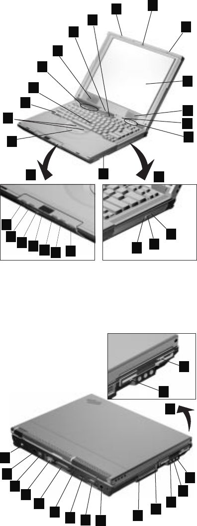
1
12
13
14 15 16 17 18 19
20
21
23
24
25
26 1
3
4
4
5
6
22
7
11
10 9
8
2
Note: 15" LCD has different locations of speakers, micro-
phone and status indicator. The speakers are
located in the back of LCD. Microphone and status
indicator are moved to the main unit.
Rear View
1
45678910 11 12
13
14
2
3
15
16
17
1. Power jack
ThinkPad i Series 1400/1500 41
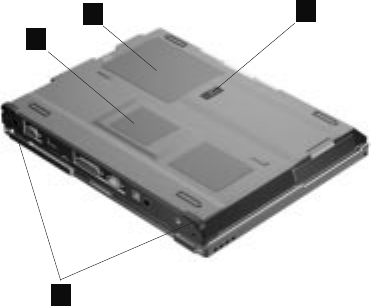
2. Mouse/keyboard (PS/2) connector
3. Telephone connector
4. Serial connector
5. Parallel connector
6. Security keyhole
7. Universal serial bus (USB) connector
8. External monitor connector
9. TV-out (S-video) jack
10. PC Card slots
11. PC Card eject buttons
12. Line-out/headphone jack
13. Line-in jack
14. Microphone-in jack
15. Diskette drive
16. Diskette-drive-activity indicator
17. Diskette eject button
Bottom View
1
2
3
4
1. Battery-pack latch
2. Memory slot door
3. Modem card compartment
4. Tilt feet
42 ThinkPad i Series 1400/1500 HMM
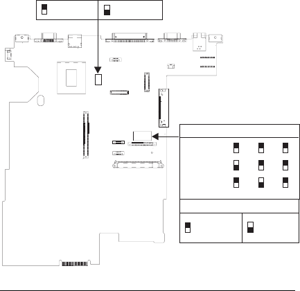
Switch Locations
There are two switches found on the system board. Refer
to the figure below on how to set these switches.
English
Japanese
German
Pin 3 Pin 4 Pin 5
Boot Block
Disabled Boot Block
Enabled
Check
Password
Enabled
Check
Password
Disabled
Pin 6
ThinkPad i Series 1400/1500 (Part I)
This section applies to the models in Group-A and B. (See
the 2621 model table on page iii.)
ThinkPad i Series 1400/1500 43

Product overview
The following shows an overview of the system features.
Note: The table below applies to the models in Group-A
(See the 2621 model table on page iii.)
Feature Description
Processor Intel** Celeron** processor 400,
433 or 466 MHz
Bus architecture PCI
System memory 2 DIMM slots, no memory on
system board
32 MB, 64 MB, and 128 MB DIMM
card
Maximum frequency: 66 MHz
CMOS RAM 114 bytes + 4 Kbytes
Video 12.1–inch, 16M colors, 800x600
pixel TFT SVGA color LCD
13.0–inch, 16M colors, 800x600
pixel HPA SVGA color LCD
—or—
14.1–inch, 16M colors, 1024x768
pixel TFT XGA color LCD
Audio 16-bit audio
Internal stereo speakers
Internal microphone
Diskette drive 1.44MB (3–mode), 3.5 inch
Hard disk drive 4.8/6,4/8.1GB above, 2.5–inch,
EIDE interface
CD-ROM drive or
DVD-ROM drive
CD-ROM: 5.25–inch, 24X speed,
EIDE interface
—or—
DVD-ROM: 5.25–inch, 4X speed,
EIDE interface
Modem 56.6 Kbps, internal (depends on
the model)
PC Card (PCMCIA) One Type III or Type II, with
CardBus and ZV support
I/O ports External monitor
Speaker-out
Line-in
Microphone-in
DC-in
Mouse/keyboard
Parallel
Serial
USB
Telephone (RJ11)
TV-out (S-video) (DV model only)
44 ThinkPad i Series 1400/1500 HMM

Note: The table below applies to the models in Group-B
(See the 2621 model table on page iii.)
Feature Description
AC Adapter 56–Watt type
Feature Description
Processor Intel** Celeron** processor 466
MHz
Bus architecture PCI
System memory 2 DIMM slots, no memory on
system board
32 MB, 64 MB, and 128 MB DIMM
card
Maximum frequency: 66 MHz
CMOS RAM 114 bytes + 4 Kbytes
Video 12.1–inch, 16M colors, 800x600
pixel TFT SVGA color LCD
13.0–inch, 16M colors, 800x600
pixel HPA SVGA color LCD
—or—
14.1–inch, 16M colors, 1024x768
pixel TFT XGA color LCD
Audio 16-bit audio
Internal stereo speakers
Internal microphone
Diskette drive 1.44MB (3–mode), 3.5 inch
Hard disk drive 6/9/12GB above, 2.5–inch, EIDE
interface
CD-ROM drive or
DVD-ROM drive
CD-ROM: 5.25–inch, 24X speed,
EIDE interface
—or—
DVD-ROM: 5.25–inch, 4X speed,
EIDE interface
Modem 56.6 Kbps, internal (depends on
the model)
PC Card (PCMCIA) One Type III or Type II, with
CardBus and ZV support
I/O ports External monitor
Speaker-out
Line-in
Microphone-in
DC-in
Mouse/keyboard
Parallel
Serial
USB
Telephone (RJ11)
TV-out (S-video)
ThinkPad i Series 1400/1500 45
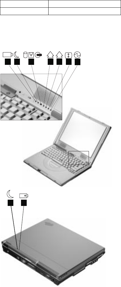
Status indicators: The system-status indicators on
the computer show the current status of your computer by
their on or off states and colors (green and orange). Each
indicator is identified with a symbol. The following shows
the location and the meaning of each icon:
1
A
+
7
12 6
5
4
3
21
Feature Description
AC Adapter 56–Watt type
46 ThinkPad i Series 1400/1500 HMM
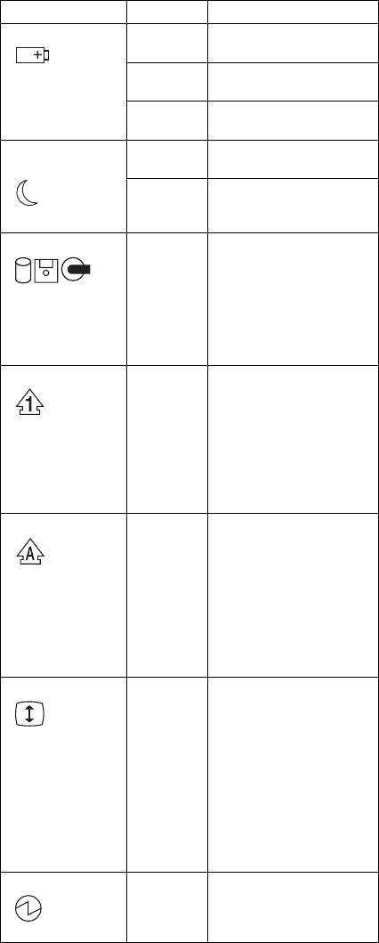
Symbol Color Meaning
(1) Battery status Green Enough battery power
remains for operation.
Blinking
orange
The battery pack needs
to be charged
Orange The battery pack is
being charged.
(2) Standby
mode
Green The computer is in
standby mode
Blinking
green
The computer is entering
or resuming from
hibernation mode.
(3) Drive in use Orange
(some
will be
Green)
Data is being read from
or written to the hard
disk, floppy drive, or data
is being read from the
CD-ROM drive. Do not
enter standby mode or
power off the computer
when this indicator is on.
(4) Numeric lock Green The numeric keypad on
the keyboard is enabled.
You enable or disable
the keypad by pressing
and holding the Shift
key, and pressing the
NumLk key. For details,
see the
User's Refer-
ence
.
(5) Caps lock Green Caps Lock mode is
enabled. All alphabetic
characters
(A-Z)
are
entered in capital letters
without the Shift key
being pressed. You
enable or disable the
Caps Lock mode by
pressing the Caps Lock
key.
(6) Scroll lock Green Scroll Lock mode is
enabled. The Arrow
keys can be used as
screen-scroll function
keys. The cursor cannot
be moved with the
Arrow keys.
Not all
application programs
support this function.
You enable or disable
Scroll Lock mode by
pressing the ScrLk key.
(7) Power on Green The computer is opera-
tional. This indicator is
on when the computer is
on.
ThinkPad i Series 1400/1500 47

FRU tests: The following table shows the applicable
test for each FRU using PC-Doctor.
FRU Applicable test
System board 1. CPU/Coprocessor (Diagnostics)
2. System board (Diagnostics)
Power Battery (Diagnostics)
LCD unit 1. Video Adapter (Diagnostics)
2. Video (Interactive Tests)
Modem 1. Make sure the modem set up
correctly.
2. Replacing the modem jack and
modem card one at a time, run
the modem tests in Other
Devices (Diagnostics)
Audio Internal Speaker (Interactive Tests)
Stereo Speaker (Interactive Tests)
Speaker System beeper: Internal Speaker
(Interactive Tests)
PC Card slots System board (Diagnostics)
Keyboard 1. Keyboard (Diagnostics)
2. Keyboard (Interactive Tests)
TrackPont or
Pointing device
If the TrackPoint does not work, see if
an external PS/2 mouse is connected
to the mouse/keyboard connector and
remove it. The TrackPoint is automat-
ically disabled if an external PS/2
mouse is attached. Check also if the
TrackPoint driver is correctly installed
by accessing Windows Device
Manager via the System icon in the
Control Panel.
After you use the TrackPoint, the
pointer drifts on the screen for a short
time. This self-acting pointer move-
ment can occur when a slight, steady
pressure is applied to the TrackPoint
pointer. This symptom is not a hard-
ware problem. No service actions are
necessary if the pointer movement
stops in a short period of time.
If this does not correct the TrackPoint
problem, continue with the following:
Mouse (Interactive Tests).
Hard disk drive Fixed Disks (Diagnostics)
Diskette drive 1. Diskette Drive (Diagnostics)
2. Diskette (Interactive Tests)
CD-ROM or
DVD-ROM drive
CD-ROM/DVD (Interactive Tests)
48 ThinkPad i Series 1400/1500 HMM

FRU Applicable test
Memory 1. If a DIMM is installed, remove it
and run Memory Test-Quick
(Diagnostics)
2. If the problem does not recur,
replace the DIMM and run the
test again.
3. If the test does not detect the
error, run Memory Test-Full
(Diagnostics)
Fan 1. Start Windows 98 and check the
air turbulence at the louver at the
rear of the computer.
2. Run the fan test in Other Devices
(Diagnostics).
ThinkPad i Series 1400/1500 49

FRU removals and replacements
This section contains information about removals and
replacements.
Do not damage any parts. Only certified and trained
personnel should service the computer.
The arrows in this section show the direction of move-
ment to remove a FRU, or to turn a screw to release
the FRU. The arrows are marked in numeric order, in
square callout, to show the correct sequence of
removal.
Any FRUs that must be removed before removing the
failing FRU are listed at the top of the page.
To replace a FRU, reverse the removal procedure
and follow any notes that pertain to replacement. See
“Locations” on page 40 for internal cable connections
and arrangement information.
When replacing a FRU, use the correct screw size, as
shown in the procedure.
Safety Notice 1
Translations in "Safety Notices (Multilingual Trans-
lations)" section: Before the computer is powered-on
after FRU replacement, make sure all screws, springs,
or other small parts are in place and are not left loose
inside the computer. Verify this by shaking the com-
puter and listening for rattling sounds. Metallic parts or
metal flakes can cause electrical shorts.
Safety Notice 3
Translations in "Safety Notices (Multilingual Trans-
lations)" section: The battery pack contains small
amounts of nickel. Do not disassemble it, throw it into
fire or water, or short-circuit it. Dispose of the battery
pack as required by local ordinances or regulations.
Use only the battery in the appropriate parts listing
when replacing the battery pack. Use of an incorrect
battery can result in ignition or explosion of the
battery.
Safety Notice 8
Translations in "Safety Notices (Multilingual Trans-
lations)" section: Before removing any FRU, power-off
the computer, unplug all power cords from electrical
outlets, remove the battery pack, then disconnect any
interconnecting cables.
Attention: The system board is sensitive and can be
damaged by electronic discharge. Establish personal
grounding by touching a ground point with one hand before
touching these units.
50 ThinkPad i Series 1400/1500 HMM
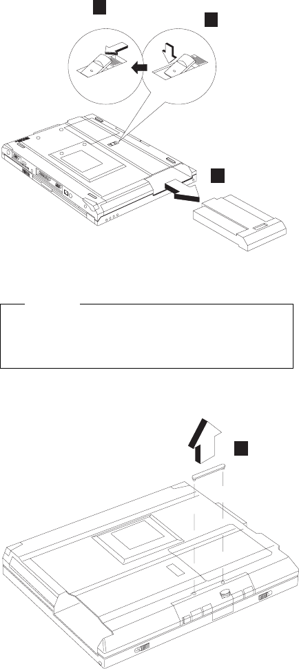
An electrostatic discharge (ESD) strap (P/N: 6405959)
must be used to establish personal grounding.
Battery assembly
1
3
2
Note: When install a new battery pack, push the battery
in and lock it. No need to repeat step 1 and 2.
Warning
Battery packs are capable of delivering high currents
for a significant amount of time. Do not short the
battery terminals.
CD player panel and CD player control
board
1
ThinkPad i Series 1400/1500 51
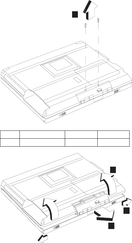
2
5
3
4
Step Size (Quantity) Color Torque
1 M2.5 x 6L (2) Black 3.2 kgf-cm
52 ThinkPad i Series 1400/1500 HMM
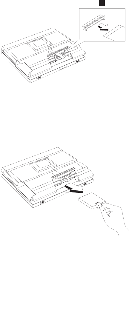
6
Note: The FPC is connected to the system board by the
other end. When removing the CD player panel
and CD player control board, release the FPC with
caution.
Hard disk drive assembly
“Battery assembly” on page 51
“CD player panel and CD player control board” on
page 51
Warning
Do not drop or apply any shock to the hard disk drive.
The hard disk drive is sensitive to physical shock.
Incorrect handling can cause damage and permanent
loss of data on the drive.
Before removing the drive, have the user make a
backup copy of all the information on the drive if pos-
sible.
Never remove the drive while the system is operating
or is in suspend mode.
ThinkPad i Series 1400/1500 53
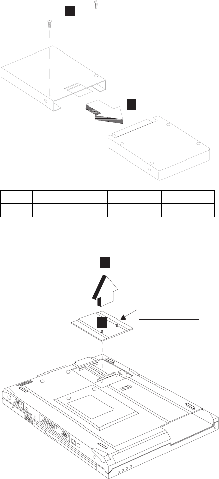
Hard disk drive kitting pack
“Battery assembly” on page 51
“CD player panel and CD player control board” on
page 51
“Hard disk drive assembly” on page 53
1
2
Memory cover and memory card
“Battery assembly” on page 51
2
1
Memory cover
Step Size (Quantity) Color Torque
1 M3 x 4L (2) Silver 3.2 kgf-cm
54 ThinkPad i Series 1400/1500 HMM
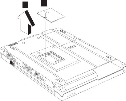
Note: The screw does not separate from the memory
cover.
To install the memory card:
With the notched end of the memory card toward the right
side of the socket, insert the memory card, at an angle of
approximately 20°, into the socket; then press it firmly.
Pivot the memory card until it snaps into place.
Modem cover and modem card
“Battery assembly” on page 51
1
2
Note: The screw does not separate from the modem
cover.
To remove the modem card:
1. Disconnect the modem cable.
2. Press the release latches on both sides of the modem
board.
3. Pull out the modem card.
ThinkPad i Series 1400/1500 55

1
3
2
When reinserting the card, reverse the procedures above.
Middle cover and launch key assembly
“Battery assembly” on page 51
1
56 ThinkPad i Series 1400/1500 HMM
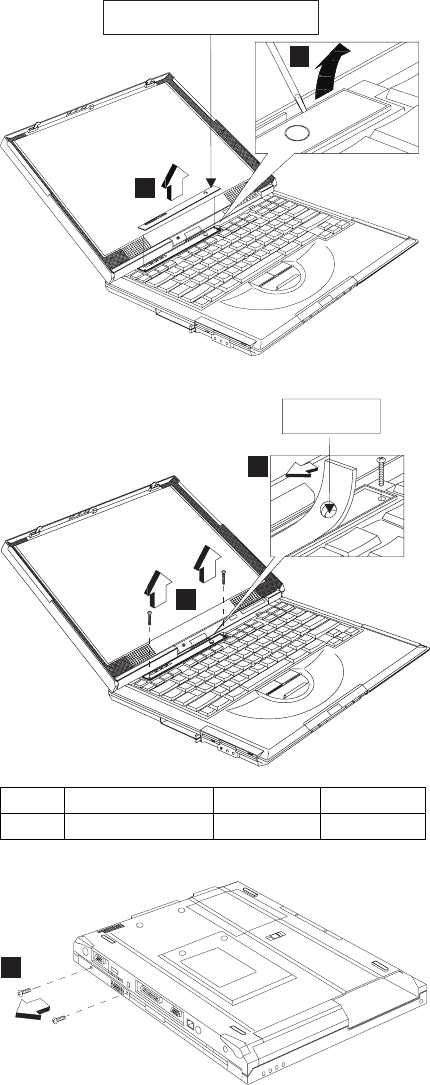
2
3
Optional customerized sheet
Power button
5
4
6
Step Size (Quantity) Color Torque
1 M2 x 4L (2) Silver 1.6 kgf-cm
ThinkPad i Series 1400/1500 57

7
8
9
Turn over
Stick
Step Size (Quantity) Color Torque
3 M2.5 x 3.5L (2) Black 3.2 kgf-cm
58 ThinkPad i Series 1400/1500 HMM
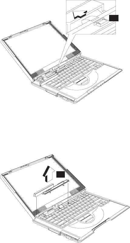
Notes:
1. Adjust the LCD module to the widest angle. Be
careful not to scratch the surface of the middle cover.
2. Turn the middle cover and launch key assembly
upside down when removing the FFC.
10
CAUTION:
There is a FFC connected to the middle cover. When
removing the middle cover, release the FFC with
caution.
11
ThinkPad i Series 1400/1500 59
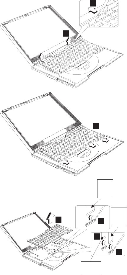
Keyboard
“Battery assembly” on page 51
“Middle cover and launch key assembly” on page 56
1
2
3
4
5
6
7
Large
green
FPC
Small
green
FPC
Yellow
FPC
Note: Make sure the FPC finger side is facing outwards,
when inserted.
60 ThinkPad i Series 1400/1500 HMM
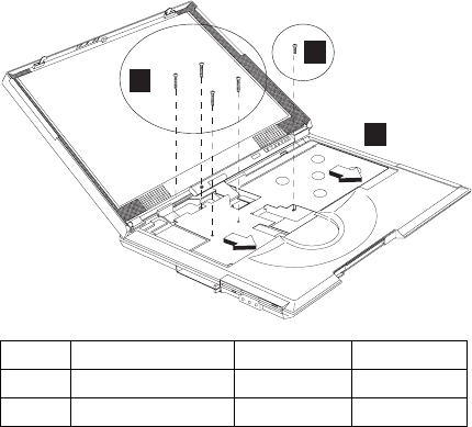
Notes:
1. When replacing the keyboard, make sure that the 3
cables are clean and insert them directly into the con-
nectors, making sure they make contact with the
bottom of the connector. Now press down on the
latch of the connector to secure.
2. If the cables do not touch the bottom of the con-
nector, the keyboard function will be rendered
useless.
3. The cables of the keyboard are fragile and could be
damaged. Be careful when pulling out the cables.
Upper heat sink
“Battery assembly” on page 51
“Middle cover and launch key assembly” on page 56
“Keyboard” on page 60
1
3
2
Step Size (Quantity) Color Torque
1 M2 x 8L (4) Black 1.6 kgf-cm
2 M2.5 x 10L (1) Black 3.2 kgf-cm
ThinkPad i Series 1400/1500 61

4
CD-ROM/DVD-ROM assembly
“Battery assembly” on page 51
“Middle cover and launch key assembly” on page 56
“Keyboard” on page 60
“Upper heat sink” on page 61
1
CAUTION:
When the CD-ROM/DVD-ROM assembly is removed,
the machine is unstable.
CD-ROM/DVD-ROM chassis assembly
“Battery assembly” on page 51
“Middle cover and launch key assembly” on page 56
“Keyboard” on page 60
“Upper heat sink” on page 61
“CD-ROM/DVD-ROM assembly”
62 ThinkPad i Series 1400/1500 HMM
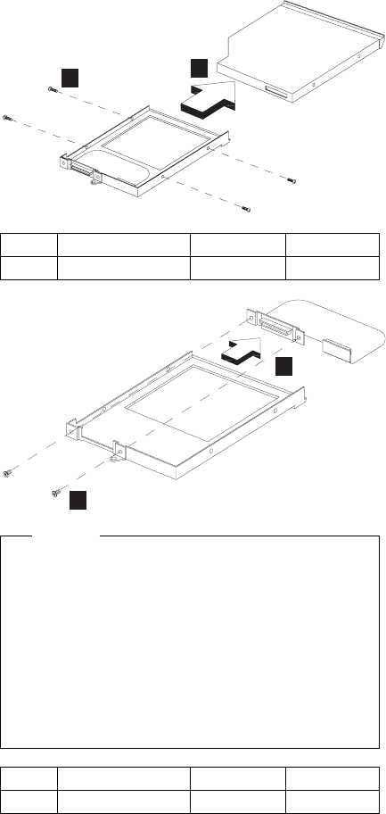
12
3
4
Caution
Do not disassemble the CD-ROM; there are no user
adjustments or serviceable parts inside. The use of
controls, adjustments or performing procedures other
than those specified may result in hazardous radiation
exposure.
The CD-ROM is a sensitive electronic device, handling
should be cautious.
Do not apply any extra force to the CD-ROM drive
when removing it.
PCMCIA holder
“Battery assembly” on page 51
“Middle cover and launch key assembly” on page 56
“Keyboard” on page 60
“Upper heat sink” on page 61
Step Size (Quantity) Color Torque
1 M2 x 3L (4) Silver 1.8 kgf-cm
Step Size (Quantity) Color Torque
1 M2 x 3L (2) Silver 1.3 kgf-cm
ThinkPad i Series 1400/1500 63

1
2
Step Size (Quantity) Color Torque
1 M2 x 4L (4) Silver with
washer
head
1.6 kgf-cm
64 ThinkPad i Series 1400/1500 HMM
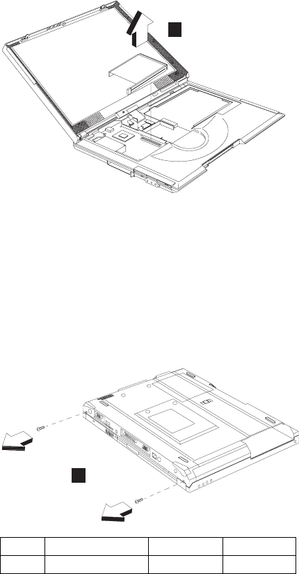
3
Note: Before removing and replacing the PCMCIA holder,
make sure that the PCMCIA cards are removed.
CAUTION:
When removing the PCMCIA holder, pull them up at an
angle. It cannot be removed when pulled straight up.
LCD assembly
“Battery assembly” on page 51
“Middle cover and launch key assembly” on page 56
“Keyboard” on page 60
1
Step Size (Quantity) Color Torque
1 M2.5 x 6L (2) Black 3.2 kgf-cm
ThinkPad i Series 1400/1500 65
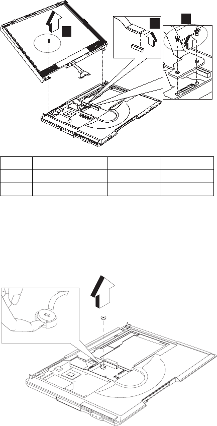
432
Backup battery
“Battery assembly” on page 51
“Middle cover and launch key assembly” on page 56
“Keyboard” on page 60
“Upper heat sink” on page 61
Step Size (Quantity) Color Torque
2 M2 x 12L (2) Silver 1.6 kgf-cm
4 M2.5 x 6L (1) Black 3.2 kgf-cm
66 ThinkPad i Series 1400/1500 HMM
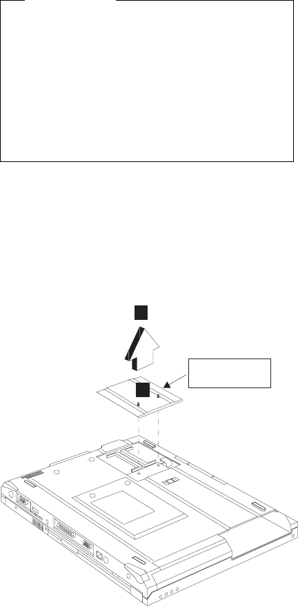
Safety Notice 4
Translation in "Safety Notices: Multilingual Trans-
lations" section: The backup battery is a lithium battery
and can cause a fire, an explosion, or severe burns.
Do not recharge it, remove its polarized connector,
disassemble it, heat it above 100°C (212°F), incinerate
it, or expose its cell contents to water. Dispose of the
battery as required by local ordinances or regulations.
Use of an incorrect battery can result in ignition or
explosion of the battery. Replacement batteries can be
ordered from IBM or IBM Authorized Dealers.
Keyboard bezel
“Battery assembly” on page 51
“Middle cover and launch key assembly” on page 56
“Keyboard” on page 60
“Upper heat sink” on page 61
“CD-ROM/DVD-ROM assembly” on page 62
“LCD assembly” on page 65
Memory cover
1
2
ThinkPad i Series 1400/1500 67
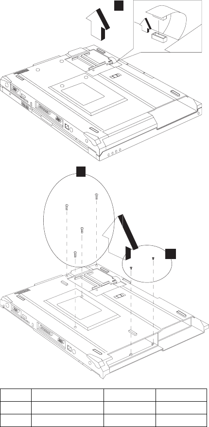
3
5
4
Step Size (Quantity) Color Torque
1 M2.5 x 6L (4) Black 3.2 kgf-cm
2 M2.5 x 3.5L (2) Black 3.2 kgf-cm
68 ThinkPad i Series 1400/1500 HMM
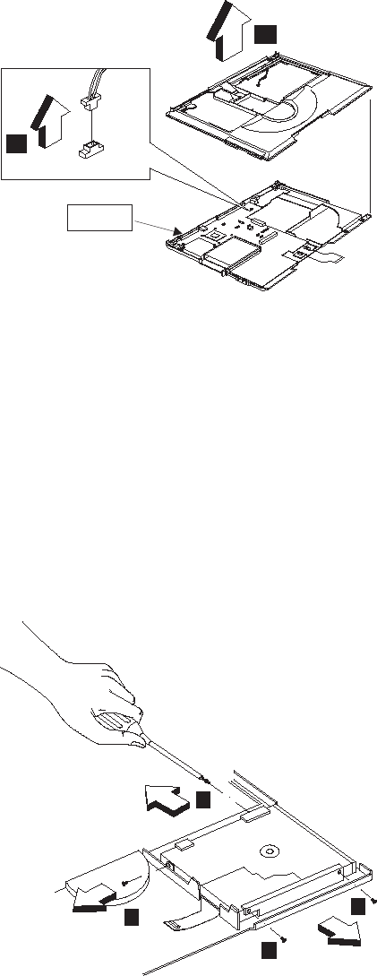
7
6
Fragile
CAUTION:
The upper cover has several latches. When removing
the upper cover from the bottom cover, gently release
these latches, then raise the side of the uppoer cover
facing the palm rest to remove it. Be careful not to
break the latches.
Diskette drive assembly
“Battery assembly” on page 51
“Middle cover and launch key assembly” on page 56
“Keyboard” on page 60
“Upper heat sink” on page 61
“CD-ROM/DVD-ROM assembly” on page 62
“LCD assembly” on page 65
“Keyboard bezel” on page 67
1
1
1
2
ThinkPad i Series 1400/1500 69
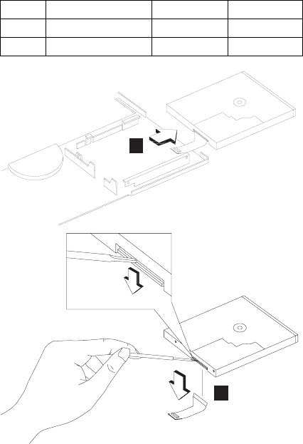
2
3
Fan assembly
“Battery assembly” on page 51
“Middle cover and launch key assembly” on page 56
“Keyboard” on page 60
“Upper heat sink” on page 61
“CD-ROM/DVD-ROM assembly” on page 62
“LCD assembly” on page 65
“Keyboard bezel” on page 67
Step Size (Quantity) Color Torque
1 M2.5 x 3.5L (3) Black 2.0 kgf-cm
2 M2 x 4L (1) Silver 1.6 kgf-cm
70 ThinkPad i Series 1400/1500 HMM
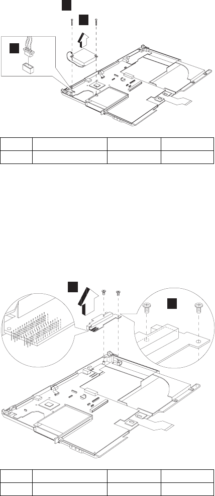
1
3
2
DC-DC charger board
“Battery assembly” on page 51
“Middle cover and launch key assembly” on page 56
“Keyboard” on page 60
“Upper heat sink” on page 61
“CD-ROM/DVD-ROM assembly” on page 62
“LCD assembly” on page 65
“Keyboard bezel” on page 67
1
2
Step Size (Quantity) Color Torque
2 M2.5 x 3.5L (2) Black 3.2 kgf-cm
Step Size (Quantity) Color Torque
1 M2.5 x 3.5L (2) Black 3.2 kgf-cm
ThinkPad i Series 1400/1500 71
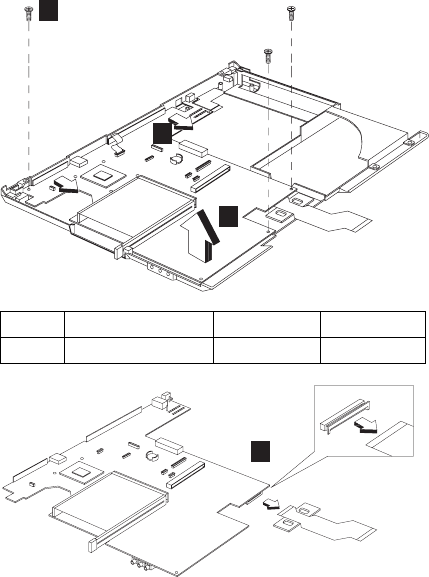
System board
“Battery assembly” on page 51
“Middle cover and launch key assembly” on page 56
“Keyboard” on page 60
“Upper heat sink” on page 61
“LCD assembly” on page 65
“Keyboard bezel” on page 67
“Fan assembly” on page 70
“DC-DC charger board” on page 71
1
3
2
4
Notes:
1. When removing the system board from the bottom
cover, gently raise the side of the system board
facing the rear I/O ports; then pull out the system
board.
2. When replacing the system board, align the power
switch and power actuator. Make sure that the power
switch operates correctly before securing the screws.
Step Size (Quantity) Color Torque
1 M2.5 x 3.5L(3) Black 3.2 kgf-cm
72 ThinkPad i Series 1400/1500 HMM
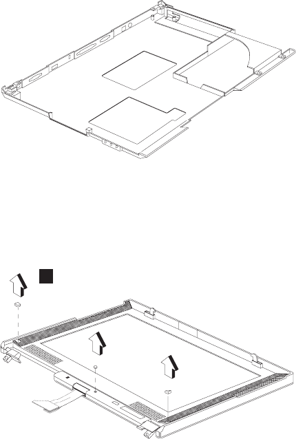
Bottom case
“Battery assembly” on page 51
“Middle cover and launch key assembly” on page 56
“Keyboard” on page 60
“Upper heat sink” on page 61
“CD-ROM/DVD-ROM assembly” on page 62
“LCD assembly” on page 65
“Keyboard bezel” on page 67
“System board” on page 72
LCD bezel assembly (12.1")
“Battery assembly” on page 51
“Middle cover and launch key assembly” on page 56
“Keyboard” on page 60
“LCD assembly” on page 65
1
ThinkPad i Series 1400/1500 73
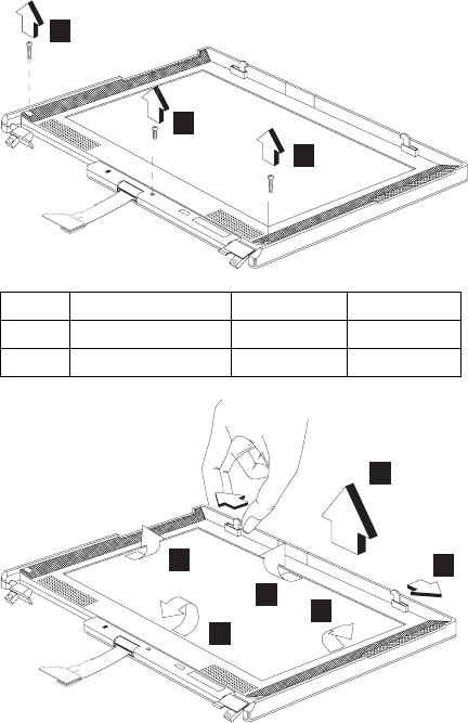
2
2
3
9
4
7
6
8
5
Note: When removing the LCD, take note of the
following:
Be careful not to scratch the LCD cover when
removing the screw covers.
The LCD front cover has several latches.
Release these latches; then remove the LCD
cover. Be careful not to break these latches.
Gently push the two hooks outward to remove
the LCD front cover.
LCD bezel assembly (13.0")
“Battery assembly” on page 51
“Middle cover and launch key assembly” on page 56
“Keyboard” on page 60
“LCD assembly” on page 65
Step Size (Quantity) Color Torque
2 M2.5 x 10L(2) Black 1.6 kgf-cm
3 M2.5 x 6L(1) Black 1.6 kgf-cm
74 ThinkPad i Series 1400/1500 HMM
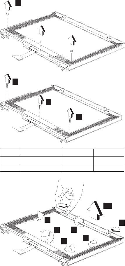
1
2
3
2
10
4
8
9
5
6
7
Note: When removing the LCD, take note of the
following:
Be careful not to scratch the LCD cover when
removing the screw covers.
The LCD front cover has several latches.
Release these latches; then remove the LCD
cover. Be careful not to break these latches.
Step Size (Quantity) Color Torque
2 M2.5 x 10L(2) Black 3.2 kgf-cm
3 M2.5 x 6L(1) Black 3.2 kgf-cm
ThinkPad i Series 1400/1500 75
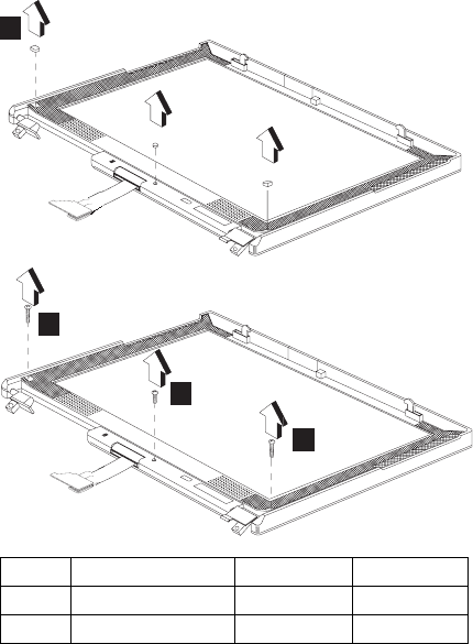
Gently push the two hooks outward to remove
the LCD front cover.
LCD bezel assembly (14.1")
“Battery assembly” on page 51
“Middle cover and launch key assembly” on page 56
“Keyboard” on page 60
“LCD assembly” on page 65
1
2
3
2
Step Size (Quantity) Color Torque
2 M2.5 x 10L(2) Black 3.2 kgf-cm
3 M2.5 x 6L(1) Black 3.2 kgf-cm
76 ThinkPad i Series 1400/1500 HMM
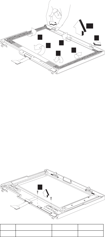
4
8
9
75
6
10
Note: When removing the LCD, take note of the
following:
Be careful not to scratch the LCD cover when
removing the screw covers.
The LCD front cover has several latches.
Release these latches; then remove the LCD
cover. Be careful not to break these latches.
Gently push the two hooks outward to remove
the LCD front cover.
LED board (12.1")
“Battery assembly” on page 51
“Middle cover and launch key assembly” on page 56
“Keyboard” on page 60
“LCD assembly” on page 65
“LCD bezel assembly (12.1")” on page 73
1
Step Size (Quantity) Color Torque
1 M2 x 4L(2) Silver 1.6 kgf-cm
ThinkPad i Series 1400/1500 77

2
3
Right speaker
Left speaker
Microphone
5
4
6
LED board (13.0")
“Battery assembly” on page 51
“Middle cover and launch key assembly” on page 56
“Keyboard” on page 60
“LCD assembly” on page 65
“LCD bezel assembly (13.0")” on page 74
1
Step Size (Quantity) Color Torque
1 M2 x 4L(2) Silver 1.6 kgf-cm
78 ThinkPad i Series 1400/1500 HMM
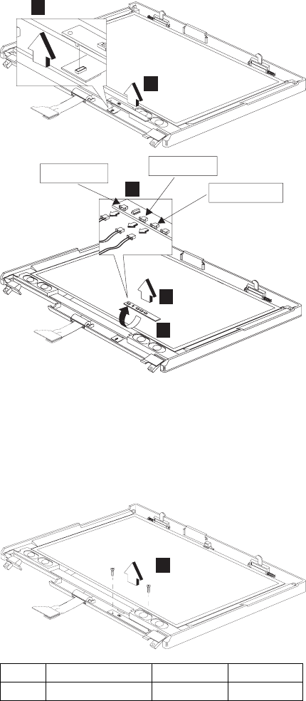
3
2
Right speaker
Left speaker
Microphone
5
4
6
LED board (14.1")
“Battery assembly” on page 51
“Middle cover and launch key assembly” on page 56
“Keyboard” on page 60
“LCD assembly” on page 65
“LCD bezel assembly (14.1")” on page 76
1
Step Size (Quantity) Color Torque
1 M2 x 4L(2) Silver 1.6 kgf-cm
ThinkPad i Series 1400/1500 79
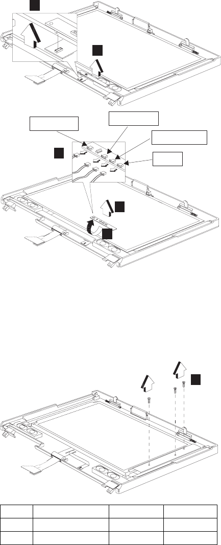
3
2
4
6
5Light
Right speaker
Left speaker
Microphone
LCD inverter (12.1")
“Battery assembly” on page 51
“Middle cover and launch key assembly” on page 56
“Keyboard” on page 60
“LCD assembly” on page 65
“LCD bezel assembly (12.1")” on page 73
1
Step Size (Quantity) Color Torque
1 M2 x 4L(2) Silver 1.6 kgf-cm
M3 x 5L(1) Silver 3.2 kgf-cm
80 ThinkPad i Series 1400/1500 HMM
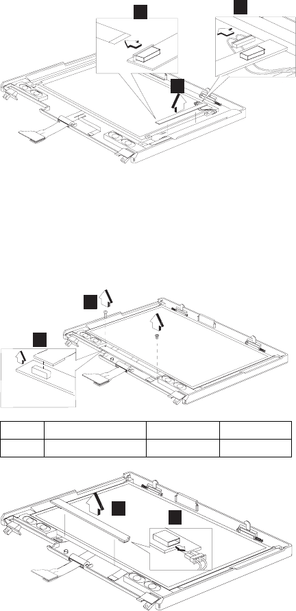
4
2
3
LCD inverter (13.0")
“Battery assembly” on page 51
“Middle cover and launch key assembly” on page 56
“Keyboard” on page 60
“LCD assembly” on page 65
“LCD bezel assembly (13.0")” on page 74
2
1
3
4
LCD inverter (14.1")
“Battery assembly” on page 51
“Middle cover and launch key assembly” on page 56
“Keyboard” on page 60
“LCD assembly” on page 65
“LCD bezel assembly (14.1")” on page 76
Step Size (Quantity) Color Torque
1 M2 x 4L(2) Silver 1.6 kgf-cm
ThinkPad i Series 1400/1500 81
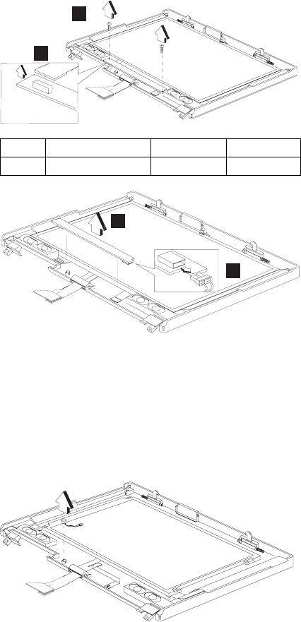
1
2
4
3
Cable assembly of microphone (12.1")
“Battery assembly” on page 51
“Middle cover and launch key assembly” on page 56
“Keyboard” on page 60
“LCD assembly” on page 65
“LCD bezel assembly (12.1")” on page 73
“LED board (12.1")” on page 77
Cable assembly of microphone (13.0")
“Battery assembly” on page 51
“Middle cover and launch key assembly” on page 56
“Keyboard” on page 60
“LCD assembly” on page 65
“LCD bezel assembly (13.0")” on page 74
“LED board (13.0")” on page 78
Step Size (Quantity) Color Torque
1 M2 x 4L(2) Silver 1.6 kgf-cm
82 ThinkPad i Series 1400/1500 HMM
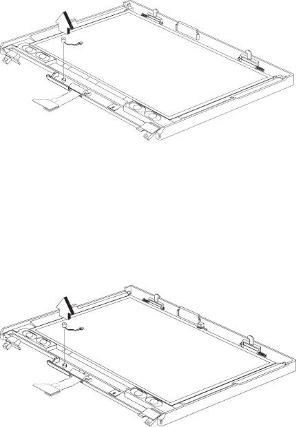
Cable assembly of microphone (14.1")
“Battery assembly” on page 51
“Middle cover and launch key assembly” on page 56
“Keyboard” on page 60
“LCD assembly” on page 65
“LCD bezel assembly (14.1")” on page 76
“LED board (14.1")” on page 79
LCD bracket hinge assembly, speaker
assembly and LCD rear cover assembly
(12.1")
“Battery assembly” on page 51
“Middle cover and launch key assembly” on page 56
“Keyboard” on page 60
“LCD assembly” on page 65
“LCD bezel assembly (12.1")” on page 73
“LED board (12.1")” on page 77
“LCD inverter (12.1")” on page 80
“Cable assembly of microphone (12.1")” on page 82
ThinkPad i Series 1400/1500 83
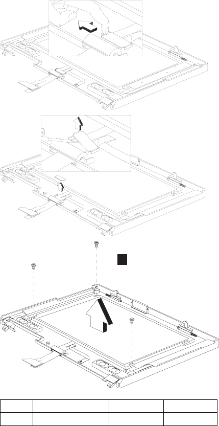
1
Step Size (Quantity) Color Torque
1 M3 x 5L(3) Silver 3.2 kgf-cm
84 ThinkPad i Series 1400/1500 HMM
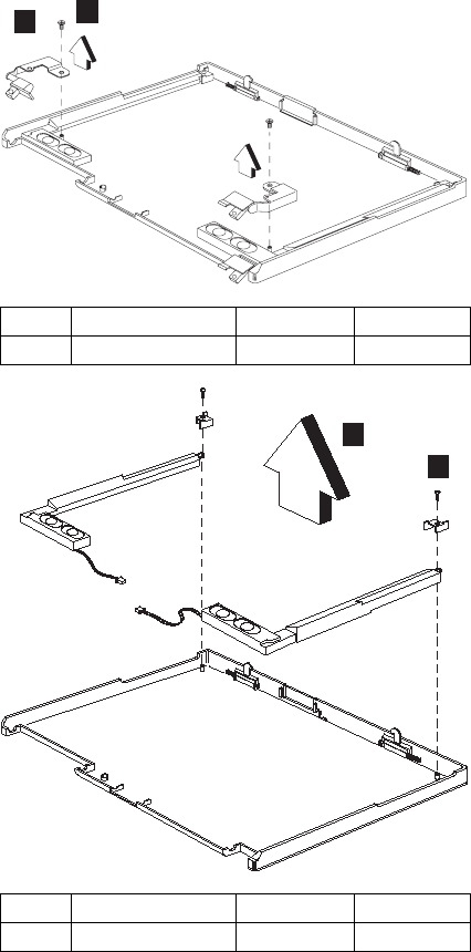
3
2
5
4
LCD bracket hinge assembly, speaker
assembly and LCD rear cover assembly
(13.0")
“Battery assembly” on page 51
“Middle cover and launch key assembly” on page 56
“Keyboard” on page 60
“LCD assembly” on page 65
“LCD bezel assembly (13.0")” on page 74
Step Size (Quantity) Color Torque
2 M2.5 x 6L(3) Black 3.2 kgf-cm
Step Size (Quantity) Color Torque
4 M2.5 x 6L(2) Black 3.2 kgf-cm
ThinkPad i Series 1400/1500 85
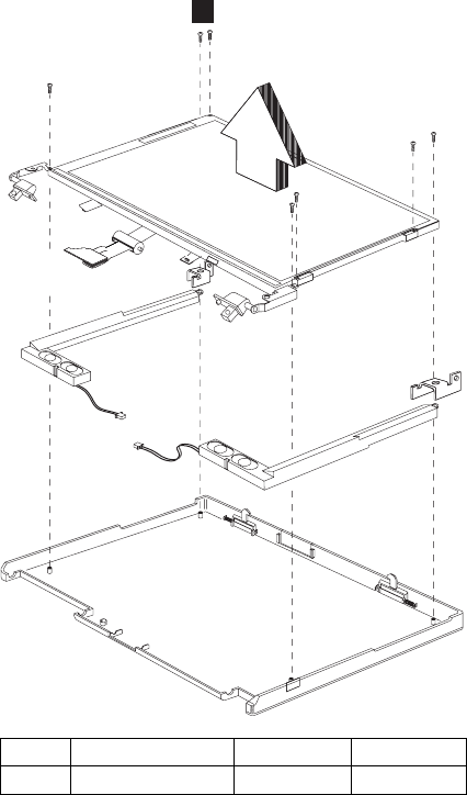
“LED board (13.0")” on page 78
“LCD inverter (13.0")” on page 81
“Cable assembly of microphone (13.0")” on page 82
1
LCD bracket hinge assembly, speaker
assembly, keyboard light, and LCD rear
cover assembly (14.1")
“Battery assembly” on page 51
“Middle cover and launch key assembly” on page 56
“Keyboard” on page 60
“LCD assembly” on page 65
“LCD bezel assembly (14.1")” on page 76
“LED board (14.1")” on page 79
“LCD inverter (14.1")” on page 81
Step Size (Quantity) Color Torque
1 M2.5 x 6L(7) Black 3.2 kgf-cm
86 ThinkPad i Series 1400/1500 HMM
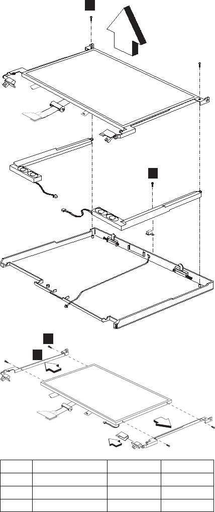
“Cable assembly of microphone (14.1")” on page 83
1
2
3
4
Step Size (Quantity) Color Torque
1 M2.5 x 6L(2) Black 3.2 kgf-cm
2 M2 x 4L(1) Silver 1.6 kgf-cm
3 M2 x 3L(4) Silver 1.6 kgf-cm
ThinkPad i Series 1400/1500 87
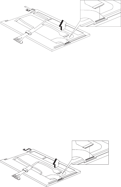
LCD FPC assembly (12.1")
“Battery assembly” on page 51
“Middle cover and launch key assembly” on page 56
“Keyboard” on page 60
“LCD assembly” on page 65
“LCD bezel assembly (12.1")” on page 73
“LED board (12.1")” on page 77
“LCD inverter (12.1")” on page 80
“Cable assembly of microphone (12.1")” on page 82
“LCD bracket hinge assembly, speaker assembly and
LCD rear cover assembly (12.1")” on page 83
LCD FPC assembly (13.0")
“Battery assembly” on page 51
“Middle cover and launch key assembly” on page 56
“Keyboard” on page 60
“LCD assembly” on page 65
“LCD bezel assembly (13.0")” on page 74
“LED board (13.0")” on page 78
“LCD inverter (13.0")” on page 81
“Cable assembly of microphone (13.0")” on page 82
“LCD bracket hinge assembly, speaker assembly and
LCD rear cover assembly (13.0")” on page 85
LCD FPC assembly (14.1")
“Battery assembly” on page 51
“Middle cover and launch key assembly” on page 56
“Keyboard” on page 60
“LCD assembly” on page 65
88 ThinkPad i Series 1400/1500 HMM
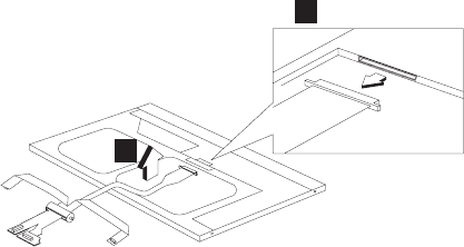
“LCD bezel assembly (14.1")” on page 76
“LED board (14.1")” on page 79
“LCD inverter (14.1")” on page 81
“Cable assembly of microphone (14.1")” on page 83
“LCD bracket hinge assembly, speaker assembly,
keyboard light, and LCD rear cover assembly (14.1")”
on page 86
1
2
ThinkPad i Series 1400/1500 89
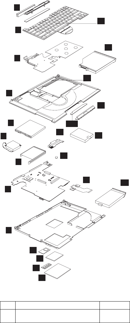
Parts list (ThinkPad i Series 1400/1500)
1
3
4
5
6
7
8
9
10
11
12
13
14
15
16
17
19
20
21 22
18
2
2-a
Note: The table below applies to the models in Group-A
(See the 2621 model table on page iii.)
No. Description FRU No.
1 Middle Cover & Launch Key ASM
14.1"
08K5865
90 ThinkPad i Series 1400/1500 HMM

No. Description FRU No.
Middle Cover & Launch Key ASM
14.1" (for Japan)
08K6054
Middle Cover & Launch Key ASM
12.1"/13.0"
08K5869
Middle Cover & Launch Key ASM
12.1"/13.0" (for Japan)
08K6055
2 Launch Key Board 08K3404
2-a CD Control Card 08K3405
3 Upper Heat sink 08K5868
4 Keyboard Bezel (IBM Logo, Lid SW,
Bracket Screw, PCMCIA Shutter)
08K5918
Keyboard Bezel (IBM Logo, Lid SW,
Bracket Screw, PCMCIA Shutter) (for
Japan)
08K6053
5 FDD w/ Bezel 05K9179
6 Fan ASM 08K5872
7 PCMCIA Holder 08K5873
8 Planar W/O TV out (Celeron 400) 10L1535
Planar W/ TV out (Celeron 433) 10L1537
Planar W/ TV out (Celeron 466) 10L1539
9 Bottom Case (w/ TV-out)
(PCMCIA Shutter, Rubber Foot, Stand
Foot, Battery Latch)
08K5866
Bottom Case (w/o TV-out)
(PCMCIA Shutter, Rubber Foot, Stand
Foot, Battery Latch)
08K5867
10 PCI Modem (Ambit) 10L1296
11 Modem Cover 08K5863
12 DIMM 32 MB 08K3408
DIMM 64 MB 08K3409
13 DIMM Cover 05K7073
14 Pointing Stick Caps 84G6536
15 24X CD-ROM Module (LG) 05K9264
24X CD-ROM Module (TEAC) 05K9178
4X DVD Module (Toshiba) 27L3864
CD-ROM Chassis 08K5862
16 Lid S/W ASM 08K5871
17 CD Control Panel 08K5876
18 DC/DC Charger 10L1729
19 HDD Module Assy. 4.8 GB (IBM) 05K9172
HDD Module Assy. 4.8 GB (Hitachi) 05K9173
HDD Module Assy. 6.4 GB (IBM) 05K9174
HDD Module Assy. 6.4 GB (Hitachi) 05K9175
ThinkPad i Series 1400/1500 91

No. Description FRU No.
HDD Module Assy. 8.1 GB (IBM) 05K9176
Kitting, HDD (HDD adapter bracket
SCR)
08K5861
20 RTC Battery 11J8591
21 FPC Cable Group (FPCs of CD-ROM,
FDD, EZ Launch, CD-Play)
27L0498
22 Battery Assy (LiIon) 9 Cells
(Panasonic)
02K6647
Battery Assy (NiMH) 8 Cells
(Panasonic)
02K6630
9-a LEG (R/L) 08K5870
Miscellaneous Kit
Right Hinge Cap 12.1"/13.0"
Right Hinge Cap 14.1"
Rubber Foot * 4
PCMCIA Screw Cover * 4
Modem Cover Mylar Film
CD-Player Panel Mylar
Screw Cushion for LCD Bezel * 2
Screw Cap for LCD Bezel
Screw Mylar for Rear Cover * 4
12.1" LCD FPC Holder
RJ-11 Cable
12.1" Top Bracket * 2
13.0" Top Bracket * 2
Battery Latch Knob
Keyboard Light Switch
Launch Key Panel
08K6604
92 ThinkPad i Series 1400/1500 HMM

Note: The table below applies to the models in Group-B
(See the 2621 model table on page iii.)
No. Description FRU No.
Miscellaneous Kit (for Japan)
Right Hinge Cap 12.1"/13.0"
12.1" LCD FPC Holder
12.1" Top Bracket * 2
Right Hinge Cap 14.1"
Rubber Foot * 4
PCMCIA Screw Cover * 4
Modem Cover Mylar Film
CD-Player Panel Mylar
Screw Cushion for LCD Bezel * 2
(Japan model)
Screw Cap for LCD Bezel (Japan
model)
Screw Mylar for Rear Cover * 4
(Japan model)
RJ11 Cable
13.0" Top Bracket * 2
Battery Latch Knob
Keyboard Light Switch
Launch Key Panel
08K6592
Screw Kit
WAFER MYLO M2.5*3.5LB-ZN
Black
PAN NYLOK M2.5*6LB-ZN Black
PAN NYLOK M2.5*10LB-ZN
Black
MACH PH M2*8LB-ZN Pan
Black
MACH PAN M2*10L NI Silver
M2*4 WAFER NI Silver
M2*L3 Wafer Head Black
SCREW PAN M2*12L NI Silver
SCREW M3*5L 700 Wafer Silver
08K5877
No. Description FRU No.
1 Middle Cover & Launch Key ASM
14.1"
08K5865
Middle Cover & Launch Key ASM
14.1" (for Japan)
08K6054
Middle Cover & Launch Key ASM
12.1"/13.0"
08K5869
Middle Cover & Launch Key ASM
12.1"/13.0" (for Japan)
08K6055
2 Launch Key Board 08K3404
2-a CD Control Card 08K3405
ThinkPad i Series 1400/1500 93

No. Description FRU No.
3 Upper Heatsink 08K5868
4 Keyboard Bezel (IBM Logo, Lid SW,
Bracket Screw, PCMCIA Shutter)
08K5918
Keyboard Bezel (IBM Logo, Lid SW,
Bracket Screw, PCMCIA Shutter) (for
Japan)
08K6053
5 FDD w/ Bezel 05K9179
6 Fan ASM 08K5872
7 PCMCIA Holder 08K5873
8 Planar W/O TV out (Celeron 400) 10L1535
Planar W/ TV out (Celeron 433) 10L1537
Planar W/ TV out (Celeron 466) 10L1539
9 Bottom Case (w/ TV-out)
(PCMCIA Shutter, Rubber Foot, Stand
Foot, Battery Latch)
08K5866
Bottom Case (w/o TV-out)
(PCMCIA Shutter, Rubber Foot, Stand
Foot, Battery Latch)
08K5867
10 PCI Modem (Ambit) 10L1296
11 Modem Cover 08K5863
12 DIMM 32 MB 08K3408
DIMM 64 MB 08K3409
13 DIMM Cover 05K7073
14 Pointing Stick Caps 84G6536
15 24X CD-ROM Module (LG) 05K9264
24X CD-ROM Module (TEAC) 05K9178
4X DVD Module (Toshiba) 27L3864
CD-ROM Chassis 08K5862
16 Lid S/W ASM 08K5871
17 CD Control Panel 08K5876
18 DC/DC Charger 10L1729
19 HDD Module ASM 6.0 GB (IBM) 05K9250
HDD Module ASM 9.0 GB (IBM) 05K9252
HDD Module ASM 12.0 GB (IBM) 05K9254
Kitting, HDD (HDD adapter bracket
SCR)
08K5861
20 RTC Battery 11J8591
21 FPC Cable Group 27L0498
22 Battery Assy (LiIon) 9 Cells
(Panasonic)
02K6647
Battery Assy (NiMH) 8 Cells
(Panasonic)
02K6630
9-a LEG (R/L) 08K5870
94 ThinkPad i Series 1400/1500 HMM

No. Description FRU No.
CD Control Card 08K3405
Miscellaneous Kit
Right Hinge Cap 12.1"/13.0"
Right Hinge Cap 14.1"
Rubber Foot * 4
PCMCIA Screw Cover * 4
Modem Cover Mylar Film
CD-Player Panel Mylar
Screw Cushion for LCD Bezel * 2
Screw Cap for LCD Bezel
Screw Mylar for Rear Cover * 4
12.1" LCD FPC Holder
RJ11 Cable
12.1" Top Bracket * 2
13.0" Top Bracket * 2
Battery Latch Knob
Keyboard Light Switch
Launch Key Panel
08K6604
Miscellaneous Kit (for Japan)
Right Hinge Cap 12.1"/13.0"
12.1" LCD FPC Holder
12.1" Top Bracket * 2
Right Hinge Cap 14.1"
Rubber Foot * 4
PCMCIA Screw Cover * 4
Modem Cover Mylar Film
CD-Player Panel Mylar
Screw Cushion for LCD Bezel * 2
(Japan model)
Screw Cap for LCD Bezel (Japan
model)
Screw Mylar for Rear Cover * 4
(Japan model)
RJ11 Cable
13.0" Top Bracket * 2
Battery Latch Knob
Keyboard Light Switch
Launch Key Panel
08K6592
ThinkPad i Series 1400/1500 95

No. Description FRU No.
Screw Kit
WAFER MYLO M2.5*3.5LB-ZN
Black
PAN NYLOK M2.5*6LB-ZN Black
PAN NYLOK M2.5*10LB-ZN
Black
MACH PH M2*8LB-ZN Pan
Black
MACH PAN M2*10L NI Silver
M2*4 WAFER NI Silver
M2*L3 Wafer Head Black
SCREW PAN M2*12L NI Silver
SCREW M3*5L 700 Wafer Silver
08K5877
96 ThinkPad i Series 1400/1500 HMM
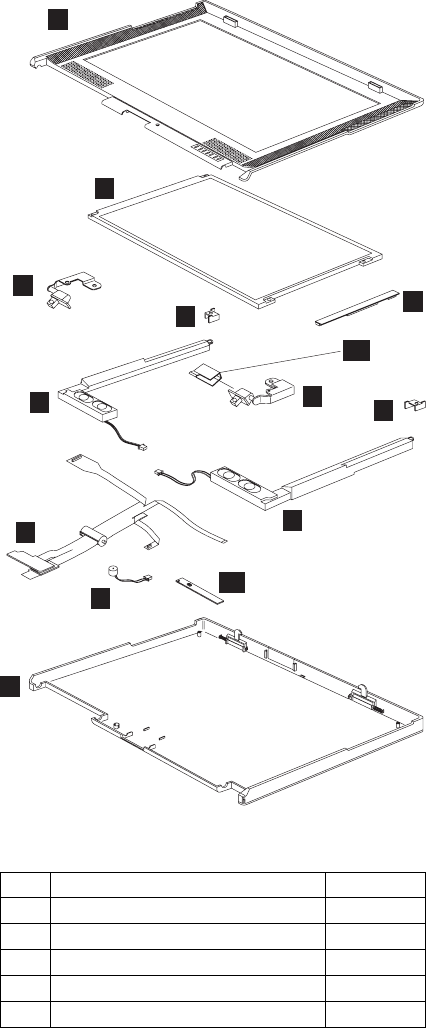
LCD FRU
12.1-inch SVGA TFT
1
3
3
5
5
6
7
8
9
4
4
11
2
10
Note: The table below applies to the models in Group-A
(See the 2621 model table on page iii.)
No. Description FRU No.
1 LCD BEZEL ASM 12.1" 08K5849
2 12.1" TFT LCD 08K5844
3 LCD Bracket-Hinge 12.1" (R,L) 08K5850
4 Misc. 12.1" Top Bracket 08K5878
5 Speaker ASM (R,L) 08K6374
ThinkPad i Series 1400/1500 97

Note: The table below applies to the models in Group-B
(See the 2621 model table on page iii.)
No. Description FRU No.
6 12.1" LCD FPC Assy. 27L0494
7 Cable Asm. of Microphone & Key-
board LED Light
27L0497
Cable Asm. of Microphone & Key-
board LED Light (for Japan)
27L0511
8 LCD Rear Cover ASM 12.1" TFT 08K5848
9 LCD Inverter 12.1" 10L1380
10 Misc. Right Hinge Cap 12.1"/13.0" (for
worldwide)
08K6604
Misc. Right Hinge Cap 12.1"/13.0" (for
Japan)
08K6592
11 LED BD 10L1443
LG/IBM Logo Kit 08K5860
No. Description FRU No.
1 LCD BEZEL ASM 12.1" 08K5849
12.1" TFT LCD Bezel (for Japan
model)
08K6388
2 12.1" TFT LCD 08K5844
3 LCD Bracket-Hinge 12.1" (R,L) 08K5850
4 Misc. 12.1" Top Bracket 08K5878
5 Speaker ASM (R,L) 08K6374
6 12.1" LCD FPC Assy. 27L0494
12.1" LCD FPC Assy. (for Japan
model)
27L0536
7 Cable Asm. of Microphone 27L0497
Cable Asm. of Microphone (for Japan
model)
27L0511
8 LCD Rear Cover ASM 12.1" TFT 08K5848
LCD Rear Cover ASM 12.1" TFT (for
Japan model0
08K6387
9 LCD Inverter 12.1" 10L1380
10 Misc. Right Hinge Cap 12.1"/13.0" (for
worldwide)
08K6604
Misc. Right Hinge Cap 12.1"/13.0" (for
Japan)
08K6592
11 LED BD 10L1443
LG/IBM Logo Kit 08K5860
98 ThinkPad i Series 1400/1500 HMM
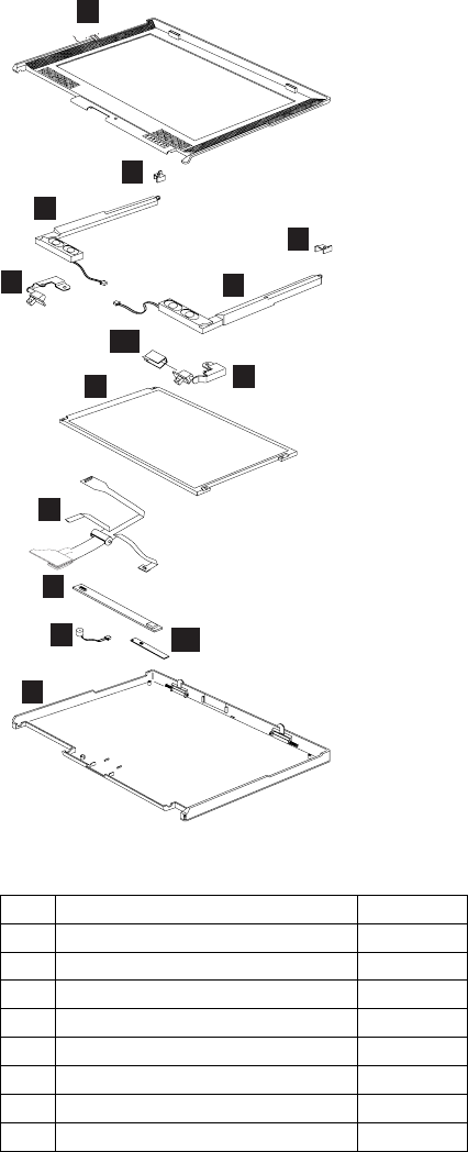
13.0-inch SVGA HPA
1
2
3
4
54
2
3
10
6
7
8
9
11
Note: The table below applies to the models in Group-A
and B (See the 2621 model table on page iii.)
No. Description FRU No.
1 LCD BEZEL ASM 13.0" 08K5853
LCD BEZEL ASM 13.0" (for Japan) 08K6051
2 Misc. 13.0" Top Bracket 08K5878
3 Speaker Module (R,L) 08K6374
4 LCD Bracket-Hinge 13.0" (R,L) 08K5854
5 13.0" HPA LCD 05K9596
6 13.0" LCD FPC Assy. 27L0495
13.0" LCD FPC Assy. (for Japan) 27L0510
ThinkPad i Series 1400/1500 99

No. Description FRU No.
7 LCD Inverter 12.1"/13.0" 10L1380
8 Cable Asm. of Microphone & Key-
board LED Light
27L0497
Cable Asm. of Microphone & Key-
board LED Light (for Japan)
27L0511
9 LCD Rear Cover ASM 13.0" HPA 08K5852
LCD Rear Cover ASM 13.0" HPA
(with logo kit) (for Japan)
08K6048
10 Misc. Right Hinge Cap 12.1"/13.0" (for
worldwide)
08K6604
Misc. Right Hinge Cap 12.1"/13.0" (for
Japan)
08K6592
11 LED BD 10L1443
LG/IBM Logo Kit 08K5860
100 ThinkPad i Series 1400/1500 HMM
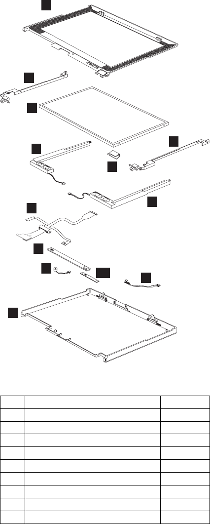
14.1" XGA TFT
1
9
3
4
4
5
6
77
8
10
2
2
Note: The table below applies to the models in Group-A
(See the 2621 model table on page iii.)
No. Description FRU No.
1 LCD BEZEL ASM 14.1" 08K5856
LCD BEZEL ASM 14.1" (for Japan) 08K6050
2 LCD Bracket-Hinge 14.1" (R,L) 08K5857
3 14.1" TFT LCD (LG) 05K9591
14.1" TFT LCD (Samsung) 05K9498
4 Speaker Module (R,L) 08K6374
5 14.1" LCD FPC Assy. 27L0496
14.1" LCD FPC Assy. (for Japan) 27L0509
6 LCD Inverter 14.1" 10L1442
ThinkPad i Series 1400/1500 101

Note: The table below applies to the models in Group-B
(See the 2621 model table on page iii.)
No. Description FRU No.
7 Cable ASM of Microphone & Key-
board LED Light
27L0497
Cable ASM of Microphone & Key-
board LED Light (for Japan)
27L0511
8 LCD Rear Cover ASM 14.1" TFT 08K5855
LCD Rear Cover ASM 14.1" TFT (for
Japan)
08K6047
9 Misc. Right Hinge Cap 14.1" (for
worldwide)
08K6604
Misc. Right Hinge Cap 14.1" (for
Japan)
08K6592
10 LED BD 10L1443
LG/IBM Logo Kit 08K5860
No. Description FRU No.
1 LCD BEZEL ASM 14.1" 08K5856
LCD BEZEL ASM 14.1" (for Japan
model)
08K6050
LCD BEZEL ASM 14.1" (NEC LCD) 08K6276
LCD BEZEL ASM 14.1" (NEC LCD)
(for Japan model)
08K6386
2 LCD Bracket-Hinge 14.1" (R,L) 08K5857
LCD Bracket-Hinge 14.1" (R,L) (NEC
LCD)
08K6282
3 14.1" TFT LCD (LG) 05K9591
14.1" TFT LCD (Samsung) 05K9498
14.1" TFT LCD (NEC) 05K9602
4 Speaker Module (R,L) 08K6374
5 14.1" LCD FPC Assy. 27L0496
14.1" LCD FPC Assy. (for Japan) 27L0509
14.1" LCD FPC Assy. (NEC LCD) 27L0523
14.1" LCD FPC Assy. (NEC LCD) (for
Japan model)
27L0535
6 LCD Inverter 14.1" 10L1442
7 Cable ASM of Microphone & Key-
board LED Light
27L0497
Cable ASM of Microphone & Key-
board LED Light (for Japan)
27L0511
Cable ASM of Microphone & Key-
board LED Light (NEC LCD)
27L0566
8 LCD Rear Cover ASM 14.1" TFT 08K5855
LCD Rear Cover ASM 14.1" TFT (for
Japan)
08K6047
102 ThinkPad i Series 1400/1500 HMM

Keyboard
No. Description FRU No.
LCD Rear Cover ASM 14.1" TFT
(NEC LCD)
08K6275
LCD Rear Cover ASM 14.1" TFT
(NEC LCD) (for Japan model)
08K6385
9 Misc. Right Hinge Cap 14.1" (for
worldwide)
08K6604
Misc. Right Hinge Cap 14.1" (for
Japan)
08K6592
10 LED BD 10L1443
LG/IBM Logo Kit 08K5860
Description Vendor FRU
No.
Keyboard US API 02K5077
Keyboard Chinese API 02K5078
Keyboard Korean API 02K5079
Keyboard Swiss API 02K5080
Keyboard Canadian French API 02K5081
Keyboard Belgian API 02K5082
Keyboard Danish API 02K5083
Keyboard Italy API 02K5084
Keyboard French API 02K5085
Keyboard German API 02K5086
Keyboard Norwegian API 02K5087
Keyboard Portuguese API 02K5088
Keyboard Spanish API 02K5089
Keyboard Dutch API 02K5090
Keyboard Swedish/Finnish API 02K5091
Keyboard Japan API 02K5092
Keyboard UK English API 02K5093
Keyboard La Spanish API 02K5095
Keyboard US ENGLISH ALPS 02K5060
Keyboard KOREAN ALPS 02K5061
Keyboard UK ENGLISH ALPS 02K5062
Keyboard CANADIAN FRENCH ALPS 02K5063
Keyboard GERMANY ALPS 02K5064
Keyboard FRENCH ALPS 02K5065
Keyboard DUTCH ALPS 02K5066
Keyboard SWEDISH/FINNISH ALPS 02K5067
Keyboard NORWEGIAN ALPS 02K5068
Keyboard DANISH ALPS 02K5069
ThinkPad i Series 1400/1500 103

Common parts list
Tools
Miscellaneous
Modem cable
Description Vendor FRU
No.
Keyboard JAPANESE ALPS 02K5070
Keyboard TRAD. CHINESE ALPS 02K5071
Keyboard ITALIAN ALPS 02K5072
Keyboard SPANISH ALPS 02K5073
Keyboard SWISS ALPS 02K5074
Keyboard PORTUGUESE ALPS 02K5075
Keyboard BELGIAN ALPS 02K5076
Keyboard LA SPANISH ALPS 02K5094
Description FRU No.
Tri-Connector Wrap Plug 72X8546
PC Test Card 35G4703
Audio Wrap Cable 66G5180
Screwdriver Kit 95F3598
USB Parallel Test Cable 05K2580
Torque Screwdriver 05K4695
5mm Socket Wrench 05K4694
Screwdriver 05K4693
Description FRU No.
Headset (for Japan only) 02K4941
Description FRU No.
Modem cable (German) 27L0441
Modem cable (UK, NZ) 27L0442
Modem cable (France) 27L0443
Modem cable (Holland) 27L0444
Modem cable (Sweden) 27L0445
Modem cable (Norway/Fin) 27L0446
Modem cable (Danish) 27L0447
Modem cable (Italy) 27L0448
Modem cable (Austria) 27L0449
Modem cable (Spain) 27L0450
Modem cable (Belgium) 27L0451
Modem cable (Switzerland) 27L0462
104 ThinkPad i Series 1400/1500 HMM

Description FRU No.
Modem cable (Portugal) 27L0447
Modem cable (US/C, JPN, Twn, APN, LA,
Brz)
27L0465
Modem cable (Australia) 27L0467
ThinkPad i Series 1400/1500 105

AC adapter
Power cords:
IBM power cords for a specific country
are usually available only in that country.
For 2–pin power cords:
For 3–pin power cords:
Note: The grounded adapter is required for full MPRII
compliance. If a 3–pin power cord came with your
computer, see “Safety Information” on page 11.
Description FRU No.
AC Adapter 2-pin (Delta) 02K6548
AC Adapter 2-pin (Sanken) 02K6554
AC Adapter 3-pin (Delta) 02K6550
AC Adapter 3-pin (Sanken) 02K6555
IBM power
cord part
number Used in these countries or regions
13H5273 Japan
IBM power
cord part
number Used in these countries or regions
02K0539 Simple China
36L8867 Argentina
76H3514 Australia, New Zealand, Papua New Guinea,
Paraguay, Uruguay
76H3516 Aruba, Bahamas, Barbados, Bermuda,
Bolivia, Brazil, Canada, Cayman Islands,
Colombia, Costa Rica, Curacao, Dominican
Republic, Ecuador, El Salvador, Guatemala,
Guyana, Haiti, Honduras, Jamaica, Korea
(South), Liberia, Mexico, Netherlands
Antilles, Nicaragua, Panama, Peru,
Philippines, Saudi Arabia, Suriname, Taiwan,
Thailand, Trinidad (West Indies), United
States of America, Venezuela
76H3518 Austria, Belgium, Bosnia-Herzogovina,
Bulgaria, Croatia, Czech Republic, Egypt,
Finland, France, Germany, Greece, Hungary,
Iceland, Indonesia, Macao, Macedonia,
Netherlands, Norway, Poland, Portugal,
Romania, Slovakia, Slovenia, Spain,
Sweden, Turkey, Yugoslavia
76H3520 Denmark
Note: Due to consumer product, 2621 sup-
plies power cord 76H3518 to
Denmark.
76H3522 Bangladesh, Myanmar, Pakistan, South
Africa, Sri Lanka
106 ThinkPad i Series 1400/1500 HMM

IBM power
cord part
number Used in these countries or regions
76H3524 Abu Dhabi, Albania, Antigua, Bahrain,
Brunei, Dubai, Fiji, Hong Kong, India,
Ireland, Kenya, Kuwait, Malaysia, Nigeria,
Oman, Qatar, Singapore, United Kingdom
76H3528 Liechtenstein, Switzerland
76H3530 Chile, Ethiopia, Italy, Libya
76H3532 Israel
76H3535 Korea
ThinkPad i Series 1400/1500 (Part II)
This section applies to the models in Group-C. (See the
2621 model table on page iii.)
ThinkPad i Series 1400/1500 107

Product overview
The following shows an overview of the system features.
Feature Description
Processor Intel** Pentium** III processor 500
MHz
—or—
Intel** Celeron** processor 500
MHz
Bus architecture PCI & AGP
System memory 2 DIMM slots, no memory on
system board
32 MB, 64 MB, and 128 MB DIMM
card
Maximum frequency: 100 MHz
CMOS RAM 114 bytes + 4 Kbytes
Video 12.1–inch, 18 bit colors, 800x600
pixel TFT SVGA color LCD
13.0–inch, 16 bit colors, 800x600
pixel HPA SVGA color LCD
—or—
14.1–inch, 18 bit colors, 1024x768
pixel TFT XGA color LCD
15.0–inch, 18 bit colors, 1024x768
pixel TFT XGA color LCD
CRT 32 bit colors
Audio 16-bit audio
Internal stereo speakers
Internal microphone
Diskette drive 1.44MB (3–mode), 3.5 inch
Hard disk drive 6/12/18GB above, 2.5–inch, EIDE
interface
CD-ROM drive or
DVD-ROM drive
CD-ROM: 5.25–inch, 24X speed,
EIDE interface
—or—
DVD-ROM: 5.25–inch, 6X speed,
EIDE interface
Modem 56.6 Kbps, internal (depends on
the model)
PC Card (PCMCIA) One Type III or Type II, with
CardBus and ZV support
108 ThinkPad i Series 1400/1500 HMM

Status indicators: The system-status indicators on
the computer show the current status of your computer by
their on or off states and colors (green and orange). Each
indicator is identified with a symbol. The following shows
the location and the meaning of each icon:
1
A
+
7
12 6
5
4
3
Feature Description
I/O ports External monitor
Speaker-out
Line-in
Microphone-in
DC-in
Mouse/keyboard
Parallel
Serial
USB
Telephone (RJ11)/Modem
TV-out (S-video)
AC Adapter 56–Watt type
ThinkPad i Series 1400/1500 109
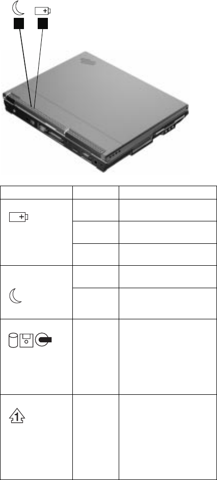
21
Symbol Color Meaning
(1) Battery status Green Enough battery power
remains for operation.
Blinking
orange
The battery pack needs
to be charged
Orange The battery pack is
being charged.
(2) Standby
mode
Green The computer is in
standby mode
Blinking
green
The computer is entering
or resuming from
hibernation mode.
(3) Drive in use Green Data is being read from
or written to the hard
disk, floppy drive, or data
is being read from the
CD-ROM drive. Do not
enter standby mode or
power off the computer
when this indicator is on.
(4) Numeric lock Green The numeric keypad on
the keyboard is enabled.
You enable or disable
the keypad by pressing
and holding the Shift
key, and pressing the
NumLk key. For details,
see the
User's Refer-
ence
.
110 ThinkPad i Series 1400/1500 HMM

Symbol Color Meaning
(5) Caps lock Green Caps Lock mode is
enabled. All alphabetic
characters
(A-Z)
are
entered in capital letters
without the Shift key
being pressed. You
enable or disable the
Caps Lock mode by
pressing the Caps Lock
key.
(6) Scroll lock Green Scroll Lock mode is
enabled. The Arrow
keys can be used as
screen-scroll function
keys. The cursor cannot
be moved with the
Arrow keys.
Not all
application programs
support this function.
You enable or disable
Scroll Lock mode by
pressing the ScrLk key.
(7) Power on Green The computer is opera-
tional. This indicator is
on when the computer is
on.
FRU tests: The following table shows the applicable
test for each FRU using PC-Doctor.
FRU Applicable test
System board 1. CPU/Coprocessor (Diagnostics)
2. System board (Diagnostics)
Power Battery (Diagnostics)
LCD unit 1. Video Adapter (Diagnostics)
2. Video (Interactive Tests)
Modem 1. Make sure the modem set up
correctly.
2. Replacing the modem jack and
modem card one at a time, run
the modem tests in Other
Devices (Diagnostics)
Audio Internal Speaker (Interactive Tests)
Stereo Speaker (Interactive Tests)
Speaker System beeper: Internal Speaker
(Interactive Tests)
PC Card slots System board (Diagnostics)
Keyboard 1. Keyboard (Diagnostics)
2. Keyboard (Interactive Tests)
ThinkPad i Series 1400/1500 111

FRU Applicable test
TrackPont or
Pointing device
If the TrackPoint does not work, see if
an external PS/2 mouse is connected
to the mouse/keyboard connector and
remove it. The TrackPoint is automat-
ically disabled if an external PS/2
mouse is attached. Check also if the
TrackPoint driver is correctly installed
by accessing Windows Device
Manager via the System icon in the
Control Panel.
After you use the TrackPoint, the
pointer drifts on the screen for a short
time. This self-acting pointer move-
ment can occur when a slight, steady
pressure is applied to the TrackPoint
pointer. This symptom is not a hard-
ware problem. No service actions are
necessary if the pointer movement
stops in a short period of time.
If this does not correct the TrackPoint
problem, continue with the following:
Mouse (Interactive Tests).
Hard disk drive Fixed Disks (Diagnostics)
Diskette drive 1. Diskette Drive (Diagnostics)
2. Diskette (Interactive Tests)
CD-ROM or
DVD-ROM drive
CD-ROM/DVD (Interactive Tests)
Memory 1. If a DIMM is installed, remove it
and run Memory Test-Quick
(Diagnostics)
2. If the problem does not recur,
replace the DIMM and run the
test again.
3. If the test does not detect the
error, run Memory Test-Full
(Diagnostics)
Fan 1. Start Windows 98 and check the
air turbulence at the louver at the
rear of the computer.
2. Run the fan test in Other Devices
(Diagnostics).
112 ThinkPad i Series 1400/1500 HMM

FRU removals and replacements
This section contains information about removals and
replacements of model types in Group-C III (15.0" TFT).
For other model types in Group-C, please refer to Part I for
removals and replacements.
Do not damage any parts. Only certified and trained
personnel should service the computer.
The arrows in this section show the direction of move-
ment to remove a FRU, or to turn a screw to release
the FRU. The arrows are marked in numeric order, in
square callout, to show the correct sequence of
removal.
Any FRUs that must be removed before removing the
failing FRU are listed at the top of the page.
To replace a FRU, reverse the removal procedure
and follow any notes that pertain to replacement. See
“Locations” on page 40 for internal cable connections
and arrangement information.
When replacing a FRU, use the correct screw size, as
shown in the procedure.
Safety Notice 1
Translations in "Safety Notices (Multilingual Trans-
lations)" section: Before the computer is powered-on
after FRU replacement, make sure all screws, springs,
or other small parts are in place and are not left loose
inside the computer. Verify this by shaking the com-
puter and listening for rattling sounds. Metallic parts or
metal flakes can cause electrical shorts.
Safety Notice 3
Translations in "Safety Notices (Multilingual Trans-
lations)" section: The battery pack contains small
amounts of nickel. Do not disassemble it, throw it into
fire or water, or short-circuit it. Dispose of the battery
pack as required by local ordinances or regulations.
Use only the battery in the appropriate parts listing
when replacing the battery pack. Use of an incorrect
battery can result in ignition or explosion of the
battery.
Safety Notice 8
Translations in "Safety Notices (Multilingual Trans-
lations)" section: Before removing any FRU, power-off
the computer, unplug all power cords from electrical
outlets, remove the battery pack, then disconnect any
interconnecting cables.
Attention: The system board is sensitive and can be
damaged by electronic discharge. Establish personal
ThinkPad i Series 1400/1500 113
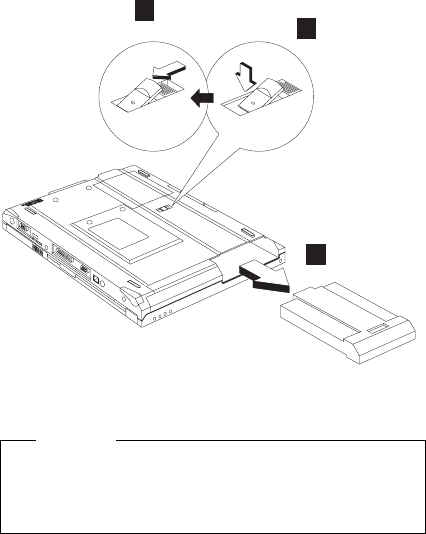
grounding by touching a ground point with one hand before
touching these units.
An electrostatic discharge (ESD) strap (P/N: 6405959)
must be used to establish personal grounding.
Battery assembly
1
3
2
Note: When install a new battery pack, push the battery
in and lock it. No need to repeat step 1 and 2.
Warning
Battery packs are capable of delivering high currents
for a significant amount of time. Do not short the
battery terminals.
114 ThinkPad i Series 1400/1500 HMM
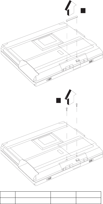
CD player panel and CD player control
board
1
2
Step Size (Quantity) Color Torque
1 M2.5 x 6L (2) Black 3.2 kgf-cm
ThinkPad i Series 1400/1500 115
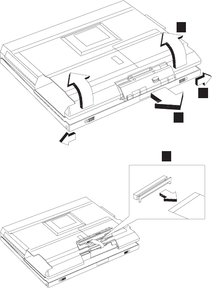
5
3
4
6
Note: The FPC is connected to the system board by the
other end. When removing the CD player panel
and CD player control board, release the FPC with
caution.
Hard disk drive assembly
“Battery assembly” on page 114
“CD player panel and CD player control board” on
page 115
116 ThinkPad i Series 1400/1500 HMM
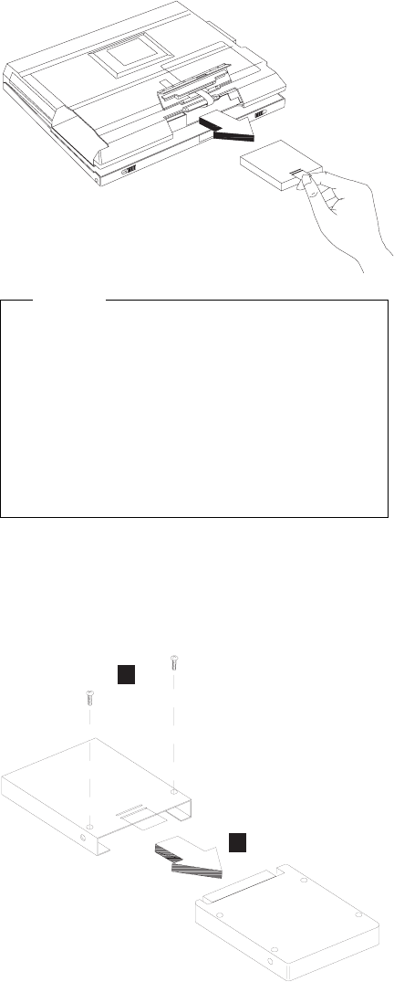
Warning
Do not drop or apply any shock to the hard disk drive.
The hard disk drive is sensitive to physical shock.
Incorrect handling can cause damage and permanent
loss of data on the drive.
Before removing the drive, have the user make a
backup copy of all the information on the drive if pos-
sible.
Never remove the drive while the system is operating
or is in suspend mode.
Hard disk drive kitting pack
“Battery assembly” on page 114
“CD player panel and CD player control board” on
page 115
“Hard disk drive assembly” on page 116
1
2
ThinkPad i Series 1400/1500 117
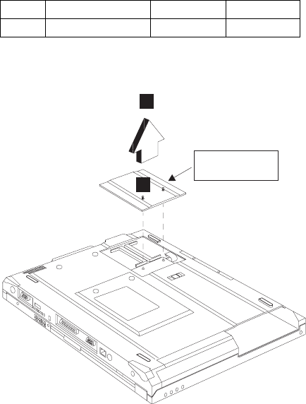
Memory cover and memory card
“Battery assembly” on page 114
2
1
Memory cover
Note: The screw does not separate from the memory
cover.
To install the memory card:
With the notched end of the memory card toward the right
side of the socket, insert the memory card, at an angle of
approximately 20°, into the socket; then press it firmly.
Pivot the memory card until it snaps into place.
Step Size (Quantity) Color Torque
1 M3 x 4L (2) Silver 3.2 kgf-cm
118 ThinkPad i Series 1400/1500 HMM
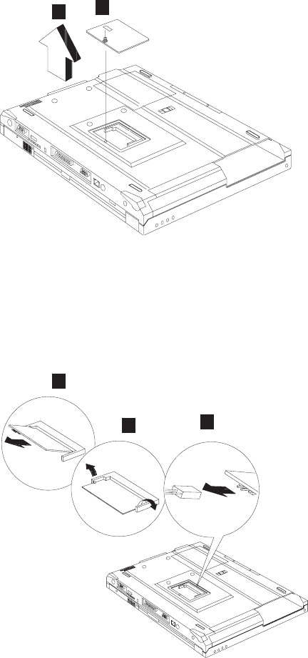
Modem cover and modem card
“Battery assembly” on page 114
1
2
Note: The screw does not separate from the modem
cover.
To remove the modem card:
1. Disconnect the modem cable.
2. Press the release latches on both sides of the modem
board.
3. Pull out the modem card.
1
3
2
When reinserting the card, reverse the procedures above.
ThinkPad i Series 1400/1500 119
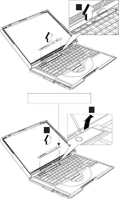
Launch key assembly
“Battery assembly” on page 114
1
2
3
Optional customerized sheet
120 ThinkPad i Series 1400/1500 HMM
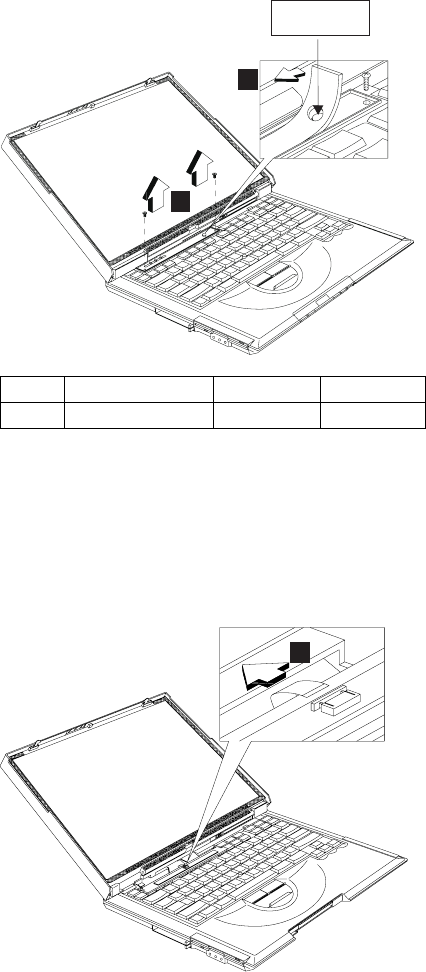
4
5
Power button
Notes:
1. Adjust the LCD module to the widest angle. Be
careful not to scratch the surface of the middle cover.
2. Turn the middle cover and launch key assembly
upside down when removing the FFC.
6
Step Size (Quantity) Color Torque
5 M2 x 4L (2) Silver 1.6 kgf-cm
ThinkPad i Series 1400/1500 121
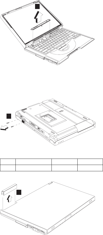
CAUTION:
There is a FFC connected to the middle cover. When
removing the middle cover, release the FFC with
caution.
7
Left hinge cap
“Battery assembly” on page 114
“Launch key assembly” on page 120
1
2
Step Size (Quantity) Color Torque
1 M2.5 x 3.5L (2) Black 3.2 kgf-cm
122 ThinkPad i Series 1400/1500 HMM
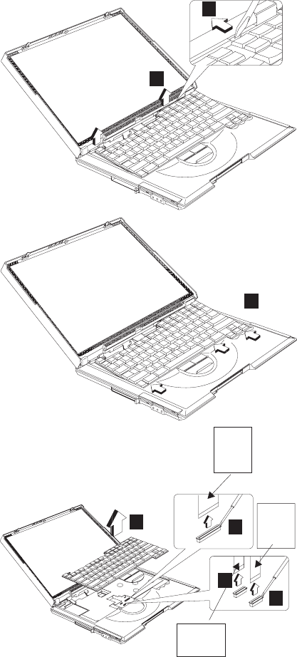
Keyboard
“Battery assembly” on page 114
“Launch key assembly” on page 120
“Left hinge cap”
1
2
3
4
5
6
7
Large
green
FPC
Small
green
FPC
Yellow
FPC
Note: Make sure the FPC finger side is facing outwards,
when inserted.
ThinkPad i Series 1400/1500 123
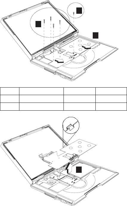
Notes:
1. When replacing the keyboard, make sure that the 3
cables are clean and insert them directly into the con-
nectors, making sure they make contact with the
bottom of the connector. Now press down on the
latch of the connector to secure.
2. If the cables do not touch the bottom of the con-
nector, the keyboard function will be rendered
useless.
3. The cables of the keyboard are fragile and could be
damaged. Be careful when pulling out the cables.
Upper heat sink
“Battery assembly” on page 114
“Launch key assembly” on page 120
“Left hinge cap” on page 122
“Keyboard” on page 123
1
2
3
4
Step Size (Quantity) Color Torque
1 M2 x 8L (4) Black 1.6 kgf-cm
2 M2.5 x 10L (1) Black 3.2 kgf-cm
124 ThinkPad i Series 1400/1500 HMM
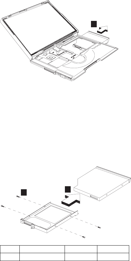
CD-ROM/DVD-ROM assembly
“Battery assembly” on page 114
“Launch key assembly” on page 120
“Left hinge cap” on page 122
“Keyboard” on page 123
“Upper heat sink” on page 124
1
CAUTION:
When the CD-ROM/DVD-ROM assembly is removed,
the machine is unstable.
CD-ROM/DVD-ROM chassis assembly
“Battery assembly” on page 114
“Launch key assembly” on page 120
“Left hinge cap” on page 122
“Keyboard” on page 123
“Upper heat sink” on page 124
“CD-ROM/DVD-ROM assembly”
12
Step Size (Quantity) Color Torque
1 M2 x 3L (4) Silver 1.8 kgf-cm
ThinkPad i Series 1400/1500 125
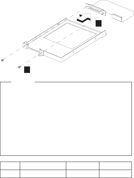
3
4
Caution
Do not disassemble the CD-ROM; there are no user
adjustments or serviceable parts inside. The use of
controls, adjustments or performing procedures other
than those specified may result in hazardous radiation
exposure.
The CD-ROM is a sensitive electronic device, handling
should be cautious.
Do not apply any extra force to the CD-ROM drive
when removing it.
PCMCIA holder
“Battery assembly” on page 114
“Launch key assembly” on page 120
“Left hinge cap” on page 122
“Keyboard” on page 123
“Upper heat sink” on page 124
Step Size (Quantity) Color Torque
1 M2 x 3L (2) Silver 1.3 kgf-cm
126 ThinkPad i Series 1400/1500 HMM
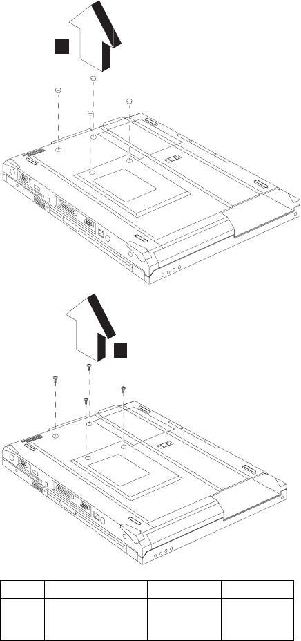
1
2
Step Size (Quantity) Color Torque
1 M2 x 4L (4) Silver with
washer
head
1.6 kgf-cm
ThinkPad i Series 1400/1500 127
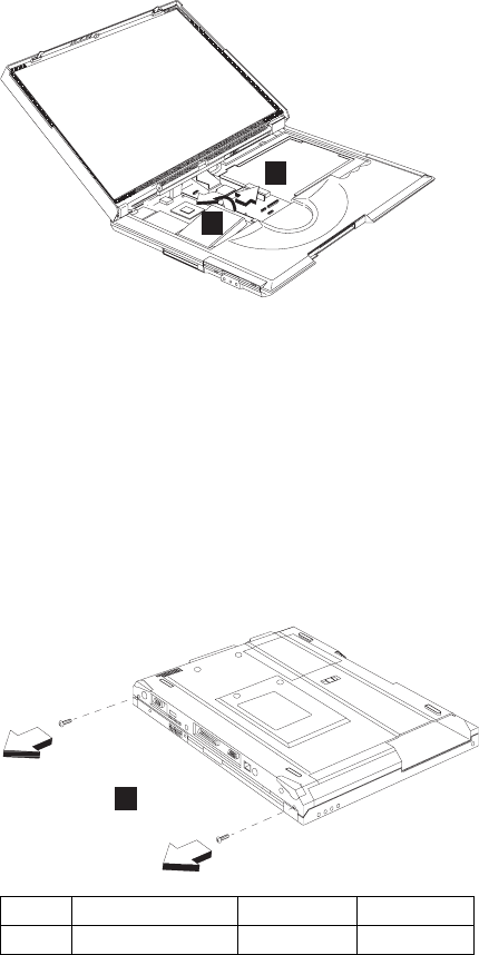
3
4
Note: Before removing and replacing the PCMCIA holder,
make sure that the PCMCIA cards are removed
and the eject levers are sticking out.
CAUTION:
When removing the PCMCIA holder, pull them up at an
angle. It cannot be removed when pulled straight up.
LCD assembly
“Battery assembly” on page 114
“Launch key assembly” on page 120
“Left hinge cap” on page 122
“Keyboard” on page 123
1
Step Size (Quantity) Color Torque
1 M2.5 x 6L (2) Black 3.2 kgf-cm
128 ThinkPad i Series 1400/1500 HMM
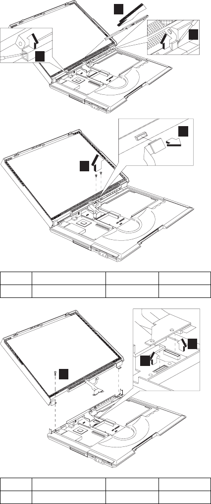
2
3
4
5
6
7
9
8
Step Size (Quantity) Color Torque
6 M2 x 12L (2) Silver 1.6 kgf-cm
Step Size (Quantity) Color Torque
7 M2.5 x 6L (1) Black 3.2 kgf-cm
ThinkPad i Series 1400/1500 129
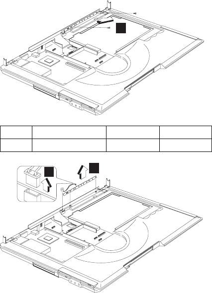
LED board assembly and Cable assembly
of microphone
“Battery assembly” on page 114
“Launch key assembly” on page 120
“Left hinge cap” on page 122
“Keyboard” on page 123
“LCD assembly” on page 128
1
3
2
Backup battery
“Battery assembly” on page 114
“Launch key assembly” on page 120
“Keyboard” on page 123
“Upper heat sink” on page 124
Step Size (Quantity) Color Torque
1 M2 x 4L(2) Silver 1.6 kgf-cm
130 ThinkPad i Series 1400/1500 HMM
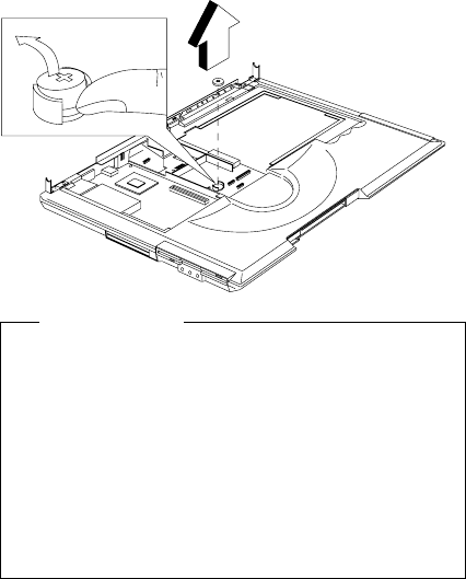
Safety Notice 4
Translation in "Safety Notices: Multilingual Trans-
lations" section: The backup battery is a lithium battery
and can cause a fire, an explosion, or severe burns.
Do not recharge it, remove its polarized connector,
disassemble it, heat it above 100°C (212°F), incinerate
it, or expose its cell contents to water. Dispose of the
battery as required by local ordinances or regulations.
Use of an incorrect battery can result in ignition or
explosion of the battery. Replacement batteries can be
ordered from IBM or IBM Authorized Dealers.
Keyboard bezel
“Battery assembly” on page 114
“Launch key assembly” on page 120
“Left hinge cap” on page 122
“Keyboard” on page 123
“Upper heat sink” on page 124
“CD-ROM/DVD-ROM assembly” on page 125
“LCD assembly” on page 128
“LED board assembly and Cable assembly of
microphone” on page 130
ThinkPad i Series 1400/1500 131
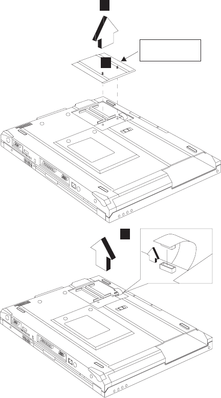
Memory cover
1
2
3
132 ThinkPad i Series 1400/1500 HMM
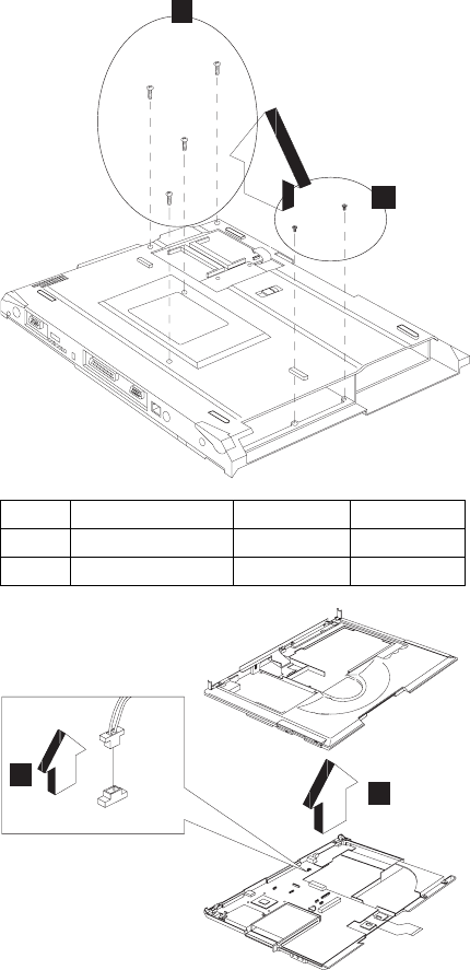
5
4
67
CAUTION:
The upper cover has several latches. When removing
the upper cover from the bottom cover, gently release
these latches, then raise the side of the uppoer cover
facing the palm rest to remove it. Be careful not to
break the latches.
Step Size (Quantity) Color Torque
1 M2.5 x 6L (4) Black 3.2 kgf-cm
2 M2.5 x 3.5L (2) Black 3.2 kgf-cm
ThinkPad i Series 1400/1500 133
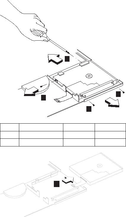
Diskette drive assembly
“Battery assembly” on page 114
“Launch key assembly” on page 120
“Left hinge cap” on page 122
“Keyboard” on page 123
“Upper heat sink” on page 124
“CD-ROM/DVD-ROM assembly” on page 125
“LCD assembly” on page 128
“LED board assembly and Cable assembly of
microphone” on page 130
“Keyboard bezel” on page 131
1
1
1
2
2
Step Size (Quantity) Color Torque
1 M2.5 x 3.5L (3) Black 2.0 kgf-cm
2 M2 x 4L (1) Silver 1.6 kgf-cm
134 ThinkPad i Series 1400/1500 HMM
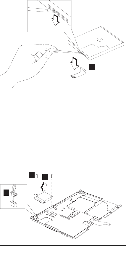
3
Fan assembly
“Battery assembly” on page 114
“Launch key assembly” on page 120
“Left hinge cap” on page 122
“Keyboard” on page 123
“Upper heat sink” on page 124
“LCD assembly” on page 128
“LED board assembly and Cable assembly of
microphone” on page 130
“Keyboard bezel” on page 131
1
3
2
DC-DC charger board and System board
“Battery assembly” on page 114
“Launch key assembly” on page 120
“Left hinge cap” on page 122
“Keyboard” on page 123
“Upper heat sink” on page 124
“CD-ROM/DVD-ROM assembly” on page 125
Step Size (Quantity) Color Torque
2 M2.5 x 3.5L (2) Black 3.2 kgf-cm
ThinkPad i Series 1400/1500 135
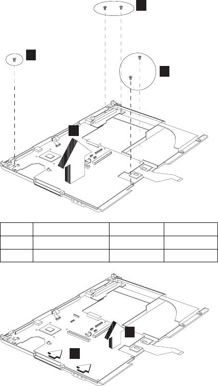
“LCD assembly” on page 128
“LED board assembly and Cable assembly of
microphone” on page 130
“Keyboard bezel” on page 131
“Fan assembly” on page 135
1
2
2
3
4
5
Step Size (Quantity) Color Torque
1 M2.5 x 3.5L (2) Black 3.2 kgf-cm
2 M2.5 x 3.5L (3) Black 3.2 kgf-cm
136 ThinkPad i Series 1400/1500 HMM
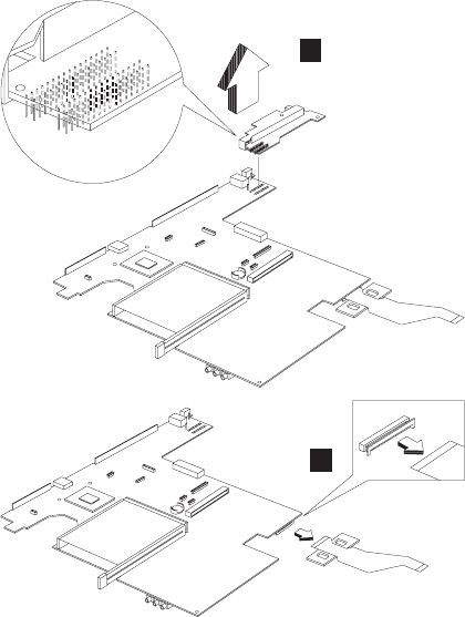
6
7
Notes:
1. When removing the system board from the bottom
cover, gently raise the side of the system board
facing the rear I/O ports; then pull out the system
board.
2. When replacing the system board, align the power
switch and power actuator. Make sure that the power
switch operates correctly before securing the screws.
Bottom case
“Battery assembly” on page 114
“Launch key assembly” on page 120
“Left hinge cap” on page 122
“Keyboard” on page 123
“Upper heat sink” on page 124
“CD-ROM/DVD-ROM assembly” on page 125
“LCD assembly” on page 128
“LED board assembly and Cable assembly of
microphone” on page 130
“Keyboard bezel” on page 131
“DC-DC charger board and System board” on
page 135
ThinkPad i Series 1400/1500 137
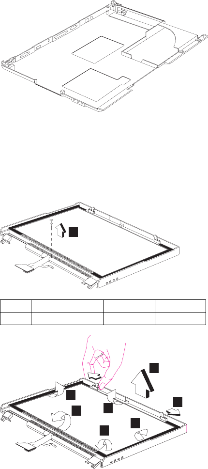
LCD bezel assembly (15.0")
“Battery assembly” on page 114
“Launch key assembly” on page 120
“Left hinge cap” on page 122
“Keyboard” on page 123
“LCD assembly” on page 128
1
2
3
4
5
6
7
8
Note: When removing the LCD, take note of the
following:
Be careful not to scratch the LCD cover when
removing the screw covers.
Step Size (Quantity) Color Torque
1 M2.5 x 4L(1) Silver 1.6 kgf-cm
138 ThinkPad i Series 1400/1500 HMM
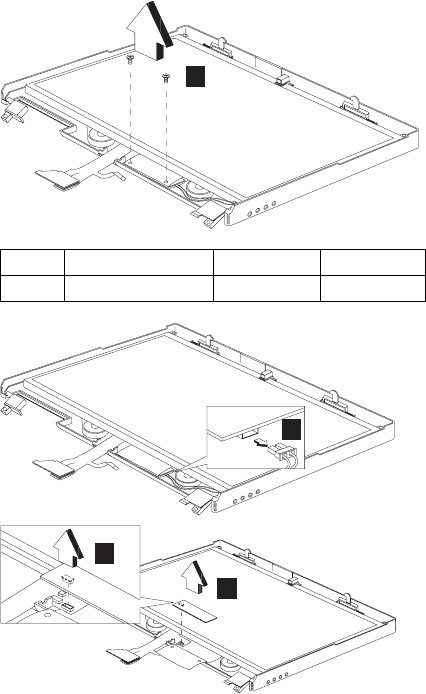
The LCD front cover has several latches.
Release these latches; then remove the LCD
cover. Be careful not to break these latches.
Gently push the two hooks outward to remove
the LCD front cover.
LCD inverter (15.0")
“Battery assembly” on page 114
“Launch key assembly” on page 120
“Left hinge cap” on page 122
“Keyboard” on page 123
“LCD assembly” on page 128
“LCD bezel assembly (15.0")” on page 138
1
2
3
4
Step Size (Quantity) Color Torque
1 M2 x 4L(2) Silver 1.6 kgf-cm
ThinkPad i Series 1400/1500 139
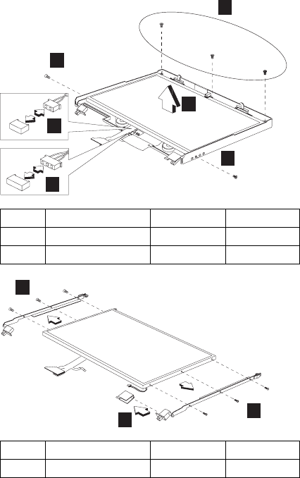
LCD bracket hinge assembly (15.0")
“Battery assembly” on page 114
“Launch key assembly” on page 120
“Left hinge cap” on page 122
“Keyboard” on page 123
“LCD assembly” on page 128
“LCD bezel assembly (15.0")” on page 138
“LCD inverter (15.0")” on page 139
1
2
2
3
4
5
6
6
7
LCD FPC assembly (15.0")
“Battery assembly” on page 114
“Launch key assembly” on page 120
“Left hinge cap” on page 122
“Keyboard” on page 123
“LCD assembly” on page 128
“LCD bezel assembly (15.0")” on page 138
Step Size (Quantity) Color Torque
1 M2.5 x 4L(3) Silver 1.6 kgf-cm
2 M2.5 x 6L(2) Black 3.2 kgf-cm
Step Size (Quantity) Color Torque
6 M2 x 3L(6) Silver 1.6 kgf-cm
140 ThinkPad i Series 1400/1500 HMM

“LCD inverter (15.0")” on page 139
“LCD bracket hinge assembly (15.0")” on page 140
1
2
Speaker assembly (15.0")
“Battery assembly” on page 114
“Launch key assembly” on page 120
“Left hinge cap” on page 122
“Keyboard” on page 123
“LCD assembly” on page 128
“LCD bezel assembly (15.0")” on page 138
“LCD inverter (15.0")” on page 139
“LCD bracket hinge assembly (15.0")” on page 140
1
1
2
1
Step Size (Quantity) Color Torque
1 M2 x 4L(3) Silver 1.6 kgf-cm
ThinkPad i Series 1400/1500 141

Parts list (ThinkPad i Series 1400/1500)
1
3
4
5
6
7
8
9
10
11
12
13
14
15
16
17
19
20
21 22
18
2
2-a
Note: The table below applies to the models in Group-C
I, II, and IV. (See the 2621 model table on page iii.)
No. Description FRU No.
1 Middle Cover & Launch Key ASM
14.1"
08K5865
142 ThinkPad i Series 1400/1500 HMM

No. Description FRU No.
Middle Cover & Launch Key ASM
14.1" (for Japan)
08K6054
Middle Cover & Launch Key ASM
12.1"/13.0"
08K5869
Middle Cover & Launch Key ASM
12.1"/13.0" (for Japan)
08K6055
2 Launch Key Board 08K3404
2-a CD Control Card 08K3183
3 Upper Heat sink 08K6695
4 Keyboard Bezel (IBM Logo, Lid SW,
Bracket Screw, PCMCIA Shutter)
08K6693
Keyboard Bezel (IBM Logo, Lid SW,
Bracket Screw, PCMCIA Shutter) (for
Japan)
08K6694
5 FDD w/ Bezel 05K9179
FDD w/ Bezel (w/ version: W) 05K9271
6 Fan ASM 08K5872
7 PCMCIA Holder 08K5873
8 Planar W/TV out (Celeron 500) 08K3114
Planar W/TV out (Coppermine 500) 08K3140
9 Bottom Case (w/TV out, w/w 2621) 08K6672
Bottom Case (w/TV out, for IIPC) 08K6673
Bottom Case (w/TV out, for Korea) 08K6674
Bottom Case (w/TV out, for 2651
worldwide)
08K6677
10 PCI Modem (Ambit) 10L1296
11 Modem Cover 08K5863
12 DIMM 32 MB 08K3408
DIMM 64 MB 08K3409
13 DIMM Cover 05K7073
14 Pointing Stick Caps 84G6536
15 24X CD-ROM Module (LG) 05K9277
24X CD-ROM Module (Teac) 05K9278
6X DVD-ROM Module (Toshiba) 05K9258
CD-ROM Chassis 08K5862
16 Lid S/W ASM 08K5871
17 CD Control Panel 08K5876
18 DC/DC Charger 08K3186
19 HDD Module ASM 6.0 GB (IBM) 05K9250
HDD Module ASM 9.0 GB (IBM) 05K9252
HDD Module ASM 12.0 GB (IBM) 05K9254
HDD Module ASM 18.0 GB (IBM) 27L3428
ThinkPad i Series 1400/1500 143

No. Description FRU No.
Kitting, HDD (HDD adapter, HDD
bracket (for 9.5mm HDD), HDD
bracket (for 12.5mm HDD), screw x
2))
08K5861
20 RTC Battery 11J8591
21 FPC Cable Group 27L0498
22 Battery Assy (LiIon) 9 Cells (Sanyo) 02K6632
Battery Assy (LiIon) 9 Cells
(Panasonic)
02K6647
Battery Assy (NiMH) 8 Cells
(Panasonic)
02K6630
Battery Assy (NiMH) 8 Cells (Sanyo) 02K6634
LEG (R/L) 08K5870
CD Control Card 08K3183
Miscellaneous Kit
Right Hinge Cap 12.1"/13.0"
Right Hinge Cap 14.1"
Rubber Foot * 4
PCMCIA Screw Cover * 4
Modem Cover Mylar Film
CD-Player Panel Mylar
Screw Cushion for LCD Bezel * 2
Screw Cap for LCD Bezel
Screw Mylar for Rear Cover * 4
Screw Mylar for 15.0" LCD Bezel
Side Screw Mylar for 15.0" LCD
Bezel * 2
12.1" LCD FPC Holder
RJ11 Cable
12.1" Top Bracket * 2
13.0" Top Bracket * 2
Battery Latch Knob
Keyboard Light Switch
Launch Key Panel
08K6604
144 ThinkPad i Series 1400/1500 HMM

No. Description FRU No.
Miscellaneous Kit (for Japan)
Right Hinge Cap 12.1"/13.0"
12.1" LCD FPC Holder
12.1" Top Bracket * 2
Right Hinge Cap 14.1"
Rubber Foot * 4
PCMCIA Screw Cover * 4
Modem Cover Mylar Film
CD-Player Panel Mylar
Screw Cushion for LCD Bezel * 2
(Japan model)
Screw Cap for LCD Bezel (Japan
model)
Screw Mylar for Rear Cover * 4
(Japan model)
Screw Mylar for 15.0" LCD Bezel
(Japan model)
Side Screw Mylar for 15.0" LCD
Bezel * 2 (Japan model)
RJ11 Cable
13.0" Top Bracket * 2
Battery Latch Knob
Keyboard Light Switch
Launch Key Panel
08K6592
Screw Kit
WAFER MYLO M2.5*3.5LB-ZN
Black
PAN NYLOK M2.5*6LB-ZN Black
PAN NYLOK M2.5*10LB-ZN
Black
MACH PH M2*8LB-ZN Pan
Black
MACH PAN M2*10L NI Silver
M2*4 WAFER NI Silver
M2*L3 Wafer Head Black
SCREW PAN M2*12L NI Silver
SCREW M3*5L 700 Wafer Silver
MACH PAN M2*6L NI Silver
08K6691
ThinkPad i Series 1400/1500 145
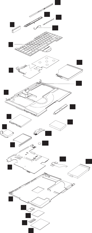
13
1
2
3
4
5
6
7
8
9
10
11
12
14
15 16
17
18
19
20
21
22
23
24 25
Note: The table below applies to the models in Group-C
III. (See the 2621 model table on page iii.)
146 ThinkPad i Series 1400/1500 HMM

No. Description FRU No.
1 15.0" Hinge Cap ASM 08K6380
15.0" Hinge Cap ASM (for Japan
model)
08K6391
2 Pointing Stick Caps 84G6536
3 Upper Heat sink 08K6695
4 Keyboard Bezel for 15.0" model
(PCMCIA Shutter, Rubber Foot, Stand
Foot, Battery Latch)
08K6277
Keyboard Bezel for 15.0" model
(PCMCIA Shutter, Rubber Foot, Stand
Foot, Battery Lactch) (for Japan
model)
08K6392
5 FDD w/ Bezel (w/version: W) 05K9271
6 Fan ASM 08K5872
7 PCMCIA Holder 08K5873
8 Planar W/TV out (Celeron 500) 08K3114
Planar W/TV out (Coppermine 500) 08K3140
9 Bottom Case (w/TV out, w/w 2621) 08K6672
Bottom Case (w/TV out, for IIPC) 08K6673
Bottom Case (w/TV out, for Korea) 08K6674
Bottom Case (w/TV out, for 2651
worldwide)
08K6677
10 PCI Modem (Ambit) 10L1296
PCI Modem (CIS) 10L1329
11 Modem Cover 08K5863
12 DIMM 32 MB 08K3408
DIMM 64 MB 08K3409
13 DIMM Cover 05K7073
14 LED Cover for 15.0" Model 08K6381
LED Cover for 15.0" Model (for Japan
model)
08K6410
15 Middle Cover for 15" 08K6280
Middle Cover for 15" (for Japan
model)
08K6393
16 LED Board for 15.0" Model 08K3116
17 Cable ASM of Microphone & Key-
board LED Light for 15.0" LCD
27L0540
Cable ASM of Microphone & Key-
board LED Light for 15.0" LCD (for
Japan model)
27L0541
18 24X CD-ROM Module (LG) 05K9277
24X CD-ROM Module (Teac) 05K9278
6X DVD-ROM Module (Toshiba) 05K9258
CD-ROM Chassis 08K5862
ThinkPad i Series 1400/1500 147

No. Description FRU No.
19 Lid S/W ASM 08K5871
20 CD Control Panel 08K5876
21 HDD Module ASM 6.0 GB (IBM) 05K9250
HDD Module ASM 9.0 GB (IBM) 05K9252
HDD Module ASM 12.0 GB (IBM) 05K9254
HDD Module ASM 18.0 GB (IBM) 27L3428
Kitting, HDD (HDD adapter, HDD
bracket (for 9.5mm HDD), HDD
bracket (for 12.5mm HDD), screw x
2))
08K5861
22 DC/DC Charger 08K3186
23 RTC Battery 11J8591
24 FPC Cable Group (CD-ROM FPC,
FDD FPC, Launch Key FPC,
CD-Player FPC)
27L0498
25 Battery Assy (LiIon) 9 Cells
(Panasonic)
02K6647
Battery Assy (NiMH) 8 Cells
(Panasonic)
02K6630
LEG (R/L) 08K5870
CD-ROM Chassis 08K5862
CD Control Card 08K3183
Miscellaneous Pack
Right Hinge Cap 12.1"/13.0"
Right Hinge Cap 14.1"
Rubber Foot * 4
PCMCIA Screw Cover * 4
Modem Cover Mylar Film
CD-Player Panel Mylar
Screw Cushion for LCD Bezel * 2
Screw Cap for LCD Bezel
Screw Mylar for Rear Cover * 4
Screw Mylar for 15.0" LCD Bezel
Side Screw Mylar for 15.0" LCD
Bezel * 2
12.1" LCD FPC Holder
RJ11 Cable
12.1" Top Bracket * 2
13.0" Top Bracket * 2
Battery Latch Knob
Keyboard Light Switch
Launch Key Panel
08K6604
148 ThinkPad i Series 1400/1500 HMM

LCD FRU
No. Description FRU No.
Miscellaneous Pack (for Japan)
Right Hinge Cap 12.1"/13.0"
12.1" LCD FPC Holder
12.1" Top Bracket * 2
Right Hinge Cap 14.1"
Rubber Foot * 4
PCMCIA Screw Cover * 4
Modem Cover Mylar Film
CD-Player Panel Mylar
Screw Cushion for LCD Bezel * 2
(Japan model)
Screw Cap for LCD Bezel (Japan
model)
Screw Mylar for Rear Cover * 4
(Japan model)
Screw Mylar for 15.0" LCD Bezel
(Japan model)
Side Screw Mylar for 15.0" LCD
Bezel * 2 (Japan model)
RJ11 Cable
13.0" Top Bracket * 2
Battery Latch Knob
Keyboard Light Switch
Launch Key Panel
08K6592
Screw Kit
WAFER MYLO M2.5*3.5LB-ZN
Black
PAN NYLOK M2.5*6LB-ZN Black
PAN NYLOK M2.5*10LB-ZN
Black
MACH PH M2*8LB-ZN Pan
Black
MACH PAN M2*10L NI Silver
M2*4 WAFER NI Silver
M2*L3 Wafer Head Black
SCREW PAN M2*12L NI Silver
SCREW M3*5L 700 Wafer Silver
MACH PAN M2*6L NI Silver
08K6691
ThinkPad i Series 1400/1500 149
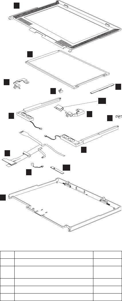
12.1-inch SVGA TFT
1
3
3
5
5
6
7
8
9
4
4
11
2
10
Note: The table below applies to the models in Group-C
I. (See the 2621 model table on page iii.)
No. Description FRU No.
1 LCD BEZEL ASM 12.1" 08K5849
LCD BEZEL ASM 12.1" (for Japan
model)
08K6388
2 12.1" TFT LCD 08K5844
3 LCD Bracket-Hinge 12.1" (R,L) 08K5850
4 Misc. 12.1" Top Bracket 08K5878
150 ThinkPad i Series 1400/1500 HMM

No. Description FRU No.
5 Speaker ASM (R,L) 08K6374
6 12.1" LCD FPC Assy. 27L0494
12.1" LCD FPC Assy. (for Japan
model)
27L0536
7 Cable Asm. of Microphone 27L0497
Cable Asm. of Microphone (for Japan
model)
27L0511
8 LCD Rear Cover ASM 12.1" TFT 08K5848
LCD Rear Cover ASM 12.1" TFT (for
Japan model0
08K6387
9 LCD Inverter 12.1" 10L1380
10 Misc. Right Hinge Cap 12.1"/13.0" (for
worldwide)
08K6604
Misc. Right Hinge Cap 12.1"/13.0" (for
Japan)
08K6592
11 LED BD 08K3182
LG/IBM Logo Kit 08K5860
ThinkPad i Series 1400/1500 151

13.0-inch SVGA HPA
1
2
3
4
54
2
3
10
6
7
8
9
11
Note: The table below applies to the models in Group-C
IV. (See the 2621 model table on page iii.)
No. Description FRU No.
1 LCD BEZEL ASM 13.0" 08K5853
13.0" HPA LCD Bezel (for Japan) 08K6051
2 Misc. 13.0" Top Bracket 08K5878
3 Speaker Module (R,L) 08K6374
4 LCD Bracket-Hinge 13.0" (R,L) 08K5854
5 13.0" HPA LCD 05K9596
6 13.0" LCD FPC Assy. 27L0495
13.0" LCD FPC Assy. (for Japan) 27L0510
152 ThinkPad i Series 1400/1500 HMM
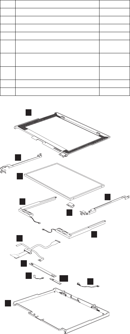
14.1–inch XGA TFT
1
9
3
4
4
5
6
77
8
10
2
2
No. Description FRU No.
7 LCD Inverter 13.0" 10L1380
8 Cable Asm. of Microphone 27L0497
Cable Asm. of Microphone (for Japan) 27L0511
9 LCD Rear Cover ASM 13.0" HPA 08K5852
LCD Rear Cover ASM 13.0" HPA
(with logo kit) (for Japan)
08K6048
10 Misc. Right Hinge Cap 12.1"/13.0" (for
worldwide)
08K6604
Misc. Right Hinge Cap 12.1"/13.0" (for
Japan)
08K6592
11 LED BD 08K3182
LG/IBM Logo Kit 08K5860
ThinkPad i Series 1400/1500 153

Note: The table below applies to the models in Group-C
II. (See the 2621 model table on page iii.)
No. Description FRU No.
1 LCD BEZEL ASM 14.1" 08K5856
LCD BEZEL ASM 14.1" (for Japan
model)
08K6050
LCD BEZEL ASM 14.1" (NEC LCD) 08K6276
LCD BEZEL ASM 14.1" (NEC LCD)
(for Japan model)
08K6386
2 LCD Bracket-Hinge 14.1" (R,L) 08K5857
LCD Bracket-Hinge 14.1" (R,L) (NEC
LCD)
08K6282
3 14.1" TFT LCD (LG) 05K9591
14.1" TFT LCD (Samsung) 05K9498
14.1" TFT LCD (NEC) 05K9602
4 Speaker Module (R,L) 08K6374
5 14.1" LCD FPC Assy. 27L0496
14.1" LCD FPC Assy. (for Japan) 27L0509
14.1" LCD FPC Assy. (NEC LCD) 27L0523
14.1" LCD FPC Assy. (NEC LCD) (for
Japan model)
27L0535
6 LCD Inverter 14.1" 10L1442
7 Cable ASM of Microphone & Key-
board LED Light
27L0497
Cable ASM of Microphone & Key-
board LED Light (for Japan)
27L0511
Cable ASM of Microphone & Key-
board LED Light (NEC LCD)
27L0566
8 LCD Rear Cover ASM 14.1" TFT 08K5855
LCD Rear Cover ASM 14.1" TFT (for
Japan)
08K6047
LCD Rear Cover ASM 14.1" TFT
(NEC LCD)
08K6275
LCD Rear Cover ASM 14.1" TFT
(NEC LCD) (for Japan model)
08K6385
9 Misc. Right Hinge Cap 14.1" 08K6604
Misc. Right Hinge Cap 14.1" 08K6592
10 LED BD 08K3182
LG/IBM Logo Kit 08K5860
154 ThinkPad i Series 1400/1500 HMM
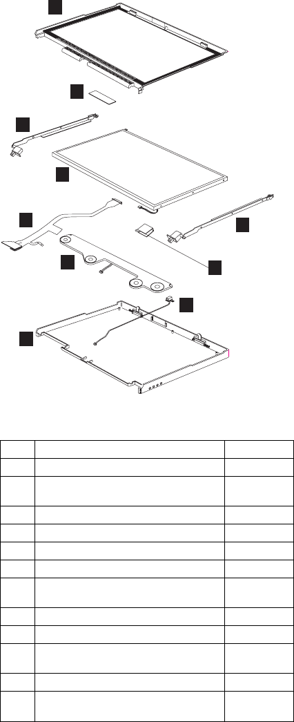
15.0–inch XGA TFT
1
2
3
4
3
5
6
7
8
9
Note: The table below applies to the models in Group-C
III. (See the 2621 model table on page iii.)
No. Description FRU No.
1 LCD Bezel ASM 15.0" 08K6279
15.0" TFT LCD Bezel (for Japan
model)
08K6390
2 LCD Inverter 15.0" 08K3113
3 15.0" Hinge ASM 08K6281
4 15.0" TFT LCD 05K9604
5 15.0" TFT LCD FPC ASM 27L0522
15.0" TFT LCD FPC ASM (for Japan
model)
27L0537
6 Speaker Module for 15.0" LCD 08K6382
7 LCD Rear Cover ASM 15.0" TFT 08K6278
LCD Rear Cover ASM 15.0" TFT (for
Japan model)
08K6389
8 15.0" Hinge Cap ASM 08K6380
9 Cable ASM of Microphone & Key-
board LED Light for 15.0" LCD
27L0540
ThinkPad i Series 1400/1500 155

Keyboard
No. Description FRU No.
Cable ASM of Microphone & Key-
board LED Light for 15.0" LCD (for
Japan model)
27L0541
LG/IBM Logo Kit 08K5860
Description Vendor FRU
No.
Keyboard US API 02K5077
Keyboard Chinese API 02K5078
Keyboard Korean API 02K5079
Keyboard Swiss API 02K5080
Keyboard Canadian French API 02K5081
Keyboard Belgian API 02K5082
Keyboard Danish API 02K5083
Keyboard Italy API 02K5084
Keyboard French API 02K5085
Keyboard German API 02K5086
Keyboard Norwegian API 02K5087
Keyboard Portuguese API 02K5088
Keyboard Spanish API 02K5089
Keyboard Dutch API 02K5090
Keyboard Swedish/Finnish API 02K5091
Keyboard Japan API 02K5092
Keyboard UK English API 02K5093
Keyboard La Spanish API 02K5095
Keyboard US ENGLISH ALPS 02K5060
Keyboard KOREAN ALPS 02K5061
Keyboard UK ENGLISH ALPS 02K5062
Keyboard CANADIAN FRENCH ALPS 02K5063
Keyboard GERMANY ALPS 02K5064
Keyboard FRENCH ALPS 02K5065
Keyboard DUTCH ALPS 02K5066
Keyboard SWEDISH/FINNISH ALPS 02K5067
Keyboard NORWEGIAN ALPS 02K5068
Keyboard DANISH ALPS 02K5069
Keyboard JAPANESE ALPS 02K5070
Keyboard TRAD. CHINESE ALPS 02K5071
Keyboard ITALIAN ALPS 02K5072
Keyboard SPANISH ALPS 02K5073
Keyboard SWISS ALPS 02K5074
156 ThinkPad i Series 1400/1500 HMM

Common parts list
Tools
Miscellaneous
Modem cable
AC adapter
Description Vendor FRU
No.
Keyboard PORTUGUESE ALPS 02K5075
Keyboard BELGIAN ALPS 02K5076
Keyboard LA SPANISH ALPS 02K5094
Description FRU No.
Tri-Connector Wrap Plug 72X8546
PC Test Card 35G4703
Audio Wrap Cable 66G5180
Screwdriver Kit 95F3598
USB Parallel Test Cable 05K2580
Torque Screwdriver 05K4695
5mm Socket Wrench 05K4694
Screwdriver 05K4693
Description FRU No.
Headset (for Japan only) 02K4941
Description FRU No.
Modem cable (German) 27L0441
Modem cable (UK, NZ) 27L0442
Modem cable (France) 27L0443
Modem cable (Holland) 27L0444
Modem cable (Sweden) 27L0445
Modem cable (Norway/Fin) 27L0446
Modem cable (Danish) 27L0447
Modem cable (Italy) 27L0448
Modem cable (Austria) 27L0449
Modem cable (Spain) 27L0450
Modem cable (Belgium) 27L0451
Modem cable (Switzerland) 27L0462
Modem cable (Portugal) 27L0447
Modem cable (US/C, JPN, Twn, APN, LA,
Brz)
27L0465
Modem cable (Australia) 27L0467
ThinkPad i Series 1400/1500 157

Power cords:
IBM power cords for a specific country
are usually available only in that country.
For 2–pin power cords:
For 3–pin power cords:
Note: The grounded adapter is required for full MPRII
compliance. If a 3–pin power cord came with your
computer, see “Safety Information” on page 11.
Description FRU No.
AC Adapter 2-pin (Delta) 02K6548
AC Adapter 2-pin (Sanken) 02K6554
AC Adapter 3-pin (Delta) 02K6550
AC Adapter 3-pin (Sanken) 02K6555
IBM power
cord part
number Used in these countries or regions
13H5273 Japan
IBM power
cord part
number Used in these countries or regions
02K0539 Simple China
36L8867 Argentina
76H3514 Australia, New Zealand, Papua New Guinea,
Paraguay, Uruguay
76H3516 Aruba, Bahamas, Barbados, Bermuda,
Bolivia, Brazil, Canada, Cayman Islands,
Colombia, Costa Rica, Curacao, Dominican
Republic, Ecuador, El Salvador, Guatemala,
Guyana, Haiti, Honduras, Jamaica, Korea
(South), Liberia, Mexico, Netherlands
Antilles, Nicaragua, Panama, Peru,
Philippines, Saudi Arabia, Suriname, Taiwan,
Thailand, Trinidad (West Indies), United
States of America, Venezuela
76H3518 Austria, Belgium, Bosnia-Herzogovina,
Bulgaria, Croatia, Czech Republic, Egypt,
Finland, France, Germany, Greece, Hungary,
Iceland, Indonesia, Macao, Macedonia,
Netherlands, Norway, Poland, Portugal,
Romania, Slovakia, Slovenia, Spain,
Sweden, Turkey, Yugoslavia
76H3520 Denmark
Note: Due to consumer product, 2621 sup-
plies power cord 76H3518 to
Denmark.
76H3522 Bangladesh, Myanmar, Pakistan, South
Africa, Sri Lanka
158 ThinkPad i Series 1400/1500 HMM

IBM power
cord part
number Used in these countries or regions
76H3524 Abu Dhabi, Albania, Antigua, Bahrain,
Brunei, Dubai, Fiji, Hong Kong, India,
Ireland, Kenya, Kuwait, Malaysia, Nigeria,
Oman, Qatar, Singapore, United Kingdom
76H3528 Liechtenstein, Switzerland
76H3530 Chile, Ethiopia, Italy, Libya
76H3532 Israel
76H3535 Korea
ThinkPad i Series 1400/1500 159

Notices
References in this publication to IBM products, programs,
or services do not imply that IBM intends to make these
available in all countries in which IBM operates. Any refer-
ence to an IBM product, program, or service is not
intended to state or imply that only IBM product, program,
or service may be used. Subject to IBM's valid intellectual
property or other legally protectable rights, any functionally
equivalent product program, or service may be used
instead of the IBM product, program, or service. The evalu-
ation and verification of operation in conjunction with other
products, except those expressly designated by IBM, are
the responsibility of the user.
IBM may have patents or pending patent applications cov-
ering subject matter in this document. The furnishing of
this document does not give you any license to these
patents. You can send license inquiries, in writing, to:
IBM Director of Licensing
IBM Corporation
500 Columbus Avenue
Thornwood, NY 10594
U.S.A.
160 ThinkPad i Series 1400/1500 HMM

Trademarks
The following terms are trademarks or service marks of
IBM Corporation in the United States and other countries:
IBM
PS/2
ThinkPad
TrackPoint
TrackPoint IV
The following terms are trademarks or service marks of
other companies as follows:
AMD-K6-2 Advanced Micro Devices, Inc.
AMD Advanced Micro Devices, Inc.
Intel Intel Corporation
Celeron Intel Corporation
Mylar E.I. Du Pont de Nemours and Company
PC-Doctor Watergate Software, Inc.
PCMCIA Personal Computer Memory Card Interface
Association
Pentium Intel Corporation
ThinkPad i Series 1400/1500 161

IBM
Part Number: 09N8606
Printed in U.S.A.
Sð9N-1ð84-ð1
