Icom Iu82 Users Manual IC V82_U82
ICOM--IC-V82-U82-manual ICOM--IC-V82-U82-manual
2015-02-05
: Icom Icom-Iu82-Users-Manual-357627 icom-iu82-users-manual-357627 icom pdf
Open the PDF directly: View PDF ![]() .
.
Page Count: 96
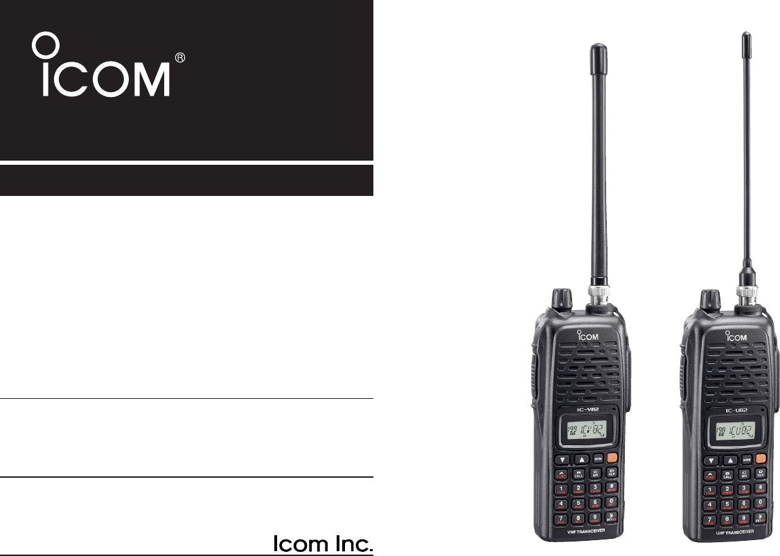
INSTRUCTION MANUAL
iV82
VHF TRANSCEIVER
iU82
UHF TRANSCEIVER
This device complies with Part 15 of the FCC rules. Operation is sub-
ject to the following two conditions: (1) This device may not cause
harmful interference, and (2) this device must accept any interference
received, including interference that may cause undesired operation.
IC-U82IC-V82
FOREWORD
Thank you for purchasing this Icom product. The IC-V82/U82
VHF
/
UHF TRANSCEIVERS
are designed and built with Icom’s su-
perior technology and craftsmanship. With proper care, this
product should provide you with years of trouble-free opera-
tion.
We want to take a couple of moments of your time to thank
you for making your IC-V82/U82 your radio of choice, and
hope you agree with Icom’s philosophy of “technology first.”
Many hours of research and development went into the de-
sign of your IC-V82/U82.
DD
FEATURES
❍7W*— high transmit output power
(*IC-V82, 5 W for IC-U82)
❍CTCSS and DTCS encoder/decoder stan-
dard
❍Optional digital modulator/demodulator
❍Optional DTMF decoder
IMPORTANT
READ ALL INSTRUCTIONS carefully and completely
before using the transceiver.
SAVE THIS INSTRUCTION MANUAL— This in-
struction manual contains important operating instructions for
the IC-V82/U82.
EXPLICIT DEFINITIONS
WORD DEFINITION
RWARNING!
CAUTION
NOTE
Personal injury, fire hazard or electric shock
may occur.
Equipment damage may occur.
Recommended for optimum use. No risk of
personal injury, fire or electric shock.
Icom, Icom Inc. and the logo are registered trademarks of Icom
Incorporated (Japan) in the United States, the United Kingdom, Ger-
many, France, Spain, Russia and/or other countries.
i

ii
RWARNING! NEVER hold the transceiver so that the
antenna is very close to, or touching exposed parts of the
body, especially the face or eyes, while transmitting. The
transceiver will perform best if the microphone is 5 to 10 cm
(2 to 4 inches) away from the lips and the transceiver is verti-
cal.
RWARNING! NEVER operate the transceiver with a
headset or other audio accessories at high volume levels.
Hearing experts advise against continuous high volume op-
eration. If you experience a ringing in your ears, reduce the
volume or discontinue use.
NEVER connect the transceiver to a power source that is
DC fused at more than 5 A. Accidental reverse connection will
be protected by this fuse, but higher fuse values will not give
any protection against such accidents and the transceiver will
be ruined.
NEVER attempt to charge alkaline or dry cell batteries. Be
aware that external DC power connections will charge batter-
ies inside the battery case. This will damage not only the bat-
tery case but also the transceiver.
DO NOT push the PTT when not actually desiring to trans-
mit.
Place the unit in a secure place to avoid inadvertent use by
children.
DO NOT operate the transceiver near unshielded electrical
blasting caps or in an explosive atmosphere.
AVOID using or placing the transceiver in direct sunlight or
in areas with temperatures below –10°C (+14˚F) or above
+60°C (+140˚F).
The use of non-Icom battery packs/chargers may impair
transceiver performance and invalidate the warranty.
Even when the transceiver power is OFF, a slight current still
flows in the circuits. Remove the battery pack or case from
the transceiver when not using it for a long time. Otherwise,
the battery pack or installed rechargeable batteries (Ni-Cd:
BP-222N, BP-209N, Ni-MH: BP-210N, Li-Ion: BP-211N) will
become exhausted.
For USA only:
Caution: Changes or modifications to this transceiver, not ex-
pressly approved by Icom Inc., could void your authority to
operate this transceiver under FCC regulations.
PRECAUTIONS
iii
SUPPLIED ACCESSORIES
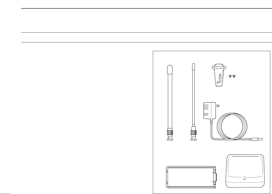
■Supplied Accessories
qAntenna* . . . . . . . . . . . . . . . . . . . . . . . . . . . . . . . . . . . . . 1
wBelt clip (with screws) . . . . . . . . . . . . . . . . . . . . . . . . . . . 1
eAC Adapter*. . . . . . . . . . . . . . . . . . . . . . . . . . . . . . . . . . . 1
rBattery pack*/Battery case* . . . . . . . . . . . . . . . . . . . . . . 1
tBattery charger*. . . . . . . . . . . . . . . . . . . . . . . . . . . . . 1 set
*Not supplied with some versions.
e
qw
r
t
for IC-V82 for IC-U82

iv
CAUTION
To ensure that your exposure to RF electromagnetic en-
ergy is within the FCC allowable limits, always adhere to
the following guidelines:
• DO NOT operate the radio without a proper antenna at-
tached, as this may damage the radio and may also cause
you to exceed FCC RF exposure limits. A proper antenna is
the antenna supplied with this radio by the manufacturer or
an antenna specifically authorized by the manufacturer for
use with this radio.
• DO NOT transmit for more than 50% of total radio use time
(“50% duty cycle”). Transmitting more than 50% of the time
can cause FCC RF exposure compliance requirements to
be exceeded. The radio is transmitting when the “Tx indica-
tor” appears. You can cause the radio to transmit by press-
ing the “PTT” switch.
• ALWAYS use Icom authorized accessories (antennas, bat-
teries, belt clips, speaker/mics, etc.). Use of unauthorized
accessories can cause the FCC RF exposure compliance
requirements to be exceeded.
• ALWAYS keep the antenna at least 2.5 cm (1 inch) away
from the body when transmitting, and only use the Icom
belt-clips which are listed in this manual when attaching the
radio to your belt, etc. To provide the recipients of your
transmission the best sound quality, hold the transceiver at
least 5 cm (2 inches) from your mouth, and turned slightly
to one side.
The information listed above provides the user with the infor-
mation needed to make him or her aware of RF exposure,
and what to do to assure that this radio operates within the
FCC RF exposure limits of this radio.
Electromagnetic Interference/Compatibility
During transmissions, your Icom radio generates RF energy
that can possibly cause interference with other devices or
systems. To avoid such interference, turn off the radio in
areas where signs are posted to do so. DO NOT operate the
transmitter in areas that are sensitive to electromagnetic ra-
diation such as hospitals, aircraft, and blasting sites.
SAFETY TRAINING INFORMATION

v
TABLE OF CONTENTS
FOREWORD .................................................................................... i
IMPORTANT..................................................................................... i
EXPLICIT DEFINITIONS.................................................................. i
PRECAUTIONS............................................................................... ii
SUPPLIED ACCESSORIES ........................................................... iii
SAFETY TRAINING INFORMATION.............................................. iv
TABLE OF CONTENTS .............................................................. v–vi
QUICK REFERENCE GUIDE ...................................................... I–V
■Preparation............................................................................... I
■Your first contact..................................................................... III
■Repeater operation ................................................................ IV
■Programming memory channels............................................. V
1 ACCESSORIES...................................................................... 1–2
■Accessory attachment............................................................. 1
2PANEL DESCRIPTION .......................................................... 3–7
■Switches, controls, keys and connectors ................................ 3
■Function display ...................................................................... 6
3BATTERY PACKS................................................................ 8–12
■Battery pack replacement ....................................................... 8
■Battery caution ........................................................................ 9
■Charging NOTE ...................................................................... 9
■Battery charging .................................................................... 10
■Battery case (optional for some versions) ............................ 12
4BASIC OPERATION........................................................... 13–16
■Power ON.............................................................................. 13
■VFO mode selection.............................................................. 13
■Setting a frequency ............................................................... 13
■Setting audio/squelch level ................................................... 15
■Receive and transmit ............................................................ 15
■Display type........................................................................... 16
■Key lock function ................................................................... 16
5REPEATER OPERATION .................................................. 17–20
■General ................................................................................. 17
■Reversed duplex mode ......................................................... 17
■Offset frequency.................................................................... 18
■Subaudible tones .................................................................. 18
■Repeater lockout ................................................................... 19
■Auto repeater function (USA/CSA versions only).................. 20
6MEMORY/CALL OPERATION ........................................... 21–26
■General description ............................................................... 21
■Selecting a memory channel................................................. 21
■Selecting the call channel ..................................................... 21
■Programming the memory/call channels............................... 22
■Channel name programming................................................. 23
■Memory transfers .................................................................. 23
■Memory bank selection ......................................................... 25
■Memory bank setting............................................................. 25
■Transferring bank contents.................................................... 26
7DTMF MEMORY................................................................. 27–29
■Programming a DTMF code sequence ................................. 27
■Transmitting a DTMF code sequence ................................... 28
■DTMF transmission rate........................................................ 29

vi
8SCAN OPERATION............................................................ 30–33
■Scan types ............................................................................ 30
■Programmed scan................................................................. 30
■Memory scan..........................................................................31
■Skip channels........................................................................ 32
■Priority watch......................................................................... 32
■Scan resume condition.......................................................... 33
9SUBAUDIBLE TONES....................................................... 34–37
■Tone squelch ......................................................................... 34
■Pocket beep operation .......................................................... 36
■Tone scan.............................................................................. 37
10PAGER/CODE SQUELCH (Requires Optional UT-108) .. 38–41
■Pager function ....................................................................... 38
■Code programming ............................................................... 38
■Pager operation..................................................................... 40
■Code squelch ........................................................................ 41
11 DIGITAL MODE OPERATION
(Requires Optional UT-118)...............................................42–58
■Digital mode operation .......................................................... 42
■Call sign programming .......................................................... 42
■Digital voice mode operation ................................................. 45
■When receiving a digital call ................................................. 46
■Break-in communication ....................................................... 47
■EMR communication ............................................................. 48
■Pocket beep operation .......................................................... 48
■Digital squelch functions ....................................................... 49
■Digital monitor ....................................................................... 49
■Low-speed data communication ........................................... 50
■About D-STAR system .......................................................... 51
■Repeater call sign programming ........................................... 52
■Setting other items ................................................................ 53
■GPS operation ...................................................................... 57
12OTHER FUNCTIONS ......................................................... 59–70
■SET MODE............................................................................ 59
■INITIAL SET MODE .............................................................. 63
■Weather channel operation
(IC-V82 [USA]/[CSA] versions only)...................................... 69
■CPU reset.............................................................................. 70
■Partial reset ........................................................................... 70
13CLONING ........................................................................... 71–72
■Transceiver-to-transceiver cloning ........................................ 71
■Cloning using a PC ............................................................... 72
14OPTIONAL UNITS.............................................................. 73–74
■Optional UT-108/118 installation ........................................... 73
■Optional MB-86 installation ................................................... 73
15SPECIFICATIONS.............................................................. 75–76
■IC-V82 ................................................................................... 75
■IC-U82................................................................................... 76
16OPTIONS............................................................................ 77–78
17MODE ARRANGEMENT.................................................... 79–81
18CE....................................................................................... 82–83
1
2
3
4
5
6
7
8
9
10
11
12
13
14
15
16
17
18
I
QUICK REFERENCE GUIDE
■Preparation
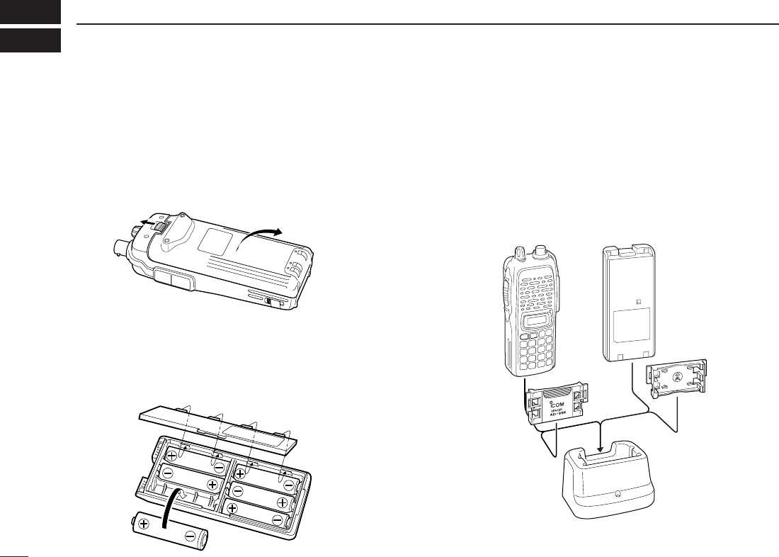
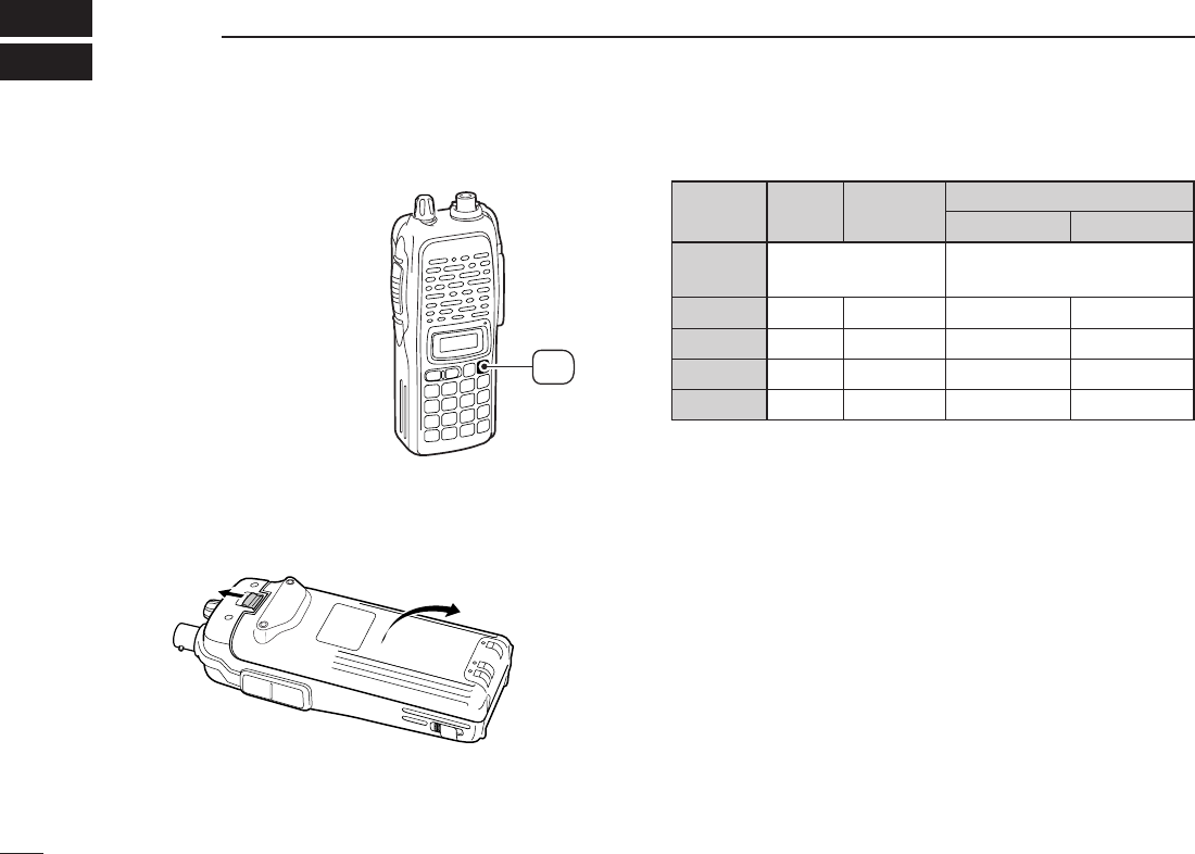
DBattery pack replacement
Before replacing the battery pack, push and hold [PWR] for 1
sec. to turn the power OFF.
•Slide the battery release forward, then pull the battery pack upward
with the transceiver facing away from you.
DBattery case— optional for some versions
When using a BP-208N
BATTERY CASE
attached to the trans-
ceiver, install 6 AA (LR6) size alkaline batteries as illustrated
below.
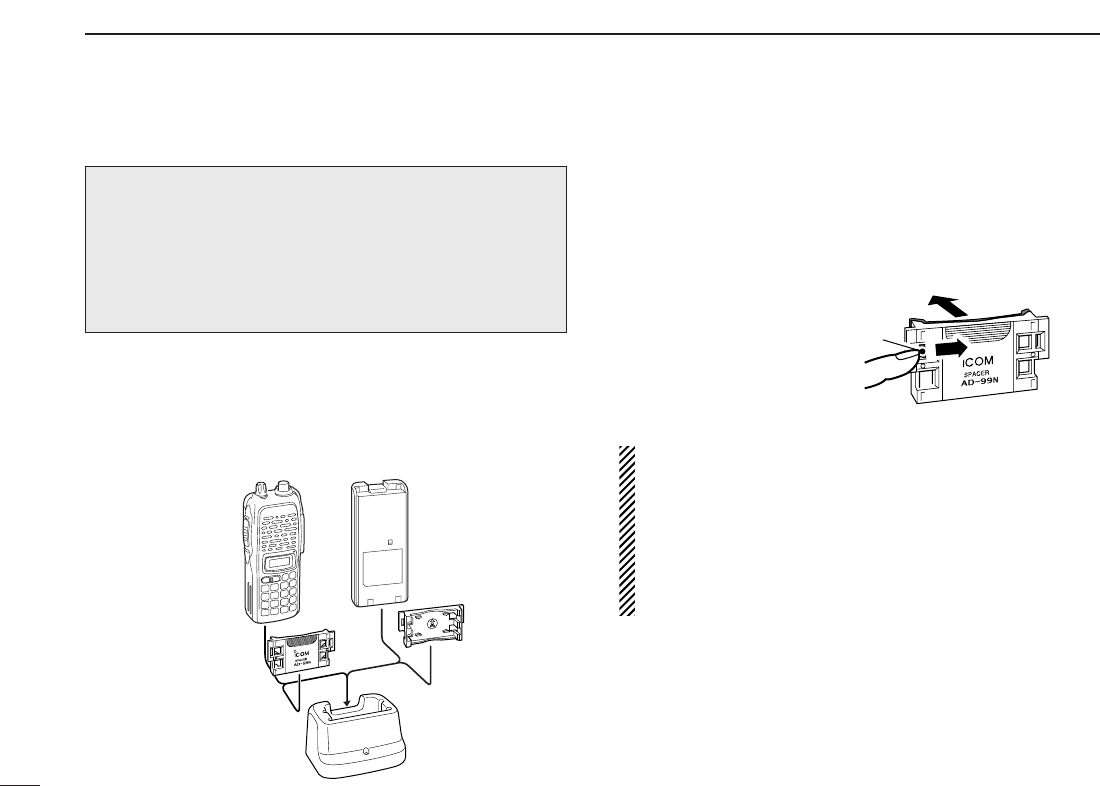
DCharging with the BC-144N/146
The optional BC-144N provides rapid charging, and the BC-
146 provides regular charging of an optional battery pack with
or without a transceiver attached. The following is addition-
ally required:
• An optional AC adapter. (An AD-99N is supplied with BC-144N or
BC-146.)
Check orientation
for correct charg-
ing. (Insert together
with AD-99N.)
Turn power OFF.
BC-144N/146
+AD-99N
II
QUICK REFERENCE GUIDE
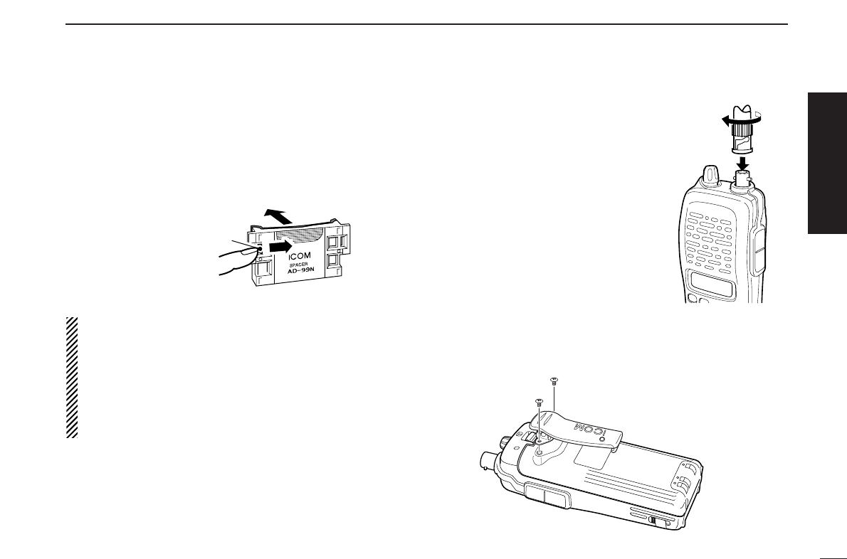
DAbout AD-99N
The adapter (Spacer A) only is required for the IC-V82/U82
series. When removing the spacer (Spacer B/C),
push the
latch carefully with your finger to remove the spacer (Spacer
B/C) from the adapter (Spacer A).
RCAUTION!
• DO NOT push or force the latch with a screw driver, etc.,
to remove it.
• DO NOT bend the latch when the adapter and spacer are
not joined together. This will cause weakening of the latch
plastic.
• Both cases may break the latch and it may not be able to
be reattached.
DAntenna
Attach the antenna to the transceiver
as illustrated at right.
DBelt clip
Conveniently attaches to your belt.
Attach the belt clip with the supplied screws using a phillips
screwdriver.
To attach the belt clip
Push the latch
carefully.
Remove the spacer (Spacer B/C)
from the adapter.
Quick reference guide
III
QUICK REFERENCE GUIDE
■Your first contact
Now that you have your IC-V82/U82 ready, you are excited
to get on the air. We would like to walk you through a few
basic operational steps to make your first “On The Air” use an
enjoyable experience.
DAbout default setting
The [VOL] control function can be exchanged with [YY]/[ZZ]
keys function in
INITIAL SET MODE
. However, in this QUICK
REFERENCE, the factory default setting ([VOL] controls
audio output level) is used to simplify instructions.
DBasic operation
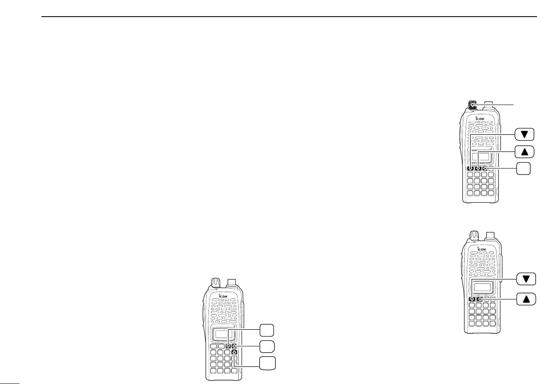
1. Turning ON the transceiver
Although you have purchased a brand new transceiver, some
settings may be changed from the factory defaults because
of the Quality Control process. Resetting the CPU is neces-
sary to start from factory default.
➥While pushing [MONI] and
[D•
CLR
], push and hold [PWR] for
1 sec. to reset the CPU and turn
power ON.
2. Adjusting audio output level
➥Rotate [VOL] to set the desired
audio level.
3. Adjusting the squelch level
➥While pushing and holding
[MONI], push [YY]or [ZZ]to set the
squelch level.
4. Tune the desired frequency
The up/down keys, [YY]/[ZZ], will
allow you to tune to the frequency
that you want to operate on. Page 14
will instruct you on how to adjust the
tuning step size.
➥Push [YY]or [ZZ]to adjust the fre-
quency.
PWR
MONI
CLR
D
MONI
[VOL]
IV
QUICK REFERENCE GUIDE
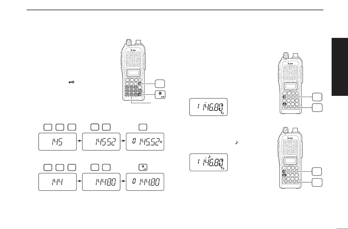
Direct frequency input from the key-
pad is also available.
➥To enter the desired frequency,
enter 6 digits starting from the
100 MHz digit.
•Entering three* to five digits then
pushing [✱•
ENT
]will also set the
frequency. (*Some versions only re-
quires two digits.)
•When a digit is mistakenly input,
push [D.
CLR
]to abort input.
5. Transmit and receive
➥Push and hold [PTT] to transmit, then speak into the mi-
crophone; release to receive.
■Repeater operation
1. Setting duplex
➥Push [A•
FUNC
], then [4•
DUP
]sev-
eral times to select minus duplex
or plus duplex.
•The USA/CSA versions have an auto
repeater function, therefore, setting
duplex is not required.
2. Repeater tone
➥Push [A•
FUNC
], then [1•
TONE
]
several times until “ ” appears, if
required.
TONE
1
FUNC
A
DUP
4
FUNC
A
• Example 1— when entering 145.525 MHz
Push
• Example 2— when entering 144.800 MHz
P.B EEP
2
DUP
4
DUP
TONE
4
1
SCAN
5
SCAN
5
SCAN
5
Push
DUP
TONE
4
1
OPT
0
SET
8
ENT
CLR
D
Keypad
ENT
Quick reference guide
V
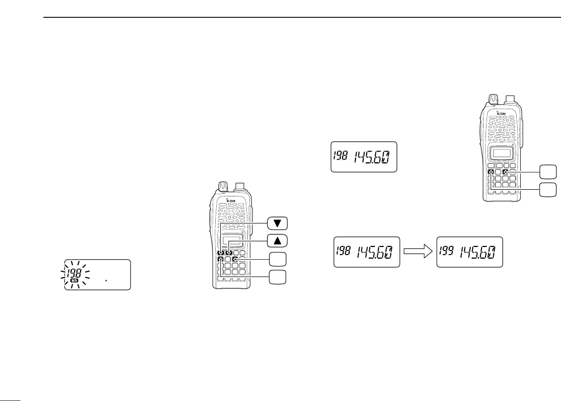
QUICK REFERENCE GUIDE
The IC-V82/U82 has a total of 207 memory channels (includ-
ing 6 scan edges and 1 call channel) for storing often used
operating frequency, repeater settings, etc.
1. Setting frequency
In VFO mode, set the desired operating frequency with other
desired settings, such as repeater and subaudible tone.
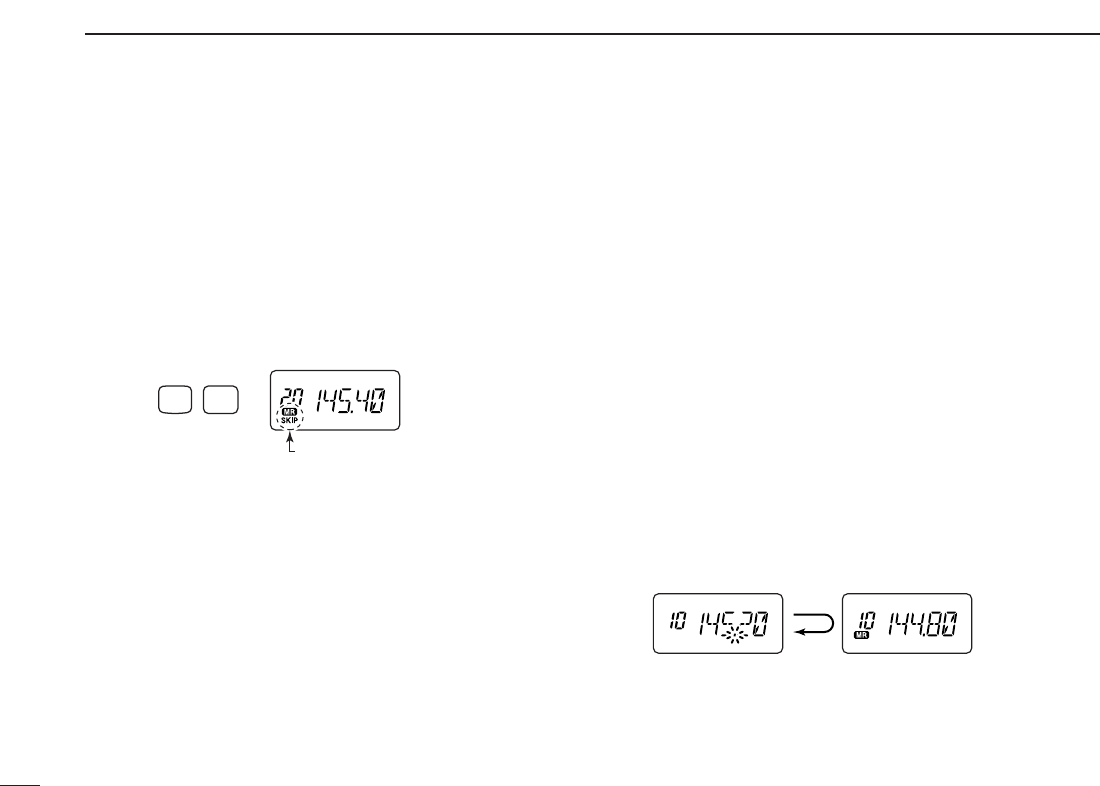
2. Selecting a memory channel
➥Push [A•
FUNC
]and [C•
MR
]then
push [YY] or [ZZ]several times to
select the desired memory chan-
nel.
•“
X” indicator and memory channel
number blink.
3. Writing a memory channel
➥Push [A•
FUNC
], then push and
hold [C•
MR
]for 1 sec. to program.
•3 beeps sound.
•Continue to push and hold [C•
MR
]for 1 sec. after 3 beeps are
emitted, to increment the displayed memory channel number.
MR
C
FUNC
A
MR
C
FUNC
A
■Programming memory channels
1
1
ACCESSORIES
1
■Accessory attachment
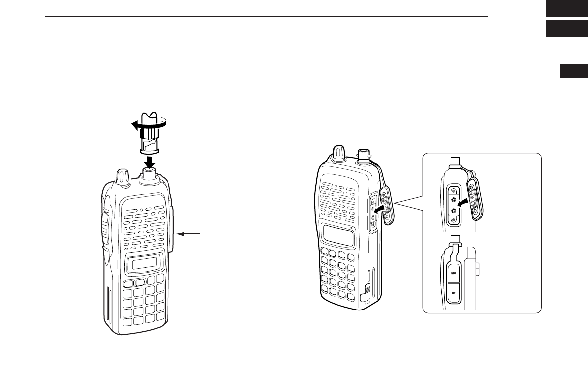
DAntenna
Attach the antenna to the transceiver as illustrated below. Keep the [SP/MIC] cap (SP/MIC jack cover) attached when
jacks are not in use to keep the contacts clean.
Attach the
[SP/MIC] cap.
[SP/MIC] cap

2
1ACCESSORIES
DBelt clip
Conveniently attaches to your belt.
Attach the belt clip with the supplied screws using a phillips
screwdriver.
To attach the belt clip
DHandstrap (Not supplied)
Slide the hand strap through the loop on the top of the rear
panel as illustrated below. Facilitates carrying.
3
2
PANEL DESCRIPTION
1
2
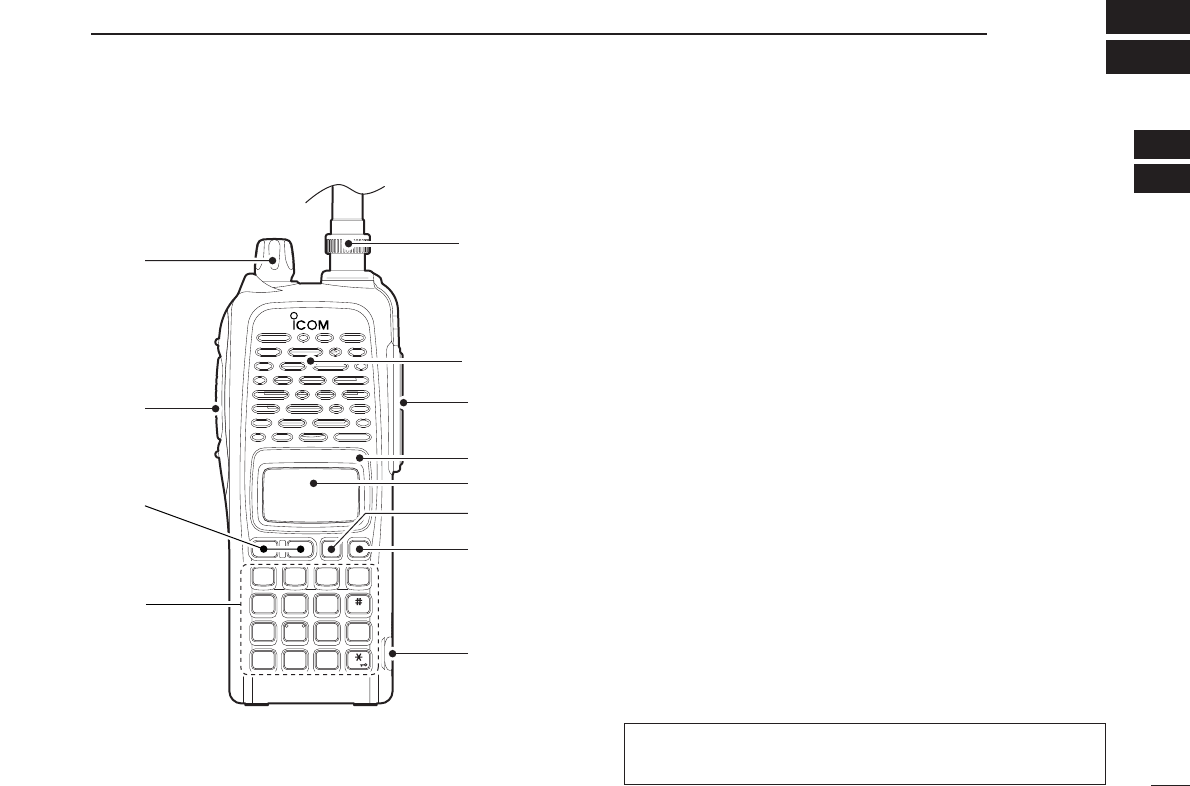
qCONTROL DIAL [VOL]
*Rotate to adjust the volume level.
wPTT SWITCH [PTT]
Push and hold to transmit; release to receive.
eUP/DOWN KEYS [YY]/[ZZ]
*Selects the operating frequency.
rKEYPAD (pgs. 4, 5)
Used to enter operating frequency, the DTMF codes, etc.
tANTENNA CONNECTOR (p. 1)
Connects the supplied antenna.
y[SP]/[MIC] JACK
Connect an optional speaker-microphone or headset, if de-
sired. The internal microphone and speaker will not func-
tion when a connector is inserted.
uFUNCTION DISPLAY (pgs. 6, 7)
iSQUELCH/MONITOR SWITCH [MONI]
Push and hold to force the squelch open, and set the
squelch level, if required.
oPOWER SWITCH [PWR]
Push and hold for 1 sec. to turn the power ON and OFF.
MONI
CALL
DUP SCAN
PRIO
ENT
SET
H/M/L
OPTSKIP
BANK
TONE
T.SCANP.B E EP
MR CLRFUNC
PWR
987
4
123
AB DC
560
q
w
t
Microphone
Speaker
y
!0
o
u
i
e
r
■Switches, controls, keys and connectors
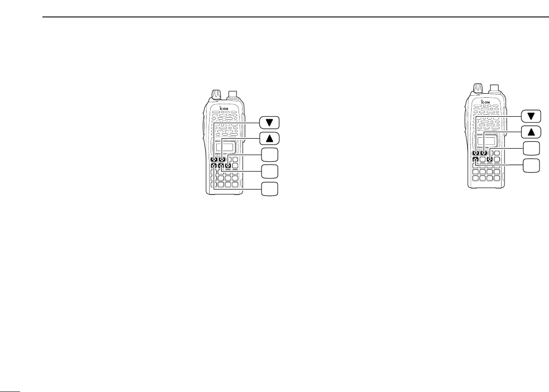
*The assigned function for [VOL] and [YY]/[ZZ]can be ex-
changed in
INITIAL SET MODE
(pgs. 14, 65).
4
2PANEL DESCRIPTION
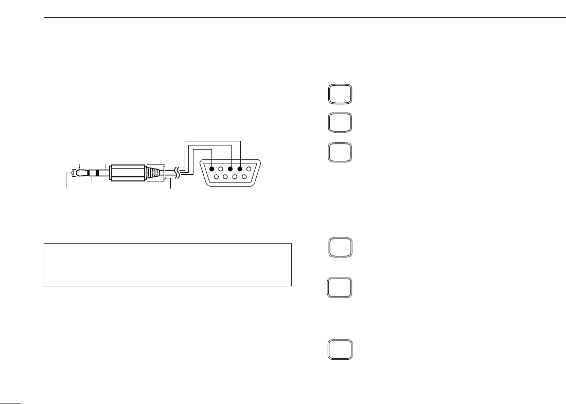
!0 [DATA] JACK
Connect to a PC or GPS receiver via the RS-232 cable (D-
sub 9 pin) for data communication in the RS-232 format.
DKeypad
[A•
FUNC
]
Access to secondary function.
[B•
CALL
]
Selects the call channel. (p. 21)
[C•
MR
]
➥Selects a memory mode. (p. 21)
➥After pushing [A•
FUNC
], enter into memory pro-
gramming/editing mode. (pgs. 22–24)
➥After pushing [A•
FUNC
], programs/transfers
VFO/memory or call channel contents into
memory channel/VFO when pushed and held
for 1 sec. (pgs. 22–24)
[D•
CLR
]
Selects VFO mode, aborts direct frequency input,
or cancels scanning, etc. (pgs. 13, 30)
[1•
TONE
]
➥Input digit “1” during frequency input, memory
channel selection, etc. (pgs. 13, 21)
➥After pushing [A•
FUNC
], selects the subaudible
tone function. (pgs. 17, 34)
[2•
P
.
BEEP
]
➥Input digit “2” during frequency input, memory
channel selection, etc. (pgs. 13, 21)
➥After pushing [A•
FUNC
], turns the pocket beep
function ON and OFF. (p. 36)
P.BEEP
2
TONE
1
CLR
D
MR
C
CALL
B
FUNC
A
Pin 2 (RxD),
Pin 3 (TxD),
Pin 5 (GND)
to [DATA] jack
TxD
2.5(d) mm Less than
10(d) mm
GND
RxD
1
5
69
RS-232
(DB-9 female)
When making the connection between your transceiver and
PC or other device, ensure that the correct connections are
made otherwise data communications may fail.

5
2
PANEL DESCRIPTION
2
[3•
T
.
SCAN
]
➥Input digit “3” during frequency input, memory
channel selection, etc. (pgs. 13, 21)
➥After pushing [A•
FUNC
], starts tone scanning.
(pgs. 19, 37)
[4•
DUP
]
➥Input digit “4” during frequency input, memory
channel selection, etc. (pgs. 13, 21)
➥After pushing [A•
FUNC
], selects duplex function
(–duplex, +duplex, simplex). (p. 17)
[5•
SCAN
]
➥Input digit “5” during frequency input, memory
channel selection, etc. (pgs. 13, 21)
➥After pushing [A•
FUNC
], starts scanning. (p. 30)
[6•
SKIP
]
➥Input digit “6” during frequency input, memory
channel selection, etc. (pgs. 13, 21)
➥After pushing [A•
FUNC
], sets and cancels skip
setting for memory scan during memory mode.
(p. 32)
[7•
PRIO
]
➥Input digit “7” during frequency input, memory
channel selection, etc. (pgs. 13, 21)
➥After pushing [A•
FUNC
], starts priority watch.
(p. 32)
[8•
SET
]
➥Input digit “8” during frequency input, memory
channel selection, etc. (pgs. 13, 21)
➥After pushing [A•
FUNC
], enters into
SET MODE
.
(p. 59)
[9•
H
/
M
/
L
]
➥Input digit “9” during frequency input, memory
channel selection, etc. (pgs. 13, 21)
➥After pushing [A•
FUNC
], switches transmit
power between high, middle and low output
power. (p. 15)
[0•
OPT
]
➥Input digit “0” during frequency input, memory
channel selection, etc. (pgs. 13, 21)
➥After pushing [A•
FUNC
], selects an optional
function mode, such as pager, code squelch or
digital operation. (pgs. 40, 42)
[#•
BANK
]
After pushing [A•
FUNC
], enters a memory bank
selection. (p. 25)
[✱•
ENT
]
➥Sets the frequency even if the full 6 digits of
frequency have not been entered. (p. 13)
➥After pushing [A•
FUNC
], switches key lock func-
tion ON and OFF when pushed and held for 1
sec. Lock all keys, except [PWR], [PTT],
[MONI] and audio level adjustment. (p. 16)
ENT
BANK
OPT
0
H/M/L
9
SET
8
PRIO
7
SKIP
6
SCAN
5
DUP
4
T.SCAN
3
6
2PANEL DESCRIPTION
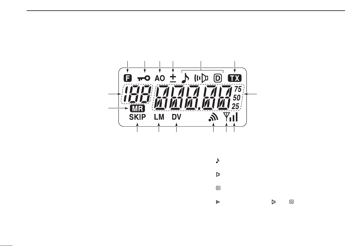
■Function display
qFUNCTION INDICATOR
Appears while a secondary function is being accessed.
wKEY LOCK INDICATOR (p. 16)
Appears when the key lock function is ON.
eAUTO POWER OFF INDICATOR (p. 64)
Appears while the auto power OFF function is activated.
rDUPLEX INDICATOR (p. 17)
Either “–” or “+” appears during repeater operation.
tTONE INDICATOR
❍While in the analog (FM) mode operation
➥“” appears while the subaudible tone encoder is in
use. (p. 17)
➥“” appears while the tone (CTCSS) squelch func-
tion is in use. (p. 34)
➥“” appears while the tone (DTCS) squelch function
is in use. (p. 34)
➥“” appears with the “ ” or “ ” indicator while the
pocket beep function (CTCSS or DTCS) is in use.
(p. 36)
q q q q qqwer t y
u
!5
!4
!3 !2 !1 io!0

7
2
PANEL DESCRIPTION
2
❍While in the digital (DV) mode operation with an optional
UT-118
DIGITAL UNIT
installed.
➥“” appears while the digital code (CSQL) squelch
function is in use. (p. 49)
➥“” appears while the call sign (DSQL) squelch func-
tion is in use. (p. 49)
➥“” appears with the “ ” or “ ” indicator while the
pocket beep function (CSQL or DSQL) is in use.
(p. 48)
yTRANSMIT INDICATOR (p. 15)
Appears during transmit.
uFREQUENCY READOUT
Shows operating frequency, channel number or channel
names, depending on display type (p. 16).
iSIGNAL INDICATOR
➥Shows receiving signal strength as below.
➥Shows the output power level while transmitting.
oBUSY INDICATOR
➥Appears when a signal is being received or the squelch
is open.
➥Blinks while the monitor function is activated. (pgs. 15, 49)
!0 PAGER CALL INDICATOR (p. 41)
Blinks when a pager call is received. (This indicator ap-
pears only when an optional UT-108
DTMF DECODER UNIT
is installed.)
!1 DIGITAL MODE INDICATOR (p. 45)
Appears when digital mode is selected. (This indicator ap-
pears only when an optional UT-118
DIGITAL UNIT
is in-
stalled.)
!2 LOW/MIDDLE POWER INDICATOR (p. 15)
➥“L” or “M” appears when the low or middle output power
is selected, respectively.
➥No indicator appears when high output power is se-
lected.
!3 SKIP CHANNEL INDICATOR (p. 32)
Appears when the selected memory channel is specified
as a skip channel.
!4 MEMORY MODE INDICATOR (p. 21)
Appears while in memory mode or channel number indica-
tion mode.
!5 MEMORY CHANNEL INDICATOR (p. 21)
➥Shows the selected memory channel number.
➥“C” appears when the call channel is selected.
Low Middle High
Weak ⇐ RX Signal level ⇒ Strong
■Battery pack replacement
qBefore replacing the battery
pack, push and hold [PWR]
for 1 sec. to turn the power
OFF.
wSlide the battery release forward, then pull the battery pack
upward with the transceiver facing away from you.
DDBATTERY PACKS
*1Operating periods are calculated under the following conditions;
Tx : Rx : standby =1 : 1 : 8, power save function: auto setting is
activated
*2Operating period depends on the alkaline cells used.
Battery Voltage Capacity Battery life*1
pack IC-V82 IC-U82
BP-208N Battery case for AA —*2
(LR6)×6 alkaline
BP-209N 7.2 V 1100 mAh 3 hrs. 20 min. 3 hrs. 40 min.
BP-210N 7.2 V 1650 mAh 6 hrs. 7 hrs.
BP-211N 7.4 V 1800 mAh 6 hrs. 10 min. 8 hrs. 15 min.
BP-222N 7.2 V 600 mAh 2 hrs. 15 min. 2 hrs. 50 min.
Push and
hold for 1 sec.
PWR
8
BATTERY PACKS
3

9
3
BATTERY PACKS
3
■Battery caution
RDANGER! Use/Charge the specified Icom batteries only.
Only tested and approved for use with genuine Icom bat-
teries. Fire and/or explosion may occur when a third party
battery pack or counterfeit product is used/charged.
• CAUTION! NEVER short the terminals of the battery pack
(or charging terminals of the transceiver). Also, current may
flow into nearby metal objects such as a necklace, so be
careful when placing battery packs (or the transceiver) in
handbags, etc.
Simply carrying with or placing near metal objects such as a
necklace, etc. causes shorting. This will damage not only
the battery pack, but also the transceiver.
• NEVER incinerate used battery packs. Internal battery gas
may cause an explosion.
• NEVER immerse the battery pack in water. If the battery
pack becomes wet, be sure to wipe it dry BEFORE attach-
ing it to the transceiver.
• Clean the battery terminals to avoid rust or poor contact.
• Keep battery contacts clean. It’s a good idea to clean bat-
tery terminals once a week.
If your battery pack seems to have no capacity even after
being charged, completely discharge it by leaving the power
ON overnight. Then, fully charge the battery pack again. If the
battery pack still does not retain a charge (or only very little
charge), a new battery pack must be purchased (p. 77).
■Charging NOTE
Prior to using the transceiver for the first time, the battery
pack must be fully charged for optimum life and operation.
• Recommended temperature range for charging:
+10°C to +40°C (; +50˚F to 140˚F)
• Use the supplied charger or optional charger (BC-119N/121N/144N
for rapid charging, BC-146 for regular charging) only. NEVER use
other manufacturers’ chargers.
The optional BP-222N, BP-209N, BP-210N or BP-211N bat-
tery packs include rechargeable batteries (Ni-Cd: BP-222N,
BP-209N, Ni-MH: BP-210N, Li-Ion: BP-211N) and can be
charged approx. 300 times. Charge the battery pack before
first operating the transceiver or when the battery pack be-
comes exhausted.
If you want to charge the battery pack more than 300 times,
the following points should be observed:
• Avoid over charging. The charging period should be less than
24 hours.
• Use the battery until it becomes almost completely exhausted
under normal conditions. We recommend battery charging after
transmitting becomes impossible.
DDBattery pack life
When the operating period becomes extremely short even
after charging the battery pack fully, a new battery pack is
needed.
10
3BATTERY PACKS
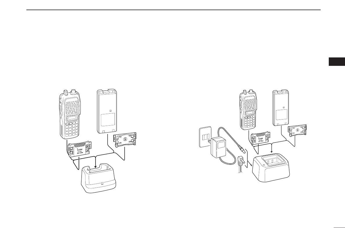
■Battery charging
DRegular charging with the BC-146
The optional BC-146 provides regular charging of an optional
battery pack with or without a transceiver attached. The fol-
lowing is additionally required:
• An optional AC adapter. (An AD-99N is supplied with BC-146.)
DAbout AD-99N
The adapter (Spacer A) only is required for IC-V82/U82 se-
ries. When removing the spacer (Spacer B/C),
push the latch
carefully with your finger to remove the spacer (Spacer B/C)
from the adapter (Spacer A).
RCAUTION!
• DO NOT push or force the latch with a screw driver, etc.,
to remove it.
• DO NOT bend the latch when the adapter and spacer are
not joined together. This will cause weakening of the latch
plastic.
• Both cases may break the latch and it may not be able to
be reattached.
Push the latch
carefully.
Remove the spacer (Spacer B/C)
from the adapter.
Check orienta-
tion for correct
charging. (In-
sert together
with AD-99N.)
Turn power OFF.
BC-146+AD-99N
• Chargeable battery
BP-210N (Ni-MH battery)
BP-209N, BP-222N
(Ni-Cd batteries)
Recommendation:
Charge the BP-211N (Li-Ion) by BC-119N (or BC-121N) for
a maximum of 2.5 hours. Li-Ion batteries are different from
Ni-Cd batteries in that it is not necessary to completely
charge and discharge them to prolong the battery life.
Therefore, charging the battery in intervals, and not for ex-
tended periods is recommended.
11
3
BATTERY PACKS
3
DRapid charging with the BC-144N
The optional BC-144N provides rapid charging of optional
battery packs.
The following are additionally required:
• An AC adapter (may be supplied with the BC-144N depending on
version).
• Chargeable battery
BP-210N (Ni-MH battery)
BP-209N, BP-222N (Ni-Cd batteries)
DRapid charging with the BC-119N+AD-101
The optional BC-119N provides rapid charging of battery
packs. The following items are additionally required.
• AD-101 (Charger Adapter).
• An AC adapter (may be supplied with the BC-119N depending on
version) or the DC power cable (OPC-515L/CP-17L).
• Chargeable battery
BP-210N (Ni-MH battery)
BP-209N, BP-222N (Ni-Cd batteries)
BP-211N (Li-Ion battery)
DC power cable (OPC-515L)
(Connect with the DC power supply;
13.8 V/at least 2 A)
Turn power OFF.
Check orienta-
tion for correct
charging. (In-
sert together
with AD-99N.)
Turn power OFF.
BC-144N+AD-99N
12
3BATTERY PACKS
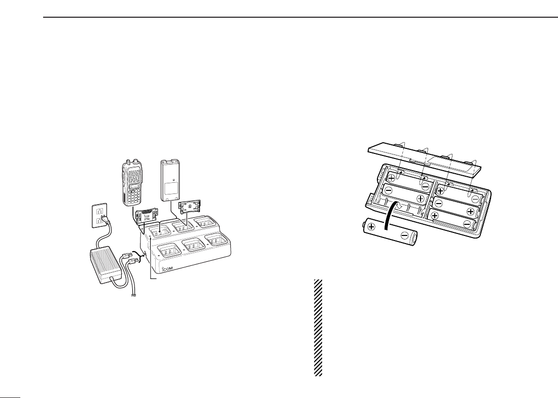
DRapid charging with the BC-121N+AD-101
The optional BC-121N allows up to 6 battery packs to be
charged simultaneously. The following items are additionally
required.
• Six AD-101 (Charger Adapter).
• An AC adapter (BC-124; may be supplied with the BC-121N de-
pending on version) or the DC power cable (OPC-656).
• Chargeable battery
BP-210N (Ni-MH battery)
BP-209N, BP-222N (Ni-Cd batteries)
BP-211N (Li-Ion battery)
■Battery case
(optional for some versions)
When using a BP-208N BATTERY CASE attached to the
transceiver, install 6 AA (LR6) size alkaline batteries as illus-
trated below.
DDCAUTION
• Use ALKALINE batteries only.
• Make sure all battery cells are the same brand, type and
capacity. Never mix old and new batteries.
Either of the above may cause a fire hazard or damage
the transceiver if neglected.
• Never incinerate used battery cells since internal battery
gas may cause them to rupture.
• Never expose a detached battery case to water. If the
battery case gets wet, be sure to wipe it dry before use.
AC adapter
(purchased
separately)
DC power cable (OPC-656)
(Connect with the DC power supply;
13.8 V/at least 7 A)
Charge indicator
(each indicator functions independently)
Turn power OFF.
13
4
BASIC OPERATION
3
4
■Power ON
➥Push and hold [PWR] for 1
sec. to turn power ON.
■VFO mode selection
The transceiver has 2 basic oper-
ating modes: VFO mode and
memory mode.
➥Push [D•
CLR
]to select VFO
mode.
■Setting a frequency
DVia the keypad
qPush [D•
CLR
]to select VFO mode, if necessary.
wTo enter the desired frequency, enter 6 digits starting from
the 100 MHz digit.
•Entering three* to five digits then pushing [✱•
ENT
]will also
set the frequency. (*Some versions only requires two digits.)
•When a digit is mistakenly input, push [D.
CLR
]to abort input.
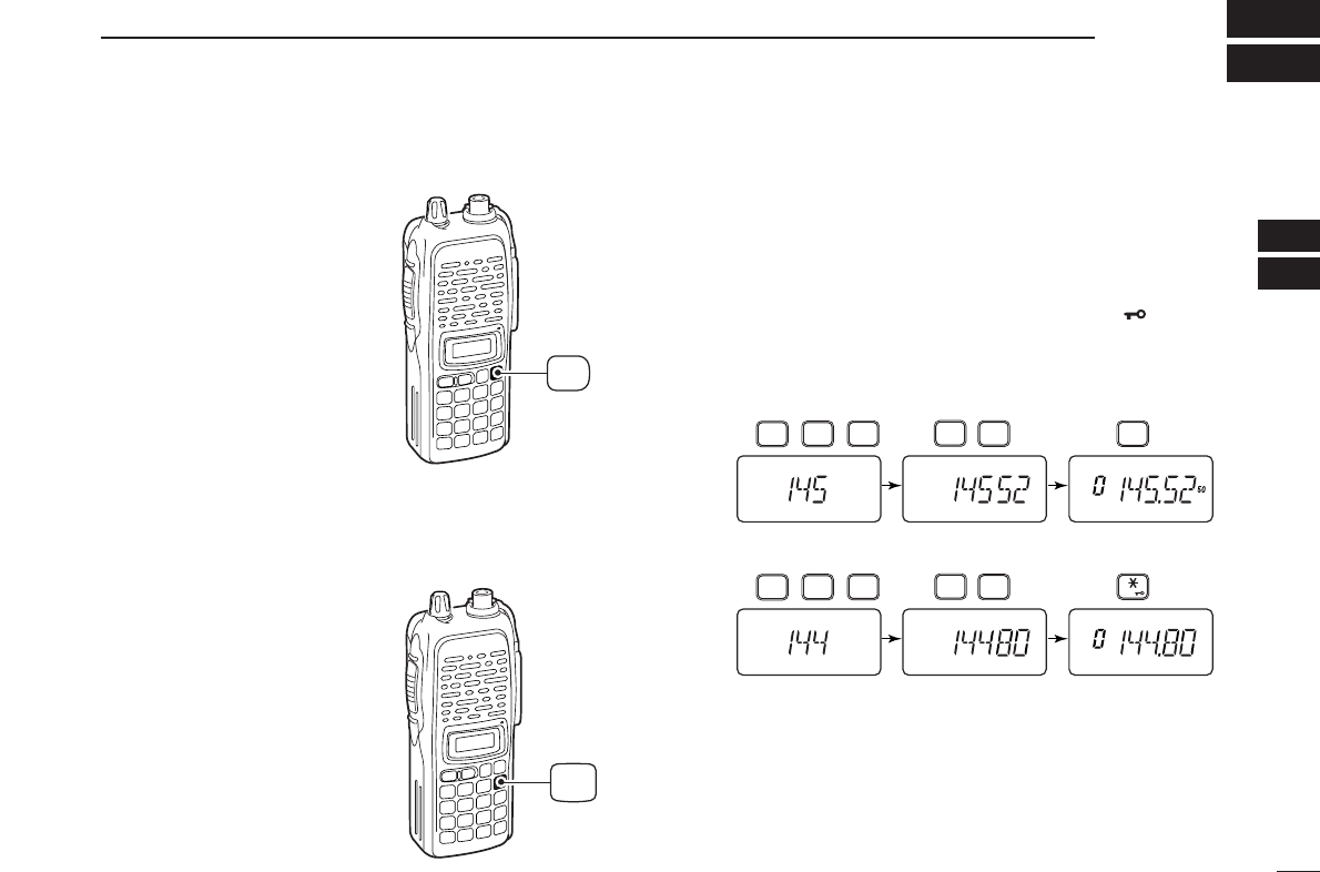
• Example 1— when entering 145.525 MHz
Push
• Example 2— when entering 144.800 MHz
P.BEEP
2
DUP
4
DUP
TONE
4
1
SCAN
5
SCAN
5
SCAN
5
Push
DUP
TONE
4
1
OPT
0
SET
8
ENT
CLR
D
Push and
hold for 1 sec.
PWR
DBy other methods
Via the [YY]/[ZZ] keys
➥Push [YY]or [ZZ]several times to set the desired frequency.
•Each push increases/decreases the frequency by the selected
tuning step. See next set of instructions for setting tuning step
size.
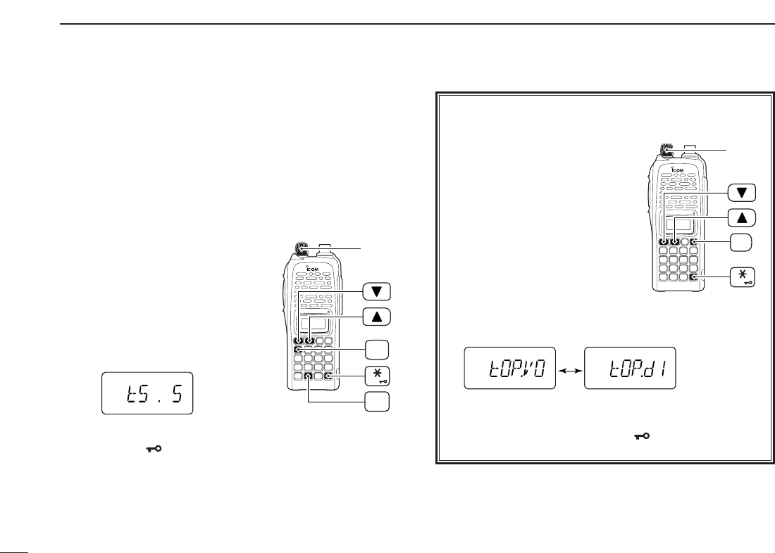
DTuning step selection
The IC-V82/U82 has 8 tuning
steps— 5, 10, 12.5, 15, 20, 25, 30
and 50 kHz. The tuning step is selec-
table in
SET MODE
.
qPush [A•
FUNC
]then [8•
SET
]to
enter
SET MODE
.
wPush [YY]or [ZZ]several times to
select the tuning step item.
eRotate [VOL] to select the desired tuning step.
rPush [✱•
ENT
]to exit
SET MODE
.
[VOL]
ENT
FUNC
A
SET
8
14
4BASIC OPERATION
✔For your information— [VOL] function assignment
The [VOL] control can be used as
a tuning dial for frequency tuning
instead of [YY]/[ZZ]keys. However,
when [VOL] functions as tuning
dial, [YY]/[ZZ]keys functions as
volume control.
qWhile pushing [YY]and [ZZ],
turn power ON to enter
INITIAL
SET MODE
.
wPush [YY]or [ZZ]several times
to select the dial assignment
item, “tOP.”
eRotate [VOL] to select the condition.
rTo exit
SET MODE
, push [✱•
ENT
].
[VOL] is assigned as
AF volume control. [VOL] is assigned as
tuning dial.
[VOL]
ENT
PWR
15
4
BASIC OPERATION
4
■Setting audio/squelch level
DTo set the audio level
Rotate [VOL] to set the desired
audio level while receiving a sig-
nal.
• When no signal is received, push
and hold [MONI] while setting the
audio level.
• When [VOL] is assigned as tuning
dial, push [YY]/[ZZ]to adjust the audio
output level. (pgs. 14, 65)
DTo set the squelch level
While pushing [MONI], push
[YY]/[ZZ]to set the squelch level.
• The squelch level “1” is loose
squelch, “10” is tight squelch.
• When [VOL] is assigned as tuning
dial, rotate [VOL] while pressing
[MONI]. (pgs. 14, 65)
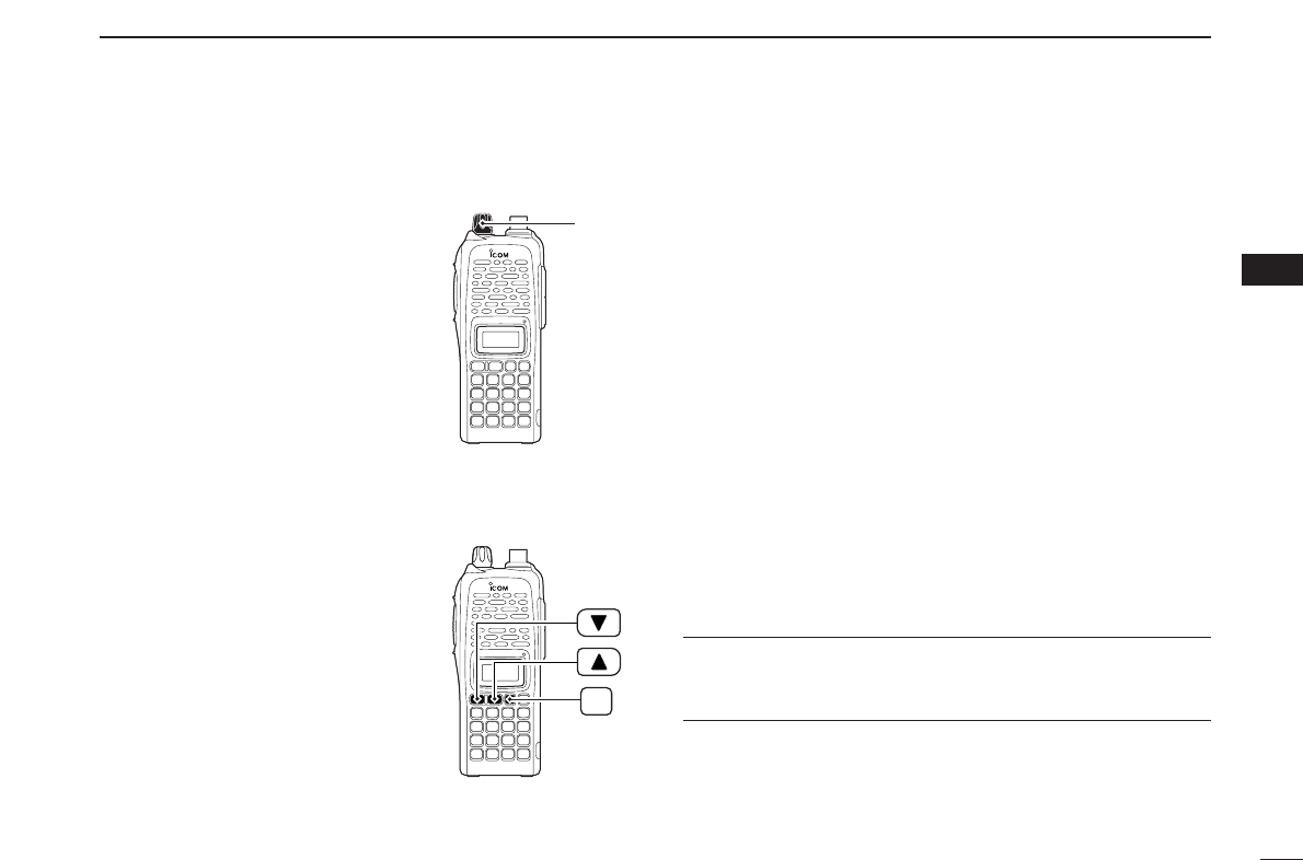
■Receive and transmit
qPush and hold [PWR] for 1 sec. to turn the power ON.
wAdjust audio volume to the desired level.
eSet the frequency.
When a signal is received:
• Squelch opens and audio is emitted from the speaker.
• Signal indicator shows the relative signal strength level.
rPush [A•
FUNC
], then [9•
H
/
M
/
L
]to select output power be-
tween high, middle and low.
•“L” appears when low power is selected.
•“M” appears when middle power is selected.
•No indication appears when high power is selected.
tPush and hold [PTT] to transmit, then speak into the micro-
phone.
• “$” appears.
•Do not hold the microphone too close to your mouth or
speak too loudly. This may distort the signal.
yRelease [PTT] to receive.
✔For your information— Monitor function:
Push and hold [MONI] to listen to weak signals that do not
open the squelch.
MONI
[VOL]

16
4BASIC OPERATION
■Display type
The transceiver has 3 display types to suit your operating
style during memory mode operation. The display type is
selected in
INITIAL SET MODE
(p. 65).
“Frequency Indication” type
Displays operating frequency.
“Channel Number Indication” type
Displays memory channel number. In this type only pre-
programmed memory channel numbers are displayed.
VFO mode cannot be selected.
• When the channel indication type is selected, only the following
functions can be performed.
- Scan function (p. 30)
- Output power setting (p. 15)
- DTMF memory function (p. 27)
- Key lock function (see next set of instructions)
- Scan pause timer setting, function key timer setting and LCD
backlight setting in
SET MODE
(p. 61)
“Channel Name Indication” type
Displays memory channel name you have assigned. In this
display pre-programmed memory channel names are dis-
played.
VFO mode is selectable.
• Programmed frequencies are indicated when you have not pre-
programmed the channel names in the selected memory channel.
• Push and hold [MONI] to display the operating frequency.
■Key lock function
The key lock function prevents accidental frequency changes
and function activation.
Push [A•
FUNC
]then push and hold
[✱•
ENT
]for 1 sec. to toggle the
function ON and OFF.
•“ ” appears while the lock function is
activated.
•[PWR], [PTT], [VOL] and [MONI] can
be operated regardless of this setting.
USING
INITIAL SET MODE
FUNC
A
ENT
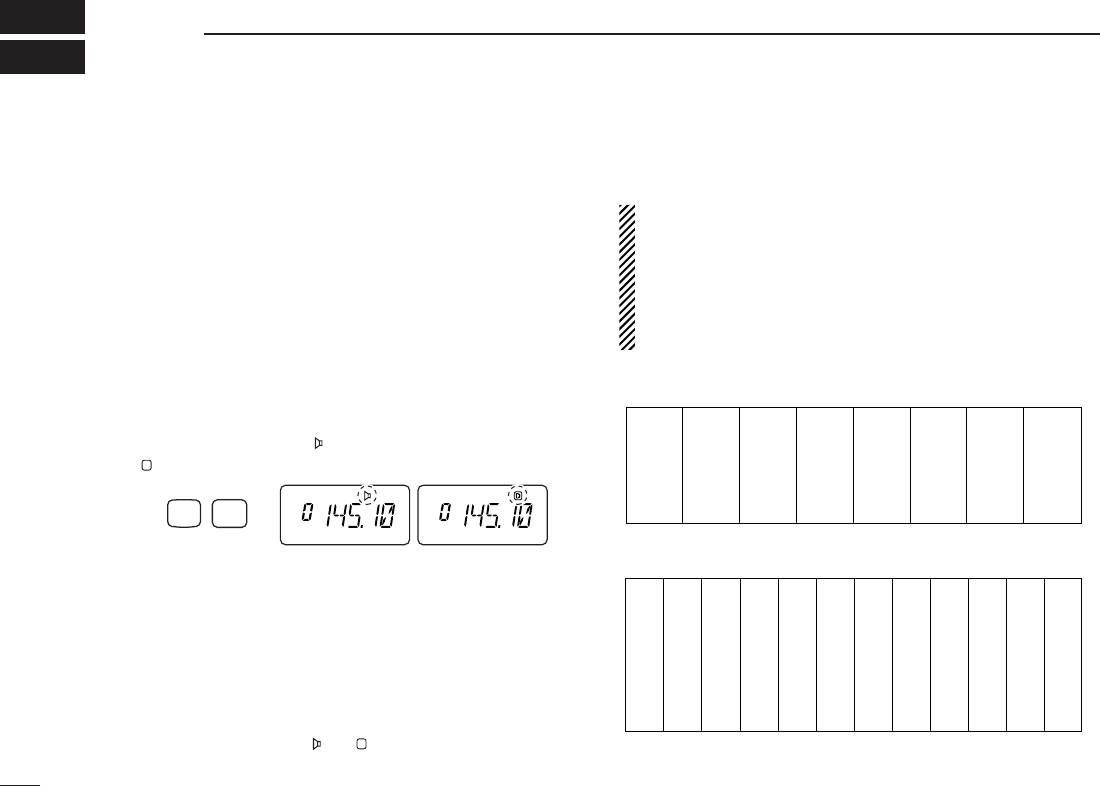
■General
When using a repeater, the transmit frequency is shifted from
the receive frequency by the offset frequency. It is convenient
to program repeater information into memory channels.
qSet the receive frequency (repeater output frequency).
wPush [A•
FUNC
]and [4•
DUP
]several times to select “–” or “+.”
•“–” indicates the transmit frequency is shifted down; “+” indicates
the transmit frequency is shifted up.
• Blinking “–” or “+” indicates the reversed duplex mode is selected
in
SET MODE
(p. 58).
ePush [A•
FUNC
]and [1•
TONE
]several times to activate the
subaudible tone encoder, if required.
•“ ” appears.
•Select the desired subaudible tone frequency, if necessary.
(p. 18)
rPush and hold [PTT] to transmit.
•The displayed frequency automatically changes to the transmit
frequency (repeater input frequency).
•If “OFF” appears, check the offset frequency (see next page for
details) and direction.
tRelease [PTT] to receive.
yPush and hold [MONI] to check whether the other station’s
transmit signal can be directly received.
■Reversed duplex mode
When the reversed duplex mode is selected, the receive fre-
quency shifts. (Transmit frequency shifts in normal duplex mode.)
Each receive and transmit frequency is shown in the table
below with the following conditions;
IC-V82
Input frequency : 145.30 MHz
Direction : – (negative)
Offset frequency : 0.6 MHz
IC-U82
Input frequency : 439.80 MHz
Direction : – (negative)
Offset frequency : 5 MHz
qPush [A•
FUNC
], then push [8•
SET
]to enter
SET MODE
.
wPush [YY]or [ZZ]several times until “REV” appears.
eRotate [VOL] to turn the reversed duplex mode ON or
OFF.
rPush [✱•
ENT
](or [D•
CLR
])to exit
SET MODE
.
USING
SET MODE
17
5
REPEATER OPERATION
4
5
IC-V82 IC-U82
Reversed OFF ON OFF ON
Rx freq. 145.30 MHz 144.70 MHz 439.80 MHz 434.80 MHz
Tx freq. 144.70 MHz 145.30 MHz 434.80 MHz 439.80 MHz

18
5REPEATER OPERATION
■Offset frequency
When communicating through a repeater, the transmit fre-
quency is shifted from the receive frequency by an amount
determined by the offset frequency.
qPush [A•
FUNC
], then push [8•
SET
]to enter
SET MODE
.
wPush [YY]or [ZZ]several times until “±” and offset frequency
appear.
eRotate [VOL] to select the desired offset frequency.
•Selectable steps are the same as the pre-set tuning steps.
•The unit of the displayed offset frequency is “MHz.”
rPush [✱•
ENT
](or [D•
CLR
]) to set the offset frequency
and exit
SET MODE
.
■Subaudible tones
Some repeaters require subaudible tones to be accessed.
Subaudible tones are added to your normal signal and must
be set in advance.
qPush [A•
FUNC
], then push [8•
SET
]to enter
SET MODE
.
wPush [YY]or [ZZ]one or more times until “rt” appears.
eRotate [VOL] to select the desired subaudible tone.
rPush [✱•
ENT
](or [D•
CLR
]) to set the selected tone and
exit
SET MODE
.
• Available subaudible tone frequencies (unit: Hz)
67.0
69.3
71.9
74.4
77.0
85.4
88.5
91.5
94.8
97.4
100.0
103.5
79.7
82.5
107.2
110.9
114.8
118.8
123.0
127.3
131.8
136.5
141.3
146.2
151.4
156.7
159.8
162.2
165.5
167.9
171.3
173.8
177.3
179.9
183.5
186.2
189.9
192.8
196.6
199.5
203.5
206.5
210.7
218.1
225.7
229.1
233.6
241.8
250.3
254.1
USING
SET MODE
USING
SET MODE

19
5
REPEATER OPERATION
5
DDTone information
Some repeaters require different tone system to be accessed.
DTMF TONES
While pushing [PTT], push the desired DTMF keys (0–9,
[A•
FUNC
], [B•
CALL
], [C•
MR
], [D•
CLR
], [#•
BANK
]and
[✱•
ENT
]) to transmit DTMF tones.
•[✱•
ENT
]transmits tone “E,” [#•
BANK
]transmits tone “F.”
•The transceiver has 16 DTMF memory channels (p. 27).
1750 Hz TONE
While pushing [PTT], push [YY]or [ZZ]to transmit a 1750 Hz
tone signal.
✔Convenient
Tone scan function: When you don’t know the subaudible
tone used for a repeater, the tone scan is convenient for de-
tecting the tone frequency.
Push [A•
FUNC
], then push [3•
T
.
SCAN
]to start the tone scan.
• Push [D•
CLR
]to cancel the scan.
• When the required tone frequency is detected, the scan pauses.
■Repeater lockout
This function helps prevent interference to other stations by
inhibiting your transmission when a signal is received. The
transceiver has two inhibiting conditions, repeater and busy.
qWhile pushing and holding [YY]and [ZZ], turn the power ON
to enter
INITIAL SET MODE
.
wPush [YY]or [ZZ]several times until “RLO” appears.
eRotate [VOL] to select the repeater lockout function to
“RP,” “bU” or OFF.
•“RP”: Transmit is inhibited when a signal with un-matched sub-
audible tone is received.
•“bU”: Transmit is inhibited when a signal is received.
rPush [✱•
ENT
](or [D•
CLR
]) to exit
INITIAL SET MODE
.
USING
INITIAL SET MODE
20
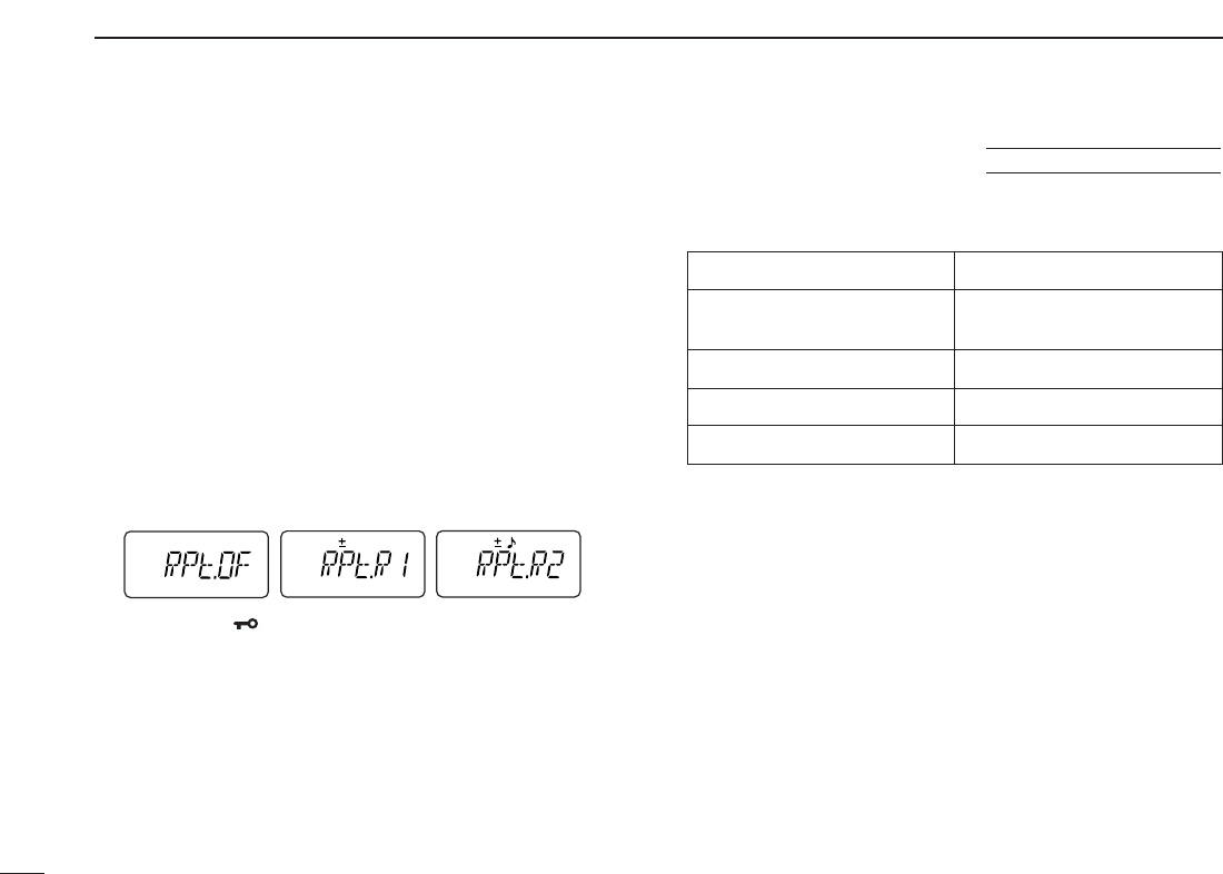
5REPEATER OPERATION
The USA/CSA versions automatically activate the repeater
settings (duplex ON/OFF, duplex direction, tone encoder
ON/OFF) when the operating frequency falls within or outside
of the general repeater output frequency range. The offset
and repeater tone frequencies are not changed by the auto
repeater function. Reset these frequencies, if necessary.
qWhile pushing and holding [YY]and [ZZ], turn the power ON
to enter
INITIAL SET MODE
.
wPush [YY]or [ZZ]several times until “RPt” appears.
eRotate [VOL] to select the desired condition.
•“OF”— the auto repeater function is turned OFF;
•“R1”— the auto repeater function activates duplex only;
•“R2”— the auto repeater function activates duplex and tone.
rPush [✱•
ENT
](or [D•
CLR
]) to exit
INITIAL SET MODE
.
• Frequency range and offset direction
Frequency range Duplex direction
145.200–145.495 MHz “–” appears
146.610–146.995 MHz
147.000–147.395 MHz “+” appears
442.000–444.995 MHz “+” appears
447.000–449.995 MHz “–” appears
■Auto repeater function (USA/CSA versions only)
USING
INITIAL SET MODE
21
6
MEMORY/CALL OPERATION
6
5
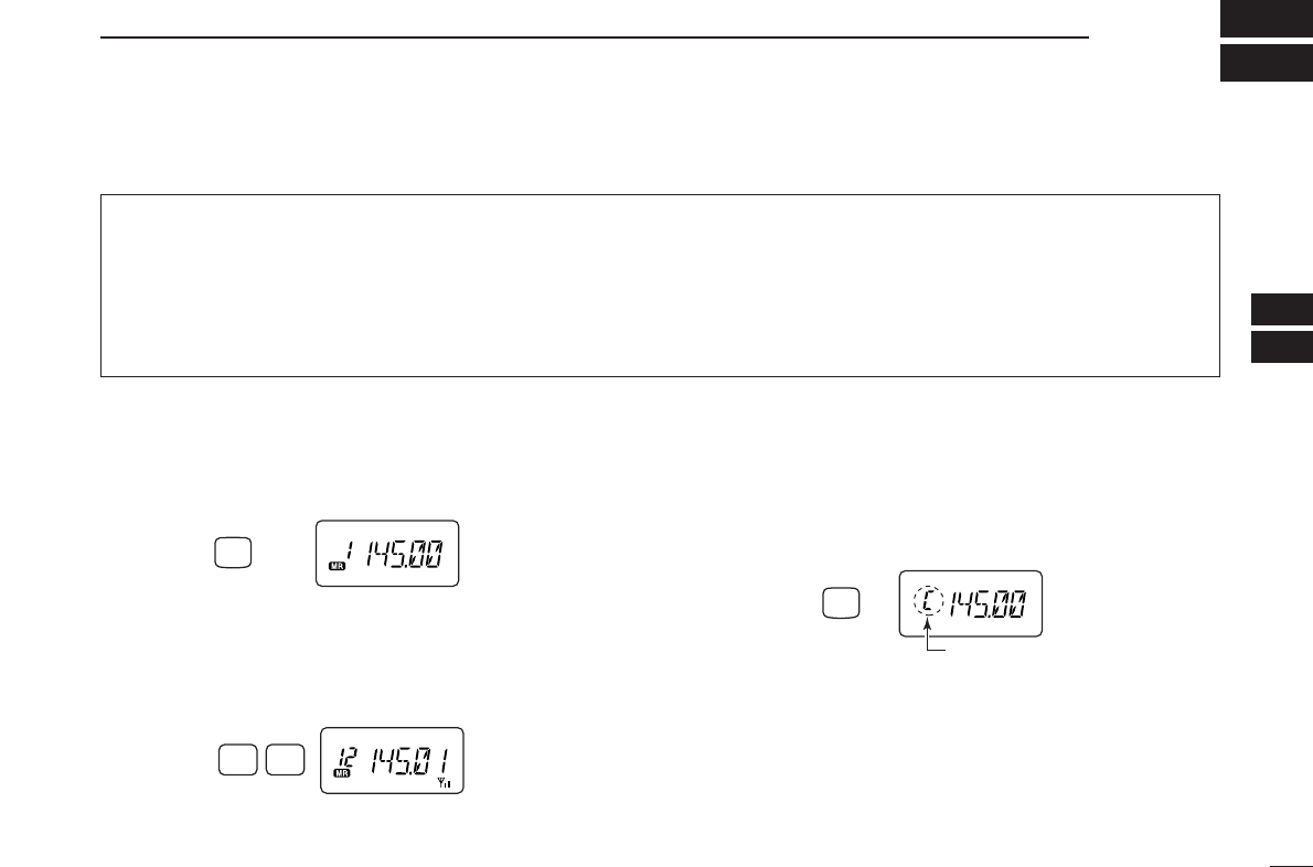
■Selecting a memory channel
qPush [C•
MR
]to select memory mode.
•“
X” appears.
wEnter 2 digits to select the desired memory channel (or
push the [YY]/[ZZ]keys).
•The memory channels 0–9 are proceeded by a “0.”
• When [VOL] is assigned as tuning dial, rotate [VOL] to select
the memory channel. (pgs. 14, 65)
■Selecting the call channel
➥Push [B•
CALL
]to select the call channel.
•“C” is displayed instead of the memory channel number.
•Push [D•
CLR
]or [C•
MR
]to select VFO or memory mode, respec-
tively.
Push
“C” appears
CALL
B
TONE
P.BEEP
12
Push
MR
C
Push
The transceiver has 207 memory channels including 6 scan
edge memory channels (3 pairs), and 1 call channel. Each
of these channels can be individually programmed with op-
erating frequency (pgs. 13, 14), duplex direction (p. 17) and
offset (p. 18), subaudible tone encoder or tone squelch and
its tone frequency (pgs. 18, 35) and skip information* (p. 32).
*except for scan edge memory channels.
In addition, a total of 10 memory banks, A to J, are available
for usage by group, etc.
■General description
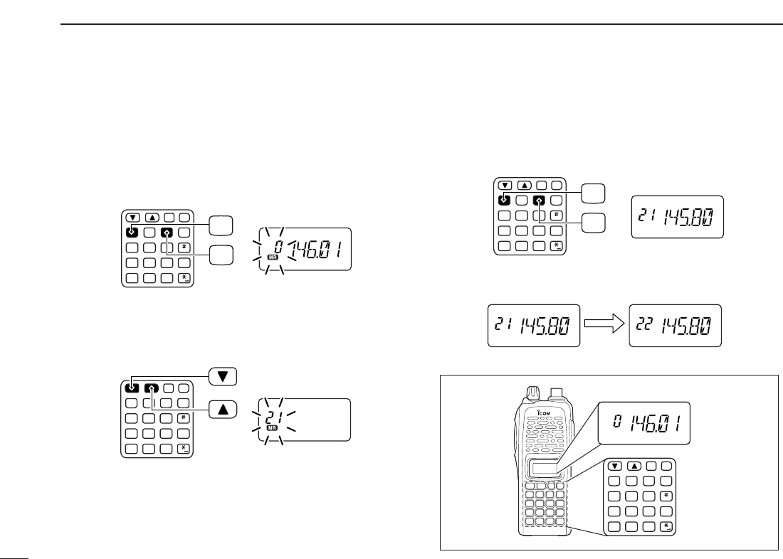
qPush [D•
CLR
]to select VFO mode, if necessary.
wSet the desired frequency.
eSet other information, such as tone, duplex, as desired.
rPush [A•
FUNC
], then [C•
MR
]momentarily.
•“
X” and memory channel number blink.
tPush [YY]or [ZZ]to select the desired memory channel.
• When programming the call channel, select “C.”
• When [VOL] is assigned as tuning dial, rotate [VOL] to select
the memory channel. (pgs. 14, 65)
yPush [A•
FUNC
], then push and hold [C•
MR
]for 1 sec., when
3 beeps will sound to program the information into the se-
lected memory channel and return to VFO.
•After 3 beeps are emitted, continue to hold [C•
MR
]to increment
the displayed memory channel number.
MONI
CALL
DUP SCAN
PRIO
ENT
SET
H/M/L
OPTSKIP
BANK
TONE
T.SCANP.BEEP
MR CLRFUNC
PWR
987
4
123
AB DC
560
MONI
CALL
DUP SCAN
PRIO
ENT
SET
H/M/L
OPTSKIP
BANK
TONE
T.SCANP.BEEP
MR CLRFUNC
PWR
987
4
123
AB DC
560
MR
FUNC
A
C
MONI
CALL
DUP SCAN
PRIO
ENT
SET
H/M/L
OPTSKIP
BANK
TONE
T.SCANP.BEEP
MR CLRFUNC
PWR
987
4
123
AB DC
560
MONI
CALL
DUP SCAN
PRIO
ENT
SET
H/M/L
OPTSKIP
BANK
TONE
T.SCANP.BEEP
MR CLRFUNC
PWR
987
4
123
AB DC
560
MR
FUNC
A
C
■Programming the memory/call channels
22
6MEMORY/CALL OPERATION
23
6
MEMORY/CALL OPERATION
6
■Channel name programming
qSelect a “Channel Name Indication” type in
INITIAL SET
MODE
(p. 65).
wPush [C•
MR
]to select memory
mode, if necessary.
ePush [A•
FUNC
], then push [8•
SET
]
to enter into the channel name
programming mode.
• The character to be edited blinks.
rRotate [VOL] to select a charac-
ter.
tPush [YY]to move the cursor to right, [ZZ]to move the cur-
sor to left.
• Up to 5 characters can be used for channel name.
• Usable characters are A–Z, 0–9, “space,” +, –, =, ✱, /, [, ] and :.
yPush [✱•
ENT
](or [D•
CLR
]) to set the name and exit the
channel name programming mode.
■Memory transfers
This function transfers a memory channel’s contents to VFO
(or another memory/call channel). This is useful when search-
ing for signals around a memory channel frequency and for
recalling the offset frequency, subaudible tone frequency etc.
DMemory/call ➾VFO
qSelect the memory (call) channel
to be transferred:
➥Push [C•
MR
](or [B•
CALL
]) to
select memory (call) mode.
➥Push [YY]or [ZZ]to select the
memory channel.
• When [VOL] is assigned as tuning
dial, rotate [VOL] to select the
memory channel. (pgs. 14, 65)
wPush [A•
FUNC
], then push and
hold [C•
MR
]for 1 sec. to transfer
the selected memory contents to
the VFO.
•VFO mode is selected automatically.
FUNC
A
MR
C
CALL
B
FUNC
A
MR
C
SET
8
[VOL]
ENT
DMemory/call ➾memory/call
qSelect the memory (call) channel
to be transferred:
➥Push [C•
MR
](or [B•
CALL
]) to
select the memory (call) mode.
➥Push [YY]or [ZZ]to select the
memory channel.
• When [VOL] is assigned as tuning
dial, rotate [VOL] to select the
memory channel. (pgs. 14, 65)
wPush [A•
FUNC
], then push [C•
MR
]
momentarily.
•“--” and “X” blink.
ePush [YY]or [ZZ]to select the target memory.
• When [VOL] is assigned as tuning dial, rotate [VOL] to select
the target channel. (pgs. 14, 65)
rPush [A•
FUNC
], then push and hold [C•
MR
]for 1 sec.
•Memory mode is selected and the contents are transferred to the
target memory.
DClearing a memory
qPush [A•
FUNC
], then push [C•
MR
]
to enter the memory transfer
mode.
•“
X” and a memory channel num-
ber blink.
wPush [YY]or [ZZ]to select the
memory channel to be cleared.
• When [VOL] is assigned as tuning
dial, rotate [VOL] to select the
memory channel. (pgs. 14, 65)
•The call channel cannot be cleared.
ePerform the following operation within 1.5 sec, otherwise
the transceiver returns to the memory mode without clear-
ing the memory.
- Push [A•
FUNC
], then push [C•
MR
]momentarily.
- Push [A•
FUNC
], then push and hold [C•
MR
]for 1 sec.
•The contents of the selected memory are cleared.
rPush [D•
CLR
]to return to regular operation.
24
6MEMORY/CALL OPERATION
FUNC
A
MR
C
CALL
B
FUNC
A
MR
C
25
6
MEMORY/CALL OPERATION
6
■Memory bank selection
The IC-V82/U82 has a total of 10 banks (A to J). Each mem-
ory channel, 0 to 199, may be assigned to one of the banks
for easy memory management.
qPush [C•
MR
]to select memory mode.
wPush [A•
FUNC
]and [#•
BANK
]to enter
memory bank selection.
•Bank indicator blinks.
eRotate [VOL] to select the desired
bank, A to J.
•Banks that have no programmed con-
tents are skipped.
rPush [✱•
ENT
](or [D•
CLR
]) to se-
lect the bank.
•Indicator stops blinking.
tPush [YY]or [ZZ]to select the channel in the bank.
•No channel numbers are displayed for memory bank operation.
yTo return to regular memory condition, push [A•
FUNC
]and
[#•
BANK
]to enter memory bank mode, then push
[✱•
ENT
](or [D•
CLR
]).
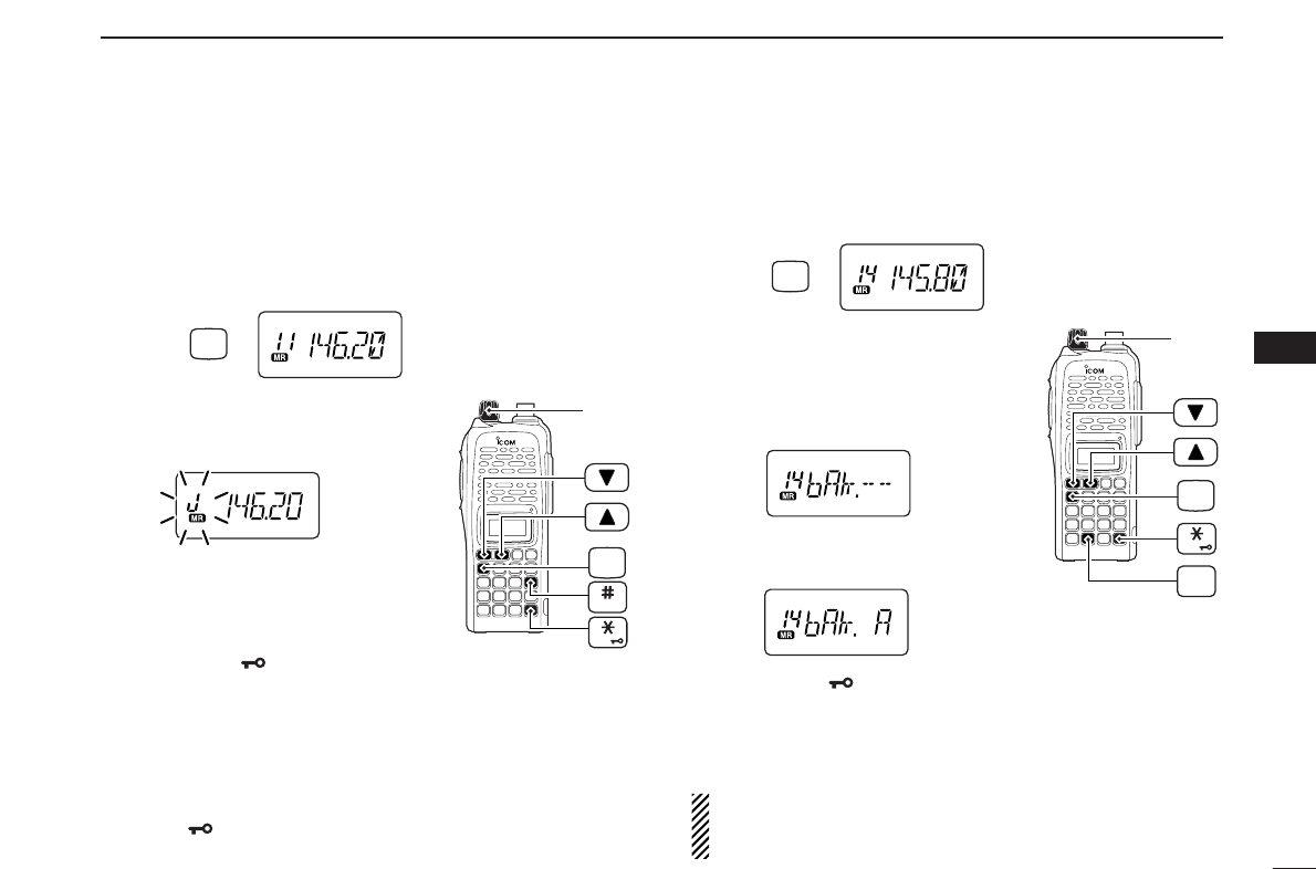
■Memory bank setting
qPush [C•
MR
]to select memory mode, then select the de-
sired memory channel via [YY]or [ZZ].
wPush [A•
FUNC
]and [8•
SET
]to enter
SET MODE
.
ePush [YY]or [ZZ]several times until
“bAk” appears.
•“– –” indication blinks as follows.
rRotate [VOL] to select the desired
bank.
tPush [✱•
ENT
](or [D•
CLR
]) to assign the channel to the
bank and return to regular memory condition.
yRepeat steps qto tto assign another memory channel
to the same or another bank.
NOTE: Display type setting (pgs. 16, 65) in
INITIAL SET
MODE
must be selected “FR,” otherwise the memory bank
operation cannot be performed.
[VOL]
ENT
FUNC
A
SET
8
MR
C
Push
[VOL]
ENT
FUNC
A
BANK
MR
C
Push
26
6MEMORY/CALL OPERATION
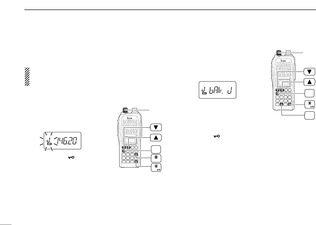
■Transferring bank contents
Contents of programmed memory banks can be cleared or
transferred to another bank.
INFORMATION: Even if the memory bank contents are
cleared, the memory channel contents still remain pro-
grammed.
q
Select the desired bank contents to be transferred or erased.
➥Push [C•
MR
]to select memory mode.
➥Push [A•
FUNC
]and [#•
BANK
],
then rotate [VOL] to select the
desired memory bank.
•Bank indicator blinks.
➥Push [✱•
ENT
](or [D•
CLR
]) to
select the bank then push [YY]
and [ZZ]to select the desired con-
tents.
•Bank indicator stops blinking.
wPush [A•
FUNC
]and [8•
SET
]to enter
SET MODE
.
ePush [YY]or [ZZ]several times until
“bAk” appears.
•Bank indicator appears.
rRotate [VOL] to select the desired
bank to receive the transferred infor-
mation or erase the bank contents.
•Select “– –” indication when erasing the
contents from the bank.
tPush [✱•
ENT
](or [D•
CLR
]) to transfer or erase, and re-
turn to regular memory mode.
yRepeat steps qto tfor transferring or erasing an an-
other bank’s contents.
[VOL]
ENT
FUNC
A
SET
8
[VOL]
ENT
FUNC
A
BANK
27
7
DTMF MEMORY
6
7
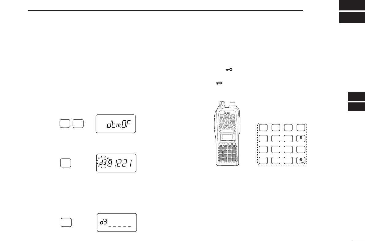
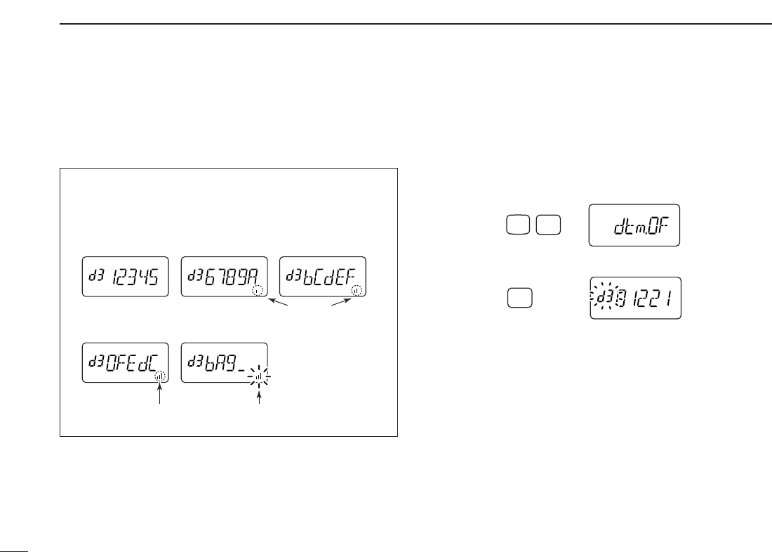
■Programming a DTMF code sequence
The transceiver has 16 DTMF memory channels (d0 to dF)
for storage of often-used DTMF code sequence of up to 24
digits. DTMF memories are used to store phone numbers or
control codes.
qPush [A•
FUNC
], then push [0•
OPT
]to enter
OPTION SET MODE
.
•Rotate [VOL] to select “dtm.OF,” if necessary. Or when an op-
tional UT-118
DIGITAL UNIT
is installed, push [YY]or [ZZ]several
times until “dtm.OF” appears.
wPush and hold [0•
OPT
]for 1 sec. to select the DTMF memory.
•One of “d0” to “dF” appears.
e
Rotate [VOL] to select the desired DTMF memory.
rPush and hold [0•
OPT
]for 1 sec. to enter the DTMF pro-
gramming mode.
•“_____” appears.
•Programmed memories can be cleared in this way.
tEnter the desired DTMF code sequence by pushing the
digit keys, [A•
FUNC
], [B•
CALL
], [C•
MR
], [D•
CLR
], [#•
BANK
]
and [✱•
ENT
], in the desired sequence.
•Amaximum of 24 digits can be input.
•[✱•
ENT
]enters tone “E”, [#•
BANK
]enters tone “F.”
•If a digit is mistakenly input, push [MONI] or [PTT] momentarily
then repeat from step q.
yPush [MONI] or [PTT] to save the digits and exit the DTMF
programming mode.
•Programmed DTMF code sequence sounds when [MONI] is
pushed.
•Or after 24th digit is input, the transceiver automatically saves
the digits and returns to step w.
CALL
DUP SCAN
PRIO
ENT
SET
H/M/L
OPTSKIP
BANK
TONE
T.SCANP.BEEP
MR CLRFUNC
987
4
123
AB DC
560
OPT
0
Push for 1 sec.
OPT
0
Push for 1 sec.
FUNC
A
OPT
0
Push
28
7DTMF MEMORY
• DTMF memory indication
■Transmitting a DTMF code
sequence
DUsing a DTMF memory channel
qPush [A•
FUNC
], then push [0•
OPT
]to enter
OPTION SET MODE
.
•Rotate [VOL] to select “dtm.OF,” if necessary.
wPush and hold [0•
OPT
]for 1 sec. to select the DTMF memory.
eRotate [VOL] to select the desired memory.
rPush [MONI] or [PTT] to exit the DTMF memory mode.
•Selected DTMF code sequence sounds when [MONI] is pushed.
tWhile pushing [PTT], push [MONI] to transmit the selected
DTMF memory.
•After the DTMF code sequence is transmitted, the transceiver re-
turns to receive automatically.
OPT
0
Push for 1 sec.
FUNC
A
OPT
0
Push
The DTMF memory consists of 5 pages that are 1st to 5th,
6th to 10th, 11th to 15th, 16th to 20th and 21st to 24th dig-
its.
• 1st page
indication
• 4th page
indication • 5th page
indication
• 2nd page
indication • 3rd page
indication
Appears
Appears Blinks
29
7
DTMF MEMORY
7
DManual DTMF code transmission
While pushing [PTT], push digit keys, [A•
FUNC
], [B•
CALL
],
[C•
MR
], [D•
CLR
], [#•
BANK
]and [✱•
ENT
]to transmit a DTMF
code sequence manually.
•[✱•
ENT
]transmits tone “E”, [#•
BANK
]transmits tone “F.”
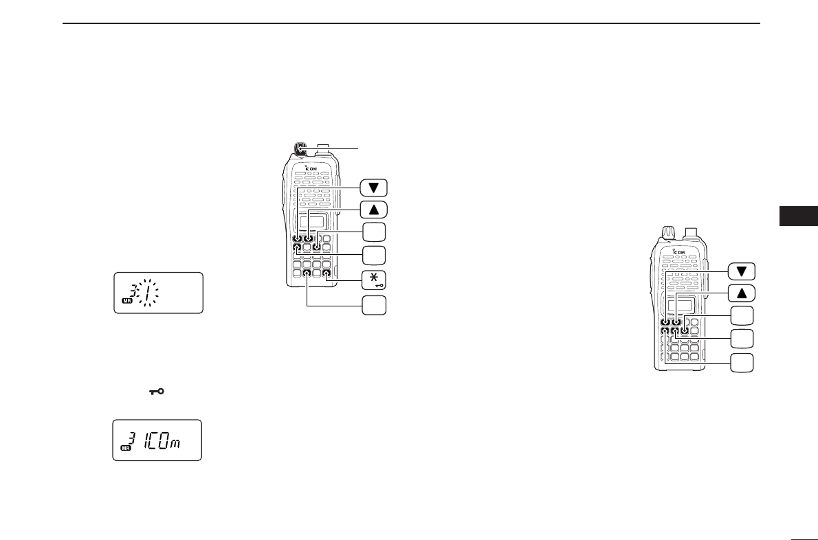
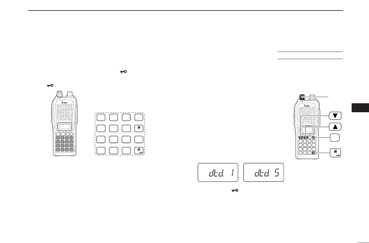
■DTMF transmission rate
When slow DTMF transmission rates are required with DTMF
memory transmission (as for some repeaters), the trans-
ceiver’s rate of DTMF transmission can be adjusted.
qWhile pushing and holding [YY]and
[ZZ], turn the power ON to enter
INI
-
TIAL SET MODE
.
wPush [YY]or [ZZ]several times until
“dtd” appears.
eRotate [VOL] to select the desired
DTMF transmission rate.
•Four rates are available: “1” (100 msec.
intervals) is the fastest; “5” (500 msec.
intervals) is the slowest.
rPush [✱•
ENT
]to exit
INITIAL SET MODE
.
[VOL]
ENT
PWR
USING
INITIAL SET MODE
CALL
DUP SCAN
PRIO
ENT
SET
H/M/L
OPTSKIP
BANK
TONE
T.SCANP.BEEP
MR CLRFUNC
987
4
123
AB DC
560
30
SCAN OPERATION
8
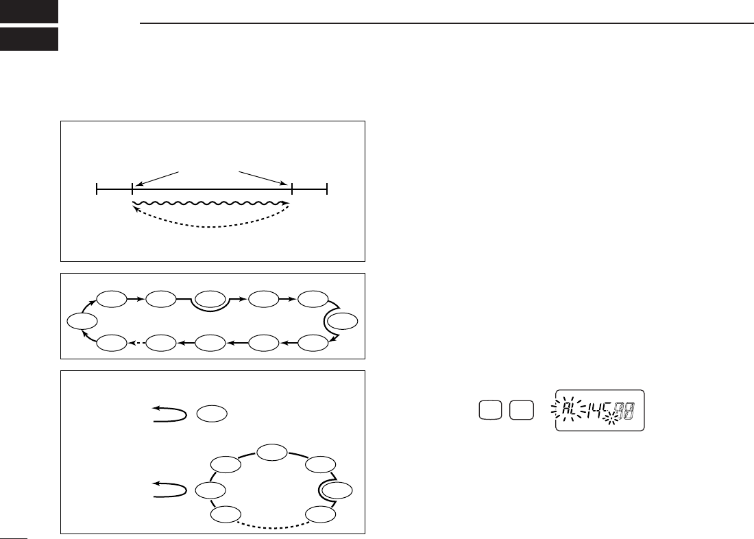
■Programmed scan
Programmed scan repeatedly scans between two user pro-
grammed frequencies (memory channels “1A–3A” and
“1b–3b”) or scans between upper and lower band edges. This
scan is useful for checking for signals within a specific fre-
quency range such as repeater output frequencies, etc.
Scans between lower (start) and high (stop) frequency.
qPush [D•
CLR
]to select VFO mode, if necessary.
wPush [A•
FUNC
]and [5•
SCAN
]to start the scan, then a se-
lected scan edge appears as “P1,” “P2,” “P3” or “AL.”
•To change the scan edge, push [A•
FUNC
]and [8•
SET
]several
times until the desired scan edge appears.
• “AL” for full scan, “P1”, “P2” and “P3” for programmed scan be-
tween the programmed scan edge channels as “1A”–“1b,”
“2A”–“2b” and “3A”–“3b.”
•To change the scan direction, push [YY]or [ZZ].
• When [VOL] is assigned as tuning dial, rotate [VOL] to change
the scan direction. (pgs. 14, 65)
ePush [D•
CLR
]to stop the scan.
Push
SCAN
FUNC
A
5
PROGRAMMED SCAN
MEMORY (SKIP) SCAN
PRIORITY WATCH
Band
edge Band
edge
Start
1A
2A
3A
End
1b
2b
3b
Scan edges
Scan
Jump
SKIP SKIP
SKIP
Mch 1
Mch 0
Mch 2 Mch 3
Mch 3
Mch 4 Mch 5
Mch 10
Mch 199
Mch 9 Mch 8 Mch 7
Mch 6
Mch 1
Mch 2
Mch 3
Mch 4
Mch 5
Mch 199
Mch 6
VFO frequency
145.20 MHz
VFO frequency
145.20 MHz
5 sec. 50 msec.
5 sec. 50 msec.
Priority channel
Priority channels
Memory
scan
Priority memory channel watch
Priority memory channel scan
Programmed scan P1 scans between 1A and 1b, P2 scans be-
tween 2A and 2b, and P3 scans between 3A and 3b frequencies.
■Scan types
31
8
SCAN OPERATION
8
NOTE: Scan edges, 1A–3A/1b–3b, must be programmed
in advance. Program them in the same manner as regular
memory channels. (p. 22)
If identical frequencies are programmed into the scan
edges, programmed scan will not proceed.
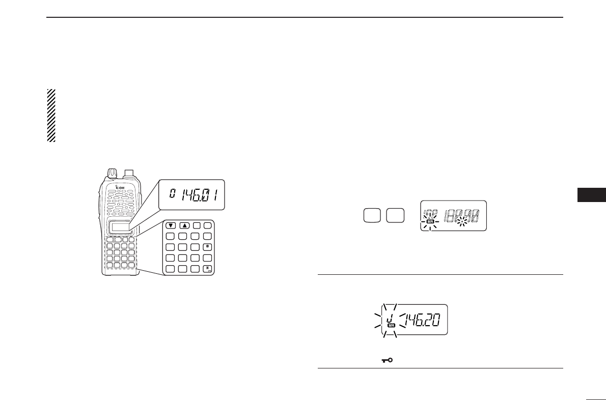
■Memory scan
Memory scan repeatedly scans all programmed memory
channels, except those set as skip channels.
qPush [C•
MR
]to select memory mode, if necessary.
•“
X” appears.
•See below to select bank scan.
wPush [A•
FUNC
]and [5•
SCAN
]to start the scan.
•To change the scan direction, push [YY]or [ZZ].
• When [VOL] is assigned as tuning dial, rotate [VOL] to change
the scan direction. (pgs. 14, 65)
ePush [D•
CLR
]to stop the scan.
• Bank scan —Select the desired bank in step qabove.
qPush [A•
FUNC
]and [#•
BANK
]to select memory bank mode.
wRotate [VOL] to select the desired bank, A to J.
ePush [✱•
ENT
](or [D•
CLR
]) to select the bank.
Push
SCAN
FUNC
A
5
MONI
CALL
DUP SCAN
PRIO
ENT
SET
H/M/L
OPTSKIP
BANK
TONE
T.SCANP.BEEP
MR CLRFUNC
PWR
987
4
123
AB DC
560
32
8SCAN OPERATION
■Skip channels
In order to speed up the scan rate, you can select memory
channels you don’t wish to scan as skip channels.
qPush [C•
MR
]to select memory mode, if necessary.
•“
X” appears.
wSelect a memory channel to set as a skip channel.
ePush [A•
FUNC
]and [6•
SKIP
]to toggle the skip setting ON
and OFF.
•“SKIP” appears when the channel is set as a skip channel.
■Priority watch
Priority watch checks for signals on “priority channels” while
operating on a VFO frequency.
DMemory or call channel watch
While operating on a VFO frequency, memory or call channel
watch monitors for signals in the selected memory or call
channel every 5 sec.
qSelect the desired memory channel or the call channel.
wPush [D•
CLR
]to select VFO mode.
ePush [A•
FUNC
], then push [7•
PRIO
]to start watching.
•VFO is displayed, then the decimal point “.”, on the frequency
readout blinks.
•The priority channel is monitored every 5 sec.
• When the signal is detected on the priority channel, the watching
is suspended according to the setting of the scan resume condi-
tion.
rPush [D•
CLR
]to stop watching.
5 sec. 50 msec.
VFO frequency Memory channel
Push
“SKIP” appears
SKIP
FUNC
A
6
33
8
SCAN OPERATION
8
DMemory scan watch
While operating on a VFO frequency, memory scan watch
monitors for signals in each memory channel in sequence,
every 5 sec.
qPush [C•
MR
]to select memory mode, if necessary.
•“X” appears.
wPush [A•
FUNC
], then push [5•
SCAN
]to start the memory
scan.
ePush [A•
FUNC
], then push [7•
PRIO
]to start the watching.
•VFO is displayed, then the decimal point “.”, on the frequency
readout blinks.
• When the signal is detected on the priority channel, the watching
is suspended according to the setting of the scan resume condi-
tion.
rPush [D•
CLR
]to stop the watching.
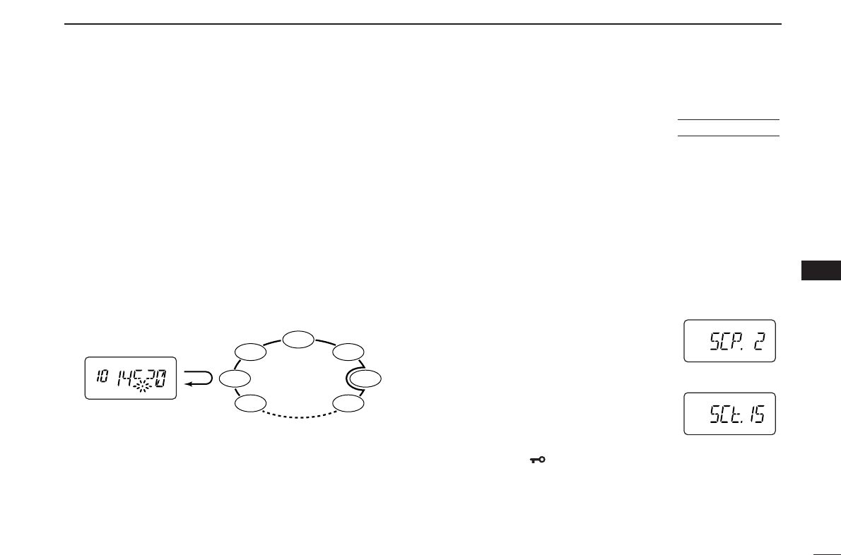
■Scan resume condition
When a signal is received during scanning, the scan resume
condition determines what action the transceiver takes. The
transceiver has 2 scan resume conditions available as
illustrated below. Use
SET MODE
to select the one which best
suits your needs.
qPush [A•
FUNC
], then push [8•
SET
]to enter
SET MODE
.
wPush [YY]or [ZZ]several times until “SCP” or “SCt” ap-
pears.
eRotate [VOL] to select the desired scan resume condition.
•Pause scan:
When receiving a signal, scan pauses on
the signal until it disappears. Resumes
2sec. after the signal disappears.
•Timer scan:
When receiving a signal, scan pauses on
the signal for 5 sec., 10 sec. or 15 sec.,
then resumes.
rPush [✱•
ENT
](or [D•
CLR
]) to set and exit
SET MODE
.
Timer scan
Pause scan
USING
SET MODE
SKIP
Mch 1
Mch 2
Mch 3
Mch 4
Mch 5
Mch 199
Mch 6
Priority channel
Memory
scan
5 sec.
50 msec.
VFO frequency
■Tone squelch
DOperation
The tone squelch opens only when receiving a signal con-
taining a matching subaudible tone. You can wait for calls
from group members using the same tone and not hear other
signals.
qSet the operating frequency.
•
Set the volume and squelch to the desired level as the normal op-
eration.
wSet the desired subaudible tone in
SET MODE
.
• See page 35 for programming.
ePush [A•
FUNC
], then push [1•
TONE
].
•Repeat several times until “ ” appears when selecting CTCSS,
or “ ” appears when selecting DTCS.
rWhen the received signal includes a matching tone,
squelch opens and the signal can be heard.
• When the received signal’s tone does not match, tone squelch
does not open, however, the S-indicator shows signal strength.
• To open the squelch manually, push and hold [MONI].
tTransmit in the normal way.
yTo cancel the tone squelch, push [A•
FUNC
]and [1•
TONE
].
•Repeat several times until “ ” or “ ” disappears.
NOTE: The transceiver has 50 tone frequencies and con-
sequently their spacing is narrow compared to units having
38 tones. Therefore, some tone frequencies may receive
interference from adjacent tone frequencies.
To prevent interference from adjacent tone frequencies,
using the frequencies as in the following table, is recom-
mended.
• Recommended CTCSS frequencies (Unit: Hz)
• Recommended DTCS codes
023
025
026
031
032
043
047
051
054
065
071
072
073
074
114
115
116
125
131
132
134
143
152
155
156
162
165
172
174
205
223
226
243
244
245
251
261
263
265
271
306
311
315
331
343
346
351
364
365
371
411
412
413
423
431
432
445
464
465
466
503
506
516
532
546
565
606
612
624
627
631
632
654
662
664
703
712
723
731
732
734
743
754
67.0
69.3
71.9
74.4
77.0
79.7
82.5
85.4
88.5
91.5
94.8
97.4
100.0
103.5
107.2
110.9
114.8
118.8
123.0
127.3
131.8
136.5
141.3
146.2
151.4
156.7
162.2
167.9
173.8
179.9
186.2
192.8
203.5
210.7
218.1
225.7
233.6
241.8
250.3
D
Push FUNC
A
TONE
1
CTCSS DTCS
D
34
SUBAUDIBLE TONES
9
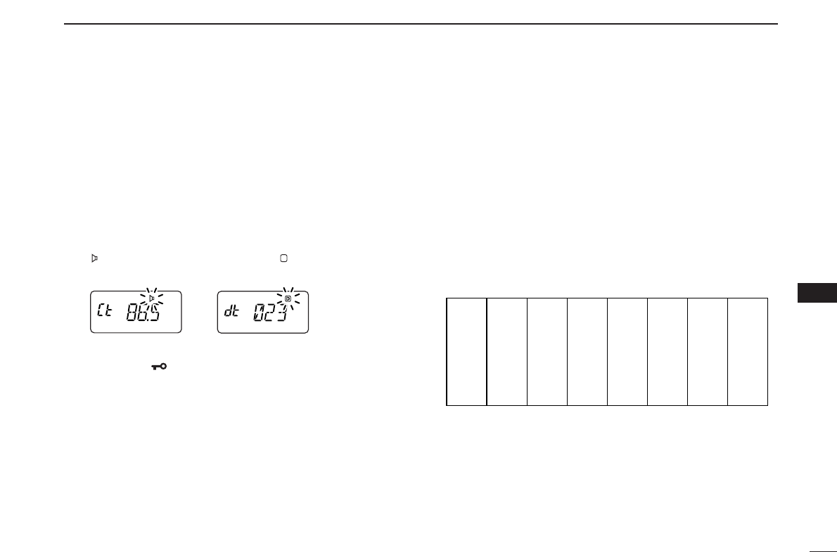
35
9
SUBAUDIBLE TONES
9
Separate tone frequencies can be select for tone squelch op-
eration rather than repeater operation (the same range of
tones is available— see right below). Like the repeater tones,
these are set in
SET MODE
.
qSelect VFO or memory channel.
wPush [A•
FUNC
], then push [8•
SET
]to enter
SET MODE
.
ePush [YY]or [ZZ]several times until “Ct” appears when se-
lecting CTCSS, or “dt” appears when selecting DTCS.
•“ ” blinks when selecting CTCSS, or “ ” blinks when selecting
DTCS.
rRotate [VOL] to select the desired subaudible tone.
tPush [✱•
ENT
](or [D•
CLR
]) to program the selected tone
and exit
SET MODE
.
•The recommended CTCSS frequencies or DTCS codes are
shown at previous page.
When
SET MODE
is selected from memory mode.
The tone squelch frequency is not stored in the selected
memory channel unless you follow steps yand u.
yPush [A•
FUNC
], then push and hold [C•
MR
]for 1 sec. to
transfer the contents to VFO.
•3 beeps are emitted.
•VFO mode is selected automatically.
uPush [A•
FUNC
], then push and hold [C•
MR
]for 1 sec.
•3 beeps are emitted.
•Available CTCSS tone frequency list (unit: Hz)
67.0
69.3
71.9
74.4
77.0
85.4
88.5
91.5
94.8
97.4
100.0
103.5
79.7
82.5
107.2
110.9
114.8
118.8
123.0
127.3
131.8
136.5
141.3
146.2
151.4
156.7
159.8
162.2
165.5
167.9
171.3
173.8
177.3
179.9
183.5
186.2
189.9
192.8
196.6
199.5
203.5
206.5
210.7
218.1
225.7
229.1
233.6
241.8
250.3
254.1
D
DSetting subaudible tones for tone squelch operation
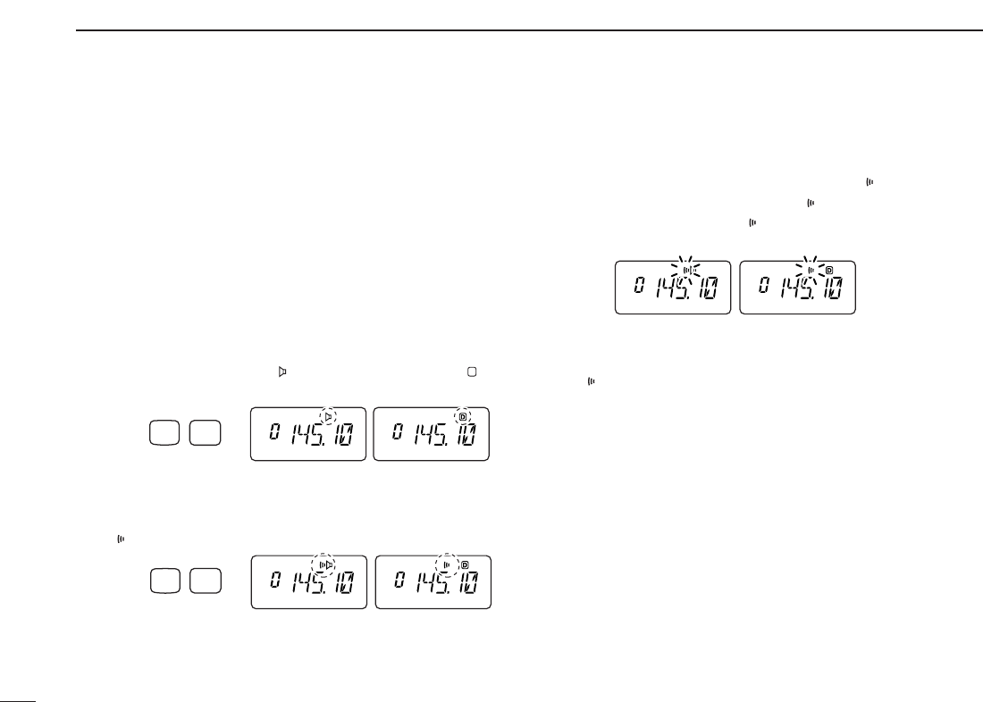
36
9SUBAUDIBLE TONES
■Pocket beep operation
This function listens for subaudible tones and can be used as
a “common pager” to inform you that someone has called
when you were away from the transceiver.
DWaiting for a call from a specific station
qSet the operating frequency.
wSet the desired CTCSS tone frequency or DTCS code in
SET MODE
.
• See p. 35 for programming details.
ePush [A•
FUNC
], then push [1•
TONE
].
•Repeat several times until “ ” appears when CTCSS, or “ ” ap-
pears when DTCS is selected.
rPush [A•
FUNC
], then push [2•
P
.
BEEP
]to activate the pocket
beep function.
•“” appears.
tWhen a signal with the matching tone is received, the
transceiver emits beep tones and blinks “ .”
• Beep tones sound for 30 sec. and “ ” blinks. To stop the beeps
manually, push any key. “ ” continues blinking until step yis
operated.
yPush [PTT] to answer.
• “ ” disappears and cancels the pocket beep function automati-
cally.
CTCSS DTCS
Push FUNC
A
P.BEEP
2
CTCSS DTCS
Push FUNC
A
TONE
1
CTCSS DTCS
D
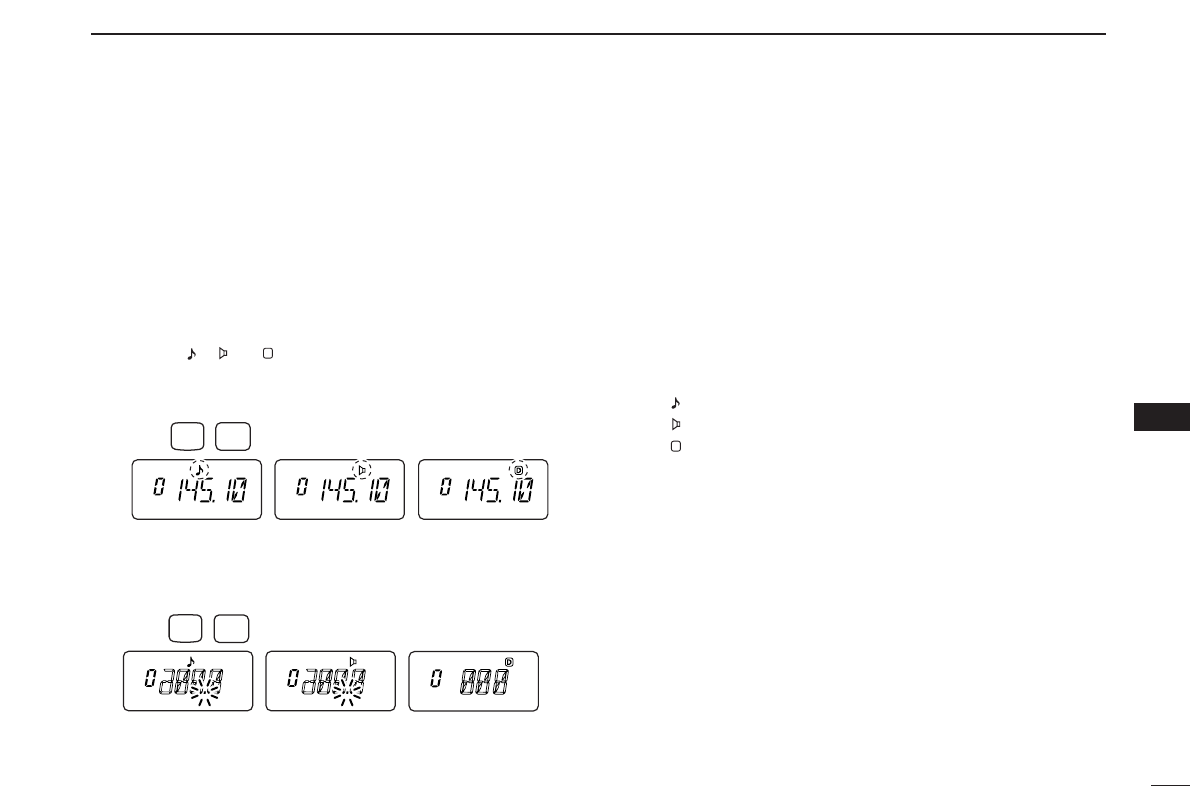
37
9
SUBAUDIBLE TONES
9
■Tone scan
By monitoring a signal on a repeater, or using pocket beep or
tone squelch function, you can determine the tone frequency
necessary to access a repeater or open the squelch.
qSet the frequency to be checked for a tone frequency or
code.
wPush [A•
FUNC
], then push [1•
TONE
].
•Repeat several times to select the type of tone to be scanned.
(One of “ ,” “ ” or “ ” appears)
•Tone scan may be used even if the tone condition or type is not
selected.
ePush [A•
FUNC
], then push [3•
T
.
SCAN
]to start the tone
scan.
• To change the scanning direction, push [YY]or [ZZ].
rWhen the CTCSS tone frequency or DTCS code is
matched, the squelch opens and the tone frequency or
code is temporarily programmed into the selected mode
such as memory or call channel.
•The tone scan pauses when a CTCSS tone frequency or 3-digit
DTCS code is detected.
•The decoded CTCSS tone frequency or 3-digit DTCS code is
used for the tone encoder or tone encoder/decoder depending
on the selected tone condition or type in step w.
-No indication : Cannot be used for operation.
-“ ” : CTCSS tone encoder
-“ ” : CTCSS tone encoder/decoder
-“ ” : DTCS tone encoder/decoder
tPush [D•
CLR
]to stop the scan.
D
Push FUNC
A
T.SCAN
3
Push FUNC
A
TONE
1
D
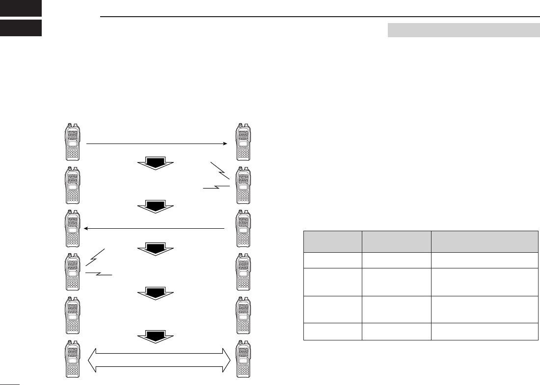
38
PAGER/CODE SQUELCH
10
■Pager function
This function uses DTMF codes for paging and can be used
as a “message pager” to confirm you of a caller’s identification
even when you leave the transceiver temporarily unattended.
■
Code programming
DDBefore programming
The pager and code squelch functions require ID codes and a
group code. These codes are 3-digit DTMF codes and must
be written into the code channels before operation.
qDecide the ID code of each transceiver and a group code
for your group.
wDecide whether you want to return to normal operation or
code squelch operation after a connection is made.
eProgram the ID code, group code and transmit codes
(other station’s codes) as below.
DDCode channel assignment
*
Channel CP automatically memorizes an ID code when receiving a
pager call. The contents in channel CP cannot be changed manually.
Pager selective code (push [PTT])
Beep Beep
Beep
Answer back (manual)
Beep Beep
Beep
Set both transceivers to either
code squelch or non-coded operation
Communication
Requires Optional UT-108
ID OR CODE CHANNEL “RECEIVE ACCEPT” OR
GROUP CODE NUMBER “RECEIVE INHIBIT”
Your ID code
Other parties’
ID code
Group code
Memory space*
0
1–6
One of 1–6
P
“Receive accept” only
“Receive inhibit” should be
programmed in each channel.
“Receive accept” must be
programmed in one channel.
“Receive inhibit” only.
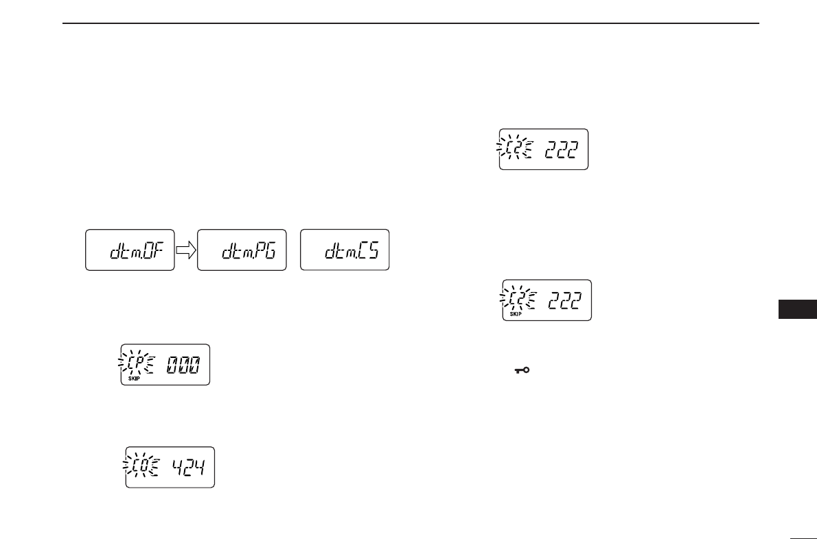
39
10
PAGER/CODE SQUELCH
10
DDCode programming
Your ID code MUST be programmed into code channel C0.
Up to 6 transmit codes (codes that you transmit) are pro-
grammable into code channels, C1 to C6, if required.
qPush [A•
FUNC
], then push [0•
OPT
]to enter
OPTION SET
MODE
.
•Rotate [VOL] to select “dtm.PG” or “dtm.CS,” if “dtm.OF” ap-
pears.
wPush and hold [0•
OPT
]for 1 sec. to enter the code selec-
tion mode.
•One of either “CP” or “C0” to “C6” blinks.
•“C0” is your ID code and “C1” to “C6” are transmit codes.
eRotate [VOL] (or push [YY]/[ZZ]) to select code channel C0.
•Each transceiver should have a different ID code.
rEnter the desired 3-digit ID code via the keypad.
tRotate [VOL] (or push [YY]/[ZZ]) to select a transmit code
channel from C1 to C6.
yEnter the desired 3-digit transmit code via the keypad.
uPush [A•
FUNC
], then push [6•
SKIP
]to set the channel to
“receive inhibit” or “receive accept.”
•When “receive inhibit” is set, “SKIP” appears as below.
•Code channel C0 cannot be set as “receive inhibit.”
•See the table for “receive accept” and “receive inhibit” details
(p. 38).
iRepeat steps tand yto set additional transmit code
channels, if desired.
oPush [✱•
ENT
]or [PTT] to exit code selection mode.
•Receive accept/receive inhibit
➥“Receive accept” (“SKIP” indicator does not appear) ac-
cepts pager calls when the transceiver receives a signal
with a code the same as that in the code channel.
➥“Receive inhibit” (“SKIP” indicator appears) ignores calls
even when the transceiver receives a code the same as
that in the code channel. Transmit codes should therefore
be programmed for “receive inhibit,” otherwise the trans-
ceiver will not reject unnecessary calls.
or

40
10 PAGER/CODE SQUELCH
■Pager operation
DCalling a specific station
qProgram the code channel in advance (p. 39).
wSet the operating frequency.
•
Set the volume and squelch to the desired level as in normal op-
eration.
ePush [A•
FUNC
], then push [0•
OPT
].
•Rotate [VOL] to select “dtm.PG,” if “dtm.CS” or “dtm.OF” ap-
pears.
rSelect the desired transmit code channel:
➥Push and hold [0•
OPT
]for 1 sec. to enter the code se-
lection mode.
➥Rotate [VOL] to select the desired code channel.
➥Push [✱•
ENT
]to return to previous mode.
•100 MHz digit shows “P.”
tPush [PTT] to transmit the pager code.
yWait for an answer back.
•When the transceiver receives an answer back code, the func-
tion display shows the other member’s ID or group code.
uAfter confirming a connection, push [A•
FUNC
] and [0•
OPT
]
to enter
OPTION SET MODE
, then rotate [VOL] to select the
code squelch operation “dtm.CS,” or non-selective calling
system “dtm.OF.”
•DO NOT push any digit keys while code channels C0 to C6 are
displayed, otherwise code channel contents will be changed.
iCommunicate with the other party as normal: push [PTT]
to transmit; release to receive.
DWaiting for a call from a specific station
qSet the operating frequency.
wPush [A•
FUNC
], then push [0•
OPT
].
➥Rotate [VOL] to select “dtm.PG,” if “dtm.CS” or
“dtm.OF” appears.
➥Push [✱•
ENT
]to return to previous mode.
•100 MHz digit shows “P.”
eWait for a call.
•When receiving a call, the caller’s ID or group code appears as
shown at next page.
•DO NOT push any digit keys while code channels C0 to C6 are
displayed, otherwise code channel contents will be changed.
rPush [PTT] to send an answer back call and display the
operating frequency.
tAfter confirming a connection, push [A•
FUNC
] and [0•
OPT
]
to enter
OPTION SET MODE
, then rotate [VOL] to select the
code squelch operation “dtm.CS,” or non-selective calling
system “dtm.OF.”
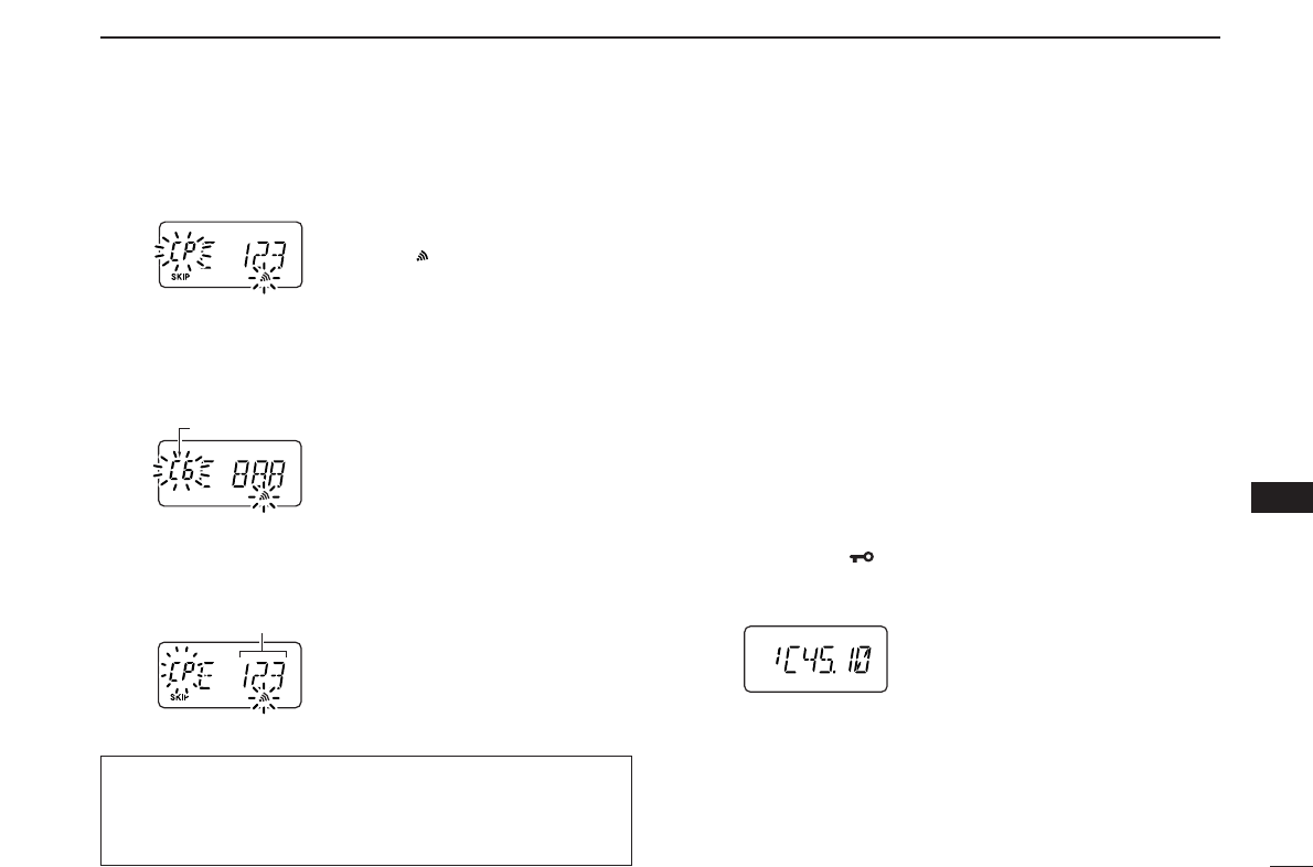
41
10
PAGER/CODE SQUELCH
10
•PERSONAL CALLS
This display appears when you are called with your ID code
and the calling station’s ID code is 123.
•GROUP CALLS
This display appears when you are called with the group
code, 888, and 888 has been programmed into code channel
C6.
•ERROR INFORMATION
When the transceiver receives an incomplete code, “E” and
previously received code appear.
■Code squelch
When using code squelch you will only receive calls from sta-
tions which know your ID or group code. A 3-digit code is sent
each time [PTT] is pushed in order to open the receiving sta-
tion’s code squelch prior to voice transmission.
qSet the operating frequency.
• Set the volume and squelch to the desired level as in normal op-
eration.
wPush [A•
FUNC
], then push [0•
OPT
].
• Rotate [VOL] to select “dtm.CS,” if “dtm.PG” or “dtm.OF” ap-
pears.
eSelect the desired transmit code channel:
➥Push and hold [0•
OPT
]for 1 sec. to enter code selection
mode.
➥Rotate [VOL] to select the desired code channel.
➥Push [✱•
ENT
]to exit code selection mode and return
to previous mode.
•100 MHz digit shows “C.”
rOperate the transceiver in the normal way (push [PTT] to
transmit; release [PTT] to receive).
tTo cancel the code squelch, push [A•
FUNC
]and [0•
OPT
],
then rotate [VOL] to select “dtm.OF.”
•100 MHz digit shows “1” for IC-V82 or “4” for IC-U82 when the
function is cancelled.
Previously received code.
Code channel
“CP” and “ ” blink.
During channel number indication (described on page 16)
To use these functions in channel number indication, the
pager/code squelch setting must be programmed with other
memory contents before selecting channel number indication.
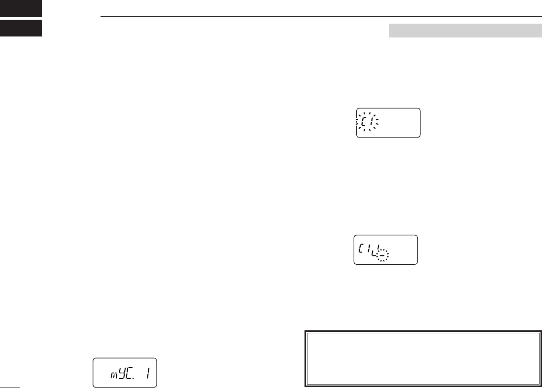
■Digital mode operation
The IC-V82/U82 with optional UT-118
DIGITAL UNIT
can be op-
erated for digital voice mode and low-speed data operation
for both transmit and receive. It can also be connected to a
GPS receiver (compatible with an RS-232 output/NMEA for-
mat/4800 bps) and transmit/receive position data.
■Call sign programming
Four types of call sign memories are available for your own
call sign “myC,” other station call sign “yUC,” nearest repeater
call sign “R1C” and another zone’s repeater call sign “R2C.”
Each call sign memory can store up to 6 call signs, and each
call sign programmed up to 8 characters.
DDYour own call sign programming
Your own call sign must be programmed for both digital voice
and low-speed data communications (including GPS trans-
mission).
qPush [A•
FUNC
]and [0•
OPT
]to enter
OPTION SET MODE
, then
push [YY]or [ZZ]several times to select the call sign select
mode.
•“myC” appears.
wPush and hold [0•
OPT
]for 1 sec. then rotate [VOL] to se-
lect the desired call sign channel.
ePush [YY]to select call sign programming mode.
•The 1st digit blinks and channel indication stops blinking.
rRotate [VOL] to set the desired character or code.
•Push [ZZ]or [YY]to move the cursor to left or right, respectively.
tPush [YY]to select 2nd digit, then rotate [VOL] to select
the desired character or code.
•2nd digit blinks (1st digit stops blinking).
•Repeat this step for programming your own call sign.
yPush [0•
OPT
]to save the call sign.
uRotate [VOL] to select an another channel from “C1” to
“C6.”
iRepeat steps wto uto program your own call sign channels.
42
DIGITAL MODE OPERATION
11 Requires Optional UT-118
NOTE: All digital (DV) mode operation/settings require an
optional UT-118
DIGITAL UNIT
. A transceiver without UT-118
does not indicate any items for the digital (DV) mode de-
scribed in this section.

43
11
DIGITAL MODE OPERATION
11
DDYour call sign note programming
You can add information to your own call sign such as oper-
ating radio type or area. Call sign notes are coupled with the
same channel number of your own call signs, and they are
transmitted or indicated after your own call signs. Call sign
notes can be stored up to 6 types, and each call sign note
programmed up to 4 characters.
qPush [A•
FUNC
]and [0•
OPT
]to enter
OPTION SET MODE
, then
push [YY]or [ZZ]several times to select the call sign select
mode.
•“myS” appears.
wPush and hold [0•
OPT
]for 1 sec. then rotate [VOL] to se-
lect the desired call sign note channel.
ePush [YY]to set into call sign note programming mode.
•The 1st digit blinks and channel indication stops blinking.
rRotate [VOL] to select the desired character or code.
•Push [ZZ]or [YY]to move the cursor to left or right, respectively.
tPush [YY]to select 2nd digit, then rotate [VOL] to select
the desired character or code.
•2nd digit blinks (1st digit stops blinking).
•Repeat this step for programming your own call sign note.
yPush [0•
OPT
]to save the call sign.
uRotate [VOL] to select an another channel from “C1” to
“C6.”
iRepeat steps wto uto program your call sign note chan-
nels.
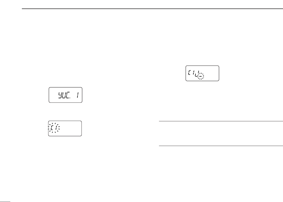
44
11 DIGITAL MODE OPERATION
DDStation call sign programming
Station call sign must be programmed for the specified sta-
tion call as well as repeater operation in both digital voice and
low-speed data communications.
qPush [A•
FUNC
]and [0•
OPT
]to enter
OPTION SET MODE
, then
push [YY]or [ZZ]several times to select the call sign select
mode.
•“yUC” appears for station call sign.
wPush and hold [0•
OPT
]for 1 sec. then rotate [VOL] to se-
lect the desired call sign channel.
ePush [YY]to select call sign programming mode.
•The 1st digit blinks and channel indication stops blinking.
rRotate [VOL] to select the desired character or code.
•Push [ZZ]or [YY]to move the cursor to left or right, respectively.
tPush [YY]to select 2nd digit, then rotate [VOL] to select
the desired character or code.
•2nd digit blinks (1st digit stops blinking).
•Repeat this step for programming station call sign.
yPush [0•
OPT
]to save the call sign.
uRotate [VOL] to select an another channel from “C1” to
“C6.”
iRepeat steps wto uto program another station call sign
channels.
✔
For your information:
Station and/or repeater call sign can be programmed from
Received call record when a call is received.
See page 46 for details.
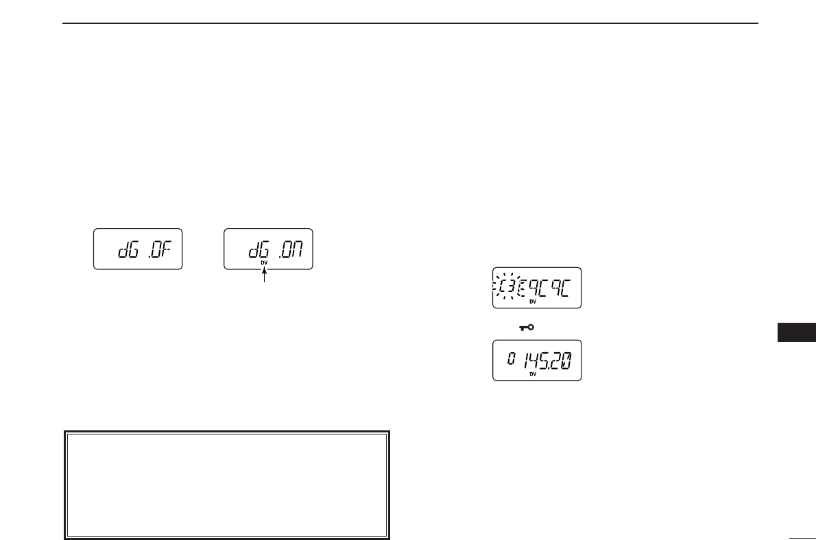
45
11
DIGITAL MODE OPERATION
11
■Digital voice mode operation
qSet the desired frequency in VFO mode. (pgs. 13, 14)
•Select output power, if desired. (p. 15)
wPush [A•
FUNC
]then [0•
OPT
]to enter
OPTION SET MODE
,
then push [YY]or [ZZ]several times to select the digital se-
lect mode.
•“DG” appears.
eRotate [VOL] to turn the digital mode ON.
r
Push
[YY]
once to select the your own call sign select mode.
•“myC” appears.
tPush and hold [0•
OPT
]for 1 sec. then rotate [VOL] to se-
lect the desired your own call sign channel, if you have
programmed several call signs.
• After selecting the your own call sign, push [0•
OPT
]to return to
OPTION SET MODE
.
DDWhen sending a CQ
(continued from step t)
ySelect “CQ” as the station call sign.
-Push [YY]or [ZZ]several times to select the call sign se-
lect mode.
•“yUC” appears.
-Push and hold [0•
OPT
]for 1 sec. then rotate [VOL] to se-
lect the desired channel.
-Push and hold [0•
OPT
]for 1 sec. to set “CqCqCq.”
-Push [✱•
ENT
](or [D•
CLR
]) to exit
OPTION SET MODE
.
uPush and hold [PTT] to transmit and speak into the micro-
phone at normal voice level.
•Transmit indicator appears and the RF meter shows the output power.
iRelease [PTT] to return to receive.
•The other station call sign will be received.
•Received call signs can be stored into the received call record
automatically. See page 46 for details.
NOTE: In the digital mode operation; when “BUSY” indi-
cator appears but no sound comes out the speaker, it may
be caused by the interference of analog FM mode. In this
case, to prevent interference of analog FM mode, set the
digital monitor setting (p. 49) to “An (analog)” then listen
on the channel before transmitting by pushing [MONI].
Appears
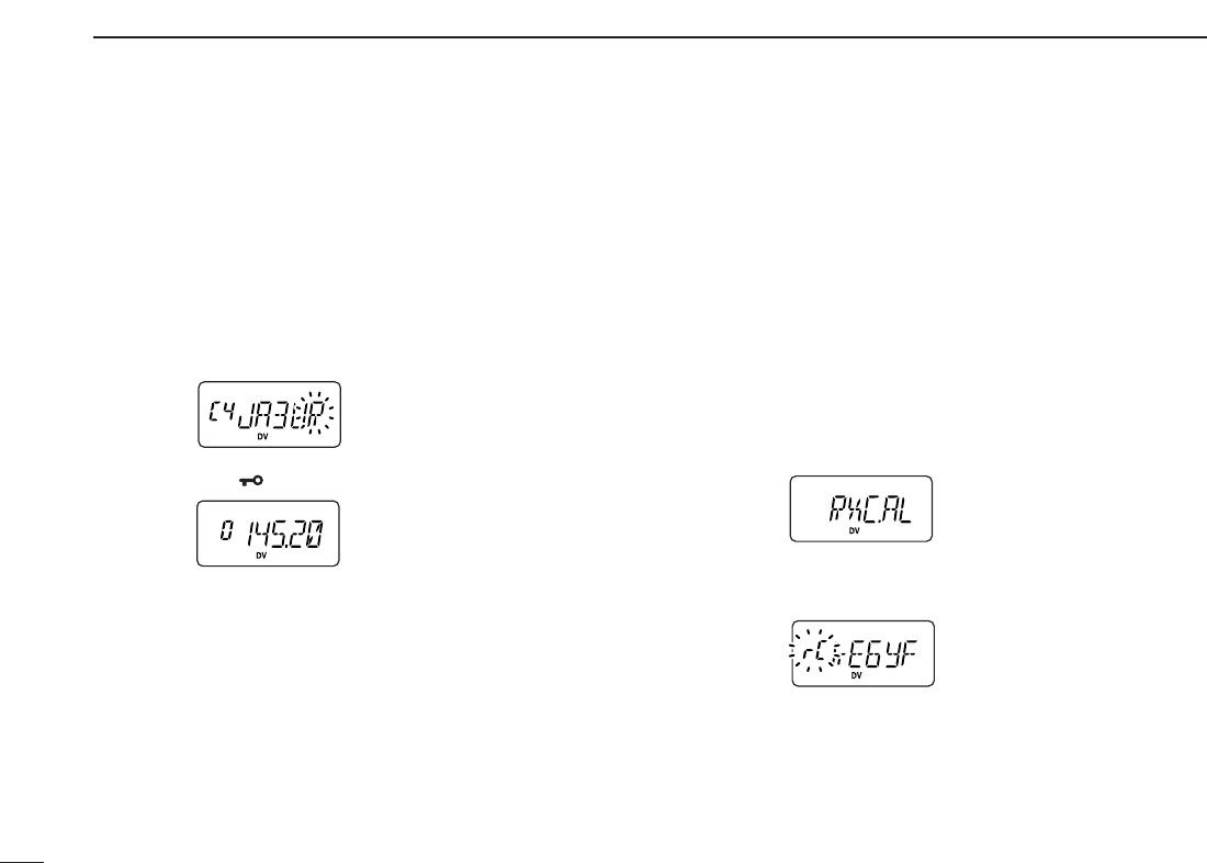
46
11 DIGITAL MODE OPERATION
DDWhen calling the desired station
(continued from p. 45 step t)
ySelect the desired station call sign.
-
Push [YY]or [ZZ]several times
to select the call sign select
mode.
•“yUC” appears.
-Push [0•opt] then rotate [VOL] to select the desired call
sign (pre-programmed), or set the desired call sign. (see
p. 44)
-Push [✱•
ENT
]to exit
OPTION SET MODE
.
uPush and hold [PTT] to transmit and speak into the micro-
phone at normal voice level.
•Transmit indicator appears and the RF meter shows the output power.
iRelease [PTT] to return to receive.
•The other station call sign will be received.
•Received call signs can be stored into the received call record
automatically (see next set of instructions).
■When receiving a digital call
When an individual station call is received, the calling station
call sign can be stored into the received call record.
The record is cleared once the transceiver is turned OFF.
DDReceived call record
qPush [A•
FUNC
]then [0•
OPT
]to enter
OPTION SET MODE
,
then push [YY]or [ZZ]several times
to select the received
call indication.
•“RXC.AL,” “RSC.AL,” “R1C.AL,” and “R2C.AL” are available for
the received station call sign, station call sign note, repeater 1
and repeater 2 call signs, respectively.
wTo confirm the received call, push and hold [0•
OPT
]for 1
sec. to enter the received call sign indication mode.
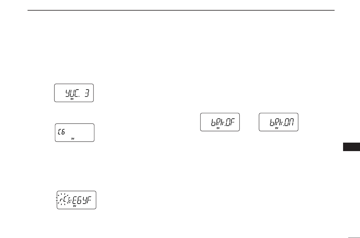
47
11
DIGITAL MODE OPERATION
11
DDTo store a received call
qPush [A•
FUNC
]and [0•
OPT
]to enter
OPTION SET MODE
, then
push [YY]or [ZZ]several times to select the call sign select
mode.
•“yUC” appears for station call sign.
•“R1C” or “R2C” appears for repeater call sign.
wPush and hold [0•
OPT
]for 1 sec. to display call sign, rotate
[VOL] to select the blank channel or erasable channel.
ePush [0•
OPT
]then, push [YY]or [ZZ]several times to select
the received call indication.
•“RXC.AL” appears for received station call sign.
•“R1C.AL” or “R2C.AL” appears for received repeater call sign.
rTo confirm the received call, push and hold [0•
OPT
]for 1
sec. to enter the received call sign indication mode.
tPush and hold [0•
OPT
]for 1 sec. to store the call sign into
the selected (in step w) station call sign channel or re-
peater call sign channel.
■Break-in communication
The break-in function allows you to break into an another sta-
tion’s communications in both digital voice and low-speed
data operation.
qWhile receiving another station’s communication, push
[A•
FUNC
]then [0•
OPT
]to enter
OPTION SET MODE
.
wPush [YY]or [ZZ]several times to select the break-in set-
ting, then turn the break-in setting ON.
•“bRk” appears.
eWhen both stations are in standby, transmit to send a
break-in call.
•Programmed call sign station receives the break-in call as well
as your own call sign.
rWait for the reply call from the station who receives the
break-in call.
tAfter you receive a reply, communicate normally.
yTo cancel the break-in, push [A•
FUNC
]and [0•
OPT
], then ro-
tate [VOL] to turn OFF.
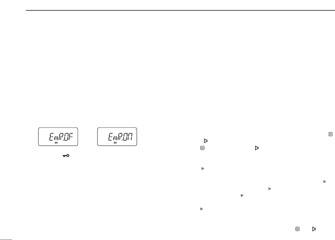
48
11 DIGITAL MODE OPERATION
■EMR communication
The EMR communication mode is available for digital mode
operation. In the EMR communication mode, no call sign set-
ting is necessary. When an EMR communication mode sig-
nal is received, the audio (voice) will be sound in the specified
level (‘12’ level) even the volume setting is set to any level.
qSet the desired frequency then push [A•
FUNC
]and [0•
OPT
]
to enter
OPTION SET MODE
.
wPush [YY]or [ZZ]several times to select the EMR setting,
then rotate [VOL] to turn the EMR setting ON.
•“EmR” appears.
ePush [✱•
ENT
](or [D•
CLR
]) to exit
OPTION SET MODE
, then
operate the transceiver normal way.
rTo cancel the EMR communication mode, push [A•
FUNC
]
and [0•
OPT
], then rotate [VOL] to turn OFF.
■Pocket beep operation
This function uses a digital code/call sign for calling and can
be used as a “common pager” to inform you that someone
has called while you were away from the transceiver. The dig-
ital code or call sign squelch does not function while in a low-
speed data communication.
DDWaiting for a call from a specific station
qSet the operating frequency.
wProgram the digital code or call sign.
•See p. 53, “Digital code setting” or p. 42 “Call sign program-
ming.”
ePush [A•
FUNC
]and [1•
TONE
]one or more times until “ ”
or “ ” appears in the function display.
•“ ” for call sign squelch; “ ” for digital code squelch operation.
rPush [A•
FUNC
], then push [2•
P
.
BEEP
]to activate the pocket
beep function.
•“ ” appears.
tWhen a signal with the matched call sign/digital code is re-
ceived, the transceiver emits beep tones and blinks “ .”
• Beep tones sound for 30 sec. and “ ” blinks. To stop the beeps man-
ually, push any key. “ ” continues blinking until step yis operated.
yPush [PTT] to answer.
• “ ” disappears and cancels the pocket beep function automati-
cally.
uTo cancel the call sign/digital code squelch, push [A•
FUNC
]
and [1•
TONE
]one or more times until or “ ” or “ ” disap-
pears.
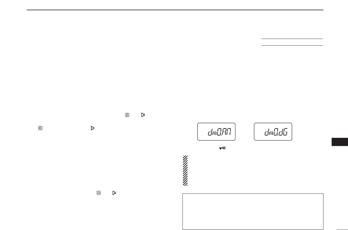
49
11
DIGITAL MODE OPERATION
11
■Digital squelch functions
The digital code (CSQL) or call sign (DSQL) squelch opens
only when receiving a voice signal with the same pre-pro-
grammed digital code or call sign, respectively. The digital
code or call sign squelch does not function while in a low-
speed data communication.
qSet the operating frequency.
wProgram the digital code or call sign.
•See p. 53, “Digital code setting” or p. 42 “Call sign program-
ming.”
ePush [1•
TONE
]one or more times until “ ” or “ ” appears
in the function display.
•“ ” for call sign squelch; “ ” for digital code squelch operation.
rWhen a signal with the matched call sign/digital code is re-
ceived, the squelch opens and the signal can be heard.
•When the received signal includes an unmatched call sign/digital
code, the squelch does not open. However, the S-meter shows
the received signal strength.
•To open the squelch manually, push and hold [MONI].
tOperate the transceiver in the normal way (push [PTT] to
transmit; release [PTT] to receive).
yTo cancel the call sign/digital code squelch, push [1•
TONE
]
one or more times until or “ ” or “ ” disappears.
■Digital monitor
This function is used to listen to the analog signal (FM mode
signal) without changing the operating mode during digital
(DV mode) operation.
qWhile pushing and holding [YY]and [ZZ], turn the power ON
to enter
INITIAL SET MODE
.
wPush [YY]or [ZZ]several times until “dmO” appears.
eRotate [VOL] to turn the digital monitor setting to “An” or
“dG.”
•“An”: Activate for monitoring the analog (FM mode) signals.
(default)
•“dG”: Activate to open the call sign or digital code squelch.
rPush [✱•
ENT
](or [D•
CLR
]) to exit
INITIAL SET MODE
.
NOTE: When “digital monitor setting” is set to “An (ana-
log),” the monitor function (pushing [MONI]) works as the
analog monitor for receiving an FM signal. Then digital
monitor function is activated using the Squelch control
(pushing [MONI] and [YY]or [ZZ]).
USING
INITIAL SET MODE
✔
While scanning in digital mode:
• The call sign squelch function deactivate, then after can-
celling the scan it will activate again.
• Scan stops near channel in a 5 kHz tuning steps, and then
no sound comes out.
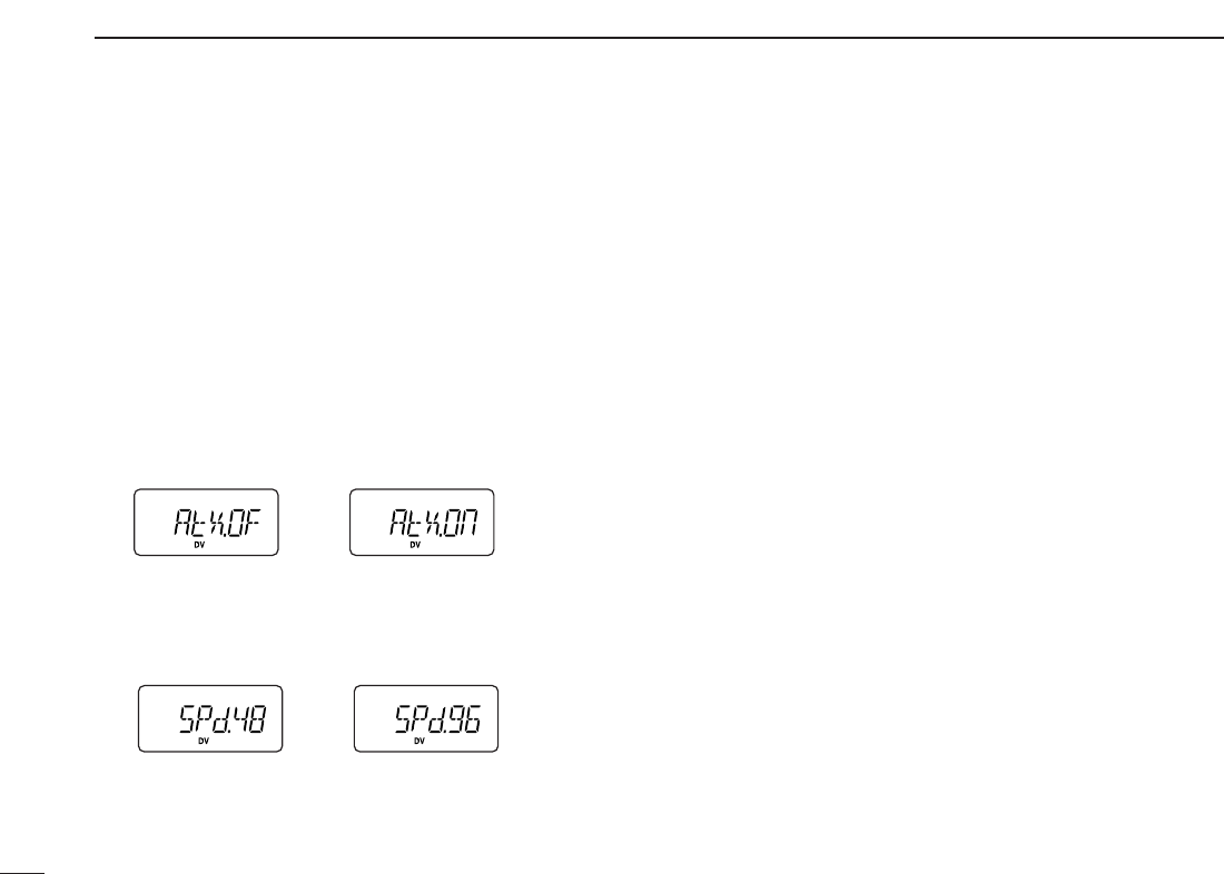
50
11 DIGITAL MODE OPERATION
■
Low-speed data communication
In addition to the digital voice communication, a low-speed
data communication is available (Refer p. 4 about the trans-
ceiver-PC connection details).
qSet the desired frequency.
wVerify and set repeater call, transmit output power and
other conditions.
ePush [A•
FUNC
]then [0•
OPT
]to enter
OPTION SET MODE
,
then push [YY]or [ZZ]several times to select the automatic
data transmission setting. (see p. 53)
•“AtX” appears.
•Skip this setting, if you want to transmit manually.
rPush [YY]once to select the data communication speed
setting. (see p. 54)
•“SPd” appears.
•Select suitable data speed for your PC or application.
tStart up the low-speed data communication application.
ySet the application as follows.
•Port : The same COM port number as trans-
ceiver’s
•Baud rate : 4800 bps or 9600 bps (same as step r)
•Data : 8 bit
•Parity : None
•Stop : 1 bit
•Flow control: Xon/Xoff
uTransceiver automatically transmits or receives the data
while the computer is sending data to transceiver. Or push
and hold [PTT] to transmit, release to receive the data
manually.
•Refer to the instructions of the application that how to send or re-
ceive data.
4800 bps 9600 bps
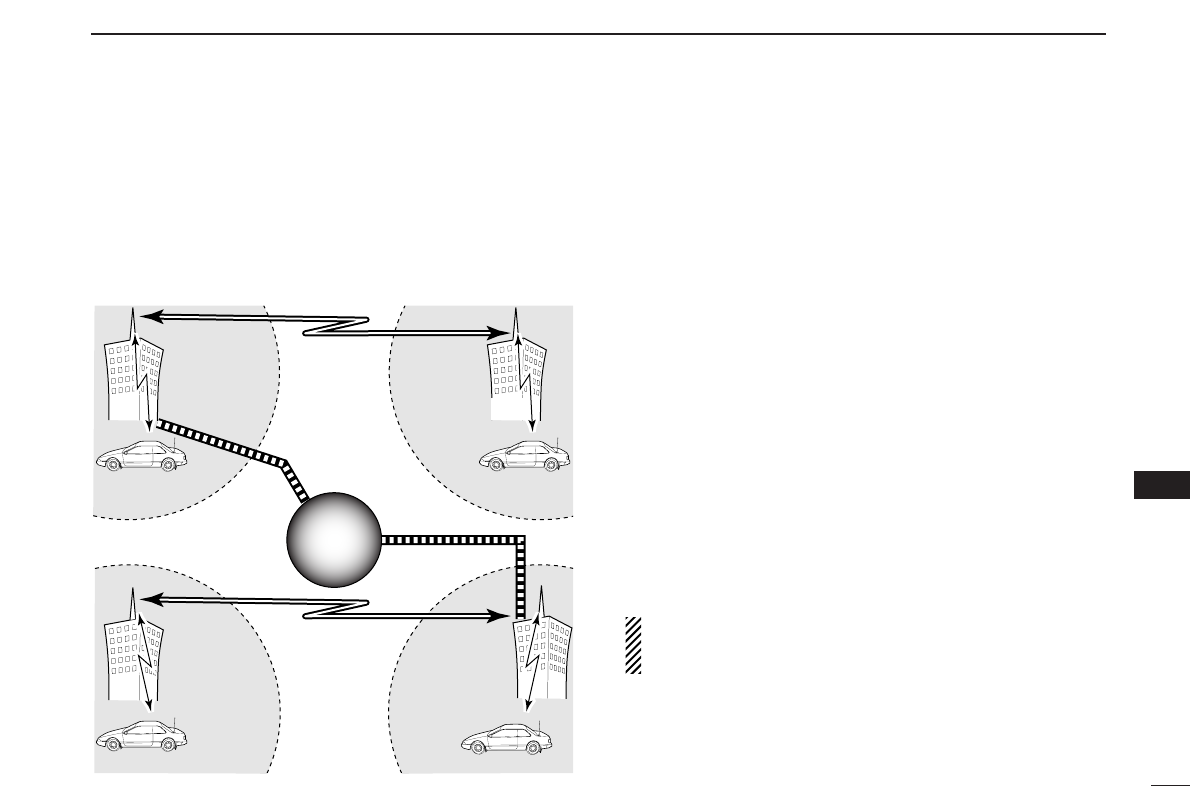
51
11
DIGITAL MODE OPERATION
11
■About D-STAR system
In the D-STAR system, repeater linking via a 10 GHz band
backbone and internet network (gateway connection) capa-
bilities are available. This system provides you with much
wider coverage range during digital voice mode operation.
•D-STAR system outline (440 MHz band)
For current existing repeater operation, stations that are com-
municating must be in the same repeater’s operating area.
However, in the D-STAR system as in the illustration at left,
the repeaters can be linked via the system repeaters (with a
10 GHz signal). Thus stations A and B can communicate even
though they are in different repeater operating areas.
Also, the D-STAR system repeaters are connectable through
the internet network— gateway connection capability.
For example, when station B uses the gateway connection
station B can communicate with the station C!
By using the gateway connection, long distance communica-
tions like DX operation may be possible with 144 MHz (for IC-
V82)/ 440MHz (for IC-U82) digital voice!
In the D-STAR system, an independent repeater’s operating
area is called an Area and a group that links repeaters via a
10 GHz backbone is called a Zone.
NOTE: The digital repeater for either 144 MHz or 440 MHz
of amateur radio bands operation is not available at pre-
sent of November 2004. It will be designed in the future.
Station A
Repeater A
Repeater D
440 MHz signal
Station C
Repeater C
440 MHz signal
10 GHz signal
440 MHz
signal
Station D
Station B
Repeater B
10 GHz signal
440 MHz signal
Internet
network
Internet
network
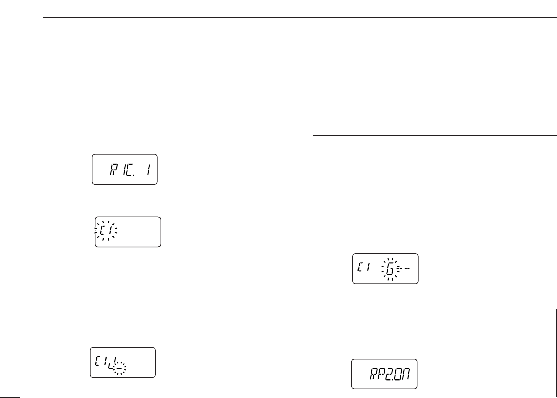
52
11 DIGITAL MODE OPERATION
■Repeater call sign programming
Repeater call sign must be programmed for repeater opera-
tion in both digital voice and low speed data communications.
qPush [A•
FUNC
] and [0•
OPT
]to enter
OPTION SET MODE
, then
push [YY]or [ZZ]several times to select the call sign items.
•“R1C” or “R2C” appears for repeater call sign.
wPush and hold [0•
OPT
]for 1 sec. then rotate [VOL] to se-
lect the desired call sign channel.
ePush [YY]to select call sign programming mode.
•The 1st digit blinks and channel indication stops blinking.
rRotate [VOL] to set the desired character or code.
•Push [ZZ]or [YY]to move the cursor to left or right, respectively.
tPush [YY]to select 2nd digit, then rotate [VOL] to set the
desired character or code.
•2nd digit blinks (1st digit stop blinking).
•Repeat this step for programming repeater call sign.
yPush [0•
OPT
]to save the call sign.
uRotate [VOL] to select an another channel from “C1” to
“C6.”
iRepeat steps wto uto program other repeater call sign
channels.
✔
For your information:
Station and/or repeater call sign can be programmed from
Received call record when a call is received.
See page 46 for details.
✔
For your information:
Repeater call sign can be programmed for gateway connec-
tion capabilities at step rfor connecting to the another Area
or Zone.
•“G” appears or disappears as the 8th digit when pushing [8•
SET
].
While using the repeater 2 (other Area or Zone) system, the
repeater 2 setting must be selected ON in
OPTION SET MODE
.
•“R2C” (Repeater 2 call sign) can be programmed or used when
“RP2” (Repeater 2 setting) is set to ON (default).
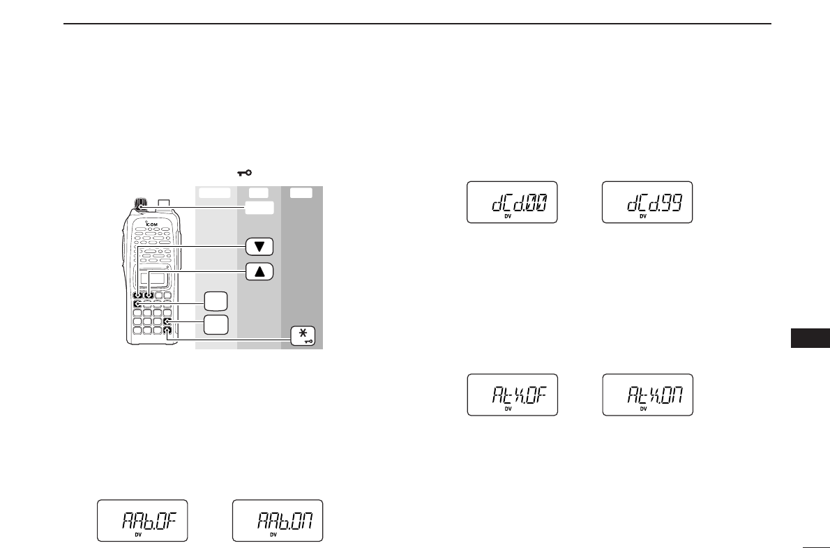
53
11
DIGITAL MODE OPERATION
11
■Setting other items
qPush [A•
FUNC
]and [0•
OPT
]to enter
OPTION SET MODE
, then
push [YY]or [ZZ]several times to select the desired item.
wRotate [VOL] to select the desired value or condition.
•To exit
SET MODE
, push [✱•
ENT
](or [D•
CLR
]).
DDAuto Reply
During digital mode operation, auto reply function is available.
This function replies to an individual station call even you are
away from the transceiver. (default: OFF)
After the manual transmission (pushing [PTT]) or message
transmission, the Auto Reply setting returns to OFF automat-
ically.
DDDigital Code
Sets the desired digital code for digital code squelch opera-
tion. Total of 100 codes (00–99) are available. (default: 00)
DDAuto data Transmission
During low-speed data operation, auto data transmission
function is available. This function transmits when data has
been input from PC via the [DATA] jack. (default: OFF)
After the manual transmission (pushing [PTT]), the Auto
Transmission setting returns to OFF automatically.
FUNC
A
OPT
0
ENT
[VOL]
Enter ExitSet
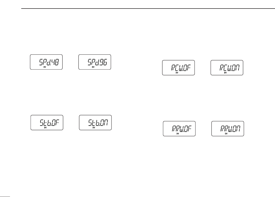
54
11 DIGITAL MODE OPERATION
DDData Speed
Select the communication speed between the transceiver and
PC from 4800 bps or 9600 bps. (default: 9600 bps)
DDStandby Beep
Changes the beep emission capability when the communi-
cating station finishes transmitting or the receive signal dis-
appears. (default: OFF)
DDAuto Rx call sign Write
When an individual station call is received, the calling station
call sign can be stored automatically. The stored call sign can
be re-called when selecting a station call sign. (default: OFF)
DDAuto Rx repeater call sign Write
When an individual station call via the repeater is received,
the repeater call sign can be stored automatically. The stored
repeater’s call sign can be re-called when selecting a re-
peater call sign. (default: OFF)
4800 bps 9600 bps
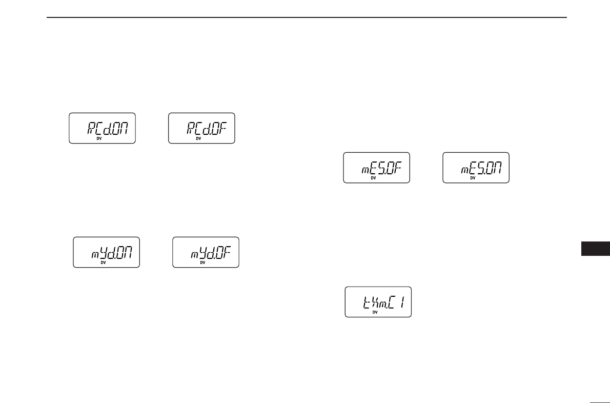
55
11
DIGITAL MODE OPERATION
11
DDAuto Rx call sign Display
When an individual station call is received, the calling station
call sign can be indicated automatically. (default: ON)
DDAuto your own call sign Display
Sets auto your own call sign display function ON and OFF.
When this setting is set to ON, the transceiver automatically
indicates your programmed call sign at turning power ON or
digital mode transmission. (default: OFF)
DDMessage Transmission
Select the Message transmission function ON and OFF.
When ON is selected, transceiver transmits a text message
(pre-programmed). (default: OFF)
After one transmission, the Message Transmission setting re-
turns to OFF automatically.
DDTx message
Tx messages are available up to 6 channels and each chan-
nel can be programmed with a message of up to 20 charac-
ters. Available characters are 0to 9, Ato Z(capital letters
only), some symbols and space. (see the next page for de-
tails)
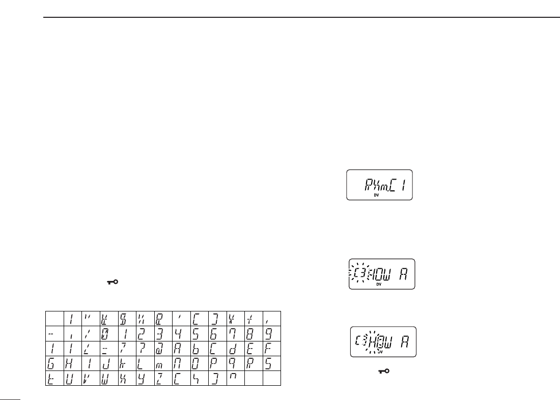
56
11 DIGITAL MODE OPERATION
DDTx message programming
At least one of the Tx message channels must be pro-
grammed, if you want to use the GPS message. The GPS
message is transmitted from Tx message channels.
qWhile in
OPTION SET MODE
, push [YY]or [ZZ]several times
to select “tXm,” then push and hold [0•
OPT
]for 1 sec. to
edit the message indication, and then rotate [VOL] to se-
lect the message channel.
•One of either “C1” to “C6” blinks.
wPush [YY]to select message programming mode.
•The 1st digit blinks and channel indication stops blinking.
eRotate [VOL] to set the desired character.
rPush [YY]to select 2nd digit, then rotate [VOL] to select
the desired character.
•2nd digit blinks (1st digit stop blinking).
•Repeat this step for programming.
tPush [0•
OPT
]to save the message.
yRepeat steps wto tto set another message channels.
uPush [✱•
ENT
](or [D•
CLR
])
to exit
OPTION SET MODE
.
• Available characters
DDRx message indication
When an individual station call with message is received, the
message can be stored into the Rx message record, up to 6
records and each record can indicate a message of up to 20
characters. The oldest record is overwritten when another
message is received.
qWhile in
OPTION SET MODE
, push [YY]or [ZZ]several times
until “RXm” appears.
wPush and hold [0•
OPT
]for 1 sec. to edit the message indi-
cation, and then rotate [VOL] to select the message
recored.
•One of either “C1” to “C6” blinks.
ePush [YY](or [ZZ]) to scroll the message.
•Push [ZZ]or [YY]to move the cursor to left or right, respectively.
rPush [✱•
ENT
](or [D•
CLR
])
to exit
OPTION SET MODE
.
(3)
(D)
(N)
(X)
(+)
(4)
(E)
(O)
(Y)
(–)
(”)
(5)
(F)
(P)
(Z)
(✱)
(6)
(G) (Q)
(/) (7)
(H)
(R)
(,)
(8)
(I) (S)
(space)
(9)
(T)
(0)
(A)
(U)
(1)
(B)
(V)
(2)
(C)
(J) (K) (L)
(M)
(W)
(.)
(
))((
)(’)(&)(
%
)($)(#)(!)
(<)(:) (;) (=) (>) (?)
(@)
([) (\) (]) (^)
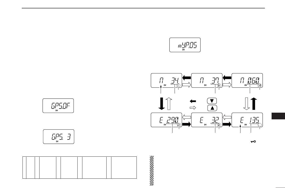
57
11
DIGITAL MODE OPERATION
11
■GPS operation
AGPS receiver (RS-232 output/NMEA format/4800 bps) can
be connected to [DATA] jack of the IC-V82/U82 to indicate the
current position (Latitude and Longitude). The position data
can also be transmitted with a message to another station.
DDPosition indication
qWhile connected to a GPS receiver, push [A•
FUNC
]and
[0•
OPT
]to enter
OPTION SET MODE
.
wPush [YY]or [ZZ]several times to select the GPS setting.
•“GPS” appears.
eRotate [VOL] to select the suitable sentence formatter for
the connecting GPS receiver.
•Sentence formatters
rPush [YY]twice to select the position indication.
tPush and hold [0•
OPT
]for 1 sec. to enter the position indi-
cation.
•Latitude and longitude date appear in order as below.
yAfter checking the current position, push [✱•
ENT
](or
[D•
CLR
]) to return to normal operating mode.
IMPORTANT: When setting the sentence formatter in
step efor connection to a GPS receiver, and you have al-
ready programmed your own call sign, the GPS transmit
setting will automatically activate to every 3 minutes. The
automatic transmission can be changed to an interval time
or deactivated, if desired. (see the next page)
DegreesNorth or South Minutes
AppearsAppears Appears
AppearsAppears Appears
Seconds
Push
Push
DegreesEast or West
MinutesSeconds
1
2
3
4
5
GLL
GGA
RMC
GSA
VTG
6
7
8
9
10
GLL, GGA
GLL, RMC
GLL, GSA
GLL, VTG
GGA, RMC
11
12
13
14
15
GGA, GSA
GGA, VTG
RMC, GSA
RMC, VTG
GSA, VTG
16
17
18
19
20
GLL, GGA, RMC
GLL, GGA, GSA
GLL, GGA, VTG
GLL, RMC, GSA
GLL, RMC, VTG
21
22
23
24
25
GLL, GSA, VTG
GGA, RMC, GSA
GGA, RMC, VTG
GGA, GSA, VTG
RMC, GSA, VTG
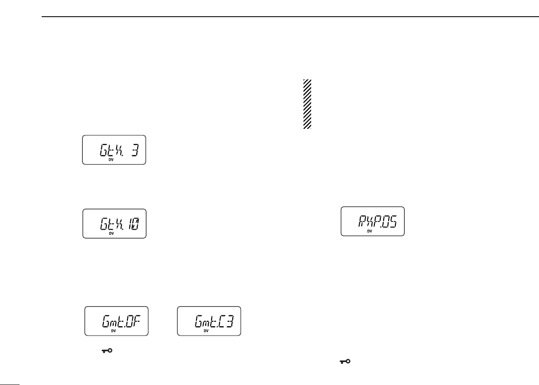
58
11 DIGITAL MODE OPERATION
DDGPS Automatic transmission
qWhile connected to a GPS receiver, push [A•
FUNC
]and
[0•
OPT
]to enter
OPTION SET MODE
.
wPush [YY]or [ZZ]several times to select the GPS automatic
transmission.
•“GtX” appears.
eRotate [VOL] to set the interval time for the GPS auto-
matic transmission.
•Interval time is selectable from 0.5 (30 sec.), 1, 3, 5, 10, 30 min.
rPush [YY]three times to select the transmit message se-
lection, if desired.
•GPS Tx message is selectable from OFF and C1 to C6.
•Tx message must be programmed in advance. (see page 56 for
setting)
tPush [✱•
ENT
](or [D•
CLR
]) to exit
OPTION SET MODE
.
IMPORTANT: GPS Automatic transmission transmits at
every setting interval even while receiving an another sta-
tions communication. To prevent interference to other sta-
tions, set the the Repeater lockout item “RLO” (set to “bU”
busy lockout) in
INITIAL SET MODE
. (p. 64)
DDReceiving a GPS transmission
qPush [A•
FUNC
]and [0•
OPT
]to enter
OPTION SET MODE
.
wPush [YY]or [ZZ]several times to select the received posi-
tion.
•“RXP.OS” appears.
ePush and hold [0•
OPT
]for 1 sec. to enter the position indi-
cation.
•Latitude data and longitude date appear by every pushing [YY]
or [ZZ].
rPush [0•
OPT
]to return
OPTION SET MODE
, then push [YY]
twice to select the received GPS message.
tPush and hold [0•
OPT
]for 1 sec. to enter the message.
•Received message is indicated, push [ZZ]or [YY]to move the
cursor to left or right, respectively.
yAfter checking a received position or message, push
[✱•
ENT
](or [D•
CLR
]) to return to normal operating mode.
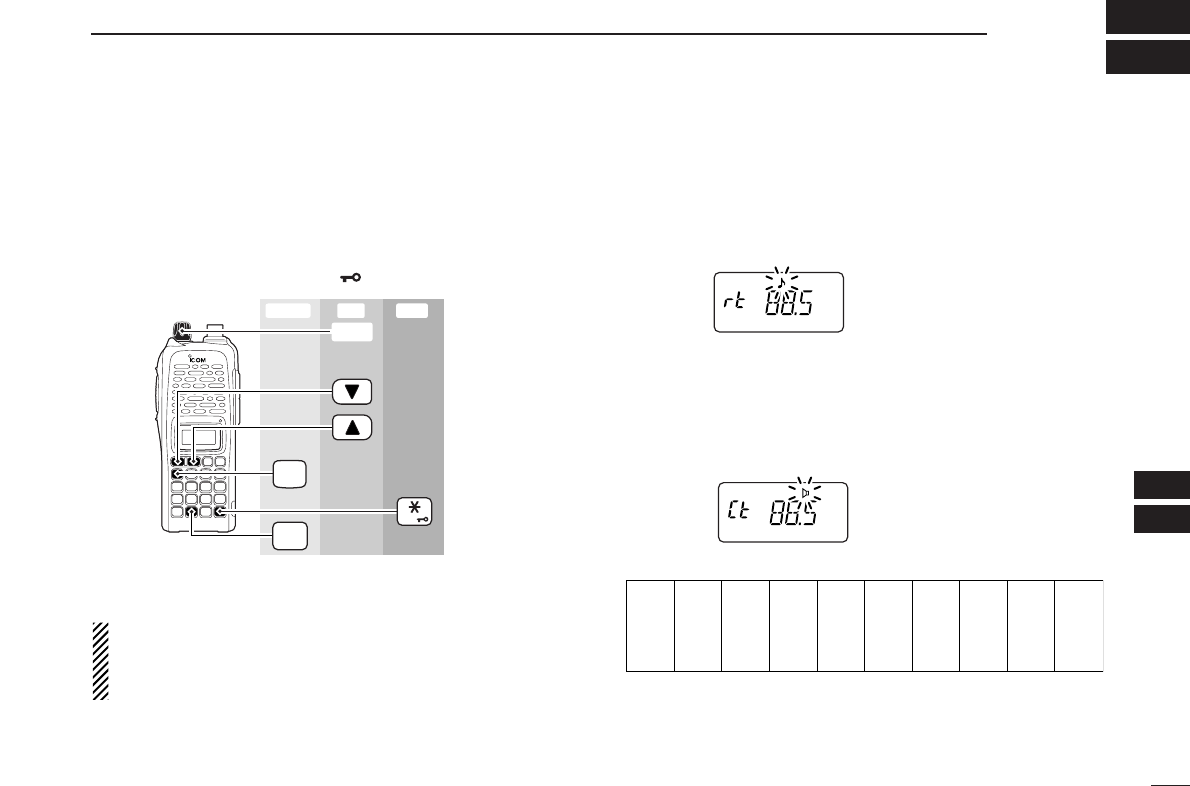
59
12
OTHER FUNCTIONS
11
12
■SET MODE
DDEntering SET MODE
qPush [A•
FUNC
], then push [8•
SET
]to enter
SET MODE
.
wPush [YY]or [ZZ]to select the desired item.
eRotate [VOL] to select the condition/value.
•To exit
SET MODE
, push [✱•
ENT
](or [D•
CLR
]).
NOTE: When the display type setting (pgs. 16, 65) in
INI
-
TIAL SET MODE
is selected other than “FR” (“CH” or “nm”)
and accessing
SET MODE
from memory mode, most of set
mode items are restricted.
DDRepeater tone frequency
Selects tone encoder frequency for accessing a repeater, etc.
from one of 50 available frequencies.
•67.0–254.1 Hz (50 tones): 88.5 Hz (default)
DDTone squelch frequency
Selects frequency for tone squelch or pocket beep operation
from one of 50 available frequencies.
•67.0–254.1 Hz (50 tones): 88.5 Hz (default)
•Available subaudible tone frequencies
67.0
69.3
71.9
74.4
77.0
79.7
82.5
85.4
88.5
91.5
94.8
97.4
100.0
103.5
107.2
110.9
114.8
118.8
123.0
127.3
131.8
136.5
141.3
146.2
151.4
156.7
159.8
162.2
165.5
167.9
171.3
173.8
177.3
179.9
183.5
186.2
189.9
192.8
196.6
199.5
203.5
206.5
210.7
218.1
225.7
229.1
233.6
241.8
250.3
254.1
FUNC
A
SET
8
ENT
[VOL]
Enter ExitSet
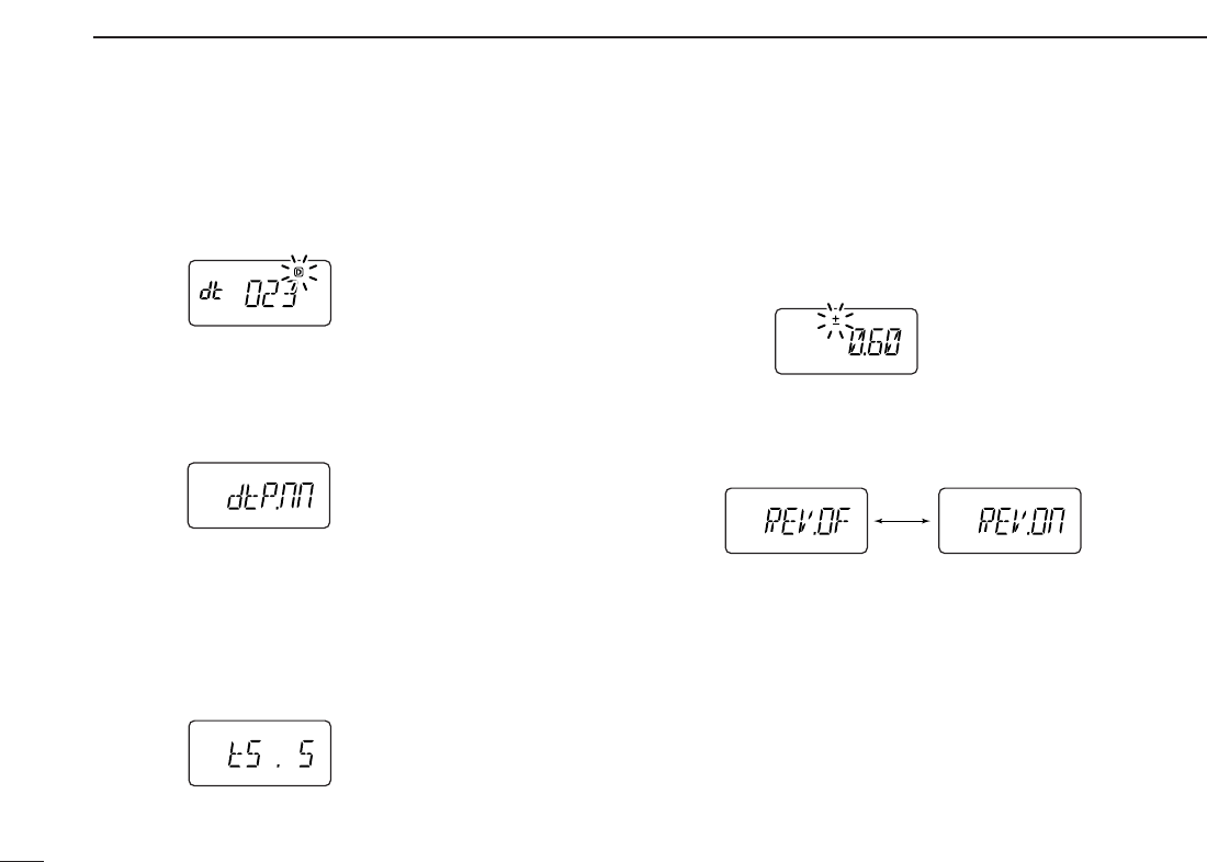
60
12 OTHER FUNCTIONS
DDDTCS code
Selects DTCS (both encoder/decoder code) for DTCS
squelch operation. Total of 104 codes are available.
•023–754: 023 (default)
DDDTCS polarity
Selects DTCS polarities for transmission and reception from
“nn (default),” “nR,” “Rn” and “RR.” (n: normal/R: reverse)
DDTuning step
Selects tuning step from 5, 10, 12.5, 15, 20, 25, 30 and
50 kHz for [YY]/[ZZ]or [VOL] (When [VOL] is assigned as tuning
dial) operation. (default value may differ depending on trans-
ceiver types and versions)
DDOffset frequency
Sets the duplex offset frequency within 0 to 20 MHz range.
During duplex (repeater) operation, transmit frequency (or re-
ceive when reverse function is set to ON) shifts the set fre-
quency. (default value may differ depending on transceiver
types and versions)
DDReverse function
Turns the reverse function ON and OFF (default).
Reverse function OFF Reverse function ON
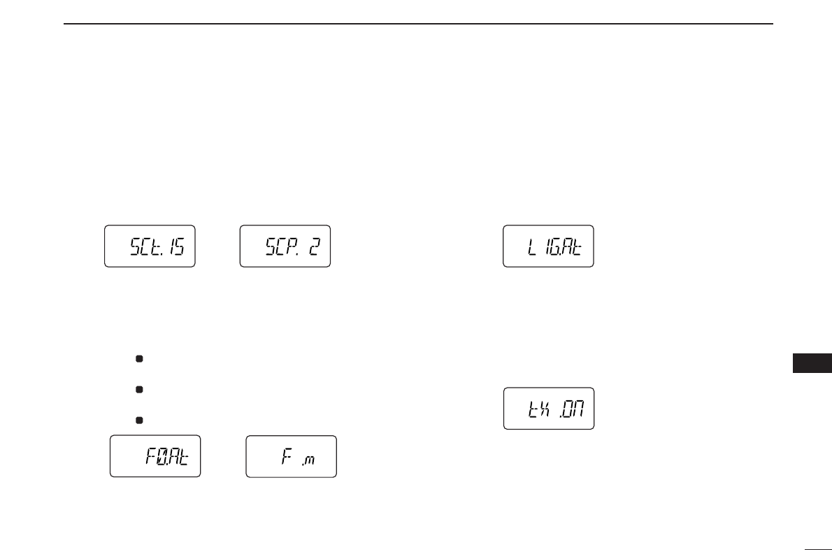
61
12
OTHER FUNCTIONS
12
DDScan pause timer
Selects the scan pause time from SCt.5, SCt.10, SCt.15 and
SCP. 2. When receiving signals, the scan pauses according
to the scan pause time.
•SCt. 5/10/15 : Scan pauses for 5/10/15 sec.
(default: SCt.15)
•SCP. 2 : Scan pauses until the signal disappears. Re-
sumes 2 sec. after the signal disappears.
DDFunction key timer
Selects the function indicator display timer (when pushed
[A•
FUNC
]) from F0.At, F1.At, F2.At, F3.At and F .m.
•F0.At : “ ” disappears immediately after secondary func-
tion is operated. (default)
•F1/2/3.At: “ ” disappears after 1/2/3 sec. after secondary
function is operated.
•F .m : “ ” appears until [A•
FUNC
]is pushed again.
DDLCD backlight
Selects LCD backlight lighting condition from auto, ON and
OFF.
•LIG.At : Lights when any key except [PTT] is pushed. (de-
fault)
•LIG.ON: Lights continuously while the transceiver is pow-
ered ON.
•LIG.OF : Never lights.
DDTransmission permission
Turns transmission permission ON and OFF. This function
can be set for each memory and call channel, independently.
•tX .On : Transmission is permitted. (default)
•tX .OF : Transmission is inhibited.
F
F
F
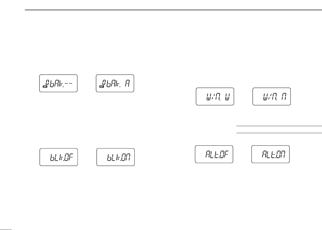
62
12 OTHER FUNCTIONS
DDMemory bank setting
Sets the desired memory bank (A to J and OFF) to assign the
regular memory channels.
This item appears when
SET MODE
is accessed from memory
mode only.
DDMemory bank link function
Sets the memory bank link function ON and OFF (default).
The link function provides continuous banks scan, scanning
all contents in the selected banks during bank scan.
This item appears when
SET MODE
is accessed from memory
mode only.
•Bank link setting
qRotate [VOL] to select the memory bank link function ON.
wPush [YY]or [ZZ]to select the desired bank to be linked.
•bLA: Bank A, bLb: Bank B, bLC: Bank C, bLd: Bank D,
bLE: Bank E, bLF: Bank F, bLG: Bank G, bLH: Bank H,
bLI: Bank I, bLJ: Bank J
eRotate [VOL] to “ON” to link the bank.
rRepeat steps wand eto link other banks.
DDWide/Narrow setting
Selects both the transmission and reception passband width
from wide (default) and narrow.
When narrow is selected, the transmission and reception
passband width become half of the wide setting (approx.).
This setting can be set for each memory, call and VFO inde-
pendently.
DDWeather alert function
Turns weather alert function ON and OFF (default).
IC-V82 [USA]/[CSA] versions only
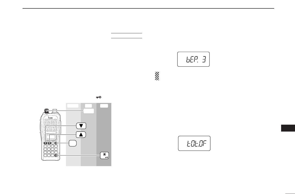
63
12
OTHER FUNCTIONS
12
■INITIAL SET MODE
The
INITIAL SET MODE
is accessed at power on and allows you
to set seldom-changed settings. In this way, you can “cus-
tomize” transceiver operations to suit your preference and op-
erating style.
DDEntering INITIAL SET MODE
qWhile pushing and holding [YY]and [ZZ], turn power ON.
wPush [YY]or [ZZ]to select the desired item.
eRotate [VOL] to select the condition or value.
•To exit
INITIAL SET MODE
, push [✱•
ENT
](or [D•
CLR
]).
DDKey-touch beep
Turns key-touch beep emission ON (Beep level 1 to 3) or
OFF. (default: 3)
NOTE: The pocket beep level (Beep level 1 to 3 or OFF)
also changes as this setting.
DDTime-out timer
To prevent accidental prolonged transmission, etc., the trans-
ceiver has a time-out timer. This function cuts a transmission
OFF after 1–30 min. of continuous transmission. This timer
can be cancelled.
•tOt.OF : The time-out timer is turned OFF. (default)
•tOt. 1–30: The transmission is cut OFF after the set period
elapses.
[VOL]
ENT
PWR
Enter ExitSet
AT
POWER ON
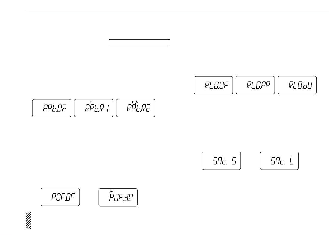
64
12 OTHER FUNCTIONS
DDAuto repeater
The auto repeater function automatically turns ON or OFF the
duplex operation and tone encoder. The offset and repeater
tone is not changed by the auto repeater function. Reset
these frequencies, if necessary.
•RPt.OF : The auto repeater function is turned OFF.
•RPt.R1 : Activates for duplex only. (default)
•RPt.R2 : Activates for duplex and tone.
DDAuto power-off
The transceiver can be set to automatically turn OFF after a
specified period with a beep when no key operations are per-
formed.
•30min., 1 hour, 2 hours and OFF (default) can be specified.
The specified period is retained even when the transceiver
is turned OFF by the auto power-off function. To cancel the
function, select “
POF.OF” in this
SET MODE
.
NOTE: While an optional UT-118
DIGITAL UNIT
is installed
and GPS automatic transmit function is activated, this
function does not work.
DDRepeater lock-out
Selects lockout type from repeater, busy and OFF.
•RLO.OF : No lockout is activated. (default)
•RLO.RP : The repeater lockout is turned ON.
•RLO.bU : The busy lockout is turned ON.
DDSquelch delay
Selects squelch delay from short and long to prevent re-
peated opening and closing of the squelch during reception
of the same signal.
•Sqt. S : The squelch closes in short delay. (default)
•Sqt. L : The squelch closes in long delay.
USA/CSA versions only
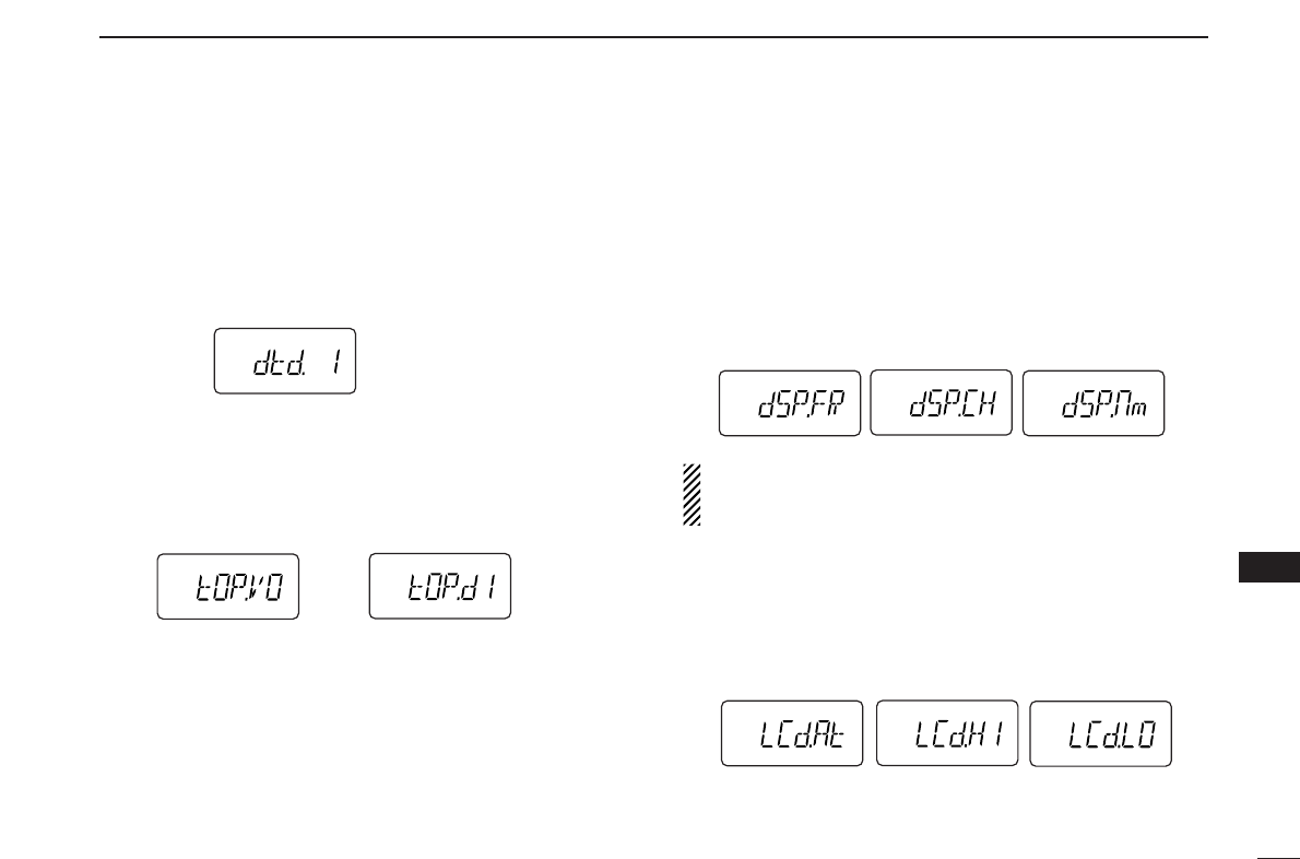
65
12
OTHER FUNCTIONS
12
DDDTMF rate
The rate at which DTMF memories send individual DTMF
characters can be set to accommodate operating needs.
•1: 100 msec. interval; 5.0 cps rate (default)
•2: 200 msec. interval; 2.5 cps rate
•3: 300 msec. interval; 1.6 cps rate
•5: 500 msec. interval; 1.0 cps rate (cps=characters/sec.)
DDDial assignment
Selects [VOL] control action from volume and tuning dial.
•tOP.VO: AF volume (default)
•tOP.dI : Tuning dial
DDDisplay type
Selects LCD indication type from frequency, channel number
and channel names.
•dSP.FR : Shows frequency (default)
•dSP.CH : Shows channel number*
•dSP.nm : Shows channel names†
*Only memory channels can be selected.
† Frequency indication will be displayed when the selected memory
channel has no programmed memory name.
NOTE: When this setting is selected other than “FR” (“CH”
or “nm”) and accessing
SET MODE
from memory mode,
most of set mode items are restricted.
DDLCD contrast
Selects LCD contrast from auto, high and low.
•LCd.At : Automatic (default)
•LCd.HI : High contrast
•LCd.LO : Low contrast
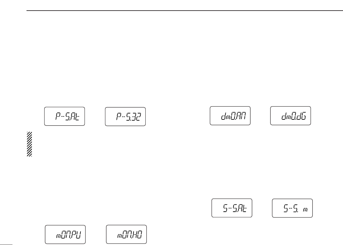
66
12 OTHER FUNCTIONS
DDPower save
Selects duty cycle for power save function from auto, 1:32,
1:16, 1:8, 1:2 and OFF.
•P–S.At : Duty cycle changes automatically. (default)
•P–S.32 : 1:32 duty cycle
•P–S.16 : 1:16 duty cycle
•P–S. 8 :
1:8 duty cycle
•P–S. 2 :
1:2 duty cycle
•P–S.OF : The power save function is turned OFF.
NOTE: While DV mode operation (with UT-118), or pager/
code squelch operation (with UT-108), the active duty cycle
is fixed 1:1 only (even for duty cycle settings other than
OFF).
DDMonitor key action
The monitor key, [MONI], can be set as a ‘sticky’ key. When
set to the sticky condition, each push of [MONI] toggles the
monitor function ON and OFF.
•PU (Push) : Pushing and holding [MONI] to monitor the fre-
quency. (default)
•HO (Hold) : Push [MONI] to monitor the frequency and push
again to cancel it.
DDDigital monitor setting
Set the desired monitoring mode during digital mode opera-
tion from “An (Analog)” and “dG (Digital).”
This item appears only when an optional UT-118
DIGITAL UNIT
is installed.
•An (Analog): Activate for monitoring the analog (FM mode)
signals. (default)
•dG (Digital) : Activate to open the call sign or digital code
squelch.
DDTuning speed acceleration
The tuning speed acceleration automatically speeds up the
tuning speed when pushing and holding [YY]or [ZZ], or rotat-
ing [VOL] rapidly.*
•S–S.At : The tuning speed acceleration is activated. (de-
fault)
•S–S. m : The tuning speed acceleration is not activated.
*When tuning dial is assigned with [VOL].
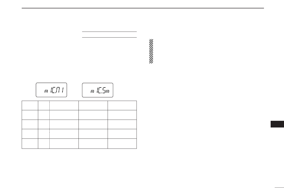
67
12
OTHER FUNCTIONS
12
DDMic simple mode
This item turns the microphone simple mode ON and OFF.
Microphone simple mode is used to change the function as-
signments for keys in the optional HM-75A
REMOTE CONTROL
SPEAKER
-
MICROPHONE
as below. This assignment is conve-
nient for 3-channel use of simple operation.
•mIC.n1 : Normal 1 (default)
•mIC.n2 : Normal 2
•mIC.Sm: Simple mode
A1750 Hz tone can be transmitted with the HM-75A opera-
tion.
➥Push [A] while pushing [PTT].
NOTE:
Turn power OFF when connecting the HM-75A to the
transceiver.
VFO mode cannot be selected via the microphone when
SIMPLE mode is selected.
Optional HM-75A required
HM-75A Mode NORMAL1 NORMAL2 SIMPLE
key
[A] Freq. [B•
CALL
][MONI] [MONI]
CH Null
[B] Freq. VFO/Memory VFO/Memory [B•
CALL
]
CH Null Null
[YY]Freq. Freq. Up Freq. Up MR-00CH
CH Memory CH Up Memory CH Up
[ZZ]Freq. Freq. Down Freq. Down MR-01CH
CH Memory CH Down Memory CH Down
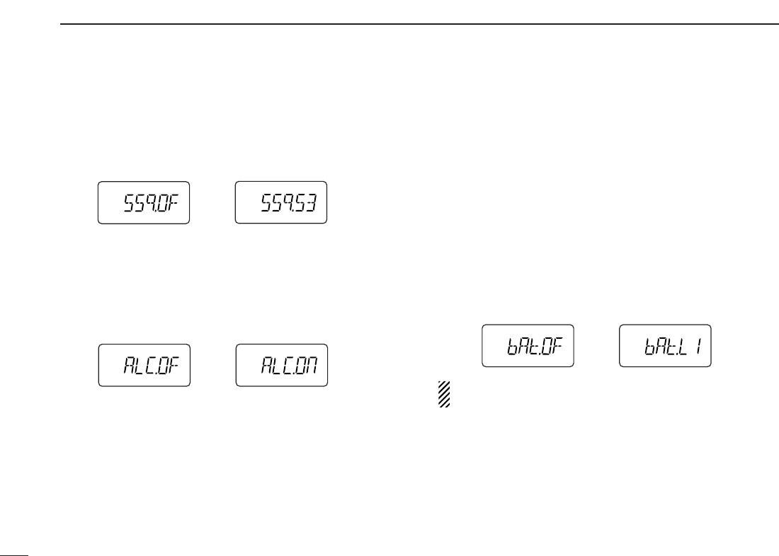
68
12 OTHER FUNCTIONS
DDS-meter squelch
Sets S-meter squelch threshold level from OFF (default) and
S1–S3.
This setting allows you to set a minimum signal level needs to
open the squelch.
DDALC function
Sets the ALC (automatic Level Control) function ON and OFF
(default).
The ALC function reduces the microphone gain automatically
when the transmission audio is distorted.
DDBattery protection function
Sets the Battery protection function from LI (Li-Ion) and OFF
(default).
LI(Li-Ion):
➥The transceiver does not memorized the transceiver
ON/OFF condition when battery is detached, and automat-
ically returns to OFF condition even if you detach the bat-
tery with the transceiver ON condition. You are required to
turn ON the transceiver by pushing [PWR] for every bat-
tery attach.
➥Beep sounds when the attached battery is exhaustion.
•The battery must be charged presently.
OFF : The transceiver memorizes the transceiver ON/OFF
condition when battery is detached.
NOTE: This item MUST be set “LI” (Li-Ion) when the at-
taching battery is BP-211N (Li-Ion).
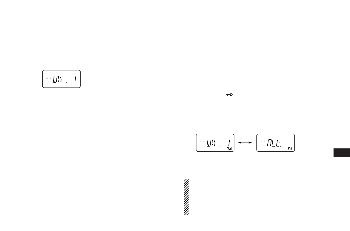
69
12
OTHER FUNCTIONS
12
DDWeather channel selection
qPush [C•
MR
]several times to select weather channel group.
wPush [YY]or [ZZ]several times to select the desired
weather channel.
ePush [C•
MR
]to select memory mode, or push [D•
CLR
]to
select VFO mode.
DDWeather alert function
An NOAA broadcast station transmits weather alert tone be-
fore important weather announcements. When the weather
alert function is turned ON, the selected weather channel is
monitored each 5 sec. for the announcement. When the alert
signal is detected, the “ALt” and the WX channel are dis-
played alternately and sounds a beep tone until the trans-
ceiver is operated. The previously selected (used) weather
channel is checked periodically during standby or while scan-
ning.
qSelect the desired weather channel.
wTurn the weather alert function ON in
SET MODE
.
➥Push
[A•
FUNC
]and [8•
SET
]
to enter
SET MODE
.
➥Push
[YY]
or [ZZ]to select the weather alert item, then
rotate [VOL] to set ON.
➥push [✱•
ENT
](or [D•
CLR
]) to exit
SET MODE
.
eSets the desired stand-by condition.
•Selects VFO, memory or call channel.
•Scan or priority watch operation can also be selected.
rWhen the alert is detected, a beep sounds and the follow-
ing indication will be displayed.
tTurn the weather alert function OFF in
SET MODE
.
NOTE: While receiving a signal (on a frequency other than
the weather alert ON frequency), the receiving signal or
audio will be interrupted momentarily every 5 sec. (approx.)
in case the alert function is turned ON. This symptom is
caused by the WX alert function. To cancel these symp-
toms, set the weather alert item OFF in
SET MODE
.
Shows above indications alternately.
Weather channel group indication
■Weather channel operation (IC-V82 [USA] version only)

70
12 OTHER FUNCTIONS
■CPU reset
The function display may occasionally display erroneous in-
formation (e.g. when first applying power). This may be
caused externally by static electricity or by other factors.
If this problem occurs, turn power OFF. After waiting a few
seconds, turn power ON again. If the problem persists, per-
form the following procedure.
•Partial resetting is also available. See right for details.
IMPORTANT!:
Resetting the transceiver CLEARS all memory information
and initializes all values in the transceiver.
➥While pushing [MONI] and [D•
CLR
],
push and hold [PWR] for 1 sec. to
reset the CPU.
•“CLEAR” indicates, then initial display
appears.
■Partial reset
If you want to initialize the operating conditions (VFO fre-
quency, VFO settings, set mode contents) without clearing
the memory contents, a partial resetting function is available
for the transceiver.
➥While pushing [D•
CLR
], push and
hold [PWR] for 1 sec. to partially
reset.
AT
POWER ON
AT
POWER ON
PWR
MONI
CLR
D
PWR
CLR
D
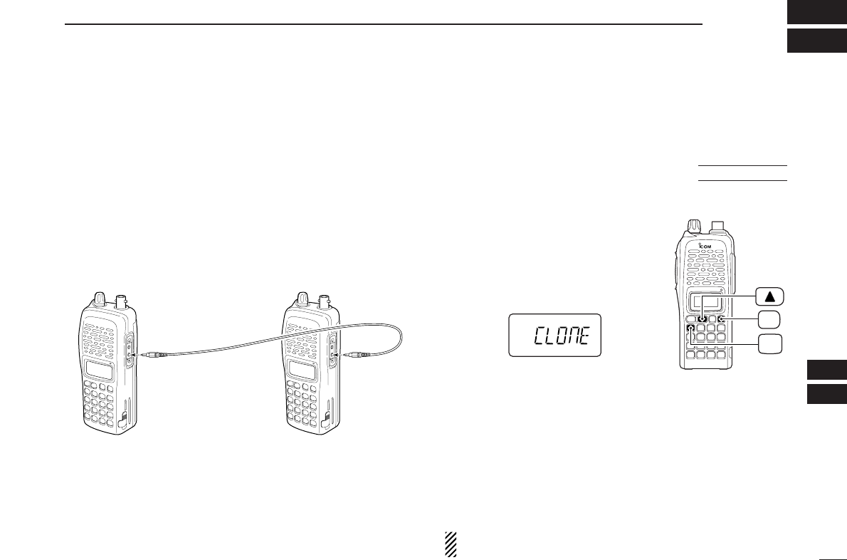
71
13
CLONING
12
13
qConnect the OPC-474
CLONING CABLE
to the [SP] jack of
the master and sub-transceivers.
•The master transceiver is used to send data to the sub-trans-
ceiver.
wWhile pushing [A•
FUNC
]and [YY],
turn power ON to enter cloning
mode (master transceiver only—
power ON for sub-transceiver).
•“CLONE” appears and the transceivers
enter the clone standby condition.
ePush [PTT] on the master trans-
ceiver.
•“CL OU” appears in the master transceiver’s display and S-meter
indicator shows that data is being transferred to the sub-trans-
ceiver.
•“CL IN” appears automatically in the sub-transceiver’s display
and S-meter indicator shows that data is being received from
the master transceiver.
rWhen cloning is finished, turn power OFF, then ON again
to exit cloning mode.
NOTE: DO NOT push [PTT] on the sub-transceiver during
cloning. This will cause a cloning error.
PWR
FUNC
A
Cloning allows you to quickly and easily transfer the pro-
grammed contents from one transceiver to another trans-
ceiver.
■Transceiver-to-transceiver cloning
AT
POWER ON
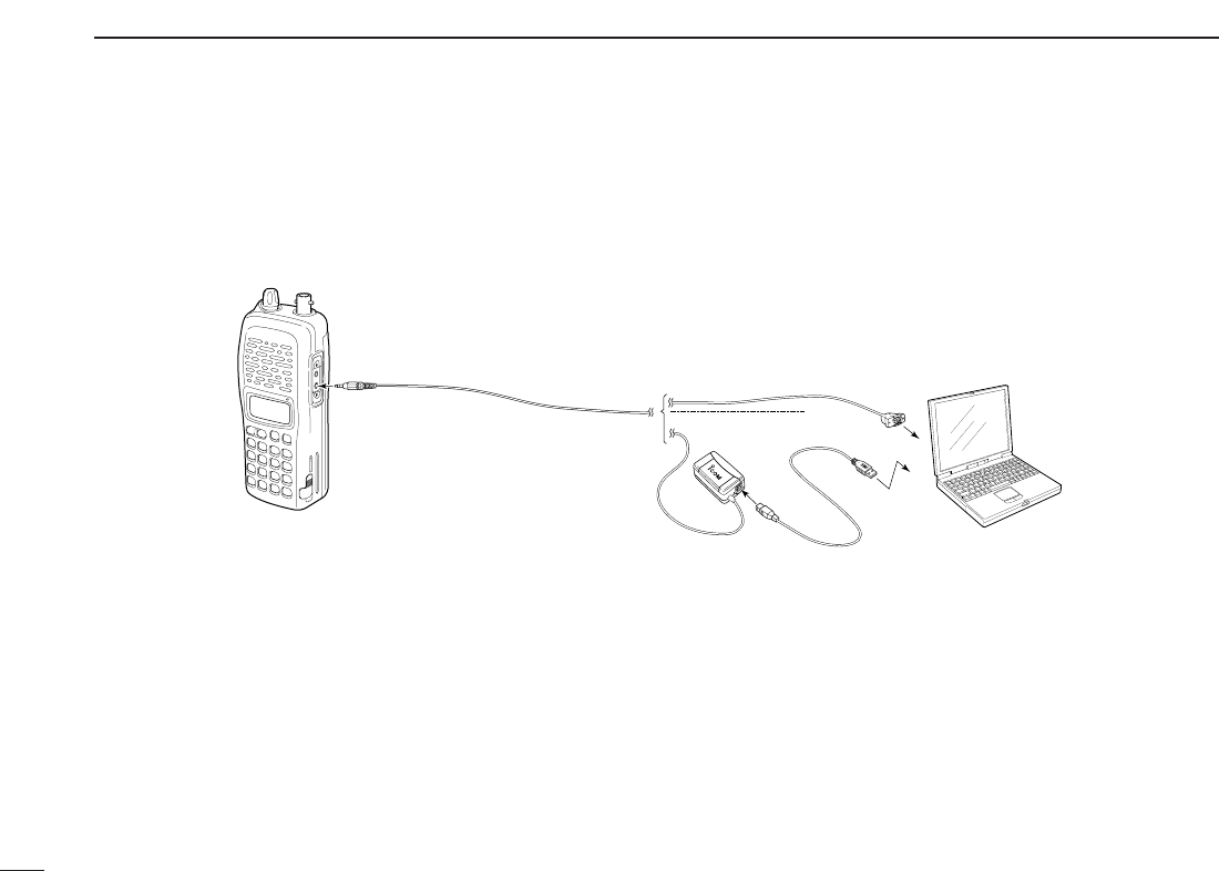
72
13 CLONING
Please refer to the HELP file that comes with CS-V82
CLONING SOFTWARE
.
■Cloning using a PC
PC
TRANSCEIVER
to USB port
to RS-232C port
OPC-478 (RS-232C type)
OPC-478U (USB type)
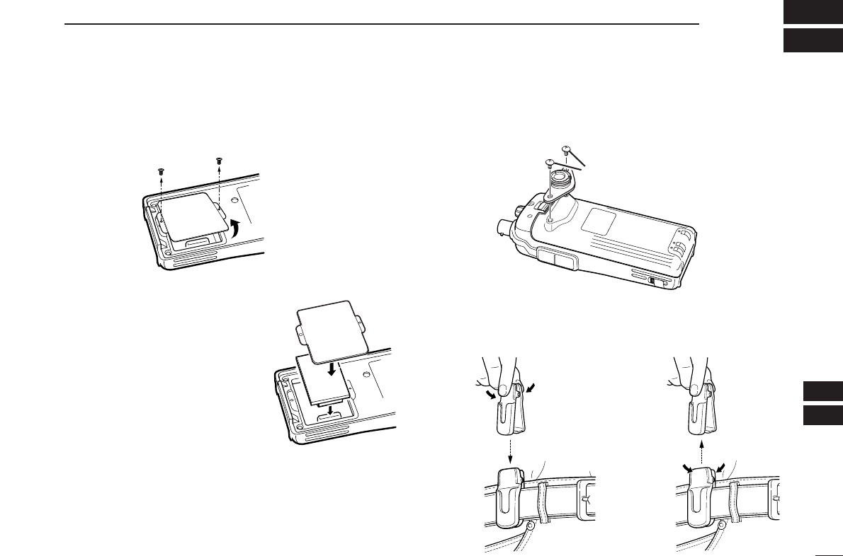
73
14
OPTIONAL UNITS
13
14
■Optional UT-108/118 installation
qRemove the optional connector access cover.
•Unscrew two screws and remove the optional connector cover.
wAttach the optional unit. Insert
the connector firmly to avoid a
bad contact.
•Remove the paper baking of the
optional unit before installing.
eReplace the optional connector
cover and two screws.
rProgram the necessary infor-
mation from the transceivers
keypad or using the cloning
software, before operation.
■Optional MB-86 installation
DMB-86 stopper
DMB-86 belt clip
When clipping to a part of your belt When releasing
Supplied screws
w
e
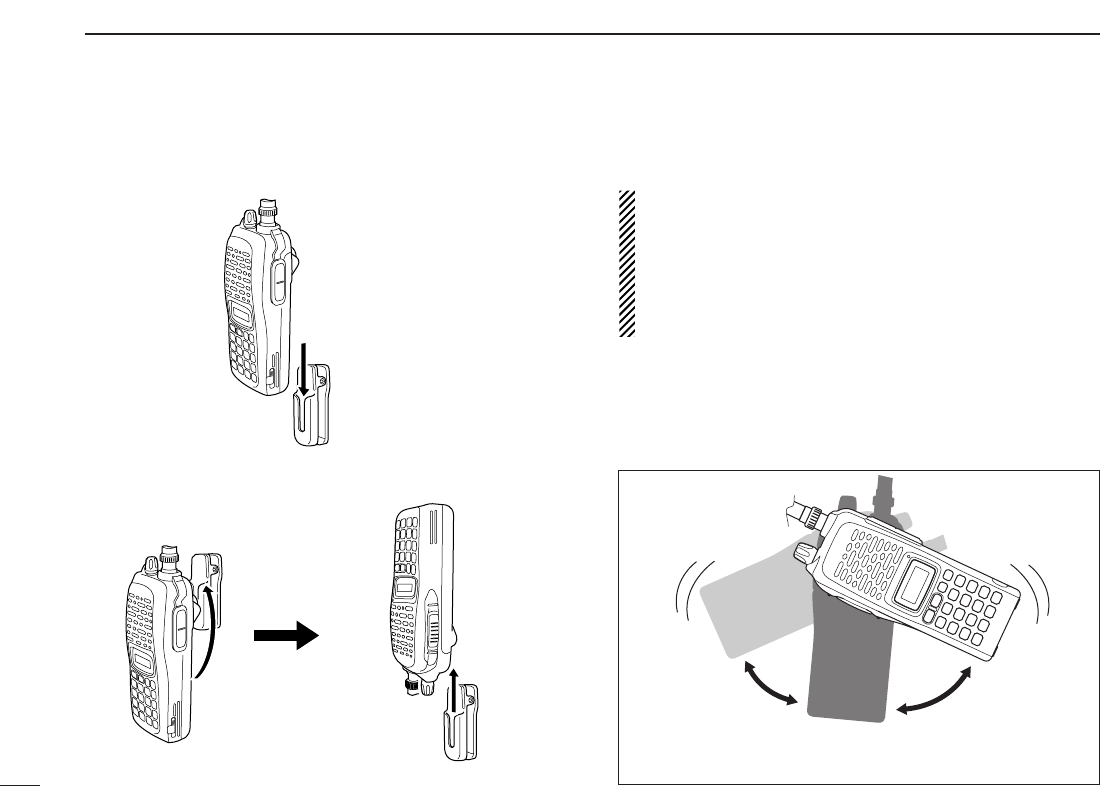
DMB-86 stopper
• When attaching
• When removing
CAUTION!
HOLD THE TRANSCEIVER TIGHTLY, WHEN ATTACH-
ING OR REMOVING THE TRANSCEIVER FROM THE
BELT CLIP.
If the transceiver is accidentally dropped and the swivel
belt clip’s stopper is cracked or damaged, the swivel belt
clip may not work properly.
Once the transceiver is locked in place,
it will swivel 360 degrees.
74
14 OPTIONAL UNITS

75
15
SPECIFICATIONS
14
15
GENERAL
•Frequency coverage : (unit: MHz)
USA Tx: 144–148/Rx: 136–174*
Europe, Taiwan, Korea Tx/Rx: 144–146
General (LM), CSA (LM) Tx/Rx: 136–174*
*Guaranteed: 144–148 MHz range only.
•Type of emission : FM
•Number of memory channels : 207 (incl. 6 scan edges and 1 call)
•Frequency resolution : 5, 10, 12.5, 15, 20, 25, 30, 50 kHz
•Operating temperature range : –10°C to +60°C; +14˚F to +140˚F
•Frequency stability : ±2.5 ppm (–10°C to +60°C)
•Power supply requirement : 7.2 V DC (6–10.3 V DC acceptable;
Icom’s battery pack only)
•Current drain (at 7.2 V DC: approx.):
Transmit at 7 W (High) 2.6 A
at 4 W (Middle) 2.0 A
at 0.5 W (Low) 1.0 A
Receive standby 80 mA
power save 30 mA
max. audio 250 mA
•Antenna connector : BNC (50 Ω)
•Dimensions (proj. not included) :54(W) ×139(H) ×36.7(D) mm
21⁄8(W)×515⁄32(H)×17⁄16(D) in
•Weight (approx.) : 390 g; 13.8 oz
(with BP-222N and Ant.)
200 g; 7.1 oz
(without battery pack and Ant.)
•Ext. data connector : 3-conductor 2.5 (d) mm (1⁄10″)
TRANSMITTER
•Modulation system : Variable reactance frequency mod.
•Output power (at 7.2 V) : 7 W/4 W/0.5 W (High/Mid/Low)
•Max. frequency deviation : ±5.0 kHz [Wide]/±2.5 kHz [Narrow]
•Spurious emissions : Less than –60 dBc
•Microphone connector :
3-conductor 2.5 (d) mm (
1
⁄
10
″)/2.2 kΩ
RECEIVER
•Receive system : Double-conversion superheterodyne
•Intermediate frequencies : 1st: 46.35 MHz, 2nd: 450 kHz
•Sensitivity (at 12 dB SINAD) :0.16 µV typical
•Squelch sensitivity (threshold) :0.11 µV typical
•Selectivity :
[Wide] More than 55 dB
[Narrow] More than 50 dB
•Spurious and image rejection : 80 dB typical
•Intermodulation : 65 dB typical
•
Audio output power
:More than 0.3 W at 10% distortion with
(at 7.2 V DC)
an 8 Ωload
•Ext. speaker connector : 3-conductor 3.5 (d) mm (1⁄8″)/8 Ω
All stated specifications are subject to change without notice or obligation.
■IC-V82

76
15 SPECIFICATIONS
GENERAL
•Frequency coverage : (unit: MHz)
USA Tx: 420–450*1/Rx: 400–479*1
Europe, Korea Tx/Rx: 430–440
General (LM), China (LM) Tx/Rx: 400–479*2
*1Guaranteed: 440–450 MHz range only.
*2Guaranteed: 430–440 MHz range only.
•Type of emission : FM
•Number of memory channels : 207 (incl. 6 scan edges and 1 call)
•Frequency resolution : 5, 10, 12.5, 15, 20, 25, 30, 50 kHz
•Operating temperature range : –10°C to +60°C; +14˚F to +140˚F
•Frequency stability : ±2.5 ppm (–10°C to +60°C)
•Power supply requirement : 7.2 V DC (6–10.3 V DC acceptable;
Icom’s battery pack only)
•Current drain (at 7.2 V DC: approx.):
Transmit at 5 W (High) 2.0 A
at 2 W (Middle) 1.4 A
at 0.5 W (Low) 0.9 A
Receive standby 80 mA
power save 30 mA
max. audio 250 mA
•Antenna connector : BNC (50 Ω)
•Dimensions (proj. not included) :54(W) ×139(H) ×36.7(D) mm
21⁄8(W)×515⁄32(H)×17⁄16(D) in
•Weight (approx.) : 390 g; 13.8 oz
(with BP-222N and Ant.)
200 g; 7.1 oz
(without battery pack and Ant.)
•Ext. data connector : 3-conductor 2.5 (d) mm (1⁄10″)
TRANSMITTER
•Modulation system : Variable reactance frequency mod.
•Output power (at 7.2 V) : 5 W/2 W/0.5 W (High/Mid/Low)
•Max. frequency deviation : ±5.0 kHz [Wide]/±2.5 kHz [Narrow]
•Spurious emissions : Less than –60 dBc
•Microphone connector :
3-conductor 2.5 (d) mm (
1
⁄
10
″)/2.2 kΩ
RECEIVER
•Receive system : Double-conversion superheterodyne
•Intermediate frequencies : 1st: 46.35 MHz, 2nd: 450 kHz
•Sensitivity (at 12 dB SINAD) :0.16 µV typical
•Squelch sensitivity (threshold) :0.11 µV typical
•Selectivity :
[Wide] More than 55 dB
[Narrow] More than 50 dB
•Spurious and image rejection : 70 dB typical
•Intermodulation : 65 dB typical
•
Audio output power
:More than 0.3 W at 10% distortion with
(at 7.2 V DC)
an 8 Ωload
•Ext. speaker connector : 3-conductor 3.5 (d) mm (1⁄8″)/8 Ω
All stated specifications are subject to change without notice or obligation.
■IC-U82
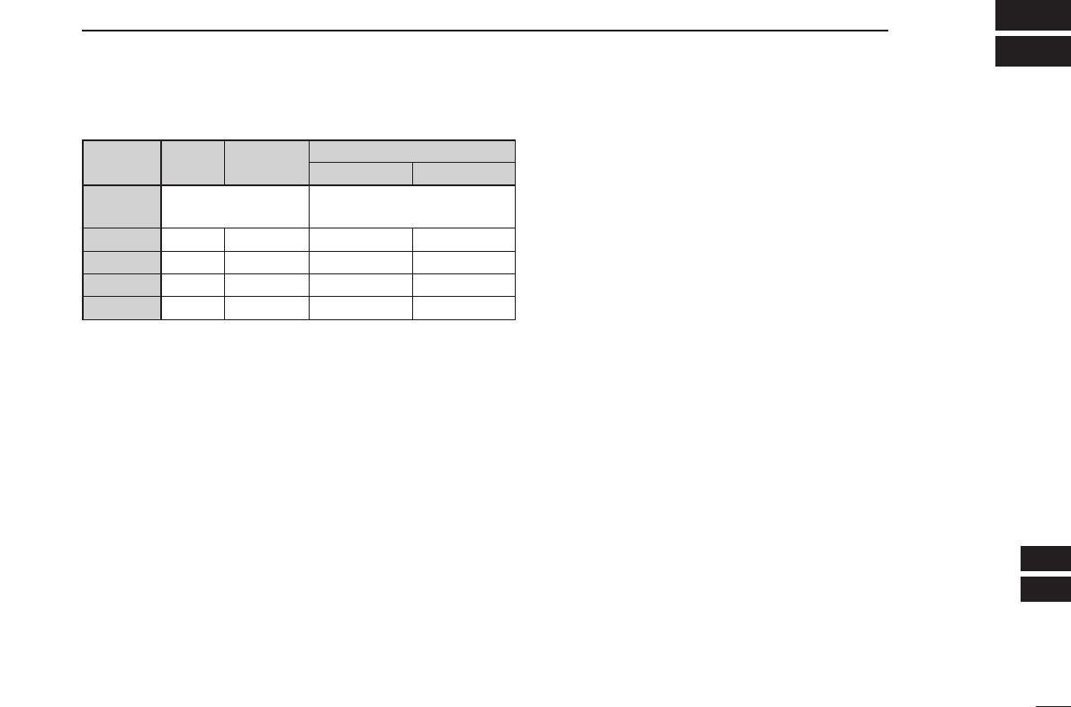
77
16
OPTIONS
15
16
DDBATTERY PACKS
*1Operating periods are calculated under the following conditions:
Tx:Rx:standby=1:1:8, power save function: auto setting, is activated
*2Operating period depends on the alkaline cells used.
DDCHARGER
• BC-144N
DESKTOP CHARGER
+ BC-145
AC ADAPTER
For rapid charging of battery packs. An AC adapter is sup-
plied with the charger. Charging time: 1.5 to 2 hrs.
• BC-146
BATTERY CHARGER
+ BC-147
AC ADAPTER
For regular charging of battery packs. An AC adapter is ad-
ditionally required. Charging time: 6.5 to 18.5 hrs.
• BC-119N
DESKTOP CHARGER
+ AD-101
CHARGER ADAPTER
For rapid charging of battery packs. An AC adapter is sup-
plied with the charger. Charging time: 1.5 to 2 hrs.
•
BC-121N
MULTI
-
CHARGER
+ AD-101
CHARGER ADAPTER
(6 pcs.)
For rapid charging of up to 6 battery packs (six AD-101’s are
required) simultaneously. An AC adapter may be supplied
depending on version. Charging time: 1.5 to 2 hrs.
DDBELT CLIP
• MB-103/MB-86
BELT CLIPS
MB-103: Same as that supplied with the transceiver.
MB-86: Swivel belt clip
• MB-96F/MB-96N
LEATHER BELT HANGER
MB-96F: Fixed type belt hanger for use with MB-103.
MB-96N: Swivel belt hanger. MB-86’s base clip is required.
DDINTERNAL UNIT
• UT-108
DTMF DECODER UNIT
Provides pager and code squelch capabilities.
• UT-118
DIGITAL UNIT
Provides digital mode operation capabilities.
DDOTHER OPTIONS
• HM-75A/HM-131L
SPEAKER
-
MICROPHONES
Combination speaker-microphones that provide convenient
operation while hanging the transceiver from your belt.
HM-75A has 4 function switches for remote control capabil-
ities.
HM-131L has moisture proof construction.
• HM-128L
EARPHONE
-
MICROPHONE
You can clip the microphone with PTT switch to your lapel or
breast pocket.
• HS-85
HEADSET
Allows you hands-free operation. Includes VOX, PTT and
“one-touch” PTT with time-out timer.
Battery Voltage Capacity Battery life*1
pack IC-V82 IC-U82
BP-208N Battery case for AA —*2
(LR6)×6 alkaline
BP-209N 7.2 V 1100 mAh 3 hrs. 20 min. 3 hrs. 40 min.
BP-210N 7.2 V 1650 mAh 6 hrs. 7 hrs.
BP-211N 7.4 V 1800 mAh 6 hrs. 10 min. 8 hrs. 15 min.
BP-222N 7.2 V 600 mAh 2 hrs. 15 min. 2 hrs. 50 min.

78
16 OPTIONS
• VS-1L
PTT
/
VOX UNIT
+HS-94/HS-95/HS-97
HEADSET
VS-1L
PTT
/
VOX UNIT
Required when using these headsets.
HS-94
EAR
-
PIECE TYPE HEADSET
Earhook headset with flexible boom microphone.
HS-95
NECK
-
ARM TYPE HEADSET
Behind-the-head headset with flexible boom microphone.
HS-97
THROAT MICROPHONE
Throat microphone fits around your neck and picks up
speech vibration.
• CS-V82
CLONING SOFTWARE
+OPC-478/U
CLONING CABLE
Provide quick and easy programming of memory channel,
memory name etc.
• OPC-474
CLONING CABLE
For cloning between transceivers.
• SP-13
EARPHONE
Provides clear receive audio in noisy environments.
• FA-B2E
WHIP ANTENNA
(for IC-V82)
Same as that supplied with IC-V82.
• FA-B70C
WHIP ANTENNA
(for IC-U82)
Same as that supplied with IC-U82.
Some options may not be available in some countries. Please ask your dealer for details.
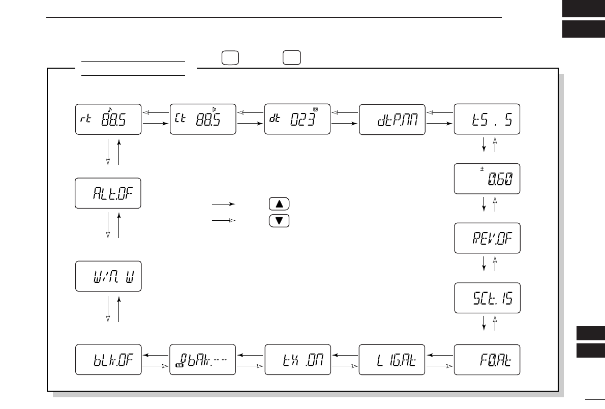
79
17
MODE ARRANGEMENT
16
17
SET MODE
• Weather alert* (p. 62)
• Repeater tone
frequency (p. 59) • Tone squelch
frequency (p. 59) • DTCS code (p. 60) • DTCS polarity (p. 60)
• Offset frequency (p. 60)
• Reverse function (p. 60)
• Tuning step (p. 60)
• Scan pause timer (p. 61)
• Function key timer (p. 61)
• LCD backlight
(p. 61)
• Tx permission
(p. 61)
• Wide/Narrow setting
(p. 62)
• Bank link function†
(p. 62) • Bank setting†
(p. 62)
*Available for IC-V82 [USA]/[CSA] versions only.
†Appears when accessing SET MODE from memory mode only.
: Push
: Push
Push , then push to enter SET MODE (p. 59).
SET
FUNC
8
A
NOTE: When the display type setting (pgs. 16, 65) in INITIAL
SET MODE is selected other than “FR” (“CH” or “nm”) and
accessing SET MODE from memory mode, most of set mode
items are restricted.
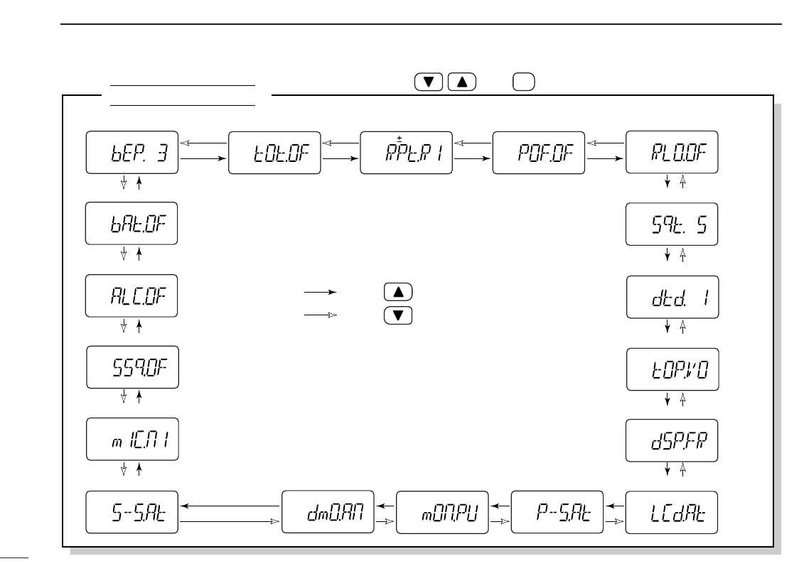
80
17 MODE ARRANGEMENT
INITIAL SET MODE
• ALC function (p. 68)
• Battery protection function (p. 68)
• S-meter squelch (p. 68)
• Mic simple mode (p. 67)
• Key touch beep (p. 63) • Time-out timer (p. 63) • Auto repeater* (p. 64) • Auto power-off (p. 64)
• Squelch delay (p. 64)
• DTMF rate (p. 65)
• Repeater lock-out (p. 64)
• Dial assignment (p. 65)
• Display type (p. 65)
• LCD contrast (p. 65)• Power save (p. 66)• Tuning speed acceleration (p. 66) • Digital monitor
setting† (p. 66) • Monitor key action
(p. 66)
*Available for [USA]/[CSA] versions only.
†Appears only when an optional UT-118 DIGITAL UNIT is installed.
: Push
: Push
While pushing and holding , push PWR to enter INITIAL SET MODE (p. 63).
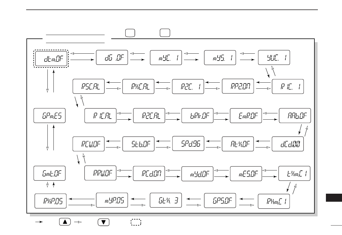
81
17
MODE ARRANGEMENT
17
OPTION SET MODE
• Position indication
(p. 57)
• Rx position (p. 58)
• Rx GPS
message (p. 58)
• GPS message
transmission (p. 58)
• GPS auto
transmission (p. 58) • GPS setting (p. 57)
• DTMF function* (pgs. 27, 39) • Digital mode (p. 45) • Your own call sign (p. 42) • Your call sign note (p. 43)
• Repeater1 call
sign (p. 52)
• Repeater2
ON/OFF (p. 52)
• Repeater2
call sign (p. 52)
• Rx call sign
(p. 46)
• Rx call sign
note (p. 46)
• Rx repeater1
call sign (p. 46) • Rx repeater2
call sign (p. 46) • Break-in setting
(p. 47)
• Station call sign (p. 44)
• EMR setting
(p. 48) • Auto reply
(p. 53)
• Digital code
(p. 53)
• Auto data
transmission (p. 53)
• Auto Rx repeater
call sign write (p. 54)
• Data speed
(p. 54)
• Standby beep
(p. 54)
• Auto Rx call sign
write
(p. 54)
• Auto Rx call sign
display (p. 55) • Auto your own call
sign display (p. 55)
• Rx message
(p. 56)
• Tx message
(p. 55)
• Message
transmission
(p. 55)
: Push : Push
*“PG” or “CS” are selectable only when an optional UT-108 DTMF DECODER UNIT is installed.
Only this item appears when no optional unit is installed, the other
items appear when an optional UT-118 DIGITAL UNIT is installed.
Push , then push to enter OPTION SET MODE (p. 53).
FUNC
A
OPT
0

82
CE
18
DECLARATION
OF CONFORMITY
We Icom Inc. Japan
1-1-32, Kamiminami, Hirano-ku
Osaka 547-0003, Japan
Declare on our sole responsibility that this equipment complies with the
essential requirements of the Radio and Telecommunications Terminal
Equipment Directive, 1999/5/EC, and that any applicable Essential Test
Suite measurements have been performed.
Kind of equipment: FM TRANSCEIVER
Type-designation: iV82
Version (where applicable):
This compliance is based on conformity with the following harmonised
standards, specifications or documents:
i) EN 301 489-1 v 1.3.1 (2001-09)
ii) EN 301 489-15 v 1.1.1 (2000-09)
iii) EN 301 783 v 1.1.1 (2000-09)
iv) EN 60950 (1992-08) + A11:1997
Düsseldorf 12th Nov. 2004
Place and date of issue
Icom (Europe) GmbH
Himmelgeister straße 100
D-40225 Düsseldorf
Authorized representative name
H. Ikegami
General Manager
Signature

83
18
CE
18
DECLARATION
OF CONFORMITY
We Icom Inc. Japan
1-1-32, Kamiminami, Hirano-ku
Osaka 547-0003, Japan
Declare on our sole responsibility that this equipment complies with the
essential requirements of the Radio and Telecommunications Terminal
Equipment Directive, 1999/5/EC, and that any applicable Essential Test
Suite measurements have been performed.
Kind of equipment: FM TRANSCEIVER
Type-designation: iU82
Version (where applicable):
This compliance is based on conformity with the following harmonised
standards, specifications or documents:
i) EN 301 489-1 v 1.3.1 (2001-09)
ii) EN 301 489-15 v 1.1.1 (2000-09)
iii) EN 301 783 v 1.1.1 (2000-09)
iv) EN 60950 (1992-08) + A11:1997
Düsseldorf 12th Nov. 2004
Place and date of issue
Icom (Europe) GmbH
Himmelgeister straße 100
D-40225 Düsseldorf
Authorized representative name
H. Ikegami
General Manager
Signature
1-1-32 Kamiminami, Hirano-ku, Osaka 547-0003, Japan
A-6413D-1EX-q
Printed in Japan
©2004 Icom Inc.
<Intended Country of Use>
■GER ■FRA ■ESP ■SWE
■AUT ■NED ■POR ■DEN
■GBR ■BEL ■ITA ■FIN
■IRL ■LUX ■■GRE ■■SUI
■■NOR
#02 Europe
#12 Europe-1
#22 Europe-2
#42 Europe-3
IC-V82
<Intended Country of Use>
■GER ■FRA ■ESP ■SWE
■AUT ■NED ■POR ■DEN
■GBR ■BEL ■ITA ■FIN
■IRL ■LUX ■■GRE ■■SUI
■■NOR
#02 Europe
#12 Europe-1
#22 Europe-2
#42 Europe-3
IC-U82
