Identec Solutions ICARD-NA RF ID PC Card User Manual 9 00
Identec Solutions, Inc. RF ID PC Card 9 00
UserManual.wiki
>
Identec Solutions
>
ICARD-NA User Manual
>
manual
Contents
1.
manual
2.
users manual revised
manual
Navigation menu
Upload a User Manual
Namespaces
Wiki Guide
HTML
PDF
Info
Views
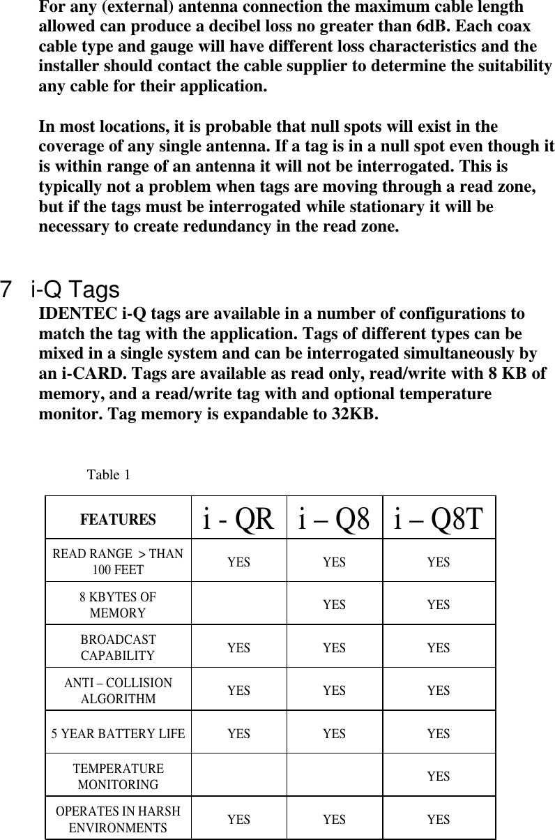
User Manual
Discussion / Help
Navigation