Identec Solutions ICARD-NA RF ID PC Card User Manual 9 00
Identec Solutions, Inc. RF ID PC Card 9 00
Contents
- 1. manual
- 2. users manual revised
manual

i-CARD
Reference Manual
The product, and product features as described in this document are subject to change
without notice and does not represent a commitment on the part of IDENTEC
Solutions, Inc. The software described in this document is furnished under a license
agreement.
Limitation of Liability. In no event shall Identec or its suppliers be liable for any
damages whatsoever, including damages for loss of business profits, business
interruption, loss of business information or any other loss arising out of the use of
or inability to use this product, or the provision or failure to provide support
services. IDENTEC’s entire liability shall be limited to the replacement cost of this
product.
NOTE: This equipment has been tested and found to comply with the limits
for a Class A digital device, pursuant to Part 15 of the FCC Rules. These limits
are designed to provide reasonable protection against harmful interference when
the equipment is operated in a commercial environment. This equipment
generates, uses, and can radiate radio frequency energy and, if not installed and
used in accordance with the instruction manual, may cause harmful interference
to radio communication. Operation of this equipment in a residential area is
likely to cause harmful interference in which case the user will be required to
correct the interference at his own expense.
Warning: Changes or modifications to this unit not expressly approved by the
party responsible for compliance could void the user’s authority to operate the
equipment.
FCC ID: O2E-ICARD-NA
CANADA: XXXXXXXXXXXX
MODEL: i-CARD
TYPE: NA
This Class A digital apparatus meets all requirements of the Canadian
Interference-Causing Equipment Regulations.
Cet appareil numérique de la classe A respecte toutes les exigencies du Règlement
sur le matériel brouilleur du Canada.
This User Manual is copyright © 2000 by IDENTEC Solutions, Inc.
1 Contents
1 CONTENTS 3
2 INTRODUCTION 3
2.1 GENERAL 3
2.2 PRODUCT DESCRIPTION 4
3 I-CARD CONNECTORS — SYSTEM INPUTS AND OUTPUTS 5
4 EXTERNAL POWER SUPPLY REQUIREMENTS 7
5 INSTALLATION 8
5.1 PHYSICAL INSTALLATION 8
5.2 ELECTRICAL INSTALLATION 8
6 I-CARD ANTENNAS 8
7 I-Q TAGS 9
8 SOFTWARE 10
9 PRODUCT SUPPORT 11
9.1 TO REACH IDENTEC SUPPORT 11
9.1.1 Online support 11
9.1.2 E-mail support 11
9.1.3 Telephone and Fax Support 11
9.1.4 Support numbers 11
9.1.5 Order Desk 12
9.1.6 Warranty Service 12
9.1.7 Additional Tools and Training 12
2 Introduction
2.1 General
This document provides information for the installation and
operation of the IDENTEC i-CARD, a PC Card type RFID
interrogator.
Other documentation that may be applicable includes the
Application Developers Guide To Programming For The ILR
Library, the i-COM User Manual, the i-CARD Installation &
Configuration Sheet, and the i-Q Tag Technical Sheet.

2.2 Product Description
The i-CARD is a PC Card type RFID device for communicating with
the i-Q series of active tags. It will plug into PCMCIA slots of
portable devices like handheld scanners, etc. It must be powered by a
5V source, capable of supplying 150mA.
The i-CARD is configurable via firmware to provide application
developers with both a PCMCIA, as well as a serial interface for
advanced automatic data capture applications using ILR technology.
The operating system in the hosting device can be Windows 98®,
Windows NT® or Windows CE®, providing the interface to the i-
CARD Application programs developed to run on the i-CARD use
calls to the IDENTEC i-PORT software library to access the RF
functions on the i-CARD.
The i-CARD enclosure is a PC Card type II tin can. Three status
LEDs can be viewed from the front edge; they are Carrier Detect
(green), Transmit (red) and Receive (green). The front also hosts the
MMCX 50Ù coax RF connector for the antenna.
In addition, the front edge holds a 15-pin PC Card I/O connector for
serial (RS-232) access and card programming.
The i-CARD contains a Configurable Processor System Unit (CPSU)
with internal non-volatile memory. The CPSU chip is programmed
by IDENTEC and contains the firmware code.
The i-CARD contains the RF circuitry for the wireless
communication with IDENTEC tags. The application software
running on the i-PORT, or other host computer, sends commands to
the CPSU to communicate with the tags. The CPSU on the i-CARD
controls all functions of the board. The normal mode (power-up and
standby) of the i-CARD is ‘Receive Mode’, as opposed to the time-
limited ‘Transmit Mode’, which has to be initiated by the controlling
host computer.
Note: The i-CARD used in the i-PORT is in a PC Card Type II housing
but it is not configured with a PCMCIA interface. The i-CARD in the i-
PORT has a serial interface and can only be used in the assigned card
slot on the i-PORT.
i-CARDs with PCMCIA interface code are suitable for any other
standard portable equipment.
Each i-CARD is marked with an interface type, either PCMCIA or
serial. Do not use an i-CARD with a PCMCIA interface in the i-PORT.
Vice versa, do not use an i-CARD with a serial interface in any other
portable device with PCMCIA slot.
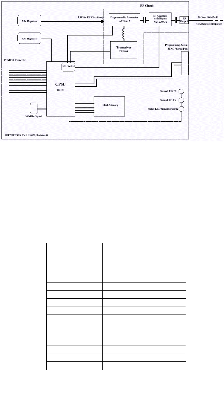
Figure 1
i-CARD Block Diagram
3 i-CARD Connectors — System Inputs and Outputs
The i-CARD’s two I/O connector pinouts are depicted in figure 1 &
2. The function of the connectors is described below.
Caution: Never remove or install a PC Card while its supply power is
turned on.
Pinout of 15-pin I/O serial & programming connector, located on front
edge:
Pin Number Signal Name
1 +5V Input
2 +5V Input
3 RXD
4 TXD
5 JTAG
6 JTAG
7 JTAG
8 JTAG
9 Powerdown (act. high)
10 Do not use
11 Do not use
12 RESET (active low)
13 Ground
14 Ground
15 +3.3V (do not use)

Pinout of 68-pin PCMCIA connector, located on the card’s back edge:
Pin Number
Signal Name
1. GND
2. Reserve 1
3. Reserve 2
4. CONT
5. i-PORT RXD
6. i-PORT TXD
7. ANTSEL 2#
8. ANTSEL 1#
9. ANTSEL 2
10. N.C.
11. N.C.
12. DIR
13. Charge_on
14. N.C.
15. Test RXD
16. Test TXD
17. Vcc
18. N.C.
19. ANTSEL 1
20. RLY 1
21. RLY 2
22. N.C.
23. N.C.
24. Barcode Trig
25. OPT 1
26. OPT 2
27. OPT 3
28. OPT 4
29. LCD Temp
30. RLY 3
31. RLY 4
32. LCD Heat
33. RESETb
34. GND
35. GND
36. GND
37. Barcode RXD
38. Barcode TXD
39. i-PORT RXD#
40. i-PORT TXD#
41. PWR LED
42. BAT LED

43. ANTLED 1
44. ANTLED 2
45. Reserve 3
46. 30V LED
47. 12V LED
48. 5V LED
49. Master Reset#
50. RSSI LED
51. Vcc
52. N.C.
53. N.C.
54. N.C.
55. N.C.
56. N.C.
57. N.C.
58. AD5
59. Beep 2
60. Beep 1
61. AD6
62. AD4
63. AD3
64. AD2
65. AD1
66. AD0
67. GND
68. GND
Figure 2
Most of these pins are being used for i-PORT operation. For
operation in regular PCMCIA slots, the user does not have to worry
about the above pinout table, since the configuration is done by the I-
CARD’s firmware for PCMCIA.
4 External Power Supply Requirements
Operation of the i-CARD requires a 5VDC power supply, which is an
integral part of the PCMCIA slot.
Some slots may only provide 3.3V supply and are not suitable for this
revision of the I-CARD.
The maximum supply current will not exceed 150mA.
5 Installation
This chapter describes the installation and antenna connection
procedure for an i-CARD in mobile equipment, such as a handheld
scanner. For installation in an i-PORT, see the i-PORT Reference
Manual.
Important Note to Installer:
This device requires professional installation by a certified
electronics technician or electrical engineer, following each and all
procedures of the installation manual. This device is only legal to
operate in conjunction with the antenna type approved by FCC and
Industry Canada.
The installer is taking legal responsibility that all steps outlined in
the IDENTEC installation manual have been executed properly, and
that the installed device is complying with FCC Part 15 and the limits
for a ‘Class A Digital Device’, as defined by Industry Canada.
5.1 Physical Installation
The I-CARD plugs into either an i-PORT’s appropriate slot, or into
any PCMCIA slot with a 5V supply voltage.
5.2 Electrical Installation
Every time the i-CARD’s 5V power is cycled it is being reset.
Thereby, a default sequence table is automatically loaded, limiting
RF output power to a low level. The receiver sensitivity is also limited
in this process.
6 i-CARD Antennas
Antennas for use with the i-CARD are required to have a gain equal
to or less than 3dB(ic). It is recommended that the antenna
polarization should be elliptical or circular, although in applications
where the orientation of the tag is in a consistent and known position
linearly polarized antennas can also be used.
Normally, a miniature antenna, like a quarter-wavelength whip, a
bent half-wavelength dipole or a subminiature patch antenna should
be used. These antennas would typically be integrated in the portable
device.

For any (external) antenna connection the maximum cable length
allowed can produce a decibel loss no greater than 6dB. Each coax
cable type and gauge will have different loss characteristics and the
installer should contact the cable supplier to determine the suitability
any cable for their application.
In most locations, it is probable that null spots will exist in the
coverage of any single antenna. If a tag is in a null spot even though it
is within range of an antenna it will not be interrogated. This is
typically not a problem when tags are moving through a read zone,
but if the tags must be interrogated while stationary it will be
necessary to create redundancy in the read zone.
7 i-Q Tags
IDENTEC i-Q tags are available in a number of configurations to
match the tag with the application. Tags of different types can be
mixed in a single system and can be interrogated simultaneously by
an i-CARD. Tags are available as read only, read/write with 8 KB of
memory, and a read/write tag with and optional temperature
monitor. Tag memory is expandable to 32KB.
FEATURES
i - QR
i – Q8
i – Q8T
READ RANGE > THAN
100 FEET YES YES YES
8 KBYTES OF
MEMORY YES YES
BROADCAST
CAPABILITY YES YES YES
ANTI – COLLISION
ALGORITHM YES YES YES
5 YEAR BATTERY LIFE
YES YES YES
TEMPERATURE
MONITORING YES
OPERATES IN HARSH
ENVIRONMENTS YES YES YES
Table 1
All i-Q tags are active and include an RF transmitter, RF receiver,
and a microprocessor. The communication range between a tag and
an antenna connected to an i-CARD interrogator will be up to 30 feet
under typical conditions. Read range will vary depending on antenna
gain and local conditions, and it is important to test tag read
performance under a variety of probable scenarios.
For more information see the i-Q Tag Technical Sheet.
8 Software
This chapter provides basic information on how to control the
operation of the i-CARD. For more detailed information please see
the Application Developers Guide To Programming For The ILR
Library.
ILR technology requires an application program to provide end-user
functions, this level of software is provided by the System Integrator.
To facilitate the development of user specific applications, IDENTEC
has extended the Windows API (Application Program Interface) to
include easy access to ILR functions using C program calls.
IDENTEC does provide a demonstration package to allow the
installer to configure and to test the basic functions of the i-CARD.
To allow maximum flexibility in interrogating tags, scanning
barcodes, allowing user data entry, providing user information,
formatting and sorting data, and data transfer to tags and over a
network (i.e. Wireless LAN), the i-CARD functions under the
direction of a control program. This control program customizes the
i-CARD to do the required task. It is generated by a menu-driven
Windows application that allows the user to specify how the system
will operate.
This is a simple but very powerful feature of the IDENTEC ILR
system. It allows an i-CARD to perform similar tasks in very
different ways from completely automated tag interrogation and
reporting to automated assistance in process operations. The data
source for various fields can be specified, e.g. tag ID, tag file or
barcode scan. A sequence of events can be specified to gather data,
format data in a specific way, and/or communicate data to a specific
location.

Note: Microsoft® Windows® CE Toolkit for Visual C++ is required to
make applications run on Windows® CE operating system for x86
microprocessors that is used on the i-PORT.
9 Product Support
Technical support for IDENTEC ILR products is available by e-mail,
online and by telephone or fax. Full support is provided to
Authorized Systems Integrators who have completed the technical
training sessions and are certified ILR technicians.
Additional training and product support is available from IDENTEC
under a support agreement. Field Support is also available on a
contract basis. Support can be provided for site surveys, and for
product installation and testing. Contact your account manager for
full details.
9.1 To Reach IDENTEC Support
9.1.1 Online support
Technical support is available online to all IDENTEC Authorized
System Integrators. Answers to many common questions and
problems are included in our searchable database at
www.IDENTEC.com\faq.htm this database can be made accessible to
any product user.
9.1.2 E-mail support
When sending an e-mail include your name, company, telephone and
fax numbers along with your question or problem.
In North America support@IDENTEC.com
In Europe and the UK support@IDENTEC.au
9.1.3 Telephone and Fax Support
Telephone assistance in North America is available from 8:30 to 5:30
Pacific time, Monday through Friday, Canadian holidays not
included. .
9.1.4 Support numbers
North America
Tel: (250) 860-6567
Fax: (250) 860-6541
Toll Free Phone 1-877-IDENTEC

9.1.5 Order Desk
To order products contact the order desk by phone or fax
North America
Tel: (250) 860-6567
Fax: (250) 860-6541
Toll Free Phone 1-877-IDENTEC
9.1.6 Warranty Service
For warranty service contact the warranty department within your
region to get a warranty claim number. All products returned for
warrantee service must include a warranty service number for
prompt processing.
In North America phone (250) 860-6567
9.1.7 Additional Tools and Training
Support is provided only to trained systems integrators. IDENTEC
provides training in ILR technology with the purchase of a
development kit. To have additional employees or third party
consultants certified to receive full access to product support
IDENTEC offers certification training.