Identec Solutions ILR-916IP3 UHF Intelligent Long Range Interrogator System User Manual RevCiQiPORT III IM
Identec Solutions, Inc. UHF Intelligent Long Range Interrogator System RevCiQiPORT III IM
UserManual.wiki
>
Identec Solutions
>
ILR-916IP3 User Manual
>
Manual 1
Contents
1.
Manual 1
2.
Manuzl 2
Manual 1
Navigation menu
Upload a User Manual
Namespaces
Wiki Guide
HTML
PDF
Info
Views
User Manual
Discussion / Help
Navigation
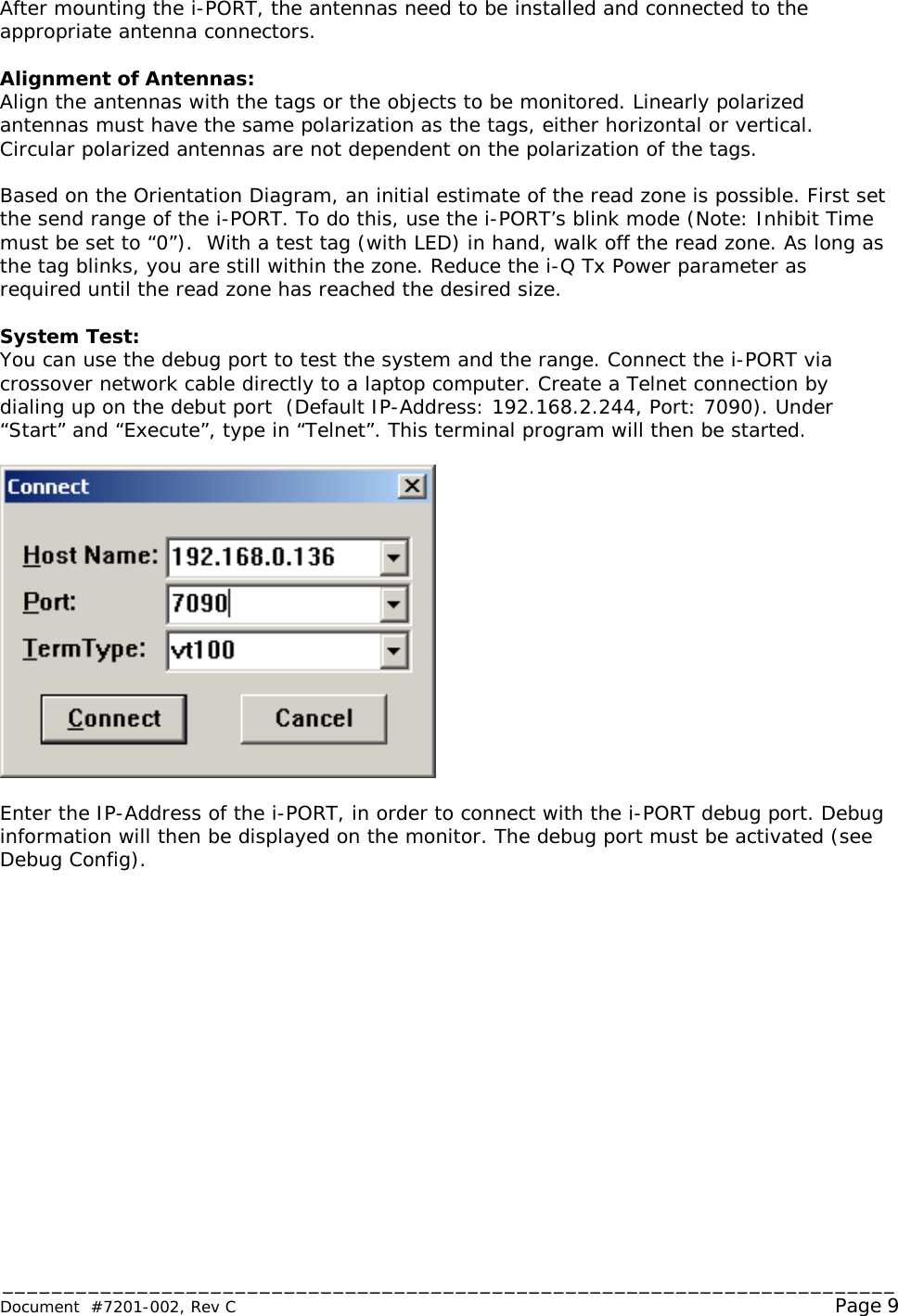
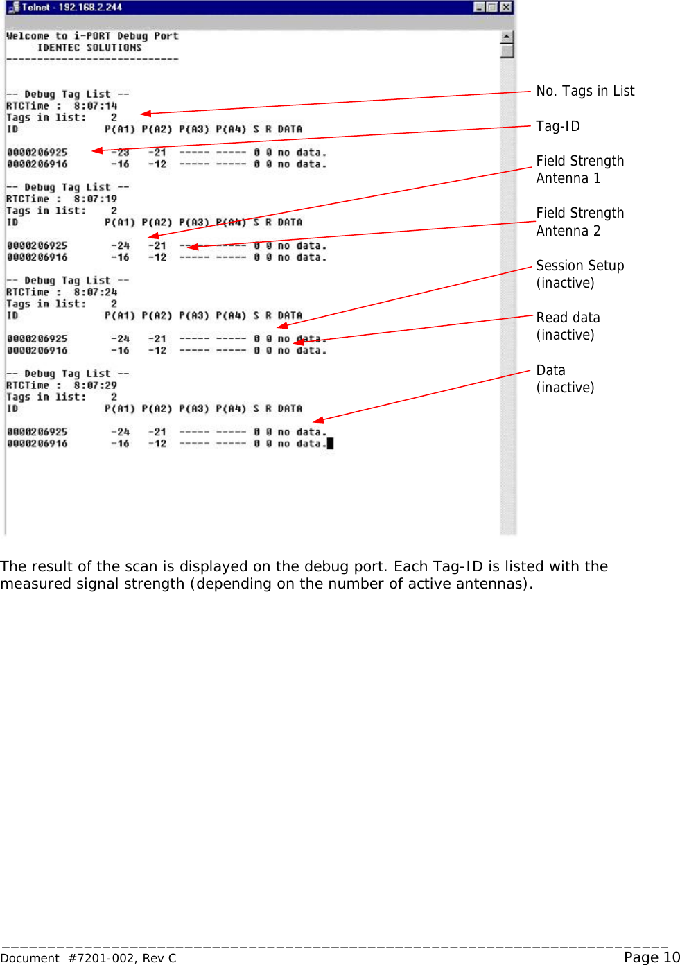
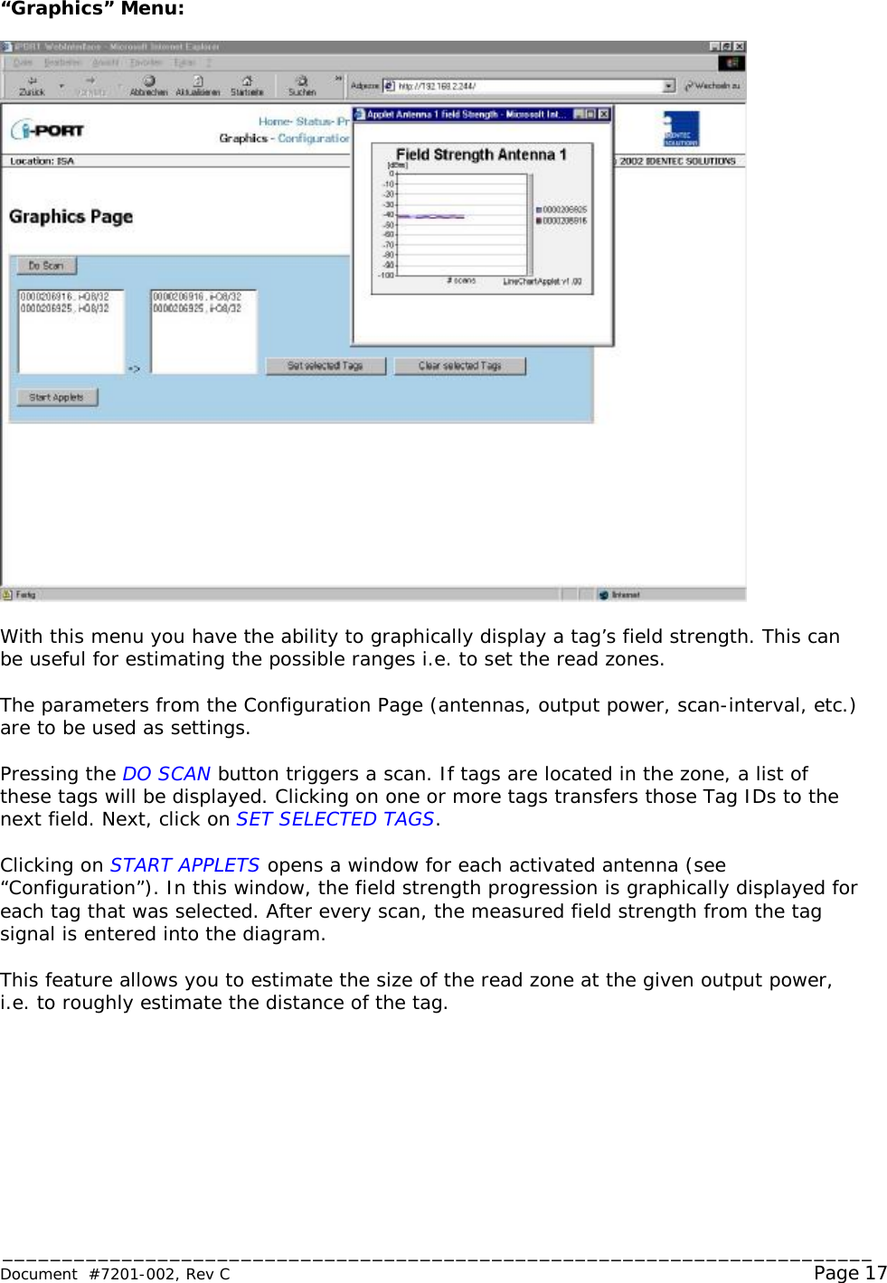
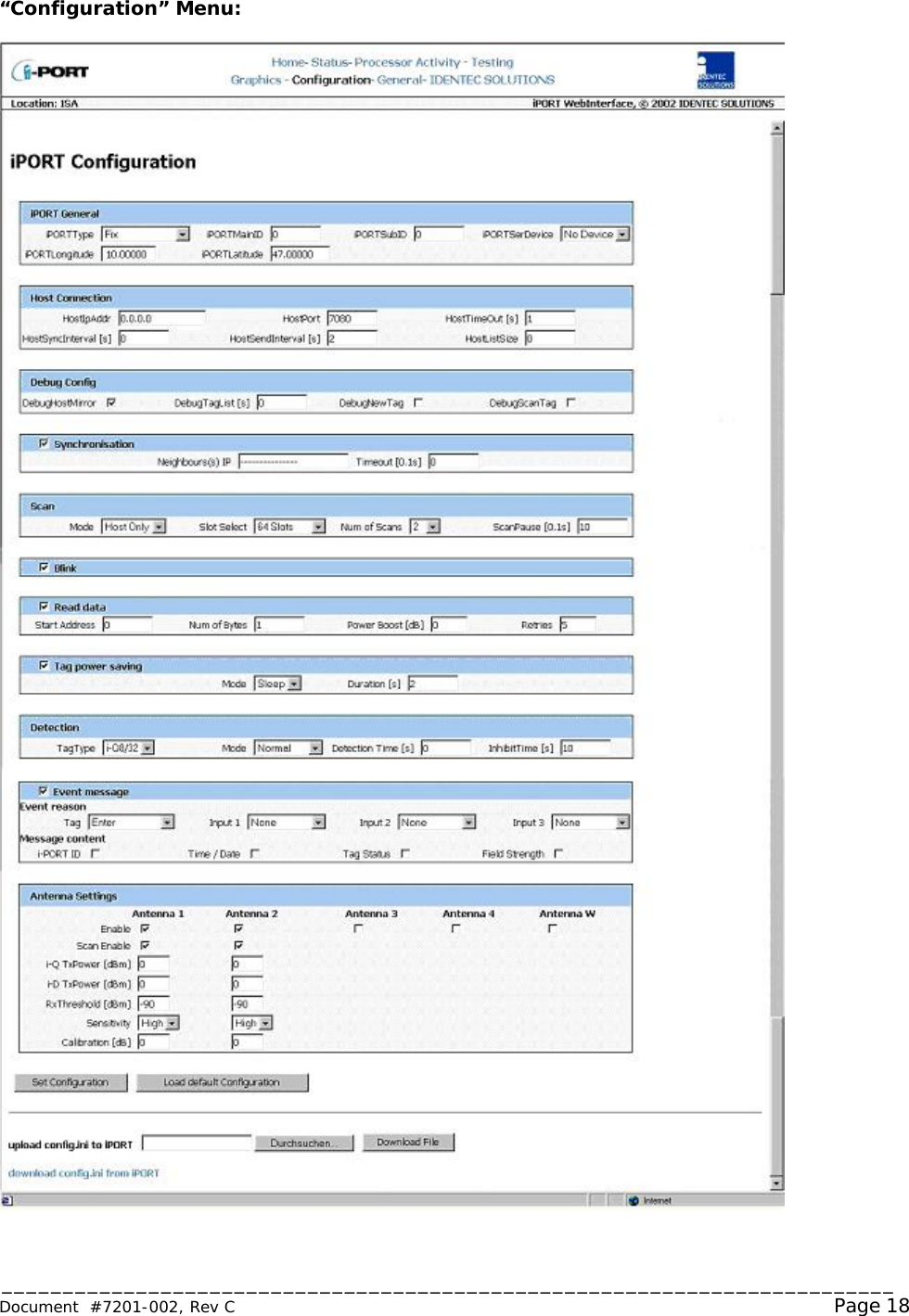
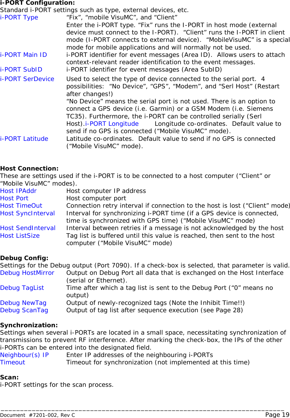
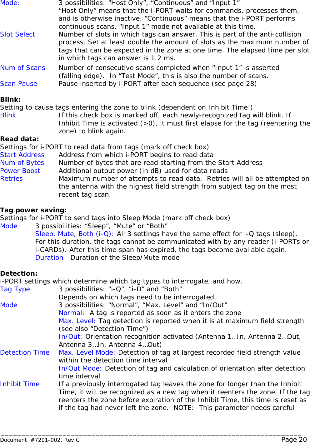
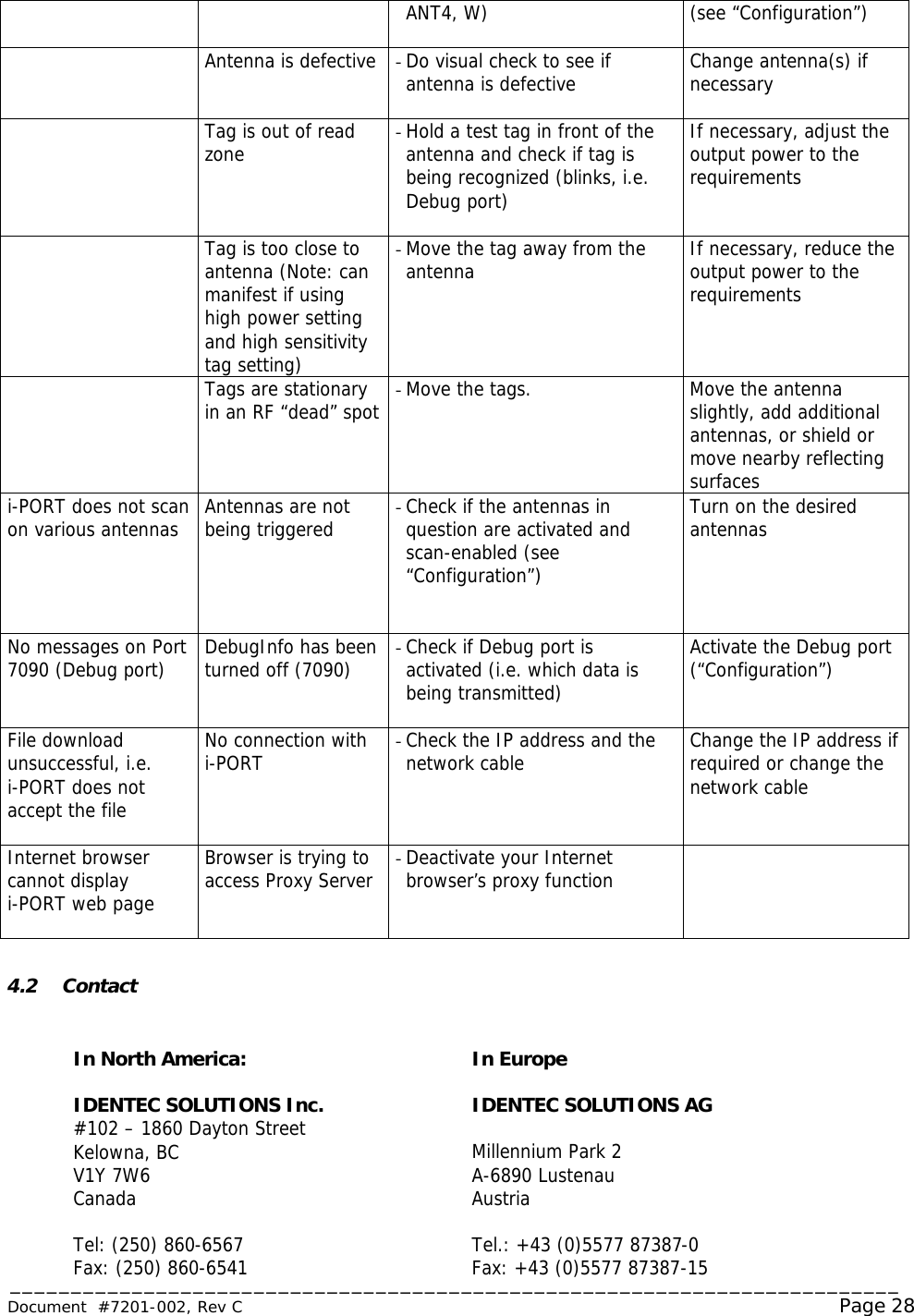
![_________________________________________________________________________ Document #7201-002, Rev C Page 29 5.0 Appendix A - Effective Radiated Power Calculation The following is the licensed limit allowable by the appropriate regulatory bodies for operation of IDENTEC’s RFID devices: i-Q Operation In North America, the approved frequency is 916.5 MHz. Our equipment is certified to transmit an Effective Radiated Power (ERP) of 50mV/m @ 3m. This equates to transmitting 0.75mW from the antenna, or –1.25 dBm. To calculate the power being transmitted from the antenna, the following formula may be applied: Effective Radiated Power (ERP) = [Output Setting] - [Cable/Connector Loss] + [Antenna Gain] The variables are defined as follows: [Output Setting] = User defined; [Cable/Connector Loss] = Variable depending on the type of cable and connectors being used. A typical installation may use RG-58 cable with a loss of 0.2 dBm/ft. Typical connector loss is around 0.2dB per junction; [Antenna Gain] = 5 dBm for our antenna PN 210270-001. NOTE: It is the responsibility of the installer to ensure that operation is within the limits of the appropriate regulatory body where the equipment is being used.](https://usermanual.wiki/Identec-Solutions/ILR-916IP3.Manual-1/User-Guide-315216-Page-29.png)