Identec Solutions ILR-IB2NA Beacon Tag User Manual IB2SNA UG
Identec Solutions AG Beacon Tag IB2SNA UG
Users Manual
i-B2 S/NA User’s Guide
Version 1.0
IDENTEC SOLUTIONS AG
Millennium Park 2
A-6890 Lustenau
Austria
Tel: +43 (0) 5577 87387 - 0
Fax: +43 (0) 5577 87387 - 15
info@identecsolutions.at
www.identecsolutions.com

i-B2 S – User’s Guide
Version 1.0 03.08.2006 Page ii/12
Proprietary Notice
This document contains confidential information proprietary to IDENTEC SOLUTIONS and may not be used or
disclosed to other parties in whole or in part without prior written authorization from IDENTEC SOLUTIONS.
Disclaimer and Limitation of Liability
IDENTEC SOLUTIONS AG and its affiliates, subsidiaries, officers, directors, employees and agents provide the
information contained in this Manual on an “as-is” basis and do not make any express or implied warranties or
representations with respect to such information including, without limitation, warranties as to non-infringement,
reliability, fitness for a particular purpose, usefulness, completeness, accuracy or currentness. IDENTEC
SOLUTIONS AG shall not in any circumstances be liable to any person for any special, incidental, indirect or
consequential damages, including without limitation, damages resulting from use of or reliance on information
presented herein, or loss of profits or revenues or costs of replacement goods, even if informed in advance of
the possibility of such damages.
Trademarks
“IDENTEC SOLUTIONS”, “Intelligent Long Range”, “ILR” and the stylized “i” are registered trademarks and
“i-Q”, “i-D”, “i-CARD”, “i-PORT”, “i-LINKS”, “Solutions. It’s in our name.”, “Smarten up your assets.” are
trademarks of IDENTEC SOLUTIONS, Inc. and/or IDENTEC SOLUTIONS AG.
Copyright Notice
Copyright © 2006 IDENTEC SOLUTIONS. All rights reserved.
No part of this document may be reproduced or transmitted in any form by any means, photographic, electronic,
mechanical or otherwise, or used in any information storage and retrieval system, without the prior written
permission of IDENTEC SOLUTIONS.

i-B2 S – User’s Guide
Version 1.0 03.08.2006 Page iii/12
Radio Frequency Compliance Statement
IDENTEC SOLUTIONS AG. is the responsible party for the compliance of the following devices:
MODEL: i-B2 S i-CARD CF i-D TAGS i-Qxx TAGS
FCC ID: OO4-ILR-IB2NA OO4-ILR-ICARDCF OO4-ILR-ID2 OO4-ILR-IQ8T or
OO4-ILR-IQR
CANADA: Pending Pending 3538A 12112 35381021756A or
35381021825
EUROPE: CE CE CE 0678(!) CE 0682(!)
The user(s) of these products are cautioned to only use accessories and peripherals approved, in advance, by
IDENTEC SOLUTIONS. The use of accessories and peripherals, other than those approved by IDENTEC
SOLUTIONS, or unauthorized changes to approved products, may void the compliance of these products and
may result in the loss of the user(s) authority to operate the equipment.
Operation is subject to the following conditions: (1) these devices may not cause harmful interference, and (2)
these devices must accept any interference, including interference that may cause undesired operation of the
device.
FCC Compliance (i-B2 S/NA)
This equipment has been tested and found to comply with the limits for a Class A digital device, pursuant to Part
15 of the FCC Rules. These limits are designed to provide reasonable protection against harmful interference
when the equipment is operated in a commercial environment. This equipment generates, uses, and can radiate
radio frequency energy and, if not installed and used in accordance with the instruction manual, may cause
harmful interference to radio communication. Operation of this equipment in a residential area is likely to cause
harmful interference in which case the user will be required to correct the interference at his/her own expense.
Warning: Changes or modifications to this unit not expressly approved by the party responsible for
compliance could void the user’s authority to operate the equipment.
Industry Canada Compliance (i-B2 S/NA)
This Class A digital apparatus meets all requirements of the Canadian Interference-Causing Equipment
Regulations.
Cet appareil numérique de la classe A respecte toutes les exigences du Règlement sur le matériel brouilleur du
Canada.
To reduce potential radio interference to other users, the antenna type and its gain should be so chosen that the
equivalent isotropically radiated power (EIRP) is not more than that required for successful communication.
The installer of this radio equipment must ensure that the antenna is located or pointed such that it does not
emit RF field in excess of Health Canada limits for the general population; consult Safety Code 6, obtainable
from Health Canada.
This device complies with Part 15 of the FCC rules. Operation is subject to the following two conditions: (1)
This device may not cause harmful interference, and (2) this device must accept any interference received,
including interference that may cause undesired operation.
Warning: Changes or modifications to this unit not expressly approved by the party responsible for
compliance could void the user's authority to operate the equipment.

i-B2 S – User’s Guide
Version 1.0 03.08.2006 Page iv/12
European Notification according R&TTE Directive (i-B2 S/EU)
This equipment complies to Art. 6.4 of R&TTE Directive (1999/5/EC) and can be used in the following European
countries:
Austria, Belgium, Denmark, Finland, France, Germany, Greece, Iceland, Italy, Ireland, Luxembourg, Netherlands
, Norway, Portugal, Switzerland, Sweden, Spain, United Kingdom, Czech Republic, Cyprus, Estonia, Hungary,
Lithuania, Latvia, Malta, Poland, Slovenia.

i-B2 S – User’s Guide
Version 1.0 03.08.2006 Page v/12
Table of Contents
1.0
Overview __________________________________________6
2.0
Functionality________________________________________6
2.1 Telegram content __________________________________________ 6
2.2 Programming _____________________________________________ 6
Appendix A: Technical Specifications ____________________________7
Appendix B: Battery lifetime__________________________________8
Appendix C: Tag mounting___________________________________9
C.1 Rivets ______________________________________________9
C.2 Screws ____________________________________________10
C.3 Taping (on metal surfaces) ___________________________11
C.4 Mounting with Suction Cups ___________________________12

i-B2 S – User’s Guide
Version 1.0 03.08.2006 Page 6/12
1.0 Overview
This guide explains how to install and operate the beacon tag i-B2 S.
2.0 Functionality
The i-B2 S/NA is a high performance maintenance free beacon tag to be used with IDENTEC SOLUTIONS’
Intelligent Long Range (ILR
®
) beacon readers. Its’ robust and slim housing allows easy mounting on most of the
assets to be tracked.
Beacon tags of IDENTEC SOLUTIONS’ i-B series transmit a unique ID together with user definable data in
regular intervals (ping rate). Combined with fixed readers read ranges of typically 100 m can easily be reached.
With mobile readers based on i-CARD R2 (PC card Type 2) or i-CARD CF B (CF Type 2) reading distances up to
30 m are realistic.
2.1 Telegram content
The tag transmits telegrams via the air interface to the reader. After decoding the following information is
supplied to the host:
- Unique Tag ID (UID)
Length 32 bits, LSB first. Can not be set or altered by the user.
- User data
Length 9 bytes. Is reported by the reader in exactly the same format as programmed on the tag. Can be
written to the tag via a proximity 13.56 MHz link using IDENTEC SOLUTIONS’ i-B2 programmer.
- Flag byte
Length 8 bits. Meaning of the single bits depend on implemented tag functionality, in the standard
version these 8 bits are user definable.
- Age Counter
Length 2 x 8 bits. These 2 bytes are 2 cut outs from the tag internal tag age counter which is
incremented by 1 with each transmission.
The low byte is incremented by 1 and can therefore be used to detect missing telegram reception. The
high byte counts millions of telegrams and indicate battery usage. Comparing the actual value to a
predefined maximum remaining lifetime can be calculated.
2.2 Programming
With IDENTEC SOLUTIONS’ i-B2 programmer following data can be written to the i-B2 S tag:
- User Data (9 bytes)
- Flag byte (8 bis)
- Ping rate in steps of 0.5 seconds
In addition the tag can be switched between active and inactive state if needed, i.e. if permanent transmission is
not allowed.

i-B2 S – User’s Guide
Version 1.0 03.08.2006 Page 7/12
Appendix A: Technical Specifications
Performance
Read range to i-PORT R2 Up to 100 m (300 ft) (free air)
Read range to i-CARD R2 Up to 100 m (300 ft) (free air)
Operating frequency 868 MHz (EC) or 915 MHz (NA)
Operation Transmits in regular intervals a pre-programmed data string
Repetition rate (ping rate) 0.5 – 60 seconds in 0.5 second steps
Transmit power <1 mW
Certification CE (EN 300 220-1, -3; ETSI EN 301 489-1, -3),
FCC part 15 (US), Industry Canada
pending
Electrical
Power source Lithium battery (not replaceable)
Expected battery life See table
Data
Programmability One time
Programming and activation Wireless by proximity device over a distance of maximum 5 cm
Reprogrammable Yes
Deactivation Yes
Lockable Yes
Memory capacity 4 bytes ID + 9 bytes user data
Environmental
Operating temperature -30°C to +70°C (-22ºF to +158ºF)
*1
-50°C to +85°C (-58°F to +185°F)
*1
Shock 50 G, 3 times DIN IEC 68-2-27
Multiple drops to concrete from 1 m (3 ft)
Vibration 3 G, 20 sine wave cycles, 5 Hz to 150 Hz,
DIN IEC 68-2-6
5 G, noise 5 Hz to 1000 Hz, 30 minutes
DIN IEC 68-2-64
Physical
Dimensions 131 mm x 28 mm x 21 mm (5.2 in. x 1.1 in. x 0.85 in.)
Case Material Plastic (Luran
®
S)
Mass 50 grams (1.75 ounces)
Enclosure rating IP 65 — Protected against dust and low-pressure jets of water
Colour dark blue
*1: Depending on battery type

i-B2 S – User’s Guide
Version 1.0 03.08.2006 Page 8/12
Appendix B: Battery lifetime
Life time of the whole tag depends on battery lifetime and therefore primarily on ping rate and battery capacity.
The i-B2 S can be equipped with either a 560 mAh or a 2,100 mAh battery. Following table shows these
influences:
Battery 560 mAh Battery 2,100 mAh
Ping rate (sec)
Lifetime (years) Max. Age Counter Lifetime (years) Max. Age Counter
0.5 1.25 74 4.90 147
1.0 2.43 73 9.56 144
2.0 4.65 69 >10 137
5.0 10.00 61 >10 120
10.0 >10 51 >10 100
i-B2 S – User’s Guide
Version 1.0 03.08.2006 Page 9/12
Appendix C: Tag mounting
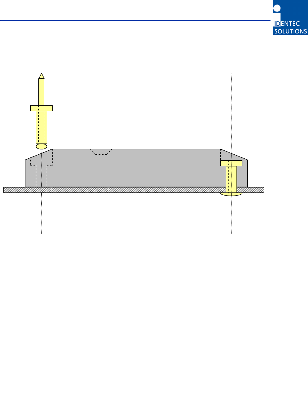
C.1 Rivets
Important Information:
(1) A temperature of at least +10°C (+50°F) must be maintained during riveting to prevent the casing from
cracking.
(2) Always position the blind-rivet gun straight down on the rivet site and all the way to the rivet socket.
(3) On occasion, a tag casing has been damaged through improper handling of the blind-rivet gun (slanted
positioning of the gun to access the rivet socket). If there is a chance this might occur, it is better to use
a blind rivet with a large head
1
or insert an M5 washer. This has the effect of distributing the pressure
over a larger surface area during riveting. The use of the washer has the added effect of positioning the
rivet slightly higher in the depression, so that one can better access the rivet socket with the rivet gun.
(4) Metal surfaces in direct proximity to the tag can reduce the tag’s range of function. Tags should therefore
not be mounted in metal recesses or corners.
(5) After mounting, the tag’s function should be tested, i.e. with a handheld.
1
Refer to UN9924
Blind Rivets 5 x ...
i-B2 S – User’s Guide
Version 1.0 03.08.2006 Page 10/12
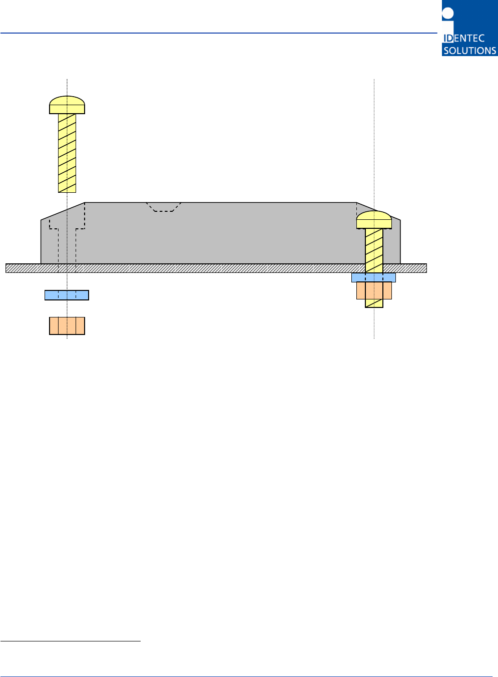
C.2 Screws
Important Information:
(1) Only screws with cylindrical heads are suitable for mounting the tag. We do not advise using counter-
sunk screws. If for some reason this should be necessary, then only together with a suitable counter-
sunk cushioning disc
2
.
(2) Secure the screws so they cannot work themselves loose i.e. by using self-locking nuts or spring washers
or Nordlock washers
3
.
(3) If the tag is mounted out-of-doors or in a damp environment, all mounting parts need to be made of
stainless steel or other non-rusting material.
(4) A temperature of at least +10°C (+50°F) must be maintained during mounting to prevent the casing
from cracking.
(5) Depending on the type and strength category of the M5 screw used, the maximum tightening torque
must be between 2 and 10 Nm. If the torque is any greater, the screw may overtighten, or the casing
might break.
(6) Metal surfaces in direct proximity to the tag can reduce the tag’s range of function. Tags should therefore
not be mounted in metal recesses or corners.
(7) After mounting, the tag’s function should be tested, i.e. with a handheld.
2
refer to UN 1277
3
refer to UN 7014
i.e. cylinder head or lenticular head screws M5 x
i.e. M5 hexagonal locknut with M5 washer
OR M5 hexagonal nut, but together with spring
washer or M5 Nordlock washer
i-B2 S – User’s Guide
Version 1.0 03.08.2006 Page 11/12
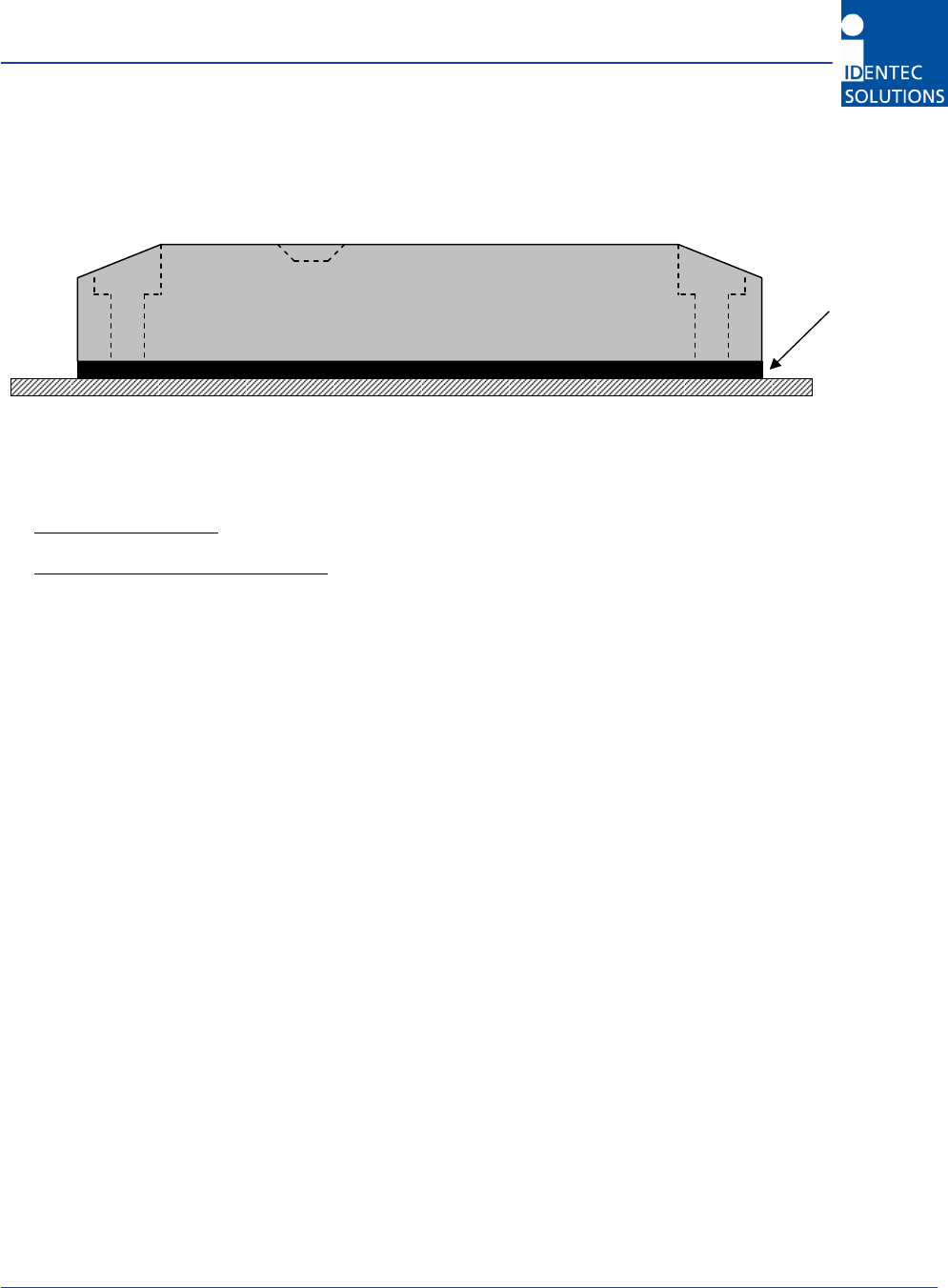
C.3 Taping (on metal surfaces)
The following double-sided tapes from 3M are currently being used/recommended:
• On level, flat surface: 3M acrylic foam tape #5952 F (Temperature: 120°C [248°F], short-term at 150°C
[300°F])
• On uneven, slightly curved surface: 3M acrylic foam tape #4959 F (Temperature 150°C [300°F], short-term
at 204°C [368°F])
Dimensions
• On the roll: 50m (164 feet)
• Width: 19mm (3/4 inch)
• Thickness: 1.1mm (0.043 inches) for #5952 or 3.0mm (1/8 inch) for#4959
• Length: max. 130mm (5 1/8 inches) – cut to length
Procedure
• Preparation of surfaces:
-
Plastic casing: preliminary cleaning, 3M Primer 26 GZH, 2 minutes waiting period
-
Metal surface: preliminary cleaning, 3M Primer 86 A, 15 minutes waiting period
• First attach tape to tag bottom and press on with the roll
• Then attach the tag to the prepared metal surface
Important Information:
(1) Before using the tape, cleaning agents and primers as listed, need to check if these are compatible with
the customer’s operating conditions. The customer’s approval must be obtained.
(2) Metal surfaces in direct proximity to the tag can reduce the tag’s range of function. Tags should therefore
not be mounted in metal recesses or corners.
(3) After mounting, the tag’s function should be tested, i.e. with a handheld.
Double-sided
Tape
i-B2 S – User’s Guide
Version 1.0 03.08.2006 Page 12/12
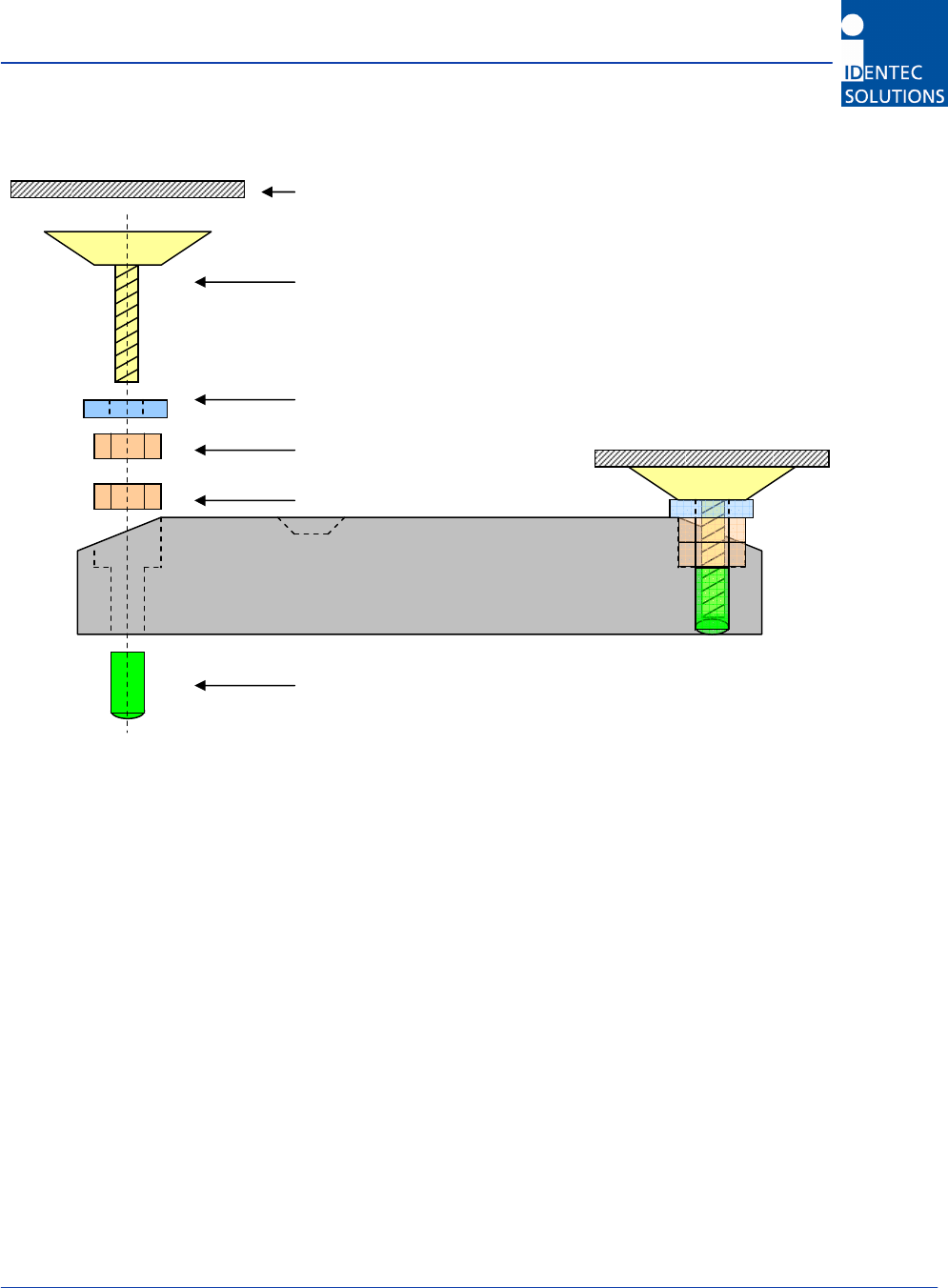
C.4 Mounting with Suction Cups
*) Supplier: i.e. Vakuplastic Kunststoff GmbH & Co. KG, Berlin Vendor part number: 1.1.3510
Suction cup 35mm [1
3/8 inch] with threaded bolts M4 x 10
Glass plate (c
lean, free of fatty substances
)
M4 washe
r
M4 screw nut
M4 screw nut
10 mm [0.4
inch] bushing with M4 inside th
read