Identec Solutions ILR-IB350LS Active Transponder Tag User Manual Street Pricing Deutsch
Identec Solutions AG Active Transponder Tag Street Pricing Deutsch
user manual
ILR 350 Series
i-B350L S
Installation and Operation Manual
(preliminary)

VISIBILITY DELIVERED. PAGE 2 OF 15
Proprietary Notice
This document contains confidential information proprietary to IDENTEC SOLUTIONS and may not be used or
disclosed to other parties in whole or in part without prior written authorization from IDENTEC SOLUTIONS.
Disclaimer and Limitation of Liability
IDENTEC SOLUTIONS AG and its affiliates, subsidiaries, officers, directors, employees and agents do not make
any express or implied warranties or representations with respect to such information including, without
limitation, warranties as to non-infringement, reliability, suitability for a particular purpose and accuracy.
IDENTEC SOLUTIONS shall not under any circumstances be liable to any person for any special, incidental,
indirect or consequential damages, including without limitation, damages resulting from use of or reliance on
information presented herein, or loss of profits or revenues or costs of replacement goods, even if informed in
advance of the possibility of such damages.
Trademarks
―IDENTEC SOLUTIONS‖, ―Intelligent Long Range‖, ―ILR‖ and the stylized ―i‖ are registered trademarks and
―i-Q‖, ―i-D‖, ―i-B‖, ―i-CARD‖, ―i-PORT‖, ―i-LINKS‖, ―Visibility Delivered‖ are trademarks of IDENTEC
SOLUTIONS, Inc. and/or IDENTEC SOLUTIONS AG.
Copyright Notice
Copyright © 2011 IDENTEC SOLUTIONS. All rights reserved.
No part of this document may be reproduced or transmitted in any form by any means, photographic,
electronic, mechanical or otherwise, or used in any information storage and retrieval system, without the prior
written permission of IDENTEC SOLUTIONS.
Issue 1 / August 2011
– 29. September 2011 –
IDENTEC SOLUTIONS AG,
Millennium Park 2, 6890 Lustenau, Austria
Phone: +43 5577 87387- 0, Fax: +43 5577 87387-15
E-Mail: info@identecsolutions.at
www.identecsolutions.com
Subject to alteration without prior notice.
© Copyright IDENTEC SOLUTIONS 2010

VISIBILITY DELIVERED. PAGE 3 OF 15
IDENTEC SOLUTIONS is the responsible party for the compliance of the following devices:
MODELS:
i-B350 S, i-B350L S
Region/Country
Organization
Marking
EUROPE:
EC
CE
USA
FCC
FFC ID OO4-ILR-IB350LS
Canada
Industry Canada
IC: 3538A-IB350LS
European Notification according R&TTE Directive
This equipment complies to Art. 6.4 of R&TTE Directive (1999/5/EC). It is tested for compliance with the
following standards: ETSI EN 300 220, ETSI EN 301 489, EN 60950
USA Notification
This device complies with part 15 of the FCC Rules. Operation is subject to the following two conditions: (1)
This device may not cause harmful interference, and (2) this device must accept any interference received,
including interference that may cause undesired operation.
The user(s) of these products are cautioned to only use accessories and peripherals approved, in advance, by
IDENTEC SOLUTIONS. The use of accessories and peripherals, other than those approved by IDENTEC
SOLUTIONS, or any changes or modifications not expressly approved by the party responsible for compliance
could void the users’ authority to operate the equipment.
The device has been tested and found to comply with the limits for a Class A digital device, pursuant to part
15 of the FCC Rules. These limits are designed to provide reasonable protection against harmful interference
when the equipment is operated in a commercial environment. This equipment generates, uses, and can
radiate radio frequency energy and, if not installed and used in accordance with the instruction manual, may
cause harmful interference to radio communications. Operation of this equipment in a residential area is likely
to cause harmful interference in which case the user will be required to correct the interference at his own
expense.

VISIBILITY DELIVERED. PAGE 4 OF 15
Contents
1 INTRODUCTION ................................................... .
1.1 PREPARATIONS ........................................................ .
1.2 RECOMMENDED PROCEDURE ....................................... .
1.3 SCOPE OF THIS DOCUMENT ......................................... .
1.4 RESPONSIBILITY ...................................................... .
1.5 ASSOCIATED DOCUMENTS .......................................... .
1.6 SCOPE OF DELIVERY—VISUAL INSPECTION ..................... .
2 SAFETY PRECAUTIONS ........................................ .
3 TAG MOUNTING TECHNIQUES ..................................................................................... 5
3.1 DIMENSIONAL DRAWING ................................................................................................... 8
3.2 CABLE STRAPS ................................................................................................................ 8
3.3 RIVETS ......................................................................................................................... 9
3.4 SCREWS ..................................................................................................................... 10
4 INITIAL OPERATION, CONFIGURATION OF THE TAG
4.1 GENERAL ............................................................... .
4.2 PING RATE ............................................................. .
4.3 BURSTS WHEN PASSING A POSITION MARKER .................. .
4.4 LIMITATIONS OF THE USER DATA FIELD ......................... .
4.5 INFORMATION ON BURST SETTINGS .............................. .
5 MAINTENANCE .................................................... .
5.1 GENERAL ............................................................... .
5.2 REGULAR CLEANING OF THE SURFACE ........................... .
5.3 PRECAUTIONARY MAINTENANCE ................................... .
5.4 RETURNS ............................................................... .
6 TECHNICAL DATA ....................................................................................................... 14

VISIBILITY DELIVERED. PAGE 5 OF 15
1 Introduction
1.1 Preparations
This installation manual must be read carefully prior to starting the installation. The described installation
works assume that installation materials like cable, antenna, tag holder, etc. are available.
1.2 Recommended Procedure
1. Check the Scope of Delivery according to the Bill of Delivery
2. Read this manual completely
3. Do the initial operation for every single tag
4. Mount the tags
5. An additional performance check of the tags and a system test can now be done
1.3 Scope of this Document
This document is the users’ manual of the models i-B350 S and i-B350L S.
This document is intended only for mechanical installation rsp. everyday use.
1.4 Responsibility
IDENTEC SOLUTIONS is not responsible for any errors occurring in this document.
1.5 Associated Documents
i-B350L W — ILR350 Wristband Tag Datasheet
1.6 Scope of Delivery—Visual Inspection
Check delivery whether it is complete and for any damages. If the delivery is not complete or damaged
immediately inform the carrier. The dispatch and service organization of IDENTEC SOLUTIONS should also be
informed to facilitate the repair or exchange of the system.

VISIBILITY DELIVERED. PAGE 6 OF 15
2 Safety Precautions
Important Safety Note
The devices described in this manual are for exclusive operation by trained employees. Only qualified
personnel that know the potential dangers involved should perform the installation, settings, maintenance and
repair of the units used.
Operational Safety
The correct and safe use of these systems assumes that operating and service personnel follow the safety
measures described in the manual alongside the generally acceptable safety procedures.
If there is a possibility where a safe operation cannot be guaranteed, the system must be switched off and
secured against accidental use. Then, the service unit responsible must be informed.
Do not open the housing
There is no need to open the housing. There are no user serviceable parts inside. Set-up and configuration
during initial operation is done wireless with the built-in air interface.
Handling Safety
In the event of high operating temperature of 70 °C (+158 °F), the tags are heated and must be handled with
care. To prevent burns, wait until the tags have cooled down or use appropriate gloves. At temperatures
below 0 °C (+32 °F) tags can be frozen. In this case, wait a while until tags are warmed up or use
appropriate gloves.
Battery Inside
All tags contain a battery. That is the reason for the following instructions:
Warning
Fire, explosion and burn hazard
Risk of explosion if battery is replaced by an incorrect type
Do not recharge, short circuit, crush, disassemble, heat above 70 °C (158 °F)
Do not incinerate, or expose contents to water
Electrostatic Discharge
This product contains components that are sensitive to electrostatic discharges. Please observe
the special instructions for their protection. Incorrect handling can damage the unit and cause the
invalidation of the warranty.
Safety Documents
This ILR system was designed, tested and supplied in perfect condition according to the test report document
EN60950.
Condensation/Change of Temperature
Moving the systems from a cold to a warm environment could lead to dangerous situations due to
condensation. Therefore it must be ensured that the system can adjust itself to the warmer temperature.

VISIBILITY DELIVERED. PAGE 7 OF 15
Spare Parts
We recommend that only original products, spare and replacement parts authorized by IDENTEC SOLUTIONS
be used for installation, service and repair. Otherwise IDENTEC SOLUTIONS does not accept any responsibility
for materials used, work carried out or possible consequences.
VISIBILITY DELIVERED. PAGE 8 OF 15
1 Tag Mounting Techniques
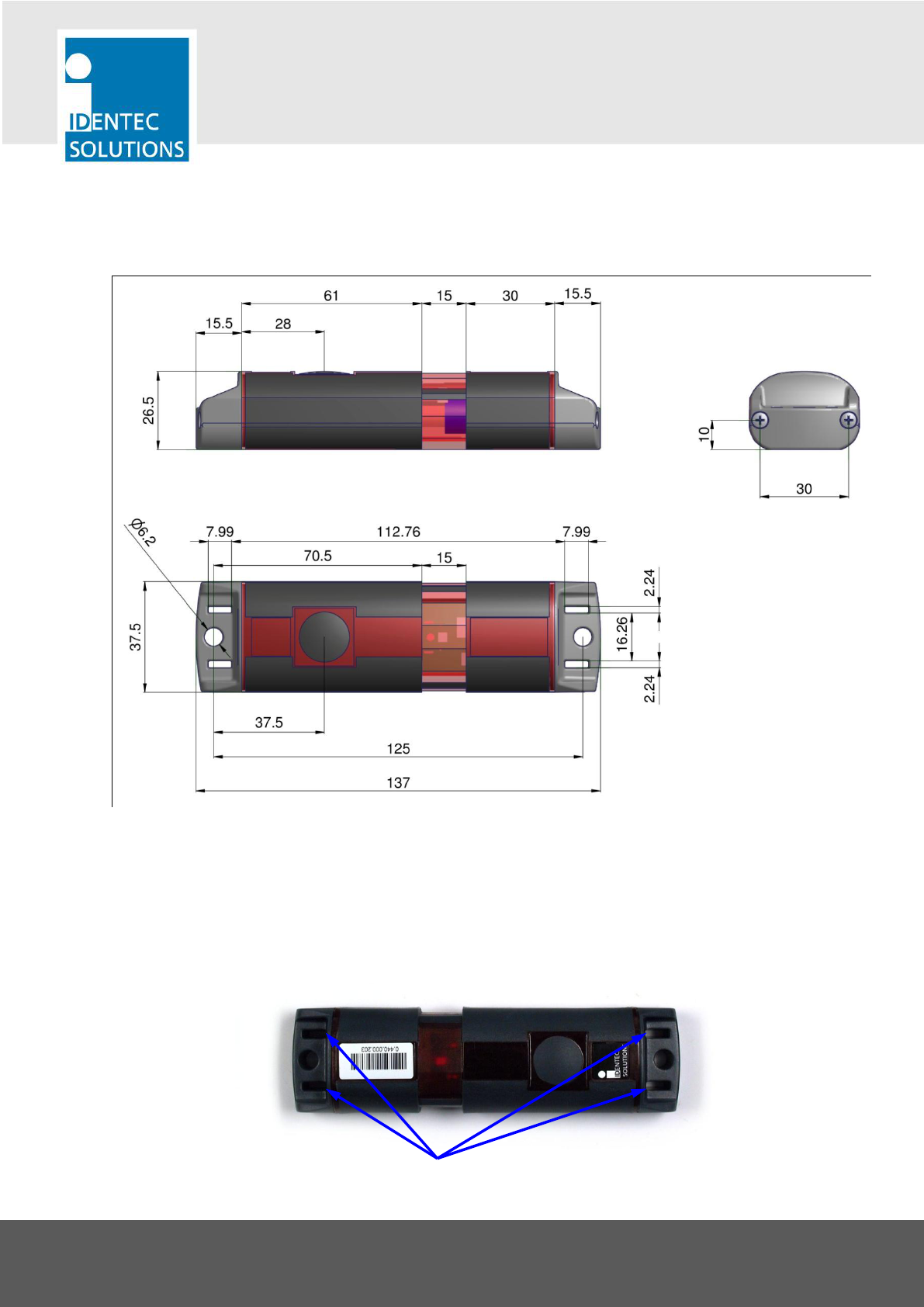
1.1 Dimensional Drawing
All dimensions in mm.
1.2 Cable Straps
The Tag can be mounted either with cable straps using the 2 slits at each end or using rivets or screws as
described in the following 2 subchapters.
Slits for mounting with cable straps
VISIBILITY DELIVERED. PAGE 9 OF 15
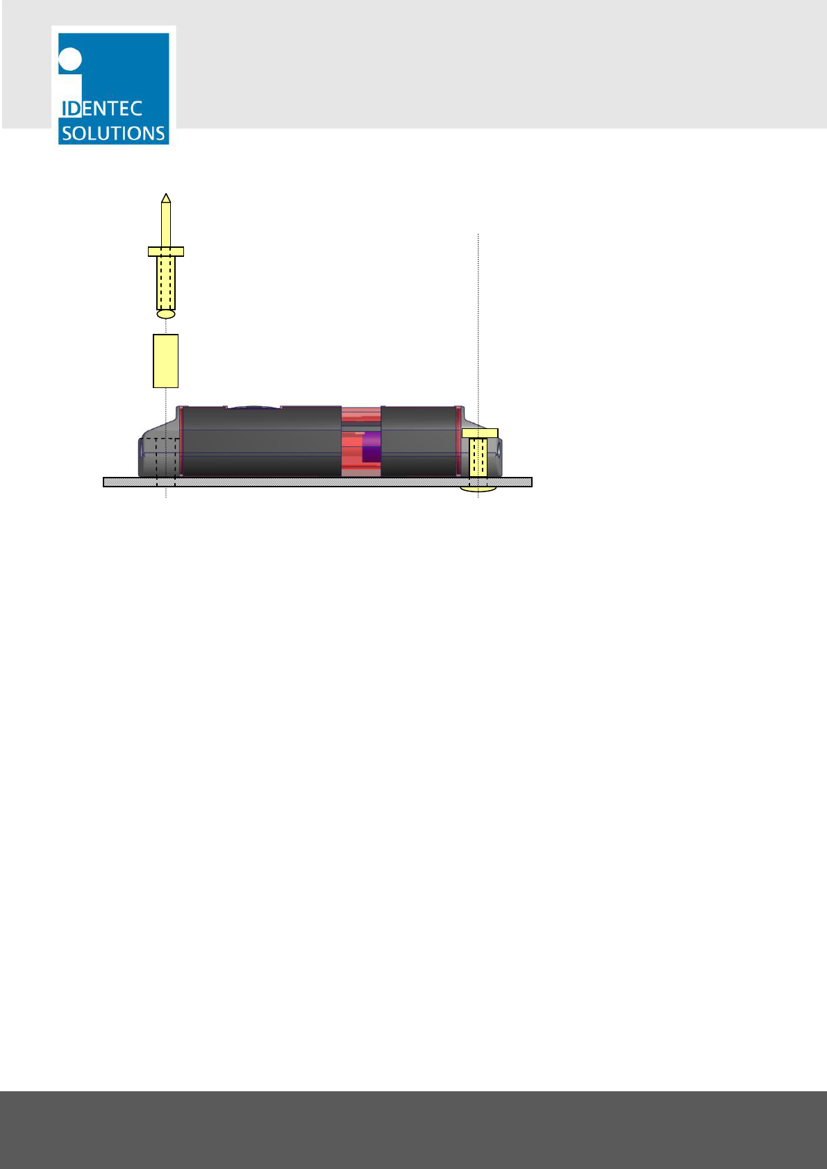
1.3 Rivets
Important Information
1. A temperature of at least +10 °C (+50 °F) must be maintained during riveting to prevent the casing from
cracking.
2. A bushing is recommended to protect the plastic around the mounting hole from being damaged when
tightening the rivet.
3. Always position the rivet gun straight down on the rivet site and all the way to the rivet socket.
4. Tag casing may become damaged through improper handling of the rivet gun (slanted positioning of the
gun to access the rivet socket). If there is a chance this might occur, it is better to use a blind rivet with
a large head (Refer to UN9924) or insert a 5/32‖ washer. This has the effect of distributing the pressure
over a larger surface area during riveting. Use of a washer has the added effect of positioning the rivet
slightly higher in the depression, so that one can better access the rivet socket with the rivet gun.
5. Metal surfaces in direct proximity to the tag can reduce the tag’s range of function. Tags should not be
mounted in metal recesses or corners.
6. After mounting, the tag’s function should be tested with appropriate device and software.
4 × 20 mm or 4 × 25 mm blind rivet
(length depending on thickness of mounting plate)
Bushing with 6/4.5 mm (15/64‖, 11/64‖) outer/inner diameter,
14.5 mm (37/54‖) length
VISIBILITY DELIVERED. PAGE 10 OF 15
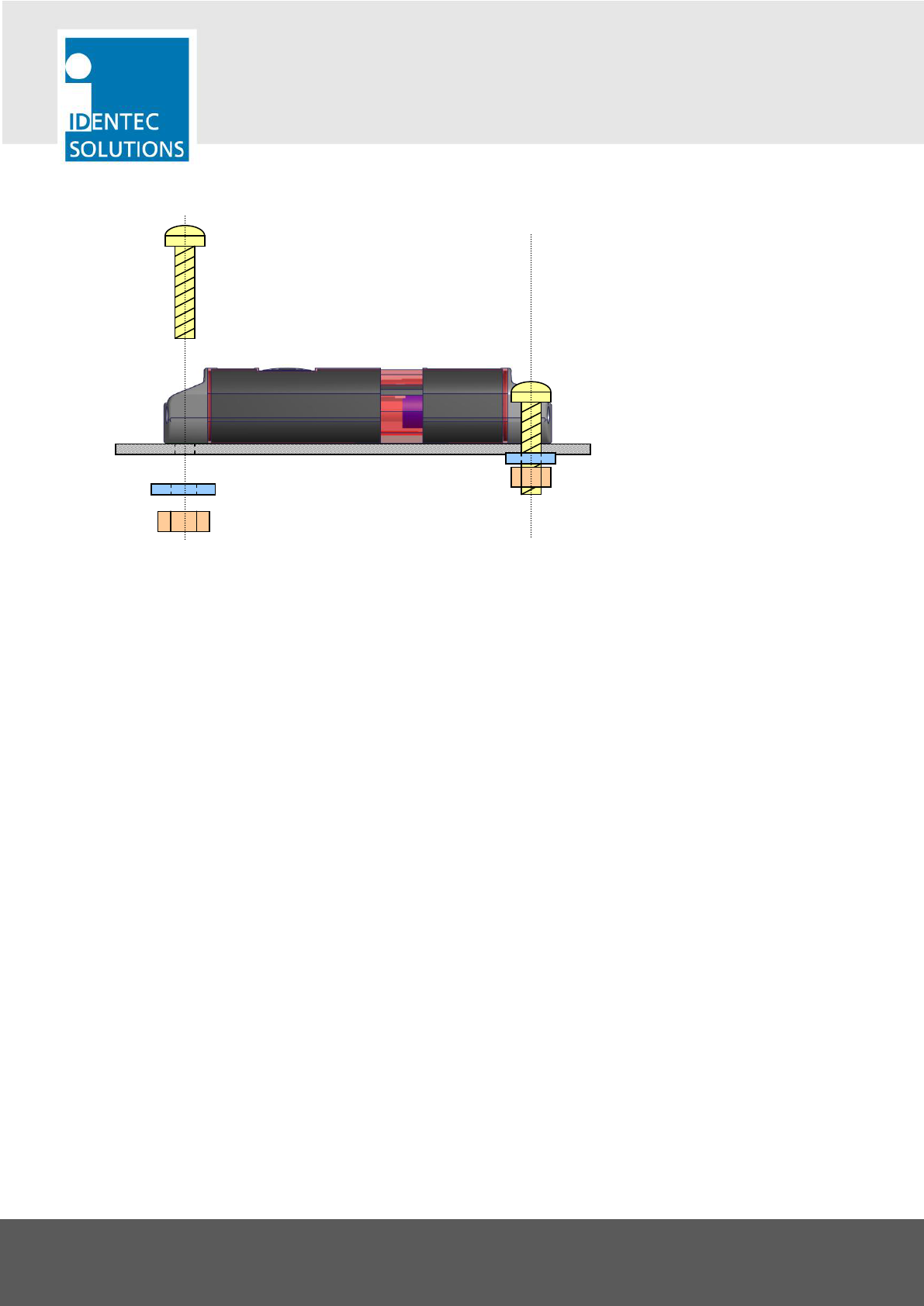
1.4 Screws
Important Information
1. Only screws with cylindrical heads are suitable for mounting the tag. We do not advise using counter-
sunk screws. If for some reason this should be necessary, then use only with a suitable counter-sunk
cushioning disc (refer to UN 1277).
2. Secure the screws with self-locking nuts, spring washers or Nord-lock washers (refer to UN 7014). Should
mounting be completed with self tapping screws, loosening may occur over time.
3. If the tag is mounted outdoors or in a damp environment, all mounting parts need to be made of
stainless steel or other non-rusting material.
4. A temperature of at least +10 °C (+50 °F) must be maintained during mounting to prevent the casing
from cracking.
5. Recommended maximum torque
M4/ #8 (with bushing): 2 Nm
M5/#10 (w/o bushing): 3 Nm
M6/#14 (w/o bushing): 3 Nm
If the torque is any greater, the screw may over tighten, or the casing might break.
6. Metal surfaces in direct proximity to the tag may reduce the tag’s range of function. Tags should not be
mounted in metal recesses or corners.
7. After mounting, the tag’s function should be tested with appropriate devices and software.
e.g. 5/32‖hexagonal locknut with 5/32‖washer
OR
5/32‖hexagonal nut, but together with spring washer
or 5/32‖Nordlock washer
e.g. M4/#8 cylinder head or lenticular head screws
VISIBILITY DELIVERED. PAGE 11 OF 15
2 Configuration of the tag
The i-B350L S is configured using the i-PROG M350L programming device.
Important Note
Do not open the housing! Configuration is done using the built-in air interface of the i-B350L S.
In addition to the Broadcast mode the i-B350L S offers the following special functions that can be configured:
Bursts on entering a marker field can be configured independent from regular Pings
Marker technology
Bursts triggered by the push button can be configured independent from regular Pings
Tools Needed
PC running on MS Windows with the ILR Tag Configuration for ILR 350 series tags
Connected to an i-PROG M350L to configure the tags
The ILR Tag Configuration software tool is described in detail in this manual:
ILR 350 Tag Configuration Plug-In Manual
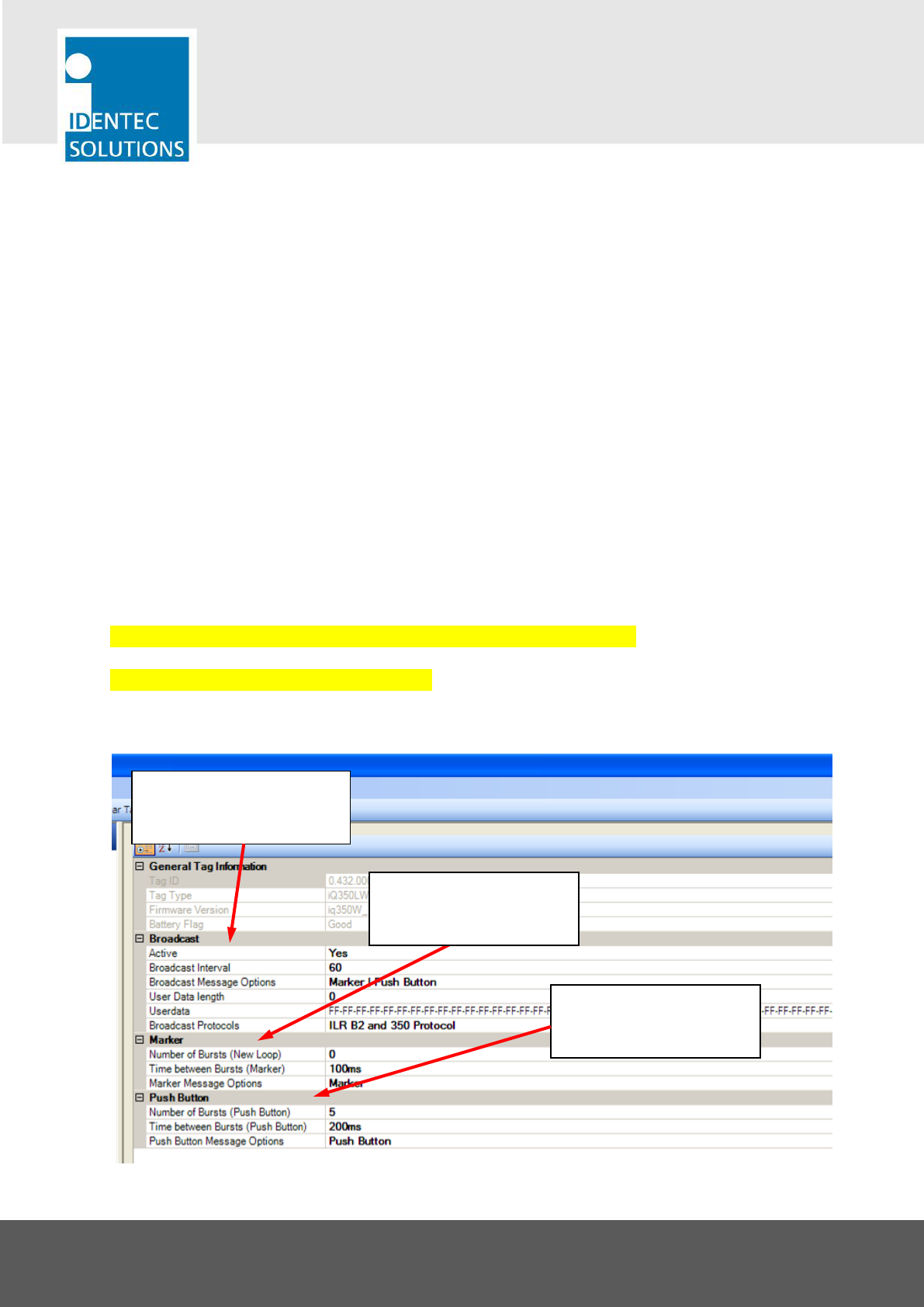
Overview on the Configuration Software
Select Ping Rate and Ping
Message Content in the block
―Broadcast‖
Select Burst behavior on
entering a marker field in
the block ―Marker‖
Select Burst behavior when
the button is pressed in the
block ―Push Button‖

VISIBILITY DELIVERED. PAGE 12 OF 15
2.1 Ping Rate
Note: This settings can be found in the ILR Tag Configuration software tool in the edit block ―Broadcast‖
Broadcast Interval: 0 = no broadcast messages are sent, value > 0 = Broadcast interval in seconds. This
can be set in steps of 0.5 sec, from 0.5 to 300 seconds.
Broadcast Message Options: The options in this field depend on the capabilities of the tag.
User Data Length: Configure the number of Bytes from the ―User Data‖ that is sent with a broadcast
message. The number starts from Byte 0 (zero). Please pay attention to the limits of the User Data
Length described at the end of this chapter.
2.2 Bursts when passing a Position Marker
Note: This settings can be found in the ILR Tag Configuration software tool in the edit block ―Marker‖
Number of Bursts (New Loop): 0 = no bursts, max. 15 bursts
Time between Bursts (Marker): This sets a timeslot inside which the tag sends out as single burst. This
gives a random delay between every single burst message to avoid collisions with tags that are triggered
by the same source to burst. Possible settings are 40, 100, 200, 300, 400, 500, 600, and 700 ms. Please
read the details in the following subchapter ―Information on Burst Settings‖.
Marker Message Options: Entering a marker field triggers a burst. This parameter determines the
contents of the burst messages.
2.3 Bursts triggered by the Push Button
Number of Bursts (Push Button): 0 = no bursts, max. 15 bursts
Time between Bursts (Push Button): This sets a timeslot inside which the tag sends out a single burst.
This gives a random delay between every single burst message to avoid collisions with tags that are
triggered by the same source to burst. Possible settings are 100, 200, 300, 400, 500, 600, and 700 ms.
Please read the details in the following subchapter ―Information on Burst Settings‖.
Push Button Message Options: Pushing the button triggers a burst. This parameter determines the
contents of the burst messages.
2.4 Limitations of the User Data Field
The total length of the broadcast message (burst or ping) is limited to 50 Bytes. So depending on the
broadcast message options, these are the allowed number of bytes for the user data:
User Data only => max. 50 Bytes of user data
Marker | User Data => max. 38 Bytes of user data
Marker | Push Button | User Data => max. 32 Bytes Bytes of user data
VISIBILITY DELIVERED. PAGE 13 OF 15
Push Button | User Data => max. 43 Bytes of user data
Push Button | User Data | Marker => max. 32 Bytes of user data
2.5 Information on Burst Settings
The parameter ―Time between Bursts (Marker)‖ is not simply a delay time. It is in fact a timeslot. In this
timeslot the tag chooses a random moment to do a single burst. This avoids that bursts collide with other
tags, that are simultaneously triggered by the same marker loop. These timeslots are repeated until all bursts
are sent.
With very few tags the factory setting of 40 ms is sufficient. In case there is the possibility that dozens of tags
are triggered to burst at once, this value can be increased. This brings the tradeoff of a longer overall time
until all bursts are sent. E.g. with a slot width (Time between Bursts) of 700 ms and 8 bursts, the amount of
time for all bursts is 5.6 seconds.
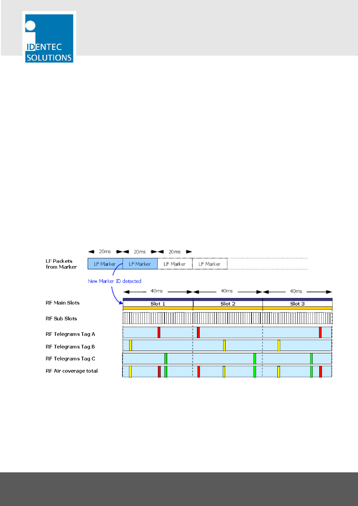
Example
This example shows 3 tags (A, B, C) that are simultaneously triggered by a marker loop (LF marker) and are
configured to burst 3 times. The timeslot (Time between Bursts) is set to the default of 40 ms.
The last row shows how the random use of the timeslot avoids collision between the tags.

VISIBILITY DELIVERED. PAGE 14 OF 15
3 Maintenance
3.1 General
When installed correctly the ILR System will operate virtually maintenance free for many years. However, in
the event maintenance is required only trained and authorized personnel are permitted to perform the
updates, changes and maintenance necessary.
3.2 Regular Cleaning of The Surface
Remove dust with a brush or compressed air. If there are fatty or oily substances use a soft cloth moistened
with a mild rinsing agent.
Warning
Do not clean the tag in a dishwasher. Do not sandblast the tag. Do not use high pressure water jet or steam
cleaner. Do not use cleaning products containing chemical additives.
3.3 Precautionary Maintenance
A regular check of the system is recommended. Unstable connections could lead to damage and malfunctions
of the system and should therefore be repaired as soon as possible.
A Brief Checklist
Are all housings intact?
Are all cables intact?
Are all connectors intact?
Are all connectors securely fastened?
Are all screws still tight?
Is there a malfunction at a specific unit?
3.4 Returns
Parts or main components returned for repair or exchange must be handled with great care. PC cards must be
returned in the appropriate ESD-protecting packaging material. All returns should include an error description
and a short application overview and be sent to the local distributor or to:
IDENTEC SOLUTIONS AG
Service Department
Millenium Park 2
6890 Lustenau
AUSTRIA

VISIBILITY DELIVERED. PAGE 15 OF 15
4 Technical Data
Operating Data
Operating frequency ILR-RFID 868 MHz (EU) or 920 MHz (NA), further frequencies on request
Maximum transmission power < 1mW (EU / NA)
Compatibility i-PORT M 350, i-CARD CF-350
Standards/Certification FCC Part 15 (US), ETSI EN 300 220 (EU)
Communication Data Long-Range RFID (ILR, Beacon Technology)
Read range broadcast Up to 500 m (1600 feet) free air*
Operation mode Transmits marker information in at regular intervals
Repetition rate (ping rate) 0,5 – 300 seconds, adjustable in steps of 0,5 seconds
Data rate broadcast 115.2 kbits/s
* The communication range depends on the antenna type, the antenna cable runs and the
environmental conditions.
Communication Data Inductive Loop (Marker)
Read range Up to several meters
Operating frequency 125 kHz (world-wide approved)
Operation mode Receives marker ID number and transmits marker information several
times
Electrical
Power source Lithium battery, non replaceable
Battery monitoring Yes
Data
Data retention >10 years without power
Write cycles 100,000 writes to a tag
Memory size 10,000 Bytes user definable
Identification code 48 bit fixed ID
Environmental Conditions
Operating temperature –40 °C to +85 °C (–40 ºF to +185 ºF)
Humidity 10 % to 95 % relative humidity @ 30 °C
Shock 50 G, 3 times DIN IEC 68-2-27
Multiple drops to concrete from 1 m (3 ft)
Vibration 3 G, 20 sine wave cycles, 5 Hz to 150 Hz, DIN IEC 68-2-6
5 G, noise 5 Hz to 1000 Hz, 30 minutes, DIN IEC 68-2-64
Physical
Dimensions 137 × 37.5 × 26.5 mm (5.4 × 1.48 × 1.04 in.)
Enclosure Plastic
Weight 50 g (1.75 ounces)
Enclosure rating IP 65