Identec Solutions ILR-ICARD350 Gen3 CF Card Reader User Manual CERTIFICATE OF COMPLIANCE
Identec Solutions, Inc. Gen3 CF Card Reader CERTIFICATE OF COMPLIANCE
User Manual

Rhein Tech Laboratories, Inc. Client: Identec Solutions Inc.
360 Herndon Parkway Model: i-CARD CF-350
Suite 1400 Standards: FCC 15.249 & RSS-210
ID’s: O2E-ILR-ICARD350/3538B-ICARD350 Herndon, VA 20170
http://www.rheintech.com Report #: 2008094
Page 21 of 25
Appendix J: Manual
Please refer to the following pages.
i-CARD CF-350

Compact Flash ILR Interrogator
Page 2 of 15
Proprietary Notice
This document contains confidential information proprietary to IDENTEC SOLUTIONS and may not be
used or disclosed to other parties in whole or in part without prior written authorization from IDENTEC
SOLUTIONS.
Disclaimer and Limitation of Liability
IDENTEC SOLUTIONS AG and its affiliates, subsidiaries, officers, directors, employees and agents
provide the information contained in this Manual on an “as-is” basis and do not make any express or
implied warranties or representations with respect to such information including, without limitation,
warranties as to non-infringement, reliability, fitness for a particular purpose, usefulness,
completeness, accuracy or up-to-dateness. IDENTEC SOLUTIONS shall not in any circumstances be
liable to any person for any special, incidental, indirect or consequential damages, including without
limitation, damages resulting from use of or reliance on information presented herein, or loss of
profits or revenues or costs of replacement goods, even if informed in advance of the possibility of
such damages.
Trademarks
“IDENTEC SOLUTIONS”, “Intelligent Long Range”, “ILR” and the stylized “i” are registered
trademarks and “i-Q”, “i-D”, “i-B”, “i-CARD”, “i-PORT”, “i-LINKS”, “Solutions. It’s in our name.”,
“Smarten up your assets” are trademarks of IDENTEC SOLUTIONS, Inc. and/or IDENTEC SOLUTIONS
AG.
Copyright Notice
Copyright © 2008 IDENTEC SOLUTIONS. All rights reserved.
No part of this document may be reproduced or transmitted in any form by any means, photographic,
electronic, mechanical or otherwise, or used in any information storage and retrieval system, without
the prior written permission of IDENTEC SOLUTIONS.
Reg. No. IM.0754.EN
Order Code:
Issue 0 / April 2008
– 28. April 2008 –
IDENTEC SOLUTIONS AG,
Millenium Park 2, 6890 Lustenau, Austria
Phone: +43 5577 87387- 0, Fax: +43 5577 87387-15
Email: info@identecsolutions.at
www.identecsolutions.com
Subject to alteration without prior notice.
© Copyright IDENTEC SOLUTIONS 2008
Printed in Germany

i-CARD CF-350
Page 3 of 15
Radio Frequency Compliance Statement
The user(s) of the product described within this document are cautioned to only use accessories and
peripherals approved, in advance, by IDENTEC SOLUTIONS, Inc. The use of accessories and
peripherals, other than those approved by IDENTEC SOLUTIONS, Inc., or unauthorized changes to
approved products, may void the compliance of these products and may result in the loss of the
user(s) authority to operate the equipment.
This device complies with Part 15 of the FCC Rules. Operation is subject to the following conditions:
(1) these devices may not cause harmful interference, and (2) these devices must accept any
interference, including interference that may cause undesired operation of the device.
FCC Compliance (i-CARD CF-350 / NA)
This equipment has been tested and found to comply with the limits for a Class A digital device,
pursuant to Part 15 of the FCC Rules. These limits are designed to provide reasonable protection
against harmful interference when the equipment is operated in a commercial environment. This
equipment generates, uses, and can radiate radio frequency energy and, if not installed and used in
accordance with the instruction manual, may cause harmful interference to radio communication.
Operation of this equipment in a residential area is likely to cause harmful interference in which case
the user will be required to correct the interference at his/her own expense.
Warning: Changes or modifications to this unit not expressly approved by the party responsible for
compliance could void the user’s authority to operate the equipment.
Industry Canada Compliance (i-CARD CF-350 / NA)
This Class A digital apparatus meets all requirements of the Canadian Interference-Causing Equipment
Regulations.
Cet appareil numérique de la classe A respecte toutes les exigences du Règlement sur le matériel
brouilleur du Canada.
To reduce potential radio interference to other users, the antenna type and its gain should be so
chosen that the equivalent isotropically radiated power (EIRP) is not more than that required for
successful communication.
This device has been designed to operate with the antennas listed below, and having a maximum
gain of 0 dB. Antennas not included in this list or having a gain greater than 0 dB are strictly
prohibited for use with this device. The required antenna impedance is 50 Ohm.
• Antenna: MDM-9000P, manufactured by MOBILE MARK (EUROPE), LTD.

Compact Flash ILR Interrogator
Page 4 of 15
Important Note
To comply with FCC radio frequency exposure compliance requirements, this device must be installed
by an IDENTEC SOLUTIONS certified technician.
The installer of this radio equipment must ensure that the antenna is located or pointed such that it
does not emit RF field in excess of Health Canada limits for the general population; consult Safety
Code 6, obtainable from Health Canada.

i-CARD CF-350
Page 5 of 15
Contents
1 SAFETY INSTRUCTIONS ...............................................................................................6
2 INTRODUCTION ...........................................................................................................7
2.1 GENERAL ...................................................................................................................7
2.1.1 Preparations.............................................................................................................7
2.1.2 Scope of This Document............................................................................................ 7
2.1.3 Responsibility...........................................................................................................7
2.1.4 Updates...................................................................................................................7
2.1.5 Scope of Delivery—Visual Inspection ..........................................................................7
2.2 TECHNICAL OVERVIEW...................................................................................................8
2.3 FUNCTIONALITY ...........................................................................................................8
2.4 COMPONENTS..............................................................................................................8
3 INSTALLATION.............................................................................................................9
3.1 MECHANICAL INSTALLATION ............................................................................................9
3.2 DRIVER INSTALLATION...................................................................................................9
3.2.1 Windows 2000/Windows XP..................................................................................... 10
4 USAGE.........................................................................................................................11
5 APPLICATION PROGRAM RULES................................................................................12
6 MAINTENANCE ...........................................................................................................13
6.1 GENERAL ................................................................................................................. 13
6.2 PRECAUTIONARY MAINTENANCE...................................................................................... 13
6.3 SPARE PARTS ............................................................................................................ 13
6.3.1 Recommended spare parts stock.............................................................................. 13
6.3.2 Preparing the spare parts........................................................................................ 13
6.3.3 Examination and repair of exchanged parts............................................................... 14
6.4 RETURNS ................................................................................................................. 14
7 TECHNICAL SPECIFICATIONS....................................................................................15

Compact Flash ILR Interrogator
Page 6 of 15
1 Safety Instructions
The system described in this manual is for exclusive operation by trained employees. Only qualified
personnel that know the potential dangers involved should perform the installation, settings,
maintenance and repair of the units used.
Operational Safety
The correct and safe use of these systems assumes that operating and service personnel follow the
safety measures described in the manual alongside the generally acceptable safety procedures.
If there is a possibility that safe operation cannot be guaranteed the system must be switched off and
secured against accidental use. Then the service unit responsible must be informed.
Safety Documents
This ILR system was designed, tested and supplied in perfect condition according to document IEC348
Safety Requirements for Electronic Units of Class 1.
Condensate / Change of Temperature
Moving the systems from a cold to a warm environment could lead to dangerous situations due to
condensation. Therefore it must be ensured that the system can adjust itself to the warmer
temperature.
Do not open the housing
There is no need to open the housing in order to set any ILR unit. No unit has any internal setting
elements or displays. All settings are performed using software via the Service Interface.
Spare Parts
We recommend that only personnel, original products, spare and replacement parts authorized by
IDENTEC SOLUTIONS be used for installation, service and repair. Otherwise IDENTEC SOLUTIONS
does not accept any responsibility for materials used, work carried out or possible consequences.
IDENTEC SOLUTIONS does not accept returns of products where the regulations concerning the ESD
precautions and protective packaging materials were not followed.
ESD – Electrostatic Discharge

i-CARD CF-350
Page 7 of 15
2 Introduction
2.1 General
2.1.1 Preparations
This installation manual must be read carefully prior to starting the installation. The described
installation works assume that installation materials like cable, antenna and data tag holder etc are
available
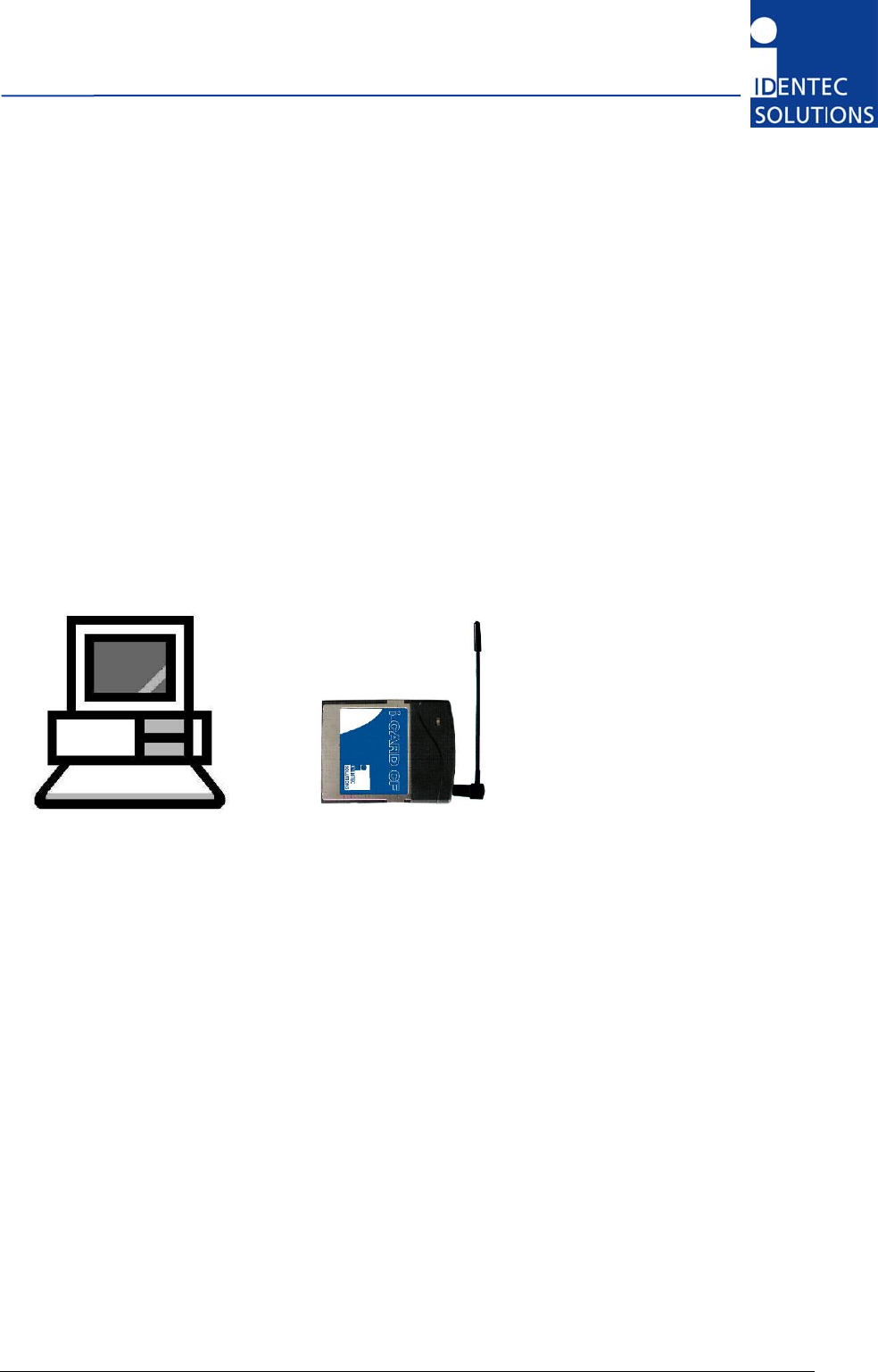
2.1.2 Scope of This Document
This guide explains how to install and operate the i-CARD CF-350 when using a laptop or desktop
computer.
2.1.3 Responsibility
IDENTEC SOLUTIONS is not responsible for any errors occurring in this document.
2.1.4 Updates
Updates will be provided on request. The information in this document can be changed without prior
notice and IDENTEC SOLUTIONS are under no obligation.
2.1.5 Scope of Delivery—Visual Inspection
Check delivery whether it is complete and for any damages. If the delivery is not complete or
damaged immediately inform the carrier. The dispatch and service organization of IDENTEC
SOLUTIONS should also be informed to facilitate the repair or exchange of the system.
Compact Flash ILR Interrogator
Page 8 of 15
2.2 Technical Overview
2.3 Functionality
The i-CARD CF-350 is IDENTEC SOLUTIONS’ Intelligent Long Range (ILR®) radio frequency mobile
interrogator in a type II CF Card format. The i-CARD CF-350 is easily integrated into portable or
laptop computers and is used in conjunction with ILR® software to read and write data to tags. The
flexibility of an interrogator on a CF Card allows for easy integration of ILR® into enterprise systems
and permits combination with other technologies such as bar code and wireless LAN.
The i-CARD CF-350 is available in a FCC compliant version (i-CARD CF/NA) and an European versions
(i-CARD CF / EU) to communicate in a global market. The signal propagation characteristics of the
UHF radio band used by ILR® technology provide long-range communication and high-speed
transmission rates for reliable data exchange.
Computers with an i-CARD CF-350 can communicate to tags at a distance of up to 100 meters
(300 feet). The i-CARD CF-350 communicates with the all series i-Q 350 and series i-B 350 active
tags.
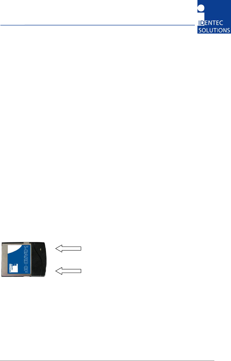
2.4 Components
The i-CARD CF resembles a standard CF card with one addition: an external antenna. On the exposed
end of the i-CARD CF, there are an MMCX antenna connector and a bi-color status LED indicating
Transmit, Receive and Host Communication. The exact meaning of the color depends on the firmware
version installed on the card.
Note
The current version only supports a quarter wavelength antenna available under P/N 887124 from
IDENTEC SOLUTIONS and equivalent internal antennas for hand-helds.
Status LED
Antenna connector
Figure 1: i-CARD CF Components
i-CARD CF-350
Page 9 of 15
3 Installation
The i-CARD CF-350 is easy to install—simply attach the antenna, insert the i-CARD CF-350 into the
desired computer (if necessary use a standard PCMCIA-CF adapter) and install the necessary
hardware driver for the specific operating system. The following sections describe each of these steps
in detail.
Note
The hardware driver only needs to be installed the first time an i-CARD CF is inserted into a computer
or when performing an upgrade to the driver.
3.1 Mechanical Installation
To install the external antenna, grasp its base and insert it into the antenna connector until it locks
into place.
Figure 2: Antenna Installation
To remove the antenna, grasp the base firmly and remove carefully to avoid damage.
3.2 Driver Installation
The computer being used for i-CARD CF-350 operations must be running one of the following
operating systems: Windows 2000/XP.
To install the i-CARD CF-350, perform the following steps:
1. Insert the ILR® Installation Disk (either floppy disk or CD) into the computer that will operate the
i-CARD CF-350.
2. Insert the i-CARD CF-350 into the CF card slot of the desktop or laptop computer.
An installation wizard will start immediately after the i-CARD CF-350 is inserted.
3. Complete the wizard instructions
Note
A readme.txt file is available for each operating system on the ILR® Installation Disk and contains the
same instructions that are described in the following sections.

Compact Flash ILR Interrogator
Page 10 of 15
3.2.1 Windows 2000/Windows XP
The following section describes how to install the device driver on Windows 2000 and Windows XP.
When the i-CARD CF-350 is inserted into the CF slot, an installation wizard begins automatically.
Select the “Search for a suitable driver for my device” option and click “Next”.
Selecting a search location depends on the type of ILR® Technical CD you received.
For a search location, select the “Floppy Disk Drives” option, and click “Next”. Click the “Browse”
button to copy drivers from your ILR® Technical CD:
Using the “Browse” dialog box, select the
\ILR_Support_Kit\iCARD CF\Drivers\Win_2000_XP folder. Select the iCARD-CF.inf file, then click OK.
The hardware driver is loaded and a confirmation screen appears. This screen verifies that the
installation has completed successfully. Click Next to complete the installation.
The hardware driver installation is now complete.
Note
There is no special driver on the CD. Supplied .inf file instructs Windows to use the standard serial
driver contained in the system.
Note
If you have problems installing the driver under Windows 2000 please make sure you have the latest
Service Pack installed. Please refer to Article 281505 in Microsoft Knowledge Base.

i-CARD CF-350
Page 11 of 15
4 Usage
After completing the i-CARD CF-350 installation, please refer to the user’s guide of the applicable
software to continue with the system implementation.

Compact Flash ILR Interrogator
Page 12 of 15
5 Application program rules
Due to national restrictions not all parameter values are valid in each version of the i-CARD CF-350.
Programmers of application software are strongly recommended to read the documentation which
comes with the development package.
Note
When trying to set an operation mode or output power which is not allowed in the national version
the i-CARD CF returns with an error code. Please refer to the library manual.
According to ERC/REC70-03 a maximum duty cycle of 1 % (i-Q350 tags) is allowed in Europe. Due to
the protocol used on the RF link this means no restrictions for interactive operation. However in
continuously running applications the application programmer must ensure observance of these rules.
For details please see the documentation which comes with the development package.
To minimize spurious radiation consecutive scans must be separated by pauses with a length of at
least 0.2 seconds. Again this is no restriction for interactive application as a scan is typically followed
by manual selection of a tag in a list which normally lasts longer than this required time.

i-CARD CF-350
Page 13 of 15
6 Maintenance
6.1 General
In principle, the ILR system is maintenance-free. When correctly installed it operates for many years
without any problems.
6.2 Precautionary Maintenance
Regular checking of all ports and cables belonging to the system is recommended. Unstable
connections could lead to damage and malfunctions of the system and therefore should be repaired
as soon as possible.
A Brief Checklist
• Are all casing intact?
• Are all cables intact?
• Are all connectors intact?
• Are all connectors securely fastened?
• Are all screws still tight?
• Is there suddenly a malfunction at a specific unit?
6.3 Spare Parts
6.3.1 Recommended spare parts stock
In order to keep the down time of the system during malfunctions as short as possible it is
recommended to have certain spare parts in stock. At least one central unit, one antenna and one
antenna cable should be available. With larger systems with more than approx. 15 interrogators
(i-CARD, i-PORT) the doubling of the recommended stock quantity should be considered.
Furthermore, it is recommended to have several spare tags in stock, corresponding
to approx. 0.5 – 1 % of the total number of tags.
6.3.2 Preparing the spare parts
In general all spare parts can be used immediately after delivery from IDENTEC SOLUTIONS.
However, for the compact communicator there are various settings of the communication parameters.
In order to keep the down times short it is recommended to set these parameters before the
component is entered into the spare part stock system. In most cases all units within an identification
system are used in the same way so that only one setting is required.

Compact Flash ILR Interrogator
Page 14 of 15
6.3.3 Examination and repair of exchanged parts
The data tags and compact communicators are complex electronic power units on which the customer
can carry out only very limited repairs. Normally the repairs are carried out at IDENTEC SOLUTIONS
or possibly at a distributor.
Before a part is sent in for repair a short examination should be carried out.
6.4 Returns
Parts or main components returned for repair or exchange must be handled with great care. PC cards
must be returned in the appropriate ESD-protecting packaging material.
All returns should include a completed returns form (see appendix) and be sent to the local distributor
or to:
IDENTEC SOLUTIONS AG
Service Department
Millenium Park 2
6890 Lustenau
AUSTRIA / AUTRICHE

i-CARD CF-350
Page 15 of 15
7 Technical Specifications
Tag Compatibility
i-CARD CF-350/EU all of series i-Q350/EU (e.g. i-Q350 GPS/EU)
all of series i-B350/EU (e.g. i-B350T/EU)
i-CARD CF-350/NA all of series i-Q350/NA (e.g. i-Q350 WAM/NA,
i-Q350 GPS/NA, i-Q350T HH/NA)
all of series i-B350/NA (e.g. i-B350T HH/NA)
Performance
Read/write range (adjustable) 100 m (300 ft)
Read rate (ID only) * 100 tags/s
Read rate * 35 tags/s @ 128 bit data reading
Multiple tag handling * Up to 2,000 tags in the read zone
* Applies only when using series i-Q350 tags
Communication
Frequency 850 – 928 MHz (depending on national regulations)
Certification Pending FCC, IC and CE
Number of antennas 1
Output power Up to 10 mW (depending on national regulations)
Sensitivity –105 dBm (depending on data rate)
CPU
Hardware drivers for different O/S Windows 2000/Windows XP
Program memory 64 kBytes Flash
User Interfaces
Parallel interface CF standard
Number of status indications 1 LED (bi-color)
Electrical
Input power 3.3 V DC or 5 V DC ±5 %
Power consumption < 50 mA (operating)
Standards/Safety CE
Environmental
Operating temperature –20°C to +60°C (–4ºF to +140ºF)
Storage temperature –40°C to +80°C (–40ºF to +176ºF)
Humidity max. 90 % non-condensing
Physical
Dimensions Standard Type II CF Card
Enclosure Metal/ABS
Mass 15 grams (0.53 oz)