Identec Solutions ILR-IMS350 Active transponder TAG User Manual Street Pricing Deutsch
Identec Solutions AG Active transponder TAG Street Pricing Deutsch
UserManual.wiki
>
Identec Solutions
>
ILR IMS350 User Manual
Users manual
Navigation menu
Upload a User Manual
Namespaces
Wiki Guide
HTML
PDF
Info
Views
User Manual
Discussion / Help
Navigation
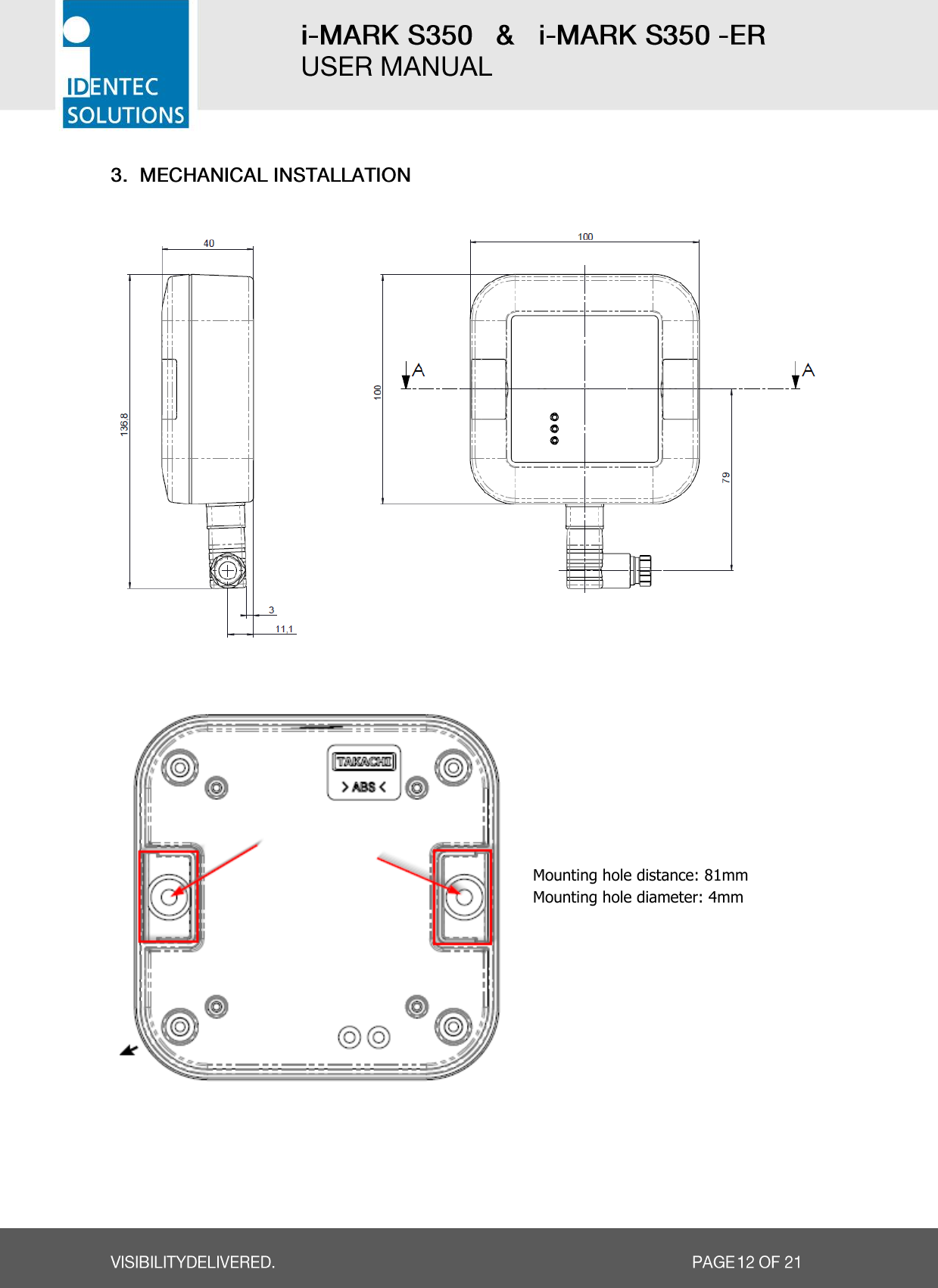
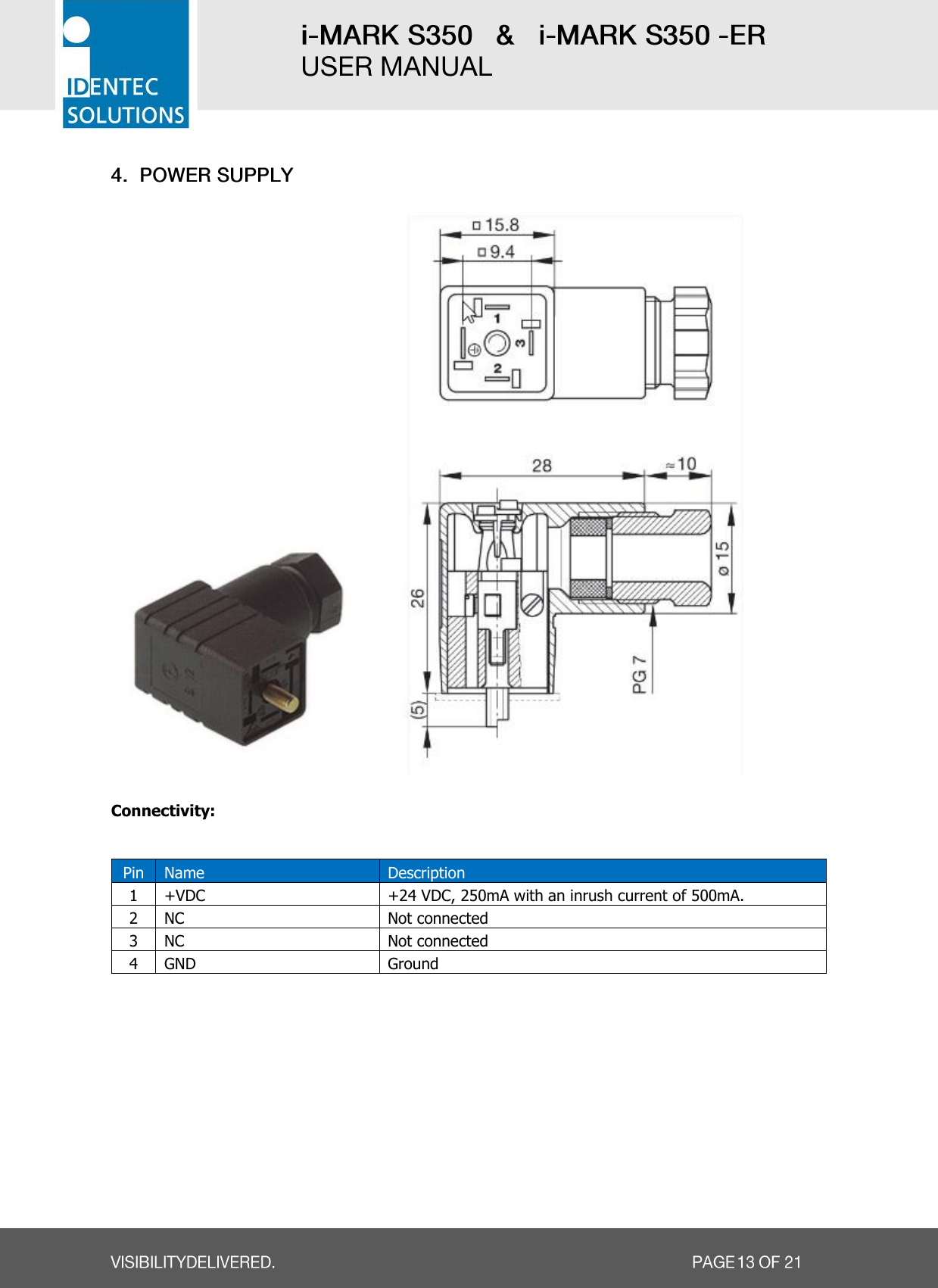
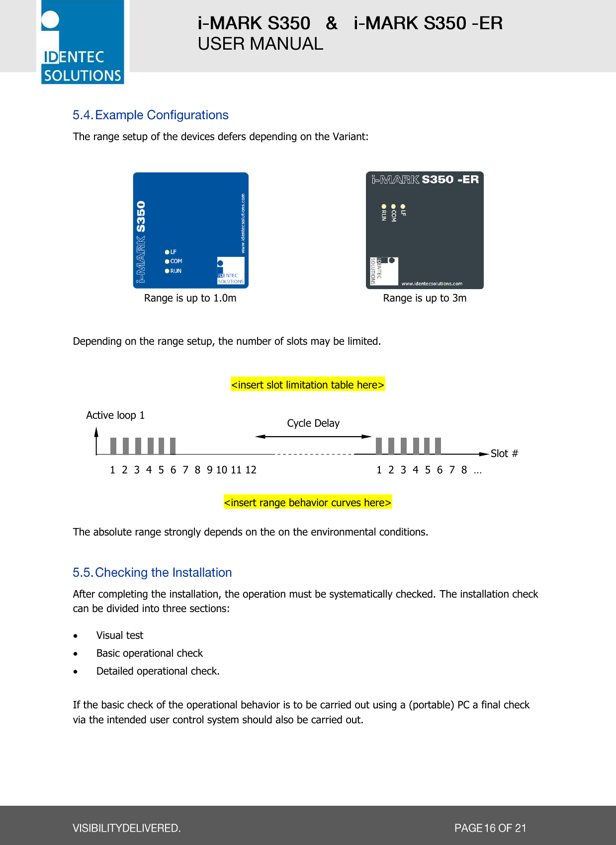
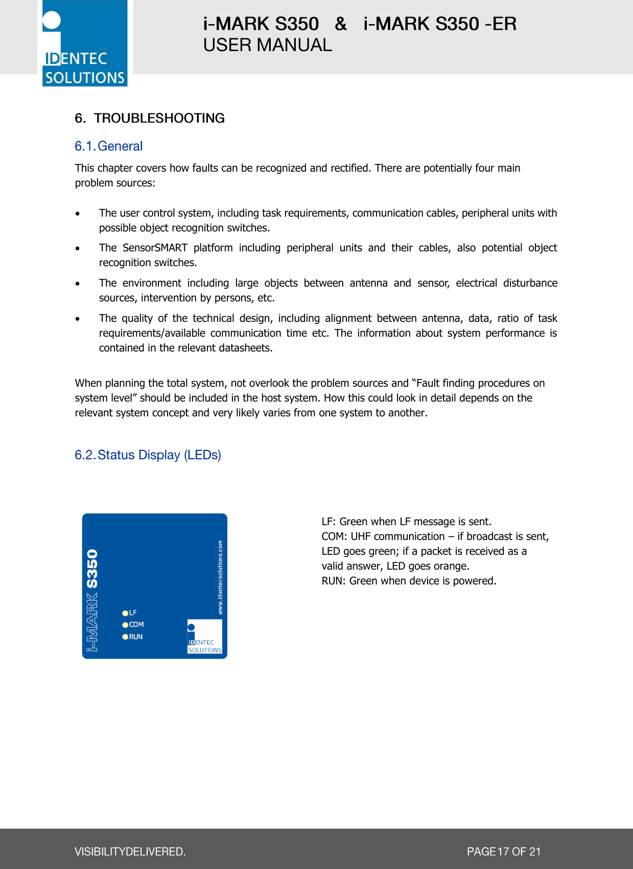
![Radio Frequency Compliance Statement IDENTEC SOLUTIONS is the responsible party for the compliance of the following devices: MODEL: i-MARK Region/Country Organization Marking EUROPE: EC CE USA: FCC FCC ID: OO4-ILR-IMS350 Canada: Industry Canada IC: 3538A-IMS350 The user(s) of these products are cautioned to only use accessories and peripherals approved, in advance, by IDENTEC SOLUTIONS. The use of accessories and peripherals, other than those approved by IDENTEC SOLUTIONS, or unauthorized changes to approved products, may void the compliance of these products and may result in the loss of the user(s) authority to operate the equipment. European Notification according R&TTE Directive This equipment complies to Art. 6.4 of R&TTE Directive (2014/35/EU, 2014/30/EU, 99/5/EC [expires on June, 12th 2016] and 2014/53/EU [valid from June, 13th 2016]). It is tested for compliance with the following standards: EN 300 220-1, ETSI EN 300 220-2, ETSI EN 301 489-1, ETSI EN 301 489-3, EN 60950-1:2006 + A11:2009 + A1:2010 + A12:2011 USA Notification This device complies with FCC and Industry Canada RF radiation exposure limits set forth for general population (uncontrolled exposure). This device must not be collocated or operating in conjunction with any other antenna or transmitter. Operation is subject to the following two conditions: (1) This device may not cause harmful interference, and (2) this device must accept any interference received, including interference that may cause undesired operation. Canada Certification This device complies with Industry Canada’s license exempt RSS’s. Operation is subject to the following two conditions: (1) This device may not cause harmful interference, and (2) this device must accept any interference received, including interference that may cause undesired operation. Le présent appareil est conforme aux CNR d‘Industrie Canada applicables aux appareils radio exempts de licence. L‘exploitation est autorisée aux deux conditions suivantes: (1) l‘appareil ne doit pas produire de brouillage, et (2) l‘utilisateur de l‘appareil doit accepter tout brouillage radioélectrique subi, même si le brouillage est susceptible d‘en compromettre le fonctionnement.](https://usermanual.wiki/Identec-Solutions/ILR-IMS350/User-Guide-3203391-Page-3.png)