Identec Solutions ILR-IP3NA i-Port3 User Manual Part 15 with 38 dB rejection
Identec Solutions, Inc. i-Port3 Part 15 with 38 dB rejection
Manual

Rhein Tech Laboratories, Inc. Client: Identec Solutions, Inc.
360 Herndon Parkway Model: i-PORT 3
Suite 1400 Report No: 2005011
Herndon, VA 20170 Standards: FCC 15.245/IC RSS-210
http://www.rheintech.com Date: May 11, 2005
Page 36 of 48
APPENDIX H: MANUAL
Please see the following pages.

_______________________________________________________________________
Document #7201-001, Rev C Page 1
i-PORT3 User’s Guide
IDENTEC SOLUTIONS, Inc.
Suite 102, 1860 Dayton Street
Kelowna, British Columbia
Canada V1Y 7W6
Tel: (250) 860-6567
Fax: (250) 860-6541
www.identecsolutions.com
________________________________________________________________________
Document #7201-001, Rev C Page 2
Proprietary Notice
This document contains confidential information proprietary to IDENTEC SOLUTIONS,
Inc. and may not be used or disclosed to other parties in whole or in part without prior
written authorization from IDENTEC SOLUTIONS, Inc.
Disclaimer and Limitation of Liability
IDENTEC SOLUTIONS, Inc. and its affiliates, subsidiaries, officers, directors, employees
and agents provide the information contained in this Manual on an “as-is” basis and do
not make any express or implied warranties or representations with respect to such
information including, without limitation, warranties as to non-infringement, reliability,
fitness for a particular purpose, usefulness, completeness, accuracy or currentness.
IDENTEC SOLUTIONS, Inc. shall not in any circumstances be liable to any person for
any special, incidental, indirect or consequential damages, including without limitation,
damages resulting from use of or reliance on information presented herein, or loss of
profits or revenues or costs of replacement goods, even if informed in advance of the
possibility of such damages.
Trademarks
“IDENTEC SOLUTIONS”, “Intelligent Long Range”, “ILR” and the stylized “i” are
registered trademarks and “i-Q”, “i-D”, “i-CARD”, “i-PORT”, “i-LINKS”, “Solutions. It’s in
our name.” are trademarks of IDENTEC SOLUTIONS, Inc. and/or IDENTEC SOLUTIONS
AG.
Copyright Notice
Copyright © 2002 IDENTEC SOLUTIONS, Inc. All rights reserved.
No part of this document may be reproduced or transmitted in any form by any means,
photographic, electronic, mechanical or otherwise, or used in any information storage
and retrieval system, without the prior written permission of IDENTEC SOLUTIONS, Inc.

________________________________________________________________________
Document #7201-001, Rev C Page 3
Radio Frequency Compliance Statement
IDENTEC SOLUTIONS, Inc. is the responsible party for the compliance of the following devices:
MODEL: i-PORT 3
FCC ID: O2E-ILR-IPORT3
CANADA: Pending
EUROPE: CE 0678(!)
The user(s) of these products are cautioned to only use accessories and peripherals approved, in
advance, by IDENTEC SOLUTIONS, Inc. The use of accessories and peripherals, other than those
approved by IDENTEC SOLUTIONS, Inc., or unauthorized changes to approved products, may void the
compliance of these products and may result in the loss of the user(s) authority to operate the
equipment.
Operation is subject to the following conditions: (1) these devices may not cause harmful interference,
and (2) these devices must accept any interference, including interference that may cause undesired
operation of the device.
FCC Compliance
This equipment has been tested and found to comply with the limits for a Class A digital device,
pursuant to Part 15 of the FCC Rules. These limits are designed to provide reasonable protection
against harmful interference when the equipment is operated in a commercial environment. This
equipment generates, uses, and can radiate radio frequency energy and, if not installed and used in
accordance with the instruction manual, may cause harmful interference to radio communication.
Operation of this equipment in a residential area is likely to cause harmful interference in which case
the user will be required to correct the interference at his/her own expense.
Warning: Changes or modifications to this unit not expressly approved by the party responsible for
compliance could void the user’s authority to operate the equipment.
Industry Canada Compliance
This Class A digital apparatus meets all requirements of the Canadian Interference-Causing Equipment
Regulations.
Cet appareil numérique de la classe A respecte toutes les exigences du Règlement sur le matériel
brouilleur du Canada.
To reduce potential radio interference to other users, the antenna type and its gain should be so
chosen that the equivalent isotropically radiated power (EIRP) is not more than that required for
successful communication.
Important Note
To comply with FCC radio frequency exposure compliance requirements, this device must be installed by an
IDENTEC SOLUTIONS certified technician. When installing antennas, a 20 centimeter passing distance must
be maintained from any body part of the user or nearby persons and the antenna.
The installer of this radio equipment must ensure that the antenna is located or pointed such that it
does not emit RF field in excess of Health Canada limits for the general population; consult Safety Code
6, obtainable from Health Canada.
________________________________________________________________________
Document #7201-001, Rev C Page 4
Table of Contents
1.0 INTRODUCTION ...........................................................................................................................................5
1.1 FUNDAMENTALS.............................................................................................................................................5
1.2 SYSTEM OVERVIEW........................................................................................................................................5
2.0 COMPONENTS...............................................................................................................................................6
2.1 I-PORT3.........................................................................................................................................................6
2.2 ANTENNAS .....................................................................................................................................................6
2.3 I-Q TAG ..........................................................................................................................................................7
2.4 I-D2 TAG ........................................................................................................................................................8
3.0 INSTALLATION AND START-UP..............................................................................................................9
3.1 INSTALLATION AND START-UP.......................................................................................................................9
MOUNTING THE I-PORT...........................................................................................................................................13
3.2 LED DISPLAYS.............................................................................................................................................14
3.3 CABLE CONNECTIONS AND PLUG ALLOCATION ...........................................................................................15
4.0 SOFTWARE, CONFIGURATION..............................................................................................................16
4.1 STANDARD SETTINGS, IP-ADDRESS, PASSWORD ..........................................................................................16
4.2 CONFIGURATION, SETTINGS .........................................................................................................................16
4.3 BOOT MENU (SERIAL)..................................................................................................................................25
4.4 INTERFACES ................................................................................................................................................27
4.5 PROTOCOLS.................................................................................................................................................27
5.0 SYSTEM DESCRIPTION............................................................................................................................28
5.1 COMMUNICATION SYSTEM, I-PORT, TAG....................................................................................................28
6.0 TECHNICAL SPECIFICATIONS ..............................................................................................................30
6.1 CODES, PARAMETERS...................................................................................................................................30
7.0 TROUBLESHOOTING................................................................................................................................32
7.1 TROUBLESHOOTING......................................................................................................................................32
7.2 HOTLINE.......................................................................................................................................................33
________________________________________________________________________
Document #7201-001, Rev C Page 5
1.0 Introduction
1.1
Fundamentals
IDENTEC SOLUTIONS’ ILR® (Intelligent Long Range®) technology is the next generation of
long range RFID (Radio Frequency IDentification). The objective is wireless and automated
data collection over large distances.
HOW RFID WORKS
Data is transmitted via high frequency radio waves between a tag and an interrogator.
Information stored on the tag can be read and modified. Data can be exchanged over long
distances, even in the presence of extreme operating conditions such as dust, dirt, paint or
oil.
The core element of the system is the active ILR tag, which can communicate large amounts
of data (up to 32 kBytes) at a rapid rate of transmission over very long distances (up to 100
meters). A sophisticated anti-collision handling algorithm enables the interrogator (i-PORT)
to record data simultaneously from hundreds of these tags within seconds. Connection of
the interrogator to a host computer system permits global data accessibility via a variety of
software platforms.
CHARACTERISTICS OF ILR:
• UHF Frequency (868 / 915 MHz)
• Long read and write range of 30 meters (optional up to 100 meters)
• Variable read range from just a few meters up to 100 meters
• Large storage capacity (8 kB or 32 kB)
• Temperature monitoring and recording (optional)
• Highly visible LED “pick-by-light” (optional)
• Long battery lifetime (up to 6 years)
• Anti-collision process and multi-tag handling
1.2
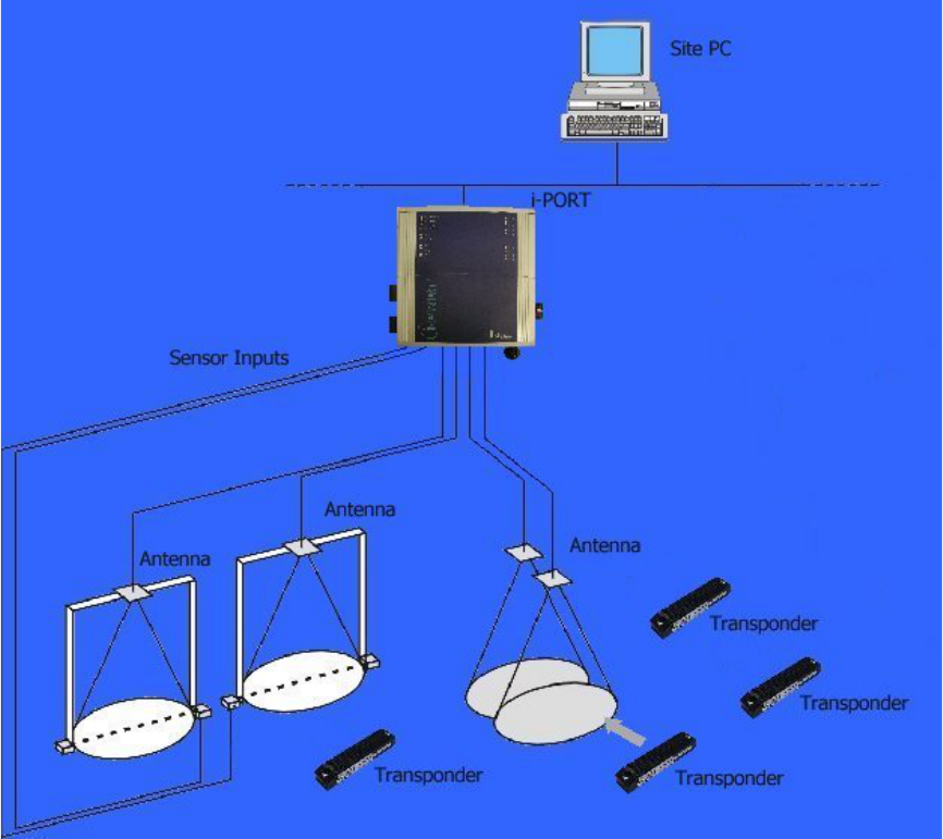
System Overview
IDENTEC SOLUTIONS’ ILR-System consists of 4 main components:
• Active tags (also called transponders) with internal power supply, which are used to
identify goods or to store data and histories
• Interrogator (i-PORT; fixed-mounted) and handheld devices (mobile), which exchange
information with the tags and host computer systems
• Antenna types for different applications
• A central computer system as basis for control and monitoring

_______________________________________________________________________
Document #7201-001, Rev C Page 6
2.0 COMPONENTS
2.1
i-PORT3
i-PORT3 is the next generation of IDENTEC SOLUTIONS’
ILR interrogators. It is capable of communicating not
only with tags from the i-Q series, but also with tags
from the i-D2 series. The communication range is up to
100 meters for i-Q tags and up to 6 meters for i-D tags.
Up to four antennas (plus one extra send antenna) can
be connected to i-PORT3; built-in signal strength
measurement capability enables the localization of tags
using triangulation.
i-PORT3 is delivered complete with standard software,
which offers the user a variety of options:
• Communication with ILR tags (i-Q and i-D)
• Simultaneous operation with up to four antennas
(receive), with the option of a fifth antenna (send)
• Communication with host computer systems via Ethernet interface
• Data processing (event messages, in/out, etc.)
• Configuration by means of web-interface (remote maintenance)
i-PORT3 has a Real-Time Operating System (RTOS: Thread X) and an internal Real-Time
Clock (RTC), which permit an exact time allocation of the data. Up to 2000 data messages
can be stored temporarily.
2.2
Antennas
A variety of antennas can be used, depending on application. The antennas are
differentiated by characteristics such as polarization, apex angle, and gain. Optimal fit to
the read zone is achieved by the right choice of antenna (characteristics) and the power
setting. As the antennas are passive system elements, no tuning is required, which
facilitates installation and maintenance.
Please consult with your system provider to discuss which antenna is most suited for your
project implementation.
_________________________________________________________________________
Document #7201-001, Rev C Page 7
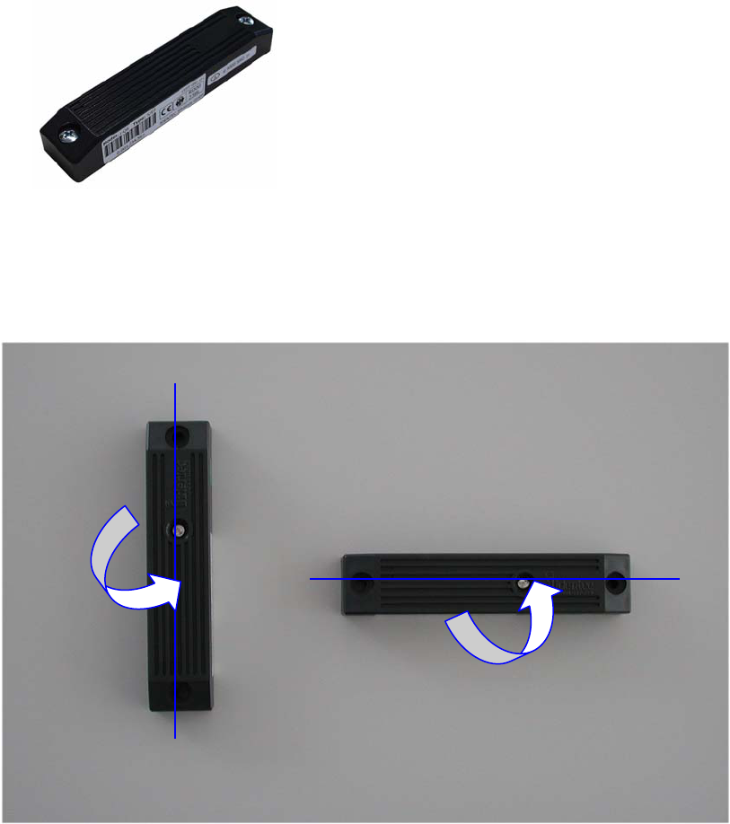
2.3
i-Q Tag
This active tag is particularly suited for:
- Identification
- Tracking and Tracing
- Localization
- Temperature Monitoring
i-Q tags are available in a variety of configurations, i.e. with 8 kByte or 32 kByte of
memory, an optional LED for visual recognition, and optional temperature logging function.
Furthermore, they are available at 868 MHz for use in Europe, at 915 MHz for use in North
America and at both frequencies for transcontinental applications.
Polarization is dependent on orientation and is rotation symmetrical.
Vertically Polarized Horizontally Polarized
_________________________________________________________________________
Document #7201-001, Rev C Page 8
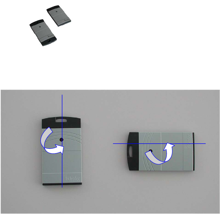
2.4
i-D2 Tag
This active tag is particularly suited for:
- Identification
- Tracking and Tracing
- Localization
i-D tags are available in a variety of configurations. The tags have 64 bytes of memory, an
optional LED for visual recognition, and are available in two different housing types (for
personnel identification and for industrial applications). The tag transmits a low power
signal at 868 MHz and can therefore be used in both Europe and North America.
Polarization is dependent on orientation and is rotation symmetrical.
Vertically Polarized Horizontally Polarized

_________________________________________________________________________
Document #7201-001, Rev C Page 9
3.0 INSTALLATION AND START-UP
3.1
Installation and Start-Up
Before installation, the user should have thorough knowledge of the application. The read
locations need to be defined; whether the object is moving or stationary needs to be
determined. If the objects in question are moving objects, their speed is important for
determining the scan interval. The read locations need to be sufficiently spaced. Rule of
thumb is that the distance between two i-PORTs should be at least double the read range
of the i-PORTs (or double the distance required) to synchronize the i-PORTs.
Mounting Site:
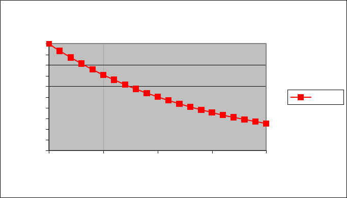
The i-PORT should be mounted as close as possible to the read location as lengthy antenna
cables reduce the range of the system. A 10-meter coaxial cable induces a loss of 6 dB.
This in turn means a reduction by 50% in output power and range (see diagrams).
Cable losses as a function of cable length are displayed in the above diagram. The values
are based on an RG58 coaxial cable at a frequency of 900 MHz.
Cable Length vs. Cable Loss
0.00
2.00
4.00
6.00
8.00
10.00
12.00
0.00 5.00 10.00 15.00 20.00
Cable Length (m)
Cable Loss (dB)
Cable Loss / dB
_________________________________________________________________________
Document #7201-001, Rev C Page 10
In the diagram above, the relative range is displayed as a function of the cable length.
Relative because the range is dependent on the environment of the system. Under ideal
conditions (free field, high-sensitivity tags, high-sensitivity i-PORT, maximum output
power), ranges of up to 100 meters can be achieved. But if 20 meters of antenna cabling
are used, the cable losses amount to approximately 12 dB, which reduces the original
range to just one-quarter (25 meters)!
The range losses as displayed in the diagram are independent of the original range. If the
range is 30 meters (free field, low-sensitivity tags, low-sensitivity i-PORT, maximum
output power) and 10 meters of antenna cabling are used, the range is reduced by 50%.
After mounting the i-PORT, the antennas need to be installed and connected to the
designated antenna sockets. If antenna extension cables are required, check these for
function or short circuits before you begin with the start-up.
Alignment of Antennas:
Align the antennas with the tags or the objects to be monitored. Linearly polarized
antennas must have the same polarization as the tags, either horizontal or vertical.
Circular polarized antennas are not dependent on the polarization of the tags.
Based on the Orientation Diagram, an initial rough estimate of the read zone is possible.
First set the send range of the i-PORT. To do this, use the i-PORT’s blink mode (Note:
Inhibit Time must be set to “0”). With a test tag (with LED) in hand, walk off the read
zone. As long as the tag blinks, you are still within the zone. Reduce the i-Q or i-D Tx
Power parameter as much as required until the read zone has reached the desired size.
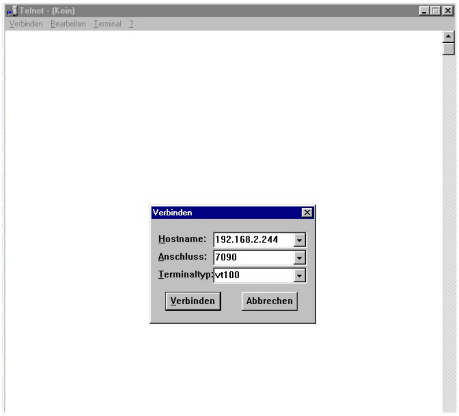
System Test:
You can use the debug port to test the system and the range. Connect the i-PORT via
crossover network cable directly to a laptop computer. Create a Telnet connection by
dialing up on the debut port (IP-Address: 192.168.2.244, Port: 7090). Under “Start” and
“Execute”, type in “Telnet”. This terminal program will then be started.
Cable Length vs. Range
0
10
20
30
40
50
60
70
80
90
100
0.00 5.00 10.00 15.00 20.00
Cable Length (m)
Range (%)
Range
c
_________________________________________________________________________
Document #7201-001, Rev C Page 11
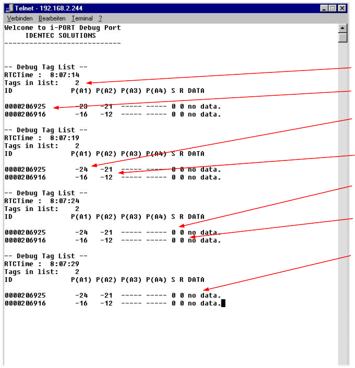
Enter the IP-Address of the i-PORT, in order to connect with the i-PORT debug port. Debug
information will then be displayed on the monitor. The debug port must be activated (see
Debug Config).
_________________________________________________________________________
Document #7201-001, Rev C Page 12
The result of the scan is displayed on the debug port. Each Tag-ID is listed with the
measured signal strength (depending on the number of active antennas).
No. Tags in List
Tag-ID
Field Strength
A
ntenna 1
Field Strength
A
ntenna 2
Session Setup
(inactive)
Read data
(inactive)
Data
(inactive)
_________________________________________________________________________
Document #7201-001, Rev C Page 13
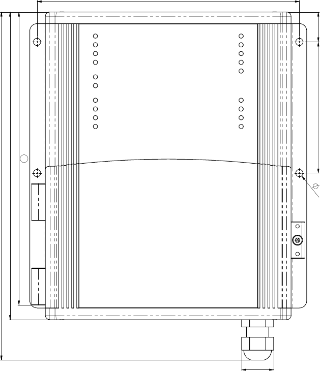
Mounting the i-PORT
211
238,7
21,9
180
20,590
5
201
a
Use the four mounting holes (diameter 5 mm) to attach the i-PORT to the side of the
housing. The amount of space required to mount the i-PORT is 200mm x 250mm x 60mm
(L x H x W). The i-PORT has a mass of approximately 2 kg. A 3mm hex wrench is required
to open the i-PORT.
Use the rubber grommet with hole to feed cables through the housing to the outside (cable
diameter 4.75 mm to 6 mm); seal the unused feed-throughs with the blind plugs. These
feed-throughs are intended for RG58 (antenna), Ethernet or serial cables.
Enclosure rating IP64 is thus achieved. If a higher enclosure rating is required, the i-PORT
must be placed in an additional housing.
_________________________________________________________________________
Document #7201-001, Rev C Page 14
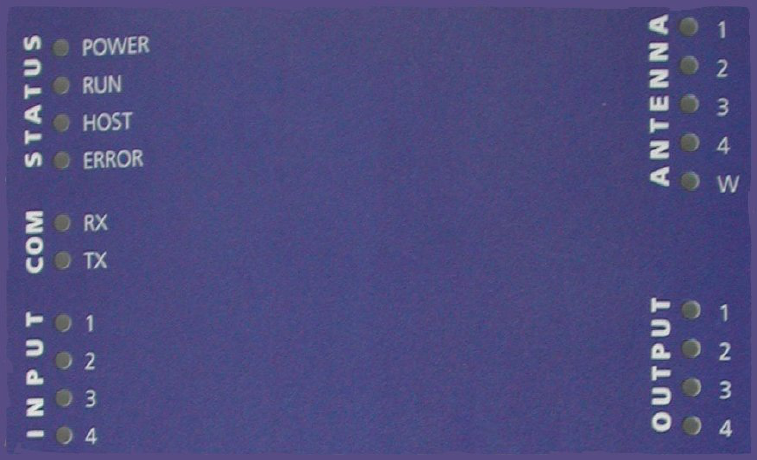
3.2
LED Displays
Status LEDs:
a) POWER: Lights up when power is applied to the i-PORT
b) RUN: Blinks (every 2 seconds) as soon as the i-PORT has booted (approx. 10
seconds after power-up)
c) HOST: Lights up when a host is connected to the i-PORT
d) ERROR: Lights up when an error occurs (see section: Troubleshooting)
COM LEDs:
a) RX: Lights up when the i-PORT receives data on serial interface
b) TX: Lights up when the i-PORT sends data on serial interface
INPUT LEDs:
a) 1-4: Light up when Inputs 1-4 are set (Connection to Ground)
ANTENNA LEDs:
a) 1-4: Light up when there is activity at corresponding Antennas 1-4
Green: Antenna is sending
Red: Antenna is receiving (Orange to red, depending on the strength of
the signal
b) W: Lights up when there is activity at the Wake-up Antenna
OUTPUT LEDs:
a) 1-4: Light up when the corresponding Outputs 1-4 are set
_________________________________________________________________________
Document #7201-001, Rev C Page 15
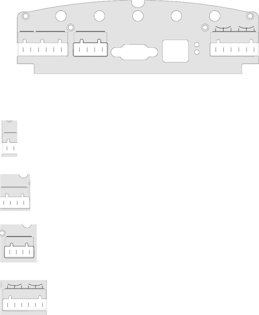
3.3
Cable Connections and Plug Allocation
IN 1
+10..30V
GND
+10..30V
IN 2
GND
IN 1
+10..30V
IN 2
GND
INPUTSUPPLY INPUT RS 232 10/100 BASE-T
LNK
ACT
OUTPUT
123 4
ANT 1 ANT 2 ANT 3 ANT 4 ANT W
Antenna jacks:
ANT1-4: SMA sockets, send and receive antennas
ANT W: SMA socket, send antenna ONLY (WakeUp Antenna)
Terminal Block 1: +10-30V Connection for power supply (10-30V DC) Supply
GND Connection for power supply (GND) Supply
Terminal Block 2: +10-30V Power supply for optional inputs (max. 4W) Input
IN1 Connection for Sensor 1 Input
IN2 Connection for Sensor 2 Input
GND Ground connection for optional inputs Input
Terminal Block 3: +10-30V Power supply for optional inputs (max. 4W) Input
IN3 Connection for Sensor 3 Input
IN4 Connection for Sensor 4 Input
GND Ground connection for optional inputs Input
Terminal Block 4: 1 Normally open Output 1 (Relay) Output
COM Ground from Relays 1 and 2 Output
2 Normally open Output 2 (Relay) Output
3 Normally open Output 3 (Relay) Output
COM Ground from Relays 3 and 4 Output
4 Normally open Output 4 (Relay) Output
Serial and Ethernet Interface:
RS 232 interface (up to 115 kb/s) and Ethernet interface (10 / 100 Mbit/s)
GND
+10..30V
SUPPLY
IN 1
+10..30V
IN 2
GND
INPUT
IN 1
+10..30V
IN 2
GND
INPUT
OUTPUT
123 4
_________________________________________________________________________
Document #7201-001, Rev C Page 16
4.0 Software, Configuration
4.1
Standard Settings, IP-Address, Password
The i-PORT is supplied with the following factory settings:
IP-Address 192.168.2.244
Subnet-Mask: 255.255.255.0
User Name: user
Password: identec
To change the IP-Address, see “Boot Menu (Serial)”
4.2
Configuration, Settings
Direct Connection:
Connect the i-PORT directly to the network connection in your PC, laptop, etc. using a
crossover network cable.
Ensure that the PC’s IP-Address lies in the same subnet as that of the i-PORT.
Network Connection:
Connect the i-PORT with a straight network cable to the network.
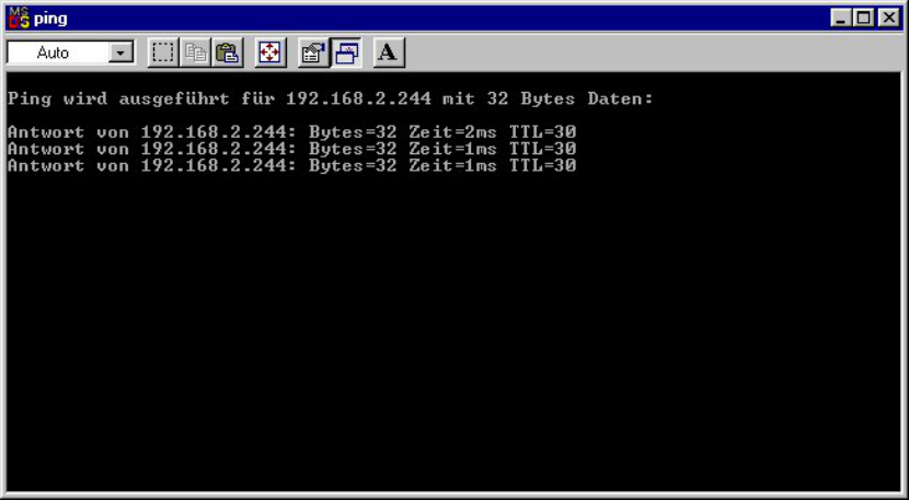
To test the connection to the i-PORT, open a DOS window and type in the command <ping
192.168.2.244>. You should receive a reply from the i-PORT.
After successfully testing the i-PORT connection, you can start your browser and open the
i-PORT web interface. To do this, type in the i-PORT address http://192.168.2.244
In doing this, you will get to the Start page for the i-PORT. Several sub-menus are
available to you for configuration and for testing purposes.
_________________________________________________________________________
Document #7201-001, Rev C Page 17
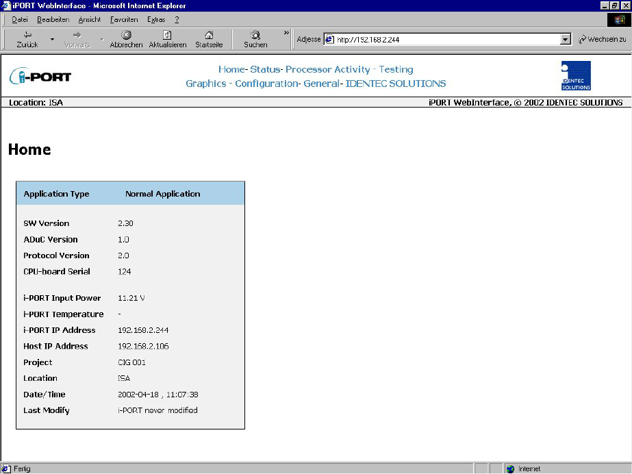
“Home” Menu:
Information about version numbers, firmware, serial numbers, etc. is contained in this
menu.
In the top line you can see an overview of all the menus. Click here to get to any of the
other menus.
_________________________________________________________________________
Document #7201-001, Rev C Page 18
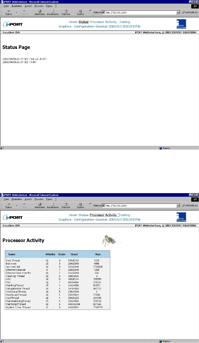
“Status” Menu:
Status information, which may be required in case maintenance is needed, is available in
this menu.
“Processor Activity” Menu:
Processor information, which may be required in case maintenance is needed, is available
in this menu.
_________________________________________________________________________
Document #7201-001, Rev C Page 19
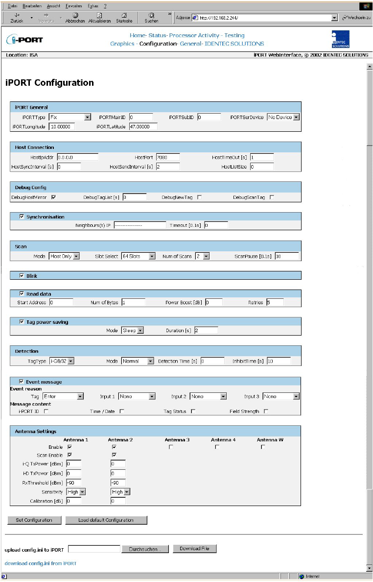
“Configuration” Menu:
For explanation of parameters, see next page.
_________________________________________________________________________
Document #7201-001, Rev C Page 20
i-PORT General:
Standard i-PORT settings such as type, external devices, etc.
i-PORT Type 2 possibilities: “Fix” and “mobile VisuMC”
Enter the i-PORT type here. Standard type is “Fix”, this means that the
i-PORT is stationary. Currently only special software “MobileVisuMC” still
available.
i-PORT Main ID i-PORT identifier for event messages (Area ID)
i-PORT SubID i-PORT identifier for event messages (Area SubID)
i-PORT SerDevice Used to select the type of device connected to the serial port. This
functionality has not been implemented at this time.
i-PORT Longitude Longitude co-ordinates
i-PORT Latitude Latitude co-ordinates
Host Connection:
These are settings used if the i-PORT is to be connected to a host computer (currently only
“Mobile VisuMC”).
Host IPAddr Host computer IP address
Host Port Host computer port
Host TimeOut i-PORT timeout
Host SyncInterval Interval for synchronizing i-PORT time (if a GPS device is connected,
time is synchronized with GPS time)
Host SendInterval Interval for sending messages to host computer
Host ListSize When this value is reached, the list is sent to the host computer
Debug Config:
Settings for the Debug output (Port 7090). If a check-box is selected, that parameter is valid.
Debug HostMirror Output on Debug Port of all data that is exchanged on the Host Interface
(serial or Ethernet).
Debug TagList Time after which a tag list is outputted on the Debug Port (“0” means no
output)
Debug NewTag Output of newly-recognized tags (Note the Inhibit Time!!)
Debug ScanTag Output of tag list after sequence execution (see Page 28)
Synchronization:
Settings when several i-PORTs are located in a small space, necessitating synchronization.
After marking the check-box, the IPs of the other i-PORTs can be entered into the designated
field.
Neighbour(s) IP Enter IP addresses of the neighbouring i-PORTs
Timeout Timeout for synchronization
Scan:
i-PORT settings for the scan process.
Mode: 3 possibilities: “Host Only”, “Continuous” and “Input 1”
“Host Only” means that the i-PORT waits for commands, processes them, and is
otherwise inactive. “Continuous” means that the i-PORT performs continuous
scans. “Input 1” mode has not been implemented at this time.
Slot Select Number of slots in which tags can answer. This is part of the anti-collision
process. Set at least double the amount of slots as the maximum number of
tags that can be located in the zone at one time. The elapsed time per slot in
which tags can answer is 1.2 ms.
Num of Scans In “Test Mode”, this is also the number of scans.
Scan Pause Pause inserted by i-PORT after each sequence (see page 28)
_________________________________________________________________________
Document #7201-001, Rev C Page 21
Blink:
Setting to cause tags entering the zone to blink (dependent on Inhibit Time!)
Blink If this check box is marked off, each newly-recognized tag will blink. If
Inhibit Time is activated (>0), it must first elapse for the tag (reentering the
zone) to blink again.
Read data:
Settings for i-PORT to read data from tags (mark off check box)
Start Address Address from which i-PORT begins to read data
Num of Bytes Number of bytes that are read starting from the Start Address
Power Boost Additional output power required for read process
Retries Number of maximum attempts to read data
Tag power saving:
Settings for i-PORT to send tags into Sleep Mode (mark off check box)
Mode 3 possibilities: “Sleep”, “Mute” or “Both”
Sleep, Mute, Both (i-Q): All 3 settings have the same effect for i-Q tags (sleep).
For this duration, the tags can no longer be communicated with (also from other
i-PORTs). After this time span has expired, the tags become available again.
Sleep (i-D): The tag cannot be communicated with for the duration of the sleep
time. If after the sleep time a renewed sleep signal is received from the same
i-PORT, the tag will again go into sleep mode. If no signal is received from the
same i-PORT or if a signal is received from a different i-PORT, the tag returns to
normal mode.
Mute (i-D): Tags receive a signal, but give no answer for the duration of the
“mute”. If the tag receives a renewed signal from the same i-PORT, the time will be
re-triggered. Otherwise, the tag returns to normal mode, as it likewise does if it
receives a signal from a different i-PORT.
Both (i-D): Combination of Sleep and Mute!
Duration Duration of the Sleep/Mute mode
Detection:
i-PORT settings which determine which tag types to interrogate, and how.
Tag Type 3 possibilities: “i-Q”, “i-D” and “Both”
Depends on which tags need to be interrogated.
Mode 3 possibilities: “Normal”, “Max. Level” and “In/Out”
Normal: A tag is detected when it enters the zone
Max. Level: Tag detection at maximum field strength (see also “Detection
Time”)
In/Out: Orientation recognition activated (Antenna 1…In, Antenna 2…Out,
Antenna 3…In, Antenna 4…Out)
Detection Time Max. Level Mode: Detection of tag at largest recorded field strength value
within the detection time interval
In/Out Mode: Detection of tag and calculation of orientation after detection
time interval
Inhibit Time If a previously interrogated tag leaves the zone for longer than the Inhibit
Time, it will be recognized as a new tag when it reenters the zone. If the tag
reenters the zone before expiration of the Inhibit Time, this time is reset as
if the tag had never left the zone

_________________________________________________________________________
Document #7201-001, Rev C Page 22
Event message:
Settings to determine when an event message is to be sent and how it should look.
Event reason A tag or an input can serve as a trigger for an event
Tag 3 possibilities: “Enter”, “Leave” or “Enter or Leave”
A message is generated when the tag enters the zone, when it leaves the
zone, or both when it enters AND when it leaves the zone.
Input 3 possibilities: “Rising Edge”, “Falling Edge” or “Changing”
A message is sent when the trigger detects either a rising edge, a
falling edge, or when changes in the Input occur.
Message content Each message can contain up to 4 additional pieces of information. By
clicking on the check box, the corresponding information is added to
the message (in addition to the Tag ID): i-PORT ID, Time/Date, Tag
Status and Field Strength.
Antenna settings:
Settings for the antennas, power outputs, etc.
Enable By marking the check box, the corresponding antenna is activated
Scan Enable By marking the check box, the corresponding antenna is also able to send
i-Q TxPower Power setting for i-Q tags at time of scan (send)
i-D TxPower Power setting for i-D tags at time of scan (send)
Rx Threshold Threshold (field strength of tag signal) required for tag recognition
Sensitivity i-PORT receiver mode; this means that the Rx Threshold reaches –60dBm
in low sensitivity mode and –90dBm in high sensitivity mode
Calibration Differences in the various antenna types and cable lengths can be
adjusted here (see example below)
Valid data for each parameter can be obtained from table in Appendix A.
Sequence:
A sequence is defined as successive scans on one or several antennas.
Example: 2 antennas are connected (enabled and scan enabled)
“Scan” command is sent to the i-PORT
Scan is executed on Antenna 1 (Tx), Antennas 1 and 2 receive (Rx)
Scan is executed on Antenna 2 (Tx), Antennas 1 and 2 receive (Rx)
Results of the scan command / sequence are sent back
Calculation example for calibration:
Coaxial cable RG58 loss of approximately 6dB for every 10 meters (at 900 MHz), i.e. 0.6
dB/m
1) Antenna 1: 5dB gain, 3-meter coaxial cable
Antenna 2: 5dB gain, 10-meter coaxial cable
Calibration parameters
Antenna 1 = –(Gain Ant1 – Loss Cable 1) = –(5dB – 3m x 0.6 dB/m) = –3.2 dB
Antenna 2 = –(Gain Ant2 – Loss Cable 2) = –(5dB – 10m x 0.6 dB/m) = +1.0 dB
2) Antenna 1: 5dB gain, 3-meter coaxial cable
Antenna 2: 5dB gain, 15-meter coaxial cable
Calibration parameters

_________________________________________________________________________
Document #7201-001, Rev C Page 23
Antenna 1 = –(Gain Ant1 – Loss Cable 1) = –(5dB – 3m x 0.6 dB/m) = –3.2 dB
Antenna 2 = –(Gain Ant2 – Loss Cable 2) = –(5dB – 15m x 0.6 dB/m) =+4.0 dB
_________________________________________________________________________
Document #7201-001, Rev C Page 24
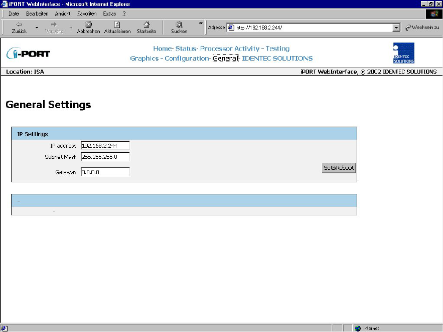
“General” Menu:
With this menu, you can change the network settings of the i-PORT. Simply enter the new
values in the appropriate fields and click on the SET&REBOOT button. The i-PORT will then
reboot with the new network settings. You can write down the new IP address in the
designated spot inside the i-PORT door.
_________________________________________________________________________
Document #7201-001, Rev C Page 25
4.3
Boot Menu (Serial)
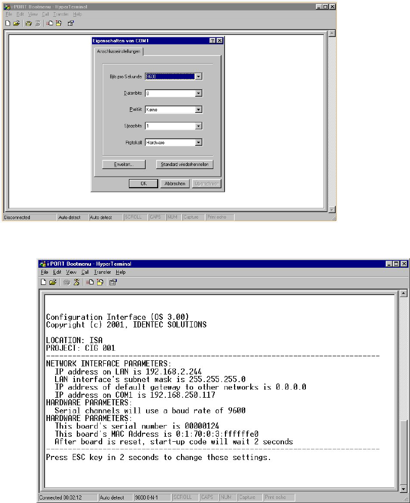
It is possible to change basic settings such as IP address, passwords, etc. via the serial
interface. To accomplish this, the i-PORT has to be connected via the serial interface to a PC,
(with a null-modem serial cable). Next, you need to start a terminal program (Hyperterminal,
GanTerm, etc.) with the following settings:
Bits per second: 9600
Data bits: 8
Parity: None
Stop bits: 1
Protocol: None
Start up the i-PORT as soon as there is a connection. Boot information appears on the screen
and you must press the ESCAPE button within 2 seconds, in order to change the standard
settings.
_________________________________________________________________________
Document #7201-001, Rev C Page 26
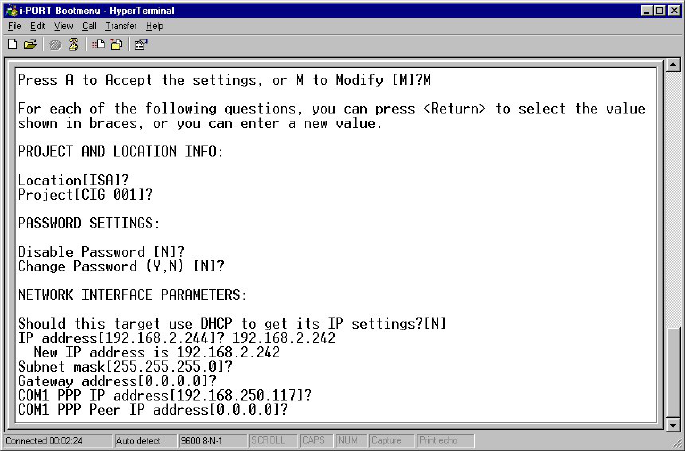
You now have the ability to change various standard settings:
Project and Location Info: Location Assignment of i-PORT, Mounting Location
Project Assignment of i-PORT, Project
Password Settings: Password Enable/Disable Password on/off
Username and Password Username/Password
Network Interface Parameters: DHCP/IP Address DHCP or fixed IP
Subnet Mask Subnet mask
Gateway Gateway, if needed
Com1 PPP IP Necessary for GSM-Modem
Com1 PPP Peer IP Necessary for GSM-Modem
Hardware Parameters: Baud Rate Data transmission 1.2 to 57.6 kbit/s
Boot Delay Time to start Boot menu
After the changes have been made and confirmed, the i-PORT will boot up and go into the
designated mode. You can write down the new IP address in the designated spot inside the
i-PORT door.
_________________________________________________________________________
Document #7201-001, Rev C Page 27
4.4 Interfaces
Ethernet Interface:
Rate of transmission: 10 / 100 Mbit/s
Protocols: TCP/IP, FTP, Telnet, HTTP, SNMP
Ports: Debugport 7090 for Debug data
Communication Port 7070 for communication (commands, messages)
WLAN:
It is possible to effect a WLAN connection by means of a converter, for example a Client
Bridge or Access Point.
4.5 Protocols
The protocol used by the i-PORT is an ASCII protocol. The protocol allows a host computer
to take control of the process or of the i-PORT. It is possible to execute scans, to read or
write data, to start temperature logs etc. on command.
For more information about the protocol, please refer to the i-PORT “Communication
Protocol”.
_________________________________________________________________________
Document #7201-001, Rev C Page 28
5.0 System Description
5.1
Communication System, i-PORT, Tag
Data communication between i-PORT and Tag:
First the i-PORT sends out a scan signal. This signal contains an i-PORT ID and the number
of available slots. All tags that are located in the read zone and that receive the signal
search out a slot at random and answer in this slot. Each slot has a duration of 1.2 ms.
This anti-collision process requires the availability of at least double the number of slots as
the maximum number of tags expected; the probability of collisions increases as the slots
are utilized. As a result of this scan signal, the i-PORT generates a tag list. Data can now
be exchanged (read from or written to) with the tags on this list. Before data is exchanged
with the tag, the i-PORT sends a Session Setup signal to this tag in order to prepare the
tag for the impending interrogation. In contrast to the scan, which addresses all the tags,
all other commands always refer to only one particular tag.
_________________________________________________________________________
Document #7201-001, Rev C Page 29
Host Only Mode:
The i-PORT is inactive in “Host Only” mode and waits for commands from the host
computer. When the host computer sends a scan command to the i-PORT, the i-PORT
executes the scan and sends the results back to the host computer. If data now needs to
be read from or written to a tag, the host computer must send the command to do so to
the i-PORT. The i-PORT can be operated via the Ethernet interface (Port 7070) or via the
serial interface in “Host Only” mode.
Continuous Mode:
In contrast to the “Host Only” mode, the i-PORT scans continuously in “Continuous Mode”.
The settings to determine which data are to be read and in what intervals are configurable
(see “Configuration”). The messages are made available at Port 7070.
Events:
Messages can be generated by tags or through inputs. The content of the messages can
also be configured (see “Configuration”).

_________________________________________________________________________
Document #7201-001, Rev C Page 30
6.0 Technical Specifications
6.1
Codes, Parameters
ILR® Parameters
Compatibility ILR® i-Q Tags and
ILR® i-D Tags
ILR® i-Q Tag ILR® i-D Tag
Read range (adjustable) 100m (300 ft) 6m (18 ft)
Write range (adjustable) 100m (300 ft) 6m (18 ft)
Max. response time (single tag) < 150 ms < 10ms
Read rate (ID only) 100 tags/s
Read rate – 128 bit data 35 tags/s
Multi-tag-handling (simultaneous) Up to 2,000 tags
RF Interface
Frequency 868 MHz (EU) or
915 MHz (NA) ISM Band
Certification
RF rate of transmission
FCC, Part 15 (US)
Industry Canada
EN 330 220 (EU)
i-Q 115.2 kbit/s; i-D 38.4 kbit/s (Tx), 115.2 kbit/s (Rx)
Number of antennas 5 (4 read/write + 1 wakeup)
Antenna transmitters 1
Output power: up to 23 dBm — adjustable (50 steps)
Antenna receivers 4
Sensitivity: up to -85 dBm — adjustable (100 steps)
Antenna control Independent antennas, simultaneous operation (receive)
User Interface
Ethernet interface 10 Mbit/s / 100 Mbit/s
Protocols
Ports TCP/IP, FTP, Telnet, HTTP, SNMP
7090 Debug port, 7070 Communication port
Serial interface RS232 – Setup and diagnostics only
Input control 4 digital inputs for process synchronization
Active when grounded, Rmax=560 Ohm
Output control 4 relay outputs for process control
max. breaking capacity: 30W (DC); 62.5VA (AC)
max. contact load: 1A at 30VDC, 0.5A at 125VAC
Status signals 19 status LEDs (for service and installation)
CPU
Operating system RTOS (Real Time Operating System) Thread X
Program memory 2 MB Flash
8 MB DRAM
Data memory 128 KB SRAM
Configuration memory 8 KB EEPROM
Time base Battery-backed Real Time Clock (RTC)
Electrical Data
Input voltage 10 – 30 VDC

_________________________________________________________________________
Document #7201-001, Rev C Page 31
Input power 7.5 W minimum
Standards / safety CE and EN 330 220
Environmental Conditions
Operating temperature 0°C to +50°C
optional –30°C to +70°C
Storage temperature -40°C to +80°C
Humidity 90%, non-condensing
Physical Data
Dimensions 211mm x 190mm x 58mm
Enclosure Aluminum, anodized
Mass 1.9 kg
Mounting 4 mounting holes, diameter 5mm
Enclosure rating IP 64

_________________________________________________________________________
Document #7201-001, Rev C Page 32
7.0 Troubleshooting
7.1
Troubleshooting
1) If the red Error LED blinks during the boot process and continues blinking after a
restart, contact the IDENTEC SOLUTIONS hotline.
2) If the Error LED lights up during operation, a system error has occurred (exception).
First execute a cold start (interrupt the power supply) and observe the system. If the
error occurs again, contact the IDENTEC SOLUTIONS hotline.
3) For other problems, follow the procedures as outlined below.
Problem Possible Cause Procedure Solution
No functionality after
turning on the power
supply
No power
- Measure the
voltage at the
terminal blocks
- If no voltage at terminal
blocks, check power supply
unit
- Measure directly at the outlet
for a power adaptor
- For a switching power supply,
measure voltage at both input
and output sides
Change power supply
unit, if necessary
No communication
between i-PORT and
network (PC) i.e.
cannot ping i-PORT
Wrong IP address - Double-check the i-PORT IP
address. Default-IP:
192.168.2.244
- Perform a ping on the IP (see
“Configuration, Settings”)
- If this is unsuccessful, start
the Boot menu and
check/change the IP
Change the IP address if
necessary and try to
ping the i-PORT
i-PORT IP and Host
IP are not in the
same subnet
- Double-check the subnet mask Change the subnet mask
Wrong network
cable - Direct connection i-PORT /
Host: cross-over network cable
- i-PORT integrated into
network: network cable
Possibly change the
network cable
Defective network
cable - Do optical check on cable
Change network cable
Tags are not being
recognized Antennas are not
connected - Check if the antennas are
connected correctly
Fasten antenna cables
to the designated sites.
Use torque wrench, if
available, otherwise
tighten the SMA plug
lightly.
Antennas are not
being triggered - Check if antenna LEDs light up
(LED: ANT1, ANT2, ANT3,
ANT4, W)
Activate the
corresponding antenna
(see “Configuration”)

_________________________________________________________________________
Document #7201-001, Rev C Page 33
Antenna is defective - Do optical check to see if
antenna is defective
Change antenna(s) if
necessary
Tag is out of read
zone - Hold the test tag in front of the
antenna and check if tag is
being recognized (blinks, i.e.
Debug port)
If necessary, adjust the
output power to the
requirements
i-PORT does not scan
on various antennas Antennas are not
being triggered - Check if the antennas in
question are activated and
scan-enabled (see
“Configuration”)
Turn on the desired
antennas
No messages on Port
7090 (Debug port) DebugInfo has been
turned off (7090) - Check if Debug port is
activated (i.e. which data is
being transmitted)
Activate the Debug port
(“Configuration”)
File download
unsuccessful, i.e.
i-PORT does not
accept the file
No connection with
i-PORT - Check the IP address and the
network cable
Change the IP address if
required or change the
network cable
Internet browser
cannot display
i-PORT web page
Browser is trying to
access Proxy Server - Deactivate your Internet
browser’s proxy function
7.2
Hotline
www.identecsolutions.com
In North America:
IDENTEC SOLUTIONS Inc.
#102 – 1860 Dayton Street
Kelowna, BC
V1Y 7W6
Canada
Tel: (250) 860-6567
Fax: (250) 860-6541
In Europe
IDENTEC SOLUTIONS AG
Millennium Park 2
A-6890 Lustenau
Austria
Tel.: +43 (0)5577 87387-0
Fax: +43 (0)5577 87387-15