Identec Solutions ILR-IPM Tag Reader for Active Tags User Manual i PORT MB Manual V1 1
Identec Solutions AG Tag Reader for Active Tags i PORT MB Manual V1 1
UserManual.wiki
>
Identec Solutions
>
ILR IPM User Manual
User Manual
Navigation menu
Upload a User Manual
Namespaces
Wiki Guide
HTML
PDF
Info
Views
User Manual
Discussion / Help
Navigation

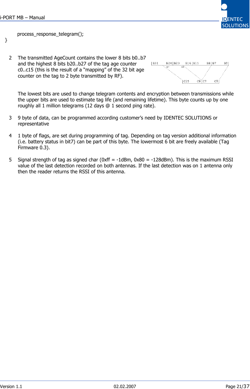
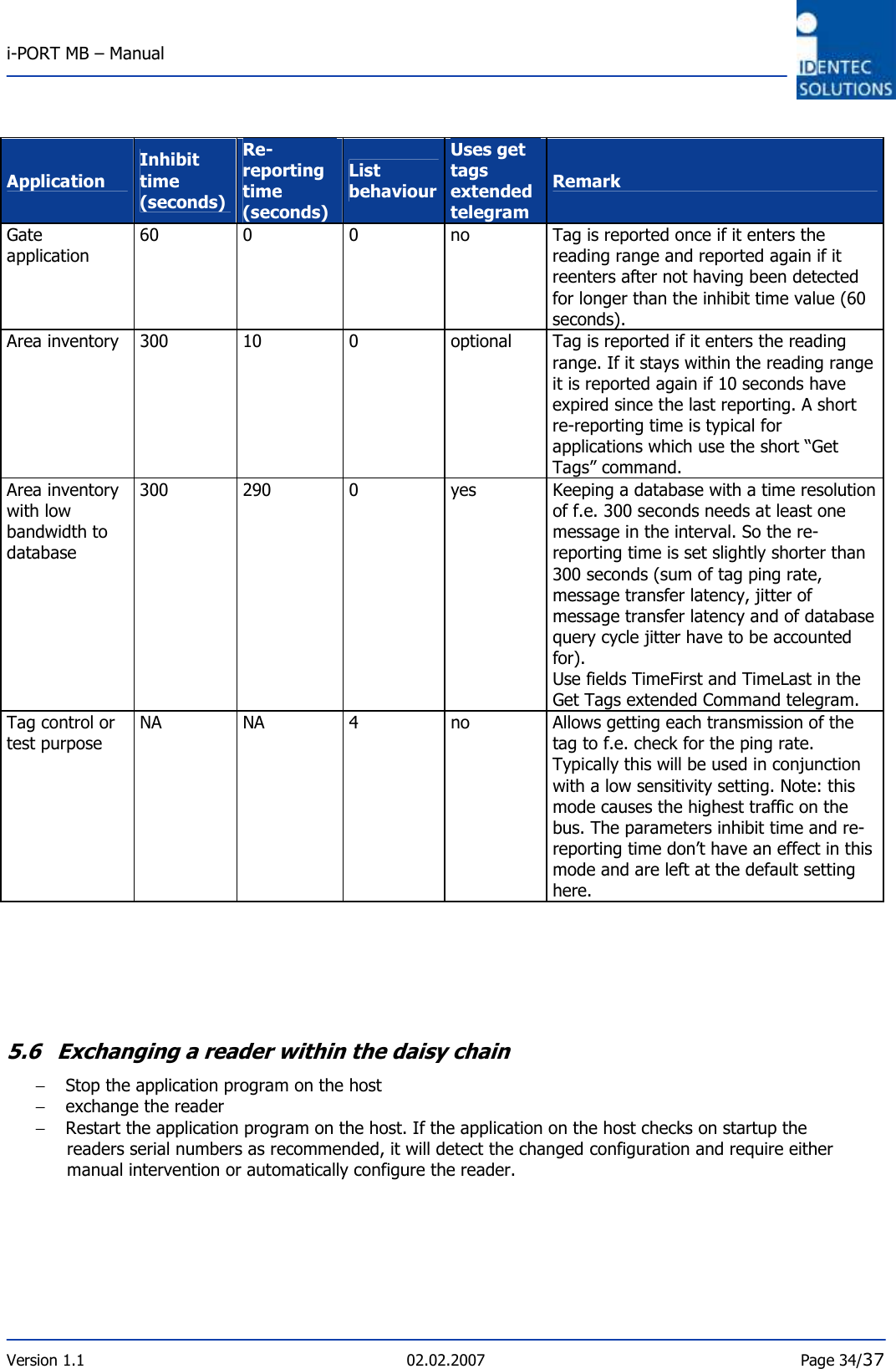
![i-PORT MB – Manual Version 1.1 02.02.2007 Page 36/37 6.0 APPENDIX 7.1 Sample CRC calculation The following sample code is provided ‘as is’. IDENTEC SOLUTIONS does not guarantee compatibility with any interface or protocol except this used in the standard version of the i-PORT R2. //! crc table for host communication unsigned char code crc_tab_hi[256] = // table of CRC values for high order byte { 0x00, 0xc1, 0x81, 0x40, 0x01, 0xc0, 0x80, 0x41, //01 0x01, 0xc0, 0x80, 0x41, 0x00, 0xc1, 0x81, 0x40, //02 0x01, 0xc0, 0x80, 0x41, 0x00, 0xc1, 0x81, 0x40, //03 0x00, 0xc1, 0x81, 0x40, 0x01, 0xc0, 0x80, 0x41, //04 0x01, 0xc0, 0x80, 0x41, 0x00, 0xc1, 0x81, 0x40, //05 0x00, 0xc1, 0x81, 0x40, 0x01, 0xc0, 0x80, 0x41, //06 0x00, 0xc1, 0x81, 0x40, 0x01, 0xc0, 0x80, 0x41, //07 0x01, 0xc0, 0x80, 0x41, 0x00, 0xc1, 0x81, 0x40, //08 0x01, 0xc0, 0x80, 0x41, 0x00, 0xc1, 0x81, 0x40, //09 0x00, 0xc1, 0x81, 0x40, 0x01, 0xc0, 0x80, 0x41, //10 0x00, 0xc1, 0x81, 0x40, 0x01, 0xc0, 0x80, 0x41, //11 0x01, 0xc0, 0x80, 0x41, 0x00, 0xc1, 0x81, 0x40, //12 0x00, 0xc1, 0x81, 0x40, 0x01, 0xc0, 0x80, 0x41, //13 0x01, 0xc0, 0x80, 0x41, 0x00, 0xc1, 0x81, 0x40, //14 0x01, 0xc0, 0x80, 0x41, 0x00, 0xc1, 0x81, 0x40, //15 0x00, 0xc1, 0x81, 0x40, 0x01, 0xc0, 0x80, 0x41, //16 0x01, 0xc0, 0x80, 0x41, 0x00, 0xc1, 0x81, 0x40, //17 0x00, 0xc1, 0x81, 0x40, 0x01, 0xc0, 0x80, 0x41, //18 0x00, 0xc1, 0x81, 0x40, 0x01, 0xc0, 0x80, 0x41, //19 0x01, 0xc0, 0x80, 0x41, 0x00, 0xc1, 0x81, 0x40, //20 0x00, 0xc1, 0x81, 0x40, 0x01, 0xc0, 0x80, 0x41, //21 0x01, 0xc0, 0x80, 0x41, 0x00, 0xc1, 0x81, 0x40, //22 0x01, 0xc0, 0x80, 0x41, 0x00, 0xc1, 0x81, 0x40, //23 0x00, 0xc1, 0x81, 0x40, 0x01, 0xc0, 0x80, 0x41, //24 0x00, 0xc1, 0x81, 0x40, 0x01, 0xc0, 0x80, 0x41, //25 0x01, 0xc0, 0x80, 0x41, 0x00, 0xc1, 0x81, 0x40, //26 0x01, 0xc0, 0x80, 0x41, 0x00, 0xc1, 0x81, 0x40, //27 0x00, 0xc1, 0x81, 0x40, 0x01, 0xc0, 0x80, 0x41, //28 0x01, 0xc0, 0x80, 0x41, 0x00, 0xc1, 0x81, 0x40, //29 0x00, 0xc1, 0x81, 0x40, 0x01, 0xc0, 0x80, 0x41, //30 0x00, 0xc1, 0x81, 0x40, 0x01, 0xc0, 0x80, 0x41, //31 0x01, 0xc0, 0x80, 0x41, 0x00, 0xc1, 0x81, 0x40 //32 }; //! crc table for host communication unsigned char code crc_tab_lo[256] = // table of CRC values for low order byte { 0x00, 0xc0, 0xc1, 0x01, 0xc3, 0x03, 0x02, 0xc2, //01 0xc6, 0x06, 0x07, 0xc7, 0x05, 0xc5, 0xc4, 0x04 //02 0xcc, 0x0c, 0x0d, 0xcd, 0x0f, 0xcf, 0xce, 0x0e //03 0x0a, 0xca, 0xcb, 0x0b, 0xc9, 0x09, 0x08, 0xc8 //04 0xd8, 0x18, 0x19, 0xd9, 0x1b, 0xdb, 0xda, 0x1a //05 0x1e, 0xde, 0xdf, 0x1f, 0xdd, 0x1d, 0x1c, 0xdc //06 0x14, 0xd4, 0xd5, 0x15, 0xd7, 0x17, 0x16, 0xd6 //07 0xd2, 0x12, 0x13, 0xd3, 0x11, 0xd1, 0xd0, 0x10 //08 0xf0, 0x30, 0x31, 0xf1, 0x33, 0xf3, 0xf2, 0x32 //09 0x36, 0xf6, 0xf7, 0x37, 0xf5, 0x35, 0x34, 0xf4 //10 0x3c, 0xfc, 0xfd, 0x3d, 0xff, 0x3f, 0x3e, 0xfe //11 0xfa, 0x3a, 0x3b, 0xfb, 0x39, 0xf9, 0xf8, 0x38 //12 0x28, 0xe8, 0xe9, 0x29, 0xeb, 0x2b, 0x2a, 0xea //13 0xee, 0x2e, 0x2f, 0xef, 0x2d, 0xed, 0xec, 0x2c //14 0xe4, 0x24, 0x25, 0xe5, 0x27, 0xe7, 0xe6, 0x26 //15 0x22, 0xe2, 0xe3, 0x23, 0xe1, 0x21, 0x20, 0xe0 //16 0xa0, 0x60, 0x61, 0xa1, 0x63, 0xa3, 0xa2, 0x62 //17 0x66, 0xa6, 0xa7, 0x67, 0xa5, 0x65, 0x64, 0xa4 //18 0x6c, 0xac, 0xad, 0x6d, 0xaf, 0x6f, 0x6e, 0xae //19 0xaa, 0x6a, 0x6b, 0xab, 0x69, 0xa9, 0xa8, 0x68 //20 0x78, 0xb8, 0xb9, 0x79, 0xbb, 0x7b, 0x7a, 0xba //21 0xbe, 0x7e, 0x7f, 0xbf, 0x7d, 0xbd, 0xbc, 0x7c //22 0xb4, 0x74, 0x75, 0xb5, 0x77, 0xb7, 0xb6, 0x76 //23 0x72, 0xb2, 0xb3, 0x73, 0xb1, 0x71, 0x70, 0xb0 //24 0x50, 0x90, 0x91, 0x51, 0x93, 0x53, 0x52, 0x92 //25 0x96, 0x56, 0x57, 0x97, 0x55, 0x95, 0x94, 0x54 //26 0x9c, 0x5c, 0x5d, 0x9d, 0x5f, 0x9f, 0x9e, 0x5e //27 0x5a, 0x9a, 0x9b, 0x5b, 0x99, 0x59, 0x58, 0x98, //28](https://usermanual.wiki/Identec-Solutions/ILR-IPM/User-Guide-773454-Page-36.png)
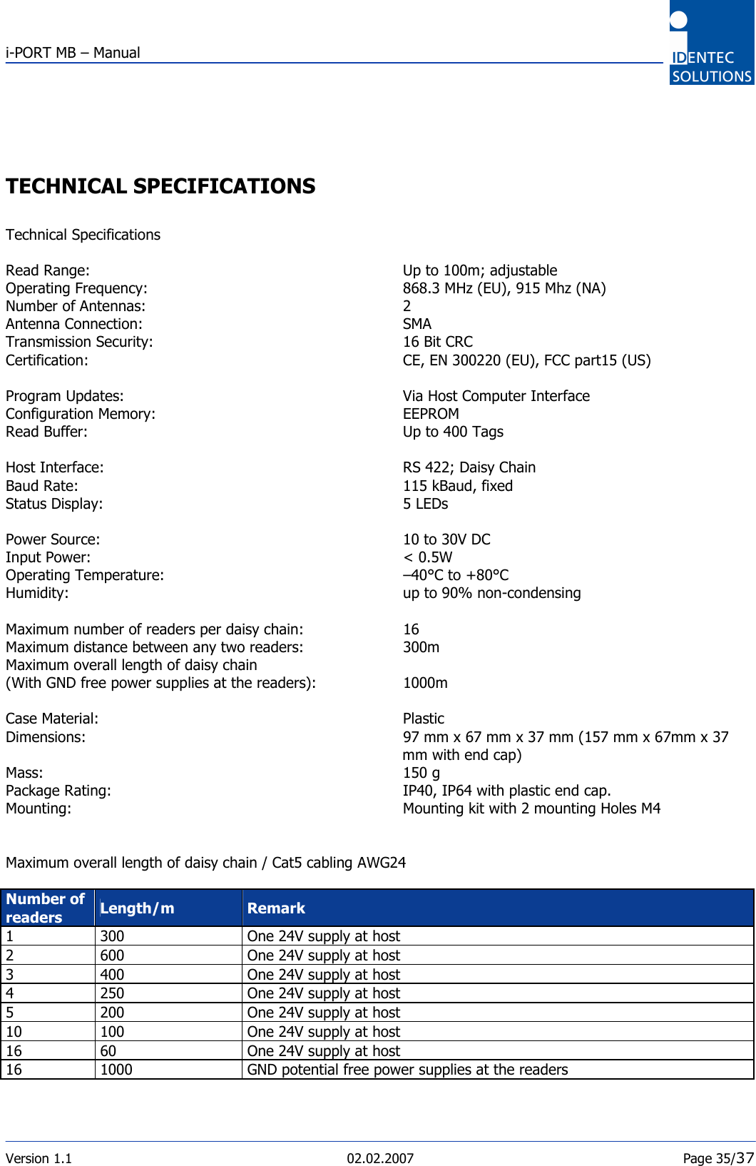
![i-PORT MB – Manual Version 1.1 02.02.2007 Page 37/37 0x88, 0x48, 0x49, 0x89, 0x4b, 0x8b, 0x8a, 0x4a, //29 0x4e, 0x8e, 0x8f, 0x4f, 0x8d, 0x4d, 0x4c, 0x8c, //30 0x44, 0x84, 0x85, 0x45, 0x87, 0x47, 0x46, 0x86, //31 0x82, 0x42, 0x43, 0x83, 0x41, 0x81, 0x80, 0x40, //32 }; //! CRC calculation for Host communication unsigned int build_crc16(unsigned char *host_msg, unsigned int len) { unsigned char crc_hi = 0xFF; // high CRC byte initialized unsigned char crc_lo = 0xFF; // low CRC byte initialized unsigned char index; // will index into CRC lookup table while (len--) // pass through message buffer { // and calculate the CRC index = crc_hi ^ *host_msg++; crc_hi = crc_lo ^ crc_tab_hi[index]; crc_lo = crc_tab_lo[index]; } return crc_lo<<8 | crc_hi; } Example commands with CRC This example shows two commands sent to a reader. Sending “disconnect slave port” to the broadcast address: \x01\xFF\x43\x10\x90\x00\x00\x00\x00\x3f\xDB\x04 Note, there is no response to this command as it is sent to the broadcast address. The character 0x10 has been translated into the sequence 0x10 0x90. Sending “get parameter serial number” to the last reader in chain: \x01\xFE\x44\x10\x81\xF0\xE2\x04 The character 0x01 has been translated into the sequence 0x10 0x81. The device responds with its serial number: \x01\x11\xC4\x00\x18\x7F\x5D\xCA\x3A\x85\x04 www.identecsolutions.com Europe: Austria: IDENTEC SOLUTIONS AG, Millennium Park 2, 6890 Lustenau / AUSTRIA Tel: +43 (0)5577 87387-0 Fax: +43 (0)5577 87387-15 North America: USA: IDENTEC SOLUTIONS INC., Liberty Plaza II, 5057 Keller Springs Road Suite 375, Addison, Texas 75001 / USA Tel: +1(972) 535 4144 Fax: +1(469) 424 0404](https://usermanual.wiki/Identec-Solutions/ILR-IPM/User-Guide-773454-Page-37.png)