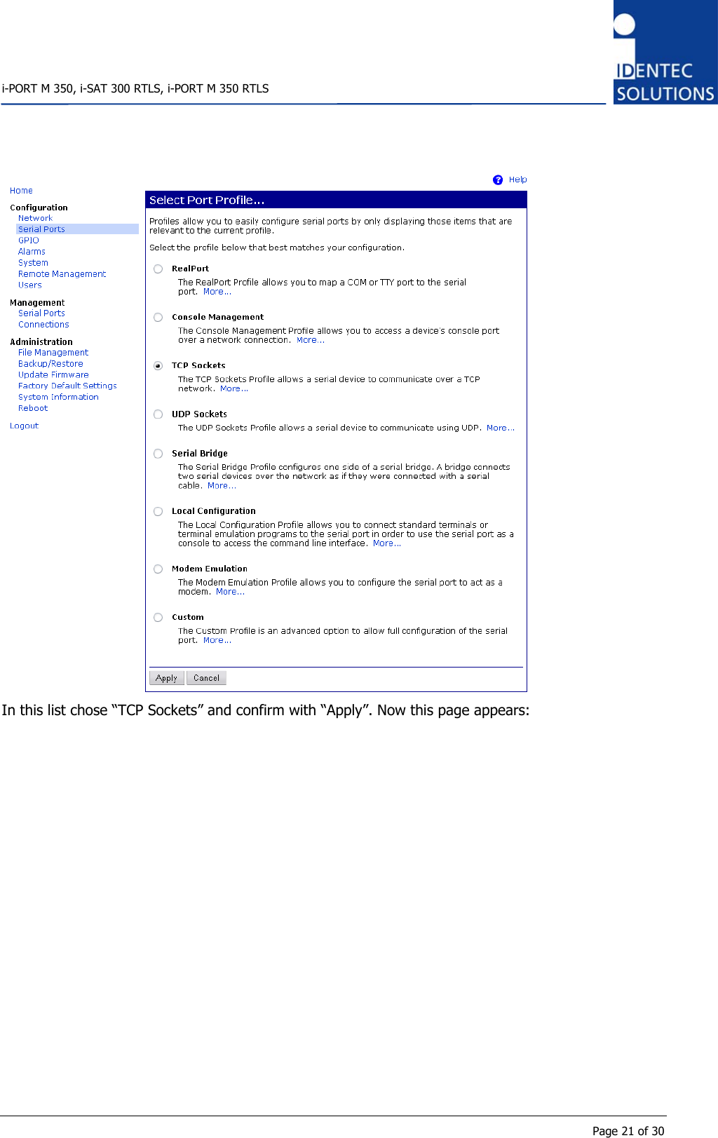
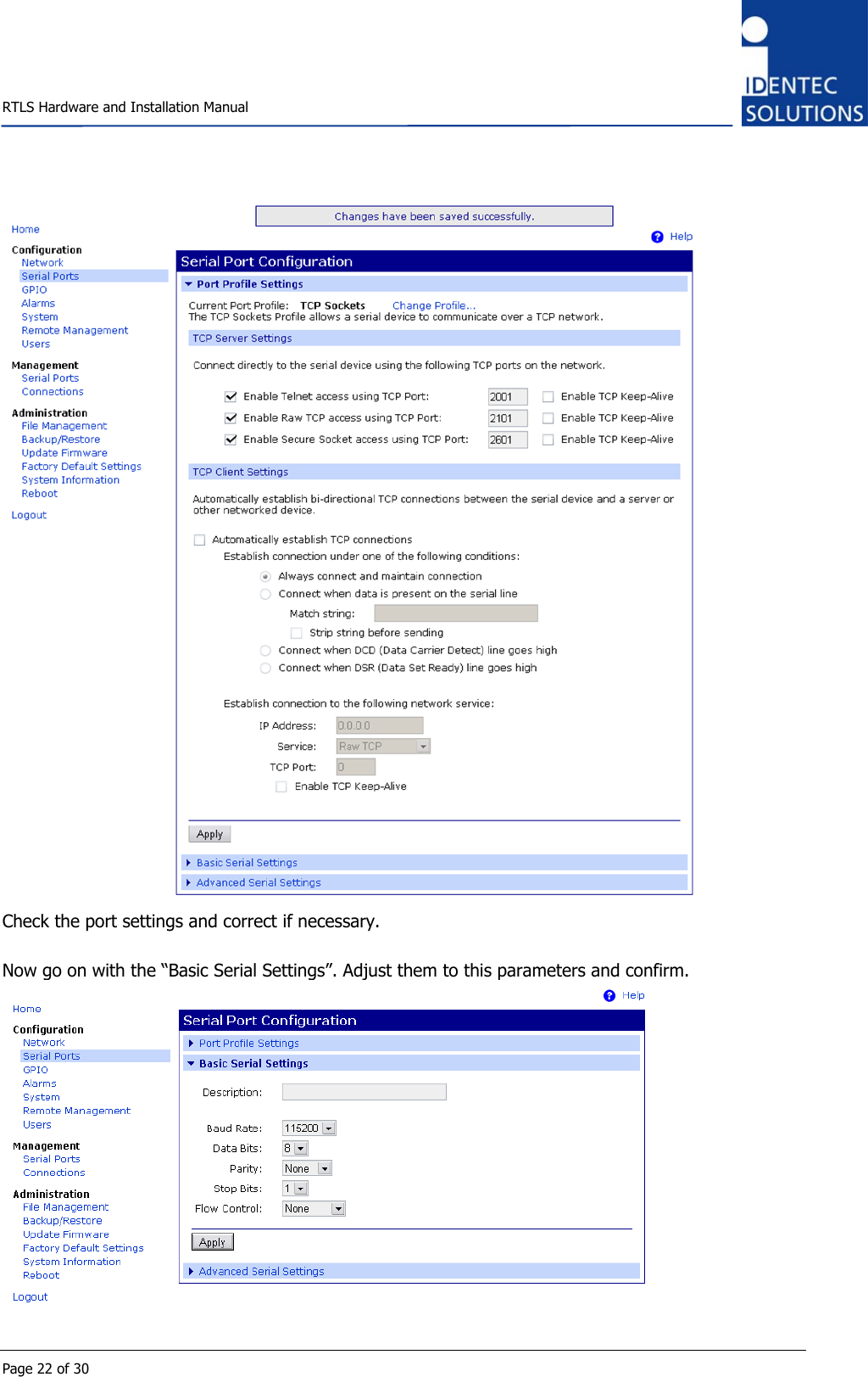
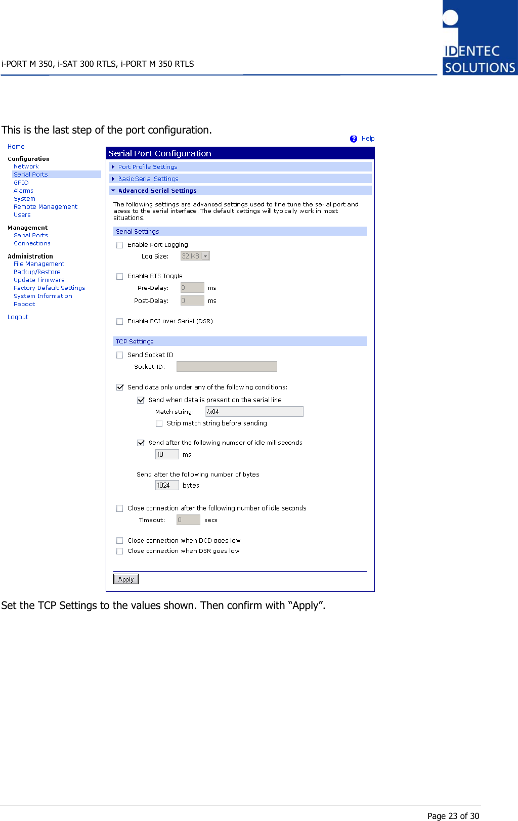
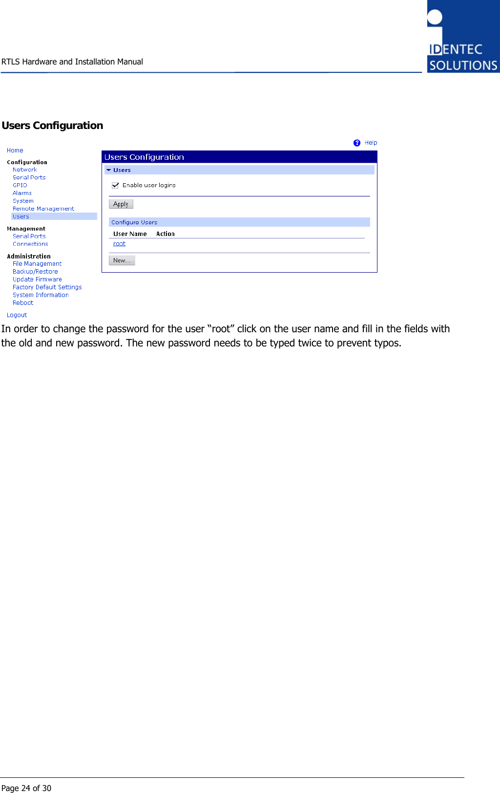
Identec Solutions ILR-IPM350N RFID Reader User Manual i PORT M 350 RTLS Manual

Identec Solutions AG RFID Reader i PORT M 350 RTLS Manual

User Manual

                       ILR 350 Series i-PORT M 350, i-SAT 300 RTLS, i-PORT M 350 RTLS Installation and Operation Manual
   RTLS Hardware and Installation Manual  Page 2 of 30 Proprietary Notice This document contains confidential information proprietary to IDENTEC SOLUTIONS and may not be used or disclosed to other parties in whole or in part without prior written authorization from IDENTEC SOLUTIONS. Disclaimer and Limitation of Liability IDENTEC SOLUTIONS AG and its affiliates, subsidiaries, officers, directors, employees and agents provide the information contained in this Manual on an “as-is” basis and do not make any express or implied warranties or representations with respect to such information including, without limitation, warranties as to non-infringement, reliability, fitness for a particular purpose, usefulness, completeness, accuracy or up-to-dateness. IDENTEC SOLUTIONS shall not in any circumstances be liable to any person for any special, incidental, indirect or consequential damages, including without limitation, damages resulting from use of or reliance on information presented herein, or loss of profits or revenues or costs of replacement goods, even if informed in advance of the possibility of such damages. Trademarks “IDENTEC SOLUTIONS”,  “Intelligent Long Range”, “ILR” and the stylized “i” are registered trademarks and “i-Q”, “i-D”, “i-B”, “i-CARD”, “i-PORT”, “i-LINKS”, “Solutions. It’s in our name.”, “Smarten up your assets” are trademarks of IDENTEC SOLUTIONS, Inc. and/or IDENTEC SOLUTIONS AG. Copyright Notice Copyright © 2007 IDENTEC SOLUTIONS. All rights reserved. No part of this document may be reproduced or transmitted in any form by any means, photographic, electronic, mechanical or otherwise, or used in any information storage and retrieval system, without the prior written permission of IDENTEC SOLUTIONS.        Issue 0 / March 2010 – 17. March 2010 –  IDENTEC SOLUTIONS AG,  Millennium Park 2, 6890 Lustenau, Austria Phone +43 5577 87387-0, Fax +43 5577 87387-15 info@identecsolutions.at www.identecsolutions.com  Subject to alteration without prior notice. © Copyright IDENTEC SOLUTIONS 2008 Printed in Germany
   i-PORT M 350, i-SAT 300 RTLS, i-PORT M 350 RTLS      Page 3 of 30 Radio Frequency Compliance Statement  IDENTEC SOLUTIONS is the responsible party for the compliance of the following devices:  MODEL:   i-PORT M 350 Region/Country  Organization  Marking EUROPE:  EC  CE USA:  FCC  FCC ID OO4-ILR-IPM350N Canada:  Industry Canada  IC:3538A-IPM350N  MODEL:   i-SAT 300 RTLS Region/Country  Organization  Marking EUROPE:  EC  CE USA:  FCC  FCC ID OO4-ILR-ISAT300 Canada:  Industry Canada  IC:3538A-ISAT300  MODEL:   i-PORT M 350 RTLS Region/Country  Organization  Marking EUROPE:  EC  CE USA:  FCC  FCC ID OO4-ILR-IPM350RT Canada:  Industry Canada  IC:3538A-IPM350RT  The user(s) of these products are cautioned to only use accessories and peripherals approved, in advance, by IDENTEC SOLUTIONS. The use of accessories and peripherals, other than those approved by IDENTEC SOLUTIONS, or any changes or modifications not expressly approved by the party responsible for compliance could void the user’s authority to operate the equipment.  Warning: This product requires professional installation. Any frequency and RF-power setting not expressly authorized by Identec Solutions is prohibited and will void the users authority to operate the equipment.
   RTLS Hardware and Installation Manual  Page 4 of 30 European Notification according R&TTE Directive  This equipment complies to Art. 6.4 of R&TTE Directive (1999/5/EC). It is tested for compliance with the following standards: ETSI EN 300 220, ETSI EN 300 440, ETSI EN 301 489, EN 60950.  USA Notification This device complies with part 15 of the FCC Rules. Operation is subject to the following two conditions: (1) This device may not cause harmful interference, and (2) this device must accept any interference received, including interference that may cause undesired operation. The user(s) of these products are cautioned to only use accessories and peripherals approved, in advance, by IDENTEC SOLUTIONS. The use of accessories and peripherals, other than those approved by IDENTEC SOLUTIONS, or any changes or modifications not expressly approved by the party responsible for compliance could void the user’s authority to operate the equipment.  The device has been tested and found to comply with the limits for a Class A digital device, pursuant to part 15 of the FCC Rules. These limits are designed to provide reasonable protection against harmful interference when the equipment is operated in a commercial environment. This equipment generates, uses, and can radiate radio frequency energy and, if not installed and used in accordance with the instruction manual, may cause harmful interference to radio communications. Operation of this equipment in a residential area is likely to cause harmful interference in which case the user will be required to correct the interference at his own expense. Canada Certification To reduce potential radio interference to other users, the antenna type and its gain should be so chosen that the equivalent isotropically radiated power (e.i.r.p.) is not more than that permitted for successfulcommunication. 2.4 GHz: This device has been designed to operate with the antennas listed below, and having a maximum gain of6.0 dBi. Antennas not included in this list or having a gain greater than 6.0 dBi are strictly prohibited for use with this device. The required antenna impedance is 50 ohms. 916 MHz: This device has been designed to operate with the antennas listed below, and having a maximum gain of2.0 dBi. Antennas not included in this list or having a gain greater than 2.0 dBi are strictly prohibited for use with this device. The required antenna impedance is 50 ohms.  List of antennas:2.4 GHz: Huber & Suhner 90A-2400/360/6/0/V: 6.0 dBi, 50 ohms916 MHz: Kathrein K751161: 2.0 dBi, 50 ohms
   i-PORT M 350, i-SAT 300 RTLS, i-PORT M 350 RTLS      Page 5 of 30             This product contains components that are sensitive to electrostatic discharges. Please observe the special instructions for their protection. Incorrect handling can damage the unit and cause the invalidation of the warranty.  Minimum safety precautions against electrostatic discharge:  • Establish earth contact bef ore you touch the unit. For example, touch the earthing scr ew on the unit. Ev en bet ter: Use an antistatic ribbon and earth  yourself permanently for the time you handle the unit. • Avoid unnecessary contact with the unit connectors and assemblies inside the unit. • Only open the unit if the operational settings (as described in the manual) expressly require this. • Use antistatic tools f or the set ting of the unit.  (Warning: Do not touch lif e-threatening voltages with these tools). • Do not store unit and components without protective packaging. • Only remove unit and components from the packaging immediately prior to installation.  These notes are not sufficient to guarantee complete protection from electrostatic discharges! We recommend the use of suitable protective equipment.
   RTLS Hardware and Installation Manual  Page 6 of 30 Contents 1 INTRODUCTION ...........................................................................................................7 1.1 FEATURES .................................................................................................................. 7 1.2 DOCUMENTS OVERVIEW ................................................................................................. 8 2 MECHANICAL INSTALLATION ......................................................................................9 2.1 HINTS ....................................................................................................................... 9 2.2 DIMENSIONAL DRAWINGS ............................................................................................. 10 3 ELECTRICAL INSTALLATION ......................................................................................12 3.1 SAFETY INSTRUCTIONS ................................................................................................ 12 3.2 POSITION OF PORTS.................................................................................................... 12 3.3 OVERVIEW ............................................................................................................... 13 3.4 POWER SUPPLY.......................................................................................................... 13 3.5 MAXIMUM OVERALL CABLE RUNS OF I-BUS ....................................................................... 13 3.6 THE I-BUS CONNECTOR............................................................................................... 14 3.7 ETHERNET CONNECTOR................................................................................................ 15 4 INITIAL OPERATION..................................................................................................16 4.1 CHECKING THE INSTALLATION ........................................................................................ 16 4.2 CONFIGURATION ........................................................................................................ 16 4.2.1 Tools Needed ......................................................................................................... 16 4.3 STATUS DISPLAY (LEDS) ............................................................................................. 26 5 MAINTENANCE ...........................................................................................................27 5.1 GENERAL ................................................................................................................. 27 5.2 PRECAUTIONARY MAINTENANCE...................................................................................... 27 5.3 SPARE PARTS ............................................................................................................ 28 5.3.1 Recommended spare parts stock.............................................................................. 28 5.3.2 Preparing the spare parts ........................................................................................ 28 5.3.3 Examination and repair of exchanged parts............................................................... 28 5.4 RETURNS ................................................................................................................. 28 6 TECHNICAL DATA .......................................................................................................29
   i-PORT M 350, i-SAT 300 RTLS, i-PORT M 350 RTLS      Page 7 of 30 1 Introduction The RTLS system is the newest development in IDENTEC SOLUTIONS’ Intelligent Long Range® (ILR®) interrogators. ILR provides highly accurate, real-time data collection with minimal human intervention.  The very long communication range of up to 500 m (1500 ft) allows automated identification, tracking and tracing of assets and people in areas as large as a steel construction workshop without human intervention.  The new RTLS system allows localization of tags down to several meters. This new series of ILR products is the next step forward in wireless applications such as:  • Identification • Tracking and tracing and • Localization of assets or personnel.  1.1 Features Easy Installation  Only few components need to be configured. Only the i-PORTs needs a host connection. The i-SAT only needs power supply. Cable-free Installation  With the solar installation kit even the power supply is an easy job. Light Infrastructure  Automatic gathering of information from several i-PORTs. Preprocessing of multiple position information from the RTLS in position sever. LED on Tag (option)  Provides visual identification of an addressed tag ("pick by light"). 32 kByte read/write memory on tag Allows storage of complete process information on every tag. Handheld units  Manual finding an object. Up to 500 m (1500 ft) read/write range Allows automated identification, tracking and tracing of assets and people without human intervention. 500 Tag simultaneous Identification Large numbers of tags can be identified virtually simultaneously. RTLS only used when needed  This saves battery lifetime and installation costs.
   RTLS Hardware and Installation Manual  Page 8 of 30 1.2 Documents Overview Manuals IM.0710.DE  RTLS System Description, German IM.0710.EN ditto, English IM.0711.DE  Description of PC software „Position-Server“, German IM.0711.EN ditto, English IM.0712.DE Manual, especially for demo and test installations, German IM.0712.EN ditto, English IM.0713.DE  Position node i-SAT 300 hardware and installation manual, German IM.0713.DE ditto, English IM.0714.DE  ILR reader i-PORT M350, i-SAT 300 RTLS, i-PORT M 350 RTLS hardware and installation manual, German IM.0714.DE  ditto, English (this document) IM.0732.DE  Marker System Description and Installation manual for i-MARK 2 & i-MARK 3, German IM.0732.EN ditto, English  Data Sheets ID.0640.DE RTLS-System Description, German ID.0640.EN ditto, English ID.0643.DE  Position Server Software, German ID.0643.EN ditto, English ID.0626.DE  data tag i-Q350 RTLS, German ID.0626.EN ditto, English ID.0627.DE  ILR reader i-PORT M 350 RTLS, German ID.0627.EN ditto, English ID.0628.DE  position node i-SAT 300, German ID.0628.EN ditto, English ID.0665.DE  position markers i-MARK 2 & 3, German ID.0665.EN ditto, English
   i-PORT M 350, i-SAT 300 RTLS, i-PORT M 350 RTLS      Page 9 of 30 2 Mechanical Installation 2.1 Hints  Mounting Kit  DIN Rail Clamp  Mounting Kit with DIN Rail Clamp  The i-PORT M 350 RTLS is plugged into the mounting kit. Between the mounting kit and the reader module there is 5 mm space left for the screws.  It is intended to always use the mounting kit. If mounting on a DIN rail is desired, the additional clamp is mounted on the rear side of the mounting kit.  Use the two mounting holes (diameter 4,5 mm) to  attach the mounting kit to a suitable mounting surface. Once the mounting kit is fixed, plug in the i-PORT M 350 RTLS reader.  Enclosure rating is IP40 without the end cap and IP64 with. If greater enclosure rating is required, the i-PORT M 350 RTLS must be placed in an  additional protective housing, in this situation the end cap could be removed.
   RTLS Hardware and Installation Manual  Page 10 of 30 2.2 Dimensional Drawings R1a0,511a36(3x)4,5(2x)3,260±0,208966156744,51°62,97951,96,9R1 (4x) Dimensions of mounting kit   67,39136,5 Dimensions without end cap (cable inlet protection), but without mounting kit
   i-PORT M 350, i-SAT 300 RTLS, i-PORT M 350 RTLS      Page 11 of 30 36,567,3144 Dimensions with end cap (cable inlet protection), but without mounting kit
   RTLS Hardware and Installation Manual  Page 12 of 30 3 Electrical Installation 3.1 Safety Instructions • The power supply circuit must comply with the requirements of the SELV circuits (see EN 60950). • The signal circuits must comply with the requirements of the SELV circuits (see EN 60950). • In the i-BUS connectors ther e ar e RS422 lev els on  its RX and TX Pins, although Ethernet jack/plugs mechanically fit, the device is not Ethernet compatible! • Industry standard Cat 5 straight patch cables can be used to daisy chain the devices. • If devices are power ed ov er the i-BUS the RJ 45  cabling must be done with wir es of at least AWG24 (0.25 mm²).  Glossary SELV  Safety Extra Low Voltage – Protective measure against dangerous body currents.    Protective first voltage, circuit not floating. EMC E lectromagnetic Compatibility RxD Rec eive Data TxD Trans mit Data   3.2 Position of Ports   with standard i-BUS connectors  with Ethernet   To Master  RJ 45 connector to the host computer or the slave port of the previous i-MARK or  i-PORT in the daisy chain. To Slave  RJ 45 connector to the master port of the next i-MARK or i-PORT in the daisy chain. Leave this connector open at the last device in the chain.
   i-PORT M 350, i-SAT 300 RTLS, i-PORT M 350 RTLS      Page 13 of 30 3.3 Overview PositionServerEthernetor RS422 (i-BUS)i-PORT M 350 RTLS i-PORT M 350 RTLSi-BUS i-BUSCentral Power Supplyi-PORT M 350 RTLS   3.4 Power Supply The i-PORT M 350 RTLS is powered by the i-BUS.  Total Power Consumption—i-PORT M 350 RTLS with 4 i-SAT 300 RTLS 1 × i-PORT M 350 RTLS, app. 2 W 4 × i-SAT 300 RTLS, app. each 2 W  This gives a maximum sum of 7 W of power consumption.   3.5 Maximum Overall Cable Runs of i-BUS There are 2 general limitations on the length of the i-BUS cabling:  • The overall length of the i-BUS over all units on the BUS must not exceed 1000 m (3000 ft) • The distance from one unit to the next on the i-BUS must not exceed 300 m (1000 ft)  This tables is valid for Cat 5 cabling with gauge diameters of AWG24 (0.25 mm²).  # of i-PORTs  Length (m/ft)  Remark 1  300/1000  Central supply with 24 VDC via the i-BUS 2  600/2000  Central supply with 24 VDC via the i-BUS 3  400/1300  Central supply with 24 VDC via the i-BUS 4  250/820  Central supply with 24 VDC via the i-BUS 4  1000/3000  GND potential free power supplies at every i-PORT M
   RTLS Hardware and Installation Manual  Page 14 of 30 3.6 The i-BUS Connector Please Note • The i-BUS uses RS422 lev els on its RX  and TX Pins, although Ethernet jack/plugs mechanically fit, the device is not Ethernet compatible. • As the TxD/RxD cr ossing is done by the pinout of  the connectors, simple str aight cabling can be used. • If devices are powered by the RJ45 cabling of th e i-BUS, wire gauge must be at least A WG24 (0.25 mm²)   View into the connector = crimp/solder side of plug  Pin  To Master  To Slave  T568B color  Description 1 RxD+  TxD+  White/orange   2 RxD–  TxD–  Orange   3 TxD+  RxD+  White/Green   4  V+ (10 … 30V)  V+ (10 … 30V)  Blue  Power supply over i-BUS 5  V+ (10 … 30V)  V+ (10 … 30V)  White/Blue  Power supply over i-BUS 6 TxD–  RxD–  Green   7  GND  GND  White/Brown  Power supply over i-BUS 8  GND  GND  Brown  Power supply over i-BUS  Connection Parameters  Signal levels:  RS422 Baud rate:  115200 bits per second Data bits:  8 Stop bits:  1 Parity: none Mode: half duplex Flow Control:  none
   i-PORT M 350, i-SAT 300 RTLS, i-PORT M 350 RTLS      Page 15 of 30 3.7 Ethernet Connector The Ethernet interface is an option for an i-PORT M 350 RTLS.  Warning Do not connect any device to your network before it has been configured. Before connecting to your network, check that the desired IP address has been set. A not-configured device may have any IP address. A device with the wrong settings may impede the functioning of your network.  Ethernet interface with 10 or 100Mbit/s. Connect the central unit to your network with a wired 1:1 network cable. The host connection is a RJ45 socket. Use a regular Ethernet cable here. The allocation corresponds to that of simple network adapters in PCs (10/100-Base T). Therefore, to connect to the network or the hub, a simple 1:1 network cable is required. If you want to connect directly to a computer you must use a so-called crossed cable.  View into the connector = crimp/solder side of plug  Pin  To Slave  T568B color  Description 1 TxD+  White/orange   2 TxD–  Orange   3 RxD+  White/Green   4   Blue   5   White/Blue   6 RxD–  Green   7   White/Brown   8 GND  Brown
   RTLS Hardware and Installation Manual  Page 16 of 30 4 Initial Operation 4.1 Checking the Installation After completing the installation the operation must be systematically checked. The installation check can be divided into three sections:  • Visual test • Basic operational check • Detailed operational check  If the basic check of the operational behavior is to be carried out using a (portable) PC a final check via the intended user control system should also be carried out.   4.2 Configuration 4.2.1 Tools Needed • Standard-PC running Microsoft Windows • RS422 Interface (USB to RS422 converter, order code 292 771) • 9 pin D type to RJ45 adaptor with power supply plug (order code 348 369) • Power Supply Plug (24 VDC, 30 W, order code 367 976) • 1:1 fully wired RJ45 Patch-Cable, length: 2 m (order code 696 627) • Configuration Tool “ILR Config” with RTLS plug-in
   i-PORT M 350, i-SAT 300 RTLS, i-PORT M 350 RTLS      Page 17 of 30 4.3 Configuration of the Ethernet Interface Tools needed • PC with working Ethernet NIC running MS Windows for configuration software • Software “Device Discovery Utility” • Crossover Ethernet cable • Power supply (24 VDC) for the i-PORT • Network settings from your network administrator  Prepare the PC • Disconnect the PC from the network • Set the Ethernet connection of the PC to DHCP (described below) • Switch off the proxy settings of the standard web browser  After finishing the configuration of all i-PORTs restore the previous settings of the PC.  In order to gain access to the network settings of the PC, double click on the network icon in the systray. The icon appears as two computer symbols.      Now click on “Properties”.
   RTLS Hardware and Installation Manual  Page 18 of 30  Select “Network Protocol (TCP/IP) and click on “Properties”.   Check if both checkboxes “Obtain … automatically” are checked. Confirm with “OK”.
   i-PORT M 350, i-SAT 300 RTLS, i-PORT M 350 RTLS      Page 19 of 30 Discover the i-PORT’s Ethernet Interface • Connect the PC with the i-PORT. • Start the software “Device Discovery Utility”. This software will automatically detect the Ethernet device of the i-PORT. • Select the device listed, then chose “Device Tasks” => “Open Web Interface”.    Now the standard web browser on the PC should start, opening the IP address of the Ethernet device. In the following login display use this default access codes:  • Default login name:   root • Default login password:  dbps  Note The web interface automatically logs out after a very short time.
   RTLS Hardware and Installation Manual  Page 20 of 30 Configuration of the Internal Communication  In the category “Configuration” select “Serial Ports”.   Click on “Change Profile”.
   i-PORT M 350, i-SAT 300 RTLS, i-PORT M 350 RTLS      Page 21 of 30  In this list chose “TCP Sockets” and confirm with “Apply”. Now this page appears:
   RTLS Hardware and Installation Manual  Page 22 of 30  Check the port settings and correct if necessary.  Now go on with the “Basic Serial Settings”. Adjust them to this parameters and confirm.
   i-PORT M 350, i-SAT 300 RTLS, i-PORT M 350 RTLS      Page 23 of 30 This is the last step of the port configuration.  Set the TCP Settings to the values shown. Then confirm with “Apply”.
   RTLS Hardware and Installation Manual  Page 24 of 30 Users Configuration  In order to change the password for the user “root” click on the user name and fill in the fields with the old and new password. The new password needs to be typed twice to prevent typos.
   i-PORT M 350, i-SAT 300 RTLS, i-PORT M 350 RTLS      Page 25 of 30 Network Configuration Important Note As the connection to the Ethernet device will probably be lost, after the network configuration it is recommended to do this as the last step of configuration.   In the category “Configuration” chose “Network” and change to the “Advanced Network Settings”. Here you can give the i-PORT a useful name for identification in the network. Confirm with “Apply”.
   RTLS Hardware and Installation Manual  Page 26 of 30  In the category “Configuration” chose “Network”. Now adjust the network settings as required. Then finish by click on “Apply”. Finally, in the category “Administration” choose “Reboot”.   4.4 Status Display (LEDs)  ANT 1: This is the antenna of the 2.45 GHz RTLS part. LED blinks green when a valid packet has been received. It blinks RED when a ranging of type 1 has been successfully done.  ANT 2: This is the antenna of the UHF part.  Sending a command: As long as wake up is sent, the ANT2 Led is green. If a packet is received as a valid answer, goes red. (Give orange effect). Beacon receiving: beacon message is detected -> ANT2 goes green. If this tag is a new tag in the reader’s list, it goes orange. If it is already in the list it stays green.  RUN: Device is running properly (LED blinks at approx 1 Hz).  BUS: Blinks GREEN when data is received on the i-BUS. Blinks RED when sending data to the i-BUS.  ERR: Blinks RED when an error occurs.
   i-PORT M 350, i-SAT 300 RTLS, i-PORT M 350 RTLS      Page 27 of 30 5 Maintenance 5.1 General In principle, the ILR system is maintenance-free. When correctly installed it operates for many years without any problems.   5.2 Precautionary Maintenance Regular checking of all ports and cables belonging to the system is recommended. Unstable connections could lead to damage and malfunctions of the system and therefore should be repaired as soon as possible.  A Brief Checklist • Are all casing intact? • Are all cables intact? • Are all connectors intact? • Are all connectors securely fastened? • Are all screws still tight? • Is there suddenly a malfunction at a specific unit?
   RTLS Hardware and Installation Manual  Page 28 of 30 5.3 Spare Parts 5.3.1 Recommended spare parts stock  In order to keep the down time of the system during malfunctions as short as possible it is recommended to have certain spare parts in stock. At least one central unit, one antenna and one antenna cable should be available. With larger systems with more than approx. 15 i-PORTs the doubling of the recommended stock quantity should be considered. Furthermore, it is recommended to have several spare tags in stock,  corresponding to approx. 0.5 – 1 % of the total number of tags.  5.3.2 Preparing the spare parts In general all spare parts can be used immediately after delivery from IDENTEC SOLUTIONS. However, for the compact communicator there are various settings of the communication parameters. In order to keep the down times short it is recommended to set these parameters before the component is entered into the spare part stock system. In most cases all units within an identification system are used in the same way so that only one setting is required.  5.3.3 Examination and repair of exchanged parts  The data tags and compact communicators are complex electronic power units on which the customer can carry out only very limited repairs. Normally the repairs are carried out at IDENTEC SOLUTIONS or possibly at a distributor. Before a part is sent in for repair a short examination should be carried out.  5.4 Returns  Parts or main components returned for repair or exchange must be handled with great care. PC cards must be returned in the appropriate ESD-protecting packaging material. All returns should include a completed returns form (see appendix) and be sent to the local distributor or to:  IDENTEC SOLUTIONS AG Service Department Millenium Park 2 6890 Lustenau AUSTRIA / AUTRICHE
   i-PORT M 350, i-SAT 300 RTLS, i-PORT M 350 RTLS      Page 29 of 30 6 Technical Data Operating Data Long-Range RFID (ILR, 2400 – 2485 MHz ISM Band) Read/write/localization range  Up to 180 m (590 ft) in free air with line of sight Channels  3 Non-Overlapping channels (for EU and US) or 7 Overlapping channels Data rate  250 kbits/s and 1 Mbits/s Maximum transmission power  100 mW EIRP or local regulation Standards/Certification  ISO 24730 part 5 (upcoming standard),  FCC part 15, EN 300 328 (EU) Compatibility  i-Q350 RTLS series tags Operating Data Long-Range RFID (ILR, UHF Band) Read/write range  Up to 300 m (900 ft) in free air with line of sight Frequency  868 MHz band (EU) and 902 - 928 MHz (NA) Data rate (read and write)  19.2 up to 115.2 kbits/s Maximum transmission power  0.75 mW ERP Standards/Certification  FCC Part 15 (US), Industry Canada, EN 300 220 (EU) Compatibility  i-Q350 and i-Q350 RTLS series tags Performance Identification code  48 bits fixed ID Read rate  Up to 100 tags/s (identification code only) Localization rate  Up to 400 tags per min per zone Multiple tags handling  Up to 500 tags in the read zone Antennas RFID  1 SMA connector for external antenna at 868 (EU) or 915 MHz (US) Localization  1 SMA connector for external antenna at 2.4 GHz Electrical Power source  10 – 30 VDC Power consumption  < 2 W Host interface  RS422, 115.2 kbit/s or Ethernet 10/100 Mbit/s Environmental Operating temperature  –30 °C to +70 °C (–22 ºF to +158 ºF) Shock  50 G, 3 times DIN IEC 68-2-27 Multiple drops to concrete from 1 m (3 ft) Vibration  3 G, 20 sine wave cycles, 5 Hz to 150 Hz, DIN IEC 68-2-6 5 G, noise 5 Hz to 1000 Hz, 30 minutes, DIN IEC 68-2-64 Humidity  90 %, non-condensing
   RTLS Hardware and Installation Manual  Page 30 of 30 Physical  Dimensions  97 × 67 × 97 mm (3.8 × 2.6 × 3.8 in.) 153 × 67 × 97 mm (6.0 × 2.6 × 3.8 in.) incl. cover Case Material  Plastic Mass  150 grams (5.29 ounces) Enclosure rating  IP 64 with cover

Navigation menu