Identec Solutions ILR-IPORTM350 Active Transponder Tag User Manual
Identec Solutions AG Active Transponder Tag
User Manual

i-PORT M350
Installation and Hardware Manual

Installation and Hardware Manual
Page 2 of 30
Proprietary Notice
This document contains confidential information proprietary to IDENTEC SOLUTIONS and may not be
used or disclosed to other parties in whole or in part without prior written authorization from IDENTEC
SOLUTIONS.
Disclaimer and Limitation of Liability
IDENTEC SOLUTIONS AG and its affiliates, subsidiaries, officers, directors, employees and agents
provide the information contained in this Manual on an “as-is” basis and do not make any express or
implied warranties or representations with respect to such information including, without limitation,
warranties as to non-infringement, reliability, fitness for a particular purpose, usefulness,
completeness, accuracy or up-to-dateness. IDENTEC SOLUTIONS shall not in any circumstances be
liable to any person for any special, incidental, indirect or consequential damages, including without
limitation, damages resulting from use of or reliance on information presented herein, or loss of
profits or revenues or costs of replacement goods, even if informed in advance of the possibility of
such damages.
Trademarks
“IDENTEC SOLUTIONS”, “Intelligent Long Range”, “ILR” and the stylized “i” are registered
trademarks and “i-Q”, “i-D”, “i-B”, “i-CARD”, “i-PORT”, “i-LINKS”, “Solutions. It’s in our name.”,
“Smarten up your assets” are trademarks of IDENTEC SOLUTIONS, Inc. and/or IDENTEC SOLUTIONS
AG.
Copyright Notice
Copyright © 2007 IDENTEC SOLUTIONS. All rights reserved.
No part of this document may be reproduced or transmitted in any form by any means, photographic,
electronic, mechanical or otherwise, or used in any information storage and retrieval system, without
the prior written permission of IDENTEC SOLUTIONS.
Reg. No. IM.0740.EN
Order Code:
Issue 1 / November 2007
– 18. December 2007 –
IDENTEC SOLUTIONS AG,
Millenium Park 2, 6890 Lustenau, Austria
Phone: +43 5577 87387- 0, Fax: +43 5577 87387-15
Email: info@identecsolutions.at
www.identecsolutions.com
Subject to alteration without prior notice.
© Copyright IDENTEC SOLUTIONS 2007

i-PORT M350
Page 3 of 30
Printed in Germany
Radio Frequency Compliance Statement
IDENTEC SOLUTIONS is the responsible party for the compliance of the following devices:
MODEL: i-PORT M350
FCC ID: OO4-ILR-IPORTM350
CANADA: IC: 3538A-IPM350
EUROPE:
The user(s) of these products are cautioned to only use accessories and peripherals approved, in
advance, by IDENTEC SOLUTIONS. The use of accessories and peripherals, other than those approved by
IDENTEC SOLUTIONS, or unauthorized changes to approved products, may void the compliance of these
products and may result in the loss of the user(s) authority to operate the equipment.
Operation is subject to the following conditions: (1) these devices may not cause harmful interference,
and (2) these devices must accept any interference, including interference that may cause undesired
operation of the device.
European Notification according R&TTE Directive
This equipment complies to Art. 6.4 of R&TTE Directive (1999/5/EC). It is tested for compliance with the
following standards:
EN 300 220-1 V1.3.1 (2000-09), EN 300 220-3 V1.3.1 (2000-09), ETSI EN 301 489 V1.4.1 (2002-08),
ETSI EN 301 489 V1.4.1 (2002-08)
Professional Installation
Professional installation justification: To qualify for professional installation, the applicant must explain
why the hardware cannot simply be purchased and installed by the average (technically inclined) person.
1) Marketing
The device cannot be sold retail, to the general public or by mail order. It must be sold to dealers.
2) Requires professional installation;
- installation must be controlled
- installed by licensed professionals (EUT sold to dealer who hire installers)
- installation requires special training (special programming, access to keypad, field strength
measurements made)
3) Application
The intended use is generally not for the general public. It is generally for industry/commercial use.

Installation and Hardware Manual
Page 4 of 30
USA Notification
This device complies with part 15 of the FCC Rules. Operation is subject to the following two
conditions: (1) This device may not cause harmful interference, and (2) this device must accept any
interference received, including interference that may cause undesired operation.
Any changes or modifications not expressly approved by the party responsible for compliance could
void the user's authority to operate the equipment.
FCC-NOTICE:
To comply with FCC Part 15 Rules in the United States, the system must be professionally installed to
ensure compliance with the FCC Part 15 certification. It is the responsibility of the operator and
professional installer to ensure that only certified systems are deployed in the United States. The use
of the system in any other combination (such as collocated antennas transmitting the same
information) is expressly forbidden.
INDUSTRY-CANADA-NOTICE:
To comply with Industry Canada Radio Standard Specifications in Canada, the system must be
professionally installed to ensure compliance with Industry Canada Radio Standard Specification
certification. It is the responsibility of the operator and professional installer to ensure that only
certified systems are deployed in Canada. The use of the system in any other combination (such as
collocated antennas transmitting the same information) is expressly forbidden.
CANADA:
To reduce potential radio interference to other users, the antenna type and its gain should be so
chosen that the equivalent isotropically radiated power (EIRP) is not more than that permitted for
successful communication.
This device has been designed to operate with the antennas mentioned in this document below, and
having a maximum gain of 12 dBi. Antennas not included in this list or having a gain greater than 12
dBi are strictly prohibited for use with this device. The required antenna impedance is 50 ohms.
The allowed setting for the transmit power are expressively mentioned in the appropriate chapter.
• ASTRON, Model: DH-8195, elliptical polarized antenna
• WIMO, Model: 900R, linear polarized antenna
• HyperLink Technologies, Model HG903RD-RSP, 1/2-wave whip antenna
For a Class A digital device or peripheral, the instructions furnished the user shall include the following or
similar statement, placed in a prominent location in the text of the manual:
NOTE: This equipment has been tested and found to comply with the limits for a Class A digital device,
pursuant to Part 15 of the FCC Rules. These limits are designed to provide reasonable protection against
harmful interference when the equipment is operated in a commercial environment. This equipment
generates, uses, and can radiate radio frequency energy and, if not installed and used in accordance with
the instruction manual, may cause harmful interference to radio communications. Operation of this
equipment in a residential area is likely to cause harmful interference in which case the user will be
required to correct the interference at his own expense.
i-PORT M350
Page 5 of 30
This product contains components that are sensitive to electrostatic discharges. Please observe the
special instructions for their protection. Incorrect handling can damage the unit and cause the
invalidation of the warranty.
Minimum safety precautions against electrostatic discharge:
• Establish earth contact before you touch the unit. For example, touch the earthing screw on the
unit. Even better: Use an antistatic ribbon and earth yourself permanently for the time you
handle the unit.
• Avoid unnecessary contact with the unit connectors and assemblies inside the unit.
• Only open the unit if the operational settings (as described in the manual) expressly require this.
• Use antistatic tools for the setting of the unit. (Warning: Do not touch life-threatening voltages
with these tools).
• Do not store unit and components without protective packaging.
• Only remove unit and components from the packaging immediately prior to installation.
These notes are not sufficient to guarantee complete protection from electrostatic
discharges! We recommend the use of suitable protective equipment.

Installation and Hardware Manual
Page 6 of 30
Contents
1 SAFETY INSTRUCTIONS ...............................................................................................8
2 PREFACE .....................................................................................................................10
2.1 PREPARATIONS .......................................................................................................... 10
2.2 SCOPE OF THIS DOCUMENT........................................................................................... 10
2.3 RESPONSIBILITY......................................................................................................... 10
2.4 UPDATES ................................................................................................................. 10
2.5 SCOPE OF DELIVERY—VISUAL INSPECTION ........................................................................ 10
2.6 ASSOCIATED DOCUMENTS ............................................................................................. 10
3 INTRODUCTION .........................................................................................................11
3.1 FUNDAMENTALS ......................................................................................................... 11
3.2 COMPONENT OVERVIEW ............................................................................................... 12
3.3 SYSTEM COMPONENTS—DATA TAGS................................................................................ 13
3.3.1 i-Q350 Tags ........................................................................................................... 13
3.3.2 i-Q350 WAM........................................................................................................... 13
3.3.3 Polarization of Tags ................................................................................................ 14
3.4 SYSTEM COMPONENTS—READERS................................................................................... 15
3.4.1 i-HUB..................................................................................................................... 15
3.4.2 i-PORT M350.......................................................................................................... 16
3.5 SYSTEM COMPONENTS—ANTENNAS ................................................................................. 17
3.5.1 Elliptical Polarized Antennas..................................................................................... 17
3.5.2 Linear Polarized Antennas........................................................................................ 18
3.5.3 1/2-Wave Whip Antenna ......................................................................................... 19
4 INSTALLATION ...........................................................................................................20
4.1 MECHANICAL INSTALLATION .......................................................................................... 20
4.2 ELECTRICAL INSTALLATION ........................................................................................... 23
4.2.1 Safety Instructions.................................................................................................. 23
4.2.2 Position of Ports ..................................................................................................... 23
4.2.3 Power Supply ......................................................................................................... 24
4.2.4 Maximum Overall Cable Runs of i-BUS ...................................................................... 24
4.2.5 The i-BUS Connector............................................................................................... 25
5 INITIAL OPERATION ..................................................................................................26
5.1 CONFIGURATION ........................................................................................................ 26
5.2 IMPORTANT SETTINGS—TRANSMIT POWER......................................................................... 26
5.3 CHECKING THE INSTALLATION ........................................................................................ 26
6 TROUBLESHOOTING...................................................................................................27
6.1 GENERAL ................................................................................................................. 27
6.2 STATUS DISPLAY (LEDS) ............................................................................................. 27

i-PORT M350
Page 7 of 30
7 MAINTENANCE ...........................................................................................................28
7.1 GENERAL ................................................................................................................. 28
7.2 PRECAUTIONARY MAINTENANCE...................................................................................... 28
7.3 EXCHANGING AN I-PORT WITHIN THE I-BUS DAISY CHAIN .................................................... 28
7.4 FIRMWARE UPDATE..................................................................................................... 28
7.5 SPARE PARTS ............................................................................................................ 29
7.5.1 Recommended spare parts stock.............................................................................. 29
7.5.2 Preparing the spare parts ........................................................................................ 29
7.5.3 Examination and repair of exchanged parts............................................................... 29
7.6 RETURNS ................................................................................................................. 29
8 TECHNICAL SPECIFICATIONS ....................................................................................30

Installation and Hardware Manual
Page 8 of 30
1 Safety Instructions
The system described in this manual is for exclusive operation by trained employees. Only qualified
personnel that know the potential dangers involved should perform the installation, settings,
maintenance and repair of the units used.
Operational Safety
The correct and safe use of these systems assumes that operating and service personnel follow the
safety measures described in the manual alongside the generally acceptable safety procedures.
If there is a possibility that safe operation cannot be guaranteed the system must be switched off and
secured against accidental use. Then the service unit responsible must be informed.
Safety Documents
This ILR system was designed, tested and supplied in perfect condition according to document IEC348
Safety Requirements for Electronic Units of Class 1.
Condensate / Change of Temperature
Moving the systems from a cold to a warm environment could lead to dangerous situations due to
condensation. Therefore it must be ensured that the system can adjust itself to the warmer
temperature.
Do not open the housing
There is no need to open the housing in order to set any ILR unit. No unit has any internal setting
elements or displays. The i-PORT M350 is not configured directly. It is managed via the master unit
on the i-BUS, the i-HUB.
Earthing
Before establishing any connections the housing of the system must be earthed.
Connections / Power Supply
The supply circuits must comply with the conditions set out for the SELV circuits (see EN 60950).
The signal circuits must comply with the conditions set out for the SELV circuits (see EN 60950).
Use screened cables for the power supply. This is the only way to achieve the prescribed EMC.
During maintenance damage could occur if printed circuit boards or cables are connected or
disconnected whilst the power supply is still on. Therefore only work on the connection and the
components when they are not live.

i-PORT M350
Page 9 of 30
Fuses
Only experts who are aware of the dangers involved may replace the fuses. It must be ensured that
only fuses of the required current rating and the correct type are used for replacement. The use of
repaired fuses and/or short-circuiting the fuse holders is prohibited.
Spare Parts
We recommend that only personnel, original products, spare and replacement parts authorized by
IDENTEC SOLUTIONS be used for installation, service and repair. Otherwise IDENTEC SOLUTIONS
does not accept any responsibility for materials used, work carried out or possible consequences.
Electrostatic Discharge
Semi-conductors of the type MOS or CMOS as well as two-pin types and precision resistance are
sensitive to ESD. All components, printed circuit boards and auxiliary systems should therefore always
be classed as sensitive to electrostatic discharge.
Before opening the cover the unit should be placed onto an ESD-protected surface. As with all work
on modern electronic modules the use of ESD clamps and ESD mats during work on the unit is
recommended.
• Sufficiently protect all printed circuit boards that were removed from the unit from damage.
• Observe all normal precautions for the use of tools.
• Use ESD-protected packaging material.
Never use measuring units with low impedance for measuring or testing systems with semi-conductor
components. Never use high voltage testing units or dielectric test units to test systems with semi-
conductor components.
If it is necessary to check the isolating properties of the field wiring, the assemblies (electronic units
and sensors) should be disconnected.
Earth the test units.
IDENTEC SOLUTIONS does not accept returns of products where the regulations concerning the ESD
precautions and protective packaging materials were not followed.
ESD – Electrostatic Discharge
EMC – Electromagnetic Compatibility
SELV – Safety Extra Low Voltage – Protective measure against dangerous body currents, formerly: protective first voltage range

Installation and Hardware Manual
Page 10 of 30
2 Preface
2.1 Preparations
This installation manual must be read carefully prior to starting the installation. The described
installation works assume that installation materials like cable, antenna and data tag holder etc are
available
2.2 Scope of This Document
This document is the hardware description of the i-PORT M350 to operate i-Q, especially i-Q350
reefer tags. This document is intended only for mechanical and electrical installation of this central
units.
2.3 Responsibility
IDENTEC SOLUTIONS is not responsible for any errors occurring in this document.
2.4 Updates
Updates will be provided on request. The information in this document can be changed without prior
notice and IDENTEC SOLUTIONS are under no obligation.
2.5 Scope of Delivery—Visual Inspection
Check delivery whether it is complete and for any damages. If the delivery is not complete or
damaged immediately inform the carrier. The dispatch and service organization of IDENTEC
SOLUTIONS should also be informed to facilitate the repair or exchange of the system.
2.6 Associated Documents
Hardware description and installation manual (this document)
• Reg-No: IM.0740.EN, i-PORT M350 Hardware and Installation Manual, English
Software description and Programmer’s Guide
• i-CORE Users Guide, English
• Reg-No: IM.0750.EN, i-CAL Users Guide, English

i-PORT M350
Page 11 of 30
3 Introduction
3.1 Fundamentals
IDENTEC SOLUTIONS’ ILR® (Intelligent Long Range®) technology is the next generation of long range
RFID (Radio Frequency IDentification). The objective is wireless and automated data collection over
large distances.
HOW RFID WORKS
Data is transmitted via high frequency radio waves between a tag and an interrogator. Information
stored on the tag can be read and processed. Data can be exchanged over large distances, even in
extreme environmental conditions such as dust, dirt, paint or oil.
The core element of the system is the active ILR tag, which can communicate its’ unique ID at a rapid
rate of transmission over very large distances (up to 500 meters/1500 feet). The reader (i-PORT
M350) can decode data simultaneously from hundreds of these tags within seconds. Connection of
the reader to a host computer system enables global data accessibility via a variety of software
platforms (Internet).
CHARACTERISTICS OF ILR GEN300
• UHF Frequency (850 – 928 MHz)
• Large read/write range of up to 500 meters (1500 feet)
• Variable read/write range from just a few meters up to 500 meters (1500 feet)
• Long transponder battery lifetime (up to 3 years)
• Anti-collision process and multi-tag handling
System Overview
IDENTEC SOLUTIONS’ ILR-System consists of 4 main components:
• Active tags (also called transponders) with internal power supply, which are used to identify
goods or assets
• Reader (i-PORT; fixed-mounted) or handheld devices (mobile) which exchange information with
the tags and host computer systems
• Various antenna types/characteristics for different applications
• A central computer system as basis for control and monitoring

Installation and Hardware Manual
Page 12 of 30
3.2 Component Overview
i-CAL
i-PORT M350
i-Q350
ILR Gateway
Software
ILR Reader Module
ILR Transponder
i-HUB
ILR System Components
• Tags from the i-Q350 series monitor, record and transmit stored data over large distances. The
high data transmission rate ensures optimal communication.
• Data can be written to or read from the tags by means of the fixed interrogator (i-PORT) and
then transmitted via LAN (or WLAN, PPP, etc.) to a host computer network. Application software
as well as all IDENTEC SOLUTIONS products can be seamlessly integrated into existing software
environments by means of standard interfaces (TCP/IP, FTP, HTTP, etc.)
• Data can also be written to or read from tags by a mobile handheld interrogator. Thanks to the
i-CARD CF, an RFID interrogator in a Compact Flash format, a flexible and adaptable, practically
hardware independent application is created. The i-CARD can be used in third-party handheld
devices from a variety of manufacturers (Symbol, Latschbacher, Teklogix…)
• Handheld readers, based on the Compact Flash i-CARD CF, can also be used to receive
transmissions from the tags over distances up to 30 m. After decoding this data can either be
processed locally or transferred to a network via optional radio cards (WLAN, GPRS).
i-PORT M350
Page 13 of 30
3.3 System Components—Data Tags
3.3.1 i-Q350 Tags
This active tag is particularly suited for:
• Identification
• Tracking and Tracing
• Localization
• Temperature Monitoring
Using ILR technology, distances of up to 500 meters can be achieved with this tag.
Used in combination with the i-PORT, several hundred tags can be interrogated nearly simultaneously,
thanks to a sophisticated anti-collision algorithm.
i-Q350 tags are available in a variety of configurations, i.e. with 32 Kbytes of memory, an optional
LED for visual recognition, push-button and optional temperature logging function. Furthermore, they
are available at 868 and 920 MHz (dual frequency) for use in Europe and America for transcontinental
applications (dual frequency).
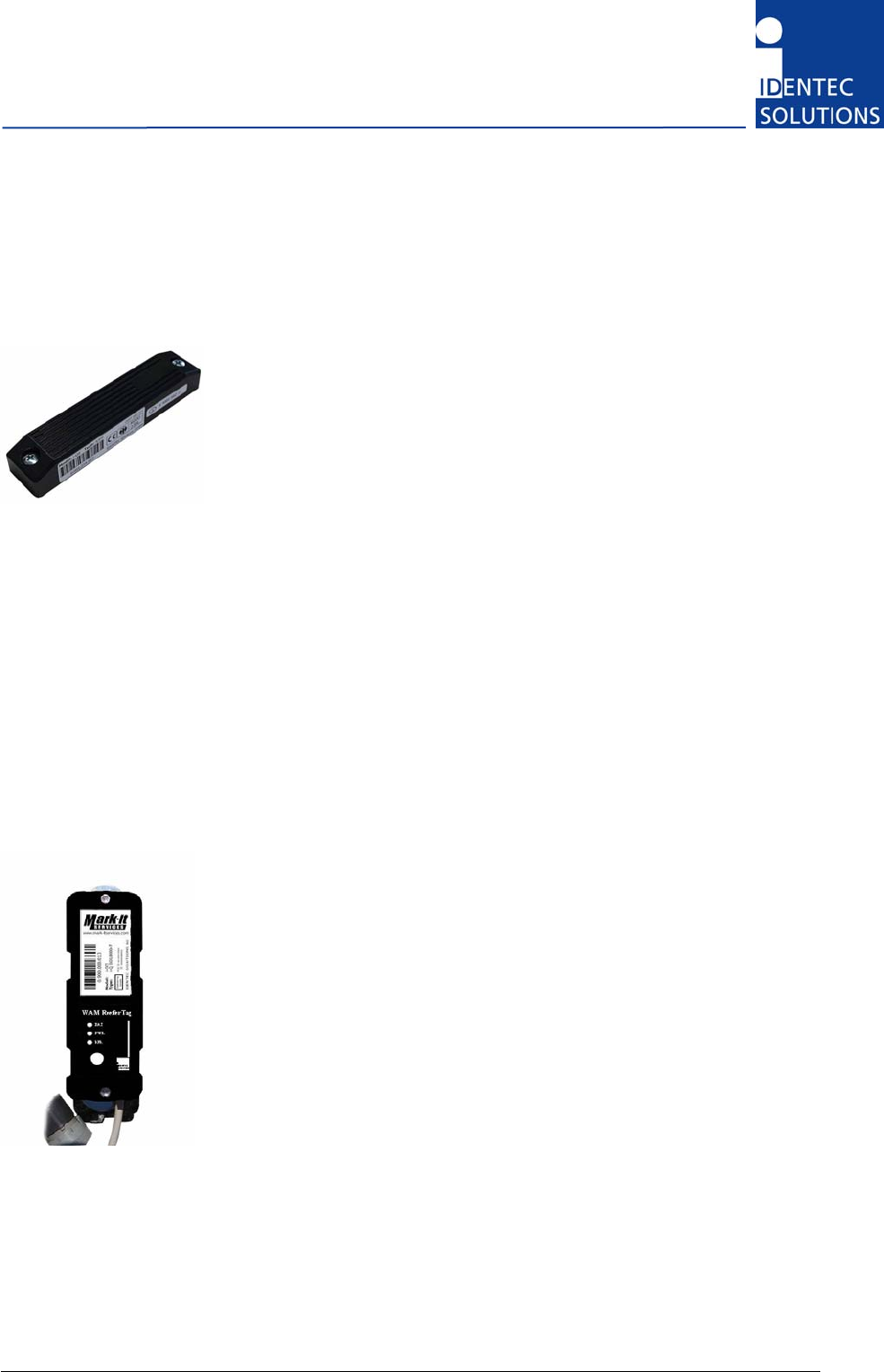
3.3.2 i-Q350 WAM
This active tag is particularly suited for:
• Identification
• Tracking and Tracing
• Localization
• System Monitoring
Using ILR technology, distances of up to 500 meters can be achieved with
this tag. An operation lifetime of up to 3 years (at 600 128-bit readings per
day) can be expected due to the tag’s minimal energy requirement.
Used in combination with the i-PORT, several hundred tags can be interrogated nearly simultaneously,
thanks to a sophisticated anti-collision algorithm.
i-Q350 tags are available in a variety of configurations, i.e. with 32 Kbytes of memory, an optional
LED for visual recognition, push-button and optional temperature logging function. Furthermore, they
are available at 868 and 920 MHz (dual frequency) for use in Europe and America for transcontinental
applications (dual frequency).
Installation and Hardware Manual
Page 14 of 30
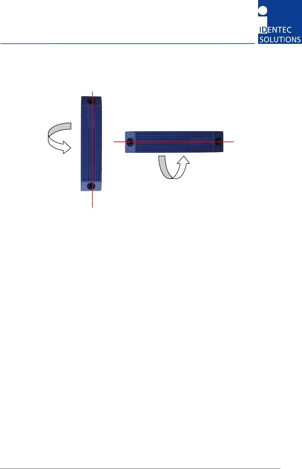
3.3.3 Polarization of Tags
Polarization is dependent on orientation and is rotation symmetrical.
Verticall
y
Polarized Horizontall
y
Polarized
i-PORT M350
Page 15 of 30
3.4 System Components—Readers
3.4.1 i-HUB
Readers from the i-HUB series are part of the newest generation of
IDENTEC SOLUTIONS™ Intelligent Long Range® (ILR®) RFID readers. The
i-HUB collects, filters and edits data from transponders and sends them to
a Host System via GPRS or Ethernet.
Systems equipped with ILR tags and readers provide identification and
real-time data collection with maximum accuracy and minimal effort in
wireless applications such as:
• identification
• tracking, and localization of assets and personnel.
Power Supply
The i-HUB is supplied a local 24 VDC supply. Additional daisy-chained i-PORTs are also supplied via
the i-BUS.
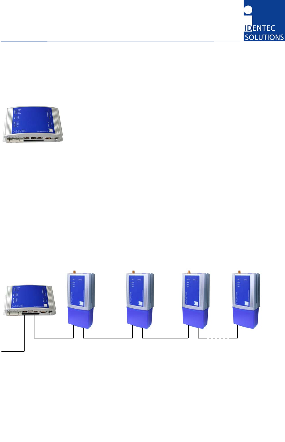
Example of i-HUB with up to 8 i-PORT M350
i-HUB i-PORT M350 i-PORT M350 i-PORT
M350
i-PORT M350
Host (Ethernet)
i-BUS (RS422)

Installation and Hardware Manual
Page 16 of 30
3.4.2 i-PORT M350
The i-PORT M350 is a reader for the i-Q350 series of ILR® Response Tags.
Built into a compact metal housing, the i-PORT M350 reads data from and
writes data to the i-Q350 tags at distances of up to 500 meters
(1500 feet). Connection to the host system is established via a RS422
interface, resulting in the capability to connect up to 8 readers in a Daisy
Chain using commercially available CAT 5 cables and connectors.
A simple master/slave protocol enables data exchange. Not only does the
protocol contain the data received from the tag but it can also provide
information about the time of data reception, field strength and information
about the number of times the tag has been received by the reader.
i-PORT M350
Page 17 of 30
3.5 System Components—Antennas
IDENTEC SOLUTIONS’ antennas are distinguished by their compact design. A variety of antennas can
be used, depending on application. The antennas are differentiated by characteristics such as
polarization, apex angle, and gain. Optimal fit to the read zone is achieved by the right choice of
antenna (characteristics) and receive sensitivity. As the antennas are passive system elements, no
tuning is required, which facilitates installation and maintenance.
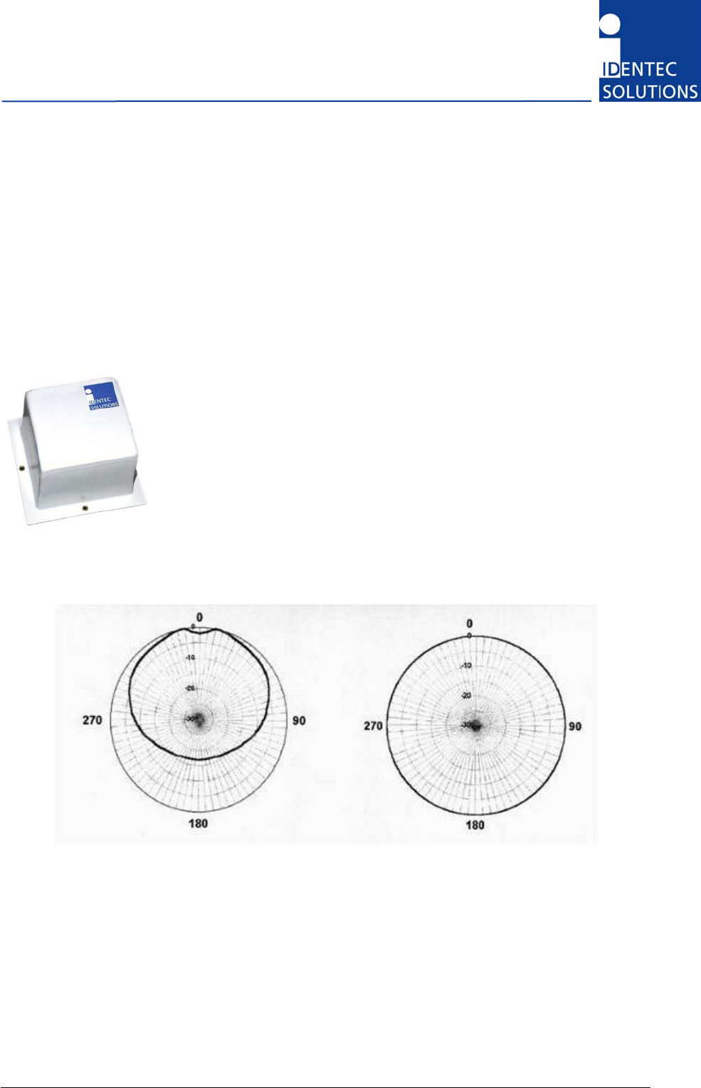
3.5.1 Elliptical Polarized Antennas
Because of the wide apex angle (120º), a large read zone is achieved,
which is desirable when a large quantity of tags need to be read at one
time, or when tags moving at great speeds need to be interrogated.
Since the polarization is elliptical, orientation of the tag relative to the
antenna is not important; if the tag is in front of the antenna the tag may
be polarized horizontally or vertically along the line of sight of the antenna.
Due to its small size and weight, this antenna is very easy to integrate.
Orientation Diagrams: Elliptical polarized antenna
Elevation Azimuth
For this antenna this is the maximum transmit power setting:
• Astron DH-9185: -8 dBm
Installation and Hardware Manual
Page 18 of 30
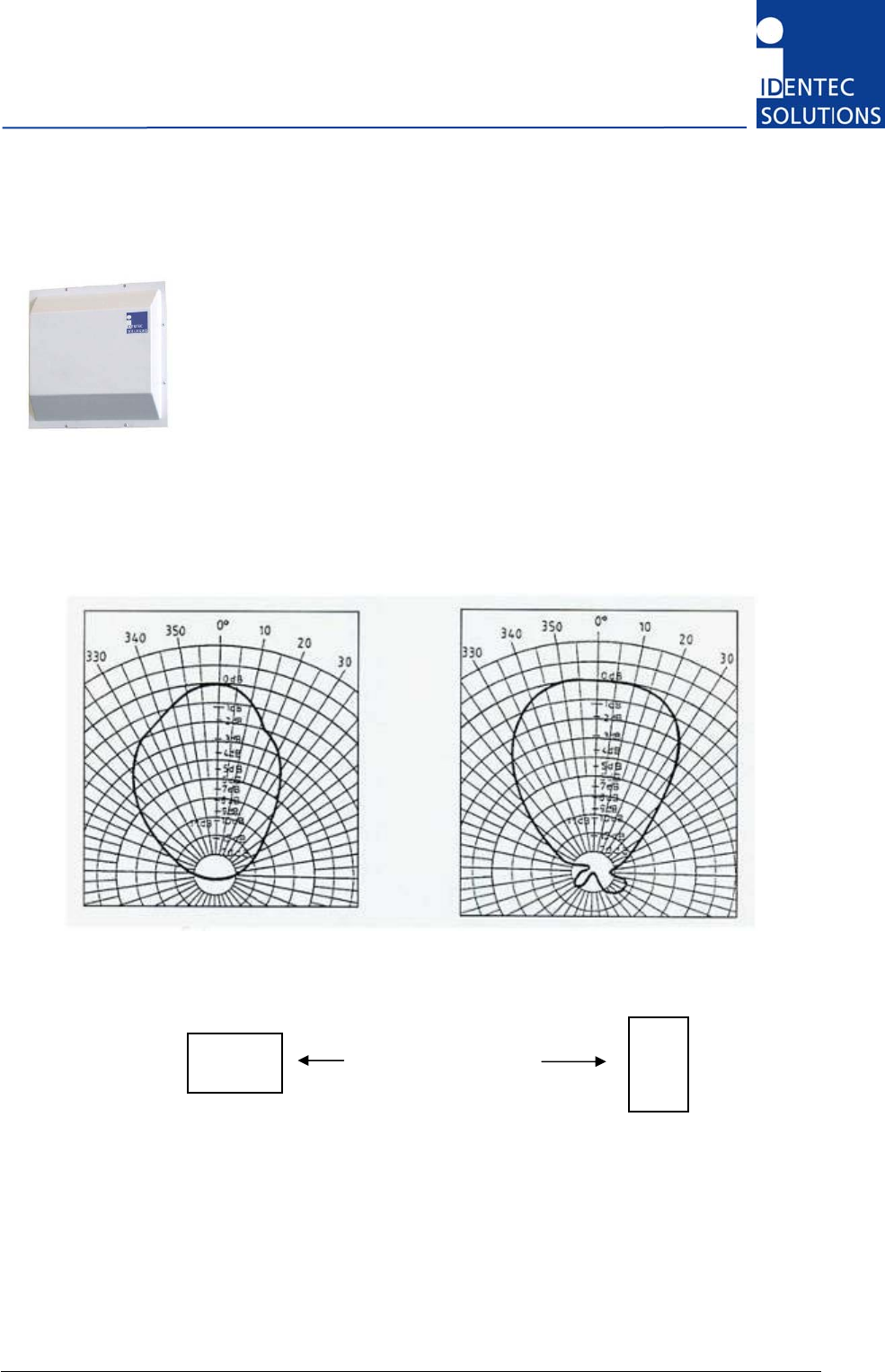
3.5.2 Linear Polarized Antennas
Because of the smaller apex angle (60º), this antenna is more suited to
selective data collection and restriction of read zones.
Depending on the direction of mounting, the antenna’s field is either
vertically or horizontally polarized, requiring the tag to have the same
orientation.
Because of the greater gain, longer read ranges can be achieved with this
antenna compared to the elliptical polarized type above.
Orientation Diagrams: Linear polarized antenna
Elevation Azimuth
Vertical Polarization Horizontal Polarization
For this antenna this is the maximum transmit power setting:
• Wimo 900R: -12 dBm
A
ntenna Orientation
i-PORT M350
Page 19 of 30
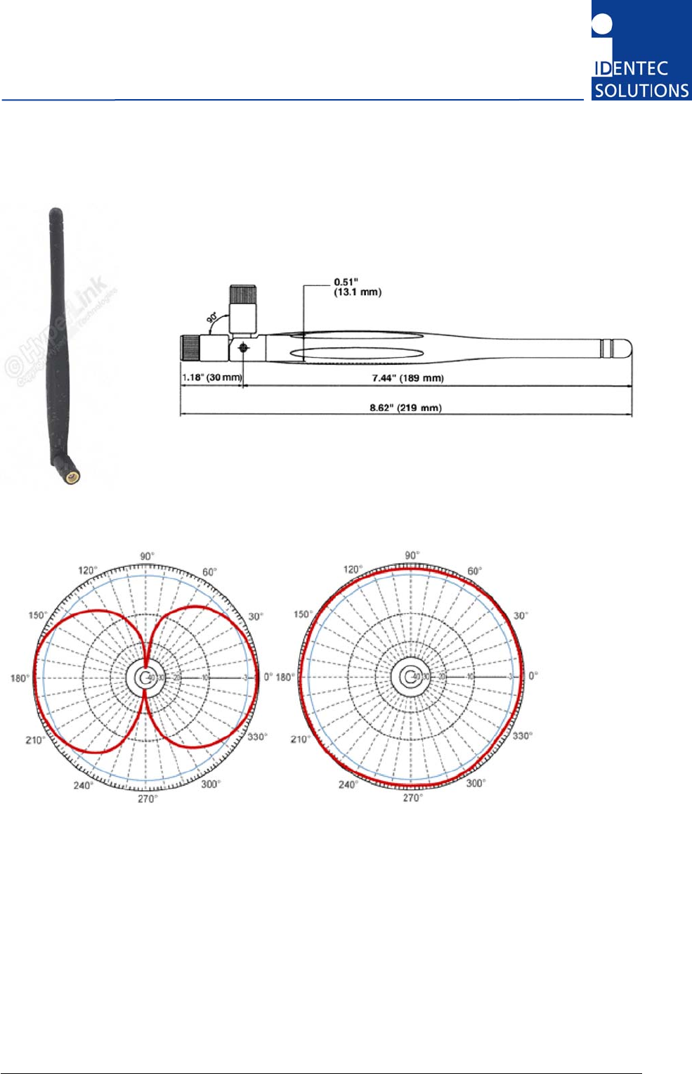
3.5.3 1/2-Wave Whip Antenna
Dimensions
Orientation Diagrams
Elevation Azimuth
Vertical Polarization Horizontal Polarization
For this antenna this is the maximum transmit power setting:
• HyperLink Technologies HG903RD-RSP: -3 dBm
Installation and Hardware Manual
Page 20 of 30
4 Installation
4.1 Mechanical Installation
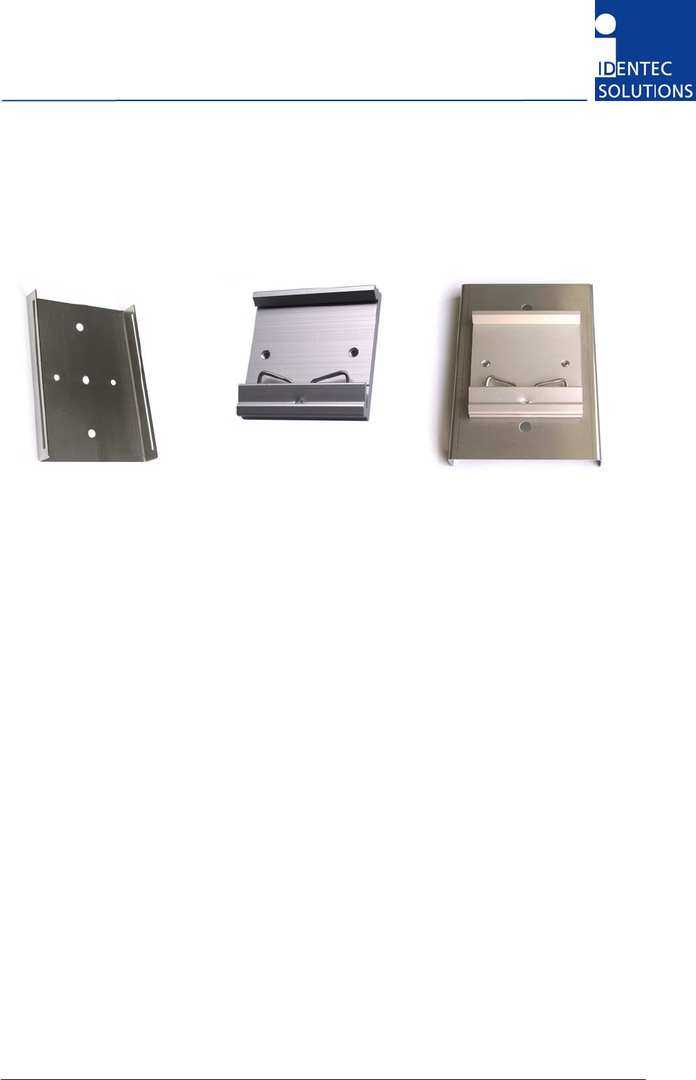
Mounting Kit
DIN Rail Clamp
Mounting Kit with DIN Rail Clamp
The mounting kit is to be clipped on the back of the i-PORT M350,
there is 5 mm space left for the screws between the mounting kit and the reader.
It is intended to always use the mounting kit. If mounting on a DIN rail is desired, the additional
clamp is mounted on the back side of the mounting kit.
Use the two mounting holes (diameter 4,5 mm) to attach the i-PORT M350 mounting kit to a suitable
mounting surface. Once the mounting kit is fixed, clipped in the i-PORT M350 reader.
Please add to the i-PORT M350 dimensions approximately 70 mm on the antenna side and 40 mm on
the cable side to calculate the required mounting space. The i-PORT M350 weights approx. 310 g in
total including all mounting parts.
Enclosure rating is IP40 without the end cap and IP64 with. If greater enclosure rating is required, the
i-PORT M350 must be placed in an additional protective housing, in this situation the end cap could be
removed.
i-PORT M350
Page 21 of 30
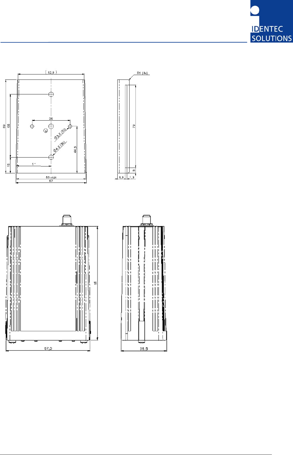
Dimensions of mounting kit
Dimensions without end cap (cable inlet protection), but without mounting kit
Installation and Hardware Manual
Page 22 of 30
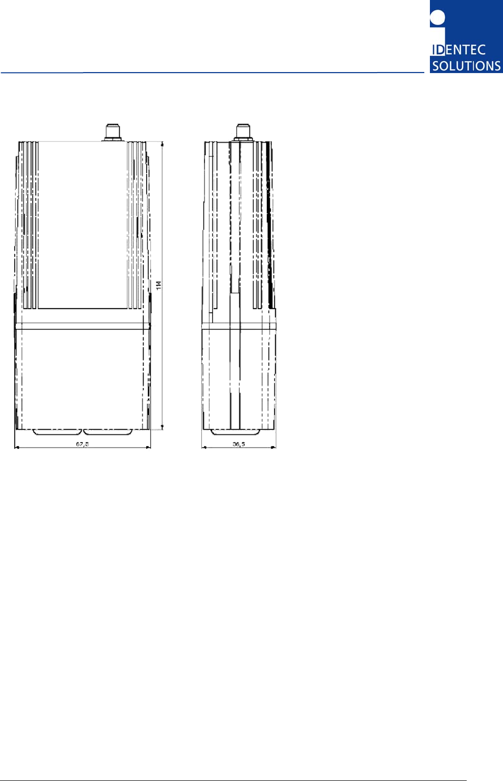
Dimensions with end cap (cable inlet protection), but without mounting kit

i-PORT M350
Page 23 of 30
4.2 Electrical Installation
4.2.1 Safety Instructions
The power supply circuit must comply with the requirements of the SELV circuits (see EN 60950).
The signal circuits must comply with the requirements of the SELV circuits (see EN 60950).
Use a ferrite rod for all cables and place it close to the units.
A screened cable must be used for the power supply. Only then is the required EMC achieved.
The device uses RS422 levels on its RX and TX Pins, although Ethernet jack/plugs mechanically fit, the
device is not Ethernet compatible!
Industry standard cat 5 straight patch cables can be used to daisy chain the devices
Glossary
SELV Safety Extra Low Voltage – Protective measure against dangerous body currents.
Protective first voltage, circuit not floating.
EMC Electromagnetic Compatibility
RxD Receive Data
TxD Transmit Data
4.2.2 Position of Ports
MASTER SLAVE
i-BUS/RS422 i-BUS/RS422

Installation and Hardware Manual
Page 24 of 30
4.2.3 Power Supply
The i-PORT M350 are powered by the i-BUS.
Total Power Consumption—i-HUB with i-PORT M types
1 × i-HUB, app. 10 W
8 × i-PORTs (MB or MQ or M350 types), app. 0.5 W each
power supply for sensors supplied from +24V AUX
This gives a maximum sum of 14 W of power consumption for the i-HUB. Add the power consumption
of sensors supplied to that.
4.2.4 Maximum Overall Cable Runs of i-BUS
This tables is valid for Cat5 cabling with gauge diameters of AWG24. The maximum distance between
any two readers is limited to 300 m (approx. 1000 ft).
# of i-PORTs Length (m/ft) Remark
1 300/1000 One 24V
2 600/2000 One 24V
3 400/1300 One 24V
4 250/820 One 24V
5 200/650 One 24V
8 100/300 One 24V
8 1000/3000 GND potential free power supplies at every i-PORT M350
i-PORT M350
Page 25 of 30
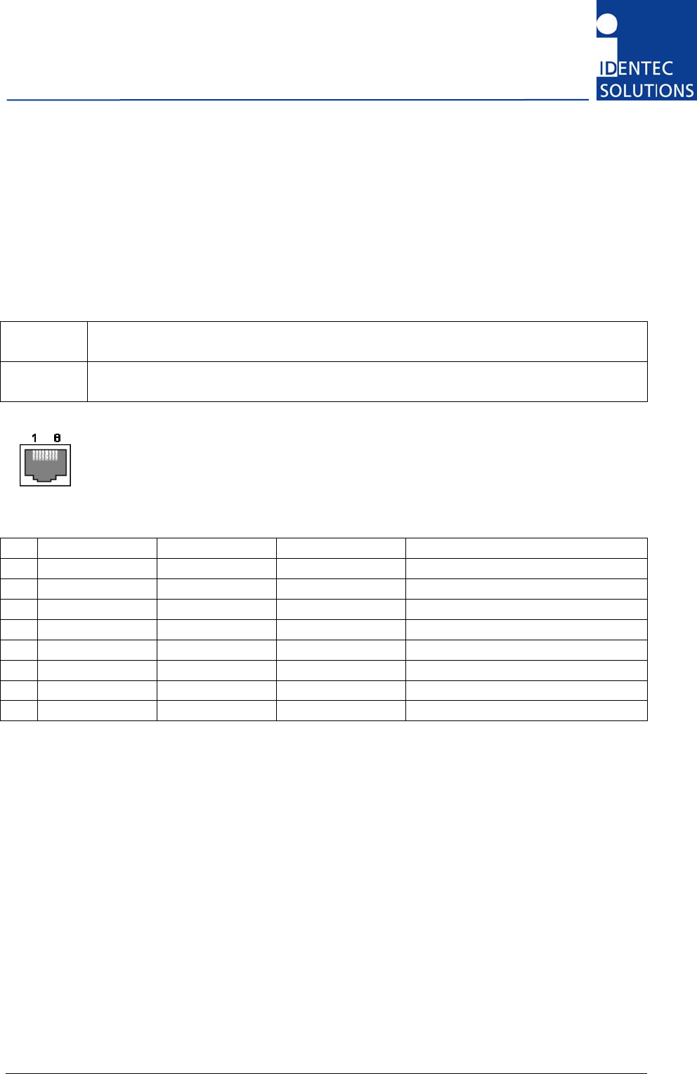
4.2.5 The i-BUS Connector
Please note
• The i-BUS uses RS422 levels on its RX and TX Pins, although Ethernet jack/plugs mechanically
fit, the device is not Ethernet compatible.
• Industry standard cat 5 straight patch cables can be used to daisy chain the devices
To Master RJ 45 connector to the Host computer or the Slave port of the previous i-PORT MB in
the Daisy Chain.
To Slave RJ 45 connector to the Master port of the next i-PORT MB in the Daisy Chain. Leave
this connector open at the last device in the chain.
View into the connector = crimp/solder side of plug
Pin To Master To Slave T568B color Description
1 RxD+ TxD+ White/orange
2 RxD– TxD– Orange
3 TxD+ RxD+ White/Green
4 V+ (10 … 30V) V+ (10 … 30V) Blue Power supply over bus
5 V+ (10 … 30V) V+ (10 … 30V) White/Blue Power supply over bus
6 TxD– RxD– Green
7 GND GND White/Brown Power supply over bus
8 GND GND Brown Power supply over bus
As the TxD/RxD crossing is done by the pinout of the connectors, simple straight cabling has to be
used.
Connection parameters
Signal levels: RS422
Baud rate: 115200 bits per second
Data bits: 8
Stop bits: 1
Parity: none
Mode: half duplex

Installation and Hardware Manual
Page 26 of 30
5 Initial Operation
5.1 Configuration
The i-PORT M350 is not configured directly. It is managed via the master unit on the i-BUS, the i-
HUB.
5.2 Important settings—transmit power
Depending on the antenna type these are the maximum transmit power settings:
• Rod antenna: -3 dBm
• A-9185: -8 dBm
• W-900R: -12 dBm
5.3 Checking the Installation
After completing the installation the operation must be systematically checked. The installation check
can be divided into three sections:
• Visual test
• Basic operational check
• Detailed operational check
If the basic check of the operational behavior is to be carried out using a (portable) PC a final check
via the intended user control system should also be carried out.

i-PORT M350
Page 27 of 30
6 Troubleshooting
6.1 General
This chapter covers how faults can be recognized and rectified. There are potentially four main
problem sources:
• The user control system, including task requirements, communication cables, peripheral units
with possible object recognition switches.
• The ILR system including peripheral units and their cables, also potential object recognition
switches.
• The environment including large objects between antenna and tag, electrical disturbance
sources, intervention by persons, etc.
• The quality of the technical design, including alignment between antenna, data, ratio of task
requirements/available communication time etc. The information about system performance is
contained in the relevant datasheets.
When planning the total system do not forget these problem sources and “Fault finding procedures on
system level” should possibly be included in the host system. How this could look in detail depends on
the relevant system concept and very likely varies from one system to another.
6.2 Status Display (LEDs)
ANT 1/ANT 2
LED blinks green when a telegram preamble has been detected.
It blinks RED when a tag telegram has been decoded correctly.
RUN
Device is running properly (LED blinks at approx 1Hz)
BUS
Blinks GREEN when data is received from the host. Blinks RED
when sending data to the host
ERR
Blinks RED when an error occurs

Installation and Hardware Manual
Page 28 of 30
7 Maintenance
7.1 General
In principle, the ILR system is maintenance-free. When correctly installed it operates for many years
without any problems.
7.2 Precautionary Maintenance
Regular checking of all ports and cables belonging to the system is recommended. Unstable
connections could lead to damage and malfunctions of the system and therefore should be repaired
as soon as possible.
A Brief Checklist
• Are all casing intact?
• Are all cables intact?
• Are all connectors intact?
• Are all connectors securely fastened?
• Are all screws still tight?
• Is there suddenly a malfunction at a specific unit?
7.3 Exchanging an i-PORT within the i-BUS daisy chain
• Exchange only one unit after another, not several in one step.
• Exchange the reader with one of the same type.
• The i-PORT automatically scans the i-BUS every 10 seconds, so it will automatically recognize the
exchanged device.
7.4 Firmware Update
The firmware is stored in a FLASH memory and can be updated if needed.

i-PORT M350
Page 29 of 30
7.5 Spare Parts
7.5.1 Recommended spare parts stock
In order to keep the down time of the system during malfunctions as short as possible it is
recommended to have certain spare parts in stock. At least one central unit, one antenna and one
antenna cable should be available. With larger systems with more than approx. 15 i-PORTs the
doubling of the recommended stock quantity should be considered.
Furthermore, it is recommended to have several spare tags in stock,
corresponding to approx. 0.5 – 1 % of the total number of tags.
7.5.2 Preparing the spare parts
In general all spare parts can be used immediately after delivery from IDENTEC SOLUTIONS.
However, for the compact communicator there are various settings of the communication parameters.
In order to keep the down times short it is recommended to set these parameters before the
component is entered into the spare part stock system. In most cases all units within an identification
system are used in the same way so that only one setting is required.
7.5.3 Examination and repair of exchanged parts
The data tags and compact communicators are complex electronic power units on which the customer
can carry out only very limited repairs. Normally the repairs are carried out at IDENTEC SOLUTIONS
or possibly at a distributor. Before a part is sent in for repair a short examination should be carried
out.
7.6 Returns
Parts or main components returned for repair or exchange must be handled with great care. PC cards
must be returned in the appropriate ESD-protecting packaging material.
All returns should include a completed returns form (see appendix) and be sent to the local distributor
or to:
IDENTEC SOLUTIONS AG
Service Department
Millenium Park 2
6890 Lustenau
AUSTRIA / AUTRICHE

Installation and Hardware Manual
Page 30 of 30
8 Technical Specifications
i-PORT M350
Compatibility ILR® i-Q350 Tags
Performance
Write range Up to 500 m (1500 ft)
Read range Up to 500 m (1500 ft)
Read rate identification 100 tags/s
Read rate 128 bit data 35 tags/s
Simultaneous
identification Up to 2000 tags
Communication
Frequency 868 MHz (EU), 919/920/921 MHz (NA)
Certification EN 300 220 (EU),
FCC part15 (US), Industry Canada
Data rate up/download 19.200 – 5000.000 kbits/s
Number of antennas 1
Antenna connection SMA
Transmit power ≤ 10 mW/+10 dBm, depending on national regulations,
software adjustable
Transmission safeguard 16 Bit CRC
Sensitivity -105 dBm / depending on data rate
CPU
Data memory Up to 200 tags (IDs)
Interfaces
Host interface i- BUS (RS422), optional Ethernet, WLAN
Status display 5 LEDs (ANT1, ANT2, RUN, BUS, ERR)
Electrical
Power source 10 – 30 VDC
Input power < 1 W
Standards / Security CE, EN 300 220
Environmental
Operating temperature –30 °C to +70 °C (–22 °F to +158 °F)
Storage temperature –40 °C to +80 °C (–40 °F to +176 °F)
Humidity 90 % non-condensing
Physical
Dimensions 97 × 67 × 97 mm; (3.8 × 2.6 × 3.8 in.)
153 × 67 × 97 mm; incl. cover (6.0 × 2.6 × 3.8 in.)
Case material Plastic
Weight 150 g
Package rating IP40, IP64 with plastic cover