Identec Solutions ILR-IQ350TL RFID System User Manual
Identec Solutions AG RFID System Users Manual
Users Manual

ILR 350 Series
Installation and Operation Manual
for Tag Models
i-Q350, i-Q350T, i-Q350L, i-Q350TL

Installation and Operation Manual
Page 2 of 11
Proprietary Notice
This document contains confidential information proprietary to IDENTEC SOLUTIONS and may not be used or
disclosed to other parties in whole or in part without prior written authorization from IDENTEC SOLUTIONS.
Disclaimer and Limitation of Liability
IDENTEC SOLUTIONS AG and its affiliates, subsidiaries, officers, directors, employees and agents provide the
information contained in this Manual on an “as-is” basis and do not make any express or implied warranties or
representations with respect to such information including, without limitation, warranties as to non-
infringement, reliability, fitness for a particular purpose, usefulness, completeness, accuracy or up-to-
dateness. IDENTEC SOLUTIONS shall not in any circumstances be liable to any person for any special,
incidental, indirect or consequential damages, including without limitation, damages resulting from use of or
reliance on information presented herein, or loss of profits or revenues or costs of replacement goods, even if
informed in advance of the possibility of such damages.
Trademarks
“IDENTEC SOLUTIONS”, “Intelligent Long Range”, “ILR” and the stylized “i” are registered trademarks and
“i-Q”, “i-D”, “i-B”, “i-CARD”, “i-PORT”, “i-LINKS”, “Solutions. It’s in our name.”, “Smarten up your assets” are
trademarks of IDENTEC SOLUTIONS, Inc. and/or IDENTEC SOLUTIONS AG.
Copyright Notice
Copyright © 2007 IDENTEC SOLUTIONS. All rights reserved.
No part of this document may be reproduced or transmitted in any form by any means, photographic,
electronic, mechanical or otherwise, or used in any information storage and retrieval system, without the prior
written permission of IDENTEC SOLUTIONS.
Reg.-No. IM.0761.EN
Issue 0 / September 2009
– 22. September 2009 –
IDENTEC SOLUTIONS AG,
Millenium Park 2, 6890 Lustenau, Österreich
Phone: +43 5577 87387- 0, Fax: +43 5577 87387-15
E-Mail: info@identecsolutions.at
www.identecsolutions.com
Subject to alteration without prior notice.
© Copyright IDENTEC SOLUTIONS 2009
Printed in Germany

i-Q350TL Tag Manual
Page 3 of 11
Radio Frequency Compliance Statement
IDENTEC SOLUTIONS is the responsible party for the compliance of the following devices:
MODELS: i-Q350, i-Q350L, i-Q350T, i-Q350TL
Region/Country Organization Marking
EUROPE: EC CE
USA FCC FFC ID IQ350TL
Canada Industry Canada IC:3538A-IQ350TL
The user(s) of these products are cautioned to only use accessories and peripherals approved, in advance, by
IDENTEC SOLUTIONS. The use of accessories and peripherals, other than those approved by IDENTEC
SOLUTIONS, or any changes or modifications not expressly approved by the party responsible for compliance
could void the user’s authority to operate the equipment.
European Notification according R&TTE Directive
This equipment complies to Art. 6.4 of R&TTE Directive (1999/5/EC). It is tested for compliance with the
following standards: ETSI EN 300 220, ETSI EN 301 489, EN 60950
USA Notification
This device complies with part 15 of the FCC Rules. Operation is subject to the following two conditions: (1)
This device may not cause harmful interference, and (2) this device must accept any interference received,
including interference that may cause undesired operation.
The user(s) of these products are cautioned to only use accessories and peripherals approved, in advance, by
IDENTEC SOLUTIONS. The use of accessories and peripherals, other than those approved by IDENTEC
SOLUTIONS, or any changes or modifications not expressly approved by the party responsible for compliance
could void the user’s authority to operate the equipment.

Installation and Operation Manual
Page 4 of 11
Contents
1 INTRODUCTION ...........................................................................................................5
1.1 PREPARATIONS ............................................................................................................5
1.2 RECOMMENDED PROCEDURE............................................................................................5
1.3 SCOPE OF THIS DOCUMENT .............................................................................................5
1.4 RESPONSIBILITY........................................................................................................... 5
1.5 ASSOCIATED DOCUMENTS...............................................................................................5
1.6 SCOPE OF DELIVERY—VISUAL INSPECTION..........................................................................5
2 SAFETY PRECAUTIONS.................................................................................................6
3 TAG MOUNTING TECHNIQUES .....................................................................................7
3.1 RIVETS......................................................................................................................7
3.2 SCREWS.....................................................................................................................8
4 MAINTENANCE .............................................................................................................9
4.1 GENERAL ...................................................................................................................9
4.2 PRECAUTIONARY MAINTENANCE........................................................................................9
4.3 RETURNS ...................................................................................................................9
5 TECHNICAL DATA .......................................................................................................10

i-Q350TL Tag Manual
Page 5 of 11
1 Introduction
1.1 Preparations
This installation manual must be read carefully prior to starting the installation. The described installation
works assume that installation materials like cable, antenna and tag holder etc are available.
1.2 Recommended Procedure
1. Check the Scope of Delivery according to the Bill of Delivery
2. Read this manual completely
3. Mount the tags
4. An additional performance check of the tags and a system test can now be done
1.3 Scope of this Document
This document is the user’s manual of this tag models: i-Q350, i-Q350T, i-Q350L, i-Q350TL
This document is intended only for mechanical installation rsp. everyday use.
1.4 Responsibility
IDENTEC SOLUTIONS is not responsible for any errors occurring in this document.
1.5 Associated Documents
• i-Q350 Data Sheet, ID.0695.EN (English)
• i-Q350T Data Sheet, ID.0675.EN (English)
• i-Q350L Data Sheet, ID.0696.EN (English)
• i-Q350TL Data Sheet, ID.0697.EN (English)
1.6 Scope of Delivery—Visual Inspection
Check delivery whether it is complete and for any damages. If the delivery is not complete or damaged
immediately inform the carrier. The dispatch and service organization of IDENTEC SOLUTIONS should also be
informed to facilitate the repair or exchange of the system.

Installation and Operation Manual
Page 6 of 11
2 Safety Precautions
Important Safety Note
The devices described in this manual is for exclusive operation by trained employees. Only qualified personnel
that know the potential dangers involved should perform the installation, settings, maintenance and repair of
the units used.
Operational Safety
The correct and safe use of these systems assumes that operating and service personnel follow the safety
measures described in the manual alongside the generally acceptable safety procedures.
If there is a possibility that safe operation cannot be guaranteed the system must be switched off and secured
against accidental use. Then the service unit responsible must be informed.
Do not open the housing
There is no need to open the housing. There are no user serviceable parts inside. Set-up and configuration
during initial operation is done wireless with the built-in air interface.
Handling Safety
On account of high operating temperature of 80 °C (+176 °F) care must be taken, if the tags are heated. To
avoid burn wait a while until the tags have cooled down or use gloves. At temperatures below 0 °C (+32 °F)
tags can be iced. In this case, wait a while until tags are warmed up or use gloves.
Battery Inside
All tags contain a battery. That is the reason for the following instructions:
Warning
Fire, explosion and burn hazard
Risk of explosion if battery is replaced by an incorrect type
Do not recharge, short circuit, crush, disassemble, heat above 100 °C (212 °F)
Do not incinerate, or expose contents to water
Electrostatic Discharge
This product contains components that are sensitive to electrostatic discharges. Please observe
the special instructions for their protection. Incorrect handling can damage the unit and cause the
invalidation of the warranty.
Safety Documents
This ILR system was designed, tested and supplied in perfect condition according to document test report
EN60950.
Condensation/Change of Temperature
Moving the systems from a cold to a warm environment could lead to dangerous situations due to
condensation. Therefore it must be ensured that the system can adjust itself to the warmer temperature.
Spare Parts
We recommend that only original products, spare and replacement parts authorized by IDENTEC SOLUTIONS
be used for installation, service and repair. Otherwise IDENTEC SOLUTIONS does not accept any responsibility
for materials used, work carried out or possible consequences.
i-Q350TL Tag Manual
Page 7 of 11
3 Tag Mounting Techniques
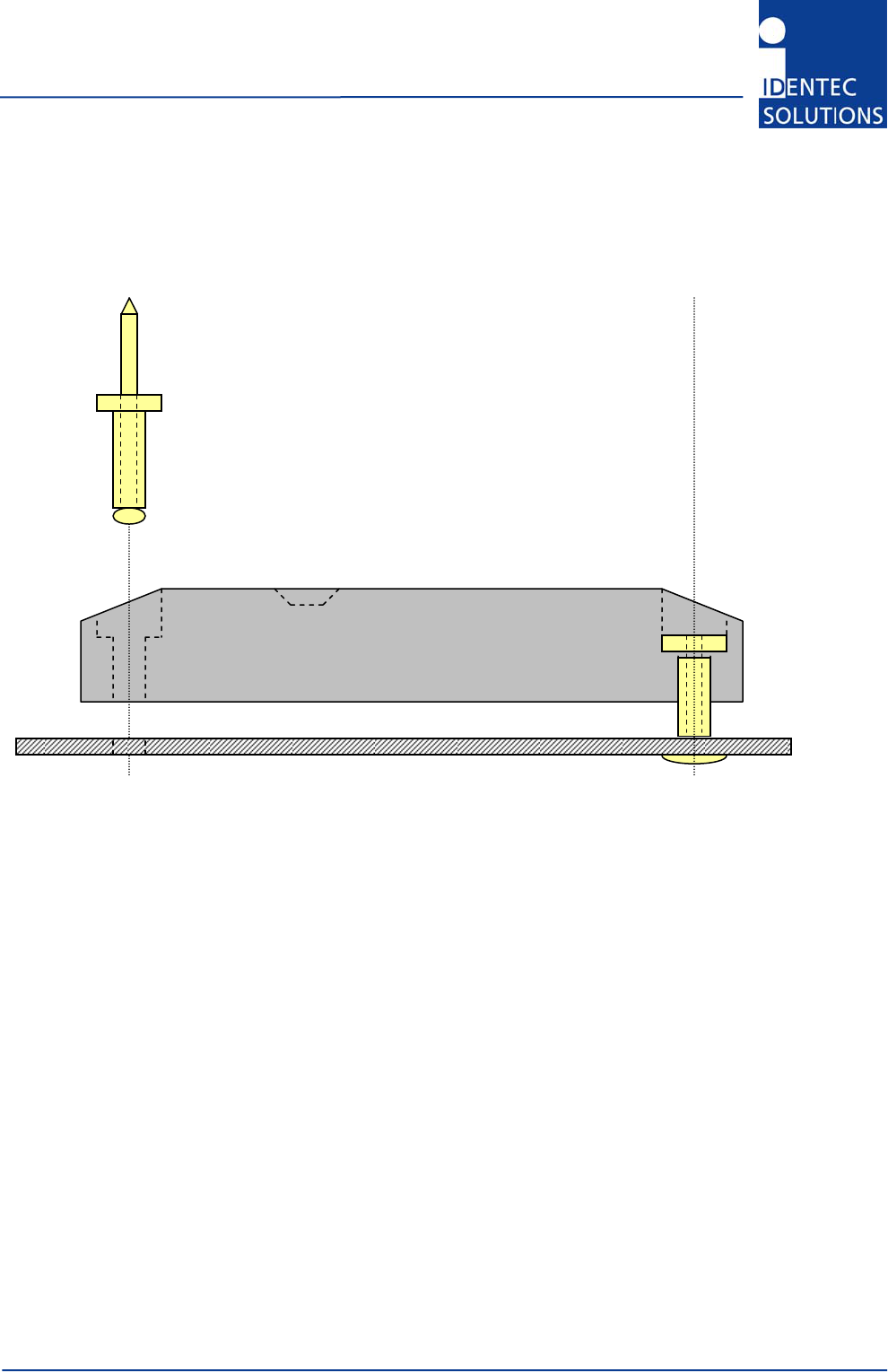
3.1 Rivets
Important Information
1. A temperature of at least +10 °C (+50 °F) must be maintained during riveting to prevent the casing from
cracking.
2. Always position the blind-rivet gun straight down on the rivet site and all the way to the rivet socket.
3. On occasion, a tag casing has been damaged through improper handling of the blind-rivet gun (slanted
positioning of the gun to access the rivet socket). If there is a chance this might occur, it is better to use
a blind rivet with a large head (Refer to UN9924) or insert a 3/16” washer. This has the effect of
distributing the pressure over a larger surface area during riveting. The use of the washer has the added
effect of positioning the rivet slightly higher in the depression, so that one can better access the rivet
socket with the rivet gun.
4. Metal surfaces in direct proximity to the tag can reduce the tag’s range of function. Tags should
therefore not be mounted in metal recesses or corners.
5. After mounting, the tag’s function should be tested, i.e. with a handheld device and the „ILR Pocket
Demo“ software.
3/16” dia. blind rivet (M5)
Installation and Operation Manual
Page 8 of 11
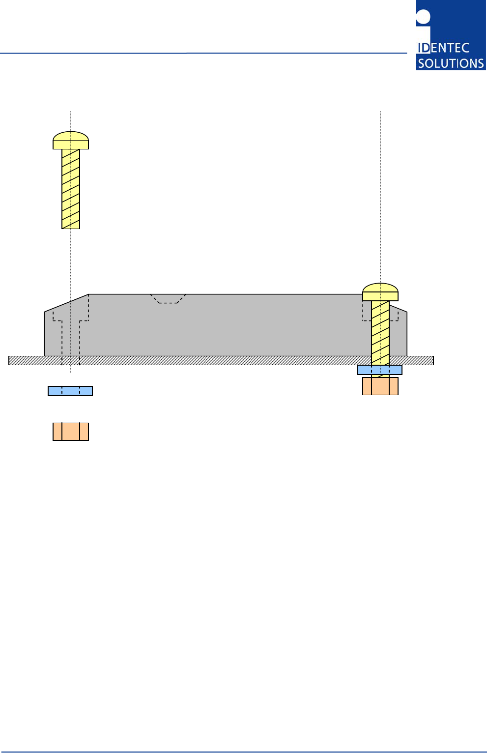
3.2 Screws
Important Information
1. Only screws with cylindrical heads are suitable for mounting the tag. We do not advise using counter-
sunk screws. If for some reason this should be necessary, then only together with a suitable counter-
sunk cushioning disc (refer to UN 1277).
2. Secure the screws so they cannot work themselves loose i.e. by using self-locking nuts or spring washers
or Nordlock washers (refer to UN 7014).
3. If the tag is mounted out-of-doors or in a damp environment, all mounting parts need to be made of
stainless steel or other non-rusting material.
4. A temperature of at least +10 °C (+50 °F) must be maintained during mounting to prevent the casing
from cracking.
5. Depending on the type and strength category of the #10 screw used, the maximum tightening torque
must be between 2 and 10 Nm. If the torque is any greater, the screw may overtighten, or the casing
might break.
6. Metal surfaces in direct proximity to the tag can reduce the tag’s range of function. Tags should
therefore not be mounted in metal recesses or corners.
7. After mounting, the tag’s function should be tested, i.e. with a handheld device and the „ILR Pocket
Demo“ software.
Variations
Mounting with self-tapping screws. Disadvantage: the screws may loosen in time.
i.e. #10 cylinder head or lenticular head screws
i.e. 3/16” hexagonal locknut with 3/16” washer
OR 3/16” hexagonal nut, but together with spring washer
or 3/16” Nordlock washer

i-Q350TL Tag Manual
Page 9 of 11
4 Maintenance
4.1 General
In principle, the ILR system is maintenance-free. When correctly installed it operates for many years without
any problems.
4.2 Precautionary Maintenance
Regular checking of all ports and cables belonging to the system is recommended. Unstable connections could
lead to damage and malfunctions of the system and therefore should be repaired as soon as possible.
A Brief Checklist
• Are all housings intact?
• Are all cables intact?
• Are all connectors intact?
• Are all connectors securely fastened?
• Are all screws still tight?
• Is there suddenly a malfunction at a specific unit?
4.3 Returns
Parts or main components returned for repair or exchange must be handled with great care. PC cards must be
returned in the appropriate ESD-protecting packaging material.
All returns should include a completed returns form (see appendix) and be sent to the local distributor or to:
IDENTEC SOLUTIONS AG
Service Department
Millenium Park 2
6890 Lustenau
AUSTRIA / AUTRICHE

Installation and Operation Manual
Page 10 of 11
5 Technical Data
Operating Data
Operating frequency ILR-RFID 868 MHz (EU) or 920 MHz (NA), further frequencies on request
Maximum transmission power 0.75mW (EU / NA)
Compatibility i-PORT M 350, i-CARD CF-350
Standards/Certification FCC Part 15 (US), ETSI EN 300 220 (EU)
Communication Data Long-Range RFID (ILR, Response Technology)
Multiple tag handling Up to 2,000 tags in the read zone
Read/write range response mode Up to 250 m (800 feet), free air*
Data rate response 19.2 to 115.2 kbits/s
Communication Data Long-Range RFID (ILR, Beacon Technology)
Read range broadcast Up to 500 m (1600 feet) free air*
Operation mode Transmits marker information in at regular intervals
Repetition rate (ping rate) 0,5 – 300 seconds, adjustable in steps of 0,5 seconds
Data rate broadcast 115.2 kbits/s
* The communication range depends on the antenna type, the antenna cable runs and the environmental conditions.
Communication Data Inductive Loop (Marker)
Read range Up to several meters
Operating frequency 125 kHz (world-wide approved)
Operation mode Receives marker ID number and transmits marker information several times
Electrical
Power source Lithium battery (not replaceable)
Battery monitoring Yes
Temperature Logging
Number of samples 10,000
Logging interval User definable in intervals from 1 to 255 min
Measuring interval User definable in intervals from 0 s to 255 min
Metering range –40 °C to +85 °C (–40 °F to +176 ºF) with std. internal sensor
–80 °C to 110 °C (–112 °F to +230 ºF) with std. external sensor
Other metering ranges are available on request
Resolution 0.1 °C (0.2 °F)
Accuracy ±0.5 °C (1 °F) from -20 °C up to +50 °C,
±1 °C (2 °F) in the remaining temperature range
Data
Data retention > 10 years without power
Write cycles 100,000 writes to a tag
Memory size 10,000 Bytes user definable
Identification code 48 bit fixed ID
Environmental Conditions
Operating temperature –40 °C to +85 °C (–40 ºF to +185 ºF)
Humidity 10 % to 95 % relative humidity @ 30 °C
Shock 50 G, 3 times DIN IEC 68-2-27
Multiple drops to concrete from 1 m (3 ft)
Vibration 3 G, 20 sine wave cycles, 5 Hz to 150 Hz, DIN IEC 68-2-6
5 G, noise 5 Hz to 1000 Hz, 30 minutes, DIN IEC 68-2-64
Physical
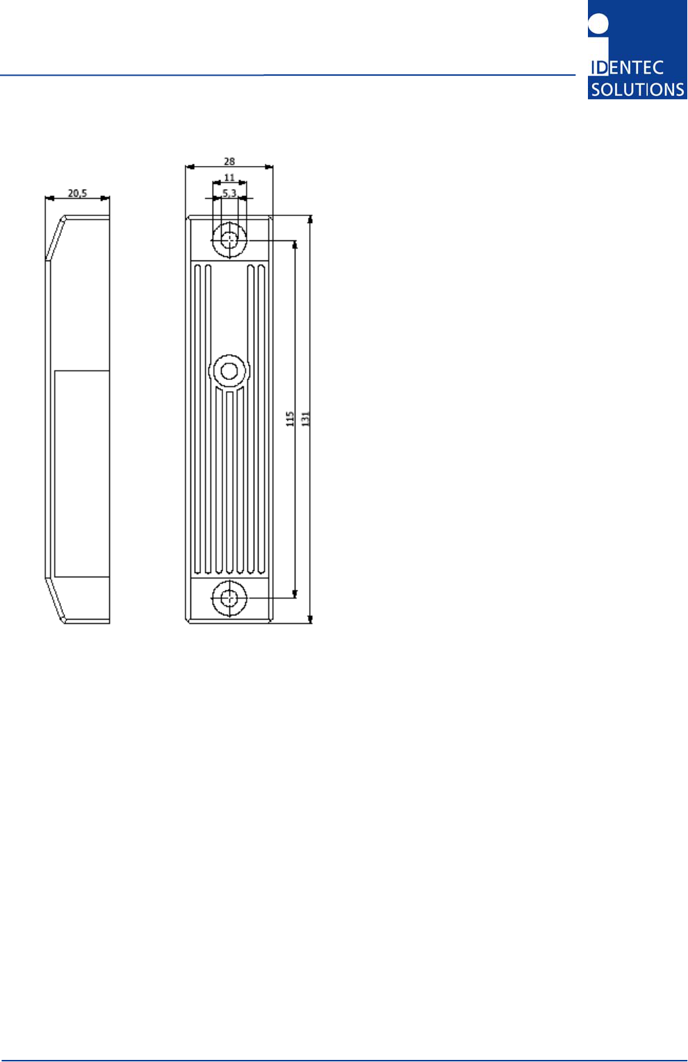
Dimensions 131 mm × 28 mm × 21 mm (5.2 in. × 1.1 in. × 0.85 in.)
Enclosure Plastic (Qinnacryl)
Weight 50 g (1.75 ounces)
Enclosure rating IP 65
i-Q350TL Tag Manual
Page 11 of 11
Dimensional Drawing
All dimensions in mm. External cable to temperature sensor (models i-Q350T & i-Q350TL) not shown.