Identec Solutions ILR-IQ350WAM2 Active RFID transponder User Manual M EN i Q350 RCM v13 FCCx
Identec Solutions AG Active RFID transponder M EN i Q350 RCM v13 FCCx
Users Manual_revised0310

VISIBILITY DELIVERED.
i-Q350 RCM
SensorSMART™
Installation and Operation Manual

i-Q350 RCM
USER MANUAL
VISIBILITY DELIVERED. PAGE 2 OF 28
Proprietary Notice
This document contains confidential information proprietary to IDENTEC SOLUTIONS and may not be used or
disclosed to other parties in whole or in part without the prior written authorization from IDENTEC
SOLUTIONS.
Disclaimer and Limitation of Liability
IDENTEC SOLUTIONS AG and its affiliates, subsidiaries, officers, directors, employees and agents do not make
any express or implied warranties or representations with respect to such information including, without
limitation, warranties as to non-infringement, reliability, suitability for a particular purpose and accuracy.
IDENTEC SOLUTIONS shall not under any circumstances be liable to any person for any special, incidental,
indirect or consequential damages, including without limitation, damages resulting from use of or reliance on
information presented herein, or loss of profits or revenues or costs of replacement goods, even if informed in
advance of the possibility of such damages.
Customer shall be solely responsible for proper selection, application, and use of Products, as well as the
incorporation/integration of Products into other equipment or systems. Customer shall indemnify and hold
IDENTEC SOLUTIONS harmless from and against any and all damages, liabilities, claims, or expenses
(including reasonable attorneys' fees) arising out of or relating to (i) improper selection, application,
installation, use or incorporation/integration of Products; or (ii) infringement of any patent, trademark,
copyright or other third party interest arising out of IDENTEC SOLUTIONS' compliance with any of Customer's
designs, specifications, or instructions
Trademarks
“IDENTEC SOLUTIONS”, “Intelligent Long Range”, “ILR” and the stylized “i” are registered trademarks and “i-
CARD”, “i-PORT”, “i-LINKS”, “Visibility Delivered.” are trademarks of IDENTEC SOLUTIONS, Inc. and/or
IDENTEC SOLUTIONS AG.
Copyright Notice
Copyright © 2014 IDENTEC SOLUTIONS. All rights reserved.
No part of this document may be reproduced or transmitted in any form by any means, photographic,
electronic, mechanical or otherwise, or used in any information storage and retrieval system, without the prior
written permission of IDENTEC SOLUTIONS.
Issue 1.3 / December 2014 (EGD)
Subject to alteration without prior notice.
Printed in Austria

i-Q350 RCM
USER MANUAL
VISIBILITY DELIVERED. PAGE 3 OF 28
Radio Frequency Compliance Statement
IDENTEC SOLUTIONS is the responsible party for the compliance of the following devices:
MODEL:
i-Q350 RCM
Region/Country
Organization
Marking
EUROPE:
EC
CE
USA:
FCC
OO4-ILR-IQ350WAM
OO4-ILR-IQ350WAM2
Canada:
Industry Canada
3538A-IQ350WAM
3538A-IQ350WAM2
The user(s) of these products are cautioned to only use accessories and peripherals approved, in advance, by
IDENTEC SOLUTIONS. The use of accessories and peripherals, other than those approved by IDENTEC
SOLUTIONS, or unauthorized changes to approved products, may void the compliance of these products and may
result in the loss of the user(s) authority to operate the equipment.
European Notification according R&TTE Directive
This equipment complies to Art. 6.4 of R&TTE Directive (2006/95/EU, 2004/108/EC, 1999/5/EC). It is tested for
compliance with the following standards: EN 300 220-1, ETSI EN 300 220-2, ETSI EN 301 489-1, ETSI EN 301
489-3, EN 60950-1:2006 + A11:2009 + A1:2010 + A12:2011
USA Notification
This device complies with part 15 of the FCC Rules. Operation is subject to the following two conditions:
(1) This device may not cause harmful interference, and
(2) this device must accept any interference received, including interference that may cause undesired
operation.
Canada Certification
This device complies with Industry Canada’s license exempt RSS’s. Operation is subject to the following two
conditions:
(1) This device may not cause harmful interference, and
(2) this device must accept any interference received, including interference that may cause undesired
operation.
Le présent appareil est conforme aux CNR d‘Industrie Canada applicables aux appareils radio exempts de
licence. L‘exploitation est autorisée aux deux conditions suivantes:
(1) l‘appareil ne doit pas produire de brouillage, et
(2) l‘utilisateur de l‘appareil doit accepter tout brouillage radioélectrique subi, même si le brouillage est
susceptible d‘en compromettre le fonctionnement.

i-Q350 RCM
USER MANUAL
VISIBILITY DELIVERED. PAGE 4 OF 28
This product contains components that are sensitive to electrostatic discharges. Please observe the special
instructions for their protection. Incorrect handling can damage the unit and cause the invalidation of the
warranty.
Minimum safety precautions against electrostatic discharge:
• Establish earth contact before you touch the unit. For example, touch the earthing screw on the unit.
Even better: Use an antistatic ribbon and earth yourself permanently for the time you handle the unit.
• Avoid unnecessary contact with the unit connectors and assemblies inside the unit.
• Only open the unit if the operational settings (as described in the manual) expressly require this.
• Use antistatic tools for the setting of the unit. (Warning: Do not touch life-threatening voltages with
these tools).
• Do not store unit and components without protective packaging.
• Only remove unit and components from the packaging immediately prior to installation.
These notes are not sufficient to guarantee complete protection from electrostatic discharges!
We recommend the use of suitable protective equipment.

i-Q350 RCM
USER MANUAL
VISIBILITY DELIVERED. PAGE 5 OF 28
Contents
1.!SAFETY INSTRUCTIONS .............................................................................................. 6!
1.1.!PREPARATIONS .............................................................................................................. 7!
1.2.!SCOPE OF THIS DOCUMENT .............................................................................................. 7!
1.3.!RESPONSIBILITY ............................................................................................................ 8!
1.4.!UPDATES ..................................................................................................................... 8!
1.5.!SCOPE OF DELIVERY—VISUAL INSPECTION ........................................................................... 8!
1.6.!ASSOCIATED DOCUMENTS ................................................................................................ 8!
2.!INTRODUCTION .......................................................................................................... 9!
2.1.!FUNDAMENTALS ............................................................................................................. 9!
2.2.!COMPONENT OVERVIEW .................................................................................................. 9!
3.!INTRODUCTION ........................................................................................................ 10!
3.1.!FUNDAMENTALS ........................................................................................................... 10!
3.2.!SYSTEM COMPONENTS—SENSORS .................................................................................... 10!
3.3.!SYSTEM COMPONENTS—READERS .................................................................................... 12!
3.4.!SYSTEM COMPONENTS—ANTENNAS .................................................................................. 12!
4.!TAG MOUNTING SOLUTIONS ..................................................................................... 16!
4.1.!CABLE STRAPS ............................................................................................................ 16!
4.2.!SCREWS .................................................................................................................... 16!
4.3.!MAGNET (OPTIONAL) .................................................................................................... 18!
5.!CONNECTING TO THE REEFER CONTROLLER ............................................................ 19!
6.!ACCESSORIES ............................................................................................................ 21!
6.1.!EXTENSION CABLE ....................................................................................................... 21!
6.2.!ADAPTORS ................................................................................................................. 22!
6.3.!CONNECTING TO THE TAG .............................................................................................. 23!
7.!TROUBLESHOOTING .................................................................................................. 25!
7.1.!GENERAL ................................................................................................................... 25!
7.2.!STATUS DISPLAY (LEDS) ............................................................................................... 25!
8.!MAINTENANCE .......................................................................................................... 26!
8.1.!GENERAL ................................................................................................................... 26!
8.2.!REGULAR CLEANING OF THE SURFACE ............................................................................... 26!
8.3.!PRECAUTIONARY MAINTENANCE ....................................................................................... 26!
8.4.!RETURNS ................................................................................................................... 26!
9.!TECHNICAL DATA ...................................................................................................... 27!

i-Q350 RCM
USER MANUAL
VISIBILITY DELIVERED. PAGE 6 OF 28
1. SAFETY INSTRUCTIONS
The system described in this manual is for exclusive operation of trained employees. Only qualified personnel
that have knowledge of the potential dangers involved should perform the installation, settings, maintenance
and repair of the units used.
Operational Safety
The correct and safe use of these systems assumes that operating and service personnel follow the safety
measures described in the manual alongside the generally acceptable safety procedures.
If there is a possibility that safe operations cannot be guaranteed, the system must be switched off, secured
against accidental use and the service unit responsible immediately informed.
Safety Documents
The i-Q350 tag was designed, tested and supplied in perfect condition according to document IEC348 Safety
Requirements for Electronic Units of Class 1.
Condensate / Change of Temperature
To avoid condensation in the system, the unit must be allowed to slowly adjust itself to warmer temperatures
after removal from cold and cool environments.
Do not open the housing
There is absolutely no need to open the systems housing during set up. Configuration is done with built in
interface wirelessly.
Earthing
Before establishing any connections the housing of the system must be earthed.
Battery Inside
All system tags contain a battery; therefore the following warning should be heeded:
WARNING - Fire, explosion and burn hazard risk of explosion if battery is replaced by an
incorrect type. Do not recharge, short circuit, crush, disassemble, heat above
100 °C (212 °F)
Do not incinerate, or expose contents to water
Fuses
Only experts who are aware of the dangers involved may replace the fuses. It must be ensured that only
fuses of the required current rating and the correct type are used for replacement. The use of repaired fuses
and/or short-circuiting the fuse holders is prohibited.

i-Q350 RCM
USER MANUAL
VISIBILITY DELIVERED. PAGE 7 OF 28
Spare Parts
We recommend that only personnel, original products, spare and replacement parts authorized by IDENTEC
SOLUTIONS be used for installation, service and repair. IDENTEC SOLUTIONS does not accept any
responsibility for materials used, work carried out or possible consequences from unauthorized third party
vendors.
Electrostatic Discharge
Semi-conductors of the type MOS or CMOS as well as two-pin types and precision resistance are sensitive to
ESD. All components, printed circuit boards and auxiliary systems should therefore always be classed as
sensitive to electrostatic discharge.
Before opening the cover the unit should be placed onto an ESD-protected surface. As with all work on
modern electronic modules, the use of ESD clamps and ESD mats during work on the unit is recommended.
• Sufficiently protect all printed circuit boards that were removed from the unit from damage.
• Observe all normal precautions for the use of tools.
• Use ESD-protected packaging material.
Never use measuring units with low impedance for measuring or testing systems with semi-conductor
components. Never use high voltage testing units or dielectric test units to test systems with semi-conductor
components.
If it is necessary to check the isolating properties of the field wiring, the assemblies (electronic units and
sensors) should be disconnected.
Earth the test units.
IDENTEC SOLUTIONS does not accept the return of products where the regulations concerning the ESD
precautions and protective packaging materials were not followed.
ESD – Electrostatic Discharge
EMC – Electromagnetic Compatibility
SELV – Safety Extra Low Voltage – Protective measure against dangerous body currents, formerly: protective first voltage range
1.1. Preparations
This installation manual must be read carefully prior to starting the installation. The described installation
works assume that installation materials like cable, antenna and data sensor holder, etc. are available.
1.2. Scope of This Document
This document is the hardware description of the i-Q350TLX R. This document is intended only for mechanical
and electrical installation of these central units.

i-Q350 RCM
USER MANUAL
VISIBILITY DELIVERED. PAGE 8 OF 28
1.3. Responsibility
IDENTEC SOLUTIONS reserves the right to make changes and updates to the content contained herein. It is
the user’s responsibility to contact the service department for any possible changes or updates to operating
and maintenance procedures.
1.4. Updates
Updates will be provided upon request. The information in this document may be subjected to changes
without prior notice.
1.5. Scope of Delivery—Visual Inspection
Check whether delivery is complete and for any damages. If the delivery is not complete or damaged
immediately inform the carrier. The dispatch and service organization of IDENTEC SOLUTIONS should also be
informed to facilitate the repair or exchange of the system.
1.6. Associated Documents
Software description and Programmer’s Guide
• SDK Online Help
• i-SHARE Manual
• Specific sensor manuals
i-Q350 RCM
USER MANUAL
VISIBILITY DELIVERED. PAGE 9 OF 28
2. INTRODUCTION
2.1. Fundamentals
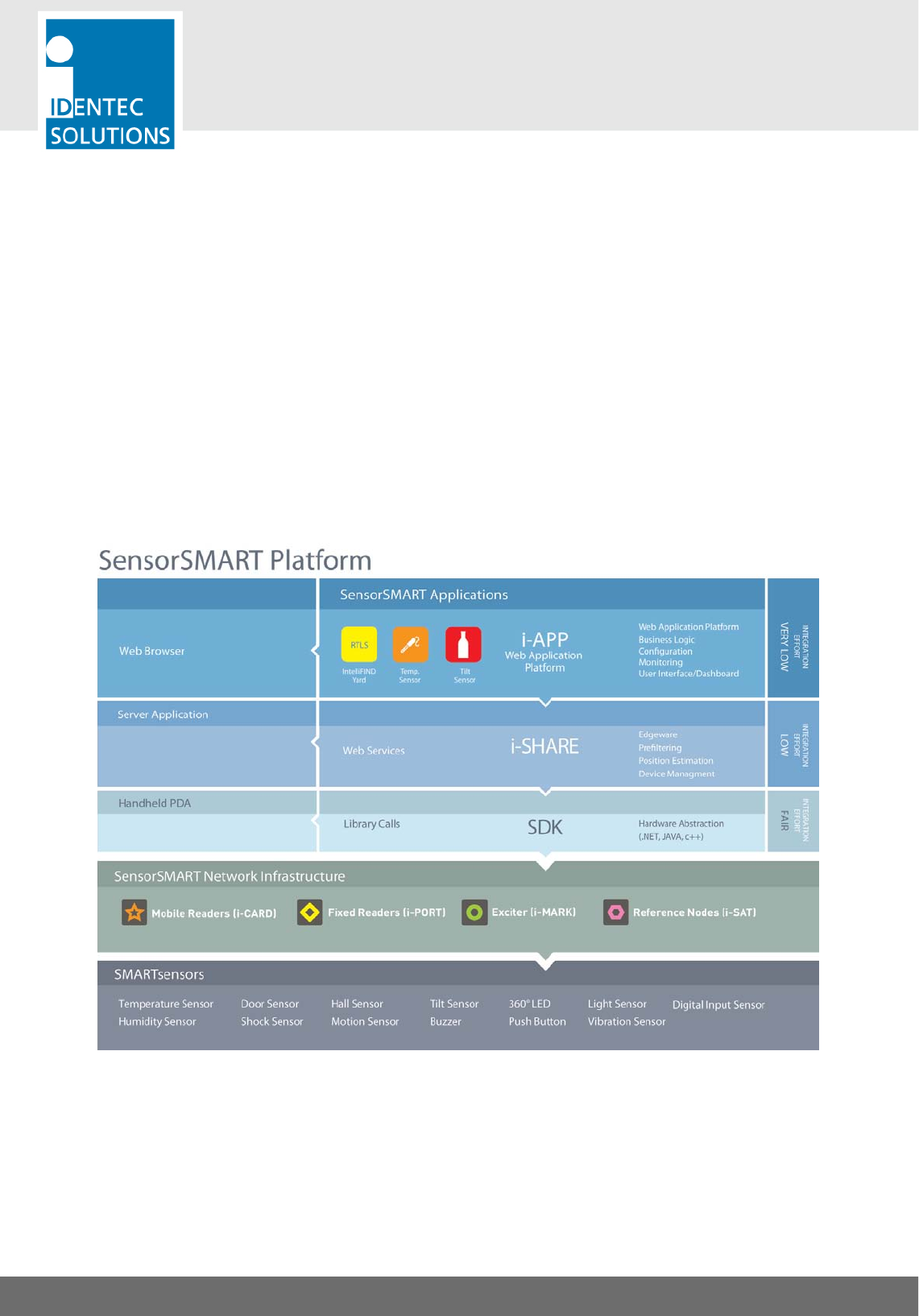
The IDENTEC SOLUTIONS’ SensorSMART Platform is the latest development in asset management,
localization and process optimization. Developed to deliver the last mile in industrial communication, the
SensorSMART Platform fulfills a niche not previously addressed by available networks.
The SensorSMART Platform takes the complexity out of managing assets, personnel safety monitoring and/or
the tracking of valuable cargo and the need for multiple technologies. The unique combination of active RFID,
RTLS and WSN in one platform eliminates the necessity for complex deployments of multiple technologies, or
the need to compromise with one technology’s specific functionalities. The pinnacle of the SensorSMART
Platform is that it captures the best of RFID, WSN, and RTLS while also avoiding the less desirable features of
each technology. Third party application development is also simplified for added flexibility.
2.2. Component Overview

i-Q350 RCM
USER MANUAL
VISIBILITY DELIVERED. PAGE 10 OF 28
3. INTRODUCTION
3.1. Fundamentals
Designed to automate the data collection and business processes associated with refrigerated container
management in complex marine and intermodal terminal environments, the Reefer Container Monitoring
System (RCMS) from IDENTEC SOLUTIONS represents the next generation in ‘plug and play’ wireless reefer
monitoring and control.
RCMS increases visibility and helps optimize operational performance with a proven, off the shelf solution for
proactive reefer box management:
• View and manage temperatures and other critical condition parameters with two-way monitoring and
control software
• Avoid undetected reefer failures and respond rapidly to events with real-time alarms
• Eliminate the need for power-line modems with low infrastructure wireless hardware
• Reduce capital outlay with managed service options
The innovation at the heart of the system is the iQ350 RCM sensor which talks directly with the reefer unit’s
microprocessor controller via the standard external serial port for immediate, live monitoring operations.
The RCM System, in conjunction with the i-Q350 RCM, provides the perfect combination to monitor the status
of all reefer containers within your terminal.
3.2. System Components—Sensors
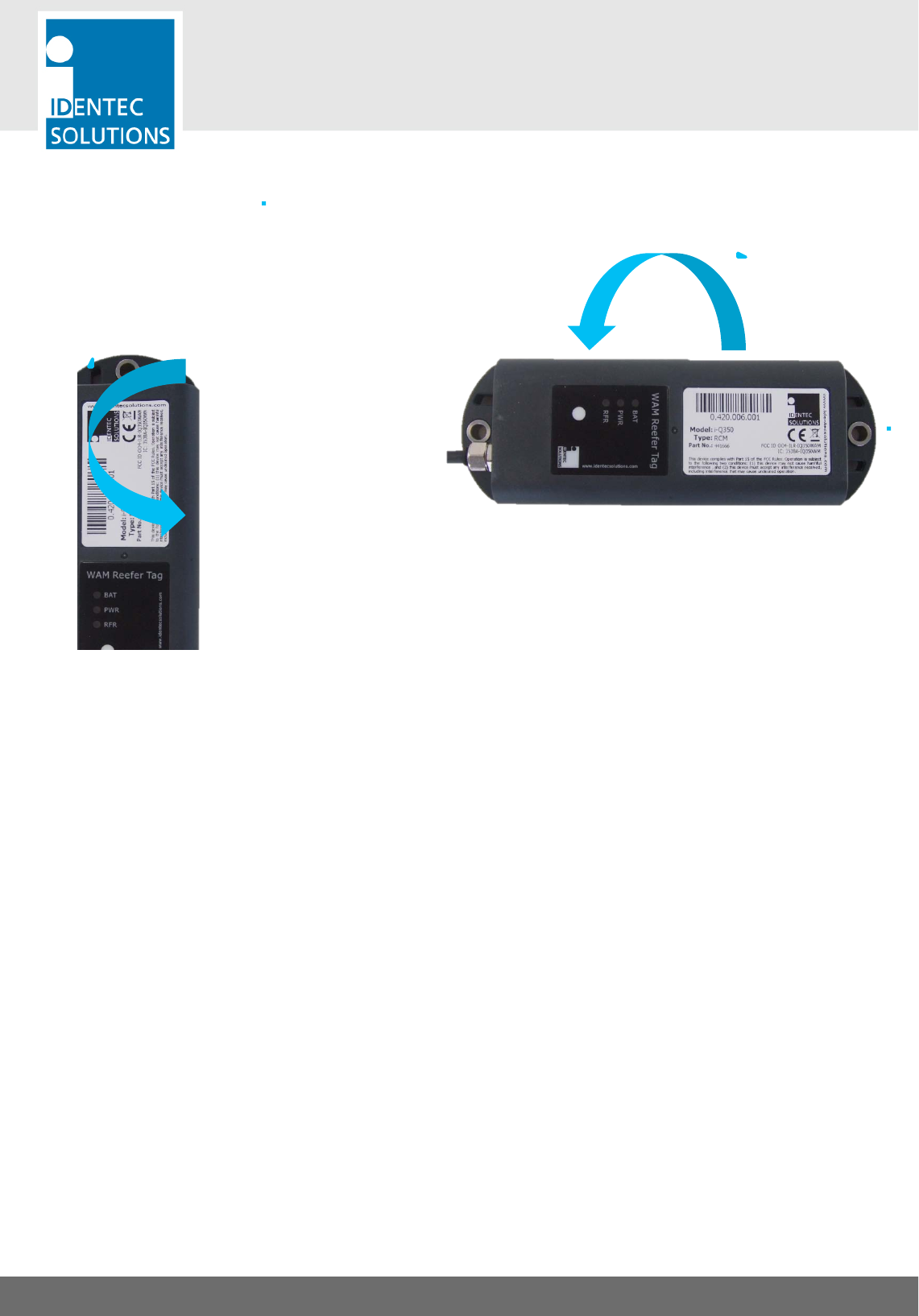
i-Q350 RCM 3.2.1.
The i-Q350 series of tags is IDENTEC SOLUTIONS’ newest generation of
Intelligent Long Range® (ILR®) active RFID tags.
ILR provides highly accurate, real-time data collection without human
intervention in wireless applications such as:
• identification
• tracking and tracing
• localization and
• Measurements monitoring.
Using advanced UHF radio frequency technology, i-Q350 WAM tags
transmit and receive data at distances of up to 30 meters (100 feet) from a
handheld device or up to 500 meters (1,640 feet) from a fixed interrogator.
The i-Q350 RCM tag includes a serial interface which communicates to container refrigeration units. The tag
auto detects the type of the controller and monitors the status information.
Also, LEDs support visual signalization during search, locate and alarms. The i-Q350 Reefer tag operates in
the 850 – 928 MHz UHF band.
i-Q350 RCM
USER MANUAL
VISIBILITY DELIVERED. PAGE 11 OF 28
Polarization of Sensors 3.2.2.
Vertically Polarized
Horizontally Polarized
Polarization is dependent on orientation and is rotation symmetrical.
i-Q350 RCM
USER MANUAL
VISIBILITY DELIVERED. PAGE 12 OF 28
3.3. System Components—Readers
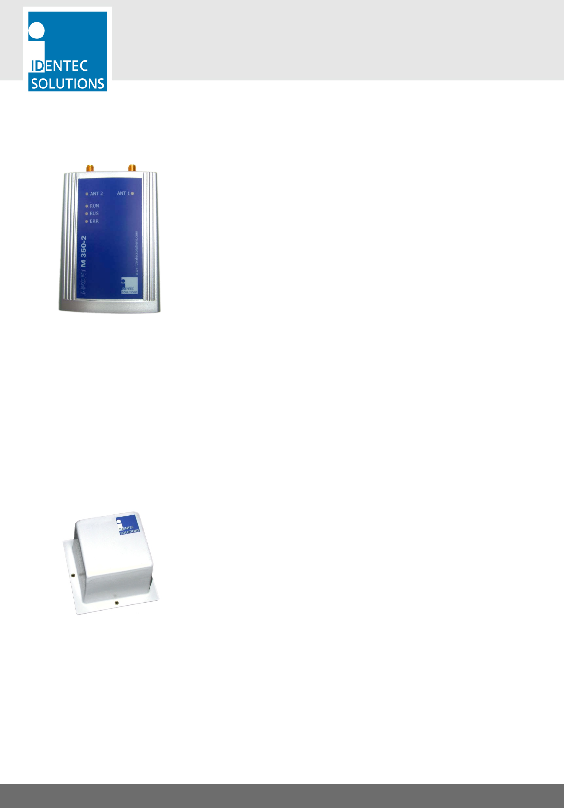
i-PORT M350-2 3.3.1.
The i-PORT M350-2 is a reader for the i-Q350 and i-B350 series of
IDENTEC SOLUTIONS’s Response and Broadcast Sensors. Built into a
compact housing, the i-PORT M350-2 reads and writes data to the sensors
at distances of up to 500 meters (1640 feet) on two antennas. Connection
to the host system is established via a RS422 interface, resulting in the
capability to connect up to 8 readers in a Daisy Chain using commercially
available CAT 5 cables and connectors.
A simple master/slave protocol enables data exchange. Not only does the
protocol contain the data received from the sensor but it can also provide
information about the time of data reception, field strength and information
about the number of times the sensor has been received by the reader.
3.4. System Components—Antennas
IDENTEC SOLUTIONS’ antennas are distinguished by their compact design. A variety of antennas can be used,
depending on application. The antennas are differentiated by characteristics such as polarization, apex angle,
and gain. Optimal fit to the reading zone is achieved by the right choice of antenna (characteristics) and
receive sensitivity. As the antennas are passive system elements, no tuning is required, which facilitates
installation and maintenance.
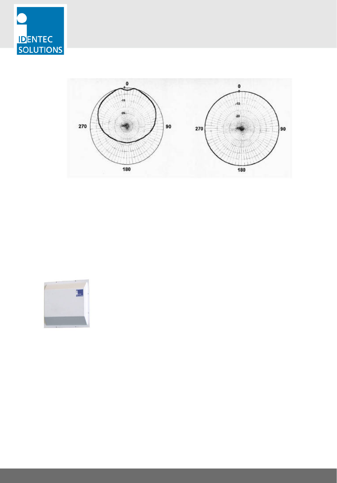
Elliptical Polarized Antennas 3.4.1.
Because of the wide apex angle (120º), a large read zone is achieved,
which is desirable when a large quantity of sensors need to be read at one
time, or when sensors moving at great speeds need to be interrogated.
Since the polarization is elliptical, orientation of the sensor relative to the
antenna is not important; if the sensor is in front of the antenna the sensor
may be polarized horizontally or vertically along the line of sight of the
antenna. Due to its small size and weight, this antenna is very easy to
integrate.
i-Q350 RCM
USER MANUAL
VISIBILITY DELIVERED. PAGE 13 OF 28
Orientation Diagrams: Elliptical polarized antenna
Elevation Azimuth
For this antenna, the maximum transmit power setting is:
• A-9185: -8 dBm
Linear Polarized Antennas 3.4.2.
Because of the smaller apex angle (60º), this antenna is more suited to
selective data collection and restriction of read zones.
Depending on the direction of mounting, the antenna’s field is either
vertically or horizontally polarized, requiring the sensor to have the same
orientation.
Because of the greater gain, longer read ranges can be achieved with this
antenna compared to the elliptical polarized type above.
i-Q350 RCM
USER MANUAL
VISIBILITY DELIVERED. PAGE 14 OF 28
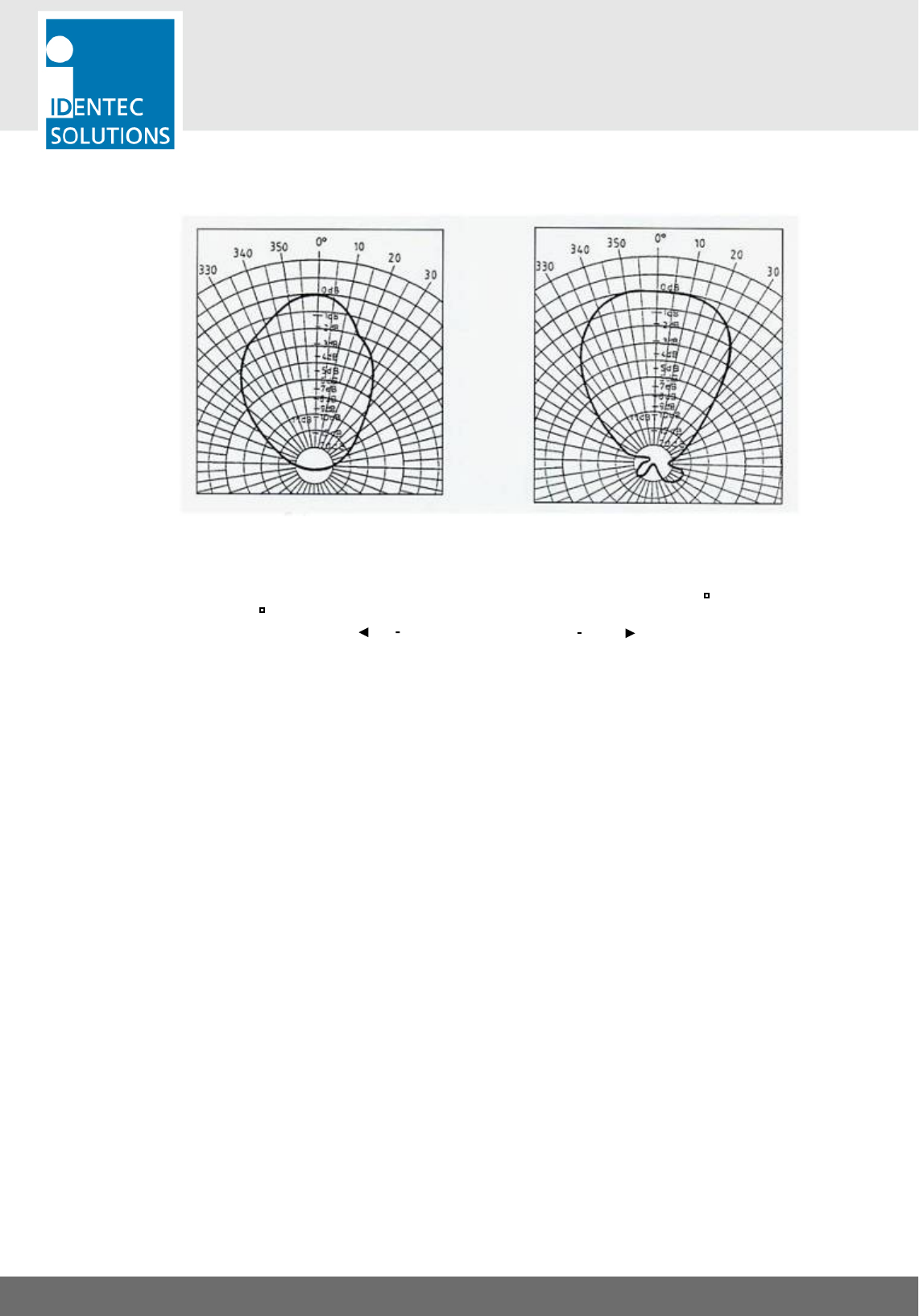
Orientation Diagrams: Linear polarized antenna
Elevation Azimuth
Vertical Polarization Horizontal Polarization
For this antenna, the maximum transmit power setting is:
• W-900R: -12 dBm
Antenna Orientation
i-Q350 RCM
USER MANUAL
VISIBILITY DELIVERED. PAGE 15 OF 28
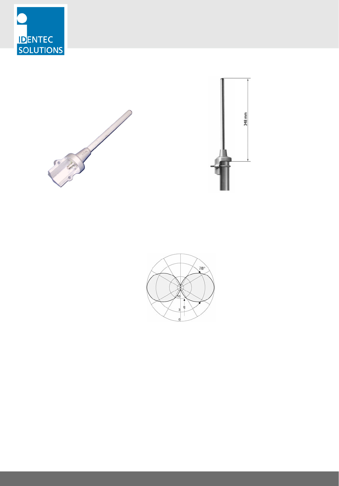
1-Wave Rod Antenna 3.4.3.
Overall Dimensions: 425 × 90 mm Mounting proposal
Antenna diagram
Vertical
For this antenna, the maximum transmit power setting is:
• Rod antenna: 6 dBm
i-Q350 RCM
USER MANUAL
VISIBILITY DELIVERED. PAGE 16 OF 28
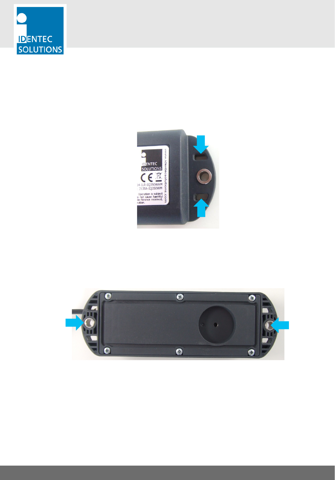
4. TAG MOUNTING SOLUTIONS
The Tag can be mounted either with cable straps using the 2 slits at each end, by using screws or a magnet
as described in the following 3 subchapters.
4.1. Cable Straps
4.2. Screws
i-Q350 RCM
USER MANUAL
VISIBILITY DELIVERED. PAGE 17 OF 28
Important Information
1. Only screws with cylindrical heads are suitable for mounting the tag. We do not advise using counter-
sunk screws. If for some reason this should be necessary, then use only with a suitable counter-sunk
cushioning disc (refer to UN 1277).
2. The attached bushing is recommended to protect the plastic around the mounting hole from being
damaged when tightening the rivet.
3. Secure the screws with self-locking nuts, spring washers or Nord-lock washers (refer to UN 7014). Should
mounting be completed with self-tapping screws, loosening may occur over time.
4. If the tag is mounted outdoors or in a damp environment, all mounting parts need to be made of
stainless steel or other non-rusting material.
5. A temperature of at least +10 °C (+50 °F) must be maintained during mounting to prevent the casing
from cracking.
6. Recommended maximum torque
M4/ #8 (with bushing): 2 Nm
M5/#10 (w/o bushing): 3 Nm
M6/#14 (w/o bushing): 3 Nm
If the torque is any greater, the screw may over tighten, or the casing might break.
7. Metal surfaces in direct proximity to the tag may reduce the tag’s range of function. Tags should not be
mounted in metal recesses or corners.
8. After mounting, the tag’s function should be tested with appropriate devices and software.
i-Q350 RCM
USER MANUAL
VISIBILITY DELIVERED. PAGE 18 OF 28
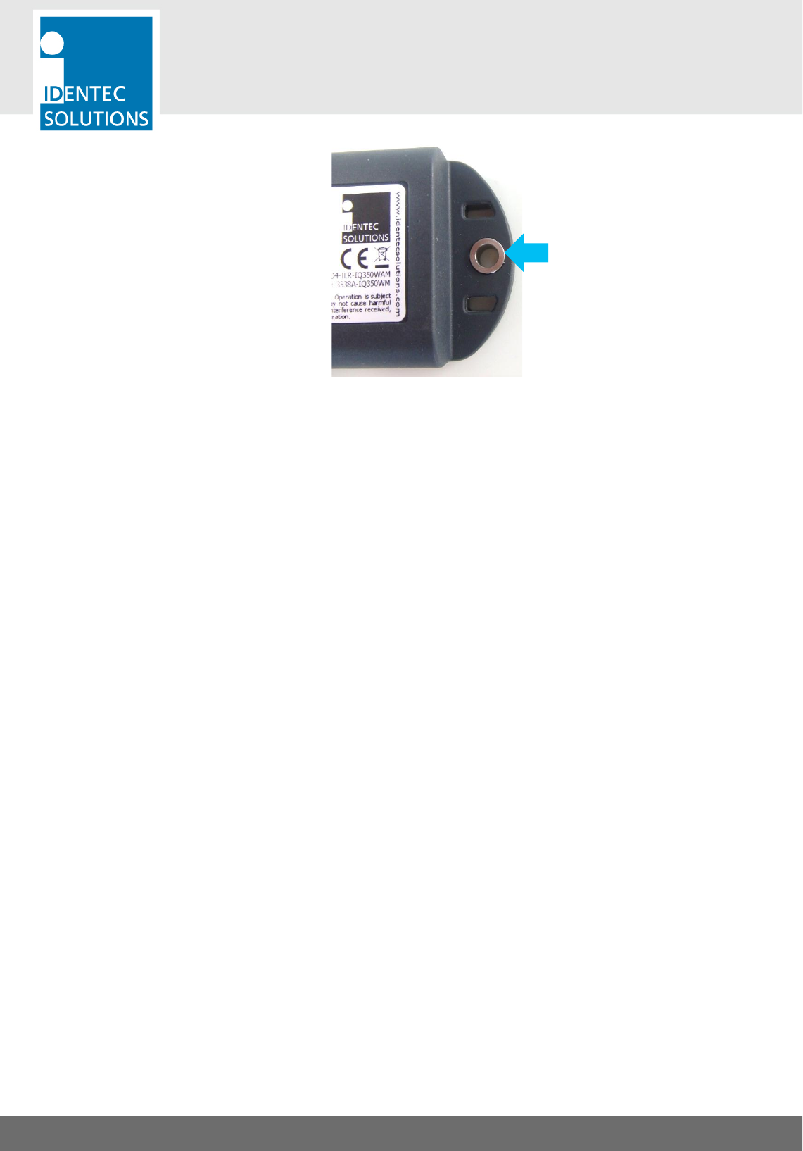
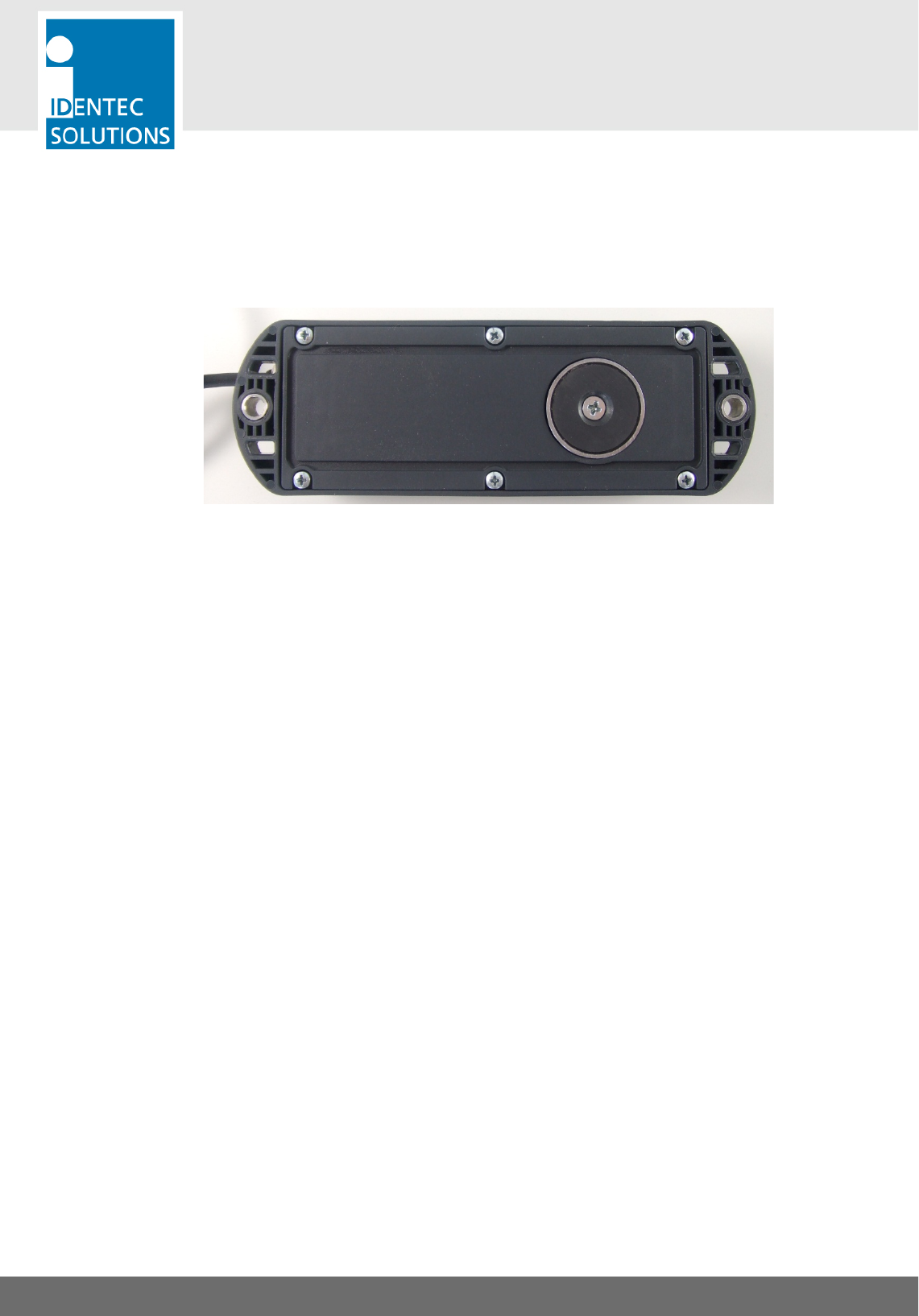
4.3. Magnet (optional)
The tag can be easily removed by grabbing it on the part of its body with the cable outlet. Slightly pull it off
the wall and the magnetic holding force is removed at once.
DO NOT pull the cable.
i-Q350 RCM
USER MANUAL
VISIBILITY DELIVERED. PAGE 19 OF 28
5. CONNECTING TO THE REEFER CONTROLLER
Safety Instructions
A screened cable must be used for the data cable.
Important Note
The total cable runs between tag and the monitored device must not exceed a total of 15 m. This is due to
limitations of the RS232 (EIA-232) standard.
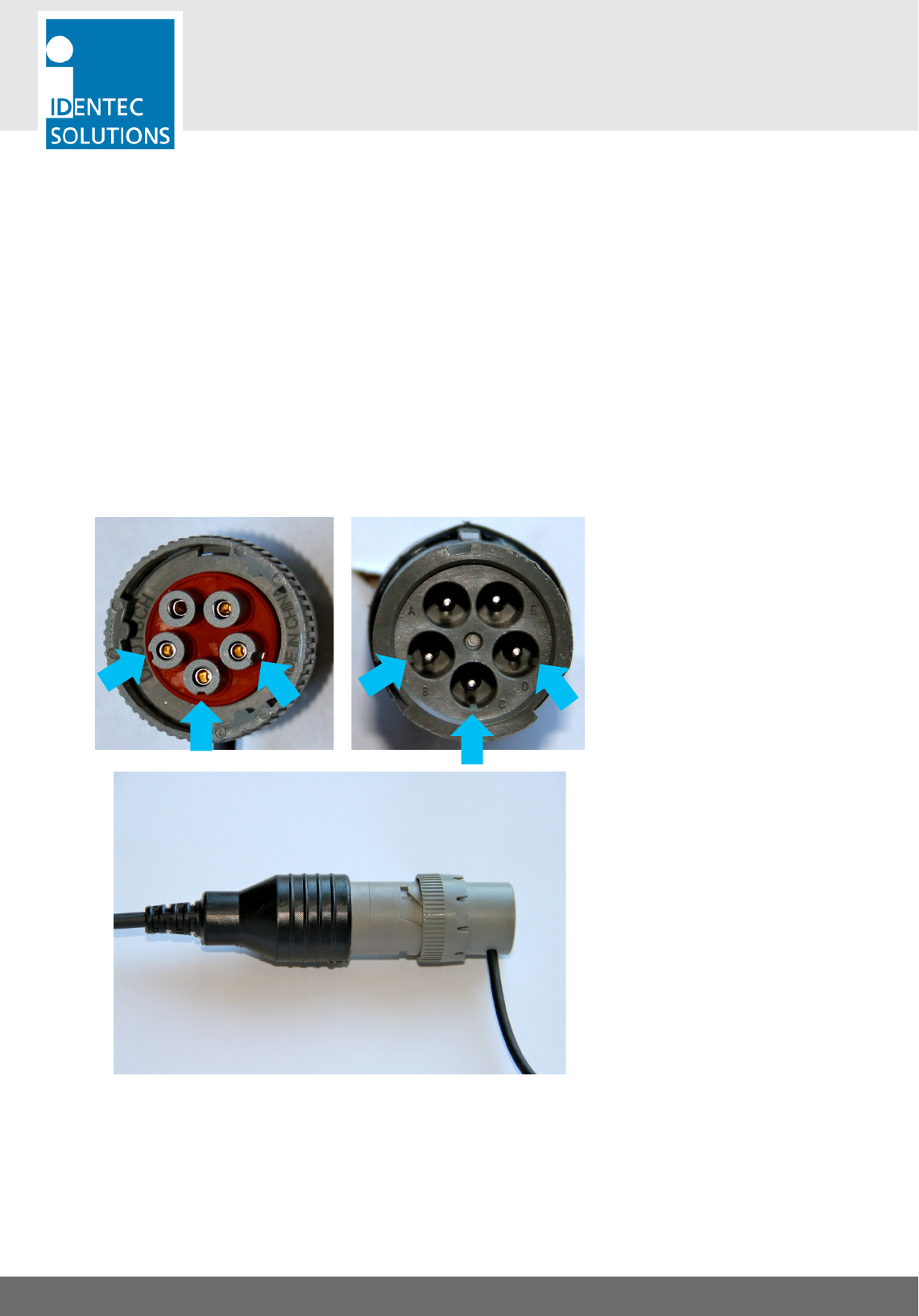
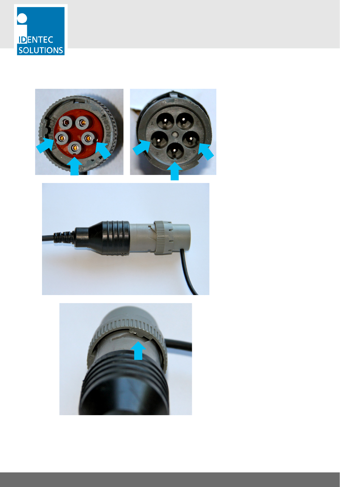
Connecting the i-Q350 RCM to the controller
3 of the 5 connector pins are coded with a small edge to align correctly the plug and connector. The 2
connector pins which are not coded are longer to simplify identification. The data rate of the external device is
automatically detected.
Follow the process hereafter to connect the tag to the reefer controller.
Step 1
Align the male connector of the i-Q350
RCM tag to the female connector on
the reefer connector.
In order to align correctly the
connectors, use the indent and edges
highlighted on the pictures on the left.
Step 2
Connect the male connector to the
female connector.
Do not apply too much pressure since
the bayonet locking mechanism might
not be properly aligned.
i-Q350 RCM
USER MANUAL
VISIBILITY DELIVERED. PAGE 20 OF 28
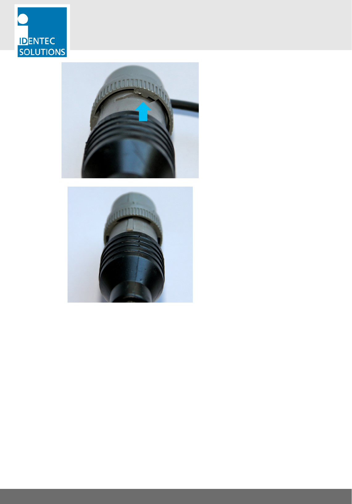
Step 3
Align the bayonet locking mechanism
by rotating the outer ring on the male
connector.
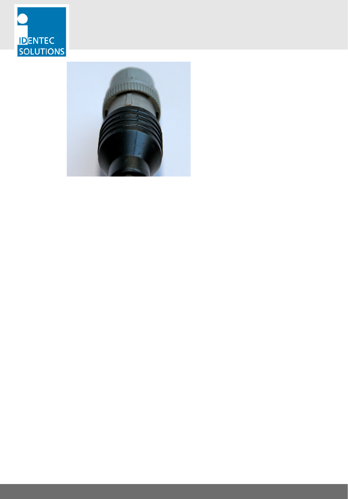
Step 4
Press both connector together and lock
the bayonet mechanism to insure
proper electrical connection and
weatherproofness.
i-Q350 RCM
USER MANUAL
VISIBILITY DELIVERED. PAGE 21 OF 28
6. ACCESSORIES
In order to accomodate different installations and to operate with most of the reefer container's plug's
variation, we are providing several accessories.
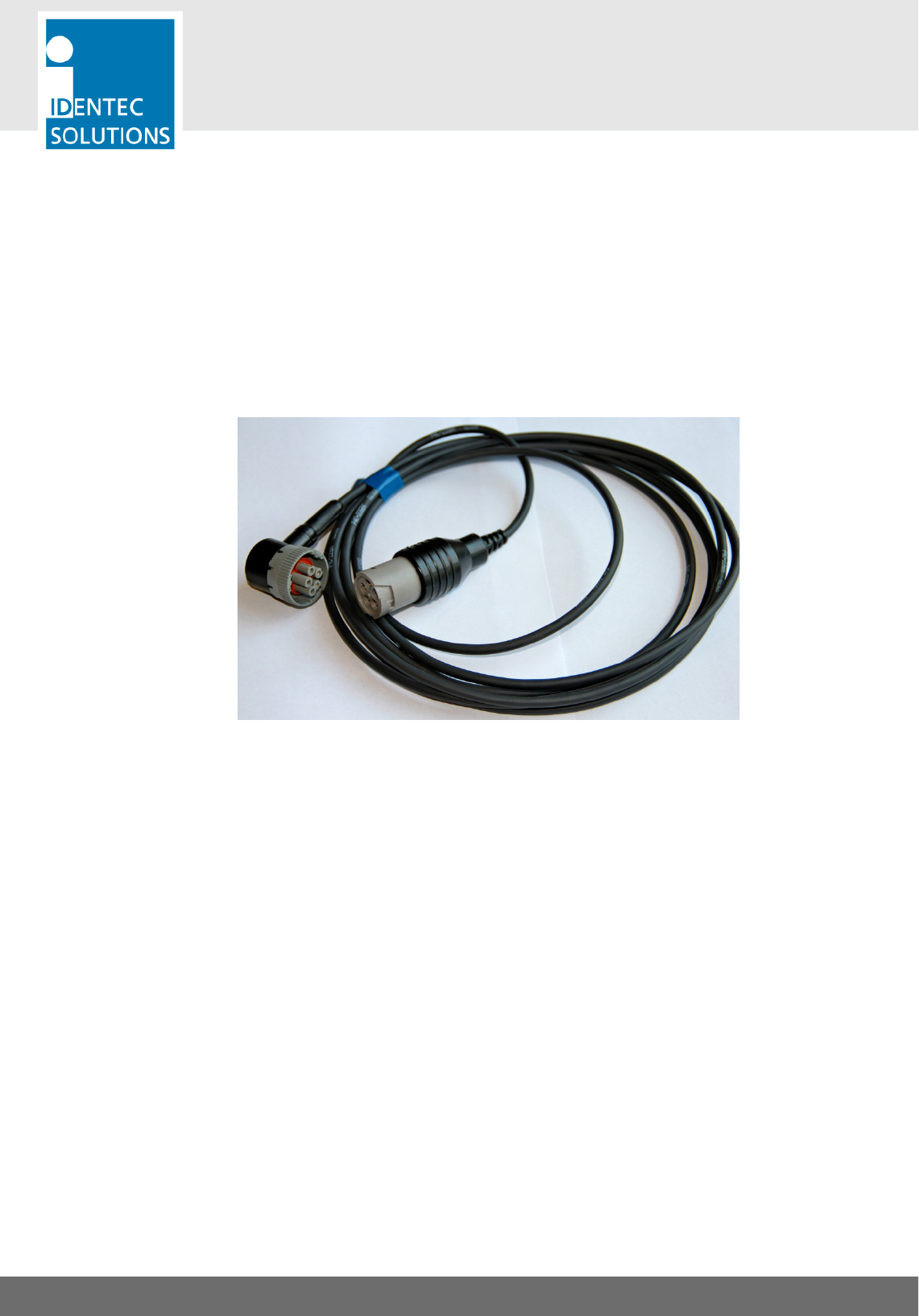
6.1. Extension Cable
We are providing a 2 meters (6 ft) extension cable to accomodate installation where the i-Q350 RCM is
installed on racks.
The extension cable can be used between the i-Q350 RCM and an adaptor.
Up to 5 extension cables can be connected together to reach greater distances.
Extension Cable
i-Q350 RCM
USER MANUAL
VISIBILITY DELIVERED. PAGE 22 OF 28
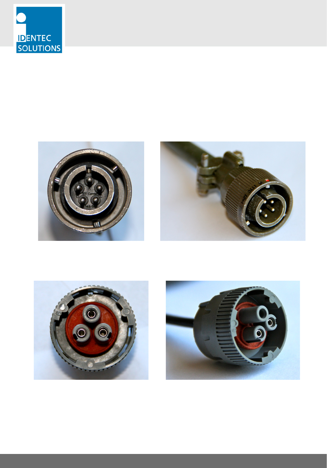
6.2. Adaptors
Multiple adaptors are available in order to connect the i-Q350 RCM to different type of reefer controllers.
Each adaptor is 50 centimeters (19 inches) long and use the standard 5 pin Deustch female connector to
connect to the tag. Adaptors can be use in combination with extension cable.
Hereafter are the list of adaptors available for the RCMS solution.
RCM Adaptor 3
Adaptor with a 5-pin Cannon connector used by some Carrier or Thermoking reefer controllers
p/n: 450363
RCM Adaptor 4
Adaptor with a 3-pin Deutsch connector used by some Daikin reefer controllers.
p/n: 450464
i-Q350 RCM
USER MANUAL
VISIBILITY DELIVERED. PAGE 23 OF 28
6.3. Connecting to the tag
Follow the process hereafter to connect the extension cable or adaptors to the i-Q350 RCM.
Step 1
Align the male connector of the i-Q350
RCM tag to the female connector of
the adaptor or extension cable.
In order to align correctly the
connectors, use the indent and edges
highlighted on the pictures on the left.
Step 2
Connect the male connector to the
female connector.
Do not apply too much pressure since
the bayonet locking mechanism might
not be properly aligned.
Step 3
Align the bayonet locking mechanism
by rotating the outer ring on the male
connector.
i-Q350 RCM
USER MANUAL
VISIBILITY DELIVERED. PAGE 24 OF 28
Step 4
Press both connector together and lock
the bayonet mechanism to insure
proper electrical connection and
weatherproofness.
i-Q350 RCM
USER MANUAL
VISIBILITY DELIVERED. PAGE 25 OF 28
7. TROUBLESHOOTING
7.1. General
This chapter covers how faults can be recognized and rectified. There are potentially four main problem
sources:
• The user control system, including task requirements, communication cables, peripheral units with
possible object recognition switches.
• The SensorSMART platform including peripheral units and their cables, also potential object recognition
switches.
• The environment including large objects between antenna and sensor, electrical disturbance sources,
intervention by persons, etc.
• The quality of the technical design, including alignment between antenna, data, ratio of task
requirements/available communication time etc. The information about system performance is contained
in the relevant datasheets.
When planning the total system, not overlook the problem sources and “Fault finding procedures on system
level” should be included in the host system. How this could look in detail depends on the relevant system
concept and very likely varies from one system to another.
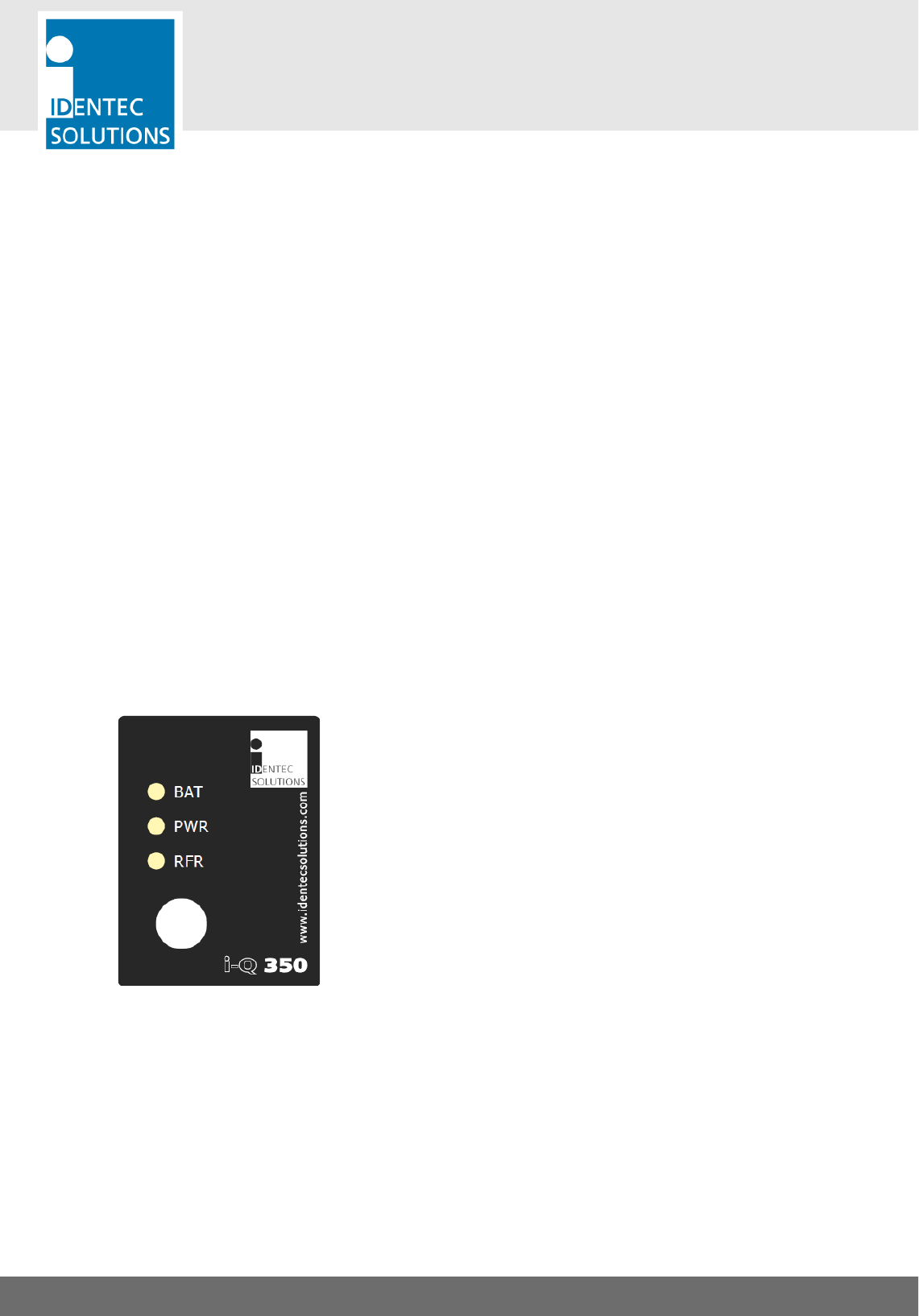
7.2. Status Display (LEDs)
BAT
Green
Red
PWR
Green
Red
RFR
Green
Orange
Red
tag’s battery is OK
tag’s battery is low and needs to be replaced
the external device is powered up
the external device is switched off
the external device is working properly
no communication with the external device
not connected to the external device or no successful
communication with the external device

i-Q350 RCM
USER MANUAL
VISIBILITY DELIVERED. PAGE 26 OF 28
8. MAINTENANCE
8.1. General
When installed correctly the ILR System will operate virtually maintenance free for many years. However, in
the event maintenance is required only trained and authorized personnel are permitted to perform the
updates, changes and maintenance necessary.
8.2. Regular Cleaning of The Surface
Remove dust with a brush or compressed air. If there are fatty or oily substances use a soft cloth moistened
with a mild rinsing agent.
Warning
Do not clean the tag in a dishwasher. Do not sandblast the tag. Do not use high pressure water jet or steam
cleaner. Do not use cleaning products containing chemical additives.
8.3. Precautionary Maintenance
A regular check of the system is recommended. Unstable connections could lead to damage and malfunctions
of the system and should therefore be repaired as soon as possible.
A Brief Checklist
• Are all housings intact?
• Are all cables intact?
• Are all connectors intact?
• Are all connectors securely fastened?
• Are all screws still tight?
• Is there a malfunction at a specific unit?
8.4. Returns
Parts or main components returned for repair or exchange must be handled with great care. PC cards must be
returned in the appropriate ESD-protecting packaging material. All returns should include an error description
and a short application overview and be sent to the local distributor or to:
IDENTEC SOLUTIONS AG
Service Department
Millenium Park 2
6890 Lustenau
AUSTRIA

i-Q350 RCM
USER MANUAL
VISIBILITY DELIVERED. PAGE 27 OF 28
9. TECHNICAL DATA
Communication Broadcast 350
Operation Mode
Transmits Sensor ID and user data in pre-defined interval
Read Range
up to 500m*
Compatibility
i-PORT M350, i-CARD CF 350 and i-PORT 4-350
Operating Frequency
868 MHz (EU) or 920 MHz (NA)
Transmit Power
<1mW
Communication Response 350
Operation Mode
Bi-directional communication (reading log, blink LED, write/read
data)
Read Range
up to 250m*
Compatibility
i-PORT M350 and i-CARD CF 350
Operating Frequency
868 MHz (EU) or 920 MHz (NA)
Transmit Power
<1mW
Data
Data Retention
> 10 years without power
Write Cycles
100,000 writes
Memory Size
10,000 Bytes user definable
Identification Code
48 bit fixed ID
Configuration
Device
i-PORT M350 or i-CARD CF350
Ping Rate
Configurable from 0.5 to 300 seconds insteps of 0.5 seconds
Number of Bursts
Configurable from 0 to 15
Broadcast User Data
Up to 50 Bytes
Interface
serial interface
RS232 Deutsch connector
supported Reefer units
Thermo King
MP4000 (monitoring only)
Daikin
Decos IIIc
Decos IIId
Starcool
RCCU5
SCC6
Carrier
Microlink 3
Microlink 2i
Microlink 2
Electrical
Power Source
Lithium Battery (replaceable)
Battery Monitoring
Yes

i-Q350 RCM
USER MANUAL
VISIBILITY DELIVERED. PAGE 28 OF 28
Environmental Conditions
Operating Temperature
–20 °C to +70 °C (–4 °F to +158 °F)
Humidity
10% to 95% relative humidity @ 30°C
Shock
Multiple drops to concrete from 1m (3ft), 3 times DIN IEC 68-2-
27
Vibrations
3G, 20 sine wave cycles, 5 to 150 Hz, DIN IEC 68-2-6
5G, noise 5 to 1.000 Hz, 30 minutes, DIN IEC 68-2-64
Standard/Certification
Europe
CE (EN 300 220-1, -3; EN 301 489-1,-3; EN 60950)
North America
FCC Part 15 (US); Industry Canada
Mechanical Data
Dimensions
171 x 56 x 26 mm (6.7 x 2.2 x 1.0 inches)
Enclosure Material
Plastics
Enclosure Rating
IP 65
Weight
50 grams (1.75 ounces)