Identec Solutions IPF310 i-PORT F310 User Manual
Identec Solutions AG i-PORT F310
UserManual.wiki
>
Identec Solutions
>
IPF310 User Manual
>
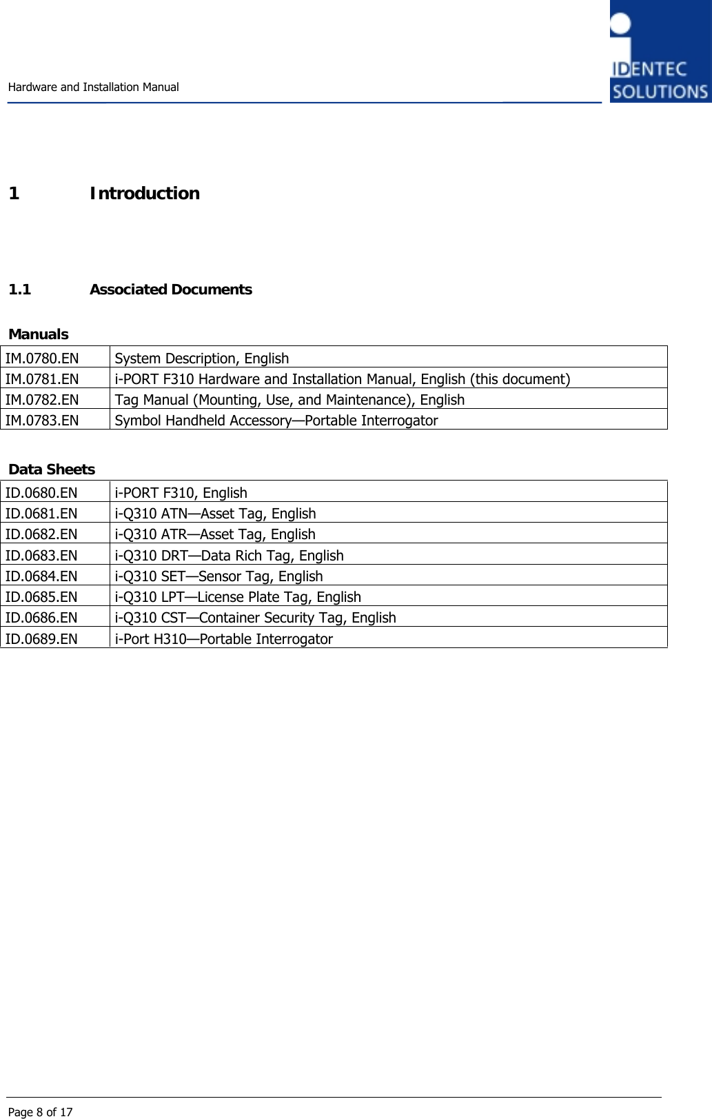
User Manual
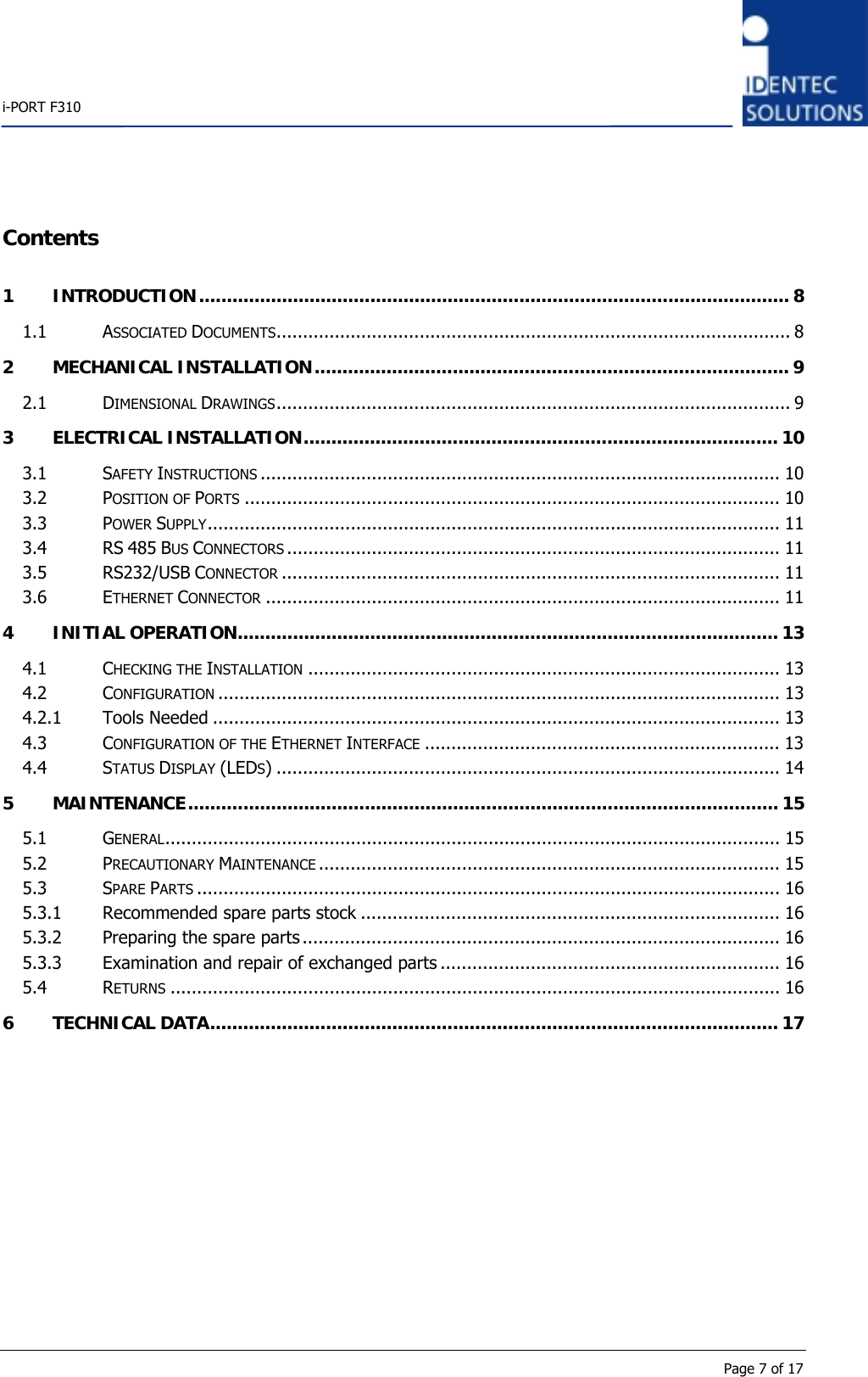
Contents
1.
User Manual
2.
Users Manual
User Manual
Navigation menu
Upload a User Manual
Namespaces
Wiki Guide
HTML
PDF
Info
Views
User Manual
Discussion / Help
Navigation