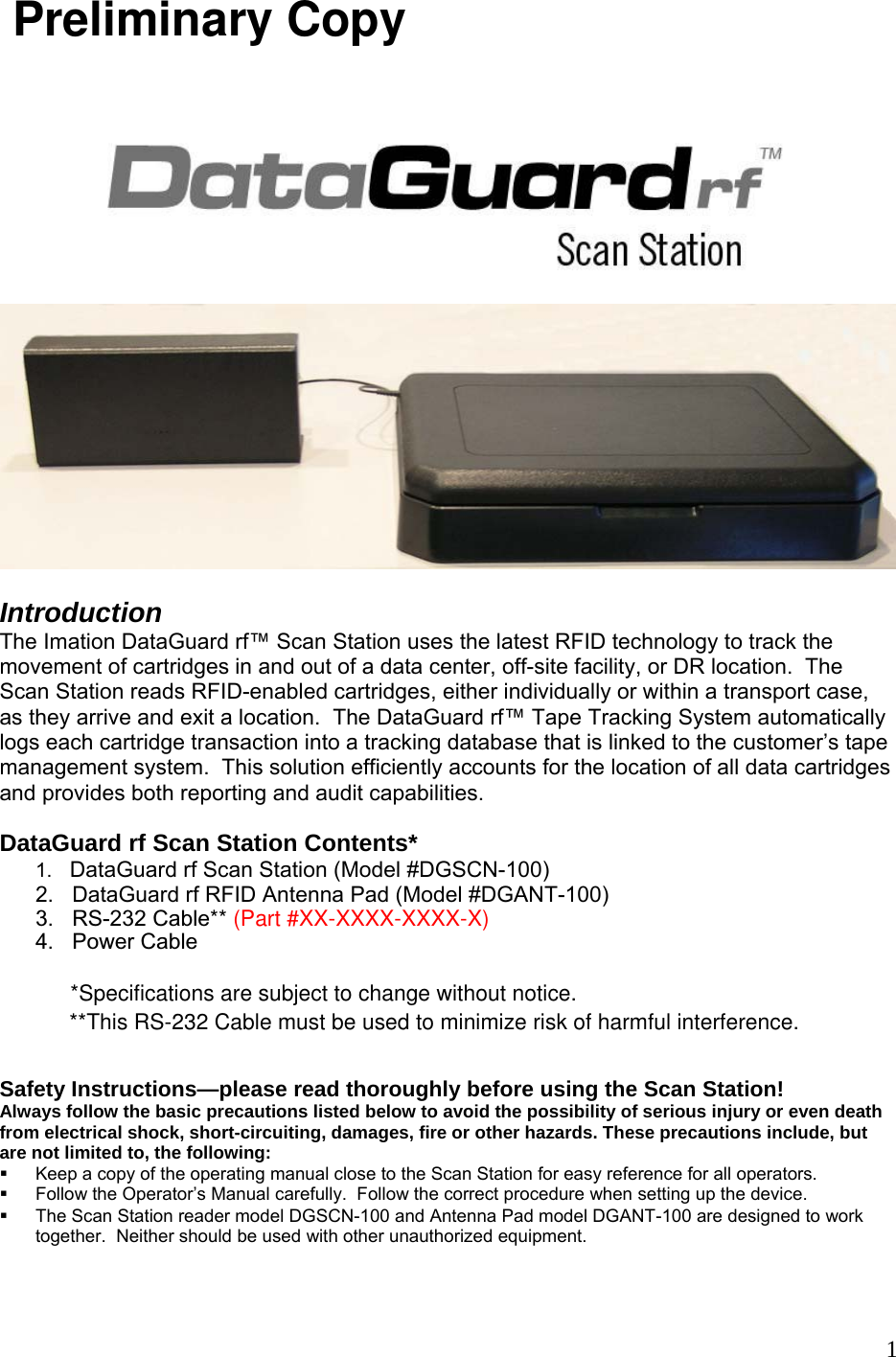
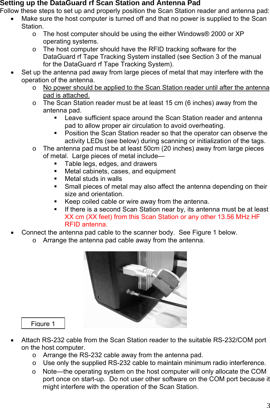
Imation DGSCN100 Data Guard RF Scan Station User Manual

Imation Corp. Data Guard RF Scan Station

User manual

                            Introduction  The Imation DataGuard rf™ Scan Station uses the latest RFID technology to track the movement of cartridges in and out of a data center, off-site facility, or DR location.  The Scan Station reads RFID-enabled cartridges, either individually or within a transport case, as they arrive and exit a location.  The DataGuard rf™ Tape Tracking System automatically logs each cartridge transaction into a tracking database that is linked to the customer’s tape management system.  This solution efficiently accounts for the location of all data cartridges and provides both reporting and audit capabilities. DataGuard rf Scan Station Contents* 1.   DataGuard rf Scan Station (Model #DGSCN-100)              2.   DataGuard rf RFID Antenna Pad (Model #DGANT-100)  Safety Instructions—please read thoroughly before using the Scan Station! Always follow the basic precautions listed below to avoid the possibility of serious injury or even death from electrical shock, short-circuiting, damages, fire or other hazards. These precautions include, but are not limited to, the following:   Keep a copy of the operating manual close to the Scan Station for easy reference for all operators.  Follow the Operator’s Manual carefully.  Follow the correct procedure when setting up the device.  The Scan Station reader model DGSCN-100 and Antenna Pad model DGANT-100 are designed to work together.  Neither should be used with other unauthorized equipment.  13.   RS-232 Cable** (Part #XX-XXXX-XXXX-X) 4.   Power Cable Preliminary Copy**This RS-232 Cable must be used to minimize risk of harmful interference.*Specifications are subject to change without notice.
  Do not open this device or attempt to disassemble or modify it.  The device contains no user-serviceable parts.  If it appears to be malfunctioning, have it inspected by qualified service personnel.  Modifying or disassembling the product will void the warranty on this product.   Do not expose this device to rain, use it near water or in damp or wet conditions, or place containers on it that contain liquids that might spill into an opening.     If unusual smells, sounds, or smoke emanate from the Scan Station or if liquids enter the Scan Station, switch its power off immediately and unplug it from the power outlet.    Make sure the host computer and the Scan Station are properly electrically grounded.  This device should be used in compliance with all national legal requirements and local electrical codes.      The electrical socket outlet should be close to this device and easily accessible.       Use this device only with the Imation DataGuard rf Tape Tracking System and associated software.        Pacemaker warning The Scan Station creates an electromagnetic field below valid limits defined for cardiac pacemakers, but there should be a minimum distance of 25 cm (10 inches) between the antenna pad and a cardiac pacemaker.  People with cardiac pacemakers should not remain close to the antenna pad for any lengthy amount of time.    Service warning for qualified service personnel—  Caution o  Disconnect the power cord before servicing. o  The Scan Station uses a double-pole/neutral fuse. o  The fact that the LEDs have turned off does not mean that the device is discharged.    No part of this publication may be reproduced, transmitted, transcribed, stored in a retrieval system, or translated into any language in any term by any means without the written permission of Imation Corporation.  Imation reserves the right to make any changes or improvements in the products described in this document at any time without prior notice.                          2
Setting up the DataGuard rf Scan Station and Antenna Pad Follow these steps to set up and properly position the Scan Station reader and antenna pad: •  Make sure the host computer is turned off and that no power is supplied to the Scan Station.   o  The host computer should be using the either Windows® 2000 or XP operating systems. o  The host computer should have the RFID tracking software for the   DataGuard rf Tape Tracking System installed (see Section 3 of the manual for the DataGuard rf Tape Tracking System). •  Set up the antenna pad away from large pieces of metal that may interfere with the operation of the antenna.    o No power should be applied to the Scan Station reader until after the antenna pad is attached.  o  The Scan Station reader must be at least 15 cm (6 inches) away from the antenna pad.    Leave sufficient space around the Scan Station reader and antenna pad to allow proper air circulation to avoid overheating.   Position the Scan Station reader so that the operator can observe the activity LEDs (see below) during scanning or initialization of the tags. o  The antenna pad must be at least 50cm (20 inches) away from large pieces of metal.  Large pieces of metal include—   Table legs, edges, and drawers   Metal cabinets, cases, and equipment   Metal studs in walls   Small pieces of metal may also affect the antenna depending on their size and orientation.   Keep coiled cable or wire away from the antenna.   If there is a second Scan Station near by, its antenna must be at least XX cm (XX feet) from this Scan Station or any other 13.56 MHz HF RFID antenna. •  Connect the antenna pad cable to the scanner body.  See Figure 1 below.     o  Arrange the antenna pad cable away from the antenna.   Figure 1 •  Attach RS-232 cable from the Scan Station reader to the suitable RS-232/COM port on the host computer.   o Arrange the RS-232 cable away from the antenna pad. o Note—the operating system on the host computer will only allocate the COM port once on start-up.  Do not user other software on the COM port because it might interfere with the operation of the Scan Station.  3o Use only the supplied RS-232 cable to maintain minimum radio interference.
 • Plug the power cable from the Scan Station reader into a suitable (100-240VAC; 50-60Hz) electrical power outlet.   o Arrange the power cable away from the antenna pad.  • Turn on the host computer to allow it to recognize the Scan Station.   Using the DataGuard rf Scan Station The RFID antenna is built into the top of the Scan Station antenna pad.  In the closed position the antenna can read individual cartridges or non-metallic cases filled with cartridges.   The outline of a case is molded into the top of the antenna pad to act as a placement guide for cartridges and for cases.  Placement of Cases and Cartridges: •  Case—place the non-metallic case centered in the grooved outline on the top of the antenna pad (Figure 3). o  The RFID labels on the cartridges in the case should face upwards. o  Imation’s 20-cartridge case (Model DGTSC-100) is ideal for the Scan Station, but other non-metallic, 20-cartridge cases and smaller cases also work well.  4.      • Single cartridge-- o  If the cartridge lies flat on the closed antenna pad, put the RFID label directly over the case outline. See Figure 3. o  If the cartridge is upright on the pad with the RFID label facing upwards, put the cartridge in the middle of the molded case outline.  See Figure 4.     RFID label facing upwards Figure 3Cartridge lying flat                                                                                  Figure 4
• Other situations— o  The face of the label is parallel to the antenna pad—the label should be centered within the molded case outline (Figure 5). o  The face of the label is perpendicular to the antenna pad—the face of the label should be parallel to one edge of the molded case outline and be above the case outline. o  9840 cartridge    This cartridge may be difficult to read in some non-metallic shipping cases.   Open the antenna pad to the vertical position and place the case within the molded case outline.  See Figure 5.   5 Figure 5 Scan Station Operation: The Scan Station is used in conjunction with the Imation Tape Tracking Application Software included with the DataGuard rf Tape Tracking System.  Refer to Section 3 of the DataGuard rf Tape Tracking System manual for a full description of that software.  The antenna pad is used to scan the RFID tags on non-metallic storage cases or individual cartridges or to initialize an RFID tag on one cartridge at a time.  The process starts when the user clicks on a button in the appropriate software screen on the host computer.1. Place the cartridge case or the cartridge on the antenna pad as described above for scanning.  Initialization can only apply to one cartridge at a time.    2. Scan to create a shipping list— • Click on the Create Shipping List tab on the Imation RFID Cartridge Tracker Software (Section 3.1 of the DataGuard rf Tape Tracking System manual). • Scan the case or cartridge by clicking on Scan.3. Scan to create a receive list— •  Click on the Create Receive List tab on the Imation RFID Cartridge Tracker Software (Section 3.2 of the DataGuard rf Tape Tracking System manual). • Scan the case or cartridge by clicking on Scan.
3.  Initialize a single RFID tag— •  Click on the RFID Tag Intialization tab on the Imation RFID Cartridge Tracker Software (Section 3.4 of the DataGuard rf Tape Tracking System manual). • Initialize the RFID tag on a single cartridge by clicking on Init RFID Tag If the antenna senses more than one RFID tag, it will send an error message to the Scan Station.  The antenna only initializes one tag at aa time in order to avoid writing incorrect data to any tag.Monitoring the Scan Station Operation:  6The Scan Station reader uses a series of lights (LEDs) to display its activity during the scanning or initialization process.  Position the Scan Station so the operator can observe the LEDs while scanning or initialization (Figure 6).       Figure 6• LED 1—Green o  The green flashing LED indicates that the reader is working properly. •  LED 2—Blue  o  Short flashes indicate error-free communication with the antenna pad during scanning or initialization. o  This LED will flash alternately with green LED 1 if the Scan Station is reset after a software update or if there is a data error after its internal check after a software update. • LED 3—Yellow o  Short flashes indicate communication with the host computer over the RS-232 cable. •  LED 4—Yellow (reserved for future use)  •  LED 5—Red  o  This LED lights up if there is an error with the antenna pad.  For example, it will flash if the antenna pad is placed too close to a large piece of metal. o  This LED also briefly flashes when the Scan Station reader is turned on or reset.   Warranty?   Product Specifications            Scan Station                             Antenna Pad                                            Model DGSCN-100                Model DGANT-100 Physical Data:  Dimensions                         41.9 x 19.1 x 12.7 cm          64.75 x 49.5 x 11.4 cm       (16.5 x 7.5 x 5 inches)         (25.5 x 19.5 x 4.5 inches)    Weight                                    3.47 kg    (7.65 lbs.)             9.53 kg    (21 lbs.)
Electrical Data:  Supply voltage                                     100-240VAC ; 50-60Hz               Current draw                                           0.4 A maximum   Power consumption                              40 watts maximum     Operating frequency                                        13.56 MHz             13.56 MHz               Transmission power                                         6 watts    Interface                      RS-232    Antenna power                                                                                                 6 watts maximum    Antenna connection                                                                SMA plug (50 Ω)  Antenna width                       0.37 m (14.6 in.)       7Environmental Conditions:  Operating temperature                          -20° C to +55° C (  -4° F to +130° F)     Storage temperature                      -25° C to +85° C (-10° F to +185° F)           Humidity                                                 5%-80%, no condensation               Applicable Standards  RF Approval   USA     FCC 47 CFR Part 15     Canada                                                            RSS-210   Europe     EN 300 330   EMC      EN 301 489   Safety            Low voltage directive                EN 60950                        Human Exposure                          EN 50364      FCC ID:  PB4DGSCN100Operation is subject to the following two conditions:  (1) This device may not cause harmful interference, and (2) this device must accept any interference received, including interference that may cause undesired operation.    Modifying this device may void the user’s authority to operate the device.  CANADA This device has been tested and found to comply with the limits for a Class A digital device, pursuant to part 15 of the FCC Rules.  These limits are designed to provide reasonable protection against harmful interference when the equipment is operated in a commercial environment.  This equipment generates, uses, and can radiate radio frequency energy and, if not installed and used in accordance with the instruction manual, may cause harmful interference to radio communications.  Operation of this equipment in a residential area is likely to cause harmful interference in which case the user will be required to correct the interference at his own expense.  USAIC:  6900A-DGSCN100    Antenna cable length                  0.9 m (36 in.)  Antenna length                      0.5 m (19.6 in.)
 8EuropeRestrictions for operating the DGSCN-100 as of October 2006 (ERC/REC 70-03, Annex 9, Band F1).Operation not currently permitted:  BEL, GRC, LUX, NOR, LVA, HRV, ROU, IRL, LIE, SUI, BUL, LTU.

Navigation menu